product and installation manual contractor series spectrum …
TRANSCRIPT

1
Revised 11/11
PRODUCT AND INSTALLATION MANUAL
Contractor Series Spectrum SystemsWhole Home Water Filtration
Retain this Product & Installation Manual for Maintenance and InformationPlease Register this Product - It is a Requirement for Warranty
EWS, Inc./Environmental Water Systems
office. 702.256.8182Monday - Friday, 8:30 am - 4:30 pm Pacific Standard Time
fax. 702.256.3744www.ewswater.com
e-mail. [email protected]
Model Numbers:
Spectrum Systems:CS-EWS-1354-7000
CS-CWL-1354-7000
Chloramine Spectrum Systems:EWS-CC-1465-7, EWS-CC-1865-7CWL-CC-1465-7, CWL-CC-1865-7
ALL FILTRATION PRODUCT PROUDLY MADE & ASSEMBLED IN THE USA

2SCHEMATIC: SPECTRUM SYSTEMS
For Illustration Purposes Only: Cut-away of CS-EWS-1354-7000
Tank, valve and all contents (as pictured below) delivered fully assembled. Bypass and supplied adaptors some assembly required.
All measurements are approximates and system heights may have variances up to 1”.Review this Manual for Proper Setup, Installation and Start-up of this System.
Model #’s: CS-EWS-1354-7000, CS-CWL-1354-7000
overall height
62”
heightto center of
bypass58”
tankheight
54” Outer Cover: White plastic cover and the coordinating plastic dome are strictly aesthetic and are non-functional parts of the Spectrum System.
self leveling base
Tank: Non-corrosive, seamless, one-piece blow molded with tough epoxy and fiberglass outer laminate. Note: actual color of tank may vary.
Filtration: 2.5 cubic feet or 65 pounds of EWS proprietary high-grade granular activated carbon.
Freeboard: Space allows media space to lift during backwash.
Lower Riser Screen and Underbed: Maintains a closed system where media does not escape into home plumbing during normal operation. The underbed provides greater water distribution during filtration and backwash.
Conditioning (EWS Series Only): ICN Riser Manifold contains two ICN conditioners that catalytically suspend hardness minerals so they inhibit adhesion to surfaces: Note: CWL Series does not contain this part.
Riser: Specialty PVC tubing food & beverage compliant for distribution of filtered water flow up through the riser and out to the home or water down through the riser to lift and properly backwash in order to self clean filtra-tion media
tank width 13”
Highly Recommended:Stainless steel corrugated water connectors, PEX or PVC Sch 40 have a flexible capability that may assist with issues where the rough and finish measurements are slightly off or where pressure surges/spikes or back pressure occur. This flexible connection may prevent tank and valve issues where rigid or hard pipe create problems over time. Perform all plumbing according to state or local codes.
18” clearance needed from center of tank for proper installation
Valve (front view)Not pictured: Bypass Valve to the rear of the Valve.

3SCHEMATIC: ALL SYSTEMS - Valve, Bypass, Adaptors and Valve Controls
BYPASSED IN SERVICE
Supplied Bypass Valve - All SystemsTop View
Outlet ValveClosed
Outlet ValveOpen
Inlet Valve Closed
Inlet ValveOpen
INLETIncoming Water Supply
OUTLETFiltered
Water to Home
INLETIncoming Water Supply
OUTLET
NO
TE:
Inle
t and
Out
let V
alve
s ar
e cl
osed
and
in th
e by
pass
po
sitio
n w
hen
the
hole
s ap
pear
at t
he to
p an
d bo
ttom
as
show
n to
the
right
No Flow Into SystemFlow Into Systemto be Filtered
Flow of FilteredWater from System
NO
TE: Inlet and Outlet Valves are open and in the service posi-
tion when the holes appear at the sides (or do not appear on top)
as shown to the left
Valve Controls - All SystemsWhat is normally seen on the display:
Current Time of Day in Data Display
PM Indicator (if applicable)
Data Display will alternate (every 10 seconds) between Time of Day to another number and then back to the Time of Day - this is normal and tells the user the next time the system will backwash counting down each day from 6 (factory pre-set) until backwash
In Service Icon
During Installation when instructed:
Use the Up and/or Down Button to set the Time of Day
Use the Extra Cycle Button to flush the system. The Parameter Display will appear and indicate the cycle engaged (“BW” or “RR”) during backwashing and the Data Display will indicate time remaining during a cycle
Contact EWS Customer Service if you see an Error Icon or have wandered into a Pro-gramming Mode that you do not understand.
valve controls 1” MNPT
drain fitting with grey clip
7’ electric cord & 24v transformer
(not shown)
model number and labeling
NOTE: a total of seven (7) red connection clips are used**A (1) - clip, top cap assembly, B (2) - clips, valve to bypass, C (2) - clips, bypass to adaptors, D (2) - clips, bypass assembly
Cbypass to adaptors
clip connections
Bvalve to bypassclip connections
A B C
CB
D
D
valve body built-in bypass
1”, 1 1/4” & 1 1/2” MNPT adaptors provided
ALL SYSTEMS: Illustration of Complete Valve Assembly, Bypass and Provided Adaptors: 18” Overall Length Front to Back
3”on center
**WARNING: Removal of any red clip while unit is under pressure will result in water damage and damage to valve. See other cautions within this manual.
removablevalve cover
Parameter Display
DataDisplay
PMIndicator
In ServiceIcon
Error Information
Icon
Programming Icon
Extra CycleButton
UpButton
DownButton

4
All measurements are approximates and system heights may have variances up to 1”.Review this Manual for Proper Setup, Installation and Start-up of this System.
For Illustration Purposes Only: Cut-away of EWS-CC-1865-7
On-Site Assembly RequiredDue to shipping weight for all Spectrum Chloramine Systems,
tank, valve and all contents (as pictured below) must be assembled on site. Bypass and supplied adaptors some assembly required.
SCHEMATIC: CHLORAMINE SPECTRUM SYSTEMSModel #’s: EWS-CC-1465-7, EWS-CC-1865-7, CWL-CC-1465-7, CWL-CC-1865-7
overall height
73”
heightto center of
bypass69”
tankheight
65” Cover Not Available with Spectrum Chloramine Systems
self leveling base
Tank: Non-corrosive, seamless, one-piece blow molded with tough epoxy and fiberglass outer laminate. Note: actual color of tank may vary.
Filtration: EWS proprietary high grade chloramine reduction media
Freeboard: Space allows media space to lift during backwash.
Lower Riser Screen and Underbed: Maintains a closed system where media does not escape into home plumbing during normal operation. The underbed provides greater water distribution during filtration and backwash.
Conditioning (EWS Series Only): ICN Riser Manifold ICN conditioners that catalytically suspend hardness minerals so they inhibit adhesion to surfaces.
Riser: Specialty PVC tubing food & beverage compliant for distribution of filtered water flow up through the riser and out to the home or water down through the riser to lift and properly backwash in order to self clean filtra-tion media
• EWS-CC-1465-7 and CWL-CC-1465-7 contains 3 cubic feet or 90 lbs.• EWS-CC-1865-7 and CWL-CC-1865-7 contains 5 cubic feet or 150 lbs.
• EWS-CC-1465-7 contains 2 ICN Conditioners• EWS-CC-1865-7 contains 3 ICN Conditioners• CWL Series does not contain this part.
tank width
14” 1465 models18” 1865 models
18” clearance needed from center of tank for proper installation
Highly Recommended:Stainless steel corrugated water connectors, PEX or PVC Sch 40 have a flexible capability that may assist with issues where the rough and finish measurements are slightly off or where pressure surges/spikes or back pressure occur. This flexible connection may prevent tank and valve issues where rigid or hard pipe create problems over time. Perform all plumbing according to state or local codes.
Valve, Bypass Valve and threaded Adaptors (side view)
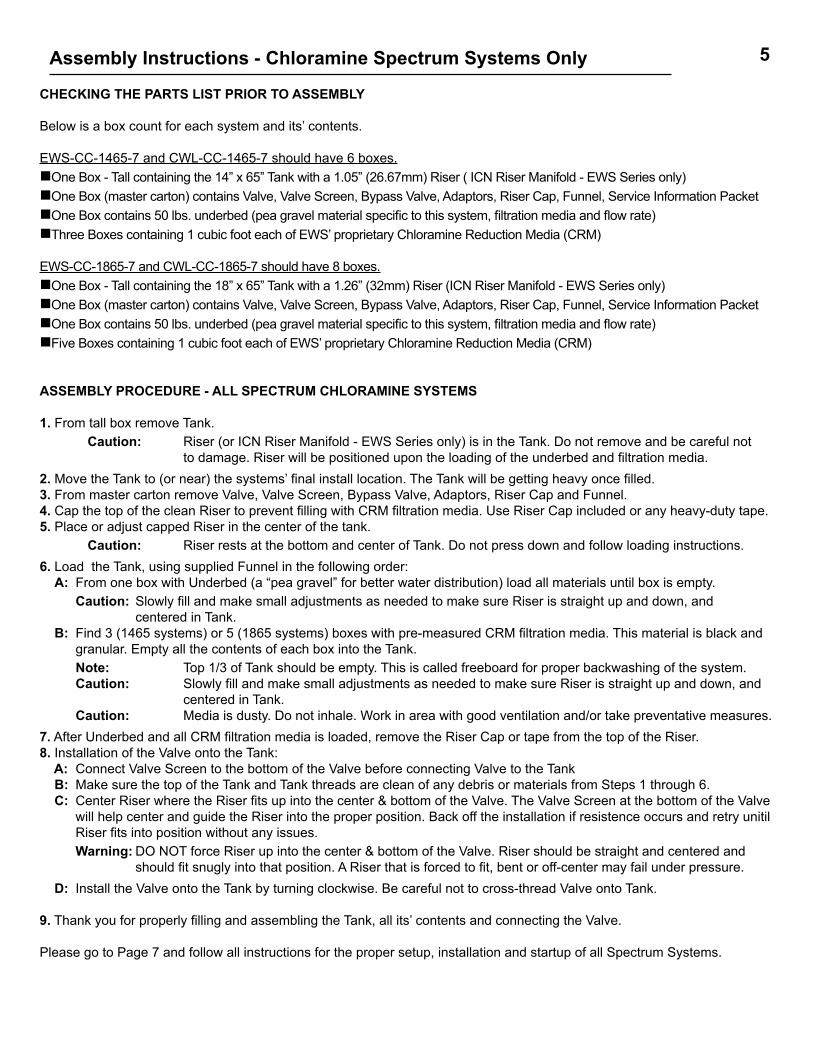
5Assembly Instructions - Chloramine Spectrum Systems Only
CHECKING THE PARTS LIST PRIOR TO ASSEMBLY Below is a box count for each system and its’ contents.
EWS-CC-1465-7 and CWL-CC-1465-7 should have 6 boxes.One Box - Tall containing the 14” x 65” Tank with a 1.05” (26.67mm) Riser ( ICN Riser Manifold - EWS Series only)One Box (master carton) contains Valve, Valve Screen, Bypass Valve, Adaptors, Riser Cap, Funnel, Service Information PacketOne Box contains 50 lbs. underbed (pea gravel material specific to this system, filtration media and flow rate)Three Boxes containing 1 cubic foot each of EWS’ proprietary Chloramine Reduction Media (CRM)
EWS-CC-1865-7 and CWL-CC-1865-7 should have 8 boxes.One Box - Tall containing the 18” x 65” Tank with a 1.26” (32mm) Riser (ICN Riser Manifold - EWS Series only)One Box (master carton) contains Valve, Valve Screen, Bypass Valve, Adaptors, Riser Cap, Funnel, Service Information PacketOne Box contains 50 lbs. underbed (pea gravel material specific to this system, filtration media and flow rate)Five Boxes containing 1 cubic foot each of EWS’ proprietary Chloramine Reduction Media (CRM)
ASSEMBLY PROCEDURE - ALL SPECTRUM CHLORAMINE SYSTEMS 1. From tall box remove Tank. Caution: Riser (or ICN Riser Manifold - EWS Series only) is in the Tank. Do not remove and be careful not to damage. Riser will be positioned upon the loading of the underbed and filtration media.2. Move the Tank to (or near) the systems’ final install location. The Tank will be getting heavy once filled. 3. From master carton remove Valve, Valve Screen, Bypass Valve, Adaptors, Riser Cap and Funnel. 4. Cap the top of the clean Riser to prevent filling with CRM filtration media. Use Riser Cap included or any heavy-duty tape. 5. Place or adjust capped Riser in the center of the tank. Caution: Riser rests at the bottom and center of Tank. Do not press down and follow loading instructions.6. Load the Tank, using supplied Funnel in the following order: A: From one box with Underbed (a “pea gravel” for better water distribution) load all materials until box is empty. Caution: Slowly fill and make small adjustments as needed to make sure Riser is straight up and down, and
centered in Tank. B: Find 3 (1465 systems) or 5 (1865 systems) boxes with pre-measured CRM filtration media. This material is black and
granular. Empty all the contents of each box into the Tank. Note: Top 1/3 of Tank should be empty. This is called freeboard for proper backwashing of the system. Caution: Slowly fill and make small adjustments as needed to make sure Riser is straight up and down, and
centered in Tank. Caution: Media is dusty. Do not inhale. Work in area with good ventilation and/or take preventative measures.7. After Underbed and all CRM filtration media is loaded, remove the Riser Cap or tape from the top of the Riser.8. Installation of the Valve onto the Tank: A: Connect Valve Screen to the bottom of the Valve before connecting Valve to the Tank B: Make sure the top of the Tank and Tank threads are clean of any debris or materials from Steps 1 through 6. C: Center Riser where the Riser fits up into the center & bottom of the Valve. The Valve Screen at the bottom of the Valve
will help center and guide the Riser into the proper position. Back off the installation if resistence occurs and retry unitil Riser fits into position without any issues.
Warning: DO NOT force Riser up into the center & bottom of the Valve. Riser should be straight and centered and should fit snugly into that position. A Riser that is forced to fit, bent or off-center may fail under pressure.
D: Install the Valve onto the Tank by turning clockwise. Be careful not to cross-thread Valve onto Tank.
9. Thank you for properly filling and assembling the Tank, all its’ contents and connecting the Valve. Please go to Page 7 and follow all instructions for the proper setup, installation and startup of all Spectrum Systems.
6
SCHEMATIC: SPECTRUM SYSTEM ............................................................................................... 2
SCHEMATIC: VALVE, BYPASS, CONTROLS - ALL SYSTEMS.............................................................. 3
SCHEMATIC: SPECTRUM CHLORAMINE SYSTEM ....................................................................... 4
SPECTRUM CHLORAMINE SYSTEM: ON SITE ASSEMBLY PROCEDURE............................................. 5
IMPORTANT SAFETY INFORMATION – All Systems Instructions Before Using ........................................................................................................ 7
SETUP - All Systems ....................................................................................................................... 8 Unpacking and Inspection Where to Install the System
INSTALLATION INSTRUCTIONS - All Systems Plumbing Connections ..................................................................................................................... 9 Drain Line .................................................................................................................................. 11 Electrical Connection ..................................................................................................................... 11
START-UP PROCEDURES - All Systems Flush and Clear Home Lines with System Still in Bypass ................................................................. 12 Tank Fill Slowly .................................................................................................................................. 12 Setting the Time of Day while The Tank is Filling Slowly ................................................................. 13 Flushing the System Procedure ........................................................................................................ 13 Last Steps Before Leaving the System ........................................................................................... 15 Repeat Flushing (if needed) Open Outlet Side of Bypass System Ready for Use Run Water throughout the Home
WATER CONSERVATION SETTINGS ....................................................................................................... 16
BACKWASH REQUIREMENTS AND SCIENCE BEHIND EWS FILTER QUALITY AND LONGEVITY ...... 17
LIMITED WARRANTY ................................................................................................................................. 18
GENERAL TERMS AND STANDARD CONDITIONS OF SALE ................................................................ 19
www.ewswater.com o. 702.256.8182; (m-f; 8:30am-4:30pm; PST) f. 702.256.3744 e-mail. [email protected]
Table of Contents

7
Instructions Before Using• Before beginning installation, read all instructions completely. Then obtain all the materials and tools needed for installation. WARNING: Failure to setup, install and/or startup the system correctly in any manner voids the warranty.
• Perform installation according to state and local plumbing codes. - Use of flexible stainless steel connections is highly recommended (if code applicable) to connect unit to water supply. Allows flexibility for tank expansion under pressure (see installation section in this manual). - Use of teflon tape is the only sealant to be used on threaded drain and adaptor connections. - Use only lead-free solder and flux for sweat-solder connections, as required by state and federal codes.
• Handle all components of the system with care. Do not drop, drag or turn components upside down.
• Existing Plumbing: Condition of existing plumbing should be free of lime &/or iron buildup. Pipe should be replaced if any heavy buildup exists. Pre-existing conditions will effect the performance of this system.
• Be sure the floor under the system is clean and level.
• Electrical: All Spectrum Systems (USA versions) use 24 volt transformer for electrical power. - Always use the supplied power cord and transformer. - Plug power cord into an indoor 120 volt, grounded and unswitched (dedicated) outlet. - Properly ground system to conform with all codes and ordinances.
• Install system in a protected area. Be sure electric outlet and transformer do not come in contact with water. See “Where to Install the System” in the Setup section, Page 7 of this manual. - Always connect the system to the proper and correct main water supply pipe before the water heater(s). - Do not install in direct sunlight. Heat from sun may cause damage. - Do not flow any water at any time over 110°F through the system. - Do not expose system to freezing temperatures which causes equipment damage and voids the warranty. WARNING: Any water over 110°F, thermal expansion of any water heater or where any hot or heated water comes back or flows through the system over 110°F at any time voids the warranty. • Pressure: Minimum inlet water pressure is 20 psi. Maximum inlet water pressure is 75 psi. Use pressure reducing valve (PRV) if necessary to prevent high pressure and problem pressure surges above 75 psi. WARNING: Pressure exceeding, surging or spiking above 75 psi or any negative pressure voids the warranty.
Important Safety Information - All SystemsCAUTION: Read and follow the information in this manual to minimize the risk of electric shock or personal injury.IMPORTANT! If you are unsure about the installation of your system, con-tact EWS customer service or consult a professional plumber.IMPORTANT! This system must be installed in compliance with applicable state and local codes, law, and regulations.
CAUTION:• Do not use with water that is microbiologically unsafe or of unknown quality without adequate disinfection. Well water needs to be properly and completely tested before the specification of any filtration and treatment system(s). • Test water periodically to verify that the system is performing satisfactorily.• Discard small parts remaining after the installation.

8
UNPACKING AND INSPECTION Check the system components for damage or missing parts.
WHERE TO INSTALL THE SYSTEM Consider the following points when determining where to install any Spectrum System point of entry filter:
Place system on the main water supply in order to filter and supply filtered water to the entire home. CAUTION: DO NOT install on a soft water loop or bypass of other water lines where the filtered water will not be available for household use. All Spectrum Systems are designed to filter water to the entire home. NOTE: All Spectrum Systems can connect for outside faucets for plants, lawn, pools, spas, and other features. However, it is nice but not necessary under normal circumstances for any outside ap- plication. It will cause no harm to the system or the other features but will use more water through the system and may not create any additional benefits for those features. Place the system as close as possible to a sewer drain or some other drain location. Air gap and proper ventilation is a requirement. Drain and water can go outside. Contact EWS customer service for more information. CAUTION: Never install drain line smaller than 3/4” in diameter. Any drain line exceeding 20’ in total length and/or is expected to flow over 5’ above the height of the drain port requires an installed drain line of 1”. Install a non-restrictive check valve in drain line if water is expected to flow 5’ above drain port.
A 120V grounded and unswitched electrical outlet is needed to plug in the transformer. If outlet is over 7 feet away use 18 gauge extension to connect up to 100 feet away. Do not exceed 100 feet.
Do not install the system where it would block access to the water heater, or access to the main water shutoff, water meter, or electrical panels. Always connect the system prior to the water heater(s).
Install the system where it will not be exposed to direct sunlight or subject to temperatures outside of the limits stated in “Instructions Before Using” on Page 7 or the Specification Section in this manual. The system is water resistant but not water-proof and should be protected from outside and weather exposure if applicable. Install the system in a place where damage is least likely to occur if any unforeseeable issue arises. System should be in an accessable location and be visable in order to visually monitor system and routinely check clock operation and valve controls.
Setup - All Systems

9Installation Instructions - All Systems - Plumbing Connections
INSTALLATION
1. Turn off gas or electric supply to the water heater(s).2. Turn off the main water supply.3. Open a hot and cold faucet to drain house water pipes. NOTE: Keep those hot and cold faucets open until these instructions tell you to close.
4. Move the system assembly into installation position and check that Valve is securely fastened to the Tank. CAUTION: Factory assembly of Valve to Tank connection is performed according to specifications. However in transportation, delivery and movement to the installation position this connection may have loos- ened. It is important to make sure this connection is tight and if necessary hand-tighten only in a clockwise direction to ensure this connection. NOTE: System has a self-leveling base which can compensate for any slight floor pitch. Refer to “Instruc- tions Before Usng” on page 7 and “Where To Install The System” on page 8.
5.a In the parts bag: Locate the Bypass Valve and 2 red clips Connect Bypass Valve to the Valve by inserting male end of the Bypass Valve completely into the Valve body. Make sure that male end is fully inserted into Valve and only then install the red clips to secure that connection. CAUTION: The red clips will break if you attempt to force into position without fully inserting the male end con- nector into the valve body. If the connector is inserted properly the red clip insertion path will be clear. Installer is responsible for securing plastic red clips when attaching bypass and adaptors. To remove red clips simply use pliers and hold tab at top and pull straight up and out. CAUTION: Check that all surfaces are clean of any debris before inserting Bypass Valve into valve body.
5.b In the parts bag: Locate the 1”, 1 1/4” or 1 1/2” MNPT Adaptors. Select the proper sized Adaptor for your incoming/outgoing water lines and connect the Adaptors to the supplied Bypass Valve. NOTE: 1” adaptors with red clips may already be inserted for shipping purposes. This is also the most common line size. Flow rate to system is determined by the incoming line size. If needed, select and use proper adaptor (1”, 1-1/4”, or 1-1/2”) for the main line size that the system is being installed on. If needed, to remove red clips simply use pliers and hold tab at top and pull straight up and out.
CAUTION: The red clips will break if you attempt to force into position without fully inserting the male end con- nector of Adaptor into the Bypass. If the connector is inserted properly the red clip insertion path will be clear. Installer is responsible for securing plastic red clips when attaching bypass and adaptors. CAUTION: Check that all surfaces are clean of any debris before inserting Adaptor into Bypass Valve.
WARNING: Make sure on the Bypass Valve both Inlet and Outlet Valves are in the bypass position
NOTE: When Inlet and Outlet Valves are in the bypass position the holes appear at the top and bottom as shown in the illustration to the right. Va
lve
in B
ypas
s
Outlet Inlet
Valve in B
ypass
Inserted Adaptors for Water LineConnections
Insert Connectionsinto Valve Body
Illustration of Bypass Valve in the bypass positionTop View

10
6. Locate water line or pipe to be cut and make sure of direction of water flow. CAUTION: Do not cross-connect or plumb backwards. Make sure of the direction of water flow from cut pipe to be connected.
7. Plumb INLET and OUTLET connections to and from the system.** • It is highly recommended to use stainless steel corrugated flexible water connectors, PEX or PVC Sch 40. • Be sure the incoming hard water supply is directed to the INLET port of the valve. • The valve body of the control is marked with arrows indicating the proper flow direction. • Connections are illustrated below.
** Highly Recommended: • Stainless steel corrugated flexible water connectors, PEX or PVC Sch 40 have a flexible capability that will assist with the installation where the rough and finish measurements are slightly off. • Flexible connections may prevent tank and valve issues where rigid or hard pipe create problems over time where the installed system is on a bottom or top floor of a home and/or where the home location is on the top or the bottom of a hill where head pressure or pressure variances will occur or wherever pressure variations cause tank to flex or move.• Flexible connections are recommended where high pressure, pressure surges/spikes or pressure variations occurCAUTION: An operating and maintained pressure reducing valve (PRV) may be required on the main water line and prior to the system to regualte pressure. If applicable, a check valve on the main supply before the system or a check valve on the outlet side of the the system (water heater will require expansion tank) to prevent backflow and excessive head pressure may be required. WARNING: Any pressure on the system exceeding, surging or spiking above 75 psi and any negative pressure due to vacuum break voids the warranty.
Installation Instructions - All Systems - Plumbing Connections - continued
CAUTION: If making a soldered copper installation, do all sweat soldering before connecting pipes to the bypass valve. Torch heat will damage plastic parts.** It is highly recommended to use stainless steel corrugated flexible water connectors. CAUTION: When turning threaded pipe fittings onto plastic fittings, use care not to cross-thread, strip threads and/or over-tighten.CAUTION: Use Teflon tape only on all external pipe threads. Do not use pipe joint compound.CAUTION: Support inlet and outlet plumbing in some manner (use pipe hangers) to keep the weight off of the valve fittings.
valve controls 1” MNPT
drain fitting with grey clip
7’ electric cord & 24v transformer
(not shown)
model number and labeling
Note: a total of seven (7) red connection clips are usedA (1) - clip, top cap assembly, B (2) - clips, valve to bypass, C (2) - clips, bypass to adaptors, D (2) - clips, bypass assembly
Cbypass to adaptors
clip connections
Bvalve to bypassclip connections
A B C
CB
D
D
valve body built-in bypass 1”, 1 1/4” & 1 1/2” MNPT adaptors provided
Inlet
Outlet
Recommended 1”, 11/4” or 11/2” flexible connection (not supplied)
Note: bypass valve shown in the closed position with holes on top for cor-rect install
Illustration of complete assembly of valve, bypass and provided adaptors
**WARNING: Removal of any red clip while unit is under pressure will result in water damage and damage to valve. See other cautions within this manual.

11INSTALL DRAIN LINE - THIS IS A SIMPLE BUT IMPORTANT STEP TO AVOID CROSS-CONTAMINATION
8. Plumb rigid tubing only (PVC recommended if code applicable) directly to the 1” MNPT drain fitting. NOTE: Install a union on the drain line in order make any service or need to disconnect easier in the future.
9. Connect and route the drain line to the drain point. Install a non-restrictive spring check valve within 2 feet of the control valve to prevent possible back flow and cross-contamination CAUTION: • Never install drain line or connect to any drain line less than 3/4” • Any drain line exceeding 20 feet in total length and/or is expected to flow over 5 feet above the height of the drain port requires an installed drain line of no less than 1”. 10. Locate the end of the drain line at a suitable drain point and create an air gap.
CAUTION: Outside system draining is allowable. It is only filtered water and not a brine discharge. •
• If using a sink, floor drain or any other drain point, an air gap is required and the drain point needs to be capable of draining water away at up to 7 (gpm) gallons per minute for up to 20 minutes** (a big bath tub once every 6 days) to avoid water damage. CAUTION: • Secure (clamp, tie or wire) installed drain line near drain point to prevent movement and avoid any possible water damage.
NOTE: **WATER CONSERVATION • Backwash is needed for proper filtration and filter life up to 10 years and yet water is usable for watering and other uses. Inquire about Water Conservation Settings to reduce time of backwash and frequency. Contact EWS for more information and a very easy to follow video to reset your valve setting.
Installation Instructions - All Systems - Drain Line and Electrical
INSTALL ELECTRICAL CONNECTION
11. Connect electrical power by plugging the transformer into a 120V grounded and unswitched electrical outlet.
If outlet is over 7 feet away use 18 gauge extension to connect up to 100 feet away. Do not exceed 100 feet.
NOTE: POWER CONSUMPTION Power consumption is that of a radio alarm clock, doorbell or timer clock used for sprinklers or irrigation.
PROCEED TO THE PROPER TANK FILL OF THIS SYSTEM
REQUIRED: • Provide a minimum 1” air gap between the end of the drain line and the drain point. (see illustration to the right) • Install a non-restrictive spring check valve in drain line within 2 feet of the control valve CAUTION: • Air gap and proper air flow and ventilation (Caution: attics and crawl spaces) is necessary to prevent any back up or cross contamination into system. Do not enclose or cover up drain point. It would be best if you can see the water flowing from the drain line into the drain point. (see illustration to the right)
minimum 1” air gap
Do not freeze. Do not block or bury water flow. Do not directly connect to irrigation (bubblers, drip line and/or sprinklers). Create a PVC drain line(s) with holes (distribution header). Drain line and surroundings must be pitched or sloped to allow for proper water flow and drainage where drain water never sits in the line or any landscape or rain water is allowed to create standing water at the drain line. Allow enough space (lawn, planter, water storage) to flow and absorb up to 140 gallons (a big bath tub) of water every 6 days**.

12
Outlet Valve in Bypass
Outlet Inlet
Illustration of Bypass Valve in Bypass Top View
Inlet Valve in Bypass
Startup Procedures - All Systems - Tank Fill
PROCEED TO THE PROPER FLUSH OF THIS SYSTEM
FLUSH AND CLEAR HOME LINES WITH SYSTEM STILL IN BYPASS
12. Keep Bypass Valve in “bypass” position and follow startup procedures
NOTE: Holes appear on the top and bottom of Bypass Valve when in bypass (see illustration to the right)
13. Turn back on gas or electric supply to the water heater(s).
14. Slowly open the main water supply and observe a steady flow from both hot and cold faucets that were opened earlier (Page 9, Step # 3). Check plumbing work for leaks and fix immediately if any are found. NOTE: Remove the aerators or any restriction at the end of the faucets and let the faucets run for a few minutes until water is free from foreign material that may have resulted from installation or material that typically loosens up when shutting off and turning on the water at the main supply.
15. Once all bypassed water has been allowed to run clear - Shut off both hot and cold faucets. NOTE: If water appears cloudy, allow to run for several more minutes until all air is expelled or until clear.
TANK FILL - SLOWLY
16. Now it is time to fill and flush the system to properly start up the system. Careful to follow instructions to prevent water hammer or unnecessary pressure on tank, valve and filtration media within tank. Inlet Side Only: (see illustration to the right) Slowly Crack Open Turn inlet side valve counter-clockwise where hole appears as illustrated. Only enough where you start to hear the water flowing into the tank. CAUTION: Bypass Valve is only a 1/4 turn. Allow the tank to fill SLOWLY.
Outlet Valve in Bypass
Illustration of Bypass Valve - Partially Open InletTop View
Outlet Closed
Inlet
Inlet Valve
Partially Open to Fill System
Slowly

13Startup Procedures - All Systems - Flushing the System
FLUSHING THE SYSTEM
18. With the inlet side of the Bypass Valve still only PARTIALLY open and the tank still filling slowly - it is time to manually backwash and flush the system.
CAUTION: The outlet side of the Bypass Valve remains closed and in the bypass position until this flushing procedure has been completed
19. Manually start a backwash to flush the system. • Press and hold (5 seconds) the Extra Cycle Button until the Parameter Display flashes “BW” and the Data Display reads “----”. • You will hear the valve engage and it will take about 1 minute (60 seconds) until the backwash “BW” cycle is reached. • Once the backwash “BW” cycle begins the Parameter Display will stop flashing and reads “BW” and the Data Display is counting down from 9:59 in 1 second increments. This backwash is a 10 minute cycle.
17. While tank is slowly filling, Set the Time of Day by presssing either the Up or Down Button. The Parameter Display will read “TD” for Time of Day and the Programming Icon will appear Continue to press either Up or Down Button until the Data Display reads the current time of day. If after 12:00 (noon) then the PM Indicator should be lit. Once set, allow up to 10 seconds and the “TD” and will disappear. What you will see on the display: • Current Time of Day, a PM Indicator (if applicable) • You will also see the Time of Day alternate (about every 10 seconds) to another number and than back to the time of day - this is normal and tells the user the next time the system will backwash counting down each day from 6 (factory pre-set) until backwash. • In Service Icon
The diagram to the right is an illustration of the system valve controls and all the displays for your reference.
Please follow the directions above to set the time of day.
Please follow the directions below to manually advance the system through each step of the backwash and flushing procedure.
SETTING THE TIME OF DAY WHILE THE TANK IS FILLING SLOWLY
Parameter Display
DataDisplay
PMIndicator
In ServiceIcon
Error Information
Icon
Programming Icon
Extra CycleButton
UpButton
DownButton

14
WARNING: Failure to follow these procedures can result in debris in the system, the system’s valve, the home and/or filtrationmediabeingexpelledcausingimmediate,shortandlongtermissueswiththesystem’svalve, intothehomepipesandthefixturesorapplianceswithinthehome.
21. The Inlet Side of the Bypass Valve is completely open (Outlet Side remains closed). The air has been purged from the system and the tank has been filled. The backwash is running in order to clean and flush filtration media prior to system usage.
What you will see on your display and hear as the valve goes through the self-cleaning and flushing, backwash and rapid rinse cycles: • The backwash “BW” cycle is already engaged (Page 10, Step # 19) and Data Display is counting down. • When the backwash “BW” cycle ends, the Parameter Display will flash “RR” and the Data Display reads “---” You will hear the valve engage again and it will take about 11/2 minutes (90 seconds) to engage the cycle. • When the rapid rinse “RR” cycle begins the Parameter Display will stop flashing and reads “RR” and the Data Display is counting down from 9:59 in 1 second increments. This rapid rinse is a 10 minute cycle. • When the rapid rinse “RR” cycle ends, the valve will engage again and it will take about 30 seconds for the valve to return to the in service position and the display will show the In Service Icon and your Time of Day.
NOTE: Allow system to go through complete backwash and rapid rinse cycles which will take from start to finish up to 23 minutes.
See Step #’s 22 through 24 on Page 15 to conclude the proper setup, installation and startup of the system.
FLUSHING THE SYSTEM - CONTINUED
20. When the air in the system is pushed out and water begins to flow continuously through the drain line, it is time to completely open the Inlet Side (only) of the BypassValve. This will purge air and relieve the pressure within the tank and completely fill the tank in the proper order.
CAUTION: The outlet side of the Bypass Valve remains closed and in the bypass position until this flushing procedure has been completed
NOTE: Holes appear on the top and bottom of Bypass Valve when in bypass (Outlet).
Holes appear on the front and backof Bypass Valve when open (Inlet).
(see illustration to the right)
Startup Procedures - All Systems - Flushing the System
Outlet Valve in Bypass
Inlet ValveOpen
Illustration of Bypass ValveClosed Outlet with Open Inlet
Top View
Outlet Inlet

15
22. Check the drain water is clear of any filtration media dust and/or fines. A quick repeat of the the flushing procedure is recommended. Start a backwash again (Page 13, Step # 19) and once water flows under full pressure through the drain line check for any dust and/or fines. Allow water to run through the drain line for at least 60 seconds.
Once the drain water appears clear, force the control to advance to the next cycle step immediately by pressing and releasing the Extra Cycle Button. The Parameter Display flashes “RR” and the Data Display reads “----”.
You will hear the valve engage again and it will take about 11/2 minutes (90 seconds) to engage the cycle. Once water flows under full pressure through the drain line check for any dust and/or fines. Allow water to run through the drain line for at least 60 seconds.
Once the water runs clear, force the control to advance to the next cycle step immediately by pressing and releasing the Extra Cycle Button. The valve will engage again and it will take about 30 seconds for the valve to return to the in service position and the display will show the In Service Icon and your Time of Day.
23. Slowly open the Outlet Side of the Bypass Valve
Final Steps - All Systems
LAST STEPS BEFORE LEAVING THE SYSTEM
NOTE: Holes appear on the front and backof Bypass Valve when open.
(see illustration to the right)
24. System is ready for use.
To ready home for filtered water, open as many hot and cold faucets throughout the home as possible. Remove the aerators or any restriction at the end of the faucets. Remember to include tubs and dispose of any ice previ- ously made. Run water throughout home for 5 minutes.
NOTE: If water appears cloudy, allow to run for several more minutes until all air is expelled or until clear. NOTE: If home is a year or more old, it is highly recommended that all water heaters or tankless on-demand heaters be flushed and that all dishwashers, washers and any other water appliances be cleaned of any existing residue. Please review Page 7 “Instructions Before Using” for existing plumbing and pre-existing conditions that will effect the performance of this system.
WARNING: Failure to follow these procedures can result in debris in the system, the system’s valve, the home and/or filtrationmediabeingexpelledcausingimmediate,shortandlongtermissueswiththesystem’svalve, intothehomepipesandthefixturesorapplianceswithinthehome.
Outlet Valve Open
Inlet ValveOpen
Illustration of Bypass ValveOpen Outlet and Inlet
Top View
Outlet Inlet

16Water Conservation – Water Restrictions – Drought Conditions
With growing issues with water shortages, it becomes more important to filter all your water. However to properly do so requires a point of entry system that properly backwashes the filter media. This is a requirement in order to get longevity out of the filtration media. Most importantly, backwashing the filter media is a requirement in order to properly filter.
The Valve:The Spectrum Valve is necessary to provide better flow rates (non-backwashing systems with flow rates @ 7gpm com-pared to EWS up to 35gpm). The valve also provides an opportunity to either backwash the system properly either auto-matically or manually.
Default Interval to 14 days or Manual Backwash:How to Set Backwash Interval: Copy & Paste in address bar: https://vimeo.com/ewswater/review/61848933/38b3c254e3The customer can decide to move the backwash interval to every 14 days as a default and if needed backwash the sys-tem manually by pushing one button if they feel there is a change in their water based on their usage. Upon going into a manual backwash the system knows to not backwash for another 14 days or as needed by customer. This greatly reduces any water usage.
How to Set Backwash Water Saver Program: Reduce Backwash & Rapid Rinse Time: Copy & Paste in address bar: https://vimeo.com/ewswater/review/61850835/c9e83ebcd9This adjustment will change the durations in which the system will backwash. The factory pre-set is for midnight every 6th day and the cycles are set for 10 minutes each.
If you wish to save water, you may choose to adjust those duration times which may save up to 50% of the water used during a typical cycle. This video will instruct you to reduce the 1st cycle (BW – backwash) down to 8 minutes and the 2nd cycle (RR – rapid rinse) down to 3 minutes.
Other intervals may be necessary for water being treated with Chloramine based on usage and water conditions. Any questions – contact EWS customer service 702-256-8182 or at [email protected]
Water Does Not Need to be Wasted:Backwash water is used to lift filtration media and prevent packing or channeling and allows for greater surface areas in order to filter effectively and over a long period of time. This is only filtered water and not a brine and can be used for all purposes and is safe for waste water treatment or to be used. Water can go back to pool to maintain water levels or be used to water desert landscape creating a zero waste. Make sure to see proper drain applications using a spring check and air gap requirements for any installation.
The Need to Backwash:We have attached a chart below comparing backwashing and non-backwashing carbon filtration media or go to the link below which is a blog published and available directly on our website which dispels the marketing of non- backwashing, point of entry whole home filtration devices – it renders the filtration ineffective. Period.
Poor Information:Running the water up through the filtration media or upflow is not a proper backwash and makes for poor surface contact and is ineffective as a filtration device. Note the chart of how ineffective this can be for proper filtration and the shortness of life spans.
In Simpler Terms (if you do not backwash):Thecarbonandfiltrationwillnotwork…!Yougetrippedoff…!Itdoesnotdowhattheysayitwill…!The article covers backwashing information and many good points for the contractor or customer looking to be informed. Copy & Paste in address bar: http://www.ewswater.com/blog/non-backwashing-upflow-systems-found-ineffective/
Completesectionstoassistwithanytroubleshooting,partslistings,replacementfilters,mediareplacementinformation,productspecificationsandinformation
are all available online.
www.ewswater.com

17
If you need any additional information or assistance, please callEWS, Inc. customer service.
702.256.8182m-f,8:30am-4:30pm,[email protected]
In two full- scale GAC applications evaluated, vastly different results were observed. At a drinking water facility with on- site and regular regeneration [backwashing], removal of trace organics occurring in source water was efficiently improved.
In contrast, a facility with relatively high levels of TOC [trace organic compounds] using GAC without regular re-placement/regeneration provided very little removal. These data collectively show that activated carbon in both powdered and granular forms has great potential for the removal of trace organic contaminants; however…GAC backwashing/regeneration will be critical for excellent removal.
Contaminant % Removed Contaminant % Removed Atrazine 94% Atrazine 3% Caffeine >99% Caffeine 16% Carbamazepine >99% Carbamazepine 15% DEET >99% DEET 36% Dilantin >99% Dilantin 22% Erythromycin >99% Erythromycin 8% Gemfibrozil >99% Gemfibrozil 8% Ibuprofen >99% Ibuprofen 16% Iopromide >99% Iopromide 28% Meprobamate >99% Meprobamate 13% Sulfamethoxazole >99% Sulfamethoxazole 16%
Original charts on page 177 of the study.
"Granular activated carbon [GAC] was highly effective at removing all target chemicals.”
“In full-scale applications, the impact of regeneration [backwashing] was observed as activated carbonfiltersthatreceivedregularregenerationhadminimalbreakthroughoforganiccontami-nants, whilenon-regeneratedfiltersdisplayednoremovaloftargetcompounds."
Facility #1 Facility #2 Testing results on backwashing GAC Testing results on non-backwashing GAC
Role of membranes and activated carbon in the removal of endocrine disruptors and pharmaceuticals
Southern Nevada Water Authority, Montgomery Watson Harza - Applied Research Department, Department of Civil and Environmental Engineering - The Pennsylvania State University: Received 31 July 2005; accepted 23 December 2005
EWS - Based on Facts, Math & ScienceWe do not deceive you based on taste. Your frig filter, carafe pitcher, shower head attachment and bottled water do a great job of marketing that to you.
EWS brings you the best filtration, longevity and quality based on facts.

18
Keep a record of the purchase receipt and/or installation receipt. Purchaser is required fill out warranty registration form(s) on applicable product(s) and register all product by either online @ www.ewswater.com, telephone, postal delivery, fax, e-mail (either [email protected] or information provided to [email protected]). Failure to do so voids the warranty unless restricted by state regulations. Privacy: EWS, Inc. does not sell, show or make available any information on any consumer in our database. This database is to ensure, if needed, proper warranty service, and good customer service for years to come. Please see our privacy policy published in our website at www.ewswater.com.
Know Your Water: • If on a municipal system, large or small, it is your right as a consumer to have access to the most recent test results and to expect adherence to federal guidelines, as well as any state or local requirements. Any problems should be reported to the appropriate agencies. Please acquire those municipal test results to become an informed consumer. • If on an individual well, have your water completely and independently tested. Local code may require a simple test for coliform bacteria to approve a well, however you may be unaware of potential problems for you and/or your home. A local water salesman is looking to close a sale and is going to test for hardness minerals and a few simple and obvious issues, which may or may not be contamination problems. Their solution is almost always the same and yet may provide no resolution to any true problems. Obtain our “Guide for the Private Well Owner” on our website; www.ewswater.com. Review our section on well water testing and applications in our complete catalog with your local distributor, dealer, or our representative or visit our website.• WARNING: Some restrictions apply to the use of softeners. Contact your local municipal water district or Gov’t Agency. Brine discharge is already restricted on, or may be a problem for, septic applications and waste water treatment facilities. Since some states have already restricted softeners to metered valves to prevent excessive brine discharge, EWS, Inc. only provides metered valving in its line of softeners. Restrictions or an outright ban may also apply to hot-side only, salt-exchange tanks or services. Local water dealers and other organizations do not inform consumers of these issues and believe these rules are unenforcable. The consumer is ultimately responsible.Softeners may also provide warranty issues with pools and spas, certain other products and finishes. Softened water should not be used for drinking, cooking, pets or plants and is usually bypassed or “looped away” from the cold side of the kitchen sink. Reverse osmosis, which also has its drawbacks and issues with other products and materials, may be used to remove the salt from the water that the softener put in at the kitchen sink, yet may be misapplied for the actual local water conditions. Any problems of water quality, or the fitness of any EWS, Inc. product that is associated with any mechanical, construction, application, installation, and/or environmental issue(s) (ie: flow rates, line pressure, piping materials, broken supply lines, changing water conditions; well or municipal water quality, et. al.), known or unknown, of the home or facility will not be considered by EWS, Inc. until such issue(s) have been resolved.Responsibility for the proper product and/or plumbing specification, application and/or installation of any device manufactured by EWS, Inc. lies with the consumer, their builder contractor, plumbing sub-contractor and any other installer of choice. Items do not specify and/or install themselves. EWS, Inc. has provided many sources to acquire informa-tion on the proper application of systems and their installation prior to any purchase. EWS, Inc. manufactures a complete product line of point of use water filtration systems and point of entry filtration, softening and/or conditioning systems and/or appliances. EWS, Inc. and the distributors of EWS, Inc. will stand behind the warranties of materials and workmanship. However, EWS, Inc. and the distributors of EWS, Inc. and the Envi-ronmental Water Systems Product Line do not bear any responsibility for improper applications of product and/or improper installation. It is for this reason that EWS, Inc. provides complete information on all product for your understanding, specification, application and selection, and proper plumbing application and installation.
To obtain warranty service support, contact your local dealer or contractor from whom you obtained the product or contact EWS, Inc., Customer Service, via phone, fax, or email.
Notification:This warranty is referenced by EWS, Inc. in all literature, addressed in General Terms and Standard Conditions of Sale, and is published in its entirety in all EWS, Inc. product manuals, websites, and in all service guides supplied with all product.Limited Warranty: EWS, Inc., a Nevada corporation, hereby warrants all products to the original consumer purchaser to be free from defects in material and workmanship as stated in the following paragraphs: • All residential point of use: countertop filtration, in-line filtration, undercounter drinking water filtration, shower filtration, residential reverse osmosis, and canister and filter cartridge point of entry pre-sediment and/or filtration units or systems for one year from date of purchase. • All residential point of entry: pH decreasing and softener (resin and ion-exchange) systems, Environmental (EWS) Water Systems, Iron Removal units, CWL whole-home (filtration media) systems, pH increasing reagent (sacrificial media) units for 10 years on the tank and riser, 10 years on the ICN conditioner(s) (if applicable) and 5 years on the valve body and electronics from date of purchase. • All commercial systems: Dependent on specification and application, please consult with EWS, Inc. upon specification.• All filtration medias, resins, cartridges, uv lamps, and/or membranes are not covered by any warranty. Filter media, resin, cartridge, uv lamp, and/or membrane replacement or maintenance schedule will vary and must be replaced, as necessary, as determined by usage and local water conditions. • Any wear and tear parts or any parts damaged in shipping, installation or application are not covered under warranty.
Product performance may vary based on local water conditions, proper product specification and application, proper plumbing application, setup, installation, startup, maintenance and/or usage. To ensure proper operation, follow all setup, installation, start-up and maintenance procedures as detailed in all service guides. Not intended for use where water is microbiologically unsafe or with water of unknown quality without adequate disinfection before or after unit(s). The contaminants or other substances removed or reduced by these and any other water filtration or treatment devices are not necessarily in your water. To confirm the presence of any primary and secondary contaminants, have your water supply completely analyzed by an independent and approved facility or if applicable, contact your local water utility for information. Aesthetic,non-healthrelated,orconstituentswithoutsetfederalstandardsmaybepartofwatertestingbutareinsufficienttodetermineproperapplicationofanywaterfiltrationortreatmentdevice.EWS, Inc. will replace, free of charge, during the warranty period, any part which proves defective in material and/or workmanship under proper product and plumbing specifica-tion and application, normal and proper installation, use, service and proper care as published in detail in all service guides included with product. Wear and tear parts such as pistons, spacers & seals are not covered under warranty. Labor charges are excluded from any warranty service or repair and are not the responsibility of EWS, Inc. Shipping charges may apply to delivered replacement parts or materials. Charges may also apply for the cost of any replacement media, resin, cartridges, uv lamp and/or membrane from any warranty service or repair. Information can be obtained at any time through a local dealer, distributor, representative or direct from EWS, Inc. and/or on-line at; www.ewswater.com. Replacement parts can be obtained from your local dealer, distributor, online or contractor. This warranty is the exclusive warranty granted by EWS, Inc. and is in lieu of all other warranties of merchantability and fitness for a particular purpose and is further limited to defective parts replacement only. Labor charges and/or damage incurred in setup, installation, and startup, or repair, or replacement, as well as, incidental and consequential damages connected there with, are excluded, and are not the responsibility of, and will not be paid by EWS, Inc.This warranty is void for any damages due to improper product and/or plumbing specification and/or application, misuse, abuse, neglect, accident, acts of nature, action of any military or civil authorities, improper handling and transportation, or improper setup, installation, and/or startup, or any violation of instructions furnished by EWS, Inc., or any replacement parts other than genuine parts or replacements supplied by EWS, Inc.This warranty is not a warranty of merchantability, fitness, taste, aesthetics, and/or performance that may be subject to improper product and/or plumbing specification and/or application, misuse, abuse, neglect, accident, acts of nature, action of any military or civil authorities, improper handling and transportation, or improper setup, installation, and/or startup, or any violation of instructions furnished by EWS, Inc. Thiswarrantyisnotawarrantyofmerchantability,fitness,taste,aesthetics,and/orperformancethatmaybepersonalandofsubjectiveopinionandthatdoesnotrelate to the performance of any system.
Warranty Notification - As Published and Available Online
Warranty Information and the Purchaser’s Responsibility

19
Invoices are expressly limited to and made conditional upon the terms and conditions contained herein. Objection by Buyer to any of the terms contained herein shall be deemed to have been waived (if not previously waived) if written notice of the objection is not received by EWS, Inc. (“EI”) within ten calendar days of the date of the first invoice or before part of the described goods are accepted by Buyer, whichever occurs first. Any additional or different terms proposed by Buyer are rejected unless assented to in writing by EI.
1. PRICES: All prices are in U.S. dollars. Prices are subject to change without notice. Orders will be invoiced at prices prevail-ing at time of shipment. All prices are F.O.B. our warehouse, Southern California and exclusive of any shipping, delivery, packaging or handling charges that may apply.
2. TERMS OF PAYMENT: The terms of payment on approved accounts only shall be net thirty days in U.S. dollars from the date of invoice to date of receipt of payment in our offices for all invoiced products whether partial or complete delivery of the product under order. All past due accounts are subject to a charge of 11/2% per month (18% per annum) for each month or fraction of a month on the unpaid balance.
3. TAXES: Prices do not include sales, use, excise or similar taxes. The amount of any present or future sales, use, excise or other tax applicable to the sale or use of EI’s products or equipment shall be paid by the Buyer unless the Buyer shall have provided EI with a tax exemption certificate acceptable to taxing authorities.
4. ACCEPTANCE: All purchase orders are subject to acceptance by EI at its corporate offices in Las Vegas, Nevada and are subject to these Standard Conditions of Sale, unless otherwise expressly provided.
5. SHIPMENTS: Delivery to carrier shall constitute delivery to customer. EI’s responsibility terminates upon delivery in good order to carrier. All goods are shipped at the customer’s risk. Any claim for loss or damage in transit should be made promptly by customer against carrier. These and other shipment terms are written clearly on the reverse side of all packing slips that accompany all accepted shipments. All costs of freight, transportation, handling, in-route storage, certification and other documentation are to be paid by Buyer. Any other terms will be issued to Buyer, in writing, with approved credit and an established EI/Buyer relationship.
6. DELAYS; FORCE MAJEURE: EI shall not be liable for delays in delivery of the goods or failure to deliver the goods caused, in whole or in part, by inability to obtain transportation, equipment, or material, insurrection, fires, floods, storms, embargoes, action of any military or civil authorities, whether legal or de facto, strikes, labor difficulties, lockouts, acts of God, or other similar or different circumstances beyond the control of EI.
7. CANCELLATION: The Buyer may not cancel all or part of an order without verifiable notification to, and acceptance by EI.
8. RETURN OF MATERIALS: No Product may be returned to EI without written approval by a Company Officer. A restocking charge of 25% will be assessed (45% if unit had been used) NO EXCEPTIONS. Product must be returned freight pre-paid, boxed and in resale condition. EI will never take responsibility, under warranty or return, for improperly installed and/or misrepresented units.
9. SELLER’S SECURITY INTEREST: EI shall retain a security interest in the goods sold hereunder until Buyer has paid in full for such goods provided by EI in connection therewith and has performed all of Buyer’s obligations under this contract.
10. COLLECTION: Buyer shall reimburse EI for all costs of collection, including reasonable attorney’s fees, incurred by EI to collect any monies owing under this contract. A $45.00 service charge will be invoiced on all returned checks.
11. WAIVER AND MODIFICATION: No waiver or modification of any of these Standard Conditions of Sale shall be effective unless such waiver or modification is in writing and signed by an officer of the Company in Las Vegas, Nevada. In event any part of these conditions be waived, or be held to be invalid by any competent court, the remainder shall continue in force and shall be inter-preted as if such waived or invalid part were not contained herein.
Published and Printed in the U.S.A.EWS Inc./Environmental Water Systems
9101 W. Sahara Ave., Suite # 105-J8, Las Vegas, Nevada 89117ph 702-256-8182, fx 702-256-3744 [email protected]
(formerly, Esbinco, Inc.) rev: 1/11www.ewswater.com
EWS, Inc. has a current, published, and widely distributed, Pricing Guide that contains suggested list prices for certain water filtration and conditioning products (“Products”) sold by EWS, Inc. (“Seller”). Seller assumes no obligation to sell to anyone any of the Products listed herein, known or unknown, at any price. This current Pricing Guide has been prepared for the convenience of Seller’s distributors and their customers. The list prices shown are guides only and do not purport to represent actual prices in any particular market and are not intended to interfere with the right and responsibility of Seller’s distributors to establish their own resale prices. All current prices herein set forth supersede all prior lists and are subject to change without notice. Seller may also, from time to time, change, modify, alter, improve and/or discontinue without notice the sale of any of the Products listed herein. All seller’s orders are accepted and delivered based upon the Terms and Conditions found on this Pricing Policy page, found in this Pricing Guide, available in all Seller’s Product Manuals and reprinted on the reverse side of all invoices submitted and monthly statements sent. Please read them carefully. They provide information that is important to Seller’s distributors and their customers.
PRICING POLICY
GENERAL TERMS AND STANDARD CONDITIONS OF SALE

20The EWS, Inc./Environmental Water System Product available through:
Contact Information:
EWS, INC. Environmental Water Systems
Authorized Kitchen & Bath Showrooms, Appliance Showrooms, Building & Plumbing Wholesale Supply Locations and their building, plumbing, HVAC and service contractors, and Authorized Online Distributors.
ewswater.com O: 702.256.8182 (M-F 8:30am-4:30pm PST) E: [email protected]: 702.256.3744
Mailing Address:9101 W. Sahara Ave., #105-J8, Las Vegas, NV. 89117
Got a Question..?
Seriously.... Give us a call. We’re here to help.
ALL FILTRATION PRODUCT PROUDLY MADE & ASSEMBLED IN THE USA
EWS Logo and Environmental Water Systems are Registered Trademarks and the Property of EWS, Inc.
EWS is a Proud Contributor and Sponsor of Organizations Dedicated to Improving Health, Well-Being and the Environment
• • • •• Heart Lung & Respiratory Allergy & Asthma Dermatology & Skin Digestive: Crohn’s & ColitisOceans Inland Water Ways Wetlands Forestry Soil Air
•• • • • •• •