product catalog - cooper bussmann · 128 fuse blocks, holders and accessories for additional...
TRANSCRIPT
Circuit Protection
Product CatalogFuse Blocks, Holders & Misc.
Fuse Blocks, Holders & Misc.Class H (K) and R Fuse Blocks H250, H600, R250 and R600 Series . . . . . . . . . . . . . . . . . . . . .124Class J Fuse Blocks J600 Series . . . . . . . . . . . . . . . . . . . . . . . . . . . . . . . . . . . . . . . . .130Class T Fuse Blocks T300 and T600 Series . . . . . . . . . . . . . . . . . . . . . . . . . . . . . . . .131Class G Fuse Blocks BG Series . . . . . . . . . . . . . . . . . . . . . . . . . . . . . . . . . . . . . . . . . .133Class CC Fuse Blocks BC Series . . . . . . . . . . . . . . . . . . . . . . . . . . . . . . . . . . . . . . . . . .134Midget Fuse Blocks BM Series . . . . . . . . . . . . . . . . . . . . . . . . . . . . . . . . . . . . . . . . . .135DIN and American Rail Adapters DRA-1 and DRA-2 . . . . . . . . . . . . . . . . . . . . . . . . . . . . . . . . . . .135Modular Fuse blocks BH Series . . . . . . . . . . . . . . . . . . . . . . . . . . . . . . . . . . . . . . . . . .136Edison Base Plug Fuse Holders Box Cover Units . . . . . . . . . . . . . . . . . . . . . . . . . . . . . . . . . . . . .137Power Blocks Enclosed Power Distribution Blocks . . . . . . . . . . . . . . . . . . . . . .139
High SCCR Terminal Blocks . . . . . . . . . . . . . . . . . . . . . . . . . . . .142Power Distrbution Blocks . . . . . . . . . . . . . . . . . . . . . . . . . . . . . .144
SAMI Fuse Covers For Class J, RK, K5, H and Midget Fuses . . . . . . . . . . . . . . . . .146Inline Fuse Holders Class CC and Midget Fuses - HEB/HET/HEY/HEX . . . . . . . . . .147Panel Mount Fuse Holders 1⁄4" x 1 1⁄4" Fuses - HKP, HKP-HH/HKP-W . . . . . . . . . . . . . . . . . .150
13⁄32" x 1 1⁄2" Fuses - HPF . . . . . . . . . . . . . . . . . . . . . . . . . . . . . . . .150Fuse Blocks 13⁄32" x 1 1⁄2" Fuses - 3835 Series . . . . . . . . . . . . . . . . . . . . . . . . . .151Fuse Blocks 1⁄4" x 1 1⁄4" Fuses - S-8000 Series . . . . . . . . . . . . . . . . . . . . . . . . .151HVAC Disconnects B22 Series . . . . . . . . . . . . . . . . . . . . . . . . . . . . . . . . . . . . . . . . .152Fuse Reducers Class H, J, K, & R . . . . . . . . . . . . . . . . . . . . . . . . . . . . . . . . . . . .153Spare Fuse Cabinet SFC-FUSE-CAB . . . . . . . . . . . . . . . . . . . . . . . . . . . . . . . . . . . . .154Fuse Clip Clamp . . . . . . . . . . . . . . . . . . . . . . . . . . . . . . . . . . . . . . . . . . . . . . . . . .154Fuse Pullers FP Series . . . . . . . . . . . . . . . . . . . . . . . . . . . . . . . . . . . . . . . . . .154
General Catalog Contents (Con’t.)Page
ii
Circuit Protection
124 For additional information, visit www.edisonfuse.com
Appl
icat
ion
Sect
ion
Fuse
Blo
cks,
Hold
ers
& M
isc.
Med
ium
Volta
ge F
uses
Cana
dian
Fuse
s &
Hol
ders
Spec
ial
Purp
ose
Fuse
sUL
/CSA
Fus
esGe
nera
l Pur
pose
UL/C
SA F
uses
Curr
ent L
imiti
ng
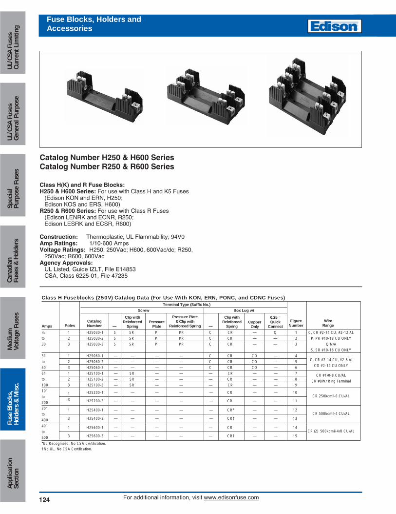
Catalog Number H250 & H600 SeriesCatalog Number R250 & R600 Series
Class H(K) and R Fuse Blocks:H250 & H600 Series: For use with Class H and K5 Fuses
(Edison KON and ERN, H250;Edison KOS and ERS, H600)
R250 & R600 Series: For use with Class R Fuses(Edison LENRK and ECNR, R250;Edison LESRK and ECSR, R600)
Construction: Thermoplastic, UL Flammability; 94V0Amp Ratings: 1/10-600 AmpsVoltage Ratings: H250, 250Vac; H600, 600Vac/dc; R250,
250Vac; R600, 600VacAgency Approvals:
UL Listed, Guide IZLT, File E14853CSA, Class 6225-01, File 47235
Fuse Blocks, Holders andAccessories
Class H Fuseblocks (250V) Catalog Data (For Use With KON, ERN, PONC, and CDNC Fuses)Terminal Type (Suffix No.)
Screw Box Lug w/
1⁄10 1 H25030-1 S SR P PR C CR — Q 1 C, CR #2-14 CU, #2-12 AL
to 2 H25030-2 S SR P PR C CR — — 2 P, PR #10-18 CU ONLY
30 3 H25030-3 S SR P PR C CR — — 3 Q N/A
S, SR #10-18 CU ONLY
31 1 H25060-1 — — — — C CR CO — 4C, CR #2-14 CU, #2-8 AL to 2 H25060-2 — — — — C CR CO — 5
CO #2-14 CU ONLY60 3 H25060-3 — — — — C CR CO — 6
61 1 H25100-1 — SR — — — CR — — 7
to 2 H25100-2 — SR — — — CR — — 8CR #1/0-8 CU/AL
100 3 H25100-3 — SR — — — CR — — 9SR #8W/ Ring Terminal
1011 H25200-1 — — — — — CR — — 10
CR 250kcmil-6 CU/ALto
2003 H25200-3 — — — — — CR — — 11
201 1 H25400-1 — — — — — CR* — — 12CR 500kcmil-4 CU/ALto
400 3 H25400-3 — — — — — CR† — — 13
401 1 H25600-1 — — — — — CR — — 14CR (2) 500kcmil-4/0 CU/ALto
600 3 H25600-3 — — — — — CR† — — 15
*UL Recognized, No CSA Certification.†No UL, No CSA Certification.
AmpsCatalogNumber
PressurePlate
Pressure Plate& Clip with
Reinforced SpringCopper
OnlyWire
Range
0.25 =Quick
Connect
Clip with Reinforced
Spring
Clip with Reinforced
Spring— —Figure
NumberPoles
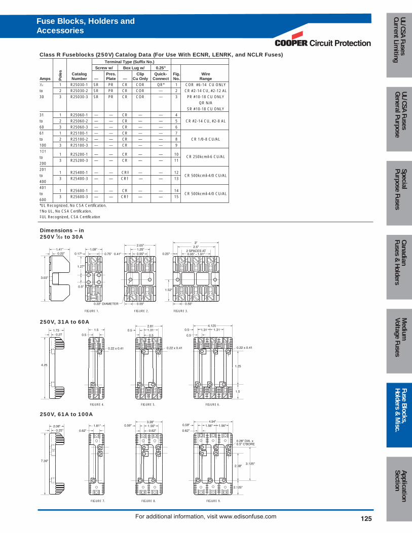
Class R Fuseblocks (250V) Catalog Data (For Use With ECNR, LENRK, and NCLR Fuses)Terminal Type (Suffix No.)
Screw w/ Box Lug w/ 0.25”
Catalog Pres. Clip Quick- Fig. WireNumber — Plate — Cu Only Connect No. Range
1⁄10 1 R25030-1 SR PR CR COR QR* 1 COR #6-14 CU ONLY
to 2 R25030-2 SR PR CR COR — 2 CR #2-14 CU, #2-12 AL
30 3 R25030-3 SR PR CR COR — 3 PR #10-18 CU ONLY
QR N/A
SR #10-18 CU ONLY
31 1 R25060-1 — — CR — — 4
to 2 R25060-2 — — CR — — 5 CR #2-14 CU, #2-8 AL
60 3 R25060-3 — — CR — — 6
61 1 R25100-1 — — CR — — 7
to 2 R25100-2 — — CR — — 8 CR 1/0-8 CU/AL
100 3 R25100-3 — — CR — — 9
1011 R25200-1 — — CR — — 10 CR 250kcmil-6 CU/AL to
2003 R25200-3 — — CR — — 11
2011 R25400-1 — — CR‡ — — 12
to CR 500kcmil-4/0 CU/AL
4003 R25400-3 — — CR† — — 13
4011 R25600-1 — — CR — — 14
to CR 500kcmil-4/0 CU/AL
6003 R25600-3 — — CR† — — 15
*UL Recognized, No CSA Certification.†No UL, No CSA Certification.‡UL Recognized, CSA Certification
Po
les
Amps
1.41"0.22"
1.09"
3.03"
0.5"
0.17" 0.75" 0.25"1.25"0.95"
0.22" DIAMETER
0.41"
2.05"
2 SPACES AT0.95" - 1.91"
2.5"3"
0.55"
1.27"
1.52"
0.55"
Dimensions – in250V 1⁄10 to 30A
FIGURE 1. FIGURE 2. FIGURE 3.
4.25
0.271.73 1.5
0.5
2.810.5 1.31
0.5
1.314.125
G
1.5
0.5
1.310.5
1.25
0.22 x 0.410.22 x 0.410.22 x 0.41
250V, 31A to 60A
FIGURE 4. FIGURE 5. FIGURE 6.
250V, 61A to 100A
FIGURE 7. FIGURE 8. FIGURE 9.
7.36"
0.25"2.06" 1.81"
0.62"
3.38"0.59"
0.62"
4.94"
2.38"
2.125"
0.62"
0.28" DIA. x0.5" C'BORE
0.59"1.56" 1.56"1.56"
3.125"
Circuit Protection
125
Medium
Voltage FusesUL/CSA FusesCurrent Lim
itingUL/CSA FusesGeneral Purpose
SpecialPurpose Fuses
CanadianFuses &
HoldersApplicationSection
Fuse Blocks,Holders &
Misc.
For additional information, visit www.edisonfuse.com
Fuse Blocks, Holders andAccessories
126 For additional information, visit www.edisonfuse.com
Appl
icat
ion
Sect
ion
Fuse
Blo
cks,
Hold
ers
& M
isc.
Med
ium
Volta
ge F
uses
Cana
dian
Fuse
s &
Hol
ders
Spec
ial
Purp
ose
Fuse
sUL
/CSA
Fus
esGe
nera
l Pur
pose
UL/C
SA F
uses
Curr
ent L
imiti
ng
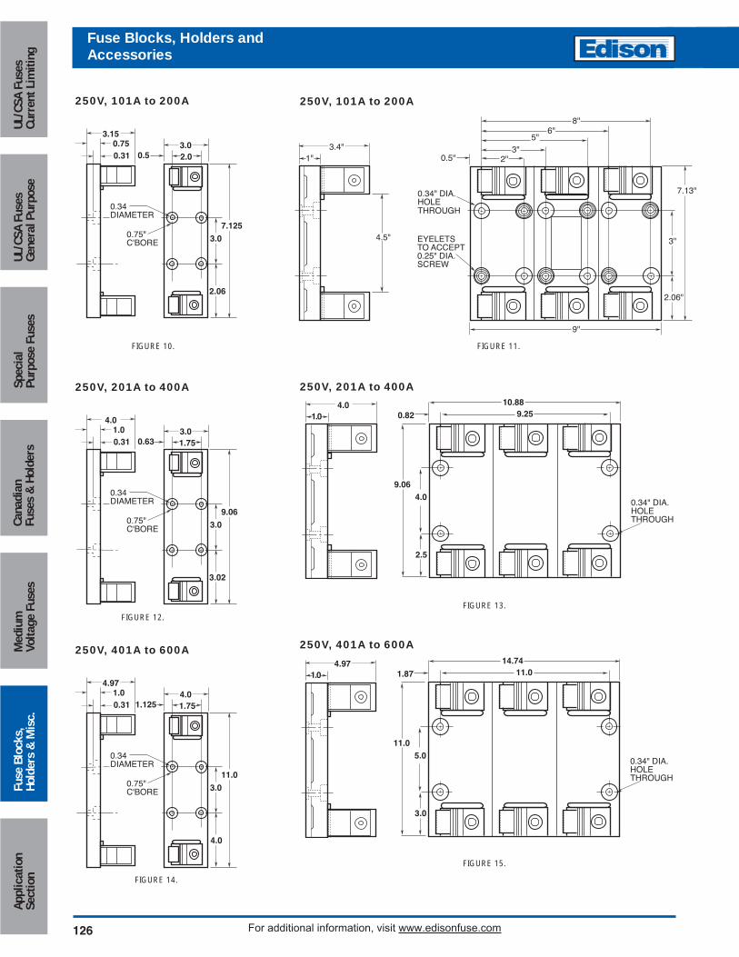
250V, 101A to 200A 250V, 101A to 200A
3.150.750.31 0.5 2.0
0.75"C'BORE
0.34DIAMETER
3.0
3.0
2.06
7.125
250V, 201A to 400A
4.01.00.31 0.63 1.75
0.75"C'BORE
0.34DIAMETER
3.0
3.0
3.02
9.06
250V, 401A to 600A
4.971.00.31 1.125 1.75
0.75"C'BORE
0.34DIAMETER
4.0
3.0
4.0
11.0
FIGURE 10. FIGURE 11.
3.4"
4.5"
1" 0.5"
EYELETSTO ACCEPT0.25" DIA. SCREW
0.34" DIA. HOLETHROUGH
8"6"
5"3"
2"
3"
2.06"
7.13"
9"
FIGURE 12.
FIGURE 14.
250V, 201A to 400A
FIGURE 13.
4.00.34" DIA. HOLETHROUGH
9.06
4.01.0
10.889.250.82
2.5
250V, 401A to 600A
FIGURE 15.
5.00.34" DIA. HOLETHROUGH
11.0
4.971.0
14.7411.01.87
3.0
Fuse Blocks, Holders andAccessories
Circuit Protection
127
Medium
Voltage FusesUL/CSA FusesCurrent Lim
itingUL/CSA FusesGeneral Purpose
SpecialPurpose Fuses
CanadianFuses &
HoldersApplicationSection
Fuse Blocks,Holders &
Misc.
For additional information, visit www.edisonfuse.com
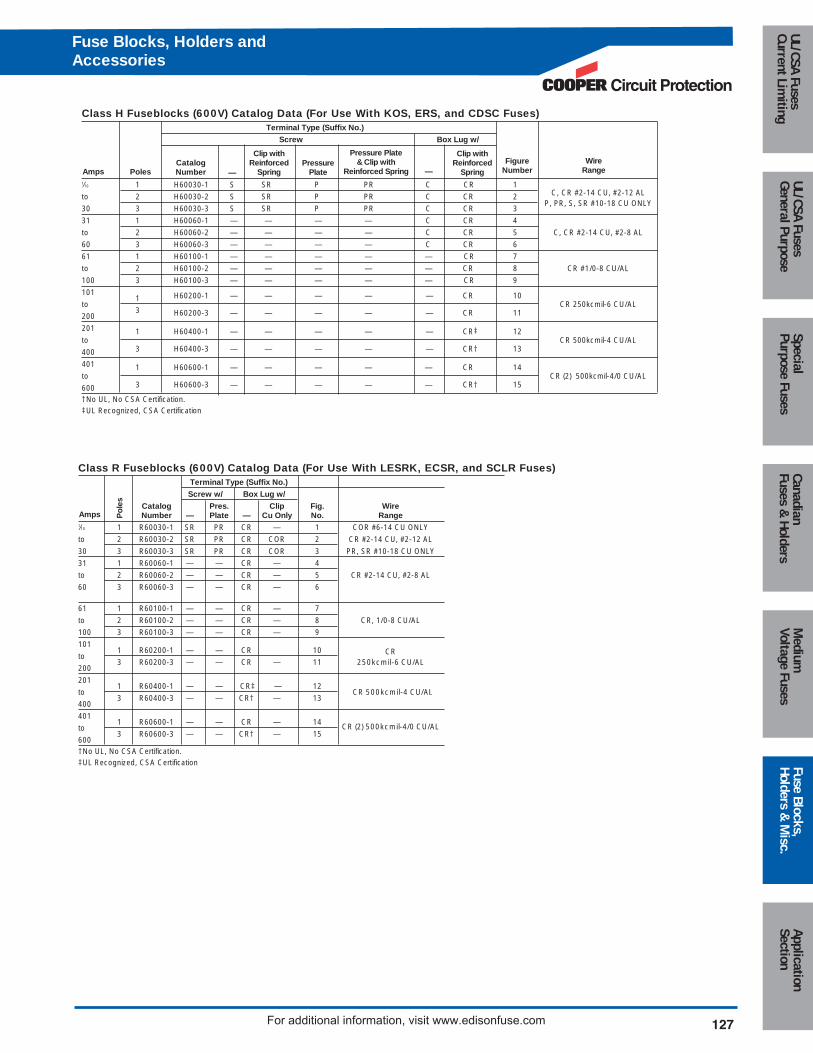
Class H Fuseblocks (600V) Catalog Data (For Use With KOS, ERS, and CDSC Fuses)Terminal Type (Suffix No.)
Screw Box Lug w/
1⁄10 1 H60030-1 S SR P PR C CR 1C, CR #2-14 CU, #2-12 ALto 2 H60030-2 S SR P PR C CR 2
P, PR, S, SR #10-18 CU ONLY30 3 H60030-3 S SR P PR C CR 3
31 1 H60060-1 — — — — C CR 4
to 2 H60060-2 — — — — C CR 5 C, CR #2-14 CU, #2-8 AL
60 3 H60060-3 — — — — C CR 6
61 1 H60100-1 — — — — — CR 7
to 2 H60100-2 — — — — — CR 8 CR #1/0-8 CU/AL
100 3 H60100-3 — — — — — CR 9
1011 H60200-1 — — — — — CR 10
CR 250kcmil-6 CU/ALto
2003 H60200-3 — — — — — CR 11
201 1 H60400-1 — — — — — CR‡ 12CR 500kcmil-4 CU/ALto
400 3 H60400-3 — — — — — CR† 13
401 1 H60600-1 — — — — — CR 14CR (2) 500kcmil-4/0 CU/ALto
600 3 H60600-3 — — — — — CR† 15
†No UL, No CSA Certification.‡UL Recognized, CSA Certification
PressurePlate
Pressure Plate& Clip with
Reinforced SpringWire
Range
Clip with Reinforced
Spring—Figure
NumberAmpsCatalogNumber
Clip with Reinforced
Spring—Poles
Class R Fuseblocks (600V) Catalog Data (For Use With LESRK, ECSR, and SCLR Fuses)Terminal Type (Suffix No.)
Screw w/ Box Lug w/
Catalog Pres. Clip Fig. WireNumber — Plate — Cu Only No. Range
1⁄10 1 R60030-1 SR PR CR — 1 COR #6-14 CU ONLY
to 2 R60030-2 SR PR CR COR 2 CR #2-14 CU, #2-12 AL
30 3 R60030-3 SR PR CR COR 3 PR, SR #10-18 CU ONLY
31 1 R60060-1 — — CR — 4
to 2 R60060-2 — — CR — 5 CR #2-14 CU, #2-8 AL
60 3 R60060-3 — — CR — 6
61 1 R60100-1 — — CR — 7
to 2 R60100-2 — — CR — 8 CR, 1/0-8 CU/AL
100 3 R60100-3 — — CR — 9
1011 R60200-1 — — CR 10 CRto
2003 R60200-3 — — CR — 11 250kcmil-6 CU/AL
2011 R60400-1 — — CR‡ — 12
to CR 500kcmil-4 CU/AL
4003 R60400-3 — — CR† — 13
4011 R60600-1 — — CR — 14 CR (2) 500kcmil-4/0 CU/ALto
6003 R60600-3 — — CR† — 15
†No UL, No CSA Certification.‡UL Recognized, CSA Certification
Po
les
Amps
Fuse Blocks, Holders andAccessories
128
Fuse Blocks, Holders andAccessories
For additional information, visit www.edisonfuse.com
Appl
icat
ion
Sect
ion
Fuse
Blo
cks,
Hold
ers
& M
isc.
Med
ium
Volta
ge F
uses
Cana
dian
Fuse
s &
Hol
ders
Spec
ial
Purp
ose
Fuse
sUL
/CSA
Fus
esGe
nera
l Pur
pose
UL/C
SA F
uses
Curr
ent L
imiti
ng
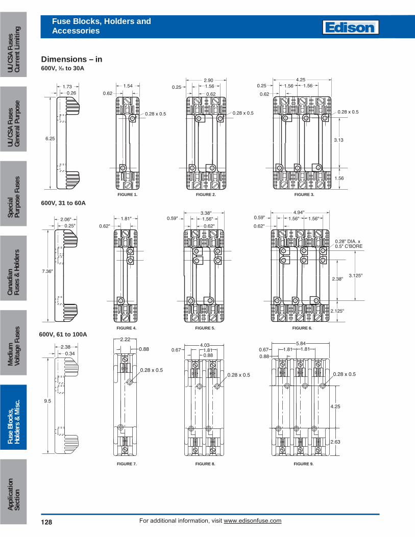
6.25
0.261.73 1.54
0.62
2.900.25 1.56
0.62
1.564.25
3.13
1.56
0.62
1.560.25
0.28 x 0.50.28 x 0.5 0.28 x 0.5
7.36"
0.25"2.06" 1.81"
0.62"
3.38"0.59"
0.62"
4.94"
2.38"
2.125"
0.62"
0.28" DIA. x0.5" C'BORE
0.59"1.56" 1.56"1.56"
3.125"
Dimensions – in600V, 1⁄10 to 30A
600V, 31 to 60A
FIGURE 1. FIGURE 2. FIGURE 3.
0.880.88
0.67 1.814.03
2.22
0.28 x 0.50.28 x 0.5
0.880.67 1.81 1.81
0.28 x 0.5
5.84
9.5
0.342.38
4.25
2.63
600V, 61 to 100A
FIGURE 7. FIGURE 8. FIGURE 9.
FIGURE 4. FIGURE 5. FIGURE 6.
Circuit Protection
129
Medium
Voltage FusesUL/CSA FusesCurrent Lim
itingUL/CSA FusesGeneral Purpose
SpecialPurpose Fuses
CanadianFuses &
HoldersApplicationSection
Fuse Blocks,Holders &
Misc.
For additional information, visit www.edisonfuse.com
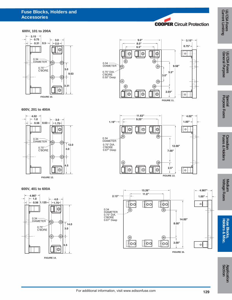
3.150.750.31 0.5 2.0
0.75"C'BORE
0.34DIAMETER
3.0
3.0
3.31
9.63
600V, 101 to 200A
6.5"8.0"
0.75" DIA.C'BORE0.50" Deep
0.34DIAMETER
9.0"
5.5"
9.58"
3.0"
2.04"
3.15"
0.75"
FIGURE 10.
FIGURE 11.
11.0"
0.34DIAMETER0.75" DIA.C'BORE0.67" Deep 14.00"
3.00"
4.987"
1.00"2.13"
15.26"
8.00"
9.25"
0.75" DIA.C'BORE0.67" Deep
0.34DIAMETER
11.63"
7.00"
12.00"
2.5"
4.02"
1.00"1.19"
600V, 201 to 400A
600V, 401 to 600A
FIGURE 12.
FIGURE 14.
FIGURE 13.
FIGURE 15.
1.00.56 0.63 1.75
0.75"C'BORE
0.34DIAMETER
3.0
4.5
12.0
4.02
3.0
1.00.56 1.125 1.75
0.75"C'BORE
0.34DIAMETER
4.0
5.5
14.0
4.987
3.0
Fuse Blocks, Holders andAccessories
130 For additional information, visit www.edisonfuse.com
Appl
icat
ion
Sect
ion
Fuse
Blo
cks,
Hold
ers
& M
isc.
Med
ium
Volta
ge F
uses
Cana
dian
Fuse
s &
Hol
ders
Spec
ial
Purp
ose
Fuse
sUL
/CSA
Fus
esGe
nera
l Pur
pose
UL/C
SA F
uses
Curr
ent L
imiti
ngFuse Blocks, Holders andAccessories
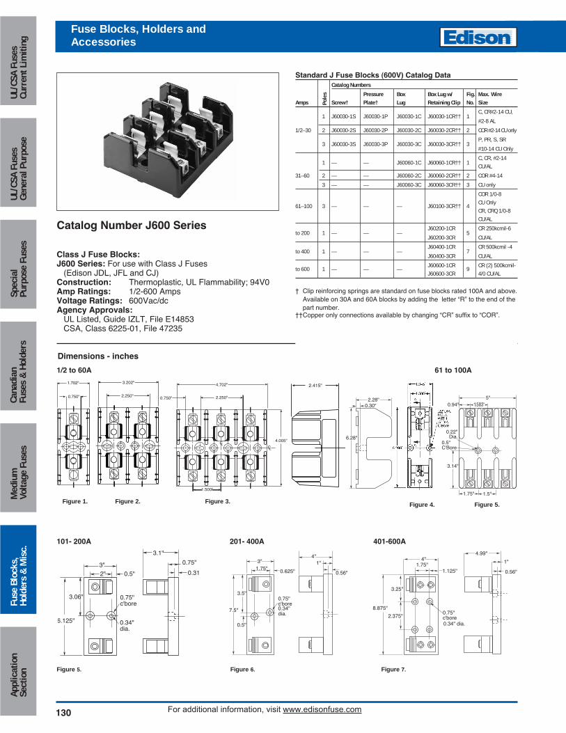
Catalog Number J600 Series
Class J Fuse Blocks:J600 Series: For use with Class J Fuses
(Edison JDL, JFL and CJ)Construction: Thermoplastic, UL Flammability; 94V0Amp Ratings: 1/2-600 AmpsVoltage Ratings: 600Vac/dcAgency Approvals:
UL Listed, Guide IZLT, File E14853CSA, Class 6225-01, File 47235
0.56"
8.875"
3.25"
1.75"
0.75"c'bore0.34" dia.
4"
2.375"
1.125"
1"
4.99"
3.5"
1.75"3"
0.625"
0.75"c'bore0.34"dia.
0.5"
7.5"
1"4"
0.56"
0.75"
3.1"
0.31"
6.125"
3.06"
2"3"
0.5"
0.75"c'bore
0.34"dia.
Figure 5. Figure 6. Figure 7.
1/2 to 60A 61 to 100A
101- 200A 201- 400A 401-600A
Dimensions - inches
Standard J Fuse Blocks (600V) Catalog DataCatalog Numbers
Pressure Box Box Lug w/ Fig. Max. WireAmps Screw† Plate† Lug Retaining Clip No. Size
1 J60030-1S J60030-1P J60030-1C J60030-1CR†† 1C, CR#2-14 CU,
#2-8 AL
1/2–30 2 J60030-2S J60030-2P J60030-2C J60030-2CR†† 2 COR #2-14 CU only
3 J60030-3S J60030-3P J60030-3C J60030-3CR†† 3P, PR, S, SR
#10-14 CU Only
1 — — J60060-1C J60060-1CR†† 1C, CR, #2-14CU/AL
31–60 2 — — J60060-2C J60060-2CR†† 2 COR #4-14
3 — — J60060-3C J60060-3CR†† 3 CU only
COR 1/0-8
61–100 3 — — — J60100-3CR†† 4CU OnlyCR, CRQ 1/0-8CU/AL
to 200 1 — — —J60200-1CR
5CR 250kcmil-6
J60200-3CR CU/AL
to 400 1 — — —J60400-1CR
7CR 500kcmil -4
J60400-3CR CU/AL
to 600 1 — — —J60600-1CR
9CR (2) 500kcmil-
J60600-3CR 4/0 CU/AL
† Clip reinforcing springs are standard on fuse blocks rated 100A and above. Available on 30A and 60A blocks by adding the letter “R” to the end of thepart number.
††Copper only connections available by changing “CR” suffix to “COR”.Po
les
0.30"2.28"
6.28"
0.94"
0.22"Dia.
0.5"C'Bore
1.583"5"
3.14"
1.75" 1.5"
2.250"
3.202"
0.750"
4.702"
2.250"
CLL
1.500"
4.005"
C
2.415"1.702"
0.750"
Figure 1. Figure 2. Figure 3. Figure 5.Figure 4.
Circuit Protection
131
Medium
Voltage FusesUL/CSA FusesCurrent Lim
itingUL/CSA FusesGeneral Purpose
SpecialPurpose Fuses
CanadianFuses &
HoldersApplicationSection
Fuse Blocks,Holders &
Misc.
For additional information, visit www.edisonfuse.com
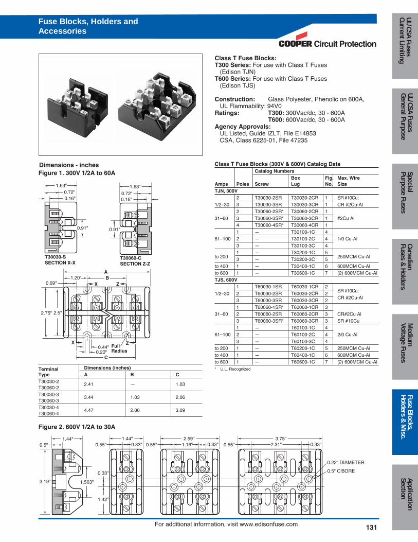
Terminal Dimensions (inches)Type A B CT30030-2 2.41 — 1.03T30060-2T30030-3 3.44 1.03 2.06T30060-3T30030-4 4.47 2.06 3.09T30060-4
Class T Fuse Blocks:T300 Series: For use with Class T Fuses
(Edison TJN)T600 Series: For use with Class T Fuses
(Edison TJS)
Construction: Glass Polyester, Phenolic on 600A,UL Flammability: 94V0
Ratings: T300: 300Vac/dc, 30 - 600AT600: 600Vac/dc, 30 - 600A
Agency Approvals:UL Listed, Guide IZLT, File E14853CSA, Class 6225-01, File 47235
Figure 2. 600V 1/2A to 30A
3.19"
1.44"
1.563"
0.33"
1.42"
0.5"1.44"
0.55" 0.33" 0.55"2.59"
1.16" 0.33" 0.55"3.75"
2.31" 0.33"
0.22" DIAMETER
0.5" C'BORE
Dimensions - inches Class T Fuse Blocks (300V & 600V) Catalog DataCatalog Numbers
Box Fig. Max. WireAmps Poles Screw Lug No. SizeTJN, 300V
2 T30030-2SR T30030-2CR 1 SR #10Cu;1/2–30 3 T30030-3SR T30030-3CR 1 CR #2Cu-Al
2 T30060-2SR* T30060-2CR 131–60 3 T30060-3SR* T30060-3CR 1 #2Cu Al
4 T30060-4SR* T30060-4CR 11 — T30100-1C 4
61–100 2 — T30100-2C 4 1/0 Cu-Al3 — T30100-3C 41 — T30200-1C 5
to 200 3 — T30200-3C 5 250MCM Cu-Al
to 400 1 — T30400-1C 6 600MCM Cu-Alto 600 1 — T30600-1C 7 (2) 600MCM Cu-AlTJS, 600V
1 T60030-1SR T60030-1CR 21/2–30 2 T60030-2SR T60030-2CR 2 SR #10Cu;
3 T60030-3SR T60030-3CR 2 CR #2Cu-Al
1 T60060-1SR* T60060-1CR 331–60 2 T60060-2SR T60060-2CR 3 CR#2Cu Al
3 T60060-3SR* T60060-3CR 3 SR #10Cu1 — T60100-1C 4
61–100 2 — T60100-2C 4 2/0 Cu-Al3 — T60100-3C 4
to 200 1 — T60200-1C 5 250MCM Cu-Alto 400 1 — T60400-1C 6 600MCM Cu-Alto 600 1 — T60600-1C 7 (2) 600MCM Cu-Al* U.L. Recognized
T30030-SSECTION X-X
0.91"
1.63"0.72"0.16"
T30060-CSECTION Z-Z
0.91"
1.63"0.72"0.16"
ZXFullRadius
ZX
0.44"0.20"
C
B1.20"A
0.69"
2.5"2.75"
Figure 1. 300V 1/2A to 60A
Fuse Blocks, Holders andAccessories
132For additional information, visit www.edisonfuse.com
Appl
icat
ion
Sect
ion
Fuse
Blo
cks,
Hold
ers
& M
isc.
Med
ium
Volta
ge F
uses
Cana
dian
Fuse
s &
Hol
ders
Spec
ial
Purp
ose
Fuse
sUL
/CSA
Fus
esGe
nera
l Pur
pose
UL/C
SA F
uses
Curr
ent L
imiti
ng
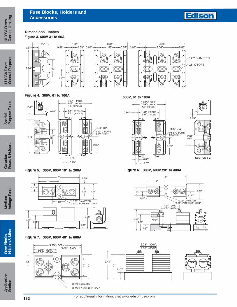
Figure 4. 300V, 61 to 100A 600V, 61 to 100A
Fuse Blocks, Holders andAccessories
3"
6"
0.28" DIAMETER0.63" C'BORE 0.5" DEEP
1.125"
2.56"1.94"
0.81"
3.06"
1.69"
0.05"
1.25" 2.25"
Figure 5. 300V, 600V 101 to 200A
3.44"
0.75"3"
2.03" - 300V
3"2"
1.5"
5.75" - 300V
0.33" Diameter
0.75" C'Bore 0.5" Deep
2.88" - 300V3.38" - 600V
6.75" - 600V 2.95" - 600V
Figure 7. 300V, 600V 401 to 600A
6"
0.63" C'BORE 0.5" DEEP0.28" DIAMETER
1.125"
2.25"
0.63"
3"
1.84" - 300V
1.25"
0.81"
2.38"
3.06"
2.72" - 600V
Figure 6. 300V, 600V 201 to 400A
Figure 3. 600V 31 to 60A
2.94"
1.75"
1.63"
1.47"
0.5"1.81"
0.59" 0.63" 0.59"3.34"
1.53" 0.63" 0.59"4.86"
3.06" 0.63"
0.22" DIAMETER
0.5" C'BORE
Dimensions - inches
Z
Z
0.52" C'BORE0.55" DEEP
0.22" DIA.
X
X
2.39"
2.25"REF.4.78"
2.06"
1.69" (1 POLE)3.09" (2 POLE)4.5" (3 POLE)
1.41" (2 POLE)2.81" (3 POLE)
0.84"
0.38"
0.75"
Z
Z
0.52" C'BORE0.55" DEEP
0.22" DIA.
X
X
2.39"
1.69" (1 POLE)3.09" (2 POLE)4.5" (3 POLE)
1.41" (2 POLE)2.81" (3 POLE)
0.84"
0.38" SECTION Z-Z
0.78"
2.34"REF.
0.75"
Circuit Protection
133
Medium
Voltage FusesUL/CSA FusesCurrent Lim
itingUL/CSA FusesGeneral Purpose
SpecialPurpose Fuses
CanadianFuses &
HoldersApplicationSection
Fuse Blocks,Holders &
Misc.
For additional information, visit www.edisonfuse.com
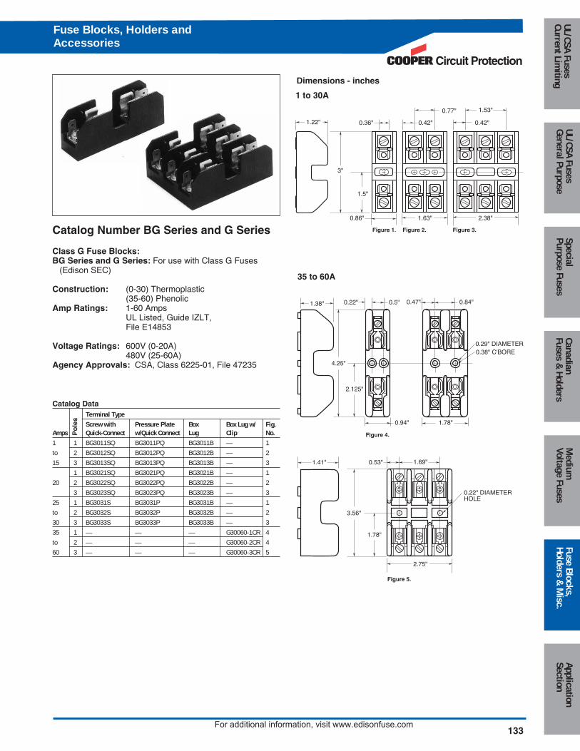
Catalog Number BG Series and G Series
Class G Fuse Blocks:BG Series and G Series: For use with Class G Fuses
(Edison SEC)
Construction: (0-30) Thermoplastic(35-60) Phenolic
Amp Ratings: 1-60 AmpsUL Listed, Guide IZLT,File E14853
Voltage Ratings: 600V (0-20A)480V (25-60A)
Agency Approvals: CSA, Class 6225-01, File 47235
Catalog DataTerminal TypeScrew with Pressure Plate Box Box Lug w/ Fig.
Amps Quick-Connect w/Quick Connect Lug Clip No.1 1 BG3011SQ BG3011PQ BG3011B — 1to 2 BG3012SQ BG3012PQ BG3012B — 215 3 BG3013SQ BG3013PQ BG3013B — 3
1 BG3021SQ BG3021PQ BG3021B — 120 2 BG3022SQ BG3022PQ BG3022B — 2
3 BG3023SQ BG3023PQ BG3023B — 325 1 BG3031S BG3031P BG3031B — 1to 2 BG3032S BG3032P BG3032B — 230 3 BG3033S BG3033P BG3033B — 335 1 — — — G30060-1CR 4to 2 — — — G30060-2CR 460 3 — — — G30060-3CR 5
Po
les
0.42"
1.53"
0.42"
0.77"
3"
1.22"
1.5"
0.36"
0.86" 1.63" 2.38"
1 to 30A
35 to 60A
Figure 1. Figure 2. Figure 3.
Figure 4.
Figure 5.
1.38" 0.5"0.22" 0.47"
0.29" DIAMETER0.38" C'BORE
0.84"
1.78"0.94"
4.25"
1.41" 1.69"0.53"
2.125"
1.78"
3.56"
2.75"
0.22" DIAMETERHOLE
Dimensions - inches
Fuse Blocks, Holders andAccessories
134 For additional information, visit www.edisonfuse.com
Appl
icat
ion
Sect
ion
Fuse
Blo
cks,
Hold
ers
& M
isc.
Med
ium
Volta
ge F
uses
Cana
dian
Fuse
s &
Hol
ders
Spec
ial
Purp
ose
Fuse
sUL
/CSA
Fus
esGe
nera
l Pur
pose
UL/C
SA F
uses
Curr
ent L
imiti
ngFuse Blocks, Holders andAccessories
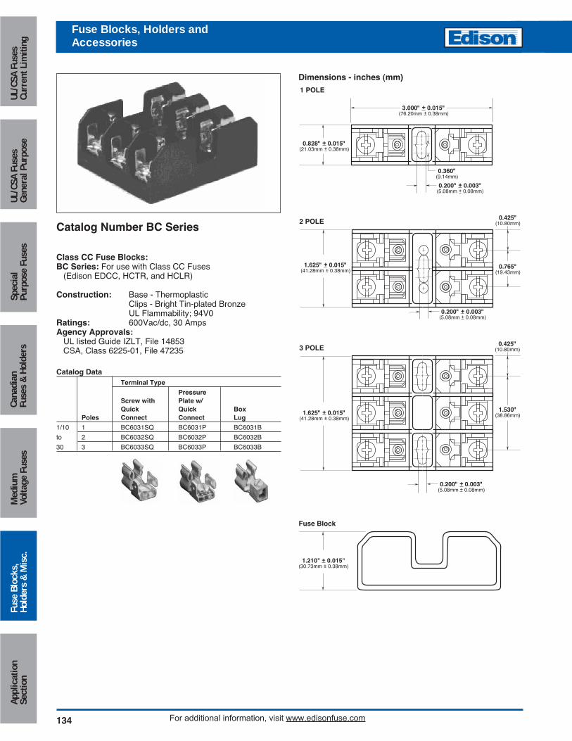
Catalog Number BC Series
Class CC Fuse Blocks:BC Series: For use with Class CC Fuses
(Edison EDCC, HCTR, and HCLR)
Construction: Base - ThermoplasticClips - Bright Tin-plated BronzeUL Flammability; 94V0
Ratings: 600Vac/dc, 30 AmpsAgency Approvals:
UL listed Guide IZLT, File 14853CSA, Class 6225-01, File 47235
1.625" + 0.015"(41.28mm + 0.38mm)
1.625" + 0.015"(41.28mm + 0.38mm)
3.000" + 0.015"(76.20mm + 0.38mm)
0.360"(9.14mm)
1 POLE
0.828" + 0.015"(21.03mm + 0.38mm)
0.200" + 0.003"(5.08mm + 0.08mm)
0.200" + 0.003"(5.08mm + 0.08mm)
0.425"(10.80mm)
1.530"(38.86mm)
0.200" + 0.003"(5.08mm + 0.08mm)
2 POLE 0.425"(10.80mm)
0.765"(19.43mm)
3 POLE
Catalog DataTerminal Type
Pressure Screw with Plate w/Quick Quick Box
Poles Connect Connect Lug
1/10 1 BC6031SQ BC6031P BC6031B
to 2 BC6032SQ BC6032P BC6032B
30 3 BC6033SQ BC6033P BC6033B
Dimensions - inches (mm)
Fuse Block
1.210" + 0.015"(30.73mm + 0.38mm)
Circuit Protection
135
Medium
Voltage FusesUL/CSA FusesCurrent Lim
itingUL/CSA FusesGeneral Purpose
SpecialPurpose Fuses
CanadianFuses &
HoldersApplicationSection
Fuse Blocks,Holders &
Misc.
For additional information, visit www.edisonfuse.com
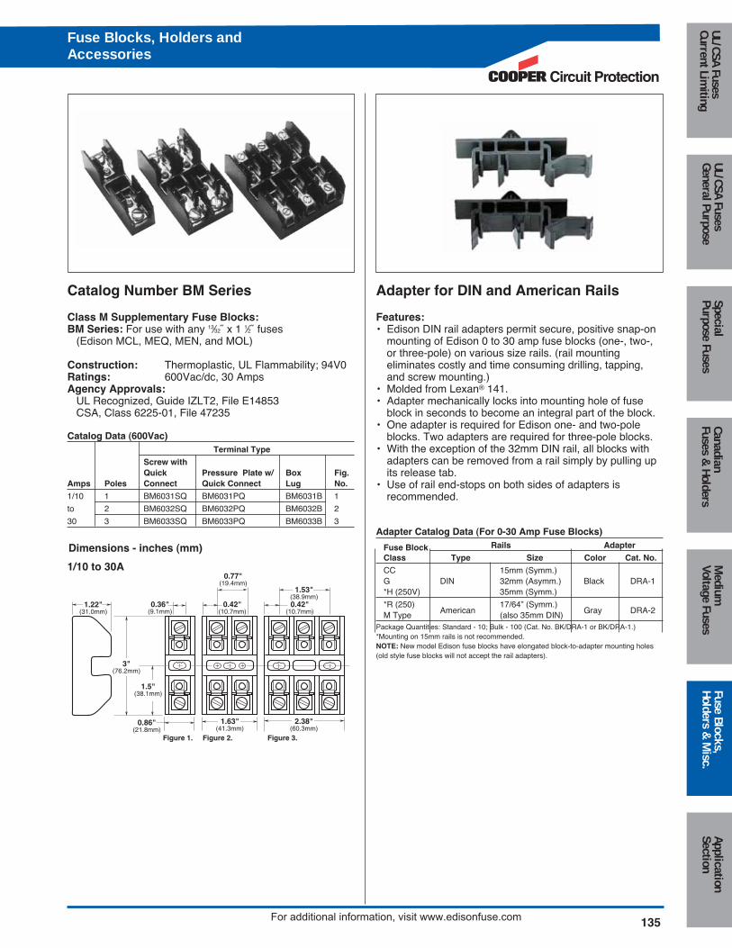
Catalog Number BM Series Adapter for DIN and American Rails
Class M Supplementary Fuse Blocks:BM Series: For use with any 13⁄32˝ x 1 1⁄2˝ fuses
(Edison MCL, MEQ, MEN, and MOL)
Construction: Thermoplastic, UL Flammability; 94V0Ratings: 600Vac/dc, 30 AmpsAgency Approvals:
UL Recognized, Guide IZLT2, File E14853CSA, Class 6225-01, File 47235
Catalog Data (600Vac)Terminal Type
Screw withQuick Pressure Plate w/ Box Fig.
Amps Poles Connect Quick Connect Lug No.
1/10 1 BM6031SQ BM6031PQ BM6031B 1
to 2 BM6032SQ BM6032PQ BM6032B 2
30 3 BM6033SQ BM6033PQ BM6033B 3
Features:• Edison DIN rail adapters permit secure, positive snap-on
mounting of Edison 0 to 30 amp fuse blocks (one-, two-,or three-pole) on various size rails. (rail mountingeliminates costly and time consuming drilling, tapping,and screw mounting.)
• Molded from Lexan® 141.• Adapter mechanically locks into mounting hole of fuse
block in seconds to become an integral part of the block.• One adapter is required for Edison one- and two-pole
blocks. Two adapters are required for three-pole blocks.• With the exception of the 32mm DIN rail, all blocks with
adapters can be removed from a rail simply by pulling upits release tab.
• Use of rail end-stops on both sides of adapters is recommended.
Adapter Catalog Data (For 0-30 Amp Fuse Blocks)
Fuse Block Rails Adapter
Class Type Size Color Cat. No.
CC 15mm (Symm.)G DIN 32mm (Asymm.) Black DRA-1*H (250V) 35mm (Symm.)
*R (250) 17/64” (Symm.)M Type American (also 35mm DIN) Gray DRA-2
Package Quantities: Standard - 10; Bulk - 100 (Cat. No. BK/DRA-1 or BK/DRA-1.)*Mounting on 15mm rails is not recommended.NOTE: New model Edison fuse blocks have elongated block-to-adapter mounting holes(old style fuse blocks will not accept the rail adapters).
Dimensions - inches (mm)
0.42"(10.7mm)
1.53"(38.9mm)
0.42"(10.7mm)
0.77"(19.4mm)
3"(76.2mm)
1.22"(31.0mm)
1.5"(38.1mm)
0.36"(9.1mm)
0.86"(21.8mm)
1.63"(41.3mm)
2.38"(60.3mm)
1/10 to 30A
Figure 1. Figure 2. Figure 3.
Fuse Blocks, Holders andAccessories

136 For additional information, visit www.edisonfuse.com
Appl
icat
ion
Sect
ion
Fuse
Blo
cks,
Hold
ers
& M
isc.
Med
ium
Volta
ge F
uses
Cana
dian
Fuse
s &
Hol
ders
Spec
ial
Purp
ose
Fuse
sUL
/CSA
Fus
esGe
nera
l Pur
pose
UL/C
SA F
uses
Curr
ent L
imiti
ng
Catalog Number BH Series
Block Series:BH Series: For use with Edison high speed semiconductorand “bolt-in” fuses
Base: Light weight, high temperature thermoplasticMounting Studs: Plated steelNut: Plated steelWasher: Spring steelAgency Approvals:
UL Recognized, Guide IZLT2/IZLT8, File E14853 up to 700VCSA, Class 6225-01, File 47235 up to 700V
Contact Edison Customer Satisfaction for ordering informationand dimensional data.
Catalog Code Description:Block Series
BH - X X X X
NOTES: 1. The #4 connector must be used with either the 7/16 - 14 or the 3/8” - 16 stud.
2. The only compatible connector for the 7/16” - 14 stud is #4.
3. Always check applicable end use standards for required spacing between blocks, fuses or other hardware.
4. For applications above 700V, consult appropriate electrical standard for proper creepage distances, clearance distances and insulator voltage withstand ratings.
Agency Approval0 No agency approval1 UL Recognition and CSA Certification2 UL Recognition only3 cURus
Fuseblock Base0 Small base for 0-200 amp fuses, 0-700V1 Medium base, for 0-400 amp fuses, 0-2500V2 Medium base, for 0-600 amp fuses, 0-5000V3 Large base, for 0-700 amp, 0-1250V
Wire Connector0 No connector1 1 Hole for #14 - 2/0 copper wire
(for use with base 0)2 2 Hole for #14 - 1/0 copper wire
(for use with base 0)3 2 Hole for #6 - 250 MCM copper wire
(for use with base 1, 2, & 3)4 2 Hole for #14 - 500 MCM copper cable
(for use with base 3)See Note 1 below
Stud Size1 1⁄4 - 20 (for use with bases 0, 1, & 2) 2 5⁄16 - 18 (For use with bases 0, 1, & 2)3 3⁄8 - 16 (for use with bases 0, 1, 2 & 3)4 7⁄16 - 14 (for use with base 3)See Note 2 below.5 3⁄8 - 16 (for use with base 3)
Fuse Blocks, Holders andAccessories
Catalog NumbersBH-0001 BH-0122 BH-2001 BH-3004BH-0002 BH-1001 BH-2002 BH-3033BH-0003 BH-1002 BH-2003 BH-3144BH-0111 BH-1003 BH-2031 BH-3145BH-0112 BH-1131 BH-2032 —BH-0113 BH-1132 BH-2033 —BH-0121 BH-1133 BH-3003 —
Circuit Protection
137
Medium
Voltage FusesUL/CSA FusesCurrent Lim
itingUL/CSA FusesGeneral Purpose
SpecialPurpose Fuses
CanadianFuses &
HoldersApplicationSection
Fuse Blocks,Holders &
Misc.
For additional information, visit www.edisonfuse.com
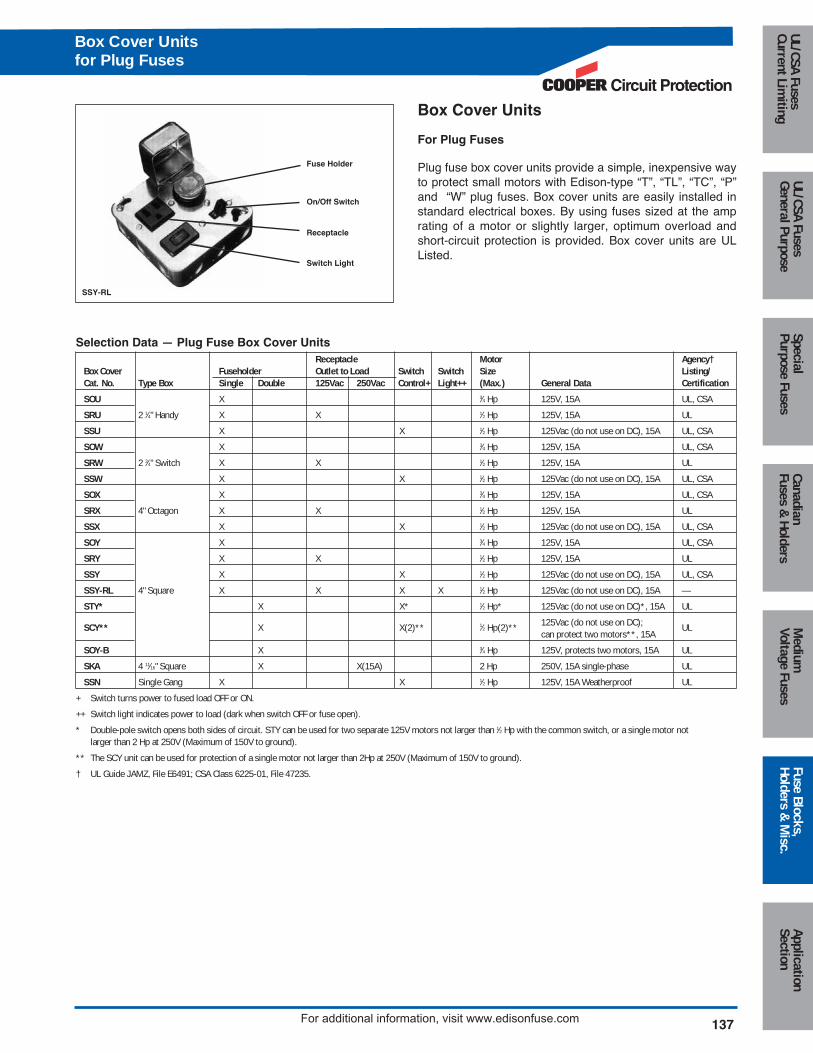
Box Cover Units
For Plug Fuses
Plug fuse box cover units provide a simple, inexpensive wayto protect small motors with Edison-type “T”, “TL”, “TC”, “P”and “W” plug fuses. Box cover units are easily installed instandard electrical boxes. By using fuses sized at the amprating of a motor or slightly larger, optimum overload andshort-circuit protection is provided. Box cover units are ULListed.
Fuse Holder
On/Off Switch
Receptacle
Switch Light
SSY-RL
Selection Data — Plug Fuse Box Cover UnitsReceptacle Motor Agency†
Box Cover Fuseholder Outlet to Load Switch Switch Size Listing/Cat. No. Type Box Single Double 125Vac 250Vac Control+ Light++ (Max.) General Data Certification
SOU X 3⁄4 Hp 125V, 15A UL, CSA
SRU 2 1⁄4" Handy X X 1⁄2 Hp 125V, 15A UL
SSU X X 1⁄2 Hp 125Vac (do not use on DC), 15A UL, CSA
SOW X 3⁄4 Hp 125V, 15A UL, CSA
SRW 2 3⁄4" Switch X X 1⁄2 Hp 125V, 15A UL
SSW X X 1⁄2 Hp 125Vac (do not use on DC), 15A UL, CSA
SOX X 3⁄4 Hp 125V, 15A UL, CSA
SRX 4" Octagon X X 1⁄2 Hp 125V, 15A UL
SSX X X 1⁄2 Hp 125Vac (do not use on DC), 15A UL, CSA
SOY X 3⁄4 Hp 125V, 15A UL, CSA
SRY X X 1⁄2 Hp 125V, 15A UL
SSY X X 1⁄2 Hp 125Vac (do not use on DC), 15A UL, CSA
SSY-RL 4" Square X X X X 1⁄2 Hp 125Vac (do not use on DC), 15A —
STY* X X* 1⁄2 Hp* 125Vac (do not use on DC)*, 15A UL
SCY** X X(2)** 1⁄2 Hp(2)** 125Vac (do not use on DC); ULcan protect two motors**, 15A
SOY-B X 3⁄4 Hp 125V, protects two motors, 15A UL
SKA 4 11⁄16" Square X X(15A) 2 Hp 250V, 15A single-phase UL
SSN Single Gang X X 1⁄2 Hp 125V, 15A Weatherproof UL
+ Switch turns power to fused load OFF or ON.
++ Switch light indicates power to load (dark when switch OFF or fuse open).
* Double-pole switch opens both sides of circuit. STY can be used for two separate 125V motors not larger than 1⁄2 Hp with the common switch, or a single motor notlarger than 2 Hp at 250V (Maximum of 150V to ground).
** The SCY unit can be used for protection of a single motor not larger than 2Hp at 250V (Maximum of 150V to ground).
† UL Guide JAMZ, File E6491; CSA Class 6225-01, File 47235.
Box Cover Unitsfor Plug Fuses
138For additional information, visit www.edisonfuse.com
Appl
icat
ion
Sect
ion
Fuse
Blo
cks,
Hold
ers
& M
isc.
Med
ium
Volta
ge F
uses
Cana
dian
Fuse
s &
Hol
ders
Spec
ial
Purp
ose
Fuse
sUL
/CSA
Fus
esGe
nera
l Pur
pose
UL/C
SA F
uses
Curr
ent L
imiti
ngBox Cover Unitsfor Plug Fuses
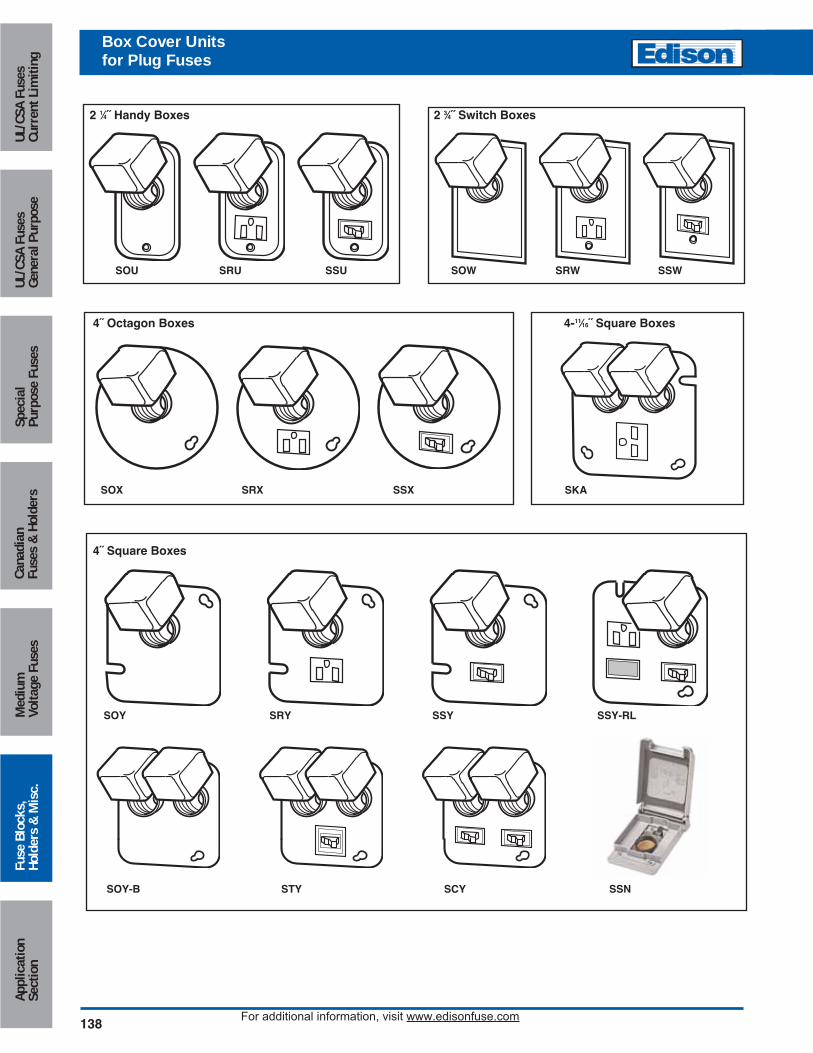
2 1⁄4˝ Handy Boxes 2 3⁄4˝ Switch Boxes
4˝ Octagon Boxes 4-11⁄16˝ Square Boxes
SOU SRU SSU SOW SRW SSW
SOX SRX SSX SKA
4˝ Square Boxes
SOY SRY SSY SSY-RL
SOY-B STY SCY SSN
Circuit Protection
139
Medium
Voltage FusesUL/CSA FusesCurrent Lim
itingUL/CSA FusesGeneral Purpose
SpecialPurpose Fuses
CanadianFuses &
HoldersApplicationSection
Fuse Blocks,Holders &
Misc.
For additional information, visit www.edisonfuse.com
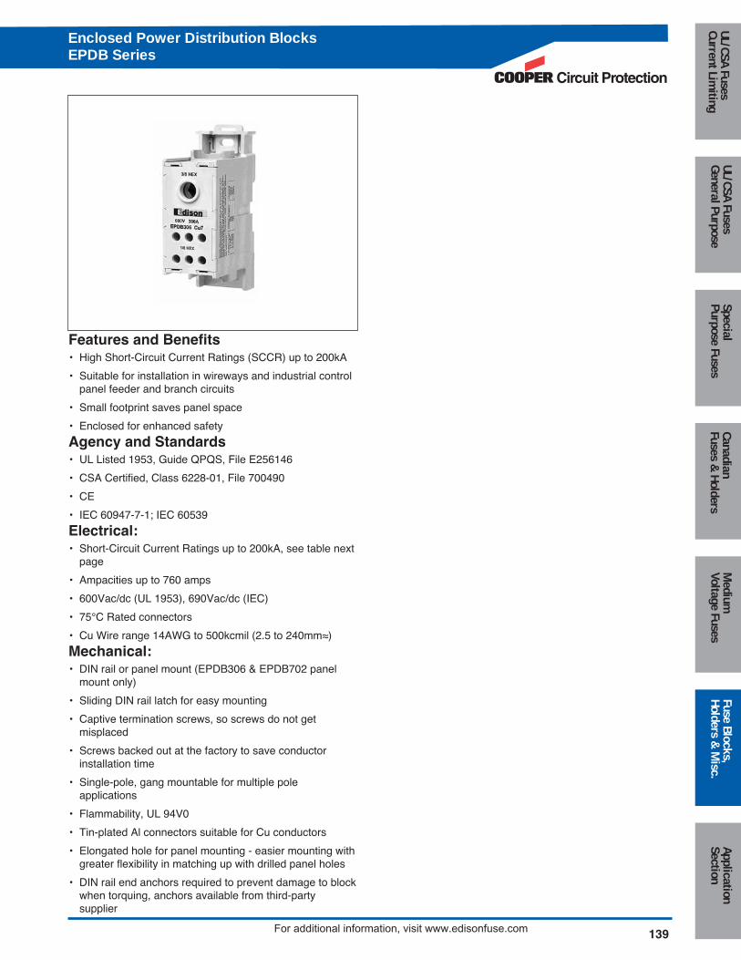
Features and Benefits• High Short-Circuit Current Ratings (SCCR) up to 200kA
• Suitable for installation in wireways and industrial controlpanel feeder and branch circuits
• Small footprint saves panel space
• Enclosed for enhanced safety
Agency and Standards• UL Listed 1953, Guide QPQS, File E256146
• CSA Certified, Class 6228-01, File 700490
• CE
• IEC 60947-7-1; IEC 60539
Electrical:• Short-Circuit Current Ratings up to 200kA, see table next
page
• Ampacities up to 760 amps
• 600Vac/dc (UL 1953), 690Vac/dc (IEC)
• 75°C Rated connectors
• Cu Wire range 14AWG to 500kcmil (2.5 to 240mm≈)
Mechanical:• DIN rail or panel mount (EPDB306 & EPDB702 panel
mount only)
• Sliding DIN rail latch for easy mounting
• Captive termination screws, so screws do not get misplaced
• Screws backed out at the factory to save conductorinstallation time
• Single-pole, gang mountable for multiple pole applications
• Flammability, UL 94V0
• Tin-plated Al connectors suitable for Cu conductors
• Elongated hole for panel mounting - easier mounting withgreater flexibility in matching up with drilled panel holes
• DIN rail end anchors required to prevent damage to blockwhen torquing, anchors available from third-party supplier
Enclosed Power Distribution BlocksEPDB Series
140 For additional information, visit www.edisonfuse.com
Appl
icat
ion
Sect
ion
Fuse
Blo
cks,
Hold
ers
& M
isc.
Med
ium
Volta
ge F
uses
Cana
dian
Fuse
s &
Hol
ders
Spec
ial
Purp
ose
Fuse
sUL
/CSA
Fus
esGe
nera
l Pur
pose
UL/C
SA F
uses
Curr
ent L
imiti
ngEnclosed Power Distribution BlocksEPDB Series
C U W ire R angeT orque
Lb -In (N m )T rim Length in (m m ) H ex K ey C U W ire R ange T orque
Lb -In (N m )T rim Length in (m m ) H ex K ey L ineside
in (m m )Loadside in (m m )
M in . Enclosure S ize - inch
4 to 6 A W G
25 to 16m m2
35 (4 .0 )8 A W G
10m m2
25 (2 .8 )10 to 14 A W G
6 to 2 .5m m2
20 (2 .3 )
2 to 3 A W G
35m m2
50 (5 .7 )4 to 6 A W G
25 to 16m m2
45 (5 .1 )8 A W G
10m m2
40 (4 .5 )10 to 14 A W G
6 to 2 .5m m ² 35 (4 .0 )4 to 6 A W G
25 to 16m m2
35 (4 .0 )8 A W G
10m m2
25 (2 .8 )10 to 14 A W G
6 to 2 .5m m2
20 (2 .3 )
24 X 20 X 6 .75
36 X 30 X 12 .625
36 X 30 X 12 .625
16 X 16 X 6 .75
16 X 16 X 6 .75
36 X 30 X 12 .625
24 X 20 X 6 .750.314 (8 .0 )
0 .265 (6 .7 )
0 .718 (18 .2)
0 .875 (22 .2)
0 .87 (22 .1)
0 .687 (17 .5)
0 .718 (18 .2)
0 .875 (22 .2)
W ire C onnector H o le D iam eter
0.45 (11 .5)
0 .45 (11 .5)
0 .72 (18 .3)
0 .45 (11 .5)
0 .246 (6 .25)
0 .72 (18 .3)
500 K cm il to 6 A W G
240 to 16m m2
275 (31 .1)
275 (31 .1)
500 (56 .5)
350 K cm il to 6 A W G
150 to 16m m2
E P D B 512
E P D B 602
E P D B 702
E P D B 101
E P D B 104
E P D B 301
E P D B 306
1.25 (31 .8) 3 /8"
S eries E P D B
500 K cm il to 6 A W G
240 to 16m m2 500 (56 .5) 1 .25 (31 .8) 3 /8"
0 .55 (14) top row 1 (25 .4) m idd le row
1.22 (31) bo ttom row1/8"
350 K cm il to 4 A W G
185 to 25m m2 5/16"350 K cm il to 4 A W G
185 to 25m m2
300 K cm il to 4 A W G
150 to 25m m2 275 (31 .1)
1 .15 (29 .2) top row 1 .4 (35 .6) bo ttom row
1/4"
275 (31 .1) 1 .250 (31 .8) 5 /16" 1 .25 (31 .8)
0 .59 (15) top row 1.2 (30 .5) bo ttom row
1/8"
350 K cm il to 6 A W G
185 to 16m m2 275 (31 .1) 1 .35 (34 .3)
500 K cm il to 6 A W G
240 to 16m m2 500 (56 .5) 1 .25 (31 .8) 3 /8"
5 /16"
3 /16"
2 /0 to 8 A W G
70 to 10m m2 120 (13 .6) 0 .75 (19 .0) 3 /16"
0 .55 (14) top row 0.85 (21 .6) bo ttom row
1/8"
1 .25 (31 .8) 5 /16"
P art N um ber
L ineside Loadside
2/0 to 8 A W G
70 to 10m m2 110 (12 .4) 0 .85 (21 .6) 3 /16"
2 /0 to 8 A W G
70 to 10m m2 110 (12 .4) 0 .97 (24 .6)
L ineside LoadsideP art
N um ber Am ps W ire R ange W ire R angeL ine Load J T R K 1 R K 5
S C C R
L ine LoadA W G or
kcm ilA W G or
kcm il JD LTJS TJN
LE S R K LE N R K
E C S R E C N R
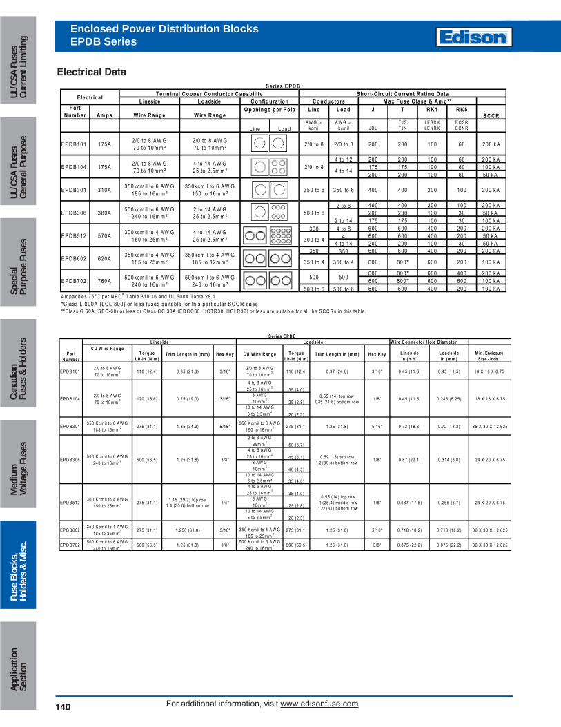
4 to 12 200 200 100 60 200 kA175 175 100 60 100 kA200 200 100 60 50 kA
2 to 6 400 400 200 100 200 kA200 200 100 30 50 kA175 175 100 30 100 kA
300 4 to 8 600 600 400 200 200 kA4 600 600 400 200 50 kA
4 to 14 200 200 100 30 50 kA350 350 600 600 400 200 200 kA
600 800* 600 400 200 kA600 800* 600 600 100 kA
500 to 6 500 to 6 600 600 400 200 100 kAA m pac ities 75°C per N E C
® Tab le 310 .16 and U L 508A Tab le 28 .1
*C lass L 800A (LC L 800) o r less fuses su itab le fo r th is particu la r SC C R case.
S eries E P D B
E lectrica l
O pen ings per Po le
**C lass G 60A (S E C -60) o r less o r C lass C C 30A (E D C C 30, H C TR 30, H C LR 30) o r less a re su itab le fo r a ll the S C C R s in th is tab le .
E P D B 101
E P D B 104
E P D B 301
E P D B 306
E P D B 512
E P D B 602
E P D B 702 760A500kcm il to 6 A W G
240 to 16m m ²
600 200 100 kA600 800*
500kcm il to 6 A W G 240 to 16m m ²
500500
620A350kcm il to 4 A W G
185 to 25m m ²350kcm il to 4 A W G
185 to 12m m ² 350 to 4350 to 4
570A300kcm il to 4 A W G
150 to 25m m ²4 to 14 A W G 25 to 2 .5m m ²
100350kcm il to 6 A W G
185 to 16m m ²350kcm il to 6 A W G
150 to 16m m ²350 to 6
2 to 14
300 to 4
200 kA
380A500kcm il to 6 A W G
240 to 16m m ²2 to 14 A W G 35 to 2 .5m m ²
500 to 6
350 to 6 400 400 200310A
60 200 kA
175A2/0 to 8 A W G 70 to 10m m ²
4 to 14 A W G 25 to 2 .5m m ²
2/0 to 84 to 14
175A2/0 to 8 A W G 70 to 10m m ²
2/0 to 8 A W G 70 to 10m m ²
100
T erm inal C opper C onductor C apab ility S hort-C ircu it C urren t R ating D ataC onfiguration C onductors M ax Fuse C lass & Am p**
2/0 to 8 2 /0 to 8 200 200
Electrical Data
Circuit Protection
141
Medium
Voltage FusesUL/CSA FusesCurrent Lim
itingUL/CSA FusesGeneral Purpose
SpecialPurpose Fuses
CanadianFuses &
HoldersApplicationSection
Fuse Blocks,Holders &
Misc.
For additional information, visit www.edisonfuse.com
EPDB101 EPDB104 EPDB301
EPDB306 EPDB512 EPDB602
EPDB702
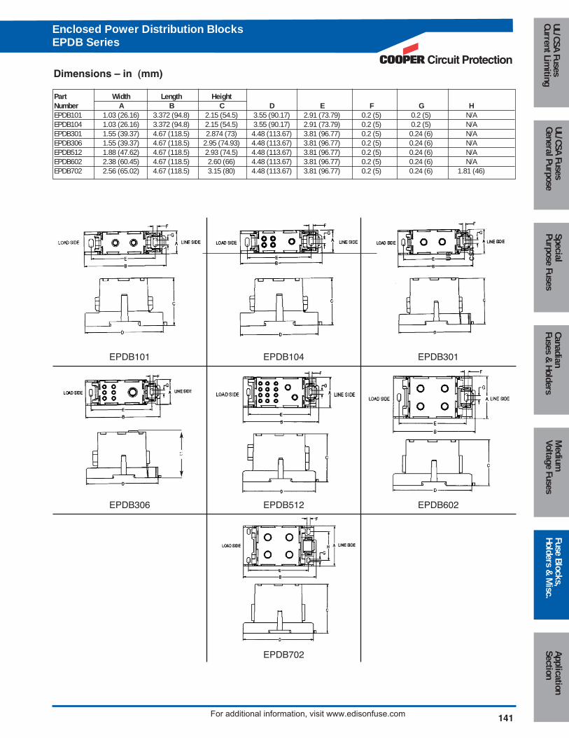
Part Width Length HeightNumber A B C D E F G HEPDB101 1.03 (26.16) 3.372 (94.8) 2.15 (54.5) 3.55 (90.17) 2.91 (73.79) 0.2 (5) 0.2 (5) N/AEPDB104 1.03 (26.16) 3.372 (94.8) 2.15 (54.5) 3.55 (90.17) 2.91 (73.79) 0.2 (5) 0.2 (5) N/AEPDB301 1.55 (39.37) 4.67 (118.5) 2.874 (73) 4.48 (113.67) 3.81 (96.77) 0.2 (5) 0.24 (6) N/AEPDB306 1.55 (39.37) 4.67 (118.5) 2.95 (74.93) 4.48 (113.67) 3.81 (96.77) 0.2 (5) 0.24 (6) N/AEPDB512 1.88 (47.62) 4.67 (118.5) 2.93 (74.5) 4.48 (113.67) 3.81 (96.77) 0.2 (5) 0.24 (6) N/AEPDB602 2.38 (60.45) 4.67 (118.5) 2.60 (66) 4.48 (113.67) 3.81 (96.77) 0.2 (5) 0.24 (6) N/AEPDB702 2.56 (65.02) 4.67 (118.5) 3.15 (80) 4.48 (113.67) 3.81 (96.77) 0.2 (5) 0.24 (6) 1.81 (46)
Dimensions – in (mm)
UR
CS
A
Enclosed Power Distribution BlocksEPDB Series
142 For additional information, visit www.edisonfuse.com
Appl
icat
ion
Sect
ion
Fuse
Blo
cks,
Hold
ers
& M
isc.
Med
ium
Volta
ge F
uses
Cana
dian
Fuse
s &
Hol
ders
Spec
ial
Purp
ose
Fuse
sUL
/CSA
Fus
esGe
nera
l Pur
pose
UL/C
SA F
uses
Curr
ent L
imiti
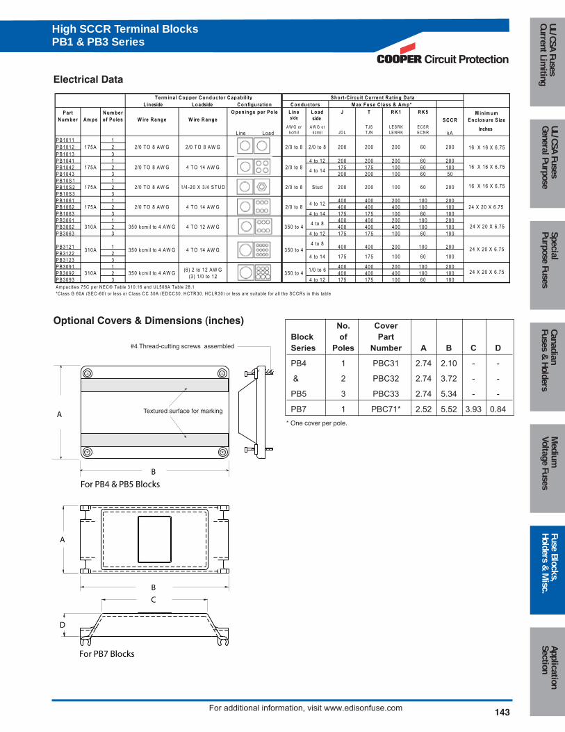
ngHigh SCCR Terminal BlocksPB1 & PB3 Series
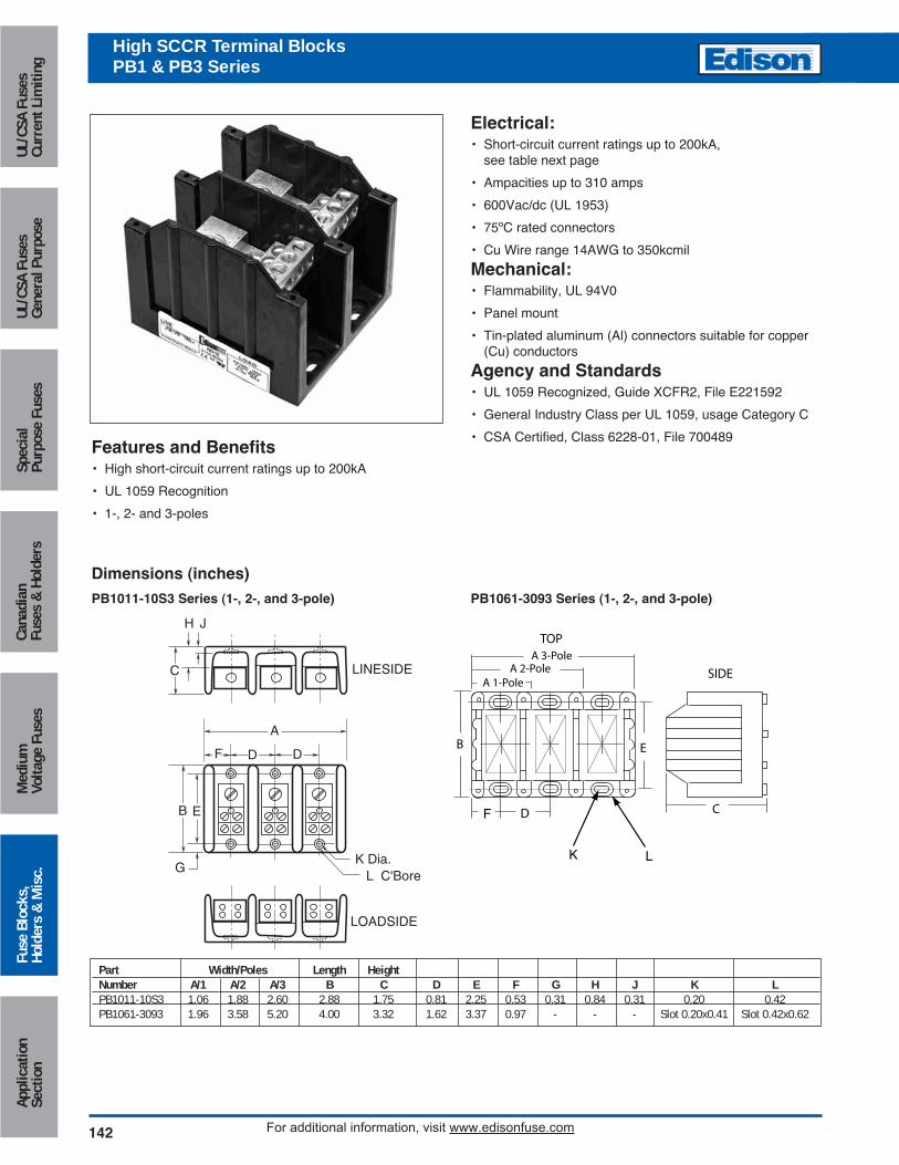
Features and Benefits• High short-circuit current ratings up to 200kA
• UL 1059 Recognition
• 1-, 2- and 3-poles
Dimensions (inches)
F
A
B
GL C'Bore
K Dia.
LOADSIDE
LINESIDE
D
H J
SIDE
TOP
C
A 3-Pole
B
D
A 2-PoleA 1-Pole
E
E
C
D
K L
F
Electrical:• Short-circuit current ratings up to 200kA,
see table next page
• Ampacities up to 310 amps
• 600Vac/dc (UL 1953)
• 75ºC rated connectors
• Cu Wire range 14AWG to 350kcmil
Mechanical:• Flammability, UL 94V0
• Panel mount
• Tin-plated aluminum (Al) connectors suitable for copper(Cu) conductors
Agency and Standards• UL 1059 Recognized, Guide XCFR2, File E221592
• General Industry Class per UL 1059, usage Category C
• CSA Certified, Class 6228-01, File 700489
Part Width/Poles Length HeightNumber A/1 A/2 A/3 B C D E F G H J K LPB1011-10S3 1.06 1.88 2.60 2.88 1.75 0.81 2.25 0.53 0.31 0.84 0.31 0.20 0.42PB1061-3093 1.96 3.58 5.20 4.00 3.32 1.62 3.37 0.97 - - - Slot 0.20x0.41 Slot 0.42x0.62
PB1061-3093 Series (1-, 2-, and 3-pole)PB1011-10S3 Series (1-, 2-, and 3-pole)
Circuit Protection
143
Medium
Voltage FusesUL/CSA FusesCurrent Lim
itingUL/CSA FusesGeneral Purpose
SpecialPurpose Fuses
CanadianFuses &
HoldersApplicationSection
Fuse Blocks,Holders &
Misc.
For additional information, visit www.edisonfuse.com
Electrical Data
L ineside Loadside
P art N um ber Am ps
N um ber o f Po les W ire R ange W ire R ange
L ine Load side
J T R K 1 R K 5
S C C R
L ine LoadA W G or
kcm ilA W G or
kcm il JD LTJS TJN
LE S R K LE N R K
E C S RE C N R kA
P B 1011 1P B 1012 2P B 1013 3P B 1041 1 4 to 12 200 200 200 60 200P B 1042 2 175 175 100 60 100P B 1043 3 200 200 100 60 50P B 10S 1 1P B 10S 2 2P B 10S 3 3P B 1061 1 400 400 200 100 200P B 1062 2 400 400 400 100 100P B 1063 3 4 to 14 175 175 100 60 100P B 3061 1 400 400 200 100 200P B 3062 2 400 400 400 100 100P B 3063 3 4 to 12 175 175 100 60 100
P B 3121 14 to 8
400 400 200 100 200P B 3122 2P B 3123 3P B 3091 1 400 400 200 100 200P B 3092 2 400 400 400 100 100P B 3093 3 4 to 12 175 175 100 60 100A m pac ities 75C per N E C ® Tab le 310 .16 and U L508A Tab le 28 .1
M in im um Enclosure S ize
4 to 14 175 175 100
4 to 8
100
4 to 14
S tud
24 X 20 X 6 .75
350 kcm il to 4 A W G
350 kcm il to 4 A W G
350 kcm il to 4 A W G(6) 2 to 12 A W G
(3 ) 1 /0 to 12
350 to 4
350 to 4
350 to 41 /0 to 6
4 T O 14 A W G
4 T O 12 A W G
2/0 to 84 T O 14 A W G
2/0 T O 8 A W G
2/0 T O 8 A W G
2/0 to 8
2 /0 to 8
4 T O 14 A W G
1/4-20 X 3 /4 S T U D 60200 200
175A
310A
310A
175A
4 to 12
10060
2/0 T O 8 A W G
200
310A
*C lass G 60A (S E C -60) o r less o r C lass C C 30A (E D C C 30, H C TR 30, H C LR 30) o r less a re su itab le fo r a ll the S C C R s in th is tab le
O pen ings per P o le
T erm inal C opper C onductor C apab ilityC onfiguration
S hort-C ircu it C urren t R ating D ataC onductors M ax Fuse C lass & Am p*
175A
175A
16 X 16 X 6 .752/0 T O 8 A W G 2/0 T O 8 A W G 200 60 2002/0 to 8 2 /0 to 8 200 200
side
Inches
16 X 16 X 6 .75
16 X 16 X 6 .75
24 X 20 X 6 .75
24 X 20 X 6 .75
24 X 20 X 6 .75
Optional Covers & Dimensions (inches)
High SCCR Terminal BlocksPB1 & PB3 Series
#4 Thread-cutting screws assembled
Textured surface for markingA
B
B
For PB4 & PB5 Blocks
For PB7 Blocks
A
C
D
No. Cover
Block of Part
Series Poles Number A B C D
PB4 1 PBC31 2.74 2.10 - -
& 2 PBC32 2.74 3.72 - -
PB5 3 PBC33 2.74 5.34 - -
PB7 1 PBC71* 2.52 5.52 3.93 0.84
* One cover per pole.
144 For additional information, visit www.edisonfuse.com
Appl
icat
ion
Sect
ion
Fuse
Blo
cks,
Hold
ers
& M
isc.
Med
ium
Volta
ge F
uses
Cana
dian
Fuse
s &
Hol
ders
Spec
ial
Purp
ose
Fuse
sUL
/CSA
Fus
esGe
nera
l Pur
pose
UL/C
SA F
uses
Curr
ent L
imiti
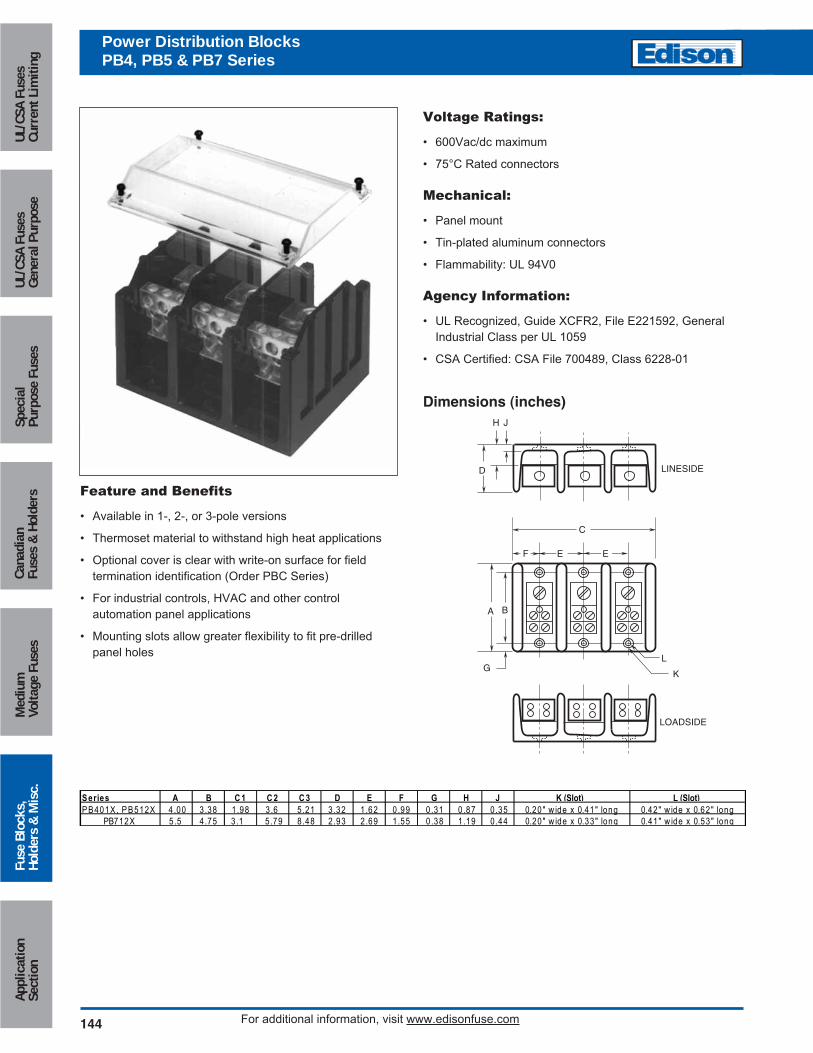
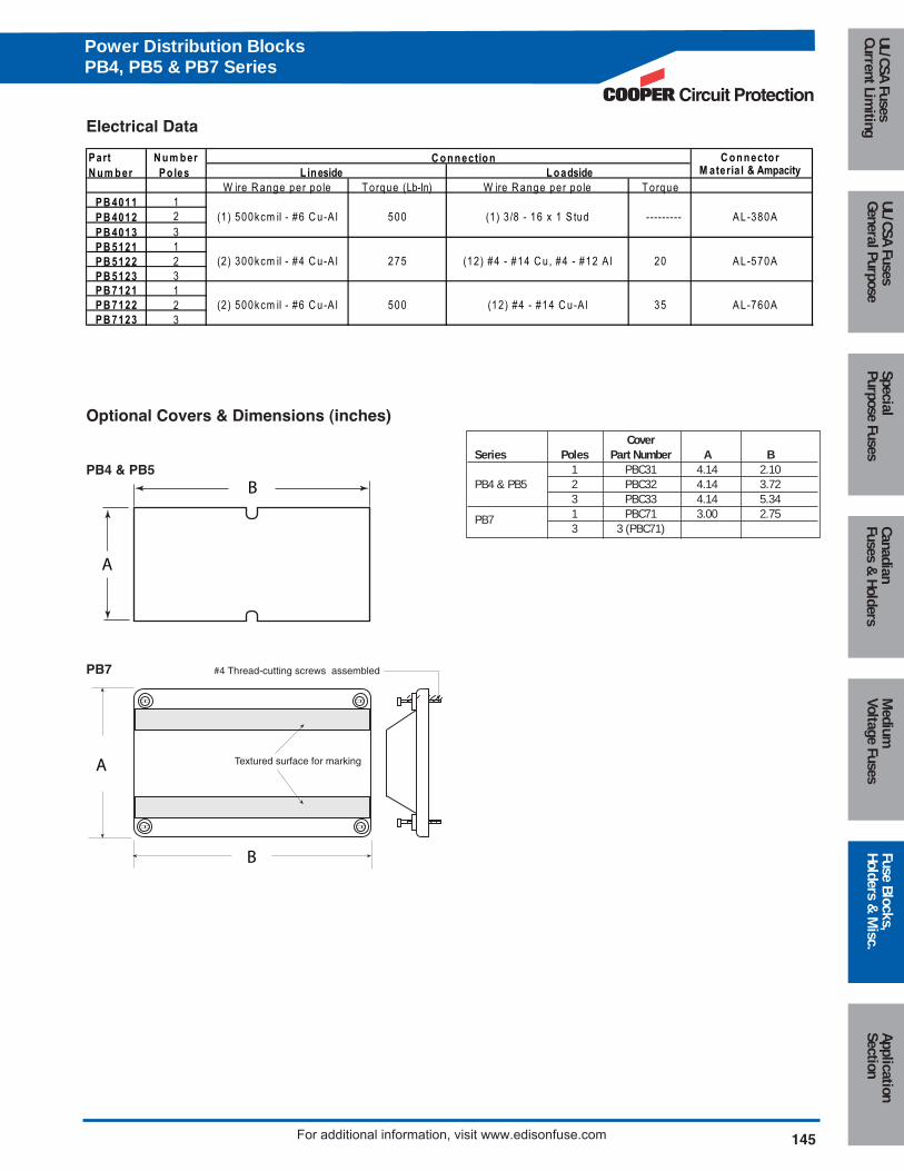
ngPower Distribution BlocksPB4, PB5 & PB7 Series
Feature and Benefits
• Available in 1-, 2-, or 3-pole versions
• Thermoset material to withstand high heat applications
• Optional cover is clear with write-on surface for field
termination identification (Order PBC Series)
• For industrial controls, HVAC and other control
automation panel applications
• Mounting slots allow greater flexibility to fit pre-drilled
panel holes
Dimensions (inches)
F EE
C
A B
GL
K
LOADSIDE
LINESIDED
H J
Voltage Ratings:
• 600Vac/dc maximum
• 75°C Rated connectors
Mechanical:
• Panel mount
• Tin-plated aluminum connectors
• Flammability: UL 94V0
Agency Information:
• UL Recognized, Guide XCFR2, File E221592, General
Industrial Class per UL 1059
• CSA Certified: CSA File 700489, Class 6228-01
S eries A B C 1 C 2 C 3 D E F G H J K (Slot) L (Slot)P B 401X , P B 512X 4.00 3.38 1.98 3.6 5.21 3.32 1.62 0.99 0.31 0.87 0.35 0.20" w ide x 0.41" long 0.42" w ide x 0.62" long
PB712X 5.5 4.75 3.1 5.79 8.48 2.93 2.69 1.55 0.38 1.19 0.44 0.20" w ide x 0.33" long 0.41" w ide x 0.53" long
#4 Thread-cutting screws assembled
Textured surface for markingA
B
B
A
Electrical Data
Optional Covers & Dimensions (inches)
W ire R ange per po le T orque (Lb-In) W ire R ange per po le T orqueP B 4011 1P B 4012 2P B 4013 3P B 5121 1P B 5122 2P B 5123 3P B 7121 1P B 7122 2P B 7123 3
(12) #4 - #14 C u-A l500(2) 500kcm il - #6 C u-A l
(2 ) 300kcm il - #4 C u-A l 275 (12) #4 - #14 C u, #4 - #12 A l
A L-380A
A L-570A
A L-760A35
20
(1) 500kcm il - #6 C u-A l 500 (1) 3 /8 - 16 x 1 S tud ---------
P art N um ber
N um ber P o les
C onnector L ineside Loadside
C onnectionM ateria l & Ampacity
CoverSeries Poles Part Number A B
1 PBC31 4.14 2.10PB4 & PB5 2 PBC32 4.14 3.72
3 PBC33 4.14 5.34
PB7 1 PBC71 3.00 2.753 3 (PBC71)
PB4 & PB5
PB7
Circuit Protection
145
Medium
Voltage FusesUL/CSA FusesCurrent Lim
itingUL/CSA FusesGeneral Purpose
SpecialPurpose Fuses
CanadianFuses &
HoldersApplicationSection
Fuse Blocks,Holders &
Misc.
For additional information, visit www.edisonfuse.com
Power Distribution BlocksPB4, PB5 & PB7 Series
146 For additional information, visit www.edisonfuse.com
Appl
icat
ion
Sect
ion
Fuse
Blo
cks,
Hold
ers
& M
isc.
Med
ium
Volta
ge F
uses
Cana
dian
Fuse
s &
Hol
ders
Spec
ial
Purp
ose
Fuse
sUL
/CSA
Fus
esGe
nera
l Pur
pose
UL/C
SA F
uses
Curr
ent L
imiti
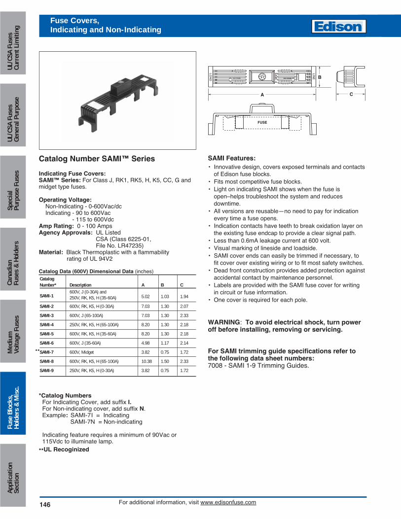
ngFuse Covers,Indicating and Non-Indicating
SAMI Features:• Innovative design, covers exposed terminals and contacts
of Edison fuse blocks.• Fits most competitive fuse blocks.• Light on indicating SAMI shows when the fuse is
open–helps troubleshoot the system and reduces downtime.
• All versions are reusable—no need to pay for indicationevery time a fuse opens.
• Indication contacts have teeth to break oxidation layer onthe existing fuse endcap to provide a clear signal path.
• Less than 0.6mA leakage current at 600 volt.• Visual marking of lineside and loadside.• SAMI cover ends can easily be trimmed if necessary, to
fit cover over existing wiring or to fit most safety switches.• Dead front construction provides added protection against
accidental contact by maintenance personnel.• Labels are provided with the SAMI fuse cover for writing
in circuit or fuse information.• One cover is required for each pole.
WARNING: To avoid electrical shock, turn poweroff before installing, removing or servicing.
For SAMI trimming guide specifications refer tothe following data sheet numbers:7008 - SAMI 1-9 Trimming Guides.
*Catalog NumbersFor Indicating Cover, add suffix I.For Non-indicating cover, add suffix N.Example: SAMI-7I = Indicating
SAMI-7N = Non-indicating
Indicating feature requires a minimum of 90Vac or115Vdc to illuminate lamp.
**UL Recoginized
LINE
Bu
ss
SA
MI -2
LOA
D TEST PROBE TEST PROBE
C
B
A
FUSE
Catalog Number SAMI™ Series
Indicating Fuse Covers:SAMI™ Series: For Class J, RK1, RK5, H, K5, CC, G andmidget type fuses.
Operating Voltage:Non-Indicating - 0-600Vac/dcIndicating - 90 to 600Vac
- 115 to 600VdcAmp Rating: 0 - 100 AmpsAgency Approvals: UL Listed
CSA (Class 6225-01,File No. LR47235)
Material: Black Thermoplastic with a flammability rating of UL 94V2
Catalog Data (600V) Dimensional Data (inches)CatalogNumber* Description A B C
SAMI-1600V, J (0-30A) and250V, RK, K5, H (35-60A) 5.02 1.03 1.94
SAMI-2 600V, RK, K5, H (0-30A) 7.03 1.30 2.07
SAMI-3 600V, J (65-100A) 7.03 1.30 2.33
SAMI-4 250V, RK, K5, H (65-100A) 8.20 1.30 2.18
SAMI-5 600V, RK, K5, H (35-60A) 8.20 1.30 2.18
SAMI-6 600V, J (35-60A) 4.98 1.17 2.14
SAMI-7 600V, Midget 3.82 0.75 1.72
SAMI-8 600V, RK, K5, H (65-100A) 10.38 1.50 2.33
SAMI-9 250V, RK, K5, H (0-30A) 3.82 0.75 1.72
**
Circuit Protection
147
Medium
Voltage FusesUL/CSA FusesCurrent Lim
itingUL/CSA FusesGeneral Purpose
SpecialPurpose Fuses
CanadianFuses &
HoldersApplicationSection
Fuse Blocks,Holders &
Misc.
For additional information, visit www.edisonfuse.com
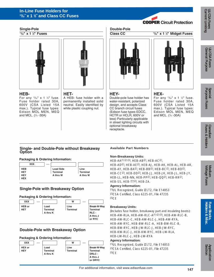
HEB-For any 13⁄32" x 1 1⁄2" fuse.Fuse holder rated 30A,600V (CSA Listed 15Amax.). Typical fuse types:Edison MOL MEN, MEQand MCL. (1⁄10 -30A)
HET-A HEB- fuse holder with apermanently installed solidneutral. Easily identified bywhite plastic coupling nut.
Single-Pole13⁄32" x 1 1⁄2" Fuses
HEY-Double-pole fuse holder haswater-resistant, polarizeddesign, and accepts ClassCC branch circuit fuses(Edison fuse types EDCC,HCTR or HCLR, 600V orless) Particularly applicablein street lighting circuits withoptional breakawayreceptacle.
HEX-For any 13⁄32" x 1 1⁄2" fuse.Fuse holder rated 30A,600V (CSA Listed 15Amax.). Typical fuse types:Edison MOL MEN, MEQand MCL. (1⁄10 -30A)
Double-PoleClass CC 13⁄32" x 1 1⁄2" Midget Fuses
Packaging & Ordering Information:
HEB Load Side LineHET Terminal TerminalHEY A thru W A thru WHEX
XXX
Single- and Double-Pole without BreakawayOption
Packaging & Ordering Information:
HEB or Load Line Break-W-WayHET Terminal Terminal Terminal
A thru K RLC -A thru Jor RYC
XXX W
Single-Pole with Breakaway Option
Packaging & Ordering Information:
HEX or Load Line Break-W-WayHEY Terminal Terminal Terminal
A thru K DRLC -A thru Jor DRYC
XXX W
Double-Pole with Breakaway Option
Available Part Numbers
Non-Breakaway Units:HEB-AA(1) (2) (3), HEB-AB(2), HEB-AC(2),HEB-AD(2), HEB-AE(2), HEB-AJ, HEB-AK, HEB-AL, HEB-AR,HEB-AY, HEB-BA(2), HEB-BB(2), HEB-BC(2), HEB-BD(2),HEB-CC(2), HEB-DD(2), HEB-JJ, HEB-JK, HEB-JL, HEB-JY,HEB-LL, HEB-NN, HEB-PP(2), HEB-QQ(2), HEB-RR(2),HEB-SS, HEB-TT(2), HEB-ZA.Agency Information:(1)UL Recognized, Guide IZLT2, File E14853(2)CSA Certified, Class 6225-01, File 47235(3)CE
Breakaway Units:(Includes fuse holder, breakaway part and insulating boots):HEB-AW-RLA, HEB-AW-RLC-A(1) (2) (3), HEB-AW-RLC-B, HEB-AW-RLC-C, HEB-AW-RLC-J, HEB-AW-RYA, HEB-AW-RYC, HEB-BW-RLC-A, HEB-BW-RLC-B,HEB-BW-RYC, HEB-JW-RLC-J, HEB-JW-RYC, HEB-KW-RLC-J, HEB-KW-RYC, HEB-LW-RLA, HEB-LW-RLC-J, HEB-LW-RYAAgency Information:(1)UL Recognized, Guide IZLT2, File E14853(2)CSA Certified, Class 6225-01, File 47235(3)CE
In-Line Fuse Holders for13⁄32˝ x 1 1⁄2˝ and Class CC Fuses
148 For additional information, visit www.edisonfuse.com
Appl
icat
ion
Sect
ion
Fuse
Blo
cks,
Hold
ers
& M
isc.
Med
ium
Volta
ge F
uses
Cana
dian
Fuse
s &
Hol
ders
Spec
ial
Purp
ose
Fuse
sUL
/CSA
Fus
esGe
nera
l Pur
pose
UL/C
SA F
uses
Curr
ent L
imiti
ngIn-LineFuse Holders
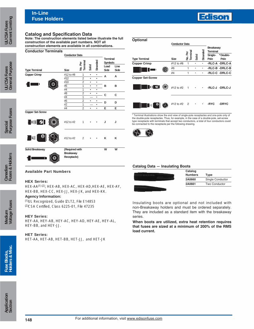
Catalog and Specification DataNote: The construction elements listed below illustrate the fullconstruction of the available part numbers. NOT all construction elements are available in all combinations.
Conductor TerminalsConductor Data
TerminalSymbolsLoad Line
Type Terminal Size Side Side
Copper Crimp #12 to #8 1 • • A A#12 2 • •#10 2 • •#6 1 • • B B#4 1 • •#8 2 • • C C#4 1 — •#6 2 • • D D#2 1 — •#4 2 • • E E
Copper Set-Screw
#12 to #2 1 • • J J
#12 to #2 2 • • K K
Solid Breakaway (Required with W WBreakawayReceptacle)
Available Part Numbers
HEX Series:HEX-AA(1) (2), HEX-AB, HEX-AC, HEX-AD,HEX-AE, HEX-AY,HEX-BB, HEX-CC, HEX-JJ, HEX-JK, and HEX-KK.Agency Information:(1)UL Recognized, Guide IZLT2, File E14853(2)CSA Certified, Class 6225-01, File 47235
HEY Series:HEY-AA, HEY-AB, HEY-AC, HEY-AD, HEY-AE, HEY-AL,HEY-BB, and HEY-JJ.
HET Series:HET-AA, HET-AB, HET-BB, HET-JJ, and HET-JK
Catalog Data — Insulating BootsCatalogNumbers Type
2A0660 Single Conductor
2A0661 Two Conductor
Insulating boots are optional and not included withnon-Breakaway holders and must be ordered separately.They are included as a standard item with the breakawayseries. When boots are utilized, extra heat retention requiresthat fuses are sized at a minimum of 200% of the RMSload current.
No. P
erTe
rmin
al
Solid
Stra
nded
OptionalConductor Data
BreakawayTerminalSingle- *Double-
Type Terminal Size Pole Pole
Copper Crimp #12 to #8 1 • • -RLC-A -DRLC-A
#6 1 • • -RLC-B -DRLC-B
#4 1 • • -RLC-C -DRLC-C
Copper Set-Screw
#12 to #2 1 • • -RLC-J -DRLC-J
#12 to #2 2 • •` -RYC -DRYC
* Terminal illustrations show the end view of single-pole receptacles and one-pole only ofthe double-pole receptacles. Thus, for example, in the case of a double-pole, set-screwtype receptacle with terminals that accept two conductors, a total of four conductors couldbe connected to the receptacle per the following drawing.
No. P
erTe
rmin
al
Solid
Stra
nded
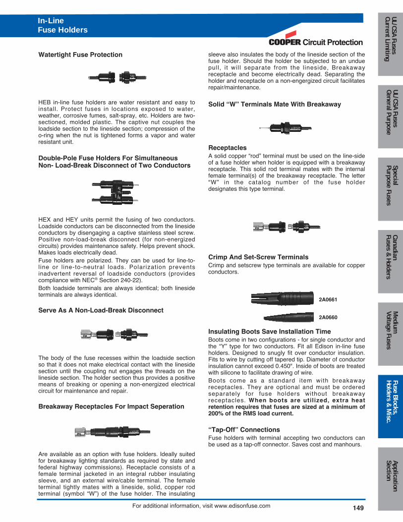
Watertight Fuse Protection
HEB in-line fuse holders are water resistant and easy toinstall. Protect fuses in locations exposed to water,weather, corrosive fumes, salt-spray, etc. Holders are two-sectioned, molded plastic. The captive nut couples theloadside section to the lineside section; compression of theo-ring when the nut is tightened forms a vapor and waterresistant unit.
Double-Pole Fuse Holders For SimultaneousNon- Load-Break Disconnect of Two Conductors
HEX and HEY units permit the fusing of two conductors.Loadside conductors can be disconnected from the linesideconductors by disengaging a captive stainless steel screw.Positive non-load-break disconnect (for non-energizedcircuits) provides maintenance safety. Helps prevent shock.Makes loads electrically dead.Fuse holders are polarized. They can be used for line-to-l ine or l ine-to-neutral loads. Polarization preventsinadvertent reversal of loadside conductors (providescompliance with NEC® Section 240-22).Both loadside terminals are always identical; both linesideterminals are always identical.
Serve As A Non-Load-Break Disconnect
The body of the fuse recesses within the loadside sectionso that it does not make electrical contact with the linesidesection until the coupling nut engages the threads on thelineside section. The holder section thus provides a positivemeans of breaking or opening a non-energized electricalcircuit for maintenance and repair.
Breakaway Receptacles For Impact Seperation
Are available as an option with fuse holders. Ideally suitedfor breakaway lighting standards as required by state andfederal highway commissions). Receptacle consists of afemale terminal jacketed in an integral rubber insulatingsleeve, and an external wire/cable terminal. The femaleterminal tightly mates with a lineside, solid, copper rodterminal (symbol “W”) of the fuse holder. The insulating
sleeve also insulates the body of the lineside section of thefuse holder. Should the holder be subjected to an unduepull, i t wil l separate from the l ineside, Breakawayreceptacle and become electrically dead. Separating theholder and receptacle on a non-engergized circuit facilitatesrepair/maintenance.
Solid “W” Terminals Mate With Breakaway
ReceptaclesA solid copper “rod” terminal must be used on the line-sideof a fuse holder when holder is equipped with a breakawayreceptacle. This solid rod terminal mates with the internalfemale terminal(s) of the breakaway receptacle. The letter“W” in the catalog number of the fuse holderdesignates this type terminal.
Crimp And Set-Screw TerminalsCrimp and setscrew type terminals are available for copperconductors.
Insulating Boots Save Installation TimeBoots come in two configurations - for single conductor andthe “Y” type for two conductors. Fit all Edison in-line fuseholders. Designed to snugly fit over conductor insulation.Fits to wire by cutting off tapered tip. Diameter of conductorinsulation cannot exceed 0.450". Inside of boots are treatedwith silicone to facilitate drawing of wire.Boots come as a standard item with breakawayreceptacles. They are optional and must be orderedseparately for fuse holders without breakawayreceptacles. When boots are utilized, extra heatretention requires that fuses are sized at a minimum of200% of the RMS load current.
“Tap-Off” ConnectionsFuse holders with terminal accepting two conductors canbe used as a tap-off connector. Saves cost and manhours.
2A0661
2A0660
Circuit Protection
149
Medium
Voltage FusesUL/CSA FusesCurrent Lim
itingUL/CSA FusesGeneral Purpose
SpecialPurpose Fuses
CanadianFuses &
HoldersApplicationSection
Fuse Blocks,Holders &
Misc.
For additional information, visit www.edisonfuse.com
In-LineFuse Holders
150 For additional information, visit www.edisonfuse.com
Appl
icat
ion
Sect
ion
Fuse
Blo
cks,
Hold
ers
& M
isc.
Med
ium
Volta
ge F
uses
Cana
dian
Fuse
s &
Hol
ders
Spec
ial
Purp
ose
Fuse
sUL
/CSA
Fus
esGe
nera
l Pur
pose
UL/C
SA F
uses
Curr
ent L
imiti
ng
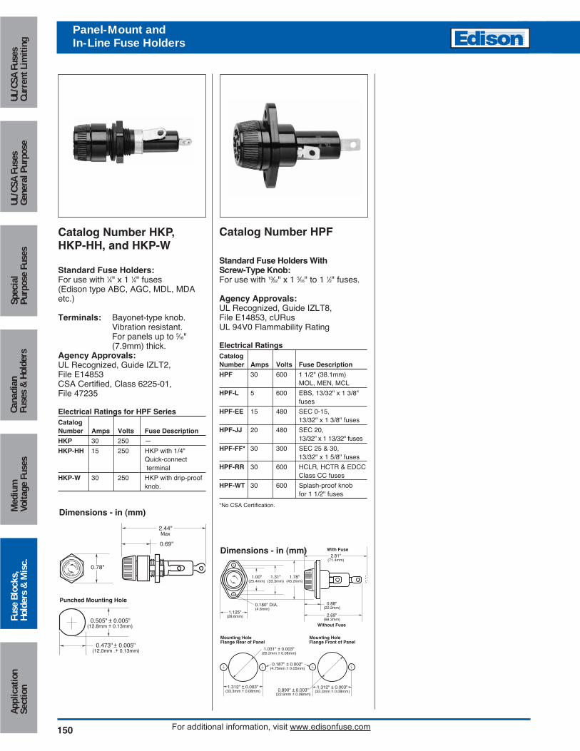
Catalog Number HKP,HKP-HH, and HKP-W
Standard Fuse Holders:For use with 1⁄4" x 1 1⁄4" fuses (Edison type ABC, AGC, MDL, MDAetc.)
Terminals: Bayonet-type knob.Vibration resistant.For panels up to 5⁄16"(7.9mm) thick.
Agency Approvals:UL Recognized, Guide IZLT2,File E14853CSA Certified, Class 6225-01,File 47235
Electrical Ratings for HPF SeriesCatalogNumber Amps Volts Fuse Description
HKP 30 250 —
HKP-HH 15 250 HKP with 1/4"Quick-connectterminal
HKP-W 30 250 HKP with drip-proof knob.
Catalog Number HPF
Standard Fuse Holders WithScrew-Type Knob:For use with 13⁄32" x 1 5⁄16" to 1 1⁄2" fuses.
Agency Approvals:UL Recognized, Guide IZLT8,File E14853, cURusUL 94V0 Flammability Rating
Electrical RatingsCatalogNumber Amps Volts Fuse Description
HPF 30 600 1 1/2" (38.1mm)MOL, MEN, MCL
HPF-L 5 600 EBS, 13/32" x 1 3/8"fuses
HPF-EE 15 480 SEC 0-15,13/32" x 1 3/8" fuses
HPF-JJ 20 480 SEC 20,13/32” x 1 13/32" fuses
HPF-FF* 30 300 SEC 25 & 30,13/32" x 1 5/8" fuses
HPF-RR 30 600 HCLR, HCTR & EDCC Class CC fuses
HPF-WT 30 600 Splash-proof knobfor 1 1/2" fuses
*No CSA Certification.
0.78"
0.69"
2.44"Max
0.505" + 0.005"(12.8mm + 0.13mm)
0.473" + 0.005"(12.0mm + 0.13mm)
Punched Mounting Hole
FU
SE FUS
E
FUSE
1.031" + 0.003"(26.2mm + 0.08mm)
0.187" + 0.002"(4.75mm + 0.05mm)
Mounting HoleFlange Rear of Panel
Mounting HoleFlange Front of Panel
0.890" + 0.003"(22.6mm + 0.08mm)
1.312" + 0.003"(33.3mm + 0.08mm)
1.312" + 0.003"(33.3mm + 0.08mm)
0.180" DIA.(4.6mm)
1.125"(28.6mm)
1.00"(25.4mm)
Without Fuse
2.69"(68.3mm)
0.88"(22.2mm)
1.78"(45.2mm)
1.31"(33.3mm)
2.81"(71.4mm)
With FuseDimensions - in (mm)
Dimensions - in (mm)
Panel-Mount andIn-Line Fuse Holders
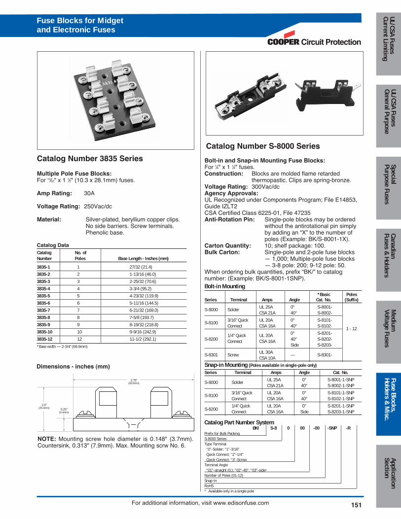
Catalog Number 3835 Series
Multiple Pole Fuse Blocks:For 13⁄32" x 1 1⁄2" (10.3 x 28.1mm) fuses.
Amp Rating: 30A
Voltage Rating: 250Vac/dc
Material: Silver-plated, beryllium copper clips.No side barriers. Screw terminals.Phenolic base.
Catalog Data Catalog No. ofNumber Poles Base Length - Inches (mm)
3835-1 1 27/32 (21.4)
3835-2 2 1-13/16 (46.0)
3835-3 3 2-25/32 (70.6)
3835-4 4 3-3/4 (95.2)
3835-5 5 4-23/32 (119.9)
3835-6 6 5-11/16 (144.5)
3835-7 7 6-21/32 (169.0)
3835-8 8 7-5/8 (193.7)
3835-9 9 8-19/32 (218.8)
3835-10 10 9-9/16 (242.9)
3835-12 12 11-1/2 (292.1)
*Base width — 2-3/4" (69.9mm)
Catalog Number S-8000 Series
Bolt-in and Snap-in Mounting Fuse Blocks:For 1⁄4" x 1 1⁄4" fuses.Construction: Blocks are molded flame retarded
thermopastic. Clips are spring-bronze.Voltage Rating: 300Vac/dcAgency Approvals:UL Recognized under Components Program; File E14853,Guide IZLT2CSA Certified Class 6225-01, File 47235Anti-Rotation Pin: Single-pole blocks may be ordered
without the antirotational pin simplyby adding an “X” to the number ofpoles (Example: BK/S-8001-1X).
Carton Quantity: 10; shelf package: 100.Bulk Carton: Single-pole and 2-pole fuse blocks
— 1,000; Multiple-pole fuse blocks— 3-8 pole: 200; 9-12 pole: 50.
When ordering bulk quantities, prefix “BK/” to catalognumber: (Example: BK/S-8001-1SNP).Bolt-in Mounting
*Basic PolesSeries Terminal Amps Angle Cat. No. (Suffix)
S-8000 Solder UL 25A 0° S-8001-CSA 21A 40° S-8002-
S-8100 3/16" Quick UL 20A 0° S-8101-Connect CSA 16A 40° S-8102- 1 - 121/4" Quick UL 20A 0° S-8201-
S-8200 Connect CSA 16A 40° S-8202-Side S-8203-
S-8301 Screw UL 30A — S-8301-CSA 10A
Snap-in Mounting (Poles available in single-pole only)
Series Terminal Amps Angle Cat. No.
S-8000 Solder UL 25A 0° S-8001-1-SNPCSA 21A 40° S-8002-1-SNP
S-8100 3/16" Quick UL 20A 0° S-8101-1-SNPConnect CSA 16A 40° S-8102-1-SNP
1/4" Quick UL 20A 0° S-8201-1-SNPS-8200 Connect CSA 16A Side S-8203-1-SNP
0.25"(6.4mm)
1.0"(25.4mm)
2.75"(69.9mm)
NOTE: Mounting screw hole diameter is 0.148" (3.7mm).Countersink, 0.313" (7.9mm). Max. Mounting scrw No. 6.
Dimensions - inches (mm)
Catalog Part Number SystemBK/ S-8 0 00 -00 -SNP -R
Prefix for Bulk PackingS-8000 SeriesType Terminal“0”-Solder; “1”-3/16" Quick Connect; “2”-1/4"Quick Connect; “3”-Screw
Terminal Angle“01”-straight (0‚); “02”-40°; “03”-side*
Number of Poles (01-12)Snap-InRoHS* Available only in a single pole
Circuit Protection
151
Medium
Voltage FusesUL/CSA FusesCurrent Lim
itingUL/CSA FusesGeneral Purpose
SpecialPurpose Fuses
CanadianFuses &
HoldersApplicationSection
Fuse Blocks,Holders &
Misc.
For additional information, visit www.edisonfuse.com
Fuse Blocks for Midgetand Electronic Fuses
152 For additional information, visit www.edisonfuse.com
Appl
icat
ion
Sect
ion
Fuse
Blo
cks,
Hold
ers
& M
isc.
Med
ium
Volta
ge F
uses
Cana
dian
Fuse
s &
Hol
ders
Spec
ial
Purp
ose
Fuse
sUL
/CSA
Fus
esGe
nera
l Pur
pose
UL/C
SA F
uses
Curr
ent L
imiti
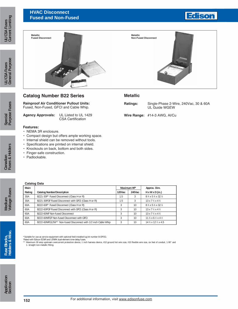
ngHVAC DisconnectFused and Non-Fused
MetallicFused Disconnect
MetallicNon-Fused Disconnect
Metallic
Ratings: Single-Phase 2-Wire, 240Vac, 30 & 60AUL Guide WGEW
Wire Range: #14-3 AWG, Al/Cu
Catalog Number B22 Series
Rainproof Air Conditioner Pullout Units:Fused, Non-Fused, GFCI and Cable Whip.
Agency Approvals: UL Listed to UL 1429CSA Certification
Features:• NEMA 3R enclosure.• Compact design but offers ample working space.• Internal shield can be removed without tools.• Specifications are printed on internal shield.• Knockouts on back, bottom and both sides.• Finger-safe construction.• Padlockable.
Catalog DataMain Maximum HP1 Approx. Dim.
Rating Catalog Number/Description 120Vac 240Vac H x W x D (in.)
30A B221-30F* Fused Disconnect (Class H or R) 1.5 3 8 3⁄4 x 5 3⁄8 x 32 7⁄8
30A B221-30FGF Fused Disconnect with GFCI (Class H or R) 1.5 3 13 x 7 1⁄2 x 4 3⁄4
60A B222-60F* Fused Disconnect (Class H or R) 3 10 8 3⁄4 x 5 3⁄8 x 32 7⁄8
60A B222-60FGF Fused Disconnect with GFCI (Class H or R) 3 10 13 x 7 1⁄2 x 4 3⁄4
60A B222-60NF Non-fused Disconnect 3 10 13 x 7 1⁄2 x 4 3⁄4
60A B222-60NFGF Non-fused Disconnect with GFCI 3 10 11 3⁄4 x 6 1⁄2 x 4 1⁄2
60A B222-60NFG12W** Non-fused Disconnect with 1/2 inch Cable Whip 3 10 14 3⁄4 x 12 1⁄2 x 4.5
*Suitable for use as service equipment with optional field installed lug kit number B-DPOG.1Rated with Edison ECNR and LENRK dual-element time-delay fuses.** Maximum 30 amp upstream overcurrent protection device, 1⁄2 inch harness device, #10 ground hot wire size, #10 flexible wire size, six feet of conduit, 1-90° and
1- straight non-metallic fitting.

Fuses Reducers for Class H, J, K, & R Fuses
Agency Approvals: UL Listed,Guide #IZZR, File #E12853
CSA Certified, Class 6225-01, File 47235
Features:• Fuse reducers install on fuses and permit smaller size
fuses to be used in larger amp size switches and blocks.• Reducers will fit into any panel or switch including the
dead-front type.• Strong contact is maintained both mechanically and
electrically.• UL Listed.• There are no reducers to go from 250V to 600V.• There are no reducers for switching from one fuse class to
another.• There are no reducers for Class T or Class L fuses.
Fuse Reducers for Class H & K Dimension Fuses KON, ERN, PONC, CDNC; KOS, ERS, CDSC
Catalog No. (Pairs)
250V 600VFuse Desired Reducer ReducerSize Size No. No.
30A 60A No. 263 No. 663
30A 100A No. 213 No. 216
60A 100A No. 216 No. 616
60A 200A No. 226 No. 626
100A 200A No. 2621 No. 2621
100A 400A *No. 2641 *No. 2641
200A 400A No. 2642 No. 2642
100A 600A *No. 2661 *No. 2661
200A 600A *No. 2662 *No. 2662
400A 600A *No. 2664 *No. 2664
* Product does not have CSA certification.
Fuse Reducers for Class J Dimension Fuses- JDL, JFL, & CJ
Catalog No. (Pairs)
Fuse Desired Reducer Size Size No.
30A 60A **J-63
30A 100A **J-13
60A 100A **J-16
60A 200A **J-26
100A †200A **J-21
100A †400A **J-41
200A †400A **J-42
200A 600A **J-62
400A †600A **J-64
† Not for Bolt-on Applications.
** Product does not have UL or CSA certification.
Fuse Reducers for Class R Dimension FusesECNR, LENRK, NCLR; ECSR, LESRK, & SCLR
Catalog No. (Pairs)
250V 600VFuse Desired Reducer ReducerSize Size No. No.
30A 60A No. 263-R No. 663-R
30A 100A No. 213-R No. 616-R
60A No. 216-R No. 616-R
60A 200A No. 226-R No. 626-R
100A *No. 2621-R
100A 400A *No. 2641-R
200A *No. 242-R *No. 642-R
100A *No. 2661-R
200A 600A *No. 2662-R
400A **No. 2664-R
* Product does not have CSA certification.
**Single reducer only (pair not required)
Note: Carton quantity - 10 pair.
Circuit Protection
153
Medium
Voltage FusesUL/CSA FusesCurrent Lim
itingUL/CSA FusesGeneral Purpose
SpecialPurpose Fuses
CanadianFuses &
HoldersApplicationSection
Fuse Blocks,Holders &
Misc.
For additional information, visit www.edisonfuse.com
Fuse ReducersClass H, J, K, and R
154 For additional information, visit www.edisonfuse.com
Appl
icat
ion
Sect
ion
Fuse
Blo
cks,
Hold
ers
& M
isc.
Med
ium
Volta
ge F
uses
Cana
dian
Fuse
s &
Hol
ders
Spec
ial
Purp
ose
Fuse
sUL
/CSA
Fus
esGe
nera
l Pur
pose
UL/C
SA F
uses
Curr
ent L
imiti
ngFuse Accessories
Catalog Number SFC-FUSE-CABSpare Fuse Cabinet
Size: 24" wide x 30" high x 12" deep
FEATURES:• Sturdy storage cabinet construction holds spare fuses.• Cabinet door equipped with locking handle.• Durable baked ASA 61 grey enamel.• Mounting holes with key slot 16-inches on center.
Extra shelf for spare fuse cabinet
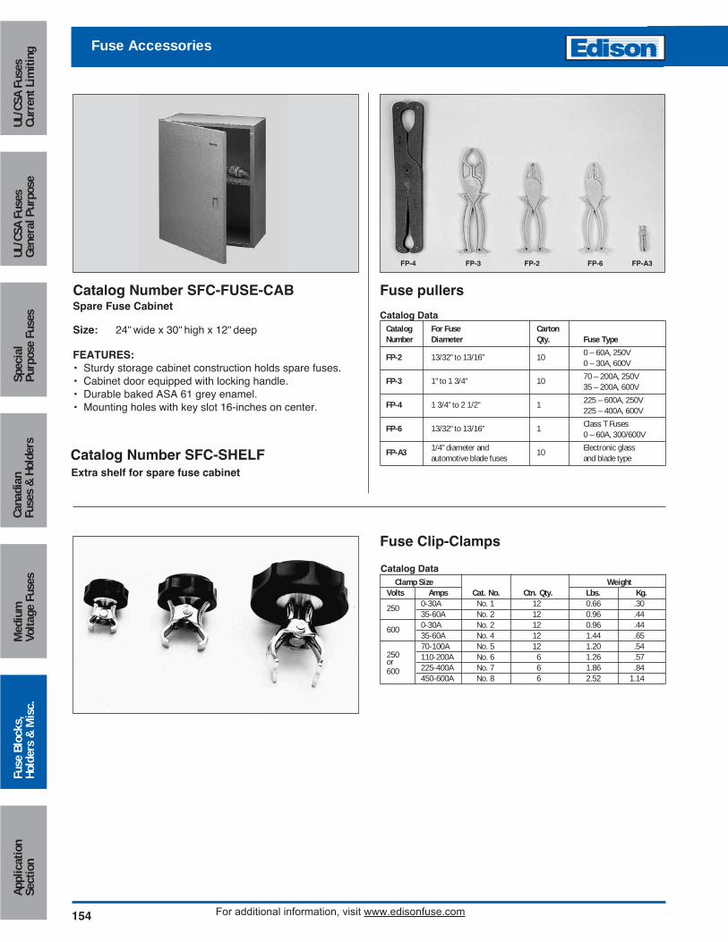
Fuse pullers
FP-4 FP-3 FP-2 FP-6 FP-A3
Catalog Data Catalog For Fuse CartonNumber Diameter Qty. Fuse Type
FP-2 13/32" to 13/16" 10 0 – 60A, 250V0 – 30A, 600V
FP-3 1" to 1 3/4" 10 70 – 200A, 250V35 – 200A, 600V
FP-4 1 3/4" to 2 1/2" 1 225 – 600A, 250V225 – 400A, 600V
FP-6 13/32" to 13/16" 1 Class T Fuses0 – 60A, 300/600V
FP-A3 1/4" diameter and 10 Electronic glassautomotive blade fuses and blade type
Fuse Clip-Clamps
Catalog Data Clamp Size Weight
Volts Amps Cat. No. Ctn. Qty. Lbs. Kg.
250 0-30A No. 1 12 0.66 .3035-60A No. 2 12 0.96 .44
600 0-30A No. 2 12 0.96 .4435-60A No. 4 12 1.44 .6570-100A No. 5 12 1.20 .54
250 110-200A No. 6 6 1.26 .57or225-400A No. 7 6 1.86 .84600450-600A No. 8 6 2.52 1.14
Catalog Number SFC-SHELF