product catalog - trane · pdf fileair-cooled scroll chillers model cgam - made in usa 20-130...
TRANSCRIPT
Air-Cooled Scroll Chillers
Model CGAM - Made in USA
20-130 Nominal Tons (50 Hz and 60 Hz)
January 2012 CG-PRC017-EN
Product Catalog
© 2012 Trane All rights reserved CG-PRC017-EN
Introduction
Design and manufacturing excellence makes Trane a leader in the air-cooled chiller market place.This tradition of using excellence to meet market demands is illustrated with the new Trane 20-130ton nominal air-cooled chiller. The introduction of this next-generation chiller is an exciting stepforward in energy-efficiency, sound, reliability, ease of serviceability, control precision, applicationversatility, and operational cost-effectiveness. The new chiller is designed to deliver proven Traneperformance based on the redesign of a European model that has been a market leader, plus allthe benefits of new heat transfer and fan designs, as well as, low-speed, direct-drive scrollcompressors.
Important Design Advances and New Features
• Higher full-load and part-load energy efficiency that exceeds ASHRAE 90.1 and reducesoperating costs.
• Significantly lower noise levels than other scroll compressor chillers.
• HFC-410A optimized design.
• Flow switch and water strainer are factory installed in the optimum locations for seamlessoperation and reduced chiller installation and maintenance time.
• Trane CH530™ with Adaptive Controls™ have improved fan algorithms for more reliableoperation at extreme conditions.
• Single chiller time of day scheduling communication for easier control of small jobs.
• Easily integrated with existing BAS via BACnet™ or LonTalk™ communication interface.
• All major service components are close to the unit edge for safe and easy maintenance.
• The chiller is designed for easy serviceability with input from our extended experience indesign, testing and field operation.

Table of Contents
CG-PRC017-EN 3
Features and Benefits . . . . . . . . . . . . . . . . . . . . . . . . . . . . . . . . . . . . . . . . . . . . . . . . . . . 4
Application Considerations . . . . . . . . . . . . . . . . . . . . . . . . . . . . . . . . . . . . . . . . . . . . . . 6
Model Number Descriptions . . . . . . . . . . . . . . . . . . . . . . . . . . . . . . . . . . . . . . . . . . . . 13
General Data . . . . . . . . . . . . . . . . . . . . . . . . . . . . . . . . . . . . . . . . . . . . . . . . . . . . . . . . . . 15
Performance Data . . . . . . . . . . . . . . . . . . . . . . . . . . . . . . . . . . . . . . . . . . . . . . . . . . . . . 19
Controls . . . . . . . . . . . . . . . . . . . . . . . . . . . . . . . . . . . . . . . . . . . . . . . . . . . . . . . . . . . . . . 27
Electrical . . . . . . . . . . . . . . . . . . . . . . . . . . . . . . . . . . . . . . . . . . . . . . . . . . . . . . . . . . . . . . 31
Electrical Connections . . . . . . . . . . . . . . . . . . . . . . . . . . . . . . . . . . . . . . . . . . . . . . . . . 36
Dimensions . . . . . . . . . . . . . . . . . . . . . . . . . . . . . . . . . . . . . . . . . . . . . . . . . . . . . . . . . . . 40
Weights . . . . . . . . . . . . . . . . . . . . . . . . . . . . . . . . . . . . . . . . . . . . . . . . . . . . . . . . . . . . . . 50
Mechanical Specifications . . . . . . . . . . . . . . . . . . . . . . . . . . . . . . . . . . . . . . . . . . . . . . 51
Options . . . . . . . . . . . . . . . . . . . . . . . . . . . . . . . . . . . . . . . . . . . . . . . . . . . . . . . . . . . . . . . 53
Features and Benefits
Reliability
• Years of laboratory testing, including running the chiller at extreme operating conditions, haveresulted in optimized compressor and chiller systems reliability by confirming a robust designand verifying quality each step of the way.
• Direct-drive, low-speed scroll compressors with fewer moving parts provide maximumefficiency, high reliability, and low maintenance requirements. Suction gas-cooled motor staysat a uniformly low temperature for long motor life.
• The third generation microprocessor control system provides improved control capabilitieswith Adaptive Control™ to keep the unit operating even in adverse conditions. Advancedmicroelectronics protect both the compressor and the motor from typical electrical faultconditions like thermal overload and phase rotation.
• Standard factory-installed water strainer helps prevent system debris from affecting unit flowor heat transfer.
• Flow switch is factory-installed at the optimum location in the piping for reduced chillerinstallation cost and superior flow sensing, reducing the potential for nuisance trips.
• Exceptionally rigid condenser coil structure is manufactured with hairpin tubes which halvesthe number of braze joints significantly reducing the potential for leaks.
• Innovative condenser pressure integrated fan control algorithms and variable frequency driveon circuits’ lead fans provides more reliable operation at extreme temperature conditions.
Life Cycle Cost-Effectiveness
• Industry leading full- and part-load efficiency
• Electronic expansion valve and high speed suction temperature sensor enables tight chilledwater temperature control and low superheat, resulting in more efficient full-load and part-loadoperation than previously available.
• Partial heat recovery available to save energy on pre-heat or reheat applications.
• Pump package features standard variable speed drive on the pump motors eliminating theneed for energy sapping chilled water system triple duty or balancing valves. Additionally,system commissioning and flexibility is greatly enhanced. Chilled water supply reliability isincreased with the dual pump design, due to standard failure/recovery functionality.
Application Versatility
• Industrial/low temperature process cooling - Excellent operating temperature range andprecise control capabilities enable tight control.
• Ice/thermal storage - Utilities and owners benefit from reduced cooling energy cost. Thechiller’s dual setpoint control and industry leading ice energy storage efficiency assures reliableoperation and superior system efficiency Trane’s partnership with CALMAC, brings a proventrack record of successful installations across many markets; from churches and schools to skyscrapers and office buildings.
• Partial heat recovery - An optional factory-installed heat exchanger provides hot water for manyneeds; water preheat and reheat for enhanced system humidity control are just two. This optionreduces operating costs associated with boilers/domestic hot water.
4 CG-PRC017-EN

Features and Benefits
Simple, Economical Installation
• Standard sound levels are roughly 5-8 dBa less than the previous Trane air-cooled models,perfect for applying outdoor HVAC equipment in neighborhoods, such as K-12 schools.
• System integration available with LonTalk or BACnet through a single twisted-pair wire for aless expensive translation to an existing building automation system.
• Powder-coated paint provides superior durability, corrosion protection, and is less likely to bedamaged while rigging/lifting/installing the chiller.
• Factory commissioned unit-mounted starter reduces overall job cost and improves systemreliability by eliminating job site design, installation and labor coordination requirements.
Precision Control
• Easily integrated with existing BAS via BACnet or LonTalk communication interfaces.
• Microprocessor-based Trane CH530 controls monitor and maintain optimal operation of thechiller and its associated sensors, actuators, relays, and switches, all of which are factory-installed and tested prior to shipping.
• Adaptive Control maintains chiller operation under adverse conditions, when many otherchillers might simply shut down. Operating conditions that are compensated for include highcondensing pressure and low suction pressure.
• Advanced microprocessor controls enable variable primary flow applications providing chilledwater temperature control accuracy of ±2°F (1.1°C) for flow changes up to 10 percent per minute,plus handling of flow changes up to 30 percent per minute with continuous operation.
• Easy-to-use operator interface displays all operating and safety messages, with completediagnostics information, on a highly readable panel with a scrolling touch-screen display.Status and diagnostic messages are in plain language - no codes to interpret - and are availablein 20 languages.
Improved Serviceability
• All major serviceable components are close to the edge. Service shutoff valves and waterstrainer are conveniently located to enable easy service.
• Water piping connections are factory piped to the edge of the unit to make installation safer andfaster.
• Electronic expansion valve designed so controls can be removed and serviced withoutrefrigerant handling.
• The optional pump package is designed to be serviced in place. The unit structure includes arigging point for pump servicing, making inspection, cleaning and pump seal changes easier.
• High pressure transducer and temperature sensors mountings enable troubleshooting andreplacement without removing refrigerant charge, greatly improving serviceability over the lifeof the unit.
• Dead front panel construction provides for enhanced service technician safety.
CG-PRC017-EN 5

Application Considerations
Certain application constraints should be considered when sizing, selecting and installing TraneCGAM chillers. Unit and system reliability is often dependent upon proper and completecompliance with these considerations. Where the application varies from the guidelines presented,it should be reviewed with your local Trane account manager.
Note: The terms water and solution are used interchangeably in the following paragraphs.
Unit Sizing
Unit capacities are listed in the Performance Data section. Intentionally over-sizing a unit to assureadequate capacity is not recommended. Erratic system operation and excessive compressorcycling are often a direct result of an oversized chiller. In addition, an oversized unit is usually moreexpensive to purchase, install, and operate. If over sizing is desired consider using two smallerunits.
Water Treatment
The use of untreated or improperly treated water in chillers may result in scaling, erosion,corrosion, and algae or slime buildup. This will adversely affect heat transfer between the waterand system components. Proper water treatment must be determined locally and depends on thetype of system and local water characteristics.
Neither salt nor brackish water is recommend for use in Trane air-cooled CGAM chillers. Use ofeither will lead to a shortened life. Trane encourages the employment of a qualified water treatmentspecialist, familiar with local water conditions, to assist in the establishment of a proper watertreatment program.
Foreign matter in the chilled water system can also increase pressure drop and, consequently,reduce water flow. For this reason it is important to thoroughly flush all water piping to the unitbefore making the final piping connections to the unit.
The capacities give in the Performance Data section of this catalog are based on water with afouling factor of 0.0001°F·ft²·h/Btu (in accordance with AHRI 550/590). For capacities at other foulingfactors, see Performance Selection Software.
Effect of Altitude on Capacity
Chiller capacities given in the Performance Data section are based upon application at sea level.At elevations substantially above sea level, the decreased air density will decrease condensercapacity and, therefore, unit capacity and efficiency.
Ambient Limitations
Trane chillers are designed for year-round operation over a range of ambient temperatures. The air-cooled model CGAM chiller will operate in ambient temperatures of 32°F to 125°F (0°C to 52°C) forhigh ambient or 0°F to 125°F (-18°C to 52°C) for wide ambient. Operation down to 0°F requires theuse of variable speed fans to modulate and maintain system differential pressure.
The minimum ambient temperatures are based on still conditions (winds not exceeding five mph).Greater wind velocities will result in a drop in head pressure, therefore increasing the minimumstarting and operating ambient temperature. The Adaptive Control™ microprocessor will attemptto keep the chiller on-line when high or low ambient conditions exist, making every effort to avoidnuisance trip-outs and provide the maximum allowable tonnage.
Water Flow Limits
The minimum water flow rates are given in the General Data section of this catalog. Evaporatorflow rates below the tabulated values will result in laminar flow causing freeze-up problems,scaling, stratification and poor control. The maximum evaporator water flow rate is also given.Flow rates exceeding those listed may result in very high pressure drop across the evaporator.
6 CG-PRC017-EN

Application Considerations
Flow Rates Out of Range
Many process cooling jobs require flow rates that cannot be met with the minimum and maximumpublished values within the CGAM evaporator. A simple piping change can alleviate this problem.For example: a plastic injection molding process requires 80 gpm (5.0 l/s) of 50°F (10°C) water andreturns that water at 60°F (15.6°C). The selected chiller can operate at these temperatures, but hasa minimum flow rate of 106 gpm (6.6 l/s). The system layout in Figure 1 can satisfy the process.
Flow Proving
Trane provides a factory-installed water flow switch monitored by CH530 which protects the chillerfrom operating in loss of flow conditions.
Variable Flow in the Evaporator
An attractive chilled water system option may be a Variable Primary Flow (VPF) system. VPFsystems present building owners with several cost-saving benefits when compared with Primary/Secondary chilled water systems. The most obvious cost savings results from eliminating theconstant volume chiller pump(s), which in turn eliminates the related expenses of the associatedpiping connections (material, labor), and electrical service and switch gear. In addition to theinstalled cost advantage building owners often cite pump related energy savings as the reasonsthat prompted them to select a VPF system.
The CGAM has the capability to handle variable evaporator flow without losing leaving watertemperature control. The microprocessor and capacity control algorithms are designed to take a10 percent change in water flow rate per minute while maintaining a ±2°F (1.1°C) leaving watertemperature control accuracy. The chiller tolerates up to 30 percent per minute water flow variationas long as the flow is equal or above the minimum flow rate requirement.
With the help of a software analysis tool such as System Analyzer™, DOE-2 or TRACE™, you candetermine whether the anticipated energy savings justify the use of variable primary flow in aparticular application. Existing constant flow chilled water systems may be relatively easilyconverted to VPF and benefit greatly from the inherent efficiency advantages.
Figure 1. Flow Rate Out of Range Systems Solution
50°F (10°C)112 gpm (7 l/s)
50°F (10°C)80 gpm (5 l/s)
60°F (15.6°C)80 gpm (5 l/s)
50°F (10°C)32 gpm (2 l/s)
57°F (14°C)112 gpm (7 l/s)
CG-PRC017-EN 7

Application Considerations
Water Temperature
Leaving Water Temperature Limits
Trane CGAM chillers have three distinct leaving water categories:
• standard, with a leaving solution range of 42 to 65°F (5.5 to 18°C)
• low temperature process cooling, with leaving solution range of 10 to 65°F (-12 to 18°C)
• ice-making, with leaving solution range of 20 to 65°F (-7 to 18°C)
Since leaving solution temperature below 42°F (5.5°C) results in suction temperature at or belowthe freezing point of water, a glycol solution is required for all low temperature and ice-makingmachines. Ice making control includes dual setpoint controls and safeties for ice making andstandard cooling capabilities. Consult your local Trane account manager for applications orselections involving low temperature or ice making machines.
The maximum water temperature that can be circulated through the CGAM evaporator when theunit is not operating is 125°F (51.7°C). Evaporator damage may result above this temperature.
Leaving Water Temperature Out of Range
Similar to the flow rate limitations above, many process cooling jobs require temperature rangesthat are outside the allowable minimum and maximum operating values for the chiller. Figure 2below shows a simple example of a mixed water piping arrangement change that can permitreliable chiller operation while meeting such cooling conditions. For example, a laboratory loadrequires 238 gpm (5 l/s) of water entering the process at 86°F (30°C) and returning at 95°F (35°C).The chiller’s maximum leaving chilled water temperature of 65°F (15.6°C) prevents direct supply tothe load. In the example shown, both the chiller and process flow rates are equal, however, this isnot necessary. For example, if the chiller had a higher flow rate, there would simply be more waterbypassing and mixing with warm water returning to the chiller.
Figure 2. Temperature Out of Range System Solution
L
P
P
59°F (15°C) 86°F (30°C)238 gpm (15 l/s)
95°F (35°C)
178 gpm (11.2 l/s)
95°F (35°C)238 gpm (15 l/s)
95°F (35°C)60 gpm (3.8 l/s)
59°F (15°C)
178 gpm (11.2 l/s)
68°F (20°C)238 gpm (15 l/s)
60 gpm (3.8 l/s)
238 gpm (15 l/s)59°F (15°C)
8 CG-PRC017-EN

Application Considerations
Supply Water Temperature Drop
The cataloged performance data for the Trane CGAM chiller is based on a chilled water temperaturedrop of 10°F (6°C) for I-P data and 9°F (5°C) for SI data. Full load chilled water temperature dropsfrom 6 to 18°F (3.3 to 10°C) may be used as long as minimum and maximum water temperatureand minimum and maximum flow rates are not violated. Temperature drops outside this range atfull load conditions are beyond the optimum range for control and may adversely affect themicrocomputer’s ability to maintain an acceptable supply water temperature range. Furthermore,full load temperature drops of less than 6°F (3.3°C) may result in inadequate refrigerant superheatwhich is critical to long term efficient and reliable operation. Sufficient superheat is always aprimary concern in any refrigerant system and is especially important in a packaged chiller wherethe evaporator is closely coupled to the compressor.
Typical Water Piping
All building water piping must be flushed prior to making final connections to the chiller. To reduceheat loss and prevent condensation, insulation should be applied. Expansion tanks are also usuallyrequired so that chilled water volume changes can be accommodated.
Avoidance of Short Water Loops
Adequate chilled water system water volume is an important system design parameter because itprovides for stable chilled water temperature control and helps limit unacceptable short cycling ofchiller compressors.
The chiller’s temperature control sensor is located in the supply (outlet) water connection or pipe.This location allows the building to act as a buffer to slow the rate of change of the system watertemperature. If there is not a sufficient volume of water in the system to provide an adequate buffer,temperature control can suffer, resulting in erratic system operation and excessive compressorcycling.
Typically, a two-minute water loop circulation time is sufficient to prevent short water loop issues.Therefore, as a guideline, ensure the volume of water in the chilled water loop equals or exceedstwo times the evaporator flow rate. For systems with a rapidly changing load profile the amountof volume should be increased.
If the installed system volume does not meet the above recommendations, the following itemsshould be given careful consideration to increase the volume of water in the system and, therefore,reduce the rate of change of the return water temperature.
• A volume buffer tank located in the return water piping.
• Larger system supply and return header piping (which also reduces system pressure drop andpump energy use).
Minimum water volume for a process application
If a chiller is attached to an on/off load such as a process load, it may be difficult for the controllerto respond quickly enough to the very rapid change in return solution temperature if the systemhas only the minimum water volume recommended. Such systems may cause chiller lowtemperature safety trips or in the extreme case evaporator freezing. In this case, it may benecessary to add or increase the size of the mixing tank in the return line.
Multiple Unit Operation
Whenever two or more units are used on one chilled water loop, Trane recommends that theiroperation be coordinated with a higher level system controller for best system efficiency andreliability. The Trane Tracer system has advanced chilled plant control capabilities designed toprovide such operation.
CG-PRC017-EN 9

Application Considerations
Ice Storage Operation
An ice storage system uses the chiller to make ice at night when utilities generate electricity moreefficiently and charge less for electricity with lower demand and energy charges. The stored icereduces or even replaces mechanical cooling during the day when utility rates are at their highest.This reduced need for cooling results in significant utility cost savings and source energy savings.
Another advantage of an ice storage system is its ability to eliminate chiller over sizing. A“rightsized” chiller plant with ice storage operates more efficiently with smaller support equipmentwhile lowering the connected load and reducing operating costs. Best of all this system stillprovides a capacity safety factor and redundancy by building it into the ice storage capacity forpractically no cost compared to over sized systems.
The Trane air-cooled chiller is uniquely suited to low temperature applications like ice storagebecause of the ambient relief experienced at night. Chiller ice making efficiencies are typicallysimilar to or even better than standard cooling daytime efficiencies as a result of night-time dry-bulb ambient relief.
Standard smart control strategies for ice storage systems are another advantage of the CGAMchiller. The dual mode control functionality are integrated right into the chiller. Trane Tracerbuilding management systems can measure demand and receive pricing signals from the utilityand decide when to use the stored cooling and when to use the chiller.
Partial Heat Recovery Operation
Partial heat recovery is designed to salvage a portion of the heat that is normally rejected to theatmosphere through the air-cooled condenser coil and put it to beneficial use. With the addition ofa heat recovery cycle, heat removed from the building cooling load can be transferred to a preheatapplication. Keep in mind that the heat recovery cycle is only possible if a cooling load exists to actas a heat source.
To provide a heat recovery cycle, a supplemental heat exchanger is mounted in series to the air-cooled condenser. The supplemental heat exchanger is piped into a preheat circuit. During the heatrecovery cycle, the unit operates just as it does in the cooling-only mode except that a portion ofthe cooling load heat is rejected to the water heating circuit rather than to the air through the air-cooled condenser. Water circulated through the heat recovery heat exchanger by the pumpsabsorbs cooling load heat from the compressed refrigerant gas discharged by the compressors.The heated water is then used to satisfy heating requirements.
Partial heat recovery can be used in applications where hot water is needed for use in kitchens,lavatories, etc. It is comparatively smaller in size and its heating capacity is not controlled. Thepartial heat recovery heat exchanger cannot operate alone without a load on the chiller.
The partial heat recovery heat exchanger can get up to 157°F (69.4°C) leaving temperature. Formore information see the Performance Selection Program.
Unit Placement
Setting The Unit
A base or foundation is not required if the selected unit location is level and strong enough tosupport the unit’s operating weight (see “Weights” section of this catalog).
For a detailed discussion of base and foundation construction, refer to the sound engineeringbulletin or the unit IOM. Manuals are available through the local Trane office.
HVAC equipment must be located to minimize sound and vibration transmission to the occupiedspaces of the building structure it serves. If the equipment must be located in close proximity toa building, it should be placed next to an unoccupied space such as a storage room, mechanicalroom, etc. It is not recommended to locate the equipment near occupied, sound sensitive areas ofthe building or near windows. Locating the equipment away from structures will also preventsound reflection, which can increase sound levels at property lines or other sensitive points.
10 CG-PRC017-EN

Application Considerations
Isolation and Sound Emission
Structurally transmitted sound can be reduced by elastomeric vibration eliminators. Elastomericisolators are generally effective in reducing vibratory noise generated by compressors, andtherefore, are recommended for sound sensitive installations. An acoustical engineer shouldalways be consulted on critical applications.
For maximum isolation effect, water lines and electrical conduit should also be isolated. Wallsleeves and rubber isolated piping hangers can be used to reduce the sound transmitted throughwater piping. To reduce the sound transmitted through electrical conduit, use flexible electricalconduit.
Local codes on sound emissions should always be considered. Since the environment in which asound source is located affects sound pressure, unit placement must be carefully evaluated. Soundpower levels for chillers are available on request.
Servicing
Adequate clearance for evaporator and compressor servicing should be provided. Recommendedminimum space envelopes for servicing are located in the dimensional data section and can serveas a guideline for providing adequate clearance. The minimum space envelopes also allow forcontrol panel door swing and routine maintenance requirements. Local code requirements maytake precedence.
Figure 3. Installation Example
Flexible electricalconduit
Chilled water piping
Isolators
Piping isolation
Concrete base
Isolators
supported.should be
CG-PRC017-EN 11

Application Considerations
Unit Location
General
Unobstructed flow of condenser air is essential to maintain chiller capacity and operatingefficiency. When determining unit placement, careful consideration must be given to assure asufficient flow of air across the condenser heat transfer surface. Two detrimental conditions arepossible and must be avoided: warm air recirculation and coil starvation. Air recirculation occurswhen discharge air from the condenser fans is recycled back to the condenser coil inlet. Coilstarvation occurs when free airflow to the condenser is restricted.
Condenser coils and fan discharge must be kept free of snow or other obstructions to permitadequate airflow for satisfactory unit operation. Debris, trash, supplies, etc., should not be allowedto accumulate in the vicinity of the air-cooled chiller. Supply air movement may draw debris intothe condenser coil, blocking spaces between coil fins and causing coil starvation.
Both warm air recirculation and coil starvation cause reductions in unit efficiency and capacitybecause of the higher head pressures associated with them. The air-cooled CGAM chiller offers anadvantage over competitive equipment in these situations. Operation is minimally affected inmany restricted air flow situations due to its advanced Adaptive Control™ microprocessor whichhas the ability to understand the operating environment of the chiller and adapt to it by firstoptimizing its performance and then staying on line through abnormal conditions. For example,high ambient temperatures combined with a restricted air flow situation will generally not causethe air-cooled model CGAM chiller to shut down. Other chillers would typically shut down on a highpressure nuisance cut-out in these conditions.
Cross winds, those perpendicular to the condenser, tend to aid efficient operation in warmerambient conditions. However, they tend to be detrimental to operation in lower ambients due tothe accompanying loss of adequate head pressure. Special consideration should be given to lowambient units. As a result, it is advisable to protect air-cooled chillers from continuous direct windsexceeding 10 mph (4.5 m/s) in low ambient conditions.
The recommended lateral clearances are depicted in the close spacing engineering bulletinavailable from your local office.
Provide Sufficient Unit-to-Unit Clearance
Units should be separated from each other by sufficient distance to prevent warm air recirculationor coil starvation. Doubling the recommended single unit air-cooled chiller clearances willgenerally prove to be adequate.
Walled Enclosure Installations
When the unit is placed in an enclosure or small depression, the top of the surrounding wallsshould be no higher than the top of the fans. The chiller should be completely open above the fandeck. There should be no roof or structure covering the top of the chiller. Ducting individual fansis not recommended.
12 CG-PRC017-EN

Model Number Descriptions
Digit 1-4 — Chiller Model
Digit 5-7 — Unit NominalTonnage
Digit 8 — Unit Voltage
Digit 9 — Manufacturing Plant
Digit 10-11 — Design Sequence
Digit 12 — Unit Type
CGAM = Air-Cooled Scroll PackagedChiller
020 = 20 Tons
026 = 26 Tons
030 = 30 Tons
035 = 35 Tons
040 = 40 Tons
052 = 52 Tons
060 = 60 Tons
070 = 70 Tons
080 = 80 Tons
090 = 90 Tons
100 = 100 Tons
110 = 110 Tons
120 = 120 Tons
130 = 130 Tons
A = 208 Volt 60 Hz 3 Phase
B = 230 Volt 60 Hz 3 Phase
D = 380 Volt 60 Hz 3 Phase
E = 400 Volt 50 Hz 3 Phase
F = 460 Volt 60 Hz 3 Phase
G = 575 Volt 60 Hz 3 Phase
2 = Pueblo, USA
A-Z = Factory/ABU Assigned
2 = High Efficiency/Performance
CG-PRC017-EN
Digit 13 — Agency Listing
Digit 14 — Pressure Vessel Code
Digit 15 — Unit Application
Digit 16 — Refrigerant IsolationValves
Digit 17 — Seismically RatedUnit
Digit 18 — Freeze Protection(Factory-Installed Only)
Digit 19 — Insulation
Digit 20 — Factory Charge
X = No Agency Listing
A = UL Listed to US and CanadianSafety Standard
X = No Pressure Vessel Code
B = High Ambient(32 to 125°F/0 to 52°C)
D = Wide Ambient(0 to 125°F/-18 to 52°C)
2 = Refrigerant Isolation Valves(Discharge Valve)
A = Not Seismically Rated Unit
B = IBC Seismically Rated Unit
C = OSHPD Seismically Rated Unit
1 = With Freeze Protection(External T-Stat Control)
A = Factory Insulation - All ColdParts
B = Insulation for High Humidity/Low Evap Temp
1 = Full Factory Refrigerant Charge(HFC-410A)
2 = Nitrogen Charge
Digit 21 — EvaporatorApplication
Digit 22 — Water Connection(Evap)
Digit 23 — Condenser FinMaterial
Digit 24 — Condenser HeatRecovery
Digit 25
Digit 26 — Starter Type
A = Standard Cooling(42 to 65°F/5.5 to 18°C)
B = Low Temperature Processing(lower than 42°F/5.5°C)
C = Ice-Making - hardwired interface(20 to 65°F/-7 to 18°C)
1 = Grooved Pipe Connection
A = Lanced Aluminum Fins
C = Non-Lanced Copper Fins
D = Lanced Aluminum Fins w/CompleteCoat™
X = No Heat Recovery
1 = Partial Heat Recovery w/ FanControl
X
A = Across the Line Starter/Direct on Line
13

Model Number Descriptions
Digit 27 — Incoming Power LineConnection
Digit 28 — Power LineConnection Type
Digit 29 — Enclosure Type
Digit 30 — Unit OperatorInterface
Digit 31 — Remote Interface(digital comm)
Digit 32 — Ext. Chilled/Hot Waterand Curr. Demand Limit Setpoint
1 = Single Point Power Connection
A = Terminal Block Conn. ForIncoming Lines
C = Circuit Breaker
D = Circuit Breaker with High FaultRated Control Panel
1 = Water Tight (Per UL 1995Standard)
A = Dyna-View/English
C = Dyna-View/Spanish-Mexico
D = Dyna-View/French
K = Dyna-View/Portuguese-Brazil
M = Dyna-View/Thai
N = Dyna-View/Simplified Chinese
P = Dyna-View/Traditional Chinese
X = No Remote DigitalCommunication
2 = LonTalk/Tracer Summit Interface
3 = Time of Day Scheduling
4 = BACNet Interface
X = No Ext. Chilled Water Setpoint
A = Ext Chilled Water and DemandLimit Setpoint - 4-20mA
B = Ext Chilled Water and DemandLimit Setpoint - 2-10Vdc
14
Digit 33 —% Capacity
Digit 34 — Programmable Relays
Digit 35 — Pump Type
Digit 36 — Pump Flow Control
Digit 37
Digit 38 — Short Circuit Rating
Digit 39 — InstallationAccessories
Digit 40 — Water Strainer
Digit 41 — Sound AttenuatorPackage
X = Without % Capacity
1 = With % Capacity
X = No Programmable Relays
A = Programmable Relays
X = No Pumps and no Contactors
8 = Dual High Head Pump
X = No Pump Control
B = Pump Flow Controlled byVariable Speed Drive
X =
A = Default A Short Circuit Rating
B = High A Short Circuit Rating
X = No Installation Accessories
1 = Elastomeric Isolators
3 = Seismically Rated Isolators
A = With Water Strainer Factory-Installed
3 = Super Quiet
5 = Comprehensive AcousticPackage
Digit 42 — Appearance Options
Digit 43 — Exterior Finish
Digit 44 — Literature Language
Digit 45 — Phase ReversalProtection
Digit 46 — Shipping Package
Digit 47 — Performance TestOptions
Digit 48 — Flow Switch Setpoint
Digit 49
Digit 50 — Specials
Notes:
1. If a digit is not defined it may be heldfor future use.
X = No Appearance Options
A = Architectural Louvered Panels
B = Half Louvers
1 = Standard Paint
B = Spanish
D = English
E = French
1 = Phase Reversal Protection
X = No Skid (Standard)
A = Unit Containerization Package
X = No Performance Test
2 = 1 Point Test with Report
3 = Witness 1 Point Test with Report
C = Flow Switch Set Point 15
F = Flow Switch Set Point 35
H = Flow Switch Set Point 45
L = Flow Switch Set Point 60
X
X = None
S = Special
CG-PRC017-EN

General Data
Table 1. General Data - 60 Hz - IP
Size 20 26 30 35 40 52 60 70 80 90 100 110 120 130
Compressor
Number # 2 2 2 2 4 4 4 4 4 4 4 4 4 6
Tonnage/circuit¹ 10+10 13+13 15+15 15+20 10+10 13+13 15+15 15+20 20+20 20+25 25+25 25+30 30+3020+20+25
Evaporator
Water storage (gal) 1.4 2.2 2.2 3.2 2.4 4.1 5.0 7.5 7.0 9.0 10.3 11.5 11.5 12.3
Min. flow (gpm) 30 38 42 50 57 74 84 100 115 129 145 157 170 184
Max. flow (gpm) 69 89 100 117 136 176 201 238 275 307 346 375 407 440
Water connection (in) 2 2.5 2.5 2.5 3 3 3 3 4 4 4 4 4 4
Condenser
Quantity of coils # 1 1 1 1 2 2 2 2 4 4 4 4 4 4
Coil length (in) 91 91 127 127 91 91 127 127 121 121 144 144 144 180
Coil height (in) 68 68 68 68 68 68 68 68 42 42 42 42 42 42
Number of rows # 2 2 2 2 2 2 2 2 3 3 3 3 3 3
Fins per foot (fpf) 192 192 192 192 192 192 192 192 192 192 192 192 192 192
Fan
Quantity # 2 2 3 3 4 4 6 6 6 6 8 8 8 10
Diameter (in) 28.8 28.8 28.8 28.8 28.8 28.8 28.8 28.8 28.8 28.8 28.8 28.8 28.8 28.8
Airflow per fan (cfm) 9413 9420 9168 9173 9413 9420 9168 9173 9470 9472 9094 9096 9098 9094
Power per motor (kW) 1.2 1.2 1.2 1.2 1.2 1.2 1.2 1.2 1.2 1.2 1.2 1.2 1.2 1.2
Motor RPM (rpm) 840 840 840 840 840 840 840 840 840 840 840 840 840 840
Tip speed (ft/min) 6333 6333 6333 6333 6333 6333 6333 6333 6333 6333 6333 6333 6333 6333
General Unit
Refrig circuits # 1 1 1 1 2 2 2 2 2 2 2 2 2 2
Capacity steps % 50-100 50-100 50-100 43-10025-50-75-100
25-50-75-100
25-50-75-100
21-43-71-100
25-50-75-100
22-44-72-100
25-50-75-100
23-45-73-100
25-50-75-100
15-31-46-62-81-100
Refrig charge/circuit ¹ (lbs) 32 34 48 48 32 32 50.5 48 74 78 81 91.5 86 112
Oil charge/circuit¹ (gal) 1.7 1.7 3.5 3.5 1.7 1.7 3.5 3.5 3.5 3.5 3.5 3.7 3.8 5.8
Min ambient - wide (°F) 0 0 0 0 0 0 0 0 0 0 0 0 0 0
Min ambient - high (°F) n/a 32 32 32 32
Pump Package
Avail head pressure² (ft H2O) 78.2 77.7 71.1 67.6 67.1 58.6 76.7 63.5 82.0 78.1 69.0 61.9 71.3 62.2
Power (HP) 5.0 5.0 5.0 5.0 5.0 5.0 7.6 7.6 10.2 10.2 10.2 10.2 15.2 15.2
Expansion tank volume
(gal) 5 5 5 5 5 5 5 5 6 6 6 6 6 6
Partial Heat Recovery
Water storage/circuit¹ (gal) 0.02 0.02 0.02 0.03 0.02 0.02 0.02 0.03 0.03 0.04 0.04 0.04 0.06 0.06
Max flow (gpm) 39 39 39 39 78 78 78 78 127 127 127 127 127 127
Water connection (in) 1.5 1.5 1.5 1.5 1.5 1.5 1.5 1.5 2.5 2.5 2.5 2.5 2.5 2.5
1. Data shown for circuit one only. The second circuits always matches.2. Pump available head pressure is based on: 44/54°F evaporator with water, .0001 hr-ft²-°F/Btu, 95°F ambient and 0 ft elevation.
CG-PRC017-EN 15

General Data
Table 2. General Data - 60 Hz - SI
Size 20 26 30 35 40 52 60 70 80 90 100 110 120 130
Compressor
Number # 2 2 2 2 4 4 4 4 4 4 4 4 4 6
Tonnage/circuit¹ 10+10 13+13 15+15 15+20 10+10 13+13 15+15 15+20 20+20 20+25 25+25 25+30 30+3020+20+25
Evaporator
Water storage (l) 5.3 8.3 8.3 12.1 9.1 15.5 18.9 28.4 26.5 34.1 39.0 43.5 43.5 46.6
Min. flow (l/s) 1.8 2.3 2.6 3.1 3.6 4.6 5.3 6.3 7.2 8.1 9.1 9.9 10.7 11.6
Max. flow (l/s) 4.4 5.6 6.3 7.4 8.6 11.1 12.7 15.1 17.4 19.4 21.9 23.7 25.7 27.8
Water connection (mm) 50.8 63.5 63.5 63.5 76.2 76.2 76.2 76.2 101.6 101.6 101.6 101.6 101.6 101.6
Condenser
Qty of coils # 1 1 1 1 2 2 2 2 4 4 4 4 4 4
Coil length (mm) 2311 2311 3226 3226 2311 2311 3226 3226 3073 3073 3658 3658 3658 4572
Coil height (mm) 1727 1727 1727 1727 1727 1727 1727 1727 1067 1067 1067 1067 1067 1067
Number of rows # 2 2 2 2 2 2 2 2 3 3 3 3 3 3
Fins per foot (fpf) 192 192 192 192 192 192 192 192 192 192 192 192 192 192
Fan
Quantity/circuit¹ # 2 2 3 3 2 2 3 3 2 3 4 4 4
Diameter (mm) 732 732 732 732 732 732 732 732 732 732 732 732 732 732
Airflow per fan(m³/h)
15993 16005 15577 15585 15993 16005 15577 15585 16090 16093 15451 15454 15458 15451
Power per motor (kW) 1.2 1.2 1.2 1.2 1.2 1.2 1.2 1.2 1.2 1.2 1.2 1.2 1.2 1.2
Motor RPM (rpm) 840 840 840 840 840 840 840 840 840 840 840 840 840 840
Tip speed (m/s) 32 32 32 32 32 32 32 32 32 32 32 32 32 32
General Unit
Refrig circuits # 1 1 1 1 2 2 2 2 2 2 2 2 2 2
Capacity steps % 50-100 50-100 50-100 43-10025-50-75-100
25-50-75-100
25-50-75-100
21-43-71-100
25-50-75-100
22-44-72-100
25-50-75-100
23-45-73-100
25-50-75-100
15-31-46-62-81-100
Refrig charge/circuit¹ (kg) 14.5 15.4 21.8 21.8 14.5 14.5 22.9 21.8 33.6 35.4 36.7 41.5 39.0 50.8
Oil charge /circuit¹ (l) 6.6 6.6 13.4 13.4 6.6 6.6 13.4 13.4 13.4 13.4 13.4 13.9 14.4 22.0
Min ambient - wide (°C) -18 -18 -18 -18 -18 -18 -18 -18 -18 -18 -18 -18 -18 -18
Min ambient - high (°C) n/a 0 0 0 0
Pump Package
Avail head pressure² (kPa) 233.7 232.3 212.6 202.1 200.6 175.0 229.2 189.7 245.1 233.3 206.3 185.0 213.1 185.8
Power (HP) 5.0 5.0 5.0 5.0 5.0 5.0 7.6 7.6 10.2 10.2 10.2 10.2 15.2 15.2
Expansion tank volume
(l) 18.9 18.9 18.9 18.9 18.9 18.9 18.9 18.9 22.7 22.7 22.7 22.7 22.7 22.7
Partial Heat Recovery
Water storage/circuit¹ (l) 0.07 0.09 0.09 0.11 0.07 0.09 0.09 0.11 0.12 0.16 0.16 0.16 0.21 0.21
Max flow (l/s) 2.5 2.5 2.5 2.5 5.0 5.0 5.0 5.0 8.0 8.0 8.0 8.0 8.0 8.0
Water connection (mm) 38.1 38.1 38.1 38.1 38.1 38.1 38.1 38.1 63.5 63.5 63.5 63.5 63.5 63.5
1. Data shown for circuit one only. The second circuit always matches.2. Pump available head pressure is based on: 6.7/12.2°C evaporator with water, .01761 m²°C/kW, 35°C ambient and 0 m elevation.
16 CG-PRC017-EN
General Data
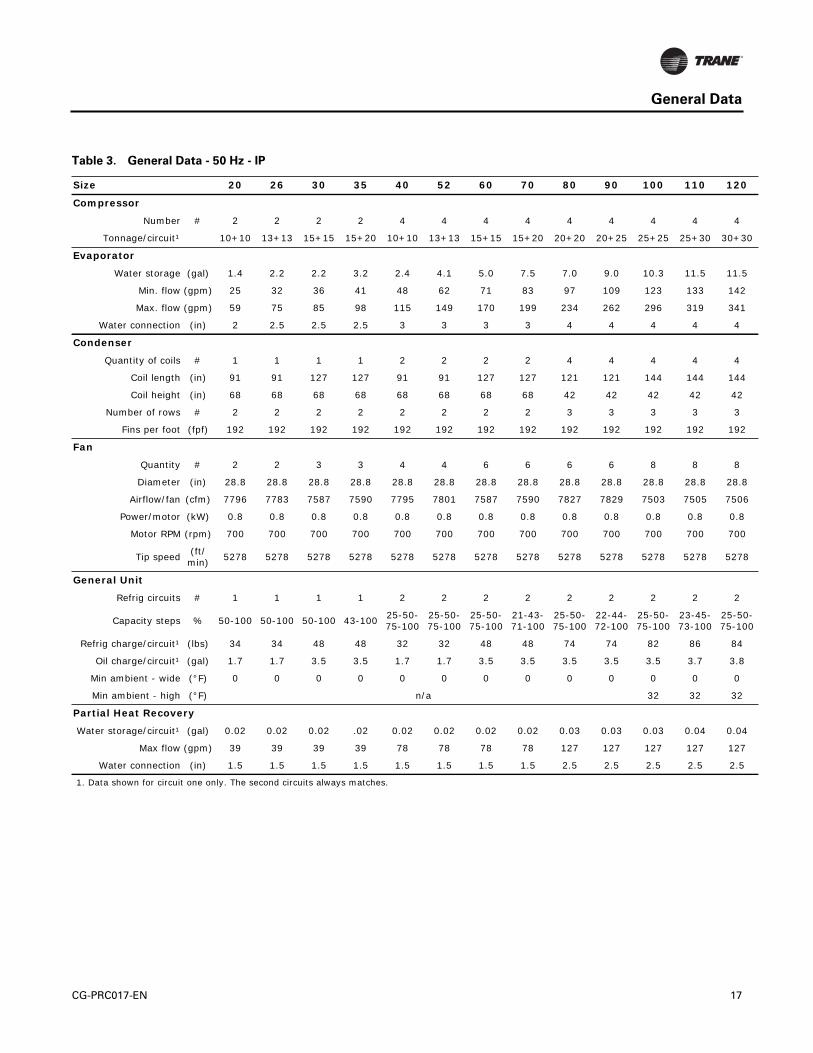
Table 3. General Data - 50 Hz - IP
Size 20 26 30 35 40 52 60 70 80 90 100 110 120
Compressor
Number # 2 2 2 2 4 4 4 4 4 4 4 4 4
Tonnage/circuit¹ 10+10 13+13 15+15 15+20 10+10 13+13 15+15 15+20 20+20 20+25 25+25 25+30 30+30
Evaporator
Water storage (gal) 1.4 2.2 2.2 3.2 2.4 4.1 5.0 7.5 7.0 9.0 10.3 11.5 11.5
Min. flow (gpm) 25 32 36 41 48 62 71 83 97 109 123 133 142
Max. flow (gpm) 59 75 85 98 115 149 170 199 234 262 296 319 341
Water connection (in) 2 2.5 2.5 2.5 3 3 3 3 4 4 4 4 4
Condenser
Quantity of coils # 1 1 1 1 2 2 2 2 4 4 4 4 4
Coil length (in) 91 91 127 127 91 91 127 127 121 121 144 144 144
Coil height (in) 68 68 68 68 68 68 68 68 42 42 42 42 42
Number of rows # 2 2 2 2 2 2 2 2 3 3 3 3 3
Fins per foot (fpf) 192 192 192 192 192 192 192 192 192 192 192 192 192
Fan
Quantity # 2 2 3 3 4 4 6 6 6 6 8 8 8
Diameter (in) 28.8 28.8 28.8 28.8 28.8 28.8 28.8 28.8 28.8 28.8 28.8 28.8 28.8
Airflow/fan (cfm) 7796 7783 7587 7590 7795 7801 7587 7590 7827 7829 7503 7505 7506
Power/motor (kW) 0.8 0.8 0.8 0.8 0.8 0.8 0.8 0.8 0.8 0.8 0.8 0.8 0.8
Motor RPM (rpm) 700 700 700 700 700 700 700 700 700 700 700 700 700
Tip speed(ft/min)
5278 5278 5278 5278 5278 5278 5278 5278 5278 5278 5278 5278 5278
General Unit
Refrig circuits # 1 1 1 1 2 2 2 2 2 2 2 2 2
Capacity steps % 50-100 50-100 50-100 43-10025-50-75-100
25-50-75-100
25-50-75-100
21-43-71-100
25-50-75-100
22-44-72-100
25-50-75-100
23-45-73-100
25-50-75-100
Refrig charge/circuit¹ (lbs) 34 34 48 48 32 32 48 48 74 74 82 86 84
Oil charge/circuit¹ (gal) 1.7 1.7 3.5 3.5 1.7 1.7 3.5 3.5 3.5 3.5 3.5 3.7 3.8
Min ambient - wide (°F) 0 0 0 0 0 0 0 0 0 0 0 0 0
Min ambient - high (°F) n/a 32 32 32
Partial Heat Recovery
Water storage/circuit¹ (gal) 0.02 0.02 0.02 .02 0.02 0.02 0.02 0.02 0.03 0.03 0.03 0.04 0.04
Max flow (gpm) 39 39 39 39 78 78 78 78 127 127 127 127 127
Water connection (in) 1.5 1.5 1.5 1.5 1.5 1.5 1.5 1.5 2.5 2.5 2.5 2.5 2.5
1. Data shown for circuit one only. The second circuits always matches.
CG-PRC017-EN 17

General Data
Table 4. General Data - 50 Hz - SI
Size 20 26 30 35 40 52 60 70 80 90 100 110 120
Compressor
Number # 2 2 2 2 4 4 4 4 4 4 4 4 4
Tonnage/circuit¹ 10+10 13+13 15+15 15+20 10+10 13+13 15+15 15+20 20+20 20+25 25+25 25+30 30+30
Evaporator
Water storage (l) 5.3 8.3 8.3 12.1 9.1 15.5 18.9 28.4 26.5 34.1 39.0 43.5 43.5
Min. flow (l/s) 1.6 2.0 2.2 2.6 3.0 3.9 4.4 5.2 6.1 6.8 7.7 8.3 8.9
Max. flow (l/s) 3.7 4.8 5.4 6.2 7.3 9.4 10.8 12.6 14.8 16.5 18.7 20.2 21.6
Water connection (mm) 50.8 63.5 63.5 63.5 76.2 76.2 76.2 76.2 101.6 101.6 101.6 101.6 101.6
Condenser
Quantity of coils # 1 1 1 1 2 2 2 2 4 4 4 4 4
Coil length (mm) 2311 2311 3226 3226 2311 2311 3226 3226 3073 3073 3658 3658 3658
Coil height (mm) 1727 1727 1727 1727 1727 1727 1727 1727 1067 1067 1067 1067 1067
Number of rows # 2 2 2 2 2 2 2 2 3 3 3 3 3
Fins per foot (fpf) 192 192 192 192 192 192 192 192 192 192 192 192 192
Fan
Quantity # 2 2 3 3 4 4 6 6 6 6 8 8 8
Diameter (mm) 732 732 732 732 732 732 732 732 732 732 732 732 732
Airflow/fan(m³/h)
13245 13223 12890 12895 13244 13254 12890 12895 13298 13302 12748 12751 12753
Power/motor (kW) 0.8 0.8 0.8 0.8 0.8 0.8 0.8 0.8 0.8 0.8 0.8 0.8 0.8
Motor RPM (rpm) 700 700 700 700 700 700 700 700 700 700 700 700 700
Tip speed (m/s) 26.8 26.8 26.8 26.8 26.8 26.8 26.8 26.8 26.8 26.8 26.8 26.8 26.8
General Unit
Refrig circuits # 1 1 1 1 2 2 2 2 2 2 2 2 2
Capacity steps % 50-100 50-100 50-100 43-10025-50-75-100
25-50-75-100
25-50-75-100
21-43-71-100
25-50-75-100
22-44-72-100
25-50-75-100
23-45-73-100
25-50-75-100
Refrig charge/circuit¹ (kg) 15.4 15.4 21.8 21.8 14.5 14.5 21.8 21.8 33.6 33.6 37.2 39.0 38.1
Oil charge/circuit ¹ (l) 6.6 6.6 13.4 13.4 6.6 6.6 13.4 13.4 13.4 13.4 13.4 13.9 14.4
Min ambient - wide (°C) -18 -18 -18 -18 -18 -18 -18 -18 -18 -18 -18 -18 -18
Min ambient - high (°C) n/a 0 0 0
Partial Heat Recovery
Water storage/circuit¹ (l) 0.07 0.07 0.09 0.09 0.07 0.07 0.09 0.09 0.12 0.12 0.12 0.16 0.16
Max flow (l/s) 2.5 2.5 2.5 2.5 5.0 5.0 5.0 5.0 8.0 8.0 8.0 8.0 8.0
Water connection (mm) 38.1 38.1 38.1 38.1 38.1 38.1 38.1 38.1 63.5 63.5 63.5 63.5 63.5
1. Data shown for circuit one only. The second circuit always matches.
18 CG-PRC017-EN

Performance Data
Table 5. Performance Data - 60 Hz - I-P units
Evaporator Leaving
Temperature (°F)
Condenser Ambient Temperature (°F)
85 95 105 115
Unit Size Tons
kW Input EER Tons
kW Input EER Tons
kW Input EER Tons
kW Input EER
42
20 tons 20.1 20.8 11.6 18.9 22.7 10 17.7 24.7 8.6 16.3 27 7.2
26 tons 25.9 27.3 11.4 24.3 29.9 9.7 22.5 32.8 8.2 20.7 35.8 6.9
30 tons 29 30.2 11.5 27.2 33.2 9.9 25.4 36.5 8.3 23.4 40 7
35 tons 34.1 36 11.4 32 39.5 9.7 29.7 43.4 8.2 27.4 47.6 6.9
40 tons 39.1 41.6 11.3 36.9 45.4 9.8 34.4 49.6 8.3 31.7 54.2 7
52 tons 51.3 54.8 11.2 47.9 60 9.6 44.4 65.8 8.1 40.7 71.9 6.8
60 tons 58.9 60.6 11.7 55.2 66.5 10 51.3 73.1 8.4 47.3 80.1 7.1
70 tons 70 73 11.5 65.4 80.1 9.8 60.6 87.8 8.3 55.8 96 7
80 tons 80.5 80.9 11.9 75.6 89.2 10.2 70.3 98.3 8.6 64.8 108.1 7.2
90 tons 90.3 93.1 11.6 84.5 102.1 9.9 78.4 111.9 8.4 72 122.4 7.1
100 tons 101.9 103.9 11.8 95.6 113.5 10.1 88.8 124 8.6 81.7 135.3 7.2
110 tons 110.7 116.2 11.4 103.6 126.9 9.8 96.1 138.4 8.3 88.3 150.8 7
120 tons 119.9 128.4 11.2 112.1 140.1 9.6 103.8 152.7 8.2 95.2 166.2 6.9
130 tons 130 132.6 11.8 121.9 145.5 10.1 113.3 159.7 8.5 104.3 174.8 7.2
44
20 tons 20.8 21 11.9 19.6 22.9 10.3 18.3 24.9 8.8 16.9 27.2 7.4
26 tons 26.8 27.6 11.7 25.1 30.2 10 23.2 33 8.4 21.3 36.1 7.1
30 tons 30 30.4 11.8 28.2 33.4 10.1 26.3 36.7 8.6 24.3 40.2 7.2
35 tons 35.3 36.3 11.7 33.1 39.8 10 30.7 43.7 8.4 28.3 47.9 7.1
40 tons 40.6 42 11.6 38.2 45.8 10 35.6 50 8.6 32.9 54.6 7.2
52 tons 53 55.4 11.5 49.5 60.6 9.8 45.9 66.3 8.3 42 72.5 7
60 tons 61 61.1 12 57.2 67.1 10.2 53.1 73.6 8.7 49 80.5 7.3
70 tons 72.4 73.8 11.8 67.7 80.8 10.1 62.7 88.5 8.5 57.7 96.7 7.2
80 tons 83.3 81.6 12.2 78.2 89.9 10.4 72.7 99 8.8 67.1 108.8 7.4
90 tons 93.3 94 11.9 87.4 103 10.2 81 112.8 8.6 74.5 123.2 7.3
100 tons 105.5 104.8 12.1 98.9 114.4 10.4 91.9 124.9 8.8 84.5 136.1 7.5
110 tons 114.4 117.3 11.7 107.1 128 10 99.3 139.5 8.5 91.3 151.8 7.2
120 tons 123.9 129.6 11.5 115.8 141.3 9.8 107.2 154 8.4 98.5 167.4 7.1
130 tons 134.4 133.9 12 126.1 146.8 10.3 117.1 160.9 8.7 107.9 176 7.4
CG-PRC017-EN 19

Performance Data
46
20 tons 21.5 21.2 12.2 20.3 23.1 10.6 18.9 25.1 9 17.5 27.4 7.6
26 tons 27.6 27.9 11.9 25.9 30.4 10.2 24 33.3 8.6 22 36.3 7.3
30 tons 31 30.6 12.2 29.1 33.6 10.4 27.2 36.9 8.8 25.1 40.4 7.5
35 tons 36.4 36.6 11.9 34.2 40.2 10.2 31.8 44 8.7 29.3 48.2 7.3
40 tons 42 42.4 11.9 39.6 46.2 10.3 36.9 50.4 8.8 34.1 55 7.4
52 tons 54.7 56 11.7 51.1 61.2 10 47.4 66.9 8.5 43.4 73 7.1
60 tons 63.1 61.6 12.3 59.2 67.6 10.5 55 74.1 8.9 50.8 81 7.5
70 tons 74.8 74.5 12.1 70 81.6 10.3 64.9 89.2 8.7 59.7 97.4 7.4
80 tons 86.1 82.4 12.5 80.8 90.7 10.7 75.2 99.8 9 69.3 109.6 7.6
90 tons 96.4 94.9 12.2 90.3 103.9 10.4 83.7 113.7 8.8 77 124.1 7.4
100 tons 109.1 105.7 12.4 102.3 115.3 10.6 95 125.8 9.1 87.4 137 7.7
110 tons 118.3 118.4 12 110.7 129.1 10.3 102.6 140.6 8.8 94.4 152.9 7.4
120 tons 127.9 130.9 11.7 119.6 142.6 10.1 110.7 155.2 8.6 101.7 168.6 7.2
130 tons 138.9 135.1 12.3 130.2 148 10.6 121 162.1 9 111.5 177.2 7.6
48
20 tons 22.2 21.4 12.5 20.9 23.3 10.8 19.5 25.3 9.3 18 27.6 7.8
26 tons 28.5 28.1 12.2 26.7 30.7 10.4 24.7 33.6 8.8 22.7 36.6 7.5
30 tons 32 30.9 12.5 30.1 33.9 10.7 28.1 37.1 9.1 26 40.6 7.7
35 tons 37.6 37 12.2 35.3 40.5 10.4 32.8 44.4 8.9 30.3 48.5 7.5
40 tons 43.5 42.9 12.2 41 46.7 10.5 38.2 50.8 9 35.3 55.4 7.6
52 tons 56.5 56.6 12 52.8 61.8 10.2 48.9 67.5 8.7 44.8 73.5 7.3
60 tons 65.3 62.2 12.6 61.2 68.1 10.8 56.9 74.6 9.2 52.6 81.5 7.7
70 tons 77.3 75.3 12.3 72.3 82.3 10.5 67 89.9 8.9 61.7 98 7.6
80 tons 88.9 83.1 12.8 83.5 91.5 11 77.7 100.6 9.3 71.6 110.3 7.8
90 tons 99.6 95.8 12.5 93.2 104.8 10.7 86.4 114.6 9 79.5 124.9 7.6
100 tons 112.7 106.6 12.7 105.7 116.2 10.9 98.1 126.7 9.3 90.4 137.8 7.9
110 tons 122.1 119.5 12.3 114.3 130.2 10.5 106 141.7 9 97.5 153.9 7.6
120 tons 132 132.2 12 123.4 143.9 10.3 114.3 156.5 8.8 105 169.7 7.4
130 tons 143.4 136.3 12.6 134.5 149.3 10.8 125 163.3 9.2 115.2 178.4 7.8
Table 5. Performance Data - 60 Hz - I-P units
Evaporator Leaving
Temperature (°F)
Condenser Ambient Temperature (°F)
85 95 105 115
Unit Size Tons
kW Input EER Tons
kW Input EER Tons
kW Input EER Tons
kW Input EER
20 CG-PRC017-EN

Performance Data
50
20 tons 23 21.6 12.8 21.6 23.5 11.1 20.2 25.5 9.5 18.6 27.8 8.1
26 tons 29.4 28.4 12.4 27.5 31 10.6 25.5 33.8 9 23.4 36.8 7.6
30 tons 33.1 31.1 12.8 31.1 34.1 10.9 29 37.4 9.3 26.8 40.9 7.9
35 tons 38.8 37.3 12.5 36.4 40.8 10.7 33.9 44.7 9.1 31.3 48.8 7.7
40 tons 45 43.3 12.5 42.4 47.1 10.8 39.6 51.3 9.3 36.5 55.8 7.9
52 tons 58.2 57.2 12.2 54.4 62.4 10.5 50.4 68 8.9 46.3 74 7.5
60 tons 67.4 62.7 12.9 63.3 68.7 11.1 58.9 75.1 9.4 54.4 81.9 8
70 tons 79.8 76 12.6 74.6 83 10.8 69.2 90.6 9.2 63.8 98.7 7.7
80 tons 91.8 83.9 13.1 86.2 92.2 11.2 80.2 101.3 9.5 74 111.1 8
90 tons 102.7 96.7 12.7 96.1 105.7 10.9 89.1 115.5 9.3 82 125.7 7.8
100 tons 116.3 107.5 13 109.1 117.1 11.2 101.3 127.5 9.5 93.3 138.6 8.1
110 tons 126 120.7 12.5 117.9 131.3 10.8 109.4 142.7 9.2 100.6 154.9 7.8
120 tons 136.1 133.5 12.2 127.2 145.2 10.5 117.8 157.7 9 108.3 170.9 7.6
130 tons 148 137.6 12.9 138.7 150.5 11.1 129 164.5 9.4 118.9 179.5 8
1. Rated in accordance with AHRI Standard 550/590 based on sea level altitude, evaporator fouling factor of 0.00010°F·ft²h/Btu, evaporator temperature drop of 10°F and 380/460/575 voltage.
2. kW input is for compressors only.3. EER = Energy Efficiency Ratio (Btu/watt-hour). Power inputs include: compressors, condenser fans, and control power.4. Interpolation between points is permissible. Extrapolation is not permitted.5. Performance based on TOPSS version 137. Consult Trane representative for performance at temperatures outside of the ranges shown.
Table 5. Performance Data - 60 Hz - I-P units
Evaporator Leaving
Temperature (°F)
Condenser Ambient Temperature (°F)
85 95 105 115
Unit Size Tons
kW Input EER Tons
kW Input EER Tons
kW Input EER Tons
kW Input EER
Table 6. Part Load Performance - 60 Hz - I-P units
Unit Size
IPLV 100% 75% 50% 25%
EER Tons kW
input EER Tons kW
input EER Tons kW
input EER Tons kW
input EER
20 tons 14.2 19.6 22.9 10.3 14.7 13.7 12.9 9.8 8.0 14.7 4.9 3.5 16.7
26 tons 15.1 25.1 30.2 10.0 18.8 16.8 13.4 12.5 9.3 16.1 6.3 4.4 17.2
30 tons 15.0 28.2 33.4 10.1 21.1 19.0 13.3 14.1 10.5 16.2 7.1 4.9 17.2
35 tons 15.2 33.1 39.8 10.0 24.8 22.6 13.1 16.5 11.9 16.7 8.3 5.6 17.6
40 tons 13.8 38.2 45.8 10.0 28.7 27.6 12.5 19.1 15.9 14.4 9.6 7.0 16.4
52 tons 15.1 49.5 60.6 9.8 37.2 33.6 13.3 24.8 18.2 16.4 12.4 8.6 17.3
60 tons 15.3 57.2 67.1 10.2 42.9 38.3 13.4 28.6 20.6 16.6 14.3 9.8 17.6
70 tons 15.6 67.7 80.8 10.1 50.8 46.1 13.2 33.8 23.6 17.2 16.9 11.1 18.3
80 tons 15.6 78.2 89.9 10.4 58.6 50.7 13.9 39.1 27.2 17.3 19.5 14.4 16.3
90 tons 15.8 87.4 103.0 10.2 65.5 57.8 13.6 43.7 29.5 17.8 21.8 15.5 16.9
100 tons 15.4 98.9 114.4 10.4 74.2 65.6 13.6 49.5 35.7 16.6 24.7 16.5 18.0
110 tons 15.3 107.1 128.0 10.0 80.3 72.9 13.2 53.6 38.5 16.7 26.8 17.7 18.2
120 tons 15.4 115.8 141.3 9.8 86.8 78.1 13.3 57.9 41.6 16.7 29.0 19.4 17.9
130 tons 16.6 126.1 146.8 10.3 94.5 79.0 14.4 63.0 42.6 17.8 31.5 18.6 20.3
1. IPLV values are rated in accordance with AHRI Standard 550/590.2. EER and IPLV values include compressors, condenser fans, and control kW.3. Performance is based on 380/460/575 voltage TOPSS version 137.
CG-PRC017-EN 21

Performance Data
Table 7. Performance Data - 60 Hz - SI units
Evaporator Leaving
Temperature(°C)
Condenser Ambient Temperature (°C)
30 35 40 45
Unit Size
kW Cooling
kW Input COP
kW Cooling
kW Input COP
kW Cooling
kW Input COP
kW Cooling
kW Input COP
7
20 tons 73.13 21.2 3.46 69.27 22.9 3.02 65.05 24.8 2.64 60.83 26.8 2.26
26 tons 94.23 27.9 3.37 88.6 30.2 2.93 82.98 32.8 2.52 77 35.5 2.17
30 tons 105.48 30.7 3.43 99.85 33.4 2.99 93.53 36.4 2.58 87.2 39.5 2.2
35 tons 124.11 36.7 3.37 117.08 39.9 2.93 109.7 43.4 2.52 101.96 47.1 2.17
40 tons 142.75 42.4 3.37 135.37 45.9 2.96 127.28 49.6 2.55 118.49 53.7 2.2
52 tons 186.35 56 3.34 175.45 60.7 2.9 163.49 65.9 2.49 151.54 71.3 2.14
60 tons 214.48 61.8 3.49 202.52 67.2 3.02 189.51 73 2.61 176.5 79.2 2.23
70 tons 254.56 74.6 3.43 239.79 81 2.96 223.97 87.8 2.55 207.8 95.2 2.2
80 tons 292.88 82.6 3.54 276.71 90.1 3.08 259.48 98.3 2.64 241.55 107 2.26
90 tons 328.39 95 3.46 309.41 103.2 2.99 289.02 112 2.58 268.27 121.3 2.23
100 tons 371.29 105.9 3.51 350.19 114.6 3.05 328.04 124 2.64 304.49 134 2.28
110 tons 402.58 118.6 3.4 379.38 128.2 2.96 354.41 138.5 2.55 329.1 149.5 2.2
120 tons 435.63 131 3.31 409.97 141.6 2.9 382.54 152.9 2.49 354.76 164.9 2.14
130 tons 472.9 135.3 3.49 446.18 147 3.05 418.05 159.7 2.61 388.52 173.2 2.26
9
20 tons 77.7 21.6 3.6 73.48 23.3 3.16 69.27 25.1 2.75 64.34 27.1 2.37
26 tons 99.5 28.4 3.51 93.88 30.7 3.05 87.55 33.3 2.64 81.22 36 2.26
30 tons 111.81 31.1 3.6 105.83 33.9 3.13 99.5 36.8 2.69 92.82 39.9 2.31
35 tons 131.5 37.3 3.51 124.11 40.5 3.05 116.03 44 2.64 108.29 47.6 2.28
40 tons 152.24 43.2 3.51 144.16 46.7 3.08 135.37 50.4 2.69 126.22 54.5 2.31
52 tons 197.25 57.1 3.46 185.64 61.8 2.99 173.34 66.9 2.58 160.68 72.3 2.23
60 tons 228.19 62.7 3.63 215.18 68.1 3.16 201.82 73.9 2.72 188.11 80.1 2.34
70 tons 270.03 76 3.54 254.21 82.3 3.08 237.68 89.1 2.67 220.8 96.4 2.28
80 tons 310.81 83.9 3.69 293.59 91.5 3.22 275.3 99.6 2.75 256.32 108.3 2.37
90 tons 347.73 96.7 3.6 327.69 104.8 3.13 306.24 113.6 2.69 284.44 122.8 2.31
100 tons 393.79 107.5 3.66 371.64 116.2 3.19 347.73 125.6 2.78 323.47 135.5 2.37
110 tons 426.49 120.6 3.54 401.88 130.2 3.08 375.51 140.5 2.67 348.79 151.4 2.31
120 tons 461.3 133.3 3.46 433.87 143.9 3.02 405.04 155.2 2.61 375.86 167 2.26
130 tons 501.03 137.6 3.63 472.9 149.2 3.16 443.02 161.9 2.72 412.08 175.3 2.34
1. Rated in accordance with AHRI Standard 550/590, based on sea level altitude, evaporator fouling factor of 0.01761 m²-°C/kW, evaporator temperature drop of 5°C and 380/460/575 voltage.
2. COP = Coefficient of Performance. Power inputs include: compressors, condenser fans, and control power.3. kW input is for compressors only.4. Interpolation between points is permissible. Extrapolation is not permitted.5. Performance based on TOPSS version 137. Consult Trane representative for performance at temperatures outside of the ranges shown.
22 CG-PRC017-EN

Performance Data
Table 8. Performance Data - 50 Hz - I-P units
Evaporator Leaving
Temperature (°F)
Condenser Ambient Temperature (°F)
85 95 105 115
Unit Size Tons
kW Input EER Tons
kW Input EER Tons
kW Input EER Tons
kW Input EER
42
20 tons 17.1 16.4 12.5 16.1 18 10.7 15 19.8 9.1 13.8 21.8 7.6
26 tons 21.9 21.6 12.1 20.5 23.9 10.3 18.9 26.4 8.6 17.3 29.1 7.1
30 tons 24.7 24.4 12.2 23.2 26.9 10.4 21.5 29.7 8.7 19.8 32.7 7.3
35 tons 28.6 28.9 11.9 26.8 32 10.1 24.9 35.4 8.4 22.8 39.1 7
40 tons 33.1 32.7 12.1 31.1 36 10.4 29 39.6 8.8 26.7 43.5 7.4
52 tons 43.2 43.3 12 40.3 47.9 10.1 37.2 52.9 8.4 34 58.3 7
60 tons 49.6 49 12.1 46.4 54 10.3 43.1 59.6 8.7 39.5 65.8 7.2
70 tons 58.3 58.2 12 54.5 64.3 10.2 50.4 71 8.5 46.1 78.3 7.1
80 tons 68.1 65.4 12.5 63.8 72.6 10.5 59.2 80.6 8.8 54.4 89.2 7.3
90 tons 76.6 75.1 12.2 71.6 82.9 10.4 66.2 91.3 8.7 60.6 100.3 7.3
100 tons 86.6 83.9 12.4 81.1 92.2 10.6 75.1 101.2 8.9 68.8 110.9 7.5
110 tons 93.7 92 12.2 87.6 101.1 10.4 81.1 110.9 8.8 74.2 121.3 7.3
120 tons 100.2 101.2 11.9 93.6 111.2 10.1 86.5 121.8 8.5 79.2 133.1 7.1
44
20 tons 17.7 16.6 12.8 16.6 18.2 11 15.5 20 9.3 14.3 21.9 7.8
26 tons 22.6 21.9 12.4 21.2 24.1 10.5 19.6 26.6 8.8 17.9 29.3 7.3
30 tons 25.6 24.5 12.5 24 27 10.7 22.3 29.8 9 20.5 32.9 7.5
35 tons 29.6 29.2 12.2 27.8 32.2 10.3 25.7 35.6 8.7 23.7 39.3 7.2
40 tons 34.3 33 12.5 32.3 36.3 10.7 30 39.9 9 27.7 43.8 7.6
52 tons 44.6 43.8 12.2 41.7 48.3 10.3 38.5 53.3 8.7 35.2 58.7 7.2
60 tons 51.4 49.4 12.5 48.1 54.4 10.6 44.7 60 8.9 41 66.1 7.4
70 tons 60.4 58.7 12.3 56.4 64.8 10.4 52.2 71.5 8.8 47.8 78.7 7.3
80 tons 70.5 66 12.8 66.1 73.2 10.8 61.3 81.2 9.1 56.4 89.8 7.5
90 tons 79.2 75.8 12.5 74 83.6 10.6 68.5 92 8.9 62.7 101 7.5
100 tons 89.6 84.6 12.7 83.9 92.9 10.8 77.8 101.9 9.2 71.3 111.5 7.7
110 tons 96.9 92.9 12.5 90.6 101.9 10.7 83.9 111.7 9 76.8 122.1 7.5
120 tons 103.6 102.3 12.2 96.7 112.2 10.3 89.4 122.8 8.7 81.9 134.1 7.3
46
20 tons 18.3 16.7 13.2 17.2 18.3 11.3 16 20.1 9.6 14.8 22.1 8
26 tons 23.4 22.1 12.7 21.9 24.3 10.8 20.2 26.8 9 18.5 29.5 7.5
30 tons 26.5 24.7 12.9 24.8 27.2 11 23.1 30 9.2 21.3 33 7.7
35 tons 30.6 29.4 12.5 28.7 32.5 10.6 26.6 35.9 8.9 24.5 39.5 7.4
40 tons 35.6 33.3 12.8 33.4 36.6 11 31.1 40.2 9.3 28.7 44.1 7.8
52 tons 46.1 44.3 12.5 43.1 48.8 10.6 39.8 53.8 8.9 36.3 59.1 7.4
60 tons 53.2 49.8 12.8 49.9 54.8 10.9 46.3 60.4 9.2 42.5 66.5 7.7
70 tons 62.5 59.3 12.6 58.4 65.3 10.7 54 72 9 49.5 79.2 7.5
80 tons 73 66.6 13.2 68.4 73.8 11.1 63.5 81.7 9.3 58.4 90.3 7.8
90 tons 81.9 76.5 12.8 76.5 84.3 10.9 70.8 92.7 9.2 64.9 101.6 7.7
100 tons 92.7 85.3 13 86.8 93.6 11.1 80.5 102.6 9.4 73.8 112.2 7.9
110 tons 100.2 93.8 12.8 93.7 102.8 10.9 86.7 112.6 9.2 79.4 122.9 7.8
120 tons 107 103.3 12.4 99.9 113.3 10.6 92.4 123.9 8.9 84.7 135 7.5
CG-PRC017-EN 23

Performance Data
48
20 tons 19 16.9 13.5 17.8 18.5 11.6 16.6 20.3 9.8 15.3 22.2 8.2
26 tons 24.1 22.3 13 22.6 24.6 11 20.9 27.1 9.2 19.1 29.7 7.7
30 tons 27.4 24.9 13.2 25.7 27.4 11.3 23.9 30.2 9.5 22 33.2 8
35 tons 31.7 29.7 12.8 29.7 32.7 10.9 27.5 36.1 9.2 25.3 39.8 7.6
40 tons 36.9 33.7 13.1 34.6 36.9 11.3 32.3 40.5 9.5 29.7 44.4 8
52 tons 47.7 44.8 12.8 44.5 49.3 10.8 41.1 54.2 9.1 37.6 59.5 7.6
60 tons 55.1 50.2 13.2 51.6 55.2 11.2 47.9 60.8 9.5 44.1 66.8 7.9
70 tons 64.6 59.8 13 60.3 65.9 11 55.8 72.5 9.2 51.2 79.7 7.7
80 tons 75.5 67.2 13.5 70.7 74.4 11.4 65.6 82.3 9.6 60.4 90.9 8
90 tons 84.6 77.2 13.2 79.1 85 11.2 73.2 93.4 9.4 67.1 102.3 7.9
100 tons 95.8 86 13.4 89.8 94.3 11.4 83.2 103.3 9.7 76.3 112.9 8.1
110 tons 103.5 94.6 13.1 96.7 103.7 11.2 89.5 113.5 9.5 82.1 123.8 8
120 tons 110.4 104.4 12.7 103.1 114.3 10.8 95.3 124.9 9.2 87.4 136 7.7
50
20 tons 19.6 17 13.8 18.4 18.6 11.8 17.1 20.4 10.1 15.8 22.4 8.5
26 tons 24.9 22.6 13.2 23.3 24.8 11.2 21.5 27.3 9.5 19.7 29.9 7.9
30 tons 28.3 25 13.5 26.5 27.6 11.6 24.7 30.3 9.8 22.8 33.4 8.2
35 tons 32.7 29.9 13.1 30.6 33 11.1 28.4 36.3 9.4 26.2 40 7.9
40 tons 38.2 34 13.5 35.9 37.3 11.5 33.4 40.9 9.8 30.8 44.8 8.3
52 tons 49.2 45.3 13 45.9 49.8 11.1 42.4 54.7 9.3 38.8 60 7.8
60 tons 57 50.6 13.5 53.4 55.6 11.5 49.6 61.2 9.7 45.6 67.2 8.1
70 tons 66.7 60.4 13.3 62.3 66.4 11.3 57.7 73.1 9.5 53 80.2 7.9
80 tons 78 67.8 13.8 73 75 11.7 67.8 82.9 9.8 62.4 91.4 8.2
90 tons 87.3 77.9 13.5 81.6 85.7 11.4 75.5 94.1 9.6 69.3 102.9 8.1
100 tons 99 86.7 13.7 92.7 95 11.7 85.9 104 9.9 78.9 113.6 8.3
110 tons 106.8 95.5 13.4 99.8 104.6 11.5 92.4 114.3 9.7 84.8 124.6 8.2
120 tons 113.9 105.5 13 106.3 115.4 11.1 98.3 126 9.4 90.2 137 7.9
1. Rated in accordance with AHRI Standard 550/590 based on sea level altitude, evaporator fouling factor of 0.00010°F·ft²h/Btu, and evaporator tem-perature drop of 10°F.
2. kW input is for compressors only.3. EER = Energy Efficiency Ratio (Btu/watt-hour). Power inputs include: compressors, condenser fans, and control power.4. Interpolation between points is permissible. Extrapolation is not permitted.5. Performance based on TOPSS version 137.Consult Trane representative for performance at temperatures outside of the ranges shown.
Table 8. Performance Data - 50 Hz - I-P units
Evaporator Leaving
Temperature (°F)
Condenser Ambient Temperature (°F)
85 95 105 115
Unit Size Tons
kW Input EER Tons
kW Input EER Tons
kW Input EER Tons
kW Input EER
24 CG-PRC017-EN
Performance Data
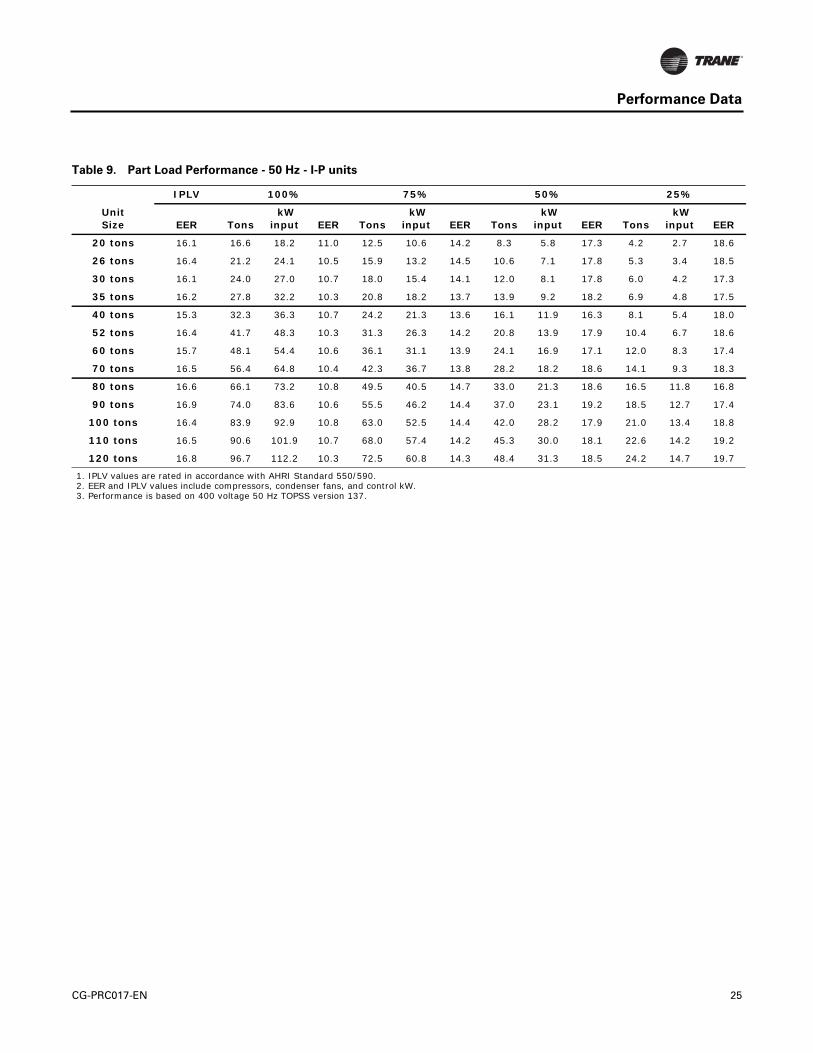
Table 9. Part Load Performance - 50 Hz - I-P units
Unit Size
IPLV 100% 75% 50% 25%
EER Tons kW
input EER Tons kW
input EER Tons kW
input EER Tons kW
input EER
20 tons 16.1 16.6 18.2 11.0 12.5 10.6 14.2 8.3 5.8 17.3 4.2 2.7 18.6
26 tons 16.4 21.2 24.1 10.5 15.9 13.2 14.5 10.6 7.1 17.8 5.3 3.4 18.5
30 tons 16.1 24.0 27.0 10.7 18.0 15.4 14.1 12.0 8.1 17.8 6.0 4.2 17.3
35 tons 16.2 27.8 32.2 10.3 20.8 18.2 13.7 13.9 9.2 18.2 6.9 4.8 17.5
40 tons 15.3 32.3 36.3 10.7 24.2 21.3 13.6 16.1 11.9 16.3 8.1 5.4 18.0
52 tons 16.4 41.7 48.3 10.3 31.3 26.3 14.2 20.8 13.9 17.9 10.4 6.7 18.6
60 tons 15.7 48.1 54.4 10.6 36.1 31.1 13.9 24.1 16.9 17.1 12.0 8.3 17.4
70 tons 16.5 56.4 64.8 10.4 42.3 36.7 13.8 28.2 18.2 18.6 14.1 9.3 18.3
80 tons 16.6 66.1 73.2 10.8 49.5 40.5 14.7 33.0 21.3 18.6 16.5 11.8 16.8
90 tons 16.9 74.0 83.6 10.6 55.5 46.2 14.4 37.0 23.1 19.2 18.5 12.7 17.4
100 tons 16.4 83.9 92.9 10.8 63.0 52.5 14.4 42.0 28.2 17.9 21.0 13.4 18.8
110 tons 16.5 90.6 101.9 10.7 68.0 57.4 14.2 45.3 30.0 18.1 22.6 14.2 19.2
120 tons 16.8 96.7 112.2 10.3 72.5 60.8 14.3 48.4 31.3 18.5 24.2 14.7 19.7
1. IPLV values are rated in accordance with AHRI Standard 550/590.2. EER and IPLV values include compressors, condenser fans, and control kW.3. Performance is based on 400 voltage 50 Hz TOPSS version 137.
CG-PRC017-EN 25

Performance Data
Table 10. Performance Data - 50 Hz - SI units
Evaporator Leaving
Temperature(°C)
Condenser Ambient Temperature (°C)
30 35 40 45
UnitSize
kW Cooling
kW Input COP
kW Cooling
kW Input COP
kW Cooling
kW Input COP
kW Cooling
kW Input COP
7
20 tons 62.23 16.7 3.72 59.07 18.2 3.22 55.2 19.8 2.78 51.33 21.6 2.37
26 tons 79.46 22.1 3.6 74.89 24.2 3.1 69.97 26.4 2.64 64.69 28.8 2.23
30 tons 90.01 24.8 3.63 85.09 27.1 3.13 79.46 29.6 2.69 73.84 32.3 2.28
35 tons 104.07 29.5 3.51 98.1 32.3 3.05 91.77 35.3 2.61 85.09 38.6 2.2
40 tons 120.95 33.4 3.6 114.27 36.3 3.13 107.24 39.6 2.69 99.85 43.1 2.31
52 tons 157.17 44.3 3.54 147.67 48.4 3.05 137.48 52.9 2.61 126.93 57.7 2.2
60 tons 180.72 50 3.63 170.53 54.5 3.13 159.63 59.5 2.67 148.02 64.9 2.28
70 tons 212.37 59.4 3.57 199.71 64.9 3.08 186.35 70.9 2.64 172.64 77.4 2.23
80 tons 248.23 66.8 3.72 233.81 73.3 3.19 218.7 80.5 2.72 203.22 88.1 2.31
90 tons 278.82 76.7 3.63 261.94 83.7 3.13 244.36 91.3 2.67 226.43 99.3 2.28
100 tons 315.39 85.5 3.69 297.1 93 3.19 277.76 101.1 2.75 257.02 109.7 2.34
110 tons 341.05 93.9 3.63 321.01 102.1 3.13 299.21 110.9 2.69 277.06 120.2 2.31
120 tons 364.26 103.4 3.51 342.46 112.4 3.05 319.25 122 2.61 295.34 132 2.23
9
20 tons 66.1 17 3.9 62.58 18.5 3.4 58.72 20.1 2.93 54.5 21.8 2.49
26 tons 84.38 22.5 3.75 79.11 24.6 3.22 73.84 26.8 2.75 68.21 29.2 2.34
30 tons 95.64 25.1 3.81 90.36 27.4 3.31 84.74 29.9 2.84 78.76 32.6 2.4
35 tons 110.75 30 3.69 104.43 32.7 3.19 97.39 35.7 2.72 90.71 39 2.31
40 tons 128.69 34 3.78 121.65 36.9 3.31 114.27 40.2 2.84 106.18 43.6 2.43
52 tons 166.66 45.2 3.69 156.46 49.3 3.16 145.56 53.7 2.72 134.66 58.5 2.31
60 tons 192.68 50.6 3.81 181.43 55.2 3.28 169.82 60.2 2.81 157.87 65.6 2.4
70 tons 225.73 60.4 3.75 212.01 65.9 3.22 197.95 71.8 2.75 183.54 78.3 2.34
80 tons 263.7 67.9 3.9 248.58 74.4 3.34 232.41 81.5 2.84 215.88 89.1 2.43
90 tons 295.7 77.9 3.78 278.12 85 3.28 259.48 92.5 2.81 240.14 100.5 2.4
100 tons 335.07 86.8 3.87 315.74 94.3 3.34 294.99 102.4 2.87 273.19 110.9 2.46
110 tons 361.44 95.5 3.78 340 103.7 3.28 317.49 112.5 2.81 293.94 121.7 2.4
120 tons 385.71 105.4 3.66 362.5 114.3 3.16 337.89 123.8 2.72 312.92 133.8 2.34
1. Rated in accordance with AHRI Standard 550/590, based on sea level altitude, evaporator fouling factor of 0.01761 m²-°C/kW, and evaporator temperature drop of 5°C.
2. COP = Coefficient of Performance. Power inputs include: compressors, condenser fans, and control power.3. kW input is for compressors only.4. Interpolation between points is permissible. Extrapolation is not permitted.5. Performance based on TOPSS version 137. Consult Trane representative for performance at temperatures outside of the ranges shown.
26 CG-PRC017-EN

Controls
LCD Touch-Screen Display with Multi-Language Support
The standard DynaView display provided with the Trane CH530 control panel features an LCDtouch-screen that is navigated by file tabs. This is an advanced interface that allows the user toaccess any important information concerning setpoints, active temperatures, modes, electricaldata, pressure, and diagnostics. It uses full text display available in 19 languages.
Display Features Include:
• LCD touch-screen with LED backlighting, for scrolling access to input and output operatinginformation
• Single-screen, folder/tab-style display of all available information on individual components(evaporator, condenser, compressor, etc.)
• Password entry/lockout system to enable or disable display
• Automatic and immediate stop capabilities for standard or immediate manual shutdown
• Fast, easy access to available chiller data in tabbed format, including:
• Modes of operation, including normal cooling as well as ice making
• Water temperatures and setpoints
• Loading and limiting status and setpoints
• Outdoor air temperature
• Start/stop differential timers
• Pump status and override
• Chilled water reset settings
• Optional external setpoints, including:
• Chilled water, demand limit, ice building
Reports, listed on a single tabbed screen for easy access, including:
• ASHRAE, containing all guideline 3 report information
• Evaporator, condenser, compressor
Evaporator, condenser, and compressor reports containing all operational information onindividual components, including:
• Water temperatures, refrigerant pressures, temperatures, and approach
• Flow switch status, EXV position, compressor starts and run-time
Alarm and diagnostic information, including:
• Flashing alarms with touch-screen button for immediate address of alarm condition
• Scrollable list of last ten active diagnostics
• Specific information on applicable diagnostic from list of over one-hundred
• Automatic or manual resetting diagnostic types
Adaptive Controls
Adaptive Controls directly sense the control variables that govern the operation of the chiller:evaporator pressure and condenser pressure. When any one of these variables approaches a limitcondition when damage may occur to the unit or shutdown on a safety, Adaptive Controls takescorrective action to avoid shutdown and keep the chiller operating. This happens throughcombined actions of compressor and/or fan staging. Whenever possible, the chiller is allowed tocontinue making chilled water. This keeps cooling capacity available until the problem can besolved. Overall, the safety controls help keep the building or process running and out of trouble.
CG-PRC017-EN 27

Controls
Stand-Alone Controls
Single chillers installed in applications without a building management system is simple to installand control: only a remote auto/stop for scheduling is required for unit operation. Signals from thechilled-water pump contactor auxiliary, or a flow switch, are wired to the chilled-water flowinterlock. Signals from a time clock or some other remote device are wired to the external auto/stopinput.
• Auto/Stop - A job-site provided contact closure turns the unit on and off.
• External Interlock - A job-site provided contact opening wired to this input turns the unit off andrequires a manual reset of the unit microcomputer. This closure is typically triggered by a job-site provided system such as a fire alarm.
Time of Day Scheduling
Time of day scheduling allows the customer to perform simple chiller scheduling without the needfor a building automation system.
This feature allows the user to set ten events in a seven day time period. For each event the usercan specify an activation time and the days of the week the event is active. Any available setpointscan be specified for each event, such as the leaving chilled water temperature (standard) and thedemand limit setpoint (optional if ordered).
Required features:
• Time of day scheduling (selectable option with chiller)
Additional options that if ordered may be incorporated into the scheduling:
• External chilled water setpoint, external demand limit setpoint
• Ice-making initiation
Hardwire Points
Microcomputer controls allow simple interface with other control systems, such as time clocks,building automation systems, and ice storage systems via hardwire points. This means you havethe flexibility to meet job requirements while not having to learn a complicated control system.
Remote devices are wired from the control panel to provide auxiliary control to a buildingautomation system. Inputs and outputs can be communicated via a typical 4–20 mA electricalsignal, an equivalent 2–10 Vdc signal, or by utilizing contact closures.
This setup has the same features as a stand-alone water chiller, with the possibility of havingadditional optional features:
• Ice making control
• External chilled water setpoint, external demand limit setpoint
• Chilled water temperature reset
• Programmable relays - available outputs are: alarm-latching, alarm-auto reset, generalalarm, warning, chiller limit mode, compressor running, and Tracer control
28 CG-PRC017-EN

Controls
BACnet Interface
BACnet interface capabilities are available, with communication link via single twisted-pair wiringto a factory-installed and tested communication board.
Required features:
• BACnet Interface (selectable option with chiller)
BACnet is a data communication protocol for building automation and control networks developedby American Society of Heating, Refrigerating and Air-Conditioning Engineers (ASHRAE).
LonTalk LCI-C Interface
LonTalk (LCI-C) communications capabilities are available, with communication link via singletwisted-pair wiring to factory-installed, tested communication board.
Required features:
• LonTalk/Tracer Summit Interface (selectable option with chiller)
LonTalk is a communications protocol developed by the Echelon Corporation. The LonMarkassociation develops control profiles using the LonTalk communication protocol. LonTalk is a unitlevel communications protocol.
LonTalk Communications Interface for Chillers (LCI-C) provides a generic automation system withthe LonMark chiller profile inputs/outputs. In addition to the standard points, Trane provides othercommonly used network output variables for greater interoperability with any automation system.The complete reference list of Trane LonTalk points is available on the LonMark web site.
Trane controls or another vendor’s system can use the predefined list of points with ease to givethe operator a complete picture of how the system is running
Tracer Summit
The chiller plant control capabilities of the Trane Tracer Summit building automation system areunequaled in the industry. Trane’s depth of experience in chillers and controls makes us a well-qualified choice for automation of chiller plants using air-cooled CGAM chillers. Our chiller plantautomation software is fully pre-engineered and tested.
Required features:
• LonTalk/Tracer Summit Interface (selectable option with chiller)
• Building Control Unit (external device required)
Energy Efficiency
• Sequences starting of chillers to optimize the overall chiller plant energy efficiency
– Individual chillers operate as base, peak, or swing based on capacity and efficiency
– Automatically rotates individual chiller operation to equalize runtime and wearbetween chillers.
– Evaluates and selects the lowest energy consumption alternative from an overallsystem perspective.
Regulatory Compliance Documentation
• Gathers information and generates the reports mandated in ASHRAE Guideline 3.
Easy Operation and Maintenance
• Remote monitoring and control
• Displays both current operation conditions and scheduled automated control actions
• Concise reports assist in planning for preventative maintenance and verifying performance
• Alarm notification and diagnostic messages aid in quick and accurate troubleshooting
CG-PRC017-EN 29

Controls
Tracer SC
The Tracer SC system controller acts as the central coordinator for all individual equipment deviceson a Tracer building automation system. The Tracer SC scans all unit controllers to updateinformation and coordinate building control, including building subsystems such as VAV andchiller water systems. With this system option, the full breadth of Trane’s HVAC and controlsexperience are applied to offer solutions to many facility issues. The LAN allows building operatorsto manage these varied components as one system from any personal computer with web access.The benefits of this system are:
• Improved usability with automatic data collection, enhanced data logging, easier to creategraphics, simpler navigation, pre-programmed scheduling, reporting, and alarm logs.
• Flexible technology allows for system sizes from 30-120 unit controllers with any combinationof LonTalk or BACnet unit controllers.
• LEED certification through site commissioning report, energy data collection measurement,optimizing energy performance, and maintaining indoor air quality.
Energy savings programs include: fan pressure optimization, ventilation reset, and chiller plantcontrol (adds and subtracts chillers to meet cooling loads).
Tracer Sumitor
LON
BACnet
Chiller LevelControls
Building LevelControls
BMS
BMS
BMS
BMS
NO - Normaly open contactsNC - Normaly closed contactsBMS - Generic building managment sy
LCI - Lon Talk/Tracer Summit Interface1A15 - Analog input/outputJ2-1, 2
BCNT - Unit level BACnet interface1A15 - Analog input/outputJ2-1, 2
PRLY - Programmable relay outputs1A18 - Binary output1A18 - J2-1, 3/J2-2, 3 NO/NCJ2-4, 6/J2-5, 6 NO/NCJ2-7, 9/J2-8, 9 NO/NCJ2-10, 12/J2-11,12 NO/NC
SETA 4-20mA SETB 2-10VDC1A14 Analog input/outputJ2-2, 3 Chilled water set pointJ2-5, 6 Demand limit set point
ICE - Ice making status1A16 - Binary input J2-1, 2 NO
PCAP 2-10VDC output1A25 Analog outputJ2-4, 6
LCI-C
BACnet
Programmable Relay
External Chilled Water SetpointDemand Limit Setpoint
Ice Making with hard wire interface
Capacity Output
30 CG-PRC017-EN

Electrical
Table 11. Electrical Data - 60 Hz
UnitSize Rated
PowerNumber Circuits
Qty Comp
Qty Fans
Fan Motor Power (kw)
Cond Fan FLA
Compressor RLA¹
CompressorLRA²
No pump Pump
MCA MOPD MCA MOP
20
208/60/3 1 2 2 1 6.2 39-39 267-267 106 125 122 150
230/60/3 1 2 2 1 6.7 39-39 267-267 106 125 122 150
380/60/3 1 2 2 1 3.7 22-22 160-160 60 80 n/a
460/60/3 1 2 2 1 3.2 19-19 142-142 51 60 64 80
575/60/3 1 2 2 1 2.6 15-15 103-103 42 50 52 60
26
208/60/3 1 2 2 1 6.2 51-51 315-315 131 175 148 175
230/60/3 1 2 2 1 6.7 44-44 315-315 117 150 134 175
380/60/3 1 2 2 1 3.7 26-26 177-177 69 90 n/a
460/60/3 1 2 2 1 3.2 21-21 158-158 56 70 69 80
575/60/3 1 2 2 1 2.6 19-19 126-126 50 60 59 70
30
208/60/3 1 2 3 1 6.2 53-53 320-320 143 175 160 200
230/60/3 1 2 3 1 6.7 54-54 320-320 146 175 153 200
380/60/3 1 2 3 1 3.7 31-31 210-210 83 110 n/a
460/60/3 1 2 3 1 3.2 26-26 160-160 70 90 83 100
575/60/3 1 2 3 1 2.6 21-21 135-135 57 70 66 80
35
208/60/3 1 2 3 1 6.2 53-74 320-485 169 225 186 250
230/60/3 1 2 3 1 6.7 54-67 320-485 162 225 175 225
380/60/3 1 2 3 1 3.7 31-40 210-260 94 125 n/a
460/60/3 1 2 3 1 3.2 26-33 160-215 79 110 92 110
575/60/3 1 2 3 1 2.6 21-26 135-175 64 90 73 90
40
208/60/3 2 4 4 1 6.2 39-39/39-39 267-267/267-267 197 225 214 250
230/60/3 2 4 4 1 6.7 39-39/39-39 267-267/267-267 198 225 214 250
380/60/3 2 4 4 1 3.7 22-22/22-22 160-160/160-160 112 125 n/a
460/60/3 2 4 4 1 3.2 19-19/19-19 142-142/142-142 95 110 108 125
575/60/3 2 4 4 1 2.6 15-15/15-15 103-103/103-103 79 90 89 100
52
208/60/3 2 4 4 1 6.2 51-51/51-51 315-315/315-315 246 250 263 300
230/60/3 2 4 4 1 6.7 44-44/44-44 315-315/315-315 220 250 237 250
380/60/3 2 4 4 1 3.7 26-26/26-26 177-177/177-177 129 150 n/a
460/60/3 2 4 4 1 3.2 21-21/21-21 158-158/158-158 106 125 119 125
575/60/3 2 4 4 1 2.6 19-19/19-19 126-126/126-126 93 110 103 110
60
208/60/3 2 4 6 1 6.2 53-53/53-53 320-320/320-320 269 300
n/a230/60/3 2 4 6 1 6.7 50-50/50-50 320-320/320-320 259 300
380/60/3 2 4 6 1 3.7 31-31/31-31 210-210/210-210 157 175
460/60/3 2 4 6 1 3.2 26-26/26-26 160-160/160-160 132 150 148 150
575/60/3 2 4 6 1 2.6 21-21/21-21 135-135/135-135 107 125 118 125
70
208/60/3 2 4 6 1 6.2 53-74/74-53 320-485/485-320 316 350
n/a230/60/3 2 4 6 1 6.7 50-67/67-50 350-485/485-350 297 350
380/60/3 2 4 6 1 3.7 31-40/40-31 210-260/260-210 177 200
460/60/3 2 4 6 1 3.2 26-33/33-26 160-215/215-160 148 175 164 175
575/60/3 2 4 6 1 2.6 21-26/26-21 135-175/175-135 120 125 131 150
CG-PRC017-EN 31

Electrical
80
208/60/3 2 4 6 1 6.2 74-74/74-74 485-485/485-485 358 400 388 450
230/60/3 2 4 6 1 6.7 67-67/67-67 485-485/485-485 331 350 362 400
380/60/3 2 4 6 1 3.7 40-40/40-40 260-260/260-260 194 225 n/a
460/60/3 2 4 6 1 3.2 33-33/33-33 215-215/215-215 162 175 186 200
575/60/3 2 4 6 1 2.6 26-26/26-26 175-175/175-175 131 150 150 175
90
208/60/3 2 4 6 1 6.2 74-91/91-74 485-560/560-485 397 450 428 500
230/60/3 2 4 6 1 6.7 67-85/85-67 485-560/560-485 370 450 401 450
380/60/3 2 4 6 1 3.7 40-55/55-40 260-310/310-260 227 275 n/a
460/60/3 2 4 6 1 3.2 33-42/42-33 215-260/260-215 182 200 206 225
575/60/3 2 4 6 1 2.6 26-34/34-26 175-210/210-175 149 175 168 200
100
208/60/3 2 4 8 1 6.2 91-91/91-91 560-560/560-560 444 500 475 500
230/60/3 2 4 8 1 6.7 85-85/85-85 560-560/560-560 418 500 449 500
380/60/3 2 4 8 1 3.7 55-55/55-55 310-310/310-310 263 300 n/a
460/60/3 2 4 8 1 3.2 42-42/42-42 260-260/260-260 206 225 230 250
575/60/3 2 4 8 1 2.6 34-34/34-34 210-210/210-210 169 200 188 200
110
208/60/3 2 4 8 1 6.2 91-110/110-91 560-680/680-560 485 500 516 600
230/60/3 2 4 8 1 6.7 85-109/109-85 560-680/680-560 473 500 504 600
380/60/3 2 4 8 1 3.7 55-60/60-55 310-360/360-310 275 300 n/a
460/60/3 2 4 8 1 3.2 42-51/51-42 260-320/320-260 226 250 250 250
575/60/3 2 4 8 1 2.6 34-39/39-34 210-235/235-210 179 200 198 225
120
208/60/3 2 4 8 1 6.2 110-110/110-110 680-680/680-680 521 600 n/a
230/60/3 2 4 8 1 6.7 109-109/109-109 680-680/680-680 522 600 568 600
380/60/3 2 4 8 1 3.7 60-60/60-60 360-360/360-360 285 300 n/a
460/60/3 2 4 8 1 3.2 51-51/51-51 320-320/320-320 244 250 268 300
575/60/3 2 4 8 1 2.6 39-39/39-39 235-235/235-235 188 225 207 225
130
208/60/3 2 6 10 1 6.2 74-74-91/91-74-74485-485-560/560-485-485
569 600 n/a
230/60/3 2 6 10 1 6.7 67-67-85/85-67-67485-485-560/560-485-485
531 600 578 600
380/60/3 2 6 10 1 3.7 40-40-55/55-40-40260-260-310/310-260-260
321 350 n/a
460/60/3 2 6 10 1 3.2 33-33-42/42-33-33215-215-260/260-215-215
261 300 285 300
575/60/3 2 6 10 1 2.6 26-26-34/34-26-26175-175-210/210-175-175
212 225 231 250
1. RLA - Rated Load Amps - Rated in accordance with UL Standard 1995.2. LRA - Locked Rotor Amps - Based on full winding starts.3. MCA - Minimum Circuit Ampacity - 125 percent of largest compressor RLA plus 100 percent of all other loads.4. MOPD or Max fuse size - 225 percent of the largest compressor RLA plus all other loads.5. Local codes may take precedence.6. Voltage Utilization Range: +/- 10% of rated voltage
Rated voltage (use range): 208/60/3 (187.2-228.8), 230/60/3(208-254), 380/60/3 (342-418), 460/60/3 (414-506), 575/60/3 (516-633)7. One separate 120/60/1, 15 amp customer provided power connection is required to power the heaters.8. n/a - not available
Table 11. Electrical Data - 60 Hz
UnitSize Rated
PowerNumber Circuits
Qty Comp
Qty Fans
Fan Motor Power (kw)
Cond Fan FLA
Compressor RLA¹
CompressorLRA²
No pump Pump
MCA MOPD MCA MOP
32 CG-PRC017-EN

Electrical
Table 12. Lug Range Size - 60 Hz
Unit Size
Rated Power
No Pump Pump
Terminal Blocks
Std Fault Ckt Breaker¹
High Fault Ckt Breaker¹
Terminal Blocks
Std Fault Ckt Breaker¹
High Fault Ckt Breaker¹
20
208/60/3 #6 - 350 MCM #14 - 1/0 #14 - 1/0 #6 - 350 MCM #6 - 350 MCM #6 - 350 MCM
230/60/3 #6 - 350 MCM #14 - 1/0 #14 - 1/0 #6 - 350 MCM #6 - 350 MCM #6 - 350 MCM
380/60/3 #6 - 350 MCM #14 - 1/0 #14 - 1/0 n/a
460/60/3 #6 - 350 MCM #14 - 1/0 #14 - 1/0 #6 - 350 MCM #14 - 1/0 #14 - 1/0
575/60/3 #6 - 350 MCM #14 - 1/0 n/a #6 - 350 MCM #14 - 1/0 n/a
26
208/60/3 #6 - 350 MCM #6 - 350 MCM #6 - 350 MCM #6 - 350 MCM #6 - 350 MCM #6 - 350 MCM
230/60/3 #6 - 350 MCM #6 - 350 MCM #6 - 350 MCM #6 - 350 MCM #6 - 350 MCM #6 - 350 MCM
380/60/3 #6 - 350 MCM #14 - 1/0 #14 - 1/0 n/a
460/60/3 #6 - 350 MCM #14 - 1/0 #14 - 1/0 #6 - 350 MCM #14 - 1/0 #14 - 1/0
575/60/3 #6 - 350 MCM #14 - 1/0 n/a #6 - 350 MCM #14 - 1/0 n/a
30
208/60/3 #6 - 350 MCM #6 - 350 MCM #6 - 350 MCM #6 - 350 MCM #6 - 350 MCM #6 - 350 MCM
230/60/3 #6 - 350 MCM #6 - 350 MCM #6 - 350 MCM #6 - 350 MCM #6 - 350 MCM #6 - 350 MCM
380/60/3 #6 - 350 MCM #14 - 1/0 #14 - 1/0 n/a
460/60/3 #6 - 350 MCM #14 - 1/0 #14 - 1/0 #6 - 350 MCM #14 - 1/0 #14 - 1/0
575/60/3 #6 - 350 MCM #14 - 1/0 n/a #6 - 350 MCM #14 - 1/0 n/a
35
208/60/3 #6 - 350 MCM #6 - 350 MCM #6 - 350 MCM #6 - 350 MCM #6 - 350 MCM #6 - 350 MCM
230/60/3 #6 - 350 MCM #6 - 350 MCM #6 - 350 MCM #6 - 350 MCM #6 - 350 MCM #6 - 350 MCM
380/60/3 #6 - 350 MCM #14 - 1/0 #14 - 1/0 n/a
460/60/3 #6 - 350 MCM #14 - 1/0 #14 - 1/0 #6 - 350 MCM #14 - 1/0 #14 - 1/0
575/60/3 #6 - 350 MCM #14 - 1/0 n/a #6 - 350 MCM #14 - 1/0 n/a
40
208/60/3 #4 - 500 MCM 3/0 - 500 MCM² 3/0 - 500 MCM² #4 - 500 MCM 3/0 - 500 MCM² 3/0 - 500 MCM²
230/60/3 #4 - 500 MCM 3/0 - 500 MCM² 3/0 - 500 MCM² #4 - 500 MCM 3/0 - 500 MCM² 3/0 - 500 MCM²
380/60/3 #4 - 500 MCM #6 - 350 MCM #6 - 350 MCM n/a
460/60/3 #4 - 500 MCM #6 - 350 MCM #6 - 350 MCM #4 - 500 MCM #6 - 350 MCM #6 - 350 MCM
575/60/3 #4 - 500 MCM #6 - 350 MCM n/a #4 - 500 MCM #6 - 350 MCM n/a
52
208/60/3 #4 - 500 MCM 3/0 - 500 MCM² 3/0 - 500 MCM² #4 - 500 MCM 3/0 - 500 MCM² 3/0 - 500 MCM²
230/60/3 #4 - 500 MCM 3/0 - 500 MCM² 3/0 - 500 MCM² #4 - 500 MCM 3/0 - 500 MCM² 3/0 - 500 MCM²
380/60/3 #4 - 500 MCM #6 - 350 MCM #6 - 350 MCM n/a
460/60/3 #4 - 500 MCM #6 - 350 MCM #6 - 350 MCM #4 - 500 MCM #6 - 350 MCM #6 - 350 MCM
575/60/3 #4 - 500 MCM #6 - 350 MCM n/a #4 - 500 MCM #6 - 350 MCM n/a
60
208/60/3 #4 - 500 MCM 3/0 - 500 MCM² 3/0 - 500 MCM²
n/a230/60/3 #4 - 500 MCM 3/0 - 500 MCM² 3/0 - 500 MCM²
380/60/3 #4 - 500 MCM #6 - 350 MCM #6 - 350 MCM
460/60/3 #4 - 500 MCM #6 - 350 MCM #6 - 350 MCM #4 - 500 MCM #6 - 350 MCM #6 - 350 MCM
575/60/3 #4 - 500 MCM #6 - 350 MCM n/a #4 - 500 MCM #6 - 350 MCM n/a
70
208/60/3 #4 - 500 MCM 3/0 - 500 MCM² 3/0 - 500 MCM²
n/a230/60/3 #4 - 500 MCM 3/0 - 500 MCM² 3/0 - 500 MCM²
380/60/3 #4 - 500 MCM 3/0 - 500 MCM² 3/0 - 500 MCM²
460/60/3 #4 - 500 MCM #6 - 350 MCM #6 - 350 MCM #4 - 500 MCM #6 - 350 MCM #6 - 350 MCM
575/60/3 #4 - 500 MCM #6 - 350 MCM n/a #4 - 500 MCM #6 - 350 MCM n/a
CG-PRC017-EN 33

Electrical
80
208/60/3 #4 - 500 MCM 3/0 - 500 MCM² 3/0 - 500 MCM² #4 - 500 MCM² 3/0-500 MCM² 3/0-500 MCM²
230/60/3 #4 - 500 MCM 3/0 - 500 MCM² 3/0 - 500 MCM² #4 - 500 MCM² 3/0-500 MCM² 3/0-500 MCM²
380/60/3 #4 - 500 MCM 3/0 - 500 MCM² 3/0 - 500 MCM² n/a
460/60/3 #4 - 500 MCM #6 - 350 MCM #6 - 350 MCM #4 - 500 MCM 3/0-500 MCM² 3/0-500 MCM²
575/60/3 #4 - 500 MCM #6 - 350 MCM n/a #4 - 500 MCM #6 - 350 MCM n/a
90
208/60/3 #4 - 500 MCM² 3/0 - 500 MCM² 3/0 - 500 MCM² #4 - 500 MCM² 3/0-500 MCM² 3/0-500 MCM²
230/60/3 #4 - 500 MCM² 3/0 - 500 MCM² 3/0 - 500 MCM² #4 - 500 MCM² 3/0-500 MCM² 3/0-500 MCM²
380/60/3 #4 - 500 MCM 3/0 - 500 MCM² 3/0 - 500 MCM² n/a
460/60/3 #4 - 500 MCM 3/0 - 500 MCM² 3/0 - 500 MCM² #6 - 350 MCM 3/0 - 500 MCM² 3/0 - 500 MCM²
575/60/3 #4 - 500 MCM #6 - 350 MCM n/a #6 - 350 MCM #6 - 350 MCM n/a
100
208/60/3 #4 - 500 MCM² 3/0 - 500 MCM² 3/0 - 500 MCM² #6 - 350 MCM 3/0-500 MCM² 3/0-500 MCM²
230/60/3 #4 - 500 MCM² 3/0 - 500 MCM² 3/0 - 500 MCM² #6 - 350 MCM 3/0-500 MCM² 3/0-500 MCM²
380/60/3 #4 - 500 MCM 3/0 - 500 MCM² 3/0 - 500 MCM² n/a
460/60/3 #4 - 500 MCM 3/0 - 500 MCM² 3/0 - 500 MCM² #6 - 350 MCM 3/0 - 500 MCM² 3/0 - 500 MCM²
575/60/3 #4 - 500 MCM 3/0 - 500 MCM² n/a #6 - 350 MCM 3/0 - 500 MCM² n/a
110
208/60/3 #4 - 500 MCM² 3/0 - 500 MCM² 3/0 - 500 MCM² #6 - 350 MCM 3/0-500 MCM² 3/0-500 MCM²
230/60/3 #4 - 500 MCM² 3/0 - 500 MCM² 3/0 - 500 MCM² #6 - 350 MCM 3/0-500 MCM² 3/0-500 MCM²
380/60/3 #4 - 500 MCM 3/0 - 500 MCM² 3/0 - 500 MCM² n/a
460/60/3 #4 - 500 MCM 3/0 - 500 MCM² 3/0 - 500 MCM² #6 - 350 MCM 3/0 - 500 MCM² 3/0 - 500 MCM²
575/60/3 #4 - 500 MCM 3/0 - 500 MCM² n/a #6 - 350 MCM 3/0 - 500 MCM² n/a
120
208/60/3 #4 - 500 MCM² 3/0 - 500 MCM² 3/0 - 500 MCM² n/a
230/60/3 #4 - 500 MCM² 3/0 - 500 MCM² 3/0 - 500 MCM² #6 - 350 MCM 3/0-500 MCM² 3/0-500 MCM²
380/60/3 #4 - 500 MCM 3/0 - 500 MCM² 3/0 - 500 MCM² n/a
460/60/3 #4 - 500 MCM 3/0 - 500 MCM² 3/0 - 500 MCM² #6 - 350 MCM 3/0 - 500 MCM² 3/0 - 500 MCM²
575/60/3 #4 - 500 MCM 3/0 - 500 MCM² n/a #6 - 350 MCM 3/0 - 500 MCM² n/a
130
208/60/3 #4 - 500 MCM 3/0 - 500 MCM² 3/0 - 500 MCM² n/a
230/60/3 #4 - 500 MCM² 3/0 - 500 MCM² 3/0 - 500 MCM² #4 - 500 MCM² 3/0 - 500 MCM² 3/0 - 500 MCM²
380/60/3 #4 - 500 MCM 3/0 - 500 MCM² 3/0 - 500 MCM² n/a
460/60/3 #4 - 500 MCM 3/0 - 500 MCM² 3/0 - 500 MCM² #4 - 500 MCM 3/0 - 500 MCM² 3/0 - 500 MCM²
575/60/3 #4 - 500 MCM 3/0 - 500 MCM² n/a #4 - 500 MCM 3/0 - 500 MCM² n/a
1. Optional circuit breaker and high fault circuit breaker.2. Will accept two conduits per phase in this size.3. Copper wire only, based on nameplate Minimum Circuit Ampacity (MCA). 4. Data shown for circuit one. The second circuit is always the same.5. n/a - not available
Table 12. Lug Range Size - 60 Hz
Unit Size
Rated Power
No Pump Pump
Terminal Blocks
Std Fault Ckt Breaker¹
High Fault Ckt Breaker¹
Terminal Blocks
Std Fault Ckt Breaker¹
High Fault Ckt Breaker¹
34 CG-PRC017-EN
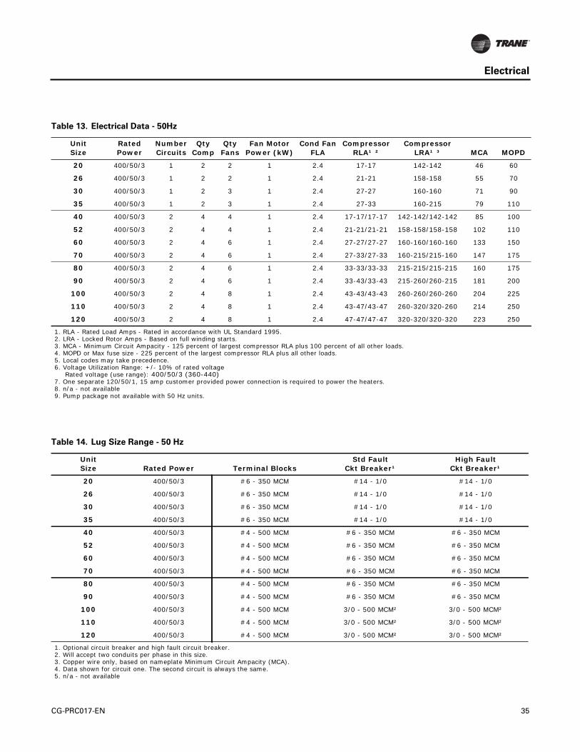
Electrical
Table 13. Electrical Data - 50Hz
UnitSize
Rated Power
Number Circuits
Qty Comp
Qty Fans
Fan Motor Power (kW)
Cond FanFLA
CompressorRLA¹ ²
CompressorLRA¹ ³ MCA MOPD
20 400/50/3 1 2 2 1 2.4 17-17 142-142 46 60
26 400/50/3 1 2 2 1 2.4 21-21 158-158 55 70
30 400/50/3 1 2 3 1 2.4 27-27 160-160 71 90
35 400/50/3 1 2 3 1 2.4 27-33 160-215 79 110
40 400/50/3 2 4 4 1 2.4 17-17/17-17 142-142/142-142 85 100
52 400/50/3 2 4 4 1 2.4 21-21/21-21 158-158/158-158 102 110
60 400/50/3 2 4 6 1 2.4 27-27/27-27 160-160/160-160 133 150
70 400/50/3 2 4 6 1 2.4 27-33/27-33 160-215/215-160 147 175
80 400/50/3 2 4 6 1 2.4 33-33/33-33 215-215/215-215 160 175
90 400/50/3 2 4 6 1 2.4 33-43/33-43 215-260/260-215 181 200
100 400/50/3 2 4 8 1 2.4 43-43/43-43 260-260/260-260 204 225
110 400/50/3 2 4 8 1 2.4 43-47/43-47 260-320/320-260 214 250
120 400/50/3 2 4 8 1 2.4 47-47/47-47 320-320/320-320 223 250
1. RLA - Rated Load Amps - Rated in accordance with UL Standard 1995.2. LRA - Locked Rotor Amps - Based on full winding starts.3. MCA - Minimum Circuit Ampacity - 125 percent of largest compressor RLA plus 100 percent of all other loads.4. MOPD or Max fuse size - 225 percent of the largest compressor RLA plus all other loads.5. Local codes may take precedence.6. Voltage Utilization Range: +/- 10% of rated voltage
Rated voltage (use range): 400/50/3 (360-440)7. One separate 120/50/1, 15 amp customer provided power connection is required to power the heaters.8. n/a - not available9. Pump package not available with 50 Hz units.
Table 14. Lug Size Range - 50 Hz
Unit Size Rated Power Terminal Blocks
Std Fault Ckt Breaker¹
High Fault Ckt Breaker¹
20 400/50/3 #6 - 350 MCM #14 - 1/0 #14 - 1/0
26 400/50/3 #6 - 350 MCM #14 - 1/0 #14 - 1/0
30 400/50/3 #6 - 350 MCM #14 - 1/0 #14 - 1/0
35 400/50/3 #6 - 350 MCM #14 - 1/0 #14 - 1/0
40 400/50/3 #4 - 500 MCM #6 - 350 MCM #6 - 350 MCM
52 400/50/3 #4 - 500 MCM #6 - 350 MCM #6 - 350 MCM
60 400/50/3 #4 - 500 MCM #6 - 350 MCM #6 - 350 MCM
70 400/50/3 #4 - 500 MCM #6 - 350 MCM #6 - 350 MCM
80 400/50/3 #4 - 500 MCM #6 - 350 MCM #6 - 350 MCM
90 400/50/3 #4 - 500 MCM #6 - 350 MCM #6 - 350 MCM
100 400/50/3 #4 - 500 MCM 3/0 - 500 MCM² 3/0 - 500 MCM²
110 400/50/3 #4 - 500 MCM 3/0 - 500 MCM² 3/0 - 500 MCM²
120 400/50/3 #4 - 500 MCM 3/0 - 500 MCM² 3/0 - 500 MCM²
1. Optional circuit breaker and high fault circuit breaker.2. Will accept two conduits per phase in this size.3. Copper wire only, based on nameplate Minimum Circuit Ampacity (MCA). 4. Data shown for circuit one. The second circuit is always the same.5. n/a - not available
CG-PRC017-EN 35

Electrical Connections
36 CG-PRC017-EN

Electrical Connections
C
TRANE
CG-PRC017-EN 37

Electrical Connections
REPLACEMENT FUSE TABLEFUSE VOLTAGE Hz CLASS AMPS NOTES
FACTORY PROVIDED PUMP INVERTER FUSE
38 CG-PRC017-EN
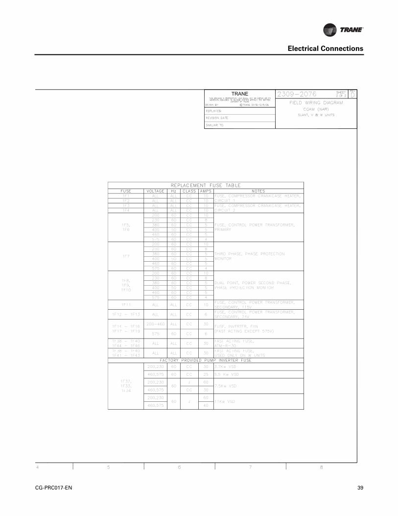
Electrical Connections
C
TRANE
REPLACEMENT FUSE TABLEFUSE VOLTAGE Hz CLASS AMPS NOTES1F1 ALL ALL CC 101F2 ALL ALL CC 101F3 ALL ALL CC 101F4 ALL ALL CC 10
200 60 CC 10230 60 CC 8380 60 CC 5400 50 CC 5460 60 CC 5575 60 CC 4200 60 CC 10230 60 CC 8380 60 CC 5400 50 CC 5460 60 CC 5575 60 CC 4200 60 CC 10230 60 CC 8380 60 CC 5400 50 CC 5460 60 CC 5575 60 CC 4
1F11 ALL ALL CC 10FUSE, CONTROL POWER TRANSFORMER,SECONDARY, 115V
1F12 - 1F13 ALL ALL CC 6FUSE, CONTROL POWER TRANSFORMER,SECONDARY, 24V
200-460 ALL CC 30
575 60 CC 6
1F38 - 1F401F44 - 1F46
ALL ALL CC 30FAST ACTING FUSE,ATM-R-30
1F38 - 1F401F41 - 1F43
ALL ALL CC 30FAST ACTING FUSE,USED ONLY ON W UNITS
FACTORY PROVIDED PUMP INVERTER FUSE
200,230 60 CC 30 3.7Kw VSD
460,575 60 CC 25 5.5 Kw VSD
200,230 J 60
460,575 CC 30
200,230 60
460,575 40
1F14 - 1F161F17 - 1F19
FUSE, INVERTER, FAN(FAST ACTING EXCEPT 575V)
FUSE, COMPRESSOR CRANKCASE HEATER,CIRCUIT 1FUSE, COMPRESSOR CRANKCASE HEATER,CIRCUIT 2
FUSE, CONTROL POWER TRANSFORMER,PRIMARY
THIRD PHASE, PHASE PROTECTIONMONITOR
DUAL POINT, POWER SECOND PHASE,PHASE PROTECTION MONITOR
1F8,1F9,1F10
1F7
1F5,1F6
1F32,1F33,1F34
60
60 J 11Kw VSD
7.5Kw VSD
CG-PRC017-EN 39

Dimensions
Figure 4. CGAM 20 and 26 ton
Figure 5. CGAM 20 and 26 ton - service clearances and mounting locations
ConnectionWire
Control
Fan
Compressor
Chilled waterinlet
Chilledwater
84.7 in(2151 mm)
50.4 in(1279 mm)
(535 mm)21.2 in
92.7 in(2354 mm)
113.8 in (2890 mm)
20.3 in
(246 mm)9.7 in
(429 mm)16.98 in
Panel
outlet
Water connections are 1.7 in (44 mm)from the end.
(515 mm)
The number of fans shown does not represent the number of fans installed.
Mounting Locations
Door
Service Clearance
Hole dia
Distance from edge to
(600 mm)
39.4 in(1000 mm)
(533 mm)
23.6 in
101.2 in (2570 mm)47.2 in (1200 mm)
47.2 inSwing
21 in
0.59 in (15 mm)middle of mounting hole
(1199 mm)
1.5 in (38 mm)
31.5 in (800 mm)
Controlpanel side
Total of four mounting locations.More clearance may be needed for airflowdepending on the installation.
Chilled water
connection side
The number of fans shown does not represent the number of fans installed.
40 CG-PRC017-EN

Dimensions
Figure 6. CGAM 30 and 35 ton
Figure 7. CGAM 30 and 35 ton - service clearances and mounting locations
ConnectionWire
Control
Fan
Compressor
Chilled waterinlet
Chilled wateroutlet
84.7 in(2151 mm)
50.4 in(1279 mm)
(541 mm)21.3 in
128.4 in (3263 mm)
149.8 in (3804 mm)
20.3 in
(246 mm)9.7 in
(429 mm)
Panel
16.9 in
Water connections are 1.6 in (40 mm)from unit end.
The number of fans shown does not represent the number of fans installed.
(516 mm)
Mounting Locations
Door
Service Clearance
Hole dia
Distance from edge to
(600 mm)
39.4 in(1000 mm)
(556 mm)
23.6 in
132.2 in (3358 mm)47.2 in (1200 mm)
47.2 inSwing
21.9 in
0.59 in (15 mm)
middle of mounting hole
(1199 mm)
1.5 in (38 mm)
31.5 in (800 mm)
Controlpanel side
Total of four mounting locations.More clearance may be needed for airflowdepending on the installation.
The number of fans shown does not represent the number of fans installed.
Chilled waterconnection side
CG-PRC017-EN 41

Dimensions
Figure 8. CGAM 40 and 52 ton
Control PanelWire
Connection
84.8 in(2155 mm)
Fan Compressor
Chilled waterinlet
Chilled wateroutlet
88.4 in(2245 mm)
113.8 in (2890 mm)
23.8 in (603 mm)
89.9 in(2282 mm)
14.4 in(367 mm)
7.9 in
25.8 in
Water connections are even with unit end.
(656 mm)
(200 mm)
The number of fans shown does not represent the number of fans installed.
Figure 9. CGAM 40 and 52 ton- service clearances and mounting locations
Mounting Locations
Door
Service Clearance
Hole dia
Distance from edge to
(1000 mm)
39.4 in (1000 mm)
(493 mm)
39.4 in
94 in (2388 mm)
47.2 in (1200 mm)
85.4 in
Swing
19.4 in
0.56 in (15 mm)
middle of mounting hole
(2164 mm)
1.5 in (38 mm)
31.5 in
(800 mm)
Controlpanel side
Total of four mounting locations.More clearance may be needed for airflowdepending on the installation.
Chilled waterconnection side
The number of fans shown does not represent the number of fans installed.
42 CG-PRC017-EN
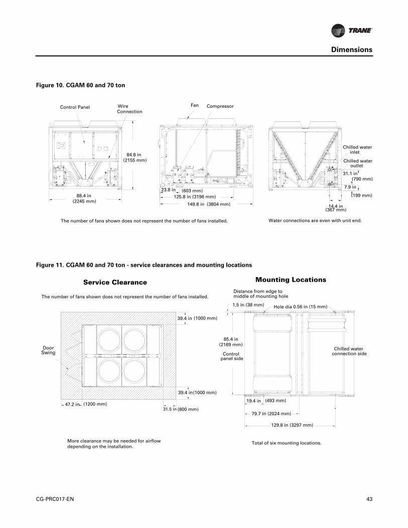
Dimensions
Figure 10. CGAM 60 and 70 ton
inletChilled water
Chilled wateroutlet
31.1 in
7.9 in
(367 mm)14.4 in
CompressorFan
125.8 in (3196 mm)
149.8 in (3804 mm)
(603 mm)23.8 in88.4 in
(2245 mm)
(2155 mm)84.8 in
Control PanelConnectionWire
Water connections are even with unit end.The number of fans shown does not represent the number of fans installed.
(199 mm)
(790 mm)
Figure 11. CGAM 60 and 70 ton - service clearances and mounting locations
Mounting Locations
Door
Service Clearance
Hole dia
Distance from edge to
(1000 mm)
39.4 in(1000 mm)
(493 mm)
39.4 in
129.8 in (3297 mm)
47.2 in (1200 mm)
85.4 in
79.7 in (2024 mm)
Swing
19.4 in
0.56 in (15 mm)
middle of mounting hole
(2169 mm)
1.5 in (38 mm)
31.5 in (800 mm)
Controlpanel side
Total of six mounting locations.More clearance may be needed for airflowdepending on the installation.
The number of fans shown does not represent the number of fans installed.
Chilled waterconnection side
CG-PRC017-EN 43

Dimensions
Figure 12. CGAM 80 and 90 ton
inletChilled water
Chilled wateroutlet
(790 mm)31.1 in
(200 mm)7.9 in
(292 mm)11.5 in
CompressorFan
89.2 in (2265 mm)
143.1 in (3634 mm)
(751 mm)29.6 in88.9 in
(2257 mm)
(2352 mm)92.6 in
PanelControl
WireConnection
Water connections are 5.5 in (139 mm)from unit end.The number of fans shown does not represent the number of fans installed.
Figure 13. CGAM 80 and 90 ton - service clearances and mounting locations
Mounting Locations
Door
Service Clearance
Hole dia
Distance from edge to
(1000 mm)
39.4 in (1000 mm)(767 mm)
39.4 in
123.9 in (3147 mm)
47.2 in
(1200 mm)
85.9 in
83.7 in (2126 mm)
Swing
30.2 in
0.56 in (15 mm)middle of mounting hole
(2182 mm)
1.5 in (38 mm)
Controlpanel side
39.4 in (1000 mm)
Total of six mounting location.More clearance may be need for airflowdepending on the installation.
Chilled waterconnection side
The number of fans shown does not represent the number of fans installed.
44 CG-PRC017-EN

Dimensions
Figure 14. CGAM 100, 110 and 120 ton
Figure 15. CGAM 100, 110 and 120 ton- service clearances and mounting locations
inletChilled water
Chilled wateroutlet
(790 mm)31.1 in
(199 mm)7.9 in11.5 in
Water connections are 5.4 in (139 mm)
CompressorFan
111.7 in (2837 mm)
165.9 in (4214 mm)
(751 mm)29.6 in88.9 in(2257 mm)
(2349 mm)92.5 in
PanelControl
(292 mm)
from unit end.
WireConnection
The number of fans shown does not represent the number of fans installed.
Mounting Locations
Door
Service Clearance
Hole dia
Distance from edge to
(1000 mm)
39.4 in (1000 mm)(767 mm)
39.4 in
146.9 in (3731 mm)
47.2 in
(1200 mm)
85.9 in
89.2 in (2266 mm)
Swing
30.2 in
0.56 in (15 mm)middle of mounting hole
(2181 mm)
1.5 in (38 mm)
Controlpanel side
39.4 in (1000 mm)
Total of six mounting locations.More clearance may be needed for airflowdepending on the installation.
The number of fans shown does not represent the number of fans installed.
Chilled waterconnection side
CG-PRC017-EN 45

Dimensions
Figure 16. CGAM 130 ton
Figure 17. CGAM 130 ton- service clearances and mounting locations
inletChilled water
Chilled wateroutlet
(790 mm)31.1 in
(199 mm)7.9 in11.5 in
Water connections are 25 in (635 mm)
Compressor Fan
149.8 in (3804 mm)
201.9 in (5128 mm)
(751 mm)29.6 in88.9 in(2257 mm)
(2349 mm)92.5 in
PanelControl
(292 mm)
from unit end.
WireConnection
Mounting Locations
Door
Service Clearance
Hole dia
Distance from edge to
(1000 mm)
39.4 in (1000 mm)(767 mm)
39.4 in
130.6 in (3317 mm)
47.2 in
(1200 mm)
85.2in
69.5 in (1765 mm)
Swing
30.2 in
0.56 in (15 mm)middle of mounting hole
(2174 mm)
1.5 in (38 mm)
Controlpanel side
39.4 in (1000 mm)
Total of eight mounting locations.More clearance may be needed for airflowdepending on the installation.
The number of fans shown does not represent the
number of fans installed.
Chilled waterconnection side
163 in (4140 mm)
46 CG-PRC017-EN

Dimensions
Figure 18. CGAM 20 and 26 ton - pump package, partial heat recovery unit water connections
Chilled Chilled
Heating10.4 in(266 mm)
70.3 in (1784mm)
15.2 in (385 mm)
(182 mm)7.2 in
12.3 in
9.7 in
Pump Package Partial Heat Recovery
Heating
12.8 in
waterinletwater
outlet
outlet inlet
Partial heat recovery connections are even with unit edge.
as the standard unit unless pump package is ordered.
Water connections are 1.3 in (33 mm) from unit end.
(246 mm)(326 mm)
(312 mm)
The chilled water inlet and outlet connections are the same
Figure 19. CGAM 30 and 35 ton - pump package, partial heat recovery unit water connections
Chilled Chilled
Heating10.4 in(265 mm)
67.4 in (1712 mm)
15.2 in (385 mm)
(182 mm)7.2 in
12.4 in
9.7 in
Pump Package Partial Heat Recovery
Heating
12.9 in
waterinletwater
outlet
outlet inlet
Partial heat recovery connections are even with unit edge.
as the standard unit unless pump package is ordered.
Water connections are 1.3 in (33mm) from unit end.
(246 mm)(327 mm)
(314 mm)
The chilled water inlet and outlet connections are the same
CG-PRC017-EN 47

Dimensions
Figure 20. CGAM 40 and 52 ton- pump package, partial heat recovery unit water connections
Chilled water
66.9 in (1696 mm)
44.2 in
(1149 mm)45.3in
18.8 in
Pump Package Partial Heat RecoveryHeating outlet
9.2 in
Chilled water
19.7 in(234 mm)
(499 mm)
(474 mm)
Heating inlet
inlet
outlet
Partial heat recovery connections are even with unit end.
Water outlet connection is even with unit end,inlet is 6.1 in (154 mm) from unit end.
(1122 mm)
54.8 in
The chilled water connections are the same as the standardunit unless pump package is ordered.
(1392 mm)
Figure 21. CGAM60 and 70 ton- pump package, partial heat recovery unit water connections
Chilled water
66.9 in (1696 mm)
44.3 in
(1158 mm)45.6 in
18.8 in
Pump Package Partial Heat RecoveryHeating outlet
9.2 in
Chilled water
19.7 in(234 mm)
(499 mm)
(474 mm)
Heating inlet
inlet
outlet
Partial heat recovery connections are even with unit end.
Water outlet connection is even with unit end,inlet is 6.1 in (154 mm) from unit end.
(1125 mm)
55.2 in
The chilled water connections are the same as the standardunit unless pump package is ordered.
(1401 mm)
48 CG-PRC017-EN
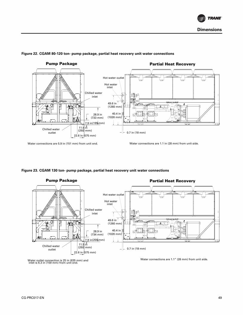
Dimensions
Figure 22. CGAM 80-120 ton- pump package, partial heat recovery unit water connections
Chilled water
22.6 in (575 mm)
7.9 in
Pump Package
11.5 in
Chilled water
28.9 in
(292 mm)
(733 mm)
(199 mm)
inlet
outlet
Water connections are 5.9 in (151 mm) from unit end.
Hot waterinlet
40.4 in
49.6 in
(1026 mm)
(1260 mm)
0.7 in (18 mm)
Hot water outlet
Partial Heat Recovery
Water connections are 1.1 in (28 mm) from unit side.
Figure 23. CGAM 130 ton- pump package, partial heat recovery unit water connections
Chilled water
22.6 in (575 mm)
7.9 in
Pump Package
11.5 in
Chilled water
28.9 in
(292 mm)
(734 mm)
(200 mm)
inlet
outlet
Water outlet connection is 25 in (635 mm) andinlet is 6.3 in (159 mm) from unit end.
Hot waterinlet
40.4 in
49.6 in
(1026 mm)
(1260 mm)
0.7 in (18 mm)
Hot water outlet
Partial Heat Recovery
Water connections are 1.1” (28 mm) from unit side.
CG-PRC017-EN 49

Weights
Weights
Table 15. Weights - 60 Hz
Tons
Without Pump With Pump Partial Heat Recovery - add Copper - add
Shipping Operating Shipping Operating Shipping Operating Additional
lbs kg lbs kg lbs kg lbs kg lbs kg lbs kg lbs kg
20 2185 991 2207 1002 2726 1236 2814 1277 39 18 24 11 258 117
26 2249 1020 2278 1034 2790 1265 2891 1311 39 8 31 14 258 117
30 2846 1291 2879 1306 3388 1537 3496 1586 47 21 36 16 360 163
35 2878 1305 2919 1325 3420 1551 3545 1608 47 21 44 20 360 163
40 3666 1663 3696 1677 4285 1944 4382 1988 94 43 34 15 515 234
52 3761 1706 3805 1726 4379 1986 4505 2044 94 43 49 22 515 234
60 4978 2258 5032 2283 5814 2637 5984 2715 111 50 59 27 719 326
70 5045 2289 5119 2323 5881 2668 6092 2764 111 50 80 36 719 326
80 5607 2543 5691 2582 6486 2942 6788 3080 170 77 90 41 1270 576
90 5859 2658 5959 2704 6738 3056 7073 3209 170 77 109 49 1270 576
100 6646 3015 6757 3066 7549 3424 7907 3587 178 81 120 54 1511 686
110 6724 3050 6844 3105 7627 3460 8003 3631 178 81 129 59 1511 686
120 6762 3067 6882 3122 8018 3637 8393 3808 178 81 131 60 1511 686
130 7753 3517 7898 3583 9006 4085 9427 4277 178 81 156 71 1889 857
1. Weights based on aluminum fins, refrigerant charge, isolators, circuit breaker and louvers.2. Base unit weights are shown above on the left side for units without a pump package and units with a pump package. The partial heat recovery and
copper weights are in addition to the base unit weights.
Table 16. Weights - 50 Hz
Tons
Base Unit Partial Heat Recovery - add Copper
Shipping Weight Operating Weight Shipping Weight Operating Weight Additional
lbs kg lbs kg lbs kg lbs kg lbs kg
20 2187 992 2209 1002 39 18 24 11 258 117
26 2249 1020 2278 1034 39 18 31 14 258 117
30 2845 1291 2879 1306 47 21 36 16 360 163
35 2877 1305 2919 1325 47 21 44 20 360 163
40 3665 1663 3696 1677 94 43 34 15 515 234
52 3760 1706 3805 1726 94 43 48 22 515 234
60 4977 2258 5032 2283 111 50 59 27 719 326
70 5044 2289 5119 2323 111 50 79 36 719 326
80 5606 2543 5691 2582 170 77 90 41 1270 576
90 5857 2657 5958 2703 170 77 107 49 1270 576
100 6628 3007 6741 3059 178 81 118 54 1511 686
110 6711 3045 6833 3100 178 81 129 59 1511 686
120 6756 3065 6878 3121 178 81 129 59 1511 686
1. Weights based on aluminum fins, refrigerant charge, isolators, circuit breaker and louvers.2. The partial heat recovery and copper weights are in addition to the base unit weights.
50 CG-PRC017-EN

Mechanical Specifications
General
Units are constructed of galvanized steel frame with galvanized steel panels and access doors.Component surfaces are finished with a powder-coated paint. Each unit ships with full operatingcharges of refrigerant and oil.
Compressor and Motor
The unit is equipped with two or more hermetic, direct-drive, 3600 rpm 60 Hz (3000 rpm 50 Hz)suction gas-cooled scroll compressors. The simple design has only three major moving parts anda completely enclosed compression chamber which leads to increased efficiency. Overloadprotection is included. The compressor includes: centrifugal oil pump, oil level sight glass and oilcharging valve. Each compressor will have compressor heaters installed and properly sized tominimize the amount of liquid refrigerant present in the oil sump during off cycles.
Unit-Mounted Starter
The control panel is designed per UL 1995. The starter is an across-the-line configuration, factory-mounted and fully pre-wired to the compressor motor and control panel. A factory-installed,factory-wired 820 VA control power transformer provides all unit control power (120 Vacsecondary) and Trane CH530 module power (24 Vac secondary). Power line connection type isstandard with a terminal block.
Evaporator
Braze plate heat exchanger is made of stainless steel with copper as the braze material. It isdesigned to withstand a refrigerant side working pressure of 430 psig (29.6 bars) and a watersideworking pressure of 150 psig (10.5 bars). Evaporator is tested at 1.1 times maximum allowablerefrigerant side working pressure and 1.5 times maximum allowable water side working pressure.It has one water pass. Immersion heaters protect the evaporator to an ambient of -20°F (-29°C).
The evaporator is covered with factory-installed 0.75 inch (19.05 mm) Armaflex II or equal (k=0.28)insulation. Foam insulation is used on the suction line. Water pipe extensions with insulation gofrom the evaporator to the edge of the unit.
Condenser
Air-cooled condenser coils have aluminum fins mechanically bonded to internally-finned coppertubing. The condenser coil has an integral subcooling circuit. The maximum allowable workingpressure of the condenser is 650 psig (44.8 bars). Condensers are factory proof and leak tested at715 psig (49.3 bars).
Direct-drive vertical discharge condenser fans are balanced. Three-phase condenser fan motorswith permanently lubricated ball bearings and external thermal overload protection are provided.
Units start and operate from 0°F to 125°F (-18°C to 52°C) for wide ambient. Wide ambient allowsoperation down to 0°F which is accomplished by a variable speed fan on each circuit that modulatesto maintain system differential pressure.
Refrigerant Circuit and Capacity Modulation
The 20-35 ton units have single refrigerant circuits. The 40-130 ton units have dual refrigerantcircuits. Each refrigerant circuit has Trane scroll compressors piped in parallel with a passive oilmanagement system. A passive oil management system maintains proper oil levels withincompressors and has no moving parts. Each refrigerant circuit includes filter drier, electronicexpansion valve, and liquid line and discharge service valves.
Capacity modulation is achieved by turning compressors on and off. The 20-35 ton units have twocapacity stages. The 40-120 ton units have four capacity stages. The 130 ton unit has six capacitystages.
CG-PRC017-EN 51

Mechanical Specifications
Unit Controls (Trane CH530)
The microprocessor-based control panel is factory-installed and factory-tested. The control systemis powered by a pre-wired control power transformer, and will turn on and off compressors to meetthe load. Microprocessor-based chilled water reset based on return water is standard.
The Trane CH530 microprocessor automatically acts to prevent unit shutdown due to abnormaloperating conditions associated with low evaporator refrigerant temperature and high condensingtemperature. If an abnormal operating condition continues and the protective limit is reached, themachine will shut down.
The panel includes machine protection for the following conditions:
• Low evaporator refrigerant temperature and pressure
• High condenser refrigerant pressure
• Critical sensor or detection circuit faults
• High compressor discharge temperature (with low temp evaporator)
• Lost communication between modules
• Electrical distribution faults: phase loss, phase reversal or over temperature protection
• External and local emergency stop
• Loss of evaporator water flow
When a fault is detected, the control system conducts more than 100 diagnostic checks and displaysresults. The display will identify the fault, indicate date, time, and operating mode at time ofoccurrence, and provide type of reset required and a help message.
Clear Language Display Panel
Factory-mounted to the control panel door, the operator interface has an LCD touch-screen displayfor operator input and information output. This interface provides access to the followinginformation: evaporator report, condenser report, compressor report, ASHRAE Guideline 3 report,operator settings, service settings, service tests, and diagnostics. All diagnostics and messages aredisplayed in “clear language.”
Data contained in available reports includes:
• Water and air temperatures
• Refrigerant pressures and temperatures
• Flow switch status
• EXV position
• Compressor starts and run-time
All necessary settings and setpoints are programmed into the microprocessor-based controller viathe operator interface. The controller is capable of receiving signals simultaneously from a varietyof control sources, in any combination, and priority order of control sources can be programmed.The control source with priority determines active setpoints via the signal it sends to the controlpanel. Control sources may be:
• Local operator interface (standard)
• Hard-wired 4-20 mA or 2-10 Vdc signal from an external source (interface optional; controlsource not supplied)
• Time of day scheduling (optional capability available from local operator interface)
• LonTalk LCI-C (interface optional; control source not supplied)
• BACNet (interface optional; control source not supplied)
• Trane Tracer Summit system (interface optional; control source not supplied)
52 CG-PRC017-EN

Options
Quality Assurance
The quality management system applied by Trane has been subject to independent third-partyassessment and approval to ISO 9001-2008. The products described in this catalog are designed,manufactured and tested in accordance with the approved system requirements described in theTrane Quality Manual.
Options
Application Options
Ice-Making with Hardwired Interface
Unit controls are factory set to handle ice-making for thermal storage application. An additionaltemperature sensor, at the compressor discharge, enables full load operation of the chiller withentering evaporator fluid temperature between 20°F (-7°C) and 65°F (18°C) with glycol.
High Ambient
The unit starts and operates from 32°F to 125°F (0°C to 52°C).
Low-Temperature Processing
An additional temperature sensor, at the compressor discharge, enables leaving evaporator fluidtemperature between 10°F (-12.2°C) and 42°F (5.5°C) with glycol.
Partial Heat Recovery with Fan Control
A supplemental brazed plate heat exchanger is mounted in series to the condenser coil. Connectingpiping and inlet and outlet water sensors are included. CH530 controls display heat recovery inletand outlet water temperatures and controls the fans. The heat rejection to the partial heat recoveryheat exchanger is not controlled. Flow and temperature variations through the partial heat recoveryheat exchanger will vary. The partial heat recovery heat exchanger is typically used to preheat waterbefore it enters a boiler or other water heating process.
Dual High Head Pump Package
Pump package includes: two high head pumps, VFD, expansion vessels, drainage valves, shut-offvalves at entering and leaving connections.
The pump package is single point power integrated into the chiller unit power with a separatefactory wired control panel.The control of the pump is integrated into the chiller controller. TheCH530 displays evaporator pump starts and run-times. Freeze protection down to an ambient of-20°F (-29°C) is included as standard. The cold parts of the pump package will also be insulated.
Designed with one redundant pump, the chiller controls both pumps through a lead/lag andfailure/recovery functionality.
A variable speed drive is installed in an additional panel to control the pump. The inverter isadjusted upon start up to balance the system flow and head requirements. The purpose is to saveon wasted pump energy caused by a traditional balancing valve.
CG-PRC017-EN 53

Options
Electrical Options:
Circuit Breaker
A molded case standard interrupting capacity circuit breaker, factory pre-wired with terminal blockpower connections and equipped with a lockable external operator handle, is available todisconnect the chiller from main power.
Circuit Breaker with High Fault Rated Control Panel
A molded case high interrupting capacity circuit breaker, factory pre-wired with terminal blockpower connections and equipped with a lockable external operator handle, is available todisconnect the chiller from main power.
Short Circuit Rating
Short circuit rating of 5 kA or up to 65 kA is available.
Control Options:
BACNet Interface
Allows user to easily interface with BACNet via a single twisted-pair wiring to a factory-installedand tested communication board.
LonTalk/Tracer Summit Interface
LonTalk (LCI-C) or Tracer Summit communications capabilities are available with communicationlink via single twisted-pair wiring to factory-installed and tested communication board. This optionwill support the functionality required to obtain Lon Mark certification.
Time of Day Scheduling
Time of day scheduling capabilities are available for scheduling single chiller applications throughTrane CH530 panel (without the need for building automation system - BAS). This feature allowsthe user to set up to ten events in a seven day time period.
External Chilled Water and Demand Limit Setpoint
Controls, sensors, and safeties allow reset of chilled water temperature, based on temperaturesignal, during periods of low outdoor air temperature (chilled water reset based on return chilledwater temperature is standard). The demand limit setpoint is communicated to a factory-installedand tested communication board through a 2-10 Vdc or 4-20 mA signal.
Percent Capacity
Output the number of compressors that are operating as an analog 2-10 Vdc or 4-20 mA signal.
Programmable Relays
Predefined, factory-installed, programmable relays allow the operation to select four relay outputs.Available outputs are: Alarm-Latching, Alarm-Auto Reset, General Alarm, Warning, Chiller LimitMode, Compressor Running, and Tracer Control.
54 CG-PRC017-EN

Options
Other Options
Architectural Louvered Panels
Louvered panels cover the complete condensing coil and service area beneath the condenser.
Half Louvers
Louvered panels cover the condenser coil only. Available on the 80-130 ton units only.
Comprehensive Acoustic Package
This option includes acoustical treatment for compressor.
Condenser Coil - CompleteCoat
Condenser coils are made of aluminum fins (plate fins) mechanically bonded to internally finnedcopper tubes. The condenser box is then submerged in an epoxy polymer bath where anelectrostatic charge is used to uniformly deposit the epoxy onto the coil. This option resists bi-metallic corrosion and allows for operation in coastal environments.
Condenser Coil - Copper
Condenser coils are made of non-slit copper fins (plate fins) mechanically bonded to internallyfinned copper tubes. Copper fins and copper tubes reduce material deterioration due to galvaniccorrosion.
Isolators
Molded elastomeric isolators sized to reduce vibration transmission to the supporting structurewhen the unit is installed. Isolators ship with the chiller.
Isolators - Seismically Rated
Spring isolators are designed and tested to control the motion of the chiller during a seismic event.
Insulation for High Humidity
The evaporator is covered with factory-installed 1.25 inch (31.8 mm) Armaflex II or equal (k=0.28)insulation. Foam insulation is used on the suction line.
Nitrogen Charge
Unit is shipped with oil and a nitrogen charge in lieu of refrigerant.
Performance Test
Performance tests are available to certify chiller performance before shipment.
Seismically Rated Unit - IBC
Unit is built and certified for seismic applications in accordance with the following InternationalBuilding Code (IBC) releases 2000, 2003, 2006 and 2009.
Seismically Rated Unit - OSHPD
Unit is built and certified for seismic applications in accordance with OSHPD.
CG-PRC017-EN 55
Trane optimizes the performance of homes and buildings around the world. A business of Ingersoll Rand, theleader in creating and sustaining safe, comfortable and energy efficient environments, Trane offers a broadportfolio of advanced controls and HVAC systems, comprehensive building services, and parts.For more information, visit www.Trane.com.
Trane has a policy of continuous product and product data improvement and reserves the right to change design and specifications without notice.
We are committed to using environmentally
conscious print practices that reduce waste.
© 2012 Trane All rights reserved
CG-PRC017-EN 13 Jan 2012
Supersedes CG-PRC017-EN (01 Jun 2011)