product catalogue - peak well · pdf fileproduct catalogue. index . flow control ... large...
TRANSCRIPT
Product Catalogue
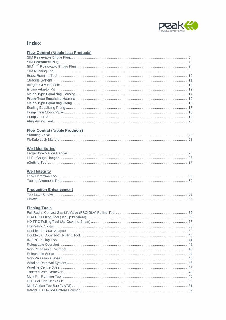
Index Flow Control (Nipple-less Products) SIM Retrievable Bridge Plug........................................................................................................................... 6 SIM Permanent Plug ...................................................................................................................................... 7 SIMPLUS Retrievable Bridge Plug .................................................................................................................... 8 SIM Running Tool ........................................................................................................................................... 9 Boost Running Tool ........................................................................................................................................ 10 Straddle System ............................................................................................................................................. 11 Integral GLV Straddle ..................................................................................................................................... 12 E-Line Adaptor Kit .......................................................................................................................................... 13 Melon-Type Equalising Housing ..................................................................................................................... 14 Prong-Type Equalising Housing ..................................................................................................................... 15 Melon-Type Equalising Prong......................................................................................................................... 16 Sealing Equalising Prong ............................................................................................................................... 17 Pump Thru Check Valve ................................................................................................................................. 18 Pump Open Sub ............................................................................................................................................. 19 Plug Pulling Tool ............................................................................................................................................. 20 Flow Control (Nipple Products) Standing Valve ............................................................................................................................................... 22 FloSafe Lock Mandrel ..................................................................................................................................... 23 Well Monitoring Large Bore Gauge Hanger ............................................................................................................................. 25 Hi-Ex Gauge Hanger ...................................................................................................................................... 26 eSetting Tool .................................................................................................................................................. 27 Well Integrity Leak Detection Tool ........................................................................................................................................ 29 Tubing Alignment Tool .................................................................................................................................... 30 Production Enhancement Top Latch Choke ............................................................................................................................................ 32 FloWell ........................................................................................................................................................... 33 Fishing Tools Full Radial Contact Gas Lift Valve (FRC-GLV) Pulling Tool ........................................................................... 35 HD-FRC Pulling Tool (Jar Up to Shear) .......................................................................................................... 36 HD-FRC Pulling Tool (Jar Down to Shear) ..................................................................................................... 37 HD Pulling System .......................................................................................................................................... 38 Double Jar Down Adaptor .............................................................................................................................. 39 Double Jar Down FRC Pulling Tool ................................................................................................................ 40 IN-FRC Pulling Tool ........................................................................................................................................ 41 Releasable Overshot ...................................................................................................................................... 42 Non-Releasable Overshot .............................................................................................................................. 43 Releasable Spear ........................................................................................................................................... 44 Non-Releasable Spear ................................................................................................................................... 45 Wireline Retrieval System .............................................................................................................................. 46 Wireline Centre Spear .................................................................................................................................... 47 Tapered Wire Retriever .................................................................................................................................. 48 Multi-Pin Running Tool ................................................................................................................................... 49 HD Dual Fish Neck Sub .................................................................................................................................. 50 Multi-Action Top Sub (MATS) ......................................................................................................................... 51 Integral Bell Guide Bottom Housing ................................................................................................................ 52
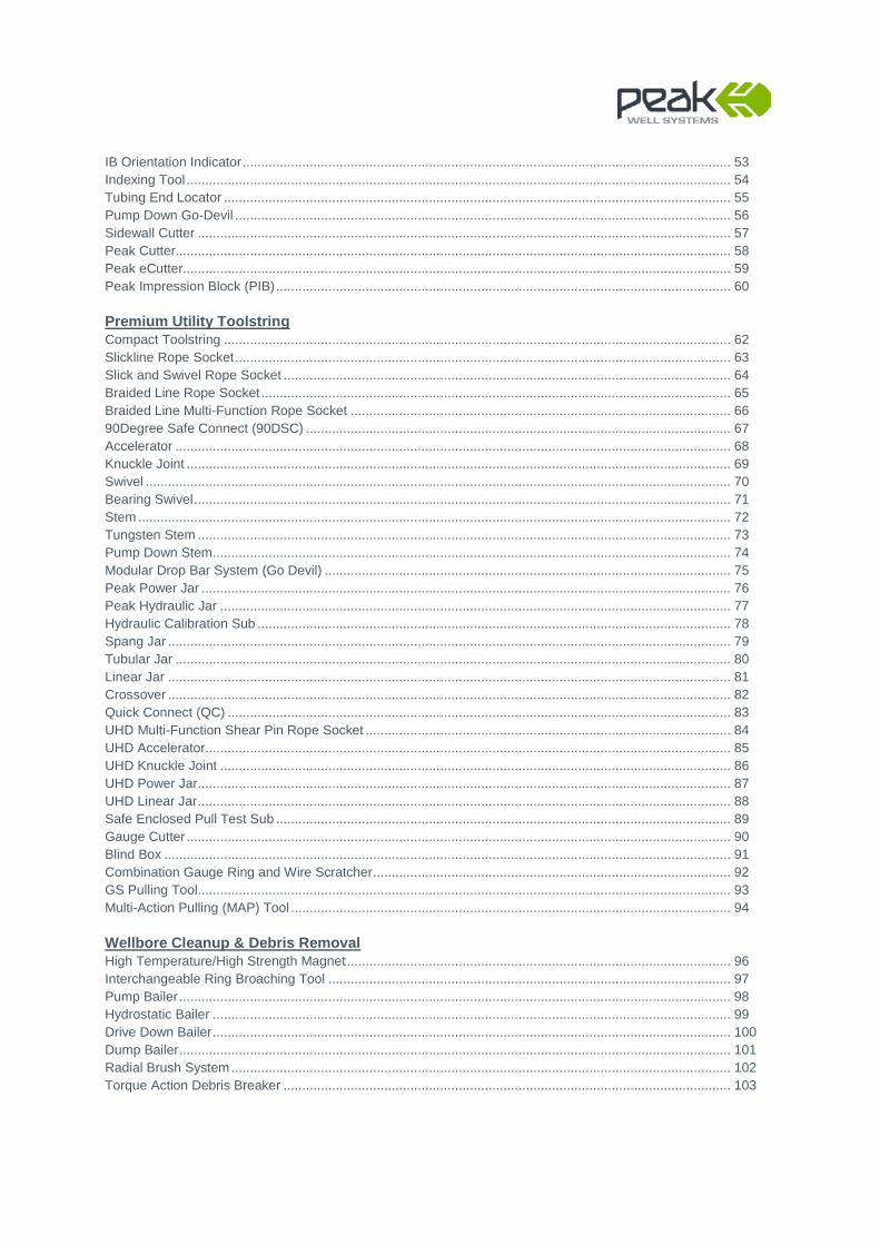
IB Orientation Indicator ................................................................................................................................... 53 Indexing Tool .................................................................................................................................................. 54 Tubing End Locator ........................................................................................................................................ 55 Pump Down Go-Devil ..................................................................................................................................... 56 Sidewall Cutter ............................................................................................................................................... 57 Peak Cutter..................................................................................................................................................... 58 Peak eCutter................................................................................................................................................... 59 Peak Impression Block (PIB) .......................................................................................................................... 60 Premium Utility Toolstring Compact Toolstring ........................................................................................................................................ 62 Slickline Rope Socket ..................................................................................................................................... 63 Slick and Swivel Rope Socket ........................................................................................................................ 64 Braided Line Rope Socket .............................................................................................................................. 65 Braided Line Multi-Function Rope Socket ...................................................................................................... 66 90Degree Safe Connect (90DSC) .................................................................................................................. 67 Accelerator ..................................................................................................................................................... 68 Knuckle Joint .................................................................................................................................................. 69 Swivel ............................................................................................................................................................. 70 Bearing Swivel ................................................................................................................................................ 71 Stem ............................................................................................................................................................... 72 Tungsten Stem ............................................................................................................................................... 73 Pump Down Stem ........................................................................................................................................... 74 Modular Drop Bar System (Go Devil) ............................................................................................................. 75 Peak Power Jar .............................................................................................................................................. 76 Peak Hydraulic Jar ......................................................................................................................................... 77 Hydraulic Calibration Sub ............................................................................................................................... 78 Spang Jar ....................................................................................................................................................... 79 Tubular Jar ..................................................................................................................................................... 80 Linear Jar ....................................................................................................................................................... 81 Crossover ....................................................................................................................................................... 82 Quick Connect (QC) ....................................................................................................................................... 83 UHD Multi-Function Shear Pin Rope Socket .................................................................................................. 84 UHD Accelerator ............................................................................................................................................. 85 UHD Knuckle Joint ......................................................................................................................................... 86 UHD Power Jar ............................................................................................................................................... 87 UHD Linear Jar ............................................................................................................................................... 88 Safe Enclosed Pull Test Sub .......................................................................................................................... 89 Gauge Cutter .................................................................................................................................................. 90 Blind Box ........................................................................................................................................................ 91 Combination Gauge Ring and Wire Scratcher ................................................................................................ 92 GS Pulling Tool ............................................................................................................................................... 93 Multi-Action Pulling (MAP) Tool ...................................................................................................................... 94 Wellbore Cleanup & Debris Removal High Temperature/High Strength Magnet ....................................................................................................... 96 Interchangeable Ring Broaching Tool ............................................................................................................ 97 Pump Bailer .................................................................................................................................................... 98 Hydrostatic Bailer ........................................................................................................................................... 99 Drive Down Bailer ........................................................................................................................................... 100 Dump Bailer .................................................................................................................................................... 101 Radial Brush System ...................................................................................................................................... 102 Torque Action Debris Breaker ........................................................................................................................ 103

Roller Systems Roller Stem ..................................................................................................................................................... 105 WellGlide ........................................................................................................................................................ 106 Fluted Centraliser ........................................................................................................................................... 107 Fluted Slip-Over Centraliser ........................................................................................................................... 108 Bespoke Products Telescoping Space-Out Joint.......................................................................................................................... 110 WellGuard Hydraulic Hold-Open Tool ............................................................................................................ 111
Flow Control(Nipple-less Products)

SIM Retrievable Bridge Plug (revision 16 October 2014) Product Code: 351 [email protected] www.peakwellsystems.com
UK Patent : GB2432607 & GB2424237 US Patent : US7,654,334B2 Australia Patent : 2004287895 Patent Pending - Malaysia and Thailand
SIM Retrievable Bridge Plug The SIM Retrievable Bridge Plug is an expandable seal-type barrier which can be mechanically set at any chosen depth inside monobore type completions, or completions where existing production nipples are damaged. The SIM Plug is conveyed using a conventional slickline toolstring. Once the setting depth has been reached, the SIM Plug is selectively set by indexing and anchoring the Running Tool. Downward jarring activates the bi-directional SIM Plug slips and expands the Sealing Element. Upward jarring releases the Running Tool from the SIM Plug body. For applications where the SIM Plug setting depth is critical, the SIM Plug can be deployed and set on electric line using standard pyrotechnic setting tools. The SIM Plug is recovered using a conventional GS Pulling Tool fitted with a Peak Multi-Action Top Sub (MATS) and Pulling Prong.
Applications
■ SIM Retrievable Bridge Plug ■ SIM Straddle & SIM Lift Straddle ■ SIM Lift (Top Latch Interchangeable Choke) ■ SIM Hanger as a gauge carrier for downhole tools
Features & Benefits
■ Multiple setting options - mechanically on slickline, coil tubing or electric line
■ Simplistic design, Simple to redress in the field ■ Multiple Equalising assembly options - Melon type, Prong type or
Pump-Open type ■ Uni- and bi-directional flow - ultimate flexibility to plug and divert flow ■ Debris Catcher Sub option for Sealing Plug version ■ High temperature / high pressure sealing element ■ Sour service components to NACE MR0175 specifications ■ Maximised “through bore” to reduce down hole “choke” effect ■ Interchangeable components for inventory reduction
Technical Information
Nominal Tubing Size
Tubing Weight
Actual OD
Pressure Rating
Max Temp.
Length Min ID
2 3/8” 4.6lbs/ft 1.810” 7,500 psi 350oF 54” 0.314”
** 2 7/8” 6.4lbs/ft 2.220” 7,500 psi See below
54” 0.781”
3 1/2” 12.7 lbs/ft 2.520” 7,500 psi 350oF 54” 0.781”
3 1/2” 9.2lbs/ft-10.2lbs/ft 2.720” *5,000 psi 350oF 61” 1.259”
4 1/2” 11.6lbs/ft-15.1lbs/ft
3.600”/ 3.650” *5,000 psi 350oF 59” 2.000”
5” 15lbs/ft-18lbs/ft 4.050” *5,000 psi 350oF 57” 1.969”
5 1/2” 17lbs/ft-20lbs/ft 4.530” *5,000 psi 350oF 61” 2.362”
* Higher Pressure Rating available on request ** 2 7/8”Standard Plug is rated to 5,000 psi @350oF or for 7,500 psi @250oF
SIM Permanent Plug Product Code: 370 [email protected] www.peakwellsystems.com
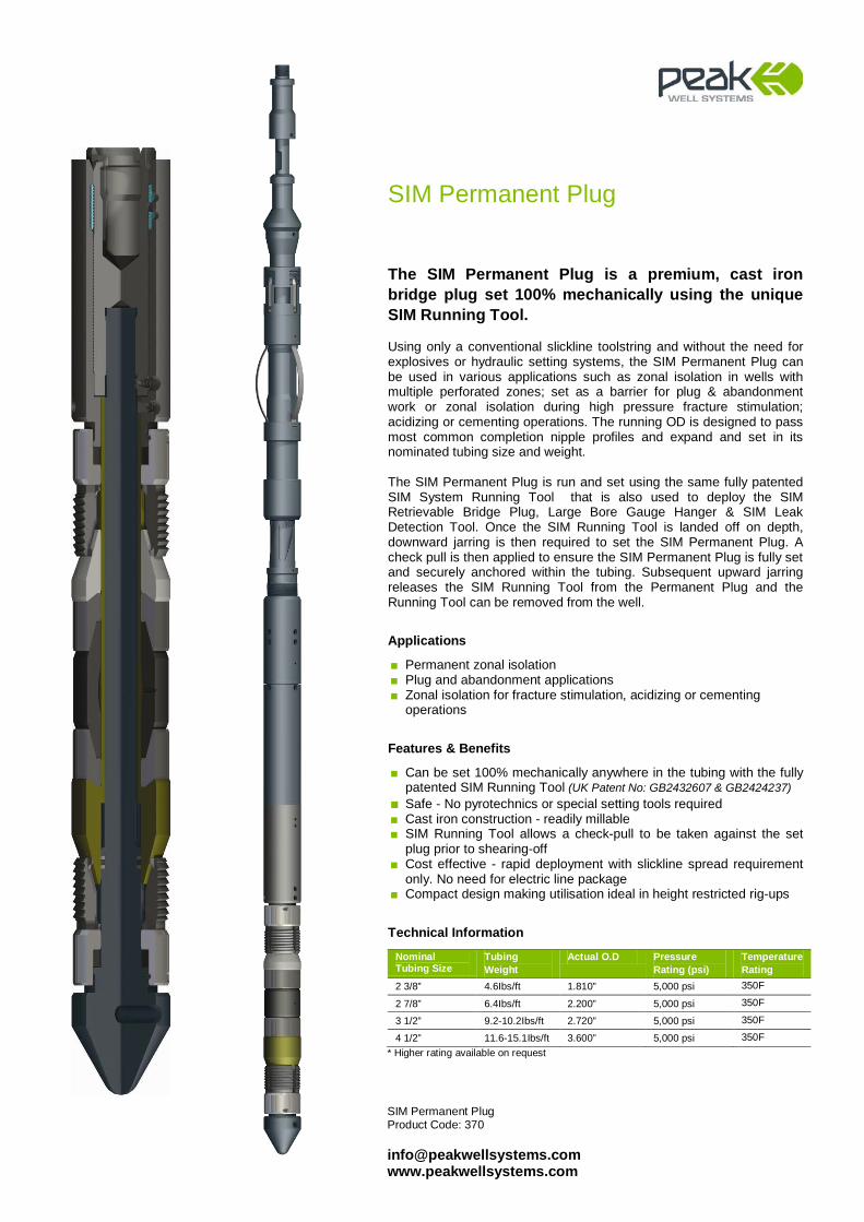
SIM Permanent Plug
The SIM Permanent Plug is a premium, cast iron bridge plug set 100% mechanically using the unique SIM Running Tool. Using only a conventional slickline toolstring and without the need for explosives or hydraulic setting systems, the SIM Permanent Plug can be used in various applications such as zonal isolation in wells with multiple perforated zones; set as a barrier for plug & abandonment work or zonal isolation during high pressure fracture stimulation; acidizing or cementing operations. The running OD is designed to pass most common completion nipple profiles and expand and set in its nominated tubing size and weight. The SIM Permanent Plug is run and set using the same fully patented SIM System Running Tool that is also used to deploy the SIM Retrievable Bridge Plug, Large Bore Gauge Hanger & SIM Leak Detection Tool. Once the SIM Running Tool is landed off on depth, downward jarring is then required to set the SIM Permanent Plug. A check pull is then applied to ensure the SIM Permanent Plug is fully set and securely anchored within the tubing. Subsequent upward jarring releases the SIM Running Tool from the Permanent Plug and the Running Tool can be removed from the well.
Applications
■ Permanent zonal isolation ■ Plug and abandonment applications ■ Zonal isolation for fracture stimulation, acidizing or cementing
operations
Features & Benefits
■ Can be set 100% mechanically anywhere in the tubing with the fully patented SIM Running Tool (UK Patent No: GB2432607 & GB2424237)
■ Safe - No pyrotechnics or special setting tools required ■ Cast iron construction - readily millable ■ SIM Running Tool allows a check-pull to be taken against the set
plug prior to shearing-off ■ Cost effective - rapid deployment with slickline spread requirement
only. No need for electric line package ■ Compact design making utilisation ideal in height restricted rig-ups
Technical Information
Nominal Tubing Size
Tubing Weight
Actual O.D Pressure Rating (psi)
Temperature Rating
2 3/8” 4.6Ibs/ft 1.810” 5,000 psi 350F
2 7/8” 6.4Ibs/ft 2.200” 5,000 psi 350F
3 1/2” 9.2-10.2Ibs/ft 2.720” 5,000 psi 350F
4 1/2” 11.6-15.1Ibs/ft 3.600” 5,000 psi 350F * Higher rating available on request
SIMPLUS Retrievable Bridge Plug (revision 24 August 2014) Product Code: 351
[email protected] www.peakwellsystems.com
UK Patent : GB2432607 & GB2424237 US Patent : US7,654,334B2 Australia Patent : 2004287895 Patent Pending - Malaysia and Thailand
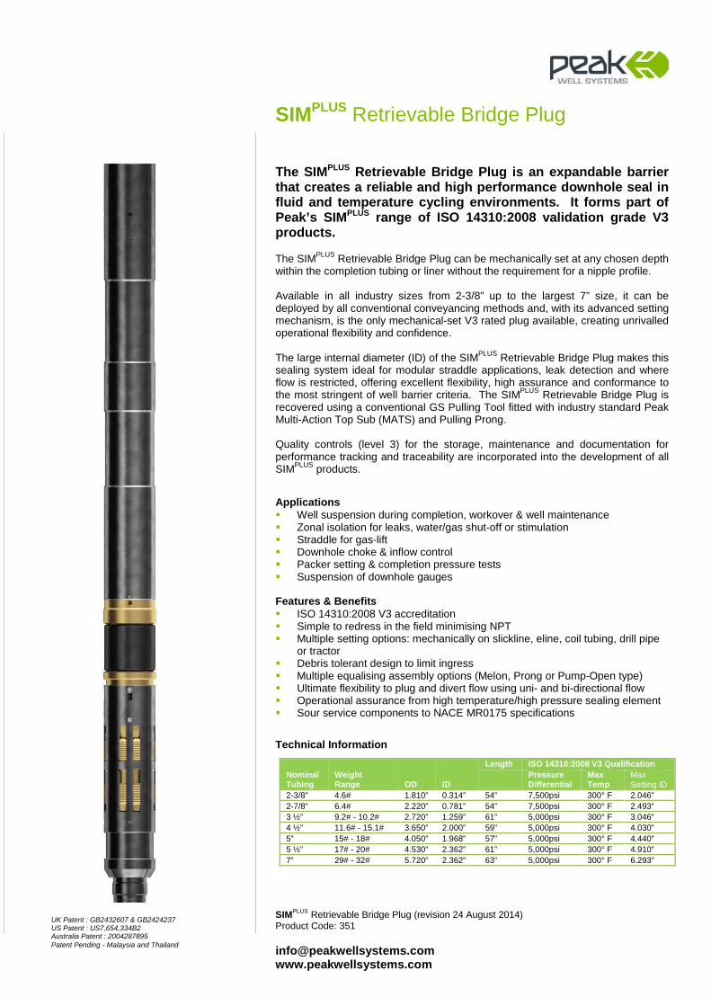
SIMPLUS Retrievable Bridge Plug
The SIMPLUS Retrievable Bridge Plug is an expandable barrier that creates a reliable and high performance downhole seal in fluid and temperature cycling environments. It forms part of Peak’s SIMPLUS range of ISO 14310:2008 validation grade V3 products.
The SIMPLUS Retrievable Bridge Plug can be mechanically set at any chosen depth within the completion tubing or liner without the requirement for a nipple profile. Available in all industry sizes from 2-3/8” up to the largest 7” size, it can be deployed by all conventional conveyancing methods and, with its advanced setting mechanism, is the only mechanical-set V3 rated plug available, creating unrivalled operational flexibility and confidence. The large internal diameter (ID) of the SIMPLUS Retrievable Bridge Plug makes this sealing system ideal for modular straddle applications, leak detection and where flow is restricted, offering excellent flexibility, high assurance and conformance to the most stringent of well barrier criteria. The SIMPLUS Retrievable Bridge Plug is recovered using a conventional GS Pulling Tool fitted with industry standard Peak Multi-Action Top Sub (MATS) and Pulling Prong. Quality controls (level 3) for the storage, maintenance and documentation for performance tracking and traceability are incorporated into the development of all SIMPLUS products.
Applications Well suspension during completion, workover & well maintenance Zonal isolation for leaks, water/gas shut-off or stimulation Straddle for gas-lift Downhole choke & inflow control Packer setting & completion pressure tests Suspension of downhole gauges Features & Benefits ISO 14310:2008 V3 accreditation Simple to redress in the field minimising NPT Multiple setting options: mechanically on slickline, eline, coil tubing, drill pipe
or tractor Debris tolerant design to limit ingress Multiple equalising assembly options (Melon, Prong or Pump-Open type) Ultimate flexibility to plug and divert flow using uni- and bi-directional flow Operational assurance from high temperature/high pressure sealing element Sour service components to NACE MR0175 specifications
Technical Information
Nominal Tubing
Weight Range OD ID
Length ISO 14310:2008 V3 Qualification
Pressure Differential
Max Temp
Max Setting ID
2-3/8” 4.6# 1.810” 0.314” 54” 7,500psi 300° F 2.046” 2-7/8” 6.4# 2.220” 0.781” 54” 7,500psi 300° F 2.493” 3 ½” 9.2# - 10.2# 2.720” 1.259” 61” 5,000psi 300° F 3.046” 4 ½” 11.6# - 15.1# 3.650” 2.000” 59” 5,000psi 300° F 4.030” 5” 15# - 18# 4.050” 1.968” 57” 5,000psi 300° F 4.440” 5 ½” 17# - 20# 4.530” 2.362” 61” 5,000psi 300° F 4.910” 7” 29# - 32# 5.720” 2.362” 63” 5,000psi 300° F 6.293”

SIM Running Tool (revision 03 April 2013) Product Code: 350 [email protected] www.peakwellsystems.com
SIM Running Tool
The SIM System is a series of mechanically interchangeable components designed to provide a range of applications for the purpose of well integrity and production management. The fully patented SIM Running Tool is used to convey and selectively set these components at any chosen depth inside monobore type completions. The SIM Running Tool is made up to the selected device at surface and conveyed into the well on a conventional slickline toolstring. A radial indexing mechanism activates a set of slips to anchor the Running Tool to the tubing wall at any desired setting depth. The device is then simply set by downward jarring. An overpull is applied to confirm the deployed component is fully set. Once set in place the SIM Running Tool is released from the device by upwards jarring.
Applications
Used for selectively setting:
■ SIM Retrievable Bridge Plugs ■ Mechanical Leak Detection Tool ■ Large Bore Gauge Hanger ■ SIM Permanent Plug
Features & Benefits
■ Continuous radial indexing mechanism ■ Variable drag Spring configurations ■ 100% mechanical - Simple to redress ■ Robust design
Technical Information
Nominal Tubing Size
Actual OD
2 3/8” 1.810”
2 7/8” 2.200”
3 1/2” 2.720”
4 1/2” 3.600”
5” 4.050”
5 1/2” 4.450”
7” 5.650”
UK Patent : GB2432607 & GB2424237 US Patent : US7,654,334B2 Australia : 2004287895 Patent Pending - Malaysia and Thailand
All Standard Industry Connections Available
Boost Running Tool (revision 27 October 2014)Product Code: 364
[email protected] www.peakwellsystems.com
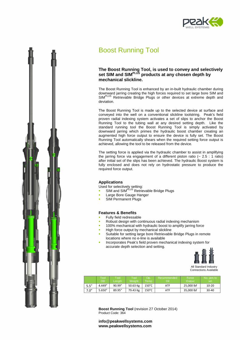
Boost Running Tool
The Boost Running Tool, is used to convey and selectively set SIM and SIMPLUS products at any chosen depth by mechanical slickline. The Boost Running Tool is enhanced by an in-built hydraulic chamber during downward jarring creating the high forces required to set large bore SIM and SIMPLUS Retrievable Bridge Plugs or other devices at extreme depth and deviation. The Boost Running Tool is made up to the selected device at surface and conveyed into the well on a conventional slickline toolstring. Peak’s field proven radial indexing system activates a set of slips to anchor the Boost Running Tool to the tubing wall at any desired setting depth. Like the standard running tool the Boost Running Tool is simply activated by downward jarring which primes the hydraulic boost chamber creating an augmented high force output to ensure the device is fully set. The Boost Running Tool automatically shears when the required setting force output is achieved, allowing the tool to be released from the device. The setting force is applied via the hydraulic chamber to assist in amplifying the jarring force via engagement of a different piston ratio (~ 2.5 : 1 ratio) after initial set of the slips has been achieved. The hydraulic Boost system is fully enclosed and does not rely on hydrostatic pressure to produce the required force output.
Applications Used for selectively setting: SIM and SIMPLUS Retrievable Bridge Plugs Large Bore Gauge Hanger SIM Permanent Plugs
Features & Benefits Fully field redressable Robust design with continuous radial indexing mechanism 100% mechanical with hydraulic boost to amplify jarring force High force output by mechanical slickline Suitable for setting large bore Retrievable Bridge Plugs in remote
locations where no e-line is available Incorporates Peak’s field proven mechanical indexing system for
accurate depth selection and setting.
Tool OD
Tool Length
Tool Weight
Op. Temp
Recommended Oil
Force Output
No. jars to set
5.5” 4.449” 90.99” 50.63 Kg 150°C ATF 25,000 lbf 10-20 7.0” 5.650” 89.95” 79.43 Kg 150°C ATF 35,000 lbf 30-40
All Standard Industry Connections Available
Straddle System (revision 20 August 2014) Product Code: 354 [email protected] www.peakwellsystems.com
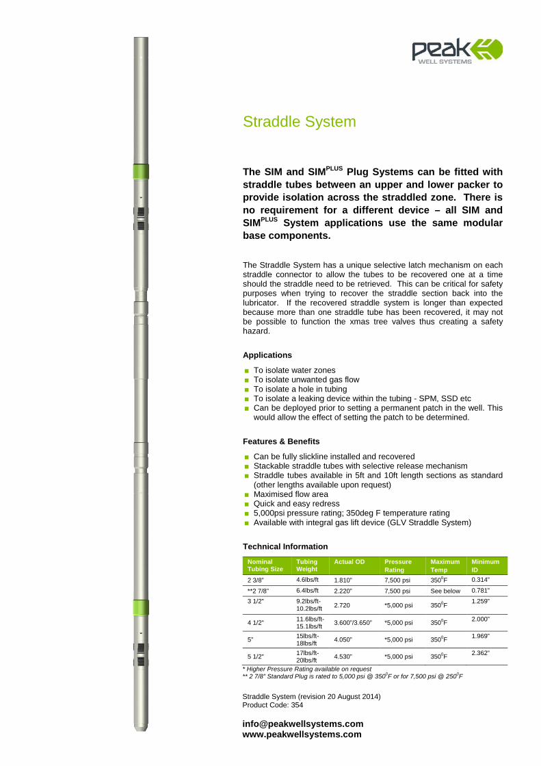
Straddle System
The SIM and SIMPLUS Plug Systems can be fitted with straddle tubes between an upper and lower packer to provide isolation across the straddled zone. There is no requirement for a different device – all SIM and SIMPLUS System applications use the same modular base components. The Straddle System has a unique selective latch mechanism on each straddle connector to allow the tubes to be recovered one at a time should the straddle need to be retrieved. This can be critical for safety purposes when trying to recover the straddle section back into the lubricator. If the recovered straddle system is longer than expected because more than one straddle tube has been recovered, it may not be possible to function the xmas tree valves thus creating a safety hazard.
Applications
■ To isolate water zones ■ To isolate unwanted gas flow ■ To isolate a hole in tubing ■ To isolate a leaking device within the tubing - SPM, SSD etc ■ Can be deployed prior to setting a permanent patch in the well. This
would allow the effect of setting the patch to be determined.
Features & Benefits
■ Can be fully slickline installed and recovered ■ Stackable straddle tubes with selective release mechanism ■ Straddle tubes available in 5ft and 10ft length sections as standard
(other lengths available upon request) ■ Maximised flow area ■ Quick and easy redress ■ 5,000psi pressure rating; 350deg F temperature rating ■ Available with integral gas lift device (GLV Straddle System)
Technical Information
Nominal Tubing Size
Tubing Weight
Actual OD Pressure Rating
Maximum Temp
Minimum ID
2 3/8” 4.6lbs/ft 1.810” 7,500 psi 3500F 0.314”
**2 7/8” 6.4lbs/ft 2.220” 7,500 psi See below 0.781”
3 1/2"
9.2lbs/ft-10.2lbs/ft 2.720 *5,000 psi 3500F 1.259”
4 1/2" 11.6lbs/ft-15.1lbs/ft 3.600”/3.650” *5,000 psi 3500F 2.000”
5” 15lbs/ft-18lbs/ft 4.050” *5,000 psi 3500F 1.969”
5 1/2" 17lbs/ft-20lbs/ft 4.530” *5,000 psi 3500F 2.362”
* Higher Pressure Rating available on request ** 2 7/8” Standard Plug is rated to 5,000 psi @ 3500F or for 7,500 psi @ 2500F
Integral GLV Straddle (revision 20 August 2014) Product Code: 354 [email protected] www.peakwellsystems.com
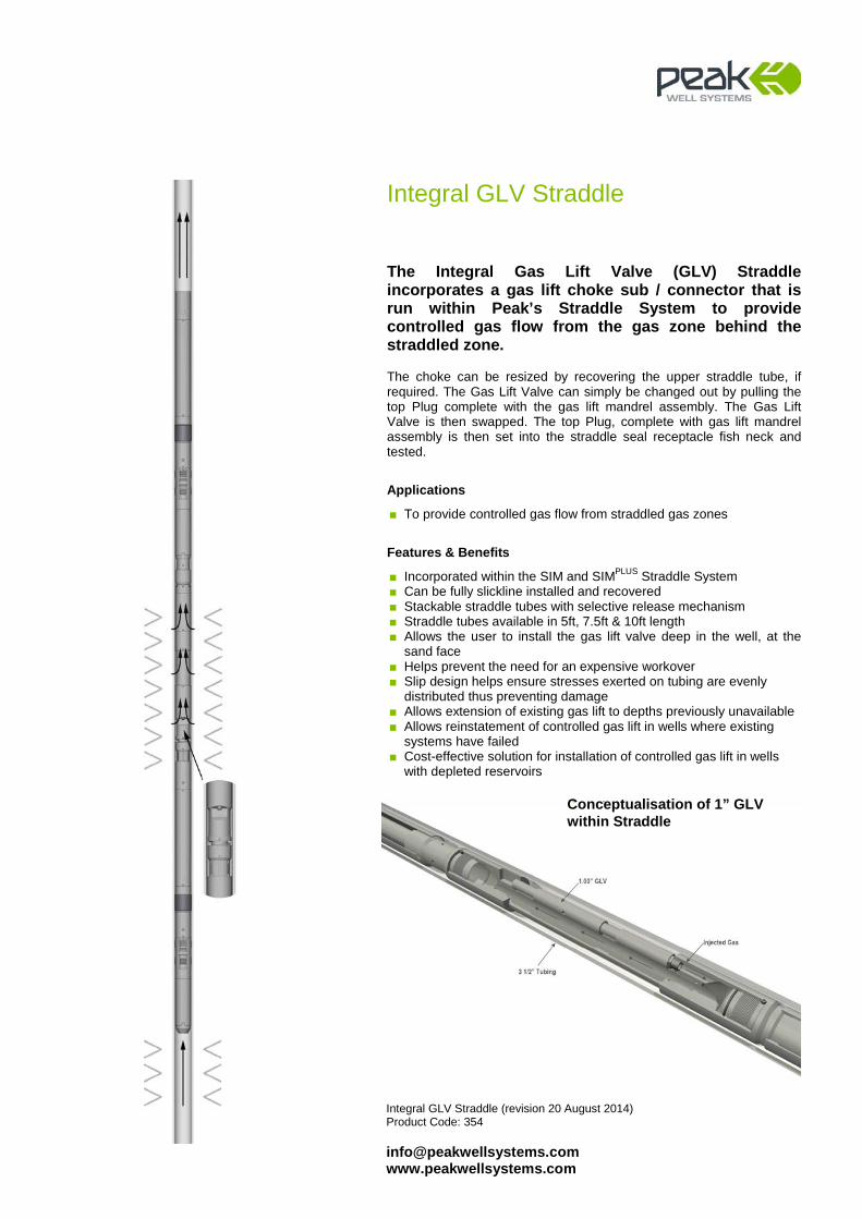
Integral GLV Straddle
The Integral Gas Lift Valve (GLV) Straddle incorporates a gas lift choke sub / connector that is run within Peak’s Straddle System to provide controlled gas flow from the gas zone behind the straddled zone. The choke can be resized by recovering the upper straddle tube, if required. The Gas Lift Valve can simply be changed out by pulling the top Plug complete with the gas lift mandrel assembly. The Gas Lift Valve is then swapped. The top Plug, complete with gas lift mandrel assembly is then set into the straddle seal receptacle fish neck and tested.
Applications
■ To provide controlled gas flow from straddled gas zones
Features & Benefits
■ Incorporated within the SIM and SIMPLUS Straddle System ■ Can be fully slickline installed and recovered ■ Stackable straddle tubes with selective release mechanism ■ Straddle tubes available in 5ft, 7.5ft & 10ft length ■ Allows the user to install the gas lift valve deep in the well, at the
sand face ■ Helps prevent the need for an expensive workover ■ Slip design helps ensure stresses exerted on tubing are evenly
distributed thus preventing damage ■ Allows extension of existing gas lift to depths previously unavailable ■ Allows reinstatement of controlled gas lift in wells where existing
systems have failed ■ Cost-effective solution for installation of controlled gas lift in wells
with depleted reservoirs
Conceptualisation of 1” GLV within Straddle
E-Line Adaptor Kit (revision 20 August 2014) Product Code: 356 [email protected] www.peakwellsystems.com
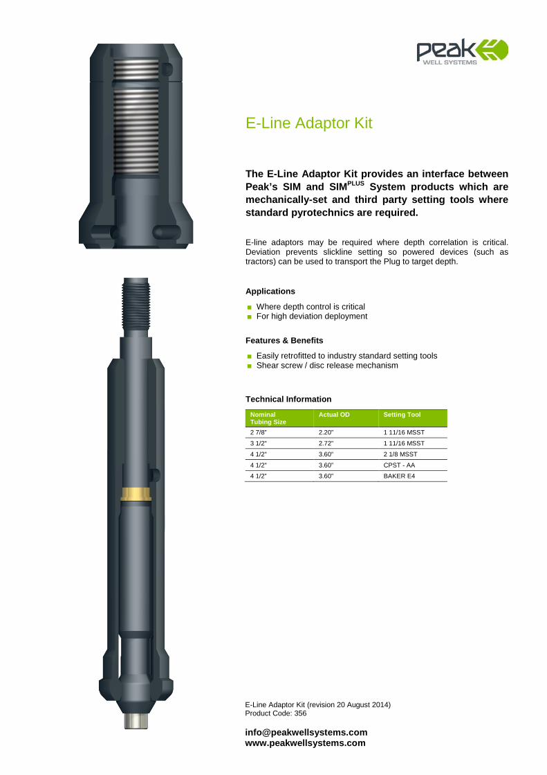
E-Line Adaptor Kit
The E-Line Adaptor Kit provides an interface between Peak’s SIM and SIMPLUS System products which are mechanically-set and third party setting tools where standard pyrotechnics are required. E-line adaptors may be required where depth correlation is critical. Deviation prevents slickline setting so powered devices (such as tractors) can be used to transport the Plug to target depth.
Applications
■ Where depth control is critical ■ For high deviation deployment
Features & Benefits
■ Easily retrofitted to industry standard setting tools ■ Shear screw / disc release mechanism
Technical Information
Nominal Tubing Size
Actual OD Setting Tool
2 7/8” 2.20” 1 11/16 MSST
3 1/2" 2.72” 1 11/16 MSST
4 1/2" 3.60” 2 1/8 MSST
4 1/2" 3.60” CPST - AA
4 1/2” 3.60” BAKER E4

Melon-Type Equalising Housing (revision 20 August 2014) Product Code: 352 [email protected] www.peakwellsystems.com
Melon-Type Equalising Housing
The Melon-Type Equalising Housing is a commonly used method of achieving pressure equalisation across a set plug. It incorporates a simple equalising melon that is run ‘on seat’ in the sealed position and allows the SIM or SIMPLUS Plug to be conveyed in a single run. Recovery of the Melon-Type Equalising Housing requires two-runs-to-pull. The Melon-Type Equalising Prong is run prior to the MATS/GS Pulling Prong to equalise pressure across the plug and allow safe recovery. Jarring down on the Equalising Prong will move the Melon ‘off seat’ allowing pressure across the plug to equalise.
Applications
■ To provide a Melon-Type equalising option for the SIM and SIMPLUS
Plug ■ For use with a Peak SIM Plug or SIMPLUS Plug when a single run
application is required
Features & Benefits
■ Threaded equalising port options to control the rate of equalisation ■ Associated Equalising Prong incorporates tell-tale feature to ensure
Melon has moved into the “off-seat” position ■ Sour service components to NACE MR0175 ■ All components ENP treated to prevent thread galling and corrosion ■ Simplistic design with minimal components ■ Sucker Rod Box thread in Equalising Assembly Bottom Sub to
convey downhole gauges or to provide a connection for roller options in high angle, deviated wells
■ Robust design
Technical Information
To Suit Plug Standard Length Minimum I.D 2 3/8” Does not include the Melon Equalising Option
2 7/8” 13.90” 0.709”
3 1/2” 12.20” 1.142”
4 1/2” 12.60” 1.870”
5” 12.60” 1.870”
5 1/2” 16.18” 1.870”
SIM Plug with Melon-Type Equalising Housing
Melon-Type Equalising Prong
Prong-Type Equalising Housing (revision 20 August 2014) Product Code: 352 [email protected] www.peakwellsystems.com
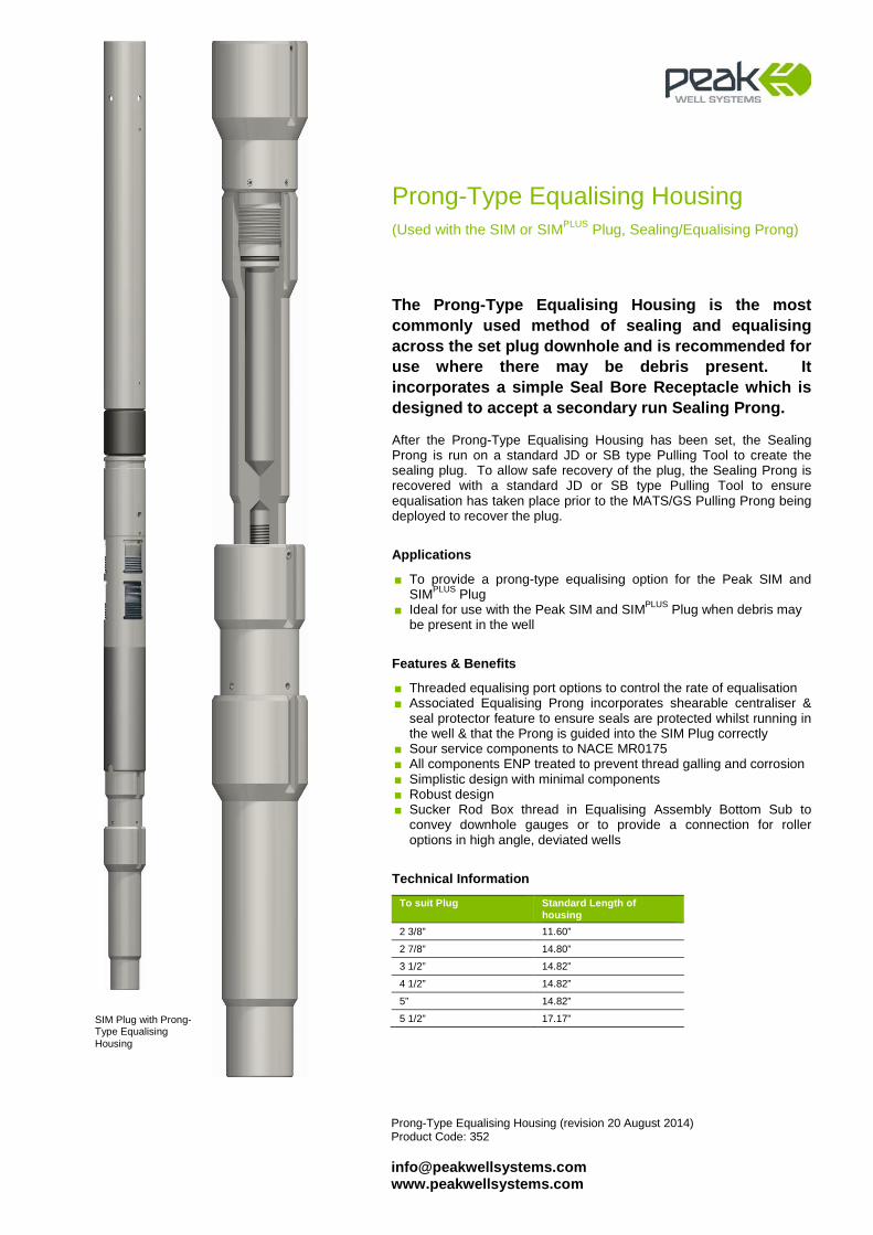
Prong-Type Equalising Housing (Used with the SIM or SIMPLUS Plug, Sealing/Equalising Prong)
The Prong-Type Equalising Housing is the most commonly used method of sealing and equalising across the set plug downhole and is recommended for use where there may be debris present. It incorporates a simple Seal Bore Receptacle which is designed to accept a secondary run Sealing Prong. After the Prong-Type Equalising Housing has been set, the Sealing Prong is run on a standard JD or SB type Pulling Tool to create the sealing plug. To allow safe recovery of the plug, the Sealing Prong is recovered with a standard JD or SB type Pulling Tool to ensure equalisation has taken place prior to the MATS/GS Pulling Prong being deployed to recover the plug.
Applications
■ To provide a prong-type equalising option for the Peak SIM and SIMPLUS Plug
■ Ideal for use with the Peak SIM and SIMPLUS Plug when debris may be present in the well
Features & Benefits
■ Threaded equalising port options to control the rate of equalisation ■ Associated Equalising Prong incorporates shearable centraliser &
seal protector feature to ensure seals are protected whilst running in the well & that the Prong is guided into the SIM Plug correctly
■ Sour service components to NACE MR0175 ■ All components ENP treated to prevent thread galling and corrosion ■ Simplistic design with minimal components ■ Robust design ■ Sucker Rod Box thread in Equalising Assembly Bottom Sub to
convey downhole gauges or to provide a connection for roller options in high angle, deviated wells
Technical Information
To suit Plug Standard Length of housing
2 3/8” 11.60”
2 7/8” 14.80”
3 1/2” 14.82”
4 1/2” 14.82”
5” 14.82”
5 1/2” 17.17”
SIM Plug with Prong-Type Equalising Housing
Melon-Type Equalising Prong (revision 20 August 2014) Product Code: 352 [email protected] www.peakwellsystems.com
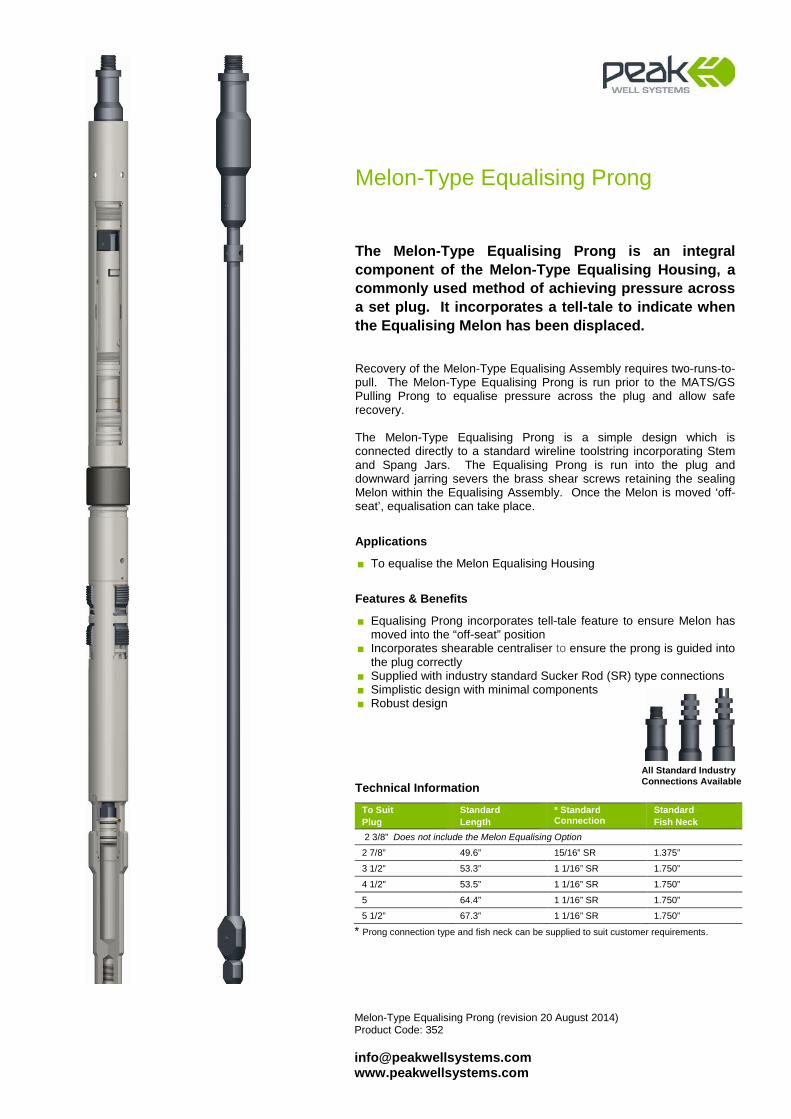
Melon-Type Equalising Prong
The Melon-Type Equalising Prong is an integral component of the Melon-Type Equalising Housing, a commonly used method of achieving pressure across a set plug. It incorporates a tell-tale to indicate when the Equalising Melon has been displaced. Recovery of the Melon-Type Equalising Assembly requires two-runs-to-pull. The Melon-Type Equalising Prong is run prior to the MATS/GS Pulling Prong to equalise pressure across the plug and allow safe recovery. The Melon-Type Equalising Prong is a simple design which is connected directly to a standard wireline toolstring incorporating Stem and Spang Jars. The Equalising Prong is run into the plug and downward jarring severs the brass shear screws retaining the sealing Melon within the Equalising Assembly. Once the Melon is moved ‘off-seat’, equalisation can take place.
Applications
■ To equalise the Melon Equalising Housing
Features & Benefits
■ Equalising Prong incorporates tell-tale feature to ensure Melon has moved into the “off-seat” position
■ Incorporates shearable centraliser to ensure the prong is guided into the plug correctly
■ Supplied with industry standard Sucker Rod (SR) type connections ■ Simplistic design with minimal components ■ Robust design
Technical Information
To Suit Plug
Standard Length
* Standard Connection
Standard Fish Neck
2 3/8” Does not include the Melon Equalising Option
2 7/8” 49.6” 15/16” SR 1.375”
3 1/2” 53.3” 1 1/16” SR 1.750”
4 1/2" 53.5” 1 1/16” SR 1.750”
5 64.4” 1 1/16” SR 1.750”
5 1/2” 67.3” 1 1/16” SR 1.750”
* Prong connection type and fish neck can be supplied to suit customer requirements.
All Standard Industry Connections Available
Sealing/Equalising Prong (revision 22 August 2014) Product Code: 352 [email protected] www.peakwellsystems.com
Equalising Prong
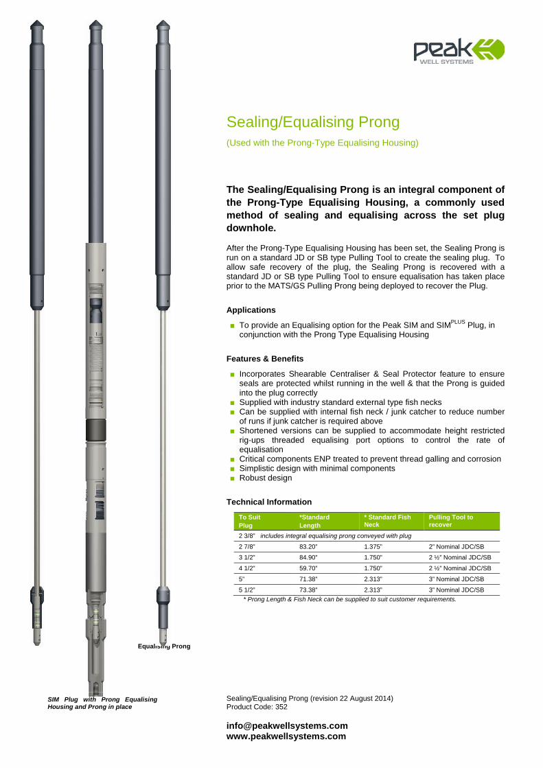
Sealing/Equalising Prong (Used with the Prong-Type Equalising Housing)
The Sealing/Equalising Prong is an integral component of the Prong-Type Equalising Housing, a commonly used method of sealing and equalising across the set plug downhole. After the Prong-Type Equalising Housing has been set, the Sealing Prong is run on a standard JD or SB type Pulling Tool to create the sealing plug. To allow safe recovery of the plug, the Sealing Prong is recovered with a standard JD or SB type Pulling Tool to ensure equalisation has taken place prior to the MATS/GS Pulling Prong being deployed to recover the Plug.
Applications
■ To provide an Equalising option for the Peak SIM and SIMPLUS Plug, in conjunction with the Prong Type Equalising Housing
Features & Benefits
■ Incorporates Shearable Centraliser & Seal Protector feature to ensure seals are protected whilst running in the well & that the Prong is guided into the plug correctly
■ Supplied with industry standard external type fish necks ■ Can be supplied with internal fish neck / junk catcher to reduce number
of runs if junk catcher is required above ■ Shortened versions can be supplied to accommodate height restricted
rig-ups threaded equalising port options to control the rate of equalisation
■ Critical components ENP treated to prevent thread galling and corrosion ■ Simplistic design with minimal components ■ Robust design
Technical Information
* Prong Length & Fish Neck can be supplied to suit customer requirements.
To Suit Plug
*Standard Length
* Standard Fish Neck
Pulling Tool to recover
2 3/8” includes integral equalising prong conveyed with plug
2 7/8” 83.20” 1.375” 2” Nominal JDC/SB
3 1/2” 84.90” 1.750” 2 ½” Nominal JDC/SB
4 1/2” 59.70” 1.750” 2 ½” Nominal JDC/SB
5” 71.38” 2.313” 3” Nominal JDC/SB
5 1/2” 73.38” 2.313” 3” Nominal JDC/SB
SIM Plug with Prong Equalising Housing and Prong in place
Pump Thru Check Valve (revision 03 April 2013) Product Code: 335 [email protected] www.peakwellsystems.com
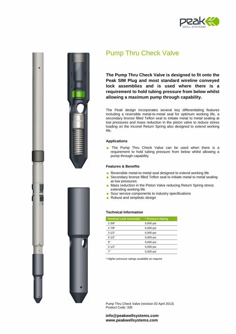
Pump Thru Check Valve
The Pump Thru Check Valve is designed to fit onto the Peak SIM Plug and most standard wireline conveyed lock assemblies and is used where there is a requirement to hold tubing pressure from below whilst allowing a maximum pump through capability. The Peak design incorporates several key differentiating features including a reversible metal-to-metal seal for optimum working life, a secondary bronze filled Teflon seal to initiate metal to metal sealing at low pressures and mass reduction in the piston valve to reduce stress loading on the Inconel Return Spring also designed to extend working life.
Applications
■ The Pump Thru Check Valve can be used when there is a requirement to hold tubing pressure from below whilst allowing a pump through capability
Features & Benefits
■ Reversible metal-to-metal seal designed to extend working life ■ Secondary bronze filled Teflon seal to initiate metal to metal sealing
at low pressures ■ Mass reduction in the Piston Valve reducing Return Spring stress
extending working life ■ Sour service components to industry specifications ■ Robust and simplistic design
Technical Information
Nominal Lock Assembly * Pressure Rating 2 3/8” 5,000 psi
2 7/8” 5,000 psi
3 1/2” 5,000 psi
4 1/2” 5,000 psi
5” 5,000 psi
5 1/2” 5,000 psi
7” 5,000 psi * Higher pressure ratings available on request

Pump Open Sub Product Code: 300 [email protected] www.peakwellsystems.com
Pump Open Sub
When deployed as part of a downhole plug assembly, the Pump Open Sub is primarily designed to act as a single barrier against well-bore contents.
The Pump Open Sub Plunger is secured in place with a series of shear screws which are designed to shear out when a predetermined pressure is applied from above the Pump Open Sub.
Once the Plunger is sheared out, there is a clear flow path through the Pump Open Sub. This allows for full equalisation across the barrier device, circulation, communication to prevent recovery of “wet” tubing strings or production of well bore contents.
Applications
When deployed as part of a downhole plug assembly, the Pump Open Sub can be: ■ used as a barrier to allow setting of hydraulically-set packers having to make
an equalising run prior to plug recovery ■ remotely “opened” by pressuring the tubing above to the pre-set shear
rating. The well can then be brought back online without any intervention ■ used for creating tubing overbalance prior to Fracture Stimulation
Operations ■ deployed as a contingent equalising device in high debris environments ■ used as a mechanical barrier during wellhead removal / tree valve
maintenance
Features & Benefits
■ Can be retrofitted to suit existing Lock Mandrel / Equalising Assemblies ■ Multiple setting values (500 psi minimum - 3000 psi maximum) in 500 psi
increments ■ Large flow area after pump out in flow type / circulating applications ■ Sheared plunger retained within the sump of Pump Open Sub eliminating
unnecessary well debris ■ Minimising wireline runs ■ Can be sheared out even if debris restricts access to primary equalising
facility by applying sufficient pressure
Technical Information
To Suit SIM Lock
Actual OD Pressure Rating
2 3/8” 1.810” *500 - 3,000 psi
2 7/8” 2.200” *500 - 3,000 psi
3 1/2” 2.720” *500 - 3,000 psi
4 1/2” 2.720” *500 - 3,000 psi *Higher Shear Ratings Available on Request

Plug Pulling Tool (revision 20 August 2014) Product Code: 207/229/353 [email protected] www.peakwellsystems.com
Plug Pulling Tool
The Plug Pulling Tool is designed for trouble-free recovery of Peak’s retrievable SIM and SIMPLUS System products. The Plug Pulling Tool incorporates a unique feature whereby, when initially run in the hole, downward jar action can be applied without the danger of prematurely shearing the Pulling Tool’s contingent release mechanism.
Applications
■ Recovery of Peak’s retrievable SIM and SIMPLUS Plugs
Features & Benefits
■ Contingent release shear pin is initially protected whilst latching the plug
■ The pin protection feature allows for a smaller shear rating pin to be run in the release mechanism. This can be of huge benefit in high deviation wells.
■ Easily redressable in remote locations
Technical Information
Nominal Plug
Multi- action Top Sub
Nominal GS Pulling Prong
2 3/8” A207-1810-XXX 2” 353-1810-001-01
2 7/8” A207-2250-XXX 2 1/2” 353-2200-001-01
3 1/2" A207-2720-XXX 3” 353-2720-001-01
4 1/2" A207-3620-XXX 4” 353-3600-001-01
5” A207-3620-XXX 4” 353-4050-001-01
5 1/2" A207-4500-XXX 5” 353-4450-001-01
Plug Pulling Tool
Flow Control(Nipple Products)

Standing Valve (revision 28 August 2014)Product Code: 304
[email protected] www.peakwellsystems.com
Peak Standing Valve
The Peak Standing Valve was designed to address an industry need for a suitably sized Standing Valve for use within a DST string to allow maximum through bore.
Differing from a standing valve that locks into a nipple profile, the Peak Standing Valve is a sit-on No-Go design that can be used to test the integrity of tubing connections and downhole jewellery situated above the standing valve. The design does not incorporate any lock-out feature and so allows the wire and toolstring to remain attached to the standing valve during pressure test operations to minimise deployment and recovery time. The Peak Standing Valve can also be designed to fit any standard Top No-Go or Bottom No-Go profile nipple with a seal bore.
Features & Benefits Integral Equalising feature to prevent pulling against any hydrostatic
head Standard rope socket fishing neck allowing running and recovery on
standard pulling tools. No special running tool required Spring-on-ball design is suitable for high deviation applications Reduces NPT by remaining latched onto standing valve during
testing
FloSafe Lock Mandrel (revision 31 Dec 2013) Product Code: 380 [email protected] www.peakwellsystems.com
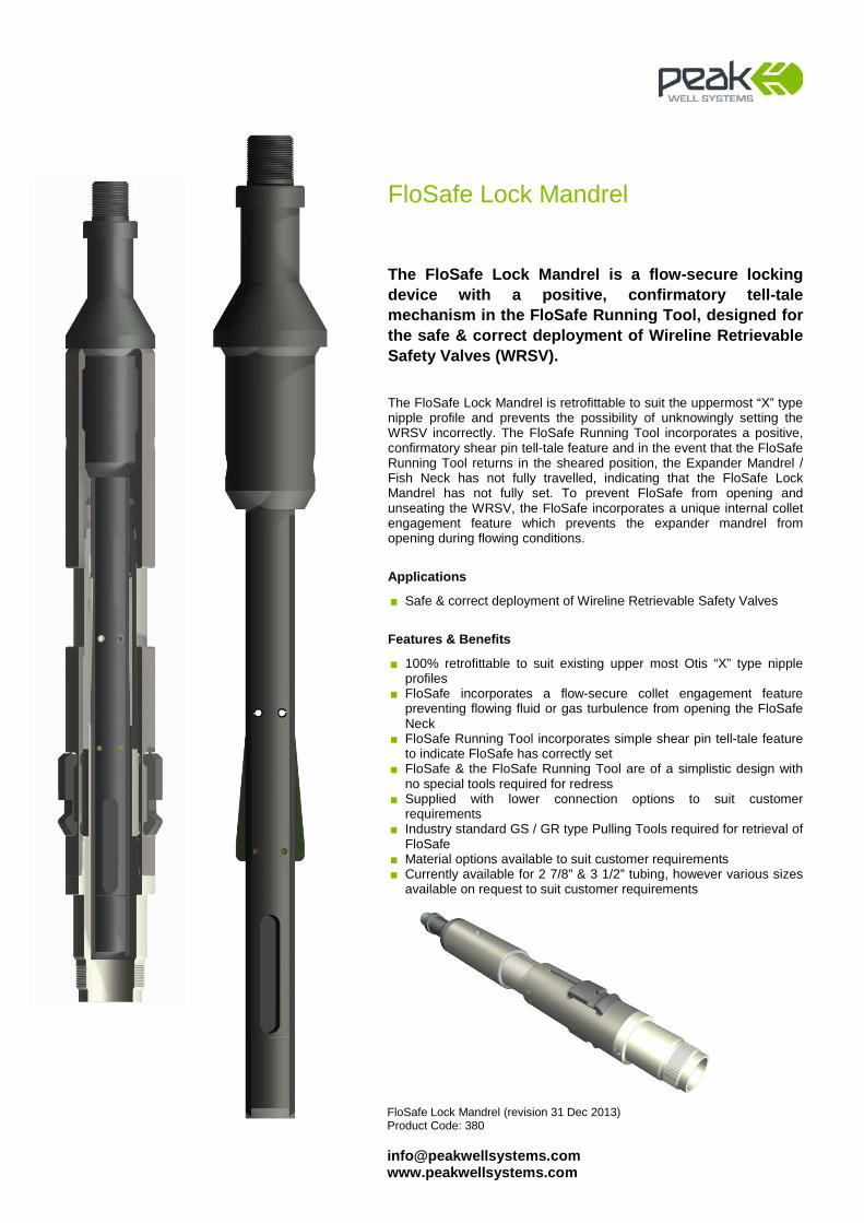
FloSafe Lock Mandrel
The FloSafe Lock Mandrel is a flow-secure locking device with a positive, confirmatory tell-tale mechanism in the FloSafe Running Tool, designed for the safe & correct deployment of Wireline Retrievable Safety Valves (WRSV). The FloSafe Lock Mandrel is retrofittable to suit the uppermost “X” type nipple profile and prevents the possibility of unknowingly setting the WRSV incorrectly. The FloSafe Running Tool incorporates a positive, confirmatory shear pin tell-tale feature and in the event that the FloSafe Running Tool returns in the sheared position, the Expander Mandrel / Fish Neck has not fully travelled, indicating that the FloSafe Lock Mandrel has not fully set. To prevent FloSafe from opening and unseating the WRSV, the FloSafe incorporates a unique internal collet engagement feature which prevents the expander mandrel from opening during flowing conditions.
Applications
■ Safe & correct deployment of Wireline Retrievable Safety Valves
Features & Benefits
■ 100% retrofittable to suit existing upper most Otis “X” type nipple profiles
■ FloSafe incorporates a flow-secure collet engagement feature preventing flowing fluid or gas turbulence from opening the FloSafe Neck
■ FloSafe Running Tool incorporates simple shear pin tell-tale feature to indicate FloSafe has correctly set
■ FloSafe & the FloSafe Running Tool are of a simplistic design with no special tools required for redress
■ Supplied with lower connection options to suit customer requirements
■ Industry standard GS / GR type Pulling Tools required for retrieval of FloSafe
■ Material options available to suit customer requirements ■ Currently available for 2 7/8” & 3 1/2” tubing, however various sizes
available on request to suit customer requirements

Well Monitoring
Large Bore Gauge Hanger (revision 03 April 2013) Product Code: 340 [email protected] www.peakwellsystems.com
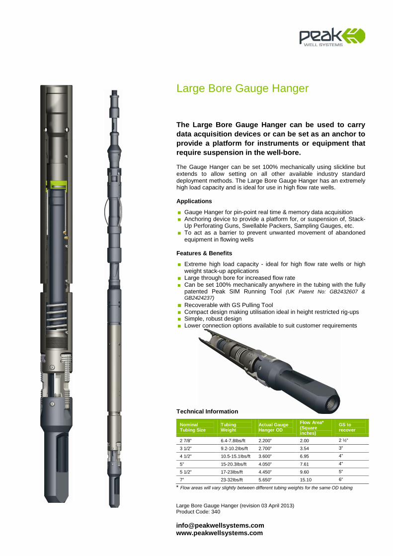
Large Bore Gauge Hanger
The Large Bore Gauge Hanger can be used to carry data acquisition devices or can be set as an anchor to provide a platform for instruments or equipment that require suspension in the well-bore. The Gauge Hanger can be set 100% mechanically using slickline but extends to allow setting on all other available industry standard deployment methods. The Large Bore Gauge Hanger has an extremely high load capacity and is ideal for use in high flow rate wells.
Applications
■ Gauge Hanger for pin-point real time & memory data acquisition ■ Anchoring device to provide a platform for, or suspension of, Stack-
Up Perforating Guns, Swellable Packers, Sampling Gauges, etc. ■ To act as a barrier to prevent unwanted movement of abandoned
equipment in flowing wells
Features & Benefits
■ Extreme high load capacity - ideal for high flow rate wells or high weight stack-up applications
■ Large through bore for increased flow rate ■ Can be set 100% mechanically anywhere in the tubing with the fully
patented Peak SIM Running Tool (UK Patent No: GB2432607 & GB2424237)
■ Recoverable with GS Pulling Tool ■ Compact design making utilisation ideal in height restricted rig-ups ■ Simple, robust design ■ Lower connection options available to suit customer requirements
Technical Information
Nominal Tubing Size
Tubing Weight
Actual Gauge Hanger OD
Flow Area* (Square inches)
GS to recover
2 7/8” 6.4-7.8Ibs/ft 2.200” 2.00 2 ½”
3 1/2” 9.2-10.2Ibs/ft 2.700” 3.54 3”
4 1/2” 10.5-15.1Ibs/ft 3.600” 6.95 4”
5” 15-20.3Ibs/ft 4.050” 7.61 4”
5 1/2” 17-23Ibs/ft 4.450” 9.60 5”
7” 23-32Ibs/ft 5.650” 15.10 6”
* Flow areas will vary slightly between different tubing weights for the same OD tubing
Hi-Ex Gauge Hanger (Revision 25 March 2014) Product Code: 341 [email protected] www.peakwellsystems.com
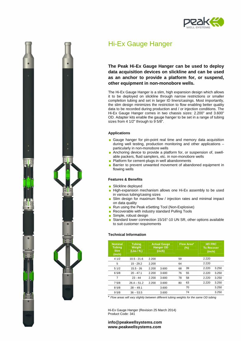
Hi-Ex Gauge Hanger
The Peak Hi-Ex Gauge Hanger can be used to deploy data acquisition devices on slickline and can be used as an anchor to provide a platform for, or suspend, other equipment in non-monobore wells. The Hi-Ex Gauge Hanger is a slim, high expansion design which allows it to be deployed on slickline through narrow restrictions or smaller completion tubing and set in larger ID liners/casings. Most importantly, the slim design minimizes the restriction to flow enabling better quality data to be recorded during production and / or injection conditions. The Hi-Ex Gauge Hanger comes in two chassis sizes: 2.200” and 3.600” OD. Adapter kits enable the gauge hanger to be set in a range of tubing sizes from 4 1/2” through to 9 5/8”.
Applications
■ Gauge hanger for pin-point real time and memory data acquisition during well testing, production monitoring and other applications – particularly in non-monobore wells
■ Anchoring device to provide a platform for, or suspension of, swell-able packers, fluid samplers, etc. in non-monobore wells
■ Platform for cement-plugs in well abandonments ■ Barrier to prevent unwanted movement of abandoned equipment in
flowing wells
Features & Benefits
■ Slickline deployed ■ High-expansion mechanism allows one Hi-Ex assembly to be used
in various tubing/casing sizes ■ Slim design for maximum flow / injection rates and minimal impact
on data quality ■ Run using the Peak eSetting Tool (Non-Explosive) ■ Recoverable with industry standard Pulling Tools ■ Simple, robust design ■ Standard lower connection 15/16”-10 UN SR, other options available
to suit customer requirements
Technical Information
Nominal Tubing
Size (inch)
Tubing Weight
(Lbs / ft.)
Actual Gauge Hanger OD
(inch)
Flow Area* (%)
HD FRC To Recover
(inch)
4 1/2 10.5 - 21.6 2.200 59 2.220
5 15 - 29.2 2.200 64 2.220
5 1/2 15.5 - 26 2.200 3.600 68 39 2.220 3.250
6 5/8 20 - 47.1 2.200 3.600 76 55 2.220 3.250
7 23 - 44 2.200 3.600 78 58 2.220 3.250
7 5/8 26.4 – 51.2 2.200 3.600 80 63 2.220 3.250
8 5/8 28 – 49.1 3.600 70 3.250
9 5/8 36 – 53.5 3.600 74 3.250
* Flow areas will vary slightly between different tubing weights for the same OD tubing

eSetting Tool (revision 29 December 2014)Product Code: 342
[email protected] www.peakwellsystems.com
eSetting Tool
Peak’s non-explosive eSetting Tool is used to deploy Peak’s Hi-Ex Gauge Hanger to any location in the wellbore using simple slickline operations.
The eSetting Tool provides a reliable deployment technique without the need for pyrotechnics, pressurised nitrogen or electro-hydraulic tools that would usually require additional field specialists.
Simple actuation using the pre-programmed electronic timer system gives full operational flexibility and control across a broad range of different operating environments and well depths. The force required to set the Hi-Ex Hanger is derived from a staged spring mechnaism in the eSetting Tool and is capable of securely setting Hi-Ex Gauge Hangers in all sizes of casing. The low-power electronic timer is powered by small Lithium batteries making for easy transportation and rapid deployment of the complete system in the field.
At depth, the eSetting Tool activates and sets the Hi-Ex Gauge Hanger, expanding its arms to the tubing wall and securely anchoring and centralising itself inside the tubing via the bi-directional slips. Once the Hi-Ex Gauge Hanger is set, the eSetting Tool automatically releases from the hanger. The ability to disarm the timer by upward jarring provides a fail-safe system in the event of operational difficulties.
The eSetting Tool is available to customers through Peak’s Service Business exclusively for the Hi-Ex Gauge Hanger.
Applications Used for the deployment of 2.200” Hi-Ex Gauge Hangers on slickline Rated to 10,000psi, 150degC
Features & Benefits Simplified logistics: safe and rapid mobilisation to well sites globally Integrated non-hydraulic, non-pyrotechnic power system No radio-silence requirement, reducing NPT Disposable, low cost electronics, for simple field redress Range of pre-programmed countdown times for operational flexibility and control Emergency jar-up feature to dis-arm the timer
Nominal Tubing
Size (inch)
Tubing Weight
(Lbs / ft.)
Flow Area* (%)
Actual Gauge Hanger OD
(inch)
4 1/2 11.6# 12.6# 59 2.200 5 15# 64 2.200
5 1/2 17# 20# 23# 26# 68 2.200
7 26# 29# 32# 78 2.200 Adaptor subs are available for all tubing weights within the above sizes.

Well Integrity

Leak Detection Tool (revision 20 August 2014) Product Code: 362 [email protected] www.peakwellsystems.com
Leak Detection Tool
The Leak Detection Tool is designed to create a temporary sealing barrier to enable a surface pressure test to ascertain a potential leak path between the tubing and annulus. Using the proven SIM Running Tool, the Leak Detection Tool is deployed in the well to a desired depth, predominantly at a depth below a suspected leak path, on a conventional slickline toolstring. Reciprocation at depth allows the radial indexing mechanism to activate, anchoring the Running Tool slips to the tubing wall. To effect the “seal”, light jarring down is required to expand the element of the Leak Detection Tool. Tubing pressure is then applied to test tubing integrity. The cycle can then be repeated and fine tuned until the exact location of a leak is detected.
Applications
■ As a temporary barrier to identify the location of a downhole leak ■ To determine the position of tubing to annulus communication ■ To check the integrity of older wells
Features & Benefits
■ Leak Detection device which can be reset a number of times without the need to pull back to surface
■ Multiple setting capability reduces NPT by allowing the leak to be pinpointed quickly, minimising wireline runs
■ Holds pressures of 1500 psi @ 350F from above ■ The integral self-equalising device allows the pressure to equalise
across the elastomer cup before moving the elastomer into the fully retracted position
■ Simple, robust design ■ The Mechanical Leak Detection Tool can be supplied as an Adapter
System to the patented SIM Running Tool (UK Patent No: GB2432607 & GB2424237)
■ The Leak Detection Tool can also be purchased as a complete system packaged in conjunction with the patented SIM Running Tool (UK Patent No: GB2432607 & GB2424237)
■ Currently available for 2 7/8”, 3 ½” & 4 ½” tubing, however various sizes available on request to suit customer requirements
Technical Information
Nominal Tubing Size
Tubing Weight
Actual O.D Pressure Rating
Temperature Rating
2 7/8” 6.4-7.8Ibs/ft 2.220” 1,500 psi 350F
3 1/2” 9.2-10.2Ibs/ft 2.720” 1,500 psi 350F
4 1/2” 10.5-17.1Ibs/ft 3.650” 1,500 psi 350F

Tubing Alignment Tool (revision 25 September 2013) Product Code: 290 [email protected] www.peakwellsystems.com
Tubing Alignment Tool
The Peak Tubing Alignment Tool is designed to realign and create a conduit across parted tubing, allowing remedial work to be conducted below the tubing break. The tool does not create a pressure seal as it is designed primarily to allow a deep set barrier to be placed below the tubing break in order to make the well safe prior to further remedial intervention. The design of the Tubing Alignment Tool is highly subject to each individual application, dependent on location and nature of the tubing break.
Applications
■ Restoring well integrity in older ‘brown’ fields ■ Allowing the setting of deep set barrier below break in completion
tubing to make well safe ■ Making wells safe prior to rig conducting work-over
Features & Benefits
■ Simple slickline deployment and installation ■ Can be recovered to surface if required ■ Flexible design that allows for easy in-field set-up once the length of
the tubing gap is ascertained ■ Can be supplied with various options for landing-off in the upper
section of tubing ■ Maximum through bore to allow passage of deep set plug on
slickline or e-line ■ Will pass through most standard TRSCSSSV nipples ■ Recovered using standard GS-type Pulling Tool ■ Locking and No-Go fingers can be included for added retention ■ Tailor made solutions for all tubing sizes
Expandable No-Go Fingers prevent the alignment tool dropping through the lower completion

Production Enhancement
Top Latch Choke (revision 20 August 2014) Product Code: 358 [email protected] www.peakwellsystems.com
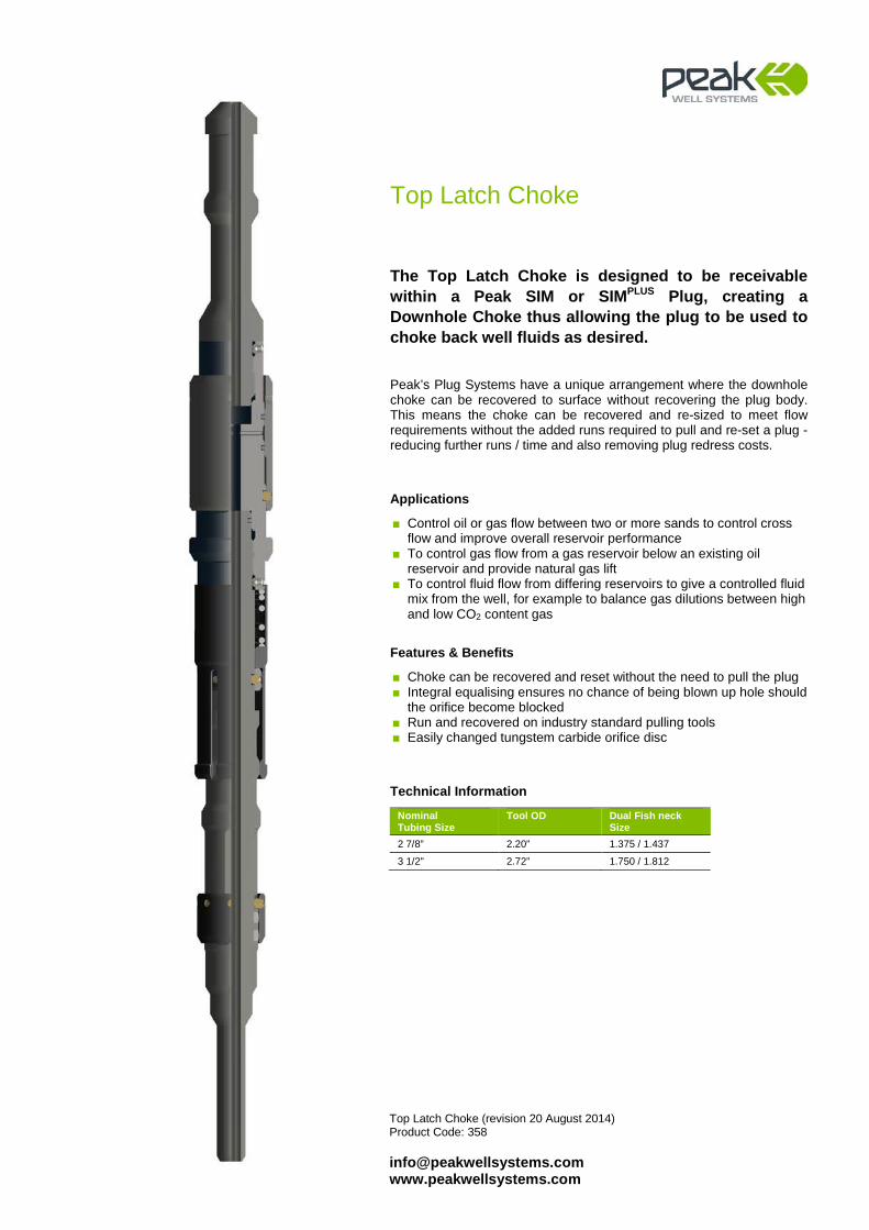
Top Latch Choke
The Top Latch Choke is designed to be receivable within a Peak SIM or SIMPLUS Plug, creating a Downhole Choke thus allowing the plug to be used to choke back well fluids as desired. Peak’s Plug Systems have a unique arrangement where the downhole choke can be recovered to surface without recovering the plug body. This means the choke can be recovered and re-sized to meet flow requirements without the added runs required to pull and re-set a plug - reducing further runs / time and also removing plug redress costs.
Applications
■ Control oil or gas flow between two or more sands to control cross flow and improve overall reservoir performance
■ To control gas flow from a gas reservoir below an existing oil reservoir and provide natural gas lift
■ To control fluid flow from differing reservoirs to give a controlled fluid mix from the well, for example to balance gas dilutions between high and low CO2 content gas
Features & Benefits
■ Choke can be recovered and reset without the need to pull the plug ■ Integral equalising ensures no chance of being blown up hole should
the orifice become blocked ■ Run and recovered on industry standard pulling tools ■ Easily changed tungstem carbide orifice disc
Technical Information
Nominal Tubing Size
Tool OD Dual Fish neck Size
2 7/8” 2.20” 1.375 / 1.437
3 1/2" 2.72” 1.750 / 1.812
FloWell (revision 20 August 2014) Product Code: 420 [email protected] www.peakwellsystems.com
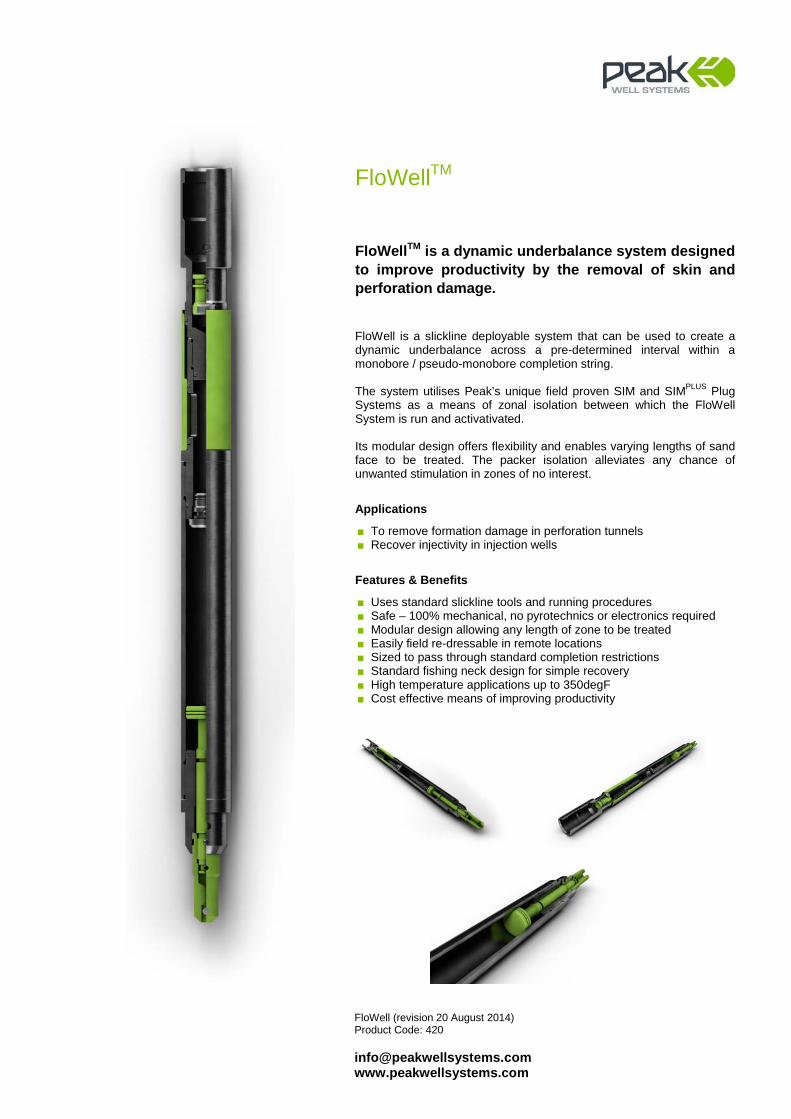
FloWellTM
FloWellTM is a dynamic underbalance system designed to improve productivity by the removal of skin and perforation damage. FloWell is a slickline deployable system that can be used to create a dynamic underbalance across a pre-determined interval within a monobore / pseudo-monobore completion string. The system utilises Peak’s unique field proven SIM and SIMPLUS Plug Systems as a means of zonal isolation between which the FloWell System is run and activativated.
Its modular design offers flexibility and enables varying lengths of sand face to be treated. The packer isolation alleviates any chance of unwanted stimulation in zones of no interest.
Applications
■ To remove formation damage in perforation tunnels ■ Recover injectivity in injection wells
Features & Benefits
■ Uses standard slickline tools and running procedures ■ Safe – 100% mechanical, no pyrotechnics or electronics required ■ Modular design allowing any length of zone to be treated ■ Easily field re-dressable in remote locations ■ Sized to pass through standard completion restrictions ■ Standard fishing neck design for simple recovery ■ High temperature applications up to 350degF ■ Cost effective means of improving productivity

Fishing Systems

FRC-GLV Pulling Tool Product Code: 206 [email protected] www.peakwellsystems.com
FRC-GLV Pulling Tool
Peak’s Full Radial Contact Gas Lift Valve (FRC-GLV) Pulling Tool is used in conjunction with a kickover tool for recovering gas lift valves (GLV) during GLV change-out operations. The FRC-GLV Pulling Tool is designed to engage the full 360 degree underside of an external fish neck and is generally used in conventional and heavy jarring applications. The full contact area provides a much greater load bearing area compared to standard 2 or 3 dog type pulling tools which are commonly used in gas-lift valve changeout operations. The full supporting latch finger face reduces the amount of damage to both the latch fingers and the fish neck to be recovered by evenly distributing the load whilst also improving impact transmission, greatly increasing chances for successful recovery. Incorporating a positive locking key feature & expansion profiles on the Core & Latch Fingers, ensures clean disengagement from the GLV during downward jarring. The FRC-GLV Pulling Tool does not rely upon springs and steel memory for disengagement which also makes re-pinning safe & easy.
Applications
■ Retrieval of gas lift valves in conventional or heavy jarring applications
Features & Benefits
■ Cores available to suit top & bottom latch GLV’s ■ Suits all standard SPM pockets & GLV latches ■ Full 360 degree (Full Radial Contact) Latch Finger coverage ■ Jar down to release - positive locking Core & Latch Finger
expansion profile feature to assist in safe tool disengagement ■ Simple & safe to redress - no special pinning tools required ■ Additional Cores available to suit special reach requirements ■ Robust design
Technical Information
Nominal Size
Actual OD To Engage Fish Neck
1 1/2” 1.350” 0.875” (1”GLV) 1.187”
1 3/4” 1.750” 1.187” (11/2” GLV) 1.187”
1 3/4” 1.750” 1.187” (11/2” GLV) 1.375”
All Standard Industry Connections Available
HD-FRC Pulling Tool (Jar Up to Shear) Product Code: 224 [email protected] www.peakwellsystems.com
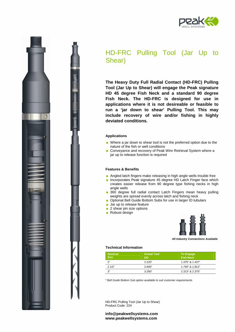
HD-FRC Pulling Tool (Jar Up to Shear)
The Heavy Duty Full Radial Contact (HD-FRC) Pulling Tool (Jar Up to Shear) will engage the Peak signature HD 45 degree Fish Neck and a standard 90 degree Fish Neck. The HD-FRC is designed for use in applications where it is not desireable or feasible to run a ‘jar down to shear’ Pulling Tool. This may include recovery of wire and/or fishing in highly deviated conditions.
Applications
■ Where a jar down to shear tool is not the preferred option due to the nature of the fish or well conditions
■ Conveyance and recovery of Peak Wire Retrieval System where a jar up to release function is required
Features & Benefits
■ Angled latch fingers make releasing in high angle wells trouble free ■ Incorporates Peak signature 45 degree HD Latch Finger face which
creates easier release from 90 degree type fishing necks in high angle wells
■ 360 degree full radial contact Latch Fingers mean heavy pulling weights are spread evenly across latch and fishing neck
■ Optional Bell Guide Bottom Subs for use in larger ID tubulars ■ Jar up to release feature ■ 2 shear pin size options ■ Robust design
Technical Information
Nominal Size
Actual Tool OD
To Engage Fish Neck
2” 2.220” 1.375” & 1.437”
2 1/2” 2.600” 1.750” & 1.812”
3” 3.250” 2.313” & 2.375”
* Bell Guide Bottom Sub option available to suit customer requirements
All Industry Connections Available

HD-FRC Pulling Tool (Jar Down to Shear) Product Code: 228 [email protected] www.peakwellsystems.com
HD-FRC Pulling Tool (Jar Down to Shear)
The Peak Heavy Duty Full Radial Contact (HD-FRC) Pulling Tool (Jar Down to Shear) will engage the Peak signature HD 45 degree Fish Neck and a standard 90 Degree Fish Neck. The HD-FRC is designed for use in applications where heavy upward jarring is required to retrieve a stuck fish with a jar down to release function. The Peak signature HD 45 degree Fish Neck has a 60% increased load bearing area to that of standard fish necks. The 360 degree “full radial contact” design of the HD-FRC Latch Fingers increases impact transmission through the fish during continuous heavy upward jarring. The HD-FRC has a jar down to release and locking core feature allowing it to be safely retrieved back to surface if required.
Applications
■ Heavy upward jarring applications with a jar down to release function
Features & Benefits
■ Built to withstand prolonged heavy upward jarring ■ Incorporates Peak signature 45 degree HD Latch Finger face with a
60% increased load bearing area compared to standard latch fingers ■ 360 degree full radial contact Latch Fingers minimise flaring of fish
neck & increase impact transmission ■ Optional Bell Guide Bottom Subs for use in larger ID tubulars ■ Jar down to release feature ■ 2 shear pin size options ■ Robust design
Technical Information
Nominal Tubing Size
Actual Tool OD
To Engage Fish Neck
2 7/8” 2.220” 1.375” & 1.437”
3 1/2" 2.600” 1.750” & 1.812”
4 1/2" 3.250” 2.313” & 2.375”
5 1/2" 4.150” 3.125” *Bell Guide Bottom Sub option available to suit customer requirements
All Standard Industry Connections Available
Heavy Duty Pulling System (revision 03 April 2013) Product Code: 211/228 [email protected] www.peakwellsystems.com
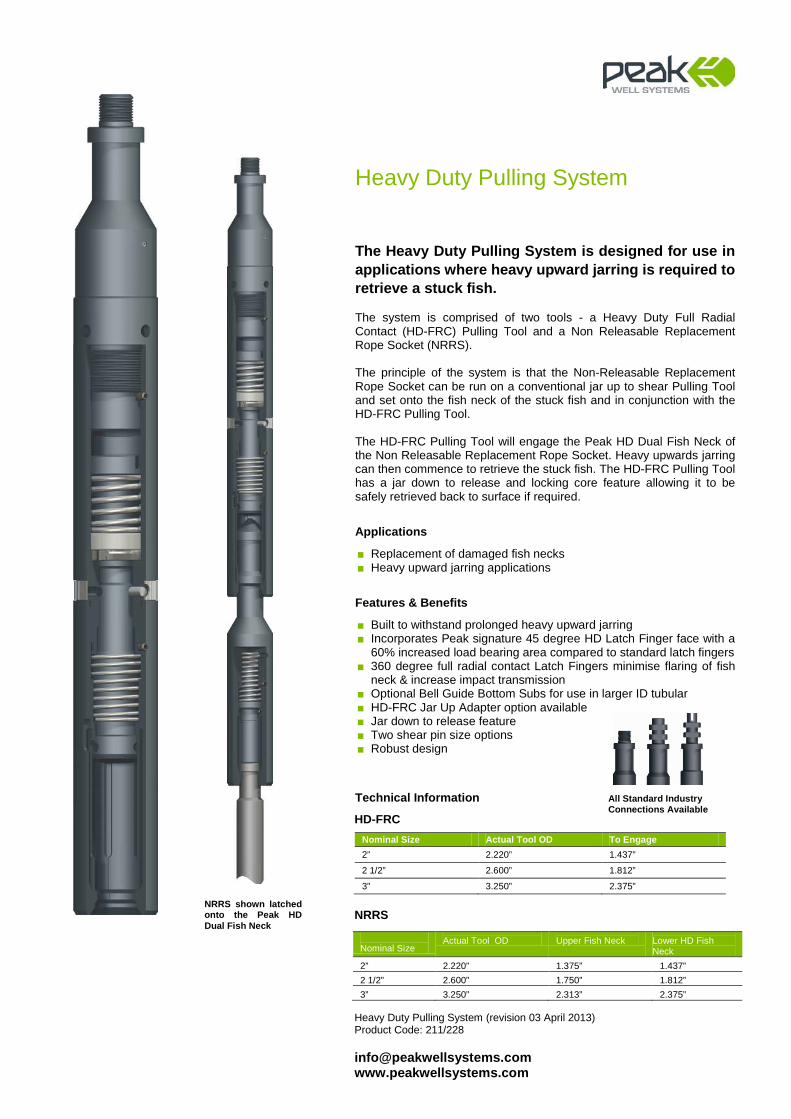
Heavy Duty Pulling System
The Heavy Duty Pulling System is designed for use in applications where heavy upward jarring is required to retrieve a stuck fish. The system is comprised of two tools - a Heavy Duty Full Radial Contact (HD-FRC) Pulling Tool and a Non Releasable Replacement Rope Socket (NRRS). The principle of the system is that the Non-Releasable Replacement Rope Socket can be run on a conventional jar up to shear Pulling Tool and set onto the fish neck of the stuck fish and in conjunction with the HD-FRC Pulling Tool. The HD-FRC Pulling Tool will engage the Peak HD Dual Fish Neck of the Non Releasable Replacement Rope Socket. Heavy upwards jarring can then commence to retrieve the stuck fish. The HD-FRC Pulling Tool has a jar down to release and locking core feature allowing it to be safely retrieved back to surface if required.
Applications
■ Replacement of damaged fish necks ■ Heavy upward jarring applications
Features & Benefits
■ Built to withstand prolonged heavy upward jarring ■ Incorporates Peak signature 45 degree HD Latch Finger face with a
60% increased load bearing area compared to standard latch fingers ■ 360 degree full radial contact Latch Fingers minimise flaring of fish
neck & increase impact transmission ■ Optional Bell Guide Bottom Subs for use in larger ID tubular ■ HD-FRC Jar Up Adapter option available ■ Jar down to release feature ■ Two shear pin size options ■ Robust design
Technical Information
HD-FRC
Nominal Size Actual Tool OD To Engage 2” 2.220” 1.437”
2 1/2” 2.600” 1.812”
3” 3.250” 2.375”
NRRS
Nominal Size
Actual Tool OD
Upper Fish Neck
Lower HD Fish Neck
2”
2.220”
1.375”
1.437”
2 1/2”
2.600”
1.750”
1.812”
3”
3.250”
2.313”
2.375”
All Standard Industry Connections Available
NRRS shown latched onto the Peak HD Dual Fish Neck

Double Jar Down Adaptor Product Code: 233 [email protected] www.peakwellsystems.com
Double Jar Down Adaptor
The Double Jar Down Adaptor can be fitted to a Full Radial Contact (FRC) and Heavy Duty FRC (HD-FRC) Pulling Tool to recover an external fishing neck. Unlike the FRC Pulling Tool which has a fixed ‘jar down to release’ mode, the Double Jar Down Adaptor enables repetitive jarring down as much as needed to latch the fish without the inherent risk or prematurely shearing the ‘jar down to release’ pin. If the fish cannot be recovered, the upper pin in the Double Jar Down Adaptor will shear thus allowing subsequent downward jarring to release the Pulling Tool.
Applications
■ Gas lift work ■ High deviation well intervention
Features & Benefits
■ Retro fittable to Peak’s FRC Pulling Tool ■ Reduces toolbox inventory ■ Simple shear pin to redress ■ Reduced NPT due to elimination of premature shearing of pin.
Technical Information
Nominal Tubing Size
Tool OD Fits FRC sizes Overall Length
2 3/8 1.750” 1.750” 13.19”
2 7/8” 2.220” 2.220” 17.32”
3 1/2" 2.600” 2.600” 19.25”
4 1/2" 3.250” 3.250” 18.86”
Double Jar Down Adaptor shown installed to FRC Pulling Tool
(Note: FRC Pulling Tool available separately)
Double Jar Down FRC Pulling Tool (revision 26 September 2013) Product Code: 234 [email protected] www.peakwellsystems.com
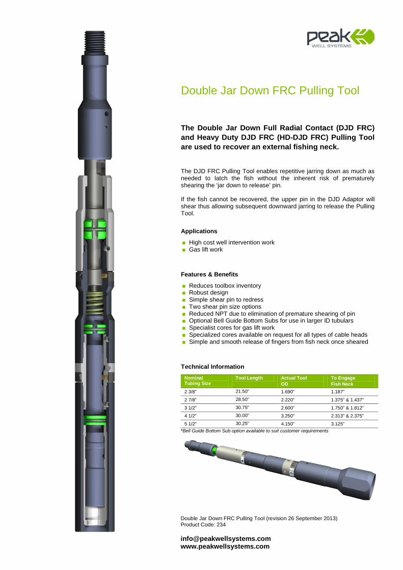
Double Jar Down FRC Pulling Tool
The Double Jar Down Full Radial Contact (DJD FRC) and Heavy Duty DJD FRC (HD-DJD FRC) Pulling Tool are used to recover an external fishing neck. The DJD FRC Pulling Tool enables repetitive jarring down as much as needed to latch the fish without the inherent risk of prematurely shearing the ‘jar down to release’ pin. If the fish cannot be recovered, the upper pin in the DJD Adaptor will shear thus allowing subsequent downward jarring to release the Pulling Tool.
Applications
■ High cost well intervention work ■ Gas lift work
Features & Benefits
■ Reduces toolbox inventory ■ Robust design ■ Simple shear pin to redress ■ Two shear pin size options ■ Reduced NPT due to elimination of premature shearing of pin ■ Optional Bell Guide Bottom Subs for use in larger ID tubulars ■ Specialist cores for gas lift work ■ Specialized cores available on request for all types of cable heads ■ Simple and smooth release of fingers from fish neck once sheared
Technical Information
Nominal Tubing Size
Tool Length Actual Tool OD
To Engage Fish Neck
2 3/8” 21.50” 1.690” 1.187”
2 7/8” 28.50” 2.220” 1.375” & 1.437”
3 1/2" 30.75” 2.600” 1.750” & 1.812”
4 1/2" 30.00” 3.250” 2.313” & 2.375”
5 1/2" 30.25” 4.150” 3.125” *Bell Guide Bottom Sub option available to suit customer requirements
IN-FRC Pulling Tool Product Code: 210 [email protected] www.peakwellsystems.com
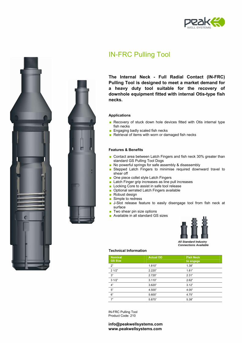
IN-FRC Pulling Tool
The Internal Neck - Full Radial Contact (IN-FRC) Pulling Tool is designed to meet a market demand for a heavy duty tool suitable for the recovery of downhole equipment fitted with internal Otis-type fish necks.
Applications
■ Recovery of stuck down hole devices fitted with Otis internal type fish necks
■ Engaging badly scaled fish necks ■ Retrieval of items with worn or damaged fish necks
Features & Benefits
■ Contact area between Latch Fingers and fish neck 30% greater than standard GS Pulling Tool Dogs
■ No powerful springs for safe assembly & disassembly ■ Stepped Latch Fingers to minimise required downward travel to
shear off ■ One piece collet style Latch Fingers ■ Latch Finger grip increases as line pull increases ■ Locking Core to assist in safe tool release ■ Optional serrated Latch Fingers available ■ Robust design ■ Simple to redress ■ J-Slot release feature to easily disengage tool from fish neck at
surface ■ Two shear pin size options ■ Available in all standard GS sizes
Technical Information
Nominal GS Size
Actual OD Fish Neck to engage
2” 1.810” 1.38”
2 1/2” 2.220” 1.81”
3” 2.720” 2.31”
3 1/2” 3.110” 2.62”
4” 3.620” 3.12”
5” 4.500” 4.00”
6” 5.600” 4.75”
7” 5.875” 5.38”
All Standard Industry Connections Available
Releasable Overshot Product Code: 230 [email protected] www.peakwellsystems.com
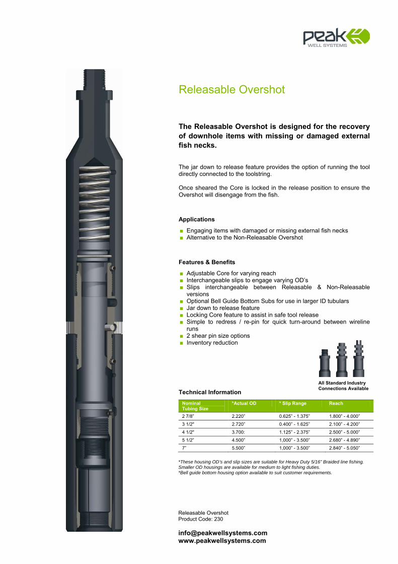
Releasable Overshot
The Releasable Overshot is designed for the recovery of downhole items with missing or damaged external fish necks. The jar down to release feature provides the option of running the tool directly connected to the toolstring. Once sheared the Core is locked in the release position to ensure the Overshot will disengage from the fish.
Applications
■ Engaging items with damaged or missing external fish necks ■ Alternative to the Non-Releasable Overshot
Features & Benefits
■ Adjustable Core for varying reach ■ Interchangeable slips to engage varying OD’s ■ Slips interchangeable between Releasable & Non-Releasable
versions ■ Optional Bell Guide Bottom Subs for use in larger ID tubulars ■ Jar down to release feature ■ Locking Core feature to assist in safe tool release ■ Simple to redress / re-pin for quick turn-around between wireline
runs ■ 2 shear pin size options ■ Inventory reduction
Technical Information
Nominal Tubing Size
*Actual OD * Slip Range Reach
2 7/8” 2.220” 0.625” - 1.375” 1.800” - 4.000”
3 1/2" 2.720” 0.400” - 1.625” 2.100” - 4.200”
4 1/2" 3.700: 1.125” - 2.375” 2.500” - 5.000”
5 1/2” 4.500” 1,000” - 3.500” 2.680” - 4.890”
7” 5.500” 1,000” - 3.500” 2.840” - 5.050”
*These housing OD’s and slip sizes are suitable for Heavy Duty 5/16” Braided line fishing. Smaller OD housings are available for medium to light fishing duties. *Bell guide bottom housing option available to suit customer requirements.
All Standard Industry Connections Available

Non-Releasable Overshot Product Code:231 [email protected] www.peakwellsystems.com
Non-Releasable Overshot
The Non-Releasable Overshot is used for the retrieval of downhole items with damaged or missing external fish necks. The Overshot is “planted” onto the fish to provide a new fish neck profile. This is then engaged with a standard releasable pulling tool or a Peak HD-FRC Pulling Tool for heavy jarring applications.
Applications
■ Replacing damaged or missing external fish necks ■ Providing a new fish neck profile for releasable pulling tools to
engage
Features & Benefits
■ Adjustable Core for varying reach ■ Interchangeable slips to engage varying OD’s ■ Slips interchangeable between Releasable & Non-Releasable
versions ■ Multiple Running Neck options - Multi-Pin Running Tool, HD Dual
Fish Neck etc. ■ Optional Bell Guide Bottom Subs for use in larger ID tubular ■ Bypass ports through tool body to provide maximum flow area if fish
cannot be recovered ■ Robust design ■ Inventory reduction
Technical Information
Nominal Tubing Size
*Actual OD *Slip Range Reach
2 3/8” 1.750” 0.500” - 1.000” 1.600” - 3.100”
2 7/8” 2.220” 0.625” - 1.375” 1.800” - 4.000”
3 1/2” 2.720” 0.400” - 1.625” 2.100” - 4.200”
4 1/2” 3.700” 1.125” - 2.375” 2.500” - 5.000”
5 1/2" 4.850” 1.000” - 3.500” 2.700” - 5.000”
*These Housing OD’s and slip sizes are suitable for Heavy Duty 5/16” Braided Line Fishing. Smaller OD Housings are available for medium to light duty fishing operations. * Bell Guide bottom housing option available to suit customer requirements.
Non-Releasable Overshot fitted with Peak Heavy Duty Dual Fish Neck
Non-Releasable Overshot fitted with Internal Fish Neck

Releasable Spear Product Code: 204 [email protected] www.peakwellsystems.com
Releasable Spear
The Releasable Spear is used for the recovery of downhole items with missing or damaged internal fish necks. An Adjustment Sleeve varies the reach of the tool and interchangeable slips are fitted to suit the inside diameter that the Spear needs to engage. With the Spear’s reach correctly adjusted and if required, a release pin can be sheared by downward jarring. Once sheared, a positive locking feature will ensure that the slips remain retracted, allowing the toolstring and Spear to disengage from the fish for safe recovery back to the surface. The jar down to release feature provides the option of running the tool directly connected to the toolstring.
Applications
■ Retrieval of items with damaged or missing internal fish necks
Features & Benefits
■ Reach Adjustment Sleeve to suit varying engagement depth of slips ■ Interchangeable slips for engaging varying internal diameters ■ Slips interchangeable between Releasable & Non Releasable
versions ■ Jar down to release feature ■ Positive locking feature to assist in safe tool release ■ Simple to redress / re-pin for quick turn around between wireline
runs ■ Robust design ■ Inventory reduction
Technical Information
Nominal Tubing Size
Actual OD Slip Range Reach
2 3/8” 1.75 1 - 1 1/2" 3.25”
2 7/8” 2.20 1 1/4" - 2” 3.70”
3 1/2” 2.70 1 5/8” - 2 1/2" 3.40”
4 1/2” 3.62 2 3/8” - 3 1/2" 6.00”
5 1/2” 4.50 3 1/2” - 4 7/16” 5.75”
7” 5.50 4 1/16” - 5 3/8” 4.56” *Customized slips and spear sizes available
All Standard Industry Connections Available
Short Reach Adjustment Sleeve
Long Reach Adjustment Sleeve
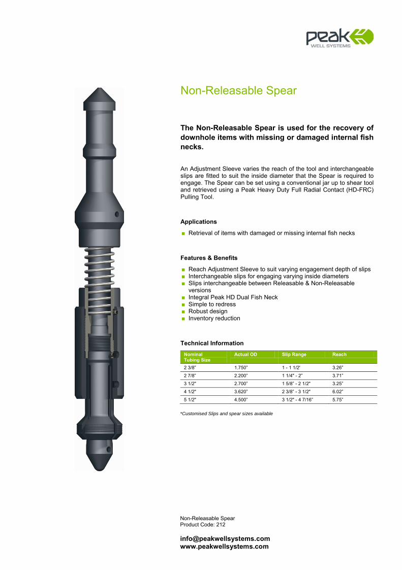
Non-Releasable Spear Product Code: 212 [email protected] www.peakwellsystems.com
Non-Releasable Spear
The Non-Releasable Spear is used for the recovery of downhole items with missing or damaged internal fish necks. An Adjustment Sleeve varies the reach of the tool and interchangeable slips are fitted to suit the inside diameter that the Spear is required to engage. The Spear can be set using a conventional jar up to shear tool and retrieved using a Peak Heavy Duty Full Radial Contact (HD-FRC) Pulling Tool.
Applications
■ Retrieval of items with damaged or missing internal fish necks
Features & Benefits
■ Reach Adjustment Sleeve to suit varying engagement depth of slips ■ Interchangeable slips for engaging varying inside diameters ■ Slips interchangeable between Releasable & Non-Releasable
versions ■ Integral Peak HD Dual Fish Neck ■ Simple to redress ■ Robust design ■ Inventory reduction
Technical Information
Nominal Tubing Size
Actual OD Slip Range Reach
2 3/8” 1.750” 1 - 1 1/2' 3.26”
2 7/8” 2.200” 1 1/4" - 2” 3.71”
3 1/2" 2.700” 1 5/8” - 2 1/2" 3.25”
4 1/2" 3.620” 2 3/8” - 3 1/2" 6.02”
5 1/2" 4.500” 3 1/2" - 4 7/16” 5.75”
*Customised Slips and spear sizes available

Wireline Retrieval System Product Code: 200 [email protected] www.peakwellsystems.com
Wireline Retrieval System
The Peak Wireline Retrieval System consists of a combination of interchangeable tool components used for the process of locating and recovering parted wireline. The system incorporates a unique design feature which allows the Slotted Finder Finger Sleeve to be adjusted to any chosen diameter to suit a range of nominal tubing ID and nipple dimensions.
Applications
■ Safely locating the top of parted wire ■ Balling over the top of wire ■ Latching and retrieving wire back to surface
Features & Benefits
■ Fully interchangeable components ■ Adjustable Finder Finger Sleeve ■ Extension Bar options ■ Option to run in conjunction with Peak Centre Spear, 2, 3 or 4 Prong
Wireline Grab, Lead Impression Block or Adjustable Finder Finger Sleeve
■ Multiple Running Neck options ■ Robust design ■ Inventory reduction
Technical Information
Nominal Tubing Size
Actual OD Finger Adjustment Range
2 3/8” 1.750” 1.750” - 1.992”
2 7/8” 2.195” 2.195” - 2.441”
3 1/2” 2.701” 2.701” - 2.992”
4” 3.100” 3.100” - 3.548”
4 1/2” 3.600” 3.600” - 3.992”
5 1/2” 4.530” 4.530” - 4.892”
7” 5.512” 5.512” - 6.138”
All Standard Industry Connections Available
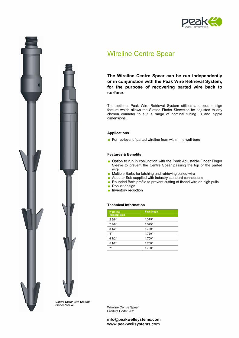
Wireline Centre Spear Product Code: 202 [email protected] www.peakwellsystems.com
Wireline Centre Spear
The Wireline Centre Spear can be run independently or in conjunction with the Peak Wire Retrieval System, for the purpose of recovering parted wire back to surface. The optional Peak Wire Retrieval System utilises a unique design feature which allows the Slotted Finder Sleeve to be adjusted to any chosen diameter to suit a range of nominal tubing ID and nipple dimensions.
Applications
■ For retrieval of parted wireline from within the well-bore
Features & Benefits
■ Option to run in conjunction with the Peak Adjustable Finder Finger Sleeve to prevent the Centre Spear passing the top of the parted wire
■ Multiple Barbs for latching and retrieving balled wire ■ Adaptor Sub supplied with industry standard connections ■ Rounded Barb profile to prevent cutting of fished wire on high pulls ■ Robust design ■ Inventory reduction
Technical Information
Nominal Tubing Size
Fish Neck
2 3/8” 1.375”
2 7/8” 1.375”
3 1/2” 1.750”
4” 1.750”
4 1/2” 1.750”
5 1/2” 1.750”
7” 1.750”
Centre Spear with Slotted Finder Sleeve
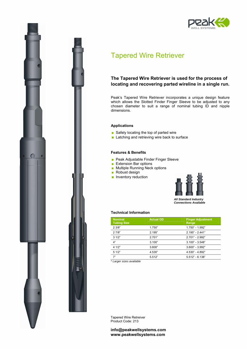
Tapered Wire Retreiver Product Code: 213 [email protected] www.peakwellsystems.com
Tapered Wire Retriever
The Tapered Wire Retriever is used for the process of locating and recovering parted wireline in a single run. Peak’s Tapered Wire Retriever incorporates a unique design feature which allows the Slotted Finder Finger Sleeve to be adjusted to any chosen diameter to suit a range of nominal tubing ID and nipple dimensions.
Applications
■ Safely locating the top of parted wire ■ Latching and retrieving wire back to surface
Features & Benefits
■ Peak Adjustable Finder Finger Sleeve ■ Extension Bar options ■ Multiple Running Neck options ■ Robust design ■ Inventory reduction
Technical Information
Nominal Tubing Size
Actual OD Finger Adjustment Range
2 3/8” 1.750” 1.750” - 1.992”
2 7/8” 2.195” 2.195” - 2.441”
3 1/2” 2.701” 2.701” - 2.992”
4” 3.100” 3.100” - 3.548”
4 1/2” 3.600” 3.600” - 3.992”
5 1/2” 4.530” 4.530” - 4.892”
7” 5.512” 5.512” - 6.138” * Larger sizes available
All Standard Industry Connections Available

Multi-Pin Running Tool Product Code: 201 [email protected] www.peakwellsystems.com
Multi-Pin Running Tool
Multi-Pin Running Tools (MPRT) are designed for use primarily as shearable devices which can be connected to a variety of tools such as Wireline Grabs, Wire Finders, Perforating Gun Drifts, RBP Drifts, Non-Releasable Overshots / Spears etc. With jar-up & jar-down to shear options, the MPRT can also be used to deploy Junk Catchers or Sealing Prongs. Internal & External Fish Neck options provide the operator with the flexibility to choose the device which best suits the well geometry and operation to be performed.
Applications
■ Utilised as safety shear-out device for fishing applications including conveyance of Wireline Grabs, Wire Finders, Non-Releasable Overshots & Spears etc.
■ Conveyance of extended, rigid assemblies including Perforating Gun Drifts, Retrievable Bridge Plug Drifts etc.
■ Deployment of Junk Catchers & Sealing Prongs
Features & Benefits
■ Internal & External Neck options to suit well geometry and operation ■ All Internal Neck Subs suit all standard GS & Peak IN-FRC sizes ■ External Neck Sub incorporates a standard Fish Neck & Peak HD
Chamfered Fish Neck which is aligned for use with the Peak HD-FRC Pulling Tool for ultra heavy jarring applications
■ Jar-up & jar-down to release functions ■ Multiple Pinning options to suit varied applications ■ Simple to re-pin ■ Robust design
Technical Information
External Multi-Pin Running Tool and Fish Neck Sub Actual OD Contingent Recovery
F/N 2.125” 1.375” / 1.437”
2.600” 1.750” / 1.812”
3.250” 2.313” / 2.375”
Internal Multi-Pin Running Tool and Fish Neck Sub
Actual OD
Contingent Recovery F/N
1.810”
1.380”
2.200”
1.810”
2.720”
2.313”
3.116”
2.620”
3.620”
3.120”
4.500”
4.000”
5.830”
5.380”
All Standard Industry Connections Available
Internal External
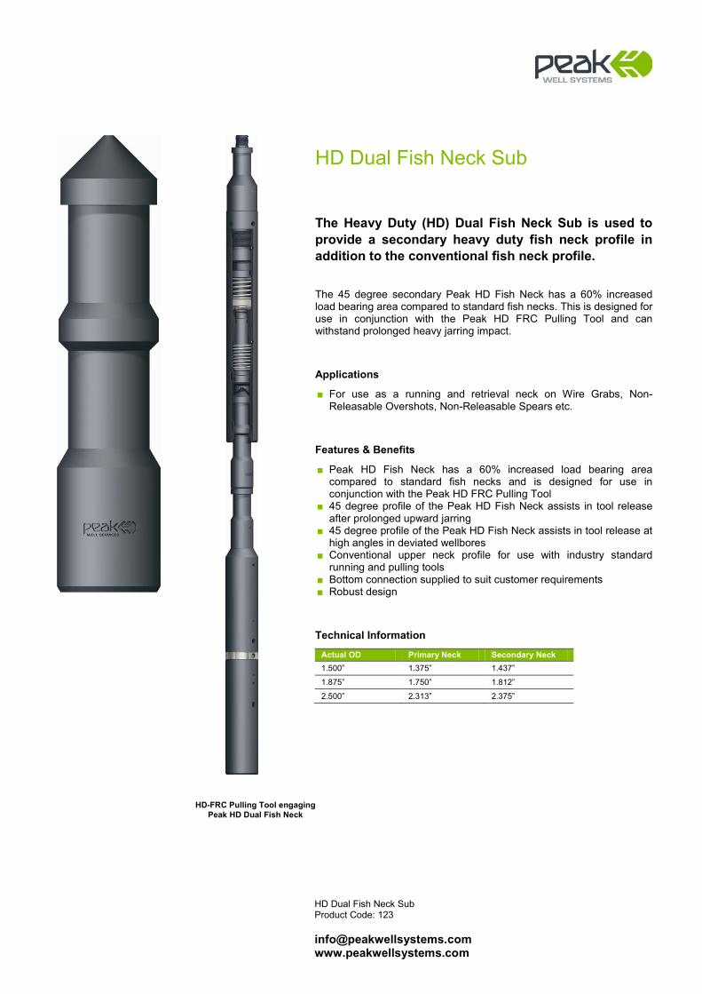
HD Dual Fish Neck Sub Product Code: 123 [email protected] www.peakwellsystems.com
HD Dual Fish Neck Sub
The Heavy Duty (HD) Dual Fish Neck Sub is used to provide a secondary heavy duty fish neck profile in addition to the conventional fish neck profile. The 45 degree secondary Peak HD Fish Neck has a 60% increased load bearing area compared to standard fish necks. This is designed for use in conjunction with the Peak HD FRC Pulling Tool and can withstand prolonged heavy jarring impact.
Applications
■ For use as a running and retrieval neck on Wire Grabs, Non-Releasable Overshots, Non-Releasable Spears etc.
Features & Benefits
■ Peak HD Fish Neck has a 60% increased load bearing area compared to standard fish necks and is designed for use in conjunction with the Peak HD FRC Pulling Tool
■ 45 degree profile of the Peak HD Fish Neck assists in tool release after prolonged upward jarring
■ 45 degree profile of the Peak HD Fish Neck assists in tool release at high angles in deviated wellbores
■ Conventional upper neck profile for use with industry standard running and pulling tools
■ Bottom connection supplied to suit customer requirements ■ Robust design
Technical Information
Actual OD Primary Neck Secondary Neck 1.500” 1.375” 1.437”
1.875” 1.750” 1.812”
2.500” 2.313” 2.375”
HD-FRC Pulling Tool engaging Peak HD Dual Fish Neck
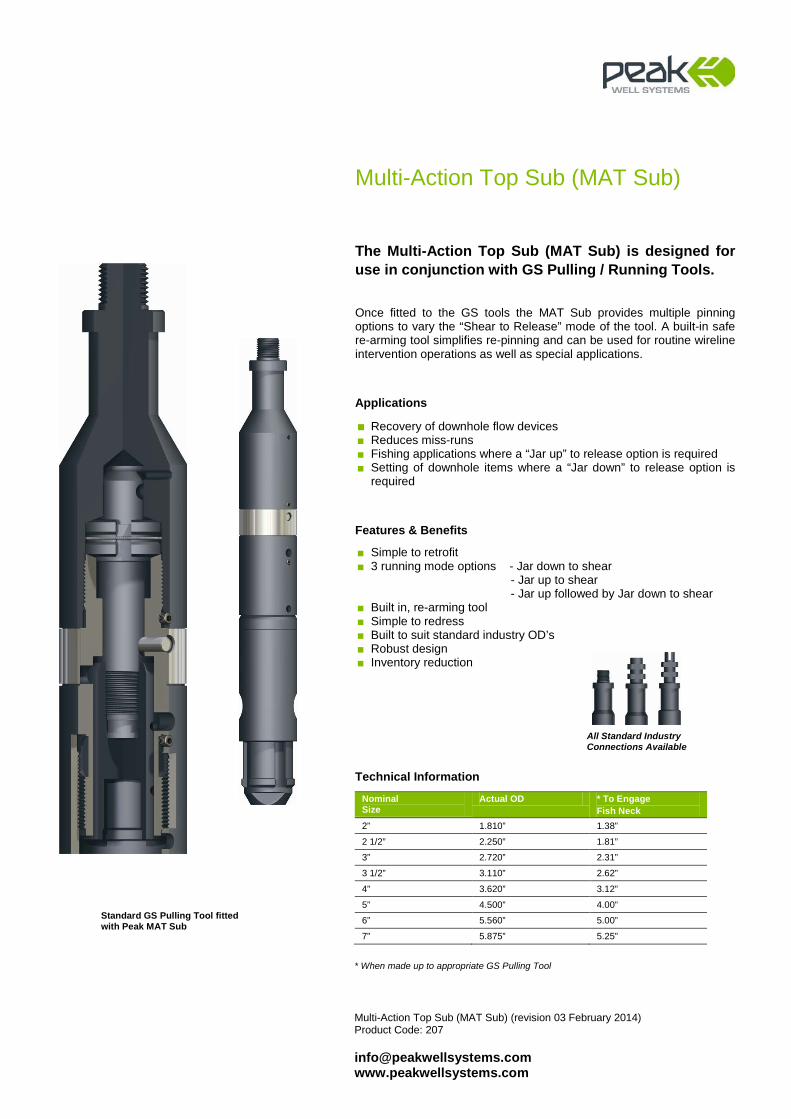
Multi-Action Top Sub (MAT Sub) (revision 03 February 2014) Product Code: 207 [email protected] www.peakwellsystems.com
Multi-Action Top Sub (MAT Sub)
The Multi-Action Top Sub (MAT Sub) is designed for use in conjunction with GS Pulling / Running Tools. Once fitted to the GS tools the MAT Sub provides multiple pinning options to vary the “Shear to Release” mode of the tool. A built-in safe re-arming tool simplifies re-pinning and can be used for routine wireline intervention operations as well as special applications.
Applications
■ Recovery of downhole flow devices ■ Reduces miss-runs ■ Fishing applications where a “Jar up” to release option is required ■ Setting of downhole items where a “Jar down” to release option is
required
Features & Benefits
■ Simple to retrofit ■ 3 running mode options - Jar down to shear
- Jar up to shear - Jar up followed by Jar down to shear
■ Built in, re-arming tool ■ Simple to redress ■ Built to suit standard industry OD’s ■ Robust design ■ Inventory reduction
Technical Information
Nominal Size
Actual OD * To Engage Fish Neck
2” 1.810” 1.38”
2 1/2” 2.250” 1.81”
3” 2.720” 2.31”
3 1/2” 3.110” 2.62”
4” 3.620” 3.12”
5” 4.500” 4.00”
6” 5.560” 5.00”
7” 5.875” 5.25”
* When made up to appropriate GS Pulling Tool
Standard GS Pulling Tool fitted with Peak MAT Sub
All Standard Industry Connections Available
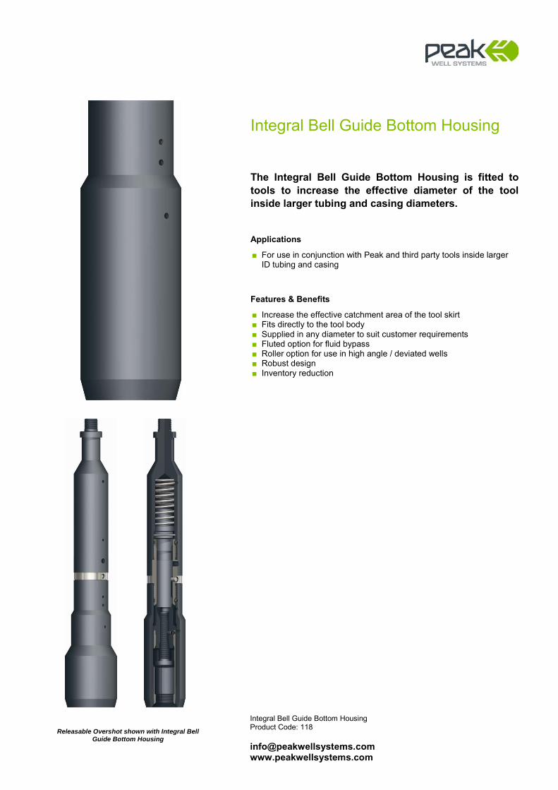
Integral Bell Guide Bottom Housing Product Code: 118 [email protected] www.peakwellsystems.com
Integral Bell Guide Bottom Housing
The Integral Bell Guide Bottom Housing is fitted to tools to increase the effective diameter of the tool inside larger tubing and casing diameters.
Applications
■ For use in conjunction with Peak and third party tools inside larger ID tubing and casing
Features & Benefits
■ Increase the effective catchment area of the tool skirt ■ Fits directly to the tool body ■ Supplied in any diameter to suit customer requirements ■ Fluted option for fluid bypass ■ Roller option for use in high angle / deviated wells ■ Robust design ■ Inventory reduction
Releasable Overshot shown with Integral Bell Guide Bottom Housing
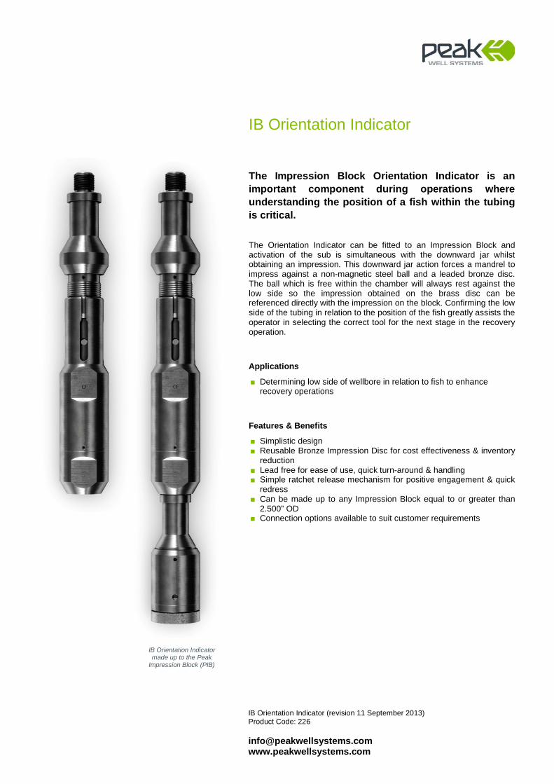
IB Orientation Indicator (revision 11 September 2013) Product Code: 226 [email protected] www.peakwellsystems.com
IB Orientation Indicator
The Impression Block Orientation Indicator is an important component during operations where understanding the position of a fish within the tubing is critical. The Orientation Indicator can be fitted to an Impression Block and activation of the sub is simultaneous with the downward jar whilst obtaining an impression. This downward jar action forces a mandrel to impress against a non-magnetic steel ball and a leaded bronze disc. The ball which is free within the chamber will always rest against the low side so the impression obtained on the brass disc can be referenced directly with the impression on the block. Confirming the low side of the tubing in relation to the position of the fish greatly assists the operator in selecting the correct tool for the next stage in the recovery operation.
Applications
■ Determining low side of wellbore in relation to fish to enhance recovery operations
Features & Benefits
■ Simplistic design ■ Reusable Bronze Impression Disc for cost effectiveness & inventory
reduction ■ Lead free for ease of use, quick turn-around & handling ■ Simple ratchet release mechanism for positive engagement & quick
redress ■ Can be made up to any Impression Block equal to or greater than
2.500” OD ■ Connection options available to suit customer requirements
IB Orientation Indicator made up to the Peak
Impression Block (PIB)

Indexing Tool (revision 25 September 2013) Product Code: 222 [email protected] www.peakwellsystems.com
All Standard Industry Connections Available
Indexing Tool
The Indexing Tool is designed to rotate the toolstring bottom hole assembly (BHA) on a radial J Slot mechanism. By simply sitting down & picking up, the Indexing Tool rotates and increases the lower connected tool coverage within the wellbore. This ultimately improves the probability to recover a fish that may be resting in a position within the well that makes standard recovery difficult.
Applications
■ To increase area coverage within the tubing string and improve chances of fish recovery
Features & Benefits
■ Minimum 3-point indexing system (Smaller OD tools) ■ Spring assisted ‘J’ Mandrel ensures Indexing Tool continuously
rotates regardless of deviation etc. ■ Multiple upper & lower connection options ■ Special designs can be made to suit customer requirements ■ The Peak Indexing Tool is supplied as standard with concentric
threads top and bottom, and can be supplied with eccentric thread for specific applications. The eccentric lower thread design is useful in deviated and larger bore completions where a fish may not be sitting central. Care must be taken with the eccentric thread design to ensure that the effective OD of the offset tool does not compromise well intervention.
Actual OD Fish-neck Size Overall Length
1.875” 1.750 16.9”
2.250” 1.750” 17.2”
2.500” 2.313” 18.0”
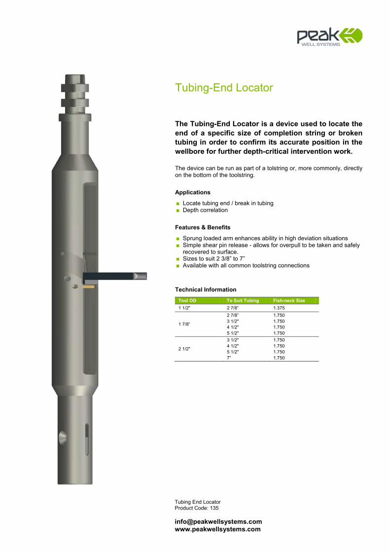
Tubing End Locator Product Code: 135 [email protected] www.peakwellsystems.com
Tubing-End Locator
The Tubing-End Locator is a device used to locate the end of a specific size of completion string or broken tubing in order to confirm its accurate position in the wellbore for further depth-critical intervention work. The device can be run as part of a tolstring or, more commonly, directly on the bottom of the toolstring.
Applications
■ Locate tubing end / break in tubing ■ Depth correlation
Features & Benefits
■ Sprung loaded arm enhances ability in high deviation situations ■ Simple shear pin release - allows for overpull to be taken and safely
recovered to surface. ■ Sizes to suit 2 3/8” to 7” ■ Available with all common toolstring connections
Technical Information
Tool OD To Suit Tubing Fish-neck Size 1 1/2" 2 7/8” 1.375
1 7/8”
2 7/8” 3 1/2" 4 1/2" 5 1/2"
1.750 1.750 1.750 1.750
2 1/2"
3 1/2" 4 1/2" 5 1/2" 7”
1.750 1.750 1.750 1.750
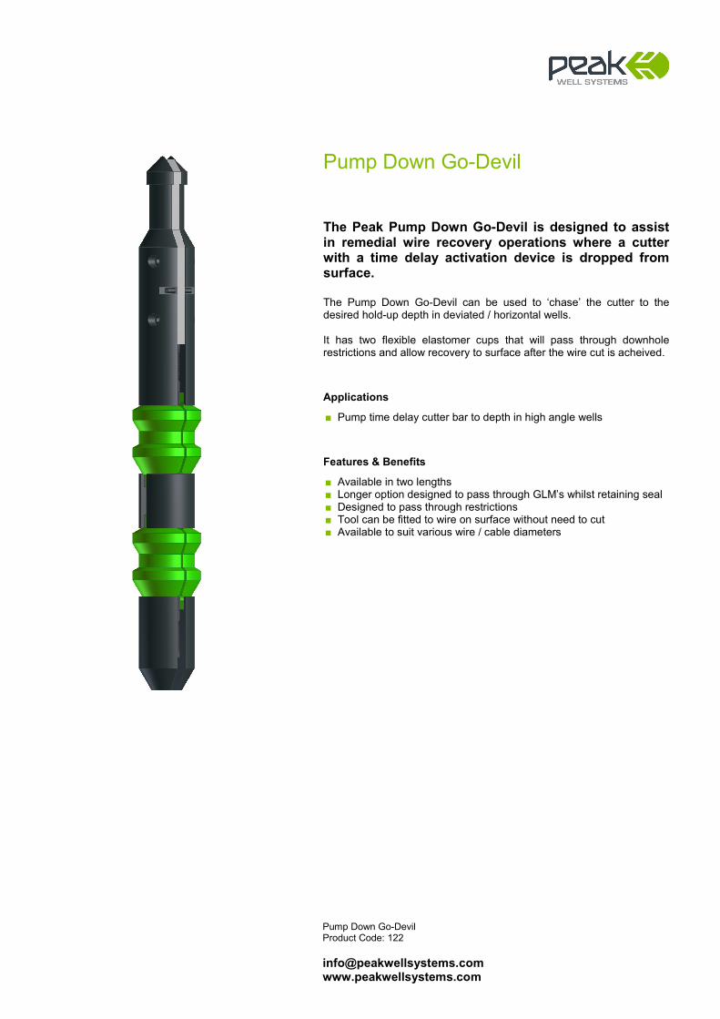
Pump Down Go-Devil
The Peak Pump Down Go-Devil is designed to assist in remedial wire recovery operations where a cutter with a time delay activation device is dropped from surface. The Pump Down Go-Devil can be used to ‘chase’ the cutter to the desired hold-up depth in deviated / horizontal wells. It has two flexible elastomer cups that will pass through downhole restrictions and allow recovery to surface after the wire cut is acheived.
Applications
■ Pump time delay cutter bar to depth in high angle wells
Features & Benefits
■ Available in two lengths ■ Longer option designed to pass through GLM’s whilst retaining seal ■ Designed to pass through restrictions ■ Tool can be fitted to wire on surface without need to cut ■ Available to suit various wire / cable diameters
Pump Down Go-Devil Product Code: 122 [email protected] www.peakwellsystems.com
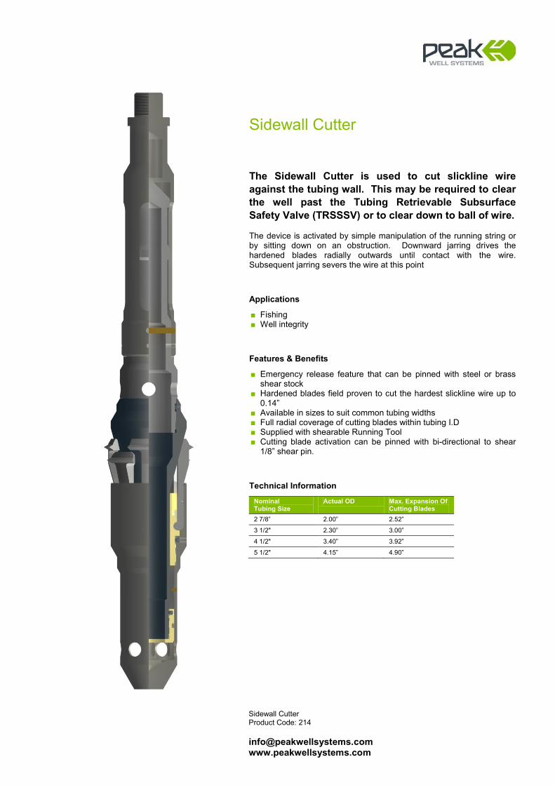
Sidewall Cutter Product Code: 214 [email protected] www.peakwellsystems.com
Sidewall Cutter
The Sidewall Cutter is used to cut slickline wire against the tubing wall. This may be required to clear the well past the Tubing Retrievable Subsurface Safety Valve (TRSSSV) or to clear down to ball of wire. The device is activated by simple manipulation of the running string or by sitting down on an obstruction. Downward jarring drives the hardened blades radially outwards until contact with the wire. Subsequent jarring severs the wire at this point
Applications
■ Fishing ■ Well integrity
Features & Benefits
■ Emergency release feature that can be pinned with steel or brass shear stock
■ Hardened blades field proven to cut the hardest slickline wire up to 0.14”
■ Available in sizes to suit common tubing widths ■ Full radial coverage of cutting blades within tubing I.D ■ Supplied with shearable Running Tool ■ Cutting blade activation can be pinned with bi-directional to shear
1/8” shear pin.
Technical Information
Nominal Tubing Size
Actual OD Max. Expansion Of Cutting Blades
2 7/8” 2.00” 2.52”
3 1/2" 2.30” 3.00”
4 1/2" 3.40” 3.92”
5 1/2" 4.15” 4.90”

Peak Cutter Product Code: 215 [email protected] www.peakwellsystems.com
Peak Cutter
The Peak Cutter is a unique, power-charged, non-explosive cutter that is dropped from surface to sever slicklines and cables in the event that a toolstring becomes stuck downhole. It is designed to cut cleanly above the toolstring assembly - safely and reliably - and allow the upper section of the wire/cable to be recovered quickly to surface.
Applications
■ Deployment in the event that a toolstring becomes stuck downhole
■ Recovery of wire or cable from situations where wire or tools have been blown up hole
■ Deployment in subsea wells where the Peak Cutter is held as a contingency within a tool catcher integral to the seabed well control package
Features & Benefits
■ Incorporates an integral non-hydraulic, non-pyrotechnic power charge, a contingent cutting arrangement and integral wire/cable clamp assembly
■ No need for explosives, so the Peak Cutter is also safe to deploy
■ Capable of cutting all industry wire from 0.108” slickline up to 5/16” heavy duty die-form cable
■ Supplied with three retaining plates which cover full 0.108” – 0.312” range of tool
■ Rollerised versions are available on request subject to completion size
■ Simple field redress ■ Supplied with safety clamp for secure and safe handling at the
well site ■ Offers an accurate and reliable result, particularly when
deployed in high viscous fluids and deviated wells ■ Available for rapid rental with immediate mobilisation ■ Does not require radio silence
Technical Information
Nominal Tubing Size
Actual OD
Fishneck Size
Length
2-7/8”
2.185”
1.375”
45”
4 ½” to 7”
2.500”
1.750”
45”

Peak eCutter (Revision 25 March 2014) Product Code: 215 [email protected] www.peakwellsystems.com
Peak eCutter
The Peak eCutter is a unique, electronically activated, power-charged non-explosive cutter that is dropped from surface to sever slicklines and cables in the event that a toolstring becomes stuck downhole. The Peak eCutter is a variant of the standard Peak Cutter whereby, rather than being activated by impact against the stuck toolstring, the Peak eCutter is activated via an electronic timer and trigger module. Providing the same elements of unparalleled safety and reliability to cleanly cut a wide range of wire sizes as the field-proven standard Peak Cutter, the Peak eCutter provides the ultimate operational flexibility and functionality to ensure that the cut is performed at the required point especially in highly deviated or complex geometry wells.
Applications
■ Deployment in all stuck toolstring events for target depth & activation assurance
■ Severing of wire and cable in highly deviated wells ■ Pump-Down deployment
Features & Benefits
■ Integral non-pyrotechnic power charge ■ No radio-silence requirement ■ HSE compliant – no explosives ■ Range of pre-programmed countdown times (optional custom-
programming also available) ■ Remote power capability with lithium-based power source ■ LED operability indicator for timer activation confirmation ■ Same tool capable of cutting all industry wire/cables from 0.108”
slickline to 5/16” heavy duty die-form cable ■ Supplied with safety handling clamps for safe and secure operations
at the well site ■ Offers a reliable and accurate result even in highly deviated wells,
high viscous fluids and complex geometries ■ Roller Centralisers available for larger tubing/casing sizes ■ Pump-Down systems available upon request ■ Simple field redress ■ Logistically simple, safe and rapid mobilization to well sites globally
Technical Information
Nominal Tubing Size
(inch)
Actual OD
(inch)
Fishing Neck Size (inch)
Overall Length (inch)
2-7/8” 2.200” 1.375” 88.44” 3-1/2” 2.800” (Rollerised) 1.375” 88.44” 4-1/2” to 9-5/8” * 2.500” 2.313” or 1.750” 88.44” * Range of Roller Centralisers & Pump-Down available for all tubing sizes 4 ½” and above
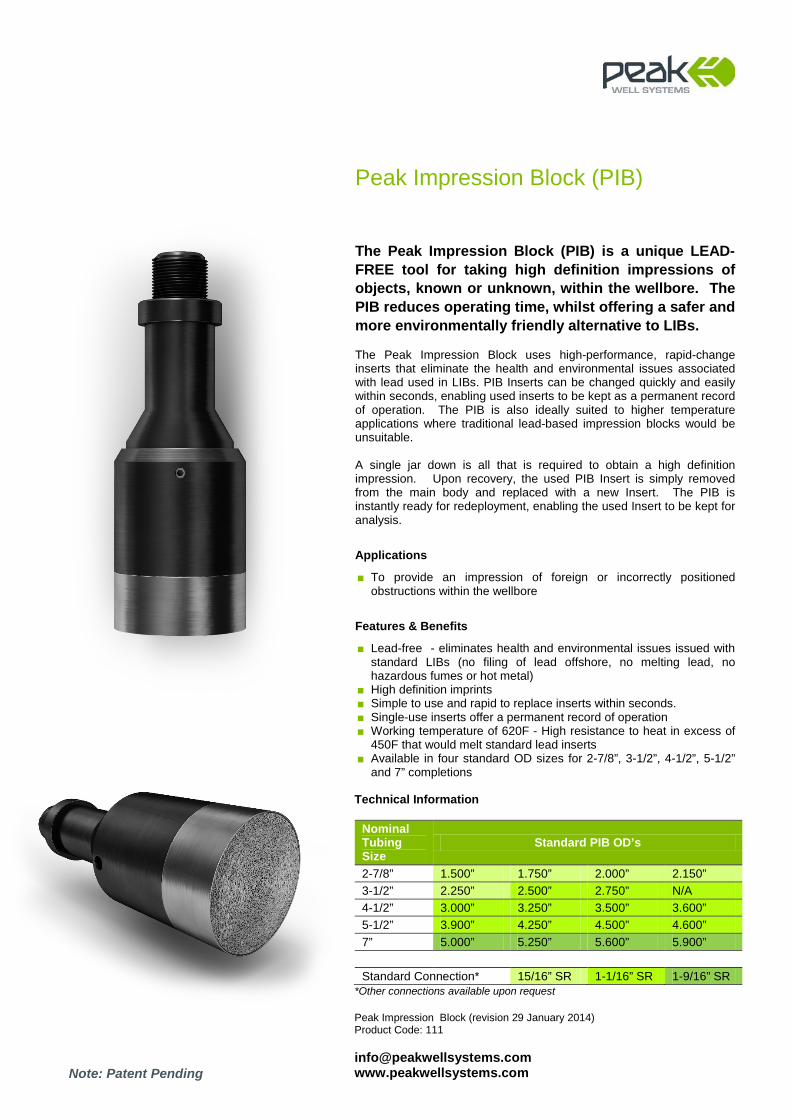
Peak Impression Block (revision 29 January 2014) Product Code: 111 [email protected] www.peakwellsystems.com
Peak Impression Block (PIB)
The Peak Impression Block (PIB) is a unique LEAD-FREE tool for taking high definition impressions of objects, known or unknown, within the wellbore. The PIB reduces operating time, whilst offering a safer and more environmentally friendly alternative to LIBs. The Peak Impression Block uses high-performance, rapid-change inserts that eliminate the health and environmental issues associated with lead used in LIBs. PIB Inserts can be changed quickly and easily within seconds, enabling used inserts to be kept as a permanent record of operation. The PIB is also ideally suited to higher temperature applications where traditional lead-based impression blocks would be unsuitable. A single jar down is all that is required to obtain a high definition impression. Upon recovery, the used PIB Insert is simply removed from the main body and replaced with a new Insert. The PIB is instantly ready for redeployment, enabling the used Insert to be kept for analysis.
Applications
■ To provide an impression of foreign or incorrectly positioned obstructions within the wellbore
Features & Benefits
■ Lead-free - eliminates health and environmental issues issued with standard LIBs (no filing of lead offshore, no melting lead, no hazardous fumes or hot metal)
■ High definition imprints ■ Simple to use and rapid to replace inserts within seconds. ■ Single-use inserts offer a permanent record of operation ■ Working temperature of 620F - High resistance to heat in excess of
450F that would melt standard lead inserts ■ Available in four standard OD sizes for 2-7/8”, 3-1/2”, 4-1/2”, 5-1/2”
and 7” completions Technical Information
Nominal Tubing Size
Standard PIB OD’s
2-7/8” 1.500” 1.750” 2.000” 2.150” 3-1/2” 2.250” 2.500” 2.750” N/A 4-1/2” 3.000” 3.250” 3.500” 3.600” 5-1/2” 3.900” 4.250” 4.500” 4.600” 7” 5.000” 5.250” 5.600” 5.900” Standard Connection* 15/16” SR 1-1/16” SR 1-9/16” SR
*Other connections available upon request
Note: Patent Pending

Premium Utility Toolstring
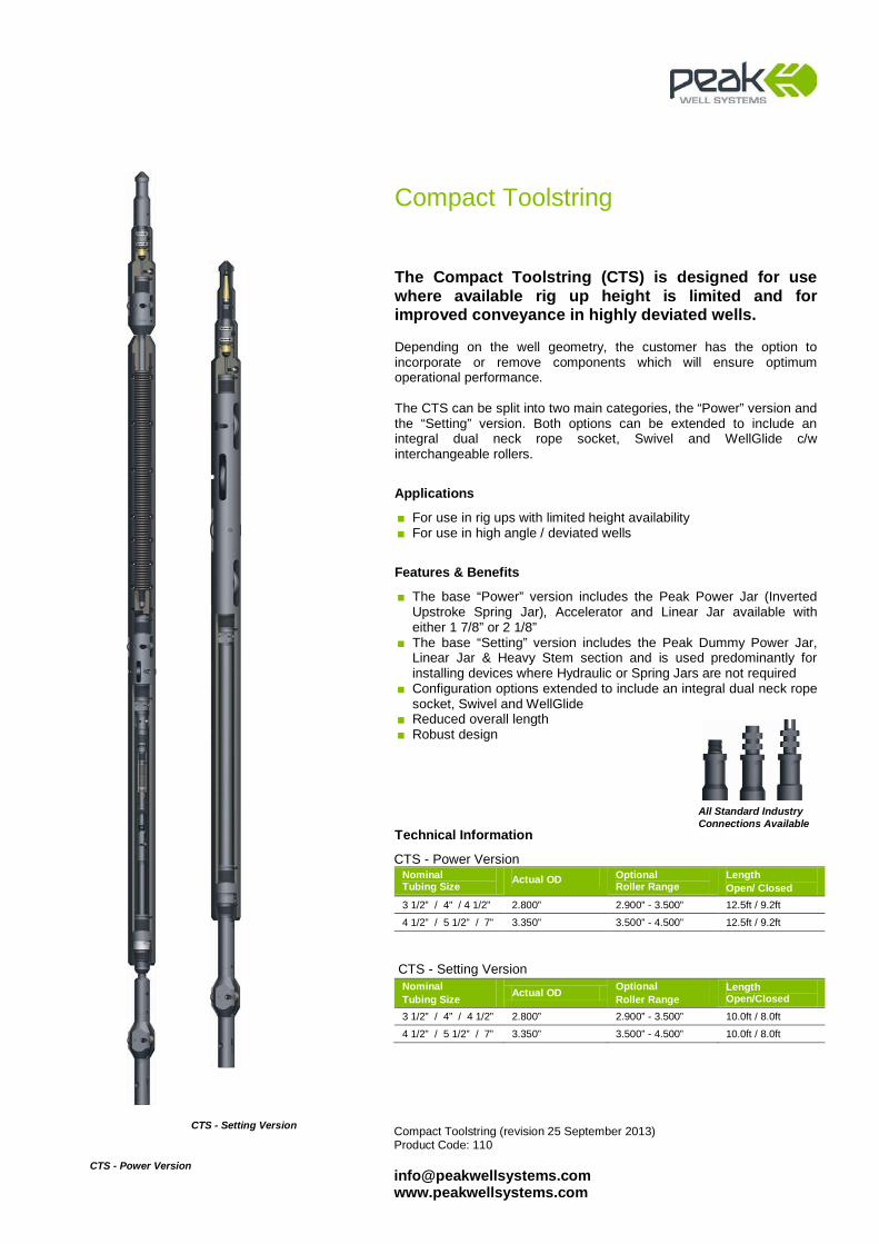
Compact Toolstring (revision 25 September 2013) Product Code: 110 [email protected] www.peakwellsystems.com
Compact Toolstring
The Compact Toolstring (CTS) is designed for use where available rig up height is limited and for improved conveyance in highly deviated wells. Depending on the well geometry, the customer has the option to incorporate or remove components which will ensure optimum operational performance. The CTS can be split into two main categories, the “Power” version and the “Setting” version. Both options can be extended to include an integral dual neck rope socket, Swivel and WellGlide c/w interchangeable rollers.
Applications
■ For use in rig ups with limited height availability ■ For use in high angle / deviated wells
Features & Benefits
■ The base “Power” version includes the Peak Power Jar (Inverted Upstroke Spring Jar), Accelerator and Linear Jar available with either 1 7/8” or 2 1/8”
■ The base “Setting” version includes the Peak Dummy Power Jar, Linear Jar & Heavy Stem section and is used predominantly for installing devices where Hydraulic or Spring Jars are not required
■ Configuration options extended to include an integral dual neck rope socket, Swivel and WellGlide
■ Reduced overall length ■ Robust design
Technical Information
CTS - Power Version Nominal Tubing Size
Actual OD Optional Roller Range
Length Open/ Closed
3 1/2” / 4” / 4 1/2” 2.800” 2.900” - 3.500” 12.5ft / 9.2ft
4 1/2” / 5 1/2” / 7” 3.350” 3.500” - 4.500” 12.5ft / 9.2ft
CTS - Setting Version Nominal Tubing Size Actual OD Optional
Roller Range Length Open/Closed
3 1/2” / 4” / 4 1/2” 2.800” 2.900” - 3.500” 10.0ft / 8.0ft
4 1/2” / 5 1/2” / 7” 3.350” 3.500” - 4.500” 10.0ft / 8.0ft
All Standard Industry Connections Available
CTS - Power Version
CTS - Setting Version

Slickline Rope Socket Product Code: 123 [email protected] www.peakwellsystems.com
Slickline Rope Socket
Designed to attach the wireline to the toolstring, the Slickline Rope Socket incorporates a robust Sleeve feature which is designed to maintain form and ensure continuous performance. Should the Rope Socket & toolstring be left in the well due to any unforeseen circumstances and the wire has been recovered, the HD-FRC Pulling Tool can be run to engage the Peak HD Dual Fish Neck & if required, prolonged, heavy jarring can be carried out to recover the toolstring.
Applications
■ To provide connection of the wireline to the toolstring
Features & Benefits
■ Robust Pear Drop and Sleeve feature to maintain form and ensure continuous performance
■ The Peak signature HD Dual Fish Neck allows use of both standard pulling tools and Peak HD-FRC Pulling Tool range for recovery
■ Suits all wire sizes ■ Third party proprietary connections available to suit customer
requirements
Technical Information
Actual OD Fish Neck 1.250” 1.187”
1.500” 1.375” / 1.437”
1.750” 1.375” / 1.437”
1.875” 1.750” / 1.812”
2.125” 1.750” / 1.812”
2.500” 2.313” / 2.375”

Slick & Swivel Rope Socket Product Code: 123 [email protected] www.peakwellsystems.com
Slick & Swivel Rope Socket
The Slick & Swivel Rope Socket is designed to reduce the overall length of a toolstring by removing the requirement for an extra connection. The working life of alloy slicklines can be extended when a swivel is incorporated below the rope socket. The swivel assists the tool rotation and prevents “over-torqueing” of the wire. The integral configuration ensures that a swivel is always included in the toolstring.
Applications
■ For use with slickline operations
Features & Benefits
■ Integral Rope Socket & Swivel - reducing overall toolstring length & ensuring a swivel is incorporated into the slickline toolstring
■ Heavy Duty Thrust Bearings for enhanced rotation under load ■ Integral Grease Nipple to allow easy lubrication and prevent
corrosion ■ Critical components ENP treated to further assist in prevention of
internal corrosion ■ Heavy duty robust design ■ Integral Belleville Spring design to guarantee positive load
maintained on thrust bearings to ensure continuous rotation ■ Debris Rings to prevent ingress of foreign matter ■ Swivel components are supported at rotation point to prevent lateral
movement and wear ■ Third party proprietary connections available to suit customer
requirements
Technical Information
Actual OD Fish Neck 1.500” 1.375” / 1.437”
1.750” 1.375” / 1.437”
1.875” 1.750” / 1.812”
2.125” 1.750” / 1.812”
2.500” 2.313” / 2.375”
All Standard Industry Connections Available

Braided Line Rope Socket Product Code: 123 [email protected] www.peakwellsystems.com
Braided Line Rope Socket
The Braided Line Rope Socket is available for use where high pulling forces are anticipated. The design incorporates a special one-piece Slip & Initiator Clamp arrangement to ensure maximum line pull can be attained with minimal slippage. A Belleville Spring Stack assembly creates a pre-loaded tension to ensure there is very little movement of the termination during upward and downward jarring.
Applications
■ For use with braided line operations to provide connection of the wireline to the toolstring
Features & Benefits
■ Incorporates a Peak Heavy Duty Dual Fish Neck ■ One piece slip assembly for ease of use ■ Belleville Spring Stack to minimise cable slippage ■ Assembly/Disassembly tool provided to aid make up/break out of
Slip assembly
Technical Information
Actual OD Fish Neck 1.500” 1.375” / 1.437”
1.750” 1.375” / 1.437”
1.875” 1.750” / 1.812”
2.125” 1.750” / 1.812”
2.500” 2.313” / 2.375”
All Standard Industry Connections Available

Braided Line Multi-function Rope Socket Product Code: 123 [email protected] www.peakwellsystems.com
Braided Line Multi-function Rope Socket
The Braided Line Multi-function Rope Socket (MFRS) is designed to reduce the overall length of a toolstring by removing the requirement for an extra connection. The integral configuration also ensures that a swivel, a crucial component when using braided line, is always included in the toolstring. A unique one-piece Slip & Initiator Clamp arrangement ensures maximum line pull can be attained with minimal slippage. A Belleville Washer assembly creates a pre-load tension to ensure there is very little movement of the termination during upward and downward jarring.
Applications
■ For use with braided line operations
Features & Benefits
■ Integral Rope Socket & Swivel - reducing overall toolstring length & ensuring a swivel is incorporated into the braided line toolstring
■ One piece Slip & Initiator Clamp arrangement for ease of use and inventory reduction
■ Heavy Duty Thrust Bearings for enhanced rotation under load ■ Integral Grease Nipple to allow easy lubrication and prevent
corrosion ■ Critical components ENP treated to further assist in prevention of
internal corrosion ■ Assembly / Disassembly Tool provided for simple cable termination
& break out ■ Heavy duty robust design ■ Integral Belleville Spring design to guarantee positive load
maintained on thrust bearings to ensure continuous rotation ■ Debris Rings to prevent ingress of foreign matter ■ Swivel components are supported at rotation point to prevent lateral
movement and wear ■ Third party proprietary connections available to suit customer
requirements
Technical Information
Actual OD Fish Neck 1.500” 1.375” / 1.437”
1.750” 1.375” / 1.437”
1.875” 1.750” / 1.812”
2.125” 1.750 / 1.812”
2.500” 2.313” / 2.375”
All Standard Industry Connections Available
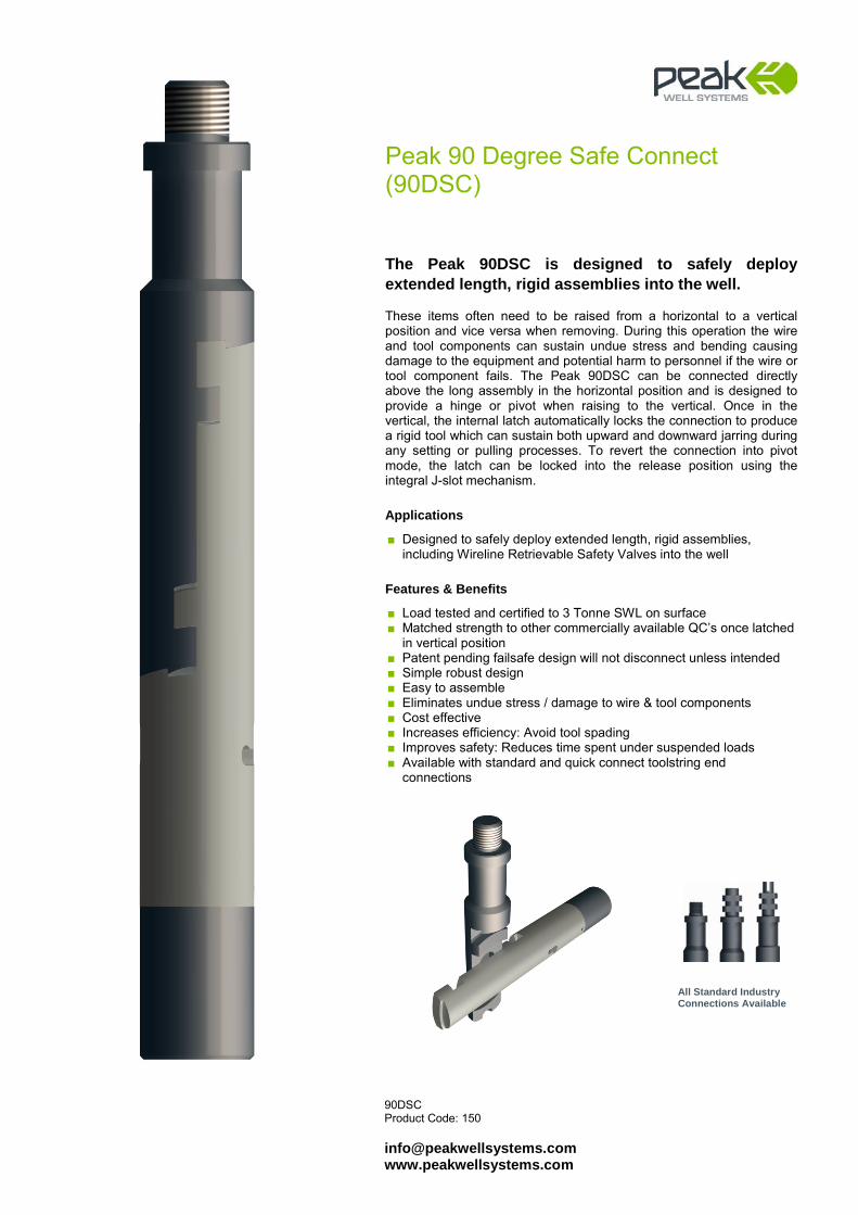
90DSC Product Code: 150 [email protected] www.peakwellsystems.com
Peak 90 Degree Safe Connect (90DSC)
The Peak 90DSC is designed to safely deploy extended length, rigid assemblies into the well. These items often need to be raised from a horizontal to a vertical position and vice versa when removing. During this operation the wire and tool components can sustain undue stress and bending causing damage to the equipment and potential harm to personnel if the wire or tool component fails. The Peak 90DSC can be connected directly above the long assembly in the horizontal position and is designed to provide a hinge or pivot when raising to the vertical. Once in the vertical, the internal latch automatically locks the connection to produce a rigid tool which can sustain both upward and downward jarring during any setting or pulling processes. To revert the connection into pivot mode, the latch can be locked into the release position using the integral J-slot mechanism.
Applications
■ Designed to safely deploy extended length, rigid assemblies, including Wireline Retrievable Safety Valves into the well
Features & Benefits
■ Load tested and certified to 3 Tonne SWL on surface ■ Matched strength to other commercially available QC’s once latched
in vertical position ■ Patent pending failsafe design will not disconnect unless intended ■ Simple robust design ■ Easy to assemble ■ Eliminates undue stress / damage to wire & tool components ■ Cost effective ■ Increases efficiency: Avoid tool spading ■ Improves safety: Reduces time spent under suspended loads ■ Available with standard and quick connect toolstring end
connections
All Standard Industry Connections Available
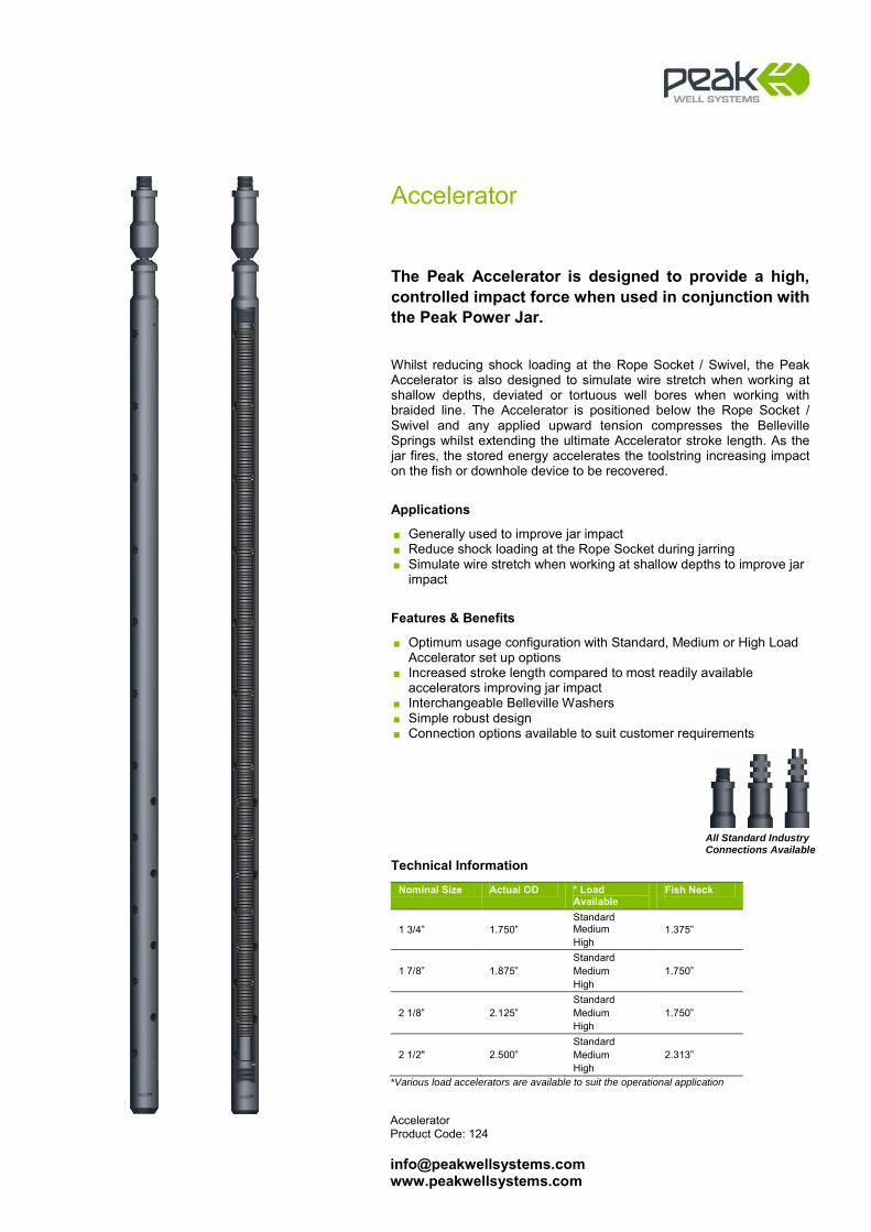
Accelerator Product Code: 124 [email protected] www.peakwellsystems.com
Accelerator
The Peak Accelerator is designed to provide a high, controlled impact force when used in conjunction with the Peak Power Jar. Whilst reducing shock loading at the Rope Socket / Swivel, the Peak Accelerator is also designed to simulate wire stretch when working at shallow depths, deviated or tortuous well bores when working with braided line. The Accelerator is positioned below the Rope Socket / Swivel and any applied upward tension compresses the Belleville Springs whilst extending the ultimate Accelerator stroke length. As the jar fires, the stored energy accelerates the toolstring increasing impact on the fish or downhole device to be recovered.
Applications
■ Generally used to improve jar impact ■ Reduce shock loading at the Rope Socket during jarring ■ Simulate wire stretch when working at shallow depths to improve jar
impact
Features & Benefits
■ Optimum usage configuration with Standard, Medium or High Load Accelerator set up options
■ Increased stroke length compared to most readily available accelerators improving jar impact
■ Interchangeable Belleville Washers ■ Simple robust design ■ Connection options available to suit customer requirements
Technical Information
Nominal Size Actual OD * Load Available
Fish Neck
1 3/4” 1.750” Standard Medium High
1.375”
1 7/8” 1.875” Standard Medium High
1.750”
2 1/8” 2.125” Standard Medium High
1.750”
2 1/2" 2.500” Standard Medium High
2.313”
*Various load accelerators are available to suit the operational application
All Standard Industry Connections Available
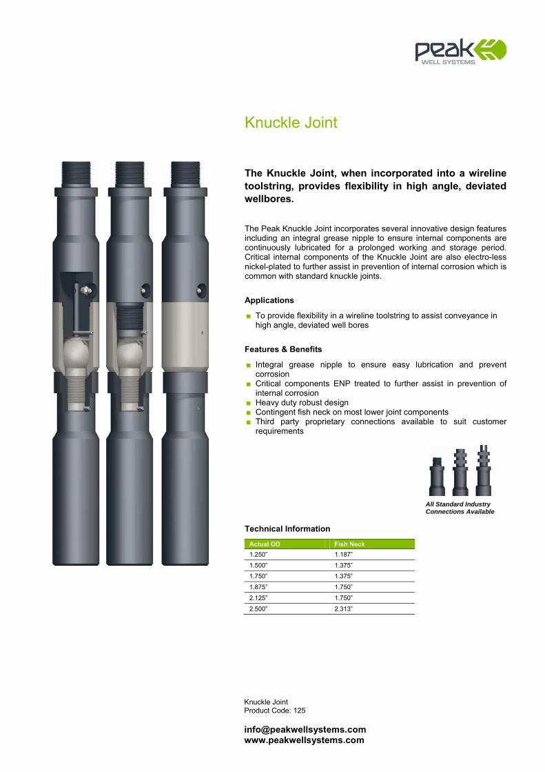
Knuckle Joint Product Code: 125 [email protected] www.peakwellsystems.com
Knuckle Joint
The Knuckle Joint, when incorporated into a wireline toolstring, provides flexibility in high angle, deviated wellbores. The Peak Knuckle Joint incorporates several innovative design features including an integral grease nipple to ensure internal components are continuously lubricated for a prolonged working and storage period. Critical internal components of the Knuckle Joint are also electro-less nickel-plated to further assist in prevention of internal corrosion which is common with standard knuckle joints.
Applications
■ To provide flexibility in a wireline toolstring to assist conveyance in high angle, deviated well bores
Features & Benefits
■ Integral grease nipple to ensure easy lubrication and prevent corrosion
■ Critical components ENP treated to further assist in prevention of internal corrosion
■ Heavy duty robust design ■ Contingent fish neck on most lower joint components ■ Third party proprietary connections available to suit customer
requirements
Technical Information
Actual OD Fish Neck 1.250” 1.187”
1.500” 1.375”
1.750” 1.375”
1.875” 1.750”
2.125” 1.750”
2.500” 2.313”
All Standard Industry Connections Available
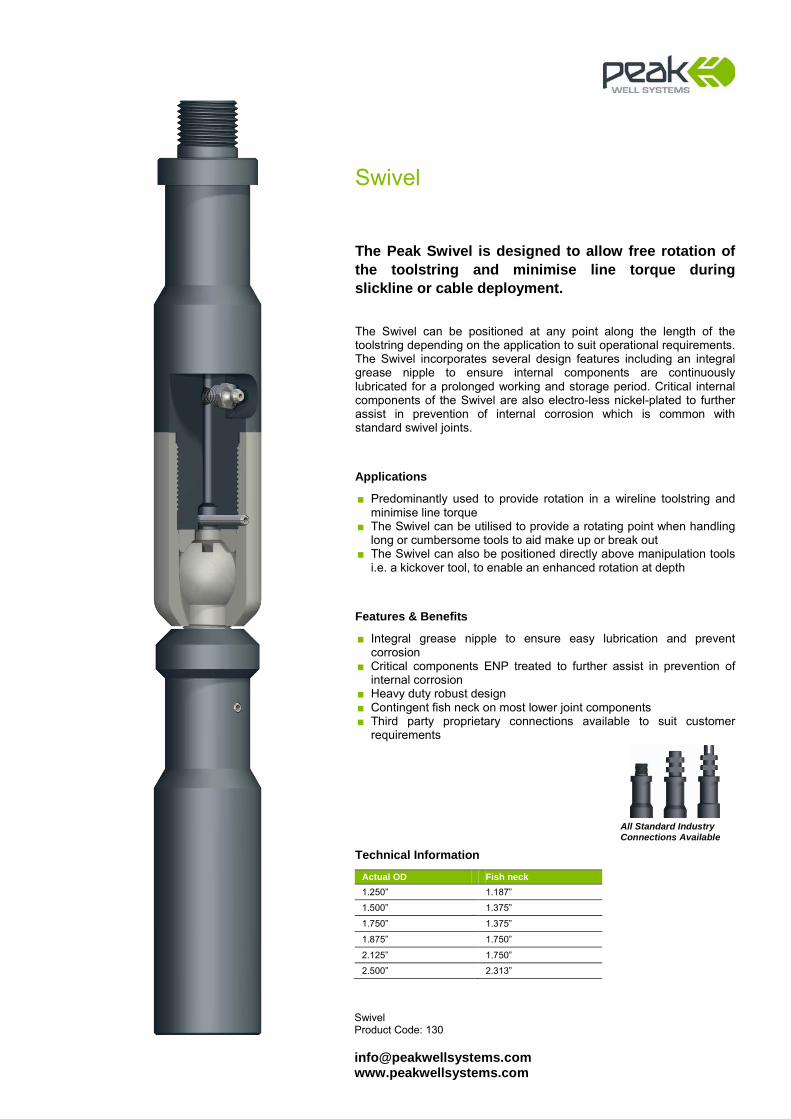
Swivel Product Code: 130 [email protected] www.peakwellsystems.com
Swivel
The Peak Swivel is designed to allow free rotation of the toolstring and minimise line torque during slickline or cable deployment. The Swivel can be positioned at any point along the length of the toolstring depending on the application to suit operational requirements. The Swivel incorporates several design features including an integral grease nipple to ensure internal components are continuously lubricated for a prolonged working and storage period. Critical internal components of the Swivel are also electro-less nickel-plated to further assist in prevention of internal corrosion which is common with standard swivel joints.
Applications
■ Predominantly used to provide rotation in a wireline toolstring and minimise line torque
■ The Swivel can be utilised to provide a rotating point when handling long or cumbersome tools to aid make up or break out
■ The Swivel can also be positioned directly above manipulation tools i.e. a kickover tool, to enable an enhanced rotation at depth
Features & Benefits
■ Integral grease nipple to ensure easy lubrication and prevent corrosion
■ Critical components ENP treated to further assist in prevention of internal corrosion
■ Heavy duty robust design ■ Contingent fish neck on most lower joint components ■ Third party proprietary connections available to suit customer
requirements
Technical Information
Actual OD Fish neck 1.250” 1.187”
1.500” 1.375”
1.750” 1.375”
1.875” 1.750”
2.125” 1.750”
2.500” 2.313”
All Standard Industry Connections Available
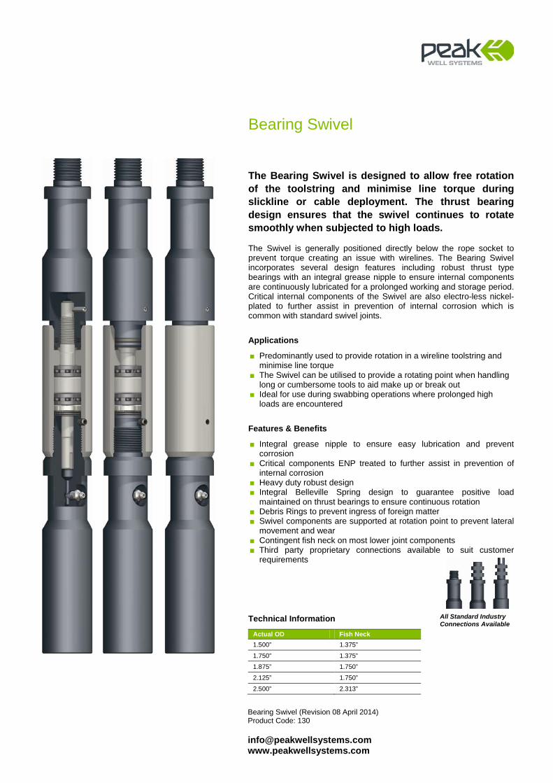
Bearing Swivel (Revision 08 April 2014) Product Code: 130 [email protected] www.peakwellsystems.com
Bearing Swivel
The Bearing Swivel is designed to allow free rotation of the toolstring and minimise line torque during slickline or cable deployment. The thrust bearing design ensures that the swivel continues to rotate smoothly when subjected to high loads. The Swivel is generally positioned directly below the rope socket to prevent torque creating an issue with wirelines. The Bearing Swivel incorporates several design features including robust thrust type bearings with an integral grease nipple to ensure internal components are continuously lubricated for a prolonged working and storage period. Critical internal components of the Swivel are also electro-less nickel-plated to further assist in prevention of internal corrosion which is common with standard swivel joints.
Applications
■ Predominantly used to provide rotation in a wireline toolstring and minimise line torque
■ The Swivel can be utilised to provide a rotating point when handling long or cumbersome tools to aid make up or break out
■ Ideal for use during swabbing operations where prolonged high loads are encountered
Features & Benefits
■ Integral grease nipple to ensure easy lubrication and prevent corrosion
■ Critical components ENP treated to further assist in prevention of internal corrosion
■ Heavy duty robust design ■ Integral Belleville Spring design to guarantee positive load
maintained on thrust bearings to ensure continuous rotation ■ Debris Rings to prevent ingress of foreign matter ■ Swivel components are supported at rotation point to prevent lateral
movement and wear ■ Contingent fish neck on most lower joint components ■ Third party proprietary connections available to suit customer
requirements
Technical Information
Actual OD Fish Neck 1.500” 1.375”
1.750” 1.375”
1.875” 1.750”
2.125” 1.750”
2.500” 2.313”
All Standard Industry Connections Available
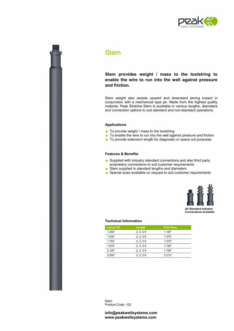
Stem Product Code: 102 [email protected] www.peakwellsystems.com
Stem
Stem provides weight / mass to the toolstring to enable the wire to run into the well against pressure and friction. Stem weight also assists upward and downward jarring impact in conjunction with a mechanical type jar. Made from the highest quality material, Peak Slickline Stem is available in various lengths, diameters and connection options to suit standard and non-standard operations.
Applications
■ To provide weight / mass to the toolstring ■ To enable the wire to run into the well against pressure and friction ■ To provide extension length for diagnostic or space out purposes
Features & Benefits
■ Supplied with industry standard connections and also third party proprietary connections to suit customer requirements
■ Stem supplied in standard lengths and diameters ■ Special sizes available on request to suit customer requirements
Technical Information
Actual OD Length Fish Neck 1.250” 2, 3, 5 ft 1.187”
1.500” 2, 3, 5 ft 1.375”
1.750” 2, 3, 5 ft 1.375”
1.875” 2, 3, 5 ft 1.750”
2.125” 2, 3, 5 ft 1.750”
2.500” 2, 3, 5 ft 2.313”
All Standard Industry Connections Available
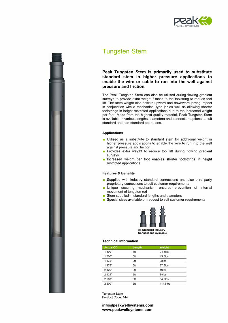
Tungsten Stem Product Code: 144 [email protected] www.peakwellsystems.com
Tungsten Stem
Peak Tungsten Stem is primarily used to substitute standard stem in higher pressure applications to enable the wire or cable to run into the well against pressure and friction. The Peak Tungsten Stem can also be utilised during flowing gradient surveys to provide extra weight / mass to the toolstring to reduce tool lift. The stem weight also assists upward and downward jarring impact in conjunction with a mechanical type jar as well as allowing shorter toolstrings in height restricted applications due to the increased weight per foot. Made from the highest quality material, Peak Tungsten Stem is available in various lengths, diameters and connection options to suit standard and non-standard operations.
Applications
■ Utilised as a substitute to standard stem for additional weight in higher pressure applications to enable the wire to run into the well against pressure and friction
■ Provides extra weight to reduce tool lift during flowing gradient surveys
■ Increased weight per foot enables shorter toolstrings in height restricted applications
Features & Benefits
■ Supplied with industry standard connections and also third party proprietary connections to suit customer requirements
■ Unique securing mechanism ensures prevention of internal movement of tungsten rod
■ Stem supplied in standard lengths and diameters ■ Special sizes available on request to suit customer requirements
Technical Information
Actual OD Length Weight 1.500” 3ft 24.5Ibs
1.500” 5ft 43.5Ibs
1.875” 3ft 38Ibs
1.875” 5ft 67.5Ibs
2.125” 3ft 49Ibs
2.125” 5ft 88Ibs
2.500” 3ft 64.5Ibs
2.500” 5ft 114.5Ibs
All Standard Industry Connections Available
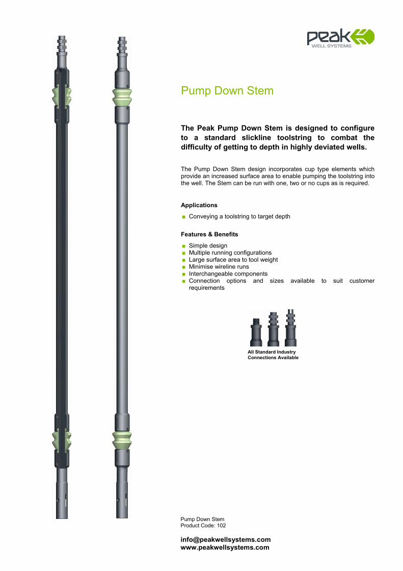
Pump Down Stem Product Code: 102 [email protected] www.peakwellsystems.com
Pump Down Stem
The Peak Pump Down Stem is designed to configure to a standard slickline toolstring to combat the difficulty of getting to depth in highly deviated wells. The Pump Down Stem design incorporates cup type elements which provide an increased surface area to enable pumping the toolstring into the well. The Stem can be run with one, two or no cups as is required.
Applications
■ Conveying a toolstring to target depth
Features & Benefits
■ Simple design ■ Multiple running configurations ■ Large surface area to tool weight ■ Minimise wireline runs ■ Interchangeable components ■ Connection options and sizes available to suit customer
requirements
All Standard Industry Connections Available
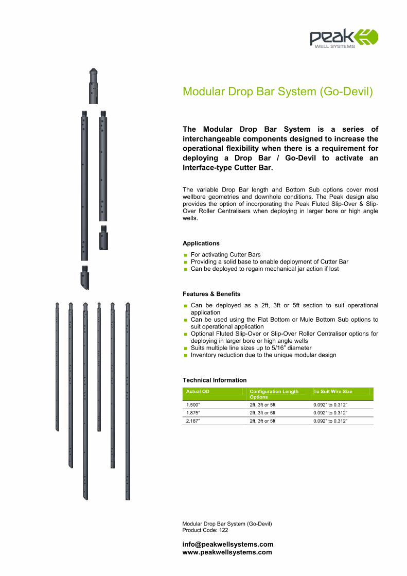
Modular Drop Bar System (Go-Devil) Product Code: 122 [email protected] www.peakwellsystems.com
Modular Drop Bar System (Go-Devil)
The Modular Drop Bar System is a series of interchangeable components designed to increase the operational flexibility when there is a requirement for deploying a Drop Bar / Go-Devil to activate an Interface-type Cutter Bar. The variable Drop Bar length and Bottom Sub options cover most wellbore geometries and downhole conditions. The Peak design also provides the option of incorporating the Peak Fluted Slip-Over & Slip-Over Roller Centralisers when deploying in larger bore or high angle wells.
Applications
■ For activating Cutter Bars ■ Providing a solid base to enable deployment of Cutter Bar ■ Can be deployed to regain mechanical jar action if lost
Features & Benefits
■ Can be deployed as a 2ft, 3ft or 5ft section to suit operational application
■ Can be used using the Flat Bottom or Mule Bottom Sub options to suit operational application
■ Optional Fluted Slip-Over or Slip-Over Roller Centraliser options for deploying in larger bore or high angle wells
■ Suits multiple line sizes up to 5/16” diameter ■ Inventory reduction due to the unique modular design
Technical Information
Actual OD Configuration Length Options
To Suit Wire Size
1.500” 2ft, 3ft or 5ft 0.092” to 0.312”
1.875” 2ft, 3ft or 5ft 0.092” to 0.312”
2.187” 2ft, 3ft or 5ft 0.092” to 0.312”
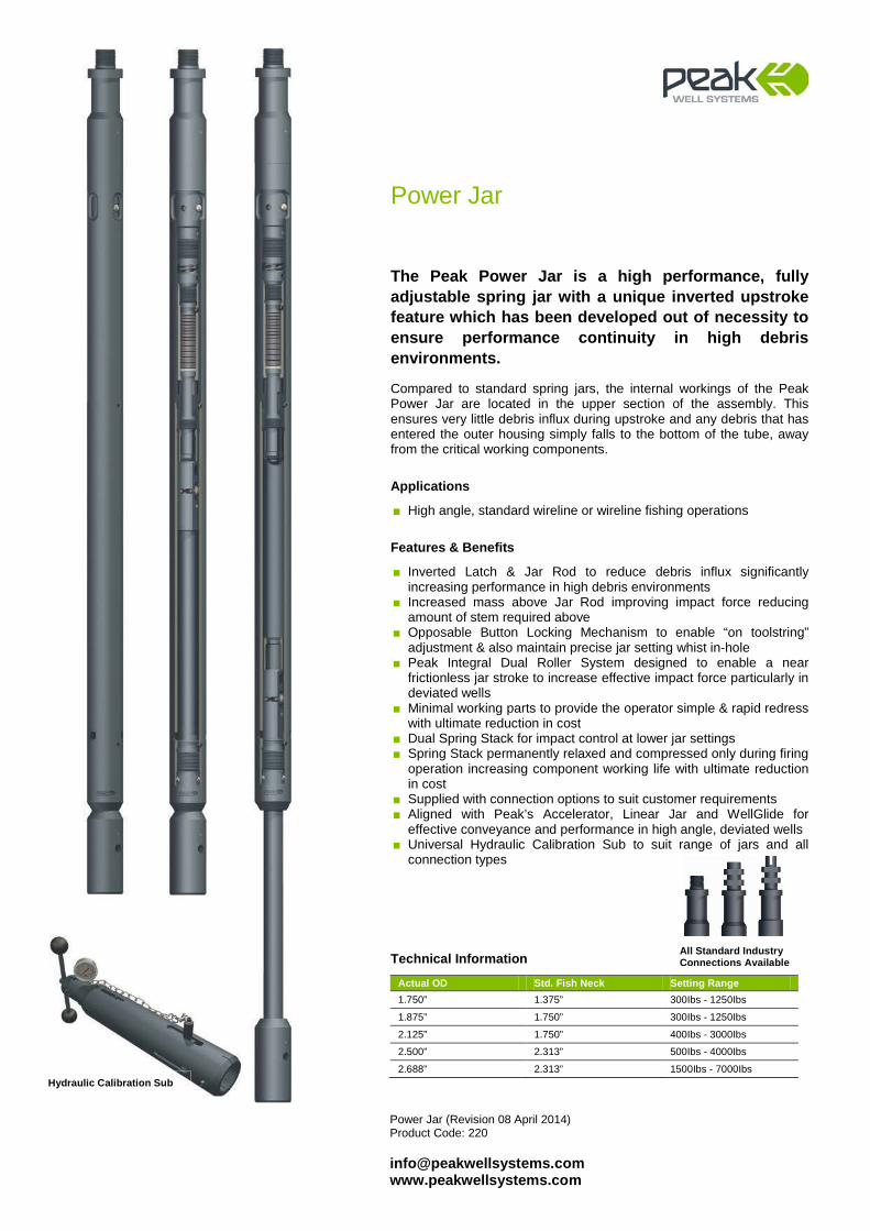
Power Jar (Revision 08 April 2014) Product Code: 220 [email protected] www.peakwellsystems.com
Power Jar
The Peak Power Jar is a high performance, fully adjustable spring jar with a unique inverted upstroke feature which has been developed out of necessity to ensure performance continuity in high debris environments. Compared to standard spring jars, the internal workings of the Peak Power Jar are located in the upper section of the assembly. This ensures very little debris influx during upstroke and any debris that has entered the outer housing simply falls to the bottom of the tube, away from the critical working components.
Applications
■ High angle, standard wireline or wireline fishing operations
Features & Benefits
■ Inverted Latch & Jar Rod to reduce debris influx significantly increasing performance in high debris environments
■ Increased mass above Jar Rod improving impact force reducing amount of stem required above
■ Opposable Button Locking Mechanism to enable “on toolstring” adjustment & also maintain precise jar setting whist in-hole
■ Peak Integral Dual Roller System designed to enable a near frictionless jar stroke to increase effective impact force particularly in deviated wells
■ Minimal working parts to provide the operator simple & rapid redress with ultimate reduction in cost
■ Dual Spring Stack for impact control at lower jar settings ■ Spring Stack permanently relaxed and compressed only during firing
operation increasing component working life with ultimate reduction in cost
■ Supplied with connection options to suit customer requirements ■ Aligned with Peak’s Accelerator, Linear Jar and WellGlide for
effective conveyance and performance in high angle, deviated wells ■ Universal Hydraulic Calibration Sub to suit range of jars and all
connection types
Technical Information
Actual OD Std. Fish Neck Setting Range 1.750” 1.375” 300Ibs - 1250Ibs
1.875” 1.750” 300Ibs - 1250Ibs
2.125” 1.750” 400Ibs - 3000Ibs
2.500” 2.313” 500Ibs - 4000Ibs
2.688” 2.313” 1500Ibs - 7000Ibs
All Standard Industry Connections Available
Hydraulic Calibration Sub

Hydraulic Jar (Revision 16 April 2014) Product Code: 147 [email protected] www.peakwellsystems.com
Hydraulic Jar
The Peak Hydraulic Jar is a high performance tool with a unique inverted upstroke feature to ensure performance continuity in high debris environments. Compared to standard hydraulic jars, the internal workings of the Peak Hydraulic Jar are located in the upper section of the assembly. This ensures minimal debris influx during upstroke and that any debris which has entered the outer housing simply falls to the bottom of the tube and away from the critical working components.
Applications
■ High angle, standard wireline or wireline fishing operations
Features & Benefits
■ Inverted Latch & Jar Rod to reduce debris influx significantly increasing performance in high debris environments
■ Increased mass above Jar Rod improving impact force reducing amount of stem required above
■ Minimal working parts to provide the operator simple & rapid redress ■ Critical components hard chrome-plated to further assist in
prevention of internal corrosion ■ High performance Lee Chek® and Lee Jeva® (check and restrictor)
ensure consistent and accurate firing times ■ Supplied with connection options to suit customer requirements ■ Suitable for use in high temperature wells up to 200degC ■ Aligned with Peak’s Accelerator, Linear Jar and WellGlide for
effective conveyance and performance in high angle, deviated wells
Technical Information
Actual OD Std. Fish Neck Working Range 1.750” 1.375” 500Ibs - 2000Ibs
1.875” 1.750” 500Ibs - 2000Ibs
2.125” 1.750” 500Ibs - 3000Ibs
All Standard Industry Connections Available
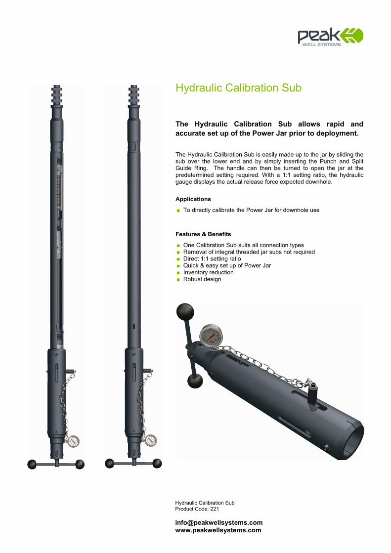
Hydraulic Calibration Sub Product Code: 221 [email protected] www.peakwellsystems.com
Hydraulic Calibration Sub
The Hydraulic Calibration Sub allows rapid and accurate set up of the Power Jar prior to deployment. The Hydraulic Calibration Sub is easily made up to the jar by sliding the sub over the lower end and by simply inserting the Punch and Split Guide Ring. The handle can then be turned to open the jar at the predetermined setting required. With a 1:1 setting ratio, the hydraulic gauge displays the actual release force expected downhole.
Applications
■ To directly calibrate the Power Jar for downhole use
Features & Benefits
■ One Calibration Sub suits all connection types ■ Removal of integral threaded jar subs not required ■ Direct 1:1 setting ratio ■ Quick & easy set up of Power Jar ■ Inventory reduction ■ Robust design

Spang Jar Product Code: 127 [email protected] www.peakwellsystems.com
Spang Jar
The force required downhole to manipulate tools and sever shear pins is generated by the impact of the Spang Jar. Jar impact is mainly affected by speed of movement, applied stem weight above the Jar, stroke length and deviation. Peak Spang Jars are available in various stroke lengths, diameters and connection options to suit the customers’ needs.
Applications
■ To provide upward and downward impact in conjunction with the toolstring weight and wireline speed
Features & Benefits
■ Supplied in a range of sizes and stroke lengths to suit most applications
■ Third party proprietary connections available to suit customer requirements
Technical Information
Size Stroke Fish Neck 1.250” 20” / 30” 1.187”
1.500” 20” / 30” 1.375”
1.750” 20” / 30” 1.375”
1.875” 20” / 30” 1.750”
2.125” 20” / 30” 1.750”
2.500” 20” / 30” 2.313”
All Standard Industry Connections Available
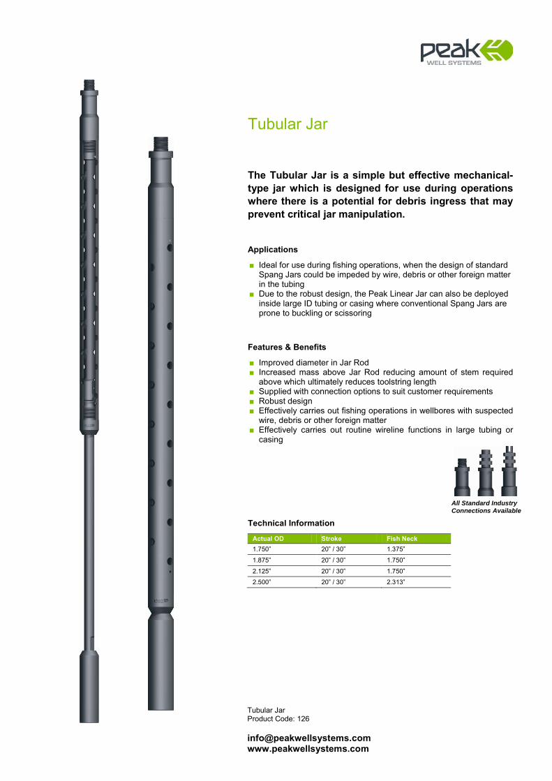
Tubular Jar Product Code: 126 [email protected] www.peakwellsystems.com
Tubular Jar
The Tubular Jar is a simple but effective mechanical-type jar which is designed for use during operations where there is a potential for debris ingress that may prevent critical jar manipulation.
Applications
■ Ideal for use during fishing operations, when the design of standard Spang Jars could be impeded by wire, debris or other foreign matter in the tubing
■ Due to the robust design, the Peak Linear Jar can also be deployed inside large ID tubing or casing where conventional Spang Jars are prone to buckling or scissoring
Features & Benefits
■ Improved diameter in Jar Rod ■ Increased mass above Jar Rod reducing amount of stem required
above which ultimately reduces toolstring length ■ Supplied with connection options to suit customer requirements ■ Robust design ■ Effectively carries out fishing operations in wellbores with suspected
wire, debris or other foreign matter ■ Effectively carries out routine wireline functions in large tubing or
casing
Technical Information
Actual OD Stroke Fish Neck 1.750” 20” / 30” 1.375”
1.875” 20” / 30” 1.750”
2.125” 20” / 30” 1.750”
2.500” 20” / 30” 2.313”
All Standard Industry Connections Available
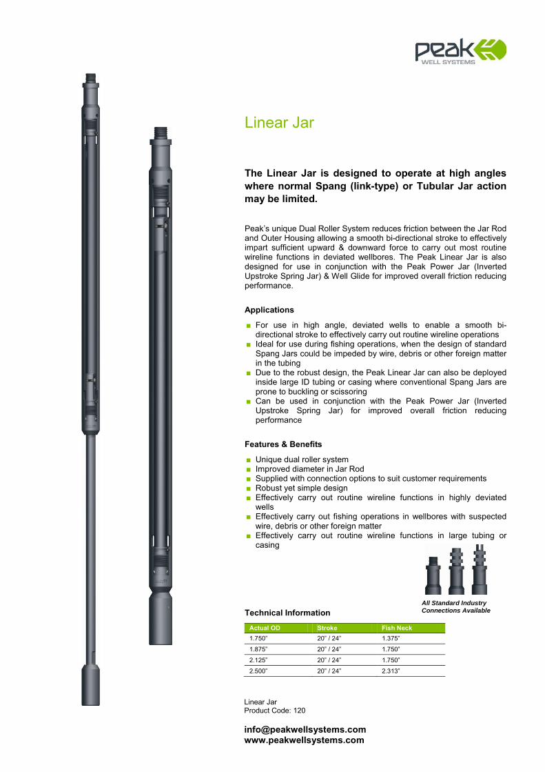
Linear Jar Product Code: 120 [email protected] www.peakwellsystems.com
Linear Jar
The Linear Jar is designed to operate at high angles where normal Spang (link-type) or Tubular Jar action may be limited. Peak’s unique Dual Roller System reduces friction between the Jar Rod and Outer Housing allowing a smooth bi-directional stroke to effectively impart sufficient upward & downward force to carry out most routine wireline functions in deviated wellbores. The Peak Linear Jar is also designed for use in conjunction with the Peak Power Jar (Inverted Upstroke Spring Jar) & Well Glide for improved overall friction reducing performance.
Applications
■ For use in high angle, deviated wells to enable a smooth bi-directional stroke to effectively carry out routine wireline operations
■ Ideal for use during fishing operations, when the design of standard Spang Jars could be impeded by wire, debris or other foreign matter in the tubing
■ Due to the robust design, the Peak Linear Jar can also be deployed inside large ID tubing or casing where conventional Spang Jars are prone to buckling or scissoring
■ Can be used in conjunction with the Peak Power Jar (Inverted Upstroke Spring Jar) for improved overall friction reducing performance
Features & Benefits
■ Unique dual roller system ■ Improved diameter in Jar Rod ■ Supplied with connection options to suit customer requirements ■ Robust yet simple design ■ Effectively carry out routine wireline functions in highly deviated
wells ■ Effectively carry out fishing operations in wellbores with suspected
wire, debris or other foreign matter ■ Effectively carry out routine wireline functions in large tubing or
casing
Technical Information
Actual OD Stroke Fish Neck 1.750” 20” / 24” 1.375”
1.875” 20” / 24” 1.750”
2.125” 20” / 24” 1.750”
2.500” 20” / 24” 2.313”
All Standard Industry Connections Available

Crossover Product Code: 101 [email protected] www.peakwellsystems.com
Crossover
The Peak Crossover is designed to connect two toolstring items with different connections. Manufactured from the highest quality material, Peak can supply the complete range of Crossovers to suit most readily available connection types.
Applications
■ To provide a connection between two toolstring items with different connections
Features & Benefits
■ Supplied with industry standard crossover configurations ■ Crossovers supplied in both standard and special lengths and
diameters to suit operational requirements ■ Crossovers can be supplied with third party proprietary connections
to suit customer requirements
Technical Information
Actual OD Pin Connection Box Connection Fish Neck 1.875” 15/16” SR 1 1/16” SR 1.375”
1.875” 1 1/16” SR 15/16” SR 1.750”
2.125” 15/16” SR 1 1/16” SR 1.375”
2.125” 1 1/16” SR 15/16” SR 1.750”
2.500” 15/16” SR 1 9/16” SR 1.375”
2.500” 1 1/16” SR 1 9/16” SR 1.750”
2.500” 1 9/16” SR 15/16” SR 2.313”
2.500” 1 9/16” SR 1 1/16” SR 2.313”
Actual OD Pin Connection Pin Connection Fish Neck 1.500” 15/16” SR 15/16” SR 1.375”
1.875” 1 1/16” SR 1 1/16” SR 1.750”
2.125” 1 1/16” SR 1 1/16” SR 1.750”
2.500” 1 9/16” SR 1 9/16” SR 2.313”
Actual OD Box Connection Box Connection Fish Neck 1.500” 15/16” SR 15/16” SR 1.375”
1.875” 1 1/16” SR 1 1/16” SR 1.750”
2.125” 1/16” SR 1 1/16” SR 1.750”
2.500” 1 9/16” SR 1 9/16” SR 2.313”
Peak Combination Wire Scratcher shown
with Sucker Rod Crossover
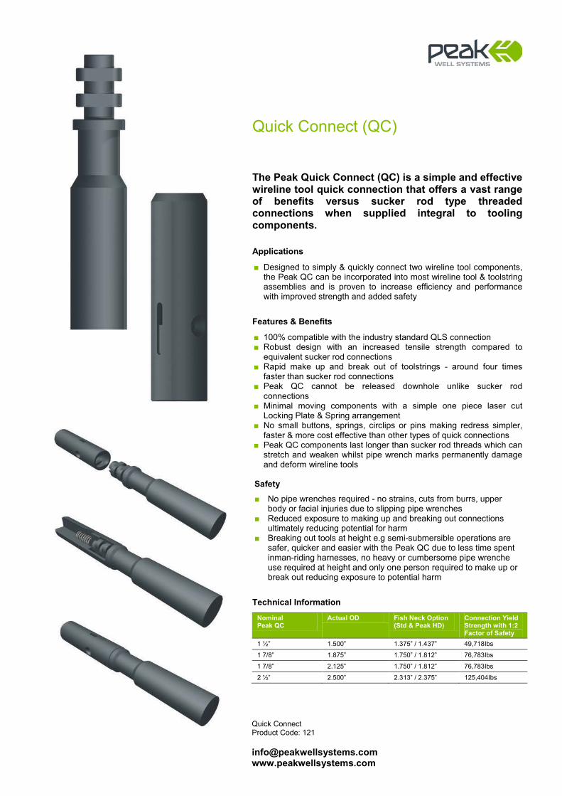
Quick Connect Product Code: 121 [email protected] www.peakwellsystems.com
Quick Connect (QC)
The Peak Quick Connect (QC) is a simple and effective wireline tool quick connection that offers a vast range of benefits versus sucker rod type threaded connections when supplied integral to tooling components.
Applications
■ Designed to simply & quickly connect two wireline tool components, the Peak QC can be incorporated into most wireline tool & toolstring assemblies and is proven to increase efficiency and performance with improved strength and added safety
Features & Benefits
■ 100% compatible with the industry standard QLS connection ■ Robust design with an increased tensile strength compared to
equivalent sucker rod connections ■ Rapid make up and break out of toolstrings - around four times
faster than sucker rod connections ■ Peak QC cannot be released downhole unlike sucker rod
connections ■ Minimal moving components with a simple one piece laser cut
Locking Plate & Spring arrangement ■ No small buttons, springs, circlips or pins making redress simpler,
faster & more cost effective than other types of quick connections ■ Peak QC components last longer than sucker rod threads which can
stretch and weaken whilst pipe wrench marks permanently damage and deform wireline tools
Safety
■ No pipe wrenches required - no strains, cuts from burrs, upper body or facial injuries due to slipping pipe wrenches
■ Reduced exposure to making up and breaking out connections ultimately reducing potential for harm
■ Breaking out tools at height e.g semi-submersible operations are safer, quicker and easier with the Peak QC due to less time spent inman-riding harnesses, no heavy or cumbersome pipe wrenche use required at height and only one person required to make up or break out reducing exposure to potential harm
Technical Information
Nominal Peak QC
Actual OD Fish Neck Option (Std & Peak HD)
Connection Yield Strength with 1:2 Factor of Safety
1 ½” 1.500” 1.375” / 1.437” 49,718Ibs
1 7/8” 1.875” 1.750” / 1.812” 76,783Ibs
1 7/8” 2.125” 1.750” / 1.812” 76,783Ibs
2 ½” 2.500” 2.313” / 2.375” 125,404Ibs
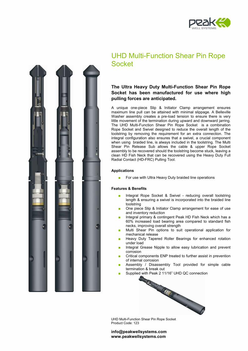
UHD Multi-Function Shear Pin Rope Socket Product Code: 123 [email protected] www.peakwellsystems.com
UHD Multi-Function Shear Pin Rope Socket
The Ultra Heavy Duty Multi-Function Shear Pin Rope Socket has been manufactured for use where high pulling forces are anticipated. A unique one-piece Slip & Initiator Clamp arrangement ensures maximum line pull can be attained with minimal slippage. A Belleville Washer assembly creates a pre-load tension to ensure there is very little movement of the termination during upward and downward jarring. The UHD Multi-Function Shear Pin Rope Socket is a combination Rope Socket and Swivel designed to reduce the overall length of the toolstring by removing the requirement for an extra connection. The integral configuration also ensures that a swivel, a crucial component when using braided line, is always included in the toolstring. The Multi Shear Pin Release Sub allows the cable & upper Rope Socket assembly to be recovered should the toolstring become stuck, leaving a clean HD Fish Neck that can be recovered using the Heavy Duty Full Radial Contact (HD-FRC) Pulling Tool.
Applications
■ For use with Ultra Heavy Duty braided line operations
Features & Benefits
■ Integral Rope Socket & Swivel - reducing overall toolstring length & ensuring a swivel is incorporated into the braided line toolstring
■ One piece Slip & Initiator Clamp arrangement for ease of use and inventory reduction
■ Integral primary & contingent Peak HD Fish Neck which has a 60% increased load bearing area compared to standard fish necks, improving overall strength
■ Multi Shear Pin options to suit operational application for mechanical release
■ Heavy Duty Tapered Roller Bearings for enhanced rotation under load
■ Integral Grease Nipple to allow easy lubrication and prevent corrosion
■ Critical components ENP treated to further assist in prevention of internal corrosion
■ Assembly / Disassembly Tool provided for simple cable termination & break out
■ Supplied with Peak 2 11/16” UHD QC connection
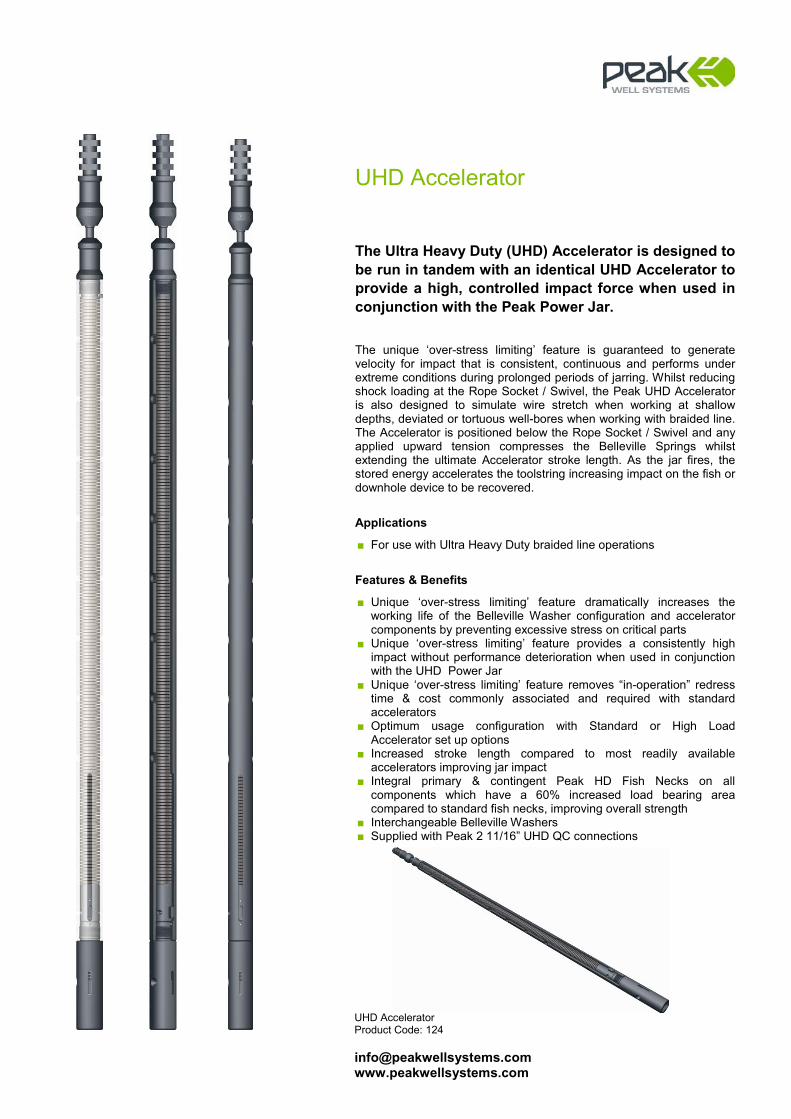
UHD Accelerator Product Code: 124 [email protected] www.peakwellsystems.com
UHD Accelerator
The Ultra Heavy Duty (UHD) Accelerator is designed to be run in tandem with an identical UHD Accelerator to provide a high, controlled impact force when used in conjunction with the Peak Power Jar. The unique ‘over-stress limiting’ feature is guaranteed to generate velocity for impact that is consistent, continuous and performs under extreme conditions during prolonged periods of jarring. Whilst reducing shock loading at the Rope Socket / Swivel, the Peak UHD Accelerator is also designed to simulate wire stretch when working at shallow depths, deviated or tortuous well-bores when working with braided line. The Accelerator is positioned below the Rope Socket / Swivel and any applied upward tension compresses the Belleville Springs whilst extending the ultimate Accelerator stroke length. As the jar fires, the stored energy accelerates the toolstring increasing impact on the fish or downhole device to be recovered.
Applications
■ For use with Ultra Heavy Duty braided line operations
Features & Benefits
■ Unique ‘over-stress limiting’ feature dramatically increases the working life of the Belleville Washer configuration and accelerator components by preventing excessive stress on critical parts
■ Unique ‘over-stress limiting’ feature provides a consistently high impact without performance deterioration when used in conjunction with the UHD Power Jar
■ Unique ‘over-stress limiting’ feature removes “in-operation” redress time & cost commonly associated and required with standard accelerators
■ Optimum usage configuration with Standard or High Load Accelerator set up options
■ Increased stroke length compared to most readily available accelerators improving jar impact
■ Integral primary & contingent Peak HD Fish Necks on all components which have a 60% increased load bearing area compared to standard fish necks, improving overall strength
■ Interchangeable Belleville Washers ■ Supplied with Peak 2 11/16” UHD QC connections

UHD Knuckle Joint Product Code: 125 [email protected] www.peakwellsystems.com
UHD Knuckle Joint
The Ultra Heavy Duty (UHD) Knuckle Joint, when incorporated into a wireline toolstring, provides flexibility in high angle, deviated wellbores. The UHD Knuckle Joint incorporates several design features including integral grease nipple to ensure internal components are continuously lubricated for a prolonged working and storage period. Critical internal components of the UHD Knuckle Joint are also electroless nickel-plated to further assist in prevention of internal corrosion which is common with standard knuckle joints.
Applications
■ To provide flexibility in a wireline toolstring to assist conveyance in high angle, deviated wellbores
Features & Benefits
■ Integral grease nipple to ensure easy lubrication and prevent corrosion
■ Critical components ENP treated to further assist in prevention of internal corrosion
■ Integral primary & contingent Peak HD Fish Necks on all components which have a 60% increased load bearing area compared to standard fish necks, improving overall strength
■ Supplied with Peak 2 11/16” UHD QC connections
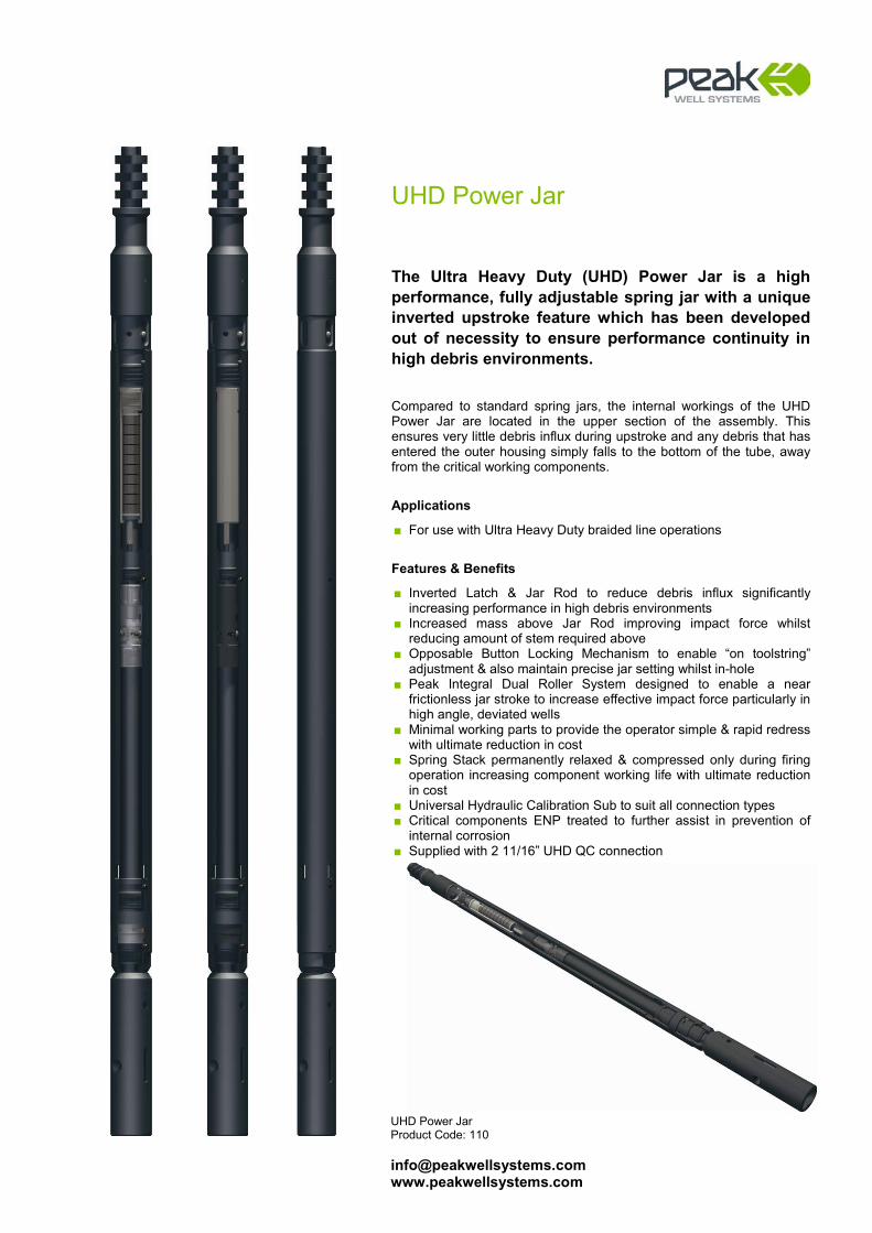
UHD Power Jar Product Code: 110 [email protected] www.peakwellsystems.com
UHD Power Jar
The Ultra Heavy Duty (UHD) Power Jar is a high performance, fully adjustable spring jar with a unique inverted upstroke feature which has been developed out of necessity to ensure performance continuity in high debris environments. Compared to standard spring jars, the internal workings of the UHD Power Jar are located in the upper section of the assembly. This ensures very little debris influx during upstroke and any debris that has entered the outer housing simply falls to the bottom of the tube, away from the critical working components.
Applications
■ For use with Ultra Heavy Duty braided line operations
Features & Benefits
■ Inverted Latch & Jar Rod to reduce debris influx significantly increasing performance in high debris environments
■ Increased mass above Jar Rod improving impact force whilst reducing amount of stem required above
■ Opposable Button Locking Mechanism to enable “on toolstring” adjustment & also maintain precise jar setting whilst in-hole
■ Peak Integral Dual Roller System designed to enable a near frictionless jar stroke to increase effective impact force particularly in high angle, deviated wells
■ Minimal working parts to provide the operator simple & rapid redress with ultimate reduction in cost
■ Spring Stack permanently relaxed & compressed only during firing operation increasing component working life with ultimate reduction in cost
■ Universal Hydraulic Calibration Sub to suit all connection types ■ Critical components ENP treated to further assist in prevention of
internal corrosion ■ Supplied with 2 11/16” UHD QC connection

UHD Linear Jar Product Code: 120 [email protected] www.peakwellsystems.com
UHD Linear Jar
The Ultra Heavy Duty (UHD) Linear Jar is designed to operate at high angles where normal tubular jar action may be limited. The Peak Dual Roller System reduces friction between the Jar Rod and Outer Housing allowing a smooth bi-directional stroke to effectively impart sufficient upward & downward force to carry out most routine wireline functions in deviated wellbores. The UHD Linear Jar is specifically designed for use with braided line work where line speed is often minimal and in conjunction with the UHD Power Jar & Peak’s Well Glide for improved overall friction reducing performance during heavy duty fishing operations.
Applications
■ For use with Ultra Heavy Duty braided line operations ■ For use in high angle, deviated wells to enable a smooth bi-
directional stroke to effectively carry out routine wireline and heavy duty braided line fishing operations
■ Ideal for use during fishing operations, when the design of standard Spang Jars could be impeded by wire, debris or other foreign matter in the tubing
■ Designed for use in conjunction with the UHD Power Jar and Peak’s Well Glide for improved overall friction reducing performance
Features & Benefits
■ Peak Integral Dual Roller System designed to enable a near frictionless jar stroke to increase effective impact force particularly in high angle, deviated wells
■ Supplied with Peak 2 11/16” UHD QC connections
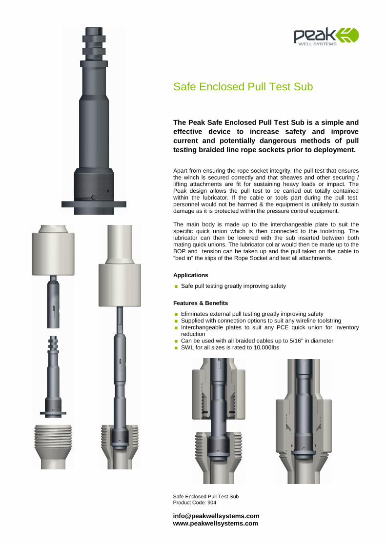
Safe Enclosed Pull Test Sub Product Code: 904 [email protected] www.peakwellsystems.com
Safe Enclosed Pull Test Sub
The Peak Safe Enclosed Pull Test Sub is a simple and effective device to increase safety and improve current and potentially dangerous methods of pull testing braided line rope sockets prior to deployment. Apart from ensuring the rope socket integrity, the pull test that ensures the winch is secured correctly and that sheaves and other securing / lifting attachments are fit for sustaining heavy loads or impact. The Peak design allows the pull test to be carried out totally contained within the lubricator. If the cable or tools part during the pull test, personnel would not be harmed & the equipment is unlikely to sustain damage as it is protected within the pressure control equipment. The main body is made up to the interchangeable plate to suit the specific quick union which is then connected to the toolstring. The lubricator can then be lowered with the sub inserted between both mating quick unions. The lubricator collar would then be made up to the BOP and tension can be taken up and the pull taken on the cable to “bed in” the slips of the Rope Socket and test all attachments.
Applications
■ Safe pull testing greatly improving safety
Features & Benefits
■ Eliminates external pull testing greatly improving safety ■ Supplied with connection options to suit any wireline toolstring ■ Interchangeable plates to suit any PCE quick union for inventory
reduction ■ Can be used with all braided cables up to 5/16” in diameter ■ SWL for all sizes is rated to 10,000Ibs
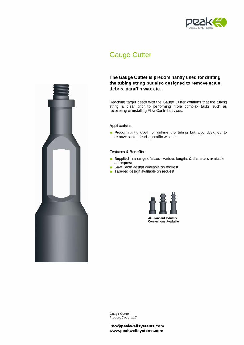
Gauge Cutter Product Code: 117 [email protected] www.peakwellsystems.com
Gauge Cutter
The Gauge Cutter is predominantly used for drifting the tubing string but also designed to remove scale, debris, paraffin wax etc. Reaching target depth with the Gauge Cutter confirms that the tubing string is clear prior to performing more complex tasks such as recovering or installing Flow Control devices.
Applications
■ Predominantly used for drifting the tubing but also designed to remove scale, debris, paraffin wax etc.
Features & Benefits
■ Supplied in a range of sizes - various lengths & diameters available on request
■ Saw Tooth design available on request ■ Tapered design available on request
All Standard Industry Connections Available
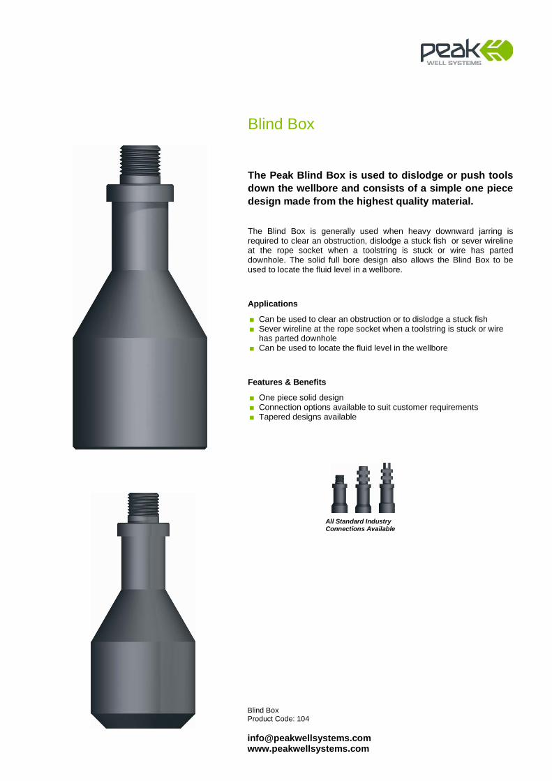
Blind Box Product Code: 104 [email protected] www.peakwellsystems.com
Blind Box
The Peak Blind Box is used to dislodge or push tools down the wellbore and consists of a simple one piece design made from the highest quality material. The Blind Box is generally used when heavy downward jarring is required to clear an obstruction, dislodge a stuck fish or sever wireline at the rope socket when a toolstring is stuck or wire has parted downhole. The solid full bore design also allows the Blind Box to be used to locate the fluid level in a wellbore.
Applications
■ Can be used to clear an obstruction or to dislodge a stuck fish ■ Sever wireline at the rope socket when a toolstring is stuck or wire
has parted downhole ■ Can be used to locate the fluid level in the wellbore
Features & Benefits
■ One piece solid design ■ Connection options available to suit customer requirements ■ Tapered designs available
All Standard Industry Connections Available

Combination Gauge Ring & Wire Scratcher Product Code: 113 [email protected] www.peakwellsystems.com
Combination Gauge Ring & Wire Scratcher
The Combination Gauge Ring & Wire Scratcher is a flexible system designed to drift the well and brush a specific area within the tubing in a single run. The interchangeable Gauge Cutter Rings allow the system to be utilised across a range of tubing sizes that will save the customer significant time and ultimately cost by removing unnecessary wireline runs.
Applications
■ Designed to drift the well and brush a specific area in a single run ■ Can be used as a traditional Gauge Cutter when Wire Scratcher not
required
Features & Benefits
■ Combined design of Gauge Cutter & Wire Scratcher reduces Wireline runs saving customer time & ultimate cost
■ Interchangeable Gauge Cutter Rings provide flexibility to suit a range of tubing sizes
■ Ported Gauge Cutter Rings provide sufficient bypass in fluid ■ Positive stop prevents Gauge Cutter Ring from backing off from the
Mandrel ■ Minimal components & robust design ■ Inventory reduction
Technical Information
Nominal Mandrel Size
Gauge Ring Range To Suit Wire Size (Brush)
1 1/2” 2.375” - 3.950” Up to 7/32”
1 7/8” 2.750” - 5.500” Up to 5/16”
2 1/2” 2.750” - 8.500” Up to 5/16”
All Standard Industry Connections Available

GS Pulling Tool Product Code: 229 [email protected] www.peakwellsystems.com
GS Pulling Tool
The GS style Pulling Tool is designed to latch and recover downhole products that have a standard internal fishing neck. The tools include a safety feature of jar down to release and a unique and safer surface release mechanism on the larger sizes.
Applications
■ Routine slickline operations ■ Wireline fishing
Features & Benefits
■ Robust design ■ Individual retractable dogs ■ Unique helical slot for easy punch release ■ Available with standard and quick connect toolstring connections
Technical Information
Nominal Tubing Size
Nominal GS Designation
Actual Tool OD
Core Thread
2-3/8” 2” 1.750” 5/8”-11 UNC
2-7/8” 2.5” 2.250” 5/8”-11 UNC
3-1/2” 3” 2.720” 5/8”-11 UNC
4” 3.5” 3.110” 1-3/8”-12 UN
4-1/2” 4” 3.620” 2-1/8”-12 UN
5-1/2” 5” 4.500” 2-1/2”-10 UN
7” 6” 5.560” 2-3/4”-10 UN
7” 7” 5.875” 3-5/8”-10 UN
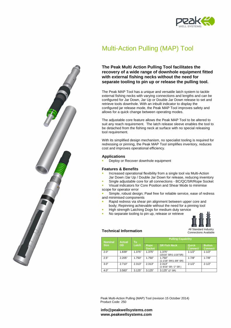
Peak Multi-Action Pulling (MAP) Tool (revision 15 October 2014) Product Code: 250
[email protected] www.peakwellsystems.com
Multi-Action Pulling (MAP) Tool
The Peak Multi Action Pulling Tool facilitates the recovery of a wide range of downhole equipment fitted with external fishing necks without the need for separate tooling to pin up or release the pulling tool.
The Peak MAP Tool has a unique and versatile latch system to tackle external fishing necks with varying connections and lengths and can be configured for Jar Down, Jar Up or Double Jar Down release to set and retrieve tools downhole. With an inbuilt indicator to display the configured jar release mode, the Peak MAP Tool improves safety and allows for a quick change between operating modes.
The adjustable core feature allows the Peak MAP Tool to be altered to suit any reach requirement. The latch release sleeve enables the tool to be detached from the fishing neck at surface with no special releasing tool requirement.
With its simplified design mechanism, no specialist tooling is required for redressing or pinning, the Peak MAP Tool simplifies inventory, reduces cost and improves operational efficiency.
Applications Deploy or Recover downhole equipment
Features & Benefits Increased operational flexibility from a single tool via Multi-Action
Jar Down /Jar Up / Double Jar Down for release, reducing inventory Single adjustable core for all connections - BC/QC/SR/Rope Socket Visual indicators for Core Position and Shear Mode to minimise scope for operator error Simple, robust design; Pawl free for reliable service, ease of redress and minimised components Rapid redress via shear pin alignment between upper core and
body; Repinning achievable without the need for a pinning tool High strength Latching Dogs for medium duty service No separate tooling to pin up, release or retrieve
Technical Information
Nominal
Size
Actual OD
To Latch
Pulling Capability Rope Socket
SR Fish Neck Quick Connect
Button Connect
2.0” 1.839” 1.375” 1.375” 1.375” (15/16” SR/1-1/16”SR)
1-1/2” 1-1/2”
2.5” 2.205” 1.750” 1.750” 1.750” (1-1/16” SR/1-3/8” SR)
1-7/8” 1-7/8”
3.0”
2.710” 2.313” 2.313” 2.313” (1-9/16” SR / 2” SR )
2-1/2” 2-1/2”
4.0” 3.583” 3.125” 3.125” 3.125” (2” SR)
All Standard Industry Connections Available

Wellbore Clean-up Systems

High Temperature / High Strength Magnet Product Code: 115 [email protected] www.peakwellsystems.com
High Temperature / High Strength Magnet
The High Temperature / High Strength Magnet is used to recover loose ferrous objects from within a well. Unlike normal magnets, the Peak magnetic insert can withstand prolonged exposure to very high downhole temperatures without losing magnetic strength.
Applications
■ Recovery of ferrous objects such as parted pulling tool dogs, perforating gun debris, corrosion scale etc.
Features & Benefits
■ Extreme high temperature rating ■ Suitable for oil & gas environments with high resistance to CO2 &
H2S ■ Powerful magnetic insert ensures effective recovery of ferrous
objects ■ Available in a range of sizes to suit application & well geometry ■ Stainless Steel Shroud ensures effective conveyance into the well ■ Customised magnet designs available
Magnetic Performance Table
Contact Magnet Assembly OD
Point 1.750 2.220” 2.720” 3.500” 3.750” 4.500”
15/16”SR Thread
140Ibs
210Ibs
235Ibs
250Ibs
250Ibs
275Ibs
1 1/16” SR Thread
175Ibs
245Ibs
265Ibs
300Ibs
300Ibs
320Ibs
1 ½” UN Thread
100Ibs*
230Ibs*
380Ibs
460Ibs
460Ibs
500Ibs
2” UN Thread
N/A
150Ibs*
345Ibs*
565Ibs
565Ibs
650Ibs * Magnet stands off contact point so full face contact not made
Technical Information
Nominal Tubing Size Actual OD Temperature Rating 2 3/8” 1.750” 500oF
2 7/8” 2.220” 500oF
3 ½” 2.720” 500oF
4 ½” 3.500” 500oF
4 ½” 3.750” 500oF
5 ½” 4.500” 500oF
7” 5.500” 500oF
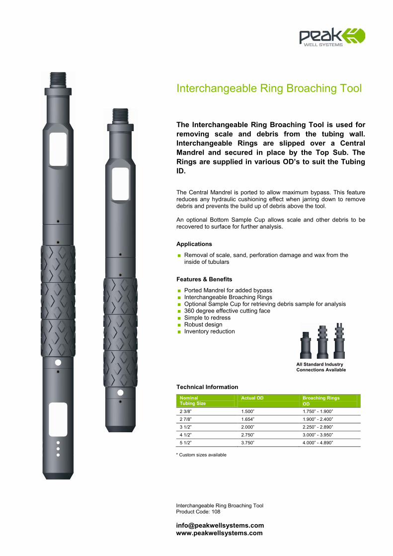
Interchangeable Ring Broaching Tool Product Code: 108 [email protected] www.peakwellsystems.com
Interchangeable Ring Broaching Tool
The Interchangeable Ring Broaching Tool is used for removing scale and debris from the tubing wall. Interchangeable Rings are slipped over a Central Mandrel and secured in place by the Top Sub. The Rings are supplied in various OD’s to suit the Tubing ID. The Central Mandrel is ported to allow maximum bypass. This feature reduces any hydraulic cushioning effect when jarring down to remove debris and prevents the build up of debris above the tool. An optional Bottom Sample Cup allows scale and other debris to be recovered to surface for further analysis.
Applications
■ Removal of scale, sand, perforation damage and wax from the inside of tubulars
Features & Benefits
■ Ported Mandrel for added bypass ■ Interchangeable Broaching Rings ■ Optional Sample Cup for retrieving debris sample for analysis ■ 360 degree effective cutting face ■ Simple to redress ■ Robust design ■ Inventory reduction
Technical Information
Nominal Tubing Size
Actual OD Broaching Rings OD
2 3/8” 1.500” 1.750” - 1.900”
2 7/8” 1.654” 1.900” - 2.400”
3 1/2” 2.000” 2.250” - 2.890”
4 1/2” 2.750” 3.000” - 3.950”
5 1/2” 3.750” 4.000” - 4.890” * Custom sizes available
All Standard Industry Connections Available
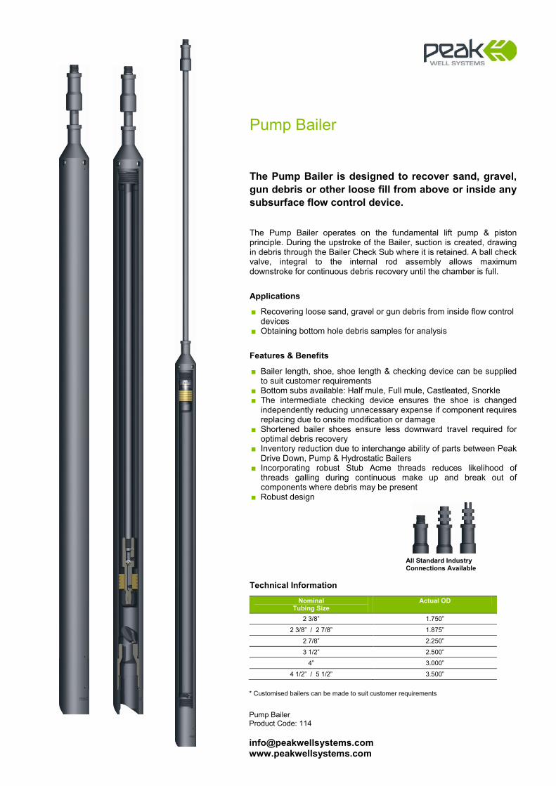
Pump Bailer Product Code: 114 [email protected] www.peakwellsystems.com
Pump Bailer
The Pump Bailer is designed to recover sand, gravel, gun debris or other loose fill from above or inside any subsurface flow control device. The Pump Bailer operates on the fundamental lift pump & piston principle. During the upstroke of the Bailer, suction is created, drawing in debris through the Bailer Check Sub where it is retained. A ball check valve, integral to the internal rod assembly allows maximum downstroke for continuous debris recovery until the chamber is full.
Applications
■ Recovering loose sand, gravel or gun debris from inside flow control devices
■ Obtaining bottom hole debris samples for analysis
Features & Benefits
■ Bailer length, shoe, shoe length & checking device can be supplied to suit customer requirements
■ Bottom subs available: Half mule, Full mule, Castleated, Snorkle ■ The intermediate checking device ensures the shoe is changed
independently reducing unnecessary expense if component requires replacing due to onsite modification or damage
■ Shortened bailer shoes ensure less downward travel required for optimal debris recovery
■ Inventory reduction due to interchange ability of parts between Peak Drive Down, Pump & Hydrostatic Bailers
■ Incorporating robust Stub Acme threads reduces likelihood of threads galling during continuous make up and break out of components where debris may be present
■ Robust design
Technical Information
Nominal Tubing Size
Actual OD
2 3/8” 1.750”
2 3/8” / 2 7/8” 1.875”
2 7/8” 2.250”
3 1/2” 2.500”
4” 3.000”
4 1/2” / 5 1/2” 3.500”
* Customised bailers can be made to suit customer requirements
All Standard Industry Connections Available

Hydrostatic Bailer Product Code: 114 [email protected] www.peakwellsystems.com
Hydrostatic Bailer
The Hydrostatic Bailer is designed to recover sand, gravel, gun debris or other loose fill from above or inside any subsurface flow control device. Due to the force exerted as a result of larger piston areas, the 3” and 3.500” version incorporates a unique Trip Key system that removes the requirement for long, drawn out hydrostatic & shear pin strength calculations. The Trip Keys hold the travelling Internal Plug in place until jarring down shears the ¼” shear screws. The mandrel will then move up & the keys, which are no longer supporting the Internal Plug, retract causing the Internal Plug to accelerate upward creating an increased suction (in conjunction with the higher external pressure) which draws debris into the Bailer through the Bailer Check Sub. The 3.000”, 2.500”, 2.250”, 1.875”, and 1.750” versions incorporate a pressure retaining Single or Multi-Pin Sub which seals in atmospheric pressure at surface. The Multi-Pin Sub allows the operator to select the number & type of pins depending on the differential pressure and operational application. The bailer is activated by jarring down & shearing the selected pins in the Multi-Pin Sub.
Applications
■ Recovering loose sand, gravel or gun debris from inside hard to reach flow control devices
Features & Benefits
■ Trip key design means shear pin / screw sees no direct loading from well pressure.
■ Safe Break design - three equalising functions ■ Bailer length, shoe, shoe length & checking device can be supplied
to suit customer requirements ■ Bottom subs available: Half mule, Full mule, Castleated, Snorkle ■ No requirement for long, drawn out hydrostatic or shear pin strength
calculations ■ The intermediate checking device ensures the shoe is changed
independently reducing unnecessary expense if component requires replacing due to onsite modification or damage
■ Inventory reduction due to interchange ability of parts between Peak Drive Down, Pump & Hydrostatic Bailers
■ Incorporating robust Stub Acme threads reduces likelihood of threads galling during continuous make up and break out of components where debris may be present
Technical Information
Actual OD Shear Out Device 1.750” Single Pin
1.875” Single Pin
2.250” Multi Pin
2.500” Multi Pin
3.000” Multi Pin and Trip Key 3.500” Trip Key
* Customised bailers can be designed to suit customer requirements
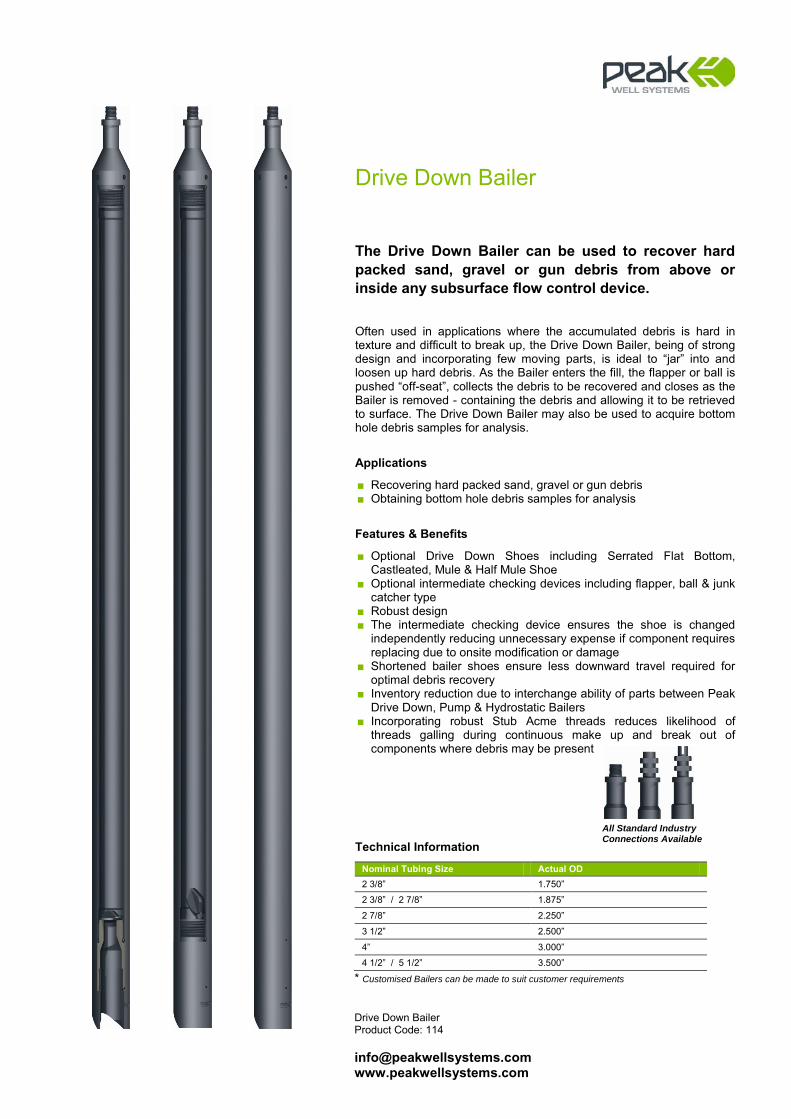
Drive Down Bailer Product Code: 114 [email protected] www.peakwellsystems.com
Drive Down Bailer
The Drive Down Bailer can be used to recover hard packed sand, gravel or gun debris from above or inside any subsurface flow control device. Often used in applications where the accumulated debris is hard in texture and difficult to break up, the Drive Down Bailer, being of strong design and incorporating few moving parts, is ideal to “jar” into and loosen up hard debris. As the Bailer enters the fill, the flapper or ball is pushed “off-seat”, collects the debris to be recovered and closes as the Bailer is removed - containing the debris and allowing it to be retrieved to surface. The Drive Down Bailer may also be used to acquire bottom hole debris samples for analysis.
Applications
■ Recovering hard packed sand, gravel or gun debris ■ Obtaining bottom hole debris samples for analysis
Features & Benefits
■ Optional Drive Down Shoes including Serrated Flat Bottom, Castleated, Mule & Half Mule Shoe
■ Optional intermediate checking devices including flapper, ball & junk catcher type
■ Robust design ■ The intermediate checking device ensures the shoe is changed
independently reducing unnecessary expense if component requires replacing due to onsite modification or damage
■ Shortened bailer shoes ensure less downward travel required for optimal debris recovery
■ Inventory reduction due to interchange ability of parts between Peak Drive Down, Pump & Hydrostatic Bailers
■ Incorporating robust Stub Acme threads reduces likelihood of threads galling during continuous make up and break out of components where debris may be present
Technical Information
Nominal Tubing Size Actual OD 2 3/8” 1.750”
2 3/8” / 2 7/8” 1.875”
2 7/8” 2.250”
3 1/2” 2.500”
4” 3.000”
4 1/2” / 5 1/2” 3.500”
* Customised Bailers can be made to suit customer requirements
All Standard Industry Connections Available
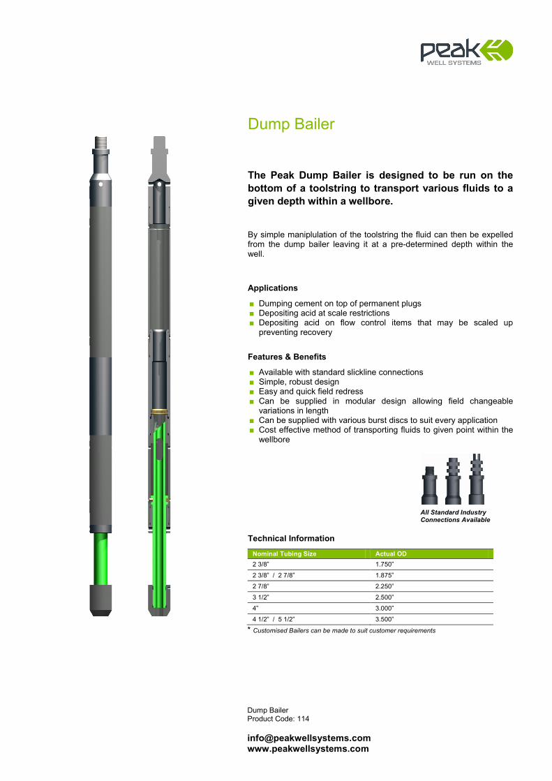
Dump Bailer
The Peak Dump Bailer is designed to be run on the bottom of a toolstring to transport various fluids to a given depth within a wellbore. By simple maniplulation of the toolstring the fluid can then be expelled from the dump bailer leaving it at a pre-determined depth within the well.
Applications
■ Dumping cement on top of permanent plugs ■ Depositing acid at scale restrictions ■ Depositing acid on flow control items that may be scaled up
preventing recovery
Features & Benefits
■ Available with standard slickline connections ■ Simple, robust design ■ Easy and quick field redress ■ Can be supplied in modular design allowing field changeable
variations in length ■ Can be supplied with various burst discs to suit every application ■ Cost effective method of transporting fluids to given point within the
wellbore
Technical Information
Nominal Tubing Size Actual OD 2 3/8” 1.750”
2 3/8” / 2 7/8” 1.875”
2 7/8” 2.250”
3 1/2” 2.500”
4” 3.000”
4 1/2” / 5 1/2” 3.500”
* Customised Bailers can be made to suit customer requirements
All Standard Industry Connections Available
Dump Bailer Product Code: 114 [email protected] www.peakwellsystems.com

Radial Brush System Product Code: 142 [email protected] www.peakwellsystems.com
Radial Brush System
The Radial Brush System has been developed to assist in the cleaning of downhole nipple profiles and associated completion components. The design incorporates a series of interchangeable radial brush rings assembled on a common mandrel. The use of a common mandrel means a reduced inventory as the same mandrel can be utilised for a range of different brush sizes to suit various completion designs. As the tool utilises a series of brush rings it can be configured with brushes of different diameters thereby providing a tapered brush effect. The brush bristles can be supplied in various stiffness’ and several different materials such as phosphor bronze, stainless steel etc.
Applications
■ Scale debris removal from sub surface safety valves (SSSV) and nipples
■ Wax removal ■ Pre-cleaning of casing / tubing wall prior to setting patches or
packers ■ Cleaning riser and tubing hanger bores
Features & Benefits
■ Reduced inventory due to common mandrel across a given size range
■ Brushes available with different bristle stiffness’ ■ Brushes available with bristles from various materials ■ Multi-ring design allows for different brush sizes to be run at the
same time ■ Reduced re-dress cost as bristle wear may be limited to only one
brush ring out of the set of three ■ Can be supplied with a Sucker Rod Bottom Sub to connect a series
of brushes
All Standard Industry Connections Available
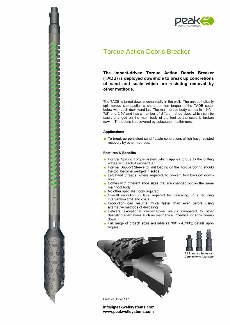
TTorque Action Debris Breaker Product Code: 117 [email protected] www.peakwellsystems.com
Torque Action Debris Breaker
The impact-driven Torque Action Debris Breaker (TADB) is deployed downhole to break up concretions of sand and scale which are resisting removal by other methods. The TADB is jarred down mechanically in the well. The unique helically split torque sub applies a short duration torque to the TADB cutter below with each downward jar. The main torque body comes in 1 ½”, 1 7/8” and 2 ½” and has a number of different shoe sizes which can be easily changed on the main body of the tool as the scale is broken down. The debris is recovered by subsequent bailer runs.
Applications
■ To break-up persistent sand / scale concretions which have resisted recovery by other methods.
Features & Benefits
■ Integral Sprung Torque system which applies torque to the cutting edges with each downward jar
■ Internal Support Sleeve to limit loading on the Torque Spring should the tool become wedged in solids
■ Left hand threads, where required, to prevent tool back-off down-hole
■ Comes with different shoe sizes that are changed out on the same main tool body
■ No other specialist tools required ■ Overall reduction in time required for descaling, thus reducing
intervention time and costs ■ Production can resume much faster than ever before using
alternative methods of descaling ■ Delivers exceptional cost-effective results compared to other
descaling alternatives such as mechanical, chemical or sonic break-down.
■ Full range of broach sizes available (1.700” - 4.700”); details upon request.
All Standard Industry Connections Available

Roller Systems
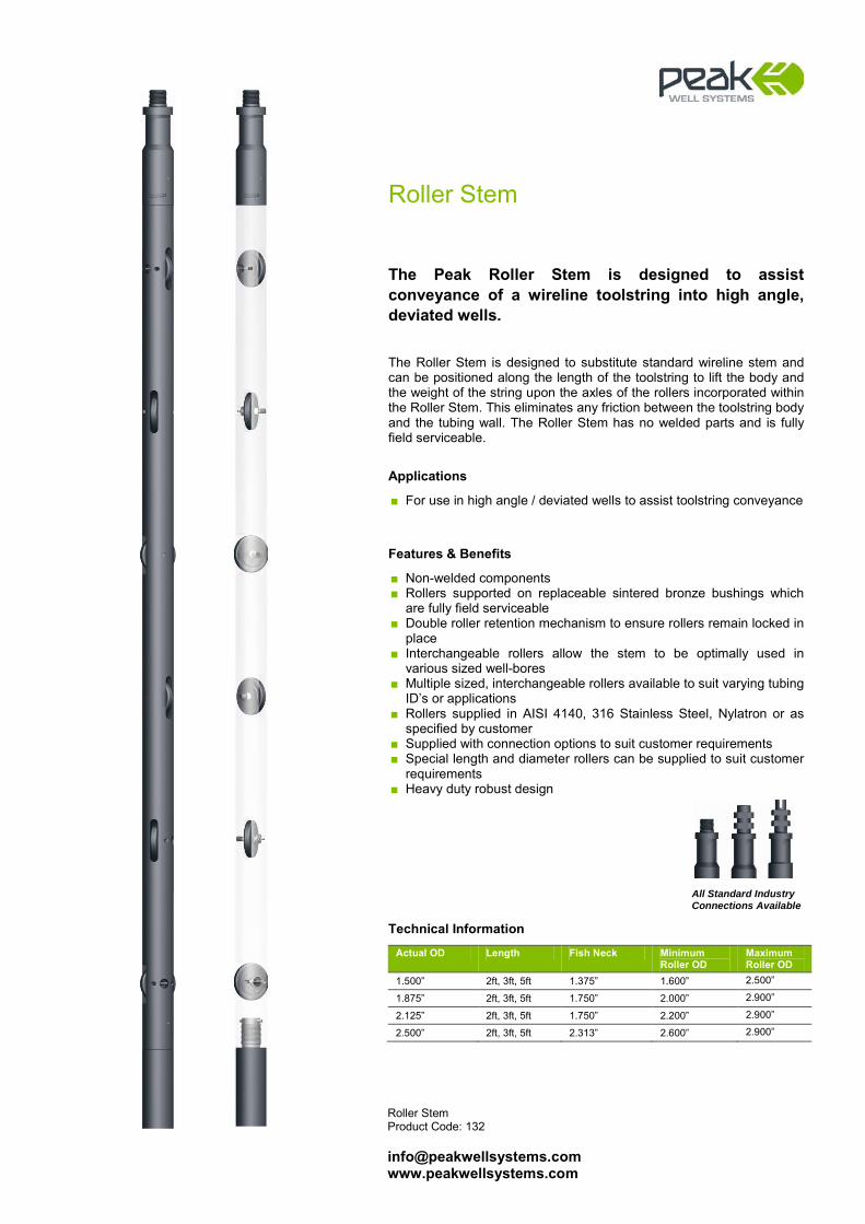
Roller Stem Product Code: 132 [email protected] www.peakwellsystems.com
Roller Stem
The Peak Roller Stem is designed to assist conveyance of a wireline toolstring into high angle, deviated wells. The Roller Stem is designed to substitute standard wireline stem and can be positioned along the length of the toolstring to lift the body and the weight of the string upon the axles of the rollers incorporated within the Roller Stem. This eliminates any friction between the toolstring body and the tubing wall. The Roller Stem has no welded parts and is fully field serviceable.
Applications
■ For use in high angle / deviated wells to assist toolstring conveyance
Features & Benefits
■ Non-welded components ■ Rollers supported on replaceable sintered bronze bushings which
are fully field serviceable ■ Double roller retention mechanism to ensure rollers remain locked in
place ■ Interchangeable rollers allow the stem to be optimally used in
various sized well-bores ■ Multiple sized, interchangeable rollers available to suit varying tubing
ID’s or applications ■ Rollers supplied in AISI 4140, 316 Stainless Steel, Nylatron or as
specified by customer ■ Supplied with connection options to suit customer requirements ■ Special length and diameter rollers can be supplied to suit customer
requirements ■ Heavy duty robust design
Technical Information
Actual OD Length Fish Neck Minimum Roller OD
Maximum Roller OD
1.500” 2ft, 3ft, 5ft 1.375” 1.600” 2.500”
1.875” 2ft, 3ft, 5ft 1.750” 2.000” 2.900”
2.125” 2ft, 3ft, 5ft 1.750” 2.200” 2.900”
2.500” 2ft, 3ft, 5ft 2.313” 2.600” 2.900”
All Standard Industry Connections Available
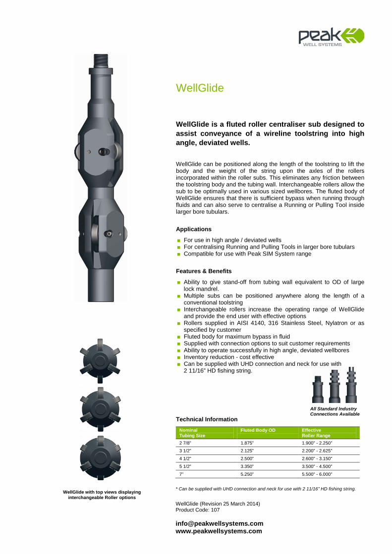
WellGlide (Revision 25 March 2014) Product Code: 107 [email protected] www.peakwellsystems.com
WellGlide
WellGlide is a fluted roller centraliser sub designed to assist conveyance of a wireline toolstring into high angle, deviated wells. WellGlide can be positioned along the length of the toolstring to lift the body and the weight of the string upon the axles of the rollers incorporated within the roller subs. This eliminates any friction between the toolstring body and the tubing wall. Interchangeable rollers allow the sub to be optimally used in various sized wellbores. The fluted body of WellGlide ensures that there is sufficient bypass when running through fluids and can also serve to centralise a Running or Pulling Tool inside larger bore tubulars.
Applications
■ For use in high angle / deviated wells ■ For centralising Running and Pulling Tools in larger bore tubulars ■ Compatible for use with Peak SIM System range
Features & Benefits
■ Ability to give stand-off from tubing wall equivalent to OD of large lock mandrel.
■ Multiple subs can be positioned anywhere along the length of a conventional toolstring
■ Interchangeable rollers increase the operating range of WellGlide and provide the end user with effective options
■ Rollers supplied in AISI 4140, 316 Stainless Steel, Nylatron or as specified by customer
■ Fluted body for maximum bypass in fluid ■ Supplied with connection options to suit customer requirements ■ Ability to operate successfully in high angle, deviated wellbores ■ Inventory reduction - cost effective ■ Can be supplied with UHD connection and neck for use with
2 11/16” HD fishing string.
Technical Information
Nominal Tubing Size
Fluted Body OD Effective Roller Range
2 7/8” 1.875” 1.900” - 2.250”
3 1/2” 2.125” 2.200” - 2.625”
4 1/2” 2.500” 2.600” - 3.150”
5 1/2” 3.350” 3.500” - 4.500”
7” 5.250” 5.500” - 6.000”
* Can be supplied with UHD connection and neck for use with 2 11/16” HD fishing string.
All Standard Industry Connections Available
WellGlide with top views displaying interchangeable Roller options
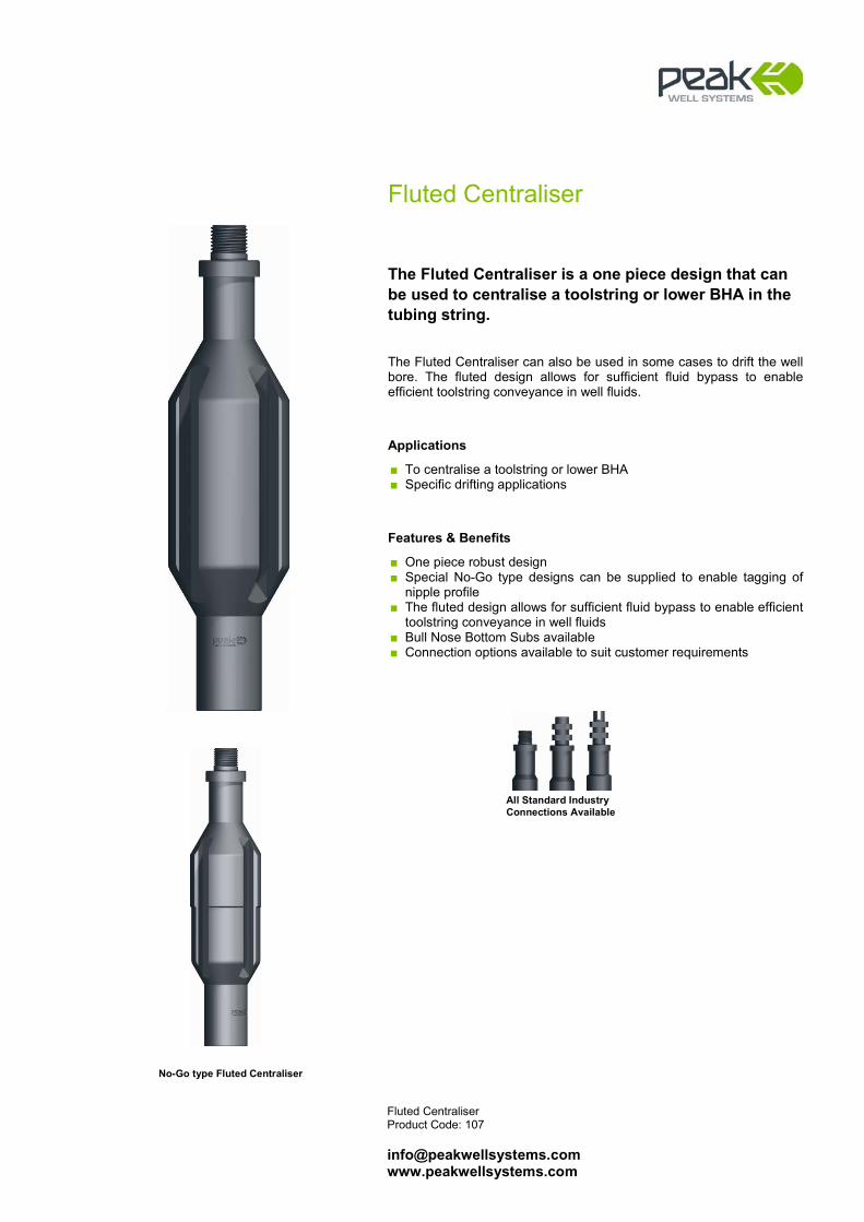
Fluted Centraliser Product Code: 107 [email protected] www.peakwellsystems.com
Fluted Centraliser
The Fluted Centraliser is a one piece design that can be used to centralise a toolstring or lower BHA in the tubing string. The Fluted Centraliser can also be used in some cases to drift the well bore. The fluted design allows for sufficient fluid bypass to enable efficient toolstring conveyance in well fluids.
Applications
■ To centralise a toolstring or lower BHA ■ Specific drifting applications
Features & Benefits
■ One piece robust design ■ Special No-Go type designs can be supplied to enable tagging of
nipple profile ■ The fluted design allows for sufficient fluid bypass to enable efficient
toolstring conveyance in well fluids ■ Bull Nose Bottom Subs available ■ Connection options available to suit customer requirements
All Standard Industry Connections Available
No-Go type Fluted Centraliser
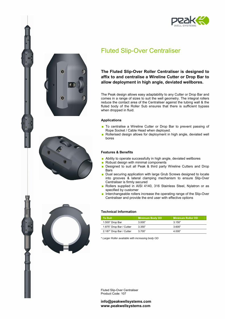
Fluted Slip-Over Centraliser Product Code: 107 [email protected] www.peakwellsystems.com
Fluted Slip-Over Centraliser
The Fluted Slip-Over Roller Centraliser is designed to affix to and centralise a Wireline Cutter or Drop Bar to allow deployment in high angle, deviated wellbores. The Peak design allows easy adaptability to any Cutter or Drop Bar and comes in a range of sizes to suit the well geometry. The integral rollers reduce the contact area of the Centraliser against the tubing wall & the fluted body of the Roller Sub ensures that there is sufficient bypass when dropped in fluid.
Applications
■ To centralise a Wireline Cutter or Drop Bar to prevent passing of Rope Socket / Cable Head when deployed.
■ Rollerised design allows for deployment in high angle, deviated well bores
Features & Benefits
■ Ability to operate successfully in high angle, deviated wellbores ■ Robust design with minimal components ■ Designed to suit all Peak & third party Wireline Cutters and Drop
Bars ■ Dual securing application with large Grub Screws designed to locate
into grooves & lateral clamping mechanism to ensure Slip-Over Centraliser is firmly secured
■ Rollers supplied in AISI 4140, 316 Stainless Steel, Nylatron or as specified by customer
■ Interchangeable rollers increase the operating range of the Slip-Over Centraliser and provide the end user with effective options
Technical Information
To Suit Minimum Body OD Minimum Roller OD 1.500” Drop Bar 3.000” 3.150”
1.875” Drop Bar / Cutter 3.350” 3.600”
2.187” Drop Bar / Cutter 3.700” 4.000” * Larger Roller available with increasing body OD

Bespoke Products
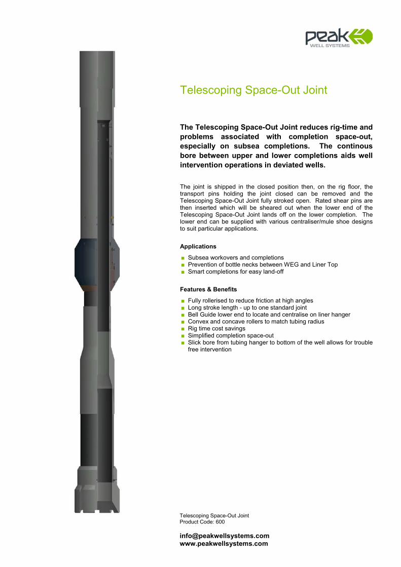
Telescoping Space-Out Joint Product Code: 600 [email protected] www.peakwellsystems.com
Telescoping Space-Out Joint
The Telescoping Space-Out Joint reduces rig-time and problems associated with completion space-out, especially on subsea completions. The continous bore between upper and lower completions aids well intervention operations in deviated wells. The joint is shipped in the closed position then, on the rig floor, the transport pins holding the joint closed can be removed and the Telescoping Space-Out Joint fully stroked open. Rated shear pins are then inserted which will be sheared out when the lower end of the Telescoping Space-Out Joint lands off on the lower completion. The lower end can be supplied with various centraliser/mule shoe designs to suit particular applications.
Applications
■ Subsea workovers and completions ■ Prevention of bottle necks between WEG and Liner Top ■ Smart completions for easy land-off
Features & Benefits
■ Fully rollerised to reduce friction at high angles ■ Long stroke length - up to one standard joint ■ Bell Guide lower end to locate and centralise on liner hanger ■ Convex and concave rollers to match tubing radius ■ Rig time cost savings ■ Simplified completion space-out ■ Slick bore from tubing hanger to bottom of the well allows for trouble
free intervention
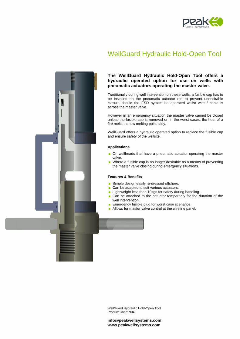
WellGuard Hydraulic Hold-Open Tool Product Code: 904 [email protected] www.peakwellsystems.com
WellGuard Hydraulic Hold-Open Tool
The WellGuard Hydraulic Hold-Open Tool offers a hydraulic operated option for use on wells with pneumatic actuators operating the master valve. Traditionally during well intervention on these wells, a fusible cap has to be installed on the pneumatic actuator rod to prevent undesirable closure should the ESD system be operated whilst wire / cable is across the master valve. However in an emergency situation the master valve cannot be closed unless the fusible cap is removed or, in the worst cases, the heat of a fire melts the low melting point alloy. WellGuard offers a hydraulic operated option to replace the fusible cap and ensure safety of the wellsite.
Applications
■ On wellheads that have a pneumatic actuator operating the master valve.
■ Where a fusible cap is no longer desirable as a means of preventing the master valve closing during emergency situations.
Features & Benefits
■ Simple design easily re-dressed offshore. ■ Can be adapted to suit various actuators. ■ Lightweight less than 10kgs for safety during handling. ■ Can be attached to the actuator temporarily for the duration of the
well intervention. ■ Emergency fusible plug for worst case scenarios. ■ Allows for master valve control at the wireline panel.