product data · 50tc cooling only/electric heat packaged rooftop 3to12.5nominaltons product data...
TRANSCRIPT

50TCCooling Only/Electric Heat Packaged Rooftop3 to 12.5 Nominal Tons
Product Data
C08613
the environmentally sound refrigerant

2
TABLE OF CONTENTSPAGE
FEATURES AND BENEFITS 3. . . . . . . . . . . . . . . . . . . .
MODEL NUMBER NOMENCLATURE 4. . . . . . . . . . . .
FACTORY OPTIONS & ACCESSORIES 5. . . . . . . . . . .
AHRI CAPACITY RATING 8. . . . . . . . . . . . . . . . . . . . . .
SOUND PERFORMANCE 10. . . . . . . . . . . . . . . . . . . . . .
PHYSICAL DATA 11. . . . . . . . . . . . . . . . . . . . . . . . . . . . .
BASE UNIT DIMENSIONS 25. . . . . . . . . . . . . . . . . . . . .
APPLICATION DATA 34. . . . . . . . . . . . . . . . . . . . . . . . .
PAGE
COOLING TABLES 36. . . . . . . . . . . . . . . . . . . . . . . . . . .
STATIC PRESSURE TABLES 55. . . . . . . . . . . . . . . . . . .
FAN PERFORMANCE 56. . . . . . . . . . . . . . . . . . . . . . . . .
OUTDOOR AIR INTAKE & EXHAUST PERF 68. . . . .
ELECTRICAL INFO 69. . . . . . . . . . . . . . . . . . . . . . . . . . .
MCA / MOCP 73. . . . . . . . . . . . . . . . . . . . . . . . . . . . . . . .
TYPICAL WIRING DIAGRAM 95. . . . . . . . . . . . . . . . . .
GUIDE SPECIFICATIONS 102. . . . . . . . . . . . . . . . . . . . .
Your Carrier rooftop unit (RTU) was designed by customers for customers. With no--strip screw collars, handled accesspanels, and more we’ve made your unit easy to install, easy to maintain and easy to use.
Easy to install:
All WeatherMakert units are field--convertible to horizontal air flow; no special adapter curbs or kits are necessary.Convertible airflow design makes it easy to adjust to unexpected job--site complications. Lighter units make easyreplacement. Carrier 3--12.5 ton 50TC rooftops fit on existing Carrier curbs dating back to 1989. Also, our large controlbox gives you room to work and room to mount Carrier accessory controls.
Easy to maintain:
Easy access handles by Carrier provide quick and easy access to all normally serviced components. Our “no--strip” screwsystem has superior holding power and guides screws into position while preventing the screw from stripping the unit’smetal. Take accurate pressure readings by reading condenser pressure with panels on. Simply remove the black, compositeplug, route your gauge line(s) through the hole, and connect them to the refrigeration service valve(s). Now, you can takerefrigeration system pressure readings without affecting the condenser airflow.
Easy to use:
The newly designed, master terminal board by Carrier puts all your connections and troubleshooting points in oneconvenient place, standard. Most low voltage connections are made to the same board and make it easy to find what you’relooking for and easy to access it. Carrier rooftops have high and low pressure switches, a filter drier, and 2” (51mm) filtersstandard.
50TC

3
FEATURES AND BENEFITSS Up to 28% lighter than similar industry units. Lighter rooftops make easier replacement jobs.
S 3--12.5 ton units fit on existing Carrier rooftop curbs making the utility connections the same. This saves time and moneyon replacement jobs.
S Standardized components and layout. Standardized components and controls make service and stocking parts easier.
S Scroll compressors on all units. This makes service, stocking parts, replacement, and troubleshooting easier.
S Field convertible airflow (3--12.5 tons). Being able to convert a unit from vertical airflow to horizontal makes it easy toovercome job site complications.
S Easy--adjust, belt--drive motor available. Carrier provides a factory solution for most points in the fan performance table.There’s no need for field--supplied drives or motors.
S Provisions for bottom or side condensate drain.
S Capable of thru--the--base or thru--the--curb electrical routing.
S Single--point electrical connection.
S Sloped, composite drain pan. Sloped, composite drain pan sheds water; and won’t rust.
S Standardized controls and control box layout. Standardized components and controls make stocking parts and serviceeasier.
S Clean, easy to use control box.
S Color--coded wiring.
S Large, laminated wiring and power wiring drawings which are affixed to unit make troubleshooting easy.
S Single, central terminal board for test and wiring connections.
S Fast--access, handled, panels for easy access to the blower and blower motor, control box, and compressors.
S “No--strip” screw system guides screws into the panel and captures them tightly without stripping the screw, the panel, orthe unit.
S Exclusive, newly--design indoor refrigerant header for easier maintenance and replacement.
S Mechanical cooling (115_F to 40_F or 46_C to 4_C) standard on all models. Winter start kit allows cooling operationdown to 25_F (--4_C) and MotorMaster to --20_F (--29_C).
S 2” (51mm) disposable filters on all units.
S Refrigerant filter--drier on each circuit.
S High and low pressure switches. Added reliability with high pressure switch and low pressure switch.
S Factory--installed Humidi--MiZer adaptive dehumidification system on 3--12.5 ton models, includes MotorMaster Icontroller for cooling operation down to --20_F (--29_C).
the environmentally sound refrigerant
50TC

4
MODEL NUMBER NOMENCLATURE1 2 3 4 5 6 7 8 9 10 11 12 13 14 15 16 17 185 0 T C -- A 0 6 A 1 A 5 A 0 A 0 A 0____ ____ ____
Unit Heat Type Brand / Packaging50 = Cooling/Elec Heat RTU 0 = Standardwith Puron refrigerant 1 = LTL
ModelTC = WeatherMaker Series Electrical Options
A = NoneHeat Size C = Non--- fused disc--- = No heat D = Thru the base
F = Non--- fused & thru the baseRefrig. System OptionsA = Standard 1---stage cooling Service OptionsB = Standard 1---stage cooling models with 0 = None
Humidi---MiZer (04---07 models only) 1 = Unpowered convenience outletD = Standard 2---stage cooling 2 = Powered convenience outletE = 2---stage cooling 08---14 w/Al/Cu condensercoil and Humidi---MiZer Intake / Exhaust Options
A = NoneCooling Tons B = Temp econo w/ baro relief04 = 3 Ton F = Enthalpy econo w/ baro relief05 = 4 Ton K = 2 position damper06 = 5 Ton07 = 6 Ton Base Unit Controls08 = 7.5 Ton 0 = Electromechanical controller09 = 8.5 Ton 1 = PremierLink DDC controller12 = 10 Ton 2 = Open protocol DDC controller14 = 12.5 Ton
Design RevSensor Options Factory assignedA = NoneB = RA smoke detector VoltageC = SA smoke detector 1 = 575/3/60D = RA & SA smoke detector 3 = 208---230/1/60E = CO2 sensor 5 = 208---230/3/60F = RA smoke detector & CO2 6 = 460/3/60G = SA smoke detector & CO2H = RA & SA smoke detector & CO2 Models w/Round Tube Plate Fin (RTPF) condenser coil
(Outdoor --- Indoor --- Hail Guard)Indoor Fan Options A = Al/Cu --- Al/Cu1 = Standard static option B = Precoat Al/Cu --- Al/Cu2 = Medium static option C = E coat Al/Cu --- Al/Cu3 = High static option D = E coat Al/Cu --- E coat Al/Cu
E = Cu/Cu --- Al/CuF = Cu/Cu --- Cu/CuM = Al/Cu --- Al/Cu --- Louvered Hail GuardsN = Precoat Al/Cu --- Al/Cu --- Louvered Hail GuardsP = E coat Al/Cu --- Al/Cu --- Louvered Hail GuardsQ = E coat Al/Cu --- E coat Al/Cu --- Louvered Hail GuardsR = Cu/Cu --- Al/Cu --- Louvered Hail GuardsS = Cu/Cu --- Cu/Cu --- Louvered Hail GuardsModels w/All aluminum, Novation condenser coils(Outdoor --- Indoor --- Hail Guard)G = Al/Al --- Al/CuH = Al/Al --- Cu/CuJ = Al/Al --- E---coat Al/CuK = E---coat Al/Al --- Al/CuL = E---coat Al/Al --- E---coat Al/CuT = Al/Al --- Al/Cu --- Louvered Hail GuardsU = Al/Al --- Cu/Cu --- Louvered Hail GuardsV = Al/Al --- E---coat Al/Cu --- Louvered Hail GuardsW = E---coat Al/Al --- Al/Cu --- Louvered Hail GuardsX = E---coat Al/Al --- E---coat Al/Cu --- Louvered Hail Guards
50TC

5
Table 1 – FACTORY--INSTALLED OPTIONS AND FIELD--INSTALLED ACCESSORIES
CATEGORY ITEMFACTORYINSTALLEDOPTION
FIELDINSTALLEDACCESSORY
Cabinet Thru--- the---base electrical connections X X
Coil OptionsCu/Cu indoor and/or outdoor coils1 XPre---coated outdoor coils1 XPremium, E---coated outdoor coils1 X
Humidity Control Humidi---MiZer Adaptive Dehumidification System(3---12.5T) X
Condenser Protection Condenser coil hail guard (louvered design) X X
Controls
Thermostats, temperature sensors, and subbases XPremierLink DDC communicating controller X XRTU---MP open---protocol controller XSmoke detector (supply and/or return air) XTime Guard II compressor delay control circuit XPhase Monitor X
Economizers& Outdoor AirDampers
EconoMi$er IV (for electro---mechanical controlled RTUs) X XEconoMi$er2 (for DDC controlled RTUs) X XMotorized 2 position outdoor---air damper X XManual outdoor---air damper (25% and 50%) XBarometric relief2 X XPower exhaust X
Economizer Sensors &IAQ Devices
Single dry bulb temperature sensors3 X XDifferential dry bulb temperature sensors3 XSingle enthalpy sensors3 X XDifferential enthalpy sensors3 XCO2 sensor (wall, duct, or unit mounted)3 X X
Electric HeatElectric Resistance Heaters XSingle Point Kit X
Indoor Motor & Drive Multiple motor and drive packages XLow AmbientControl
Winter start kit4 XMotormaster head pressure controller4 X
PowerOptions
Convenience outlet (powered) XConvenience outlet (unpowered) XNon--- fused disconnect X
Roof CurbsRoof curb 14--- in (356mm) XRoof curb 24--- in (610mm) X
NOTES:1. Novation coated coils are only available with E---coat.2. Included with economizer.3. Sensors for optimizing economizer.4. See application data for assistance.
50TC

6
FACTORY OPTIONS AND/OR ACCESSORIESEconomizer (dry--bulb or enthalpy)
Economizers save money. They bring in fresh, outside airfor ventilation; and provide cool, outside air to cool yourbuilding. This is the preferred method of low ambientcooling. When coupled to CO2 sensors, Economizers canprovide even more savings by coupling the ventilation airto only that amount required.
Economizers are available, installed and tested by thefactory, with either enthalpy or dry--bulb temperatureinputs. There are also models for electromechanical aswell as direct digital controllers. Additional sensors areavailable as accessories to optimize the economizers.
Economizers include gravity controlled, barometric reliefwhich equalizes building pressure and ambient airpressures. This can be a cost effective solution to preventbuilding pressurization.
CO2 Sensor
Improves productivity and saves money by working withthe economizer to intake only the correct amount ofoutside air for ventilation. As occupants fill your building,the CO2 sensor detects their presence through increasingCO2 levels, and opens the economizer appropriately.
When the occupants leave, the CO2 levels decrease, andthe sensor appropriately closes the economizer. Thisintelligent control of the ventilation air, called DemandControl Ventilation (DCV) reduces the overall load on therooftop, saving money.
Smoke Detectors
Trust the experts. Smoke detectors make your applicationsafer and your job easier. Carrier smoke detectorsimmediately shut down the rooftop unit when smoke isdetected. They are available, installed by the factory, forsupply air, return air, or both.
Louvered Hail Guards
Sleek, louvered panels protect the condenser coil fromhail damage, foreign objects, and incidental contact.
Convenience Outlet (powered or un--powered)
Reduce service and/or installation costs by including aconvenience outlet in your specification. Carrier willinstall this service feature at our factory. Provides aconvenient, 15 amp, 115v GFCI receptacle with “Wet inUse” cover. The “powered” option allows the installer topower the outlet from the line side of the disconnect orload side as required by code. The “unpowered” option isto be powered from a separate 115/120v power source.
Non--fused Disconnect
This OSHA--compliant, factory--installed, safety switchallows a service technician to locally secure power to therooftop.
Power Exhaust with Barometric Relief.
Superior internal building pressure control. Thisfield--installed accessory may eliminate the need forcostly, external pressure control fans.
PremierLink
This CCN controller regulates your rooftop’s performanceto tighter tolerances and expanded limits, as well asfacilitates zoning systems and digital accessories. It alsounites your Carrier HVAC equipment together on one,coherent CCN network. The PremierLink can befactory--installed, or easily field--installed.
RTU--MP, Multi--protocol Controller
Connect the rooftop to an existing BAS without needingcomplicated translators or adapter modules using theRTU--MP controller. This new controller speaks the 4most common building automation system languages(Bacnet, Modbus, N2, and Lonworks). Use this controllerwhen you have an existing BAS.
Time Guard II Control Circuit
This accessory protects your compressor by preventingshort--cycling in the event of some other failure, preventsthe compressor from restarting for 30 seconds afterstopping. Not required with PremierLink, RTU--MP, orauthorized commercial thermostats.
Filter or Fan Status Switches
Use these differential pressure switches to detect a filterclog or indoor fan motor failure. When used inconjunction with a compatible unit controller/thermostat,the switches will activate an alarm to warn the appropriatepersonnel.
Motorized 2--Position Damper
The new Carrier 2--position, motorized outdoor air damperadmits up to 100% outside air. Using reliable, gear--driventechnology, the 2--position damper opens to allowventilation air and closes when the rooftop stops, stoppingunwanted infiltration.
Manual OA Damper
Manual outdoor air dampers are an economical way tobring in ventilation air. The dampers are available in 25%and 50% versions.
Optional Humidi--MiZer AdaptiveDehumidification System
Carrier’s Humidi--MiZer adaptive dehumidificationsystem is an all--inclusive factory--installed option that canbe ordered with any WeatherMaker 50TC--04--14 rooftopunit.
50TC

7
FACTORY OPTIONS AND/OR ACCESSORIES (cont.)This system expands the envelope of operation ofCarrier’s WeatherMaker rooftop products to provideunprecedented flexibility to meet year--round comfortconditions.
The Humidi--MiZer adaptive dehumidification system hasthe industry’s only dual dehumidification mode setting.The Humidi--MiZer system includes two new modes ofoperation.
The WeatherMaker 50TC--04--14 rooftop coupled with theHumidi--MiZer system is capable of operating in normaldesign cooling mode, subcooling mode, and hot gas reheatmode. Normal design cooling mode is when the unit willoperate under its normal sequence of operation by cyclingcompressors to maintain comfort conditions.
Subcooling mode will operate to satisfy part load typeconditions when the space requires combined sensible anda higher proportion of latent load control. Hot Gas Reheatmode will operate when outdoor temperatures diminishand the need for latent capacity is required for solehumidity control. Hot Gas Reheat mode will provideneutral air for maximum dehumidification operation.
Motormaster Head Pressure Controller
The Motormaster motor controller is a low ambient, headpressure controller kit that is designed to maintain theunit’s condenser head pressure during periods of lowambient cooling operation. This device should be used asan alternative to economizer free cooling wheneconomizer usage is either not appropriate or desired. TheMotormaster will either cycle the outdoor fan motors oroperate them at reduced speed to maintain the unitoperation, depending on the model.
Winter Start Kit
The winter start kit by Carrier extends the low ambientlimit of your rooftop to 25_F (--4_C). The kit bypasses thelow pressure switch, preventing nuisance tripping of thelow pressure switch. Other low ambient precautions maystill be prudent.
Alternate Motors and Drives
Some applications need larger horsepower motors, someneed more airflow, and some need both. Regardless of thecase, your Carrier expert has a factory installedcombination to meet your application. A wide selection ofmotors and pulleys (drives) are available, factoryinstalled, to handle nearly any application.
Thru--the--Base Connections
Thru--the--base connections, available as either anaccessory or as a factory option, are necessary to ensureproper connection and seal when routing wire and pipingthrough the rooftop’s basepan and curb. These couplingseliminate roof penetration and should be considered forgas lines, main power lines, as well as control power.
Electric Heaters
Carrier offers a full--line of field--installed accessoryheaters. The heaters are very easy to use, install and areall pre--engineered and certified.
50TC

8
Table 2 – AHRI COOLING RATING TABLES
UNIT COOLINGSTAGES
NOM.CAPACITY(TONS)
NETCOOLINGCAPACITY(MBH)
TOTALPOWER (KW) SEER EER IEER
A04 1 3 34.6 3.1 13.00 11.00 N/AA05 1 4 45.0 4.0 13.00 11.00 N/AA06 1 5 59.0 5.5 13.00 10.75 N/AA07 1 6 70.0 6.4 N/A 11.20 11.4A08 1 7.5 88.0 8.0 N/A 11.20 11.4A09 1 8.5 97.0 8.8 N/A 11.20 11.4A12 1 10 117.0 10.6 N/A 11.20 11.4
TABLE 3 – AHRI COOLING RATING TABLE2--STAGE COOLING
UNIT COOLINGSTAGES
NOM.CAPACITY(TONS)
NETCOOLINGCAPACITY(MBH)
TOTALPOWER (kW) SEER EER IEER
D08 2 7.5 83.0 7.5 N/A 11.20 11.7D09 2 8.5 99.0 9.0 N/A 11.20 11.7D12 2 10 114.0 10.3 N/A 11.30 12.2D14 2 12.5 140.0 12.9 N/A 11.00 11.2
LEGENDAHRI --- Air Conditioning, Heating and Refrigeration
InstituteASHRAE --- American Society of Heating, Refrigerating
and Air Conditioning, Inc.EER --- Energy Efficiency RatioIEER --- Integrated Energy Efficiency RatioSEER --- Seasonal Energy Efficiency Ratio
Use of the AHRI Certified TMMark indicates a manufacturer’s participation in the program Forverification of certification forindividual products, go to www.ahridirectory.org.
NOTES1. Rated and certified under AHRI Standard 210/240 or340/360, as appropriate.
2. Ratings are based on:Cooling Standard: 80_F (27_C) db, 67_F (19_C) wbindoor air temp and 95_F db outdoor air temp.IEER Standard: A measure that expresses cooling part---load EER efficiency for commercial unitary air condition-ing and heat pump equipment on the basis of weightedoperation at various load capacities.
3. All 50TC units comply with ASHRAE 90.1 EnergyStandard for minimum SEER and EER requirements.
4. Where appropriate, 50TC units comply with US EnergyPolicy Act (2005). Refer to state and local codes or visitthe following website: http://bcap---energy. org todetermine if compliance with this standard pertains toyour state, territory, or municipality.
50TC

9
Table 4 – MINIMUM -- MAXIMUM AIRFLOWS ELECTRIC HEAT
UNITCOOLING ELECTRIC HEATERS
Minimum Maximum Minimum Maximum50TC**04 900 1500 900 150050TC**05 1200 2000 1200 200050TC**06 1500 2500 1500 250050TC**07 1800 3000 1800 300050TC**08 2250 3750 2250* 375050TC**09 2550 4250 2250* 425050TC**12 3000 5000 3000* 500050TC**14 3600 6000 3000* 6000
* Minimum electric heat CFM exceptions :
UNIT UNIT VOLTAGE HEATER KW UNIT CONFIGURATION REQUIRED MINIMUMCFM
50TC**1250TC**14 208/230 42.4 Horizontal 3200
50TC**1250TC**14 208/230 50.0 Horizontal 3200
50TC**1250TC**14 460 50.0 Horizontal or Vertical 3200
50TC**0850TC**0950TC**1250TC**14
57517.0
Horizontal or Vertical2800
34.0 2350
50TC

10
Table 5 – SOUND PERFORMANCE TABLE
UNIT COOLINGSTAGES
OUTDOOR SOUND (dB)A---WEIGHTED 63 125 250 500 1000 2000 4000 8000
A04 1 80 90.6 80.9 80.2 76 74.6 71.3 68.5 63.9A05 1 81 90.9 84.6 79.5 77.9 76.5 71.1 66.9 62.5A06 1 78 84.0 82.2 76.3 74.8 72.5 68.8 65.6 61.8A07 1 78 88.8 81.8 76.9 74.4 73.3 69.8 66.3 62.7A08 1 82 90.1 82.6 81.0 79.4 77.0 73.0 70.4 66.7D08 2 82 85.8 84.3 80.5 78.7 76.4 72.7 68.3 65.1A09 1 83 91.2 86.4 81.9 81.0 78.3 73.9 71.4 67.3A12 1 82 88.6 85.0 81.6 79.5 77.4 74.1 71.0 66.3D12 2 82 89.0 83.1 80.5 78.5 75.5 71.6 69.6 69.3D14 2 87 87.0 85.2 84.6 84.9 82.2 78.4 75.3 72.9
LEGENDdB --- Decibel
NOTES:1. Outdoor sound data is measure in accordance with AHRIstandard 270---2008.
2. Measurements are expressed in terms of sound power.Do not compare these values to sound pressure valuesbecause sound pressure accounts for specific environ-mental factors which do not match individual applica-tions. Sound power values are independent of the envir-onment and therefore more accurate.
3. A---weighted sound ratings filter out very high and verylow frequencies, to better approximate the response ofan “average” human ear. A---weighted measurements forCarrier units are taken in accordance with 270---2008.
50TC

11
Table 6 – PHYSICAL DATA (COOLING) 3 -- 6 TONS50TC*A04 50TC*A05 50TC*A06 50TC*A07
Refrigeration System# Circuits / # Comp. / Type 1 / 1 / Scroll 1 / 1 / Scroll 1 / 1 / Scroll 1 / 1 / Scroll
Puronr refrig. (R---410A) charge per circuit A/B (lbs---oz) 5---10 / --- 8---8 / --- 10---11 / --- 14---2 / ---Operating charge (lbs---oz) --- Humidi---MiZer Unit 8---11 14---13 16---0 22---5
Metering Device Acutrol Acutrol Acutrol AcutrolHigh---press. Trip / Reset (psig) 630 / 505 630 / 505 630 / 505 630 / 505Low---press. Trip / Reset (psig) 54 / 117 54 / 117 54 / 117 54 / 117
Compressor Capacity Staging (%) 100% 100% 100% 100%Evap. Coil
Material (Tube/Fin) Cu / Al Cu / Al Cu / Al Cu / AlCoil type 3/8--- in RTPF 3/8--- in RTPF 3/8--- in RTPF 3/8--- in RTPFRows / FPI 2 / 15 2 / 15 4 / 15 4 / 15
Total Face Area (ft2) 5.5 5.5 5.5 7.3Condensate Drain Conn. Size 3/4--- in 3/4--- in 3/4--- in 3/4--- in
Evap. Fan and Motor
StandardStatic
1phase
Motor Qty / Drive Type 1 / Belt 1 / Belt 1 / Belt ---Max BHP 1.2 1.2 1.2 ---
RPM Range 560---854 560---854 770---1175 ---Motor Frame Size 48 48 48 ---Fan Qty / Type 1 / Centrifugal 1 / Centrifugal 1 / Centrifugal ---
Fan Diameter (in) 10 x 10 10 x 10 10 x 10 ---
MediumStatic
1phase
Motor Qty / Drive Type 1 / Belt 1 / Belt 1 / Belt ---Max BHP 1.2 1.2 1.5 ---
RPM Range 770---1175 770---1175 1035---1466 ---Motor Frame Size 48 48 56 ---Fan Qty / Type 1 / Centrifugal 1 / Centrifugal 1 / Centrifugal ---
Fan Diameter (in) 10 x 10 10 x 10 10 x 10 ---
StandardStatic
3phase
Motor Qty / Drive Type 1 / Belt 1 / Belt 1 / Belt 1 / BeltMax BHP 1.2 1.2 1.5 2.4
RPM Range 560---854 560---854 770---1175 1073---1457Motor Frame Size 48 48 48 56Fan Qty / Type 1 / Centrifugal 1 / Centrifugal 1 / Centrifugal 1 / Centrifugal
Fan Diameter (in) 10 x 10 10 x 10 10 x 10 10 x 10
MediumStatic
3phase
Motor Qty / Drive Type 1 / Belt 1 / Belt 1 / Belt 1 / BeltMax BHP 1.2 1.2 2.4 2.9*
RPM Range 770---1175 770---1175 1035---1466 1173---1518Motor Frame Size 48 48 56 56Fan Qty / Type 1 / Centrifugal 1 / Centrifugal 1 / Centrifugal 1 / Centrifugal
Fan Diameter (in) 10 x 10 10 x 10 10 x 10 10 x 10
HighStatic
3phase
Motor Qty / Drive Type 1 / Belt 1 / Belt 1 / Belt 1 / BeltMax BHP 2.4 2.4 2.9 3.7
RPM Range 1035---1466 1035---1466 1303---1687 1474---1788Motor Frame Size 56 56 56 56Fan Qty / Type 1 / Centrifugal 1 / Centrifugal 1 / Centrifugal 1 / Centrifugal
Fan Diameter (in) 10 x 10 10 x 10 10 x 10 10 x 10
Cond. CoilMaterial (Tube/Fin) Cu / Al Cu / Al Cu / Al Cu / Al
Coil type 3/8--- in RTPF 3/8--- in RTPF 3/8--- in RTPF 3/8--- in RTPFRows / FPI 1 / 17 2 / 17 2 / 17 2 / 17
Total Face Area (ft2) 14.6 16.5 16.5 21.3Humidi---MiZer Coil
Material (Tube/Fin) Cu / Al Cu / Al Cu / Al Cu / AlRows..Fins/in. 1 / 17 2 / 17 2 / 17 2 / 17
Total Face Area (ft2) 3.9 3.9 3.9 5.2Cond. fan / motor
Qty / Motor Drive Type 1/ Direct 1/ Direct 1/ Direct 1/ DirectMotor HP / RPM 1/4 / 1100 1/4 / 1100 1/4 / 1100 1/4 / 1100Fan diameter (in) 22 22 22 22
FiltersRA Filter # / Size (in) 2 / 16 x 25 x 2 2 / 16 x 25 x 2 2 / 16 x 25 x 2 4 / 16 x 16 x 2
OA inlet screen # / Size (in) 1 / 20 x 24 x 1 1 / 20 x 24 x 1 1 / 20 x 24 x 1 1 / 20 x 24 x 1NOTE: Humidi---MiZer is not available with Novation condenser coil models. Only Round Tube / Plate Fin (RTPF).* 575V motor utilizes 3.7 BHP.
50TC

12
Table 7 – PHYSICAL DATA (COOLING) 7.5 -- 8.5 TONS50TC*A08 50TC*D08 50TC*A09 50TC*D09
Refrigeration System# Circuits / # Comp. / Type 1 / 1 / Scroll 2 / 2 / Scroll 1 / 1 / Scroll 2 / 2 / Scroll
RTPF models R---410a charge A/B (lbs --- oz) 13 --- 12 8 --- 5 / 8 --- 2 15 --- 4 10 --- 5 / 10 --- 12Humidi---MiZer R---410a charge A/B (lbs --- oz) --- 13 --- 3 / 13 --- 3 --- 16 --- 13 / 16 --- 13
Metering device Acutrol Acutrol Acutrol AcutrolNovation R---410a charge A/B (lbs --- oz) --- 4 --- 6 / 4 --- 6 --- ---
High---press. Trip / Reset (psig) 630 / 505 630 / 505 630 / 505 630 / 505Low---press. Trip / Reset (psig) 54 / 117 54 / 117 54 / 117 54 / 117
Compressor Capacity Staging (%) 100% 50% / 100% 100% 50% / 100%Evap. Coil
Material (Tube/Fin) Cu / Al Cu / Al Cu / Al Cu / AlCoil type 3/8--- in RTPF 3/8--- in RTPF 3/8--- in RTPF 3/8--- in RTPFRows / FPI 3 / 15 3 / 15 3 / 15 3 / 15
Total face area (ft2) 8.9 8.9 11.1 11.1Condensate drain conn. size 3/4” 3/4” 3/4” 3/4”
Evap. fan and motor
StandardStatic
3phase
Motor Qty / Drive type 1 / Belt 1 / Belt 1 / Belt 1 / BeltMax BHP 1.7 1.7 1.7 1.7RPM range 489---747 489---747 518---733 518---733
Motor frame size 56 56 56 56Fan Qty / Type 1 / Centrifugal 1 / Centrifugal 1 / Centrifugal 1 / Centrifugal
Fan Diameter (in) 15 x 15 15 x 15 15 x 15 15 x 150
MediumStatic
3phase
Motor Qty / Drive type 1 / Belt 1 / Belt 1 / Belt 1 / BeltMax BHP 2.9 2.9 2.4 2.4RPM range 733---949 733---949 690---936 690---936
Motor frame size 56 56 56 56Fan Qty / Type 1 / Centrifugal 1 / Centrifugal 1 / Centrifugal 1 / Centrifugal
Fan Diameter (in) 15 x 15 15 x 15 15 x 15 15 x 15
HighStatic
3phase
Motor Qty / Drive type 1 / Belt 1 / Belt 1 / Belt 1 / BeltMax BHP 4.7 4.7 3.7 3.7RPM range 909---1102 909---1102 838---1084 838---1084
Motor frame size 145TY 145TY 56 56Fan Qty / Type 1 / Centrifugal 1 / Centrifugal 1 / Centrifugal 1 / Centrifugal
Fan Diameter (in) 15 x 15 15 x 15 15 x 15 15 x 15
RTPF Cond. CoilMaterial (Tube/Fin) Cu / Al Cu / Al Cu / Al Cu / Al
Coil type 3/8--- in RTPF 3/8--- in RTPF 3/8--- in RTPF 3/8--- in RTPFRows / FPI 2 / 17 2 / 17 2 / 17 2 / 17
Total Face Area (ft2) 20.5 20.5 21.4 25.1Humidi---MiZer Cond. Coil
Material (Tube/Fin) --- Cu / Al --- Cu / AlCoil type --- 3/8--- in RTPF --- 3/8--- in RTPFRows / FPI --- 1 / 20 --- 1 / 20
Total Face Area (ft2) --- 6.3 --- 8.4Novation Cond. Coil
Material (Tube/Fin) --- Al / Al --- ---Coil type --- Novation --- ---Rows / FPI --- 1 / 20 --- ---
Total Face Area (ft2) --- 20.5 --- ---Cond. fan / motor
Qty / Motor drive type 2 / Direct 2 / Direct 2 / Direct 2 / DirectMotor HP / RPM 1/4 / 1100 1/4 / 1100 1/4 / 1100 1/4 / 1100Fan diameter (in) 22 22 22 22
FiltersRA Filter # / size (in) 4 / 16 x 20 x 2 4 / 16 x 20 x 2 4 / 20 x 20 x 2 4 / 20 x 20 x 2
OA inlet screen # / size (in) 1 / 20 x 24 x 1 1 / 20 x 24 x 1 1 / 20 x 24 x 1 1 / 20 x 24 x 1NOTE: Humidi---MiZer is not available with Novation condenser coil models or RTPF 08---12 models.
50TC

13
TABLE 8 – PHYSICAL DATA (COOLING) 10 -- 12.5 TONS50TC*A12 50TC*D12 50TC*D14
Refrigeration System# Circuits / # Comp. / Type 1 / 1 / Scroll 2 / 2 / Scroll 2 / 2 / Scroll
RTPF models R---410a charge A/B (lbs --- oz) 20 --- 0 10 --- 5 / 10 --- 3 11 --- 0 / 11 --- 6Humidi---MiZer R---410a charge A/B (lbs --- oz) --- 16 --- 10 / 16 --- 0 17 --- 10 / 18 --- 3
Metering device Acutrol Acutrol AcutrolNovation R---410a charge A/B (lbs --- oz) --- 6 --- 0 / 6 --- 0 7 --- 6 / 8 --- 0
High---press. Trip / Reset (psig) 630 / 505 630 / 505 630 / 505Low---press. Trip / Reset (psig) 54 / 117 54 / 117 54 / 117
Compressor Capacity Staging (%) 100% 50% / 100% 50% / 100%Evap. Coil
Material (Tube/Fin) Cu / Al Cu / Al Cu / AlCoil type 3/8--- in RTPF 3/8--- in RTPF 3/8--- in RTPFRows / FPI 4 / 15 4 / 15 4 / 15
Total Face Area (ft2) 11.1 11.1 11.1Condensate drain conn. size 3/4--- in 3/4--- in 3/4--- in
Evap. fan and motor
StandardStatic
3phase
Motor Qty / Drive type 1 / Belt 1 / Belt 1 / BeltMax BHP 2.4 2.4 2.9RPM range 591---838 591---838 652---843
Motor frame size 56 56 56Fan Qty / Type 1 / Centrifugal 1 / Centrifugal 1 / Centrifugal
Fan Diameter (in) 15 x 15 15 x 15 15 x 15
MediumStatic
3phase
Motor Qty / Drive type 1 / Belt 1 / Belt 1 / BeltMax BHP 3.7 3.7 3.7RPM range 838---1084 838---1084 838---1084
Motor frame size 56 56 56Fan Qty / Type 1 / Centrifugal 1 / Centrifugal 1 / Centrifugal
Fan Diameter (in) 15 x 15 15 x 15 15 x 15
HighStatic
3phase
Motor Qty / Drive type 1 / Belt 1 / Belt 1 / BeltMax BHP 4.7 4.7 4.7RPM range 1022---1240 1022---1240 1022---1240
Motor frame size 145TY 145TY 145TYFan Qty / Type 1 / Centrifugal 1 / Centrifugal 1 / Centrifugal
Fan Diameter (in) 15 x 15 15 x 15 15 x 15
RTPF Cond. CoilMaterial (Tube/Fin) Cu / Al Cu / Al Cu / Al
Coil type 3/8--- in RTPF 3/8--- in RTPF 3/8--- in RTPFRows / FPI 2 / 17 2 / 17 3 / 17
Total face area (ft2) 25.1 25.1 25.1Humidi---MiZer Cond. Coil
Material (Tube/Fin) --- Cu / Al Cu / AlCoil type --- 3/8--- in RTPF 3/8--- in RTPFRows / FPI --- 2 / 17 2 / 17
Total Face Area (ft2)) --- 8.4 8.4Novation Cond. Coil
Material (Tube/Fin) --- Al / Al Al / AlCoil type --- Novation NovationRows / FPI --- 1 / 20 2 / 20
Total Face Area (ft2)) --- 25.1 25.1Cond. fan / motor
Qty / Motor drive type 2 / Direct 2 / Direct 1 / DirectMotor HP / RPM 1/4 / 1100 1/4 / 1100 1 / 1175Fan diameter (in) 22 22 30
FiltersRA Filter # / size (in) 4 / 20 x 20 x 2 4 / 20 x 20 x 2 4 / 20 x 20 x 2
OA inlet screen # / size (in) 1 / 20 x 24 x 1 1 / 20 x 24 x 1 1 / 20 x 24 x 1NOTE: Humidi---MiZer is not available with Novation condenser coil models or RTPF 08---12 models.
50TC

14
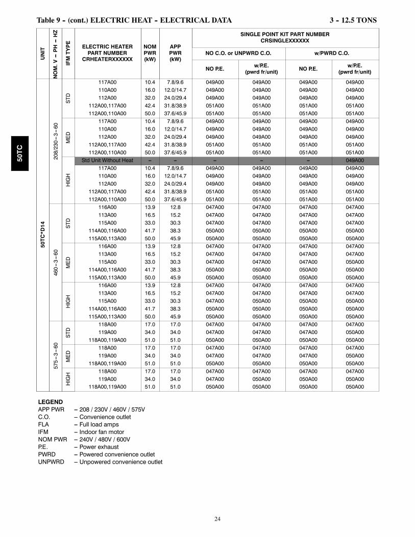
Table 9 – ELECTRIC HEAT -- ELECTRICAL DATA 3 -- 12.5 TONS
UNIT
NOM.V---PH---HZ
IFMTYPE
ELECTRIC HEATERPART NUMBER
CRHEATERXXXXXX
NOMPWR(kW)
APPPWR(kW)
SINGLE POINT KIT PART NUMBERCRSINGLEXXXXXX
NO C.O. or UNPWRD C.O. w/PWRD C.O.
NO P.E. w/P.E.(pwrd fr/unit) NO P.E. w/P.E.
(pwrd fr/unit)
50TC*A04
208/230---1---60 STD
101A00 4.4 3.3/4.0 --- --- --- ---102A00 6.5 4.9/6.0 --- --- --- ---103B00 8.7 6.5/8.0 --- --- --- ---104B00 10.5 7.9/9.6 040A00 040A00 040A00 040A00
102A00,102A00 13 9.8/11.9 040A00 040A00 040A00 040A00
MED
101A00 4.4 3.3/4.0 --- --- --- ---102A00 6.5 4.9/6.0 --- --- --- ---103B00 8.7 6.5/8.0 --- --- --- ---104B00 10.5 7.9/9.6 040A00 040A00 040A00 040A00
102A00,102A00 13 9.8/11.9 040A00 040A00 040A00 040A00
208/230---3---60
STD
101A00 4.4 3.3/4.0 --- --- --- ---102A00 6.5 4.9/6.0 --- --- --- ---103B00 8.7 6.5/8.0 --- --- --- ---104B00 10.5 7.9/9.6 --- --- --- ---105A00 16 12.0/14.7 --- --- 038A00 038A00
MED
101A00 4.4 3.3/4.0 --- --- --- ---102A00 6.5 4.9/6.0 --- --- --- ---103B00 8.7 6.5/8.0 --- --- --- ---104B00 10.5 7.9/9.6 --- --- --- ---105A00 16 12.0/14.7 --- --- 038A00 038A00
HIGH
101A00 4.4 3.3/4.0 --- --- --- ---102A00 6.5 4.9/6.0 --- --- --- ---103B00 8.7 6.5/8.0 --- --- --- ---104B00 10.5 7.9/9.6 --- --- --- ---105A00 16 12.0/14.7 --- --- 038A00 038A00
460---3---60
STD
106A00 6 5.5 --- --- --- ---107A00 8.8 8.1 --- --- --- ---108A00 11.5 10.6 --- --- --- ---109A00 14 12.9 --- --- --- ---
MED
106A00 6 5.5 --- --- --- ---107A00 8.8 8.1 --- --- --- ---108A00 11.5 10.6 --- --- --- ---109A00 14 12.9 --- --- --- ---
HIGH
106A00 6 5.5 --- --- --- ---107A00 8.8 8.1 --- --- --- ---108A00 11.5 10.6 --- --- --- ---109A00 14 12.9 --- --- --- ---
LEGENDAPP PWR --- 208 / 230V / 460V / 575VC.O. --- Convenience outletFLA --- Full load ampsIFM --- Indoor fan motorNOM PWR --- 240V / 480V / 600VP.E. --- Power exhaustPWRD --- Powered convenience outletUNPWRD --- Unpowered convenience outlet
50TC

15
Table 9 -- (cont.) ELECTRIC HEAT -- ELECTRICAL DATA 3 -- 12.5 TONS
UNIT
NOM.V---PH---HZ
IFMTYPE
ELECTRIC HEATERPART NUMBER
CRHEATERXXXXXX
NOMPWR(kW)
APPPWR(kW)
SINGLE POINT KIT PART NUMBERCRSINGLEXXXXXX
NO C.O. or UNPWRD C.O. w/PWRD C.O.
NO P.E. w/P.E.(pwrd fr/unit) NO P.E. w/P.E.
(pwrd fr/unit)
50TC*A05
208/230---1---60 STD
101A00 4.4 3.3/4.0 --- --- --- ---103B00 8.7 6.5/8.0 --- --- --- ---
102A00,102A00 13 9.8/11.9 040A00 040A00 040A00 040A00103B00,103B00 17.4 13.1/16.0 040A00 040A00 040A00 040A00104B00,104B00 21 15.8/19.3 040A00 040A00 040A00 040A00
MED
101A00 4.4 3.3/4.0 --- --- --- ---103B00 8.7 6.5/8.0 --- --- --- ---
102A00,102A00 13 9.8/11.9 040A00 040A00 040A00 040A00103B00,103B00 17.4 13.1/16.0 040A00 040A00 040A00 040A00104B00,104B00 21 15.8/19.3 040A00 040A00 040A00 040A00
208/230---3---60
STD
102A00 6.5 4.9/6.0 --- --- --- ---103B00 8.7 6.5/8.0 --- --- --- ---105A00 16 12.0/14.7 --- --- 038A00 038A00
104B00,104B00 21 15.8/19.3 038A00 038A00 038A00 038A00
MED
102A00 6.5 4.9/6.0 --- --- --- ---103B00 8.7 6.5/8.0 --- --- --- ---105A00 16 12.0/14.7 --- --- 038A00 038A00
104B00,104B00 21 15.8/19.3 038A00 038A00 038A00 038A00
HIGH
102A00 6.5 4.9/6.0 --- --- --- ---103B00 8.7 6.5/8.0 --- --- --- ---105A00 16 12.0/14.7 --- --- 038A00 038A00
104B00,104B00 21 15.8/19.3 038A00 038A00 038A00 038A00
460---3---60
STD
106A00 6 5.5 --- --- --- ---108A00 11.5 10.6 --- --- --- ---109A00 14 12.9 --- --- --- ---
108A00,108A00 23 21.1 --- --- --- ---
MED
106A00 6 5.5 --- --- --- ---108A00 11.5 10.6 --- --- --- ---109A00 14 12.9 --- --- --- ---
108A00,108A00 23 21.1 --- --- --- ---
HIGH
106A00 6 5.5 --- --- --- ---108A00 11.5 10.6 --- --- --- ---109A00 14 12.9 --- --- --- ---
108A00,108A00 23 21.1 --- --- --- ---
LEGENDAPP PWR --- 208 / 230V / 460V / 575VC.O. --- Convenience outletFLA --- Full load ampsIFM --- Indoor fan motorNOM PWR --- 240V / 480V / 600VP.E. --- Power exhaustPWRD --- Powered convenience outletUNPWRD --- Unpowered convenience outlet
50TC

16
Table 9 -- (cont.) ELECTRIC HEAT -- ELECTRICAL DATA 3 -- 12.5 TONS
UNIT
NOM.V---PH---HZ
IFMTYPE
ELECTRIC HEATERPART NUMBER
CRHEATERXXXXXX
NOMPWR(kW)
APPPWR(kW)
SINGLE POINT KIT PART NUMBERCRSINGLEXXXXXX
NO C.O. or UNPWRD C.O. w/PWRD C.O.
NO P.E. w/P.E.(pwrd fr/unit) NO P.E. w/P.E.
(pwrd fr/unit)
50TC*A06
208/230---1---60 STD
102A00 6.5 4.9/6.0 --- --- --- ---103B00 8.7 6.5/8.0 --- --- --- ---
102A00,102A00 13 9.8/11.9 040A00 040A00 040A00 040A00103B00,103B00 17.4 13.1/16.0 040A00 040A00 040A00 040A00104B00,104B00 21 15.8/19.3 040A00 040A00 040A00 040A00
MED
102A00 6.5 4.9/6.0 --- --- --- ---103B00 8.7 6.5/8.0 --- --- 040A00 040A00
102A00,102A00 13 9.8/11.9 040A00 040A00 040A00 040A00103B00,103B00 17.4 13.1/16.0 040A00 040A00 040A00 040A00104B00,104B00 21 15.8/19.3 040A00 040A00 040A00 040A00
208/230---3---60
STD
102A00 6.5 4.9/6.0 --- --- --- ---104B00 10.5 7.9/9.6 --- --- --- ---105A00 16 12.0/14.7 --- --- 038A00 038A00
104B00,104B00 21 15.8/19.3 038A00 038A00 038A00 038A00104B00,105A00 26.5 19.9/24.3 038A00 038A00 038A00 038A00
MED
102A00 6.5 4.9/6.0 --- --- --- ---104B00 10.5 7.9/9.6 --- --- --- ---105A00 16 12.0/14.7 --- --- 038A00 038A00
104B00,104B00 21 15.8/19.3 038A00 038A00 038A00 038A00104B00,105A00 26.5 19.9/24.3 038A00 038A00 038A00 038A00
HIGH
102A00 6.5 4.9/6.0 --- --- --- ---104B00 10.5 7.9/9.6 --- --- --- ---105A00 16 12.0/14.7 --- --- 038A00 038A00
104B00,104B00 21 15.8/19.3 038A00 038A00 038A00 038A00104B00,105A00 26.5 19.9/24.3 038A00 038A00 038A00 038A00
460---3---60
STD
106A00 6 5.5 --- --- --- ---108A00 11.5 10.6 --- --- --- ---109A00 14 12.9 --- --- --- ---
108A00,108A00 23 21.1 --- --- --- ---108A00,109A00 25.5 23.4 --- --- --- ---
MED
106A00 6 5.5 --- --- --- ---108A00 11.5 10.6 --- --- --- ---109A00 14 12.9 --- --- --- ---
108A00,108A00 23 21.1 --- --- --- ---108A00,109A00 25.5 23.4 --- --- --- ---
HIGH
106A00 6 5.5 --- --- --- ---108A00 11.5 10.6 --- --- --- ---109A00 14 12.9 --- --- --- ---
108A00,108A00 23 21.1 --- --- --- ---108A00,109A00 25.5 23.4 --- --- --- ---
LEGENDAPP PWR --- 208 / 230V / 460V / 575VC.O. --- Convenience outletFLA --- Full load ampsIFM --- Indoor fan motorNOM PWR --- 240V / 480V / 600VP.E. --- Power exhaustPWRD --- Powered convenience outletUNPWRD --- Unpowered convenience outlet
50TC

17
Table 9 -- (cont.) ELECTRIC HEAT -- ELECTRICAL DATA 3 -- 12.5 TONS
UNIT
NOM.V---PH---HZ
IFMTYPE
ELECTRIC HEATERPART NUMBER
CRHEATERXXXXXX
NOMPWR(kW)
APPPWR(kW)
SINGLE POINT KIT PART NUMBERCRSINGLEXXXXXX
NO C.O. or UNPWRD C.O. w/PWRD C.O.
NO P.E. w/P.E.(pwrd fr/unit) NO P.E. w/P.E.
(pwrd fr/unit)
50TC*A07
208/230---3---60
STD
102A00 6.5 4.9/6.0 --- --- --- ---104B00 10.5 7.9/9.6 --- --- --- ---105A00 16.0 12.0/14.7 037A00 037A00 038A00 038A00
104B00,104B00 21.0 15.8/19.3 038A00 038A00 038A00 038A00104B00,105A00 26.5 19.9/24.3 038A00 038A00 038A00 038A00
MED
102A00 6.5 4.9/6.0 --- --- --- ---104B00 10.5 7.9/9.6 --- --- --- ---105A00 16.0 12.0/14.7 037A00 037A00 038A00 038A00
104B00,104B00 21.0 15.8/19.3 038A00 038A00 038A00 038A00104B00,105A00 26.5 19.9/24.3 038A00 038A00 038A00 038A00
HIGH
102A00 6.5 4.9/6.0 --- --- --- ---104B00 10.5 7.9/9.6 --- --- --- ---105A00 16.0 12.0/14.7 037A00 037A00 038A00 038A00
104B00,104B00 21.0 15.8/19.3 038A00 038A00 038A00 038A00104B00,105A00 26.5 19.9/24.3 038A00 038A00 038A00 038A00
460---3---60
STD
106A00 6.0 5.5 --- --- --- ---108A00 11.5 10.6 --- --- --- ---109A00 14.0 12.9 --- --- --- ---
108A00,108A00 23.0 21.1 037A00 037A00 037A00 037A00108A00,109A00 25.5 23.4 037A00 037A00 037A00 037A00
MED
106A00 6.0 5.5 --- --- --- ---108A00 11.5 10.6 --- --- --- ---109A00 14.0 12.9 --- --- --- ---
108A00,108A00 23.0 21.1 037A00 037A00 037A00 037A00108A00,109A00 25.5 23.4 037A00 037A00 037A00 037A00
HIGH
106A00 6.0 5.5 --- --- --- ---108A00 11.5 10.6 --- --- --- ---109A00 14.0 12.9 --- --- --- ---
108A00,108A00 23.0 21.1 037A00 037A00 037A00 037A00108A00,109A00 25.5 23.4 037A00 037A00 037A00 037A00
LEGENDAPP PWR --- 208 / 230V / 460V / 575VC.O. --- Convenience outletFLA --- Full load ampsIFM --- Indoor fan motorNOM PWR --- 240V / 480V / 600VP.E. --- Power exhaustPWRD --- Powered convenience outletUNPWRD --- Unpowered convenience outlet
50TC

18
Table 9 -- (cont.) ELECTRIC HEAT -- ELECTRICAL DATA 3 -- 12.5 TONS
UNIT
NOM.V---PH---HZ
IFMTYPE
ELECTRIC HEATERPART NUMBER
CRHEATERXXXXXX
NOMPWR(kW)
APPPWR(kW)
SINGLE POINT KIT PART NUMBERCRSINGLEXXXXXX
NO C.O. or UNPWRD C.O. w/PWRD C.O.
NO P.E. w/P.E.(pwrd fr/unit) NO P.E. w/P.E.
(pwrd fr/unit)
50TC*A08
208/230---3---60
STD
117A00 10.4 7.8/9.6 042A00 042A00 042A00 042A00110A00 16.0 12.0/14.7 042A00 042A00 043A00 043A00111A00 24.8 18.6/22.8 043A00 043A00 043A00 043A00112A00 32.0 24.0/29.4 043A00 043A00 043A00 043A00
112A00,117A00 42.4 31.8/38.9 045A00 045A00 045A00 045A00
MED
117A00 10.4 7.8/9.6 042A00 042A00 042A00 042A00110A00 16.0 12.0/14.7 042A00 043A00 043A00 043A00111A00 24.8 18.6/22.8 043A00 043A00 043A00 043A00112A00 32.0 24.0/29.4 043A00 043A00 043A00 043A00
112A00,117A00 42.4 31.8/38.9 045A00 045A00 045A00 045A00
HIGH
117A00 10.4 7.8/9.6 042A00 042A00 043A00 043A00110A00 16.0 12.0/14.7 043A00 043A00 043A00 043A00111A00 24.8 18.6/22.8 043A00 043A00 043A00 043A00112A00 32.0 24.0/29.4 043A00 043A00 043A00 043A00
112A00,117A00 42.4 31.8/38.9 045A00 045A00 045A00 045A00
460---3---60
STD
116A00 13.9 12.8 042A00 042A00 042A00 042A00113A00 16.5 15.2 042A00 042A00 042A00 042A00114A00 27.8 25.5 042A00 042A00 042A00 042A00115A00 33.0 30.3 042A00 042A00 042A00 042A00
114A00,116A00 41.7 38.3 044A00 044A00 044A00 044A00
MED
116A00 13.9 12.8 042A00 042A00 042A00 042A00113A00 16.5 15.2 042A00 042A00 042A00 042A00114A00 27.8 25.5 042A00 042A00 042A00 042A00115A00 33.0 30.3 042A00 042A00 042A00 042A00
114A00,116A00 41.7 38.3 044A00 044A00 044A00 044A00
HIGH
116A00 13.9 12.8 042A00 042A00 042A00 042A00113A00 16.5 15.2 042A00 042A00 042A00 042A00114A00 27.8 25.5 042A00 042A00 042A00 042A00115A00 33.0 30.3 042A00 044A00 044A00 044A00
114A00,116A00 41.7 38.3 044A00 044A00 044A00 044A00
575---3---60 STD
118A00 17.0 17.0 042A00 042A00 042A00 042A00119A00 34.0 34.0 042A00 042A00 042A00 044A00
MED 118A00 17.0 17.0 042A00 042A00 042A00 042A00
119A00 34.0 34.0 042A00 042A00 042A00 044A00
HIGH 118A00 17.0 17.0 042A00 042A00 042A00 042A00
119A00 34.0 34.0 042A00 044A00 044A00 044A00
LEGENDAPP PWR --- 208 / 230V / 460V / 575VC.O. --- Convenience outletFLA --- Full load ampsIFM --- Indoor fan motorNOM PWR --- 240V / 480V / 600VP.E. --- Power exhaustPWRD --- Powered convenience outletUNPWRD --- Unpowered convenience outlet
50TC

19
Table 9 -- (cont.) ELECTRIC HEAT -- ELECTRICAL DATA 3 -- 12.5 TONS
UNIT
NOM.V---PH---HZ
IFMTYPE
ELECTRIC HEATERPART NUMBER
CRHEATERXXXXXX
NOMPWR(kW)
APPPWR(kW)
SINGLE POINT KIT PART NUMBERCRSINGLEXXXXXX
NO C.O. or UNPWRD C.O. w/PWRD C.O.
NO P.E. w/P.E.(pwrd fr/unit) NO P.E. w/P.E.
(pwrd fr/unit)
50TC*D08
208/230---3---60
STD
117A00 10.4 7.8/9.6 042A00 042A00 042A00 042A00110A00 16.0 12.0/14.7 042A00 042A00 043A00 043A00111A00 24.8 18.6/22.8 043A00 043A00 043A00 043A00112A00 32.0 24.0/29.4 043A00 043A00 043A00 043A00
112A00,117A00 42.4 31.8/38.9 045A00 045A00 045A00 045A00
MED
117A00 10.4 7.8/9.6 042A00 042A00 042A00 042A00110A00 16.0 12.0/14.7 042A00 043A00 043A00 043A00111A00 24.8 18.6/22.8 043A00 043A00 043A00 043A00112A00 32.0 24.0/29.4 043A00 043A00 043A00 043A00
112A00,117A00 42.4 31.8/38.9 045A00 045A00 045A00 045A00
HIGH
117A00 10.4 7.8/9.6 042A00 042A00 042A00 043A00110A00 16.0 12.0/14.7 043A00 043A00 043A00 043A00111A00 24.8 18.6/22.8 043A00 043A00 043A00 043A00112A00 32.0 24.0/29.4 043A00 043A00 043A00 043A00
112A00,117A00 42.4 31.8/38.9 045A00 045A00 045A00 045A00
460---3---60
STD
116A00 13.9 12.8 042A00 042A00 042A00 042A00113A00 16.5 15.2 042A00 042A00 042A00 042A00114A00 27.8 25.5 042A00 042A00 042A00 042A00115A00 33.0 30.3 042A00 042A00 042A00 042A00
114A00,116A00 41.7 38.3 044A00 044A00 044A00 044A00
MED
116A00 13.9 12.8 042A00 042A00 042A00 042A00113A00 16.5 15.2 042A00 042A00 042A00 042A00114A00 27.8 25.5 042A00 042A00 042A00 042A00115A00 33.0 30.3 042A00 042A00 042A00 042A00
114A00,116A00 41.7 38.3 044A00 044A00 044A00 044A00
HIGH
116A00 13.9 12.8 042A00 042A00 042A00 042A00113A00 16.5 15.2 042A00 042A00 042A00 042A00114A00 27.8 25.5 042A00 042A00 042A00 042A00115A00 33.0 30.3 042A00 044A00 044A00 044A00
114A00,116A00 41.7 38.3 044A00 044A00 044A00 044A00
575---3---60 STD
118A00 17.0 17.0 042A00 042A00 042A00 042A00119A00 34.0 34.0 042A00 042A00 042A00 044A00
MED 118A00 17.0 17.0 042A00 042A00 042A00 042A00
119A00 34.0 34.0 042A00 042A00 042A00 044A00
HIGH 118A00 17.0 17.0 042A00 042A00 042A00 042A00
119A00 34.0 34.0 042A00 044A00 044A00 044A00
LEGENDAPP PWR --- 208 / 230V / 460V / 575VC.O. --- Convenience outletFLA --- Full load ampsIFM --- Indoor fan motorNOM PWR --- 240V / 480V / 600VP.E. --- Power exhaustPWRD --- Powered convenience outletUNPWRD --- Unpowered convenience outlet
50TC

20
Table 9 -- (cont.) ELECTRIC HEAT -- ELECTRICAL DATA 3 -- 12.5 TONS
UNIT
NOM.V---PH---HZ
IFMTYPE
ELECTRIC HEATERPART NUMBER
CRHEATERXXXXXX
NOMPWR(kW)
APPPWR(kW)
SINGLE POINT KIT PART NUMBERCRSINGLEXXXXXX
NO C.O. or UNPWRD C.O. w/PWRD C.O.
NO P.E. w/P.E.(pwrd fr/unit) NO P.E. w/P.E.
(pwrd fr/unit)
50TC*A09
208/230---3---60
STD
117A00 10.4 7.8/9.6 047A00 047A00 047A00 049A00110A00 16.0 12.0/14.7 047A00 047A00 049A00 049A00111A00 24.8 18.6/22.8 049A00 049A00 049A00 049A00112A00 32.0 24.0/29.4 049A00 049A00 049A00 049A00
112A00,117A00 42.4 31.8/38.9 051A00 051A00 051A00 051A00
MED
117A00 10.4 7.8/9.6 047A00 047A00 047A00 049A00110A00 16.0 12.0/14.7 047A00 047A00 049A00 049A00111A00 24.8 18.6/22.8 049A00 049A00 049A00 049A00112A00 32.0 24.0/29.4 049A00 049A00 049A00 049A00
112A00,117A00 42.4 31.8/38.9 051A00 051A00 051A00 051A00
HIGH
117A00 10.4 7.8/9.6 047A00 049A00 049A00 049A00110A00 16.0 12.0/14.7 049A00 049A00 049A00 049A00111A00 24.8 18.6/22.8 049A00 049A00 049A00 049A00112A00 32.0 24.0/29.4 049A00 049A00 049A00 049A00
112A00,117A00 42.4 31.8/38.9 051A00 051A00 051A00 051A00
460---3---60
STD
116A00 13.9 12.8 047A00 047A00 047A00 047A00113A00 16.5 15.2 047A00 047A00 047A00 047A00114A00 27.8 25.5 047A00 047A00 047A00 047A00115A00 33.0 30.3 047A00 047A00 047A00 047A00
114A00,116A00 41.7 38.3 050A00 050A00 050A00 050A00
MED
116A00 13.9 12.8 047A00 047A00 047A00 047A00113A00 16.5 15.2 047A00 047A00 047A00 047A00114A00 27.8 25.5 047A00 047A00 047A00 047A00115A00 33.0 30.3 047A00 047A00 047A00 047A00
114A00,116A00 41.7 38.3 050A00 050A00 050A00 050A00
HIGH
116A00 13.9 12.8 047A00 047A00 047A00 047A00113A00 16.5 15.2 047A00 047A00 047A00 047A00114A00 27.8 25.5 047A00 047A00 047A00 047A00115A00 33.0 30.3 047A00 047A00 047A00 050A00
114A00,116A00 41.7 38.3 050A00 050A00 050A00 050A00
575---3---60
STD
118A00 17.0 17.0 047A00 047A00 047A00 047A00119A00 34.0 34.0 047A00 047A00 047A00 050A00
MED 118A00 17.0 17.0 047A00 047A00 047A00 047A00
119A00 34.0 34.0 047A00 047A00 047A00 050A00
HIGH 118A00 17.0 17.0 047A00 047A00 047A00 047A00
119A00 34.0 34.0 047A00 047A00 047A00 050A00
LEGENDAPP PWR --- 208 / 230V / 460V / 575VC.O. --- Convenience outletFLA --- Full load ampsIFM --- Indoor fan motorNOM PWR --- 240V / 480V / 600VP.E. --- Power exhaustPWRD --- Powered convenience outletUNPWRD --- Unpowered convenience outlet
50TC

21
Table 9 -- (cont.) ELECTRIC HEAT -- ELECTRICAL DATA 3 -- 12.5 TONS
UNIT
NOM.V---PH---HZ
IFMTYPE
ELECTRIC HEATERPART NUMBER
CRHEATERXXXXXX
NOMPWR(kW)
APPPWR(kW)
SINGLE POINT KIT PART NUMBERCRSINGLEXXXXXX
NO C.O. or UNPWRD C.O. w/PWRD C.O.
NO P.E. w/P.E.(pwrd fr/unit) NO P.E. w/P.E.
(pwrd fr/unit)
50TC*D09
208/230---3---60
STD
117A00 10.4 7.8/9.6 047 047 047 047110A00 16.0 12.0/14.7 047 047 049 049111A00 24.8 18.6/22.8 049 049 049 049112A00 32.0 24.0/29.4 049 049 049 049
112A00,117A00 42.4 31.8/38.9 051 051 051 051
MED
117A00 10.4 7.8/9.6 047 047 047 047110A00 16.0 12.0/14.7 047 047 049 049111A00 24.8 18.6/22.8 049 049 049 049112A00 32.0 24.0/29.4 049 049 049 049
112A00,117A00 42.4 31.8/38.9 051 051 051 051
HIGH
117A00 10.4 7.8/9.6 047 047 047 047110A00 16.0 12.0/14.7 049 049 049 049111A00 24.8 18.6/22.8 049 049 049 049112A00 32.0 24.0/29.4 049 049 049 049
112A00,117A00 42.4 31.8/38.9 051 051 051 051
460---3---60
STD
116A00 13.9 12.8 047 047 047 047113A00 16.5 15.2 047 047 047 047114A00 27.8 25.5 047 047 047 047115A00 33.0 30.3 047 047 047 047
114A00,116A00 41.7 38.3 050 050 050 050
MED
116A00 13.9 12.8 047 047 047 047113A00 16.5 15.2 047 047 047 047114A00 27.8 25.5 047 047 047 047115A00 33.0 30.3 047 047 047 047
114A00,116A00 41.7 38.3 050 050 050 050
HIGH
116A00 13.9 12.8 047 047 047 047113A00 16.5 15.2 047 047 047 047114A00 27.8 25.5 047 047 047 047115A00 33.0 30.3 047 047 047 050
114A00,116A00 41.7 38.3 050 050 050 050
575---3---60 STD
118A00 17.0 17.0 047 047 047 047119A00 34.0 34.0 047 047 047 050
MED 118A00 17.0 17.0 047 047 047 047
119A00 34.0 34.0 047 047 047 050
HIGH 118A00 17.0 17.0 047 047 047 047
119A00 34.0 34.0 047 047 047 050
LEGENDAPP PWR --- 208 / 230V / 460V / 575VC.O. --- Convenience outletFLA --- Full load ampsIFM --- Indoor fan motorNOM PWR --- 240V / 480V / 600VP.E. --- Power exhaustPWRD --- Powered convenience outletUNPWRD --- Unpowered convenience outlet
50TC

22
Table 9 -- (cont.) ELECTRIC HEAT -- ELECTRICAL DATA 3 -- 12.5 TONS
UNIT
NOM.V---PH---HZ
IFMTYPE
ELECTRIC HEATERPART NUMBER
CRHEATERXXXXXX
NOMPWR(kW)
APPPWR(kW)
SINGLE POINT KIT PART NUMBERCRSINGLEXXXXXX
NO C.O. or UNPWRD C.O. w/PWRD C.O.
NO P.E. w/P.E.(pwrd fr/unit) NO P.E. w/P.E.
(pwrd fr/unit)
50TC*A12
208/230---3---60
STD
117A00 10.4 7.8/9.6 047A00 047A00 047A00 049A00110A00 16.0 12.0/14.7 047A00 047A00 049A00 049A00112A00 32.0 24.0/29.4 049A00 049A00 049A00 049A00
112A00,117A00 42.4 31.8/38.9 051A00 051A00 051A00 051A00112A00,110A00 50.0 37.6/45.9 051A00 051A00 051A00 051A00
MED
117A00 10.4 7.8/9.6 047A00 049A00 049A00 049A00110A00 16.0 12.0/14.7 049A00 049A00 049A00 049A00112A00 32.0 24.0/29.4 049A00 049A00 049A00 049A00
112A00,117A00 42.4 31.8/38.9 051A00 051A00 051A00 051A00112A00,110A00 50.0 37.6/45.9 051A00 051A00 051A00 051A00
HIGH
117A00 10.4 7.8/9.6 049A00 049A00 049A00 049A00110A00 16.0 12.0/14.7 049A00 049A00 049A00 049A00112A00 32.0 24.0/29.4 049A00 049A00 049A00 049A00
112A00,117A00 42.4 31.8/38.9 051A00 051A00 051A00 051A00112A00,110A00 50.0 37.6/45.9 051A00 051A00 051A00 051A00
460---3---60
STD
116A00 13.9 12.8 047A00 047A00 047A00 047A00113A00 16.5 15.2 047A00 047A00 047A00 047A00115A00 33.0 30.3 047A00 047A00 047A00 047A00
114A00,116A00 41.7 38.3 050A00 050A00 050A00 050A00115A00,113A00 50.0 45.9 050A00 050A00 050A00 050A00
MED
116A00 13.9 12.8 047A00 047A00 047A00 047A00113A00 16.5 15.2 047A00 047A00 047A00 047A00115A00 33.0 30.3 047A00 047A00 047A00 050A00
114A00,116A00 41.7 38.3 050A00 050A00 050A00 050A00115A00,113A00 50.0 45.9 050A00 050A00 050A00 050A00
HIGH
116A00 13.9 12.8 047A00 047A00 047A00 047A00113A00 16.5 15.2 047A00 047A00 047A00 047A00115A00 33.0 30.3 047A00 050A00 050A00 050A00
114A00,116A00 41.7 38.3 050A00 050A00 050A00 050A00115A00,113A00 50.0 45.9 050A00 050A00 050A00 050A00
575---3---60
STD
118A00 17.0 17.0 047A00 047A00 047A00 047A00119A00 34.0 34.0 047A00 047A00 047A00 050A00
118A00,119A00 51.0 51.0 050A00 050A00 050A00 050A00
MED
118A00 17.0 17.0 047A00 047A00 047A00 047A00119A00 34.0 34.0 047A00 047A00 047A00 050A00
118A00,119A00 51.0 51.0 050A00 050A00 050A00 050A00
HIGH 118A00 17.0 17.0 047A00 047A00 047A00 047A00
119A00 34.0 34.0 047A00 050A00 050A00 050A00118A00,119A00 51.0 51.0 050A00 050A00 050A00 050A00
LEGENDAPP PWR --- 208 / 230V / 460V / 575VC.O. --- Convenience outletFLA --- Full load ampsIFM --- Indoor fan motorNOM PWR --- 240V / 480V / 600VP.E. --- Power exhaustPWRD --- Powered convenience outletUNPWRD --- Unpowered convenience outlet
50TC

23
Table 9 -- (cont.) ELECTRIC HEAT -- ELECTRICAL DATA 3 -- 12.5 TONS
UNIT
NOM.V---PH---HZ
IFMTYPE
ELECTRIC HEATERPART NUMBER
CRHEATERXXXXXX
NOMPWR(kW)
APPPWR(kW)
SINGLE POINT KIT PART NUMBERCRSINGLEXXXXXX
NO C.O. or UNPWRD C.O. w/PWRD C.O.
NO P.E. w/P.E.(pwrd fr/unit) NO P.E. w/P.E.
(pwrd fr/unit)
50TC*D12
208/230---3---60
STD
117A00 10.4 7.8/9.6 047A00 047A00 047A00 047A00110A00 16.0 12.0/14.7 047A00 047A00 049A00 049A00112A00 32.0 24.0/29.4 049A00 049A00 049A00 049A00
112A00,117A00 42.4 31.8/38.9 051A00 051A00 051A00 051A00112A00,110A00 50.0 37.6/45.9 051A00 051A00 051A00 051A00
MED
117A00 10.4 7.8/9.6 047A00 047A00 047A00 049A00110A00 16.0 12.0/14.7 049A00 049A00 049A00 049A00112A00 32.0 24.0/29.4 049A00 049A00 049A00 049A00
112A00,117A00 42.4 31.8/38.9 051A00 051A00 051A00 051A00112A00,110A00 50.0 37.6/45.9 051A00 051A00 051A00 051A00
HIGH
117A00 10.4 7.8/9.6 047A00 049A00 049A00 049A00110A00 16.0 12.0/14.7 049A00 049A00 049A00 049A00112A00 32.0 24.0/29.4 049A00 049A00 049A00 049A00
112A00,117A00 42.4 31.8/38.9 051A00 051A00 051A00 051A00112A00,110A00 50.0 37.6/45.9 051A00 051A00 051A00 051A00
460---3---60
STD
116A00 13.9 12.8 047A00 047A00 047A00 047A00113A00 16.5 15.2 047A00 047A00 047A00 047A00115A00 33.0 30.3 047A00 047A00 047A00 047A00
114A00,116A00 41.7 38.3 050A00 050A00 050A00 050A00115A00,113A00 50.0 45.9 050A00 050A00 050A00 050A00
MED
116A00 13.9 12.8 047A00 047A00 047A00 047A00113A00 16.5 15.2 047A00 047A00 047A00 047A00115A00 33.0 30.3 047A00 047A00 047A00 050A00
114A00,116A00 41.7 38.3 050A00 050A00 050A00 050A00115A00,113A00 50.0 45.9 050A00 050A00 050A00 050A00
HIGH
116A00 13.9 12.8 047A00 047A00 047A00 047A00113A00 16.5 15.2 047A00 047A00 047A00 047A00115A00 33.0 30.3 047A00 050A00 050A00 050A00
114A00,116A00 41.7 38.3 050A00 050A00 050A00 050A00115A00,113A00 50.0 45.9 050A00 050A00 050A00 050A00
575---3---60
STD
118A00 17.0 17.0 047A00 047A00 047A00 047A00119A00 34.0 34.0 047A00 047A00 047A00 050A00
118A00,119A00 51.0 51.0 050A00 050A00 050A00 050A00
MED
118A00 17.0 17.0 047A00 047A00 047A00 047A00119A00 34.0 34.0 047A00 047A00 047A00 050A00
118A00,119A00 51.0 51.0 050A00 050A00 050A00 050A00
HIGH 118A00 17.0 17.0 047A00 047A00 047A00 047A00
119A00 34.0 34.0 047A00 050A00 050A00 050A00118A00,119A00 51.0 51.0 050A00 050A00 050A00 050A00
LEGENDAPP PWR --- 208 / 230V / 460V / 575VC.O. --- Convenience outletFLA --- Full load ampsIFM --- Indoor fan motorNOM PWR --- 240V / 480V / 600VP.E. --- Power exhaustPWRD --- Powered convenience outletUNPWRD --- Unpowered convenience outlet
50TC
24
Table 9 -- (cont.) ELECTRIC HEAT -- ELECTRICAL DATA 3 -- 12.5 TONS
UNIT
NOM.V---PH---HZ
IFMTYPE
ELECTRIC HEATERPART NUMBER
CRHEATERXXXXXX
NOMPWR(kW)
APPPWR(kW)
SINGLE POINT KIT PART NUMBERCRSINGLEXXXXXX
NO C.O. or UNPWRD C.O. w/PWRD C.O.
NO P.E. w/P.E.(pwrd fr/unit) NO P.E. w/P.E.
(pwrd fr/unit)
50TC*D14
208/230---3---60
STD
117A00 10.4 7.8/9.6 049A00 049A00 049A00 049A00110A00 16.0 12.0/14.7 049A00 049A00 049A00 049A00112A00 32.0 24.0/29.4 049A00 049A00 049A00 049A00
112A00,117A00 42.4 31.8/38.9 051A00 051A00 051A00 051A00112A00,110A00 50.0 37.6/45.9 051A00 051A00 051A00 051A00
MED
117A00 10.4 7.8/9.6 049A00 049A00 049A00 049A00110A00 16.0 12.0/14.7 049A00 049A00 049A00 049A00112A00 32.0 24.0/29.4 049A00 049A00 049A00 049A00
112A00,117A00 42.4 31.8/38.9 051A00 051A00 051A00 051A00112A00,110A00 50.0 37.6/45.9 051A00 051A00 051A00 051A00
HIGH
Std Unit Without Heat --- --- --- --- --- 049A00117A00 10.4 7.8/9.6 049A00 049A00 049A00 049A00110A00 16.0 12.0/14.7 049A00 049A00 049A00 049A00112A00 32.0 24.0/29.4 049A00 049A00 049A00 049A00
112A00,117A00 42.4 31.8/38.9 051A00 051A00 051A00 051A00112A00,110A00 50.0 37.6/45.9 051A00 051A00 051A00 051A00
460---3---60
STD
116A00 13.9 12.8 047A00 047A00 047A00 047A00113A00 16.5 15.2 047A00 047A00 047A00 047A00115A00 33.0 30.3 047A00 047A00 047A00 047A00
114A00,116A00 41.7 38.3 050A00 050A00 050A00 050A00115A00,113A00 50.0 45.9 050A00 050A00 050A00 050A00
MED
116A00 13.9 12.8 047A00 047A00 047A00 047A00113A00 16.5 15.2 047A00 047A00 047A00 047A00115A00 33.0 30.3 047A00 047A00 047A00 050A00
114A00,116A00 41.7 38.3 050A00 050A00 050A00 050A00115A00,113A00 50.0 45.9 050A00 050A00 050A00 050A00
HIGH
116A00 13.9 12.8 047A00 047A00 047A00 047A00113A00 16.5 15.2 047A00 047A00 047A00 047A00115A00 33.0 30.3 047A00 050A00 050A00 050A00
114A00,116A00 41.7 38.3 050A00 050A00 050A00 050A00115A00,113A00 50.0 45.9 050A00 050A00 050A00 050A00
575---3---60
STD
118A00 17.0 17.0 047A00 047A00 047A00 047A00119A00 34.0 34.0 047A00 047A00 047A00 050A00
118A00,119A00 51.0 51.0 050A00 050A00 050A00 050A00
MED
118A00 17.0 17.0 047A00 047A00 047A00 047A00119A00 34.0 34.0 047A00 047A00 047A00 050A00
118A00,119A00 51.0 51.0 050A00 050A00 050A00 050A00
HIGH 118A00 17.0 17.0 047A00 047A00 047A00 047A00
119A00 34.0 34.0 047A00 050A00 050A00 050A00118A00,119A00 51.0 51.0 050A00 050A00 050A00 050A00
LEGENDAPP PWR --- 208 / 230V / 460V / 575VC.O. --- Convenience outletFLA --- Full load ampsIFM --- Indoor fan motorNOM PWR --- 240V / 480V / 600VP.E. --- Power exhaustPWRD --- Powered convenience outletUNPWRD --- Unpowered convenience outlet
50TC

25
CURBS & WEIGHTS DIMENSIONS -- 50TC 04--07
C08529
Fig. 1 -- Dimensions 50TC 04--07
50TC

26
CURBS & WEIGHTS DIMENSIONS -- 50TC 04--07 (cont.)
C08530
Fig. 2 -- Dimensions 50TC 04--07
C
B
A
D
C08337
Fig. 3 -- Service Clearance
LOC DIMENSION CONDITION
A
48--- in (1219 mm) Unit disconnect is mounted on panel18--- in (457 mm) No disconnect, convenience outlet option18--- in (457 mm) Recommended service clearance12--- in (305 mm) Minimum clearance
B42--- in (1067 mm) Surface behind servicer is grounded (e.g., metal, masonry wall)36--- in (914 mm) Surface behind servicer is electrically non---conductive (e.g., wood, fiberglass)Special Check for sources of flue products within 10--- ft of unit fresh air intake hood
C36--- in (914 mm) Side condensate drain is used18--- in (457 mm) Minimum clearance
D42--- in (1067 mm) Surface behind servicer is grounded (e.g., metal, masonry wall, another unit)36--- in (914 mm) Surface behind servicer is electrically non---conductive (e.g., wood, fiberglass)
50TC

27
CURBS & WEIGHTS DIMENSIONS -- 50TC 04--07 (cont.)
C10318
Fig. 4 -- Roof Curb Details
50TC

28
CURBS & WEIGHTS DIMENSIONS -- 50TC 08--12
C10300
Fig. 5 -- Dimensions 50TC 08--12
50TC

29
CURBS & WEIGHTS DIMENSIONS -- 50TC 08--12 (cont.)
C10301
Fig. 6 -- Dimensions 50TC 08--12
C
B
A
D
C08337
Fig. 7 -- Service Clearance
LOC DIMENSION CONDITION
A
48--- in (1219 mm) Unit disconnect is mounted on panel36--- in (914 mm) If dimension---B is 12--- in (305 mm)18--- in (457 mm) No disconnect, convenience outlet option18--- in (457 mm) Recommended service clearance (use electric screwdriver)12--- in (305 mm) Minimum clearance (use manual ratchet screwdriver)
B36--- in (914 mm) Unit has economizer12--- in (305 mm) If dimension---A is 36--- in (914 mm)Special Check for sources of flue products within 10--- ft of unit fresh air intake hood
C36--- in (914 mm) Side condensate drain is used18--- in (457 mm) Minimum clearance
D42--- in (1067 mm) Surface behind servicer is grounded (e.g., metal, masonry wall, another unit)36--- in (914 mm) Surface behind servicer is electrically non---conductive (e.g., wood, fiberglass)
50TC

30
CURBS & WEIGHTS DIMENSIONS -- 50TC 08--14
C10317
Fig. 8 -- Roof Curb Details
50TC

31
CURBS & WEIGHTS DIMENSIONS -- 50TC 14
C08533
Fig. 9 -- Dimensions 50TC--14
50TC
32
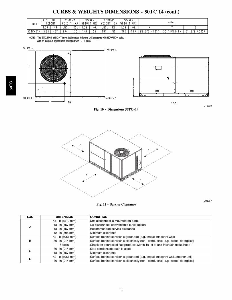
CURBS & WEIGHTS DIMENSIONS -- 50TC 14 (cont.)
C10329
Fig. 10 -- Dimensions 50TC--14
C
B
A
D
C08337
Fig. 11 -- Service Clearance
LOC DIMENSION CONDITION
A
48--- in (1219 mm) Unit disconnect is mounted on panel18--- in (457 mm) No disconnect, convenience outlet option18--- in (457 mm) Recommended service clearance12--- in (305 mm) Minimum clearance
B42--- in (1067 mm) Surface behind servicer is grounded (e.g., metal, masonry wall)36--- in (914 mm) Surface behind servicer is electrically non---conductive (e.g., wood, fiberglass)Special Check for sources of flue products within 10--- ft of unit fresh air intake hood
C36--- in (914 mm) Side condensate drain is used18--- in (457 mm) Minimum clearance
D42--- in (1067 mm) Surface behind servicer is grounded (e.g., metal, masonry wall, another unit)36--- in (914 mm) Surface behind servicer is electrically non---conductive (e.g., wood, fiberglass)
50TC

33
OPTION / ACCESSORY WEIGHTS
OPTION / ACCESSORYOPTION / ACCESSORY WEIGHTS
04 05 06 07 08 09 12 14lb kg lb kg lb kg lb kg lb kg lb kg lb kg lb kg
Humidi---MiZer1 15 7 23 10 25 11 29 13 38 17 47 21 57 21 47 21Power Exhaust --- vertical 50 23 50 23 50 23 50 23 75 34 75 34 75 34 75 34Power Exhaust --- horizontal 30 14 30 14 30 14 30 14 30 14 30 14 30 14 30 14EconoMi$er (IV or 2) 50 23 50 23 50 23 50 23 75 34 75 34 75 34 75 34Two Position damper 39 18 39 18 39 18 39 18 58 26 58 26 58 26 58 26Manual Dampers 12 5 12 5 12 5 12 5 18 8 18 8 18 8 18 8Hail Guard (louvered) 16 7 16 7 16 7 16 7 34 15 34 15 34 15 34 15Cu/Cu Condenser Coil2 6 3 13 6 13 6 15 7 12 5 23 10 23 10 23 10Cu/Cu Cond. & Evaporator Coils2 12 5 19 9 21 10 26 12 25 11 49 22 49 22 49 22Roof Curb (14--- in. curb) 115 52 115 52 115 52 115 52 143 65 143 65 143 65 143 65Roof Curb (24--- in. curb) 197 89 197 89 197 89 197 89 245 111 245 111 245 111 245 111CO2 sensor 5 2 5 2 5 2 5 2 5 2 5 2 5 2 5 2Electric Heater 30 14 30 14 30 14 30 14 45 20 45 20 45 20 45 20Single Point Kit 10 5 10 5 10 5 10 5 12 5 12 5 12 5 15 7Optional Indoor Motor / Drive 10 5 10 5 10 5 10 5 15 7 15 7 15 7 15 7Motor Master Controller 35 16 35 16 35 16 35 16 35 16 35 16 35 16 40 18Return Smoke Detector 5 2 5 2 5 2 5 2 5 2 5 2 5 2 5 2Supply Smoke Detector 5 2 5 2 5 2 5 2 5 2 5 2 5 2 5 2Non---Fused Disconnect 15 7 15 7 15 7 15 7 15 7 15 7 15 7 15 7Powered Convenience outlet 35 16 35 16 35 16 35 16 35 16 35 16 35 16 35 16Non---Powered Convenience outlet 5 2 5 2 5 2 5 2 5 2 5 2 5 2 5 2Enthalpy Sensor 2 1 2 1 2 1 2 1 2 1 2 1 2 1 2 1Differential Enthalpy Sensor 3 1 3 1 3 1 3 1 3 1 3 1 3 1 3 1
NOTE: Where multiple variations are available, the heaviest combination is listed.1 For Humidi---MiZer add MotorMaster controller.2 Where Available
50TC

34
APPLICATION DATAMin operating ambient temp (cooling):
In mechanical cooling mode, your Carrier rooftop cansafely operate down to an outdoor ambient temperature of40_F (4_C) and 25_F (--4_C), with an accessory winterstart kit. It is possible to provide cooling at lower outdoorambient temperatures by using less outside air,economizers, and/or accessory low ambient kits.
Max operating ambient temp (cooling):
The maximum operating ambient temperature for coolingmode is 115_F (46_C). While cooling operation above115_F (46_C) may be possible, it could cause either areduction in performance, reliability, or a protective actionby the unit’s internal safety devices.
Min and max airflow (cooling mode):
To maintain safe and reliable operation of your rooftop,operate within the cooling airflow limits. Operating abovethe max may cause blow--off, undesired airflow noise, orairflow related problems with the rooftop unit. Operatingbelow the min may cause problems with coil freeze--up.
Airflow:
All units are draw--through in cooling mode.
Outdoor air application strategies:
Economizers reduce operating expenses and compressorrun time by providing a free source of cooling and ameans of ventilation to match application changing needs.In fact, they should be considered for most applications.Also, consider the various economizer control methodsand their benefits, as well as sensors required toaccomplish your application goals. Please contact yourlocal Carrier representative for assistance.
Motor limits, Brake horsepower (BHP):
Due to Carrier’s internal unit design, air path, andspecially designed motors, the full horsepower (maximumcontinuous BHP) band, as listed in Table 5, can be usedwith the utmost confidence. There is no need for extrasafety factors, as Carrier’s motors are designed andrigorously tested to use the entire, listed BHP rangewithout either nuisance tripping or premature motorfailure.
Sizing a rooftop
Bigger isn’t necessarily better. While an air conditionerneeds to have enough capacity to meet the load, it doesn’tneed excess capacity. In fact, having excess capacitytypically results in very poor part load performance andhumidity control.
Using higher design temperatures than ASHRAErecommends for your location, adding “safety factors” tothe calculated load, and rounding up to the next largestunit, are all signs of oversizing air conditioners.Oversizing can cause short--cycling, and short cyclingleads to poor humidity control, reduced efficiency, higherutility bills, drastic indoor temperature swings, excessivenoise, and increased wear and tear on the air conditioner.
Rather than oversizing an air conditioner, wise contractorsand engineers “right--size” or even slightly undersize airconditioners. Correctly sizing an air conditioner controlshumidity better; promotes efficiency; reduces utility bills;extends equipment life, and maintains even, comfortabletemperatures.
Low ambient applications
When equipped with a Carrier economizer, your rooftopunit can cool your space by bringing in fresh, cool outsideair. In fact, when so equipped, accessory low ambient kitmay not be necessary. In low ambient conditions, unlessthe outdoor air is excessively humid or contaminated,economizer--based “free cooling” is the preferred lesscostly and energy conscious method.
In low ambient applications where outside air might notbe desired (such as contaminated or excessively humidoutdoor environments), your Carrier rooftop can operateat ambient temperatures down to --20_F (--29_C) using therecommended accessory Motormaster low ambientcontroller.
Winter start
Carrier’s winter start kit extends the low ambient limit ofyour rooftop to 25_F (--4_C). The kit bypasses the lowpressure switch, preventing nuisance tripping of the lowpressure switch. Other low ambient precautions may stillbe prudent.
50TC

35
SELECTION PROCEDURE (WITH 50TC*A07 EXAMPLE)I. Determine cooling and heating loads.
Given:Mixed Air Drybulb 80_F (27_C)Mixed Air Wetbulb 67_F (19_C)Ambient Drybulb 95_F (35_C)TCLoad 69.0 MBHSHCLoad 51.0 MBHVertical Supply Air 2100 CFMExternal Static Pressure 0.66 in.wgElectrical Characteristics 230--3--60
II. Make an initial guess at cooling tons.
Refrig. tons = TCLoad / 12 MBH per tonRefrig. tons = 69.0 / 12 = 5.75 tons
In this case, start by looking at the 50TC*A07.
III. Look up the rooftop’s TC and SHC.
Table 12 shows that, at the application’s supply airCFM, mixed air and ambient temperatures, the50TC*A07 supplies:TCLoad = 73.7 MBHSHCLoad = 54.4 MBH.
IV. Calculate the building Latent Heat Load.
LCLoad = TCLoad -- SHCLoadLCLoad = 69.0 MBH -- 51.0 MBH = 18.0 MBH
V. Calculate RTU Latent Heat Capacity
LC = TC -- SHCLC = 73.7 MBH -- 54.4 MBH = 19.3 MBH
VI. Compare RTU capacities to loads. 2,3
Compare the rooftop’s SHC and LC to the building’sSensible and Latent Heat Loads.
VII. Select factory options (FIOP)
Local code requires an economizer for any unit withTC larger than 65.0 MBH.
VIII. Calculate the total static pressure.
External static pressure 0.66 in. wgSum of FIOP/Accessory static +0.14 in. wg
Total Static Pressure 0.80 in. wg
IX. Look up the Indoor Fan RPM & BHP.
Table 33 shows, at 2100 CFM & ESP= 0.8,RPM = 1268 & BHP = 1.52
X. Determine electrical requirementsTable 52 shows the MCA and MOCP of a50TC*A07 (without convenience outlet) as:
MCA = 30.5 amps & MOCP = 45 ampsMin. Disconnect Size: FLA = 30 & LRA = 157.
LEGENDBHP — Brake horsepowerFLA — Full load ampsLC — Latent capacityLRA — Lock rotor ampMBH — (1,000) BTUHMCA — Min. circuit ampacityMOCP — Max. over---current protectionRPM — Revolutions per minuteRTU — Rooftop unitSHC — Sensible heat capacityTC — Total capacity
NOTES:1. Selection software by Carrier saves time by performingmany of the steps above. Contact your Carrier sales rep-resentative for assistance.
2. Selecting a unit with a SHC slightly lower than theSHCLoad is often better than oversizing. Slightly lowerSHC’s will help control indoor humidity, and prevent tem-perature swings.
3. If the rooftop’s capacity meets the Sensible Heat Load,but not the Latent Heat Load.
4. Indoor Fan Motor efficiency is available in Table 42. Usethe decimal form in the equation eg. 80% =.8.
50TC

36
Table 10 – COOLING CAPACITIES 1--STAGE COOLING 3 TONS
50TC*A04(RTPF)
AMBIENT TEMPERATURE85 95 105 115
EAT (db) EAT (db) EAT (db) EAT (db)75 80 85 75 80 85 75 80 85 75 80 85
900Cfm
EAT(wb)
58TC 28.1 28.1 31.7 26.3 26.3 29.8 24.5 24.5 27.7 22.6 22.6 25.5SHC 24.4 28.1 31.7 22.9 26.3 29.8 21.3 24.5 27.7 19.6 22.6 25.5
62TC 30.3 30.3 31.0 27.8 27.8 29.8 25.1 25.1 28.4 22.6 22.6 26.5SHC 22.6 26.8 31.0 21.5 25.7 29.8 20.2 24.3 28.4 18.7 22.6 26.5
67TC 35.5 35.5 35.5 33.1 33.1 33.1 30.5 30.5 30.5 27.5 27.5 27.5SHC 19.5 23.7 27.9 18.5 22.7 26.9 17.4 21.6 25.8 16.2 20.4 24.6
72TC 39.0 39.0 39.0 37.1 37.1 37.1 35.1 35.1 35.1 32.7 32.7 32.7SHC 15.3 19.5 23.7 14.5 18.8 23.0 13.7 17.9 22.2 12.9 17.1 21.3
76TC --- 41.4 41.4 --- 39.6 39.6 --- 37.6 37.6 --- 35.4 35.4SHC --- 16.0 21.0 --- 15.4 20.2 --- 14.6 19.3 --- 13.8 18.3
1050Cfm
EAT(wb)
58TC 30.2 30.2 34.2 28.4 28.4 32.2 26.5 26.5 30.0 24.5 24.5 27.7SHC 26.3 30.2 34.2 24.7 28.4 32.2 23.1 26.5 30.0 21.3 24.5 27.7
62TC 31.9 31.9 34.2 29.4 29.4 32.8 26.7 26.7 31.2 24.5 24.5 28.8SHC 24.6 29.4 34.2 23.4 28.1 32.8 22.0 26.6 31.2 20.3 24.5 28.8
67TC 36.7 36.7 36.7 34.8 34.8 34.8 32.2 32.2 32.2 29.1 29.1 29.1SHC 20.6 25.4 30.2 19.8 24.6 29.4 18.8 23.6 28.4 17.6 22.4 27.2
72TC 40.1 40.1 40.1 38.2 38.2 38.2 36.1 36.1 36.1 33.7 33.7 33.7SHC 15.7 20.5 25.3 15.0 19.8 24.6 14.2 19.0 23.8 13.4 18.2 23.0
76TC --- 42.4 42.4 --- 40.6 40.6 --- 38.5 38.5 --- 36.2 36.2SHC --- 16.6 22.2 --- 15.9 21.3 --- 15.2 20.4 --- 14.4 19.5
1200Cfm
EAT(wb)
58TC 32.2 32.2 36.4 30.4 30.4 34.3 28.4 28.4 32.1 26.3 26.3 29.7SHC 28.0 32.2 36.4 26.4 30.4 34.3 24.7 28.4 32.1 22.8 26.3 29.7
62TC 33.3 33.3 37.0 30.8 30.8 35.5 28.4 28.4 33.4 26.3 26.3 30.9SHC 26.4 31.7 37.0 25.1 30.3 35.5 23.4 28.4 33.4 21.7 26.3 30.9
67TC 37.7 37.7 37.7 35.6 35.6 35.6 33.4 33.4 33.4 30.4 30.4 30.4SHC 21.7 27.0 32.4 20.9 26.3 31.6 20.0 25.4 30.8 18.8 24.2 29.6
72TC 40.9 40.9 40.9 39.0 39.0 39.0 36.9 36.9 36.9 34.4 34.4 34.4SHC 16.1 21.5 26.8 15.4 20.8 26.1 14.7 20.0 25.4 13.8 19.2 24.5
76TC --- 43.1 43.1 --- 41.3 41.3 --- 39.1 39.1 --- 36.8 36.8SHC --- 17.1 23.1 --- 16.4 22.3 --- 15.7 21.4 --- 14.9 20.5
1350Cfm
EAT(wb)
58TC --- --- --- 32.1 32.1 36.3 30.0 30.0 34.0 27.9 27.9 31.5SHC --- --- --- 27.9 32.1 36.3 26.1 30.0 34.0 24.2 27.9 31.5
62TC 28.4 28.4 30.5 32.2 32.2 37.8 30.1 30.1 35.3 27.9 27.9 32.8SHC 17.6 24.1 30.5 26.6 32.2 37.8 24.8 30.1 35.3 23.0 27.9 32.8
67TC 33.2 33.2 33.2 36.4 36.4 36.4 34.1 34.1 34.1 31.5 31.5 32.0SHC 15.0 21.4 27.9 21.9 27.8 33.7 21.0 26.9 32.9 20.0 26.0 32.0
72TC 37.5 37.5 37.5 39.7 39.7 39.7 37.5 37.5 37.5 35.0 35.0 35.0SHC 11.8 18.3 24.8 15.8 21.7 27.5 15.0 20.9 26.8 14.2 20.1 26.0
76TC --- 40.1 40.1 --- 41.8 41.8 --- 39.6 39.6 --- 37.3 37.3SHC --- 15.3 22.7 --- 16.8 23.2 --- 16.1 22.3 --- 15.3 21.5
1500Cfm
EAT(wb)
58TC 28.1 28.1 34.2 33.7 33.7 38.1 31.6 31.6 35.7 29.3 29.3 33.2SHC 21.9 28.1 34.2 29.3 33.7 38.1 27.4 31.6 35.7 25.5 29.3 33.2
62TC 30.3 30.3 33.8 33.7 33.7 39.6 31.6 31.6 37.1 29.4 29.4 34.5SHC 19.8 26.8 33.8 27.8 33.7 39.6 26.1 31.6 37.1 24.2 29.4 34.5
67TC 35.5 35.5 35.5 36.9 36.9 36.9 34.6 34.6 34.9 32.0 32.0 34.0SHC 16.7 23.7 30.7 22.8 29.2 35.7 21.9 28.4 34.9 21.0 27.5 34.0
72TC 39.0 39.0 39.0 40.2 40.2 40.2 38.0 38.0 38.0 35.5 35.5 35.5SHC 12.4 19.5 26.6 16.1 22.5 28.8 15.4 21.7 28.1 14.6 21.0 27.4
76TC --- 41.4 41.4 --- 42.2 42.2 --- 40.0 40.0 --- --- ---SHC --- 16.0 24.3 --- 17.2 24.0 --- 16.5 23.2 --- --- ---
LEGEND:--- --- Do not operateCfm --- Cubic feet per minute (supply air)EAT(db) --- Entering air temperature (dry bulb)EAT(wb) --- Entering air temperature (wet bulb)SHC --- Sensible heat capacityTC --- Total capacity
50TC

37
Table 11 – COOLING CAPACITIES 1--STAGE COOLING 3 TONS
50TC04 (3 TONS) --- UNIT WITH HUMIDI---MIZER SYSTEM IN SUBCOOLING MODEAir Entering Evaporator --- CFM
Temp (F) Air EntCondenser (Edb)
80 dry bulb 80 dry bulb 80 dry bulb72 wet bulb 67 wet bulb 62 wet bulb
900 1200 1500 900 1200 1500 900 1200 1500
75TC 40.6 43.2 45.3 37.0 39.4 41.3 33.4 35.6 37.4SHC 21.6 23.9 25.6 25.6 27.7 29.3 29.6 31.6 33.1kW 2.0 2.0 2.0 2.0 2.0 2.0 2.0 2.0 2.0
85TC 37.0 39.6 41.7 33.6 36.0 37.9 30.2 32.3 34.1SHC 17.7 20.2 22.2 22.7 25.0 26.9 27.7 29.9 31.6kW 2.3 2.3 2.3 2.3 2.3 2.3 2.3 2.3 2.3
95TC 33.5 36.0 38.1 30.2 32.5 34.4 26.9 29.1 30.8SHC 13.7 16.6 18.8 19.7 22.4 24.4 25.7 28.2 30.1kW 2.6 2.6 2.6 2.5 2.5 2.5 2.5 2.5 2.5
105TC 29.9 32.4 34.5 26.8 29.1 31.0 23.6 25.8 27.5SHC 9.8 12.9 15.3 16.8 19.7 22.0 23.8 26.5 28.6kW 2.9 2.9 2.9 2.8 2.8 2.8 2.8 2.8 2.8
115TC 26.3 28.8 30.9 23.3 25.7 27.5 20.4 22.5 24.2SHC 5.8 9.2 11.9 13.8 17.0 19.5 21.9 24.8 27.1kW 3.2 3.2 3.2 3.1 3.1 3.1 3.1 3.1 3.1
50TC04 (3 TONS) --- UNIT WITH HUMIDI---MIZER SYSTEM IN HOT GAS REHEAT MODEAir Entering Evaporator --- CFM
Temp (F) Air EntCondenser (Edb)
75 dry bulb 75 dry bulb 75 dry bulb62.5 wet bulb (50% relative) 64 wet bulb (55% relative) 65.3 wet bulb (60% relative)1050 1200 1350 1050 1200 1350 1050 1200 1350
80TC 14.7 15.5 16.2 15.9 16.7 17.4 16.9 17.7 18.4SHC 6.7 7.6 8.5 4.8 5.7 6.6 3.2 4.1 5.0kW 2.0 2.0 2.0 2.0 2.0 2.0 2.0 2.0 2.0
75TC 15.1 15.8 16.4 16.2 17.0 17.6 17.2 18.0 18.6SHC 7.5 8.4 9.2 5.8 6.7 7.5 4.4 5.2 6.0kW 1.9 1.9 1.9 2.0 2.0 2.0 2.0 2.0 2.0
70TC 15.5 16.1 16.7 16.6 17.3 17.9 17.5 18.2 18.8SHC 8.4 9.3 10.0 6.9 7.7 8.5 5.5 6.4 7.1kW 1.9 1.9 1.9 1.9 1.9 1.9 1.9 1.9 1.9
60TC 16.2 16.8 17.3 17.2 17.8 18.3 18.1 18.7 19.2SHC 10.2 10.9 11.6 8.9 9.7 10.4 7.8 8.6 9.3kW 1.8 1.8 1.8 1.8 1.8 1.8 1.9 1.9 1.9
50TC 17.0 17.5 17.9 17.9 18.4 18.8 18.7 19.2 19.6SHC 11.9 12.6 13.2 11.0 11.6 12.2 10.1 10.8 11.4kW 1.7 1.7 1.7 1.8 1.8 1.8 1.8 1.8 1.8
40TC 17.7 18.1 18.5 18.6 19.0 19.3 19.3 19.7 20.1SHC 13.7 14.3 14.8 13.0 13.6 14.1 12.4 13.0 13.5kW 1.7 1.7 1.7 1.7 1.7 1.7 1.7 1.7 1.7
LEGENDEdb --- Entering Dry---BulbEwb --- Entering Wet---BulbkW --- Compressor Motor Power InputIdb --- Leaving Dry---BulbIwb --- Leaving Wet---BulbSHC --- Sensible Heat Capacity (1000 Btuh) GrossTC --- Total Capacity (1000 Btuh) Gross
NOTES:1. Direct interpolation is permissible. Do not extrapolate.2. The following formulas may be used:
tldb = tedb –sensible capacity (Btuh)
1.10 x cfmtlwb = Wet---bulb temperature corresponding to enthalpy of airleaving evaporator coil (hlwb)
hlwb = hewb –total capacity (Btuh)
4.5 x cfmWhere: hewb = Enthalpy of air entering evaporator coil
50TC

38
Table 12 – COOLING CAPACITIES 1--STAGE COOLING 4 TONS
50TC*A05(RTPF)
AMBIENT TEMPERATURE85 95 105 115
EAT (db) EAT (db) EAT (db) EAT (db)75 80 85 75 80 85 75 80 85 75 80 85
1200Cfm
EAT(wb)
58TC --- --- --- --- --- --- 36.1 36.1 40.7 34.3 34.3 38.6SHC --- --- --- --- --- --- 31.5 36.1 40.7 29.9 34.3 38.6
62TC 43.1 43.1 43.1 40.8 40.8 40.8 38.4 38.4 39.4 35.9 35.9 38.2SHC 31.2 36.4 41.7 30.1 35.3 40.6 28.9 34.1 39.4 27.8 33.0 38.2
67TC 47.4 47.4 47.4 45.2 45.2 45.2 42.9 42.9 42.9 40.3 40.3 40.3SHC 25.9 31.2 36.4 25.0 30.2 35.5 23.9 29.2 34.4 22.9 28.2 33.4
72TC 51.1 51.1 51.1 49.1 49.1 49.1 46.8 46.8 46.8 43.9 43.9 43.9SHC 20.1 25.5 30.9 19.4 24.7 30.1 18.4 23.7 29.0 17.4 22.7 28.0
76TC --- 53.3 53.3 --- 51.5 51.5 --- 49.2 49.2 --- 45.9 45.9SHC --- 20.8 27.4 --- 20.2 26.8 --- 19.3 25.7 --- 18.3 24.6
1400cfm
EAT(wb)
58TC 41.9 41.9 47.3 40.1 40.1 45.3 38.2 38.2 43.2 36.3 36.3 41.0SHC 36.6 41.9 47.3 35.0 40.1 45.3 33.3 38.2 43.2 31.7 36.3 41.0
62TC 44.6 44.6 45.4 42.3 42.3 44.2 39.8 39.8 42.9 37.3 37.3 41.6SHC 33.4 39.4 45.4 32.3 38.3 44.2 31.0 37.0 42.9 29.8 35.7 41.6
67TC 48.7 48.7 48.7 46.6 46.6 46.6 44.2 44.2 44.2 41.4 41.4 41.4SHC 27.3 33.2 39.2 26.4 32.3 38.3 25.3 31.3 37.3 24.2 30.2 36.2
72TC 52.2 52.2 52.2 50.3 50.3 50.3 47.8 47.8 47.8 44.8 44.8 44.8SHC 20.6 26.7 32.7 19.9 25.9 32.0 18.9 24.9 30.9 17.9 23.8 29.7
76TC --- 54.1 54.1 --- 52.3 52.3 --- 49.9 49.9 --- 46.4 46.4SHC --- 21.5 29.0 --- 20.8 28.0 --- 19.9 26.9 --- 18.8 25.7
1600Cfm
EAT(wb)
58TC 44.0 44.0 49.6 42.1 42.1 47.4 40.1 40.1 45.2 38.1 38.1 43.0SHC 38.3 44.0 49.6 36.7 42.1 47.4 34.9 40.1 45.2 33.2 38.1 43.0
62TC 45.7 45.7 48.6 43.5 43.5 47.5 41.0 41.0 46.0 38.5 38.5 44.4SHC 35.3 42.0 48.6 34.2 40.8 47.5 32.9 39.4 46.0 31.6 38.0 44.4
67TC 49.8 49.8 49.8 47.6 47.6 47.6 45.1 45.1 45.1 42.3 42.3 42.3SHC 28.4 35.0 41.6 27.6 34.2 40.9 26.5 33.2 39.9 25.4 32.1 38.7
72TC 53.0 53.0 53.0 51.1 51.1 51.1 48.6 48.6 48.6 45.4 45.4 45.4SHC 21.0 27.6 34.3 20.3 27.0 33.6 19.4 26.0 32.6 18.3 24.8 31.3
76TC --- 54.6 54.6 --- 52.8 52.8 --- 50.4 50.4 --- 46.8 46.8SHC --- 22.0 29.9 --- 21.3 29.0 --- 20.3 27.9 --- 19.2 26.6
1800Cfm
EAT(wb)
58TC 44.0 44.0 50.3 42.1 42.1 48.1 40.1 40.1 45.9 38.0 38.0 43.5SHC 37.6 44.0 50.3 36.0 42.1 48.1 34.3 40.1 45.9 32.6 38.0 43.5
62TC 45.7 45.7 49.5 43.5 43.5 48.3 41.0 41.0 46.8 38.4 38.4 45.2SHC 34.5 42.0 49.5 33.4 40.8 48.3 32.1 39.4 46.8 30.8 38.0 45.2
67TC 49.8 49.8 49.8 47.6 47.6 47.6 45.1 45.1 45.1 42.3 42.3 42.3SHC 27.6 35.0 42.5 26.8 34.2 41.7 25.7 33.2 40.7 24.6 32.1 39.5
72TC 53.0 53.0 53.0 51.1 51.1 51.1 48.6 48.6 48.6 45.4 45.4 45.4SHC 20.2 27.6 35.1 19.5 27.0 34.4 18.5 26.0 33.4 17.5 24.8 32.1
76TC --- 54.6 54.6 --- 52.8 52.8 --- 50.4 50.4 --- 46.8 46.8SHC --- 22.0 30.9 --- 21.3 30.0 --- 20.3 28.9 --- 19.2 27.5
2000Cfm
EAT(wb)
58TC 46.9 46.9 52.9 45.0 45.0 50.8 42.9 42.9 48.4 40.7 40.7 45.9SHC 40.9 46.9 52.9 39.3 45.0 50.8 37.4 42.9 48.4 35.5 40.7 45.9
62TC 47.5 47.5 54.0 45.3 45.3 52.5 43.0 43.0 50.3 40.7 40.7 47.7SHC 38.5 46.3 54.0 37.3 44.9 52.5 35.6 43.0 50.3 33.8 40.7 47.7
67TC 51.2 51.2 51.2 49.1 49.1 49.1 46.5 46.5 46.5 43.5 43.5 43.5SHC 30.5 38.3 46.0 29.8 37.6 45.5 28.7 36.6 44.5 27.5 35.4 43.2
72TC 54.0 54.0 54.0 52.1 52.1 52.1 49.7 49.7 49.7 46.2 46.2 46.2SHC 21.7 29.2 36.8 21.1 28.7 36.4 20.1 27.8 35.4 18.9 26.4 33.9
76TC --- 55.2 55.2 --- 53.5 53.5 --- 51.0 51.0 --- 47.3 47.3SHC --- 22.7 31.4 --- 22.0 30.6 --- 21.1 29.6 --- 19.9 28.1
LEGEND:--- --- Do not operateCfm --- Cubic feet per minute (supply air)EAT(db) --- Entering air temperature (dry bulb)EAT(wb) --- Entering air temperature (wet bulb)SHC --- Sensible heat capacityTC --- Total capacity
50TC

39
Table 13 – COOLING CAPACITIES 1--STAGE COOLING 4 TONS
50TC05 (4 TONS) --- UNIT WITH HUMIDI---MIZER SYSTEM IN SUBCOOLING MODEAir Entering Evaporator --- CFM
Temp (F) Air EntCondenser (Edb)
80 dry bulb 80 dry bulb 80 dry bulb72 wet bulb 67 wet bulb 62 wet bulb
1200 1600 2000 1200 1600 2000 1200 1600 2000
75TC 52.5 55.9 58.6 47.1 50.2 52.7 41.7 44.5 46.8SHC 22.6 25.5 27.8 27.1 29.9 32.0 31.6 34.2 36.2kW 2.5 2.5 2.5 2.5 2.5 2.5 2.5 2.5 2.5
85TC 48.7 52.2 54.9 43.4 46.5 49.0 38.0 40.8 43.1SHC 18.0 21.3 23.9 23.6 26.8 29.2 29.3 32.2 34.4kW 2.9 2.9 2.9 2.9 2.9 2.9 2.9 2.9 2.9
95TC 44.9 48.4 51.2 39.6 42.8 45.3 34.3 37.1 39.4SHC 13.4 17.2 20.0 20.2 23.7 26.4 27.0 30.2 32.7kW 3.4 3.4 3.4 3.3 3.3 3.3 3.3 3.3 3.3
105TC 41.1 44.7 47.5 35.9 39.1 41.7 30.6 33.5 35.8SHC 8.8 13.0 16.1 16.7 20.6 23.6 24.6 28.2 31.0kW 3.8 3.8 3.8 3.7 3.7 3.7 3.7 3.7 3.7
115TC 37.4 41.0 43.9 32.1 35.4 38.0 26.8 29.8 32.1SHC 4.3 8.8 12.2 13.3 17.5 20.7 22.3 26.2 29.2kW 4.2 4.2 4.2 4.2 4.2 4.2 4.1 4.1 4.1
50TC05 (4 TONS) --- UNIT WITH HUMIDI---MIZER SYSTEM IN HOT GAS REHEAT MODEAir Entering Evaporator --- CFM
Temp (F) Air EntCondenser (Edb)
75 dry bulb 75 dry bulb 75 dry bulb62.5 wet bulb (50% relative) 64 wet bulb (55% relative) 65.3 wet bulb (60% relative)1200 1600 2000 1200 1600 2000 1200 1600 2000
80TC 11.6 13.8 15.5 13.5 15.8 17.6 15.2 17.5 19.3SHC ---1.0 1.2 3.0 ---3.1 ---0.8 0.9 ---4.8 ---2.6 ---0.9kW 2.5 2.5 2.5 2.5 2.5 2.5 2.5 2.5 2.5
75TC 12.5 14.6 16.2 14.3 16.4 18.1 15.9 18.1 19.8SHC ---0.7 1.4 3.0 ---2.7 ---0.6 1.1 ---4.3 ---2.2 ---0.6kW 2.5 2.5 2.5 2.5 2.5 2.5 2.5 2.5 2.5
70TC 13.4 15.3 16.8 15.1 17.1 18.7 16.6 18.7 20.3SHC ---0.5 1.5 3.0 ---2.3 ---0.3 1.2 ---3.8 ---1.9 ---0.3kW 2.5 2.5 2.5 2.5 2.5 2.5 2.5 2.5 2.5
60TC 15.1 16.8 18.1 16.7 18.4 19.8 18.1 19.9 21.2SHC 0.0 1.7 3.1 ---1.5 0.2 1.5 ---2.8 ---1.1 0.2kW 2.6 2.6 2.6 2.6 2.6 2.6 2.6 2.6 2.6
50TC 16.9 18.3 19.4 18.3 19.8 20.9 19.6 21.0 22.2SHC 0.6 2.0 3.1 ---0.7 0.7 1.8 ---1.8 ---0.4 0.7kW 2.6 2.6 2.6 2.6 2.6 2.6 2.6 2.6 2.6
40TC 18.7 19.8 20.7 19.9 21.1 22.0 21.0 22.2 23.2SHC 1.1 2.2 3.1 0.1 1.2 2.1 ---0.8 0.4 1.3kW 2.6 2.6 2.6 2.7 2.7 2.7 2.7 2.7 2.7
LEGENDEdb --- Entering Dry---BulbEwb --- Entering Wet---BulbkW --- Compressor Motor Power InputIdb --- Leaving Dry---BulbIwb --- Leaving Wet---BulbSHC --- Sensible Heat Capacity (1000 Btuh) GrossTC --- Total Capacity (1000 Btuh) Gross
NOTES:1. Direct interpolation is permissible. Do not extrapolate.2. The following formulas may be used:
tldb = tedb –sensible capacity (Btuh)
1.10 x cfmtlwb = Wet---bulb temperature corresponding to enthalpy of airleaving evaporator coil (hlwb)
hlwb = hewb –total capacity (Btuh)
4.5 x cfmWhere: hewb = Enthalpy of air entering evaporator coil
50TC

40
Table 14 – COOLING CAPACITIES 1--STAGE COOLING 5 TONS
50TC*A06(RTPF)
AMBIENT TEMPERATURE85 95 105 115
EAT (db) EAT (db) EAT (db) EAT (db)75 80 85 75 80 85 75 80 85 75 80 85
1500Cfm
EAT(wb)
58TC 52.9 52.9 60.0 49.9 49.9 56.6 46.6 46.6 52.9 43.1 43.1 48.9SHC 45.8 52.9 60.0 43.2 49.9 56.6 40.4 46.6 52.9 37.3 43.1 48.9
62TC 56.2 56.2 57.6 52.2 52.2 55.7 47.8 47.8 53.5 43.2 43.2 51.0SHC 41.8 49.7 57.6 39.9 47.8 55.7 37.8 45.6 53.5 35.5 43.2 51.0
67TC 62.4 62.4 62.4 58.8 58.8 58.8 54.4 54.4 54.4 49.5 49.5 49.5SHC 34.8 42.8 50.7 33.2 41.2 49.1 31.4 39.3 47.3 29.4 37.3 45.3
72TC 68.2 68.2 68.2 64.8 64.8 64.8 60.8 60.8 60.8 56.2 56.2 56.2SHC 27.2 35.2 43.2 25.9 33.9 41.9 24.4 32.4 40.4 22.6 30.6 38.6
76TC --- 71.1 71.1 --- 69.0 69.0 --- 65.4 65.4 --- 60.9 60.9SHC --- 28.4 36.6 --- 27.6 35.9 --- 26.3 34.6 --- 24.8 33.0
1750Cfm
EAT(wb)
58TC 56.5 56.5 64.0 53.3 53.3 60.4 49.8 49.8 56.5 46.1 46.1 52.3SHC 48.9 56.5 64.0 46.1 53.3 60.4 43.1 49.8 56.5 39.9 46.1 52.3
62TC 58.5 58.5 63.4 54.4 54.4 61.3 49.9 49.9 58.9 46.1 46.1 54.4SHC 45.2 54.3 63.4 43.2 52.2 61.3 41.0 49.9 58.9 37.9 46.1 54.4
67TC 64.3 64.3 64.3 60.5 60.5 60.5 56.2 56.2 56.2 51.3 51.3 51.3SHC 36.9 46.1 55.2 35.3 44.5 53.7 33.6 42.8 51.9 31.6 40.8 49.9
72TC 69.5 69.5 69.5 66.5 66.5 66.5 62.4 62.4 62.4 57.7 57.7 57.7SHC 27.8 36.9 45.9 26.7 35.9 45.1 25.2 34.5 43.7 23.5 32.8 42.0
76TC --- 72.2 72.2 --- 70.1 70.1 --- 66.6 66.6 --- --- ---SHC --- 29.3 38.9 --- 28.6 38.2 --- 27.4 36.8 --- --- ---
2000Cfm
EAT(wb)
58TC 59.3 59.3 67.3 56.1 56.1 63.6 52.5 52.5 59.5 48.6 48.6 55.1SHC 51.4 59.3 67.3 48.6 56.1 63.6 45.4 52.5 59.5 42.1 48.6 55.1
62TC 60.1 60.1 68.5 56.2 56.2 66.3 52.5 52.5 62.0 48.7 48.7 57.4SHC 48.1 58.3 68.5 46.2 56.2 66.3 43.1 52.5 62.0 39.9 48.7 57.4
67TC 65.7 65.7 65.7 61.9 61.9 61.9 57.5 57.5 57.5 52.6 52.6 54.4SHC 38.8 49.1 59.5 37.3 47.7 58.1 35.6 46.0 56.4 33.6 44.0 54.4
72TC 70.1 70.1 70.1 67.6 67.6 67.6 63.6 63.6 63.6 58.9 58.9 58.9SHC 28.3 38.1 48.0 27.4 37.7 48.0 26.0 36.4 46.7 24.3 34.7 45.2
76TC --- 72.9 72.9 --- 70.8 70.8 --- 67.4 67.4 --- --- ---SHC --- 30.1 40.7 --- 29.3 39.9 --- 28.2 38.7 --- --- ---
2250Cfm
EAT(wb)
58TC 61.5 61.5 69.8 58.4 58.4 66.2 54.8 54.8 62.1 50.8 50.8 57.6SHC 53.2 61.5 69.8 50.5 58.4 66.2 47.4 54.8 62.1 43.9 50.8 57.6
62TC 61.6 61.6 72.6 58.4 58.4 68.9 54.8 54.8 64.6 50.8 50.8 59.9SHC 50.6 61.6 72.6 47.9 58.4 68.9 45.0 54.8 64.6 41.7 50.8 59.9
67TC 66.8 66.8 66.8 63.0 63.0 63.0 58.5 58.5 60.6 53.6 53.6 58.6SHC 40.5 52.0 63.4 39.1 50.7 62.3 37.4 49.0 60.6 35.5 47.0 58.6
72TC 70.8 70.8 70.8 68.5 68.5 68.5 64.5 64.5 64.5 59.8 59.8 59.8SHC 28.7 39.5 50.2 28.0 39.3 50.5 26.7 38.1 49.6 25.0 36.6 48.1
76TC --- 73.4 73.4 --- 71.2 71.2 --- 67.9 67.9 --- --- ---SHC --- 30.7 42.1 --- 30.0 41.4 --- 28.9 40.4 --- --- ---
2500Cfm
EAT(wb)
58TC 63.3 63.3 71.8 60.1 60.1 68.2 56.5 56.5 64.1 52.6 52.6 59.6SHC 54.8 63.3 71.8 52.1 60.1 68.2 49.0 56.5 64.1 45.5 52.6 59.6
62TC 63.4 63.4 74.7 60.2 60.2 71.0 56.6 56.6 66.7 52.6 52.6 62.1SHC 52.0 63.4 74.7 49.4 60.2 71.0 46.5 56.6 66.7 43.2 52.6 62.1
67TC 67.6 67.6 67.6 63.8 63.8 66.2 59.3 59.3 64.6 54.4 54.4 62.5SHC 42.1 54.6 67.1 40.9 53.5 66.2 39.2 51.9 64.6 37.2 49.8 62.5
72TC 71.3 71.3 71.3 69.0 69.0 69.0 65.1 65.1 65.1 60.4 60.4 60.4SHC 29.1 40.7 52.2 28.5 40.7 52.9 27.3 39.7 52.2 25.7 38.3 50.9
76TC --- 73.8 73.8 --- 71.4 71.4 --- 68.3 68.3 --- --- ---SHC --- 31.2 43.3 --- 30.5 42.6 --- 29.6 41.9 --- --- ---
LEGEND:--- --- Do not operateCfm --- Cubic feet per minute (supply air)EAT(db) --- Entering air temperature (dry bulb)EAT(wb) --- Entering air temperature (wet bulb)SHC --- Sensible heat capacityTC --- Total capacity
50TC

41
Table 15 – COOLING CAPACITIES 1--STAGE COOLING 5 TONS
50TC06 (5 TONS) --- UNIT WITH HUMIDI---MIZER SYSTEM IN SUBCOOLING MODEAir Entering Evaporator --- CFM
Temp (F) Air EntCondenser (Edb)
80 dry bulb 80 dry bulb 80 dry bulb72 wet bulb 67 wet bulb 62 wet bulb
1750 2000 2250 1750 2000 2250 1750 2000 2250
75TC 73.1 78.7 84.5 63.2 66.9 70.8 53.2 55.1 57.1SHC 35.3 37.2 38.8 42.0 43.7 45.3 48.7 50.3 51.8kW 3.3 3.3 3.3 3.3 3.3 3.3 3.3 3.3 3.3
85TC 67.6 71.2 75.0 59.1 61.2 63.3 50.6 51.1 51.5SHC 27.9 30.0 31.9 36.3 38.3 40.1 44.8 46.6 48.2kW 3.8 3.8 3.8 3.8 3.8 3.8 3.8 3.8 3.8
95TC 62.1 63.8 65.5 55.1 55.4 55.8 48.0 47.0 46.0SHC 20.5 22.9 24.9 30.7 32.9 34.8 40.9 42.9 44.7kW 4.3 4.3 4.3 4.3 4.3 4.3 4.3 4.3 4.3
105TC 56.6 56.3 56.0 51.0 49.6 48.3 45.4 43.0 40.5SHC 13.1 15.7 18.0 25.0 27.5 29.6 36.9 39.2 41.2kW 4.8 4.8 4.8 4.8 4.8 4.8 4.7 4.7 4.7
115TC 51.1 48.8 46.5 46.9 43.9 40.7 42.8 39.0 35.0SHC 5.8 8.6 11.0 19.4 22.0 24.4 33.0 35.5 37.7kW 5.3 5.3 5.3 5.3 5.3 5.3 5.2 5.2 5.2
50TC06 (5 TONS) --- UNIT WITH HUMIDI---MIZER SYSTEM IN HOT GAS REHEAT MODEAir Entering Evaporator --- CFM
Temp (F) Air EntCondenser (Edb)
75 dry bulb 75 dry bulb 75 dry bulb62.5 wet bulb (50% relative) 64 wet bulb (55% relative) 65.3 wet bulb (60% relative)1750 2000 2250 1750 2000 2250 1750 2000 2250
80TC 23.0 24.4 25.6 24.7 26.2 27.4 26.3 27.7 29.0SHC 5.3 6.1 6.8 3.2 4.0 4.7 1.4 2.2 2.9kW 2.9 2.9 2.9 2.9 2.9 2.9 2.9 2.9 2.9
75TC 23.3 24.6 25.7 25.0 26.3 27.5 26.4 27.8 29.0SHC 5.1 5.8 6.5 3.1 3.9 4.5 1.4 2.2 2.8kW 2.9 2.9 2.9 2.9 2.9 2.9 2.9 2.9 2.9
70TC 23.5 24.8 25.9 25.2 26.4 27.5 26.6 27.9 29.0SHC 4.8 5.5 6.2 3.0 3.7 4.3 1.4 2.1 2.8kW 3.0 3.0 3.0 3.0 3.0 3.0 3.0 3.0 3.0
60TC 24.1 25.2 26.1 25.6 26.7 27.7 26.9 28.0 29.0SHC 4.3 5.0 5.5 2.8 3.4 3.9 1.4 2.0 2.6kW 3.0 3.0 3.0 3.0 3.0 3.0 3.0 3.0 3.0
50TC 24.7 25.6 26.4 26.1 27.0 27.8 27.2 28.2 29.0SHC 3.8 4.4 4.8 2.5 3.1 3.5 1.4 2.0 2.4kW 3.1 3.1 3.1 3.1 3.1 3.1 3.1 3.1 3.1
40TC 25.3 26.0 26.7 26.5 27.3 27.9 27.6 28.3 29.0SHC 3.3 3.8 4.2 2.3 2.8 3.1 1.4 1.9 2.3kW 3.1 3.1 3.1 3.2 3.2 3.2 3.2 3.2 3.2
LEGENDEdb --- Entering Dry---BulbEwb --- Entering Wet---BulbkW --- Compressor Motor Power InputIdb --- Leaving Dry---BulbIwb --- Leaving Wet---BulbSHC --- Sensible Heat Capacity (1000 Btuh) GrossTC --- Total Capacity (1000 Btuh) Gross
NOTES:1. Direct interpolation is permissible. Do not extrapolate.2. The following formulas may be used:
tldb = tedb –sensible capacity (Btuh)
1.10 x cfmtlwb = Wet---bulb temperature corresponding to enthalpy of airleaving evaporator coil (hlwb)
hlwb = hewb –total capacity (Btuh)
4.5 x cfmWhere: hewb = Enthalpy of air entering evaporator coil
50TC

42
Table 16 – COOLING CAPACITIES 1--STAGE COOLING 6 TONS
50TC*A07(RTPF)
AMBIENT TEMPERATURE85 95 105 115
EAT (db) EAT (db) EAT (db) EAT (db)75 80 85 75 80 85 75 80 85 75 80 85
1800Cfm
EAT(wb)
58TC 64.9 64.9 73.3 62.1 62.1 70.0 58.9 58.9 66.4 55.6 55.6 62.7SHC 56.6 64.9 73.3 54.1 62.1 70.0 51.4 58.9 66.4 48.5 55.6 62.7
62TC 68.7 68.7 70.3 64.9 64.9 68.5 60.8 60.8 66.4 56.4 56.4 64.0SHC 51.7 61.0 70.3 49.9 59.2 68.5 47.9 57.2 66.4 45.7 54.9 64.0
67TC 75.6 75.6 75.6 71.7 71.7 71.7 67.4 67.4 67.4 62.5 62.5 62.5SHC 42.8 52.2 61.5 41.2 50.5 59.8 39.3 48.6 58.0 37.2 46.5 55.8
72TC 82.6 82.6 82.6 78.5 78.5 78.5 73.7 73.7 73.7 67.8 67.8 67.8SHC 33.5 42.8 52.2 31.9 41.3 50.6 30.0 39.3 48.6 27.8 36.9 45.9
76TC --- 87.5 87.5 --- 83.3 83.3 --- 77.7 77.7 --- 70.9 70.9SHC --- 35.0 44.9 --- 33.5 43.4 --- 31.6 41.5 --- 29.3 39.1
2100Cfm
EAT(wb)
58TC 68.9 68.9 77.7 65.9 65.9 74.3 62.5 62.5 70.5 58.7 58.7 66.2SHC 60.1 68.9 77.7 57.4 65.9 74.3 54.5 62.5 70.5 51.2 58.7 66.2
62TC 70.9 70.9 76.9 67.1 67.1 75.0 63.0 63.0 72.5 58.7 58.7 68.7SHC 55.6 66.3 76.9 53.8 64.4 75.0 51.6 62.1 72.5 48.7 58.7 68.7
67TC 77.8 77.8 77.8 73.7 73.7 73.7 69.2 69.2 69.2 64.0 64.0 64.0SHC 45.4 56.1 66.8 43.7 54.4 65.2 41.8 52.5 63.2 39.6 50.2 60.7
72TC 84.5 84.5 84.5 80.3 80.3 80.3 75.1 75.1 75.1 68.8 68.8 68.8SHC 34.5 45.2 55.9 32.9 43.5 54.2 30.9 41.4 52.0 28.5 38.7 48.9
76TC --- 89.2 89.2 --- 84.7 84.7 --- 78.8 78.8 --- 71.6 71.6SHC --- 36.3 47.8 --- 34.7 46.0 --- 32.6 43.7 --- 30.1 40.9
2400Cfm
EAT(wb)
58TC 72.0 72.0 81.2 68.7 68.7 77.5 65.2 65.2 73.5 61.1 61.1 68.9SHC 62.8 72.0 81.2 60.0 68.7 77.5 56.9 65.2 73.5 53.3 61.1 68.9
62TC 72.8 72.8 82.8 68.9 68.9 80.7 65.2 65.2 76.4 61.2 61.2 71.6SHC 59.1 71.0 82.8 57.2 68.9 80.7 54.1 65.2 76.4 50.7 61.2 71.6
67TC 79.4 79.4 79.4 75.2 75.2 75.2 70.5 70.5 70.5 65.1 65.1 65.3SHC 47.7 59.8 71.8 46.0 58.1 70.2 44.0 56.0 68.1 41.6 53.5 65.3
72TC 86.0 86.0 86.0 81.6 81.6 81.6 76.1 76.1 76.1 69.6 69.6 69.6SHC 35.3 47.2 59.2 33.7 45.6 57.5 31.7 43.3 55.0 29.1 40.3 51.4
76TC --- 90.3 90.3 --- 85.7 85.7 --- 79.6 79.6 --- 72.1 72.1SHC --- 37.3 49.8 --- 35.6 48.0 --- 33.5 45.6 --- 30.8 42.5
2700Cfm
EAT(wb)
58TC 60.3 60.3 74.1 71.1 71.1 80.2 67.4 67.4 76.0 63.0 63.0 71.1SHC 46.4 60.3 74.1 62.0 71.1 80.2 58.8 67.4 76.0 55.0 63.0 71.1
62TC 65.4 65.4 69.3 71.2 71.2 83.3 67.5 67.5 79.0 63.1 63.1 73.8SHC 41.0 55.1 69.3 59.0 71.2 83.3 55.9 67.5 79.0 52.3 63.1 73.8
67TC 72.7 72.7 72.7 76.3 76.3 76.3 71.5 71.5 72.6 65.8 65.8 69.4SHC 33.8 48.0 62.2 48.2 61.6 74.9 46.1 59.3 72.6 43.5 56.5 69.4
72TC 79.7 79.7 79.7 82.5 82.5 82.5 76.9 76.9 76.9 70.1 70.1 70.1SHC 25.8 40.2 54.6 34.5 47.5 60.5 32.3 45.0 57.7 29.7 41.7 53.8
76TC --- 85.1 85.1 --- 86.4 86.4 --- 80.2 80.2 --- 72.5 72.5SHC --- 33.5 48.4 --- 36.5 49.9 --- 34.3 47.3 --- 31.5 44.0
3000Cfm
EAT(wb)
58TC 64.9 64.9 78.8 73.1 73.1 82.5 69.2 69.2 78.0 64.5 64.5 72.7SHC 51.1 64.9 78.8 63.8 73.1 82.5 60.3 69.2 78.0 56.2 64.5 72.7
62TC 68.7 68.7 76.5 73.2 73.2 85.7 69.2 69.2 81.0 64.5 64.5 75.5SHC 45.5 61.0 76.5 60.7 73.2 85.7 57.4 69.2 81.0 53.5 64.5 75.5
67TC 75.6 75.6 75.6 77.2 77.2 79.4 72.2 72.2 76.8 66.3 66.3 73.0SHC 36.6 52.2 67.7 50.2 64.8 79.4 48.0 62.4 76.8 45.1 59.1 73.0
72TC 82.6 82.6 82.6 83.3 83.3 83.3 77.5 77.5 77.5 70.5 70.5 70.5SHC 27.2 42.8 58.5 35.1 49.2 63.3 32.9 46.6 60.3 30.2 43.0 55.9
76TC --- 87.5 87.5 --- 86.9 86.9 --- 80.6 80.6 --- 72.8 72.8SHC --- 35.0 51.5 --- 37.3 51.6 --- 35.0 48.9 --- 32.1 45.3
LEGEND:--- --- Do not operate in this regionCfm --- Cubic feet per minute (supply air)EAT(db) --- Entering air temperature (dry bulb)EAT(wb) --- Entering air temperature (wet bulb)SHC --- Sensible heat capacityTC --- Total capacity
50TC

43
Table 17 – COOLING CAPACITIES 1--STAGE COOLING 6 TONS
50TC07 (6 TONS) --- UNIT WITH HUMIDI---MIZER SYSTEM IN SUBCOOLING MODEAir Entering Evaporator --- CFM
Temp (F) Air EntCondenser (Edb)
80 dry bulb 80 dry bulb 80 dry bulb72 wet bulb 67 wet bulb 62 wet bulb
2100 2400 2700 2100 2400 2700 2100 2400 2700
75TC 86.7 89.9 92.8 79.3 82.3 84.9 71.9 74.6 77.0SHC 40.1 41.8 43.3 46.9 48.5 49.9 53.7 55.2 56.5kW 4.3 4.3 4.3 4.2 4.2 4.2 4.2 4.2 4.2
85TC 79.5 82.6 85.4 72.5 75.3 77.9 65.4 68.0 70.3SHC 32.1 34.0 35.7 40.7 42.5 44.1 49.4 51.0 52.5kW 5.0 5.0 5.0 5.0 5.0 5.0 4.9 4.9 4.9
95TC 72.4 75.3 78.1 65.6 68.3 70.8 58.8 61.3 63.6SHC 24.1 26.3 28.1 34.6 36.6 38.3 45.1 46.9 48.5kW 5.8 5.8 5.8 5.7 5.7 5.7 5.6 5.6 5.6
105TC 65.2 68.1 70.7 58.7 61.4 63.8 52.3 54.7 56.8SHC 16.2 18.5 20.5 28.5 30.6 32.6 40.7 42.8 44.6kW 6.5 6.5 6.5 6.4 6.4 6.4 6.3 6.3 6.3
115TC 58.0 60.8 63.3 51.9 54.4 56.7 45.7 48.0 50.1SHC 8.2 10.7 13.0 22.3 24.7 26.8 36.4 38.6 40.6kW 7.2 7.2 7.2 7.1 7.1 7.1 7.0 7.0 7.0
50TC07 (6 TONS) --- UNIT WITH HUMIDI---MIZER SYSTEM IN HOT GAS REHEAT MODEAir Entering Evaporator --- CFM
Temp (F) Air EntCondenser (Edb)
75 dry bulb 75 dry bulb 75 dry bulb62.5 wet bulb (50% relative) 64 wet bulb (55% relative) 65.3 wet bulb (60% relative)2100 2400 2700 2100 2400 2700 1750 2000 2700
80TC 16.7 19.8 22.5 18.8 21.9 24.7 16.2 19.4 26.7SHC 0.6 0.6 0.6 ---0.4 ---0.4 ---0.4 ---1.3 ---1.3 ---1.3kW 4.0 4.0 4.0 4.0 4.0 4.0 4.0 4.0 4.0
75TC 17.7 20.6 23.1 19.6 22.6 25.3 17.3 20.3 27.1SHC 0.6 0.6 0.6 ---0.3 ---0.3 ---0.3 ---1.2 ---1.2 ---1.2kW 4.0 4.0 4.0 4.0 4.0 4.0 4.0 4.0 4.0
70TC 18.6 21.3 23.7 20.5 23.3 25.8 18.3 21.1 27.6SHC 0.7 0.7 0.7 ---0.2 ---0.2 ---0.2 ---1.0 ---1.0 ---1.0kW 4.0 4.0 4.0 4.1 4.1 4.1 4.1 4.1 4.1
60TC 20.5 22.9 25.0 22.2 24.7 26.8 20.4 22.8 28.5SHC 0.7 0.7 0.7 ---0.0 ---0.0 ---0.0 ---0.7 ---0.7 ---0.7kW 4.1 4.1 4.1 4.1 4.1 4.1 4.1 4.1 4.1
50TC 22.4 24.4 26.2 24.0 26.0 27.9 22.4 24.5 29.3SHC 0.8 0.8 0.8 0.1 0.1 0.1 ---0.4 ---0.4 ---0.4kW 4.1 4.1 4.1 4.1 4.1 4.1 4.2 4.2 4.2
40TC 24.3 25.9 27.4 25.7 27.4 28.9 24.5 26.3 30.2SHC 0.8 0.8 0.8 0.3 0.3 0.3 ---0.1 ---0.1 ---0.1kW 4.1 4.1 4.1 4.2 4.2 4.2 4.2 4.2 4.2
LEGENDEdb --- Entering Dry---BulbEwb --- Entering Wet---BulbkW --- Compressor Motor Power InputIdb --- Leaving Dry---BulbIwb --- Leaving Wet---BulbSHC --- Sensible Heat Capacity (1000 Btuh) GrossTC --- Total Capacity (1000 Btuh) Gross
NOTES:1. Direct interpolation is permissible. Do not extrapolate.2. The following formulas may be used:
tldb = tedb –sensible capacity (Btuh)
1.10 x cfmtlwb = Wet---bulb temperature corresponding to enthalpy of airleaving evaporator coil (hlwb)
hlwb = hewb –total capacity (Btuh)
4.5 x cfmWhere: hewb = Enthalpy of air entering evaporator coil
50TC

44
Table 18 – COOLING CAPACITIES 1--STAGE COOLING 7.5 TONS
50TC*A08(RTPF)
AMBIENT TEMPERATURE85 95 105 115
EAT (db) EAT (db) EAT (db) EA (db)75 80 85 75 80 85 75 80 85 75 80 85
2250Cfm
EAT(wb)
58TC 81.2 81.2 91.8 77.5 77.5 87.7 73.6 73.6 83.3 69.5 69.5 78.7SHC 70.5 81.2 91.8 67.3 77.5 87.7 63.9 73.6 83.3 60.4 69.5 78.7
62TC 86.9 86.9 86.9 82.3 82.3 84.0 77.2 77.2 81.5 71.9 71.9 78.8SHC 63.6 74.9 86.2 61.4 72.7 84.0 58.9 70.2 81.5 56.3 67.6 78.8
67TC 95.2 95.2 95.2 90.7 90.7 90.7 85.7 85.7 85.7 79.9 79.9 79.9SHC 52.8 64.2 75.6 50.9 62.2 73.6 48.8 60.1 71.5 46.3 57.6 68.9
72TC 103.5 103.5 103.5 98.9 98.9 98.9 93.8 93.8 93.8 87.3 87.3 87.3SHC 41.5 53.1 64.6 39.7 51.2 62.7 37.7 49.2 60.6 35.3 46.6 57.8
76TC --- 109.6 109.6 --- 104.8 104.8 --- 99.1 99.1 --- 91.6 91.6SHC --- 43.7 56.0 --- 42.0 54.3 --- 40.0 52.4 --- 37.4 49.8
2625Cfm
EAT(wb)
58TC 85.9 85.9 97.2 82.2 82.2 93.1 78.1 78.1 88.4 73.9 73.9 83.6SHC 74.6 85.9 97.2 71.4 82.2 93.1 67.9 78.1 88.4 64.1 73.9 83.6
62TC 89.6 89.6 94.1 85.1 85.1 91.7 80.1 80.1 89.1 74.6 74.6 86.0SHC 68.1 81.1 94.1 65.9 78.8 91.7 63.4 76.3 89.1 60.6 73.3 86.0
67TC 97.9 97.9 97.9 93.2 93.2 93.2 88.1 88.1 88.1 82.0 82.0 82.0SHC 55.7 68.7 81.7 53.7 66.7 79.8 51.6 64.6 77.6 49.0 62.0 74.9
72TC 106.0 106.0 106.0 101.3 101.3 101.3 95.9 95.9 95.9 89.0 89.0 89.0SHC 42.7 55.8 68.9 40.9 53.9 67.0 38.8 51.8 64.7 36.2 48.9 61.7
76TC --- 111.8 111.8 --- 106.9 106.9 --- 100.7 100.7 --- 92.7 92.7SHC --- 45.3 59.8 --- 43.6 58.0 --- 41.4 55.6 --- 38.7 52.6
3000Cfm
EAT(wb)
58TC 89.6 89.6 101.4 85.9 85.9 97.2 81.7 81.7 92.5 77.0 77.0 87.1SHC 77.9 89.6 101.4 74.6 85.9 97.2 71.0 81.7 92.5 66.9 77.0 87.1
62TC 91.8 91.8 101.1 87.2 87.2 98.6 82.3 82.3 95.5 77.1 77.1 90.6SHC 72.2 86.7 101.1 69.9 84.3 98.6 67.2 81.3 95.5 63.5 77.1 90.6
67TC 99.9 99.9 99.9 95.2 95.2 95.2 89.9 89.9 89.9 83.6 83.6 83.6SHC 58.3 72.9 87.5 56.4 71.0 85.5 54.2 68.8 83.4 51.6 66.1 80.5
72TC 107.9 107.9 107.9 103.0 103.0 103.0 97.3 97.3 97.3 90.1 90.1 90.1SHC 43.7 58.3 72.8 41.9 56.4 70.9 39.7 54.1 68.4 37.0 51.0 65.0
76TC --- 113.8 113.8 --- 108.4 108.4 --- 102.0 102.0 --- 93.4 93.4SHC --- 46.7 62.5 --- 44.8 60.4 --- 42.6 57.9 --- 39.6 54.7
3375Cfm
EAT(wb)
58TC 92.7 92.7 104.9 88.8 88.8 100.5 84.6 84.6 95.7 79.6 79.6 90.0SHC 80.5 92.7 104.9 77.1 88.8 100.5 73.4 84.6 95.7 69.1 79.6 90.0
62TC 93.7 93.7 107.3 89.1 89.1 104.7 84.6 84.6 99.5 79.6 79.6 93.6SHC 75.8 91.6 107.3 73.5 89.1 104.7 69.8 84.6 99.5 65.6 79.6 93.6
67TC 101.5 101.5 101.5 96.7 96.7 96.7 91.3 91.3 91.3 84.8 84.8 85.7SHC 60.8 76.9 93.0 58.8 74.9 91.0 56.7 72.8 88.9 53.9 69.8 85.7
72TC 109.4 109.4 109.4 104.3 104.3 104.3 98.4 98.4 98.4 90.9 90.9 90.9SHC 44.6 60.5 76.4 42.8 58.6 74.4 40.5 56.2 71.8 37.7 52.8 68.0
76TC --- 115.1 115.1 --- 109.5 109.5 --- 102.8 102.8 --- 94.0 94.0SHC --- 47.8 64.9 --- 45.9 62.7 --- 43.5 60.1 --- 40.4 56.5
3750Cfm
EAT(wb)
58TC 95.3 95.3 107.8 91.3 91.3 103.3 86.9 86.9 98.3 81.7 81.7 92.4SHC 82.7 95.3 107.8 79.3 91.3 103.3 75.5 86.9 98.3 70.9 81.7 92.4
62TC 95.5 95.5 112.2 91.3 91.3 107.4 87.0 87.0 102.2 81.7 81.7 96.0SHC 78.7 95.5 112.2 75.3 91.3 107.4 71.7 87.0 102.2 67.4 81.7 96.0
67TC 102.8 102.8 102.8 97.9 97.9 97.9 92.3 92.3 94.0 85.7 85.7 90.5SHC 63.1 80.6 98.2 61.2 78.7 96.3 59.0 76.5 94.0 56.0 73.2 90.5
72TC 110.6 110.6 110.6 105.4 105.4 105.4 99.2 99.2 99.2 91.5 91.5 91.5SHC 45.5 62.7 79.9 43.5 60.7 77.8 41.3 58.1 75.0 38.3 54.5 70.7
76TC --- 116.1 116.1 --- 110.3 110.3 --- 103.5 103.5 --- 94.5 94.5SHC --- 48.9 67.0 --- 46.8 64.8 --- 44.4 62.0 --- 41.1 58.1
LEGEND:--- --- Do not operate in this regionCfm --- Cubic feet per minute (supply air)EAT(db) --- Entering air temperature (dry bulb)EAT(wb) --- Entering air temperature (wet bulb)SHC --- Sensible heat capacityTC --- Total capacity
50TC

45
Table 19 – COOLING CAPACITIES 2--STAGE COOLING 7.5 TONS
50TC*D08(RTPF & Novation)
AMBIENT TEMPERATURE85 95 105 115
EAT (db) EAT (db) EAT (db) EA (db)75 80 85 75 80 85 75 80 85 75 80 85
2250Cfm
EAT(wb)
58TC 77.4 77.4 87.8 73.8 73.8 83.8 70.1 70.1 79.5 66.0 66.0 74.9SHC 66.9 77.4 87.8 63.9 73.8 83.8 60.6 70.1 79.5 57.1 66.0 74.9
62TC 82.2 82.2 83.9 77.5 77.5 81.7 72.6 72.6 79.2 67.3 67.3 76.4SHC 60.8 72.4 83.9 58.6 70.1 81.7 56.3 67.7 79.2 53.6 65.0 76.4
67TC 90.1 90.1 90.1 86.0 86.0 86.0 81.4 81.4 81.4 75.9 75.9 75.9SHC 50.2 61.8 73.3 48.5 60.1 71.6 46.5 58.1 69.7 44.2 55.8 67.4
72TC 98.0 98.0 98.0 94.0 94.0 94.0 89.5 89.5 89.5 84.3 84.3 84.3SHC 39.1 50.7 62.4 37.5 49.2 60.9 35.8 47.5 59.2 33.8 45.5 57.2
76TC --- 104.3 104.3 --- 100.4 100.4 --- 95.9 95.9 --- 90.7 90.7SHC --- 41.7 54.0 --- 40.3 52.7 --- 38.7 51.0 --- 36.8 49.0
2625Cfm
EAT(wb)
58TC 82.1 82.1 93.2 78.4 78.4 89.0 74.4 74.4 84.4 70.0 70.0 79.5SHC 71.0 82.1 93.2 67.8 78.4 89.0 64.3 74.4 84.4 60.6 70.0 79.5
62TC 84.9 84.9 91.8 80.4 80.4 89.5 75.4 75.4 86.7 70.2 70.2 82.9SHC 65.4 78.6 91.8 63.2 76.3 89.5 60.6 73.7 86.7 57.6 70.2 82.9
67TC 92.5 92.5 92.5 88.3 88.3 88.3 83.6 83.6 83.6 78.3 78.3 78.3SHC 53.0 66.3 79.5 51.3 64.6 78.0 49.4 62.8 76.1 47.2 60.6 73.9
72TC 100.4 100.4 100.4 96.4 96.4 96.4 91.7 91.7 91.7 86.4 86.4 86.4SHC 40.2 53.5 66.7 38.7 52.0 65.3 36.9 50.3 63.7 35.0 48.4 61.8
76TC --- 106.5 106.5 --- 102.6 102.6 --- 98.0 98.0 --- 92.7 92.7SHC --- 43.3 57.6 --- 41.8 55.9 --- 40.2 54.1 --- 38.4 52.2
3000Cfm
EAT(wb)
58TC 85.7 85.7 97.3 82.2 82.2 93.3 78.0 78.0 88.6 73.5 73.5 83.4SHC 74.1 85.7 97.3 71.1 82.2 93.3 67.5 78.0 88.6 63.6 73.5 83.4
62TC 86.9 86.9 98.7 82.8 82.8 96.4 78.2 78.2 92.3 73.6 73.6 86.9SHC 69.3 84.0 98.7 67.2 81.8 96.4 64.1 78.2 92.3 60.3 73.6 86.9
67TC 94.3 94.3 94.3 90.1 90.1 90.1 85.2 85.2 85.2 79.8 79.8 80.1SHC 55.6 70.5 85.4 54.0 68.9 83.9 52.1 67.1 82.2 49.9 65.0 80.1
72TC 102.2 102.2 102.2 98.1 98.1 98.1 93.3 93.3 93.3 87.9 87.9 87.9SHC 41.2 56.0 70.7 39.7 54.6 69.5 38.0 53.0 68.0 36.0 51.1 66.2
76TC --- 108.1 108.1 --- 104.2 104.2 --- 99.5 99.5 --- 94.2 94.2SHC --- 44.5 60.2 --- 43.2 58.7 --- 41.6 57.0 --- 39.8 55.2
3375Cfm
EAT(wb)
58TC 88.5 88.5 100.4 85.0 85.0 96.4 81.0 81.0 92 76.5 76.5 86.8SHC 76.5 88.5 100.4 73.5 85.0 96.4 70.1 81.0 92 66.1 76.5 86.8
62TC 88.9 88.9 103.9 85.1 85.1 100.4 81.1 81.1 95.7 76.5 76.5 90.3SHC 72.3 88.1 103.9 69.7 85.1 100.4 66.5 81.1 95.7 62.7 76.5 90.3
67TC 95.8 95.8 95.8 91.5 91.5 91.5 86.6 86.6 87.9 81.1 81.1 85.8SHC 58.0 74.4 90.9 56.4 73.0 89.6 54.6 71.3 87.9 52.4 69.1 85.8
72TC 103.6 103.6 103.6 99.4 99.4 99.4 94.6 94.6 94.6 89.1 89.1 89.1SHC 42.0 58.3 74.5 40.6 57.0 73.4 38.9 55.5 72.0 37.0 53.7 70.3
76TC --- 109.2 109.2 --- 105.4 105.4 --- 100.7 100.7 --- 95.3 95.3SHC --- 45.6 62.6 --- 44.4 61.3 --- 42.8 59.7 --- 41.0 58.0
3750Cfm
EAT(wb)
58TC 90.8 90.8 103.0 87.3 87.3 99.1 83.3 83.3 94.5 78.8 78.8 89.4SHC 78.5 90.8 103.0 75.5 87.3 99.1 72.0 83.3 94.5 68.2 78.8 89.4
62TC 90.9 90.9 107.2 87.4 87.4 103.1 83.3 83.3 98.4 78.9 78.9 93.1SHC 74.5 90.9 107.2 71.6 87.4 103.1 68.3 83.3 98.4 64.7 78.9 93.1
67TC 97.0 97.0 97.0 92.6 92.6 95.1 87.6 87.6 93.4 82.1 82.1 91.2SHC 60.3 78.2 96.2 58.8 76.9 95.1 56.9 75.2 93.4 54.8 73.0 91.2
72TC 104.7 104.7 104.7 100.5 100.5 100.5 95.6 95.6 95.6 90.1 90.1 90.1SHC 42.9 60.5 78.1 41.4 59.3 77.1 39.8 57.8 75.9 37.9 56.1 74.3
76TC --- 110.2 110.2 --- 106.2 106.2 --- 101.6 101.6 --- 96.1 96.1SHC --- 46.7 64.8 --- 45.4 63.6 --- 44.0 62.3 --- 42.2 60.6
LEGEND:--- --- Do not operate in this regionCfm --- Cubic feet per minute (supply air)EAT(db) --- Entering air temperature (dry bulb)EAT(wb) --- Entering air temperature (wet bulb)SHC --- Sensible heat capacityTC --- Total capacity
50TC

46
Table 20 – COOLING CAPACITIES 2--STAGE COOLING 7.5 TONS50TC08 COOLING CAPACITIES, UNIT WITH HUMIDI---MIZER SYSTEM IN SUBCOOLING MODE
TEMP (F) AIR ENTCONDENSER (Edb)
AIR ENTERING EVAPORATOR --- CFM2250/0.05 3000/0.07 3750/0.09
Air Entering Evaporator --- Ewb (F)72 67 62 72 67 62 72 67 62
75TC 103.05 93.02 83.60 109.77 99.52 90.08 114.01 103.69 95.19SHC 43.66 55.34 67.09 50.99 66.29 81.31 57.49 76.27 92.20kW 4.90 4.83 4.77 4.82 4.88 4.96 4.99 4.91 4.85
85TC 95.39 85.83 76.88 101.59 91.89 82.95 105.53 95.76 87.77SHC 36.42 48.47 60.60 43.24 58.99 74.40 49.44 68.68 84.90kW 5.49 5.42 5.36 5.40 5.47 5.54 5.58 5.50 5.44
95TC 87.48 78.44 69.97 93.21 84.05 75.61 96.84 87.63 80.14SHC 28.98 41.46 53.97 35.32 51.53 67.34 41.21 60.92 77.41kW 6.16 6.09 6.03 6.08 6.14 6.21 6.24 6.17 6.11
105TC 79.35 70.83 62.84 84.57 75.96 68.04 87.88 79.23 72.26SHC 21.34 34.26 47.18 27.17 43.86 60.08 32.73 52.95 69.70kW 6.93 6.86 6.81 6.85 6.91 6.97 7.00 6.93 6.88
115TC 70.87 62.89 55.42 75.58 67.54 60.15 78.56 70.51 64.06SHC 13.40 26.79 40.14 18.70 35.89 52.54 23.94 44.68 61.67kW 7.79 7.74 7.69 7.73 7.78 7.83 7.86 7.80 7.76
50TC08 COOLING CAPACITIES, UNIT WITH HUMIDI---MIZER SYSTEM IN HOT GAS REHEAT MODE
TEMP (F) AIR ENTCONDENSER (Edb)
AIR ENTERING EVAPORATOR --- Ewb (F)75 Dry Bulb62.5 Wet Bulb(50% Relative)
75 Dry Bulb64 Wet Bulb(56% Relative)
75 Dry Bulb65.3 Wet Bulb(60% Relative)
Air Entering Evaporator --- Cfm2250 3000 3750 2250 3000 3750 2250 3000 3750
80TC 27.60 32.75 30.19 40.09 39.43 37.73 45.06 45.25 44.25SHC ---3.12 5.20 6.71 3.75 5.24 6.75 3.77 5.26 6.78kW 4.56 4.51 4.46 4.63 4.60 4.56 4.70 4.67 4.64
75TC 35.40 33.78 31.20 41.14 40.51 38.80 46.15 46.37 45.38SHC 4.67 6.17 7.69 4.71 6.21 7.73 4.74 6.24 7.76kW 4.41 4.36 4.39 4.41 4.36 4.36 4.41 4.39 4.36
70TC 36.36 34.71 32.18 42.10 41.47 39.77 47.08 47.31 46.32SHC 5.63 7.14 8.66 5.67 7.18 8.71 5.70 7.21 8.74kW 4.43 4.49 4.41 4.44 4.40 4.39 4.49 4.47 4.44
60TC 38.25 36.64 34.15 43.97 43.37 41.72 48.98 49.22 48.26SHC 7.56 9.09 10.62 7.60 9.13 10.66 7.62 9.15 10.69kW 4.56 4.55 4.43 4.57 4.53 4.46 4.56 4.55 4.50
50TC 40.15 38.60 36.14 45.95 45.37 43.73 50.57 50.97 49.56SHC 9.48 11.03 12.58 9.52 11.07 12.62 9.54 11.10 12.64kW 4.63 4.52 4.38 4.45 4.41 4.33 5.25 4.91 5.60
40TC 42.18 40.62 38.11 47.80 47.25 45.43 52.65 52.75 51.83SHC 11.41 12.98 14.54 11.45 13.02 14.58 11.47 13.04 14.60kW 4.32 4.37 4.37 4.65 4.60 4.89 4.96 5.20 5.12
LEGENDEdb --- Entering Dry---BulbEwb --- Entering Wet---BulbkW --- Compressor Motor Power InputIdb --- Leaving Dry---BulbIwb --- Leaving Wet---BulbSHC --- Sensible Heat Capacity (1000 Btuh) GrossTC --- Total Capacity (1000 Btuh) Gross
NOTES:1. Direct interpolation is permissible. Do not extrapolate.2. The following formulas may be used:
tldb = tedb –sensible capacity (Btuh)
1.10 x cfmtlwb = Wet---bulb temperature corresponding to enthalpy of airleaving evaporator coil (hlwb)
hlwb = hewb –total capacity (Btuh)
4.5 x cfmWhere: hewb = Enthalpy of air entering evaporator coil
50TC

47
Table 21 – COOLING CAPACITIES 1--STAGE COOLING 8.5 TONS
50TC*A09(RTPF)
AMBIENT TEMPERATURE85 95 105 115
EAT (db) EAT (db) EAT (db) EAT (db)75 80 85 75 80 85 75 80 85 75 80 85
2550Cfm
EAT(wb)
58TC 88.1 88.1 99.9 84.1 84.1 95.3 79.6 79.6 90.3 74.9 74.9 84.9SHC 76.4 88.1 99.9 72.8 84.1 95.3 69.0 79.6 90.3 64.9 74.9 84.9
62TC 93.9 93.9 95.2 88.6 88.6 92.6 82.8 82.8 89.7 76.6 76.6 86.5SHC 69.4 82.3 95.2 66.8 79.7 92.6 64.1 76.9 89.7 61.0 73.8 86.5
67TC 103.8 103.8 103.8 98.7 98.7 98.7 93.0 93.0 93.0 86.7 86.7 86.7SHC 57.8 70.7 83.6 55.6 68.5 81.4 53.1 66.1 79.0 50.5 63.4 76.4
72TC 113.1 113.1 113.1 108.0 108.0 108.0 102.4 102.4 102.4 96.1 96.1 96.1SHC 45.2 58.3 71.3 43.2 56.3 69.3 41.1 54.1 67.1 38.7 51.7 64.7
76TC --- 119.9 119.9 --- 114.7 114.7 --- 109.0 109.0 --- 102.7 102.7SHC --- 47.9 61.9 --- 46.0 60.1 --- 44.1 58.1 --- 41.9 55.8
2975Cfm
EAT(wb)
58TC 93.6 93.6 106.1 89.3 89.3 101.2 84.6 84.6 96.0 79.6 79.6 90.3SHC 81.1 93.6 106.1 77.4 89.3 101.2 73.3 84.6 96.0 69.0 79.6 90.3
62TC 97.5 97.5 104.3 92.0 92.0 101.4 86.1 86.1 98.3 79.8 79.8 94.1SHC 74.7 89.5 104.3 72.0 86.7 101.4 69.1 83.7 98.3 65.6 79.8 94.1
67TC 106.7 106.7 106.7 101.5 101.5 101.5 95.7 95.7 95.7 89.2 89.2 89.2SHC 61.0 75.8 90.6 58.8 73.6 88.5 56.4 71.3 86.1 53.8 68.7 83.6
72TC 115.8 115.8 115.8 110.6 110.6 110.6 104.9 104.9 104.9 98.4 98.4 98.4SHC 46.5 61.3 76.2 44.5 59.4 74.2 42.3 57.2 72.1 40.0 54.8 69.7
76TC --- 122.4 122.4 --- 117.0 117.0 --- 111.1 111.1 --- 104.5 104.5SHC --- 49.8 66.1 --- 47.8 63.9 --- 45.7 61.6 --- 43.4 59.0
3400Cfm
EAT(wb)
58TC 98.1 98.1 111.3 93.7 93.7 106.2 88.9 88.9 100.8 83.7 83.7 94.9SHC 85.0 98.1 111.3 81.2 93.7 106.2 77.0 88.9 100.8 72.5 83.7 94.9
62TC 100.0 100.0 112.3 94.9 94.9 108.6 89.1 89.1 104.9 83.8 83.8 98.7SHC 79.3 95.8 112.3 76.3 92.5 108.6 73.2 89.1 104.9 68.8 83.8 98.7
67TC 109.0 109.0 109.0 103.6 103.6 103.6 97.6 97.6 97.6 91.0 91.0 91.0SHC 63.9 80.5 97.2 61.8 78.5 95.2 59.4 76.1 92.9 56.8 73.5 90.3
72TC 117.9 117.9 117.9 112.5 112.5 112.5 106.6 106.6 106.6 100.0 100.0 100.0SHC 47.6 64.1 80.6 45.6 62.1 78.7 43.4 60.0 76.6 41.1 57.6 74.2
76TC --- 124.2 124.2 --- 118.6 118.6 --- 112.5 112.5 --- 105.7 105.7SHC --- 51.2 69.0 --- 49.2 66.7 --- 47.0 64.4 --- 44.7 61.9
3825Cfm
EAT(wb)
58TC 101.6 101.6 115.1 97.2 97.2 110.1 92.3 92.3 104.6 87.0 87.0 98.6SHC 88.0 101.6 115.1 84.2 97.2 110.1 80.0 92.3 104.6 75.4 87.0 98.6
62TC 101.9 101.9 120.0 97.3 97.3 114.6 92.4 92.4 108.9 87.1 87.1 102.6SHC 83.7 101.8 120.0 79.9 97.3 114.6 75.9 92.4 108.9 71.6 87.1 102.6
67TC 110.7 110.7 110.7 105.3 105.3 105.3 99.2 99.2 99.3 92.5 92.5 96.7SHC 66.7 85.0 103.4 64.6 83.0 101.5 62.2 80.8 99.3 59.6 78.2 96.7
72TC 119.4 119.4 119.4 114.0 114.0 114.0 108.0 108.0 108.0 101.3 101.3 101.3SHC 48.5 66.6 84.6 46.6 64.7 82.7 44.4 62.6 80.7 42.1 60.2 78.4
76TC --- 125.5 125.5 --- 119.8 119.8 --- 113.6 113.6 --- 106.7 106.7SHC --- 52.4 71.5 --- 50.4 69.3 --- 48.2 67.0 --- 45.9 64.4
4250Cfm
EAT(wb)
58TC 104.4 104.4 118.3 99.9 99.9 113.2 95.0 95.0 107.6 89.5 89.5 101.5SHC 90.4 104.4 118.3 86.6 99.9 113.2 82.3 95.0 107.6 77.6 89.5 101.5
62TC 104.4 104.4 123.0 99.9 99.9 117.8 95.0 95.0 112.0 89.6 89.6 105.6SHC 85.8 104.4 123.0 82.1 99.9 117.8 78.1 95.0 112.0 73.6 89.6 105.6
67TC 112.1 112.1 112.1 106.6 106.6 107.5 100.4 100.4 105.3 93.6 93.6 102.7SHC 69.2 89.2 109.2 67.2 87.3 107.5 64.9 85.1 105.3 62.3 82.5 102.7
72TC 120.7 120.7 120.7 115.1 115.1 115.1 109.0 109.0 109.0 102.2 102.2 102.2SHC 49.4 68.9 88.4 47.4 67.0 86.5 45.3 64.9 84.6 42.9 62.6 82.3
76TC --- 126.6 126.6 --- 120.8 120.8 --- 114.5 114.5 --- 107.4 107.4SHC --- 53.5 73.9 --- 51.5 71.7 --- 49.3 69.4 --- 46.9 66.8
LEGEND:--- --- Do not operate in this regionCfm --- Cubic feet per minute (supply air)EAT(db) --- Entering air temperature (dry bulb)EAT(wb) --- Entering air temperature (wet bulb)SHC --- Sensible heat capacityTC --- Total capacity
50TC

48
TABLE 22 – COOLING CAPACITIES 2--STAGE COOLING 8.5 TONS
50TC*D09(RTPF)
AMBIENT TEMPERATURE85 95 105 115
EA (dB) EA (dB) EA (dB) EA (dB)75 80 85 75 80 85 75 80 85 75 80 85
2550Cfm
EAT(wb)
58TC 89.7 89.7 101.6 85.2 85.2 96.5 79.6 79.6 90.1 73.8 73.8 83.6SHC 77.8 89.7 101.6 73.9 85.2 96.5 69.0 79.6 90.1 64.0 73.8 83.6
62TC 94.3 94.3 97.9 88.7 88.7 95.2 81.3 81.3 91.5 74.3 74.3 86.5SHC 71.0 84.4 97.9 68.2 81.7 95.2 64.7 78.1 91.5 60.6 73.6 86.5
67TC 105.0 105.0 105.0 99.3 99.3 99.3 92.2 92.2 92.2 84.1 84.1 84.1SHC 59.0 72.6 86.1 56.6 70.1 83.7 53.6 67.1 80.7 50.3 63.8 77.3
72TC 115.9 115.9 115.9 110.4 110.4 110.4 104.2 104.2 104.2 96.0 96.0 96.0SHC 46.4 60.0 73.6 44.3 57.9 71.5 41.9 55.5 69.1 38.8 52.4 65.9
76TC --- 123.7 123.7 --- 118.3 118.3 --- 112.4 112.4 --- 105.7 105.7SHC --- 49.3 63.3 --- 47.3 61.4 --- 45.3 59.3 --- 42.9 56.7
2975Cfm
EAT(wb)
58TC 95.3 95.3 107.9 90.7 90.7 102.7 84.8 84.8 96.1 78.7 78.7 89.1SHC 82.6 95.3 107.9 78.6 90.7 102.7 73.5 84.8 96.1 68.2 78.7 89.1
62TC 97.9 97.9 107.8 92.1 92.1 104.7 85.4 85.4 99.4 78.8 78.8 92.8SHC 76.7 92.2 107.8 73.9 89.3 104.7 69.6 84.5 99.4 64.8 78.8 92.8
67TC 108.5 108.5 108.5 102.6 102.6 102.6 95.4 95.4 95.4 86.9 86.9 86.9SHC 62.8 78.4 94.1 60.4 76.0 91.7 57.4 73.1 88.8 54.0 69.7 85.3
72TC 119.1 119.1 119.1 113.5 113.5 113.5 107.2 107.2 107.2 99.2 99.2 99.2SHC 47.9 63.5 79.2 45.8 61.5 77.1 43.5 59.2 74.9 40.6 56.3 72.0
76TC --- 126.4 126.4 --- 120.8 120.8 --- 114.8 114.8 --- 108.2 108.2SHC --- 51.1 67.4 --- 49.2 65.3 --- 47.0 63.0 --- 44.8 60.7
3400Cfm
EAT(wb)
58TC 100.0 100.0 113.3 95.2 95.2 107.9 89.3 89.3 101.1 82.9 82.9 93.9SHC 86.7 100.0 113.3 82.6 95.2 107.9 77.4 89.3 101.1 71.8 82.9 93.9
62TC 101.1 101.1 115.8 95.7 95.7 111.7 89.4 89.4 105.3 83.0 83.0 97.7SHC 81.5 98.7 115.8 78.2 94.9 111.7 73.5 89.4 105.3 68.2 83.0 97.7
67TC 111.1 111.1 111.1 105.1 105.1 105.1 97.8 97.8 97.8 89.1 89.1 93.0SHC 66.2 83.9 101.6 63.9 81.6 99.3 61.0 78.7 96.5 57.5 75.3 93.0
72TC 121.3 121.3 121.3 115.6 115.6 115.6 109.4 109.4 109.4 101.5 101.5 101.5SHC 49.2 66.7 84.3 47.1 64.7 82.3 44.9 62.5 80.2 42.1 59.9 77.7
76TC --- 128.3 128.3 --- 122.6 122.6 --- 116.3 116.3 --- 109.7 109.7SHC --- 52.7 70.7 --- 50.7 68.6 --- 48.6 66.4 --- 46.4 64.2
3825Cfm
EAT(wb)
58TC 104.0 104.0 117.8 99.1 99.1 112.3 93.2 93.2 105.5 86.5 86.5 97.9SHC 90.2 104.0 117.8 86.0 99.1 112.3 80.8 93.2 105.5 75.0 86.5 97.9
62TC 104.2 104.2 122.7 99.3 99.3 116.9 93.3 93.3 109.8 86.6 86.6 101.9SHC 85.7 104.2 122.7 81.7 99.3 116.9 76.7 93.3 109.8 71.2 86.6 101.9
67TC 113.1 113.1 113.1 107.1 107.1 107.1 99.9 99.9 103.8 91.0 91.0 100.3SHC 69.4 89.1 108.8 67.1 86.8 106.5 64.3 84.1 103.8 60.9 80.6 100.3
72TC 123.0 123.0 123.0 117.2 117.2 117.2 110.9 110.9 110.9 103.3 103.3 103.3SHC 50.3 69.7 89.0 48.3 67.7 87.1 46.1 65.6 85.2 43.5 63.3 83.0
76TC --- 129.7 129.7 --- 124.0 124.0 --- 117.5 117.5 --- 110.8 110.8SHC --- 54.0 73.7 --- 52.1 71.7 --- 50.0 69.5 --- 47.8 67.4
4250Cfm
EAT(wb)
58TC 107.4 107.4 121.7 102.5 102.5 116.1 96.5 96.5 109.3 89.5 89.5 101.4SHC 93.1 107.4 121.7 88.9 102.5 116.1 83.7 96.5 109.3 77.6 89.5 101.4
62TC 107.5 107.5 126.6 102.6 102.6 120.8 96.6 96.6 113.7 89.6 89.6 105.5SHC 88.4 107.5 126.6 84.4 102.6 120.8 79.5 96.6 113.7 73.7 89.6 105.5
67TC 114.7 114.7 115.6 108.7 108.7 113.5 101.7 101.7 110.8 92.6 92.6 107.2SHC 72.5 94.0 115.6 70.2 91.8 113.5 67.5 89.2 110.8 64.0 85.6 107.2
72TC 124.3 124.3 124.3 118.5 118.5 118.5 112.1 112.1 112.1 104.7 104.7 104.7SHC 51.3 72.4 93.4 49.3 70.5 91.7 47.2 68.5 89.9 44.7 66.4 88.1
76TC --- 130.7 130.7 --- 125.0 125.0 --- 118.5 118.5 --- 111.6 111.6SHC --- 55.3 76.5 --- 53.5 74.6 --- 51.3 72.4 --- 49.2 70.3
LEGEND:--- --- Do not operate in this regionCfm --- Cubic feet per minute (supply air)EAT(db) --- Entering air temperature (dry bulb)EAT(wb) --- Entering air temperature (wet bulb)SHC --- Sensible heat capacityTC --- Total capacity
50TC

49
Table 23 – COOLING CAPACITIES 2--STAGE COOLING 8.5 TONS50TC09 COOLING CAPACITIES, UNIT WITH HUMIDI---MIZER SYSTEM IN SUBCOOLING MODE
TEMP (F) AIR ENTCONDENSER (Edb)
AIR ENTERING EVAPORATOR --- CFM2550/0.04 3400/0.05 4250/0.07
Air Entering Evaporator --- Ewb (F)72 67 62 72 67 62 72 67 62
75TC 119.20 107.44 96.41 126.95 114.98 103.92 131.87 119.81 109.54SHC 50.63 63.94 77.40 59.17 76.72 94.21 66.80 88.44 108.22kW 5.67 5.57 5.47 5.54 5.63 5.74 5.79 5.68 5.59
85TC 110.40 99.22 88.76 117.63 106.26 95.77 122.21 110.77 101.07SHC 42.39 56.16 70.07 50.42 68.45 86.38 57.71 79.86 99.95kW 6.33 6.23 6.14 6.20 6.30 6.40 6.45 6.34 6.25
95TC 101.37 90.79 80.86 108.07 97.31 87.39 112.29 101.47 92.38SHC 33.97 48.22 62.56 41.46 60.01 78.39 48.40 71.09 91.47kW 7.08 6.99 6.90 6.96 7.05 7.16 7.20 7.09 7.01
105TC 92.04 82.06 72.71 98.19 88.05 78.72 102.07 91.86 83.40SHC 25.31 40.06 54.88 32.24 51.33 70.17 38.85 62.06 82.67kW 7.94 7.85 7.77 7.83 7.91 8.01 8.06 7.95 7.87
115TC 82.37 73.01 64.24 87.95 78.45 69.73 91.46 81.90 74.09SHC 16.38 31.65 46.95 22.71 42.37 61.69 28.94 52.74 73.52kW 8.92 8.84 8.77 8.82 8.89 8.98 9.02 8.93 8.86
50TC09 COOLING CAPACITIES, UNIT WITH HUMIDI---MIZER SYSTEM IN HOT GAS REHEAT MODE
TEMP (F) AIR ENTCONDENSER (Edb)
AIR ENTERING EVAPORATOR --- Ewb (F)75 Dry Bulb62.5 Wet Bulb(50% Relative)
75 Dry Bulb64 Wet Bulb(56% Relative)
75 Dry Bulb65.3 Wet Bulb(60% Relative)
Air Entering Evaporator --- Cfm2550 3400 4250 2550 3400 4250 2550 3400 4250
80TC 37.61 33.13 26.77 44.74 41.60 36.46 50.96 48.99 44.93SHC ---0.52 ---0.63 ---0.73 ---0.46 ---0.57 ---0.67 ---0.42 ---0.53 ---0.62kW 5.88 5.68 5.44 6.13 5.97 5.76 6.35 6.24 6.06
75TC 38.71 34.24 27.86 45.84 42.73 37.59 52.05 50.11 46.06SHC 0.45 0.34 0.25 0.50 0.40 0.31 0.54 0.44 0.36kW 5.68 5.47 5.22 5.94 5.78 5.56 6.18 6.07 5.88
70TC 39.70 35.25 28.83 46.80 43.70 38.59 52.97 51.04 47.02SHC 1.41 1.32 1.23 1.47 1.37 1.29 1.50 1.41 1.34kW 5.65 5.42 5.24 5.97 5.79 5.53 6.26 6.13 5.91
60TC 41.77 37.33 30.76 48.86 45.80 40.71 55.00 53.10 49.12SHC 3.34 3.26 3.18 3.40 3.32 3.25 3.43 3.36 3.29kW 5.42 5.15 5.17 5.80 5.59 5.30 6.16 6.01 5.75
50TC 43.83 39.27 32.61 50.92 47.89 42.70 57.04 55.16 51.22SHC 5.27 5.21 5.14 5.32 5.27 5.21 5.36 5.31 5.25kW 5.18 5.15 5.17 5.62 5.39 5.05 6.04 5.87 5.59
40TC 45.75 41.13 34.50 53.08 50.00 44.64 59.24 57.40 53.44SHC 7.20 7.15 6.95 7.26 7.21 7.16 7.29 7.25 7.21kW 4.79 4.98 4.80 5.25 5.01 5.23 5.68 5.51 5.21
NOTE: Humidi---MiZer only available on 2---stage RTPF models.LEGENDEdb --- Entering Dry---BulbEwb --- Entering Wet---BulbkW --- Compressor Motor Power InputIdb --- Leaving Dry---BulbIwb --- Leaving Wet---BulbSHC --- Sensible Heat Capacity (1000 Btuh) GrossTC --- Total Capacity (1000 Btuh) Gross
NOTES:1. Direct interpolation is permissible. Do not extrapolate.2. The following formulas may be used:
tldb = tedb –sensible capacity (Btuh)
1.10 x cfmtlwb = Wet---bulb temperature corresponding to enthalpy of airleaving evaporator coil (hlwb)
hlwb = hewb –total capacity (Btuh)
4.5 x cfmWhere: hewb = Enthalpy of air entering evaporator coil
50TC

50
Table 24 – COOLING CAPACITIES 1--STAGE COOLING 10 TONS
50TC*A12(RTPF)
AMBIENT TEMPERATURE85 95 105 115
EAT (db) EAT (db) EAT (db) EAT (db)75 80 85 75 80 85 75 80 85 75 80 85
3000Cfm
EAT(wb)
58TC 106.3 106.3 120.5 101.7 101.7 115.2 96.6 96.6 109.4 91.0 91.0 103.1SHC 92.2 106.3 120.5 88.2 101.7 115.2 83.8 96.6 109.4 78.9 91.0 103.1
62TC 112.5 112.5 115.2 106.5 106.5 112.3 99.9 99.9 109.0 92.7 92.7 105.2SHC 83.8 99.5 115.2 81.0 96.6 112.3 77.8 93.4 109.0 74.2 89.7 105.2
67TC 123.5 123.5 123.5 117.8 117.8 117.8 111.3 111.3 111.3 104.0 104.0 104.0SHC 69.2 85.0 100.7 66.8 82.5 98.3 64.1 79.8 95.5 61.0 76.8 92.5
72TC 134.3 134.3 134.3 128.5 128.5 128.5 122.0 122.0 122.0 114.7 114.7 114.7SHC 53.8 69.6 85.5 51.6 67.4 83.2 49.1 64.9 80.7 46.3 62.1 77.9
76TC --- 142.4 142.4 --- 136.3 136.3 --- 129.5 129.5 --- 121.8 121.8SHC --- 56.8 73.3 --- 54.7 71.2 --- 52.3 68.8 --- 49.7 66.2
3500Cfm
EAT(wb)
58TC 112.9 112.9 127.8 108.0 108.0 122.3 102.7 102.7 116.3 96.8 96.8 109.7SHC 97.9 112.9 127.8 93.6 108.0 122.3 89.0 102.7 116.3 83.9 96.8 109.7
62TC 116.3 116.3 126.2 110.5 110.5 123.3 103.8 103.8 119.5 97.1 97.1 114.3SHC 90.2 108.2 126.2 87.4 105.3 123.3 84.0 101.8 119.5 79.8 97.1 114.3
67TC 126.9 126.9 126.9 120.9 120.9 120.9 114.3 114.3 114.3 106.8 106.8 106.8SHC 73.2 91.3 109.4 70.8 88.9 107.1 68.1 86.2 104.4 65.0 83.2 101.3
72TC 137.5 137.5 137.5 131.4 131.4 131.4 124.7 124.7 124.7 117.2 117.2 117.2SHC 55.3 73.4 91.5 53.1 71.1 89.2 50.6 68.7 86.7 47.8 65.9 83.9
76TC --- 145.1 145.1 --- 138.8 138.8 --- 131.7 131.7 --- 123.6 123.6SHC --- 59.0 78.2 --- 56.7 75.8 --- 54.3 73.1 --- 51.5 70.0
4000Cfm
EAT(wb)
58TC 117.8 117.8 133.5 113.0 113.0 128.0 107.5 107.5 121.8 101.5 101.5 115.0SHC 102.2 117.8 133.5 98.0 113.0 128.0 93.3 107.5 121.8 88.0 101.5 115.0
62TC 119.1 119.1 136.0 113.5 113.5 132.5 107.7 107.7 126.7 101.6 101.6 119.6SHC 95.8 115.9 136.0 92.8 112.6 132.5 88.6 107.7 126.7 83.6 101.6 119.6
67TC 129.4 129.4 129.4 123.3 123.3 123.3 116.5 116.5 116.5 108.9 108.9 109.8SHC 76.9 97.3 117.7 74.5 95.0 115.4 71.8 92.3 112.8 68.8 89.3 109.8
72TC 139.7 139.7 139.7 133.5 133.5 133.5 126.6 126.6 126.6 118.8 118.8 118.8SHC 56.7 76.8 97.0 54.4 74.6 94.7 51.9 72.1 92.3 49.1 69.3 89.5
76TC --- 147.0 147.0 --- 140.5 140.5 --- 133.2 133.2 --- 124.9 124.9SHC --- 60.6 81.7 --- 58.4 79.3 --- 55.8 76.5 --- 53.0 73.5
4500Cfm
EAT(wb)
58TC 121.7 121.7 137.9 116.8 116.8 132.3 111.2 111.2 126.0 105.0 105.0 118.9SHC 105.6 121.7 137.9 101.3 116.8 132.3 96.4 111.2 126.0 91.0 105.0 118.9
62TC 121.8 121.8 143.4 116.9 116.9 137.6 111.3 111.3 131.0 105.1 105.1 123.7SHC 100.2 121.8 143.4 96.1 116.9 137.6 91.6 111.3 131.0 86.5 105.1 123.7
67TC 131.3 131.3 131.3 125.1 125.1 125.1 118.2 118.2 120.8 110.5 110.5 117.7SHC 80.3 102.9 125.5 78.0 100.7 123.3 75.3 98.0 120.8 72.3 95.0 117.7
72TC 141.5 141.5 141.5 135.1 135.1 135.1 128.0 128.0 128.0 120.1 120.1 120.1SHC 57.9 80.0 102.1 55.6 77.7 99.9 53.1 75.2 97.4 50.3 72.4 94.6
76TC --- 148.3 148.3 --- 141.8 141.8 --- 134.3 134.3 --- 125.8 125.8SHC --- 62.1 84.9 --- 59.8 82.5 --- 57.3 79.7 --- 54.4 76.6
5000Cfm
EAT(wb)
58TC 125.0 125.0 141.6 120.0 120.0 135.9 114.3 114.3 129.5 107.9 107.9 122.3SHC 108.4 125.0 141.6 104.0 120.0 135.9 99.1 114.3 129.5 93.6 107.9 122.3
62TC 125.1 125.1 147.2 120.1 120.1 141.4 114.4 114.4 134.7 108.0 108.0 127.2SHC 102.9 125.1 147.2 98.8 120.1 141.4 94.1 114.4 134.7 88.9 108.0 127.2
67TC 132.8 132.8 133.0 126.5 126.5 130.8 119.6 119.6 128.2 111.8 111.8 125.1SHC 83.6 108.3 133.0 81.2 106.0 130.8 78.6 103.4 128.2 75.6 100.3 125.1
72TC 142.8 142.8 142.8 136.3 136.3 136.3 129.1 129.1 129.1 121.1 121.1 121.1SHC 59.0 82.9 106.9 56.7 80.7 104.7 54.1 78.2 102.2 51.3 75.4 99.4
76TC --- 149.4 149.4 --- 142.8 142.8 --- 135.1 135.1 --- 126.5 126.5SHC --- 63.4 87.9 --- 61.2 85.5 --- 58.6 82.7 --- 55.6 79.4
LEGEND:--- --- Do not operate in this regionCfm --- Cubic feet per minute (supply air)EAT(db) --- Entering air temperature (dry bulb)EAT(wb) --- Entering air temperature (wet bulb)SHC --- Sensible heat capacityTC --- Total capacity
50TC

51
Table 25 – COOLING CAPACITIES 2--STAGE COOLING 10 TONS
50TC*D12(RTPF & Novation)
AMBIENT TEMPERATURE85 95 105 115
EAT (db) EAT (db) EAT (db) EAT (db)75 80 85 75 80 85 75 80 85 75 80 85
3000Cfm
EAT(wb)
58TC 107.6 107.6 121.9 102.5 102.5 116.2 96.8 96.8 109.7 90.5 90.5 102.6SHC 93.2 107.6 121.9 88.8 102.5 116.2 83.9 96.8 109.7 78.4 90.5 102.6
62TC 113.6 113.6 116.5 107.1 107.1 113.4 99.7 99.7 109.8 91.8 91.8 104.9SHC 84.6 100.6 116.5 81.5 97.4 113.4 78.0 93.9 109.8 73.7 89.3 104.9
67TC 124.4 124.4 124.4 118.4 118.4 118.4 111.5 111.5 111.5 103.3 103.3 103.3SHC 69.7 85.7 101.7 67.1 83.2 99.2 64.3 80.3 96.3 60.8 76.8 92.8
72TC 135.8 135.8 135.8 129.7 129.7 129.7 122.8 122.8 122.8 115 115 115SHC 54.3 70.4 86.6 52.0 68.1 84.2 49.3 65.4 81.6 46.4 62.5 78.6
76TC --- 145.3 145.3 --- 139 139 --- 131.9 131.9 --- 124.1 124.1SHC --- 57.8 74.3 --- 55.6 72.1 --- 53.1 69.6 --- 50.4 66.9
3500Cfm
EAT(wb)
58TC 114.2 114.2 129.4 108.9 108.9 123.4 102.9 102.9 116.6 96.3 96.3 109.1SHC 98.9 114.2 129.4 94.3 108.9 123.4 89.1 102.9 116.6 83.4 96.3 109.1
62TC 117.2 117.2 127.9 111.0 111.0 124.7 104.0 104.0 119.5 96.5 96.5 113.7SHC 91.1 109.5 127.9 88.1 106.4 124.7 83.9 101.7 119.5 79.3 96.5 113.7
67TC 127.8 127.8 127.8 121.7 121.7 121.7 114.5 114.5 114.5 106.6 106.6 106.6SHC 73.8 92.3 110.8 71.3 89.8 108.3 68.4 87.0 105.5 65.2 83.8 102.3
72TC 139.4 139.4 139.4 133.0 133.0 133 125.8 125.8 125.8 117.9 117.9 117.9SHC 56.0 74.6 93.1 53.7 72.2 90.8 51.0 69.6 88.2 48.1 66.7 85.4
76TC --- 148.8 148.8 --- 142.2 142.2 --- 134.9 134.9 --- 126.8 126.8SHC --- 60.2 79.5 --- 58.0 77.1 --- 55.4 74.5 --- 52.7 71.6
4000Cfm
EAT(wb)
58TC 119.0 119.0 134.9 114.0 114.0 129.2 108.0 108.0 122.4 101.1 101.1 114.6SHC 103.1 119.0 134.9 98.7 114.0 129.2 93.6 108.0 122.4 87.6 101.1 114.6
62TC 120.3 120.3 137.1 114.7 114.7 132.8 108.2 108.2 127.5 101.3 101.3 119.3SHC 96.5 116.8 137.1 93.0 112.9 132.8 88.9 108.2 127.5 83.2 101.3 119.3
67TC 130.5 130.5 130.5 124.1 124.1 124.1 116.8 116.8 116.8 108.7 108.7 111.1SHC 77.7 98.6 119.5 75.2 96.2 117.2 72.3 93.3 114.4 69.1 90.1 111.1
72TC 142.1 142.1 142.1 135.5 135.5 135.5 128.2 128.2 128.2 120.0 120.0 120.0SHC 57.6 78.4 99.3 55.2 76.1 97.1 52.5 73.6 94.6 49.7 70.7 91.8
76TC --- 151.4 151.4 --- 144.7 144.7 --- 137.1 137.1 --- --- ---SHC --- 62.3 83.8 --- 60.0 81.4 --- 57.5 78.8 --- --- ---
4500Cfm
EAT(wb)
58TC 123.0 123.0 139.5 117.8 117.8 133.6 111.9 111.9 126.9 105.3 105.3 119.3SHC 106.6 123.0 139.5 102.1 117.8 133.6 97.0 111.9 126.9 91.2 105.3 119.3
62TC 123.4 123.4 144.4 117.9 117.9 139.0 112.0 112.0 132.0 105.4 105.4 124.2SHC 100.9 122.7 144.4 96.9 117.9 139 92.1 112.0 132 86.6 105.4 124.2
67TC 132.6 132.6 132.6 126.0 126 126.0 118.7 118.7 122.9 110.4 110.4 119.6SHC 81.4 104.6 127.9 78.9 102.3 125.7 76.1 99.5 122.9 72.9 96.2 119.6
72TC 144.2 144.2 144.2 137.4 137.4 137.4 129.9 129.9 129.9 121.6 121.6 121.6SHC 59.0 82.1 105.2 56.6 79.8 103.1 54.0 77.3 100.7 51.1 74.5 98
76TC --- 153.4 153.4 --- 146.6 146.6 --- 138.9 138.9 --- --- ---SHC --- 64.1 87.8 --- 61.9 85.6 --- 59.4 83 --- --- ---
5000Cfm
EAT(wb)
58TC 126.5 126.5 143.3 121.2 121.2 137.4 115.1 115.1 130.5 108.4 108.4 122.8SHC 109.6 126.5 143.3 105.0 121.2 137.4 99.8 115.1 130.5 93.9 108.4 122.8
62TC 126.5 126.5 149.1 121.3 121.3 142.9 115.2 115.2 135.8 108.5 108.5 127.8SHC 104.0 126.5 149.1 99.7 121.3 142.9 94.7 115.2 135.8 89.1 108.5 127.8
67TC 134.2 134.2 135.9 127.5 127.5 133.8 120.1 120.1 131.0 111.9 111.9 127.6SHC 84.9 110.4 135.9 82.4 108.1 133.8 79.6 105.3 131 76.4 102.0 127.6
72TC 145.8 145.8 145.8 139.0 139.0 139.0 131.3 131.3 131.3 122.9 122.9 122.9SHC 60.3 85.6 110.8 57.9 83.4 108.9 55.3 81.0 106.6 52.5 78.2 104
76TC --- 155.1 155.1 --- 148.2 148.2 --- --- --- --- --- ---SHC --- 65.9 91.5 --- 63.7 89.5 --- --- --- --- --- ---
LEGEND:--- --- Do not operate in this regionCfm --- Cubic feet per minute (supply air)EAT(db) --- Entering air temperature (dry bulb)EAT(wb) --- Entering air temperature (wet bulb)SHC --- Sensible heat capacityTC --- Total capacity
50TC

52
Table 26 – COOLING CAPACITIES 2--STAGE COOLING 10 TONS50TC12 COOLING CAPACITIES, UNIT WITH HUMIDI---MIZER SYSTEM IN SUBCOOLING MODE
TEMP (F) AIR ENTCONDENSER (Edb)
AIR ENTERING EVAPORATOR --- CFM3000/0.04 4000/0.06 5000/0.07
Air Entering Evaporator --- Ewb (F)72 67 62 72 67 62 72 67 62
75TC 142.85 129.44 116.93 152.09 138.44 125.76 157.99 144.23 132.06SHC 58.38 74.88 91.58 67.96 89.45 111.02 76.63 102.94 127.93kW 7.19 6.97 6.79 6.92 7.12 7.35 7.45 7.22 7.02
85TC 132.33 119.68 107.86 140.92 128.03 116.10 146.41 133.41 121.98SHC 48.44 65.56 82.83 57.37 79.50 101.68 65.65 92.58 118.12kW 7.98 7.77 7.58 7.72 7.92 8.14 8.25 8.01 7.82
95TC 121.41 109.52 98.43 129.35 117.22 106.04 134.43 122.20 111.50SHC 38.19 55.92 73.78 46.47 69.22 92.01 54.34 81.92 107.96kW 8.87 8.66 8.48 8.61 8.80 9.03 9.14 8.90 8.71
105TC 110.04 98.92 88.56 117.27 105.94 95.53 121.88 110.46 100.54SHC 27.59 45.94 64.39 35.16 58.57 81.98 42.56 70.82 97.40kW 9.86 9.66 9.48 9.61 9.79 10.02 10.12 9.89 9.70
115TC 98.09 87.74 78.13 104.62 94.08 84.45 108.76 98.13 89.01SHC 16.52 35.47 54.53 23.37 47.44 71.46 30.32 59.25 86.31kW 10.95 10.76 10.60 10.72 10.89 11.10 11.19 10.98 10.81
50TC12 COOLING CAPACITIES, UNIT WITH HUMIDI---MIZER SYSTEM IN HOT GAS REHEAT MODE
TEMP (F) AIR ENTCONDENSER (Edb)
AIR ENTERING EVAPORATOR --- Ewb (F)75 Dry Bulb62.5 Wet Bulb(50% Relative)
75 Dry Bulb64 Wet Bulb(56% Relative)
75 Dry Bulb65.3 Wet Bulb(60% Relative)
Air Entering Evaporator --- Cfm3000 4000 5000 3000 4000 5000 3000 4000 5000
80TC 44.78 39.41 31.89 53.22 49.44 43.38 60.56 58.12 53.32SHC ---0.44 ---0.57 ---0.69 ---0.37 ---0.51 ---0.61 ---0.33 ---0.46 ---0.56kW 6.96 6.77 6.52 7.26 7.13 6.91 7.54 7.45 7.27
75TC 45.84 40.46 32.86 54.28 50.51 44.45 61.61 59.19 54.40SHC 0.53 0.40 0.29 0.60 0.47 0.37 0.64 0.52 0.42kW 6.77 6.56 6.29 7.11 6.95 6.72 7.41 7.31 7.12
70TC 46.91 41.48 33.50 55.36 51.59 45.50 62.69 60.28 55.49SHC 1.51 1.38 1.27 1.57 1.45 1.35 1.61 1.50 1.40kW 6.54 6.32 6.02 6.90 6.74 6.49 7.23 7.13 6.92
60TC 48.88 43.42 35.76 57.29 53.56 47.48 64.56 62.16 57.42SHC 3.44 3.34 3.24 3.51 3.40 3.31 3.55 3.45 3.37kW 6.45 6.16 6.70 6.93 6.72 6.39 7.38 7.24 6.96
50TC 50.83 45.28 37.67 59.22 55.52 49.43 66.05 64.03 59.34SHC 5.38 5.29 5.20 5.45 5.36 5.28 5.48 5.40 5.33kW 6.46 6.01 6.34 6.98 6.71 6.29 8.15 7.38 7.02
40TC 52.82 47.29 39.50 61.14 57.48 51.39 68.23 65.88 61.25SHC 7.32 7.24 7.20 7.38 7.31 7.24 7.43 7.36 7.29kW 6.29 6.09 6.12 7.05 6.72 6.29 7.78 7.55 7.10
NOTE: Humidi---MiZer only available on 2---stage RTPF models.LEGENDEdb --- Entering Dry---BulbEwb --- Entering Wet---BulbkW --- Compressor Motor Power InputIdb --- Leaving Dry---BulbIwb --- Leaving Wet---BulbSHC --- Sensible Heat Capacity (1000 Btuh) GrossTC --- Total Capacity (1000 Btuh) Gross
NOTES:1. Direct interpolation is permissible. Do not extrapolate.2. The following formulas may be used:
tldb = tedb –sensible capacity (Btuh)
1.10 x cfmtlwb = Wet---bulb temperature corresponding to enthalpy of airleaving evaporator coil (hlwb)
hlwb = hewb –total capacity (Btuh)
4.5 x cfmWhere: hewb = Enthalpy of air entering evaporator coil
50TC

53
Table 27 – COOLING CAPACITIES 2--STAGE COOLING 12.5 TONS
50TC*D14(RTPF & Novation)
AMBIENT TEMPERATURE85 95 105 115
EAT (db) EAT (db) EAT (db) EAT (db)75 80 85 75 80 85 75 80 85 75 80 85
3600Cfm
EAT(wb)
58TC 127.6 127.6 142.9 121.7 121.7 137.6 115.0 115.0 130 108.3 108.3 122.6SHC 110.3 126.6 142.9 105.8 121.7 137.6 99.9 115.0 130 94.1 108.3 122.6
62TC 136.1 136.1 136.1 131.1 131.1 131.1 123.8 123.8 124.5 114.9 114.9 120.3SHC 96.6 112.8 129.0 94.7 111.2 127.7 91.4 108.0 124.5 87.3 103.8 120.3
67TC 146.2 146.2 146.2 142.0 142.0 142.0 136.2 136.2 136.2 128.8 128.8 128.8SHC 78.5 94.4 110.3 76.9 93.1 109.2 74.7 91.0 107.3 71.7 88.1 104.6
72TC 155.9 155.9 155.9 152.4 152.4 152.4 147.2 147.2 147.2 140.1 140.1 140.1SHC 60.1 76.6 93.2 58.7 75.2 91.7 56.8 73.3 89.7 54.2 70.6 87.0
76TC --- 163.0 163 --- 160.0 160 --- 155.1 155.1 --- 148.2 148.2SHC --- 62.0 81.8 --- 61.1 80.9 --- 59.5 79.3 --- 57.0 76.3
4200Cfm
EAT(wb)
58TC 132.2 132.2 149.5 128.2 128.2 144.9 121.9 121.9 137.8 115.0 115.0 130.1SHC 115.0 132.2 149.5 111.5 128.2 144.9 106.0 121.9 137.8 99.9 115.0 130.1
62TC 139.6 139.6 139.6 134.7 134.7 138 128.0 128.0 135.6 119.1 119.1 131.2SHC 102.5 120.8 139 100.8 119.4 138 98.1 116.8 135.6 93.9 112.6 131.2
67TC 149.5 149.5 149.5 145.4 145.4 145.4 139.6 139.6 139.6 132.1 132.1 132.1SHC 81.8 99.6 117.4 80.6 98.7 116.8 78.5 96.9 115.2 75.7 94.3 112.8
72TC 159.0 159.0 159.0 155.5 155.5 155.5 150.3 150.3 150.3 143.1 143.1 143.1SHC 61.4 79.6 97.8 60.2 78.5 96.8 58.3 76.7 95 55.8 74.2 92.5
76TC --- 165.7 165.7 --- 162.8 162.8 --- 157.8 157.8 --- 150.8 150.8SHC --- 64.6 87.7 --- 63.5 86.3 --- 61.5 83.3 --- 58.9 79.9
4800Cfm
EAT(wb)
58TC 136.7 136.7 154.5 133.0 133.0 150.3 127.7 127.7 144.3 120.6 120.6 136.4SHC 118.9 136.7 154.5 115.7 133.0 150.3 111.0 127.7 144.3 104.9 120.6 136.4
62TC 142.2 142.2 147.8 137.4 137.4 147.1 131.0 131.0 144.7 122.8 122.8 140.3SHC 107.7 127.8 147.8 106.2 126.7 147.1 103.6 124.2 144.7 99.3 119.8 140.3
67TC 152.1 152.1 152.1 148.0 148 148 142.2 142.2 142.2 134.6 134.6 134.6SHC 84.8 104.3 123.7 83.8 103.8 123.7 82.0 102.3 122.6 79.4 99.9 120.4
72TC 161.3 161.3 161.3 157.8 157.8 157.8 152.5 152.5 152.5 145.4 145.4 145.4SHC 62.6 82.2 101.9 61.4 81.4 101.3 59.7 79.7 99.8 57.2 77.3 97.5
76TC --- 167.7 167.7 --- 164.9 164.9 --- 159.9 159.9 --- 152.8 152.8SHC --- 66.4 91.4 --- 65 89.2 --- 63.1 86.4 --- 60.5 83.1
5400Cfm
EAT(wb)
58TC 140.5 140.5 158.8 136.9 136.9 154.7 131.8 131.8 149 125.2 125.2 141.6SHC 122.2 140.5 158.8 119 136.9 154.7 114.7 131.8 149 108.9 125.2 141.6
62TC 144.3 144.3 155.7 139.6 139.6 155 133.5 133.5 152.4 125.8 125.8 147.8SHC 112.2 133.9 155.7 110.9 132.9 155 108.1 130.2 152.4 103.9 125.8 147.8
67TC 154.2 154.2 154.2 150.0 150.0 150.0 144.2 144.2 144.2 136.7 136.7 136.7SHC 87.6 108.6 129.6 86.8 108.5 130.1 85.2 107.3 129.4 82.8 105.1 127.4
72TC 163.1 163.1 163.1 159.7 159.7 159.7 154.3 154.3 154.3 147.1 147.1 147.1SHC 63.6 84.6 105.6 62.5 83.9 105.4 60.8 82.5 104.2 58.4 80.2 102
76TC --- 169.3 169.3 --- 166.5 166.5 --- 161.5 161.5 --- 154.2 154.2SHC --- 67.6 93.7 --- 66.4 91.7 --- 64.5 89.2 --- 61.9 86.1
6000Cfm
EAT(wb)
58TC 143.6 143.6 162.3 140.1 140.1 158.3 135.1 135.1 152.7 128.7 128.7 145.5SHC 124.9 143.6 162.3 121.8 140.1 158.3 117.5 135.1 152.7 111.9 128.7 145.5
62TC 146.1 146.1 162.4 141.7 141.7 161.5 135.6 135.6 159.2 128.8 128.8 151.2SHC 116.1 139.3 162.4 114.7 138.1 161.5 112.1 135.6 159.2 106.4 128.8 151.2
67TC 155.8 155.8 155.8 151.6 151.6 151.6 145.9 145.9 145.9 138.3 138.3 138.3SHC 90.1 112.6 135 89.6 112.8 136 88.3 112.0 135.8 85.9 110.0 134.1
72TC 164.5 164.5 164.5 161.2 161.2 161.2 155.8 155.8 155.8 148.5 148.5 148.5SHC 64.5 86.7 108.9 63.5 86.3 109.1 61.9 85.1 108.2 59.6 82.9 106.3
76TC --- 170.6 170.6 --- 167.8 167.8 --- 162.8 162.8 --- 155.5 155.5SHC --- 68.7 95.8 --- 67.5 94.1 --- 65.7 91.8 --- 63.3 88.8
LEGEND:--- --- Do not operate in this regionCfm --- Cubic feet per minute (supply air)EAT(db) --- Entering air temperature (dry bulb)EAT(wb) --- Entering air temperature (wet bulb)SHC --- Sensible heat capacityTC --- Total capacity
50TC

54
Table 28 – COOLING CAPACITIES 2--STAGE COOLING 12.5 TONS50TC14 COOLING CAPACITIES, UNIT WITH HUMIDI---MIZER SYSTEM IN SUBCOOLING MODE
TEMP (F) AIR ENTCONDENSER (Edb)
AIR ENTERING EVAPORATOR --- CFM/BF3750/0.02 5000/0.06 6250/0.05
Air Entering Evaporator --- Ewb (F)72 67 62 72 67 62 72 67 62
75TC 183.66 166.86 151.43 194.90 177.83 162.05 201.97 184.84 170.53SHC 79.39 100.52 121.91 91.70 119.42 147.05 102.94 137.00 166.71kW 9.82 9.63 9.46 9.58 9.76 9.96 10.04 9.84 9.67
85TC 172.71 156.78 142.09 183.32 167.13 152.17 189.98 173.73 160.25SHC 69.03 90.92 112.95 80.69 109.17 137.51 91.49 126.33 156.65kW 10.82 10.63 10.45 10.57 10.76 10.96 11.04 10.84 10.67
95TC 161.37 146.24 132.38 171.36 156.04 141.86 177.62 162.22 149.50SHC 58.44 81.04 103.77 69.42 98.67 127.71 79.83 115.45 146.15kW 11.92 11.73 11.56 11.68 11.86 12.05 12.14 11.93 11.77
105TC 149.57 135.32 122.21 158.89 144.45 131.10 164.74 150.27 138.35SHC 47.57 70.92 94.32 57.85 87.91 117.61 67.79 104.26 135.30kW 13.12 12.94 12.77 12.89 13.06 13.24 13.32 13.13 12.97
115TC 137.22 123.88 111.55 145.85 132.33 119.84 151.27 137.71 126.67SHC 36.31 60.47 84.57 45.87 76.77 107.19 55.34 92.66 123.98kW 14.41 14.25 14.10 14.20 14.35 14.53 14.59 14.42 14.28
50 TC14 COOLING CAPACITIES, UNIT WITH HUMIDI---MIZER SYSTEM IN HOT GAS REHEAT MODE
TEMP (F)AIR ENTCONDENSER(Edb)
AIR ENTERING EVAPORATOR --- Ewb (F)75 Dry Bulb62.5 Wet Bulb(50% Relative)
75 Dry Bulb64 Wet Bulb(56% Relative)
75 Dry Bulb65.3 Wet Bulb(60% Relative)
Air Entering Evaporator --- Cfm3750 5000 6250 3750 5000 6250 3750 5000 6250
80TC 52.42 45.88 36.99 62.64 58.07 51.07 71.56 68.64 63.23SHC ---0.39 ---0.54 ---0.67 ---0.31 ---0.46 ---0.58 ---0.26 ---0.40 ---0.52kW 9.65 9.39 9.07 9.97 9.77 9.50 10.25 10.11 9.89
75TC 53.45 46.63 36.10 63.77 59.11 51.87 72.76 69.80 64.31SHC 0.59 0.44 0.30 0.67 0.52 0.40 0.72 0.58 0.47kW 9.09 8.83 8.49 9.39 9.20 8.94 9.67 9.53 9.32
70TC 54.33 46.91 37.58 64.77 60.01 52.30 73.80 70.80 65.24SHC 1.56 1.41 1.29 1.64 1.50 1.38 1.70 1.56 1.45kW 8.81 8.53 8.62 9.15 8.94 8.65 9.46 9.31 9.08
60TC 55.47 49.48 40.48 66.62 62.07 54.88 75.68 72.76 67.28SHC 3.50 3.38 3.27 3.59 3.47 3.36 3.65 3.52 3.42kW 8.36 8.84 8.98 9.88 9.56 9.10 9.83 9.64 9.31
50TC 58.33 51.72 42.81 68.72 63.93 55.84 77.74 74.77 69.24SHC 5.47 5.35 5.24 5.54 5.43 5.32 5.60 5.49 5.39kW 8.98 9.25 9.43 9.33 8.97 8.73 9.55 9.33 9.70
40TC 60.33 53.69 46.89 70.67 65.93 49.83 79.46 76.62 71.24SHC 7.42 7.31 7.22 7.49 7.39 7.23 7.55 7.45 7.37kW 9.16 9.88 9.06 9.50 9.05 9.47 10.31 10.00 9.48
NOTE: Humidi---MiZer only available on 2---stage RTPF models.LEGENDEdb --- Entering Dry---BulbEwb --- Entering Wet---BulbkW --- Compressor Motor Power InputIdb --- Leaving Dry---BulbIwb --- Leaving Wet---BulbSHC --- Sensible Heat Capacity (1000 Btuh) GrossTC --- Total Capacity (1000 Btuh) Gross
NOTES:1. Direct interpolation is permissible. Do not extrapolate.2. The following formulas may be used:
tldb = tedb –sensible capacity (Btuh)
1.10 x cfmtlwb = Wet---bulb temperature corresponding to enthalpy of airleaving evaporator coil (hlwb)
hlwb = hewb –total capacity (Btuh)
4.5 x cfmWhere: hewb = Enthalpy of air entering evaporator coil
50TC

55
Table 29 – STATIC PRESSURE ADDERS (Factory Options and/or Accessories)
Economizer3 --- 6 TONS
CFM (in. wg) 600 800 1000 1250 1500 1750 2000 2250 2500 2750 3000VerticalEconomizer 0.01 0.02 0.04 0.05 0.07 0.09 0.12 0.15 0.18 0.22 0.26
HorizontalEconomizer 0.02 0.03 0.04 0.06 0.08 0.10 0.13 0.15 0.18 0.23 0.28
7.5 --- 12.5 TONSCFM (in. wg) 2250 2500 2750 3000 3250 3500 3750 4000 4250 4500 4750 5000 5250 5500 5750 6000VerticalEconomizer 0.06 0.08 0.09 0.12 0.13 0.15 0.17 0.20 0.22 0.25 0.29 0.33 0.36 0.40 0.44 0.48
HorizontalEconomizer 0.08 0.10 0.13 0.15 0.18 0.21 0.25 0.28 0.30 0.34 0.39 0.43 0.47 0.51 0.56 0.60
Electric Heaters3 --- 6 TONS
CFM (in. wg) 600 900 1200 1400 1600 1800 2000 2200 2400 26001 ElectricHeater Module 0.03 0.05 0.07 0.09 0.09 0.10 0.11 0.11 0.12 0.13
2 ElectricHeater Modules 0.13 0.15 0.16 0.16 0.16 0.17 0.17 0.17 0.18 0.18
7.5 --- 12.5 TONSCFM (in. wg) 2250 2500 2750 3000 3250 3500 3750 4000 4250 4500 4750 5000 5250 5500 5750 60001 ElectricHeater Module 0.03 0.04 0.04 0.05 0.06 0.07 0.08 0.09 0.10 0.11 0.12 0.13 0.14 0.15 0.16 0.18
2 ElectricHeater Modules 0.04 0.05 0.05 0.06 0.07 0.08 0.09 0.10 0.11 0.12 0.13 0.15 0.16 0.17 0.19 0.20
Humidi--MiZer3---6 TONS
CFM (in. wg) 1000 1250 1500 1750 2000 2250 2500 2750 30003 Tons 0.04 0.052 0.07 --- --- --- --- --- ---4 Tons --- 0.106 0.138 0.172 0.21 --- --- --- ---5 Tons --- --- 0.138 0.172 0.21 0.252 0.30 --- ---6 Tons --- --- --- 0.112 0.125 0.161 0.19 0.22 0.25
7.5---12.5 TONSCFM (in. wg) 2250 2500 2750 3000 3250 3500 3750 4000 4250 4500 4750 5000 5250 5500 5750 60007.5 Tons 0.12 0.14 0.16 0.19 0.21 0.23 0.26 --- --- --- --- --- --- --- --- ---8.5 Tons --- 0.11 0.12 0.13 0.15 0.17 0.18 0.20 0.22 --- --- --- --- --- --- ---10 Tons --- --- --- 0.13 0.15 0.17 0.18 0.20 0.22 0.24 0.26 0.28 --- --- --- ---12.5 Tons --- --- --- --- --- 0.17 0.18 0.20 0.22 0.24 0.26 0.28 0.31 0.33 0.36 0.39
General fan performance notes:1. Interpolation is permissible. Do not extrapolate.2. External static pressure is the static pressure difference between the return duct and the supply duct plus the static
pressure caused by any FIOPs or accessories.3. Tabular data accounts for pressure loss due to clean filters, unit casing, and wet coils. Factory options and accessories
may add static pressure losses, as shown in the tables above. Selection software is available, through your salesperson,to help you select the best motor/drive combination for your application.
4. The Fan Performance tables offer motor/drive recommendations. In cases when two motor/drive combinations wouldwork, Carrier recommended the lower horsepower option.
5. For information on the electrical properties of Carrier motors, please see the Electrical information section of thisbook.
6. For more information on the performance limits of Carrier motors, see the application data section of this book.7. The EPACT (Energy Policy Act of 1992) regulates energy requirements for specific types of indoor fan motors. Motors
regulated by EPACT include any general purpose, T--frame (three--digit, 143 and larger), single--speed, foot mounted,polyphase, squirrel cage induction motors of NEMA (National Electrical Manufacturers Association) design A and B,manufactured for use in the United States. Ranging from 1 to 200 Hp, these continuous--duty motors operate on 230and 460 volt, 60 Hz power. If a motor does not fit into these specifications, the motor does not have to be replaced byan EPACT compliant energy--efficient motor. Variable--speed motors are exempt from EPACT compliance require-ments. Therefore, the indoor fan motors for Carrier 50TC04--14 units are exempt from these requirements.
50TC

56
FAN PERFORMANCETable 30 – 50TC**04 1 PHASE 3 TON HORIZONTAL SUPPLY
CFM
AVAILABLE EXTERNAL STATIC PRESSURE (IN. WG)0.2 0.4 0.6 0.8 1.0
RPM BHP RPM BHP RPM BHP RPM BHP RPM BHPField Supplied Drive1 Standard Static Option Medium Static Option
900 554 0.14 681 0.22 783 0.32 870 0.42 947 0.53975 575 0.16 701 0.25 801 0.35 888 0.45 965 0.571050 597 0.18 721 0.28 821 0.38 906 0.49 983 0.611125 620 0.21 741 0.31 840 0.42 925 0.54 1001 0.661200 643 0.23 762 0.35 860 0.46 944 0.58 1020 0.711275 666 0.27 784 0.38 880 0.50 964 0.63 1039 0.761350 690 0.30 805 0.42 900 0.55 983 0.68 1058 0.821425 714 0.34 827 0.47 921 0.60 1003 0.74 1077 0.881500 738 0.38 849 0.52 942 0.66 1024 0.80 1097 0.95
CFM
AVAILABLE EXTERNAL STATIC PRESSURE (IN. WG)1.2 1.4 1.6 1.8 2.0
RPM BHP RPM BHP RPM BHP RPM BHP RPM BHPMedium Static Option Field Supplied Drive2
900 1017 0.64 1082 0.76 1143 0.88 1200 1.01 1254 1.14975 1035 0.68 1100 0.81 1160 0.93 1217 1.07 1271 1.201050 1053 0.73 1117 0.86 1177 0.99 1234 1.13 --- ---1125 1071 0.78 1135 0.92 1195 1.05 1251 1.19 --- ---1200 1089 0.84 1153 0.98 1212 1.12 --- --- --- ---1275 1107 0.90 1171 1.04 1230 1.19 --- --- --- ---1350 1126 0.96 1189 1.11 --- --- --- --- --- ---1425 1145 1.03 1208 1.18 --- --- --- --- --- ---1500 1164 1.10 --- --- --- --- --- --- --- ---
NOTE: For more information, see General Fan Performance Notes.Boldface indicates field---supplied drive is required.1. Recommend using field---supplied fan pulley (part no. KR11AG006) and belt (part no. KR30AE039).2. Recommend using field---supplied motor pulley (part no. KR11HY161) and belt (part no. KR30AE035).
Table 31 – 50TC**04 1 PHASE 3 TON VERTICAL SUPPLY
CFM
AVAILABLE EXTERNAL STATIC PRESSURE (IN. WG)0.2 0.4 0.6 0.8 1.0
RPM BHP RPM BHP RPM BHP RPM BHP RPM BHPField Supplied Drive1 Standard Static Option Medium Static Option
900 566 0.14 690 0.23 791 0.32 879 0.42 957 0.52975 590 0.17 711 0.26 811 0.36 897 0.46 975 0.571050 615 0.19 733 0.29 831 0.39 916 0.50 993 0.621125 640 0.22 755 0.33 851 0.43 936 0.55 1012 0.671200 666 0.25 778 0.36 873 0.48 956 0.60 1031 0.721275 692 0.29 802 0.41 894 0.53 976 0.65 1051 0.781350 719 0.33 825 0.45 916 0.58 997 0.71 1071 0.841425 746 0.37 850 0.50 939 0.63 1019 0.77 1091 0.911500 774 0.42 875 0.55 962 0.69 1041 0.83 1112 0.98
CFM
AVAILABLE EXTERNAL STATIC PRESSURE (IN. WG)1.2 1.4 1.6 1.8 2.0
RPM BHP RPM BHP RPM BHP RPM BHP RPM BHPMedium Static Option Field Supplied Drive2
900 1029 0.63 1095 0.75 1157 0.86 1216 0.99 1272 1.11975 1046 0.68 1112 0.80 1174 0.92 1232 1.05 1287 1.181050 1064 0.73 1129 0.86 1190 0.98 1248 1.11 --- ---1125 1082 0.79 1147 0.92 1208 1.05 1265 1.18 --- ---1200 1100 0.85 1165 0.98 1225 1.12 --- --- --- ---1275 1119 0.91 1183 1.05 1243 1.19 --- --- --- ---1350 1139 0.98 1202 1.12 --- --- --- --- --- ---1425 1159 1.05 1221 1.20 --- --- --- --- --- ---1500 1179 1.13 --- --- --- --- --- --- --- ---
NOTE: For more information, see General Fan Performance Notes.Boldface indicates field---supplied drive is required.1. Recommend using field---supplied fan pulley (part no. KR11AG006) and belt (part no. KR30AE039).2. Recommend using field---supplied motor pulley (part no. KR11HY161) and belt (part no. KR30AE035).
50TC

57
FAN PERFORMANCE (cont.)
Table 32 – 50TC**04 3 PHASE 3 TON HORIZONTAL SUPPLY
CFM
AVAILABLE EXTERNAL STATIC PRESSURE (IN. WG)0.2 0.4 0.6 0.8 1.0
RPM BHP RPM BHP RPM BHP RPM BHP RPM BHPField Supplied Drive1 Standard Static Option Medium Static Option
900 554 0.14 681 0.22 783 0.32 870 0.42 947 0.53975 575 0.16 701 0.25 801 0.35 888 0.45 965 0.571050 597 0.18 721 0.28 821 0.38 906 0.49 983 0.611125 620 0.21 741 0.31 840 0.42 925 0.54 1001 0.661200 643 0.23 762 0.35 860 0.46 944 0.58 1020 0.711275 666 0.27 784 0.38 880 0.50 964 0.63 1039 0.761350 690 0.30 805 0.42 900 0.55 983 0.68 1058 0.821425 714 0.34 827 0.47 921 0.60 1003 0.74 1077 0.881500 738 0.38 849 0.52 942 0.66 1024 0.80 1097 0.95
CFM
AVAILABLE EXTERNAL STATIC PRESSURE (IN. WG)1.2 1.4 1.6 1.8 2.0
RPM BHP RPM BHP RPM BHP RPM BHP RPM BHPMedium Static Option High Static Option
900 1017 0.64 1082 0.76 1143 0.88 1200 1.01 1254 1.14975 1035 0.68 1100 0.81 1160 0.93 1217 1.07 1271 1.201050 1053 0.73 1117 0.86 1177 0.99 1234 1.13 1288 1.271125 1071 0.78 1135 0.92 1195 1.05 1251 1.19 1305 1.341200 1089 0.84 1153 0.98 1212 1.12 1269 1.26 1322 1.411275 1107 0.90 1171 1.04 1230 1.19 1286 1.33 1340 1.491350 1126 0.96 1189 1.11 1249 1.26 1304 1.41 1357 1.571425 1145 1.03 1208 1.18 1267 1.33 1323 1.49 1375 1.661500 1164 1.10 1227 1.25 1285 1.41 1341 1.58 1394 1.75
NOTE: For more information, see General Fan Performance Notes.Boldface indicates field---supplied drive is required.1. Recommend using field---supplied fan pulley (part no. KR11AG006) and belt (part no. KR30AE039).
Table 33 – 50TC**04 3 PHASE 3 TON VERTICAL SUPPLY
CFM
AVAILABLE EXTERNAL STATIC PRESSURE (IN. WG)0.2 0.4 0.6 0.8 1.0
RPM BHP RPM BHP RPM BHP RPM BHP RPM BHPField Supplied Drive1 Standard Static Option Medium Static Option
900 566 0.14 690 0.23 791 0.32 879 0.42 957 0.52975 590 0.17 711 0.26 811 0.36 897 0.46 975 0.571050 615 0.19 733 0.29 831 0.39 916 0.50 993 0.621125 640 0.22 755 0.33 851 0.43 936 0.55 1012 0.671200 666 0.25 778 0.36 873 0.48 956 0.60 1031 0.721275 692 0.29 802 0.41 894 0.53 976 0.65 1051 0.781350 719 0.33 825 0.45 916 0.58 997 0.71 1071 0.841425 746 0.37 850 0.50 939 0.63 1019 0.77 1091 0.911500 774 0.42 875 0.55 962 0.69 1041 0.83 1112 0.98
CFM
AVAILABLE EXTERNAL STATIC PRESSURE (IN. WG)1.2 1.4 1.6 1.8 2.0
RPM BHP RPM BHP RPM BHP RPM BHP RPM BHPMedium Static Option High Static Option
900 1029 0.63 1095 0.75 1157 0.86 1216 0.99 1272 1.11975 1046 0.68 1112 0.80 1174 0.92 1232 1.05 1287 1.181050 1064 0.73 1129 0.86 1190 0.98 1248 1.11 1304 1.251125 1082 0.79 1147 0.92 1208 1.05 1265 1.18 1320 1.321200 1100 0.85 1165 0.98 1225 1.12 1282 1.26 1337 1.401275 1119 0.91 1183 1.05 1243 1.19 1300 1.34 1354 1.491350 1139 0.98 1202 1.12 1262 1.27 1318 1.42 1372 1.571425 1159 1.05 1221 1.20 1280 1.35 1336 1.51 1390 1.661500 1179 1.13 1241 1.28 1300 1.44 1355 1.60 1408 1.76
NOTE: For more information, see General Fan Performance Notes.Boldface indicates field---supplied drive is required.1. Recommend using field---supplied fan pulley (part no. KR11AG006) and belt (part no. KR30AE039).
50TC

58
FAN PERFORMANCE (cont.)
Table 34 – 50TC**05 1 PHASE 4 TON HORIZONTAL SUPPLY
CFM
AVAILABLE EXTERNAL STATIC PRESSURE (IN. WG)0.2 0.4 0.6 0.8 1.0
RPM BHP RPM BHP RPM BHP RPM BHP RPM BHPStandard Static Option Medium Static Option
1200 643 0.23 762 0.35 860 0.46 944 0.58 1020 0.711300 674 0.28 791 0.40 887 0.52 970 0.65 1045 0.781400 706 0.33 820 0.45 914 0.59 997 0.72 1071 0.861500 738 0.38 849 0.52 942 0.66 1024 0.80 1097 0.951600 771 0.44 879 0.59 971 0.74 1051 0.89 1124 1.041700 804 0.51 910 0.66 1000 0.82 1079 0.98 1151 1.141800 837 0.59 941 0.75 1029 0.91 1107 1.08 --- ---1900 871 0.67 972 0.84 1059 1.02 1136 1.19 --- ---2000 906 0.76 1004 0.94 1089 1.12 --- --- --- ---
CFM
AVAILABLE EXTERNAL STATIC PRESSURE (IN. WG)1.2 1.4 1.6 1.8 2.0
RPM BHP RPM BHP RPM BHP RPM BHP RPM BHPMedium Static Option Field Supplied Drive1
1200 1089 0.84 1153 0.98 1212 1.12 --- --- --- ---1300 1114 0.92 1177 1.06 --- --- --- --- --- ---1400 1139 1.01 1202 1.15 --- --- --- --- --- ---1500 1164 1.10 --- --- --- --- --- --- --- ---1600 1190 1.20 --- --- --- --- --- --- --- ---1700 --- --- --- --- --- --- --- --- --- ---1800 --- --- --- --- --- --- --- --- --- ---1900 --- --- --- --- --- --- --- --- --- ---2000 --- --- --- --- --- --- --- --- --- ---
NOTE: For more information, see General Fan Performance Notes.Boldface indicates field---supplied drive is required.1. Recommend using field---supplied motor pulley (part no. KR11HY161) and belt (part no. KR30AE035).
Table 35 – 50TC**05 1 PHASE 4 TON VERTICAL SUPPLY
CFM
AVAILABLE EXTERNAL STATIC PRESSURE (IN. WG)0.2 0.4 0.6 0.8 1.0
RPM BHP RPM BHP RPM BHP RPM BHP RPM BHPStandard Static Option Medium Static Option
1200 666 0.25 778 0.36 873 0.48 956 0.60 1031 0.721300 701 0.30 809 0.42 902 0.54 983 0.67 1057 0.801400 737 0.36 842 0.48 932 0.61 1012 0.75 1085 0.891500 774 0.42 875 0.55 962 0.69 1041 0.83 1112 0.981600 811 0.49 909 0.63 994 0.78 1071 0.93 1141 1.081700 849 0.57 943 0.72 1026 0.87 1101 1.03 1170 1.191800 887 0.65 978 0.81 1059 0.98 1133 1.14 --- ---1900 926 0.75 1014 0.92 1092 1.09 --- --- --- ---2000 965 0.86 1050 1.03 --- --- --- --- --- ---
CFM
AVAILABLE EXTERNAL STATIC PRESSURE (IN. WG)1.2 1.4 1.6 1.8 2.0
RPM BHP RPM BHP RPM BHP RPM BHP RPM BHPMedium Static Option Field Supplied Drive1
1200 1100 0.85 1165 0.98 1225 1.12 --- --- --- ---1300 1126 0.94 1189 1.07 --- --- --- --- --- ---1400 1152 1.03 1215 1.17 --- --- --- --- --- ---1500 1179 1.13 --- --- --- --- --- --- --- ---1600 1206 1.24 --- --- --- --- --- --- --- ---1700 1235 1.36 --- --- --- --- --- --- --- ---1800 1264 1.48 --- --- --- --- --- --- --- ---1900 1293 1.62 --- --- --- --- --- --- --- ---2000 1324 1.77 --- --- --- --- --- --- --- ---
NOTE: For more information, see General Fan Performance Notes.Boldface indicates field---supplied drive is required.1. Recommend using field---supplied motor pulley (part no. KR11HY161) and belt (part no. KR30AE035).
50TC

59
FAN PERFORMANCE (cont.)
Table 36 – 50TC**05 3 PHASE 4 TON HORIZONTAL SUPPLY
CFM
AVAILABLE EXTERNAL STATIC PRESSURE (IN. WG)0.2 0.4 0.6 0.8 1.0
RPM BHP RPM BHP RPM BHP RPM BHP RPM BHPStandard Static Option Medium Static Option
1200 643 0.23 762 0.35 860 0.46 944 0.58 1020 0.711300 674 0.28 791 0.40 887 0.52 970 0.65 1045 0.781400 706 0.33 820 0.45 914 0.59 997 0.72 1071 0.861500 738 0.38 849 0.52 942 0.66 1024 0.80 1097 0.951600 771 0.44 879 0.59 971 0.74 1051 0.89 1124 1.041700 804 0.51 910 0.66 1000 0.82 1079 0.98 1151 1.141800 837 0.59 941 0.75 1029 0.91 1107 1.08 1178 1.251900 871 0.67 972 0.84 1059 1.02 1136 1.19 1206 1.372000 906 0.76 1004 0.94 1089 1.12 1165 1.31 1234 1.49
CFM
AVAILABLE EXTERNAL STATIC PRESSURE (IN. WG)1.2 1.4 1.6 1.8 2.0
RPM BHP RPM BHP RPM BHP RPM BHP RPM BHPMedium Static Option High Static Option
1200 1089 0.84 1153 0.98 1212 1.12 1269 1.26 1322 1.411300 1114 0.92 1177 1.06 1236 1.21 1292 1.36 1346 1.521400 1139 1.01 1202 1.15 1261 1.31 1316 1.47 1369 1.631500 1164 1.10 1227 1.25 1285 1.41 1341 1.58 1394 1.751600 1190 1.20 1252 1.36 1311 1.53 1366 1.70 1418 1.871700 1217 1.31 1278 1.48 1336 1.65 1391 1.83 1443 2.011800 1244 1.42 1305 1.60 1362 1.78 1416 1.97 1468 2.151900 1271 1.55 1331 1.73 1388 1.92 1442 2.11 1494 2.312000 1298 1.68 1358 1.87 1415 2.07 1468 2.27 --- ---
NOTE: For more information, see General Fan Performance Notes.Boldface indicates field---supplied drive is required.1. Recommend using field---supplied fan pulley (part no. KR11AZ506), motor pulley (part no. KR11HY181) and belt (part no.KR30AE041).
Table 37 – 50TC**05 3 PHASE 4 TON VERTICAL SUPPLY
CFM
AVAILABLE EXTERNAL STATIC PRESSURE (IN. WG)0.2 0.4 0.6 0.8 1.0
RPM BHP RPM BHP RPM BHP RPM BHP RPM BHPStandard Static Option Medium Static Option
1200 666 0.25 778 0.36 873 0.48 956 0.60 1031 0.721300 701 0.30 809 0.42 902 0.54 983 0.67 1057 0.801400 737 0.36 842 0.48 932 0.61 1012 0.75 1085 0.891500 774 0.42 875 0.55 962 0.69 1041 0.83 1112 0.981600 811 0.49 909 0.63 994 0.78 1071 0.93 1141 1.081700 849 0.57 943 0.72 1026 0.87 1101 1.03 1170 1.191800 887 0.65 978 0.81 1059 0.98 1133 1.14 1200 1.311900 926 0.75 1014 0.92 1092 1.09 1164 1.26 1231 1.442000 965 0.86 1050 1.03 1127 1.21 1197 1.39 1262 1.58
CFM
AVAILABLE EXTERNAL STATIC PRESSURE (IN. WG)1.2 1.4 1.6 1.8 2.0
RPM BHP RPM BHP RPM BHP RPM BHP RPM BHPMedium Static Option High Static Option
1200 1100 0.85 1165 0.98 1225 1.12 1282 1.26 1337 1.401300 1126 0.94 1189 1.07 1249 1.22 1306 1.36 1360 1.511400 1152 1.03 1215 1.17 1274 1.32 1330 1.48 1384 1.631500 1179 1.13 1241 1.28 1300 1.44 1355 1.60 1408 1.761600 1206 1.24 1268 1.40 1326 1.56 1381 1.73 1433 1.901700 1235 1.36 1295 1.52 1352 1.69 1407 1.87 1459 2.041800 1264 1.48 1323 1.66 1380 1.84 1434 2.02 1485 2.201900 1293 1.62 1352 1.80 1408 1.99 1461 2.17 1512 2.372000 1324 1.77 1381 1.96 1436 2.15 1489 2.34 --- ---
NOTE: For more information, see General Fan Performance Notes.Boldface indicates field---supplied drive is required.1. Recommend using field---supplied fan pulley (part no. KR11AZ506), motor pulley (part no. KR11HY181) and belt (part no.KR30AE041).
50TC

60
FAN PERFORMANCE (cont.)
Table 38 – 50TC**06 1 PHASE 5 TON HORIZONTAL SUPPLY
CFM
AVAILABLE EXTERNAL STATIC PRESSURE (IN. WG)0.2 0.4 0.6 0.8 1.0
RPM BHP RPM BHP RPM BHP RPM BHP RPM BHPField Supplied Drive1 Standard Static Option
1500 724 0.33 837 0.45 937 0.59 1028 0.74 1111 0.911625 765 0.40 873 0.53 969 0.67 1056 0.83 1137 1.001750 806 0.48 909 0.61 1002 0.76 1087 0.92 1165 1.101875 849 0.57 947 0.71 1036 0.86 1118 1.03 1195 1.212000 892 0.67 986 0.82 1072 0.98 1151 1.15 1226 1.332125 935 0.79 1025 0.94 1108 1.11 1185 1.29 1258 1.472250 980 0.92 1066 1.08 1146 1.25 1220 1.43 --- ---2375 1024 1.06 1107 1.23 1184 1.41 --- --- --- ---2500 1069 1.22 1149 1.39 --- --- --- --- --- ---
CFM
AVAILABLE EXTERNAL STATIC PRESSURE (IN. WG)1.2 1.4 1.6 1.8 2.0
RPM BHP RPM BHP RPM BHP RPM BHP RPM BHPMedium Static Option
1500 1188 1.09 1261 1.29 1330 1.49 --- --- --- ---1625 1213 1.18 1284 1.38 --- --- --- --- --- ---1750 1239 1.28 1309 1.49 --- --- --- --- --- ---1875 1267 1.40 --- --- --- --- --- --- --- ---2000 --- --- --- --- --- --- --- --- --- ---2125 --- --- --- --- --- --- --- --- --- ---2250 --- --- --- --- --- --- --- --- --- ---2375 --- --- --- --- --- --- --- --- --- ---2500 --- --- --- --- --- --- --- --- --- ---
NOTE: For more information, see General Fan Performance Notes.Boldface indicates field---supplied drive is required.1. Recommend using field---supplied fan pulley (part no. KR11AZ606) and belt (part no. KR30AE037).
Table 39 – 50TC**06 1 PHASE 5 TON VERTICAL SUPPLY
CFM
AVAILABLE EXTERNAL STATIC PRESSURE (IN. WG)0.2 0.4 0.6 0.8 1.0
RPM BHP RPM BHP RPM BHP RPM BHP RPM BHPStandard Static Option
1500 790 0.40 897 0.53 991 0.68 1075 0.83 1152 1.001625 837 0.48 940 0.62 1030 0.77 1112 0.94 1187 1.111750 885 0.58 983 0.73 1070 0.89 1150 1.06 1223 1.241875 934 0.69 1027 0.85 1112 1.01 1189 1.19 1260 1.382000 983 0.81 1073 0.98 1154 1.16 1229 1.34 --- ---2125 1033 0.95 1119 1.13 1198 1.31 1270 1.50 --- ---2250 1084 1.11 1166 1.29 1242 1.49 --- --- --- ---2375 1134 1.28 1214 1.48 --- --- --- --- --- ---2500 1185 1.48 --- --- --- --- --- --- --- ---
CFM
AVAILABLE EXTERNAL STATIC PRESSURE (IN. WG)1.2 1.4 1.6 1.8 2.0
RPM BHP RPM BHP RPM BHP RPM BHP RPM BHPMedium Static Option
1500 1224 1.18 1291 1.36 --- --- --- --- --- ---1625 1257 1.30 1323 1.49 --- --- --- --- --- ---1750 1292 1.43 --- --- --- --- --- --- --- ---1875 --- --- --- --- --- --- --- --- --- ---2000 --- --- --- --- --- --- --- --- --- ---2125 --- --- --- --- --- --- --- --- --- ---2250 --- --- --- --- --- --- --- --- --- ---2375 --- --- --- --- --- --- --- --- --- ---2500 --- --- --- --- --- --- --- --- --- ---
NOTE: For more information, see General Fan Performance Notes.Boldface indicates field---supplied drive is required.
50TC

61
FAN PERFORMANCE (cont.)
Table 40 – 50TC**06 3 PHASE 5 TON HORIZONTAL SUPPLY
CFM
AVAILABLE EXTERNAL STATIC PRESSURE (IN. WG)0.2 0.4 0.6 0.8 1.0
RPM BHP RPM BHP RPM BHP RPM BHP RPM BHPField Supplied Drive1 Standard Static Option
1500 724 0.33 837 0.45 937 0.59 1028 0.74 1111 0.911625 765 0.40 873 0.53 969 0.67 1056 0.83 1137 1.001750 806 0.48 909 0.61 1002 0.76 1087 0.92 1165 1.101875 849 0.57 947 0.71 1036 0.86 1118 1.03 1195 1.212000 892 0.67 986 0.82 1072 0.98 1151 1.15 1226 1.332125 935 0.79 1025 0.94 1108 1.11 1185 1.29 1258 1.472250 980 0.92 1066 1.08 1146 1.25 1220 1.43 1291 1.632375 1024 1.06 1107 1.23 1184 1.41 1256 1.60 1325 1.792500 1069 1.22 1149 1.39 1223 1.58 1293 1.77 1360 1.98
CFM
AVAILABLE EXTERNAL STATIC PRESSURE (IN. WG)1.2 1.4 1.6 1.8 2.0
RPM BHP RPM BHP RPM BHP RPM BHP RPM BHPMedium Static Option
1500 1188 1.09 1261 1.29 1330 1.49 1395 1.71 1457 1.951625 1213 1.18 1284 1.38 1352 1.59 1416 1.81 1478 2.041750 1239 1.28 1309 1.49 1375 1.70 1439 1.92 1499 2.161875 1267 1.40 1335 1.60 1400 1.82 1462 2.04 1522 2.282000 1296 1.53 1363 1.74 1427 1.95 1488 2.18 1546 2.422125 1326 1.67 1392 1.88 1454 2.11 1514 2.34 1571 2.582250 1358 1.83 1421 2.05 1483 2.27 1541 2.51 1598 2.752375 1390 2.00 1452 2.22 1512 2.45 1570 2.69 1625 2.942500 1424 2.19 1484 2.42 1543 2.65 1599 2.89 1654 3.15
NOTE: For more information, see General Fan Performance Notes.--- High Static Option
Boldface indicates field---supplied drive is required.1. Recommend using field---supplied fan pulley (part no. KR11AZ606) and belt (part no. KR30AE037).
Table 41 – 50TC**06 3 PHASE 5 TON VERTICAL SUPPLY
CFM
AVAILABLE EXTERNAL STATIC PRESSURE (IN. WG)0.2 0.4 0.6 0.8 1.0
RPM BHP RPM BHP RPM BHP RPM BHP RPM BHPStandard Static Option
1500 790 0.40 897 0.53 991 0.68 1075 0.83 1152 1.001625 837 0.48 940 0.62 1030 0.77 1112 0.94 1187 1.111750 885 0.58 983 0.73 1070 0.89 1150 1.06 1223 1.241875 934 0.69 1027 0.85 1112 1.01 1189 1.19 1260 1.382000 983 0.81 1073 0.98 1154 1.16 1229 1.34 1299 1.532125 1033 0.95 1119 1.13 1198 1.31 1270 1.50 1338 1.712250 1084 1.11 1166 1.29 1242 1.49 1312 1.69 1386 1.892375 1134 1.28 1214 1.48 1287 1.68 1355 1.89 1420 2.102500 1185 1.48 1262 1.68 1333 1.89 1399 2.10 1462 2.33
CFM
AVAILABLE EXTERNAL STATIC PRESSURE (IN. WG)1.2 1.4 1.6 1.8 2.0
RPM BHP RPM BHP RPM BHP RPM BHP RPM BHPMedium Static Option High Static Option
1500 1224 1.18 1291 1.36 1354 1.56 1414 1.77 1472 1.981625 1257 1.30 1323 1.49 1385 1.69 1445 1.90 1501 2.121750 1292 1.43 1356 1.63 1418 1.83 1476 2.05 1532 2.271875 1327 1.57 1391 1.78 1451 1.99 1509 2.21 1564 2.442000 1364 1.74 1427 1.95 1486 2.17 1542 2.39 1596 2.632125 1402 1.92 1463 2.13 1521 2.36 1577 2.59 1630 2.832250 1441 2.11 1501 2.34 1558 2.57 1612 2.81 --- ---2375 1481 2.33 1539 2.56 1595 2.80 --- --- --- ---2500 1522 2.56 1579 2.80 --- --- --- --- --- ---
NOTE: For more information, see General Fan Performance Notes.Boldface indicates field---supplied drive is required.
50TC

62
FAN PERFORMANCE (cont.)
Table 42 – 50TC**07 3 PHASE 6 TON HORIZONTAL SUPPLY
CFM
AVAILABLE EXTERNAL STATIC PRESSURE (IN. WG)0.2 0.4 0.6 0.8 1.0
RPM BHP RPM BHP RPM BHP RPM BHP RPM BHPField Supplied Drive1 Standard Static Option
1800 822 0.51 927 0.66 1018 0.82 1100 0.98 1174 1.151950 872 0.62 973 0.79 1061 0.95 1140 1.13 1213 1.312100 923 0.75 1019 0.92 1104 1.10 1182 1.29 1253 1.482250 974 0.90 1067 1.08 1149 1.27 1224 1.46 1294 1.662400 1026 1.06 1115 1.26 1195 1.46 1268 1.66 1336 1.872550 1079 1.25 1164 1.46 1241 1.67 1312 1.88 1379 2.102700 1132 1.46 1214 1.67 1289 1.90 1358 2.12 1422 2.352850 1186 1.69 1264 1.92 1336 2.15 1404 2.39 1467 2.633000 1240 1.94 1315 2.18 1385 2.43 1451 2.68 1512 2.93
CFM
AVAILABLE EXTERNAL STATIC PRESSURE (IN. WG)1.2 1.4 1.6 1.8 2.0
RPM BHP RPM BHP RPM BHP RPM BHP RPM BHPStandard Static Option Medium Static Option
1800 1244 1.33 1308 1.51 1369 1.70 1427 1.90 1483 2.101950 1281 1.49 1345 1.68 1405 1.88 1462 2.09 1517 2.302100 1320 1.67 1382 1.87 1441 2.08 1498 2.29 1552 2.512250 1359 1.87 1420 2.08 1479 2.29 1534 2.51 1587 2.742400 1400 2.09 1460 2.31 1517 2.53 1572 2.76 1624 2.992550 1441 2.33 1500 2.55 1557 2.79 1610 3.03 1662 3.272700 1483 2.59 1541 2.83 1597 3.07 1650 3.32 1701 3.572850 1527 2.87 1583 3.12 1638 3.37 1690 3.63 --- ---3000 1571 3.18 1626 3.44 1680 3.70 --- --- --- ---
NOTE: For more information, see General Fan Performance Notes.--- Medium Static Option --- High Static Option
Boldface indicates field---supplied drive is required.1. Recommend using field---supplied fan pulley (part no. KR11AZ406), motor pulley (part no. KR11HY151) and belt (part no.KR30AE035).
Table 43 – 50TC**07 3 PHASE 6 TON VERTICAL SUPPLY
CFM
AVAILABLE EXTERNAL STATIC PRESSURE (IN. WG)0.2 0.4 0.6 0.8 1.0
RPM BHP RPM BHP RPM BHP RPM BHP RPM BHPField Supplied Drive1 Standard Static Option
1800 907 0.63 1006 0.80 1092 0.97 1169 1.14 1239 1.321950 965 0.77 1060 0.95 1143 1.13 1218 1.32 1287 1.512100 1024 0.93 1115 1.12 1195 1.32 1268 1.52 1335 1.722250 1083 1.11 1170 1.32 1248 1.53 1319 1.74 1385 1.962400 1143 1.32 1227 1.54 1302 1.76 1371 1.99 1435 2.222550 1203 1.55 1284 1.78 1357 2.02 1424 2.26 1487 2.502700 1264 1.81 1342 2.06 1412 2.31 1478 2.56 1539 2.822850 1326 2.09 1400 2.36 1469 2.62 1532 2.89 1592 3.163000 1387 2.41 1459 2.69 1525 2.97 1587 3.25 1646 3.53
CFM
AVAILABLE EXTERNAL STATIC PRESSURE (IN. WG)1.2 1.4 1.6 1.8 2.0
RPM BHP RPM BHP RPM BHP RPM BHP RPM BHPStandard Static Option Medium Static Option High Static Option
1800 1304 1.51 1365 1.69 1422 1.88 1477 2.08 1528 2.281950 1350 1.71 1410 1.91 1467 2.11 1520 2.31 1572 2.522100 1398 1.93 1457 2.14 1512 2.35 1565 2.57 1616 2.792250 1446 2.18 1504 2.40 1559 2.62 1611 2.85 1661 3.092400 1496 2.45 1552 2.68 1606 2.92 1658 3.16 1707 3.402550 1546 2.75 1601 2.99 1654 3.24 1705 3.50 --- ---2700 1597 3.07 1651 3.33 1703 3.59 --- --- --- ---2850 1648 3.43 1702 3.70 --- --- --- --- --- ---3000 --- --- --- --- --- --- --- --- --- ---
NOTE: For more information, see General Fan Performance Notes.Boldface indicates field---supplied drive is required.1. Recommend using field---supplied fan pulley (part no. KR11AZ406), motor pulley (part no. KR11HY151) and belt (part no.KR30AE035).
50TC

63
FAN PERFORMANCE (cont.)
Table 44 – 50TC**08 3 PHASE 7.5 TON HORIZONTAL SUPPLY
CFM
AVAILABLE EXTERNAL STATIC PRESSURE (IN. WG)0.2 0.4 0.6 0.8 1.0
RPM BHP RPM BHP RPM BHP RPM BHP RPM BHPField Supplied Drive1 Standard Static Option Medium Static Option
2250 465 0.43 555 0.64 629 0.86 694 1.10 753 1.342438 488 0.51 575 0.73 648 0.97 712 1.21 769 1.472625 510 0.60 595 0.84 666 1.09 729 1.34 786 1.622813 533 0.70 616 0.95 686 1.22 748 1.49 804 1.773000 557 0.82 637 1.08 705 1.36 766 1.64 822 1.943188 581 0.94 659 1.23 726 1.51 785 1.81 840 2.123375 606 1.08 681 1.38 746 1.68 805 2.00 859 2.323563 630 1.24 703 1.55 767 1.87 825 2.20 878 2.533750 655 1.41 726 1.74 789 2.07 845 2.41 897 2.76
CFM
AVAILABLE EXTERNAL STATIC PRESSURE (IN. WG)1.2 1.4 1.6 1.8 2.0
RPM BHP RPM BHP RPM BHP RPM BHP RPM BHPMedium Static Option High Static Option
2250 806 1.60 856 1.87 903 2.15 947 2.45 988 2.752438 822 1.74 872 2.03 918 2.32 961 2.62 1003 2.932625 839 1.90 887 2.19 933 2.49 977 2.81 1018 3.132813 856 2.06 904 2.37 949 2.68 992 3.01 1033 3.343000 873 2.24 921 2.56 966 2.89 1008 3.22 1049 3.563188 891 2.44 938 2.77 982 3.10 1025 3.45 1065 3.813375 909 2.65 955 2.99 1000 3.34 1041 3.70 1081 4.063563 927 2.88 973 3.23 1017 3.59 1059 3.96 1098 4.343750 946 3.12 992 3.48 1035 3.86 1076 4.24 1115 4.632
NOTE: For more information, see General Fan Performance Notes.Boldface indicates field---supplied drive is required.1. Recommend using field---supplied fan pulley (part no. KR11AK012), motor pulley (part no. KR11HY161) and belt (part no.KR30AE035).
2. Recommend using field---supplied fan pulley (part no. KR11AZ002) and belt (part no. KR29AF054).
Table 45 – 50TC**08 3 PHASE 7.5 TON VERTICAL SUPPLY
CFM
AVAILABLE EXTERNAL STATIC PRESSURE (IN. WG)0.2 0.4 0.6 0.8 1.0
RPM BHP RPM BHP RPM BHP RPM BHP RPM BHPStandard Static Option Medium Static Option
2250 511 0.53 591 0.73 660 0.95 722 1.19 779 1.442438 540 0.64 616 0.85 683 1.08 743 1.33 799 1.592625 569 0.76 642 0.99 706 1.23 765 1.49 819 1.762813 599 0.90 669 1.14 731 1.39 788 1.66 841 1.943000 630 1.06 696 1.31 756 1.58 811 1.86 863 2.153188 661 1.23 724 1.50 782 1.78 836 2.07 886 2.383375 692 1.43 753 1.71 809 2.00 861 2.31 910 2.623563 723 1.65 782 1.94 836 2.25 887 2.56 934 2.893750 755 1.89 811 2.20 864 2.52 913 2.84 959 3.18
CFM
AVAILABLE EXTERNAL STATIC PRESSURE (IN. WG)1.2 1.4 1.6 1.8 2.0
RPM BHP RPM BHP RPM BHP RPM BHP RPM BHPMedium Static Option High Static Option
2250 832 1.71 882 1.99 928 2.29 973 2.59 1015 2.922438 851 1.87 899 2.16 945 2.46 989 2.78 1031 3.112625 870 2.04 918 2.34 963 2.66 1006 2.98 1048 3.322813 890 2.24 937 2.55 982 2.87 1024 3.21 1065 3.553000 912 2.46 958 2.78 1001 3.11 1043 3.45 1083 3.803188 934 2.69 979 3.02 1022 3.36 1063 3.72 1102 4.083375 956 2.95 1000 3.29 1042 3.64 1083 4.00 1122 4.383563 980 3.23 1023 3.58 1064 3.94 1104 4.32 1142 4.703750 1004 3.54 1046 3.90 1086 4.27 1125 4.65 --- ---
NOTE: For more information, see General Fan Performance Notes.Boldface indicates field---supplied drive is required.1. Recommend using field---supplied fan pulley (part no. KR11AZ002) and belt (part no. KR29AF054).
50TC

64
FAN PERFORMANCE (cont.)Table 46 – 50TC**09 3 PHASE 8.5 TON HORIZONTAL SUPPLY
CFM
AVAILABLE EXTERNAL STATIC PRESSURE (IN. WG)0.2 0.4 0.6 0.8 1.0
RPM BHP RPM BHP RPM BHP RPM BHP RPM BHPField Supplied Drive1 Standard Static Option
2550 438 0.39 523 0.50 595 0.64 658 0.78 716 0.942763 459 0.47 541 0.60 611 0.73 673 0.88 730 1.052975 481 0.56 560 0.70 628 0.84 689 1.00 745 1.163188 504 0.67 580 0.82 646 0.97 705 1.13 760 1.303400 526 0.80 600 0.95 664 1.11 722 1.27 776 1.453613 550 0.94 620 1.10 683 1.26 740 1.43 793 1.623825 573 1.09 641 1.26 702 1.43 758 1.61 810 1.804038 597 1.26 663 1.44 722 1.62 777 1.81 827 2.004250 621 1.45 685 1.64 743 1.83 796 2.02 845 2.22
CFM
AVAILABLE EXTERNAL STATIC PRESSURE (IN. WG)1.2 1.4 1.6 1.8 2.0
RPM BHP RPM BHP RPM BHP RPM BHP RPM BHPMedium Static Option High Static Option
2550 769 1.11 819 1.30 865 1.49 909 1.70 951 1.922763 782 1.22 831 1.41 877 1.60 921 1.81 963 2.042975 796 1.34 845 1.53 890 1.73 933 1.94 974 2.163188 811 1.48 858 1.67 903 1.88 946 2.09 987 2.313400 826 1.63 873 1.83 917 2.04 959 2.25 1000 2.483613 842 1.81 888 2.01 932 2.22 973 2.44 1013 2.673825 858 2.00 903 2.20 946 2.42 988 2.64 1027 2.874038 875 2.20 919 2.41 962 2.63 1002 2.86 1041 3.104250 892 2.43 936 2.65 978 2.87 1018 3.10 1056 3.34
NOTE: For more information, see General Fan Performance Notes.Boldface indicates field---supplied drive is required.1. Recommend using field---supplied fan pulley (part no. KR11AK012) and belt (part no. KR30AE055).
Table 47 – 50TC**09 3 PHASE 8.5 VERTICAL SUPPLY
CFM
AVAILABLE EXTERNAL STATIC PRESSURE (IN. WG)0.2 0.4 0.6 0.8 1.0
RPM BHP RPM BHP RPM BHP RPM BHP RPM BHPField Supplied Drive1 Standard Static Option Medium Static Option
2550 477 0.43 556 0.57 624 0.71 685 0.85 742 0.992763 503 0.52 578 0.67 644 0.82 704 0.97 759 1.132975 529 0.62 601 0.79 665 0.95 724 1.11 777 1.283188 556 0.74 625 0.92 687 1.09 744 1.26 796 1.443400 583 0.88 650 1.06 710 1.24 765 1.43 816 1.623613 611 1.03 675 1.22 733 1.42 787 1.61 836 1.813825 639 1.19 701 1.40 757 1.61 809 1.81 857 2.024038 668 1.38 727 1.60 781 1.81 832 2.03 879 2.254250 696 1.58 753 1.81 806 2.04 855 2.27 901 2.50
CFM
AVAILABLE EXTERNAL STATIC PRESSURE (IN. WG)1.2 1.4 1.6 1.8 2.0
RPM BHP RPM BHP RPM BHP RPM BHP RPM BHPMedium Static Option High Static Option
2550 794 1.14 842 1.29 888 1.44 932 1.59 973 1.752763 810 1.28 858 1.44 903 1.60 946 1.77 987 1.932975 827 1.44 874 1.61 919 1.78 961 1.95 1001 2.133188 845 1.62 891 1.79 935 1.98 977 2.16 1017 2.343400 864 1.80 909 1.99 952 2.18 993 2.38 1033 2.573613 883 2.01 928 2.21 970 2.41 1010 2.61 1049 2.823825 903 2.23 947 2.44 988 2.65 1028 2.87 1066 3.084038 924 2.47 967 2.70 1008 2.92 1047 3.14 1084 3.374250 945 2.73 987 2.97 1027 3.20 1066 3.43 1103 3.672
NOTE: For more information, see General Fan Performance Notes.Boldface indicates field---supplied drive is required.1. Recommend using field---supplied fan pulley (part no. KR11AK012) and belt (part no. KR29AE055).2. Recommend using field---supplied fan pulley (part no. KR11AZ002), motor pulley (part no. KR11HY310) and belt (part no.KR29AF054).
50TC

65
FAN PERFORMANCE (cont.)
Table 48 – 50TC**12 3 PHASE 10 TON HORIZONTAL SUPPLY
CFM
AVAILABLE EXTERNAL STATIC PRESSURE (IN. WG)0.2 0.4 0.6 0.8 1.0
RPM BHP RPM BHP RPM BHP RPM BHP RPM BHPField Supplied Drive1 Standard Static Option
3000 523 0.58 592 0.73 657 0.88 718 1.05 775 1.223250 555 0.71 620 0.87 681 1.04 739 1.21 794 1.393500 588 0.86 649 1.03 707 1.21 762 1.39 815 1.583750 621 1.03 679 1.21 734 1.40 786 1.59 837 1.794000 655 1.23 709 1.42 761 1.61 812 1.82 860 2.034250 689 1.45 741 1.65 790 1.86 838 2.07 885 2.294500 723 1.69 773 1.90 820 2.12 866 2.35 910 2.574750 758 1.96 805 2.19 850 2.42 894 2.65 937 2.895000 793 2.26 838 2.50 881 2.74 923 2.98 965 3.23
CFM
AVAILABLE EXTERNAL STATIC PRESSURE (IN. WG)1.2 1.4 1.6 1.8 2.0
RPM BHP RPM BHP RPM BHP RPM BHP RPM BHPStandard Static Opt. Medium Static Option
3000 830 1.39 883 1.57 934 1.76 982 1.95 1029 2.143250 847 1.57 897 1.76 946 1.96 993 2.16 1039 2.363500 865 1.77 914 1.97 961 2.18 1007 2.38 1051 2.603750 885 1.99 932 2.20 978 2.42 1022 2.64 1065 2.864000 907 2.24 952 2.46 996 2.68 1038 2.91 1080 3.144250 930 2.51 973 2.74 1015 2.97 1057 3.21 1097 3.454500 954 2.81 996 3.05 1037 3.29 1076 3.54 1115 3.794750 979 3.13 1019 3.38 1059 3.63 1097 3.89 1135 4.155000 1005 3.49 1044 3.74 1082 4.01 1119 4.27 1156 4.55
NOTE: For more information, see General Fan Performance Notes.Boldface indicates field---supplied drive is required.1. Recommend using field---supplied fan pulley (part no. KR11AD912) and belt (part no. KR29AF051).
Table 49 – 50TC**12 3 PHASE 10 VERTICAL SUPPLY
CFM
AVAILABLE EXTERNAL STATIC PRESSURE (IN. WG)0.2 0.4 0.6 0.8 1.0
RPM BHP RPM BHP RPM BHP RPM BHP RPM BHPField Supplied Drive1 Standard Static Option
3000 556 0.65 623 0.80 684 0.95 738 1.11 789 1.263250 590 0.79 655 0.96 713 1.13 766 1.29 815 1.463500 625 0.96 687 1.14 742 1.32 794 1.50 841 1.683750 661 1.16 719 1.35 773 1.54 822 1.73 869 1.934000 697 1.37 753 1.58 804 1.79 852 1.99 897 2.204250 733 1.62 787 1.84 836 2.06 883 2.28 926 2.494500 770 1.89 821 2.13 869 2.36 914 2.59 956 2.824750 807 2.20 856 2.45 902 2.69 945 2.94 986 3.185000 844 2.54 891 2.80 936 3.06 978 3.31 1018 3.57
CFM
AVAILABLE EXTERNAL STATIC PRESSURE (IN. WG)1.2 1.4 1.6 1.8 2.0
RPM BHP RPM BHP RPM BHP RPM BHP RPM BHPMedium Static Option
3000 836 1.42 881 1.57 923 1.73 963 1.89 1001 2.053250 861 1.63 904 1.79 945 1.96 985 2.13 1023 2.303500 886 1.86 929 2.04 969 2.22 1008 2.40 1045 2.583750 912 2.12 954 2.31 994 2.50 1031 2.70 1068 2.894000 940 2.40 980 2.61 1019 2.81 1056 3.02 1092 3.224250 968 2.71 1007 2.93 1045 3.15 1081 3.36 1117 3.584500 996 3.05 1035 3.28 1072 3.51 1108 3.74 1142 3.974750 1026 3.42 1063 3.66 1100 3.91 1135 4.15 1168 4.395000 1056 3.82 1093 4.08 1128 4.34 1162 4.59 --- ---
NOTE: For more information, see General Fan Performance Notes.Boldface indicates field---supplied drive is required.1. Recommend using field---supplied fan pulley (part no. KR11AD912) and belt (part no. KR29AF051).
50TC

66
FAN PERFORMANCE (cont.)Table 50 – 50TC**14 3 PHASE 12.5 TON HORIZONTAL SUPPLY
CFM
AVAILABLE EXTERNAL STATIC PRESSURE (IN. WG)0.2 0.4 0.6 0.8 1.0
RPM BHP RPM BHP RPM BHP RPM BHP RPM BHPField Supplied Drive1 Standard Static Option
3438 580 0.82 642 0.99 700 1.16 756 1.34 809 1.533750 621 1.03 679 1.21 734 1.40 786 1.59 837 1.794063 663 1.28 717 1.47 769 1.67 818 1.88 866 2.094375 706 1.56 757 1.77 805 1.98 852 2.20 897 2.434688 749 1.89 797 2.11 843 2.34 887 2.57 930 2.815000 793 2.26 838 2.50 881 2.74 923 2.98 965 3.235313 837 2.69 880 2.93 921 3.19 961 3.44 1000 3.715625 882 3.16 922 3.42 961 3.68 999 3.95 1037 4.235938 926 3.68 964 3.96 1001 4.23 1038 4.52 --- ---6250 971 4.26 1007 4.55 --- --- --- --- --- ---
CFM
AVAILABLE EXTERNAL STATIC PRESSURE (IN. WG)1.2 1.4 1.6 1.8 2.0
RPM BHP RPM BHP RPM BHP RPM BHP RPM BHPMedium Static Option
3438 860 1.72 910 1.92 957 2.12 1003 2.32 1048 2.543750 885 1.99 932 2.20 978 2.42 1022 2.64 1065 2.864063 912 2.31 957 2.53 1001 2.75 1043 2.98 1084 3.224375 941 2.66 984 2.89 1026 3.13 1066 3.37 1106 3.624688 972 3.05 1013 3.29 1053 3.54 1092 3.80 1130 4.065000 1005 3.49 1044 3.74 1082 4.01 1119 4.27 1156 4.555313 1038 3.97 1076 4.24 1113 4.52 --- --- --- ---5625 1073 4.51 --- --- --- --- --- --- --- ---5938 --- --- --- --- --- --- --- --- --- ---6250 --- --- --- --- --- --- --- --- --- ---
NOTE: For more information, see General Fan Performance Notes.Boldface indicates field---supplied drive is required.1. Recommend using field---supplied fan pulley (part no. KR11AK012) and belt (part no. KR29AE055).2. Recommend using field---supplied fan pulley (part no. KR11AZ002), motor pulley (part no. KR11HY310) and belt (part no.KR29AF054).
Table 51 – 50TC**14 3 PHASE 12.5 TON VERTICAL SUPPLY
CFM
AVAILABLE EXTERNAL STATIC PRESSURE (IN. WG)0.2 0.4 0.6 0.8 1.0
RPM BHP RPM BHP RPM BHP RPM BHP RPM BHPField Supplied Drive1 Standard Static Option
3438 616 0.92 679 1.10 735 1.27 786 1.45 835 1.623750 661 1.16 719 1.35 773 1.54 822 1.73 869 1.934063 706 1.43 761 1.64 812 1.85 860 2.06 904 2.274375 752 1.75 804 1.98 852 2.20 898 2.43 941 2.654688 798 2.12 847 2.36 894 2.60 937 2.85 979 3.095000 844 2.54 891 2.80 936 3.06 978 3.31 1018 3.575313 891 3.01 936 3.28 978 3.56 1019 3.83 1057 4.115625 938 3.53 981 3.83 1022 4.12 1060 4.41 1097 4.705938 986 4.12 1026 4.43 --- --- --- --- --- ---6250 --- --- --- --- --- --- --- --- --- ---
CFM
AVAILABLE EXTERNAL STATIC PRESSURE (IN. WG)1.2 1.4 1.6 1.8 2.0
RPM BHP RPM BHP RPM BHP RPM BHP RPM BHPMedium Static Option
3438 880 1.80 922 1.98 963 2.15 1002 2.33 1039 2.513750 912 2.12 954 2.31 994 2.50 1031 2.70 1068 2.894063 947 2.48 987 2.68 1025 2.89 1062 3.10 1098 3.314375 982 2.88 1021 3.10 1058 3.32 1094 3.55 1129 3.774688 1018 3.33 1056 3.57 1093 3.81 1128 4.04 1162 4.295000 1056 3.82 1093 4.08 1128 4.34 1162 4.59 --- ---5313 1094 4.38 1130 4.65 --- --- --- --- --- ---5625 --- --- --- --- --- --- --- --- --- ---5938 --- --- --- --- --- --- --- --- --- ---6250 --- --- --- --- --- --- --- --- --- ---
NOTE: For more information, see General Fan Performance Notes.--- High Static Option
Boldface indicates field---supplied drive is required.1. Recommend using field---supplied fan pulley (part no. KR11AK012) and belt (part no. KR29AE055).2. Recommend using field---supplied fan pulley (part no. KR11AZ002), motor pulley (part no. KR11HY310) and belt (part no.KR29AF054).
50TC

67
FAN PERFORMANCE (cont.)
Table 52 – PULLEY ADJUSTMENT
UNITMOTOR/DRIVECOMBO
MOTOR PULLEY TURNS OPEN0.0 0.5 1.0 1.5 2.0 2.5 3.0 3.5 4.0 4.5 5.0
04
1phase Standard Static 854 825 795 766 736 707 678 648 619 589 560
Medium Static 1175 1135 1094 1054 1013 973 932 892 851 811 770
High Static --- --- --- --- --- --- --- --- --- --- ---
3phase Standard Static 854 825 795 766 736 707 678 648 619 589 560
Medium Static 1175 1135 1094 1054 1013 973 932 892 851 811 770
High Static 1466 1423 1380 1337 1294 1251 1207 1164 1121 1078 1035
05
1phase Standard Static 854 825 795 766 736 707 678 648 619 589 560
Medium Static 1175 1135 1094 1054 1013 973 932 892 851 811 770
High Static --- --- --- --- --- --- --- --- --- --- ---
3phase Standard Static 854 825 795 766 736 707 678 648 619 589 560
Medium Static 1175 1135 1094 1054 1013 973 932 892 851 811 770
High Static 1466 1423 1380 1337 1294 1251 1207 1164 1121 1078 1035
06
1phase Standard Static 1175 1135 1094 1054 1013 973 932 892 851 811 770
Medium Static 1466 1423 1380 1337 1294 1251 1207 1164 1121 1078 1035
High Static --- --- --- --- --- --- --- --- --- --- ---
3phase Standard Static 1175 1135 1094 1054 1013 973 932 892 851 811 770
Medium Static 1466 1423 1380 1337 1294 1251 1207 1164 1121 1078 1035
High Static 1687 1649 1610 1572 1533 1495 1457 1418 1380 1341 1303
07
3phase Standard Static 1457 1419 1380 1342 1303 1265 1227 1188 1150 1111 1073
Medium Static 1518 1484 1449 1415 1380 1346 1311 1277 1242 1208 1173
High Static 1788 1757 1725 1694 1662 1631 1600 1568 1537 1505 1474
08
3phase Standard Static 747 721 695 670 644 618 592 566 541 515 489
Medium Static 949 927 906 884 863 841 819 798 776 755 733
High Static 1102 1083 1063 1044 1025 1006 986 967 948 928 909
09
3phase Standard Static 733 712 690 669 647 626 604 583 561 540 518
Medium Static 936 911 887 862 838 813 788 764 739 715 690
High Static 1084 1059 1035 1010 986 961 936 912 887 863 838
12
3phase Standard Static 838 813 789 764 739 715 690 665 640 616 591
Medium Static 1084 1059 1035 1010 986 961 936 912 887 863 838
High Static 1240 1218 1196 1175 1153 1131 1109 1087 1066 1044 1022
14
3phase Standard Static 838 813 789 764 739 715 690 665 640 616 591
Medium Static 1084 1059 1035 1010 986 961 936 912 887 863 838
High Static 1240 1218 1196 1175 1153 1131 1109 1087 1066 1044 1022
NOTE: Do not adjust pulley further than 5 turns open.--- Factory settings
50TC

68
ECONOMIZER, BAROMETRIC RELIEF AND PE PERFORMANCE
0
500
1000
1500
2000
2500
0 0.05 0.1 0.15 0.2 0.25 0.3RETURN DUCT STATIC PRESSURE (in. wg)
RE
LIE
F FL
OW
(CFM
)
3 -6 Ton7½ - 12½ Ton
Horizontal Economizers
C08070
Fig. 12 -- Barometric Relief Flow Capacity
0
5
10
15
20
25
30
0.00 0.10 0.20 0.30 0.40 0.50STATIC PRESSURE DELTA (in. wg)
LE
AK
AG
E A
CR
OSS
DA
MPE
R (C
FM)
3 - 6 Ton
7 1/2 - 12 1/2 Ton
Horizontal Economizers
C08071
Fig. 13 -- Outdoor Air Damper Leakage
0
1000
2000
3000
4000
5000
6000
0 0.1 0.2 0.3 0.4RETURN DUCT STATIC PRESSURE DROP (in. wg)
RE
TU
RN
AIR
FL
OW
(CFM
)
3 - 6 TON
7 1/2 - 12 1/2 Ton
Horizontal Economizers
C08072
Fig. 14 -- Return Air Pressure Drop
0
500
1000
1500
2000
2500
0 0.1 0.2 0.3 0.4 0.5
EXH
AU
ST A
IRFL
OW
(cfm
)
RETURN DUCTSTATIC PRESSURE (in. wg)
Horizontal Power Exhaust
C08012
Fig. 15 -- Horizontal Power Exhaust Performance
0
500
1000
1500
2000
2500
0 0.05 0.1 0.15 0.2 0.25 0.3RETURN DUCT STATIC PRESSURE (in. wg)
RE
LIE
F FL
OW
(CFM
)
3 -6 Ton7½ - 12½ Ton
Vertical Economizers
C08073
Fig. 16 -- Barometric Relief Flow Capacity
0
5
10
15
20
25
30
0.00 0.10 0.20 0.30 0.40 0.50STATIC PRESSURE DELTA (in. wg)
LEA
KA
GE
AC
RO
SS D
AM
PER
(CFM
)
3 - 6 Ton
7 1/2 - 12 1/2 Ton
Vertical Economizers
C08074
Fig. 17 -- Outdoor Air Damper Leakage
0
1000
2000
3000
4000
5000
6000
0 0.1 0.2 0.3 0.4RETURN DUCT STATIC PRESSURE DROP (in. wg)
RE
TU
RN
AIR
FL
OW
(CFM
)
3 - 6 TON
7 1/2 - 12 1/2 Ton
Vertical Economizers
C08075
Fig. 18 -- Return Air Pressure Drop
C08013
Fig. 19 -- Power Exhaust Performance
50TC

69
ELECTRICAL INFORMATION
Table 53 – 50TC*A04 1--Stage Cooling 3 TONS
V---Ph---HzVOLTAGERANGE
COMP (ea) OFM (ea) IFM
RLA LRA WATTS FLA TYPE MaxWATTS
MaxAMP Draw EFF at Full Load FLAMIN MAX
208---1---60 187 253 16.6 79 325 1.5Std Static 1000 5.1 70% 4.9Med Static 1000 5.1 70% 4.9
230---1---60 187 253 16.6 79 325 1.5Std Static 1000 5.1 70% 4.9Med Static 1000 5.1 70% 4.9
208---3---60 187 253 10.4 73 325 1.5Std Static 1000 5.1 70% 4.9Med Static 1000 5.1 70% 4.9High Static 2120 5.5 80% 5.2
230---3---60 187 253 10.4 73 325 1.5Std Static 1000 5.1 70% 4.9Med Static 1000 5.1 70% 4.9High Static 2120 5.5 80% 5.2
460---3---60 414 506 5.8 38 325 0.8Std Static 1000 2.2 70% 2.1Med Static 1000 2.2 70% 2.1High Static 2120 2.7 80% 2.6
575---3---60 518 633 3.8 37 325 0.6Std Static 1000 2.0 71% 1.9Med Static 1000 2.0 71% 1.9High Static 2120 2.1 80% 2.0
Table 54 – 50TC*A05 1--Stage Cooling 4 TONS
V---Ph---HzVOLTAGERANGE
COMP (ea) OFM (ea) IFM
RLA LRA WATTS FLA TYPE MaxWATTS
MaxAMP Draw EFF at Full Load FLAMIN MAX
208---1---60 187 253 21.8 117 325 1.5Std Static 1000 5.1 70% 4.9Med Static 1850 7.4 78% 7.0
230---1---60 187 253 21.8 117 325 1.5Std Static 1000 5.1 70% 4.9Med Static 1850 7.4 78% 7.0
208---3---60 187 253 13.7 83 325 1.5Std Static 1000 5.1 70% 4.9Med Static 1000 5.1 70% 4.9High Static 2120 5.5 80% 5.2
230---3---60 187 253 13.7 83 325 1.5Std Static 1000 5.1 70% 4.9Med Static 1000 5.1 70% 4.9High Static 2120 5.5 80% 5.2
460---3---60 414 506 6.2 41 325 0.8Std Static 1000 2.2 70% 2.1Med Static 1000 2.2 70% 2.1High Static 2120 2.7 80% 2.6
575---3---60 518 633 4.8 37 325 0.6Std Static 1000 2.0 71% 1.9Med Static 1000 2.2 71% 2.1High Static 2120 2.1 80% 2.0
Table 55 – 50TC*A06 1--Stage Cooling 5 TONS
V---Ph---HzVOLTAGERANGE
COMP (ea) OFM (ea) IFM
RLA LRA WATTS FLA TYPE MaxWATTS
MaxAMP Draw EFF at Full Load FLAMIN MAX
208---1---60 187 253 26.2 134 325 1.5Std Static 1000 5.1 70% 4.9Med Static 1850 7.4 78% 7.0
230---1---60 187 253 26.2 134 325 1.5Std Static 1000 5.1 70% 4.9Med Static 1850 7.4 78% 7.0
208---3---60 187 253 15.6 110 325 1.5Std Static 1000 5.1 70% 4.9Med Static 2120 5.5 80% 5.2High Static 2615 7.9 81% 7.5
230---3---60 187 253 15.6 110 325 1.5Std Static 1000 5.1 70% 4.9Med Static 2120 5.5 80% 5.2High Static 2615 7.9 81% 7.5
460---3---60 414 506 7.7 52 325 0.8Std Static 1000 2.2 70% 2.1Med Static 2120 2.7 80% 2.6High Static 2615 3.6 81% 3.4
575---3---60 518 633 5.8 39 325 0.6Std Static 1000 2.0 71% 1.9Med Static 1390 2.1 81% 2.0High Static 3775 2.9 81% 2.8
50TC

70
ELECTRICAL INFORMATION (cont.)
Table 56 – 50TC*A07 1--Stage Cooling 6 TONS
V---Ph---HzVOLTAGERANGE
COMP (ea) OFM (ea) IFM
RLA LRA WATTS FLA TYPE MaxWATTS
MaxAMP Draw EFF at Full Load FLAMIN MAX
208---3---60 187 253 19.0 123 325 1.5Std Static 2120 5.5 80% 5.2Med Static 2615 7.9 81% 7.5High Static 2615 7.9 81% 7.5
230---3---60 187 253 19.0 123 325 1.5Std Static 2120 5.5 80% 5.2Med Static 2615 7.9 81% 7.5High Static 2615 7.9 81% 7.5
460---3---60 414 506 9.7 62 325 0.8Std Static 2120 2.7 80% 2.6Med Static 2615 3.6 81% 3.4High Static 3775 4.6 81% 4.4
575---3---60 518 633 7.4 50 325 0.6Std Static 2120 2.1 80% 2.0Med Static 3775 2.9 81% 2.8High Static 3775 2.9 81% 2.8
Table 57 – 50TC*A08 1--Stage Cooling 7.5 TONS
V---Ph---HzVOLTAGERANGE
COMP (ea) OFM (ea) IFM
RLA LRA WATTS FLA TYPE MaxWATTS
MaxAMP Draw EFF at Full Load FLAMIN MAX
208---3---60 187 253 25.0 164 325 1.5Std Static 1448 5.5 80% 5.2Med Static 2278 7.9 81% 7.5High Static 4400 15.0 81% 15.0
230---3---60 187 253 25.0 164 325 1.5Std Static 1448 5.5 80% 5.2Med Static 2278 7.9 81% 7.5High Static 4400 15.0 81% 15.0
460---3---60 414 506 12.2 100 325 0.8Std Static 1448 2.7 80% 2.6Med Static 2278 3.6 81% 3.4High Static 4400 7.4 81% 7.4
575---3---60 518 633 9.0 78 325 0.6Std Static 1379 2.5 80% 2.4Med Static 3775 2.9 81% 2.8High Static 4400 5.9 81% 5.6
Table 58 – 50TC*D08 2--Stage Cooling 7.5 TONS
V---Ph---Hz
VOLTAGERANGE
COMP (Cir 1) COMP (Cir 2) OFM (ea) IFM
RLA LRA RLA LRA WATTS FLA TYPE MaxWATTS
MaxAMPDraw
EFF atFullLoad
FLAMIN MAX
208---3---60 187 253 13.6 83 13.6 83 325 1.5STD 1448 5.5 80% 5.2MED 2278 7.9 81% 7.5HIGH 4400 15.0 81% 15.0
230---3---60 187 253 13.6 83 13.6 83 325 1.5STD 1448 5.5 80% 5.2MED 2278 7.9 81% 7.5HIGH 4400 15.0 81% 15.0
460---3---60 414 506 6.1 41 6.1 41 325 0.8STD 1448 2.7 80% 2.6MED 2278 3.6 81% 3.4HIGH 4400 7.4 81% 7.4
575---3---60 518 633 4.2 33 4.2 33 325 0.6STD 1379 2.5 80% 2.4MED 3775 2.9 81% 2.8HIGH 4400 5.9 81% 5.6
50TC
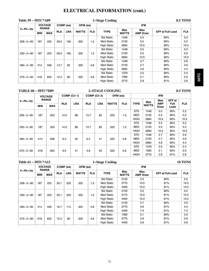
71
ELECTRICAL INFORMATION (cont.)
Table 59 – 50TC*A09 1--Stage Cooling 8.5 TONS
V---Ph---HzVOLTAGERANGE
COMP (ea) OFM (ea) IFM
RLA LRA WATTS FLA TYPE MaxWATTS
MaxAMP Draw EFF at Full Load FLAMIN MAX
208---3---60 187 253 29.5 195 325 1.5Std Static 1448 5.5 80% 5.2Med Static 2120 5.5 80% 5.2High Static 2694 10.5 80% 10.0
230---3---60 187 253 29.5 195 325 1.5Std Static 1448 5.5 80% 5.2Med Static 2120 5.5 80% 5.2High Static 2694 10.5 80% 10.0
460---3---60 414 506 14.7 95 325 0.8Std Static 1448 2.7 80% 2.6Med Static 2120 2.7 80% 2.6High Static 2694 4.6 80% 4.4
575---3---60 518 633 12.2 80 325 0.6Std Static 1379 2.5 80% 2.4Med Static 1390 2.1 80% 2.0High Static 3775 2.9 81% 2.8
TABLE 60 – 50TC*D09 2--STAGE COOLING 8.5 TONS
V---Ph---Hz
VOLTAGERANGE
COMP (Cir 1) COMP (Cir 2) OFM (ea) IFM
RLA LRA RLA LRA WATTS FLA TYPE MaxWATTS
MaxAMPDraw
EFF atFullLoad
FLAMIN MAX
208---3---60 187 253 14.5 98 13.7 83 325 1.5STD 1448 5.5 80% 5.2MED 2120 5.5 80% 5.2HIGH 2694 10.5 80% 10.0
230---3---60 187 253 14.5 98 13.7 83 325 1.5STD 1448 5.5 80% 5.2MED 2120 5.5 80% 5.2HIGH 2694 10.5 80% 10.0
460---3---60 414 506 6.3 55 6.2 41 325 0.8STD 1448 2.7 80% 2.6MED 2120 2.7 80% 2.6HIGH 2694 4.6 80% 4.4
575---3---60 518 633 6.0 41 4.8 33 325 0.6STD 1379 2.5 80% 2.4MED 1390 2.1 80% 2.0HIGH 3775 2.9 81% 2.8
Table 61 – 50TC*A12 1--Stage Cooling 10 TONS
V---Ph---HzVOLTAGERANGE
COMP (ea) OFM (ea) IFM
RLA LRA WATTS FLA TYPE MaxWATTS
MaxAMP Draw EFF at Full Load FLAMIN MAX
208---3---60 187 253 30.1 225 325 1.5Std Static 2120 5.5 80% 5.2Med Static 3775 10.5 81% 10.0High Static 4400 15.0 81% 15.0
230---3---60 187 253 30.1 225 325 1.5Std Static 2120 5.5 80% 5.2Med Static 3775 10.5 81% 10.0High Static 4400 15.0 81% 15.0
460---3---60 414 506 16.7 114 325 0.8Std Static 2120 2.7 80% 2.6Med Static 3775 4.6 81% 4.4High Static 4400 7.4 81% 7.4
575---3---60 518 633 12.2 80 325 0.6Std Static 1390 2.1 80% 2.0Med Static 3775 2.9 81% 2.8High Static 4400 5.9 81% 5.6
50TC

72
ELECTRICAL INFORMATION (cont.)
Table 62 – 50TC*D12 2--Stage Cooling 10 TONS
V---Ph---Hz
VOLTAGERANGE
COMP (Cir 1) COMP (Cir 2) OFM (ea) IFM
RLA LRA RLA LRA WATTS FLA TYPE MaxWATTS
MaxAMPDraw
EFF atFullLoad
FLAMIN MAX
208---3---60 187 253 15.6 110 15.9 110 325 1.5STD 2120 5.5 80% 5.2MED 3775 10.5 81% 10.0HIGH 4400 15.0 81% 15.0
230---3---60 187 253 15.6 110 15.9 110 325 1.5STD 2120 5.5 80% 5.2MED 3775 10.5 81% 10.0HIGH 4400 15.0 81% 15.0
460---3---60 414 506 7.7 52 7.7 52 325 0.8STD 2120 2.7 80% 2.6MED 3775 4.6 81% 4.4HIGH 4400 7.4 81% 7.4
575---3---60 518 633 5.8 39 5.7 39 325 0.6STD 1390 2.1 80% 2.0MED 3775 2.9 81% 2.8HIGH 4400 5.9 81% 5.6
Table 63 – 50TC*D14 2--Stage Cooling 12.5 TONS
V---Ph---Hz
VOLTAGERANGE
COMP (Cir 1) COMP (Cir 2) OFM (ea) IFM
RLA LRA RLA LRA WATTS FLA TYPE MaxWATTS
MaxAMPDraw
EFF atFullLoad
FLAMIN MAX
208---3---60 187 253 19.0 123 22.4 149 1288 6.2STD 2615 7.9 81% 7.5MED 3775 10.5 81% 10.0HIGH* 4400 15.0 81% 15.0
230---3---60 187 253 19.0 123 22.4 149 1288 6.2STD 2615 7.9 81% 7.5MED 3775 10.5 81% 10.0HIGH* 4400 15.0 81% 15.0
460---3---60 414 506 9.7 62 10.6 75 1288 3.1STD 2615 3.6 81% 3.4MED 3775 4.6 81% 4.4HIGH 4400 7.4 81% 7.4
575---3---60 518 633 7.4 50 7.7 54 1288 2.5STD 3775 2.9 81% 2.8MED 3775 2.9 81% 2.8HIGH 4400 5.9 81% 5.6
* Single Point Kit required.
50TC

73
Table 64 – MCA/MOCP DETERMINATION NO C.O. OR UNPWRD C.O.
UNIT
NOM.V---PH---HZ
IFMTYPE
ELECTRIC HEATER NO C.O. or UNPWR C.O.
Nom*(kW) FLA
NO P.E. w/ P.E. (pwrd fr/unit)
MCA MOCPDISC. SIZE
MCA MOCPDISC. SIZE
FLA LRA FLA LRA
50TC*A04
208/230---1---60
STD
None None 27.2 40 26 95 29.1 45 29 973.3/4.4 15.9/18.3 27.2/29.0 40/40 26/27 95/95 29.1/31.4 45/45 29/29 97/974.9/6.5 23.5/27.1 35.5/40.0 40/45 33/37 95/95 37.9/42.4 45/45 35/39 97/976.5/8.7 31.4/36.3 45.4/51.5 50/60 42/47 95/95 47.8/53.9 50/60 44/50 97/977.9/10.5 37.9/43.8 53.5/60.9 60/70 49/56 95/95 55.9/63.3 60/70 51/58 97/979.8/13.0 46.9/54.2 64.8/73.9 70/80 60/68 95/95 67.1/76.3 70/80 62/70 97/97
MED
None None 27.2 40 26 95 29.1 45 29 973.3/4.4 15.9/18.3 27.2/29.0 40/40 26/27 95/95 29.1/31.4 45/45 29/29 97/974.9/6.5 23.5/27.1 35.5/40.0 40/45 33/37 95/95 37.9/42.4 45/45 35/39 97/976.5/8.7 31.4/36.3 45.4/51.5 50/60 42/47 95/95 47.8/53.9 50/60 44/50 97/977.9/10.5 37.9/43.8 53.5/60.9 60/70 49/56 95/95 55.9/63.3 60/70 51/58 97/979.8/13.0 46.9/54.2 64.8/73.9 70/80 60/68 95/95 67.1/76.3 70/80 62/70 97/97
208/230---3---60
STD
None None 19.4 25 19 89 21.3 30 22 913.3/4.4 9.2/10.6 19.4/19.4 25/25 19/19 89/89 21.3/21.8 30/30 22/22 91/914.9/6.5 13.6/15.6 23.1/25.6 25/30 21/24 89/89 25.5/28.0 30/30 23/26 91/916.5/8.7 18.1/20.9 28.8/32.3 30/35 26/30 89/89 31.1/34.6 35/35 29/32 91/917.9/10.5 21.9/25.3 33.5/37.8 35/40 31/35 89/89 35.9/40.1 40/45 33/37 91/9112.0/16.0 33.4/38.5 47.9/54.3 50/60 44/50 89/89 50.3/56.6 60/60 46/52 91/91
MED
None None 19.4 25 19 89 21.3 30 22 913.3/4.4 9.2/10.6 19.4/19.4 25/25 19/19 89/89 21.3/21.8 30/30 22/22 91/914.9/6.5 13.6/15.6 23.1/25.6 25/30 21/24 89/89 25.5/28.0 30/30 23/26 91/916.5/8.7 18.1/20.9 28.8/32.3 30/35 26/30 89/89 31.1/34.6 35/35 29/32 91/917.9/10.5 21.9/25.3 33.5/37.8 35/40 31/35 89/89 35.9/40.1 40/45 33/37 91/9112.0/16.0 33.4/38.5 47.9/54.3 50/60 44/50 89/89 50.3/56.6 60/60 46/52 91/91
HIGH
None None 19.7 30 20 107 21.6 30 22 1093.3/4.4 9.2/10.6 19.7/19.8 30/30 20/20 107/107 21.6/22.1 30/30 22/22 109/1094.9/6.5 13.6/15.6 23.5/26.0 30/30 22/24 107/107 25.9/28.4 30/30 24/26 109/1096.5/8.7 18.1/20.9 29.1/32.6 30/35 27/30 107/107 31.5/35.0 35/40 29/32 109/1097.9/10.5 21.9/25.3 33.9/38.1 35/40 31/35 107/107 36.3/40.5 40/45 33/37 109/10912.0/16.0 33.4/38.5 48.3/54.6 50/60 44/50 107/107 50.6/57.0 60/60 47/52 109/109
460---3---60
STD
None None 10.2 15 10 46 11.2 15 11 476.0 7.2 11.6 15 11 46 12.9 15 12 478.8 10.6 15.9 20 15 46 17.1 20 16 4711.5 13.8 19.9 20 18 46 21.1 25 19 4714.0 16.8 23.6 25 22 46 24.9 25 23 47
MED
None None 10.2 15 10 46 11.2 15 11 476.0 7.2 11.6 15 11 46 12.9 15 12 478.8 10.6 15.9 20 15 46 17.1 20 16 4711.5 13.8 19.9 20 18 46 21.1 25 19 4714.0 16.8 23.6 25 22 46 24.9 25 23 47
HIGH
None None 10.7 15 11 55 11.7 15 12 566.0 7.2 12.3 15 11 55 13.5 15 12 568.8 10.6 16.5 20 15 55 17.8 20 16 5611.5 13.8 20.5 25 19 55 21.8 25 20 5614.0 16.8 24.3 25 22 55 25.5 30 23 56
575---3---60 STD None None 7.3 15 7 44 9.2 15 9 46
MED None None 7.3 15 7 44 9.2 15 9 46
HIGH None None 7.4 15 7 50 9.3 15 10 52
* Nominal values, listed as 208/240V, 480V or 600V as appropriate.See Legend and calculations on page 87.
50TC

74
Table 64 –(cont.) MCA/MOCP DETERMINATION NO C.O. OR UNPWRD C.O.
UNIT
NOM.V---PH---HZ
IFMTYPE
ELECTRIC HEATER NO C.O. or UNPWR C.O.
Nom*(kW) FLA
NO P.E. w/ P.E. (pwrd fr/unit)
MCA MOCPDISC. SIZE
MCA MOCPDISC. SIZE
FLA LRA FLA LRA
50TC*A05
208/230---1---60
STD
None None 33.7 50 32 133 35.6 50 35 1353.3/4.4 15.9/18.3 33.7/33.7 50/50 32/32 133/133 35.6/35.6 50/50 35/35 135/1356.5/8.7 31.4/36.3 45.4/51.5 50/60 42/47 133/133 47.8/53.9 50/60 44/50 135/1359.8/13.0 46.9/54.2 64.8/73.9 70/80 60/68 133/133 67.1/76.3 70/80 62/70 135/13513.1/17.4 62.8/72.5 84.6/96.8 90/100 78/89 133/133 87.0/99.1 90/100 80/91 135/13515.8/21.0 75.8/87.5 100.9/115.5 110/125 93/106 133/133 103.3/117.9 110/125 95/108 135/135
MED
None None 33.7 50 32 133 35.6 50 35 1353.3/4.4 15.9/18.3 33.7/33.7 50/50 32/32 133/133 35.6/35.6 50/50 35/35 135/1356.5/8.7 31.4/36.3 45.4/51.5 50/60 42/47 133/133 47.8/53.9 50/60 44/50 135/1359.8/13.0 46.9/54.2 64.8/73.9 70/80 60/68 133/133 67.1/76.3 70/80 62/70 135/13513.1/17.4 62.8/72.5 84.6/96.8 90/100 78/89 133/133 87.0/99.1 90/100 80/91 135/13515.8/21.0 75.8/87.5 100.9/115.5 110/125 93/106 133/133 103.3/117.9 110/125 95/108 135/135
208/230---3---60
STD
None None 23.5 30 23 99 25.4 30 25 1014.9/6.5 13.6/15.6 23.5/25.6 30/30 23/24 99/99 25.5/28.0 30/30 25/26 101/1016.5/8.7 18.1/20.9 28.8/32.3 30/35 26/30 99/99 31.1/34.6 35/35 29/32 101/10112.0/16.0 33.4/38.5 47.9/54.3 50/60 44/50 99/99 50.3/56.6 60/60 46/52 101/10115.8/21.0 43.8/50.5 60.9/69.3 70/70 56/64 99/99 63.3/71.6 70/80 58/66 101/101
MED
None None 23.5 30 23 99 25.4 30 25 1014.9/6.5 13.6/15.6 23.5/25.6 30/30 23/24 99/99 25.5/28.0 30/30 25/26 101/1016.5/8.7 18.1/20.9 28.8/32.3 30/35 26/30 99/99 31.1/34.6 35/35 29/32 101/10112.0/16.0 33.4/38.5 47.9/54.3 50/60 44/50 99/99 50.3/56.6 60/60 46/52 101/10115.8/21.0 43.8/50.5 60.9/69.3 70/70 56/64 99/99 63.3/71.6 70/80 58/66 101/101
HIGH
None None 23.8 30 23 117 25.7 30 26 1194.9/6.5 13.6/15.6 23.8/26.0 30/30 23/24 117/117 25.9/28.4 30/30 26/26 119/1196.5/8.7 18.1/20.9 29.1/32.6 30/35 27/30 117/117 31.5/35.0 35/40 29/32 119/11912.0/16.0 33.4/38.5 48.3/54.6 50/60 44/50 117/117 50.6/57.0 60/60 47/52 119/11915.8/21.0 43.8/50.5 61.3/69.6 70/70 56/64 117/117 63.6/72.0 70/80 59/66 119/119
460---3---60
STD
None None 10.7 15 10 49 11.7 15 12 506.0 7.2 11.6 15 11 49 12.9 15 12 5011.5 13.8 19.9 20 18 49 21.1 25 19 5014.0 16.8 23.6 25 22 49 24.9 25 23 5023.0 27.7 37.3 40 34 49 38.5 40 35 50
MED
None None 10.7 15 10 49 11.7 15 12 506.0 7.2 11.6 15 11 49 12.9 15 12 5011.5 13.8 19.9 20 18 49 21.1 25 19 5014.0 16.8 23.6 25 22 49 24.9 25 23 5023.0 27.7 37.3 40 34 49 38.5 40 35 50
HIGH
None None 11.2 15 11 58 12.2 15 12 596.0 7.2 12.3 15 11 58 13.5 15 12 5911.5 13.8 20.5 25 19 58 21.8 25 20 5914.0 16.8 24.3 25 22 58 25.5 30 23 5923.0 27.7 37.9 40 35 58 39.1 40 36 59
575---3---60 STD None None 8.5 15 8 44 10.4 15 11 46
MED None None 8.5 15 8 44 10.4 15 11 46
HIGH None None 8.6 15 9 50 10.5 15 11 52
* Nominal values, listed as 208/240V, 480V or 600V as appropriate.See Legend and calculations on page 87.
50TC

75
Table 64 – (cont.) MCA/MOCP DETERMINATION NO C.O. OR UNPWRD C.O.
UNIT
NOM.V---PH---HZ
IFMTYPE
ELECTRIC HEATER NO C.O. or UNPWR C.O.
Nom*(kW) FLA
NO P.E. w/ P.E. (pwrd fr/unit)
MCA MOCPDISC. SIZE
MCA MOCPDISC. SIZE
FLA LRA FLA LRA
50TC*A06
208/230---1---60
STD
None None 39.2 60 37 150 41.1 60 40 1524.9/6.5 23.5/27.1 39.2/40.0 60/60 37/37 150/150 41.1/42.4 60/60 40/40 152/1526.5/8.7 31.4/36.3 45.4/51.5 60/60 42/47 150/150 47.8/53.9 60/60 44/50 152/1529.8/13.0 46.9/54.2 64.8/73.9 70/80 60/68 150/150 67.1/76.3 70/80 62/70 152/15213.1/17.4 62.8/72.5 84.6/96.8 90/100 78/89 150/150 87.0/99.1 90/100 80/91 152/15215.8/21.0 75.8/87.5 100.9/115.5 110/125 93/106 150/150 103.3/117.9 110/125 95/108 152/152
MED
None None 41.3 60 40 175 43.2 60 42 1774.9/6.5 23.5/27.1 41.3/42.6 60/60 40/40 175/175 43.2/45.0 60/60 42/42 177/1776.5/8.7 31.4/36.3 48.0/54.1 60/60 44/50 175/175 50.4/56.5 60/60 46/52 177/1779.8/13.0 46.9/54.2 67.4/76.5 70/80 62/70 175/175 69.8/78.9 70/80 64/73 177/17713.1/17.4 62.8/72.5 87.3/99.4 90/100 80/91 175/175 89.6/101.8 90/110 82/94 177/17715.8/21.0 75.8/87.5 103.5/118.1 110/125 95/109 175/175 105.9/120.5 110/125 97/111 177/177
208/230---3---60
STD
None None 25.9 30 25 126 27.8 40 27 1284.9/6.5 13.6/15.6 25.9/25.9 30/30 25/25 126/126 27.8/28.0 40/40 27/27 128/1287.9/10.5 21.9/25.3 33.5/37.8 40/40 31/35 126/126 35.9/40.1 40/45 33/37 128/12812.0/16.0 33.4/38.5 47.9/54.3 50/60 44/50 126/126 50.3/56.6 60/60 46/52 128/12815.8/21.0 43.8/50.5 60.9/69.3 70/70 56/64 126/126 63.3/71.6 70/80 58/66 128/12819.9/26.5 55.2/63.8 75.1/85.9 80/90 69/79 126/126 77.5/88.3 80/90 71/81 128/128
MED
None None 26.2 40 26 144 28.1 40 28 1464.9/6.5 13.6/15.6 26.2/26.2 40/40 26/26 144/144 28.1/28.4 40/40 28/28 146/1467.9/10.5 21.9/25.3 33.9/38.1 40/40 31/35 144/144 36.3/40.5 40/45 33/37 146/14612.0/16.0 33.4/38.5 48.3/54.6 50/60 44/50 144/144 50.6/57.0 60/60 47/52 146/14615.8/21.0 43.8/50.5 61.3/69.6 70/70 56/64 144/144 63.6/72.0 70/80 59/66 146/14619.9/26.5 55.2/63.8 75.5/86.3 80/90 69/79 144/144 77.9/88.6 80/90 72/82 146/146
HIGH
None None 28.5 40 28 170 30.4 45 30 1724.9/6.5 13.6/15.6 28.5/28.9 40/40 28/28 170/170 30.4/31.3 45/45 30/30 172/1727.9/10.5 21.9/25.3 36.8/41.0 40/45 34/38 170/170 39.1/43.4 45/45 36/40 172/17212.0/16.0 33.4/38.5 51.1/57.5 60/60 47/53 170/170 53.5/59.9 60/60 49/55 172/17215.8/21.0 43.8/50.5 64.1/72.5 70/80 59/67 170/170 66.5/74.9 70/80 61/69 172/17219.9/26.5 55.2/63.8 78.4/89.1 80/90 72/82 170/170 80.8/91.5 90/100 74/84 172/172
460---3---60
STD
None None 12.5 20 12 60 13.5 20 13 616.0 7.2 12.5 20 12 60 13.5 20 13 6111.5 13.8 19.9 20 18 60 21.1 25 19 6114.0 16.8 23.6 25 22 60 24.9 25 23 6123.0 27.7 37.3 40 34 60 38.5 40 35 6125.5 30.7 41.0 45 38 60 42.3 45 39 61
MED
None None 13 20 13 69 14 20 14 706.0 7.2 13.0 20 13 69 14.0 20 14 7011.5 13.8 20.5 25 19 69 21.8 25 20 7014.0 16.8 24.3 25 22 69 25.5 30 23 7023.0 27.7 37.9 40 35 69 39.1 40 36 7025.5 30.7 41.6 45 38 69 42.9 45 39 70
HIGH
None None 13.8 20 14 82 14.8 20 15 836.0 7.2 13.8 20 14 82 14.8 20 15 8311.5 13.8 21.5 25 20 82 22.8 25 21 8314.0 16.8 25.3 30 23 82 26.5 30 24 8323.0 27.7 38.9 40 36 82 40.1 45 37 8325.5 30.7 42.6 45 39 82 43.9 45 40 83
575---3---60 STD None None 9.8 15 10 46 11.7 15 12 48
MED None None 9.9 15 10 52 11.8 15 12 54
HIGH None None 10.7 15 11 63 12.6 15 13 65
* Nominal values, listed as 208/240V, 480V or 600V as appropriate.See Legend and calculations on page 87.
50TC

76
Table 64 –(cont.) MCA/MOCP DETERMINATION NO C.O. OR UNPWRD C.O.
UNIT
NOM.V---PH---HZ
IFMTYPE
ELECTRIC HEATER NO C.O. or UNPWR C.O.
Nom*(kW) FLA
NO P.E. w/ P.E. (pwrd fr/unit)
MCA MOCPDISC. SIZE
MCA MOCPDISC. SIZE
FLA LRA FLA LRA
50TC*A07
208/230---3---60
STD
None None 30.5 45 30 157 32.4 50 32 1594.9/6.5 13.6/15.6 30.5/30.5 45/45 30/30 157/157 32.4/32.4 50/50 32/32 159/1597.9/10.5 21.9/25.3 33.9/38.1 45/45 31/35 157/157 36.3/40.5 50/50 33/37 159/15912.0/16.0 33.4/38.5 48.3/54.6 50/60 44/50 157/157 50.6/57.0 60/60 47/52 159/15915.8/21.0 43.8/50.5 61.3/69.6 70/70 56/64 157/157 63.6/72.0 70/80 59/66 159/15919.9/26.5 55.2/63.8 75.5/86.3 80/90 69/79 157/157 77.9/88.6 80/90 72/82 159/159
MED
None None 32.8 50 32 183 34.7 50 34 1854.9/6.5 13.6/15.6 32.8/32.8 50/50 32/32 183/183 34.7/34.7 50/50 34/34 185/1857.9/10.5 21.9/25.3 36.8/41.0 50/50 34/38 183/183 39.1/43.4 50/50 36/40 185/18512.0/16.0 33.4/38.5 51.1/57.5 60/60 47/53 183/183 53.5/59.9 60/60 49/55 185/18515.8/21.0 43.8/50.5 64.1/72.5 70/80 59/67 183/183 66.5/74.9 70/80 61/69 185/18519.9/26.5 55.2/63.8 78.4/89.1 80/90 72/82 183/183 80.8/91.5 90/100 74/84 185/185
HIGH
None None 32.8 50 32 183 34.7 50 34 1854.9/6.5 13.6/15.6 32.8/32.8 50/50 32/32 183/183 34.7/34.7 50/50 34/34 185/1857.9/10.5 21.9/25.3 36.8/41.0 50/50 34/38 183/183 39.1/43.4 50/50 36/40 185/18512.0/16.0 33.4/38.5 51.1/57.5 60/60 47/53 183/183 53.5/59.9 60/60 49/55 185/18515.8/21.0 43.8/50.5 64.1/72.5 70/80 59/67 183/183 66.5/74.9 70/80 61/69 185/18519.9/26.5 55.2/63.8 78.4/89.1 80/90 72/82 183/183 80.8/91.5 90/100 74/84 185/185
460---3---60
STD
None None 15.5 25 15 79 16.5 25 16 806.0 7.2 15.5 25 15 79 16.5 25 16 8011.5 13.8 20.5 25 19 79 21.8 25 20 8014.0 16.8 24.3 25 22 79 25.5 30 23 8023.0 27.7 37.9 40 35 79 39.1 40 36 8025.5 30.7 41.6 45 38 79 42.9 45 39 80
MED
None None 16.3 25 16 92 17.3 25 17 936.0 7.2 16.3 25 16 92 17.3 25 17 9311.5 13.8 21.5 25 20 92 22.8 25 21 9314.0 16.8 25.3 30 23 92 26.5 30 24 9323.0 27.7 38.9 40 36 92 40.1 45 37 9325.5 30.7 42.6 45 39 92 43.9 45 40 93
HIGH
None None 17.3 25 17 101 18.3 25 18 1026.0 7.2 17.3 25 17 101 18.3 25 18 10211.5 13.8 22.8 25 21 101 24.0 25 22 10214.0 16.8 26.5 30 24 101 27.8 30 26 10223.0 27.7 40.1 45 37 101 41.4 45 38 10225.5 30.7 43.9 45 40 101 45.1 50 42 102
575---3---60 STD None None 11.9 15 12 63 13.8 20 14 65
MED None None 12.7 20 12 74 14.6 20 15 76
HIGH None None 12.7 20 12 74 14.6 20 15 76
* Nominal values, listed as 208/240V, 480V or 600V as appropriate.See Legend and calculations on page 87.
50TC

77
Table 64 –(cont.) MCA/MOCP DETERMINATION NO C.O. OR UNPWRD C.O.
UNIT
NOM.V---PH---HZ
IFMTYPE
ELECTRIC HEATER NO C.O. or UNPWR C.O.
Nom*(kW) FLA
NO P.E. w/ P.E. (pwrd fr/unit)
MCA MOCPDISC. SIZE
MCA MOCPDISC. SIZE
FLA LRA FLA LRA
50TC*A08
208/230---3---60
STD
None None 39.5 60 38 191 43.3 60 43 1957.8/10.4 21.7/25.0 39.5/39.5 60/60 38/38 191/191 43.3/43.3 60/60 43/43 195/19512.0/16.0 33.4/38.5 48.3/54.6 60/60 44/50 191/191 53.0/59.4 60/60 49/55 195/19518.6/24.8 51.7/59.7 71.1/81.1 80/90 65/75 191/191 75.9/85.9 80/90 70/79 195/19524.0/32.0 66.7/77.0 89.9/102.8 90/110 83/95 191/191 94.6/107.5 100/110 87/99 195/19531.8/42.4 88.4/102.0 117.0/134.0 125/150 108/123 191/191 121.8/138.8 125/150 112/128 195/195
MED
None None 41.8 60 41 228 45.6 60 45 2327.8/10.4 21.7/25.0 41.8/41.8 60/60 41/41 228/228 45.6/45.6 60/60 45/45 232/23212.0/16.0 33.4/38.5 51.1/57.5 60/60 47/53 228/228 55.9/62.3 60/70 51/57 232/23218.6/24.8 51.7/59.7 74.0/84.0 80/90 68/77 228/228 78.8/88.8 80/90 72/82 232/23224.0/32.0 66.7/77.0 92.8/105.6 100/110 85/97 228/228 97.5/110.4 100/125 90/102 232/23231.8/42.4 88.4/102.0 119.9/136.9 125/150 110/126 228/228 124.6/141.6 125/150 115/130 232/232
HIGH
None None 49.3 60 49 254 53.1 60 54 2587.8/10.4 21.7/25.0 49.3/50.0 60/60 49/49 254/254 53.1/54.8 60/60 54/54 258/25812.0/16.0 33.4/38.5 60.5/66.9 70/70 56/62 254/254 65.3/71.6 70/80 60/66 258/25818.6/24.8 51.7/59.7 83.4/93.4 90/100 77/86 254/254 88.1/98.1 90/100 81/90 258/25824.0/32.0 66.7/77.0 102.1/115.0 110/125 94/106 254/254 106.9/119.8 110/125 98/110 258/25831.8/42.4 88.4/102.0 129.3/146.3 150/150 119/135 254/254 134.0/151.0 150/175 123/139 258/258
460---3---60
STD
None None 19.5 30 19 113 21.3 30 21 11513.9 16.7 24.1 30 22 113 26.4 30 24 11516.5 19.8 28.0 30 26 113 30.3 35 28 11527.8 33.4 45.0 50 41 113 47.3 50 43 11533.0 39.7 52.9 60 49 113 55.1 60 51 11541.7 50.2 66.0 70 61 113 68.3 70 63 115
MED
None None 20.3 30 20 132 22.1 30 22 13413.9 16.7 25.1 30 23 132 27.4 30 25 13416.5 19.8 29.0 30 27 132 31.3 35 29 13427.8 33.4 46.0 50 42 132 48.3 50 44 13433.0 39.7 53.9 60 50 132 56.1 60 52 13441.7 50.2 67.0 70 62 132 69.3 70 64 134
HIGH
None None 24.3 30 24 145 26.1 30 26 14713.9 16.7 30.1 35 28 145 32.4 35 30 14716.5 19.8 34.0 35 31 145 36.3 40 33 14727.8 33.4 51.0 60 47 145 53.3 60 49 14733.0 39.7 58.9 60 54 145 61.1 70 56 14741.7 50.2 72.0 80 66 145 74.3 80 68 147
575---3---60
STDNone None 14.9 20 14 89 18.7 25 19 9317.0 20.4 28.5 30 26 89 33.3 35 31 9334.0 40.9 54.1 60 50 89 58.9 60 54 93
MEDNone None 15.3 20 15 104 19.1 25 19 10817.0 20.4 29.0 30 27 104 33.8 35 31 10834.0 40.9 54.6 60 50 104 59.4 60 55 108
HIGHNone None 18.1 25 18 118 21.9 30 23 12217.0 20.4 32.5 35 30 118 37.3 40 34 12234.0 40.9 58.1 60 53 118 62.9 70 58 122
* Nominal values, listed as 208/240V, 480V or 600V as appropriate.See Legend and calculations on page 87.
50TC

78
Table 64 –(cont.) MCA/MOCP DETERMINATION NO C.O. OR UNPWRD C.O.
UNIT
NOM.V---PH---HZ
IFMTYPE
ELECTRIC HEATER NO C.O. or UNPWR C.O.
Nom*(kW) FLA
NO P.E. w/ P.E. (pwrd fr/unit)
MCA MOCPDISC. SIZE
MCA MOCPDISC. SIZE
FLA LRA FLA LRA
50TC*D08
208/230---3---60
STD
--- --- 38.8 50 41 193 42.6 50 45 1977.8/10.4 21.7/25.0 38.8/38.8 50/50 41/41 193/193 42.6/42.6 50/50 45/45 197/19712.0/16.0 33.4/38.5 48.3/54.6 50/60 44/50 193/193 53.0/59.4 60/60 49/55 197/19718.6/24.8 51.7/59.7 71.1/81.1 80/90 65/75 193/193 75.9/85.9 80/90 70/79 197/19724.0/32.0 66.7/77.0 89.9/102.8 90/110 83/95 193/193 94.6/107.5 100/110 87/99 197/19731.8/42.4 88.4/102.0 117.0/134.0 125/150 108/123 193/193 121.8/138.8 125/150 112/128 197/197
MED
--- --- 41.1 50 43 230 44.9 50 48 2347.8/10.4 21.7/25.0 41.1/41.1 50/50 43/43 230/230 44.9/45.4 50/50 48/48 234/23412.0/16.0 33.4/38.5 51.1/57.5 60/60 47/53 230/230 55.9/62.3 60/70 51/57 234/23418.6/24.8 51.7/59.7 74.0/84.0 80/90 68/77 230/230 78.8/88.8 80/90 72/82 234/23424.0/32.0 66.7/77.0 92.8/105.6 100/110 85/97 230/230 97.5/110.4 100/125 90/102 234/23431.8/42.4 88.4/102.0 119.9/136.9 125/150 110/126 230/230 124.6/141.6 125/150 115/130 234/234
HIGH
--- --- 49.0 60 52 256 52.8 60 56 2607.8/10.4 21.7/25.0 49.0/50.0 60/60 52/52 256/256 52.8/54.8 60/60 56/56 260/26012.0/16.0 33.4/38.5 60.5/66.9 70/70 56/62 256/256 65.3/71.6 70/80 60/66 260/26018.6/24.8 51.7/59.7 83.4/93.4 90/100 77/86 256/256 88.1/98.1 90/100 81/90 260/26024.0/32.0 66.7/77.0 102.1/115.0 110/125 94/106 256/256 106.9/119.8 110/125 98/110 260/26031.8/42.4 88.4/102.0 129.3/146.3 150/150 119/135 256/256 134.0/151.0 150/175 123/139 260/260
460---3---60
STD
--- --- 17.9 20 19 95 19.7 25 21 9713.9 16.7 24.1 25 22 95 26.4 30 24 9716.5 19.8 28.0 30 26 95 30.3 35 28 9727.8 33.4 45.0 50 41 95 47.3 50 43 9733.0 39.7 52.9 60 49 95 55.1 60 51 9741.7 50.2 66.0 70 61 95 68.3 70 63 97
MED
--- --- 18.7 25 20 114 20.5 25 22 11613.9 16.7 25.1 30 23 114 27.4 30 25 11616.5 19.8 29.0 30 27 114 31.3 35 29 11627.8 33.4 46.0 50 42 114 48.3 50 44 11633.0 39.7 53.9 60 50 114 56.1 60 52 11641.7 50.2 67.0 70 62 114 69.3 70 64 116
HIGH
--- --- 23.1 30 24 127 24.9 30 26 12913.9 16.7 30.1 35 28 127 32.4 35 30 12916.5 19.8 34.0 35 31 127 36.3 40 33 12927.8 33.4 51.0 60 47 127 53.3 60 49 12933.0 39.7 58.9 60 54 127 61.1 70 56 12941.7 50.2 72.0 80 66 127 74.3 80 68 129
575---3---60
STD--- --- 13.1 15 14 77 16.9 20 18 8117.0 20.4 28.5 30 26 77 33.3 35 31 8134.0 40.9 54.1 60 50 77 58.9 60 54 81
MED--- --- 13.5 15 14 92 17.3 20 19 9617.0 20.4 29.0 30 27 92 33.8 35 31 9634.0 40.9 54.6 60 50 92 59.4 60 55 96
HIGH--- --- 16.6 20 17 106 20.4 25 22 11017.0 20.4 32.5 35 30 106 37.3 40 34 11034.0 40.9 58.1 60 53 106 62.9 70 58 110
* Nominal values, listed as 208/240V, 480V or 600V as appropriate.See Legend and calculations on page 87.
50TC

79
Table 64 –(cont.) MCA/MOCP DETERMINATION NO C.O. OR UNPWRD C.O.
UNIT
NOM.V---PH---HZ
IFMTYPE
ELECTRIC HEATER NO C.O. or UNPWR C.O.
Nom*(kW) FLA
NO P.E. w/ P.E. (pwrd fr/unit)
MCA MOCPDISC. SIZE
MCA MOCPDISC. SIZE
FLA LRA FLA LRA
50TC*A09
208/230---3---60
STD
None None 45.1 60 43 222 48.9 60 48 2267.8/10.4 21.7/25.0 45.1/45.1 60/60 43/43 222/222 48.9/48.9 60/60 48/48 226/22612.0/16.0 33.4/38.5 48.3/54.6 60/60 44/50 222/222 53.0/59.4 60/60 49/55 226/22618.6/24.8 51.7/59.7 71.1/81.1 80/90 65/75 222/222 75.9/85.9 80/90 70/79 226/22624.0/32.0 66.7/77.0 89.9/102.8 90/110 83/95 222/222 94.6/107.5 100/110 87/99 226/22631.8/42.4 88.4/102.0 117.0/134.0 125/150 108/123 222/222 121.8/138.8 125/150 112/128 226/226
MED
None None 45.1 60 43 233 48.9 60 48 2377.8/10.4 21.7/25.0 45.1/45.1 60/60 43/43 233/233 48.9/48.9 60/60 48/48 237/23712.0/16.0 33.4/38.5 48.3/54.6 60/60 44/50 233/233 53.0/59.4 60/60 49/55 237/23718.6/24.8 51.7/59.7 71.1/81.1 80/90 65/75 233/233 75.9/85.9 80/90 70/79 237/23724.0/32.0 66.7/77.0 89.9/102.8 90/110 83/95 233/233 94.6/107.5 100/110 87/99 237/23731.8/42.4 88.4/102.0 117.0/134.0 125/150 108/123 233/233 121.8/138.8 125/150 112/128 237/237
HIGH
None None 49.9 60 49 276 53.7 80 53 2807.8/10.4 21.7/25.0 49.9/49.9 60/60 49/49 276/276 53.7/53.7 80/80 53/53 280/28012.0/16.0 33.4/38.5 54.3/60.6 60/70 50/56 276/276 59.0/65.4 80/80 54/60 280/28018.6/24.8 51.7/59.7 77.1/87.1 80/90 71/80 276/276 81.9/91.9 90/100 75/85 280/28024.0/32.0 66.7/77.0 95.9/108.8 100/110 88/100 276/276 100.6/113.5 110/125 93/104 280/28031.8/42.4 88.4/102.0 123.0/140.0 125/150 113/129 276/276 127.8/144.8 150/150 118/133 280/280
460---3---60
STD
None None 22.6 30 22 108 24.4 30 24 11013.9 16.7 24.1 30 22 108 26.4 30 24 11016.5 19.8 28.0 30 26 108 30.3 35 28 11027.8 33.4 45.0 50 41 108 47.3 50 43 11033.0 39.7 52.9 60 49 108 55.1 60 51 11041.7 50.2 66.0 70 61 108 68.3 70 63 110
MED
None None 22.6 30 22 114 24.4 30 24 11613.9 16.7 24.1 30 22 114 26.4 30 24 11616.5 19.8 28.0 30 26 114 30.3 35 28 11627.8 33.4 45.0 50 41 114 47.3 50 43 11633.0 39.7 52.9 60 49 114 55.1 60 51 11641.7 50.2 66.0 70 61 114 68.3 70 63 116
HIGH
None None 24.4 30 24 136 26.2 30 26 13813.9 16.7 26.4 30 24 136 28.6 30 26 13816.5 19.8 30.3 35 28 136 32.5 40 30 13827.8 33.4 47.3 50 43 136 49.5 50 46 13833.0 39.7 55.1 60 51 136 57.4 60 53 13841.7 50.2 68.3 70 63 136 70.5 80 65 138
575---3---60
STDNone None 18.9 30 18 91 22.7 30 23 9517.0 20.4 28.5 30 26 91 33.3 35 31 9534.0 40.9 54.1 60 50 91 58.9 60 54 95
MEDNone None 18.5 30 18 95 22.3 30 22 9917.0 20.4 28.0 30 26 95 32.8 35 30 9934.0 40.9 53.6 60 49 95 58.4 60 54 99
HIGHNone None 19.3 30 19 106 23.1 30 23 11017.0 20.4 29.0 30 27 106 33.8 35 31 11034.0 40.9 54.6 60 50 106 59.4 60 55 110
* Nominal values, listed as 208/240V, 480V or 600V as appropriate.See Legend and calculations on page 87.
50TC

80
Table 64 –(cont.) MCA/MOCP DETERMINATION NO C.O. OR UNPWRD C.O.
UNIT
NOM.V---PH---HZ
IFMTYPE
ELECTRIC HEATER NO C.O. or UNPWR C.O.
Nom (kW) FLA
NO P.E. w/ P.E. (pwrd fr/unit)
MCA MOCPDISC. SIZE
MCA MOCPDISC. SIZE
FLA LRA FLA LRA
50TC*D09
208/230---3---60
STD
--- --- 40.0 50 42 208 43.8 50 46 2127.8/10.4 21.7/25.0 40.0/40.0 50/50 42/42 208/208 43.8/43.8 50/50 46/46 212/21212.0/16.0 33.4/38.5 48.3/54.6 50/60 44/50 208/208 53.0/59.4 60/60 49/55 212/21218.6/24.8 51.7/59.7 71.1/81.1 80/90 65/75 208/208 75.9/85.9 80/90 70/79 212/21224.0/32.0 66.7/77.0 89.9/102.8 90/110 83/95 208/208 94.6/107.5 100/110 87/99 212/21231.8/42.4 88.4/102.0 117.0/134.0 125/150 108/123 208/208 121.8/138.8 125/150 112/128 212/212
MED
--- --- 40.0 50 42 219 43.8 50 46 2237.8/10.4 21.7/25.0 40.0/40.0 50/50 42/42 219/219 43.8/43.8 50/50 46/46 223/22312.0/16.0 33.4/38.5 48.3/54.6 50/60 44/50 219/219 53.0/59.4 60/60 49/55 223/22318.6/24.8 51.7/59.7 71.1/81.1 80/90 65/75 219/219 75.9/85.9 80/90 70/79 223/22324.0/32.0 66.7/77.0 89.9/102.8 90/110 83/95 219/219 94.6/107.5 100/110 87/99 223/22331.8/42.4 88.4/102.0 117.0/134.0 125/150 108/123 219/219 121.8/138.8 125/150 112/128 223/223
HIGH
--- --- 44.8 50 47 262 48.6 60 52 2667.8/10.4 21.7/25.0 44.8/44.8 50/50 47/47 262/262 48.6/48.6 60/60 52/52 266/26612.0/16.0 33.4/38.5 54.3/60.6 60/70 50/56 262/262 59.0/65.4 60/70 54/60 266/26618.6/24.8 51.7/59.7 77.1/87.1 80/90 71/80 262/262 81.9/91.9 90/100 75/85 266/26624.0/32.0 66.7/77.0 95.9/108.8 100/110 88/100 262/262 100.6/113.5 110/125 93/104 266/26631.8/42.4 88.4/102.0 123.0/140.0 125/150 113/129 262/262 127.8/144.8 150/150 118/133 266/266
460---3---60
STD
--- --- 18.3 20 19 109 20.1 25 21 11113.9 16.7 24.1 25 22 109 26.4 30 24 11116.5 19.8 28.0 30 26 109 30.3 35 28 11127.8 33.4 45.0 50 41 109 47.3 50 43 11133.0 39.7 52.9 60 49 109 55.1 60 51 11141.7 50.2 66.0 70 61 109 68.3 70 63 111
MED
--- --- 18.3 20 19 115 20.1 25 21 11713.9 16.7 24.1 25 22 115 26.4 30 24 11716.5 19.8 28.0 30 26 115 30.3 35 28 11727.8 33.4 45.0 50 41 115 47.3 50 43 11733.0 39.7 52.9 60 49 115 55.1 60 51 11741.7 50.2 66.0 70 61 115 68.3 70 63 117
HIGH
--- --- 20.1 25 21 137 21.9 25 23 13913.9 16.7 26.4 30 24 137 28.6 30 26 13916.5 19.8 30.3 35 28 137 32.5 35 30 13927.8 33.4 47.3 50 43 137 49.5 50 46 13933.0 39.7 55.1 60 51 137 57.4 60 53 13941.7 50.2 68.3 70 63 137 70.5 80 65 139
575---3---60
STD--- --- 15.9 20 17 85 19.7 25 21 8917.0 20.4 28.5 30 26 85 33.3 35 31 8934.0 40.9 54.1 60 50 85 58.9 60 54 89
MED--- --- 15.5 20 16 89 19.3 25 20 9317.0 20.4 28.0 30 26 89 32.8 35 30 9334.0 40.9 53.6 60 49 89 58.4 60 54 93
HIGH--- --- 16.3 20 17 100 20.1 25 21 10417.0 20.4 29.0 30 27 100 33.8 35 31 10434.0 40.9 54.6 60 50 100 59.4 60 55 104
* Nominal values, listed as 208/240V, 480V or 600V as appropriate.See Legend and calculations on page 87.
50TC

81
Table 64 –(cont.) MCA/MOCP DETERMINATION NO C.O. OR UNPWRD C.O.
UNIT
NOM.V---PH---HZ
IFMTYPE
ELECTRIC HEATER NO C.O. or UNPWR C.O.
Nom*(kW) FLA
NO P.E. w/ P.E. (pwrd fr/unit)
MCA MOCPDISC. SIZE
MCA MOCPDISC. SIZE
FLA LRA FLA LRA
50TC*A12
208/230---3---60
STD
None None 45.8 60 44 263 49.6 60 48 2677.8/10.4 21.7/25.0 45.8/45.8 60/60 44/44 263/263 49.6/49.6 60/60 48/48 267/26712.0/16.0 33.4/38.5 48.3/54.6 60/60 44/50 263/263 53.0/59.4 60/60 49/55 267/26724.0/32.0 66.7/77.0 89.9/102.8 90/110 83/95 263/263 94.6/107.5 100/110 87/99 267/26731.8/42.4 88.4/102.0 117.0/134.0 125/150 108/123 263/263 121.8/138.8 125/150 112/128 267/26737.6/50.0 104.2/120.3 136.8/126.8 150/150 126/144 263/263 141.5/131.6 150/150 130/149 267/267
MED
None None 50.6 60 50 306 54.4 80 54 3107.8/10.4 21.7/25.0 50.6/50.6 60/60 50/50 306/306 54.4/54.4 80/80 54/54 310/31012.0/16.0 33.4/38.5 54.3/60.6 60/80 50/56 306/306 59.0/65.4 80/80 54/60 310/31024.0/32.0 66.7/77.0 95.9/108.8 100/110 88/100 306/306 100.6/113.5 110/125 93/104 310/31031.8/42.4 88.4/102.0 123.0/140.0 125/150 113/129 306/306 127.8/144.8 150/150 118/133 310/31037.6/50.0 104.2/120.3 142.8/132.8 150/150 131/150 306/306 147.5/137.6 150/150 136/154 310/310
HIGH
None None 55.6 80 55 315 59.4 80 60 3197.8/10.4 21.7/25.0 55.6/55.6 80/80 55/55 315/315 59.4/59.4 80/80 60/60 319/31912.0/16.0 33.4/38.5 60.5/66.9 80/80 56/62 315/315 65.3/71.6 80/80 60/66 319/31924.0/32.0 66.7/77.0 102.1/115.0 110/125 94/106 315/315 106.9/119.8 110/125 98/110 319/31931.8/42.4 88.4/102.0 129.3/146.3 150/150 119/135 315/315 134.0/151.0 150/175 123/139 319/31937.6/50.0 104.2/120.3 149.0/139.1 150/175 137/156 315/315 153.8/143.8 175/175 141/160 319/319
460---3---60
STD
None None 25.1 30 24 133 26.9 40 26 13513.9 16.7 25.1 30 24 133 26.9 40 26 13516.5 19.8 28.0 30 26 133 30.3 40 28 13533.0 39.7 52.9 60 49 133 55.1 60 51 13541.7 50.2 66.0 70 61 133 68.3 70 63 13550.0 60.1 63.4 70 72 133 65.6 70 74 135
MED
None None 26.9 40 26 155 28.7 45 28 15713.9 16.7 26.9 40 26 155 28.7 45 28 15716.5 19.8 30.3 40 28 155 32.5 45 30 15733.0 39.7 55.1 60 51 155 57.4 60 53 15741.7 50.2 68.3 70 63 155 70.5 80 65 15750.0 60.1 65.6 80 74 155 67.9 80 76 157
HIGH
None None 29.9 45 30 159 31.7 45 32 16113.9 16.7 30.1 45 30 159 32.4 45 32 16116.5 19.8 34.0 45 31 159 36.3 45 33 16133.0 39.7 58.9 60 54 159 61.1 70 56 16141.7 50.2 72.0 80 66 159 74.3 80 68 16150.0 60.1 69.4 80 78 159 71.6 80 80 161
575---3---60
STD
None None 18.5 30 18 95 22.3 30 22 9917.0 20.4 28.0 30 26 95 32.8 35 30 9934.0 40.9 53.6 60 49 95 58.4 60 54 9951.0 61.3 63.8 70 73 95 68.6 80 77 99
MED
None None 19.3 30 19 106 23.1 30 23 11017.0 20.4 29.0 30 27 106 33.8 35 31 11034.0 40.9 54.6 60 50 106 59.4 60 55 11051.0 61.3 64.8 70 74 106 69.6 80 78 110
HIGH
None None 22.1 30 22 120 25.9 30 26 12417.0 20.4 32.5 35 30 120 37.3 40 34 12434.0 40.9 58.1 60 53 120 62.9 70 58 12451.0 61.3 68.3 80 77 120 73.1 80 81 124
* Nominal values, listed as 208/240V, 480V or 600V as appropriate.See Legend and calculations on page 87.
50TC

82
Table 64 –(cont.) MCA/MOCP DETERMINATION NO C.O. OR UNPWRD C.O.
UNIT
NOM.V---PH---HZ
IFMTYPE
ELECTRIC HEATER NO C.O. or UNPWR C.O.
Nom*(kW) FLA
NO P.E. w/ P.E. (pwrd fr/unit)
MCA MOCPDISC. SIZE
MCA MOCPDISC. SIZE
FLA LRA FLA LRA
50TC*D12
208/230---3---60
STD
--- --- 43.7 50 46 258 47.5 60 50 2627.8/10.4 21.7/25.0 43.7/43.7 50/50 46/46 258/258 47.5/47.5 60/60 50/50 262/26212.0/16.0 33.4/38.5 48.3/54.6 50/60 46/50 258/258 53.0/59.4 60/60 50/55 262/26224.0/32.0 66.7/77.0 89.9/102.8 90/110 83/95 258/258 94.6/107.5 100/110 87/99 262/26231.8/42.4 88.4/102.0 117.0/134.0 125/150 108/123 258/258 121.8/138.8 125/150 112/128 262/26237.6/50.0 104.2/120.3 136.8/126.8 150/150 126/144 258/258 141.5/131.6 150/150 130/149 262/262
MED
--- --- 48.5 60 51 301 52.3 60 56 3057.8/10.4 21.7/25.0 48.5/48.5 60/60 51/51 301/301 52.3/52.3 60/60 56/56 305/30512.0/16.0 33.4/38.5 54.3/60.6 60/70 51/56 301/301 59.0/65.4 60/70 56/60 305/30524.0/32.0 66.7/77.0 95.9/108.8 100/110 88/100 301/301 100.6/113.5 110/125 93/104 305/30531.8/42.4 88.4/102.0 123.0/140.0 125/150 113/129 301/301 127.8/144.8 150/150 118/133 305/30537.6/50.0 104.2/120.3 142.8/132.8 150/150 131/150 301/301 147.5/137.6 150/150 136/154 305/305
HIGH
--- --- 53.5 60 57 310 57.3 70 61 3147.8/10.4 21.7/25.0 53.5/53.5 60/60 57/57 310/310 57.3/57.3 70/70 61/61 314/31412.0/16.0 33.4/38.5 60.5/66.9 70/70 57/62 310/310 65.3/71.6 70/80 61/66 314/31424.0/32.0 66.7/77.0 102.1/115.0 110/125 94/106 310/310 106.9/119.8 110/125 98/110 314/31431.8/42.4 88.4/102.0 129.3/146.3 150/150 119/135 310/310 134.0/151.0 150/175 123/139 314/31437.6/50.0 104.2/120.3 149.0/139.1 150/175 137/156 310/310 153.8/143.8 175/175 141/160 314/314
460---3---60
STD
--- --- 21.5 25 23 123 23.3 30 25 12513.9 16.7 24.1 25 23 123 26.4 30 25 12516.5 19.8 28.0 30 26 123 30.3 35 28 12533.0 39.7 52.9 60 49 123 55.1 60 51 12541.7 50.2 66.0 70 61 123 68.3 70 63 12550.0 60.1 63.4 70 72 123 65.6 70 74 125
MED
--- --- 23.3 30 25 145 25.1 30 27 14713.9 16.7 26.4 30 25 145 28.6 30 27 14716.5 19.8 30.3 35 28 145 32.5 35 30 14733.0 39.7 55.1 60 51 145 57.4 60 53 14741.7 50.2 68.3 70 63 145 70.5 80 65 14750.0 60.1 65.6 80 74 145 67.9 80 76 147
HIGH
--- --- 26.3 30 28 149 28.1 35 30 15113.9 16.7 30.1 35 28 149 32.4 35 30 15116.5 19.8 34.0 35 31 149 36.3 40 33 15133.0 39.7 58.9 60 54 149 61.1 70 56 15141.7 50.2 72.0 80 66 149 74.3 80 68 15150.0 60.1 69.4 80 78 149 71.6 80 80 151
575---3---60
STD
--- --- 16.2 20 17 93 20.0 25 21 9717.0 20.4 28.0 30 26 93 32.8 35 30 9734.0 40.9 53.6 60 49 93 58.4 60 54 9751.0 61.3 63.8 70 73 93 68.6 80 77 97
MED
--- --- 17.0 20 18 104 20.8 25 22 10817.0 20.4 29.0 30 27 104 33.8 35 31 10834.0 40.9 54.6 60 50 104 59.4 60 55 10851.0 61.3 64.8 70 74 104 69.6 80 78 108
HIGH
--- --- 19.8 25 21 118 23.6 30 25 12217.0 20.4 32.5 35 30 118 37.3 40 34 12234.0 40.9 58.1 60 53 118 62.9 70 58 12251.0 61.3 68.3 80 77 118 73.1 80 81 122
* Nominal values, listed as 208/240V, 480V or 600V as appropriate.See Legend and calculations on page 87.
50TC

83
Table 64 –(cont.) MCA/MOCP DETERMINATION NO C.O. OR UNPWRD C.O.
UNIT
NOM.V---PH---HZ
IFMTYPE
ELECTRIC HEATER NO C.O. or UNPWR C.O.
Nom*(kW) FLA
NO P.E. w/ P.E. (pwrd fr/unit)
MCA MOCPDISC. SIZE
MCA MOCPDISC. SIZE
FLA LRA FLA LRA
50TC*D14
208/230---3---60
STD
--- --- 60.7 80 63 360 64.5 80 68 3647.8/10.4 21.7/25.0 60.7/60.7 80/80 63/63 360/360 64.5/64.5 80/80 68/68 364/36412.0/16.0 33.4/38.5 60.7/60.7 80/80 63/63 360/360 64.5/64.5 80/80 68/68 364/36424.0/32.0 66.7/77.0 92.8/105.6 100/110 85/97 360/360 97.5/110.4 100/125 90/102 364/36431.8/42.4 88.4/102.0 119.9/136.9 125/150 110/126 360/360 124.6/141.6 125/150 115/130 364/36437.6/50.0 104.2/120.3 139.6/129.7 150/150 128/147 360/360 144.4/134.4 150/150 133/151 364/364
MED
--- --- 63.2 80 66 377 67.0 80 71 3817.8/10.4 21.7/25.0 63.2/63.2 80/80 66/66 377/377 67.0/67.0 80/80 71/71 381/38112.0/16.0 33.4/38.5 63.2/63.2 80/80 66/66 377/377 67.0/67.0 80/80 71/71 381/38124.0/32.0 66.7/77.0 95.9/108.8 100/110 88/100 377/377 100.6/113.5 110/125 93/104 381/38131.8/42.4 88.4/102.0 123.0/140.0 125/150 113/129 377/377 127.8/144.8 150/150 118/133 381/38137.6/50.0 104.2/120.3 142.8/132.8 150/150 131/150 377/377 147.5/137.6 150/150 136/154 381/381
HIGH
--- --- 68.2 80 72 386 72.0 80 76 3907.8/10.4 21.7/25.0 68.2/68.2 80/80 72/72 386/386 72.0/72.0 80/80 76/76 390/39012.0/16.0 33.4/38.5 68.2/68.2 80/80 72/72 386/386 72.0/72.0 80/80 76/76 390/39024.0/32.0 66.7/77.0 102.1/115.0 110/125 94/106 386/386 106.9/119.8 110/125 98/110 390/39031.8/42.4 88.4/102.0 129.3/146.3 150/150 119/135 386/386 134.0/151.0 150/175 123/139 390/39037.6/50.0 104.2/120.3 149.0/139.1 150/175 137/156 386/386 153.8/143.8 175/175 141/160 390/390
460---3---60
STD
--- --- 29.5 40 31 181 31.3 40 33 18313.9 16.7 29.5 40 31 181 31.3 40 33 18316.5 19.8 29.5 40 31 181 31.3 40 33 18333.0 39.7 53.9 60 50 181 56.1 60 52 18341.7 50.2 67.0 70 62 181 69.3 70 64 18350.0 60.1 64.4 70 73 181 66.6 70 75 183
MED
--- --- 30.5 40 32 190 32.3 40 34 19213.9 16.7 30.5 40 32 190 32.3 40 34 19216.5 19.8 30.5 40 32 190 32.5 40 34 19233.0 39.7 55.1 60 51 190 57.4 60 53 19241.7 50.2 68.3 70 63 190 70.5 80 65 19250.0 60.1 65.6 80 74 190 67.9 80 76 192
HIGH
--- --- 33.5 40 35 194 35.3 45 37 19613.9 16.7 33.5 40 35 194 35.3 45 37 19616.5 19.8 34.0 40 35 194 36.3 45 37 19633.0 39.7 58.9 60 54 194 61.1 70 56 19641.7 50.2 72.0 80 66 194 74.3 80 68 19650.0 60.1 69.4 80 78 194 71.6 80 80 196
575---3---60
STD
--- --- 22.3 30 23 142 26.1 30 28 14617.0 20.4 29.0 30 27 142 33.8 35 31 14634.0 40.9 54.6 60 50 142 59.4 60 55 14651.0 61.3 64.8 70 74 142 69.6 80 78 146
MED
--- --- 22.3 30 23 142 26.1 30 28 14617.0 20.4 29.0 30 27 142 33.8 35 31 14634.0 40.9 54.6 60 50 142 59.4 60 55 14651.0 61.3 64.8 70 74 142 69.6 80 78 146
HIGH
--- --- 25.1 30 27 156 28.9 35 31 16017.0 20.4 32.5 35 30 156 37.3 40 34 16034.0 40.9 58.1 60 53 156 62.9 70 58 16051.0 61.3 68.3 80 77 156 73.1 80 81 160
* Nominal values, listed as 208/240V, 480V or 600V as appropriate.See Legend and calculations on page 87.
50TC

84
Table 65 – MCA/MOCP DETERMINATION W/ PWRD C.O.
UNIT
NOM.V---PH---HZ
IFMTYPE
ELECTRIC HEATER W/PWRD C.O.
Nom*(kW) FLA
NO P.E. w/ P.E. (pwrd fr/unit)
MCA MOCPDISC. SIZE
MCA MOCPDISC. SIZE
FLA LRA FLA LRA
50TC*A04
208/230---1---60
STD
None None 32 45 32 100 33.9 50 34 1023.3/4.4 15.9/18.3 32.0/35.0 45/45 32/32 100/100 34.4/37.4 50/50 34/34 102/1024.9/6.5 23.5/27.1 41.5/46.0 45/50 38/42 100/100 43.9/48.4 50/50 40/45 102/1026.5/8.7 31.4/36.3 51.4/57.5 60/60 47/53 100/100 53.8/59.9 60/60 49/55 102/1027.9/10.5 37.9/43.8 59.5/66.9 60/70 55/62 100/100 61.9/69.3 70/70 57/64 102/1029.8/13.0 46.9/54.2 70.8/79.9 80/80 65/73 100/100 73.1/82.3 80/90 67/76 102/102
MED
None None 32 45 32 100 33.9 50 34 1023.3/4.4 15.9/18.3 32.0/35.0 45/45 32/32 100/100 34.4/37.4 50/50 34/34 102/1024.9/6.5 23.5/27.1 41.5/46.0 45/50 38/42 100/100 43.9/48.4 50/50 40/45 102/1026.5/8.7 31.4/36.3 51.4/57.5 60/60 47/53 100/100 53.8/59.9 60/60 49/55 102/1027.9/10.5 37.9/43.8 59.5/66.9 60/70 55/62 100/100 61.9/69.3 70/70 57/64 102/1029.8/13.0 46.9/54.2 70.8/79.9 80/80 65/73 100/100 73.1/82.3 80/90 67/76 102/102
208/230---3---60
STD
None None 24.2 30 25 94 26.1 30 27 963.3/4.4 9.2/10.6 24.2/25.4 30/30 25/25 94/94 26.1/27.8 30/30 27/27 96/964.9/6.5 13.6/15.6 29.1/31.6 30/35 27/29 94/94 31.5/34.0 35/35 29/31 96/966.5/8.7 18.1/20.9 34.8/38.3 35/40 32/35 94/94 37.1/40.6 40/45 34/37 96/967.9/10.5 21.9/25.3 39.5/43.8 40/45 36/40 94/94 41.9/46.1 45/50 39/42 96/9612.0/16.0 33.4/38.5 53.9/60.3 60/70 50/55 94/94 56.3/62.6 60/70 52/58 96/96
MED
None None 24.2 30 25 94 26.1 30 27 963.3/4.4 9.2/10.6 24.2/25.4 30/30 25/25 94/94 26.1/27.8 30/30 27/27 96/964.9/6.5 13.6/15.6 29.1/31.6 30/35 27/29 94/94 31.5/34.0 35/35 29/31 96/966.5/8.7 18.1/20.9 34.8/38.3 35/40 32/35 94/94 37.1/40.6 40/45 34/37 96/967.9/10.5 21.9/25.3 39.5/43.8 40/45 36/40 94/94 41.9/46.1 45/50 39/42 96/9612.0/16.0 33.4/38.5 53.9/60.3 60/70 50/55 94/94 56.3/62.6 60/70 52/58 96/96
HIGH
None None 24.5 30 25 112 26.4 30 27 1143.3/4.4 9.2/10.6 24.5/25.8 30/30 25/25 112/112 26.4/28.1 30/30 27/27 114/1144.9/6.5 13.6/15.6 29.5/32.0 30/35 27/29 112/112 31.9/34.4 35/35 29/32 114/1146.5/8.7 18.1/20.9 35.1/38.6 40/40 32/36 112/112 37.5/41.0 40/45 35/38 114/1147.9/10.5 21.9/25.3 39.9/44.1 40/45 37/41 112/112 42.3/46.5 45/50 39/43 114/11412.0/16.0 33.4/38.5 54.3/60.6 60/70 50/56 112/112 56.6/63.0 60/70 52/58 114/114
460---3---60
STD
None None 12.4 15 13 48 13.4 15 14 496.0 7.2 14.4 15 13 48 15.6 20 14 498.8 10.6 18.6 20 17 48 19.9 20 18 4911.5 13.8 22.6 25 21 48 23.9 25 22 4914.0 16.8 26.4 30 24 48 27.6 30 25 49
MED
None None 12.4 15 13 48 13.4 15 14 496.0 7.2 14.4 15 13 48 15.6 20 14 498.8 10.6 18.6 20 17 48 19.9 20 18 4911.5 13.8 22.6 25 21 48 23.9 25 22 4914.0 16.8 26.4 30 24 48 27.6 30 25 49
HIGH
None None 12.9 15 13 57 13.9 20 14 586.0 7.2 15.0 15 14 57 16.3 20 15 588.8 10.6 19.3 20 18 57 20.5 25 19 5811.5 13.8 23.3 25 21 57 24.5 25 23 5814.0 16.8 27.0 30 25 57 28.3 30 26 58
575---3---60 STD None None 9 15 9 46 10.9 15 11 48
MED None None 9 15 9 46 10.9 15 11 48
HIGH None None 9.1 15 9 52 11 15 12 54
* Nominal values, listed as 208/240V, 480V or 600V as appropriate.See Legend and calculations on page 87.
50TC

85
Table 65 –(cont.) MCA/MOCP DETERMINATION W/ PWRD C.O.
UNIT
NOM.V---PH---HZ
IFMTYPE
ELECTRIC HEATER W/PWRD C.O.
Nom*(kW) FLA
NO P.E. w/ P.E. (pwrd fr/unit)
MCA MOCPDISC. SIZE
MCA MOCPDISC. SIZE
FLA LRA FLA LRA
50TC*A05
208/230---1---60
STD
None None 38.5 60 38 138 40.4 60 40 1403.3/4.4 15.9/18.3 38.5/38.5 60/60 38/38 138/138 40.4/40.4 60/60 40/40 140/1406.5/8.7 31.4/36.3 51.4/57.5 60/60 47/53 138/138 53.8/59.9 60/60 49/55 140/1409.8/13.0 46.9/54.2 70.8/79.9 80/80 65/73 138/138 73.1/82.3 80/90 67/76 140/14013.1/17.4 62.8/72.5 90.6/102.8 100/110 83/95 138/138 93.0/105.1 100/110 86/97 140/14015.8/21.0 75.8/87.5 106.9/121.5 110/125 98/112 138/138 109.3/123.9 110/125 101/114 140/140
MED
None None 38.5 60 38 138 40.4 60 40 1403.3/4.4 15.9/18.3 38.5/38.5 60/60 38/38 138/138 40.4/40.4 60/60 40/40 140/1406.5/8.7 31.4/36.3 51.4/57.5 60/60 47/53 138/138 53.8/59.9 60/60 49/55 140/1409.8/13.0 46.9/54.2 70.8/79.9 80/80 65/73 138/138 73.1/82.3 80/90 67/76 140/14013.1/17.4 62.8/72.5 90.6/102.8 100/110 83/95 138/138 93.0/105.1 100/110 86/97 140/14015.8/21.0 75.8/87.5 106.9/121.5 110/125 98/112 138/138 109.3/123.9 110/125 101/114 140/140
208/230---3---60
STD
None None 28.3 40 29 104 30.2 40 31 1064.9/6.5 13.6/15.6 29.1/31.6 40/40 29/29 104/104 31.5/34.0 40/40 31/31 106/1066.5/8.7 18.1/20.9 34.8/38.3 40/40 32/35 104/104 37.1/40.6 40/45 34/37 106/10612.0/16.0 33.4/38.5 53.9/60.3 60/70 50/55 104/104 56.3/62.6 60/70 52/58 106/10615.8/21.0 43.8/50.5 66.9/75.3 70/80 62/69 104/104 69.3/77.6 70/80 64/71 106/106
MED
None None 28.3 40 29 104 30.2 40 31 1064.9/6.5 13.6/15.6 29.1/31.6 40/40 29/29 104/104 31.5/34.0 40/40 31/31 106/1066.5/8.7 18.1/20.9 34.8/38.3 40/40 32/35 104/104 37.1/40.6 40/45 34/37 106/10612.0/16.0 33.4/38.5 53.9/60.3 60/70 50/55 104/104 56.3/62.6 60/70 52/58 106/10615.8/21.0 43.8/50.5 66.9/75.3 70/80 62/69 104/104 69.3/77.6 70/80 64/71 106/106
HIGH
None None 28.6 40 29 122 30.5 40 31 1244.9/6.5 13.6/15.6 29.5/32.0 40/40 29/29 122/122 31.9/34.4 40/40 31/32 124/1246.5/8.7 18.1/20.9 35.1/38.6 40/40 32/36 122/122 37.5/41.0 40/45 35/38 124/12412.0/16.0 33.4/38.5 54.3/60.6 60/70 50/56 122/122 56.6/63.0 60/70 52/58 124/12415.8/21.0 43.8/50.5 67.3/75.6 70/80 62/70 122/122 69.6/78.0 70/80 64/72 124/124
460---3---60
STD
None None 12.9 15 13 51 13.9 20 14 526.0 7.2 14.4 15 13 51 15.6 20 14 5211.5 13.8 22.6 25 21 51 23.9 25 22 5214.0 16.8 26.4 30 24 51 27.6 30 25 5223.0 27.7 40.0 45 37 51 41.3 45 38 52
MED
None None 12.9 15 13 51 13.9 20 14 526.0 7.2 14.4 15 13 51 15.6 20 14 5211.5 13.8 22.6 25 21 51 23.9 25 22 5214.0 16.8 26.4 30 24 51 27.6 30 25 5223.0 27.7 40.0 45 37 51 41.3 45 38 52
HIGH
None None 13.4 15 14 60 14.4 20 15 616.0 7.2 15.0 15 14 60 16.3 20 15 6111.5 13.8 23.3 25 21 60 24.5 25 23 6114.0 16.8 27.0 30 25 60 28.3 30 26 6123.0 27.7 40.6 45 37 60 41.9 45 39 61
575---3---60 STD None None 10.2 15 10 46 12.1 15 13 48
MED None None 10.2 15 10 46 12.1 15 13 48
HIGH None None 10.3 15 10 52 12.2 15 13 54
* Nominal values, listed as 208/240V, 480V or 600V as appropriate.See Legend and calculations on page 87.
50TC

86
Table 65 –(cont.) MCA/MOCP DETERMINATION W/ PWRD C.O.
UNIT
NOM.V---PH---HZ
IFMTYPE
ELECTRIC HEATER W/PWRD C.O.
Nom*(kW) FLA
NO P.E. w/ P.E. (pwrd fr/unit)
MCA MOCPDISC. SIZE
MCA MOCPDISC. SIZE
FLA LRA FLA LRA
50TC*A06
208/230---1---60
STD
None None 44 60 43 155 45.9 60 45 1574.9/6.5 23.5/27.1 44.0/46.0 60/60 43/43 155/155 45.9/48.4 60/60 45/45 157/1576.5/8.7 31.4/36.3 51.4/57.5 60/60 47/53 155/155 53.8/59.9 60/60 49/55 157/1579.8/13.0 46.9/54.2 70.8/79.9 80/80 65/73 155/155 73.1/82.3 80/90 67/76 157/15713.1/17.4 62.8/72.5 90.6/102.8 100/110 83/95 155/155 93.0/105.1 100/110 86/97 157/15715.8/21.0 75.8/87.5 106.9/121.5 110/125 98/112 155/155 109.3/123.9 110/125 101/114 157/157
MED
None None 46.1 60 45 180 48 60 48 1824.9/6.5 23.5/27.1 46.1/48.6 60/60 45/45 180/180 48.0/51.0 60/60 48/48 182/1826.5/8.7 31.4/36.3 54.0/60.1 60/70 50/55 180/180 56.4/62.5 60/70 52/58 182/1829.8/13.0 46.9/54.2 73.4/82.5 80/90 68/76 180/180 75.8/84.9 80/90 70/78 182/18213.1/17.4 62.8/72.5 93.3/105.4 100/110 86/97 180/180 95.6/107.8 100/110 88/99 182/18215.8/21.0 75.8/87.5 109.5/124.1 110/125 101/114 180/180 111.9/126.5 125/150 103/116 182/182
208/230---3---60
STD
None None 30.7 45 31 131 32.6 45 33 1334.9/6.5 13.6/15.6 30.7/31.6 45/45 31/31 131/131 32.6/34.0 45/45 33/33 133/1337.9/10.5 21.9/25.3 39.5/43.8 45/45 36/40 131/131 41.9/46.1 45/50 39/42 133/13312.0/16.0 33.4/38.5 53.9/60.3 60/70 50/55 131/131 56.3/62.6 60/70 52/58 133/13315.8/21.0 43.8/50.5 66.9/75.3 70/80 62/69 131/131 69.3/77.6 70/80 64/71 133/13319.9/26.5 55.2/63.8 81.1/91.9 90/100 75/85 131/131 83.5/94.3 90/100 77/87 133/133
MED
None None 31 45 31 149 32.9 45 33 1514.9/6.5 13.6/15.6 31.0/32.0 45/45 31/31 149/149 32.9/34.4 45/45 33/33 151/1517.9/10.5 21.9/25.3 39.9/44.1 45/45 37/41 149/149 42.3/46.5 45/50 39/43 151/15112.0/16.0 33.4/38.5 54.3/60.6 60/70 50/56 149/149 56.6/63.0 60/70 52/58 151/15115.8/21.0 43.8/50.5 67.3/75.6 70/80 62/70 149/149 69.6/78.0 70/80 64/72 151/15119.9/26.5 55.2/63.8 81.5/92.3 90/100 75/85 149/149 83.9/94.6 90/100 77/87 151/151
HIGH
None None 33.3 45 34 175 35.2 50 36 1774.9/6.5 13.6/15.6 33.3/34.9 45/45 34/34 175/175 35.2/37.3 50/50 36/36 177/1777.9/10.5 21.9/25.3 42.8/47.0 45/50 39/43 175/175 45.1/49.4 50/50 42/45 177/17712.0/16.0 33.4/38.5 57.1/63.5 60/70 53/58 175/175 59.5/65.9 60/70 55/61 177/17715.8/21.0 43.8/50.5 70.1/78.5 80/80 65/72 175/175 72.5/80.9 80/90 67/74 177/17719.9/26.5 55.2/63.8 84.4/95.1 90/100 78/88 175/175 86.8/97.5 90/100 80/90 177/177
460---3---60
STD
None None 14.7 20 15 62 15.7 20 16 636.0 7.2 14.7 20 15 62 15.7 20 16 6311.5 13.8 22.6 25 21 62 23.9 25 22 6314.0 16.8 26.4 30 24 62 27.6 30 25 6323.0 27.7 40.0 45 37 62 41.3 45 38 6325.5 30.7 43.8 45 40 62 45.0 50 41 63
MED
None None 15.2 20 15 71 16.2 20 16 726.0 7.2 15.2 20 15 71 16.3 20 16 7211.5 13.8 23.3 25 21 71 24.5 25 23 7214.0 16.8 27.0 30 25 71 28.3 30 26 7223.0 27.7 40.6 45 37 71 41.9 45 39 7225.5 30.7 44.4 45 41 71 45.6 50 42 72
HIGH
None None 16 20 16 84 17 20 17 856.0 7.2 16.0 20 16 84 17.3 20 17 8511.5 13.8 24.3 25 22 84 25.5 30 23 8514.0 16.8 28.0 30 26 84 29.3 30 27 8523.0 27.7 41.6 45 38 84 42.9 45 39 8525.5 30.7 45.4 50 42 84 46.6 50 43 85
575---3---60 STD None None 11.5 15 12 48 13.4 15 14 50
MED None None 11.6 15 12 54 13.5 15 14 56
HIGH None None 12.4 15 13 65 14.3 20 15 67
* Nominal values, listed as 208/240V, 480V or 600V as appropriate.See Legend and calculations on page 87.
50TC

87
Table 65 –(cont.) MCA/MOCP DETERMINATION W/ PWRD C.O.
UNIT
NOM.V---PH---HZ
IFMTYPE
ELECTRIC HEATER W/PWRD C.O.
Nom*(kW) FLA
NO P.E. w/ P.E. (pwrd fr/unit)
MCA MOCPDISC. SIZE
MCA MOCPDISC. SIZE
FLA LRA FLA LRA
50TC*A07
208/230---3---60
STD
None None 35.3 50 35 162 37.2 50 37 1644.9/6.5 13.6/15.6 35.3/35.3 50/50 35/35 162/162 37.2/37.2 50/50 37/37 164/1647.9/10.5 21.9/25.3 39.9/44.1 50/50 37/41 162/162 42.3/46.5 50/50 39/43 164/16412.0/16.0 33.4/38.5 54.3/60.6 60/70 50/56 162/162 56.6/63.0 60/70 52/58 164/16415.8/21.0 43.8/50.5 67.3/75.6 70/80 62/70 162/162 69.6/78.0 70/80 64/72 164/16419.9/26.5 55.2/63.8 81.5/92.3 90/100 75/85 162/162 83.9/94.6 90/100 77/87 164/164
MED
None None 37.6 50 38 188 39.5 50 40 1904.9/6.5 13.6/15.6 37.6/37.6 50/50 38/38 188/188 39.5/39.5 50/50 40/40 190/1907.9/10.5 21.9/25.3 42.8/47.0 50/50 39/43 188/188 45.1/49.4 50/50 42/45 190/19012.0/16.0 33.4/38.5 57.1/63.5 60/70 53/58 188/188 59.5/65.9 60/70 55/61 190/19015.8/21.0 43.8/50.5 70.1/78.5 80/80 65/72 188/188 72.5/80.9 80/90 67/74 190/19019.9/26.5 55.2/63.8 84.4/95.1 90/100 78/88 188/188 86.8/97.5 90/100 80/90 190/190
HIGH
None None 37.6 50 38 188 39.5 50 40 1904.9/6.5 13.6/15.6 37.6/37.6 50/50 38/38 188/188 39.5/39.5 50/50 40/40 190/1907.9/10.5 21.9/25.3 42.8/47.0 50/50 39/43 188/188 45.1/49.4 50/50 42/45 190/19012.0/16.0 33.4/38.5 57.1/63.5 60/70 53/58 188/188 59.5/65.9 60/70 55/61 190/19015.8/21.0 43.8/50.5 70.1/78.5 80/80 65/72 188/188 72.5/80.9 80/90 67/74 190/19019.9/26.5 55.2/63.8 84.4/95.1 90/100 78/88 188/188 86.8/97.5 90/100 80/90 190/190
460---3---60
STD
None None 17.7 25 18 81 18.7 25 19 826.0 7.2 17.7 25 18 81 18.7 25 19 8211.5 13.8 23.3 25 21 81 24.5 25 23 8214.0 16.8 27.0 30 25 81 28.3 30 26 8223.0 27.7 40.6 45 37 81 41.9 45 39 8225.5 30.7 44.4 45 41 81 45.6 50 42 82
MED
None None 18.5 25 19 94 19.5 25 20 956.0 7.2 18.5 25 19 94 19.5 25 20 9511.5 13.8 24.3 25 22 94 25.5 30 23 9514.0 16.8 28.0 30 26 94 29.3 30 27 9523.0 27.7 41.6 45 38 94 42.9 45 39 9525.5 30.7 45.4 50 42 94 46.6 50 43 95
HIGH
None None 19.5 25 20 103 20.5 30 21 1046.0 7.2 19.5 25 20 103 20.5 30 21 10411.5 13.8 25.5 30 23 103 26.8 30 25 10414.0 16.8 29.3 30 27 103 30.5 35 28 10423.0 27.7 42.9 45 39 103 44.1 45 41 10425.5 30.7 46.6 50 43 103 47.9 50 44 104
575---3---60 STD None None 13.6 20 13 65 15.5 20 16 67
MED None None 14.4 20 14 76 16.3 20 17 78HIGH None None 14.4 20 14 76 16.3 20 17 78
* Nominal values, listed as 208/240V, 480V or 600V as appropriate.LEGEND:C.O. --- Convenience outletDISC --- DisconnectFLA --- Full load ampsIFM --- Indoor fan motorLRA --- Locked rotor ampsMCA --- Minimum circuit ampsMOCP --- Maximum over current protectionP.E. --- Power exhaustUNPWRD C.O. --- Unpowered convenience outletNOTES:1. In compliance with NEC requirements for multimotor andcombination load equipment (refer to NEC Articles 430 and440), the overcurrent protective device for the unit shall befuse or HACR breaker. Canadian units may be fuse or cir-cuit breaker.
2. Unbalanced 3-Phase Supply VoltageNever operate a motor where a phase imbalance in supplyvoltage is greater than 2%. Use the following formula to de-termine the percentage of voltage imbalance.
% Voltage Imbalance = 100 xmax voltage deviation from average voltage
average voltage
Example: Supply voltage is 230-3-60
AB = 224 vBC = 231 vAC = 226 v
Average Voltage =(224 + 231 + 226)
=681
3 3= 227
Determine maximum deviation from average voltage.(AB) 227 – 224 = 3 v Maximum deviation is 4 v.(BC) 231 – 227 = 4 v Determine percent of voltage imbal-ance.
% Voltage Imbalance = 100 x4227
= 1.76%
This amount of phase imbalance is satisfactory as it is below themaximum allowable 2%.IMPORTANT: If the supply voltage phase imbalance is more than2%, contact your local electric utility company immediately.
50TC

88
Table 65 –(cont.) MCA/MOCP DETERMINATION W/ PWRD C.O.
UNIT
NOM.V---PH---HZ
IFMTYPE
ELECTRIC HEATER W/PWRD C.O.
Nom*(kW) FLA
NO P.E. w/ P.E. (pwrd fr/unit)
MCA MOCPDISC. SIZE
MCA MOCPDISC. SIZE
FLA LRA FLA LRA
50TC*A08
208/230---3---60
STD
None None 44.3 60 44 196 48.1 60 48 2007.8/10.4 21.7/25.0 44.3/44.3 60/60 44/44 196/196 48.1/48.5 60/60 48/48 200/20012.0/16.0 33.4/38.5 54.3/60.6 60/70 50/56 196/196 59.0/65.4 60/70 54/60 200/20018.6/24.8 51.7/59.7 77.1/87.1 80/90 71/80 196/196 81.9/91.9 90/100 75/85 200/20024.0/32.0 66.7/77.0 95.9/108.8 100/110 88/100 196/196 100.6/113.5 110/125 93/104 200/20031.8/42.4 88.4/102.0 123.0/140.0 125/150 113/129 196/196 127.8/144.8 150/150 118/133 200/200
MED
None None 46.6 60 46 233 50.4 60 51 2377.8/10.4 21.7/25.0 46.6/46.6 60/60 46/46 233/233 50.4/51.4 60/60 51/51 237/23712.0/16.0 33.4/38.5 57.1/63.5 60/70 53/58 233/233 61.9/68.3 70/70 57/63 237/23718.6/24.8 51.7/59.7 80.0/90.0 90/100 74/83 233/233 84.8/94.8 90/100 78/87 237/23724.0/32.0 66.7/77.0 98.8/111.6 100/125 91/103 233/233 103.5/116.4 110/125 95/107 237/23731.8/42.4 88.4/102.0 125.9/142.9 150/150 116/131 233/233 130.6/147.6 150/150 120/136 237/237
HIGH
None None 54.1 70 55 259 57.9 80 59 2637.8/10.4 21.7/25.0 54.1/56.0 70/70 55/55 259/259 57.9/60.8 80/80 59/59 263/26312.0/16.0 33.4/38.5 66.5/72.9 70/80 61/67 259/259 71.3/77.6 80/80 66/71 263/26318.6/24.8 51.7/59.7 89.4/99.4 90/100 82/91 259/259 94.1/104.1 100/110 87/96 263/26324.0/32.0 66.7/77.0 108.1/121.0 110/125 99/111 259/259 112.9/125.8 125/150 104/116 263/26331.8/42.4 88.4/102.0 135.3/152.3 150/175 124/140 259/259 140.0/157.0 150/175 129/144 263/263
460---3---60
STD
None None 21.7 30 21 115 23.5 30 23 11713.9 16.7 26.9 30 25 115 29.1 30 27 11716.5 19.8 30.8 35 28 115 33.0 35 30 11727.8 33.4 47.8 50 44 115 50.0 60 46 11733.0 39.7 55.6 60 51 115 57.9 60 53 11741.7 50.2 68.8 70 63 115 71.0 80 65 117
MED
None None 22.5 30 22 134 24.3 30 24 13613.9 16.7 27.9 30 26 134 30.1 35 28 13616.5 19.8 31.8 35 29 134 34.0 35 31 13627.8 33.4 48.8 50 45 134 51.0 60 47 13633.0 39.7 56.6 60 52 134 58.9 60 54 13641.7 50.2 69.8 70 64 134 72.0 80 66 136
HIGH
None None 26.5 30 27 147 28.3 40 29 14913.9 16.7 32.9 35 30 147 35.1 40 32 14916.5 19.8 36.8 40 34 147 39.0 40 36 14927.8 33.4 53.8 60 49 147 56.0 60 52 14933.0 39.7 61.6 70 57 147 63.9 70 59 14941.7 50.2 74.8 80 69 147 77.0 80 71 149
575---3---60
STDNone None 16.6 25 16 91 20.4 25 21 9517.0 20.4 30.6 35 28 91 35.4 40 33 9534.0 40.9 56.3 60 52 91 61.0 70 56 95
MEDNone None 17 25 17 106 20.8 25 21 11017.0 20.4 31.1 35 29 106 35.9 40 33 11034.0 40.9 56.8 60 52 106 61.5 70 57 110
HIGHNone None 19.8 25 20 120 23.6 30 24 12417.0 20.4 34.6 35 32 120 39.4 40 36 12434.0 40.9 60.3 70 55 120 65.0 70 60 124
* Nominal values, listed as 208/240V, 480V or 600V as appropriate.See Legend and calculations on page 87.
50TC

89
Table 65 –(cont.) MCA/MOCP DETERMINATION W/ PWRD C.O.
UNIT
NOM.V---PH---HZ
IFMTYPE
ELECTRIC HEATER W/PWRD C.O.
Nom*(kW) FLA
NO P.E. w/ P.E. (pwrd fr/unit)
MCA MOCPDISC. SIZE
MCA MOCPDISC. SIZE
FLA LRA FLA LRA
50TC*D08
208/230---3---60
STD
--- --- 43.6 50 46 198 47.4 60 51 2027.8/10.4 21.7/25.0 43.6/43.8 50/50 46/46 198/198 47.4/48.5 60/60 51/51 202/20212.0/16.0 33.4/38.5 54.3/60.6 60/70 50/56 198/198 59.0/65.4 60/70 54/60 202/20218.6/24.8 51.7/59.7 77.1/87.1 80/90 71/80 198/198 81.9/91.9 90/100 75/85 202/20224.0/32.0 66.7/77.0 95.9/108.8 100/110 88/100 198/198 100.6/113.5 110/125 93/104 202/20231.8/42.4 88.4/102.0 123.0/140.0 125/150 113/129 198/198 127.8/144.8 150/150 118/133 202/202
MED
--- --- 45.9 50 49 235 49.7 60 53 2397.8/10.4 21.7/25.0 45.9/46.6 50/50 49/49 235/235 49.7/51.4 60/60 53/53 239/23912.0/16.0 33.4/38.5 57.1/63.5 60/70 53/58 235/235 61.9/68.3 70/70 57/63 239/23918.6/24.8 51.7/59.7 80.0/90.0 90/100 74/83 235/235 84.8/94.8 90/100 78/87 239/23924.0/32.0 66.7/77.0 98.8/111.6 100/125 91/103 235/235 103.5/116.4 110/125 95/107 239/23931.8/42.4 88.4/102.0 125.9/142.9 150/150 116/131 235/235 130.6/147.6 150/150 120/136 239/239
HIGH
--- --- 53.8 60 58 261 57.6 70 62 2657.8/10.4 21.7/25.0 53.8/56.0 60/60 58/58 261/261 57.6/60.8 70/70 62/62 265/26512.0/16.0 33.4/38.5 66.5/72.9 70/80 61/67 261/261 71.3/77.6 80/80 66/71 265/26518.6/24.8 51.7/59.7 89.4/99.4 90/100 82/91 261/261 94.1/104.1 100/110 87/96 265/26524.0/32.0 66.7/77.0 108.1/121.0 110/125 99/111 261/261 112.9/125.8 125/150 104/116 265/26531.8/42.4 88.4/102.0 135.3/152.3 150/175 124/140 261/261 140.0/157.0 150/175 129/144 265/265
460---3---60
STD
--- --- 20.1 25 21 97 21.9 25 23 9913.9 16.7 26.9 30 25 97 29.1 30 27 9916.5 19.8 30.8 35 28 97 33.0 35 30 9927.8 33.4 47.8 50 44 97 50.0 60 46 9933.0 39.7 55.6 60 51 97 57.9 60 53 9941.7 50.2 68.8 70 63 97 71.0 80 65 99
MED
--- --- 20.9 25 22 116 22.7 25 24 11813.9 16.7 27.9 30 26 116 30.1 35 28 11816.5 19.8 31.8 35 29 116 34.0 35 31 11827.8 33.4 48.8 50 45 116 51.0 60 47 11833.0 39.7 56.6 60 52 116 58.9 60 54 11841.7 50.2 69.8 70 64 116 72.0 80 66 118
HIGH
--- --- 25.3 30 27 129 27.1 30 29 13113.9 16.7 32.9 35 30 129 35.1 40 32 13116.5 19.8 36.8 40 34 129 39.0 40 36 13127.8 33.4 53.8 60 49 129 56.0 60 52 13133.0 39.7 61.6 70 57 129 63.9 70 59 13141.7 50.2 74.8 80 69 129 77.0 80 71 131
575---3---60
STD--- --- 14.8 20 16 79 18.6 20 20 8317.0 20.4 30.6 35 28 79 35.4 40 33 8334.0 40.9 56.3 60 52 79 61.0 70 56 83
MED--- --- 15.2 20 16 94 19.0 25 21 9817.0 20.4 31.1 35 29 94 35.9 40 33 9834.0 40.9 56.8 60 52 94 61.5 70 57 98
HIGH--- --- 18.3 20 19 108 22.1 25 24 11217.0 20.4 34.6 35 32 108 39.4 40 36 11234.0 40.9 60.3 70 55 108 65.0 70 60 112
* Nominal values, listed as 208/240V, 480V or 600V as appropriate.See Legend and calculations on page 87.
50TC

90
Table 65 –(cont.) MCA/MOCP DETERMINATION W/ PWRD C.O.
UNIT
NOM.V---PH---HZ
IFMTYPE
ELECTRIC HEATER W/PWRD C.O.
Nom*(kW) FLA
NO P.E. w/ P.E. (pwrd fr/unit)
MCA MOCPDISC. SIZE
MCA MOCPDISC. SIZE
FLA LRA FLA LRA
50TC*A09
208/230---3---60
STD
None None 49.9 60 49 227 53.7 80 53 2317.8/10.4 21.7/25.0 49.9/49.9 60/60 49/49 227/227 53.7/53.7 80/80 53/53 231/23112.0/16.0 33.4/38.5 54.3/60.6 60/70 50/56 227/227 59.0/65.4 80/80 54/60 231/23118.6/24.8 51.7/59.7 77.1/87.1 80/90 71/80 227/227 81.9/91.9 90/100 75/85 231/23124.0/32.0 66.7/77.0 95.9/108.8 100/110 88/100 227/227 100.6/113.5 110/125 93/104 231/23131.8/42.4 88.4/102.0 123.0/140.0 125/150 113/129 227/227 127.8/144.8 150/150 118/133 231/231
MED
None None 49.9 60 49 238 53.7 80 53 2427.8/10.4 21.7/25.0 49.9/49.9 60/60 49/49 238/238 53.7/53.7 80/80 53/53 242/24212.0/16.0 33.4/38.5 54.3/60.6 60/70 50/56 238/238 59.0/65.4 80/80 54/60 242/24218.6/24.8 51.7/59.7 77.1/87.1 80/90 71/80 238/238 81.9/91.9 90/100 75/85 242/24224.0/32.0 66.7/77.0 95.9/108.8 100/110 88/100 238/238 100.6/113.5 110/125 93/104 242/24231.8/42.4 88.4/102.0 123.0/140.0 125/150 113/129 238/238 127.8/144.8 150/150 118/133 242/242
HIGH
None None 54.7 80 54 281 58.5 80 59 2857.8/10.4 21.7/25.0 54.7/54.7 80/80 54/54 281/281 58.5/58.5 80/80 59/59 285/28512.0/16.0 33.4/38.5 60.3/66.6 80/80 55/61 281/281 65.0/71.4 80/80 60/66 285/28518.6/24.8 51.7/59.7 83.1/93.1 90/100 76/86 281/281 87.9/97.9 90/100 81/90 285/28524.0/32.0 66.7/77.0 101.9/114.8 110/125 94/106 281/281 106.6/119.5 110/125 98/110 285/28531.8/42.4 88.4/102.0 129.0/146.0 150/150 119/134 281/281 133.8/150.8 150/175 123/139 285/285
460---3---60
STD
None None 24.8 30 24 110 26.6 40 26 11213.9 16.7 26.9 30 25 110 29.1 40 27 11216.5 19.8 30.8 35 28 110 33.0 40 30 11227.8 33.4 47.8 50 44 110 50.0 60 46 11233.0 39.7 55.6 60 51 110 57.9 60 53 11241.7 50.2 68.8 70 63 110 71.0 80 65 112
MED
None None 24.8 30 24 116 26.6 40 26 11813.9 16.7 26.9 30 25 116 29.1 40 27 11816.5 19.8 30.8 35 28 116 33.0 40 30 11827.8 33.4 47.8 50 44 116 50.0 60 46 11833.0 39.7 55.6 60 51 116 57.9 60 53 11841.7 50.2 68.8 70 63 116 71.0 80 65 118
HIGH
None None 26.6 40 26 138 28.4 40 28 14013.9 16.7 29.1 40 27 138 31.4 40 29 14016.5 19.8 33.0 40 30 138 35.3 40 32 14027.8 33.4 50.0 60 46 138 52.3 60 48 14033.0 39.7 57.9 60 53 138 60.1 70 55 14041.7 50.2 71.0 80 65 138 73.3 80 67 140
575---3---60
STDNone None 20.6 30 20 93 24.4 30 24 9717.0 20.4 30.6 35 28 93 35.4 40 33 9734.0 40.9 56.3 60 52 93 61.0 70 56 97
MEDNone None 20.2 30 20 97 24 30 24 10117.0 20.4 30.1 35 28 97 34.9 35 32 10134.0 40.9 55.8 60 51 97 60.5 70 56 101
HIGHNone None 21 30 21 108 24.8 30 25 11217.0 20.4 31.1 35 29 108 35.9 40 33 11234.0 40.9 56.8 60 52 108 61.5 70 57 112
* Nominal values, listed as 208/240V, 480V or 600V as appropriate.See Legend and calculations on page 87.
50TC

91
Table 65 –(cont.) MCA/MOCP DETERMINATION W/ PWRD C.O.
UNIT
NOM.V---PH---HZ
IFMTYPE
ELECTRIC HEATER w/ PWRD C.O.
Nom (kW) FLA
NO P.E. w/ P.E. (pwrd fr/unit)
MCA MOCPDISC. SIZE
MCA MOCPDISC. SIZE
FLA LRA FLA LRA
50TC*D09
208/230---3---60
STD
--- --- 44.8 50 47 213 48.6 60 52 2177.8/10.4 21.7/25.0 44.8/44.8 50/50 47/47 213/213 48.6/48.6 60/60 52/52 217/21712.0/16.0 33.4/38.5 54.3/60.6 60/70 50/56 213/213 59.0/65.4 60/70 54/60 217/21718.6/24.8 51.7/59.7 77.1/87.1 80/90 71/80 213/213 81.9/91.9 90/100 75/85 217/21724.0/32.0 66.7/77.0 95.9/108.8 100/110 88/100 213/213 100.6/113.5 110/125 93/104 217/21731.8/42.4 88.4/102.0 123.0/140.0 125/150 113/129 213/213 127.8/144.8 150/150 118/133 217/217
MED
--- --- 44.8 50 47 224 48.6 60 52 2287.8/10.4 21.7/25.0 44.8/44.8 50/50 47/47 224/224 48.6/48.6 60/60 52/52 228/22812.0/16.0 33.4/38.5 54.3/60.6 60/70 50/56 224/224 59.0/65.4 60/70 54/60 228/22818.6/24.8 51.7/59.7 77.1/87.1 80/90 71/80 224/224 81.9/91.9 90/100 75/85 228/22824.0/32.0 66.7/77.0 95.9/108.8 100/110 88/100 224/224 100.6/113.5 110/125 93/104 228/22831.8/42.4 88.4/102.0 123.0/140.0 125/150 113/129 224/224 127.8/144.8 150/150 118/133 228/228
HIGH
--- --- 49.6 60 53 267 53.4 60 57 2717.8/10.4 21.7/25.0 49.6/49.8 60/60 53/53 267/267 53.4/54.5 60/60 57/57 271/27112.0/16.0 33.4/38.5 60.3/66.6 70/70 55/61 267/267 65.0/71.4 70/80 60/66 271/27118.6/24.8 51.7/59.7 83.1/93.1 90/100 76/86 267/267 87.9/97.9 90/100 81/90 271/27124.0/32.0 66.7/77.0 101.9/114.8 110/125 94/106 267/267 106.6/119.5 110/125 98/110 271/27131.8/42.4 88.4/102.0 129.0/146.0 150/150 119/134 267/267 133.8/150.8 150/175 123/139 271/271
460---3---60
STD
--- --- 20.5 25 22 111 22.3 25 24 11313.9 16.7 26.9 30 25 111 29.1 30 27 11316.5 19.8 30.8 35 28 111 33.0 35 30 11327.8 33.4 47.8 50 44 111 50.0 60 46 11333.0 39.7 55.6 60 51 111 57.9 60 53 11341.7 50.2 68.8 70 63 111 71.0 80 65 113
MED
--- --- 20.5 25 22 117 22.3 25 24 11913.9 16.7 26.9 30 25 117 29.1 30 27 11916.5 19.8 30.8 35 28 117 33.0 35 30 11927.8 33.4 47.8 50 44 117 50.0 60 46 11933.0 39.7 55.6 60 51 117 57.9 60 53 11941.7 50.2 68.8 70 63 117 71.0 80 65 119
HIGH
--- --- 22.3 25 24 139 24.1 30 26 14113.9 16.7 29.1 30 27 139 31.4 35 29 14116.5 19.8 33.0 35 30 139 35.3 40 32 14127.8 33.4 50.0 60 46 139 52.3 60 48 14133.0 39.7 57.9 60 53 139 60.1 70 55 14141.7 50.2 71.0 80 65 139 73.3 80 67 141
575---3---60
STD--- --- 17.6 20 19 87 21.4 25 23 9117.0 20.4 30.6 35 28 87 35.4 40 33 9134.0 40.9 56.3 60 52 87 61.0 70 56 91
MED--- --- 17.2 20 18 91 21.0 25 22 9517.0 20.4 30.1 35 28 91 34.9 35 32 9534.0 40.9 55.8 60 51 91 60.5 70 56 95
HIGH--- --- 18.0 20 19 102 21.8 25 23 10617.0 20.4 31.1 35 29 102 35.9 40 33 10634.0 40.9 56.8 60 52 102 61.5 70 57 106
* Nominal values, listed as 208/240V, 480V or 600V as appropriate.See Legend and calculations on page 87.
50TC

92
Table 65 – (cont.) MCA/MOCP DETERMINATION W/ PWRD C.O.
UNIT
NOM.V---PH---HZ
IFMTYPE
ELECTRIC HEATER W/PWRD C.O.
Nom*(kW) FLA
NO P.E. w/ P.E. (pwrd fr/unit)
MCA MOCPDISC. SIZE
MCA MOCPDISC. SIZE
FLA LRA FLA LRA
50TC*A12
208/230---3---60
STD
None None 50.6 60 50 268 54.4 80 54 2727.8/10.4 21.7/25.0 50.6/50.6 60/60 50/50 268/268 54.4/54.4 80/80 54/54 272/27212.0/16.0 33.4/38.5 54.3/60.6 60/80 50/56 268/268 59.0/65.4 80/80 54/60 272/27224.0/32.0 66.7/77.0 95.9/108.8 100/110 88/100 268/268 100.6/113.5 110/125 93/104 272/27231.8/42.4 88.4/102.0 123.0/140.0 125/150 113/129 268/268 127.8/144.8 150/150 118/133 272/27237.6/50.0 104.2/120.3 142.8/132.8 150/150 131/150 268/268 147.5/137.6 150/150 136/154 272/272
MED
None None 55.4 80 55 311 59.2 80 59 3157.8/10.4 21.7/25.0 55.4/55.4 80/80 55/55 311/311 59.2/59.2 80/80 59/59 315/31512.0/16.0 33.4/38.5 60.3/66.6 80/80 55/61 311/311 65.0/71.4 80/80 60/66 315/31524.0/32.0 66.7/77.0 101.9/114.8 110/125 94/106 311/311 106.6/119.5 110/125 98/110 315/31531.8/42.4 88.4/102.0 129.0/146.0 150/150 119/134 311/311 133.8/150.8 150/175 123/139 315/31537.6/50.0 104.2/120.3 148.8/138.8 150/150 137/155 311/311 153.5/143.6 175/175 141/160 315/315
HIGH
None None 60.4 90 61 320 64.2 90 65 3247.8/10.4 21.7/25.0 60.4/60.4 90/90 61/61 320/320 64.2/64.2 90/90 65/65 324/32412.0/16.0 33.4/38.5 66.5/72.9 90/90 61/67 320/320 71.3/77.6 90/90 66/71 324/32424.0/32.0 66.7/77.0 108.1/121.0 110/125 99/111 320/320 112.9/125.8 125/150 104/116 324/32431.8/42.4 88.4/102.0 135.3/152.3 150/175 124/140 320/320 140.0/157.0 150/175 129/144 324/32437.6/50.0 104.2/120.3 155.0/145.1 175/175 143/161 320/320 159.8/149.8 175/175 147/165 324/324
460---3---60
STD
None None 27.3 40 27 135 29.1 45 29 13713.9 16.7 27.3 40 27 135 29.1 45 29 13716.5 19.8 30.8 40 28 135 33.0 45 30 13733.0 39.7 55.6 60 51 135 57.9 60 53 13741.7 50.2 68.8 70 63 135 71.0 80 65 13750.0 60.1 66.1 70 75 135 68.4 70 77 137
MED
None None 29.1 45 29 157 30.9 45 31 15913.9 16.7 29.1 45 29 157 31.4 45 31 15916.5 19.8 33.0 45 30 157 35.3 45 32 15933.0 39.7 57.9 60 53 157 60.1 70 55 15941.7 50.2 71.0 80 65 157 73.3 80 67 15950.0 60.1 68.4 80 77 157 70.6 80 79 159
HIGH
None None 32.1 45 32 161 33.9 50 34 16313.9 16.7 32.9 45 32 161 35.1 50 34 16316.5 19.8 36.8 45 34 161 39.0 50 36 16333.0 39.7 61.6 70 57 161 63.9 70 59 16341.7 50.2 74.8 80 69 161 77.0 80 71 16350.0 60.1 72.1 80 80 161 74.4 80 82 163
575---3---60
STD
None None 20.2 30 20 97 24 30 24 10117.0 20.4 30.1 35 28 97 34.9 35 32 10134.0 40.9 55.8 60 51 97 60.5 70 56 10151.0 61.3 65.9 70 75 97 70.7 80 79 101
MED
None None 21 30 21 108 24.8 30 25 11217.0 20.4 31.1 35 29 108 35.9 40 33 11234.0 40.9 56.8 60 52 108 61.5 70 57 11251.0 61.3 66.9 70 76 108 71.7 80 80 112
HIGH
None None 23.8 30 24 122 27.6 35 28 12617.0 20.4 34.6 35 32 122 39.4 40 36 12634.0 40.9 60.3 70 55 122 65.0 70 60 12651.0 61.3 70.4 80 79 122 75.2 80 83 126
* Nominal values, listed as 208/240V, 480V or 600V as appropriate.See Legend and calculations on page 87.
50TC

93
Table 65 –(cont.) MCA/MOCP DETERMINATION W/ PWRD C.O.
UNIT
NOM.V---PH---HZ
IFMTYPE
ELECTRIC HEATER W/PWRD C.O.
Nom*(kW) FLA
NO P.E. w/ P.E. (pwrd fr/unit)
MCA MOCPDISC. SIZE
MCA MOCPDISC. SIZE
FLA LRA FLA LRA
50TC*D12
208/230---3---60
STD
--- --- 48.5 60 51 263 52.3 60 56 2677.8/10.4 21.7/25.0 48.5/48.5 60/60 51/51 263/263 52.3/52.3 60/60 56/56 267/26712.0/16.0 33.4/38.5 54.3/60.6 60/70 51/56 263/263 59.0/65.4 60/70 56/60 267/26724.0/32.0 66.7/77.0 95.9/108.8 100/110 88/100 263/263 100.6/113.5 110/125 93/104 267/26731.8/42.4 88.4/102.0 123.0/140.0 125/150 113/129 263/263 127.8/144.8 150/150 118/133 267/26737.6/50.0 104.2/120.3 142.8/132.8 150/150 131/150 263/263 147.5/137.6 150/150 136/154 267/267
MED
--- --- 53.3 60 57 306 57.1 70 61 3107.8/10.4 21.7/25.0 53.3/53.3 60/60 57/57 306/306 57.1/57.1 70/70 61/61 310/31012.0/16.0 33.4/38.5 60.3/66.6 70/70 57/61 306/306 65.0/71.4 70/80 61/66 310/31024.0/32.0 66.7/77.0 101.9/114.8 110/125 94/106 306/306 106.6/119.5 110/125 98/110 310/31031.8/42.4 88.4/102.0 129.0/146.0 150/150 119/134 306/306 133.8/150.8 150/175 123/139 310/31037.6/50.0 104.2/120.3 148.8/138.8 150/150 137/155 306/306 153.5/143.6 175/175 141/160 310/310
HIGH
--- --- 58.3 70 62 315 62.1 70 67 3197.8/10.4 21.7/25.0 58.3/58.3 70/70 62/62 315/315 62.1/62.1 70/70 67/67 319/31912.0/16.0 33.4/38.5 66.5/72.9 70/80 62/67 315/315 71.3/77.6 80/80 67/71 319/31924.0/32.0 66.7/77.0 108.1/121.0 110/125 99/111 315/315 112.9/125.8 125/150 104/116 319/31931.8/42.4 88.4/102.0 135.3/152.3 150/175 124/140 315/315 140.0/157.0 150/175 129/144 319/31937.6/50.0 104.2/120.3 155.0/145.1 175/175 143/161 315/315 159.8/149.8 175/175 147/165 319/319
460---3---60
STD
--- --- 23.7 30 25 125 25.5 30 27 12713.9 16.7 26.9 30 25 125 29.1 30 27 12716.5 19.8 30.8 35 28 125 33.0 35 30 12733.0 39.7 55.6 60 51 125 57.9 60 53 12741.7 50.2 68.8 70 63 125 71.0 80 65 12750.0 60.1 66.1 70 75 125 68.4 70 77 127
MED
--- --- 25.5 30 27 147 27.3 30 29 14913.9 16.7 29.1 30 27 147 31.4 35 29 14916.5 19.8 33.0 35 30 147 35.3 40 32 14933.0 39.7 57.9 60 53 147 60.1 70 55 14941.7 50.2 71.0 80 65 147 73.3 80 67 14950.0 60.1 68.4 80 77 147 70.6 80 79 149
HIGH
--- --- 28.5 35 31 151 30.3 35 33 15313.9 16.7 32.9 35 31 151 35.1 40 33 15316.5 19.8 36.8 40 34 151 39.0 40 36 15333.0 39.7 61.6 70 57 151 63.9 70 59 15341.7 50.2 74.8 80 69 151 77.0 80 71 15350.0 60.1 72.1 80 80 151 74.4 80 82 153
575---3---60
STD
--- --- 17.9 20 19 95 21.7 25 23 9917.0 20.4 30.1 35 28 95 34.9 35 32 9934.0 40.9 55.8 60 51 95 60.5 70 56 9951.0 61.3 65.9 70 75 95 70.7 80 79 99
MED
--- --- 18.7 25 20 106 22.5 25 24 11017.0 20.4 31.1 35 29 106 35.9 40 33 11034.0 40.9 56.8 60 52 106 61.5 70 57 11051.0 61.3 66.9 70 76 106 71.7 80 80 110
HIGH
--- --- 21.5 25 23 120 25.3 30 27 12417.0 20.4 34.6 35 32 120 39.4 40 36 12434.0 40.9 60.3 70 55 120 65.0 70 60 12451.0 61.3 70.4 80 79 120 75.2 80 83 124
* Nominal values, listed as 208/240V, 480V or 600V as appropriate.See Legend and calculations on page 87.
50TC

94
Table 65 – (cont.) MCA/MOCP DETERMINATION W/ PWRD C.O.
UNIT
NOM.V---PH---HZ
IFMTYPE
ELECTRIC HEATER W/PWRD C.O.
Nom*(kW) FLA
NO P.E. w/ P.E. (pwrd fr/unit)
MCA MOCPDISC. SIZE
MCA MOCPDISC. SIZE
FLA LRA FLA LRA
50TC*D14
208/230---3---60
STD
--- --- 65.5 80 69 365 69.3 80 73 3697.8/10.4 21.7/25.0 65.5/65.5 80/80 69/69 365/365 69.3/69.3 80/80 73/73 369/36912.0/16.0 33.4/38.5 65.5/65.5 80/80 69/69 365/365 69.3/69.3 80/80 73/73 369/36924.0/32.0 66.7/77.0 98.8/111.6 100/125 91/103 365/365 103.5/116.4 110/125 95/107 369/36931.8/42.4 88.4/102.0 125.9/142.9 150/150 116/131 365/365 130.6/147.6 150/150 120/136 369/36937.6/50.0 104.2/120.3 145.6/135.7 150/150 134/152 365/365 150.4/140.4 175/150 138/157 369/369
MED
--- --- 68.0 80 72 382 71.8 80 76 3867.8/10.4 21.7/25.0 68.0/68.0 80/80 72/72 382/382 71.8/71.8 80/80 76/76 386/38612.0/16.0 33.4/38.5 68.0/68.0 80/80 72/72 382/382 71.8/71.8 80/80 76/76 386/38624.0/32.0 66.7/77.0 101.9/114.8 110/125 94/106 382/382 106.6/119.5 110/125 98/110 386/38631.8/42.4 88.4/102.0 129.0/146.0 150/150 119/134 382/382 133.8/150.8 150/175 123/139 386/38637.6/50.0 104.2/120.3 148.8/138.8 150/150 137/155 382/382 153.5/143.6 175/175 141/160 386/386
HIGH
--- --- 73.0 80 78 391 76.8 90 82 3957.8/10.4 21.7/25.0 73.0/73.0 80/80 78/78 391/391 76.8/76.8 90/90 82/82 395/39512.0/16.0 33.4/38.5 73.0/73.0 80/80 78/78 391/391 76.8/77.6 90/90 82/82 395/39524.0/32.0 66.7/77.0 108.1/121.0 110/125 99/111 391/391 112.9/125.8 125/150 104/116 395/39531.8/42.4 88.4/102.0 135.3/152.3 150/175 124/140 391/391 140.0/157.0 150/175 129/144 395/39537.6/50.0 104.2/120.3 155.0/145.1 175/175 143/161 391/391 159.8/149.8 175/175 147/165 395/395
460---3---60
STD
--- --- 31.7 40 33 183 33.5 40 35 18513.9 16.7 31.7 40 33 183 33.5 40 35 18516.5 19.8 31.8 40 33 183 34.0 40 35 18533.0 39.7 56.6 60 52 183 58.9 60 54 18541.7 50.2 69.8 70 64 183 72.0 80 66 18550.0 60.1 67.1 70 76 183 69.4 80 78 185
MED
--- --- 32.7 40 35 192 34.5 45 37 19413.9 16.7 32.7 40 35 192 34.5 45 37 19416.5 19.8 33.0 40 35 192 35.3 45 37 19433.0 39.7 57.9 60 53 192 60.1 70 55 19441.7 50.2 71.0 80 65 192 73.3 80 67 19450.0 60.1 68.4 80 77 192 70.6 80 79 194
HIGH
--- --- 35.7 45 38 196 37.5 45 40 19813.9 16.7 35.7 45 38 196 37.5 45 40 19816.5 19.8 36.8 45 38 196 39.0 45 40 19833.0 39.7 61.6 70 57 196 63.9 70 59 19841.7 50.2 74.8 80 69 196 77.0 80 71 19850.0 60.1 72.1 80 80 196 74.4 80 82 198
575---3---60
STD
--- --- 24.0 30 25 144 27.8 30 30 14817.0 20.4 31.1 35 29 144 35.9 40 33 14834.0 40.9 56.8 60 52 144 61.5 70 57 14851.0 61.3 66.9 70 76 144 71.7 80 80 148
MED
--- --- 24.0 30 25 144 27.8 30 30 14817.0 20.4 31.1 35 29 144 35.9 40 33 14834.0 40.9 56.8 60 52 144 61.5 70 57 14851.0 61.3 66.9 70 76 144 71.7 80 80 148
HIGH
--- --- 26.8 30 29 158 30.6 35 33 16217.0 20.4 34.6 35 32 158 39.4 40 36 16234.0 40.9 60.3 70 55 158 65.0 70 60 16251.0 61.3 70.4 80 79 158 75.2 80 83 162
* Nominal values, listed as 208/240V, 480V or 600V as appropriate.See Legend and calculations on page 87.
50TC

95
TYPICAL WIRING DIAGRAMS
C07466
Fig. 20 -- 1--Stage Cooling Typical Power Diagram
LEGENDC --- Contactor, compressorCAP --- CapacitorCB --- Circuit breakerCOMP --- Compressor motorDDC --- Direct digital controlFU --- FuseGND --- GroundHPS --- High pressure switchIAQ --- Indoor air quality sensorsIFC --- Indoor fan contactorIFM --- Indoor fan motorLA --- Low ambient lockoutLPS --- Low pressure switch
OAT --- Outdoor air temp sensorOFM --- Outdoor fan motorOLR --- Overload relayPL --- Plug assemblyPOT --- PotentiometerPMR --- Phase monitor relayQT --- Quadruple terminalR --- RelayRAT --- Return air temp sensorSAT --- Supply air temp sensorTDR --- Time delay relayTRAN --- Transformer
NOTES:1. If any of the original wire furnished must be replaced, it must be replaced with type 90 C wire or its equivalent.2. Compressor and fan motors are thermally protected. Three phase motors are protected against primary single phasingconditions.
3. On 208/230V units, transformer is wired for 230V. If unit is to be run with 208V power supply, disconnect black wire from230V tap and connect to 200V tap. 230V, 200V taps on transformer do not appear on 575V transformer and 575V tap doesnot appear on 208/23/460V transformer.
4. Use copper, copper clad, aluminum or aluminum connectors.5. Use copper conductor only.
50TC

96
TYPICAL WIRING DIAGRAMS (cont.)
C08536
Fig. 21 -- 2--Stage Cooling Typical Power Diagram
50TC

97
C08002
Fig
.22
--1-
-Sta
geT
ypic
alW
irin
gD
iagr
amNOTES:
Terminalboardschematiclayoutdoesnotmatchactualterminalboardtosimplifycircuittraces.Ensuredesignatedjumpersonterminalboardarecut
whenaddingsmokedetectors,phaselossrelayandremoteshutdown.
ECONOMIZERNOTES:
1.620ohm,1watt,5%resistershouldberemovedonlywhenusingdifferentialenthalpyordrybulb.
2.Ifaseparatefield---supplied24VtransformerisusedfortheIAQsensorpowersupply,itcannothavethesecondaryofthetransformergrounded.
3.Forfield---installedremoteminimumpositionPOT,removeblackwirejumperbetweenPandP1andsetcontrolminimumpositionPOTtothe
minimumposition.
50TC

98
C08576
Fig
.23
--2-
-Sta
geT
ypic
alW
irin
gD
iagr
am
50TC

99
SEQUENCE OF OPERATION
GeneralThe sequence below describes the sequence of operationfor an electromechanical unit with and without a factoryinstalled EconoMi$ert IV (called “economizer” in thissequence). For information regarding a direct digitalcontroller, see the start--up, operations, andtroubleshooting manual for the applicable controller.
Electromechanical units with no economizer
Cooling —
When the thermostat calls for cooling, terminals G and Y1are energized. As a result, the indoor fan contactor (IFC)and the compressor contactor (C1) are energized, causingthe indoor fan motor (IFM), compressor #1, and outdoorfan to start. If the unit has 2 stages of cooling, thethermostat will additionally energize Y2. The Y2 signalwill energize compressor contactor #2 (C2), causingcompressor #2 to start. Regardless of the number ofstages, the outdoor fan motor runs continuously while unitis cooling.
Heating
NOTE: The 50TC is sold as cooling only. If electricheaters are required, use only factory--approved electricheaters. They will operate as described below.
Units have either 1 or 2 stages of electric heat. When thethermostat calls for heating, power is applied to the W1terminal at the unit. The unit control will energize theindoor fan contactor and the first stage of electric heat. Onunits with two stage heating, when additional heating isrequired, the second stage of electric heat (if equipped)will be energized when power is applied at the W2terminal on the unit.
Electromechanical units with an economizer
Cooling —
When free cooling is not available, the compressors willbe controlled by the zone thermostat. When free cooling isavailable, the outdoor air damper is modulated by theEconoMi$er IV control to provide a 50_F (10_C) to 55_F(13_C) mixed air temperature into the zone. As the mixedair temperature fluctuates above 55_F (13_C) or below50_F (10_C) dampers will be modulated (open or close)to bring the mixed air temperature back within control. Ifmechanical cooling is utilized with free cooling, theoutdoor air damper will maintain its current position at thetime the compressor is started. If the increase in coolingcapacity causes the mixed air temperature to drop below45_F (9_C), then the outdoor air damper position will bedecreased to the minimum position. If the mixed airtemperature continues to fall, the outdoor air damper willclose. Control returns to normal once the mixed airtemperature rises above 48_F (9_C). The power exhaustfans will be energized and de--energized, if installed, asthe outdoor air damper opens and closes.
If field--installed accessory CO2 sensors are connected tothe EconoMi$er IV control, a demand controlledventilation strategy will begin to operate. As the CO2level in the zone increases above the CO2 setpoint, theminimum position of the damper will be increasedproportionally. As the CO2 level decreases because of theincrease in fresh air, the outdoor air damper will beproportionally closed. For EconoMi$er IV operation, theremust be a thermostat call for the fan (G). If the unit isoccupied and the fan is on, the damper will operate atminimum position. Otherwise, the damper will be closed.
When the EconoMi$er IV control is in the occupied modeand a call for cooling exists (Y1 on the thermostat), thecontrol will first check for indoor fan operation. If the fanis not on, then cooling will not be activated. If the fan ison, then the control will open the EconoMi$er IV damperto the minimum position.
On the initial power to the EconoMi$er IV control, it willtake the damper up to 2 1/2 minutes before it begins toposition itself. After the initial power--up, further changesin damper position can take up to 30 seconds to initiate.Damper movement from full closed to full open (or viceversa) will take between 1 1/2 and 2 1/2 minutes. If freecooling can be used as determined from the appropriatechangeover command (switch, dry bulb, enthalpy curve,differential dry bulb, or differential enthalpy), then thecontrol will modulate the dampers open to maintain themixed air temperature setpoint at 50_F (10_C) to 55_F(13_C). If there is a further demand for cooling (coolingsecond stage -- Y2 is energized), then the control willbring on compressor stage 1 to maintain the mixed airtemperature setpoint. The EconoMi$er IV damper will beopen at maximum position. EconoMi$er IV operation islimited to a single compressor.
Heating
The sequence of operation for the heating is the same asan electromechanical unit with no economizer. The onlydifference is how the economizer acts. The economizerwill stay at the Economizer Minimum Position while theevaporator fan is operating. The outdoor air damper isclosed when the indoor fan is not operating.
Optional Humidi--MiZer Dehumidification System
Units with the factory--equipped Humidi--MiZer optionare capable of providing multiple modes of improveddehumidification as a variation of the normal coolingcycle. The Humidi--MiZer option includes additionalvalves in the liquid line and discharge line of eachrefrigerant circuit, a small reheat condenser coildownstream of the evaporator, and Motormastervariable--speed control of some or all outdoor fans.Operation of the revised refrigerant circuit for each modeis described below.
NOTE: x = refrigerant circuit A, B, or C.
50TC

100
SEQUENCE OF OPERATION (cont.)Normal Cooling
Refrigerant flows from the outdoor condenser through thenormally open Cooling Valve (CV.x) to the expansiondevice. Reheat1 Valve (RH1.x) and Reheat2 Valve(RH2.x) are closed.
Reheat1 (Subcooling Mode) -- 50TC04--14
This mode increases latent cooling and decreases sensiblecooling compared to normal cooling. Refrigerant flowsfrom the outdoor condenser, through the normally openReheat1 Valve (RH1.x), and through the reheat condensercoil to the expansion device. Cooling Valve (CV.x) andReheat2 Valve (RH2.x) are closed.
Reheat2 (Hot Gas Reheat Mode) --50TC04--14
This mode provides maximum latent cooling with little tono sensible capacity. This mode can operate to providedehumidification when there is no cooling demand. LikeReheat1 mode, refrigerant flows from the outdoorcondenser, through the normally open Reheat1 Valve(RH1.x), and through the reheat condenser coil to theexpansion device. The Cooling Valve (CV.x) is closed.Reheat2 Valve (RH2.x) is open which provides somecompressor discharge gas to the reheat condenser tofurther increase the reheat of the evaporator airstream.
COMPCOND COIL HUMIDI-MIZER COIL
EVAP COIL
INDOOR ENTERING AIR
OUTDOOR AIR
METERINGDEVICE
CLOSED VALVE
OPEN VALVE
RH1.x
RH2.x
CV.x
a48-8172
C07119
Normal Cooling Mode -- Humidi--MiZer System (50TC04--14)
COMPCOND COIL HUMIDI-MIZER COIL
EVAP COIL
INDOOR ENTERINGAIR
OUTDOOR AIR
METERINGDEVICE
CLOSED VALVE
OPEN VALVE
RH1.x
RH2.x
CV.x
a48-8173
C07120
Subcooling Mode (Reheat 1) -- Humidi--MiZer System (50TC04--14)
50TC

101
SEQUENCE OF OPERATION (cont.)
COMPCOND COIL HUMIDI-MIZER COIL
EVAP COIL
INDOOR ENTERING AIR
OUTDOOR AIR
METERINGDEVICE
CLOSED VALVE
OPEN VALVE
RH1.x
RH2.x
CV.x
a48-8174
C07121
Hot Gas Reheat Mode (Reheat2) -- Humidi--MiZer System (50TC04--14)
50TC

102
GUIDE SPECIFICATIONS -- 50TC**04--14Note about this specification:
Carrier wrote this specification in the 2004 version of the “Masterformat” as published by the Construction SpecificationInstitute. Please feel free to copy this specification directly into your building spec.
Cooling Only/Electric Heat Packaged RooftopHVAC Guide Specifications
Size Range: 3 to 12.5 Nominal Tons
Section Description
23 06 80 Schedules for Decentralized HVAC Equipment
23 06 80.13 Decentralized Unitary HVAC Equipment Schedule23 06 80.13.A. Rooftop unit schedule
1. Schedule is per the project specification requirements.
23 07 16 HVAC Equipment Insulation
23 07 16.13 Decentralized, Rooftop Units:23 07 16.13.A. Evaporator fan compartment:
1. Interior cabinet surfaces shall be insulated with a minimum 1/2--in. thick, minimum 1 1/2 lb density, flexiblefiberglass insulation bonded with a phenolic binder, neoprene coated on the air side.
2. Insulation and adhesive shall meet NFPA 90A requirements for flame spread and smoke generation.23 07 16.13.B. Electric heat compartment:
1. Aluminum foil--faced fiberglass insulation shall be used.2. Insulation and adhesive shall meet NFPA 90A requirements for flame spread and smoke generation.
23 09 13 Instrumentation and Control Devices for HVAC
23 09 13.23 Sensors and Transmitters23 09 13.23.A. Thermostats
1. Thermostat musta. energize both “W” and “G” when calling for heat.b. have capability to energize 2 different stages of cooling, and 2 different stages of heating.c. include capability for occupancy scheduling.
23 09 23 Direct--digital Control system for HVAC
23 09 23.13 Decentralized, Rooftop Units:23 09 23.13.A. PremierLink controller
1. Shall be ASHRAE 62--2001 compliant.2. Shall accept 18--32VAC input power.3. Shall have an operating temperature range from --40_F (--40_C) to 158_F (70_C), 10% -- 95% RH (non--condens-
ing).4. Shall include an integrated economizer controller to support an economizer with 4 to 20 mA actuator input and no
microprocessor controller.5. Controller shall accept the following inputs: space temperature, setpoint adjustment, outdoor air temperature, in-
door air quality, outdoor air quality, indoor relative humidity, compressor lock--out, fire shutdown, enthalpy, fanstatus, remote time clock/door switch.
6. Shall accept a CO2 sensor in the conditioned space, and be Demand Control Ventilation (DCV) ready.7. Shall provide the following outputs: Economizer, fan, cooling stage 1, cooling stage 2, heat stage 1, heat stage 2,
heat stage 3/ exhaust/ reversing valve/ dehumidify/ occupied.8. Unit shall provide surge protection for the controller through a circuit breaker.9. Shall be Internet capable, and communicate at a Baud rate of 38.4K or faster
10. Shall have an LED display independently showing the status of activity on the communication bus, and processoroperation.
50TC

103
11. Shall include an EIA--485 protocol communication port, an access port for connection of either a computer or aCarrier technician tool, an EIA--485 port for network communication to intelligent space sensors and displays, anda port to connect an optional LonWorks plug--in communications card.
12. Shall have built--in Carrier Comfort Network (CCN) protocol, and be compatible with other CCN devices, includ-ing ComfortLink and ComfortVIEW controllers.
13. Shall have built--in support for Carrier technician tool.14. Software upgrades will be accomplished by local download. Software upgrades through chip replacements are not
allowed.15. Shall be shock resistant in all planes to 5G peak, 11ms during operation, and 100G peak, 11ms during storage.16. Shall be vibration resistant in all planes to 1.5G @ 20--300 Hz.17. Shall support a bus length of 4000 ft max, 60 devices per 1000 ft section, and 1 RS--485 repeater per 1000ft
sections.23 09 23.13.B. Open protocol, direct digital controller:
1. Shall be ASHRAE 62--2001 compliant.2. Shall accept 18--30VAC, 50--60Hz, and consumer 15VA or less power.3. Shall have an operating temperature range from --40_F (--40_C) to 130_F (54_C), 10% -- 90% RH (non--condens-
ing).4. Shall include built--in protocol for BACNET (MS/TP and PTP modes), Modbus (RTU and ASCII), Johnson N2
and LonWorks. LonWorks Echelon processor required for all Lon applications shall be contained in separate com-munication board.
5. Shall allow access of up to 62 network variables (SNVT). Shall be compatible with all open controllers6. Baud rate Controller shall be selectable using a dipswitch.7. Shall have an LED display independently showing the status of serial communication, running, errors, power, all
digital outputs, and all analog inputs.8. Shall accept the following inputs: space temperature, setpoint adjustment, outdoor air temperature, indoor air qu-
ality, outdoor air quality, compressor lock--out, fire shutdown, enthalpy switch, and fan status/filter status/ humid-ity/ remote occupancy.
9. Shall provide the following outputs: economizer, fan, cooling stage 1, cooling stage 2, heat stage 1, heat stage 2,heat stage 3/ exhaust/ reversing valve.
10. Shall have built--in surge protection circuitry through solid state polyswitches. Polyswitches shall be used on in-coming power and network connections. Polyswitches will return to normal when the “trip” condition clears.
11. Shall have a battery backup capable of a minimum of 10,000 hours of data and time clock retention during poweroutages.
12. Shall have built--in support for Carrier technician tool.13. Shall include an EIA--485 protocol communication port, an access port for connection of either a computer or a
Carrier technician tool, an EIA--485 port for network communication to intelligent space sensors and displays, anda port to connect an optional LonWorks communications card.
14. Software upgrades will be accomplished by either local or remote download. No software upgrades through chipreplacements are allowed.
23 09 33 Electric and Electronic Control System for HVAC
23 09 33.13 Decentralized, Rooftop Units:23 09 33.13.A. General:
1. Shall be complete with self--contained low--voltage control circuit protected by a resettable circuit breaker on the24--v transformer side. Transformer shall have 75VA capability.
2. Shall utilize color--coded wiring.3. Shall include a central control terminal board to conveniently and safely provide connection points for vital con-
trol functions such as: smoke detectors, phase monitor, economizer, thermostat, DDC control options, and low andhigh pressure switches.
4. Unit shall include a minimum of one 8--pin screw terminal connection board for connection of control wiring.23 09 33.23.B. Safeties:
1. Compressor over--temperature, over current.2. Low pressure switch.
a. Units with 2 compressors shall have different sized connectors for the circuit 1 and circuit 2 low and high pres-sure switches. They shall physically prevent the cross--wiring of the safety switches between circuits 1 and 2.
b. Low pressure switch shall use different color wire than the high pressure switch. The purpose is to assist theinstaller and service technician to correctly wire and or troubleshoot the rooftop unit.
50TC
104
3. High pressure switch.a. Units with 2 compressors shall have different sized connectors for the circuit 1 and circuit 2 low and high pres-
sure switches. They shall physically prevent the cross--wiring of the safety switches between circuits 1 and 2.b. High pressure switch shall use different color wire than the low pressure switch. The purpose is to assist the
installer and service technician to correctly wire and or troubleshoot the rooftop unit.4. Automatic reset, motor thermal overload protector.
23 09 93 Sequence of Operations for HVAC Controls
23 09 93.13 Decentralized, Rooftop Units:23 09 93.13 INSERT SEQUENCE OF OPERATION
23 40 13 Panel Air Filters
23 40 13.13 Decentralized, Rooftop Units:23 40 13.13.A. Standard filter section
1. Shall consist of factory--installed, low velocity, throwaway 2--in. thick fiberglass filters of commercially availablesizes.
2. Unit shall use only one filter size. Multiple sizes are not acceptable.3. Filters shall be accessible through an access panel with “no--tool” removal as described in the unit cabinet section
of this specification (23 81 19.13.H).
23 81 19 Self--Contained Air Conditioners
23 81 19.13 Small--Capacity Self--Contained Air Conditioners (50TC**04--14)23 81 19.13.A. General
1. Outdoor, rooftop mounted, electrically controlled, heating and cooling unit utilizing a(n) hermetic scroll com-pressor(s) for cooling duty and gas combustion for heating duty.
2. Factory assembled, single--piece heating and cooling rooftop unit. Contained within the unit enclosure shall be allfactory wiring, piping, controls, and special features required prior to field start--up.
3. Unit shall use environmentally safe, Puron refrigerant.4. Unit shall be installed in accordance with the manufacturer’s instructions.5. Unit must be selected and installed in compliance with local, state, and federal codes.
23 81 19.13.B. Quality Assurance1. Unit meets ASHRAE 90.1 minimum efficiency requirements.2. 3 phase units are Energy Star qualified.3. Unit shall be rated in accordance with AHRI Standards 210/240 and 340/360.4. Unit shall be designed to conform to ASHRAE 15, 2001.5. Unit shall be UL--tested and certified in accordance with ANSI Z21.47 Standards and UL--listed and certified
under Canadian standards as a total package for safety requirements.6. Insulation and adhesive shall meet NFPA 90A requirements for flame spread and smoke generation.7. Unit casing shall be capable of withstanding 500--hour salt spray exposure per ASTM B117 (scribed specimen).8. Unit casing shall be capable of withstanding Federal Test Method Standard No. 141 (Method 6061) 5000--hour salt
spray.9. Unit shall be designed in accordance with ISO 9001:2000, and shall be manufactured in a facility registered by
ISO 9001:2000.10. Roof curb shall be designed to conform to NRCA Standards.11. Unit shall be subjected to a completely automated run test on the assembly line. The data for each unit will be
stored at the factory, and must be available upon request.12. Unit shall be designed in accordance with UL Standard 1995, including tested to withstand rain.13. Unit shall be constructed to prevent intrusion of snow and tested to prevent snow intrusion into the control box up
to 40 mph.14. Unit shake tested to assurance level 1, ASTM D4169 to ensure shipping reliability.
23 81 19.13.C. Delivery, Storage, and Handling1. Unit shall be stored and handled per manufacturer’s recommendations.2. Lifted by crane requires either shipping top panel or spreader bars.3. Unit shall only be stored or positioned in the upright position.
23 81 19.13.D. Project Conditions1. As specified in the contract.
50TC

105
23 81 19.13.E. Project Conditions1. As specified in the contract.
23 81 19.13.F. Operating Characteristics1. Unit shall be capable of starting and running at 115_F (46_C) ambient outdoor temperature, meeting maximum
load criteria of AHRI Standard 210/240 or 340/360 at ± 10% voltage.2. Compressor with standard controls shall be capable of operation down to 40_F (4_C) , ambient outdoor temperat-
ures. Accessory winter start kit is necessary if mechanically cooling at ambient temperatures down to 25_F(--4_C).
3. Unit shall discharge supply air vertically or horizontally as shown on contract drawings.4. Unit shall be factory configured for vertical supply & return configurations.5. Unit shall be field convertible from vertical to horizontal configuration6. Unit shall be capable of mixed operation: vertical supply with horizontal return or horizontal supply with vertical
return.23 81 19.13.G. Electrical Requirements
1. Main power supply voltage, phase, and frequency must match those required by the manufacturer.23 81 19.13.H. Unit Cabinet
1. Unit cabinet shall be constructed of galvanized steel, and shall be bonderized and coated with a pre--painted bakedenamel finish on all externally exposed surfaces.
2. Unit cabinet exterior paint shall be: film thickness, (dry) 0.003 inches minimum, gloss (per ASTM D523, 60_F):60, Hardness: H--2H Pencil hardness.
3. Evaporator fan compartment interior cabinet insulation shall conform to AHRI Standards 210/240 or 340/360minimum exterior sweat criteria. Interior surfaces shall be insulated with a minimum 1/2--in. thick, 1 lb density,flexible fiberglass insulation, neoprene coated on the air side. Aluminum foil--faced fiberglass insulation shall beused in the heat compartment.
4. Base of unit shall have a minimum of four locations for thru--the--base gas and electrical connections (factoryinstalled or field installed), standard.
5. Base Raila. Unit shall have base rails on a minimum of 2 sides.b. Holes shall be provided in the base rails for rigging shackles to facilitate maneuvering and overhead rigging.c. Holes shall be provided in the base rail for moving the rooftop by fork truck.d. Base rail shall be a minimum of 16 gauge thickness.
6. Condensate pan and connections:a. Shall be a sloped condensate drain pan made of a non--corrosive material.b. Shall comply with ASHRAE Standard 62.c. Shall use a 3/4” --14 NPT drain connection, possible either through the bottom or end of the drain pan. Con-
nection shall be made per manufacturer’s recommendations.7. Top panel:
a. Shall be a single piece top panel on 04 thru 12 sizes, two piece on 14 size.8. Electrical Connections
a. All unit power wiring shall enter unit cabinet at a single, factory--prepared, knockout location.b. Thru--the--base capability(1.) Standard unit shall have a thru--the--base electrical location(s) using a raised, embossed portion of the unit
basepan.(2.) Optional, factory--approved, water--tight connection method must be used for thru--the--base electrical con-
nections.(3.) No basepan penetration, other than those authorized by the manufacturer, is permitted.
9. Component access panels (standard)a. Cabinet panels shall be easily removable for servicing.b. Unit shall have one factory installed, tool--less, removable, filter access panel.c. Panels covering control box, indoor fan, indoor fan motor, gas components (where applicable), and com-
pressors shall have molded composite handles.d. Handles shall be UV modified, composite. permanently attached, and recessed into the panel.e. Screws on the vertical portion of all removable access panel shall engage into heat resistant, molded compos-
ite collars.f. Collars shall be removable and easily replaceable using manufacturer recommended parts.
50TC

106
23 81 19.13.I. N/A23 81 19.13.J. Coils
1. Standard Aluminum fin -- Copper Tube Coils:a. Standard evaporator and condenser coils shall have aluminum lanced plate fins mechanically bonded to seam-
less internally grooved copper tubes with all joints brazed.b. Evaporator coils shall be leak tested to 150 psig, pressure tested to 450 psig, and qualified to UL 1995 burst
test at 1775 psig.c. Condenser coils shall be leak tested to 150 psig, pressure tested to 650 psig, and qualified to UL 1995 burst
test at 1980 psig.2. Optional Pre--coated aluminum--fin condenser coils:
a. Shall have a durable epoxy--phenolic coating to provide protection in mildly corrosive coastal environments.b. Coating shall be applied to the aluminum fin stock prior to the fin stamping process to create an inert barrier
between the aluminum fin and copper tube.c. Epoxy--phenolic barrier shall minimize galvanic action between dissimilar metals.
3. Optional Copper--fin evaporator and condenser coils:a. Shall be constructed of copper fins mechanically bonded to copper tubes and copper tube sheets.b. Galvanized steel tube sheets shall not be acceptable.c. A polymer strip shall prevent coil assembly from contacting the sheet metal coil pan to minimize potential for
galvanic corrosion between coil and pan.4. Optional E--coated aluminum--fin evaporator and condenser coils:
a. Shall have a flexible epoxy polymer coating uniformly applied to all coil surface areas without materialbridging between fins.
b. Coating process shall ensure complete coil encapsulation of tubes, fins and headers.c. Color shall be high gloss black with gloss per ASTM D523--89.d. Uniform dry film thickness from 0.8 to 1.2 mil on all surface areas including fin edges.e. Superior hardness characteristics of 2H per ASTM D3363--92A and cross--hatch adhesion of 4B--5B per ASTM
D3359--93.f. Impact resistance shall be up to 160 in.--lb (ASTM D2794--93).g. Humidity and water immersion resistance shall be up to minimum 1000 and 250 hours respectively (ASTM
D2247--92 and ASTM D870--92).h. Corrosion durability shall be confirmed through testing to be no less than 1000 hours salt spray per ASTM
B117--90.5. Standard All Aluminum Novation Coils:
a. Standard condenser coils shall have all aluminum Novation Heat Exchanger Technology design consisting ofaluminum multi port flat tube design and aluminum fin. Coils shall be a furnace brazed design and containepoxy lined shrink wrap on all aluminum to copper connections.
b. Condenser coils shall be leak tested to 150 psig, pressure tested to 650 psig, and qualified to UL 1995 bursttest at 1980 psig.
6. Optional E--coated aluminum--fin, aluminum tube condenser coils:a. Shall have a flexible epoxy polymer coating uniformly applied to all coil external surface areas without mater-
ial bridging between fins or louvers.b. Coating process shall ensure complete coil encapsulation, including all exposed fin edges.c. E--coat thickness of 0.8 to 1.2 mil with top coat having a uniform dry film thickness from 1.0 to 2.0 mil on all
external coil surface areas, including fin edges, shall be provided.d. Shall have superior hardness characteristics of 2H per ASTM D3363--00 and cross--hatch adhesion of 4B--5B
per ASTM D3359--02.e. Shall have superior impact resistance with no cracking, chipping or peeling per NSF/ANSI 51--2002 Method
10.2.23 81 19.13.K. Refrigerant Components
1. Refrigerant circuit shall include the following control, safety, and maintenance features:a. Fixed orifice metering system shall prevent mal--distribution of two--phase refrigerant by including multiple
fixed orifice devices in each refrigeration circuit. Each orifice is to be optimized to the coil circuit it serves.b. Refrigerant filter drier.c. Service gauge connections on suction and discharge lines.d. Pressure gauge access through a specially designed access port in the top panel of the unit.
50TC

107
2. There shall be gauge line access port in the skin of the rooftop, covered by a black, removable plug.a. The plug shall be easy to remove and replace.b. When the plug is removed, the gauge access port shall enable maintenance personnel to route their pressure
gauge lines.c. This gauge access port shall facilitate correct and accurate condenser pressure readings by enabling the read-
ing with the compressor access panel on.d. The plug shall be made of a leak proof, UV--resistant, composite material.
3. Compressorsa. Unit shall use one fully hermetic, scroll compressor for each independent refrigeration circuit.b. Compressor motors shall be cooled by refrigerant gas passing through motor windings.c. Compressors shall be internally protected from high discharge temperature conditions.d. Compressors shall be protected from an over--temperature and over--amperage conditions by an internal, motor
overload device.e. Compressor shall be factory mounted on rubber grommets.f. Compressor motors shall have internal line break thermal, current overload and high pressure differential pro-
tection.g. Crankcase heaters shall not be required for normal operating range, unless provided by compressor manufac-
turer due to refrigerant charge limits.23 81 19.13.L. Filter Section
1. Filters access is specified in the unit cabinet section of this specification.2. Filters shall be held in place by a pivoting filter tray, facilitating easy removal and installation.3. Shall consist of factory--installed, low velocity, throw--away 2--in. thick fiberglass filters.4. Filters shall be standard, commercially available sizes.5. Only one size filter per unit is allowed.
23 81 19.13.M. Evaporator Fan and Motor1. Evaporator fan motor:
a. Shall have permanently lubricated bearings.b. Shall have inherent automatic--reset thermal overload protection or circuit breaker.c. Shall have a maximum continuous bhp rating for continuous duty operation; no safety factors above that rating
shall be required.2. Belt--driven Evaporator Fan:
a. Belt drive shall include an adjustable pitch motor pulley.b. Shall use sealed, permanently lubricated ball--bearing type.c. Blower fan shall be double--inlet type with forward--curved blades.d. Shall be constructed from steel with a corrosion resistant finish and dynamically balanced.
23 81 19.13.N. Condenser Fans and Motors1. Condenser fan motors:
a. Shall be a totally enclosed motor.b. Shall use permanently lubricated bearings.c. Shall have inherent thermal overload protection with an automatic reset feature.d. Shall use a shaft--down design on 04 to 12 models and shaft--up design on 14 size with rain shield.
2. Condenser Fans:a. Shall be a direct--driven propeller type fan.b. Shall have aluminum blades riveted to corrosion--resistant steel spiders and shall be dynamically balanced.
23 81 19.13.O. Special Features, Options and Accessories1. Integrated Economizers:
a. Integrated, gear--driven parallel modulating blade design type capable of simultaneous economizer and com-pressor operation.
b. Independent modules for vertical or horizontal return configurations shall be available. Vertical return modulesshall be available as a factory installed option.
c. Damper blades shall be galvanized steel with composite gears. Plastic or composite blades on intake or returnshall not be acceptable.
d. Shall include all hardware and controls to provide free cooling with outdoor air when temperature and/or hu-midity are below setpoints.
50TC

108
e. Shall be equipped with gear driven dampers for both the outdoor ventilation air and the return air for positiveair stream control.
f. Shall be equipped with low--leakage dampers, not to exceed 2% leakage at 1 in. wg pressure differential.g. Shall be capable of introducing up to 100% outdoor air.h. Shall be equipped with a barometric relief damper capable of relieving up to 100% return air.i. Shall be designed to close damper(s) during loss--of--power situations with spring return built into motor.j. Dry bulb outdoor air temperature sensor shall be provided as standard. Outdoor air sensor setpoint shall be
adjustable and shall range from 40 to 100_F / 4 to 38_C. Additional sensor options shall be available as ac-cessories.
k. The economizer controller shall also provide control of an accessory power exhaust unit. function. Factory setat 100%, with a range of 0% to 100%.
l. The economizer shall maintain minimum airflow into the building during occupied period and provide designventilation rate for full occupancy. A remote potentiometer may be used to override the damper setpoint.
m. Dampers shall be completely closed when the unit is in the unoccupied mode.n. Economizer controller shall accept a 2--10Vdc CO2 sensor input for IAQ/DCV control. In this mode, dampers
shall modulate the outdoor air damper to provide ventilation based on the sensor input.o. Compressor lockout sensor shall open at 35_F (2_C) and close closes at 50_F (10_C).p. Actuator shall be direct coupled to economizer gear. No linkage arms or control rods shall be acceptable.q. Economizer controller shall provide indications when in free cooling mode, in the DCV mode, or the exhaust
fan contact is closed.2. Two--Position Damper
a. Damper shall be a Two--Position Damper. Damper travel shall be from the full closed position to the field ad-justable %--open setpoint.
b. Damper shall include adjustable damper travel from 25% to 100% (full open).c. Damper shall include single or dual blade, gear driven dampers and actuator motor.d. Actuator shall be direct coupled to damper gear. No linkage arms or control rods shall be acceptable.e. Damper will admit up to 100% outdoor air for applicable rooftop units.f. Damper shall close upon indoor (evaporator) fan shutoff and/or loss of power.g. The damper actuator shall plug into the rooftop unit’s wiring harness plug. No hard wiring shall be required.h. Outside air hood shall include aluminum water entrainment filter
3. Manual dampera. Manual damper package shall consist of damper, air inlet screen, and rain hood which can be preset to admit
up to 50% outdoor air for year round ventilation.4. Humidi--MiZer Adaptive Dehumidification System:
a. The Humidi--MiZer Adaptive Dehumidification System shall be factory--installed in single stage 50TC04--07and two stage 50TC08--14 models with RTPF (round tube plate fin) condenser coils, and shall provide greaterdehumidification of the occupied space by two modes of dehumidification operations beside its normal designcooling mode:
(1.) Subcooling mode further subcools the hot liquid refrigerant leaving the condenser coil when both temperat-ure and humidity in the space are not satisfied.
(2.) Hot gas reheat mode shall mix a portion of the hot gas from the discharge of the compressor with the hotliquid refrigerant leaving the condenser coil to create a two--phase heat transfer in the system, resulting in aneutral leaving-- air temperature when only humidity in the space is not satisfied.
(3.) Includes Head Pressure Controller mentioned below.5. Head Pressure Control Package
a. Controller shall control coil head pressure by condenser--fan speed modulation or condenser--fan cycling andwind baffles.
b. Shall consist of solid--state control and condenser--coil temperature sensor to maintain condensing temperaturebetween 90_F (32_C) and 110_F (43_C) at outdoor ambient temperatures down to --20_F (--29_C).
6. Condenser Coil Hail Guard Assemblya. Shall protect against damage from hail.b. Shall be louvered design.
7. Unit--Mounted, Non--Fused Disconnect Switch:a. Switch shall be factory--installed, internally mounted.b. National Electric Code (NEC) and UL approved non--fused switch shall provide unit power shutoff.
50TC

109
c. Shall be accessible from outside the unitd. Shall provide local shutdown and lockout capability.
8. Convenience Outlet:a. Powered convenience outlet.
(1.) Outlet shall be powered from main line power to the rooftop unit.(2.) Outlet shall be powered from line side or load side of disconnect by installing contractor, as required by
code. If outlet is powered from load side of disconnect, unit electrical ratings shall be UL certified andrated for additional outlet amperage.
(3.) Outlet shall be factory--installed and internally mounted with easily accessible 115--v female receptacle.(4.) Outlet shall include 15 amp GFI receptacles with independent fuse protection.(5.) Voltage required to operate convenience outlet shall be provided by a factory--installed step--down trans-
former.(6.) Outlet shall be accessible from outside the unit.(7.) Outlet shall include a field--installed “Wet in Use” cover.
b. Non--Powered convenience outlet.(1.) Outlet shall be powered from a separate 115/120v power source.(2.) A transformer shall not be included.(3.) Outlet shall be factory--installed and internally mounted with easily accessible 115--v female receptacle.(4.) Outlet shall include 15 amp GFI receptacles with independent fuse protection.(5.) Outlet shall be accessible from outside the unit.(6.) Outlet shall include a field--installed “Wet in Use” cover.
9. Thru--the--Base Connectors:a. Kits shall provide connectors to permit electrical connections to be brought to the unit through the unit base-
pan.b. Minimum of four connection locations per unit.
10. Propeller Power Exhaust:a. Power exhaust shall be used in conjunction with an integrated economizer.b. Independent modules for vertical or horizontal return configurations shall be available.c. Horizontal power exhaust is shall be mounted in return ductwork.d. Power exhaust shall be controlled by economizer controller operation. Exhaust fans shall be energized when
dampers open past the 0--100% adjustable setpoint on the economizer control.11. Roof Curbs (Vertical):
a. Full perimeter roof curb with exhaust capability providing separate air streams for energy recovery from theexhaust air without supply air contamination.
b. Formed galvanized steel with wood nailer strip and shall be capable of supporting entire unit weight.c. Permits installation and securing of ductwork to curb prior to mounting unit on the curb.
12. High--Static Indoor Fan Motor(s) and Drive(s) (04--14):a. High--static motor(s) and drive(s) shall be factory--installed to provide additional performance range.
13. Condenser Coil Grille:a. The grille protects the condenser coil from damage by large objects without increasing unit clearances.
14. Thru--the--Bottom Utility Connectors:a. Kit shall provide connectors to permit gas and electrical connections to be brought to the unit through the
basepan.15. Outdoor Air Enthalpy Sensor:
a. The outdoor air enthalpy sensor shall be used to provide single enthalpy control. When used in conjunctionwith a return air enthalpy sensor, the unit will provide differential enthalpy control. The sensor allows the unitto determine if outside air is suitable for free cooling.
16. Return Air Enthalpy Sensor:a. The return air enthalpy sensor shall be used in conjunction with an outdoor air enthalpy sensor to provide dif-
ferential enthalpy control.17. Indoor Air Quality (CO2) Sensor:
a. Shall be able to provide demand ventilation indoor air quality (IAQ) control.b. The IAQ sensor shall be available in duct mount, wall mount, or wall mount with LED display. The setpoint
shall have adjustment capability.
50TC

110
18. Smoke detectors (factory--installed only):a. Shall be a Four--Wire Controller and Detector.b. Shall be environmental compensated with differential sensing for reliable, stable, and drift--free sensitivity.c. Shall use magnet--activated test/reset sensor switches.d. Shall have tool--less connection terminal access.e. Shall have a recessed momentary switch for testing and resetting the detector.f. Controller shall include:
(1.) One set of normally open alarm initiation contacts for connection to an initiating device circuit on a firealarm control panel.
(2.) Two Form--C auxiliary alarm relays for interface with rooftop unit or other equipment.(3.) One Form--C supervision (trouble) relay to control the operation of the Trouble LED on a remote test/reset
station.(4.) Capable of direct connection to two individual detector modules.(5.) Can be wired to up to 14 other duct smoke detectors for multiple fan shutdown applications.
19. Winter start kita. Shall contain a bypass device around the low pressure switch.b. Shall be required when mechanical cooling is required down to 25_F (--4_C).c. Shall not be required to operate on an economizer when below an outdoor ambient of 40_F (4_C).
20. Time Guarda. Shall prevent compressor short--cycling by providing a 5--minute delay (±2 minutes) before restarting a com-
pressor after shutdown for any reason.b. One device shall be required per compressor.
21. Electric Heat:a. Heating Section
(1.) Heater element open coil resistance wire, nickel--chrome alloy, 0.29 inches inside diameter, strung throughceramic insulators mounted on metal frame. Coil ends are staked and welded to terminal screw slots.
(2.) Heater assemblies are provided with integral fusing for protection of internal heater circuits not exceeding48 amps each. Auto reset thermo limit controls, magnetic heater contactors (24 v coil) and terminal blockall mounted in electric heater control box (minimum 18 ga galvanized steel) attached to end of heater as-sembly.
Copyright 2010 Carrier Corp. S 7310 W. Morris St. S Indianapolis, IN 46231 Printed in U.S.A. Edition Date: 03/10
Manufacturer reserves the right to change, at any time, specifications and designs without notice and without obligations.
Catalog No: 50TC---08PD
Replaces: 50TC---07PD
50TC