product data sheet 00813-0100-4015, rev fa catalog … transmitter stability decreases calibration...
TRANSCRIPT
Product Data Sheet00813-0100-4015, Rev FA
Catalog 2008 - 2009 Rosemount 3095FT
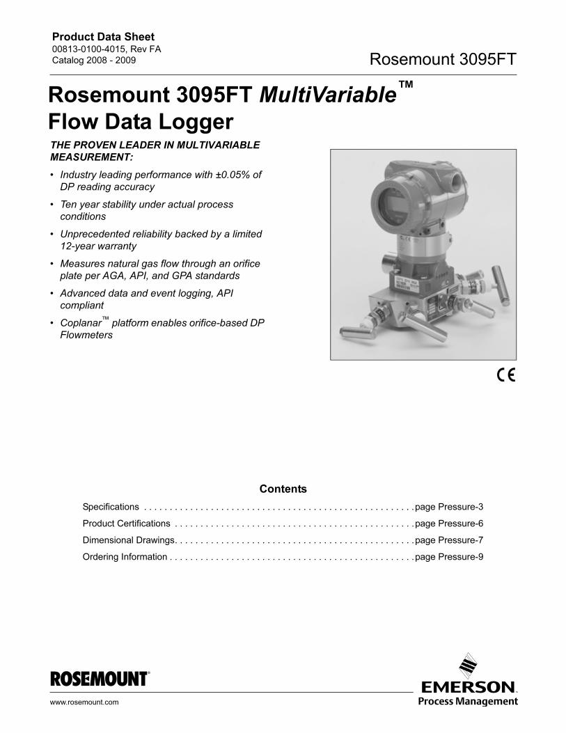
Rosemount 3095FT MultiVariable™
Flow Data Logger
THE PROVEN LEADER IN MULTIVARIABLEMEASUREMENT:
• Industry leading performance with ±0.05% of
DP reading accuracy
• Ten year stability under actual process
conditions
• Unprecedented reliability backed by a limited
12-year warranty
• Measures natural gas flow through an orifice
plate per AGA, API, and GPA standards
• Advanced data and event logging, API
compliant
• Coplanar™ platform enables orifice-based DP
Flowmeters
www.ro
Contents
Specifications . . . . . . . . . . . . . . . . . . . . . . . . . . . . . . . . . . . . . . . . . . . . . . . . . . . . .page Pressure-3
Product Certifications . . . . . . . . . . . . . . . . . . . . . . . . . . . . . . . . . . . . . . . . . . . . . . .page Pressure-6
Dimensional Drawings. . . . . . . . . . . . . . . . . . . . . . . . . . . . . . . . . . . . . . . . . . . . . . .page Pressure-7
Ordering Information . . . . . . . . . . . . . . . . . . . . . . . . . . . . . . . . . . . . . . . . . . . . . . . .page Pressure-9
semount.com
Product Data Sheet00813-0100-4015, Rev FA
Catalog 2008 - 2009Rosemount 3095FT
Rosemount 3095FT — Leader in
MultiVariable Measurement
Developed in coordination with the Gas Research Institute, the state-of-the-art 3095FT is the world’s most compact electronic flow
measurement (EFM) device. The 3095FT delivers four measurements from one coplanar device while performing user configured data logging.
Industry leading performance with ±0.05% of DP
reading accuracy
Enabled by superior sensor technology and engineered for optimal
flow performance, the 3095FT delivers unprecedented reference
accuracy with 100:1 rangeability. Superior performance means
reduced variability for improved billing accuracy.
Ten year stability under actual process
conditions
Through aggressive simulation testing, the 3095FT has proven its
ability to maintain unprecedented performance under the most
demanding conditions. Superior transmitter stability decreases
calibration frequency for reduced maintenance and operation
costs.
Unprecedented reliability backed by a limited
12-year warranty
Further enhance installation practices with the most reliable
platform supported by a 12-year warranty.
Four variables in one device
The advanced 3095FT measured three process variables
simultaneously, while calculating flow through an orifice plate per
American Gas Association (AGA), American Petroleum Institute
(API) and Gas Processors Associations (GPA) standards. One
installation means reduced process penetrations, inventory and
installation costs.
Advanced data logging
With user-configurable data logging exceeding EFM requirements
of API MPMS Chapter 21.1, the 3095FT logs the continuously
averaged flow data. The nonvolatile memory logs 50 days of daily,
variable and event logs. A cost effective solution for natural gas
flow monitoring and custody transfer.
Coplanar platform enables DP flowmeters
The solution arrives factory calibrated, pressure-tested, and ready
to install right out of the box. Only Rosemount has a scalable
coplanar transmitter design to reduce engineering and inventory
costs.
Advanced PlantWeb functionality
From multiple process variable generation to
advanced compensated Mass Flow functionality
and highly integrated flowmeter solutions, the 3095
reduces operational and maintenance
expenditures while improving throughput and
utilities management.
Rosemount DP-Flow Solutions
Rosemount 3051S Series of InstrumentationScalable pressure, flow, and level measurement solutions improve
installation and maintenance practices.
Rosemount 3095 Mass Flow TransmitterAccurately measures differential pressure, static pressure, and
process temperature to dynamically calculate fully compensated
mass flow.
Rosemount 305, 306 and 304 ManifoldsFactory-assembled, calibrated, and seal-tested
transmitter-to-manifold assemblies reduce on-site installation
costs.
Rosemount 1495, 1496, 1497, and 1595 Orifice Plate
Primary Element SystemsA comprehensive offering of orifice plates, flange unions and
meter sections that is easy to specify and order. The 1595
Conditioning Orifice provides superior performance in tight fit
applications.
Rosemount 3051SFA, 3095MFA, 485, and 285
Annubar® Series
The state-of-the-art, fifth generation Rosemount 485 Annubar
combined with the 3051S or 3095 MultiVariable transmitter creates
an accurate, repeatable and dependable insertion-type flowmeter.
The Rosemount 285 provides a commercial product offering for
your general purpose applications.
Rosemount 3051SFC, 3095MFC, and 405 Compact
Orifice Series
Compact Orifice Flowmeters can be installed between existing
flanges, up to a Class 600 (PN100) rating. In tight fit applications,
a conditioning orifice plate version is available, requiring only two
diameters of straight run upstream and two diameters
downstream.
Rosemount 3051SFP, 3095MFP, and 1195 ProPlate®
Series
These Integral Orifice Flowmeters eliminate the inaccuracies that
become more pronounced in small orifice line installations. The
completely assembled, ready to install flowmeters reduce cost and
simplify installation.
Pressure-2
Product Data Sheet00813-0100-4015, Rev FA
Catalog 2008 - 2009 Rosemount 3095FT
Pressure-3
Specifications
FUNCTIONAL
Service
AGA 8 Natural Gas, AGA 3 Orifice Plates
Consult factory for other fluid and primary element
combinations
Differential Sensor
Limits
• Range 2: –250 to 250 inH2O (-62,2 to 62,2 kPa)
• Range 3: –1000 to 1000 inH2O (-249 to 249 kPa)
Absolute Sensor
Limits
• Range 3: 0.5 to 800 psia (0,0034 to 5,516 MPa)
• Range 4: 0.5 to 3,626 psia (0,0034 to 25,00 MPa)
Gage Pressure
Limits
• Range C: 0 to 800 psig (0 to 5,516 MPa)
• Range D: 0 to 3,626 psig (0 to 25,00 MPa)
Over Pressure Limit
0.5 psia (0,0034 MPa) to two times the absolute pressure sensor
range up to a maximum of 3,626 psia (25,00 MPa).
Static Pressure Limit
Operates within specifications between static line pressures of 0.5
psia (0,0034 MPa) and the URL of the absolute pressure sensor.
Flow Calculations
• 1992 AGA Report No. 3(1)
• API MPMS Chapter 14.3(1)
• GPA(1)
• Flange tap configurable per corresponding AGA calculations
• Pipe Tap configurable per corresponding AGA calculations
NOTE
Flow calculations will cease when DP readings are below low flow
cut off.
Compressibility Calculations
• AGA Report No. 8
• API MPMS Chapter 14.2
• Gross or Detailed Characterization Method
Data Logging
• Exceeds API MPMS 21.1
• Daily & Variable Logs have user selected time duration
between 1-99 minutes
• Event Logs record alarms, configuration changes, and
significant occurrences affecting flow calculation
• 50 days of daily logs maintained for user-selected process
variables and calculated values when seven required API
variables are logged.
• Logged files saved as ASCII file or comma separated value
file.
Daily Variable Log Parameters
Maximum: DP, PT, and SP
Minimum: DP, PT, and SP
Average: DP, PT, and SP
Total: Energy, Flow, and Flow Time
Average: Energy Rate, Flow Rate, Integral Value, C', Z
Specific Gravity
Heating Value
Audit Trail
Exceeds API MPMS Chapter 21.1 standards for electronic flow
measurement systems.
User Interface Software and Hardware Requirements
• PC with CD-ROM Drive
• 4 MB RAM minimum
• Microsoft® Windows® 98, NT, 2000, or XP
• 2 MB of free hard disk space
Output
Two-wire, constant 9.5mA current, data logging
Power Supply
External power supply required. Data Logger operates on terminal
voltage of 7.5–35 V dc with a constant average operating current
of 9.5 mA.
(1) “Orifice Metering of Natural Gas and Other Related Hydrocarbon Fluids.” Third Edition, August 1992. Part 3 Natural Gas Applications.
American Gas Association Report No. 3; American Petroleum Institute API 14.3; Gas Processor Association GPA 8185-92.
Product Data Sheet00813-0100-4015, Rev FA
Catalog 2008 - 2009Rosemount 3095FT
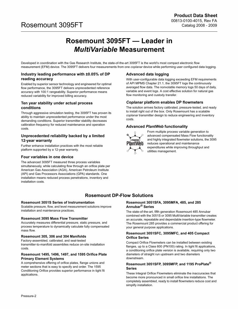
Load Limitations
Maximum loop resistance is determined by the voltage level of the
external power supply, as described by:
Temperature Limits
Process (at transmitter isolator flange for atmospheric pressures
and above)
• –40 to 185 °F (–40 to 85 °C)
Ambient:
• -40 to 185 °F (-40 to 85 °C)
• With LCD Display(1): -40 to 175 °F (-40 to 80 °C)
Storage:
• -50 to 212 °F (-46 to 100 °C)
• With LCD Display: -40 to 185 °F (-40 to 85 °C)
Humidity Limits
0–100% relative humidity
Failure Mode Alarm
If self-diagnostics detect a gross transmitter failure, the output
registers an alarm with each message.
Turn-on Time
Process variables will be within specifications less than 60
seconds after power is applied to transmitter.
Damping
Response to step input change can be user-selectable from 0 to
15 seconds for one time constant. This is in addition to sensor
response time of 0.2 seconds.
Real-Time Clock Accuracy
±2 minutes per month at reference conditions
Memory
Non-volatile memory per applicable A.G.A., A.P.I., and G.P.A.
orifice meter and electronic flow measurement standards.
PERFORMANCE Zero-based spans, reference conditions, silicone oil fill, 316 SST
isolating diaphragms, and digital trim values equal to the span end
points.
Specification Conformance
The Rosemount 3095 maintains a specification conformance of
measured variables to at least 3�.
Differential PressureRange 2:
0–2.5 to 0-250 inH2O (0–0,6227 to 0-62,27 kPa)
Range 3:
0-10 to 0-1000 inH2O (0–2,491 to 0-249,1 kPa)
Reference Accuracy (including Linearity, Hysteresis,
Repeatability)
Range 2-3 Ultra for Flow (Option U3)(2)
• ±0.05% of DP reading up to 3:1 DP turndown from URL
• For DP turndowns up to 100:1 from URL,
Accuracy =
Range 2-3
• ±0.075% of span for spans from 1:1 to 10:1 of URL
• For spans less than 10:1 of URL,
Ambient Temperature Effect per 50 °F (28 °C)
Range 2-3 Ultra for Flow (Option U3)(2)
• ±0.130% of DP reading up to 3:1 DP turndown from URL
• ±[0.05 + 0.0345 (URL/DP Reading)]% of DP reading up to
100:1 DP turndown from URL
Range 2-3
• ±(0.025% URL + 0.125% span) spans from 1:1 to 30:1
• ±(0.035% URL – 0.175% span) spans from 30:1 to 100:1
Static Pressure Effects
• Zero error = ±0.05% of URL per 1,000 psi (6895 kPa)
• Span error = ±0.20% of DP Reading per 1,000 psi (6895 kPa)
Stability
Range 2-3 Ultra for Flow (Option U3)(2)
• ±0.25% of URL for 10 years; for ±50 °F (28 °C) temperature
changes, up to 1000 psi (6895 kPa) line pressure
Range 2-3
• ±0.125% of URL for five years for ±50 °F (28 °C) ambient
temperature changes, and up to 1000 psi (6895 kPa) line
pressure.
(1) LCD Display may not be readable and LCD updates will
be slow at temperatures below -4 °F (-20 °C).
1964
250
07.5 11.0 Power Supply
Voltage35
Operating
Region
Communication requires a minimum loop resistance of 250 ohms.
Max. Loop ResistancePower Supply Voltage 7.5–
0.014-------------------------------------------------------------------------=
Lo
ad
(O
hm
s)
(2) Ultra for Flow (option U3) applicable for DP ranges 2
and 3 with SST isolator material and silicone fill fluid
options only.
0.05 0.0145URL
DPReading----------------------------------⎝ ⎠⎛ ⎞+± % of DP Reading
% of Span0.025 0.005URL
Span---------------⎝ ⎠⎛ ⎞+Accuracy =±
Pressure-4
Product Data Sheet00813-0100-4015, Rev FA
Catalog 2008 - 2009 Rosemount 3095FT
Absolute/ Gage Pressure Absolute (100:1 rangeability allowed)
Range 3
0.5–8 to 0.5–800 psia (0,0034–0,055 to 0,0034–5,516 MPa)
Range 4
0.5–36.26 to 0.5–3,626 psia (0,0034–0,250 to 0,0034–25,00 MPa)
Gage (100:1 rangeability allowed)
Range C
0–8 to 0–800 psig (0–0,055 to 0–5,516 MPa)
Range D
0–36.26 to 0–3,626 psig (0–0,250 to 0–25,00 MPa)
Reference Accuracy (including linearity, hysteresis,
repeatability)
• ±0.075% of span for spans from 1:1 to 6:1 of URL
• For spans less than 6:1 rangedown
Ambient Temperature Effect per 50 °F (28 °C)
• ±(0.05% URL + 0.125% of span) spans from 1:1 to 30:1
• ±(0.06% URL - 0.175% of span) spans from 30:1 to 100:1
Stability
• ±0.125% of URL for five years for ±50 °F (28 °C) ambient
temperature changes, and up to 1000 psi (6,89 MPa) line
pressure.
Process Temperature (RTD)Specification for process temperature is for the transmitter portion
only. Sensor errors caused by the RTD are not included. The
transmitter is compatible with any PT100 RTD conforming to IEC
751 Class B, which has a nominal resistance of 100 ohms at 0 °C
and ∝ = 0.00385.Examples of compatible RTDs include the
Rosemount Series 68 and 78 RTD Temperature Sensors.
Range
–40 to 185 °F (–40 to 85 °C). May be limited by the flow calculation
characterization method.
Accuracy (including Linearity, Hysteresis,
Repeatability)
±1.0 °F (0.56 °C)
Ambient Temperature Effects
±0.72 °F (0.40 °C) per 50 °F (28 °C)
Stability
±1.0 °F (0.56 °C) for one year
PHYSICAL
Security
Transmitter security switch mounted on electronics board, when
enabled prevents changes to transmitter security.
User Interface Software provides three levels of password
security, they are as follows:
• System Administrator (one password)
• Maintenance (three passwords)
• Operation (six passwords)
Electrical Connections
½–14 NPT, M20 x 1.5 (CM20), PG-13.5
Process Connections
Transmitter
• ¼–18 NPT on 21/8-in. centers.
RTD
• RTD dependent (see “Ordering Information” on page 9)
RTD Process Temperature Input
100-ohm platinum RTD per IEC-751 Class B
Process Wetted Parts
Isolating Diaphragms
• 316L SST or Hastelloy C-276®
Drain/Vent Valves
• 316 SST or Hastelloy C-276
Flanges
• Plated carbon steel, 316 SST, or Hastelloy C-276
Wetted O-rings
• Glass-Filled PTFE
Non-Wetted Parts
Electronics Housing
• Low copper aluminum
Bolts
• Plated carbon steel per ASTM A449, Grade 5;
or austenitic 316 SST
Fill Fluid
• Silicone oil
Paint
• Polyurethane
O-rings
• Buna-N
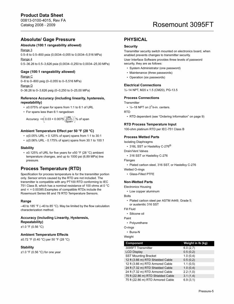
Weight
Accuracy 0.03 0.0075URL
Span--------------⎝ ⎠⎛ ⎞+ % of span=±
Component Weight in lb (kg)
3095FT Transmitter 6.0 (2,7)
LCD Display 0.5 (0,2)
SST Mounting Bracket 1.0 (0,4)
12 ft (3.66 m) RTD Shielded Cable 0.5 (0,2)
12 ft (3.66 m) RTD Armored Cable 1.1 (0,5)
24 ft (7.32 m) RTD Shielded Cable 1.0 (0,4)
24 ft (7.32 m) RTD Armored Cable 2.2 (1,0)
75 ft (22.86 m) RTD Shielded Cable 3.1 (1,4)
75 ft (22.86 m) RTD Armored Cable 6.9 (3,1)
Pressure-5

Product Data Sheet00813-0100-4015, Rev FA
Catalog 2008 - 2009Rosemount 3095FT
Product Certifications
Approved Manufacturing LocationsRosemount Inc. — Chanhassen, Minnesota USA
Emerson Process Management GmbH & Co. — Wessling,
Germany
Emerson Process Management Asia Pacific
Private Limited — Singapore
Beijing Rosemount Far East Instrument Co., Limited – Beijing,
China
European Directive InformationThe EC declaration of conformity for all applicable European directives for this product can be found on the Rosemount website at www.rosemount.com. A hard copy may be obtained by contacting our local sales office.
ATEX Directive (94/9/EC)
Emerson Process Management complies with the ATEX
Directive.
European Pressure Equipment Directive (PED) (97/23/EC)
3095F_2/3,4/D Flow Transmitters — QS Certificate of
Assessment - EC No. PED-H-100 Module H Conformity
Assessment
All other 3095_ Transmitters/Level Controller \— Sound
Engineering Practice
Transmitter Attachments: Process Flange - Manifold — Sound
Engineering Practice
Electro Magnetic Compatibility (EMC) (2004/108/EC)
3095FT Flow Transmitters — EN 61326:1997/ A1, A2, and A3
Ordinary Location Certification for Factory Mutual
As standard, the transmitter has been examined and tested to
determine that the design meets basic electrical, mechanical, and
fire protection requirements by FM, a nationally recognized testing
laboratory (NRTL) as accredited by the Federal Occupational
Safety and Health Administration (OSHA).
Hazardous Locations Certifications
North American Certifications
FM Approvals
A Explosion Proof for Class I, Division 1, Groups B, C, and D.
Dust-Ignition Proof for Class II, Division 1, Groups E, F, and
G. Suitable for Class III, Division 1, indoor and outdoor
(Type 4X) hazardous locations. Factory Sealed. Provides
non-incendive RTD connections for Class I, Division 2,
Groups A, B, C, and D. Install per Rosemount drawing
03095-1025.
Canadian Standards Association (CSA)
C Explosion Proof for Class I, Division 1, Groups B, C, and D.
Dust-Ignition Proof for Class II, Division 1, Groups E, F, and
G. Suitable for Class III, Division 1, indoor and outdoor
hazardous locations, CSA enclosure Type 4X. Factory
Sealed. Provides non-incendive RTD connection for Class I,
Division 2, Groups A, B, C, and D. Approved for Class I,
Division 2, Groups A, B, C, and D. Install in accordance with
Rosemount Drawing 03095-1024.
European Certifications
H ATEX Flameproof
Certificate Number: KEMA02ATEX2320X II 1/2 G
EEx d IIC T5 (-50°C ≤ Tamb ≤ 80°C)
T6 (-50°C ≤ Tamb ≤ 65°C)
1180
Special Conditions for Safe Use (x):
The device contains a thin wall diaphragm. Installation,
maintenance, and use shall take into account the
environmental conditions to which the diaphragm will be
subjected. the manufacturer’s instructions fro installation
and maintenance shall be followed in detail to assure safety
during its expected lifetime.
P ATEX Dust
Certificate Number: KEMA02ATEX2321 II 1 D
V = 55 Vdc MAX
I = 23 mA MAX
IP66
1180
IECEx Certifications
7 IECEx Flameproof
Certificate Number: IECEx KEM 06.0018
Zone 0/1 Ex d IIC T6 (-20°C ≤ Ta ≤ 65°C)
Zone 0/1 Ex d IIC T5 (-20°C ≤ Ta ≤ 80°C)
Vmax = 55 Vdc
Imax = 23 mAdc
8 IECEx Dust
Certificate Number: IECEx KEM 06.0018
Ex tD A22 T90°C
IP66
Pressure-6
Product Data Sheet00813-0100-4015, Rev FA
Catalog 2008 - 2009 Rosemount 3095FT
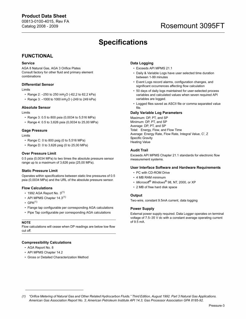
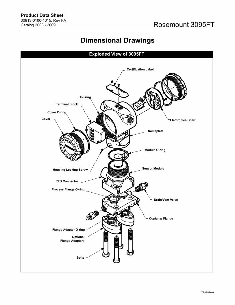
Dimensional Drawings
Exploded View of 3095FT
Housing
Cover O-ring
Terminal Block
Cover
Housing Locking Screw
Electronics Board
Nameplate
Sensor Module
Coplanar Flange
Optional
Flange Adapters
Bolts
Drain/Vent Valve
Certification Label
RTD Connector
Process Flange O-ring
Flange Adapter O-ring
Module O-ring
Pressure-7
Product Data Sheet00813-0100-4015, Rev FA
Catalog 2008 - 2009Rosemount 3095FT
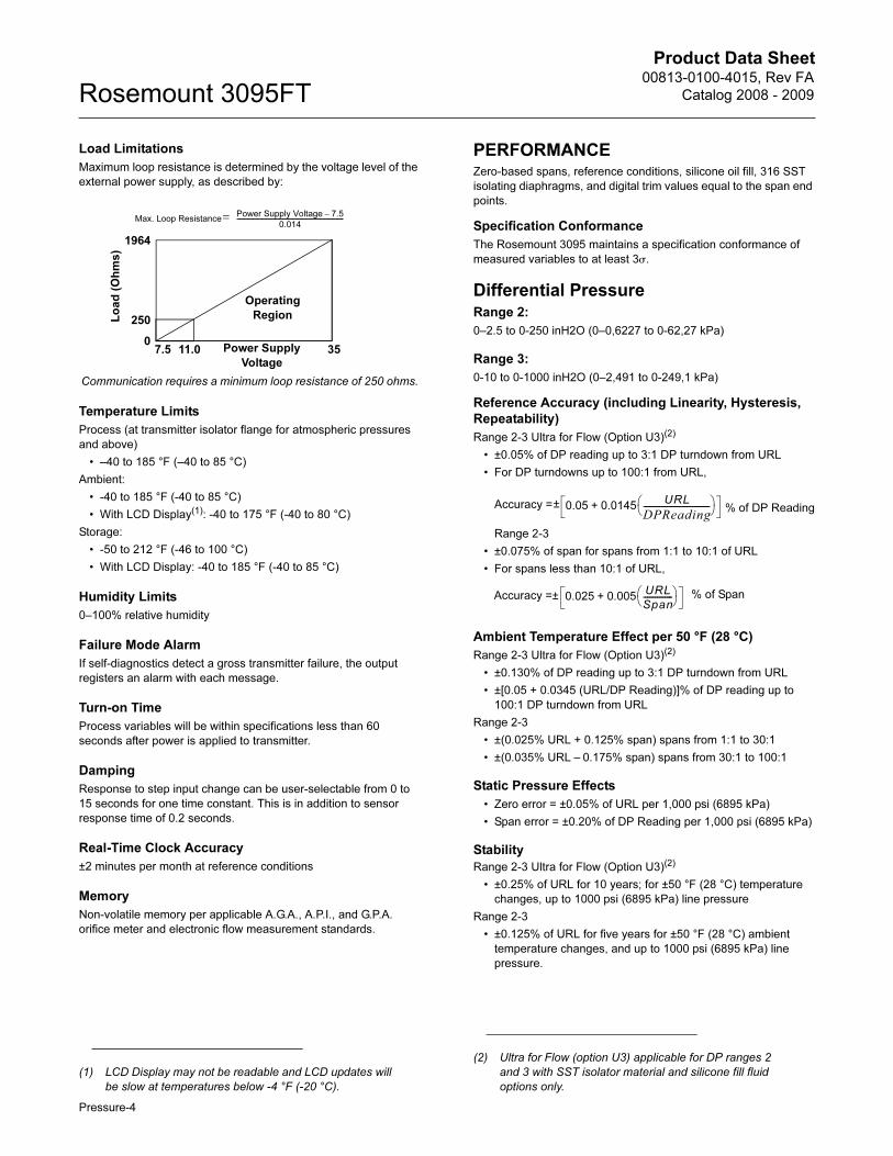
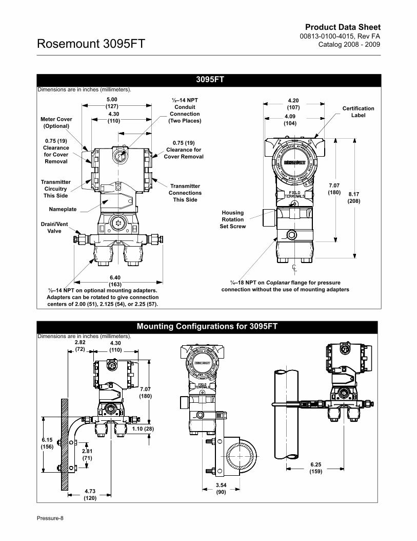
3095FT
Meter Cover
(Optional)
0.75 (19)
Clearance
for Cover
Removal
Transmitter
Circuitry
This Side
Nameplate
Drain/Vent
Valve
½–14 NPT on optional mounting adapters.
Adapters can be rotated to give connection
centers of 2.00 (51), 2.125 (54), or 2.25 (57).
6.40
(163)
½–14 NPT
Conduit
Connection
(Two Places)
Transmitter
Connections
This Side
5.00
(127)
4.30
(110)
0.75 (19)
Clearance for
Cover Removal
7.07
(180) 8.17
(208)
¼–18 NPT on Coplanar flange for pressure
connection without the use of mounting adapters
Housing
Rotation
Set Screw
4.20
(107)
4.09
(104)
Certification
Label
Mounting Configurations for 3095FT
2.81
(71)
2.82
(72)
6.15
(156)
4.30
(110)
7.07
(180)
1.10 (28)
4.73
(120)
3.54
(90)
6.25
(159)
Dimensions are in inches (millimeters).
Dimensions are in inches (millimeters).
Pressure-8
Product Data Sheet00813-0100-4015, Rev FA
Catalog 2008 - 2009 Rosemount 3095FT
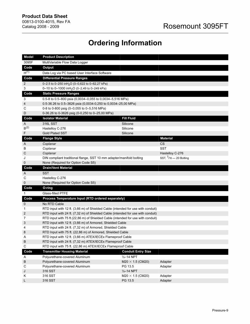
Ordering Information
Model Product Description
3095F MultiVariable Flow Data Logger
Code Output
H(1) Data Log via PC based User Interface Software
Code Differential Pressure Ranges
2 0–2.5 to 0–250 inH2O (0–0,622 to 0–62,27 kPa)
3 0–10 to 0–1000 inH2O (0–2,49 to 0–249 kPa)
Code Static Pressure Ranges
3 0.5-8 to 0.5–800 psia (0,0034–0,055 to 0,0034–5,516 MPa)
4 0.5-36.26 to 0.5–3626 psia (0,0034-0,250 to 0,0034–25,00 MPa)
C 0-8 to 0-800 psig (0–0,055 to 0–5,516 MPa)
D 0-36.26 to 0-3626 psig (0-0,250 to 0–25,00 MPa)
Code Isolator Material Fill Fluid
A 316L SST Silicone
B(2) Hastelloy C-276 Silicone
F Gold Plated SST Silicone
Code Flange Style Material
A Coplanar CS
B Coplanar SST
C Coplanar Hastelloy C-276
J DIN compliant traditional flange, SST 10 mm adapter/manifold bolting SST, 7/16 — 20 Bolting
0 None (Required for Option Code S5)
Code Drain/Vent Material
A SST
C Hastelloy C-276
0 None (Required for Option Code S5)
Code O-ring
1 Glass-filled PTFE
Code Process Temperature Input (RTD ordered separately)
0 No RTD Cable
1 RTD input with 12 ft. (3,66 m) of Shielded Cable (intended for use with conduit)
2 RTD input with 24 ft. (7,32 m) of Shielded Cable (intended for use with conduit)
7 RTD input with 75 ft.(22,86 m) of Shielded Cable (intended for use with conduit)
3 RTD input with 12 ft. (3,66 m) of Armored, Shielded Cable
4 RTD input with 24 ft. (7,32 m) of Armored, Shielded Cable
8 RTD Input with 75 ft. (22,86 m) of Armored, Shielded Cable
A RTD input with 12 ft. (3,66 m) ATEX/IECEx Flameproof Cable
B RTD input with 24 ft. (7,32 m) ATEX/IECEx Flameproof Cable
C RTD input with 75 ft. (22,86 m) ATEX/IECEx Flameproof Cable
Code Transmitter Housing Material Conduit Entry Size
A Polyurethane-covered Aluminum ½–14 NPT
B Polyurethane-covered Aluminum M20 � 1.5 (CM20) Adapter
C Polyurethane-covered Aluminum PG 13.5 Adapter
J 316 SST ½–14 NPT
K 316 SST M20 � 1.5 (CM20) Adapter
L 316 SST PG 13.5 Adapter
Pressure-9

Product Data Sheet00813-0100-4015, Rev FA
Catalog 2008 - 2009Rosemount 3095FT
Code Terminal Block
A Standard
B With Integral Transient Protection
Code Display
0 None
1 LCD Display
Code Bracket
0 None
1 Coplanar SST flange bracket for 2-in. pipe or panel mount, SST bolts
2 Traditional Flange Bracket for 2-in. Pipe Mounting, CS Bolts
3 Traditional Flange Bracket for panel Mounting, CS Bolts
4 Traditional Flange Flat Bracket for 2-in. Pipe Mounting, CS Bolts
5 Traditional Flange Bracket for 2-in. Pipe Mounting, 300-Series, SST Bolts
6 Traditional Flange Bracket for panel Mounting, 300-Series, SST Bolts
7 Traditional Flange Flat Bracket for 2-in. Pipe Mounting, 300-Series, SST Bolts
8 SST Traditional Flange Bracket for 2-in. Pipe Mounting, 300-Series, SST Bolts
9 SST Traditional Flange Flat Bracket for 2-in. Pipe Mounting, 300-Series, SST Bolts
Code Bolts
0 CS bolts
1 Austenitic 316 SST Bolts
N None (Required for Option Code S5)
Code Product Certifications
0 None
A FM Explosion-proof, Dust Ignition-proof
C CSA Explosion-proof, Dust Ignition-proof, Division 2
H ATEX Flameproof
P ATEX Dust
7 IECEx Flameproof
8 IECEx Dust
Code Engineered Measurement Solution (EMS)
A Averaging Method: Flow Dependent Time-weighted Formulaic Averaging
Compressibility Factor: A.G.A. Report No. 8 /API MPMS Chapter 14.2
Code Options
Performance Class
U3(3) Ultra for Flow: ±0.05% DP reading accuracy, up to 100:1 rangedown, 10 year stability, limited 12 year warranty
S5(4) Assembly with Rosemount 305 Integral Manifold
S6(4) Assemble to Rosemount 304 Manifold or Connection System (Required traditional Flange Style Option J, K, and L)
C1 Custom Configuration (requires completed Configuration Data Sheet)
DF Flange Adapters — Adapter Type Determined by Selected Flange Material: Plated CS, SST, Hastelloy C-276
P1 Hydrostatic Testing with Certificate
P2 Cleaning for Special Services
Q4 Calibration Certificate
Q8 Material Traceability Certification per EN 10204 3.1B
Typical Model Number 3095F H 2 3 A B A 1 1 A B 1 1 0 A A
(1) Communication based on Digital HART Protocol.
(2) Materials of Construction comply with metallurgical requirements highlighted within NACE MR0175/ISO 15156 for sour oil field production environments. Environmental limits apply to certain materials. Consult latest standard for details. Selected materials also conform to NACE MR0103 for sour refining environments.
(3) Ultra for Flow (Option U3) applicable for DP ranges 2 and 3 with SST isolator material and silicone fill fluid only.
(4) “Assemble-to” items are specified separately and require a completed model number.
Pressure-10

Product Data Sheet00813-0100-4015, Rev FA
Catalog 2008 - 2009 Rosemount 3095FT
OPTIONS
Standard Configuration
Unless otherwise specified, the transmitter is shipped as follows:
Custom Configuration (Option Code C1)
If Option Code C1 is ordered, the customer specifies the following
information for the 3095FT in addition to the standard
configuration parameters.
Configuration Data Sheet (see page Pressure-12): Gas
composition parameters, contract hour, log parameters, LCD
display parameters, meter run configuration parameters, low flow
cut-off, passwords, static pressure tap location, static pressure
measurement, damping, descriptor, message, and upper and
lower trim points for each process variable.
Tagging
Three customer tagging options are available:
• Standard SST tag is wired to the transmitter.
Tag character height is 0.125 in. (3,18 mm),
85 characters maximum.
• Tag may be stored in transmitter memory. Software tag (8
characters maximum) is left blank unless specified.
• Tag may be permanently stamped on transmitter nameplate
upon request. Tag character height is 0.0625 in. (1,59 mm), 65
characters maximum.
• Software tag (8 characters maximum) is left blank unless
specified.
ADDITIONAL INFORMATIONRosemount transmitters are available as fully assembled and
factory calibrated flowmeters. Flowmeter Product Data Sheets are
listed below:
ACCESSORIES
3095FT User Interface Software Packages
All configurations are packaged separately.
Windows 98, NT, 2000, and XP
• Single PC license: 03095-5100-0104
Site license: 03095-5100-0105
• Single PC license, Serial Port HART
Modem and cables: 3095-5100-0102
• Single PC license, USB HART Modem and Cables (Requires
Windows XP or 2000 Operating System): 03095-5100-0103
Communication Accessories
Engineering units:
Differential inH2O at 60 °F (All ranges)
Absolute/gage psi (all ranges)
Output: 9.5mA with Data Logging
Flange type: Specified model code option
Flange material: Specified model code option
O-ring material: Specified model code option
Drain/vent: Specified model code option
Flow Configuration
Parameters:
Factory default
Software tag: (Blank)
• Orifice Plate Primary Element Systems: 00813-0100-4792
Rosemount 1495 Orifice Plate
Rosemount 1496 Flange Union
Rosemount 1497 Meter Section
Item Description Part Number
Serial Port HART Modem and Cables Only 03095-5105-0001
USB Port HART Modem and Cables Only 03095-5105-0002
Pressure-11

Product Data Sheet00813-0100-4015, Rev FA
Catalog 2008 - 2009Rosemount 3095FT
Standard Terms and Conditions of Sale can be found at www.rosemount.com\terms_of_saleThe Emerson logo is a trade mark and service mark of Emerson Electric Co. Annubar, ProPlate, Rosemount and the Rosemount logotype are registerd trademarks of Rosemount Inc.Coplanar and Multivariable are trademarks of Rosemount Inc.HART is a registered trademark of the HART Communications Foundation.
Emerson Process Management
© 2008 Rosemount Inc. All rights reserved.
Modbus is a trademark of Modicon, Inc.Hastelloy C and Hastelloy C-276 are registered trademarks of Cabot Corp.Microsoft and Windows are registered trademarks of Microsoft Corp.PlantWeb is a mark of one of the Emerson Process Management companies.All other marks are the property of their respective owners.
¢00813-0100-4015;¤
Emerson Process Management Asia Pacific Private Limited1 Pandan CrescentSingapore 128461T (65) 6777 8211F (65) 6777 [email protected]
Emerson Process ManagementHeath PlaceBognor RegisWest Sussex PO22 9SHEnglandT 44 (0) 1243 863121F 44 (0) 1243 867554
Rosemount Inc.8200 Market BoulevardChanhassen, MN 55317 USAT (U.S.) 1 800 999 9307T (International) (952) 906 8888F (952) 949 7001
www.rosemount.com