product data sheet ds433 - bridgelux
TRANSCRIPT

1
Bridgelux® Gen 8 Vero® SE 29 ArrayProduct Data Sheet DS433

Introduction
The Vero® SE Series is a revolutionary light source system that integrates Bridgelux’s eighth generation COB technology with poke-in connectivity, enabling solder-free installation. Vero SE LED light sources streamline assembly processes, lower manufacturing costs, simplify the luminaire design process, improve light quality, and increase design flexibility.
Vero SE is available in four different light emitting surface (LES) configurations that operate reliably over a broad current range. With Vero SE, secondary connector and holder components are not required, allowing for rapid integration of arrays into fixtures, and an efficient field replaceable solution. Vero SE arrays deliver increased lumen density for improved beam control and precision lighting, with 2 and 3 SDCM color control standards for clean and consistent uniform lighting.
Ve
ro S
E
Features
• Poke-in electrical connectivity
• Top side part number markings
• Efficacy of 185 lm/W typical, 3000K 80 CRI
• Reliable operation at up to 3x nominal current, 30% increase in maximum lumens per LES size
• Wide selection of CCT options (2700K-6500K) with minimum 70, 80 and 90 CRI options
• Uniform high-quality illumination
• 2 and 3 SDCM binning options (2700K – 4000K)
• Forward voltage bin codes (backside marking)
• 10-Year warranty
Benefits
• Low cost, solderless, connector free installation and field upgradability
• Improved inventory management and quality control
• Enables high efficiency lighting systems and lower operating costs
• Supports the trend toward luminaire miniaturization and delivers enhanced optical control
• Design flexibility for a broad range of lighting applica-tions
• Clean white light without pixelation
• Uniform consistent white light
• Design flexibility for multi-source applications
• Design with confidence
1
Contents
Product Feature Map 2
Product Nomenclature 2
Product Selection Guide 3
Performance at Commonly Used Drive Currents 7
Electrical Characteristics 16
Eye Safety 17
Absolute Maximum Ratings 18
Performance Curves 19
Typical Radiation Pattern 21
Typical Color Spectrum 23
Mechanical Dimensions 24
Color Binning Information 25
Packaging and Labeling 26
Design Resources 28
Precautions 28
Disclaimers 28
About Bridgelux 29

2
Product Feature Map
Vero SE 29 is the largest form factor in the product family of next generation solid state light sources. In addition to delivering the performance and light quality required for many lighting applications, Vero SE incorporates several
features to simplify the design integration and manufacturing process, accelerate time to market and reduce system costs. Please visit www.bridgelux.com for more information on the Vero SE Series family of products.
Mounting holes
Polarity indication marks simplify manufacturing operator instructions
2D Bar code provides full manufacturing traceability
Dual poke-in connectivity
Wire release mechanisms x4
Tc Measurement point
Radial die configuration improves lumen density and beam control
Top side part number marking improves inventory management and outgoing quality control
Test ports for probing
Optic mounting holes
Product Nomenclature
The part number designation for Bridgelux Vero SE LED arrays is explained as follows:
1 2 3 4 – 5 6 7 8 9 10 11 – 12 – 13 14 – 15 16
Product Family
CCT Bin Options
2 = 2 SDCM3 = 3 SDCM4 = 4 SDCM
CRIC = 70 CRI min.E = 80 CRI min. G = 90 CRI min.
Array Configuration
27 = 2,700K30 = 3,000K35 = 3,500K40 = 4,000K50 = 5,000K57 = 5,700K65 = 6,500K
BXRC – 30 E 10K 0 – C – 8 3 – SE
Color Targeting Designator0 = Cold Targeted1 = Hot Targeted
Gen. 8
Nominal CCT
Flux Indicator10Kx = 10,000 lm
Special Edition

3
Product Selection Guide
The following product configurations are available:
Table 1: Selection Guide, Pulsed Measurement Data (Tj = Tc = 25°C)
Part NumberNominal
CCT1
(K)CRI2
Nominal Drive Current3
(mA)
Typical Pulsed Flux4,5,6
Tc = 25ºC(lm)
Minimum Pulsed Flux6,7
Tc = 25ºC(lm)
Typical Vf (V)
Typical Power
(W)
Typical Efficacy (lm/W)
BXRC-27E10K0-B-8x-SE 2700 80 1400 12216 10994 50.2 70.3 174
BXRC-27E10K0-C-8x-SE 2700 80 1300 15062 13555 66.7 86.7 174
BXRC-27E10K0-D-8x-SE 2700 80 1700 10744 9670 36.4 61.9 174
BXRC-27G10K0-B-8x-SE 2700 90 1400 10078 9070 50.2 70.3 143
BXRC-27G10K0-C-8x-SE 2700 90 1300 12426 11183 66.7 86.7 143
BXRC-27G10K0-D-8x-SE 2700 90 1700 8864 7977 36.4 61.9 143
BXRC-27G1KH0-B-8x-SE 2700 90 1400 10513 9462 50.2 70.3 150
BXRC-27G1KH0-C-8x-SE 2700 90 1300 12962 11666 66.7 86.7 149
BXRC-27G1KH0-D-8x-SE 2700 90 1700 9246 8322 36.4 61.9 149
BXRC-30C10K1-B-8x-SE 3000 70 1400 13590 12231 50.2 70.3 193
BXRC-30C10K1-C-8x-SE 3000 70 1300 16756 15080 66.7 86.7 193
BXRC-30C10K1-D-8x-SE 3000 70 1700 11953 10757 36.4 61.9 193
BXRC-30E10K0-B-8x-SE 3000 80 1400 12979 11682 50.2 70.3 185
BXRC-30E10K0-C-8x-SE 3000 80 1300 16003 14403 66.7 86.7 185
BXRC-30E10K0-D-8x-SE 3000 80 1700 11415 10274 36.4 61.9 184
BXRC-30G10K0-B-8x-SE 3000 90 1400 10536 9483 50.2 70.3 150
BXRC-30G10K0-C-8x-SE 3000 90 1300 12991 11692 66.7 86.7 150
BXRC-30G10K0-D-8x-SE 3000 90 1700 9267 8340 36.4 61.9 150
BXRC-30G1KH0-B-8x-SE 3000 90 1400 11033 9929 50.2 70.3 157
BXRC-30G1KH0-C-8x-SE 3000 90 1300 13602 12242 66.7 86.7 157
BXRC-30G1KH0-D-8x-SE 3000 90 1700 9703 8733 36.4 61.9 157
BXRC-35E10K0-B-8x-SE 3500 80 1400 13285 11956 50.2 70.3 189
BXRC-35E10K0-C-8x-SE 3500 80 1300 16379 14741 66.7 86.7 189
BXRC-35E10K0-D-8x-SE 3500 80 1700 11684 10516 36.4 61.9 189
BXRC-35G10K0-B-8x-SE 3500 90 1400 10918 9826 50.2 70.3 155
BXRC-35G10K0-C-8x-SE 3500 90 1300 13461 12115 66.7 86.7 155
BXRC-35G10K0-D-8x-SE 3500 90 1700 9602 8642 36.4 61.9 155
BXRC-40C10K1-B-8x-SE 4000 70 1400 13972 12575 50.2 70.3 199
BXRC-40C10K1-C-8x-SE 4000 70 1300 17227 15504 66.7 86.7 199
BXRC-40C10K1-D-8x-SE 4000 70 1700 12288 11059 36.4 61.9 199
BXRC-40E10K0-B-8x-SE 4000 80 1400 13361 12025 50.2 70.3 190
BXRC-40E10K0-C-8x-SE 4000 80 1300 16474 14826 66.7 86.7 190
BXRC-40E10K0-D-8x-SE 4000 80 1700 11751 10576 36.4 61.9 190
BXRC-40G10K0-B-8x-SE 4000 90 1400 11147 10032 50.2 70.3 159
BXRC-40G10K0-C-8x-SE 4000 90 1300 13744 12369 66.7 86.7 159
BXRC-40G10K0-D-8x-SE 4000 90 1700 9804 8823 36.4 61.9 158
Notes for Table 1:1. Nominal CCT as defined by ANSI C78.377-2011. Products with a CCT of 5000K-6500K are hot targeted to Tc = 85°C.2. CRI values are minimums for all products. Minimum R9 value for 80 CRI products is 0, the minimum R9 values for 90 CRI products is 50. Bridgelux maintains
a ±3 tolerance on CRI and R9 values.3. Drive current is referred to as nominal drive current. 4. Products tested under pulsed condition (10ms pulse width) at nominal test current where Tj (junction temperature) = Tc (case temperature) = 25°C. 5. Typical performance values are provided as a reference only and are not a guarantee of performance. 6. Bridgelux maintains a ±7% tolerance on flux measurements. 7. Minimum flux values at the nominal test current are guaranteed by 100% test.

4
Product Selection Guide
Table 1: Selection Guide, Pulsed Measurement Data (Tj = Tc = 25°C) (continued)
Part NumberNominal
CCT1 (K)
CRI2 Nominal Drive
Current3 (mA)
Typical Pulsed Flux4,5,6
Tc = 25ºC(lm)
Minimum Pulsed Flux6,7
Tc = 25ºC(lm)
Typical Vf (V)
Typical Power
(W)
Typical Efficacy (lm/W)
BXRC-50C10K1-B-8x-SE 5000 70 1400 14048 12644 50.2 70.3 200
BXRC-50C10K1-C-8x-SE 5000 70 1300 17321 15589 66.7 86.7 200
BXRC-50C10K1-D-8x-SE 5000 70 1700 12355 11120 36.4 61.9 200
BXRC-50E10K1-B-8x-SE 5000 80 1400 13514 12163 50.2 70.3 192
BXRC-50E10K1-C-8x-SE 5000 80 1300 16662 14996 66.7 86.7 192
BXRC-50E10K1-D-8x-SE 5000 80 1700 11885 10697 36.4 61.9 192
BXRC-50G10K1-B-8x-SE 5000 90 1400 11682 10513 50.2 70.3 166
BXRC-50G10K1-C-8x-SE 5000 90 1300 14403 12962 66.7 86.7 166
BXRC-50G10K1-D-8x-SE 5000 90 1700 10274 9246 36.4 61.9 166
BXRC-57C10K1-B-8x-SE 5700 70 1400 13667 12300 50.2 70.3 194
BXRC-57C10K1-C-8x-SE 5700 70 1300 16850 15165 66.7 86.7 194
BXRC-57C10K1-D-8x-SE 5700 70 1700 12020 10818 36.4 61.9 194
BXRC-57E10K1-B-8x-SE 5700 80 1400 12979 11682 50.2 70.3 185
BXRC-57E10K1-C-8x-SE 5700 80 1300 16003 14403 66.7 86.7 185
BXRC-57E10K1-D-8x-SE 5700 80 1700 11415 10274 36.4 61.9 184
BXRC-65C10K1-B-8x-SE 6500 70 1400 13667 12300 50.2 70.3 194
BXRC-65C10K1-C-8x-SE 6500 70 1300 16850 15165 66.7 86.7 194
BXRC-65C10K1-D-8x-SE 6500 70 1700 12020 10818 36.4 61.9 194
BXRC-65E10K1-B-8x-SE 6500 80 1400 13132 11819 50.2 70.3 187
BXRC-65E10K1-C-8x-SE 6500 80 1300 16191 14572 66.7 86.7 187
BXRC-65E10K1-D-8x-SE 6500 80 1700 11550 10395 36.4 61.9 187
Notes for Table 1:1. Nominal CCT as defined by ANSI C78.377-2011. Products with a CCT of 5000K-6500K are hot targeted to Tc = 85°C.2. CRI values are minimums for all products. Minimum R9 value for 80 CRI products is 0, the minimum R9 values for 90 CRI products is 50. Bridgelux maintains a
±3 tolerance on CRI and R9 values.3. Drive current is referred to as nominal drive current. 4. Products tested under pulsed condition (10ms pulse width) at nominal test current where Tj (junction temperature) = Tc (case temperature) = 25°C. 5. Typical performance values are provided as a reference only and are not a guarantee of performance. 6. Bridgelux maintains a ±7% tolerance on flux measurements. 7. Minimum flux values at the nominal test current are guaranteed by 100% test.

5
Product Selection Guide
Table 2: Selection Guide, Stabilized DC Performance (Tc = 85°C) 4,5
Part Number Nominal CCT1 (K) CRI2
Nominal Drive Current3
(mA)
Typical DC Flux4,5
Tc = 85ºC(lm)
Minimum DC Flux6
Tc = 85ºC(lm)
Typical Vf (V)
Typical Power
(W)
Typical Efficacy (lm/W)
BXRC-27E10K0-B-8x-SE 2700 80 1400 10994 9895 49.2 68.9 160
BXRC-27E10K0-C-8x-SE 2700 80 1300 13555 12200 65.4 85.0 159
BXRC-27E10K0-D-8x-SE 2700 80 1700 9670 8703 35.7 60.7 159
BXRC-27G10K0-B-8x-SE 2700 90 1400 9070 8163 49.2 68.9 132
BXRC-27G10K0-C-8x-SE 2700 90 1300 11183 10065 65.4 85.0 132
BXRC-27G10K0-D-8x-SE 2700 90 1700 7977 7180 35.7 60.7 132
BXRC-27G1KH0-B-8x-SE 2700 90 1400 9462 8516 49.2 68.9 137
BXRC-27G1KH0-C-8x-SE 2700 90 1300 11666 10499 65.4 85.0 137
BXRC-27G1KH0-D-8x-SE 2700 90 1700 8322 7490 35.7 60.7 137
BXRC-30C10K1-B-8x-SE 3000 70 1400 12231 11008 49.2 68.9 178
BXRC-30C10K1-C-8x-SE 3000 70 1300 15080 13572 65.4 85.0 177
BXRC-30C10K1-D-8x-SE 3000 70 1700 10757 9682 35.7 60.7 177
BXRC-30E10K0-B-8x-SE 3000 80 1400 11682 10513 49.2 68.9 170
BXRC-30E10K0-C-8x-SE 3000 80 1300 14403 12962 65.4 85.0 169
BXRC-30E10K0-D-8x-SE 3000 80 1700 10274 9246 35.7 60.7 169
BXRC-30G10K0-B-8x-SE 3000 90 1400 9483 8534 49.2 68.9 138
BXRC-30G10K0-C-8x-SE 3000 90 1300 11692 10522 65.4 85.0 138
BXRC-30G10K0-D-8x-SE 3000 90 1700 8340 7506 35.7 60.7 137
BXRC-30G1KH0-B-8x-SE 3000 90 1400 9929 8936 49.2 68.9 144
BXRC-30G1KH0-C-8x-SE 3000 90 1300 12242 11018 65.4 85.0 144
BXRC-30G1KH0-D-8x-SE 3000 90 1700 8733 7859 35.7 60.7 144
BXRC-35E10K0-B-8x-SE 3500 80 1400 11956 10761 49.2 68.9 174
BXRC-35E10K0-C-8x-SE 3500 80 1300 14741 13267 65.4 85.0 173
BXRC-35E10K0-D-8x-SE 3500 80 1700 10516 9464 35.7 60.7 173
BXRC-35G10K0-B-8x-SE 3500 90 1400 9826 8844 49.2 68.9 143
BXRC-35G10K0-C-8x-SE 3500 90 1300 12115 10904 65.4 85.0 143
BXRC-35G10K0-D-8x-SE 3500 90 1700 8642 7778 35.7 60.7 142
BXRC-40C10K1-B-8x-SE 4000 70 1400 12575 11317 49.2 68.9 183
BXRC-40C10K1-C-8x-SE 4000 70 1300 15504 13954 65.4 85.0 182
BXRC-40C10K1-D-8x-SE 4000 70 1700 11059 9954 35.7 60.7 182
BXRC-40E10K0-B-8x-SE 4000 80 1400 12025 10823 49.2 68.9 175
BXRC-40E10K0-C-8x-SE 4000 80 1300 14826 13344 65.4 85.0 174
BXRC-40E10K0-D-8x-SE 4000 80 1700 10576 9518 35.7 60.7 174
BXRC-40G10K0-B-8x-SE 4000 90 1400 10032 9029 49.2 68.9 146
BXRC-40G10K0-C-8x-SE 4000 90 1300 12369 11132 65.4 85.0 146
BXRC-40G10K0-D-8x-SE 4000 90 1700 8823 7941 35.7 60.7 145
Notes for Table 2:1. Nominal CCT as defined by ANSI C78.377-2011. Products with a CCT of 5000K-6500K are hot targeted to Tc = 85°C. 2. All CRI values are measured at Tj = Tc = 25°C. CRI values are minimums for all products. Minimum R9 value for 80 CRI products is 0, the minimum R9 values
for 90 CRI products is 50. Bridgelux maintains a ±3 tolerance on CRI and R9 values. 3. Drive current is referred to as nominal drive current. 4. Typical stabilized DC performance values are provided as reference only and are not a guarantee of performance. 5. Typical performance is estimated based on operation under DC (direct current) with LED array mounted onto a heat sink with thermal interface
material and the case temperature maintained at 85°C. Based on Bridgelux test setup, values may vary depending on the thermal design of the luminaire and/or the exposed environment to which the product is subjected.
6. Minimum flux values at elevated temperatures are provided for reference only and are not guaranteed by 100% production testing. Based on Bridgelux test setup, values may vary depending on the thermal design of the luminaire and/or the exposed environment to which the product is subjected.

6
Product Selection Guide
Table 2: Selection Guide, Stabilized DC Performance (Tc = 85°C) 4,5 (continued)
Part Number Nominal CCT1 (K) CRI2
Nominal Drive Current3
(mA)
Typical DC Flux4,5
Tc = 85ºC(lm)
Minimum DC Flux6
Tc = 85ºC(lm)
Typical Vf (V)
Typical Power
(W)
Typical Efficacy (lm/W)
BXRC-50C10K1-B-8x-SE 5000 70 1400 12644 11379 49.2 68.9 184
BXRC-50C10K1-C-8x-SE 5000 70 1300 15589 14030 65.4 85.0 183
BXRC-50C10K1-D-8x-SE 5000 70 1700 11120 10008 35.7 60.7 183
BXRC-50E10K1-B-8x-SE 5000 80 1400 12163 10946 49.2 68.9 177
BXRC-50E10K1-C-8x-SE 5000 80 1300 14996 13496 65.4 85.0 176
BXRC-50E10K1-D-8x-SE 5000 80 1700 10697 9627 35.7 60.7 176
BXRC-50G10K1-B-8x-SE 5000 90 1400 10513 9462 49.2 68.9 153
BXRC-50G10K1-C-8x-SE 5000 90 1300 12962 11666 65.4 85.0 153
BXRC-50G10K1-D-8x-SE 5000 90 1700 9246 8322 35.7 60.7 152
BXRC-57C10K1-B-8x-SE 5700 70 1400 12300 11070 49.2 68.9 179
BXRC-57C10K1-C-8x-SE 5700 70 1300 15165 13649 65.4 85.0 178
BXRC-57C10K1-D-8x-SE 5700 70 1700 10818 9736 35.7 60.7 178
BXRC-57E10K1-B-8x-SE 5700 80 1400 11682 10513 49.2 68.9 170
BXRC-57E10K1-C-8x-SE 5700 80 1300 14403 12962 65.4 85.0 169
BXRC-57E10K1-D-8x-SE 5700 80 1700 10274 9246 35.7 60.7 169
BXRC-65C10K1-B-8x-SE 6500 70 1400 12300 11070 49.2 68.9 179
BXRC-65C10K1-C-8x-SE 6500 70 1300 15165 13649 65.4 85.0 178
BXRC-65C10K1-D-8x-SE 6500 70 1700 10818 9736 35.7 60.7 178
BXRC-65E10K1-B-8x-SE 6500 80 1400 11819 10637 49.2 68.9 172
BXRC-65E10K1-C-8x-SE 6500 80 1300 14572 13115 65.4 85.0 171
BXRC-65E10K1-D-8x-SE 6500 80 1700 10395 9355 35.7 60.7 171
Notes for Table 2:1. Nominal CCT as defined by ANSI C78.377-2011. Products with a CCT of 5000K-6500K are hot targeted to Tc = 85°C. 2. All CRI values are measured at Tj = Tc = 25°C. CRI values are minimums for all products. Minimum R9 value for 80 CRI products is 0, the minimum R9 values
for 90 CRI products is 50. Bridgelux maintains a ±3 tolerance on CRI and R9 values. 3. Drive current is referred to as nominal drive current. 4. Typical stabilized DC performance values are provided as reference only and are not a guarantee of performance. 5. Typical performance is estimated based on operation under DC (direct current) with LED array mounted onto a heat sink with thermal interface
material and the case temperature maintained at 85°C. Based on Bridgelux test setup, values may vary depending on the thermal design of the luminaire and/or the exposed environment to which the product is subjected.
6. Minimum flux values at elevated temperatures are provided for reference only and are not guaranteed by 100% production testing. Based on Bridgelux test setup, values may vary depending on the thermal design of the luminaire and/or the exposed environment to which the product is subjected.

7
Performance at Commonly Used Drive Currents
Vero LED arrays are tested to the specifications shown using the nominal drive currents in Table 1. Vero SE may also
be driven at other drive currents dependent on specific application design requirements. The performance at any
drive current can be derived from the current vs. voltage characteristics shown in Figures 1, 2 & 3 and the flux vs. current
characteristics shown in Figures 4, 5 & 6. The performance at commonly used drive currents is summarized in Table 3.
Table 3: Product Performance at Commonly Used Drive Currents
Part Number CRIDrive
Current1
(mA)
Typical Vf Tc = 25ºC
(V)
Typical Power Tc = 25ºC
(W)
Typical Flux2
Tc = 25ºC(lm)
Typical DC Flux3 Tc = 85ºC
(lm)
Typical Efficacy Tc = 25ºC(lm/W)
BXRC-27E10K0-B-8x-SE 80
700 48.5 34.0 6160 5544 1811050 49.4 51.9 9200 8280 1771400 50.2 70.3 12216 10994 1741800 51.2 92.1 15457 13911 1682800 53.3 149.1 23251 20926 1564750 56.6 268.8 36646 32981 136
BXRC-27E10K0-C-8x-SE 80
650 64.4 41.9 7595 6835 181975 65.6 64.0 11344 10209 177
1300 66.7 86.7 15062 13555 1741710 68.0 116.4 19472 17525 1672600 70.7 183.9 28667 25800 1564750 75.8 360.1 47950 43155 133
BXRC-27E10K0-D-8x-SE 80
850 35.1 29.9 5418 4876 1811275 35.8 45.6 8092 7283 1771700 36.4 61.9 10744 9670 1742100 36.9 77.6 13090 11781 1693400 38.6 131.1 20449 18404 1565500 40.7 224.1 31002 27902 138
BXRC-27G10K0-B-8x-SE 90
700 48.5 34.0 5082 4574 150
1050 49.4 51.9 7590 6831 1461400 50.2 70.3 10078 9070 143
1800 51.2 92.1 12752 11477 1382800 53.3 149.1 19182 17264 1294750 56.6 268.8 30233 27209 112
BXRC-27G10K0-C-8x-SE 90
650 64.4 41.9 6266 5639 150975 65.6 64.0 9358 8423 146
1300 66.7 86.7 12426 11183 143
1710 68.0 116.4 16064 14458 1382600 70.7 183.9 23650 21285 1294750 75.8 360.1 39558 35603 110
BXRC-27G10K0-D-8x-SE 90
850 35.1 29.9 4470 4023 1501275 35.8 45.6 6676 6008 1461700 36.4 61.9 8864 7977 143
2100 36.9 77.6 10799 9719 1393400 38.6 131.1 16870 15183 1295500 40.7 224.1 25577 23019 114
Notes for Table 3:1. Alternate drive currents in Table 3 are provided for reference only and are not a guarantee of performance.2. Bridgelux maintains a ± 7% tolerance on flux measurements.3. Typical stabilized DC performance values are provided as reference only and are not a guarantee of performance.

8
Performance at Commonly Used Drive Currents
Table 3: Product Performance at Commonly Used Drive Currents (Continued)
Part Number CRIDrive
Current1
(mA)
Typical Vf Tc = 25ºC
(V)
Typical Power Tc = 25ºC
(W)
Typical Flux2
Tc = 25ºC(lm)
Typical DC Flux3 Tc = 85ºC
(lm)
Typical Efficacy Tc = 25ºC(lm/W)
BXRC-27G1KH0-B-8x-SE 90
700 48.5 34.0 5301 4771 1561050 49.4 51.9 7918 7126 1531400 50.2 70.3 10513 9462 149
1800 51.2 92.1 13303 11972 1442800 53.3 149.1 20010 18009 1344750 56.6 268.8 31538 28384 117
BXRC-27G1KH0-C-8x-SE 90
650 64.4 41.9 6536 5883 156975 65.6 64.0 9762 8786 153
1300 66.7 86.7 12962 11666 1491710 68.0 116.4 16758 15082 1442600 70.7 183.9 24671 22204 1344750 75.8 360.1 41267 37140 115
BXRC-27G1KH0-D-8x-SE 90
850 35.1 29.9 4663 4196 1561275 35.8 45.6 6964 6268 1531700 36.4 61.9 9246 8322 1492100 36.9 77.6 11265 10139 1453400 38.6 131.1 17599 15839 1345500 40.7 224.1 26681 24013 119
BXRC-30C10K1-B-8x-SE 70
700 48.5 34.0 6853 6168 202
1050 49.4 51.9 10235 9212 1971400 50.2 70.3 13590 12231 1931800 51.2 92.1 17196 15476 1872800 53.3 149.1 25866 23280 1734750 56.6 268.8 40768 36692 152
BXRC-30C10K1-C-8x-SE 70
650 64.4 41.9 8449 7604 202975 65.6 64.0 12620 11358 197
1300 66.7 86.7 16756 15080 1931710 68.0 116.4 21663 19496 1862600 70.7 183.9 31892 28703 1734750 75.8 360.1 53344 48010 148
BXRC-30C10K1-D-8x-SE 70
850 35.1 29.9 6027 5424 2021275 35.8 45.6 9002 8102 1971700 36.4 61.9 11953 10757 193
2100 36.9 77.6 14562 13106 1883400 38.6 131.1 22749 20474 1735500 40.7 224.1 34490 31041 154
BXRC-30E10K0-B-8x-SE 80
700 48.5 34.0 6545 5890 1931050 49.4 51.9 9775 8798 1881400 50.2 70.3 12979 11682 185
1800 51.2 92.1 16423 14781 1782800 53.3 149.1 24704 22234 1664750 56.6 268.8 38936 35042 145
Notes for Table 3:1. Alternate drive currents in Table 3 are provided for reference only and are not a guarantee of performance.2. Bridgelux maintains a ± 7% tolerance on flux measurements.3. Typical stabilized DC performance values are provided as reference only and are not a guarantee of performance.

9
Table 3: Product Performance at Commonly Used Drive Currents (Continued)
Performance at Commonly Used Drive Currents
Part Number CRIDrive
Current1
(mA)
Typical Vf Tc = 25ºC
(V)
Typical Power Tc = 25ºC
(W)
Typical Flux2
Tc = 25ºC(lm)
Typical DC Flux3 Tc = 85ºC
(lm)
Typical Efficacy Tc = 25ºC(lm/W)
BXRC-30E10K0-C-8x-SE 80
650 64.4 41.9 8070 7263 193975 65.6 64.0 12052 10847 188
1300 66.7 86.7 16003 14403 185
1710 68.0 116.4 20689 18620 1782600 70.7 183.9 30458 27413 1664750 75.8 360.1 50946 45852 141
BXRC-30E10K0-D-8x-SE 80
850 35.1 29.9 5756 5181 1931275 35.8 45.6 8597 7738 1881700 36.4 61.9 11415 10274 1852100 36.9 77.6 13908 12517 1793400 38.6 131.1 21727 19554 1665500 40.7 224.1 32940 29646 147
BXRC-30G10K0-B-8x-SE 90
700 48.5 34.0 5313 4782 1561050 49.4 51.9 7935 7142 1531400 50.2 70.3 10536 9483 1501800 51.2 92.1 13332 11999 1452800 53.3 149.1 20054 18048 1344750 56.6 268.8 31607 28446 118
BXRC-30G10K0-C-8x-SE 90
650 64.4 41.9 6551 5896 156
975 65.6 64.0 9784 8805 1531300 66.7 86.7 12991 11692 1501710 68.0 116.4 16795 15115 1442600 70.7 183.9 24725 22253 1344750 75.8 360.1 41357 37221 115
BXRC-30G10K0-D-8x-SE 90
850 35.1 29.9 4673 4205 1561275 35.8 45.6 6979 6281 1531700 36.4 61.9 9267 8340 1502100 36.9 77.6 11290 10161 1463400 38.6 131.1 17637 15873 1345500 40.7 224.1 26739 24065 119
BXRC-30G1KH0-B-8x-SE 90
700 48.5 34.0 5563 5007 1641050 49.4 51.9 8309 7478 1601400 50.2 70.3 11033 9929 157
1800 51.2 92.1 13960 12564 1522800 53.3 149.1 20998 18898 1414750 56.6 268.8 33096 29786 123
BXRC-30G1KH0-C-8x-SE 90
650 64.4 41.9 6859 6173 164975 65.6 64.0 10245 9220 160
1300 66.7 86.7 13602 12242 157
1710 68.0 116.4 17586 15827 1512600 70.7 183.9 25890 23301 1414750 75.8 360.1 43304 38974 120
Notes for Table 3:1. Alternate drive currents in Table 3 are provided for reference only and are not a guarantee of performance.2. Bridgelux maintains a ± 7% tolerance on flux measurements.3. Typical stabilized DC performance values are provided as reference only and are not a guarantee of performance.

10
Performance at Commonly Used Drive Currents
Table 3: Product Performance at Commonly Used Drive Currents (Continued)
Part Number CRIDrive
Current1
(mA)
Typical Vf Tc = 25ºC
(V)
Typical Power Tc = 25ºC
(W)
Typical Flux2
Tc = 25ºC(lm)
Typical DC Flux3 Tc = 85ºC
(lm)
Typical Efficacy Tc = 25ºC(lm/W)
BXRC-30G1KH0-D-8x-SE 90
850 35.1 29.9 4893 4404 1641275 35.8 45.6 7308 6577 1601700 36.4 61.9 9703 8733 157
2100 36.9 77.6 11822 10639 1523400 38.6 131.1 18468 16621 1415500 40.7 224.1 27999 25199 125
BXRC-35E10K0-B-8x-SE 80
700 48.5 34.0 6699 6029 1971050 49.4 51.9 10005 9005 1931400 50.2 70.3 13285 11956 1891800 51.2 92.1 16809 15129 1832800 53.3 149.1 25285 22757 1704750 56.6 268.8 39852 35867 148
BXRC-35E10K0-C-8x-SE 80
650 64.4 41.9 8259 7433 197975 65.6 64.0 12336 11102 193
1300 66.7 86.7 16379 14741 1891710 68.0 116.4 21176 19058 1822600 70.7 183.9 31175 28058 1704750 75.8 360.1 52145 46931 145
BXRC-35E10K0-D-8x-SE 80
850 35.1 29.9 5892 5303 197
1275 35.8 45.6 8800 7920 1931700 36.4 61.9 11684 10516 1892100 36.9 77.6 14235 12812 1843400 38.6 131.1 22238 20014 1705500 40.7 224.1 33715 30343 150
BXRC-35G10K0-B-8x-SE 90
700 48.5 34.0 5505 4955 1621050 49.4 51.9 8223 7401 1591400 50.2 70.3 10918 9826 1551800 51.2 92.1 13815 12433 1502800 53.3 149.1 20780 18702 1394750 56.6 268.8 32752 29477 122
BXRC-35G10K0-C-8x-SE 90
650 64.4 41.9 6788 6109 162975 65.6 64.0 10138 9124 159
1300 66.7 86.7 13461 12115 155
1710 68.0 116.4 17403 15663 1502600 70.7 183.9 25621 23059 1394750 75.8 360.1 42855 38569 119
BXRC-35G10K0-D-8x-SE 90
850 35.1 29.9 4842 4358 1621275 35.8 45.6 7232 6509 1591700 36.4 61.9 9602 8642 155
2100 36.9 77.6 11699 10529 1513400 38.6 131.1 18276 16449 1395500 40.7 224.1 27708 24937 124
Notes for Table 3:1. Alternate drive currents in Table 3 are provided for reference only and are not a guarantee of performance.2. Bridgelux maintains a ± 7% tolerance on flux measurements.3. Typical stabilized DC performance values are provided as reference only and are not a guarantee of performance.

11
Performance at Commonly Used Drive Currents
Table 3: Product Performance at Commonly Used Drive Currents (Continued)
Part Number CRIDrive
Current1
(mA)
Typical Vf Tc = 25ºC
(V)
Typical Power Tc = 25ºC
(W)
Typical Flux2
Tc = 25ºC(lm)
Typical DC Flux3 Tc = 85ºC
(lm)
Typical Efficacy Tc = 25ºC(lm/W)
BXRC-40C10K1-B-8x-SE 70
700 48.5 34.0 7045 6341 2071050 49.4 51.9 10523 9471 2031400 50.2 70.3 13972 12575 199
1800 51.2 92.1 17679 15911 1922800 53.3 149.1 26593 23934 1784750 56.6 268.8 41914 37722 156
BXRC-40C10K1-C-8x-SE 70
650 64.4 41.9 8687 7818 207975 65.6 64.0 12974 11677 203
1300 66.7 86.7 17227 15504 1991710 68.0 116.4 22271 20044 1912600 70.7 183.9 32788 29509 1784750 75.8 360.1 54842 49358 152
BXRC-40C10K1-D-8x-SE 70
850 35.1 29.9 6196 5577 2071275 35.8 45.6 9255 8329 2031700 36.4 61.9 12288 11059 1992100 36.9 77.6 14971 13474 1933400 38.6 131.1 23388 21050 1785500 40.7 224.1 35459 31913 158
BXRC-40E10K0-B-8x-SE 80
700 48.5 34.0 6737 6064 198
1050 49.4 51.9 10063 9057 1941400 50.2 70.3 13361 12025 1901800 51.2 92.1 16906 15215 1842800 53.3 149.1 25430 22887 1714750 56.6 268.8 40081 36073 149
BXRC-40E10K0-C-8x-SE 80
650 64.4 41.9 8307 7476 198975 65.6 64.0 12407 11166 194
1300 66.7 86.7 16474 14826 1901710 68.0 116.4 21298 19168 1832600 70.7 183.9 31354 28219 1714750 75.8 360.1 52445 47200 146
BXRC-40E10K0-D-8x-SE 80
850 35.1 29.9 5926 5333 1981275 35.8 45.6 8850 7965 1941700 36.4 61.9 11751 10576 190
2100 36.9 77.6 14317 12885 1853400 38.6 131.1 22366 20129 1715500 40.7 224.1 33909 30518 151
BXRC-40G10K0-B-8x-SE 90
700 48.5 34.0 5621 5059 1651050 49.4 51.9 8395 7556 1621400 50.2 70.3 11147 10032 158
1800 51.2 92.1 14105 12694 1532800 53.3 149.1 21216 19095 1424750 56.6 268.8 33439 30095 124
Notes for Table 3:1. Alternate drive currents in Table 3 are provided for reference only and are not a guarantee of performance.2. Bridgelux maintains a ± 7% tolerance on flux measurements.3. Typical stabilized DC performance values are provided as reference only and are not a guarantee of performance.
12
Performance at Commonly Used Drive Currents
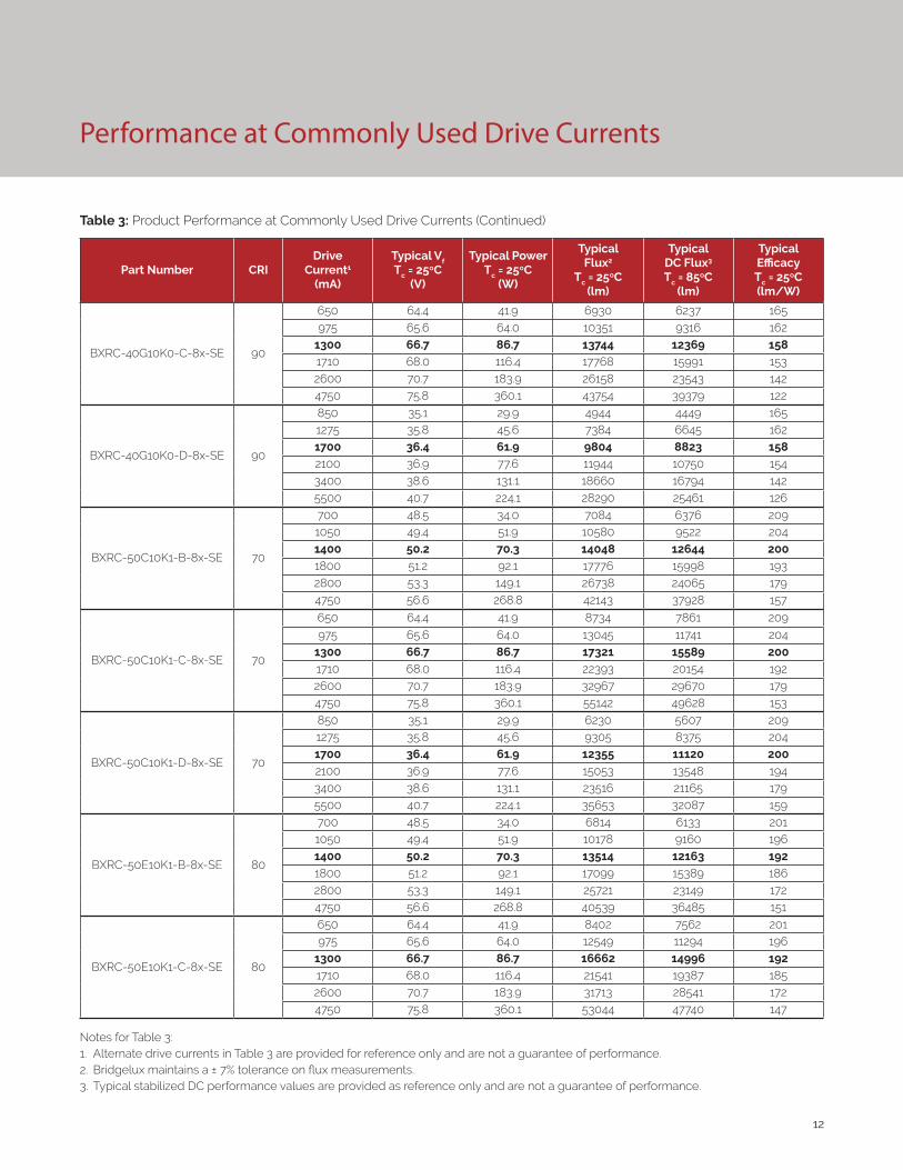
Table 3: Product Performance at Commonly Used Drive Currents (Continued)
Part Number CRIDrive
Current1
(mA)
Typical Vf Tc = 25ºC
(V)
Typical Power Tc = 25ºC
(W)
Typical Flux2
Tc = 25ºC(lm)
Typical DC Flux3 Tc = 85ºC
(lm)
Typical Efficacy Tc = 25ºC(lm/W)
BXRC-40G10K0-C-8x-SE 90
650 64.4 41.9 6930 6237 165975 65.6 64.0 10351 9316 162
1300 66.7 86.7 13744 12369 158
1710 68.0 116.4 17768 15991 1532600 70.7 183.9 26158 23543 1424750 75.8 360.1 43754 39379 122
BXRC-40G10K0-D-8x-SE 90
850 35.1 29.9 4944 4449 1651275 35.8 45.6 7384 6645 1621700 36.4 61.9 9804 8823 1582100 36.9 77.6 11944 10750 1543400 38.6 131.1 18660 16794 1425500 40.7 224.1 28290 25461 126
BXRC-50C10K1-B-8x-SE 70
700 48.5 34.0 7084 6376 2091050 49.4 51.9 10580 9522 2041400 50.2 70.3 14048 12644 2001800 51.2 92.1 17776 15998 1932800 53.3 149.1 26738 24065 1794750 56.6 268.8 42143 37928 157
BXRC-50C10K1-C-8x-SE 70
650 64.4 41.9 8734 7861 209
975 65.6 64.0 13045 11741 2041300 66.7 86.7 17321 15589 2001710 68.0 116.4 22393 20154 1922600 70.7 183.9 32967 29670 1794750 75.8 360.1 55142 49628 153
BXRC-50C10K1-D-8x-SE 70
850 35.1 29.9 6230 5607 2091275 35.8 45.6 9305 8375 2041700 36.4 61.9 12355 11120 2002100 36.9 77.6 15053 13548 1943400 38.6 131.1 23516 21165 1795500 40.7 224.1 35653 32087 159
BXRC-50E10K1-B-8x-SE 80
700 48.5 34.0 6814 6133 2011050 49.4 51.9 10178 9160 1961400 50.2 70.3 13514 12163 192
1800 51.2 92.1 17099 15389 1862800 53.3 149.1 25721 23149 1724750 56.6 268.8 40539 36485 151
BXRC-50E10K1-C-8x-SE 80
650 64.4 41.9 8402 7562 201975 65.6 64.0 12549 11294 196
1300 66.7 86.7 16662 14996 192
1710 68.0 116.4 21541 19387 1852600 70.7 183.9 31713 28541 1724750 75.8 360.1 53044 47740 147
Notes for Table 3:1. Alternate drive currents in Table 3 are provided for reference only and are not a guarantee of performance.2. Bridgelux maintains a ± 7% tolerance on flux measurements.3. Typical stabilized DC performance values are provided as reference only and are not a guarantee of performance.

13
Performance at Commonly Used Drive Currents
Table 3: Product Performance at Commonly Used Drive Currents (Continued)
Part Number CRIDrive
Current1
(mA)
Typical Vf Tc = 25ºC
(V)
Typical Power Tc = 25ºC
(W)
Typical Flux2
Tc = 25ºC(lm)
Typical DC Flux3 Tc = 85ºC
(lm)
Typical Efficacy Tc = 25ºC(lm/W)
BXRC-50E10K1-D-8x-SE 80
850 35.1 29.9 5993 5394 2011275 35.8 45.6 8951 8056 1961700 36.4 61.9 11885 10697 192
2100 36.9 77.6 14480 13032 1873400 38.6 131.1 22622 20359 1725500 40.7 224.1 34296 30867 153
BXRC-50G10K1-B-8x-SE 90
700 48.5 34.0 5890 5301 1731050 49.4 51.9 8798 7918 1701400 50.2 70.3 11682 10513 1661800 51.2 92.1 14781 13303 1612800 53.3 149.1 22234 20010 1494750 56.6 268.8 35042 31538 130
BXRC-50G10K1-C-8x-SE 90
650 64.4 41.9 7263 6536 173975 65.6 64.0 10847 9762 170
1300 66.7 86.7 14403 12962 1661710 68.0 116.4 18620 16758 1602600 70.7 183.9 27413 24671 1494750 75.8 360.1 45852 41267 127
BXRC-50G10K1-D-8x-SE 90
850 35.1 29.9 5181 4663 173
1275 35.8 45.6 7738 6964 1701700 36.4 61.9 10274 9246 1662100 36.9 77.6 12517 11265 1613400 38.6 131.1 19554 17599 1495500 40.7 224.1 29646 26681 132
BXRC-57C10K1-B-8x-SE 70
700 48.5 34.0 6891 6202 2031050 49.4 51.9 10293 9264 1981400 50.2 70.3 13667 12300 1941800 51.2 92.1 17293 15563 1882800 53.3 149.1 26012 23411 1744750 56.6 268.8 40997 36898 153
BXRC-57C10K1-C-8x-SE 70
650 64.4 41.9 8497 7647 203975 65.6 64.0 12691 11421 198
1300 66.7 86.7 16850 15165 194
1710 68.0 116.4 21784 19606 1872600 70.7 183.9 32071 28864 1744750 75.8 360.1 53644 48279 149
BXRC-57C10K1-D-8x-SE 70
850 35.1 29.9 6061 5455 2031275 35.8 45.6 9053 8147 1981700 36.4 61.9 12020 10818 194
2100 36.9 77.6 14644 13180 1893400 38.6 131.1 22877 20590 1745500 40.7 224.1 34684 31215 155
Notes for Table 3:1. Alternate drive currents in Table 3 are provided for reference only and are not a guarantee of performance.2. Bridgelux maintains a ± 7% tolerance on flux measurements.3. Typical stabilized DC performance values are provided as reference only and are not a guarantee of performance.
14
Performance at Commonly Used Drive Currents
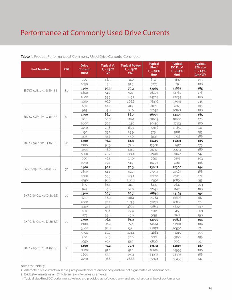
Table 3: Product Performance at Commonly Used Drive Currents (Continued)
Part Number CRIDrive
Current1
(mA)
Typical Vf Tc = 25ºC
(V)
Typical Power Tc = 25ºC
(W)
Typical Flux2
Tc = 25ºC(lm)
Typical DC Flux3 Tc = 85ºC
(lm)
Typical Efficacy Tc = 25ºC(lm/W)
BXRC-57E10K1-B-8x-SE 80
700 48.5 34.0 6545 5890 1931050 49.4 51.9 9775 8798 1881400 50.2 70.3 12979 11682 185
1800 51.2 92.1 16423 14781 1782800 53.3 149.1 24704 22234 1664750 56.6 268.8 38936 35042 145
BXRC-57E10K1-C-8x-SE 80
650 64.4 41.9 8070 7263 193975 65.6 64.0 12052 10847 188
1300 66.7 86.7 16003 14403 1851710 68.0 116.4 20689 18620 1782600 70.7 183.9 30458 27413 1664750 75.8 360.1 50946 45852 141
BXRC-57E10K1-D-8x-SE 80
850 35.1 29.9 5756 5181 1931275 35.8 45.6 8597 7738 1881700 36.4 61.9 11415 10274 1852100 36.9 77.6 13908 12517 1793400 38.6 131.1 21727 19554 1665500 40.7 224.1 32940 29646 147
BXRC-65C10K1-B-8x-SE 70
700 48.5 34.0 6891 6202 203
1050 49.4 51.9 10293 9264 1981400 50.2 70.3 13667 12300 1941800 51.2 92.1 17293 15563 1882800 53.3 149.1 26012 23411 1744750 56.6 268.8 40997 36898 153
BXRC-65C10K1-C-8x-SE 70
650 64.4 41.9 8497 7647 203975 65.6 64.0 12691 11421 198
1300 66.7 86.7 16850 15165 1941710 68.0 116.4 21784 19606 1872600 70.7 183.9 32071 28864 1744750 75.8 360.1 53644 48279 149
BXRC-65C10K1-D-8x-SE 70
850 35.1 29.9 6061 5455 2031275 35.8 45.6 9053 8147 1981700 36.4 61.9 12020 10818 194
2100 36.9 77.6 14644 13180 1893400 38.6 131.1 22877 20590 1745500 40.7 224.1 34684 31215 155
BXRC-65E10K1-B-8x-SE 80
700 48.5 34.0 6622 5960 1951050 49.4 51.9 9890 8901 1911400 50.2 70.3 13132 11819 187
1800 51.2 92.1 16616 14955 1802800 53.3 149.1 24995 22495 1684750 56.6 268.8 39394 35455 147
Notes for Table 3:1. Alternate drive currents in Table 3 are provided for reference only and are not a guarantee of performance.2. Bridgelux maintains a ± 7% tolerance on flux measurements.3. Typical stabilized DC performance values are provided as reference only and are not a guarantee of performance.

15
Performance at Commonly Used Drive Currents
Table 3: Product Performance at Commonly Used Drive Currents (Continued)
Part Number CRIDrive
Current1
(mA)
Typical Vf Tc = 25ºC
(V)
Typical Power Tc = 25ºC
(W)
Typical Flux2
Tc = 25ºC(lm)
Typical DC Flux3 Tc = 85ºC
(lm)
Typical Efficacy Tc = 25ºC(lm/W)
BXRC-65E10K1-C-8x-SE 80
650 64.4 41.9 8164 7348 195975 65.6 64.0 12194 10975 191
1300 66.7 86.7 16191 14572 187
1710 68.0 116.4 20932 18839 1802600 70.7 183.9 30817 27735 1684750 75.8 360.1 51546 46391 143
BXRC-65E10K1-D-8x-SE 80
850 35.1 29.9 5824 5242 1951275 35.8 45.6 8699 7829 1911700 36.4 61.9 11550 10395 1872100 36.9 77.6 14071 12664 1813400 38.6 131.1 21983 19784 1685500 40.7 224.1 33327 29995 149
Notes for Table 3:1. Alternate drive currents in Table 3 are provided for reference only and are not a guarantee of performance.2. Bridgelux maintains a ± 7% tolerance on flux measurements.3. Typical stabilized DC performance values are provided as reference only and are not a guarantee of performance.

16
Electrical Characteristics
Table 4: Electrical Characteristics
Part NumberDrive Current
(mA)
Forward VoltagePulsed, Tc = 25ºC (V) 1, 2, 3, 8 Typical
Coefficient of Forward
Voltage4 ∆Vf/∆Tc
(mV/ºC)
Typical Thermal
Resistance Junction to Case5,6
Rj-c (ºC/W)
Driver Selection Voltages7
(V)
Minimum Typical MaximumVf Min.
Hot Tc = 105ºC
(V)
Vf Max. Cold
Tc = -40ºC (V)
BXRC-xxx10Kx-B-8x-SE1400 46.4 50.2 54.0 -16.19 0.05 45.1 55.0
4750 52.4 56.6 60.8 -18.26 0.10 50.9 62.0
BXRC-xxx10Kx-C-8x-SE1300 61.7 66.7 71.7 -21.51 0.05 60.0 73.1
4750 70.1 75.8 81.5 -24.45 0.11 68.2 83.1
BXRC-xxx10Kx-D-8x-SE1700 33.7 36.4 39.1 -11.74 0.06 32.7 39.9
5500 37.6 40.7 43.8 -13.13 0.11 36.6 44.6
Notes for Table 4:
1. Parts are tested in pulsed conditions, Tc = 25°C. Pulse width is 10ms.
2. Voltage minimum and maximum are provided for reference only and are not a guarantee of performance.
3. Bridgelux maintains a tester tolerance of ± 0.10V on forward voltage measurements.
4. Typical coefficient of forward voltage tolerance is ± 0.1mV for nominal current.
5. Thermal resistance values are based from test data of a 3000K 80 CRI product.
6. Thermal resistance value was calculated using total electrical input power; optical power was not subtracted from input power. The thermal interface material used during testing is not included in the thermal resistance value.
7. Vf min hot and max cold values are provided as reference only and are not guaranteed by test. These values are provided to aid in driver design and selection over the operating range of the product.
8. This product has been designed and manufactured per IEC 62031:2014. This product has passed dielectric withstand voltage testing at 1140 V. The working voltage designated for the insulation is 70V d.c. The maximum allowable voltage across the array must be determined in the end product application.

17
Eye Safety
Table 5: Eye Safety Risk Group (RG) Classifications
Part NumberDrive Current
(mA)
CCT
2700K/3000K 4000K2 5000K3 6500K4
BXRC-xxx10Kx-B-8x-SE
2145 RG1 RG1 RG1 RG1
2970 RG1 RG1 RG1 RG2
3945 RG1 RG1 RG2 RG2
4750 RG1 RG2 RG2 RG2
BXRC-xxx10Kx-C-8x-SE
1615 RG1 RG1 RG1 RG1
2235 RG1 RG1 RG1 RG2
2970 RG1 RG1 RG2 RG2
4750 RG1 RG2 RG2 RG2
BXRC-xxx10Kx-D-8x-SE
2960 RG1 RG1 RG1 RG1
4100 RG1 RG1 RG1 RG2
5500 RG1 RG1 RG2 RG2
Notes for Table 5:
1. Eye safety classification for the use of Bridgelux V Series LED arrays is in accordance with specification IEC/TR 62778: Application of IEC 62471 for the assessment of blue light hazard to light sources and luminaires.
2. For products classified as RG2 at 4000K, Ethr= 1980 lx.
3. For products classified as RG2 at 5000K Ethr= 1530 lx.
4. For products classified as RG2 at 6500K, Ethr= 1170 lx.
5. Please contact your Bridgelux sales representative for Ethr values at specific drive currents and CCTs not listed.

18
Absolute Maximum Ratings
Parameter Maximum Rating
LED Junction Temperature (Tj) 150°C
Storage Temperature -40°C to +105°C
Operating Case Temperature1 (Tc) 105°C
Soldering Temperature2 300°C or lower for a maximum of 6 seconds
BXRC-xxx10Kx-B-8x-SE BXRC-xxx10Kx-C-8x-SE BXRC-xxx10Kx-D-8x-SE
Maximum Drive Current3 4750 mA 4750 mA 5500 mA
Maximum Peak Pulsed Drive Current4,5 5320 mA 5320 mA 6160 mA
Maximum Reverse Voltage6 -90V -120V -65V
Notes for Table 6:
1. For IEC 62717 requirement, please consult your Bridgelux sales representative.
2. Refer to Bridgelux Application Note AN121: Assembly Considerations for Bridgelux Vero SE LED Arrays.
3. Arrays may be driven at higher currents however lumen maintenance may be reduced and warranty will not apply.
4. Bridgelux recommends a maximum duty cycle of 10% and pulse width of 20 ms when operating LED Arrays at maximum peak pulsed current specified. Maximum peak pulsed currents indicate values where LED Arrays can be driven without catastrophic failures.
5. Light emitting diodes are not designed to be driven in reverse voltage and will not produce light under this condition. Maximum rating provided for reference only.
Table 6: Maximum Ratings

19
Performance Curves
Figure 3: Vero SE 29D Drive Current vs. Voltage Figure 4: Vero SE 29B Typical Relative Flux vs. Current
Notes for Figures 1-6:
1. Bridgelux does not recommend driving high power LEDs at low currents. Doing so may produce unpredictable results. Pulse width modulation (PWM) is recommended for dimming effects.
2. Products tested under pulsed condition (10ms pulse width) at nominal test current where Tj (junction temperature) = Tc (case temperature) = 25°C.
Figure 5: Vero SE 29C Typical Relative Flux vs. Current Figure 6: Vero SE 29D Typical Relative Flux vs. Current
Figure 1: Vero SE 29B Drive Current vs. Voltage Figure 2: Vero SE 29C Drive Current vs. Voltage
48.0
49.0
50.0
51.0
52.0
53.0
54.0
55.0
56.0
57.0
0 750 1500 2250 3000 3750 4500 5250
Vo
ltag
e (
V)
Drive Current (mA)
62.0
64.0
66.0
68.0
70.0
72.0
74.0
76.0
78.0
0 750 1500 2250 3000 3750 4500 5250
Vo
ltag
e (
V)
Drive Current (mA)
34.0
35.0
36.0
37.0
38.0
39.0
40.0
41.0
42.0
0 750 1500 2250 3000 3750 4500 5250 6000
Vo
ltag
e (
V)
Drive Current (mA)
0%
50%
100%
150%
200%
250%
300%
350%
0 750 1500 2250 3000 3750 4500 5250
Re
lati
ve L
um
ino
us
Flu
x (%
)
Drive Current (mA)
0%
50%
100%
150%
200%
250%
300%
350%
0 750 1500 2250 3000 3750 4500 5250
Re
lati
ve L
um
ino
us
Flu
x (%
)
Drive Current (mA)
0%
50%
100%
150%
200%
250%
300%
350%
0 750 1500 2250 3000 3750 4500 5250 6000
Re
lati
ve L
um
ino
us
Flu
x (%
)
Drive Current (mA)
20
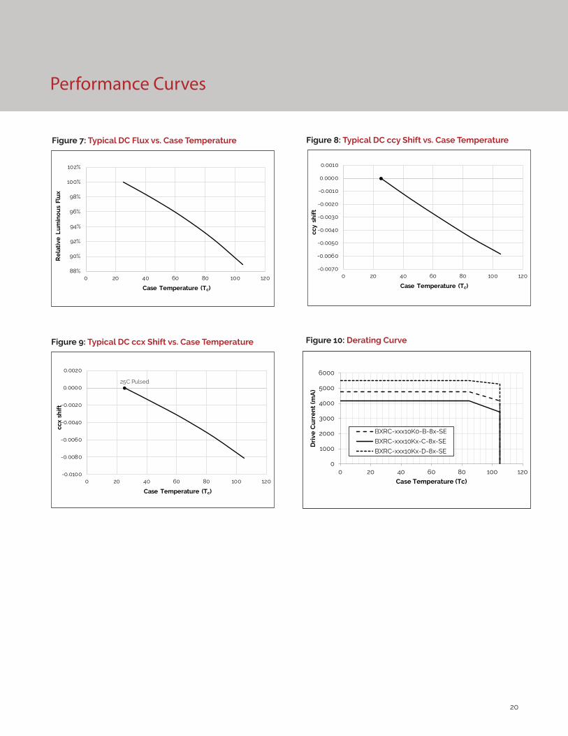
Performance Curves
Figure 7: Typical DC Flux vs. Case Temperature
Figure 9: Typical DC ccx Shift vs. Case Temperature
Figure 8: Typical DC ccy Shift vs. Case Temperature
25C Pulsed
-0.0100
-0.0080
-0.0060
-0.0040
-0.0020
0.0000
0.0020
0 20 40 60 80 100 120
ccx
shif
t
Case Temperature (Tc)
-0.0070
-0.0060
-0.0050
-0.0040
-0.0030
-0.0020
-0.0010
0.0000
0.0010
0 20 40 60 80 100 120
ccy
shif
t
Case Temperature (Tc)
88%
90%
92%
94%
96%
98%
100%
102%
0 20 40 60 80 100 120
Re
lati
ve L
um
ino
us
Flu
x
Case Temperature (Tc)
Figure 10: Derating Curve
0
1000
2000
3000
4000
5000
6000
0 20 40 60 80 100 120
Dri
ve C
urr
en
t (m
A)
Case Temperature (Tc)
BXRC-xxx10K0-B-8x-SE
BXRC-xxx10Kx-C-8x-SE
BXRC-xxx10Kx-D-8x-SE
21
Figure 8: Typical DC ccy Shift vs. Case Temperature
Typical Radiation Pattern
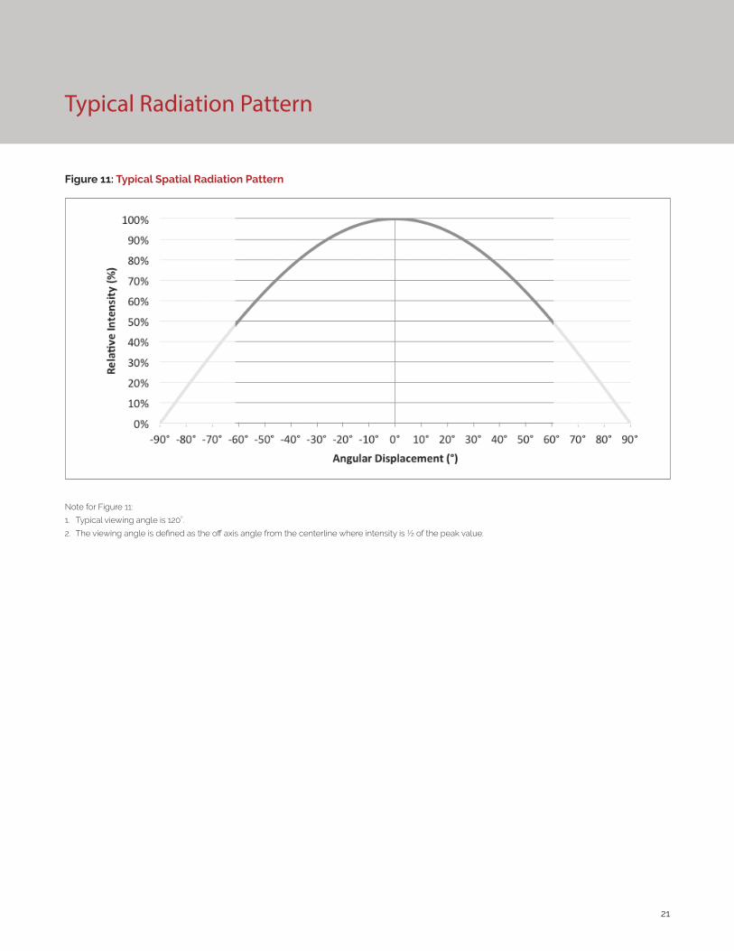
Figure 11: Typical Spatial Radiation Pattern
Note for Figure 11:
1. Typical viewing angle is 120⁰.
2. The viewing angle is defined as the off axis angle from the centerline where intensity is ½ of the peak value.
22
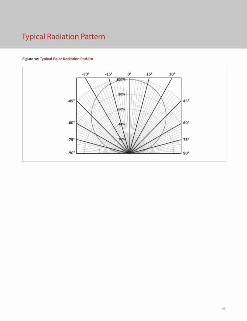
Typical Radiation Pattern
Figure 12: Typical Polar Radiation Pattern

23
Typical Color Spectrum
Figure 13: Typical Color Spectrum
Note for Figure 13:
1. Color spectra measured at nominal current for Tj = Tc = 25°C.
2. Color spectra shown is 3000K and 80 CRI.
3. Color spectra shown is 4000K and 80 CRI.
4. Color spectra shown is 5000K and 70 CRI.
4. Color spectra shown is 6500K and 70 CRI.
0%
10%
20%
30%
40%
50%
60%
70%
80%
90%
100%
110%
400 450 500 550 600 650 700 750 800
Rela
tive
Spec
tral
Pow
er D
istr
ibut
ion
Wavelength (nm)
3000K4000K5000K6500K
24
Mechanical Dimensions
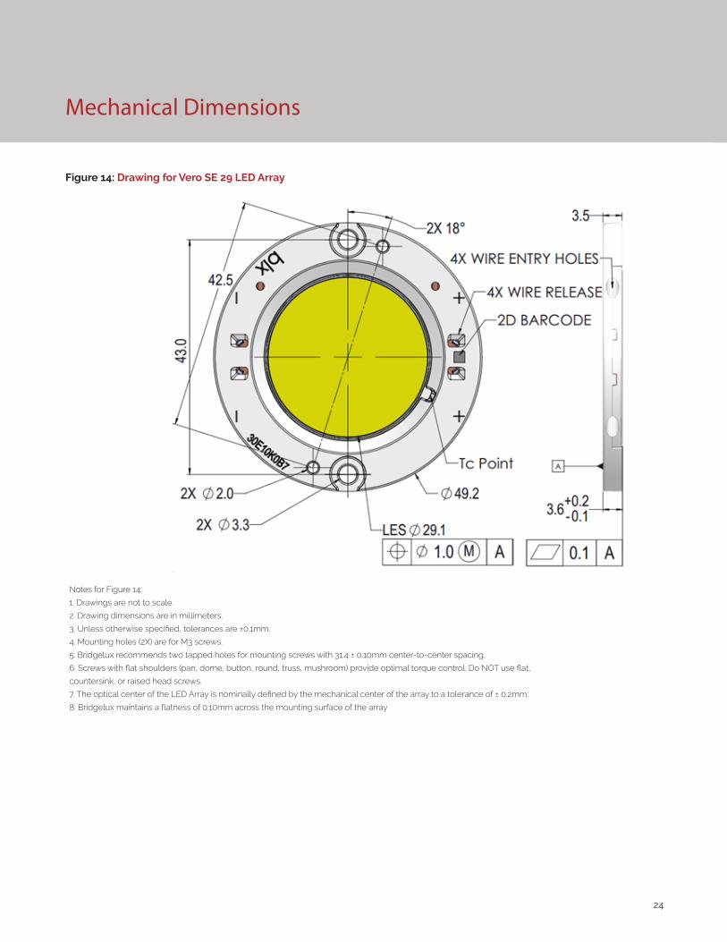
Figure 14: Drawing for Vero SE 29 LED Array
Notes for Figure 14:
1. Drawings are not to scale.
2. Drawing dimensions are in millimeters.
3. Unless otherwise specified, tolerances are ±0.1mm.
4. Mounting holes (2X) are for M3 screws.
5. Bridgelux recommends two tapped holes for mounting screws with 31.4 ± 0.10mm center-to-center spacing.
6. Screws with flat shoulders (pan, dome, button, round, truss, mushroom) provide optimal torque control. Do NOT use flat,
countersink, or raised head screws.
7. The optical center of the LED Array is nominally defined by the mechanical center of the array to a tolerance of ± 0.2mm.
8. Bridgelux maintains a flatness of 0.10mm across the mounting surface of the array

25
Figure 15: Graph of Warm and Neutral White Test Bins in xy Color Space
Figure 16: Graph of Cool White Test Bins in xy Color Space
Color Binning Information
Bin Code 2700K 3000K 3500K 4000K
ANSI Bin(for reference only)
(2580K - 2870K) (2870K - 3220K) (3220K - 3710K) (3710K - 4260K)
83 (3 SDCM) (2651K - 2794K) (2968K - 3136K) (3369K - 3586K) (3851K - 4130K)
82 (2 SDCM) (2674K - 2769K) (2995K - 3107K) (3404K - 3548K) (3895K - 4081K)
Center Point (x,y) (0.4578, 0.4101) (0.4338, 0.403) (0.4073, 0.3917) (0.3818, 0.3797)
Table 7: Warm and Neutral White xy Bin Coordinates and Associated Typical CCT
Bin Code 5000K 5700K 6500K
ANSI Bin (for reference only) (4745K - 5311K) (5312K - 6022K) (6022K - 7042K)
84 (4 SDCM) (4801K - 5282K) (5829K - 5481K) (6270K - 6765K)
83 (3 SDCM) (4835K - 5215K) (5490K - 5820K) (6250K - 6745K)
Center Point (x,y) (0.3447, 0.3553) (0.3287, 0.3417) (0.3123, 0.3282)
Table 8: Cool White xy Bin Coordinates and Associated Typical CCT (product is hot targeted to Tc = 85°C)
Note: Pulsed Test Conditions, Tc = 25°C
Note: Pulsed Test Conditions, Tc = 25°C
0.3
0.31
0.32
0.33
0.34
0.35
0.36
0.37
0.38
0.39
0.3 0.31 0.32 0.33 0.34 0.35 0.36
Y
X
4 SDCM
3 SDCM
6500K
5700K
5000K
0.34
0.36
0.38
0.4
0.42
0.44
0.36 0.39 0.42 0.45 0.48
Y
X
3 SDCM
2 SDCM
3500K
2700K
3000K
4000K

26
Packaging and Labeling
Figure 17: Drawing for Vero SE 29 Packaging Tray
Notes for Figure 17:
1. Dimensions are in millimeters.
2. Drawings are not to scale.

27
Packaging and Labeling
Figure 18: Vero SE Series Packaging and Labeling
Notes for Figure 18:
1. Each tray holds 50 COBs.
2. Each tray is vacuum sealed in an anti-static bag and placed in its own box.
3. Each tray, bag and box is to be labeled as shown above.
Figure 19: Vero SE Product Labeling
Bridgelux COB arrays have laser markings on the back side of the substrate to help with product identification. In
addition to the product identification markings, Bridgelux COB arrays also contain markings for internal Bridgelux
manufacturing use only. The image below shows which markings are for customer use and which ones are for Bridgelux
internal use only. The Bridgelux internal manufacturing markings are subject to change without notice, however these
will not impact the form, function or performance of the COB array.
Customer Use- 2D Barcode Scannable barcode provides product part number and other Bridgelux internal production information.
Customer Use- Product part number 30E10K0C 83 2F Customer Use- Vf Bin Code included to enable greater luminaire design flexibility. Refer to AN92 for bin definitions.
28
Design Resources
Disclaimers
Precautions
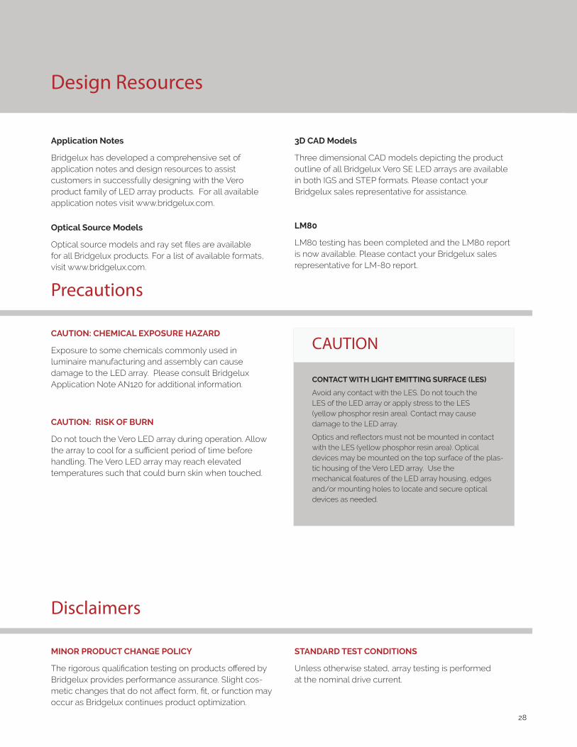
Application Notes
Bridgelux has developed a comprehensive set of application notes and design resources to assist customers in successfully designing with the Vero product family of LED array products. For all available application notes visit www.bridgelux.com.
Optical Source Models
Optical source models and ray set files are available for all Bridgelux products. For a list of available formats, visit www.bridgelux.com.
MINOR PRODUCT CHANGE POLICY
The rigorous qualification testing on products offered by Bridgelux provides performance assurance. Slight cos-metic changes that do not affect form, fit, or function may occur as Bridgelux continues product optimization.
CAUTION: CHEMICAL EXPOSURE HAZARD
Exposure to some chemicals commonly used in luminaire manufacturing and assembly can cause damage to the LED array. Please consult Bridgelux Application Note AN120 for additional information.
CAUTION: RISK OF BURN
Do not touch the Vero LED array during operation. Allow the array to cool for a sufficient period of time before handling. The Vero LED array may reach elevated temperatures such that could burn skin when touched.
3D CAD Models
Three dimensional CAD models depicting the product outline of all Bridgelux Vero SE LED arrays are available in both IGS and STEP formats. Please contact your Bridgelux sales representative for assistance.
LM80
LM80 testing has been completed and the LM80 report is now available. Please contact your Bridgelux sales representative for LM-80 report.
CAUTION
CONTACT WITH LIGHT EMITTING SURFACE (LES)
Avoid any contact with the LES. Do not touch the LES of the LED array or apply stress to the LES (yellow phosphor resin area). Contact may cause damage to the LED array.
Optics and reflectors must not be mounted in contact with the LES (yellow phosphor resin area). Optical devices may be mounted on the top surface of the plas-tic housing of the Vero LED array. Use the mechanical features of the LED array housing, edges and/or mounting holes to locate and secure optical devices as needed.
STANDARD TEST CONDITIONS
Unless otherwise stated, array testing is performed at the nominal drive current.

29
About Bridgelux: Bridging Light and Life™
© 2020 Bridgelux, Inc. All rights reserved. Product specifications are subject to change without notice. Bridgelux, the Bridgelux stylized logo design, Vero, V Series and V Series HD are registered trademarks, and Decor Series is a trademark of Bridgelux, Inc. All other trademarks are the property of their respective owners.
Bridgelux Gen 8 Vero SE 29 Array Series Product Data Sheet DS433 Rev. A (06/2020)
46430 Fremont Boulevard
Fremont, CA 94538 U.S.A.
Tel (925) 583-8400
www.bridgelux.com
At Bridgelux, we help companies, industries and people experience the power and possibility of light. Since 2002, we’ve designed LED solutions that are high performing, energy efficient, cost effective and easy to integrate. Our focus is on light’s impact on human behavior, delivering products that create better environments, experiences and returns—both experiential and financial. And our patented technology drives new platforms for commercial and industrial luminaires.
For more information about the company, please visit bridgelux.comtwitter.com/Bridgeluxfacebook.com/Bridgeluxyoutube.com/user/Bridgeluxlinkedin.com/company/bridgelux-inc-_2WeChat ID: BridgeluxInChina