product description - e-file.huawei.com
TRANSCRIPT
OceanStor 2600 V5V500R007 Kunpeng
Product Description
Issue 01
Date 2020-11-30
HUAWEI TECHNOLOGIES CO., LTD.

Copyright © Huawei Technologies Co., Ltd. 2020. All rights reserved.
No part of this document may be reproduced or transmitted in any form or by any means without priorwritten consent of Huawei Technologies Co., Ltd. Trademarks and Permissions
and other Huawei trademarks are trademarks of Huawei Technologies Co., Ltd.All other trademarks and trade names mentioned in this document are the property of their respectiveholders. NoticeThe purchased products, services and features are stipulated by the contract made between Huawei andthe customer. All or part of the products, services and features described in this document may not bewithin the purchase scope or the usage scope. Unless otherwise specified in the contract, all statements,information, and recommendations in this document are provided "AS IS" without warranties, guaranteesor representations of any kind, either express or implied.
The information in this document is subject to change without notice. Every effort has been made in thepreparation of this document to ensure accuracy of the contents, but all statements, information, andrecommendations in this document do not constitute a warranty of any kind, express or implied.
Huawei Technologies Co., Ltd.Address: Huawei Industrial Base
Bantian, LonggangShenzhen 518129People's Republic of China
Website: https://e.huawei.com
Issue 01 (2020-11-30) Copyright © Huawei Technologies Co., Ltd. i

About This Document
PurposeThis document describes the positioning, features, typical applications,architecture, specifications, environmental requirements, standards compliance,and granted certifications of OceanStor storage systems.
The following table lists the product models that this document is applicable to.
Product Series Product Model
OceanStor 2000 V5series
OceanStor 2600 V5
Intended AudienceThis document is intended for: All readers
Symbol ConventionsThe symbols that may be found in this document are defined as follows.
Symbol Description
Indicates a hazard with a high level of risk which,if not avoided, will result in death or seriousinjury.
Indicates a hazard with a medium level of riskwhich, if not avoided, could result in death orserious injury.
Indicates a hazard with a low level of risk which,if not avoided, could result in minor or moderateinjury.
OceanStor 2600 V5Product Description About This Document
Issue 01 (2020-11-30) Copyright © Huawei Technologies Co., Ltd. ii

Symbol Description
Indicates a potentially hazardous situation which,if not avoided, could result in equipment damage,data loss, performance deterioration, orunanticipated results.NOTICE is used to address practices not related topersonal injury.
Supplements the important information in themain text.NOTE is used to address information not relatedto personal injury, equipment damage, andenvironment deterioration.
Change HistoryChanges between document issues are cumulative. The latest document issuecontains all the changes made in earlier issues.
Issue 01 (2020-11-30)This issue is the first official release.
OceanStor 2600 V5Product Description About This Document
Issue 01 (2020-11-30) Copyright © Huawei Technologies Co., Ltd. iii

Contents
About This Document................................................................................................................ ii
1 Product Positioning................................................................................................................. 1
2 Product Features...................................................................................................................... 3
3 Typical Applications..............................................................................................................113.1 High-Performance Applications....................................................................................................................................... 113.2 High-Availability Applications.......................................................................................................................................... 133.3 High-Density and Multi-Service Applications............................................................................................................. 15
4 Hardware Architecture.........................................................................................................184.1 Device Composition..............................................................................................................................................................184.2 3D Interactive Hardware Demonstration......................................................................................................................194.3 2 U Controller Enclosure.....................................................................................................................................................204.3.1 Overview...............................................................................................................................................................................204.3.2 Component Description...................................................................................................................................................234.3.2.1 System Subrack............................................................................................................................................................... 234.3.2.2 Controller.......................................................................................................................................................................... 234.3.2.3 BBU..................................................................................................................................................................................... 264.3.2.4 Fan Module...................................................................................................................................................................... 274.3.2.5 Power Module................................................................................................................................................................. 284.3.2.6 Disk Module..................................................................................................................................................................... 294.3.3 Indicator Introduction...................................................................................................................................................... 314.4 Interface Module................................................................................................................................................................... 354.4.1 GE Electrical Interface Module..................................................................................................................................... 354.4.2 10GE Electrical Interface Module.................................................................................................................................374.4.3 25 Gbit/s RDMA Interface Module.............................................................................................................................. 394.4.4 40GE Interface Module....................................................................................................................................................414.4.5 100GE Interface Module................................................................................................................................................. 434.4.6 100 Gbit/s RDMA Interface Module............................................................................................................................454.4.7 SmartIO Interface Module............................................................................................................................................. 484.4.8 12 Gbit/s SAS Expansion Module.................................................................................................................................544.5 SAS Disk Enclosure (2 U, 2.5-Inch Disks)..................................................................................................................... 564.5.1 Overview...............................................................................................................................................................................564.5.2 Component Description...................................................................................................................................................57
OceanStor 2600 V5Product Description Contents
Issue 01 (2020-11-30) Copyright © Huawei Technologies Co., Ltd. iv

4.5.2.1 System Subrack............................................................................................................................................................... 574.5.2.2 Expansion Module......................................................................................................................................................... 584.5.2.3 Power Module................................................................................................................................................................. 594.5.2.4 Disk Module..................................................................................................................................................................... 614.5.3 Indicator Introduction...................................................................................................................................................... 624.6 SAS Disk Enclosure (4 U, 3.5-Inch Disks)..................................................................................................................... 644.6.1 Overview...............................................................................................................................................................................644.6.2 Component Description...................................................................................................................................................664.6.2.1 System Subrack............................................................................................................................................................... 664.6.2.2 Expansion Module......................................................................................................................................................... 674.6.2.3 Power Module................................................................................................................................................................. 694.6.2.4 Fan Module...................................................................................................................................................................... 704.6.2.5 Disk Module..................................................................................................................................................................... 714.6.3 Indicator Introduction...................................................................................................................................................... 724.7 High-Density Disk Enclosure............................................................................................................................................. 754.7.1 Overview...............................................................................................................................................................................754.7.2 Component Description...................................................................................................................................................784.7.2.1 System Subrack............................................................................................................................................................... 784.7.2.2 Expansion Module......................................................................................................................................................... 794.7.2.3 Disk Module..................................................................................................................................................................... 804.7.2.4 Power Module................................................................................................................................................................. 824.7.2.5 Fan Module...................................................................................................................................................................... 834.7.3 Indicator Introduction...................................................................................................................................................... 844.8 Coffer Disk...............................................................................................................................................................................874.9 (Optional) Quorum Server................................................................................................................................................ 914.9.1 (Optional) Quorum Server (1288H V5).................................................................................................................... 914.9.2 (Optional) Quorum Server (TaiShan 200)................................................................................................................954.10 Device Cables.....................................................................................................................................................................1014.10.1 Power Cables.................................................................................................................................................................. 1014.10.2 Ground Cables............................................................................................................................................................... 1024.10.3 Network Cables............................................................................................................................................................. 1024.10.4 Serial Cables................................................................................................................................................................... 1034.10.5 Mini SAS HD Cables.....................................................................................................................................................1044.10.5.1 Mini SAS HD Electrical Cables.............................................................................................................................. 1054.10.5.2 Mini SAS HD Optical Cables..................................................................................................................................1054.10.6 Optical Fibers................................................................................................................................................................. 1064.10.7 100G QSFP28 Cables................................................................................................................................................... 1074.10.8 25G SFP28 Cables......................................................................................................................................................... 107
5 Software Architecture........................................................................................................ 109
6 Product Specifications........................................................................................................117
7 Environmental Requirements...........................................................................................118
OceanStor 2600 V5Product Description Contents
Issue 01 (2020-11-30) Copyright © Huawei Technologies Co., Ltd. v
7.1 Environment Parameters................................................................................................................................................. 1187.2 Contaminants.......................................................................................................................................................................1197.2.1 Particle Contaminants................................................................................................................................................... 1197.2.2 Corrosive Airborne Contaminants............................................................................................................................. 120
8 Standards Compliance....................................................................................................... 124
9 Certifications........................................................................................................................ 129
10 Operation and Maintenance.......................................................................................... 134
A How to Obtain Help...........................................................................................................136A.1 Preparations for Contacting Huawei........................................................................................................................... 136A.1.1 Collecting Troubleshooting Information................................................................................................................. 136A.1.2 Making Debugging Preparations.............................................................................................................................. 136A.2 How to Use the Document............................................................................................................................................. 137A.3 How to Obtain Help from Website..............................................................................................................................137A.4 Ways to Contact Huawei................................................................................................................................................. 137
B Glossary................................................................................................................................. 138
C Acronyms and Abbreviations........................................................................................... 139
OceanStor 2600 V5Product Description Contents
Issue 01 (2020-11-30) Copyright © Huawei Technologies Co., Ltd. vi

1 Product Positioning
The OceanStor 2600 V5 storage system is Huawei entry-level storage providingstable, reliable, converged, and efficient data services for enterprises.
The 2600 V5 storage system offers comprehensive and superb solutions byunifying file-based, block-based offerings and various protocols into a singleproduct and using diverse efficiency boost mechanisms to provide industry-leadingperformance. Those solutions help customers maximize their return on investment(ROI) and meet the requirements of different application scenarios such as OnlineTransaction Processing (OLTP) and Online Analytical Processing (OLAP) of largedatabases, high-performance computing (HPC), digital media, Internet operation,centralized storage, backup, disaster recovery, and data migration.
In addition to providing high-performance storage services for application servers,the 2600 V5 storage system supports advanced data backup and disaster recoverytechnologies, ensuring the secure and smooth running of data services. Also, itoffers easy-to-use management modes and convenient local/remote maintenancemodes, greatly decreasing the management and maintenance costs.
Position and Application on a Unified SAN and NAS NetworkFigure 1-1 shows the position and application of the storage system on a unifiedSAN and NAS network.
OceanStor 2600 V5Product Description 1 Product Positioning
Issue 01 (2020-11-30) Copyright © Huawei Technologies Co., Ltd. 1

Figure 1-1 Position and application
Block reads/writes via FC SAN and IP SAN
Connections via Ethernet, management and maintenance using visualized management tools
Backup medium
Local backup/Remote backup
Domain user
Local user
Administrator
Service engineer
Domain controller
Connections via Ethernet, LDAP/AD/NIS/DNS domain management
Backup server
Backup management
NAS application hosts
Storage systemRemote and local maintenance
Connections via GE or 10GE, file reads/writes using NFS/CIFS/FTP/HTTP
Remote storage devices
SAN application hosts
Connections via GE or 10GE, file reads/writes using NFS/CIFS/FTP/HTTP
Connections via GE or 10GE, file reads/writes using NFS/CIFS (domain environment)
Remote disaster recovery application, file-level remote replication, SAN remote mirroring
OceanStor 2600 V5Product Description 1 Product Positioning
Issue 01 (2020-11-30) Copyright © Huawei Technologies Co., Ltd. 2

2 Product Features
Designed for midtier-to-enterprise storage environments, the storage systemutilizes high-specification hardware and is available in block, file, and unifiedconfigurations. It offers significant advancements in data applications andprotection and provides the following benefits.
Unified Storage● SAN and NAS unified storage technologies
Unifies SAN and NAS technologies to store both structured and unstructureddata.
● A wide range of mainstream storage protocolsSupports mainstream storage protocols such as iSCSI, Fibre Channel, NFS,CIFS, HTTP, and FTP.
● Support for hosts to access any LUN or file system using the front-end portsof any controller.
High PerformanceThe storage system offers a three-level performance acceleration technology, anddelivers hierarchical performance for different applications. The three levels are:
1. State-of-the-art hardwareThe storage system is equipped with 64-bit multi-core processors, high-speedand large-capacity caches, and various high-speed interface modules. Thesuperior hardware allows it to offer better storage performance than traditionstorage systems.
2. SmartTierThe SmartTier technology identifies hotspot data and periodically promotesthem to high-performance storage medium for a performance boost. Inaddition, SmartTier supports SSD data caching, accelerating access to hotspotdata.
3. Solid state drives (SSDs)The storage system adopts the operating system specially designed for all-flash arrays to fully utilize SSDs and provide peak performance for the most-demanding applications.
OceanStor 2600 V5Product Description 2 Product Features
Issue 01 (2020-11-30) Copyright © Huawei Technologies Co., Ltd. 3
Flexible ScalabilityThe storage system has an outstanding scalability. It supports a wide range of thefollowing disks and host interface modules in a high density:
● Disks:SAS disks, NL-SAS disks, and SSDs.
● Interface modules: For details, see 4.4 Interface Module.
The storage system also supports the Scale-out technology to improve storagesystem performance as the number of controllers increases.
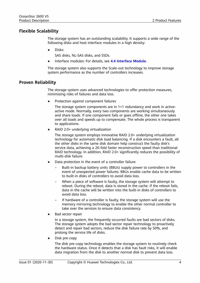
Proven ReliabilityThe storage system uses advanced technologies to offer protection measures,minimizing risks of failures and data loss.
● Protection against component failuresThe storage system components are in 1+1 redundancy and work in active-active mode. Normally, every two components are working simultaneouslyand share loads. If one component fails or goes offline, the other one takesover all loads and speeds up to compensate. The whole process is transparentto applications.
● RAID 2.0+ underlying virtualizationThe storage system employs innovative RAID 2.0+ underlying virtualizationtechnology for automatic disk load balancing. If a disk encounters a fault, allthe other disks in the same disk domain help construct the faulty disk'sservice data, achieving a 20-fold faster reconstruction speed than traditionalRAID technology. In addition, RAID 2.0+ significantly reduces the possibility ofmulti-disk failure.
● Data protection in the event of a controller failure– Built-in backup battery units (BBUs) supply power to controllers in the
event of unexpected power failures. BBUs enable cache data to be writtento built-in disks of controllers to avoid data loss.
– When a piece of software is faulty, the storage system will attempt toreboot. During the reboot, data is stored in the cache. If the reboot fails,data in the cache will be written into the built-in disks of controllers toavoid data loss.
– If hardware of a controller is faulty, the storage system will use thememory mirroring technology to enable the other normal controller totake over the services to ensure data consistency.
● Bad sector repairIn a storage system, the frequently occurred faults are bad sectors of disks.The storage system adopts the bad sector repair technology to proactivelydetect and repair bad sectors, reduce the disk failure rate by 50%, andprolong the service life of disks.
● Disk pre-copyThe disk pre-copy technology enables the storage system to routinely checkthe hardware status. Once it detects that a disk has fault risks, it will enabledata migration from the disk to another normal disk to prevent data loss.
OceanStor 2600 V5Product Description 2 Product Features
Issue 01 (2020-11-30) Copyright © Huawei Technologies Co., Ltd. 4

● IP address failoverThe storage system adopts IP address failover technology. If a physical hostport that implements the NAS protocol is damaged, the IP address assignedto that port automatically fails over to another functional port. Based on thecorrect networking, services are seamlessly failed over, preventing damage toa port from affecting services.
● Online disk diagnosisThe online disk diagnosis feature is used to handle disk faults. If a disk faultoccurs, the storage system takes the disk offline. Then, the online diagnosismodule reads the S.M.A.R.T information about the disk and takes analysis,testing, and recovery measures. After the disk is recovered, the onlinediagnosis module enables the disk to rejoin the RAID, prolonging the lifecycleof the disk.
● Data coffer diskData coffer disks consist of the first four disks of a storage system's controllerenclosure and one disk built in each controller. They store three types of data:cache data requiring power failure protection, OceanStor OS system data, andsystem configuration information and logs.
High AvailabilityIn routine maintenance:
The storage system uses Turbo Module, online capacity expansion, and diskroaming technologies to provide high availability for applications and non-disruptive system running during maintenance.
● Turbo Module enables controllers, fans, power modules, interface modules,BBUs, and disks to be hot-swappable, allowing online operations.
● Dynamic capacity expansion enables users to add disks to a disk domain in anonline and easy manner.
● Disk roaming enables a storage system to automatically identify relocateddisks and resume their services.
In data protection:
The storage system provides the following advanced data protection technologiesand protocols to protect data integrity and continuous system running even whencatastrophic disasters happen:
● HyperSnap generates multiple point-in-time images for the source logical unitnumber (LUN) or source file system data. The snapshot images can be usedto recover data quickly when needed.
● HyperCopy backs up data among heterogeneous storage systems for dataprotection.
● HyperReplication backs up local data onto a remote storage system fordisaster recovery.
● HyperClone preserves a real-time physical copy of a source LUN for the highavailability of local data.
● HyperMirror backs up data in real time. If the source data becomesunavailable, applications can automatically use the data copy, ensuring datasecurity and application continuity.
OceanStor 2600 V5Product Description 2 Product Features
Issue 01 (2020-11-30) Copyright © Huawei Technologies Co., Ltd. 5

● HyperMetro synchronizes and replicates data between storage arrays,monitors service operating status, and performs failovers. In addition, it canswitch over services and implement service load sharing when storage arraysare running.
The Network Data Management Protocol (NDMP) is also used for data backupand recovery.
In resource management:
The storage system employs the following resource application technologies forflexible resource management to protect customers' storage investments:
● SmartVirtualization enables a local storage system to centrally managestorage resources of heterogeneous storage systems, simplifying storagesystem management and reducing maintenance costs.
● SmartMigration migrates LUNs in or between storage systems, adjusting andallocating resources along with business development.
● SmartMulti-Tenant enables a storage system to provide different tenants withshared storage resources and to separate tenant access and management.
The storage system supports memory upgrade so that storage performancematches service development.
High System SecurityStorage network security:
● Security of management channelsThe management operations from physical ports are controlled by the accessauthentication mechanism of the storage system, and only authorized usersare allowed to manage the storage system.
● Anti-attack protection for protocols and portsThe storage system provides only necessary ports to the external for systemoperations and maintenance. All the ports used are listed in theCommunication Matrix. Dynamic listening ports are functioning in the properscope, and no undisclosed interface exists.
● Service ports are isolated from management portsThe Access Control List (ACL) mechanism is adopted to isolate Ethernet portsfrom internal heartbeat network ports, management network ports, andmaintenance network ports.
Storage service security:
● Security of the operating systemThe storage system uses a dedicated operating system. Security of theoperating system has been hardened before the storage system is delivered.The storage systems update security patches for their operating systems andopen-source software based on site requirements, safeguarding users' data.
● Data storage encryption– The storage system supports data encryption by using a network
password manager. The network password manager employs thestandard cryptographic algorithm supported by the State Encryption
OceanStor 2600 V5Product Description 2 Product Features
Issue 01 (2020-11-30) Copyright © Huawei Technologies Co., Ltd. 6

Administration of China. It allows only the hosts that comply withsecurity policies to access storage system data by auditing access controlpolicies and controlling access attempts from hosts. After the networkpassword manager is deployed, all mutual information between the hostsand storage system will pass the network password manager to enableread/write data encryption and decryption. This ensures data security ofthe storage system.
– The storage system supports self-encrypting drives (SEDs). The hardwarecircuits and internal data encrypt key of SEDs are used for data writingencryption and data reading decryption. To ensure the security of thedata encrypt key, the storage system and the third-party keymanagement server jointly provide a highly secure, reliable, and availablekey management solution.
NO TE
SEDs are only sold outside Chinese mainland.
● Data destructionWhen deleting unwanted data, the system erases the specified LUN to makethe deleted data unable to be restored, preventing critical data leaks.
● File antivirusWhen the storage system runs a file system and shares the file system withclients through CIFS, third-party antivirus software can be used to triggervirus scanning and delete virus-infected files, improving storage systemsecurity.
Storage management security:
● Security of management and maintenanceThe operations of users can be allowed and denied. All managementoperations are logged by the system.
● Data integrity protection and tamper resistanceThe Write Once Read Many (WORM) feature allows users to set critical datato the read-only state, preventing unauthorized data change and deletionduring a specified period of time.
In addition, trusted verification is enabled during the storage system startup tomeasure and verify BIOS > Grub > Euler Linux Kernel > Euler Linux > Storageapplication software level by level to prove integrity of loaded software at eachlevel and to prevent software tampering. The storage system's power-on processwill be verified to ensure that the system is not tampered with.
Virtualization, Intelligence, and Efficiency
The storage system absorbs the concept of "Virtualization, Intelligence, andEfficiency", which fits the up-to-date storage design idea and wins a leadingposition for the storage system. Compared with traditional storage systems, theseries introduces the following technologies to provide higher storage space usage,faster data reconstruction, smarter performance allocation, and finer servicequality control:
● RAID 2.0+ underlying virtualization
OceanStor 2600 V5Product Description 2 Product Features
Issue 01 (2020-11-30) Copyright © Huawei Technologies Co., Ltd. 7

Divides disk storage space into small-sized data blocks and uses the blocks tocreate RAID groups for fine-grained resource management. The technologyrealizes automatic load balancing, higher storage performance, better storagespace utilization, faster disk reconstruction, and finer storage spacemanagement. RAID 2.0+ serves as a basis for a number of other advancedstorage technologies.
● SmartTier (intelligent storage tiering)
Enables a storage system to automatically analyze data access frequency perunit time and relocate data to disks of different performance levels based onthe analysis result. High-performance disks store hot data, performance disksstore warm data, and large-capacity disks store cold data. As a result,SmartTier optimizes overall performance and reduces costs per IOPS.
● SmartQoS (intelligent service quality control)
Enables a storage system to categorize service data based on datacharacteristics (each category represents a type of application) and set apriority and performance objective for each category. In this way, resourcesare assigned to services based on priorities, ensuring the performance ofmission-critical services that have the top priority.
● SmartThin (Thin provisioning)
Allows on-demand allocation of storage space rather than the traditionalmethod of pre-allocating all storage space at the initial stage. It is moreefficient because the amount of resources used is close to the amount ofresources allocated. In this way, the initial purchase cost and total cost ofownership are reduced.
● SmartCache (intelligent storage cache)
Uses SSDs as cache resources to significantly promote system readperformance when random, small I/Os with hot data require more readoperations than write operations.
● Quick document incremental backup with Tivoli Storage Manager (TSM)
When the storage system interworks with the TSM backup software toperform incremental file backup, the Snapdiff feature uses the snapshotmechanism to quickly obtain differential file information and identify changedfiles. Without the need for full scanning, only changed files are backed,greatly shortening backup time. The backup performance is not affected bythe number of files, which greatly improves the backup efficiency.
Cost-Effectiveness and Ease-of-Use
The storage system delivers cost-effective performance through delicate fan speedcontrol and deduplication and compression. It also provides a series ofmanagement and maintenance tools for easy use and maintenance.
● Cost-effectiveness
– Delicate fan speed control
Dynamically adjusts the fan speed based on the storage system'stemperature. It lowers the noise and power consumption and cuts theoperation cost.
– Deduplication and compression
OceanStor 2600 V5Product Description 2 Product Features
Issue 01 (2020-11-30) Copyright © Huawei Technologies Co., Ltd. 8

Checks and processes duplicate data in disks based on deduplication, andminimizes space occupied by data based on compression to improve diskutilization.
● Ease-of-use– DeviceManager
An HTML5-based tool providing the graphical user interface (GUI) allowsyou to easily manage storage systems through wizard-instructedoperations.
– Integrated managementImplements convenient device management by integrating amanagement plug-in into mainstream management software such asVMware vCenter plug-in, Hyper-V System Center, vSphere API for StorageAwareness (VASA), vSphere Storage APIs for Array Integration (VAAI),and Volume Shadow Copy Service (VSS) Provider.
– Tablet managementSupports flexible storage system management on a tablet.
– Various alarm notification methodsProvides alarm notification by sound, indicator, short message service(SMS), and email.
– Tool for an upgrade at your fingertipsProvides online upgrade for controllers. The operation is easy withoutinterrupting services.
Intelligent O&M
The eService intelligent cloud management system (eService for short) improvescustomers' O&M capabilities and takes planned maintenance actions to preventpotential risks.
Being authorized by customers, eService monitors device alarms in 24/7 mode.Whenever an alarm is detected, eService automatically notifies Huawei technicalsupport center and creates service requests (SRs). Huawei service engineers willhelp customers solve problems in a timely manner.
● eService provides a self-service O&M system for customers, aiming for preciseand customized information services.
● Based on HUAWEI CLOUD, the eService cloud system drives IT O&M activitiesvia big data analytics and artificial intelligence (AI) technologies to identifyfaults in advance, reduce O&M difficulties, and improve O&M efficiency.
● Data is encrypted during the data transmission, ensuring secure datatransmission. eService can access the customer's system only after beingauthorized by the customer.
● eService provides 24/7 secure, reliable, and proactive O&M services. SRs canbe automatically created.
● Customers can use any PC to access eService at any time and any place toview device information.
eService enables the client system to work with the cloud system.
OceanStor 2600 V5Product Description 2 Product Features
Issue 01 (2020-11-30) Copyright © Huawei Technologies Co., Ltd. 9

● eService client system:
Deployed on the customer side, the eService client system collects customer devicealarms and sends them to the eService cloud system in a timely manner toimplement remote maintenance functions, such as remote inspection and remotelog collection.
● eService cloud system:
Deployed in Huawei technical support center, the eService cloud system receivesdevice alarms from the client system in 24/7 mode, automatically notifies Huaweitechnical support personnel to handle the alarms in a timely manner, andsupports automatic inspection and log collection for devices on the customer side.
For details, see the eService Intelligent Cloud Management System User Guide orlog in to http://support.eservice.huawei.com to access and use eService.
OceanStor 2600 V5Product Description 2 Product Features
Issue 01 (2020-11-30) Copyright © Huawei Technologies Co., Ltd. 10

3 Typical Applications
About This Chapter
The storage system offers industry-leading hardware specifications, a flexible andreliable hardware design, a virtualized underlying architecture, and a variety ofdata protection technologies, addressing the needs of differentiated storageapplications. It is designed for a wide range of applications including high-performance, high-availability, or high-density and multi-service applications.
3.1 High-Performance Applications
3.2 High-Availability Applications
3.3 High-Density and Multi-Service Applications
3.1 High-Performance ApplicationsThe storage system incorporates various technologies to boost the systemperformance. Its high-performance hardware delivers outstanding data accessperformance. The virtualization technology can improve the storage performancecontinuously and it shatters performance bottlenecks from future business growth.The intelligent data tiering technology SmartTier automatically detects andprioritizes hotspot data. Therefore, the storage system is a great choice for thehigh-performance applications.
On-Demand System Performance Boost
In certain scenarios, a storage system may have been provisioned to meet theinitial application requirements. However, the future growth of applications oftenexceeds expectation, and the performance of a traditional storage system willsoon become a limiting factor. The virtualization technology of the storage systemcan address this issue. It dynamically increases storage performance based oncurrent application requirements. This prolongs the system service life and lowerscustomers' total cost of ownership (TCO).
After the initial purchase, the storage system is equipped with affordable hard diskdrives (HDDs) to deliver data storage services. As the service requirementsincrease and the storage system requires higher performance, administrators canadd HDDs or SSDs to boost the system performance. If even greater system
OceanStor 2600 V5Product Description 3 Typical Applications
Issue 01 (2020-11-30) Copyright © Huawei Technologies Co., Ltd. 11

performance is required, administrators can replace all the existing HDDs withSSDs to further improve system performance.
This on-demand system performance boost brings the following benefits:
● The system performance is improved gradually, balancing the return oninvestment (ROI) and the system service life.
● Components for upgrade are available, following the Moore's Law to reducethe purchase cost and the TCO.
Dynamic Storage Tiering for Hotspot Data
In media and website applications, information has a high access frequency, whichcan generate hotspot data. The hotspot data receives simultaneous read and writerequests from a large number of servers, and poses a demanding requirement onstorage system performance. Traditional storage systems cannot address such astorage requirement.
The storage system uses its resident intelligent data tiering technology, SmartTier,to identify hotspot data and promote it to high-performance SAS disks or SSDs. IfSmartTier later finds out that the hotspot data becomes cold (receiving feweraccess requests), it demotes the data to low-performance disks and clears storagespace for new hotspot data. Figure 3-1 depicts the working principle of SmartTier.
Figure 3-1 SmartTier working principle
OceanStor 2600 V5Product Description 3 Typical Applications
Issue 01 (2020-11-30) Copyright © Huawei Technologies Co., Ltd. 12

3.2 High-Availability ApplicationsThe storage system has a highly reliable design, achieving a long mean timebetween failures (MTBF), and ensuring high availability of storage applications. Italso incorporates a variety of data protection technologies, and protects dataintegrity and service continuity against catastrophic disasters.
In-Service Routine MaintenanceIn traditional storage systems, routine maintenance tasks, such as componentreplacement and capacity expansion, must be implemented in offline mode. Thestorage system, however, assembles advanced technologies for in-service routinemaintenance:
● Turbo ModuleEnables online replacement of components and requires no system restart.
● Online capacity expansionAllows online addition of disks and expansion of storage pools.
Tolerance of Single Points of FailuresThe storage system incorporates a hierarchical redundancy design to eliminate theimpact of single points of failure:
● Hardware redundancyAll components of the series are in redundancy and work in active-activemode. If one component fails, the other speeds up to compensate so that thestorage system can continue operating.
● Link redundancyIf there is only one link between the storage system and an application server,the disconnection of the link terminates their communication. To eliminatethis failure, the series storage system uses two or more links to communicatewith the application server. Therefore, if one link is down, the other links takeover the services to continue the data transmission.
● Application server clusteringIf the storage system cooperates with only one application server, the failureof the application server interrupts services. Application server clustering canaddress this issue. A cluster consists of two or more application servers thatshare loads. If one application server in the cluster fails, the other applicationservers take over its loads, and the whole process is transparent to users.Application server clustering supported by the series ensures businesscontinuity.
Based on the previous protection mechanisms, the storage system has proventolerance of single points of failure, as shown in Figure 3-2.
OceanStor 2600 V5Product Description 3 Typical Applications
Issue 01 (2020-11-30) Copyright © Huawei Technologies Co., Ltd. 13

Figure 3-2 Tolerance of single points of failure
In the example in Figure 3-2, application server A and controller A are faulty, anda link between the cluster and the storage system is down. Under thiscircumstance, the redundant components and links compensate for the failedones, and services are switched to application server B that is running properly.This ensures the nonstop system operations and greatly improves the serviceavailability.
Resilience Against DisastersThe storage system compliments various data protection methods for backup anddisaster recovery. Those methods eliminate the risks of unexpected downtime anddata loss caused by natural disasters, serious device failures, or man-mademisoperations.
The supported data protection methods include:
● BackupThe storage system processes a huge amount of data, and the loss of anydata can lead to a disastrous result. Therefore, enterprises are used toperiodically back up their critical data. The following backup technologies aremost commonly used because they complete data backup in a hitless manner:– HyperSnap: locally generates a virtual duplicate for a source LUN at a
specified point in time. The duplicate is immediately usable and anyaccess to it will have no impact on the source LUN data.
– HyperClone: locally generates a complete copy for a source LUN at aspecified point in time. After the clone task, the destination LUN storesthe same data as the source LUN, and their relationship can be split.
OceanStor 2600 V5Product Description 3 Typical Applications
Issue 01 (2020-11-30) Copyright © Huawei Technologies Co., Ltd. 14

Then any access to the destination LUN has no impact on the source LUNdata.
– HyperCopy: replicates data from the source LUN to the destination LUNat block level. A LUN copy task can be performed within a storage systemor among storage systems (even if they are heterogeneous).
– HyperMirror: backs up data in real time. If the source data becomesunavailable, applications can automatically use the data copy, ensuringdata security and application continuity.
– HyperMetro: synchronizes and replicates data between storage arrays,monitors service operating status, and performs failovers. In addition, itcan switch over services and implement service load sharing whenstorage arrays are running.
● Disaster recoveryDisaster recovery is essential for critical applications that must continueoperating even during catastrophic disasters. Disaster recovery technologiesinvolve many aspects such as storage systems, application servers, applicationsoftware, and technicians. From the storage system aspect, the remotereplication technology is used for disaster recovery because it can back updata in real time.The technology duplicates backup data in real time across sites, and utilizesthe long distance between sites to eliminate data loss. This ensures that datais readily available on other sites if one site is destroyed.
3.3 High-Density and Multi-Service ApplicationsThe storage system delivers industry-leading density of interface modules in anenclosure and a flexible configuration of interface modules and hard disks ofdifferent types. This design makes the series suitable for high-density and multi-service applications.
High-Density Virtual Machine ApplicationsThe virtual machine technology greatly improves application servers' utilization,and lowers services' deployment and operating expense. Therefore, it is popular inmany application scenarios. However, virtual machines are now facing a challenge,that is, they are equipped with an increasing number of application systems andvirtual desktops, leading to the high density of virtual machines. Compared with asingle server, high-density virtual machines generate more service data, consumemore bandwidth, and pose more demanding requirements on performance andscalability.
Excellent in both performance and compatibility, the storage system is ideal forhigh-density virtual machine applications:
● The three-level performance acceleration technology provides robust storageperformance for high-density virtual machine applications.
● The proprietary Turbo Module technology significantly improves the density ofinterface modules in a single enclosure. This high-density design translatesinto a capability to support hundreds of virtual machines.
● Various virtual machine applications are supported, including VMware, Hyper-V, and Citrix Xen.
OceanStor 2600 V5Product Description 3 Typical Applications
Issue 01 (2020-11-30) Copyright © Huawei Technologies Co., Ltd. 15
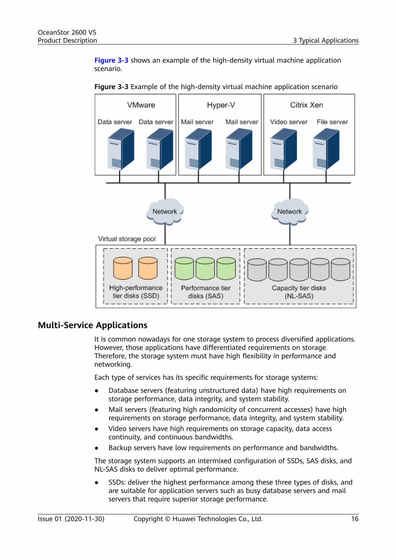
Figure 3-3 shows an example of the high-density virtual machine applicationscenario.
Figure 3-3 Example of the high-density virtual machine application scenario
Multi-Service ApplicationsIt is common nowadays for one storage system to process diversified applications.However, those applications have differentiated requirements on storage.Therefore, the storage system must have high flexibility in performance andnetworking.
Each type of services has its specific requirements for storage systems:
● Database servers (featuring unstructured data) have high requirements onstorage performance, data integrity, and system stability.
● Mail servers (featuring high randomicity of concurrent accesses) have highrequirements on storage performance, data integrity, and system stability.
● Video servers have high requirements on storage capacity, data accesscontinuity, and continuous bandwidths.
● Backup servers have low requirements on performance and bandwidths.
The storage system supports an intermixed configuration of SSDs, SAS disks, andNL-SAS disks to deliver optimal performance.
● SSDs: deliver the highest performance among these three types of disks, andare suitable for application servers such as busy database servers and mailservers that require superior storage performance.
OceanStor 2600 V5Product Description 3 Typical Applications
Issue 01 (2020-11-30) Copyright © Huawei Technologies Co., Ltd. 16

● SAS disks: deliver performance lower than SSDs but higher than NL-SAS disks,and are suitable for application servers such as common database servers,mail servers, and high-definition (HD) video servers that have a moderatestorage performance requirement.
● NL-SAS disks: deliver the lowest performance among these three types ofdisks, and are suitable for application servers such as low-end video serversand backup servers that have a low storage performance requirement.
Multiple front-end interface modules are flexibly configured with customizabletransmission rates, adapting to various networks and providing storage services indifferent networks.
Figure 3-4 shows an example of multi-service application scenario.
Figure 3-4 Example of a multi-service application scenario
OceanStor 2600 V5Product Description 3 Typical Applications
Issue 01 (2020-11-30) Copyright © Huawei Technologies Co., Ltd. 17

4 Hardware Architecture
About This ChapterThe OceanStor storage hardware is the basis of data storage. A storage unittypically consists of a controller enclosure or a controller enclosure plus diskenclosures.
4.1 Device Composition
4.2 3D Interactive Hardware Demonstration
4.3 2 U Controller Enclosure
4.4 Interface Module
4.5 SAS Disk Enclosure (2 U, 2.5-Inch Disks)
4.6 SAS Disk Enclosure (4 U, 3.5-Inch Disks)
4.7 High-Density Disk Enclosure
4.8 Coffer Disk
4.9 (Optional) Quorum Server
4.10 Device Cables
4.1 Device CompositionA storage system consists of one or more controller enclosures and diskenclosures, and it provides an intelligent storage platform that features robustreliability, high performance, and large capacity.
Different product models use different types of controller enclosures and diskenclosures Table 4-1.
OceanStor 2600 V5Product Description 4 Hardware Architecture
Issue 01 (2020-11-30) Copyright © Huawei Technologies Co., Ltd. 18

Table 4-1 Model comparison
Product Model Controller Enclosure Disk Enclosure
OceanStor 2600 V5with disk andcontroller integration
● 2 U controllerenclosure with 12disk slots
● 2 U controllerenclosure with 25disk slots
● 2 U SAS disk enclosure with25 disk slots
● 4 U SAS disk enclosure with24 disk slots
● 4 U SAS high-density diskenclosure with 75 x 3.5-inchdisk slots
The following figures show the appearances of the storage devices.
Figure 4-1 2 U controller enclosure with 12 disk slots
Figure 4-2 2 U controller enclosure with 25 disk slots
Figure 4-3 4 U high-density disk enclosure with 75 disk slots
4.2 3D Interactive Hardware DemonstrationOceanStor storage systems provide all-new hardware simulation for interactiveexperience, which supports all-round demonstration of hardware components andmanual disassembly, providing details on the internal structure. Furthermore,documents, utilities, multimedia, software, and success stories relevant to theproducts are provided for reference.
OceanStor 2600 V5Product Description 4 Hardware Architecture
Issue 01 (2020-11-30) Copyright © Huawei Technologies Co., Ltd. 19

1. Log in to https://support.huawei.com/enterprise/.2. Choose Technical Support > Product Support > Enterprise Data Center >
Enterprise Storage.3. Select the desired product model.4. Click the Video tab and select 3D Demo in Type.
Figure 4-4 Selecting 3D Demo
5. Select the desired demonstration.A page similar to Figure 4-5 is displayed
Figure 4-5 3D interactive demonstration
4.3 2 U Controller EnclosureThis section describes a controller enclosure in terms of its hardware structure,component functions, front and rear views, and indicators.
4.3.1 OverviewThe controller enclosure adopts a modular design and consists of a systemsubrack, controllers (housing fan modules), power modules, BBUs, and diskmodules.
Both AC and DC power modules are supported. One controller enclosure supportsdual controllers.
OceanStor 2600 V5Product Description 4 Hardware Architecture
Issue 01 (2020-11-30) Copyright © Huawei Technologies Co., Ltd. 20

Overall StructureFigure 4-6 shows the overall structure and components of a 2 U 25-disk controllerenclosure and Figure 4-7 shows the overall structure and components of a 2 U12-disk controller enclosure.
Figure 4-6 Overall structure of a 2 U 25-disk controller enclosure
System subrack
Disk module
Power module
Fan module
Controller
BBU
Figure 4-7 Overall structure of a 2 U 12-disk controller enclosure
System subrack
Disk module
Power module
Fan module
Controller
BBU
NO TE
Controller A is above controller B. Controllers communicate with each other using internalheartbeat links and do not need cable connections.
Front ViewFigure 4-8 shows the front view of a 2 U 25-disk controller enclosure and Figure4-9 shows the front view of a 2 U 12-disk controller enclosure.
OceanStor 2600 V5Product Description 4 Hardware Architecture
Issue 01 (2020-11-30) Copyright © Huawei Technologies Co., Ltd. 21

Figure 4-8 Front view of a 2 U 25-disk controller enclosureDisk module handle
Disk module latch
Information plate (with ESN)
ID display of the controller enclosure
Power indicator/Power button
Coffer disk label
Figure 4-9 Front view of a 2 U 12-disk controller enclosureDisk module handle
Disk module latch
Information plate (with ESN)
ID display of the controller enclosure
Power indicator/Power button
Coffer disk label
NO TE
● The disk slots of a 2 U 25-disk controller enclosure are numbered 0 to 24 from left toright. The four coffer disks are located in slot 0 to slot 3.
● The disk slots of a 2 U 12-disk controller enclosure are numbered 0 to 11 from left toright and from top to bottom. The four coffer disks are located in slot 0 to slot 3.
● SAS, NL-SAS, and SSD disks can be used as coffer disks. The type of the four coffer disksmust be the same.
● Slots are used to accommodate and secure disks, interface modules, controller modules,fan modules, and power modules.
● The information plate records device information.
Rear ViewFigure 4-10 shows the rear view of a controller enclosure.
Figure 4-10 Rear view of a controller enclosure (with AC power modules as anexample)
A.IOM 0
A.IOM 1
B.IOM 0
B.IOM 1
Interface module handle
Power module socketPower module lever
Power module handle Power module latch
Power module
Management network port
Maintenance network port
Serial port
Mini SAS HD expansion port
Controller lever
BBU handleBBU latchBBU
10GE/25GE optical port
OceanStor 2600 V5Product Description 4 Hardware Architecture
Issue 01 (2020-11-30) Copyright © Huawei Technologies Co., Ltd. 22

NO TE
● Controllers are numbered A and B from top to bottom. Each controller has two interfacemodule slots. From top to bottom, the slot IDs of the interface modules on controller Aare numbered IOM 0 and IOM 1.
● For the types of interface modules supported by controller enclosures, see 4.4 InterfaceModule. A scale-out interface module and a pluggable 12 Gbit/s SAS expansion modulecan only be installed in slot IOM 0 and slot IOM 1 respectively.
● Onboard ports include GE ports, 10GE/25GE ports (25GE reserved), and mini SAS HDexpansion ports.
● The maintenance network port is used for special management and maintenance onlyby Huawei technical support engineers in emergency. The initial IP address of themaintenance network port is 172.31.128.101 or 172.31.128.102. The default subnetmask is 255.255.0.0. You are advised to only connect the management network port tothe network.
4.3.2 Component DescriptionThis section provides the detailed illustration and description for each component.
4.3.2.1 System SubrackThe system subrack houses a midplane to provide reliable connections forinterface modules and to distribute power and signals to inner modules.
AppearanceFigure 4-11 shows the appearance of a system subrack.
Figure 4-11 System subrack
4.3.2.2 ControllerA controller is the core component of a storage system. It processes storageservices, receives configuration management commands, saves configuration data,
OceanStor 2600 V5Product Description 4 Hardware Architecture
Issue 01 (2020-11-30) Copyright © Huawei Technologies Co., Ltd. 23

connects to disks, and saves critical data onto coffer disks. Each controller housesone CBU (supercapacitor) to supply power to a controller enclosure in the event ofunexpected power failures.
NO TE
Each controller has one built-in disk. The disk is used to store the data of a storage systemand the data in cache after a power failure. The disk built in one controller and the onebuilt in another are redundant for each other.
Ports
Figure 4-12 describes the ports of a controller.
Figure 4-12 Ports of a controller
Controller lever
BBU Running/Alarm indicator
BBU handle
Speed indicator of the GE electrical port
GE electrical port
Link/Active indicator of the GE electrical portInterface module handle
Power indicator of the interface module
Controller Power indicatorController Alarm indicator
Built-in FRU Alarm indicatorMini SAS HD expansion port indicator
Mini SAS HD expansion portPort indicator of the interface module
10GE/25GE optical port10GE/25GE port indicator Speed indicator of the
management network portManagement network port
Link/Active indicator of the management network port
Maintenance network port
Serial port
Indicators
Table 4-2 describes the states and corresponding meanings of indicators on acontroller after it is powered on.
Table 4-2 Checklist for indicators on a controller
Indicator Status and Description
10GE/25GE port indicator ● Steady blue: The speed is the highest.● Blinking blue (2 Hz): The port is transmitting
data at the highest speed.● Steady green: The speed is not the highest.● Blinking green (2 Hz): The port is transmitting
data, but not at the highest speed.● Steady yellow: The optical module or cable is
faulty or not supported by the port.● Blinking yellow (2 Hz): The problem is being
located.● Off: The link to the port is down.
Link/Active indicator ofthe management networkport
● Steady green: The port is connected properly.● Blinking green (2 Hz): Data is being transferred.● Off: The port is connected abnormally.
OceanStor 2600 V5Product Description 4 Hardware Architecture
Issue 01 (2020-11-30) Copyright © Huawei Technologies Co., Ltd. 24

Indicator Status and Description
Speed indicator of themanagement networkport
● Steady yellow: Data is being transferred at thehighest rate.
● Off: The data transfer speed is lower than thehighest speed.
Controller Power indicator ● Steady green: The controller is powered on.● Blinking green (0.5 Hz): The controller is
powered on and in the BIOS boot process.● Blinking green (2 Hz): The controller is in the
operating system boot process, or the controlleris in the power-off process.
● Off: The controller is absent or powered off.
Controller Alarm indicator ● Steady yellow: An alarm is generated on thecontroller.
● The Alarm indicator blinking red and the Powerindicator blinking green: The controller is beinglocated.
● Off: The controller is working correctly.
Built-in FRU Alarmindicator
● Steady yellow: The internal FRU (fan module)of the controller is faulty.
● Off: The internal FRU of the controller isworking correctly.
Indicator of the mini SASHD expansion port
● Steady blue: The port transmission rate is 4 x 12Gbit/s.
● Steady green: The port transmission rate is 4 x 3Gbit/s or 4 x 6 Gbit/s.
● Steady yellow: The port is faulty.● Off: The link to the port is down.
Link/Active indicator ofthe GE electrical port
● Steady green: The link to the application serveris normal.
● Blinking green: Data is being transferred.● Off: The link to the application server is down
or no link exists.
Speed indicator of the GEelectrical port
● Steady yellow: The data transfer rate betweenthe storage system and the application server is1 Gbit/s.
● Off: The data transfer rate between the storagesystem and the application server is less than 1Gbit/s.
OceanStor 2600 V5Product Description 4 Hardware Architecture
Issue 01 (2020-11-30) Copyright © Huawei Technologies Co., Ltd. 25

4.3.2.3 BBUA BBU provides backup power for a storage system during an external powerfailure, protecting the integrity of service data. When the external power supply isnormal, BBUs are standby. In the event of a power failure, BBUs provide power forthe storage system. A faulty BBU can be isolated without affecting the normalrunning of the storage system. If a power failure occurs, BBUs ensure that thestorage system writes cached data to the built-in disks of the controllers,preventing data loss. After the external power supply resumes, the driver readsdata from the built-in disks of the controllers to the cache. In a system using thelithium batteries, the battery capacity is updated and detected by charging anddischarging the batteries. In this way, the problems can be detected in advancethat the battery capacity attenuates, the batteries fail to meet the power backuprequirements of the system, and thus the data backup fails when the batteries arenot used for a long time. Then, the reliability of data protection upon the systempower failure can be improved.
AppearanceFigure 4-13 shows the appearance of a BBU. Figure 4-14 shows the front view ofa BBU.
Figure 4-13 Appearance of a BBU
BBU latchBBU latch
BBU handleBBU handleRunning/Alarm
indicator on a BBURunning/Alarm
indicator on a BBU
OceanStor 2600 V5Product Description 4 Hardware Architecture
Issue 01 (2020-11-30) Copyright © Huawei Technologies Co., Ltd. 26

Figure 4-14 Front view of a BBU
BBU latchBBU latch
BBU handleBBU handleRunning/Alarm indicator
on a BBURunning/Alarm indicator
on a BBU
Indicator
Table 4-3 describes the indicator on a BBU of a storage system that is poweredon.
Table 4-3 Indicator on a BBU
Indicator Status and Description
Running/Alarm indicatoron a BBU
● Steady green: The BBU is fully charged.● Blinking green (1 Hz): The BBU is being
charged.● Blinking green (4 Hz): The BBU is being
discharged.● Steady yellow: The BBU is faulty.● Off: The interface module is powered off or hot
swappable.
4.3.2.4 Fan Module
A fan module dissipates heat and enables a controller enclosure to work properlyat the maximum power consumption.
Appearance
Figure 4-15 shows the appearance of a fan module.
OceanStor 2600 V5Product Description 4 Hardware Architecture
Issue 01 (2020-11-30) Copyright © Huawei Technologies Co., Ltd. 27

Figure 4-15 Appearance of a fan module
IndicatorsA fan module is located inside a controller and its running status can bedetermined from the built-in FRU Alarm indicator or alarm information onDeviceManager. For details about the built-in FRU Alarm indicator, see 4.3.3Indicator Introduction.
4.3.2.5 Power ModulePower modules can ensure that a controller enclosure works correctly in maximumpower consumption mode. Both AC and DC power modules are supported.
Each controller enclosure has two power supply units (PSUs), named PSU 0 andPSU 1. The two PSUs form a power plane and work in redundancy mode to supplypower to controllers A and B. To ensure power supply reliability, you are advised toinsert PSU 0 and PSU 1 into different PDUs.
AppearanceFigure 4-16 and #EN-US_TOPIC_0287798369/d69e29 show the appearances of anAC power module and a DC power module respectively.
OceanStor 2600 V5Product Description 4 Hardware Architecture
Issue 01 (2020-11-30) Copyright © Huawei Technologies Co., Ltd. 28

Figure 4-16 AC power module
Power module handle
Power module lever
Power module socket
Running/Alarm indicator of the power module
Indicators
Table 4-4 describes the indicator on a power module of a powered-on storagesystem.
Table 4-4 Indicator on a power module
Indicator Status and Description
Running/Alarm indicatorof the power module
● Steady green: The power supply is workingproperly.
● Blinking green (1 Hz): The power input isnormal but the device is powered off.
● Blinking green (4 Hz): The power module isbeing upgraded online.
● Steady yellow: The power module is faulty.● Off: No external power is input.
4.3.2.6 Disk Module
Disk modules provide storage capacity for a storage system. Disk modules canfunction as system coffer disks to save service data, system data, and cache data.
Appearance
Figure 4-17 shows the appearance of a 2.5-inch disk module. Figure 4-18 showsthe appearance of a 3.5-inch disk module.
OceanStor 2600 V5Product Description 4 Hardware Architecture
Issue 01 (2020-11-30) Copyright © Huawei Technologies Co., Ltd. 29

Figure 4-17 2.5-inch disk module
Figure 4-18 3.5-inch disk module
IndicatorsTable 4-5 describes indicators on a disk module of a powered-on storage system.
OceanStor 2600 V5Product Description 4 Hardware Architecture
Issue 01 (2020-11-30) Copyright © Huawei Technologies Co., Ltd. 30

Table 4-5 Indicators on a disk module
Indicator Status and Description
Running indicator of thedisk module
● Steady green: The disk module is workingcorrectly.
● Blinking green (4 Hz or above): The diskmodule is reading and writing data.
● Off: The disk module is powered off or poweredon incorrectly.
Alarm/Location indicatorof the disk module
● Steady yellow: The disk module is faulty.● Blinking yellow (2 Hz): The disk module is being
located.● Off: The disk module is working correctly or hot
swappable.
4.3.3 Indicator IntroductionAfter a controller enclosure is powered on, you can check the current operatingstatus of the controller enclosure by viewing its indicators.
Indicators on the Front PanelFigure 4-19 shows the indicators on the front panel of a 2 U 25-disk controllerenclosure and Figure 4-20 shows the indicators on the front panel of a 2 U 12-disk controller enclosure.
Figure 4-19 Indicators on the front panel of a 2 U 25-disk controller enclosure
Power indicator/Power button of the controller enclosureDisk module Running indicator
Location/Alarm indicator of the disk module
Location indicator of the controller enclosureAlarm indicator of the controller enclosure
Figure 4-20 Indicators on the front panel of a 2 U 12-disk controller enclosureRunning indicator of the disk module Location/Alarm indicator of the disk module
Location indicator of the controller enclosureAlarm indicator of the controller enclosure
Power indicator/Power button of the controller enclosure
Table 4-6 describes the indicators on the front panel of a controller enclosure.
OceanStor 2600 V5Product Description 4 Hardware Architecture
Issue 01 (2020-11-30) Copyright © Huawei Technologies Co., Ltd. 31

Table 4-6 Description of the indicators on the front panel of a controller enclosure
Module Indicator Status and Description
Diskmodule
Running indicator of thedisk module
● Steady green: The disk module isworking correctly.
● Blinking green (4 Hz or above):The disk module is reading andwriting data.
● Off: The disk module is poweredoff or powered on incorrectly.
Location/Alarm indicator ofthe disk module
● Steady yellow: The disk module isfaulty.
● Blinking yellow (2 Hz): The diskmodule is being located.
● Off: The disk module is workingcorrectly or hot swappable.
Systemsubrack
Location indicator of thecontroller enclosure
● Blinking blue (2 Hz): Thecontroller enclosure is beinglocated.
● Off: The controller enclosure isnot located.
Alarm indicator of thecontroller enclosure
● Steady yellow: An alarm whoseseverity is major or higher isgenerated on the storage system.
● Off: The storage system isrunning properly.
Power indicator/Powerbutton of the controllerenclosure
● Steady green: The controllerenclosure is powered on.
● Blinking green (0.5 Hz): Thecontroller enclosure is beingpowered on.
● Blinking green (1 Hz): Thecontroller enclosure is in theburn-in test.
● Blinking green (2 Hz): Thecontroller enclosure is in theoperating system boot process, oris being powered off.
● Off: The controller enclosure ispowered off or is in the standbystate.
Indicators on the Rear PanelFigure 4-21 shows the indicators on the rear panel of a controller enclosure.
OceanStor 2600 V5Product Description 4 Hardware Architecture
Issue 01 (2020-11-30) Copyright © Huawei Technologies Co., Ltd. 32

Figure 4-21 Indicators on the rear panel of a controller enclosureRunning/Alarm indicator
of the power module
Controller Power indicatorController Alarm indicator
Built-in FRU Alarm indicator10GE/25GE port indicator
Mini SAS HD expansion port indicatorSpeed indicator of the management network port
Link/Active indicator of the management network port
Speed indicator of the GE electrical port
Link/Active indicator of the GE electrical portInterface module Power indicatorBBU Running/Alarm indicator
Interface module port indicator
Table 4-7 describes the indicators on the rear panel of a controller enclosure.
Table 4-7 Description of the indicators on the rear panel of a controller enclosure
Module Indicator Status and Description
Interfacemodule
InterfacemodulePowerindicator
Controllers support a wide range of interfacemodules. For details about the indicator status ofinterface modules, see 4.4 Interface Module.
Interfacemodule portindicator
Powermodule
Running/Alarmindicator ofthe powermodule
● Steady green: The power supply is workingproperly.
● Blinking green (1 Hz): The power input isnormal but the device is powered off.
● Blinking green (4 Hz): The power module isbeing upgraded online.
● Steady yellow: The power module is faulty.● Off: No external power is input.
Controller 10GE/25GEport indicator
● Steady blue: The speed is the highest.● Blinking blue (2 Hz): The port is transmitting
data at the highest speed.● Steady green: The speed is not the highest.● Blinking green (2 Hz): The port is transmitting
data, but not at the highest speed.● Steady yellow: The optical module or cable is
faulty or not supported by the port.● Blinking yellow (2 Hz): The problem is being
located.● Off: The link to the port is down.
OceanStor 2600 V5Product Description 4 Hardware Architecture
Issue 01 (2020-11-30) Copyright © Huawei Technologies Co., Ltd. 33

Module Indicator Status and Description
Link/Activeindicator ofthemanagementnetwork port
● Steady green: The port is connected properly.● Blinking green: Data is being transferred.● Off: The port is connected abnormally.
Speedindicator ofthemanagementnetwork port
● Steady yellow: Data is being transferred at thehighest rate.
● Off: The data transfer speed is lower than thehighest speed.
ControllerPowerindicator
● Steady green: The controller is powered on.● Blinking green (0.5 Hz): The controller is
powered on and in the BIOS boot process.● Blinking green (2 Hz): The controller is in the
operating system boot process, or the controlleris in the power-off process.
● Off: The controller is absent or powered off.
Built-in FRUAlarmindicator
● Steady yellow: The FRU (fan module) in thecontroller is faulty.
● Off: The FRU in the controller is normal.
ControllerAlarmindicator
● Steady yellow: An alarm is generated on thecontroller.
● Off: The controller is working correctly.
Indicator ofthe mini SASHDexpansionport
● Steady blue: The port transmission rate is 4 x 12Gbit/s.
● Steady green: The port transmission rate is 4 x 3Gbit/s or 4 x 6 Gbit/s.
● Steady yellow: The port is faulty.● Off: The link to the port is down.
Link/Activeindicator ofthe GEelectrical port
● Steady green: The link to the application serveris normal.
● Blinking green (2 Hz): Data is being transferred.● Off: The link to the application server is down or
no link exists.
Speedindicator ofthe GEelectrical port
● Steady yellow: The data transfer rate betweenthe storage system and the application server is1 Gbit/s.
● Off: The data transfer rate between the storagesystem and the application server is less than 1Gbit/s.
OceanStor 2600 V5Product Description 4 Hardware Architecture
Issue 01 (2020-11-30) Copyright © Huawei Technologies Co., Ltd. 34

Module Indicator Status and Description
BBU BBURunning/Alarmindicator
● Steady green: The BBU is fully charged.● Blinking green (1 Hz): The BBU is being charged.● Blinking green (4 Hz): The BBU is being
discharged.● Steady yellow: The BBU is faulty.● Off: The two planes are shut down or powered
off successfully.
4.4 Interface ModuleThis section describes the functions, appearance, and indicator status of interfacemodules. For details about the types of hot-swappable interface modulessupported by each product model, see the Hardware Specifications.
4.4.1 GE Electrical Interface Module
FunctionA GE electrical interface module has four 1 Gbit/s electrical ports that cannot slowdown to 100 Mbit/s or 10 Mbit/s.
PortsFigure 4-22 shows the appearance of a GE electrical interface module. FE standsfor front-end.
OceanStor 2600 V5Product Description 4 Hardware Architecture
Issue 01 (2020-11-30) Copyright © Huawei Technologies Co., Ltd. 35

Figure 4-22 GE electrical interface module
Module handleModule handle
Module Power indicator
Module Power indicator
GE electrical portGE electrical portSpeed indicator of the
GE electrical portSpeed indicator of the
GE electrical port
Link/Active indicator of the GE electrical portLink/Active indicator of the GE electrical port
IndicatorsTable 4-8 describes indicators on a GE electrical interface module of a powered-on storage system.
Table 4-8 Indicators on a GE electrical interface module
Indicator Status and Description
Module Power indicator ● Steady green: The interface module is workingcorrectly.
● Blinking green (2 Hz): There is a hot swaprequest to the module.
● Steady yellow: The module is faulty.● Off: The interface module is powered off or hot
swappable.
OceanStor 2600 V5Product Description 4 Hardware Architecture
Issue 01 (2020-11-30) Copyright © Huawei Technologies Co., Ltd. 36

Indicator Status and Description
Port Link/Active indicator ● Steady green: The link to the application serveris normal.
● Blinking green (2 Hz): Data is being transferred.● Off: The link to the application server is down
or no link exists.
Port Speed indicator ● Steady yellow: The speed is the highest.● Off: The speed is not the highest.
4.4.2 10GE Electrical Interface ModuleThe 10GE electrical interface module is used to connect storage devices toapplication servers.
Function
A 10GE electrical interface module provides four 10 Gbit/s electrical ports. Theelectrical module rate must be consistent with that on the interface module label.Otherwise, the storage system reports an alarm and this port is unavailable.
Table 4-9 describes the requirements for the electrical modules on the storagesystem and at the peer end of the storage system.
Table 4-9 Electrical module parameters
Electrical Module Rate onthe Storage System
Type Electrical Module Rate atthe Peer End
10 Gbit/s SFP+ 10 Gbit/s
NO TE
The storage system does not support electrical modules purchased by the customerelsewhere.
Ports
Figure 4-23 shows the appearance of a 10GE electrical interface module. FEstands for front-end.
NO TE
A 10GE electrical interface module has the same appearance as a SmartIO interfacemodule that uses a 10 Gbit/s optical module. You can distinguish between them only by theBOM numbers on their handles. You can check the BOM number on the spare parts querytool to determine the interface module type.
OceanStor 2600 V5Product Description 4 Hardware Architecture
Issue 01 (2020-11-30) Copyright © Huawei Technologies Co., Ltd. 37

Figure 4-23 10GE electrical interface module
HandleHandle
Power indicatorPower indicator
PortPort
Link/Active/Mode indicator of the portLink/Active/Mode
indicator of the port
NO TE
You must first install electrical modules before using the 10GE electrical interface module.Figure 4-24 shows how to install an electrical module. For details about the standard cabletypes and length requirements for the ports, see Specifications Query (https://support-it.huawei.com/spec/#/home).
Figure 4-24 Installing an electrical module
OceanStor 2600 V5Product Description 4 Hardware Architecture
Issue 01 (2020-11-30) Copyright © Huawei Technologies Co., Ltd. 38

IndicatorsTable 4-10 describes the indicators on a 10GE electrical interface module after thestorage system is powered on.
Table 4-10 Indicators on a 10GE electrical interface module
Indicator Status and Description
Power indicator ● Steady green: The interface module is workingproperly.
● Blinking green: There is a hot swap request tothe module.
● Steady yellow: The module is faulty.● Off: The interface module is powered off or hot
swappable.
Port Link/Active/Modeindicator
● Steady green: The interface module is workingin Ethernet mode and the port link is up.
● Blinking green (2 Hz): The interface module isworking in Ethernet mode and data is beingtransmitted.
● Steady yellow: The electrical module is faulty ordoes not match the port specifications.
● Blinking yellow (2 Hz): The port is beinglocated.
● Off: The port is not connected.
4.4.3 25 Gbit/s RDMA Interface ModuleThe 25 Gbit/s RDMA interface module is used to connect two controllerenclosures.
FunctionA 25 Gbit/s RDMA interface module provides four 25 Gbit/s optical ports.
PortsFigure 4-25 shows the appearance of a 25 Gbit/s RDMA interface module. SOstands for scale-out.
OceanStor 2600 V5Product Description 4 Hardware Architecture
Issue 01 (2020-11-30) Copyright © Huawei Technologies Co., Ltd. 39

Figure 4-25 25 Gbit/s RDMA interface module
Module handleModule handle
Module Power indicator
Module Power indicator
PortPort
Port Speed indicator
Port Speed indicator
IndicatorTable 4-11 describes the indicators on a 25 Gbit/s RDMA interface module afterthe storage system is powered on.
Table 4-11 Indicators on a 25 Gbit/s RDMA interface module
Indicator Status and Description
Module Power indicator ● Steady green: The interface module is workingcorrectly.
● Blinking green: There is a hot swap request tothe module.
● Steady yellow: The module is faulty.● Off: The module is powered off or hot
swappable.
OceanStor 2600 V5Product Description 4 Hardware Architecture
Issue 01 (2020-11-30) Copyright © Huawei Technologies Co., Ltd. 40

Indicator Status and Description
Port Speed indicator ● Steady blue: The speed is the highest.● Blinking blue (2 Hz): The port is transmitting
data at the highest speed.● Steady green: The speed is not the highest.● Blinking green (2 Hz): The port is transmitting
data, but not at the highest speed.● Steady yellow: The optical module or cable is
faulty or not supported by the port.● Blinking yellow (2 Hz): The problem is being
located.● Off: The port is not connected.
4.4.4 40GE Interface ModuleThe 40GE interface module is used to connect storage devices to applicationservers.
FunctionA 40GE interface module provides two 40 Gbit/s optical ports.
PortsFigure 4-26 shows the appearance of a 40GE interface module. FE stands forfront-end.
OceanStor 2600 V5Product Description 4 Hardware Architecture
Issue 01 (2020-11-30) Copyright © Huawei Technologies Co., Ltd. 41

Figure 4-26 40GE interface module
Module handleModule handle
Module Power indicator
Module Power indicator
PortPort
Port Speed indicator
Port Speed indicator
IndicatorTable 4-12 describes the indicators on a 40GE interface module after the storagesystem is powered on.
Table 4-12 Indicators on a 40GE interface module
Indicator Status and Description
Module Power indicator ● Steady green: The interface module is workingcorrectly.
● Blinking green: There is a hot swap request tothe module.
● Steady yellow: The module is faulty.● Off: The module is powered off or hot
swappable.
OceanStor 2600 V5Product Description 4 Hardware Architecture
Issue 01 (2020-11-30) Copyright © Huawei Technologies Co., Ltd. 42

Indicator Status and Description
Port Speed indicator ● Steady blue: The speed is the highest.● Blinking blue (2 Hz): The port is transmitting
data at the highest speed.● Steady green: The speed is not the highest.● Blinking green (2 Hz): The port is transmitting
data, but not at the highest speed.● Steady yellow: The optical module or cable is
faulty or not supported by the port.● Off: The port is not connected.
4.4.5 100GE Interface ModuleThe 100GE interface module is used to connect storage devices to applicationservers.
FunctionA 100GE interface module provides two 100 Gbit/s optical ports.
PortsFigure 4-27 shows the appearance of a 100GE interface module. FE stands forfront-end.
OceanStor 2600 V5Product Description 4 Hardware Architecture
Issue 01 (2020-11-30) Copyright © Huawei Technologies Co., Ltd. 43

Figure 4-27 100GE interface module
Module handleModule handle
Module Power indicator
Module Power indicator
PortPort
Port Speed indicatorPort Speed indicator
IndicatorTable 4-13 describes the indicators on a 100GE interface module after the storagesystem is powered on.
Table 4-13 Indicators on a 100GE interface module
Indicator Status and Description
Module Power indicator ● Steady green: The interface module is workingcorrectly.
● Blinking green: There is a hot swap request tothe module.
● Steady yellow: The module is faulty.● Off: The module is powered off or hot
swappable.
OceanStor 2600 V5Product Description 4 Hardware Architecture
Issue 01 (2020-11-30) Copyright © Huawei Technologies Co., Ltd. 44

Indicator Status and Description
Port Speed indicator ● Steady blue: The speed is the highest.● Blinking blue (2 Hz): The port is transmitting
data at the highest speed.● Steady green: The speed is not the highest.● Blinking green (2 Hz): The port is transmitting
data, but not at the highest speed.● Steady yellow: The optical module or cable is
faulty or not supported by the port.● Blinking yellow (2 Hz): The problem is being
located.● Off: The port is not connected.
4.4.6 100 Gbit/s RDMA Interface ModuleThe 100 Gbit/s RDMA interface module is used to connect a controller enclosureto another controller enclosure or a smart disk enclosure.
FunctionA 100 Gbit/s RDMA interface module provides two 100 Gbit/s optical ports.
PortsFigure 4-28 and Figure 4-29 show the appearances of 100 Gbit/s RDMA interfacemodules. SO stands for scale-out and BE stands for back-end.
OceanStor 2600 V5Product Description 4 Hardware Architecture
Issue 01 (2020-11-30) Copyright © Huawei Technologies Co., Ltd. 45
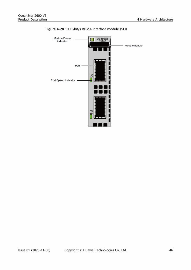
Figure 4-28 100 Gbit/s RDMA interface module (SO)
Module handleModule handle
Module Power indicator
Module Power indicator
PortPort
Port Speed indicatorPort Speed indicator
OceanStor 2600 V5Product Description 4 Hardware Architecture
Issue 01 (2020-11-30) Copyright © Huawei Technologies Co., Ltd. 46

Figure 4-29 100 Gbit/s RDMA interface module (BE)
IndicatorTable 4-14 describes the indicators on a 100 Gbit/s RDMA interface module afterthe storage system is powered on.
Table 4-14 Indicators on a 100 Gbit/s RDMA interface module
Indicator Status and Description
Module Power indicator ● Steady green: The interface module is workingcorrectly.
● Blinking green: There is a hot swap request tothe module.
● Steady yellow: The module is faulty.● Off: The module is powered off or hot
swappable.
OceanStor 2600 V5Product Description 4 Hardware Architecture
Issue 01 (2020-11-30) Copyright © Huawei Technologies Co., Ltd. 47

Indicator Status and Description
Port Speed indicator ● Steady blue: The speed is the highest.● Blinking blue (2 Hz): The port is transmitting
data at the highest speed.● Steady green: The speed is not the highest.● Blinking green (2 Hz): The port is transmitting
data, but not at the highest speed.● Steady yellow: The optical module or cable is
faulty or not supported by the port.● Blinking yellow (2 Hz): The problem is being
located.● Off: The link to the port is down.
4.4.7 SmartIO Interface Module
FunctionSmartIO interface modules support 8 Gbit/s, 10 Gbit/s, 16 Gbit/s, 25 Gbit/s, and 32Gbit/s optical modules. The rate of an optical module must be the same as thatmarked by the label on the interface module. Otherwise, a storage system alarmis generated and ports on the module cannot be used.
NO TE
● For a Fibre Channel optical module, the enabled auto-negotiation function allows it toauto-negotiate a maximum of three speeds:● If a 32 Gbit/s Fibre Channel optical module is used, the SmartIO interface module
auto-negotiates the speed of 32 Gbit/s, 16 Gbit/s, or 8 Gbit/s.● If a 16 Gbit/s Fibre Channel optical module is used, the SmartIO interface module
auto-negotiates the speed of 16 Gbit/s, 8 Gbit/s, or 4 Gbit/s.● If an 8 Gbit/s Fibre Channel optical module is used, the SmartIO interface module
auto-negotiates the speed of 8 Gbit/s, 4 Gbit/s, or 2 Gbit/s.● The ETH optical module does not support auto-negotiation.● The storage system does not support optical modules purchased by the customer
elsewhere. The working mode and rate of the interface module cannot be modified. Ifthe customer requires a different rate on the interface module, contact Huaweitechnical support engineers and purchase a new interface module of the required rate.
Ports● Figure 4-30, Figure 4-31, Figure 4-32, Figure 4-33, and Figure 4-34 show 8
Gbit/s, 10 Gbit/s, 16 Gbit/s, 25 Gbit/s, and 32 Gbit/s SmartIO interfacemodules respectively. FE stands for front-end.
OceanStor 2600 V5Product Description 4 Hardware Architecture
Issue 01 (2020-11-30) Copyright © Huawei Technologies Co., Ltd. 48
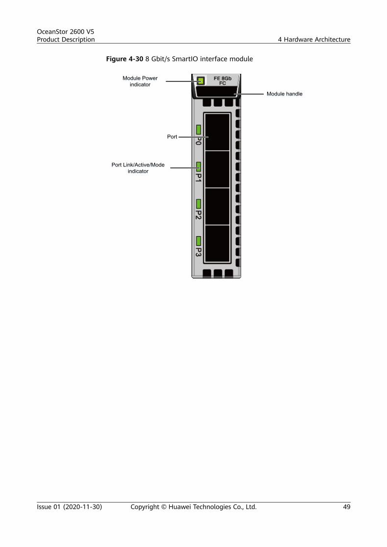
Figure 4-30 8 Gbit/s SmartIO interface module
Module handleModule handle
Module Power indicator
Module Power indicator
PortPort
Port Link/Active/Mode indicator
Port Link/Active/Mode indicator
OceanStor 2600 V5Product Description 4 Hardware Architecture
Issue 01 (2020-11-30) Copyright © Huawei Technologies Co., Ltd. 49

Figure 4-31 10 Gbit/s SmartIO interface module
Module handleModule handle
Module Power indicator
Module Power indicator
PortPort
Port Link/Active/Mode indicator
Port Link/Active/Mode indicator
OceanStor 2600 V5Product Description 4 Hardware Architecture
Issue 01 (2020-11-30) Copyright © Huawei Technologies Co., Ltd. 50

Figure 4-32 16 Gbit/s SmartIO interface module
Module handleModule handle
Module Power indicator
Module Power indicator
PortPort
Port Link/Active/Mode indicator
Port Link/Active/Mode indicator
OceanStor 2600 V5Product Description 4 Hardware Architecture
Issue 01 (2020-11-30) Copyright © Huawei Technologies Co., Ltd. 51

Figure 4-33 25 Gbit/s SmartIO interface module
Module handleModule handle
Module Power indicator
Module Power indicator
PortPort
Port Link/Active/Mode indicator
Port Link/Active/Mode indicator
OceanStor 2600 V5Product Description 4 Hardware Architecture
Issue 01 (2020-11-30) Copyright © Huawei Technologies Co., Ltd. 52
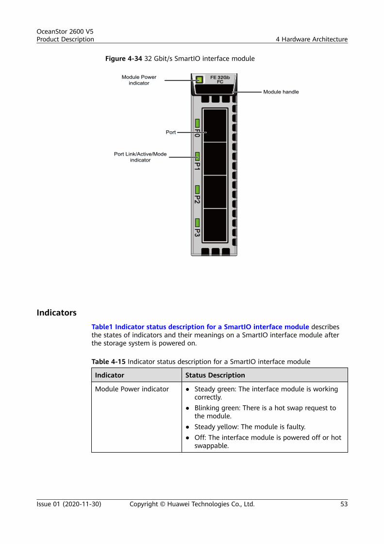
Figure 4-34 32 Gbit/s SmartIO interface module
Module handleModule handle
Module Power indicator
Module Power indicator
PortPort
Port Link/Active/Mode indicator
Port Link/Active/Mode indicator
IndicatorsTable1 Indicator status description for a SmartIO interface module describesthe states of indicators and their meanings on a SmartIO interface module afterthe storage system is powered on.
Table 4-15 Indicator status description for a SmartIO interface module
Indicator Status Description
Module Power indicator ● Steady green: The interface module is workingcorrectly.
● Blinking green: There is a hot swap request tothe module.
● Steady yellow: The module is faulty.● Off: The interface module is powered off or hot
swappable.
OceanStor 2600 V5Product Description 4 Hardware Architecture
Issue 01 (2020-11-30) Copyright © Huawei Technologies Co., Ltd. 53

Indicator Status Description
Port Link/Active/Modeindicator
● Steady blue: The interface module is working inFC mode, the port link is up, and no data isbeing transmitted.
● Blinking blue slowly (1 Hz): The interfacemodule is working in FC mode, and the portlink is down.a
● Blinking blue quickly (2 Hz): The interfacemodule is working in FC mode, and data isbeing transmitted.
● Steady green: The interface module is workingin ETH mode, the port link is up, and no data isbeing transmitted.
● Blinking green slowly (1 Hz): The interfacemodule is working in ETH mode, and the portlink is down.a
● Blinking green quickly (2 Hz): The interfacemodule is working in ETH mode, and data isbeing transmitted.
● Steady yellow: The port is faulty.● Off: The port is powered off.
a: The indicator status is only available in V500R007C60SPC100 and earlierversions.
4.4.8 12 Gbit/s SAS Expansion ModuleAn expansion module provides expansion ports that are used for communicationbetween a controller enclosure and a SAS disk enclosure.
FunctionA 12 Gbit/s SAS expansion module provides four 4 x 12 Gbit/s mini SAS HDexpansion ports that provide connectivity to disk enclosures. The SAS expansionmodule connects to the back-end storage array of the storage system via a miniSAS HD cable. When the transfer rate of the connected device is less than that ofthe expansion port, the expansion port automatically adjusts the transfer rate tothat of the connected device to ensure the connectivity of the data transferchannel.
PortsFigure 4-35 shows the appearance of a 12 Gbit/s SAS expansion module. In thelabel, BE indicates back-end.
OceanStor 2600 V5Product Description 4 Hardware Architecture
Issue 01 (2020-11-30) Copyright © Huawei Technologies Co., Ltd. 54

Figure 4-35 12 Gbit/s SAS expansion module
Module handleModule handle
Module Power indicator
Module Power indicator
Mini SAS HD expansion portMini SAS HD expansion port
Indicator of the mini SAS HD expansion port
Indicator of the mini SAS HD expansion port
IndicatorsTable 4-16 describes indicators on a 12 Gbit/s SAS expansion module of apowered-on storage system.
Table 4-16 Indicators on a 12 Gbit/s SAS expansion module
Indicator Status and Description
Module Power indicator ● Steady green: The interface module is workingcorrectly.
● Blinking green: There is a hot swap request tothe module.
● Steady yellow: The module is faulty.● Off: The interface module is powered off or hot
swappable.
OceanStor 2600 V5Product Description 4 Hardware Architecture
Issue 01 (2020-11-30) Copyright © Huawei Technologies Co., Ltd. 55

Indicator Status and Description
Indicator of the mini SASHD expansion port
● Steady blue: The port transmission rate is 4 x 12Gbit/s.
● Steady green: The port transmission rate is 4 x 3Gbit/s or 4 x 6 Gbit/s.
● Steady yellow: The port is faulty.● Off: The link to the port is down.
4.5 SAS Disk Enclosure (2 U, 2.5-Inch Disks)This section describes a disk enclosure in terms of its hardware structure,component functions, front and rear views, and indicators.
4.5.1 OverviewThe disk enclosure consists of a system subrack, expansion modules, disk modules,and power modules.
Overall StructureFigure 4-36 shows the overall structure of a disk enclosure.
Figure 4-36 Overall structure of a disk enclosure
System subrack
Disk module
Power module
Expansion module
Power module
Front ViewFigure 4-37 shows the front view of a disk enclosure.
OceanStor 2600 V5Product Description 4 Hardware Architecture
Issue 01 (2020-11-30) Copyright © Huawei Technologies Co., Ltd. 56

Figure 4-37 Front view of a disk enclosure
Disk enclosure ID displayDisk module latch Disk module handle
NO TE
The disk slots are numbered 0 to 24 from left to right.
Rear ViewFigure 4-38 shows the rear view of a disk enclosure.
Figure 4-38 Rear view of a disk enclosure (with AC power modules as anexample)
Power modulePower module latchPower module handle Expansion module handle
Expansion moduleSerial port
Mini SAS HD P0 expansion port
Mini SAS HD P1 expansion port
Disk enclosure ID display
4.5.2 Component DescriptionThis section provides the detailed illustration and description for each component.
4.5.2.1 System SubrackThe system subrack houses a midplane to provide reliable connections forinterface modules and to distribute power and signals to inner modules.
AppearanceFigure 4-39 shows the appearance of a system subrack.
OceanStor 2600 V5Product Description 4 Hardware Architecture
Issue 01 (2020-11-30) Copyright © Huawei Technologies Co., Ltd. 57

Figure 4-39 System subrack
4.5.2.2 Expansion Module
An expansion module provides expansion ports for communication between a diskenclosure and a controller enclosure, or between different disk enclosures. Eachexpansion module provides P0 and P1 expansion ports.
Appearance
Figure 4-40 shows the appearance of an expansion module.
Figure 4-40 Expansion module
OceanStor 2600 V5Product Description 4 Hardware Architecture
Issue 01 (2020-11-30) Copyright © Huawei Technologies Co., Ltd. 58
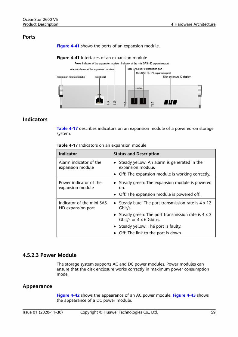
Ports
Figure 4-41 shows the ports of an expansion module.
Figure 4-41 Interfaces of an expansion module
Indicators
Table 4-17 describes indicators on an expansion module of a powered-on storagesystem.
Table 4-17 Indicators on an expansion module
Indicator Status and Description
Alarm indicator of theexpansion module
● Steady yellow: An alarm is generated in theexpansion module.
● Off: The expansion module is working correctly.
Power indicator of theexpansion module
● Steady green: The expansion module is poweredon.
● Off: The expansion module is powered off.
Indicator of the mini SASHD expansion port
● Steady blue: The port transmission rate is 4 x 12Gbit/s.
● Steady green: The port transmission rate is 4 x 3Gbit/s or 4 x 6 Gbit/s.
● Steady yellow: The port is faulty.● Off: The link to the port is down.
4.5.2.3 Power Module
The storage system supports AC and DC power modules. Power modules canensure that the disk enclosure works correctly in maximum power consumptionmode.
Appearance
Figure 4-42 shows the appearance of an AC power module. Figure 4-43 showsthe appearance of a DC power module.
OceanStor 2600 V5Product Description 4 Hardware Architecture
Issue 01 (2020-11-30) Copyright © Huawei Technologies Co., Ltd. 59

Figure 4-42 AC power module
Figure 4-43 DC power module
IndicatorsTable 4-18 describes indicators on a power module of a powered-on storagesystem.
OceanStor 2600 V5Product Description 4 Hardware Architecture
Issue 01 (2020-11-30) Copyright © Huawei Technologies Co., Ltd. 60

Table 4-18 Indicators on a power module
Indicator Status and Description
Running/Alarm indicatorof the power/fan module
● Steady green: The power/fan module is workingcorrectly.
● Blinking green (1 Hz): The power input isnormal but the device is powered off.
● Blinking green (4 Hz): The power module isbeing upgraded online.
● Steady yellow: The power or fan module isfaulty.
● Off: No external power is input.
4.5.2.4 Disk Module
Disk modules provide storage capacity for a storage system. Disk modules canfunction as system coffer disks to save service data, system data, and cache data.
Appearance
Figure 4-44 shows the appearance of a disk module.
Figure 4-44 Disk module
OceanStor 2600 V5Product Description 4 Hardware Architecture
Issue 01 (2020-11-30) Copyright © Huawei Technologies Co., Ltd. 61

IndicatorsTable 4-19 describes indicators on a disk module of a powered-on storage system.
Table 4-19 Indicators on a disk module
Indicator Status and Description
Running indicator of thedisk module
● Steady green: The disk module is workingcorrectly.
● Blinking green (4 Hz or above): The diskmodule is reading and writing data.
● Off: The disk module is powered off or poweredon incorrectly.
Alarm/Location indicatorof the disk module
● Steady yellow: The disk module is faulty.● Blinking yellow (2 Hz): The disk module is being
located.● Off: The disk module is working correctly or hot
swappable.
4.5.3 Indicator IntroductionAfter a disk enclosure is powered on, you can check the current operating status ofthe disk enclosure by viewing its indicators.
Indicators on the Front PanelFigure 4-45 shows the indicators on the front panel of a disk enclosure.
Figure 4-45 Indicators on the front panel of a disk enclosure
Power indicator of the disk enclosureRunning indicator of the disk module
Alarm/Location indicator of the disk module
Location indicator of the disk enclosureAlarm indicator of the disk enclosure
Table 4-20 describes the indicators on the front panel of the disk enclosure.
OceanStor 2600 V5Product Description 4 Hardware Architecture
Issue 01 (2020-11-30) Copyright © Huawei Technologies Co., Ltd. 62

Table 4-20 Description of the indicators on the front panel of a disk enclosure
Module Indicator Status and Description
Diskmodule
Running indicator of thedisk module
● Steady green: The disk module isworking correctly.
● Blinking green (4 Hz or above):The disk module is reading andwriting data.
● Off: The disk module is poweredoff or powered on incorrectly.
Alarm/Location indicator ofthe disk module
● Steady yellow: The disk moduleis faulty.
● Blinking yellow (2 Hz): The diskmodule is being located.
● Off: The disk module is workingcorrectly or hot swappable.
Systemsubrack
Location indicator of thedisk enclosure
● Blinking blue (2 Hz): The diskenclosure is being located.
● Off: The disk enclosure is notlocated.
Alarm indicator of the diskenclosure
● Steady yellow: An alarm isgenerated in the disk enclosure.
● Off: The disk enclosure isworking correctly.
Power indicator of the diskenclosure
● Steady green: The disk enclosureis powered on.
● Off: The disk enclosure ispowered off.
Indicators on the Rear PanelFigure 4-46 shows the indicators on the rear panel of a disk enclosure.
Figure 4-46 Indicators on the rear panel of a disk enclosure
Running/Alarm indicator of the power/fan module
Power indicator of the expansion module
Alarm indicator of the expansion module Mini SAS HD expansion port indicator
Table 4-21 describes the indicators on the rear panel of the disk enclosure.
OceanStor 2600 V5Product Description 4 Hardware Architecture
Issue 01 (2020-11-30) Copyright © Huawei Technologies Co., Ltd. 63

Table 4-21 Description of the indicators on the rear panel of a disk enclosure
Module Indicator Status and Description
Expansionmodule
Alarmindicator oftheexpansionmodule
● Steady yellow: An alarm is generated on theexpansion module.
● Off: The expansion module is working correctly.
Powerindicator oftheexpansionmodule
● Steady green: The expansion module is poweredon.
● Off: The expansion module is powered off.
Indicator ofthe mini SASHDexpansionport
● Steady blue: The port transmission rate is 4 x 12Gbit/s.
● Steady green: The port transmission rate is 4 x 3Gbit/s or 4 x 6 Gbit/s.
● Steady yellow: The port is faulty.● Off: The link to the port is down.
Powermodule
Running/Alarmindicator ofthepower/fanmodule
● Steady green: The power supply is workingproperly.
● Blinking green (1 Hz): The power input isnormal but the device is powered off.
● Blinking green (4 Hz): The power module isbeing upgraded online.
● Steady yellow: The power or fan module isfaulty.
● Off: No external power is input.
4.6 SAS Disk Enclosure (4 U, 3.5-Inch Disks)This section describes a disk enclosure in terms of its hardware structure,component functions, front and rear views, and indicators.
4.6.1 OverviewThe disk enclosure consists of a system subrack, expansion modules, powermodules, fan modules, and disk modules.
Overall StructureFigure 4-47 shows the overall structure of a 4 U disk enclosure.
OceanStor 2600 V5Product Description 4 Hardware Architecture
Issue 01 (2020-11-30) Copyright © Huawei Technologies Co., Ltd. 64
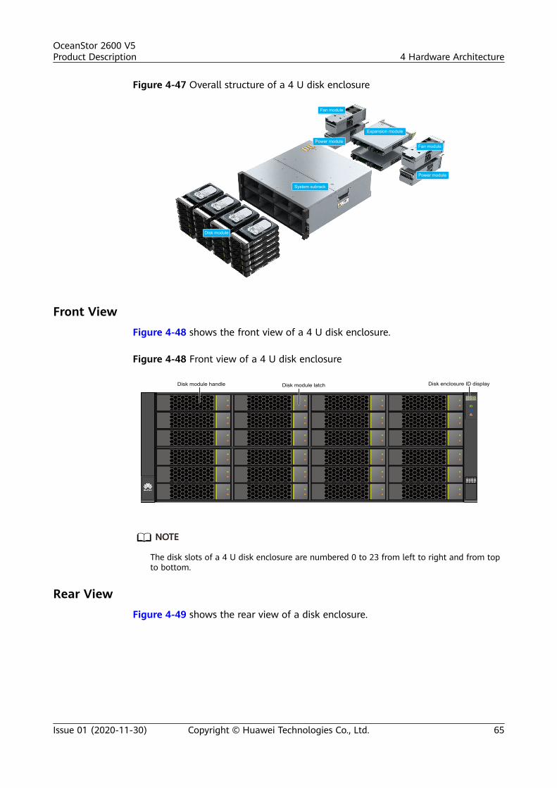
Figure 4-47 Overall structure of a 4 U disk enclosure
System subrack
Disk module
Power module
Fan module
Expansion module
Power module
Fan module
Front ViewFigure 4-48 shows the front view of a 4 U disk enclosure.
Figure 4-48 Front view of a 4 U disk enclosure
Disk enclosure ID displayDisk module handle Disk module latch
NO TE
The disk slots of a 4 U disk enclosure are numbered 0 to 23 from left to right and from topto bottom.
Rear ViewFigure 4-49 shows the rear view of a disk enclosure.
OceanStor 2600 V5Product Description 4 Hardware Architecture
Issue 01 (2020-11-30) Copyright © Huawei Technologies Co., Ltd. 65
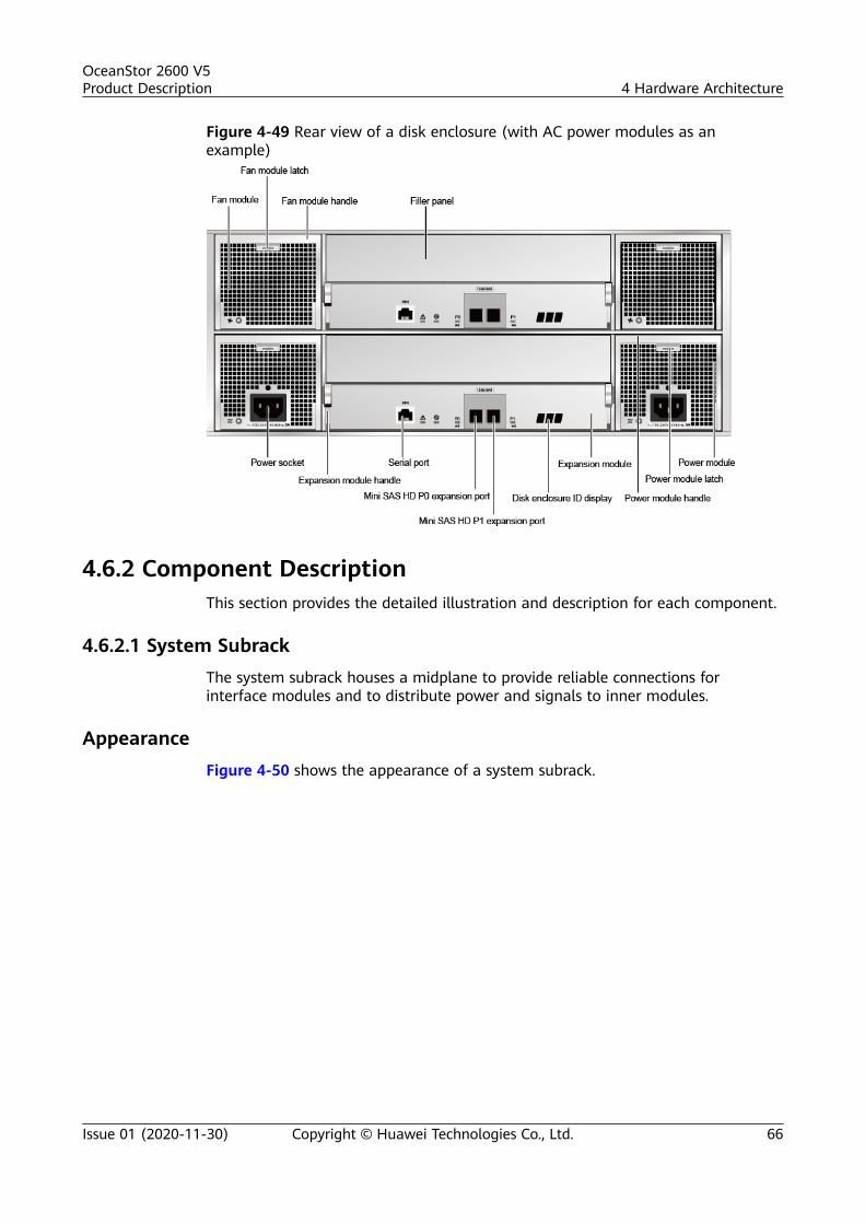
Figure 4-49 Rear view of a disk enclosure (with AC power modules as anexample)
4.6.2 Component DescriptionThis section provides the detailed illustration and description for each component.
4.6.2.1 System SubrackThe system subrack houses a midplane to provide reliable connections forinterface modules and to distribute power and signals to inner modules.
AppearanceFigure 4-50 shows the appearance of a system subrack.
OceanStor 2600 V5Product Description 4 Hardware Architecture
Issue 01 (2020-11-30) Copyright © Huawei Technologies Co., Ltd. 66

Figure 4-50 System subrack
4.6.2.2 Expansion ModuleAn expansion module connects a disk enclosure and a controller enclosurethrough expansion ports. Each expansion module provides P0 and P1 expansionports.
AppearanceFigure 4-51 shows the appearance of an expansion module.
OceanStor 2600 V5Product Description 4 Hardware Architecture
Issue 01 (2020-11-30) Copyright © Huawei Technologies Co., Ltd. 67

Figure 4-51 Expansion module
Ports
Figure 4-52 shows the ports of an expansion module.
Figure 4-52 Interfaces of an expansion module
Indicators
Table 4-22 describes indicators on an expansion module of a powered-on storagesystem.
Table 4-22 Indicators on an expansion module
Indicator Status and Description
Alarm indicator of theexpansion module
● Steady yellow: An alarm is generated in theexpansion module.
● Off: The expansion module is working correctly.
OceanStor 2600 V5Product Description 4 Hardware Architecture
Issue 01 (2020-11-30) Copyright © Huawei Technologies Co., Ltd. 68

Indicator Status and Description
Power indicator of theexpansion module
● Steady green: The expansion module is poweredon.
● Off: The expansion module is powered off.
Indicator of the mini SASHD expansion port
● Steady blue: The port transmission rate is 4 x 12Gbit/s.
● Steady green: The port transmission rate is 4 x 3Gbit/s or 4 x 6 Gbit/s.
● Steady yellow: The port is faulty.● Off: The link to the port is down.
4.6.2.3 Power ModuleThe storage system supports AC and DC power modules. Power modules canensure that the disk enclosure works correctly in maximum power consumptionmode.
AppearanceFigure 4-53 shows the appearance of an AC power module. Figure 4-54 showsthe appearance of a DC power module.
Figure 4-53 AC power module
OceanStor 2600 V5Product Description 4 Hardware Architecture
Issue 01 (2020-11-30) Copyright © Huawei Technologies Co., Ltd. 69

Figure 4-54 DC power module
Indicators
Table 4-23 describes indicators on a power module of a powered-on storagesystem.
Table 4-23 Indicators on a power module
Indicator Status and Description
Running/Alarm indicatorof the power module
● Steady green: The power module is workingcorrectly.
● Blinking green (1 Hz): The power input isnormal but the device is powered off.
● Blinking green (4 Hz): The power module isbeing upgraded online.
● Steady yellow: The power or fan module isfaulty.
● Off: No external power is input.
4.6.2.4 Fan Module
A fan module provides heat dissipation and supports the normal running of thedisk enclosure in maximum power consumption mode.
Appearance
Figure 4-55 shows the appearance of a fan module.
OceanStor 2600 V5Product Description 4 Hardware Architecture
Issue 01 (2020-11-30) Copyright © Huawei Technologies Co., Ltd. 70

Figure 4-55 Fan module
IndicatorsTable 4-24 describes indicators on a fan module of a powered-on storage system.
Table 4-24 Indicators on a fan module
Indicator Status and Description
Running/Alarm indicatorof the fan module
● Steady green: The fan module is workingcorrectly.
● Steady yellow: The fan module is faulty.● Off: The fan module is powered off.
4.6.2.5 Disk ModuleDisk modules provide storage capacity for a storage system to store service dataand can function as system coffer disks.
AppearanceFigure 4-56 shows the appearance of a disk module.
OceanStor 2600 V5Product Description 4 Hardware Architecture
Issue 01 (2020-11-30) Copyright © Huawei Technologies Co., Ltd. 71

Figure 4-56 Disk module
IndicatorsTable 4-25 describes indicators on a disk module of a powered-on storage system.
Table 4-25 Indicators on a disk module
Indicator Status and Description
Alarm/Location indicatorof the disk module
● Steady yellow: The disk module is faulty.● Blinking yellow (2 Hz): The disk module is being
located.● Off: The disk module is working correctly or hot
swappable.
Running indicator of thedisk module
● Steady green: The disk module is workingcorrectly.
● Blinking green (4 Hz or above): The diskmodule is reading and writing data.
● Off: The disk module is powered off or poweredon incorrectly.
4.6.3 Indicator IntroductionAfter a disk enclosure is powered on, you can check the current operating status ofthe disk enclosure by viewing its indicators.
Indicators on the Front PanelFigure 4-57 shows the indicators on the front panel of a disk enclosure.
OceanStor 2600 V5Product Description 4 Hardware Architecture
Issue 01 (2020-11-30) Copyright © Huawei Technologies Co., Ltd. 72

Figure 4-57 Indicators on the front panel of a disk enclosure
Power indicator of the disk enclosure
Running indicator of the disk moduleAlarm/Location indicator of the disk module
Location indicator of the disk enclosureAlarm indicator of the disk enclosure
Table 4-26 describes the indicators on the front panel of the disk enclosure.
Table 4-26 Description of the indicators on the front panel of a disk enclosure
Module Indicator Status and Description
Diskmodule
Running indicator of the diskmodule
● Steady green: The disk module isworking correctly.
● Blinking green (4 Hz or above):The disk module is reading andwriting data.
● Off: The disk module is poweredoff or powered on incorrectly.
Alarm/Location indicator ofthe disk module
● Steady yellow: The disk module isfaulty.
● Blinking yellow (2 Hz): The diskmodule is being located.
● Off: The disk module is workingcorrectly or hot swappable.
Systemsubrack
Location indicator of thedisk enclosure
● Blinking blue (2 Hz): The diskenclosure is being located.
● Off: The disk enclosure is notlocated.
Alarm indicator of the diskenclosure
● Steady yellow: An alarm isgenerated in the disk enclosure.
● Off: The disk enclosure isworking correctly.
Power indicator of the diskenclosure
● Steady green: The disk enclosureis powered on.
● Off: The disk enclosure ispowered off.
OceanStor 2600 V5Product Description 4 Hardware Architecture
Issue 01 (2020-11-30) Copyright © Huawei Technologies Co., Ltd. 73

Indicators on the Rear Panel
Figure 4-58 shows the indicators on the rear panel of a disk enclosure.
Figure 4-58 Indicators on the rear panel of a disk enclosure
Table 4-27 describes the indicators on the rear panel of the disk enclosure.
Table 4-27 Description of the indicators on the rear panel of a disk enclosure
Module Indicator Status and Description
Fanmodule
Running/Alarmindicator ofthe fanmodule
● Steady green: The fan module is workingcorrectly.
● Steady yellow: The fan module is faulty.● Off: The fan module is powered off.
Powermodule
Running/Alarmindicator ofthe powermodule
● Steady green: The power supply is workingproperly.
● Blinking green (1 Hz): The power input isnormal but the device is powered off.
● Blinking green (4 Hz): The power module isbeing upgraded online.
● Steady yellow: The power module is faulty.● Off: No external power is input.
Expansionmodule
Indicator ofthe mini SASHDexpansionport
● Steady blue: The port transmission rate is 4 x 12Gbit/s.
● Steady green: The port transmission rate is 4 x 3Gbit/s or 4 x 6 Gbit/s.
● Steady yellow: The port is faulty.● Off: The link to the port is down.
OceanStor 2600 V5Product Description 4 Hardware Architecture
Issue 01 (2020-11-30) Copyright © Huawei Technologies Co., Ltd. 74

Module Indicator Status and Description
Powerindicator oftheexpansionmodule
● Steady green: The expansion module is poweredon.
● Off: The expansion module is powered off.
Alarmindicator oftheexpansionmodule
● Steady yellow: An alarm is generated on theexpansion module.
● Off: The expansion module is working correctly.
4.7 High-Density Disk EnclosureThis chapter describes a high-density disk enclosure in terms of its hardwarestructure, component functions, front and rear views, and indicators.
4.7.1 OverviewA high-density disk enclosure employs a modular design and consists of a systemsubrack, disk modules, fan modules, power modules, and expansion modules.
Overall StructureFigure 4-59 shows the overall structure of a high-density disk enclosure.
Figure 4-59 Overall structure of a high-density disk enclosure with four 1200 Wpower modules
System subrack
Disk module
Power module
Fan module
Expansion module
Front ViewFigure 4-60 shows the front view of a high-density disk enclosure.
OceanStor 2600 V5Product Description 4 Hardware Architecture
Issue 01 (2020-11-30) Copyright © Huawei Technologies Co., Ltd. 75

Figure 4-60 Front view of a high-density disk enclosure
Rear ViewFigure 4-61 shows the rear view of a high-density disk enclosure.
Figure 4-61 Rear view of a high-density disk enclosure
OceanStor 2600 V5Product Description 4 Hardware Architecture
Issue 01 (2020-11-30) Copyright © Huawei Technologies Co., Ltd. 76

Top ViewFigure 4-62 shows the top view of a high-density disk enclosure.
Figure 4-62 Top view of a high-density disk enclosure
The disk number of a high-density disk enclosure displayed on DeviceManager orCLI ranges from 0 to 74. These disks are numbered from left to right (15 columns)and from bottom to top (five rows). The slots of a high-density disk enclosure arenumbered 0 to 14 from left to right (15 columns), and A to E from bottom to top(five rows). For example, in the preceding figure, the disk in the red box isnumbered 40 in slot C10.
Table 4-28 lists the mappings between disk numbers and slot numbers of high-density disk enclosures.
OceanStor 2600 V5Product Description 4 Hardware Architecture
Issue 01 (2020-11-30) Copyright © Huawei Technologies Co., Ltd. 77

Table 4-28 Mappings between disk numbers and slot numbers of high-densitydisk enclosures
DiskNo.
SlotNo.
DiskNo.
SlotNo.
DiskNo.
SlotNo.
DiskNo.
SlotNo.
DiskNo.
SlotNo.
0 A0 15 B0 30 C0 45 D0 60 E0
1 A1 16 B1 31 C1 46 D1 61 E1
2 A2 17 B2 32 C2 47 D2 62 E2
3 A3 18 B3 33 C3 48 D3 63 E3
4 A4 19 B4 34 C4 49 D4 64 E4
5 A5 20 B5 35 C5 50 D5 65 E5
6 A6 21 B6 36 C6 51 D6 66 E6
7 A7 22 B7 37 C7 52 D7 67 E7
8 A8 23 B8 38 C8 53 D8 68 E8
9 A9 24 B9 39 C9 54 D9 69 E9
10 A10 25 B10 40 C10 55 D10 70 E10
11 A11 26 B11 41 C11 56 D11 71 E11
12 A12 27 B12 42 C12 57 D12 72 E12
13 A13 28 B13 43 C13 58 D13 73 E13
14 A14 29 B14 44 C14 59 D14 74 E14
4.7.2 Component DescriptionThis section provides the detailed illustration and description for each component.
4.7.2.1 System SubrackThe system subrack houses a midplane to provide reliable connections forinterface modules and to distribute power and signals to inner modules.
AppearanceFigure 4-63 shows the appearance of a system subrack.
OceanStor 2600 V5Product Description 4 Hardware Architecture
Issue 01 (2020-11-30) Copyright © Huawei Technologies Co., Ltd. 78

Figure 4-63 System subrack
4.7.2.2 Expansion ModuleEach expansion module provides two PRI HD expansion ports and two EXP HDexpansion ports. Expansion modules enable a high-density disk enclosure tocommunicate with a controller enclosure or another high-density disk enclosure.
AppearanceFigure 4-64 shows the appearance of an expansion module.
Figure 4-64 Expansion module
OceanStor 2600 V5Product Description 4 Hardware Architecture
Issue 01 (2020-11-30) Copyright © Huawei Technologies Co., Ltd. 79

Ports
Figure 4-65 shows the ports of an expansion module.
Figure 4-65 Ports on an expansion module
Indicators
Table 4-29 describes the indicators on a disk enclosure expansion module of astorage system that is powered on.
Table 4-29 Indicators on an expansion module in a disk enclosure
Indicator Status and Description
Power indicator of theexpansion module
● Steady green: The expansion module is workingcorrectly.
● Off: The expansion module is powered off.
Alarm indicator of theexpansion module
● Steady red: An alarm about the expansionmodule is generated.
● Off: The expansion module is powered off orworking correctly.
Mini SAS HD expansionport indicator
● Steady blue: The link to the expansion port isnormal, and the data transfer rate is 4 x 12Gbit/s.
● Steady green: The link to the expansion port isnormal, and the data transfer rate is 4 x 6Gbit/s.
● Steady red: The port is faulty.● Off: The link to the expansion port is down.
4.7.2.3 Disk Module
Disk modules provide storage capacity for a storage system to store service data.
OceanStor 2600 V5Product Description 4 Hardware Architecture
Issue 01 (2020-11-30) Copyright © Huawei Technologies Co., Ltd. 80
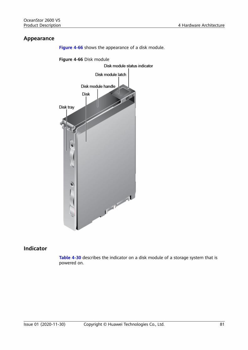
AppearanceFigure 4-66 shows the appearance of a disk module.
Figure 4-66 Disk module
IndicatorTable 4-30 describes the indicator on a disk module of a storage system that ispowered on.
OceanStor 2600 V5Product Description 4 Hardware Architecture
Issue 01 (2020-11-30) Copyright © Huawei Technologies Co., Ltd. 81

Table 4-30 Indicator on a disk module
Indicator Status and Description
Disk module statusindicator
● Steady green: The disk module is workingcorrectly.
● Blinking green: Data is being read and writtenon the disk module.
● Steady red: The disk module is faulty.● Blinking red: The disk module is located.● Off: The disk module is powered off or powered
on incorrectly.
4.7.2.4 Power ModuleThe storage system supports AC power modules that ensure that a high-densitydisk enclosure works correctly in maximum power consumption mode.
AppearanceFigure 4-67 shows the appearance of a power module.
Figure 4-67 AC power module
OceanStor 2600 V5Product Description 4 Hardware Architecture
Issue 01 (2020-11-30) Copyright © Huawei Technologies Co., Ltd. 82

Indicator
Table 4-31 describes the indicator on a power module of a storage system that ispowered on.
Table 4-31 Indicator on a power module
Indicator Status and Description
Running/Alarm indicatorof the power module
● Steady green: The power module is workingcorrectly.
● Off: The power module is powered off, orundervoltage, overvoltage, overtemperature, orshort-circuit occurs.
4.7.2.5 Fan Module
A fan module provides heat dissipation and supports the normal running of thedisk enclosure in maximum power consumption mode.
Appearance
Figure 4-68 shows the appearance of a fan module.
Figure 4-68 Fan module
OceanStor 2600 V5Product Description 4 Hardware Architecture
Issue 01 (2020-11-30) Copyright © Huawei Technologies Co., Ltd. 83

Indicator
Table 4-32 describes the indicator on a fan module of a storage system that ispowered-on.
Table 4-32 Indicator on a fan module
Indicator Status and Description
Fan module Running/Alarm indicator
● Steady green: The fan module is workingcorrectly.
● Steady red: The fan module is faulty.● Off: The fan module is powered off.
4.7.3 Indicator IntroductionAfter a disk enclosure is powered on, you can check the current operating status ofthe disk enclosure by viewing its indicators.
Indicators on the Front Panel
Figure 4-69 shows the indicators on the front panel of a high-density diskenclosure.
Figure 4-69 Indicators on the front panel of a high-density disk enclosure
Table 4-33 describes the indicators on the front panel of a high-density diskenclosure.
Table 4-33 Description of the indicators on the front panel of a high-density diskenclosure
Module Indicator Status and Description
Systemsubrack
Locationindicator
● Blinking blue: The high-density diskenclosure has been located.
● Off: The high-density disk enclosure is notlocated.
OceanStor 2600 V5Product Description 4 Hardware Architecture
Issue 01 (2020-11-30) Copyright © Huawei Technologies Co., Ltd. 84
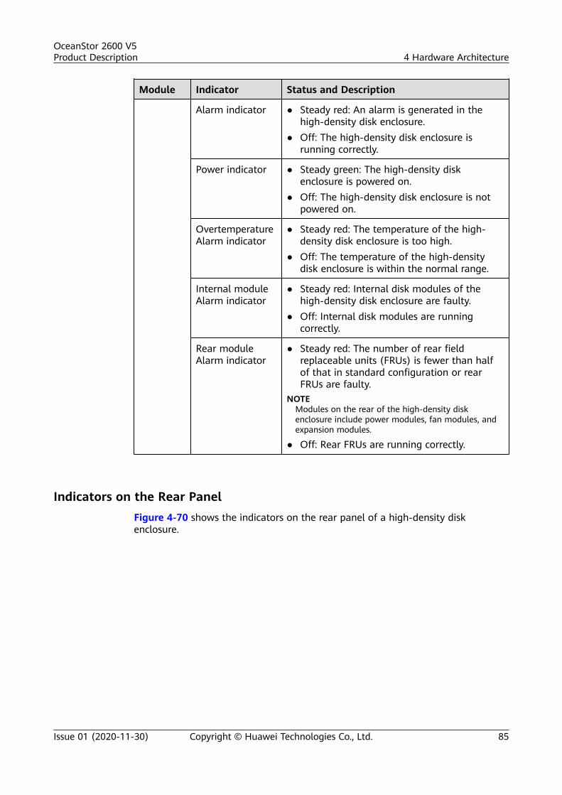
Module Indicator Status and Description
Alarm indicator ● Steady red: An alarm is generated in thehigh-density disk enclosure.
● Off: The high-density disk enclosure isrunning correctly.
Power indicator ● Steady green: The high-density diskenclosure is powered on.
● Off: The high-density disk enclosure is notpowered on.
OvertemperatureAlarm indicator
● Steady red: The temperature of the high-density disk enclosure is too high.
● Off: The temperature of the high-densitydisk enclosure is within the normal range.
Internal moduleAlarm indicator
● Steady red: Internal disk modules of thehigh-density disk enclosure are faulty.
● Off: Internal disk modules are runningcorrectly.
Rear moduleAlarm indicator
● Steady red: The number of rear fieldreplaceable units (FRUs) is fewer than halfof that in standard configuration or rearFRUs are faulty.
NOTEModules on the rear of the high-density diskenclosure include power modules, fan modules, andexpansion modules.
● Off: Rear FRUs are running correctly.
Indicators on the Rear PanelFigure 4-70 shows the indicators on the rear panel of a high-density diskenclosure.
OceanStor 2600 V5Product Description 4 Hardware Architecture
Issue 01 (2020-11-30) Copyright © Huawei Technologies Co., Ltd. 85

Figure 4-70 Indicators on the rear panel of a high-density disk enclosure
Table 4-34 describes the indicators on the rear panel of a high-density diskenclosure.
Table 4-34 Description of the indicators on the rear panel of a high-density diskenclosure
Module Indicator Status and Description
Powermodule
Running/Alarm indicator ofthe power module
● Steady green: The power moduleis working correctly.
● Off: The power module ispowered off, or the undervoltage,overvoltage, overtemperature,overcurrent, fan fault, or short-circuit occurs.
Expansionmodule
Indicator of the mini SAS HDexpansion port
● Steady blue: The link is up andthe data transfer rate is 4 x 12Gbit/s.
● Steady green: The link is up andthe data transfer rate is 4 x 6Gbit/s.
● Steady red: The expansion port isfaulty.
● Off: The link is down.
Fanmodule
Fan module Running/Alarmindicator
● Steady green: The fan module isrunning correctly.
● Steady red: The fan module isfaulty.
● Off: The fan module is notpowered on.
OceanStor 2600 V5Product Description 4 Hardware Architecture
Issue 01 (2020-11-30) Copyright © Huawei Technologies Co., Ltd. 86

Module Indicator Status and Description
Expansionmodule
Expansion module Alarmindicator
● Steady red: An alarm isgenerated on the expansionmodule.
● Off: The expansion module isrunning correctly.
Expansion module Powerindicator
● Steady green: The expansionmodule is running correctly.
● Off: The expansion module is notpowered on.
4.8 Coffer DiskThe storage system has two kinds of coffer disks: built-in coffer disk and externalcoffer disk. Coffer disks are used to store three types of data: cache data requiringpower failure protection, OceanStor OS system data, and system configurationinformation and logs.
Built-in Coffer DiskEach controller houses one or more disks as coffer disks. Table 4-35 describescapacity partitions of the built-in coffer disks.
Table 4-35 Capacity partitions of built-in coffer disks
Built-inCoffer Disk
2600 V5 Description
Size 1 x 64 GB M.2 SATA -
Cache dirtydatapartition
9.5 GB Stores the cache dirty datathat has not been writteninto a disk when the storagesystem is powered off.
OS systempartition
32 GB Stores the OceanStor OSsystem data.
OceanStor 2600 V5Product Description 4 Hardware Architecture
Issue 01 (2020-11-30) Copyright © Huawei Technologies Co., Ltd. 87
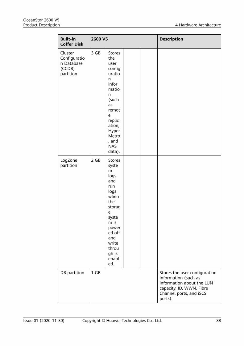
Built-inCoffer Disk
2600 V5 Description
ClusterConfiguration Database(CCDB)partition
3 GB Storestheuserconfigurationinformation(suchasremotereplication,HyperMetro, andNASdata).
LogZonepartition
2 GB Storessystemlogsandrunlogswhenthestoragesystem ispowered offandwritethrough isenabled.
DB partition 1 GB Stores the user configurationinformation (such asinformation about the LUNcapacity, ID, WWN, FibreChannel ports, and iSCSIports).
OceanStor 2600 V5Product Description 4 Hardware Architecture
Issue 01 (2020-11-30) Copyright © Huawei Technologies Co., Ltd. 88
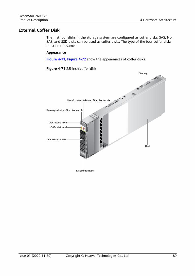
External Coffer DiskThe first four disks in the storage system are configured as coffer disks. SAS, NL-SAS, and SSD disks can be used as coffer disks. The type of the four coffer disksmust be the same.
Appearance
Figure 4-71, Figure 4-72 show the appearances of coffer disks.
Figure 4-71 2.5-inch coffer disk
OceanStor 2600 V5Product Description 4 Hardware Architecture
Issue 01 (2020-11-30) Copyright © Huawei Technologies Co., Ltd. 89

Figure 4-72 3.5-inch coffer disk
Positions
If a storage system employs the disk and controller integration architecture, thefirst four disks in the storage system are configured as coffer disks. Figure 4-73uses a 2 U controller enclosure with 25 disk slots as an example.
Figure 4-73 Positions of external coffer disks in the disk and controller integrationarchitecture
0 1 32
Capacity partitions
For the disk and controller integration device, the first four disks each spares 6 GBof space to form a RAID 1 group. The rest of the coffer disk space can be used tostore service data. Table 4-36 describes capacity partitions of external coffer disks.
Table 4-36 Capacity partitions of external coffer disks
Partition Name Partition Size Description
CCDB partition 3 GB Stores the user configurationinformation (such as remotereplication, HyperMetro, and NASdata). The four coffer disks are mirrorsof each other for redundancy.
OceanStor 2600 V5Product Description 4 Hardware Architecture
Issue 01 (2020-11-30) Copyright © Huawei Technologies Co., Ltd. 90
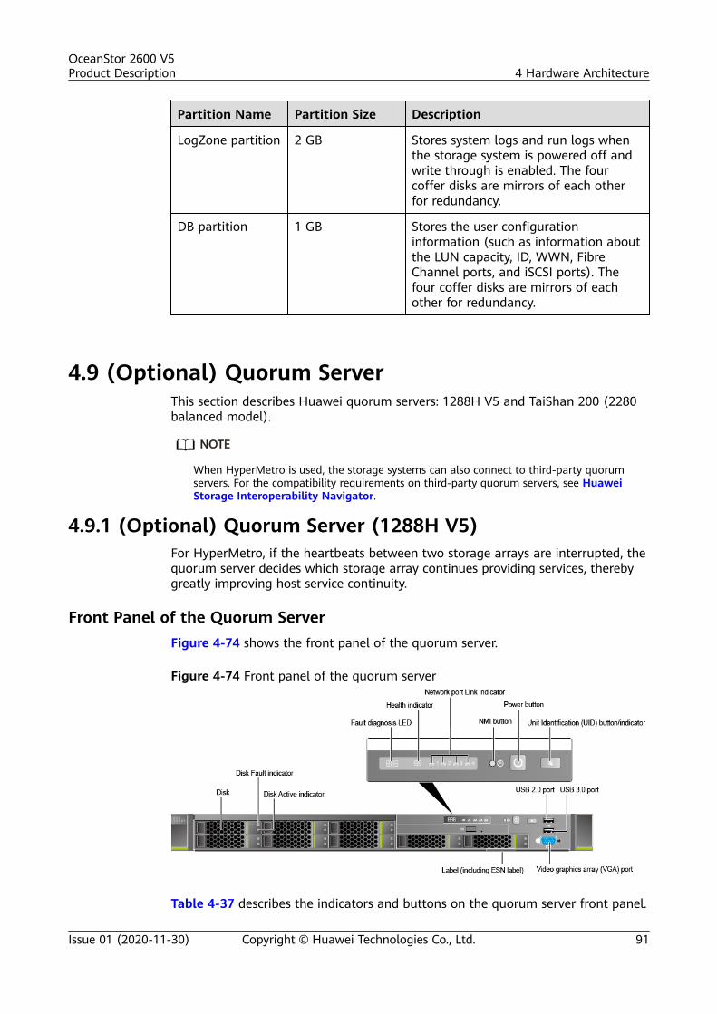
Partition Name Partition Size Description
LogZone partition 2 GB Stores system logs and run logs whenthe storage system is powered off andwrite through is enabled. The fourcoffer disks are mirrors of each otherfor redundancy.
DB partition 1 GB Stores the user configurationinformation (such as information aboutthe LUN capacity, ID, WWN, FibreChannel ports, and iSCSI ports). Thefour coffer disks are mirrors of eachother for redundancy.
4.9 (Optional) Quorum ServerThis section describes Huawei quorum servers: 1288H V5 and TaiShan 200 (2280balanced model).
NO TE
When HyperMetro is used, the storage systems can also connect to third-party quorumservers. For the compatibility requirements on third-party quorum servers, see HuaweiStorage Interoperability Navigator.
4.9.1 (Optional) Quorum Server (1288H V5)For HyperMetro, if the heartbeats between two storage arrays are interrupted, thequorum server decides which storage array continues providing services, therebygreatly improving host service continuity.
Front Panel of the Quorum ServerFigure 4-74 shows the front panel of the quorum server.
Figure 4-74 Front panel of the quorum server
Table 4-37 describes the indicators and buttons on the quorum server front panel.
OceanStor 2600 V5Product Description 4 Hardware Architecture
Issue 01 (2020-11-30) Copyright © Huawei Technologies Co., Ltd. 91

Table 4-37 Indicators and buttons on the front panel
Indicator and Button Color State
Fault diagnosis LED None ● ---: The quorum server isoperating properly.
● Error Code: A fault occurs inquorum server hardware.
Power button/indicator
Yellow andgreen
● Off: The quorum server is notpowered on.
● Blinking yellow: The iBMC isstarting.
● Steady yellow: The server is in thestandby state.
● Steady green: The server isproperly powered on.
NOTEYou can hold down the power button for6 seconds to power off the quorumserver.
UID button/indicator Blue The UID button/indicator helpsidentify and locate a quorum serverin a rack. You can turn on or off theUID indicator by manually pressingthe UID button or remotely runninga command on the iBMC CLI.● Steady on: The quorum server is
located.● Off: The quorum server is not
located.● You can hold down the UID
button for 4 to 6 seconds to resetthe system.
Health indicator Red and green ● Steady green: The quorum serveris operating properly.
● Blinking red at 1 Hz: A majoralarm is generated.
● Blinking red at 5 Hz: A criticalalarm is generated.
OceanStor 2600 V5Product Description 4 Hardware Architecture
Issue 01 (2020-11-30) Copyright © Huawei Technologies Co., Ltd. 92

Indicator and Button Color State
NMI button None The NMI button triggers a quorumserver to generate a non-maskableinterrupt. You can press this buttonor control it remotely through theWebUI.NOTE
● Click the NMI button only when theOS is abnormal. Do not click thisbutton when the quorum server isoperating properly.
● Click the NMI button only forinternal commissioning. Beforeclicking this button, ensure that theOS has the handler for NMIinterrupt. Otherwise, the OS maycrash. Exercise caution when clickingthis button.
Disk Active indicator Green ● Off: The disk is not detected or isfaulty.
● Blinking green: Data is being readfrom, written to the disk, orsynchronized between disks.
● Steady green: The disk is inactive.
Disk Fault indicator Yellow ● Off: The disk is working properlyor disks cannot be detected in theRAID group.
● Blinking yellow: The disk is beinglocated, or the RAID is beingreconstructed.
● Steady yellow: The disk is faultyor member disks in the RAIDgroup are abnormal.
Network port Linkindicator
Green Each indicator shows the status ofan Ethernet port on the networkinterface card (NIC).● Steady green: The port is properly
connected.● Off: The port is not in use.NOTE
If the NIC provides only two networkports, network port indicators 1 and 2on the front panel are used.
Rear View of the Quorum Server
Figure 4-75 shows the rear view of the quorum server.
OceanStor 2600 V5Product Description 4 Hardware Architecture
Issue 01 (2020-11-30) Copyright © Huawei Technologies Co., Ltd. 93

Figure 4-75 Rear view of the quorum server
NO TE
● The default IP address of the management network port on the quorum server is192.168.2.100, and the default subnet mask is 255.255.255.0.
● a: This port is reserved and does not have any function. Do not connect cables here.
Table 4-38 describes the indicators on the quorum server rear panel.
Table 4-38 Indicators on the rear panel
Indicator Color State
Data transmission statusindicator
Yellow ● Off: No data is being transmitted.● Blinking: Data is being transmitted.
Connectivity statusindicator
Green ● Steady green: The port is properlyconnected.
● Off: The port is not in use.
UID indicator Blue The UID indicator helps identify andlocate a quorum server in a rack. Youcan turn on or off the UID indicator bymanually pressing the UID button orremotely running a command on theiBMC CLI.● Steady on: The quorum server is
located.● Off: The quorum server is not
located.● You can hold down the UID button
for 4 to 6 seconds to reset thesystem.
OceanStor 2600 V5Product Description 4 Hardware Architecture
Issue 01 (2020-11-30) Copyright © Huawei Technologies Co., Ltd. 94

Indicator Color State
Power module indicator Green ● Steady green: The power input isnormal.
● Off: There is no AC power input, orthe power module is in the standbystate or is faulty.
4.9.2 (Optional) Quorum Server (TaiShan 200)This section describes the 2280 balanced model (2280 for short) of the TaiShan200 server. For HyperMetro, if the heartbeats between two storage arrays areinterrupted, the quorum server decides which storage array continues providingservices, thereby greatly improving host service continuity.
Front Panel Components
Figure 4-76 shows the components on the front panel of a server with 12 x 3.5-inch disks.
Figure 4-76 Components on the front panel of a server with 12 x 3.5-inch disks
1 Disk 2 VGA port
3 USB 3.0 port 4 Label plate with an SN label
Table 4-39 Description of ports on the front panel
Port Type Description
USB port USB 3.0 The USB ports allow USB devices to beconnected to the server.NOTE
Before connecting an external USB device, checkthat the USB device functions properly. A servermay operate abnormally if an abnormal USBdevice is connected.
OceanStor 2600 V5Product Description 4 Hardware Architecture
Issue 01 (2020-11-30) Copyright © Huawei Technologies Co., Ltd. 95

Port Type Description
VGA port DB15 The VGA port is connected to a terminal,such as a monitor or KVM.
Front Panel Indicators and ButtonsFigure 4-77 shows the indicators and buttons on the front panel of a server with12 x 3.5-inch disks.
Figure 4-77 Indicators and buttons on the front panel of a server with 12 x 3.5-inch disks
1 UID button/indicator 2 Health indicator
3 Power button/indicator 4 Fault diagnosis LED
5 FlexIO presenceindicators (1 and 2)
- -
OceanStor 2600 V5Product Description 4 Hardware Architecture
Issue 01 (2020-11-30) Copyright © Huawei Technologies Co., Ltd. 96

Table 4-40 Indicators and buttons on the front panel
No. Type Description
1 UID button/indicator The UID button/indicator helps identify andlocate a device.UID indicator:● Off: The device is not being located.● Blinking blue: The device has been
located and is differentiated from otherdevices that have also been located.
● Steady blue: The device is being located.UID button:● You can turn on or off the UID indicator
by pressing the UID button on the panelor by using the iBMC CLI or WebUI.
● You can press this button to turn on or offthe UID indicator.
● You can press and hold down this buttonfor 4 to 6 seconds to reset the iBMC.
2 Health indicator ● Steady green: The server is operatingproperly.
● Blinking red at 1 Hz: A major alarm isgenerated.
● Blinking red at 5 Hz: A critical alarm isgenerated.
3 Power button/indicator
Power indicator:● Steady yellow: The server is in the
standby state.● Steady green: The server is properly
powered on.● Blinking yellow: The iBMC is starting.● Off: The server is not connected to a
power source.Power button:● When the server is powered on, you can
press this button to shut down the OS.● When the server is powered on, you can
hold down this button for 6 seconds toforcibly power off the server.
● When the server is ready to power on,you can press this button to start theserver.
4 Fault diagnosis LED ● ---: The server is operating normally.● Error code: A server component is faulty.
OceanStor 2600 V5Product Description 4 Hardware Architecture
Issue 01 (2020-11-30) Copyright © Huawei Technologies Co., Ltd. 97

No. Type Description
5 FlexIO presenceindicators (1 and 2)
● 1 and 2: The numbers 1 and 2 respectivelyrepresent the FlexIOs 1 and 2.
● Steady green: The FlexIO is properlyconnected.
● Off: The FlexIO is faulty or not in use.
Rear Panel ComponentsFigure 4-78 shows the components on the rear panel of the 2280.
Figure 4-78 Rear panel components
1 I/O module 1 2 I/O module 2
3 I/O module 3 4 PSU socket
5 Power supply unit (PSU) 6 FlexIO 2
7 USB 3.0 port 8 VGA port
9 Serial port 10 Management network port
11 FlexIO 1 - -
NO TE
● I/O modules 1, 2 and 3 can be disk modules or riser modules. The preceding figure is forreference only.
● FlexIO 1 or 2 can be a NIC with four GE electrical ports.● FlexIO 1 or 2 is not hot-swappable. If you need to replace it, power off the server.
OceanStor 2600 V5Product Description 4 Hardware Architecture
Issue 01 (2020-11-30) Copyright © Huawei Technologies Co., Ltd. 98

Table 4-41 Ports on the rear panel
Port Type Quantity
Description
VGA port DB15 1 The VGA port is connected to a terminal,such as a monitor or KVM.
USB port USB 3.0 2 The USB ports allow USB devices to beconnected to the server.NOTE
Before connecting an external USB device, checkthat the USB device functions properly. A servermay operate abnormally if an abnormal USBdevice is connected.
Managementnetwork port
RJ45 1 This 1000 Mbit/s Ethernet port is used forserver management.
Serial port RJ45 1 The serial port is used as the system serialport by default. You can set it as the iBMCserial port by using the iBMC CLI. This port isused for debugging.
GE electricalport
RJ45 4/8 The mainboard CPU can provide GE electricalports. A maximum of eight GE electrical portscan be provided through the two FlexIOs.
PSU socket - 2 Determine the number of PSUs based onactual requirements, but ensure that therated power of the PSUs is greater than thatof the server. When one PSU is used,Predicted PSU Status cannot be set toActive/Standby on the iBMC WebUI.
Rear Panel IndicatorsFigure 4-79 shows the indicators on the rear panel of the 2280.
Figure 4-79 Rear panel indicators
OceanStor 2600 V5Product Description 4 Hardware Architecture
Issue 01 (2020-11-30) Copyright © Huawei Technologies Co., Ltd. 99

1 PSU indicator 2 GE electrical port linkstatus indicator
3 GE electrical port datatransmission status indicator
4 UID indicator
5 Management network portlink status indicator
6 Management network portdata transmission statusindicator
Table 4-42 Indicators on the rear panel
No. Indicator Status
1 PSU indicator ● Steady green: The power input and output arenormal.
● Steady orange: The input is normal, but nopower output is supplied due to overheatprotection, overcurrent protection, short circuitprotection, output overvoltage protection, orsome component failures.
● Blinking green at 1 Hz:– The input is normal, the server is standby.– The input is overvoltage or undervoltage.
● Blinking green at 4 Hz: under online PSUfirmware upgrade.
● Off: No AC power is supplied.
2 GE electrical portlink status indicator
● Steady green: The network is properlyconnected.
● Off: The network is not connected.
3 GE electrical portdata transmissionstatus indicator
● Blinking yellow: Data is being transmitted.● Off: No data is being transmitted.
4 UID indicator The UID indicator helps identify and locate adevice.● Off: The device is not being located.● Blinking blue: The device has been located
and is differentiated from other devices thathave also been located.
● Steady blue: The device is being located.NOTE
You can turn on or off the UID indicator by pressingthe UID button or remotely running a command on theiBMC CLI.
OceanStor 2600 V5Product Description 4 Hardware Architecture
Issue 01 (2020-11-30) Copyright © Huawei Technologies Co., Ltd. 100

No. Indicator Status
5 Managementnetwork port linkstatus indicator
● Steady green: The network is properlyconnected.
● Off: The network is not connected.
6 Managementnetwork port datatransmission statusindicator
● Blinking yellow: Data is being transmitted.● Off: No data is being transmitted.
NO TE
For details about the components of the 2280 balanced model of the TaiShan 200 server,see the TaiShan 200 Server User Guide (Model 2280).
4.10 Device CablesDevice cables used in the storage system include power cables, ground cables, andsignal cables. This section displays their appearances and describes the functionsand specifications of various cables.
4.10.1 Power CablesPower cables supply power to devices in a cabinet. One end of a power cable isconnected to the power socket of the storage system, and the other end to anexternal power supply.
DC Power
Each DC power module is equipped with two DC power cables. Figure 4-80 showsthe appearance of DC power cables.
Figure 4-80 DC power cable
NO TE
Connect the black cable to the positive pole of the battery (+) and the blue cable to thenegative pole (-).
AC Power
Each AC power module is equipped with one AC power cable. Figure 4-81 showsthe appearance of an AC power cable.
OceanStor 2600 V5Product Description 4 Hardware Architecture
Issue 01 (2020-11-30) Copyright © Huawei Technologies Co., Ltd. 101

Figure 4-81 AC power cable
PDU Power CableIf a cabinet is equipped with PDUs, use PDU power cables to supply power todevices in the cabinet. Figure 4-82 shows the appearance of a PDU power cable.
Figure 4-82 PDU power cable
4.10.2 Ground CablesGround cables are used for device grounding to improve the security when youperform operations on a storage device.
AppearanceFigure 4-83 shows the appearance of a ground cable.
Figure 4-83 Ground cable
4.10.3 Network CablesThe storage system uses network cables for its management network ports,service network ports, and other ports to connect to other devices or applicationservers for communication.
AppearanceThe storage system communicates with the external network using networkcables. One end of the network cable connects to the management network port,
OceanStor 2600 V5Product Description 4 Hardware Architecture
Issue 01 (2020-11-30) Copyright © Huawei Technologies Co., Ltd. 102

service network port, or other maintenance network port of the storage system,and the other end connects to the network switch, application server, or otherdevices.
Figure 4-84 shows the appearance of a network cable.
NO TE
● GE electrical ports employ CAT5 network cables or CAT6A shielded network cables.● For details about the standard cable types and length requirements for 10GE electrical
ports, see Specifications Query (https://support-it.huawei.com/spec/#/home).
Figure 4-84 Network cable
4.10.4 Serial CablesSerial cables are used to connect the serial ports of the storage system to otherdevices.
AppearanceA serial cable connects the serial port of the storage system to the port of themaintenance terminal.
One end of a serial cable is the RJ-45 port used to connect to the serial port of astorage system. The other end is a DB-9 port used to connect to the port of themaintenance terminal.
Figure 4-85 shows the appearance of a serial cable.
Figure 4-85 Serial cable
StructureFigure 4-86 shows the structure of a serial cable.
OceanStor 2600 V5Product Description 4 Hardware Architecture
Issue 01 (2020-11-30) Copyright © Huawei Technologies Co., Ltd. 103

Figure 4-86 Structure of a serial cable
Pin Assignments
Table 4-43 describes the pin assignments of a serial cable.
Table 4-43 Pin assignments of a serial cable
X1 (DB9) X2 (RJ45) Signal
8 1 CTS (Clear to Send)
6 2 DSR (Data Set Ready)
2 3 RXD (Receive Data)
5 4 GND
5 5 GND
3 6 TXD (Transmit Data)
4 7 DTR (Data TerminalReady)
7 8 RTS (Request to Send)
4.10.5 Mini SAS HD CablesMini SAS HD cables are used to connect expansion ports. Mini SAS HD cables aredivided into mini SAS HD electrical cables and mini SAS HD optical cables.
NO TE
● For the lengths of the mini SAS HD electrical and optical cables, see SpecificationsQuery (https://support-it.huawei.com/spec/#/home).
● For OceanStor 5300 V5, use mini SAS HD electrical cables to connect controllerenclosures to disk enclosures. It is recommended that a controller enclosure and itsconnected disk enclosure be installed in the same cabinet.
● The mini SAS HD optical cables can be used to connect devices over distance, forexample, cross-cabinet connections.
● The optical connector of a mini SAS HD optical cable has a built-in O/E conversionmodule and provides electrical ports.
OceanStor 2600 V5Product Description 4 Hardware Architecture
Issue 01 (2020-11-30) Copyright © Huawei Technologies Co., Ltd. 104

4.10.5.1 Mini SAS HD Electrical CablesMini SAS HD electrical cables are used to connect a controller enclosure to a diskenclosure or connect two disk enclosures.
Figure 4-87 shows the appearance of a mini SAS HD electrical cable.
Figure 4-87 Mini SAS HD electrical cable
4.10.5.2 Mini SAS HD Optical CablesMini SAS HD optical cables are used to connect a controller enclosure to astandard disk enclosure or connect two standard disk enclosures.
Figure 4-88 shows the appearance of a mini SAS HD optical cable.
NO TE
The interface of a mini SAS HD optical cable is inconsistent with that of an optical fiber.Bind the mini SAS HD optical cable according to the cable binding method. For detailsabout how to bind the mini SAS HD optical cable, see section "Cable Routing and BindingBasics" in Installation Guide.
OceanStor 2600 V5Product Description 4 Hardware Architecture
Issue 01 (2020-11-30) Copyright © Huawei Technologies Co., Ltd. 105

Figure 4-88 Mini SAS HD optical cable
4.10.6 Optical FibersThe storage system communicates with Fibre Channel switches through opticalfibers. One end of the optical fiber connects to the Fibre Channel host bus adapter(HBA), and the other end connects to the Fibre Channel switch or the applicationserver. The two ends of the optical fiber are LC connectors.
Figure 4-89 shows the appearance of optical fibers.
NO TE
● Huawei provides orange OM1 optical fibers, blue OM3 and OM4 optical fibers, and blueMPO OM4 optical fibers.
● Huawei provides no longer than 10 m OM1 optical fibers.
● When connecting cables, select proper cables according to site requirements and labelinformation.
● For details about how to bind the cables, see section "Cable Routing and BundlingBasics" in Installation Guide.
Figure 4-89 Optical fibers
OceanStor 2600 V5Product Description 4 Hardware Architecture
Issue 01 (2020-11-30) Copyright © Huawei Technologies Co., Ltd. 106

4.10.7 100G QSFP28 CablesThe 100G QSFP28 cable is used for connections between two controller enclosuresor for smart disk enclosure connections.
NO TE
For the types and lengths of the cables, see "Type and length of back-end cables" in theSpecifications Query (https://support-it.huawei.com/spec/#/home).
Figure 4-90 shows the appearance of a 100G QSFP28 cable.
Figure 4-90 QSFP28 cable
4.10.8 25G SFP28 CablesThe 25G SFP28 cable is used for connections between two controller enclosures.
NO TE
For the types and lengths of the cables, see "Type and length of back-end cables" in theSpecifications Query (https://support-it.huawei.com/spec/#/home).
Figure 4-91 shows the appearance of a 25G SFP28 cable.
OceanStor 2600 V5Product Description 4 Hardware Architecture
Issue 01 (2020-11-30) Copyright © Huawei Technologies Co., Ltd. 107

Figure 4-91 SFP28 cable
OceanStor 2600 V5Product Description 4 Hardware Architecture
Issue 01 (2020-11-30) Copyright © Huawei Technologies Co., Ltd. 108

5 Software Architecture
Storage system software manages storage devices and the data stored on them,and assists application servers in data operations.
The software suite of the storage system consists of software running on a storagesystem, software running on a maintenance terminal, and software running on anapplication server. These three types of software work jointly to deliver storage,backup, and disaster recovery services in a smart, efficient, and cost-effectivemanner.
Figure 5-1 shows the storage system software architecture.
OceanStor 2600 V5Product Description 5 Software Architecture
Issue 01 (2020-11-30) Copyright © Huawei Technologies Co., Ltd. 109

Figure 5-1 Storage system software architectureSoftware running on a maintenance terminal
Software running on a storage system
Operating system layer of a storage system
Value-added function control softwareBasic function control software
Software running on an application server (SAN)
Management network port/serial port
Fibre Channel/iSCSI channel
Cache
SCSI
Operating system layer of a management host
Operating system layer of a SAN host
SRAID
SPool
SmartKit
OceanStorSystemReporter
OceanStoreService
OceanStorBCManager eReplication
UItraPath
eSDK OceanStor
HyperSnap
SmartThin
HyperReplication
SmartQoS
HyperCopy
HyperClone Consistency group
SmartMotion SmartPartition
SmartEraseSmartMigration SmartVirtualization
SmartMulti-Tenant HyperMirror
File protocol
Quota manage
ment
Volume management module of file systems SmartDedupe&
SmartCompression
Management function control software
OceanStor DeviceManager SNMP CLI Syslog
HyperLock HyperMetro
HyperVault
Table 5-1 describes the software running on a storage system. The dedicatedoperating system OceanStor OS manages storage system hardware and supportsthe running of storage service software. The basic function control softwareprovides basic data storage and access functions. The value-added function controlsoftware provides advanced functions such as backup, disaster recovery, andperformance tuning. The management function control software provides themanagement utilities to the storage system.
OceanStor 2600 V5Product Description 5 Software Architecture
Issue 01 (2020-11-30) Copyright © Huawei Technologies Co., Ltd. 110

Table 5-1 Description of software running on a storage system
Software Set Software Function
Storage systemoperating system
- Manages storage system hardware andsupports the running of storage servicesoftware.
Managementfunction controlsoftware
DeviceManager DeviceManager is an integrated storagemanagement platform developed byHuawei. DeviceManager provides easyconfiguration, management, andmaintenance of storage devices.
SNMPab The storage system can be connectedto third-party management softwareusing the SNMP protocol. In addition,the storage system provides thefunctions supported by the third-partymanagement software using the MIBinterface. A variety of networkmanagement software supports SNMP.Users can choose the software basedon their requirements.
CLIc The storage system supports CLI-basedmanagement and configuration. Userscan use a third-party terminal softwareto log in to the storage system throughits serial port or management networkport (over SSH), and manage thestorage system on the CLI.
Syslog The storage system can send alarminformation to a third party. Syslogsoftware is used to receive and save theinformation. Among various third-partySyslog software, users can choose onebased on site requirements.
Basic functioncontrol software
SCSI softwaremodule
Manages the status of SCSI commands,and dispatches, resolves, and processesSCSI commands.
Cache softwaremodule
Converts a high-speed and small-capacity memory to a buffer of low-speed and large-capacity disks fortiered storage and improved systemperformance.Its major functions include datacaching, delayed writes, and prefetch.
OceanStor 2600 V5Product Description 5 Software Architecture
Issue 01 (2020-11-30) Copyright © Huawei Technologies Co., Ltd. 111

Software Set Software Function
SRAID softwaremodule
Uses data stripping and redundancy toprovide high performance, largecapacity, and high reliability for datastorage.A wide range of RAID levels areprovided for diversified data reliabilityand access performance.
SPool softwaremodule
Logically combines disks from differentdisk enclosures into a disk domain, inwhich storage pools are created toprovide storage resources for services.
File protocolmodule
Provides file system sharing and backupfunctions. It supports CIFS and NFS filesharing protocols.
Quotamanagementmodule
Provides quota management for filesystem sharing. A shared file systemallows you to specify the maximumstorage capacity available to a specificdirectory.
Volumemanagementmodule of filesystem
Implements virtualized managementbased on volumes.
Value-addedfunction controlsoftware
SmartVirtualiza-tion softwaremodule
Provides the SmartVirtualizationfunction. SmartVirtualization enables alocal storage system to centrallymanage storage resources ofheterogeneous storage systems,simplifying storage systemmanagement and reducingmaintenance costs.
SmartErasesoftware module
Provides the SmartErase function.SmartErase erases unnecessary data ona specified LUN several times so thatthe data on the LUN cannot berecovered in case of leakage.
SmartMulti-Tenant softwaremodule
Provides the SmartMulti-Tenantfunction. SmartMulti-Tenant enables astorage system to provide differenttenants with shared storage resourcesand to separate tenant access andmanagement.
OceanStor 2600 V5Product Description 5 Software Architecture
Issue 01 (2020-11-30) Copyright © Huawei Technologies Co., Ltd. 112

Software Set Software Function
SmartCachesoftware module
Provides SmartCache function, whichuses SSDs as cache resources tosignificantly promote system readperformance when random, small I/Oswith hot data require more readoperations than write operations.
SmartQoSsoftware module
Provides the SmartQoS function.SmartQoS controls the storageperformance of LUNs or file systems,and prioritizes the quality of service(QoS) of critical applications.
SmartMotionsoftware module
Provides the SmartMotion function.Based on the analysis on service status,SmartMotion dynamically balancescapacity and performance by evenlydistributing data across storage mediaof the same type.
HyperLocksoftware module
Implements WORM to set critical datato read-only state, preventingunauthorized data change and deletionduring a specified period of time.
SmartPartitionsoftware module
Provides the SmartPartition function.SmartPartition allocates the cacheresources from storage system engineson demand to improve QoS formission-critical applications and high-level users.
SmartDedupe&SmartCompressionsoftware module
Provides deduplication andcompression. The deduplicationfunction is used to analyze and deleteduplicate data in a storage system. Thecompression function is used tominimize space occupied by data.
HyperMetrosoftware module
Provides the HyperMetro function ofSAN and NAS. HyperMetro enablesreal-time data synchronization andaccess between two storage systems,improving resource utilization. Whendata access fails, HyperMetroimplements seamless serviceswitchover, ensuring data security andservice continuity.
HyperVaultsoftware module
Provides the HyperVault function.HyperVault enables storage systems toprotect their data.
OceanStor 2600 V5Product Description 5 Software Architecture
Issue 01 (2020-11-30) Copyright © Huawei Technologies Co., Ltd. 113

Software Set Software Function
SmartThinsoftware module
Provides the SmartThin function.SmartThin achieves the on-demandspace allocation. It allocates freestorage space in quota to applicationservers only as needed, increasing thestorage space usage.
SmartTiersoftware module
Provides the SmartTier function.SmartTier periodically detects hotspotdata per unit time, and promotes themfrom low-speed storage media to high-speed one, boosting the systemperformance at an affordable cost.
SmartMigrationsoftware module
Provides the SmartMigration function.SmartMigration migrates services on asource LUN transparently to a targetLUN without interrupting host services.After the migration, the target LUN canreplace the source LUN to carry theservices.
HyperMirrorsoftware module
Provides the HyperMirror function.HyperMirror backs up data in real time.If the source data becomes unavailable,applications can automatically use thedata copy, ensuring data security andapplication continuity.
HyperSnapsoftware module
Provides the snapshot function.Snapshot does not provide a completephysical duplicate but only an image ofthe source data, and locates the imagethrough a mapping table.
HyperReplicationsoftware module
Provides the remote replicationfunction. Remote replication creates anavailable data duplicate almost in realtime on a storage system that resides ina different region from the localstorage system. The duplicate can beused immediately without datarecovery, protecting service continuityand data availability to the maximum.
HyperCopysoftware module
Provides the LUN copy function.HyperCopy copies the source LUN dataonto the target LUN, addressing therequirements of applications such astiered storage, application upgrade, andremote backup.
OceanStor 2600 V5Product Description 5 Software Architecture
Issue 01 (2020-11-30) Copyright © Huawei Technologies Co., Ltd. 114

Software Set Software Function
HyperClonesoftware module
Provides the clone function. Clonegenerates a full data copy of the sourcedata in the local storage system.
Consistencygroup softwaremodule
Provides the consistency groupfunction. A consistency group managesremote replication tasks in batches. Anyoperation to the consistency group isalso applied to the remote replicationtasks in the group, ensuring dataconsistency throughout those remotereplication tasks.
a: Simple Network Management Protocolb: The supported character encoding is UTF-8.c: command-line interface
Table 5-2 describes the software running on a maintenance terminal.Maintenance terminal software configures and maintains the storage system. Thesoftware includes SmartKit, OceanStor SystemReporter, and OceanStor eService.
Table 5-2 Description of software running on a maintenance terminal
Software Function
SmartKit Helps service engineers and O&M engineers deploy,maintain, and upgrade devices.
eService A piece of remote maintenance and management softwareused for device monitoring, alarm reporting, and deviceinspection.
OceanStorSystemReporter
A dedicated performance and capacity report analysis toolfor the storage system.
Table 5-3 describes the software running on an application server. On a SANnetwork, software running on an application server enables the application serverto communicate and cooperate with the storage system. This software categoryincludes BCManager eReplication, UltraPath, and eSDK OceanStor.
OceanStor 2600 V5Product Description 5 Software Architecture
Issue 01 (2020-11-30) Copyright © Huawei Technologies Co., Ltd. 115

Table 5-3 Description of software running on an application server (SAN)
Software Function
BCManagereReplication
Provides data protection and disaster recovery forapplication servers based on the related storage systemvalue-added features (HyperReplication/S,HyperReplication/A, HyperSnap, HyperCopy, HyperClone,HyperMetro, and HyperVault). It centrally manages therequirements for data protection and disaster recoverybetween the storage system and application servers.
UltraPath A storage system driver program installed on applicationservers. When multiple data channels are set up betweenan application server and a storage system, the UltraPathselects an optimal channel for the application server toaccess the storage system. Therefore, UltraPath is an easyand efficient path management solution for proven datatransmission reliability and high path security.
eSDK OceanStor A Huawei-developed integration platform for storagedevices. It has open capabilities and provides standardinterfaces and preinstalled plug-ins. The plug-ins andproviders of eSDK OceanStor enable the storage systemto interconnect with vCenter and System Center so thatcustomers can use their existing network managementsystems to manage Huawei's storage devices.
OceanStor 2600 V5Product Description 5 Software Architecture
Issue 01 (2020-11-30) Copyright © Huawei Technologies Co., Ltd. 116

6 Product Specifications
Product specifications include hardware and software specifications. For details,see Specifications Query (https://support-it.huawei.com/spec/#/home).
OceanStor 2600 V5Product Description 6 Product Specifications
Issue 01 (2020-11-30) Copyright © Huawei Technologies Co., Ltd. 117

7 Environmental Requirements
About This Chapter
Environmental requirements cover the following aspects: temperature, humidity,particle contaminants, corrosive airborne contaminants, heat dissipation, andnoise.
7.1 Environment Parameters
7.2 Contaminants
7.1 Environment ParametersTemperature, humidity, and altitude requirements must be met so that storagesystems can correctly work or be properly preserved.
Heat Dissipation
Heat dissipation modes are as follows:
● Controller enclosureCooling air enters from the front-end fan holes and gaps of the controllerenclosure. After dissipating the heat of interface modules, controllers, powermodules, disks, and BBUs, the air is discharged out of rear-end fan holes andgaps. The controller enclosure dynamically adjusts rotational speed of thefans based on the operational temperature of the storage system.
● Disk enclosure– For a 2 U SAS disk enclosure: Cooling air enters from the front-end fan
holes and gaps of the disk enclosure. After dissipating the heat of powermodules, disks, and expansion modules, the air is discharged out ofpower modules' fan holes in the rear end. The disk enclosure dynamicallyadjusts rotational speed of the fans based on the operationaltemperature of the storage system.
– For a 4 U SAS disk enclosure: Cooling air enters from the front-end fanholes and gaps of the disk enclosure. After dissipating the heat of powermodules, disks, and expansion modules, the air is discharged out of thefan holes of power modules and fan modules in the rear end. The disk
OceanStor 2600 V5Product Description 7 Environmental Requirements
Issue 01 (2020-11-30) Copyright © Huawei Technologies Co., Ltd. 118

enclosure dynamically adjusts rotational speed of the fans based on theoperational temperature of the storage system.
– For a high-density disk enclosure: Cooling air enters from the front-endfan holes and gaps of the disk enclosure. After dissipating the heat ofpower modules, disks, and expansion modules, the air is discharged outof rear-end fan holes and gaps. The disk enclosure dynamically adjustsrotational speed of the fans based on the operational temperature of thestorage system.
For better maintenance, ventilation, and heat dissipation, pay attention to thefollowing when installing the storage system in the cabinet:
● To ensure smooth ventilation, the cabinet should be at least 100 cm awayfrom the equipment room walls and at least 120 cm away from othercabinets (that are in front of or behind).
● To keep air convection between the cabinet and the equipment room, noenclosed space is allowed in the cabinet. 1 U (44.45 mm) space should be leftabove and below each device.
Noise
The disks and fans make noise when in operation, with fans being the major noisesource. The intensity of fan rotation is associated with the temperature. A highertemperature leads to greater rotational speed by the fans, which in return createsgreater noise. Therefore, there is a direct correlation between the noise made by astorage system and the ambient temperature in the equipment room.
For details about a storage system's environmental requirements for systemoperating and data storage, see Specifications Query (https://support-it.huawei.com/spec/#/home).
7.2 Contaminants
7.2.1 Particle ContaminantsParticle contaminants and other negative environmental factors (such asabnormal temperature and humidity) may expose IT equipment to a higher risk ofcorrosive failure. This section specifies the limitation on particle contaminants withthe aim at avoiding such risks.
The concentration level of particle contaminants in a data center should meet therequirements listed in the white paper entitled Gaseous and ParticulateContamination Guidelines for Data Centers published in 2011 by the AmericanSociety of Heating Refrigerating and Air-conditioning Engineers (ASHRAE)Technical Committee (TC) 9.9.
ASHRAE, affiliated to International Organization for Standardization (ISO), is aninternational organization operated for the exclusive purpose of advancing thearts and sciences of heating, ventilation, air-conditioning, and refrigeration (HVAC& R). The Gaseous and Particulate Contamination Guidelines for Data Centers iswidely accepted, which is prepared by the members of ASHRAE TC 9.9, AMD,Cisco, Cray, Dell, EMC, Hitachi, HP, IBM, Intel, Seagate, SGI, and Sun.
OceanStor 2600 V5Product Description 7 Environmental Requirements
Issue 01 (2020-11-30) Copyright © Huawei Technologies Co., Ltd. 119

According to the Guidelines, particle contaminants in a data center shall reach thecleanliness of ISO 14644-1 Class 8:
● Each cubic meter contains not more than 3,520,000 particles that are greaterthan or equal to 0.5 μm.
● Each cubic meter contains not more than 832,000 particles that are greaterthan or equal to 1 μm.
● Each cubic meter contains not more than 29,300 particles that are greaterthan or equal to 5 μm.
It is recommended that you use an effective filter to process air flowing into thedata center as well as a filtering system to periodically clean the air already in thedata center.
ISO 14644-1, Cleanrooms and Associated Controlled Environments - Part 1:Classification of Air Cleanliness, is the primary global standard on air cleanlinessclassification. Table 7-1 gives the air cleanliness classification by particleconcentration.
Table 7-1 Air cleanliness classification by particle concentration of ISO 14644-1and maximum allowable concentrations (particles/m3) for particles
ISOClass
ParticleSize≥ 0.1 μm
ParticleSize≥ 0.2 μm
ParticleSize≥ 0.3 μm
ParticleSize≥ 0.5 μm
ParticleSize≥ 1 μm
ParticleSize≥ 5 μm
Class 1 10 2 - - - -
Class 2 100 24 10 4 - -
Class 3 1000 237 102 35 8 -
Class 4 10,000 2370 1020 352 83 -
Class 5 100,000 23,700 10,200 3520 832 29
Class 6 1,000,000
237,000 102,000 35,200 8320 293
Class 7 - - - 352,000 83,200 2930
Class 8 - - - 3,520,000 832,000 29,300
Class 9 - - - - 8,320,000
293,000
7.2.2 Corrosive Airborne ContaminantsCorrosive airborne contaminants and other negative environmental factors (suchas abnormal temperature and humidity) may expose IT equipment to higher risksof corrosive failure. This article specifies the limitation on corrosive airbornecontaminants with an aim at avoiding such risks.
Table 7-2 lists common corrosive airborne contaminants and their sources.
OceanStor 2600 V5Product Description 7 Environmental Requirements
Issue 01 (2020-11-30) Copyright © Huawei Technologies Co., Ltd. 120

Table 7-2 Common corrosive airborne contaminants and their sources
Symbol Sources
H2S Geothermal emissions, microbiological activities,fossil fuel processing, wood rot, sewage treatment
SO2, SO3 Coal combustion, petroleum products, automobileemissions, ore smelting, sulfuric acid manufacture
S Foundries, sulfur manufacture, volcanoes
HF Fertilizer manufacture, aluminum manufacture,ceramics manufacture, steel manufacture, electronicsdevice manufacture
NOX Automobile emissions, fossil fuel combustion,chemical industry
NH3 Microbiological activities, sewage, fertilizermanufacture, geothermal emissions, refrigerationequipment
C Incomplete combustion (aerosol constituent),foundry
CO Combustion, automobile emissions, microbiologicalactivities, tree rot
Cl2, ClO2 Chlorine manufacture, aluminum manufacture, zincmanufacture, refuse decomposition
HCl Automobile emissions, combustion, forest fire,oceanic processes, polymer combustion
HBr, HI Automobile emissions
O3 Atmospheric photochemical processes mainlyinvolving nitrogen oxides and oxygenatedhydrocarbons
CNHN Automobile emissions, animal waste, sewage, treerot
Organosilicon, organotin Chemical plant, rubber plant, paint or ink containingorganosilicon
The concentration level of corrosive airborne contaminants in a data center shouldmeet the requirements listed in the white paper entitled Gaseous and ParticulateContamination Guidelines for Data Centers published in 2011 by the AmericanSociety of Heating, Refrigerating and Air-conditioning Engineers (ASHRAE)Technical Committee (TC) 9.9.
According to the Guidelines, corrosive airborne contaminants in a data centershould meet the following requirements:
OceanStor 2600 V5Product Description 7 Environmental Requirements
Issue 01 (2020-11-30) Copyright © Huawei Technologies Co., Ltd. 121

● Copper corrosion rate
Less than 300 Å/month per ANSI/ISA-71.04-1985 severity level G1.
● Silver corrosion rate
Less than 200 Å/month.
NO TE
Å, or angstrom, is a unit of length. One Å is equal to 1/10,000,000,000 meter.
According to ANSI/ISA-71.04-1985 Environmental Conditions for ProcessMeasurement and Control Systems: Airborne Contaminants, the gaseouscorrosivity levels are G1 (mild), G2 (moderate), G3 (harsh), and GX (severe), asdescribed in Table 7-3.
Table 7-3 Gaseous corrosivity levels per ANSI/ISA-71.04-1985
SeverityLevel
Copper ReactivityLevel
Description
G1 (mild) 300 Å/month An environment sufficiently well-controlled such that corrosion is not afactor in determining equipmentreliability.
G2(moderate)
300 Å/month to1000 Å/month
An environment in which the effects ofcorrosion are measurable and may be afactor in determining equipmentreliability.
G3 (harsh) 1000 Å/month to2000 Å/month
An environment in which there is highprobability that corrosion will occur.
GX (severe) > 2000 Å/month An environment in which only speciallydesigned and packaged equipment wouldbe expected to survive.
See Table 7-4 for the copper and silver corrosion rate requirements.
Table 7-4 Concentration limitation of corrosive airborne contaminants in a datacenter
Group Gas Unit Concentration
Group A H2S ppba < 3
SO2 ppb < 10
Cl2 ppb < 1
NO2 ppb < 50
Group B HF ppb < 1
OceanStor 2600 V5Product Description 7 Environmental Requirements
Issue 01 (2020-11-30) Copyright © Huawei Technologies Co., Ltd. 122
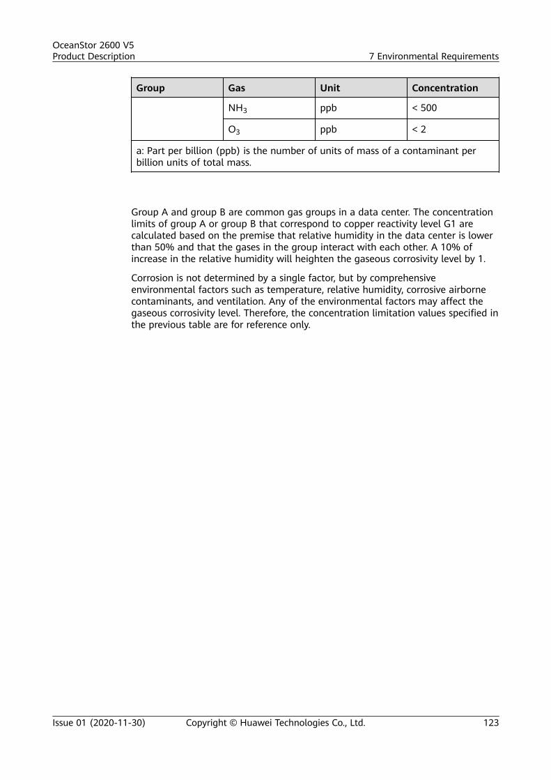
Group Gas Unit Concentration
NH3 ppb < 500
O3 ppb < 2
a: Part per billion (ppb) is the number of units of mass of a contaminant perbillion units of total mass.
Group A and group B are common gas groups in a data center. The concentrationlimits of group A or group B that correspond to copper reactivity level G1 arecalculated based on the premise that relative humidity in the data center is lowerthan 50% and that the gases in the group interact with each other. A 10% ofincrease in the relative humidity will heighten the gaseous corrosivity level by 1.
Corrosion is not determined by a single factor, but by comprehensiveenvironmental factors such as temperature, relative humidity, corrosive airbornecontaminants, and ventilation. Any of the environmental factors may affect thegaseous corrosivity level. Therefore, the concentration limitation values specified inthe previous table are for reference only.
OceanStor 2600 V5Product Description 7 Environmental Requirements
Issue 01 (2020-11-30) Copyright © Huawei Technologies Co., Ltd. 123

8 Standards Compliance
The chapter describes the protocol standards, the safety specifications andelectromagnetic compatibility (EMC) standards, and the industry standards thatthe storage system complies with.
Protocol Standards
Table 8-1 lists the protocol standards that the storage system complies with.
Table 8-1 Protocol standards
Name Standard No.
SCSIsystem
FC-PH: ANSI X3.230
FC-PH2: ANSI X3.297
SCSI-FCP: ANSI X.269
FC-AL: ANSI X.272
FC-AL-2: ANSI NCITS 332-1999
FC-SW: ANSI NCITS 321
FC-SW-2: ANSI NCITS 355-2001
FC-GS: ANSI X.288 (for FC switch)
FC-GS2: ANSI NCITS 288 (for FC switch)
SAS Serial Attached SCSI-1.1 (SAS-1.1)
SAS Serial Attached SCSI-2.0 (SAS-2.0)
SAS Serial Attached SCSI-3.0 (SAS-3.0)
T10/1562D Rev.05 Serial Attached SCSI (SAS)
T10/1601D Rev.07 Serial Attached SCSI Model-1.1 (SAS-1.1)
T10/1601D Rev.07 Serial Attached SCSI Model-1.1 (SAS-2.0)
OceanStor 2600 V5Product Description 8 Standards Compliance
Issue 01 (2020-11-30) Copyright © Huawei Technologies Co., Ltd. 124

Name Standard No.
T10/1601D Rev.07 Serial Attached SCSI Model-1.1 (SAS-3.0)
SFF 8301 form factor of 3.5" disk drive
SFF 8323 3.5" disk drive form factor with serial connector
SFF 8482 SAS plug connector
SAM-4 INCITS 447-2008
SPC-4 INCITS 513-2015
SBC-3 INCITS 514-2014
PICMG3.0 Advanced Telecommunications Computing Architecture
PICMG3.1 Ethernet/Fibre Channel Over PICMG3.0
iSCSI RFC 3720/7143
TCP/IPsystem
SNMP v1
SNMP v2c
SNMP v3
PCIesystem
PCI Express Base Specification R1.1
PCI Express Base Specification v2.0
PCI Express Base Specification v3.0
Interface StandardsTable 8-2 describes the interface standards that the storage systems comply with.
Table 8-2 Interface standards that the storage systems comply with
Name Description
VAAI An application programming interface (API) framework fromVMware. It enables some storage-related tasks (such as thinprovisioning) to be offloaded from a VMware server to a storagearray.
VASA An API used for VMware vSphere ESXi hosts to communicate withstorage devices. It enables vCenter to manage storage arrays in aunified manner.
SRA An interface between VMware Site Recovery Manager (SRM) and astorage system. It enables SRM to perform the following operations:discovery of storage systems, non-disruptive failover test, emergencyor planned failover, reverse replication, backup, and restoration.
OceanStor 2600 V5Product Description 8 Standards Compliance
Issue 01 (2020-11-30) Copyright © Huawei Technologies Co., Ltd. 125

Name Description
SMI-S A storage standard developed and maintained by the StorageNetworking Industry Association (SNIA). It aims to simplify themanagement of a storage area network (SAN) that contains devicesfrom various manufacturers. It provides a universal managementinterface for all types of network elements and simplifies themanagement of a heterogeneous SAN environment.NOTE
Log in to https://support.huawei.com/enterprise/. In the search field, entereSDK Storage, and select a path from the paths that are automaticallydisplayed to go to the document page. Search, browse, and download the SMI-S Provider documents of the corresponding version to get more information.
ODX Offloaded data transfer (ODX) is a feature of Windows Server, whichoffloads data copy operations to storage arrays. If ODX is not used, ahost reads data from and then writes it to a storage array. With ODXenabled, the data copying tasks are offloaded from the host to thestorage array, reducing I/O workloads of the host.
Safety Specifications and EMC Standards
Table 8-3 lists the safety specifications and EMC standards that the storagesystem complies with.
Table 8-3 Safety specifications and EMC standards
Name Standard No.
China safety standard GB 4943.1-2011
North America safetystandard
UL 60950-1 and UL 62368-1
European safety directive 2014/35/EU
European safetystandard
EN 60950-1 and EN 62368-1
China EMC standard GB/T9254-2008
GB17625.1-2012
Canada EMC standard ICES-003
North America EMCstandard
FCC, CFR47 Part 15, Subpart B
European EMC directive 2014/30/EU
European EMC standard EN 55032
EN 55024 or EN 55035
OceanStor 2600 V5Product Description 8 Standards Compliance
Issue 01 (2020-11-30) Copyright © Huawei Technologies Co., Ltd. 126

Industry StandardsTable 8-4 lists the industry standards that the storage system complies with.
Table 8-4 Industry standards
Name Standard No.
Ethernet IEEE 802.3
Fast Ethernet IEEE 802.3u
Gigabit Ethernet IEEE 802.3z
IEEE 802.3ab
10-Gigabit Ethernet IEEE 802.3ae
VLAN IEEE 802.1q
IEEE standard test accessport and boundary-scanarchitecture
IEEE 1149.1-2001
Procedure for failuremodes and effectsanalysis (FMEA)
IEC 812
Presentation ofreliability,maintainability andavailability predictions
IEC 863
ETSI standard(environment)
ETS 300 019
ETSI standard (power) ETS 300 132
ETSI standard (noise) ETS 300 753
ETSI standard(environment)
ETS 300 119
ETSI standard(grounding)
ETS 300 253
ITUT standard(grounding)
ITUT K.27
Environmentalprotection
ECMA TR/70
Reliability GR-929, Telcordia SR-332
Clean room and relatedcontrolled environments
ISO 14664-1 Class8
OceanStor 2600 V5Product Description 8 Standards Compliance
Issue 01 (2020-11-30) Copyright © Huawei Technologies Co., Ltd. 127

Name Standard No.
Airborne contaminantsand environmentstandards
ANSI/ISA-71.04-1985 severity level G1
OceanStor 2600 V5Product Description 8 Standards Compliance
Issue 01 (2020-11-30) Copyright © Huawei Technologies Co., Ltd. 128

9 Certifications
The chapter describes the certifications of the storage system.
Table 9-1 lists the certifications that the storage system obtains.
Table 9-1 Certifications
Name Description
CB The Certification Bodies (CB) Scheme is an international schemeoperated by the IEC System for Conformity Testing and Certificationof Electrical Equipment (IECEE). Member countries of the IECEE testelectrical product performance based on the IEC standards. Theresults, which are CB test reports and CB test certificates, arerecognized by all countries within the IECEE. The CB scheme isdesigned for eliminating the international commerce barriersresulted from the compliance with certifications and approvalguidelines of different countries.The CB Scheme is formulated based on the IEC standard. If membercountries' national standards are not completely consistent with IECstandards, the differences are allowed but must be disclosed to theother members. A CB test certificate is used in the Scheme to provethat a tested product sample has passed CB tests and meets relatedIEC and member countries' requirements.
CCC China Compulsory Certification (CCC) is a three-in-one authoritativecertification incorporating the Conformity Certification of ElectricalEquipment (CCEE), the certificate for the safe license of importgranted by China Commodity Inspection Bureau (CCIB), and Safetyand Electro Magnetic Compatibility (EMC).The CCC mainly involves the products related to human health andsecurity, animal and plant life and health, environmental protection,and public security.
OceanStor 2600 V5Product Description 9 Certifications
Issue 01 (2020-11-30) Copyright © Huawei Technologies Co., Ltd. 129

Name Description
FCC Federal Communications Commission (FCC) authorizes andmanages all RF transmission facilities and devices except for thoseused by the federal government. It is also responsible for theenvironmental damages generated by the facilities and devices itapproves.
IC Industry Canada (IC) sets up the test standards for analog anddigital terminal devices and specifies corresponding EMC certificatesthat all import electronic products must obtain.
NRTL A Nationally Recognized Testing Laboratory (NRTL) is anindependent laboratory recognized by the Occupational Safety andHealth Administration (OSHA) of the United States to test productsto applicable product safety standards.The OSHA requires that products used in the workplace must betested by an NRTL and obtain security certificates after the productspass all related tests to ensure the personal safety of users.
CE (LVDandEMC)
Conformite Europeenne (CE): Products marked with CE conform tothe Electromagnetic Compatibility (EMC) Directive and Low VoltageDirective (LVD) published by the European Commission. The LVDand EMC Directive are mandatory requirements for entry to themarket.
REACH Registration, Evaluation, Authorisation and Restriction of Chemicals(REACH) is a regulation on the registration, assessment,authorization and limitation of chemical substances, includingmixtures and articles made up of chemical substances. It is one ofEU's compulsory admission regulations.
CE(RoHS)
The restriction of the use of certain hazardous substances inelectrical and electronic equipment (RoHS) is one of EU'scompulsory admission regulations.
WEEE Waste Electrical and Electronic Equipment Regulation (WEEE) is anEU directive on electrical and electronic wastes. Electronic andelectrical products sold to the EU market must comply with thedirective, that is, the 3R (recovery, reuse, and recycling) of electronicand electrical wastes and symbols of crossed-out wheeled bins.
CE (ErP) The Energy-related Product (ErP) Directive defines the ecodesignrequirements for storage systems, including the requirements onpower efficiency, material efficiency, and product information. It isone of EU's compulsory admission regulations.
EAC Russia, Kazakhstan, and Belarus have integrated their owncertification technology requirements and formulated a unifiedCustoms Union (CU) certification. The products within the scope ofcontrol are subject to mandatory certification of customs uniontechnical regulations (CU-TR), unified technical regulations andevaluation modes, product qualification directories, certificate forms,and technical supervision and registration.
OceanStor 2600 V5Product Description 9 Certifications
Issue 01 (2020-11-30) Copyright © Huawei Technologies Co., Ltd. 130

Name Description
RCM The Australian & New Zealand Regulatory Compliance Mark (RCM)is the mandatory compliance for selling electrical equipmentproducts in the market.
VCCI As the EMC mark in Japan, the VCCI certificate is managed by theVoluntary Control Council for Interference by InformationTechnology Equipment. The organization determines whether aninformation technology product meets VCCI requirements based onthe Special International Committee on Radio Interference(abbreviated as CISPR from its French name) 32 standard.
Security Symbol (CCC)
The product is a Class A device based on the CCC. Use of it in a residential area islikely to cause radio interference. Users may be required to prevent theinterference by taking protective measures.
FCC-DOC
Supplier's Declaration of Conformity (SDoC)Unique Identifier: trade name: HUAWEI; product name: Storage System; modelnumber: OceanStor 2600 V5Responsible Party- U.S. Contact InformationHuawei Technologies USA Inc.5700 Tennyson Parkway, Suite 500Plano, Texas 75024Main: 214-919-6000 / TAC Hotline: 877-448-2934FCC Compliance Statement (for products subject to Part 15)This device complies with part 15 of the FCC Rules. Operation is subject to thefollowing two conditions: (1) This device may not cause harmful interference,and (2) this device must accept any interference received, including interferencethat may cause undesired operation.
VCCI
Product complies with VCCI Class A by Information Technology Equipment (ITE).
Class A ITE
OceanStor 2600 V5Product Description 9 Certifications
Issue 01 (2020-11-30) Copyright © Huawei Technologies Co., Ltd. 131

ErP InformationEnergy-related Product information
Product type Storage system
Manufacturer'sname, registeredtrade name andregistered tradeaddress
Administration Building, Headquarters of HuaweiTechnologies Co., Ltd., Bantian, Longgang District,Shenzhen, 518129, P.R.CTel: +86 755 28780808Fax: +86 755 89652518
Product modelnumber
OceanStor 5300 V5OceanStor 5500 V5OceanStor 5600 V5OceanStor 5800 V5OceanStor 6800 V5
Manufacture data See the qualification certificate on the equipment.
PSU information Internalpowersupply
Ratedpoweroutput(W)
Load Powerfactor
Efficiency
PAC800D1205-CE
800 10% / 85.61%
20% / 91.92%
50% 0.990 94.20%
100% / 92.50%
PAC1500S12-BE
1500 10% / 87.96%
20% / 92.41%
50% 0.994 94.28%
100% / 93.20%
PAC2000S12-BG
2000 10% / 88.83%
20% / 92.56%
50% 0.999 94.15%
100% / 92.54%
Declaredoperatingcondition class
A3
OceanStor 2600 V5Product Description 9 Certifications
Issue 01 (2020-11-30) Copyright © Huawei Technologies Co., Ltd. 132

Information onthe secure datadeletionfunctionality
Refer to section Erasing Data from Disks in theAdministrator Guide.
OceanStor 2600 V5Product Description 9 Certifications
Issue 01 (2020-11-30) Copyright © Huawei Technologies Co., Ltd. 133

10 Operation and Maintenance
The storage systems can be operated and maintained by using DeviceManagerand the command-line interface (CLI), adapting to different environments anduser habits.
Introduction to DeviceManager
Figure 10-1 shows the DeviceManager main window.
Figure 10-1 DeviceManager main window
Table 10-1 describes the components of the DeviceManager main window.
Table 10-1 Components of the DeviceManager main window
No. Name Description
1 Function pane The function pane shows a page associated withthe current operation.
OceanStor 2600 V5Product Description 10 Operation and Maintenance
Issue 01 (2020-11-30) Copyright © Huawei Technologies Co., Ltd. 134

No. Name Description
2 Status bar The status bar shows information such as the username currently logged in and the login time.
3 Navigation bar The navigation bar shows the function modules ofa storage system. Users can click a functionmodule to configure the corresponding functions.
4 Exit, help, andlanguage selectionarea
This area displays an exit button, a help button,and a language selection button. DeviceManagersupports two languages: simplified Chinese andEnglish.
5 Fault statistics area The fault statistics area shows the number ofeach level of system faults, helping usersunderstand the running status of a storagesystem.
Users can log in to DeviceManager using a common browser.
To master GUI-based operations, you are advised to read this document andpractice the operations using the DeviceManager Demo. As a simulation programof storage system management software, the DeviceManager Demo simulatesconfiguration and management operations on a storage system.
Introduction to the CLIAfter logging in to the storage system through CLI, you can query, set, manage,and maintain the storage system.
Users need to log in to the CLI by using terminal software, such as theHyperTerminal provided by Windows, or PuTTY.
There are two ways to log in to the CLI.
● Log in through a serial port of a storage system. To connect to a serial port,the maintenance terminal must be located next to the storage system.Therefore, this login mode is applicable to the scenario where a user does notknow the management IP address of a storage system or a storage system isfaulty.
● Log in through a management network port of a storage system. When thereare reachable routes, a user can log in to the CLI by entering the IP address ofthe management network port of a storage system in the terminal software.IP networks are easily accessible. Therefore, a user can log in to a storagesystem remotely, and this login mode is more popular.
OceanStor 2600 V5Product Description 10 Operation and Maintenance
Issue 01 (2020-11-30) Copyright © Huawei Technologies Co., Ltd. 135

A How to Obtain Help
If a tough or critical problem persists in routine maintenance or troubleshooting,contact Huawei for technical support.
A.1 Preparations for Contacting HuaweiTo better solve the problem, you need to collect troubleshooting information andmake debugging preparations before contacting Huawei.
A.1.1 Collecting Troubleshooting InformationYou need to collect troubleshooting information before troubleshooting.
You need to collect the following information:
● Name and address of the customer● Contact person and telephone number● Time when the fault occurred● Description of the fault phenomena● Device type and software version● Measures taken after the fault occurs and the related results● Troubleshooting level and required solution deadline
A.1.2 Making Debugging PreparationsWhen you contact Huawei for help, the technical support engineer of Huaweimight assist you to do certain operations to collect information about the fault orrectify the fault directly.
Before contacting Huawei for help, you need to prepare the boards, port modules,screwdrivers, screws, cables for serial ports, network cables, and other requiredmaterials.
OceanStor 2600 V5Product Description A How to Obtain Help
Issue 01 (2020-11-30) Copyright © Huawei Technologies Co., Ltd. 136

A.2 How to Use the DocumentHuawei provides guide documents shipped with the device. The guide documentscan be used to handle the common problems occurring in daily maintenance ortroubleshooting.
To better solve the problems, use the documents before you contact Huawei fortechnical support.
A.3 How to Obtain Help from WebsiteHuawei provides users with timely and efficient technical support through theregional offices, secondary technical support system, telephone technical support,remote technical support, and onsite technical support.
Contents of the Huawei technical support system are as follows:
● Huawei headquarters technical support department● Regional office technical support center● Customer service center● Technical support website: https://support.huawei.com/enterprise/
You can query how to contact the regional offices at https://support.huawei.com/enterprise/.
A.4 Ways to Contact HuaweiHuawei Technologies Co., Ltd. provides customers with comprehensive technicalsupport and service. For any assistance, contact our local office or companyheadquarters.
Huawei Technologies Co., Ltd.
Address: Huawei Industrial Base Bantian, Longgang Shenzhen 518129 People'sRepublic of China
Website: https://e.huawei.com/
OceanStor 2600 V5Product Description A How to Obtain Help
Issue 01 (2020-11-30) Copyright © Huawei Technologies Co., Ltd. 137

B Glossary
If you want to obtain information about glossaries, visit https://support.huawei.com/enterprise/. In the search field, enter a product model, andselect a path from the paths that are automatically displayed to go to thedocument page of the product. Browse or download the OceanStor V5 SeriesV500R007 Glossary.
OceanStor 2600 V5Product Description B Glossary
Issue 01 (2020-11-30) Copyright © Huawei Technologies Co., Ltd. 138

C Acronyms and Abbreviations
A
ANSI American National Standards Institute
B
BBU Backup Battery Unit
C
CLI Command Line Interface
E
ESN Equipment Serial Number
F
FC Fibre Channel
FC-AL Fibre Channel Arbitrated Loop
FCoE Fibre Channel over Ethernet
G
GE Gigabit Ethernet
GUI Graphical User Interface
H
HBA Host Bus Adapter
HD High Density
I
IP Internet Protocol
OceanStor 2600 V5Product Description C Acronyms and Abbreviations
Issue 01 (2020-11-30) Copyright © Huawei Technologies Co., Ltd. 139

ISA Instrument Society of America
iSCSI Internet Small Computer Systems Interface
ISO International Organization for Standardization
L
LUN Logical Unit Number
M
MTBF Mean Time Between Failures
MTTR Mean Time to Repair
N
NL-SAS Near Line Serial Attached SCSI
P
PDU Power Distribution Unit
U
USB Universal Serial Bus
R
RAID Redundant Array of Independent Disks
RSCN Registered State Change Notification
S
SAN Storage Area Network
SAS Serial Attached SCSI
SCSI Small Computer System Interface
SSD Solid State Drive
V
VLAN Virtual Local Area Network
VPN Virtual Private Network
OceanStor 2600 V5Product Description C Acronyms and Abbreviations
Issue 01 (2020-11-30) Copyright © Huawei Technologies Co., Ltd. 140