product information and user guide
TRANSCRIPT

ICV VALVESPRODUCT INFORMATION AND USER GUIDE
ICV ValvesRobust valves for highly demanding irrigation systems

Page 2
RESIDENTIAL & COMMERCIAL IRRIGATION | Built on Innovation®
Overview
Durable, glass-filled Hunter ICV series valves are the leading solution for irrigation systems worldwide. Industrial strength, unmatched reliability, and advanced technologies make the ICV an ideal choice for commercial and high-end residential projects. Every ICV valve is loaded with professional features for maximum reliability.
The maintenance-friendly ICV is designed with captive parts, common components such as a single solenoid for all valves, and a convenient triple-tool design for easy accessibility. Since all Hunter valves are 100% water-tested prior to shipping, you can be sure they are working properly before ever coming into your hands.
This guide explains the key benefits of ICV valves, as well as our best-in-class Accu Sync® pressure regulators. You will also find helpful installation details, a parts list, and a troubleshooting section.
Please read the guide carefully to fully understand the top-quality products you have invested in. Thank you for choosing Hunter Industries as your partner for irrigation needs.
Table of Contents
3 Valve Operation4 Product Details6 Accu Sync Pressure Regulators7 Valve Comparison8 Technical Information10 Product Performance11 Installation Details12 Replacement Parts15 Installation16 Troubleshooting

Page 3
| Visit support.hunterindustries.com
Valve Operation
Principles of Valve OperationValve mechanics are based on the formula F = P x A where:
◦ P = Water pressure within the valve ◦ A = Surface area of the diaphragm (top or bottom) ◦ F = Amount of force exerted on either side of diaphragm
Since the top of the diaphragm is larger than the bottom, the force is higher on the diaphragm top when pressure equalizes, keeping the valve closed.
Opening a Valve ElectricallyWhen operating a valve electrically, 24 VAC flows to the solenoid and lifts the solenoid plunger. The pressurized water then vacates downstream through an exhaust port. With pressure released on the top of the diaphragm, the force below pushes the diaphragm up, opening the valve.
Opening a Valve ManuallyTurn the bleed screw (above the flow control knob) counterclockwise to externally bleed water from the upper chamber to open the valve or rotate the solenoid a ¼-turn to internally bleed the water from the top of the diaphragm downstream to open the valve.
Closing a Valve• When the controller shuts off the electricity from the solenoid, the solenoid plunger is released
and forced downward to cover the exhaust port.• Covering the port stops the discharge of water from the upper chamber and allows the chamber
to pressurize to mainline pressure once again.• As the pressure above the diaphragm increases, the diaphragm slowly closes. • The valve will fully close when the diaphragm sits completely on the body of the valve.
! Note: Example of opening valve using external bleed.

RESIDENTIAL & COMMERCIAL IRRIGATION | Built on Innovation®
Page 4
Large Filtering AreaExcellent choice for dirty water applications:• Large filtering surface area assists in ensuring
consistent opening/closing of valve
Optional Filter Sentry®• Scrapes filter fully and continuously while valve is open• Cleans full screen regardless of flow control adjustments• Filter Sentry cleaning system is uniquely attached to the
diaphragm, not the valve; the valve body does not need to be removed to replace the diaphragm
Filter Sentry
Double-Beaded Diaphragm
Heavy-Duty ConstructionDesigned to operate within highly demanding systems up to 220 PSI (15 bar; 1518 kPa) for many years of operation:• Body and bonnet made with glass-filled nylon to provide
extra strength and durability• Diaphragm manufactured from fabric-reinforced EPDM
rubber highly resistant to abrasion• Through-hole brass inserts in the body provide greater
strength between body and bonnet
Reliability and durability proven through grueling tests:• High-pressure surge• Sand and grit• Cyclical burst• Life cycle• Heat/freeze
Flow RangeIncredibly versatile with wide flow range:• Flows starting at 0.1 GPM and reaching up to 300 GPM (0.03
to 68 m3/hr; 0.4 to 1,135 l/min)• Designed for minimal friction loss • Use for micro irrigation systems as well as large
turf projects
Product Details
DC-Latching Solenoid
AC Solenoid
Robust SolenoidProvides dependable operation and long life:• Common AC solenoid for all Hunter valves• Common DC-latching solenoid for all Hunter valves having
one black (common) wire and one red (station) wire • Contractors/distributors only need to stock one
solenoid for Hunter valves• Eliminate damage from pressure surges with Hunter’s
innovative reverse-flow solenoid design• The most dependable and efficient solenoids on the
market: - Only 370 mA (8.9 VA) inrush current, 190 mA (4.5 VA)
holding current at 60 Hz - Allows for longer wire runs between the valve
and controller

| Visit support.hunterindustries.com
Brass InsertsAdding strength where it matters:• Contribute to serviceability by preventing dirt from packing
into the hole as in other valves• Dirt falls through the inserts, allowing the bonnet to fully
tighten on the body
Warranty Information The date code is located on top of the bonnet (mo/yr)
Warranty period: 5 years
Page 5
Top of Bonnet
Product Details
Captive Bonnet Bolts
Flat/Phillips/Hex Driver
Debris Tolerant• “Knife-edged” body seat helps eliminate weeping due to
debris caught under the diaphragm• EPDM diaphragm seat assembly provides substantial grit
tolerance and wear resistance
Fully Supported, Slow-Closing DiaphragmMinimizes water hammer:• Slow closing speed helps prevent water hammer• Support ring protects the fabric-reinforced diaphragm from
additional stresses• Small holes in the support ring flush around the diaphragm
and prevent sticking• Double-beaded diaphragm seal design ensures leak-free
performance • Offered in purple reclaimed version designed to withstand
high levels of chlorine and chloramines in the water
Adjustable Flow Control with Non-Rising Handle• Flow adjustment and servicing made easy• All sizes equipped with non-rising flow control
“Knife-Edged” Body Seat
White Support Ring
Flow Control Knob
Two Methods to Manually Bleed ValveInternal bleed for completely dry operation:• Quick ¼-turn of solenoid allows water to bleed downstream
and open valve• All the exhaust water stays in the valve
External bleed using easy access bleed screw:• Turn the bleed screw on top of the flow control stem• Water will vent outside the valve
Captive PartsNo more lost bolts, nuts, or solenoid plungers:• Captive diaphragm remains on bonnet until you remove it• Captive solenoid plunger remains intact• Captive bonnet bolts stay in the bonnet even when tipped
upside down• With the bolts having a combination of slot/Phillips/hex
for easy servicing, this is the easiest valve in the industry to maintain without losing the parts in a muddy valve box
External Bleed Screw

Page 6
RESIDENTIAL & COMMERCIAL IRRIGATION | Built on Innovation®
RECOMMENDED FLOW RANGES FOR ICV VALVES WITH ACCU SYNC
Valve Flow
GPM m3/hr l/min
ICV-101G 5–40 1.2–9.0 19–150
ICV-151G 20–150 4.5–31 75–510
ICV-201G 40–200 9.0–34 150–560
ICV-301G 150–300 34–68 565–1135
4. Thread the solenoid adapter into place by inserting it and holding it steady while rotating the solenoid in its socket.
Pressure Regulation for Any Hunter Valve • Accu Sync can be used to regulate pressure for any type of applications to meet optimum pressure level• Offered in fixed outlet pressure options of either 30 or 40 PSI (2 or 2.75 bar; 200 or 275 kPa)• Offered in adjustable outlet pressure setting from 20 to 100 PSI (1.4 to 7.0 bar; 140 to 700 kPa)• Required dynamic pressure differential: 15 PSI (1.0 bar; 100 kPa) above outlet selection• Works with all Hunter valves and both AC solenoids and DC-latching solenoids• Consistent outlet pressure regardless of incoming pressure fluctuations• Ideal for any Hunter valve as long as appropriate pressure and flow is met• No need for cumbersome gauge to double-check pressure. Every Accu Sync is calibrated and tested for appropriate pressures.
Accu Sync Pressure Regulators
ACCU-SYNC-ADJ Adjustment
1. Turn the outer black dial until the white line is next to the desired downstream pressure.
Installation Instructions
1. After shutting off the water supply, remove the solenoid from the Hunter valve.
2. Thread the Accu Sync into the side inlet of the adapter.
3. Thread the solenoid into the top port of the adapter.
!Note: When activating the valve by twisting the solenoid counterclockwise, the valve will continue to regulate pressure. If using the bleed screw to activate, the valve will not regulate pressure.
2. Accu Sync shows PSI on one side and bar on the other. For kPa, multiply bar by 100.
Desired Downstream Pressure
Outer Dial
Page 7
| Visit support.hunterindustries.com
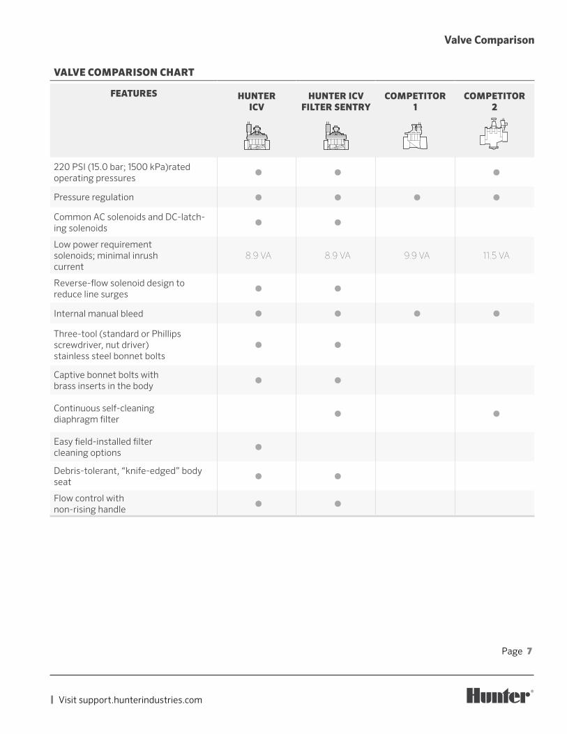
VALVE COMPARISON CHART
FEATURES HUNTER ICV
HUNTER ICV FILTER SENTRY
COMPETITOR 1
COMPETITOR 2
220 PSI (15.0 bar; 1500 kPa)rated operating pressures
⬤ ⬤ ⬤
Pressure regulation ⬤ ⬤ ⬤ ⬤
Common AC solenoids and DC-latch-ing solenoids
⬤ ⬤
Low power requirement solenoids; minimal inrush current
8.9 VA 8.9 VA 9.9 VA 11.5 VA
Reverse-flow solenoid design to reduce line surges
⬤ ⬤
Internal manual bleed ⬤ ⬤ ⬤ ⬤
Three-tool (standard or Phillips screwdriver, nut driver) stainless steel bonnet bolts
⬤ ⬤
Captive bonnet bolts with brass inserts in the body
⬤ ⬤
Continuous self-cleaning diaphragm filter
⬤ ⬤
Easy field-installed filter cleaning options
⬤
Debris-tolerant, “knife-edged” body seat
⬤ ⬤
Flow control with non-rising handle
⬤ ⬤
Valve Comparison

Page 8
RESIDENTIAL & COMMERCIAL IRRIGATION | Built on Innovation®
ICV-101G-FSInlet diameter: 1" (25 mm) Height: 5½" 14 cm) Length: 4¾" (12 cm) Width: 4" (10 cm)
ICV-151G-FSInlet diameter: 1½" (40 mm) Height: 7⅛" (18 cm) Length: 6⅞" (17 cm) Width: 5½" (14 cm)
ICV-201G-FSInlet diameter: 2" (50 mm) Height: 7⅛" (18 cm) Length: 6⅞" (17 cm) Width: 5½" (14 cm)
ICV-301-FSInlet diameter: 3" (80 mm) Height: 10¾" (27 cm) Length: 9" (22 cm) Width: 7⅜" (19 cm)
Technical Information
Operating Specifications• Flow:
ICV-101G / ICV-101G-FS: 0.1 to 40 GPM; (0.03 to 9 m3/hr; 0.4 to 150 l/min)
ICV-151G / ICV-151G-FS: 0.1 to 150 GPM; (0.03 to 34 m3/hr; 0.4 to 568 l/min)
ICV-201G / ICV-201G-FS: 0.1 to 200 GPM (0.03 to 45 m3/hr; 0.4 to 757 l/min)
ICV-301 / ICV-301W-FS: 0.1 to 300 GPM; (0.03 to 68 m3/hr; 0.4 to 1,135 l/min)
• Recommended pressure range: 20 to 220 PSI (1.5 to 15.0 bar; 150 to 1500 kPa)
• Temperature rating: 150°F (66°C)• Warranty period: 5 years
ICV SPECIFICATION BUILDER
Model Threading Options
ICV-101G 1" (25 mm) globe valve Blank NFPT FS Filter Sentry
ICV-151G 11/ 2" (40 mm) globe valve B BSP FS-R Filter Sentry, Reclaimed
ICV-201G 2" (50 mm) globe valve
ICV-301G 3" (80 mm) globe/angle valve
Examples: ICV-201G-FS-R = 2" (50 mm) ICV globe valve with Filter Sentry and reclaimed componentsICV-101G-DC = 1" (25 mm) ICV globe valve with installed DC-latching solenoid
Page 9
| Visit support.hunterindustries.com
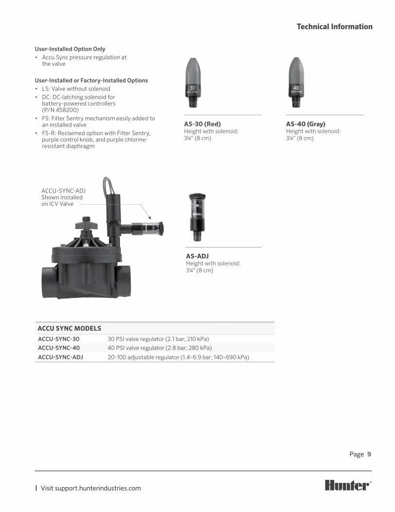
AS-30 (Red)Height with solenoid: 31/4" (8 cm)
AS-ADJHeight with solenoid: 31/4" (8 cm)
Technical Information
User-Installed Option Only• Accu Sync pressure regulation at
the valve
User-Installed or Factory-Installed Options• LS: Valve without solenoid• DC: DC-latching solenoid for
battery-powered controllers (P/N 458200)
• FS: Filter Sentry mechanism easily added to an installed valve
• FS-R: Reclaimed option with Filter Sentry, purple control knob, and purple chlorine-resistant diaphragm
ACCU-SYNC-ADJ Shown Installed on ICV Valve
AS-40 (Gray)Height with solenoid: 31/4” (8 cm)
ACCU SYNC MODELS
ACCU-SYNC-30 30 PSI valve regulator (2.1 bar; 210 kPa)
ACCU-SYNC-40 40 PSI valve regulator (2.8 bar; 280 kPa)
ACCU-SYNC-ADJ 20-100 adjustable regulator (1.4–6.9 bar; 140–690 kPa)

Page 10
RESIDENTIAL & COMMERCIAL IRRIGATION | Built on Innovation®
ICV PRESSURE LOSS (AT OPTIMAL FLOWS) IN kPa
Flow l/min
1" (25 mm) Globe
1½" (40 mm) Globe
2" (50 mm) Globe
3" (80 mm) Globe
3" (80 mm) Angle
1 142 144 14
20 1740 2060 2075 20 9.6115 62 10150 139 12 5.0190 15 7.0225 18 9.3280 26 14340 37 20380 46 26450 65 36510 84 47565 104 57 16 12660 79 22 17750 103 29 23850 38 30950 47 38
1,050 58 471,135 69 56
ICV PRESSURE LOSS (AT OPTIMAL FLOWS) IN BAR
Flow m3/hr
1" (25 mm) Globe
1½" (40 mm) Globe
2" (50 mm) Globe
3" (80 mm) Globe
3" (80 mm) Angle
0.05 0.10.1 0.10.3 0.11.0 0.22.5 0.23.5 0.24.5 0.2 0.17.0 0.4 0.19.0 1.0 0.1 0.111.0 0.2 0.113.5 0.2 0.117.0 0.3 0.120.5 0.4 0.223.0 0.5 0.327.0 0.7 0.430.5 0.9 0.534.0 1.2 0.6 0.2 0.140.0 0.9 0.2 0.245.5 1.2 0.3 0.251.0 0.3 0.357.0 0.4 0.462.5 0.5 0.568.0 0.6 0.6
ICV PRESSURE LOSS (AT OPTIMAL FLOWS) IN PSI
Flow (GPM)
1" Globe
1½" Globe
2"Globe
3" Globe
3" Angle
0.1 2.00.5 2.0
1 2.05 2.510 3.015 3.020 3.0 1.530 9.0 1.540 20.0 1.7 0.850 2.2 1.260 3.0 1.775 3.9 2.490 5.5 3.2100 7.0 4.2120 10.9 6.5135 12.7 7.9150 16.2 9.8 2.5 1.9175 13.3 3.0 2.4200 17.7 4.1 3.3225 5.3 4.3250 6.7 5.5275 8.3 6.9300 10.1 8.5
Product Performance
Page 11
| Visit support.hunterindustries.com
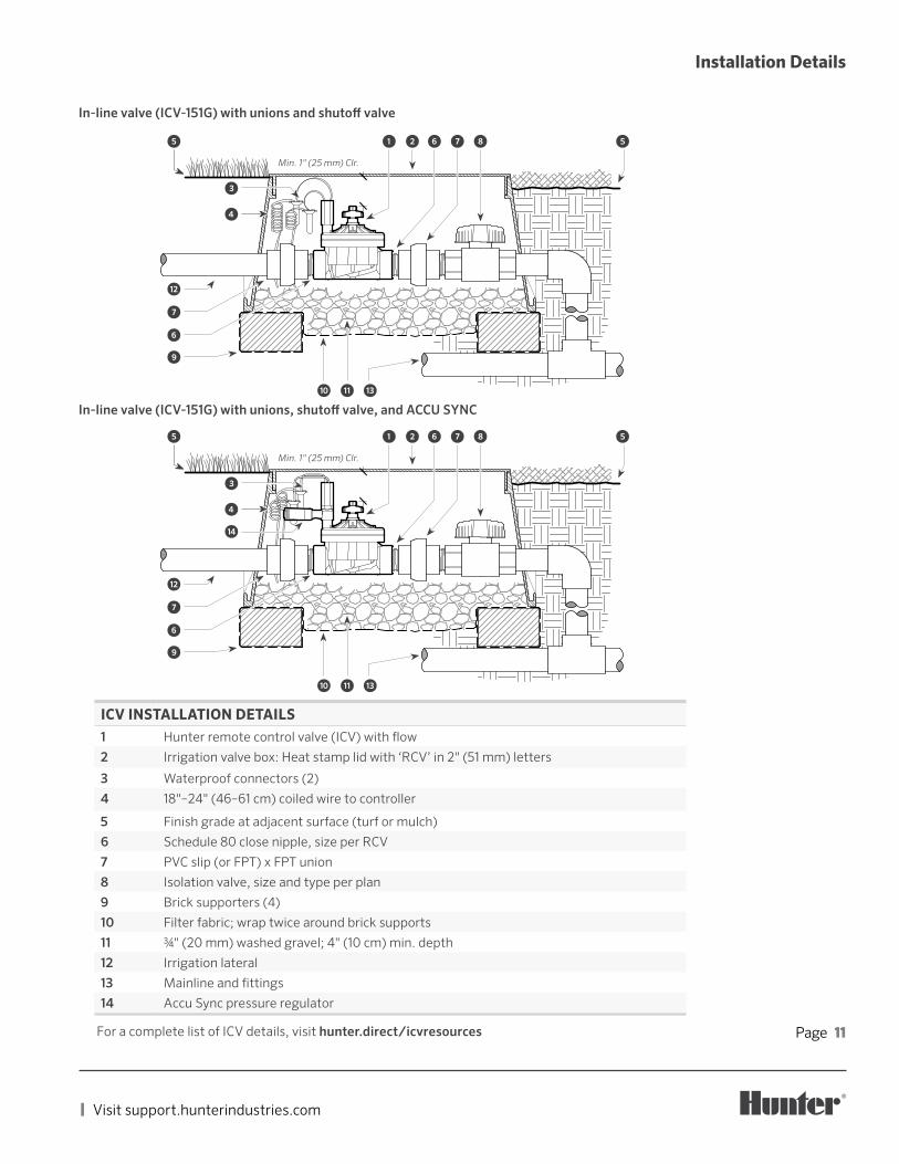
In-line valve (ICV-151G) with unions and shutoff valve
Installation Details
Min. 1" (25 mm) Clr.
➊ ➋
➍
➌
⑫
⑦
➏
⑩ ⑪ ⑬
⑤ ⑤➏ ⑦ ⑧
⑨
ICV INSTALLATION DETAILS1 Hunter remote control valve (ICV) with flow
2 Irrigation valve box: Heat stamp lid with ‘RCV’ in 2" (51 mm) letters
3 Waterproof connectors (2)
4 18"–24" (46–61 cm) coiled wire to controller
5 Finish grade at adjacent surface (turf or mulch)
6 Schedule 80 close nipple, size per RCV
7 PVC slip (or FPT) x FPT union
8 Isolation valve, size and type per plan
9 Brick supporters (4)
10 Filter fabric; wrap twice around brick supports
11 3/4" (20 mm) washed gravel; 4" (10 cm) min. depth
12 Irrigation lateral
13 Mainline and fittings
14 Accu Sync pressure regulator
For a complete list of ICV details, visit hunter.direct/icvresources
Min. 1" (25 mm) Clr.
➊ ➋
➍
➌
⓮
⑫
⑦
➏
⑩ ⑪ ⑬
⑤ ⑤➏ ⑦ ⑧
⑨
In-line valve (ICV-151G) with unions, shutoff valve, and ACCU SYNC

Page 12
RESIDENTIAL & COMMERCIAL IRRIGATION | Built on Innovation®
Replacement Parts
④
ICV-101G: PLASTIC VALVE
ITEM DESCRIPTION CATALOG NO.
1Solenoid Assembly (Includes 2 & 3)
AC Solenoid
606800
DC Solenoid
458200
2 O-Ring 262600
3 Solenoid Seal 364400
4 Bleed Assembly 561400
5 Bonnet Bolt 386900
6 Flow Control Knob561200SP
561205SP
7 E-Clip Retainer 387200
8 Bonnet 387700
9Flow Control Stem Assembly (Includes Stem, Stem Nut, O-Ring)
387900
Flow Control Stem 560900
Flow Control Stem Nut 386000
Flow Control Stem O-Ring 387100
10 Spring 386700
11 Diaphragm Assembly, Standard 387800SP
12Diaphragm Assembly with Filter Sentry Mechanism
461503SP
13 Diaphragm Support Ring 711900
14 Filter Sentry Tag, Yellow (10-Pack) 700392SP
15 Purple Reclaimed ID Tag (10-Pack) LIT-700
FILTER SENTRY™
INSTALLED LIT-301 P/N: 700392
DO NOT DRINK LIT-700
⑭
⑬
⑫
⑪
⑩
⑨
⑧⑦
⑥
⑤
③②
①
⑮
Page 13
| Visit support.hunterindustries.com
⑭
⑮⑯
①
②③
④
⑥
⑦
⑧
➈
⑩
⑪ ⑫
⑤
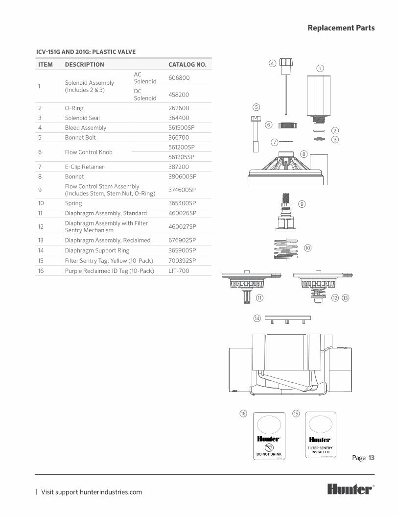
ICV-151G AND 201G: PLASTIC VALVE
ITEM DESCRIPTION CATALOG NO.
1Solenoid Assembly (Includes 2 & 3)
AC Solenoid
606800
DC Solenoid
458200
2 O-Ring 262600
3 Solenoid Seal 364400
4 Bleed Assembly 561500SP
5 Bonnet Bolt 366700
6 Flow Control Knob561200SP
561205SP
7 E-Clip Retainer 387200
8 Bonnet 380600SP
9Flow Control Stem Assembly (Includes Stem, Stem Nut, O-Ring)
374600SP
10 Spring 365400SP
11 Diaphragm Assembly, Standard 460026SP
12Diaphragm Assembly with Filter Sentry Mechanism
460027SP
13 Diaphragm Assembly, Reclaimed 676902SP
14 Diaphragm Support Ring 365900SP
15 Filter Sentry Tag, Yellow (10-Pack) 700392SP
16 Purple Reclaimed ID Tag (10-Pack) LIT-700
FILTER SENTRY™
INSTALLED LIT-301 P/N: 700392
DO NOT DRINK LIT-700
⑬
Replacement Parts

Page 14
RESIDENTIAL & COMMERCIAL IRRIGATION | Built on Innovation®
Replacement Parts
ICV-301G: PLASTIC VALVE
ITEM DESCRIPTION CATALOG NO.
1Solenoid Assembly (Includes 2 & 3)
AC Solenoid
606800
DC Solenoid
458200
2 O-Ring 262600
3 Solenoid Seal 364400
4 Bleed Assembly (2015 and Older) 836200
Bleed Assembly, for Old-Style Female Threaded Flow Control Stem
518800
5
Flow Control Knob, (2015 and Older)
Black 515000
Purple 515005
Flow Control Knob, for Use with Current Production Flow Control Stem with Male Threads
Black 836500
Purple 836501SP
6 Bonnet Bolt 386900
7 Bonnet Assembly (incl. 4, 5, 8) 856300SP
8
Flow Control Stem Assembly (2015 and Older)
836200
Flow Control Stem Assembly, Old-Style with Female Threads
516100
9 Diaphragm Spring 518000
10 Diaphragm Assembly 518900SP
11 Filter Sentry Diaphragm Assembly 518905SP
12 Diaphragm Support 514600
13Port Plug Assembly including O-Ring
NPT 514900
BSP 514905
14 Filter Sentry Tag, Yellow (10-Pack) 700392SP
15 Purple Reclaimed ID Tag (10-Pack) LIT-700
16 Diaphragm Filter Sentry 365200
FILTER SENTRY™
INSTALLED LIT-301 P/N: 700392
DO NOT DRINK LIT-700
④
⑯
⑬
⑫
⑪
⑩
⑨
⑧
⑦
⑥
⑤③
②
①
⑭⑮
Page 15
| Visit support.hunterindustries.com
Installation
Teflon is a trademark of The Chemours Company.
Tuning MethodsDrip:With the system running, start with the flow control fully open. As you slowly adjust the flow control down, you will hear and feel turbulence in the valve as the flow gets too low. Adjust back up a half-turn.
Sprays and Rotors:1. Turn flow control knob clockwise until you feel it bottom
out (do not crank tight).2. Turn flow control knob counter-clockwise one full turn.3. ¼ turn solenoid counter-clockwise (as indicated on
solenoid) to manually bleed the valve (will come on). Only turn ¼ turn. The solenoid is not meant to be unscrewed completely for manual operation
4. Slowly turn flow control counter-clockwise using ½ turns (180o) increments.
5. Listen and observe! Watch the sprays increase to their maximum operation. A slight sound of restriction of flow from the valve should be heard.
6. Once set, turn solenoid back ¼ turn to allow valve to turn off.
7. Once off, make a final ½-turn (180o) counter-clockwise with the flow control knob. It is now set!
8. Confirm that the valve closes smoothly in about 6-8 seconds by turning on the valve manually again from the solenoid.
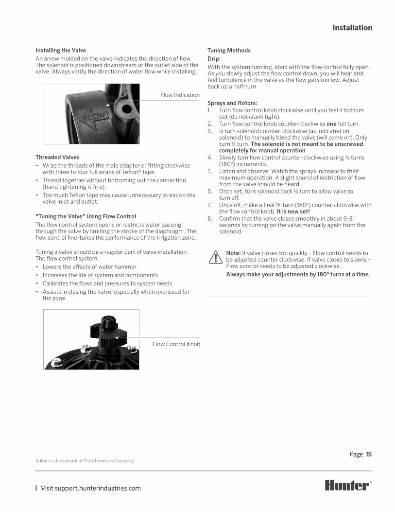
Installing the ValveAn arrow molded on the valve indicates the direction of flow. The solenoid is positioned downstream or the outlet side of the valve. Always verify the direction of water flow while installing.
Threaded Valves• Wrap the threads of the male adapter or fitting clockwise
with three to four full wraps of Teflon® tape.• Thread together without bottoming out the connection
(hand tightening is fine).• Too much Teflon tape may cause unnecessary stress on the
valve inlet and outlet.
“Tuning the Valve” Using Flow ControlThe flow control system opens or restricts water passing through the valve by limiting the stroke of the diaphragm. The flow control fine-tunes the performance of the irrigation zone.
Tuning a valve should be a regular part of valve installation. The flow control system:• Lowers the effects of water hammer• Increases the life of system and components• Calibrates the flows and pressures to system needs• Assists in closing the valve, especially when oversized for
the zone
Flow Indication
!Note: If valve closes too quickly – Flow control needs to be adjusted counter clockwise. If valve closes to slowly – Flow control needs to be adjusted clockwise.Always make your adjustments by 180o turns at a time.
Flow Control Knob
Page 16
RESIDENTIAL & COMMERCIAL IRRIGATION | Built on Innovation®
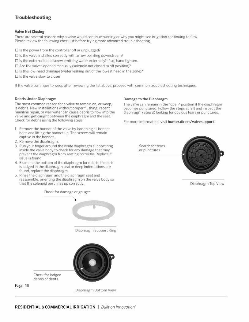
Check for lodged debris or dents
Damage to the DiaphragmThe valve can remain in the “open” position if the diaphragm becomes punctured. Follow the steps at left and inspect the diaphragm (Step 3) looking for obvious tears or punctures. For more information, visit hunter.direct/valvesupport.
Valve Not ClosingThere are several reasons why a valve would continue running or why you might see irrigation continuing to flow. Please review the following checklist before trying more advanced troubleshooting.
□ Is the power from the controller off or unplugged? □ Is the valve installed correctly with arrow pointing downstream? □ Is the external bleed screw emitting water externally? If so, hand tighten. □ Are the valves opened manually (solenoid not closed to off position)? □ Is this low-head drainage (water leaking out of the lowest head in the zone)? □ Is the valve slow to close?
If the valve continues to weep after reviewing the list above, proceed with common troubleshooting techniques.
Debris Under DiaphragmThe most common reason for a valve to remain on, or weep, is debris. New installations without proper flushing, recent mainline repair, or well water can cause debris to flow into the valve and get caught between the diaphragm and the seat. Check for debris using the following steps:
1. Remove the bonnet of the valve by loosening all bonnet bolts and lifting the bonnet up. The screws will remain captive in the bonnet.
2. Remove the diaphragm. 3. Run your finger around the white diaphragm support ring
inside the valve body to check for any damage that may prevent the diaphragm from seating correctly. Replace if issue is found.
4. Examine the bottom of the diaphragm for debris. If debris is lodged in the diaphragm seal or deep indentations are found, replace the diaphragm.
5. Rinse the diaphragm and the diaphragm seat and reassemble, orienting the diaphragm on the valve body so that the solenoid port lines up correctly.
Troubleshooting
Search for tears or punctures
Diaphragm Top View
Check for damage or gouges
Diaphragm Support Ring
Diaphragm Bottom View
Page 17
| Visit support.hunterindustries.com
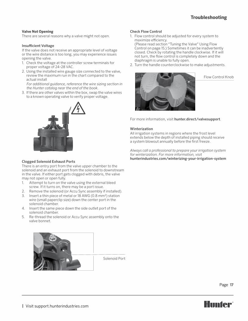
Flow Control Knob
Check Flow Control1. Flow control should be adjusted for every system to
maximize efficiency. (Please read section “Tuning the Valve” Using Flow Control on page 15.) Sometimes it can be inadvertently closed. Check by rotating the handle clockwise. If it will not turn, the flow control is completely down and the diaphragm is unable to fully open.
2. Turn the handle counterclockwise to make adjustments.
Valve Not OpeningThere are several reasons why a valve might not open.
Insufficient VoltageIf the valve does not receive an appropriate level of voltage or the wire distance is too long, you may experience issues opening the valve.1. Check the voltage at the controller screw terminals for
proper voltage of 24–28 VAC.2. Using the installed wire gauge size connected to the valve,
review the maximum run in the chart compared to the actual installFor additional guidance, reference the wire sizing section in the Hunter catalog near the end of the book.
3. If there are other valves within the box, swap the valve wires to a known operating valve to verify proper voltage.
Troubleshooting
For more information, visit hunter.direct/valvesupport.
WinterizationAll irrigation systems in regions where the frost level extends below the depth of installed piping should receive a system blowout annually before the first freeze.
Always call a professional to prepare your irrigation system for winterization. For more information, visit hunterindustries.com/winterizing-your-irrigation-system
Clogged Solenoid Exhaust PortsThere is an entry port from the valve upper chamber to the solenoid and an exhaust port from the solenoid to downstream in the valve. If either port gets clogged with debris, the valve may not open or open fully.1. Attempt to turn on the valve using the external bleed
screw. If it turns on, there may be a port issue.2. Remove the solenoid (or Accu Sync assembly if installed).3. Insert a thin piece of metal or 18 AWG (0.8 mm2) station
wire (small paperclip size) down the center port in the solenoid chamber.
4. Insert the same piece down the side outlet port of the solenoid chamber.
5. Re-thread the solenoid or Accu Sync assembly onto the valve bonnet.
Solenoid Port
!

Page 18
RESIDENTIAL & COMMERCIAL IRRIGATION | Built on Innovation®
hunter.direct/valvesupport
Find other helpful information about your product, including installation tips and more.
hunter.direct/valvevideos
Troubleshooting

Page 19
| Visit support.hunterindustries.com
Notes

HUNTER INDUSTRIES INCORPORATED | Built on Innovation®1940 Diamond Street, San Marcos, California 92078 USAhunterindustries.com
RC-154-PG-EN A 1/21
© 2021 Hunter Industries Inc. Hunter, the Hunter logo, and all other trademarks are property of Hunter Industries, registered in the U.S. and other countries.