product manual 26727 (revision f, 8/2015) (vs-i) electro-hydraulic actuator manual 26727 ii woodward...
TRANSCRIPT

Product Manual 26727(Revision F, 8/2015)
Original Instructions
VariStroke-I (VS-I) Electro-hydraulic Actuator
Installation and Operation Manual

General Precautions
Read this entire manual and all other publications pertaining to the work to be performed before installing, operating, or servicing this equipment.
Practice all plant and safety instructions and precautions.
Failure to follow instructions can cause personal injury and/or property damage.
Revisions
This publication may have been revised or updated since this copy was produced. To verify that you have the latest revision, check manual 26455, Customer Publication Cross Reference and Revision Status & Distribution Restrictions, on the publications page of the Woodward website:
www.woodward.com/publications The latest version of most publications is available on the publications page. If your publication is not there, please contact your customer service representative to get the latest copy.
Proper Use
Any unauthorized modifications to or use of this equipment outside its specified mechanical, electrical, or other operating limits may cause personal injury and/or property damage, including damage to the equipment. Any such unauthorized modifications: (i) constitute "misuse" and/or "negligence" within the meaning of the product warranty thereby excluding warranty coverage for any resulting damage, and (ii) invalidate product certifications or listings.
Translated Publications
If the cover of this publication states "Translation of the Original Instructions" please note:
The original source of this publication may have been updated since this translation was made. Be sure to check manual 26455, Customer Publication Cross Reference and Revision Status & Distribution Restrictions, to verify whether this translation is up to date. Out-of-date translations are marked with . Always compare with the original for technical specifications and for proper and safe installation and operation procedures.
Revisions—Changes in this publication since the last revision are indicated by a black line
alongside the text. Woodward reserves the right to update any portion of this publication at any time. Information provided by Woodward is believed to be correct and reliable. However, no responsibility is assumed by Woodward unless otherwise expressly undertaken.
Manual 26727 Copyright © Woodward 2013–2015
All Rights Reserved
Manual 26727 VariStroke-I (VS-I) Electro-hydraulic Actuator
Woodward i
Contents
WARNINGS AND NOTICES ............................................................................ V
ELECTROSTATIC DISCHARGE AWARENESS ................................................. VI
REGULATORY COMPLIANCE .......................................................................VII
CHAPTER 1. GENERAL INFORMATION ........................................................... 1 Introduction ............................................................................................................. 1 VS-I Integrated and Remote Construction ............................................................. 3 VS-I Remote Servo Only Construction ................................................................... 9
CHAPTER 2. SPECIFICATIONS .................................................................... 13 Physical and Performance Specifications ............................................................ 13 Environmental Specifications ............................................................................... 14 Electrical Specifications ........................................................................................ 14 Cylinder Position Sensor Requirements (Remote Servo Only) ........................... 15 Hydraulic Specifications ....................................................................................... 15 Special Ambient Temperature Specifications / Allowances ................................. 17 Stability Specifications .......................................................................................... 18 Diagrams .............................................................................................................. 20
CHAPTER 3. INSTALLATION........................................................................ 24 Receiving Instructions .......................................................................................... 24 Unpacking Instructions ......................................................................................... 24 Installation Instructions ......................................................................................... 25
CHAPTER 4. SERVICE TOOL INSTALLATION ................................................ 46 Setup .................................................................................................................... 46 Installing the VariStroke-I Service Tool ................................................................ 47 Connecting to the VariStroke-I ............................................................................. 49
CHAPTER 5. CALIBRATION AND MONITORING ............................................. 51 Introduction ........................................................................................................... 51 System Information ............................................................................................... 51 System Information Page ..................................................................................... 53 Configuration and Calibration ............................................................................... 54 Cylinder Configuration .......................................................................................... 56 Manual Operation ................................................................................................. 62
CHAPTER 6. CONFIGURATION .................................................................... 63 Input Configuration ............................................................................................... 63 Output Configuration ............................................................................................ 65 Advanced Configuration ....................................................................................... 67 Linearization ......................................................................................................... 68 Alarms/ Shutdown ................................................................................................ 68 Saving and Loading Settings ................................................................................ 70
CHAPTER 7. REPAIR AND TROUBLESHOOTING ........................................... 71 General ................................................................................................................. 71 Servo Valve / Hydraulic Cylinder Replacement.................................................... 71 Troubleshooting .................................................................................................... 72 Maintenance ......................................................................................................... 79
CHAPTER 8. PRODUCT SUPPORT AND SERVICE OPTIONS ........................... 80 Product Support Options ...................................................................................... 80 Product Service Options ....................................................................................... 80 Returning Equipment for Repair ........................................................................... 81 Replacement Parts ............................................................................................... 82 Engineering Services ............................................................................................ 82

VariStroke-I (VS-I) Electro-hydraulic Actuator Manual 26727
ii Woodward
Contacting Woodward’s Support Organization .................................................... 82 Technical Assistance ............................................................................................ 83
CHAPTER 9. ASSET MANAGEMENT AND REFURBISHMENT SCHEDULING
PERIOD ..................................................................................................... 84
CHAPTER 10. LONG-TERM STORAGE REQUIREMENTS ................................ 84
APPENDICES OUTLINE DRAWINGS AND INSTALLATION FEATURES ............... 85 Appendix A – V25 Servo, 4-inch (100mm) Bore Integrated Servo-Cylinder (V25TD-10XX) ...................................................................................................... 86 Appendix B – V25 Servo, 6-inch (150mm) Bore Integrated Servo-Cylinder (V25TD-15XX) ...................................................................................................... 88 Appendix C – V45 Servo, 6-inch (150mm) Bore Integrated Servo-Cylinder (V45TD-15XX) ...................................................................................................... 90 Appendix D – V45 Servo, 8-inch (200mm) Bore Integrated Servo-Cylinder (V45TD-20XX) ...................................................................................................... 92 Appendix E – V45 Servo, 10-inch (250mm) Bore Integrated Servo-Cylinder (V45TD-25XX) ...................................................................................................... 94 Appendix F – V45 Servo, 8-inch (200mm) Bore 3-inch (75mm) Stroke Integrated Spring Assist Servo-Cylinder (V45TT-2007-MUE) ............................................... 96 Appendix G – V25 Servo, 4-inch (100mm) Bore Remote Servo-Cylinder (V25RD-10XX) .................................................................................................................... 98 Appendix H – V25 Servo, 6-inch (150mm) Bore Remote Servo-Cylinder (V25RD-15XX) ..................................................................................................................101 Appendix I – V45 Servo, 6-inch (150mm) Bore Remote Servo-Cylinder (V45RD-15XX) ..................................................................................................................104 Appendix J – V45 Servo, 8-inch (200mm) Bore Remote Servo-Cylinder (V45RD-20XX) ..................................................................................................................107 Appendix K – V45 Servo, 10-inch (250mm) Bore Remote Servo-Cylinder (V45RD-25XX) ....................................................................................................110 Appendix L – V45 Servo, 8-inch (200mm) Bore 3-inch (75mm) Stroke Remote Spring Assist Servo-Cylinder (V45RT-2007-MUE) .............................................113 Appendix M – Remote Servo Version ................................................................116
REVISION HISTORY .................................................................................. 118
DECLARATIONS ....................................................................................... 119

Manual 26727 VariStroke-I (VS-I) Electro-hydraulic Actuator
Woodward iii
Illustrations and Tables Figure 1-1. VariStroke-I, Key Features ................................................................... 3 Figure 1-2. VariStroke-I Remote, Key Features ..................................................... 4 Figure 1-3. Hydraulic Power Cylinder. Stroke Adjustment Options ....................... 5 Figure 1-4. Application Example ............................................................................ 7 Figure 1-5. VariStroke-I Remote Servo, Key Features .......................................... 9 Figure 1-6. Application Example .......................................................................... 10 Figure 1-7. Nomenclature and Ordering Number Encoder .................................. 12 Figure 2-1. Basic Device Block Diagram without Trip Function ........................... 20 Figure 2-2. VS-I Integrated Hydraulic Schematic ................................................. 20 Figure 2-3. VS-I Remote Hydraulic Schematic ..................................................... 21 Figure 2-4. VS-I Remote Servo Hydraulic Schematic .......................................... 21 Figure 2-5. VS-I Spring Assist Integrated Hydraulic Schematic ........................... 22 Figure 2-6. VS-I Spring Assist Remote Hydraulic Schematic .............................. 22 Figure 3-1a. VS-I Integrated Product Installation Interface—Bolting Pattern and
Installation Features ........................................................................ 25 Figure 3-1b. VS-I Integrated Product Installation Interface—Bolting Pattern and
Installation Features ........................................................................ 26 Figure 3-2a. VS-I Remote. Product Installation Interface—Bolting Pattern and
Installation Features ........................................................................ 27 Figure 3-2b. VS-I Remote. Product Installation Interface—Bolting Pattern and
Installation Features ........................................................................ 28 Figure 3-3. VS-I Remote Servo. Product Installation Interface—Bolting Pattern . 29 Figure 3-5. VS-I Lifting Positions .......................................................................... 30 Figure 3-5. Incorrect Lifting Method ..................................................................... 31 Figure 3-6. Suggested Configuration ................................................................... 33 Figure 3-7. Electrical Wiring Diagram ................................................................... 34 Figure 3-8. Power Supply Input Connections ....................................................... 35 Figure 3-9. Correct Wiring to Power Supply Input ................................................ 36 Figure 3-10. Example of Incorrect Wiring to Power Supply Input ........................ 36 Figure 3-11. Recommended Wiring Strain Relief ................................................. 37 Figure 3-12. Analog Input Connections ................................................................ 38 Figure 3-13. Final Cylinder Position Feedback Analog Input Connections .......... 39 Figure 3-14. Cylinder Position Sensor wiring diagram when using VS-1 internal
power ............................................................................................... 39 Figure 3-15. Cylinder Position Sensor wiring diagram when using External Power
Supply .............................................................................................. 40 Figure 3-16. Example of Incorrect Cylinder Position Sensor connection when
using External Power Supply ........................................................... 40 Figure 3-17. Cylinder Position Connectors ........................................................... 40 Figure 3-18. Cylinder Position Sensor Connection Scheme with MTS Sensor ... 40 Figure 3-19. Analog Output Connection ............................................................... 41 Figure 3-20. Discrete Inputs Connections ............................................................ 42 Figure 3-21. Discrete Output Connections ........................................................... 43 Figure 3-22. CAN Ports Connections ................................................................... 44 Figure 4-1. Service Port Connections .................................................................. 46 Figure 4-2. Home Screen ..................................................................................... 49 Figure 5-1. System Information Page ................................................................... 53 Figure 5-2. Configuration/Calibration Page .......................................................... 54 Figure A-1a. V25TD-10XX Integrated Installation Dimensions ............................ 86 Figure A-1b. V25TD-10XX Integrated Installation Dimensions ............................ 87 Figure A-2a. V25TD-15XX Integrated Installation Dimensions ............................ 88 Figure A-2b. V25TD-15XX Integrated Installation Dimensions ............................ 89 Figure A-3a. V45TD-15XX Integrated Installation Dimensions ............................ 90 Figure A-3b. V45TD-15XX Integrated Installation Dimensions ............................ 91 Figure A-4a. V45TD-20XX Integrated Installation Dimensions ............................ 92 Figure A-4b. V45TD-20XX Integrated Installation Dimensions ............................ 93

VariStroke-I (VS-I) Electro-hydraulic Actuator Manual 26727
iv Woodward
Figure A-5a. V45TD-25XX Integrated Installation Dimensions ............................ 94 Figure A-5b. V45TD-25XX Integrated Installation Dimensions ............................ 95 Figure A-6a. V45TT-2007-MUE Integrated Spring Assist Installation
Dimensions ...................................................................................... 96 Figure A-6b. V45TT-2007-MUE Integrated Spring Assist Installation
Dimensions ...................................................................................... 97 Figure A-7a. VS-I Remote Maximum Allowable Distance between Actuator and
Servo ................................................................................................ 98 Figure A-7b. V25RD-10XX Remote Installation Dimensions ............................... 99 Figure A-7c. V25RD-10XX Remote Installation Dimensions .............................100 Figure A-8a. VS-I Remote Maximum Allowable Distance between Actuator and
Servo ..............................................................................................101 Figure A-8b. V25RD-15XX Remote Installation Dimensions .............................102 Figure A-8c. V25RD-15XX Remote Installation Dimensions .............................103 Figure A-9a. VS-I Remote Maximum Allowable Distance between Actuator and
Servo ..............................................................................................104 Figure A-9b. V45RD-15XX Remote Installation Dimensions .............................105 Figure A-9c. V45RD-15XX Remote Installation Dimensions .............................106 Figure A-10a. VS-I Remote Maximum Allowable Distance between Actuator and
Servo ..............................................................................................107 Figure A-10b. V45RD-20XX Remote Installation Dimensions ...........................108 Figure A-10c. V45RD-20XX Remote Installation Dimensions ...........................109 Figure A-11a. VS-I Remote Maximum Allowable Distance between Actuator and
Servo ..............................................................................................110 Figure A-11b. V45RD-25XX Remote Installation Dimensions ...........................111 Figure A-11c. V45RD-25XX Remote Installation Dimensions ...........................112 Figure A-12a. VS-I Remote Maximum Allowable Distance between Actuator and
Servo ..............................................................................................113 Figure A-12b. V45RT-2007-MUE Remote Spring Assis Installation
Dimensions ....................................................................................114 Figure A-12c. V45RT-2007-MUE Remote Spring Assis Installation
Dimensions ....................................................................................115 Figure A-13a. Typical VS-I Remote Servo Installation Dimensions ...................116 Figure A-13b. Typical VS-I Remote Servo Installation Dimensions ...................117 Table 2-1. VS-I Installation Drawings ................................................................... 23 Table 3-1. VS-I Installation Bolts and Bolting Torques Recommendation ........... 28 Table 7-1. VS-I General Troubleshooting Guide .................................................. 73 Table 7-2. VS-I Demand Faults Guide ................................................................. 74 Table 7-3. VS-I Power Supply Faults ................................................................... 75 Table 7-4. VS-I Feedback Faults .......................................................................... 76 Table 7-5. VS-I Temperature Faults ..................................................................... 77 Table 7-6. Performance Faults ............................................................................. 78 Table 7-6. Performance Faults (continued) .......................................................... 79 Table 7-7. Internal Faults ...................................................................................... 79

Manual 26727 VariStroke-I (VS-I) Electro-hydraulic Actuator
Woodward v
Warnings and Notices Important Definitions
This is the safety alert symbol. It is used to alert you to potential personal injury hazards. Obey all safety messages that follow this symbol to avoid possible injury or death.
DANGER—Indicates a hazardous situation which, if not avoided, will result in death or serious injury.
WARNING—Indicates a hazardous situation which, if not avoided, could result in death or serious injury.
CAUTION—Indicates a hazardous situation which, if not avoided, could result in minor or moderate injury.
NOTICE—Indicates a hazard that could result in property damage only (including damage to the control).
IMPORTANT—Designates an operating tip or maintenance suggestion.
Overspeed / Overtemperature /
Overpressure
The engine, turbine, or other type of prime mover should be equipped with an overspeed shutdown device to protect against runaway or damage to the prime mover with possible personal injury, loss of life, or property damage.
The overspeed shutdown device must be totally independent of the prime mover control system. An overtemperature or overpressure shutdown device may also be needed for safety, as appropriate.
Personal Protective Equipment
The products described in this publication may present risks that could lead to personal injury, loss of life, or property damage. Always wear the appropriate personal protective equipment (PPE) for the job at hand. Equipment that should be considered includes but is not limited to: Eye Protection Hearing Protection Hard Hat Gloves Safety Boots Respirator
Always read the proper Material Safety Data Sheet (MSDS) for any working fluid(s) and comply with recommended safety equipment.
Start-up
Be prepared to make an emergency shutdown when starting the engine, turbine, or other type of prime mover, to protect against runaway or overspeed with possible personal injury, loss of life, or property damage.
Automotive Applications
On- and off-highway Mobile Applications: Unless Woodward's control functions as the supervisory control, customer should install a system totally independent of the prime mover control system that monitors for supervisory control of engine (and takes appropriate action if supervisory control is lost) to protect against loss of engine control with possible personal injury, loss of life, or property damage.

VariStroke-I (VS-I) Electro-hydraulic Actuator Manual 26727
vi Woodward
Battery Charging Device
To prevent damage to a control system that uses an alternator or battery-charging device, make sure the charging device is turned off before disconnecting the battery from the system.
Electrostatic Discharge Awareness
Electrostatic Precautions
Electronic controls contain static-sensitive parts. Observe the following precautions to prevent damage to these parts: Discharge body static before handling the control (with power to
the control turned off, contact a grounded surface and maintain contact while handling the control).
Avoid all plastic, vinyl, and Styrofoam (except antistatic versions) around printed circuit boards.
Do not touch the components or conductors on a printed circuit board with your hands or with conductive devices.
To prevent damage to electronic components caused by improper handling, read and observe the precautions in Woodward manual 82715, Guide for Handling and Protection of Electronic Controls, Printed Circuit Boards, and Modules.
Follow these precautions when working with or near the control. 1. Avoid the build-up of static electricity on your body by not wearing clothing
made of synthetic materials. Wear cotton or cotton-blend materials as much as possible because these do not store static electric charges as much as synthetics.
2. Do not remove the printed circuit board (PCB) from the control cabinet unless absolutely necessary. If you must remove the PCB from the control cabinet, follow these precautions:
Do not touch any part of the PCB except the edges. Do not touch the electrical conductors, the connectors, or the
components with conductive devices or with your hands. When replacing a PCB, keep the new PCB in the plastic antistatic
protective bag it comes in until you are ready to install it. Immediately after removing the old PCB from the control cabinet, place it in the antistatic protective bag.

Manual 26727 VariStroke-I (VS-I) Electro-hydraulic Actuator
Woodward vii
Regulatory Compliance Product Compliance Code: Product certifications are dictated by the product model number, and traceable per the product serial number. For information on which hazardous locations any particular VariStroke is rated for, refer to the Model Number and Model Number information below. The Model Number can be found on the nameplate of the VariStroke.
European Compliance for CE Marking EMC Directive: Declared to 2004/108/EC COUNCIL DIRECTIVE of
15 December 2004 on the approximation of the laws of the Member States relating to electromagnetic compatibility.
ATEX – Potentially Declared to 94/9/EC Council Directive of 23 May 1997 Explosive Atmospheres on the Approximation of the Law of the Member Directive: States concerning equipment and protective
systems intended for use in potentially explosive atmospheres.
Zone 2, Category 3, Group IIG, Ex nA IIC T4 Gc Certificate: Sira 14ATEX5029X Zone 1, Category 2, Group IIG, Ex d IIB T4 Gb Certificate: Sira 14ATEX1028X North American Compliance: CSA: CSA Certified for Class I, Div. 1, Groups C & D
Class I, Division 2, Groups A, B, C, & D, T4 at 85 °C For use in Canada and the United States Other European and International Compliance: IECEx: Certified for use in hazardous locations Zone 1, Category 2, Group IIG, Ex d IIB T4 Gb Zone 2, Category 3, Group IIG, Ex nA IIC T4 Gc Certificate: IECEx CSA 13.0041 Machinery Directive: Compliant as partly completed machinery with
Directive 2006/42/EC of the European Parliament and the Council of 17 May 2006 on machinery.

VariStroke-I (VS-I) Electro-hydraulic Actuator Manual 26727
viii Woodward
Pressure Equipment Compliant as “SEP” per Article 3.3 to Pressure Directive: Equipment Directive 97/23/EC of 29 May 1997 on
the approximation of the laws of the Member States concerning pressure equipment.
Ingress Protection Rating: Product meets the IEC/EN 60529 Ingress Protection
rating of IP66. Special Conditions for Safe Use Wiring must be in accordance with North American, European, or other International wiring methods as applicable, and in accordance with the authority having jurisdiction. For Zone 1 / Division 1: Conduit seals must be installed within 18 inches (457 mm) of the conduit entry when used in zone 1 / Division 1 hazardous locations. Field wiring must be suitable for at least +85 °C and 10 °C above the maximum fluid and ambient temperatures. The maximum hydraulic oil temperature is 70 °C continuous. The VS-I actuator must be used in ambient temperature range from –40 °C to +85 °C. The following have a maximum constructional gap (ic) less than that required by Tables 1 and 2 of EN 60079-1 and hence are as detailed below:
Linear Electro-Hydraulic Actuator, Model VariStroke-I
Flame Path Max Gap, ic (mm)
Comment Min. width of joint L
(mm) Comment Spool to Spacer 0.079 13.46
Sleeve to Spacer 0.079 12.85 Sleeve to Sleeve 0.048 14.76
Sleeve to Housing 0.076 15.85 Sensor to Plate 0.08 36.25
Plate to Housing 0.10 22.91 Plate to Housing 0.10 20.22
Plate to Plate 0.10 22.91 Connect external safety ground terminal to earth ground. Compliance with the Machinery Directive 2006/42/EC noise measurement and mitigation requirements is the responsibility of the manufacturer of the machinery into which this product is incorporated. The risk of electrostatic discharge is reduced by permanent installation of the valve, proper connection of the equipotential ground lugs, and care when cleaning. That valve should not be cleaned unless the area is known to be non-hazardous.

Manual 26727 VariStroke-I (VS-I) Electro-hydraulic Actuator
Woodward ix
Under certain extreme circumstances, the non-metallic parts incorporated in the enclosure of this equipment may generate an ignition-capable level of electrostatic charge. Therefore the equipment shall not be installed in a location where the external conditions are conducive to the build-up of electrostatic charge on such surfaces. This is particularly important if the equipment is installed in a Zone 0 location. In addition, the equipment shall only be cleaned with a damp cloth. Transient protection for the VariStroke-I is to be provided externally by the end user. The transient protection device is to be set at a level not exceeding 140% of the peak rated voltage. The installation of the VariStroke-I shall only be within a Pollution Degree 2 environment as defined in IEC 60664-1.
EXPLOSION HAZARD—Do not connect or disconnect while circuits are live unless area is known to be non-hazardous. Substitution of components may impair suitability for Zone 2 applications.
The external ground lugs shown on the installation drawing must be properly connected to ensure equipotential bonding. This will reduce the risk of electrostatic discharge in an explosive atmosphere.


Manual 26727 VariStroke-I (VS-I) Electro-hydraulic Actuator
Woodward 1
Chapter 1. General Information
Introduction The VariStroke-I is a linear electro-hydraulic actuator that utilizes a double-acting or spring-assist power cylinder with integrated electronic driver module, servo valve, and redundant MLDTs (Magnetostrictive Linear Displacement Transducer) – based position feedback sensors to precisely control steam turbine valves. The actuator’s driver module accepts one or two (redundant) 4–20 mA demand setpoints and compares these setpoints to the sensed actuator shaft position to accurately control output shaft position. The actuator’s output shaft position is controlled by a digital controller with an internal rotary servo valve that ports supply oil to and from its power cylinder piston. This actuator’s digital controller architecture allows it to perform stable position control during normal conditions, and also respond quickly to desired valve step changes during system or plant transients. The actuator output force is generated only by oil pressure for double-acting power cylinder. For the spring assist actuator output force is a combination of force from hydraulic pressure and spring. Spring assist cylinder is still working as double acting actuator but it has a spring installed inside the cylinder. Spring can be mounted either on the piston or rod side and it generates force toward the fail safe position. There are 3 different spring force categories for each cylinder diameter, except for 8” and 10” cylinder bores which need 4 spring force categories to cover application needs. The springs are rated at about ~1.5%, ~2.5%, ~5.5% and ~10.5% of stall force at 500 psi supply pressure. As a means of protecting the turbine, an internal servo valve-return spring forces the actuator to a failsafe position to safely close turbine control valves upon any internal unit failure (electrical input power failure, position sensor failure, processor failure, etc.). Additionally for the spring assist power cylinder the actuator spring assists in closing the valve in the event of the loss of oil pressure and helps to maintain fail safe position. The VariStroke-I actuator is a product family with many different models available for purchase depending on the force, stroke, and redundancy required. Two, V25 and V45 servo sizes are available. Smaller servo – V25 (flow 68-169 l/min) works with 4 and 6 inch actuators while servo V45 (flow 212-530l/min) works with 6, 8 and 10 inch actuators. Cylinders are available with standard bore diameters and standard stroke ranges. The VariStroke’s unique “variable stroke” capability also allows users to customize/set the actuator’s exact maximum stop position in the field to meet their requirement. The VariStroke-I is available as an integrated unit, or as a Remote Servo kit where the cylinder can be mounted up to 3 meters (approx. 10 feet) away from the servo. Both servos are available as Servo Only option for users who wish to use their own hydraulic cylinder. The VariStroke-I is factory and/or field configurable via a computer-based service tool. The actuator’s PCI Service Tool uses a simple user-friendly format to allow users to easily configure, calibrate, and adjust all internal functions and response settings. The VariStroke-I also includes a 4–20 mA output channel to indicate output shaft (control valve) position, and unit alarm and shut down relay outputs for use as unit health and status indications. The total installed cost for this fully integrated actuator is low because it has been completely assembled and tested at the factory. This greatly reduces OEM and end-user fabrication time, testing time, and site assembly time.

VariStroke-I (VS-I) Electro-hydraulic Actuator Manual 26727
2 Woodward
The VariStroke Actuator offers the following benefits to the user in comparison to other electro-hydraulic actuators: Dirt Tolerance—The VariStroke-I actuator is specifically designed for steam turbine applications where turbine lube oil is also used to power the hydraulic turbine control valve actuator(s). Steam turbine applications can be extremely challenging for hydraulic control valve actuators as dirt, metal shavings, water, and other contaminants (babbitt, ammonia, etc.) are common in such oil systems. Also due to the high temperatures at which steam turbines operate, turbine oil breakdown is common, resulting in the creation of a sludge-type substance and the varnishing of internal system components. However, the VariStroke-I actuator is designed to operate reliably within such challenging applications. Its corrosion-resistant materials, single moving rotary valve, 222 N (50 lbf) of chip shear force, and self-cleaning port design allow it to operate in such applications without experiencing undesirable sticking or dragging. Valve Rack Linearization—Since flow-through single and staged inlet steam valves tend to be non-linear throughout their flow range, turbine controls must be de-tuned to compensate for instability or sluggish control points throughout this range. As a way of allowing turbine control optimization, the VariStroke-I includes an 11-point linearization table to allow turbine OEMs or users to compensate for poor valve linearization by digitally linearizing the control-to-valve flow relationship. Side Load Capability—A common problem with turbine actuators is oil leaking from their output shaft due to connection to valve rack linkages which have an arc-type of motion. This motion results in side loading of the actuator shaft, and after long periods may result in shaft-seal wear and resultant oil leakage. Designed for a continuous side load of up to 10% of actuator output, the VariStroke-I actuator incorporates a high-force precision bearing and triple-seal technology on its output shaft to solve this typical application problem.

Manual 26727 VariStroke-I (VS-I) Electro-hydraulic Actuator
Woodward 3
VS-I Integrated and Remote Construction The VariStroke-I is made up of the following major components (Figure 1-1): 1. Hydraulic Power Cylinder 2. Rotary Servo Valve 3. Feedback Sensors: MLDT (Magnetostrictive Linear Displacement
Transducer) – for power cylinder position controlling 4. Integrated electronic driver module (PCB)
Figure 1-1. VariStroke-I, Key Features
Hydraulic Power Cylinder with Integrated MLDT Position Sensor(s)
Electronic Driver Module Enclosure
Rotary Servo Valve with Integrated Position Sensor

VariStroke-I (VS-I) Electro-hydraulic Actuator Manual 26727
4 Woodward
The VariStroke-I Remote Servo Kit (Figure 1-2) contains the same primary components as Integrated version, This kit allows the Hydraulic Power Cylinder to be mounted separately from the servo in applications where space is constrained.
Figure 1-2. VariStroke-I Remote, Key Features
Hydraulic Power Cylinder with Integrated MLDT Position Sensor(s)
Rotary Servo Valve with Integrated Position Sensor
Electronic Driver Module Enclosure

Manual 26727 VariStroke-I (VS-I) Electro-hydraulic Actuator
Woodward 5
Hydraulic Power Cylinder The simple and robust design of VS-I hydraulic cylinder (Figure 1-3) is capable of consistent performance for extended periods in challenging environments. Hydraulic cylinder is designed to operate in wide range of hydraulic pressures and with high oil contamination. The actuation stroke range can be adjusted precisely using PC service tool allowing the same actuator to accommodate a variety of strokes. The hydraulic power cylinder is designed to be field replaceable in turbine shut down condition.
Figure 1-3. Hydraulic Power Cylinder. Stroke Adjustment Options
VariStroke-I (VS-I) Electro-hydraulic Actuator Manual 26727
6 Woodward
Rotary Servo Valve The servo valve has four ports: Supply, two Control Ports, and Drain/Tank. With the hydraulic valve in its middle position, all ports are blocked. As the valve rotates, the supply is connected to a control port while simultaneously connecting the drain to the other control port. The combined action of the servo position controller and cylinder position controller modulate the power cylinder position as necessary to match the input demand. Additionally, the Remote Servo has an OVBD (Over Board Drain) port which is permanently connected to drain. This port can (optionally) be connected to the OVBD connection on Hydraulic Power Cylinder to drain any leakage pass the primary rod seal. A unique function of the software is a periodic, symmetrically opposed impulse which flushes silt and debris from the servo valve without causing undue wear called “Silt Buster”. At the interval and amplitude selected by the user, this function provides a very rapid motion of the hydraulic valve allowing any silt to be flushed to the drain passage. This motion is followed immediately by a step of equal amplitude in the opposite direction. The opposing symmetry of the impulse results in no net change in fluid volume to the controlled servo valve, and thus does not interrupt the control of the turbine. This unique function provides a higher degree of stability, reliability, and silt resistance. If the unit detects any diagnostic shut down condition, or if the detected diagnostic condition prevents reliable control, or if a loss of power occurs, the servo valve return spring forces the valve to connect the appropriate control pressure to drain causing the cylinder to move to the fail-safe position. Servo Valve Actuator The VS-I uses a rotary limited angle torque (LAT) actuator. The permanent magnet rotor is directly coupled to the servo valve. The position of the rotor is measured by a solid state integrated circuit on the PCB which detects the orientation of the sensing magnet on the shaft. The H-bridge drive is regulated by the microprocessor to precisely control the servo valve position and maintain the cylinder stroke position demand. Electronic Driver Module (PCB) The printed circuit board (PCB) is mounted on top of the housing. The PCB performs the following tasks: Power Supply Isolated Input and Outputs Dual Redundant Demand inputs Dual Redundant inputs for Final Cylinder Feedback Microprocessor based control Actuator H-Bridge Drive Current Limiting for Thermal Protection Advanced Diagnostics Discrete Outputs for Fault, Alarm and Shutdown Enunciation

Manual 26727 VariStroke-I (VS-I) Electro-hydraulic Actuator
Woodward 7
Figure 1-4. Application Example The shield connections for the Analog Output (terminal #20), CAN1 (terminal #23) and CAN2 (terminal #29) are through capacitors only as indicated in the wiring section of this manual. The power supply section performs the EMI filtering on the (18 to 32) V (dc) input voltage and generates controlled voltages for several electronics sub-systems. The power supply system is monitored for proper operation. If input voltage or internal power systems are detected outside of allowable operating ranges, a diagnostic alarm will be enunciated. Calibration and configuration of alarms and shut down and redundancy operation are configurable via the PC Service Tool. The primary demand and redundant demand / feedback input signals are designed for a (4 to 20) mA control signal. Each input signal is EMC protected. Discrete outputs are provided for alarm and shut down enunciation. An internal LED also is illuminated when a fault condition is detected. Cover needs to be removed to see this LED. The configurable discrete output can be customized to output a variety of enunciations using the PC Service Tool. All of the discrete outputs are configurable for normally-open or normally-closed action using the PC Service Tool.

VariStroke-I (VS-I) Electro-hydraulic Actuator Manual 26727
8 Woodward
Cylinder Position Control The cylinder position controller adjusts the hydraulic power cylinder position to match the feedback signal to the demand. Both the servo position controller and cylinder position controller are monitored to ensure accurate tracking. The position controller regulates a pulse width modulated (PWM) drive signal to the actuator. The drive current to the actuator is regulated, transiently allowing up to 10 Amps to be provided to move the actuator at its maximum speed and torque. A steady state current limit becomes active after a period of a few seconds to protect the actuator and electronics.

Manual 26727 VariStroke-I (VS-I) Electro-hydraulic Actuator
Woodward 9
VS-I Remote Servo Only Construction The Remote Servo (Figure 1-5) is made up of the following major components: 1. Rotary Servo Valve 2. Integrated electronic driver module (PCB) Rotary Servo Valve The hydraulic servo valve has five ports: Supply, two Control Ports, Over Board Drain (OVBD), and Drain/Tank. With the hydraulic valve in its middle position, both control ports are blocked. As the valve rotates, supply pressure is connected to a control port while simultaneously connecting the drain to the other control port. The combined action of the servo position controller and cylinder position controller modulate the power cylinder position as necessary to match the input demand. OVBD is permanently connected to drain and can (optionally) be connected to the OVBD connection on Hydraulic Power Cylinder to drain any leakage pass the primary rod seal.
Figure 1-5. VariStroke-I Remote Servo, Key Features
Electronic Driver Module Enclosure
Rotary Servo Valve with Integrated Position Sensor

VariStroke-I (VS-I) Electro-hydraulic Actuator Manual 26727
10 Woodward
A unique function of the software is a periodic, symmetrically opposed impulse (called "Silt Buster") which flushes silt and debris from the servo valve without causing undue wear. At the interval and amplitude selected by the user, this function provides a very rapid motion of the hydraulic valve, allowing any silt to be flushed to the drain passage. This motion is followed immediately by a step of equal amplitude in the opposite direction. The opposing symmetry of the impulse results in no net change in fluid volume to the controlled servo valve, and thus does not interrupt the control of the turbine. This unique function provides a higher degree of stability, reliability, and silt resistance. If the unit detects any diagnostic shut down condition, or if the detected diagnostic condition prevents reliable control, or if a loss of power occurs, the servo valve return spring forces the valve to connect the appropriate control pressure to drain, causing the cylinder to move to the fail-safe position. Electronic Driver Module (PCB) The printed circuit board (PCB) is mounted on top of the housing (see Figure 1-6). The PCB performs the following tasks: Power Supply Isolated Input and Outputs Dual Redundant Demand Inputs Dual Redundant Inputs for Final Cylinder Feedback Microprocessor-based Control Actuator H-Bridge Drive Current Limiting for Thermal Protection Advanced Diagnostics Discrete Outputs for Fault, Alarm, and Shutdown Enunciation
Figure 1-6. Application Example
Primary Power Source (24Vdc)
Power supply conditioner(Protection, Voltage
Regulation)
VS-I Supervisory
Logic
TERM+
TERM+
HIGH
LOW
COM
Shield
CAN1 PortIsolated
CAN Port
121Ω
RS-232 Service Port
Isolated Analog Output
+
-
Alarm Indication
DI GND
RUN ENABLE IN
(NOT USED)
RESETIsolated Discrete Inputs
Discrete Inputs
TERM+TERM+
HIGH
LOW
COM
Shield
Isolated CAN Port
121Ω
Signal Conditioner
Demand Input #1
1-
Demand Input #2 (Redundant – Optional)
AVG, HSS, or LSS
+-
Valve Cylinder
Input Supply
Oil
Drain Oil
2
3
4
5
6
15
16
17
18
19
Signal Conditioner
34
33
32
31
30
29
28
27
26
25
24
23
CAN2 Port
38
37
36
35
22
21
20
8
7
Shutdown Indication 10
9
(Configurable 1)12
11
(Configurable 2)14
13
+
-
+
(NOT USED)
(NOT USED)
(NOT USED) Battery (24Vdc)
SHUTDOWNALARM
(NOT USED)
(NOT USED)
AVG, HSS, or LSS
LinearizationTable
Redundant Power Source (24Vdc)
Position Feedback #1
Position Feedback #2
Manual 26727 VariStroke-I (VS-I) Electro-hydraulic Actuator
Woodward 11
The shield connections for the Analog Output (terminal #20), CAN1 (terminal #23), and CAN2 (terminal #29) are through capacitors only as indicated in the wiring section of this manual. The power supply section performs the EMI filtering on the (18 to 32) V (dc) input voltage and generates controlled voltages for several electronics sub-systems. The power supply system is monitored for proper operation. If input voltage or internal power systems are detected outside of allowable operating ranges, a diagnostic alarm will be enunciated. Calibration and configuration of alarms and shut down and redundancy operation are configurable via the PC Service Tool. The primary demand and redundant demand / feedback input signals are designed for a (4 to 20) mA control signal. Each input signal is EMC protected. Discrete outputs are provided for alarm and shut down enunciation. An internal LED also is illuminated when a fault condition is detected. Cover needs to be removed to see this LED. The configurable discrete output can be customized to output a variety of enunciations using the PC Service Tool. All of the discrete outputs are configurable for normally-open or normally-closed action using the PC Service Tool. Hydraulic Power Cylinder The VariStroke Remote Servo can be connected to any hydraulic cylinder, however; proper operation requires that the VariStroke Stability Equation be satisfied (see Chapter 2, Stability Specifications). In order to control cylinder position, the Cylinder must be equipped with a position feedback sensor. The position sensor must meet the following specifications: Output Signal: 4–20 mA Input voltage (provided by the VariStroke Circuit Board): 15 Vdc Update Rate: ≤1 ms Linearity: ±0.04% Full Stroke Current Drain: < 100 mA Sensor Length must not exceed 2 times the Cylinder Stroke Length Cylinder Position Control The cylinder position controller adjusts the hydraulic power cylinder position to match the feedback signal to the demand. Both the servo position controller and cylinder position controller are monitored to ensure accurate tracking. The position controller regulates a pulse width modulated (PWM) drive signal to the actuator. The drive current to the actuator is regulated, transiently allowing up to 10 A to be provided to move the actuator at its maximum speed and torque. A steady-state current limit becomes active after a period of a few seconds to protect the actuator and electronics.

VariStroke-I (VS-I) Electro-hydraulic Actuator Manual 26727
12 Woodward
Figure 1-7. Nomenclature and Ordering Number Encoder

Manual 26727 VariStroke-I (VS-I) Electro-hydraulic Actuator
Woodward 13
Chapter 2. Specifications
Physical and Performance Specifications
Bore Diameter (OD) Rod Diameter (ID)
4 inches (101.6 mm) 1.75 inches (44.5 mm)
6 inches (152.4 mm) 2.5 inches (63.5 mm)
8 inches (203.2 mm) 3.5 inches (88.9 mm)
10 inches (254.0 mm) 4.5 inches (114.3 mm)
Stall Force (extending): Extend Stall force can be obtained from following equation:
Extend Stall =π OD²
4 p
[in² psi = lbf] or [mm² MPa = N]
Stall Force (retracting): Retract Stall force can be obtained from following equation:
Retract Stall =π (OD² – ID²)
4 p
[in² psi = lbf] or [mm² MPa = N]
Extending Slew Rate: Configurable Retracting Slew Rate: Configurable The formulas above are valid for double acting cylinders. For spring-assist actuators additionally spring force and its direction has to be taken in to account. Extending Slew Rate: Configurable Retracting Slew Rate: Configurable NOTE: Slew Rates for Remote Servo Applications may be 10–15% slower due to pressure drop on servo-cylinder piping.
It is highly recommended that inlet supply pressure not decrease by more than 10% of nominal value during slew/step.
Position Accuracy: ±1% of full stroke Position Repeatability: ±0.5% of full stroke MLDT Temperature Drift: 0.04% /°C Failsafe Operation: Internal return spring on servo valve spool force the
hydraulic power cylinder to extend or retract (part number depended) in case of electrical signal loss.
Additionally for spring-assist power cylinder internal
spring installed in the cylinder generates force toward the fail save position.

VariStroke-I (VS-I) Electro-hydraulic Actuator Manual 26727
14 Woodward
Make sure that the VS-I hydraulic connections are installed correctly. Equipment damage is possible if the hydraulic connections are attached incorrectly (backwards). Reversed hydraulic connects will cause the actuator to operate backwards, making the fail-safe position opposite of where the user expects it to be.
Environmental Specifications
Ambient Temperature: (–40 to +85) °C / (–40 to +185) °F Vibration Resistance: MIL-STD 810F, M514.5A, Cat. 4 (0.015 G²/Hz, 1.04 Grms) Shock Resistance: US MIL-STD-810C method 516.2, procedure 1 (10 G Peak, 11 ms duration, saw tooth) Corrosion resistance: Two part epoxy paint coating. Designed for
outdoor conditions
Electrical Specifications Supply Voltage: (18 to 32) V (dc), 24 V (dc) nominal (use cable at least 1.5 mm² / 16 AWG) Hold-up time: 7 ms @ 2 A (dc) LAT current Current Consumption: 2.3 A (MAX) at steady state @ 24 V 10 A transient (100 ms maximum) Demand Signals #1, 2: (4 to 20) mA into 200 Ω. >70 dB CMRR.
Common Mode Voltage Range ±50 V (dc), Accuracy 0.1% of full scale @ 25 °C
Cylinder Position Feedback Signals #1, 2: (4 to 20) mA into 235 Ω. >70 dB CMRR.
Common Mode Voltage Range ±50 V (dc), Accuracy 0.1% of full scale @ 25 °C
Analog Output Signal: (4 to 20) mA. Maximum load: 500 Ω. Accuracy 0.5% of full scale @ 25 °C
Discrete Output Signal: Configurable NO or NC 0.5 A at 24 V (dc), max 32 V (dc) 0.5 A inductive at 28 (dc) 0.2 Henry Discrete Input Signal: Contact current 3.8 mA (typ.) @ input closed Max input voltage 32 V (dc), High signal
threshold > 7 V; Low signal Threshold < 3 V Feedback Device (integrated): MLDT (Magnetostrictive Linear Displacement
Transducer) Connections: Removable terminal suitable for 0.14 to 2.5 mm²
or 12 to 24 AWG stranded wire Cable Entries: Analog: 0.750”-14 NPT Power: 0.750”-14 NPT CAN: 0.500”-14 NPT Spare: 0.500”-14 NPT 2 X Ground Cable Entry for Remote Cylinder: Position Sensor: 0.750”-14 NPT

Manual 26727 VariStroke-I (VS-I) Electro-hydraulic Actuator
Woodward 15
Cylinder Position Sensor Requirements (Remote Servo Only)
Output Signal: Analog: 4–20 mA Input Voltage: 15 Vdc (power provided by VariStroke) Linearity: ±0.04% Full Stroke Current Drain: <100 mA Sensor Length: ≤ 2 times the Cylinder Stroke Length Update Rate: ≤ 1 ms Sensor Cable Length Limit: 3 m (10 feet) maximum between sensor and
VariStroke
Slower update rates than the one shown in the above requirements could result in excessive limit cycle, wear, and poor position accuracy.
It is for this reason that Woodward does NOT recommend using a combination of LVDTs and Signal Conditioners. This combination will typically result in unacceptable delays in the position sensor update rate.
Woodward recommends that the installer consider Magnetostrictive position sensors and/or DCDTs.
Hydraulic Specifications
Fluid Type: Petroleum-based hydraulic fluids as well as fire resistant hydraulic fluids such as Fyrquel EHC
Minimum Supply Pressure: 5.5 bar (80 psi) Maximum Supply Pressure: 34.5 bar (500 psi)
It is recommended to set hydraulic system pressure regulator to 110% or less of normal operating pressure to prevent over-pressure.
Proof Pressure : 51.7 bar (750 psig) Burst Pressure: 86.2 bar (1250 psig) Fluid Temperature: (15 to 70) °C / (59 to 158) °F continuous Fluid Cleanliness Level: ISO 4406 code 20/18/16 or cleaner Output Cylinder Action: Double Hydraulic Connections for Integrated Actuators: Hydraulic Supply Port: 1.250 SAE Code 61 Flange Hydraulic Drain Port: 1.500 SAE Code 61 Flange Hydraulic Connections for for Remote Servo: Hydraulic Supply Port: 1.250 SAE Code 61 Flange Hydraulic Drain Port: 1.500 SAE Code 61 Flange Control ports C1 and C2: 1.000 SAE Code 61 Flange Actuator and Servo OVBD: .438-20 UNF STI Pipe Size Between Remote Servo and Cylinder: Diameter: 25.4 mm (1 inch) minimum Length: 3 m (120 inch) maximum Supply Fluid Flow: Refer to following figures for Maximum Transient Flow
Rate and Steady State Flow Rate Requirements:

VariStroke-I (VS-I) Electro-hydraulic Actuator Manual 26727
16 Woodward
The figure above shows the estimated hydraulic flow necessary to maintain optimum performance of the VS-I. If the flow supplied to the actuator is lower than what is specified, the actuator will continue to operate, but at reduced performance.
The figure above shows the estimated hydraulic flow necessary during steady state operation for the V45 servo valve. All other VS-I servo valve models will consume less fluid during steady-state operation.
0
100
200
300
400
500
600
0 5 10 15 20 25 30 35
Flo
w R
ate
(Lit
ers
Per
Min
ute
)
Pressure Drop (Bar)
VSI Maximum Transient Flow Rates (During Full Slew)
V45 Servo
V25 Servo
Manual 26727 VariStroke-I (VS-I) Electro-hydraulic Actuator
Woodward 17
Special Ambient Temperature Specifications / Allowances
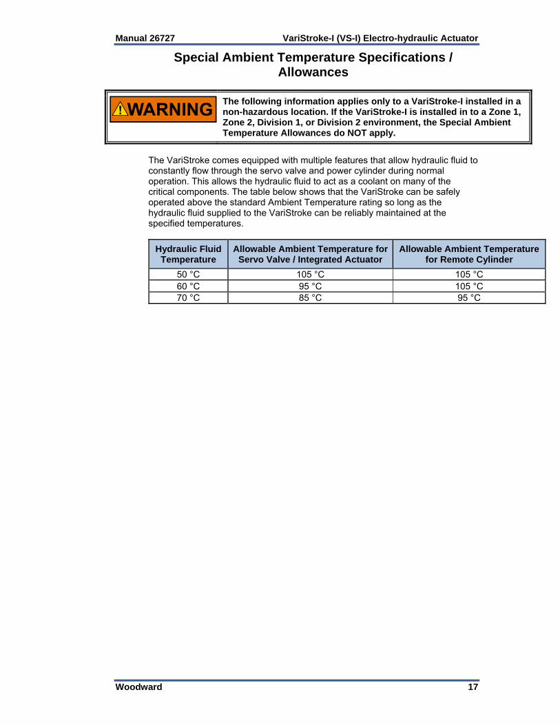
The following information applies only to a VariStroke-I installed in a non-hazardous location. If the VariStroke-I is installed in to a Zone 1, Zone 2, Division 1, or Division 2 environment, the Special Ambient Temperature Allowances do NOT apply.
The VariStroke comes equipped with multiple features that allow hydraulic fluid to constantly flow through the servo valve and power cylinder during normal operation. This allows the hydraulic fluid to act as a coolant on many of the critical components. The table below shows that the VariStroke can be safely operated above the standard Ambient Temperature rating so long as the hydraulic fluid supplied to the VariStroke can be reliably maintained at the specified temperatures.
Hydraulic Fluid Temperature
Allowable Ambient Temperature for Servo Valve / Integrated Actuator
Allowable Ambient Temperature for Remote Cylinder
50 °C 105 °C 105 °C 60 °C 95 °C 105 °C 70 °C 85 °C 95 °C

VariStroke-I (VS-I) Electro-hydraulic Actuator Manual 26727
18 Woodward
Stability Specifications Before purchasing or installing a VS-I actuator, the user should verify that the actuator will be stable during operation. As shown in the relationship below, the stability of the VS-I is dependent on servo valve size, supply pressure, and the used cylinder volume. If the relationship below is satisfied, the actuator will operate smoothly, with minimal limit cycle.
If the relationship below is NOT satisfied, the actuator performance will be compromised, resulting in excessive limit cycle and accelerated wear. The actuator will also output a "Stability Warning" alarm that cannot be disabled.
∗ ∗
∗
Where:
Note: (This is the used maximum stop position. It may or may not equal the Cylinder Length)
(listed in table below)
Servo Valve Size
V25 185
V45 600

Manual 26727 VariStroke-I (VS-I) Electro-hydraulic Actuator
Woodward 19
Graphical representations of the stability relationship are shown in the following two charts.

VariStroke-I (VS-I) Electro-hydraulic Actuator Manual 26727
20 Woodward
Diagrams Functional Block Diagram
Figure 2-1. Basic Device Block Diagram without Trip Function VS-I Integrated Hydraulic Schematic
Figure 2-2. VS-I Integrated Hydraulic Schematic

Manual 26727 VariStroke-I (VS-I) Electro-hydraulic Actuator
Woodward 21
VS-I Remote Servo Hydraulic Schematic
Figure 2-3. VS-I Remote Hydraulic Schematic VS-I Servo Only Hydraulic Schematic
Figure 2-4. VS-I Remote Servo Hydraulic Schematic
VariStroke-I (VS-I) Electro-hydraulic Actuator Manual 26727
22 Woodward
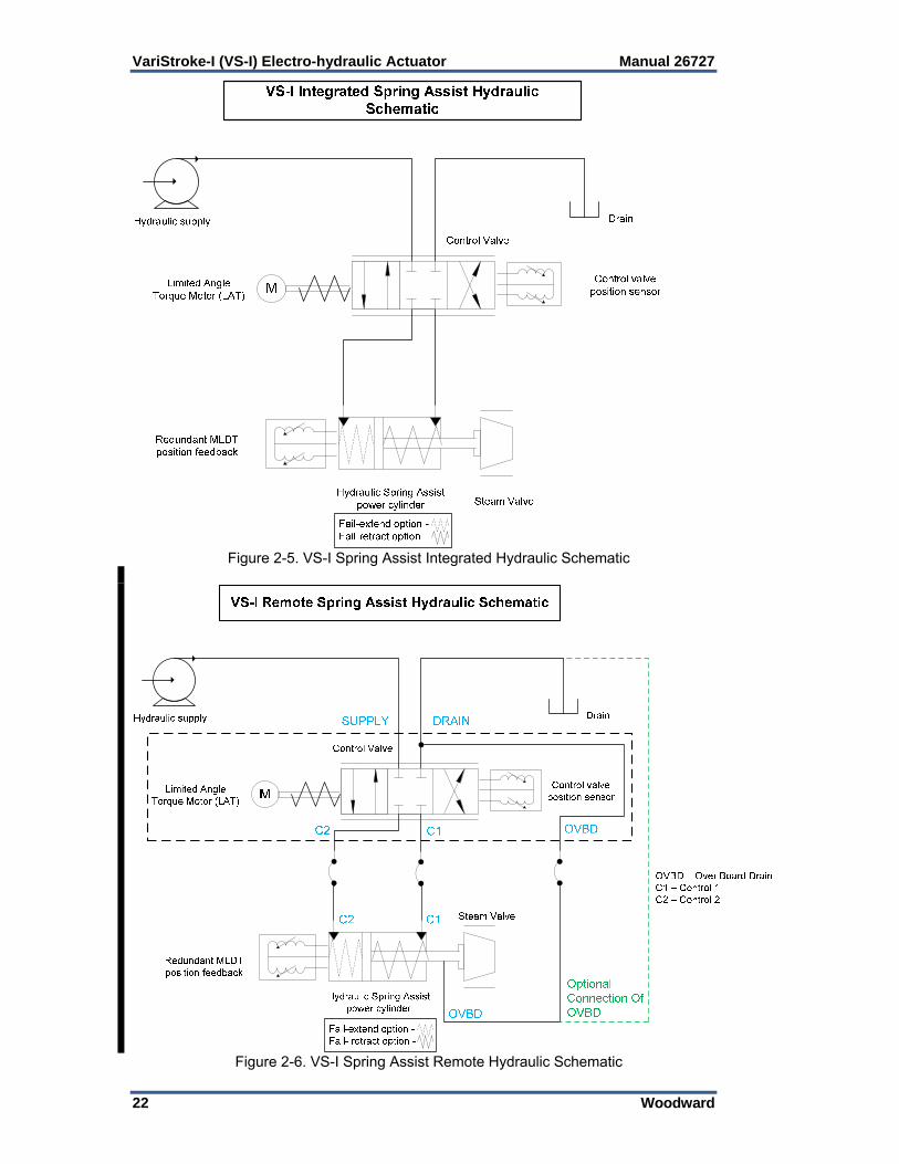
Figure 2-5. VS-I Spring Assist Integrated Hydraulic Schematic
Figure 2-6. VS-I Spring Assist Remote Hydraulic Schematic
Manual 26727 VariStroke-I (VS-I) Electro-hydraulic Actuator
Woodward 23
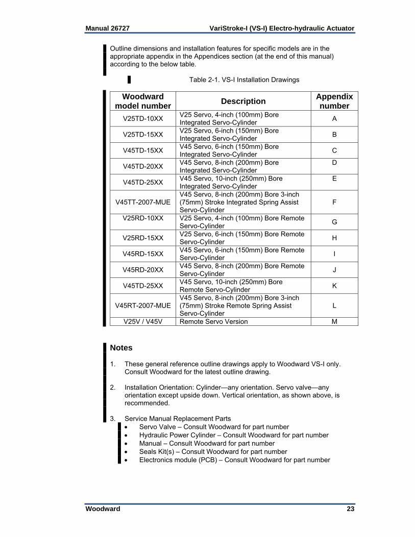
Outline dimensions and installation features for specific models are in the appropriate appendix in the Appendices section (at the end of this manual) according to the below table.
Table 2-1. VS-I Installation Drawings
Woodward model number
Description Appendix number
V25TD-10XX V25 Servo, 4-inch (100mm) Bore Integrated Servo-Cylinder
A
V25TD-15XX V25 Servo, 6-inch (150mm) Bore Integrated Servo-Cylinder
B
V45TD-15XX V45 Servo, 6-inch (150mm) Bore Integrated Servo-Cylinder
C
V45TD-20XX V45 Servo, 8-inch (200mm) Bore Integrated Servo-Cylinder
D
V45TD-25XX V45 Servo, 10-inch (250mm) Bore Integrated Servo-Cylinder
E
V45TT-2007-MUE V45 Servo, 8-inch (200mm) Bore 3-inch (75mm) Stroke Integrated Spring Assist Servo-Cylinder
F
V25RD-10XX
V25 Servo, 4-inch (100mm) Bore Remote Servo-Cylinder
G
V25RD-15XX V25 Servo, 6-inch (150mm) Bore Remote Servo-Cylinder
H
V45RD-15XX V45 Servo, 6-inch (150mm) Bore Remote Servo-Cylinder
I
V45RD-20XX V45 Servo, 8-inch (200mm) Bore Remote Servo-Cylinder
J
V45TD-25XX V45 Servo, 10-inch (250mm) Bore Remote Servo-Cylinder
K
V45RT-2007-MUE V45 Servo, 8-inch (200mm) Bore 3-inch (75mm) Stroke Remote Spring Assist Servo-Cylinder
L
V25V / V45V Remote Servo Version M Notes 1. These general reference outline drawings apply to Woodward VS-I only.
Consult Woodward for the latest outline drawing. 2. Installation Orientation: Cylinder—any orientation. Servo valve—any
orientation except upside down. Vertical orientation, as shown above, is recommended.
3. Service Manual Replacement Parts
Servo Valve – Consult Woodward for part number Hydraulic Power Cylinder – Consult Woodward for part number Manual – Consult Woodward for part number Seals Kit(s) – Consult Woodward for part number Electronics module (PCB) – Consult Woodward for part number
VariStroke-I (VS-I) Electro-hydraulic Actuator Manual 26727
24 Woodward
Chapter 3. Installation
Receiving Instructions The VS-I is carefully packed at the factory to protect it from damage during shipping; however, careless handling during shipment can result in damage. If any damage to the VS-I is discovered, immediately notify both the shipping agent and Woodward.
Unpacking Instructions Carefully unpack the VS-I and remove it from the shipping container. Do not remove the hydraulic, electric blanking covers and hydraulic power cylinder’s output threaded shaft mesh until you are ready to mount the unit.
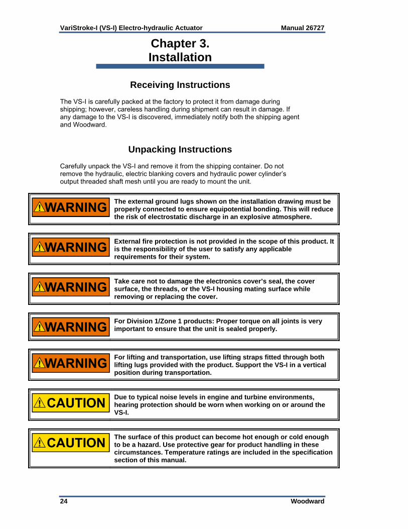
The external ground lugs shown on the installation drawing must be properly connected to ensure equipotential bonding. This will reduce the risk of electrostatic discharge in an explosive atmosphere.
External fire protection is not provided in the scope of this product. It is the responsibility of the user to satisfy any applicable requirements for their system.
Take care not to damage the electronics cover’s seal, the cover surface, the threads, or the VS-I housing mating surface while removing or replacing the cover.
For Division 1/Zone 1 products: Proper torque on all joints is very important to ensure that the unit is sealed properly.
For lifting and transportation, use lifting straps fitted through both lifting lugs provided with the product. Support the VS-I in a vertical position during transportation.
Due to typical noise levels in engine and turbine environments, hearing protection should be worn when working on or around the VS-I.
The surface of this product can become hot enough or cold enough to be a hazard. Use protective gear for product handling in these circumstances. Temperature ratings are included in the specification section of this manual.

Manual 26727 VariStroke-I (VS-I) Electro-hydraulic Actuator
Woodward 25
Installation Instructions General See the outline drawings and Specifications for: Outline dimensions Hydraulic connections and fitting sizes Electrical connections Weight of the VS-I A vertical actuator position is generally preferred to conserve floor space as well as ease of making electrical and hydraulic connections. However, the VS-I can be mounted in any attitude. It is recommended that the Remote Servo not be mounted upside-down to minimize the possibility of hydraulic oil dripping onto the circuit board. Allow space for removal of the top cover for access to the terminal blocks and to see the status LEDs on the printed circuit board. If the VS-I actuator is to be installed in close proximity to uninsulated/unshielded steam valves or piping, radiation heat shields should be installed between the actuator and these hot surfaces. The Integrated VS-I is designed for support by the Hydraulic Power Cylinder Mating bottom or top surface. For each individual VS-I actuator bolt pattern, bolts and bolting torques recommendation needs to be followed as per Table 3-1. For Remote Servo Kit installation, both Cylinder and Servo have their own mounting requirements. See the following drawings and table for bolt pattern position tolerances, thread sizes and recommended torques. The Hydraulic Cylinder can be bottom or top mounted while the Servo only has one mounting interface. Installation Dimensions for Integrated Actuator
Figure 3-1a. VS-I Integrated Product Installation Interface—Bolting
Pattern and Installation Features

VariStroke-I (VS-I) Electro-hydraulic Actuator Manual 26727
26 Woodward
Figure 3-1b. VS-I Integrated Product Installation Interface—Bolting Pattern and Installation Features

Manual 26727 VariStroke-I (VS-I) Electro-hydraulic Actuator
Woodward 27
Installation Dimensions for Remote Servo Kit
Figure 3-2a. VS-I Remote. Product Installation Interface—Bolting Pattern and
Installation Features

VariStroke-I (VS-I) Electro-hydraulic Actuator Manual 26727
28 Woodward
Figure 3-2b. VS-I Remote. Product Installation Interface—Bolting Pattern and
Installation Features
Table 3-1. VS-I Installation Bolts and Bolting Torques Recommendation
VariStroke Cylinder Bore Size
inch
Thread “T1” & “T2”
Min Thread Engagement in
(mm)
Min. Bolt Grade
Bolting Torque
lbf-ft (Nm)
Bolt Tol.
Class
Thread “T3” M - Male
F- Female
4 M14x2 1.00 (25.4)
8.8 50-55
(68-75) 6 g
M – M30x2 F – M26x1.5
6 M16x2 1.40
(35.56) 8.8
110-120 (149-163)
6 g M - M48x2 F - M33x2
8 M24x3 1.40
(35.56) 8.8
270-300 (366-407)
6 g M - M64x3 F - M48x2
10 M30x3.5 1.40
(35.56) 8.8
365-400 (495-542)
6 g M - M64x3 F - M48x2

Manual 26727 VariStroke-I (VS-I) Electro-hydraulic Actuator
Woodward 29
Installation Dimensions for Servo Only
Figure 3-3. VS-I Remote Servo. Product Installation Interface—Bolting Pattern
Minimum Bolt Grade, Bolting Torque and Thread Engagement Recommendation is valid for low carbon steel mounting surface to which product is bolted. For different configuration please consult Woodward for torque and bolts grade recommendations.

VariStroke-I (VS-I) Electro-hydraulic Actuator Manual 26727
30 Woodward
Lifting VariStroke comes equipped with lifting brackets for vertical lifting. When transporting, use both brackets as shown below. Remote Servo and Remote Cylinder have their own, separate lifting features. Both Integrated and Remote Servo units can be transported in either the vertical or horizontal position.
Figure 3-5. VS-I Lifting Positions

Manual 26727 VariStroke-I (VS-I) Electro-hydraulic Actuator
Woodward 31
Figure 3-5. Incorrect Lifting Method
The VS-I Actuator is designed for support by the hydraulic power cylinder mating surface. Additional supports are neither needed nor recommended.
The servo valve is not designed to carry any load resulting from field mounting. For VS-I Integrated, the user is obligated to maintain the minimum required gap between servo valve and the actuator installation surface. For reference see outline drawing (Figure 3-1).
Any mounting deviation from the one recommended by Woodward might cause assembly damage, improper performance or operator injury risk.
Improper mounting might be considered as a violation of warranty conditions.
Maximum allowable linkage misalignment is 5°. It is highly recommended that the customer strictly warn the installer of this. Assure required pattern tolerance is adhered to based on interface as shown in Figures 3-1 and 3-2.

VariStroke-I (VS-I) Electro-hydraulic Actuator Manual 26727
32 Woodward
Ensure that the linkages and couplings connecting the VS-I output shaft to the turbine are appropriately sized and are able to withstand the stall force and dynamic loads.
The lifting eye located on the top of the VS-I Servo Valve is intended to lift ONLY the servo itself, not integrated servo-cylinder configurations.
Make sure that the crane, cables, straps, and all other lifting equipment used for VS-I lifting is able to support the VS-I weight. See outline drawings for VS-I weights.
When transporting the Hydraulic Cylinder in an upside-down position, the cylinder rod must be properly secured against uncontrolled rod movement.
Hydraulic Connections For the Integrated VS-I, there are two hydraulic connections that must be made to each actuator: 1.250 SAE J518 Code 61 Flange for Hydraulic Supply Port 1.500 SAE J518 Code 61 Flange for Hydraulic Drain Port (Note: SAE J518, JIS B 8363, ISO/DIS 6162 AND DIN 20066 are interchangeable, except for bolt sizes/threads. The VS-I uses metric bolt sizes.) For the VS-I Remote Servo Kit and Servo Only options, there is an additional hydraulic connection between servo and cylinder: 1.000 SAE J518 Code 61 Flange for Hydraulic Control Ports (Note: SAE J518, JIS B 8363, ISO/DIS 6162 AND DIN 20066 are interchangeable, except for bolt sizes. VS-I uses metric bolt sizes.) Maximum Pipe Length between Remote Servo and Cylinder : 3 meters Hydraulic connection tightening torques: Hydraulic Supply: 4x M10x1.5 Screws Torque to (34 to 48) N·m, (25 to 35 lb-ft) Hydraulic Drain: 4x M12x1.75 Screws Torque to (48 to 61) N·m, (35 to 45 lb-ft) Control ports, C1 and C2 (Remote and Remote Servo): 4x M10x1.5 Screws Torque to (34 – 48) Nm, (25 - 35 lbf-ft) OVBD Straight Thread port: Torque to (7 – 8) Nm, (65 - 69 lbf-in).
Before installing the VS-I, all hydraulic lines must be thoroughly flushed.
Make provisions for proper filtration of the hydraulic fluid that will supply the actuator. The system filtration should be designed to assure a supply of hydraulic oil with a target cleanliness level of ISO 4406 code 20/18/16 or cleaner. The tubing connected to the actuator and/or servo must be constructed to eliminate any transfer of vibration or other forces to the actuator.
Manual 26727 VariStroke-I (VS-I) Electro-hydraulic Actuator
Woodward 33
The hydraulic supply to the servo is to be 32 mm (1.25 inches) tubing capable of supplying 681 L/min (180 US gal/min) at 34.5 bar / 500 psig. The hydraulic drain should be 38 mm (1.5 inches) tubing or larger and must not restrict the flow of fluid from the actuator. The drain pressure must not exceed 10% of supply pressure or 3.4 bar (50 psig), whichever is less, under any condition. Pipe diameters to both the Supply and Drain connections should be maximized, within reason, to ensure that flow losses and restrictions are minimized. For the same reason, pipe lengths should be kept to a minimum. For Remote Servo-Cylinder connection, use 25 mm (1 inch) tubing to minimize servo-actuator plumbing flow restrictions. Rigid/steel tubing is recommended for these connections.
It is highly recommended that inlet supply pressure not be allowed to decrease by more than 10% of nominal value during slew/step.
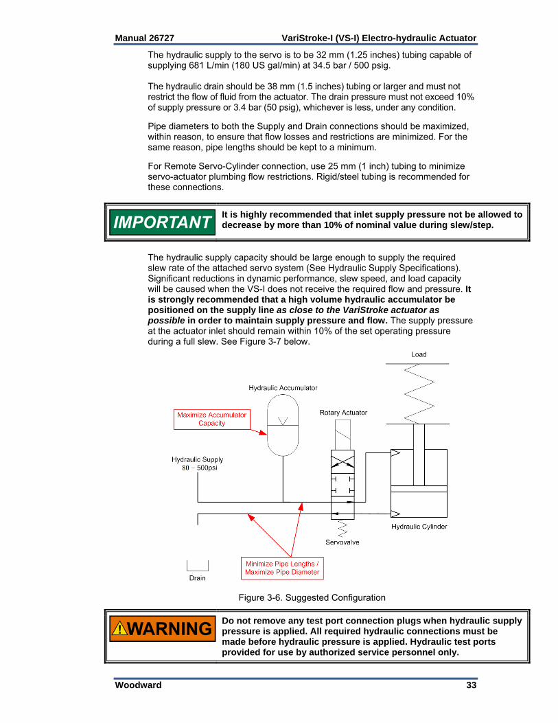
The hydraulic supply capacity should be large enough to supply the required slew rate of the attached servo system (See Hydraulic Supply Specifications). Significant reductions in dynamic performance, slew speed, and load capacity will be caused when the VS-I does not receive the required flow and pressure. It is strongly recommended that a high volume hydraulic accumulator be positioned on the supply line as close to the VariStroke actuator as possible in order to maintain supply pressure and flow. The supply pressure at the actuator inlet should remain within 10% of the set operating pressure during a full slew. See Figure 3-7 below.
Figure 3-6. Suggested Configuration
Do not remove any test port connection plugs when hydraulic supply pressure is applied. All required hydraulic connections must be made before hydraulic pressure is applied. Hydraulic test ports provided for use by authorized service personnel only.

VariStroke-I (VS-I) Electro-hydraulic Actuator Manual 26727
34 Woodward
Electrical Connections An overall electrical wiring diagram is shown in Figure 3-8. Detailed wiring requirements for these connections will follow in the remainder of the Electrical Connections section. The RS-232 connection is covered in Chapter 4 (Installing and Running The PC Service Tool).
Figure 3-7. Electrical Wiring Diagram
POWER
SUPPLY #1
3536
3738
(-) 2(+) 2(-) 1(+) 1 POWER
SUPPLY #2

Manual 26727 VariStroke-I (VS-I) Electro-hydraulic Actuator
Woodward 35
Input Power The VS-I requires a power source capable of a supplying the necessary output voltage and current at full transient conditions. The maximum power in watts (W) of a DC source can be calculated by multiplying the rated output voltage by the maximum output current capability. The calculated power rating of the supply should be greater than or equal to VS-I requirements. The electrical power supply should be able to provide 2.3 A at 24 V (dc) continuously, with a peak of 10 A for 100 ms, 6 A for 4 seconds. Cable selection and sizing are very important to avoid power loss during driver operation. The power supply input at the driver’s input terminal must always provide the required nominal voltage for the driver. The input power wire must comply with local code requirements and be of sufficient size such that the power supply voltage minus the IR loss in the two lead wires to the VariStroke driver does not drop below the driver input minimum voltage requirement. The VS-I is not equipped with an input power disconnect. A means of disconnecting input power to the VS-I must be provided for safe installation and servicing. The VS-I is not equipped with input power protection. A means of protecting input power to the VS-I must be provided. Breakers or fuses are intended to protect installation wiring and power sources from faults in the VS-I or wiring. A circuit breaker meeting the requirements from the table below, or a separate protection with the appropriate ratings, may be used for this purpose. Refer to the table below for recommended fuse ratings or circuit breakers.
Components Input Voltage
Steady State Input
Current
Maximum Transient
Input Current
Maximum Power
Maximum Slow Blow Fuse / C.B.
Rating
VS-I (18 to 32) V (dc)
24 V (dc) nominal 3.1 A @ 18 V (dc)
10 A 340 W
(100 ms)
20% above Steady State
Current
Figure 3-8. Power Supply Input Connections

VariStroke-I (VS-I) Electro-hydraulic Actuator Manual 26727
36 Woodward
The VS-I is capable of connecting two redundant power supplies. The following table presents terminal assignment for this option usage.
Power Input (+) Power Input (-) Power Supply #1 Terminal # 38 Terminal # 37 Power Supply #2 Terminal # 36 Terminal # 35
If redundancy option is not used, both (+) signals (Terminal #36 and Terminal #38) should be connected together on the terminal.
Although the VS-I is protected against input voltage transients, good wiring practices must be followed. The following drawings illustrate correct and incorrect wiring methods to the power supply.
Figure 3-9. Correct Wiring to Power Supply Input
Figure 3-10. Example of Incorrect Wiring to Power Supply Input Power Wiring Requirements: Keep these inputs separated from low level signals to reduce signal noise Wire Gauge Requirements: 1.5…2.5 mm² / 12…16 AWG Maximum Wiring Distance: 30 m

Manual 26727 VariStroke-I (VS-I) Electro-hydraulic Actuator
Woodward 37
Unit Grounding The unit housing must be grounded using the designated PE ground connection point and EMC ground connection point (see installation drawings). For the PE connection, use required type (typically green/yellow, 2.5 mm² / 12 AWG) as necessary to meet the installation safety ground requirements. For the EMC ground connection, use a short, low-impedance strap or cable (typically > 3 mm² / 12 AWG and < 46 cm / 18 inches in length). Torque the ground lugs to 5.1 N·m (3.8 lb-in).
In cases where the EMC ground configuration also meets installation safety ground requirements, no additional PE ground is required.
Wiring Strain Relief Tie down points and ratcheting tie wraps are provided to secure the wiring to the top of the PCB cover. This helps prevent wire strain from being transmitted to the connection at the terminal block and to keep the wiring from chafing on the cover when tightening and under vibration. Failure to secure the wiring could result in intermittent connections resulting in alarm or shut down conditions.
Figure 3-11. Recommended Wiring Strain Relief Shielded Wiring Use shielded cable for all analog signals. Terminate shields as shown in the following sections. Avoid routing power supply and signal wires within the same conduit or near each other within the unit. When bundling the field wiring inside the unit, separate the unshielded power and discrete inputs/outputs from the shielded analog signals.
VariStroke-I (VS-I) Electro-hydraulic Actuator Manual 26727
38 Woodward
Shield Installation Notes Wires exposed beyond the shield should be as short as possible, not
exceeding 50 mm (2 inches). The shield termination wire (or drain wire) should be kept as short as
possible, not exceeding 50 mm (2 inches), and where possible the diameter should be maximized.
Installations with severe electromagnetic interference (EMI) may require additional shielding precautions. Contact Woodward for more information.
Do not ground shield on both ends, except where permitted by the control wiring diagram.
Failure to provide shielding can produce future conditions which are difficult to diagnose. Proper shielding, at the time of installation is required to ensure satisfactory operation of the product.
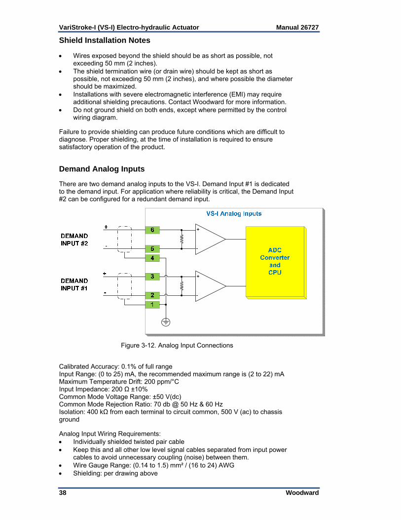
Demand Analog Inputs There are two demand analog inputs to the VS-I. Demand Input #1 is dedicated to the demand input. For application where reliability is critical, the Demand Input #2 can be configured for a redundant demand input.
Figure 3-12. Analog Input Connections Calibrated Accuracy: 0.1% of full range Input Range: (0 to 25) mA, the recommended maximum range is (2 to 22) mA Maximum Temperature Drift: 200 ppm/°C Input Impedance: 200 Ω ±10% Common Mode Voltage Range: ±50 V(dc) Common Mode Rejection Ratio: 70 db @ 50 Hz & 60 Hz Isolation: 400 kΩ from each terminal to circuit common, 500 V (ac) to chassis ground Analog Input Wiring Requirements: Individually shielded twisted pair cable Keep this and all other low level signal cables separated from input power
cables to avoid unnecessary coupling (noise) between them. Wire Gauge Range: (0.14 to 1.5) mm² / (16 to 24) AWG Shielding: per drawing above
Manual 26727 VariStroke-I (VS-I) Electro-hydraulic Actuator
Woodward 39
Cylinder Position Feedback Analog Inputs (Remote Servo Only) There are two Final Cylinder Position Feedback analog inputs. Refer to the service tool chapter for information on configuring these inputs.
Figure 3-13. Final Cylinder Position Feedback Analog Input Connections Input Range: (0 to 25) mA, the recommended maximum range is (2 to 22) mA Current Limit: 30 mA @ 25 °C Calibrated Accuracy: 0.1% of full range @ 25 °C Maximum Temperature Drift: 200 ppm/°C Input Impedance: 235 Ω ±25 Ω Loop power: +15 V ±0.5 V over temperature range Max output current: 200 mA total (100 mA per sensor) Common Mode Voltage Range: ±50 V (dc) Common Mode Rejection Ratio: 70 db @ 50 Hz & 60 Hz Isolation: 500 V (ac) to chassis ground
Overloading +15 V power output will result in unit reset and shut down.
The following drawings illustrate correct and incorrect wiring methods to the Cylinder Position Feedback Analog Inputs.
Figure 3-14. Cylinder Position Sensor wiring diagram when using VS-1 internal power
VS-I Cylinder Position Feedback Analog Inputs
-
+
ADCConverter
and CPU
-
+FEEDBACK INPUT #1
FEEDBACK INPUT #2
Current limiter
DGND
+15V
Feedback 1+
Feedback 1-
Current limiter
Feedback 2+
Feedback 2-

VariStroke-I (VS-I) Electro-hydraulic Actuator Manual 26727
40 Woodward
Figure 3-15. Cylinder Position Sensor wiring diagram when using External Power Supply
Figure 3-16. Example of Incorrect Cylinder Position Sensor connection when using External Power Supply
When using external power supply, do NOT connect it to VS-I driver power outputs on the Position Feedback terminals. This may result in permanent damage to the VS-I driver.
Figure 3-17. Cylinder Position Connectors
Figure 3-18. Cylinder Position Sensor Connection Scheme with MTS Sensor
VS-I Cylinder Position Feedback Analog Inputs
-
+
DGND
+15V
Current limiter
Feedback +
Feedback -
Cylinder Position Sensor
(4 – 20mA)
External Power Supply
RIGHT
VS-I Cylinder Position Feedback Analog Inputs
-
+
DGND
+15V
Current limiter
Feedback +
Feedback -
Cylinder Position Sensor
(4 – 20mA)
External Power Supply
WRONG

Manual 26727 VariStroke-I (VS-I) Electro-hydraulic Actuator
Woodward 41
Cylinder Position Feedback Analog Input Wiring Requirements: Individually shielded twisted pair cable Keep this and all other low level signal cables separated from input power
cables to avoid unnecessary coupling (noise) between them. Wire Gauge Range: (0.14 to 1.5) mm² / (16 to 24) AWG Shielding: per drawing above Cable length: less than 3 m (10 feet) Analog Output The analog output of the VS-I is in the form of a (4 to 20) mA output and can drive load resistance from 0 up to 500 Ω. This output can be configured. Refer to the service tool chapter for configuration information. This output is designed for monitoring and diagnostic purposes only, and is not meant for any type of closed loop feedback.
Figure 3-19. Analog Output Connection Calibrated Accuracy: ±0.5 % of full range, (0 to 25) mA Output Range: (2 to 22) mA Load Range: 0 Ω up to 500 Ω (for output up to 25 mA) Maximum Temperature Drift: 300 ppm/°C Isolation: 500 V (ac) from circuit common, and chassis Analog Output Wiring Requirements: Individually shielded twisted pair cable Keep this and all other low level signal cables separated from input power
cables to avoid unnecessary coupling (noise) between them. Wire Gauge Range: (0.14 to 1.5) mm² / (16 to 24) AWG Shielding: per drawing above Discrete Inputs The VS-I has four discrete inputs. External power is not necessary for these inputs as the isolation is provided internally. The discrete inputs have an internal pull-up resistor and are inverted at the processor, such that an open circuit is the passive low state. The high state is achieved when the input is pulled low by an external contact to the isolated ground terminal provided. There are four inputs and one ground terminal (DI GND) provided, so it is necessary to share the one ground if more than one input is used.
VS-I Analog Output
+
-
22
21
20
CPU
-
+
IC
2.2nF 2.2nF
GND_AISODGND
Load
+24V_AISO
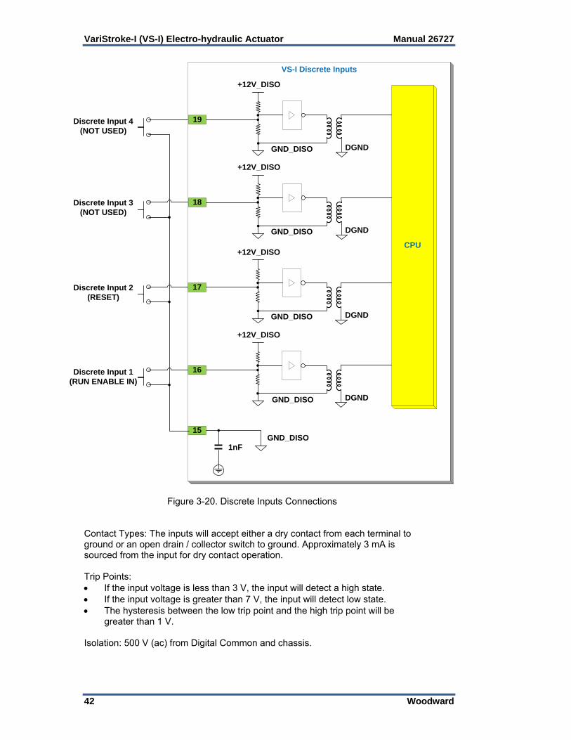
VariStroke-I (VS-I) Electro-hydraulic Actuator Manual 26727
42 Woodward
Figure 3-20. Discrete Inputs Connections Contact Types: The inputs will accept either a dry contact from each terminal to ground or an open drain / collector switch to ground. Approximately 3 mA is sourced from the input for dry contact operation. Trip Points: If the input voltage is less than 3 V, the input will detect a high state. If the input voltage is greater than 7 V, the input will detect low state. The hysteresis between the low trip point and the high trip point will be
greater than 1 V. Isolation: 500 V (ac) from Digital Common and chassis.
VS-I Discrete Inputs
19
15
CPU
1nF
GND_DISO DGND
+12V_DISO
18
GND_DISO DGND
+12V_DISO
17
GND_DISO DGND
+12V_DISO
16
GND_DISO DGND
+12V_DISO
GND_DISO
Discrete Input 4(NOT USED)
Discrete Input 3(NOT USED)
Discrete Input 2(RESET)
Discrete Input 1(RUN ENABLE IN)
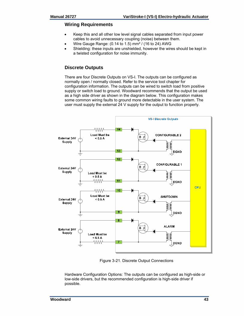
Manual 26727 VariStroke-I (VS-I) Electro-hydraulic Actuator
Woodward 43
Wiring Requirements Keep this and all other low level signal cables separated from input power
cables to avoid unnecessary coupling (noise) between them. Wire Gauge Range: (0.14 to 1.5) mm² / (16 to 24) AWG Shielding: these inputs are unshielded, however the wires should be kept in
a twisted configuration for noise immunity. Discrete Outputs There are four Discrete Outputs on VS-I. The outputs can be configured as normally open / normally closed. Refer to the service tool chapter for configuration information. The outputs can be wired to switch load from positive supply or switch load to ground. Woodward recommends that the output be used as a high side driver as shown in the diagram below. This configuration makes some common wiring faults to ground more detectable in the user system. The user must supply the external 24 V supply for the output to function properly.
Figure 3-21. Discrete Output Connections Hardware Configuration Options: The outputs can be configured as high-side or low-side drivers, but the recommended configuration is high-side driver if possible.
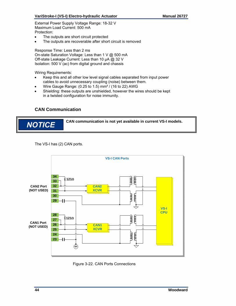
VariStroke-I (VS-I) Electro-hydraulic Actuator Manual 26727
44 Woodward
External Power Supply Voltage Range: 18-32 V Maximum Load Current: 500 mA Protection: The outputs are short circuit protected The outputs are recoverable after short circuit is removed Response Time: Less than 2 ms On-state Saturation Voltage: Less than 1 V @ 500 mA Off-state Leakage Current: Less than 10 μA @ 32 V Isolation: 500 V (ac) from digital ground and chassis Wiring Requirements: Keep this and all other low level signal cables separated from input power
cables to avoid unnecessary coupling (noise) between them. Wire Gauge Range: (0.25 to 1.5) mm² / (16 to 22) AWG Shielding: these outputs are unshielded, however the wires should be kept
in a twisted configuration for noise immunity. CAN Communication
CAN communication is not yet available in current VS-I models.
The VS-I has (2) CAN ports.
Figure 3-22. CAN Ports Connections
VS-I CAN Ports
VS-I CPU
CAN1 Port(NOT USED)
121Ω
CAN2 XCVR
121Ω34
33
32
31
30
29
28
27
26
25
24
23
CAN2 Port(NOT USED)
CAN1 XCVR

Manual 26727 VariStroke-I (VS-I) Electro-hydraulic Actuator
Woodward 45
CAN Specification: Interface Standard: CAN 2.0 A/B (configured in the CPU) Network Connections: (2) separate connectors Network Isolation: 500 V (ac) to chassis, input power, I/O channels, between
CAN ports Network Termination: (121 ±10) Ω built into the each port of VS-I Cable / Part Number: 2008-1512 (120 Ω, 3-wire, shielded twisted pair)—
Belden YR58684 or similar CAN Cable Shield Termination & Exposed Cable Limitations For robust communications performance, the CAN cabling needs to minimize the exposed, non-shielded cable section that occurs at terminal blocks. The exposed length of CAN wiring must be limited to less than 3.8 cm (1.5 inches) from the end of the shield to the terminal block. This limits the total length of exposed wiring during a series or daisy chain connection on each side of the terminal block to 7.6 cm (3 inches). CAN shields are terminated to chassis (EARTH) through a capacitor-resistor network. However, the shield must also be directly terminated to chassis (Earth) at one point in the network.
Always use shielded cables for improved communications in industrial environments. Wire terminations at the node should expose as little un-shielded cable as possible (less than 25 to 38 mm / 1.0 to 1.5 inches).
Wiring The VS-I has four NPT wiring entries: two ¾ inch (19.05 mm), two ½ inch (12.7 mm). When wiring using cable and cable glands, the gland fitting must meet the same hazardous locations criteria as the VS-I. Follow all installation recommendations and special conditions for safe use that are supplied with the cable gland. The cable insulation must have a temperature rating of at least 85 °C and 10 °C above the maximum ambient and fluid temperature. Strip the cable insulation (not the wire insulation) to expose 12 mm (1/2 inch) of the conductors. Strip the wire insulation 5 mm from each conductor. Mark wires according to their designation and install connectors, if required. Remove the top access cover. Pass the wires through the cable gland (not provided) or conduit fitting and attach to the printed circuit board terminal blocks in accordance with their wiring diagram. Snap the terminal blocks into the header terminal blocks on the PCB. Tighten the terminal block flange screws to 0.5 N·m (4.4 lb-in). Replace the top access cover and tighten until the O-ring seal is compressed and the cover is fully seated against the housing. Install the PE ground and EMC ground straps to the lugs provided. Tighten to 5.1 N·m (45 lb-in). Tighten the cable gland fitting per manufacturer’s instructions or pour the conduit seal to provide strain relief for the cable and to seal the interface between the wiring cable and the VS-I.

VariStroke-I (VS-I) Electro-hydraulic Actuator Manual 26727
46 Woodward
Chapter 4. Service Tool Installation
Setup The VS-I includes a software-based Programming and Configuration tool (PCT) that can be loaded onto a computer and used to: Change maximum stop position and cylinder size settings. Calibrate the final cylinder. Configure the inputs and outputs View diagnostic flags
An unsafe condition could occur with improper use of these software tools. Only trained personnel should have access to these tools.
The PC Service Tool or Programming and Configuration Tool is a software application which runs on Windows-based PC or laptop. It requires a physical RS-232 connection between the computer and the VS-I. The physical connection can be made by connecting to the VS-I at the Service Port (RS-232). Use a straight-through serial cable (not null modem). For newer PCs or laptops with USB ports, a USB-to-serial converter is required. An approved converter can be obtained from Woodward P/N 8928-1151. Woodward offers a serial cable as a kit that can be ordered. The part number for this kit is 8928-7323, which contains a 10-foot long (3 m) DB9-F to DB9-M straight-through cable. Note that this cable has two nuts on the screws on the female end that need to be removed prior installing this end.
Figure 4-1. Service Port Connections
Do not to damage the cover seal, the cover surface, the threads, or the VS-I surface while removing or replacing the cover. Damage to sealing surfaces may result in moisture ingress, fire, or explosion. Clean the surface with rubbing alcohol if necessary. Inspect the cover joint surfaces to ensure that they are not damaged or contaminated.
VS-I Serial Port
RS-232 Transceiver
RS232_TX
RS232_RX
RS232_GND
DGND
CPU
Straight-throughSerial cable

Manual 26727 VariStroke-I (VS-I) Electro-hydraulic Actuator
Woodward 47
Installing the VariStroke-I Service Tool Use the following installation procedure to install the VariStroke-I Service Tool (Programming and Configuration Tool). Locate/obtain VS-I Service Tool Installation CD provided with each VS-I. (Alternatively, the VS-I Service Tool Installation file can be downloaded from Woodward’s website [www.woodward.com/software]). To run the installation program follow the installation instructions (shown below). 1. Double click on the install file 9927-2124_xxx.exe. (Note: xxx is a
placeholder for the revision of the install package i.e. 9927-2124_NEW.exe. or 9927-2124_A.exe are examples of Rev NEW and Rev A versions.)
2. The Tool launches and the Welcome screen is displayed. Click on “Next”.
3. The EULA screen appears. Accept the terms of the License Agreement then click “Next” to continue.

VariStroke-I (VS-I) Electro-hydraulic Actuator Manual 26727
48 Woodward
4. The Install page appears. “Create shortcut for this program on the desktop” is set as the default. Uncheck this box if you do not want a Service Tool icon on your desktop. Click on “Install”.
5. The Installation of the Service tool will proceed.
6. When the installation is finished, the Installation Complete screen will
appear. The “Launch when setup exits” box in the lower left is unchecked by default. You do not want to launch the Service tool until the VS-I has been connected to the computer through a serial cable. At launch the Service tool detects which COM port is connected to the VS-I.

Manual 26727 VariStroke-I (VS-I) Electro-hydraulic Actuator
Woodward 49
If you launch the service tool application before you connect the serial cable between the computer and the VS-I the service tool will not detect the new serial connection. To detect the connection you will have to exit and re-launch the service tool.
7. When you click on “Finish” you will exit the installation wizard.
Connecting to the VariStroke-I
1. To connect to the VariStroke-I (VS-I) connect a serial cable between the computer and the VS-I driver then double-click on the service tool icon on the desktop. The service tool will launch and the next screen you will see will be the Home Screen of the VS-I service Tool.
Figure 4-2. Home Screen

VariStroke-I (VS-I) Electro-hydraulic Actuator Manual 26727
50 Woodward
2. Press the “Connect” button in the ribbon at the top of the service tool screen. You will see the following screen.
3. Select the network connection that the serial cable is connected to. Select
your available network and then set “Baud Rate” to “AutoDetection”. Press the “Connect” button.
4. The Service Tool will connect to the VS-I within a few seconds. When it
does the “Connect” button in the ribbon will be grayed-out and the “Disconnect” button will be activated. The Service tool is now connected and communicating with the VS-I and you can calibrate, configure and control the VS-I through the service tool.
5. When you want to end your session and disconnect the Service Tool from
the VS-I press the “Disconnect “ button . The Service tool will cease communication with the VS-I, the “Disconnect” button will be grayed-out and the “Connect” button will be activated. The service tool is now ready to communicate with the VS-I the next time you press the “Connect” button.

Manual 26727 VariStroke-I (VS-I) Electro-hydraulic Actuator
Woodward 51
Chapter 5. Calibration and Monitoring
Introduction The VS-I Service Tool is organized in to a series of pages that allow the VS-I to be set up for proper operation. The following section will outline the various pages and their functions.
The engine, turbine, or other type of prime mover should be equipped with an overspeed shutdown system to protect against runaway or damage to the prime mover with possible personal injury, loss of life, or property damage.
The overspeed shutdown system must be totally independent of the prime mover control system. An overtemperature or overpressure shutdown system may also be needed for safety, as appropriate.
An unsafe condition could occur with improper use of these software tools. Only trained personnel should have access to these tools.
System Information System Information will be displayed along the left hand side of the Service Tool screens. This provides general information about the product status.
Shutdown LED: When this LED indicator is illuminated, a shut down condition
has been invoked. The unit has been commanded to shut down or detected an operating condition which adversely affects the ability of the unit to operate reliably and predictably. Refer to Chapter 7 for a list of Shut down conditions.

VariStroke-I (VS-I) Electro-hydraulic Actuator Manual 26727
52 Woodward
Alarm LED: When this LED indicator is illuminated, the unit has detected an operating condition, which is outside of recommended operating parameters, but the VS-I is still operating. The cause of alarm conditions should be determined and corrected to prevent damage to the turbine, VS-I, or other auxiliary equipment. Refer to Chapter 7 for a list of Alarm conditions.
Operating Mode: Shows the status of the driver. Possible states are: STARTUP—Initialization is in progress SPRING_CHK—Initialization of the system is currently testing the spring. ANALOG_DMD—Normal operating mode when the cylinder position is being selected by the analog input demand signals(s). There is an option of one or two demand signals on the Input configuration page. SHUTDOWN—This “smart” button only appears when the VS-I is running and can be shut down. This state may have occurred because the analog inputs are not in the 4–20 mA range, or the Run Enable discrete input is selected and not on, or the Shutdown button has been pressed. After checking that the analog demands and the Run Enable are OK, refer to Chapter 7 for a list of Shut down conditions if the problem persists. CONFIGURATION— The system is ready to receive the configuration or calibration information. When this process is completed and saved, turn on the input signals to re-enable normal operation. CSD_FETS—This means the system is shut down due to a critical error. Please check your input power and connections and then reset the system. If the problem persists, service may be required. CSD_CURR—The system is shut down due to a critical error. Please reset the system. If the problem persists, service may be required. CSD_SERVO—The system is shut down due to a critical error. Please check the connections to the final cylinder feedback and then reset the system. If the problem persists, service may be required. Demand and Feedback: The Demand and Feedback indicators show the current
demanded position and measured feedback position of the final cylinder.
Shutdown Button: Pressing this button will invoke a shut down condition. Navigation Buttons: Pressing these buttons will navigate you to the most commonly
used pages of the VS-I Service Tool. Pages can also be accessed by using the dropdown menu at the top of the Toolkit Window.

Manual 26727 VariStroke-I (VS-I) Electro-hydraulic Actuator
Woodward 53
System Information Page This page will display system information about the VS-I servo that is currently connected to the PC Service Tool.
Figure 5-1. System Information Page Actuator P/N, S/N, Revision: These fields display the Actuator Assembly Part Number (P/N), Serial Number (S/N), and Revision Number. This information is entered automatically by the VS-I software. Driver P/N, S/N, Revision: These fields display the Electronic Driver Part Number (B_P/N), Serial Number (B_S/N), and Revision Number. This information is entered automatically by the VS-I software. Servo P/N S/N, Revision: These fields display the Servo Valve Part Number (S_P/N), Serial Number (S_S/N), and Revision Number. This information is entered automatically by the VS-I software. Firmware Revision: This field displays the firmware part number and revision to the software programmed into the VS-I driver. This information is entered automatically by the VS-I software. Demand & Feedback Bar Charts: These bar charts display the current demanded position and measured feedback position of the final cylinder. Trending Plot/ Graph: This graph will display the current demanded position and the measured feedback position of the final cylinder with respect to time. The “Start” button in the upper left hand corner of the graph must be pressed to see the current cylinder position on the chart.
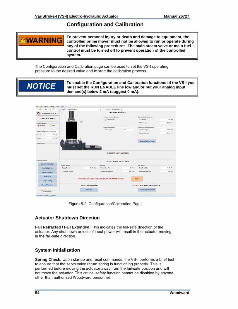
VariStroke-I (VS-I) Electro-hydraulic Actuator Manual 26727
54 Woodward
Configuration and Calibration
To prevent personal injury or death and damage to equipment, the controlled prime mover must not be allowed to run or operate during any of the following procedures. The main steam valve or main fuel control must be turned off to prevent operation of the controlled system.
The Configuration and Calibration page can be used to set the VS-I operating pressure to the desired value and to start the calibration process.
To enable the Configuration and Calibration functions of the VS-I you must set the RUN ENABLE line low and/or put your analog input demand(s) below 2 mA (suggest 0 mA).
Figure 5-2. Configuration/Calibration Page Actuator Shutdown Direction Fail Retracted / Fail Extended: This indicates the fail-safe direction of the actuator. Any shut down or loss of input power will result in the actuator moving in the fail-safe direction. System Initialization Spring Check: Upon startup and reset commands, the VS-I performs a brief test to ensure that the servo valve return spring is functioning properly. This is performed before moving the actuator away from the fail-safe position and will not move the actuator. This critical safety function cannot be disabled by anyone other than authorized Woodward personnel.

Manual 26727 VariStroke-I (VS-I) Electro-hydraulic Actuator
Woodward 55
Currently Calibrated Limits 0% Demand: This value is the minimum travel of the cylinder stroke. This is calibrated at the factory but can be changed as part of the calibration process (Step 2). 100% Demand: This value is the maximum travel of the cylinder stroke. This is calibrated at the factory but can be changed as part of the calibration process (Step 2). Current Cylinder Configuration Cylinder Length / Diameter: Displays the currently calibrated dimensions of the cylinder. These values are shown for reference only. If these values must be modified, the Remote Cylinder Setup button must be used. Remote Cylinder Setup
If the VariStroke unit came from the factory as an Integrated unit with a cylinder attached, these values should NOT be changed.
This screen is used ONLY when the user must modify the cylinder and position sensor parameters. This is commonly used when setting up a VariStroke Servo Only with a cylinder that was not manufactured by Woodward. Cylinder Length: This value must equal the physical stroke range of the hydraulic cylinder. This dimension is used by the VariStroke controller to automatically tune the actuator. Cylinder Diameter: This value must equal the bore diameter of the hydraulic cylinder. This dimension is used by the VariStroke controller to automatically tune the actuator. Position Sensor Length: This value is used to scale 0 to 100% positions of the VariStroke in to millimeters. This must equal the full length of the cylinder position sensor. Position Sensor Length is defined as the distance measured between the 4 mA position and 20 mA position of the sensor. It is recommended that the Position Sensor Length be slightly longer than the Cylinder Length in order to ensure the sensor output is always within the usable (4–20 mA) range. For a list of standard / Woodward position sensor lengths used in Integrated and Remote Servo Kits, refer to the table shown in Chapter 7: Repair and Troubleshooting. Reverse Acting: This field can be used if the user wishes to invert the cylinder behavior based on the input demand. If the field is set to “Yes”, the minimum input demand (4 mA) will result in cylinder moving to the 100% position.

VariStroke-I (VS-I) Electro-hydraulic Actuator Manual 26727
56 Woodward
Cylinder Configuration Before starting the configuration, the unit must be in a safe and shut-down state. The unit can be shut down by putting 0 mA onto the analog inputs or by opening the “run enable” discrete input (note: the “run enable” must be set to “used”). The unit must also not have any active faults, such as a Cylinder Tracking Fault. If there are active faults that prevent the unit from being in configuration mode, the faults should be analyzed and disabled (see Chapter 7: Repair and Troubleshooting). Step 1—Stability Settings Use the cylinder configuration section to input the hydraulic supply pressure. Supply Pressure: To set the Supply pressure (Step 1): 1. Input the hydraulic supply pressure (bar) into the Supply Pressure control
indicator and press the Apply button. Based on this pressure, the VS-I driver will automatically tune itself to provide optimum performance.
2. For confirmation, two additional control buttons will appear, “Cancel/Revert Configuration” and “Save Configuration”. Press the “Save Configuration” button to save the new cylinder pressure value. Press “Cancel/ Revert Configuration” to revert back to the previous saved cylinder supply pressure.
3. After pressing the “Save Configuration” button the data will be transferred to the VS-I.
Failure to input the correct Supply Pressure can result in unstable actuator performance. Ensure that this setting is correct and that the system pressure regulators do not allow more than a ±10% variation in Supply Pressure.
Stability: Certain combinations of Supply Pressure and Cylinder Volume can cause the actuator to operate at reduced performance. See Chapter 2: Stability Specifications for more information on this Alarm.
Slew rates: Manual Slew Rate: This adjustment allows the user to limit the slew rate
when in Manual Operation. Consider lowering this value if the attached linkage and valve are not robust.
Operational Slew Limit: This adjustment allows the user to limit the slew rate when in Normal Operation. Consider lowering this value if the linkage and valve attached are not robust. Also consider using the Soft Seating to lower valve seating velocities.
The Soft Seating feature will not function in some shut down conditions. Loss of cylinder position feedback, loss of electrical power, or an internal electronics fault will result in loss of the Soft Seating functionality.

Manual 26727 VariStroke-I (VS-I) Electro-hydraulic Actuator
Woodward 57
Soft seating: The VS-I Soft Seating function allows the actuator to a have different Slew Rate limits when positioned within the lower 10% of the total calibrated stroke. This feature provides a behavior similar to that of a conventional hydraulic cushion. This function can be used to limit the steam valve seating velocity in order to lengthen the life of the valve. Slow Zone Edge: This adjustment sets the position at which the actuator
slew rate limit will switch from the Operation Slew Rate Limit to the Slow Zone Velocity.
Slow Zone Velocity: This adjustment sets the slew rate limit of the actuator when position below the Slow Zone Edge value. Consider lowering this value if valve seating velocities are higher than desired.
Incorrect Slew Rate Limits and Soft Seating adjustments can result in high seating velocities that may damage equipment.
Configuration of the Slow Zone settings and Slew Rate Limits can result in excessively slow closing speeds.
The engine, turbine, or other type of prime mover should be equipped with an overspeed shut down device to protect against runaway or damage to the prime mover with possible personal injury, loss of life, or property damage.
Step 2—Calibration To calibrate, start by pressing the Calibrate button (Step 2). Upon pressing the Calibrate button, there are two options available on the left side of the page: “Find Minimum Stop” and ”Find Minimum AND Maximum Stop” (see screens and details below). One of these options must be selected and run before any further configuration can take place.
The Calibration features will cause the actuator to move. Ensure all personnel are clear of moving components before initiating the calibration sequence.
Potential damage to linkage and/or attachments can occur if the linkage and/or attachments are not designed to withstand the full stall force of the actuator at the supplied operating pressure. It is the installer’s responsibility to verify the structural capabilities of the linkage and/or attachments. IF the linkage and/or attachments CANNOT WITHSTAND THE FULL STALL FORCE of the actuator DO NOT USE FIND MINIMUM AND MAXIMUM STOPS. Instead, Find Minimum Stop must be used.
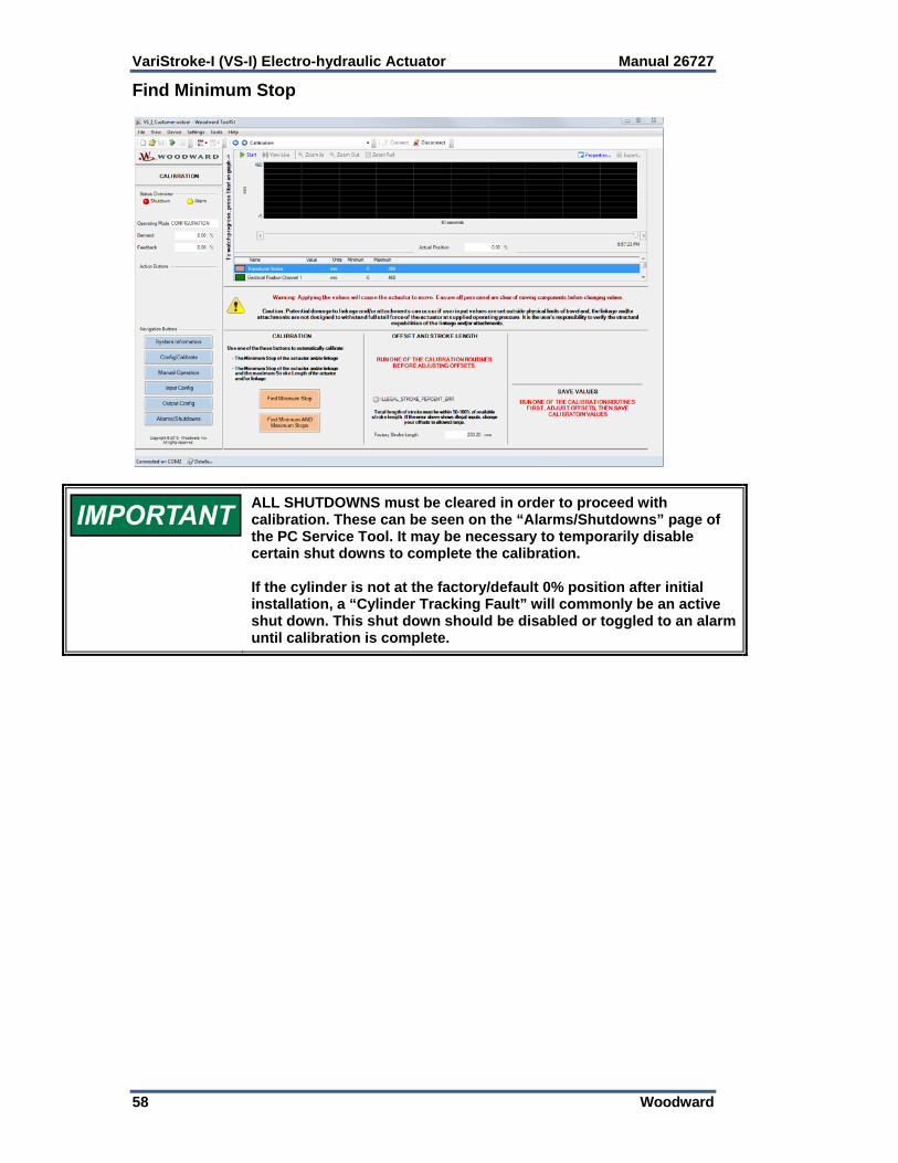
VariStroke-I (VS-I) Electro-hydraulic Actuator Manual 26727
58 Woodward
Find Minimum Stop
ALL SHUTDOWNS must be cleared in order to proceed with calibration. These can be seen on the “Alarms/Shutdowns” page of the PC Service Tool. It may be necessary to temporarily disable certain shut downs to complete the calibration. If the cylinder is not at the factory/default 0% position after initial installation, a “Cylinder Tracking Fault” will commonly be an active shut down. This shut down should be disabled or toggled to an alarm until calibration is complete.

Manual 26727 VariStroke-I (VS-I) Electro-hydraulic Actuator
Woodward 59
To use the Find Minimum Stop option, press the “Find Minimum Stop” button. The Find Minimum Stop feature allows the user to scale the desired minimum position offset and maximum stop position to the 4 to 20 mA demand input range. After pressing the Find Minimum Stop button, the following screen will appear.
Press the “Find Minimum Stop” button. Pressing this button will slightly open the VS-I servo valve, causing the actuator to slowly move toward the minimum/fail-safe position. Once a physical stop is contacted, the servo valve will close and the VS-I will automatically configure this as the minimum (4 mA demand) position. Actuator movement can be monitored and viewed using the trend chart. To do so, press “Start” at the top left corner of the trend chart. Cancel Button: Pressing the Cancel button will cause the Find Minimum Stop process to stop and the service tool to return to the Calibration page.
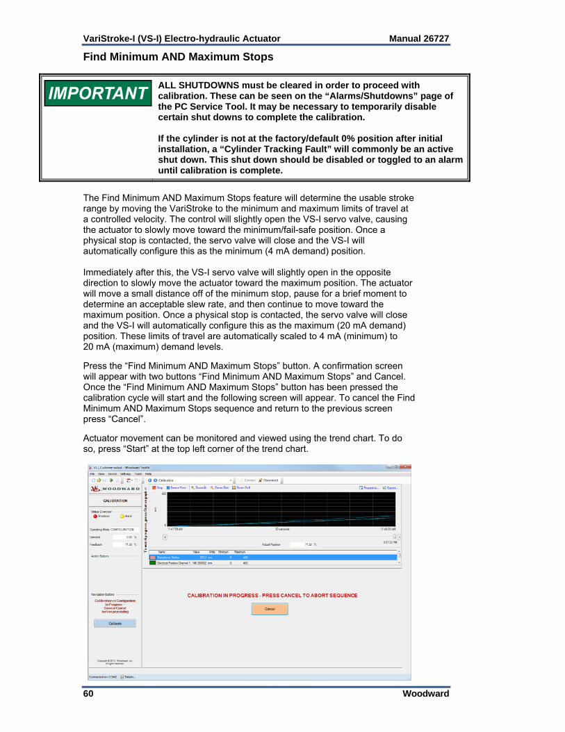
VariStroke-I (VS-I) Electro-hydraulic Actuator Manual 26727
60 Woodward
Find Minimum AND Maximum Stops
ALL SHUTDOWNS must be cleared in order to proceed with calibration. These can be seen on the “Alarms/Shutdowns” page of the PC Service Tool. It may be necessary to temporarily disable certain shut downs to complete the calibration. If the cylinder is not at the factory/default 0% position after initial installation, a “Cylinder Tracking Fault” will commonly be an active shut down. This shut down should be disabled or toggled to an alarm until calibration is complete.
The Find Minimum AND Maximum Stops feature will determine the usable stroke range by moving the VariStroke to the minimum and maximum limits of travel at a controlled velocity. The control will slightly open the VS-I servo valve, causing the actuator to slowly move toward the minimum/fail-safe position. Once a physical stop is contacted, the servo valve will close and the VS-I will automatically configure this as the minimum (4 mA demand) position. Immediately after this, the VS-I servo valve will slightly open in the opposite direction to slowly move the actuator toward the maximum position. The actuator will move a small distance off of the minimum stop, pause for a brief moment to determine an acceptable slew rate, and then continue to move toward the maximum position. Once a physical stop is contacted, the servo valve will close and the VS-I will automatically configure this as the maximum (20 mA demand) position. These limits of travel are automatically scaled to 4 mA (minimum) to 20 mA (maximum) demand levels. Press the “Find Minimum AND Maximum Stops” button. A confirmation screen will appear with two buttons “Find Minimum AND Maximum Stops” and Cancel. Once the “Find Minimum AND Maximum Stops” button has been pressed the calibration cycle will start and the following screen will appear. To cancel the Find Minimum AND Maximum Stops sequence and return to the previous screen press “Cancel”. Actuator movement can be monitored and viewed using the trend chart. To do so, press “Start” at the top left corner of the trend chart.

Manual 26727 VariStroke-I (VS-I) Electro-hydraulic Actuator
Woodward 61
Set Offset and Maximum Stop Position
If one of the calibration routines has already been run, or the user wishes to adjust these values based on the factory calibration, the “Adjust Minimum Offset and Maximum Position” button may be pressed. This will skip the automatic calibration process.
After either calibration routine is run, the service tool will return to the Calibration page where setting the desired “Offset at Minimum Position” and “Maximum Stop Position” is now allowed. The Maximum Stop Position minus the Offset at Minimum Position must not be less than 40% of the Factory Maximum stop position shown on at the bottom of this page, or an Illegal Stroke Percent Error will appear. After changing the “Offset at Minimum Position” and “Maximum Stop Position”, press the Apply button. During this process, the “Position Request” on the right side of the page can be used to manually position the actuator during this process. The “Manual Slew Rate” is also shown, but is for reference only. “Manual Slew Rate” can be changed on the Config/Calibrate page, before entering the Calibration mode.
Note: If calibration was performed with linkage attached, a small negative number can be input into the “Offset at Minimum Position” field to provide additional valve seating force. It is the installer’s responsibility to verify the structural capabilities of the linkage and/or attachments.
Saving the Calibration Settings To save the new “Offset at Minimum Position” and “Maximum Stop Position” settings, press the “Save Calibration” button. Press the “Cancel/Revert Calibration” button to discard the changed values and to exit the calibration.

VariStroke-I (VS-I) Electro-hydraulic Actuator Manual 26727
62 Woodward
Manual Operation
To prevent personal injury or death and damage to equipment, the controlled prime mover must not be allowed to run or operate during any of the following procedures. The main steam valve or main fuel control must be turned off to prevent operation of the controlled system.
To enable manual Operation the RUN ENABLE line must be low and/or the analog input demands must be at less than 2 mA (0 mA recommended). The VS-I can be put into manual mode by pressing the Manual Operation button. The VS-I can be returned to normal operation by pressing the Exit button, by enabling Run Enable, or by supplying an analog input demand level. When the VS-I is in manual mode, you can enter a desired position. The VS-I will move the final cylinder to that position at a rate given on the Configuration page. If the VS-I is in normal operation, this page can be used just to track that operation. The “Start” button in the upper left hand corner of the graph must be pressed to view trending data. Manual Operation Page Once the Manual Operation button is pressed, the following screen will be displayed below the trend chart. Actuator movement can be monitored and viewed using this trend chart. To do so, press “Start” at the top left corner of the trend chart. To change the cylinder position, change the Position Request value (see below).

Manual 26727 VariStroke-I (VS-I) Electro-hydraulic Actuator
Woodward 63
Chapter 6. Configuration
Input Configuration
The analog input settings including scaling and diagnostics levels are displayed from this screen. The values of the current operational and diagnostic settings are also displayed.
Analog Demand Inputs 1&2 Current Reading: Displays the current value of the analog input signal in mA and percent of full stroke for the analog input channels 1 and 2. Analog Input Scaling Minimum Analog Demand In: Indicates the minimum input demand current (4 mA default) that is used to position the actuator to 0%. Note that the values can only be saved after the VS-I is shut down. Maximum Analog Demand In: Indicates the maximum input demand current (20 mA default) that is used to position the actuator to 100%. Fault Detection Thresholds, High/Low Limit: Displays the fault detection limits of the analog demand signals. Any demand signal below the Low Limit or above the High Limit will trigger an alarm.
Demand Input Configuration Input Mode: Allows selection of Single Channel 1, Single Channel 2, Dual Averaging, Dual Low Signal Select, and Dual High Signal Select. If a Dual mode is selected, but only 1 signal is supplied, the actuator will operate while outputting an alarm for the other signal.

VariStroke-I (VS-I) Electro-hydraulic Actuator Manual 26727
64 Woodward
Demand Inputs Demand Input 1 / 2: Displays the value (in percent position) of the individual demand signals. Demand: Displays the value (in percent position) of the demand signals after they have been averaged, low signal selected, or high signal selected. Dual Input Configuration: These fields will only be displayed when the Input Mode is set to one of the Dual options. Spread Alarm Limit: Indicates the difference allowed between Demand Input 1 and Demand Input 2 before the Demand Spread Warning flag is set. The action of this flag can be configured on the Alarms/Shutdowns page (by pressing the Configure Alarms and Shutdowns button). Actual Spread: The difference in percent between the dual inputs. Spread Fault Mode: This field determines which of the two demand inputs is used after the Actual Spread exceeds the Spread Alarm Limit. It can be set to Low Signal Select, High Signal Select, or Average. Demand Spread Warning: When lit, this light indicates that the Input Spread Alarm Limit (the difference between demand signals) has exceeded the configured value. Position Feedback Configuration Input Mode: Allows selection of Single Channel 1, Single Channel 2, or Dual Averaging. If Dual Averaging is selected, but only 1 signal is supplied, the actuator will operate while outputting and alarm for the other signal. Feedbacks Position Feedback (1 and 2): Shows the current position of the cylinder in percent. Feedback: This indicator shows the value that is being used for control based on the Input Mode selection. Dual Feedback Configuration: These fields will only be displayed when the Input Mode is set to one of the Dual options. Spread Alarm Limit: Indicates the difference allowed between Position Feedback 1 and Position Feedback 2 before the feedback spread warning flag is set. The action of this flag can be configured on the Alarms/Shutdowns page (by pressing the Configure Alarms and Shutdowns button). Feedback Spread Warning: When lit, this light indicates that the Feedback Spread Alarm Limit (the difference between the cylinder feedback signals) has exceeded the configured value.

Manual 26727 VariStroke-I (VS-I) Electro-hydraulic Actuator
Woodward 65
Run Enable
If the Run Enable is toggled to USED while the circuit is open, the actuator will immediately shut down.
Run Enable: This input either enables or disables the Run Enable functionality. If Used is selected, and the Run Enable circuit is opened, then the system will ignore the analog demand input signals and shut down. This allows internal setup and calibration without turning off or disconnecting the demand(s). If the Run Enable is set to Used, the Run Enable circuit must be closed before resuming normal operation. If the Run Enable is set to Not Used, the actuator will ignore the Run Enable circuit. Reset The VariStroke has a dedicated, discrete input for resetting the driver. When this circuit is closed, the actuator will clear all alarms and shut downs. The actuator will then resume operation as long as valid demand signals are present and there are no active shut downs.
The actuator driver can also be reset by power cycling, pressing the reset button on the Alarms/Shutdowns page of the Service Tool, or by stepping the Analog Demand Inputs from 0 to 4 mA.
Output Configuration Output Configuration Page

VariStroke-I (VS-I) Electro-hydraulic Actuator Manual 26727
66 Woodward
Alarm / Shutdown Discrete Outputs Alarm / Shutdown Indication: Any flag marked as an alarm will cause the discrete output relay to energize. Alarm / Shutdown Results In: Sets the state at which the discrete output relay will be when energized. Alarm / Shutdown Relay Energized: Indicates the current state of the discrete output. Configurable 1 / 2 Discrete Outputs Energize Results In: Sets the state at which the discrete output relay will be when energized. Current Status: Indicates the current state of the discrete output relay. Mode: Configures the discrete output mode to one of the following options. Unused/Manual: Sets the discrete output to unused. This mode can also be
used to manually toggle the output by switching the “Energize Results” In configuration.
Alarm Indication: Sets the discrete output to energize when any alarm is
active. Shutdown Indication: Sets the discrete output to energize when any shut
down is active. Alarm and/or Shutdown Indication: Sets the discrete output to energize
when any alarm and/or shut down is active. Internal Fault Indication: Sets the discrete output to energize when the
Internal Fault alarm is active. Cylinder Position Low Indication: Sets the discrete output to energize
whenever the cylinder is below the configured “Energize Position”. The output will de-energize once the cylinder is above the configured “De-Energize” position. Note: these configurable fields will only be displayed when the Mode is set to “Cylinder Position Low Indication”.
Cylinder Position High Indication: Sets the discrete output to energize
whenever the cylinder is above the configured “Energize Position”. The output will de-energize once the cylinder is below the configured “De-Energize” position. Note: these configurable fields will only be displayed when the Mode is set to “Cylinder Position High Indication”.
Analog Output Analog Output Function: This function is used to select what functionality drives the actuator. No Output: No output will be sourced.
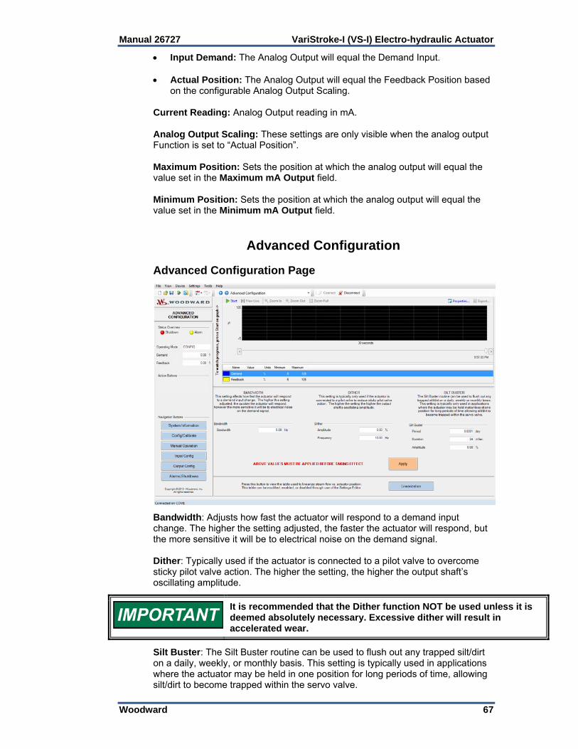
Manual 26727 VariStroke-I (VS-I) Electro-hydraulic Actuator
Woodward 67
Input Demand: The Analog Output will equal the Demand Input. Actual Position: The Analog Output will equal the Feedback Position based
on the configurable Analog Output Scaling. Current Reading: Analog Output reading in mA. Analog Output Scaling: These settings are only visible when the analog output Function is set to “Actual Position”. Maximum Position: Sets the position at which the analog output will equal the value set in the Maximum mA Output field. Minimum Position: Sets the position at which the analog output will equal the value set in the Minimum mA Output field.
Advanced Configuration Advanced Configuration Page
Bandwidth: Adjusts how fast the actuator will respond to a demand input change. The higher the setting adjusted, the faster the actuator will respond, but the more sensitive it will be to electrical noise on the demand signal. Dither: Typically used if the actuator is connected to a pilot valve to overcome sticky pilot valve action. The higher the setting, the higher the output shaft’s oscillating amplitude.
It is recommended that the Dither function NOT be used unless it is deemed absolutely necessary. Excessive dither will result in accelerated wear.
Silt Buster: The Silt Buster routine can be used to flush out any trapped silt/dirt on a daily, weekly, or monthly basis. This setting is typically used in applications where the actuator may be held in one position for long periods of time, allowing silt/dirt to become trapped within the servo valve.
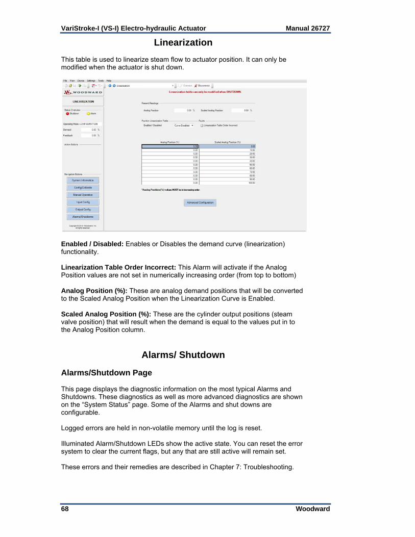
VariStroke-I (VS-I) Electro-hydraulic Actuator Manual 26727
68 Woodward
Linearization This table is used to linearize steam flow to actuator position. It can only be modified when the actuator is shut down.
Enabled / Disabled: Enables or Disables the demand curve (linearization) functionality. Linearization Table Order Incorrect: This Alarm will activate if the Analog Position values are not set in numerically increasing order (from top to bottom) Analog Position (%): These are analog demand positions that will be converted to the Scaled Analog Position when the Linearization Curve is Enabled. Scaled Analog Position (%): These are the cylinder output positions (steam valve position) that will result when the demand is equal to the values put in to the Analog Position column.
Alarms/ Shutdown Alarms/Shutdown Page This page displays the diagnostic information on the most typical Alarms and Shutdowns. These diagnostics as well as more advanced diagnostics are shown on the “System Status” page. Some of the Alarms and shut downs are configurable. Logged errors are held in non-volatile memory until the log is reset. Illuminated Alarm/Shutdown LEDs show the active state. You can reset the error system to clear the current flags, but any that are still active will remain set. These errors and their remedies are described in Chapter 7: Troubleshooting.

Manual 26727 VariStroke-I (VS-I) Electro-hydraulic Actuator
Woodward 69
Diagnostic Values: Supply Voltage: Indicates the supply voltage value. Internal Actuator Drive Current: Indicates the actuator drive current. Configure Alarms/Shutdowns Page
From the Alarm/Shutdown Configuration page, some of the alarms and shut downs can be configured. Faults that can be edited are shown as colored buttons on the page. The colored buttons can be configured based on the following descriptions:

VariStroke-I (VS-I) Electro-hydraulic Actuator Manual 26727
70 Woodward
Changing these settings may cause the actuator to move and/or shut down. Ensure all personnel are clear of moving components before changing values. If an active Alarm is toggled to a Shut down, the actuator will immediately shut down. It is recommended that the alarm be disabled before configuring it and then re-enabled when configuration is completed.
Enable/Disable (E/D): Enables or disables the alarm/shut down. Note: Even if an active alarm/shut down is disabled, it will still be shown as active on the Alarms/Shutdowns page; however, it will have no effect on the general Alarm or Shutdown indications. Alarm/Shutdown (A/S): Determines the action that will take place when the alarm is active and enabled. Latching/Non-Latching (N/L): When set to Latching, a triggered alarm will remain active until the driver is reset. When set to Non-Latching, a triggered alarm will de-activate once the problem has been remedied.
Saving and Loading Settings It is highly recommended that the user save the VS-I settings after calibration and configuration. These settings can be saved for the user’s future reference. These settings can also be loaded in to another VS-I should the unit ever be replaced. To save the VS-I settings, click on Settings in the ribbon at the top left of the page and select “Save from Device to file…”
To load settings from a PC to the VS-I, click on Settings in the ribbon at the top left of the page and select “Load Settings File to Device…”
Manual 26727 VariStroke-I (VS-I) Electro-hydraulic Actuator
Woodward 71
Chapter 7. Repair and Troubleshooting
To prevent possible serious personal injury, or damage to equipment, be sure all electric power, hydraulic pressure, and rod end force have been removed from the actuator before beginning any maintenance or repairs.
Due to typical noise levels in turbine environments, hearing protection should be worn when working on or around the VS-I actuator.
General The Varistroke-I is warranted to be free from defects in materials and workmanship, when installed and used in the manner for which it was intended, for a period of 36 months from the date of shipment from Woodward. It is recommended that all repairs and servicing of the VS-I be performed by Woodward or its authorized service facilities. Use of a cable gland or stopping plug that does not meet the hazardous area certification requirements or thread form or thread size will invalidate the suitability for hazardous locations. Never remove or alter the nameplate as it bears important information which may be necessary to service or repair the unit.
Servo Valve / Hydraulic Cylinder Replacement Before performing any repairs or replacement procedures to the VS-I, all Product Support Options listed in Chapter 8 should be understood and considered. If it is determined that a Servo Valve or Hydraulic Cylinder must be replaced, replacement procedures can be found in Woodward manual 26836, Varistroke-I Replacement Procedures.
VariStroke-I (VS-I) Electro-hydraulic Actuator Manual 26727
72 Woodward
Troubleshooting General The following troubleshooting guide will help you isolate trouble with the servo valve, hydraulic power cylinder, control circuit board, wiring, and system problems. Troubleshooting beyond this level is recommended ONLY when complete facility control testing is available. Troubleshooting Procedure This table is a general guide for isolating system problems. In general, most problems are a result of incorrect wiring or installation practices. Make sure that the system wiring, input/output connections, controls and contacts are correct and in good working order. Complete the checks in order. Each check assumes that the preceding checks have been completed and any problems have been corrected.
Be prepared to make an emergency shut down of the turbine, or other type of prime mover, to protect against runaway or overspeed with possible personal injury, loss of life, or property damage.
EXPLOSION HAZARD—Do not remove covers or connect/disconnect electrical connectors unless power has been switched off or the area is known to be non-hazardous.
ELECTRICAL SHOCK HAZARD—Follow all local plant and safety instructions/precautions before proceeding with Troubleshooting the VS-I Control.
The external ground lugs shown on the installation drawing must be properly connected to ensure equipotential bonding. This will reduce the risk of electrostatic discharge in an explosive atmosphere.

Manual 26727 VariStroke-I (VS-I) Electro-hydraulic Actuator
Woodward 73
Table 7-1. VS-I General Troubleshooting Guide
General Faults Problem Cause Remedy
Shut down
Detection: Shut down command sent by
Service Tool, Analog Demand out of range, digital communication
protocols (CAN open), Run Enable, or diagnostic.
It is normal for this to occur when a shut down position has been commanded from an external source. I.E. Service Tool, Digital Communication or Discrete Input. This is also normal when the Analog Demand signal has been turned off or set out of range.
Take away command and reset VS-I for normal operation. Ensure the VS-I has a valid demand signal.
Unexpected command from digital communication.
Take away command and reset VS-I for normal operation.
Discrete input wiring problem. Fix wiring problem.
Run Enable configuration problem.
Ensure the Used / Not Used settings inside the VS-I match the Active/Inactive settings of the controller. Settings can be modified using the Service Tool. If the Run Enable is not used, disable this function using the Service Tool.
Critical Alarm / Diagnostic triggered a shut down
Using the Service Tool, view the Alarms / Shutdowns page to determine the fault. Use the remainder of this chapter to determine the cause and solution to the fault.
Position Sensor Loop Power Output Overloaded (Remote Servo Only)
Ensure position sensor wiring and power supply are connected correctly. See Chapter 3: Cylinder Position Feedback Analog Inputs
Alarm
Detection: Alarm or Shut down has been
detected.
Diagnostic triggered an Alarm and/or Shut down
Using the Service Tool, view the Alarms / Shutdowns page to determine the fault. Use the remainder of this chapter to determine the cause and solution to the fault.

VariStroke-I (VS-I) Electro-hydraulic Actuator Manual 26727
74 Woodward
Table 7-2. VS-I Demand Faults Guide
Demand Faults Problem / Alarm Cause Remedy
Run Enable Line Low Run Enable circuit is open, or Run Enable configured incorrectly.
Ensure the Used / Not Used settings inside the VS-I match the Active/Inactive settings of the controller. Settings can be modified using the Service Tool. If the Run Enable is not used, disable this function using the Service Tool
Demand Invalid All selected analog inputs are outside the specified range.
Check input source and connections.
Demand 1 / 2 Input Low
Detection: The analog input is below the diagnostic threshold. This is a user configurable parameter.
Typically 2 mA.
Wiring is disconnected or loose. Check terminals and connections.
Short in wiring to external voltage. Check wiring for shorts to positive voltages.
Control system 4 to 20 mA output has failed high.
Check the current to the analog input to the VS-I. Fix control system.
Incorrect user configurable parameter in the electronics module for the max input diagnostic.
Verify the 4–20 mA Diagnostic Range: High Limit Value using the VS-I Service Tool.
VS-I internal electronics failure. Contact Woodward Technical Support for further assistance.
Demand 1 / 2 Input High
Detection: The analog demand input is
above the diagnostic threshold. This is a user configurable
parameter. Typically 22 mA.
Short in wiring to external voltage. Check wiring for shorts to positive voltages.
Control system 4 to 20 mA output has failed high.
Check the current to the analog input to the VS-I. Fix control system.
Incorrect user configurable parameter in the electronics module for the max input diagnostic.
Verify the 4–20 mA Diagnostic Range: High Limit Value using the VS-I Service Tool.
VS-I internal electronics failure. Contact Woodward Technical Support for further assistance.
Demand Spread Alarm
Detection: Demand Inputs are configured to Dual Mode and 1 or both analog
inputs in range, however; the difference between the two
signals is greater than the spread warning limit.
Incorrect input configuration and/or Spread Alarm Limits
If dual demand signals are not being connected and used, set mode to Single Channel. If dual demand signals are being used, check source hardware and connections.
Demand Linearization Table Order Incorrect
Demand Linearization is not monotonically increasing.
Correct the table OR disable linearization.

Manual 26727 VariStroke-I (VS-I) Electro-hydraulic Actuator
Woodward 75
Table 7-3. VS-I Power Supply Faults
Power Supply Faults Problem Cause Remedy
Power-up Reset
Detection: CPU reset by a power up event.
It is normal for the Power Up Reset diagnostic to occur upon power up of the VS-I.
Issue a reset to the VS-I.
If this occurs while the VS-I is powered, and the diagnostic is set during a fast position transient, most likely the power infrastructure is not delivering the power needed.
During transient: Check terminal voltage at the VS-I during a 0-100% position transient, check wire gauge, fuses or other resistive components in the power supply system.
Input Voltage Low Input Power level detected below reasonable limit.
Check power source and connections. If the battery voltage decreases slowly during power down, Input Voltage Low flag may be set.
Input Voltage High Input Power level detected above reasonable limit.
(Remote Servo Only) Shut down Position Sensor Loop Power overloaded due to wiring fault or failed sensor.
Check sensor current draw and ensure position sensor wiring and power supply are connected correctly. See Chapter 3: Cylinder Position Feedback Analog Inputs.

VariStroke-I (VS-I) Electro-hydraulic Actuator Manual 26727
76 Woodward
Table 7-4. VS-I Feedback Faults
Feedback Faults Problem Cause Remedy
Position 1 / 2 Feedback Low
Detection: Power cylinder feedback 1 < 4 mA
Feedback sensor wiring fault or failed sensor channel.
Check all connections to the final cylinder; check for any impediment
to motion.
If problem persists, service will be required.
Position 1 / 2 Feedback High
Detection: Power cylinder feedback 1 > 20 mA
Position Feedback Spread Alarm
Detection: The difference between the redundant
power cylinder feedback signals is greater than the set limits.
Sensors incorrectly calibrated Complete one of the Calibration procedures listed in Chapter 5 to
recalibrate the sensors.
Both Position Feedbacks Failed
Detection: Both power cylinder feedback signals
are out of usable range.
Feedback sensor wiring fault or failed sensor channel(s).
Check all connections to the final cylinder; check for any impediment
to motion.
If problem persists, service will be required.
Sensor temperature is too high.
Note: This fault will typically clear after the actuator has cooled.
Ensure that the environment AND the mounting location are within the environmental specifications listed
in chapter 2.
Position Feedback 1 / 2 Readings are Negative or Much Greater 100%
Detection:
Service tool readings of Position Feedback 1 / 2.
Stroke / Position In Service Tool Does Not Match Actual Stroke /
Position
Detection: Actual measurements using external
measurement device.
Incorrect “Position Sensor Length” input in to Service Tool.
Ensure that the “Position Sensor Length” input in to the Service Tool equals the full, 4–20 mA range of
the position sensor.
Position sensor requirements for accuracy and linearity are not
fulfilled.
If greater accuracy is desired, consider replacing the cylinder
position sensor with a more accurate sensor.

Manual 26727 VariStroke-I (VS-I) Electro-hydraulic Actuator
Woodward 77
Table 7-5. VS-I Temperature Faults
Temperature Faults Problem Cause Remedy
Temperature Derating Active Current limits reduced because of high temperature. Limits will automatically reset. Reduce ambient temperature to
within specification limits. Temperature Sensor High
Detection: The Control Board temperature sensor indicates a temperature
above operational limits.
The ambient temperature of the electronics module is higher than allowed by specification.
The Temperature sensor is defective.
Contact Woodward Technical Support for further assistance.
Temperature Sensor Low
Detection: The Control Board temperature sensor indicates a temperature
below operational limits.
The ambient temperature of the electronics module is lower than allowed by specification.
Increase ambient temperature to within specification limits.
The Temperature sensor is defective.
Contact Woodward Technical Support for further assistance.
Electric Servo Temp High
Detection: The Servo Electric Motor
temperature sensor indicates a temperature above operational
limits.
The ambient temperature of the electronics module is higher than allowed by specification.
Reduce ambient temperature to within specification limits.
The Temperature sensor is defective.
Contact Woodward Technical Support for further assistance.
Electric Servo Temp Low
Detection: The Servo Electric Motor
temperature sensor indicates a temperature below operational
limits.
The ambient temperature of the electronics module is lower than allowed by specification.
Increase ambient temperature to within specification limits.
The Temperature sensor is defective.
Contact Woodward Technical Support for further assistance.

VariStroke-I (VS-I) Electro-hydraulic Actuator Manual 26727
78 Woodward
Table 7-6. Performance Faults
Performance Faults Problem Cause Remedy
Spring Check Failed
Detection: Start up test showed a detected failure of the servo valve safety return spring.
Broken return spring
Service is required.
Servo valve seizure
Servo Tracking Alarm
Detection: The Servo Valve is unable to maintain position within the tracking error fault
limits. This will trigger an Alarm
Servo Tracking Fault
Detection: The Servo Valve is unable to position within the tracking error fault limits.
This will trigger an Shut down
Contamination in the valve/actuator system.
Ensure oil supply meets cleanliness requirements. Replace / filter oil and flush the valve with clean oil. If problem persists, service may be required.
Excessive Valve/Actuator Wear Service is required.
VS-I electronics failure. Contact Woodward Technical Support for assistance.
Cylinder Tracking Alarm
Detection: The Power Cylinder is unable to
position within the tracking error fault limits. This will trigger an Alarm
Cylinder Tracking Fault
Detection:
The Power Cylinder is unable to position within the tracking error fault limits. This will trigger a Shut down
Seized valve / linkage
Ensure that the force required to move the valve and linkage does not exceed 2/3 the stall force of the VariStroke at the operating hydraulic pressure.
Excessive thermal growth in linkage
Lower the ambient temperature of the VariStroke and/or linkage. If this is not possible, consider disabling this diagnostic.
Contamination in the valve/actuator system.
Ensure oil supply meets cleanliness requirements. Replace / filter oil and flush the valve with clean oil. If problem persists, service may be required.
Excessive Valve/Actuator Wear Service is required.
Faulty / erratic position sensor feedback
Check all connections to the final cylinder; check for any impediment to motion. If problem persists, service will be required.
Illegal Maximum Stop Position Error
Detection: The Maximum stop position has been set to less than 40% of the physical
cylinder length.
Incorrect cylinder or position sensor configuration OR incorrect calibration limits
Ensure that calibrated maximum stop position is greater than 40% of the physical cylinder length and sensor length. Check that the settings in the Remote Cylinder Setup are correct.

Manual 26727 VariStroke-I (VS-I) Electro-hydraulic Actuator
Woodward 79
Table 7-6. Performance Faults (continued)
Performance Faults Problem Cause Remedy
Stability Warning
Detection: The settings for Supply Pressure, Offset at Minimum Position, and
Maximum Stop Position result in a violation of the Stability Relationship.
Incorrect configuration and calibration settings.
See Chapter 2: Stability Specifications for the details of this alarm. The VS-I servo valve is too large
for the set cylinder volume.
Slow Slew Rates Loss or reduction in hydraulic supply pressure
Ensure that hydraulic pressure does not drop more than 10%
during a full slew. Consider adding a high volume hydraulic
accumulator to the supply line. See Chapter 2 : Hydraulic
Specifications
Table 7-7. Internal Faults
Internal Faults
Problem Cause Remedy
Electronics Fault An internal error has occurred in the driver.
Service required.
Maintenance To maximize the life of the VS-I, please refer to the maintenance recommendation in Chapter 9: Asset Management and Refurbishment Scheduling Period
VariStroke-I (VS-I) Electro-hydraulic Actuator Manual 26727
80 Woodward
Chapter 8. Product Support and Service Options
Product Support Options If you are experiencing problems with the installation, or unsatisfactory performance of a Woodward product, the following options are available: Consult the troubleshooting guide in the manual. Contact the manufacturer or packager of your system. Contact the Woodward Full Service Distributor serving your area. Contact Woodward technical assistance (see “How to Contact Woodward”
later in this chapter) and discuss your problem. In many cases, your problem can be resolved over the phone. If not, you can select which course of action to pursue based on the available services listed in this chapter.
OEM or Packager Support: Many Woodward controls and control devices are installed into the equipment system and programmed by an Original Equipment Manufacturer (OEM) or Equipment Packager at their factory. In some cases, the programming is password-protected by the OEM or packager, and they are the best source for product service and support. Warranty service for Woodward products shipped with an equipment system should also be handled through the OEM or Packager. Please review your equipment system documentation for details. Woodward Business Partner Support: Woodward works with and supports a global network of independent business partners whose mission is to serve the users of Woodward controls, as described here:
A Full Service Distributor has the primary responsibility for sales, service, system integration solutions, technical desk support, and aftermarket marketing of standard Woodward products within a specific geographic area and market segment.
An Authorized Independent Service Facility (AISF) provides authorized service that includes repairs, repair parts, and warranty service on Woodward's behalf. Service (not new unit sales) is an AISF's primary mission.
A Recognized Turbine Retrofitter (RTR) is an independent company that does both steam and gas turbine control retrofits and upgrades globally, and can provide the full line of Woodward systems and components for the retrofits and overhauls, long term service contracts, emergency repairs, etc.
A current list of Woodward Business Partners is available at www.woodward.com/directory.
Product Service Options The following factory options for servicing Woodward products are available through your local Full-Service Distributor or the OEM or Packager of the equipment system, based on the standard Woodward Product and Service Warranty (5-01-1205) that is in effect at the time the product is originally shipped from Woodward or a service is performed: Replacement/Exchange (24-hour service) Flat Rate Repair Flat Rate Remanufacture

Manual 26727 VariStroke-I (VS-I) Electro-hydraulic Actuator
Woodward 81
Replacement/Exchange: Replacement/Exchange is a premium program designed for the user who is in need of immediate service. It allows you to request and receive a like-new replacement unit in minimum time (usually within 24 hours of the request), providing a suitable unit is available at the time of the request, thereby minimizing costly downtime. This is a flat-rate program and includes the full standard Woodward product warranty (Woodward Product and Service Warranty 5-01-1205).
This option allows you to call your Full-Service Distributor in the event of an unexpected outage, or in advance of a scheduled outage, to request a replacement control unit. If the unit is available at the time of the call, it can usually be shipped out within 24 hours. You replace your field control unit with the like-new replacement and return the field unit to the Full-Service Distributor.
Charges for the Replacement/Exchange service are based on a flat rate plus shipping expenses. You are invoiced the flat rate replacement/exchange charge plus a core charge at the time the replacement unit is shipped. If the core (field unit) is returned within 60 days, a credit for the core charge will be issued.
Flat Rate Repair: Flat Rate Repair is available for the majority of standard products in the field. This program offers you repair service for your products with the advantage of knowing in advance what the cost will be. All repair work carries the standard Woodward service warranty (Woodward Product and Service Warranty 5-01-1205) on replaced parts and labor.
Flat Rate Remanufacture: Flat Rate Remanufacture is very similar to the Flat Rate Repair option with the exception that the unit will be returned to you in “like-new” condition and carry with it the full standard Woodward product warranty (Woodward Product and Service Warranty 5-01-1205). This option is applicable to mechanical products only.
Returning Equipment for Repair
Return for Repair Instructions Should the VS-I need to be returned for repair, attach a tag on the unit. Include the following information on the tag: Customer's name and address The name and location where the equipment is installed Complete Woodward part number and serial number Description of the failure Instructions as to what type of repair is to be done
Protective Packing The following procedures are used for protective packaging of the VS-I, if returning for repair: 1. Install shipping plates or plugs in all hydraulic connection ports or seal with
tape. 2. Wrap the VS-I with packaging materials that will not damage the surface of
the unit. 3. Place in a double-walled packing box. 4. Secure the unit inside of the box by removing all of its degrees of the
freedom using straps and belts, do not damage the unit. 5. Place at least 100 mm (4 inches) of tightly packed, industry-approved,
shock-absorbing material around the unit. 6. Secure the box with strong metal straps around the outside of the box to
increase the strength of the box.

VariStroke-I (VS-I) Electro-hydraulic Actuator Manual 26727
82 Woodward
Replacement Parts
When ordering replacement parts for a VS-1, include the following information: the part number(s) (XXXX-XXXX) that is on the enclosure nameplate; the unit serial number, which is also on the nameplate.
Engineering Services
Woodward offers various Engineering Services for our products. For these services, you can contact us by telephone, by email, or through the Woodward website. Technical Support Product Training Field Service
Technical Support is available from your equipment system supplier, your local Full-Service Distributor, or from many of Woodward’s worldwide locations, depending upon the product and application. This service can assist you with technical questions or problem solving during the normal business hours of the Woodward location you contact. Emergency assistance is also available during non-business hours by phoning Woodward and stating the urgency of your problem.
Product Training is available as standard classes at many of our worldwide locations. We also offer customized classes, which can be tailored to your needs and can be held at one of our locations or at your site. This training, conducted by experienced personnel, will assure that you will be able to maintain system reliability and availability.
Field Service engineering on-site support is available, depending on the product and location, from many of our worldwide locations or from one of our Full-Service Distributors. The field engineers are experienced both on Woodward products as well as on much of the non-Woodward equipment with which our products interface.
For information on these services, please contact us via telephone, email us, or use our website: www.woodward.com.
Contacting Woodward’s Support Organization
For the name of your nearest Woodward Full-Service Distributor or service facility, please consult our worldwide directory at www.woodward.com/directory, which also contains the most current product support and contact information.
You can also contact the Woodward Customer Service Department at one of the following Woodward facilities to obtain the address and phone number of the nearest facility at which you can obtain information and service.
Products Used in Electrical Power Systems
Facility --------------- Phone Number Brazil ------------- +55 (19) 3708 4800 China ----------- +86 (512) 6762 6727 Germany: Kempen ---- +49 (0) 21 52 14 51 Stuttgart - +49 (711) 78954-510 India --------------- +91 (129) 4097100 Japan --------------- +81 (43) 213-2191 Korea --------------- +82 (51) 636-7080 Poland -------------- +48 12 295 13 00 United States ----- +1 (970) 482-5811
Products Used in Engine Systems
Facility --------------- Phone Number Brazil ------------- +55 (19) 3708 4800 China ----------- +86 (512) 6762 6727 Germany ------ +49 (711) 78954-510 India --------------- +91 (129) 4097100 Japan --------------- +81 (43) 213-2191 Korea --------------- +82 (51) 636-7080 The Netherlands -- +31 (23) 5661111 United States ----- +1 (970) 482-5811
Products Used in Industrial Turbomachinery Systems
Facility --------------- Phone Number Brazil ------------- +55 (19) 3708 4800 China ----------- +86 (512) 6762 6727 India --------------- +91 (129) 4097100 Japan --------------- +81 (43) 213-2191 Korea --------------- +82 (51) 636-7080 The Netherlands -- +31 (23) 5661111 Poland -------------- +48 12 295 13 00 United States ----- +1 (970) 482-5811

Manual 26727 VariStroke-I (VS-I) Electro-hydraulic Actuator
Woodward 83
Technical Assistance
If you need to contact technical assistance, you will need to provide the following information. Please write it down here before contacting the Engine OEM, the Packager, a Woodward Business Partner, or the Woodward factory:
General
Your Name
Site Location
Phone Number
Fax Number
Prime Mover Information
Manufacturer
Turbine Model Number
Type of Fuel (gas, steam, etc.)
Power Output Rating
Application (power generation, marine, etc.)
Control/Governor Information
Control/Governor #1
Woodward Part Number & Rev. Letter
Control Description or Governor Type
Serial Number
Control/Governor #2
Woodward Part Number & Rev. Letter
Control Description or Governor Type
Serial Number
Control/Governor #3
Woodward Part Number & Rev. Letter
Control Description or Governor Type
Serial Number
Symptoms
Description
If you have an electronic or programmable control, please have the adjustment setting positions or the menu settings written down and with you at the time of the call.

VariStroke-I (VS-I) Electro-hydraulic Actuator Manual 26727
84 Woodward
Chapter 9. Asset Management and Refurbishment
Scheduling Period The following recommendations regarding the Woodward designed and manufactured VS-I actuator are to assist in properly managing the reliability, availability, and “safety of operation” expectations established for turbines. While there are electronic control systems designed to monitor and diagnose the operational performance of these components, control monitoring cannot replace normal preventative maintenance practices. It is important to follow these recommendations in order to avoid unnecessary and unscheduled shut downs. This product is designed for continuous operation under normal industrial operating conditions. There are no components that require periodic service between scheduled major turnarounds normally every five to eight years depending on the site and application. During major outages, Woodward recommends the VS-I be sent back to Woodward or a Woodward Authorized Service Facility (AISF) for inspection, component servicing and to take advantage of related product software and hardware improvements. Installations that do not meet “normal” industrial operating conditions may require customized maintenance cycles to maximize reliability, performance and asset life. Contact your local Woodward representative for a detailed evaluation of your site conditions to determine the right maintenance cycles for your installation. Woodward’s overhaul services will return the unit to “like new” condition ready for another full operating cycle, lasting until the next planned maintenance outage. Upon reaching the recommended maintenance cycle of the auxiliary component, please contact either the sites turbine OEM service representative, local Woodward Distributor or Woodward Authorized Independent Service Facility to facilitate services. Reference Chapter 8 for Product Support and Services Options.
Chapter 10. Long-Term Storage Requirements
Units that will not be put into service within twelve months should be packaged for long-term storage as described in Woodward manual 25075, Commercial Preservation Packaging for Storage of Mechanical-Hydraulic Controls.

Manual 26727 VariStroke-I (VS-I) Electro-hydraulic Actuator
Woodward 85
Appendices Outline Drawings and Installation
Features
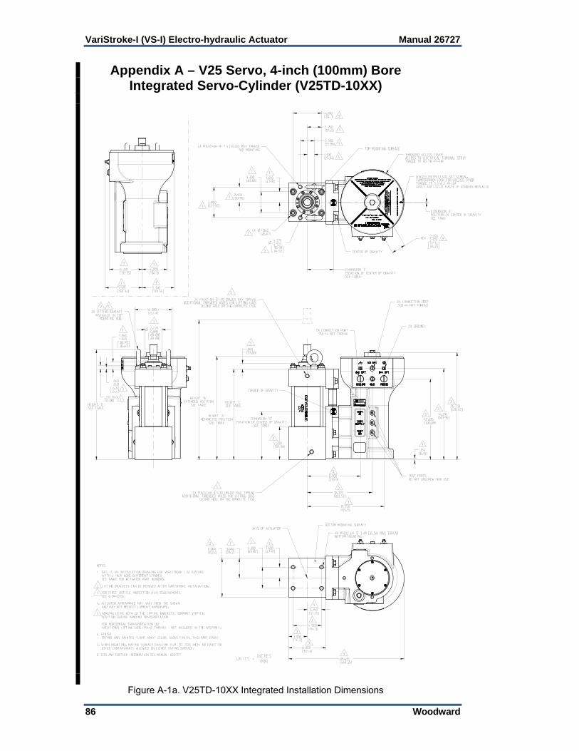
VariStroke-I (VS-I) Electro-hydraulic Actuator Manual 26727
86 Woodward
Appendix A – V25 Servo, 4-inch (100mm) Bore Integrated Servo-Cylinder (V25TD-10XX)
Figure A-1a. V25TD-10XX Integrated Installation Dimensions

Manual 26727 VariStroke-I (VS-I) Electro-hydraulic Actuator
Woodward 87
Figure A-1b. V25TD-10XX Integrated Installation Dimensions

VariStroke-I (VS-I) Electro-hydraulic Actuator Manual 26727
88 Woodward
Appendix B – V25 Servo, 6-inch (150mm) Bore Integrated Servo-Cylinder (V25TD-15XX)
Figure B-1a. V25TD-15XX Integrated Installation Dimensions

Manual 26727 VariStroke-I (VS-I) Electro-hydraulic Actuator
Woodward 89
Figure B-1b. V25TD-15XX Integrated Installation Dimensions

VariStroke-I (VS-I) Electro-hydraulic Actuator Manual 26727
90 Woodward
Appendix C – V45 Servo, 6-inch (150mm) Bore Integrated Servo-Cylinder (V45TD-15XX)
Figure C-1a. V45TD-15XX Integrated Installation Dimensions

Manual 26727 VariStroke-I (VS-I) Electro-hydraulic Actuator
Woodward 91
Figure C-2b. V45TD-15XX Integrated Installation Dimensions

VariStroke-I (VS-I) Electro-hydraulic Actuator Manual 26727
92 Woodward
Appendix D – V45 Servo, 8-inch (200mm) Bore Integrated Servo-Cylinder (V45TD-20XX)
Figure D-1a. V45TD-20XX Integrated Installation Dimensions

Manual 26727 VariStroke-I (VS-I) Electro-hydraulic Actuator
Woodward 93
Figure D-1b. V45TD-20XX Integrated Installation Dimensions

VariStroke-I (VS-I) Electro-hydraulic Actuator Manual 26727
94 Woodward
Appendix E – V45 Servo, 10-inch (250mm) Bore Integrated Servo-Cylinder (V45TD-25XX)
Figure E-1a. V45TD-25XX Integrated Installation Dimensions

Manual 26727 VariStroke-I (VS-I) Electro-hydraulic Actuator
Woodward 95
Figure E-1b. V45TD-25XX Integrated Installation Dimensions

VariStroke-I (VS-I) Electro-hydraulic Actuator Manual 26727
96 Woodward
Appendix F – V45 Servo, 8-inch (200mm) Bore 3-inch (75mm) Stroke Integrated Spring Assist Servo-
Cylinder (V45TT-2007-MUE)
Figure F-1a. V45TT-2007-MUE Integrated Spring Assist Installation Dimensions

Manual 26727 VariStroke-I (VS-I) Electro-hydraulic Actuator
Woodward 97
Figure F-1b. V45TT-2007-MUE Integrated Spring Assist Installation Dimensions

VariStroke-I (VS-I) Electro-hydraulic Actuator Manual 26727
98 Woodward
Appendix G – V25 Servo, 4-inch (100mm) Bore Remote Servo-Cylinder (V25RD-10XX)
Figure G-1a. VS-I Remote Maximum Allowable Distance between Actuator and
Servo

Manual 26727 VariStroke-I (VS-I) Electro-hydraulic Actuator
Woodward 99
Figure G-1b. V25RD-10XX Remote Installation Dimensions
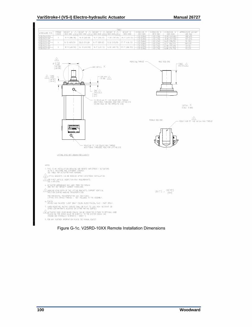
VariStroke-I (VS-I) Electro-hydraulic Actuator Manual 26727
100 Woodward
Figure G-1c. V25RD-10XX Remote Installation Dimensions

Manual 26727 VariStroke-I (VS-I) Electro-hydraulic Actuator
Woodward 101
Appendix H – V25 Servo, 6-inch (150mm) Bore Remote Servo-Cylinder (V25RD-15XX)
Figure H-1a. VS-I Remote Maximum Allowable Distance between Actuator and
Servo
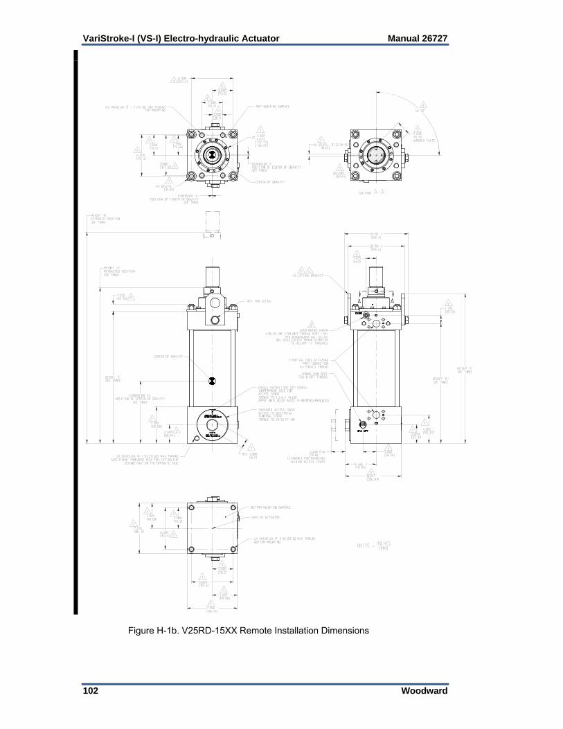
VariStroke-I (VS-I) Electro-hydraulic Actuator Manual 26727
102 Woodward
Figure H-1b. V25RD-15XX Remote Installation Dimensions

Manual 26727 VariStroke-I (VS-I) Electro-hydraulic Actuator
Woodward 103
Figure H-1c. V25RD-15XX Remote Installation Dimensions

VariStroke-I (VS-I) Electro-hydraulic Actuator Manual 26727
104 Woodward
Appendix I – V45 Servo, 6-inch (150mm) Bore Remote Servo-Cylinder (V45RD-15XX)
Figure I-1a. VS-I Remote Maximum Allowable Distance between Actuator and Servo

Manual 26727 VariStroke-I (VS-I) Electro-hydraulic Actuator
Woodward 105
Figure I-1b. V45RD-15XX Remote Installation Dimensions

VariStroke-I (VS-I) Electro-hydraulic Actuator Manual 26727
106 Woodward
Figure I-1c. V45RD-15XX Remote Installation Dimensions
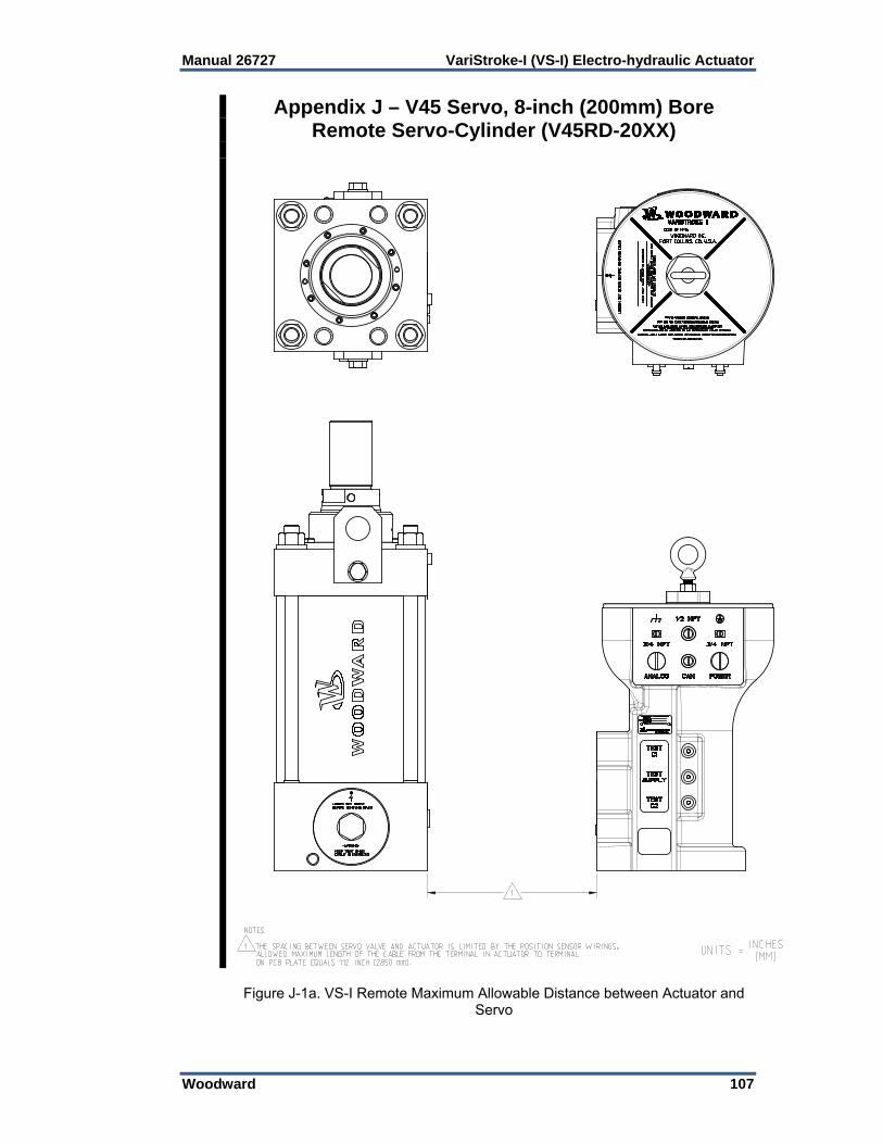
Manual 26727 VariStroke-I (VS-I) Electro-hydraulic Actuator
Woodward 107
Appendix J – V45 Servo, 8-inch (200mm) Bore Remote Servo-Cylinder (V45RD-20XX)
Figure J-1a. VS-I Remote Maximum Allowable Distance between Actuator and Servo

VariStroke-I (VS-I) Electro-hydraulic Actuator Manual 26727
108 Woodward
Figure J-1b. V45RD-20XX Remote Installation Dimensions

Manual 26727 VariStroke-I (VS-I) Electro-hydraulic Actuator
Woodward 109
Figure J-1c. V45RD-20XX Remote Installation Dimensions

VariStroke-I (VS-I) Electro-hydraulic Actuator Manual 26727
110 Woodward
Appendix K – V45 Servo, 10-inch (250mm) Bore Remote Servo-Cylinder (V45RD-25XX)
Figure K-1a. VS-I Remote Maximum Allowable Distance between Actuator and Servo

Manual 26727 VariStroke-I (VS-I) Electro-hydraulic Actuator
Woodward 111
Figure K-1b. V45RD-25XX Remote Installation Dimensions

VariStroke-I (VS-I) Electro-hydraulic Actuator Manual 26727
112 Woodward
Figure K-1c. V45RD-25XX Remote Installation Dimensions

Manual 26727 VariStroke-I (VS-I) Electro-hydraulic Actuator
Woodward 113
Appendix L – V45 Servo, 8-inch (200mm) Bore 3-inch (75mm) Stroke Remote Spring Assist Servo-Cylinder
(V45RT-2007-MUE)
Figure L-1a. VS-I Remote Maximum Allowable Distance between Actuator and Servo

VariStroke-I (VS-I) Electro-hydraulic Actuator Manual 26727
114 Woodward
Figure L-1b. V45RT-2007-MUE Remote Spring Assis Installation Dimensions

Manual 26727 VariStroke-I (VS-I) Electro-hydraulic Actuator
Woodward 115
Figure L-1c. V45RT-2007-MUE Remote Spring Assis Installation Dimensions

VariStroke-I (VS-I) Electro-hydraulic Actuator Manual 26727
116 Woodward
Appendix M – Remote Servo Version
Figure M-1a. Typical VS-I Remote Servo Installation Dimensions

Manual 26727 VariStroke-I (VS-I) Electro-hydraulic Actuator
Woodward 117
Figure M-1b. Typical VS-I Remote Servo Installation Dimensions
VariStroke-I (VS-I) Electro-hydraulic Actuator Manual 26727
118 Woodward
Revision History Changes in Revision F— Miscellaneous updates as marked with change bars Appendices A through M and associated figures Changes in Revision E— Miscellaneous updates as marked with change bars Changes in Revision D— Updated Compliance information & Declarations Updated Figures 2-3 & 2-4 Expanded explanation of Cylinder Configuration (Chapter 5) Updated Hardware Replacement instructions (Chapter 7) Changes in Revision C— Major updates throughout Changes in Revision B— Major updates throughout Changes in Revision A— Updated product photo Added information to Hydraulic Specifications Updated Figures 1-3 & 2-1

Manual 26727 VariStroke-I (VS-I) Electro-hydraulic Actuator
Woodward 119
Declarations

VariStroke-I (VS-I) Electro-hydraulic Actuator Manual 26727
120 Woodward

We appreciate your comments about the content of our publications.
Send comments to: [email protected]
Please reference publication 26727F.
ËB26727:F´¸¶¹µ¹Î
PO Box 1519, Fort Collins CO 80522-1519, USA 1000 East Drake Road, Fort Collins CO 80525, USA Phone +1 (970) 482-5811 Fax +1 (970) 498-3058
Email and Website—www.woodward.com
Woodward has company-owned plants, subsidiaries, and branches, as well as authorized distributors and other authorized service and sales facilities throughout the world.
Complete address / phone / fax / email information for all locations is available on our website.