product overview | compact drive technology
TRANSCRIPT

Product Overview | Compact Drive Technology

Compact Drive Technology Overview
Servomotor Stepper Motor
EtherCAT Terminals Bus Terminals EtherCAT Terminals EtherCAT Box
IP 20 IP 20 IP 20 IP 67
EL7201
4 A
KL2531
1.5 A
KL2541
5 A
EL7031
1.5 A
EL7041
5 A
EP7041-0002
5 A
EP7041-2002
5 A
EL9570 KL9570 EL9570
AM3111
3.22 A,
0.16 Nm
AM31123.4 A, 0.32 Nm
AM31214.6 A, 0.65 Nm
AS1010 AS1020 AS1030 AS1050 AS1060
1 A, 1 A, 1.5 A, 5 A, 5 A,
0.38 Nm 0.5 Nm 0.6 Nm 1.2 Nm 5.0 Nm
AG2250 AG1000-+PM52.x AG1000-
to AS1030/AS1050 +PM81.x
to AS1060
ZK4704-0411-2xxx Motor cable
ZK4000-6200-2xxx Motor cable
ZK4000-6261-2xxx Motor cable
ZK4724-0410-2xxx Resolver cable
ZK4000-5100-00xx Encoder cable
ZK4000-5151-00xx Encoder cable
I/O
Opt
ion
Acce
ssor
.
23
45
10
UpUs
2
1
4
3
23
45
10
UpUs
2
1
4
3
Mot
ors
Gea
r un
its
111
A,
Nm
AS
1 A
0.3
112
Nm
M31216 A, 65 Nm
.0 Nm
o AS1060
AG2250
Gea
r un
its
New Automation TechnologyBECKHOFF We reserve the right to make technical changes.
2

DC motor
Bus Terminals EtherCAT Terminals EtherCAT Box
IP 20 IP 20 IP 67
EP7041-3002
5 A
EP7041-1002
1.5 A
KL2532
1 A
KL2552
5 A
EL7332
1 A
EL7342
3.5 A
EP7342
3.5 A
KL9570 EL9570
23
45
10
UpUs
2
1
4
3
23
45
10
UpUs
2
1
4
3
23
45
10
UpUs
2
1
4
3
New Automation TechnologyBECKHOFFWe reserve the right to make technical changes.
3

Technical data EL7201
Number of channels 1 servomotor, resolver, motor brake
Connection method direct motor connection
Load type permanent-magnet synchronous motors
Nominal voltage 8…50 V DC
Output current IN 4 A
Peak current IN 8 A, 1 s
Frequency range 0…1 kHz
PWM clock frequency 16 kHz
Current controller frequency double PWM clock frequency
Rated speed controller frequ. 16 kHz
Output voltage motor brake 24 V DC (+6 %/-10 %)
Output current motor brake max. 0.5 A
Current consumption
power contacts
typ. 50 mA + holding current motor brake
Current consumption E-bus 120 mA
The EL7201 servomotor EtherCAT Terminal, with integrated resolver interface, offers high servo performance in a very compact design. The fast control technology, based on fi eld-oriented current and PI speed control, supports fast and highly dynamic positioning tasks. The monitoring of numerous parameters, such as overvoltage and undervoltage, overcurrent, terminal temperature or motor load via the calculation of a I²T model, offers maximum operational reliability. EtherCAT, as a high-performance system communication, and CAN-over-EtherCAT (CoE), as the application layer, enable ideal interfacing with PC-based control technology. The latest power semiconductors guarantee minimum power loss and enable feedback into the DC-Link when braking. 16 LEDs indicate status, warning and error messages as well as possibly active limitations.
EL7201 | Servomotor terminal 50 V DC, 4 A
www. beckhoff.com/EL7201
The shielding connection
system enables the shielding
to be located very close to the
terminals of the shielded line.
Accessories | Shielding connection systemOrdering information Description
ZB8500 clamp strap for shield connection with knurled screw, width 11 mm, shield diameter max. 8 mm, packing unit = 10
ZB8510 shield busbar 10 x 3 mm, 1000 mm galvanised Cu, packing unit = 1
ZB8511 shield busbar clamp 10 x 3 mm for 5 Bus Terminals/EtherCAT Terminals 12 mm, packing unit = 10
ZB8520 mounting rail holder for shield busbar (10 x 3 mm), packing unit = 2
ZB8530 U-clamp terminal up to 4 mm² for PE connection to the rail (10 x 3 mm), packing unit = 20
U
Excitation +Excitation –
UN +UN –
Brake +Brake –
Sin +Sin –
Cos +Cos –
V
W
Resolver
M3 ~
9
10
11
14
15
16
13
12
1
2
3
6
7
8
5
4
EL7201
New Automation TechnologyBECKHOFF We reserve the right to make technical changes.
4
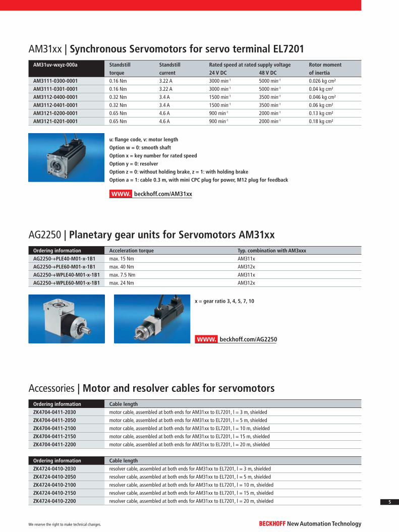
AG2250 | Planetary gear units for Servomotors AM31xxOrdering information Acceleration torque Typ. combination with AM3xxx
AG2250-+PLE40-M01-x-1B1 max. 15 Nm AM311x
AG2250-+PLE60-M01-x-1B1 max. 40 Nm AM312x
AG2250-+WPLE40-M01-x-1B1 max. 7.5 Nm AM311x
AG2250-+WPLE60-M01-x-1B1 max. 24 Nm AM312x
x = gear ratio 3, 4, 5, 7, 10
u: fl ange code, v: motor length
Option w = 0: smooth shaft
Option x = key number for rated speed
Option y = 0: resolver
Option z = 0: without holding brake, z = 1: with holding brake
Option a = 1: cable 0.3 m, with mini CPC plug for power, M12 plug for feedback
AM31uv-wxyz-000a Standstill
torque
Standstill
current
Rated speed at rated supply voltage Rotor moment
of inertia24 V DC 48 V DC
AM3111-0300-0001 0.16 Nm 3.22 A 3000 min-1 5000 min-1 0.026 kg cm²
AM3111-0301-0001 0.16 Nm 3.22 A 3000 min-1 5000 min-1 0.04 kg cm²
AM3112-0400-0001 0.32 Nm 3.4 A 1500 min-1 3500 min-1 0.046 kg cm²
AM3112-0401-0001 0.32 Nm 3.4 A 1500 min-1 3500 min-1 0.06 kg cm²
AM3121-0200-0001 0.65 Nm 4.6 A 900 min-1 2000 min-1 0.13 kg cm²
AM3121-0201-0001 0.65 Nm 4.6 A 900 min-1 2000 min-1 0.18 kg cm²
AM31xx | Synchronous Servomotors for servo terminal EL7201
Accessories | Motor and resolver cables for servomotorsOrdering information Cable length
ZK4704-0411-2030 motor cable, assembled at both ends for AM31xx to EL7201, l = 3 m, shielded
ZK4704-0411-2050 motor cable, assembled at both ends for AM31xx to EL7201, l = 5 m, shielded
ZK4704-0411-2100 motor cable, assembled at both ends for AM31xx to EL7201, l = 10 m, shielded
ZK4704-0411-2150 motor cable, assembled at both ends for AM31xx to EL7201, l = 15 m, shielded
ZK4704-0411-2200 motor cable, assembled at both ends for AM31xx to EL7201, l = 20 m, shielded
Ordering information Cable length
ZK4724-0410-2030 resolver cable, assembled at both ends for AM31xx to EL7201, l = 3 m, shielded
ZK4724-0410-2050 resolver cable, assembled at both ends for AM31xx to EL7201, l = 5 m, shielded
ZK4724-0410-2100 resolver cable, assembled at both ends for AM31xx to EL7201, l = 10 m, shielded
ZK4724-0410-2150 resolver cable, assembled at both ends for AM31xx to EL7201, l = 15 m, shielded
ZK4724-0410-2200 resolver cable, assembled at both ends for AM31xx to EL7201, l = 20 m, shielded
www. beckhoff.com/AM31xx
www. beckhoff.com/AG2250
New Automation TechnologyBECKHOFFWe reserve the right to make technical changes.
5

The KL2531 Bus Terminal is intended for the direct connection of different small Stepper Motors. The slimline PWM output stage for two motor coils is located in the Bus Terminal together with two inputs for limit switches.
The KL2541 Bus Terminal is intended for Stepper Motors with medium performance range. The PWM output stages cover a wide range of voltages and currents. Together with two inputs for limit switches, they are located in the Bus Terminal.
Together with a Stepper Motor, the Bus Terminals represent an inexpensive small servo axis. 64-fold micro stepping ensures particularly quiet and precise motor operation.
KL2531, KL2541 | Stepper Motor Bus Terminals
Technical data KL2531 | KS2531 KL2541 | KS2541
Connection technology direct motor connection
Load type uni- or bipolar Stepper Motors
Max. output current 1.5 A 5 A
Number of outputs 1 Stepper Motor 1 Stepper Motor, encoder input
Number of inputs 2 2 for limit position, 4 for an encoder system
Nominal voltage 24 V (-15 %/+20 %) 8…50 V DC
Current consumption
power contacts
only load typ. 35 mA
Current consumption K-bus typ. 60 mA typ. 100 mA
Maximum step frequency 125,000 steps/s
Step pattern full step, half step, up to 64-fold micro stepping
Current controller frequency approx. 25 kHz
Control resolution approx. 5,000 positions in typ. applications (per revolution)
Encoder signal – 5…24 V, 5 mA, single-ended
Pulse frequency – max. 400,000 increments/s (with 4-fold evaluation)
Special features travel distance control travel distance control, encoder input
Operating temperature 0…+55 °C
Approvals CE
www. beckhoff.com/KL2531 www. beckhoff.com/KL2541
For Stepper Motors see page 9
1 5
2 6
3 7
4 8
1 5
2 6
3 7
4 8
1’ 5’
2’ 6’
3’ 7’
4’ 8’
Enc
M
B1
B2
A1 A2
KL2531 KL2541
New Automation TechnologyBECKHOFF We reserve the right to make technical changes.
6
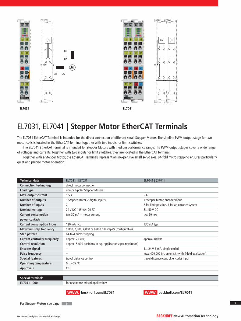
The EL7031 EtherCAT Terminal is intended for the direct connection of different small Stepper Motors. The slimline PWM output stage for two motor coils is located in the EtherCAT Terminal together with two inputs for limit switches.
The EL7041 EtherCAT Terminal is intended for Stepper Motors with medium performance range. The PWM output stages cover a wide range of voltages and currents. Together with two inputs for limit switches, they are located in the EtherCAT Terminal.
Together with a Stepper Motor, the EtherCAT Terminals represent an inexpensive small servo axis. 64-fold micro stepping ensures particularly quiet and precise motor operation.
EL7031, EL7041 | Stepper Motor EtherCAT Terminals
www. beckhoff.com/EL7031 www. beckhoff.com/EL7041
For Stepper Motors see page 9
1 5
2 6
3 7
4 8
M
B1
B2
A1 A2
Enc
1 5
2 6
3 7
4 8
1’ 5’
2’ 6’
3’ 7’
4’ 8’
EL7031 EL7041
Technical data EL7031 | ES7031 EL7041 | ES7041
Connection technology direct motor connection
Load type uni- or bipolar Stepper Motors
Max. output current 1.5 A 5 A
Number of outputs 1 Stepper Motor, 2 digital inputs 1 Stepper Motor, encoder input
Number of inputs 2 2 for limit position, 4 for an encoder system
Nominal voltage 24 V DC (-15 %/+20 %) 8…50 V DC
Current consumption
power contacts
typ. 30 mA + motor current typ. 50 mA
Current consumption E-bus 120 mA typ. 130 mA typ.
Maximum step frequency 1,000, 2,000, 4,000 or 8,000 full steps/s (confi gurable)
Step pattern 64-fold micro stepping
Current controller frequency approx. 25 kHz approx. 30 kHz
Control resolution approx. 5,000 positions in typ. applications (per revolution)
Encoder signal – 5…24 V, 5 mA, single-ended
Pulse frequency – max. 400,000 increments/s (with 4-fold evaluation)
Special features travel distance control travel distance control, encoder input
Operating temperature 0…+55 °C
Approvals CE
Special terminals
EL7041-1000 for resonance-critical applications
New Automation TechnologyBECKHOFFWe reserve the right to make technical changes.
7

Technical data EP7041-3002 EP7041-0002, EP7041-2002 EP7041-1002
Connection method screw type M12
Load type uni- or bipolar Stepper Motors
Number of outputs 1 Stepper Motor, 1 digital 24 V DC output
Number of inputs 2 digital inputs, encoder system (24 V DC encoder)
Nominal voltage 8…50 V DC
Distributed clocks yes
Protocol EtherCAT
Output current 2 x 3.5 A, 2 x 5 A peak current
(overload- and short-circuit-proof)
2 x 3.5 A, 2 x 5 A peak current
(overload- and short-circuit-proof)
1.5 A
Maximum step frequency 1,000, 2,000, 4,000 or 8,000 full steps/s (confi gurable)
Step pattern 64-fold micro stepping
Current controller frequency dynamic approx. 30 kHz approx. 30 kHz
Resolution approx. 5,000 positions (per revolution, according to motor and encoder type)
Current consumption from US
(without sensor current)
120 mA
Special features travel distance control,
encoder input, load indication,
for resonance-critical applications
travel distance control,
encoder input
travel distance control,
encoder input
Operating temperature -25…+60 °C
Approvals CE, UL
Protection class IP 65/66/67 (according to EN 60529)
The EP7041 EtherCAT Box is intended for the direct connection of different Stepper Motors. The PWM output stages for two motor coils with compact design are located in the module together with two inputs for limit switches and cover a wide voltage and current range. The EP7041 can be adjusted to the motor and the application by changing just a few parameters. 64-fold micro-stepping ensures particularly quiet and precise motor operation. Connection of an incremental encoder enables a simple servo axis to be realised. Two digital inputs and a digital 0.5 A output enable connection of end switches and a motor brake.
EP7041-xxxx | Stepper Motor EtherCAT Box
www. beckhoff.com/EP7041
2
1
3
45
2
1
3
45
2
1
3
45
2
1
3
45
M
1 | +24 V DC US
2 | +24 V DC UP
3 | GNDS
4 | GNDP
1 | A12 | A23 | B14 | | B25 | n. c.
1, 2 | V motor3, 4 | GND motor5 | n. c.1 | +24 V DC US
2 | Input B3 | GND4 | Input A5 | Output1 | GND2 | V Enc3 | A Enc4 | B Enc5 | C Enc
1 | Tx+2 | Rx+3 | Rx-4 | Tx-
2
1
3
45
23
45
10
UpUs
2
1
4
3
StepperMotor
Motor supply
Digital inputs
Encoder
23
45
10
UpUs
2
1
4
3
EP7041-0002
EP7041-1002
EP7041-2002
EP7041-3002
New Automation TechnologyBECKHOFF We reserve the right to make technical changes.
8

Technical data AS1010-0000 AS1020-0xyz AS1030-0000 AS1050-0xyz AS1060-wxyz
Rated supply voltage 24…50 V DC
Rated current (per phase) 1.0 A 1.0 A 1.5 A 5.0 A 5.0 A
Standstill torque 0.38 Nm 0.5 Nm 0.6 Nm 1.2 Nm 5.0 Nm
Rotor moment of inertia 0.056 kg cm² 0.074 kg cm² 0.21 kg cm² 0.36 kg cm² 3.0 kg cm²
Resolution 1.8°/200 full steps
Dimensions (r x length) 42 mm x 39 mm 42 mm x 48 mm 56 mm x 53 mm 56 mm x 75 mm 86 mm x 97 mm
Bus Terminal KL2531/EL7031 EL7031/EP7041 KL2531/EL7031 KL2541/EL7041 KL2541/EL7041
Option w = 0: smooth shaft with 2 fl ats (AS1030/AS1050 only smooth shaft);
w = 1: shaft with groove and feather key according to DIN 6885 (only AS1060)
Option x = 0: single shaft, x = 1; second shaft (only AS1020/AS1050/AS1060)
Option y = 0: no incremental encoder; y = 1: incremental encoder 24 V DC, 200 inc/rev; y = 2: 1,024 inc/rev
Option z = 0: standard; z = 1: customer-specifi c
Ordering information AG1000-+PM52.x to AS1030/AS1050 AG1000-+PM81.x to AS1060
Rated torque 4 Nm 20 Nm
Acceleration torque 6 Nm 30 Nm
Gear backlash ≤ 0.7° ≤ 0.5°
AG1000 | Planetary gear unit for Stepper Motors
www. beckhoff.com/AS1010
www. beckhoff.com/AG1000
Accessories | Motor and encoder cables for Stepper Motors
x = 4: gear ratio 1:4 (more precisely 3.7 or 63/17 as a fraction),
x = 7: gear ratio 1:7 (more precisely 6.75 or 27/4 as a fraction)
Ordering information Motor cables for AS1000 Stepper Motors to Bus Terminals KL2531/41 or EtherCAT Terminals EL70x1
ZK4000-6200-2010 motor cable, assembled at both ends for AS1000 Stepper Motors, 4 x 0.5 mm², l = 1 m, shielded
ZK4000-6200-2030 motor cable, assembled at both ends for AS1000 Stepper Motors, 4 x 0.5 mm², l = 3 m, shielded
ZK4000-6200-2050 motor cable, assembled at both ends for AS1000 Stepper Motors, 4 x 0.5 mm², l = 5 m, shielded
ZK4000-6200-2100 motor cable, assembled at both ends for AS1000 Stepper Motors, 4 x 0.5 mm², l = 10 m, shielded
Ordering information Encoder cables for AS1000 Stepper Motors to KL2531/41 or EL70x1
ZK4000-5100-2010 encoder cable, assembled on both sides for AS1000 Stepper Motors, 5 x 0.35 mm², l = 1 m, shielded
ZK4000-5100-2030 encoder cable, assembled on both sides for AS1000 Stepper Motors, 5 x 0.35 mm², l = 3 m, shielded
ZK4000-5100-2050 encoder cable, assembled on both sides for AS1000 Stepper Motors, 5 x 0.35 mm², l = 5 m, shielded
ZK4000-5100-2100 encoder cable, assembled on both sides for AS1000 Stepper Motors, 5 x 0.35 mm², l = 10 m, shielded
Ordering information Motor cables for AS1000 Stepper Motors to EP7041 EtherCAT Box
ZK4000-6261-0005 motor cable, assembled at both ends for AS1000 Stepper Motors, 4 x 0.5 mm², l = 0.5 m, shielded
ZK4000-6261-0010 motor cable, assembled at both ends for AS1000 Stepper Motors, 4 x 0.5 mm², l = 1 m, shielded
ZK4000-6261-0020 motor cable, assembled at both ends for AS1000 Stepper Motors, 4 x 0.5 mm², l = 2 m, shielded
Ordering information Encoder cables for AS1000 Stepper Motors to EP7041 EtherCAT Box
ZK4000-5151-0005 encoder cable, assembled on both sides for AS1000 Stepper Motors, 5 x 0.35 mm², l = 0.5 m, shielded
ZK4000-5151-0010 encoder cable, assembled on both sides for AS1000 Stepper Motors, 5 x 0.35 mm², l = 1 m, shielded
ZK4000-5151-0020 encoder cable, assembled on both sides for AS1000 Stepper Motors, 5 x 0.35 mm², l = 2 m, shielded
The maximum motor cable length is 10 m.
AS1xxx | Stepper Motors for KL2531, KL2541, EL7031, EL7041
Stepper Motor terminals and EP7041 Stepper Motor module
New Automation TechnologyBECKHOFFWe reserve the right to make technical changes.
9
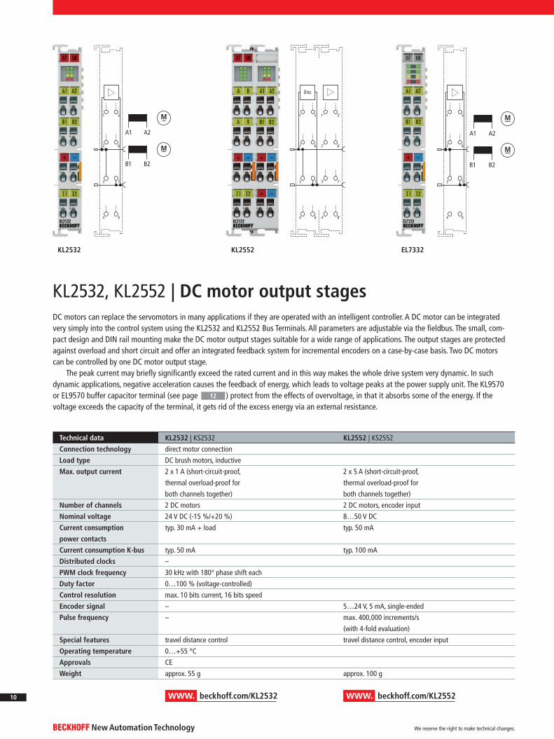
KL2532, KL2552 | DC motor output stages
www. beckhoff.com/KL2532 www. beckhoff.com/KL2552
DC motors can replace the servomotors in many applications if they are operated with an intelligent controller. A DC motor can be integrated very simply into the control system using the KL2532 and KL2552 Bus Terminals. All parameters are adjustable via the fi eldbus. The small, com-pact design and DIN rail mounting make the DC motor output stages suitable for a wide range of applications. The output stages are protected against overload and short circuit and offer an integrated feedback system for incremental encoders on a case-by-case basis. Two DC motors can be controlled by one DC motor output stage.
The peak current may briefl y signifi cantly exceed the rated current and in this way makes the whole drive system very dynamic. In such dynamic applications, negative acceleration causes the feedback of energy, which leads to voltage peaks at the power supply unit. The KL9570 or EL9570 buffer capacitor terminal (see page ) protect from the effects of overvoltage, in that it absorbs some of the energy. If the voltage exceeds the capacity of the terminal, it gets rid of the excess energy via an external resistance.
12
Technical data KL2532 | KS2532 KL2552 | KS2552
Connection technology direct motor connection
Load type DC brush motors, inductive
Max. output current 2 x 1 A (short-circuit-proof,
thermal overload-proof for
both channels together)
2 x 5 A (short-circuit-proof,
thermal overload-proof for
both channels together)
Number of channels 2 DC motors 2 DC motors, encoder input
Nominal voltage 24 V DC (-15 %/+20 %) 8…50 V DC
Current consumption
power contacts
typ. 30 mA + load typ. 50 mA
Current consumption K-bus typ. 50 mA typ. 100 mA
Distributed clocks –
PWM clock frequency 30 kHz with 180° phase shift each
Duty factor 0…100 % (voltage-controlled)
Control resolution max. 10 bits current, 16 bits speed
Encoder signal – 5…24 V, 5 mA, single-ended
Pulse frequency – max. 400,000 increments/s
(with 4-fold evaluation)
Special features travel distance control travel distance control, encoder input
Operating temperature 0…+55 °C
Approvals CE
Weight approx. 55 g approx. 100 g
1 5
2 6
3 7
4 8
1 5
2 6
3 7
4 8
M
M
A1 A2
B1 B2
M
M
A1 A2
B1 B2
1 5
2 6
3 7
4 8
1’ 5’
2’ 6’
3’ 7’
4’ 8’
Enc
KL2532 KL2552 EL7332
New Automation TechnologyBECKHOFF We reserve the right to make technical changes.
10
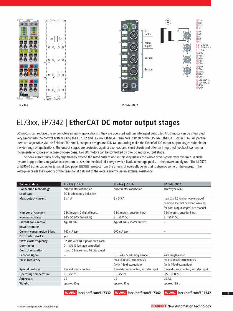
EL73xx, EP7342 | EtherCAT DC motor output stages
www. beckhoff.com/EL7342www. beckhoff.com/EL7332 www. beckhoff.com/EP7342
DC motors can replace the servomotors in many applications if they are operated with an intelligent controller. A DC motor can be integrated very simply into the control system using the EL7332 and EL7342 EtherCAT Terminals in IP 20 or the EP7342 EtherCAT Box in IP 67. All param-eters are adjustable via the fi eldbus. The small, compact design and DIN rail mounting make the EtherCAT DC motor output stages suitable for a wide range of applications. The output stages are protected against overload and short circuit and offer an integrated feedback system for incremental encoders on a case-by-case basis. Two DC motors can be controlled by one DC motor output stage.
The peak current may briefl y signifi cantly exceed the rated current and in this way makes the whole drive system very dynamic. In such dynamic applications, negative acceleration causes the feedback of energy, which leads to voltage peaks at the power supply unit. The KL9570 or EL9570 buffer capacitor terminal (see page ) protect from the effects of overvoltage, in that it absorbs some of the energy. If the voltage exceeds the capacity of the terminal, it gets rid of the excess energy via an external resistance.
12
Technical data EL7332 | ES7332 EL7342 | ES7342 EP7342-0002
Connection technology direct motor connection direct motor connection screw type M12
Load type DC brush motors, inductive
Max. output current 2 x 1 A 2 x 3.5 A max. 2 x 3.5 A (short-circuit-proof,
common thermal overload warning
for both output stages) per channel
Number of channels 2 DC motors, 2 digital inputs 2 DC motors, encoder input 2 DC motors, encoder input
Nominal voltage 24 V DC (-15 %/+20 %) 8…50 V DC 8…50 V DC
Current consumption
power contacts
typ. 40 mA typ. 70 mA + motor current –
Current consumption E-bus 140 mA typ. 200 mA typ. –
Distributed clocks yes
PWM clock frequency 32 kHz with 180° phase shift each
Duty factor 0…100 % (voltage-controlled)
Control resolution max. 10 bits current, 16 bits speed
Encoder signal – 5 … 24 V, 5 mA, single-ended 24 V, single-ended
Pulse frequency – max. 400,000 increments/s
(with 4-fold evaluation)
max. 400,000 increments/s
(with 4-fold evaluation)
Special features travel distance control travel distance control, encoder input travel distance control, encoder input
Operating temperature 0…+55 °C 0…+55 °C -25…+60 °C
Approvals CE CE CE, UL
Weight approx. 50 g approx. 90 g approx. 165 g
Enc
1 5
2 6
3 7
4 8
1’ 5’
2’ 6’
3’ 7’
4’ 8’
23
45
67
10
UpUs
2
1
4
3
DC motor
Motor supply
Encoder
Encoder
1 | +24 V DC US
2 | +24 V DC UP
3 | GNDS
4 | GNDP
1 | A12 | A23 | B14 | | B25 | n. c.
1, 2 | V motor3, 4 | GND motor5 | n. c.
1 | GND2 | V Enc3 | A Enc4 | B Enc5 | C Enc
1 | GND2 | V Enc3 | A Enc4 | B Enc5 | C Enc
1 | Tx+2 | Rx+3 | Rx-4 | Tx-
2
1
3
45
2
1
3
45
2
1
3
45
2
1
3
45
M
EL7342 EP7342-0002
New Automation TechnologyBECKHOFFWe reserve the right to make technical changes.
11

Technical data KL9570 | KS9570 EL9570 | ES9570
Technology buffer capacitor terminal
Diagnostics –
Nominal voltage 50 V
Capacity 500 µF
Ripple current 10 A in continuous operation
Internal resistance < 10 mΩ
Surge voltage protection > 56 V
Recommended
ballast resistor
10 Ω, typ. 10 W
Overvoltage control range ±2 V
Ballast resistor clock rate load-dependent, 2-point control
Electrical isolation 1,500 V (terminal/K-bus) 1,500 V (terminal/E-bus)
Operating temperature 0…+55 °C
Approvals CE, Ex
Weight approx. 65 g approx. 90 g
The buffer capacitor terminals KL9570 (Bus Terminal) and EL9570 (EtherCAT Terminal) contain high-performance capacitors for stabilising supply voltages. They can be used in conjunction with the terminals of the compact Drive Technology. Low internal resistance and high-pulsed current capability enable good buffering in parallel with a power supply unit. Return currents are stored, particularly in the context of drive applications, thereby preventing overvolt-ages. If the regenerative energy exceeds the capacity of the capacitors, the KL9570/EL950 switches the load voltage through to the terminal points 1 and 5. The energy is dissipated by the connection of an external ballast resistor.
KL9570, EL9570 | Buffer capacitor terminals
www. beckhoff.com/KL9570 www. beckhoff.com/EL9570
Voltage spikes at the power supply unit
Occurrence of ripple currents
Prevention of overvoltage
V DCmax. t
U
55 V DCt
U
I
t
1 5
2 6
3 7
4 8
1 5
2 6
3 7
4 8
10
EL9570KL9570
New Automation TechnologyBECKHOFF We reserve the right to make technical changes.
12
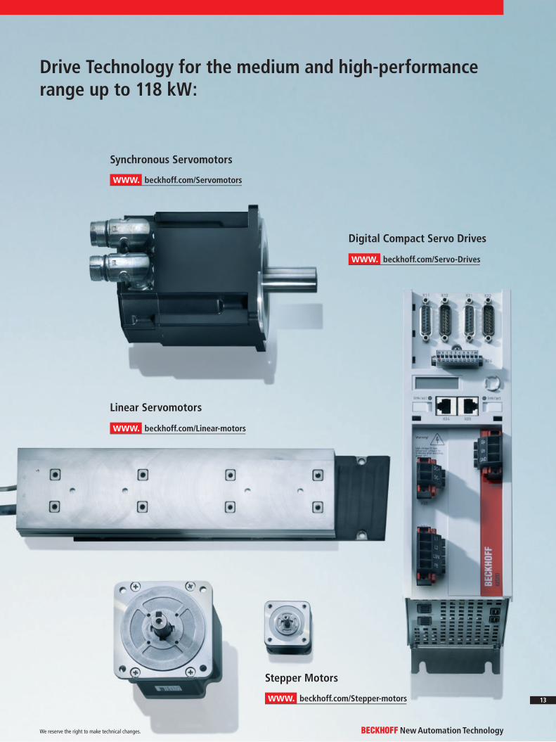
Drive Technology for the medium and high-performance range up to 118 kW:
www. beckhoff.com/Servomotors
www. beckhoff.com/Linear-motors
www. beckhoff.com/Stepper-motors
www. beckhoff.com/Servo-Drives
Synchronous Servomotors
Stepper Motors
Digital Compact Servo Drives
Linear Servomotors
New Automation TechnologyBECKHOFFWe reserve the right to make technical changes.
13
Beckhoff®, TwinCAT®, EtherCAT®, Safety over EtherCAT®, TwinSAFE® and XFC® are registered trademarks of and licensed by Beckhoff Automation GmbH. Other designations used in this publication may be trademarks whose use by third parties for their own purposes could violate the rights of the owners.
© Beckhoff Automation GmbH 12/2011
The information provided in this brochure contains merely general descriptions or characteristics of performance which in case of actual application do not always apply as described or which may change as a result of further development of the products. An obligation to provide the respective characteristics shall only exist if expressively agreed in the terms of contract.
Headquarters
Beckhoff Automation GmbHEiserstraße 533415 VerlGermanyPhone: + 49 (0) 52 46 / 9 63 - [email protected]
Beckhoff Drive TechnologyThis fl yer provides an overview over the compact Drive Technology. The complete product range up to 118 KW can be found on the Internet:
www. beckhoff.com/DriveTechnology
DK3
412-
1211