product specifications - planet · data delivered with planet’s imagery products that describes...
TRANSCRIPT


Page 2© Planet Labs Inc 2018
TABLE OF CONTENTS
LIST OF FIGURES _______________________________________________________________________________________ 3
LIST OF TABLES ________________________________________________________________________________________ 4
GLOSSARY ____________________________________________________________________________________________ 5
1. OVERVIEW OF DOCUMENT _____________________________________________________________________________ 7
1.1 Company Overview _________________________________________________________________________________ 7
1.2 Data Product Overview ______________________________________________________________________________ 7
2. SATELLITE CONSTELLATION AND SENSOR OVERVIEW _____________________________________________________ 8
2.1 PlanetScope Satellite Constellation and Sensor Characteristics ______________________________________________ 8
2.2 RapidEye Satellite Constellation and Sensor Characteristics ________________________________________________ 8
2.3 SkySat Satellite Constellation and Sensor Characteristics ___________________________________________________ 9
3. PLANETSCOPE IMAGERY PRODUCTS ____________________________________________________________________ 10
3.1 PlanetScope Basic Scene Product Specification _________________________________________________________ 10
3.2 PlanetScope Ortho Scenes Product Specification _________________________________________________________ 11
3.2.1 PlanetScope Visual Ortho Scene Product Specification _________________________________________________ 12
3.2.2 PlanetScope Analytic Ortho Scene Product Specification ______________________________________________ 13
3.3 PlanetScope Ortho Tile Product Specification ___________________________________________________________ 14
3.3.1 PlanetScope Visual Ortho Tile Product Specification __________________________________________________ 15
3.3.2 PlanetScope Analytic Ortho Tile Product Specification ________________________________________________ 16
4. RAPIDEYE IMAGERY PRODUCTS _______________________________________________________________________ 18
4.1 RapidEye Basic Scene Product Specification ___________________________________________________________ 18
4.2 RapidEye Ortho Tile Product Specification _____________________________________________________________ 20
4.2.1 RapidEye Visual Ortho Tile Product Specification _____________________________________________________ 20
4.2.2 RapidEye Analytic Ortho Tile Product Specification __________________________________________________ 22
5. SKYSAT IMAGERY PRODUCTS __________________________________________________________________________ 23
5.1 SkySat Basic Scene Product Specification ______________________________________________________________ 23
5.2 SkySat Ortho Scene Product Specification _____________________________________________________________ 24
5.2.1 SkySat Visual Ortho Scene ______________________________________________________________________ 24
5.2.2 SkySat Pansharpened Multispectral Ortho Scene ____________________________________________________ 25
5.2.3 SkySat Analytic DN Ortho Scene _________________________________________________________________ 25
5.2.4 SkySat Panchromatic DN Ortho Scene _____________________________________________________________ 26
6. OTHER PROVIDER IMAGERY PRODUCTS _________________________________________________________________ 27
6.1 Landsat 8 Product Specification ______________________________________________________________________ 27
6.2 Sentinel-2 Product Specification _____________________________________________________________________ 28
7. PRODUCT PROCESSING _______________________________________________________________________________ 29
7.1 PlanetScope Processing ____________________________________________________________________________ 29
7.2 RapidEye Processing _______________________________________________________________________________ 31
7.3 SkySat Processing _________________________________________________________________________________ 32
8. QUALITY ATTRIBUTES_______________________________________________________________________________ 33
Page 3© Planet Labs Inc 2018
8.1 Product Geometric Positional Accuracy ________________________________________________________________ 33
8.2 Cloud Cover ______________________________________________________________________________________ 33
8.2.1 PlanetScope ___________________________________________________________________________________ 33
8.2.2 RapidEye _____________________________________________________________________________________ 33
8.3 Band Co-Registration ______________________________________________________________________________ 34
8.3.1 PlanetScope __________________________________________________________________________________ 34
8.3.2 RapidEye _____________________________________________________________________________________ 34
8.3.3 SkySat _______________________________________________________________________________________ 34
8.4 Radiometry and Radiometric Accuracy ________________________________________________________________ 35
8.4.1 PlanetScope __________________________________________________________________________________ 35
8.4.2 RapidEye ____________________________________________________________________________________ 35
9. PRODUCT METADATA ________________________________________________________________________________ 37
9.1 Ortho Tiles _______________________________________________________________________________________ 37
9.1.1 PlanetScope ___________________________________________________________________________________ 37
9.1.2 RapidEye _____________________________________________________________________________________ 38
9.2 Ortho Scenes _____________________________________________________________________________________ 39
9.2.1 PlanetScope ___________________________________________________________________________________ 39
9.2.2 SkySat _______________________________________________________________________________________ 40
9.3 Basic Scenes _____________________________________________________________________________________ 41
9.3.1 PlanetScope __________________________________________________________________________________ 41
9.3.2 RapidEye _____________________________________________________________________________________ 42
9.3.3 SkySat _______________________________________________________________________________________ 43
10. PRODUCT DELIVERY ________________________________________________________________________________ 44
10.1 Planet Application Programming Interface (API) ________________________________________________________ 45
10.2 Planet Graphical User Interface (GUI) _________________________________________________________________ 47
10.3 Planet Account Management Tools ___________________________________________________________________ 47
10.4 File Format ______________________________________________________________________________________ 48
10.5 Bulk Delivery Folder Structure ______________________________________________________________________ 48
APPENDIX A - IMAGE SUPPORT DATA _____________________________________________________________________ 49
1. General XML Metadata File ___________________________________________________________________________ 49
2. Unusable Data Mask File _____________________________________________________________________________ 53
APPENDIX B - TILE GRID DEFINITION _____________________________________________________________________ 55
LIST OF FIGURES
Figure A: Planet Imagery Product Offerings __________________________________________________________________ 7
Figure B: PlanetScope Scene to Ortho Tile Conversion ________________________________________________________ 14
Figure C: PlanetScope Analytic Ortho Tiles with RGB (left) and NIR False-Color Composite (right) ____________________ 16
Figure D: PlanetScope Analytic Bands ______________________________________________________________________ 17
Figure E: RapidEye Visual Ortho Tile ________________________________________________________________________ 21
Figure F: PlanetScope Image Processing Chain ______________________________________________________________ 30
Figure G: RapidEye Image Processing Chain _________________________________________________________________ 31
Figure H: SkySat Image Processing Chain ___________________________________________________________________ 32

Page 4© Planet Labs Inc 2018
Figure A-1: Concepts Behind the Unusable Data Mask File ______________________________________________________ 54
Figure B-1: Layout of UTM Zones __________________________________________________________________________ 55
Figure B-2: Layout of Tile Grid within a single UTM zone _______________________________________________________ 56
Figure B-3: Illustration of Grid Layout of Rows and Columns for a Single UTM Zone _________________________________ 57
LIST OF TABLES
Table 2-A: PlanetScope Constellation and Sensor Specifications __________________________________________________ 8
Table 2-B: RapidEye Constellation and Sensor Specifications ____________________________________________________ 8
Table 2-C: SkySat Constellation Overview ____________________________________________________________________ 9
Table 2-D: SkySat Pointing ________________________________________________________________________________ 9
Table 2-E: SkySat Sensor Specifications ______________________________________________________________________ 9
Table 3-A: PlanetScope Satellite Image Product Processing Levels _______________________________________________ 10
Table 3-B: PlanetScope Basic Scene Product Attributes ________________________________________________________ 11
Table 3-C: PlanetScope Ortho Scene Product Attributes ________________________________________________________ 12
Table 3-D: PlanetScope Visual Ortho Scene Product Attributes __________________________________________________ 12
Table 3-E: PlanetScope Analytic Ortho Scene Product Attributes ________________________________________________ 13
Table 3-F: PlanetScope Ortho Tile Product Attributes _________________________________________________________ 14
Table 3-G: PlanetScope Visual Ortho Tile Product Attributes ____________________________________________________ 15
Table 3-H: PlanetScope Analytic Ortho Tile Product Attributes __________________________________________________ 16
Table 4-A: RapidEye Satellite Image Product Processing Levels _________________________________________________ 18
Table 4-B: RapidEye Basic Scene Product Attributes __________________________________________________________ 19
Table 4-C: RapidEye Ortho Tile Product Attributes ___________________________________________________________ 20
Table 4-D: RapidEye Visual Ortho Tile Product Attributes _______________________________________________________ 21
Table 4-E: RapidEye Analytic Ortho Tile Product Attributes ____________________________________________________ 22
Table 5-A: SkySat Basic Scene Product Attributes ____________________________________________________________ 23
Table 5-B: SkySat Ortho Scene Product Attributes ____________________________________________________________ 24
Table 5-C: SkySat Visual Ortho Scene Attributes ______________________________________________________________ 24
Table 5-D: SkySat Pansharpened Multispectral Ortho Scene Attributes ___________________________________________ 25
Table 5-E: SkySat Analytic DN Ortho Scene Attributes ________________________________________________________ 25
Table 5-F: SkySat Panchromatic Ortho Scene Attributes _______________________________________________________ 26
Table 6-A: Landsat 8 Product Attributes ____________________________________________________________________ 27
Table 6-B: Sentinel-2 Product Attributes ____________________________________________________________________ 28
Table 7-A: PlanetScope Processing Steps ___________________________________________________________________ 29
Table 7-B: RapidEye Processing Steps ______________________________________________________________________ 31
Table 7-C: SkySat Processing Steps ________________________________________________________________________ 32
Table 9-A: PlanetScope Ortho Tile GeoJSON Metadata Schema _________________________________________________ 37
Table 9-B: RapidEye Ortho Tile GeoJSON Metadata Schema ____________________________________________________ 38
Table 9-C: PlanetScope Ortho Scene GeoJSON Metadata Schema _______________________________________________ 39
Table 9-D: SkySat Ortho Scene GeoJSON Metadata Schema ___________________________________________________ 40
Table 9-E: PlanetScope Basic Scene GeoJSON Metadata Schema _______________________________________________ 40
Table 9-F: RapidEye Basic Scene GeoJSON Metadata Schema __________________________________________________ 42
Table 9-G: SkySat Basic Scene GeoJSON Metadata Schema ____________________________________________________ 43
Table 10-A: Planet Data API - Item Types ____________________________________________________________________ 44
Table 10-B: Planet Data API - Asset Types ___________________________________________________________________ 45
Table A-1: General XML Metadata File Field Descriptions _______________________________________________________ 49
Disclaimer
This document is designed as a general guideline for customers interested in acquiring Planet imagery products and services. Planet takes an agile and iterative approach to its technology, and therefore may make changes to the product(s) described in this document.
Page 5© Planet Labs Inc 2018
GLOSSARY
The following list defines terms used to describe Planet’s satellite imagery products.
Alpha Mask
An alpha mask is an image channel with binary values that can be used to render areas of the image product transparent where no data is available.
Application Programming Interface (API)
A set of routines, protocols, and tools for building software applications.
Blackfill
Non-imaged pixels or pixels outside of the buffered area of interest that are set to black. They may appear as pixels with a value of “0” or as “noData” depending on the viewing software.
Digital Elevation Model (DEM)
The representation of continuous elevation values over a topographic surface by a regular array of z-values, referenced to a common datum. DEMs are typically used to represent terrain relief.
GeoJSON
A standard for encoding geospatial data using JSON (see JSON below).
GeoTIFF
An image format with geospatial metadata suitable for use in a GIS or other remote sensing software.
Ground Sample Distance (GSD)
The distance between pixel centers, as measured on the ground. It is mathematically calculated based on optical characteristics of the telescope, the altitude of the satellite, and the size and shape of the CCD sensor.
Graphical User Interface (GUI)
The web-based graphical user interfaces allows users to browse, preview and download Planet’s imagery products.
International Space Station (ISS) Orbit
International Space Station (ISS) orbits at a 51.6°inclination at approximately 400 km altitude. Planet deploys satellites from the ISS, each having a similar orbit.
JavaScript Object Notation (JSON)
Text-based data interchange format used by the Planet API.
Landsat 8
Freely available dataset offered through NASA and the United States Geological Survey.
Metadata
Data delivered with Planet’s imagery products that describes the products content and context and can be used to conduct analysis or further processing.
Nadir
The point on the ground directly below the satellite.
Page 6© Planet Labs Inc 2018
Near-Infrared (NIR)
Near Infrared is a region of the electromagnetic spectrum.
Orthorectification
The process of removing and correcting geometric image distortions introduced by satellite collection geometry, pointing error, and terrain variability.
Ortho Tile
Ortho Tiles are Planet’s core product lines of high-resolution satellite images. Ortho tiles are available in two different product formats: Visual and Analytic, each offered in GeoTIFF format.
PlanetScope
The first three generations of Planet’s optical systems are referred to as PlanetScope 0, PlanetScope 1, and PlanetScope 2.
Radiometric Correction
The correction of variations in data that are not caused by the object or image being scanned. These include correction for relative radiometric response between detectors, filling non-responsive detectors and scanner inconsistencies.
Reflectance Coefficient
The reflectance coefficient provided in the metadata is used as a multiplicative to convert Analytic TOA Radiance values to TOA Reflectance.
RapidEye
RapidEye refers to the five-satellite constellation in operation since 2009.
Scene
A single image captured by a PlanetScope satellite.
Sensor Correction
The correction of variations in the data that are caused by sensor geometry, attitude and ephemeris.
Sentinel-2
Copernicus Sentinel-2 is a multispectral imaging satellite constellation operated by the European Space Agency.
Sun Azimuth
The angle of the sun as seen by an observer located at the target point, as measured in a clockwise direction from the North.
Sun Elevation
The angle of the sun above the horizon.
Sun Synchronous Orbit (SSO)
A geocentric orbit that combines altitude and inclination in such a way that the satellite passes over any given point of the planet’s surface at the same local solar time.
Tile Grid System
Ortho tiles are based on a worldwide, fixed UTM grid system. The grid is defined in 24 km by 24 km tile centers, with 1 km of overlap (each tile has an additional 500 m overlap with adjacent tiles), resulting in 25 km by 25 km tiles.

Page 7© Planet Labs Inc 2018
1. OVERVIEW OF DOCUMENT
This document describes Planet satellite imagery products. It is intended for users of satellite imagery interested in working with Planet’s product offerings.
1.1. COMPANY OVERVIEW
Planet uses an agile aerospace approach for the design of its satellites, mission control and operations systems; and the development of its web-based platform for imagery processing and delivery. Planet employs an “always on” image-capturing method as opposed to the traditional tasking model used by most satellite companies today.
1.2. DATA PRODUCT OVERVIEW
Planet operates the PlanetScope (PS), RapidEye (RE) and SkySat (SS) Earth-imaging constellations. Imagery is collected and processed in a variety of formats to serve different use cases, be it mapping, deep learning, disaster response, precision agriculture, or simple temporal image analytics to create rich information products.
PlanetScope satellite imagery is captured as a continuous strip of single frame images known as “scenes.” Scenes may be acquired as a single RGB (red, green, blue) frame or a split-frame with a RGB half and a NIR (near-infrared) half depending on the capability of the satellite.
Planet offers three product lines for PlanetScope imagery: a Basic Scene product, an Ortho Scene product, and an Ortho Tile product. The Basic Scene product is a scaled Top of Atmosphere Radiance (at sensor) and sensor-corrected product. The Basic Scene product is designed for users with advanced image processing and geometric correction capabilities. The product is not orthorectified or corrected for terrain distortions. Ortho Scenes represent the single-frame image captures as acquired by a PlanetScope satellite with additional post processing applied. Ortho Tiles are multiple orthorectified scenes in a single strip that have been merged and then divided according to a defined grid.
SkySat imagery is captured similar to PlanetScope in a continuous strip of single frame images known as “scenes”, which are all acquired in the blue, green, red, nir-infrared, and panchromatic bands. SkySat data is available in two product lines: the Basic Scene and Ortho Scene products.
Figure A: Planet Imagery Product Offerings
RapidEye~6M km2/day
PlanetScope~150M km2/day
SkySat 50K km2/day
Basic Scene Ortho Tile Basemaps Basic Scene Ortho Scene Ortho Tile Basic Scene Ortho Scene
Analytic Visual Analytic Analytic Visual Analytic Visual Analytic Analytic Panchromatic Visual Analytic Panchromatic Pansharpened
B G R RE NIR R G B B G R RE NIR B G R NIR R G B B G R NIR R G B B G R NIR B G R NIR PAN R G B B G R NIR PAN B G R NIR

Page 8© Planet Labs Inc 2018
2. SATELLITE CONSTELLATION AND SENSOR OVERVIEW
2.1 PLANETSCOPE SATELLITE CONSTELLATION AND SENSOR CHARACTERISTICS
The PlanetScope satellite constellation consists of multiple launches of groups of individual satellites. Therefore, on-orbit capacity is constantly improving in capability or quantity, with technology improvements deployed at a rapid pace.
Each PlanetScope satellite is a CubeSat 3U form factor (10 cm by 10 cm by 30 cm). The complete PlanetScope constellation of approximately 120 satellites will be able to image the entire land surface of the Earth every day (equating to a daily collection capacity of 150 million km²/day).
Table 2-A: PlanetScope Constellation and Sensor Specifications
CONSTELLATION OVERVIEW: PLANETSCOPE
Mission Characteristics International Space Station Orbit Sun-synchronous Orbit
Orbit Altitude (reference) 400 km (51.6° inclination) 475 km (~98° inclination)
Max/Min Latitude Coverage ±52° (depending on season) ±81.5° (depending on season)
Equator Crossing Time Variable 9:30 - 11:30 am (local solar time)
Sensor Type Three-band frame Imager or four-band frame Imager with a split-frame NIR filter
Spectral Bands Blue Green Red NIR
455 – 515 nm 500 – 590 nm 590 – 670 nm 780 – 860 nm
Ground Sample Distance (nadir) 3.0 m (approximate) 3.5 m - 4 m depending on flock
Frame Size 20 km x 12 km (approximate) 24.6 km x 16.4 km (approximate)
Maximum Image Strip per orbit 8,100 km² 20,000 km²
Revisit Time Variable Daily at nadir (early 2017)
Image Capture Capacity Variable 340 million km²/day
Camera Dynamic Range 12-bit 12-bit
2.2 RAPIDEYE SATELLITE CONSTELLATION AND SENSOR CHARACTERISTICS
The RapidEye satellite constellation consists of five satellites collectively able to collect over 6 million square kilometers of data per day at 6.5 meter GSD (at nadir). Each satellite measures less than one cubic meter and weighs 150 kg (bus + payload). All five satellites are equipped with identical sensors and are located in the same orbital plane.
Table 2-B: RapidEye Constellation and Sensor Specifications
CONSTELLATION OVERVIEW: RAPIDEYE
Mission Characteristic Information
Number of Satellites 5
Orbit Altitude 630 km in Sun-Synchronous Orbit
Equator Crossing Time 11:00 am local time (approximately)
Sensor Type Multispectral push broom
Spectral Bands Blue Green Red Red Edge NIR
440 – 510 nm 520 – 590 nm 630 – 685 nm 690 – 730 nm 760 – 850 nm
Ground Sampling Distance (nadir) 6.5 m
Swath Width 77 km
Maximum Image Strip per orbit Up to 1500 km of image data per orbit
Revisit Time Daily (off-nadir) / 5.5 days (at nadir)
Image Capture Capacity > 6 million km²/day
Camera Dynamic Range 12-bit

Page 9© Planet Labs Inc 2018
2.3 SKYSAT SATELLITE CONSTELLATION AND SENSOR CHARACTERISTICS
The SkySat-C generation satellite is a high-resolution Earth imaging satellite, first launched in 2016. Five are currently in orbit, with six more scheduled to launch at the end of 2017. Each satellite is 3-axis stabilized and agile enough to slew between different targets of interest. Each satellite has four thrusters for orbital control, along with four reaction wheels and three magnetic torquers for attitude control.
All SkySats contain Cassegrain telescopes with a focal length of 3.6m, with three 5.5 megapixel CMOS imaging detectors making up the focal plane.
Table 2-C: SkySat Constellation Overview
CONSTELLATION OVERVIEW: SKYSAT
Attribute Value
Mass 110 kg
Dimensions 60 x 60 x 95 cm
Total DeltaV 180 m/s
Onboard Storage 360 GB + 360 GB cold spare storage
RF Communication X-band downlink (payload): variable, up to 580 Mbit/sX-band downlink (telemetry): 64 Kbit/s S-band uplink (command): 32 Kbit/s
Design Life ~6 years
Table 2-D: SkySat Pointing
SKYSAT POINTING
Attribute Value
Geolocation Knowledge 30 m CE90 in a 500 km altitude orbit
Agility 2.3 targets (6.6 x 10 km) per minute
Revisit (per satellite) 4 - 5 days*Reference altitude 500 km
Equatorial Crossing (UTC) 10:30 - Current C-Gen satellites13:00 - SkySat-1 and SkySat-213:30 - Block-2 C-Gen satellites (November 2017)
Table 2-E: SkySat Sensor Specifications
SKYSAT SENSOR SPECIFICATIONS
Product Attribute Description
Image Configurations Multispectral Sensor (Blue, Green, Red, NIR)
Panchromatic Sensor
Product Framing SkySat Satellites have three cameras per satellite, which capture overlapping strips. Each of these strips contain overlapping scenes. One scene is approximately 2560 x 1080 pixels
Sensor Type CMOS Frame Camera with Panchromatic and Multispectral halves
Spectral Bands Blue Green Red NIR Pan
450 – 515 nm 515 – 595 nm 605 – 695 nm 740 – 900 nm 450 – 900 nm

Page 10© Planet Labs Inc 2018
3. PLANETSCOPE IMAGERY PRODUCTS
PlanetScope imagery products are available as either individual Basic Scenes, Ortho Scenes, or Ortho Tile products.
Table 3-A: PlanetScope Satellite Image Product Processing Levels
PLANETSCOPE SATELLITE IMAGE PRODUCT PROCESSING LEVELS
Name Description Product Level
PlanetScope Basic Scene Product Scaled Top of Atmosphere Radiance (at sensor) and sensor corrected product. The Basic Scene product is designed for users with advanced image processing and geometric correction capabilities. This product has scene based framing and is not projected to a cartographic projection. Radiometric and sensor corrections applied to the data.
Level 1B
PlanetScope Ortho Scene Product Orthorectified, scaled Top of Atmosphere Radiance (at sensor) image product suitable for analytic and visual applications. This product has scene based framing and projected to a cartographic projection.
Level 3B
PlanetScope Ortho Tile Product Radiometric and sensor corrections applied to the data. Imagery is orthorectified and projected to a UTM projection.
Level 3A
The name of each acquired PlanetScope image is designed to be unique and allow for easier recognition and sorting of the imagery. It includes the date and time of capture, as well as the id of the satellite that captured it. The name of each downloaded image product is composed of the following elements:
<acquisition date>_<acquisition time>_<satellite_id>_<productLevel><bandProduct>.<extension>
3.1 PLANETSCOPE BASIC SCENE PRODUCT SPECIFICATION
The PlanetScope Basic Scene product is a Scaled Top of Atmosphere Radiance (at sensor) and sensor corrected product, providing imagery as seen from the spacecraft without correction for any geometric distortions inherent in the imaging process. It has a scene based framing, and is not mapped to a cartographic projection. This product line is available in GeoTIFF and NITF 2.1 formats.
The PlanetScope Basic Scene product is a multispectral analytic data product from the satellite constellation. This product has not been processed to remove distortions caused by terrain and allows analysts to derive information products for data science and analytics.
The Basic Scene product is designed for users with advanced image processing capabilities and a desire to geometrically correct the product themselves. The imagery data is accompanied by Rational Polynomial Coefficients (RPCs) to enable orthorectification by the user.
The geometric sensor corrections applied to this product correct for:
• Optical distortions caused by sensor optics• Co-registration of bands
Page 11© Planet Labs Inc 2018
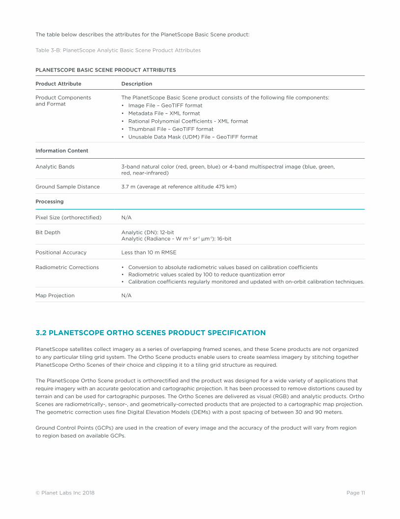
The table below describes the attributes for the PlanetScope Basic Scene product:
Table 3-B: PlanetScope Analytic Basic Scene Product Attributes
PLANETSCOPE BASIC SCENE PRODUCT ATTRIBUTES
Product Attribute Description
Product Components and Format
The PlanetScope Basic Scene product consists of the following file components:• Image File – GeoTIFF format• Metadata File – XML format• Rational Polynomial Coefficients - XML format• Thumbnail File – GeoTIFF format• Unusable Data Mask (UDM) File – GeoTIFF format
Information Content
Analytic Bands 3-band natural color (red, green, blue) or 4-band multispectral image (blue, green, red, near-infrared)
Ground Sample Distance 3.7 m (average at reference altitude 475 km)
Processing
Pixel Size (orthorectified) N/A
Bit Depth Analytic (DN): 12-bitAnalytic (Radiance - W m-2 sr-1 μm-1): 16-bit
Positional Accuracy Less than 10 m RMSE
Radiometric Corrections • Conversion to absolute radiometric values based on calibration coefficients• Radiometric values scaled by 100 to reduce quantization error• Calibration coefficients regularly monitored and updated with on-orbit calibration techniques.
Map Projection N/A
3.2 PLANETSCOPE ORTHO SCENES PRODUCT SPECIFICATION
PlanetScope satellites collect imagery as a series of overlapping framed scenes, and these Scene products are not organized to any particular tiling grid system. The Ortho Scene products enable users to create seamless imagery by stitching together PlanetScope Ortho Scenes of their choice and clipping it to a tiling grid structure as required.
The PlanetScope Ortho Scene product is orthorectified and the product was designed for a wide variety of applications that require imagery with an accurate geolocation and cartographic projection. It has been processed to remove distortions caused by terrain and can be used for cartographic purposes. The Ortho Scenes are delivered as visual (RGB) and analytic products. Ortho Scenes are radiometrically-, sensor-, and geometrically-corrected products that are projected to a cartographic map projection. The geometric correction uses fine Digital Elevation Models (DEMs) with a post spacing of between 30 and 90 meters.
Ground Control Points (GCPs) are used in the creation of every image and the accuracy of the product will vary from region to region based on available GCPs.

Page 12© Planet Labs Inc 2018
The table below describes the attributes for the PlanetScope Ortho Scene product:
Table 3-C: PlanetScope Ortho Scene Product Attributes
PLANETSCOPE ORTHO SCENE PRODUCT ATTRIBUTES
Product Attribute Description
Product Components and Format
PlanetScope Ortho Scene product consists of the following file components:• Image File – GeoTIFF format• Metadata File – XML format• Thumbnail File – GeoTIFF format• Unusable Data Mask (UDM) file – GeoTIFF format
Product Orientation Map North up
Product Framing Scene Based
Pixel Size (orthorectified) 3.125 m
Bit Depth Visual: 8-bit | Analytic (DN): 12-bitAnalytic (Radiance - W m-2 sr-1 μm-1): 16-bit
Product Size Nominal scene size is approximately 24 km by 7 km, but varies by altitude.
Geometric Corrections Sensor-related effects are corrected using sensor telemetry and a sensor model. Orthorectification uses GCPs and fine DEMs (30 m to 90 m posting).
Horizontal Datum WGS84
Map Projection UTM
Resampling Kernel Cubic Convolution
3.2.1 PLANETSCOPE VISUAL ORTHO SCENE PRODUCT SPECIFICATION
The PlanetScope Visual Ortho Scene product is orthorectified and color-corrected (using a color curve). This correction attempts to optimize colors as seen by the human eye providing images as they would look if viewed from the perspective of the satellite. This product has been processed to remove distortions caused by terrain and can be used for cartographic mapping and visualization purposes. This correction also eliminates the perspective effect on the ground (not on buildings), restoring the geometry of a vertical shot. Additionally, a correction is made to the sun angle in each image to account for differences in latitude and time of acquisition.
The Visual Ortho Scene product is optimal for simple and direct use of an image. It is designed and made visually appealing for a wide variety of applications that require imagery with an accurate geolocation and cartographic projection. The product can be used and ingested directly into a Geographic Information System.
Table 3-D: PlanetScope Visual Ortho Scene Product Attributes
PLANETSCOPE VISUAL ORTHO SCENE PRODUCT ATTRIBUTES
Product Attribute Description
Information Content
Visual Bands 3-band natural color (red, green, blue)
Ground Sample Distance 3.7 m (average at reference altitude 475 km)
Processing
Pixel Size (orthorectified) 3.125 m
Bit Depth 8-bit
Geometric Corrections Sensor-related effects are corrected using sensor telemetry and a sensor model. Spacecraft-related effects are corrected using attitude telemetry and best available ephemeris data. Orthorectified using GCPs and fine DEMs (30 m to 90 m posting) to <10 m RMSE positional accuracy.
Positional Accuracy Less than 10 m RMSE
Color Enhancements Enhanced for visual use and corrected for sun angle
Page 13© Planet Labs Inc 2018
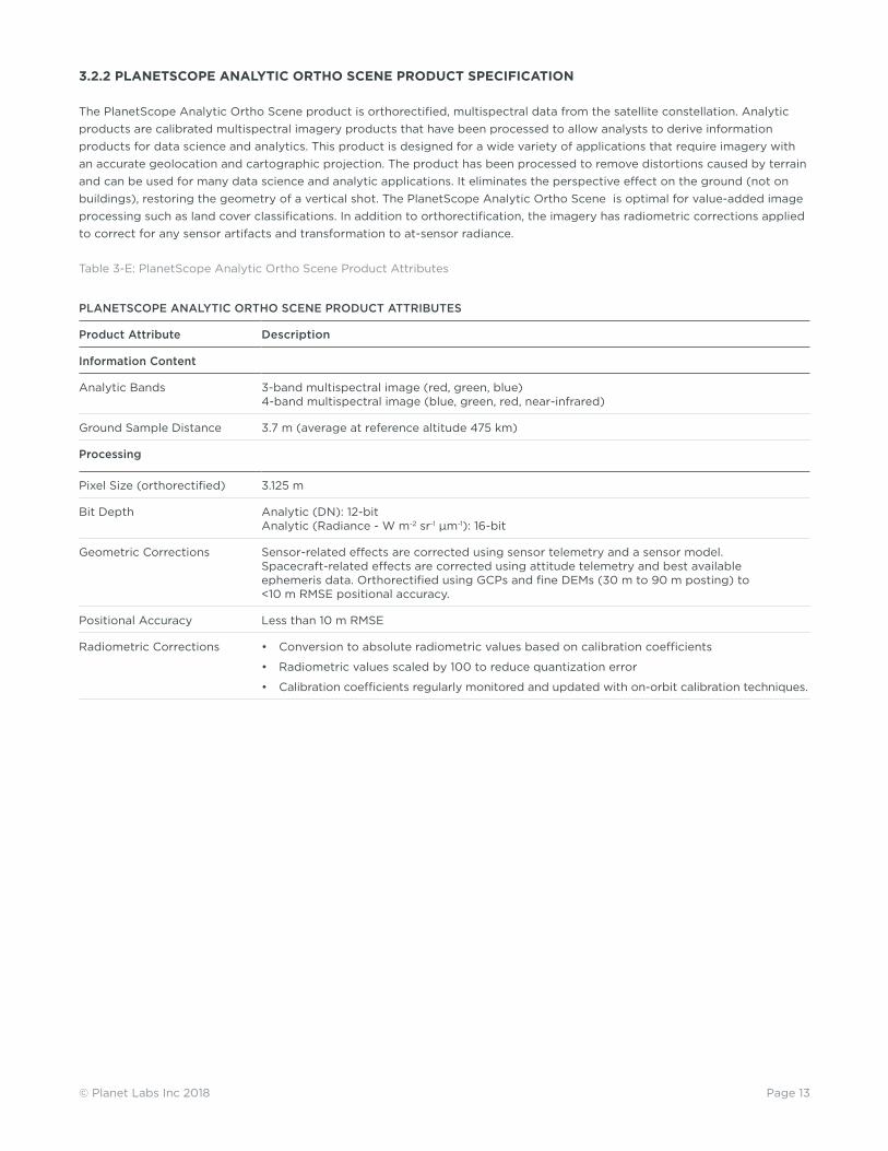
3.2.2 PLANETSCOPE ANALYTIC ORTHO SCENE PRODUCT SPECIFICATION
The PlanetScope Analytic Ortho Scene product is orthorectified, multispectral data from the satellite constellation. Analytic products are calibrated multispectral imagery products that have been processed to allow analysts to derive information products for data science and analytics. This product is designed for a wide variety of applications that require imagery with an accurate geolocation and cartographic projection. The product has been processed to remove distortions caused by terrain and can be used for many data science and analytic applications. It eliminates the perspective effect on the ground (not on buildings), restoring the geometry of a vertical shot. The PlanetScope Analytic Ortho Scene is optimal for value-added image processing such as land cover classifications. In addition to orthorectification, the imagery has radiometric corrections applied to correct for any sensor artifacts and transformation to at-sensor radiance.
Table 3-E: PlanetScope Analytic Ortho Scene Product Attributes
PLANETSCOPE ANALYTIC ORTHO SCENE PRODUCT ATTRIBUTES
Product Attribute Description
Information Content
Analytic Bands 3-band multispectral image (red, green, blue) 4-band multispectral image (blue, green, red, near-infrared)
Ground Sample Distance 3.7 m (average at reference altitude 475 km)
Processing
Pixel Size (orthorectified) 3.125 m
Bit Depth Analytic (DN): 12-bitAnalytic (Radiance - W m-2 sr-1 μm-1): 16-bit
Geometric Corrections Sensor-related effects are corrected using sensor telemetry and a sensor model. Spacecraft-related effects are corrected using attitude telemetry and best available ephemeris data. Orthorectified using GCPs and fine DEMs (30 m to 90 m posting) to <10 m RMSE positional accuracy.
Positional Accuracy Less than 10 m RMSE
Radiometric Corrections • Conversion to absolute radiometric values based on calibration coefficients
• Radiometric values scaled by 100 to reduce quantization error
• Calibration coefficients regularly monitored and updated with on-orbit calibration techniques.
Page 14© Planet Labs Inc 2018
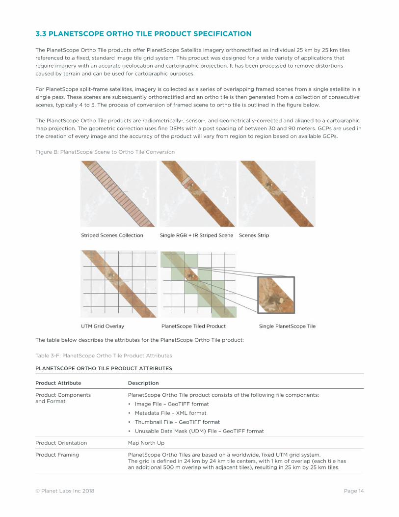
3.3 PLANETSCOPE ORTHO TILE PRODUCT SPECIFICATION
The PlanetScope Ortho Tile products offer PlanetScope Satellite imagery orthorectified as individual 25 km by 25 km tiles referenced to a fixed, standard image tile grid system. This product was designed for a wide variety of applications that require imagery with an accurate geolocation and cartographic projection. It has been processed to remove distortions caused by terrain and can be used for cartographic purposes.
For PlanetScope split-frame satellites, imagery is collected as a series of overlapping framed scenes from a single satellite in a single pass. These scenes are subsequently orthorectified and an ortho tile is then generated from a collection of consecutive scenes, typically 4 to 5. The process of conversion of framed scene to ortho tile is outlined in the figure below.
The PlanetScope Ortho Tile products are radiometrically-, sensor-, and geometrically-corrected and aligned to a cartographic map projection. The geometric correction uses fine DEMs with a post spacing of between 30 and 90 meters. GCPs are used in the creation of every image and the accuracy of the product will vary from region to region based on available GCPs.
Figure B: PlanetScope Scene to Ortho Tile Conversion
The table below describes the attributes for the PlanetScope Ortho Tile product:
Table 3-F: PlanetScope Ortho Tile Product Attributes
PLANETSCOPE ORTHO TILE PRODUCT ATTRIBUTES
Product Attribute Description
Product Components and Format
PlanetScope Ortho Tile product consists of the following file components:
• Image File – GeoTIFF format
• Metadata File – XML format
• Thumbnail File – GeoTIFF format
• Unusable Data Mask (UDM) File – GeoTIFF format
Product Orientation Map North Up
Product Framing PlanetScope Ortho Tiles are based on a worldwide, fixed UTM grid system. The grid is defined in 24 km by 24 km tile centers, with 1 km of overlap (each tile has an additional 500 m overlap with adjacent tiles), resulting in 25 km by 25 km tiles.

Page 15© Planet Labs Inc 2018
PLANETSCOPE ORTHO TILE PRODUCT ATTRIBUTES
Product Attribute Description
Pixel Size (orthorectified) 3.125 m
Bit Depth 16-bit
Product Size Tile size is 25 km (8000 lines) by 25 km (8000 columns). 5 to 500 Mbytes per Tile for 4 bands at 3.125 m pixel size after orthorectification.
Geometric Corrections Sensor-related effects are corrected using sensor telemetry and a sensor model. Orthorectified using GCPs and fine DEMs (30 m to 90 m posting).
Horizontal Datum WGS84
Map Projection UTM
Resampling Kernel Cubic Convolution
3.3.1 PLANETSCOPE VISUAL ORTHO TILE PRODUCT SPECIFICATION
The PlanetScope Visual Ortho Tile product is orthorectified and color-corrected (using a color curve). This correction attempts to optimize colors as seen by the human eye providing images as they would look if viewed from the perspective of the satellite. It has been processed to remove distortions caused by terrain and can be used for cartographic mapping and visualization purposes. It eliminates the perspective effect on the ground (not on buildings), restoring the geometry of a vertical shot. Additionally, a correction is made to the sun angle in each image to account for differences in latitude and time of acquisition.
The Visual product is optimal for simple and direct use of the image. It is designed and made visually appealing for a wide variety of applications that require imagery with an accurate geolocation and cartographic projection. The product can be used and ingested directly into a Geographic Information System.
Table 3-G: PlanetScope Visual Ortho Tile Product Attributes
PLANETSCOPE VISUAL ORTHO TILE PRODUCT ATTRIBUTES
Product Attribute Description
Information Content
Visual Bands 3-band natural color (red, green, blue)
Ground Sample Distance 3.7 m (average at reference altitude 475 km)
Processing
Pixel Size (orthorectified) 3.125 m
Bit Depth 8-bit
Geometric Corrections Sensor-related effects are corrected using sensor telemetry and a sensor model, bands are co-registered, and spacecraft-related effects are corrected using attitude telemetry and best available ephemeris data. Orthorectified using GCPs and fine DEMs (30 m to 90 m posting) to < 10 m RMSE positional accuracy.
Positional Accuracy Less than 10 m RMSE
Color Enhancements Enhanced for visual use and corrected for sun angle

Page 16© Planet Labs Inc 2018
3.3.2 PLANETSCOPE ANALYTIC ORTHO TILE PRODUCT SPECIFICATION
The PlanetScope Analytic Ortho Tile product is orthorectified, multispectral data from the satellite constellation. Analytic products are calibrated multispectral imagery products that have been processed to allow analysts to derive information products for data science and analytics. This product is designed for a wide variety of applications that require imagery with an accurate geolocation and cartographic projection. It has been processed to remove distortions caused by terrain and can be used for many data science and analytic applications. It eliminates the perspective effect on the ground (not on buildings), restoring the geometry of a vertical shot. The orthorectified visual imagery is optimal for value-added image processing including vegetation indices, land cover classifications, etc. In addition to orthorectification, the imagery has radiometric corrections applied to correct for any sensor artifacts and transformation to scaled at-sensor radiance.
Figure C: PlanetScope Analytic Ortho Tiles with RGB (left) and NIR False-Color Composite (right)
Table 3-H: PlanetScope Analytic Ortho Tile Product Attributes
PLANETSCOPE ANALYTIC ORTHO TILE PRODUCT ATTRIBUTES
Product Attribute Description
Information Content
Analytic Bands 4-band multispectral image (blue, green, red, near-infrared)
Ground Sample Distance 3.7 m (average at reference altitude 475 km)
Processing
Pixel Size (orthorectified) 3.125 m
Bit Depth Analytic (DN): 12-bitAnalytic (Radiance - W m-2 sr-1 μm-1): 16-bit
Geometric Corrections Sensor-related effects are corrected using sensor telemetry and a sensor model, bands are co-registered, and spacecraft-related effects are corrected using attitude telemetry and best available ephemeris data. Orthorectified using GCPs and fine DEMs (30 m to 90 m posting) to <10 m RMSE positional accuracy.
Positional Accuracy Less than 10 m RMSE
Radiometric Corrections • Conversion to absolute radiometric values based on calibration coefficients
• Radiometric values scaled by 100 to reduce quantization error
• Calibration coefficients regularly monitored and updated with on-orbit calibration techniques.

Page 17© Planet Labs Inc 2018
Figure D: PlanetScope Analytic Bands
bare dense/healthysparse/unhealthy

Page 18© Planet Labs Inc 2018
4. RAPIDEYE IMAGERY PRODUCTS
RapidEye imagery products are available in two different processing levels to be directly applicable to customer needs.
Table 4-A: RapidEye Satellite Image Product Processing Levels
RAPIDEYE SATELLITE IMAGE PRODUCT PROCESSING LEVELS
Name Description Product Level
RapidEye Basic Scene Product Radiometric and sensor corrections applied to the data. On-board spacecraft attitude and ephemeris applied to the data.
Level 1B
RapidEye Ortho Tile Product Radiometric and sensor corrections applied to the data. Imagery is orthorectified using the RPCs and an elevation model.
Level 3A
The name of each acquired RapidEye image is designed to be unique and allow for easier recognition and sorting of the imagery. It includes the date and time of capture, as well as the id of the satellite that captured it. The name of each downloaded image product is composed of the following elements:
RapidEye Ortho Tiles:
<tileid>_<acquisition_date>_<satellite_id>_<productLevel>_<productType>.<extension>
RapidEye Basic Scenes:
<acquisition_date>T<acquisition_time>_<satellite_id>_<productLevel>_<productType>.<extension>
4.1 RAPIDEYE BASIC SCENE PRODUCT SPECIFICATION
RapidEye Basic product is the least processed of the available RapidEye imagery products. This product is designed for customers with advanced image processing capabilities and a desire to geometrically correct the product themselves. This product line will be available in GeoTIFF and NITF formats.
The RapidEye Basic Scene product is radiometrically- and sensor-corrected, providing imagery as seen from the spacecraft without correction for any geometric distortions inherent in the imaging process, and is not mapped to a cartographic projection. The imagery data is accompanied by all spacecraft telemetry necessary for the processing of the data into a geo-corrected form, or when matched with a stereo pair, for the generation of digital elevation data. Resolution of the images is 6.5 meters GSD at nadir. The images are resampled to a coordinate system defined by an idealized basic camera model for band alignment. The radiometric corrections applied to this product are:• Correction of relative differences of the radiometric response between detectors• Non-responsive detector filling which fills null values from detectors that are no longer responding• Conversion to absolute radiometric values based on calibration coefficients
The geometric sensor corrections applied to this product correct for:
• Internal detector geometry which combines the two sensor chipsets into a virtual array
• Optical distortions caused by sensor optics
• Registration of all bands together to ensure all bands line up with each other correctly

Page 19© Planet Labs Inc 2018
The table below lists the product attributes for the RapidEye Basic Scene product.
Table 4-B: RapidEye Basic Scene Product Attributes
RAPIDEYE BASIC SCENE PRODUCT ATTRIBUTES
Product Attribute Description
Product Components and Format
RapidEye Basic Scene product consists of the following file components:
• Image File – Image product delivered as a group of single-band NITF or GeoTIFF files with associated RPC values. Bands are co-registered.
• Metadata File – XML format metadata file and GeoJSON metadata available
• Unusable Data Mask (UDM) File – GeoTIFF format
• Spacecraft information (SCI) file - XML format and contains additional information related to spacecraft attitude, spacecraft ephemeris, spacecraft temperature measurements, line imaging times, camera geometry, and radiometric calibration data.
• Browse Image - GeoTIFF format
Product Orientation Spacecraft/Sensor Orientation
Product Framing
Geographic based framing – a geographic region is defined by two corners. The product width is close to the full image swath as observed by all bands (77 km at nadir, subject to minor trimming of up to 3 km during processing) with a product length that does not exceed 300 km with a minimum length of 50 km and around a 10km overlap.
Geographic perspective Image perspective
Ground Sample Distance (nadir) 6.5 m
Bit Depth 16-bit unsigned integers
Pixel Size (orthorectified) 6.5m at Nadir
Geometric Corrections Idealized sensor, orbit and attitude models. Bands are co-registered.
Horizontal Datum WGS84
Map Projection N/A
Resampling Kernel Cubic Convolution

Page 20© Planet Labs Inc 2018
4.2 RAPIDEYE ORTHO TILE PRODUCT SPECIFICATION
The RapidEye Ortho Tile products offer RapidEye Satellite imagery orthorectified as individual 25 km by 25 km tiles. This product was designed for a wide variety of applications that require imagery with an accurate geolocation and cartographic projection. It has been processed to remove distortions caused by terrain and can be used for many cartographic purposes.
The RapidEye Ortho Tile products are radiometrically-, sensor- and geometrically-corrected and aligned to a cartographic map projection. The geometric correction uses fine DEMs with a post spacing of between 30 and 90 meters. GCPs are used in the creation of every image and the accuracy of the product will vary from region to region based on available GCPs. RapidEye Ortho Tile products are output as 25 km by 25 km tiles referenced to a fixed, standard RapidEye image tile grid system.
The table below lists the product attributes for the RapidEye Ortho Tile product.
Table 4-C: RapidEye Ortho Tile Product Attributes
RAPIDEYE ORTHO TILE PRODUCT ATTRIBUTES
Product Attribute Description
Product Components and Format
RapidEye Ortho Tile product consists of the following file components:
• Image File – GeoTIFF file that contains image data and geolocation information
• Metadata File – XML format metadata file and GeoJSON metadata available
• Unusable Data Mask (UDM) File – GeoTIFF format
Product Orientation Map North Up
Product Framing RapidEye Ortho Tiles are based on a worldwide, fixed UTM grid system. The grid is defined in 24 km by 24 km tile centers, with 1 km of overlap (each tile has an additional 500 m overlap with adjacent tiles), resulting in 25 km by 25 km tiles.
Pixel Size (orthorectified) 5 m
Bit Depth Visual: 8-bitAnalytic (Radiance - W m-2 sr-1 μm-1): 16-bit
Product Size Tile size is 25 km (5000 lines) by 25 km (5000 columns). 250 Mbytes per Tile for 5 bands at 5 m pixel size after orthorectification.
Geometric Corrections Sensor-related effects are corrected using sensor telemetry and a sensor model, bands are co-registered, and spacecraft-related effects are corrected using attitude telemetry and best available ephemeris data. Orthorectified using GCPs and fine DEMs (30 m to 90 m posting).
Horizontal Datum WGS84
Map Projection UTM
Resampling Kernel Cubic Convolution
4.2.1 RAPIDEYE VISUAL ORTHO TILE PRODUCT SPECIFICATION
The RapidEye Visual Ortho Tile product is orthorectified and color-corrected (using a color curve). This correction attempts to optimize colors as seen by the human eye providing images as they would look if viewed from the perspective of the satellite. It has been processed to remove distortions caused by terrain and can be used for cartographic mapping and visualization purposes. It eliminates the perspective effect on the ground (not on buildings), restoring the geometry of a vertical shot. Additionally, a correction is made to the sun angle in each image to account for differences in latitude and time of acquisition.
The Visual product is optimal for simple and direct use of the image. It is designed and made visually appealing for a wide variety of applications that require imagery with an accurate geolocation and cartographic projection. The product can be used and ingested directly into a Geographic Information System.

Page 21© Planet Labs Inc 2018
Below is a sample of a RapidEye Visual Ortho Tile:
Figure E: RapidEye Visual Ortho Tile
Table 4-D: RapidEye Visual Ortho Tile Product Attributes
RAPIDEYE VISUAL ORTHO TILE PRODUCT ATTRIBUTES
Product Attribute Description
Information Content
Visual Bands 3-band natural color (red, green, blue)
Ground Sample Distance 6.5 m (at reference altitude 630 km)
Processing
Pixel Size (orthorectified) 5 m
Bit Depth 8-bit
Geometric Corrections Sensor-related effects are corrected using sensor telemetry and a sensor model, ban are co-registered, and spacecraft-related effects are corrected using attitude telemetry and best available ephemeris data. Orthorectified using GCPs and fine DEMs (30 m to 90 m posting) to < 10 m RMSE positional accuracy.
Positional Accuracy Less than 10 m RMSE
Radiometric Corrections • Correction of relative differences of the radiometric response between detectors.
• Non-responsive detector filling which fills nulls values from detectors that are no longer responding.
• Conversion to absolute radiometric values based on calibration coefficients.
Color Enhancements Enhanced for visual use and corrected for sun angle

Page 22© Planet Labs Inc 2018
4.2.2 RAPIDEYE ANALYTIC ORTHO TILE PRODUCT SPECIFICATION
The RapidEye Analytic Ortho Tile product is orthorectified, multispectral data from the RapidEye satellite constellation. This product is designed for a wide variety of applications that require imagery with an accurate geolocation and cartographic projection. It has been processed to remove distortions caused by terrain and can be used for many data science and analytic applications. It eliminates the perspective effect on the ground (not on buildings), restoring the geometry of a vertical shot. The orthorectified imagery is optimal for value-added image processing including vegetation indices, land cover classifications, etc. In addition to orthorectification, the imagery has radiometric corrections applied to correct for any sensor artifacts and transformation to at-sensor radiance.
Table 4-E: RapidEye Analytic Ortho Tile Product Attributes
RAPIDEYE ANALYTIC ORTHO TILE PRODUCT ATTRIBUTES
Product Attribute Description
Information Content
Analytic Bands 5-band multispectral image (blue, green, red, red edge, near-infrared)
Ground Sample Distance 6.5 m (at reference altitude 630 km)
Processing
Pixel Size (orthorectified) 5 m
Bit Depth 16-bit
Geometric Corrections Sensor-related effects are corrected using sensor telemetry and a sensor model, bands are co-registered, and spacecraft-related effects are corrected using attitude telemetry and best available ephemeris data. Orthorectified using GCPs and fine DEMs (30 m to 90 m posting) to < 10 m RMSE positional accuracy.
Positional Accuracy Less than 10 m RMSE
Radiometric Corrections • Correction of relative differences of the radiometric response between detectors.
• Non-responsive detector filling which fills nulls values from detectors that are no longer responding.
• Conversion to absolute radiometric values based on calibration coefficients.

Page 23© Planet Labs Inc 2018
5. SKYSAT IMAGERY PRODUCTS
5.1 SKYSAT BASIC SCENE PRODUCT SPECIFICATION
The SkySat Basic Scene product includes Analytic and Panchromatic imagery that is uncalibrated and in a raw digital number format. The Basic Scene Product is not radiometrically corrected for atmosphere or for any geometric distortions inherent in the imaging process.
Imagery data is accompanied by Rational Polynomial Coefficients (RPCs) to enable orthorectification by the user. This product is designed for users with advanced image processing capabilities and a desire to geometrically correct the product themselves.
The SkySat Basic Scene Product has a sensor-based framing, and is not mapped to a cartographic projection.
Table 5-A: SkySat Basic Scene Product Attributes
SKYSAT BASIC SCENE PRODUCT ATTRIBUTES
Product Attribute Description
Product Components and Format
Image File – GeoTIFF format
Metadata File – JSON format
Rational Polynomial Coefficients – Text File
UDM File – GeoTIFF format
Information Content
Image Configurations 4-band Analytic DN Image (Blue, Green, Red, NIR)
1-band Panchromatic DN Image (Pan)
Product Orientation Spacecraft/Sensor Orientation
Product Framing SkySat Satellites have three cameras per satellite, which capture overlapping strips. Each of these strips contain overlapping scenes. One scene is approximately 3199m x 1349m.
Sensor Type CMOS Frame Camera with Panchromatic and Multispectral halves
Spectral Bands Blue Green Red NIR Pan
450 – 515 nm 515 – 595 nm 605 – 695 nm 740 – 900 nm 450 – 900 nm
Processing Basic Scene v0 (Aug 1, 2017) Basic Scene v1 (Sep 15, 2017)
Product Bit Depth 16-bit Unsigned Integer Multispectral and Panchromatic Imagery (12 bit data depth)
Radiometric Corrections Cross-Sensor Non Uniformity Correction (1%)Color Balancing across cameras
Geometric Corrections Idealized sensor model and Rational Polynomial Coefficients (RPC) Bands are co-registered
Horizontal Datum WGS84
Map Projection N/A
Resampling Kernel Resampling of Analytic Data to > 1.0 m GSD Resampling of Analytic Multispectral Data to > 1.0 m GSD
Ground Sample Distance [SkySat-1, SkySat-2] Panchromatic: 0.86 m
Multispectral: 1.0 m
[SkySat-3 - SkySat-7]
Panchromatic: 0.72 m
Multispectral: 1.0 m
[SkySat-1, SkySat-2] Panchromatic: 0.86 m
Multispectral: 1.0 m
[SkySat-3 - SkySat-7] Panchromatic: 0.72 m
Multispectral: 1.0 m
Geometric Accuracy < 90 m RMSE

Page 24© Planet Labs Inc 2018
5.2 SKYSAT ORTHO SCENE PRODUCT SPECIFICATION
The Ortho Scene product enables users to create seamless imagery by stitching together SkySat Ortho Scenes of their choice and clipping them to a tiling grid structure as required. The SkySat Ortho Scene product is orthorectified and the product was designed for a wide variety of applications that require imagery with an accurate geolocation and cartographic projection. It has been processed to remove distortions caused by terrain and can be used for cartographic purposes.
The SkySat Ortho Scene product includes Visual, Analytic, Panchromatic, and Pansharpened Multispectral imagery that is uncalibrated and in a raw digital number format. The Ortho Scene product is sensor- and geometrically-corrected, and is projected to a cartographic map projection. The geometric correction uses fine Digital Elevation Models (DEMs) with a post spacing of between 30 and 90 meters.
Ground Control Points (GCPs) are used in the creation of every image and the accuracy of the product will vary from region to region based on available GCPs.
Table 5-B: SkySat Ortho Scene Attributes
SKYSAT ORTHO SCENE PRODUCT ATTRIBUTES
Product Attribute Description
Product Components and Format
Image File – GeoTIFF formatMetadata File – JSON formatUDM File – GeoTIFF format
Information Content
Product Framing Scene Based: SkySat Satellites have three cameras per satellite, which capture overlapping strips. Each of these strips contain overlapping scenes. One scene is approximately 3199 m x 1349 m.
Sensor Type CMOS Frame Camera with Panchromatic and Multispectral halves
Spectral Bands Blue Green Red NIR Pan
450 – 515 nm 515 – 595 nm 605 – 695 nm 740 – 900 nm 450 – 900 nm
Processing Ortho Scene v0 (Sep 15, 2017) Ortho Scene v1 (Jun 1, 2018)
Radiometric Corrections No correction applied; pixel values are digital numbers
Digital Number and TOA Reflectance
Geometric Corrections Sensor-related effects are corrected using sensor telemetry and a sensor model. Orthorectification uses GCPs and fine DEMs (30 m to 90 m posting).
Horizontal Datum WGS84 WGS84
Map Projection UTM UTM
Resampling Kernel Cubic Convolution Cubic Convolution
Geometric Accuracy < 10 m RMSE < 10 m RMSE
5.2.1 SKYSAT VISUAL ORTHO SCENE
The SkySat Visual Ortho Scene product is orthorectified, pansharpened, and color-corrected (using a color curve) 3-band RGB Imagery.
Table 5-C: SkySat Visual Ortho Scene Attribute
SKYSAT VISUAL ORTHO SCENE ATTRIBUTES
Product Attribute Description
Visual Bands Visual: 3-band Pansharpened Image (PS Red, PS Green, PS Blue)
Ground Sample Distance Multispectral: 1.0 m
Panchromatic: 0.72 m
Processing
Pixel Size (Orthorectified) 0.8 m*
Bit Depth 8-bit Unsigned Integer

Page 25© Planet Labs Inc 2018
SKYSAT VISUAL ORTHO SCENE ATTRIBUTES
Product Attribute Description
Geometric Corrections Sensor-related effects are corrected using sensor telemetry and a sensor model. Orthorectification uses GCPs and fine DEMs (30 m to 90 m posting).
Positional Accuracy Less than 10 m RMSE
Color Enhancements Enhanced for visual use
5.2.2 SKYSAT PANSHARPENED MULTISPECTRAL ORTHO SCENE
The SkySat Pansharpened Multispectral Scene product is orthorectified, pansharpened, and color-corrected (using a color curve) 4-band BGRN Imagery.
Table 5-D: SkySat Pansharpened Multispectral Ortho Scene Attributes
SKYSAT PANSHARPENED MULTISPECTRAL ORTHO SCENE ATTRIBUTES
Product Attribute Description
Visual Bands Visual: 4-band Pansharpened Image (PS Red, PS Green, PS Blue, PS Near Infrared)
Ground Sample Distance Multispectral: 1.0 m
Panchromatic: 0.72 m
Processing
Pixel Size (Orthorectified) 0.8 m
Bit Depth 8-bit Unsigned Integer
Geometric Corrections Sensor-related effects are corrected using sensor telemetry and a sensor model. Orthorectification uses GCPs and fine DEMs (30 m to 90 m posting).
Positional Accuracy Less than 10 m RMSE
Color Enhancements Enhanced for visual use
5.2.3 SKYSAT ANALYTIC DN ORTHO SCENE
The SkySat Analytic DN Ortho Scene product is orthorectified, multispectral data from the SkySat constellation. The Analytic DN product is an uncalibrated, digital number imagery product. This product is designed for a wide variety of applications that require imagery with an accurate geolocation and cartographic projection. The product has been processed to remove distortions caused by terrain. It eliminates the perspective effect on the ground (not on buildings), restoring the geometry of a vertical shot. In addition to orthorectification, the imagery has radiometric corrections applied to correct for any sensor artifacts. The initial availability does not include transformation to at-sensor radiance.
Table 5-E: SkySat Analytic DN Ortho Scene Attributes
SKYSAT ANALYTIC DN ORTHO SCENE ATTRIBUTES
Product Attribute Description
Analytic Bands 4-band Analytic DN Image (B, G, R, N)
Ground Sample Distance 1 m
Processing
Pixel Size (Orthorectified) 1 m
Bit Depth 16-bit Unsigned Integer (12 bit data depth)
Geometric Corrections Sensor-related effects are corrected using sensor telemetry and a sensor model. Orthorectification uses GCPs and fine DEMs (30 m to 90 m posting).
Positional Accuracy Less than 10 m RMSE
Radiometric Calibration Accuracy Initial availability: No correction applied; pixel values are digital numbers

Page 26© Planet Labs Inc 2018
5.2.4 SKYSAT PANCHROMATIC DN ORTHO SCENE
The SkySat Panchromatic Ortho Scene product is orthorectified, panchromatic data from the SkySat constellation. The Panchromatic DN product is an uncalibrated, digital number imagery product. The Panchromatic product has a finer GSD than the Analytic Product due to NOAA license restrictions, and is useful for visual interpretation as well as pan-sharpening of coarser resolution Multispectral data. The initial availability does not include transformation to at-sensor radiance.
Table 5-F: SkySat Panchromatic Ortho Scene Attributes
SKYSAT PANCHROMATIC ORTHO SCENE ATTRIBUTES
Product Attribute Description
Analytic Bands 1-band Panchromatic Image
Ground Sample Distance 0.72 m
Processing
Pixel Size (Orthorectified) 0.8 m
Bit Depth 16-bit Unsigned Integer (12 bit data depth)
Geometric Corrections Sensor-related effects are corrected using sensor telemetry and a sensor model. Orthorectification uses GCPs and fine DEMs (30 m to 90 m posting).
Positional Accuracy Less than 10 m RMSE
Radiometric Calibration Accuracy Initial availability: No correction applied: pixel values are digital numbers

Page 27© Planet Labs Inc 2018
6. OTHER PROVIDER IMAGERY PRODUCTS
Planet provides access to two other freely available datasets: Landsat 8, operated by the NASA and the United States Geological Survey, and Sentinel-2, operated by the European Space Agency. The goal is to make these products easily available to Planet users to augment their analyses.
6.1 LANDSAT 8 PRODUCT SPECIFICATION
For detailed characteristics of the Landsat 8 sensor and mission please refer to the official Landsat 8 documentation which can be found here: https://landsat.usgs.gov/landsat-8
Table 6-A: Landsat 8 data properties
LANDSAT 8 L1G PRODUCT ATTRIBUTE
Product Attribute Description
Information Content
Analytic Bands
Pan Band 8
Visible, NIR, SWIR Band 1 - 7 and Band 9 (Coastal/Aerosol, Blue, Green, Red, NIR, SWIR 1, SWIR 2, Cirrus)
TIR Band 10, 11 (TIR-1, TIR-2)
Processing
Pixel Size
Pan 15 m
Visible, NIR, SWIR 30 m
TIR 100 m
Bit Depth 12-bit data depth, distributed as 16-bit data for easier processing
Geometric Corrections The Geometric Processing Subsystem (GPS) creates L1 geometrically corrected imagery (L1G) from L1R products. The geometrically corrected products can be systematic terrain corrected (L1Gt) or precision terrain-corrected products (L1T). The GPS generates a satellite model, prepares a resampling grid, and resamples the data to create an L1Gt or L1T product. The GPS performs sophisticated satellite geometric correction to create the image according to the map projection and orientation specified for the L1 standard product.
Positional Accuracy 12 m CE90
Radiometric Corrections • Converts the brightness of the L0R image pixels to absolute radiance in preparation for geometric correction.
• Performs radiometric characterization of L0R images by locating radiometric artifacts in images.
• Corrects radiometric artifacts and converts the image to radiance.
Metadata Landsat 8 MTL text file

Page 28© Planet Labs Inc 2018
6.2 SENTINEL-2 PRODUCT SPECIFICATION
For detailed characteristics of the Sentinel-2 sensor and mission please refer to the official Sentinel-2 documentation which can be found here: https://earth.esa.int/web/sentinel/user-guides/sentinel-2-msi/product-types/level-1c
Table 6-B: Sentinel-2 Data Properties
SENTINAL-2 LEVEL 1C PRODUCT ATTRIBUTE
Product Attribute Description
Information Content
Analytic Bands
Visible, NIR 4 bands at 10 m: blue (490 nm), green (560 nm), red (665 nm) and near infrared (842 nm).
RedEdge and NIR 4 narrow bands for vegetation characterisation (705 nm, 740 nm, 783 nm and 865 nm)
SWIR 2 larger SWIR bands (1610 nm and 2190 nm)
Aerosol, Water Vapor, Cirrus 443 nm for aerosols, 945 for water vapour and 1375 nm for cirrus detection
Processing
Pixel Size
Visible, NIR (4 bands) 10 m
RedEdge, NIR (6 bands) 20 m
SWIR (2 bands) 20 m
Cirrus, Aerosol, Water Vapor (3 bands)
60 m
Bit Depth 12
Geometric Corrections • Resampling on the common geometry grid for registration between the Global Reference Image (GRI) and the reference band.
• Collection of the tie-points from the two images for registration between the GRI and the reference band.
• Tie-points filtering for image-GRI registration: filtering of the tie-points over several areas. A minimum number of tie-points is required.
• Refinement of the viewing model using the initialised viewing model and GCPs. The output refined model ensures registration between the GRI and the reference band.
• Resampling grid computation: enabling linking of the native geometry image to the target geometry image (ortho-rectified).
• Resampling of each spectral band in the geometry of the ortho-image using the resampling grids and an interpolation filter.
Positional Accuracy 20 m 2σ without GCPs; 12.5 m 2σ with GCPs
Radiometric Corrections • Dark Signal Correction
• Pixel Response non-uniformity correction
• Crosstalk correction
• Defective pixels identification
• High Spatial resolution bands restoration (deconvolution and de-noising)
• Binning of the 60m spectral bands
• TOA reflectance calculation
MetaData/Data Structure • Level-1C_Tile_Metadata_File (Tile Metadata): XML main metadata file (DIMAP mandatory file) containing the requested level of information and referring all the product elements describing the tile.
• IMG_DATA: folder containing image data files compressed using the JPEG2000 algorithm, one file per band.
• QI_DATA: folder containing QLQC XML reports of quality checks, mask files and PVI files.
• Inventory_Metadata.xml: inventory metadata file (mandatory).
• manifest.safe: XML SAFE manifest file (Mandatory)
• rep-info: folder containing the XSD schema provided inside a SAFE Level-0 granule

Page 29© Planet Labs Inc 2018
7. PRODUCT PROCESSING
7.1 PLANETSCOPE PROCESSING
Several processing steps are applied to PlanetScope imagery products, listed in the table below.
Table 7-A: PlanetScope Processing Steps
PLANETSCOPE PROCESSING STEPS
Step Description
Darkfield/Offset Correction
Corrects for sensor bias and dark noise. Master offset tables are created by averaging on-orbit darkfield collects across 5-10 degree temperature bins and applied to scenes during processing based on the CCD temperature at acquisition time.
Flat Field Correction Flat fields are collected for each optical instrument prior to launch. These fields are used to correct image lighting and CCD element effects to match the optimal response area of the sensor.
Camera Acquisition Parameter Correction
Determines a common radiometric response for each image (regardless of exposure time, TDI, gain, camera temperature and other camera parameters).
Absolute Calibration As a last step, the spatially and temporally adjusted datasets are transformed from digital number values into physical based radiance values (scaled to W/(m²*str*μm)*100).
Visual Product Processing
Presents the imagery as natural color, optimize colors as seen by the human eye. This process is broken down into 4 steps:
• Flat fielding applied to correct for vignetting.
• Nominalization - Sun angle correction, to account for differences in latitude and time of acquisition. This makes the imagery appear to look like it was acquired at the same sun angle by converting the exposure time to the nominal time (noon).
• Two filters applied: an unsharp mask for improving local dynamic range, and a sharpening filter for accentuating spatial features.
• Custom color curve applied post warping.
Orthorectification Removes terrain distortions. This process is broken down into 2 steps:
• The rectification tiedown process wherein tie points are identified across the source images and a collection of reference images (NAIP, OSM, Landsat, and high resolution image chips) and RPCs are generated.
• The actual orthorectification of the scenes using the RPCs, to remove terrain distortions. The terrain model used for the orthorectification process is derived from multiple sources (SRTM, Intermap, and other local elevation datasets) which are periodically updated. Snapshots of the elevation datasets used are archived (helps in identifying the DEM that was used for any given scene at any given point.

Page 30© Planet Labs Inc 2018
The figure below illustrates the processing chain and steps involved to generate each of PlanetScope’s imagery products.
Figure F: PlanetScope Image Processing Chain

Page 31© Planet Labs Inc 2018
7.2 RAPIDEYE PROCESSING
For RapidEye imagery products, the processing steps are listed in the table below.
Table 7-B: RapidEye Processing Steps
RAPIDEYE PROCESSING STEPS
Step Description
Flat Field Correction (also referred to as spatial calibration)
Correction parameters to achieve the common response of all CCD element when exposed to the same amount of light have been collected for each optical instrument prior to launch. During opera-tions, these corrections are adjusted on an as-needed basis when effects become visible or measur-able using side slither or statistical methods. This step additionally involves statistical adjustments of the read-out channel gains and offsets on a per image basis.
Temporal Calibration Corrections are applied so that all RapidEye cameras read the same DN (digital number) regardless of when the image has been taken in the mission lifetime. Additionally with this step a cross calibration between all spacecraft is achieved.
Absolute Calibration As a last step the spatially and temporally adjusted datasets are transformed from digital number val-ues into physical based radiance values (scaled to W/(m²*str*µm)*100).
Visual Product Processing
Presents the imagery as natural color, optimize colors as seen by the human eye. This process is broken down into 3 steps:
• Nominalization - Sun angle correction, to account for differences in latitude and time of acquisition. This makes the imagery appear to look like it was acquired at the same sun angle by converting the exposure time to the nominal time (noon).
• Unsharp mask (sharpening filter) applied before the warp process.
• Custom color curve applied post warping.
Orthorectification Removes terrain distortions. This process is broken down into 2 steps:
• The rectification tiedown process wherein tie points are identified across the source images and a collection of reference images (NAIP, OSM, Landsat, and high resolution image chips) and RPCs are generated.
• The actual orthorectification of the scenes using the RPCs, to remove terrain distortions. The terrain model used for the orthorectification process is derived from multiple sources (SRTM, Intermap, and other local elevation datasets) which are periodically updated. Snapshots of the elevation datasets used are archived (helps in identifying the DEM that was used for any given scene at any given point.
The figure below illustrates the processing chain and steps involved to generate each of RapidEye’s imagery products.
Figure G: RapidEye Image Processing Chain
STRIP OUT NIR & RE
RAW DATA
IMAGE PROCESSING CHAIN
GCP PRE-MARKING & GEO-LOCATIONAL REFINEMENT
Image Take CatalogingCLOUD ASSESSMENT
SENSOR & RADIOMETRIC CALIBRATION
BAND CO-REGISTRATION
ORTHORECTIFICATION (REMOVE TERRAIN DISTORTIONS)
Imagery Imagery
Radiometric Improvements:Color Curve Applied
VISUAL ORTHO TILE PRODUCT
ANALYTIC ORTHO TILE PRODUCT
GCP Marking
Improved RPCs
RPCs
WGS84
UTM
Projections
BGR
B G R RE NIR
BASIC SCENEPRODUCTBASIC SCENEPRODUCT
B G R RE NIR

Page 32© Planet Labs Inc 2018
7.3 SKYSAT PROCESSING
For SkySat imagery products, the processing steps are listed in the table below.
Table 7-C: SkySat Processing Steps
SKYSAT PROCESSING STEPS
Step Description
Darkfield/Offset Correction Corrects for sensor bias and dark noise. Master offset tables are created by averaging ground calibration data collected across 5-10 degree temperature bins and applied to scenes during processing based on the CCD temperature at acquisition time.
Flat Field Correction Flat fields are created using cloud flats collected on-orbit post-launch. These fields are used to correct image lighting and CCD element effects to match the optimal response area of the sensor.
Camera Acquisition Parameter Correction
Determines a common radiometric response for each image (regardless of exposure time, TDI, gain, camera temperature and other camera parameters).
Inter Sensor Radiometric Response (Intra Camera)
Cross calibrates the 3 sensors in each camera to a common relative radiometric response. The offsets between each sensor is derived using on-orbit cloud flats and the overlap regions between sensors on SkySat spacecraft.
Super Resolution(Level 1B Processing)
A super resolved image, SR, is the process of creating an improved resolution image fusing information from low resolution images, with the created higher resolution image being a better description of the scene.
Visual Product Processing
Presents the imagery as natural color, optimizing colors as seen by the human eye. Custom color curves applied post warping to deliver a visually appealing image.
Orthorectification Removes terrain distortions. This process is broken down into 2 steps:
The rectification tiedown process wherein tie points are identified across the source images and a collection of reference images (NAIP, ALOS, Landsat, and high resolution image chips) and RPCs are generated. The actual orthorectification of the scenes using the RPCs, to remove terrain distortions. The terrain model used for the orthorectification process is derived from multiple sources (SRTM, Intermap, and other local elevation datasets) which are periodically updated. Snapshots of the elevation datasets used are archived (helps in identifying the DEM that was used for any given scene at any given point.
The figure below illustrates the processing chain and steps involved to generate each of SkySat’s imagery products.
Figure H: SkySat Image Processing Chain

Page 33© Planet Labs Inc 2018
8. QUALITY ATTRIBUTES
8.1 PRODUCT GEOMETRIC POSITIONAL ACCURACY
The locational accuracy of all the imagery products depends on the quality of the reference data used: Ground Control Points (GCPs) and Digital Elevation Model (DEMs). Additionally, the roll angle of the spacecraft during the image acquisition and the number as well as the distribution of GCPs within the image will impact the final product accuracy.
Planet utilizes a unique imagery rectification approach that minimizes processing steps to increase overall processing efficiency in preparation for the large amounts of imagery data that will be downloaded and rectified at Full Operational Capability (FOC). This approach reduces resampling steps through a proprietary parallel processing approach that enables moving from raw to orthorectified imagery without degradation of imagery quality.
To ensure the high accuracy of all of our ortho products on a global basis, Planet uses GCPs derived from high resolution satellite and airborne imagery. For most of Earth’s land mass, GCPs are derived from an ALOS 2.5 m resolution basemap. NAIP is used over the continental United States and Landsat 8 is used as a fallback solution over remote polar areas and some small islands.
The vertical component is derived from DEMs with a post spacing under 30 m globally. Planet products produced using GCPs and the World30 DEM will have a locational accuracy of 10 m RMSE or better. Internal testing conducted on multiple locations worldwide indicates that locational accuracy will typically (80% of the times) be better than 7 m RMSE.
8.2 CLOUD COVER
8.2.1 PLANETSCOPE AND SKYSAT
The cloud estimation for PlanetScope and the SkySats is based off of the expected radiance of pixels for a given time of year. A historical per-pixel database has been built from the Landsat 8 archive. If the radiance of a PlanetScope or SkySat pixel is significantly higher than expected for that time of year, the pixel is marked as ‘cloudy’.
This method is fast and simple, but has limitations:
1. If a region may be covered by snow at a given time of year, clouds are much less likely to be identified.2. Darker clouds are less likely to be identified. This includes both thin clouds and self-shadowed clouds.3. Brighter areas, such as desert surfaces, sands, and salt flats, are less likely to be identified as containing clouds.4. Specular reflection at noon local time are more likely to be marked as clouds.
8.2.2 RAPIDEYE
Cloud cover assessment for RapidEye image products is done at the cataloging stage for each image using a semi-automated process.
This process automatically applies a regular grid pattern of 1 km by 1 km over a reduced resolution image at a 50 meter pixel size. The algorithm computes a confidence value for each pixel in the Image Take in order to determine whether the pixel is a cloud or non-cloud pixel by thresholding the radiance values of the pixels within the red band of the image. Each grid cell is then tested to determine if the minimum number of cloudy pixels are present in the cell for it to be marked automatically as cloudy. Currently, at least 10 % of the pixels in a grid should be cloudy for a grid cell to be automatically classified as cloudy.
After the automatic cloud mask is generated the Image Take processing will stops for operator intervention. This allows the operator to visually inspect the cloud mask and edit it if necessary by either removing falsely classified grid cells or marking more grid cells as cloudy that were not identified and marked automatically as cloudy. When the operator is satisfied with the cloud mask, the Image Take is accepted and the cloud assessment process is complete.

Page 34© Planet Labs Inc 2018
The results from this process are used to create the Unusable Data Mask (UDM) file that accompanies every image product is used to determine whether each tile can be accepted or whether a new collection is required and the area re-tasked. This value is also used to report the cloud cover percentage value for the product in the Planet platform.
8.3 BAND CO-REGISTRATION
8.3.1 PLANETSCOPE
The RGB and the NIR “stripes” are 2 separate acquisitions (approximately 0.5 seconds apart). The imagery is first rectified to the ground and any adjacent rectified scenes with high accuracy. All tiepoints from this rectification solution (geographic and image coordinate tuples) are saved for future use. The Planet Pipeline is then able to quickly perform an operation similar to bundle adjustment over all scenes in a strip, optimizing for ground alignment and band co-registration. If one is familiar with the traditional bundle adjustment workflow, think of it as replacing the camera models with RPC equations, with the added benefit of ground tiepoints.
8.3.2 RAPIDEYE
The focal plane of the RapidEye sensors is comprised of five separate CCD arrays, one for each band. This means that the bands have imaging time differences of up to three seconds for the same point on the ground, with the blue and red bands being the furthest apart in time. During processing, every product is band co-registered using a DEM to roughly correlate the bands to the reference band (Red Edge); a final alignment is done using an auto-correlation approach between the bands. For areas where the slope is below 10°, the band co-registration should be within 0.2 pixels or less (1-sigma). For areas with a slope angle of more than 10° and/or areas with very limited image structure (e.g. sand dunes, water bodies, areas with significant snow cover) the co-registration threshold mentioned above may not be met.
The separation between the RapidEye spectral bands leads to some effects that can be seen in the imagery. In a regular RapidEye scene with clouds, the cloud may show a red-blue halo around the main cloud. This is due to the Red and Blue bands being furthest apart on the sensor array, and the cloud moving during the imaging time between the two bands. Also, clouds are not reflected within the DEM which may lead to mis-registration. The same effect is visible for jet exhaust trails and flying planes. Bright vehicles moving on the ground will also look like colored streaks due to the image time differences.
8.3.3 SKYSAT
Each SkySat has three sensors, each of which have a panchromatic and multispectral half. These halves are adjacent. The multispectral half is in turn a butcher block filter design consisting of red, green, blue and near infrared bands. From the optical system standpoint these CMOS sensors have a different vertical separation and have a small overlap in the horizontal dimension. The output of the image processing is the classic tuning fork.
The image processing is divided up into various steps and starts with the analysis of the panchromatic bands to determine a minimal set that can be effectively mosaicked, stipulating a degree of overlap between them. With state of the art processing, an accurate transform is derived between each of the frames to each other. These are further refined at a local level to enable subpixel super resolvability.
As with the RapidEye processing, there are characteristic artifacts seen in SkySat imagery, namely at the interfaces of clouds and moving vehicles. These reflect that the objects are moving relative to the ground. Beyond the generation of the imagery, the Planet Pipeline is utilized to bundle adjust the imagery and create ortho rectifications.

Page 35© Planet Labs Inc 2018
8.4 RADIOMETRY AND RADIOMETRIC ACCURACY
8.4.1 PLANETSCOPE
Significant effort is made to ensure radiometric image product quality of all PlanetScope Satellite Imagery Products. This is achieved through a vigorous sensor calibration concept that is based on lab calibration, regular checks of the statistics from all incoming image data, temporal monitoring using lunar calibration, and on-orbit absolute calibration using instantaneous crossovers with well calibrated satellites and vicarious campaigns.
Analytic Scene and Ortho Tiles are scaled to Top of Atmosphere Radiance using calibration data sourced either from pre-launch data or from absolute calibration data from on-orbit methods. Radiometric accuracy is maintained over time using monthly moon imaging by each satellite to detect temporal changes. Absolute calibration can be updated at any time if changes are detected - calibration data for each satellite is continually processed using instantaneous crossovers with well-calibrated satellites such as RapidEye and Landsat 8. Radiometric accuracy of the on-orbit calibration has been measured at 5% using vicarious collects in the Railroad Valley calibration site.
All PlanetScope satellite images are collected at a bit depth of 12 bits and stored on-board the satellites with a bit depth of up to 12 bits. During on-ground processing, radiometric corrections are applied and all images are scaled to a 16-bit dynamic range. This scaling converts the (relative) pixel DNs coming directly from the sensor into values directly related to absolute at sensor radiances. The scaling factor is applied to minimize quantization error and the resultant single DN values correspond to 1/100th of a W/(m²*sr*μm). The DNs of the PlanetScope image pixels represent the absolute calibrated radiance values for the image.
Converting to Radiance and Top of Atmosphere Reflectance
To convert the pixel values of the Analytic products to radiance, it is necessary to multiply the DN value by the radiometric scale factor, as follows:
RAD(i) = DN(i) * radiometricScaleFactor(i), where radiometricScaleFactor(i) = 0.01
The resulting value is the at sensor radiance of that pixel in watts per steradian per square meter (W/m²*sr*μm).
To convert the pixel values of the Analytic products to Top of Atmosphere Reflectance, it is necessary to multiply the DN value by the reflectance coefficient found in the XML file. This makes the complete conversion from DN to Top of Atmosphere Reflectance to be as follows:
REF(i) = DN(i) * reflectanceCoefficient(i)
8.4.2 RAPIDEYE
Significant effort is made to ensure radiometric image product quality of all RapidEye Satellite Imagery Products. This is achieved through a vigorous sensor calibration concept that is based on regular checks of the statistics from all incoming image data, acquisitions over selected temporal calibration sites, and absolute ground calibration campaigns.
The long term stability and inter-comparability among all five satellites is done by monitoring all incoming image data, along with frequent acquisitions from a number of calibration sites located worldwide. Statistics from all collects are used to update the gain and offset tables for each satellite. These statistics are also used to ensure that each band is within a range of +/- 2.5% from the band mean value across the constellation and over the satellite’s lifetime.
All RapidEye satellite images are collected at a bit depth of 12 bits and stored on-board the satellites with a bit depth of up to 12 bits. The bit depth of the original raw imagery can be determined from the “shifting” field in the XML metadata file. During on-ground processing, radiometric corrections are applied and all images are scaled to a 16-bit dynamic range. This scaling converts the (relative) pixel DNs coming directly from the sensor into values directly related to absolute at sensor radiances. The scaling factor is applied so that the resultant single DN values correspond to 1/100th of a W/(m²*sr*μm). The DNs of the RapidEye image pixels represent the absolute calibrated radiance values for the image.

Page 36© Planet Labs Inc 2018
Absolute calibration is validated continuously and updated in the processing chain when necessary.
The radiometric sensitivity for each band is defined in absolute values for standard conditions (21 March, 45° North, Standard Atmosphere) in terms of a minimum detectable reflectance difference. This determines the already mentioned bit depth as well as the tolerable radiometric noise within the images. It is more restrictive for the Red, Red Edge, and NIR bands, compared with the Blue and Green bands. During image quality control, a continuous check of the radiometric noise level is performed.
Converting to Radiance and Top of Atmosphere Reflectance
To convert the pixel values of the Analytic products to radiance, it is necessary to multiply the DN value by the radiometric scale factor, as follows:
RAD(i) = DN(i) * radiometricScaleFactor(i), where radiometricScaleFactor(i) = 0.01
The resulting value is the at-sensor radiance of that pixel in watts per steradian per square meter (W/m²*sr*μm).Reflectance is generally the ratio of the reflected radiance divided by the incoming radiance. Note, that this ratio has a directional aspect. To turn radiances into a reflectance it is necessary to relate the radiance values (e.g. the pixel DNs) to the radiance the object is illuminated with. This is often done by applying an atmospheric correction software to the image, because this way the impact of the atmosphere to the radiance values is eliminated at the same time. But it would also be possible to neglect the influence of the atmosphere by calculating the Top Of Atmosphere (TOA) reflectance taking into consideration only the sun distance and the geometry of the incoming solar radiation. The formula to calculate the TOA reflectance not taking into account any atmospheric influence is as follows:
with:
i = Number of the spectral bandREF = reflectance valueRAD = Radiance valueSunDist = Earth-Sun Distance at the day of acquisition in Astronomical Units. Note: This value is not fixed, it varies between
0.983 289 8912 AU and 1.016 710 3335 AU and has to be calculated for the image acquisition point in time.EAI = Exo-Atmospheric IrradianceSolarZenith = Solar Zenith angle in degrees (= 90° – sun elevation)
For RapidEye, the EAI values for the 5 bands are:
Blue: 1997.8 W/m²µmGreen: 1863.5 W/m²µmRed: 1560.4 W/m²µmRE: 1395.0 W/m²µmNIR: 1124.4 W/m²µm

Page 37© Planet Labs Inc 2018
9. PRODUCT METADATA
9.1 ORTHO TILES
9.1.1 PLANETSCOPE
As mentioned in earlier sections, the Ortho Tile data in the Planet API will contain metadata in machine-readable GeoJSON and supported by standards-compliant GIS tools (e.g. GDAL and derivatives, JavaScript libraries). See APPENDIX A for info on general product XML metadata.
The table below describes the GeoJSON metadata schema for PlanetScope Ortho Tile products:
Table 9-A: PlanetScope Ortho Tile GeoJSON Metadata Schema
PLANETSCOPE ORTHO TILE GEOJSON METADATA SCHEMA
Parameter Description Type
acquired The RFC 3339 acquisition time of the image. string
anomalous_pixel Percentage of anomalous pixels. Pixels that have image quality issues documented in the quality taxonomy (e.g. hot columns). This is represented spatially within the UDM.
number
black_fill Ratio of image containing artificial black fill due to clipping to actual data.
number (0 - 1)
cloud_cover Ratio of the area covered by clouds to that which is uncovered. number (0 - 1)
columns Number of columns in the image. number
epsg_code The identifier for the grid cell that the imagery product is coming from if the product is an Ortho Tile (not used if Scene).
number
grid_cell The grid cell identifier of the gridded item. string
ground_control If the image meets the positional accuracy specifications this value will be true. If the image has uncertain positional accuracy, this value will be false.
boolean
gsd The ground sampling distance of the image acquisition. number
item_type The name of the item type that models shared imagery data schema. string (e.g. “PSOrthoTile”)
origin_x ULX coordinate of the extent of the data. The coordinate references the top left corner of the top left pixel.
number
origin_y ULY coordinate of the extent of the data. The coordinate references the top left corner of the top left pixel.
number
pixel_resolution Pixel resolution of the imagery in meters. number
provider Name of the imagery provider. string (e.g. “planetscope”,”rapideye””)
published The RFC 3339 timestamp at which this item was added to the API. string
quality_category Metric for image quality. To qualify for “standard” image quality an image must meet the following criteria: sun altitude greater than or equal to 10 degrees, off nadir view angle less than 20 degrees, and saturated pixels fewer than 20%. If the image does not meet these criteria it is considered “test” quality.
string: “standard” or “test”
rows Number of rows in the image. number
satellite_id Globally unique identifier of the satellite that acquired the underlying imagery.
string
sun_azimuth Angle from true north to the sun vector projected on the horizontal plane in degrees.
number (0 - 360)
sun_elevation Elevation angle of the sun in degrees. number (0 - 90)

Page 38© Planet Labs Inc 2018
PLANETSCOPE ORTHO TILE GEOJSON METADATA SCHEMA
Parameter Description Type
updated The RFC 3339 timestamp at which this item was updated in the API. string
usable_data Ratio of the usable to unusable portion of the imagery due to cloud cover or black fill
number (0 - 1)
view_angle Spacecraft across-track off-nadir viewing angle used for imaging, in degrees with + being east and - being west.
number (-25 - +25)
9.1.2 RAPIDEYE
The table below describes the GeoJSON metadata schema for RapidEye Ortho Tile products:
Table 9-B: RapidEye Ortho Tile GeoJSON Metadata Schema
RAPIDEYE ORTHO TILE GEOJSON METADATA SCHEMA
Parameter Description Type
acquired The RFC 3339 acquisition time of underlying imagery. string
catalog_id The catalog ID for the RapidEye Basic Scene product. string
anomalous_pixel Percentage of anomalous pixels. Pixels that have image quality issues documented in the quality taxonomy (e.g. hot columns). This is represented spatially within the UDM.
number
black_fill Ratio of image containing artificial black fill due to clipping to actual data.
number (0 - 1)
cloud_cover Ratio of the area covered by clouds to that which is uncovered. number (0 - 1)
columns Number of columns in the image. number
epsg_code The identifier for the grid cell that the imagery product is coming from if the product is an Ortho Tile (not used if Scene).
number
grid_cell The grid cell identifier of the gridded item. string
ground_control If the image meets the positional accuracy specifications this value will be true. If the image has uncertain positional accuracy, this value will be false.
boolean
gsd The ground sampling distance of the image acquisition. number
item_type The name of the item type that models shared imagery data schema. string (e.g “PSOrthoTile”)
origin_x ULX coordinate of the extent of the data. The coordinate references the top left corner of the top left pixel
number
origin_y ULY coordinate of the extent of the data. The coordinate references the top left corner of the top left pixel
number
pixel_resolution Pixel resolution of the imagery in meters. number
provider Name of the imagery provider. string (e.g. "planetscope","rapideye")
published The RFC 3339 timestamp at which this item was added to the API. string
rows Number of rows in the image. number
satellite_id Globally unique identifier of the satellite that acquiredthe underlying imagery.
string
sun_azimuth Angle from true north to the sun vector projected on the horizontal plane in degrees.
number (0 - 360)
sun_elevation Elevation angle of the sun in degrees. number (0 - 90)
updated The RFC 3339 timestamp at which this item was updated in the API. string
usable_data Ratio of the usable to unusable portion of the imagery due to cloud cover or black fill.
number (0 - 1)
view_angle Spacecraft across-track off-nadir viewing angle used for imaging, in degrees with + being east and - being west.
number (-25 - +25)

Page 39© Planet Labs Inc 2018
9.2 ORTHO SCENES
9.2.1 PLANETSCOPE
The table below describe the GeoJSON metadata schema for PlanetScope Ortho Scene products.
Table 9-C: PlanetScope Ortho Scene GeoJSON Metadata Schema
PLANETSCOPE ORTHO SCENE GEOJSON METADATA SCHEMA
Parameter Description Type
acquired The RFC 3339 acquisition time of the image. string
anomalous_pixel Percentage of anomalous pixels. Pixels that have image quality issues documented in the quality taxonomy (e.g. hot columns). This is represented spatially within the UDM.
number
cloud_cover Ratio of the area covered by clouds to that which is uncovered. number (0 - 1)
columns Number of columns in the image. number
ground_control If the image meets the positional accuracy specifications this value will be true. If the image has uncertain positional accuracy, this value will be false.
boolean
gsd The ground sampling distance of the image acquisition. number
instrument The generation of the satellite telescope. string (e.g.”PS0”, “PS1” ,”PS2”)
item_type The name of the item type that models shared imagery data schema. string (e.g. “PSScene3Band”, ”PSScene4Band”)
origin_x ULX coordinate of the extent of the data. The coordinate references the top left corner of the top left pixel.
number
origin_y ULY coordinate of the extent of the data. The coordinate references the top left corner of the top left pixel.
number
pixel_resolution Pixel resolution of the imagery in meters. number
provider Name of the imagery provider. string (“planetscope”, “rapideye”)
published The RFC 3339 timestamp at which this item was added to the API. string
quality_category Metric for image quality. To qualify for “standard” image quality an image must meet the following criteria: sun altitude greater than or equal to 10 degrees, off nadir view angle less than 20 degrees, and saturated pixels fewer than 20%. If the image does not meet these criteria it is considered “test” quality.
string (“standard”, “test”)
rows Number of rows in the image number
satellite_id Globally unique identifier of the satellite that acquired the underlying imagery.
string
sun_azimuth Angle from true north to the sun vector projected on the horizontal plane in degrees.
number (0 - 360)
sun_elevation Elevation angle of the sun in degrees. number (0 - 90)
updated The RFC 3339 timestamp at which this item was updated in the API. string
usable_data Ratio of the usable to unusable portion of the imagery due to cloud cover or black fill.
number (0 - 1)
view_angle Spacecraft across-track off-nadir viewing angle used for imaging, in degrees with + being east and - being west.
number (-25 - +25)

Page 40© Planet Labs Inc 2018
9.2.2 SKYSAT
The table below describe the GeoJSON metadata schema for SkySat Ortho Scene products.
Table 9-D: SkySat Ortho Scene GeoJSON Metadata Schema
SKYSAT ORTHO SCENE GEOJSON METADATA SCHEMA
Parameter Description Type
acquired The RFC 3339 acquisition time of the image. string
camera_id The specific detector used to capture the scene. String (e.g. “d1”, “d2”)
cloud_cover The estimated percentage of the image covered by clouds. number (0 - 100)
ground_control If the image meets the positional accuracy specifications this value will be true. If the image has uncertain positional accuracy, this value will be false.
boolean
gsd The ground sampling distance of the image acquisition. number
item_type The name of the item type that models shared imagery data schema. string (e.g. “PSScene3Band”, ”SkySatScene”)
provider Name of the imagery provider. string ("planetscope", "rapideye", “skysat”)
published The RFC 3339 timestamp at which this item was added to the API. string
quality_category Metric for image quality. To qualify for “standard” image quality an image must meet the following criteria: sun altitude greater than or equal to 10 degrees, off nadir view angle less than 20 degrees, and saturated pixels fewer than 20%. If the image does not meet these criteria it is considered “test” quality.
string (“standard”, “test”)
satellite_azimuth Angle from true north to the satellite vector at the time of imaging, projected on the horizontal plane in degrees.
number (0 - 360)
satellite_id Globally unique identifier of the satellite that acquired the underlying imagery.
string
strip_id Globally unique identifier of the image strip this scene was collected against
string
sun_azimuth Angle from true north to the sun vector projected on the horizontal plane in degrees.
number (0 - 360)
sun_elevation Elevation angle of the sun in degrees. number (0 - 90)
updated The RFC 3339 timestamp at which this item was updated in the API. string
view_angle Spacecraft across-track off-nadir viewing angle used for imaging, in degrees with + being east and - being west.
number (-25 - +25)

Page 41© Planet Labs Inc 2018
9.3 BASIC SCENES
9.3.1 PLANETSCOPE
The tables below describe the GeoJSON metadata schema for PlanetScope Basic Scene products:
Table 9-E: PlanetScope Basic Scene GeoJSON Metadata Schema
PLANETSCOPE BASIC SCENE GEOJSON METADATA SCHEMA
Parameter Description Type
acquired The RFC 3339 acquisition time of underlying imagery. string
anomalous_pixel Percentage of anomalous pixels. Pixels that have image quality issues documented in the quality taxonomy (e.g. hot columns). This is represented spatially within the UDM.
number
cloud_cover Ratio of the area covered by clouds to that which is uncovered. number (0 - 1)
columns Number of columns in the image number
epsg_code The identifier for the grid cell that the imagery product is coming from if the product is an imagery tile (not used if scene)
number
ground_control If the image meets the positional accuracy specifications this value will be true. If the image has uncertain positional accuracy, this value will be false.
boolean
gsd The ground sampling distance of the image acquisition number
instrument The generation of the satellite telescope. string (e.g. “PS0”, ”PS1”, ”PS2”)
item_type The name of the item type that models shared imagery data schema. string (e.g. “PSScene3Band”, ”PSScene4Band”)
origin_x ULX coordinate of the extent of the data. The coordinate references the top left corner of the top left pixel.
number
origin_y ULY coordinate of the extent of the data. The coordinate references the top left corner of the top left pixel.
number
provider Name of the imagery provider. string (e.g. "planetscope","rapideye")
published The RFC 3339 timestamp at which this item was added to the API. string
quality_category Metric for image quality. To qualify for “standard” image quality an image must meet the following criteria: sun altitude greater than or equal to 10 degrees, off nadir view angle less than 20 degrees, and saturated pixels fewer than 20%. If the image does not meet these criteria it is considered “test” quality.
string (“standard”, “test”)
rows Number of rows in the image. number
satellite_id Globally unique identifier of the satellite that acquired the underlying imagery.
string
sun_azimuth Angle from true north to the sun vector projected on the horizontal plane in degrees.
number (0 - 360)
sun_elevation Elevation angle of the sun in degrees. number (0 - 90)
updated The RFC 3339 timestamp at which this item was updated in the API. string
usable_data Ratio of the usable to unusable portion of the imagery due to cloud cover or black fill
number (0 - 1)
view_angle Spacecraft across-track off-nadir viewing angle used for imaging, in degrees with + being east and - being west.
number (-25 - +25)

Page 42© Planet Labs Inc 2018
9.3.2 RAPIDEYE
The table below describe the GeoJSON metadata schema for RapidEye Basic Scene products:
Table 9-F: RapidEye Basic Scene GeoJSON Metadata Schema
RAPIDEYE BASIC SCENE GEOJSON METADATA SCHEMA
Parameter Description Type
acquired The time that image was taken in ISO 8601 format, in UTC. string
anomalous_pixles Count of any identified anomalous pixels number
cloud_cover The estimated percentage of the image covered by clouds. number (0-100)
gsd The ground sample distance (distance between pixel centers measured on the ground) of the image in meters.
number
black_fill The percent of image pixels without valid image data. It is always zero. number (0)
catalog_id The catalog ID for the RapidEye Basic Scene product. string
satellite_id A unique identifier for the satellite that captured this image. string
view_angle The view angle in degrees at which the image was taken. number
strip_id The RapidEye Level 1B catalog id for older L1B products or the ImageTake ID for newer versions.
string
sun_elevation The altitude (angle above horizon) of the sun from the imaged location at the time of capture in degrees.
number
sun_azimuth The azimuth (angle clockwise from north) of the sun from the imaged location at the time of capture in degrees.
number
updated The last time this asset was updated in the Planet archive. Images may be updated after they are originally published
string
usable_data Amount of image that is considered usable data, for example non-cloud cover pixels, expressed as a percentage
Number (0-1)
columns The number of columns in the image number
rows The number of rows in the image number
published The date the image was originally published string
provider The satellite constellation String: “rapideye”
item_type The item type as catalogued in the Planet Archive String: “REScene”

Page 43© Planet Labs Inc 2018
9.3.3 SKYSAT
The table below describe the GeoJSON metadata schema for SkySat Basic Scene products:
Table 9-G: SkySat Basic Scene GeoJSON Metadata Schema
SKYSAT BASIC SCENE GEOJSON METADATA SCHEMA
Parameter Description Type
acquired The RFC 3339 acquisition time of the image. string
camera_id The specific detector used to capture the scene. String (e.g. “d1”, “d2”)
cloud_cover The estimated percentage of the image covered by clouds. number (0-100)
ground_control If the image meets the positional accuracy specifications this value will be true. If the image has uncertain positional accuracy, this value will be false.
boolean
gsd The ground sampling distance of the image acquisition. number
item_type The name of the item type that models shared imagery data schema. string (e.g. “PSScene3Band”, “SkySatScene”)
provider Name of the imagery provider. string (“planetscope”,“rapideye”, “skysat”)
published The RFC 3339 timestamp at which this item was added to the API. string
quality_category Metric for image quality. To qualify for “standard” image quality an image must meet the following criteria: sun altitude greater than or equal to 10 degrees, off nadir view angle less than 20 degrees, and saturated pixels fewer than 20%. If the image does not meet these criteria it is considered “test” quality.
string (“standard”, “test”)
satellite_azimuth Angle from true north to the satellite vector at the time of imaging, projected on the horizontal plane in degrees.
number (0 - 360)
satellite_id Globally unique identifier of the satellite that acquired the underlying imagery.
string
strip_id Globally unique identifier of the image strip this scene was collected against.
string
sun_azimuth Angle from true north to the sun vector projected on the horizontal plane in degrees.
number (0 - 360)
sun_elevation Elevation angle of the sun in degrees. number (0 - 90)
updated The RFC 3339 timestamp at which this item was updated in the API. string
view_angle Spacecraft across-track off-nadir viewing angle used for imaging, in degrees with + being east and - being west.
number (-25 - +25)
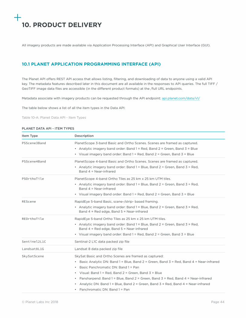
Page 44© Planet Labs Inc 2018
10. PRODUCT DELIVERY
All imagery products are made available via Application Processing Interface (API) and Graphical User Interface (GUI).
10.1 PLANET APPLICATION PROGRAMMING INTERFACE (API)
The Planet API offers REST API access that allows listing, filtering, and downloading of data to anyone using a valid API key. The metadata features described later in this document are all available in the responses to API queries. The full TIFF / GeoTIFF image data files are accessible (in the different product formats) at the /full URL endpoints.
Metadata associate with imagery products can be requested through the API endpoint: api.planet.com/data/v1/
The table below shows a list of all the item types in the Data API:
Table 10-A: Planet Data API - Item Types
PLANET DATA API - ITEM TYPES
Item Type Description
PSScene3Band PlanetScope 3-band Basic and Ortho Scenes. Scenes are framed as captured.
• Analytic imagery band order: Band 1 = Red, Band 2 = Green, Band 3 = Blue
• Visual imagery band order: Band 1 = Red, Band 2 = Green, Band 3 = Blue
PSScene4Band PlanetScope 4-band Basic and Ortho Scenes. Scenes are framed as captured.
• Analytic imagery band order: Band 1 = Blue, Band 2 = Green, Band 3 = Red, Band 4 = Near-infrared
PSOrthoTile PlanetScope 4-band Ortho Tiles as 25 km x 25 km UTM tiles.
• Analytic imagery band order: Band 1 = Blue, Band 2 = Green, Band 3 = Red, Band 4 = Near-infrared
• Visual imagery Band order: Band 1 = Red, Band 2 = Green, Band 3 = Blue
REScene RapidEye 5-band Basic, scene-/strip- based framing.
• Analytic imagery band order: Band 1 = Blue, Band 2 = Green, Band 3 = Red, Band 4 = Red edge, Band 5 = Near-infrared
REOrthoTile RapidEye 5-band Ortho Tiles as 25 km x 25 km UTM tiles.
• Analytic imagery band order: Band 1 = Blue, Band 2 = Green, Band 3 = Red, Band 4 = Red edge, Band 5 = Near-infrared
• Visual imagery band order: Band 1 = Red, Band 2 = Green, Band 3 = Blue
Sentinel2L1C Sentinal-2 L1C data packed zip file
Landsat8L1G Landsat 8 data packed zip file
SkySatScene SkySat Basic and Ortho Scenes are framed as captured:
• Basic Analytic DN: Band 1 = Blue, Band 2 = Green, Band 3 = Red, Band 4 = Near-infrared
• Basic Panchromatic DN: Band 1 = Pan
• Visual: Band 1 = Red, Band 2 = Green, Band 3 = Blue
• Pansharpend: Band 1 = Blue, Band 2 = Green, Band 3 = Red, Band 4 = Near-infrared
• Analytic DN: Band 1 = Blue, Band 2 = Green, Band 3 = Red, Band 4 = Near-infrared
• Panchromatic DN: Band 1 = Pan

Page 45© Planet Labs Inc 2018
The table below shows a list of all the asset types in the Data API:
Table 10-B: Planet Data API - Asset Types
PLANET DATA API - ASSET TYPES
Asset Type Description
analytic Radiometrically-calibrated analytic imagery stored as 16-bit scaled radiance, suitable for analytic applications.
analytic_b1 Band 1
analytic_b10 Band 10
analytic_b11 Band 11
analytic_b12 Band 12
analytic_b2 Band 2
analytic_b3 Band 3
analytic_b4 Band 4
analytic_b5 Band 5
analytic_b6 Band 6
analytic_b7 Band 7
analytic_b8 Band 8
analytic_b8a Band 8a
analytic_b9 Band 9
analytic_bqa Band QA
analytic_dn Non-radiometrically-calibrated analytic image stored as 12-bit digital numbers
analytic_dn_xml Non-radiometrically-calibrated analytic image metadata
analytic_ms True Color Composite
analytic_xml Radiometrically-calibrated analytic image metadata
basic_analytic Unorthorectified radiometrically-calibrated analytic image stored as 16-bit scaled radiance
basic_analytic_b1 RapidEye band 1 (Blue) scaled Top of Atmosphere Radiance (at sensor) and Sensor corrected, Basic Scene product designed for users with advanced image processing and geometric correction capabilities. Scene based framing and not projected to a cartographic projection.
basic_analytic_b1_nitf RapidEye band 1 (Blue) scaled Top of Atmosphere Radiance (at sensor) and Sensor corrected, Basic Scene product in the NITF format, designed for users with advanced image processing and geometric correction capabilities. Scene based framing and not projected to a cartographic projection.
basic_analytic_b2 RapidEye band 2 (Green) scaled Top of Atmosphere Radiance (at sensor) and Sensor corrected, Basic Scene product designed for users with advanced image processing and geometric correction capabilities. Scene based framing and not projected to a cartographic projection.
basic_analytic_b2_nitf RapidEye band 2 (Green) scaled Top of Atmosphere Radiance (at sensor) and Sensor corrected, Basic Scene product in the NITF format, designed for users with advanced image processing and geometric correction capabilities. Scene based framing and not projected to a cartographic projection.
basic_analytic_b3 RapidEye band 3 (Red) scaled Top of Atmosphere Radiance (at sensor) and Sensor corrected, Basic Scene product designed for users with advanced image processing and geometric correction capabilities. Scene based framing and not projected to a cartographic projection.
basic_analytic_b3_nitf RapidEye band 3 (Red) scaled Top of Atmosphere Radiance (at sensor) and Sensor corrected, Basic Scene product in the NITF format, designed for users with advanced image processing and geometric correction capabilities. Scene based framing and not projected to a cartographic projection.
basic_analytic_b4 RapidEye band 4 (Red Edge) scaled Top of Atmosphere Radiance (at sensor) and Sensor corrected, Basic Scene product designed for users with advanced image processing and geometric correction capabilities. Scene based framing and not projected to a cartographic projection.
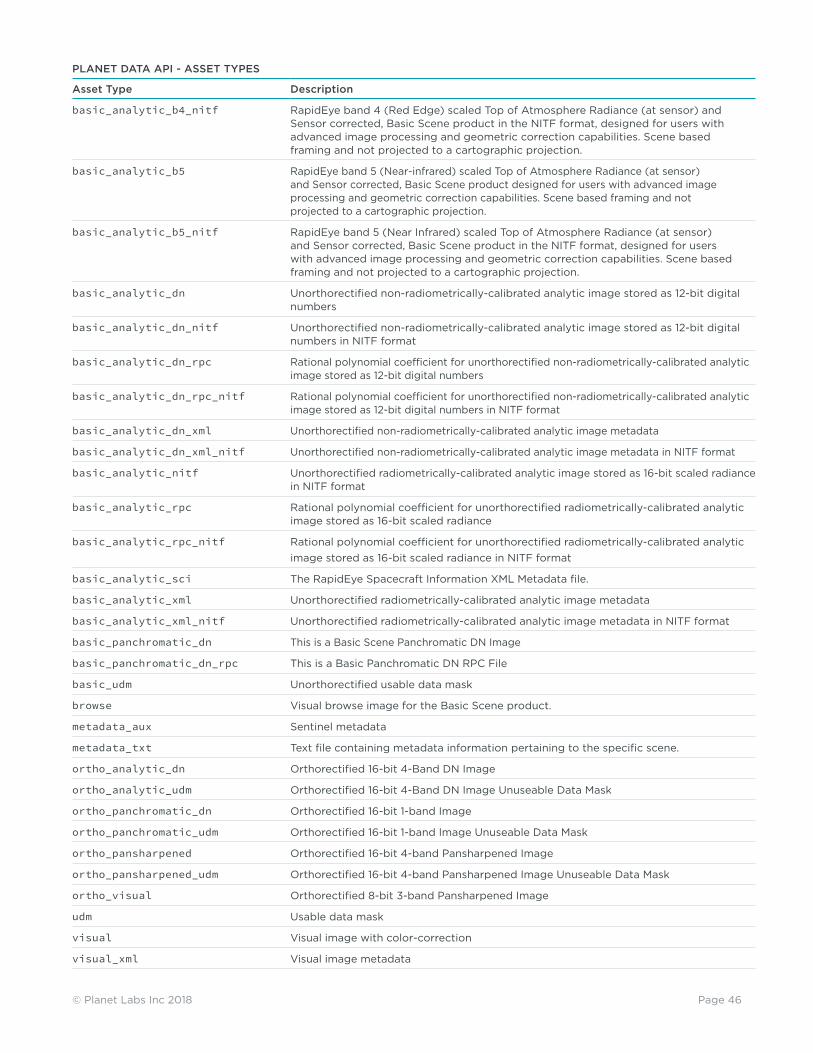
Page 46© Planet Labs Inc 2018
PLANET DATA API - ASSET TYPES
Asset Type Description
basic_analytic_b4_nitf RapidEye band 4 (Red Edge) scaled Top of Atmosphere Radiance (at sensor) and Sensor corrected, Basic Scene product in the NITF format, designed for users with advanced image processing and geometric correction capabilities. Scene based framing and not projected to a cartographic projection.
basic_analytic_b5 RapidEye band 5 (Near-infrared) scaled Top of Atmosphere Radiance (at sensor) and Sensor corrected, Basic Scene product designed for users with advanced image processing and geometric correction capabilities. Scene based framing and not projected to a cartographic projection.
basic_analytic_b5_nitf RapidEye band 5 (Near Infrared) scaled Top of Atmosphere Radiance (at sensor) and Sensor corrected, Basic Scene product in the NITF format, designed for users with advanced image processing and geometric correction capabilities. Scene based framing and not projected to a cartographic projection.
basic_analytic_dn Unorthorectified non-radiometrically-calibrated analytic image stored as 12-bit digital numbers
basic_analytic_dn_nitf Unorthorectified non-radiometrically-calibrated analytic image stored as 12-bit digital numbers in NITF format
basic_analytic_dn_rpc Rational polynomial coefficient for unorthorectified non-radiometrically-calibrated analytic image stored as 12-bit digital numbers
basic_analytic_dn_rpc_nitf Rational polynomial coefficient for unorthorectified non-radiometrically-calibrated analytic image stored as 12-bit digital numbers in NITF format
basic_analytic_dn_xml Unorthorectified non-radiometrically-calibrated analytic image metadata
basic_analytic_dn_xml_nitf Unorthorectified non-radiometrically-calibrated analytic image metadata in NITF format
basic_analytic_nitf Unorthorectified radiometrically-calibrated analytic image stored as 16-bit scaled radiance in NITF format
basic_analytic_rpc Rational polynomial coefficient for unorthorectified radiometrically-calibrated analytic image stored as 16-bit scaled radiance
basic_analytic_rpc_nitf Rational polynomial coefficient for unorthorectified radiometrically-calibrated analytic image stored as 16-bit scaled radiance in NITF format
basic_analytic_sci The RapidEye Spacecraft Information XML Metadata file.
basic_analytic_xml Unorthorectified radiometrically-calibrated analytic image metadata
basic_analytic_xml_nitf Unorthorectified radiometrically-calibrated analytic image metadata in NITF format
basic_panchromatic_dn This is a Basic Scene Panchromatic DN Image
basic_panchromatic_dn_rpc This is a Basic Panchromatic DN RPC File
basic_udm Unorthorectified usable data mask
browse Visual browse image for the Basic Scene product.
metadata_aux Sentinel metadata
metadata_txt Text file containing metadata information pertaining to the specific scene.
ortho_analytic_dn Orthorectified 16-bit 4-Band DN Image
ortho_analytic_udm Orthorectified 16-bit 4-Band DN Image Unuseable Data Mask
ortho_panchromatic_dn Orthorectified 16-bit 1-band Image
ortho_panchromatic_udm Orthorectified 16-bit 1-band Image Unuseable Data Mask
ortho_pansharpened Orthorectified 16-bit 4-band Pansharpened Image
ortho_pansharpened_udm Orthorectified 16-bit 4-band Pansharpened Image Unuseable Data Mask
ortho_visual Orthorectified 8-bit 3-band Pansharpened Image
udm Usable data mask
visual Visual image with color-correction
visual_xml Visual image metadata

Page 47© Planet Labs Inc 2018
10.2 PLANET GRAPHICAL USER INTERFACE (GUI)
The Planet Explorer Beta is a set of web-based GUI tools that can be used to search Planet’s catalog of imagery, view metadata, and download full-resolution images. The interface and all of its features are built entirely on the externally available Planet API.
The link to the Planet Explorer Beta is: www.planet.com/explorer
Planet’s GUI allows users to:
1. View Timelapse Mosaics: A user can view Planet’s quarterly and monthly mosaics for all of 2016, and can zoom in up to zoom level 12 (38 m / pixel per OpenStreetMap)
2. Search: A user can Search for any location or a specific area of interest by entering into the input box OR by uploading a geometry file (Shapefile, GeoJSON, KML, or WKT).
3. Save Search: The Save functionality allows a user to save search criteria based on area of interest, dates, and filters.
4. Filter: A user can filter by a specific date range and/or customizing metadata parameters (e.g. estimated cloud cover, GSD).
5. Zoom and Preview Imagery: Zoom and Preview allows a user to zoom in or out of the selected area and preview imagery.
6. View Imagery Details: A user can review metadata details about each imagery product.
7. Download: The Download icon allows a user to download imagery based on subscription type.
8. Draw Tools: These tools allow you to specify an area to see imagery results. The draw tool capabilities available are drawing a circle, drawing a rectangle, drawing a polygon, and/or limiting the size of the drawing to the size of loadable imagery.
9. Imagery Compare Tool: The Compare Tool allows you to compare sets of Planet imagery from different dates.
Planet will also enable additional functionality in the form of “Labs,” which are demonstrations of capability made accessible to users through the GUI. Labs are active product features and will evolve over time based on Planet technology evolution and user feedback.
10.3 PLANET ACCOUNT MANAGEMENT TOOLS
As part of the Planet GUI, an administration and account management tool is provided. This tool is used to change user settings and to see past data orders. In addition, users who have administrator privileges will be able to manage users in their organization as well as review usage statistics.
The core functionality provided by account management tools are outlined below, and Planet may evolve Account Management tools over time to meet user needs:
1. User Accounts Overview: Every user account on the Planet Platform is uniquely identified by an email address. Each user also has a unique API key that can be used when interacting programmatically with the Platform.
2. Organization and Sub-organization Overview: Every user on the Planet Platform belongs to one organization. The Platform also supports “sub-organizations,” which are organizations that are attached to a “parent” organization. An administrator of a parent organization is also considered an administrator on all sub-organizations.
3. Account Privileges: Every user account on the Planet Platform has one of two roles: user or administrator. An administrator has elevated access and can perform certain user management operations or download usage metrics that are not available to standard users. An administrator of a parent organization is also considered an administrator on all sub-organizations. Administrators can enable or disable administrator status and enable or disable users’ access to the platform altogether.
4. Orders and Usage Review: This tool records all part orders made and allows users and administrators to view and download past orders. Usage metrics are also made available, including imagery products downloaded and bandwidth usage. Usage metrics are displayed for each individual API key that is part of the organization.

Page 48© Planet Labs Inc 2018
10.4 FILE FORMAT
The Basic Scene products are available as NITF and GeoTIFFs; the Visual and Analytic Ortho Tile products are GeoTIFFs.
The Ortho Tile product GeoTIFFs are resampled at 3.125 m, and projected in the UTM projection using the WGS84 datum. An alpha mask is provided as a binary color channel. The alpha mask can be used to remove or hide low-image-quality pixels near the periphery of a given scene. The alpha mask compensates for effects due to vignetting, low SNR, or hot or cold pixels.
The Ortho Scene product GeoTIFFs are resampled at 3 m, and projected in the UTM projection using the WGS84 datum. An alpha mask is provided as a binary color channel. The alpha mask can be used to remove or hide low-image-quality pixels near the periphery of a given scene. The alpha mask compensates for effects due to vignetting, low SNR, or hot or cold pixels.
Landsat 8 and Sentinal-2 data are passed through in the original provider’s format. In the case of Landsat 8 the format is geotiff. In the case of Sentinel-2, the format is jpeg2000.
10.5 BULK DELIVERY FOLDER STRUCTURE
Sets of imagery products can be ordered through the Planet API. The name of the parent folder is:
planet_order_[id]
Bulk deliveries are delivered in a .zip folder file format. Each .zip file contains:
• A README file with information about the order.• A subfolder for each scene requested named with the scene id.• Each subfolder contains the TIFF or GeoTIFF requested and an associated metadata file.• If basic data is requested, the subfolder will also contain an RPC text file.

Page 49© Planet Labs Inc 2018
APPENDIX A – IMAGE SUPPORT DATA
All PlanetScope and RapidEye Ortho Tile Products are accompanied by a set of image support data (ISD) files. These ISD files provide important information regarding the image and are useful sources of ancillary data related to the image. The ISD files are:
A. General XML Metadata File B. Unusable Data Mask File
Each file is described along with its contents and format in the following sections.
1. GENERAL XML METADATA FILE
All PlanetScope Ortho Tile Products will be accompanied by a single general XML metadata file. This file contains a description of basic elements of the image. The file is written in Geographic Markup Language (GML) version 3.1.1 and follows the application schema defined in the Open Geospatial Consortium (OGC) Best Practices document for Optical Earth Observation products version 0.9.3, see http://www.opengeospatial.org/standards/gml
The contents of the metadata file will vary depending on the image product processing level. All metadata files will contain a series of metadata fields common to all imagery products regardless of the processing level. However, some fields within this group of metadata may only apply to certain product levels. In addition, certain blocks within the metadata file apply only to certain product types. These blocks are noted within the table. The table below describes the fields present in the General XML Metadata file for all product levels.
Table A - 1: General XML Metadata File Field Descriptions
GENERAL METADATA FILE FIELD CONTENTS
Field Description
“metaDataProperty” Block
EarthObservationMetaData
Identifier Root file name of the image
status Status type of image, if newly acquired or produced from a previously archived image
downlinkedTo
acquisitionStation X-band downlink station that received image from satellite
acquisitionDate Date and time image was acquired by satellite
archivedIn
archivingCenter Location where image is archived
archivingDate Date image was archived
archivingIdentifier Catalog ID of image.
processing
processorName Name of ground processing system
processorVersion Version of processor

Page 50© Planet Labs Inc 2018
GENERAL METADATA FILE FIELD CONTENTS
Field Description
nativeProductFormat Native image format of the raw image data
license
licenseType Name of selected license for the product
resourceLink Hyperlink to the physical license file
versionIsd Version of the ISD
orderId Order ID of the product
tileId Tile ID of the product corresponding to the Tile Grid
pixelFormat Number of bits per pixel per band in the product image file
“validTime” Block
TimePeriod
beginPosition Start date and time of acquisition for source image take used to create product, in UTC
endPosition End date and time of acquisition for source image take used to create product, in UTC
“using” Block
EarthObservationEquipment
platform
shortName Identifies the name of the satellite platform used to collect the image
serialIdentifier ID of the satellite that acquired the data
orbitType Orbit type of satellite platform
instrument
shortName Identifies the name of the satellite instrument used to collect the image
sensor
sensorType Type of sensor used to acquire the data
resolution Spatial resolution of the sensor used to acquire the image, units in meters
scanType Type of scanning system used by the sensor
acquisitionParameters
orbitDirection The direction the satellite was traveling in its orbit when the image was acquired
incidenceAngle The angle between the view direction of the satellite and a line perpendicular to the image or tile center
illumination AzimuthAngle
Sun azimuth angle at center of product, in degrees from North (clockwise) at the time of the first image line
illumination ElevationAngle
Sun elevation angle at center of product, in degrees

Page 51© Planet Labs Inc 2018
GENERAL METADATA FILE FIELD CONTENTS
Field Description
azimuthAngle The angle from true north at the image or tile center to the scan (line) direction at image center, in clockwise positive degrees.
spaceCraftView Angle Spacecraft across-track off-nadir viewing angle used for imaging, in degrees with “+” being East and “-” being West
acquisitionDateTime Date and Time at which the data was imaged, in UTC. Note: the imaging times will be somewhat different for each spectral band. This field is not intended to provide accurate image time tagging and hence is simply the imaging time of some (unspecified) part of the image.
“target” Block
Footprint
multiExtentOf
posList Position listing of the four corners of the image in geodetic coordinates in the format:ULX ULY URX URY LRX LRY LLX LLY ULX ULYwhere X = latitude and Y = longitude
centerOf
pos Position of center of product in geodetic coordinate X and Y, where X = latitude and Y = longitude
geographicLocation
topLeft
latitude Latitude of top left corner in geodetic WGS84 coordinates
longitude Longitude of top left corner in geodetic WGS84 coordinates
topRight
latitude Latitude of top right corner in geodetic WGS84 coordinates
longitude Longitude of top right corner in geodetic WGS84 coordinates
bottomLeft
latitude Latitude of bottom left corner in geodetic WGS84 coordinates
longitude Longitude of bottom left corner in geodetic WGS84 coordinates
bottomRight
latitude Latitude of bottom right corner in geodetic WGS84 coordinates
longitude Longitude of bottom right corner in geodetic WGS84 coordinates
“resultOf“ Block
EarthObservationResult
browse
BrowseInformation
type Type of browse image that accompanies the image product as part of the ISD
reference SystemIdentifier
Identifies the reference system used for the browse image
fileName Name of the browse image file

Page 52© Planet Labs Inc 2018
GENERAL METADATA FILE FIELD CONTENTS
Field Description
product
fileName Name of image file.
size The size of the image product in kbytes
productFormat File format of the image product
spatialReferenceSystem
epsgCode EPSG code that corresponds to the datum and projection information of the image
geodeticDatum Name of datum used for the map projection of the image
projection Projection system used for the image
projectionZone Zone used for map projection
resamplingKernel Resampling method used to produce the image. The list of possible algorithms is extendable
numRows Number of rows (lines) in the image
numColumns Number of columns (pixels) per line in the image
numBands Number of bands in the image product
rowGsd The GSD of the rows (lines) within the image product
columnGsd The GSD of the columns (pixels) within the image product
radiometricCorrection Applied
Indicates whether radiometric correction has been applied to the image
geoCorrectionLevel Level of correction applied to the image
atmospheric CorrectionApplied
Indicates whether atmospheric correction has been applied to the image
atmosphericCorrectionParameters
autoVisibility Indicates whether the visibility was automatically calculated or defaulted
visibility The visibility value used for atmospheric correction in km
aerosolType The aerosol type used for atmospheric correction
waterVapor The water vapor category used
hazeRemoval Indicates whether haze removal was performed
roughTerrainCorrection Indicates whether rough terrain correction was performed
bRDF Indicates whether BRDF correction was performed
mask
MaskInformation
type Type of mask file accompanying the image as part of the ISD
format Format of the mask file
referenceSystem Identifier
EPSG code that corresponds to the datum and projection information of the mask file
fileName File name of the mask file
cloudCoverPercentage Estimate of cloud cover within the image
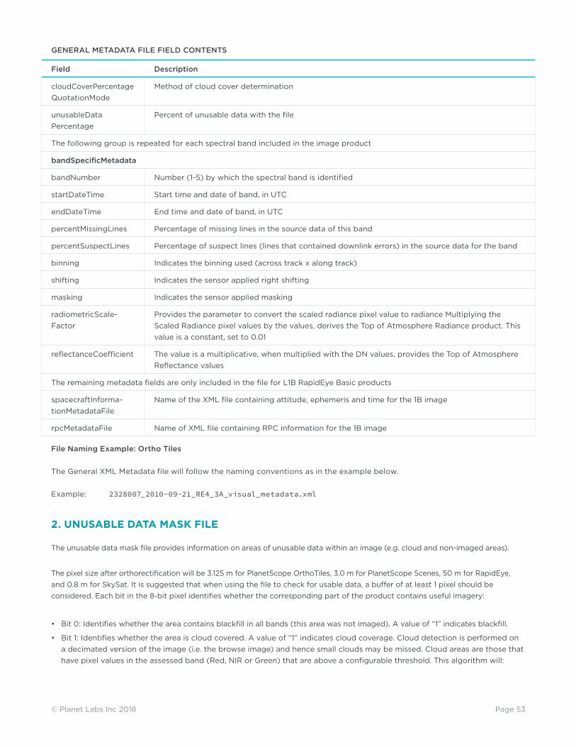
Page 53© Planet Labs Inc 2018
GENERAL METADATA FILE FIELD CONTENTS
Field Description
cloudCoverPercentage QuotationMode
Method of cloud cover determination
unusableData Percentage
Percent of unusable data with the file
The following group is repeated for each spectral band included in the image product
bandSpecificMetadata
bandNumber Number (1-5) by which the spectral band is identified
startDateTime Start time and date of band, in UTC
endDateTime End time and date of band, in UTC
percentMissingLines Percentage of missing lines in the source data of this band
percentSuspectLines Percentage of suspect lines (lines that contained downlink errors) in the source data for the band
binning Indicates the binning used (across track x along track)
shifting Indicates the sensor applied right shifting
masking Indicates the sensor applied masking
radiometricScale-Factor
Provides the parameter to convert the scaled radiance pixel value to radiance Multiplying the Scaled Radiance pixel values by the values, derives the Top of Atmosphere Radiance product. This value is a constant, set to 0.01
reflectanceCoefficient The value is a multiplicative, when multiplied with the DN values, provides the Top of Atmosphere Reflectance values
The remaining metadata fields are only included in the file for L1B RapidEye Basic products
spacecraftInforma-tionMetadataFile
Name of the XML file containing attitude, ephemeris and time for the 1B image
rpcMetadataFile Name of XML file containing RPC information for the 1B image
File Naming Example: Ortho Tiles
The General XML Metadata file will follow the naming conventions as in the example below.
Example: 2328007_2010-09-21_RE4_3A_visual_metadata.xml
2. UNUSABLE DATA MASK FILE
The unusable data mask file provides information on areas of unusable data within an image (e.g. cloud and non-imaged areas).
The pixel size after orthorectification will be 3.125 m for PlanetScope OrthoTiles, 3.0 m for PlanetScope Scenes, 50 m for RapidEye, and 0.8 m for SkySat. It is suggested that when using the file to check for usable data, a buffer of at least 1 pixel should be considered. Each bit in the 8-bit pixel identifies whether the corresponding part of the product contains useful imagery:
• Bit 0: Identifies whether the area contains blackfill in all bands (this area was not imaged). A value of “1” indicates blackfill.
• Bit 1: Identifies whether the area is cloud covered. A value of “1” indicates cloud coverage. Cloud detection is performed on a decimated version of the image (i.e. the browse image) and hence small clouds may be missed. Cloud areas are those that have pixel values in the assessed band (Red, NIR or Green) that are above a configurable threshold. This algorithm will:

Page 54© Planet Labs Inc 2018
° Assess snow as cloud;
° Assess cloud shadow as cloud free;
° Assess haze as cloud free.
• Bit 2: Identifies whether the area contains missing (lost during downlink) or suspect (contains downlink errors) data in the Blue band. A value of “1” indicates missing/suspect data. If the product does not include this band, the value is set to “0”.
• Bit 3: Identifies whether the area contains missing (lost during downlink and hence blackfilled) or suspect (contains downlink errors) data in the Green band. A value of “1” indicates missing/suspect data. If the product does not include this band, the value is set to “0”.
• Bit 4: Identifies whether the area contains missing (lost during downlink) or suspect (contains downlink errors) data in the Red band. A value of “1” indicates missing/suspect data. If the product does not include this band, the value is set to “0”.
• Bit 5: Identifies whether the area contains missing (lost during downlink) or suspect (contains downlink errors) data in the Red Edge band. A value of “1” indicates missing/suspect data. If the product does not include this band, the value is set to “0”.
• Bit 6: Identifies whether the area contains missing (lost during downlink) or suspect (contains downlink errors) data in the NIR band. A value of “1” indicates missing/suspect data. If the product does not include this band, the value is set to “0”.
• Bit 7: Is currently set to “0”.
The figure below illustrates the concepts behind the Unusable Data Mask file.
Figure A-1: Concepts Behind the Unusable Data Mask File
File Naming
The UDM file will follow the naming conventions as in the example below.
Example: 2328007_2010-09-21_RE4_3A_udm.tif

Page 55© Planet Labs Inc 2018
APPENDIX B – TILE GRID DEFINITION
Ortho Tile imagery products are based on the UTM map grid as shown in Figure B-1 and B-2. The grid is defined in24 km by 24 km tile centers, with 1 km of overlap, resulting in 25 km by 25 km tiles.
Figure B-1: Layout of UTM Zones
An Ortho Tile imagery products is named by the UTM zone number, the grid row number, and the grid column number within the UTM zone in the following format:
<ZZRRRCC>
Where:
ZZ = UTM Zone Number (This field is not padded with a zero for single digit zones in the tile shapefile)RRR = Tile Row Number (increasing from South to North, see Figure B-2) CC = Tile Column Number (increasing from West to East, see Figure B-2)
Example: Tile 547904 = UTM Zone = 5, Tile Row = 479, Tile Column = 04 Tile 3363308 = UTM Zone = 33, Tile Row = 633, Tile Column = 08

Page 56© Planet Labs Inc 2018
Due to the convergence at the poles, the number of grid columns varies with grid row as illustrated in Figure B-3.
Figure B-2: Layout of Tile Grid within a single UTM zone
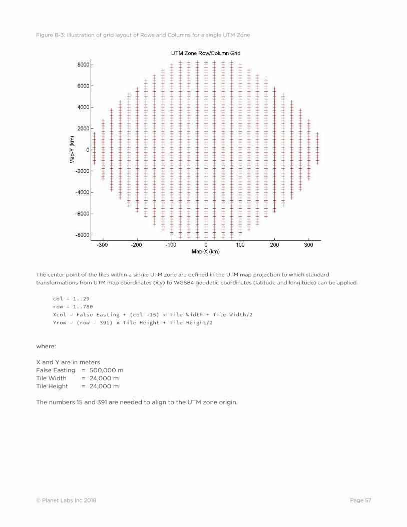
Page 57© Planet Labs Inc 2018
The center point of the tiles within a single UTM zone are defined in the UTM map projection to which standard transformations from UTM map coordinates (x,y) to WGS84 geodetic coordinates (latitude and longitude) can be applied.
col = 1..29 row = 1..780 Xcol = False Easting + (col –15) x Tile Width + Tile Width/2 Yrow = (row – 391) x Tile Height + Tile Height/2
where:
X and Y are in metersFalse Easting = 500,000 mTile Width = 24,000 mTile Height = 24,000 m
The numbers 15 and 391 are needed to align to the UTM zone origin.
Figure B-3: Illustration of grid layout of Rows and Columns for a single UTM Zone