production guide 2-10 conductive polymer electrolyte type 11 … · · 2011-12-02detail...
TRANSCRIPT

Production Guide 2-10
List of Products 2-3
Series Group Chart 4-6
Detail Specifications of Taping Method 7-8
Packing Quantity 9-10
Conductive Polymer Electrolyte Type 11-26
Precautions and Guideline(Conductive Polymer Solid Capacitors) 12-16
Product Specifications 17-26
C O N T E N T S
Aluminum Electrolytic Capacitors 27-189
List of Substitute for discontinued Series 28
Precautions and Guideline to Users(Aluminum Electrolytic Capacitor) 29-37
Lead cutting/Forming Specifications 38
Part Number Indication Chart 39
Standard Frequency Multiplying Factor 40
Surface mount Aluminum Electrolytic Capacitors(Chip Types) 41-65
Miniature Aluminum Electrolytic Capacitors(Radial Types) 66-139
Large Sized Aluminum Electrolytic Capacitors 140-189(PCB Terminal/Screw-Bolt Types)
ALUMINUM ELECTROLYTIC CAPACITORS
LLooaadd lliiffeeSSeerriieess AApppplliiccaattiioonnss TTiimmee
((HHrrss))
LLooaadd lliiffeeSSeerriieess AApppplliiccaattiioonnss TTiimmee
((HHrrss))
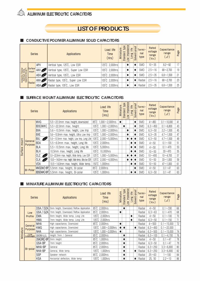
CONDUCTIVE POLYMER ALUMINUM SOLID CAPACITORS
MINIATURE ALUMINUM ELECTROLYTIC CAPACITORS
MMiinniiaattuurree
SSttaanndd
aarrdd
ttyyppee
LLooww iimmppee
ddaanncc
ee
LLoonngg
lliiffee
SSoollvvee
nntt--pp
rrooooff
PPaaggee
TTeerrmmii--nnaallttyyppee
RRaatteeddvvoollttaaggeerraannggee((VVDDCC))
CCaappaacciittaanncceerraannggee
(())
SSuurrffaacceemmoouunntt
RRaaddiiaallCCoonndd
uuccttiivv
ee PPoo
llyymmeerr
AAlluumm
iinnuumm
SSoolliidd
CCaappaa
cciittoorrss((
rreeAALL
ccaappTTMM
))
LLoowwPPrrooffiillee
GGeenneerraallPPuurrppoossee
LLoowwLLeeaakkaaggee
BBii--ppoollaarr
MMiinniiaattuurree
LIST OF PRODUCTS
MMiinniiaattuurree
SSttaanndd
aarrdd
ttyyppee
LLooww iimmppee
ddaanncc
ee
LLoonngg
lliiffee
SSoollvvee
nntt--pp
rrooooff
PPaaggee
TTeerrmmii--nnaallttyyppee
RRaatteeddvvoollttaaggeerraannggee((VVDDCC))
CCaappaacciittaanncceerraannggee
(())
AAPPVV
AAXXVV
AASSVV
AAXXAA
AASSAA
Vertical type, 125, Low ESR
Vertical type, 105, Super Low ESR
Vertical type, 105, Low ESR
Radial type, 105, Super Low ESR
Radial type, 105, Low ESR
125 2,000hrs
105 2,000hrs
105 2,000hrs
105 2,000hrs
105 2,000hrs
SMD
SMD
SMD
Radial
Radial
10~35
2.5~16
2.5~35
2.5~16
2.5~35
8.2~82
68~2,700
6.8~1,500
68~2,700
6.8~1,500
17
19
21
23
25
SURFACE MOUNT ALUMINUM ELECTROLYTIC CAPACITORS
MMiinniiaattuurree
SSttaanndd
aarrdd
ttyyppee
LLooww iimmppee
ddaanncc
ee
LLoonngg
lliiffee
SSoollvvee
nntt--pp
rrooooff
PPaaggee
TTeerrmmii--nnaallttyyppee
RRaatteeddvvoollttaaggeerraannggee((VVDDCC))
CCaappaacciittaanncceerraannggee
(())
GGeenneerraallPPuurrppoossee
BBii--PPoollaarr
SSuurrffaaccee
mmoouu
nntt
MMVVGGBBDDSS((MMVVKK))BBXXAABBXXEEBBXXJJBBDDAABBLLAABBLLHHCCLLZZCCLLXXVVDDAAMMVVGG((MMVV))--BBPPBBDDSS((MMVVKK))--BBPP
85 1,000~2,000hrs105 1,000~2,000hrs105 1,000~2,000hrs105 1,000~2,000hrs105 2,000~5,000hrs105 2,000hrs105 5,000hrs105 10,000hrs125 1,000~5,000hrs125 2,000~4,000hrs150 1,000hrs85 2,000hrs105 1,000hrs
SMDSMDSMDSMDSMDSMDSMDSMDSMDSMDSMDSMDSMD
4~4506.3~4506.3~506.3~356.3~50
4~504~5010~5010~40010~5010~504~506.3~50
0.1~10,0000.1~6,8002.2~1,5004.7~1,5004.7~1,5000.1~1000.1~47033~47010~4,70033~1,00047~1,0000.1~470.1~47
41434547495153555759616363
DDSSAA // DDZZAAGGSSAA // GGZZAAEEMMAAHHMMAAMMHHAAKKMMGGNNHHAAGGSSAA((SSRRAA))--LLLL//LLLL
DDSSAA((SSRREE))--BBPPGGSSAA--BBPPMMHHAA--BBPPNNHHAA--BBPPSSSSPPKKSSAA
5mm height, Downsized / Reflow Application
7mm height, Downsized / Reflow Application
5mm height, Wide temp. Long Life
7mm height, Wide temp. Long Life
High capacitance, Downsized
High capacitance, Downsized
High capacitance, Downsized
Height 7mm / General
5mm height
7mm height
General
General, Wide temp.
Speaker network
Horizontal deflection, Wide temp
85 2,000hrs85 2,000hrs105 2,000hrs105 2,000hrs85 2,000hrs105 1,000~2,000hrs105 1,000~2,000hrs85 2,000hrs85 1,000hrs85 2,000hrs85 2,000hrs105 1,000hrs85 2,000hrs105 1,000hrs
RadialRadialRadialRadialRadialRadialRadialRadialRadialRadialRadialRadialRadialRadial
4~506.3~634~506.3~504~5006.3~4506.3~5006.3~1004~506.3~506.3~2506.3~25025~6325, 50
0.1~3300.1~4700.1~1000.1~150
0.1~15,0000.1~22,0000.1~15,0000.1~4,7000.1~470.1~47
3.3~6,8003.3~6,8001~1002.2~10
6668707172
7476787980828486
5.5~22.0mm max. height,downsized5.5~22.0mm max. height5.6~10.5mm max. height, Low Imp5.6~10.5mm max. height, Ultra Low Imp5.6~10.5mm max. height, Low Imp, Long Life5.5~6.0mm max. height, Long life5.5~10.5mm max. height, Long life10.5mm max. height, Long life5.5~22.0mm max. height, Wide temp. Low ESR10.5~14.0mm max. height, Wide temp. Ultra low ESR10.5~14.0mm max. height, Wide temp.5.5mm max. height, Bi-polar5.5mm max. height, Bi-polar
ALUMINUM ELECTROLYTIC CAPACITORS
Upgra
de
Upgra
de
Upgra
de
Upgra
de
LLooaadd lliiffeeSSeerriieess AApppplliiccaattiioonnss TTiimmee
((HHrrss))
Upgra
de
Upgra
de
Upgra
de
EEXXBBHHXXBBHHXXLLNNXXLL((LLXXVV))NNXXPP((LLXXZZ))NNXXAANNXXBBNNXXHHNNXXJJNNXXQQNNXXKKNNXXFFNNXXEENNFFDD((KKMMFF))NNZZEENNFFCCNNFFKKNNFFSSNNFFAANNFFLLNNLLAANNLLCCPPXXBBPPXXDDPPHHAAAAHHSSPPHHLLNNZZDD
LLooaadd lliiffeeSSeerriieess AApppplliiccaattiioonnss TTiimmee
((HHrrss))
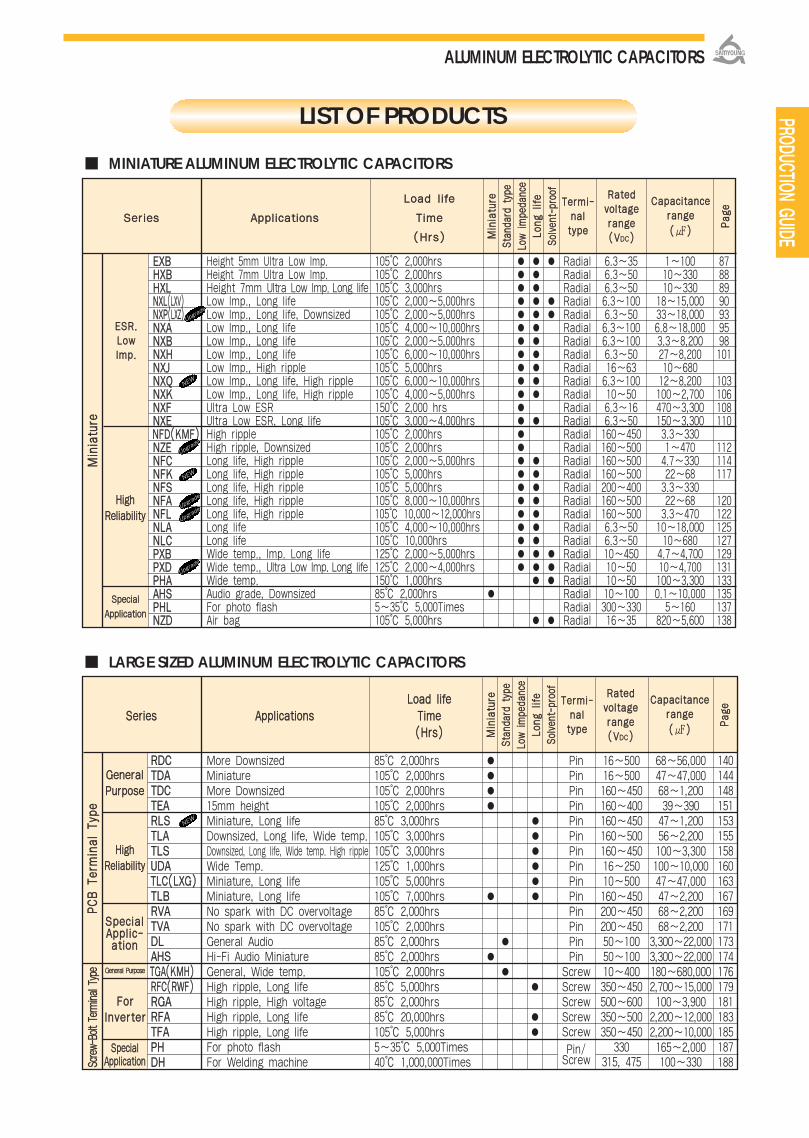
MINIATURE ALUMINUM ELECTROLYTIC CAPACITORS
MMiinniiaattuurree
SSttaanndd
aarrdd
ttyyppee
LLooww iimmppee
ddaanncc
ee
LLoonngg
lliiffee
SSoollvvee
nntt--pp
rrooooff
PPaaggee
TTeerrmmii--nnaallttyyppee
RRaatteeddvvoollttaaggeerraannggee((VVDDCC))
CCaappaacciittaanncceerraannggee
(())
MMiinniiaattuurree
LARGE SIZED ALUMINUM ELECTROLYTIC CAPACITORS
MMiinniiaattuurree
SSttaanndd
aarrdd
ttyyppee
LLooww iimmppee
ddaanncc
ee
LLoonngg
lliiffee
SSoollvvee
nntt--pp
rrooooff
PPaaggee
TTeerrmmii--nnaallttyyppee
RRaatteeddvvoollttaaggeerraannggee((VVDDCC))
CCaappaacciittaanncceerraannggee
(())
PPCCBB TT
eerrmmiinnaall TTyy
ppeeSSccrreeww--
BBoolltt TTeerrmm
iinnaall TT
yyppee
GGeenneerraallPPuurrppoossee
HHiigghhRReelliiaabbiilliittyy
SSppeecciiaallAApppplliicc--aattiioonn
GGeenneerraall PPuurrppoossee
FFoorrIInnvveerrtteerr
SSppeecciiaallAApppplliiccaattiioonn
LIST OF PRODUCTS
EESSRR..LLoowwIImmpp..
Height 5mm Ultra Low Imp.Height 7mm Ultra Low Imp.Height 7mm Ultra Low lmp. Long lifeLow lmp., Long lifeLow lmp., Long life, DownsizedLow lmp., Long lifeLow lmp., Long lifeLow lmp., Long lifeLow lmp., High rippleLow lmp., Long life, High rippleLow lmp., Long life, High rippleUltra Low ESRUltra Low ESR, Long lifeHigh rippleHigh ripple, DownsizedLong life, High rippleLong life, High rippleLong life, High rippleLong life, High rippleLong life, High rippleLong lifeLong lifeWide temp., lmp. Long lifeWide temp., Ultra Low lmp. Long lifeWide temp.Audio grade, DownsizedFor photo flashAir bag
105 2,000hrs105 2,000hrs105 3,000hrs105 2,000~5,000hrs105 2,000~5,000hrs105 4,000~10,000hrs105 2,000~5,000hrs105 6,000~10,000hrs105 5,000hrs105 6,000~10,000hrs105 4,000~5,000hrs150 2,000 hrs105 3,000~4,000hrs105 2,000hrs105 2,000hrs105 2,000~5,000hrs105 5,000hrs105 5,000hrs105 8,000~10,000hrs105 10,000~12,000hrs105 4,000~10,000hrs105 10,000hrs125 2,000~5,000hrs125 2,000~4,000hrs150 1,000hrs85 2,000hrs5~35 5,000Times105 5,000hrs
RadialRadialRadialRadialRadialRadialRadialRadialRadialRadialRadialRadialRadialRadialRadialRadialRadialRadialRadialRadialRadialRadialRadialRadialRadialRadialRadialRadial
6.3~356.3~506.3~506.3~1006.3~506.3~1006.3~1006.3~5016~636.3~10010~506.3~166.3~50160~450160~500160~500160~500200~400160~500160~5006.3~506.3~5010~45010~5010~5010~100300~33016~35
87888990939598101
103106108110
112114117
120122125127129131133135137138
RRDDCCTTDDAATTDDCCTTEEAARRLLSSTTLLAATTLLSSUUDDAATTLLCC((LLXXGG))TTLLBBRRVVAATTVVAADDLLAAHHSSTTGGAA((KKMMHH))RRFFCC((RRWWFF))RRGGAARRFFAATTFFAAPPHHDDHH
More DownsizedMiniatureMore Downsized15mm heightMiniature, Long lifeDownsized, Long life, Wide temp.Downsized, Long life, Wide temp. High rippleWide Temp.Miniature, Long lifeMiniature, Long lifeNo spark with DC overvoltageNo spark with DC overvoltageGeneral AudioHi-Fi Audio MiniatureGeneral, Wide temp.High ripple, Long lifeHigh ripple, High voltageHigh ripple, Long lifeHigh ripple, Long lifeFor photo flashFor Welding machine
85 2,000hrs105 2,000hrs105 2,000hrs105 2,000hrs85 3,000hrs105 3,000hrs105 3,000hrs125 1,000hrs105 5,000hrs105 7,000hrs85 2,000hrs105 2,000hrs85 2,000hrs85 2,000hrs105 2,000hrs85 5,000hrs85 2,000hrs85 20,000hrs105 5,000hrs5~35 5,000Times40 1,000,000Times
PinPinPinPinPinPinPinPinPinPinPinPinPinPin
ScrewScrewScrewScrewScrewPin/Screw
16~50016~500160~450160~400160~450160~500160~45016~25010~500160~450200~450200~45050~10050~10010~400350~450500~600350~500350~450
330315, 475
68~56,00047~47,00068~1,20039~39047~1,20056~2,200100~3,300100~10,00047~47,00047~2,20068~2,20068~2,200
3,300~22,0003,300~22,000180~680,0002,700~15,000100~3,900
2,200~12,0002,200~10,000165~2,000100~330
140144148151153155158160163167169171173174176179181183185187188
ALUMINUM ELECTROLYTIC CAPACITORS
PRODUCTION GUIDE
1~10010~33010~330
18~15,00033~18,0006.8~18,0003.3~8,20027~8,20010~68012~8,200100~2,700470~3,300150~3,3003.3~3301~4704.7~33022~683.3~33022~683.3~47010~18,00010~680
4.7~4,70010~4,700100~3,3000.1~10,0005~160
820~5,600
LLooaadd lliiffee
SSeerriieess AApppplliiccaattiioonnss TTiimmee
((HHrrss))
NEW
Upgra
de
Upgra
de
Upgra
de
Upgra
deUp
grade
NEW
HHiigghhRReelliiaabbiilliittyy
SSppeecciiaall
AApppplliiccaattiioonn
NEW
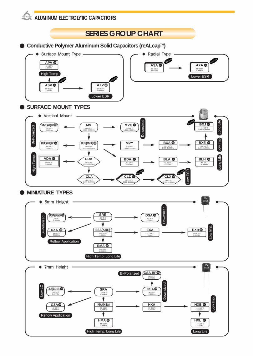
SURFACE MOUNT TYPES
Conductive Polymer Aluminum Solid Capacitors (reALcapTM)
VVeerrttiiccaall MMoouunntt
MINIATURE TYPES
55mmmm HHeeiigghhtt
SERIES GROUP CHART
77mmmm HHeeiigghhtt
Bi-P
olar
ized
Bi-P
olar
ized
Low
Imp.
Dow
nsiz
ed
Low
LC
Hig
h T
emp.
Long
Life
Bi-Polarized
Reflow Application
High Temp. Long Life
High Temp. Long Life Long Life
Dow
nsiz
ed
Low
Imp.
Low
Imp.
MV-40~85
1,000~2,000Hrs
MVG(MV)-BP-40~852,000Hrs
63 MVG-40~85
1,000~2,000Hrs
41
MVY-40~105
1,000~2,000Hrs
BDS(MVK)-BP-40~1051,000Hrs
63 BDS(MVK)-40~105
1,000~2,000Hrs
43
BDA-40~1052,000Hrs
51
ESA(KRE)-55~1051,000Hrs
EXA-55~1051,000Hrs
EXB-55~1052,000Hrs
87
EMA-55~1052,000Hrs
70
BLA40~1055,000Hrs
53 BLH40~105
10,000Hrs
55
BXE-55~105
1,000~2,000Hrs
47
DSA(SRE)-BP-40~851,000Hrs
78 SRE-40~852,000Hrs
DSA-40~852,000Hrs
66
DZA-40~852,000Hrs
66
HXA-55~1051,000Hrs
HXB-40~1052,000Hrs
88
HMA-55~1052,000Hrs
71
KMA(HSA)-55~1051,000Hrs
GSA(SRA)-LL/LL-40~852,000Hrs
76 GSA-40~852,000Hrs
68
GSA-BP-40~852,000Hrs
79
SRA-40~852,000Hrs
GZA-40~852,000Hrs
68
Reflow Application
SSuurrffaaccee MMoouunntt TTyyppee
Lower ESR
High Temp
ASV -55~1052,000Hrs
RRaaddiiaall TTyyppee
Lower ESR
ASA -55~1052,000Hrs
Long
Life
21
25 AXA-55~1052,000Hrs
23
AXV-55~1052,000Hrs
APV-55~1252,000Hrs
19
CLA-40~125
3,000~5,000Hrs
CDA-40~125
1,000~2,000Hrs
VDA-40~1501,000Hrs
61
BXJ-55~105
2,000~5,000Hrs
49
Low
ES
R
BXA-55~105
1,000~2,000Hrs
CLZ-40~125
2,000~5,000Hrs
CLX-40~125
2,000~4,000Hrs
Upgra
de
Upgra
de
Upgra
de
Dow
nsiz
ed
HXL-40~1053,000Hrs
89
17
57 59
45
ALUMINUM ELECTROLYTIC CAPACITORS
Upgra
de
Upgra
de
Upgra
deUpgra
de
PHL-20~55
5~35 5,000 Times
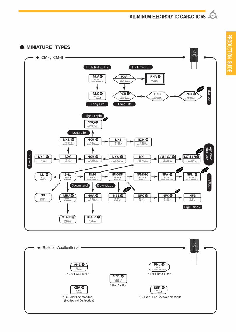
MINIATURE TYPES
SSppeecciiaall AApppplliiccaattiioonnss
CCMM--II,, CCMM--IIII
For Hi-Fi Audio
Bi-Polar For Monitor(Horizontal Deflection)
For Photo Flash
For Air Bag
Bi-Polar For Speaker Network
Low
Imp.
Long
Life
Long Life
High Ripple
Long Life Long Life
Low
Imp.
NXF-40~1052000Hrs
NXA-40~105
4,000~10,000Hrs
NXB-40~105
2,000~5,000Hrs
KMG-55~105
1,000~2,000Hrs
NXE-40~105
3,000~4,000Hrs
NXH-40~105
6,000~10,000Hrs
KXL-55~105
1,000~2,000Hrs
NXL(LXV)-55~105
2,000~5,000Hrs
NXP(LXZ)-55~105
2,000~5,000Hrs
NFD(KMF)-40~1052,000Hrs
NZE-40~1052,000Hrs
NFC-40~1055,000Hrs
KSA-55~1051,000Hrs
86
NZD-55~1055,000Hrs
138
SHL-40~852,000Hrs
LL -40~852,000Hrs
SR-40~852,000Hrs
NHA-BP-55~1051,000Hrs
MHA-BP-40~852,000Hrs
AHS-40~852,000Hrs
135
SSP-40~852,000Hrs
84
137
High Reliability
PHA-40~1501,000Hrs
Downsized
High Ripple
Downsized
Long
Life
Low
Imp.
NXC -40~1052,000Hrs
High Temp.
NLA-55~105
4,000~10,000Hrs
125
NLC-55~10510,000Hrs
127
133
110 101
108 9598 90 93
NFA-40~105
8,000~10,000Hrs
120 NFL-40~105
10,000~12,000Hrs
122
114 NFS-40~1055,000Hrs
NFK-40~1055,000Hrs
117112NHA-55~105
1,000~2,000Hrs
74MHA-40~852,000Hrs
72
76
80 82
PXC-40~125
3,000~5,000Hrs
PXA-40~125
1,000~2,000Hrs
Upgra
de
PXB-40~125
2,000~5,000Hrs
129
ALUMINUM ELECTROLYTIC CAPACITORS
NFE(KMX)-40~1055,000Hrs
PRODUCTION GUIDE
NXJ-40~1055,000Hrs
NXK-40~105
4,000~5,000Hrs
106
NXQ-40~105
6,000~10,000Hrs
103NE
W
Upgra
de
Upgra
de
NEW
131PXD-40~125
2,000~4,000Hrs
Upgra
de
Upgra
de

SSppeecciiaall AApppplliiccaattiioonnss
PPCCBB TTeerrmmiinnaallss
SSccrreeww--BBoolltt TTeerrmmiinnaallss
For General Audio For Hi-Fi Audio No Sparks with DC Overvoltage
For Welding MachineFor Photo Flash
LARGE TYPES
15m
m H
eigh
t
Long
Life
Long
Life
Low
lmp.
Long
Life
RGB(SMH)-40~852,000Hrs
RFA-25~8520,000Hrs
183
RGA-25~852,000Hrs
181
TDA-40~1052,000Hrs
144 TDC-25~1052,000Hrs
148
TLA-25~1053,000Hrs
155
TLS-25~1053,000Hrs
158
TLC(LXG)-40~1055,000Hrs
163 TLB-25~1057,000Hrs
167
TEA-25~1052,000Hrs
151
TGA(KMH)-40~1052,000Hrs
176 TFA-25~1055,000Hrs
185
RDA-40~852,000Hrs
RDC-25~852,000Hrs
140 RLS-25~853,000Hrs
153
RFC(RWF)-25~855,000Hrs
179
DL-40~852,000Hrs
173 AHS-40~852,000Hrs
174
Wide WV
Wide Temp.
Dow
nsiz
ed
Hig
h T
emp.
UDA-40~1251,000 Hrs
160
RVA-25~852,000Hrs
TVA-25~1052,000Hrs
171
ALUMINUM ELECTROLYTIC CAPACITORS
PH-20~55
5~35 5,000 Times
187 DH-25~70
40 1,000,000 Times
188
169
High Ripple
NEW

SSeerriieess CCaassee CCooddee WW((mmmm)) QQ’’ttyy((ppccss//rreeeell)) QQ’’ttyy((ppccss//bbooxx))
∅3(B55) 14 2,000 20,000
∅4(D55,D56,D60) 14 2,000 20,000
∅5(E55,E56,E60) 14 1,000 10,000
∅6.3(F55,F56,F60) 18 1,000 10,000
∅6.3×8L(F80) 18 900 9,000
∅8×6L(H63) 18 1,000 10,000
∅8×6.7L(H70) 26 1,000 6,000
∅8×10L(H10) 26 500 3,000
∅8×11.5L(H12) 26 400 2,400
∅10×10L(J10) 26 500 3,000
∅10×12.2L(J12) 26 400 2,400
∅12.5×13.5L(K14) 34 200 1,000
SSeerriieess CCaassee CCooddee FFiigg WW AA BB FF EE PP tt SS
∅3(B55) 1 12 3.5±0.2 3.5±0.2 5.5 1.75±0.1 8 5.9±0.2 -
∅4(D55,D56,D60) 1 12 4.7±0.2 4.7±0.2 5.5 1.75±0.1 85.7±0.2(D55,D56)
-6.3±0.2(D60)
∅5(E55,E56,E60) 2 12 5.7±0.2 5.7±0.2 5.5 1.75±0.1 125.7±0.2(E55,E56)
-6.3±0.2(E60)
∅6.3(F55,F56,F60) 2 16 7.0±0.2 7.0±0.2 7.5 1.75±0.1 125.7±0.2(F55,F56)
-6.3±0.3(F60)
∅6.3×8L(F80) 2 16 7.0±0.2 7.0±0.2 7.5 1.75±0.1 12 8.2±0.2 -
∅8×6L(H63) 2 16 8.7±0.2 8.7±0.2 7.5 1.75±0.1 12 6.8±0.2 -
∅8×6.7L(H70) 2 24 8.7±0.2 8.7±0.2 11.5 1.75±0.1 12 7.3±0.2 -
∅8×10L(H10) 3 24 8.7±0.2 8.7±0.2 11.5 1.75±0.1 16 11.0±0.2 -
∅8×11.5L(H12) 3 24 8.7±0.2 8.7±0.2 11.5 1.75±0.1 16 12.3±0.2 -
∅10×10L(J10) 3 24 10.7±0.2 10.7±0.2 11.5 1.75±0.1 16 11.0±0.2 -
∅10×12.2L(J12) 3 24 10.7±0.2 10.7±0.2 11.5 1.75±0.1 16 13.0±0.2 -
∅12.5×13.5L(K14) 4 32 13.4±0.2 13.4±0.2 14.2 1.75±0.1 24 14.0±0.2 28.4±0.1
DDIIMMEENNSSIIOONNSS((mmmm))
SURFACE MOUNT TYPE(TRAY)
QQUUAANNTTIITTYY PPEERR TTRRAAYY//BBOOXX
RREEEELL QQUUAANNTTIITTYY PPEERR RREEEELL
OORRIIEENNTTAATTIIOONN OOFF PPOOLLAARRIITTYYAALL CCHHIIPPrreeAALLccaappTTMM
FFeeeedd DDiirreeccttiioonn
FFeeeedd DDiirreeccttiioonn
DETAIL SPECIFICATIONS OF TAPING METHOD
<<∅12.5>
<<∅3~∅10>
(mm)
CCaassee CCooddee
LL1177~~LL2222
MM1177~~MM2222
28.0
28.0
284
284
24.0
24.0
80
60
160, 400
120, 300
HH((mmmm))
WW11((mmmm))
HH11((mmmm))
QQ’’ttyy((ppccss//ttrraayy))
QQ’’ttyy((ppccss//bbooxx))
AALL CCHHIIPP
rreeAALLccaappTTMM
AALL CCHHIIPP
rreeAALLccaappTTMM
ALUMINUM ELECTROLYTIC CAPACITORS
PRODUCTION GUIDE
SURFACE MOUNT TYPETTAAPPIINNGG DDIIMMEENNSSIIOONNSS
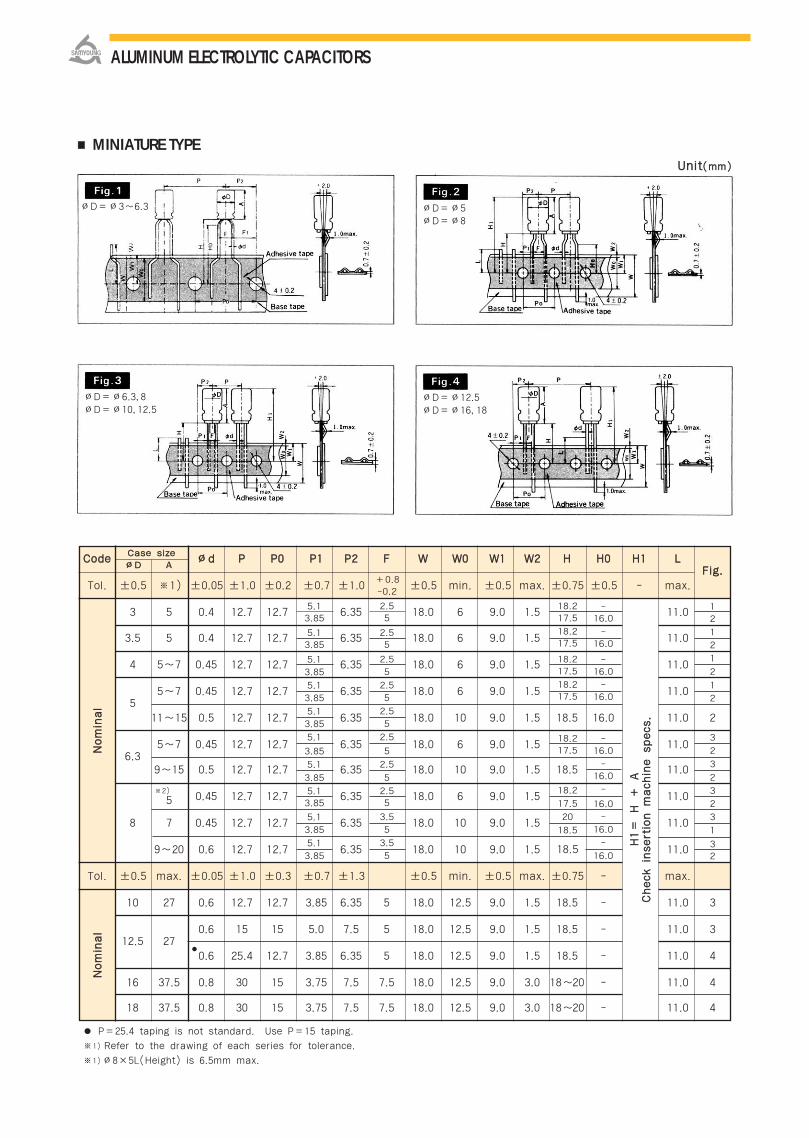
MINIATURE TYPE
CCooddee ∅∅dd PP PP00 PP11 PP22 FF WW WW00 WW11 WW22 HH HH00 HH11 LLFFiigg..
Tol. ±0.5 ※1) ±0.05 ±1.0 ±0.2 ±0.7 ±1.0 ±0.5 min. ±0.5 max. ±0.75 ±0.5 - max.
3 5 0.4 12.7 12.7 6.35 18.0 6 9.0 1.5 11.0
3.5 5 0.4 12.7 12.7 6.35 18.0 6 9.0 1.5 11.0
4 5~7 0.45 12.7 12.7 6.35 18.0 6 9.0 1.5 11.0
55~7 0.45 12.7 12.7 6.35 18.0 6 9.0 1.5 11.0
11~15 0.5 12.7 12.7 6.35 18.0 10 9.0 1.5 18.5 16.0 11.0 2
6.35~7 0.45 12.7 12.7 6.35 18.0 6 9.0 1.5 11.0
9~15 0.5 12.7 12.7 6.35 18.0 10 9.0 1.5 18.5 11.0
5 0.45 12.7 12.7 6.35 18.0 6 9.0 1.5 11.0
8 7 0.45 12.7 12.7 6.35 18.0 10 9.0 1.5 11.0
9~20 0.6 12.7 12.7 6.35 18.0 10 9.0 1.5 11.0
Tol. ±0.5 max. ±0.05 ±1.0 ±0.3 ±0.7 ±1.3 ±0.5 min. ±0.5 max. ±0.75 - max.
10 27 0.6 12.7 12.7 3.85 6.35 5 18.0 12.5 9.0 1.5 18.5 - 11.0 3
12.5 270.6 15 15 5.0 7.5 5 18.0 12.5 9.0 1.5 18.5 - 11.0 3
0.6 25.4 12.7 3.85 6.35 5 18.0 12.5 9.0 1.5 18.5 - 11.0 4
16 37.5 0.8 30 15 3.75 7.5 7.5 18.0 12.5 9.0 3.0 18~20 - 11.0 4
18 37.5 0.8 30 15 3.75 7.5 7.5 18.0 12.5 9.0 3.0 18~20 - 11.0 4
P=25.4 taping is not standard. Use P=15 taping.
※1) Refer to the drawing of each series for tolerance.
※1)∅8×5L(Height) is 6.5mm max.
5.13.85
5.13.85
5.1
3.85
5.1
3.85
5.1
3.85
5.1
3.85
5.1
3.85
5.13.85
5.1
3.85
5.1
3.85
2.55
2.55
2.5
5
2.5
5
2.5
5
2.5
5
2.5
5
2.55
3.5
5
3.5
5
18.217.5
18.217.5
18.217.5
18.217.5
18.217.5
18.2
17.5
20
18.5
18.5
12
1
2
1
2
1
2
3
2
3
2
3
2
3
1
32
CCaassee ssiizzee
∅∅DD AA
NNoommiinnaall
NNoommiinnaall
HH11==
HH ++
AA
CChheecckk iinnsseerrttiioonn mmaacchhiinnee ssppeeccss..
※2)
+0.8-0.2
-16.0
-16.0
-16.0
-16.0
-16.0
-16.0
-
16.0
-
16.0
-
16.0
UUnniitt((mmmm))
∅D=∅3~6.3 ∅D=∅5∅D=∅8
∅D=∅12.5∅D=∅16, 18
∅D=∅6.3, 8∅D=∅10, 12.5
ALUMINUM ELECTROLYTIC CAPACITORS
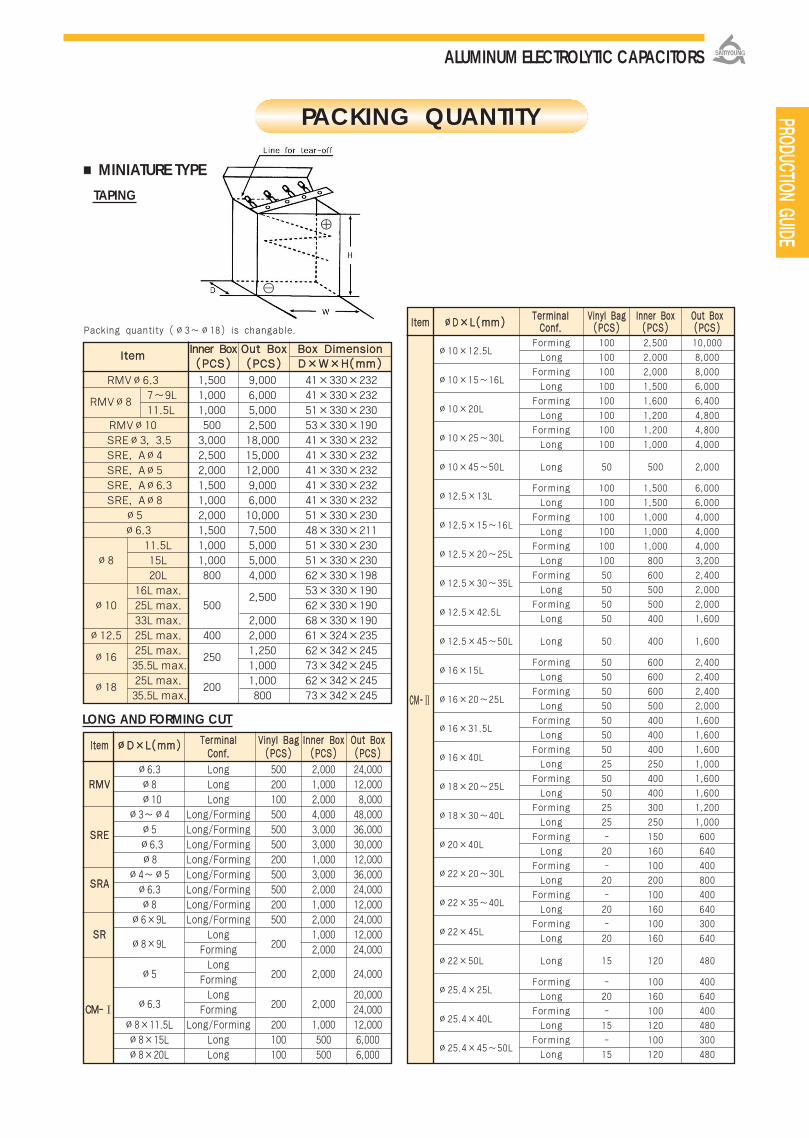
IItteemmIInnnneerr BBooxx OOuutt BBooxx BBooxx DDiimmeennssiioonn((PPCCSS)) ((PPCCSS)) DD××WW××HH((mmmm))
RMV∅6.3 1,500 9,000 41×330×232
RMV∅87~9L 1,000 6,000 41×330×232
11.5L 1,000 5,000 51×330×230
RMV∅10 500 2,500 53×330×190
SRE∅3, 3.5 3,000 18,000 41×330×232
SRE, A∅4 2,500 15,000 41×330×232
SRE, A∅5 2,000 12,000 41×330×232
SRE, A∅6.3 1,500 9,000 41×330×232
SRE, A∅8 1,000 6,000 41×330×232
∅5 2,000 10,000 51×330×230
∅6.3 1,500 7,500 48×330×211
11.5L 1,000 5,000 51×330×230
∅8 15L 1,000 5,000 51×330×230
20L 800 4,000 62×330×198
16Lmax.2,500
53×330×190
∅10 25Lmax. 500 62×330×190
33Lmax. 2,000 68×330×190
∅12.5 25Lmax. 400 2,000 61×324×235
∅1625Lmax.
2501,250 62×342×245
35.5L max. 1,000 73×342×245
∅1825Lmax.
2001,000 62×342×245
35.5L max. 800 73×342×245
IItteemm ∅∅DD××LL((mmmm)) TTeerrmmiinnaall VViinnyyll BBaagg IInnnneerr BBooxx OOuutt BBooxxCCoonnff.. ((PPCCSS)) ((PPCCSS)) ((PPCCSS))
∅6.3 Long 500 2,000 24,000RRMMVV ∅8 Long 200 1,000 12,000
∅10 Long 100 2,000 8,000
∅3~∅4 Long/Forming 500 4,000 48,000
∅5 Long/Forming 500 3,000 36,000SSRREE∅6.3 Long/Forming 500 3,000 30,000
∅8 Long/Forming 200 1,000 12,000
SSRRAA∅4~∅5 Long/Forming 500 3,000 36,000
∅6.3 Long/Forming 500 2,000 24,000
∅8 Long/Forming 200 1,000 12,000
∅6×9L Long/Forming 500 2,000 24,000SSRR
∅8×9LLong
2001,000 12,000
Forming 2,000 24,000
∅5Long
200 2,000 24,000Forming
∅6.3Long
200 2,00020,000
CCMM--Ⅰ Forming 24,000
∅8×11.5L Long/Forming 200 1,000 12,000
∅8×15L Long 100 500 6,000
∅8×20L Long 100 500 6,000
Packing quantity (∅3~∅18) is changable.
LONG AND FORMING CUT
PACKING QUANTITY
MINIATURE TYPETAPING
PRODUCTION GUIDE
CCMM--Ⅱ
IItteemm ∅∅DD××LL((mmmm))TTeerrmmiinnaall VViinnyyll BBaagg IInnnneerr BBooxx OOuutt BBooxxCCoonnff.. ((PPCCSS)) ((PPCCSS)) ((PPCCSS))
∅10×12.5LForming 100 2,500 10,000
Long 100 2,000 8,000
∅10×15~16LForming 100 2,000 8,000
Long 100 1,500 6,000
∅10×20LForming 100 1,600 6,400
Long 100 1,200 4,800
∅10×25~30LForming 100 1,200 4,800
Long 100 1,000 4,000
∅10×45~50L Long 50 500 2,000
∅12.5×13LForming 100 1,500 6,000
Long 100 1,500 6,000
∅12.5×15~16LForming 100 1,000 4,000
Long 100 1,000 4,000
∅12.5×20~25LForming 100 1,000 4,000
Long 100 800 3,200
∅12.5×30~35LForming 50 600 2,400
Long 50 500 2,000
∅12.5×42.5LForming 50 500 2,000
Long 50 400 1,600
∅12.5×45~50L Long 50 400 1,600
∅16×15LForming 50 600 2,400
Long 50 600 2,400
∅16×20~25LForming 50 600 2,400
Long 50 500 2,000
∅16×31.5LForming 50 400 1,600
Long 50 400 1,600
∅16×40LForming 50 400 1,600
Long 25 250 1,000
∅18×20~25LForming 50 400 1,600
Long 50 400 1,600
∅18×30~40LForming 25 300 1,200
Long 25 250 1,000
∅20×40LForming - 150 600
Long 20 160 640
∅22×20~30LForming - 100 400
Long 20 200 800
∅22×35~40LForming - 100 400
Long 20 160 640
∅22×45LForming - 100 300
Long 20 160 640
∅22×50L Long 15 120 480
∅25.4×25LForming - 100 400
Long 20 160 640
∅25.4×40LForming - 100 400
Long 15 120 480
∅25.4×45~50LForming - 100 300
Long 15 120 480
ALUMINUM ELECTROLYTIC CAPACITORS
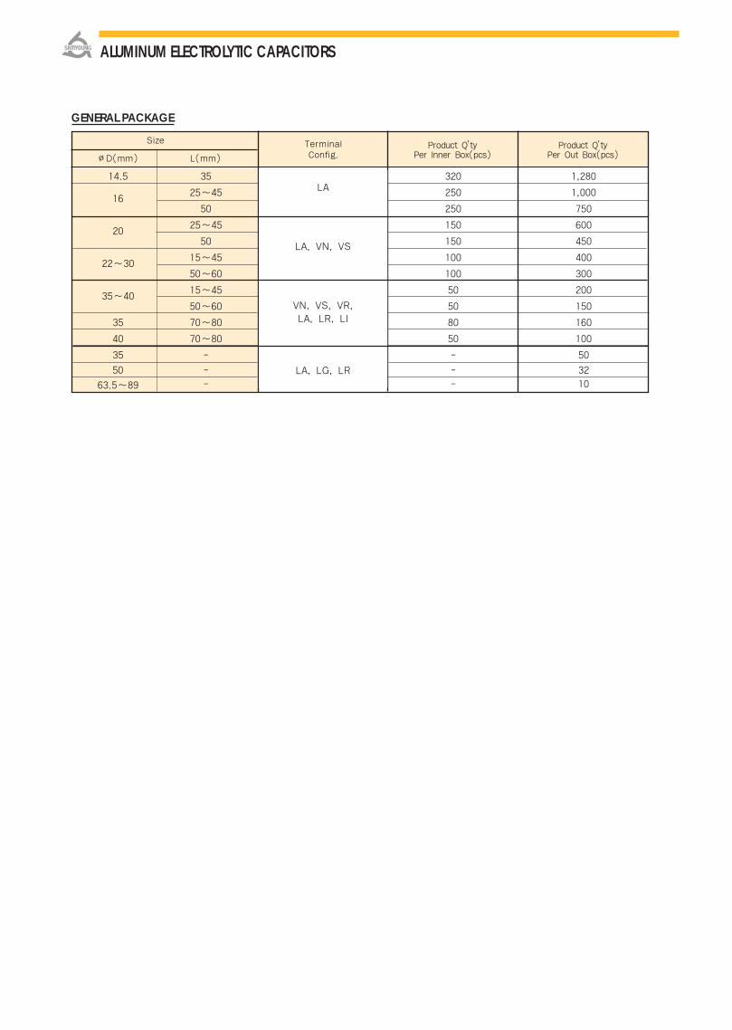
GENERAL PACKAGE
14.5 35 320 1,280
1625~45 250 1,000
50 250 750
2025~45 150 600
50 150 450
22~3015~45 100 400
50~60 100 300
35~4015~45 50 200
50~60 50 150
35 70~80 80 160
40 70~80 50 100
35 - - 50
50 - - 32
63.5~89 - - 10
Size Terminal Product Q’ty Product Q’ty
∅D(mm) L(mm) Config. Per Inner Box(pcs) Per Out Box(pcs)
LA
LA, VN, VS
VN, VS, VR,LA, LR, LI
LA, LG, LR
ALUMINUM ELECTROLYTIC CAPACITORS
Conductive Polymer Aluminum Solid Capacitors

회회로로 설설계계시시 주주의의 사사항항DDEESSIIGGNNIINNGG DDEEVVIICCEE CCIIRRCCUUIITTSS
PRECAUTIONS AND GUIDELINES (CONDUCTIVE POLYMER SOLID CAPACITORS)
1. Types of circuits where reALcap capacitorsare not to be used
The leakage current may increase due to soldering andother processes. Since large leakage current can bringproblems, avoid the use of conductive polymer solidcapacitors(hereafter called solid capacitors) in thefollowing circuits.
1) High impedance circuits
2) Time constant circuitsThe capacitance can be varied depending theoperating conditions. The change of capacitanceaffects the time constant circuit.
3) Coupling circuits4) Other circuits where circuits are affected by leakage
current.
2. Polarity
Solid Capacitors are polarized. Do not apply either rev-erse voltage or AC voltage to the solid capacitor. Rev-erse voltage may cause a short circuit.
3. Rated voltage
Do not apply voltage exceeding rated voltage.Overvoltage may cause a short circuit.
4. Operating Temperature
Do not use the solid capacitor at temperature which ex-ceeds the specified range. High temperature may ca-use decrease the life of the solid capacitor.
5. Ripple current
Do not apply the exceeding current which valueexceeds the rated ripple current. The over ripplecurrent cause decrease the life of the solid capacitor.
6. Charge and discharge
Do not use the solid capacitor in circuits for rapidcharge and discharge repetitively. Repetitively charge and discharge of capacitors mayreduce the capacitance.
1. 고체콘덴서 사용을 피해야 하는 회로
누설전류는 납땜이나 다른 이유로 인해 증가할 수 있습니다.
누설전류는 문제를 야기할 수 있기 때문에 아래의 회로에는
고체콘덴서 사용을 피하여 주십시오. (전도성 고분자 고체 콘
덴서를 축약하여 고체 콘덴서로 표기함.)
1 ) 큰 임피던스를 갖는 회로
2) 시정수용 회로
고체콘덴서는작동조건에따라용량이변할수있습니다.
용량의 변화는 시정수 회로에 향을 줍니다.
3) 커플링 회로
4) 누설전류에 의해 향을 받는 회로
2. 극성
고체콘덴서는 극성을 갖고 있습니다. 역전압이나 교류전압을
고체콘덴서에 인가하지 마십시오. 역전압은 고체콘덴서를 쇼트
시킬 수 있습니다.
3. 정격전압
정격전압을 초과하는 전압을 인가하지 마십시오.
과전압은 고체콘덴서를 쇼트 시킬 수 있습니다.
4. 사용 온도
보증 온도를 초과하는 온도에서 고체콘덴서를 사용하지 마십
시오. 높은 온도는 고체콘덴서의 수명을 줄어들게 합니다.
5. 리플 전류
정격 리플전류를 초과하는 전류를 인가하지 마십시오. 과도한
리플전류는 고체콘덴서의 수명을 줄어들게 합니다.
6. 충전과 방전
고체콘덴서를 빠르게 충전과 방전을 반복하는 회로에 사용
하지 마십시오. 반복적인 충전과 방전은 용량을 줄어들게 합
니다.
CONDUCTIVE POLYMER ALUMINUM SOLID CAPACITORS

7. Insulation
Aluminum case, cathode lead wire, anode lead wireand circuit pattern should be electrically isolated.
8. Solid Capacitor Usage EnvironmentThe following environment should be avoided.
1) Damp conditions such as water, saltwater spray,or oil spray or fumes.High humidity or humidity condensation situations.
2) Hazardous gas/fumes such as hydrogen sulfide,sulfurous acid gas, nitrous acid, chlorine gas orammonia.
3) Ozone, ultraviolet rays or radiation.
4) Severe vibration or mechanical shock.
9. Capacitor Mounting
1) Surface Mount TypeLand pattern on PCB board should comply with thespecification.
2) Radial TypeInterval of terminal holes on the PCB is inaccordance with the specification.
1. Installing
1) Do not reuse capacitors which already ass-embled.
2) The capacitor may have self-charge duringstorage time. In this case, discharge the capacitorthrough about 1kΪ resistor before use.
3) Leakage current of capacitors may be increasedduring storage. In this case, the capacitors can bereformed by the voltage treatment through about1kΪ resistor.
<Voltage Treatment>Applying rated voltage for 120 minutes at maximumoperating temperature range.4) Do not apply severe vibration or mechanical
shock.
7. 절연
알루미늄 케이스, 음극 단자선, 양극 단자선 그리고 회로
패턴은 전기적으로 절연상태에 있어야 합니다.
8. 고체콘덴서 사용 환경
아래의 환경은 피해 주십시오.
1) 습한 환경
(물, 소금물, 기름이 있는 환경)
2) 유해한 가스
(황화 수소, 아황산 가스, 아질산, 염소, 암모니아)가 있는 환경
3) 오존, 자외선이 있는 환경
4) 진동과 기계적 충격이 있는 환경
9. 고체콘덴서의 장착
1) SMD 타입 제품
PCB의 패턴은 규정과 일치해야 합니다.
2) RADIAL 타입 제품
PCB의 홀 간격은 규정과 일치해야 합니다.
1. 설치
1) 장착되었던 콘덴서를 다시 사용하지 마십시오.
2) 고체콘덴서는 보관 중에 충전될 수 있습니다. 이 경우에는,
사용 전에 약 1kΪ 저항을 통하여 방전하십시오.
3) 누설전류는 보관 중에 증가할 수 있습니다. 이 경우에, 고체
콘덴서는 1kΪ 저항을 통하여 전압처리를 한 후에 사용하
십시오.
<전압처리>
최고사용온도에서120분동안정격전압인가.
4) 진동이나기계적충격을주지마십시오.
IINNSSTTAALLLLIINNGG CCAAPPAACCIITTOORRSS
CCoonndduuccttiivvee PPoollyymmeerr
CONDUCTIVE POLYMER ALUMINUM SOLID CAPACITORS
콘콘덴덴서서 설설치치

2. Soldering
The leakage current may increase due to thermal stressthat occur during soldering. Ensure the solderingconditions meet the specifications.
2-1. Soldering with a soldering iron
1) Ensure the lead spacing of the solid capacitor meetsthe hole spacing on the PCB board.
2) Ensure the soldering conditions meets the approval sheet.
3) Soldering iron should not touch the solid capacitor’sbody.
2-2. Reflow soldering
1) Reflow soldering must not be used for radial typesolid capacitors.
2) Soldering conditions(preheat, solder temperature andreflow time) should be within the limits prescribed inthe catalogs or product specifications.
3) For setting a degree of heating infrared heaters,consider that the infrared absorption may vary in thecolor and materials of a solid capacitor.
4) Do not solder solid capacitors more than once byreflow.
3. Handling after soldering
1) Do not lean or twist the solid capacitor’s body aftersoldering on PCB.
2) Do not pick-up or move PCB by holding the solderedsolid capacitors.
4. Cleaning PCB boards
4-1. Agents must be avoided
1) Do not wash boards by using the following agents. Halogenated solvents Alkali system solvents Petroleum system solvents Xylene, Acetone
2) Monitor conductivity, pH, specific gravity and thewater content before cleaning boards.
2. 납땜
누설전류는 납땜 중에 발생하는 열 충격에 의하여 증가할 수
있습니다. 납땜조건이 규정을 만족하는지 확인하십시오.
2-1. 인두를 사용한 납땜
1) 고체콘덴서의 단자간격이 PCB 기판의 홀 간격과 일치하는
지 확인하십시오.
2) 납땜 조건이 승인원을 만족하는지 확인하십시오.
3) 납땜 인두로 고체콘덴서 몸체를 접촉하지 마십시오.
2-2. 리플로 납땜
1) 리플로 솔더링은 RADIAL 타입 고체콘덴서에 적용하지 마
십시오.
2) 솔더링 조건(온도 및 시간)은 카탈로그나 제품승인원에서
규정한 제한치 이내이어야 합니다.
3) 적외선 히터 사용시, 고체콘덴서 색상과 재질에 따라 적외
선 흡수율이 상이함을 고려하십시오.
4) 고체콘덴서를 2회 이상 리플로를 통과시키지 마십시오.
3. 납땜 후 관리
1) 납땜 후 고체콘덴서의 몸체를 기울이거나 비틀지 마십시오.
2) 납땜되어진 고체콘덴서를 잡고 PCB 기판을 들어올리거나
움직이지 마십시오.
4. PCB 기판 세척
4-1. 피해야 할 세척제
1) 아래의 약품으로 세척하지 마십시오. Halogenated solvents Alkali system solvents Petroleum system solvents Xylene, Acetone
2) 기판 세척 전에, 세척제의 전도도, pH, 비중과 수분함유량
을 확인하십시오.
CONDUCTIVE POLYMER ALUMINUM SOLID CAPACITORS

3) Influence of cleaning agents(Halogenated solvents)Solid capacitors are easily affected by halogenions, particularly by chloride ions. When halogenions enter the inside of the solid capacitor, thecapacitor may be failed due to corrosion ofcapacitor’s foil.
4-2. Recommended Agents
1) Higher alcohol cleaning agentsSolid capacitors may withstand immersion orultrasonic cleaning for 10 minutes at a maximumliquid temperature of 60
2) IPA(Isopropyl Alcohol)Solid capacitors are capable of withstanding anyone of immersion, ultrasonic or vapor cleaningfor 5 minutes.
5. Using adhesives and coating materials
1) Do not use halogenated adhesives and coatingmaterials.
2) Flux and cleaning agents should be removedbefore using adhesives or coating materials.
3) Do not cover up the whole surface of the solidcapacitor. Make coverage only partial.(The sealing area 30%)
Do not directly touch the solid capacitor terminals. Do not connect with conductors between the
terminals. The following environment should be avoided
when using solid capacitors.
- Damp conditions such as water, saltwaterspray, or oil spray or fumes, High humidity orhumidity condensation situations.
- Hazardous gas/fumes such as hydrogensulfide, sulfurous acid gas, nitrous acid,
3) 할로겐계세척제의문제점
고체콘덴서는 할로겐 이온(특히 염소 이온)에 의해 쉽게 향
을 받습니다. 할로겐 이온들이 고체콘덴서 내부에 침투하게 되
면, 콘덴서 박의 부식에 의해 고장날 수 있습니다.
4-2. 권장 세척제
1) Higher alcohol cleaning agents
고체콘덴서는침적혹은초음파세척을최 60에서10분동안
견딜수있습니다.
2) IPA(Isopropyl Alcohol)
고체콘덴서는 침적이나 초음파 혹은 증기 세척을 5분 동안
견딜 수 있습니다.
5. 제품의 고정제와 코팅제
1) 할로겐계의 고정제와 코팅제를 사용하지 마십시오.
2) 고정제와 코팅제를 사용하기 전에, 플럭스와 세척제를 제거
하십시오.
3) 고체콘덴서 봉구부 전체를 봉시키지 마십시오.
(봉구부의 30% 이하)
콘덴서 단자를 직접적으로 만지지 마십시오. 단자 사이를 도전체로 연결하지 마십시오.
아래의 환경에서는 고체콘덴서 사용을 피하여 주십시오.
- 습한 환경 (물, 소금물, 기름이 있는 환경)
- 유해 가스 (황화 수소, 아황산 가스, 아질산, 염소, 암모니
아 등) 에 노출된 환경
기기기기 작작동동 중중 주주의의사사항항TTHHEE OOPPEERRAATTIIOONN OOFF DDEEVVIICCEESS
CCoonndduuccttiivvee PPoollyymmeerr
CONDUCTIVE POLYMER ALUMINUM SOLID CAPACITORS

chlorine gas or ammonia.- Exposure to ozone, ultraviolet rays or radiation.
If a short circuit occurs and odorous gas isreleased, immediately turn off the main powerswitch or pull out the plug from the power outlet.
If the gas comes in contact with eyes or skin,rinse immediately. If the gas is inhaled, gargleimmediately.
Do not store solid capacitors at a hightemperature and high humidity. Store the solidcapacitors indoors at a temperature 5~35 and ahumidity of less than 75%RH.
Store solid capacitors in places free from water,oil or salt water.
Store solid capacitors in places free from toxicgases(hydrogen sulfide, sulfurous acid, nitrousacid, chlorine, ammonium, etc.)
Store solid capacitors in places out of ozone,ultraviolet rays or radiation.
Keep solid capacitors in the package.
Case sizes and other product standards specifiedin this catalog may be changed or modifiedwithout notice for improvement of quality.
- 오존, 자외선에 노출된 환경
콘덴서가 쇼트 되거나 냄새가 나는 가스를 배출하면, 즉시
전원을 끄십시오.
배출된 가스가 눈이나 피부에 닿게되면, 즉시 세척하십시
오. 가스 흡입 시 입안을 닦아 주십시오.
고체콘덴서를 고온/다습한 환경에서 보관하지 마십시오. 온
도가 5~35, 습도가 75%RH 이하인 실내에서 보관하여
주십시오.
물이나 소금물, 기름이 없는 장소에 보관하십시오.
유해 가스(황화 수소, 아황산 가스, 아질산, 염소, 암모니아
등)가 없는 환경에서 보관하십시오.
오존, 자외선이 없는 곳에서 보관하십시오.
고체콘덴서를 포장된 상태에서 보관하십시오.
카탈로그에 규정된 케이스 사이즈나 다른 제품 기준은 품질
개선을 위하여 귀사에 통지 없이 변경될 수 있습니다.
보보관관 조조건건CCOONNDDIITTIIOONNSS OOFF SSTTOORRAAGGEE
기기타타OOTTHHEERRSS
응응급급 조조치치EEMMEERRGGEENNCCYY AACCTTIIOONN
CONDUCTIVE POLYMER ALUMINUM SOLID CAPACITORS
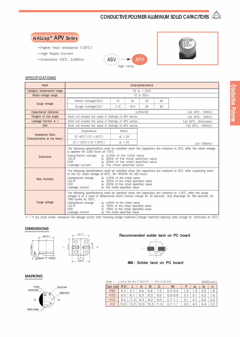
reALcapTM APV Series
SSPPEECCIIFFIICCAATTIIOONNSS
-55 to +125
10 to 35VDC
±20%(M)
Shall not exceed the value in Ratings of APV series.
Shall not exceed the value in Ratings of APV series.
Shall not exceed the value in Ratings of APV series.
(at 20, 120Hz)
(at 20, 120Hz)
(at 20, 2minutes)
(at 20, 100kHz)
IItteemm
CCaatteeggoorryy tteemmppeerraattuurree rraannggee
RRaatteedd vvoollttaaggee rraannggee
SSuurrggee vvoollttaaggee
CCaappaacciittaannccee ttoolleerraannccee
TTaannggeenntt ooff lloossss aannggllee
LLeeaakkaaggee CCuurrrreenntt ※※ 11
EESSRR
IImmppeeddaannccee RRaattiioo((CChhaarraacctteerriissttiiccss aatt llooww tteemmpp..))
EEnndduurraannccee
BBiiaass HHuummiiddiittyy
SSuurrggee vvoollttaaggee
CChhaarraacctteerriissttiiccss
The following specifications shall be satisfied when the capacitors are restored to 20 after the rated voltageis applied for 2,000 hours at 125.Capacitance change ±20% of the initial value Tan δ 200% of the initial specified value ESR 200% of the initial specified valueLeakage current The initial specified value
The following specifications shall be satisfied when the capacitors are restored to 20 after subjecting themto the DC rated voltage at 60, 90~95%RH for 500 hours.Capacitance change ±20% of the initial valueTan δ 200% of the initial specified valueESR 200% of the initial specified valueLeakage current The initial specified value
The following specifications shall be satisfied when the capacitors are restored to +20 after the surgevoltage is at a cycle of 360seconds which consist charge for 30 seconds and discharge for 330 seconds, for1000 cycles at 125.Capacitance change ±20% of the initial valueTan δ 150% of the initial specified valueESR 150% of the initial specified valueLeakage current The initial specified value
Higher heat resistance (125)
High Ripple Current
Endurance 125, 2,000hrs
Rated Voltage(WV) 10
11.5 18.4
16
29
25
40
35
Surge Voltage(SV)
Impedance Ratio
1.25
1.25 (at 100kHz)
Z(-55)/Z(+20)
Z(+125)/Z(+20)
CCoonndduuccttiivvee PPoollyymmeerr
※ 1:If any doubt arises, remeasure the leakage current after following voltage treatment.(Voltage treatment:Applying rated voltage for 120minutes at 125)
Unit(mm)
CCaassee ccooddee ∅∅DD LL AA BB CC WW PP aa bb ccF60 6.3 5.7 6.6 6.6 7.2 0.5-0.8 1.9 1.9 3.5 1.6
H70 8.0 6.7 8.3 8.3 9.0 0.5-0.8 3.1 3.1 4.2 1.6
H12 8.0 11.5 8.3 8.3 9.0 0.7-1.1 3.1 3.1 4.2 2.2J12 10.0 12.2 10.3 10.3 11.0 0.7-1.1 4.5 4.5 4.4 2.2
AASSVV AAPPVVHigh Temp.
CONDUCTIVE POLYMER ALUMINUM SOLID CAPACITORS
: Solder land on PC board
Recommended solder land on PC board
DIMENSIONS
MARKING
Note 1 : L±0.5 for 8×11.5(H12) ~ 10×12.2(J12)

RRAATTIINNGGSS OOFF AAPPVV SSeerriieess
25
10
35
25
16
35
25
35
25
10
56
8.2
22
82
22
47
47
82
65
45
70
48
40
50
30
30
28
474
538
400
580
670
700
943
1,150
1,202
1,500
1,700
1,300
1,835
2,120
2,300
2,980
3,650
3,800
0.10
0.12
0.10
0.10
0.12
0.12
0.12
0.12
0.12
50
112
57
110
262
154
235
329
410
FF6600
HH7700
HH1122
JJ1122
CCaassee CCooddee RRaatteedd VVoollttaaggee((VV))
RRaatteeddCCaappaacciittaannccee
((μμFF))
EESSRR((mmΪΪ))((aatt 110000kkHHzz))
RRaatteedd RRiippppllee CCuurrrreenntt((mmAArrmmss)) aatt 110000kkHHzz
110055<<TTeemmpp..112255 TTeemmpp..110055
TTaannggeenntt ooff lloossss aannggllee
LLeeaakkaaggee CCuurrrreenntt((μμAA))
CONDUCTIVE POLYMER ALUMINUM SOLID CAPACITORS
CCoonndduuccttiivvee PPoollyymmeerr
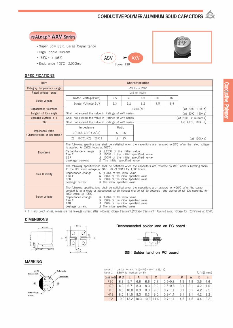
reALcapTM AXV Series
SSPPEECCIIFFIICCAATTIIOONNSS
-55 to +105
2.5 to 16VDC
±20%(M)
Shall not exceed the value in Ratings of AXV series.
Shall not exceed the value in Ratings of AXV series.
Shall not exceed the value in Ratings of AXV series.
(at 20, 120Hz)
(at 20, 120Hz)
(at 20, 2 minutes)
(at 20, 100kHz)
IItteemm
CCaatteeggoorryy tteemmppeerraattuurree rraannggee
RRaatteedd vvoollttaaggee rraannggee
SSuurrggee vvoollttaaggee
CCaappaacciittaannccee ttoolleerraannccee
TTaannggeenntt ooff lloossss aannggllee
LLeeaakkaaggee CCuurrrreenntt ※※ 11
EESSRR
IImmppeeddaannccee RRaattiioo((CChhaarraacctteerriissttiiccss aatt llooww tteemmpp..))
EEnndduurraannccee
BBiiaass HHuummiiddiittyy
SSuurrggee vvoollttaaggee
CChhaarraacctteerriissttiiccss
The following specifications shall be satisfied when the capacitors are restored to 20 after the rated voltageis applied for 2,000 hours at 105.Capacitance change ±20% of the initial value Tan δ 150% of the initial specified value ESR 150% of the initial specified valueLeakage current The initial specified value
The following specifications shall be satisfied when the capacitors are restored to 20 after subjecting themto the DC rated voltage at 60, 90~95%RH for 1,000 hours.Capacitance change ±20% of the initial valueTan δ 150% of the initial specified valueESR 150% of the initial specified valueLeakage current The initial specified value
The following specifications shall be satisfied when the capacitors are restored to +20 after the surgevoltage is at a cycle of 360seconds which consist charge for 30 seconds and discharge for 330 seconds, for1000 cycles at 105.Capacitance change ±20% of the initial valueTan δ 150% of the initial specified valueESR 150% of the initial specified valueLeakage current The initial specified value
Super Low ESR, Large Capacitance
High Ripple Current
-55~+105
Endurance 105, 2,000hrs
Rated Voltage(WV) 2.5
3.3 5.2 8.2 11.5 18.4
4 6.3 10 16
Surge Voltage(SV)
Impedance Ratio
1.25
1.25 (at 100kHz)
Z(-55)/Z(+20)
Z(+105)/Z(+20)
: Solder land on PC board
Unit(mm)
※ 1:If any doubt arises, remeasure the leakage current after following voltage treatment.(Voltage treatment: Applying rated voltage for 120minutes at 105)
CCaassee ccooddee ∅∅DD LL AA BB CC WW PP aa bb ccF60 6.3 5.7 6.6 6.6 7.2 0.5-0.8 1.9 1.9 3.5 1.6
H70 8.0 6.7 8.3 8.3 9.0 0.5-0.8 3.1 3.1 4.2 1.6
H10 8.0 10.0 8.3 8.3 9.0 0.7-1.1 3.1 3.1 4.2 2.2
H12 8.0 11.5 8.3 8.3 9.0 0.7-1.1 3.1 3.1 4.2 2.2
J12 10.0 12.2 10.3 10.3 11.0 0.7-1.1 4.5 4.5 4.4 2.2
Recommended solder land on PC board
AASSVV AAXXVVLower ESR
DIMENSIONS
MARKING
Note 1 : L±0.5 for 8×10.0(H10)~10×12.2(J12)Note 2 : 6.3WV is marked by 6V
CONDUCTIVE POLYMER ALUMINUM SOLID CAPACITORS

RRAATTIINNGGSS OOFF AAXXVV SSeerriieess
16
10
10
6.3
6.3
4
2.5
2.5
16
16
10
6.3
4
2.5
16
6.3
4
4
2.5
2.5
68
120
150
220
330
330
390
390
120
150
270
390
560
680
220
820
560
1,200
1,500
2,700
30
27
27
27
27
27
25
15
27
22
22
22
22
20
12
12
9
12
10
12
2,200
2,320
2,320
2,320
2,320
2,320
2,410
3,160
2,900
3,220
3,220
3,220
3,220
3,370
5,060
4,700
5,380
4,700
5,150
5,080
0.12
0.12
0.12
0.12
0.12
0.12
0.12
0.12
0.12
0.12
0.12
0.12
0.12
0.12
0.12
0.15
0.15
0.15
0.15
0.15
300
300
300
300
415
300
300
300
500
500
500
491
500
500
704
1,033
500
960
750
1,350
FF6600
HH7700
HH1122
HH1100
JJ1122
CCaassee CCooddeeRRaatteedd VVoollttaaggee
((VV))RRaatteedd
CCaappaacciittaannccee((μμFF))EESSRR((mmΪΪ))((aatt 110000kkHHzz))
RRaatteedd RRiipppplleeCCuurrrreenntt((mmAArrmmss))
aatt 110000kkHHzz
TTaannggeenntt ooff lloossssaannggllee
LLeeaakkaaggee CCuurrrreenntt((μμAA))
CONDUCTIVE POLYMER ALUMINUM SOLID CAPACITORS

reALcapTM ASV Series
SSPPEECCIIFFIICCAATTIIOONNSS
-55 to +105
2.5 to 35VDC
±20%(M)
Shall not exceed the value in Ratings of ASV series.
Shall not exceed the value in Ratings of ASV series.
Shall not exceed the value in Ratings of ASV series.
(at 20, 120Hz)
(at 20, 120Hz)
(at 20, 2 minutes)
(at 20, 100kHz)
IItteemm
CCaatteeggoorryy tteemmppeerraattuurree rraannggee
RRaatteedd vvoollttaaggee rraannggee
SSuurrggee vvoollttaaggee
CCaappaacciittaannccee ttoolleerraannccee
TTaannggeenntt ooff lloossss aannggllee
LLeeaakkaaggee CCuurrrreenntt ※※ 11
EESSRR
IImmppeeddaannccee RRaattiioo((CChhaarraacctteerriissttiiccss aatt llooww tteemmpp..))
EEnndduurraannccee
BBiiaass HHuummiiddiittyy
SSuurrggee vvoollttaaggee
CChhaarraacctteerriissttiiccss
The following specifications shall be satisfied when the capacitors are restored to 20 after the rated voltageis applied for 2,000 hours at 105.Capacitance change ±20% of the initial value Tan δ 150% of the initial specified value ESR 150% of the initial specified valueLeakage current The initial specified value
The following specifications shall be satisfied when the capacitors are restored to 20 after subjecting themto the DC rated voltage at 60, 90~95%RH for 1,000 hours.Capacitance change ±20% of the initial valueTan δ 150% of the initial specified valueESR 150% of the initial specified valueLeakage current The initial specified value
The following specifications shall be satisfied when the capacitors are restored to +20 after the surgevoltage is at a cycle of 360seconds which consist charge for 30 seconds and discharge for 330 seconds, for1000 cycles at 105.Capacitance change ±20% of the initial valueTan δ 150% of the initial specified valueESR 150% of the initial specified valueLeakage current The initial specified value
Low ESR (at 100kHz~300kHz)
High Ripple Current
-55~+105
Endurance 105, 2,000hrs
Rated Voltage(WV) 2.5
3.3 5.2 8.2 11.5 18.4 23.0 29.0 40.0
4 6.3 10 16 20 25 35
Surge Voltage(SV)
Impedance Ratio
1.25
1.25 (at 100kHz)
Z(-55)/Z(+20)
Z(+105)/Z(+20)
CCoonndduuccttiivvee PPoollyymmeerr
※ 1:If any doubt arises, remeasure the leakage current after following voltage treatment.(Voltage treatment:Applying rated voltage for 120minutes at 105)
Unit(mm)
CCaassee ccooddee ∅∅DD LL AA BB CC WW PP aa bb ccF60 6.3 5.7 6.6 6.6 7.2 0.5-0.8 1.9 1.9 3.5 1.6
H70 8.0 6.7 8.3 8.3 9.0 0.5-0.8 3.1 3.1 4.2 1.6
H10 8.0 10.0 8.3 8.3 9.0 0.7-1.1 3.1 3.1 4.2 2.2
H12 8.0 11.5 8.3 8.3 9.0 0.7-1.1 3.1 3.1 4.2 2.2
J10 10.0 10.0 10.3 10.3 11.0 0.7-1.1 4.5 4.5 4.4 2.2
J12 10.0 12.2 10.3 10.3 11.0 0.7-1.1 4.5 4.5 4.4 2.2
CONDUCTIVE POLYMER ALUMINUM SOLID CAPACITORS
: Solder land on PC board
Recommended solder land on PC board
DIMENSIONS
MARKINGNote 1 : L±0.5 for 8×10.0(H10)~10×12.2(J12)Note 2 : 6.3WV is marked by 6V

CONDUCTIVE POLYMER ALUMINUM SOLID CAPACITORSRRAATTIINNGGSS OOFF AASSVV SSeerriieess
10
10
6.8
22
27
39
47
47
56
82
100
120
150
33
47
56
82
120
150
220
150
330
47
68
180
220
270
330
22
33
33
100
180
330
470
560
680
680
56
150
330
470
560
680
1,200
1,500
56
150
330
560
820
1,200
1,500
80
45
45
40
40
35
35
30
30
30
30
30
30
45
45
45
40
35
35
35
35
35
30
25
20
17
17
17
35
35
30
24
20
17
15
13
13
13
25
20
16
14
13
13
13
13
28
20
16
13
12
12
12
1,380
1,840
1,840
1,950
1,950
2,080
2,080
2,250
2,250
2,250
2,250
2,250
2,250
1,890
1,890
1,890
2,120
2,560
2,560
2,560
2,560
2,560
2,640
2,890
3,240
3,510
3,510
3,510
2,000
2,000
2,980
3,320
3,640
3,950
4,210
4,520
4,520
4,520
3,430
3,830
4,280
4,570
4,750
4,750
4,750
4,750
3,800
4,320
4,720
5,230
5,440
5,440
5,440
0.12
0.10
0.10
0.10
0.10
0.10
0.10
0.12
0.12
0.12
0.12
0.12
0.12
0.12
0.12
0.12
0.12
0.12
0.12
0.12
0.12
0.12
0.12
0.12
0.12
0.12
0.12
0.12
0.12
0.12
0.12
0.15
0.15
0.15
0.15
0.15
0.15
0.15
0.12
0.12
0.12
0.12
0.12
0.12
0.12
0.12
0.12
0.15
0.15
0.15
0.15
0.18
0.18
70
125
85
88
108
125
150
94
112
103
126
151
120
132
188
179
262
240
300
277
120
264
588
272
576
440
340
264
154
231
413
400
576
660
592
448
544
340
1,250
600
1,056
940
706
544
960
750
700
600
792
840
775
960
750
FF6600
HH1100
HH1122
JJ1100
JJ1122
CCaassee CCooddeeRRaatteedd VVoollttaaggee
((VV))RRaatteedd
CCaappaacciittaannccee((μμFF))EESSRR((mmΪΪ))((aatt 110000kkHHzz))
RRaatteedd RRiipppplleeCCuurrrreenntt((mmAArrmmss))
aatt 110000kkHHzz
TTaannggeenntt ooff lloossssaannggllee
LLeeaakkaaggee CCuurrrreenntt((μμAA))
25
35
25
20
20
16
16
10
10
6.3
6.3
6.3
4
20
20
16
16
10
10
6.3
4
4
25
20
16
10
6.3
4
25
35
35
20
16
10
6.3
4
4
2.5
25
20
16
10
6.3
4
4
2.5
20
25
16
10
6.3
4
2.5
HH7700

CCoonndduuccttiivvee PPoollyymmeerr
reALcapTM AXA Series
SSPPEECCIIFFIICCAATTIIOONNSS
-55 to +105
2.5 to 16VDC
±20%(M)
Shall not exceed the value in Ratings of AXA series.
Shall not exceed the value in Ratings of AXA series.
Shall not exceed the value in Ratings of AXA series.
(at 20, 120Hz)
(at 20, 120Hz)
(at 20, 2 minutes)
(at 20, 100kHz)
IItteemm
CCaatteeggoorryy tteemmppeerraattuurree rraannggee
RRaatteedd vvoollttaaggee rraannggee
SSuurrggee vvoollttaaggee
CCaappaacciittaannccee ttoolleerraannccee
TTaannggeenntt ooff lloossss aannggllee
LLeeaakkaaggee CCuurrrreenntt ※※ 11
EESSRR
IImmppeeddaannccee RRaattiioo((CChhaarraacctteerriissttiiccss aatt llooww tteemmpp..))
EEnndduurraannccee
BBiiaass HHuummiiddiittyy
SSuurrggee vvoollttaaggee
CChhaarraacctteerriissttiiccss
The following specifications shall be satisfied when the capacitors are restored to 20 after the rated voltageis applied for 2,000 hours at 105.Capacitance change ±20% of the initial value Tan δ 150% of the initial specified value ESR 150% of the initial specified valueLeakage current The initial specified value
The following specifications shall be satisfied when the capacitors are restored to 20 after subjecting themto the DC rated voltage at 60, 90~95%RH for 1,000 hours.Capacitance change ±20% of the initial valueTan δ 150% of the initial specified valueESR 150% of the initial specified valueLeakage current The initial specified value
The following specifications shall be satisfied when the capacitors are restored to +20 after the surgevoltage is at a cycle of 360seconds which consist charge for 30 seconds and discharge for 330 seconds, for1000 cycles at 105.Capacitance change ±20% of the initial valueTan δ 150% of the initial specified valueESR 150% of the initial specified valueLeakage current The initial specified value
Super Low ESR, Large Capacitance
High Ripple Current
-55~+105
Endurance 105, 2,000hrs
Rated Voltage(WV) 2.5
3.3 5.2 8.2 11.5 18.4
4 6.3 10 16
Surge Voltage(SV)
Impedance Ratio
1.25
1.25 (at 100kHz)
Z(-55)/Z(+20)
Z(+105)/Z(+20)
※ 1:If any doubt arises, remeasure the leakage current after following voltage treatment.(Voltage treatment: Applying rated voltage for 120minutes at 105)
AASSAA AAXXAALower ESR
DIMENSIONS MARKING
Note 1 : 6.3WV is marked by 6V
∅∅DD((++00..55mmaaxx..))
LL
LLmmaaxx..
∅∅dd((±±00..0055))
FF((±±00..55))
8.0
7.0
7.0max.
0.45
3.5
6.3
6.0
6.0max.
0.45
2.5
8.0
9.0
9.0max.
0.6
3.5
8.0
10.0
10max.
0.6
3.5
10.0
12.5
12.5max.
0.6
5.0
8.0
11.5
11.5max.
0.6
3.5
:Silver Color
Coating Case Type
CONDUCTIVE POLYMER ALUMINUM SOLID CAPACITORS
Unit(mm)
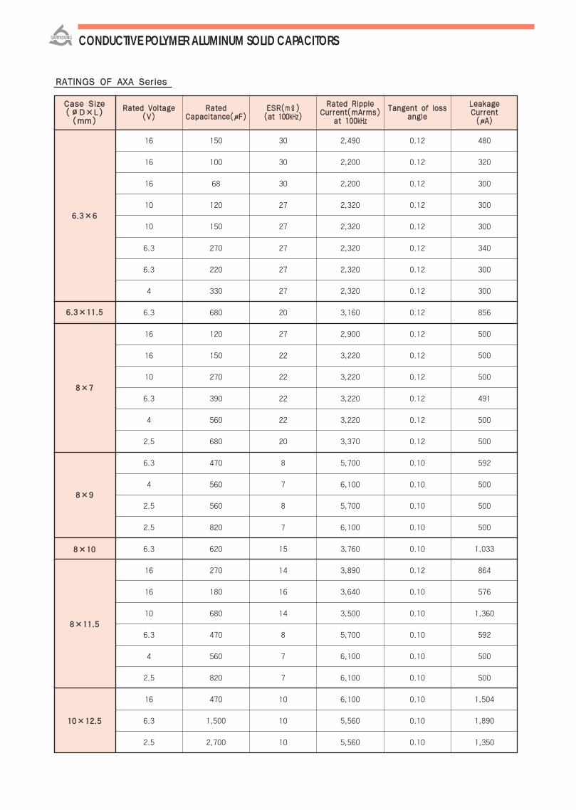
RRAATTIINNGGSS OOFF AAXXAA SSeerriieess
16
16
16
10
10
6.3
6.3
4
6.3
16
16
10
6.3
4
2.5
6.3
4
2.5
2.5
6.3
16
16
10
6.3
4
2.5
16
6.3
2.5
0.12
0.12
0.12
0.12
0.12
0.12
0.12
0.12
0.12
0.12
0.12
0.12
0.12
0.12
0.12
0.10
0.10
0.10
0.10
0.10
0.12
0.10
0.10
0.10
0.10
0.10
0.10
0.10
0.10
480
320
300
300
300
340
300
300
856
500
500
500
491
500
500
592
500
500
500
1,033
864
576
1,360
592
500
500
1,504
1,890
1,350
88××77
66..33××1111..55
66..33××66
88××1111..55
88××1100
88××99
1100××1122..55
CCaassee SSiizzee((∅∅DD××LL))((mmmm))
RRaatteedd VVoollttaaggee((VV))
RRaatteeddCCaappaacciittaannccee((μμFF))
EESSRR((mmΪΪ))((aatt 110000kkHHzz))
RRaatteedd RRiipppplleeCCuurrrreenntt((mmAArrmmss))
aatt 110000kkHHzz
TTaannggeenntt ooff lloossssaannggllee
LLeeaakkaaggee CCuurrrreenntt((μμAA))
CONDUCTIVE POLYMER ALUMINUM SOLID CAPACITORS
150
100
68
120
150
270
220
330
680
120
150
270
390
560
680
470
560
560
820
620
270
180
680
470
560
820
470
1,500
2,700
30
30
30
27
27
27
27
27
20
27
22
22
22
22
20
8
7
8
7
15
14
16
14
8
7
7
10
10
10
2,490
2,200
2,200
2,320
2,320
2,320
2,320
2,320
3,160
2,900
3,220
3,220
3,220
3,220
3,370
5,700
6,100
5,700
6,100
3,760
3,890
3,640
3,500
5,700
6,100
6,100
6,100
5,560
5,560
CCoonndduuccttiivvee PPoollyymmeerr
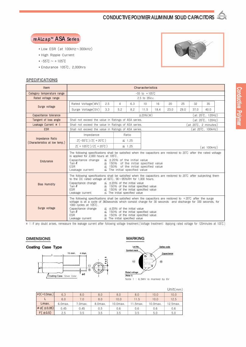
reALcapTM ASA Series
SSPPEECCIIFFIICCAATTIIOONNSS
-55 to +105
2.5 to 35VDC
±20%(M)
Shall not exceed the value in Ratings of ASA series.
Shall not exceed the value in Ratings of ASA series.
Shall not exceed the value in Ratings of ASA series.
(at 20, 120Hz)
(at 20, 120Hz)
(at 20, 2 minutes)
(at 20, 100kHz)
IItteemm
CCaatteeggoorryy tteemmppeerraattuurree rraannggee
RRaatteedd vvoollttaaggee rraannggee
SSuurrggee vvoollttaaggee
CCaappaacciittaannccee ttoolleerraannccee
TTaannggeenntt ooff lloossss aannggllee
LLeeaakkaaggee CCuurrrreenntt ※※ 11
EESSRR
IImmppeeddaannccee RRaattiioo((CChhaarraacctteerriissttiiccss aatt llooww tteemmpp..))
EEnndduurraannccee
BBiiaass HHuummiiddiittyy
SSuurrggee vvoollttaaggee
CChhaarraacctteerriissttiiccss
The following specifications shall be satisfied when the capacitors are restored to 20 after the rated voltageis applied for 2,000 hours at 105.Capacitance change ±20% of the initial value Tan δ 150% of the initial specified value ESR 150% of the initial specified valueLeakage current The initial specified value
The following specifications shall be satisfied when the capacitors are restored to 20 after subjecting themto the DC rated voltage at 60, 90~95%RH for 1,000 hours.Capacitance change ±20% of the initial valueTan δ 150% of the initial specified valueESR 150% of the initial specified valueLeakage current The initial specified value
The following specifications shall be satisfied when the capacitors are restored to +20 after the surgevoltage is at a cycle of 360seconds which consist charge for 30 seconds and discharge for 330 seconds, for1000 cycles at 105.Capacitance change ±20% of the initial valueTan δ 150% of the initial specified valueESR 150% of the initial specified valueLeakage current The initial specified value
Low ESR (at 100kHz~300kHz)
High Ripple Current
-55~+105
Endurance 105, 2,000hrs
Rated Voltage(WV) 2.5
3.3Surge Voltage(SV)
4
5.2
6.3
8.2
10
11.5
16
18.4
20
23.0
25
29.0
32
37.0
35
40.0
Impedance Ratio
1.25
1.25 (at 100kHz)
Z(-55)/Z(+20)
Z(+105)/Z(+20)
DIMENSIONS
※ 1:If any doubt arises, remeasure the leakage current after following voltage treatment.(Voltage treatment: Applying rated voltage for 120minutes at 105)
Coating Case Type
∅∅DD((++00..55mmaaxx..))
LL
LLmmaaxx..
∅∅dd((±±00..0055))
FF((±±00..55))
6.3
6.0
6.0max.
0.45
2.5
8.0
7.0
7.0max.
0.45
3.5
8.0
8.0
8.0max.
0.5
3.5
8.0
10.0
10.0max.
0.6
3.5
8.0
11.5
11.5max.
0.6
3.5
10.0
10.0
10.0max.
0.6
5.0
10.0
12.5
12.5max.
0.6
5.0
CONDUCTIVE POLYMER ALUMINUM SOLID CAPACITORS
MARKING
Coating Case Type
:Silver Color
Unit(mm)
Note 1 : 6.3WV is marked by 6V

RRAATTIINNGGSS OOFF AASSAA SSeerriieess
10
22
18
33
10
6.8
22
39
56
68
82
100
150
8.2
22
33
47
56
82
120
150
220
150
330
120
68
47
150
68
180
220
270
330
22
33
33
100
180
330
470
560
680
56
150
330
470
560
680
56
56
150
330
560
820
1,200
1,500
35
32
32
25
25
25
20
16
10
10
6.3
4
4
35
25
20
20
16
16
10
10
6.3
4
4
20
32
25
20
20
16
10
6.3
4
35
35
25
20
16
10
6.3
4
2.5
25
20
16
10
6.3
4
35
25
20
16
10
6.3
4
2.5
80
35
80
45
45
45
40
35
30
30
30
30
30
70
60
45
45
45
40
35
35
35
35
35
45
70
30
25
25
20
17
17
17
35
35
30
24
20
17
15
13
13
25
20
16
13
13
13
30
28
20
16
13
12
12
12
1,380
2,300
1,380
1,840
1,840
1,840
1,950
2,080
2,250
2,250
2,250
2,250
2,250
1,300
1,630
1,890
1,890
1,890
2,120
2,560
2,560
2,560
2,560
2,560
1,890
1,500
2,640
2,890
2,890
3,240
3,510
3,510
3,510
2,000
2,000
2,980
3,320
3,640
3,950
4,210
4,520
4,520
3,430
3,830
4,280
4,750
4,750
4,750
3,270
3,800
4,320
4,720
5,230
5,440
5,440
5,440
0.12
0.12
0.10
0.10
0.10
0.10
0.10
0.10
0.12
0.12
0.12
0.12
0.12
0.10
0.10
0.12
0.12
0.12
0.12
0.12
0.12
0.12
0.12
0.12
0.12
0.10
0.12
0.12
0.12
0.12
0.12
0.12
0.12
0.12
0.12
0.15
0.15
0.15
0.15
0.15
0.15
0.15
0.12
0.12
0.12
0.12
0.12
0.12
0.12
0.12
0.15
0.15
0.15
0.15
0.18
0.18
70
140
115
413
125
85
220
312
280
340
258
200
300
57
275
132
188
179
262
240
300
277
120
264
480
435
588
600
272
576
440
340
264
154
231
413
400
576
660
592
448
340
700
600
1,056
940
706
544
392
700
600
792
840
775
960
750
66..33××66
88××88
88××1100
88××1111..55
1100××1100
1100××1122..55
CCaassee SSiizzee((∅∅DD××LL))((mmmm))
RRaatteedd VVoollttaaggee((VV))
RRaatteeddCCaappaacciittaannccee((μμFF))
EESSRR((mmΪΪ))((aatt 110000kkHHzz))
RRaatteedd RRiipppplleeCCuurrrreenntt((mmAArrmmss))
aatt 110000kkHHzz
TTaannggeenntt ooff lloossssaannggllee
LLeeaakkaaggee CCuurrrreenntt((μμAA))
88××77
CONDUCTIVE POLYMER ALUMINUM SOLID CAPACITORS
Aluminum Electrolytic Capacitors

LIST OF SUBSTITUTE FOR DISCONTINUED SERIES
LIST OF SMD REPLACEMENTS
LIST OF RADIAL REPLACEMENTS
The following series are discontinued.Please use the recommended replacements in the table.
85 standard
105 standard
85 Bi-polarized
85 Bi-polarized
105 Bi-polarized
85 Bi-polarized
85 Bi-polarized
105 Bi-polarized
Low Impedance
Low Impedance
Ultra Low ESR
High Ripple
High Reliability
High Temperature
High Temperature, Low Impedance
7L Standard
Solvent - proof (5L, 7L)
5L Standard
5L Low Impedance
7L Low Impedance
SL,SM,SMS,SRF,SHL,SR
KM,KMC,KME,KRF,KMG
SRE-BP,SRA-BP
SM-BP(D), SMS-BP,SH-BP
KM-BP(D),KME-BP,KMG-BP
SM-BP(P)
SM-BP(S),SSA
KM-BP(S)
LXF
RX,RZ,SXA,SXC,SXE,LXJ,KXL
NXC
KHR,NFD(KMF),NFE(KMX)
KU,KUX
KXC,PXA
PXC
SRA
SRM,SRJ,KRE(ESA),KMA(HAS)
SRE
EXA
HXA
MHA
NHA
DSA-BP,GSA-BP
MHA-BP
NHA-BP
SSP
KSA
KSA
NXL(LXV),NXP(LXZ)
NXL(LXV)
NXE
NZE
NXL(LXV)
PXB
PXD
GSA
EMA,HMA
DSA
EXB
HXB
Discontinued Series Substitute SeriesCharacteristics
Discontinued Series Substitute SeriesCharacteristics
85 standardLow ImpedanceHigh Temperature
MVMVY
CDA, CLA
MVGBXACLZ
LIST OF SNAP-IN REPLACEMENTSDiscontinued Series Substitute SeriesCharacteristics
85 standard105 standardProtecting Overvoltage
SM,NM,SMS,SHL,SMK,SMG,SMH, SLT,RDAKM,KME,KMG,KMH,KLT
KLG
RDCTDA
RVA,TVA
LIST OF SCREW-BOLT REPLACEMENTSDiscontinued Series Substitute SeriesCharacteristics
85 standard105 standardFor Inverter
RGB(SMH)KME
GW,RWA
TGA(KMH)TGA(KMH)RFC(RWF)
ALUMINUM ELECTROLYTIC CAPACITORS

알알루루미미늄늄 전전해해 콘콘덴덴서서의의 사사용용상상의의 주주의의점점PPRREECCAAUUTTIIOONN FFOORR UUSSEE OOFF
AALLUUMMIINNUUMM EELLEECCTTRROOLLYYTTIICC CCAAPPAACCIITTOORRSS
PRECAUTIONS AND GUIDELINES TO USERS
Select the capacitors suited to their installation andoperating environment, and use them within theperformance limits prescribed in their catalog orproduct specifications, please pay attention to thepoints listed below.
Allowable operating temperature range is exceed PCB board cleaning conditions Reverse voltage Voltage exceeds rated working voltage Rapid charging and discharging Severe vibration or mechanical shock
Please pay attention to right circuit pattern design.When you fail to follow above precautions, you canexpect the leakage of electrolyte or opening of thevent in a capacitor because of sudden heating andincreased internal pressure.
1. Rated voltage If a voltage exceeding the capacitor's rated voltageis applied, the capacitor may be damaged asleakage current increases. When using thecapacitor with AC voltage superimposed on DCvoltage, care must be exercised that the peak valueof AC voltage does not exceed the rated voltage.
2. Operating Temperature Do not use Aluminum Electrolytc Capacitors at tem-perature which exceeds the specified operatingtemperature range. Applying capacitors surpassingguaranteed conditions may cause destruction dueto rappid characteristic det-erioration. Where,temperature of a capacitor in-cludes radiation heatof Power transistor, IC, Re-sitor, etc. and self heatby ripple current as well as ambient temperature ofa set.
3. Ripple Current Do not apply excessive current to the capacitors,which exceeds the specfied maximum permissibleripple current. If you apply over-rated ripple current,you can expect initial failure in your set. When thevalue of direct bias voltage is small, even thoughyou apply permissible ripple current, reversedvoltage can be occurred. Please take deepattention to possible reversed voltage.
4. Charge and discharge General Aluminum Electrolytic Capacitors are notsuitable for rapid charge and discharge app-
콘덴서를 사용하고자 할때 카다로그나 승인원에 제시된 범위내에서 설치 및 사용 환경에 맞게 선정하고 검토시 아래 사항에 해 유의하시길 바랍니다.
허용 사용온도 범위 초과 기판 세척 조건 역전압 정격 전압을 초과하는 과전압 급격한 충전 방전 가혹한 진동과 기계적 쇼크
상기와 같은 경우, 급격한 발열 및 내압 상승으로 인한 전해액누설 또는 방폭변 동작으로 발열, 발화되는 경우가 있으므로회로 패턴 설계시 주의하여 주시기 바랍니다.
1. 정격 전압정격전압 이상의 전압을 인가하면 콘덴서의 누설전류가 증되어 파손되어 버립니다. 또 DC에 AC를 중첩하여 사용할 때에는 AC전압의 Peak치가 정격전압 이하가 되도록 주의하여주십시오.
2. 사용 온도규정되어 있는 사용온도 범위를 초과하여 사용하지말아 주십시오. 보증범위를 초과하는 조건에서의 사용은 급격한 특성 열화가 발생되어 파손되는 경우가 있습니다. 온도는 Set의 주위온도 뿐만 아니라 Set내의 발열체(Power TR, IC, 저항 등)의방사열, 리플 전류에 따른 자기발열 등이 모두 포함된 콘덴서의 실제온도를 확인하여 주십시오.
3. 리플 전류과전류(허용 리플을 초과하는 전류)를 흘리지 말아주십시오. 정격치 이상의 리플전류가 흐르게 되면 초기고장이 발생할 수 있습니다. 허용 리플치 이하에서 사용하더라도 직류 Bias 전압이작을 때는 역전압이 인가되는 경우가 있습니다. 역전압이 인가되지 않는 범위에서 사용하여 주십시오.
4. 충∙방전일반적인 Al전해 콘덴서는 급격한 충방전이 이루어지는 회로에 사용하지 말아 주십시오.
CCAAUUTTIIOONN DDUURRIINNGG CCIIRRCCUUIITT DDEESSIIGGNN 회회로로 설설계계시시 주주의의 사사항항
GUIDE
ALUMINUM ELECTROLYTIC CAPACITORS

4
5
Rated Voltage (WV)
Surge Voltage (SV)6.3
8
10
13
16
20
25
32
35
44
50
63
63
79
80
100
100
125
160
200
200
250
250
300
315
365
350
400
400
450
420
470
450
500
500
550
550
600
600
650
ALUMINUM ELECTROLYTIC CAPACITORS
충방전 목적의 회로에 적용할 경우에는 폐사에 연락 바랍니다.
5. 극성
Al 전해 콘덴서는 극성이 있습니다. 역전압 또는 교류 전압을인가하지 말아 주십시오. 극성이 불확실하거나 극성이 반전하는 회로에는 무극성 콘덴서를 사용하십시오. 그러나 무극성 콘덴서라 하더라도 교류 회로에는 사용하실 수가 없습니다. 역전압 혹은 교류전압이 인가되어지지 않을 경우에도 확인 후사용해 주십시오. 극성은 아래와 같이 표시되어 집니다.
음극은 제품 옆면에 띠 또는 실선 인쇄로 표시되어집니다.
리드선 단자 동일 방향 콘덴서는 리드선이 짧은 쪽이 음극을 표시합니다.
기판 자립형(pcb terminal)인 LUG 단자의 콘덴서는〔 , 〕로 음극을 표시합니다.
SMD Type은〔 〕로 음극을 표시합니다.
6. 절연 Al 케이스와 음극 리드선, 양극 리드선을 회로적으로 완전
히 격리시켜 주십시오.
BLANK 단자는 PCB 회로에서 음극 또는 양극 단자와 연결납땜하지 말아 주십시오.
콘덴서의 외장 PVC Sleeve는 절연이 보장되어 있지 않습니다. 절연기능이 필요한 경우에는 사용하지 말아 주십시오. Sleeve의 절연 기능이 필요한 경우에는 폐사에 연락바랍니다.
7. 써지전압써지전압이란 DC 최 과전압으로 6분의 주기로 약 30초간견딜수 있는 전압을 말합니다. (30초 충전, 5분 30초 방전)시험방법은 직렬저항 1000Ω을 통하여 상온에서 충∙방전하여 1000회 실시하게 되어 있습니다.시험 후의 전기적 특성은 KS C IEC 60384-4 규격을 참조바랍니다. 특별한 언급이 없을 경우 써지전압은 아래의 표와 같습니다.
8. 리드 스트레스콘덴서의 리드선이나 단자에 무리한 힘을 가하지 마십시오.
lications. Consult with samyoung about speciallydesigned capacitors for rapid charge and discharge.
5. Polarization Aluminum Electrolytic Capacitors are normallypolarized. Reverse voltage or AC voltage shouldnot be applied. When polarity of applied voltage isuncertain or when the polarity may flip over, non-polar type capacitors should be used. But the non-polar type cannot be used for AC circuit. Pleaseconfirm the polarity to avoid applying any reversevoltage or ac voltage to the capacitors. Polarity isindicated as below:
Negative polarity is indicated on the side of bodyby meams of a stripe or an arrow.
On radial leaded Aluminum ElectrolyticCapacitors, the shorter lead is the negativeterminal.
On Snap-In and Lug Terminal type capacitors,the knurled rivets 〔 , 〕indicates the negativeterminal.
On Surface Mount Capacitors, the mark 〔 〕indicates the direction of Negative Polarity.
6. INSULATION Aluminum case, cathode lead wire, anode lead
wire and circuit pattern should be electricallyisolated.
The blank terminals must not be connected to asolder trace on the pc board, but be electricallyisolated from negative or positve terminal.
The PVC sleeve of Aluminum ElectrolyticCapacitors is not recognized as an insulator, andtherefore, the standard capacitor should not beused in a place where insulation function isneeded. Please consult with Samyoung shouldyour require a higher grade of insulating sleeve.
7. Surge Voltage The surge voltage rating is the maximum DCovervoltage to which the capacitor may besubjected for short periods not exceedingapproximately 30 seconds at infrequent intervals ofnot more than six minutes. According to KS C IEC60384-4, the test shall be continued 1000 cycles atroom temperature for the capacitors of character-istic KS C IEC 60384-4 or at the maximumoperating temperature for the capacitors ofcharacteristics B and C of KS C IEC 60384-4 withvoltage applied through a series resistance of 1000ohms without discharge, the electrical character-istics of the capacitor after the test are specified inKS C IEC 60384-4 unless otherwise specified, thesurge voltages are as follows:.
8. LEAD STRESS Do not apply excessive force to the lead wires or

terminals. If excessive force is applied to the leadwires and/or terminals, they may break and causean open circuit. After mounting, avoid holding orapplying force to the capacitor. Do not twist or carrythe PC board by grasping the capacitor body afterthe capacitor are soldered to the PC board.
9. MOUNTING The distance between the terminal holes on thecircuit board should be the same as that betweenthe lead wires or terminals of the capacitor.Excessive force in mounting on circuit boardsshould be avoided.Improper insertion of the lead wires in circuit boardmay cause electrolyte leakage, break the lead wiresor impair their connection with the internalelements.When the distance between the two terminal holeson the circuit board cannot be reduced to thatbetween the lead wires, lead formed capacitors arerecommended.
Design the appropriate hole spacing to match thelead pitch of capacitors.
Do not locate any wiring and circuit patternsdirectly above the capacitor`s vent.
The sealing side of the screw terminal typeshould not face down in the application. Whenthe capacitors are mounted horizontally, theanode screw terminals must be positioned at theupper side.
Parts which radiate heat should not be placedCapacitors on the PCB board.
Land pattern of Surface Mount Capacitors shouldcomply with the specification which is mentionedin the catalog or specification sheets. (Refer to SMD Type)
Torque of tightening screw terminals should notexceed the specified maximum value which isdescribed in the catalog or specification sheets.
리드선이나 단자의 단선 및 회로의 개방을 초래할 수 있습니다.기판 장착 후에도 콘덴서에 무리한 힘을 가하지 마십시오.회로기판에 장착 후 콘덴서를 잡고 이동하거나 비틀지 마십시오.
9. 기판 장착회로기판에서 단자 홀(hole) 간격은 콘덴서의 리드선이나 단자간의 간격과 같아야 합니다.회로기판에 장착시 무리한 힘을 가하지 마십시오.회로기판에 리드선을 무리하게 삽입할 경우 전해액의 누설, 리드선의 손상, 내부 요소와의 접속부위의 파손 등이 발생할 수있습니다. 회로기판의 홀(hole) 간격과 리드선의 간격이 맞지 않을 때에는 리드선이 가공된 콘덴서를 사용하십시오.
콘덴서 단자 간격에 맞게 PCB 구멍을 설계해 주십시오.
콘덴서 안전장치(방폭변)부분 위에 배선 및 PCB 회로패턴이 닿지 않게 설계해 주십시오.
Screw 단자형 콘덴서의 봉구부를 밑으로 향하게 하지 말아주십시오. 만약 제품을 옆으로 눕힐 경우에는 양극 단자를 위로 향하게 하여 주십시오.
콘덴서의 주변 및 PCB 의 반 쪽(제품 밑)에 발열 부품의배치를 피해주십시오.
SMD Type형 콘덴서의 PCB 패턴의 납땜 Land는Catalog 또는 승인원에 규정된 범위내에서 연결하여 주시길 바랍니다. (SMD Type 참조)
Screw 단자에 회로를 연결하실 때의 토르크는 Catalog또는 승인원에 규정된 범위내에서 연결하여 주시기 바랍니다.
: Solder land
GUIDE
취취급급 환환경경 설설계계CCOONNSSIIDDEERRAATTIIOONN TTOO AASSSSEEMMBBLLYY CCOONNDDIITTIIOONN
ALUMINUM ELECTROLYTIC CAPACITORS
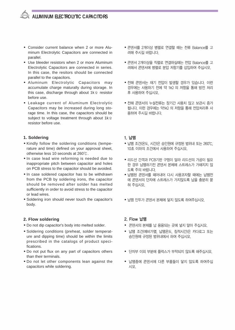
Consider current balance when 2 or more Alu-minum Electrolytic Capacitors are connected inparallel.
Use bleeder resistors when 2 or more AluminumElectrolytic Capacitors are connected in series.In this case, the resitors should be connectedparallel to the capacitors.
Aluminum Electrolytic Capacitors mayaccumulate charge maturally during storage. Inthis case, discharge through about 1kΪ resistorbefore use.
Leakage current of Aluminum ElectrolyticCapacitors may be increased during long sto-rage time. In this case, the capacitors should besubject to voltage treatment through about 1kΪresistor before use.
1. Soldering Kindly follow the soldering conditions (tempe-
rature and time) defined on your approval sheet,otherwise less 10 seconds at 260.
In case lead wire reforming is needed due toinappropriate pitch between capacitor and holeson PCB stress to the capacitor should be avoided.
In case soldered capacitor has to be withdrawnfrom the PCB by soldering irons, the capacitorshould be removed after solder has meltedsufficiently in order to avoid stress to the capacitoror lead wires.
Soldering iron should never touch the capacitor'sbody.
2. Flow soldering Do not dip capacitor's body into melted solder. Soldering conditions (preheat, solder temperat-
ure and dipping time) should be within the limitsprescribed in the catalogs of product speci-fications.
Do not put flux on any part of capacitors othersthan their terminals.
Do not let other components lean against thecapacitors while soldering.
콘덴서를 2개이상 병렬로 연결할 때는 전류 Balance를 고
려해 주시길 바랍니다.
콘덴서 2개이상을 직렬로 연결하실때는 전압 Balance를 고
려해서 콘덴서에 병렬로 분압 저항기를 삽입하여 주십시오.
전해 콘덴서는 재기 전압이 발생할 경우가 있습니다. 이런
경우에는 사용하기 전에 약 1kΪ 의 저항을 통해 방전 처리
후 사용하여 주십시오.
전해 콘덴서의 누설전류는 장기간 사용치 않고 보관시 증가
됩니다. 이런 경우에는 약1kΪ 의 저항을 통해 전압처리후 사
용하여 주시길 바랍니다.
1. 납땜 납땜 조건(온도, 시간)은 승인원에 규정된 범위내 또는 260,
10초 이하의 조건에서 사용하여 주십시오.
리드선 간격과 PCB기판 구멍이 달라 리드선의 가공이 필요
한 경우 납땜하기전 콘덴서 본체에 스트레스가 가해지지 않
도록 주의 바랍니다. 납땜된 콘덴서를 떼어내어 다시 사용코자할 때에는 납땜전
에 콘덴서의 단자에 스트레스가 가지않도록 납을 충분히 묻
혀 주십시오.
납땜 인두가 콘덴서 본체에 닿지 않도록 하여주십시오.
2. Flow 납땜
콘덴서의 본체를 납 용융되는 곳에 넣지 말아 주십시오.
납땜 조건(예비가열, 납땜온도, 침적시간)은 카다로그 또는
승인원에 규정된 범위내에서 하여 주십시오.
단자부 이외 부분에 플럭스가 부착되지 않도록 해주십시오.
납땜중에 콘덴서에 다른 부품들이 닿지 않도록 하여주십
시오.
ALUMINUM ELECTROLYTIC CAPACITORS

3. Reflow 납땜 (65page 참조)
납땜 조건(예비가열, 납땜온도, Relfow시간)은 카다로그 또
는 승인원에 규정된 범위내에서 하여 주십시오.
적외선 히터를 사용할때에는 콘덴서의 색깔이나 재질에 따
라 적외선 흡수율이 다르기 때문에 가열 온도를 맞추어 주십
시오. 한번 Reflow를 통과한 것에 해서 다시 하지 말아주십시
오.
4. 납땜후 제품 취급 요령 PCB에 콘덴서를 납땜한 후 제품을 비틀지 말아 주십시오.
납땜 되어진 콘덴서를 잡고 PCB를 올리거나 이동시키지
말아 주십시오.
PCB에 콘덴서가 장착된 상태로 PCB를 쌓을 경우 PCB나
기타 제품이 닿지 않게 하여 주십시오.
5. 안전변이 있는 제품의 장착
콘덴서 안전변이 동작할 수 있는 공간이 있어야 합니다.
콘덴서의 안전변 위에 배선이나 회로 패턴이 없도록 하여
주십시오.
만약 콘덴서의 안전변이 PCB쪽으로 향할경우 PCB에 구멍
을 설치하여야 합니다.
양면 PCB를 사용한 경우 콘덴서 밑으로 회로를 설계 하지
말고 만약 불가피할 경우 최소한 콘덴서로 부터 1mm ~
2mm 정도 떨어지게 설계해 주십시오.
6. 진동 비
리드 동일방향형 : 질량 10g, ∅ 18 이상 또는 L치수
30이상 제품
PCB Terminal Type : ∅ 22, L치수 40이상 제품
3. Reflow soldering (Refer to page 67) Soldering conditions (preheat, solder temperatur
and reflow time) should be within the limitsprecribed in the catalogs or product specifi-cations.
For setting a degree of heating infrared heaterconsider that the color and material of a cap-acitvary their infrared absorption.
Do not solder capacitors more than once byrefolw.
4. Handling after soldering Do not bend of twist the capacitor’s body after
soldering on PCB. Do not pick-up or move PCB by holding the
soered capacitors.
Do not hit the capacitors and isolate capacitorfrom the PCB of their device when stacking PCBstore.
5. Mounting Capacitors with pressure Re-lief Vent
Make the following open space over the pressurerelief vent of the capacitor so that the vent canoperate.
Do not locate any wire or copper trace over thevent of the capacitor
If the capacitor is mounted with its vent faceddown on the PCB, make a ventilation hole in thePCB in place.
In designing double-sided PCB, do not locateany copper trace under the seal side of acapacitor. If it is absolutely unavoidable, these traces mustbe sufficiently spaced at least 1 or 2 mm apart..
6. Protecting Vibration Radial lead type : Applicable to items with over
10g in weight, diameter of 18mm or longer than30mm in length
PCB terminal type : Applicable to items withdiameter of 22mm and longer than 40mm inlength.
∅D(mm) 6.3~16 18~35 40~space 2mm min. 3mm min. 5mm min.
GUIDE
ALUMINUM ELECTROLYTIC CAPACITORS

In order to prevent possible damage by vibrationon the PCB, kindly bond our capacitors on thePCB or use any fastening devices.
7. Adhesive and Coating Materials Do not use halogenated adhesives and coating
materials to fix Aluminum Electrolytic Capacitors.
Flux between the surface of capacitors should becleaned before using adhesives or coating mat-erials.
Solvents should be dried up before using ad-hesives or coating materials.
Do not cover up all the sealing area of capacitorwith adhesives or coating materials. Makecoverag only partial. (The sealing area 30%)
8. Influence of cleaning solvent foraluminum electrolytic capacitors
Aluminum electrolytic capacitors are easilyaffected by halogen ions, particularly by chlorideions. Excessive amounts of halogen ions, ifhappened to enter the inside of the capacitors,will give corrosion accidents-rapid capacitancedrop and vent open. The extent of corrosionaccidents varies with kinds of electrolytes andseal-materials.
Therefore, the prevention of halogen ion con-tamination is the most important check point forquality lines. At present, halogenated hydro-carbon-contained organic solvents tcontainedorganic solvents such as Trichloroethylene,1-1-1Trich-loroethane, and Freon are used to removeflux from circuit boards. However, if generaltypes of aluminum, electroytic capacitors, whoseseal constructions are not solvent-proof, arecleaned with such solvents, the solvents maygradually penetrate the seal portion and erode.
The inside of the capacitors, the mechanism ofcorrosion of aluminum electrolytic capacitors byhalogen ions can be explained as follows: Halides(RX) are absorbed and diffused intothseal portion. The halides then enter the insideof the capacitors and contact with the electrolyteof the capacitors, where by halogen ions aremade free by a hydrolysis with water in theelectrolyte:
RX + H2O → ROH + H+ + X-
진동으로 문제시되는 PCB에 상기 제품을 장착하는 경우에
는 반드시 PCB와 제품 바닥면을 Bonding하여 사용하거
나 별도 지그를 부착하여 사용하십시오.
7. 제품 고정제와 코팅 할로겐계 용제를 포함하는 고정제, 코팅제는 사용하지 말아
주십시오.
고정제, 코팅제를 사용하기 전에 기판과 콘덴서 봉구부 부
분에 플럭스가 남거나 오염된 채로 놓아두지 말아주십시오.
기판 세척제는 고정제, 코팅제를 사용하기 전에 완전히 건
조시켜 주십시오.
고정제, 코팅제를 사용할 때 콘덴서 봉구부 전체를 봉시
키지 말아 주십시오.(봉구부의 30% 이하)
8. 알루미늄 전해 콘덴서 세척용 용매의 향
알루미늄 전해 콘덴서는 할로겐계 이온, 특히 염소 이온에
쉽게 향을 받습니다. 할로겐계 이온이 콘덴서 내부로 침
투하게 되면 부식활동에 의해 급속한 용량감소 및 방폭변이
개변등의 현상이 일어납니다. 부식활동의 정도는 전해액 및
봉합물질의 종류에 따라 달라지게 됩니다.
따라서 폐사의 생산 라인에서는 할로겐계 이온의 침투 방지
를 품질관리의 최고 중점관리 사항으로 관리하고 있습니다.
현재 Trichloroethylene, 1-1-1 Trichloroethane 및
Freon과 같은 탄화수소 화합물이 들어있는 유기용제들이
회로기판의 플럭스를 제거하기 위해 사용됩니다. 그러나 봉
구 구조가 내세척용이 아닌 일반 전해콘덴서에 그와같은 용
매로 세척할 경우 점차적으로 봉입부분으로 흘러들어가 콘
덴서 내부의 부식이 발생합니다.
할로겐이온에 의한 부식의 진행은 다음과 같이 설명되어 집
니다. 할로겐화물이 수분과 반응하여 다음식과 같이 해리된
다음 봉입부분으로 확산되어 집니다.
RX + H2O → ROH + H+ + X-
ALUMINUM ELECTROLYTIC CAPACITORS
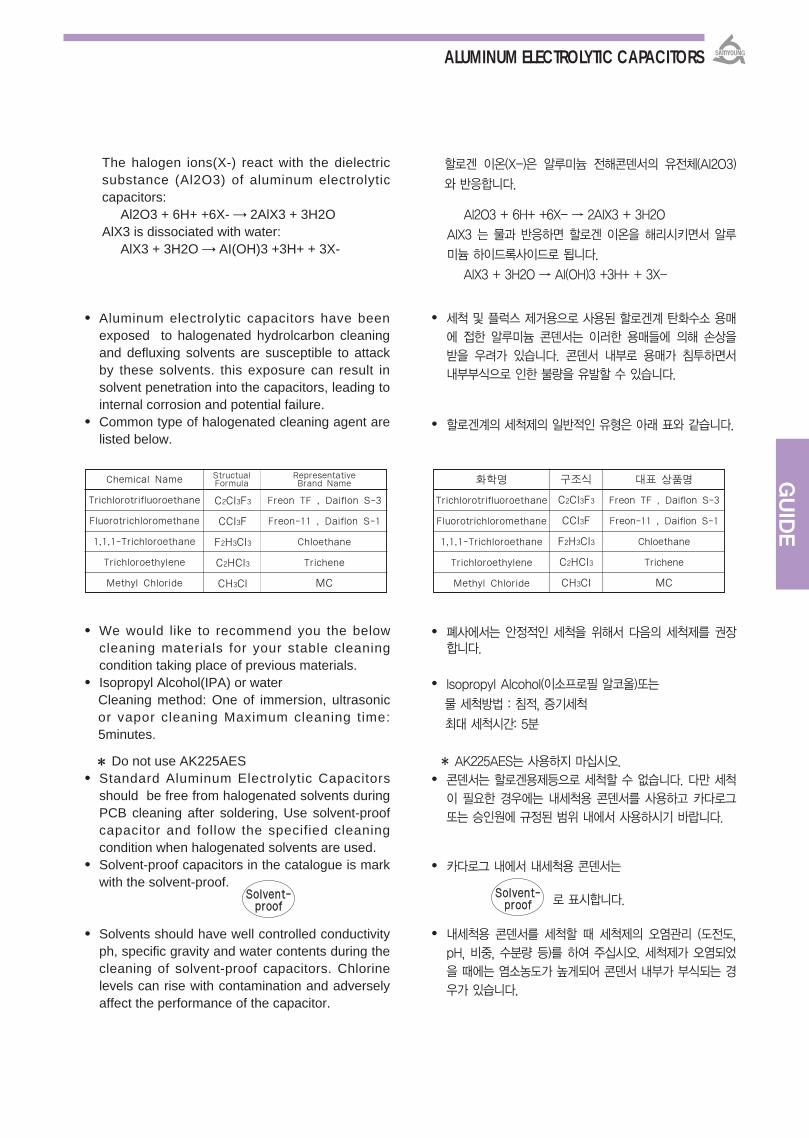
The halogen ions(X-) react with the dielectricsubstance (Al2O3) of aluminum electrolyticcapacitors:
Al2O3 + 6H+ +6X- → 2AlX3 + 3H2OAlX3 is dissociated with water:
AlX3 + 3H2O → AI(OH)3 +3H+ + 3X-
Aluminum electrolytic capacitors have beenexposed to halogenated hydrolcarbon cleaningand defluxing solvents are susceptible to attackby these solvents. this exposure can result insolvent penetration into the capacitors, leading tointernal corrosion and potential failure.
Common type of halogenated cleaning agent arelisted below.
We would like to recommend you the belowcleaning materials for your stable cleaningcondition taking place of previous materials.
Isopropyl Alcohol(IPA) or waterCleaning method: One of immersion, ultrasonicor vapor cleaning Maximum cleaning time:5minutes.
Do not use AK225AES Standard Aluminum Electrolytic Capacitors
should be free from halogenated solvents duringPCB cleaning after soldering, Use solvent-proofcapacitor and follow the specified cleaningcondition when halogenated solvents are used.
Solvent-proof capacitors in the catalogue is markwith the solvent-proof.
Solvents should have well controlled conductivityph, specific gravity and water contents during thecleaning of solvent-proof capacitors. Chlorinelevels can rise with contamination and adverselyaffect the performance of the capacitor.
할로겐 이온(X-)은 알루미늄 전해콘덴서의 유전체(Al2O3)
와 반응합니다.
Al2O3 + 6H+ +6X- → 2AlX3 + 3H2O
AlX3 는 물과 반응하면 할로겐 이온을 해리시키면서 알루
미늄 하이드록사이드로 됩니다.
AlX3 + 3H2O → AI(OH)3 +3H+ + 3X-
세척 및 플럭스 제거용으로 사용된 할로겐계 탄화수소 용매
에 접한 알루미늄 콘덴서는 이러한 용매들에 의해 손상을
받을 우려가 있습니다. 콘덴서 내부로 용매가 침투하면서
내부부식으로 인한 불량을 유발할 수 있습니다.
할로겐계의 세척제의 일반적인 유형은 아래 표와 같습니다.
폐사에서는 안정적인 세척을 위해서 다음의 세척제를 권장합니다.
Isopropyl Alcohol(이소프로필 알코올)또는
물 세척방법 : 침적, 증기세척
최 세척시간: 5분
AK225AES는 사용하지 마십시오. 콘덴서는 할로겐용제등으로 세척할 수 없습니다. 다만 세척
이 필요한 경우에는 내세척용 콘덴서를 사용하고 카다로그
또는 승인원에 규정된 범위 내에서 사용하시기 바랍니다.
카다로그 내에서 내세척용 콘덴서는
로 표시합니다.
내세척용 콘덴서를 세척할 때 세척제의 오염관리 (도전도,
pH, 비중, 수분량 등)를 하여 주십시오. 세척제가 오염되었
을 때에는 염소농도가 높게되어 콘덴서 내부가 부식되는 경
우가 있습니다.
SSoollvveenntt--pprrooooff
Chemical Name
Trichlorotrifluoroethane
Fluorotrichloromethane
1,1,1-Trichloroethane
Trichloroethylene
Methyl Chloride
StructualFormula
RepresentativeBrand Name
C2Cl3F3
CCl3F
F2H3Cl3
C2HCl3
CH3Cl
Freon TF , Daiflon S-3
Freon-11 , Daiflon S-1
Chloethane
Trichene
MC
SSoollvveenntt--pprrooooff
화학명
Trichlorotrifluoroethane
Fluorotrichloromethane
1,1,1-Trichloroethane
Trichloroethylene
Methyl Chloride
구조식
C2Cl3F3
CCl3F
F2H3Cl3
C2HCl3
CH3Cl
표 상품명
Freon TF , Daiflon S-3
Freon-11 , Daiflon S-1
Chloethane
Trichene
MC
GUIDE
ALUMINUM ELECTROLYTIC CAPACITORS

When the vent is open and some gas blows outfrom the capacitor, please turn the main swich ofthe equipment off or pull out the plug from thepower outlet immediately.
During vent operation, extremly hot gas(over 100)may blow out from the capacitors. Do not standclose to the capacitors. In case of eye contact,flush the open eye(s) with large amount or cleanwater immediately, do not swallow. Do not touchelectrolyte but wash skin with soap and water incase or skin contact.
If electrolytic capacitors temperatures caused bysuch things as direct sunlight,the l i fe of thecapacitor may be adversely affected. Storage in ahigh humidity atmosphere may affect the sold-erability of lead wires and terminals.
1. STORAGE AREA Do not store capacitors at a high temperature
and high humidity. Store the capacitors indoorsat a temperature of 5 to 35 and a humidity ofless than 75%RH.
Store the capacitors in places free from water, oilor salt water.
Store the capacitors in places free from toxicgasses (hydrogen sulfide, sulrurous acid, nitrousacid, chlorine, ammonium, etc.)
Store the capacitors in places out of ozone, ult-raviolet rays or radiation.
Keep capacitors in the package.
2. CONDITIONS OF USE The following environment should be avoided whenusing aluminum electrolytic capacitors. Damp conditions such as water, saltwater spray,
or oil spray or fumes, High humidity or humiditycondensation situations.
Hazardous gas/fumes such as hydrogen sulfide,sulfurous acid gas,nitrous acid, chlorine gas orammonia.
Exposure to ozone, ultraviolet rays or radiation.
3. VOLTAGE TREATMENT If the electrolytic capacitor is allowed to stand for along time, its withstand voltage is liable to drop,resulting in increased leakage current. If the ratedvoltage is applied to such a product, a large
사용중 콘덴서가 개변되어 Gas가 분출될 경우 Set의 주전원 장치의 스위치를 끄거나 플러그를 뽑아 주십시오.
콘덴서의 안전변 동작시 +100를 초과하는 고온Gas가분출하기 때문에 얼굴을 가까이 지 말아주십시오. 분출한Gas가 눈에 들어 가거나 흡입한 경우에는 즉시 물로 눈을씻거나 삼키지 말고 입안을 닦아주시기 바랍니다. 전해액은만지지 말고 만약 피부에 묻었을 경우 물이나 비누로 닦아주시길 바랍니다.
전해 콘덴서를 직사광을 받는 장소, 고온장소에 보관하게되면 제품 수명에 악 향을 초래하며 또 다습한 장소에 보관 하게 되면 리드선과 단자의 납땜성이 나빠질 우려가 있습니다.
1. 보관 장소 콘덴서를 고온 다습 조건에 보관하지 말아 주십시오. 실내
온도가 5~35, 습도는 75%RH 이하 조건에서 보관하시길 바랍니다.
콘덴서를 물, 기름 또는 소금물에 오염되지 않도록 해주십시오.
콘덴서를 유해 Gas(유화 수소, 아황산, 아질산, 염소, 암모늄 등)에 노출된 환경에서 보관하지 말아주십시오.
콘덴서를 오존, 자외선 및 방사선에 노출되는 환경에서 보관하지 말아 주십시오.
포장 상태에서 보관하여 주십시오.
2. 사용 조건다음의 환경에서는 전해 콘덴서를 사용하지 말아 주십시오.
직접수, 염수, 기름이 근접해 있거나 다습 또는 결로 상태가되는 환경
유해 Gas(유화수소, 아황산, 아질산, 염소, 암모니아 등 )가가득한 환경
오존, 자외선 또는 방사선에 노출된 환경
3. 전압 처리전해 콘덴서는 장시간 방치하게 되면 내압이 떨어져 누설전류가 증가하는 경향이 있습니다. 이러한 제품에 전압을 인가하면 과 한 누설전류로 인한 내부 발열로 파손되는 일이 있습니다. 장기간 방치된 제품에 해서는 전압처리후 사용하여
ALUMINUM ELECTROLYTIC CAPACITORS
만만일일의의 경경우우EEMMEERRGGEENNCCYY AACCTTIIOONN
CCOONNDDIITTIIOONN OOFF SSTTOORRAAGGEE//UUSSEE 보보관관//사사용용 조조건건

GUIDE
leakage current occurs and this generates internalheat, which damaged the capacitor. Of theelectrolytic capacitor is allowed to stand for a longtime, therefore, use it after giving voltage treatment.Voltage treatment shall be performed by increasingvoltage up to the capacitor's voltage rating graduallywhile lowering the leakage current. In this case, theleakage current of the electrolytic capacitor is lessthan specified value.Meanwhile, the voltage treatment time may beeffectively shortened if the ambient temperature isincreased (within the maximum operatingtemperature range).
4. RECOVERY VOLTAGEAfter discharged aluminum electrolytic capacitor,the voltage wil l be increasing again. Thisphenomenon is called by “Recovery Voltage”, ithappens very often and commonly for all aluminumelectrolytic capacitors. In this case, dischargethrough a 1KΪ resistance before use at yourprocess, because you may have trouble onsensitive device and frighten a person working withthe capacitor.
In case of destructing our capacitors, kindly takefollowing instructions. Burn capacitors up after making holes on them or
scrapping. When you try to destrory them by fire,you may expect explosion in the capacitors.
In order to prevent hazardous gas like chlorinegas, burn our capacitors on high temperature ra-nge. Burning sleeve on low temperature maycause producting chlorine gas.
When you do not have burning facilities, pleasecontact special industrial wastes processingcompanies.
Since it has possibilities for electric shock orburns, kindly discharge it at the level of 1kΪ inadvance.(sufficient and safe resistance valuesshould be considered before applying)
Capacitor case sizes and other productstandards specified in this catalog may bechanged or modified without notice for imp-rovement of quality.
For methods of testing, refer to KS C IEC 60384-4 (JIS C 5101-1, JIS C 5101-4)
주십시오.전압처리란 인가전압을 누설 전류가 낮아질때까지 서서히 정격전압까지 인가함을 말하며, 이 때의 누설전류치는 규격보다작아야 합니다. 만일 주위온도가 상승되어 지면 전압 처리 시간이 단축되어 질수 있습니다.(최고 사용온도 이내)
4. 재기전압알루미늄 전해 콘덴서를 방치하면 전압이 다시 상승하게 됩니다. ‘재기전압’이라고 하는 이 현상은 알루미늄 전해 콘덴서에서 자주 발생할 수 있는 흔한 현상입니다. 콘덴서를 이용한 공정 시 이러한 재기전압으로 인해 민감한 장치에는 트러블을 일으키고 작업자 또한 놀랄 수 있으므로 작업 전 1kΪ 의 저항으로 콘덴서를 방전 시키는 것이 좋습니다.
콘덴서를 폐기할 경우에는 다음의 방법 로 하여주십시오.
콘덴서에 구멍을 내거나 충분히 부순 후에 소각하여 주십시오. 소각시 콘덴서가 폭발하는 경우가 있습니다.
콘덴서는 외장슬리브(폴리염화비닐)가 씌워져 있기 때문에고온 소각을 하여 주십시요. 저온 소각을 하면 염소 Gas등의 유해 Gas가 발생되는 원인이 됩니다.
콘덴서를 소각하지 않는 경우는 전문 산업폐기물 처리업체에 의뢰하여 주십시오.
감전 및 화상의 우려가 있으므로 사용전에 1kΪ (전압, 용량에 따라 충분히 여유를 고려한 저항 선택)의 저항을 통해서방전처리해 주십시오.
카다로그에 규정된 제품 케이스 사이즈 및 기타 제품기준은품질 개선의 필요성으로 인하여 귀사에 통지없이 변경될 수있습니다.
기타 시험규격에 해서는 KS C IEC 60384-4 (JIS C5101-1, JIS C 5101-4)을 참조 바랍니다.
기기타타OOTTHHEERRSS
DDEESSTTRRUUCCTTIINNGG CCAAPPAACCIITTOORRSS 폐폐기기에에 하하여여
ALUMINUM ELECTROLYTIC CAPACITORS
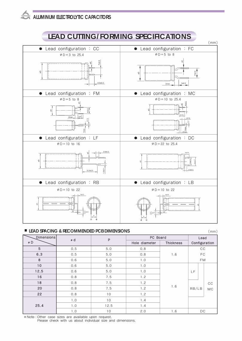
※Note:Other case sizes are available upon request.Please check with us about individual size and dimensions.
LEAD SPACING & RECOMMENDED PCB DIMENSIONS (mm)
Lead configuration : CC Lead configuration : FC
Lead configuration : FM Lead configuration : MC
Lead configuration : LF Lead configuration : DC
Lead configuration : RB Lead configuration : LB
(mm)
∅D=3 to 25.4 ∅D=5 to 8
∅D=5 to 8 ∅D=10 to 25.4
∅D=10 to 16 ∅D=22 to 25.4
∅D=10 to 22 ∅D=10 to 22
LEAD CUTTING/FORMING SPECIFICATIONS
LF
CC
MC1.6
RB/LB
ALUMINUM ELECTROLYTIC CAPACITORS
DDiimmeennssiioonnssdd PP
PPCC BBooaarrdd LLeeaaddDD HHoollee ddiiaammeetteerr TThhiicckknneessss CCoonnffiigguurraattiioonn
55 0.5 5.0 0.8 CC
66..33 0.5 5.0 0.8 1.6 FC
88 0.6 5.0 1.0 FM
1100 0.6 5.0 1.0
1122..55 0.6 5.0 1.0
1166 0.8 7.5 1.2
1188 0.8 7.5 1.2
2200 0.8 7.5 1.2
2222 0.8 10 1.2
1.0 10 1.4
2255..44 1.0 12.5 1.4
1.0 10 2.0 1.6 DC
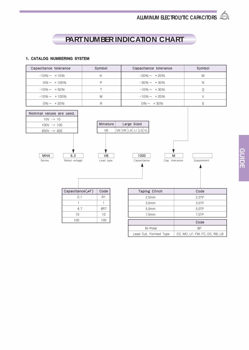
Bi-Polar BP
Lead Cut, Formed Type CC, MC, LF, FM, FC, DC, RB, LB
TTaappiinngg CClliinncchh CCooddee CCaappaacciittaannccee((μμFF)) CCooddee
MMiinniiaattuurree LLaarrggee SSiizzeedd
VB VN VR LA LI LG VL
NNoommiinnaall vvaalluueess aarree uusseedd..
10V 10
100V 100
450V 450
11.. CCAATTAALLOOGG NNUUMMBBEERRIINNGG SSYYSSTTEEMM
2.5mm 2.5TP
3.5mm 3.5TP
5.0mm 5.0TP
7.5mm 7.5TP
MMHHAA 66..33 VVBB 11000000 MM Series Rated voltage Lead type Capacitance Cap. tolerance Supplement
PART NUMBER INDICATION CHART
GUIDE
CCaappaacciittaannccee ttoolleerraannccee SSyymmbbooll CCaappaacciittaannccee ttoolleerraannccee SSyymmbbooll
-10%~ +10% K -20%~ +20% M
0%~ +100% P -30%~ +30% N
-10%~ +50% T -10%~ +30% Q
-10%~ +100% W -10%~ +20% V
0%~ +20% R 0%~ +30% S
ALUMINUM ELECTROLYTIC CAPACITORS
CCooddee
0.1
1
4.7
10
100
R1
1
4R7
10
100

μμFF FFrreeqquueennccyy((HHzz)) 6600 112200 330000 11kk 1100kk 110000kk
0.1 ~ 3.3 0.65 1 1.35 1.75 2.30 2.50
4.7 ~ 33 0.75 1 1.25 1.50 1.75 1.80
47 ~ 1,000 0.80 1 1.15 1.30 1.40 1.50
2,200 ~ 0.85 1 1.03 1.05 1.08 1.08
SSyymmbbooll CCoonnffiigguurraattiioonn TTyyppee
VB CE04 (SINGLE ENDED) TYPE (∅3~∅25.4)
VN/VS PCB TERMINAL TYPE (∅20~∅40 : 2 TERMINALS)
LG SCREW-BOLT TERMINALS TYPE (∅35~∅89)
LR PCB TERMINAL TYPE (∅35~∅63.5 : 2 TERMINALS)
VR PCB TERMINAL TYPE (∅35~∅50 : 4 TERMINALS)
LA CE62 TYPE (∅14.5~∅50 : 2 TERMINALS)
LI PCB TERMINAL TYPE (∅30~∅35 : 2 TERMINALS)
22.. SSUUBBSSTTAANNCCEE
STANDARD FREQUENCY MULTIPLYING FACTOR
ALUMINUM ELECTROLYTIC CAPACITORS
TTeerrmmiinnaall TTyyppee
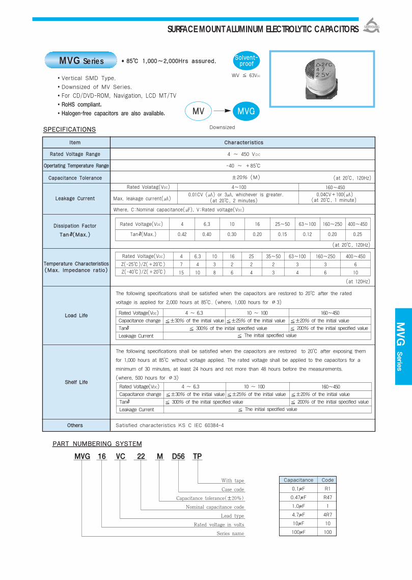
PPAARRTT NNUUMMBBEERRIINNGG SSYYSSTTEEMM
Vertical SMD Type.
Downsized of MV Series.
For CD/DVD-ROM, Navigation, LCD MT/TV
RoHS compliant.
Halogen-free capacitors are also available. MMVV MMVVGG
Downsized
8855 11,,000000~~22,,000000HHrrss aassssuurreedd..MVG Series SSoollvveenntt--pprrooooff
WV 63VDC
Capacitance Code
0.1μF R1
0.47μF R47
1.0μF 1
4.7μF 4R7
10μF 10
100μF 100
With tape
Case code
Capacitance tolerance(±20%)
Nominal capacitance code
Lead type
Rated voltage in volts
Series name
MVG 16 VC 22 M D56 TP
IItteemm CChhaarraacctteerriissttiiccss
RRaatteedd VVoollttaaggee RRaannggee 4 ~ 450 VDC
OOppeerrttaattiinngg TTeemmppeerraattuurree RRaannggee -40 ~ +85
CCaappaacciittaannccee TToolleerraannccee ±20% (M) (at 20, 120Hz)
LLeeaakkaaggee CCuurrrreenntt
DDiissssiippaattiioonn FFaaccttoorr
TTaannδδ((MMaaxx..))
(at 20, 120Hz)
The following specifications shall be satisfied when the capacitors are restored to 20 after the rated
voltage is applied for 2,000 hours at 85. (where, 1,000 hours for ∅3)
The following specifications shall be satisfied when the capacitors are restored to 20 after exposing them
for 1,000 hours at 85 without voltage applied. The rated voltage shall be applied to the capacitors for a
minimum of 30 minutes, at least 24 hours and not more than 48 hours before the measurements.
(where, 500 hours for ∅3)
Rated Voltage(VDC) 4 6.3 10 16 25~50 63~100 160~250 400~450
Tanδ(Max.) 0.42 0.40 0.30 0.20 0.15 0.12 0.20 0.25
Rated Voltage(VDC)
Z(-25)/Z(+20)
Z(-40)/Z(+20)
SSPPEECCIIFFIICCAATTIIOONNSS
Rated Voltage(VDC) 4 ~ 6.3 10 ~ 100
Capacitance change ±30% of the initial value ±25% of the initial value
Tanδ 300% of the initial specified value
Leakage Current
(at 20, 2 minutes)
TTeemmppeerraattuurree CChhaarraacctteerriissttiiccss((MMaaxx.. IImmppeeddaannccee rraattiioo))
LLooaadd LLiiffee
SShheellff LLiiffee
OOtthheerrss
±20% of the initial value
200% of the initial specified value
160~450
The initial specified value
Rated Voltage(VDC) 4 ~ 6.3 10 ~ 100
Capacitance change ±30% of the initial value ±25% of the initial value
Tanδ 300% of the initial specified value
Leakage Current
±20% of the initial value
200% of the initial specified value
160~450
The initial specified value
Satisfied characteristics KS C IEC 60384-4
10
3
8
16
2
6
4
7
15
6.3
4
10
25
2
4
35~50
2
3
63~100
3
4
160~250
3
6
400~450
6
10
Rated Volatag(VDC)
Max. leakage current()
4~100 160~450
0.01CV () or 3, whichever is greater.
Where, C:Nominal capacitance(), V:Rated voltage(VDC)
(at 20, 1 minute)
(at 120Hz)
0.04CV+100()
MVG Serie
s
SURFACE MOUNT ALUMINUM ELECTROLYTIC CAPACITORS

DDIIMMEENNSSIIOONNSS OOFF MMVVGG SSeerriieess((TTyyppee::VVCC))
DIMENSIONS MARKING
: Solder land on PC board
: Dummy terminals
Recommended Solder land on PC board
CCaassee ccooddee ∅∅DD LL AA BB CC WW PP aa bb cc aa bb cc
B55 3 5.2 3.3 3.3 3.7 0.45-0.75 0.8 0.8 2.2 1.6
D56 4 5.3 4.3 4.3 5.1 0.5-0.8 1.0 1.0 2.6 1.6
E56 5 5.3 5.3 5.3 5.9 0.5-0.8 1.4 1.4 3.0 1.6
F56 6.3 5.3 6.6 6.6 7.2 0.5-0.8 1.9 1.9 3.5 1.6
F60 6.3 5.7 6.6 6.6 7.2 0.5-0.8 1.9 1.9 3.5 1.6
F80 6.3 7.7 6.6 6.6 7.2 0.5-0.8 1.9 1.9 3.5 1.6
H63 8 6.3 8.3 8.3 9.0 0.5-0.8 2.3 2.3 4.5 1.6
H10 8 10 8.3 8.3 9.0 0.7-1.1 3.1 3.1 4.2 2.2
J10 10 10 10.3 10.3 11.0 0.7-1.1 4.5 4.5 4.4 2.2
K14 12.5 13.5 13.0 13.0 13.7 1.0-1.3 4.2 4.0 5.7 2.5
L17 16 16.5 17.0 17.0 18.0 1.0-1.3 6.5 6.0 6.9 2.5
L22 16 21.5 17.0 17.0 18.0 1.0-1.3 6.5 6.0 6.9 2.5
M17 18 16.5 19.0 19.0 20.0 1.0-1.3 6.5 6.0 7.9 2.5
M22 18 21.5 19.0 19.0 20.0 1.0-1.3 6.5 6.0 7.9 2.5
Note 1 : L±0.5 for 8×6.3(H63) ~ 18×21.5(M22)Note 2 : 3×5.2(B55), 4×5.3(D56), 5×5.3(E56)is excluded symbol markNote 3 : 6.3WV is marked by 6V
RRAATTIINNGGSS OOFF MMVVGG SSeerriieess
<B55 ~ J10>
<Size code:B55~M22> <Size code:L17~M22>
Vibration Resistance
<K14~M22>
4.71022334768100
μμFFVVDDCC 160 200 250 400 450
Height 4.6mm max. is available request.Please check with us about individual size and dimensions.
VVDDCC 44 66..33 1100 1166 2255 3355 5500 6633 110000μμFF
B55 D56 1.1 1.3 D56 1.3B55 D56 2.0 2.9 D56 3.0B55 D56 3.0 3.5 D56 4.0B55 D56 3.8 4.2 D56 5.0B55 D56 5.6 6.2 D56 8.0
B55 D56 7.7 B55 D56 8.3 10 D56 12B55 D56 9.4 D56 14 E56 17
B55 D56 10.5 D56 15 D56 19 E56 20B55 D56 12.8 B55 D56 14 17 D56 20 D56 25 E56 29 F60 32
B55 D56 14 B55 D56 23 D56 27 D56 27 E56 28 F56 33 F60 40 F80 60 H10 90D56 23 D56 30 D56 30 E56 40 E56 40 F56 40 F80 55 H10 110 J10 120D56 27 D56 33 E56 45 E56 45 F56 60 F60 55 H63 140 H10 130 J10 144E56 38 E56 49 F56 54 F56 78 F60 90 H63 157 H10 170 J10 170 K14 380E56 46 E56 55 F56 65 F60 85 F80 H63 145 H10 175 H10 190 K14 380 K14 440F56 74 F60 75 F80 H63 130 F80 130 H10 260 H10 260 J10 320 K14 580 M17 800
F80 H63 135 H10 270 H10 270 H10 300 J10 360 K14 600 L17 820 M22 1000H10 280 H10 280 H10 280 J10 400 K14 600 L17 850 M17 1000J10 430 J10 430 K14 710 K14 820 L17 1100 L22 1300J10 480 K14 850K14 890 K14 960 L17 1150 M17 1400 M22 1700L17 1200 L17 1300 M17 1450 M22 1800L17 1400 M17 1600 M22 1750M17 1700 M22 1850M22 2000
Rated Ripple Current(mArms/85, 120Hz)Case code
J10K14K14L17L17M17
K14K14L17L17M17M22
55240260400500590
150240350420510590
K14L17L17M17M22
150300340420490
K14L17M17M22
120140280350
K14L17L22M22
120140280350
4.7 7.8 9.6
4.7 8.8 9.6
Vibration Resistance
SURFACE MOUNT ALUMINUM ELECTROLYTIC CAPACITORS
1022334768100220330470
1,0001,5002,2003,3004,7006,80010,000
0.10.220.330.47
12.23.34.7
Unit(mm)

BDS(M
VK)Serie
s
IItteemm CChhaarraacctteerriissttiiccss
RRaatteedd VVoollttaaggee RRaannggee 6.3 ~ 450 VDC
OOppeerrttaattiinngg TTeemmppeerraattuurree RRaannggee -40 ~ +105
CCaappaacciittaannccee TToolleerraannccee ±20%(M) (at 20, 120Hz)
The following specifications shall be satisfied when the capacitors are restored to 20 after the rated voltage is applied with the following conditions.
∅4~∅6.3:105, 1,000 hours, ∅8~∅18:105, 2,000 hours. Capacitance change
∅4~∅6.3 ±30% of the initial value∅8~∅18 ±20% of the initial value
Tanδ∅4~∅6.3 300% of the initial specified value∅8~∅18 200% of the initial specified value
Leakage current The initial specified value
∅4~∅6.3:105, 500 hours, ∅8~∅18:105, 1,000 hours.Capacitance change
∅4~∅6.3 ±25% of the initial value∅8~∅18 ±20% of the initial value
Tanδ 200% of the initial specified valueLeakage current The initial specified value
OOtthheerrss
110055 11,,000000~~22,,000000HHrrss aassssuurreedd..
Vertical SMD type.
Wide Temperature range.
For CD/DVD-ROM, Navigation, LCD MT/TV
RoHS compliant.
Halogen-free capacitors are also available.
SSPPEECCIIFFIICCAATTIIOONNSS
PPAARRTT NNUUMMBBEERRIINNGG SSYYSSTTEEMM
SSoollvveenntt--pprrooooff
Capacitance Code
0.1μF R1
0.47μF R47
1.0μF 1
4.7μF 4R7
10μF 10
100μF 100
LLooaadd LLiiffee
SShheellff LLiiffee
With tape
Case code
Capacitance tolerance(±20%)
Nominal capacitance code
Lead type
Rated voltage in volts
Series name
BDS 50 VC R47 M D55 TP
TTeemmppeerraattuurree CChhaarraacctteerriissttiiccss((MMaaxx.. IImmppeeddaannccee rraattiioo))
BDS(MVK) Series
MMVV BBDDSS((MMVVKK))
Wide Temp.
WV 63VDC
(at 20, 2 minutes)
Rated Voltage(VDC)
Max. Leakage current()
6.3~100 160~450
0.01CV () or 3 , whichever is greater.
Where, C:Nominal capacitance(), V:Rated voltage(VDC)
(at 20, 1 minute)0.04CV+100()
(at 20, at 120Hz)
DDiissssiippaattiioonn FFaaccttoorr
TTaannδδ((MMaaxx..))
LLeeaakkaaggee CCuurrrreenntt
The following specifications shall be satisfied when the capacitors are restored to 20 after exposing them for thespecified time at 105 without voltage applied. The rated voltage shall be applied to the capacitors for a minimumof 30 minutes, at least 24 hours and not more than 48 hours before the measurements.
Satisfied characteristics KS C IEC 60384-4
Rated voltage(VDC) 6.3
0.30
0.40
10
0.24
0.30
16
0.20
0.26
25
0.16
0.16
35
0.14
0.14
50~100
0.12
0.12
160~250
-
0.15
400~450
-
0.20
∅4~∅6.3
∅8~∅18
(at 120Hz)
Z(-25)/Z(+20)
Z(-40)/Z(+20)
Rated voltage(VDC) 6.3
4
10
10
3
8
16
2
6
25
2
4
35
2
3
50~100
3
4
160~250
3
6
400~450
6
10
SURFACE MOUNT ALUMINUM ELECTROLYTIC CAPACITORS

MARKINGDIMENSIONS
Recommended Solder land on PC board
: Solder land on PC board
: Dummy terminals
<D55 ~ J10> <K14 ~ M22>
RRAATTIINNGGSS OOFF BBDDSS((MMVVKK)) SSeerriieess
3.34.71022334768100
μμFFVVDDCC 160 200 250 400 450
J10K14K14L17M17L22
K14K14L17M17M22
458595260320380
8085220270330
K14L17L17M17M22
65100180230280
K14L17L17M22
306085130
K14L17L17M22
406085130
D55 1.3 D55 1.3D55 2.6 D55 3.0D55 3.2 D55 4.0D55 3.8 D55 5.0D55 5.6 D55 8.0D55 10 D55 12D55 14 E55 17
D55 15 E55 19 E55 20D55 16 E55 25 E55 25 F55 29 F60 32 H63 48
D55 21 E55 30 E55 30 F55 40 F55 40 H63 70 H10 80 H10 90E55 34 E55 34 F55 45 F55 45 H63 80 H10 140 H10 145 J10 150E55 36 F55 48 F55 48 F60 H63 52 80 H63 140 H10 170 H10 180 K14 250
F55 F60 56 F60 H63 90 F60 H10 110 180 F80 H63 135 H10 250 J10 310 K14 380 K14 380H63 150 F80 H63 150 F80 H10 150 275 H10 275 J10 375 K14 420 K14 470 M17 750
F80 H10 127 290 J10 450 J10 450 J10 450 K14 480 K14 500 L17 700 M22 980J10 460 J10 460 J10 460 J10 460 K14 520 L17 700 M17 900J10 520 J10 540 K14 550 K14 550 L17 750 M22 1200J10 550 K14 620K14 680 L17 850 M17 1000 M22 1300 M22 1450M17 1000 M17 1100 M17 1200L22 1200 M22 1350M22 1350
66..33 1100 1166 2255 3355 5500 6633 110000μμFF
Rated Ripple Current(mArms/105, 120Hz)Case code
VVDDCC
CCaassee ccooddee ∅∅DD LL AA BB CC WW PP aa bb cc aa bb cc
D55 4 5.2 4.3 4.3 5.1 0.5-0.8 1.0 1.0 2.6 1.6
E55 5 5.2 5.3 5.3 5.9 0.5-0.8 1.4 1.4 3.0 1.6
F55 6.3 5.2 6.6 6.6 7.2 0.5-0.8 1.9 1.9 3.5 1.6
F60 6.3 5.7 6.6 6.6 7.2 0.5-0.8 1.9 1.9 3.5 1.6
F80 6.3 7.7 6.6 6.6 7.2 0.5-0.8 1.9 1.9 3.5 1.6
H63 8 6.3 8.3 8.3 9.0 0.5-0.8 2.3 2.3 4.5 1.6
H10 8 10 8.3 8.3 9.0 0.7-1.1 3.1 3.1 4.2 2.2
J10 10 10 10.3 10.3 11.0 0.7-1.1 4.5 4.5 4.4 2.2
K14 12.5 13.5 13.0 13.0 13.7 1.0-1.3 4.2 4.0 5.7 2.5
L17 16 16.5 17.0 17.0 18.0 1.0-1.3 6.5 6.0 6.9 2.5
L22 16 21.5 17.0 17.0 18.0 1.0-1.3 6.5 6.0 6.9 2.5
M17 18 16.5 19.0 19.0 20.0 1.0-1.3 6.5 6.0 7.9 2.5
M22 18 21.5 19.0 19.0 20.0 1.0-1.3 6.5 6.0 7.9 2.5
Note 1 : L±0.5 for 8×6.3(H63) ~ 18×21.5(M22)Note 2 : 4×5.2(D55), 5×5.2(E55) is excluded symbol markNote 3 : 6.3WV is marked by 6V
4.7 7.8 9.6
4.7 8.8 9.6
Vibration Resistance
<Size code:D55~M22> <Size code:L17~M22>
Vibration Resistance
SURFACE MOUNT ALUMINUM ELECTROLYTIC CAPACITORS
10223347100220330470
1,0001,5002,2003,3004,7006,800
0.10.220.330.47
12.23.34.7
DDIIMMEENNSSIIOONNSS OOFF BBDDSS((MMVVKK)) SSeerriieess((TTyyppee::VVCC)) Unit(mm)

BXA Serie
s
IItteemm CChhaarraacctteerriissttiiccss
RRaatteedd VVoollttaaggee RRaannggee 6.3 ~ 50 VDC
OOppeerrttaattiinngg TTeemmppeerraattuurree RRaannggee -55 ~ +105
CCaappaacciittaannccee TToolleerraannccee ±20%(M) (at 20, 120Hz)
I=0.01CV or 3μA, whichever is greater.
LLeeaakkaaggee CCuurrrreenntt Where, I:Max. Leakage current(μA), C:Nominal capacitance(μF), V:Rated voltage(VDC)
(at 20, 2 minutes)
DDiissssiippaattiioonn FFaaccttoorr
TTaannδδ((MMaaxx..))
TTeemmppeerraattuurree CChhaarraacctteerriissttiiccss
The following specifications shall be satisfied when the capacitors are restored to 20 after the ratedvoltage is applied with the following conditions.
∅4~∅6.3 : 105, 1,000 hours, ∅8 & ∅10 : 105, 2,000 hours.
The following specifications shall be satisfied when the capacitors are restored to 20 after exposing them for 1000 hours at 105 without voltage applied. The rated voltage shall be applied to the capacitors for a minimum of 30 minutes, at least 24 hours and not more than 48 hours before the measurements.
Capacitance change ±25% of the initial value
Tanδ 200% of the initial specified value
Leakage current The initial specified value
OOtthheerrss Satisfied characteristics KS C IEC 60384-4
110055 11,,000000~~22,,000000HHrrss aassssuurreedd..
Vertical SMD type.
Low impedance.
For STB, Satellite Radio, Computer Server
RoHS compliant.
Halogen-free capacitors are also available.
SSPPEECCIIFFIICCAATTIIOONNSS
PPAARRTT NNUUMMBBEERRIINNGG SSYYSSTTEEMM
BXA 16 VC 100 M F60 TP
SSoollvveenntt--pprrooooff
With tape
Case code
Capacitance tolerance(±20%)
Nominal capacitance code
Lead type
Rated voltage in volts
Series name
LLooaadd LLiiffee
SShheellff LLiiffee
(at 120Hz)((MMaaxx.. IImmppeeddaannccee rraattiioo))
(at 20, 120Hz)
BXA Series
MMVVYY BBXXAALow Imp.
Capacitance Code
0.1μF R1
0.47μF R47
1.0μF 1
4.7μF 4R7
10μF 10
100μF 100
6.3 10 16 25 35 50
D56~H63 0.24 0.20 0.16 0.14 0.12 0.12
H10~J10 0.28 0.24 0.20 0.16 0.14 0.12
SIZE
Rated Voltage(VDC)
Rated voltage(VDC) 6.3 10 16 25 35 50
Z(-25)/Z(20) 3 2 2 2 2 2
Z(-55)/Z(20) 5 4 4 3 3 3
Capacitance change ±25% of the initial value
Tanδ 200% of the initial specified value
Leakage current The initial specified value
SURFACE MOUNT ALUMINUM ELECTROLYTIC CAPACITORS

DDIIMMEENNSSIIOONNSS OOFF BBXXAA SSeerriieess((TTyyppee :: VVCC))
DIMENSIONS MARKING
: Solder land on PC board
Note 1 : L±0.5 for 8×10(H10), 10×10(J10).Note 2 : 4×5.3(D56), 5×5.3(E56) is excluded symbol mark.Note 3 : 6.3WV is marked by 6V.
Recommended solder land on PC board
CCaassee ccooddee ∅∅DD LL AA BB CC WW PP aa bb ccD56 4 5.3 4.3 4.3 5.1 0.5-0.8 1.0 1.0 2.6 1.6E56 5 5.3 5.3 5.3 5.9 0.5-0.8 1.4 1.4 3.0 1.6
F60 6.3 5.7 6.6 6.6 7.2 0.5-0.8 1.9 1.9 3.5 1.6
F80 6.3 7.7 6.6 6.6 7.2 0.5-0.8 1.9 1.9 3.5 1.6
H63 8 6.3 8.3 8.3 9.0 0.5-0.8 2.3 2.3 4.5 1.6
H10 8 10 8.3 8.3 9.0 0.7-1.1 3.1 3.1 4.2 2.2
J10 10 10 10.3 10.3 11.0 0.7-1.1 4.5 4.5 4.4 2.2
66..33 1100 1166 2255 3355 5500
RRAATTIINNGGSS OOFF BBXXAA SSeerriieess
VVDDCC
D56 4.8 30
D56 2.10 80 E56 3.0 50
D56 2.10 80 E56 0.90 150 F60 2.0 70
D56 2.10 80 E56 0.90 150 E56 0.90 150 E56 0.90 150 F60 2.0 70
D56 2.10 80 E56 0.90 150 F60 0.44 230 F60 0.44 230 F60 0.44 230 F80 1.0 170
E56 0.90 150 F60 0.44 230 F60 0.44 230 F60 0.44 230 F60 0.44 230 H63 0.9 150
F60 0.44 230 F60 0.44 230 F60 0.44 230 F60 0.44 230 F80 0.34 280 H10 0.44 230
F60 0.44 230 F60 0.44 230 F60 0.44 230F80 0.34 280
H10 0.17 450 H10 0.44 230H63 0.32 300
F60 0.44 230 F80 0.34 280 F80 0.34 280 H10 0.17 450 H10 0.17 450 J10 0.30 350
F80 0.34 280 H10 0.17 450 H10 0.17 450 H10 0.17 450 J10 0.09 670
H10 0.17 450 H10 0.17 450 H10 0.17 450 J10 0.09 670
H10 0.17 450 J10 0.09 670
J10 0.09 670
Rated Ripple Current (mArms/105, 100kHz)Impedance (Ϊmax./20, 100kHz)Case code
22..22
44..77
1100
2222
3333
4477
6688
110000
222200
333300
447700
11,,000000
11,,550000
SURFACE MOUNT ALUMINUM ELECTROLYTIC CAPACITORS
Unit(mm)
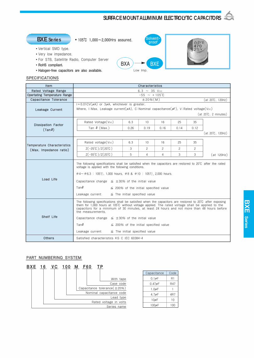
BXE Serie
s
IItteemm CChhaarraacctteerriissttiiccss
RRaatteedd VVoollttaaggee RRaannggee 6.3 ~ 35 VDC
OOppeerrttaattiinngg TTeemmppeerraattuurree RRaannggee -55 ~ +105
CCaappaacciittaannccee TToolleerraannccee ±20%(M)
I=0.01CV(μA) or 3μA, whichever is greater.
LLeeaakkaaggee CCuurrrreenntt Where, I:Max. Leakage current(μA), C:Nominal capacitance(μF), V:Rated voltage(VDC)
(at 20, 2 minutes)
DDiissssiippaattiioonn FFaaccttoorr
((TTaannδδ))
TTeemmppeerraattuurree CChhaarraacctteerriissttiiccss
The following specifications shall be satisfied when the capacitors are restored to 20 after the ratedvoltage is applied with the following conditions.
∅4~∅6.3 : 105, 1,000 hours, ∅8 & ∅10 : 105, 2,000 hours.
The following specifications shall be satisfied when the capacitors are restored to 20 after exposing them for 1,000 hours at 105 without voltage applied. The rated voltage shall be applied to the capacitors for a minimum of 30 minutes, at least 24 hours and not more than 48 hours before the measurements.
Capacitance change ±30% of the initial value
Tanδ 200% of the initial specified value
Leakage current The initial specified value
OOtthheerrss Satisfied characteristics KS C IEC 60384-4
110055 11,,000000~~22,,000000HHrrss aassssuurreedd..
Vertical SMD type.
Very low impedance.
For STB, Satellite Radio, Computer Server
RoHS compliant.
Halogen-free capacitors are also available.
SSPPEECCIIFFIICCAATTIIOONNSS
PPAARRTT NNUUMMBBEERRIINNGG SSYYSSTTEEMM
BXE 16 VC 100 M F60 TP
SSoollvveenntt--pprrooooff
With tape
Case code
Capacitance tolerance(±20%)
Nominal capacitance code
Lead type
Rated voltage in volts
Series name
LLooaadd LLiiffee
SShheellff LLiiffee
(at 120Hz)
((MMaaxx.. IImmppeeddaannccee rraattiioo))
(at 20, 120Hz)
(at 20, 120Hz)
BXE Series
BBXXAA BBXXEELow Imp.
Capacitance Code
0.1μF R1
0.47μF R47
1.0μF 1
4.7μF 4R7
10μF 10
100μF 100
Rated Voltage(VDC) 6.3 10 16 25 35
Tan δ(Max.) 0.26 0.19 0.16 0.14 0.12
Rated voltage(VDC) 6.3 10 16 25 35
Z(-25)/Z(20) 3 2 2 2 2
Z(-55)/Z(20) 5 4 4 3 3
Capacitance change ±30% of the initial value
Tanδ 200% of the initial specified value
Leakage current The initial specified value
SURFACE MOUNT ALUMINUM ELECTROLYTIC CAPACITORS

Unit(mm)
66..33 1100 1166 2255 3355
RRAATTIINNGGSS OOFF BBXXEE SSeerriieess
DDIIMMEENNSSIIOONNSS OOFF BBXXEE SSeerriieess((TTyyppee :: VVCC))
DIMENSIONS MARKING
: Solder land on PC board
CCaassee ccooddee ∅∅DD LL AA BB CC WW PP aa bb ccD56 4 5.3 4.3 4.3 5.1 0.5-0.8 1.0 1.0 2.6 1.6E56 5 5.3 5.3 5.3 5.9 0.5-0.8 1.4 1.4 3.0 1.6
F60 6.3 5.7 6.6 6.6 7.2 0.5-0.8 1.9 1.9 3.5 1.6
F80 6.3 7.7 6.6 6.6 7.2 0.5-0.8 1.9 1.9 3.5 1.6
H10 8 10 8.3 8.3 9.0 0.7-1.1 3.1 3.1 4.2 2.2
J10 10 10 10.3 10.3 11.0 0.7-1.1 4.5 4.5 4.4 2.2
VVDDCC
D56 1.8 85
D56 1.8 85 E56 0.8 155
D56 1.8 85 E56 0.8 155 E56 0.8 155 E56 0.8 155
D56 1.8 85 E56 0.8 155 F60 0.36 240 F60 0.36 240 F60 0.36 240
E56 0.8 155 F60 0.36 240 F60 0.36 240 F60 0.36 240 F60 0.36 240
F60 0.36 240 F60 0.36 240 F60 0.36 240 F60 0.36 240 F80 0.34 280
F60 0.36 240 F60 0.36 240 F60 0.36 240 F80 0.34 280 H10 0.16 600
F60 0.36 240 F80 0.34 280 F80 0.34 280 H10 0.16 600 H10 0.16 600
F80 0.34 280 H10 0.16 600 H10 0.16 600 H10 0.16 600 J10 0.08 850
H10 0.16 600 H10 0.16 600 H10 0.16 600 J10 0.08 850
H10 0.16 600 J10 0.08 850
J10 0.08 850
Rated Ripple Current (mArms/105, 100kHz)Impedance (Ϊmax./20, 100kHz)Case code
44..77
1100
2222
3333
4477
6688
110000
222200
333300
447700
11,,000000
11,,550000
Note 1 : L±0.5 for 8×10(H10), 10×10(J10).Note 2 : 4×5.3(D56), 5×5.3(E56) is excluded symbol mark.Note 3 : 6.3WV is marked by 6V.
Recommended solder land on PC board
SURFACE MOUNT ALUMINUM ELECTROLYTIC CAPACITORS
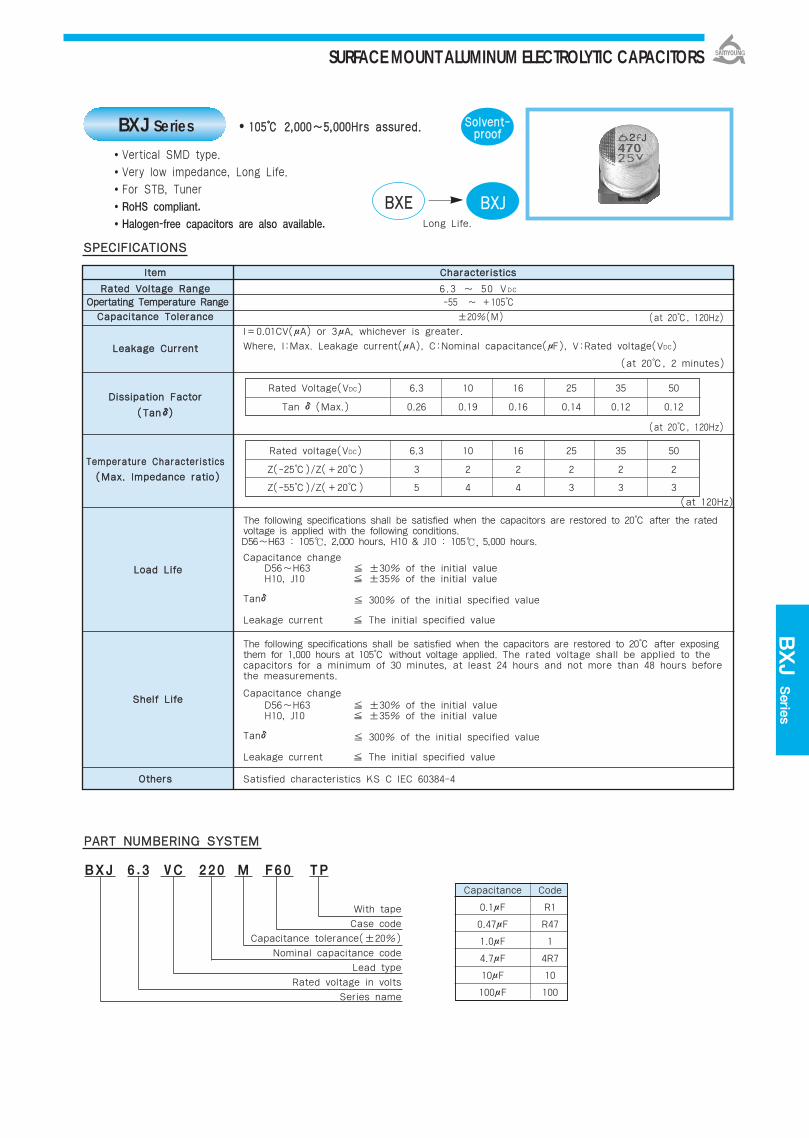
BXJ Serie
s
110055 22,,000000~~55,,000000HHrrss aassssuurreedd..
Vertical SMD type.
Very low impedance, Long Life.
For STB, Tuner
RoHS compliant.
Halogen-free capacitors are also available.
SSoollvveenntt--pprrooooffBXJ Series
BBXXEE BBXXJJLong Life.
IItteemm CChhaarraacctteerriissttiiccss
RRaatteedd VVoollttaaggee RRaannggee 6.3 ~ 50 VDC
OOppeerrttaattiinngg TTeemmppeerraattuurree RRaannggee -55 ~ +105
CCaappaacciittaannccee TToolleerraannccee ±20%(M)
I=0.01CV(μA) or 3μA, whichever is greater.
LLeeaakkaaggee CCuurrrreenntt Where, I:Max. Leakage current(μA), C:Nominal capacitance(μF), V:Rated voltage(VDC)
(at 20, 2 minutes)
DDiissssiippaattiioonn FFaaccttoorr
((TTaannδδ))
TTeemmppeerraattuurree CChhaarraacctteerriissttiiccss
The following specifications shall be satisfied when the capacitors are restored to 20 after the ratedvoltage is applied with the following conditions.D56~H63 : 105, 2,000 hours, H10 & J10 : 105, 5,000 hours.
Capacitance changeD56~H63 ±30% of the initial valueH10, J10 ±35% of the initial value
Tanδ 300% of the initial specified value
Leakage current The initial specified value
The following specifications shall be satisfied when the capacitors are restored to 20 after exposing them for 1,000 hours at 105 without voltage applied. The rated voltage shall be applied to the capacitors for a minimum of 30 minutes, at least 24 hours and not more than 48 hours before the measurements.
Capacitance changeD56~H63 ±30% of the initial valueH10, J10 ±35% of the initial value
Tanδ 300% of the initial specified value
Leakage current The initial specified value
OOtthheerrss Satisfied characteristics KS C IEC 60384-4
SSPPEECCIIFFIICCAATTIIOONNSS
PPAARRTT NNUUMMBBEERRIINNGG SSYYSSTTEEMM
BXJ 6 . 3 VC 220 M F60 TP
With tape
Case code
Capacitance tolerance(±20%)
Nominal capacitance code
Lead type
Rated voltage in volts
Series name
LLooaadd LLiiffee
SShheellff LLiiffee
(at 120Hz)
((MMaaxx.. IImmppeeddaannccee rraattiioo))
(at 20, 120Hz)
(at 20, 120Hz)
Capacitance Code
0.1μF R1
0.47μF R47
1.0μF 1
4.7μF 4R7
10μF 10
100μF 100
Rated Voltage(VDC) 6.3 10 16 25 35 50
Tan δ(Max.) 0.26 0.19 0.16 0.14 0.12 0.12
Rated voltage(VDC) 6.3 10 16 25 35 50
Z(-25)/Z(+20) 3 2 2 2 2 2
Z(-55)/Z(+20) 5 4 4 3 3 3
SURFACE MOUNT ALUMINUM ELECTROLYTIC CAPACITORS

D56 1.8 85 E56 3.0 55
D56 1.8 85 E56 0.8 155 F60 1.2 120
D56 1.8 85 E56 0.8 155 E56 0.8 155 F55 0.55 220 F60 1.2 120
D56 1.8 85 E56 0.8 155 F60 0.36 240 F60 0.36 240 F60 0.36 240 F80 0.9 150
E56 0.8 155 F60 0.36 240 F60 0.36 240 F60 0.36 240 F60 0.36 240 H63 0.75 200
F60 0.36 240 F60 0.36 240 F60 0.36 240 F60 0.36 240 H10 0.42 300
F60 0.36 240 F60 0.36 240 F60 0.36 240F80 0.34 280 H10 0.42 300
H63 0.26 300 J10 0.25 420
F60 0.36 240 F80 0.34 280 F80 0.34 280 H10 0.16 600 H10 0.16 600 J10 0.25 420
F80 0.34 280 H10 0.16 600 H10 0.16 600 H10 0.16 600 J10 0.08 850
H10 0.16 600 H10 0.16 600 H10 0.16 600 J10 0.08 850
H10 0.16 600 J10 0.08 850
J10 0.08 850
Unit(mm)
66..33 1100 1166 2255 3355 5500
RRAATTIINNGGSS OOFF BBXXJJ SSeerriieess
DDIIMMEENNSSIIOONNSS OOFF BBXXJJ SSeerriieess((TTyyppee :: VVCC))
DIMENSIONS MARKING
: Solder land on PC board
CCaassee ccooddee ∅∅DD LL AA BB CC WW PP aa bb ccD56 4 5.3 4.3 4.3 5.1 0.5-0.8 1.0 1.0 2.6 1.6
E56 5 5.3 5.3 5.3 5.9 0.5-0.8 1.4 1.4 3.0 1.6
F55 6.3 5.2 6.6 6.6 7.2 0.5-0.8 1.9 1.9 3.5 1.6
F60 6.3 5.7 6.6 6.6 7.2 0.5-0.8 1.9 1.9 3.5 1.6
F80 6.3 7.7 6.6 6.6 7.2 0.5-0.8 1.9 1.9 3.5 1.6
H63 8 6.3 8.3 8.3 9.0 0.5-0.8 2.3 2.3 4.5 1.6
H10 8 10 8.3 8.3 9.0 0.7-1.1 3.1 3.1 4.2 2.2
J10 10 10 10.3 10.3 11.0 0.7-1.1 4.5 4.5 4.4 2.2
VVDDCC
Rated Ripple Current (mArms/105, 100kHz)Impedance (Ϊmax, 120, 100kHz)Case code
44..77
1100
2222
3333
4477
6688
110000
222200
333300
447700
11,,000000
11,,550000
Note 1 : L±0.5 for 8×6.3(H63)~10×10(J10).Note 2 : 4×5.3(D56), 5×5.3(E56) is excluded symbol mark.Note 3 : 6.3WV is marked by 6V.
Recommended solder land on PC board
SURFACE MOUNT ALUMINUM ELECTROLYTIC CAPACITORS
F80 0.34 280
H63 0.26 300
H10 0.16 600
J10 0.08 850

BDA Serie
s
110055 22,,000000HHrrss aassssuurreedd..
Vertical SMD type.
Long life of BDS(MVK) Series.
For LCD MT/TV, Copying Machine
RoHS compliant.
Halogen-free capacitors are also available.
SSoollvveenntt--pprrooooffBDA Series
BBDDSS BBDDAALong life.
IItteemm CChhaarraacctteerriissttiiccss
RRaatteedd VVoollttaaggee RRaannggee 4 ~ 50 VDC
OOppeerrttaattiinngg TTeemmppeerraattuurree RRaannggee -40 ~ +105
CCaappaacciittaannccee TToolleerraannccee ±20%(M) (at 20, 120Hz)
I=0.01CV(μA) or 3μA, whichever is greater.
LLeeaakkaaggee CCuurrrreenntt Where, I:Max. Leakage current(μA), C:Nominal capacitance(μF), V:Rated voltage(VDC)
(at 20, 2 minutes)
DDiissssiippaattiioonn FFaaccttoorr
TTaannδδ((MMaaxx..))
TTeemmppeerraattuurree CChhaarraacctteerriissttiiccss
The following specifications shall be satisfied when the capacitors are restored to 20 after the ratedvoltage applied for 2,000 hours at 105.
Rated voltage(VDC) 4 ~ 16VDC 25 ~ 50VDC
Capacitance change ±25% of the initial value ±20% of the initial value
Tanδ 200% of the initial specified value
Leakage current The initial specified value
The following specifications shall be satisfied when the capacitors are restored to 20 after exposing them for 1,000 hours at 105 without voltage applied. The rated voltage shall be applied to the capacitors for a minimum of 30 minutes, at least 24 hours and not more than 48 hours before the measurements.
Rated voltage(VDC) 4 ~ 16VDC 25 ~ 50VDC
Capacitance change ±25% of the initial value ±20% of the initial value
Tanδ 200% of the initial specified value
Leakage current The initial specified value
OOtthheerrss Satisfied characteristics KS C IEC 60384-4
SSPPEECCIIFFIICCAATTIIOONNSS
PPAARRTT NNUUMMBBEERRIINNGG SSYYSSTTEEMM
BDA 16 VC 100 M F60 TP
With tape
Case code
Capacitance tolerance(±20%)
Nominal capacitance code
Lead type
Rated voltage in volts
Series name
Rated voltage(VDC) 4 6.3 10 16 25 35 50
Tanδ(Max.) 0.37 0.28 0.24 0.20 0.16 0.13 0.12
LLooaadd LLiiffee
SShheellff LLiiffee
Rated voltage(VDC) 4 6.3 10 16 25~50
Z(-25)/Z(20) 6 3 3 2 2
Z(-40)/Z(20) 12 8 5 4 3(at 120Hz)
((MMaaxx.. IImmppeeddaannccee rraattiioo))
(at 20, 120Hz)
Capacitance Code
0.1μF R1
0.47μF R47
1.0μF 1
4.7μF 4R7
10μF 10
100μF 100
SURFACE MOUNT ALUMINUM ELECTROLYTIC CAPACITORS
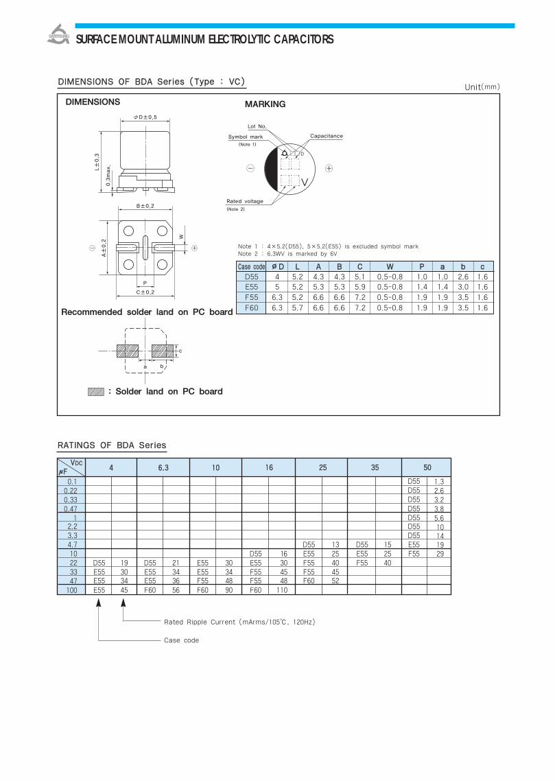
DDIIMMEENNSSIIOONNSS OOFF BBDDAA SSeerriieess ((TTyyppee :: VVCC))
DIMENSIONS MARKING
: Solder land on PC board
CCaassee ccooddee ∅∅DD LL AA BB CC WW PP aa bb ccD55 4 5.2 4.3 4.3 5.1 0.5-0.8 1.0 1.0 2.6 1.6E55 5 5.2 5.3 5.3 5.9 0.5-0.8 1.4 1.4 3.0 1.6
F55 6.3 5.2 6.6 6.6 7.2 0.5-0.8 1.9 1.9 3.5 1.6
F60 6.3 5.7 6.6 6.6 7.2 0.5-0.8 1.9 1.9 3.5 1.6
Rated Ripple Current (mArms/105, 120Hz)
Case code
Note 1 : 4×5.2(D55), 5×5.2(E55) is excluded symbol markNote 2 : 6.3WV is marked by 6V
RRAATTIINNGGSS OOFF BBDDAA SSeerriieess
VVDDCC1166 2255 3355 5500μμFF
D55D55D55D55D55D55D55
D55 13 D55 15 E55D55 16 E55 25 E55 25 F55
D55 19 D55 21 E55 30 E55 30 F55 40 F55 40E55 30 E55 34 E55 34 F55 45 F55 45E55 34 E55 36 F55 48 F55 48 F60 52E55 45 F60 56 F60 90 F60 110
Recommended solder land on PC board
SURFACE MOUNT ALUMINUM ELECTROLYTIC CAPACITORS
0.10.220.330.47
12.23.34.710223347
100
1.32.63.23.85.610141929
44 66..33 1100
Unit(mm)

IItteemm CChhaarraacctteerriissttiiccss
RRaatteedd VVoollttaaggee RRaannggee 4 ~ 50 VDC
OOppeerraattiinngg TTeemmppeerraattuurree RRaannggee -40 ~ +105CCaappaacciittaannccee TToolleerraannccee ±20%(M) (at 20, 120Hz)
I=0.01CV(μA) or 3μA, whichever is greater.LLeeaakkaaggee CCuurrrreenntt Where, I:Max. Leakage current(μA), C:Nominal capacitance(μF), V:Rated voltage(VDC)
(at 20, 2 minutes)
DDiissssiippaattiioonn FFaaccttoorr
TTaannδδ((MMaaxx..))
TTeemmppeerraattuurree CChhaarraacctteerriissttiiccss
The following specifications shall be satisfied when the capacitors are restored to 20 after the ratedvoltage is applied for 5,000 hours at 105.
Capacitance change ±30% of the initial value
Tanδ 300% of the initial specified value
Leakage current The initial specified value
The following specifications shall be satisfied when the capacitors are restored to 20 after exposing them for 1,000 hours at 105 without voltage applied. The rated voltage shall be applied to the capacitors for a minimum of 30 minutes, at least 24 hours and not more than 48 hours before the measurements.
Capacitance change ±30% of the initial value
Tanδ 300% of the initial specified value
Leakage current The initial specified value
OOtthheerrss Satisfied characteristics KS C IEC 60384-4
110055 55,,000000HHrrss aassssuurreedd..
Vertical SMD type.Long life of BDA SeriesFor LCD MT, AVNRoHS compliant.Halogen-free capacitors are also available.
SSPPEECCIIFFIICCAATTIIOONNSS
PPAARRTT NNUUMMBBEERRIINNGG SSYYSSTTEEMM
BLA 16 VC 100 M F60 TP
SSoollvveenntt--pprrooooff
With tapeCase code
Capacitance tolerance(±20%)Nominal capacitance code
Lead typeRated voltage in volts
Series name
Capacitance Code0.1μF R10.47μF R471.0μF 14.7μF 4R710μF 10100μF 100
Rated voltage(VDC) 4 6.3 10 16 25 35 50
Tanδ(Max.) 0.37 0.28 0.24 0.20 0.16 0.13 0.12
LLooaadd LLiiffee
SShheellff LLiiffee
Rated voltage(VDC) 4 6.3 10 16 25~50
Z(-25)/Z(+20) 8 4 3 2 2
Z(-40)/Z(+20) 14 10 7 5 3(at 120Hz)
((MMaaxx.. IImmppeeddaannccee rraattiioo))
(at 20, 120Hz)
BLA Series
BBDDAA BBLLAALong life
SURFACE MOUNT ALUMINUM ELECTROLYTIC CAPACITORS
BLA
Series
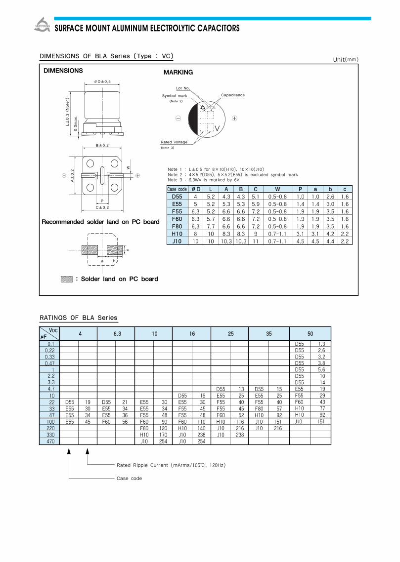
DIMENSIONS MARKING
: Solder land on PC board
CCaassee ccooddee ØØDD LL AA BB CC WW PP aa bb ccDD5555 4 5.2 4.3 4.3 5.1 0.5-0.8 1.0 1.0 2.6 1.6EE5555 5 5.2 5.3 5.3 5.9 0.5-0.8 1.4 1.4 3.0 1.6FF5555 6.3 5.2 6.6 6.6 7.2 0.5-0.8 1.9 1.9 3.5 1.6 FF6600 6.3 5.7 6.6 6.6 7.2 0.5-0.8 1.9 1.9 3.5 1.6 FF8800 6.3 7.7 6.6 6.6 7.2 0.5-0.8 1.9 1.9 3.5 1.6 HH1100 8 10 8.3 8.3 9 0.7-1.1 3.1 3.1 4.2 2.2 JJ1100 10 10 10.3 10.3 11 0.7-1.1 4.5 4.5 4.4 2.2
Note 1 : L±0.5 for 8×10(H10), 10×10(J10)Note 2 : 4×5.2(D55), 5×5.2(E55) is excluded symbol markNote 3 : 6.3WV is marked by 6V
Rated Ripple Current (mArms/105, 120Hz)
Case code
RRAATTIINNGGSS OOFF BBLLAA SSeerriieess
DDIIMMEENNSSIIOONNSS OOFF BBLLAA SSeerriieess ((TTyyppee :: VVCC))
D55D55D55D55D55D55D55E55F55F60H10H10J10
1.32.63.23.85.610141929437792151
Recommended solder land on PC board
SURFACE MOUNT ALUMINUM ELECTROLYTIC CAPACITORS
0.10.220.330.47
12.23.34.710223347
100220330470
VVDDCC 44 66..33 1100 1166 2255 3355 5500μμFF
D55 13 D55 15D55 16 E55 25 E55 25
D55 19 D55 21 E55 30 E55 30 F55 40 F55 40E55 30 E55 34 E55 34 F55 45 F55 45 F80 57E55 34 E55 36 F55 48 F55 48 F60 52 H10 92E55 45 F60 56 F60 90 F60 110 H10 116 J10 151
F80 120 H10 140 J10 216 J10 216H10 170 J10 238 J10 238J10 254 J10 254
Unit(mm)

IItteemm CChhaarraacctteerriissttiiccss
RRaatteedd VVoollttaaggee RRaannggee 10 ~ 50 VDC
OOppeerraattiinngg TTeemmppeerraattuurree RRaannggee -40 ~ +105CCaappaacciittaannccee TToolleerraannccee ±20%(M)
I=0.01CV(μA) or 3μA, whichever is greater.LLeeaakkaaggee CCuurrrreenntt Where, I:Max. Leakage current(μA), C:Nominal capacitance(μF), V:Rated voltage(VDC)
(at 20, 2 minutes)
DDiissssiippaattiioonn FFaaccttoorr
((TTaannδδ))
TTeemmppeerraattuurree CChhaarraacctteerriissttiiccss
The following specifications shall be satisfied when the capacitors are restored to 20 after the ratedvoltage is applied for 10,000 hours at 105
Capacitance change ±30% of the initial value
Tanδ 300% of the initial specified value
Leakage current The initial specified value
The following specifications shall be satisfied when the capacitors are restored to 20 after exposing them for 1,000 hours at 105 without voltage applied. The rated voltage shall be applied to the capacitors for a minimum of 30 minutes, at least 24 hours and not more than 48 hours before the measurements.
Capacitance change ±30% of the initial valueTanδ 300% of the initial specified valueLeakage current The initial specified value
OOtthheerrss Satisfied characteristics KS C IEC 60384-4
110055 1100,,000000HHrrss aassssuurreedd..
Vertical SMD type.Long life of BLA SeriesFor LCD MT/TV, AVNRoHS compliant.Halogen-free capacitors are also available.
SSPPEECCIIFFIICCAATTIIOONNSS
PPAARRTT NNUUMMBBEERRIINNGG SSYYSSTTEEMM
BLH 16 VC 220 M H10 TP
SSoollvveenntt--pprrooooff
With tapeCase code
Capacitance tolerance(±20%)Nominal capacitance code
Lead typeRated voltage in volts
Series name
Capacitance Code0.1μF R10.47μF R471.0μF 14.7μF 4R710μF 10100μF 100
Rated voltage(VDC) 10 16 25 35 50
Tanδ(Max.) 0.24 0.20 0.16 0.13 0.12
LLooaadd LLiiffee
SShheellff LLiiffee
Rated voltage(VDC) 10 16 25~50
Z(-25)/Z(+20) 3 2 2
Z(-40)/Z(+20) 7 5 3(at 120Hz)
((MMaaxx.. IImmppeeddaannccee rraattiioo))
(at 20, 120Hz)
(at 20, 120Hz)
BLH Series
BBLLAA BBLLHHLong life
SURFACE MOUNT ALUMINUM ELECTROLYTIC CAPACITORS
BLH
Series
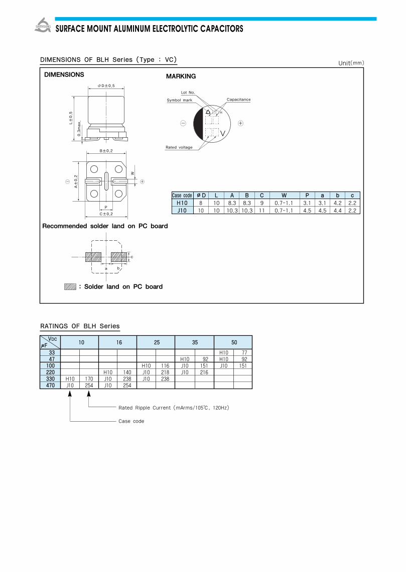
DDIIMMEENNSSIIOONNSS OOFF BBLLHH SSeerriieess ((TTyyppee :: VVCC))
DIMENSIONS MARKING
: Solder land on PC board
Rated Ripple Current (mArms/105, 120Hz)
Case code
RRAATTIINNGGSS OOFF BBLLHH SSeerriieess
VVDDCC 1100 1166 2255 3355 5500μμFF
Recommended solder land on PC board
CCaassee ccooddee ØØDD LL AA BB CC WW PP aa bb ccHH1100 8 10 8.3 8.3 9 0.7-1.1 3.1 3.1 4.2 2.2 JJ1100 10 10 10.3 10.3 11 0.7-1.1 4.5 4.5 4.4 2.2
SURFACE MOUNT ALUMINUM ELECTROLYTIC CAPACITORS
33334477
110000222200333300447700
H10J10
170254
H10J10J10
140238254
H10J10J10
116218238
H10J10J10
92151216
H10H10J10
7792151
Unit(mm)
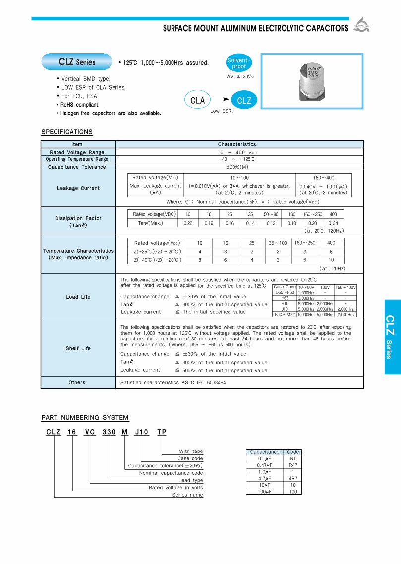
IItteemm CChhaarraacctteerriissttiiccss
RRaatteedd VVoollttaaggee RRaannggee 10 ~ 400 VDC
OOppeerraattiinngg TTeemmppeerraattuurree RRaannggee -40 ~ +125
CCaappaacciittaannccee TToolleerraannccee ±20%(M)
Where, C : Nominal capacitance(), V : Rated voltage(VDC)
The following specifications shall be satisfied when the capacitors are restored to 20after the rated voltage is applied for the specified time at 125
Capacitance change ±30% of the initial value
Tanδ 300% of the initial specified valueLeakage current The initial specified value
The following specifications shall be satisfied when the capacitors are restored to 20 after exposing them for 1,000 hours at 125 without voltage applied. The rated voltage shall be applied to thecapacitors for a minimum of 30 minutes, at least 24 hours and not more than 48 hours before the measurements. (Where, D55 ~ F60 is 500 hours)
Capacitance change ±30% of the initial value
Tanδ 300% of the initial specified valueLeakage current 500% of the initial specified value
OOtthheerrss Satisfied characteristics KS C IEC 60384-4
112255 11,,000000~~55,,000000HHrrss aassssuurreedd..
Vertical SMD type.LOW ESR of CLA SeriesFor ECU, ESARoHS compliant.Halogen-free capacitors are also available.
SSPPEECCIIFFIICCAATTIIOONNSS
PPAARRTT NNUUMMBBEERRIINNGG SSYYSSTTEEMM
CLZ 16 VC 330 M J10 TP
SSoollvveenntt--pprrooooff
With tapeCase code
Capacitance tolerance(±20%)Nominal capacitance code
Lead typeRated voltage in volts
Series name
Capacitance Code0.1μF R10.47μF R471.0μF 14.7μF 4R710μF 10100μF 100
Rated voltage(VDC)
Tanδ(Max.)
LLooaadd LLiiffee
SShheellff LLiiffee
Rated voltage(VDC) 10 16 25 35~100
Z(-25)/Z(+20) 4 3 2 2
Z(-40)/Z(+20) 8 6 4 3
(at 120Hz)
(at 20, 120Hz)
CLZ Series
CCLLAA CCLLZZLow ESR.
10
0.22
16
0.19
25
0.16
35
0.14
50~80
0.12
100
0.10
160~250
0.20
400
0.24
160~250
3
6
400
6
10
WV 80VDC
SURFACE MOUNT ALUMINUM ELECTROLYTIC CAPACITORS
Rated voltage(VDC)
Max. Leakage current(μA)
10~100
I=0.01CV(μA) or 3μA, whichever is greater.(at 20, 2 minutes)
160~400
0.04CV + 100(μA)(at 20, 2 minutes)
DDiissssiippaattiioonn FFaaccttoorr((TTaannδδ))
TTeemmppeerraattuurree CChhaarraacctteerriissttiiccss((MMaaxx.. IImmppeeddaannccee rraattiioo))
LLeeaakkaaggee CCuurrrreenntt
Case CodeD55~F60
H63H10J10
K14~M22
10~80V1,000Hrs3,000Hrs5,000Hrs5,000Hrs5,000Hrs
100V--
2,000Hrs2,000Hrs5,000Hrs
160~400V---
2,000Hrs2,000Hrs C
LZ Series

DDIIMMEENNSSIIOONNSS OOFF CCLLZZ SSeerriieess ((TTyyppee :: VVCC))
DIMENSIONS MARKING
(Not
e 1)
RRAATTIINNGGSS OOFF CCLLZZ SSeerriieess
Rated Ripple Current (mArms/125, 120Hz)Case code
VVDDCCμμFF
Recommended solder land on PC board
<D55~J10> <K14~M22>
CCaassee ccooddee ØØDD LL AA BB CC WW PP aa bb cc aa bb ccDD5555EE5555FF5555FF6600HH6633HH1100JJ1100KK1144LL1177LL2222MM1177MM2222
456.36.3881012.516161818
5.25.25.25.76.3101013.516.521.516.521.5
4.35.36.66.68.38.310.313.017.017.019.019.0
4.35.36.66.68.38.310.313.017.017.019.019.0
5.15.97.27.29.09.011.013.718.018.020.020.0
0.5~0.80.5~0.80.5~0.80.5~0.80.5~0.80.7~1.10.7~1.11.0~1.31.0~1.31.0~1.31.0~1.31.0~1.3
1.01.41.91.92.33.14.54.26.56.56.56.5
1.01.41.91.92.33.14.54.06.06.06.06.0
2.63.03.53.54.54.24.45.76.96.97.97.9
1.61.61.61.61.62.22.22.52.52.52.52.5
4.7 8.8 9.6
4.7 7.8 9.6
Vibration Resistance
: Solder land on PC board
: Dummy terminals
<Size code:H63~M22> <Size code:L17~M22>
Vibration Resistance
116600 220000 225500 440000
12.23.34.71022334768
K14L17M17M22M22
100180245315380
K14L17M17M22
100180245315
L17M17M22
120205260
J10J10J10K14L22
18263770140
Note 1 : L±0.5 for 8×6.3(H63)~18×21.5(M22)Note 2 : 4×5.2(D55), 5×5.2(E55)is excluded symbol mark
SURFACE MOUNT ALUMINUM ELECTROLYTIC CAPACITORS
VVDDCCμμFF
10223347100220330470
1,0002,2003,3004,700
E55E55F55H63H10J10J10K14L17M17M22
3.303.302.000.900.400.300.300.140.100.100.058
49.549.530.014.06.04.54.52.11.51.5
0.87
232340110220296296750
100012001550
Rated Ripple Current (mArms/125, 100kHz)ESR (Ωmax./-40, 100kHz)ESR (Ωmax./20, 100kHz)Case code
D55E55F55F60H63H10J10K14M17
7.003.302.001.600.900.400.300.140.10
10549.530.024.014.06.04.52.11.5
49.530.024.014.06.04.52.11.50.87
24.024.014.06.06.04.52.11.5
42.030.011.011.07.53.52.32.3
11035.025.025.012.59.09.05.5
50.035.035.016.59.02.5
50.050.035.016.516.5
122340691102202967501200
E55F55F60H63H10J10K14L17M22
3.302.001.600.900.400.300.140.100.058
23406911022029675010001550
1100 1166 2255
F60F60H63H10H10J10K14M17
1.601.600.900.400.400.300.140.10
69691102202202967501000
3355
F60H63H10J10J10K14L17M17
2.801.600.700.500.500.230.150.15
5183160247247550850920
5500
H63H10J10J10K14L17L17L22
2.001.000.550.550.330.240.240.16
6070115115450650650950
6633
H10J10J10K14L17M17
1.200.550.550.330.240.16
70115115450650950
8800
H10J10J10K14K14
1.601.600.800.330.33
7070
115450450
110000
Unit(mm)
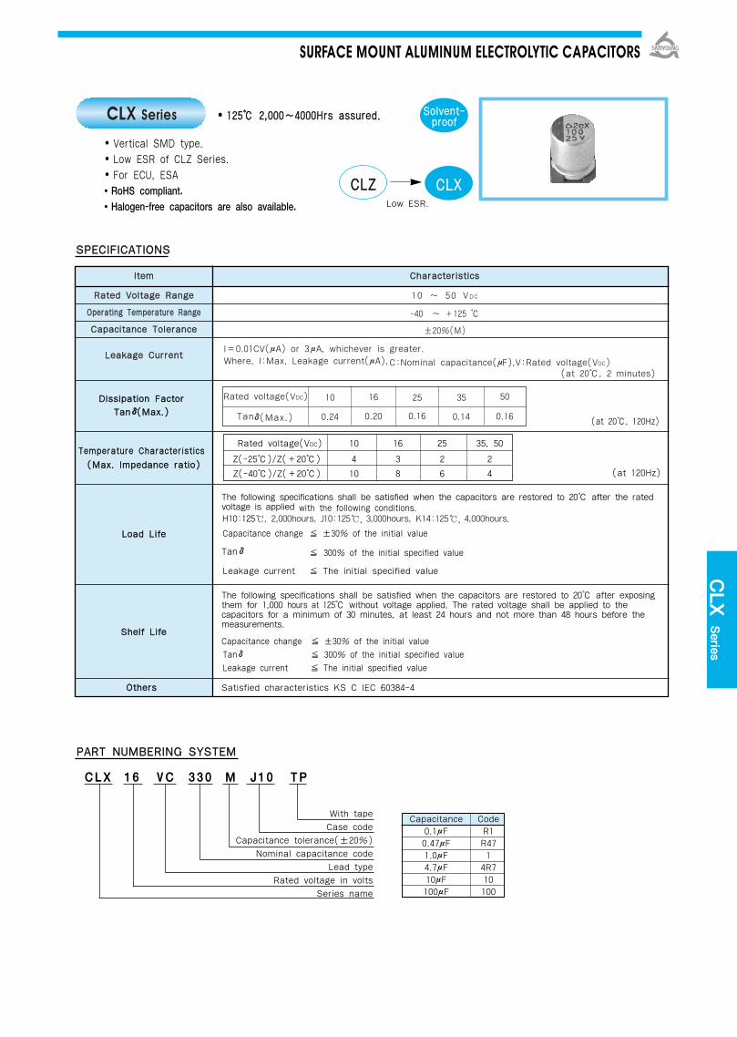
DDiissssiippaattiioonn FFaaccttoorrTTaannδδ((MMaaxx..))
TTeemmppeerraattuurree CChhaarraacctteerriissttiiccss
The following specifications shall be satisfied when the capacitors are restored to 20 after the ratedvoltage is applied with the following conditions.
Capacitance change ±30% of the initial value
Tanδ 300% of the initial specified value
Leakage current The initial specified value
The following specifications shall be satisfied when the capacitors are restored to 20 after exposing them for 1,000 hours at 125 without voltage applied. The rated voltage shall be applied to the capacitors for a minimum of 30 minutes, at least 24 hours and not more than 48 hours before the measurements.
Capacitance change ±30% of the initial valueTanδ 300% of the initial specified valueLeakage current The initial specified value
OOtthheerrss Satisfied characteristics KS C IEC 60384-4
112255 22,,000000~~44000000HHrrss aassssuurreedd..
Vertical SMD type.Low ESR of CLZ Series.For ECU, ESA RoHS compliant.Halogen-free capacitors are also available.
SSPPEECCIIFFIICCAATTIIOONNSS
PPAARRTT NNUUMMBBEERRIINNGG SSYYSSTTEEMM
CLX 16 VC 330 M J10 TP
SSoollvveenntt--pprrooooff
With tapeCase code
Capacitance tolerance(±20%)Nominal capacitance code
Lead typeRated voltage in volts
Series name
Capacitance Code0.1μF R10.47μF R471.0μF 14.7μF 4R710μF 10100μF 100
LLooaadd LLiiffee
SShheellff LLiiffee
Rated voltage(VDC) 10 16 25 35, 50
Z(-25)/Z(+20) 4 3 2 2
Z(-40)/Z(+20) 10 8 6 4 (at 120Hz)((MMaaxx.. IImmppeeddaannccee rraattiioo))
(at 20, 120Hz)
CLX Series
CCLLZZ CCLLXXLow ESR.
H10:125, 2,000hours, J10:125, 3,000hours, K14:125, 4,000hours.
IItteemm
RRaatteedd VVoollttaaggee RRaannggee
OOppeerraattiinngg TTeemmppeerraattuurree RRaannggee
CCaappaacciittaannccee TToolleerraannccee
LLeeaakkaaggee CCuurrrreenntt
CChhaarraacctteerriissttiiccss
10 ~ 50 VDC
-40 ~ +125
±20%(M)
I=0.01CV(μA) or 3μA, whichever is greater.Where, I:Max. Leakage current(μA),C:Nominal capacitance(μF),V:Rated voltage(VDC)
(at 20, 2 minutes)
Rated voltage(VDC)
Tanδ(Max.)
10 16 25 35 50
0.24 0.20 0.16 0.14 0.16
SURFACE MOUNT ALUMINUM ELECTROLYTIC CAPACITORS
CLX
Series

DDIIMMEENNSSIIOONNSS OOFF CCLLXX SSeerriieess((TTyyppee :: VVCC))
RRAATTIINNGGSS OOFF CCLLXX SSeerriieess
DIMENSIONS MARKING
Recommended solder land on PC board
: Solder land on PC board
CCaassee ccooddee ØØDD LL AA BB CC WW PP aa bb ccHH1100 8 10 8.3 8.3 9.0 0.7~1.1 3.1 3.1 4.2 2.2JJ1100 10 10 10.3 10.3 11.0 0.7~1.1 4.5 4.5 4.4 2.2KK1144 12.5 13.5 13.0 13.0 13.7 1.0~1.3 4.2 4.0 5.7 2.5
<H10 ~ J10> <K14>
H10 0.53 8.0 192H10 0.30 4.5 264 J10 0.38 5.7 296
H10 0.30 4.5 264 H10 0.30 4.5 264 J10 0.38 5.7 296H10 0.30 4.5 264 H10 0.30 4.5 264 J10 0.23 3.5 355 J10 0.23 3.5 355 K14 0.18 2.7 650J10 0.23 3.5 355 J10 0.23 3.5 355 K14 0.11 1.7 950 K14 0.11 1.7 950J10 0.23 3.5 355 K14 0.11 1.7 950K14 0.11 1.7 950
1166VV1100VV 2255VV 3355VV 5500VV
33334477
110000222200333300447700
11000000
μμFFVVDDCC
Rated Ripple Current (mArms/ 125, 100kHz)ESR (Ωmax./-40, 100kHz)ESR (Ωmax./20, 100kHz)Case code
SURFACE MOUNT ALUMINUM ELECTROLYTIC CAPACITORS
Unit(mm)
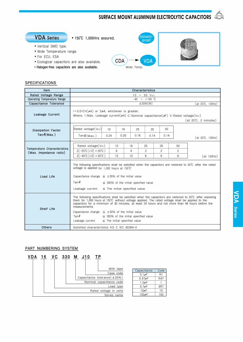
IItteemm CChhaarraacctteerriissttiiccss
RRaatteedd VVoollttaaggee RRaannggee 10 ~ 50 VDC
OOppeerraattiinngg TTeemmppeerraattuurree RRaannggee -40 ~ +150 CCaappaacciittaannccee TToolleerraannccee ±20%(M)
I=0.01CV(μA) or 3μA, whichever is greater.LLeeaakkaaggee CCuurrrreenntt Where, I:Max. Leakage current(μA)
DDiissssiippaattiioonn FFaaccttoorrTTaannδδ((MMaaxx..))
TTeemmppeerraattuurree CChhaarraacctteerriissttiiccss((MMaaxx.. IImmppeeddaannccee rraattiioo))
The following specifications shall be satisfied when the capacitors are restored to 20 after the ratedvoltage is applied for 1,000 hours at 150
Capacitance change ±30% of the initial value
Tanδ 300% of the initial specified value
Leakage current The initial specified value
The following specifications shall be satisfied when the capacitors are restored to 20 after exposing them for 1,000 hours at 150 without voltage applied. The rated voltage shall be applied to the capacitors for a minimum of 30 minutes, at least 24 hours and not more than 48 hours before the measurements.
Capacitance change ±30% of the initial valueTanδ 300% of the initial specified valueLeakage current The initial specified value
OOtthheerrss Satisfied characteristics KS C IEC 60384-4
115500 11,,000000HHrrss aassssuurreedd..
Vertical SMD type.Wide Temperature range.For ECU, ESA Ecological capacitors are also available.Halogen-free capacitors are also available.
SSPPEECCIIFFIICCAATTIIOONNSS
PPAARRTT NNUUMMBBEERRIINNGG SSYYSSTTEEMM
VDA 16 VC 330 M J10 TP
SSoollvveenntt--pprrooooff
With tapeCase code
Capacitance tolerance(±20%)Nominal capacitance code
Lead typeRated voltage in volts
Series name
Capacitance Code0.1μF R10.47μF R471.0μF 14.7μF 4R710μF 10100μF 100
Rated voltage(VDC)
Tanδ(Max.)
LLooaadd LLiiffee
SShheellff LLiiffee
Rated voltage(VDC) 10 16 25 35 50
Z(-25)/Z(+20) 6 4 3 2 2
Z(-40)/Z(+20) 12 10 8 6 6 (at 120Hz)
(at 20, 120Hz)
(at 20, 120Hz)
VDA Series
CCDDAA VVDDAAWide Temp.
10 16 25 35 50
0.24 0.20 0.16 0.14
C:Nominal capacitance(μF) V:Rated voltage(VDC)
(at 20, 2 minutes)
0.14
SURFACE MOUNT ALUMINUM ELECTROLYTIC CAPACITORS
VDA Series
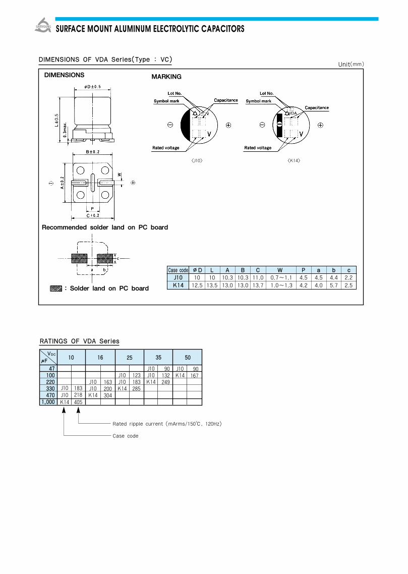
DDIIMMEENNSSIIOONNSS OOFF VVDDAA SSeerriieess((TTyyppee :: VVCC))
DIMENSIONS MARKING
Recommended solder land on PC board
: Solder land on PC board
RRAATTIINNGGSS OOFF VVDDAA SSeerriieess
Rated ripple current (mArms/150, 120Hz)
Case code
CCaassee ccooddee ØØDD LL AA BB CC WW PP aa bb ccJJ1100 10 10 10.3 10.3 11.0 0.7~1.1 4.5 4.5 4.4 2.2KK1144 12.5 13.5 13.0 13.0 13.7 1.0~1.3 4.2 4.0 5.7 2.5
<J10> <K14>
163200304
J10J10K14
123183285
90167
183218405
J10J10K14
J10J10K14
J10J10K14
1100 1166 2255 3355 5500
4477110000222200333300447700
11,,000000
J10K14
90132249
μμFFVVDDCC
SURFACE MOUNT ALUMINUM ELECTROLYTIC CAPACITORS
Unit(mm)
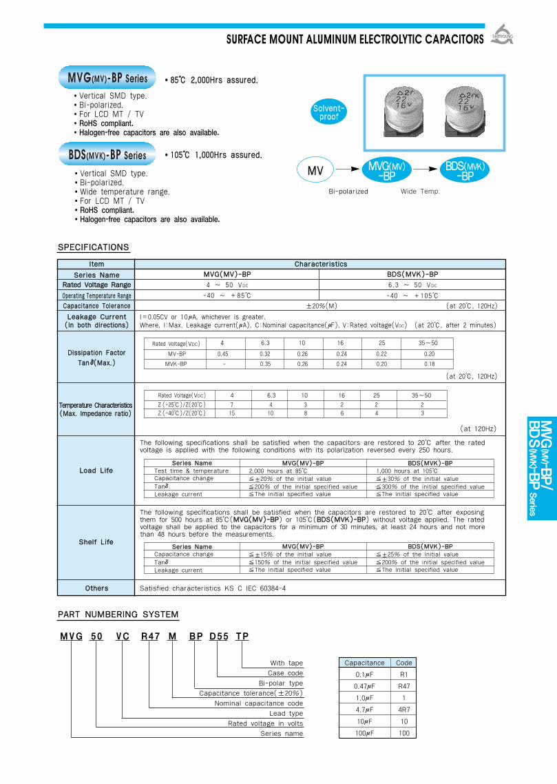
IItteemm CChhaarraacctteerriissttiiccss
SSeerriieess NNaammeeRRaatteedd VVoollttaaggee RRaannggee
OOppeerraattiinngg TTeemmppeerraattuurree RRaannggeeCCaappaacciittaannccee TToolleerraannccee ±20%(M) (at 20, 120Hz)
LLeeaakkaaggee CCuurrrreenntt I=0.05CV or 10μA, whichever is greater. ((IInn bbootthh ddiirreeccttiioonnss)) Where, I:Max. Leakage current(μA), C:Nominal capacitance(μF), V:Rated voltage(VDC) (at 20, after 2 minutes)
DDiissssiippaattiioonn FFaaccttoorrTTaannδδ((MMaaxx..))
The following specifications shall be satisfied when the capacitors are restored to 20 after the rated voltage is applied with the following conditions with its polarization reversed every 250 hours.
The following specifications shall be satisfied when the capacitors are restored to 20 after exposingthem for 500 hours at 85(MMVVGG((MMVV))--BBPP) or 105(BBDDSS((MMVVKK))--BBPP) without voltage applied. The ratedvoltage shall be applied to the capacitors for a minimum of 30 minutes, at least 24 hours and not morethan 48 hours before the measurements.
OOtthheerrss Satisfied characteristics KS C IEC 60384-4
8855 22,,000000HHrrss aassssuurreedd..
110055 11,,000000HHrrss aassssuurreedd..
Vertical SMD type.Bi-polarized.For LCD MT / TVRoHS compliant.Halogen-free capacitors are also available.
SSPPEECCIIFFIICCAATTIIOONNSS
PPAARRTT NNUUMMBBEERRIINNGG SSYYSSTTEEMM
MVG 50 VC R47 M BP D55 TP
With tapeCase code
Bi-polar typeCapacitance tolerance(±20%)
Nominal capacitance codeLead type
Rated voltage in voltsSeries name
SSoollvveenntt--pprrooooff
Rated Voltage(VDC) 4 6.3 10 16 25 35~50
MV-BP 0.45 0.32 0.26 0.24 0.22 0.20
MVK-BP - 0.35 0.26 0.24 0.20 0.18
SSeerriieess NNaammeeTest time & temperatureCapacitance changeTanδLeakage current
SSeerriieess NNaammeeCapacitance changeTanδLeakage current
Rated Voltage(VDC) 4 6.3 10 16 25 35~50Z (-25)/Z(20) 7 4 3 2 2 2 Z (-40)/Z(20) 15 10 8 6 4 3
TTeemmppeerraattuurree CChhaarraacctteerriissttiiccss((MMaaxx.. IImmppeeddaannccee rraattiioo))
(at 120Hz)
(at 20, 120Hz)
Capacitance Code
0.1μF R1
0.47μF R47
1.0μF 1
4.7μF 4R7
10μF 10
100μF 100
MVG(MV)-BP Series
BDS(MVK)-BP Series
Wide Temp.
MMVV MMVVGG((MMVV))--BBPP
BBDDSS((MMVVKK))--BBPP
Bi-polarized
Vertical SMD type.Bi-polarized.Wide temperature range.For LCD MT / TVRoHS compliant.Halogen-free capacitors are also available.
SShheellff LLiiffee
LLooaadd LLiiffee
SURFACE MOUNT ALUMINUM ELECTROLYTIC CAPACITORS
MMVVGG((MMVV))--BBPP4 ~ 50 VDC
-40 ~ +85
BBDDSS((MMVVKK))--BBPP6.3 ~ 50 VDC
-40 ~ +105
MMVVGG((MMVV))--BBPP2,000 hours at 85±20% of the initial value200% of the initial specified valueThe initial specified value
BBDDSS((MMVVKK))--BBPP1,000 hours at 105±30% of the initial value300% of the initial specified valueThe initial specified value
MMVVGG((MMVV))--BBPP±15% of the initial value150% of the initial specified valueThe initial specified value
BBDDSS((MMVVKK))--BBPP±25% of the initial value200% of the initial specified valueThe initial specified value
MVG
(MV)-BP/
BDS
(MVK)-BP
Series

VVDDCC 66..33 1100 1166 2255 3355 5500
D55 1.2D55 1.7D55 2.2D55 2.7D55 3.2D55 4.0D55 5.3D55 7.2
D55 7 E55 9.0D55 8 E55 12
D55 10 E55 14 F60 16D55 11 E55 16 F60 20
D55 12 E55 18 F60 23E55 20 F60 28
E55 23 F60 32F60 35
F60 39
VVDDCC 44 66..33 1100 1166 2255 3355 5500
D55 1.3D55 1.9D55 2.3D55 2.8D55 3.4D55 4.1D55 5.5D55 6.5
D55 8 E55 9D55 9 E55 11
D55 11 E55 13 F55 14D55 12 E55 15 F55 17
D55 13 E55 18 F55 21D55 14 E55 21 F55 24
E55 23 F55 28F55 33 Case code
F55 36
DDIIMMEENNSSIIOONNSS OOFF MMVVGG((MMVV))--BBPP,, BBDDSS((MMVVKK))--BBPP SSeerriieess((TTyyppee ::VVCC))
RRAATTIINNGGSS OOFF MMVVGG((MMVV))--BBPP,, BBDDSS((MMVVKK))--BBPP SSeerrii eess
CCaassee ccooddee ØØDD LL AA BB CC WW PP aa bb ccD55 5.2 4.3 4.3 5.1 0.5-0.8 1.0 1.0 2.6 1.6E55 5.2 5.3 5.3 5.9 0.5-0.8 1.4 1.4 3.0 1.6F55 6.3 5.2 6.6 6.6 7.2 0.5-0.8 1.9 1.9 3.5 1.6F60 6.3 5.7 6.6 6.6 7.2 0.5-0.8 1.9 1.9 3.5 1.6
Recommended solder land on PC board
Note : → Use next higher voltage part.Parenthesized capacitance is not standard part.
MMVVGG((MMVV))--BBPP
BBDDSS((MMVVKK))--BBPP
Solder land on PC board
Rated Ripple Current(mArms/ 85, 120Hz)
SURFACE MOUNT ALUMINUM ELECTROLYTIC CAPACITORS
00..1100((00..1155))00..222200..333300..4477
((00..6688))11..00
((11..55))22..2233..3344..77
((66..88))1100
((1155))222233334477
00..1100((00..1155))00..222200..333300..4477
((00..6688))11..00
((11..55))22..2233..3344..77
((66..88))1100
((1155))222233334477
45
Unit(mm)
Rated Ripple Current (mA rms/105, 120Hz)Case code

Soldering methodThe capacitors of Alchip have no capability to withstand such dip orwave soldering as totally immerses a components into a solder bath.
Reflow solderingUse the capacitors within the Recommended Reflow SolderingConditions, and also make sure to check the temperature stress tothe capacitors because the following makes a difference in the stressto the capacitors. If any other reflow soldering conditions are applied,please consult us.① Location of components. ( The edge sides of a PC board
increases its temperature more than the center does. )② Population of components. The less the component population is
the more the temperature is increased.③ Material of printed circuit board. As a ceramic board needs
heating up more than a glass epoxy board to reach the same board temperature, the capacitors may be damaged.
④ Thickness of PC board. A thick PC board needs heating up more than a thin board. It may damage the capacitors.
⑤ Size of PC board. A large PC board needs heating up more than a small board, and it may damage the capacitors.
⑥ Location of infrared ray lamps. On IR reflow as well as hot plate reflow, heating only the reverse side of the PC boardwill reduce a stress to the capacitors.
Rework of solderingAvoid soldering more than once by reflow. Use a soldering iron forrework of solder, and do not exceed an iron tip temperature of 300and a max. exposure time of 5 seconds.
Mechanical stressDo not lift up or push the capacitor after soldering. Avoid curvature ofthe PC board. These may damage the capacitor.
Cleaning of assembly boardFor the cleaning conditions, see page 34~35. Immediately after solvent cleaning, evaporate a residual solvent for atleast 10 minutes with a hot forced air. If the assembly board isinadequately dried after a washing process, the capacitors will keepsuffering from a residual solvent for long periods of time, and will becorroded while in service.
Coating on assembly board① Before coating, evaporate cleaning solvents from the
assembly board.② Before the conformal coating, using a buffer pre-coat which
does not contain chloride is recommanded to reduce stressto the capacitors.
Molding by resinInner pressure of a capacitor slowly increases over the service life ofthe capacitor with gas being produced by internal chemical reaction.If the end seal of the capacitor is completely be in danger. Also if theresin contains a large amount of chlorine ion, it will penetrate into theend seal, get into the inside element of the capacitor, and damagethe capacitor while in service.
OthersThe Precautions to Users for Aluminum Electrolytic Capacitors shallbe applied. (page 31)
PRECAUTIONS TO USERS
RECOMMENDED PB-FREE REFLOW SOLDERING CONDITIONS
TEMPERATURE PROFILE
The following conditions are recomended for air or infrared reflow soldering of the surface mount capacitors onto a glass epoxy circuitboard of 90×50×0.8mm (with resist) by cream solder (eutectic solder) . The temperatures shown are the surface temperature values ofthe top of the capacitor.
CCAASSEE CCOODDEE TTiimmee ooff PPrreehheeaatt tteemmpp..((ffrroomm 115500 ttoo 220000))
60 ~ 100 Sec
60 ~ 100 Sec
TTiimmee ttoo bbee MMaaiinnttaaiinneeddAAbboovvee 221177
60 ~ 70 Sec
50 ~ 60 Sec
TTiimmee ttoo bbee MMaaiinnttaaiinneeddAAbboovvee 223300
20 ~ 30 Sec
-
PPeeaakk TTeemmpp..
250(10 Sec ↓)
230(10 Sec ↓)
RReefflloowwCCyyccllee
1 TIME
1 TIME
BB5555,, DD5555,, DD5566EE5555,, FF5555,, FF6600,, FF8800HH6633,, HH1100,, JJ1100,, KK1144
LL1177,, LL2222MM1177,, MM2222
SURFACE MOUNT ALUMINUM ELECTROLYTIC CAPACITORS

SSPPEECCIIFFIICCAATTIIOONNSS
DDIIMMEENNSSIIOONNSS OOFF DDSSAA//DDZZAA
8855 22,,000000HHrrss aassssuurreedd..
8855 22,,000000HHrrss aassssuurreedd..
DSA Series
DZA Series
Non-solvent proof.Height 5mm.For CAR-Audio, Tuner
Solvent proof.Height 5mm.Reflow Application.For CAR-Audio, Tuner
RoHS compliant.Halogen-free capacitors arealso available.
RoHS compliant.Halogen-free capacitors arealso available.
Marking- DSA : BLACK SLEEVE, WHITE INKDZA : GREEN SLEEVE, BLACK INK
SRE DSA
DZA
DDoowwnnssiizzeedd
RReeffllooww AApppplliiccaattiioonn
ØØDD 3 3.5 4 5 6.3 8ØØdd 0.4 0.4 0.45 0.45 0.45 0.45FF 1.0 1.0 1.5 2.0 2.5 2.5
ØØDD′′ ØD+0.5 max.LL′′ L+1.0 max. L+1.5 max.
IItteemm CChhaarraacctteerriissttiiccss
RRaatteedd VVoollttaaggee RRaannggee 4 ~ 50 VDC
OOppeerraattiinngg TTeemmppeerraattuurree RRaannggee - 40 ~ +85
CCaappaacciittaannccee TToolleerraannccee ±20% (M) (at 20, 120Hz)
LLeeaakkaaggee CCuurrrreennttI=0.01CV(μA)or 3μA, whichever is greater.
Where, I:Max. Leakage current(μA), C:Nominal capacitance(μF), V:Rated voltage(VDC) (at 20, 2 minutes)
Rated Voltage(VDC) 4 6.3 10 16 25 35 50
DDiissssiippaattiioonn FFaaccttoorr((TTaannδδ)) Tanδ(Max.) 0.38 0.35 0.32 0.30 0.18 0.14 0.12
(at 20, 120Hz)
TTeemmppeerraattuurree CChhaarraacctteerriissttiiccss
(at 120Hz)
The following specifications shall be satisfied when the capacitors are restored to 20 after the rated voltage is applied for 2,000 hours at 85.
Capacitance change ±20% of the initial valueTan δ 200% of the initial specified valueLeakage current The initial specified value
The following specifications shall be satisfied when the capacitors are restored to 20 after exposing them for1,000 hours at 85 without voltage applied. The rated voltage shall be applied to the capacitors for a minimum of 30 minutes, at least 24 hours and not more than 48 hours before the measurements.
Capacitance change ±20% of the initial valueTan δ 200% of the initial specified valueLeakage current 200% of the initial specified value
OOtthheerrss Satisfied characteristics KS C IEC 60384-4
LLooaadd LLiiffee
SShheellff LLiiffee
SSoollvveenntt--pprrooooff
((MMaaxx.. IImmppeeddaannccee rraattiioo))
Rated Voltage(VDC) 4 6.3 10 16 25 35~50 Z(-25)/Z(20) 7 4 3 2 2 2 Z(-40)/Z(20) 15 10 8 5 4 3
MINIATURE ALUMINUM ELECTROLYTIC CAPACITORS
Unit(mm)

RRAATTIINNGGSS OOFF DDSSAA//DDZZAA SSeerriieess
VVDDCC
44 66..33 1100 1166 2255 3355 5500
3×51.33×52.03×52.93×53.53×54.23×55.13×56.23×57.33×59.0
3×58.3
3×59.5
3×510
3×5113×513
3×512
3×515
3.5×5214×5304×5365×548
6.3×560
6.3×5728×593
8×5141
3.5×518
4×527
5×535
5×543
6.3×554
6.3×572
8×588
8×598
3×5123×5154×5245×5325×540
6.3×550
6.3×560
6.3×577
3×511
3.5×5144×5215×5285×535
6.3×545
6.3×559
8×574
8×590
3×510
3.5×5134×518
5×525
5×531
6.3×540
6.3×550
8×565
3.5×512
4×517
5×522
5×527
6.3×536
6.3×5458×561
Case SizeØD×L (mm)Rated Ripple Current (mArms/85, 120Hz )
RREECCOOMMMMEENNDDEEDD RREEFFLLOOWW SSOOLLDDEERRIINNGG CCOONNDDIITTIIOONNSS((FFoorr DDZZAA SSeerriieess))
TTiimmee ooff PPrreehheeaatt tteemmpp..((ffrroomm 115500 ttoo 220000))
TTiimmee ttoo bbeeMMaaiinnttaaiinneeddAAbboovvee 221177
TTiimmee ttoo bbeeMMaaiinnttaaiinneeddAAbboovvee 223300
PPeeaakkTTeemmpp..
RReefflloowwCCyyccllee
60 ~ 100 Sec 60 ~ 70 Sec 20~30 Sec250
(10 Sec↓)1 TIME
TEMPERATURE PROFILE
DSA/D
ZA Series
MINIATURE ALUMINUM ELECTROLYTIC CAPACITORS
00..11
00..1155
00..2222
00..3333
00..4477
00..6688
11
11..55
22..22
33..33
44..77
66..88
1100
1155
2222
3333
4477
6688
110000
115500
222200
333300
3×510
3.5×515
3.5×520
4×528
5×533
5×548
6.3×570
6.3×579
8×595

Rated Voltage(VDC) 6.3 10 16 25 35 50~63Z(-25)/Z(+20) 4 3 2 2 2 2 Z(-40)/Z(+20) 8 6 4 3 3 4
8855 22,,000000HHrrss aassssuurreedd..
8855 22,,000000HHrrss aassssuurreedd..
Non-solvent proof.Height 7mm.For CAR-Audio, Tuner
SSPPEECCIIFFIICCAATTIIOONNSS
DDIIMMEENNSSIIOONNSS OOFF GGSSAA//GGZZAA SSeerriieess
ØØDD 4 5 6.3 8ØØdd 0.45FF 1.5 2.0 2.5 3.5
ØØDD′′ ØD+0.5 max.LL′′ L+1.0 max.
Marking- GSA : BLACK SLEEVE, WHITE INKGZA : GREEN SLEEVE, BLACK INK
(at 120Hz)
(at 20, 120Hz)
((MMaaxx.. IImmppeeddaannccee rraattiioo))
GSA Series
Solvent proof.Height 7mm.For CAR-Audio, Tuner
GZA Series
Rated Voltage(VDC) 6.3 10 16 25 35 50 63Tanδ(Max.) 0.24 0.20 0.16 0.14 0.12 0.11 0.08
※6.3 VB 220(0.27) , 16 VB 100(0.19)
SRA GSA
GZA
DDoowwnnssiizzeedd
RReeffllooww AApppplliiccaattiioonn
SSoollvveenntt--pprrooooff
RoHS compliant.Halogen-free capacitors arealso available.
RoHS compliant.Halogen-free capacitors arealso available.
MINIATURE ALUMINUM ELECTROLYTIC CAPACITORS
IItteemm CChhaarraacctteerriissttiiccss
RRaatteedd VVoollttaaggee RRaannggee 6.3 ~ 63 VDC
OOppeerraattiinngg TTeemmppeerraattuurree RRaannggee -40 ~ +85CCaappaacciittaannccee TToolleerraannccee ±20%(M)
LLeeaakkaaggee CCuurrrreennttI=0.01CV(μA)or 3μA, whichever is greater.where, I:Max. Leakage current(μA) C:Nominal capacitance(μF), V:Rated voltage(VDC) (at 20, 2 minutes)
DDiissssiippaattiioonn FFaaccttoorr((TTaannδδ))(at 20, 120Hz)
TTeemmppeerraattuurree CChhaarraacctteerriissttiiccss
The following specifications shall be satisfied when the capacitors are restored to 20 after the rated voltage is applied for 2,000 hours at 85.
LLooaadd LLiiffee Capacitance change ±25% of the initial value (where, ±20% for GZA Series)Tanδ 200% of the initial specified valueLeakage current The initial specified value
The following specifications shall be satisfied when the capacitors are restored to 20 after exposing them for 1,000 hours at 85 without voltage applied.The rated voltage shall be applied to the capacitors for a minimum of 30 minutes, at least 24 hours and not more than 48 hours before the measurements.SShheellff LLiiffeeCapacitance change ±20% of the initial valueTanδ 200% of the initial specified valueLeakage current 200% of initial specified value
OOtthheerrss Satisfied characteristics KS C IEC 60384-4
Unit(mm)

RRAATTIINNGGSS OOFF GGSSAA // GGZZAA SSeerriieess
Case SizeØD×L (mm) Rated Ripple Current (mArms/85, 120Hz)
RREECCOOMMMMEENNDDEEDD RREEFFLLOOWW SSOOLLDDEERRIINNGG CCOONNDDIITTIIOONNSS((FFoorr GGZZAA SSeerriieess))
TTiimmee ooff PPrreehheeaatt tteemmpp..((ffrroomm 115500 ttoo 220000))
TTiimmee ttoo bbeeMMaaiinnttaaiinneeddAAbboovvee 221177
TTiimmee ttoo bbeeMMaaiinnttaaiinneeddAAbboovvee 223300
PPeeaakkTTeemmpp..
RReefflloowwCCyyccllee
60 ~ 100 Sec 60 ~ 70 Sec 20~30 Sec250
(10 Sec↓)1 TIME
TEMPERATURE PROFILE
GSA/G
ZA Series
MINIATURE ALUMINUM ELECTROLYTIC CAPACITORS
00..11
00..1155
00..2222
00..3333
00..4477
00..6688
11
11..55
22..22
33..33
44..77
66..88
1100
1155
2222
3333
4477
6688
110000
115500
222200
333300
447700
66..33 1100 1166 2255 3355 5500 6633VVDDCC
4×7 4×71.3 1.3
4×7 4×72.0 2.0
4×7 4×72.9 3.04×7 4×73.5 3.74×7 4×75.0 5.4
4×7 4×77.1 7.6
4×7 4×710 11
4×7 4×712 13
4×7 4×715 17
4×7 4×7 4×717 18 20
4×7 4×7 4×7 4×719 20 22 25
4×7 4×7 5×7 5×720 23 25 28
4×7 4×7 4×7 5×7 6.3×725 26 27 31 38
4×7 4×7 5×7 6.3×7 6.3×728 30 36 48 51
4×7 4×7 4×7 5×7 5×7 6.3×7 6.3×731 32 34 41 44 58 62
4×7 4×7 5×7 5×7 6.3×7 6.3×7 8×735 38 45 50 64 68 72
4×7 5×7 5×7 6.3×7 6.3×7 8×742 50 55 65 70 84
4×7 5×7 6.3×7 6.3×7 8×756 60 83 85 91
5×7 6.3×7 6.3×7 6.3×768 80 95 101
6.3×7 6.3×7 8×7 8×790 95 199 127
6.3×7 6.3×7 8×7120 122 140
6.3×7 8×7141 1528×7168

Height 5mm.
Wide Temperature range.
Long Life of KRE Series
For CAR-Audio, TunerRoHS compliant.
Halogen-free capacitors are also available.
SSoollvveenntt--pprrooooff
110055 22,,000000HHrrss aassssuurreedd..
KKRREE EEMMAALong life.
EMA Series
SSPPEECCIIFFIICCAATTIIOONNSS
RRAATTIINNGGSS OOFF EEMMAA SSeerriieess
μμFFVVDDCC 44 66..33 1100 1166 2255 3355 5500
3×53×53×53×53×53×53×53×5
3×5 3.5×53×5 3.5×5 4×5
3×5 3.5×5 4×5 5×53×5 11 3.5×5 4×5 5×5 6.3×5
3×5 12 3.5×5 14 3.5×5 5×5 5×5 6.3×53.5×5 15 3.5×5 16 4×5 20 5×5 6.3×5 6.3×54×5 21 4×5 21 5×5 27 5×5 6.3×5 6.3×54×5 29 5×5 30 5×5 34 6.3×5 6.3×54×5 36 5×5 36 6.3×5 43 6.3×55×5 45 6.3×5 46 6.3×5 525×5 55 6.3×5 56
Rated Ripple Current (mArms/105, 120Hz)Case Size ØD×L(mm)
(at 120Hz)
((MMaaxx..IImmppeeddaannccee rraattiioo))
DDIIMMEENNSSIIOONNSS OOFF EEMMAA SSeerriieess
MINIATURE ALUMINUM ELECTROLYTIC CAPACITORS
00..1100..115500..222200..333300..447700..6688
1111..5522..2233..3344..7766..88110011552222333344776688110000
9.4131625304048
8.8111623303745
7.7111520253340
1.32.02.63.23.84.65.66.91014192429
IItteemm CChhaarraacctteerriissttiiccss
RRaatteedd VVoollttaaggee RRaannggee 4 ~ 50 VDC
OOppeerraattiinngg TTeemmppeerraattuurree RRaannggee -55 ~ +105CCaappaacciittaannccee TToolleerraannccee ±20%(M) (at 20, 120Hz)
LLeeaakkaaggee CCuurrrreennttI=0.01CV(μA)or 3μA, whichever is greater. Where, I:Max. Leakage current(μA), C:Nominal capacitance(μF), V:Rated voltage(VDC) (at 20, 2 minutes)
Rated Voltage(VDC) 4 6.3 10 16 25 35 50
DDiissssiippaattiioonn FFaaccttoorr((TTaannδδ)) Tanδ(Max.) 0.30 0.27 0.23 0.19 0.15 0.13 0.11
※For Ø3×5L EMA, 0.02 shall be added to the above value. (at 20, 120Hz)
TTeemmppeerraattuurree CChhaarraacctteerriissttiiccssW.V 4 6.3 10 16 25~50
Z(-25)/Z(20) 6 3 3 2 2 Z(-40)/Z(20) 12 9 7 5 3
The following specifications shall be satisfied when the capacitors are restored to 20 after the rated voltage is applied for 2,000 hours at 105.
LLooaadd LLiiffee Capacitance change ±25% of the initial valueTanδ 200% of the initial specified valueLeakage current The initial specified value
The following specifications shall be satisfied when the capacitors are restored to 20 after the exposingthem for 1,000 hours at 105 without voltage applied. The rated voltage shell be applied to the capacitorsfor a minimum of 30minutes, at least 24hours and not more than 48 hours before the measurements.
SShheellff LLiiffeeCapacitance change ±25% of the initial valueTanδ 200% of the initial specified valueLeakage current The initial specified value
OOtthheerrss Satisfied characteristics KS C IEC 60384-4
Marking: BROWN SLEEVE, WHITE INK
ØØDD 3 3.5 4 5 6.3ØØdd 0.4 0.4 0.45 0.45 0.45FF 1.0 1.0 1.5 2.0 2.5
ØØDD′′ ØD+0.5 max.LL′′ L+1.0 max.
Unit(mm)

EMA/H
MA
Series
Height 7mm.
Wide Temperature range.
Long Life of KMA Series.
For CAR-Audio, Tuner
RoHS compliant.
Halogen-free capacitors are also available.
SSoollvveenntt--pprrooooff
110055 22,,000000HHrrss aassssuurreedd..
KKMMAA HHMMAALong life.
HMA Series
μμFFVVDDCC 66..33 1100 1166 2255 3355 5500
4×74×74×74×74×7
4×74×74×74×7
4×7 17 4×74×7 19 4×7 20 5×7
4×7 20 5×7 23 5×7 24 6.3×74×7 25 5×7 28 5×7 30 6.3×7
4×7 28 5×7 31 6.3×7 35 6.3×7 37 6.3×74×7 31 5×7 35 5×7 39 6.3×7 43 6.3×7 47 6.3×75×7 39 5×7 43 6.3×7 49 6.3×7 53 8×7 62 8×75×7 47 6.3×7 53 6.3×7 59 8×7 686.3×7 57 6.3×7 63 8×7 766.3×7 71 6.3×7 808×7 94 8×7 94
SSPPEECCIIFFIICCAATTIIOONNSS
RRAATTIINNGGSS OOFF HHMMAA SSeerriieess
Rated Ripple Current (mArms/105, 120Hz)Case Size ØD×L(mm)
(at 120Hz)((MMaaxx.. IImmppeeddaannccee rraattiioo))
DDIIMMEENNSSIIOONNSS OOFF HHMMAA SSeerriieess
Marking: BROWN SLEEVE, WHITE INKØØDD 4 5 6.3 8ØØdd 0.45FF 1.5 2.0 2.5 3.5ØØDD′′ ØD+0.5 max.LL′′ L+1.0 max.
MINIATURE ALUMINUM ELECTROLYTIC CAPACITORS
00..1100..115500..222200..333300..447700..6688
1111..5522..2233..3344..7766..88110011552222333344776688110000115500
1.32.02.93.55.07.110121518232834415268
IItteemm CChhaarraacctteerriissttiiccss
RRaatteedd VVoollttaaggee RRaannggee 6.3 ~ 50 VDC
OOppeerraattiinngg TTeemmppeerraattuurree RRaannggee -55 ~ +105CCaappaacciittaannccee TToolleerraannccee ±20%(M) (at 20, 120Hz)
LLeeaakkaaggee CCuurrrreennttI=0.01CV(μA)or 3μA, whichever is greater.Where, I:Max. Leakage current(μA), C:Nominal capacitance(μF), V:Rated voltage(VDC) (at 20, 2 minutes)
Rated Voltage(VDC) 6.3 10 16 25 35 50DDiissssiippaattiioonn FFaaccttoorr((TTaannδδ))Tanδ(Max.) 0.22 0.19 0.16 0.14 0.12 0.10 (at 20, 120Hz)
TTeemmppeerraattuurree CChhaarraacctteerriissttiiccssRated Voltage(VDC) 6.3 10 16 25~50
Z(-25)/Z(+20) 4 3 2 2 Z(-40)/Z(+20) 8 6 6 3
The following specifications shall be satisfied when the capacitors are restored to 20 after the rated voltage is applied for 2,000 hours at 105.
LLooaadd LLiiffee Capacitance change ±20% of the initial value(where, ±25% for 6.3 VDC~16 VDC)Tanδ 200% of the initial specified valueLeakage current The initial specified value
The following specifications shall be satisfied when the capacitors are restored to 20 after exposing them for 1,000 hours at 105 without voltage applied.The rated voltage shall be applied to the capacitors for a minimum of 30 minutes, at least 24 hours and not more than 48 hours before the measurements.
SShheellff LLiiffeeCapacitance change ±20% of initial value(where, ±25% for 6.3 VDC~16 VDC)Tan δ 200% of initial specified valueLeakage current 200% of initial specified value
OOtthheerrss Satisfied characteristics KS C IEC 60384-4
Unit(mm)

IItteemm CChhaarraacctteerriissttiiccss
RRaatteedd VVoollttaaggee RRaannggee 6.3 ~ 100 VDC 160 ~ 500 VDC
OOppeerrttaattiinngg TTeemmppeerraattuurree RRaannggee -40 ~ +85 -25 ~ +85
CCaappaacciittaannccee TToolleerraannccee ±20% (M) (at 20, 120Hz)
After 1 minute:0.03 CV() or 4 , whichever is greater
After 2 minutes:0.01 CV() or 3 , whichever is greater
Where, C=Nominal capacitance() V=Rated Voltage(VDC) (at 20)
When the capacitance exceeds 1,000, 0.02 shall be added every 1,000 increase. (at 20, 120Hz)
The following specifications shall be satisfied when the capacitors are restored to 20 after the rated
voltage is applied for 2,000 hours at 85.
LLooaadd LLiiffeeCapacitance change ±20% of the initial value
Tanδ 200% of the initial specified value
Leakage current The initial specified value
The following specifications shall be satisfied when the capacitors are restored to 20 after exposing
them for 1,000 hours at 85 without voltage applied. The rated voltage shall be applied to the capacitorsfor a minimum of 30 minutes, at least 24 hours and not more than 48 hours before the measurements.
SShheellff LLiiffeeCapacitance change ±20% of the initial value
Tanδ 200% of the initial specified value
Leakage current The initial specified value (where, 200% for WV 160 VDC)
OOtthheerrss Satisfied characteristics KS C IEC 60384-4
8855 22,,000000HHrrss aassssuurreedd
SSPPEECCIIFFIICCAATTIIOONNSS
Rated Voltage(VDC) 6.3 10 16 25 35 50 63~100 160 200~250 350~500
Z(-25)/Z(20) 5 4 3 2 2 2 3 4 8 16
Z(-40)/Z(20) 12 10 8 5 4 3 4 - - -
After 1 minute After 5 minutes
CV1,000 CV1,000 CV1,000 CV1,000
0.1CV+40 0.04CV+100 0.03CV+15 0.02CV+25
RRaatteedd VVoollttaaggee((VVDDCC)) 6.3 10 16 25 35 50 63 100 160~250 350~500
Tanδ(Max.) 0.24 0.20 0.16 0.14 0.12 0.10 0.09 0.20 0.240.34
MHA Series
Non-solvent proof.
Downsized of SHL series.
For Digital Household Appliance
RoHS compliant.
Halogen-free capacitors are also available. SSHHLL MMHHAA
Downsized
DDiissssiippaattiioonn FFaaccttoorr ((TTaannδδ))
TTeemmppeerraattuurree CChhaarraacctteerriissttiiccss((MMaaxx.. IImmppeeddaannccee rraattiioo))
Unit(mm)DDIIMMEENNSSIIOONNSS OOFF MMHHAA SSeerriieess
LLeeaakkaaggee CCuurrrreenntt
(at 120Hz)
MINIATURE ALUMINUM ELECTROLYTIC CAPACITORS
Marking :BLACK SLEEVE, WHITE INK
※∅8 X 9L,∅D′≤D+0.5 and L≤L+1.0
∅∅DD∅∅ddFF∅∅DD′′LL′′
50.52.0
∅D+0.5 max.
L+1.5 max. L+2.0 max.
6.30.52.5
80.63.5
100.65.0
12.50.65.0
160.87.5
180.87.5
220.810.0
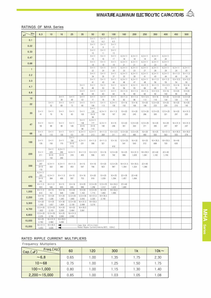
~~66..88
1100~~6688
110000~~11,,000000
22,,220000~~1155,,000000
6600 112200 330000 11kk 1100kk~~
0.65 1.00 1.35 1.75 2.30
0.75 1.00 1.25 1.50 1.75
0.80 1.00 1.15 1.30 1.40
0.85 1.00 1.03 1.05 1.08
FFrreeqq..((HHzz))CCaapp..(())
Frequency Multipliers
RRAATTEEDD RRIIPPPPLLEE CCUURRRREENNTT MMUULLTTIIPPLLIIEERRSS
RRAATTIINNGGSS OOFF MMHHAA SSeerriieess
5×11
41
5×11
59
5×11
90
5×11
135
5×11
211
6.3×11
297
8×9
170
6.3×11
355
8×9
241
8×11.5
503
8×11.5
610
10×16
1,059
10×20
1,350
12.5×20
1,822
12.5×20
2,235
16×25
2,760
16×31.5
3,453
5×11
52
5×11
70
5×11
88
5×11
110
5×11
150
5×11
229
8×9
150
6.3×11
322
6.3×11
384
8×11.5
546
8×15
751
10×20
1,226
10×25
1,657
12.5×25
2,103
12.5×35
2,706
16×31.5
2,960
18×35.5
3,826
5×11
39
5×11
68
5×11
76
5×11
98
5×11
130
5×11
170
6.3×11
290
8×9
290
6.3×11
360
8×11.5
499
8×15
655
10×16
928
10×20
1,340
10×30
1,804
16×20
2,200
16×25
2,690
16×35.5
3,490
5×11
49
5×11
73
5×11
83
5×11
126
5×11
151
5×11
184
8×9
115
6.3×11
318
8×11.5
453
8×15
597
10×16
826
10×20
1,094
12.5×25
1,800
12.5×30
2,159
16×25
2,464
16×31.5
2,992
5×11
35
5×11
46
5×11
53
5×11
80
5×11
100
5×11
138
8×9
98
6.3×11
191
6.3×11
231
8×11.5
405
8×15
547
10×16
753
10×20
988
10×20
1,163
12.5×35
2,055
16×31.5
2,498
16×35.5
3,061
5×11
5.5
5×11
8
5×11
10
5×11
15
5×11
18
5×11
22
5×11
34
5×11
41
5×11
48
5×11
59
5×11
71
5×11
106
5×11
129
8×9
98
6.3×11
177
8×9
110
6.3×11
213
8×11.5
306
10×12.5
506
10×16
706
10×20
918
12.5×20
1,296
12.5×25
1,715
16×31.5
2,320
18×35.5
3,218
5×11
6.2
5×11
9
5×11
11
5×11
16
5×11
19
5×11
24
5×11
35
5×11
43
5×11
53
5×11
63
5×11
76
5×11
113
6.3×11
159
6.3×11
190
8×11.5
269
8×11.5
321
10×16
615
10×20
823
10×20
1,039
12.5×25
1,512
16×25
1,850
18×35.5
2,740
5×11
6.5
5×11
11
5×11
13
5×11
17
5×11
19
5×11
24
5×11
37
5×11
44
5×11
55
5×11
64
5×11
76
6.3×11
130
8×11.5
187
8×15
246
10×12.5
311
10×16
416
12.5×20
742
12.5×25
987
16×25
1,394
16×35.5
1,620
18×35.5
1,995
6.3×11
18
6.3×11
21
6.3×11
23
6.3×11
33
6.3×11
46
6.3×11
56
8×11.5
78
8×11.5
82
10×16
150
10×20
243
10×20
301
12.5×20
410
12.5×25
541
16×25
906
18×31.5
1,304
22×35
1,457
22×40
1,680
6.3×11
18
6.3×11
21
6.3×11
23
6.3×11
39
6.3×11
47
6.3×11
55
8×11.5
80
8×11.5
96
10×16
168
10×20
245
12.5×20
343
12.5×25
480
16×20
543
16×31.5
1,029
18×35.5
1,324
22×40
1,494
6.3×11
19
6.3×11
22
6.3×11
27
6.3×11
41
6.3×11
48
8×11.5
66
8×11.5
82
10×12.5
113
10×20
198
12.5×20
286
12.5×25
371
16×20
490
16×25
572
18×35.5
1,061
22×40
1,366
6.3×11
20
6.3×11
23
6.3×11
28
6.3×11
43
8×11.5
56
8×11.5
68
10×12.5
92
10×16
118
12.5×20
233
12.5×25
300
16×20
395
16×25
500
16×35.5
688
22×40
1,100
6.3×11
20
6.3×11
23
6.3×11
29
6.3×11
44
8×11.5
59
10×12.5
73
10×16
100
10×20
134
10×25
229
12.5×25
321
16×25
437
16×31.5
563
18×35.5
720
22×45
1,150
6.3×11
24
8×11.5
40
10×12.5
54
10×16
72
10×20
90
12.5×20
120
16×20
216
16×20
297
16×31.5
397
16×35.5
555
18×40
630
6.3×11
20
8×11.5
34
10×12.5
50
10×16
68
10×20
85
12.5×20
110
16×20
140
16×31.5
220
18×31.5
247
18×35.5
278
00..11
00..2222
00..3333
00..4477
00..6688
11
22..22
33..33
44..77
66..88
1100
2222
3333
4477
6688
110000
222200
333300
447700
668800
Case Size ∅D×L(mm)Rated Ripple Current(mArms/85, 120Hz)
μμFFVVDDCC 66..33 1100 1166 2255 3355 5500 6633 110000 116600 220000 225500 335500 440000 445500 550000
MINIATURE ALUMINUM ELECTROLYTIC CAPACITORS
MHA Serie
s
11,,000000
22,,220000
33,,330000
44,,770000
66,,880000
1100,,000000
1155,,000000
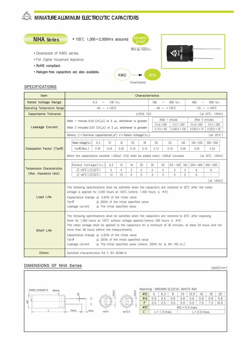
IItteemm CChhaarraacctteerriissttiiccss
RRaatteedd VVoollttaaggee RRaannggee 6.3 ~ 100 VDC 160 ~ 400 VDC 450 ~ 500 VDC
OOppeerraattiinngg TTeemmppeerraattuurree RRaannggee -55 ~ +105 -40 ~ +105 -25 ~ +105
CCaappaacciittaannccee TToolleerraannccee ±20% (M) (at 20, 120Hz)
After 1 minute:0.03 CV() or 4 , whichever is greater
After 2 minutes:0.01 CV() or 3 , whichever is greater
Where, C=Nominal capacitance() V=Rated Voltage(VDC) (at 20)
When the capacitance exceeds 1,000, 0.02 shall be added every 1,000 increase. (at 20, 120Hz)
TTeemmppeerraattuurree CChhaarraacctteerriissttiiccss
((MMaaxx .. IImmppeeddaannccee rraattiioo))
(at 120Hz)
The following specifications shall be satisfied when the capacitors are restored to 20 after the rated
voltage is applied for 2,000 hours at 105.(where, 1,000 hours ≤ ∅8)
LLooaadd LLiiffee Capacitance change ±20% of the initial value
Tanδ 200% of the initial specified value
Leakage current The initial specified value
The following specifications shall be satisfied when the capacitors are restored to 20 after exposing
them for 1,000 hours at 105 without voltage applied.(where, 500 hours ≤ ∅8)
The rated voltage shall be applied to the capacitors for a minimum of 30 minutes, at least 24 hours and not
more than 48 hours before the measurements.SShheellff LLiiffee
Capacitance change ±20% of the initial value
Tanδ 200% of the initial specified value
Leakage current The initial specified value (where, 200% for WV 160 VDC)
OOtthheerrss Satisfied characteristics KS C IEC 60384-4
110055 11,,000000~~22,,000000HHrrss aassssuurreedd
SSPPEECCIIFFIICCAATTIIOONNSS
Rated Voltage(VDC) 6.3 10 16 25 35 50 63~100 200~400 450~500
Z(-25)/Z(20) 5 4 3 2 2 2 6 6
Z(-40)/Z(20) 12 10 8 5 4 3 6 -
After 1 minute After 5 minutes
CV1,000 CV1,000 CV1,000 CV1,000
0.1CV+40 0.04CV+100 0.03CV+15 0.02CV+25
Rated Voltage(VDC) 6.3 10 16 25 35 50 63 100 160~250 350~500
Tanδ(Max.) 0.24 0.20 0.16 0.14 0.12 0.10 0.09 0.20 0.240.34
(at 120Hz)
NHA Series
Downsized of KMG series.
For Digital Household Appliance
RoHS compliant.
Halogen-free capacitors are also available.
DDiissssiippaattiioonn FFaaccttoorr ((TTaannδδ))
DDIIMMEENNSSIIOONNSS OOFF NNHHAA SSeerriieess
LLeeaakkaaggee CCuurrrreenntt
SSoollvveenntt--pprrooooff
WV100VDC
KKMMGG NNHHAA
Downsized
MINIATURE ALUMINUM ELECTROLYTIC CAPACITORS
Marking :BROWN SLEEVE, WHITE INK
∅∅DD∅∅ddFF∅∅DD′′LL′′
50.52.0
∅D+0.5 max.
L+1.5 max. L+2.0 max.
6.30.52.5
80.63.5
100.65.0
12.50.65.0
160.87.5
180.87.5
220.810.0
Unit(mm)
160
3
5
3
4
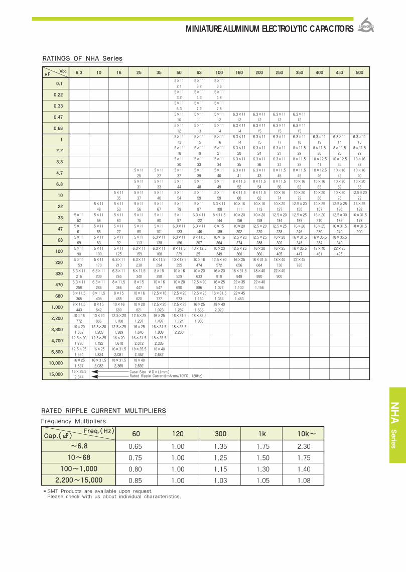
RRAATTIINNGGSS OOFF NNHHAA SSeerriieess
~~66..88
1100~~6688
110000~~11,,000000
22,,220000~~1155,,000000
6600 112200 330000 11kk 1100kk~~
0.65 1.00 1.35 1.75 2.30
0.75 1.00 1.25 1.50 1.75
0.80 1.00 1.15 1.30 1.40
0.85 1.00 1.03 1.05 1.08
FFrreeqq..((HHzz))CCaapp..(())
Frequency Multipliers
RRAATTEEDD RRIIPPPPLLEE CCUURRRREENNTT MMUULLTTIIPPLLIIEERRSS
SMT Products are available upon request.Please check with us about individual characteristics.
5×11
52
5×11
61
5×11
69
5×11
90
5×11
153
6.3×11
216
6.3×11
258
8×11.5
365
8×11.5
443
10×16
772
10×20
1,032
12.5×20
1,280
12.5×25
1,554
16×25
1,897
16×35.5
2,344
5×11
48
5×11
56
5×11
66
5×11
83
5×11
100
5×11
170
6.3×11
239
6.3×11
286
8×11.5
405
8×15
542
10×20
886
12.5×20
1,205
12.5×25
1,492
16×25
1,824
16×31.5
2,082
5×11
35
5×11
53
5×11
60
5×11
77
5×11
92
5×11
125
6.3×11
213
6.3×11
265
8×11.5
366
8×15
455
10×16
680
12.5×20
1,108
12.5×25
1,389
16×20
1,610
16×31.5
2,081
18×31.5
2,365
5×11
25
5×11
31
5×11
37
5×11
56
5×11
75
5×11
80
5×11
113
6.3×11
159
6.3×11
238
8×11.5
340
8×15
447
10×16
620
10×20
821
12.5×25
1,297
16×25
1,646
16×31.5
2,012
18×35.5
2,452
18×40
2,692
5×11
27
5×11
33
5×11
40
5×11
67
5×11
80
5×11
101
6.3×11
138
6.3×11
168
8×11.5
294
8×15
398
10×16
547
12.5×16
777
12.5×20
1,023
16×25
1,497
16×31.5
1,808
18×35.5
2,335
18×40
2,642
5×11
2.1
5×11
3.2
5×11
6.3
5×11
10
5×11
12
5×11
13
5×11
18
5×11
30
5×11
37
5×11
44
5×11
54
5×11
79
5×11
97
6.3×11
133
6.3×11
156
8×11.5
229
10×12.5
395
10×16
529
10×20
690
12.5×20
973
12.5×25
1,287
16×31.5
1,724
18×35.5
2,260
5×11
3.2
5×11
4.3
5×11
7.2
5×11
11
5×11
13
5×11
15
5×11
19
5×11
33
5×11
39
5×11
48
5×11
59
5×11
87
6.3×11
122
6.3×11
146
8×11.5
207
10×12.5
251
10×16
474
10×20
633
12.5×20
886
12.5×25
1,160
16×25
1,565
18×35.5
1,938
5×11
3.6
5×11
4.8
5×11
7.8
5×11
12
5×11
14
5×11
16
5×11
21
5×11
34
5×11
40
5×11
49
5×11
59
6.3×11
100
8×11.5
144
8×15
189
10×16
264
10×20
349
12.5×20
572
16×20
810
16×25
1,072
16×31.5
1,364
18×40
2,020
6.3×11
12
6.3×11
14
6.3×11
14
6.3×11
20
6.3×11
35
6.3×11
41
8×11.5
52
8×11.5
60
10×16
111
10×20
156
10×20
202
12.5×20
274
12.5×25
360
16×25
656
18×31.5
848
22×35
1,130
22×45
1,463
6.3×11
12
6.3×11
15
6.3×11
15
6.3×11
24
6.3×11
36
6.3×11
43
8×11.5
54
8×11.5
62
10×16
113
10×20
158
12.5×20
220
12.5×25
288
16×20
366
16×31.5
684
18×40
880
22×40
1,156
6.3×11
12
6.3×11
15
6.3×11
17
6.3×11
27
6.3×11
37
8×11.5
45
8×11.5
56
10×16
74
10×20
127
12.5×20
184
12.5×25
238
16×20
300
16×25
405
18×40
730
22×40
900
6.3×11
12
6.3×11
15
6.3×11
18
8×11.5
29
8×11.5
38
8×11.5
45
10×16
62
10×20
79
12.5×20
150
12.5×25
189
16×20
246
16×31.5
348
16×35.5
447
22×45
780
6.3×11
19
8×11.5
30
10×12.5
41
10×12.5
46
10×16
65
10×20
86
10×25
157
16×20
210
16×25
280
16×35.5
384
18×40
461
6.3×11
14
8×11.5
25
10×12.5
35
10×16
42
10×20
59
10×20
76
12.5×25
136
12.5×30
189
16×31.5
240
18×35.5
349
22×35
425
6.3×11
13
8×11.5
22
10×16
32
10×16
40
10×20
55
12.5×20
72
16×25
132
16×31.5
178
18×31.5
200
Case Size ∅D×L(mm)Rated Ripple Current(mArms/105, 120Hz)
μμFFVVDDCC 66..33 1100 1166 2255 3355 5500 6633 110000 116600 220000 225500 335500 440000 445500 550000
MINIATURE ALUMINUM ELECTROLYTIC CAPACITORS
NHA Serie
s
00..11
00..2222
00..3333
00..4477
00..6688
11
22..22
33..33
44..77
66..88
1100
2222
3333
4477
6688
110000
222200
333300
447700
668800
11,,000000
22,,220000
33,,330000
44,,770000
66,,880000
1100,,000000
1155,,000000
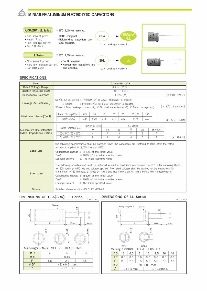
16
2
4
6.3
4
8
Z(-25)/Z(+20)
Z(-40)/Z(+20)
DDIIMMEENNSSIIOONNSS OOFF LLLL SSeerriieess
8855 22,,000000HHrrss aassssuurreedd..
Non-solvent proof.Height 7mm.Low leakage current.For CAR-Audio
RoHS compliant.Halogen-free capacitors arealso available.
RoHS compliant.Halogen-free capacitors arealso available.
DDIIMMEENNSSIIOONNSS OOFF GGSSAA((SSRRAA))--LLLL SSeerriieess
∅∅DD 4 5 6.3
∅∅dd 0.45
FF 1.5 2.0 2.5∅∅DD′′ ∅D+0.5 max.LL′′ L+1.0 max.
SSPPEECCIIFFIICCAATTIIOONNSS
GSA(SRA)-LL Series
8855 22,,000000HHrrss aassssuurreedd..
Non-solvent proof.Very low leakage current.For CAR-Audio
LL Series
GGSSAA GGSSAA((SSRRAA))--LLLL
Low Leakage current
Low Leakage current
SSHHLL LLLL
Rated Voltage(VDC) 6.3 10 16 25 35 50~63 100
Tanδ(Max.) 0.24 0.20 0.16 0.14 0.12 0.10 0.07
(at 120Hz)
(at 20, 2 minutes)
Marking:ORANGE SLEEVE, BLACK INK
LL Series
8
10
3
6
25
2
3
35~100
2
3
MINIATURE ALUMINUM ELECTROLYTIC CAPACITORS
GSA(SRA)-LL Series
4
Rated Voltage(VDC)
Marking : ORANGE SLEEVE, BLACK INK.
∅∅DD∅∅ddFF∅∅DD′′LL′′
50.52.0
∅D+0.5 max.
L+1.5 max. L+2.0 max.
6.30.52.5
80.63.5
100.65.0
12.50.65.0
160.87.5
180.87.5
Unit(mm) Unit(mm)
IItteemm CChhaarraacctteerriissttiiccss
RRaatteedd VVoollttaaggee RRaannggee 6.3 ~ 100 VDC
OOppeerraattiinngg TTeemmppeerraattuurree RRaannggee -40 ~ +85
CCaappaacciittaannccee TToolleerraannccee ±20% (M) (at 20, 120Hz)
LLeeaakkaaggee CCuurrrreenntt((MMaaxx..))GSA(SRA)-LL Series : I=0.004V() or 0.4, whichever is greater.
LL Series : I=0.002CV() or 0.2, whichever is greater.Where, I:Max. leakage current(), C:Nominal capacitance(), V:Rated voltage(VDC)
DDiissssiippaattiioonn FFaaccttoorr((TTaannδδ))
(at 20, 120Hz)
TTeemmppeerraattuurree CChhaarraacctteerriissttiiccss((MMaaxx.. IImmppeeddaannccee rraattiioo))
The following specifications shall be satisfied when the capacitors are restored to 20 after the rated voltage is applied for 2,000 hours at 85.
Capacitance change ±20% of the initial valueTanδ 200% of the initial specified valueLeakage current The initial specified value
The following specifications shall be satisfied when the capacitors are restored to 20 after exposing themfor 500 hours at 85 without voltage applied. The rated voltage shall be applied to the capacitors for a minimum of 30 minutes, at least 24 hours and not more than 48 hours before the measurements.
Capacitance change ±20% of the initial value
Tanδ 200% of the initial specified value
Leakage current The initial specified value
OOtthheerrss Satisfied characteristics KS C IEC 60384-4
SShheellff LLiiffee
LLooaadd LLiiffee

GSA
(SRA)-LL/LLSeries
RRAATTIINNGGSS OOFF GGSSAA((SSRRAA))--LLLL SSeerriieess
Rated Ripple Current (mArms/85, 120Hz)Case Size∅D×L(mm)
VVDDCC
μF
4×7
5×7
5×7
6.3×7
6.3×7
6.3×7
4×7
4×7 4×7
4×7
4×7
4×7
4×7
4×7
4×7
4×7
4×7
5×74×7
5×7
4×7
4×7
5×7
5×7
4×7
4×7
4×7
4×7
4×7
4×7
4×7
4×7
4×7
4×7
5×7
5×7
5×7
5×7
6.3×7
6.3×7
6.3×7
6.3×7
6.3×7
6.3×7
6.3×7
6.3×7
6.3×7
6.3×7
6.3×7
6.3×7
6.3×7
6.3×7
6.3×7
6.3×7
6.3×7
28
33
41
49
59
73
25
30
37
45
55
65
17
21
25
30
37
45
55
18
22
28
33
39
49
66..33 1100 1166 2255 3355 5500
RRAATTIINNGGSS OOFF LLLL SSeerriieess
Rated Ripple Current (mArms/85, 120Hz)Case Size∅D×L(mm)
VVDDCC
μμFF 66..33 1100 1166 2255 3355 5500 6633 110000
10×12.5
10×16
10×20
12.5×25
16×25
16×35.5
18×35.5
5×11
6.3×11
6.3×11
8×11.5
10×16
10×20
12.5×20
12.5×25
16×31.5
16×35.5
18×40
5×11
6.3×11
6.3×11
8×11.5
10×12.5
10×20
12.5×20
12.5×20
16×25
18×35.5
18×40
5×11
6.3×11
8×11.5
8×11.5
10×12.5
10×16
12.5×20
12.5×25
16×25
18×35.5
18×40
5×11
6.3×11
8×11.5
10×12.5
10×12.5
10×20
12.5×25
12.5×25
16×25
16×25
5×11
5×11
5×11
5×11
5×11
5×11
5×11
6.3×11
8×11.5
10×12.5
10×16
10×16
12.5×20
16×25
16×31.5
16×35.5
18×40
8×11.5
10×16
10×16
10×20
12.5×25
16×31.5
16×35.5
18×35.5
5×11
5×11
5×11
5×11
5×11
6.3×11
8×11.5
8×11.5
10×16
10×20
12.5×20
12.5×25
16×25
18×35.5
18×40
229
309
399
702
1,107
1,438
1,676
51
72
86
143
276
367
485
769
1,295
1,554
1,820
39
66
80
110
189
335
454
542
951
1,529
1,804
28
47
80
98
138
223
397
528
697
1,120
1,647
31
51
87
125
149
260
466
631
753
1,262
5
7
9
11
16
23
28
38
64
112
151
181
316
564
744
908
1,404
64
124
151
196
344
607
761
948
6
9
11
13
19
31
44
52
100
160
217
282
455
775
964
MINIATURE ALUMINUM ELECTROLYTIC CAPACITORS
00..11
00..1155
00..2222
00..3333
00..4477
00..6688
11
11..55
22..22
33..33
44..77
66..88
1100
1155
2222
3333
4477
6688
110000
00..11
00..2222
00..3333
00..4477
11
22..22
33..33
44..77
1100
2222
3333
4477
110000
222200
333300
447700
11,,000000
22,,220000
33,,330000
44,,770000
1.0
1.5
2.0
3.1
4.2
6.8
9.2
11
12
15
20
23
27
33
42
52
62
1.5
2.0
3.1
3.7
5.2
7.3
12
14
17
21
25
31
40
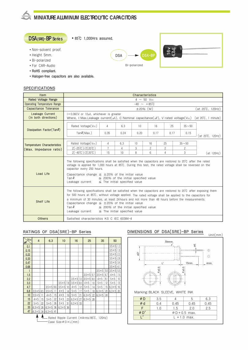
IItteemm CChhaarraacctteerriissttiiccss
RRaatteedd VVoollttaaggee RRaannggee 4 ~ 50 VDC
OOppeerraattiinngg TTeemmppeerraattuurree RRaannggee -40 ~ +85
CCaappaacciittaannccee TToolleerraannccee ±20% (M) (at 20, 120Hz)
LLeeaakkaaggee CCuurrrreenntt l=0.06CV or 10, whichever is greater((IInn bbootthh ddiirreeccttiioonnss)) Where, I:Max.Leakage current(), C:Nominal capacitance(), V:rated voltage(VDC) (at 20, 1 minute)
DDiissssiippaattiioonn FFaaccttoorr((TTaannδδ))
(at 20, 120Hz)
TTeemmppeerraattuurree CChhaarraacctteerriissttiiccss
((MMaaxx.. IImmppeeddaannccee rraattiioo))
The following specifications shall be satisfied when the capacitors are restored to 20 after the rated voltage is applied for 1,000 hours at 85. During this test, the rated voltage shall be reversed on thecapacitor every 250 hours.
LLooaadd LLiiffee Capacitance change ±20% of the initial valueTanδ 200% of the initial specified valueLeakage current The initial specified value
The following specifications shall be satisfied when the capacitors are restored to 20 after exposing them for 500 hours at 85, without voltage applied. The rated voltage shall be applied to the capacitors for a minimum of 30 minutes, at least 24hours and not more than 48 hours before the measurements.
SShheellff LLiiffee Capacitance change ±20% of the initial valueTanδ 200% of the initial specified value
Leakage current The initial specified value
OOtthheerrss Satisfied characteristics KS C IEC 60384-4
∅∅DD 3.5 4 5 6.3
∅∅dd 0.4 0.45 0.45 0.45
FF 1.0 1.5 2.0 2.5∅∅DD′′ ∅D+0.5 max.LL′′ L+1.0 max.
8855 11,,000000HHrrss aassssuurreedd..
Non-solvent proof.
Height 5mm.
Bi-polarized
For CAR-Audio
RoHS compliant.
Halogen-free capacitors are also available.
DDIIMMEENNSSIIOONNSS OOFF DDSSAA((SSRREE))--BBPP SSeerriieess
Marking:BLACK SLEEVE, WHITE INK
SSPPEECCIIFFIICCAATTIIOONNSS
Rated Voltage(VDC) 4 6.3 10 16 25 35~50
Tanδ(Max.) 0.35 0.24 0.20 0.17 0.17 0.15
Rated Voltage(VDC) 4 6.3 10 16 25 35~50
Z(-25)/Z(20) 7 4 3 2 2 2
Z(-40)/Z(20) 15 10 8 6 4 3 (at 120Hz)
DSA(SRE)-BP Series
DDSSAA DDSSAA--BBPP
Bi-polarized
MINIATURE ALUMINUM ELECTROLYTIC CAPACITORS
μμFFVVDDCC 44 66..33 1100 1166 2255 3355 5500
3.5×53.5×53.5×53.5×53.5×53.5×5
3.5×5 3.5×53.5×5 3.5×5
3.5×5 3.5×53.5×5 3.5×5
3.5×5 3.5×5 6.3×53.5×5 3.5×5 6.3×5 6.3×53.5×5 6.3×5 6.3×5
6.3×5 6.3×56.3×5
6.3×5 6.3×5 6.3×56.3×5 6.3×5
RRAATTIINNGGSS OOFF DDSSAA((SSRREE))--BBPP SSeerriieess
Rated Ripple Current (mArms/85, 120Hz)Case Size∅D×L(mm)
4×55×5
4×55×55×5
8.51115222834
8.6
111522263641
4×54×55×55×5
7.8101419233138
4×55×55×5
7.09.0
1217212733
4×55×55×5
5.78.01014182228
5.06.79.112152024
4×55×55×5
4×55×55×5
1.31.92.32.83.44.15.57.5
10131620
00..1100..115500..222200..333300..447700..6688
1111..5522..2233..3344..7766..8811001155222233334477
Unit(mm)

DSA(SRE)-BP/GSA-BP
Serie
s
4×7
4×7
4×7
4×7
4×7
4×7 13 4×7
4×7 15 4×7 15 4×7
4×7 18 4×7 18 5×7 20 5×7
4×7 23 4×7 25 5×7 27 6.3×7 33 6.3×7
4×7 31 4×7 35 5×7 39 6.3×7 44
5×7 40 5×7 48 6.3×7 49
6.3×7 49 6.3×7 53
00..11
00..2222
00..3333
00..4477
11
22..22
33..33
44..77
1100
2222
3333
4477
Rated Ripple Current(mArms/85, 120Hz)Case Size ∅D×L(mm)
IItteemm CChhaarraacctteerriissttiiccss
RRaatteedd VVoollttaaggee RRaannggee 6.3 ~ 50 VDC
OOppeerraattiinngg TTeemmppeerraattuurree RRaannggee -40 ~ +85
CCaappaacciittaannccee TToolleerraannccee ±20%(M) (at 20, 120Hz)
l=0.06CV(μA) or 10μA, whichever is greater.
Where, I:Max. Leakage current(μA), C:Nominal capacitance(μF), V:Rated voltage(VDC)
(at 20, 1 minute)
DDiissssiippaattiioonn FFaaccttoorr((TTaannδδ))
TTeemmppeerraattuurree CChhaarraacctteerriissttiiccss
The following specifications shall be satisfied when the capacitors are restored to 20after the rated is voltage for 2,000 hours at 85. During the test, the rated voltage shall be reversedon the capacitor every 250 hours.
Capacitance change ±20% of the initial value
Tanδ 200% of the initial specified value
Leakage current The initial specified value
The following specifications shall be satisfied when the capacitors are restored to 20 after exposing them for 1,000 hours at 85 without voltage applied. The rated voltage shall be applied to the capacitors for a minimum of 30 minutes, at least 24 hours and not more than 48 hours before the measurements.
Capacitance change ±20% of the initial value
Tanδ 200% of the initial specified value
Leakage current The initial specified value
OOtthheerrss Satisfied characteristics KS C IEC 60384-4
8855 22,,000000HHrrss aassssuurreedd..
Non-solvent proof.
Height 7mm.
Bi-polarized
Downsized of SRA-BP series.
For CAR-Audio, VCR
RoHS compliant.Halogen-free capacitors are also available.
SSPPEECCIIFFIICCAATTIIOONNSS
LLooaadd LLiiffee
SShheellff LLiiffee
Rated voltage(VDC) 6.3 10 16 25 35~50
Z(-25)/Z(20) 4 3 2 2 2
Z(-40)/Z(20) 10 8 6 4 3 (at 120Hz)
((MMaaxx.. IImmppeeddaannccee rraattiioo))
(at 20, 120Hz)
GSA-BP Series
SSRRAA--BBPPDownsized
RRAATTIINNGGSS OOFF GGSSAA--BBPP SSeerriieess
∅∅DD 4 5 6.3
∅∅dd 0.45
FF 1.5 2.0 2.5
∅∅DD、、 ∅D+0.5max.
LL、、 L+1.0max.
Rated voltage(VDC) 6.3 10 16 25 35 50
Tanδ(Max.) 0.24 0.20 0.17 0.16 0.15 0.14
Marking : BLACK SLEEVE, WHITE INK
GGSSAA--BBPP
LLeeaakkaaggee CCuurrrreenntt((IInn bbootthh ddiirreeccttiioonnss))
DDIIMMEENNSSIIOONNSS OOFF GGSSAA--BBPP SSeerriieess
MINIATURE ALUMINUM ELECTROLYTIC CAPACITORS
2.1
4.5
5.6
6.6
9.7
14
17
21
35
μμFF VVDDCC 1100 1166 2255 3355 5500
Unit(mm)
66..33

IItteemm CChhaarraacctteerriissttiiccss
RRaatteedd VVoollttaaggee RRaannggee 6.3 ~ 100 VDC 160 ~ 250 VDC
OOppeerraattiinngg TTeemmppeerraattuurree RRaannggee -40 ~ +85 -25 ~ +85
CCaappaacciittaannccee TToolleerraannccee ±20% (M) (at 20, 120Hz)
I=0.03CV(μA) or 3μA, whichever is greater.
Where, I:Max. Leakage current(μA), C:Nominal capacitance(μF), V:Rated voltage(VDC)
(at 20, 5 minutes)
When the capacitance exceeds 1,000, 0.02 shall be added every 1,000 increase. (at 20, 120Hz)
TTeemmppeerraattuurree CChhaarraacctteerriissttiiccss
((MMaaxx .. IImmppeeddaannccee rraattiioo))
The following specifications shall be satisfied when the capacitors are restored to 20 after the rated
voltage is applied for 2,000 hours at 85. During this test, the rated voltage shall be reversed on the
LLooaadd LLiiffeecapacitor every 250 hours.
Capacitance change ±20% of the initial value (where, ±25% for 16 VDC)
Tanδ 200% of the initial specified value
Leakage current The initial specified value
The following specifications shall be satisfied when the capacitors are restored to 20 after exposing
them for 1,000 hours at 85 without voltage applied. The rated voltage shall be applied to the capacitorsfor a minimum of 30 minutes, at least 24 hours and not more than 48 hours before the measurements.
SShheellff LLiiffeeCapacitance change ±20% of the initial value (where, ±25% for 16 VDC)
Tanδ 200% of the initial specified value
Leakage current 200% of the initial specified value
OOtthheerrss Satisfied characteristics KS C IEC 60384-4
8855 22,,000000HHrrss aassssuurreedd
SSPPEECCIIFFIICCAATTIIOONNSS
Rated Voltage(VDC) 6.3 10 16 25~100 160 160~250
Z(-25)/Z(20) 4 3 2 2 4 6
Z(-40)/Z(20) 10 8 6 4 - -
Rated Voltage(VDC) 6.3 10 16~25 35 50 63~100 160 200~250
Tanδ(Max.) 0.25 0.24 0.20 0.16 0.14 0.12 0.15 0.20
(at 120Hz)
MHA-BP Series
Non-solvent proof.
Bi-polarized
Downsized of SHL-BP series.
For Digital Household Appliances
RoHS compliant.
Halogen-free capacitors are also available.
SSHHLL--BBPP MMHHAA--BBPP
Downsized
DDiissssiippaattiioonn FFaaccttoorr ((TTaannδδ))
DDIIMMEENNSSIIOONNSS OOFF MMHHAA--BBPP SSeerriieess
LLeeaakkaaggee CCuurrrreenntt((IInn bbootthh ddiirreeccttiioonnss))
MINIATURE ALUMINUM ELECTROLYTIC CAPACITORS
Marking :BLACK SLEEVE, WHITE INK
∅∅DD∅∅ddFF∅∅DD′′LL′′
50.52.0
∅D+0.5 max.
L+1.5 max. L+2.0 max.
6.30.52.5
80.63.5
100.65.0
12.50.65.0
160.87.5
180.87.5
220.810.0
Unit(mm)
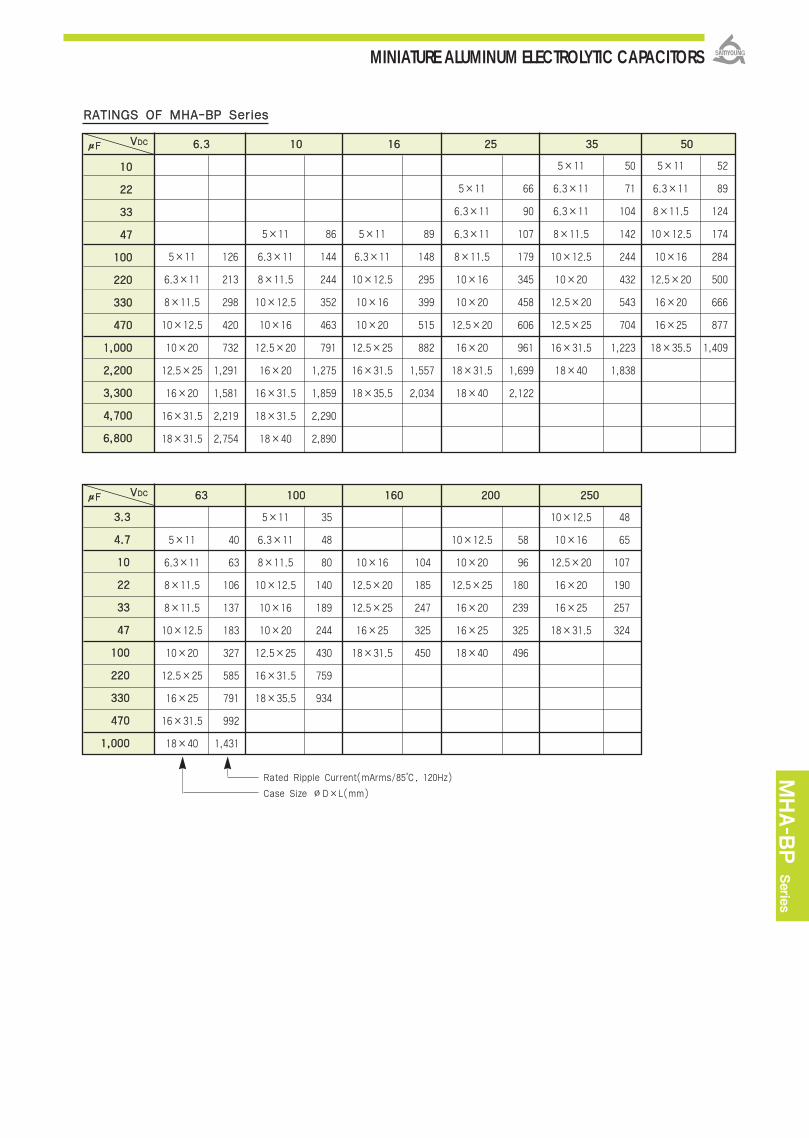
MHA-B
P Serie
s
RRAATTIINNGGSS OOFF MMHHAA--BBPP SSeerriieess
μμFF 66..33 1100 1166 2255 3355 5500
5×11 50 5×11 52
5×11 66 6.3×11 71 6.3×11 89
6.3×11 90 6.3×11 104 8×11.5 124
5×11 86 5×11 89 6.3×11 107 8×11.5 142 10×12.5 174
5×11 126 6.3×11 144 6.3×11 148 8×11.5 179 10×12.5 244 10×16 284
6.3×11 213 8×11.5 244 10×12.5 295 10×16 345 10×20 432 12.5×20 500
8×11.5 298 10×12.5 352 10×16 399 10×20 458 12.5×20 543 16×20 666
10×12.5 420 10×16 463 10×20 515 12.5×20 606 12.5×25 704 16×25 877
10×20 732 12.5×20 791 12.5×25 882 16×20 961 16×31.5 1,223 18×35.5 1,409
12.5×25 1,291 16×20 1,275 16×31.5 1,557 18×31.5 1,699 18×40 1,838
16×20 1,581 16×31.5 1,859 18×35.5 2,034 18×40 2,122
16×31.5 2,219 18×31.5 2,290
18×31.5 2,754 18×40 2,890
1100
2222
3333
4477
110000
222200
333300
447700
11,,000000
22,,220000
33,,330000
44,,770000
66,,880000
Rated Ripple Current(mArms/85, 120Hz)
Case Size ∅D×L(mm)
VVDDCC
μμFF 6633 110000 116600 220000 225500
5×11 35 10×12.5 48
5×11 40 6.3×11 48 10×12.5 58 10×16 65
6.3×11 63 8×11.5 80 10×16 104 10×20 96 12.5×20 107
8×11.5 106 10×12.5 140 12.5×20 185 12.5×25 180 16×20 190
8×11.5 137 10×16 189 12.5×25 247 16×20 239 16×25 257
10×12.5 183 10×20 244 16×25 325 16×25 325 18×31.5 324
10×20 327 12.5×25 430 18×31.5 450 18×40 496
12.5×25 585 16×31.5 759
16×25 791 18×35.5 934
16×31.5 992
18×40 1,431
1100
2222
3333
4477
110000
222200
333300
447700
11,,000000
33..33
44..77
VVDDCC
MINIATURE ALUMINUM ELECTROLYTIC CAPACITORS
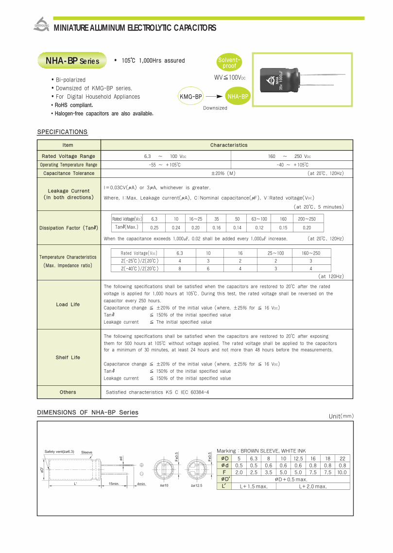
IItteemm CChhaarraacctteerriissttiiccss
RRaatteedd VVoollttaaggee RRaannggee 6.3 ~ 100 VDC 160 ~ 250 VDC
OOppeerraattiinngg TTeemmppeerraattuurree RRaannggee -55 ~ +105 -40 ~ +105
CCaappaacciittaannccee TToolleerraannccee ±20% (M) (at 20, 120Hz)
I=0.03CV(μA) or 3μA, whichever is greater.
Where, I:Max. Leakage current(μA), C:Nominal capacitance(μF), V:Rated voltage(VDC)
(at 20, 5 minutes)
When the capacitance exceeds 1,000, 0.02 shall be added every 1,000 increase. (at 20, 120Hz)
TTeemmppeerraattuurree CChhaarraacctteerriissttiiccss
((MMaaxx .. IImmppeeddaannccee rraattiioo))
The following specifications shall be satisfied when the capacitors are restored to 20 after the rated
voltage is applied for 1,000 hours at 105. During this test, the rated voltage shall be reversed on the
LLooaadd LLiiffeecapacitor every 250 hours.
Capacitance change ±20% of the initial value (where, ±25% for 16 VDC)
Tanδ 150% of the initial specified value
Leakage current The initial specified value
The following specifications shall be satisfied when the capacitors are restored to 20 after exposing
them for 500 hours at 105 without voltage applied. The rated voltage shall be applied to the capacitorsfor a minimum of 30 minutes, at least 24 hours and not more than 48 hours before the measurements.
SShheellff LLiiffee
Capacitance change ±20% of the initial value (where, ±25% for 16 VDC)
Tanδ 150% of the initial specified value
Leakage current 150% of the initial specified value
OOtthheerrss Satisfied characteristics KS C IEC 60384-4
110055 11,,000000HHrrss aassssuurreedd
SSPPEECCIIFFIICCAATTIIOONNSS
Rated Voltage(VDC) 6.3 10 16 25~100 160~250
Z(-25)/Z(20) 4 3 2 2 3
Z(-40)/Z(20) 8 6 4 3 4
Rated Voltage(VDC) 6.3 10 16~25 35 50 63~100 160 200~250
Tanδ(Max.) 0.25 0.24 0.20 0.16 0.14 0.12 0.15 0.20
(at 120Hz)
NHA-BP Series
Bi-polarized
Downsized of KMG-BP series.
For Digital Household Appliances
RoHS compliant.
Halogen-free capacitors are also available.
KKMMGG--BBPP NNHHAA--BBPP
Downsized
DDiissssiippaattiioonn FFaaccttoorr ((TTaannδδ))
DDIIMMEENNSSIIOONNSS OOFF NNHHAA--BBPP SSeerriieess
LLeeaakkaaggee CCuurrrreenntt((IInn bbootthh ddiirreeccttiioonnss))
SSoollvveenntt--pprrooooff
WV100VDC
MINIATURE ALUMINUM ELECTROLYTIC CAPACITORS
Marking :BROWN SLEEVE, WHITE INK
∅∅DD∅∅ddFF∅∅DD′′LL′′
50.52.0
∅D+0.5 max.
L+1.5 max. L+2.0 max.
6.30.52.5
80.63.5
100.65.0
12.50.65.0
160.87.5
180.87.5
220.810.0
Unit(mm)

NHA-B
P Serie
s
RRAATTIINNGGSS OOFF NNHHAA--BBPP SSeerriieess
1100
2222
3333
4477
110000
222200
333300
447700
11,,000000
22,,220000
33,,330000
44,,770000
66,,880000
5×11 33 5×11 37
5×11 47 6.3×11 55 6.3×11 63
6.3×11 66 6.3×11 68 8×11.5 88
5×11 57 5×11 64 6.3×11 78 8×11.5 93 10×12.5 123
5×11 79 6.3×11 94 6.3×11 107 8×11.5 131 10×12.5 159 10×16 198
6.3×11 134 8×11.5 160 10×12.5 215 10×16 252 10×20 283 12.5×20 354
8×11.5 188 10×12.5 231 10×16 290 10×20 335 12.5×20 371 16×20 471
10×12.5 264 10×16 304 10×20 375 12.5×20 429 12.5×25 481 16×25 620
10×20 460 12.5×20 533 12.5×25 623 16×20 679 16×31.5 836 18×35.5 996
12.5×25 823 16×20 859 16×31.5 1,101 18×31.5 1,238 18×40 1,342
16×20 1,008 16×31.5 1,253 18×35.5 1,438 18×40 1,592
16×31.5 1,432 18×31.5 1,544
18×31.5 1,778 18×40 1,949
VVDDCC
Rated Ripple Current(mArms/105, 120Hz)
Case Size ∅D×L(mm)
μμFF 6633 110000 116600 220000 225500
5×11 25 10×12.5 34
5×11 28 6.3×11 34 10×12.5 41 10×16 45
6.3×11 47 8×11.5 57 10×16 66 10×20 71 12.5×20 79
8×11.5 79 10×12.5 99 12.5×20 117 12.5×25 125 16×20 127
8×11.5 97 10×16 134 12.5×25 154 16×20 156 16×25 172
10×12.5 136 10×20 173 16×25 206 16×25 206 18×31.5 229
10×20 238 12.5×25 304 18×31.5 334 18×40 350
12.5×25 403 16×31.5 537
16×25 545 18×35.5 661
16×31.5 702
18×40 1,108
33..33
44..77
1100
2222
3333
4477
110000
222200
333300
447700
11,,000000
VVDDCC
MINIATURE ALUMINUM ELECTROLYTIC CAPACITORS
μμFF 66..33 1100 1166 2255 3355 5500

IItteemm CChhaarraacctteerriissttiiccss
RRaatteedd VVoollttaaggee RRaannggee 25 ~ 63 VDC
OOppeerraattiinngg TTeemmppeerraattuurree RRaannggee -40 ~ +85
CCaappaacciittaannccee TToolleerraannccee ±20% (M) (at 1kHz, 20)
LLeeaakkaaggee CCuurrrreennttAfter 1 minute: I = 0.06CV(μA) or 10 μA, whichever is greater
After 5 minutes: I = 0.03CV(μA) or 3 μA, whichever is greater ((IInn bbootthh ddiirreeccttiioonnss))
Where, I:MAX.Leakage current(), C:Nominal capacitance(), V:Rated voltage(VDC) (at 20)
DDiissssiippaattiioonn FFaaccttoorr((TTaannδδ))
0.20 at 10kHz (Applicable to the capacitances of 10μF or less) (at 1kHz, 20)
TTeemmppeerraattuurree CChhaarraacctteerriissttiiccss
The following specifications shall be satisfied when the capacitors are restored to 20 after rated DC
voltage is applied for 2,000 hours at 85. During this test, the rated DC voltage shall be reversed on the
capacitor every 250 hours. LLooaadd LLiiffee
Capacitance change ±15% of the initial value
Tanδ 150% of the initial specified value
Leakage current The initial specified value
The following specifications shall be satisfied when the capacitors are restored to 20 after exposing them
at 85 for 1,000 hours without voltage applied.
SShheellff LLiiffeeCapacitance change ±20% of the initial value
Tanδ 200% of the initial specified value
Leakage current 200% The of initial specified value
OOtthheerrss Satisfied characteristics KS C IEC 60384-4
Rated Voltage(VDC) 25 50 63
Tanδ(Max.) 0.12 0.10 0.09
Rated Voltage(VDC) 25 50 63
Z(-25)/Z(20) 2 2 2
Z(-40)/Z(20) 4 3 3
SSPPEECCIIFFIICCAATTIIOONNSS
(at 120Hz)
((MMaaxx.. IImmppeeddaannccee rraattiioo))
8855 22,,000000HHrrss aassssuurreedd..
Non-solvent proof.
Bi-polarized.
For Speaker Cross-Over Network.
RoHS compliant.Halogen-free capacitors are also available.
SSP Series
DDIIMMEENNSSIIOONNSS OOFF SSSSPP SSeerriieess
MINIATURE ALUMINUM ELECTROLYTIC CAPACITORS
Marking :BLACK SLEEVE, WHITE INK
100.65.0
∅D+0.5 max.
L+2.0 max.
12.50.65.0
160.87.5
Unit(mm)
∅∅DD∅∅ddFF∅∅DD′′LL′′

SSP Serie
s
μμFFVVDDCC 2255 5500 6633
11 10×12.5
11..55 10×12.5
22..22 10×12.5
33..33 10×12.5
44..77 10×12.5 10×16
66..88 10×12.5 10×16 10×20
1100 10×16 10×16 12.5×20
1155 10×16 10×20 12.5×20
2222 10×20 10×20 12.5×25
3333 10×20 12.5×20 16×25
4477 10×20 12.5×20 16×25
6688 12.5×20 12.5×25 16×31.5
110000 12.5×25 16×25 16×35.5
RRAATTIINNGGSS OOFF SSSSPP SSeerriieess
Case Size ∅D×L(mm)
MINIATURE ALUMINUM ELECTROLYTIC CAPACITORS

IItteemm CChhaarraacctteerriissttiiccss
RRaatteedd VVoollttaaggee RRaannggee 25, 50 VDC
OOppeerraattiinngg TTeemmppeerraattuurree RRaannggee -55 ~ +105
NNoommiinnaall CCaappaacciittaannccee 2.2(μF) 3.3(μF) 4.7(μF) 6.8(μF) 8.2(μF) 10(μF)
CCaassee ssiizzee ∅∅DD××LL ((mmmm)) 16×25 16×31.5 16×35.5 16×35.5 16×35.5 16×35.5
PPeerrmmiissssiibbllee RRiippppllee CCuurrrreenntt((AApp--pp))3.4 4.1 4.5 4.6 4.9 5.4
CCaappaacciittaannccee TToolleerraannccee ±20% (M) (at 20, 120Hz)
LLeeaakkaaggee CCuurrrreenntt((iinn bbootthh ddiirreeccttiioonnss)) 100μA max. (at 20, 3 minutes)
DDiissssiippaattiioonn FFaaccttoorr((TTaannδδ)) 0.05 max. (at 20, 120Hz)
TTeemmppeerraattuurree CChhaarraacctteerriissttiiccss
The following specifications shall be satisfied when the capacitors are restored to 20 after the specified ripple
current (ACpp Voltage+applied DC voltageWV) applied for 1,000 hours at 105.
LLooaadd LLiiffee Capacitance change ±15% of the initial value
Tanδ 200% of the initial specified value
Leakage current The initial specified value
The following specifications shall be satisfied when the capacitors are restored to 20 after exposing
them for 500 hours. at 105 without voltage and ripple current applied.
SShheellff LLiiffee Capacitance change ±15% of the initial value
Tan δ 200% of the initial specified value
Leakage current 200% of the initial specified value
OOtthheerrss Satisfied characteristics KS C IEC 60384-4
Bi-polarized.
High ripple capability.
For Horizontal Deflection Circuit, CRT TV/MT
RoHS compliant.
Halogen-free capacitors are also available.
110055 11,,000000HHrrss aassssuurreedd..
SSPPEECCIIFFIICCAATTIIOONNSS
DDIIMMEENNSSIIOONNSS OOFF KKSSAA SSeerriieess
Rated Voltage(VDC) 25 50
Z(-25)/Z(20) 2 2
Z(-40)/Z(20) 4 3
Marking : BROWN SLEEVE, WHITE INK
SSoollvveenntt--pprrooooff
(at 120Hz)
(at max. operating temperature, 15.75kHz)
((MMaaxx.. IImmppeeddaannccee rraattiioo))
KSA Series
SSSSAA KKSSAA
Wide temp.
※ IR(rms) =IR(p-p)2√3
IR(p-p) is peak-to-peak value at specifications.IR(rms) is effective current value.
MINIATURE ALUMINUM ELECTROLYTIC CAPACITORS
Unit(mm)

KSA/E
XB
Serie
s
MINIATURE ALUMINUM ELECTROLYTIC CAPACITORS
11 11..5522..2233..3344..7766..88110011552222333344776688
110000
IItteemm CChhaarraacctteerriissttiiccss
RRaatteedd VVoollttaaggee RRaannggee 6.3 ~ 35 VDC
OOppeerraattiinngg TTeemmppeerraattuurree RRaannggee -55 ~ +105
CCaappaacciittaannccee TToolleerraannccee ±20%(M) (at 20, 120Hz)
I=0.01CV or 3μA, whichever is greater.
LLeeaakkaaggee CCuurrrreenntt Where, I:Max. Leakage current(μA), C:Nominal capacitance(μF), V:Rated voltage(VDC)
(at 20, 2 minutes)
DDiissssiippaattiioonn FFaaccttoorr((TTaannδδ))
TTeemmppeerraattuurreeCChhaarraacctteerriissttiiccss
The following specifications shall be satisfied when the capacitors are restored to 20
after the rated voltage is applied for 2,000 hours at 105.
Capacitance change ±20% of the initial value
Tanδ 200% of the initial specified value
Leakage current The initial specified value
The following specifications shall be satisfied when the capacitors are restored to 20 after exposing them for 1,000 hours at 105 without voltage applied. The rated voltage shall be applied to the capacitors for a minimum of 30 minutes, at least 24 hours and not more than 48 hours before the measurements.
Capacitance change ±20% of the initial value
Tanδ 200% of the initial specified value
Leakage current The initial specified value
OOtthheerrss Satisfied characteristics KS C IEC 60384-4
110055 22,,000000HHrrss aassssuurreedd..
Ultra Low Impedance, Long Life
Height 5mm.
For LCD/PDP TV PSU, DVD Driver
RoHS compliant.
Halogen-free capacitors are also available.
SSPPEECCIIFFIICCAATTIIOONNSS
SSoollvveenntt--pprrooooff
LLooaadd LLiiffee
SShheellff LLiiffee
Rated voltage(VDC) 6.3 10 16 25 35
Z(-25)/Z(20) 3 3 2 2 2
Z(-40)/Z(20) 9 7 5 3 3 (at 120Hz)((MMaaxx.. IImmppeeddaannccee rraattiioo))
(at 20, 120Hz)
EXB Series
EEXXAA EEXXBB
Low lmp. Long Life
DDIIMMEENNSSIIOONNSS OOFF EEXXBB SSeerriieessRRAATTIINNGGSS OOFF EEXXBB SSeerriieess
Rated voltage(VDC) 6.3 10
Tanδ(Max.) 0.22 0.20
Marking : DARK BROWN SLEEVE, SILVER INK
5×5 3.0 80
5×5 3.0 80
5×5 3.0 80
5×5 3.0 80
5×5 3.0 80
5×5 3.0 80
5×5 1.6 100 5×5 1.6 100
1.6 100 5×5 1.6 100 5×5 1.6 100
1.6 100 5×5 1.6 100 6.3×5 0.8 140
5×5 1.6 100 5×5 1.6 100 1.6 100 6.3×5 0.8 140 6.3×5 0.8 140
5×5 1.6 100 5×5 1.6 100 0.8 140 6.3×5 0.8 140
6.3×5 0.8 140 6.3×5 0.8 140 0.8 140
6.3×5 0.8 140 6.3×5 0.8 140
Rated Ripple Current(mArms/105, 100kHz)Impedance (Ϊmax./20, 100kHz)
Case Size ∅D×L(mm)
VVDDCC
∅∅DD 5 6.3
∅∅dd 0.45
FF 2.0 2.5
∅∅DD、、 ∅D+0.5max
LL、、 L+1.0max
5×5
5×5
5×5
6.3×5
6.3×5
16
0.18
25
0.14
35
0.12
11~~110000
112200
0.40
11kk
0.75
1100kk
0.90
110000kk
1.00
FFrreeqq..((HHzz))CCaapp..(())
Frequency Multipliers
RRAATTEEDD RRIIPPPPLLEE CCUURRRREENNTT MMUULLTTIIPPLLIIEERRSS
Unit(mm)
μμFF 66..33 1100 1166 2255 3355

IItteemm CChhaarraacctteerriissttiiccss
RRaatteedd VVoollttaaggee RRaannggee 6.3 ~ 50 VDC
OOppeerraattiinngg TTeemmppeerraattuurree RRaannggee -40 ~ +105
CCaappaacciittaannccee TToolleerraannccee ±20%(M) (at 20, 120Hz)
I=0.01CV(μA) or 3μA, whichever is greater.
LLeeaakkaaggee CCuurrrreenntt Where, I:Max. Leakage current(μA), C:Nominal capacitance(μF), V:Rated voltage(VDC)
(at 20, 2 minutes)
DDiissssiippaattiioonn FFaaccttoorr((TTaannδδ))
TTeemmppeerraattuurreeCChhaarraacctteerriissttiiccss
The following specifications shall be satisfied when the capacitors are restored to 20 after the ratedvoltage is applied for 2,000 hours at 105.
Capacitance change ±25% of the initial value
Tanδ 200% of the initial specified value
Leakage current The initial specified value
The following specifications shall be satisfied when the capacitors are restored to 20 after exposing them for 1,000 hours at 105 without voltage applied. The rated voltage shall be applied to the capacitors for a minimum of 30 minutes, at least 24 hours and not more than 48 hours before the measurements.
Capacitance change ±25% of the initial value
Tanδ 200% of the initial specified value
Leakage current The initial specified value
OOtthheerrss Satisfied characteristics KS C IEC 60384-4
110055 22,,000000HHrrss aassssuurreedd..
SSPPEECCIIFFIICCAATTIIOONNSS
LLooaadd LLiiffee
SShheellff LLiiffee
(at 120Hz)((MMaaxx.. IImmppeeddaannccee rraattiioo))
(at 20, 120Hz)
HXB Series
HHXXAA HHXXBB
Low lmp. Long Life
Rated voltage(VDC)
Tanδ(Max.)
Marking : DARK BROWN SLEEVE, SILVER INK
66 1100 1166 2255 3355 5500
DDIIMMEENNSSIIOONNSS OOFF HHXXBB SSeerriieessRRAATTIINNGGSS OOFF HHXXBB SSeerriieess
22..2244..7711002222333344776688
110000115500222200333300
5X7
5X7
6.3X7
6.3X7
6.3X7
8X7
8X7
0.70
0.70
0.35
0.35
0.35
0.17
0.17
165
165
260
260
260
450
450
5X7
5X7
6.3X7
6.3X7
6.3X7
8X7
0.70
0.70
0.35
0.35
0.35
0.17
165
165
260
260
260
450
5X7
5X7
6.3X7
6.3X7
8X7
0.70
0.70
0.35
0.35
0.17
165
165
260
260
450
5X7
6.3X7
6.3X7
8X7
0.70
0.35
0.35
0.17
165
260
260
450
5X7
6.3X7
8X7
8X7
0.70
0.35
0.17
0.17
165
260
450
450
5X7
5X7
6.3X7
6.3X7
8X7
8X7
1.15
0.70
0.35
0.35
0.17
0.17
120
165
260
260
450
450
VVDDCC
Rated Ripple Current (mArms/105, 100kHz)Impedance (Ϊmax./20, 100kHz) Case Size ∅D×L(mm)
Non-solvent proof.
Ultra Low Impedance, Long Life
Height 7mm.
For LCD/PDP TV PSU, DVD Driver
RoHS compliant.
Halogen-free capacitors are also available.
6.3
0.22
10
0.19
16
0.16
25
0.14
35
0.12
50
0.10
∅∅DD 5 6.3 8
∅∅dd 0.45
FF 2.0 2.5 3.5
∅∅DD、、 ∅D+0.5max
LL、、 L+1.0max
MINIATURE ALUMINUM ELECTROLYTIC CAPACITORS
Rated voltage(VDC) 6.3 10 16 25~50
Z(-25)/Z(20) 2 2 2 2
Z(-40)/Z(20) 6 4 3 3
22..22~~118800222200~~333300
112200
0.400.50
11kk
0.750.85
1100kk
0.900.94
110000kk
1.001.00
FFrreeqq..((HHzz))CCaapp..(())
Frequency Multipliers
RRAATTEEDD RRIIPPPPLLEE CCUURRRREENNTT MMUULLTTIIPPLLIIEERRSS
Unit(mm)
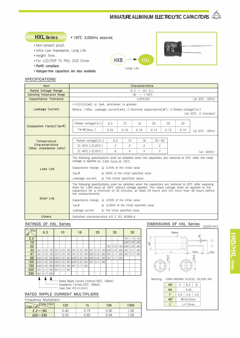
HXB/H
XL
Series
MINIATURE ALUMINUM ELECTROLYTIC CAPACITORS
IItteemm CChhaarraacctteerriissttiiccss
RRaatteedd VVoollttaaggee RRaannggee 6.3 ~ 50 VDC
OOppeerraattiinngg TTeemmppeerraattuurree RRaannggee -40 ~ +105
CCaappaacciittaannccee TToolleerraannccee ±20%(M) (at 20, 120Hz)
I=0.01CV(μA) or 3μA, whichever is greater.
LLeeaakkaaggee CCuurrrreenntt Where, I:Max. Leakage current(μA), C:Nominal capacitance(μF), V:Rated voltage(VDC)
(at 20, 2 minutes)
DDiissssiippaattiioonn FFaaccttoorr((TTaannδδ))
TTeemmppeerraattuurreeCChhaarraacctteerriissttiiccss
The following specifications shall be satisfied when the capacitors are restored to 20 after the ratedvoltage is applied for 3,000 hours at 105.
Capacitance change ±25% of the initial value
Tanδ 200% of the initial specified value
Leakage current The initial specified value
The following specifications shall be satisfied when the capacitors are restored to 20 after exposing them for 1,000 hours at 105 without voltage applied. The rated voltage shall be applied to the capacitors for a minimum of 30 minutes, at least 24 hours and not more than 48 hours before the measurements.
Capacitance change ±25% of the initial value
Tanδ ±200% of the initial specified value
Leakage current The initial specified value
OOtthheerrss Satisfied characteristics KS C IFC 60384-4
110055 33,,000000HHrrss aassssuurreedd..
SSPPEECCIIFFIICCAATTIIOONNSS
LLooaadd LLiiffee
SShheellff LLiiffee
(at 120Hz)((MMaaxx.. IImmppeeddaannccee rraattiioo))
(at 20, 120Hz)
HXL Series
HHXXBB HHXXLL
Long Life
Rated voltage(VDC)
Tanδ(Max.)
Marking : DARK BROWN SLEEVE, SILVER INK
66..33 1100 1166 2255 3355 5500
DDIIMMEENNSSIIOONNSS OOFF HHXXLL SSeerriieessRRAATTIINNGGSS OOFF HHXXLL SSeerriieess
22..2211002222333344776688
110000115500222200333300
5X7
5X7
6.3X7
6.3X7
6.3X7
8X7
8X7
0.70
0.70
0.35
0.35
0.35
0.17
0.17
165
165
260
260
260
450
450
5X7
5X7
6.3X7
6.3X7
6.3X7
8X7
0.70
0.70
0.35
0.35
0.35
0.17
165
165
260
260
260
450
5X7
5X7
6.3X7
6.3X7
8X7
0.70
0.70
0.35
0.35
0.17
165
165
260
260
450
5X7
6.3X7
6.3X7
8X7
0.70
0.35
0.35
0.17
165
260
260
450
5X7
6.3X7
8X7
8X7
0.70
0.35
0.17
0.17
165
260
450
450
5X7
6.3X7
6.3X7
8X7
8X7
1.15
0.35
0.35
0.17
0.17
120
260
260
450
450
VVDDCC
Rated Ripple Current (mArms/105, 100kHz)Impedance (Ϊmax./20, 100kHz) Case Size ∅D×L(mm)
Non-solvent proof.
Ultra Low Impedance, Long Life
Height 7mm.
For LCD/PDP TV PSU, DVD Driver
RoHS compliant.
Halogen-free capacitors are also available.
6.3
0.22
10
0.19
16
0.16
25
0.14
35
0.12
50
0.10
∅∅DD 5 6.3 8
∅∅dd 0.45
FF 2.0 2.5 3.5
∅∅DD、、 ∅D+0.5max
LL、、 L+1.0max
Rated voltage(VDC) 6.3 10 16 25~50
Z(-25)/Z(20) 2 2 2 2
Z(-40)/Z(20) 6 4 3 3
22..22~~118800222200~~333300
112200
0.400.50
11kk
0.750.85
1100kk
0.900.94
110000kk
1.001.00
FFrreeqq..((HHzz))CCaapp..(())
Frequency Multipliers
RRAATTEEDD RRIIPPPPLLEE CCUURRRREENNTT MMUULLTTIIPPLLIIEERRSS
Unit(mm)
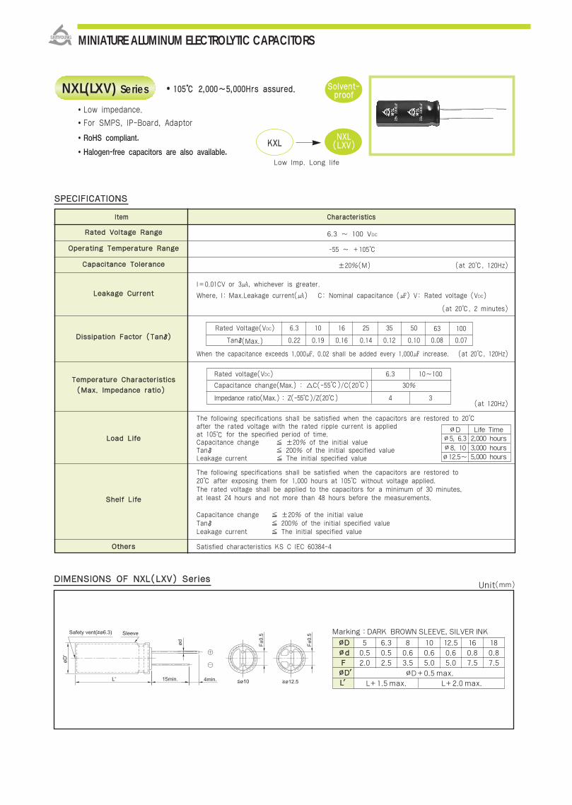
RRaatteedd VVoollttaaggee RRaannggee
OOppeerraattiinngg TTeemmppeerraattuurree RRaannggee
CCaappaacciittaannccee TToolleerraannccee
LLeeaakkaaggee CCuurrrreenntt
DDiissssiippaattiioonn FFaaccttoorr ((TTaannδδ))
TTeemmppeerraattuurree CChhaarraacctteerriissttiiccss
LLooaadd LLiiffee
SShheellff LLiiffee
OOtthheerrss
6.3 ~ 100 VDC
-55 ~ +105
±20%(M) (at 20, 120Hz)
I=0.01CV or 3, whichever is greater.
Where, I: Max.Leakage current() C: Nominal capacitance () V: Rated voltage (VDC)
(at 20, 2 minutes)
When the capacitance exceeds 1,000, 0.02 shall be added every 1,000 increase. (at 20, 120Hz)
(at 120Hz)
The following specifications shall be satisfied when the capacitors are restored to 20after the rated voltage with the rated ripple current is applied at 105 for the specified period of time.Capacitance change ±20% of the initial valueTanδ 200% of the initial specified valueLeakage current The initial specified value
The following specifications shall be satisfied when the capacitors are restored to20 after exposing them for 1,000 hours at 105 without voltage applied.The rated voltage shall be applied to the capacitors for a minimum of 30 minutes,at least 24 hours and not more than 48 hours before the measurements.
Capacitance change ±20% of the initial valueTanδ 200% of the initial specified valueLeakage current The initial specified value
Satisfied characteristics KS C IEC 60384-4
SSoollvveenntt--pprrooooff
Rated Voltage(VDC) 6.3 10 16 25 35 50
Tanδ(Max.) 0.22 0.19 0.16 0.14 0.12 0.10
Rated voltage(VDC) 6.3 10~100
Capacitance change(Max.) : C(-55)/C(20) 30%
Impedance ratio(Max.) : Z(-55)/Z(20) 4 3
110055 22,,000000~~55,,000000HHrrss aassssuurreedd..NXL(LXV) Series
KKXXLLNNXXLL((LLXXVV))
Low Imp. Long life
∅D Life Time∅5, 6.3 2,000 hours∅8, 10 3,000 hours∅12.5~ 5,000 hours
((MMaaxx.. IImmppeeddaannccee rraattiioo))
Low impedance.
For SMPS, IP-Board, Adaptor
RoHS compliant.
Halogen-free capacitors are also available.
63
0.08
100
0.07
SSPPEECCIIFFIICCAATTIIOONNSS
MINIATURE ALUMINUM ELECTROLYTIC CAPACITORS
DDIIMMEENNSSIIOONNSS OOFF NNXXLL((LLXXVV)) SSeerriieess
Marking :DARK BROWN SLEEVE, SILVER INK
∅∅DD∅∅ddFF∅∅DD′′LL′′
50.52.0
∅D+0.5 max.
L+1.5 max. L+2.0 max.
6.30.52.5
80.63.5
100.65.0
12.50.65.0
160.87.5
180.87.5
lltteemm CChhaarraacctteerriissttiiccss
Unit(mm)

MINIATURE ALUMINUM ELECTROLYTIC CAPACITORS
NXL(LXV)
Serie
s
5×11 165 82 5×11 165 56 5×11 165
6.3×11 255 180 6.3×11 255 120 6.3×11 255
6.3×15 330 270 6.3×15 330 180 6.3×15 330
8×11.5 485 270 8×11.5 485 180 8×11.5 485
10×12.5 625 470 8×11.5 330 270 10×12.5 625
8×15 495 470 8×15 495 330 8×15 495
10×16 0.084 825 680 8×20 640 470 8×20 640
8×20 0.110 640 680 10×16 0.084 825 470 10×16 0.084 825
10×20 0.062 1,040 1,000 10×20 0.062 1,040 680 10×20 0.062 1,040
10×25 0.052 1,260 1,200 10×25 0.052 1,260 820 10×25 0.052 1,260
10×30 0.044 1,440 1,500 10×30 0.044 1,440 1,200 10×30 0.044 1,440
12.5×20 0.046 1,340 1,800 12.5×20 0.046 1,340 1,200 12.5×20 0.046 1,340
12.5×25 0.034 1,690 2,200 12.5×25 0.034 1,690 1,500 12.5×25 0.034 1,690
12.5×30 0.030 1,950 2,700 12.5×30 0.030 1,950 2,200 12.5×30 0.030 1,950
16×20 0.039 1,630 3,300 12.5×35 0.027 2,200 2,200 16×20 0.039 1,630
12.5×35 0.027 2,200 3,300 16×20 0.039 1,630 2,700 12.5×35 0.027 2,200
12.5×42.5 0.024 2,390 3,900 12.5×42.5 0.024 2,390 2,700 16×25 0.029 2,070
16×25 0.029 2,070 3,900 16×25 0.029 2,070 3,300 12.5×42.5 0.024 2,390
18×20 0.038 1,750 3,900 18×20 0.038 1,750 3,300 18×20 0.038 1,750
16×31.5 0.026 2,350 5,600 16×31.5 0.026 2,350 3,900 16×31.5 0.026 2,350
18×25 0.029 2,130 5,600 18×25 0.029 2,130 3,900 18×25 0.029 2,130
16×35.5 0.023 2,550 6,800 16×35.5 0.023 2,550 4,700 16×35.5 0.023 2,550
18×31.5 0.026 2,410 6,800 18×31.5 0.026 2,410 5,600 18×31.5 0.026 2,410
18×35.5 0.023 2,660 8,200 18×35.5 0.023 2,660 6,800 18×35.5 0.023 2,660
18×40 0.019 3,010 10,000 18×40 0.019 3,010 8,200 18×40 0.019 3,010
120
220
330
330
470
560
680
820
1,200
1,500
2,200
2,200
2,700
3,900
3,900
4,700
5,600
5,600
5,600
6,800
6,800
8,200
10,000
12,000
15,000
66..33
∅∅DD××LL((mmmm)) IIMMPP.. RRiippppllee
1100
∅∅DD××LL((mmmm)) IIMMPP.. RRiippppllee
1166
∅∅DD××LL((mmmm)) IIMMPP.. RRiippppllee
RRAATTIINNGGSS OOFF NNXXLL((LLXXVV)) SSeerriieess
VVDDCC
0.72
0.38
0.27
0.19
0.12
0.16
0.72
0.38
0.27
0.19
0.27
0.16
0.11
0.72
0.38
0.27
0.19
0.12
0.16
0.11
Rated Ripple Current (mArms/105, 100kHz)Impedance (Ϊmax./20, 100kHz) Case Size
VVDDCC
VVDDCC
4.7 5×11 3.0 100
10 5×11 1.4 124
5×11 0.72 165 27 5×11 0.72 165 18 5×11 1.1 130
5×11 0.72 194 47 6.3×11 0.50 233 22 6.3×11 0.91 180
6.3×11 0.38 255 56 6.3×11 0.38 255 39 6.3×11 0.56 220
6.3×11 0.35 280 68 6.3×11 0.38 255 47 6.3×11 0.56 300
6.3×15 0.27 330 82 6.3×15 0.27 330 56 6.3×15 0.41 310
8×11.5 0.19 485 82 8×11.5 0.19 485 56 8×11.5 0.33 368
10×12.5 0.12 625 120 10×12.5 0.12 625 82 8×15 0.25 470
8×15 0.16 495 180 8×15 0.16 495 82 10×12.5 0.16 480
8×20 0.11 640 220 8×20 0.11 640 120 8×20 0.18 610
10×16 0.084 825 220 10×16 0.084 825 120 10×16 0.12 755
10×20 0.062 1,150 330 10×20 0.062 1,040 180 10×20 0.088 945
10×25 0.052 1,260 390 10×25 0.052 1,260 220 10×25 0.068 1,150
10×30 0.044 1,440 560 10×30 0.044 1,440 330 10×30 0.059 1,260
12.5×20 0.046 1,340 560 12.5×20 0.046 1,340 330 12.5×20 0.059 1,190
12.5×25 0.034 1,690 680 12.5×25 0.034 1,690 470 12.5×25 0.045 1,490
12.5×30 0.030 1,950 1,000 12.5×25 0.040 1,690 560 12.5×30 0.039 1,720
16×20 0.039 1,630 1,000 12.5×30 0.030 1,950 680 12.5×35 0.038 1,890
12.5×35 0.027 2,200 1,200 12.5×35 0.027 2,200 680 16×20 0.044 1,420
16×25 0.029 2,070 1,200 16×25 0.029 2,070 820 12.5×42.5 0.029 2,030
12.5×42.5 0.024 2,390 1,500 12.5×42.5 0.024 2,390 820 16×25 0.034 1,880
18×20 0.038 1,750 1,500 18×20 0.038 1,750 820 18×20 0.041 1,520
16×31.5 0.026 2,350 1,800 16×31.5 0.026 2,350 1,000 16×31.5 0.030 2,150
18×25 0.029 2,130 1,800 18×25 0.029 2,130 1,000 18×25 0.032 1,930
16×35.5 0.023 2,550 2,200 16×35.5 0.023 2,550 1,200 16×35.5 0.026 2,320
18×31.5 0.026 2,410 2,200 18×31.5 0.026 2,410 1,500 18×31.5 0.028 2,200
18×35.5 0.023 2,660 2,700 18×35.5 0.023 2,660 1,800 18×35.5 0.025 2,400
18×40 0.019 3,010 3,300 18×40 0.019 3,010 2,200 18×40 0.022 2,610
39
47
82
100
120
120
180
220
330
330
470
560
820
820
1,000
1,500
1,500
1,800
1,800
2,200
2,200
2,700
2,700
3,300
3,300
3,900
4,700
2255
∅∅DD××LL((mmmm)) IIMMPP.. RRiippppllee
3355
∅∅DD××LL((mmmm)) IIMMPP.. RRiippppllee
5500
∅∅DD××LL((mmmm)) IIMMPP.. RRiippppllee
VVDDCC
VVDDCC
VVDDCC
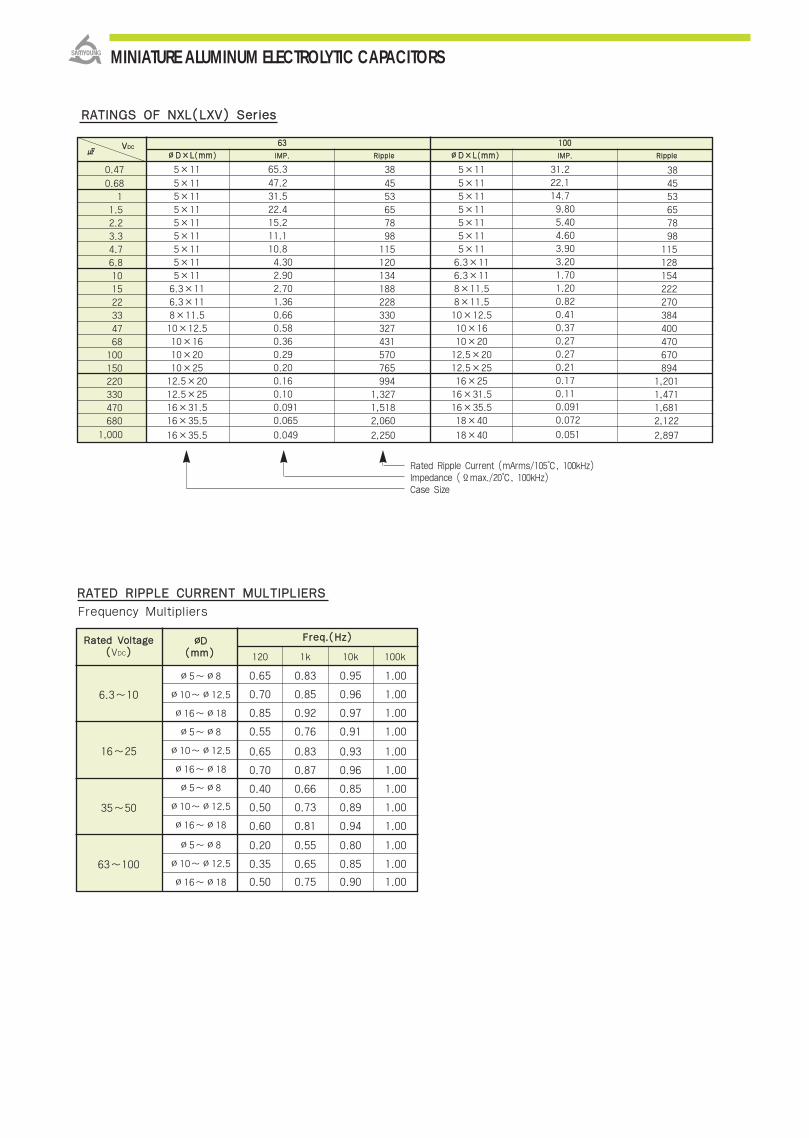
0.47
0.681
1.52.23.34.76.8101522334768100150220330470680
1,000
5×11
5×115×115×115×115×115×115×115×116.3×116.3×118×11.510×12.510×1610×2010×2512.5×2012.5×2516×31.516×35.5
16×35.5
65.3
47.231.522.415.211.110.84.302.902.701.360.660.580.360.290.200.160.100.0910.065
0.049
38
4553657898115120134188228330327431570765994
1,3271,5182,060
2,250
5×11
5×115×115×115×115×115×116.3×116.3×118×11.58×11.510×12.510×1610×2012.5×2012.5×2516×2516×31.516×35.518×40
18×40
31.222.114.79.805.404.603.903.201.701.200.820.410.370.270.270.210.170.110.0910.072
0.051
384553657898
115128154222270384400470670894
1,2011,4711,6812,122
2,897
RRAATTEEDD RRIIPPPPLLEE CCUURRRREENNTT MMUULLTTIIPPLLIIEERRSS
RRAATTIINNGGSS OOFF NNXXLL((LLXXVV)) SSeerriieess
Frequency Multipliers
MINIATURE ALUMINUM ELECTROLYTIC CAPACITORS
6.3~10
16~25
35~50
63~100
∅5~∅8
∅10~∅12.5
∅16~∅18
∅5~∅8
∅10~∅12.5
∅16~∅18
∅5~∅8
∅10~∅12.5
∅16~∅18
∅5~∅8
∅10~∅12.5
∅16~∅18
0.65
0.70
0.85
0.55
0.65
0.70
0.40
0.50
0.60
0.20
0.35
0.50
0.83
0.85
0.92
0.76
0.83
0.87
0.66
0.73
0.81
0.55
0.65
0.75
0.95
0.96
0.97
0.91
0.93
0.96
0.85
0.89
0.94
0.80
0.85
0.90
1.00
1.00
1.00
1.00
1.00
1.00
1.00
1.00
1.00
1.00
1.00
1.00
RRaatteedd VVoollttaaggee((VDC))
∅∅DD ((mmmm))
FFrreeqq..((HHzz))
120 1k 10k 100k
6633
∅∅DD××LL((mmmm)) IIMMPP.. RRiippppllee
110000
∅∅DD××LL((mmmm)) IIMMPP.. RRiipppplleeVVDDCC
Rated Ripple Current (mArms/105, 100kHz)Impedance (Ϊmax./20, 100kHz) Case Size

MINIATURE ALUMINUM ELECTROLYTIC CAPACITORS
RRaatteedd VVoollttaaggee RRaannggee
OOppeerraattiinngg TTeemmppeerraattuurree RRaannggee
CCaappaacciittaannccee TToolleerraannccee
LLeeaakkaaggee CCuurrrreenntt
DDiissssiippaattiioonn FFaaccttoorr ((TTaannδδ))
LLooaadd LLiiffee
SShheellff LLiiffee
ootthheerrss
110055 22,,000000 ~~ 55,,000000HHrrss aassssuurreedd..
SSPPEECCIIFFIICCAATTIIOONNSS
NNXXLL NNXXPP((LLXXZZ))
Low Imp.Downsized
6.3 ~ 50 VDC
-55 ~ +105
±20%(M) (at 20, 120Hz)
I = 0.01CV () or 3, whichever is greater. Where, I:Max. leakage current()
C:Nominal capacitance() V:Rated voltage(VDC) (at 20, 2 minutes)
When the capacitance exceeds 1,000, 0.02 shall be added every 1,000 increase.
(at 20, 120Hz)
The following specifications shall be satisfied when the capacitors are restored to 20after the rated voltage with the rated ripple current is applied at 105 for the specifiedperiod of time.
Capacitance change ±20% of the initial valueTanδ 200% of the initial specified valueLeakage Current The initial specified value
The following specifications shall be satisfied when the capacitors are restored to 20after exposing them for 1,000 hours at 105 without voltage applied. The ratedvoltage shall be applied to the capacitors for a minimum of 30 minutes, at least 24hours and not more than 48 hours before the measurements.
Capacitance change ±20% of the initial value
Tanδ 200% of the initial specified value
Leakage Current The initial specified value
Satisfied characteristics KS C IEC 60384-4
Rated Voltage(VDC) 6.3 10 16 25 35 50
TANδ(Max.) 0.22 0.19 0.16 0.14 0.12 0.10
RRAATTEEDD RRIIPPPPLLEE CCUURRRREENNTT MMUULLTTIIPPLLIIEERRSS
∅5, 6.3 2,000 hours
∅8 3,000 hours∅10~ 5,000 hours
112200 11kk 1100kk 110000kk
3333 ~~ 118800 0.40 0.75 0.90 1.00
222200 ~~ 556600 0.50 0.85 0.94 1.00
668800 ~~ 11,,880000 0.60 0.87 0.95 1.00
22,,220000 ~~ 33,,990000 0.75 0.90 0.95 1.00
44,,770000 ~~ 1188,,000000 0.85 0.95 0.98 1.00
DDIIMMEENNSSIIOONNSS OOFF NNXXPP((LLXXZZ)) SSeerriieess
FFrreeqq..((HHzz))CCaapp..(())
Frequency Multipliers
NXP(LXZ) SeriesLow impedance.
Downsized of LXV series.
For SMPS, IP-Board, Adaptor
RoHS compliant.
Halogen-free capacitors are also available.
SSoollvveenntt--pprrooooff
NXP(LXZ)
Serie
s
Marking :DARK BROWN SLEEVE, SILVER INK
∅∅DD∅∅ddFF∅∅DD′′LL′′
50.52.0
∅D+0.5 max.
L+1.5 max. L+2.0 max.
6.30.52.5
80.63.5
100.65.0
12.50.65.0
160.87.5
180.87.5
Unit(mm)
lltteemm CChhaarraacctteerriissttiiccss
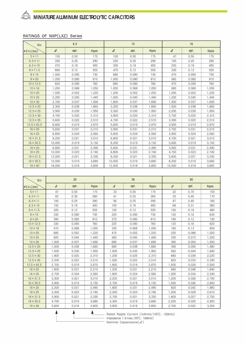
RRAATTIINNGGSS OOFF NNXXPP((LLXXZZ)) SSeerriieess
66..33 1100 1166
150 0.50 175 100 0.50 175 47 0.50 175
330 0.25 290 220 0.25 290 100 0.25 290
470 0.18 400 330 0.18 400 220 0.18 400
680 0.12 555 470 0.12 555 330 0.12 555
1,000 0.090 730 680 0.090 730 470 0.090 730
1,200 0.080 810 1,000 0.080 810 560 0.080 810
820 0.090 760 680 0.090 760 470 0.090 760
1,200 0.068 1,050 1,000 0.068 1,050 680 0.068 1,050
1,500 0.052 1,220 1,200 0.052 1,220 1,000 0.052 1,220
2,200 0.045 1,440 1,500 0.045 1,440 1,200 0.045 1,440
2,700 0.037 1,690 1,800 0.037 1,690 1,500 0.037 1,690
3,300 0.038 1,660 2,200 0.038 1,660 1,500 0.038 1,660
3,900 0.030 1,950 3,300 0.030 1,950 2,200 0.030 1,950
4,700 0.025 2,310 3,900 0.025 2,310 2,700 0.025 2,310
5,600 0.022 2,510 4,700 0.022 2,510 3,300 0.022 2,510
6,800 0.019 2,870 5,600 0.019 2,870 3,900 0.019 2,870
5,600 0.031 2,210 3,900 0.031 2,210 2,700 0.031 2,210
6,800 0.024 2,560 5,600 0.024 2,560 3,900 0.024 2,560
8,200 0.021 3,010 6,800 0.021 3,010 4,700 0.021 3,010
10,000 0.019 3,150 8,200 0.019 3,150 5,600 0.019 3,150
6,800 0.031 2,490 5,600 0.031 2,490 3,900 0.031 2,490
10,000 0.023 2,740 6,800 0.023 2,740 4,700 0.023 2,740
12,000 0.021 3,330 8,200 0.021 3,330 5,600 0.021 3,330
15,000 0.019 3,680 10,000 0.019 3,680 8,200 0.019 3,680
18,000 0.018 3,800 12,000 0.018 3,800 10,000 0.018 3,800
5×11
6.3×11
6.3×15
8×11.5
8×15
8×20
10×12.5
10×16
10×20
10×25
10×30
12.5×20
12.5×25
12.5×30
12.5×35
12.5×42.5
16×20
16×25
16×31.5
16×35.5
18×20
18×25
18×31.5
18×35.5
18×40
VVDDCC
∅∅DD××LL((mmmm)) IIMMPP.. RRiippppllee IIMMPP.. RRiippppllee IIMMPP.. RRiippppllee
2255 3355 5500
47 0.50 175 33 0.50 175
82 0.30 260 47 0.25 265
100 0.25 290 56 0.25 290
150 0.18 400 100 0.18 400
220 0.12 555 150 0.12 555
330 0.090 730 220 0.090 730
390 0.080 810 270 0.080 810
330 0.090 760 220 0.090 760
470 0.068 1,050 330 0.068 1,050
680 0.052 1,220 470 0.052 1,220
820 0.045 1,440 560 0.045 1,440
1,000 0.037 1,690 680 0.037 1,690
1,000 0.038 1,660 680 0.038 1,660
1,500 0.030 1,950 1,000 0.030 1,950
1,800 0.025 2,310 1,200 0.025 2,310
2,200 0.022 2,510 1,500 0.022 2,510
2,700 0.019 2,870 1,800 0.019 2,870
1,800 0.031 2,210 1,200 0.031 2,210
2,700 0.024 2,560 1,800 0.024 2,560
3,300 0.021 3,010 2,200 0.021 3,010
3,900 0.019 3,150 2,700 0.019 3,150
2,200 0.031 2,490 1,800 0.031 2,490
3,300 0.023 2,740 2,200 0.023 2,740
3,900 0.021 3,330 2,700 0.021 3,330
4,700 0.019 3,680 3,300 0.019 3,680
5,600 0.018 3,800 3,900 0.018 3,800
22 0.70 155
33 0.45 170
47 0.45 180
68 0.31 360
100 0.18 485
120 0.16 635
180 0.12 730
120 0.16 620
180 0.13 850
220 0.088 1,050
330 0.073 1,250
390 0.054 1,500
390 0.059 1,480
560 0.044 1,840
680 0.039 2,220
820 0.033 2,290
1,000 0.029 2,500
680 0.048 1,840
1,000 0.034 2,240
1,200 0.028 2,700
1,500 0.026 2,800
820 0.042 1,980
1,200 0.029 2,610
1,800 0.027 2,750
2,200 0.025 2,900
2,700 0.022 3,200
5×11
6.3×11
6.3×11
6.3×15
8×11.5
8×15
8×20
10×12.5
10×16
10×20
10×25
10×30
12.5×20
12.5×25
12.5×30
12.5×35
12.5×42.5
16×20
16×25
16×31.5
16×35.5
18×20
18×25
18×31.5
18×35.5
18×40
VVDDCC
∅∅DD××LL((mmmm))
MINIATURE ALUMINUM ELECTROLYTIC CAPACITORS
Rated Ripple Current (mArms/105, 100kHz)Impedance (Ϊmax./20, 100kHz)Nominal Capacitance()
IIMMPP.. RRiippppllee IIMMPP.. RRiippppllee IIMMPP.. RRiippppllee

MINIATURE ALUMINUM ELECTROLYTIC CAPACITORS
110055 44,,000000 ~~ 1100,,000000HHrrss aassssuurreedd..
SSHHLL NNXXAA
Low Imp.Long Life
NXA Series
Non-solvent proof.
Low impedance, long life
For SMPS, IP-Board, Adaptor, Noise Filter, Charger
RoHS compliant.
Halogen-free capacitors are also available.
RRaatteedd VVoollttaaggee RRaannggee
OOppeerraattiinngg TTeemmppeerraattuurree RRaannggee
CCaappaacciittaannccee TToolleerraannccee
LLeeaakkaaggee CCuurrrreenntt
TTeemmppeerraattuurree CChhaarraacctteerriissttiiccss
LLooaadd LLiiffee
SShheellff LLiiffee
OOtthheerrss
6.3 ~ 100 VDC
-40 ~ +105
±20%(M) (at 20, 120Hz)
I=0.01CV(μA) or 3μA, whichever is greater.
Where, I:Max. Leakage current(μA), C:Nominal capacitance(μF), V:Rated voltage(VDC)
(at 20, 2 minutes)
When the capacitance exceeds 1,000, 0.02 shall be added every 1,000 increase. (at 20, 120Hz)
(at 120Hz)
The following specifications shall be satisfied when the capacitors are restored to 20after the rated voltage with the rated ripple current is applied at 105 for the specified period of time.Capacitance change ±25% of the initial valueTanδ 200% of the initial specified valueLeakage current The initial specified value
The following specifications shall be satisfied when the capacitors are restored to20 after exposing them for 500 hours at 105 without voltage applied.The rated voltage shall be applied to the capacitors for a minimum of 30 minutes,at least 24 hours and not more than 48 hours before the measurements.
Capacitance change ±25% of the initial valueTanδ 200% of the initial specified valueLeakage current The initial specified value
Satisfied characteristics KS C IEC 60384-4
SSPPEECCIIFFIICCAATTIIOONNSS
Rated Voltage(VDC) 6.3 10 16 25 35 50 63 80 100
Tanδ(Max.) 0.22 0.19 0.16 0.14 0.12 0.10 0.09 0.09 0.08
((MMaaxx.. IImmppeeddaannccee rraattiioo))
6.3Rated Voltage(VDC)
Z(-25)/Z(+20)
Z(-40)/Z(+20)
4
8
10
3
6
16
2
4
25
2
3
35
2
3
50
2
3
63
2
3
80
2
3
100
2
3
VDC ∅5~∅6.3 ∅8~∅10 ∅12.5~∅18
4,000 hours 6,000 hours 8,000 hours6.3~10(V)
16~100(V) 5,000 hours 7,000 hours 10,000 hours
DDiissssiippaattiioonn FFaaccttoorr
((TTaannδδ))
DDIIMMEENNSSIIOONNSS OOFF NNXXAA SSeerriieess
NXA Serie
s
Marking :DARK BROWN SLEEVE, SILVER INK
∅∅DD∅∅ddFF∅∅DD′′LL′′
50.52.0
∅D+0.5 max.
L+1.5 max. L+2.0 max.
6.30.52.5
80.63.5
100.65.0
12.50.65.0
160.87.5
180.87.5
lltteemm CChhaarraacctteerriissttiiccss
Unit(mm)
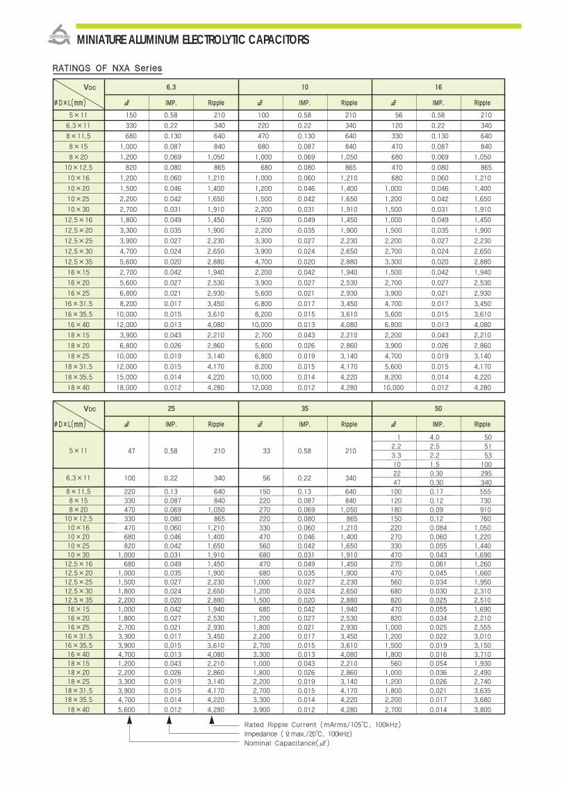
RRAATTIINNGGSS OOFF NNXXAA SSeerriieess
66..33 1100 1166
IIMMPP.. RRiippppllee IIMMPP.. RRiippppllee IIMMPP.. RRiippppllee
150 0.58 210 100 0.58 210 56 0.58 210
330 0.22 340 220 0.22 340 120 0.22 340
680 0.130 640 470 0.130 640 330 0.130 640
1,000 0.087 840 680 0.087 840 470 0.087 840
1,200 0.069 1,050 1,000 0.069 1,050 680 0.069 1,050
820 0.080 865 680 0.080 865 470 0.080 865
1,200 0.060 1,210 1,000 0.060 1,210 680 0.060 1,210
1,500 0.046 1,400 1,200 0.046 1,400 1,000 0.046 1,400
2,200 0.042 1,650 1,500 0.042 1,650 1,200 0.042 1,650
2,700 0.031 1,910 2,200 0.031 1,910 1,500 0.031 1,910
1,800 0.049 1,450 1,500 0.049 1,450 1,000 0.049 1,450
3,300 0.035 1,900 2,200 0.035 1,900 1,500 0.035 1,900
3,900 0.027 2,230 3,300 0.027 2,230 2,200 0.027 2,230
4,700 0.024 2,650 3,900 0.024 2,650 2,700 0.024 2,650
5,600 0.020 2,880 4,700 0.020 2,880 3,300 0.020 2,880
2,700 0.042 1,940 2,200 0.042 1,940 1,500 0.042 1,940
5,600 0.027 2,530 3,900 0.027 2,530 2,700 0.027 2,530
6,800 0.021 2,930 5,600 0.021 2,930 3,900 0.021 2,930
8,200 0.017 3,450 6,800 0.017 3,450 4,700 0.017 3,450
10,000 0.015 3,610 8,200 0.015 3,610 5,600 0.015 3,610
12,000 0.013 4,080 10,000 0.013 4,080 6,800 0.013 4,080
3,900 0.043 2,210 2,700 0.043 2,210 2,200 0.043 2,210
6,800 0.026 2,860 5,600 0.026 2,860 3,900 0.026 2,860
10,000 0.019 3,140 6,800 0.019 3,140 4,700 0.019 3,140
12,000 0.015 4,170 8,200 0.015 4,170 5,600 0.015 4,170
15,000 0.014 4,220 10,000 0.014 4,220 8,200 0.014 4,220
18,000 0.012 4,280 12,000 0.012 4,280 10,000 0.012 4,280
5×11
6.3×11
8×11.5
8×15
8×20
10×12.5
10×16
10×20
10×25
10×30
12.5×16
12.5×20
12.5×25
12.5×30
12.5×35
16×15
16×20
16×25
16×31.5
16×35.5
16×40
18×15
18×20
18×25
18×31.5
18×35.5
18×40
VVDDCC
∅∅DD××LL((mmmm))
2255 3355 5500
IIMMPP.. RRiippppllee IIMMPP.. RRiippppllee IIMMPP.. RRiippppllee
1 4.0 50
47 0.58 210 33 0.58 2102.2 2.5 513.3 2.2 5310 1.5 100
100 0.22 340 56 0.22 34022 0.30 29547 0.30 340
220 0.13 640 150 0.13 640 100 0.17 555330 0.087 840 220 0.087 840 120 0.12 730470 0.069 1,050 270 0.069 1,050 180 0.09 910330 0.080 865 220 0.080 865 150 0.12 760470 0.060 1,210 330 0.060 1,210 220 0.084 1,050680 0.046 1,400 470 0.046 1,400 270 0.060 1,220820 0.042 1,650 560 0.042 1,650 330 0.055 1,440
1,000 0.031 1,910 680 0.031 1,910 470 0.043 1,690680 0.049 1,450 470 0.049 1,450 270 0.061 1,260
1,000 0.035 1,900 680 0.035 1,900 470 0.045 1,6601,500 0.027 2,230 1,000 0.027 2,230 560 0.034 1,9501,800 0.024 2,650 1,200 0.024 2,650 680 0.030 2,3102,200 0.020 2,880 1,500 0.020 2,880 820 0.025 2,5101,000 0.042 1,940 680 0.042 1,940 470 0.055 1,6901,800 0.027 2,530 1,200 0.027 2,530 820 0.034 2,2102,700 0.021 2,930 1,800 0.021 2,930 1,000 0.025 2,5553,300 0.017 3,450 2,200 0.017 3,450 1,200 0.022 3,0103,900 0.015 3,610 2,700 0.015 3,610 1,500 0.019 3,1504,700 0.013 4,080 3,300 0.013 4,080 1,800 0.016 3,7101,200 0.043 2,210 1,000 0.043 2,210 560 0.054 1,9302,200 0.026 2,860 1,800 0.026 2,860 1,000 0.036 2,4903,300 0.019 3,140 2,200 0.019 3,140 1,200 0.026 2,7403,900 0.015 4,170 2,700 0.015 4,170 1,800 0.021 3,6354,700 0.014 4,220 3,300 0.014 4,220 2,200 0.017 3,680
5,600 0.012 4,280 3,900 0.012 4,280 2,700 0.014 3,800
5×11
6.3×11
8×11.58×158×20
10×12.510×1610×2010×2510×3012.5×1612.5×2012.5×2512.5×3012.5×3516×1516×2016×2516×31.516×35.516×4018×1518×2018×2518×31.518×35.5
18×40
VVDDCC
∅∅DD××LL((mmmm))
Rated Ripple Current (mArms/105, 100kHz)Impedance (Ϊmax./20, 100kHz)Nominal Capacitance()
MINIATURE ALUMINUM ELECTROLYTIC CAPACITORS

NXA Serie
s
MINIATURE ALUMINUM ELECTROLYTIC CAPACITORS
6633 8800 110000
IIMMPP.. RRiippppllee IIMMPP.. RRiippppllee IIMMPP.. RRiippppllee
15 0.88 165 6.8 1.4 125
33 0.35 265 15 0.57 205
47 0.22 500 22 0.50 310
56 0.22 500 27 0.36 355
82 0.16 665 39 0.25 450
120 0.12 820 68 0.19 565
82 0.11 690 68 0.17 480 47 0.17 480
120 0.076 950 100 0.11 600 68 0.11 600
180 0.056 1,150 120 0.084 800 82 0.084 800
220 0.046 1,350 150 0.069 900 120 0.069 900
180 0.072 1,150 150 0.11 750 100 0.11 750
270 0.041 1,500 220 0.062 1,100 150 0.062 1,100
390 0.031 1,900 330 0.047 1,250 220 0.047 1,250
470 0.028 2,300 390 0.042 1,500 270 0.042 1,500
330 0.036 1,650560 0.024 2,500 470 0.036 1,650
390 0.036 1,650
470 0.032 2,000 330 0.048 1,350 220 0.048 1,350
680 0.025 2,600 470 0.038 1,700 330 0.036 1,650
820 0.021 2,850 680 0.032 1,850 470 0.032 1,850
1,000 0.019 2,900 820 0.029 2,000 560 0.029 2,000
1,200 0.018 3,400 1,000 0.027 2,200 680 0.027 2,200
680 0.030 2,500 470 0.038 1,700 330 0.045 1,500
820 0.024 2,800 680 0.036 1,750 470 0.036 1,750
1,200 0.020 3,300 820 0.030 1,900 560 0.030 1,900
1,500 0.018 3,400 1,000 0.027 2,200 680 0.027 2,200
1,800 0.017 3,500 1,200 0.026 2,700 820 0.026 2,700
5×11
6.3×11
8×11.5
8×15
8×20
10×12.5
10×16
10×20
10×25
12.5×16
12.5×20
12.5×25
12.5×30
12.5×35
16×20
16×25
16×31.5
16×35.5
16×40
18×20
18×25
18×31.5
18×35.5
18×40
VVDDCC
∅∅DD××LL((mmmm))
0.40
0.50
0.60
0.75
0.85
0.75
0.85
0.87
0.90
0.95
0.90
0.94
0.95
0.95
0.98
1.00
1.00
1.00
1.00
1.00
RRAATTEEDD RRIIPPPPLLEE CCUURRRREENNTT MMUULLTTIIPPLLIIEERRSS
Frequency Multipliers
RRAATTIINNGGSS OOFF NNXXAA SSeerriieess
Rated Ripple Current (mArms/105, 100kHz)Impedance (Ϊmax./20, 100kHz)Nominal Capacitance()
112200 11kk 1100kk 110000kk
66..88 ~~ 118800
222200 ~~ 556600
668800 ~~ 11,,880000
22,,220000 ~~ 33,,990000
44,,770000 ~~ 1188,,000000
FFrreeqq..((HHzz))
CCaapp..(())

IItteemm CChhaarraacctteerriissttiiccss
RRaatteedd VVoollttaaggee RRaannggee 6.3 ~ 100 VDC
OOppeerraattiinngg TTeemmppeerraattuurree RRaannggee -40 ~ +105
CCaappaacciittaannccee TToolleerraannccee ±20%(M) (at 20, 120Hz)
I=0.01CV(μA) or 3μA, whichever is greater.
LLeeaakkaaggee CCuurrrreenntt Where, I:Max. Leakage current(μA), C:Nominal capacitance(μF), V:Rated voltage(VDC)
(at 20, 2 minutes)
DDiissssiippaattiioonn FFaaccttoorr
TTaannδδ
TTeemmppeerraattuurreeCChhaarraacctteerriissttiiccss
The following specifications shall be satisfied when the capacitors are restored to 20 after the ratedvoltage with the rated ripple current is applied at 105for the specified period of time.
Capacitance change ±25% of the initial value
Tanδ 200% of the initial specified value
Leakage current The initial specified value
The following specifications shall be satisfied when the capacitors are restored to 20 after exposing them for 1,000 hours at 105 without voltage applied. The rated voltage shall be applied to the capacitors for a minimum of 30 minutes, at least 24 hours and not more than 48 hours before the measurements.
Capacitance change ±25% of the initial value
Tanδ 200% of the initial specified value
Leakage current The initial specified value
OOtthheerrss Satisfied characteristics KS C IEC 60384-4
110055 22,,000000~~55,,000000HHrrss aassssuurreedd..
Non-solvent proof.
Very low impedance
For SMPS, IP-Board, Adaptor, Noise Filter, Charger
RoHS compliant.
Halogen-free capacitors are also available.
SSPPEECCIIFFIICCAATTIIOONNSS
LLooaadd LLiiffee
SShheellff LLiiffee
Z(-25)/Z(20) 2
Z(-40)/Z(20) 3 (at 120Hz)
((MMaaxx.. IImmppeeddaannccee rraattiioo))
(at 20, 120Hz)
Case Size(∅D) Life Time
∅5, 6.3 2,000 hours
∅8 3,000 hours
∅10 4,000 hours
∅12.5 ~ 5,000 hours
NXB Series
NNXXAA NNXXBBLow lmp
Rated voltage(VDC) 6.3 10 16 25 35 50 63 100
Tanδ(Max) 0.22 0.19 0.16 0.14 0.12 0.10 0.09 0.08
When the capacitance exceeds 1000μF, 0.02 shall be added every 1000μF increase.
MINIATURE ALUMINUM ELECTROLYTIC CAPACITORS
DDIIMMEENNSSIIOONNSS OOFF NNXXBB SSeerriieess
Marking :DARK BROWN SLEEVE, SILVER INK
∅∅DD∅∅ddFF∅∅DD′′LL′′
50.52.0
∅D+0.5 max.
L+1.5 max. L+2.0 max.
6.30.52.5
80.63.5
100.65.0
12.50.65.0
160.87.5
180.87.5
Unit(mm)

5×11 220 0.30 250 150 0.30 250 100 0.30 250
6.3×11 470 0.13 405 330 0.13 405 220 0.13 405
6.3×15 560 0.10 646 470 0.10 646 330 0.10 646
8×11.5 820 0.072 760 680 0.072 760 470 0.072 760
8×15 1,200 0.060 818 1,000 0.060 818 680 0.060 818
8×20 1,500 0.050 1,260 1,200 0.050 1,260 1,000 0.050 1,260
10×12.5 1,200 0.053 1,030 820 0.053 1,030 680 0.053 1,030
10×16 1,800 0.038 1,430 1,000 0.038 1,430 1,000 0.038 1,430
10×20 2,200 0.023 1,820 1,500 0.023 1,820 1,500 0.023 1,820
10×25 3,300 0.022 2,150 2,200 0.022 2,150 1,800 0.022 2,150
12.5×16 1,800 0.031 1,452 1,500 0.031 1,452 1,000 0.031 1,452
12.5×20 3,900 0.021 2,360 3,300 0.021 2,360 2,200 0.021 2,360
12.5×25 4,700 0.020 2,770 3,900 0.020 2,770 2,700 0.020 2,770
12.5×30 5,600 0.018 3,290 4,700 0.018 3,290 3,300 0.018 3,290
12.5×35 6,800 0.017 3,400 5,600 0.017 3,400 3,900 0.017 3,400
16×15 2,700 0.040 1,375 1,800 0.040 1,375 1,200 0.040 1,375
16×20 5,600 0.021 3,140 4,700 0.021 3,140 3,300 0.021 3,140
16×25 6,800 0.019 3,460 5,600 0.019 3,460 4,700 0.019 3,460
16×31.5 8,200 0.013 3,680 6,800 0.013 3,680 5,600 0.013 3,680
18×15 3,300 0.043 1,279 2,200 0.043 1,279 1,800 0.043 1,279
18×20 5,600 0.023 2,826 4,700 0.023 2,826 3,300 0.023 2,826
18×25 8,200 0.018 3,611 5,600 0.018 3,611 3,900 0.018 3,611
NXB
Serie
s
MINIATURE ALUMINUM ELECTROLYTIC CAPACITORS
66..33 1100 1166
RRAATTIINNGGSS OOFF NNXXBB SSeerriieess
VVDDCC
∅∅DD××LL((mmmm)) μμFF IMP. Ripple μμFF IMP. Ripple μμFF IMP. Ripple
2255 3355 5500VVDDCC
∅∅DD××LL((mmmm)) μμFF IMP. Ripple μμFF IMP. Ripple μμFF IMP. Ripple
1 2.5 53
2.2 2.5 56
5×11 68 0.30 250 47 0.30 250 4.7 1.5 82
10 1.0 250
27 0.30 250
6.3×11 150 0.13 405 100 0.13 405 56 0.14 385
6.3×15 220 0.10 646 150 0.10 646 100 0.10 646
8×11.5 220 0.072 760 150 0.072 760 100 0.072 724
8×15 390 0.060 818 270 0.060 818 120 0.060 818
8×20 560 0.050 1,260 390 0.050 1,260 180 0.050 1,260
10×12.5 470 0.053 1,030 330 0.053 1,030 150 0.061 979
10×16 680 0.038 1,430 470 0.038 1,430 220 0.042 1,370
10×20 820 0.023 1,820 560 0.023 1,820 330 0.030 1,580
10×25 1,000 0.022 2,150 680 0.022 2,150 470 0.028 1,870
12.5×16 680 0.031 1,452 470 0.031 1,452 270 0.042 1,071
12.5×20 1,500 0.021 2,360 1,000 0.021 2,360 470 0.027 2,050
12.5×25 1,800 0.020 2,770 1,200 0.020 2,770 560 0.023 2,410
12.5×30 2,200 0.018 3,290 1,500 0.018 3,290 680 0.021 2,860
12.5×35 2,700 0.017 3,400 1,800 0.017 3,400 820 0.019 2,960
16×15 820 0.040 1,375 560 0.040 1,375 390 0.046 1,196
16×20 2,200 0.021 3,140 1,500 0.021 3,140 820 0.023 2,730
16×25 3,300 0.019 3,460 1,800 0.019 3,460 1,000 0.021 3,010
16×31.5 3,300 0.013 3,680 2,200 0.013 3,680 1,500 0.014 3,201
18×15 1,200 0.043 1,279 680 0.043 1,279 470 0.049 1,122
18×20 2,200 0.020 3,250 1,500 0.020 3,250 1,000 0.022 2,850
18×25 2,700 0.018 3,611 1,800 0.018 3,611 1,200 0.020 3,140
Rated Ripple Current (mArms/105, 100kHz)Impedance (Ϊmax./20, 100kHz)Nominal Capacitance()

5×11 10 165
6.3×11 33 265
6.3×15 47 420
8×11.5 47 500
10×12.5 68 600
10×16 100 945
10×20 150 0.080 1,100
10×25 220 0.070 1,300
12.5×20 330 0.040 1,495
16×20 470 0.035 1,990
16×25 680 0.030 2,780
16×35.5 1,000 0.020 2,835
Rated Ripple Current (mArms/105, 100kHz)Impedance (Ϊmax./20, 100kHz)Nominal Capacitance()
6633VVDDCC
∅∅DD××LL((mmmm)) IMP. Ripple
110000VVDDCC
∅∅DD××LL((mmmm))
5×11 3.3 125
5×11 4.7 125
6.3×11 10 205
6.3×15 22 300
8×11.5 22 355
10×12.5 33 450
10×16 47 580
12.5×20 100 1,045
12.5×25 150 0.070 1,195
16×25 220 0.060 1,600
16×31.5 330 0.040 1,750
18×40 470 0.030 2,060
IMP. Rilpple
FFrreeqq..((HHzz))
CCaapp..(())
11 ~~ 118800
222200 ~~ 556600
668800 ~~ 11,,880000
22,,220000 ~~ 33,,990000
44,,770000 ~~ 1188,,000000
0.40
0.50
0.60
0.75
0.85
0.75
0.85
0.87
0.90
0.95
0.90
0.94
0.95
0.95
0.98
1.00
1.00
1.00
1.00
1.00
RRAATTEEDD RRIIPPPPLLEE CCUURRRREENNTT MMUULLTTIIPPLLIIEERRSS
Frequency Multipliers
MINIATURE ALUMINUM ELECTROLYTIC CAPACITORS
0.45
0.30
0.25
0.20
0.16
0.10
2.0
2.0
0.50
0.40
0.30
0.25
0.20
0.10
112200 11kk 1100kk 110000kk
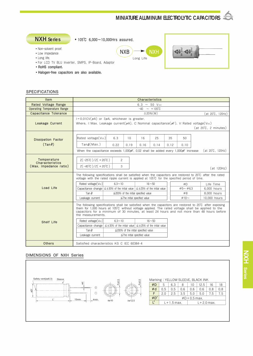
NXH Serie
s
MINIATURE ALUMINUM ELECTROLYTIC CAPACITORS
IItteemm CChhaarraacctteerriissttiiccss
RRaatteedd VVoollttaaggee RRaannggee 6.3 ~ 50 VDC
OOppeerraattiinngg TTeemmppeerraattuurree RRaannggee -40 ~ +105
CCaappaacciittaannccee TToolleerraannccee ±20%(M) (at 20, 120Hz)
I=0.01CV(μA) or 3μA, whichever is greater.
LLeeaakkaaggee CCuurrrreenntt Where, I:Max. Leakage current(μA), C:Nominal capacitance(μF), V:Rated voltage(VDC)
(at 20, 2 minutes)
DDiissssiippaattiioonn FFaaccttoorr
((TTaannδδ))
TTeemmppeerraattuurreeCChhaarraacctteerriissttiiccss
The following specifications shall be satisfied when the capacitors are restored to 20 after the ratedvoltage with the rated ripple current is applied at 105 for the specified period of time.
The following specifications shall be satisfied when the capacitors are restored to 20 after exposing them for 1,000 hours at 105 without voltage applied. The rated voltage shall be applied to the capacitors for a minimum of 30 minutes, at least 24 hours and not more than 48 hours before the measurements.
OOtthheerrss Satisfied characteristics KS C IEC 60384-4
110055 66,,000000~~1100,,000000HHrrss aassssuurreedd..
Non-solvent proof.Low impedanceLong life.For LCD TV BLU Inverter, SMPS, IP-Board, AdaptorRoHS compliant.
Halogen-free capacitors are also available.
SSPPEECCIIFFIICCAATTIIOONNSS
LLooaadd LLiiffee
SShheellff LLiiffee
Z(-25)/Z(+20) 2
Z(-40)/Z(+20) 3 (at 120Hz)
((MMaaxx.. IImmppeeddaannccee rraattiioo))
(at 20, 120Hz)
∅D Life Time
∅5~∅6.3 6,000 hours
∅8 8,000 hours
∅10~ 10,000 hours
Rated voltage(VDC) 6.3~10 16~50
Capacitance change ±30% of the initial value ±25% of the initial value
Tan 200% of the initial specified value
Leakage current The initial specified value
Rated voltage(VDC) 6.3~10 16~50
Capacitance change ±30% of the initial value ±25% of the initial value
Tan 200% of the initial specified value
Leakage current The initial specified value
NXH Series
NNXXBB NNXXHHLong Life
Rated voltage(VDC) 6.3 10 16 25 35 50
Tanδ(Max.) 0.22 0.19 0.16 0.14 0.12 0.10
When the capacitance exceeds 1,000μF, 0.02 shall be added every 1,000μF increase
δ
δ
DDIIMMEENNSSIIOONNSS OOFF NNXXHH SSeerriieess
Marking :YELLOW SLEEVE, BLACK INK
∅∅DD∅∅ddFF∅∅DD′′LL′′
50.52.0
∅D+0.5 max.
L+1.5 max. L+2.0 max.
6.30.52.5
80.63.5
100.65.0
12.50.65.0
160.87.5
180.87.5
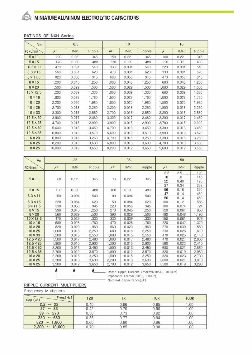
MINIATURE ALUMINUM ELECTROLYTIC CAPACITORS
RRIIPPPPLLEE CCUURRRREENNTT MMUULLTTIIPPLLIIEERRSS
112200 11kk 1100kk 110000kk
22..22 ~~ 2222 0.40 0.66 0.85 1.002277 ~~ 3333 0.42 0.70 0.90 1.003399 ~~ 227700 0.50 0.73 0.92 1.00333300 ~~ 668800 0.55 0.77 0.94 1.00882200 ~~ 11,,880000 0.60 0.80 0.96 1.00
22,,220000 ~~ 1100,,000000 0.70 0.85 0.98 1.00
FFrreeqq..((HHzz))CCaapp..(())
Frequency Multipliers
2255 3355 5500
55××1111 220 0.22 345 150 0.22 345 100 0.22 345
55××1155 470 0.13 480 330 0.13 480 220 0.13 480
66..33××1111 470 0.094 540 330 0.094 540 220 0.094 540
66..33××1155 560 0.084 620 470 0.084 620 330 0.084 620
88××1111..55 820 0.056 945 680 0.056 945 470 0.056 945
88××1155 1,200 0.045 1,250 1,000 0.045 1,250 680 0.045 1,250
88××2200 1,500 0.029 1,500 1,500 0.029 1,500 1,000 0.029 1,500
1100××1122..55 1,200 0.039 1,330 1,000 0.039 1,330 680 0.039 1,330
1100××1166 1,800 0.028 1,760 1,500 0.028 1,760 1,000 0.028 1,760
1100××2200 2,200 0.020 1,960 1,800 0.020 1,960 1,500 0.020 1,960
1100××2255 2,700 0.018 2,250 2,200 0.018 2,250 1,800 0.018 2,250
1100××3333 3,300 0.015 2,550 2,700 0.015 2,550 2,200 0.015 2,550
1122..55××2200 3,900 0.017 2,480 3,300 0.017 2,480 2,200 0.017 2,480
1122..55××2255 4,700 0.015 2,900 3,900 0.015 2,900 2,700 0.015 2,900
1122..55××3300 5,600 0.013 3,450 4,700 0.013 3,450 3,300 0.013 3,450
1122..55××3355 6,800 0.012 3,570 5,600 0.012 3,570 3,900 0.012 3,570
1166××2200 6,800 0.015 3,250 4,700 0.015 3,250 3,300 0.015 3,250
1166××2255 8,200 0.013 3,630 6,800 0.013 3,630 4,700 0.013 3,630
1188××2255 10,000 0.012 3,650 8,200 0.012 3,650 5,600 0.012 3,650
66..33 1100 1166
RRAATTIINNGGSS OOFF NNXXHH SSeerriieess
VVDDCC
∅∅DD××LL((mmmm))
VVDDCC
∅∅DD××LL((mmmm)) μμFF IMP. Ripple μμFF IMP. Ripple μμFF IMP. Ripple
Rated ripple Current (mArms/105, 100kHz)Impedance (Ϊmax./20, 100kHz)Nominal Capacitance()
μμFF IMP. Ripple μμFF IMP. Ripple μμFF IMP. Ripple
66..33××1155 220 0.084 620 150 0.084 620 100 58688××1111..55 330 0.056 945 220 0.056 945 100 0.074 72488××1155 390 0.045 1,250 270 0.045 1,250 120 0.061 95088××2200 560 0.029 1,500 390 0.029 1,500 180 0.046 1,190
1100××1122..55 470 0.039 1,330 330 0.039 1,330 150 0.061 9791100××1166 680 0.028 1,760 470 0.028 1,760 220 0.042 1,3701100××2200 820 0.020 1,960 560 0.020 1,960 270 0.030 1,5801100××2255 1,000 0.018 2,250 680 0.018 2,250 330 0.028 1,8701100××3333 1,200 0.015 2,550 1,000 0.015 2,550 470 0.025 2,1101122..55××2200 1,500 0.017 2,480 1,000 0.017 2,480 470 0.027 2,0501122..55××2255 1,800 0.015 2,900 1,200 0.015 2,900 560 0.023 2,4101122..55××3300 2,200 0.013 3,450 1,500 0.013 3,450 680 0.021 2,8601122..55××3355 2,700 0.012 3,570 1,800 0.012 3,570 820 0.019 2,9601166××2200 2,200 0.015 3,250 1,500 0.015 3,250 820 0.023 2,7301166××2255 3,300 0.013 3,630 2,200 0.013 3,630 1,000 0.021 3,0101188××2255 3,900 0.012 3,650 2,700 0.012 3,650 1,500 0.019 3,290
55××1155 150 0.13 480 100 0.13 480
55××1111 68 0.22 345 47 0.22 345
2.51.00.400.340.160.140.140.12
2.2102227564756
2.2102227564756
120145195238350450450
66..33××1111 150 0.094 540 100 0.094 540

MINIATURE ALUMINUM ELECTROLYTIC CAPACITORS
110055 66,,000000 ~~ 1100,,000000HHrrss aassssuurreedd..
NNXXHH NNXXQQ
High Ripple
NXQ Series
Non-solvent proof.
Low impedance, High ripple
For LCD, LED TV BLU Inverter, SMPS, IP-Board, Adaptor
RoHS compliant.
Halogen-free capacitors are also available.
RRaatteedd VVoollttaaggee RRaannggee
OOppeerraattiinngg TTeemmppeerraattuurree RRaannggee
CCaappaacciittaannccee TToolleerraannccee
LLeeaakkaaggee CCuurrrreenntt
TTeemmppeerraattuurree CChhaarraacctteerriissttiiccss
LLooaadd LLiiffee
SShheellff LLiiffee
OOtthheerrss
SSPPEECCIIFFIICCAATTIIOONNSS
Rated Voltage(VDC) 6.3 10 16 25 35 50 63 80 100
Tanδ(Max.) 0.22 0.19 0.16 0.14 0.12 0.10 0.09 0.08 0.08
((CCaappaacciittaannccee cchhaannggee rraattiioo))
DDiissssiippaattiioonn FFaaccttoorr
((TTaannδδ))
DDIIMMEENNSSIIOONNSS OOFF NNXXQQ SSeerriieess NXQ Serie
s
Marking :DARK BROWN SLEEVE, SILVER INK
∅∅DD∅∅ddFF∅∅DD′′LL′′
50.52.0
∅D+0.5 max.
L+1.5 max. L+2.0 max.
6.30.52.5
80.63.5
100.65.0
12.50.65.0
160.87.5
180.87.5
lltteemm CChhaarraacctteerriissttiiccss
Unit(mm)
6.3 ~ 100 VDC
-40 ~ +105
±20%(M) (at 20, 120Hz)
I=0.01CV(μA) or 3μA, whichever is greater.
Where, I:Max. Leakage current(μA), C:Nominal capacitance(μF), V:Rated voltage(VDC)
(at 20, 2minutes)
(at 20, 120Hz)
(at 120Hz)
The following specifications shall be satisfied when the capacitors are restored to 20 after therated voltage with the rated ripple current is applied at 105 for the specified period of time.
The following specifications shall be satisfied when the capacitors are restored to20 after exposing them for 500 hours at 105 without voltage applied.The rated voltage shall be applied to the capacitors for a minimum of 30 minutes,at least 24 hours and not more than 48 hours before the measurements.
Satisfied characteristics W of KS C 6421
Z(-25)/Z(+20)
Z(-40)/Z(+20)
2
3
±30% of the initial value ±25% of the initial value
6.3~10 16~100
Capacitance change
200% of the initial specified value
The initial specified value
Tanδ
Leakage current
Rated voltage(VDC)
±30% of the initial value ±25% of the initial value
6.3~10 16~100
Capacitance change
200% of the initial specified value
The initial specified value
Tanδ
Leakage current
Rated voltage(VDC)
∅5~∅6.36.3VDC
6,000hours8,000hours5,000hours
10~50VDC
7,000hours9,000hours10,000hours9,000hours
10,000hours
63~100VDC
6,000hours8,000hours9,000hours
∅8 X 11.5L∅8 X 15L~20L∅10 X 12.5L
∅10 X 16L~25L∅12.5~
∅DLife Time
When the capacitance exceeds 1,000μF, 0.02 shall be added every 1,000μF increase

MINIATURE ALUMINUM ELECTROLYTIC CAPACITORS
RRAATTIINNGGSS OOFF NNXXQQ SSeerriieess
66..33 1100 1166
IIMMPP.. RRiippppllee IIMMPP.. RRiippppllee IIMMPP.. RRiippppllee
220 0.40 345 150 0.40 450 120 0.40 450
470 0.17 540 330 0.17 700 270 0.17 700
820 0.075 945 560 0.075 1,200 470 0.075 1,200
1,000 0.059 1,250 680 0.059 1,600 560 0.059 1,600
1,500 0.041 1,500 1,000 0.041 1,960 820 0.041 1,960
1,200 0.053 1,500 820 0.053 1,700 680 0.053 1,700
1,800 0.038 1,760 1,200 0.038 2,000 1,000 0.038 2,000
2,700 0.028 1,960 1,800 0.028 2,500 1,500 0.028 2,500
3,300 0.024 2,250 2,200 0.024 2,900 1,800 0.024 2,900
3,900 0.025 2,480 2,700 0.025 2,600 2,200 0.025 2,600
4,700 0.019 2,900 3,300 0.019 3,200 2,700 0.019 3,200
5,600 0.018 3,450 4,700 0.018 3,660 3,300 0.018 3,660
6,800 0.016 3,570 5,600 0.016 4,120 3,900 0.016 4,120
6,800 0.021 3,250 4,700 0.021 3,330 3,300 0.021 3,300
8,200 0.017 3,630 5,600 0.017 3,810 4,700 0.017 3,810
55××1111
66..33××1111
88××1111..55
88××1155
88××2200
1100××1122..55
1100××1166
1100××2200
1100××2255
1122..55××2200
1122..55××2255
1122..55××3300
1122..55××3355
1166××2200
1166××2255
VVDDCC
∅∅DD××LL((mmmm))
Rated Ripple Current (mArms/105, 100kHz)Impedance (Ϊmax./20, 100kHz)Nominal Capacitance()
2255 3355 5500
IIMMPP.. RRiippppllee IIMMPP.. RRiippppllee IIMMPP.. RRiippppllee
68 0.40 450 47 0.40 450 27 0.48 310
150 0.17 700 100 0.17 700 56 0.22 500
330 0.075 1,200 180 0.075 1,200 100 0.120 950
390 0.059 1,600 220 0.059 1,600 120 0.082 1,230
560 0.041 1,960 330 0.041 1,960 180 0.058 1,580
470 0.053 1,700 270 0.053 1,700 150 0.073 1,280
680 0.038 2,000 390 0.038 2,000 220 0.053 1,650
1,000 0.028 2,500 560 0.028 2,500 330 0.038 2,060
1,200 0.024 2,900 680 0.024 2,900 390 0.032 2,240
1,500 0.025 2,600 820 0.025 2,600 470 0.032 2,300
1,800 0.019 3,200 1,200 0.019 3,200 680 0.025 2,800
2,200 0.018 3,660 1,500 0.018 3,660 820 0.023 3,370
2,700 0.016 4,120 1,800 0.016 4,120 1,000 0.021 3,810
2,200 0.021 3,330 1,500 0.021 3,330 820 0.026 3,070
3,300 0.017 3,810 1,800 0.017 3,810 1,000 0.022 3,510
55××1111
66..33××1111
88××1111..55
88××1155
88××2200
1100××1122..55
1100××1166
1100××2200
1100××2255
1122..55××2200
1122..55××2255
1122..55××3300
1122..55××3355
1166××2200
1166××2255
VVDDCC
∅∅DD××LL((mmmm))

MINIATURE ALUMINUM ELECTROLYTIC CAPACITORS
12 1.2 220 8.2 1.2 220
27 0.46 370 18 0.46 370
47 0.29 620 33 0.29 620
56 0.20 780 47 0.20 780
82 0.16 1,040 68 0.16 1,040
68 0.17 780 47 0.17 780
100 0.11 1,040 68 0.11 1,040
150 0.084 1,430 100 0.084 1,430
180 0.069 1,620 120 0.069 1,620
150 0.110 1,430 100 0.11 1,430
220 0.062 1,750 150 0.062 1,750
270 0.047 2,210 220 0.047 2,210
330 0.042 2,400 270 0.042 2,400
390 0.036 2,600 330 0.036 2,600
470 0.032 2,860 390 0.032 2,860
330 0.048 1,950 270 0.048 1,950
470 0.038 2,430 390 0.038 2,430
560 0.032 2,640 470 0.032 2,640
680 0.029 2,860 560 0.029 2,860
820 0.027 3,510 680 0.027 3,510
470 0.045 2,270 390 0.045 2,270
680 0.036 2,500 470 0.036 2,500
820 0.030 2,860 560 0.030 2,860
1,000 0.027 3,510 680 0.027 3,510
1,200 0.026 3,860 820 0.026 3,860
18 0.71 240
47 0.28 420
82 0.18 720
100 0.13 990
150 0.096 1,200
120 0.110 990
180 0.076 1,200
270 0.056 1,570
330 0.046 1,990
390 0.041 1,990
470 0.031 2,460
560 0.028 2,760
680 0.024 3,040
560 0.032 2,380
820 0.025 2,890
NXQ Serie
s
8800 110000
IIMMPP.. RRiippppllee IIMMPP.. RRiippppllee
55××1111
66..33××1111
88××1111..55
88××1155
88××2200
1100××1122..55
1100××1166
1100××2200
1100××2255
1122..55××1166
1122..55××2200
1122..55××2255
1122..55××3300
1122..55××3355
1122..55××4400
1166××2200
1166××2255
1166××3311..55
1166××3355..55
1166××4400
1188××2200
1188××2255
1188××3311..55
1188××3355..55
1188××4400
VVDDCC
∅∅DD××LL((mmmm))
1.00
1.00
1.00
RRAATTEEDD RRIIPPPPLLEE CCUURRRREENNTT MMUULLTTIIPPLLIIEERRSS
Frequency Multipliers
RRAATTIINNGGSS OOFF NNXXQQ SSeerriieess
6633
IIMMPP.. RRiippppllee
55××1111
66..33××1111
88××1111..55
88××1155
88××2200
1100××1122..55
1100××1166
1100××2200
1100××2255
1122..55××2200
1122..55××2255
1122..55××3300
1122..55××3355
1166××2200
1166××2255
VVDDCC
∅∅DD××LL((mmmm))
Rated Ripple Current (mArms/105, 100kHz)Impedance (Ϊmax./20, 100kHz)Nominal Capacitance()
88..22 ~~ 3333
4477 ~~ 227700
333300 ~~ 668800
882200 ~~ 11,,880000
22,,220000 ~~ 88,,220000
112200 11kk 1100kk 110000kkFFrreeqq..((HHzz))
CCaapp..(())
0.90
0.92
0.94
0.96
0.98
1.000.70
0.73
0.77
0.80
0.85 1.000.70
0.60
0.55
0.50
0.42

MINIATURE ALUMINUM ELECTROLYTIC CAPACITORS
110055 44,,000000~~55,,000000HHrrss aassssuurreeddNXK Series
Non-solvent proof.
Low impedance.
High Ripple.
For LCD TV BLU Inverter, SMPS, IP-Board, Adaptor
RoHS compliant.
Halogen-free capacitors are also available.
NNXXHH NNXXKK
High Ripple
DDIIMMEENNSSIIOONNSS OOFF NNXXKK SSeerriieess
IItteemm CChhaarraacctteerriissttiiccss
RRaatteedd VVoollttaaggee RRaannggee 10 ~ 50 VDC
OOppeerraattiinngg TTeemmppeerraattuurree RRaannggee -40 ~ + 105
CCaappaacciittaannccee TToolleerraannccee ±20% (M) (at 20, 120Hz)
I=0.01CV(μA) or 3μA, whichever is greater.
Where, I:Max. leakage current(μA), C:Nominal capacitance(μF), V:Rated voltage(VDC)
When the capacitance exceeds 1,000, 0.02 shall be added every 1,000 increase. (at 20, 120Hz)
TTeemmppeerraattuurree CChhaarraacctteerriissttiiccss
((MMaaxx .. IImmppeeddaannccee rraattiioo))
The following specifications shall be satisfied when the capacitors are restored to 20 after the rated voltage
with the rated ripple current is applied for the specified period of time at 105.
LLooaadd LLiiffee
The following specifications shall be satisfied when the capacitors are restored to 20 after exposing them for
1,000 hours at 105 without voltage applied. The rated voltage shall be applied to the capacitors for a minimum
of 30 minutes, at least 24 hours and not more than 48 hours before the measurements.SShheellff LLiiffee
OOtthheerrss Satisfied characteristics KS C IEC 60384-4
SSPPEECCIIFFIICCAATTIIOONNSS
Z(-25)/ Z(+20) 2
Z(-40)/ Z(+20) 3
DDiissssiippaattiioonn FFaaccttoorr ((TTaannδδ))
LLeeaakkaaggee CCuurrrreenntt
(at 20, 2 minutes)
(at 120Hz)
RRaatteedd VVoollttaaggee((VDC)) 10 16 25 35 50
Tanδ(Max.) 0.19 0.16 0.14 0.12 0.10
±30% of the initial value ±25% of the initial value
10 16~50
Capacitance change
200% of the initial specified value
The initial specified value
Tanδ
Leakage current
Rated voltage(VDC)
±30% of the initial value ±25% of the initial value
10 16~50
Capacitance change
±200% of the initial specified value
The initial specified value
Tanδ
Leakage current
Rated voltage(VDC)
∅8∅10x12.5L
∅10
Case Size(∅D)
4,000Hrs
5,000Hrs
Life Time
Marking :YELLOW SLEEVE, BLACK INK
∅∅DD∅∅ddFF∅∅DD′′LL′′
80.63.5
100.65.0
∅D+0.5 max.
L+1.5max. L+2.0max.
Unit(mm)

MINIATURE ALUMINUM ELECTROLYTIC CAPACITORS
RRAATTIINNGGSS OOFF NNXXKK sseerriieess
66880011,,00000011,,00000011,,55000011,,55000011,,88000022,,22000022,,770000
8×11.58×15
10×12.58×2010×1610×2010×2510×33
1,4172,0502,1902,3802,5502,8803,1603,570
0.0730.0590.0530.0410.0380.0280.0240.020
447700668800668800
11,,00000011,,00000011,,55000011,,88000022,,220000
8×11.58×15
10×12.58×2010×1610×2010×2510×33
1,4172,0502,1902,3802,5502,8803,1603,570
0.0730.0590.0530.0410.0380.0280.0240.020
333300339900447700556600668800882200
11,,00000011,,220000
8×11.58×15
10×12.58×2010×1610×2010×2510×33
1,4172,0502,1902,3802,5502,8803,1603,570
0.0730.0590.0530.0410.0380.0280.0240.020
222200227700333300339900447700556600668800
11,,000000
8×11.58×15
10×12.58×2010×1610×2010×2510×33
1,4172,0502,1902,3802,5502,8803,1603,570
0.0730.0590.0530.0410.0380.0280.0240.020
110000112200115500118800222200227700333300447700
8×11.58×15
10×12.58×2010×1610×2010×2510×33
1,0861,5581,6121,8881,9852,3222,6262,954
0.0960.0800.0830.0650.0570.0420.0370.033
RRIIPPPPLLEE CCUURRRREENNTT MMUULLTTIIPPLLIIEERRSS
112200 11kk 1100kk 110000kk
110000 ~~ 227700 0.50 0.73 0.92 1.00
333300 ~~ 668800 0.55 0.77 0.94 1.00
882200 ~~ 11,,880000 0.60 0.80 0.96 1.00
22,,220000 ~~ 22,,770000 0.70 0.85 0.98 1.00
FFrreeqq..((HHzz))CCaapp..(())
Frequency Multipliers
VVDDCC 5500
Capacitance ∅D×L(mm) Rated Ripple Current IMP.() (mArms/105, 100kHz) (Ϊmax./20, 100kHz)
VVDDCC 3355
Capacitance ∅D×L(mm) Rated Ripple Current IMP.() (mArms/105, 100kHz) (Ϊmax./20, 100kHz)
VVDDCC 1166
Capacitance ∅D×L(mm) Rated Ripple Current IMP.() (mArms/105, 100kHz) (Ϊmax./20, 100kHz)
VVDDCC 1100
Capacitance ∅D×L(mm) Rated Ripple Current IMP.() (mArms/105, 100kHz) (Ϊmax./20, 100kHz)
VVDDCC 2255
Capacitance ∅D×L(mm) Rated Ripple Current IMP.() (mArms/105, 100kHz) (Ϊmax./20, 100kHz)
NXK
Serie
s

MINIATURE ALUMINUM ELECTROLYTIC CAPACITORS
110055 22,,000000HHrrss aassssuurreedd..NXF Series
Non-solvent proof.
Ultra low impedance/ESR
For MAIN-Board, SMPS, Noise Filter, Charger, Adapter
RoHS compliant.
Halogen-free capacitors are also available.
NNXXCC NNXXFF
Low Imp.Low ESR
DDIIMMEENNSSIIOONNSS OOFF NNXXFF SSeerriieess
Marking :DARK BROWN SLEEVE, SILVER INK
∅∅DD∅∅ddFF∅∅DD′′LL′′
80.63.5
100.65.0
∅D+0.5 max.
L+1.5max. L+2.0max.
SSPPEECCIIFFIICCAATTIIOONNSS
Z(-25)/ Z(+20) 2
Z(-40)/ Z(+20) 3
RRaatteedd VVoollttaaggee((VDC)) 6.3 10 16
Tanδ(Max.) 0.22 0.19 0.16DDiissssiippaattiioonn FFaaccttoorr ((TTaannδδ))
LLeeaakkaaggee CCuurrrreenntt
(at 20, 2 minutes)
(at 120Hz)
IItteemm CChhaarraacctteerriissttiiccss
RRaatteedd VVoollttaaggee RRaannggee 10 ~ 50 VDC
OOppeerraattiinngg TTeemmppeerraattuurree RRaannggee -40 ~ + 105
CCaappaacciittaannccee TToolleerraannccee ±20% (M) (at 20, 120Hz)
I=0.01CV(μA) or 3μA, whichever is greater.
Where, I:Max. leakage current(μA), C:Nominal capacitance(μF), V:Rated voltage(VDC)
When the capacitance exceeds 1,000, 0.02 shall be added every 1,000 increase. (at 20, 120Hz)
TTeemmppeerraattuurree CChhaarraacctteerriissttiiccss
((MMaaxx .. IImmppeeddaannccee rraattiioo))
The following specifications shall be satisfied when the capacitors are restored to 20 after the rated voltage
with the rated ripple current is applied for 2,000 hours at 105.
LLooaadd LLiiffeeCapacitance change ±25% of the initial value
Tanδ 200% of the initial specified value
Leakage current The initial specified value
The following specifications shall be satisfied when the capacitors are restored to 20 after exposing them for
1,000 hours at 105 without voltage applied. The rated voltage shall be applied to the capacitors for a minimum
of 30 minutes, at least 24 hours and not more than 48 hours before the measurements.SShheellff LLiiffee
Capacitance change ±25% of the initial value
Tanδ 200% of the initial specified value
Leakage current The initial specified value
OOtthheerrss Satisfied characteristics KS C IEC 60384-4
Unit(mm)
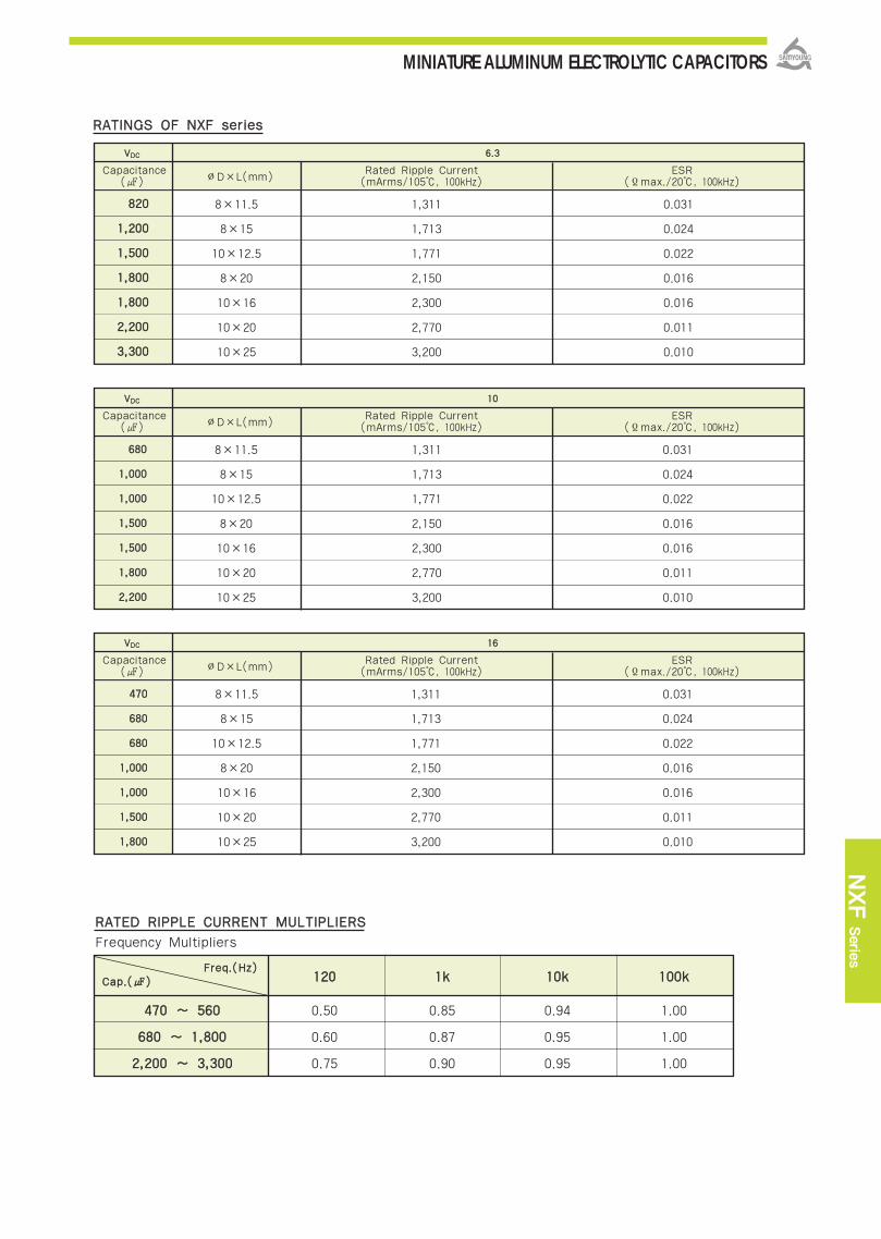
MINIATURE ALUMINUM ELECTROLYTIC CAPACITORS
NXF
Serie
s
RRAATTIINNGGSS OOFF NNXXFF sseerriieess
VVDDCC 66..33
Capacitance∅D×L(mm)
Rated Ripple Current ESR() (mArms/105, 100kHz) (Ϊmax./20, 100kHz)
882200
11,,220000
11,,550000
11,,880000
11,,880000
22,,220000
33,,330000
8×11.5
8×15
10×12.5
8×20
10×16
10×20
10×25
1,311
1,713
1,771
2,150
2,300
2,770
3,200
0.031
0.024
0.022
0.016
0.016
0.011
0.010
VVDDCC 1100
Capacitance∅D×L(mm)
Rated Ripple Current ESR() (mArms/105, 100kHz) (Ϊmax./20, 100kHz)
668800
11,,000000
11,,000000
11,,550000
11,,550000
11,,880000
22,,220000
8×11.5
8×15
10×12.5
8×20
10×16
10×20
10×25
1,311
1,713
1,771
2,150
2,300
2,770
3,200
0.031
0.024
0.022
0.016
0.016
0.011
0.010
VVDDCC 1166
Capacitance∅D×L(mm)
Rated Ripple Current ESR() (mArms/105, 100kHz) (Ϊmax./20, 100kHz)
447700
668800
668800
11,,000000
11,,000000
11,,550000
11,,880000
8×11.5
8×15
10×12.5
8×20
10×16
10×20
10×25
1,311
1,713
1,771
2,150
2,300
2,770
3,200
0.031
0.024
0.022
0.016
0.016
0.011
0.010
RRAATTEEDD RRIIPPPPLLEE CCUURRRREENNTT MMUULLTTIIPPLLIIEERRSS
112200 11kk 1100kk 110000kk
447700 ~~ 556600 0.50 0.85 0.94 1.00
668800 ~~ 11,,880000 0.60 0.87 0.95 1.00
22,,220000 ~~ 33,,330000 0.75 0.90 0.95 1.00
FFrreeqq..((HHzz))CCaapp..(())
Frequency Multipliers

MINIATURE ALUMINUM ELECTROLYTIC CAPACITORS
IItteemm CChhaarraacctteerriissttiiccss
RRaatteedd VVoollttaaggee RRaannggee 6.3 ~ 35 VDC
OOppeerraattiinngg TTeemmppeerraattuurree RRaannggee -40 ~ + 105
CCaappaacciittaannccee TToolleerraannccee ±20% (M) (at 20, 120Hz)
I=0.03CV(μA) or 4μA, whichever is greater.
Where, I:Max. leakage current(μA), C:Nominal capacitance(μF), V:Rated voltage(VDC)
(at 20, 120Hz)
TTeemmppeerraattuurree CChhaarraacctteerriissttiiccss
((MMaaxx .. IImmppeeddaannccee rraattiioo))
The following specifications shall be satisfied when the capacitors are restored to 20
after the rated voltage with the rated ripple current is applied at 105 for the specified period of time.
LLooaadd LLiiffeeCapacitance change ±25% of the initial value
Tanδ 200% of the initial specified value
Leakage current The initial specified value
The following specifications shall be satisfied when the capacitors are restored to 20 after exposing them for
1,000 hours at 105 without voltage applied. The rated voltage shall be applied to the capacitors for a minimum
of 30 minutes, at least 24 hours and not more than 48 hours before the measurements.SShheellff LLiiffee
Capacitance change ±25% of the initial value
Tanδ 200% of the initial specified value
Leakage current 200% of the initial specified value
OOtthheerrss Satisfied characteristics KS C IEC 60384-4
110055 33,,000000~~44,,000000HHrrss aassssuurreedd
SSPPEECCIIFFIICCAATTIIOONNSS
Z(-25)/ Z(20) 2
Z(-40)/ Z(20) 3
RRaatteedd VVoollttaaggee((VDC)) 6.3 10 16 25 35
Tanδ(Max.) 0.22 0.19 0.16 0.14 0.12
(at 120Hz)
NXE Series
Non-solvent proof.
Ultra low impedance/ESR, Long Life.
For MAIN-Board, SMPS
RoHS compliant.
Halogen-free capacitors are also available.
NNXXCC NNXXEE
Long Life
DDiissssiippaattiioonn FFaaccttoorr ((TTaannδδ))
DDIIMMEENNSSIIOONNSS OOFF NNXXEE SSeerriieess
LLeeaakkaaggee CCuurrrreenntt
(at 20, 2 minutes)
(at 120Hz)
∅D
∅8
∅10
Life Time
4,000 hours
3,000 hours
Marking :DARK BROWN SLEEVE, SILVER INK
∅∅DD∅∅ddFF∅∅DD′′LL′′
80.63.5
100.65.0
∅D+0.5 max.
L+1.5max. L+2.0max.
Unit(mm)

MINIATURE ALUMINUM ELECTROLYTIC CAPACITORS
NXE
Serie
s
RRAATTIINNGGSS OOFF NNXXEE sseerriieess
RRAATTEEDD RRIIPPPPLLEE CCUURRRREENNTT MMUULLTTIIPPLLIIEERRSS
112200 11kk 1100kk 110000kk
115500 ~~ 556600 0.50 0.85 0.94 1.00
668800 ~~ 11,,880000 0.60 0.87 0.95 1.00
22,,220000 ~~ 33,,330000 0.75 0.90 0.95 1.00
FFrreeqq..((HHzz))CCaapp..(())
Frequency Multipliers
VVDDCC 66..33
Capacitance ∅D×L(mm) Rated Ripple Current ESR() (mArms/105, 100kHz) (Ϊmax./20, 100kHz)
882200
11,,220000
11,,550000
11,,880000
11,,880000
22,,220000
33,,330000
8×11.5
8×15
10×12.5
8×20
10×16
10×20
10×25
1,140
1,490
1,540
1,870
2,000
2,550
2,800
0.036
0.028
0.026
0.019
0.019
0.013
0.012
VVDDCC 1100
Capacitance ∅D×L(mm) Rated Ripple Current ESR() (mArms/105, 100kHz) (Ϊmax./20, 100kHz)
668800
11,,000000
11,,000000
11,,550000
11,,550000
11,,880000
22,,220000
8×11.5
8×15
10×12.5
8×20
10×16
10×20
10×25
1,140
1,490
1,540
1,870
2,000
2,550
2,800
0.036
0.028
0.026
0.019
0.019
0.013
0.012
VVDDCC 1166
Capacitance ∅D×L(mm) Rated Ripple Current ESR() (mArms/105, 100kHz) (Ϊmax./20, 100kHz)
447700
668800
668800
11,,000000
11,,000000
11,,550000
11,,880000
8×11.5
8×15
10×12.5
8×20
10×16
10×20
10×25
1,140
1,490
1,540
1,870
2,000
2,550
2,800
0.036
0.028
0.026
0.019
0.019
0.013
0.012
VVDDCC 2255
Capacitance ∅D×L(mm) Rated Ripple Current ESR() (mArms/105, 100kHz) (Ϊmax./20, 100kHz)
222200339900447700556600668800882200
11,,00000011,,220000
8×11.58×15
10×12.58×2010×1610×2010×2512.5×20
1,1401,4901,5401,8702,0002,5502,8003,000
0.0360.0280.0260.0190.0190.0130.0120.014
VVDDCC 3355
Capacitance ∅D×L(mm) Rated Ripple Current ESR() (mArms/105, 100kHz) (Ϊmax./20, 100kHz)
115500
227700
333300
339900
447700
556600
668800
8×11.5
8×15
10×12.5
8×20
10×16
10×20
12.5×20
1,140
1,490
1,540
1,870
2,000
2,550
2,800
0.036
0.028
0.026
0.019
0.019
0.013
0.012

MINIATURE ALUMINUM ELECTROLYTIC CAPACITORS
RRaatteedd VVoollttaaggee RRaannggee
OOppeerraattiinngg TTeemmppeerraattuurree RRaannggee
CCaappaacciittaannccee TToolleerraannccee
LLeeaakkaaggee CCuurrrreenntt
DDiissssiippaattiioonn FFaaccttoorr ((TTaannδδ))
TTeemmppeerraattuurree CChhaarraacctteerriissttiiccss
((MMaaxx.. IImmppeeddaannccee rraattiioo))
LLooaadd LLiiffee
SShheellff LLiiffee
OOtthheerrss
160 ~ 400 VDC 450 ~ 500 VDC
-40 ~+ 105 -25 ~ +105
±20%(M) (at 20, 120Hz)
Where, I:Max. Leakage current() C:Nominal capacitance() V:Rated voltage(VDC) (at 20)
(at 20, 120Hz)
The following specifications shall be satisfied when the capacitors are restored to 20 after therated voltage with the rated ripple current is applied for 2,000 hours at 105 .
Capacitance change ±20% of the initial valueTanδ 200% of the initial specified valueLeakage current The initial specified value
The following specifications shall be satisfied when the capacitors are restored to 20 afterexposing them for 1,000 hours at 105 without voltage applied. The rated voltage shall beapplied to the capacitors for a minimum of 30 minutes, at least 24 hours and not more than 48hours before the measurements.
Capacitance change ±20% of the initial valueTanδ 200% of the initial specified valueLeakage current 500% of the initial specified value
Satisfied characteristics KS C IEC 60384-4
SSPPEECCIIFFIICCAATTIIOONNSS
DDIIMMEENNSSIIOONNSS OOFF NNZZEE SSeerriieess
110055 22,,000000HHrrss aassssuurreedd..
KKMMFF NNZZEE
Downsized
Rated Voltage(VDC) 160~250 350~400 450~500
Z(‐25)/Z(+20) 3 5 6
Z(‐40)/Z(+20) 6 6
c∙v Time After 1 minute After 5 minutes
1000 I=0.1CV+40 I=0.03CV+15
> 1000 I=0.04CV+100 I=0.02CV+25
NZE Series
Non-solvent proof.
Downsized , High ripple.
For SMPS, IP-Board, Adaptor
RoHS compliant.
Halogen-free capacitors are also available.
Rated Voltage(VDC) 160~250 350~500
Tanδ(Max.) 0.20 0.24
Marking :DARK BROWN SLEEVE, SILVER INK
∅∅DD∅∅ddFF∅∅DD′′LL′′
100.65.0
∅D+0.5 max.
L+2.0max.
12.50.65.0
160.87.5
180.87.5
200.87.5
220.810.0
(at 120Hz)
lltteemm CChhaarraacctteerriissttiiccss
Unit(mm)
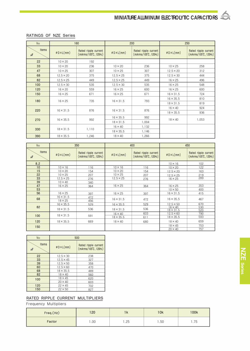
MINIATURE ALUMINUM ELECTROLYTIC CAPACITORS
NZE
Serie
s
220000
112200 11kk 1100kk 110000kk
1.00 1.25 1.50 1.75
FFrreeqq..((HHzz))
FFaaccttoorr
RRAATTEEDD RRIIPPPPLLEE CCUURRRREENNTT MMUULLTTIIPPLLIIEERRSS
Frequency Multipliers
RRAATTIINNGGSS OOFF NNZZEE SSeerriieess
VVDDCC
lltteemmss
2222
3333
4477
6688
8822
110000
112200
115500
118800
222200
227700
333300
339900
10×20
10×20
10×25
12.5×20
12.5×25
12.5×30
16×20
16×25
16×25
16×31.5
16×35.5
18×31.5
18×35.5
∅∅DD××LL((mmmm))RRaatteedd rriippppllee ccuurrrreenntt((mmAArrmmss//110055,, 112200HHZZ))
∅∅DD××LL((mmmm))RRaatteedd rriippppllee ccuurrrreenntt((mmAArrmmss//110055,, 112200HHZZ))
∅∅DD××LL((mmmm))RRaatteedd rriippppllee ccuurrrreenntt((mmAArrmmss//110055,, 112200HHZZ))
192
236
307
375
449
535
559
671
735
876
992
1,110
1,246
116600
10×20
10×25
12.5×25
12.5×25
12.5×30
16×25
16×25
16×31.5
16×31.5
16×35.5
18×31.5
16×40
18×35.5
18×40
236
307
375
449
535
600
671
793
876
992
1,004
1,132
1,146
1,266
225500
10×25
12.5×20
12.5×30
16×25
16×25
16×25
16×31.5
16×35.5
18×31.5
16×40
18×35.5
18×40
258
312
444
496
548
600
724
810
819
924
936
1,053
440000VVDDCC
lltteemmss
88..2211001155222233333399447755335566
6688
8822
110000
112200
115500
10×1610×2010×2512.5×2510×4016×25
16×2516×31.518×2516×35.5
18×31.5
18×31.5
18×35.5
∅∅DD××LL((mmmm))RRaatteedd rriippppllee ccuurrrreenntt((mmAArrmmss//110055,, 112200HHZZ))
∅∅DD××LL((mmmm))RRaatteedd rriippppllee ccuurrrreenntt((mmAArrmmss//110055,, 112200HHZZ))
∅∅DD××LL((mmmm))RRaatteedd rriippppllee ccuurrrreenntt((mmAArrmmss//110055,, 112200HHZZ))
116154207276340364
397472456529
536
591
669
335500
10×1610×2010×2512.5×25
16×25
16×25
16×31.5
16×35.5
18×31.5
16×4018×35.5
18×40
116154207276
364
397
472
529
536
603611
680
445500
10×1610×2012.5×2012.5×2516×25
16×2510×5016×31.5
16×35.5
12.5×5016×4018×31.512.5×6018×35.5
18×4018×4520×40
102122163219289
353400415
467
670530520790593
659
753757
VVDDCC
lltteemmss
222233333399660066888822
110000
112200115500
12.5×3012.5×4512.5×5012.5×6018×35.518×4018×4520×4022×4522×50
∅∅DD××LL((mmmm))RRaatteedd rriippppllee ccuurrrreenntt((mmAArrmmss//110055,, 112200HHZZ))
238327358470489560620603702827
550000
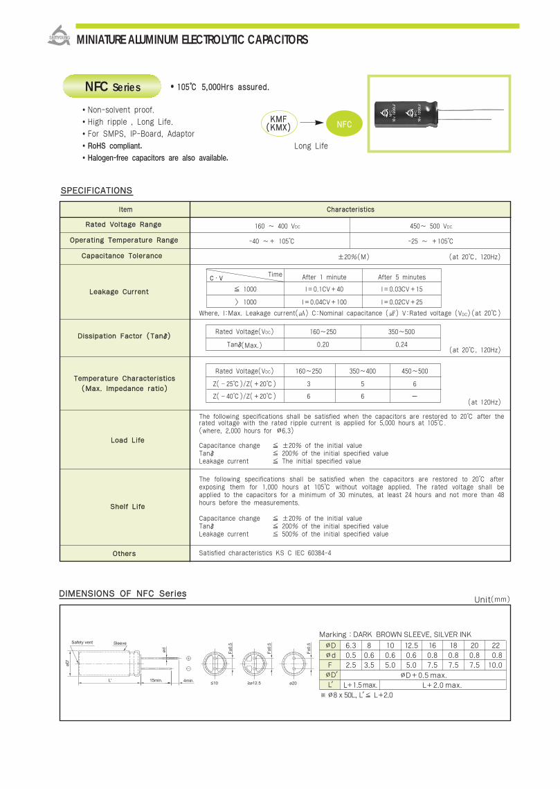
MINIATURE ALUMINUM ELECTROLYTIC CAPACITORS
RRaatteedd VVoollttaaggee RRaannggee
OOppeerraattiinngg TTeemmppeerraattuurree RRaannggee
CCaappaacciittaannccee TToolleerraannccee
LLeeaakkaaggee CCuurrrreenntt
DDiissssiippaattiioonn FFaaccttoorr ((TTaannδδ))
TTeemmppeerraattuurree CChhaarraacctteerriissttiiccss
((MMaaxx.. IImmppeeddaannccee rraattiioo))
LLooaadd LLiiffee
SShheellff LLiiffee
OOtthheerrss
lltteemm CChhaarraacctteerriissttiiccss
160 ~ 400 VDC 450~ 500 VDC
-40 ~+ 105 -25 ~ +105
±20%(M) (at 20, 120Hz)
Where, I:Max. Leakage current() C:Nominal capacitance () V:Rated voltage (VDC) (at 20)
(at 20, 120Hz)
The following specifications shall be satisfied when the capacitors are restored to 20 after therated voltage with the rated ripple current is applied for 5,000 hours at 105. (where, 2,000 hours for ∅6.3)
Capacitance change ±20% of the initial valueTanδ 200% of the initial specified valueLeakage current The initial specified value
The following specifications shall be satisfied when the capacitors are restored to 20 afterexposing them for 1,000 hours at 105 without voltage applied. The rated voltage shall beapplied to the capacitors for a minimum of 30 minutes, at least 24 hours and not more than 48hours before the measurements.
Capacitance change ±20% of the initial valueTanδ 200% of the initial specified valueLeakage current 500% of the initial specified value
Satisfied characteristics KS C IEC 60384-4
SSPPEECCIIFFIICCAATTIIOONNSS
DDIIMMEENNSSIIOONNSS OOFF NNFFCC SSeerriieess
110055 55,,000000HHrrss aassssuurreedd..
KKMMFF((KKMMXX)) NNFFCC
Long Life
Rated Voltage(VDC) 160~250 350~500
Tanδ(Max.) 0.20 0.24
Rated Voltage(VDC) 160~250 350~400 450~500
Z(‐25)/Z(+20) 3 5 6
Z(‐40)/Z(+20) 6 6
c∙v Time After 1 minute After 5 minutes
1000 I=0.1CV+40 I=0.03CV+15
> 1000 I=0.04CV+100 I=0.02CV+25
NFC Series
Non-solvent proof.
High ripple , Long Life.
For SMPS, IP-Board, Adaptor
RoHS compliant.
Halogen-free capacitors are also available.
(at 120Hz)
Marking :DARK BROWN SLEEVE, SILVER INK
∅D∅dF∅D′L′
100.65.0
∅D+0.5 max.
L+2.0 max.
12.50.65.0
160.87.5
180.87.5
200.87.5
220.8
10.0
80.63.5
6.30.52.5
L+1.5max.
※∅8 x 50L, L′ L+2.0
Unit(mm)
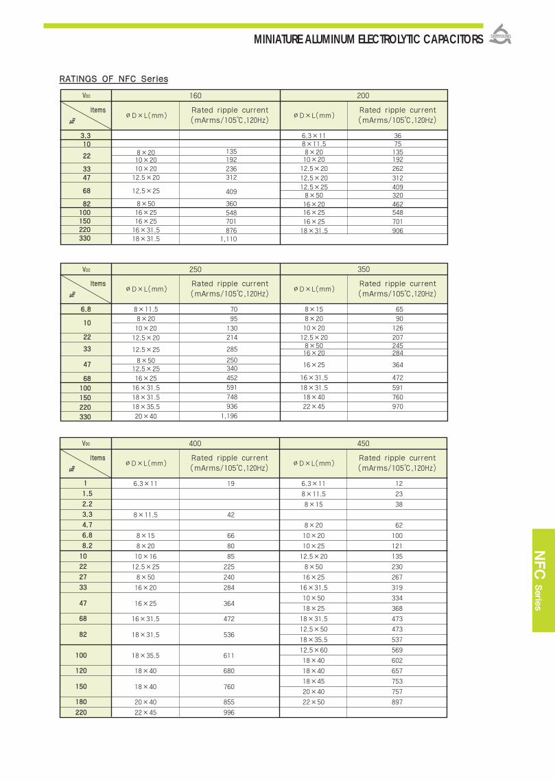
MINIATURE ALUMINUM ELECTROLYTIC CAPACITORS
NFC
Serie
s
8×15
8×20
10×20
12.5×208×5016×20
16×25
16×31.5
18×31.5
18×40
22×45
65
90
126
207245284
364
472
591
760
970
VVDDCC
lltteemmss
RRAATTIINNGGSS OOFF NNFFCC SSeerriieess
3675135192262
312409320462548701906
160 200
∅D×L(mm)Rated ripple current(mArms/105,120Hz)
∅D×L(mm)Rated ripple current(mArms/105,120Hz)
VVDDCC
lltteemmss
66..88
1100
2222
3333
4477
6688
110000
115500
222200
333300
250 350
∅D×L(mm)Rated ripple current(mArms/105,120Hz)
∅D×L(mm)Rated ripple current(mArms/105,120Hz)
VVDDCC
lltteemmss
6.3×11
8×11.5
8×15
8×20
10×16
12.5×25
8×50
16×20
16×25
16×31.5
18×31.5
18×35.5
18×40
18×40
20×40
22×45
12
23
38
62
100
121
135
230
267
319
334
368
473
473
537
569
602
657
753
757
897
400 450
∅D×L(mm)Rated ripple current(mArms/105,120Hz)
∅D×L(mm)Rated ripple current(mArms/105,120Hz)
8×2010×2010×2012.5×20
12.5×25
8×5016×2516×2516×31.518×31.5
33..331100
2222
33334477
6688
8822110000115500222200333300
135192236312
409
360548701876
1,110
6.3×118×11.58×2010×2012.5×20
12.5×2012.5×258×5016×2016×2516×2518×31.5
70
95
130214
285
250340
452
591
748
936
1,196
8×11.5
8×20
10×20
12.5×20
12.5×25
8×5012.5×25
16×25
16×31.5
18×31.5
18×35.5
20×40
1100
2222
2277
3333
4477
6688
8822
110000
112200
115500
118800
222200
11
11..55
22..22
33..33
44..77
66..88
88..22
19
42
66
80
85
225
240
284
364
472
536
611
680
760
855
996
6.3×11
8×11.5
8×15
8×20
10×20
10×25
12.5×20
8×50
16×25
16×31.5
10×50
18×25
18×31.5
12.5×50
18×35.5
12.5×60
18×40
18×40
18×45
20×40
22×50

MINIATURE ALUMINUM ELECTROLYTIC CAPACITORS
RRAATTIINNGGSS OOFF NNFFCC SSeerriieess
VVDDCC
lltteemmss
500
∅D×L(mm)Rated ripple current(mArms/105,120Hz)
10×20
12.5×20
12.5×25
12.5×30
10×50
18×25
16×31.5
12.5×50
18×31.5
12.5×60
18×35.5
18×4018×4520×4022×45
22×50
66..88
1100
1155
2222
2277
3333
3399
4477
6600
6688
8822
110000
112200
115500
100
135
182
210
253
308
319
358
393
440
489
544620618702
827
112200 11kk 1100kk 110000kk
1.00 1.25 1.50 1.75
FFrreeqq..((HHzz))
FFaaccttoorr
RRAATTEEDD RRIIPPPPLLEE CCUURRRREENNTT MMUULLTTIIPPLLIIEERRSS
Frequency Multipliers

MINIATURE ALUMINUM ELECTROLYTIC CAPACITORS
NFK
Serie
s
RRaatteedd VVoollttaaggee RRaannggee
OOppeerraattiinngg TTeemmppeerraattuurree RRaannggee
CCaappaacciittaannccee TToolleerraannccee
LLeeaakkaaggee CCuurrrreenntt
DDiissssiippaattiioonn FFaaccttoorr ((TTaannδδ))
TTeemmppeerraattuurree CChhaarraacctteerriissttiiccss
((MMaaxx.. IImmppeeddaannccee rraattiioo))
LLooaadd LLiiffee
SShheellff LLiiffee
OOtthheerrss
lltteemm CChhaarraacctteerriissttiiccss
160 ~ 400 VDC 450 ~ 500 VDC
-40 ~+105 -25 ~ +105
±20%(M) (at 20, 120Hz)
Where, I:Max. Leakage current() C:Nominal capacitance () V:Rated voltage (VDC) (at 20)
(at 20, 120Hz)
The following specifications shall be satisfied when the capacitors are restored to 20 after therated voltage with the rated ripple current is applied for 5,000 hours at 105.
Capacitance change ±20% of the initial valueTanδ 200% of the initial specified valueLeakage current The initial specified value
The following specifications shall be satisfied when the capacitors are restored to 20 afterexposing them for 1,000 hours at 105 without voltage applied. The rated voltage shall beapplied to the capacitors for a minimum of 30 minutes, at least 24 hours and not more than 48hours before the measurements.
Capacitance change ±20% of the initial valueTanδ 200% of the initial specified valueLeakage current 500% of the initial specified value
Satisfied characteristics KS C IEC 60384-4
SSPPEECCIIFFIICCAATTIIOONNSS
DDIIMMEENNSSIIOONNSS OOFF NNFFKK SSeerriieess
110055 55,,000000HHrrss aassssuurreedd..
NNFFCC NNFFKK
High Ripple
Rated Voltage(VDC) 160~250 350~500
Tanδ(Max.) 0.20 0.24
Rated Voltage(VDC) 160~250 350~400 450~500
Z(‐25)/Z(+20) 3 5 6
Z(‐40)/Z(+20) 6 6
c∙v Time After 1 minute After 5 minutes
1000 I=0.1CV+40 I=0.03CV+15
> 1000 I=0.04CV+100 I=0.02CV+25
NFK Series
Non-solvent proof.
High ripple , Long Life.
For SMPS, IP-Board, Adaptor
RoHS compliant.
Halogen-free capacitors are also available.
(at 120Hz)
Marking :DARK BROWN SLEEVE, SILVER INK
∅∅DD∅∅ddFF∅∅DD′′LL′′
100.65.0
∅D+0.5 max.
12.50.65.0
160.87.5
180.87.5
200.87.5
220.810.0
80.63.5
Unit(mm)
L+2.0 max.L+1.5max.

MINIATURE ALUMINUM ELECTROLYTIC CAPACITORS
8×2010×1612.5×2012.5×2512.5×30
16×25
18×31.5
18×35.5
18×40
120125225260380
510
743
942
1,048
VVDDCC
lltteemmss
RRAATTIINNGGSS OOFF NNFFKK SSeerriieess
160236340436550736985
160 200
∅D×L(mm)Rated ripple current(mArms/105,120Hz)
∅D×L(mm)Rated ripple current(mArms/105,120Hz)
VVDDCC
lltteemmss
1100
2222
33334477
6688
110000
115500
118800
222200
250 350
∅D×L(mm)Rated ripple current(mArms/105,120Hz)
∅D×L(mm)Rated ripple current(mArms/105,120Hz)
VVDDCC
lltteemmss
8×158×2010×1610×2012.5×1610×2512.5×2012.5×2516×2010×4512.5×3516×2512.5×4018×25
18×31.5
18×35.5
18×40
18×40
20×4020×45
79100122135
185
215260335340400405368
500
670650750700800920930
1,100
400 450
∅D×L(mm)Rated ripple current(mArms/105,120Hz)
∅D×L(mm)Rated ripple current(mArms/105,120Hz)
10×2012.5×2012.5×2512.5×3016×2516×31.518×31.5
2255333344776688
110000115500222200333300
236340436550736912
1,200
8×2010×2012.5×2012.5×2512.5×3016×2518×31.5
95105
165
250375465
463
585
591
721
860
813
925
8×1510×12.5
10×16
12.5×2012.5×2510×40
12.5×30
10×50
16×25
18×25
12.5×50
18×31.5
18×31.5
1100
1155
22222277
3333
4477
6688
8822
110000
112200
115500
118800222200
44..7766..8888..22
90105125150140200250295305352375436475472
700
795
912
1,020
1,0801,200
8×2010×1610×1610×20
10×25
10×3312.5×2512.5×3016×2510×5012.5×4016×25
18×25
12.5×5018×31.512.5×6018×35.518×4018×4520×4022×50
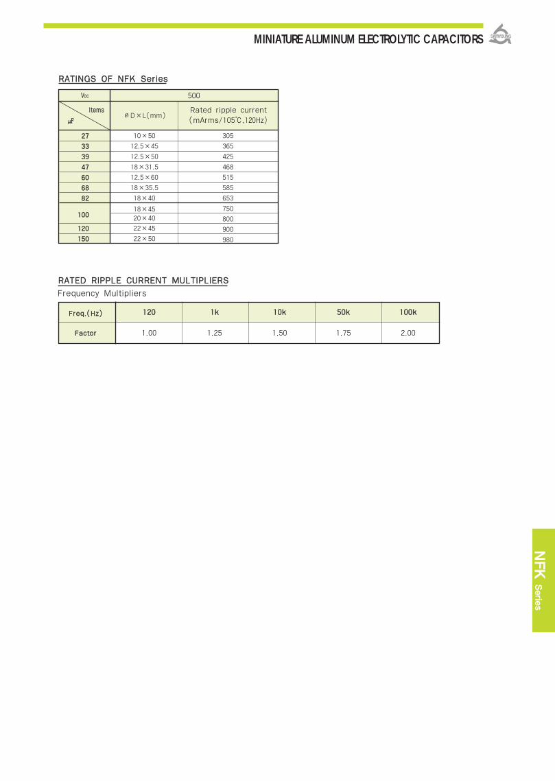
MINIATURE ALUMINUM ELECTROLYTIC CAPACITORS
NFK
Serie
s
RRAATTIINNGGSS OOFF NNFFKK SSeerriieess
VVDDCC
lltteemmss
500
∅D×L(mm)Rated ripple current(mArms/105,120Hz)
10×50
12.5×45
12.5×50
18×31.5
12.5×60
18×35.5
18×40
18×4520×40
22×45
22×50
2277
3333
3399
4477
6600
6688
8822
110000
112200
115500
305
365
425
468
515
585
653
750
800
900
980
FFrreeqq..((HHzz))
FFaaccttoorr
RRAATTEEDD RRIIPPPPLLEE CCUURRRREENNTT MMUULLTTIIPPLLIIEERRSS
Frequency Multipliers
112200 11kk 1100kk 5500kk 110000kk
1.00 1.25 1.50 1.75 2.00

MINIATURE ALUMINUM ELECTROLYTIC CAPACITORS
RRaatteedd VVoollttaaggee RRaannggee
OOppeerraattiinngg TTeemmppeerraattuurree RRaannggee
CCaappaacciittaannccee TToolleerraannccee
LLeeaakkaaggee CCuurrrreenntt
DDiissssiippaattiioonn FFaaccttoorr ((TTaannδδ))
TTeemmppeerraattuurree CChhaarraacctteerriissttiiccss
LLooaadd LLiiffee
SShheellff LLiiffee
OOtthheerrss
lltteemm CChhaarraacctteerriissttiiccss
160~400 VDC 450~500 VDC
-40~+105 -25~+105
±20%(M) (at 20, 120Hz)
Where, I:Max. Leakage current() C:Nominal capacitance() V:Rated voltage(VDC) (at 20)
(at 20, 120Hz)
The following specifications shall be satisfied when the capacitors are restored to 20 after therated voltage with the rated ripple current is applied for 10,000 hours at 105.(where, 7,000 hours for ∅∅8, 8,000 hours for ∅∅10)
Capacitance change ±20% of the initial valueTanδ 200% of the initial specified valueLeakage current The initial specified value
The following specifications shall be satisfied when the capacitors are restored to 20 afterexposing them for 1,000 hours at 105 without voltage applied. The rated voltage shall beapplied to the capacitors for a minimum of 30 minutes, at least 24 hours and not more than 48hours before the measurements.
Capacitance change ±20% of the initial valueTanδ 200% of the initial specified valueLeakage current 500% of the initial specified value
Satisfied characteristics KS C IEC 60384-4
SSPPEECCIIFFIICCAATTIIOONNSS
DDIIMMEENNSSIIOONNSS OOFF NNFFAA SSeerriieess
110055 77,,000000~~1100,,000000HHrrss aassssuurreedd..
NNFFCC NNFFAA
Long life
Rated Voltage(VDC) 160~250 350~500
Tanδ(Max.) 0.20 0.24
Rated Voltage(VDC) 160~250 350~400 450~500
Z(‐25)/Z(20) 3 5 6
Z(‐40)/Z(20) 6 6 -
c∙v Time After 1 minute After 5 minutes
1000 I=0.1CV+40 I=0.03CV+15
> 1000 I=0.04CV+100 I=0.02CV+25
(at 120Hz)
NFA Series
Non-solvent proof.High ripple and long life.For ballasts stabilizer.RoHS compliant.
Halogen-free capacitors are also available.
((MMaaxx.. IImmppeeddaannccee rraattiioo))
Marking :DARK BROWN SLEEVE, SILVER INK
∅∅DD∅∅ddFF∅∅DD′′LL′′
80.63.5
∅D+0.5 max.
L+2.0 max.L+1.5 max.
100.65.0
12.50.65.0
160.87.5
180.87.5
200.87.5
220.810.0
Unit(mm)

MINIATURE ALUMINUM ELECTROLYTIC CAPACITORS
NFA
Serie
s
10×20
12.5×20
16×20
16×25
16×31.5
18×31.5
18×40
22×45
126
207
284
364
472
591
760
970
10×20
12.5×20
12.5×25
12.5×25
10×33
16×25
16×31.5
18×25
18×31.5
20×40
130
214
285
340
350
452
591
700
850
1,196
RRAATTIINNGGSS OOFF NNFFAA SSeerriieess
VVDDCC
lltteemmss
2222
3333
4477
6688
110000
115500
222200
333300
10×20
10×20
12.5×20
12.5×25
16×2516×31.5
16×31.516×35.5
192
236
312
409
548724
876
1,110
10×2010×2012.5×2012.5×2010×3312.5×2516×2516×31.518×31.5
192236262312409409548701906
116600 220000
∅D×L(mm)Rated ripple current(mArms/105,120Hz)
∅D×L(mm)Rated ripple current(mArms/105,120Hz)
VVDDCC
lltteemmss
1100
2222
3333
4477
5566
6688
110000
115500
222200
333300
225500 335500
∅D×L(mm)Rated ripple current(mArms/105,120Hz)
∅D×L(mm)Rated ripple current(mArms/105,120Hz)
VVDDCC
lltteemmss
110022223333447766888822
110000112200115500118800222200
22..2233..3344..7766..8888..22
8×11.58×11.58×11.58×158×2010×2012.5×2516×2016×2516×31.518×31.518×35.518×4018×4020×4022×45
2733396375126225284364472536611680760855996
10×1610×1610×2010×2012.5×2016×2516×31.518×2518×31.518×35.518×4018×4020×4022×45
637496106114241319368473537602659757892
440000 445500
∅D×L(mm)Rated ripple current(mArms/105,120Hz)
∅D×L(mm)Rated ripple current(mArms/105,120Hz)
112200 11kk 1100kk 110000kk
1.00 1.25 1.50 1.75
FFrreeqq..((HHzz))
FFaaccttoorr
RRAATTEEDD RRIIPPPPLLEE CCUURRRREENNTT MMUULLTTIIPPLLIIEERRSS
Frequency Multipliers
VVDDCC
lltteemmss
11002222333344776688
12.5×2016×2518×2518×31.518×35.5
120228260393489
550000
∅D×L(mm)Rated ripple current(mArms/105,120Hz)

MINIATURE ALUMINUM ELECTROLYTIC CAPACITORS
RRaatteedd VVoollttaaggee RRaannggee
OOppeerraattiinngg TTeemmppeerraattuurree RRaannggee
CCaappaacciittaannccee TToolleerraannccee
LLeeaakkaaggee CCuurrrreenntt
DDiissssiippaattiioonn FFaaccttoorr ((TTaannδδ))
TTeemmppeerraattuurree CChhaarraacctteerriissttiiccss
LLooaadd LLiiffee
SShheellff LLiiffee
OOtthheerrss
160~400 VDC 450~500 VDC
-40~+105 -25~+105
±20%(M) (at 20, 120Hz)
Where, I:Max. Leakage current() C:Nominal capacitance() V:Rated voltage(VDC) (at 20)
(at 20, 120Hz)
The following specifications shall be satisfied when the capacitors are restored to 20 after therated voltage with the rated ripple current is applied for 12,000 hours at 105.(where, 8,000 hours for ∅∅8, 10,000 hours for ∅∅10, ∅∅8x50L)Capacitance change ±20% of the initial valueTanδ 200% of the initial specified valueLeakage current The initial specified value
The following specifications shall be satisfied when the capacitors are restored to 20 afterexposing them for 1,000 hours at 105 without voltage applied. The rated voltage shall beapplied to the capacitors for a minimum of 30 minutes, at least 24 hours and not more than 48hours before the measuremensts.
Capacitance change ±20% of the initial valueTanδ 200% of the initial specified valueLeakage current 500% of the initial specified value
Satisfied characteristics KS C IEC 60384-4
SSPPEECCIIFFIICCAATTIIOONNSS
DDIIMMEENNSSIIOONNSS OOFF NNFFLL SSeerriieess
110055 1100,,000000~~1122,,000000HHrrss aassssuurreedd..
NNFFAA NNFFLL
Long life
Rated Voltage(VDC) 160~250 350~500
Tanδ(Max.) 0.20 0.24
Rated Voltage(VDC) 160~250 350~400 450~500
Z(‐25)/Z(20) 3 5 6
Z(‐40)/Z(20) 6 6 -
c∙v Time After 1 minute After 5 minutes
1000 I=0.1CV+40 I=0.03CV+15
> 1000 I=0.04CV+100 I=0.02CV+25
(at 120Hz)
NFL SeriesNon-solvent proof.High ripple and long life.For ballasts stabilizer and other long liferequired applications.
RoHS compliant.
Halogen-free capacitors are also available.
((MMaaxx.. IImmppeeddaannccee rraattiioo))
Marking :DARK BROWN SLEEVE, SILVER INK
∅∅DD∅∅ddFF∅∅DD′′LL′′
100.65.0
80.63.5
∅D+0.5 max.
L+2.0max.
12.50.65.0
160.87.5
180.87.5
200.87.5
Unit(mm)
lltteemm CChhaarraacctteerriissttiiccss
※∅8 x 11.5~20L, L′≤ L+1.5

MINIATURE ALUMINUM ELECTROLYTIC CAPACITORS
NFL
Serie
s
10×16 120 10×16 11010×20 192 12.5×20 213
10×25 257
10×30 2908×50 250
12.5×20 31210×40 45012.5×30 44110×50 536
10×16 200
10×16 237 10×20 256
10×20 280 12.5×20 312
10×25 335 12.5×25 371
12.5×20 375 12.5×25 409
12.5×25 496 16×25 550
10×45 562 10×50 591
16×31.5 724
16×31.5 876
12.5×50 952
16×35.5 992
16×40 1,132
18×31.5 1,109
18×35.5 1,246
18×40 1,389
RRAATTIINNGGSS OOFF NNFFLL SSeerriieess
VVDDCC
lltteemmss
2277
3399
4477
5566
6688
110000
115500
222200
227700
333300
339900
447700
116600
∅∅DD××LL((mmmm)) ∅∅DD××LL((mmmm))RRaatteedd rriippppllee ccuurrrreenntt
((mmAArrmmss//110055,, 112200HHZZ))RRaatteedd rriippppllee ccuurrrreenntt
((mmAArrmmss//110055,, 112200HHZZ))
220000
VVDDCC
lltteemmss
11002222
3333
3399
4477
6688
8822110000115500118800222200
225500
∅∅DD××LL((mmmm)) ∅∅DD××LL((mmmm))RRaatteedd rriippppllee ccuurrrreenntt
((mmAArrmmss//110055,, 112200HHZZ))RRaatteedd rriippppllee ccuurrrreenntt
((mmAArrmmss//110055,, 112200HHZZ))
335500
8×11.5 33
8×15 42 10×16 70
8×20 59 10×20 90
10×20 110 12.5×20 120
8×50 230
16×25 228
8×50 154
16×20 261 16×31.5 270
10×45 340 10×50 305
16×25 335 18×31.5 360
16×31.5 460 12.5×50 473
12.5×45 482 18×35.5 500
18×31.5 520
12.5×50 527
18×35.5 630
18×40 700
VVDDCC
lltteemmss
1100
2222
2277
3333
3399
4477
6688
8822
110000
112200
440000
∅∅DD××LL((mmmm)) ∅∅DD××LL((mmmm))RRaatteedd rriippppllee ccuurrrreenntt
((mmAArrmmss//110055,, 112200HHZZ))RRaatteedd rriippppllee ccuurrrreenntt
((mmAArrmmss//110055,, 112200HHZZ))
445500
16×25
12.5×50
18×31.5
18×35.5
18×40
671
786
905
1,036
1,164
16×2518×2512.5×5018×31.5
548748800905
12.5×258×5010×4010×5016×25
16×31.5
12.5×4518×31.5
285245340405375
503
571610
18×35.5
12.5×60
18×40
20×40
12.5×20 208
549
626
670
720
33..33
44..77
66..88
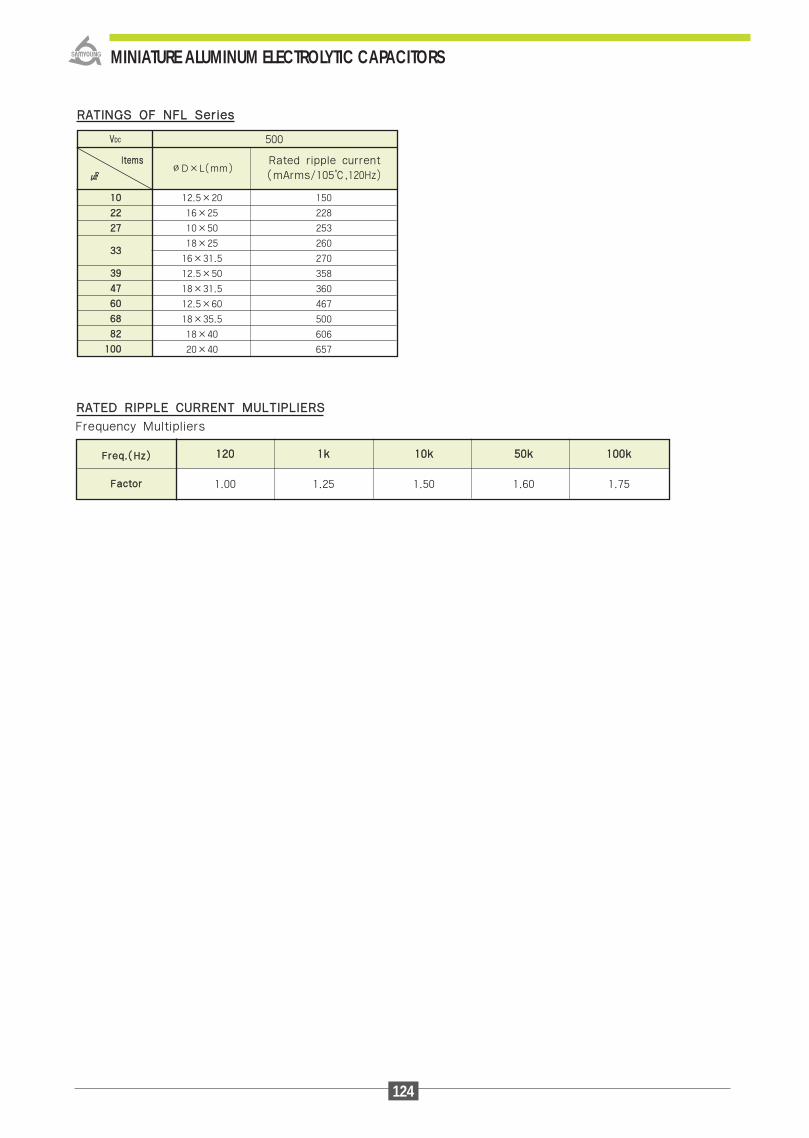
124
MINIATURE ALUMINUM ELECTROLYTIC CAPACITORS
RRAATTIINNGGSS OOFF NNFFLL SSeerriieess
VVDDCC
lltteemmss
500
∅D×L(mm)Rated ripple current(mArms/105,120Hz)
12.5×20
16×25
10×50
18×25
16×31.5
12.5×50
18×31.5
12.5×60
18×35.5
18×40
20×40
1100
2222
2277
3333
3399
4477
6600
6688
8822
110000
150
228
253
260
270
358
360
467
500
606
657
112200 11kk 1100kk 5500kk 110000kk
1.00 1.25 1.50 1.60 1.75
FFrreeqq..((HHzz))
FFaaccttoorr
RRAATTEEDD RRIIPPPPLLEE CCUURRRREENNTT MMUULLTTIIPPLLIIEERRSS
Frequency Multipliers
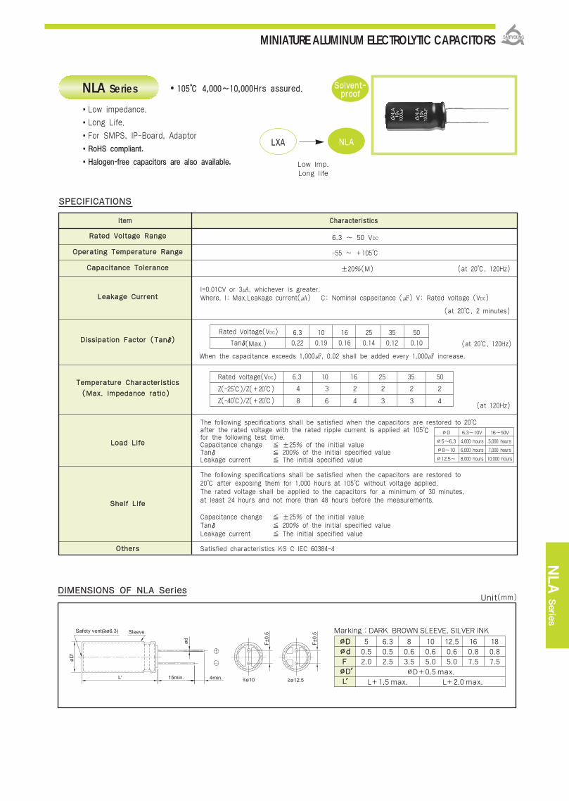
MINIATURE ALUMINUM ELECTROLYTIC CAPACITORS
NLA
Serie
s
RRaatteedd VVoollttaaggee RRaannggee
OOppeerraattiinngg TTeemmppeerraattuurree RRaannggee
CCaappaacciittaannccee TToolleerraannccee
LLeeaakkaaggee CCuurrrreenntt
DDiissssiippaattiioonn FFaaccttoorr ((TTaannδδ))
TTeemmppeerraattuurree CChhaarraacctteerriissttiiccss
LLooaadd LLiiffee
SShheellff LLiiffee
OOtthheerrss
6.3 ~ 50 VDC
-55 ~ +105
±20%(M) (at 20, 120Hz)
I=0.01CV or 3, whichever is greater. Where, I: Max.Leakage current() C: Nominal capacitance () V: Rated voltage (VDC)
(at 20, 2 minutes)
(at 120Hz)
The following specifications shall be satisfied when the capacitors are restored to 20after the rated voltage with the rated ripple current is applied at 105for the following test time.Capacitance change ±25% of the initial valueTanδ 200% of the initial specified valueLeakage current The initial specified value
The following specifications shall be satisfied when the capacitors are restored to20 after exposing them for 1,000 hours at 105 without voltage applied.The rated voltage shall be applied to the capacitors for a minimum of 30 minutes,at least 24 hours and not more than 48 hours before the measurements.
Capacitance change ±25% of the initial valueTanδ 200% of the initial specified valueLeakage current The initial specified value
Satisfied characteristics KS C IEC 60384-4
Low impedance.
Long Life.
For SMPS, IP-Board, Adaptor
RoHS compliant.
Halogen-free capacitors are also available.
SSPPEECCIIFFIICCAATTIIOONNSS
Rated Voltage(VDC) 6.3 10 16 25 35 50
Tanδ(Max.) 0.22 0.19 0.16 0.14 0.12 0.10
Rated voltage(VDC) 6.3 10 16 25 35 50
Z(-25)/Z(+20)
Z(-40)/Z(+20)
110055 44,,000000~~1100,,000000HHrrss aassssuurreedd..
DDIIMMEENNSSIIOONNSS OOFF NNLLAA SSeerriieess
NLA Series
LLXXAA NNLLAA
Low Imp.Long life
4 3 2 2 2 2
8 6 4 3 3 4
SSoollvveenntt--pprrooooff
((MMaaxx.. IImmppeeddaannccee rraattiioo))
∅D 6.3~10V 16~50V
∅5~6.3 4,000 hours 5,000 hours
∅8~10 6,000 hours 7,000 hours
∅12.5~ 8,000 hours 10,000 hours
When the capacitance exceeds 1,000, 0.02 shall be added every 1,000 increase.
(at 20, 120Hz)
Marking :DARK BROWN SLEEVE, SILVER INK
∅∅DD∅∅ddFF∅∅DD′′LL′′
50.52.0
∅D+0.5 max.
L+1.5 max. L+2.0 max.
6.30.52.5
80.63.5
100.65.0
12.50.65.0
160.87.5
180.87.5
lltteemm CChhaarraacctteerriissttiiccss
Unit(mm)

MINIATURE ALUMINUM ELECTROLYTIC CAPACITORSRRAATTIINNGGSS OOFF NNLLAA SSeerriieess
150 175 100 175 47 175
330 290 220 290 100 290
680 555 470 555 330 555
1,000 0.090 730 680 0.090 730 470 0.090 730
1,200 0.080 810 1,000 0.080 810 560 0.080 810
820 0.090 760 680 0.090 760 470 0.090 760
1,200 0.068 1,050 1,000 0.068 1,050 680 0.068 1,050
1,500 0.052 1,220 1,200 0.052 1,220 1,000 0.052 1,220
2,200 0.045 1,440 1,500 0.045 1,440 1,200 0.045 1,440
2,700 0.037 1,690 1,800 0.037 1,690 1,500 0.037 1,690
1,800 0.053 1,270 1,500 0.053 1,270 1,000 0.053 1,270
3,300 0.038 1,660 2,200 0.038 1,660 1,500 0.038 1,660
3,900 0.030 2,310 3,300 0.030 2,310 2,200 0,030 2,310
4,700 0.025 2,510 3,900 0.025 2,510 2,700 0.025 2,510
5,600 0.022 2,870 4,700 0.022 2,870 3,300 0.022 2,870
2,700 0.048 1,690 2,200 0.048 1,690 1,500 0.048 1,690
5,600 0.031 2,210 3,900 0.031 2,210 2,700 0.031 2,210
6,800 0.024 2,560 5,600 0.024 2,560 3.900 0.024 2,560
8,200 0.021 3,010 6,800 0.021 3,010 4,700 0.021 3,010
10,000 0.019 3,250 8,200 0.019 3,250 5,600 0.019 3,250
12,000 0.016 3,560 10,000 0.016 3,560 6,800 0.016 3,560
3,900 0.051 1,920 2,700 0.051 1,920 2,200 0.051 1,920
6,800 0.031 2,490 5,600 0.031 2,490 3,900 0.031 2,490
10,000 0.023 2,740 6,800 0.023 2,740 4,700 0.023 2,740
55××1111
66..33××1111
88××1111..55
88××1155
88××2200
1100××1122..55
1100××1166
1100××2200
1100××2255
1100××3300
1122..55××1166
1122..55××2200
1122..55××2255
1122..55××3300
1122..55××3355
1166××1155
1166××2200
1166××2255
1166××3311..55
1166××3355
1166××4400
1188××1155
1188××2200
1188××2255
1188××3311..55
1188××3355..55
1188××4400
VVDDCC 2255 3355 5500 IIMMPP.. RRiippppllee IIMMPP.. RRiippppllee IIMMPP.. RRiippppllee∅∅DD××LL((mmmm))
VVDDCC 66..33 1100 1166 IIMMPP.. RRiippppllee IIMMPP.. RRiippppllee IIMMPP.. RRiippppllee∅∅DD××LL((mmmm))
47
100
220
330
390
330
470
680
820
1,000
680
1,000
1,500
1,800
2,200
1,000
1,800
2,700
3,300
3,900
4,700
1,200
2,200
3,300
3,900
4,700
5,600
0.50
0.25
0.12
0.090
0.080
0.090
0.068
0.052
0.045
0.037
0.053
0.038
0.030
0.025
0.022
0.048
0.031
0.024
0.021
0.019
0.016
0.051
0.031
0.023
0.021
0.019
0.012
0.50
0.25
0.12
0.090
0.080
0.090
0.068
0.052
0.045
0.037
0.053
0.038
0.030
0.025
0.022
0.048
0.031
0.024
0.021
0.019
0.016
0.051
0.031
0.023
0.021
0.019
0.012
175
290
555
730
810
760
1,050
1,220
1,440
1,690
1,270
1,660
2,310
2,510
2,870
1,690
2,210
2,560
3,010
3,250
3,560
1,920
2,490
2,740
3,330
3,680
4,280
175
290
555
730
810
760
1,050
1,220
1,440
1,690
1,270
1,660
2,310
2,510
2,870
1,690
2,210
2,560
3,010
3,250
3,560
1,920
2,490
2,740
3,330
3,680
4,280
33
56
150
220
270
220
330
470
560
680
470
680
1,000
1,200
1,500
680
1,200
1,800
2,200
2,700
3,300
1,000
1,800
2,200
2,700
3,300
3,900
10
22
47
100
120
100
150
220
270
330
220
330
470
680
820
390
680
820
1,000
1,200
1,500
390
680
1,000
1,200
1,500
1,800
2.0
1.6
0.80
0.50
0.30
0.28
0.19
0.14
0.11
0.091
0.15
0.098
0.074
0.062
0.052
0.11
0.070
0.052
0.045
0.039
0.033
0.11
0.074
0.054
0.043
0.035
0.029
100
150
180
230
360
380
525
610
720
845
630
830
975
1,150
1,250
845
1,100
1,280
1,500
1,680
1,850
965
1,250
1,370
1,810
1,850
1,900
~~ 118800
222200 ~~ 556600
668800 ~~ 11,,880000
22,,220000 ~~ 33,,990000
44,,770000 ~~1188,,000000
0.40
0.50
0.60
0.75
0.85
CCaapp..(())FFrreeqq..((HHzz)) 11kk 1100kk 110000kk
0.75
0.85
0.87
0.90
0.95
0.90
0.94
0.95
0.95
0.98
1.00
1.00
1.00
1.00
1.00
RRAATTEEDD RRIIPPPPLLEE CCUURRRREENNTT MMUULLTTIIPPLLIIEERRSS
12,000
15,000
18,000
0.021
0.019
0.018
0.021
0.019
0.018
0.021
0.019
0.012
3,330
3,680
3,800
8,200
10,000
12,000
3,330
3,680
3,800
5,600
8,200
10,000
3,330
3,680
4,280
Rated Ripple Current (mArms/105, 100kHz)
Impedance (Ϊmax./20, 100kHz)Nominal Capacitance()
0.50
0.25
0.12
0.50
0.25
0.12
0.50
0.25
0.12
112200

MINIATURE ALUMINUM ELECTROLYTIC CAPACITORS
NLC
Serie
s
RRaatteedd VVoollttaaggee RRaannggee
OOppeerraattiinngg TTeemmppeerraattuurree RRaannggee
CCaappaacciittaannccee TToolleerraannccee
LLeeaakkaaggee CCuurrrreenntt
TTeemmppeerraattuurree CChhaarraacctteerriissttiiccss
LLooaadd LLiiffee
SShheellff LLiiffee
OOtthheerrss
6.3 ~ 50 VDC
-55 ~ +105
±20%(M)
I=0.01CV() or 3, whichever is greater. Where, I: Max.Leakage current() C: Nominal capacitance () V: Rated voltage (VDC)
(at 20, 2 minutes)
(at 20, 120Hz)
(at 120Hz)
The following specifications shall be satisfied when the capacitors are restored to 20after the rated voltage with the rated ripple current is applied for 10,000 hours at 105.Capacitance change ±25% of the initial valueTanδ 200% of the initial specified valueLeakage current The initial specified value
The following specifications shall be satisfied when the capacitors are restored to 20after exposing them for 1,000 hours at 105 without voltage applied.The rated voltage shall be applied to the capacitors for a minimum of 30 minutes,at least 24 hours and not more than 48 hours before the measurements.
Capacitance change ±25% of the initial valueTanδ 200% of the initial specified valueLeakage current The initial specified value
Satisfied characteristics KS C IEC 60384-4
Low impedance.
Long Life.
For SMPS, IP-Board, Adaptor
RoHS compliant.
Halogen-free capacitors are also available.
SSPPEECCIIFFIICCAATTIIOONNSS
Rated Voltage(VDC) 6.3 10 16 25 35 50
Tanδ(Max.) 0.22 0.19 0.16 0.14 0.12 0.10
Rated voltage(VDC) 6.3 10 16 25~35 50
Z(-25)/Z(+20)
Z(-40)/Z(+20)
110055 1100,,000000HHrrss aassssuurreedd..
DDIIMMEENNSSIIOONNSS OOFF NNLLCC SSeerriieess
NLC Series
NNLLAA NNLLCC
∅8↓Long life
4 3 2 2 2
8 6 4 3 4
SSoollvveenntt--pprrooooff
((MMaaxx.. IImmppeeddaannccee rraattiioo))
DDiissssiippaattiioonn FFaaccttoorr
((TTaannδδ))
(at 20, 120Hz)
Marking :DARK BROWN SLEEVE, SILVER INK
∅∅DD∅∅ddFF∅∅DD′′LL′′
50.52.0
∅D+0.5 max.
L+1.5max.
6.30.52.5
80.63.5
lltteemm CChhaarraacctteerriissttiiccss
Unit(mm)
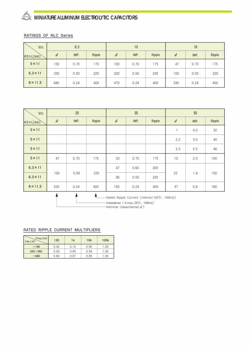
MINIATURE ALUMINUM ELECTROLYTIC CAPACITORS
RRAATTIINNGGSS OOFF NNLLCC SSeerriieess
150 0.70 175 100 0.70 175 47 0.70 175
330 0.50 220 220 0.50 220 100 0.50 220
680 0.24 400 470 0.24 400 330 0.24 400
55××1111
66..33××1111
88××1111..55
VVDDCC 66..33 1100 1166
IIMMPP.. RRiippppllee IIMMPP.. RRiippppllee IIMMPP.. RRiippppllee∅∅DD××LL((mmmm))
1 4.0 32
2.2 3.0 40
3.3 2.5 46
47 0.70 175 33 0.70 175 10 2.0 100
47 0.60 200
56 0.50 220
220 0.24 400 150 0.24 400 47 0.8 180
55××1111
55××1111
55××1111
55××1111
66..33××1111
66..33××1111
88××1111..55
VVDDCC 2255 3355 5500
IIMMPP.. RRiippppllee IIMMPP.. RRiippppllee IIMMPP.. RRiippppllee∅∅DD××LL((mmmm))
RRAATTEEDD RRIIPPPPLLEE CCUURRRREENNTT MMUULLTTIIPPLLIIEERRSS
Rated Ripple Current (mArms/105, 100kHz)
Impedance (Ϊmax./20, 100kHz)Nominal Capacitance()
FFrreeqq..((HHzz))CCaapp..(()) 112200 11kk
0.40 0.75 0.90 1.00
0.50 0.85 0.94 1.00
0.60 0.87 0.95 1.00
1100kk 110000kk
~~118800
222200~~556600
~~668800
100 0.50 220 22 1.6 150
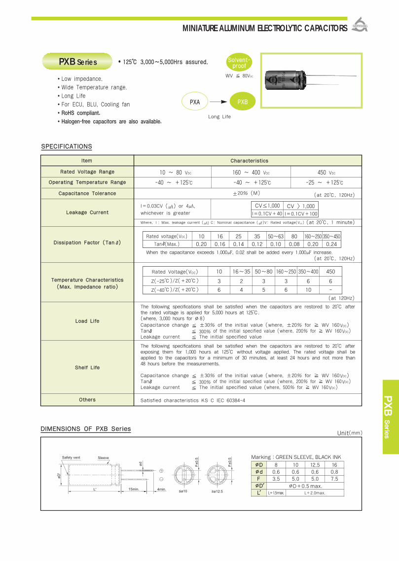
MINIATURE ALUMINUM ELECTROLYTIC CAPACITORS
PXB
Serie
s
CChhaarraacctteerriissttiiccssIItteemm
RRaatteedd VVoollttaaggee RRaannggee
OOppeerraattiinngg TTeemmppeerraattuurree RRaannggee
CCaappaacciittaannccee TToolleerraannccee
LLeeaakkaaggee CCuurrrreenntt
DDiissssiippaattiioonn FFaaccttoorr ((TTaannδ))
TTeemmppeerraattuurree CChhaarraacctteerriissttiiccss
LLooaadd LLiiffee
SShheellff LLiiffee
OOtthheerrss
±20% (M) (at 20, 120Hz)
I=0.03CV () or 4,
whichever is greater
Where, I : Max. leakage current () C: Nominal capacitance ()V: Rated voltage(VDC)
When the capacitance exceeds 1.000, 0.02 shall be added every 1.000 increase.
The following specifications shall be satisfied when the capacitors are restored to 20 afterthe rated voltage is applied for 5,000 hours at 125. (where, 3,000 hours for ∅8)Capacitance change ±30% of the initial value (where, ±20% for WV 160VDC)Tanδ 300% of the initial specified value (where, 200% for WV 160VDC)Leakage current The initial specified value
The following specifications shall be satisfied when the capacitors are restored to 20 afterexposing them for 1,000 hours at 125 without voltage applied. The rated voltage shall beapplied to the capacitors for a minimum of 30 minutes, at least 24 hours and not more than48 hours before the measurements.
Capacitance change ±30% of the initial value (where, ±20% for WV 160VDC)Tanδ 300% of the initial specified value (where, 200% for WV 160VDC)Leakage current The initial specified value (where, 500% for WV 160VDC)
Satisfied characteristics KS C IEC 60384-4
Rated voltage(VDC)
Tanδ(Max.)
(at 120Hz)
Rated Voltage(VDC)
Z(-25)/Z(+20)
Z(-40)/Z(+20)
(at 20, 1 minute)
SSPPEECCIIFFIICCAATTIIOONNSS
10 ~ 80 VDC 160 ~ 400 VDC 450 VDC
-40 ~ +125 -40 ~ +125 -25 ~ +125
((MMaaxx.. IImmppeeddaannccee rraattiioo))
CV≤1,000 CV > 1,000I=0.1CV+40 I=0.1CV+100
10 16 25 35 50~63 80 160~250 350~450
0.20 0.16 0.14 0.12 0.10 0.08 0.20 0.24
10 16~35 50~80 160~250 350~400 450
3 2 3 3 6 6
6 4 5 6 10 -
(at 20, 120Hz)
DDIIMMEENNSSIIOONNSS OOFF PPXXBB SSeerriieess
112255 33,,000000~~55,,000000HHrrss aassssuurreedd.. PXB Series
PPXXAA PPXXBB
Long Life
WV 80VDC
Low impedance.
Wide Temperature range.
Long Life
For ECU, BLU, Cooling fan
RoHS compliant.
Halogen-free capacitors are also available.
SSoollvveenntt--pprrooooff
Marking :GREEN SLEEVE, BLACK INK
∅∅DD∅∅ddFF∅∅DD′′LL′′
80.63.5
∅D+0.5 max.L+1.5max. L+2.0max.
100.65.0
12.50.65.0
160.87.5
Unit(mm)
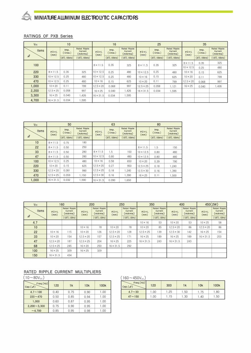
MINIATURE ALUMINUM ELECTROLYTIC CAPACITORS
((2200,,110000kkHHzz)) ((112255,,110000kkHHzz))
∅∅DD××LL((mmmm))
llmmpp..((ΪΪmmaaxx..))
RRaatteedd RRiippppllee CCuurrrreenntt
((mmAArrmmss))
RRAATTIINNGGSS OOFF PPXXBB SSeerriieess
FFrreeqq..((HHzz))
CCaapp..(())
(10~80VDC) (160~450VDC)
RRAATTEEDD RRIIPPPPLLEE CCUURRRREENNTT MMUULLTTIIPPLLIIEERRSS
VVDDCC
lltteemmss
110000
((2200,,110000kkHHzz)) ((112255,,110000kkHHzz))
222200 8×11.5
10×12.5
10×12.5
10×20
12.5×25
16×25
16×31.5
0.35
0.25
0.25
0.11
0.058
0.040
0.034
0.35
0.25
0.25
0.15
0.068
0.040
0.034
0.35
0.25
0.15
0.11
0.058
0.034
0.35
0.25
0.15
0.11
0.068
0.040
325
480
480
799
997
1,426
1,595
325
480
480
625
997
1,426
1,595
325
480
625
799
1,121
325
480
625
799
997
1,426
1,595
8×11.5
10×12.5
10×12.5
10×16
12.5×20
16×25
16×31.5
8×11.5
10×12.5
10×16
10×20
12.5×25
16×31.5
8×11.5
10×12.5
10×16
10×20
12.5×20
16×25
333300
447700
11,,000000
22,,220000
33,,330000
44,,770000
1100 1166 2255 3355
∅∅DD××LL((mmmm))
llmmpp..((ΪΪmmaaxx..))
RRaatteedd RRiippppllee CCuurrrreenntt
((mmAArrmmss))
((2200,,110000kkHHzz)) ((112255,,110000kkHHzz))
∅∅DD××LL((mmmm))
llmmpp..((ΪΪmmaaxx..))
RRaatteedd RRiippppllee CCuurrrreenntt
((mmAArrmmss))
((2200,,110000kkHHzz)) ((112255,,110000kkHHzz))
∅∅DD××LL((mmmm))
llmmpp..((ΪΪmmaaxx..))
RRaatteedd RRiippppllee CCuurrrreenntt
((mmAArrmmss))
VVDDCC
lltteemmss
1100
((2200,,110000kkHHzz)) ((112255,,110000kkHHzz))
2222
8×11.5
8×11.5
8×11.5
8×11.5
10×12.5
10×20
12.5×20
12.5×25
16×31.5
0.75
0.50
0.50
0.50
0.25
0.15
0.081
0.059
0.032
1.5
0.80
0.58
0.27
0.18
0.16
0.090
1.5
0.80
0.80
0.39
0.18
0.16
0.11
180
250
280
280
480
625
990
1,150
1,590
150
480
650
950
1,240
1,390
1,650
150
480
480
790
1,240
1,390
1,500
8×11.5
10×12.5
10×16
12.5×20
12.5×25
12.5×30
16×31.5
8×11.5
10×12.5
10×12.5
10×20
12.5×25
12.5×30
16×25
3333
4477
110000
222200
333300
447700
11,,000000
5500 6633 8800
∅∅DD××LL((mmmm))
llmmpp..((ΪΪmmaaxx..))
RRaatteedd RRiippppllee CCuurrrreenntt
((mmAArrmmss))
((2200,,110000kkHHzz)) ((112255,,110000kkHHzz))
∅∅DD××LL((mmmm))
llmmpp..((ΪΪmmaaxx..))
RRaatteedd RRiippppllee CCuurrrreenntt
((mmAArrmmss))
((2200,,110000kkHHzz)) ((112255,,110000kkHHzz))
∅∅DD××LL((mmmm))
llmmpp..((ΪΪmmaaxx..))
RRaatteedd RRiippppllee CCuurrrreenntt
((mmAArrmmss))
VVDDCC
lltteemmss
44..77
((112255,,112200HHzz))
1100
2222
3333
4477
6688
110000
115500
112200
0.40
0.50
0.60
0.75
0.85
0.75
0.85
0.87
0.90
0.95
0.90
0.94
0.95
0.95
0.98
1.00
1.00
1.00
1.00
1.00
11kk 1100kk 110000kk
44..77~~110000
222200~~447700
11,,000000
22,,220000~~33,,330000
~~44,,770000
FFrreeqq..((HHzz))
CCaapp..(()) 112200 330000
1.25
1.15
1.00
1.00
1.50
1.30
1.75
1.40
1.80
1.50
11kk 1100kk 110000kk
44..77~~3333
4477~~115500
10×16
10×20
12.5×20
12.5×25
16×25
16×31.5
115
154
187
245
329
434
10×16
10×20
12.5×20
12.5×25
16×20
16×25
78
126
157
204
250
329
10×20
12.5×20
12.5×25
16×25
16×31.5
78
128
171
225
292
10×16
10×20
12.5×25
16×25
16×31.5
53
85
139
189
243
10×20
12.5×20
12.5×30
16×25
16×31.5
53
86
142
189
243
10×25
12.5×20
16×25
16×31.5
58
86
154
203
116600 220000 225500 335500 440000 445500((22WW))
∅∅DD××LL((mmmm))
∅∅DD××LL((mmmm))
∅∅DD××LL((mmmm))
∅∅DD××LL((mmmm))
∅∅DD××LL((mmmm))
∅∅DD××LL((mmmm))
RRaatteedd RRiippppllee CCuurrrreenntt
((mmAArrmmss))
((112255,,112200HHzz))
RRaatteedd RRiippppllee CCuurrrreenntt
((mmAArrmmss))
((112255,,112200HHzz))
RRaatteedd RRiippppllee CCuurrrreenntt
((mmAArrmmss))
((112255,,112200HHzz))
RRaatteedd RRiippppllee CCuurrrreenntt
((mmAArrmmss))
((112255,,112200HHzz))
RRaatteedd RRiippppllee CCuurrrreenntt
((mmAArrmmss))
((112255,,112200HHzz))
RRaatteedd RRiippppllee CCuurrrreenntt
((mmAArrmmss))

MINIATURE ALUMINUM ELECTROLYTIC CAPACITORS
PXD
Serie
s
RRaatteedd VVoollttaaggee RRaannggee
OOppeerraattiinngg TTeemmppeerraattuurree RRaannggee
CCaappaacciittaannccee TToolleerraannccee
LLeeaakkaaggee CCuurrrreenntt
DDiissssiippaattiioonn FFaaccttoorr ((TTaannδδ))
TTeemmppeerraattuurree CChhaarraacctteerriissttiiccss((MMaaxx.. IImmppeeddaannccee rraattiioo))
LLooaadd LLiiffee
SShheellff LLiiffee
OOtthheerrss
112255 22,,000000~~44,,000000HHrrss aassssuurreedd..
SSPPEECCIIFFIICCAATTIIOONNSS
PPXXCC PPXXDD
Low lmp.
10 ~ 50 VDC
-40 ~ +125
±20%(M)
I = 0.03CV () or 4, whichever is greater. Where, I:Max. leakage current(),C:Nominal capacitance(),V:Rated voltage(VDC)
(at 20,120Hz)
(at 120Hz)
The following specifications shall be satisfied when the capacitors are restored to 20after the rated voltage is applied for 4,000 hours at 125. (where, 2,000 hours 8∅)Capacitance change ±30% of the initial valueTanδ 300% of the initial specified valueLeakage Current The initial specified value
The following specifications shall be satisfied when the capacitors are restored to 20after exposing them for 1,000 hours at 125 without voltage applied. The ratedvoltage shall be applied to the capacitors for a minimum of 30 minutes, at least 24hours and not more than 48 hours before the measurements.
Capacitance change ±30% of the initial value Tanδ 300% of the initial specified value Leakage current The initial specified value
Satisfied characteristics KS C IEC 60384-4
DDIIMMEENNSSIIOONNSS OOFF PPXXDD SSeerriieess
(at 20, 1 minute)
PXD Series
Ultra low Impedance.
Wide temperature range.
Long Life
For ECU, BLU, Cooling fan
RoHS compliant.
Halogen-free capacitors are also available.
SSoollvveenntt--pprrooooff
Rated Voltage(VDC)
Z(-25)/Z(+20)
Z(-40)/Z(+20)
10
3
6
16 ~ 35
2
4
50
3
5
Rated Volatag(VDC) 10 16 25 35 50
TANδ(Max.) 0.20 0.16 0.14 0.12 0.10
When the capacitance exceeds 1.000, 0.02 shall be added every 1.000 increase.
Marking :GREEN SLEEVE, BLACK INK
∅∅DD∅∅ddFF∅∅DD′′LL′′
80.63.5
∅D+0.5 max.L+1.5max. L+2.0max.
100.65.0
12.50.65.0
160.87.5
(at 20,120Hz)
Unit(mm)
lltteemm CChhaarraacctteerriissttiiccss
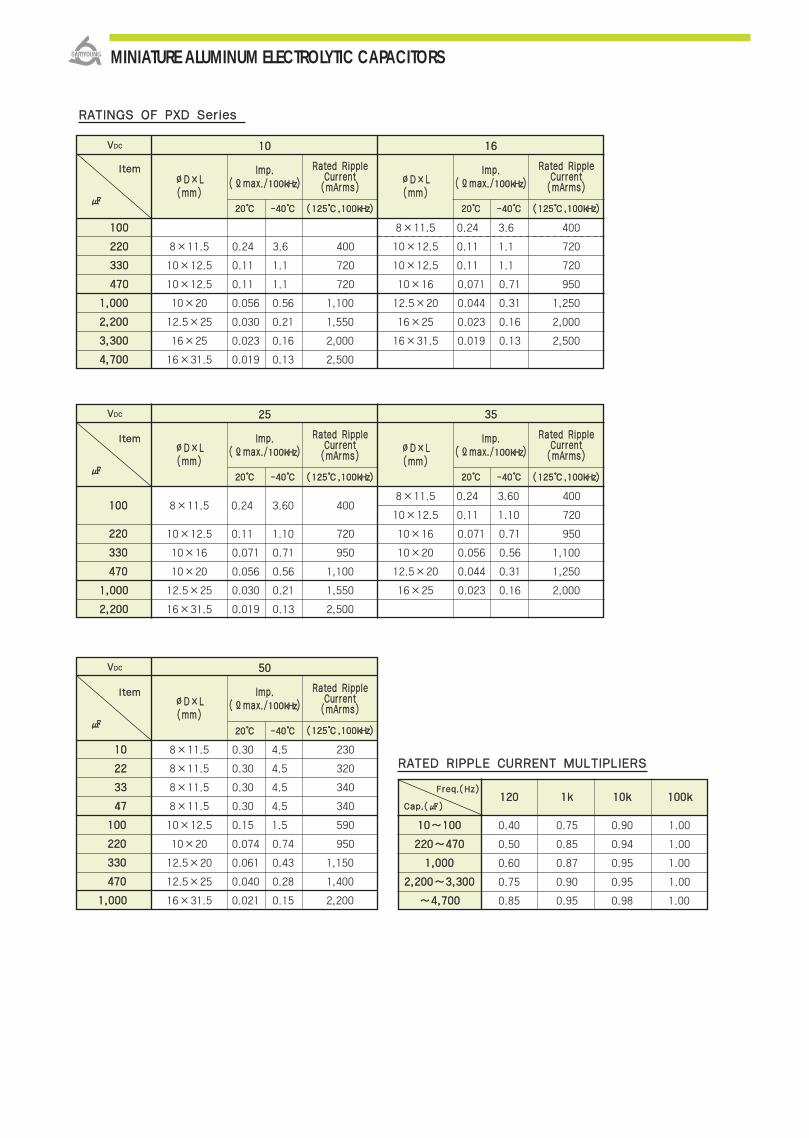
MINIATURE ALUMINUM ELECTROLYTIC CAPACITORS
RRAATTIINNGGSS OOFF PPXXDD SSeerriieess
lltteemm
110000
222200
333300
447700
11,,000000
22,,220000
8×11.5
10×12.5
10×16
10×20
12.5×25
16×31.5
0.24
0.11
0.071
0.056
0.030
0.019
3.60
1.10
0.71
0.56
0.21
0.13
400
720
950
1,100
1,550
2,500
8×11.5
10×12.5
10×16
10×20
12.5×20
16×25
0.24
0.071
0.056
0.044
0.023
400
0.11
3.60
0.71
0.56
0.31
0.16
1.10 720
950
1,100
1,250
2,000
∅∅DD××LL((mmmm))
IImmpp..((ΪΪmmaaxx..//110000kkHHzz))
2255 3355VVDDCC
RRaatteedd RRiipppplleeCCuurrrreenntt((mmAArrmmss))
((112255,,110000kkHHzz))
∅∅DD××LL((mmmm))
IImmpp..((ΪΪmmaaxx..//110000kkHHzz))
RRaatteedd RRiipppplleeCCuurrrreenntt((mmAArrmmss))
((112255,,110000kkHHzz))
lltteemm
110000
222200
333300
447700
11,,000000
22,,220000
8×11.5
10×12.5
10×12.5
10×20
12.5×25
0.24
0.11
0.11
0.056
0.030
400
720
720
1,100
1,550
2,000
8×11.5
10×12.5
10×12.5
10×16
12.5×20
16×25
0.24
0.11
0.071
0.044
0.023
400
0.11 720
720
950
1,250
2,000
16×31.5 0.019
3.6
1.1
0.71
0.31
0.16
1.1
0.13 2,500
2,500
0.023
0.019
3.6
1.1
1.1
0.56
0.21
0.16
0.13
16×25
16×31.5
33,,330000
44,,770000
∅∅DD××LL((mmmm))
IImmpp..((ΪΪmmaaxx..//110000kkHHzz))
1100 1166VVDDCC
RRaatteedd RRiipppplleeCCuurrrreenntt((mmAArrmmss))
((112255,,110000kkHHzz))
∅∅DD××LL((mmmm))
IImmpp..((ΪΪmmaaxx..//110000kkHHzz))
RRaatteedd RRiipppplleeCCuurrrreenntt((mmAArrmmss))
((112255,,110000kkHHzz))
lltteemm
1100
2222
8×11.5
8×11.5
0.30
0.30
230
320
3333
4477
110000
222200
333300
8×11.5
8×11.5
10×12.5
10×20
12.5×20
0.30
0.30
0.15
0.074
0.061
340
340
590
950
1,150
447700 12.5×25 0.040 1,400
11,,000000 16×31.5 0.021
4.5
4.5
4.5
4.5
1.5
0.74
0.43
0.28
0.15 2,200
∅∅DD××LL((mmmm))
IImmpp..((ΪΪmmaaxx..//110000kkHHzz))
5500VVDDCC
RRaatteedd RRiipppplleeCCuurrrreenntt((mmAArrmmss))
((112255,,110000kkHHzz))
RRAATTEEDD RRIIPPPPLLEE CCUURRRREENNTT MMUULLTTIIPPLLIIEERRSS
FFrreeqq..((HHzz))
CCaapp..(())
1100~~110000
222200~~447700
11,,000000
22,,220000~~33,,330000
~~44,,770000
0.40
0.50
0.60
0.75
0.85
112200
0.75
0.85
0.87
0.90
0.95
11kk
0.90
0.94
0.95
0.95
0.98
1100kk
1.00
1.00
1.00
1.00
1.00
110000kk
2200 --4400 2200 --4400
2200 --4400
2200 --4400
2200 --4400
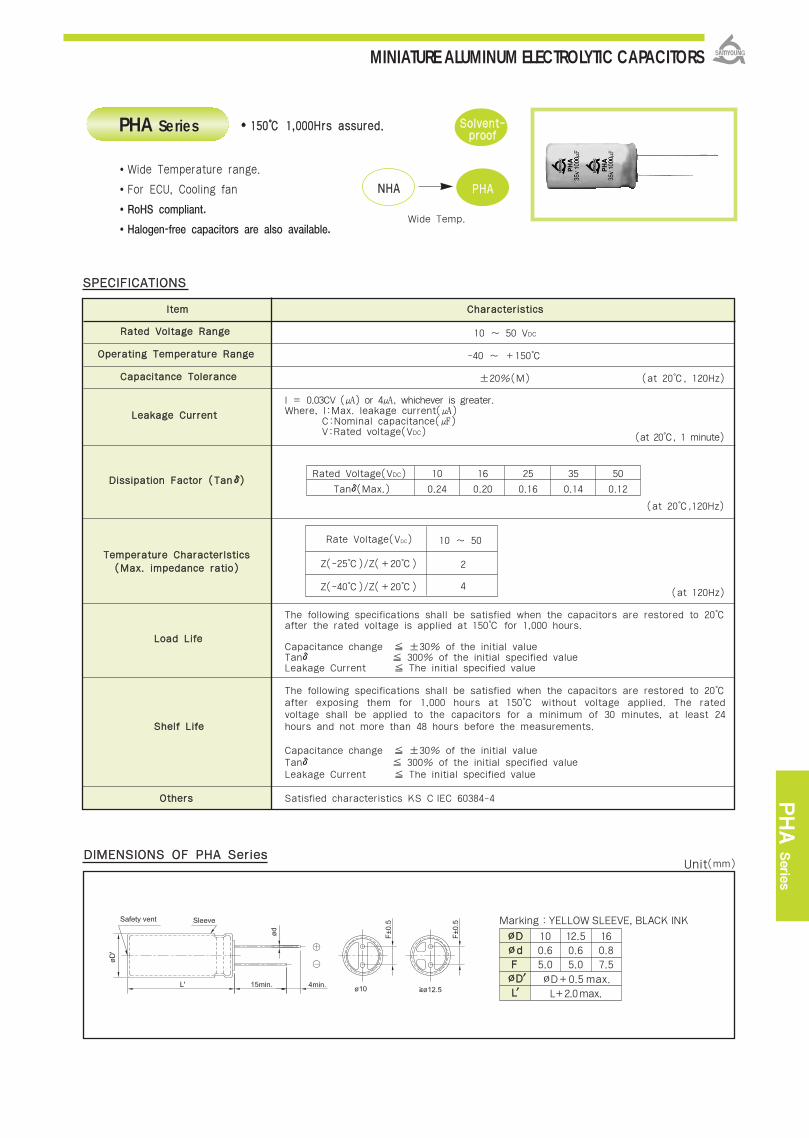
MINIATURE ALUMINUM ELECTROLYTIC CAPACITORS
PHA
Serie
s
115500 11,,000000HHrrss aassssuurreedd..
SSPPEECCIIFFIICCAATTIIOONNSS
NNHHAA PPHHAA
Wide Temp.
RRaatteedd VVoollttaaggee RRaannggee
OOppeerraattiinngg TTeemmppeerraattuurree RRaannggee
CCaappaacciittaannccee TToolleerraannccee
LLeeaakkaaggee CCuurrrreenntt
DDiissssiippaattiioonn FFaaccttoorr ((TTaannδδ))
TTeemmppeerraattuurree CChhaarraacctteerrllssttiiccss((MMaaxx.. iimmppeeddaannccee rraattiioo))
LLooaadd LLiiffee
SShheellff LLiiffee
OOtthheerrss
10 ~ 50 VDC
-40 ~ +150
±20%(M) (at 20, 120Hz)
I = 0.03CV () or 4, whichever is greater. Where, I:Max. leakage current()
C:Nominal capacitance() V:Rated voltage(VDC)
(at 20,120Hz)
(at 120Hz)
The following specifications shall be satisfied when the capacitors are restored to 20after the rated voltage is applied at 150 for 1,000 hours.
Capacitance change ±30% of the initial valueTanδ 300% of the initial specified valueLeakage Current The initial specified value
The following specifications shall be satisfied when the capacitors are restored to 20after exposing them for 1,000 hours at 150 without voltage applied. The ratedvoltage shall be applied to the capacitors for a minimum of 30 minutes, at least 24hours and not more than 48 hours before the measurements.
Capacitance change ±30% of the initial value Tanδ 300% of the initial specified value Leakage Current The initial specified value
Satisfied characteristics KS C IEC 60384-4
DDIIMMEENNSSIIOONNSS OOFF PPHHAA SSeerriieess
(at 20, 1 minute)
PHA Series
Wide Temperature range.
For ECU, Cooling fan
RoHS compliant.
Halogen-free capacitors are also available.
SSoollvveenntt--pprrooooff
Rate Voltage(VDC)
Z(-25)/Z(+20)
Z(-40)/Z(+20)
10 ~ 50
2
4
Rated Voltage(VDC) 10 16 25 35 50
Tanδ(Max.) 0.24 0.20 0.16 0.14 0.12
Marking :YELLOW SLEEVE, BLACK INK
∅∅DD∅∅ddFF∅∅DD′′LL′′
100.65.0
∅D+0.5 max.
L+2.0max.
12.50.65.0
160.87.5
lltteemm CChhaarraacctteerriissttiiccss
Unit(mm)
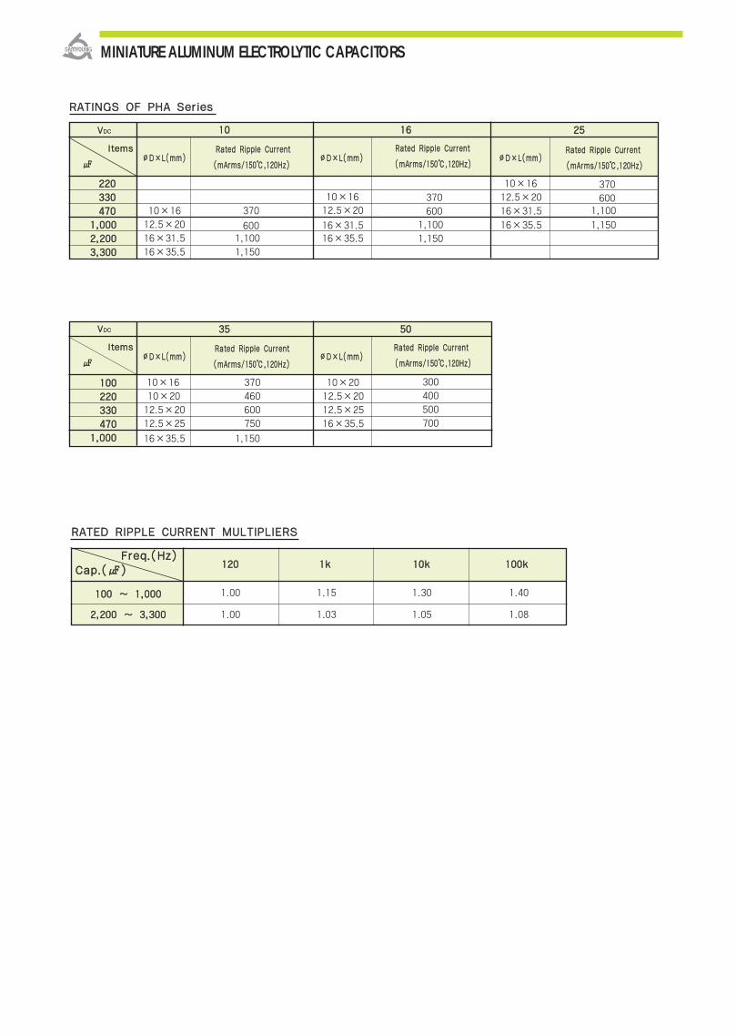
MINIATURE ALUMINUM ELECTROLYTIC CAPACITORS
RRAATTIINNGGSS OOFF PPHHAA SSeerriieess
RRAATTEEDD RRIIPPPPLLEE CCUURRRREENNTT MMUULLTTIIPPLLIIEERRSS
FFrreeqq..((HHzz))CCaapp..(())
222200
333300
447700
11,,000000
22,,220000
33,,330000
370
6001,100
1,150
370
6001,100
1,150
370
6001,100
1,150
10×16
12.5×20
16×31.5
16×35.5
10×1612.5×20
16×31.516×35.5
10×16
12.5×20
16×31.5
16×35.5
∅∅DD××LL((mmmm)) ∅∅DD××LL((mmmm)) ∅∅DD××LL((mmmm))((mmAArrmmss//115500,,112200HHzz))
RRaatteedd RRiippppllee CCuurrrreenntt
((mmAArrmmss//115500,,112200HHzz))
RRaatteedd RRiippppllee CCuurrrreenntt
((mmAArrmmss//115500,,112200HHzz))
RRaatteedd RRiippppllee CCuurrrreenntt
1100 1166 2255
VVDDCC
lltteemmss
110000
222200
333300
447700
11,,000000
110000 ~~ 11,,000000
22,,220000 ~~ 33,,330000
1.00
1.00
1.15
1.03
1.30
1.05
1.40
1.08
370
460
600
750
1,150
300
400
500
700
10×16
10×20
12.5×20
12.5×25
16×35.5
10×20
12.5×20
12.5×25
16×35.5
∅∅DD××LL((mmmm)) ∅∅DD××LL((mmmm))((mmAArrmmss//115500,,112200HHzz))
RRaatteedd RRiippppllee CCuurrrreenntt
((mmAArrmmss//115500,,112200HHzz))
RRaatteedd RRiippppllee CCuurrrreenntt
3355 5500
VVDDCC
lltteemmss
112200 11kk 1100kk 110000kk
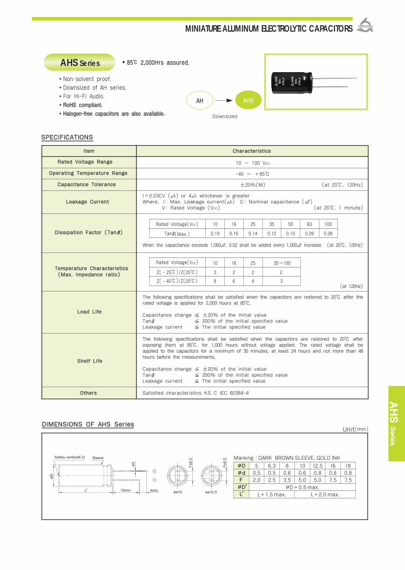
MINIATURE ALUMINUM ELECTROLYTIC CAPACITORS
AHS
Serie
s
RRaatteedd VVoollttaaggee RRaannggee
OOppeerraattiinngg TTeemmppeerraattuurree RRaannggee
CCaappaacciittaannccee TToolleerraannccee
LLeeaakkaaggee CCuurrrreenntt
DDiissssiippaattiioonn FFaaccttoorr ((TTaannδδ))
TTeemmppeerraattuurree CChhaarraacctteerriissttiiccss
LLooaadd LLiiffee
SShheellff LLiiffee
OOtthheerrss
DDIIMMEENNSSIIOONNSS OOFF AAHHSS SSeerriieess
10 ~ 100 VDC
-40 ~ +85
±20%(M) (at 20, 120Hz)
I=0.03CV () or 4 whichever is greaterWhere, I: Max. Leakage current() C: Nominal capacitance ()
V: Rated Voltage (VDC) (at 20, 1 minute)
When the capacitance exceeds 1,000, 0.02 shall be added every 1,000 increase. (at 20, 120Hz)
The following specifications shall be satisfied when the capacitors are restored to 20 after therated voltage is applied for 2,000 hours at 85.
Capacitance change ±20% of the initial valueTanδ 200% of the initial specified valueLeakage current The initial specified value
The following specifications shall be satisfied when the capacitors are restored to 20 afterexposing them at 85. for 1,000 hours without voltage applied. The rated voltage shall beapplied to the capacitors for a minimum of 30 minutes, at least 24 hours and not more than 48hours before the measurements.
Capacitance change ±20% of the initial valueTanδ 200% of the initial specified valueLeakage current The initial specified value
Satisfied characteristics KS C IEC 60384-4
8855 22,,000000HHrrss aassssuurreedd..
SSPPEECCIIFFIICCAATTIIOONNSS
Rated Voltage(VDC) 10 16 25 35 50 63 100
Tanδ(Max.) 0.19 0.16 0.14 0.12 0.10 0.09 0.08
Rated Voltage(VDC) 10 16 25 35~100
Z(‐25)/Z(20) 3 2 2 2
Z(‐40)/Z(20) 8 6 4 3
Non-solvent proof.
Downsized of AH series.
For Hi-Fi Audio.
RoHS compliant.
Halogen-free capacitors are also available.
(at 120Hz)
((MMaaxx.. IImmppeeddaannccee rraattiioo))
AHS Series
AAHH AAHHSS
Downsized
Marking :DARK BROWN SLEEVE, GOLD INK
∅∅DD∅∅ddFF∅∅DD′′LL′′
50.52.0
∅D+0.5 max.
L+1.5 max. L+2.0 max.
6.30.52.5
80.63.5
100.65.0
12.50.85.0
160.87.5
180.87.5
lltteemm CChhaarraacctteerriissttiiccss
Unit(mm)
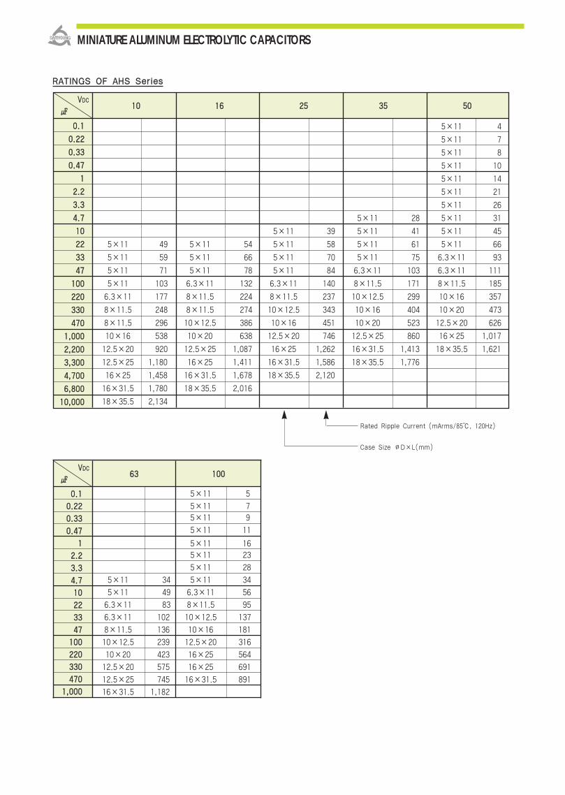
MINIATURE ALUMINUM ELECTROLYTIC CAPACITORS
5×11 5
5×11 75×11 9
5×11 11
5×11 165×11 23
5×11 28
5×11 34 5×11 34
5×11 49 6.3×11 56
6.3×11 83 8×11.5 95
6.3×11 102 10×12.5 137
8×11.5 136 10×16 181
10×12.5 239 12.5×20 316
10×20 423 16×25 564
12.5×20 575 16×25 691
12.5×25 745 16×31.5 891
16×31.5 1,182
5×11 4
5×11 7
5×11 8
5×11 10
5×11 14
5×11 21
5×11 26
5×11 28 5×11 31
5×11 39 5×11 41 5×11 45
5×11 49 5×11 54 5×11 58 5×11 61 5×11 66
5×11 59 5×11 66 5×11 70 5×11 75 6.3×11 93
5×11 71 5×11 78 5×11 84 6.3×11 103 6.3×11 111
5×11 103 6.3×11 132 6.3×11 140 8×11.5 171 8×11.5 185
6.3×11 177 8×11.5 224 8×11.5 237 10×12.5 299 10×16 357
8×11.5 248 8×11.5 274 10×12.5 343 10×16 404 10×20 473
8×11.5 296 10×12.5 386 10×16 451 10×20 523 12.5×20 626
10×16 538 10×20 638 12.5×20 746 12.5×25 860 16×25 1,017
12.5×20 920 12.5×25 1,087 16×25 1,262 16×31.5 1,413 18×35.5 1,621
12.5×25 1,180 16×25 1,411 16×31.5 1,586 18×35.5 1,776
16×25 1,458 16×31.5 1,678 18×35.5 2,120
16×31.5 1,780 18×35.5 2,016
18×35.5 2,134
00..11
00..2222
00..3333
00..4477
11
22..22
33..33
44..77
1100
2222
3333
4477
110000
222200
333300
447700
11,,000000
22,,220000
33,,330000
44,,770000
66,,880000
1100,,000000
1100 1166 2255 3355 5500
RRAATTIINNGGSS OOFF AAHHSS SSeerriieess
VVDDCC
00..11
00..2222
00..3333
00..4477
11
22..22
33..33
44..77
1100
2222
3333
4477
110000
222200
333300
447700
11,,000000
6633 110000
Rated Ripple Current (mArms/85, 120Hz)
Case Size ∅D×L(mm)
VVDDCC

MINIATURE ALUMINUM ELECTROLYTIC CAPACITORS
PHL
Serie
s
RRaatteedd VVoollttaaggee
OOppeerraattiinngg TTeemmppeerraattuurree RRaannggee
CCaappaacciittaannccee TToolleerraannccee
LLeeaakkaaggee CCuurrrreenntt
DDiissssiippaattiioonn FFaaccttoorr ((TTaannδδ))
CChhaarrggee aanndd DDiisscchhaarrggeeCChhaarraacctteerriissttiiccss
SShheellff LLiiffee
OOtthheerrss
DDIIMMEENNSSIIOONNSS OOFF PPHHLL SSeerriieess
55~~3355 55,,000000TTiimmeess..
SSPPEECCIIFFIICCAATTIIOONNSS
Note : Other case sizes, rated voltage or capacitance are also available upon request.
PHL Series
VVDDCC
RRAATTIINNGGSS OOFF PPHHLL SSeerriieess
Non-solvent proof.For Photo Flash.RoHS compliant.
Halogen-free capacitors are also available.
The following specifications shall be satisfied when the capacitors arerestored to 20 after charge and discharge are repeated 5,000 timesat room temperature (5 to 35)Discharge resistance or Xenon tube: 0.7~1.0Ϊ.
Capacitance change ±10% of the initial valueTanδ 150% of the initial specified valueLeakage current 150% of the initial specified value
The following specifications shall be satisfied when the capacitors arerestored to 20 after exposing them for 1000 hours at 55 withoutvoltage applied.
Capacitance change ±10% of the initial valueTanδ 150% of the initial specified valueLeakage current 150% of the initial specified value
300 ~ 330 VDC
-20~+55
-10~+20%(V)
(at 20, 5 minutes)
(at 20, 120Hz)
(at 20, 120Hz)
Where, I:Max.Leakage current() C: Nominal capacitance ()
Satisfied characteristics EIAJ RC - 3801A
∅D(mm) ∅5~8 ∅10~LC(Max.) I=2.0×C I=1.0×C
∅D(mm) ∅5~8 ∅10~Tanδ(Max.) 0.085 0.06
330000 331155 333300
56.810
12.51520306080100120140160
11.8×2211.8×27 13×25
13×2913×3413×3813×43
13.5×2613.5×3013.5×3413.5×38
5×16 6.3×106.3×116.3×156.3×20
8×11.58×158×178×208×23
11.8×2411.8×2911.8×35
13×2713×3213×3713×42
13.5×2813.5×3313.5×3713.5×41
11.8×32
Case size ∅D×L(mm)
Marking :BLACK SLEEVE, WHITE INK
∅∅DD∅∅ddFF∅∅DD′′LL′′
50.52.0
∅D+0.5 max.
L+1.0 max.
6.30.52.5
80.63.5
11.80.65.0
130.65.0
13.50.85.0
lltteemm CChhaarraacctteerriissttiiccss
Unit(mm)

IItteemm CChhaarraacctteerriissttiiccss
RRaatteedd VVoollttaaggee RRaannggee 16 ~ 35 VDC
OOppeerraattiinngg TTeemmppeerraattuurree RRaannggee -55 ~ +105
CCaappaacciittaannccee TToolleerraannccee 0% ~ 30%(S) (at 20, 120Hz)
I=0.01CV(μA)
Where, I:Max. leakage current(μA), C:Nominal capacitance(μF), V:Rated voltage(VDC)
When the capacitance exceeds 1,000, 0.02 shall be added every 1,000 increase. (at 20, 120Hz)
TTeemmppeerraattuurree CChhaarraacctteerriissttiiccss
((MMaaxx .. IImmppeeddaannccee rraattiioo))
The following specifications shall be satisfied when the capacitors are restored to 20
after the rated voltage with the rated ripple current is applied for 5,000 hours at 105.
LLooaadd LLiiffeeCapacitance change ±25% of the initial value
Tanδ 200% of the initial specified value
Leakage current The initial specified value
The following specifications shall be satisfied when the capacitors are restored to 20
after exposing them for 1,000 hours at 105 without voltage applied.
The rated voltage shall be applied to the capacitors for a minimum of 30 minutes,
at least 24 hours and not more than 48 hours before the measurements.SShheellff LLiiffee
Capacitance change ±20% of the initial value
Tanδ 200% of the initial specified value
Leakage current The initial specified value
OOtthheerrss Satisfied characteristics KS C IEC 60384-4
110055 55,,000000HHrrss aassssuurreedd
SSPPEECCIIFFIICCAATTIIOONNSS
Rated Voltage(VDC) 16 25 35
Tanδ(Max.) 0.16 0.14 0.12
Rated Voltage(VDC) 16 25 35
Z(-55)/Z(20) 3
NZD Series
For car air bag circuit
RoHS compliant.
Halogen-free capacitors are also available.
SSoollvveenntt--pprrooooff
DDiissssiippaattiioonn FFaaccttoorr ((TTaannδδ))
DDIIMMEENNSSIIOONNSS OOFF NNZZDD SSeerriieess
LLeeaakkaaggee CCuurrrreenntt
(at 120Hz)
(at 20, 2 minutes)
MINIATURE ALUMINUM ELECTROLYTIC CAPACITORS
Marking :DARK BROWN SLEEVE, SILVER INK
∅∅DD∅∅ddFF∅∅DD′′LL′′
12.50.65.0
∅D+1.0 max.
L+2.0max.
160.87.5
180.87.5
Unit(mm)

DDIIMMEENNSSIIOONNSS OOFF NNZZDD SSeerriieess
NZD Serie
s
MINIATURE ALUMINUM ELECTROLYTIC CAPACITORS
22,,220000
22,,770000
33,,330000
44,,770000
44,,770000
55,,660000
12.5×20
12.5×25
16×20
16×25
18×20
18×25
1,660
1,950
2,210
2,560
2,490
2,740
0.038
0.030
0.029
0.022
0.028
0.020
11,,220000
11,,880000
22,,220000
33,,330000
22,,770000
33,,990000
12.5×20
12.5×25
16×20
16×25
18×20
18×25
1,660
1,950
2,210
2,560
2,490
2,740
0.038
0.030
0.029
0.022
0.028
0.020
882200
11,,220000
11,,550000
11,,880000
11,,880000
22,,770000
12.5×20
12.5×25
16×20
16×25
18×20
18×25
1,660
1,950
2,210
2,560
2,490
2,740
0.038
0.030
0.029
0.022
0.028
0.020
VVDDCC 1166
∅∅DD××LL((mmmm))RRaatteedd RRiippppllee CCuurrrreenntt IImmppeeddaannccee((mmAArrmmss//110055,, 110000kkHHzz)) ((ΪΪmmaaxx..//2200,, 110000kkHHzz))
VVDDCC 2255
∅∅DD××LL((mmmm))RRaatteedd RRiippppllee CCuurrrreenntt IImmppeeddaannccee((mmAArrmmss//110055,, 110000kkHHzz)) ((ΪΪmmaaxx..//2200,, 110000kkHHzz))
VVDDCC 3355
∅∅DD××LL((mmmm))RRaatteedd RRiippppllee CCuurrrreenntt IImmppeeddaannccee((mmAArrmmss//110055,, 110000kkHHzz)) ((ΪΪmmaaxx..//2200,, 110000kkHHzz))
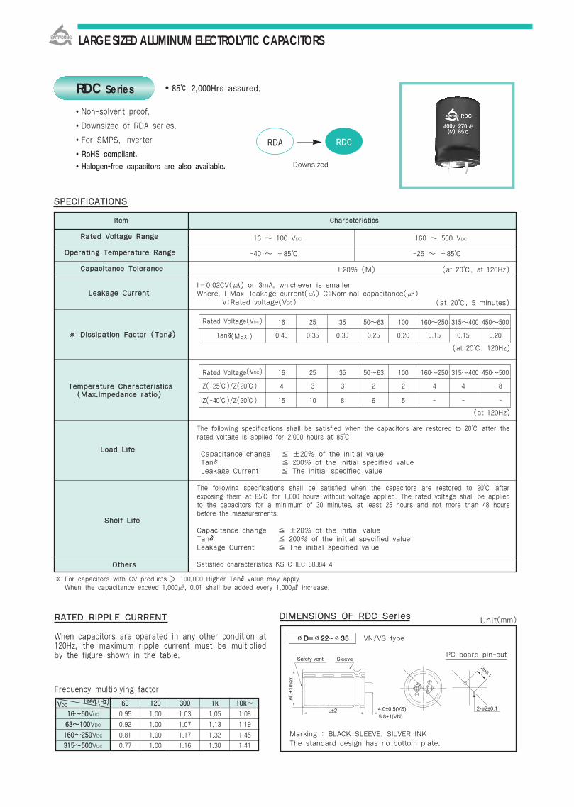
LARGE SIZED ALUMINUM ELECTROLYTIC CAPACITORS
8855 22,,000000HHrrss aassssuurreedd..
Non-solvent proof.
Downsized of RDA series.
For SMPS, Inverter
RoHS compliant.
Halogen-free capacitors are also available.
RDC Series
RRDDAA RRDDCC
Downsized
RRAATTEEDD RRIIPPPPLLEE CCUURRRREENNTT
When capacitors are operated in any other condition at120Hz, the maximum ripple current must be multipliedby the figure shown in the table.
DDIIMMEENNSSIIOONNSS OOFF RRDDCC SSeerriieess
∅D=∅22~∅35 VN/VS type
PC board pin-out
Marking : BLACK SLEEVE, SILVER INKThe standard design has no bottom plate.
16 100 VDC 160 500 VDC
-40 +85 -25 +85
±20% (M) (at 20, at 120Hz)
I=0.02CV() or 3mA, whichever is smaller Where, I:Max. leakage current() C:Nominal capacitance()
V:Rated voltage(VDC)
The following specifications shall be satisfied when the capacitors are restored to 20 after therated voltage is applied for 2,000 hours at 85
Capacitance change ±20% of the initial valueTanδ 200% of the initial specified valueLeakage Current The initial specified value
The following specifications shall be satisfied when the capacitors are restored to 20 afterexposing them at 85 for 1,000 hours without voltage applied. The rated voltage shall be appliedto the capacitors for a minimum of 30 minutes, at least 25 hours and not more than 48 hoursbefore the measurements.
Capacitance change ±20% of the initial valueTanδ 200% of the initial specified valueLeakage Current The initial specified value
Satisfied characteristics KS C IEC 60384-4
RRaatteedd VVoollttaaggee RRaannggee
OOppeerraattiinngg TTeemmppeerraattuurree RRaannggee
CCaappaacciittaannccee TToolleerraannccee
LLeeaakkaaggee CCuurrrreenntt
※※ DDiissssiippaattiioonn FFaaccttoorr ((TTaannδδ))
TTeemmppeerraattuurree CChhaarraacctteerriissttiiccss
LLooaadd LLiiffee
SShheellff LLiiffee
OOtthheerrss
Rated Voltage(VDC) 16 25 35 5063 100 160250 315400 450500
Tanδ(Max.) 0.40 0.35 0.30 0.25 0.20 0.15 0.15 0.20
Rated Voltage(VDC) 16 25 35 50~63 100 160250 315400 450500
Z(-25)/Z(20) 4 3 3 2 2 4 4 8
Z(-40)/Z(20) 15 10 8 6 5 - - -
※ For capacitors with CV products 100,000 Higher Tanδvalue may apply.※ When the capacitance exceed 1,000, 0.01 shall be added every 1,000 increase.
SSPPEECCIIFFIICCAATTIIOONNSS
(at 20, 5 minutes)
((MMaaxx..IImmppeeddaannccee rraattiioo))
6600 112200 330000 11kk 1100kk~~
11665500VDC 0.95 1.00 1.03 1.05 1.08
6633110000VDC 0.92 1.00 1.07 1.13 1.19
116600225500VDC 0.81 1.00 1.17 1.32 1.45
331155550000VDC 0.77 1.00 1.16 1.30 1.41
Frequency multiplying factor
Unit(mm)
(at 120Hz)
(at 20, 120Hz)
FFrreeqq..((HHzz))VVDDCC
lltteemm CChhaarraacctteerriissttiiccss

LARGE SIZED ALUMINUM ELECTROLYTIC CAPACITORS
RDC Serie
s
33,,990000
44,,770000
55,,660000
66,,880000
88,,220000
1100,,000000
1122,,000000
1155,,000000
1188,,000000
2222,,000000
2277,,000000
3333,,000000
3399,,000000
4477,,000000
5566,,000000
RRAATTIINNGGSS OOFF RRDDCC SSeerriieess
1166 2255 3355
22 25.4 30 35 22 25.4 30 35 22 25.4 30 35
VVDDCC
∅∅DD
22×252.51
22×252.77
22×302.86
22×353.29
22×403.72
22×504.37
25.4×252.95
25.4×303.46
25.4×353.98
25.4×404.26
25.4×454.72
30×253.66
30×303.98
30×304.21
30×354.82
30×405.36
30×456.01
30×506.79
35×305.15
35×355.95
35×406.76
35×457.62
22×252.21
22×302.40
22×352.72
22×403.09
22×453.48
22×504.00
25.4×252.56
25.4×252.80
25.4×303.12
25.4×353.43
25.4×403.95
25.4×454.45
25.4×505.02
30×253.21
30×303.86
30×304.00
30×354.46
30×455.21
30×505.94
35×253.54
35×253.95
35×304.63
35×355.16
35×405.92
35×456.75
35×507.56
22×252.22
22×302.41
22×352.75
22×402.80
22×453.11
25.4×252.42
25.4×252.64
25.4×302.74
25.4×353.10
25.4×403.53
25.4×453.98
30×252.97
30×303.13
30×303.46
30×354.01
30×404.90
30×455.43
35×253.20
35×304.02
35×355.01
35×405.54
35×456.04
35×506.89
882200
11,,000000
11,,220000
11,,550000
11,,880000
22,,220000
22,,770000
33,,330000
33,,990000
44,,770000
55,,660000
66,,880000
88,,220000
1100,,000000
1122,,000000
1155,,000000
1188,,000000
2200,,000000
5500 6633 110000
22 25.4 30 35 22 25.4 30 35 22 25.4 30 35
VVDDCC
∅∅DD
22×251.91
22×302.11
22×302.37
22×352.65
22×402.99
22×453.36
22×503.81
25.4×252.13
25.4×252.38
25.4×302.68
25.4×353.03
25.4×353.31
25.4×403.81
25.4×504.37
30×252.81
30×303.37
30×353.85
30×404.36
30×454.97
30×505.60
35×253.42
35×303.85
35×304.41
35×354.92
35×405.58
35×456.44
35×506.71
22×251.82
22×302.31
22×352.43
22×352.62
22×402.93
22×503.39
25.4×252.30
25.4×302.43
25.4×302.64
25.4×352.97
25.4×403.36
25.4×453.77
25.4×504.27
30×252.78
30×303.00
30×303.32
30×353.75
30×404.27
30×454.83
30×505.49
35×253.36
35×253.76
35×304.15
35×354.79
35×405.47
35×456.19
22×251.86
22×301.93
22×302.09
22×352.41
22×402.71
22×453.08
25.4×252.10
25.4×302.34
25.4×352.75
25.4×403.13
25.4×453.57
25.4×504.06
30×252.46
30×252.72
30×303.09
30×353.55
30×404.05
30×454.54
30×505.11
35×253.14
35×303.71
35×304.05
35×354.49
35×405.11
35×455.75
Case Size ∅D×L(mm)Rated Ripple Current(Arms/85, 120Hz)
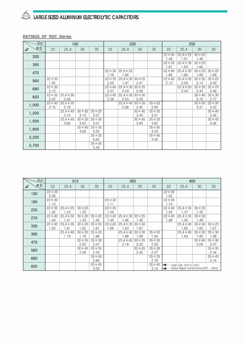
LARGE SIZED ALUMINUM ELECTROLYTIC CAPACITORS
22×25 22×300.98 1.02
22×30 22×30 22×351.10 1.11 1.14
22×35 25.4×25 30×20 22×35 22×40 25.4×30 30×251.26 1.23 1.25 1.26 1.29 1.27 1.30
22×40 25.4×30 30×25 35×20 22×40 25.4×30 30×25 22×45 25.4×35 30×301.43 1.41 1.43 1.45 1.49 1.46 1.49 1.48 1.45 1.48
22×45 25.4×35 30×25 35×20 22×45 25.4×35 30×30 25.4×40 30×30 35×251.62 1.61 1.62 1.61 1.66 1.63 1.67 1.65 1.65 1.67
25.4×40 30×30 35×25 25.4×40 30×30 35×25 25.4×45 30×35 35×301.79 1.78 1.86 1.88 1.88 1.94 1.84 1.85 1.88
30×35 35×30 25.4×45 30×35 35×30 30×40 35×302.02 2.07 2.18 2.20 2.25 2.09 2.07
30×40 35×35 30×45 35×30 35×352.28 2.33 2.40 2.37 2.34
35×40 35×35 35×452.66 2.78 2.74
35×45 35×403.00 3.15
22×30 25.4×25 30×201.49 1.51 1.48
22×35 25.4×30 30×251.67 1.63 1.66
22×30 25.4×25 22×40 25.4×30 30×25 35×201.78 1.80 1.88 1.86 1.89 1.89
22×30 22×35 25.4×30 30×25 22×45 25.4×35 30×30 35×251.95 2.00 1.97 2.01 2.13 2.09 2.14 2.09
22×30 22×40 25.4×30 30×25 25.4×50 30×35 35×252.15 2.27 2.24 2.28 2.44 2.43 2.46
22×35 25.4×30 22×45 25.4×35 30×30 30×40 35×302.42 2.45 2.58 2.53 2.59 2.75 2.77
22×40 25.4×35 25.4×40 30×35 35×25 30×45 35×352.75 2.79 2.88 2.95 2.90 3.31 3.22
25.4×40 30×30 35×25 30×40 35×30 35×403.15 3.13 3.27 3.34 3.31 3.42
25.4×45 30×35 35×30 30×45 35×35 35×453.60 3.63 3.57 3.84 3.82 4.06
30×40 35×30 35×404.09 4.05 4.33
35×35 35×454.63 4.92
35×405.30
RRAATTIINNGGSS OOFF RRDDCC SSeerriieess
116600 220000 225500
22 25.4 30 35 22 25.4 30 35 22 25.4 30 35
VVDDCC
∅∅DD
333300
339900
447700
556600
668800
882200
11,,000000
11,,220000
11,,550000
11,,880000
22,,220000
22,,770000
331155 335500 440000
22 25.4 30 35 22 25.4 30 35 22 25.4 30 35
VVDDCC
∅∅DD
115500
118800
222200
227700
333300
339900
447700
556600
668800
882200 Case Size ∅D×L(mm)Rated Ripple Current(Arms/85, 120Hz)
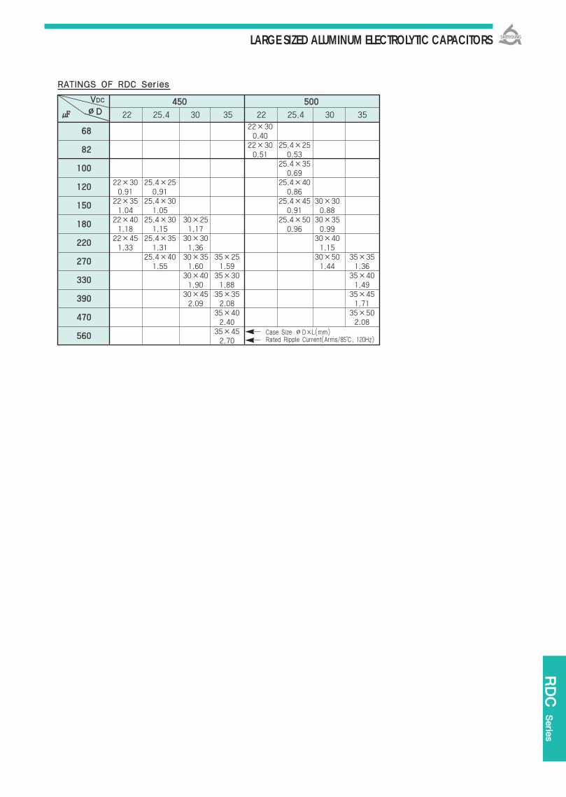
LARGE SIZED ALUMINUM ELECTROLYTIC CAPACITORS
22×300.40
22×30 25.4×250.51 0.53
25.4×350.69
22×30 25.4×25 25.4×400.91 0.91 0.86
22×35 25.4×30 25.4×45 30×301.04 1.05 0.91 0.88
22×40 25.4×30 30×25 25.4×50 30×351.18 1.15 1.17 0.96 0.99
22×45 25.4×35 30×30 30×401.33 1.31 1.36 1.15
25.4×40 30×35 35×25 30×50 35×351.55 1.60 1.59 1.44 1.36
30×40 35×30 35×401.90 1.88 1.49
30×45 35×35 35×452.09 2.08 1.71
35×40 35×502.40 2.08
35×452.70
RDC Serie
s
RRAATTIINNGGSS OOFF RRDDCC SSeerriieess
445500 550000
22 25.4 30 35 22 25.4 30 35
VVDDCC
∅∅DD
6688
8822
110000
112200
115500
118800
222200
227700
333300
339900
447700
556600 Case Size ∅D×L(mm)Rated Ripple Current(Arms/85, 120Hz)

LARGE SIZED ALUMINUM ELECTROLYTIC CAPACITORS
Non-solvent proof.
Downsized of KMH series.
For SMPS, Inverter
RoHS compliant.
Halogen-free capacitors are also available.
110055 22,,000000HHrrss aassssuurreedd..
KKMMHH TTDDAA
Downsized
TDA Series
16 100 VDC 160 500 VDC
-40 +105 -25 +105
±20% (M) (at 20, at 120Hz)
I=0.02CV() or 3mA, whichever is smaller Where, I:Max. leakage current() C:Nominal capacitance()
V:Rated voltage(VDC)
(at 20, 120Hz)
The following specifications shall be satisfied when the capacitors are restored to 20 after therated voltage is applied for 2,000 hours at 105
Capacitance change ±20% of the initial valueTanδ 200% of the initial specified valueLeakage Current The initial specified value
The following specifications shall be satisfied when the capacitors are restored to 20 after theexposing them at 105 for 1,000 hours without voltage applied. The rated voltage shall be appliedto the capacitors for a minimum of 30 minutes, at least 24 hours and not more than 48 hoursbefore the measurements.
Capacitance change ±20% of the initial valueTanδ 200% of the initial specified valueLeakage Current The initial specified value
Satisfied characteristics KS C IEC 60384-4
RRaatteedd VVoollttaaggee RRaannggee
OOppeerraattiinngg TTeemmppeerraattuurree RRaannggee
CCaappaacciittaannccee TToolleerraannccee
LLeeaakkaaggee CCuurrrreenntt
※※ DDiissssiippaattiioonn FFaaccttoorr ((TTaannδδ))
TTeemmppeerraattuurree CChhaarraacctteerriissttiiccss
LLooaadd LLiiffee
SShheellff LLiiffee
OOtthheerrss
Rated Voltage(VDC) 16 25 35 50~63 100 160400 420500
Z(-25)/Z(20) 4 3 3 2 2 4 8
Z(-40)/Z(20) 15 10 8 6 5 - -
※ For capacitors with CV products 100,000 Higher Tanδvalue may apply.※ When the capacitors exceed 1,000, 0.01 shall be added every 1,000 increase.
SSPPEECCIIFFIICCAATTIIOONNSS
(at 120HZ)
((MMaaxx..IImmppeeddaannccee rraattiioo))
(at 20, 5 minutes)
Frequency multiplying factor
RRAATTEEDD RRIIPPPPLLEE CCUURRRREENNTT
When capacitors are operated in any other condition at 120HZ, the maximum ripple current must bemultiplied by the figure shown in the table.
DDIIMMEENNSSIIOONNSS OOFF TTDDAA SSeerriieess
∅D=∅22~∅35 VN/VS type
PC board pin-out
Marking : BROWN SLEEVE, SILVER INKThe standard design has no bottom plate.
6600 112200 330000 11kk 1100kk~~
11665500VDC 0.95 1.00 1.03 1.05 1.08
6633110000VDC 0.92 1.00 1.07 1.13 1.19
116600225500VDC 0.81 1.00 1.17 1.32 1.45
331155550000VDC 0.77 1.00 1.16 1.30 1.41
Unit(mm)
FFrreeqq..((HHzz))VVDDCC
lltteemm CChhaarraacctteerriissttiiccss
Rated Voltage(VDC) 16 25~35 5063 100 160400 420500
Tanδ(Max.) 0.40 0.35 0.25 0.20 0.15 0.20

LARGE SIZED ALUMINUM ELECTROLYTIC CAPACITORS
22×251.06
22×30 25.4×251.32 1.33
22×35 25.4×301.50 1.51
22×40 25.4×35 30×25 1.69 1.71 1.68
22×45 25.4×40 30×30 1.94 1.98 1.95
22×25 25.4×25 25.4×45 30×35 35×251.33 1.52 2.23 2.26 2.17
22×30 25.4×30 25.4×50 30×40 35×301.50 1.74 2.53 2.57 2.50
22×30 25.4×25 25.4×35 30×25 30×45 35×351.69 1.70 1.99 1.91 2.88 2.86
22×35 25.4×30 25.4×40 30×30 30×50 35×401.93 1.85 2.27 2.24 3.28 3.27
22×40 25.4×35 30×25 25.4×45 30×35 35×45 2.16 2.18 2.15 2.54 2.56 3.67
22×45 25.4×35 30×30 35×25 25.4×50 30×40 35×502.43 2.39 2.35 2.48 2.86 2.86 3.80
22×50 25.4×40 30×35 35×25 30×452.75 2.70 2.76 2.70 3.22
25.4×50 30×40 35×30 30×503.30 3.30 3.25 3.66
30×45 35×353.60 3.56
30×50 35×404.04 4.03
35×454.56
22×251.40
22×301.57
22×30 25.4×251.72 1.80
22×35 25.4×30 30×251.95 1.96 1.99
22×25 25.4×25 22×40 25.4×35 30×251.57 1.87 2.20 2.23 2.19
22×30 25.4×30 30×25 22×50 25.4×40 30×301.73 2.12 2.15 2.55 2.53 2.53
22×30 25.4×25 25.4×35 30×25 25.4×45 30×35 35×301.97 1.97 2.42 2.39 2.87 2.90 2.75
22×35 25.4×30 25.4×40 30×30 25.4×50 30×40 35×30 2.22 2.24 2.74 2.70 3.24 3.23 3.23
22×40 25.4×35 25.4×45 30×35 30×45 35×35 2.55 2.58 3.15 3.13 3.72 3.67
22×45 25.4×40 30×30 25.4×50 30×40 35×40 2.87 2.92 2.88 3.54 3.54 4.37
25.4×45 30×35 30×45 35×50 3.32 3.29 4.04 4.92
25.4×50 30×40 35×303.78 3.77 3.45
30×45 35×354.30 4.26
30×50 35×404.81 4.79
35×505.43
TDA Serie
s
Case Size ∅D×L(mm)Rated Ripple Current(Arms/105, 120Hz)
RRAATTIINNGGSS OOFF TTDDAA SSeerriieess
1166 2255 3355
22 25.4 30 35 22 25.4 30 35 22 25.4 30 35
5500 6633 110000
22 25.4 30 35 22 25.4 30 35 22 25.4 30 35
VVDDCC
∅∅DD
556600
882200
11,,000000
11,,220000
11,,550000
11,,880000
22,,220000
22,,770000
33..330000
33,,990000
44,,770000
55,,660000
66,,880000
88,,220000
1100,,000000
1122,,000000
22×251.50
22×251.63
22×301.86
22×352.11
22×402.39
22×452.69
35×252.74
35×303.27
35×303.50
35×353.97
35×454.73
35×505.39
22×251.19
22×251.33
22×301.51
22×351.73
22×401.97
22×502.29
35×252.56
35×302.79
35×353.19
35×403.64
35×453.90
35×504.40
VVDDCC
∅∅DD
33,,330000
33,,990000
44,,770000
55,,660000
66,,880000
88,,220000
1100,,000000
1122,,000000
1155,,000000
1188,,000000
2222,,000000
2277,,000000
3333,,000000
3399,,000000
4477,,000000

LARGE SIZED ALUMINUM ELECTROLYTIC CAPACITORS
22×20 0.22
22×25 25.4×20 0.51 0.46
22×25 22×25 25.4×20 0.64 0.55 0.53
22×30 22×30 25.4×25 30×20 0.68 0.67 0.67 0.60
22×30 25.4×25 25.4×25 22×35 25.4×30 30×25 35×20 0.75 0.76 0.73 0.76 0.76 0.76 0.70
22×35 25.4×30 25.4×30 30×25 22×40 25.4×30 30×25 35×200.82 0.83 0.83 0.83 0.82 0.80 0.82 0.80
22×40 25.4×30 30×25 25.4×30 30×25 22×45 25.4×35 30×30 35×250.91 0.88 0.85 0.89 0.91 0.88 0.88 0.89 0.90
22×45 25.4×35 30×30 25.4×35 30×30 35×25 22×50 25.4×40 30×30 35×250.94 0.96 1.00 0.98 0.98 0.96 1.01 0.99 0.98 1.02
25.4×45 30×35 35×25 25.4×40 30×30 35×25 25.4×45 30×35 35×301.13 1.12 1.06 1.10 1.08 1.12 1.12 1.12 1.16
25.4×50 30×40 35×30 25.4×45 30×40 35×30 25.4×50 30×40 35×35 1.28 1.28 1.30 1.24 1.24 1.29 1.27 1.28 1.35
30×45 35×35 25.4×60 30×40 35×35 25.4×60 30×45 35×351.44 1.42 1.47 1.40 1.47 1.51 1.49 1.4730×50 35×40 25.4×60 30×45 35×35 30×50 35×401.63 1.64 1.70 1.67 1.65 1.63 1.62
35×45 30×50 35×40 30×60 35×50 1.87 1.87 1.86 1.88 1.88
35×50 30×60 35×50 35×60 2.07 2.18 2.18 2.19
35×60
25.4×20 0.48
25.4×20 0.59
25.4×20 22×25 25.4×20 0.64 0.78 0.75
25.4×20 25.4×20 22×30 25.4×25 30×20 0.66 0.70 0.96 0.95 0.93
25.4×20 25.4×20 22×30 25.4×25 30×20 0.80 0.83 1.11 1.10 1.10
22×25 25.4×20 25.4×25 30×20 22×35 25.4×30 30×25 35×201.20 1.10 1.21 1.20 1.20 1.20 1.26 1.17
22×30 25.4×25 30×20 25.4×25 30×25 22×40 25.4×35 30×25 35×251.30 1.29 1.19 1.27 1.25 1.45 1.49 1.44 1.49
22×30 25.4×25 30×20 35×20 25.4×30 30×25 35×20 22×45 25.4×35 30×30 35×251.36 1.39 1.31 1.35 1.41 1.50 1.30 1.53 1.50 1.57 1.57
22×35 25.4×30 30×25 35×20 25.4×35 30×30 35×25 22×50 25.4×40 30×30 35×251.46 1.51 1.54 1.41 1.53 1.57 1.52 1.77 1.74 1.73 1.72
22×40 25.4×30 30×25 35×20 25.4×35 30×30 35×25 25.4×50 30×35 35×301.66 1.65 1.68 1.69 1.69 1.74 1.72 1.84 1.94 1.97
22×45 25.4×30 30×30 35×25 25.4×45 30×35 35×30 25.4×60 30×40 35×35 1.99 1.95 2.00 1.91 1.99 2.00 2.04 2.20 2.10 1.98
22×50 25.4×40 30×30 35×25 25.4×50 30×40 35×35 30×50 35×40 2.18 2.14 2.15 2.17 2.21 2.23 2.30 2.31 2.30
25.4×45 30×35 35×30 25.4×60 30×45 35×35 30×60 35×452.39 2.37 2.41 2.57 2.53 2.57 2.50 2.43
25.4×60 30×40 35×35 30×50 35×40 35×50 2.87 2.74 2.79 3.01 2.99 2.80
30×45 35×35 30×60 35×45 3.14 3.11 3.47 3.38
30×60 35×45 35×60 3.76 3.66 3.60
Case Size ∅D×L(mm)Rated Ripple Current(Arms/105, 120Hz)
RRAATTIINNGGSS OOFF TTDDAA SSeerriieess
116600 220000 225500
22 25.4 30 35 22 25.4 30 35 22 25.4 30 35
VVDDCC
∅∅DD
110000
112200
115500
118800
222200
227700
333300
339900
447700
556600
668800
882200
11,,000000
11,,220000
11,,550000
11,,880000
22,,220000
331155 335500 440000
22 25.4 30 35 22 25.4 30 35 22 25.4 30 35
VVDDCC
∅∅DD
4477
6688
8822
110000
112200
115500
118800
222200
227700
333300
339900
447700
556600
668800
882200 2.53
22×200.53
22×200.62
22×250.70
22×250.87
22×301.20
22×301.28
22×351.41
22×451.56
22×451.73
22×250.56
22×250.67
22×300.73
22×350.83
22×400.89
22×450.98
22×501.12

LARGE SIZED ALUMINUM ELECTROLYTIC CAPACITORS
22×25 0.40
22×25 22×30 25.4×25 0.50 0.50 0.50
22×25 25.4×25 22×30 24.5×25 0.51 0.63 0.55 0.54
22×30 25.4×30 22×35 25.4×30 30×25 0.58 0.69 0.62 0.62 0.64
22×35 25.4×30 30×25 22×40 25.4×35 30×30 35×250.72 0.73 0.75 0.70 0.71 0.72 0.73
22×45 25.4×35 30×25 35×25 22×45 25.4×40 30×30 35×250.79 0.74 0.75 0.81 0.77 0.75 0.74 0.75
22×50 25.4×40 30×30 35×25 25.4×45 30×35 35×30 0.89 0.89 0.88 0.87 0.84 0.87 0.88
25.4×45 30×35 35×30 25.4×50 30×40 35×301.01 1.00 1.05 0.98 0.98 1.00
30×45 35×35 25.4×60 30×45 35×351.19 1.19 1.17 1.15 1.17
30×50 35×40 30×50 35×401.36 1.39 1.38 1.38
35×45 30×60 35×451.57 1.60 1.56
35×50 35×501.73 1.72
35×601.98
TDA Serie
s
RRAATTIINNGGSS OOFF TTDDAA SSeerriieess
442200 445500
22 25.4 30 35 22 25.4 30 35
VVDDCC
∅∅DD
5566
6688
8822
110000
112200
115500
118800
222200
227700
333300
339900
447700
556600
550000
22 25.4 30 35
Case Size ∅D×L(mm)Rated Ripple Current(Arms/105, 120Hz)
22×350.46
22×400.45
22×450.56
25.4×300.46
25.4×350.53
25.4×350.58
25.4×400.65
25.4×450.75
30×300.48
30×300.55
30×350.58
30×350.66
30×400.76
30×450.80
30×500.90
30×601.10
35×300.78
35×350.81
35×400.93
35×451.11
35×501.28
35×601.50
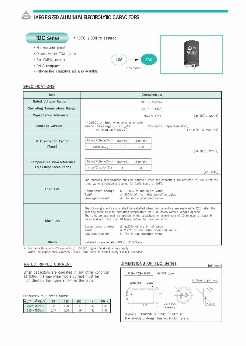
LARGE SIZED ALUMINUM ELECTROLYTIC CAPACITORS
Non-solvent proof.
Downsized of TDA series.
For SMPS, Inverter
RoHS compliant.
Halogen-free capacitors are also available.
110055 22,,000000HHrrss aassssuurreedd..
TTDDAA TTDDCC
Downsized
TDC Series
160 450 VDC
-25 +105
±20% (M) (at 20, 120Hz)
I=0.02CV or 3mA, whichever is smaller Where, I:Leakage current() C:Nominal capacitance()
V:Rated voltage(VDC)
(at 20, 120Hz)
The following specifications shall be satisfied when the capacitors are restored to 20 after therated working voltage is applied for 2,000 hours at 105
Capacitance change ±20% of the initial valueTanδ 200% of the initial specified valueLeakage Current The initial specified value
The following specifications shall be satisfied when the capacitors are restored to 20 after theexposing them at max. operating temperature for 1,000 hours without voltage applied. The rated voltage shall be applied to the capacitors for a minimum of 30 minutes, at least 24hours and not more than 48 hours before the measurements.
Capacitance change ±20% of the initial valueTanδ 200% of the initial specified valueLeakage Current The initial specified value
Satisfied characteristics KS C IEC 60384-4
RRaatteedd VVoollttaaggee RRaannggee
OOppeerraattiinngg TTeemmppeerraattuurree RRaannggee
CCaappaacciittaannccee TToolleerraannccee
LLeeaakkaaggee CCuurrrreenntt
LLooaadd LLiiffee
SShheellff LLiiffee
OOtthheerrss
Rated Voltage(VDC) 160400 420450
Tanδ(Max.) 0.15 0.20
Rated Voltage(VDC) 160400 420450
Z(-25)/Z(20) 4 8
※ For capacitors with CV products 100,000 Higher Tanδvalue may apply.※ When the capacitance exceeds 1,000, 0.01 shall be added every 1,000 increase.
6600 112200 330000 11kk 1100kk~~
116600225500VDC 0.81 1.00 1.17 1.32 1.45
331155445500VDC 0.77 1.00 1.16 1.30 1.41
SSPPEECCIIFFIICCAATTIIOONNSS
(at 120HZ)
TTeemmppeerraattuurree CChhaarraacctteerriissttiiccss
((MMaaxx..IImmppeeddaannccee rraattiioo))
※※ DDiissssiippaattiioonn FFaaccttoorr
((TTaannδδ))
(at 20, 5 minutes)
Frequency multiplying factor
RRAATTEEDD RRIIPPPPLLEE CCUURRRREENNTT
When capacitors are operated in any other condition at 120HZ, the maximum ripple current must bemultiplied by the figure shown in the table.
DDIIMMEENNSSIIOONNSS OOFF TTDDCC SSeerriieess
∅D=∅22~∅35 VN/VS type
PC board pin-out
Marking : BROWN SLEEVE, SILVER INKThe standard design has no bottom plate.
Unit(mm)
lltteemm CChhaarraacctteerriissttiiccss
FFrreeqq..((HHzz))VVDDCC

LARGE SIZED ALUMINUM ELECTROLYTIC CAPACITORS
22×200.78
22×25 25.4×201.00 0.95
22×20 25.4×201.20 1.10
22×20 22×25 25.4×20 25.4×25 30×20 35×201.20 1.28 1.27 1.20 1.26 1.17
22×25 25.4×20 30×20 22×25 25.4×20 30×20 30×20 35×201.32 1.39 1.31 1.31 1.43 1.43 1.44 1.49
22×30 25.4×25 30×20 22×30 25.4×25 30×20 30×25 35×201.46 1.51 1.54 1.45 1.53 1.53 1.57 1.57
22×30 25.4×25 30×25 22×40 25.4×30 30×25 35×20 30×30 35×251.66 1.68 1.68 1.67 1.67 1.67 1.67 1.80 1.72
22×35 25.4×30 30×25 22×45 25.4×35 30×25 35×20 30×30 35×301.87 1.88 1.96 1.75 1.75 1.74 1.72 1.94 2.10
22×40 25.4×30 30×25 35×25 22×50 25.4×40 30×30 35×25 30×35 35×302.09 2.14 2.15 2.04 2.04 2.04 2.04 2.04 2.29 2.36
25.4×35 30×30 35×25 30×35 35×30 30×45 35×352.38 2.40 2.55 2.30 2.30 2.59 2.63
25.4×40 30×35 35×30 35×302.66 2.69 2.86 2.65
TDC Serie
s
RRAATTIINNGGSS OOFF TTDDCC SSeerriieess
116600 220000 225500
22 25.4 30 35 22 25.4 30 35 22 25.4 30 35
VVDDCC
∅∅DD
331155 335500 440000
22 25.4 30 35 22 25.4 30 35 22 25.4 30 35
VVDDCC
∅∅DD
Case Size ∅D×L(mm)Rated Ripple Current(Arms/105, 120Hz)
22×200.55
22×25 22×25 25.4×200.75 0.66 0.67
22×25 22×25 25.4×250.82 0.72 0.76
22×30 25.4×25 22×30 25.4×25 25.4×25 30×200.91 0.94 0.84 0.89 0.86 0.89
25.4×25 22×35 25.4×30 25.4×30 30×25 35×201.13 0.98 0.94 0.97 1.02 1.02
25.4×30 30×25 22×40 25.4×30 30×25 25.4×35 30×30 35×201.19 1.17 1.04 1.07 1.13 1.12 1.12 1.11
25.4×40 30×30 35×20 25.4×35 30×30 25.4×40 30×30 35×251.41 1.28 1.30 1.24 1.27 1.26 1.27 1.27
30×35 35×30 25.4×40 30×35 35×25 25.4×45 30×35 35×301.40 1.49 1.39 1.43 1.49 1.44 1.43 1.44
30×40 35×30 25.4×50 30×40 35×30 25.4×50 30×40 35×301.44 1.64 1.55 1.60 1.66 1.51 1.60 1.63
30×45 35×35 25.4×50 30×45 35×30 30×45 35×351.71 1.82 1.72 1.81 1.83 1.81 1.80
35×40 35×352.00 2.07
118800
222200
227700
333300
339900
447700
556600
668800
882200
11,,000000
11,,220000
8822
110000
112200
115500
118800
222200
227700
333300
339900
447700
556600

LARGE SIZED ALUMINUM ELECTROLYTIC CAPACITORS
22×200.50
22×20 22×25 25.4×250.58 0.59 0.62
22×25 25.4×25 25.4×250.66 0.69 0.70
22×30 25.4×25 30×20 25.4×300.75 0.77 0.75 0.75
22×40 25.4×30 30×25 25.4×30 30×250.86 0.88 0.88 0.88 0.87
22×45 25.4×35 30×30 35×20 25.4×35 30×250.96 0.97 1.02 1.05 1.01 1.00
22×50 25.4×40 30×30 35×20 30×351.11 1.14 1.14 1.12 1.10
25.4×45 30×40 35×30 30×40 35×301.29 1.30 1.35 1.24 1.25
30×45 35×35 35×351.48 1.49 1.42
35×40 35×401.64 1.63
35×45 35×451.79 1.78
RRAATTIINNGGSS OOFF TTDDCC SSeerriieess
442200 445500
22 25.4 30 35 22 25.4 30 35
VVDDCC
∅∅DD
Case Size ∅D×L(mm)Rated Ripple Current(Arms/105, 120Hz)
6688
8822
110000
112200
115500
118800
222200
227700
333300
339900
447700
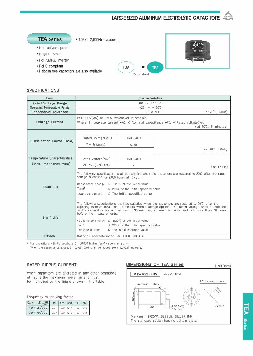
LARGE SIZED ALUMINUM ELECTROLYTIC CAPACITORS
TEA Serie
s
110055 22,,000000HHrrss aassssuurreedd..
Non-solvent proof
Height 15mm
For SMPS, Inverter
RoHS compliant.Halogen-free capacitors are also available.
※ For capacitors with CV products > 100,000 higher Tanδvalue may apply. When the capacitance exceeds 1,000, 0.01 shall be added every 1,000 increase.
SSPPEECCIIFFIICCAATTIIOONNSS
LLooaadd LLiiffee
SShheellff LLiiffee
(at 120Hz)((MMaaxx.. IImmppeeddaannccee rraattiioo))
(at 20, 120Hz)
TEA Series
Rated voltage(VDC) 160~400
Tanδ(Max.) 0.20
Rated voltage(VDC) 160~400
Z(-25)/Z(20) 4
6600 112200 330000 11kk 1100kk~~
116600~~225500VVDDCC 0.81 1.00 1.17 1.32 1.45
335500~~440000VVDDCC 0.77 1.00 1.16 1.30 1.41
TTDDAA TTEEAA
Downsized
※
Frequency multiplying factor
RRAATTEEDD RRIIPPPPLLEE CCUURRRREENNTT
When capacitors are operated in any other conditions at 120Hz the maximum ripple current must be multiplied by the figure shown in the table
DDIIMMEENNSSIIOONNSS OOFF TTEEAA SSeerriieess
∅D=∅22~∅35 VN/VS type
PC board pin-out
Marking : BROWN SLEEVE, SILVER INKThe standard design has no bottom plate.
IItteemm CChhaarraacctteerriissttiiccss
RRaatteedd VVoollttaaggee RRaannggee 160 ~ 400 VDC
OOppeerraattiinngg TTeemmppeerraattuurree RRaannggee -25 ~ +105
CCaappaacciittaannccee TToolleerraannccee ±20%(M) (at 20, 120Hz)
I=0.02CV(μA) or 3mA, whichever is smaller.LLeeaakkaaggee CCuurrrreenntt Where, I: Leakage current(μA), C:Nominal capacitance(μF), V:Rated voltage(VDC)
(at 20, 5 minutes)
DDiissssiippaattiioonn FFaaccttoorr((TTaannδδ))
TTeemmppeerraattuurree CChhaarraacctteerriissttiiccss
The following specifications shall be satisfied when the capacitors are restored to 20 after the ratedvoltage is applied for 2,000 hours at 105.
Capacitance change ±20% of the initial value
Tanδ 200% of the initial specified value
Leakage current The initial specified value
The following specifications shall be satisfied when the capacitors are restored to 20 after the exposing them at 105 for 1,000 hours without voltage applied. The rated voltage shall be appliedto the capacitors for a minimum of 30 minutes, at least 24 hours and not more than 48 hours before the measurements.
Capacitance change ±20% of the initial value
Tanδ 200% of the initial specified value
Leakage current The initial specified value
OOtthheerrss Satisfied characteristics KS C IEC 60384-4
Unit(mm)
FFrreeqq..((HHzz))VVDDCC
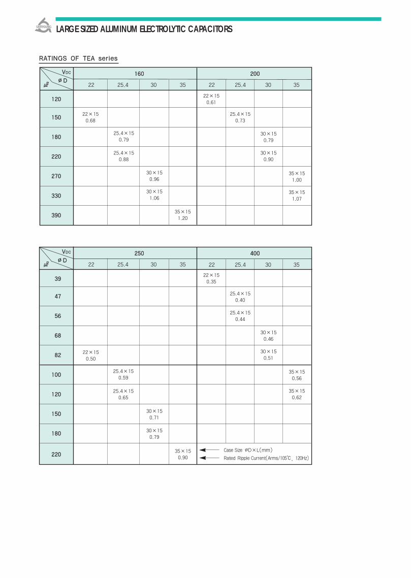
LARGE SIZED ALUMINUM ELECTROLYTIC CAPACITORS
116600 220000
112200
115500
118800
222200
227700
333300
339900
22 25.4 30 35 22 25.4 30 35
22×150.61
22×150.68
25.4×150.79
25.4×150.73
30×150.79
30×150.90
35×151.00
35×151.07
25.4×150.88
30×150.96
30×151.06
35×151.20
225500 440000
3399
4477
5566
6688
8822
110000
112200
115500
118800
222200
22 25.4 30 35
22×150.35
22×150.50
25.4×150.40
25.4×150.59
25.4×150.65
25.4×150.44
30×150.46
30×150.51
35×150.56
35×150.62
30×150.71
30×150.79
35×150.90
Case Size ∅D×L(mm)
Rated Ripple Current(Arms/105, 120Hz)
RRAATTIINNGGSS OOFF TTEEAA sseerriieess
VVDDCC
∅∅DD
VVDDCC
∅∅DD 22 25.4 30 35

LARGE SIZED ALUMINUM ELECTROLYTIC CAPACITORS
RLS Serie
s
Non-solvent proof.
Downsized of RDA series.
For SMPS, Inverter
RoHS compliant.
Halogen-free capacitors are also available.
8855 33,,000000HHrrss aassssuurreedd..
RRDDCC RRLLSS
Long Life
RLS Series
160 450 VDC
-25 +85
±20% (M) (at 20, 120Hz)
I=0.02CV or 3mA, whichever is smaller Where, I:Leakage current() C:Nominal capacitance()
V:Rated voltage(VDC)
(at 20, 120Hz)
The following specifications shall be satisfied when the capacitors are restored to 20 after therated working voltage is applied for 3,000 hours at 85
Capacitance change ±20% of the initial valueTanδ 200% of the initial specified valueLeakage Current The initial specified value
The following specifications shall be satisfied when the capacitors are restored to 20 after theexposing them at max. operating temperature for 1,000 hours without voltage applied. The rated voltage shall be applied to the capacitors for a minimum of 30 minutes, at least 24hours and not more than 48 hours before the measurement.
Capacitance change ±15% of the initial valueTanδ 150% of the initial specified valueLeakage Current The initial specified value
Satisfied characteristics KS C IEC 60384-4
RRaatteedd VVoollttaaggee RRaannggee
OOppeerraattiinngg TTeemmppeerraattuurree RRaannggee
CCaappaacciittaannccee TToolleerraannccee
LLeeaakkaaggee CCuurrrreenntt
LLooaadd LLiiffee
SShheellff LLiiffee
OOtthheerrss
Rated Voltage(VDC) 160400 420450
Tanδ(Max.) 0.15 0.20
Rated Voltage(VDC) 160400 420450
Z(-25)/Z(20) 4 8
※ For capacitors with CV products 100,000 Higher Tanδvalue may apply.※ When the capacitance exceeds 1,000, 0.01 shall be added every 1,000 increase.
6600 112200 330000 11kk 1100kk~~
116600225500VDC 0.81 1.00 1.17 1.32 1.45
335500445500VDC 0.77 1.00 1.16 1.30 1.41
SSPPEECCIIFFIICCAATTIIOONNSS
(at 120HZ)
TTeemmppeerraattuurree CChhaarraacctteerriissttiiccss
((MMaaxx..IImmppeeddaannccee rraattiioo))
※※ DDiissssiippaattiioonn FFaaccttoorr
((TTaannδδ))
(at 20, 5 minutes)
Frequency multiplying factor
RRAATTEEDD RRIIPPPPLLEE CCUURRRREENNTT
When capacitors are operated in any other condition at 120HZ, the maximum ripple current must bemultiplied by the figure shown in the table.
DDIIMMEENNSSIIOONNSS OOFF RRLLSS SSeerriieess
∅D=∅22~∅35 VN/VS type
PC board pin-out
Marking : BROWN SLEEVE, SILVER INKThe standard design has no bottom plate.
Unit(mm)
lltteemm CChhaarraacctteerriissttiiccss
FFrreeqq..((HHzz))VVDDCC

LARGE SIZED ALUMINUM ELECTROLYTIC CAPACITORS
22×20 0.54
22×200.59
22×25 25.4×20 0.71 0.68
22×20 25.4×20 22×25 25.4×20 30×20 0.72 0.74 0.86 0.74 0.79
22×25 25.4×20 22×30 25.4×25 30×200.80 0.82 0.95 0.97 0.87
22×25 25.4×20 25.4×25 30×20 22×35 25.4×30 30×25 35×201.04 0.90 1.13 0.95 1.07 1.09 1.12 0.99
22×30 25.4×25 30×20 25.4×30 30×25 22×40 25.4×30 30×25 35×201.2 1.22 1.06 1.27 1.20 1.18 1.25 1.29 1.06
22×30 25.4×25 30×20 25.4×30 30×25 35×20 22×45 25.4×35 30×30 35×251.34 1.37 1.16 1.44 1.52 1.16 1.32 1.40 1.45 1.33
22×35 25.4×30 30×25 35×20 25.4×35 30×30 35×20 22×50 25.4×40 30×30 35×251.47 1.53 1.54 1.29 1.64 1.66 1.47 1.48 1.59 1.64 1.66
25.4×35 30×25 35×25 25.4×40 30×30 35×25 25.4×45 30×35 35×30 1.73 1.8 1.49 1.79 1.82 1.63 1.73 1.89 1.90
30×30 35×25 25.4×45 30×35 35×30 25.4×50 30×40 35×352.03 1.8 2.00 2.05 2.05 2.12 2.12 2.1530×35 35×30 25.4×50 30×40 35×35 30×45 35×402.23 2.3 2.12 2.26 2.28 2.35 2.3830×35 35×30 30×45 35×35 30×50 35×45 2.53 2.55 2.51 2.54 2.65 2.68
35×35 30×50 35×40 35×50 2.75 2.85 2.85 2.88
35×403.15
Case Size ∅D×L(mm)Rated Ripple Current(Arms/85, 120Hz)
335500 440000 445500
22 25.4 30 35 22 25.4 30 35 22 25.4 30 35
VVDDCC
∅∅DD
4477
5566
6688
8822
110000
112200
115500
118800
222200
227700
333300
339900
447700
556600
668800
22×200.65
22×250.84
22×250.99
22×301.09
22×351.24
22×401.41
22×451.58
22×501.65
22×200.97
22×201.06
22×20 22×25 25.4×201.18 1.24 1.22
22×20 22×20 25.4×20 22×30 25.4×201.30 1.37 1.35 1.54 1.32
22×25 22×25 25.4×20 22×30 25.4×25 30×201.50 1.51 1.49 1.66 1.61 1.58
22×25 25.4×20 22×30 25.4×25 30×20 22×35 25.4×30 30×25 35×201.62 1.62 1.73 1.71 1.71 1.88 1.88 1.86 1.71
22×30 25.4×25 22×30 25.4×25 30×20 25.4×35 30×25 35×201.86 1.86 1.97 1.95 1.88 2.15 2.05 1.88
22×30 25.4×25 30×20 22×40 25.4×30 30×25 35×20 25.4×35 30×30 35×252.15 2.15 2.05 2.18 2.15 2.15 2.05 2.35 2.36 2.35
22×35 25.4×30 30×25 35×20 22×40 25.4×30 30×25 35×20 30×30 35×252.35 2.33 2.33 2.26 2.48 2.48 2.48 2.36 2.71 2.58
22×40 25.4×30 30×25 35×20 22×45 25.4×40 30×30 35×25 30×35 35×302.68 2.65 2.64 2.49 2.81 2.79 2.80 2.83 2.98 2.88
22×45 25.4×35 30×30 35×25 22×50 25.4×40 30×35 35×30 30×40 35×353.02 3.00 2.96 3.31 3.28 3.28 3.15 3.26 3.56 3.48
22×50 25.4×40 30×30 35×25 25.4×45 30×35 35×303.47 3.43 3.41 3.4 3.61 3.61 3.57
RRAATTIINNGGSS OOFF RRLLSS SSeerriieess
116600 220000 225500
22 25.4 30 35 22 25.4 30 35 22 25.4 30 35
VVDDCC
∅∅DD
115500
118800
222200
227700
333300
339900
447700
556600
668800
882200
11,,000000
11,,220000
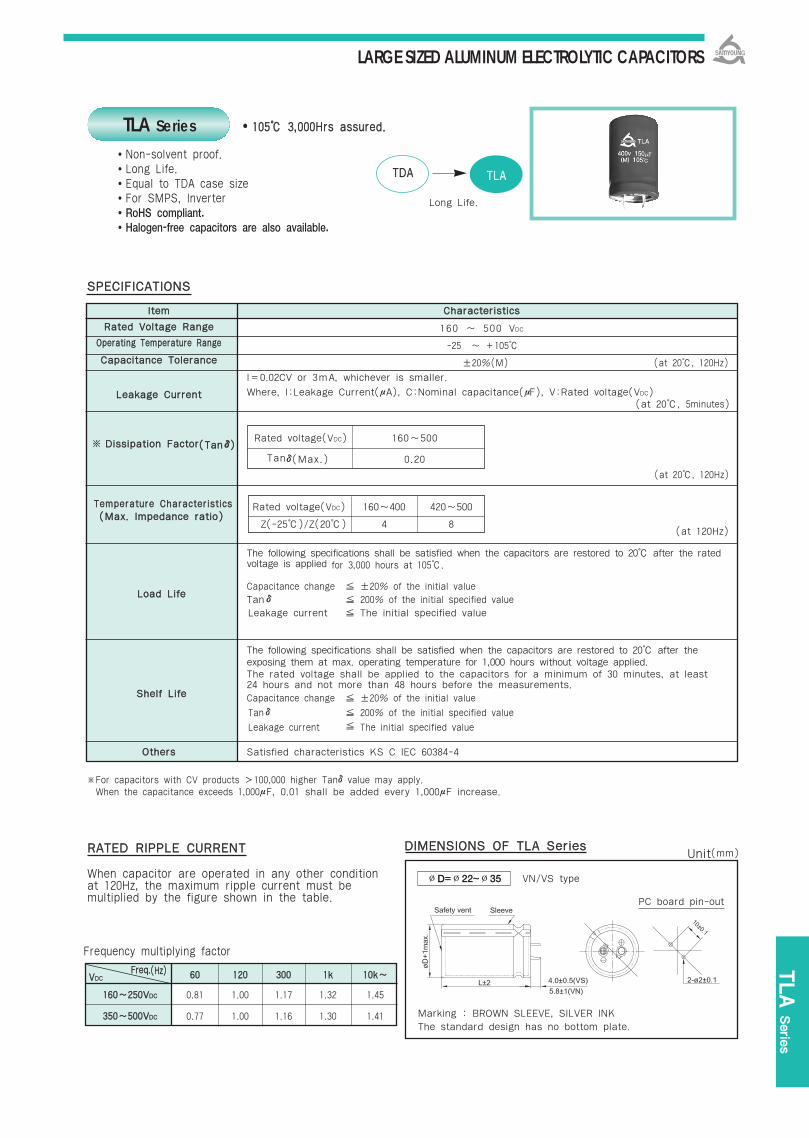
LARGE SIZED ALUMINUM ELECTROLYTIC CAPACITORS
TLA
Serie
s
110055 33,,000000HHrrss aassssuurreedd..
Non-solvent proof.Long Life.Equal to TDA case size For SMPS, InverterRoHS compliant.Halogen-free capacitors are also available.
SSPPEECCIIFFIICCAATTIIOONNSS
Rated voltage(VDC) 160~500
Tanδ(Max.) 0.20
LLooaadd LLiiffee
SShheellff LLiiffee
Rated voltage(VDC) 160~400 420~500
Z(-25)/Z(20) 4 8 (at 120Hz)
((MMaaxx.. IImmppeeddaannccee rraattiioo))
(at 20, 120Hz)
TLA Series
TTDDAA TTLLAA
Long Life.
※For capacitors with CV products 100,000 higher Tanδvalue may apply.When the capacitance exceeds 1,000μF, 0.01 shall be added every 1,000μF increase.
6600 112200 330000 11kk 1100kk~~
116600~~225500VVDDCC 0.81 1.00 1.17 1.32 1.45
335500~~550000VVDDCC 0.77 1.00 1.16 1.30 1.41
((TTaannδδ))※
Frequency multiplying factor
RRAATTEEDD RRIIPPPPLLEE CCUURRRREENNTT
When capacitor are operated in any other condition at 120Hz, the maximum ripple current must be multiplied by the figure shown in the table.
DDIIMMEENNSSIIOONNSS OOFF TTLLAA SSeerriieess
∅D=∅22~∅35 VN/VS type
PC board pin-out
Marking : BROWN SLEEVE, SILVER INKThe standard design has no bottom plate.
Unit(mm)
IItteemm CChhaarraacctteerriissttiiccss
RRaatteedd VVoollttaaggee RRaannggee 160 ~ 500 VDC
OOppeerraattiinngg TTeemmppeerraattuurree RRaannggee -25 ~ +105
CCaappaacciittaannccee TToolleerraannccee ±20%(M) (at 20, 120Hz)
I=0.02CV or 3mA, whichever is smaller.
LLeeaakkaaggee CCuurrrreenntt Where, I:Leakage Current(μA), C:Nominal capacitance(μF), V:Rated voltage(VDC)(at 20, 5minutes)
DDiissssiippaattiioonn FFaaccttoorr
TTeemmppeerraattuurree CChhaarraacctteerriissttiiccss
The following specifications shall be satisfied when the capacitors are restored to 20 after the ratedvoltage is applied for 3,000 hours at 105.
Capacitance change ±20% of the initial valueTanδ 200% of the initial specified valueLeakage current The initial specified value
The following specifications shall be satisfied when the capacitors are restored to 20 after theexposing them at max. operating temperature for 1,000 hours without voltage applied.The rated voltage shall be applied to the capacitors for a minimum of 30 minutes, at least24 hours and not more than 48 hours before the measurements.
Capacitance change ±20% of the initial value
Tanδ 200% of the initial specified value
Leakage current The initial specified value
OOtthheerrss Satisfied characteristics KS C IEC 60384-4
FFrreeqq..((HHzz))VVDDCC
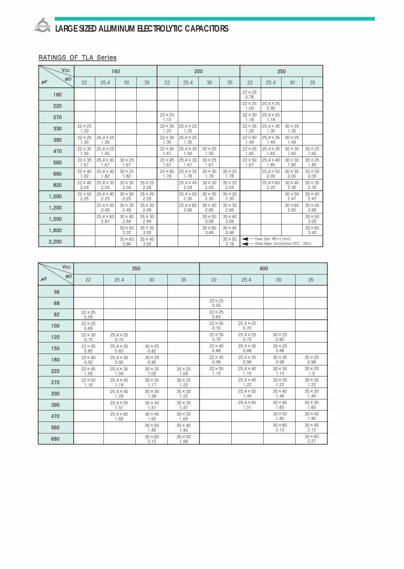
LARGE SIZED ALUMINUM ELECTROLYTIC CAPACITORS
RRAATTIINNGGSS OOFF TTLLAA SSeerriieess
∅∅DD
22×251.20
22×25 25.4×251.30 1.26
22×30 25.4×251.55 1.55
22×35 25.4×30 30×251.67 1.67 1.67
22×40 25.4×30 30×251.82 1.82 1.82
22×45 25.4×35 30×30 35×252.04 2.04 2.04 2.04
22×50 25.4×40 30×30 35×252.25 2.25 2.25 2.25
25.4×45 30×35 35×302.49 2.49 2.49
25.4×60 30×40 35×302.97 2.84 2.84
30×45 35×353.32 3.00
30×60 35×453.86 3.50
22 25.4 30 35 22 25.4 30 35 22 25.4 30 35
22×251.10
22×30 25.4×251.25 1.25
22×30 25.4×251.35 1.35
22×40 25.4×30 30×251.67 1.50 1.50
22×45 25.4×30 30×251.67 1.67 1.67
22×45 25.4×35 30×30 35×251.78 1.78 1.78 1.78
25.4×45 30×30 35×252.04 2.04 2.04
25.4×50 30×35 35×302.30 2.30 2.30
25.4×60 30×40 35×352.66 2.65 2.65
30×50 35×403.08 3.08
30×60 35×453.49 3.48
35×503.78
22×250.78
22×25 25.4×251.00 0.95
22×30 25.4×251.18 1.18
22×35 25.4×35 30×251.30 1.30 1.30
22×40 25.4×35 30×251.49 1.49 1.49
22×45 25.4×35 30×30 35×251.65 1.65 1.65 1.65
22×50 25.4×40 30×30 35×251.67 1.80 1.80 1.80
25.4×50 30×35 35×302.00 2.00 2.00
25.4×60 30×40 35×352.20 2.30 2.30
30×50 35×402.47 2.47
30×60 35×452.85 2.60
35×503.00
35×603.42
118800
222200
227700
333300
339900
447700
556600
668800
882200
11,,000000
11,,220000
11,,550000
11,,880000
22,,220000
116600 220000 225500
Case Size ∅D×L(mm)Rated Ripple Current(Arms/105, 120Hz)
μμFF
VVDDCC
VVDDCC
∅∅DD
22×250.55
22×250.69
22×30 25.4×250.75 0.75
22×35 25.4×30 30×250.82 0.83 0.82
22×40 25.4×30 30×250.92 0.92 0.90
22×45 25.4×35 30×30 35×251.05 1.04 1.02 1.04
22×50 25.4×40 30×30 35×251.16 1.18 1.17 1.20
25.4×45 30×35 35×301.29 1.34 1.22
25.4×50 30×40 35×351.51 1.51 1.47
25.4×60 30×45 35×351.66 1.65 1.69
30×50 35×401.85 1.90
30×60 35×502.15 1.99
22×250.55
22×250.64
22×30 25.4×250.70 0.70
22×35 25.4×25 30×250.75 0.75 0.80
22×40 25.4×30 30×250.88 0.88 0.88
22×45 25.4×35 30×30 35×250.98 0.98 0.98 0.98
22×50 25.4×40 30×30 35×251.10 1.10 1.10 1.0
25.4×45 30×35 35×301.22 1.22 1.22
25.4×50 30×40 35×301.44 1.44 1.44
25.4×60 30×45 35×351.51 1.60 1.60
30×50 35×401.90 1.90
30×60 35×452.10 2.12
35×602.27
22 25.4 30 35 22 25.4 30 35
5566
6688
8822
110000
112200
115500
118800
222200
227700
333300
339900
447700
556600
668800
335500 440000
μμFF

LARGE SIZED ALUMINUM ELECTROLYTIC CAPACITORS
TLA Serie
s
RRAATTIINNGGSS OOFF TTLLAA SSeerriieess
Case Size ∅D×L(mm)Rated Ripple Current(Arms/105, 120Hz)
VVDDCC
∅∅DD
22×250.50
22×25 25.4×250.64 0.58
22×30 25.4×250.70 0.70
22×35 25.4×30 30×250.75 0.75 0.73
22×40 25.4×35 30×250.88 0.88 0.88
22×45 25.4×35 30×30 35×250.95 0.95 0.95 0.94
22×50 25.4×45 30×35 35×251.10 1.10 1.10 1.10
25.4×50 30×40 35×301.22 1.22 1.22
25.4×60 30×45 35×351.41 1.45 1.45
30×50 35×401.55 1.55
30×60 35×451.79 1.90
22×250.40
22×30 25.4×250.53 0.50
22×30 25.4×250.64 0.64
22×35 25.4×30 30×250.69 0.69 0.64
22×40 25.4×30 30×25 35×250.80 0.80 0.80 0.73
22×45 25.4×35 30×30 35×250.88 0.88 0.88 0.75
22×50 25.4×40 30×301.00 1.00 1.00
25.4×45 30×35 35×301.12 1.12 1.12
25.4×50 30×40 35×351.18 1.28 1.28
30×50 35×401.45 1.45
30×60 35×401.51 1.55
35×501.85
22 25.4 30 35 22 25.4 30 35
5566
6688
8822
110000
112200
115500
118800
222200
227700
333300
339900
447700
442200 445500
μμFF
VVDDCC
∅∅DD
22×35 25.4×30 30×300.46 0.46 0.48
22×40 25.4×35 30×300.45 0.53 0.55
22×45 25.4×35 30×350.56 0.58 0.58
25.4×40 30×350.65 0.66
25.4×45 30×40 35×300.75 0.76 0.78
30×45 35×350.80 0.81
30×50 35×400.90 0.93
30×60 35×451.10 1.11
35×501.28
35×601.50
22 25.4 30 35
4477
5566
6688
8822
110000
112200
115500
118800
222200
227700
333300
339900
447700
556600
550000
μμFF

LARGE SIZED ALUMINUM ELECTROLYTIC CAPACITORS
110055 33,,000000HHrrss aassssuurreedd..
Non-solvent proof.Downsized.High ripple capability For SMPS, InverterRoHS compliant.Halogen-free capacitors are also available.
SSPPEECCIIFFIICCAATTIIOONNSS
Rated voltage(VDC) 160~400 450
Tanδ(Max.) 0.15 0.2
LLooaadd LLiiffee
SShheellff LLiiffee
Rated voltage(VDC) 160~400 450
Z(-25)/Z(20) 4 8 (at 120Hz)
((MMaaxx.. IImmppeeddaannccee rraattiioo))
(at 20, 120Hz)
TLS Series
TTLLAA TTLLSS
Downsized
※For capacitors with CV products 100,000 higher Tanδvalue may apply.When the capacitance exceeds 1,000μF, 0.01 shall be added every 1,000μF increase.
((TTaannδδ))※
6600 112200 330000 11kk 1100kk~~
116600~~225500VVDDCC 0.81 1.00 1.17 1.32 1.45
335500~~445500VVDDCC 0.77 1.00 1.16 1.30 1.41
Frequency multiplying factor
RRAATTEEDD RRIIPPPPLLEE CCUURRRREENNTT
When capacitor are operated in any other condition at 120Hz, the maximum ripple current must be multiplied by the figure shown in the table.
DDIIMMEENNSSIIOONNSS OOFF TTLLSS SSeerriieess
∅D=∅22~∅35 VN/VS type
PC board pin-out
Marking : BROWN SLEEVE, SILVER INKThe standard design has no bottom plate.
IItteemm CChhaarraacctteerriissttiiccss
RRaatteedd VVoollttaaggee RRaannggee 160 ~ 450 VDC
OOppeerraattiinngg TTeemmppeerraattuurree RRaannggee -25 ~ +105
CCaappaacciittaannccee TToolleerraannccee ±20%(M) (at 20, 120Hz)
I=0.02CV or 3mA, whichever is smaller.
LLeeaakkaaggee CCuurrrreenntt Where, I:Leakage Current(μA), C:Nominal capacitance(μF), V:Rated voltage(VDC)(at 20, 5minutes)
DDiissssiippaattiioonn FFaaccttoorr
TTeemmppeerraattuurree CChhaarraacctteerriissttiiccss
The following specifications shall be satisfied when the capacitors are restored to 20 after the ratedvoltage is applied for 3,000 hours at 105.
Capacitance change ±20% of the initial value
Tanδ ±200% of the initial specified valueLeakage current The initial specified value
The following specifications shall be satisfied when the capacitors are restored to 20 after theexposing them at max. operating temperature for 1,000 hours without voltage applied.The rated voltage shall be applied to the capacitors for a minimum of 30 minutes, at least24 hours and not more than 48 hours before the measurements.Capacitance change ±20% of the initial value
Tanδ ±200% of the initial specified value
Leakage current The initial specified value
OOtthheerrss Satisfied characteristics KS C IEC 60384-4
Unit(mm)
FFrreeqq..((HHzz))VVDDCC

LARGE SIZED ALUMINUM ELECTROLYTIC CAPACITORS
22×250.77
22×300.90
22×35 25.4×251.02 0.99
22×40 25.4×301.15 1.13
22×45 25.4×35 30×251.29 1.30 1.29
22×50 25.4×40 30×301.47 1.47 1.45
25.4×45 30×35 35×251.63 1.61 1.65
25.4×50 30×40 35×301.82 1.82 1.85
30×45 35×352.04 2.05
30×50 35×402.30 2.34
35×452.63
35×502.96
TLS Serie
s
RRAATTIINNGGSS OOFF TTLLSS SSeerriieess
∅∅DD
22×251.47
22×301.68
22×35 25.4×251.86 1.84
22×40 25.4×302.12 2.08
22×45 25.4×35 30×252.40 2.40 2.50
22×50 25.4×40 30×30 35×252.69 2.68 2.77 2.91
25.4×45 30×35 35×303.05 3.17 3.30
25.4×50 30×40 35×303.40 3.57 3.62
30×45 35×354.05 4.07
30×50 35×404.56 4.67
35×505.40
22 25.4 30 35 22 25.4 30 35 22 25.4 30 35
22×251.23
22×301.40
22×301.54
22×35 25.4×251.72 1.67
22×40 25.4×30 30×251.94 1.89 2.05
22×45 25.4×35 30×302.17 2.17 2.28
25.4×40 30×30 35×252.45 2.52 2.66
25.4×45 30×35 35×302.78 2.83 2.96
30×40 35×353.26 3.36
30×50 35×403.72 3.81
35×454.32
35×504.88
22×251.11
22×301.29
22×35 25.4×251.44 1.40
22×40 25.4×301.61 1.57
22×45 25.4×35 30×251.79 1.79 1.87
22×50 25.4×40 30×30 35×252.02 2.02 2.08 2.19
25.4×45 30×35 35×302.26 2.34 2.44
25.4×50 30×40 35×302.53 2.66 2.70
30×45 35×352.99 3.00
35×403.48
35×503.98
116600 220000 225500
μμFF
VVDDCC
227700
333300
339900
447700
556600
668800
882200
11,,000000
11,,220000
11,,550000
11,,880000
22,,220000
22,,770000
33,,330000
∅∅DD
22×250.95
22×301.10
22×35 25.4×251.24 1.21
22×40 25.4×30 30×251.40 1.38 1.43
22×45 25.4×35 30×301.56 1.57 1.57
22×50 25.4×40 30×30 35×251.70 1.76 1.73 1.82
25.4×45 30×35 35×301.96 1.93 2.02
30×40 35×302.19 2.20
30×45 35×352.47 2.48
35×402.83
35×453.18
22 25.4 30 35 22 25.4 30 35 22 25.4 30 35
22×250.70
22×300.81
22×35 25.4×250.92 0.90
22×40 25.4×35 30×251.02 1.05 1.06
22×45 25.4×35 30×301.17 1.16 1.18
25.4×40 30×30 35×251.32 1.30 1.37
25.4×45 30×35 35×301.48 1.51 1.54
25.4×50 30×40 35×301.65 1.65 1.67
30×45 35×351.86 1.87
35×402.05
35×502.44
110000
112200
115500
118800
222200
227700
333300
339900
447700
556600
668800
882200
11,,000000
11,,220000
331155 440000 445500
Case Size ∅D×L(mm)Rated Ripple Current(Arms/105, 120Hz)
μμFF
VVDDCC

LARGE SIZED ALUMINUM ELECTROLYTIC CAPACITORS
16 80 VDC 160 250 VDC
-40 +125 -25 +125
±20% (M) (at 20, 120Hz)
I=0.02CV or 3mA, whichever is smaller Where, I:Leakage current() C:Nominal capacitance()
V:Rated voltage(VDC)
(at 20, 120Hz)
The following specifications shall be satisfied when the capacitors are restored to 20 after therated working voltage is applied for 1,000 hours at 125
Capacitance change ±20% of the initial valueTanδ 200% of the initial specified valueLeakage Current The initial specified value
The following specifications shall be satisfied when the capacitors are restored to 20 after theexposing them at max. operating temperature for 500 hours without voltage applied. The rated voltage shall be applied to the capacitors for a minimum of 30 minutes, at least 24hours and not more than 48 hours before the measurement.
Capacitance change ±20% of the initial valueTanδ 200% of the initial specified valueLeakage Current The initial specified value
Satisfied characteristics KS C IEC 60384-4
Non-solvent proof.
Wide Temperature range.
For automotive and industrial machine.
RoHS compliant.
Halogen-free capacitors are also available.
112255 11,,000000HHrrss aassssuurreedd..
TDA UUDDAA
Wide Temp.
UDA Series
RRaatteedd VVoollttaaggee RRaannggee
OOppeerraattiinngg TTeemmppeerraattuurree RRaannggee
CCaappaacciittaannccee TToolleerraannccee
LLeeaakkaaggee CCuurrrreenntt
LLooaadd LLiiffee
SShheellff LLiiffee
OOtthheerrss
Rated Voltage(VDC) 16 25 35 50~80 160~250
Tanδ(Max.) 0.45 0.40 0.35 0.30 0.20
Rated Voltage(VDC) 16 25 35 50~80 160~250
Z(-25)/Z(20) 4 3 3 2 4
Z(-40)/Z(20) 15 10 8 6 -
※ For capacitors with CV products 100,000 Higher Tanδvalue may apply.※ When the capacitance exceeds 1,000, 0.01 shall be added every 1,000 increase.
6600 112200 330000 11kk 1100kk~~
11665500VDC 0.95 1.00 1.03 1.05 1.08
6633110000VDC 0.92 1.00 1.07 1.13 1.19
116600225500VDC 0.81 1.00 1.17 1.32 1.45
SSPPEECCIIFFIICCAATTIIOONNSS
(120HZ)
TTeemmppeerraattuurree CChhaarraacctteerriissttiiccss
((MMaaxx..IImmppeeddaannccee rraattiioo))
※※ DDiissssiippaattiioonn FFaaccttoorr
((TTaannδδ))
(at 20, 5 minutes)
RRAATTEEDD RRIIPPPPLLEE CCUURRRREENNTT
When capacitors are operated in any other condition at 120HZ, the maximum ripple current must bemultiplied by the figure shown in the table.
Frequency multiplying factor
DDIIMMEENNSSIIOONNSS OOFF UUDDAA SSeerriieess
∅D=∅22~∅35 VN/VS type
PC board pin-out
Marking : GREEN SLEEVE, BLACK INKThe standard design has no bottom plate.
lltteemm CChhaarraacctteerriissttiiccss
Unit(mm)
FFrreeqq..((HHzz))VVDDCC

LARGE SIZED ALUMINUM ELECTROLYTIC CAPACITORS
UDA Serie
s
RRAATTIINNGGSS OOFF UUDDAA SSeerriieess
1166 2255 3355
22 25.4 30 35 22 25.4 30 35 22 25.4 30 35
VVDDCC
∅∅DD
11,,000000
11,,550000
22,,220000
33,,330000
44,,770000
66,,880000
1100,,000000
25.4×351.41
25.4×401.77
22×301.00
22×401.36
22×501.78
30×301.74
30×402.31
35×302.26
35×453.14
22×300.95
22×401.28
22×501.72
25.4×301.41
25.4×401.72
25.4×502.23
30×301.68
30×402.22
30×502.90
35×302.17
35×402.87
22×300.85
22×401.16
22×501.54
25.4×301.14
25.4×401.54
30×301.50
30×402.04
35×302.09
35×402.61
5500 6633 8800
22 25.4 30 35 22 25.4 30 35 22 25.4 30 35
VVDDCC
∅∅DD
333300
447700
668800
11,,000000
11,,550000
22,,220000
33,,330000
25.4×301.04
25.4×401.42
22×300.78
22×401.06
22×501.42
30×301.39
30×401.86
35×351.91
35×402.45
22×350.69
22×400.87
25.4×300.71
25.4×350.91
25.4×451.21
30×300.93
30×351.19
30×451.60
35×301.22
35×401.65
35×502.16
22×300.59
22×400.79
25.4×350.82
25.4×401.04
30×351.07
30×451.42
35×351.40
35×451.86
Case Size ∅D×L(mm)Rated Ripple Current(Arms/125, 120Hz)

LARGE SIZED ALUMINUM ELECTROLYTIC CAPACITORS
RRAATTIINNGGSS OOFF UUDDAA SSeerriieess
116600 220000 225500
22 25.4 30 35 22 25.4 30 35 22 25.4 30 35
VVDDCC
∅∅DD
110000
115500
222200
333300
447700
668800
11,,000000
25.4×300.49
25.4×400.67
25.4×500.87
22×300.37
22×400.50
22×500.67
30×300.65
30×400.86
30×501.12
35×300.84
35×401.11
35×501.46
22×350.42
22×450.56
25.4×400.58
25.4×500.77
30×300.57
30×400.77
35×300.75
35×400.98
35×501.28
22×300.32
22×400.44
22×500.58
25.4×300.43
25.4×400.58
30×350.60
30×450.80
35×300.61
35×350.79
35×451.03
35×501.28
Case Size ∅D×L(mm)Rated Ripple Current(Arms/125, 120Hz)

LARGE SIZED ALUMINUM ELECTROLYTIC CAPACITORS
TLC(LX
G)
Series
RRaatteedd VVoollttaaggee RRaannggee
OOppeerraattiinngg TTeemmppeerraattuurree RRaannggee
CCaappaacciittaannccee TToolleerraannccee
LLeeaakkaaggee CCuurrrreenntt
※※ DDiissssiippaattiioonn FFaaccttoorr((TTaannδδ))
TTeemmppeerraattuurree CChhaarraacctteerriissttiiccss
LLooaadd LLiiffee
SShheellff LLiiffee
OOtthheerrss
10 ~ 100 VDC 200 ~ 500 VDC
-40 ~ +105 -25 ~ +105
±20%(M) (at 20, 120Hz)
I=0.02CV or 3mA, whichever is smaller. Where, I: Leakage current () C: Nominal capacitance () V: Rated voltage (VDC)
(at 20, 5 minutes)
(at 20,120Hz)
After the capacitor are subjected to DC voltage and the rated ripple current applied for 5,000hours at 105, the following specifications shall be satisfied when the capacitors are restored to20. The sum of DC voltage and peak AC voltage must not exceed the full rated voltage of thecapacitor. Capacitance change ±25% of the initial valueTanδ 250% of the initial specified valueLeakage current The initial specified value
The following specifications shall be satisfied when the capacitors are restored to 20 afterexposing them at 105 for 500 hours without voltage applied. The rated voltage shall beapplied to the capacitors for a minimum of 30 minutes, at least 24 hours and notmore than 48 hours before the measurements.
Capacitance change ±20% of the initial valueTanδ 150% of the initial specified valueLeakage current The initial specified value
Satisfied characteristics KS C IEC 60384-4
SSPPEECCIIFFIICCAATTIIOONNSS
Rated Voltage(VDC) 10 16 25 35 50 63~400 420~500
Tanδ(Max.) 0.60 0.45 0.30 0.25 0.20 0.15 0.20
※ For capacitors with CV products 100,000 higher Tanδvalue may apply.When the capacitance exceeds 1,000 , 0.01 shall be added every 1,000 increase.
110055 55,,000000HHrrss aassssuurreedd..
KKMMGG TTLLCC((LLXXGG))
High ReliabilityLong Life
(at 120Hz)
5500 112200 330000 11kk 1100kk~~
1100~~5500VVDDCC 0.95 1.00 1.03 1.05 1.08
6633~~110000VVDDCC 0.92 1.00 1.07 1.13 1.19
220000,, 225500VVDDCC 0.81 1.00 1.17 1.32 1.45
335500~~550000VVDDCC 0.77 1.00 1.16 1.30 1.41
TLC(LXG) Series
Non-solvent proof.
Long life.
Almost equal to KMG case sizes.
For SMPS, Inverter
RoHS compliant.Halogen-free capacitors are also available.
((MMaaxx..IImmppeeddaannccee rraattiioo))
Frequency multiplying factor
RRAATTEEDD RRIIPPPPLLEE CCUURRRREENNTT
When capacitors are operated in any other conditionsat 120Hz the maximum ripple current must bemultiplied by the figure shown in the table.
DDIIMMEENNSSIIOONNSS OOFF TTLLCC((LLXXGG)) SSeerriieess
∅D=∅22~∅35 VN/VS type
PC board pin-out
Marking : BROWN SLEEVE, SILVER INKThe standard design has no bottom plate.
Rated Voltage(VDC) 10~16 25 35 50~63 80~100 200~400
Z(-25)/Z(20) 4 3 3 2 2 4
Z(-40)/Z(20) 15 10 8 6 5 -
420~500
8
-
Unit(mm)
lltteemm CChhaarraacctteerriissttiiccss
FFrreeqq..((HHzz))VVDDCC

LARGE SIZED ALUMINUM ELECTROLYTIC CAPACITORS
22×251.00
22×30 25.4×251.15 1.15
22×25 22×351.02 1.32
22×30 25.4×25 22×40 25.4×30 30×251.17 1.17 1.49 1.45 1.48
22×25 22×35 25.4×35 30×30 35×251.10 1.33 1.67 1.68 1.71
22×40 25.4×30 30×25 22×50 25.4×40 30×351.51 1.47 1.50 1.92 1.90 1.93
22×30 25.4×25 25.4×35 30×30 35×25 25.4×50 35×301.42 1.41 1.70 1.70 1.74 2.20 2.1822×35 25.4×30 22×50 25.4×40 30×40 35×351.58 1.58 1.91 1.89 2.41 2.4322×40 30×35 30×35 35×30 30×50 35×401.78 1.77 2.11 2.16 2.80 2.78
25.4×35 30×30 35×25 25.4×50 30×40 35×351.98 1.98 2.03 2.38 2.39 2.41
22×50 25.4×40 30×50 35×40 35×502.26 2.24 2.79 2.78 3.55
25.4×50 30×35 35×302.57 2.50 2.55
30×40 35×35 35×502.86 2.88 3.57
30×50 35×403.32 3.30
35×504.29
22×251.31
22×30 25.4×251.51 1.51
22×25 22×351.44 1.70
22×25 22×30 25.4×25 22×40 25.4×30 30×251.30 1.66 1.66 1.92 1.87 1.90
22×35 25.4×35 30×30 35×251.87 2.14 2.15 2.19
22×30 25.4×25 22×40 25.4×30 30×25 22×50 25.4×401.65 1.64 2.12 2.07 2.11 2.45 2.4322×35 25.4×30 30×25 25.4×35 30×30 35×25 25.4×50 30×35 35×301.85 1.85 1.89 2.37 2.37 2.42 2.78 2.70 2.7622×40 25.4×35 22×50 25.4×40 30×40 35×352.12 2.16 2.74 2.71 3.13 3.1622×50 25.4×40 30×30 35×25 25.4×50 30×35 35×30 30×50 35×402.45 2.43 2.37 2.42 3.11 3.02 3.09 3.64 3.61
30×35 35×30 30×40 35×352.73 2.79 3.46 3.49
25.4×50 30×40 30×50 35×40 35×503.11 3.13 4.07 4.04 4.70
35×353.49
30×50 35×40 35×503.99 3.96 5.16
35×504.62
RRAATTIINNGGSS OOFF TTLLCC((LLXXGG)) SSeerriieess
1100 1166 2255
22 25.4 30 35 22 25.4 30 35 22 25.4 30 35
VVDDCC
∅∅DD
3355 5500 6633
22 25.4 30 35 22 25.4 30 35 22 25.4 30 35
VVDDCC
∅∅DD
Case Size ∅D×L(mm)Rated Ripple Current(Arms/105, 120Hz)
33,,990000
44,,770000
55,,660000
66,,880000
88,,220000
1100,,000000
1122,,000000
1155,,000000
1188,,000000
2222,,000000
2277,,000000
3333,,000000
3399,,000000
4477,,000000
11,,000000
11,,220000
11,,550000
11,,880000
22,,220000
22,,770000
33,,330000
33,,990000
44,,770000
55,,660000
66,,880000
88,,220000
1100,,000000
1122,,000000
1188,,000000
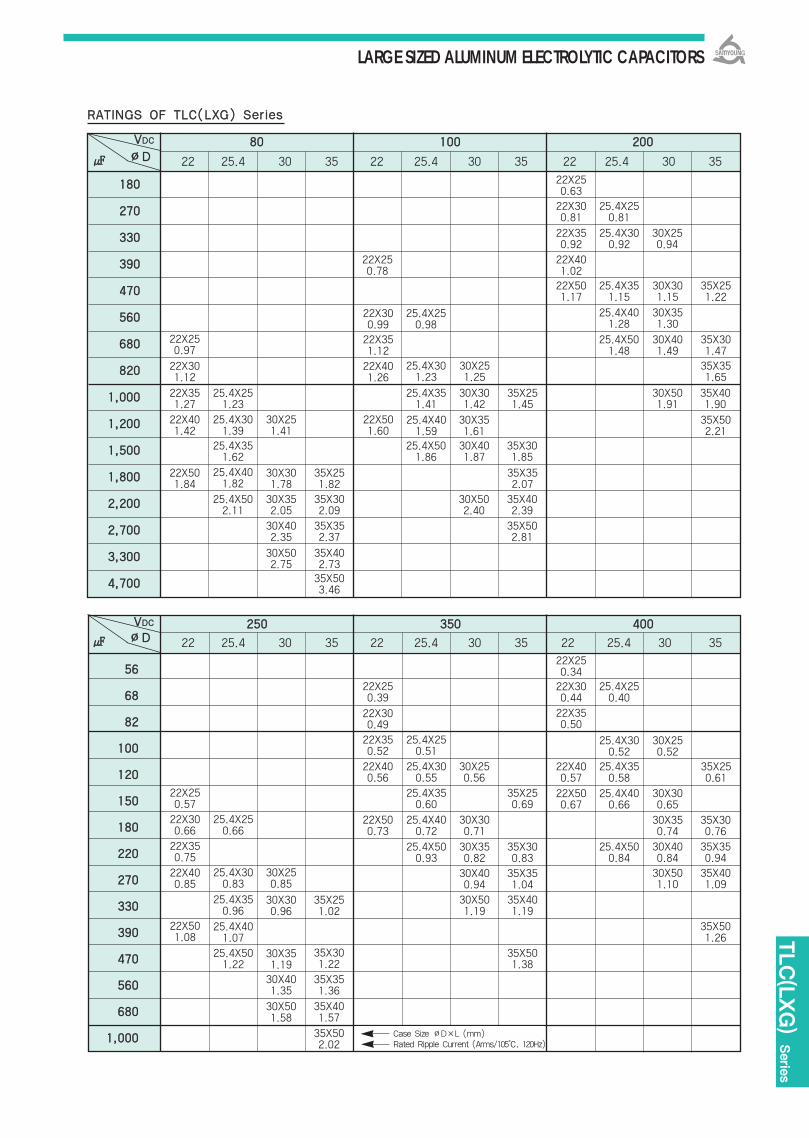
LARGE SIZED ALUMINUM ELECTROLYTIC CAPACITORS
TLC(LXG)
Serie
s
RRAATTIINNGGSS OOFF TTLLCC((LLXXGG)) SSeerriieess
8800 110000 220000
22 25.4 30 35 22 25.4 30 35 22 25.4 30 35
118800
227700
333300
339900
447700
556600
668800
882200
11,,000000
11,,220000
11,,550000
11,,880000
22,,220000
22,,770000
33,,330000
44,,770000
VVDDCC
∅∅DD
225500 335500 440000
22 25.4 30 35 22 25.4 30 35 22 25.4 30 35
5566
6688
8822
110000
112200
115500
118800
222200
227700
333300
339900
447700
556600
668800
11,,000000
VVDDCC
∅∅DD
Case Size ∅D×L (mm)Rated Ripple Current (Arms/105, 120Hz)
22X250.57
22X250.39
22X250.34
22X250.63
22X300.81
22X350.92
22X401.0222X501.17
25.4X351.15
30X301.15
25.4X401.28
30X351.30
35X251.22
25.4X501.48
30X401.49
35X301.4735X351.65
22X250.78
22X300.99
25.4X250.98
25.4X301.23
30X251.25
22X351.12
22X401.26
22X301.12
22X351.27
22X401.42
25.4X251.23
25.4X351.41
30X301.42
35X251.45
35X401.90
30X501.91
25.4X301.39
30X251.41
22X501.60
25.4X401.59
30X351.61
35X502.21
30X301.78
35X251.82
35X352.07
30X352.05
30X402.35
30X502.75
35X302.09
30X502.40
35X402.39
35X352.37
35X502.81
35X402.7335X503.46
25.4X351.62
25.4X501.86
30X401.87
35X301.85
25.4X401.82
25.4X502.11
22X501.84
22X250.97
25.4X300.92
30X250.94
25.4X250.81
22X300.44
25.4X250.40
22X350.50
22X400.57
25.4X350.58
22X500.67
25.4X400.66
30X300.65
30X350.74
35X300.76
30X400.84
25.4X500.84
35X350.94
30X501.10
35X401.09
35X501.26
35X250.61
25.4X300.52
30X250.52
22X300.49
22X350.52
25.4X250.51
22X400.56
22X500.73
25.4X400.72
30X300.71
25.4X500.93
30X350.82
35X300.83
30X400.94
35X351.04
30X501.19
35X401.19
35X501.38
25.4X300.55
25.4X350.60
35X250.69
30X250.56
22X300.66
25.4X250.66
25.4X300.83
30X250.85
30X300.96
35X251.02
35X301.22
35X351.36
35X401.57
35X502.02
30X351.1930X401.35
30X501.58
25.4X350.96
25.4X401.07
25.4X501.22
22X350.75
22X400.85
22X501.08

LARGE SIZED ALUMINUM ELECTROLYTIC CAPACITORS
RRAATTIINNGGSS OOFF TTLLCC((LLXXGG)) SSeerriieess
442200 445500
22 25.4 30 35 22 25.4 30 35
550000
22 25.4 30 35
VVDDCC
∅∅DD
Case Size ∅D×L(mm)Rated Ripple Current(Arms/105, 120Hz)
22×300.44
22×300.50
22×350.52
22×400.56
22×450.67
22×50
25.4×300.50
25.4×300.52
25.4×350.56
25.4×400.67
25.4×400.74
25.4×500.84
30×300.57
30×300.67
30×350.75
30×400.84
30×451.10
30×501.22
35×300.76
35×300.84
35×351.10
35×401.22
35×451.35
35×501.47
22×250.30
22×300.36
22×350.44
22×350.50
22×400.53
22×450.57
22×500.67
25.4×300.45
25.4×300.50
25.4×350.52
25.4×350.58
25.4×400.67
25.4×450.76
25.4×500.84
30×300.53
30×300.58
30×350.67
30×350.76
30×400.84
30×451.10
30×501.22
35×300.59
35×300.68
35×350.86
35×401.11
35×451.23
35×501.35
22×350.32
22×350.38
22×400.45
22×450.54
25.4×300.36
25.4×350.47
25.4×350.54
25.4×400.55
25.4×450.62
30×300.39
30×300.44
30×350.50
30×350.56
30×400.62
30×450.70
30×500.85
30×601.00
35×300.63
35×300.74
35×400.86
35×350.96
35×401.44
35×601.55
4477
5566
6688
8822
110000
112200
115500
118800
222200
227700
333300
339900
447700
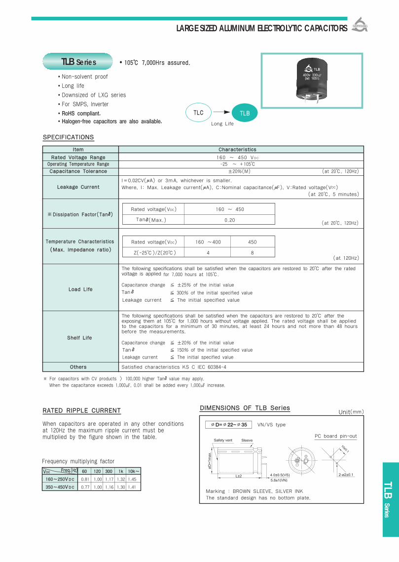
LARGE SIZED ALUMINUM ELECTROLYTIC CAPACITORS
TLB
Series
IItteemm CChhaarraacctteerriissttiiccss
RRaatteedd VVoollttaaggee RRaannggee 160 ~ 450 VDC
OOppeerraattiinngg TTeemmppeerraattuurree RRaannggee -25 ~ +105
CCaappaacciittaannccee TToolleerraannccee ±20%(M) (at 20, 120Hz)
I=0.02CV(μA) or 3mA, whichever is smaller. LLeeaakkaaggee CCuurrrreenntt Where, I: Max. Leakage current(μA), C:Nominal capacitance(μF), V:Rated voltage(VDC)
(at 20, 5 minutes)
TTeemmppeerraattuurree CChhaarraacctteerriissttiiccss
The following specifications shall be satisfied when the capacitors are restored to 20 after the ratedvoltage is applied for 7,000 hours at 105.
Capacitance change ±25% of the initial value
Tanδ 300% of the initial specified value
Leakage current The initial specified value
The following specifications shall be satisfied when the capacitors are restored to 20 after the exposing them at 105 for 1,000 hours without voltage applied. The rated voltage shall be appliedto the capacitors for a minimum of 30 minutes, at least 24 hours and not more than 48 hours before the measurements.
Capacitance change ±20% of the initial value
Tanδ 150% of the initial specified value
Leakage current The initial specified value
OOtthheerrss Satisfied characteristics KS C IEC 60384-4
110055 77,,000000HHrrss aassssuurreedd..
Non-solvent proof
Long life
Downsized of LXG series
For SMPS, Inverter
RoHS compliant.Halogen-free capacitors are also available.
※ For capacitors with CV products > 100,000 higher Tanδvalue may apply. When the capacitance exceeds 1,000, 0.01 shall be added every 1,000 increase.
SSPPEECCIIFFIICCAATTIIOONNSS
LLooaadd LLiiffee
SShheellff LLiiffee
(at 120Hz)
((MMaaxx.. IImmppeeddaannccee rraattiioo))
(at 20, 120Hz)
TLB Series
Rated voltage(VDC) 160 ~ 450
Tanδ(Max.) 0.20
Rated voltage(VDC) 160 ~400 450
Z(-25)/Z(20) 4 8
6600 112200 330000 11kk 1100kk~~
116600~~225500VVDDCC 0.81 1.00 1.17 1.32 1.45
335500~~445500VVDDCC 0.77 1.00 1.16 1.30 1.41
TTLLCC TTLLBB
Long Life
※DDiissssiippaattiioonn FFaaccttoorr((TTaannδδ))
Frequency multiplying factor
RRAATTEEDD RRIIPPPPLLEE CCUURRRREENNTT
When capacitors are operated in any other conditions at 120Hz the maximum ripple current must be multiplied by the figure shown in the table.
DDIIMMEENNSSIIOONNSS OOFF TTLLBB SSeerriieess
∅D=∅22~∅35 VN/VS type
PC board pin-out
Marking : BROWN SLEEVE, SILVER INKThe standard design has no bottom plate.
Unit(mm)
FFrreeqq..((HHzz))VVDDCC
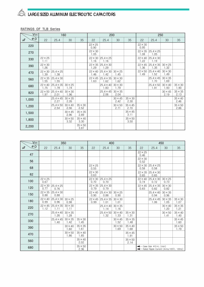
LARGE SIZED ALUMINUM ELECTROLYTIC CAPACITORS
RRAATTIINNGGSS OOFF TTLLBB SSeerriieess
116600 220000 225500
22 25.4 30 35 22 25.4 30 35 22 25.4 30 35
222200
227700
333300
339900
447700
556600
668800
882200
11,,000000
11,,220000
11,,550000
11,,880000
22,,220000
VVDDCC
∅∅DD
335500 440000 445500
22 25.4 30 35 22 25.4 30 35 22 25.4 30 35
4477
5566
6688
8822
110000
112200
115500
118800
222200
227700
333300
339900
447700
556600
668800
VVDDCC
∅∅DD
Case Size ∅D×L (mm)Rated Ripple Current (Arms/105, 120Hz)
22×300.77
22×250.67
22×250.46
22×300.95
22×351.08
25.4×251.05
22×401.22
22×451.36
25.4×351.35
30×251.32
22×501.49
25.4×401.52
30×301.49
25.4×451.70
30×351.69
25.4×501.91
30×452.19
30×401.93
35×301.90
35×352.13
22×250.90
22×301.05
22×301.16
25.4×251.16
22×351.29
25.4×301.29
22×401.46
25.4×301.42
30×251.45
22×451.63
25.4×351.62
30×301.62
25.4×401.83
30×301.79
25.4×452.06
30×352.04
22×301.26
22×301.39
25.4×251.38
22×351.55
25.4×301.55
22×401.75
25.4×351.78
30×251.74
25.4×452.27
30×352.26
30×452.42
35×302.30
35×402.46
25.4×502.54
30×402.56
35×302.52
30×452.96
35×352.89
30×503.32
30×502.71
35×452.70
35×502.86
35×403.30
35×503.50
35×503.87
35×453.11
22×501.97
25.4×402.01
30×301.96
22×251.11
25.4×301.19
22×300.52
25.4×250.58
22×300.58
22×400.74
25.4×300.72
22×450.83
25.4×350.82
25.4×400.94
30×300.82
30×350.96
30×351.05
25.4×451.06
35×301.07
30×401.20
30×501.41
35×401.40
35×351.21
35×451.60
35×501.79
25.4×300.65
22×350.65
30×250.73
22×250.55
22×300.63
22×300.70
22×400.90
25.4×300.88
30×250.90
25.4×351.01
22×450.99
30×301.01
30×351.16
25.4×401.14
30×401.33
30×451.52
35×351.48
30×501.69
25.4×501.32
35×301.31
35×401.68
35×451.91
35×502.14
25.4×250.70
25.4×300.79
22×350.79
22×350.88
25.4×300.88
25.4×250.76
25.4×351.11
30×301.11
30×250.98
30×351.28
30×351.42
35×301.45
35×351.61
35×401.85
35×402.02
35×502.36
30×401.60
30×501.86
25.4×401.26
25.4×451.40
22×400.99
25.4×300.96
22×451.12

LARGE SIZED ALUMINUM ELECTROLYTIC CAPACITORS
RVA Serie
s
IItteemm CChhaarraacctteerriissttiiccss
RRaatteedd VVoollttaaggee RRaannggee 200 ~ 450 VDC
OOppeerraattiinngg TTeemmppeerraattuurree RRaannggee -25 ~ +85
CCaappaacciittaannccee TToolleerraannccee ±20%(M) (at 20, 120Hz)
I=0.02CV or 3mA, whichever is smaller.
LLeeaakkaaggee CCuurrrreenntt Where, I:Leakage Current(μA), C:Nominal capacitance(μF), V:Rated voltage(VDC)(at 20, 5 minutes)
DDiissssiippaattiioonn FFaaccttoorr
When an excessive DC voltage is applied to the capacitors under the test conditions on nextpage, the voltage shall operate and than the capacitors shall come to open-circult without flamingmaterials.
The following specifications shall be satisfied when the capacitors are restored to 20 after the ratedvoltage is applied for 2,000 hours at 85.
Capacitance change ±20% of the initial value
Tanδ ±200% of the initial specified valueLeakage current The initial specified value
The following specifications shall be satisfied when the capacitors are restored to 20 after theexposing them at 85 for 1,000 hours without voltage applied.The rated voltage shall be applied to the capacitors for a minimum of 30 minutes, at least24 hours and not more than 48 hours before the measurements.
Capacitance change ±20% of the initial value
Tanδ ±200% of the initial specified value
Leakage current The initial specified value
OOtthheerrss Satisfied characteristics KS C IEC 60384-4
8855 22,,000000HHrrss aassssuurreedd..
Non-solvent proof.
No sparks with DC overvoltage.
For SMPS(SET is specified Safety Standard)
RoHS compliant.
Halogen-free capacitors are also available.
SSPPEECCIIFFIICCAATTIIOONNSS
LLooaadd LLiiffee
DDCC OOvveerr VVoollttaaggee TTeesstt
SShheellff LLiiffee
Rated voltage(VDC) 200~400 450
Z(-25)/Z(20) 4 8 (at 120Hz)
((MMaaxx.. IImmppeeddaannccee rraattiioo))
TTeemmppeerraattuurree CChhaarraacctteerriissttiiccss
(at 20, 120Hz)
Rated voltage(VDC) 200~400 450
Tanδ(Max.) 0.15 0.20
RVA Series
RRDDAA RRVVAA
High Reliability
6600 112200 330000 11kk 1100kk~~
220000~~225500VVDDCC 0.81 1.00 1.17 1.32 1.45
335500~~445500VVDDCC 0.77 1.00 1.16 1.30 1.41
((TTaannδδ))※
Frequency multiplying factor
RRAATTEEDD RRIIPPPPLLEE CCUURRRREENNTT
When capacitor are operated in any other condition at 120Hz, the maximum ripple current must be multiplied by the figure shown in the table.
※ For capacitors with CV products > 100,000 higher Tanδvalue may apply. When the capacitance exceeds 1,000, 0.01 shall be added every 1,000 increase.
DDIIMMEENNSSIIOONNSS OOFF RRVVAA SSeerriieess
∅D=∅22~∅35 VN/VS type
PC board pin-out
Marking : BLACK SLEEVE, SILVER INKThe standard design has no bottom plate.
Unit(mm)
FFrreeqq..((HHzz))VVDDCC
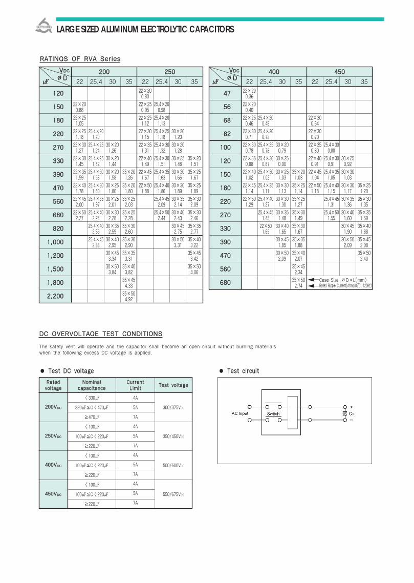
LARGE SIZED ALUMINUM ELECTROLYTIC CAPACITORS
TTeesstt cciirrccuuiitt
DDCC OOVVEERRVVOOLLTTAAGGEE TTEESSTT CCOONNDDIITTIIOONNSS
The safety vent will operate and the capacitor shall become an open circuit without burning materialswhen the following excess DC voltage is applied.
TTeesstt DDCC vvoollttaaggee
RRaatteeddvvoollttaaggee
220000VVDDCC 300/375VDC
350/450VDC
500/600VDC
550/675VDC
225500VVDDCC
440000VVDDCC
445500VVDDCC
NNoommiinnaallccaappaacciittaannccee
<330
330C<470
470
<100
100C<220
220
<100
100C<220
220
<100
100C<220
220
4A
5A
7A
4A
5A
7A
4A
5A
7A
4A
5A
7A
CCuurrrreennttLLiimmiitt
TTeesstt vvoollttaaggee
RRAATTIINNGGSS OOFF RRVVAA SSeerriieess
220000 225500
22 25.4 30 35 22 25.4 30 35
VVDDCC
∅∅DD
22×200.88
22×251.05
22×251.18
22×301.27
22×301.45
22×351.59
22×401.78
22×452.00
22×502.27
25.4×201.20
25.4×251.24
25.4×251.42
25.4×301.58
25.4×301.80
25.4×351.97
25.4×402.24
25.4×402.53
25.4×452.88
30×201.26
30×201.44
30×201.58
30×251.80
30×252.01
30×302.28
30×352.59
30×402.95
30×453.34
30×503.84
35×201.26
35×201.80
35×252.03
35×252.28
35×302.60
35×302.90
35×353.31
35×403.82
35×454.33
35×504.92
22×200.80
22×250.95
22×251.12
22×301.15
22×351.31
22×401.49
22×451.67
22×501.88
25.4×200.98
25.4×201.13
25.4×251.18
25.4×301.32
25.4×301.51
25.4×351.63
25.4×401.86
25.4×452.09
25.4×502.44
30×201.20
30×201.28
30×251.48
30×301.66
30×301.89
30×352.14
30×402.43
30×452.75
30×503.31
35×201.51
35×251.67
35×251.89
35×302.09
35×302.46
35×352.77
35×403.22
35×453.42
35×504.06
112200
115500
118800
222200
227700
333300
339900
447700
556600
668800
882200
11,,000000
11,,220000
11,,550000
11,,880000
22,,220000
440000 445500
22 25.4 30 35 22 25.4 30 35
VVDDCC
∅∅DD
22×200.36
22×200.40
22×250.46
22×300.71
22×300.78
22×350.88
22×401.02
22×451.14
22×501.29
25.4×200.48
25.4×200.72
25.4×250.78
25.4×300.87
25.4×301.02
25.4×351.11
25.4×401.27
25.4×451.45
22×501.65
30×200.79
30×250.90
30×251.03
30×301.13
30×301.30
30×351.48
30×401.65
30×451.85
30×502.09
35×201.03
35×251.14
35×251.27
35×301.49
35×301.67
35×351.88
35×402.07
35×452.34
35×502.74
22×300.64
22×300.70
22×350.80
22×400.91
22×451.04
22×501.18
25.4×300.80
25.4×300.91
25.4×351.05
25.4×401.15
25.4×451.31
25.4×501.55
30×250.92
30×301.03
30×301.17
30×351.36
30×401.60
30×451.90
30×502.09
35×251.20
35×301.35
35×351.59
35×401.88
35×452.08
35×502.40
4477
5566
6688
8822
110000
112200
115500
118800
222200
227700
333300
339900
447700
556600
668800 Case Size ∅D×L(mm)Rated Ripple Current(Arms/85, 120Hz)
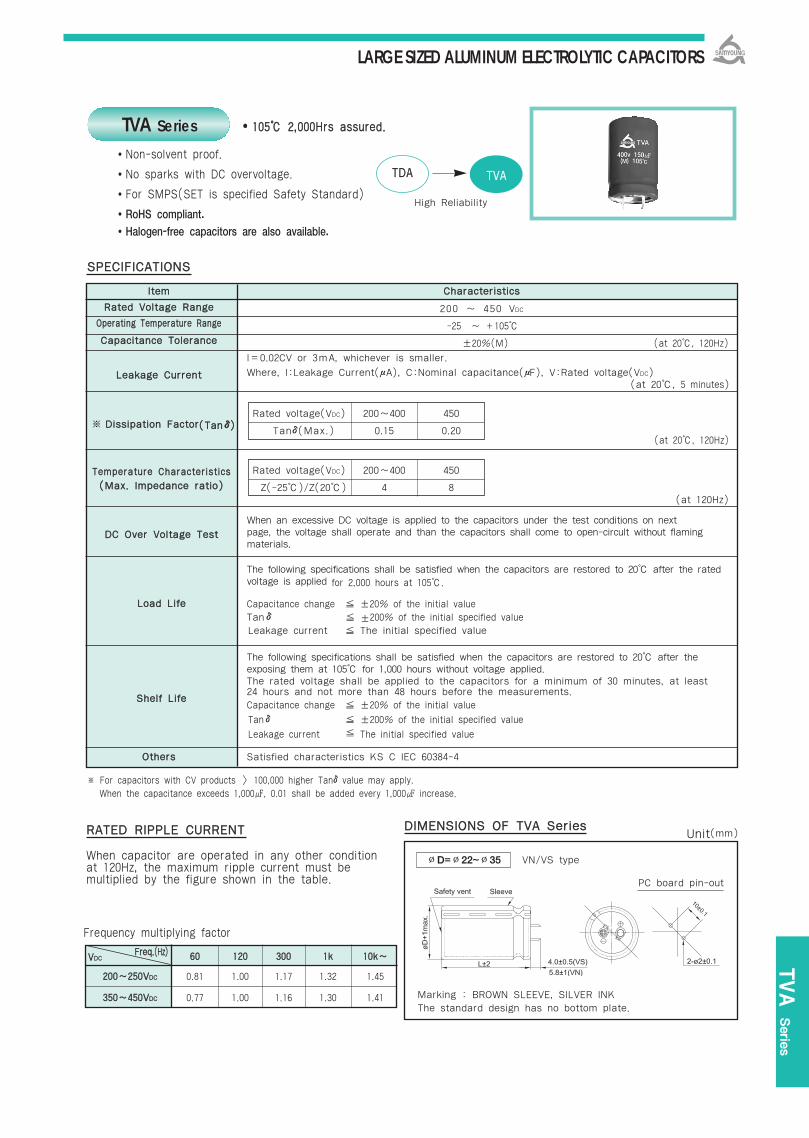
LARGE SIZED ALUMINUM ELECTROLYTIC CAPACITORS
TVA Serie
s
IItteemm CChhaarraacctteerriissttiiccss
RRaatteedd VVoollttaaggee RRaannggee 200 ~ 450 VDC
OOppeerraattiinngg TTeemmppeerraattuurree RRaannggee -25 ~ +105
CCaappaacciittaannccee TToolleerraannccee ±20%(M) (at 20, 120Hz)
I=0.02CV or 3mA, whichever is smaller.
LLeeaakkaaggee CCuurrrreenntt Where, I:Leakage Current(μA), C:Nominal capacitance(μF), V:Rated voltage(VDC)(at 20, 5 minutes)
DDiissssiippaattiioonn FFaaccttoorr
When an excessive DC voltage is applied to the capacitors under the test conditions on nextpage, the voltage shall operate and than the capacitors shall come to open-circult without flamingmaterials.
The following specifications shall be satisfied when the capacitors are restored to 20 after the ratedvoltage is applied for 2,000 hours at 105.
Capacitance change ±20% of the initial value
Tanδ ±200% of the initial specified valueLeakage current The initial specified value
The following specifications shall be satisfied when the capacitors are restored to 20 after theexposing them at 105 for 1,000 hours without voltage applied.The rated voltage shall be applied to the capacitors for a minimum of 30 minutes, at least24 hours and not more than 48 hours before the measurements.
Capacitance change ±20% of the initial value
Tanδ ±200% of the initial specified value
Leakage current The initial specified value
OOtthheerrss Satisfied characteristics KS C IEC 60384-4
110055 22,,000000HHrrss aassssuurreedd..
Non-solvent proof.
No sparks with DC overvoltage.
For SMPS(SET is specified Safety Standard)
RoHS compliant.
Halogen-free capacitors are also available.
SSPPEECCIIFFIICCAATTIIOONNSS
LLooaadd LLiiffee
DDCC OOvveerr VVoollttaaggee TTeesstt
SShheellff LLiiffee
Rated voltage(VDC) 200~400 450
Z(-25)/Z(20) 4 8 (at 120Hz)
((MMaaxx.. IImmppeeddaannccee rraattiioo))
TTeemmppeerraattuurree CChhaarraacctteerriissttiiccss
(at 20, 120Hz)
Rated voltage(VDC) 200~400 450
Tanδ(Max.) 0.15 0.20
TVA Series
TTDDAA TTVVAA
High Reliability
6600 112200 330000 11kk 1100kk~~
220000~~225500VVDDCC 0.81 1.00 1.17 1.32 1.45
335500~~445500VVDDCC 0.77 1.00 1.16 1.30 1.41
((TTaannδδ))※
Frequency multiplying factor
RRAATTEEDD RRIIPPPPLLEE CCUURRRREENNTT
When capacitor are operated in any other condition at 120Hz, the maximum ripple current must be multiplied by the figure shown in the table.
※ For capacitors with CV products > 100,000 higher Tanδvalue may apply. When the capacitance exceeds 1,000, 0.01 shall be added every 1,000 increase.
DDIIMMEENNSSIIOONNSS OOFF TTVVAA SSeerriieess
∅D=∅22~∅35 VN/VS type
PC board pin-out
Marking : BROWN SLEEVE, SILVER INKThe standard design has no bottom plate.
Unit(mm)
FFrreeqq..((HHzz))VVDDCC

LARGE SIZED ALUMINUM ELECTROLYTIC CAPACITORS
TTeesstt cciirrccuuiitt
DDCC OOVVEERRVVOOLLTTAAGGEE TTEESSTT CCOONNDDIITTIIOONNSS
The safety vent will operate and the capacitor shall become an open circuit without burning materialswhen the following excess DC voltage is applied.
TTeesstt DDCC vvoollttaaggee
RRaatteeddvvoollttaaggee
220000VVDDCC 300/375VDC
350/450VDC
500/600VDC
550/675VDC
225500VVDDCC
440000VVDDCC
445500VVDDCC
NNoommiinnaallccaappaacciittaannccee
<330
330C<470
470
<100
100C<220
220
<100
100C<220
220
<100
100C<220
220
4A
5A
7A
4A
5A
7A
4A
5A
7A
4A
5A
7A
CCuurrrreennttLLiimmiitt
TTeesstt vvoollttaaggee
RRAATTIINNGGSS OOFF TTVVAA SSeerriieess
220000 225500
22 25.4 30 35 22 25.4 30 35
VVDDCC
∅∅DD
22×250.82
22×250.92
22×301.02
22×351.20
22×401.35
22×451.52
22×501.74
25.4×251.20
25.4×301.35
25.4×301.45
25.4×351.60
25.4×401.82
25.4×502.11
30×251.47
30×301.60
30×301.81
30×352.11
30×402.40
30×502.65
35×251.86
35×302.11
35×302.40
35×352.65
35×453.08
35×503.31
22×200.68
22×250.77
22×300.87
22×301.00
22×351.14
22×401.28
22×451.42
25.4×250.93
25.4×251.02
25.4×301.13
25.4×301.29
25.4×351.46
25.4×401.64
25.4×451.82
25.4×501.96
30×251.25
30×251.38
30×301.52
30×301.67
30×351.87
30×402.12
30×452.39
30×502.52
35×251.62
35×251.81
35×301.99
35×302.19
35×352.42
35×402.57
35×452.70
35×503.00
112200
115500
118800
222200
227700
333300
339900
447700
556600
668800
882200
11,,000000
11,,220000
11,,550000
11,,880000
440000 445500
22 25.4 30 35 22 25.4 30 35
VVDDCC
∅∅DD
22×250.45
22×300.51
22×300.58
22×350.66
22×400.76
22×450.85
22×500.94
25.4×250.66
25.4×300.76
25.4×350.85
25.4×400.95
25.4×451.24
25.4×501.30
30×300.85
30×300.95
30×351.24
30×401.30
30×451.47
30×501.62
35×301.24
35×301.30
35×351.47
35×401.62
35×451.90
35×502.12
22×300.53
22×350.64
22×400.69
22×450.80
22×500.88
25.4×300.69
25.4×350.80
25.4×400.88
25.4×451.00
25.4×501.12
30×300.88
30×351.00
30×401.12
30×451.28
30×501.45
35×301.12
35×351.28
35×401.45
35×451.55
35×501.85
5566
6688
8822
110000
112200
115500
118800
222200
227700
333300
339900
447700
556600 Case Size ∅D×L(mm)Rated Ripple Current(Arms/105, 120Hz)
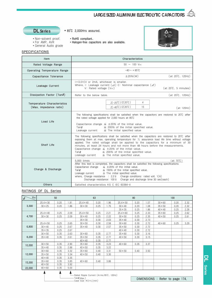
LARGE SIZED ALUMINUM ELECTROLYTIC CAPACITORS
DL Serie
s
25.4×30 0.20 1.81 25.4×40 0.20 1.96 25.4×50 0.20 1.07 30×60 0.20 2.3230×25 0.20 1.86 30×30 0.25 1.75 30×40 0.20 1.08 35×50 0.20 2.32
35×35 0.25 1.86 40×40 0.25 2.2825.4×40 0.25 2.09 25.4×50 0.25 2.21 25.4×60 0.25 2.33 35×60 0.25 2.6230×30 0.25 2.09 30×40 0.25 2.22 30×50 0.25 2.35 40×50 0.25 2.61
35×30 0.30 2.03 35×40 0.30 2.7325.4×50 0.25 2.65 30×50 0.30 2.58 30×60 0.30 2.72 40×60 0.25 3.2930×40 0.25 2.67 35×40 0.30 2.57 35×50 0.30 2.7235×35 0.25 2.67 40×40 0.30 2.7230×50 0.35 2.63 30×60 0.35 2.77 35×60 0.30 3.1635×40 0.35 2.61 35×50 0.35 2.77 40×50 0.30 3.15
40×40 0.35 2.7730×50 0.35 2.90 35×60 0.35 3.23 40×60 0.35 3.3735×40 0.35 2.88 40×50 0.35 3.2230×60 0.35 3.32 35×60 0.40 3.31 50×50 0.40 3.5035×50 0.35 3.34 40×50 0.40 3.3040×40 0.35 3.3535×60 0.35 3.85 40×60 0.40 3.8640×50 0.35 3.9240×60 0.35 5.00
RRaatteedd VVoollttaaggee RRaannggee
OOppeerraattiinngg TTeemmppeerraattuurree RRaannggee
CCaappaacciittaannccee TToolleerraannccee
LLeeaakkaaggee CCuurrrreenntt
DDiissssiippaattiioonn FFaaccttoorr ((TTaannδδ))
TTeemmppeerraattuurree CChhaarraacctteerriissttiiccss
LLooaadd LLiiffee
SShheellff LLiiffee
CChhaarrggee && DDiisscchhaarrggee
OOtthheerrss
lltteemm CChhaarraacctteerriissttiiccss
5500 6633 8800 110000
Rated Ripple Current (Arms/85, 120Hz)Tanδ(Max.)Case Size ∅D×L(mm)
8855 22,,000000HHrrss aassssuurreedd..
50 ~ 100 VDC
-40~+85
±20%(M) (at 20, 120Hz)
I=0.01CV or 2mA, whichever is smaller.Where, I: Leakage current () C: Nominal capacitance ()
V: Rated voltage (VDC) (at 20, 5 minutes)
Refer to the below table. (at 20, 120Hz)
The following specifications shall be satisfied when the capacitors are restored to 20 afterthe rated voltage applied for 2,000 hours at 85
Capacitance change ±20% of the initial value.Tanδ 200% of the initial specified value.Leakage current The initial specified value
The following specifications shall be satisfied when the capacitors are restored to 20 afterexposing them at max. operating temperature for ½ assurance load life time without voltageapplied. The rated voltage shall be applied to the capacitors for a minimum of 30minutes, at least 24 hours and not more than 48 hours before the measurements.Capacitance change ±20% of the initial value.Tanδ 200% of the initial specified value.Leakage current The initial specified value.
5,000 times (at 70)
After this test is completed, the capacitors shall be satisfied the following specificationsCapacitance change ±20% of the initial value. Tanδ 150% of the initial specified value.Leakage current The initial specified value. where, Charge resistance : 2.2Ϊ Charge conditions: rated volt. 1(A)
Discharge resistance: 100Ϊ Charge and discharge time:30 sec(each)
Satisfied characteristics KS C IEC 60384-4
SSPPEECCIIFFIICCAATTIIOONNSS
RRAATTIINNGGSS OOFF DDLL SSeerriieess
Z(-25)/Z(20) 4
Z(-40)/Z(20) 15
Non-solvent proof. RoHS compliant..For AMP, AVR Halogen-free capacitors are also available.General Audio grade
33,,330000
44,,770000
66,,880000
88,,220000
1100,,000000
1122,,000000
1155,,000000
2222,,000000
VVDDCC
(at 120Hz)((MMaaxx.. IImmppeeddaannccee rraattiioo))
DL Series
DDIIMMEENNSSIIOONNSS :: RReeffeerr ttoo ppaaggee 117744..

LARGE SIZED ALUMINUM ELECTROLYTIC CAPACITORS
RRaatteedd VVoollttaaggee RRaannggee
OOppeerraattiinngg TTeemmppeerraattuurree RRaannggee
CCaappaacciittaannccee TToolleerraannccee
LLeeaakkaaggee CCuurrrreenntt
DDiissssiippaattiioonn FFaaccttoorr ((TTaannδδ))
TTeemmppeerraattuurree CChhaarraacctteerriissttiiccss
LLooaadd LLiiffee
SShheellff LLiiffee
CChhaarrggee && DDiisscchhaarrggee
OOtthheerrss
lltteemm CChhaarraacctteerriissttiiccss
8855 22,,000000HHrrss aassssuurreedd..
50 ~ 100 VDC
-40 ~ +85
±20%(M) (at 20, 120Hz)
I=0.01CV or 2mA, whichever is smaller.Where, I: Leakage current () C: Nominal capacitance ()
V: Rated voltage (VDC) (at 20, 5 minutes)
Tanδshall not exceed the value shown in the table of RATINGS. (at 20, 120Hz)
The following specifications shall be satisfied when the capacitors are restored to 20 after therated voltage applied for 2,000 hours at 85
Capacitance change ±20% of the initial value.Tanδ 200% of the initial specified value.Leakage current The initial specified value
The following specifications shall be satisfied when the capacitors are restored to 20 afterexposing them at max. operating temperature for ½ assurance load life time without voltageapplied. The rated voltage shall be applied to the capacitors for a minimum of 30minutes, at least 24 hours and not more than 48 hours before the measurements.Capacitance change ±20% of the initial value.Tanδ 200% of the initial specified value.Leakage current The initial specified value
5,000 times (at 70)
After this test is completed, the capacitors shall be satisfied the following specifications.Capacitance change ±20% of the initial value. Tan δ 150% of the initial specified value.Leakage current The initial specified value No visible damage and no leakage electrolytewhere, Charge resistance: 2.2Ϊ Charge conditions: rated volt. 1(A)
Discharge resistance: 100Ϊ Charge and discharge time: 30 sec(each)
Satisfied characteristics KS C IEC 60384-4
SSPPEECCIIFFIICCAATTIIOONNSS
Non-solvent proof.
Hi-Fi Audio grade.
For Audio, AMP, AVR
RoHS compliant.
Halogen-free capacitors are also available.
Z(-25)/Z(20) 4
Z(-40)/Z(20) 15
DDIIMMEENNSSIIOONNSS OOFF AAHHSS//DDLL SSeerriieess
CCAAUUTTIIOONN::Please use the blank termimals for mechanical support only. The blank terminals must not be connected to a solder trace on thePC board, but be electrically isolated from negative or positive terminal.
(at 120Hz)((MMaaxx..IImmppeeddaannccee rraattiioo))
AHS Series
DDLL AAHHSS
High reliability
∅D=∅22~∅35 VN/VS type
PC board pin-out PC board pin-out
∅D=∅35~∅40 VR type (4 terminals)
B: Positive terminal.A, C: Terminals not connected electrically but used for
mechanical support only. (Blank Termimals)
Note: Sleeve has an insulating role.
Marking : AHS-DARK BROWN SLEEVE, GOLD INKDL-BLACK SLEEVE, SILVER INK
The standard design has no bottom plate.
Unit(mm)

LARGE SIZED ALUMINUM ELECTROLYTIC CAPACITORS
5500 6633 8800 110000
AHS Serie
s
Rated Ripple Current (Arms/85, 120Hz)Tanδ(Max.)Case Size ∅D×L(mm)
25.4×30 0.20 1.84 25.4×40 0.20 1.96 25.4×50 0.15 2.39 30×60 0.15 2.68
30×25 0.20 1.86 30×30 0.20 1.96 30×40 0.15 2.40 35×50 0.15 2.69
35×35 0.15 2.40 40×40 0.15 2.68
25.4×40 0.20 2.34 25.4×50 0.20 2.47 25.4×60 0.15 3.01 35×60 0.15 2.98
30×30 0.20 2.36 30×40 0.20 2.48 30×50 0.15 3.04 40×50 0.20 2.92
35×30 0.20 2.48 35×40 0.15 3.02
25.4×50 0.22 2.83 30×50 0.22 3.02 30×60 0.15 3.35 40×60 0.20 3.68
30×40 0.22 2.85 35×40 0.22 3.00 35×50 0.15 3.35
35×35 0.25 2.67 40×40 0.20 3.34
30×50 0.25 3.11 30×60 0.25 3.27 35×60 0.20 3.87
35×40 0.25 3.09 35×50 0.25 3.28 40×50 0.20 3.86
40×40 0.25 3.28
30×50 0.25 3.43 35×60 0.25 3.82 40×60 0.20 4.46
35×40 0.25 3.41 40×50 0.25 3.81
30×60 0.25 3.66 35×60 0.25 4.19
35×50 0.30 3.62 40×50 0.25 4.18
40×40 0.30 3.62
35×60 0.30 4.27 40×60 0.30 4.46
40×50 0.30 4.26
40×60 0.30 5.40
33,,330000
44,,770000
66,,880000
88,,220000
1100,,000000
1122,,000000
1155,,000000
2222,,000000
RRAATTIINNGGSS OOFF AAHHSS SSeerriieess
FFrreeqquueennccyy vvss.. IImmppeeddaannccee GGrraapphh
-- AAHHSS 8800 VVRR 88220000×× -- ×× DDLL 8800 VVRR 88220000
VVDDCC

LARGE SIZED ALUMINUM ELECTROLYTIC CAPACITORS
RRaatteedd VVoollttaaggee RRaannggee
OOppeerraattiinngg TTeemmppeerraattuurree RRaannggee
CCaappaacciittaannccee TToolleerraannccee
LLeeaakkaaggee CCuurrrreenntt
DDiissssiippaattiioonn FFaaccttoorr ((ttaannδδ))
TTeemmppeerraattuurree CChhaarraacctteerriissttiiccss
LLooaadd LLiiffee
110055 22,,000000HHrrss aassssuurreedd..
10 ~ 100 VDC 160 ~ 400 VDC
-40 ~ +105 -25 ~ +105
±20%(M) (at 20, 120Hz)
I=0.02CV or 5mA, whichever is smaller.Where, I: Leakage current () C: Nominal capacitance ()
V: Rated voltage (VDC) (at 20, 5 minutes)
Tanδshall not exceed the values shown in the RATINGS.
The following specifications shall be satisfied when the capacitors are restored to 20 after theripple duplicated voltage(WV) applied for 2,000 hours at 105.
Capacitance change ±20% of the initial valueTanδ 200% of the initial specified valueLeakage current The initial specified value
The following specifications shall be satisfied when the capacitors are restored to 20 afterexposing them at 105 for 500 hours without voltage applied. The rated voltage shall be appliedto the capacitors for a minimum of 30 minutes, at least 24 hours and not more than 48 hoursbefore the measurements.
Capacitance change ±20% of the initial valueTanδ 200% of the initial specified valueLeakage current The initial specified value
Satisfied characteristics KS C IEC 60384-4
SSPPEECCIIFFIICCAATTIIOONNSS
KKMMEE TTGGAA
Downsized
OOtthheerrss
SShheellff LLiiffee
(at 20, 120Hz)
TGA(KMH) Series
Non-solvent proof.
Wide temperature range.
For UPS
RoHS compliant.
Halogen-free capacitors are also available.
((CCaappaacciittaannccee cchhaannggee rraattiioo))
Rated Voltage(VDC) 10~100 160~400
C(-25)/C(20) - 0.7
C(-40)/C(20) 0.6 - (at 120Hz)
DDIIMMEENNSSIIOONNSS OOFF TTGGAA((KKMMHH)) SSeerriieess
BB ttyyppee mmoouunnttiinngg ccllaammpp CC ttyyppee mmoouunnttiinngg ccllaammpp
Screw specifications Plus hexagon-headed screw:
M5×0.8×12 Maximum screw tightening
torque:3.23N∙m (33kg∙cm)
Marking : BROWN SLEEVE, SILVER INK
∅∅DD AA BB WW HH FF
3355 58 44 48 3.5 12.7
5500 78 64 68 4.5 22.4
6633..55 90 75 80 4.5 28.0
7766..55 104.5 90 93.5 4.5 31.5
∅∅DD EE KK JJ FF
5500 32.5 37.0 14 22.4
6633..55 38.1 43.5 14 28.0
7766..55 44.5 50.0 14 31.5
8899 50.8 56.5 16 31.5
lltteemm CChhaarraacctteerriissttiiccss
Unit(mm)

LARGE SIZED ALUMINUM ELECTROLYTIC CAPACITORS
TGA(KMH)
Serie
s
RRAATTIINNGGSS OOFF TTGGAA((KKMMHH)) SSeerriieess
μμFF VVDDCC 1100 1166 2255 3355 5500 6633 8800
22,,220000 A5 2.4 0.15
22,,770000 A5 2.3 0.20 A5 2.7 0.15
33,,330000 A5 2.5 0.20 A5 3.0 0.15
33,,990000 A5 2.8 0.20 A5 2.8 0.20 A6 3.4 0.15
44,,770000 A5 3.1 0.20 A5 3.1 0.20 A6 3.7 0.15
55,,660000 A5 3.3 0.20 A6 3.5 0.20 A8 4.5 0.15
66,,880000 A5 3.5 0.25 A6 3.9 0.20 A8 4.9 0.15
88,,220000 A5 3.3 0.30 A6 3.8 0.25 A8 4.7 0.20 A10 5.1 0.20
1100,,000000 A5 3.6 0.30 A8 4.6 0.25 A8 4.9 0.25 A12 6.1 0.20
1122,,000000 A5 3.7 0.35 A6 4.2 0.30 A8 5.1 0.25 A10 5.5 0.25 C8 6.7 0.20
1155,,000000 A5 4.1 0.35 A6 4.7 0.30 A8 5.7 0.25 A12 6.6 0.25 C10 8.3 0.20
1188,,000000 A5 4.2 0.45 A6 4.8 0.35 A8 5.7 0.30 A8 6.0 0.25 A12 6.9 0.25 C12 9.9 0.20
2222,,000000 A5 4.7 0.45 A6 5.3 0.35 A8 6.8 0.30 A10 6.7 0.25 C8 7.4 0.25 C12 11.0 0.20
2277,,000000 A6 5.5 0.45 A8 6.4 0.35 A10 7.5 0.30 C8 9.1 0.25 C12 10.9 0.25 D10 11.4 0.25
3333,,000000 A6 5.7 0.45 A8 6.7 0.40 A12 9.0 0.30 C10 11.1 0.25 C12 12.0 0.25 E10 13.9 0.25
3399,,000000 A8 6.8 0.45 A10 7.8 0.40 C8 9.2 0.35 C12 13.1 0.25 D10 12.5 0.30 E10 14.5 0.30
4477,,000000 A8 7.1 0.50 A12 9.3 0.40 C10 11.2 0.35 C12 13.9 0.30 D12 14.9 0.30 E12 16.5 0.30
5566,,000000 A10 8.4 0.50 C8 9.7 0.45 C10 11.4 0.40 D10 14.9 0.35 D12 16.3 0.30 E12 18.1 0.30
6688,,000000 A10 8.8 0.55 C10 10.7 0.45 C12 13.6 0.40 D12 16.6 0.35 E12 18.4 0.35 E14 19.7 0.35
8822,,000000 C8 10.7 0.55 C10 11.2 0.50 D10 14.8 0.45 E12 18.9 0.40 E14 20.0 0.40 F14 22.1 0.40
110000,,000000 C8 10.8 0.65 C12 14.8 0.50 D12 16.5 0.45 E12 19.5 0.45 E14 20.5 0.50
112200,,000000 C10 13.1 0.65 D10 14.9 0.65 D12 17.6 0.55 E12 21.0 0.55 F14 21.8 0.60
115500,,000000 C12 15.3 0.70 D12 17.9 0.65 E12 18.5 0.65 F14 23.9 0.60
118800,,000000 C12 15.7 0.80 D12 18.9 0.80 E12 19.8 0.80 F14 23.9 0.75
222200,,000000 D12 19.2 0.85 E12 21.3 0.85 E14 23.4 0.80
227700,,000000 D12 19.6 1.00 E12 21.7 1.00 F14 25.5 1.00
333300,,000000 E12 21.1 1.30 E14 23.1 1.20
339900,,000000 E12 21.3 1.50 F14 24.9 1.50
447700,,000000 E14 24.2 1.60
556600,,000000 F14 28.1 2.00
668800,,000000 F14 28.5 2.40
A5 4.9 0.70
A5 5.1 0.70
A6 5.9 0.70
A8 6.3 0.70
A8 6.9 0.70
A8 7.4 0.70
A10 8.5 0.70
A10 8.9 0.70
A12 10.7 0.70
C8 11.0 0.75
C10 13.2 0.80
C12 15.7 0.80
C12 16.8 0.85
D12 19.6 1.00
D12 19.7 1.20
E12 21.3 1.50
E12 21.4 1.80
E14 23.6 2.00
F14 26.0 2.40
Tanδ(Max.)Rated Ripple Current (Arms/105, 120Hz)Case code
CCAASSEE CCOODDEE
CCaassee CCooddee
35
35
35
35
35
50
50
50
50
60
80
100
120
80
100
120
DD1100
DD1122
EE1100
EE1122
EE1133
EE1144
FF1133
FF1144
63.5
63.5
76.5
76.5
76.5
76.5
89
89
100
120
100
120
130
140
130
140
∅∅DD((mmmm))
LL((mmmm))
CCaassee CCooddee∅∅DD
((mmmm))LL
((mmmm))
AA55
AA66
AA88
AA1100
AA1122
CC88
CC1100
CC1122

LARGE SIZED ALUMINUM ELECTROLYTIC CAPACITORS
μμFF VVDDCC 110000 116600 220000 225500 331155 335500 440000
118800 A5 0.8 0.10 A5 0.8 0.10 A5 0.8 0.10
222200 A5 0.9 0.10 A5 0.9 0.10 A5 0.9 0.10
227700 A5 0.8 0.15 A5 1.0 0.10 A5 1.0 0.10 A5 1.0 0.10
333300 A5 0.9 0.15 A5 0.9 0.15 A5 1.1 0.10 A5 1.1 0.10 A6 1.2 0.10
339900 A5 1.0 0.15 A5 1.0 0.15 A5 1.2 0.10 A5 1.1 0.10 A6 1.2 0.10
447700 A5 1.1 0.15 A5 1.1 0.15 A6 1.4 0.10 A6 1.4 0.10 A8 1.4 0.10
556600 A5 1.2 0.15 A5 1.2 0.15 A5 1.2 0.15 A6 1.5 0.10 A8 1.6 0.10 A8 1.4 0.15
668800 A5 1.3 0.15 A5 1.3 0.15 A6 1.4 0.15 A8 1.7 0.10 A8 1.6 0.15 A10 1.7 0.15
882200 A5 1.4 0.15 A5 1.4 0.15 A8 1.6 0.15 A8 1.7 0.15 A10 1.8 0.15 A12 2.0 0.15
11,,000000 A5 1.6 0.15 A6 1.7 0.15 A8 1.6 0.20 A10 2.0 0.15 A12 2.2 0.15 C8 2.2 0.15
11,,220000 A6 1.9 0.15 A6 1.9 0.15 A8 1.8 0.20 A12 2.4 0.15 C8 2.4 0.15 C10 2.7 0.15
11,,550000 A6 2.1 0.15 A8 2.3 0.15 A10 2.1 0.20 C8 2.7 0.15 C10 3.0 0.15 C12 3.3 0.15
11,,880000 A8 2.5 0.15 A8 2.5 0.15 A12 2.5 0.20 C10 3.3 0.15 C12 3.6 0.15
22,,220000 A8 2.8 0.15 A10 2.7 0.15 A12 2.8 0.20 C10 4.0 0.15 C12 4.0 0.15 D10 4.2 0.15
22,,770000 A10 3.3 0.15 A12 3.6 0.15 C10 3.5 0.20 C12 4.4 0.15 D10 4.6 0.15
33,,330000 A12 3.8 0.15 C8 4.1 0.15 C12 4.2 0.20 D10 5.1 0.15 D12 5.5 0.15
33,,990000 C8 3.9 0.20 C10 4.9 0.15 C12 4.6 0.20 D12 6.0 0.15 E12 6.7 0.15
44,,770000 C10 4.6 0.20 D10 5.3 0.20 D12 5.7 0.20 E10 6.8 0.15 E13 7.6 0.15
55,,660000 C10 5.1 0.20 D10 5.8 0.20 D12 6.3 0.20 E12 8.0 0.15 E13 8.3 0.15 F14 9.4 0.15
66,,880000 C12 6.1 0.20 D12 6.9 0.20 E12 7.7 0.20 F13 9.2 0.15 E14 9.5 0.15 F14 10.4 0.15
88,,220000 D10 7.0 0.20 D12 7.6 0.20 E12 8.4 0.20 F14 11.4 0.15 F14 11.4 0.15
1100,,000000 D12 8.4 0.20 E12 9.3 0.20 E14 10.0 0.20 F14 12.6 0.15
1122,,000000 E10 9.4 0.20 E12 10.2 0.20 F14 11.9 0.20
1155,,000000 E12 11.4 0.20 E12 11.2 0.20 F14 12.2 0.20
1188,,000000 E14 13.4 0.20 F14 13.1 0.25
2222,,000000 F14 14.5 0.25
2277,,000000 F14 16.0 0.25
3333,,000000
3399,,000000
4477,,000000
5566,,000000
A5 2.7 0.10
A5 3.0 0.10
A6 3.5 0.10
A8 4.2 0.10
A8 4.5 0.12
A10 5.0 0.12
A10 5.4 0.12
A12 5.8 0.15
C8 6.4 0.15
C10 7.8 0.15
C12 9.3 0.15
C12 10.4 0.15
D10 11.0 0.20
D12 12.5 0.20
E12 13.7 0.25
E12 15.2 0.25
E14 16.1 0.30
F14 19.3 0.30
F14 21.1 0.30
RRAATTIINNGGSS OOFF TTGGAA((KKMMHH)) SSeerriieess
Tanδ(Max.)Rated Ripple Current (Arms/105, 120Hz)Case code
FFrreeqquueennccyy MMuullttiippllyyiinngg FFaaccttoorr
RRaatteedd vvoollttaaggee((VVDDCC))
1100~~5500 ∅∅3355~~∅∅8899
6633~~8800∅∅3355
∅∅5500~~∅∅8899
∅∅3355
110000 ∅∅5500
∅∅6633..55~~∅∅8899
∅∅3355
116600~~225500 ∅∅5500~~∅∅6633..55
∅∅7766..55~~∅∅8899
331155~~440000 ∅∅3355~~∅∅8899
FFrreeqquueennccyy ((HHzz))
60 120 300 1k 10k~
0.95 1.00 1.03 1.05 1.09
0.90 1.00 1.06 1.10 1.08
0.95 1.00 1.03 1.05 1.09
0.82 1.00 1.12 1.22 1.30
0.90 1.00 1.06 1.10 1.18
0.95 1.00 1.03 1.05 1.09
0.80 1.00 1.19 1.34 1.46
0.81 1.00 1.14 1.26 1.36
0.82 1.00 1.12 1.22 1.30
0.80 1.00 1.19 1.34 1.46
∅∅DD((mmmm))
RRAATTEEDD RRIIPPPPLLEE CCUURRRREENNTT

LARGE SIZED ALUMINUM ELECTROLYTIC CAPACITORS
RFC
(RWF)
Series
RRaatteedd VVoollttaaggee RRaannggee
OOppeerraattiinngg TTeemmppeerraattuurree RRaannggee
CCaappaacciittaannccee TToolleerraannccee
LLeeaakkaaggee CCuurrrreenntt
DDiissssiippaattiioonn FFaaccttoorr ((TTaannδδ))
IInnssuullaattiioonn WWiitthhssttaannddiinngg VVoollttaaggee
LLooaadd LLiiffee
SShheellff LLiiffee
OOtthheerrss
6633..55 90 75 80 4.5 28.07766..55 104.5 90 93.5 4.5 31.5
8855 55,,000000HHrrss aassssuurreedd..
350 ~ 450 VDC
-25 ~ +85
±20%(M) (at 20, 120Hz)
I=0.02CV or 5mA, whichever is smaller.Where, I: Leakage current () C: Nominal capacitance ()
V: Rated voltage (VDC) (at 20, 5 minutes)
0.25max. (at 20, 120Hz)
When a voltage of 2,000VAC is applied for one minute between the terminals shorted each other andthe mounting clamp on the insulating sleeve covering the case, there shall not be electrical damage.
After the capacitors are subjected to DC voltage with the rated ripple current applied for 5,000 hoursat 85, the following specifications shall be satisfied when the capacitors are restored to 20.The sum of DC voltage and peak AC voltage must not exceed the full rated voltage of the capacitor.
Capacitance change ±30% of the initial valueTanδ 300% of the initial specified valueLeakage current The initial specified value
The following specifications shall be satisfied when the capacitors are restored to 20 afterexposing them at 85 for 500 hours without voltage applied. The rated voltage shall be appliedto the capacitors for a minimum of 30 minutes, at least 24 hours and not more than 48 hoursbefore measurements.Capacitance change ±20% of the initial valueTanδ 300% of the initial specified valueLeakage current The initial specified value
Satisfied characteristics KS C IEC 60384-4
SSPPEECCIIFFIICCAATTIIOONNSS
RRAATTEEDD RRIIPPPPLLEE CCUURRRREENNTT MMUULLTTIIPPLLIIEERRSS
Frequency Multiplying Factor
DDIIMMEENNSSIIOONNSS OOFF RRFFCC((RRWWFF)) SSeerriieess
FFrreeqquueennccyy((HHzz)) 6600 112200 330000 11kk 33kk
FFaaccttoorr 0.8 1.0 1.1 1.3 1.4
BB ttyyppee mmoouunnttiinngg ccllaammpp
∅∅DD AA BB WW HH FF∅∅DD AA BB WW HH FF
Marking : BLACK SLEEVE, GOLD INK
63.5 38.1 43.5 14 28.076.5 44.5 50.0 14 31.589 50.8 56.5 16 31.5
CC ttyyppee mmoouunnttiinngg ccllaammpp
∅∅DD EE KK JJ FFScrew specifications∅D=∅63.5~∅89 Plus hexagon-headed screw:
M5×0.8×12 Maximum screw tightening
torque:3.23N∙m (33kg∙cm)
RRWWAA RRFFCC
Long Life
RFC(RWF) SeriesNon-solvent proof.
High ripple capability.
Long life.
For UPS, Industrial Inverter
RoHS compliant.
Halogen-free capacitors are also available.
lltteemm CChhaarraacctteerriissttiiccss
Unit(mm)

LARGE SIZED ALUMINUM ELECTROLYTIC CAPACITORS
RRAATTIINNGGSS OOFF RRFFCC((RRWWFF)) SSeerriieess
VVDDCC
∅∅DD
Note:When long life performance is required in actual use, the rms ripple current has to be reduced.
335500 440000 445500
22,,770000
33,,330000
33,,990000
44,,770000
55,,660000
66,,880000
88,,220000
1100,,000000
1122,,000000
1155,,000000
63.5 76.5 89 63.5 76.5 89 63.5 76.5 89
63.5×120
10.1
63.5×120 63.5×130
11.1 11.7
63.5×120 63.5×130 63.5×160 76.5×120
12.1 12.7 13.8 13.4
63.5×130 63.5×160 76.5×120 63.5×190 76.5×130
14.0 15.2 14.7 16.7 15.5
63.5×160 76.5×120 63.5×190 76.5×130 76.5×160
16.6 16.1 18.2 16.9 18.3
63.5×190 76.5×130 76.5×160 76.5×170
20.0 18.6 20.2 20.7
76.5×160 76.5×170 89×160
22.2 22.8 24.1
76.5×170 89×160 89×170
25.2 26.6 27.8
89×160 89×170
29.1 30.0
89×190
35.7
Case Size ∅D×L(mm)Rated Ripple Current(Arms/85, 120Hz)
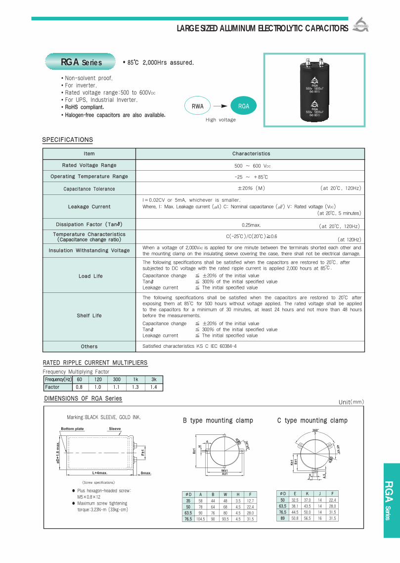
LARGE SIZED ALUMINUM ELECTROLYTIC CAPACITORS
RGA
Series
8855 22,,000000HHrrss aassssuurreedd..
RRAATTEEDD RRIIPPPPLLEE CCUURRRREENNTT MMUULLTTIIPPLLIIEERRSS
Frequency Multiplying Factor
FFrreeqquueennccyy((HHzz)) 6600 112200 330000 11kk 33kk
FFaaccttoorr 00..88 11..00 11..11 11..33 11..44
RRWWAA RRGGAA
High voltage
RGA Series
Non-solvent proof.For inverter.Rated voltage range:500 to 600VDC
For UPS, Industrial Inverter.RoHS compliant.Halogen-free capacitors are also available.
RRaatteedd VVoollttaaggee RRaannggee
OOppeerraattiinngg TTeemmppeerraattuurree RRaannggee
CCaappaacciittaannccee TToolleerraannccee
LLeeaakkaaggee CCuurrrreenntt
DDiissssiippaattiioonn FFaaccttoorr ((TTaannδδ))
TTeemmppeerraattuurree CChhaarraacctteerriissttiiccss
IInnssuullaattiioonn WWiitthhssttaannddiinngg VVoollttaaggee
LLooaadd LLiiffee
SShheellff LLiiffee
OOtthheerrss
500 ~ 600 VDC
-25 ~ +85
±20% (M) (at 20, 120Hz)
I=0.02CV or 5mA, whichever is smaller. Where, I: Max. Leakage current () C: Nominal capacitance () V: Rated voltage (VDC)
(at 20, 5 minutes)
0.25max. (at 20, 120Hz)
C(-25)/C(20)0.6(at 120Hz)
When a voltage of 2,000VAC is applied for one minute between the terminals shorted each other andthe mounting clamp on the insulating sleeve covering the case, there shall not be electrical damage.
The following specifications shall be satisfied when the capacitors are restored to 20. after subjected to DC voltage with the rated ripple current is applied 2,000 hours at 85.
Capacitance change ±20% of the initial valueTanδ 300% of the initial specified valueLeakage current The initial specified value
The following specifications shall be satisfied when the capacitors are restored to 20 afterexposing them at 85 for 500 hours without voltage applied. The rated voltage shall be appliedto the capacitors for a minimum of 30 minutes, at least 24 hours and not more than 48 hoursbefore the measurements.
Capacitance change ±20% of the initial valueTanδ 300% of the initial specified valueLeakage current The initial specified value
Satisfied characteristics KS C IEC 60384-4
SSPPEECCIIFFIICCAATTIIOONNSS
DDIIMMEENNSSIIOONNSS OOFF RRGGAA SSeerriieess
BB ttyyppee mmoouunnttiinngg ccllaammpp CC ttyyppee mmoouunnttiinngg ccllaammpp
Plus hexagon-headed screw:M5×0.8×12
Maximum screw tighteningtorque:3.23N∙m (33kg∙cm)
<Screw specifications>
Marking:BLACK SLEEVE, GOLD INK.
((CCaappaacciittaannccee cchhaannggee rraattiioo))
∅∅DD AA BB WW HH FF
3355 58 44 48 3.5 12.7
5500 78 64 68 4.5 22.4
6633..55 90 76 80 4.5 28.0
7766..55 104.5 90 93.5 4.5 31.5
∅∅DD EE KK JJ FF
5500 32.5 37.0 14 22.4
6633..55 38.1 43.5 14 28.0
7766..55 44.5 50.0 14 31.5
8899 50.8 56.5 16 31.5
lltteemm CChhaarraacctteerriissttiiccss
Unit(mm)

LARGE SIZED ALUMINUM ELECTROLYTIC CAPACITORS
RRAATTIINNGGSS OOFF RRGGAA SSeerriieess
VVDDCC
∅∅DD
35×500.7
35×500.6
35×801.0
35×1001.3
35×1201.6
50×751.7
50×952.1
50×1152.7
50×1303.1
63.5×952.5
63.5×1203.0
63.5×1303.5
76.5×954.2
76.5×1205.0
76.5×1305.8
76.5×1507.0
89×1609.3
35×801.2
35×1001.4
35×1201.7
50×751.8
50×902.5
50×1202.9
50×1303.4
63.5×953.4
63.5×1204.5
63.5×1305.2
76.5×954.6
76.5×1206.1
76.5×1607.7
89×16010.1
550000
35 50 63.5 76.5 89 35 50 63.5 76.5 89
555500
Note:When long life performance is required in actual use, the rms ripple current has to be reduced.
Case Size ∅D×L(mm)
Rated Ripple Current(Arms/85, 120Hz)
660000
35 50 63.5 76.5 89
118800
227700
333300
339900
556600
668800
882200
11,,220000
11,,550000
11,,880000
22,,220000
22,,770000
35×1001.1
35×1201.4
50×751.7
63.5×952.1
63.5×1152.6
63.5×1303.2
76.5×953.3
76.5×1154.4
76.5×1305.4
76.5×1506.5
89×1307.8
89×1558.9
50×951.8
50×1152.2
50×1302.9
110000
112200
118800
227700
333300
339900
447700
556600
668800
882200
11,,000000
11,,220000
11,,550000
11,,880000
22,,220000
22,,770000
33,,330000
33,,990000
VVDDCC
∅∅DD
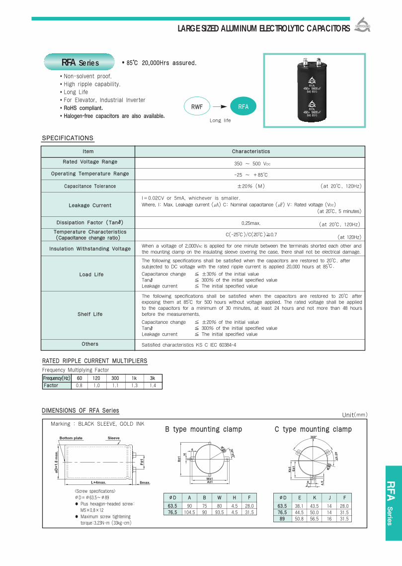
LARGE SIZED ALUMINUM ELECTROLYTIC CAPACITORS
FFrreeqquueennccyy((HHzz)) 6600 112200 330000 11kk 33kk
RFA Serie
s
8855 2200,,000000HHrrss aassssuurreedd..
RRAATTEEDD RRIIPPPPLLEE CCUURRRREENNTT MMUULLTTIIPPLLIIEERRSS
Frequency Multiplying Factor
FFaaccttoorr 0.8 1.0 1.1 1.3 1.4
Marking : BLACK SLEEVE, GOLD INK
RRWWFF RRFFAA
Long life
RFA SeriesNon-solvent proof.High ripple capability.Long LifeFor Elevator, Industrial InverterRoHS compliant.Halogen-free capacitors are also available.
RRaatteedd VVoollttaaggee RRaannggee
OOppeerraattiinngg TTeemmppeerraattuurree RRaannggee
CCaappaacciittaannccee TToolleerraannccee
LLeeaakkaaggee CCuurrrreenntt
DDiissssiippaattiioonn FFaaccttoorr ((TTaannδδ))
TTeemmppeerraattuurree CChhaarraacctteerriissttiiccss
IInnssuullaattiioonn WWiitthhssttaannddiinngg VVoollttaaggee
LLooaadd LLiiffee
SShheellff LLiiffee
OOtthheerrss
350 ~ 500 VDC
-25 ~ +85
±20% (M) (at 20, 120Hz)
I=0.02CV or 5mA, whichever is smaller. Where, I: Max. Leakage current () C: Nominal capacitance () V: Rated voltage (VDC)
(at 20, 5 minutes)
0.25max. (at 20, 120Hz)
C(-25)/C(20)0.7 (at 120Hz)
When a voltage of 2,000VAC is applied for one minute between the terminals shorted each other andthe mounting clamp on the insulating sleeve covering the case, there shall not be electrical damage.
The following specifications shall be satisfied when the capacitors are restored to 20. after subjected to DC voltage with the rated ripple current is applied 20,000 hours at 85.
Capacitance change ±30% of the initial valueTanδ 300% of the initial specified valueLeakage current The initial specified value
The following specifications shall be satisfied when the capacitors are restored to 20 afterexposing them at 85 for 500 hours without voltage applied. The rated voltage shall be appliedto the capacitors for a minimum of 30 minutes, at least 24 hours and not more than 48 hoursbefore the measurements.
Capacitance change ±20% of the initial valueTanδ 300% of the initial specified valueLeakage current The initial specified value
Satisfied characteristics KS C IEC 60384-4
SSPPEECCIIFFIICCAATTIIOONNSS
6633..55 90 75 80 4.5 28.07766..55 104.5 90 93.5 4.5 31.5
DDIIMMEENNSSIIOONNSS OOFF RRFFAA SSeerriieess
BB ttyyppee mmoouunnttiinngg ccllaammpp
∅∅DD AA BB WW HH FF
6633..55 38.1 43.5 14 28.07766..55 44.5 50.0 14 31.58899 50.8 56.5 16 31.5
CC ttyyppee mmoouunnttiinngg ccllaammpp
∅∅DD EE KK JJ FFScrew specifications∅D=∅63.5~∅89 Plus hexagon-headed screw:
M5×0.8×12 Maximum screw tightening
torque:3.23N∙m (33kg∙cm)
((CCaappaacciittaannccee cchhaannggee rraattiioo))
lltteemm CChhaarraacctteerriissttiiccss
Unit(mm)
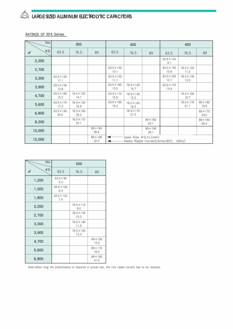
LARGE SIZED ALUMINUM ELECTROLYTIC CAPACITORS
RRAATTIINNGGSS OOFF RRFFAA SSeerriieess
VVDDCC
∅∅DD
Note:When long life preformance is required in actual use, the rms ripple current has to be reduced.
Case Size ∅D×L(mm)Rated Ripple Current(Arms/85, 120Hz)
335500
63.5 76.5 89 63.5 76.5 89 63.5 76.5 89
440000 445500
63.5×12011.1
63.5×13012.8
63.5×16015.2
63.5×17017.3
63.5×19020.0
63.5×12010.1
63.5×13011.7
63.5×16013.5
63.5×17015.8
63.5×19018.2
76.5×12014.7
76.5×13016.9
76.5×16020.2
76.5×17023.1
76.5×12014.7
76.5×13015.5
76.5×16018.3
76.5×17021.0
63.5×1209.1
63.5×13010.6
63.5×16012.7
76.5×12011.2
76.5×13013.0
76.5×16016.7
76.5×17021.1
89×16019.9
89×17023.0
89×19026.4
63.5×17014.4
89×16024.1
89×19029.1
89×16026.6
89×19032.0
VVDDCC
∅∅DD
11,,220000
11,,550000
11,,880000
22,,220000
22,,770000
33,,330000
33,,990000
44,,770000
55,,660000
66,,880000
550000
63.5 76.5 89
63.5×905.3
63.5×1006.3
63.5×1207.4
89×15015.3
76.5×13010.3
76.5×14011.9
76.5×15013.3
76.5×1109.0
89×17018.2
89×19021.0
22,,220000
22,,770000
33,,330000
33,,990000
44,,770000
55,,660000
66,,880000
88,,220000
1100,,000000
1122,,000000

LARGE SIZED ALUMINUM ELECTROLYTIC CAPACITORS
TFA Serie
s
RRaatteedd VVoollttaaggee RRaannggee
OOppeerraattiinngg TTeemmppeerraattuurree RRaannggee
CCaappaacciittaannccee TToolleerraannccee
LLeeaakkaaggee CCuurrrreenntt
DDiissssiippaattiioonn FFaaccttoorr ((TTaannδδ))
TTeemmppeerraattuurree CChhaarraacctteerriissttiiccss
IInnssuullaattiioonn WWiitthhssttaannddiinngg VVoollttaaggee
LLooaadd LLiiffee
SShheellff LLiiffee
OOtthheerrss
110055 55,,000000HHrrss aassssuurreedd..
RRAATTEEDD RRIIPPPPLLEE CCUURRRREENNTT MMUULLTTIIPPLLIIEERRSS
Frequency Multiplying Factor
FFrreeqquueennccyy((HHzz)) 112200 330000 11kk 33kk
FFaaccttoorr 1.0 1.1 1.3 1.4
Marking : BROWN SLEEVE, SILVER INK
KKMMHH TTFFAA
long life
TFA Series
Non-solvent proof.High ripple capability.Long lifeFor Elevator, Industrial InverterRoHS compliant.Halogen-free capacitors are also available.
350 ~ 450 VDC
-25 ~ +105
±20% (M) (at 20, 120Hz)
I=0.02CV or 5mA, whichever is smaller. Where, I: Max. Leakage current () C: Nominal capacitance () V: Rated voltage (VDC)
(at 20, 5 minutes)
0.15max. (at 20, 120Hz)
C(-25)/C(20)0.7 (at 120Hz)
When a voltage of 2,000VAC is applied for one minute between the terminals shorted each other andthe mounting clamp on the insulating sleeve covering the case, there shall not be electrical damage.
The following specifications shall be satisfied when the capacitors are restored to 20. after subjected to DC voltage with the rated ripple current is applied 5,000 hours at 105.
Capacitance change ±20% of the initial valueTanδ 200% of the initial specified valueLeakage current The initial specified value
The following specifications shall be satisfied when the capacitors are restored to 20 afterexposing them at 105 for 1,000 hours without voltage applied. The rated voltage shall beapplied to the capacitors for a minimum of 30 minutes, at least 24 hours and not more than 48hours before the measurements.
Capacitance change ±20% of the initial valueTanδ 200% of the initial specified valueLeakage current The initial specified value
Satisfied characteristics KS C IEC 60384-4
SSPPEECCIIFFIICCAATTIIOONNSS
6633..55 90 75 80 4.5 28.07766..55 104.5 90 93.5 4.5 31.5
DDIIMMEENNSSIIOONNSS OOFF TTFFAA SSeerriieess
BB ttyyppee mmoouunnttiinngg ccllaammpp
∅∅DD AA BB WW HH FF
6633..55 38.1 43.5 14 28.07766..55 44.5 50.0 14 31.58899 50.8 56.5 16 31.5
CC ttyyppee mmoouunnttiinngg ccllaammpp
∅∅DD EE KK JJ FFScrew specifications∅D=∅63.5~∅89 Plus hexagon-headed screw:
M5×0.8×12 Maximum screw tightening
torque:3.23N∙m (33kg∙cm)
((CCaappaacciittaannccee cchhaannggee rraattiioo))
lltteemm CChhaarraacctteerriissttiiccss
Unit(mm)
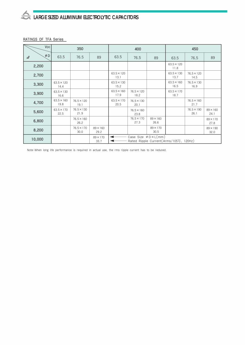
LARGE SIZED ALUMINUM ELECTROLYTIC CAPACITORS
VVDDCC
∅∅DD
22,,220000
22,,770000
33,,330000
33,,990000
44,,770000
55,,660000
66,,880000
88,,220000
1100,,000000Case Size ∅D×L(mm)Rated Ripple Current(Arms/105, 120Hz)
335500
63.5 76.5 89 63.5 76.5 89 63.5 76.5 89
440000 445500
63.5×12014.4
63.5×13016.6
63.5×16019.8
63.5×17022.5
63.5×12013.1
63.5×13015.2
63.5×16017.9
63.5×17020.5
76.5×12019.1
76.5×13021.9
76.5×16026.2
76.5×17030.0
76.5×12018.2
76.5×13020.1
76.5×16023.8
76.5×17027.3
63.5×12011.8
63.5×13013.7
63.5×16016.5
76.5×12014.5
76.5×13016.9
76.5×16021.7
76.5×19026.1
89×16024.1
89×17027.8
89×19032.0
63.5×17018.7
89×16026.6
89×17030.5
89×16029.2
89×17033.7
RRAATTIINNGGSS OOFF TTFFAA SSeerriieess
Note:When long life performance is required in actual use, the rms ripple current has to be reduced.
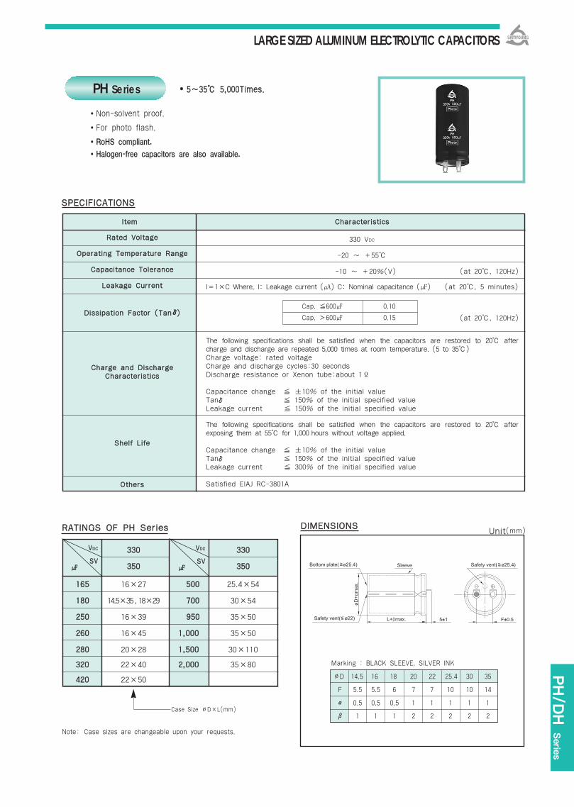
LARGE SIZED ALUMINUM ELECTROLYTIC CAPACITORS
333300 333300
335500 335500
116655 16×27 550000 25.4×54
118800 14.5×35,18×29 770000 30×54
225500 16×39 995500 35×50
226600 16×45 11,,000000 35×50
228800 20×28 11,,550000 30×110
332200 22×40 22,,000000 35×80
442200 22×50
RRaatteedd VVoollttaaggee
OOppeerraattiinngg TTeemmppeerraattuurree RRaannggee
CCaappaacciittaannccee TToolleerraannccee
LLeeaakkaaggee CCuurrrreenntt
DDiissssiippaattiioonn FFaaccttoorr ((TTaannδδ))
CChhaarrggee aanndd DDiisscchhaarrggee CChhaarraacctteerriissttiiccss
SShheellff LLiiffee
OOtthheerrss
lltteemm CChhaarraacctteerriissttiiccss
55~~3355 55,,000000TTiimmeess..
330 VDC
-20 ~ +55
-10 ~ +20%(V) (at 20, 120Hz)
I=1×C Where, I: Leakage current () C: Nominal capacitance () (at 20, 5 minutes)
(at 20, 120Hz)
The following specifications shall be satisfied when the capacitors are restored to 20 aftercharge and discharge are repeated 5,000 times at room temperature. (5 to 35)Charge voltage: rated voltageCharge and discharge cycles:30 secondsDischarge resistance or Xenon tube:about 1Ϊ
Capacitance change ±10% of the initial valueTanδ 150% of the initial specified valueLeakage current 150% of the initial specified value
The following specifications shall be satisfied when the capacitors are restored to 20 afterexposing them at 55 for 1,000 hours without voltage applied.
Capacitance change ±10% of the initial valueTanδ 150% of the initial specified valueLeakage current 300% of the initial specified value
Satisfied EIAJ RC-3801A
SSPPEECCIIFFIICCAATTIIOONNSS
RRAATTIINNGGSS OOFF PPHH SSeerriieess DDIIMMEENNSSIIOONNSS
Non-solvent proof.
For photo flash.
RoHS compliant.
Halogen-free capacitors are also available.
Cap. 600 0.10
Cap. 600 0.15
VVDDCC
SSVV
VVDDCC
SSVV
Note: Case sizes are changeable upon your requests.
Marking : BLACK SLEEVE, SILVER INK
PH Series
Case Size ∅D×L(mm)
PH/D
H Serie
s
Unit(mm)
∅D 14.5 16 18 20 22 25.4 30 35
F 5.5 5.5 6 7 7 10 10 14
α 0.5 0.5 0.5 1 1 1 1 1
β 1 1 1 2 2 2 2 2

LARGE SIZED ALUMINUM ELECTROLYTIC CAPACITORS
RRaatteedd VVoollttaaggee RRaannggee
OOppeerraattiinngg TTeemmppeerraattuurree RRaannggee
CCaappaacciittaannccee TToolleerraannccee
LLeeaakkaaggee CCuurrrreenntt
DDiissssiippaattiioonn FFaaccttoorr ((TTaannδδ))
TTeemmppeerraattuurree CChhaarraacctteerriissttiiccss
LLooaadd LLiiffee
lltteemm CChhaarraacctteerriissttiiccss
4400 11,,000000,,000000TTiimmeess..
315, 475 VDC
-25 ~ +70
-10 ~ +50%(T) (at 20, 120Hz)
I = 0.06CV or 3, whichever is smaller. Where, I:Max. leakage current()
C:Nominal capacitance() V:Rated voltage(VDC) (at 20, 5 minutes)
0.10 Max. (at 20, 120Hz)
C(-10)/C(20) 0.8(at 120Hz)
The following specifications shall be satisfied when the capacitors are restored to 40after the rated working voltage applied. And than charge and discharge (charge0.8sec. discharge 0.2sec) are repeated 1,000,000 times. And than the capacitors arerestored to 20 after the measurements.
Capacitance change ±20% of the initial value Tanδ 200% of the initial specified valueLeakage Current 200% of the initial specified value
SSPPEECCIIFFIICCAATTIIOONNSS
RRAATTIINNGGSS OOFF DDHH SSeerriieess DDIIMMEENNSSIIOONNSS
Case sizes are changeable upon your requests.
Marking : BLACK SLEEVE, SILVER INK
331155 447755
110000 35×110
115500 35×100
222255 40×110
333300 50×100
VVDDCC
∅∅DD 3355 4400 5500
FF 14 14 20 20
Non-solvent proof.
For Welding machine, Warning Light
RoHS compliant.
Halogen-free capacitors are also available.
Note:When long life performance is required inactual use, the rms ripple current has tobe reduced.
DH Series
((CCaappaacciittaannccee cchhaannggee rraattiioo))
Case Size ∅D×L(mm)
Unit(mm)

LARGE SIZED ALUMINUM ELECTROLYTIC CAPACITORS
AVAILABLE TERMINALS [mm]
PC board pin-out PC board pin-out
PC board pin-out PC board pin-out
PC board pin-out PC board pin-out
Terminal B=positiveTerminal A&C=blank
Terminal B=positiveTerminal A&C=blank
∅∅DD 3355 4400 5500
FF 12.5 14