products - mp filtri
TRANSCRIPT
POWER TRANSMISSION PRODUCTS
TO PERFORMPASSION
ACCESSORIES

A WORLDWIDE LEADER IN THE FIELD OF HYDRAULIC FILTRATION EQUIPMENT.
Our company started life in 1964, when Bruno Pasotto decided to attempt to cater for the requests of a market still to be fully explored, with the study, design, development, production and marketing of a vast range of fi lters for hydraulic equipment, capable of satisfying the needs of manufacturers in all sectors.The quality of our products, our extreme competitiveness compared with major international producers and our constant activities of research, design and development has made us a worldwide leader in the fi eld of hydraulic circuit fi ltering.Present for over 50 years in the market, we have played a truly decisive role in defi ning our sector, and by now we are a group capable of controlling our entire chain of production, monitoring all manufacturing processes to guarantee superior quality standards and to provide concrete solutions for the rapidly evolving needs of customers and the market.
A WORLDWIDE LEADER IN THE FIELD OF HYDRAULIC FILTRATION EQUIPMENT.
1

Our customer-oriented philosophy, which enables us to satisfy all customer requests rapidly and with personalized products, makes us a dynamic and fl exible enterprise.The possibility of constantly controlling and monitoring the entire production process is essential to allow us to guarantee the quality of our products.
Our work is based on a skillful interaction between advanced technology and fi ne workmanship, customizing products according to specifi c market requests, focusing strongly on innovation and quality, and following every step in the manufacturing of both standard and special products, fully respecting customer expectations.
Introduction 2
LEADERMARKET
USA
CANADAUNITED KINGDOM
FRANCE
ITALY
GERMANY
INDIA
RUSSIA
P.R. CHINA
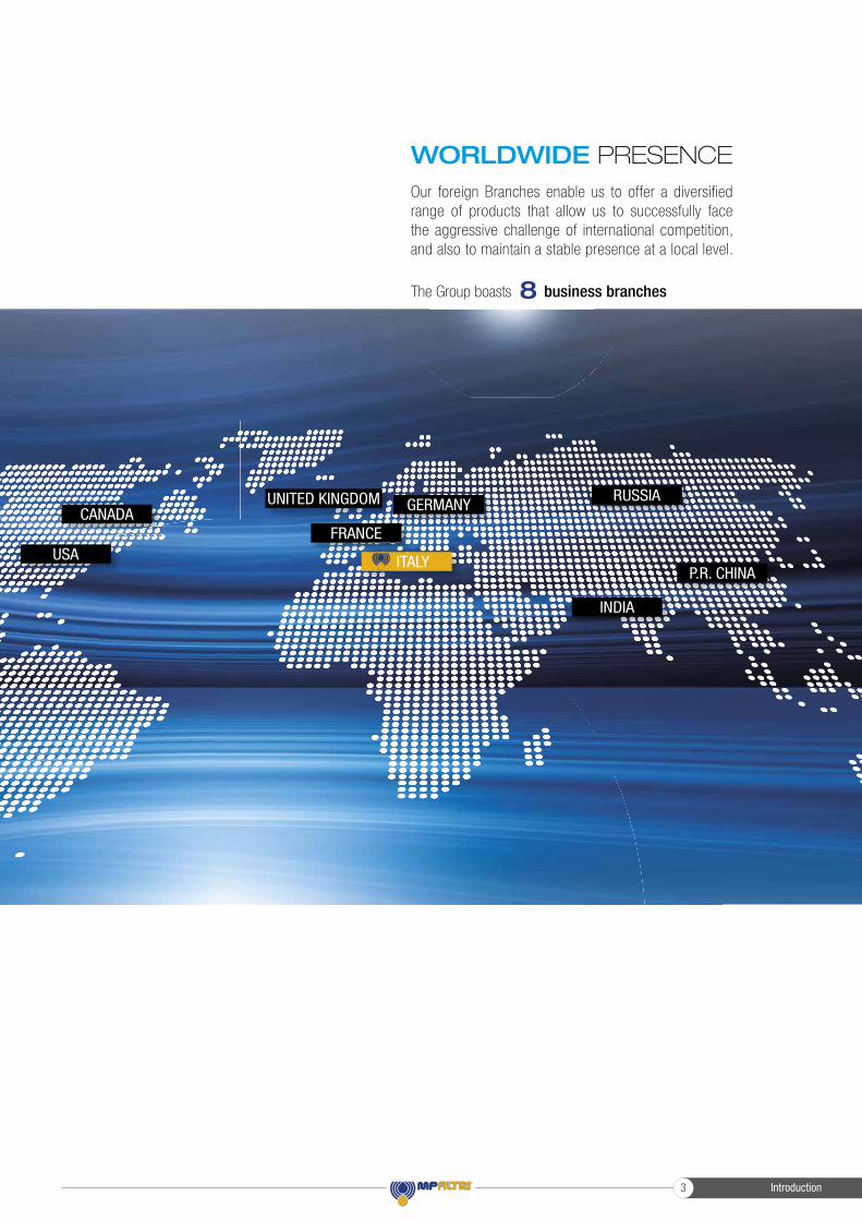
WORLDWIDE PRESENCE
8The Group boasts business branches
Our foreign Branches enable us to offer a diversified range of products that allow us to successfully face the aggressive challenge of international competition, and also to maintain a stable presence at a local level.
Introduction3
Introduction 4
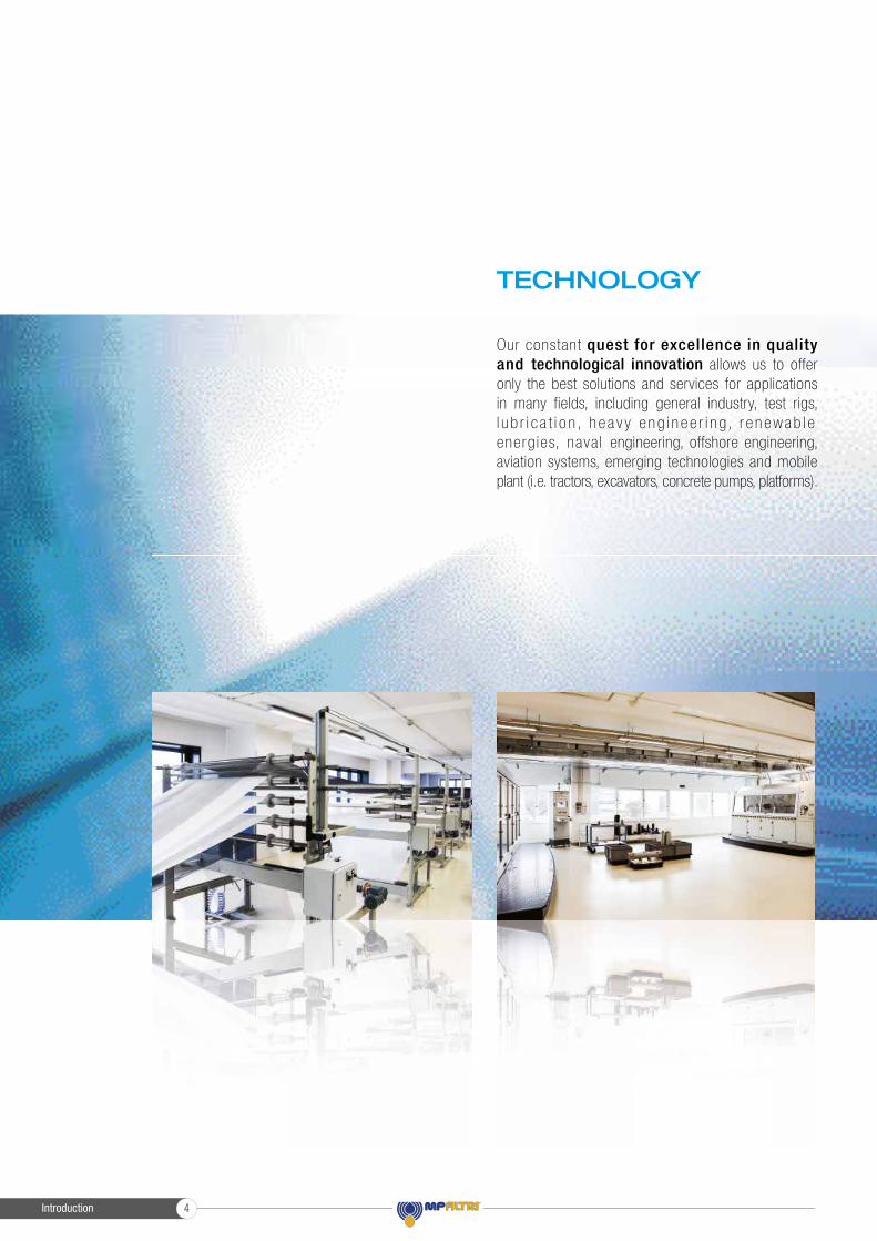
TECHNOLOGY
Our constant quest for excellence in quality and technological innovation allows us to offer only the best solutions and services for applications in many fields, including general industry, test rigs, l u b r i c a t i o n , h e a v y e ng i n e e r i n g, r e n ewab l e energ ies, nava l engineering, offshore engineering, aviation systems, emerging technologies and mobile plant (i.e. tractors, excavators, concrete pumps, platforms).

Introduction5
AND PRODUCTION
Our high level of technological expertise means we can rely entirely on our own resources, without resorting to external providers. This in turn enables us to satisfy a growing number of customer requests, also exploiting our constantly updated range of machines and equ ipmen t , f ea tu r i ng fu l ly-automated workstations capable of 24-hour production.
Introduction 6
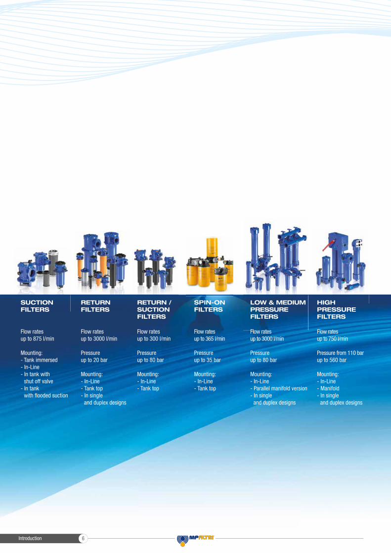
Flow rates up to 3000 l/min
Pressure up to 20 bar
Mounting:- In-Line- Tank top- In single and duplex designs
Flow rates up to 300 l/min
Pressure up to 80 bar
Mounting:- In-Line- Tank top
Flow rates up to 875 l/min
Mounting:- Tank immersed- In-Line- In tank with shut off valve- In tank with � ooded suction
Flow rates up to 750 l/min
Pressure from 110 bar up to 560 bar
Mounting:- In-Line- Manifold- In single and duplex designs
Flow rates up to 3000 l/min
Pressure up to 80 bar
Mounting:- In-Line- Parallel manifold version- In single and duplex designs
LOW & MEDIUM PRESSURE FILTERS
HIGH PRESSURE FILTERS
SPIN-ON FILTERS
Flow rates up to 365 l/min
Pressure up to 35 bar
Mounting:- In-Line- Tank top
SUCTION FILTERS
RETURN FILTERS
RETURN /SUCTIONFILTERS
Introduction7
PRODUCT RANGE
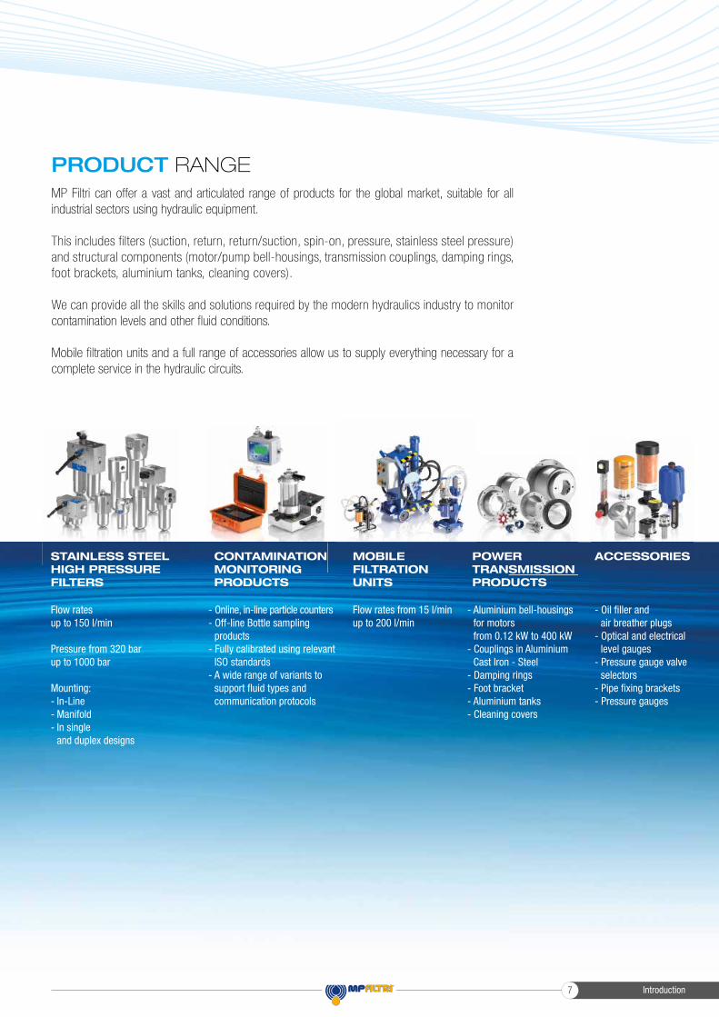
Flow rates up to 150 l/min
Pressure from 320 bar up to 1000 bar
Mounting:- In-Line- Manifold- In single and duplex designs
STAINLESS STEEL HIGH PRESSURE FILTERS
CONTAMINATION MONITORING PRODUCTS
Flow rates from 15 l/min up to 200 l/min
MOBILE FILTRATION UNITS
- Oil � ller and air breather plugs- Optical and electrical level gauges- Pressure gauge valve selectors- Pipe � xing brackets- Pressure gauges
- Aluminium bell-housings for motors from 0.12 kW to 400 kW- Couplings in Aluminium Cast Iron - Steel- Damping rings- Foot bracket- Aluminium tanks- Cleaning covers
POWER TRANSMISSIONPRODUCTS
ACCESSORIES
- Online, in-line particle counters- Off-line Bottle sampling products- Fully calibrated using relevant ISO standards- A wide range of variants to support � uid types and communication protocols
MP Filtri can offer a vast and articulated range of products for the global market, suitable for all industrial sectors using hydraulic equipment.
This includes filters (suction, return, return/suction, spin-on, pressure, stainless steel pressure) and structural components (motor/pump bell-housings, transmission couplings, damping rings, foot brackets, aluminium tanks, cleaning covers).
We can provide all the skills and solutions required by the modern hydraulics industry to monitor contamination levels and other fl uid conditions.
Mobile fi ltration units and a full range of accessories allow us to supply everything necessary for a complete service in the hydraulic circuits.
POWER TRANSMISSION PRODUCTS
Introduction 8
INDEX
LMG
LMC - LDC
LMS - LDS
MULTI-COMPONENTS
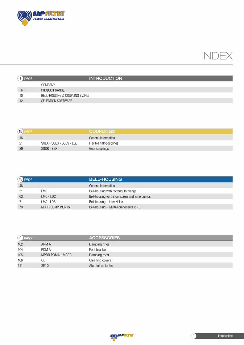
General Information
Bell-housing with rectangular flange
Bell-housing for piston, screw and vane pumps
Bell-housing - Low Noise
Bell-housing - Multi-components 2 - 3
BELL-HOUSING
46
51
63
71
79
page45
ANM A
PDM A
MPDR PDMA - MPDR
OB
SE10
Damping rings
Foot brackets
Damping rods
Cleaning covers
Aluminium tanks
ACCESSORIES
102
104
105
106
111
page101
COMPANY
PRODUCT RANGE
BELL-HOUSING & COUPLING SIZING
SELECTION SOFTWARE
INTRODUCTION
1
6
10
12
page1
SGEA - SGEG - SGES - EGE
SGDR - EGR
General Information
Flexible half-couplings
Gear couplings
COUPLINGS
16
21
39
page15
Introduction9
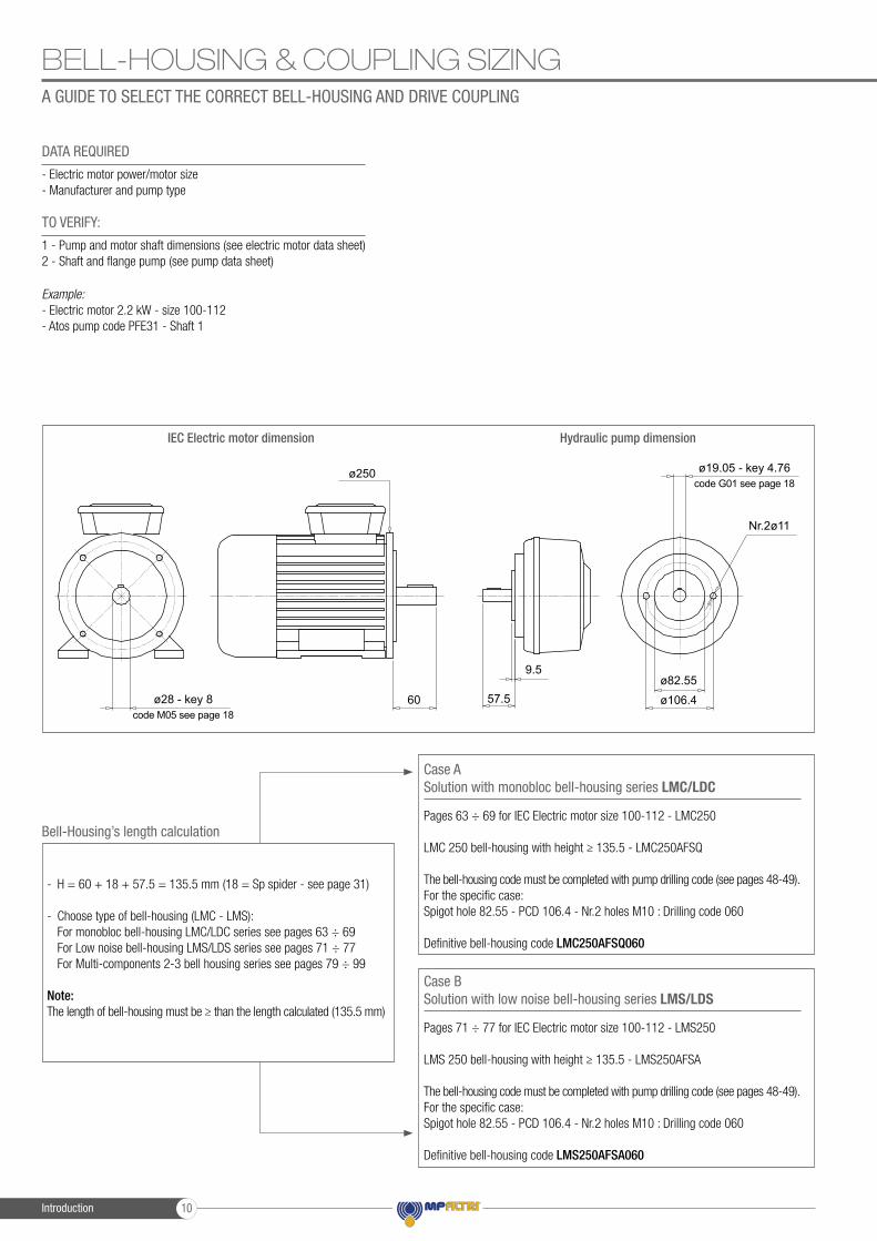
BELL-HOUSING & COUPLING SIZINGA GUIDE TO SELECT THE CORRECT BELL-HOUSING AND DRIVE COUPLING
- Electric motor power/motor size- Manufacturer and pump type
Pages 63 ÷ 69 for IEC Electric motor size 100-112 - LMC250
LMC 250 bell-housing with height ≥ 135.5 - LMC250AFSQ
The bell-housing code must be completed with pump drilling code (see pages 48-49).For the specific case:Spigot hole 82.55 - PCD 106.4 - Nr.2 holes M10 : Drilling code 060
Definitive bell-housing code LMC250AFSQ060
Pages 71 ÷ 77 for IEC Electric motor size 100-112 - LMS250
LMS 250 bell-housing with height ≥ 135.5 - LMS250AFSA
The bell-housing code must be completed with pump drilling code (see pages 48-49).For the specific case:Spigot hole 82.55 - PCD 106.4 - Nr.2 holes M10 : Drilling code 060
Definitive bell-housing code LMS250AFSA060
1 - Pump and motor shaft dimensions (see electric motor data sheet)2 - Shaft and flange pump (see pump data sheet)
Example:- Electric motor 2.2 kW - size 100-112- Atos pump code PFE31 - Shaft 1
DATA REQUIRED
Bell-Housing’s length calculation
Case ASolution with monobloc bell-housing series LMC/LDC
Case BSolution with low noise bell-housing series LMS/LDS
TO VERIFY:
- H = 60 + 18 + 57.5 = 135.5 mm (18 = Sp spider - see page 31)
- Choose type of bell-housing (LMC - LMS): For monobloc bell-housing LMC/LDC series see pages 63 ÷ 69 For Low noise bell-housing LMS/LDS series see pages 71 ÷ 77 For Multi-components 2-3 bell housing series see pages 79 ÷ 99
Note: The length of bell-housing must be ≥ than the length calculated (135.5 mm)
IEC Electric motor dimension Hydraulic pump dimension
ø28 - key 8
ø19.05 - key 4.76ø250
60 57.5
9.5ø82.55
ø106.4
Nr.2ø11
code M05 see page 18
code G01 see page 18
Introduction 10
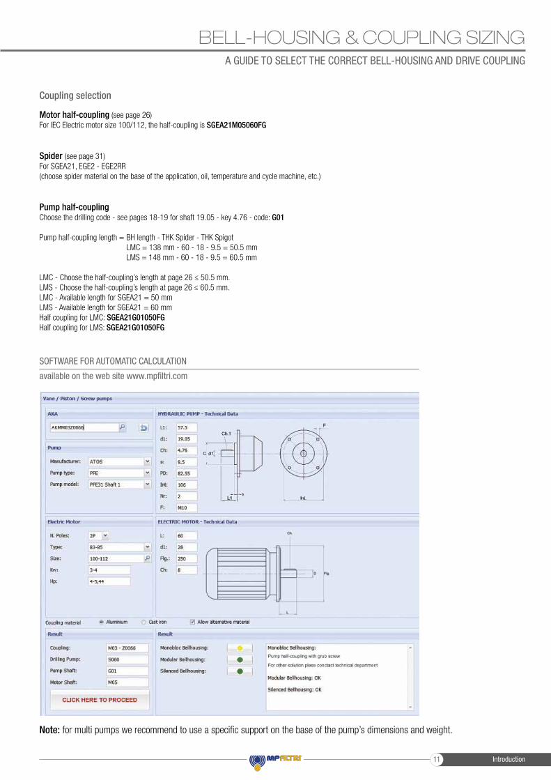
BELL-HOUSING & COUPLING SIZINGA GUIDE TO SELECT THE CORRECT BELL-HOUSING AND DRIVE COUPLING
Motor half-coupling (see page 26)For IEC Electric motor size 100/112, the half-coupling is SGEA21M05060FG
Spider (see page 31)For SGEA21, EGE2 - EGE2RR(choose spider material on the base of the application, oil, temperature and cycle machine, etc.)
Pump half-couplingChoose the drilling code - see pages 18-19 for shaft 19.05 - key 4.76 - code: G01
Pump half-coupling length = BH length - THK Spider - THK Spigot LMC = 138 mm - 60 - 18 - 9.5 = 50.5 mm LMS = 148 mm - 60 - 18 - 9.5 = 60.5 mm
LMC - Choose the half-coupling’s length at page 26 ≤ 50.5 mm.LMS - Choose the half-coupling’s length at page 26 ≤ 60.5 mm.LMC - Available length for SGEA21 = 50 mmLMS - Available length for SGEA21 = 60 mmHalf coupling for LMC: SGEA21G01050FGHalf coupling for LMS: SGEA21G01050FG
Coupling selection
SOFTWARE FOR AUTOMATIC CALCULATION
available on the web site www.mpfiltri.com
Note: for multi pumps we recommend to use a specific support on the base of the pump’s dimensions and weight.
Introduction11
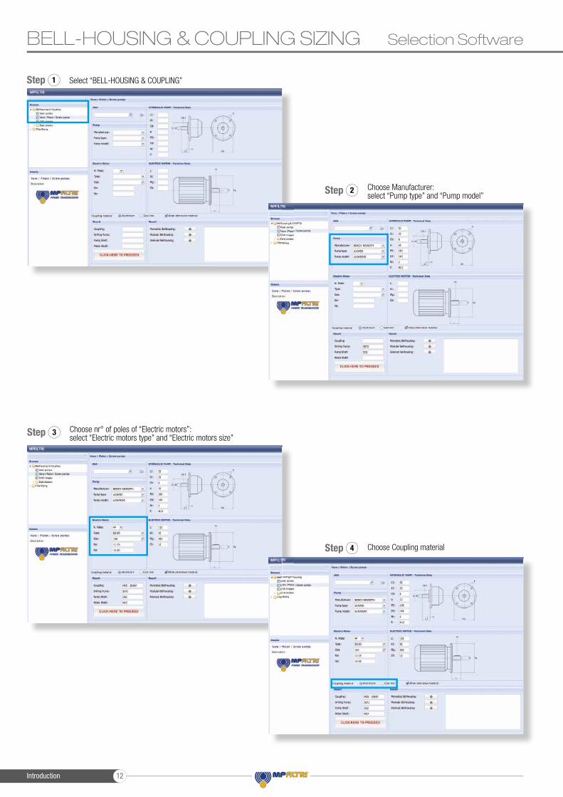
BELL-HOUSING & COUPLING SIZING Selection Software
Select “BELL-HOUSING & COUPLING”Step 1
Choose Coupling materialStep 4
Choose Manufacturer: select “Pump type” and “Pump model”
Step 2
Choose nr° of poles of “Electric motors”: select “Electric motors type” and “Electric motors size”
Step 3
Introduction 12
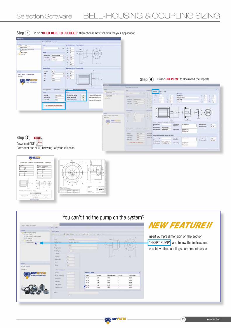
BELL-HOUSING & COUPLING SIZINGSelection Software
Download PDF Datasheet and “DXF Drawing” of your selection
Step 7
Push “CLICK HERE TO PROCEED”, then choose best solution for your application.Step 5
Sec. A-A
Ques
todo
cum
ento
e'di
prop
rieta
' dell
aM
Pfilt
riS.
p.A.
-Sen
zaau
toriz
zazio
nesc
ritta
della
stess
ano
npo
tra' e
sser
eut
ilizza
tope
rla
costr
uzion
ede
ll'ogg
etto
rapp
rese
ntat
one
venir
eco
nunic
ato
ate
rzi.
Laso
cieta
'pro
priet
aria
tute
laip
ropr
idirit
tiarig
ore
dileg
ge.
Allp
ropr
ietar
yrigh
tsre
serve
dbyM
Pfilt
riS.p.
A.-T
hisdr
awing
shall
notb
erep
rodu
ced,
orin
anyw
ayuti
lized
,fort
hema
nufac
tureo
fthec
ompo
nent
orun
ither
einillu
strate
dand
must
notb
erele
ased
tooth
erpa
rties,
witho
utwr
ittenc
onse
nt.A
nyinf
ringe
ment
willb
eleg
allyp
ursu
ed.
Revis
ioni/M
odific
ation
Per errori ammissibili di quotesenza tolleranze e per altre prescrizioni generali vediUNI EN 22768-1/1996 - f
For the permissible errors on thedimensions without tollerance andfor other general specifications .See UNI EN 22768-1/1996 - f
Data/Date
Data/Date
Q.tà/Qty
Disegnato/Drawn.
Controllato/Checked
Peso/Weight
Scala/Scale
N° Disegno/Drawing No.
Dis.grezzo/Raw Componente/ComponentNorma di collaudo/Tested std.
Denominazione/Description
Trattamento/Treatment
Sostituisce/Supersedes
Prodotto/Product
Materiale/Material
REV. Tav./Sht.
di/of
20/02/2017
1:2
1 1
FORMAT
A3
A
A
B.O.M.DESCRIPTIONCODEQTYITEM
Monobloc BellhousingLMC350AFSU0721ASpiderEGE51BMotor Half CouplingSGEA51D02045FG1CPump Half CouplingSGEA51M07109FG1D
140
300
Nr. 4 holes M16
350
Ø
250
Ø
21.hC-
Ø24
54,5
109 26 45
8 M
31
194
100
Ø
8.hC-
Ø52
Nr.2 holes M12
AKMM05Z0007Complete kit for:-IEC Electric Motor Size 160-Pump Bosch Rexroth A10VSO45 shaft P C.a. 7Kg
Complete Kit
Ø
Ø
Revis
ioni/M
odific
ation
Push “PREVIEW” to download the reports.Step 6
Insert pump’s dimension on the section
“INSERT PUMP” and follow the instructions
to achieve the couplings components code
You can’t fi nd the pump on the system?
Introduction13
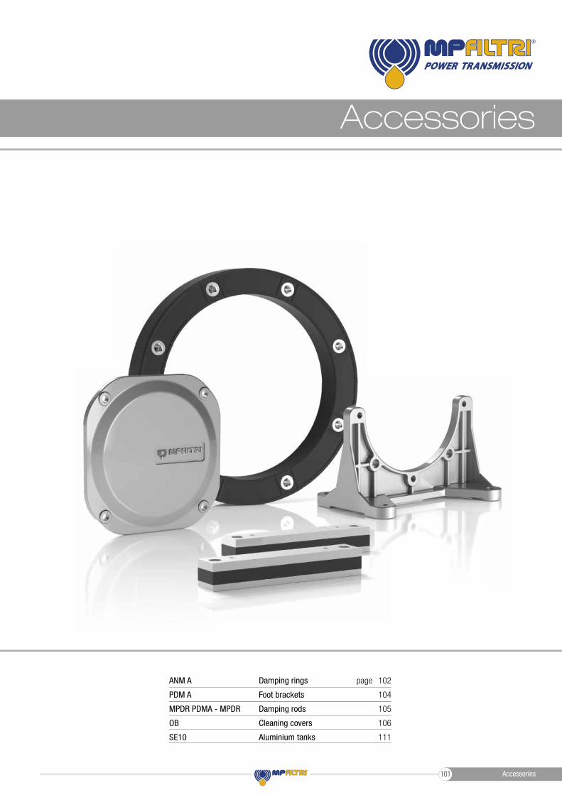
The range of products is completed by a number of accessories, including:
DAMPING RINGS, intended mainly for use with motor-pump units positioned vertically and with the pump submerged in the oil tank.
FOOT BRACKETS, which serve to support the motor pump unit in the event that the selected electric motor does not have mounting feet.
DAMPING RODS, to be mounted under the electric motor feet or under the foot brackets.
CLEANING COVERS, facilitating the maintenance of oil tanks in hydraulic power units, without necessarily having to dismantle the unit.
ALUMINIUM TANKS of 10 litres capacity, allowing the assembly of a compact hydraulic power unit.
Accessories 100
Accessories
Damping rings
Foot brackets
Damping rods
Cleaning covers
Aluminium tanks
102
104
105
106
111
pageANM A
PDM A
MPDR PDMA - MPDR
OB
SE10
Accessories101
ACCESSORIES DAMPING RINGS
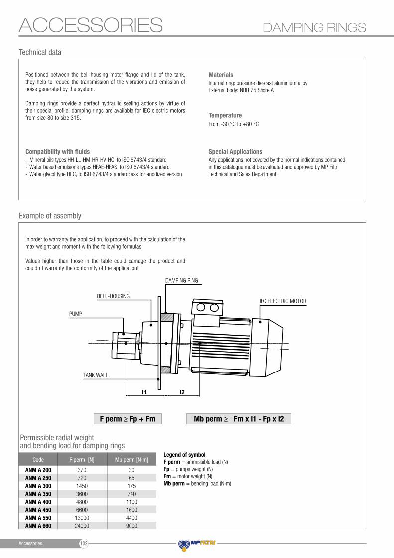
Positioned between the bell-housing motor flange and lid of the tank, they help to reduce the transmission of the vibrations and emission of noise generated by the system.
Damping rings provide a perfect hydraulic sealing actions by virtue of their special profile; damping rings are available for IEC electric motors from size 80 to size 315.
In order to warranty the application, to proceed with the calculation of the max weight and moment with the following formulas.
Values higher than those in the table could damage the product and couldn’t warranty the conformity of the application!
Permissible radial weight and bending load for damping rings
Example of assembly
Any applications not covered by the normal indications contained in this catalogue must be evaluated and approved by MP Filtri Technical and Sales Department
Special Applications- Mineral oils types HH-LL-HM-HR-HV-HC, to ISO 6743/4 standard- Water based emulsions types HFAE-HFAS, to ISO 6743/4 standard- Water glycol type HFC, to ISO 6743/4 standard: ask for anodized version
Compatibility with fluids
Internal ring: pressure die-cast aluminium alloyExternal body: NBR 75 Shore A
Materials
From -30 °C to +80 °C
Temperature
Technical data
Code F perm [N] Mb perm [N∙m]
ANM A 200 ANM A 250 ANM A 300 ANM A 350ANM A 400ANM A 450 ANM A 550 ANM A 660
370720
1450360048006600
1300024000
3065
175740
1100160044009000
Legend of symbolF perm = ammissible load (N)Fp = pumps weight (N)Fm = motor weight (N)Mb perm = bending load (N∙m)
PUMP
TANK WALL
BELL-HOUSING
DAMPING RING
IEC ELECTRIC MOTOR
F perm ≥ Fp + Fm Mb perm ≥ Fm x l1 - Fp x l2
l1 l2
Accessories 102
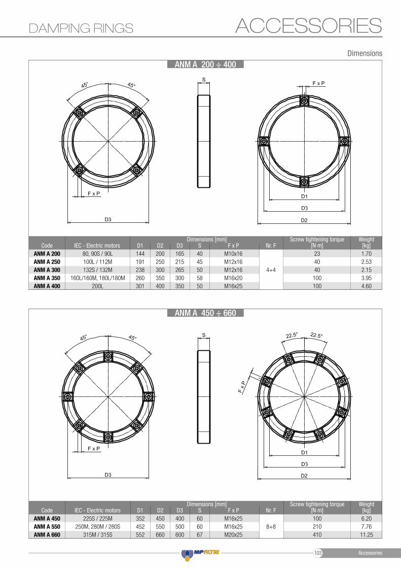
DAMPING RINGS
Dimensions
Code IEC - Electric motors D1 SD2 F x P Nr. FD3Weight
[kg]Screw tightening torque
[N∙m]4045505850
M10x16M12x16 M12x16 M16x20M16x25
4+4
ANM A 200 ANM A 250 ANM A 300 ANM A 350ANM A 400
144191238260301
80, 90S / 90L100L / 112M132S / 132M
160L/160M, 180L/180M200L
200250300350400
165215265300350
1.702.532.153.954.60
234040
100100
Code IEC - Electric motors D1 SD2 F x P Nr. FD3Weight
[kg]Screw tightening torque
[N∙m]606067
M16x25 M16x25M20x25
8+8ANM A 450 ANM A 550 ANM A 660
352452552
225S / 225M250M, 280M / 280S
315M / 315S
450550660
400500600
6.207.7611.25
100210410
ACCESSORIES
ANM A 200 ÷ 400
ANM A 450 ÷ 660
Dimensions [mm]
Dimensions [mm]
Accessories103
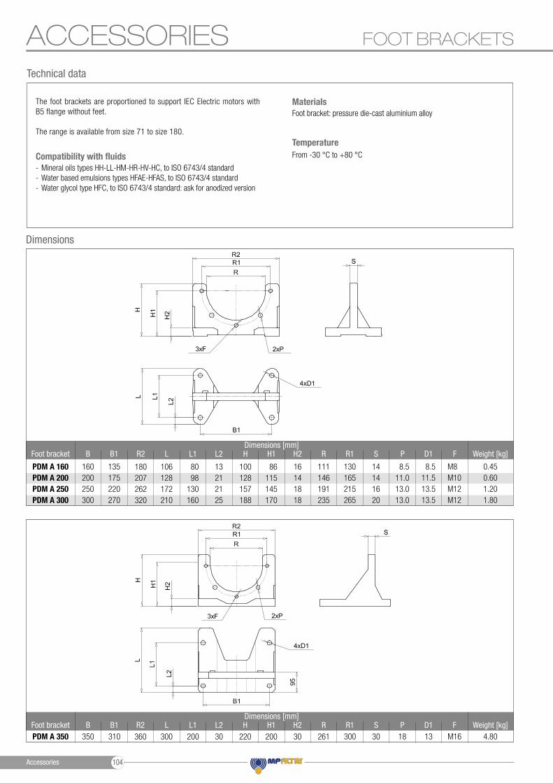
ACCESSORIES FOOT BRACKETS
- Mineral oils types HH-LL-HM-HR-HV-HC, to ISO 6743/4 standard- Water based emulsions types HFAE-HFAS, to ISO 6743/4 standard- Water glycol type HFC, to ISO 6743/4 standard: ask for anodized version
Compatibility with fluids
Dimensions
P
P
R
R
L1
L1
Foot bracket
Foot bracket
H1
H1
R2
R2
B
B
H2
H2
L
L
B1
B1
R1
R1
L2
L2
S
S
H
H
D1
D1
F
F
Weight [kg]
Weight [kg]
360
180207262320
200
86115145170
200
8098
130160
220
100128157188
300
106128172210
30
16141818
30
14141620
30
13212125
261
111146191235
18
8.511.013.013.0
PDM A 350
PDM A 160 PDM A 200 PDM A 250 PDM A 300
350
160200250300
310
135175220270
300
130165215265
13
8.511.513.513.5
4.80
0.450.601.201.80
M16
M8 M10 M12 M12
Foot bracket: pressure die-cast aluminium alloyMaterials
From -30 °C to +80 °C
Temperature
Technical data
The foot brackets are proportioned to support IEC Electric motors with B5 flange without feet.
The range is available from size 71 to size 180.
Dimensions [mm]
Dimensions [mm]
Accessories 104
ACCESSORIES
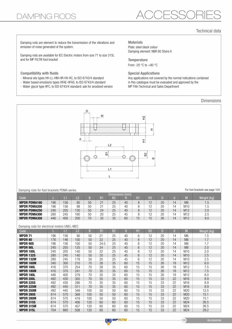
Damping rods are element to reduce the transmission of the vibrations and emission of noise generated of the system.
Damping rods are available for IEC Electric motors from size 71 to size 315L and for MP FILTRI foot bracket
Dimensions
Damping rods for foot brackets PDMA series.
Damping rods for electrical motors UNEL-MEC
For foot brackets see page 104
Dimensions [mm]
Plate: steel black colourDamping element: NBR 60 Shore A
Materials
DAMPING RODS
Technical data
- Mineral oils types HH-LL-HM-HR-HV-HC, to ISO 6743/4 standard- Water based emulsions types HFAE-HFAS, to ISO 6743/4 standard- Water glycol type HFC, to ISO 6743/4 standard: ask for anodized version
Compatibility with fluids
From -20 °C to +80 °C
Temperature
Any applications not covered by the normal indications contained in this catalogue must be evaluated and approved by the MP Filtri Technical and Sales Department
Special Applications
8098
130160200
8888
15
2121242035
4040404560
5050505070
1212121215
M8M10M12M12M12
2525252535
2020202026
MPDR PDMA160MPDR PDMA200MPDR PDMA250MPDR PDMA300MPDR PDMA350
196196240280446
156156205245400
1414141414
1.51.52.02.58.0
90100100125140140178210254241279305286311349368419406457508
8888888
15151515151515151515151515
212224.52422202028283535353535505050606060
4040404040454560606060606060606060606060
5050505050505070707070707070
100100100120120120
1212121212121215151515151515151515151515
M6M8M8M8
M10M10M10M12M12M12M12M16M16M16M20M20M20M24M24M24
2525252525252535353535353535505050606060
2020202020202026262626333333333333333333
MPDR 71MPDR 80MPDR 90SMPDR 90LMPDR 100LMPDR 132SMPDR 132MMPDR 160MMPDR 160LMPDR 180MMPDR 180LMPDR 200LMPDR 225SMPDR 225MMPDR 250MMPDR 280SMPDR 280MMPDR 315SMPDR 315MMPDR 315L
196176196240240280280340416416446492492492492614614614614704
156146156205205245245300370370400430430445445570570570570660
1414141414141418181818222222222222222222
1.51.71.72.02.02.52.56.07.57.58.08.98.98.9
12.515.115.126.526.529.2
D
D
B1
B1
Code
Code
H1
H1
L2
L2
L
L
H2
H2
B
B
L1
L1
d
d
B2
B2
M
M
H
H
Weight [kg]
Weight [kg]
Accessories105
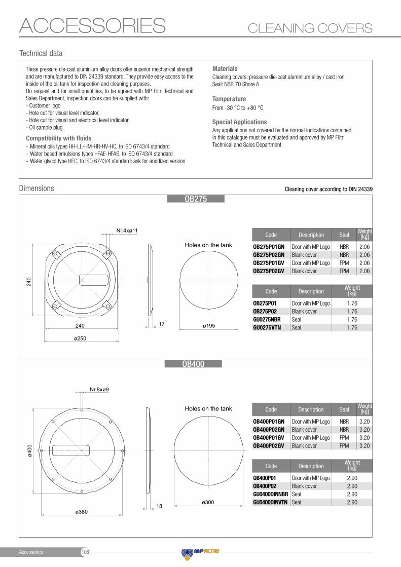
ACCESSORIES CLEANING COVERS
These pressure die-cast aluminium alloy doors offer superior mechanical strength and are manufactured to DIN 24339 standard. They provide easy access to the inside of the oil tank for inspection and cleaning purposes. On request and for small quantities, to be agreed with MP Filtri Technical and Sales Department, inspection doors can be supplied with: - Customer logo. - Hole cut for visual level indicator. - Hole cut for visual and electrical level indicator. - Oil sample plug
DimensionsOB275
OB400
Cleaning cover according to DIN 24339
Holes on the tank
Holes on the tank
Weight [kg]
1.761.761.761.76
Code Description
OB275P01 OB275P02 GU0275NBR GU0275VTN
Door with MP Logo Blank coverSeal Seal
Weight [kg]
2.902.902.902.90
Code Description
OB400P01 OB400P02 GU0400DINNBR GU0400DINVTN
Door with MP Logo Blank coverSeal Seal
Cleaning covers: pressure die-cast aluminium alloy / cast ironSeal: NBR 70 Shore A
Materials
From -30 °C to +80 °C
Temperature
Technical data
- Mineral oils types HH-LL-HM-HR-HV-HC, to ISO 6743/4 standard- Water based emulsions types HFAE-HFAS, to ISO 6743/4 standard- Water glycol type HFC, to ISO 6743/4 standard: ask for anodized version
Compatibility with fluidsAny applications not covered by the normal indications contained in this catalogue must be evaluated and approved by MP Filtri Technical and Sales Department
Special Applications
ø400
ø380
240
ø250
240
Nr.8xø9
Nr.4xø11
18
17
ø300
ø195
Weight[kg]
Weight[kg]
2.062.062.062.06
3.203.203.203.20
Code
Code
Description
Description
Seal
Seal
OB275P01GN OB275P02GNOB275P01GV OB275P02GV
OB400P01GN OB400P02GNOB400P01GV OB400P02GV
Door with MP Logo Blank coverDoor with MP Logo Blank cover
Door with MP Logo Blank coverDoor with MP Logo Blank cover
NBRNBRFPMFPM
NBRNBRFPMFPM
Accessories 106
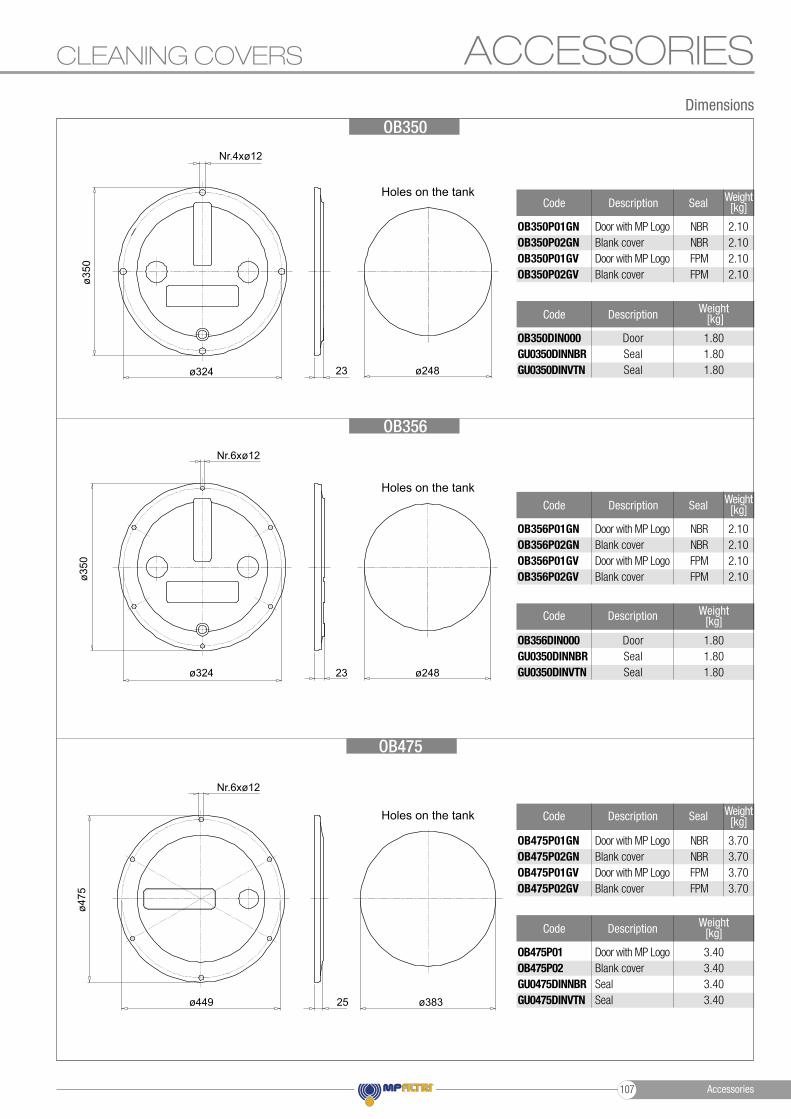
ACCESSORIESCLEANING COVERS
Dimensions
OB356
OB350
OB475
Holes on the tank
Holes on the tank
Holes on the tank
Weight [kg]
3.403.403.403.40
Code Description
OB475P01 OB475P02 GU0475DINNBR GU0475DINVTN
Door with MP Logo Blank coverSeal Seal
Weight [kg]
1.801.801.80
Code Description
OB350DIN000 GU0350DINNBR GU0350DINVTN
Door SealSeal
Weight [kg]
1.801.801.80
Code Description
OB356DIN000 GU0350DINNBR GU0350DINVTN
Door SealSeal
ø383
ø248
ø248
23
23
ø475
ø449
ø350
ø350
ø324
ø324
Nr.6xø12
Nr.6xø12
Nr.4xø12
25
Weight[kg]
Weight[kg]
Weight[kg]
2.102.102.102.10
2.102.102.102.10
3.703.703.703.70
Code
Code
Code
Description
Description
Description
Seal
Seal
Seal
OB350P01GN OB350P02GNOB350P01GV OB350P02GV
OB356P01GN OB356P02GNOB356P01GV OB356P02GV
OB475P01GN OB475P02GNOB475P01GV OB475P02GV
Door with MP Logo Blank coverDoor with MP Logo Blank cover
Door with MP Logo Blank coverDoor with MP Logo Blank cover
Door with MP Logo Blank coverDoor with MP Logo Blank cover
NBRNBRFPMFPM
NBRNBRFPMFPM
NBRNBRFPMFPM
Accessories107
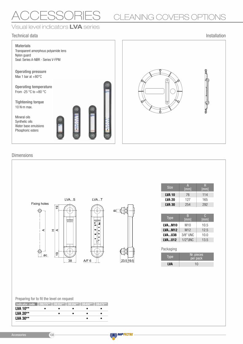
ACCESSORIES CLEANING COVERS OPTIONSVisual level indicators LVA series
Transparent amorphous polyamide lens Nylon guard Seal: Series A-NBR - Series V-FPM
Materials
Mineral oilsSynthetic oilsWater base emulsionsPhosphoric esters
From -25 °C to +80 °COperating temperature
10 N∙m max. Tightening torque
Max 1 bar at +80°C Operating pressure
Technical data
Dimensions
Installation
Packaging
Size
Type
A[mm]
B[mm]
H[mm]
C[mm]
LVA 10 LVA 20 LVA 30
LVA...M10LVA...M12LVA...U38LVA...U12
76127254
M10M12
3/8” UNC1/2”UNC
114165292
10.512.510.013.5
Type Nr. pieces per pack
LVA 10
Fixing holesLVA...S LVA...T
A/F 638 23.5 19.5
A A19
B
19øc
H
Preparing for to fit the level on request
LVA 10**LVA 20**LVA 30**
OB275** OB350** OB356** OB400** OB475**• • • • •
• •• •• •
Indicator code
Accessories 108
ACCESSORIES
DimensionsOptional
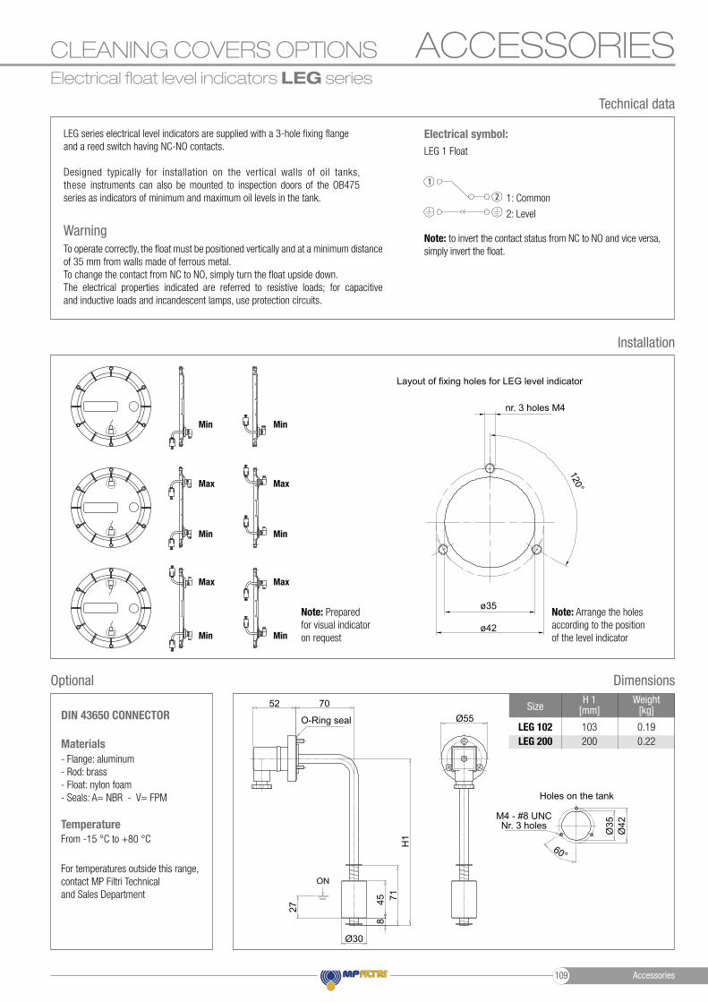
SizeH 1
[mm]Weight
[kg]
LEG 102 LEG 200
103200
0.190.22
CLEANING COVERS OPTIONS
LEG series electrical level indicators are supplied with a 3-hole fixing flange and a reed switch having NC-NO contacts.
Designed typically for installation on the vertical walls of oil tanks, these instruments can also be mounted to inspection doors of the OB475 series as indicators of minimum and maximum oil levels in the tank.
To operate correctly, the float must be positioned vertically and at a minimum distance of 35 mm from walls made of ferrous metal. To change the contact from NC to NO, simply turn the float upside down. The electrical properties indicated are referred to resistive loads; for capacitive and inductive loads and incandescent lamps, use protection circuits.
Installation
Warning
- Flange: aluminum - Rod: brass - Float: nylon foam - Seals: A= NBR - V= FPM
DIN 43650 CONNECTOR
For temperatures outside this range, contact MP Filtri Technical and Sales Department
Materials
From -15 °C to +80 °CTemperature
Technical data
Electrical float level indicators LEG series
O-Ring seal
M4 - #8 UNCNr. 3 holes
52 70
H1
27
458
71
Ø30
Ø55
Ø42
Ø35
60°
Holes on the tank
Note: Prepared for visual indicator on request Min
Max
Min
Max
Layout of fixing holes for LEG level indicator
Note: Arrange the holes according to the position of the level indicator
nr. 3 holes M4
ø35
ø42
120°
Min
Max
Min
Max
Min Min
LEG 1 Float
Electrical symbol:
1: Common
2: Level
Note: to invert the contact status from NC to NO and vice versa, simply invert the float.
Accessories109
ACCESSORIES CLEANING COVERS OPTIONS
Available customization
Installation Dimensions
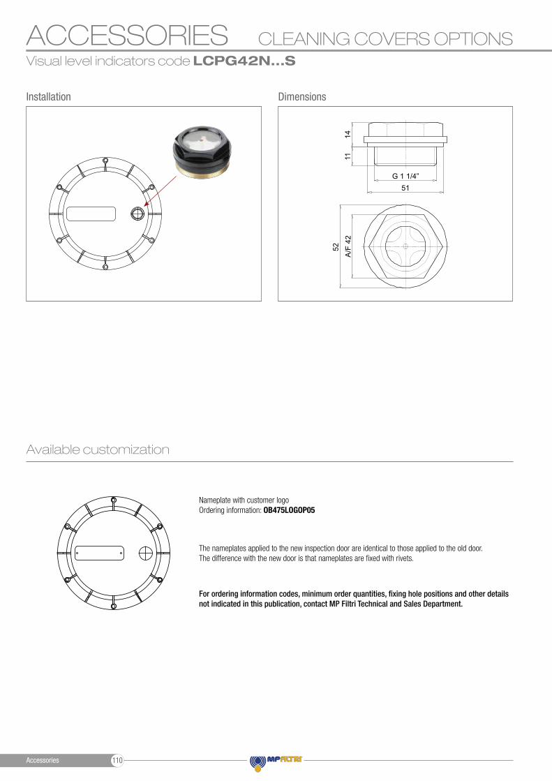
For ordering information codes, minimum order quantities, fixing hole positions and other details not indicated in this publication, contact MP Filtri Technical and Sales Department.
The nameplates applied to the new inspection door are identical to those applied to the old door.The difference with the new door is that nameplates are fixed with rivets.
Nameplate with customer logoOrdering information: OB475LOGOP05
Visual level indicators code LCPG42N...S
G 1 1/4”51
52
A/F
42
1411
Accessories 110
ACCESSORIES
Dimensions
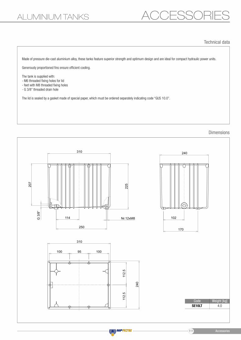
ALUMINIUM TANKS
Made of pressure die-cast aluminium alloy, these tanks feature superior strength and optimum design and are ideal for compact hydraulic power units.
Generously proportioned fins ensure efficient cooling.
The tank is supplied with: - M6 threaded fixing holes for lid - feet with M8 threaded fixing holes - G 3/8” threaded drain hole
The lid is sealed by a gasket made of special paper, which must be ordered separately indicating code “GUS 10.0”.
Technical data
SE10LT Code Weight [kg]
4.0
112.
511
2.5
240
310
310 240
102
170250
114 Nr.12xM8
225207
G 3
/8”
95100 100
Accessories111
mpfiltri.com
WORLDWIDE
TO PERFORM
NETWORK
PASSION
EN
- R
ev. 0
2-20
20C
MP
EN
001X
HEADQUARTERS
ITALFILTRI LLCMoscow - Russia+7 (495) 220 94 60 [email protected]
MP Filtri Canada Inc.Concord, Ontario - Canada+1 905 303 [email protected]
MP Filtri France SASVilleneuve la GarenneFrance+33 (0)1 40 86 47 [email protected]
MP Filtri Germany GmbHSt. Ingbert - Germany+49 (0) 6894 [email protected]
MP Filtri India Pvt. Ltd.Bangalore - India+91 80 4147 7444 / +91 80 4146 [email protected]
MP Filtri (Shanghai) Co., Ltd.Shanghai - Minhang District - China+86 21 58919916 [email protected]
MP Filtri U.K. Ltd.Bourton on the WaterGloucestershire - United Kingdom+44 (0) 1451 822 522 [email protected]
MP Filtri U.S.A. Inc.Quakertown, PA - U.S.A.+1 215 529 [email protected]
BRANCH OFFICES
MP Filtri S.p.A.Pessano con BornagoMilano - Italy+39 02 [email protected]