prof. mario dantas, phd - departamento de informática …mario.dantas/sd1.pdfdistributed systems...
TRANSCRIPT
Distributed SystemsHigh-Performance Networks
Clusters and Computational Grids
Prof. Mario Dantas, Prof. Mario Dantas, PhDPhD
Course Objectives
In this the course we are going to presented the distributed systems, high performance networks, clusters and computational grids environments.
In the end, participants will have a good idea of the basisof these subjects in both theoretical and practical aspects.
Course Outline
Distributed Systems
High Performance Networks
Clusters and Computational Grids
Course Outline
Distributed SystemsIn this part of the course we will cover the following aspects ofthe distributed systems :
• Characteristics• Architectural Models• Networking and Internetworking• InterProcess Communication (IPC)• Distributed File System (DFS)• Name Services (NS)
The recommended literature are presented below and we base our course in the first book.
Distributed Systems: Concepts and Design, 3rd Edition, G. Coulouris, J. Dollimore, T. Kindberg, Addison-Wesley, August 2000, ISBN 0201-61918-0.Distributed Systems: Principles and Paradigms, Andrew S. Tanenbaum, Maarten Van Steen, Prentice Hall, 2002, ISBN 0130888931.
Course Outline Distributed Systems - Characteristics
intranet
ISP
desktop computer:
backbone
satellite link
server:
☎
network link:
☎
☎
☎
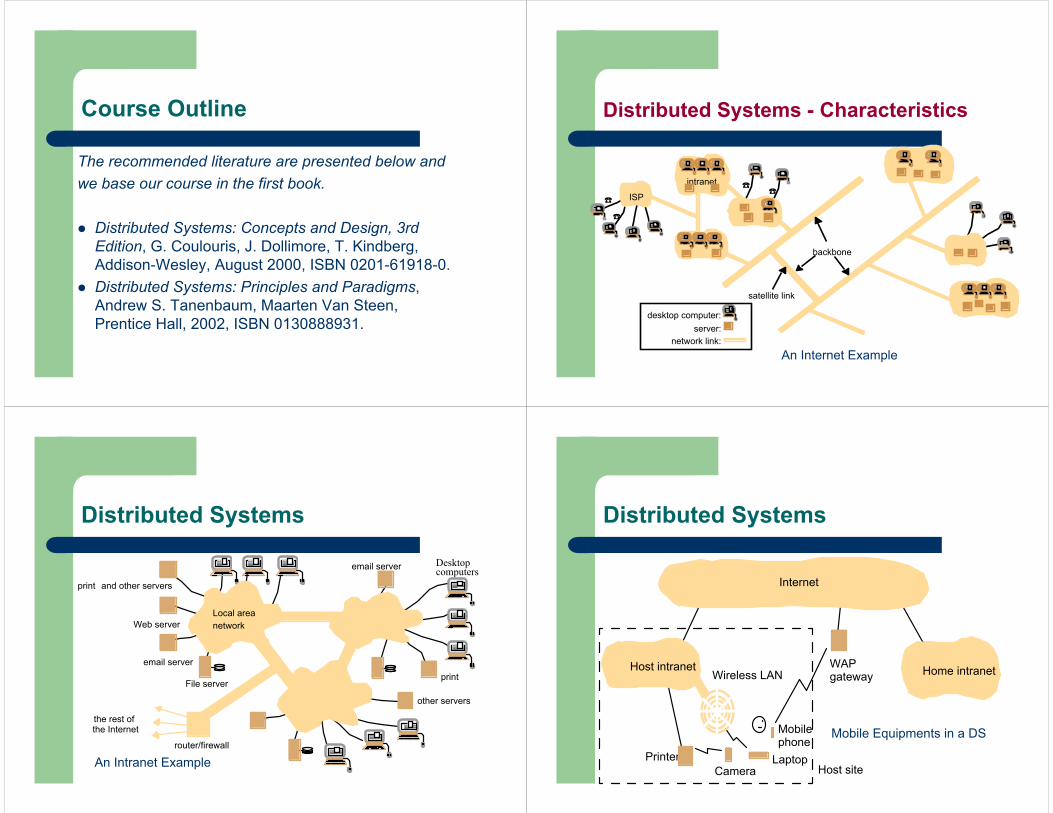
An Internet Example
Distributed Systems
the rest of
email server
Web server
Desktopcomputers
File server
router/firewall
print and other servers
other servers
Local areanetwork
email server
the Internet
An Intranet Example
Distributed Systems
Laptop
Mobile
PrinterCamera
Internet
Host intranet Home intranetWAP Wireless LAN
phone
gateway
Host site
Mobile Equipments in a DS
Distributed Systems
Internet
BrowsersWeb servers
www.google.com
www.cdk3.net
www.w3c.org
Protocols
Activity.html
http://www.w3c.org/Protocols/Activity.html
http://www.google.comlsearch?q=kindberg
http://www.cdk3.net/
File system ofwww.w3c.org
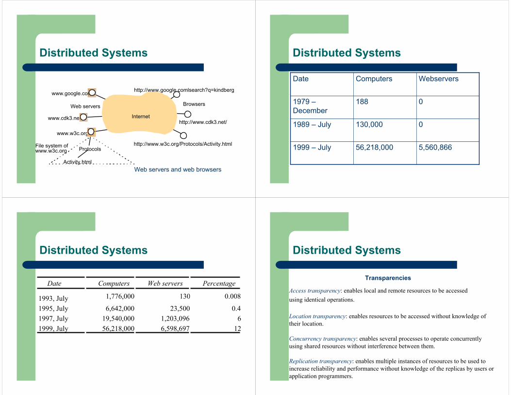
Web servers and web browsers
Distributed Systems
5,560,86656,218,0001999 – July
0130,0001989 – July
01881979 –December
WebserversComputersDate
Distributed Systems
Date Computers Web servers Percentage
1993, July 1,776,000 130 0.008
1995, July 6,642,000 23,500 0.41997, July 19,540,000 1,203,096 61999, July 56,218,000 6,598,697 12
Distributed Systems
Access transparency: enables local and remote resources to be accessed using identical operations.
Location transparency: enables resources to be accessed without knowledge of their location.
Concurrency transparency: enables several processes to operate concurrently using shared resources without interference between them.
Replication transparency: enables multiple instances of resources to be used to increase reliability and performance without knowledge of the replicas by users or application programmers.
Transparencies
Distributed Systems
Failure transparency: enables the concealment of faults, allowing users and application programs to complete their tasks despite the failure of hardware or software components.
Mobility transparency: allows the movement of resources and clients within a system without affecting the operation of users or programs.
Performance transparency: allows the system to be reconfigured to improve performance as loads vary.
Scaling transparency: allows the system and applications to expand in scale without change to the system structure or the application algorithms.
Transparencies
Distributed Systems – Architectural Model
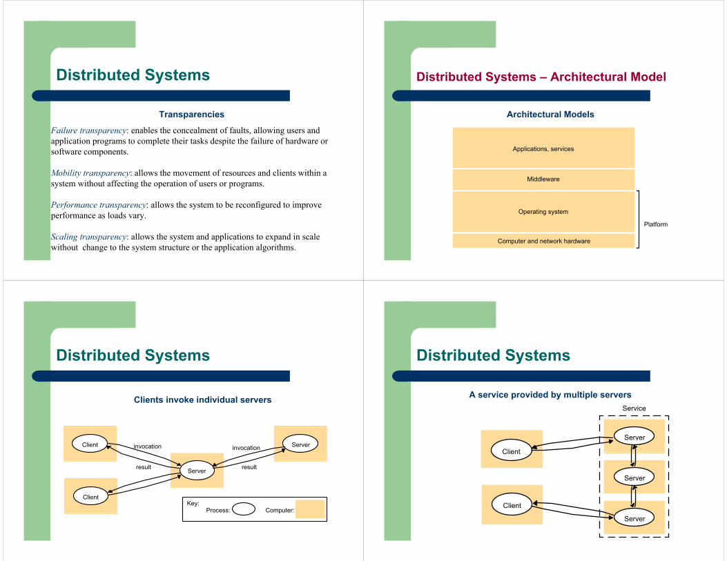
Architectural Models
Applications, services
Computer and network hardware
Platform
Operating system
Middleware
Distributed Systems
Server
Client
Client
invocation
result
Serverinvocation
result
Process:Key:
Computer:
Clients invoke individual servers
Distributed Systems
Server
Server
Server
Service
Client
Client
A service provided by multiple servers
Distributed Systems
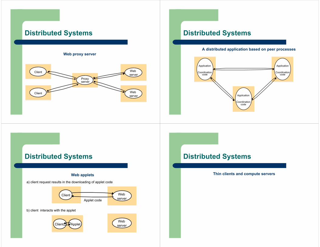
Client
Proxy
Web
server
Web
server
serverClient
Web proxy server
Distributed Systems
Coordination
Application
code
Coordination
Application
code
Coordination
Application
code
A distributed application based on peer processes
Distributed Systems
a) client request results in the downloading of applet code
Web server
ClientWeb serverApplet
Applet codeClient
b) client interacts with the applet
Web applets
Distributed Systems
Thin clients and compute servers
Distributed Systems
Internet
gateway
PDA
service
Music service
serviceDiscovery
Alarm
Camera
Guestsdevices
LaptopTV/PC
Hotel wirelessnetwork
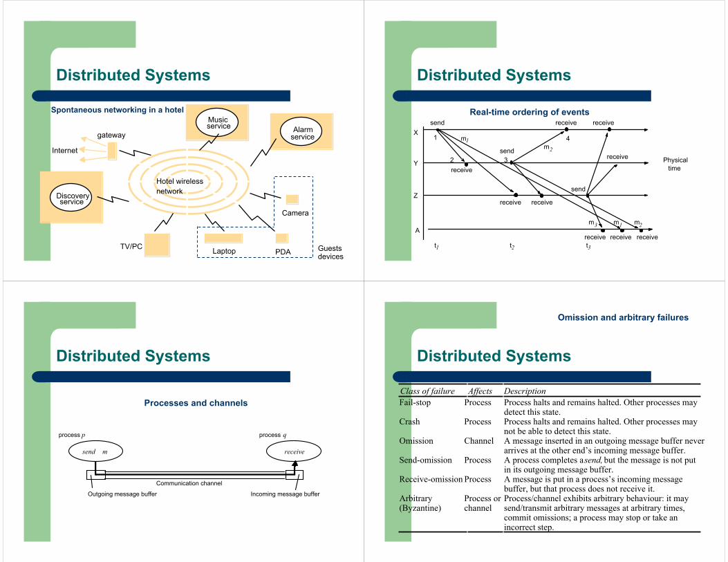
Spontaneous networking in a hotel
Distributed Systems
send
receive
send
receive
m1 m2
2
1
3
4X
Y
Z
Physical time
Am3
receive receive
send
receive receive receivet1 t2 t3
receive
receivem2
m1
Real-time ordering of events
Distributed Systems
process p process q
Communication channel
send
Outgoing message buffer Incoming message buffer
receivem
Processes and channels
Distributed Systems
Class of failure Affects DescriptionFail-stop Process Process halts and remains halted. Other processes may
detect this state.Crash Process Process halts and remains halted. Other processes may
not be able to detect this state.Omission Channel A message inserted in an outgoing message buffer never
arrives at the other end’s incoming message buffer.Send-omission Process A process completes a send, but the message is not put
in its outgoing message buffer.Receive-omission Process A message is put in a process’s incoming message
buffer, but that process does not receive it.Arbitrary(Byzantine)
Process orchannel
Process/channel exhibits arbitrary behaviour: it maysend/transmit arbitrary messages at arbitrary times,commit omissions; a process may stop or take anincorrect step.
Omission and arbitrary failures
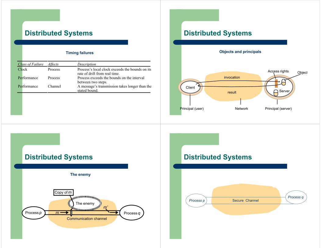
Distributed Systems
Class of Failure Affects DescriptionClock Process Process’s local clock exceeds the bounds on its
rate of drift from real time.Performance Process Process exceeds the bounds on the interval
between two steps.Performance Channel A message’s transmission takes longer than the
stated bound.
Timing failures
Distributed Systems
Network
invocation
resultClient
Server
Principal (user) Principal (server)
ObjectAccess rights
Objects and principals
Distributed Systems
Communication channel
Copy of m
Process p Process qm
The enemym’
The enemy
Distributed Systems
Process pProcess q
Secure Channel
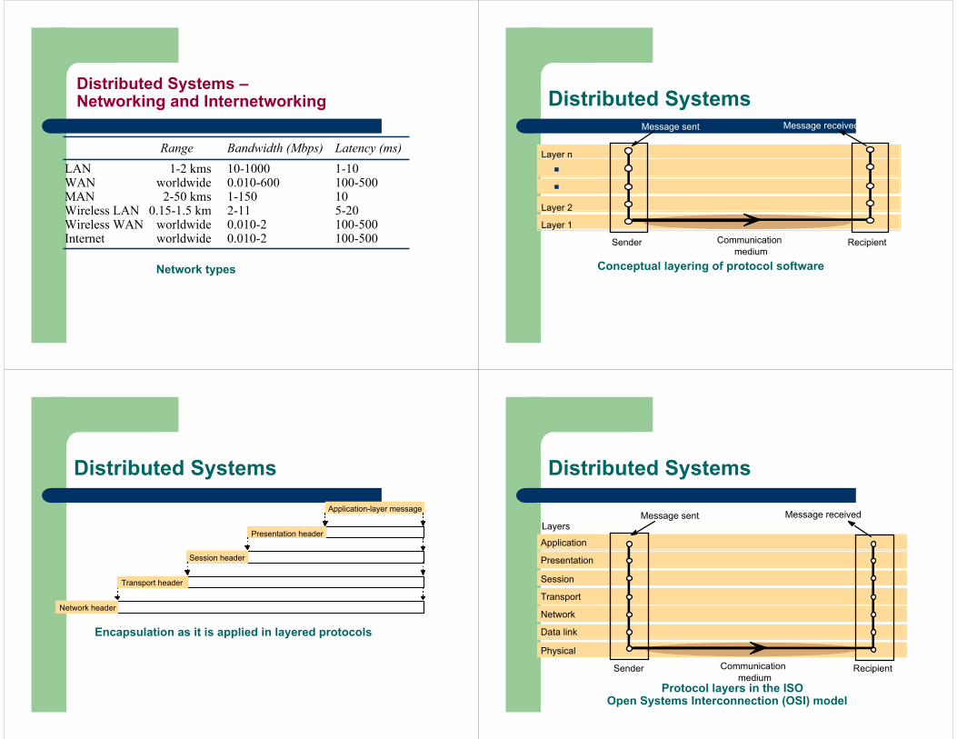
Network types
Range Bandwidth (Mbps) Latency (ms)LAN 1-2 kms 10-1000 1-10WAN worldwide 0.010-600 100-500MAN 2-50 kms 1-150 10Wireless LAN 0.15-1.5 km 2-11 5-20Wireless WAN worldwide 0.010-2 100-500Internet worldwide 0.010-2 100-500
Distributed Systems –Networking and Internetworking
Conceptual layering of protocol software
Layer n
Layer 2
Layer 1
Message sent Message received
Communicationmedium
Sender Recipient
Distributed Systems
Encapsulation as it is applied in layered protocols
Presentation header
Application-layer message
Session header
Transport header
Network header
Distributed Systems
Protocol layers in the ISO Open Systems Interconnection (OSI) model
Application
Presentation
Session
Transport
Network
Data link
Physical
Message sent Message received
Sender Recipient
Layers
Communicationmedium
Distributed Systems
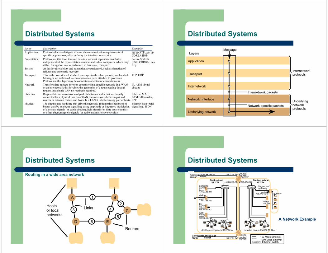
Layer Description ExamplesApplication Protocols that are designed to meet the communication requirements of
specific applications, often defining the interface to a service.HTTP, FTP, SMTP,CORBA IIOP
Presentation Protocols at this level transmit data in a network representation that isindependent of the representations used in individual computers, which maydiffer. Encryption is also performed in this layer, if required.
Secure Sockets(SSL),CORBA DataRep.
Session At this level reliability and adaptation are performed, such as detection offailures and automatic recovery.
Transport This is the lowest level at which messages (rather than packets) are handled.Messages are addressed to communication ports attached to processes,Protocols in this layer may be connection-oriented or connectionless.
TCP, UDP
Network Transfers data packets between computers in a specific network. In a WANor an internetwork this involves the generation of a route passing throughrouters. In a single LAN no routing is required.
IP, ATM virtualcircuits
Data link Responsible for transmission of packets between nodes that are directlyconnected by a physical link. In a WAN transmission is between pairs ofrouters or between routers and hosts. In a LAN it is between any pair of hosts.
Ethernet MAC,ATM cell transfer,PPP
Physical The circuits and hardware that drive the network. It transmits sequences ofbinary data by analogue signalling, using amplitude or frequency modulationof electrical signals (on cable circuits), light signals (on fibre optic circuits)or other electromagnetic signals (on radio and microwave circuits).
Ethernet base- bandsignalling, ISDN
Distributed Systems
Underlying network
Application
Network interface
Transport
Internetwork
Internetwork packets
Network-specific packets
MessageLayers
Internetworkprotocols
Underlyingnetworkprotocols
Distributed Systems
Routing in a wide area network
Hosts Linksor local networks
A
D E
B
C
12
5
43
6
Routers
Distributed Systems
file
compute
dialup
hammer
henry
hotpoint
138.37.88.230
138.37.88.162
bruno138.37.88.249
router/sickle
138.37.95.241138.37.95.240/29
138.37.95.249
copper138.37.88.248
firewall
web
138.37.95.248/29
server
desktop computers 138.37.88.xx
subnet
subnet
Eswitch
138.37.88
server
server
server
138.37.88.251
custard138.37.94.246
desktop computers
Eswitch
138.37.94
hubhub
Student subnetStaff subnet
otherservers
router/firewall
138.37.94.251
☎
1000 Mbps EthernetEswitch: Ethernet switch
100 Mbps Ethernet
file server/gateway
printers
Campusrouter
Campusrouter
138.37.94.xx
Distributed Systems
A Network Example
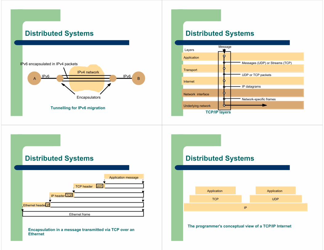
Tunnelling for IPv6 migration
A BIPv6 IPv6
IPv6 encapsulated in IPv4 packets
Encapsulators
IPv4 network
Distributed Systems
TCP/IP layers
Messages (UDP) or Streams (TCP)
Application
Transport
Internet
UDP or TCP packets
IP datagrams
Network-specific frames
MessageLayers
Underlying network
Network interface
Distributed Systems
Encapsulation in a message transmitted via TCP over an Ethernet
Application message
TCP header
IP header
Ethernet header
Ethernet frame
port
TCP
IP
Distributed Systems
The programmer's conceptual view of a TCP/IP Internet
IP
Application Application
TCP UDP
Distributed Systems
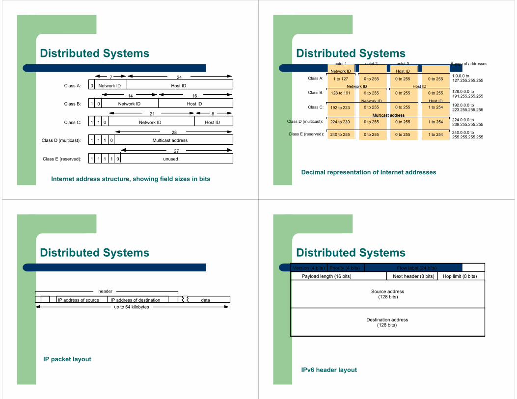
Internet address structure, showing field sizes in bits
7 24
Class A: 0 Network ID Host ID
14 16
Class B: 1 0 Network ID Host ID
21 8
Class C: 1 1 0 Network ID Host ID
28
Class D (multicast): 1 1 1 0 Multicast address
27
Class E (reserved): 1 1 1 1 unused0
Distributed Systems
Decimal representation of Internet addresses
octet 1 octet 2 octet 3
Class A: 1 to 127
0 to 255 0 to 255 1 to 254
Class B: 128 to 191
Class C: 192 to 223
224 to 239 Class D (multicast):
Network ID
Network ID
Network ID
Host ID
Host ID
Host ID
Multicast address
0 to 255 0 to 255 1 to 254
0 to 255 0 to 255 0 to 255
0 to 255 0 to 255 0 to 255
Multicast address
0 to 255 0 to 255 1 to 254240 to 255 Class E (reserved):
1.0.0.0 to 127.255.255.255
128.0.0.0 to 191.255.255.255
192.0.0.0 to 223.255.255.255
224.0.0.0 to 239.255.255.255
240.0.0.0 to 255.255.255.255
Range of addresses
Distributed Systems
IP packet layout
dataIP address of destinationIP address of source
header
up to 64 kilobytes
Distributed Systems
IPv6 header layout
Source address(128 bits)
Destination address(128 bits)
Version (4 bits) Priority (4 bits) Flow label (24 bits)
Payload length (16 bits) Hop limit (8 bits)Next header (8 bits)
Distributed Systems
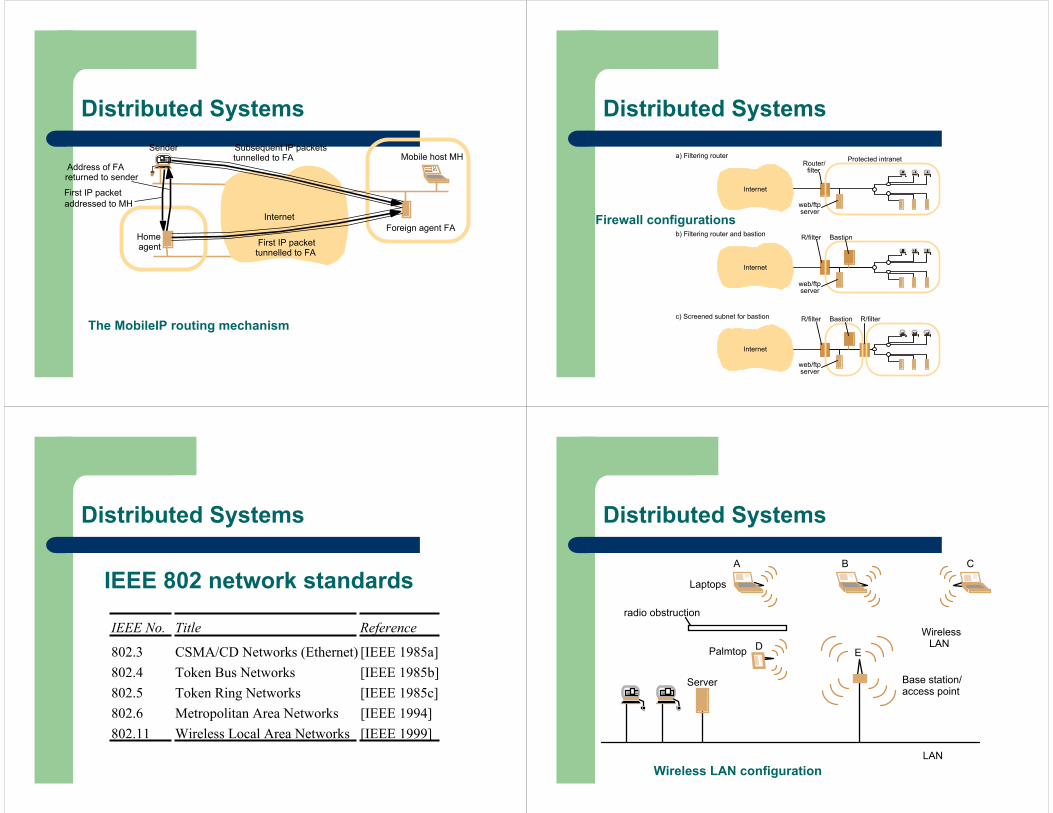
The MobileIP routing mechanism
Sender
Home
Mobile host MH
Foreign agent FAInternet
agent
First IP packet addressed to MH
Address of FAreturned to sender
First IP packettunnelled to FA
Subsequent IP packetstunnelled to FA
Distributed Systems
Firewall configurations
Internet
Router/ Protected intraneta) Filtering router
Internet
b) Filtering router and bastion
filter
Internet
R/filterc) Screened subnet for bastion R/filter Bastion
R/filter Bastion
web/ftpserver
web/ftpserver
web/ftpserver
Distributed Systems
IEEE 802 network standards
IEEE No. Title Reference
802.3 CSMA/CD Networks (Ethernet) [IEEE 1985a]802.4 Token Bus Networks [IEEE 1985b]802.5 Token Ring Networks [IEEE 1985c]802.6 Metropolitan Area Networks [IEEE 1994]802.11 Wireless Local Area Networks [IEEE 1999]
Distributed Systems
Wireless LAN configurationLAN
Server
WirelessLAN
Laptops
Base station/access point
Palmtop
radio obstruction
A B C
D E
Distributed Systems
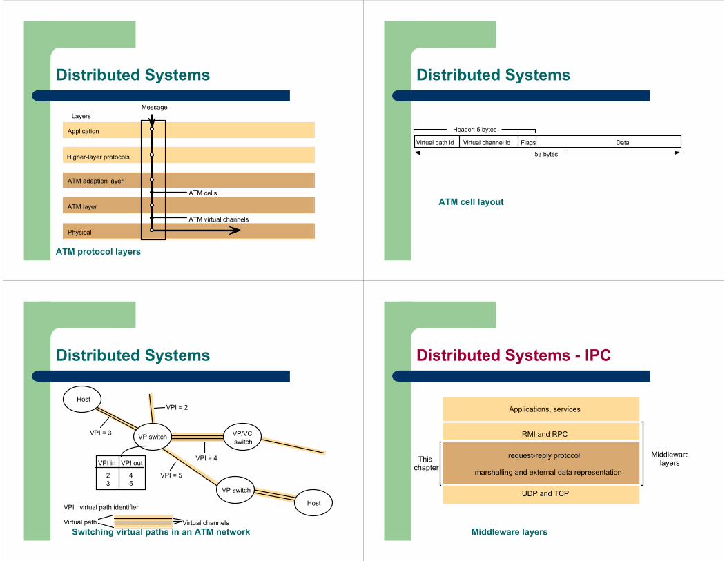
ATM protocol layers
Physical
Application
ATM layer
Higher-layer protocols
ATM cells
ATM virtual channels
MessageLayers
ATM adaption layer
Distributed Systems
ATM cell layout
Flags DataVirtual channel idVirtual path id
53 bytes
Header: 5 bytes
Distributed Systems
Switching virtual paths in an ATM network
VPI in VPI out
23
45
VPI = 3
VPI = 5
VPI = 4
Virtual path Virtual channels
VPI = 2
VPI : virtual path identifier
VP switch VP/VCswitch
VP switch
Host
Host
Distributed Systems
Middleware layers
Applications, services
Middlewarelayers
request-reply protocol
marshalling and external data representation
UDP and TCP
Thischapter
RMI and RPC
Distributed Systems - IPC
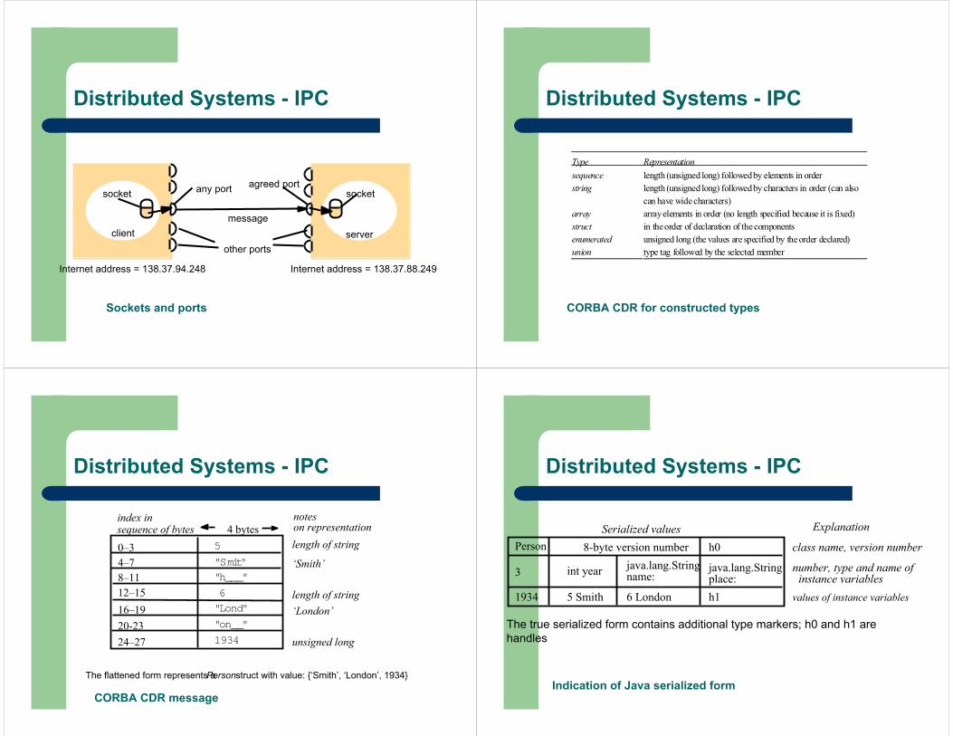
Sockets and ports
message
agreed portany port socketsocket
Internet address = 138.37.88.249Internet address = 138.37.94.248
other portsclient server
Distributed Systems - IPC
CORBA CDR for constructed types
Type Representationsequence length (unsigned long) followed by elements in orderstring length (unsigned long) followed by characters in order (can also
can have wide characters)array array elements in order (no length specified because it is fixed)struct in the order of declaration of thecomponentsenumerated unsigned long (the values are specified by the order declared)union type tag followed by the selected member
Distributed Systems - IPC
CORBA CDR message
The flattened form represents a Personstruct with value: {‘Smith’, ‘London’, 1934}
0–34–78–1112–1516–1920-2324–27
5
"Smit"
"h___"
6
"Lond"
"on__"
1934
index in sequence of bytes 4 bytes
notes on representationlength of string
‘Smith’
length of string‘London’
unsigned long
Distributed Systems - IPC
Indication of Java serialized form
Distributed Systems - IPC
The true serialized form contains additional type markers; h0 and h1 are handles
Serialized valuesPerson
3
1934
8-byte version number
int year
5 Smith
java.lang.Stringname:
6 London
h0
java.lang.Stringplace:h1
Explanation
class name, version number
number, type and name of instance variables
values of instance variables
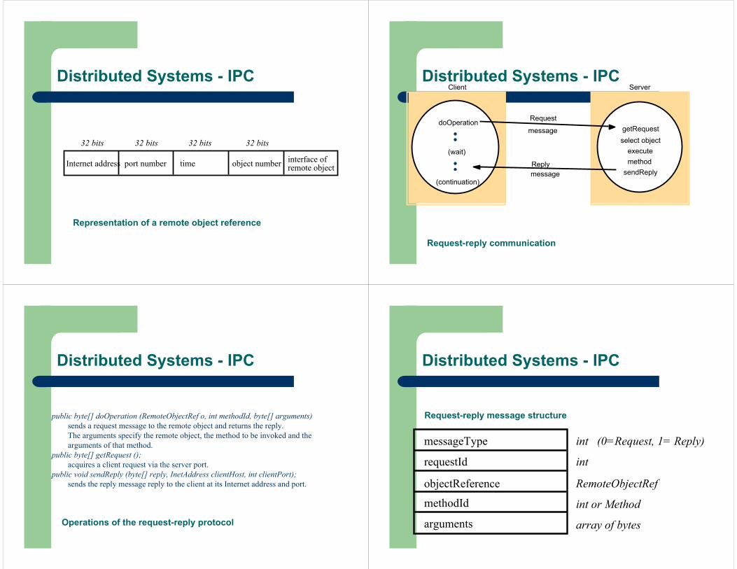
Representation of a remote object reference
Internet address port number time object number interface of remote object
32 bits 32 bits 32 bits 32 bits
Distributed Systems - IPC
Request-reply communication
Request
ServerClient
doOperation
(wait)
(continuation)
Replymessage
getRequest
executemethod
messageselect object
sendReply
Distributed Systems - IPC
Operations of the request-reply protocol
public byte[] doOperation (RemoteObjectRef o, int methodId, byte[] arguments)sends a request message to the remote object and returns the reply. The arguments specify the remote object, the method to be invoked and the arguments of that method.
public byte[] getRequest ();acquires a client request via the server port.
public void sendReply (byte[] reply, InetAddress clientHost, int clientPort);sends the reply message reply to the client at its Internet address and port.
Distributed Systems - IPC
Request-reply message structure
messageType
requestId
objectReference
methodId
arguments
int (0=Request, 1= Reply)
int
RemoteObjectRef
int or Method
array of bytes
Distributed Systems - IPC
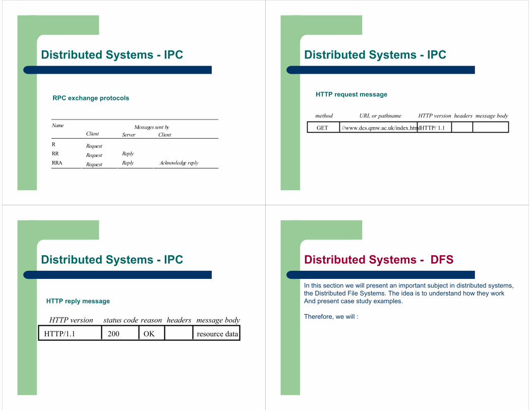
RPC exchange protocols
Name Messages sent byClient Server Client
R RequestRR Request Reply
RRA Request Reply Acknowledge reply
Distributed Systems - IPC
HTTP request message
GET //www.dcs.qmw.ac.uk/index.htmlHTTP/ 1.1
URL or pathnamemethod HTTP version headers message body
Distributed Systems - IPC
HTTP reply message
HTTP/1.1 200 OK resource data
HTTP version status code reason headers message body
Distributed Systems - IPC Distributed Systems - DFS
In this section we will present an important subject in distributed systems,the Distributed File Systems. The idea is to understand how they work And present case study examples.
Therefore, we will :

Understand the requirements that affect the design of distributed servicesNFS: understand how a relatively simple, widely-used service is designed
– Obtain a knowledge of file systems, both local and networked
– Caching as an essential design technique– Remote interfaces are not the same as APIs– Security requires special consideration
Recent advances: appreciate the ongoing research that often leads to major advances
*
Distributed Systems - DFS
Storage systems and their properties
*
In first generation of distributed systems (1974-95), file systems (e.g. NFS) were the only networked storage systems. With the advent of distributed object systems (CORBA, Java) and the web, the picture has become more complex.
Distributed Systems - DFS
Sharing Persis-tence
Distributedcache/replicas
Consistencymaintenance
Example
Main memory RAM
File system UNIX file system
Distributed file system Sun NFS
Web Web server
Distributed shared memory Ivy (Ch. 16)
Remote objects (RMI/ORB) CORBA
Persistent object store 1 CORBA PersistentObject Service
Persistent distributed object store PerDiS, Khazana
1
1
1
*
Types of consistency between copies: 1 - strict one-copy consistency√ - approximate consistencyX - no automatic consistency
Distributed Systems - DFS
WHAT IS A FILE SYSTEM ?
Persistent stored data setsHierarchic name space visible to all processesAPI with the following characteristics:
– access and update operations on persistently stored data sets– Sequential access model (with additional random facilities)
Sharing of data between users, with access controlConcurrent access:
– certainly for read-only access– what about updates?
Other features:– mountable file stores– more? ...
*
Distributed Systems - DFS
*
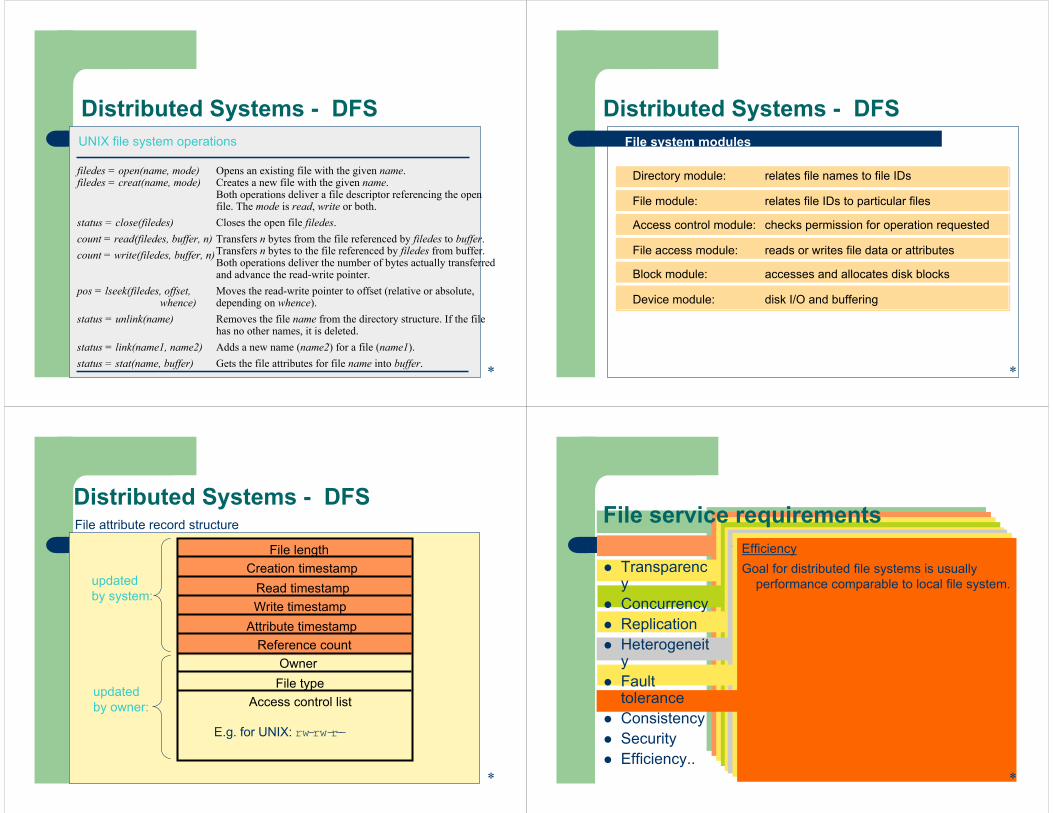
filedes = open(name, mode)filedes = creat(name, mode)
Opens an existing file with the given name.Creates a new file with the given name.Both operations deliver a file descriptor referencing the openfile. The mode is read, write or both.
status = close(filedes) Closes the open file filedes.count = read(filedes, buffer, n)count = write(filedes, buffer, n)
Transfers n bytes from the file referenced by filedes to buffer.Transfers n bytes to the file referenced by filedes from buffer.Both operations deliver the number of bytes actually transferredand advance the read-write pointer.
pos = lseek(filedes, offset,whence)
Moves the read-write pointer to offset (relative or absolute,depending on whence).
status = unlink(name) Removes the file name from the directory structure. If the filehas no other names, it is deleted.
status = link(name1, name2) Adds a new name (name2) for a file (name1).status = stat(name, buffer) Gets the file attributes for file name into buffer.
UNIX file system operations
Distributed Systems - DFS
Directory module: relates file names to file IDs
File module: relates file IDs to particular files
Access control module: checks permission for operation requested
File access module: reads or writes file data or attributes
Block module: accesses and allocates disk blocks
Device module: disk I/O and buffering
File system modules
*
Distributed Systems - DFS
updated by system:
File lengthCreation timestamp
Read timestampWrite timestamp
Attribute timestampReference count
OwnerFile type
Access control list
E.g. for UNIX: rw-rw-r--
*
File attribute record structure
updated by owner:
Distributed Systems - DFSTranparenciesAccess: Same operationsLocation: Same name space after relocation
of files or processesMobility: Automatic relocation of files is
possiblePerformance: Satisfactory performance across
a specified range of system loadsScaling: Service can be expanded to meet
additional loads
Concurrency propertiesIsolationFile-level or record-level lockingOther forms of concurrency control to minimise
contention
Replication propertiesFile service maintains multiple identical copies
of files• Load-sharing between servers makes
service more scalable• Local access has better response (lower
latency)• Fault toleranceFull replication is difficult to implement.Caching (of all or part of a file) gives most of
the benefits (except fault tolerance)
Heterogeneity propertiesService can be accessed by clients running on
(almost) any OS or hardware platform.Design must be compatible with the file
systems of different OSesService interfaces must be open - precise
specifications of APIs are published.
Fault toleranceService must continue to operate even when
clients make errors or crash.• at-most-once semantics• at-least-once semantics
•requires idempotent operations
Service must resume after a server machine crashes.
If the service is replicated, it can continue to operate even during a server crash.
ConsistencyUnix offers one-copy update semantics for
operations on local files - caching is completely transparent.
Difficult to achieve the same for distributed file systems while maintaining good performance and scalability.
SecurityMust maintain access control and privacy as
for local files.•based on identity of user making request•identities of remote users must be authenticated•privacy requires secure communication
Service interfaces are open to all processes not excluded by a firewall.
•vulnerable to impersonation and other attacks
EfficiencyGoal for distributed file systems is usually
performance comparable to local file system.
File service requirements
TransparencyConcurrencyReplicationHeterogeneityFault toleranceConsistencySecurityEfficiency..
*
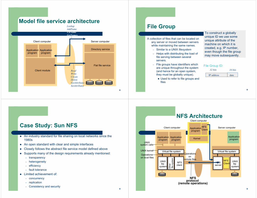
Model file service architecture
Client computer Server computer
Applicationprogram
Applicationprogram
Client module
Flat file service
Directory service
LookupAddNameUnNameGetNames
ReadWriteCreateDeleteGetAttributesSetAttributes
*
File Group
A collection of files that can be located on any server or moved between servers while maintaining the same names.
– Similar to a UNIX filesystem– Helps with distributing the load of
file serving between several servers.
– File groups have identifiers which are unique throughout the system (and hence for an open system, they must be globally unique).
Used to refer to file groups and files
To construct a globally unique ID we use some unique attribute of the machine on which it is created, e.g. IP number, even though the file group may move subsequently.
IP address date
32 bits 16 bitsFile Group ID:
*
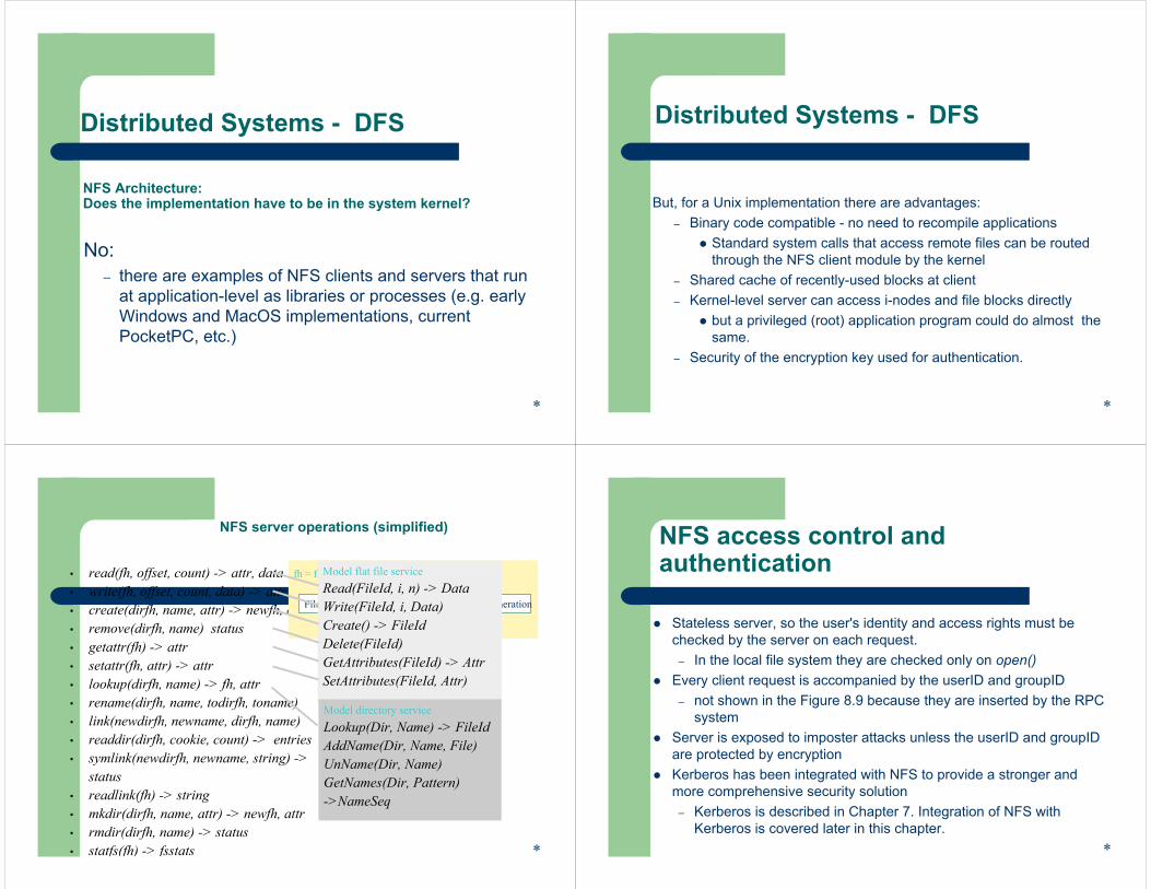
Case Study: Sun NFS
An industry standard for file sharing on local networks since the 1980s An open standard with clear and simple interfacesClosely follows the abstract file service model defined aboveSupports many of the design requirements already mentioned:
– transparency– heterogeneity– efficiency– fault tolerance
Limited achievement of:– concurrency– replication– Consistency and security
*
NFS Architecture
Client computer Server computer
UNIXfile
system
NFSclient
NFSserver
UNIXfile
system
Applicationprogram
Applicationprogram
Virtual file systemVirtual file system
Oth
erfil
e sy
stem
UNIX kernel
system calls
NFSprotocol
(remote operations)
UNIX
Operations on local files
Operationson
remote files
*
Applicationprogram
NFSClient
KernelApplicationprogram
NFSClient
Client computer
*
NFS Architecture: Does the implementation have to be in the system kernel?
No:– there are examples of NFS clients and servers that run
at application-level as libraries or processes (e.g. early Windows and MacOS implementations, current PocketPC, etc.)
Distributed Systems - DFS
*
But, for a Unix implementation there are advantages:– Binary code compatible - no need to recompile applications
Standard system calls that access remote files can be routed through the NFS client module by the kernel
– Shared cache of recently-used blocks at client– Kernel-level server can access i-nodes and file blocks directly
but a privileged (root) application program could do almost thesame.
– Security of the encryption key used for authentication.
Distributed Systems - DFS
• read(fh, offset, count) -> attr, data• write(fh, offset, count, data) -> attr• create(dirfh, name, attr) -> newfh, attr• remove(dirfh, name) status• getattr(fh) -> attr• setattr(fh, attr) -> attr• lookup(dirfh, name) -> fh, attr• rename(dirfh, name, todirfh, toname)• link(newdirfh, newname, dirfh, name)• readdir(dirfh, cookie, count) -> entries• symlink(newdirfh, newname, string) ->
status• readlink(fh) -> string• mkdir(dirfh, name, attr) -> newfh, attr• rmdir(dirfh, name) -> status• statfs(fh) -> fsstats
NFS server operations (simplified)
fh = file handle:
Filesystem identifier i-node number i-node generation
*
Model flat file serviceRead(FileId, i, n) -> DataWrite(FileId, i, Data)Create() -> FileIdDelete(FileId)GetAttributes(FileId) -> AttrSetAttributes(FileId, Attr)
Model directory serviceLookup(Dir, Name) -> FileIdAddName(Dir, Name, File)UnName(Dir, Name)GetNames(Dir, Pattern) ->NameSeq
NFS access control and authentication
Stateless server, so the user's identity and access rights must be checked by the server on each request.
– In the local file system they are checked only on open()Every client request is accompanied by the userID and groupID
– not shown in the Figure 8.9 because they are inserted by the RPCsystem
Server is exposed to imposter attacks unless the userID and groupIDare protected by encryptionKerberos has been integrated with NFS to provide a stronger and more comprehensive security solution
– Kerberos is described in Chapter 7. Integration of NFS with Kerberos is covered later in this chapter.
*
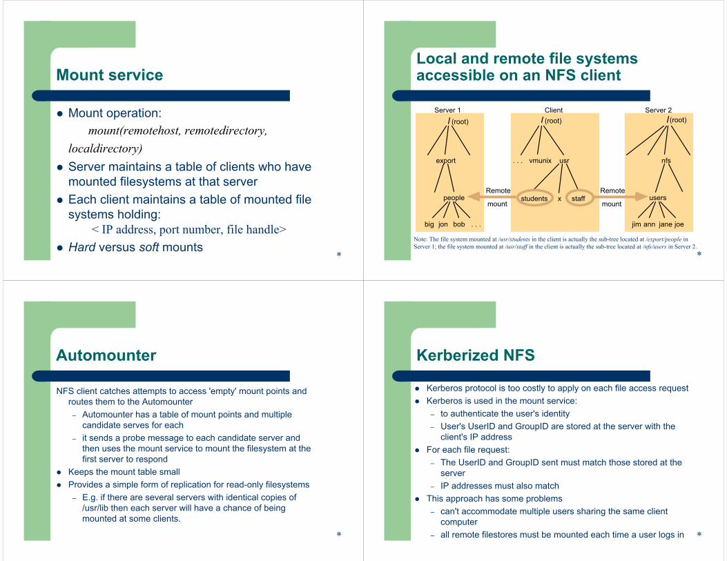
Mount service
Mount operation:mount(remotehost, remotedirectory,
localdirectory)Server maintains a table of clients who have mounted filesystems at that serverEach client maintains a table of mounted file systems holding:
< IP address, port number, file handle>Hard versus soft mounts
*
Local and remote file systems accessible on an NFS client
jim jane joeann
usersstudents
usrvmunix
Client Server 2
. . . nfs
Remote
mountstaff
big bobjon
people
Server 1
export
(root)
Remote
mount
. . .
x
(root) (root)
Note: The file system mounted at /usr/students in the client is actually the sub-tree located at /export/people in Server 1; the file system mounted at /usr/staff in the client is actually the sub-tree located at /nfs/users in Server 2.
*
Automounter
NFS client catches attempts to access 'empty' mount points and routes them to the Automounter
– Automounter has a table of mount points and multiple candidate serves for each
– it sends a probe message to each candidate server and then uses the mount service to mount the filesystem at the first server to respond
Keeps the mount table smallProvides a simple form of replication for read-only filesystems
– E.g. if there are several servers with identical copies of /usr/lib then each server will have a chance of being mounted at some clients.
*
Kerberized NFS
Kerberos protocol is too costly to apply on each file access requestKerberos is used in the mount service:
– to authenticate the user's identity– User's UserID and GroupID are stored at the server with the
client's IP addressFor each file request:
– The UserID and GroupID sent must match those stored at the server
– IP addresses must also matchThis approach has some problems
– can't accommodate multiple users sharing the same client computer
– all remote filestores must be mounted each time a user logs in *

NFS optimization - server caching
Similar to UNIX file caching for local files:– pages (blocks) from disk are held in a main memory buffer cache
until the space is required for newer pages. Read-ahead and delayed-write optimizations.
– For local files, writes are deferred to next sync event (30 second intervals)
– Works well in local context, where files are always accessed through the local cache, but in the remote case it doesn't offernecessary synchronization guarantees to clients.
*
NFS optimization - server caching
NFS v3 servers offers two strategies for updating the disk:– write-through - altered pages are written to disk as soon as they
are received at the server. When a write() RPC returns, the NFS client knows that the page is on the disk.
– delayed commit - pages are held only in the cache until a commit()call is received for the relevant file. This is the default mode used by NFS v3 clients. A commit() is issued by the client whenever a file is closed.
*
NFS optimization - client caching
Server caching does nothing to reduce RPC traffic between client and server
– further optimization is essential to reduce server load in largenetworks
– NFS client module caches the results of read, write, getattr, lookupand readdir operations
– synchronization of file contents (one-copy semantics) is not guaranteed when two or more clients are sharing the same file.
*
NFS optimization - client caching
Timestamp-based validity check – reduces inconsistency, but doesn't eliminate it– validity condition for cache entries at the client:
(T - Tc < t) v (Tmclient = Tmserver)– t is configurable (per file) but is typically set to
3 seconds for files and 30 secs. for directories– it remains difficult to write distributed
applications that share files with NFS
*
t freshness guaranteeTc time when cache entry was
last validatedTm time when block was last
updated at serverT current time

Other NFS optimizations
Sun RPC runs over UDP by default (can use TCP if required)Uses UNIX BSD Fast File System with 8-kbyte blocks reads() and writes() can be of any size (negotiated between client and server)the guaranteed freshness interval t is set adaptively for individual files to reduce gettattr() calls needed to update Tmfile attribute information (including Tm) is piggybacked in replies to all file requests
*
NFS performance
Early measurements (1987) established that:– write() operations are responsible for only 5% of server calls in
typical UNIX environmentshence write-through at server is acceptable
– lookup() accounts for 50% of operations -due to step-by-step pathname resolution necessitated by the naming and mounting semantics.
*
NFS performance
More recent measurements (1993) show high performance:1 x 450 MHz Pentium III: > 5000 server ops/sec, < 4 millisec.
average latency24 x 450 MHz IBM RS64: > 29,000 server ops/sec, < 4 millisec.
average latencysee www.spec.org for more recent measurements
*
NFS performance
Provides a good solution for many environments including:
– large networks of UNIX and PC clients– multiple web server installations sharing a single file store
*

NFS - Summary
An excellent example of a simple, robust, high-performance distributed service.Achievement of transparencies :Access: Excellent; the API is the UNIX system call
interface for both local and remote files.
Location: Not guaranteed but normally achieved; naming of filesystems is controlled by client mount operations, but transparency can be ensured by an appropriate system configuration.
NFS - Summary
Concurrency: Limited but adequate for most purposes; when read-write files are shared concurrently between clients, consistency is not perfect.
Replication: Limited to read-only file systems; for writable files, the SUN Network Information Service (NIS) runs over NFS and is used to replicate essential system files.
NFS - Summary
Achievement of transparencies (continued):Failure: Limited but effective; service is suspended if a
server fails. Recovery from failures is aided by the simple stateless design.
Mobility: Hardly achieved; relocation of files is not possible, relocation of file systems is possible, but requires updates to client configurations.
*
NFS - Summary
Performance: Good; multiprocessor servers achieve very high performance, but for a single filesystem it's not possible to go beyond the throughput of a multiprocessor server.
Scaling: Good; filesystems (file groups) may be subdivided and allocated to separate servers. Ultimately, the performance limit is determined by the load on the server holding the most heavily-used filesystem (file group).
*
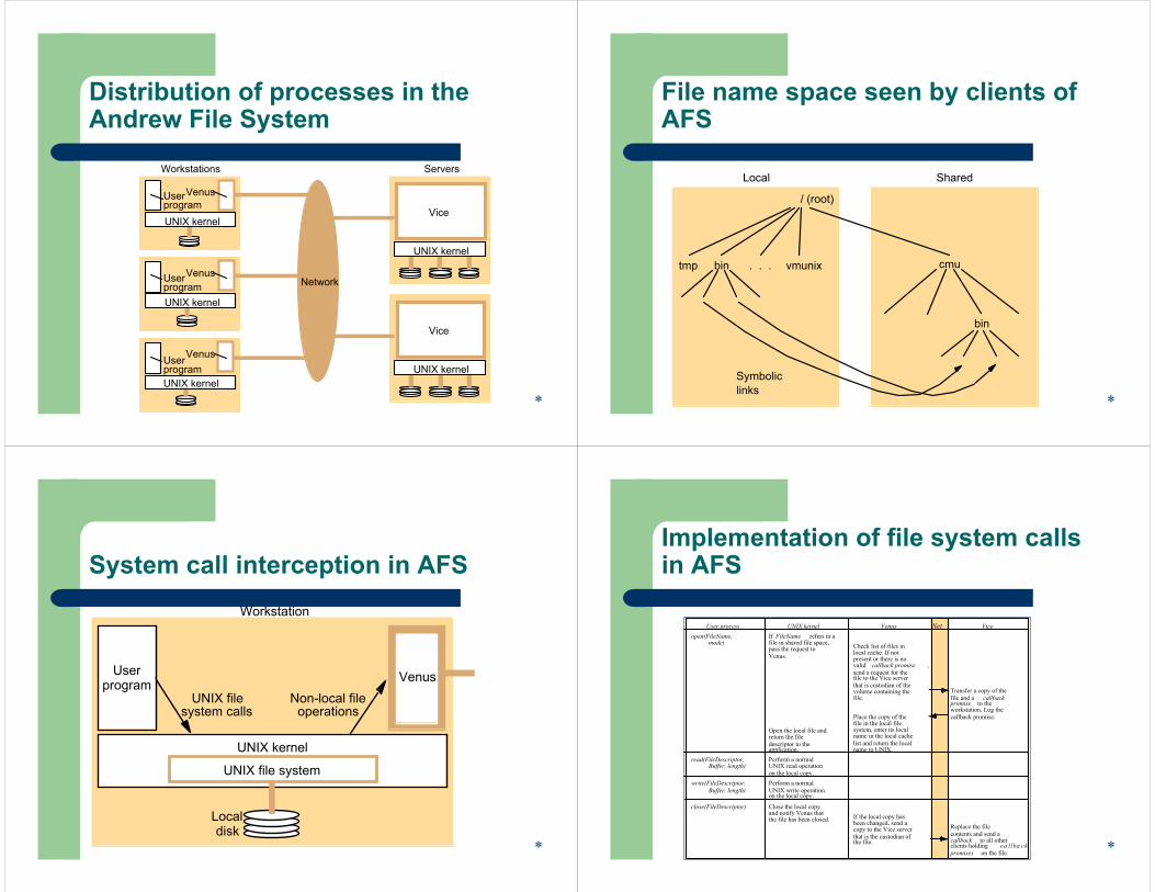
Distribution of processes in the Andrew File System
Venus
Workstations Servers
Venus
VenusUserprogram
Network
UNIX kernel
UNIX kernel
Vice
Userprogram
Userprogram
ViceUNIX kernel
UNIX kernel
UNIX kernel
*
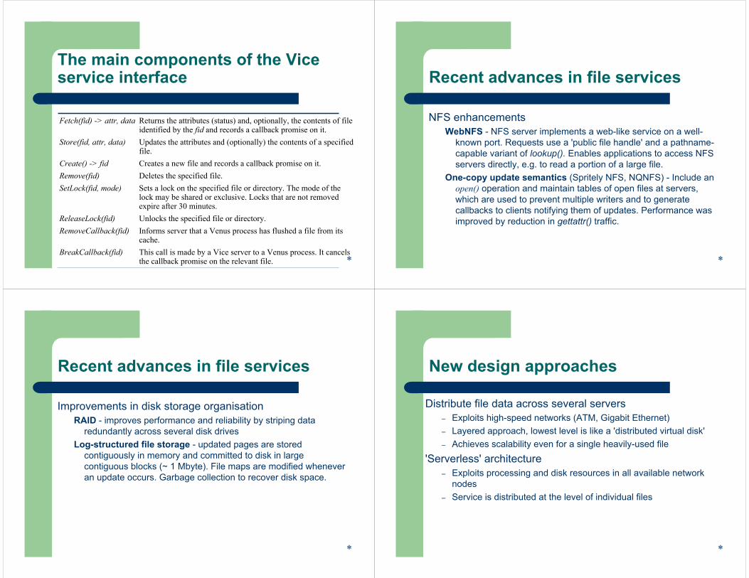
File name space seen by clients of AFS
/ (root)
tmp bin cmuvmunix. . .
bin
SharedLocal
Symboliclinks
*
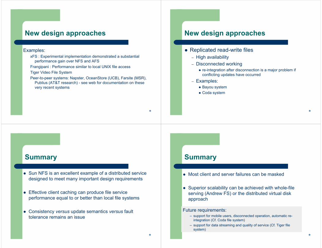
System call interception in AFS
UNIX filesystem calls
Non-local fileoperations
Workstation
Localdisk
Userprogram
UNIX kernel
Venus
UNIX file system
Venus
*
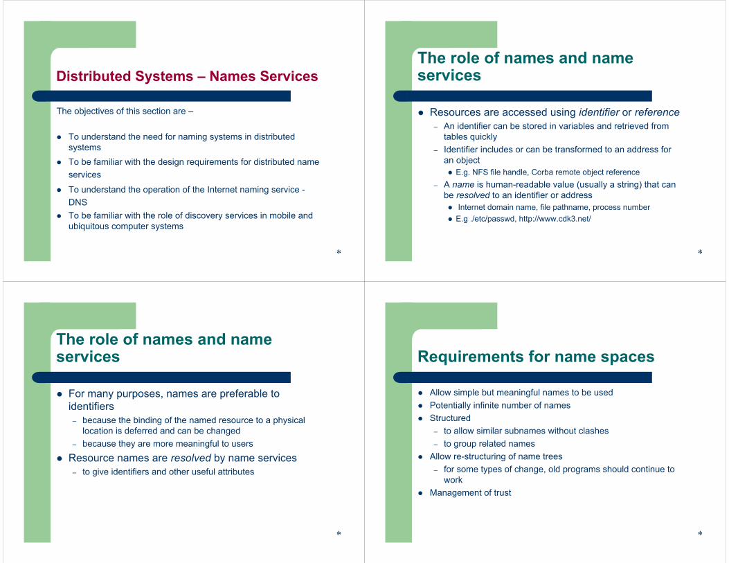
Implementation of file system calls in AFS
User process UNIX kernel Venus Net Viceopen(FileName,
mode)If FileName refers to afile in shared file space,pass the request toVenus.
Open the local file andreturn the filedescriptor to theapplication.
Check list of files inlocal cache. If notpresent or there is novalid callback promise ,send a request for thefile to the Vice serverthat is custodian of thevolume containing thefile.
Place the copy of thefile in the local filesystem, enter its localname in the local cachelist and return the localname to UNIX.
Transfer a copy of thefile and a callbackpromise to theworkstation. Log thecallback promise.
read(FileDescriptor,Buffer, length)
Perform a normalUNIX read operationon the local copy.
write(FileDescriptor,Buffer, length)
Perform a normalUNIX write operationon the local copy.
close(FileDescriptor) Close the local copyand notify Venus thatthe file has been closed. If the local copy has
been changed, send acopy to the Vice serverthat is the custodian ofthe file.
Replace the filecontents and send acallback to all otherclients holding ca llba ckpromises on the file. *
The main components of the Vice service interface
Fetch(fid) -> attr, data Returns the attributes (status) and, optionally, the contents of fileidentified by the fid and records a callback promise on it.
Store(fid, attr, data) Updates the attributes and (optionally) the contents of a specifiedfile.
Create() -> fid Creates a new file and records a callback promise on it.Remove(fid) Deletes the specified file.SetLock(fid, mode) Sets a lock on the specified file or directory. The mode of the
lock may be shared or exclusive. Locks that are not removed expire after 30 minutes.
ReleaseLock(fid) Unlocks the specified file or directory.RemoveCallback(fid) Informs server that a Venus process has flushed a file from its
cache.BreakCallback(fid) This call is made by a Vice server to a Venus process. It cancels
the callback promise on the relevant file. *
Recent advances in file services
NFS enhancementsWebNFS - NFS server implements a web-like service on a well-
known port. Requests use a 'public file handle' and a pathname-capable variant of lookup(). Enables applications to access NFS servers directly, e.g. to read a portion of a large file.
One-copy update semantics (Spritely NFS, NQNFS) - Include an open() operation and maintain tables of open files at servers, which are used to prevent multiple writers and to generate callbacks to clients notifying them of updates. Performance was improved by reduction in gettattr() traffic.
*
Recent advances in file services
Improvements in disk storage organisationRAID - improves performance and reliability by striping data
redundantly across several disk drivesLog-structured file storage - updated pages are stored
contiguously in memory and committed to disk in large contiguous blocks (~ 1 Mbyte). File maps are modified whenever an update occurs. Garbage collection to recover disk space.
*
New design approaches
Distribute file data across several servers– Exploits high-speed networks (ATM, Gigabit Ethernet)– Layered approach, lowest level is like a 'distributed virtual disk'– Achieves scalability even for a single heavily-used file
'Serverless' architecture– Exploits processing and disk resources in all available network
nodes– Service is distributed at the level of individual files
*
New design approaches
Examples: xFS : Experimental implementation demonstrated a substantial
performance gain over NFS and AFSFrangipani : Performance similar to local UNIX file accessTiger Video File System Peer-to-peer systems: Napster, OceanStore (UCB), Farsite (MSR),
Publius (AT&T research) - see web for documentation on these very recent systems
* *
New design approaches
Replicated read-write files– High availability– Disconnected working
re-integration after disconnection is a major problem if conflicting updates have occurred
– Examples: Bayou system Coda system
Summary
Sun NFS is an excellent example of a distributed service designed to meet many important design requirements
Effective client caching can produce file service performance equal to or better than local file systems
Consistency versus update semantics versus fault tolerance remains an issue
*
Summary
Most client and server failures can be masked
Superior scalability can be achieved with whole-file serving (Andrew FS) or the distributed virtual disk approach
*
Future requirements:– support for mobile users, disconnected operation, automatic re-
integration (Cf. Coda file system)– support for data streaming and quality of service (Cf. Tiger file
system)
The objectives of this section are –
To understand the need for naming systems in distributed systemsTo be familiar with the design requirements for distributed nameservices
To understand the operation of the Internet naming service -DNSTo be familiar with the role of discovery services in mobile andubiquitous computer systems
*
Distributed Systems – Names ServicesThe role of names and name services
Resources are accessed using identifier or reference– An identifier can be stored in variables and retrieved from
tables quickly– Identifier includes or can be transformed to an address for
an objectE.g. NFS file handle, Corba remote object reference
– A name is human-readable value (usually a string) that can be resolved to an identifier or address
Internet domain name, file pathname, process numberE.g ./etc/passwd, http://www.cdk3.net/
*
The role of names and name services
For many purposes, names are preferable to identifiers
– because the binding of the named resource to a physical location is deferred and can be changed
– because they are more meaningful to users
Resource names are resolved by name services– to give identifiers and other useful attributes
*
Requirements for name spaces
Allow simple but meaningful names to be usedPotentially infinite number of namesStructured
– to allow similar subnames without clashes– to group related names
Allow re-structuring of name trees– for some types of change, old programs should continue to
workManagement of trust
*
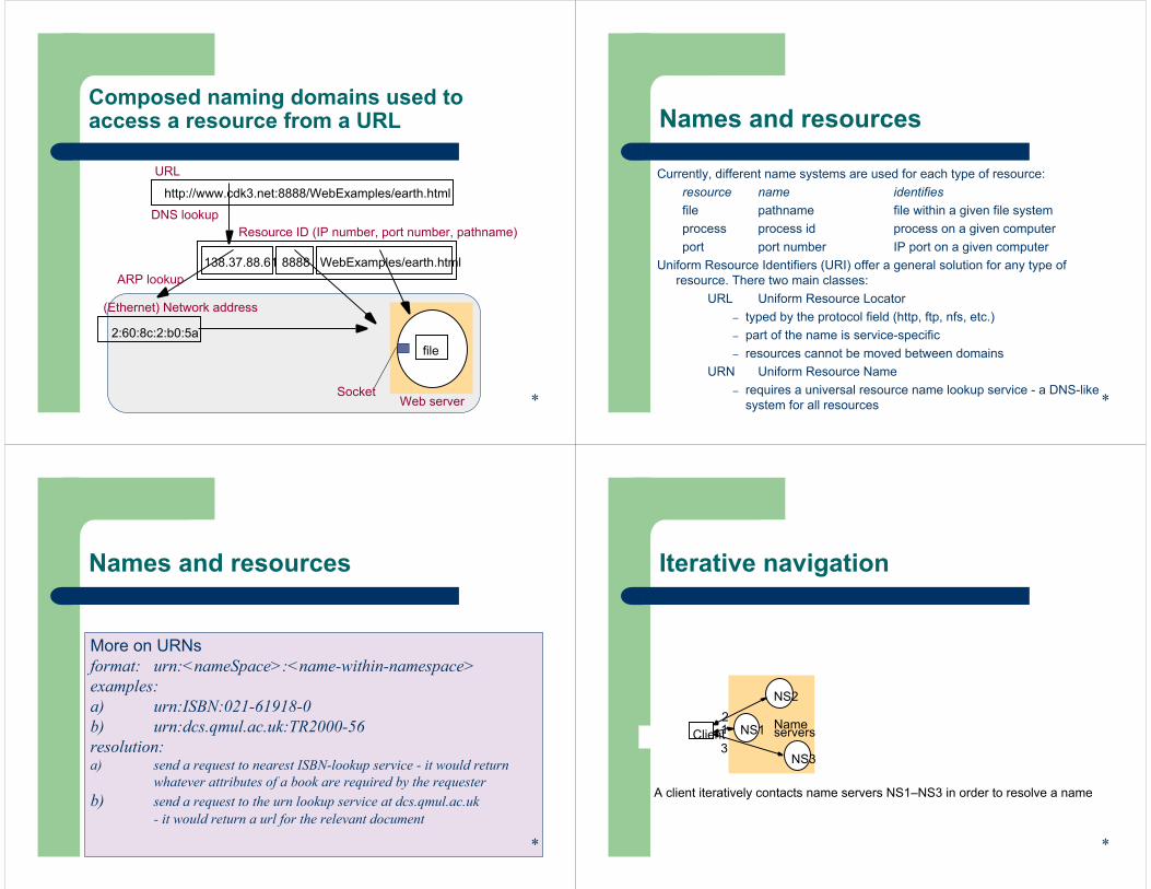
file
Web serverSocket
Composed naming domains used to access a resource from a URL
http://www.cdk3.net:8888/WebExamples/earth.html
URL
Resource ID (IP number, port number, pathname)
138.37.88.61 WebExamples/earth.html8888
DNS lookup
(Ethernet) Network address
2:60:8c:2:b0:5a
ARP lookup
*
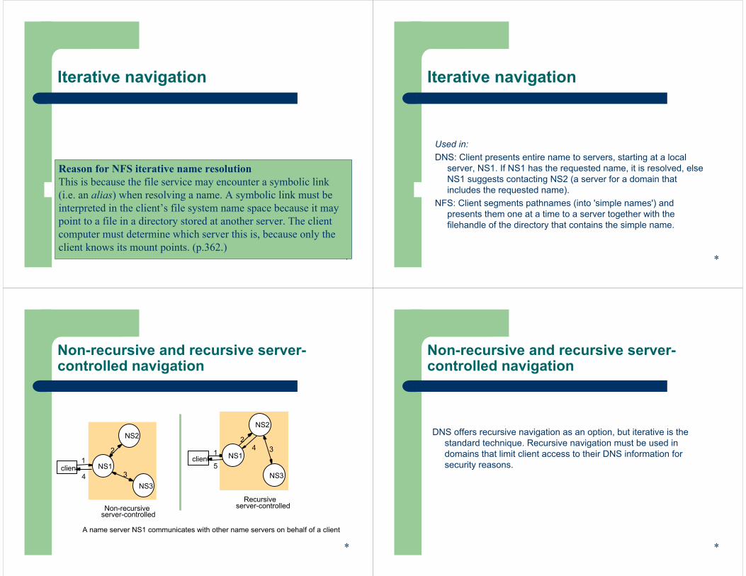
Names and resources
Currently, different name systems are used for each type of resource:resource name identifiesfile pathname file within a given file systemprocess process id process on a given computerport port number IP port on a given computer
Uniform Resource Identifiers (URI) offer a general solution for any type of resource. There two main classes:
URL Uniform Resource Locator– typed by the protocol field (http, ftp, nfs, etc.)– part of the name is service-specific– resources cannot be moved between domains
URN Uniform Resource Name– requires a universal resource name lookup service - a DNS-like
system for all resources *
Names and resources
More on URNsformat: urn:<nameSpace>:<name-within-namespace>examples:a) urn:ISBN:021-61918-0b) urn:dcs.qmul.ac.uk:TR2000-56resolution:a) send a request to nearest ISBN-lookup service - it would return
whatever attributes of a book are required by the requesterb) send a request to the urn lookup service at dcs.qmul.ac.uk
- it would return a url for the relevant document
*
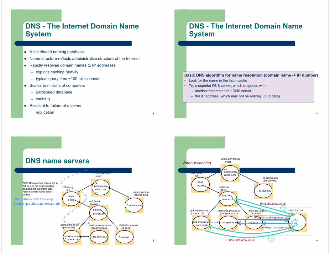
Iterative navigation
Client12
3
A client iteratively contacts name servers NS1–NS3 in order to resolve a name
NS2
NS1
NS3
Nameservers
*
Iterative navigation
*
Reason for NFS iterative name resolutionThis is because the file service may encounter a symbolic link (i.e. an alias) when resolving a name. A symbolic link must be interpreted in the client’s file system name space because it may point to a file in a directory stored at another server. The client computer must determine which server this is, because only the client knows its mount points. (p.362.)
Iterative navigation
Used in:DNS: Client presents entire name to servers, starting at a local
server, NS1. If NS1 has the requested name, it is resolved, elseNS1 suggests contacting NS2 (a server for a domain that includes the requested name).
NFS: Client segments pathnames (into 'simple names') and presents them one at a time to a server together with the filehandle of the directory that contains the simple name.
*
Non-recursive and recursive server-controlled navigation
A name server NS1 communicates with other name servers on behalf of a client
Recursiveserver-controlled
1
23
5
4client
NS2
NS1
NS3
12
34client
NS2
NS1
NS3
Non-recursiveserver-controlled
*
Non-recursive and recursive server-controlled navigation
DNS offers recursive navigation as an option, but iterative is the standard technique. Recursive navigation must be used in domains that limit client access to their DNS information for security reasons.
*
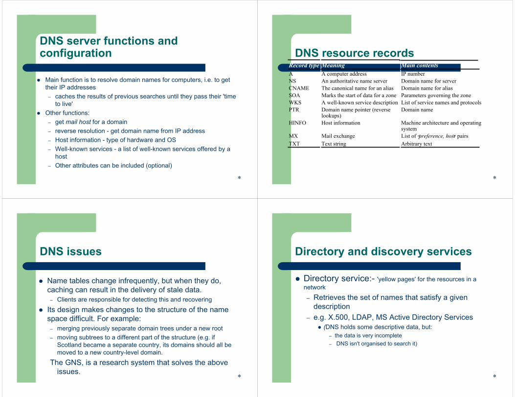
DNS - The Internet Domain Name System
A distributed naming database
Name structure reflects administrative structure of the Internet
Rapidly resolves domain names to IP addresses
– exploits caching heavily
– typical query time ~100 milliseconds
Scales to millions of computers
– partitioned database
– caching
Resilient to failure of a server
– replication *
DNS - The Internet Domain Name System
*
Basic DNS algorithm for name resolution (domain name -> IP number)• Look for the name in the local cache• Try a superior DNS server, which responds with:
– another recommended DNS server– the IP address (which may not be entirely up to date)
DNS name servers
Note: Name server names are in italics, and the corresponding domains are in parentheses.Arrows denote name server entries
a.root-servers.net(root)
ns0.ja.net(ac.uk)
dns0.dcs.qmw.ac.uk(dcs.qmw.ac.uk)
alpha.qmw.ac.uk(qmw.ac.uk)
dns0-doc.ic.ac.uk(ic.ac.uk)
ns.purdue.edu(purdue.edu)
ukpurdue.edu
ic.ac.ukqmw.ac.uk...
dcs.qmw.ac.uk*.qmw.ac.uk
*.ic.ac.uk*.dcs.qmw.ac.uk
* .purdue.edu
ns1.nic.uk(uk)
ac.uk...
co.uk
yahoo.com....
authoritative path to lookup:jeans-pc.dcs.qmw.ac.uk
*
a.root-servers.net(root)
ns0.ja.net(ac.uk)
dns0.dcs.qmw.ac.uk(dcs.qmw.ac.uk)
alpha.qmw.ac.uk(qmw.ac.uk)
dns0-doc.ic.ac.uk(ic.ac.uk)
ns.purdue.edu(purdue.edu)
ukpurdue.edu
ic.ac.ukqmw.ac.uk...
dcs.qmw.ac.uk*.qmw.ac.uk
*.ic.ac.uk*.dcs.qmw.ac.uk
* .purdue.edu
ns1.nic.uk(uk)
ac.uk...
co.uk
yahoo.com....
client.ic.ac.uk
IP: alpha.qmw.ac.uk
2
3IP:dns0.dcs.qmw.ac.uk
jeans-pc.dcs.qmw.ac.uk ?
IP:ns0.ja.net
1IP:jeans-pc.dcs.qmw.ac.uk
4
Without caching
*
DNS server functions and configuration
Main function is to resolve domain names for computers, i.e. to get their IP addresses
– caches the results of previous searches until they pass their 'time to live'
Other functions:– get mail host for a domain – reverse resolution - get domain name from IP address– Host information - type of hardware and OS– Well-known services - a list of well-known services offered by a
host– Other attributes can be included (optional)
*
DNS resource recordsRecord type Meaning Main contentsA A computer address IP numberNS An authoritative name server Domain name for serverCNAME The canonical name for an alias Domain name for aliasSOA Marks the start of data for a zone Parameters governing the zoneWKS A well-known service description List of service names and protocolsPTR Domain name pointer (reverse
lookups)Domain name
HINFO Host information Machine architecture and operatingsystem
MX Mail exchange List of <preference, host> pairsTXT Text string Arbitrary text
*
DNS issues
Name tables change infrequently, but when they do, caching can result in the delivery of stale data.
– Clients are responsible for detecting this and recovering
Its design makes changes to the structure of the name space difficult. For example:
– merging previously separate domain trees under a new root– moving subtrees to a different part of the structure (e.g. if
Scotland became a separate country, its domains should all be moved to a new country-level domain.
The GNS, is a research system that solves the above issues.
*
Directory and discovery services
Directory service:- 'yellow pages' for the resources in a network
– Retrieves the set of names that satisfy a given description
– e.g. X.500, LDAP, MS Active Directory Services(DNS holds some descriptive data, but:
– the data is very incomplete– DNS isn't organised to search it)
*
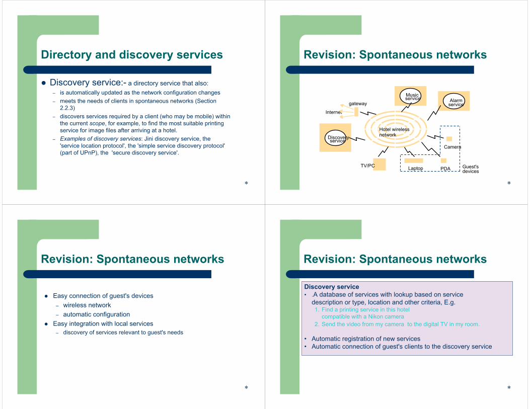
Directory and discovery services
Discovery service:- a directory service that also:– is automatically updated as the network configuration changes– meets the needs of clients in spontaneous networks (Section
2.2.3)– discovers services required by a client (who may be mobile) within
the current scope, for example, to find the most suitable printing service for image files after arriving at a hotel.
– Examples of discovery services: Jini discovery service, the 'service location protocol', the 'simple service discovery protocol' (part of UPnP), the 'secure discovery service'.
*
Revision: Spontaneous networks
Internet
gateway
PDA
service
Music service
serviceDiscovery
Alarm
Camera
Guest'sdevicesLaptopTV/PC
Hotel wirelessnetwork
*
Revision: Spontaneous networks
Easy connection of guest's devices– wireless network– automatic configuration
Easy integration with local services– discovery of services relevant to guest's needs
*
Revision: Spontaneous networks
Discovery service• .A database of services with lookup based on service
description or type, location and other criteria, E.g.1. Find a printing service in this hotel
compatible with a Nikon camera2. Send the video from my camera to the digital TV in my room.
• Automatic registration of new services• Automatic connection of guest's clients to the discovery service
*
Revision: Spontaneous networks
Other issues for spontaneous networking:• Unreliable connections when mobile• Security exposure of ports and communication channels
*
Printing service
serviceLookup
serviceLookup
Printing service
admin
admin
admin, finance
finance
Client
Mobile client
Corporate infoservice
Network
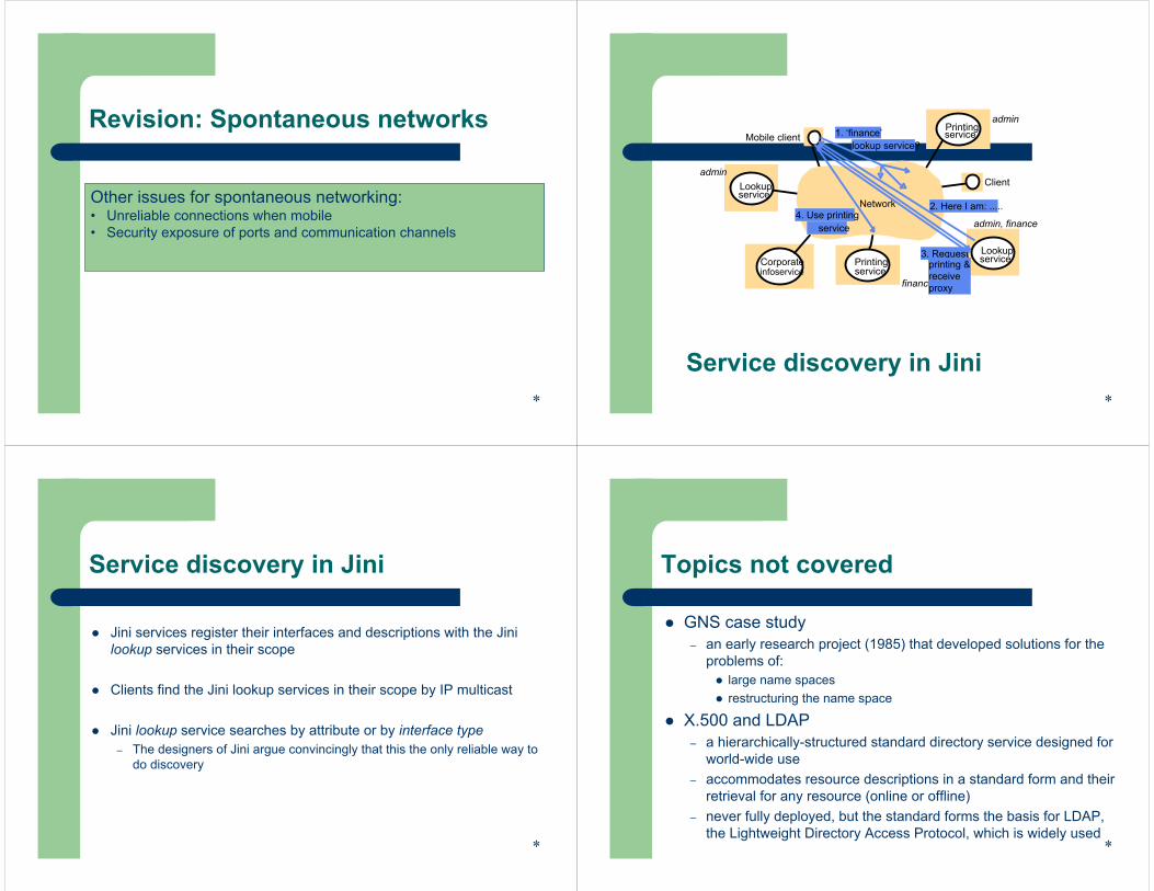
Service discovery in Jini
2. Here I am: .....4. Use printing
service
1. ‘finance’lookup service?
*
3. Requestprinting &receive proxy
Service discovery in Jini
Jini services register their interfaces and descriptions with the Jini lookup services in their scope
Clients find the Jini lookup services in their scope by IP multicast
Jini lookup service searches by attribute or by interface type– The designers of Jini argue convincingly that this the only reliable way to
do discovery
*
Topics not covered
GNS case study – an early research project (1985) that developed solutions for the
problems of:large name spaces restructuring the name space
X.500 and LDAP – a hierarchically-structured standard directory service designed for
world-wide use– accommodates resource descriptions in a standard form and their
retrieval for any resource (online or offline)– never fully deployed, but the standard forms the basis for LDAP,
the Lightweight Directory Access Protocol, which is widely used*
Topics not covered
Trading services– Directories of services with retrieval by attribute searching– Brokers negotiate the contract for the use of a service, including
negotiation of attribute such as quality and quantity of service
*
Summary
Name services:– defer the binding of resource names to addresses (and other
attributes)– Names are resolved to give addresses and other attributes– Goals :
Scalability (size of database, access traffic (hits/second), update traffic)ReliabilityTrust management (authority of servers)
– Issuesexploitation of replication and caching to achieve scalability without compromising the distribution of updatesnavigation methods *
Summary
Directory and discovery services:– 'yellow pages' retrieval by attributes– dynamic resource registration and discovery
*
End of Part I(Distributed Systems)
Questions ?Questions ?
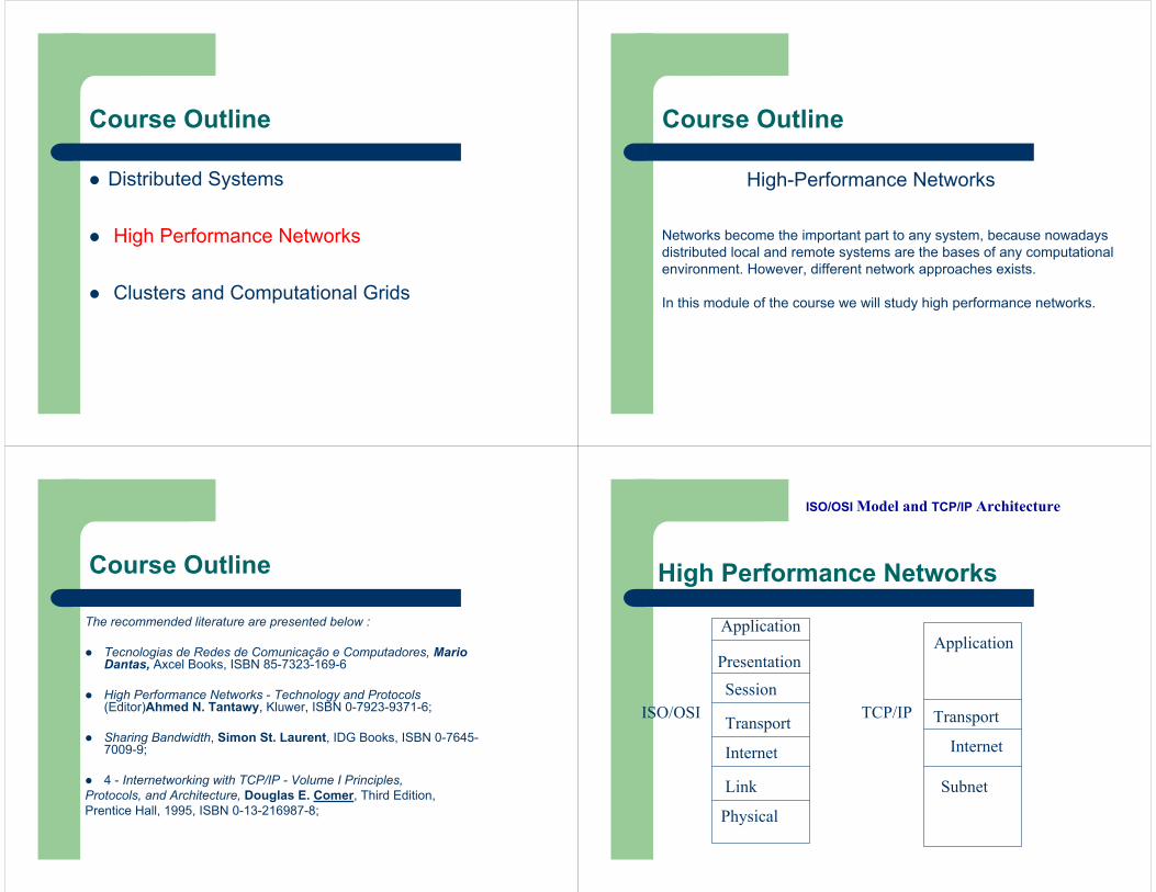
Course Outline
Distributed Systems
High Performance Networks
Clusters and Computational Grids
Course Outline
High-Performance Networks
Networks become the important part to any system, because nowadaysdistributed local and remote systems are the bases of any computationalenvironment. However, different network approaches exists.
In this module of the course we will study high performance networks.
The recommended literature are presented below :
Tecnologias de Redes de Comunicação e Computadores, Mario Dantas, Axcel Books, ISBN 85-7323-169-6
High Performance Networks - Technology and Protocols (Editor)Ahmed N. Tantawy, Kluwer, ISBN 0-7923-9371-6;
Sharing Bandwidth, Simon St. Laurent, IDG Books, ISBN 0-7645-7009-9;
4 - Internetworking with TCP/IP - Volume I Principles,Protocols, and Architecture, Douglas E. Comer, Third Edition,Prentice Hall, 1995, ISBN 0-13-216987-8;
Course Outline
Physical
Link
Internet
Transport
SessionPresentation
ApplicationApplication
Transport
Internet
Subnet
ISO/OSI TCP/IP
ISO/OSI Model and TCP/IP Architecture
High Performance Networks
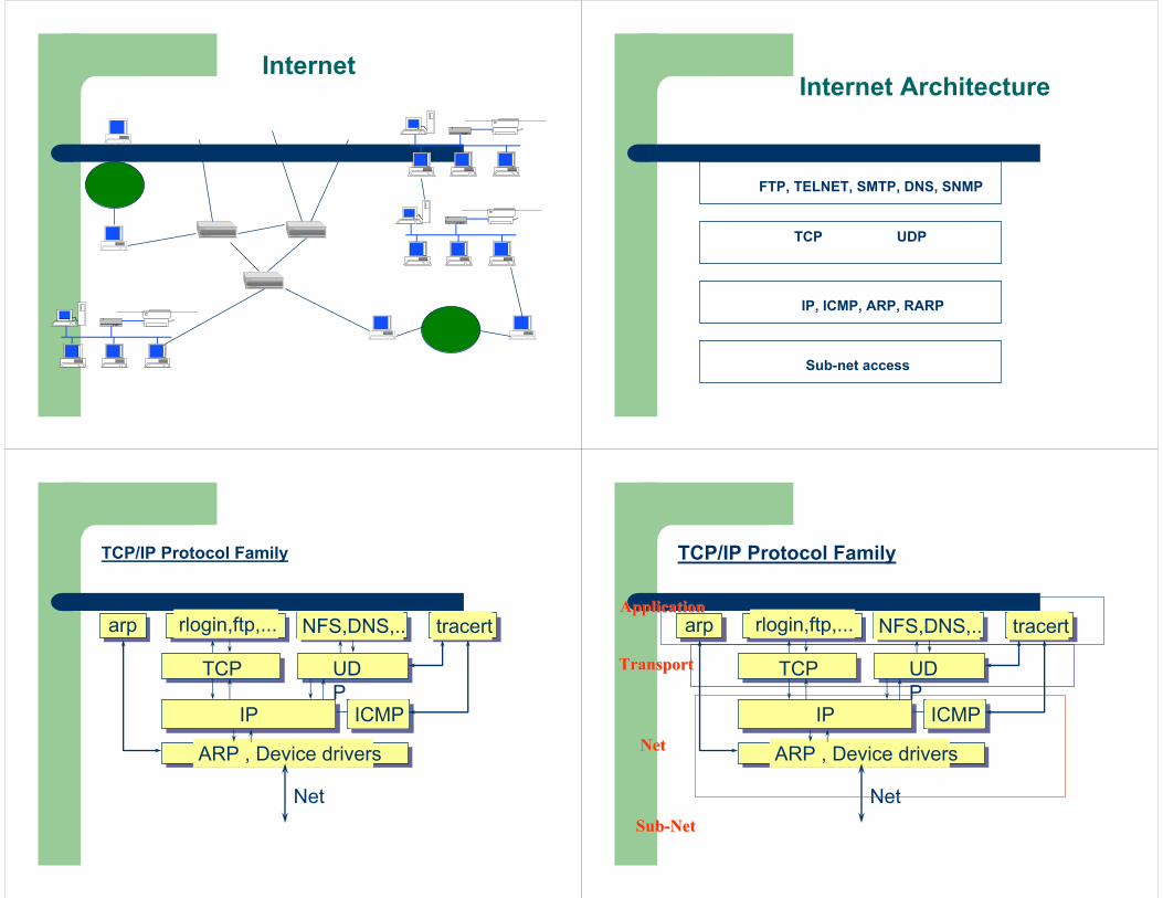
InternetInternet Architecture
Sub-net access
IP, ICMP, ARP, RARP
TCP UDP
FTP, TELNET, SMTP, DNS, SNMP
TCP/IP Protocol Family
ARP , Device drivers
IP ICMP
TCP UDP
rlogin,ftp,... NFS,DNS,.. tracertarp
Net
ARP , Device drivers
IP ICMP
TCP UDP
rlogin,ftp,... NFS,DNS,.. tracertarp
Net
NetNet
TransportTransport
ApplicationApplication
SubSub--NetNet
TCP/IP Protocol Family
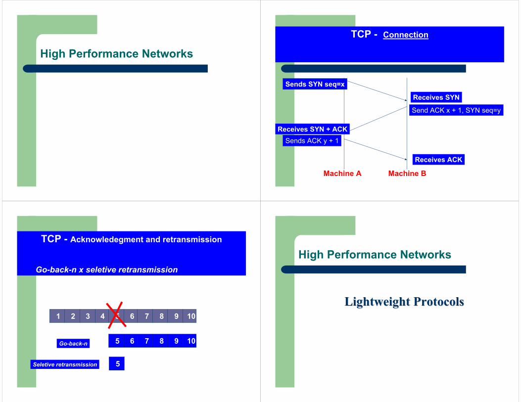
High Performance Networks
TCP - Connection
Sends SYN seq=x
Receives SYN
Send ACK x + 1, SYN seq=y
Receives SYN + ACKSends ACK y + 1
Receives ACK
Machine A Machine B
TCP - Acknowledegment and retransmission
Go-back-n x seletive retransmission
1 2 3 4 5 6 7 8 9 10
5 6 7 8 9 10Go-back-n
5Seletive retransmission
High Performance Networks
Lightweight ProtocolsLightweight Protocols
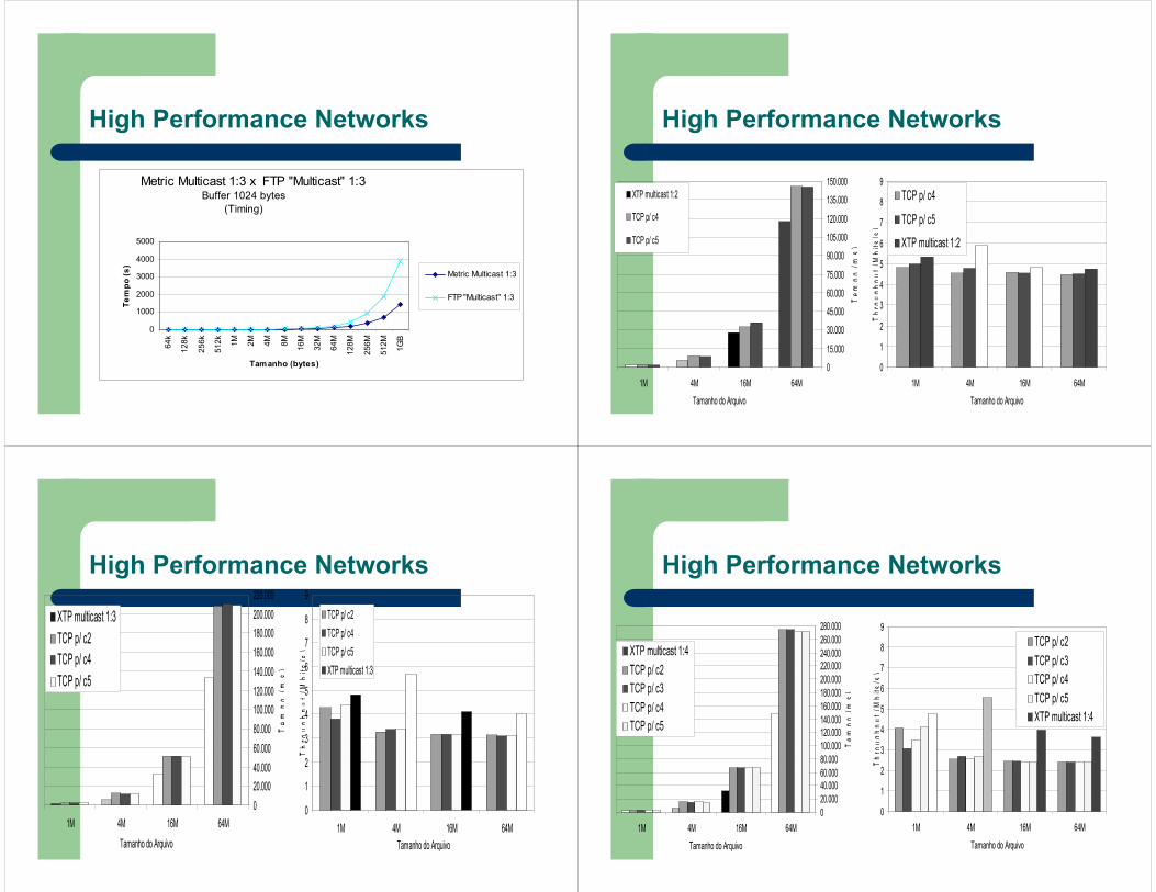
High Performance Networks
Metric Multicast 1:3 x FTP "Multicast" 1:3Buffer 1024 bytes
(Timing)
0
1000
2000
3000
4000
5000
64k
128k
256k
512k 1M 2M 4M 8M 16M
32M
64M
128M
256M
512M 1G
B
Tamanho (bytes)
Tem
po (s
)
Metric Multicast 1:3
FTP "Multicast" 1:3
High Performance Networks
0
15.000
30.000
45.000
60.000
75.000
90.000
105.000
120.000
135.000
150.000
1M 4M 16M 64M
Tamanho do Arquivo
Tem
po(m
s)
XTP multicast 1:2
TCP p/ c4
TCP p/ c5
0
1
2
3
4
5
6
7
8
9
1M 4M 16M 64M
Tamanho do Arquivo
Thro
ughp
ut(M
bits
/s)
TCP p/ c4
TCP p/ c5
XTP multicast 1:2
High Performance Networks
020.00040.00060.00080.000100.000120.000140.000160.000180.000200.000220.000
1M 4M 16M 64M
Tamanho do Arquivo
Tem
po(m
s)
XTP multicast 1:3TCP p/ c2TCP p/ c4TCP p/ c5
0
1
2
3
4
5
6
7
8
9
1M 4M 16M 64MTamanho do Arquivo
Thro
ughp
ut(M
bits
/s)
TCP p/ c2TCP p/ c4TCP p/ c5XTP multicast 1:3
High Performance Networks
020.00040.00060.00080.000100.000120.000140.000160.000180.000200.000220.000240.000260.000280.000
1M 4M 16M 64M
Tamanho do ArquivoTe
mpo
(ms)
XTP multicast 1:4TCP p/ c2TCP p/ c3TCP p/ c4TCP p/ c5
0
1
2
3
4
5
6
7
8
9
1M 4M 16M 64M
Tamanho do Arquivo
Thro
ughp
ut(M
bits
/s)
TCP p/ c2TCP p/ c3TCP p/ c4TCP p/ c5XTP multicast 1:4
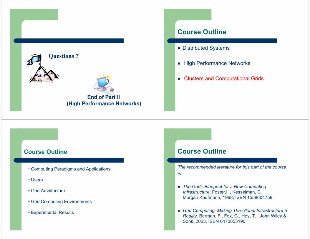
End of Part II (High Performance Networks)
Questions ?Questions ?
Course Outline
Distributed Systems
High Performance Networks
Clusters and Computational Grids
Course Outline
• Computing Paradigms and Applications
• Users
• Grid Architecture
• Grid Computing Environments
• Experimental Results
Course Outline
The recommended literature for this part of the course is :
The Grid : Blueprint for a New Computing Infrastructure, Foster,I. , Kesselman, C.Morgan Kaufmann, 1998, ISBN 1558604758.
Grid Computing: Making The Global Infrastructure a Reality, Berman, F., Fox, G., Hey, T. , John Wiley & Sons, 2003, ISBN 0470853190.

Clusters and Computational Grids
What is the difference betweenCluster and Computational Grid ?
A important difference between clusters and grids is mainly based in the way resources are managed.
In the clusters, the resource allocation is performed by a centralized resource manager and all nodes cooperatively work together as a single unified resource.
Inside the Grids, each node has its own resource manager and do not target for providing a single system view.
Computing Paradigms and Applications
Clusters
Computing Paradigms and Applications
High Performance Computing (HPC) traditionally has been basedon specific parallel architectures, such as MPP (Massively ParallelProcessors) and SMP (Symmetric Memory Processors)
More recently, low cost computers gather either physically or virtually, are used called as Clusters or Nows. These architecturesare interesting to many organizations.
Clusters
Computing Paradigms and Applications
What is a cluster configuration ?
Clusters
Computing Paradigms and Applications
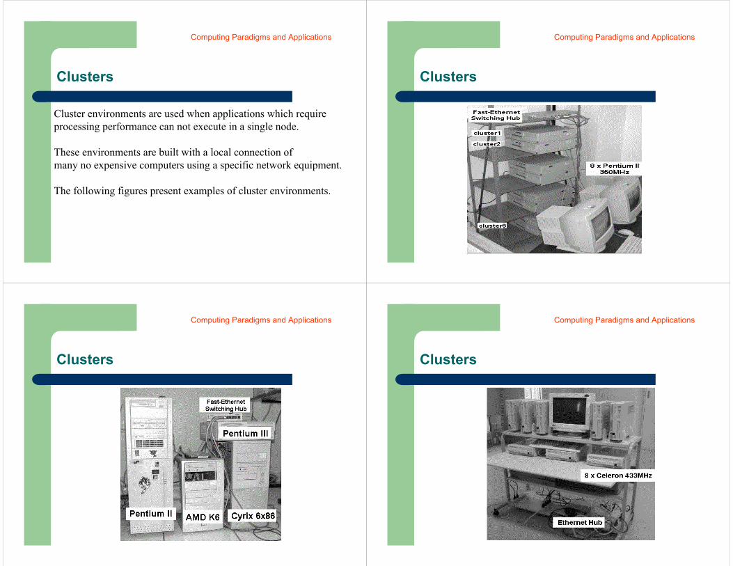
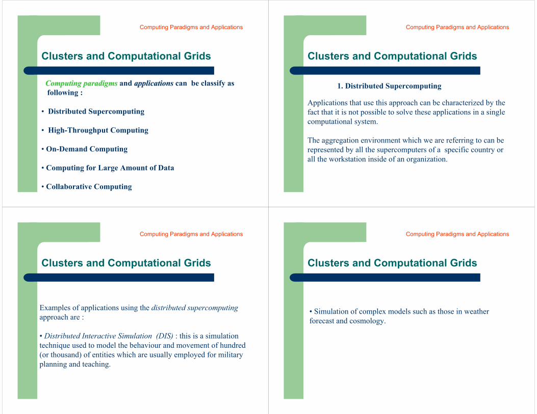
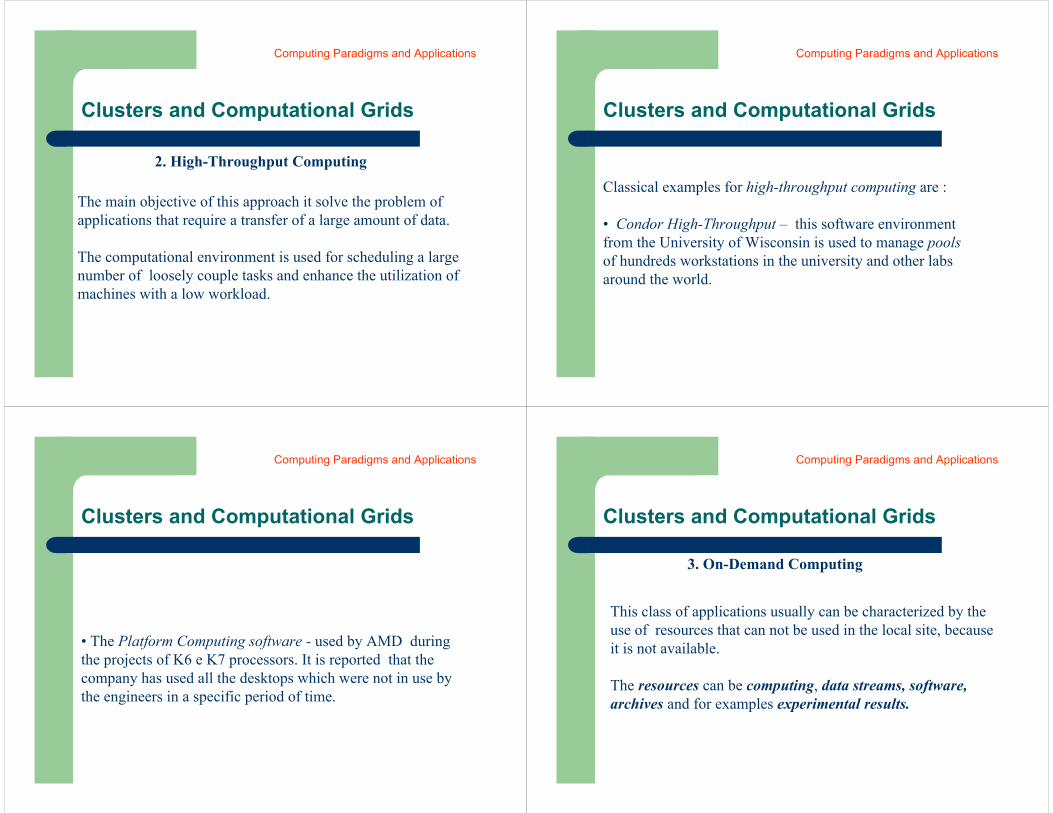
Cluster environments are used when applications which requireprocessing performance can not execute in a single node.
These environments are built with a local connection ofmany no expensive computers using a specific network equipment.
The following figures present examples of cluster environments.
Clusters
Computing Paradigms and Applications
Clusters
Computing Paradigms and Applications
Clusters
Computing Paradigms and Applications

Clusters
Computing Paradigms and Applications
Clusters
Computing Paradigms and Applications
Clusters
Computing Paradigms and Applications
Cluster management is an important taskfor this new distributed architecture, manypackages exist with this specific function(e.g. Oscar)
Clusters and Computational Grids
The experimental research with the I-WAY, first large scale Grid effort, bring to us that there were five classes of applications using a specific computing paradigm.
Computing Paradigms and Applications
Clusters and Computational Grids
Computing paradigmsComputing paradigms and applications applications can be classify as following :
• Distributed Supercomputing
• High-Throughput Computing
• On-Demand Computing
• Computing for Large Amount of Data
• Collaborative Computing
Computing Paradigms and Applications
Clusters and Computational Grids
Applications that use this approach can be characterized by the fact that it is not possible to solve these applications in a single computational system.
The aggregation environment which we are referring to can be represented by all the supercomputers of a specific country or all the workstation inside of an organization.
1. Distributed Supercomputing
Computing Paradigms and Applications
Clusters and Computational Grids
Examples of applications using the distributed supercomputingapproach are :
• Distributed Interactive Simulation (DIS) : this is a simulation technique used to model the behaviour and movement of hundred (or thousand) of entities which are usually employed for military planning and teaching.
Computing Paradigms and Applications
Clusters and Computational Grids
• Simulation of complex models such as those in weather forecast and cosmology.
Computing Paradigms and Applications
Clusters and Computational Grids
2. High-Throughput Computing
The main objective of this approach it solve the problem of applications that require a transfer of a large amount of data.
The computational environment is used for scheduling a large number of loosely couple tasks and enhance the utilization of machines with a low workload.
Computing Paradigms and Applications
Clusters and Computational Grids
Classical examples for high-throughput computing are :
• Condor High-Throughput – this software environmentfrom the University of Wisconsin is used to manage pools of hundreds workstations in the university and other labsaround the world.
Computing Paradigms and Applications
Clusters and Computational Grids
• The Platform Computing software - used by AMD during the projects of K6 e K7 processors. It is reported that the company has used all the desktops which were not in use by the engineers in a specific period of time.
Computing Paradigms and Applications
Clusters and Computational Grids
3. On-Demand Computing
This class of applications usually can be characterized by the use of resources that can not be used in the local site, because it is not available.
The resources can be computing, data streams, software, archives and for examples experimental results.
Computing Paradigms and Applications
Clusters and Computational Grids
Difference between this approach and distributedSupercomputing is related to the cost of performancethen the complete performance behaviour.
Computing Paradigms and Applications
Clusters and Computational Grids
4. Computing for Large Amount of Data
This class of application and computing paradigm covers the requirement for processing large amount of data stored in a geographic distributed fashion.
Examples are large databases and digital libraries that are available for access in a distributed way.
The Digital Sky Survey and modern weather forecastSystems are applications examples.
Computing Paradigms and Applications
Clusters and Computational Grids
5. Collaborative Computing
Examples for this class are those which are oriented to the improvement the relation between humans.
Many collaborative applications allow the share use of computational resources.
Computing Paradigms and Applications
Clusters and Computational Grids
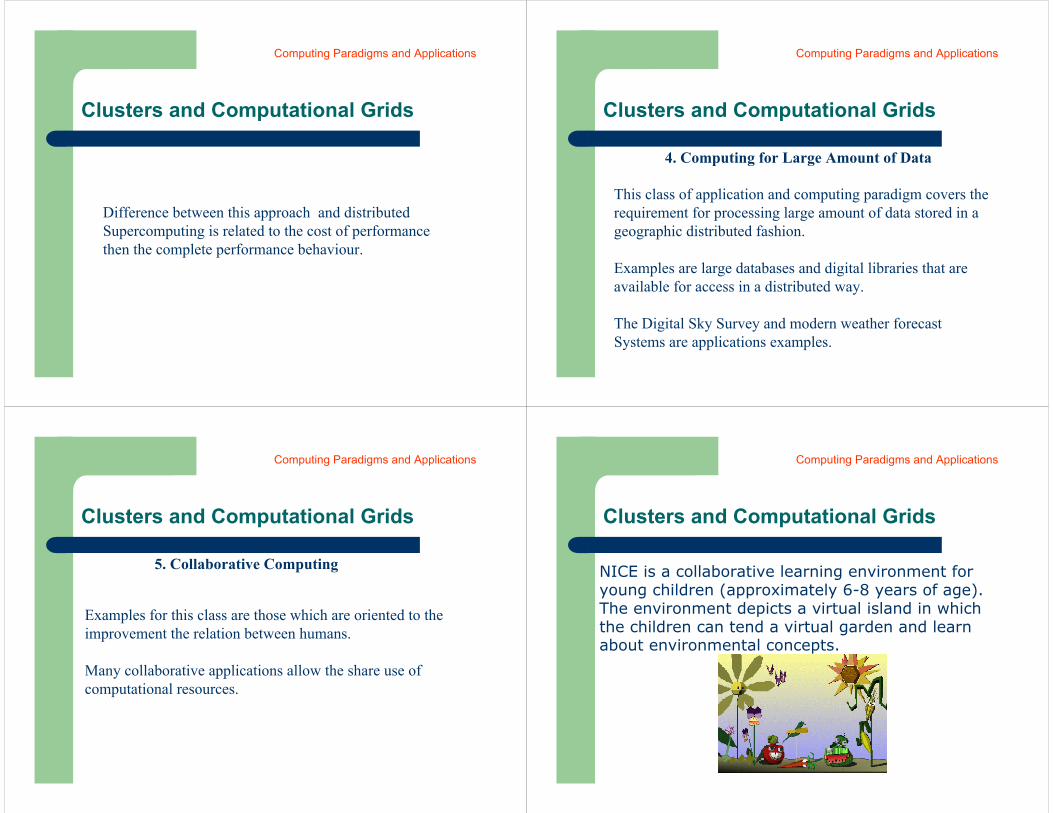
NICE is a collaborative learning environment for young children (approximately 6-8 years of age). The environment depicts a virtual island in which the children can tend a virtual garden and learn about environmental concepts.
Computing Paradigms and Applications
UsersUsers
Users
Another approach used to understand what is a Grid, is to understand who is going to use.
A Grid is above of the mechanisms of resource sharing therefore we can image two questions :
A - Which kind of entity is going to invest in the infrastructure for a Grid ? B - Which kind of resources each community of
the entity will be share ?
Clusters and Computational Grids
Answers for the two questions should be based on costs and benefits for sharing resources.
Therefore it is usually presented in the academic and commercial reports efforts for the following groups of grid environments :
• National • Private • Virtual • Public
Users
Clusters and Computational Grids
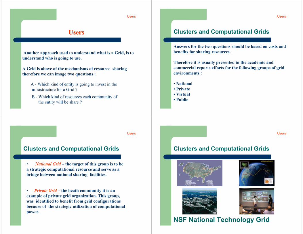
• National Grid – the target of this group is to bea strategic computational resource and serve as abridge between national sharing facilities.
• Private Grid – the heath community it is an example of private grid organization. This group,was identified to benefit from grid configurationsbecause of the strategic utilization of computationalpower.
Users
Clusters and Computational Grids
NSF National Technology Grid
Users
Clusters and Computational Grids
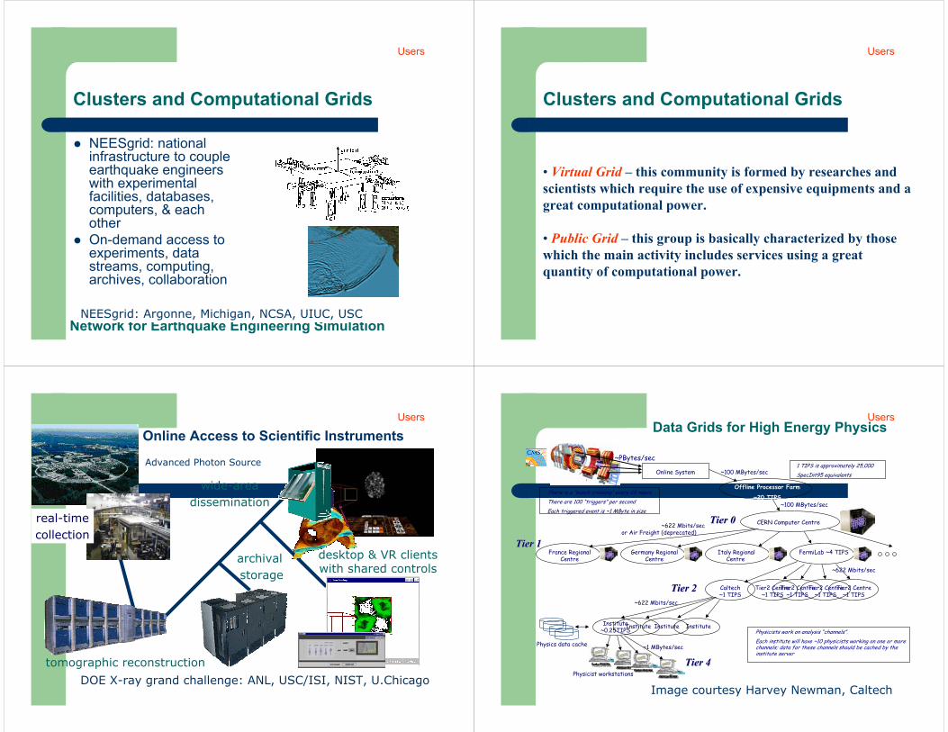
NEESgrid: national infrastructure to couple earthquake engineers with experimental facilities, databases, computers, & each otherOn-demand access to experiments, data streams, computing, archives, collaboration
Network for Earthquake Engineering SimulationNEESgrid: Argonne, Michigan, NCSA, UIUC, USC
Users
Clusters and Computational Grids
• Virtual Grid – this community is formed by researches and scientists which require the use of expensive equipments and a great computational power.
• Public Grid – this group is basically characterized by those which the main activity includes services using a great quantity of computational power.
Users
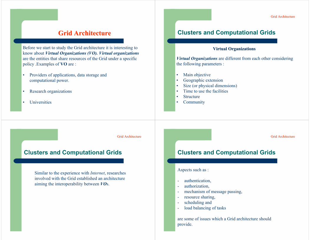
DOE X-ray grand challenge: ANL, USC/ISI, NIST, U.Chicago
tomographic reconstruction
real-timecollection
wide-areadissemination
desktop & VR clients with shared controls
Advanced Photon Source
Online Access to Scientific Instruments
archival storage
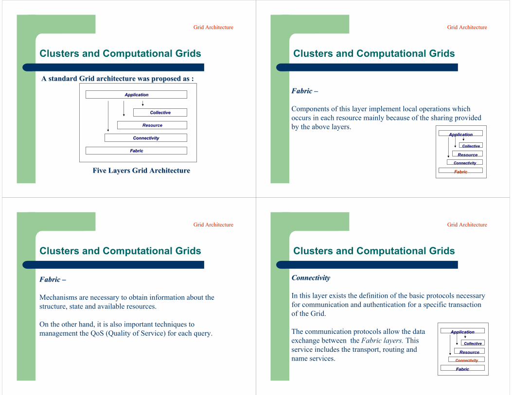
UsersData Grids for High Energy Physics
Tier2 Centre ~1 TIPS
Online System
Offline Processor Farm
~20 TIPS
CERN Computer Centre
FermiLab ~4 TIPSFrance Regional Centre
Italy Regional Centre
Germany Regional Centre
InstituteInstituteInstituteInstitute ~0.25TIPS
Physicist workstations
~100 MBytes/sec
~100 MBytes/sec
~622 Mbits/sec
~1 MBytes/sec
There is a “bunch crossing” every 25 nsecs.There are 100 “triggers” per secondEach triggered event is ~1 MByte in size
Physicists work on analysis “channels”.Each institute will have ~10 physicists working on one or more channels; data for these channels should be cached by the institute server
Physics data cache
~PBytes/sec
~622 Mbits/sec or Air Freight (deprecated)
Tier2 Centre ~1 TIPS
Tier2 Centre ~1 TIPS
Tier2 Centre ~1 TIPS
Caltech ~1 TIPS
~622 Mbits/sec
Tier 0Tier 0
Tier 1Tier 1
Tier 2Tier 2
Tier 4Tier 4
1 TIPS is approximately 25,000 SpecInt95 equivalents
Image courtesy Harvey Newman, Caltech
Users
Before we start to study the Grid architecture it is interesting to know about Virtual Organizations (VO). Virtual organizations are the entities that share resources of the Grid under a specific policy .Examples of VO are :
• Providers of applications, data storage and computational power.
• Research organizations
• Universities
Grid ArchitectureGrid Architecture Clusters and Computational Grids
Virtual Organizations are different from each other consideringthe following parameters :
• Main objective• Geographic extension• Size (or physical dimensions)• Time to use the facilities• Structure• Community
Virtual OrganizationsVirtual Organizations
Grid ArchitectureGrid Architecture
Clusters and Computational Grids
Similar to the experience with Internet, researches involved with the Grid established an architectureaiming the interoperability between VOs.
Grid ArchitectureGrid Architecture
Clusters and Computational Grids
Aspects such as :
- authentication, - authorization, - mechanism of message passing, - resource sharing, - scheduling and- load balancing of tasks
are some of issues which a Grid architecture should provide.
Grid ArchitectureGrid Architecture
Clusters and Computational Grids
A standard Grid architecture was proposed as : A standard Grid architecture was proposed as :
ApplicationApplication
CollectiveCollective
Resource
ConnectivityConnectivity
FabricFabric
Five Layers Grid ArchitectureFive Layers Grid Architecture
Grid ArchitectureGrid Architecture
Clusters and Computational Grids
Fabric Fabric ––
Components of this layer implement local operations which occurs in each resource mainly because of the sharing provided by the above layers.
ApplicationApplication
CollectiveCollective
Resource
ConConnnectivityectivity
FabricFabric
Grid ArchitectureGrid Architecture
Clusters and Computational Grids
Fabric Fabric ––
Mechanisms are necessary to obtain information about the structure, state and available resources.
On the other hand, it is also important techniques tomanagement the QoS (Quality of Service) for each query.
Grid ArchitectureGrid Architecture
Clusters and Computational Grids
Connectivity Connectivity
In this layer exists the definition of the basic protocols necessary for communication and authentication for a specific transaction of the Grid.
The communication protocols allow the data exchange between the Fabric layers. This service includes the transport, routing and name services.
ApplicationApplication
CollectiveCollective
Resource
ConConnnectivityectivity
FabricFabric
Grid ArchitectureGrid Architecture
Clusters and Computational Grids
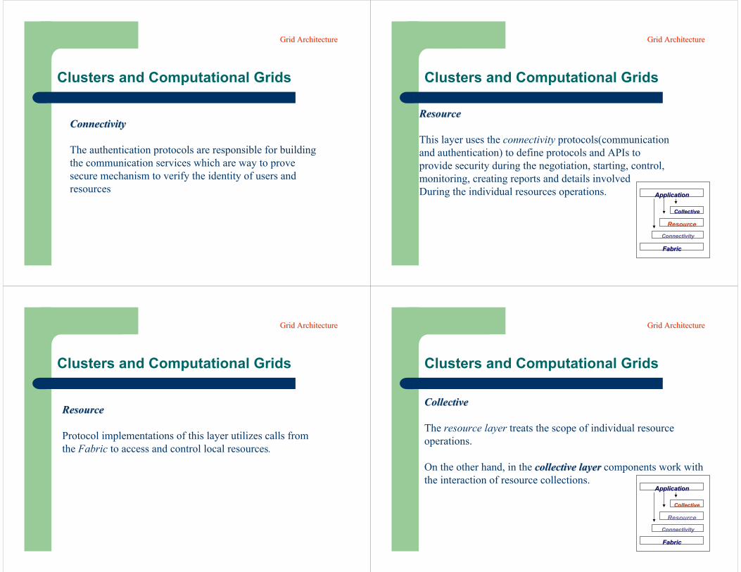
Connectivity Connectivity
The authentication protocols are responsible for buildingthe communication services which are way to prove secure mechanism to verify the identity of users andresources
Grid ArchitectureGrid Architecture
Clusters and Computational Grids
ResourceResource
This layer uses the connectivity protocols(communicationand authentication) to define protocols and APIs to provide security during the negotiation, starting, control,monitoring, creating reports and details involved During the individual resources operations. ApplicationApplication
CollectiveCollective
Resource
ConConnnectivityectivity
FabricFabric
Grid ArchitectureGrid Architecture
Clusters and Computational Grids
ResourceResource
Protocol implementations of this layer utilizes calls fromthe Fabric to access and control local resources.
Grid ArchitectureGrid Architecture
Clusters and Computational Grids
CollectiveCollective
The resource layer treats the scope of individual resource operations.
On the other hand, in the collective layer collective layer components work with the interaction of resource collections.
ApplicationApplication
CollectiveCollective
Resource
ConConnnectivityectivity
FabricFabric
Grid ArchitectureGrid Architecture
Clusters and Computational Grids
CollectiveCollective
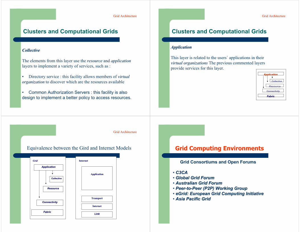
The elements from this layer use the resource resource and application application layers to implement a variety of services, such as :
• Directory service : this facility allows members of virtual virtual organization organization to discover which are the resources available
• Common Authorization Servers : this facility is alsodesign to implement a better policy to access resources.
Grid ArchitectureGrid Architecture
Clusters and Computational Grids
ApplicationApplication
This layer is related to the users´ applications in theirvirtual organizations virtual organizations The previous commented layersprovide services for this layer.
ApplicationApplication
CollectiveCollective
Resource
ConConnnectivityectivity
FabricFabric
Grid ArchitectureGrid Architecture
CollectiveCollective
ResourceResource
ConnectivityConnectivity
FabricFabric
ApplicationApplication
GridGrid
ApplicationApplication
TransportTransport
InternetInternet
LinkLink
InternetInternet
Equivalence between the Gird and Internet Models
Grid ArchitectureGrid Architecture
Grid Computing Environments
Grid Consortiums and Open Forums
•• C3CAC3CA•• Global Grid Forum Global Grid Forum •• Australian Grid Forum Australian Grid Forum •• PeerPeer--toto--Peer (P2P) Working Group Peer (P2P) Working Group •• eGrideGrid: European Grid Computing Initiative : European Grid Computing Initiative •• Asia Pacific Grid Asia Pacific Grid
Clusters and Computational Grids
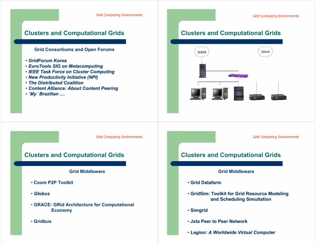
Grid Consortiums and Open Forums
•• GridForumGridForum Korea Korea •• EuroToolsEuroTools SIG on SIG on MetacomputingMetacomputing•• IEEE Task Force on Cluster Computing IEEE Task Force on Cluster Computing •• New Productivity Initiative (NPI) New Productivity Initiative (NPI) •• The Distributed Coalition The Distributed Coalition •• Content Alliance: About Content PeeringContent Alliance: About Content Peering•• `̀MyMy´́ BrazilianBrazilian ........
Grid Computing Environments
Clusters and Computational Grids
Grid Computing Environments
Clusters and Computational Grids
Grid Middleware
• Cosm P2P Toolkit
• GlobusGlobus
• GRACE: GRid Architecture for Computational Economy
• Gridbus
Grid Computing Environments
Clusters and Computational Grids
Grid Middleware
•• Grid Grid DatafarmDatafarm
•• GridSimGridSim: Toolkit for Grid Resource Modeling : Toolkit for Grid Resource Modeling and Scheduling and Scheduling SimultationSimultation
•• SimgridSimgrid
•• JxtaJxta Peer to Peer Network Peer to Peer Network
•• Legion: A Worldwide Virtual Computer Legion: A Worldwide Virtual Computer
Grid Computing Environments
Clusters and Computational Grids
DataGrid Initiatives
•Virtual Laboratory: Tools for Data Intensive Science on Grid
•EU DataGrid•DIDC Data Grid work •GriPhyN (Grid Physics Network) •HEPGrid (High Energy Physics and Grid Networks) •Particle Physics Data Grid (PPDG) •Datacentric Grid
Grid Computing Environments
Clusters and Computational Grids
Grid Systems
•Compute Power Market • Global Operating Systems • XtremWeb• JAVELIN: Java-Based Global Computing • MILAN: Metacomputing In Large Asynchronous Networks
• Harness Parallel Virtual Machine Project • Management System for Heterogeneous Networks • PUNCH - Network Computing Hub • MOBIDICK
Grid Computing Environments
Clusters and Computational Grids
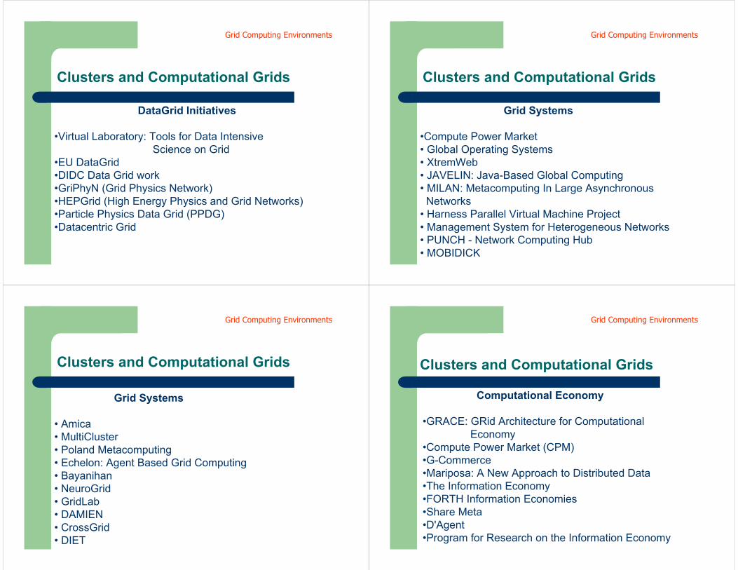
Grid Systems
• Amica• MultiCluster• Poland Metacomputing• Echelon: Agent Based Grid Computing • Bayanihan• NeuroGrid• GridLab• DAMIEN • CrossGrid• DIET
Grid Computing Environments
Clusters and Computational Grids
Computational Economy
•GRACE: GRid Architecture for Computational Economy
•Compute Power Market (CPM) •G-Commerce •Mariposa: A New Approach to Distributed Data •The Information Economy •FORTH Information Economies •Share Meta •D'Agent•Program for Research on the Information Economy
Grid Computing Environments
Clusters and Computational Grids
Computational Economy
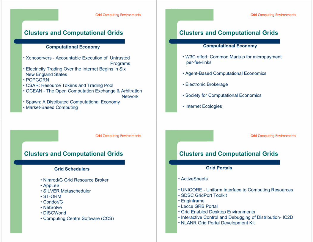
• Xenoservers - Accountable Execution of UntrustedPrograms
• Electricity Trading Over the Internet Begins in Six New England States
• POPCORN • CSAR: Resource Tokens and Trading Pool • OCEAN - The Open Computation Exchange & Arbitration
Network • Spawn: A Distributed Computational Economy • Market-Based Computing
Grid Computing Environments
Clusters and Computational Grids
Computational Economy
• W3C effort: Common Markup for micropaymentper-fee-links
• Agent-Based Computational Economics
• Electronic Brokerage
• Society for Computational Economics
• Internet Ecologies
Grid Computing Environments
Clusters and Computational Grids
Grid Schedulers
• Nimrod/G Grid Resource Broker• AppLeS• SILVER Metascheduler• ST-ORM • Condor/G • NetSolve• DISCWorld• Computing Centre Software (CCS)
Grid Computing Environments
Clusters and Computational Grids
Grid Portals
• ActiveSheets
• UNICORE - Uniform Interface to Computing Resources • SDSC GridPort Toolkit • Enginframe• Lecce GRB Portal • Grid Enabled Desktop Environments • Interactive Control and Debugging of Distribution- IC2D • NLANR Grid Portal Development Kit
Grid Computing Environments
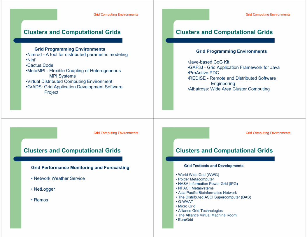
Clusters and Computational Grids
Grid Programming Environments •Nimrod - A tool for distributed parametric modeling •Ninf•Cactus Code •MetaMPI - Flexible Coupling of Heterogeneous
MPI Systems •Virtual Distributed Computing Environment •GrADS: Grid Application Development Software
Project
Grid Computing Environments
Clusters and Computational Grids
Grid Programming Environments
•Jave-based CoG Kit •GAF3J - Grid Application Framework for Java •ProActive PDC •REDISE - Remote and Distributed Software
Engineering •Albatross: Wide Area Cluster Computing
Grid Computing Environments
Clusters and Computational Grids
Grid Performance Monitoring and Forecasting
• Network Weather Service
• NetLogger
• Remos
Grid Computing Environments
Clusters and Computational Grids
Grid Testbeds and Developments
• World Wide Grid (WWG) • Polder Metacomputer• NASA Information Power Grid (IPG) • NPACI: Metasystems• Asia Pacific Bioinformatics Network • The Distributed ASCI Supercomputer (DAS) • G-WAAT • Micro Grid • Alliance Grid Technologies • The Alliance Virtual Machine Room • EuroGrid
Grid Computing Environments
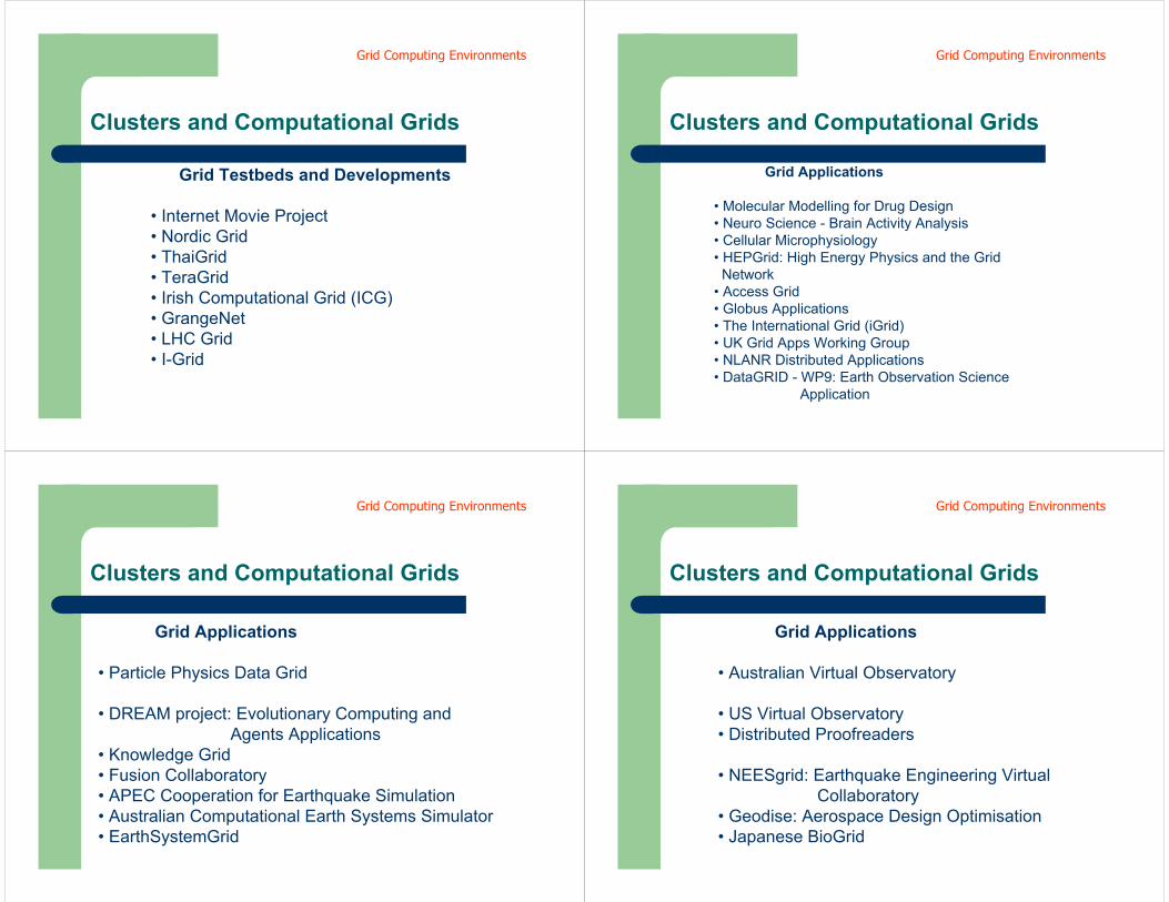
Clusters and Computational Grids
Grid Testbeds and Developments
• Internet Movie Project • Nordic Grid • ThaiGrid• TeraGrid• Irish Computational Grid (ICG) • GrangeNet• LHC Grid • I-Grid
Grid Computing Environments
Clusters and Computational Grids
Grid Applications
• Molecular Modelling for Drug Design • Neuro Science - Brain Activity Analysis • Cellular Microphysiology• HEPGrid: High Energy Physics and the Grid Network
• Access Grid • Globus Applications • The International Grid (iGrid) • UK Grid Apps Working Group • NLANR Distributed Applications • DataGRID - WP9: Earth Observation Science
Application
Grid Computing Environments
Clusters and Computational Grids
Grid Applications
• Particle Physics Data Grid
• DREAM project: Evolutionary Computing and Agents Applications
• Knowledge Grid • Fusion Collaboratory• APEC Cooperation for Earthquake Simulation • Australian Computational Earth Systems Simulator • EarthSystemGrid
Grid Computing Environments
Clusters and Computational Grids
Grid Applications
• Australian Virtual Observatory
• US Virtual Observatory • Distributed Proofreaders
• NEESgrid: Earthquake Engineering Virtual Collaboratory
• Geodise: Aerospace Design Optimisation • Japanese BioGrid
Grid Computing Environments
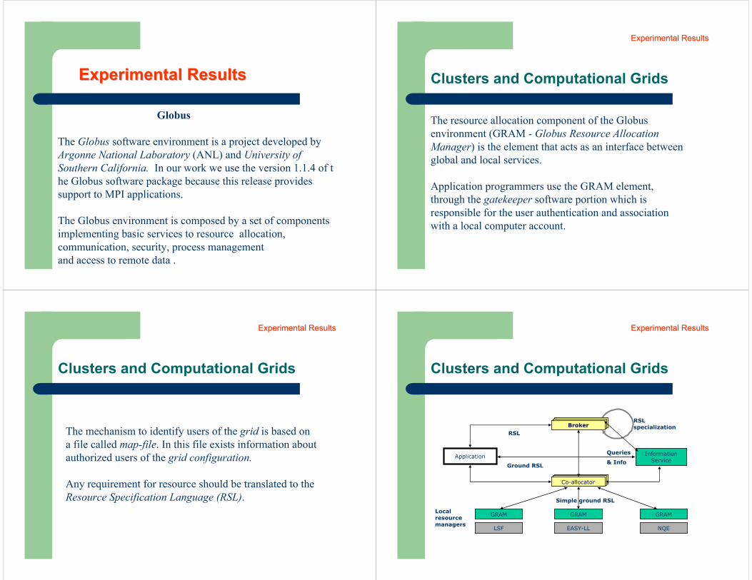
Globus
The Globus software environment is a project developed by Argonne National Laboratory (ANL) and University of Southern California. In our work we use the version 1.1.4 of the Globus software package because this release provides support to MPI applications.
The Globus environment is composed by a set of components implementing basic services to resource allocation,communication, security, process management and access to remote data .
Experimental ResultsExperimental Results Clusters and Computational Grids
The resource allocation component of the Globusenvironment (GRAM - Globus Resource Allocation Manager) is the element that acts as an interface between global and local services.
Application programmers use the GRAM element, through the gatekeeper software portion which is responsible for the user authentication and association with a local computer account.
Experimental ResultsExperimental Results
Clusters and Computational Grids
The mechanism to identify users of the grid is based on a file called map-file. In this file exists information about authorized users of the grid configuration.
Any requirement for resource should be translated to the Resource Specification Language (RSL).
Experimental ResultsExperimental Results
Clusters and Computational Grids
GRAM GRAM GRAM
LSF EASY-LL NQE
Application
RSL
Simple ground RSL
Information Service
Localresourcemanagers
RSLspecializationBroker
Ground RSL
Co-allocator
Queries
& Info
Experimental ResultsExperimental Results
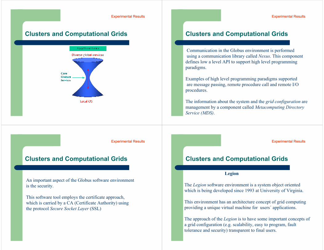
Clusters and Computational Grids
Experimental ResultsExperimental Results
Clusters and Computational Grids
Communication in the Globus environment is performed using a communication library called Nexus. This component defines low a level API to support high level programming paradigms.
Examples of high level programming paradigms supported are message passing, remote procedure call and remote I/O
procedures.
The information about the system and the grid configuration are management by a component called Metacomputing Directory Service (MDS).
Experimental ResultsExperimental Results
Clusters and Computational Grids
An important aspect of the Globus software environment is the security.
This software tool employs the certificate approach, which is carried by a CA (Certificate Authority) using the protocol Secure Socket Layer (SSL)
Experimental ResultsExperimental Results
Clusters and Computational Grids
Legion
The Legion software environment is a system object oriented which is being developed since 1993 at University of Virginia.
This environment has an architecture concept of grid computing providing a unique virtual machine for users´ applications.
The approach of the Legion is to have some important concepts of a grid configuration (e.g. scalability, easy to program, fault tolerance and security) transparent to final users.
Experimental ResultsExperimental Results
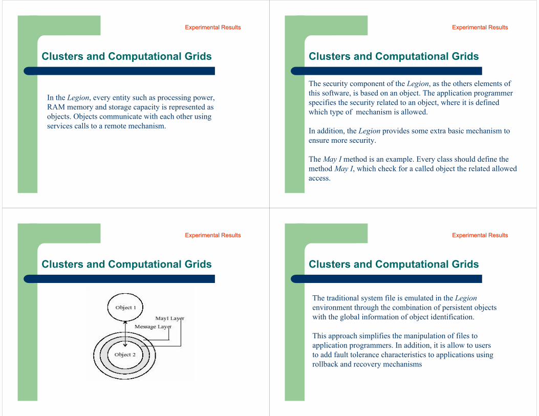
Clusters and Computational Grids
In the Legion, every entity such as processing power, RAM memory and storage capacity is represented as objects. Objects communicate with each other using services calls to a remote mechanism.
Experimental ResultsExperimental Results
Clusters and Computational Grids
The security component of the Legion, as the others elements of this software, is based on an object. The application programmerspecifies the security related to an object, where it is definedwhich type of mechanism is allowed.
In addition, the Legion provides some extra basic mechanism to ensure more security.
The May I method is an example. Every class should define the method May I, which check for a called object the related allowed access.
Experimental ResultsExperimental Results
Clusters and Computational Grids
Experimental ResultsExperimental Results
Clusters and Computational Grids
The traditional system file is emulated in the Legion environment through the combination of persistent objects with the global information of object identification.
This approach simplifies the manipulation of files to application programmers. In addition, it is allow to users to add fault tolerance characteristics to applications using rollback and recovery mechanisms
Experimental ResultsExperimental Results
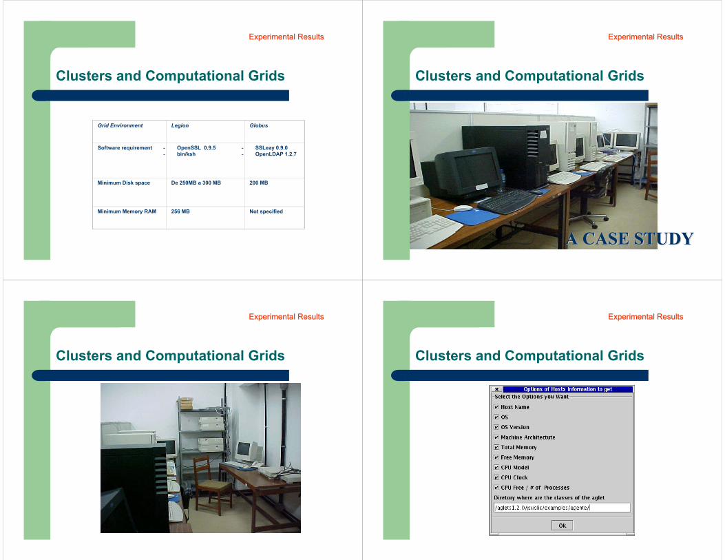
Clusters and Computational Grids
Grid Environment Legion Globus
Software requirement - OpenSSL 0.9.5- bin/ksh
- SSLeay 0.9.0- OpenLDAP 1.2.7
Minimum Disk space De 250MB a 300 MB 200 MB
Minimum Memory RAM 256 MB Not specified
Experimental ResultsExperimental Results
Clusters and Computational Grids
A CASE STUDY A CASE STUDY
Experimental ResultsExperimental Results
Clusters and Computational Grids
Experimental ResultsExperimental Results
Clusters and Computational Grids
Experimental ResultsExperimental Results
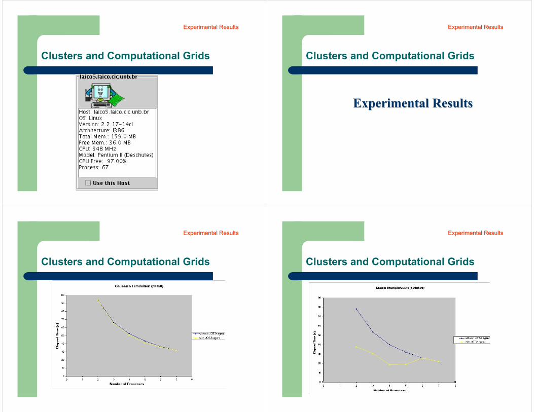
Clusters and Computational Grids
Experimental ResultsExperimental Results
Clusters and Computational Grids
Experimental ResultsExperimental Results
Experimental ResultsExperimental Results
Clusters and Computational Grids
Experimental ResultsExperimental Results
Clusters and Computational Grids
Experimental ResultsExperimental Results
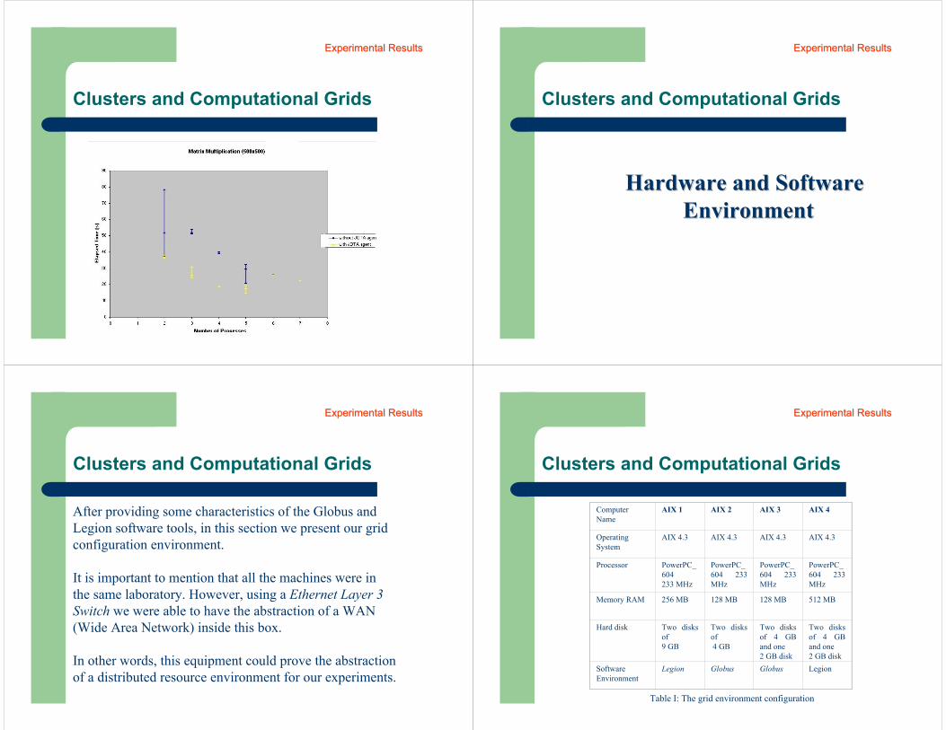
Clusters and Computational Grids
Experimental ResultsExperimental Results
Clusters and Computational Grids
Hardware and SoftwareHardware and SoftwareEnvironmentEnvironment
Experimental ResultsExperimental Results
Clusters and Computational Grids
After providing some characteristics of the Globus and Legion software tools, in this section we present our grid configuration environment.
It is important to mention that all the machines were in the same laboratory. However, using a Ethernet Layer 3 Switch we were able to have the abstraction of a WAN (Wide Area Network) inside this box.
In other words, this equipment could prove the abstraction of a distributed resource environment for our experiments.
Experimental ResultsExperimental Results
Clusters and Computational Grids
Computer Name
AIX 1 AIX 2 AIX 3 AIX 4
Operating System
AIX 4.3 AIX 4.3 AIX 4.3 AIX 4.3
Processor PowerPC_604233 MHz
PowerPC_604 233 MHz
PowerPC_604 233 MHz
PowerPC_604 233 MHz
Memory RAM 256 MB 128 MB 128 MB 512 MB
Hard disk Two disks of 9 GB
Two disks of 4 GB
Two disks of 4 GB and one 2 GB disk
Two disks of 4 GB and one 2 GB disk
Software Environment
Legion Globus Globus Legion
Table I: The grid environment configuration
Experimental ResultsExperimental Results
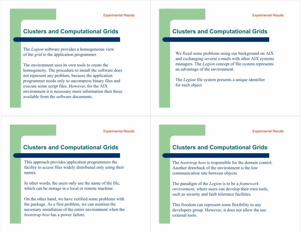
Clusters and Computational Grids
The Legion software provides a homogeneous view of the grid to the application programmer.
The environment uses its own tools to create the homogeneity. The procedure to install the software does not represent any problem, because the application programmer needs only to uncompress binary files and execute some script files. However, for the AIX environment it is necessary more information then those available from the software documents.
Experimental ResultsExperimental Results
Clusters and Computational Grids
We fixed some problems using our background on AIX and exchanging several e-mails with other AIX systems managers. The Legion concept of file system represents an advantage of the environment.
The Legion file system presents a unique identifier for each object.
Experimental ResultsExperimental Results
Clusters and Computational Grids
This approach provides application programmers the facility to access files widely distributed only using their names.
In other words, the users only use the name of the file, which can be storage in a local or remote machine.
On the other hand, we have verified some problems with the package. As a first problem, we can mention the necessary installation of the entire environment when the bootstrap host has a power failure.
Experimental ResultsExperimental Results
Clusters and Computational Grids
The bootstrap host is responsible for the domain control. Another drawback of the environment is the low communication rate between objects.
The paradigm of the Legion is to be a framework environment, where users can develop their own tools, such as security and fault tolerance facilities.
This freedom can represent some flexibility to any developers group. However, it does not allow the use external tools.
Experimental ResultsExperimental Results
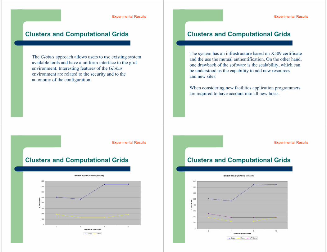
Clusters and Computational Grids
The Globus approach allows users to use existing system available tools and have a uniform interface to the gird environment. Interesting features of the Globusenvironment are related to the security and to the autonomy of the configuration.
Experimental ResultsExperimental Results
Clusters and Computational Grids
The system has an infrastructure based on X509 certificate and the use the mutual authentification. On the other hand, one drawback of the software is the scalability, which can be understood as the capability to add new resources and new sites.
When considering new facilities application programmers are required to have account into all new hosts.
Experimental ResultsExperimental Results
Clusters and Computational Grids
MATRIX MULTIPLICATION (500x500)
0
100
200
300
400
500
600
700
800
2 4 8 16
NUMBER OF PROCESSES
ELA
PSED
-TIM
E
Legion Globus
Experimental ResultsExperimental Results
Clusters and Computational Grids
MATRIX MULTIPLICATION (500x500)
0
100
200
300
400
500
600
700
800
2 4 8 16
NUMBER OF PROCESSES
ELA
PSED
-TIM
E
Legion Globus MPI Nativo
Experimental ResultsExperimental Results
End of Part III (Clusters and Computational Grids)