prof. samuel g. paikowsky - faculty server...
TRANSCRIPT

1/31/2014
1
Prof. Samuel G. Paikowsky
Lecture 2 - SUBSURFACE EXPLORATION AND SOIL PARAMETERS
1
Geotechnical Engineering Research LaboratoryUniversity of Massachusetts Lowell
USA
14.528 Drilled Deep FoundationsSpring 2014
Prof. Samuel G. Paikowsky
Lecture 2 – Part II – Subsurface Explorations and Design Parameters
2
Geotechnical Engineering Research LaboratoryUniversity of Massachusetts Lowell
USA
14.528 Drilled Deep FoundationsSpring 2014

1/31/2014
2
14.528 Drilled Deep Foundations – Samuel Paikowsky 3 of 235
Soil Origin and Deposition (Basic Review)
N.E. Geology (Basic Review)
Subsurface Exploration
In-Situ Testing
Design Parameters
Lecture Subjects
14.528 Drilled Deep Foundations – Samuel Paikowsky 4 of 235
OBJECTIVES OF SUBSURFACE EXPLORATION
Three General Objectives for Subsurface Exploration:
1. Define Soil and Rock Stratigraphy and Structure within Proposed Construction Zone of Influence.
2. Obtain Groundwater Data.- Level at Time of Testing.- Seasonal Fluctuations.
3. Determine Engineering Properties of Subsurface Materials for Use in Foundation Design.
- Collect samples for laboratory testing.- Determine insitu engineering properties.
Photograph courtesy of www.cmeco.com

1/31/2014
3
14.528 Drilled Deep Foundations – Samuel Paikowsky 5 of 235
Subsurface Exploration
Subsurface Exploration Plan:Function of
- Type and Critical Nature of Structure- Foundation Loads- Topographical Information- Site Geology (Soil and Rock Formations)- Location of Bedrock
• 1.5 m core to confirm• >3 m core required for foundations
on rock- Engineer’s Experience- Project Requirements
Consequences of Poor Subsurface Explorations
(photographs courtesy of NHI 13231)
USACE EM1110-1-1804“There are no hard and fast rules stating the number and depth of samples for a particular geotechnical investigation.”ASTM D420-98(2003) Standard Guide to Site Characterization for
Engineering, Design, and Construction Purposes
PLANNING
14.528 Drilled Deep Foundations – Samuel Paikowsky 6 of 235
Are Soil Explorations as Costly as the Repair?(Photographs courtesy of http://www.dot.state.co.us/geotech/geotechphotos.cfm)
YOU WILL NEED 1 BORING TO 100 ft TO DETERMINESEISMIC SITE CLASSIFICATION FOR IBC 2006
Subsurface ExplorationPLANNING
IBC (2009) Section 1803.3.1 (8th Edition of MSBC)The scope of the soil investigation including the number and types of borings orsoundings, the equipment used to drill and sample, the in-situ testing equipment andthe laboratory testing program shall be determined by a registered designprofessional.

1/31/2014
4
14.528 Drilled Deep Foundations – Samuel Paikowsky 7 of 235
The Massachusetts State Building Code(7th Edition)
780 CMR 1802.0 FOUNDATION AND SOILS INVESTIGATIONS
1802.5 Borings, Sampling and Testing. The scope of the subsurface
exploration, including the number and types of borings, soundings or test pits, the equipment used to drill and sample, the in-situ testing equipment and the laboratory testing program, shall be determined by a registered
design professional.Photograph courtesy of TTU Center for
Multidisciplinary Research in Transportation(www.depts.ttu.edu/techmrtweb)
Subsurface ExplorationPLANNING
14.528 Drilled Deep Foundations – Samuel Paikowsky 8 of 235
Subsurface Explorations
Although the foundations are usually hidden from sight when the structure is complete, their performance has a profound effect on the overall performance of the structure.
Karl Terzaghi (1951) (1883-1963) has said: “On account of the fact that there is no glory attached to the foundations, and that the sources of success or failure are hidden deep in the ground, building foundations have always been treated as step-children, and their acts of revenge for the lack of attention can be very embarrassing”.
Pisa Tower (From "Soil Mechanics" by Lamb & Whitman (1969), Chapter 14, p. 201)

1/31/2014
5
14.528 Drilled Deep Foundations – Samuel Paikowsky 9 of 235
Subsurface Explorations
Pisa Tower( "Soil Mechanics"
by Lamb & Whitman (1969), Chapter 14,
p. 201)
Subsurface Explorations
14.528 Drilled Deep Foundations – Samuel Paikowsky

1/31/2014
6
14.528 Drilled Deep Foundations – Samuel Paikowsky 11 of 235
Subsurface Explorations
14.528 Drilled Deep Foundations – Samuel Paikowsky 12 of 235
Subsurface Explorations
Background
Investigation of the underground conditions at a site isprerequisite to the economical design of the substructureelements. The cost of site exploration ranges between 0.5 to1% of the total construction cost and it’s elimination comparedto the risk of subsequent damage and safety is false economy.The required knowledge depends on the structure type, whichcan be divided into 3 categories:

1/31/2014
7
14.528 Drilled Deep Foundations – Samuel Paikowsky 13 of 235
Subsurface Explorations
I) Main function is interaction with the surrounding ground
Tunnel (liner)Main interest:
Load - deformation relations of the loaded interfacesSoil - Structure interaction
Sheet pile
Gravity
Retaining WallsFoundations
Shallow
Deep
Not to Scale
14.528 Drilled Deep Foundations – Samuel Paikowsky 14 of 235
Subsurface Explorations
I) Structures constructed from earth: highway fills and approach embankments, earth and rockfill dams, backfill behind walls
Approach Embankment Dam
Main interest:Properties of the construction material to determine the action of the earth structure itself and soil-structure interaction.

1/31/2014
8
14.528 Drilled Deep Foundations – Samuel Paikowsky 15 of 235
Subsurface Explorations
Background (cont’d.)
III) Structures of natural earth and rocks, e.g., natural slopes
Main interest:Knowledge of the properties of the natural materials in the natural state.
14.528 Drilled Deep Foundations – Samuel Paikowsky 16 of 235
Subsurface Explorations
Type of Subsurface Information Required for Design1. Dimensions
Areal extend, depth and thickness of each identifiable soilstratum within a depth, which depends on the structures sizeand nature as well as type of predominant soil.
2. RockDepth to top of rock and character of the rock
3. GroundwaterLocation, fluctuation, possible artesian pressures and the flowregime
4. Engineering PropertiesIn situ properties of the soil and/or rock such as permeability,compressibility, and shear strength

1/31/2014
9
14.528 Drilled Deep Foundations – Samuel Paikowsky 17 of 235
Subsurface Explorations
Obtaining Subsurface InformationTwo broad categories for exploration methods: Direct Method and Indirect Method
Indirect Methods: Geologic mapping Aerial photography Topographic map interpretation Existing data - geological reports, maps, etc. Hydrological information by US Corps. of Eng. - soils surveys, etc. Highway Dept. Manuals Records of flow, etc. Websites: Google Maps and satellite options, Google Earth ‘Typical’ conditions, e.g. the reference E.G. Johnson, “Geotechnical
Characteristics of the Boston Area”, Civil Engineering Practice, Journal of BSCE section ASCE, vol. 4, no. 1, Spring 1989, pp. 53-64.
14.528 Drilled Deep Foundations – Samuel Paikowsky 18 of 235
Subsurface Explorations
Obtaining Subsurface Information (cont’d.)Two broad categories for exploration methods: Direct Method and Indirect Method
Direct Methods: Field reconnaissance including examination of exposed materials in
natural and man-made exposures Sounding and probing and in-situ monitoring during and after
construction Borings, test pits, trenches, shafts obtaining representative disturbed
and/or undisturbed samples of in-situ material Simple field tests - SPT and CPT for correlations with engineering
properties Field tests - vane shear test, seepage and water pressure, plate bearing
test, pile load test. Measuring directly the engineering properties of the in-situ materials.

1/31/2014
10
Subsurface Explorations
Subsurface Explorations

1/31/2014
11
Subsurface Explorations
14.528 Drilled Deep Foundations – Samuel Paikowsky
Subsurface Explorations

1/31/2014
12
14.528 Drilled Deep Foundations – Samuel Paikowsky 23 of 235
Subsurface ExplorationsMass Building Code Section 1802.0 Foundation Investigations (p.23 of Review & Codes Class Notes, Volume 1)
1802.1 Where required: Boring, tests, drill holes, coreborings or any combination shall be required for all structures exceptthe following, unless specifically required by the building official:
1. One and two family dwellings and their accessory buildings;2. Structures less than 35,000 cubic feet in gross volume; and3. Structures used for agricultural purposes.
The borings, test, pits or other soil investigations shall be adequate innumber and depth and so located to accurately define the nature ofany subsurface material necessary for the support of the structure.When it is proposed to support the structure directly on bedrock, thecode official shall require core borings to be made into the rock, orshall require other satisfactory evidence to prove that the structureshall be adequately founded on bedrock.
14.528 Drilled Deep Foundations – Samuel Paikowsky 24 of 235
Subsurface Explorations
Mass Building Code Section 1802.0 Foundation Investigations (p.23 of Review & Codes Class Notes, Volume 1)
1802.2 Soil samples and boring reports: Samples of thestrata penetrated in test borings or test pits, representing the naturaldisposition and conditions at the site, shall be available forexamination by the code official. Wash or bucket samples shall not beaccepted. Duplicate copies of the results obtained from all boringsand of all test results or other pertinent soil data, shall be filed withthe code official
Note: Previous code specifically used the language of “borings plotted to a true relative elevation and to scale”.

1/31/2014
13
14.528 Drilled Deep Foundations – Samuel Paikowsky 25 of 235
GENERAL SUBSURFACE INVESTIGATION METHODS
METHOD Abbrv. ASTM SAMPLING MAX. DEPTH (ft)
Hand Auger Borings HABD1452-07a
D4700-91(06)Yes Typ. 6 - 8
20 (w/difficulty)
Test/Excavation Pits TP None YesLimits of
equipment(Typ. 20 ft)
Soil Test Borings STB
D420-98(03)
D1452-07a
D4700-91(06)
Yes~ 300 ft
(dependent of
various factors)
Green – Near Surface : Red – Near and Deep
D420-98(2003) Standard Guide to Site Characterization for Engineering, Design, and Construction Purposes
Subsurface Explorations
14.528 Drilled Deep Foundations – Samuel Paikowsky 26 of 235
HAND AUGER BORINGS (HAB)
Two Man OperationPhotograph courtesy of
http://cees.ou.edu/ugrad/reu/
Typical HAB Cross-SectionFigure courtesy of
WPC Engineering Inc.
• Requires Manual Labor.
• Typical Depths up to 6 to 8 ft.
• Standard Diameter: 3¼ in
(Other Diameters Available).
• Allows for soil samples (disturbed) to be collected for classification and laboratory testing (if desired).
Subsurface Explorations

1/31/2014
14
14.528 Drilled Deep Foundations – Samuel Paikowsky 27 of 235
TEST/EXCAVATION PITS (TP)
• Requires Appropriate Construction Equipment (e.g. backhoe).
• Typical Depths up to 20 ft(limited by equipment).
• Pit size determined by needs.
• Allows for soil samples (disturbed) to be collected for classification and laboratory testing (if desired).
• Allows for greater examination of insitu soils by geotechnical engineers and engineering technicians.
Photographs courtesy of www.ees1.lanl.gov, photos.orr.noaa.gov, & www.kerrville.org
Subsurface Explorations
14.528 Drilled Deep Foundations – Samuel Paikowsky 28 of 235
Failing Truck Mounted Rig CME750 All-Terrain Rig
SOIL TEST BORING (STB) RIGS
Photographs courtesy of FHWA NHI Course 132031 Subsurface Investigations
Subsurface Explorations

1/31/2014
15
14.528 Drilled Deep Foundations – Samuel Paikowsky 29 of 235
MoDOT Track Mounted Rig
Water Boring from Barge for Bridge Crossing
Wireline Rig for Kaolin MinesMacon, GA
Photographs courtesy of FHWA NHI Course 132031 Subsurface Investigations
SOIL TEST BORING (STB) RIGSSubsurface Explorations
14.528 Drilled Deep Foundations – Samuel Paikowsky 30 of 235
Near Shore Water Boring Using a Jack-up Barge
Photograph courtesy of www.Fugroconsultants.com
SOIL TEST BORING (STB) RIGSSubsurface Explorations

1/31/2014
16
14.528 Drilled Deep Foundations – Samuel Paikowsky 31 of 235
Subsurface Explorations
Planning the Exploration Program
A. General
1. Methods are applicable for any structure or development. The difference is in the scope and detail.
2. Our focus is on exploration for buildings and structures where the cost per unit area is high = compact site. (In this class we refer mostly to shallow foundations).
3. Our aim is to obtain maximum amount of information at minimum cost. General rule of thumb, cost of exploration is .5 to 1.0% of total construction cost.
o Lower for large project, homogeneous subsurfaceo Higher for smaller project, highly varied subsurface
14.528 Drilled Deep Foundations – Samuel Paikowsky 32 of 235
Subsurface Explorations
Planning the Exploration Program
A. General (cont’d.)
* It is justifiable to spend additional money on explorations and related testing as long as the savings in the construction cost on the basis of the obtained information are significantly greater, i.e., in some cases, no amount of detailed information may change the type, cost, or performance of the foundation.
High
Subsurface complexity
Low
large Project size small
highest
lowest
Relative cost of subsurface exploration as a function of project size and subsurface complexity

1/31/2014
17
14.528 Drilled Deep Foundations – Samuel Paikowsky 33 of 235
Subsurface Explorations
Planning the Exploration Program (cont’d.)
B. Steps in Planning a Subsurface Exploration Program
1. Assemble all available information on the structure: dimensions, column spacing, type of structure, use of building, basement requirement, special architectural considerations (e.g., sensitive facade) and loads
Approximation of 10 KN/m2/floor 1 ton/ m2/floorColumn spacing 10 stories = 10 ton/m2
e.g.: spacing = 6x6m, Max column load = 36m2x(10 ton/ m2) = 360 tons
2. Assemble all available information on the site utilizing indirect methods, field reconnaissance, and available data from nearby structures, etc.
14.528 Drilled Deep Foundations – Samuel Paikowsky 34 of 235
Subsurface Explorations
Planning the Exploration Program (cont’d.)
B. Steps in Planning a Subsurface Exploration Program
3. Preliminary site investigation (usually the only investigation on standard jobs)
From Stage 1: Loads concentrationFrom Stage 2: Possible subsurface conditionFrom 1+2 Possible foundation scheme
Establish: (i) if the possible foundation requires test pits and/or borings. (ii) the number and depth of the test pits and/or borings
4. Depth and Number of Explorationso Should always include the influence zone of the foundationo One boring, usually the first, should get more data like
extending it all the way to the bedrock (also in middle)

1/31/2014
18
14.528 Drilled Deep Foundations – Samuel Paikowsky 35 of 235
Subsurface ExplorationsPlanning the Exploration Program (cont’d.)
B. Steps in Planning a Subsurface Exploration Program4. Depth and Number of Explorations
Depth of Borings
Rules of Thumbo D (3 to 4) M
M - smallest foundationdimension
o D (1.5 to 2) smaller dimensionof building
o D not less than 6m(for very. smallbuilding) to 15m
D1 = depth at which = 0.1 qcontact
Dep
th
′
v′
v′
qcontact
∆0.05
14.528 Drilled Deep Foundations – Samuel Paikowsky 36 of 235
Subsurface Explorations
Planning the Exploration Program (cont’d.)
B. Steps in Planning a Subsurface Exploration Program4. Depth and Number of Explorations
The smaller of D1 and D2 is used to approximate the minimum required depth of the boring (unless bedrock is encountered).
See Table on page 76 (text): Number of stories and width of building for boring depth.
Office Buildings and Hospitals (See equations 2.1, 2.2, 2.3, & 2.4)
Db = (10 to 20)S0.7 where Db (ft.) and S is No. of stories
10 for light steel or narrow concrete building and 20 for heavy steel or wide concrete building.

1/31/2014
19
14.528 Drilled Deep Foundations – Samuel Paikowsky 37 of 235
Subsurface ExplorationsPlanning the Exploration Program (cont’d.)
B. Steps in Planning a Subsurface Exploration Program4. Depth and Number of Explorations
example: S = 1, Db = 10 - 20S = 3, Db = 22 - 43S = 10, Db = 50-100
Spacing - Table 2.4, pg. 77 (text)
Multi-story 30-100ftOne-story 60-200ftHighways 800-1600ftSubdivisions 800-1600ftDams and Dikes 130-260ft
Lower values relate to complex subsurface and high values relate to homogeneous subsurface.
14.528 Drilled Deep Foundations – Samuel Paikowsky 38 of 235
Subsurface ExplorationsPlanning the Exploration Program (cont’d.)
B. Steps in Planning a Subsurface Exploration Program4. Depth and Number of Explorations
o The minimum is the number of borings that can be made in one drilling day, but try not less than 5 boreholes in the following configuration:
Uniform soil less borings and more physical properties

1/31/2014
20
14.528 Drilled Deep Foundations – Samuel Paikowsky 39 of 235
Subsurface ExplorationsPlanning the Exploration Program (cont’d.)
B. Steps in Planning a Subsurface Exploration Program
5. Obtained Information: Stratification of soil (type and geometry), groundwater table (establish wells and piezometers for monitoring), rock or competent strata, sample recovery, field tests (usually SPT and/or vane tests)
Small sites - you should be present to alter requirements based on initial findings, undisturbed samples are not usually obtained.
6. Detailed or Additional site investigation Locating additional borings based on missing information or
design requirements Determine the need for additional sampling, especially
undisturbed samples Consider construction procedures
14.528 Drilled Deep Foundations – Samuel Paikowsky 40 of 235
StructureFHWA
(NHI-01-031)
USACE(Table 2-4 EM1110-1-1804)
NAVFAC(DM7.01)
Min. # Spacing Min. # Spacing Min. # Spacing
Rigid Frame Structure 1 per 230m² 50 ft spacing
Low-Load Warehouse 4 @ Corners
Isolated Rigid Ftg < 2500ft² 2 @ O.C.
Isolated Rigid Ftg < 10,00ft² 3 around Per.
Houses – Subdivisions 1 per 8000m² 200 to 400 ft
Houses – Individual Lots 1 per lot
Bridge Piers1 (< 30m wide)
2 (> 30m wide)1
Retaining Walls 1 ≤ 60 m
Roads – 2 Lane ≤ 60 m 1 per 150 m @ CL
Roads – Multi Lane 1 per 75 m @ CL
Cuts and Embankments 1 ≤ 60 m
Culverts 1 60 to 120 m
Levees 6 to 12 m high 230 m100 to 200 ft
Levees 12 to 18 m high 150 m
Subsurface Test Layout General Guidelines
Subsurface Explorations

1/31/2014
21
SUBSURFACE TEST LAYOUT GUIDELINESSCDOT Geotechnical Design Manual (2010)
Foundation Type Min. Geotechnical Site Investigation Reference
Bridge Pile Foundation Minimum one testing location per bent1 Table 4-1
Bridge Single Foundation – Drilled Shaft Minimum one testing locations per foundation location Table 4-1
Bridge Multiple Foundation – Drilled Shaft2 Minimum two testing locations per bent location Table 4-1
Bridge Shallow Foundation – Founded on Soil Minimum three testing locations per bent location Table 4-1
Bridge Shallow Foundation – Founded on Rock Minimum two testing locations per bent location Table 4-1
Retaining Wall (within 150 of bridge abutment) Minimum one testing location at least every 75 ft Section 4.3.2
Retaining Wall (within 150 of bridge abutment) Minimum one testing location at least every 75 ft Section 4.3.2
Embankments Minimum one testing location at least every 500 ft Section 4.3.3
Cut Excavations Minimum one test locations every 300 ft along cut area Section 4.3.4
CulvertsMinimum one testing locations @ each end of culvert and at every 100 ft of new crossline culvert2
Section 4.3.5
Sound Barrier Walls Dependant on shallow or deep foundation used2 Section 4.3.6
Misc. Structures (Light poles, overhead signs) Minimum of one test location per foundation location Section 4.3.7
NOTES:1. Spacing between testing locations may be increased, but shall be approved prior to field operations and shall include justification.
Spacing may not exceed 100 ft.2. See SCDOT Geotechnical Manual for additional details.
Subsurface Explorations
14.528 Drilled Deep Foundations – Samuel Paikowsky 42 of 235
Structure FHWA(NHI-01-031)
USACE(Table 2-4 EM111-1-1804)
Spread Footings
Lf ≤ 2B, Min. Depth = 2B Min. Depth = 1½B
(4.5m for houses or to unweathered rock)
Lf ≥ 5B, Min. Depth = 4B
2B < Lf < 5B, Extrapolate
Deep Foundations (Soil)Min. Depth = 6m below
anticipated foundation tip elevation
Min. Depth = 1½B of imaginary footing @ 2/3
expected pile depthDeep Foundations (Rock)
Min. Depth = 3m, 3D, or 2Bgroup
below foundation tip
Roadways Min. 2mMin. 3m below finished grade
(0.75m into rock)
Embankments/Culverts Min. 2x Embankment Height Height of Levee
Cuts Min. 5m below cut elevation
SUBSURFACE TEST DEPTH GUIDELINES
NOTE: B = Footing Width
Subsurface Explorations
1/31/2014
22
14.528 Drilled Deep Foundations – Samuel Paikowsky 43 of 235
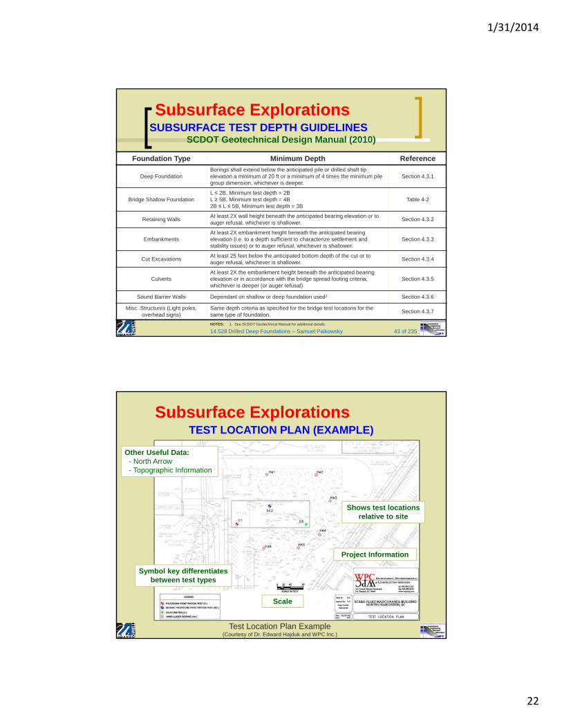
SUBSURFACE TEST DEPTH GUIDELINESSCDOT Geotechnical Design Manual (2010)
Foundation Type Minimum Depth Reference
Deep FoundationBorings shall extend below the anticipated pile or drilled shaft tip elevation a minimum of 20 ft or a minimum of 4 times the minimum pile group dimension, whichever is deeper.
Section 4.3.1
Bridge Shallow FoundationL ≤ 2B, Minimum test depth = 2BL ≥ 5B, Minimum test depth = 4B2B ≤ L ≤ 5B, Minimum test depth = 3B
Table 4-2
Retaining WallsAt least 2X wall height beneath the anticipated bearing elevation or to auger refusal, whichever is shallower.
Section 4.3.2
EmbankmentsAt least 2X embankment height beneath the anticipated bearing elevation (i.e. to a depth sufficient to characterize settlement and stability issues) or to auger refusal, whichever is shallower.
Section 4.3.3
Cut ExcavationsAt least 25 feet below the anticipated bottom depth of the cut or to auger refusal, whichever is shallower.
Section 4.3.4
CulvertsAt least 2X the embankment height beneath the anticipated bearing elevation or in accordance with the bridge spread footing criteria, whichever is deeper (or auger refusal)
Section 4.3.5
Sound Barrier Walls Dependant on shallow or deep foundation used1 Section 4.3.6
Misc. Structures (Light poles, overhead signs)
Same depth criteria as specified for the bridge test locations for the same type of foundation.
Section 4.3.7
NOTES: 1. See SCDOT Geotechnical Manual for additional details.
Subsurface Explorations
TEST LOCATION PLAN (EXAMPLE)
Test Location Plan Example(Courtesy of Dr. Edward Hajduk and WPC Inc.)
Scale
Shows test locations relative to site
Symbol key differentiates between test types
Project Information
Other Useful Data:- North Arrow- Topographic Information
Subsurface Explorations

1/31/2014
23
14.528 Drilled Deep Foundations – Samuel Paikowsky 45 of 235
EXAMPLE FOR SITE INVESTIGATION PLAN
Subsurface Explorations
Courtesy of G.Y.A., Ltd.
14.528 Drilled Deep Foundations – Samuel Paikowsky 46 of 235
EXAMPLE FOR SITE INVESTIGATION PLAN (cont’d.)
Subsurface Explorations
Courtesy of G.Y.A., Ltd.

1/31/2014
24
14.528 Drilled Deep Foundations – Samuel Paikowsky 47 of 235
EXAMPLE FOR SITE INVESTIGATION PLAN (cont’d.)
Subsurface Explorations
Courtesy of G.Y.A., Ltd.
14.528 Drilled Deep Foundations – Samuel Paikowsky 48 of 235
Soil BoringsDefinition
A hole drilled in the ground (horizontal, vertically or inclined) for the primary purpose of obtaining samples of the overburden or rock materials present, in order to determine the stratigraphy and/or engineering properties of those materials. The hole may also be used for determination of engineering properties as permeability, shear strength, compressibility, etc.
Hollow stem auger used by a truck mounted rig
1/31/2014
25
14.528 Drilled Deep Foundations – Samuel Paikowsky 49 of 235
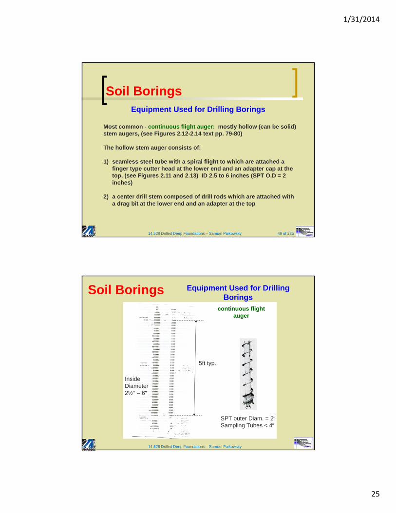
Soil BoringsEquipment Used for Drilling Borings
Most common - continuous flight auger: mostly hollow (can be solid) stem augers, (see Figures 2.12-2.14 text pp. 79-80)
The hollow stem auger consists of:
1) seamless steel tube with a spiral flight to which are attached a finger type cutter head at the lower end and an adapter cap at the top, (see Figures 2.11 and 2.13) ID 2.5 to 6 inches (SPT O.D = 2 inches)
2) a center drill stem composed of drill rods which are attached with a drag bit at the lower end and an adapter at the top
Soil Borings Equipment Used for Drilling Borings
14.528 Drilled Deep Foundations – Samuel Paikowsky
continuous flight auger
SPT outer Diam. = 2Sampling Tubes < 4
5ft typ.
InsideDiameter2½ – 6

1/31/2014
26
14.528 Drilled Deep Foundations – Samuel Paikowsky 51 of 235
Soil BoringsEquipment Used for Drilling Borings
The adapters at the top of the drill stem and auger flight are designed to permit advancement of the auger with the plug in place.
As the hole is advanced, additional lengths of hollow stem flight and center stem are added as required, each length is usually 5ft. (3 to 6 ft. are possible)
The flight acts as a screw conveyer to bring soil to the surface for up to 100m
Method applicable in all soils. Difficulties occur in saturated sands under deep hydrostatic pressure where quick conditions at the bottom may destroy the boring.
14.528 Drilled Deep Foundations – Samuel Paikowsky 52 of 235
Soil Borings
Continuous hollow flight augers, added in 5 ftincrements.
Hollow stem augers allow soil sampling without removal.
Act as temporary casing to stabilize borehole.
Center stem and plug are inserted down the hollow center during boring advance.
HSA range from about 6 to 12 inch O.D. with 3 to 8 inch I.D.
HSA generally limited to depths < 100 ft.
HSA should not be used in loose silts and sands below the GWT.
Truck-Mounted Rig with
Hollow-Stem Augers
SOIL TEST BORINGS (STB) Hollow Stem Augers (HSA)
Text & Photographs courtesy of FHWA NHI Course 132031 Subsurface Investigations
HSA outer and inner assemblywith stepwise
center bit

1/31/2014
27
14.528 Drilled Deep Foundations – Samuel Paikowsky 53 of 235
Soil Borings
Continuous flight augers, added in 5-ft increments.
Limited to non-caving soils and depths < 30 ft.
Solid flight augers are removed prior to soil sampling, thus labor-intensive.
Auger diameters from 4 in to 8 in.
Front end has finger or fish-tail bit to loosen soil.
Spoil collects around top of borehole.
SOIL TEST BORINGS (STB) Solid Flight Augers
Solid Auger and Drill Bit
Text & Photographs courtesy of FHWA NHI Course 132031 Subsurface Investigations
14.528 Drilled Deep Foundations – Samuel Paikowsky 54 of 235
Photographs courtesy of FHWA NHI Course 132031 Subsurface Investigations
SOIL TEST BORINGS (STB) Solid Flight Augers
Soil Borings

1/31/2014
28
14.528 Drilled Deep Foundations – Samuel Paikowsky 55 of 235
Soil Borings
Rotary wash techniques are best for borings extending below GWT.
Rotary wash can achieve great depths > 300+ ft.
Drilling bits: Drag bits for clays Roller bits for sand
In rotary wash method, borehole is stabilized using either temporary steel casing or drilling fluid.
Fluids include water, bentonite or polymer slurry, foam, or Revert that are re-circulated in tub or reservoir at surface.
SOIL TEST BORINGS (STB) Rotary Wash Borings
Truck Rig conducting rotary wash boring
Text & Photographs courtesy of FHWA NHI Course 132031 Subsurface Investigations
14.528 Drilled Deep Foundations – Samuel Paikowsky 56 of 235
SOIL TEST BORINGS (STB)Rotary Wash Borings
Schematic(Hvorslev 1948)
Photographs courtesy of FHWA NHI Course 132031 Subsurface Investigations
Soil Borings

1/31/2014
29
14.528 Drilled Deep Foundations – Samuel Paikowsky 57 of 235
Soil Borings
Bucket auger drills are used for obtaining large disturbed or undisturbed samples.
Diameters range from 0.6 m (2 ft) to 1.2 m (4 ft).
Increment of 0.3 m to 0.6 m depths (1 to 2 feet).
Good for gravelly soils and cobbles.
Same rigs used for constructing Drilled Shafts.
Setup of rig for Bucket Auger Boring(ASTM D4700)
SOIL TEST BORINGS (STB) Bucket Auger Borings
Text and Figure courtesy of FHWA NHI Course 132031 Subsurface Investigations
14.528 Drilled Deep Foundations – Samuel Paikowsky 58 of 235
Soil Sampling Disturbed Sampling (Most Common)
Bulk samples (from auger cuttings or TP excavations).
Bucket samples (borrow pits). Drive samples (e.g. split-spoon). Laboratory Tests: Grain size, Atterberg Limits,
Specific Gravity, Organic Content, Hydraulic Conductivity (coarse grained), Shear Strength (coarse grained).
Most of the disturbed soil samples are obtained through the SPT. Limited use can be made by data obtained through “cutting open” a clayey sample and testing it with pocket penetrometer and torque vane.
Undisturbed Sampling (ASTM D1587) Push Tubes (e.g. Shelby, Piston, Laval) Rotary & Push (e.g. Denison, Pitcher) Block Samples Laboratory Tests: Consolidation, Hydraulic
Conductivity (cohesive), Shear Strength (cohesive) Text & Photographs courtesy of FHWA NHI Course 132031 Subsurface Investigations
Split Spoon Sampler
Thin Wall Samplers

1/31/2014
30
14.528 Drilled Deep Foundations – Samuel Paikowsky 59 of 235
after Fang et al. (1991) and EM 1110-1-1905.NOTE: 1 MPa = 10.44 tsf
Soil Density/Consistency Nqt
(MPa)t
(pcf)′(°)
SANDS
V. Loose 0-4 0-2 90-105 <30
Loose 5-10 2-5 95-110 30-35
Medium Dense 11-30 5-15 105-120 35-38
Dense 31-50 15-25 115-130 38-41
Very Dense >50 >25 125-140 41-44
COHESIVE SOILS
Very Soft 0-2 0-0.5 90-100
NA
Firm 2-8 0.5-1.5 90-110
Stiff 9-15 1.5-3 105-125
Very Stiff 15-30 3-6 115-135
Hard >30 >6 120-140
Soil Engineering Property Correlationsfrom Insitu Testing
Soil Sampling
14.528 Drilled Deep Foundations – Samuel Paikowsky 60 of 235
Soil Engineering Properties DeterminationMaximum Allowable Shear Strengths (SCDOT, 2010)
Soil Sampling

1/31/2014
31
14.528 Drilled Deep Foundations – Samuel Paikowsky 61 of 235
Soil Engineering Properties DeterminationMaximum Allowable Shear Strengths (SCDOT, 2010)
Soil Sampling
14.528 Drilled Deep Foundations – Samuel Paikowsky 62 of 235
Coefficient of Variation (V) for Geotechnical Properties and Insitu Tests (after Duncan, 2000)
Measured or Interpreted Parameter
V
(%)
Unit Weight () 3 to 7
Effective Friction Angle (') 2 to 13
Undrained Shear Strength (Su) 13 to 40
Undrained Shear Ratio (Su/'vo) 5 to 15
SPT N Value 15 to 45
Electric CPT Tip Resistance (qt) 5 to 15
Also see Chapter 8 – Applying Judgement in Selecting Soil and Rock Properties for Design (FHWA IF-02-034).
Coefficient of Variation: A measure of dispersion of a probability distribution.
after Table 52. FHWA IF-02-034
Soil Sampling

1/31/2014
32
14.528 Drilled Deep Foundations – Samuel Paikowsky 63 of 235
Soil Borings – Determination of Soil Stratigraphy
Figure 9-1. FHWA NHI Course 132031 Subsurface Investigations
Soil Sampling
14.528 Drilled Deep Foundations – Samuel Paikowsky 64 of 235
Soil Sampling
Very common test worldwide
1902 - Colonel Gow of Raymond Pile Co.
Split-barrel sample driven in borehole.
Conducted on 2½ to 5 ft depth intervals.
ASTM D1586 guidelines
Drop Hammer (140 lbs falling 30 inches)
Three increments of 6 inches each; Sum last two increments = “SPT N value" (blows/ft)
Correlations available with all types of soil engineering properties.
Disturbed Soil Samples Collected
STANDARD PENETRATION TEST (SPT) (ASTM D1586-08a)
Text courtesy of FHWA NHI Course 132031 Subsurface Investigations
Marking of 6 inch Increments for SPT Test Photograph courtesy of physics.uwstout.edu

1/31/2014
33
14.528 Drilled Deep Foundations – Samuel Paikowsky 65 of 235
Soil SamplingSPT - Standard Penetration Test
General Most economic and popular means to obtain subsurface
information in the USA
“Split Spoon Sampler” ASTM D-1586-84 (text p. 81, Fig. 2.15). Thick wall sampler O.D = 2 inch, I.D. = 1 3/8 inch (See ASTM D 1586-84, attached – p. 59 of the notes)
Using a 140lb. hammer falling 30” to drive a split-barrel sampler 18 inch into the soil.
Count the number of blows required to drive the sampler 6” (3 times)
The test result, N SPT = number of blows required for the sampler to penetrate the last 12” (from 6 to 18 inch penetration)
14.528 Drilled Deep Foundations – Samuel Paikowsky 66 of 235
Soil SamplingSPT - Standard Penetration Test
General6 6 6
Example Blows/6 20 33 17 1.5
Stop test & mark boring log by “refusal” if: 50 blows required for any 6 Obtain 100 blows from the beginning In 10 successive blows, there is no evidence of movement Usually measure distance and number, e.g. 40b/2 meaning
40 blows measured along 2 inches.
When the sampler penetrates under its own weight (and rods) mark WOR = weight of rods
Boring
4ob/2”
0
5
10
15
50
10
WOR

1/31/2014
34
14.528 Drilled Deep Foundations – Samuel Paikowsky 67 of 235Figures courtesy of J. David Rogers, Ph.D., P.E., University of Missouri-Rolla & FHWA NHI Course 132031
STANDARD PENETRATION TEST (SPT) (ASTM D1586-08a)
Typical Setup
Split Spoon Dimensions (after ASTM D1586)
Soil Sampling
14.528 Drilled Deep Foundations – Samuel Paikowsky 68 of 235
STANDARD PENETRATION TEST (SPT) (ASTM D1586-08a)
Figure courtesy of FHWA NHI Course 132031 Subsurface Investigations
Soil Sampling

1/31/2014
35
14.528 Drilled Deep Foundations – Samuel Paikowsky 69 of 235
TEST RESULTS (i.e. BORING LOG)
STANDARD PENETRATION TEST (SPT) (ASTM D1586-08a)
Shows the following:
Soil Profile (determined from sampling and boring information) with respect to depth and/or elevation.
Groundwater Table (GWT).
SPT N Values.
Laboratory Test Results (if available).
Boring Log courtesy of Dr. Edward Hajduk and WPC Engineering Inc.
ASTM D5434-09 Standard Guide for Field Logging of Subsurface Explorations of Soil and Rock
Soil Sampling
14.528 Drilled Deep Foundations – Samuel Paikowsky 70 of 235
TEST RESULTS(i.e. BORING LOG)
STANDARD PENETRATION TEST (SPT) (ASTM D1586-08a)
Class Project Boring Log (pg1/3)
Soil Sampling

1/31/2014
36
14.528 Drilled Deep Foundations – Samuel Paikowsky 71 of 235
TEST RESULTS(i.e. BORING LOG)
STANDARD PENETRATION TEST (SPT) (ASTM D1586-08a)
Class Project Boring Log (pg2/3)
Soil Sampling
14.528 Drilled Deep Foundations – Samuel Paikowsky 72 of 235
TEST RESULTS(i.e. BORING LOG)
STANDARD PENETRATION TEST (SPT) (ASTM D1586-08a)
Class Project Boring Log (pg3/3)
Soil Sampling

1/31/2014
37
14.528 Drilled Deep Foundations – Samuel Paikowsky 73 of 235
Soil SamplingSPT - Standard Penetration Test
Factors Affecting the SPT
a. Overburden pressureb. Energy approaching the bottomc. Driving shoe conditiond. Hitting on a stonee. Quick conditions in the hole bottom by too rapid withdrawal of
auger or bit plug or from the SPT (liquefaction).f. Differential water level between GWL and the water inside the
hollow auger.g. “Method” of hammer fall Energy production from automatic
trip or rope on pulley
Note: Factors c to g should be dealt by adequate procedures and inspection.
“scientific factors”
14.528 Drilled Deep Foundations – Samuel Paikowsky 74 of 235
STANDARD PENETRATION TEST (SPT)Factors Affecting SPT (after Kulhawy & Mayne, 1990 & Table 8.
FHWA IF-02-034 )
Cause EffectsInfluence
on N Value
Inadequate Cleaning of BoreholeSPT not made in insitu soil, soil
trapped, recovery reducedIncreases
Failure to Maintain Adequate Head in Borehole Bottom of borehole may become quick Decreases
Careless Measure of Drop Hammer Energy varies Increases
Hammer Weight Inaccurate Hammer Energy varies Inc. or Dec.
Hammer Strikes Drill Rod Collar Eccentrically Hammer Energy reduced Increases
Lack of Hammer Free (ungreased sleeves, stiff rope, more than 2 turns on cathead, incomplete release of drop, etc.)
Hammer Energy reduced Increases
Sampler Driven Above Bottom of Casing Sampler driven in disturbed soil Inc. Greatly
Careless Blow Count Recording Inaccurate Results Inc. or Dec.
Use of Non-Standard Sampler Correlations with Std. Sampler Invalid Inc. or Dec.
Coarse Gravel or Cobbles in soil Sampler becomes clogged or impeded Increases
Use of Bent Drill Rods Inhibited transfer of energy to sampler Increases
Soil Sampling

1/31/2014
38
14.528 Drilled Deep Foundations – Samuel Paikowsky 75 of 235
CORRECTIONS TO SPT N VALUE
Nmeasured = Raw SPT Value from Field Test (ASTM D1586-08a)
N60 = Corrected N values corresponding to 60% Energy Efficiency(i.e. The Energy Ratio (ER) = 60% (ASTM D4633-10)
Note: 30% < ER < 100% with average ER = 60% in the U.S.
Factor Term Equipment Variable Correction
Energy Ratio CE = ER/60
Donut Hammer
Safety Hammer
Automatic Hammer
0.5 to 1.0
0.7 to 1.2
0.8 to 1.5
Borehole Diameter CB
65 – 155 mm
150 mm
200 mm
1.00
1.05
1.15
Sampling Method CS
Standard Sampler
Non-Standard Sampler
1.0
1.1 to 1.3
Rod Length CR
3 – 4 m
4 – 6 m
6 – 10 m
> 10 m
0.75
0.85
0.95
1.00
N60 = CECBCSCRNmeasured
For Guidance Only. Actual ER values should be measured per ASTM D4633
SPT CorrectionsFrom Table 9
FHWA IF-02-034
Soil Sampling
14.528 Drilled Deep Foundations – Samuel Paikowsky 76 of 235
Soil SamplingSPT - Standard Penetration Test
Adjusting the SPT results for Standard Readings
1. Energy
Ein = Ep = mgh
Ein = 63.5Kg 9.807m/sec2 0.762m = 474.5kN.m (Joul)=140lb.2.5ft = 350lb.ft
Er = efficiency = x 100% = 30% to 80%
(input)
mh

1/31/2014
39
14.528 Drilled Deep Foundations – Samuel Paikowsky 77 of 235
Soil SamplingSPT - Standard Penetration Test
Adjusting the SPT results for Standard Readings
1. Energy (cont’d.)
Bowles suggests to use 70%Very common in other references, the standard SPT efficiency is considered to be 60% and, hence, N60 is often used for correlations.
E1 x N1 = E2 N2 N2 = N1
e.g. hammer efficiency E1 = 55% N1 = 25
N70 = x 25 N70 = 20 (19.6)
or
N60 = x 25 N60 = 23 (22.9)
14.528 Drilled Deep Foundations – Samuel Paikowsky 78 of 235
Data from Robertson, et al. (1983), Courtesy of FHWA NHI Course 132031 Subsurface Investigations
CORRECTIONS TO SPT N VALUEEXAMPLE OF DATA FROM SAME SITE
4
6
8
10
12
14
16
0 10 20 30 40 50
Measured N-values
Dep
th (
met
ers)
Donut
Safety
Sequence
ER = 34 (energy ratio)
45
40
41
41
39
47
56
55
60
56
63
63
63
64
69
4
6
8
10
12
14
16
0 10 20 30 40 50
Corrected N60
De
pth
(m
ete
rs)
Donut
Safety
Trend
Soil Sampling

1/31/2014
40
14.528 Drilled Deep Foundations – Samuel Paikowsky 79 of 235
Soil Sampling SPT - Standard Penetration Test
Adjusting the SPT results for Standard Readings
2. Overburden PressureSee text pp. 85-86 and attached paper: “Overburden Correction Factors for SPT in Sand” by Liao & Whitman (ASCE, J. Of Geotechnical Engineering, Sept. 1985, class notes pp. 68-72).
CN - adjusting factor which is the ratio of SPT at a given effective vertical stress v to a standard stress level vref = 1 tsf = 1kg/cm2
Say 18 kN/m3 and no water, t = v 100 kN/m2
D = 5.5m 15ft.
CN = v in tsf or kg/cm2 (1 tsf = 0.976 kg/cm2)
14.528 Drilled Deep Foundations – Samuel Paikowsky 80 of 235
Soil Sampling SPT - Standard Penetration Test
Adjusting the SPT results for Standard Readings
2. Overburden Pressure (cont’d.)
Or in a general format:
CN = (Pa/'vo)n
Pa = Atmospheric Pressure (1 atm = 14.7 psi = 2116 psf = 1.06 tsf)'vo = Insitu Vertical Effective Stressn = 1 (clays) and 0.5 to 0.6 (sands)
For stresses of v < 1 tsf the relations proposed by Skempton (1986) can be used (text equations 2.12 & 2.13).
CN = v in tsf or kg/cm2

1/31/2014
41
14.528 Drilled Deep Foundations – Samuel Paikowsky 81 of 235
Soil SamplingSPT - Standard Penetration Test
Adjusting the SPT results for Standard Readings
3. Other Corrections are available including hammer type, rod length, sampler (with or without a liner), borehole diameter correction and others. On the whole, the accuracy and necessity of these corrections are questionable and their importance is secondary to the above two controlling factors and a standard procedure
4. The standard blow count to be used for correlations is:Ncorr = N60 x CN
N60 = Nx
X = the energy during test and CN to be used for granular materials
Note: Ncorr is also represented by (N1)60, N1 or N
14.528 Drilled Deep Foundations – Samuel Paikowsky 82 of 235
CARE & PRESERVATION OF SOIL SAMPLES
Mark and Log samples upon retrieval (ID, type, number, depth, recovery, soil, moisture).
Place jar samples in wood or cardboard box.
Should be protected from extreme conditions (heat, freezing, drying).
Sealed to minimize moisture loss
Packed and protected against excessive vibrations and shock.
Text and Figures courtesy of FHWA NHI Course 132031 Subsurface Investigations
Soil Sampling

1/31/2014
42
14.528 Drilled Deep Foundations – Samuel Paikowsky 83 of 235
Soil Sampling SPT - Standard Penetration Test
Correlations between SPT and Soil ParametersThe SPT has been used in correlations for unit weight, relative density, angle of internal friction and undrained shear strength. All are empirical correlations with limited accuracy
1. SPT in Clay SPT is not recommended for clays Based on Mayne and Kemper (1988)
0.193.
′
Table 2.6 (p. 84)
NOTE: N in clay does not require corrections to a standard effective stress (i.e. don’t use CN)
Su
qu
14.528 Drilled Deep Foundations – Samuel Paikowsky 84 of 235
Soil Sampling SPT - Standard Penetration Test
Correlations between SPT and Soil Parameters
2. SPT in Sand Table 2.8 (p. 87) of the text, simplified relations
Equations 2.19 to 2.25 for a correlation between relative density and effective overburden stress
Equations 2.26, 2.27 and 2.28 for a correlation between standard penetration number and friction angle
Table 2.8 Relation between the Corrected (N1)60 Values andthe Relative Density in Sands
Standardpenetrationnumber, (N1)60
Approximaterelative density,Dr′,(%)
0 – 5 0 – 55 – 10 5 – 3010 – 30 30 – 6030 – 50 60 – 95

1/31/2014
43
14.528 Drilled Deep Foundations – Samuel Paikowsky 85 of 235
Soil Sampling SPT - Standard Penetration Test
Correlations between SPT and Soil Parameters
Some Additional Correlations
Relative Density
Bowles (1996) DR = / 32 0.288 ′ ′ in kPa
for O.C.R. sand DR = / 32 0.288 ′ Cocr)
COCR = (1 + 2Ko OCR)/(1 + 2Ko NC)
Giuliani & Giuliani Nicoll (1982)
DR = / (4.188 + 0.639 0.606)
v in t/m2 = 10 kPa and N is uncorrected
14.528 Drilled Deep Foundations – Samuel Paikowsky 86 of 235
Soil Sampling SPT - Standard Penetration Test
Correlations between SPT and Soil Parameters
Some Additional Correlations (cont’d.)
Friction AngleTeng (1962) = (25o to 30o) + 0.15 DR
DR in %
Paikowsky (1982) = 30.8 + 0.1 DR for Israeli dune sands
Empirical values for , Dr, and unit weight of granular soils based on the SPT at about 6m depth and normally consolidated [approximately, = 28 + 15Dr (2)] (Bowles, 1996)
NOTE: Use Ncorr SPT values in the table

1/31/2014
44
14.528 Drilled Deep Foundations – Samuel Paikowsky 87 of 235
Soil Sampling SPT - Standard Penetration Test
Correlations between SPT and Soil Parameters
Some Additional Correlations (cont’d.)
NOTE: Use Ncorr SPT values in the table
Description Very loose Loose Medium Dense Very dense
Relative density Dr 0 0.15 0.35 0.65 0.85
SPT N70: finemediumcoarse
1-22-33-6
3-64-75-9
7-158-2010-25
16-3021-4026-45
?> 40> 45
: finemediumcoarse
26-2827-2828-30
28-3030-3230-34
30-3432-3633-40
33-3836-4240-50
< 50
wet, kN/m3 11-16* 14-18 17-20 17-22 20-23
*Excavated soil or material dumped from a truck has a unit weight of 11 to 14 kN/m3 and must be quite dense to weigh much over 21 kN/m3. No existing soil has a Dr = 0.00 nor a value of 1.00. Common ranges are from 0.63 to 0.7.
14.528 Drilled Deep Foundations – Samuel Paikowsky 88 of 235
Soil Sampling Paikowsky et al. NCHRP 12-66
0 10 20 30 40 50 60N70', (blow/ ft)
60
70
80
90
100
110
120
130
140
150
160
we
t, (p
cf)
0 10 20 30 40 50 60
60
70
80
90
100
110
120
130
140
150
160
(pcf)=
0.88N'+99 (pcf)=
1.03N'+109
(pcf)=0.72N'+89
Unit Weight vs. SPT for Sand
Loose
Medium Dense
Figure 3.1 -NRelationship for Sand (General Condition) Based on Bowles (1996).

1/31/2014
45
14.528 Drilled Deep Foundations – Samuel Paikowsky 89 of 235
Soil Sampling SPT - Standard Penetration Test
Correlations between SPT and Soil Parameters
Some Additional Correlations (cont’d.)
Correlations of to NHatanaka, M. & Uchida, A. (1996) Empirical correlation between penetration resistance and internal friction angle of sandy soils
20 20 (Eq. 2.28)
Peck, Hansen and Thornblum (1974) (Wolff, 1989 version) = 27.1 + 0.3 N60 – 0.00054(N60)2 (Eq. 2.26)
(Kulhawy and Mayne 1990 version) = 54 – 27.6034 .
Japan Road Association (JRA) (1990 & 1996) "Specifications for highway bridges, Part IV“
15 15 N > 5 and 45
14.528 Drilled Deep Foundations – Samuel Paikowsky 90 of 235
Soil Sampling SPT - Standard Penetration Test
N1 = 2 6 8 10 15 20 25 30 35 40 45 50fHNU = 26.3 31.0 32.7 34.1 37.3 40.0 42.4 44.5 46.5 48.3 50.0 51.6fPHT = 27.7 28.9 29.5 30.0 31.5 32.9 34.3 35.6 36.9 38.2 39.5 40.8fK&M = 27.2 28.6 29.3 30.0 31.6 33.1 34.5 35.9 37.1 38.2 39.3 40.3fJRA = -- 36.6 37.1 37.6 38.7 39.5 40.2 40.8 41.4 41.9 42.4 --
0 10 20 30 40 50 60 70Corrected SPT count, (N1)60
20
25
30
35
40
45
50
Soil
fri
ctio
n an
gle,
f (
deg)
PHT 1974 (Wolff, 1989)
PHT (Kulhawy & Mayne, 1990)
Hatanaka & Uchida (1996)
SHB, Japan (JRA, 1996)

1/31/2014
46
14.528 Drilled Deep Foundations – Samuel Paikowsky 91 of 235
Soil Sampling Paikowsky et al. NCHRP Report 651
Table 30 Summary of equation correlating internal friction angle (f) to corrected (N1)60 SPT-N value
Reference Correlation Equation Equation No.Peck, Hanson and Thornburn
as mentioned in Kulhawy and Mayne (1990)(PHT (Kulhawy & Mayne, 1990) )
(100)
Hatanaka and Uchida (1996) (101)
Peck, Hanson and Thornburn (1974) as mentioned by Wolff (1989)
(PHT 1974 (Wolff, 1989))(102)
Mayne et al. (2001) based on data from Hatanaka and Uchida (1996)
(103)
Specifications for Highway Bridges (SHB)
Japan, JRA (1996)(104)
1 6054 27.6034 exp 0.014f N
1 60
1 60
20 20
for 3.5 30
f N
N
2
1 160 6027.1 0.3 0.00054f N N
1 6015.4 20f N
1 60
1 60
15 15
for 5 and 45
f
f
N
N
pa is the atmospheric pressure and v is effective overburden pressure in the same units. For English units, pa = 1 and v is expressed in tsf at the depth N60 is observed.(N1)60 is the corrected SPT-N value corrected using the correction given by Liao and Whitman (1986):
(105) 1 6060 '
a
v
pN N
14.528 Drilled Deep Foundations – Samuel Paikowsky 92 of 235
Soil Sampling
0 10 20 30 40 50 60 70Corrected SPT count, (N1)60
25
30
35
40
45
Soi
l fri
ctio
n an
gle,
f (
deg)
PHT 1974 (Wolff, 1989)
PHT (Kulhawy & Mayne, 1990)
Hatanaka & Uchida (1996)
Hatanaka & Uchida(Mayne et al, 2001)
SHB, Japan (JRA, 1996)
Figure 56. Comparison of various correlations between granular soil friction angle and corrected SPT blow counts (using the overburden
correction proposed by Liao and Whitman (1986)).
Paikowsky et al. NCHRP Report 651

1/31/2014
47
Soil Sampling
Gurbuz Thesis
0 5 10 15 20 25 30 35Nuncorrected (blow/ft)
70
80
90
100
110
120
130
140
150
160
, p
cf
0 5 10 15 20 25 30 35
11
12
13
14
15
16
17
18
19
20
21
22
23
24
25
, k
N/m
3
Legend Key Soil Type Correlations Limit Reference Comment
Lean Clay 10602.1 N 140 pcf
Lean Clay 99)(33.9 NLN 140 pcf
Fat Clay 9535.1 N 140 pcf
Fat Clay 87)(65.11 NLN 140 pcf
Terzaghi and Peck (1967), Bardet (1997)
Sandy or Silty Clay
10056.1 N 147 pcf
Silty Clay with stones or rock
fragment 1152.1 N 151 pcf
Well-graded Gravel, Sand,
Silt & Clay mixture
12503.1 N 156 pcf
Valid if the soil mixture is classified as clay, otherwise use the correlation established for sand.
Organic Clay 8146.1 N 125 pcf
Organic Silt 8746.1 N 131 pcf
Terzaghi and Peck (1967),
NAVFAC Design Manual
(1986)
Figure 3.2 -NRelationship for Clay
14.528 Drilled Deep Foundations – Samuel Paikowsky 94 of 235
Elastic Method1. AASHTO – LRFD Bridge Design Specifications (1998) (cont’d.)Table 1. Elastic Constants of Various Soils Modified after U.S. Department of
the Navy (1982) and Bowels (1988) (AASHTO Table 10.6.2.2.3b-1)
Soil Type
Typical Range of Values Poisson’s
Ratio, (dim)
Estimating Es from N
Young's Modulus (tsf)
Soil Type Es (tsf)
clay: soft sensitive 25-150 0.4-0.5 Silts, sandy silts, slightly cohesive mixtures 4N1
Medium stiff to stiff 150-500 (undrained) Clean fine to medium sands & slightly silty sands 7N1
Very stiff 500-1000 Coarse sands and sand with little gravel 10N1
Sandy gravel and gravels 12N1
Loss Silt 150-600 0.1-0.3 Sandy gravel and gravels 12N1
20-200 0.3-0.35Fine Sand: Estimating Es from Su
Loose 80-120 Soft sensitive clay 400Su-1,000Su
Medium dense 120-200 0.25 Medium stiff to stiff clay 1,500Su-2,400Su
Dense 200-300 Very stiff clay 3,000Su-4,000Su
Sand:Loose 100-300 0.20-0.35
Medium dense 300-500Dense 500-800 0.30-0.40
Gravel: Estimating Es from qc
Loose 300-800 0.2-0.35Medium dense 800-1,000 Sandy Soil 4qc
Dense 1,000-2,000 0.3-0.4Notes: N = Standard Penetration Test (SPT) resistance N1 = SPT corrected for depth
Su = undrained shear strength (TSF) qc = cone penetration resistance (TSF)

1/31/2014
48
Young’s Modulus of Sands (Es) vs. Blow Count
0 10 20 30 40 50 60
Measured or Corrected N (blows/ft or 305 mm)
0
400
800
1200
Yo
un
g's
Mo
du
lus
, E/P
a
LOOSE MEDIUM DENSE V.DENSE
Driven piles
Typical
Legend Key Relations Soil Type Reference Comment
)15(5.0/ NpE as NC Sand General Sources,
see Bowles (1996) N = N55
NpE as 70/ NC Sand Denver (1982) N = N55
)ln(150/ NpE as NC Sand USSR
(See Bowles, 1996) N should be estimated as N55, and N may not be standard blow count
)ln(220/ NpE as NC Sand USSR
(See Bowles, 1996) N = N55. N may not be the standard blow count
605/ NpE a Sands with
fines Kulhawy & Mayne
(1990)
6010/ NpE a Clean NC
Sand Kulhawy & Mayne
(1990)
6015/ NpE a Clean OC
Sand Kulhawy & Mayne
(1990)
82.022/ NpE aD
Piedmont Sandy Silts
Using Mayne & Frost (1989)
Recommended by O’Neill & Reese (1999) for use with drilled shaft elastic analysis in cohesionless IGM. ED is the modulus measured in the dilatometer test (DMT).
82.002.20/ NpE a
Piedmont Sandy Silts
Mayne & Frost (1989)
ED is replaced by Es through the relation: ED=Es/(1-2), & =0.3.
66.008.9/ NpE aPMT Sand Ohya, et al (1982)
EPMT is the modulus measured in the pressuremeter test (PMT), and is often presumed to be roughly equivalent to Young’s modulus E.
)ln(200/ NpE as Sand Current study Driven Piles
For N>60 use N=60. Recommended for driven piles
)ln(112/ 007.0 NepE Nas Sand
Current study Drilled Shafts
For N>60 use N=60. Curve best fit of all information for drilled shaft.
Recommended for Drilled Shafts
Recommended for Driven Piles
For driven pilesEs / pa = 200ln(N), N 60
For drilled shaftsEs / pa = 112e0.07ln(N), N 60
where:pa = atmospheric pressure = 0.1
MPaEs = Young’s modulus of soilsN = corrected blow count in SPT
tests for 60% energy and vertical effective stresses
Paikowsky et al. NCHRP Report 651
14.528 Drilled Deep Foundations – Samuel Paikowsky 96 of 235
Young’s Modulus of Clay (Es) vs. Undrained Shear Strength
Legend Key Relations Soil Type Reference Comment
us sE )500~100( Ip > 30 or organic
General resource, see Bowles (1996)
Lines represent upper and lower range.
us sE )1500~500( Ip < 30 or stiff General resource, see Bowles (1996)
Lines represent upper and lower range.
us KsE
32 0071.073.154.1424200 ppp IIIK General clay
General resource, see Bowles (1996)
Use 20%Ip100% and round K to nearest multiple of 10. Lines represent upper and lower range.
Clay Poulos & Davis
(1990) For driven piles. Drained condition.
Clay Poulos & Davis
(1990) For bored piles. Drained condition.
40000~15000uE Soft clay Kulhawy & Mayne
(1990)
Lines represent upper and lower range. Undrained condition.
80000~40000uE Medium clay Kulhawy & Mayne
(1990)
Lines represent upper and lower range. Undrained condition.
200000~80000uE Stiff clay Kulhawy & Mayne
(1990)
Lines represent upper and lower range. Undrained condition.
us SE 200 Clay Current study Reasonable approximation for all piles in clay
0 50 100 150 200 250Su, kPa
1.0x10²
1.0x10³
1.0x10⁴
1.0x10⁵
1.0x10⁶
Es,
kP
a
0 50 100 150 200 250
1x10²
1x10³
1x10⁴
1x10⁵
1x10⁶
Paikowsky et al. NCHRP Report 651

1/31/2014
49
14.528 Drilled Deep Foundations – Samuel Paikowsky 97 of 235
Young’s Modulus - SUMMARY
For driven pilesEs / pa = 200ln(N), N 60 (6.2)
For drilled shaftsEs / pa = 112e0.07ln(N), N 60 (6.3)
where:pa = atmospheric pressure = 0.1 MPaEs = Young’s modulus of soilsN = corrected blow count in SPT tests for 60% energy and vertical effective
stressesBoth equations are limited by the value of Es for N=60, i.e. for N>60 use N=60. The
equation 6.3 has the combination of exponential and logarithmic formats to overcome the overestimation of E when N<10 and the underestimation of E when N>30.
In ClayEs = 200Su (6.4)
where:Es = Young’s modulus of soilsSu = undrained shear strength
In Sand
Paikowsky et al. NCHRP Report 651
14.528 Drilled Deep Foundations – Samuel Paikowsky 98 of 235
Soil Sampling SPT - Standard Penetration Test
EXAMPLE
Depth (ft.)0 _____________ Find the soil parameters of
//\\//\\\\////\\\\\//// the marked layer based on Fill the SPT resultst = 120pcf
10.5 _____________Silty Clayt = 118pcf _______ GW Level =15ft.
20.5 _____________
Fine to MediumSand Depth=25.0 ft. N=25
t = 120pcf
Correlations between SPT and Soil Parameters

1/31/2014
50
14.528 Drilled Deep Foundations – Samuel Paikowsky 99 of 235
Soil Sampling SPT - Standard Penetration Test
EXAMPLE (cont’d.) Vertical effective stress at the depth of measurement:
v = 10.5.120 + (15.0-10.5).118 + (20.5-15.0).(118.0-62.4) + (25.0-20.5).(120.0-62.4) = 2,356 psf = 1.178 tsf = 118 kPa. = 11.8t/m2
correction factor for the overburden:Er = 95% (measured efficiency)corrected blow count to the “standard” 60 or 70% efficiency:
N70 = (95/70) x 25 = 33.9 N60 = (95/60) x 25 = 39.6
CN = .
= 0.921
(Ncorr)60 = 39.6 x 0.921 = 36.4 = 36 blows
(Ncorr)70 = 33.9 x 0.921 = 31.3 = 31 blows
Correlations between SPT and Soil Parameters
14.528 Drilled Deep Foundations – Samuel Paikowsky 100 of 235
Soil Sampling SPT - Standard Penetration Test
EXAMPLE (cont’d.)When considering all other additional factors the corrected blow count can go up or down by one blow, in this particular case we use the final result of N = 31 blows for the correlations.
Table correlation considering sand typeUsing Bowles’ table (notes p. 90):Dense Sand, DR 70%, = 38
Establishing relative density Using the equation by Bowles:
3132 0.288 118
0.69 69%
Using Giuliani & Giuliani Nicoll:27/ 4.188 0.639 11.8 . 74%
Correlations between SPT and Soil Parameters

1/31/2014
51
14.528 Drilled Deep Foundations – Samuel Paikowsky 101 of 235
Soil Sampling SPT - Standard Penetration Test
EXAMPLE (cont’d.)
Correlations = f(DR)Using Teng: = 35 to 40Using the correlation for Israeli dune sand = 38
Correlations = f(N60)Hatanaka and Uchida = 45Using PH&T = 35.9 (Wolff), = 36.1 (Kulhawy & Mayne)
Conclusions:1. Using interpolated values in Bowles’ table provide a reasonable
solution and allow grain size consideration.2. Check several correlations to view range of results.3. Experience showed PHT (Kulhawy & Mayne) to provide good and safe
correlation of =f(N1).
Correlations between SPT and Soil Parameters
14.528 Drilled Deep Foundations – Samuel Paikowsky 102 of 235
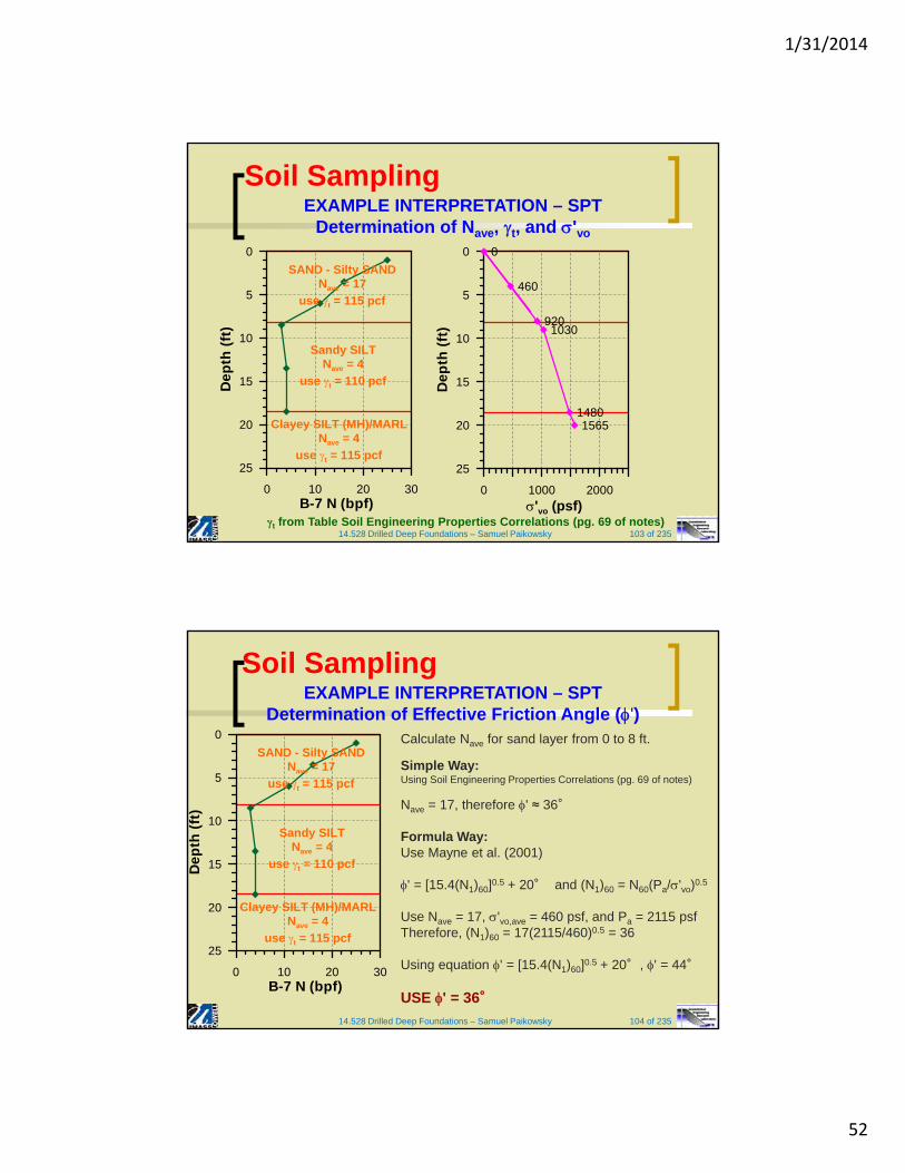
EXAMPLE INTERPRETATION –
SPT Given Data
Provided:- Soil Stratigraphy- USCS Classification- Groundwater Table(@ Time of Testing)
- SPT N Values(No Energy Measurements)
- Drilling Method (HSA)- Date Started/Ended
Soil Sampling
1/31/2014
52
14.528 Drilled Deep Foundations – Samuel Paikowsky 103 of 235t from Table Soil Engineering Properties Correlations (pg. 69 of notes)
EXAMPLE INTERPRETATION – SPTDetermination of Nave, t, and 'vo
Soil Sampling
0 10 20 30B-7 N (bpf)
25
20
15
10
5
0
De
pth
(ft
)
SAND - Silty SANDNave = 17
use t = 115 pcf
Sandy SILTNave = 4
use t = 110 pcf
Clayey SILT (MH)/MARLNave = 4
use t = 115 pcf
0 1000 2000'vo (psf)
25
20
15
10
5
0
De
pth
(ft
)
0
460
9201030
14801565
14.528 Drilled Deep Foundations – Samuel Paikowsky 104 of 235
Calculate Nave for sand layer from 0 to 8 ft.
Simple Way:Using Soil Engineering Properties Correlations (pg. 69 of notes)
Nave = 17, therefore ' ≈ 36°
Formula Way:Use Mayne et al. (2001)
' = [15.4(N1)60]0.5 + 20° and (N1)60 = N60(Pa/'vo)0.5
Use Nave = 17, 'vo,ave = 460 psf, and Pa = 2115 psfTherefore, (N1)60 = 17(2115/460)0.5 = 36
Using equation ' = [15.4(N1)60]0.5 + 20°, ' = 44°
USE ' = 36°
EXAMPLE INTERPRETATION – SPTDetermination of Effective Friction Angle (')
0 10 20 30B-7 N (bpf)
25
20
15
10
5
0
De
pth
(ft
)
SAND - Silty SANDNave = 17
use t = 115 pcf
Sandy SILTNave = 4
use t = 110 pcf
Clayey SILT (MH)/MARLNave = 4
use t = 115 pcf
Soil Sampling
1/31/2014
53
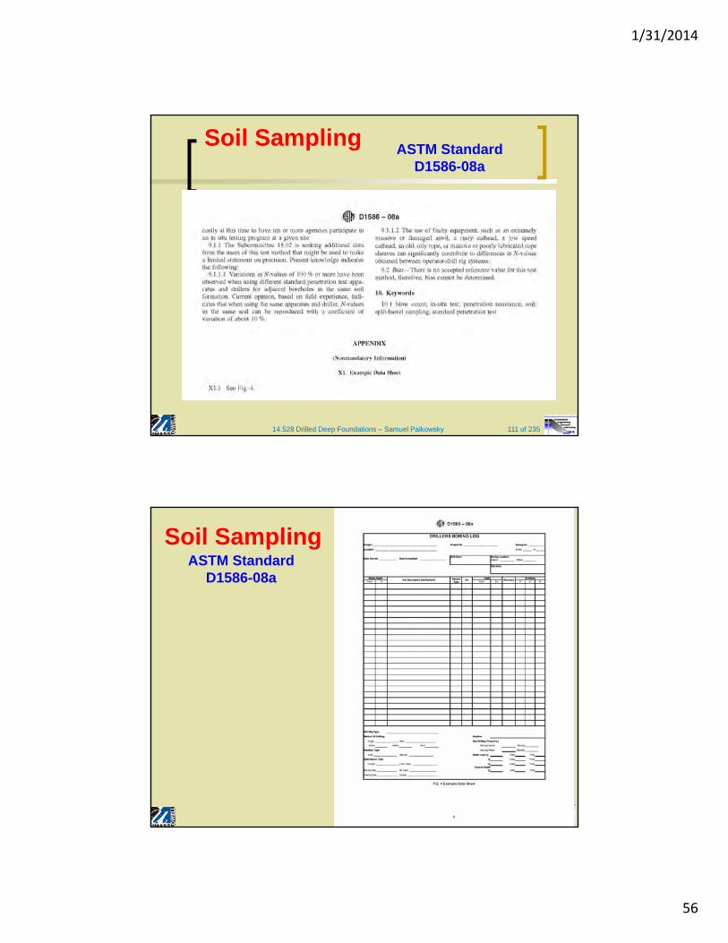
Soil SamplingASTM Standard
D1586-08a
Soil SamplingASTM Standard
D1586-08a

1/31/2014
54
Soil SamplingASTM Standard
D1586-08a
Soil SamplingASTM Standard
D1586-08a

1/31/2014
55
Soil SamplingASTM Standard
D1586-08a
Soil SamplingASTM Standard
D1586-08a
1/31/2014
56
14.528 Drilled Deep Foundations – Samuel Paikowsky 111 of 235
Soil SamplingASTM Standard
D1586-08a
Soil SamplingASTM Standard
D1586-08a

1/31/2014
57
14.528 Drilled Deep Foundations – Samuel Paikowsky 113 of 235
Soil Sampling ASTM StandardD1586-08a
Soil SamplingASCE Journal of
Geotechnical EngineeringVol. 112, No. 3
March 1986

1/31/2014
58
Soil SamplingASCE Journal of
Geotechnical EngineeringVol. 112, No. 3
March 1986
Soil SamplingASCE Journal of
Geotechnical EngineeringVol. 112, No. 3
March 1986

1/31/2014
59
Soil SamplingASCE Journal of
Geotechnical EngineeringVol. 112, No. 3
March 1986
Soil SamplingASCE Journal of
Geotechnical EngineeringVol. 112, No. 3
March 1986

1/31/2014
60
14.528 Drilled Deep Foundations – Samuel Paikowsky 119 of 235
Soil Sampling
Split-Spoon Disturbed Sampling
Thin walled Tubes –Undisturbed Sampling (ASTM D1587)
Text & Photographs courtesy of FHWA NHI Course 132031 Subsurface Investigations
Split Spoon Sampler
Thin Wall Samplers
14.528 Drilled Deep Foundations – Samuel Paikowsky 120 of 235
Soil SamplingShelby Tubes
Using a thin walled tubes (O.D. = 2in.) which is pushed into the soil under the bottom of the borehole in order to retrieve a sample mainly for laboratory tests.The sampling can be performed by a direct connection to the drill rods or using a piston sampler.
(i) Piston closes the end of the sampler while it is lowered to the bottom of the borehole.
(ii) The sampler is pushed hydraulically(iii) The pressure is released through a hole in the piston rod(iv) The assembly is pulled upwards.

1/31/2014
61
14.528 Drilled Deep Foundations – Samuel Paikowsky 121 of 235
Soil SamplingShelby Tubes
Figure 2.18 (continued), text pp.90 & 93, respectively
Soil SamplingASTM D 1587-08
Standard Practice for Thin-Walled Tube
Sampling of Soils for Geotechnical Purposes

1/31/2014
62
Soil SamplingASTM D 1587-08
Standard Practice for Thin-Walled Tube
Sampling of Soils for Geotechnical Purposes
Soil SamplingASTM D 1587-08
Standard Practice for Thin-Walled Tube
Sampling of Soils for Geotechnical Purposes

1/31/2014
63
Soil SamplingASTM D 1587-08
Standard Practice for Thin-Walled Tube
Sampling of Soils for Geotechnical Purposes
14.528 Drilled Deep Foundations – Samuel Paikowsky 126 of 235
INSITU TESTING METHODS
METHOD Abbrv. ASTM SAMPLING MAX. DEPTH (ft)
Dynamic Cone
PenetrometerDCP D6951-03
Yes(via HAB)
6 – 8 Typ.20 (w/difficulty)
Standard Penetration Test
SPT D1586-08a Yes > 300 ft(dependent on boring method)
Cone Penetration Test CPTD3441-05
D5778-07No > 300 ft
(typically 100 – 150 ft max)
Flat Plate Dilatometer DMT D6635-01 No > 300 ft(typically 100 – 150 ft max)
Pressuremeter PMT D4719-07Yes
(via boring)> 300 ft
(dependent on boring)
Vane Shear Test VST D2573-08Yes
(via Boring)> 300 ft
(dependent on boring)
Green – Near Surface : Red – Near and Deep
Soil Sampling

1/31/2014
64
14.528 Drilled Deep Foundations – Samuel Paikowsky 127 of 235
INSITU TESTING METHODS
Figure courtesy of FHWA NHI Course 132031Subsurface Investigations
Soil Sampling
14.528 Drilled Deep Foundations – Samuel Paikowsky 128 of 235
Soil Sampling
Vane Shear Test (VST) (ASTM D2573-08)
General
Vane shear test (ASTM D 2573-01) is a useful method to estimate the undrained shear strength of cohesive - soft soils, especially where much of the strength may be lost by disturbance during sampling.
not good in stiff clays or soft soils containing gravel, shells etc.

1/31/2014
65
14.528 Drilled Deep Foundations – Samuel Paikowsky 129 of 235
Soil Sampling
Performed at bottom of boring or by direct push placement of device
Four-sided blade pushed into clays and silts to measure following:
suv (peak) = Peak UndrainedStrength
suv (remolded) = Remolded Strength (after 10 revolutions)
Sensitivity, St = suv(peak)/suv
(remolded)
VANE SHEAR TEST (VST) (ASTM D2573-08)
Scandinavian Vanes
Pictures and text courtesy of FHWA NHI Course 132031 Subsurface Investigations
14.528 Drilled Deep Foundations – Samuel Paikowsky 130 of 235
Soil Sampling
Procedure
Placing a four-bladed vane in the undisturbed soil (under the bottom of the borehole) and rotating it from the surface to determine the (peak) torsional force (through torque) required to cause a cylindrical surface to be sheared by the vane. This force is then converted to a unit shearing resistance of the cylindrical surface. The test continues to measure the strength of the remolded material by measuring the resistance to the rotation after the vane is rotated rapidly through a minimum of 10 revolutions.
VANE SHEAR TEST (VST) (ASTM D2573-08)

1/31/2014
66
Soil Sampling
14.528 Drilled Deep Foundations – Samuel Paikowsky
Casing(OD) D(in) Blade thick Rod(in)
AX (17/8) 1.5 1/16 1/2BX (23/8) 2.0 1/16 1/2NX (215/16) 2.5 1/8 1/2
Vane Dimensions1.5 D 4 inch1 D H 2.5 D
VANE SHEAR TEST (VST) (ASTM D2573-08)
14.528 Drilled Deep Foundations – Samuel Paikowsky 132 of 235
VANE SHEAR TEST (VST) (ASTM D2573-08)
Figure courtesy of FHWA NHI Course 132031 Subsurface Investigations
Soil Sampling

1/31/2014
67
14.528 Drilled Deep Foundations – Samuel Paikowsky 133 of 235
Dutch Vane Equipment, Holland VST in Upstate NY
VANE SHEAR TEST (VST) (ASTM D2573-08)Vane Shear Devices
Pictures courtesy of FHWA NHI Course 132031 Subsurface Investigations
Soil Sampling
14.528 Drilled Deep Foundations – Samuel Paikowsky 134 of 235
Soil Sampling
Analysis
Obtaining the consolidated (in-situ) undrained shear strength
Suv: u=undrained, v=vane
T=SuvAR
T - TorqueSuv - shear strengthA- area of shear applicationR - arm of force
peak
Torque
residual
20 Movement(rotation in radians)
H = 2D
T
D/2
VANE SHEAR TEST (VST) (ASTM D2573-08)

1/31/2014
68
14.528 Drilled Deep Foundations – Samuel Paikowsky 135 of 235
Soil Sampling
Analysis (cont’d.)
for the circumferential shearing area:A = DH R = D/2 AR = (D2H/2)
for the top and bottom shearing area:
A = D2/4 R = D 1/3(2) = (2/3)D
AR = (D3 /4)(2/3)⅔D x ½
⅔D x ½
VANE SHEAR TEST (VST) (ASTM D2573-08)
14.528 Drilled Deep Foundations – Samuel Paikowsky 136 of 235
Soil Sampling
Analysis (cont’d.)
Combining all shearing areas, leads to:
T = SuvAR = Suv [(D2H/2) + D3 /4 (2/3)]
For the standard case in which H = 2D and square end shear, the above equation becomes:
Suv = 6T/(7D3) = 0.2728T/D3
The general assumption is that vane test results are too high and require a correction. The reason can be the influence of the rate of shear, various frictional losses such that the measured torque is higher than the one actually performing the work and other assumptions in the above relations (e.g. stress distribution at the blade).
Suvcorrected = Suv
VANE SHEAR TEST (VST) (ASTM D2573-08)

1/31/2014
69
14.528 Drilled Deep Foundations – Samuel Paikowsky 137 of 235
Soil Sampling
Analysis (cont’d.)
see equations and figure below based on Bjerrum (1972)(equation 2.35, p. 97)
Bjerrum (1972):1.7 0.54 %
Morris & Williams (1994):1.18 . 0.57 (for PI>5)
7.01 . 0.57 (where LL is in %)
Aas et al. (1986):
see figureVariation of with cu(VST)/0
VANE SHEAR TEST (VST) (ASTM D2573-08)
14.528 Drilled Deep Foundations – Samuel Paikowsky 138 of 235
Soil Sampling
Estimation of OCR based on VST
Based on Mayne and Mitchell (1988) [see text p. 97]
pc = 7.04 (Sufield)0.83 OCR =
pc = maximum past pressure [kPa]
Sufield = uncorrected field vane value [kPa] (=Cufield)
(eq. 2.37)
= 22 (PI)-0.48
VANE SHEAR TEST (VST) (ASTM D2573-08)

1/31/2014
70
14.528 Drilled Deep Foundations – Samuel Paikowsky 139 of 235
Soil Sampling
Estimation of OCR based on VST (cont’d.)
Variation of with plasticity index
(after Mayne and Mitchell, 1988)
See other correlations for (equations 2.39, 2.40)
VANE SHEAR TEST (VST) (ASTM D2573-08)
Soil Sampling
14.528 Drilled Deep Foundations – Samuel Paikowsky
VANE SHEAR TEST (VST) (ASTM D2573-08)

1/31/2014
71
14.528 Drilled Deep Foundations – Samuel Paikowsky 141 of 235
0
5
10
15
20
25
30
0 10 20 30 40 50 60 70 80
Vane Strength, suv (kPa)D
epth
(m
eter
s)
Peak
Remolded
0
5
10
15
20
25
30
0 1 2 3 4 5
Sensitivity, St
Dep
th (
met
ers)
VANE SHEAR TEST (VST) (ASTM D2573-08)Results - San Francisco Bay Mud, MUNI Metro Station
VST Results courtesy of FHWA NHI Course 132031 Subsurface Investigations
Soil Sampling
14.528 Drilled Deep Foundations – Samuel Paikowsky 142 of 235
VANE SHEAR TEST (VST) (ASTM D2573-08)
VST Results courtesy of FHWA NHI Course 132031 Subsurface Investigations
Soil Sampling
Fig. 2.9 (a) Undisturbed and (b) thoroughly remolded sample of Leda clay from Ottawa, Ontario. (Photograph courtesy of the Division of Building Research National Research Council of Canada. Hand by D.C. MacMilan)
Table 11-7 Typical Values of Sensitivity
(figure and table from: Holtz, RD, and Kovacs, WD (1981) An Introduction to Geotechnical Engineering, Prentice-Hall, New Jersey)
ConditionRange of St
U.S. SwedenLow sensitive 2 – 4 < 10Med. sensitive 4 – 8 10 – 30Highly sensitive 8 – 16 > 30Quick 16 > 50Extra quick - > 100Greased lightening -

1/31/2014
72
14.528 Drilled Deep Foundations – Samuel Paikowsky 143 of 235
• Electronic Steel Probes with 60° Apex Tip• Hydraulic Push at 20 mm/s• No Boring, No Samples, No Cuttings, No
Spoil• Continuous readings of stress, friction,
pressure• With Pore Pressure Measurements (CPTu)• With Shear Wave Measurements (SCPT)
CONE PENETRATION TEST (CPT) (ASTM D5778-07)
Text and Figures courtesy of FHWA NHI Course 132031 Subsurface Investigations
Soil Sampling
14.528 Drilled Deep Foundations – Samuel Paikowsky 144 of 235
CONE PENETRATION TEST (CPT) RIGS
Figures courtesy of FHWA NHI Course 132031 Subsurface Investigations & WPC Engineering Inc.
Soil Sampling

1/31/2014
73
14.528 Drilled Deep Foundations – Samuel Paikowsky 145 of 235
CONE PENETRATIONTESTING (CPT)
Factors Affecting CPT ResultsFigure 9-2. FHWA NHI Course 132031 Subsurface Investigations
qc
Vs
U2
fs
Soil Sampling
14.528 Drilled Deep Foundations – Samuel Paikowsky 146 of 235
Soil SamplingCPT – Cone Penetration Test
General (ASTM D-3441-01) Deep, Quasi-Static, Cone and Friction-Cone
Penetration Tests of Soils.
The CPT is an in-situ, sounding method in which a cone (usually 60o
and 10 cm2 base area) is pushed into the ground at a rate of approximately 10 to 20 mm/sec and the resistance to penetration is measured.
Useful in soft clays and fine to medium coarse sands. It encountered difficulties in stiff/hard, cemented or highly over-consolidated soils.
Advantage - obtaining considerable information in a short time.
Disadvantage - non-recoverability of samples and the above difficulties.

1/31/2014
74
14.528 Drilled Deep Foundations – Samuel Paikowsky 147 of 235
Soil SamplingCPT – Cone Penetration Test
Figure 2.24 Electric Friction-cone penetrometer (after ASTM, 2001)
14.528 Drilled Deep Foundations – Samuel Paikowsky 148 of 235
Soil SamplingCONE PENETRATION TEST (CPT) (ASTM D5778-07)
Figures courtesy of FHWA NHI Course 132031 Subsurface Investigations
Shear Wave Velocity (Vs)
qc
Vs
u2
fs
Penetration Porewater Pressure (U2)
Sleeve Friction (fs)
Cone Tip Resistance (qc)

1/31/2014
75
14.528 Drilled Deep Foundations – Samuel Paikowsky 149 of 235
Corrections to CPT Measurements (with U2)
Need to correct tip resistance (qc) for pore
pressure @ U2 location.
qc → qt
U2 = Ub
Pore PressureMeasurement behind Tip
Porous Element for U2
Materials: Sintered Metals, Ceramics, Plastics (disposable)Saturation of Porous Elements: Water, Glycerine, SiliconeProcedures: Vacuum for 24-hours, Pre-Saturated Elements, Prophylactic to maintain fluids
Courtesy of FHWA IF-02-034
Soil Sampling
14.528 Drilled Deep Foundations – Samuel Paikowsky 150 of 235
Soil SamplingCPT – Cone Penetration Test
Obtained Data cone-tip resistance qc
sleeve friction resistance fs
piezocone allows pore pressure readings, usually at the tip (u1) also possible at the base (u2) and above friction sleeve (u3).
fR = FR = Friction ratio = fs /qc x 100%
u1
u3
u2

1/31/2014
76
14.528 Drilled Deep Foundations – Samuel Paikowsky 151 of 235
Soil Sampling CPT – Cone Penetration Test
14.528 Drilled Deep Foundations – Samuel Paikowsky 152 of 235
Soil Sampling
0 100 200
qt [tsf]
0
4
8
12
16
20
24
28
32
36
40
44
48
52
56
60
64
68Dep
th [ft]
6.89
0 1 2
fs [tsf ]
0 2 4 6
u2 [tsf]
Uo [tsf]
0 2 4 6
Rf [%]
U2
Sleeve area [cm2]: 150
Tip area [cm2]: 10
Cone No: 3318
Te st no:
B-06Client:
Pro ject: Project in Savannah, GA
SAV2-02-000
Position:X: 1019956.90 m, Y: 759139.79 m
Ground level:10.43
Date:2/11/2002
Scale:
Page: 1
Fig :
File : sav2-02-010sc6.cpd
Very stiff fine grained (9)
C layey silt to silty clay (4)
C lays, clay to silty clay (3)
C layey silt to silty clay (4)
Silty sand to sandy silt (5)
Silty sand to sandy silt (5)C lays, clay to silty clay (3)
C lays, clay to silty clay (3)
Silty sand to sandy silt (5)
C layey silt to silty clay (4)C lays, clay to silty clay (3)
Silty sand to sandy silt (5)
C lean sands to silty sands (6)
Silty sand to sandy silt (5)
C lays, clay to silty clay (3)
C layey silt to silty clay (4)
CONE PENETRATION TESTING (CPT) RESULTS
qc fsuo, u2 FRSoil Profile
CPT Results courtesy of Dr. Edward Hajduk and WPC Engineering Inc.

1/31/2014
77
14.528 Drilled Deep Foundations – Samuel Paikowsky 153 of 235
Soil SamplingCPT – Cone Penetration Test
Data Interpretation
Use of data can be applied directly in design using the similarity between the cone and a pile or with correlation to soil parameters
Soil Identification
A major drawback of the cone is the inability of obtaining actual soil sample. As such correlation based on the relationship between the friction ratio and soil type has been developed. Soil identification becomes easier with the piezocone which uses pore water pressure besides the friction ratio.
14.528 Drilled Deep Foundations – Samuel Paikowsky 154 of 235
Soil SamplingCPT – Cone Penetration Test
Soil classification chart for standard electric cone. Use with caution and/or together with recovered tube samples [After Robertson and Campanella(1983)], see Figure 2.31, p. 106.

1/31/2014
78
14.528 Drilled Deep Foundations – Samuel Paikowsky 155 of 235
CONE PENETRATION TEST (CPT)DETERMINATION OF SOIL STRATIGRAPHY
CPT Soil Behavior Classification (Based on qt, FR or Bq)Figure 9-3. FHWA NHI Course 132031 Subsurface Investigations
Soil Sampling
14.528 Drilled Deep Foundations – Samuel Paikowsky 156 of 235
CONE PENETRATION TEST (CPT)DETERMINATION OF SOIL STRATIGRAPHY
Soil Sampling

1/31/2014
79
14.528 Drilled Deep Foundations – Samuel Paikowsky 157 of 235
qt (tsf) fs (tsf) Uo, U2 (tsf) FRSoil Profile
EXAMPLE INTERPRETATION – CPT Given Data
Dep
th (
ft)
Soil Sampling
14.528 Drilled Deep Foundations – Samuel Paikowsky 158 of 235
qt (tsf) fs (tsf) Uo, U2 (tsf) FRSoil Profile
EXAMPLE INTERPRETATION – CPT Soil Layers
7ft
Dep
th (
ft)
17ft
GWT @ 9ft
SAND
SANDY SILT
SILTY CLAY(MARL)
Soil Sampling

1/31/2014
80
14.528 Drilled Deep Foundations – Samuel Paikowsky 159 of 235
Soil SamplingCPT – Cone Penetration Test
Cohesive Soils
Cone bearing resistance qc correlated to undrained shear strength Su = Cu. Using ultimate bearing strength as for foundation - pile tip in clay.
qc = qp + vo
qc = cone-tip resistanceqp = point resistancevo = total vertical pressure in the soil at tip elevation
qp = CuNc or Su Nk
in which Nc = Nk = Bearing Capacity Factor or Cone Factor in this case.qc = SuNk + vo
qc = CuNc + vo Cu = (eq. 2.51, p. 105)
14.528 Drilled Deep Foundations – Samuel Paikowsky 160 of 235
Soil SamplingCPT – Cone Penetration Test
Cohesive Soils (cont’d.)
Analogous to Poulus et al. (2003)Nk= 17.2 (electronic cone), Nk= 18.9 (mechanical cone)
Nk = Nc = 10 20 use Nc = 14.5 + 30%
(Nk is based on Pent. Testing. Proc. Of 2nd European Symp. On Penet. Testing /ESPOT II. Amsterdam. 1982).
Using Mayne and Kemper (1988) (see eq. 2.55, p.107)
OCR = 0.37.

1/31/2014
81
14.528 Drilled Deep Foundations – Samuel Paikowsky 161 of 235
Soil Sampling CPT – Cone Penetration Test
Granular Soils(text pp. 102-105)
DR = f (qc, v, A, B)
Use equation 2.44 with A = -98, B = 66
Use Figure below for DR = f (qc, v)
See alternatively Figure 2.29 for v, qc and DR
correlations based on Baldi et al., 1982, and Robertson & Campanella, 1983
14.528 Drilled Deep Foundations – Samuel Paikowsky 162 of 235
Soil Sampling CPT – Cone Penetration Test
Granular Soils (cont’d.)
Internal Friction Angle from CPT Kalhawy and Mayne (1990) based
on Robertson and Campanella(1985)
0
1 log38.01.0tan
cq
(eq. 2.47, see figure)
Variation of qc with ′0 and ′ in normally consolidated quartz sand (after Robertson and Campanella, 1983).

1/31/2014
82
14.528 Drilled Deep Foundations – Samuel Paikowsky 163 of 235
EXAMPLE INTERPRETATION – CPTDetermination of qt,ave, t, and 'vo
Soil Sampling
0 100 200 300C-7 qt (tsf)
25
20
15
10
5
0
De
pth
(ft
)
SAND - Silty SANDqt,ave 125 tsf
use t = 115 pcf
Sandy SILTqt,ave 22 tsf
use t = 110 pcf
Silty CLAY - CLAYqt,ave 26 tsf
use t = 115 pcf
t from Table Soil Engineering Properties Correlations (pg. 69 of notes)
0 1000 2000'vo (psf)
25
20
15
10
5
0
De
pth
(ft
)
0
460
9201030
14801565
14.528 Drilled Deep Foundations – Samuel Paikowsky 164 of 235
EXAMPLE INTERPRETATION – CPTDetermination of Effective Friction Angle (')
Calculate qt,ave for sand layer from 0 to 7 ft
Simple Way:Using Table Soil Engineering Properties Correlations (pg. 69 of notes)
qt,ave ≈ 125 tsf ≈ 12 MPatherefore ' ≈ 37°
Formula Way:Using Robertson and Campanella (1983) formula.
' = arctan[0.1+0.38log(qt/ 'vo)]
Use qt,ave ≈ 12 MPa (250000 psf) & 'vo,ave = 405 psf for layer.Using equation, ' = 49°
USE ' ≈ 37°
0 100 200 300C-7 qt (tsf)
25
20
15
10
5
0
De
pth
(ft
)
SAND - Silty SANDqt,ave 125 tsf
use t = 115 pcf
Sandy SILTqt,ave 22 tsf
use t = 110 pcf
Silty CLAY - CLAYqt,ave 26 tsf
use t = 115 pcf
Soil Sampling

1/31/2014
83
14.528 Drilled Deep Foundations – Samuel Paikowsky 165 of 235
EXAMPLE INTERPRETATION – CPTDetermination of Undrained Shear Strength (Su)
Calculate qt,ave for Sandy Silt from 7 to 17 ftCalculate qt,ave for Silty Clay from 17 to 24 ft
Formula Way:use Aas et al. (1986)
Su = (qt-vo)/Nkt
Nkt = 15 for CHS (Lecture Slides)
Sandy SILT LayerUse qt,ave ≈ 22 tsf & vo,ave = 1355 psfSu = 2850 psf
Silty CLAY LayerUse qt,ave ≈ 26 tsf & vo,ave = 2310 psfSu = 3300 psf
0 100 200 300C-7 qt (tsf)
25
20
15
10
5
0
De
pth
(ft
)
SAND - Silty SANDqt,ave 125 tsf
use t = 115 pcf
Sandy SILTqt,ave 22 tsf
use t = 110 pcf
Silty CLAY - CLAYqt,ave 26 tsf
use t = 115 pcf
Soil Sampling
14.528 Drilled Deep Foundations – Samuel Paikowsky 166 of 235
Soil Sampling CPT – Cone Penetration Test
Correlation between SPT to qc This relation is Important as many correlations exist between N SPT and
different soil parameters and they can be utilized with the transformation from qc to N
Figure 2.30 General range of variation of qc/N60 for various types of soil (after Robertson
and Campanella, 1983)

1/31/2014
84
14.528 Drilled Deep Foundations – Samuel Paikowsky 167 of 235
Soil Sampling
CPT – Cone Penetration Test
Correlation between SPT to qc (cont’d.)
Eq. 2.50
D50 (mm); qc same units as pa
26.050
60
6429.7 DN
pq
a
c
14.528 Drilled Deep Foundations – Samuel Paikowsky 168 of 235
EXAMPLE INTERPRETATION – SPT & CPTComparison of Soil Engineering Properties
SPT CPT
Two Tests ~ 15 ft Apart
Methodt
(pcf)
'
()
SPT - Table Soil Engineering Properties Correlations (pg. 69 of
notes)
115 36
SPT - Formula NA 44
CPT - Table Soil Engineering Properties Correlations (pg. 69 of
notes)
115 37
CPT - Formula NA 49
Sand Layer Properties
0 100 200 300C-7 qt (tsf)
25
20
15
10
5
0
De
pth
(ft
)
SAND - Silty SANDqt,ave 125 tsf
use t = 115 pcf
Sandy SILTqt,ave 22 tsf
use t = 110 pcf
Silty CLAY - CLAYqt,ave 26 tsf
use t = 115 pcf
0 10 20 30B-7 N (bpf)
25
20
15
10
5
0
De
pth
(ft
)
SAND - Silty SANDNave = 17
use t = 115 pcf
Sandy SILTNave = 4
use t = 110 pcf
Clayey SILT (MH)/MARLNave = 4
use t = 115 pcf
Soil Sampling

1/31/2014
85
14.528 Drilled Deep Foundations – Samuel Paikowsky 169 of 235
ROCK EXPLORATION
Geophysical Methods
Geologic Mapping (need qualified geologists)
Drilling and Coring
Exploration Test Pits UML Health and Social Sciences
BuildingLowell, MA
June 14, 2011(picture courtesy of Dr. Edward Hajduk)
Soil Sampling
14.528 Drilled Deep Foundations – Samuel Paikowsky 170 of 235
ROCK EXPLORATIONDrilling and Coring
Rock Coring (see text section 2.24)
● Rock cores are necessary to establish the soundness of the rock. ● Using a coring bit at the bottom of the core barrel. Water is used for
washing the rock dust out and cooling the drilling.
● STB Refusal
– Auger refusal
– SPT refusal (> 50 blows per 1 inch penetration)
• Coring (ASTM D2113)
• Noncore Drilling
• Percussive Methods
ASTM D2113-08 Standard Practice for Rock Core Drilling and Sampling of Rock for Site Investigation
Soil Sampling

1/31/2014
86
14.528 Drilled Deep Foundations – Samuel Paikowsky 171 of 235
ROCK EXPLORATIONDrilling – Rotary Wash
Tricone, Roller,Plug Bits
Roller BitsDrill Rig
Figures courtesy of FHWA NHI Course 132031 Subsurface Investigations
Soil Sampling
14.528 Drilled Deep Foundations – Samuel Paikowsky 172 of 235
ROCK EXPLORATIONCoring
● Diamond Bits. Best and hardest, producing high quality core. Fastest cutting rates. Expensive.
● Synthetic Bits. Less expensive. Generally good quality cores.
● Tungsten Carbide Bits. Least expensive. Slower coring rates.
Photograph courtesy of www.ackerdrill.com
Carbide Type Bits
Diamond, Carbide Tungsten, SawtoothDiamond
Soil Sampling

1/31/2014
87
14.528 Drilled Deep Foundations – Samuel Paikowsky 173 of 235
Most rugged, least expensive.
Consists of head section, core recovery tube, reamer shell, & cutting bit.
Often used as starter when beginning core operations
ROCK EXPLORATIONCoring – Single Tube Core
Text & Figures courtesy of FHWA NHI Course 132031 Subsurface Investigations
Soil Sampling
14.528 Drilled Deep Foundations – Samuel Paikowsky 174 of 235
Soil SamplingRock Coring (cont’d.)
Double tube core barrel and core bit greater than AWT (core>1 1/8″) reduces the breakage inside the drill barrel (too large is not good either).
Using recovery ratio and RQD as measures of quality (see eqs. 2.70, 2.71 on p. 117). Using unconfined and high-pressure triaxial tests on the recovered samples (note: provides strength and deformation of the sound rock only, not the rock mass).
Recovery Ratio = Length of rock recoveredTheoretical length of rock recovered

1/31/2014
88
Soil SamplingRock Coring (cont’d.)
14.528 Drilled Deep Foundations – Samuel Paikowsky
RQD = Rock Quality Designation = L of recovered pieces 4" sizeTheoretical length of rock cored
Figure 2.38 Rock coring: (a) single-tube core barrel; (b) double-tube core barrel
14.528 Drilled Deep Foundations – Samuel Paikowsky 176 of 235
Double tube core barrel is the standard.
Outer barrel rotates with cutting bit.
Inner barrel is either fixed or swivel type (with bearings) that retains core sample.
Core diameters generally range from 21 to 85 mm (0.85 to 3.35 inch).
NX core: standard diameter = 54 mm (2.15 inches).
ASTM C42: The diameter of cores for determining f’c in load bearing structural members shall be at least 3.70 in.
ROCK EXPLORATIONCoring – Double Tube Core
Text & Figures courtesy of FHWA NHI Course 132031 Subsurface Investigations
Outer Barrel Assembly
Inner Barrel Assembly
Soil Sampling

1/31/2014
89
14.528 Drilled Deep Foundations – Samuel Paikowsky 177 of 235
Good for obtaining core samples in fractured rock and highly weathered rocks.
Outer core barrel for initial cut and second barrel to cut finer size. Third barrel to retain cored samples.
Reduces frictional heat that may damage samples.
ROCK EXPLORATIONCoring – Triple Tube Core
Text & Figures courtesy of FHWA NHI Course 132031 Subsurface Investigations
Soil Sampling
14.528 Drilled Deep Foundations – Samuel Paikowsky 178 of 235
Text & Figures courtesy of FHWA NHI Course 132031 Subsurface Investigations
• Rotary wash with water, foam, or drilling mud (bentonitic or polymeric slurries).
• Fluids reduce wear on drilling and coring bits by cooling.
• Fluids remove cuttings & rock flour.
• Re-circulate to filter fluids and to minimize impact on environment
ROCK EXPLORATIONCoring – Drilling Fluids Notes
Soil Sampling

1/31/2014
90
14.528 Drilled Deep Foundations – Samuel Paikowsky 179 of 235
Text & Figures courtesy of FHWA NHI Course 132031 Subsurface Investigations
• Stabilizes boreholes
• Driven casing
• Drilled-in casing
• Dual wall reverse circulation method
• Use in areas with expected large losses in drilling fluid
• Inner section for sampling
• Outer casing maintains fluids for drilling
ROCK EXPLORATIONCoring – Casing
Drilled-In Dual Wall
Soil Sampling
14.528 Drilled Deep Foundations – Samuel Paikowsky 180 of 235
Figures courtesy of FHWA NHI Course 132031 Subsurface Investigations
ROCK EXPLORATIONCore Recovery
• Core Runs taken in either 5- or 10-foot sections.
• Log the amount of material recovered.
• Core Recovery is percentage retained.
• RQD (Rock Quality Designation) is a modified core recovery.
• ASTM D5079 Standard Practice for Preserving and Transporting Rock Core Samples
Soil Sampling

1/31/2014
91
14.528 Drilled Deep Foundations – Samuel Paikowsky 181 of 235
Text & Figures courtesy of FHWA NHI Course 132031 Subsurface Investigations
ROCK EXPLORATION
Core Recovery
• Cores should be stored in either wooden boxes or corrugated cardboard box.
• Box marked with boring number, depth of core run, type core, bit type, core recovery (CR), rock type, RQD, and other notes.
• Core operations should be documented:
• Loss of fluid
• Drilling rates
• Sudden drop in rods
• Poor recovery
• Loss of core
Soil Sampling
14.528 Drilled Deep Foundations – Samuel Paikowsky 182 of 235Text & Figures courtesy of FHWA NHI Course 132031 Subsurface Investigations
ROCK EXPLORATIONCore Recovery
• The RQD is a modified core recovery.
• Measure of the degree of fractures, joints, and discontinuities of rock mass
• RQD = sum of pieces > 100 mm (4 inches) divided by total core run.
• Generally performed on NX-size core.
Soil Sampling
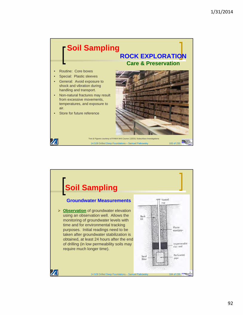
1/31/2014
92
14.528 Drilled Deep Foundations – Samuel Paikowsky 183 of 235
Text & Figures courtesy of FHWA NHI Course 132031 Subsurface Investigations
ROCK EXPLORATIONCare & Preservation
• Routine: Core boxes
• Special: Plastic sleeves
• General: Avoid exposure to shock and vibration during handling and transport.
• Non-natural fractures may result from excessive movements, temperatures, and exposure to air.
• Store for future reference
Soil Sampling
14.528 Drilled Deep Foundations – Samuel Paikowsky 184 of 235
Soil Sampling
Groundwater Measurements
Observation of groundwater elevation using an observation well. Allows the monitoring of groundwater levels with time and for environmental tracking purposes. Initial readings need to be taken after groundwater stabilization is obtained, at least 24 hours after the end of drilling (in low permeability soils may require much longer time).

1/31/2014
93
Soil Sampling
(Guide to Geotechnical Instrumentation, SLOPE INDICATOR, 2004)
14.528 Drilled Deep Foundations – Samuel Paikowsky
Piezometers
14.528 Drilled Deep Foundations – Samuel Paikowsky 186 of 235
Example of Vibrating Wire Piezometers
•Manufactured by Geokon, Inc.
Soil Sampling

1/31/2014
94
14.528 Drilled Deep Foundations – Samuel Paikowsky 187 of 235
Soil SamplingGroundwater Measurements
(cont’d.) Local Water Pressure can be
measured utilizing a piezometer. Such readings are necessary in low permeability soils, which exhibit variation of pressure with time, e.g.: following pile driving, surcharge application (to establish the progress of consolidation) or for artesian or separated acquifers. Piezometer can be “pushed” into the ground as a self contained unit or installed in a borehole.
(Guide to Geotechnical Instrumentation, SLOPE INDICATOR, 2004)
14.528 Drilled Deep Foundations – Samuel Paikowsky
Soil Sampling
Piezometers

1/31/2014
95
14.528 Drilled Deep Foundations – Samuel Paikowsky 189 of 235
Soil SamplingGeophysical Explorations
Wave Types: Three major wave types propagate through the soil upon impact or vibration;
Rayleigh Waves = surface WavesP-waves = pressure or plane waveS-waves = shear waves
Being interested in waves propagating and reflecting from various soil layers, P-waves are the fastest penetrating waves, and therefore of interest.
14.528 Drilled Deep Foundations – Samuel Paikowsky 190 of 235
Soil SamplingGeophysical Explorations
Wave Types:Three major wave types propagate through the soil upon impact or vibration;
Rayleigh Waves = surface WavesP-waves = pressure or plane waveS-waves = shear waves
Being interested in waves propagating and reflecting from various soil layers, P-waves are the fastest penetrating waves, and therefore of interest.

1/31/2014
96
14.528 Drilled Deep Foundations – Samuel Paikowsky 191 of 235
Soil SamplingGeophysical Explorations
Wave Types: (cont’d)
Directionof Travel
DirectionOf Travel
Pressure Wave Shear WavesP S
14.528 Drilled Deep Foundations – Samuel Paikowsky 192 of 235
GEOPHYSICAL METHODS – MECHANICAL WAVES
Crosshole Tests (CHT)(FHWA NHI-01-031 Figurer 5-25)
Seismic Refraction (SR)(courtesy of www.enviroscan.com)
Also Available:Downhole Tests (DHT)Spectral Analysis of Surface Waves (SASW)
Soil Sampling

1/31/2014
97
14.528 Drilled Deep Foundations – Samuel Paikowsky 193 of 235
Soil SamplingGeophysical Explorations
Seismic Refraction survey:Section 2.26 (p. 118) describes the ability to identify the variation in the layers and the subsurface based on wave velocity and time measurements utilizing impact (point A) and geophones at the ground surface at known locations (B, C, D)
14.528 Drilled Deep Foundations – Samuel Paikowsky 194 of 235
Soil SamplingGeophysical Explorations
Seismic Refraction survey: (cont’d.)1. The first arrival at locations B, C, D is measured as t1, t2, t3, etc.
2. Plotting the time vs. the distance from the source enables to identify zones of different slopes reflecting the various velocities.
Slope of
Slope of
Slope of
1
1
vab
2
1
vbc
3
1
vcd
Here, v1, v2, v3,…, are the P-wave velocities in layers I, II, III, …, respectively
Figure 2.42 Seismic refraction survey

1/31/2014
98
14.528 Drilled Deep Foundations – Samuel Paikowsky 195 of 235
Soil SamplingGeophysical Explorations
Seismic Refraction survey: (cont’d.)3. Determine the Thickness of the top Layer:
(eq. 2.73, p.120)
The value of xc can be obtained from the plot, as shown in Figure 2.31b (p. 107).
4. Determine the Thickness of the Second Layer:
(eq. 2.74, p.120)
Here Ti2 is the time intercept of the line cd in Fig. 2.42b, (p.119) extended backwards.
cxvv
vvZ
12
121 2
1
22
23
23
13
21
23
122 22
1
vv
vv
vv
vvZTZ i
14.528 Drilled Deep Foundations – Samuel Paikowsky 196 of 235
Soil Sampling Geophysical Explorations
14.431 Foundation & Soil Engineering – Samuel Paikowsky
Seismic Refraction survey: (cont’d.)Findings:
The velocities of P waves in various layers indicate the types of soil or rock that are present below the ground surface. The range of the P-wave velocity that is generally encountered in different types of soil and rock at shallow depths is given in Table 2.12

1/31/2014
99
14.528 Drilled Deep Foundations – Samuel Paikowsky 197 of 235
Soil Sampling
Geophysical Explorations
Seismic Refraction survey: (cont’d.)
Applications and Limitations1. The survey enables to cover large areas in a short time at a
relatively low cost.
2. The conditions at the site need to be adequate, namely: relatively uniform, deep ground water surface, P-wave velocity v1<v2<v3…
3. In saturated soils/fractured rock the P-wave velocity often resumes that of water (1500m/s)
4. Verification with actual drilling is needed.
14.528 Drilled Deep Foundations – Samuel Paikowsky 198 of 235
Ground Penetrating Radar (GPR)(photographs courtesy of http://www.geomodel.com)
GEOPHYSICAL METHODS – ELECTROMAGNETIC WAVES
Electrical Resistivity (ER) Survey Results(FHWA NHI-01-031 Figurer 5-35)
Other Methods:Magnetometer Surveys (MS)Resistivity Piezocone (RCPTu)
Electromagnetic (EM) Survey(FHWA NHI-01-031 Figurer 5-35)
Soil Sampling

1/31/2014
100
14.528 Drilled Deep Foundations – Samuel Paikowsky 199 of 235
ADVANTAGES OF GEOPHYSICSNondestructive and/or non-invasive
Fast and economical testing Theoretical basis for interpretation
Applicable to soils and rocks
DISADVANTAGES OF GEOPHYSICSNo samples or direct physical penetration
Models assumed for interpretationAffected by cemented layers or inclusions.Results influenced by water, clay, & depth.
GEOPHYSICAL METHODS
GPR Results for UST(FHWA NHI-01-031 Figure 5-33)
MS Results for Oil Well Location(FHWA NHI-01-031 Figure 5-37)
Soil Sampling
14.528 Drilled Deep Foundations – Samuel Paikowsky 200 of 235
INSITU TESTING METHODS
Figure courtesy of FHWA NHI Course 132031Subsurface Investigations
Soil Sampling

1/31/2014
101
14.528 Drilled Deep Foundations – Samuel Paikowsky 201 of 235
INSITU TEST METHOD ADVANTAGES/DISADVANTAGES
Method Advantages Disadvantages
VST
• Assessment of undrained shear strength of clays.
• Simple test and equipment.
• Measure inplace sensitivity.
• Long history of use in practice, particularly embankments, foundations, & cuts.
• Limited to soft to stiff clays & silts with suv
< 200 kPa
• Slow & time-consuming
• Raw suv needs empirical correction
• Can be affected by sand seams and lenses
Soil Sampling
14.528 Drilled Deep Foundations – Samuel Paikowsky 202 of 235
Method Advantages Disadvantages
DCP• Quick
• Low cost
• Limited depth range
• Limited correlations of DCP values to soil properties.
SPT
• Obtain Sample + Number
• Simple & rugged device at low cost
• Suitable in many soil types
• Can perform in weak rocks
• Available throughout the U.S. and worldwide.
• Many correlations with soil engineering properties exist
• Obtain Sample + Number
• Disturbed sample (index tests only)
• Crude number for analysis
• Not applicable in soft clays and silts
• High variability and uncertainty
• Many correlations with soil engineering properties exist
Soil SamplingINSITU TEST METHOD
ADVANTAGES/DISADVANTAGES

1/31/2014
102
14.528 Drilled Deep Foundations – Samuel Paikowsky 203 of 235
Method Advantages Disadvantages
CPT
• Fast and continuous profiling of strata.
• Economical and productive.
• Results not operator-dependent.
• Strong theoretical basis for interpretation.
• Particularly suited to soft soils.
• High capital investment
• Requires skilled operator for field use.
• Electronics must be calibrated & protected.
• No soil samples.
• Unsuited to gravelly soils and cobbles.
DMT
• Simple and Robust Equipment.
• Repeatable and Operator-Independent.
• Quick and Economical.
• Theoretical Derivations for elastic modulus, strength, stress history.
• Difficult to push in dense and hard materials.
• Primarily established on correlative relationships.
•Needs calibration for local geologies.
Soil SamplingINSITU TEST METHOD
ADVANTAGES/DISADVANTAGES
14.528 Drilled Deep Foundations – Samuel Paikowsky 204 of 235
FLAT PLATE DILATOMETER (DMT) (ASTM D6635-01(2007))
Figure courtesy of FHWA NHI Course 132031 Subsurface Investigations
Soil Sampling

1/31/2014
103
14.528 Drilled Deep Foundations – Samuel Paikowsky 205 of 235
Calibrations: A, B (positive values)
Readings: contact pressure "A" and expansion pressure "B" with depth
Corrections for membrane stiffness in air: p0 = 1.05(A + A) - 0.05(B - B)
p1 = B -B
DMT INDICES:
• ID = material index = (p1-po)/(po-uo)
• ED = dilatometer modulus = 34.7(p1-po)
• KD = horizontal stress index
= (po-uo)/vo’
FLAT PLATE DILATOMETER (DMT) (ASTM D6635-01(2007))
• B
• A
Text courtesy of FHWA NHI Course 132031 Subsurface Investigations
Soil Sampling
14.528 Drilled Deep Foundations – Samuel Paikowsky 206 of 235
Marchetti Device (ASCE JGE, March 1980; ASTM Geot. Testing J., June 1986)
FLAT PLATE DILATOMETER (DMT) (ASTM D6635-01(2007))Manual Reading System (Standard)
Figures courtesy of FHWA NHI Course 132031 Subsurface Investigations
Soil Sampling

1/31/2014
104
14.528 Drilled Deep Foundations – Samuel Paikowsky 207 of 235
FLAT PLATE DILATOMETER (DMT) (ASTM D6635-01(2007))Computerized System (Standard)
Figure courtesy of FHWA NHI Course 132031 Subsurface Investigations
Soil Sampling
14.528 Drilled Deep Foundations – Samuel Paikowsky 208 of 235
00
01,up
ppIIndexMaterial D
p0
p1
0.1 1 10 Material Index (ID)
0.6 1.8
Clay Silt Sand
FLAT PLATE DILATOMETERDETERMINATION OF SUBSURFACE DATA
Courtesy of FHWA NHI Course 132031 Subsurface Investigations
Soil Sampling

1/31/2014
105
14.528 Drilled Deep Foundations – Samuel Paikowsky 209 of 235
FLAT PLATE DILATOMETERDETERMINATION OF SUBSURFACE DATA
Figure 43. FHWA IF-02-034
Soil Sampling
14.528 Drilled Deep Foundations – Samuel Paikowsky 210 of 235
FLAT PLATE DILATOMETER (DMT) (ASTM D6635-01(2007))Results – Charleston, SC Project
Soil BehaviorClassification
ED with Depth
Raw Data & Calibrations
DMT Results courtesy of Dr. Edward Hajduk and WPC Engineering Inc.
Soil Sampling

1/31/2014
106
14.528 Drilled Deep Foundations – Samuel Paikowsky 211 of 235
0
2
4
6
8
10
12
14
16
0 200 400 600 800
Modulus ED (atm)
0
2
4
6
8
10
12
14
16
0 500 1000 1500
Pressure (kPa)
Dep
th (
me
ters
)
PoP1
0
2
4
6
8
10
12
14
16
0 1 10
Material Index ID
Clay Silt
0
2
4
6
8
10
12
14
16
0 5 10 15
Horiz. Index KD
FLAT PLATE DILATOMETER (DMT) (ASTM D6635-01(2007))Results - Piedmont Residuum, Charlotte, NC
DMT Results courtesy of FHWA NHI Course 132031 Subsurface Investigations
Soil Sampling
14.528 Drilled Deep Foundations – Samuel Paikowsky 212 of 235
SPT-CPT-DMT COMPARISON
Also see Hajduk, E.L., Meng,J., Wright, W.B., and Zur, K.J.(2006). “ DilatometerExperience in the Charleston,South Carolina Region”, 2ndInternational Conference onthe Flat Dilatometer,Washington, D.C.
From Local Project in
Charleston, SC Area (2000)
Soil Sampling

1/31/2014
107
14.528 Drilled Deep Foundations – Samuel Paikowsky 213 of 235
PRESSUREMETER TEST (PMT) (ASTM D4719-07)
Figure courtesy of FHWA NHI Course 132031 Subsurface Investigations
Soil Sampling
14.528 Drilled Deep Foundations – Samuel Paikowsky 214 of 235
0
1
2
3
4
5
0 100 200 300 400 500 600
Volume Change (cc)
Pre
ssu
re (
tsf)
0
1
2
3
4
5
0 10 20 30 40 50
Creep (cc/min)
Pre
ssu
re (
tsf)
PRESSUREMETER (PMT) (ASTM D4719-07)Results – Utah DOT Project
PMT Results courtesy of FHWA NHI Course 132031 Subsurface Investigations
Soil Sampling

1/31/2014
108
NE SubsurfaceCombining NE Geology and
Subsurface Explorations
14.528 Drilled Deep Foundations – Samuel Paikowsky 216 of 235
Agenda
Rock Core Viewing (next lecture)
New England Surficial Geology Overview
Typical Soil Types
Typical Soil Stratigraphic Sequences
Examples of Applied Subsurface Evaluation

1/31/2014
109
14.528 Drilled Deep Foundations – Samuel Paikowsky 217 of 235
Rock Coring
14.528 Drilled Deep Foundations – Samuel Paikowsky 218 of 235
Rock Coring
RQD = Rock Quality Designation
RQD = Σpieces >10cm x 100Total Core run
RQD Rock mass quality <25% very poor 25-50% poor 50-75% fair 75-90% good 90-100% excellent

1/31/2014
110
14.528 Drilled Deep Foundations – Samuel Paikowsky 219 of 235
Direct Push – Soil Sampling
14.528 Drilled Deep Foundations – Samuel Paikowsky 220 of 235
More Direct Push –Soil Sampling

1/31/2014
111
14.528 Drilled Deep Foundations – Samuel Paikowsky 221 of 235
Sonic Drilling – Sample Recovery
14.528 Drilled Deep Foundations – Samuel Paikowsky 222 of 235
Soil Sampling
Split Spoon Sampler

1/31/2014
112
14.528 Drilled Deep Foundations – Samuel Paikowsky 223 of 235
Glacial Stratigraphy – Concord, MA
14.528 Drilled Deep Foundations – Samuel Paikowsky 224 of 235
Glacial Stratigraphy – Concord, MA (2)

1/31/2014
113
14.528 Drilled Deep Foundations – Samuel Paikowsky 225 of 235
Glacial Stratigraphy – Glastonbury, CT
14.528 Drilled Deep Foundations – Samuel Paikowsky 226 of 235
Glacial Stratigraphy – Everett, MA
226

1/31/2014
114
14.528 Drilled Deep Foundations – Samuel Paikowsky 227 of 235
center of mass
trajectoryclay lens?
• 2x longer than RDX plume • Plume shallows beyond FPR • Evidence of a hydraulically significant confining layer
Frank Perkins Rd.
Pew Rd.
current RDX extent
Glacial Stratigraphy- Cape Cod, the Mass Military Reservation
14.528 Drilled Deep Foundations – Samuel Paikowsky 228 of 235
Glacial Stratigraphy-Western MA

1/31/2014
115
14.528 Drilled Deep Foundations – Samuel Paikowsky 229 of 235
Glacial Stratigraphy - Maine
bedrock
Stratified Drift
till
14.528 Drilled Deep Foundations – Samuel Paikowsky 230 of 235
Glacial Stratigraphy – Midwest Schematic

1/31/2014
116
14.528 Drilled Deep Foundations – Samuel Paikowsky 231 of 235
Central Artery Stratigraphy
231
Boston Blue Clay
Till
Bedrock (Argillite)
Fill
Organic Silt
14.528 Drilled Deep Foundations – Samuel Paikowsky 232 of 235
Boston- The Central Artery

1/31/2014
117
14.528 Drilled Deep Foundations – Samuel Paikowsky 233 of 235
Boston- Central Artery Dewatering Model Results
14.528 Drilled Deep Foundations – Samuel Paikowsky 234 of 235
Hydraulic Conductivity Ranges

1/31/2014
118
14.528 Drilled Deep Foundations – Samuel Paikowsky 235 of 235
Engineering Characteristics of Glacial Deposits
235