progr. version m001b110 - vishaypg.com · of the servo actuator and an error signal (servo error)...
TRANSCRIPT

Tec
chniccal MManual
mPosi
microitionin
Progr.
oPOng sys
version M
S 4stem
M001B110
GB


Servo unit microPOS 4
Contents 1. Introduction ................................................................................................................. 1
1.1. General ........................................................................................................... 1 1.2. System survey ................................................................................................ 2 1.3. Master ............................................................................................................. 3
Modbus RTU or Modbus TCP ...................................................................... 3 1.4. Start-up ........................................................................................................... 4
Settings from the front panel ........................................................................ 4 Settings from a PC with terminal program .................................................... 4
1.5. Servo functions ............................................................................................... 5 General ......................................................................................................... 5
1.6. Technical data ................................................................................................ 6
2. Communication ........................................................................................................... 9 2.1. Modbus genaral .............................................................................................. 9 2.2. Function codes for Modbus .......................................................................... 10 2.3. Data representation ...................................................................................... 11 2.4. Register definition ......................................................................................... 11
3. Installation ................................................................................................................. 15 3.1. Mechanical installation .................................................................................. 15 3.2. Electrical installation ..................................................................................... 16
Cables ........................................................................................................ 16 Connectors ................................................................................................. 16 Power supply .............................................................................................. 17 Feedback signal (transducer signal) ........................................................... 17 External zero adjust .................................................................................... 18 Servo valve current ..................................................................................... 19 Voltage output ............................................................................................ 19 Test outputs ................................................................................................ 19 Digital inputs ............................................................................................... 20 Relay outputs .............................................................................................. 20 Ethernet för Modbus-TCP ........................................................................... 21 RS-485 för Modbus-RTU ............................................................................ 21 Terminal communication ............................................................................ 22
3.3. Front panel, microPOS 4 .............................................................................. 23 Keys ............................................................................................................ 23 Name .......................................................................................................... 23 Editing procedure, microPOS 4 .................................................................. 24
4. Set-up ....................................................................................................................... 25 4.1. General ......................................................................................................... 25 4.2. Settings from the front panel ......................................................................... 25
Set-up mode ............................................................................................... 25 Main menus ................................................................................................ 26 Parameters ................................................................................................. 27 Views in presentation mode ....................................................................... 31
4.3. Settings from a PC with terminal program .................................................... 33 Description of menus .................................................................................. 34 Menu 1, SYSTEM STATUS ........................................................................ 37 Meny 2, MEASURING OUTPUTS (online) ................................................. 38 Menu 3, PASSWORD (online) .................................................................... 40 Menu 4, QUICK SET-UP (online) ............................................................... 41

Technical Manual
Menu 5,SET-UP (online) ............................................................................ 44 Menu 6,SYSTEM PARAMETERS (online) ................................................ 45 Menu 7,CONTROL PARAMETERS (online) .............................................. 48 Menu 8,SET VALUES (online) ................................................................... 52 Menu 9, DIGITAL I/O FUNCTIONS (online) .............................................. 55 Menu 10,START-UP (online/offline) .......................................................... 59 Menu 11, SERVO TUNING (offline) ........................................................... 60 Menu 12, CALIBRATION (offline) .............................................................. 63 Menu 13, CALIBRATION PARAMETERS ................................................. 66 Menu 14, BALANCING .............................................................................. 67 Menu 15, VALVE TEST ............................................................................. 69 Menu 17, MANUAL SERVO TEST (offline) ............................................... 72 Menu 18, Digital I/O test (offline) ............................................................... 74 Menu 19, BACKUP (online) ....................................................................... 75
5. Hydraulic installation ................................................................................................ 77 5.1. General ........................................................................................................ 77 5.2. Flushing ....................................................................................................... 77
6. Start-up ..................................................................................................................... 79 6.1. General ........................................................................................................ 79 6.2. Preparations ................................................................................................. 79 6.3. Quick set-up ................................................................................................. 79 6.4. Advanced set-up .......................................................................................... 80
Mechanical balancing ................................................................................ 80 Checking the motion direction ................................................................... 80 Electrical balancing .................................................................................... 80 Position calibration ..................................................................................... 80 Servo gain .................................................................................................. 81
7. Maintenance / Fault localisation ............................................................................... 83 7.1. General ........................................................................................................ 83 7.2. Electronic unit .............................................................................................. 83 7.3. Mechanics .................................................................................................... 84 7.4. Hydraulic system .......................................................................................... 84 7.5. Corrective maintenance ............................................................................... 86
START-UP registration Hydraulics ............................................................................... 89
START-UP registration electronics .............................................................................. 90 Settings from front panel ..................................................................................... 90 Jumpers .............................................................................................................. 90 Settings from PC with terminal program ............................................................. 91
Declaration of Conformity ............................................................................................. 97

Servo unit microPOS 4
1
1. Introduction
1.1. General The servo unit microPOS 4 is a two-channel digital servo module, intended for positioning of two individual electrohydraulic servo actuators. It is very suitable for control and positioning in high accuracy industrial processes.
The compact module is easily installed on a DIN rail or a flat surface.
Positioning commands are received from a master control unit. In normal cases the commands are transmitted to microPOS 4 by Modbus RTU.
All data in microPOS 4 is stored in a memory type FRAM that will keep the data even if the power is shut off.
Installation and service is most easily carried out using a terminal program in a lap top PC, connected to microPOS 4 by RS-485. Setting of communication parameters for the unit is performed by function keys and a display on the microPOS 4 front panel.
Servo actuator control is performed by an accurate servo valve and a position transducer with analogue voltage output. For actuator supervision programmable position limits and digital inputs for limit switches are provided. The servo unit also has relay outputs for indication of status and 'In position'.
microPOS 4
Pos
Master control unit
ModbusPLC
Terminal
Pos
+-
PC with 'servoTERM'
GATE 3SFieldbus
Figure 1.1 Examples of different ways to communicate with microPOS 4 for parameter set-up and for control of servo actuators.

Technical Manual
2
1.2. System survey The servo unit microPOS 4 is intended for use in systems where one or several servo units are controlled from one control unit (master) through a bus cable.
Position setpoint values can be entered from:
A control system at normal operation
A set-up unit at installation, test and service
Halt commands can be given from external units by digital, programmable inputs.
A position servo must react immediately on changing setpoint values and must compensate for dynamic forces. Several values and status information can be sent from the servo unit upon request.
Dynamic values can be sent to:
Control system (master) Feedback value.
Set-up unit Function selected from menu (setpoint value and feedback value).
Analogue signal outputs Function selected at system set-up (setpoint value, setpoint value for ramping, setpoint value with ramp, speed with ramp, feedback value, P-value, I-value, servo error, control command).
The following types of status can be reported:
the position is reached 'In position' reported.
servo status 'Commanded' or 'not commanded' by master is reported.
microPOS 4
Bus system
Master controller
Pos Pos Pos Pos Pos Pos Pos Pos
microPOS 4 microPOS 4 microPOS 4
Figure 1.2 Several servo units can be connected to a common control system.

Servo unit microPOS 4
3
1.3. Master Modbus RTU or Modbus TCP The control computer is a Modbus master with Modbus RTU or Modbus TCP protocol. The following activities can be performed from the master computer:
Sending position setpoint values to microPOS 4.
Receiving digital input status, ”In position” status and servo status from microPOS 4.
Receiving actual position feedback value from microPOS 4.
The activities can be addressed to any microPOS 4 unit connected to the Modbus cable.

Technical Manual
4
1.4. Start-up Settings from the front panel By the front panel keys and display the servo unit communication parameters are set to correspond to the values of the master controller and terminal PC respectively. The front panel is also used for setting of the display contrast and the security lock for the Set-up mode.
See section 4, Settings from the front panel.
The display also shows the status of the servos, set points and feedback values etc.
Settings from a PC with terminal program A PC with the terminal program servoTERM from Nobel Weighing Systems can be used for start-up and service of microPOS 4. For connection the microPOS 4 connector 'COM.1' should be used.
The user dialogue is a number of menus, selected by the PC function keys. There are two types of menus: 'Online' menus where viewing and set-up is performed with the servo in operation, and 'Offline' menus where the master control is interrupted and replaced with terminal control.
See section 4, Settings from a PC with terminal program.
PC with 'servoTERM'
Parameter settingCalibrationServo valve balancing Test and Diagnostics Backup and Restore
Terminal interface
microPOS 4+-
CommunicationDisplay contrastSecurity lock
microPOS 4 panel
Set-up by hand
Figure 1.3 Parameter set-up and service operation is handled from the microPOS 4 panel and from a PC with terminal program.
Servo unit microPOS 4
5
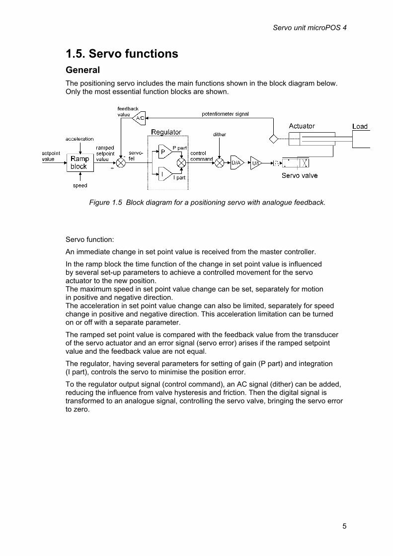
1.5. Servo functions General The positioning servo includes the main functions shown in the block diagram below. Only the most essential function blocks are shown.
Servo function:
An immediate change in set point value is received from the master controller.
In the ramp block the time function of the change in set point value is influenced by several set-up parameters to achieve a controlled movement for the servo actuator to the new position. The maximum speed in set point value change can be set, separately for motion in positive and negative direction. The acceleration in set point value change can also be limited, separately for speed change in positive and negative direction. This acceleration limitation can be turned on or off with a separate parameter.
The ramped set point value is compared with the feedback value from the transducer of the servo actuator and an error signal (servo error) arises if the ramped setpoint value and the feedback value are not equal.
The regulator, having several parameters for setting of gain (P part) and integration (I part), controls the servo to minimise the position error.
To the regulator output signal (control command), an AC signal (dither) can be added, reducing the influence from valve hysteresis and friction. Then the digital signal is transformed to an analogue signal, controlling the servo valve, bringing the servo error to zero.
Figure 1.5 Block diagram for a positioning servo with analogue feedback.

Technical Manual
6
1.6. Technical data Analogue servo inputs, force inputs/external zero adjustment, reference voltage output and analogue outputs Isolation 500 VDC
Analogue servo inputs Number of channels 2 Connector plug-in screw terminal (6 poles) Input type 0 V reference Pre-filter 100 Hz Input range 0 - 10 V Resolution 16 bits (65536) (0.15 mV/bit) Linearity < 8 LSB, (0.012 %, 1.2 mV) Zero deviation < 2 ppm/°C, (20 µV/°C) Gain inaccuracy < 0.01 % at 25 ºC, (1 mV) Gain deviation < 40 ppm/°C, (0.4 mV/°C)
External zero adjustment (option - analogue mV-inputs) Number of channels 2 Connector plug-in screw terminal (8 poles) Input type 0 V reference / differential Pre-filter 100 Hz Input range ±25 mV or 0 - 10 V Resolution 16 bits (65536), (0.8 µV/bit, 0.15 mV/bit) Linearity < 8 LSB (0.012 %, 3 µV, 1.2 mV) Zero deviation 25 mV < 60 ppm/ºC, (1.5 µV/ºC) Zero deviation 10 V < 3 ppm/ºC, (30 µV/ºC) Gain inaccuracy < 0.01 % of output range at 25 ºC, (2.5 µV, 1 mV) Gain deviation 25 mV < 125 ppm/°C, (3 µV/°C) Gain deviation 10 V < 40 ppm/°C, (0.4 mV/°C)
Analogue reference voltage output Connector plug-in screw terminal, see inputs above Output voltages +10.0 V Output deviation < 35 ppm/ºC (350 µV/°C) Output current 0 - 200 mA (min 50 ohm) between term. 1-4 and 5-8. 0 - 50 mA between terminal 9-11 and 12-14. Totally maximum 200 mA together on all reference outputs.

Servo unit microPOS 4
7
Analogue outputs Number of channels 2 with current and voltage for valve control 2 with voltage for measuring outputs Connector plug-in screw terminal (12 poles)
Current output 0 V reference Output range ±110 mA, ±55 mA, and ±22 mA, set by jumper Load max 100 ohm for 110 mA max 200 ohm for 55 mA max 500 ohm for 22 mA Resolution 12 bits, (54 µA/bit, 22 µA/bit, 11 µA/bit) Linearity < 0.1 % of range, (110 µA, 55 µA, 22 µA) Noise/hum < ±0.02 mA Zero deviation < 5 ppm/ºC of range, (0.55 µA/ºC, 28 µA/ºC, 0.11 µA/ºC) Gain inaccuracy < 0.1 % of output range at 25 ºC, (110 µA, 55 µA, 22 µA) Gain deviation < 30 ppm/ºC of range, (3.3 µA/ºC, 1.7 µA/ºC, 0.66 µA/ºC)
Voltage output 0 V reference Output range ±10 V Load min 1000 ohm Resolution 12 bits (4.9 mV/bit) Linearity < 0.1 %, (10 mV) Noise/hum < ±2 mV Zero deviation < 2 ppm/ºC, (20 µV/ºC) Gain inaccuracy < 0.1 % of output range at 25 ºC, (10 mV) Gain deviation < 35 ppm/ºC (350 µV/ºC)
Terminal communication COM 1, RS-485 Connector plug-in screw terminal (5 poles) Transmission RS-485, 4-wire Baud rate 1200 - 115200 baud Isolation 500 VDC Cable length Max 1000 m
Master communication Modbus RTU COM 2, RS-485 Connector plug-in screw terminal (5 poles) Transmission RS-485, 2- or 4-wire Baud rate 4800 - 921600 baud Isolation 500 VDC Cable length Max 1000 m
Master communication Modbus TCP Connector RJ45 (front panel) Transmission Ethernet Baud rate 10/100 Mbit/s Isolation 500 VDC Cable length Max 100 m

Technical Manual
8
Digital inputs Number of inputs 5 with common return connector Connector plug-in screw terminal (6 poles) Input type opto-isolated Filter 20 ms filter Low level -30 V to +8 V High level +18 V to +30 V Input resistance > 1 kohm Isolation 500 VDC
Relay outputs (set passive at power-up and ‘RESET’) Number of outputs 5 with common return connector, normally open Connector plug-in screw terminal (8 poles) Contact data max 1 A @ 30 VDC Isolation 500 VDC
Power supply Rated voltage 24 VDC Connector plug-in screw terminal (2 poles) Min/max voltage 19 - 29 VDC Consumption < 0.5 A Start current < 2 A
Environment Temperature range 0 to +50 ºC at operation -20 to +70 ºC at storage CE conformity EMC, industrial use
Enclosure dimensions Dimension (W x H x D) 150 x 90 x 110 mm Rail mount DIN 46277 or DIN EN 50022 Sealed to IP20 (IP10 without terminal blocks)
Hydraulic system Actuator length 10 to 655 mm (may be longer with special software) Hydraulic oil Type 32 Viscosity 25 - 50 Cst at normal operating temperature Oil temperature <60 ºC Filtering degree 6 m absolute

Servo unit microPOS 4
9
2. Communication microPOS 4 has three serial communications port, one of these is intended for parameter settings via PC and a terminal program, described in chapter 4 under the heading of Terminal communication. The other two communication ports, treated here under are used for communication with a control unit (PLC or PC).
2.1. Modbus genaral Data transmission between the master controller and microPOS 4 is performed by Modbus protocol. The Modbus protocol is a standard protocol, used for master/slave communication in the industry. For microPOS 4 the Modbus RTU (RS-485) and/or Modbus TCP (Ethernet) is used.
Information is transmitted in blocks of data to minimise polling and response time delays. For example both the feedback values and status register could be read with one command to the microPOS 4.
Depending on the type of the communicating equipment (the master), the commands in the application programme (PLC programme, or pc programme) may be different from type to type. However, if the master is not a Modicon PLC system, then the Modbus implementation in the master must have some cross-reference function to transfer the Modbus register and I/O bit numbering to the masters own register and I/O bit numbering. All register, coils described in this manual uses the standard Modbus (Modicon) register and I/O numbering. See the masters own Modbus driver documentation for how the commands should be activated in the masters application programme.
For detailed information about the Modbus protocol see:
Modicon Modbus Protocol Reference Guide PI-MBUS-300 Rev.D.

Technical Manual
10
2.2. Function codes for Modbus Function Description
01
Read coil state (output state)
Reads the state at separate outputs (address 0XXXX). The function is introduced because some control systems are using this function to initiate the communication. Coil number 00001 – 00016 Start address Hex 0000 to 000F Max. number of coils to read 16 (Hex 10) microPOS 4 answers with 0 for all coils.
02
Read input-stat
Reads the state at separate inputs (address 1XXXX). The function is introduced because some control systems are using this function to initiate the communication. Input number 00001 – 00016 Start address Hex 0000 to 000F Max. number of inputs to read 16 (Hex 10) microPOS 4 answers with 0 for all coils.
03
Read the Holding Register’s
Reads the contents in the holding registers (address 4XXXX). The function reads a selected number of registers from microPOS 4 in succession. Register 40 001 – 40 030 Start address Hex 0000 to 001D Max. number of registers to read 16 (Hex 10) microPOS 4 answers with the contents of the demanded registers.
06 Pre-set (write to) a register
Pre-set a value in a holding register (address 4XXXX). Register 40 021 – 40 030 Start address Hex 0014 to 001D
08
Diagnostics
This function can perform a sequence of different communication tests depending on sub-function codes. microPOS 4 supports only sub-function 00, which is an echo-function. Data transmitted to microPOS 4 is echoed back to the control system. Max. number of bytes: 128
16 (10 Hex)
Pre-set (write to) a number of registers
Pre-set values in a number of holding-registers (address 4XXXX). Register 40 021 – 40 030 Start address Hex 0014 to 001D Max. number of register to write to 16 (10 Hex)
23 (17 Hex)
Read/Write 4x registers
Performs a combined read and write operation in one single Modbus command. This function can write new data to a group of 4XXXX registers, and then return the contents of another group of 4XXXX registers.

Servo unit microPOS 4
11
2.3. Data representation All operative parameters: set values, feedback values, status, etc. are stored in ‘holding’ register areas with 16 bits (40XXXInteger area:
Unsigned integer Data without sign like system state, signals with range 1/0, set values and feedback values (value range 0 - 65535) are saved in a modbus register as an unsigned integer (16 bit number without decimals).
(signed) Integer Data with sign (value range ±8000 or ±100) are saved in a modbus register as an integer (16 bit number without decimals).
Examples of communication Below two examples of Modbus communication between the master controller and a microPOS 4 unit with address XX are described.
Example 1. Write the setpoint value for servo 1 and 2 to microPOS 4:
Start Addr. Func. Start addr. No. of reg. No. of bytes Data Crc. End
1 2 3-4 5-6 7 8-11 12-13
Silence 4 signs
XX 10 Hex
00 14 Hex
00 02 04 Setpoint 1 Setpoint 2
xx xx Silence 4 signs
microPOS 4 answers (confirms that the command is performed):
Start Addr. Func. Start addr. No. of reg. Crc. End
1 2 3-4 5-6 7-8
Silence 4 signs
XX 10 Hex
00 14 Hex
00 02 XX XX Silence 4 signs
Example 2. Send request to read feedback values etc. from microPOS 4 (reg. 40 001 - 40 011):
Start Addr. Func. Start addr. No. of reg. Crc. End
1 2 3-4 5-6 7-8
Silence 4 signs XX 03 Hex 00 00 00 0BHex XX XX Silence 4 signs
microPOS 4 answers:
Start Addr. Func. No of bytes Data Data Data Data Data
1 2 3 4-5 6-7 8-9 10 11 12-13
Silence 4 signs XX 03 Hex 16 Hex Feedb. 1 State 1 In pos. 1 Feedb. 2 State 2
Data Data Data Data Data Data Crc End
14-15 16-17 18-19 20-21 22-23 24-25 26-27
In pos.2 Dig in 1 Dig in 2 Dig in 3 Dig in 4 Dig in 5 xx xx Silence 4 signs
2.4. Register definition

Technical Manual
12
Register- number
Addr. Hex
Denomination Unit R/W Range
40 001 0000 Servo 1 feedback 0.1 mm R ±8000
40 002 0001 Servo 1 state contr.=1, not contr.=0 R 1/0
40 003 0002 Servo 1 In position Yes=1, No=0 R 1/0
40 004 0003 Servo 2 feedback 0.1 mm R ±8000
40 005 0004 Servo 2 state contr.=1, not contr.=0 R 1/0
40 006 0005 Servo 2 In position Yes=1, No=0 R 1/0
40 007 0006 Digital input 1 High=1, Low=0 R 1/0
40 008 0007 Digital input 2 High=1, Low=0 R 1/0
40 009 0008 Digital input 3 High=1, Low=0 R 1/0
40 010 0009 Digital input 4 High=1, Low=0 R 1/0
40 011 000A Digital input 5 High=1, Low=0 R 1/0
40 012 000B Servo 1 feedback 0.01 mm R 0 - 65535
40 013 000C Servo 2 feedback 0.01 mm R 0 - 65535
40 014 000D System state R See table below
40 021 0014 Servo 1 setpoint 1 0.01 mm R/W 0 - 65500
40 022 0015 Servo 2 setpoint 0.01 mm R/W 0 - 65500
40 023 0016 Reserve R/W
40 031 001E Ramped set v., servo 1 0,01 mm R 0 - 65500
40 032 001F Servo 1 feedback 0,01 mm R 0 - 65500
40 033 0020 Servoerror, servo 1 0,01 mm R 0 - 65500
40 034 0021 P-part, servo 1 0,1% R ±100
40 035 0022 I- part, servo 1 0,1% R ±100
40 036 0023 Control signal, servo 1 0,1% R ±100
40 041 0028 Ramped set v., servo 2 0,01 mm R 0 - 65500
40 042 0029 Servo 2 feedback 0,01 mm R 0 - 65500
40 043 002A Servoerror, servo 2 0,01 mm R 0 - 65500
40 044 002B P- part, servo 2 0,1% R ±100
40 045 002C I- part, servo 2 0,1% R ±100
40 046 002D Control signal, servo 2 0,1% R ±100
1 Valid only if external setpoint source is ’Modbus’.
Servo unit microPOS 4
13
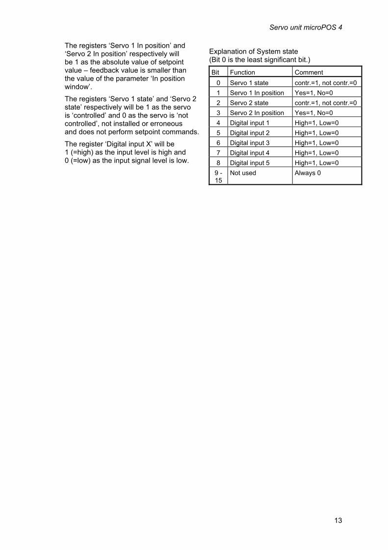
The registers ‘Servo 1 In position’ and ‘Servo 2 In position’ respectively will be 1 as the absolute value of setpoint value – feedback value is smaller than the value of the parameter ‘In position window’.
The registers ‘Servo 1 state’ and ‘Servo 2 state’ respectively will be 1 as the servo is ‘controlled’ and 0 as the servo is ‘not controlled’, not installed or erroneous and does not perform setpoint commands.
The register ‘Digital input X’ will be 1 (=high) as the input level is high and 0 (=low) as the input signal level is low.
Explanation of System state (Bit 0 is the least significant bit.)
Bit Function Comment
0 Servo 1 state contr.=1, not contr.=0
1 Servo 1 In position Yes=1, No=0
2 Servo 2 state contr.=1, not contr.=0
3 Servo 2 In position Yes=1, No=0
4 Digital input 1 High=1, Low=0
5 Digital input 2 High=1, Low=0
6 Digital input 3 High=1, Low=0
7 Digital input 4 High=1, Low=0
8 Digital input 5 High=1, Low=0
9 -15
Not used Always 0

Technical Manual
14

Servo unit microPOS 4
15
3. Installation
3.1. Mechanical installation Each servo unit microPOS 4 contains several circuit boards, built into a protective plastic housing. The module can be snap-mounted on a 35 mm wide DIN rail or attached on a flat surface by two 4 mm screws.
All connection cable shields should be connected to ground close to the servo unit, preferably to ground terminals on a ground rail or on the mounting plate.
To protect from moisture, dirt and electromagnetic interference the module can be mounted in a sealed steel enclosure. Use compression glands with integrated cable shield connection, or connect the cable shields to a ground rail close to the compression glands.
Avoid installation the servo unit in vibrating environment, or use vibration damping components.
30
735
75
149
110
5
60
134
Mounting holes, 2 x 4 mm dia. The snap fastener for
DIN rail can be opened with a fine screw driver.
Figure 3.1 Mechanical dimensions for servo unit microPOS 4 with no terminal blocks connected.

Technical Manual
16
3.2. Electrical installation Cables For the electrical connections to the servo unit shielded cables should be used, except for the power supply. All cables should be routed so that electromagnetic interference from power cables and other equipment is avoided. The cable shields should be connected to ground close to the servo unit.
Cables specified by Nobel Weighing Systems:
Potentiometer cable 3 conductors + shield, min 0.5 mm². Valve cable (DDV) 7 conductors + shield, min 0.75 mm². Valve cable (current) 2 conductors + shield, min 0.5 mm². Power supply 2 conductors, min 0.75 mm². Digital inputs 2 to 6 conductors + shield, min 0.5 mm². Relay outputs 2 to 6 conductors + shield, min 0.5 mm². Terminal 5 conductors + shield, min 0.5 mm². Modbus RTU 3 to 5 conductors + shield, min 0.5 mm².
Connectors All electrical connections to microPOS 4 are made via plug-in terminal blocks, the blocks being numbered to prevent errors.
Zero adjust
COM.1
+
Digital inputs
FeedbackAnalogue outputs
microPOS 4
XXXXXXXX XX- XXXXmi cr oPOS 4
24V Relay outputs
P1
P2
P3
P11
P12
24V
-+ -
LED
COM.2
P4
P5
P6
Figure 3.2 Location of plug-in terminal blocks and jumpers at the servo unit.

Servo unit microPOS 4
17
Power supply Figure 3.3.
Power supply voltage can be connected to microPOS 4 in two alternative ways, either via terminals 27 (+24 V) and 28 in a separate block, or via terminals 29 (+24 V) and 30 in the same block as the digital outputs (relay outputs). As the unit is correctly powered, the LED at the front panel is lit.
NOTE! The power inputs are provided with zener diodes, giving a short circuit if the power supply voltage exceeds 54 V, and with diodes that prevent output of 24 V DC from microPOS 4.
Feedback signal (transducer signal) Figure 3.4.
Each servo channel must have a feedback transducer connected and if transducers of potentiometer type are used, connections should be made according to figure 3.4. For potentiometer transducers are the servo function and direction of piston movement depended on how +10V and 0V are connected to the transducer. If the direction of motion is wrong the connections to +10V and 0V should be interchanged. For other type of transducers with voltage output are the hydraulic actuators movement direction related to output predefined. If the movement direction in those case are wrong the parameter Inverted feedback signal shall be changed.
Verify that the total load on the reference output (+10V), from feedback transducers
Figure 3.3 Power input alternatives with protective diodes on microPOS 4.
Figure 3.4 Connection of potentiometer type feedback transducers.

Technical Manual
18
and external zero potentiometers together, is within limits. See Technical data.
External zero adjust Figure 3.5
Function It is possible to connect external potentiometers for zero adjustment. The zero adjustment will influence the ‘online’ set point values, sent by Modbus RTU. By ‘offline’ operation, for example in TEST, the external zero potentiometers have no influence. One individual parameter, ‘External zero adjust’, is used to select function and range for the external zero potentiometers.
Connection The potentiometers for external zero adjustment are connected to the microPOS 4 according to figure 3.5. Both signal inputs for each channel (SIG.1+ and SIG.1–, SIG.2+ and SIG.2–) should be connected to the moving contact of the potentiometer.
The direction of the zero adjustment depends on how +10V and 0V are connected to the potentiometer. If the direction is not correct, the potentiometer connections to +10V and 0V should be interchanged.
Verify that the total load on the reference output (+10V), from feedback transducers and external zero potentiometers together, is within limits. See Technical data.
Suitable zero adjustment potentiometer resistance is normally 10 k.
Note that if no external zero adjustment potentiometer is connected, parameter ‘External zero adjustment’ must be set to ‘Not in use’.
Figure 3.5 Connection of external potentiometers for zero adjustment.
Servo unit microPOS 4
19
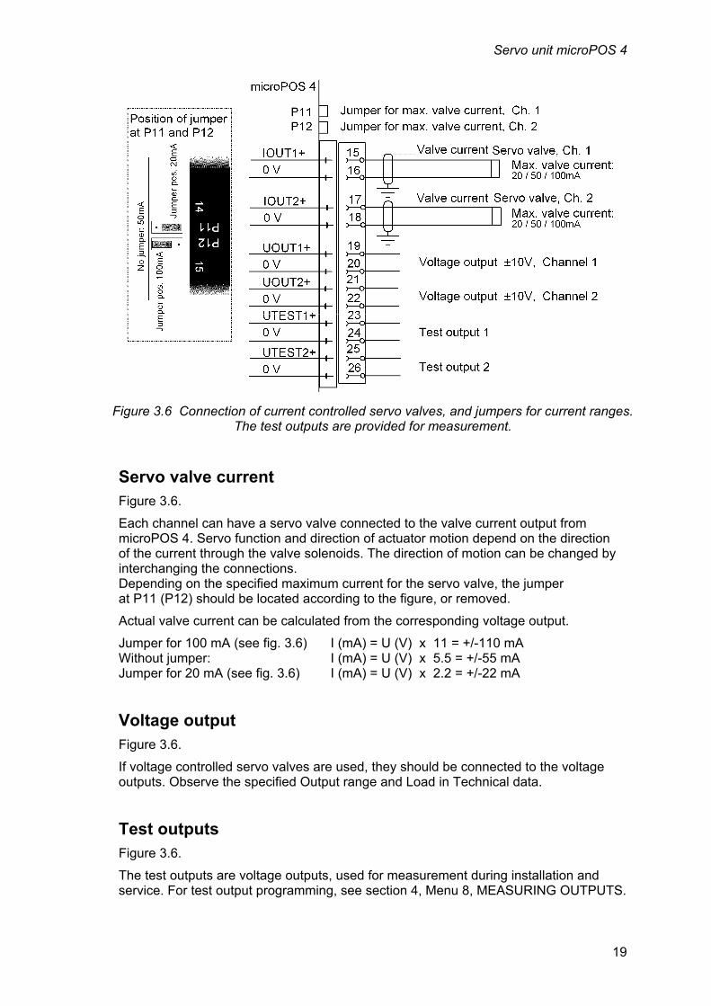
Servo valve current Figure 3.6.
Each channel can have a servo valve connected to the valve current output from microPOS 4. Servo function and direction of actuator motion depend on the direction of the current through the valve solenoids. The direction of motion can be changed by interchanging the connections. Depending on the specified maximum current for the servo valve, the jumper at P11 (P12) should be located according to the figure, or removed.
Actual valve current can be calculated from the corresponding voltage output.
Jumper for 100 mA (see fig. 3.6) I (mA) = U (V) x 11 = +/-110 mA Without jumper: I (mA) = U (V) x 5.5 = +/-55 mA Jumper for 20 mA (see fig. 3.6) I (mA) = U (V) x 2.2 = +/-22 mA
Voltage output Figure 3.6.
If voltage controlled servo valves are used, they should be connected to the voltage outputs. Observe the specified Output range and Load in Technical data.
Test outputs Figure 3.6.
The test outputs are voltage outputs, used for measurement during installation and service. For test output programming, see section 4, Menu 8, MEASURING OUTPUTS.
Figure 3.6 Connection of current controlled servo valves, and jumpers for current ranges. The test outputs are provided for measurement.
Technical Manual
20
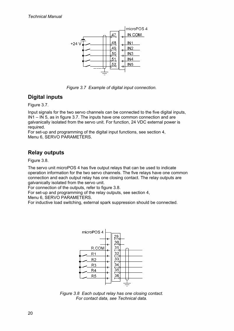
Digital inputs Figure 3.7.
Input signals for the two servo channels can be connected to the five digital inputs, IN1 – IN 5, as in figure 3.7. The inputs have one common connection and are galvanically isolated from the servo unit. For function, 24 VDC external power is required. For set-up and programming of the digital input functions, see section 4, Menu 6, SERVO PARAMETERS.
Relay outputs Figure 3.8.
The servo unit microPOS 4 has five output relays that can be used to indicate operation information for the two servo channels. The five relays have one common connection and each output relay has one closing contact. The relay outputs are galvanically isolated from the servo unit. For connection of the outputs, refer to figure 3.8. For set-up and programming of the relay outputs, see section 4, Menu 6, SERVO PARAMETERS. For inductive load switching, external spark suppression should be connected.
Figure 3.7 Example of digital input connection.
Figure 3.8 Each output relay has one closing contact. For contact data, see Technical data.

Servo unit microPOS 4
21
Ethernet för Modbus-TCP Connection for Ethernet is done to the RJ45-connector at the front panel. The keys and display at microPOS 4 perform set-up for IP-address, Subnet mask and Gateway address. See section 4. Settings from the front panel.
The Modbus registers in microPOS 4 are up-dated every 5 ms.
RS-485 för Modbus-RTU Connection for 2-wire or 4-wire to terminal block 42 – 46 is shown in figure 3.9. Up to 31 microPOS 4 units can be connected in parallel to the master computer.
For the communication to operate, each microPOS 4 units should have its unique address. Baud rate and data format for COM2 should be set to the values of the master controller. The keys and display at microPOS 4 perform this set-up. See section 4. Settings from the front panel.
The Modbus registers in microPOS 4 are up-dated every 5 ms.
Line termination, RS-485
To give reliable communication the RS-485 transmission line should have suitable line termination at both ends. If microPOS 4 makes up one end of the transmission line, the line termination should be installed by jumpers according to the table.
Connection P4 P5 P6
2-wire No jumper Jumper Jumper
4-wire Jumper Jumper Jumper
For the other microPOS 4 units along the line, no jumpers should be connected.
If the master controller makes up one end of the transmission line, refer to the master computer manual for line termination.
NOTE! Independent of the number of units along the transmission line, the units at the end points must have the line termination connected.
Figure 3.9 The master controller is connected via COM2. Only at the last unit on the transmission line,
these jumpers should be installed.

Technical Manual
22
Terminal communication Figure 3.10.
Set-up of test outputs, digital outputs, relay outputs and servo parameters for microPOS 4 is performed from a PC with the terminal program servoTERM.
Communication with the terminal PC is carried out by RS-485 via COM1 on microPOS 4. Connection at terminal block 37 – 41 as shown in figure 3.10.
Jumpers at P1, P2, and P3 connect line termination.
For the communication to operate, baud rate and data format for COM1 should be set to the values of the terminal PC. This set-up is performed with the keys and display at microPOS 4. See section 4. Settings from the front panel.
Line termination, RS-485
To give reliable communication the RS-485 transmission line should have suitable line termination at both ends, one end being the servo unit. To install line termination at microPOS 4, jumpers should be connected at P1, P2, and P3.
The PC with terminal program makes up the other end of the transmission line. Refer to the PC manual for installation of line termination there.
Figure 3.10 COM1 is used to connect a PC with terminal program. Jumpers install line termination.

Servo unit microPOS 4
23
3.3. Front panel, microPOS 4 The front panel of microPOS 4 has a 2x16 character LCD display and four keys.
The display can present the servo channel function and other information about the servo unit in several views. Key functions in this presentation mode is shown in the table below.
The front panel can also be used to switch microPOS 4 into Set-up mode, making set-up of interface parameters possible. These parameters are described on pages 3-3 and 3-4. Key functions in set-up mode is shown in the table below.
Keys
Name Functions In presentation mode In Set-up mode
ENTER To next level of views. In a ‘Main menu’:
Show the first parameter.
Parameter viewing (without cursor): Make editing possible. Parameter editing (with cursor): Accept the digit at the cursor and go to next digit. If ENTER is pressed for 2 seconds: The displayed parameter value is activated, the cursor disappears.
plus Go to next view. In a ‘Main menu’:
Go to next main menu.
Together with for 2 sec.: Parameter viewing (without cursor): Go to ‘Set-up mode’ Go to next parameter. (Password may be required). Parameter editing (with cursor): Increment the digit at the cursor or Go to next alternative.
minus Go to previous view. In a ‘Main menu’:
Go to previous main menu.
Parameter viewing (without cursor): Go to previous parameter. Parameter editing (with cursor): Decrement the digit at the cursor or Go to previous alternative.
ESCAPE Together with + for 2 sec.: In a ‘Main menu’:
Go to ‘Set-up mode’ No function.
(Password may be required). Parameter viewing (without cursor): Go to the main menu Parameter editing (with cursor): Finish the editing.

Technical Manual
24
Editing procedure, microPOS 4 From any view in the presentation mode, microPOS 4 can be switched over to
Set-up mode by holding keys and pressed for 2 seconds. (Then a correct password may be required).
In Set-up mode key or is used to find the desired Main menu.
Then the key ENTER ( ) is pressed, giving access to the parameters.
After that key or can be used to step forwards or backwards in the parameter sequence until the requested parameter is displayed.
Press to start editing the displayed parameter. A cursor starts blinking at the digit to the left on the bottom line. This indicates that parameter editing is enabled, and that the key functions are a bit different. See the table on previous page.
Key Function by parameter editing (with cursor)
Increment the cursor digit, or Go to next alternative.
Decrement the cursor digit, or Go to previous alternative.
(short) Accept the value of the cursor digit and go to next digit.
(2 sec.) Accept the actual parameter value or alternative and finish the editing. If the value is outside the range for a numeric parameter, an error message is displayed. Then press any key to remove the message, cancel the value, and make continued editing possible.
Cancel the edited value and interrupt the actual editing.
As the parameter editing is finished, microPOS 4 must leave the Set-up mode to make the display present servo functions again.
To exit the set-up mode:
press to get to the Main menu,
press several times until 'Main menu Exit set-up’ is displayed,
press , sub menu ‘Save changes? No Esc. Yes’ will be displayed.
(Press if you do not wish to exit from the Set-up mode.)
Press (No) All edited values are cancelled and the parameters will resume their previous values. microPOS 4 switches over to presentation mode.
Press (Yes) All edited values are activated and saved in the servo unit memory. microPOS 4 switches over to presentation mode. NOTE! This may result in new communication parameter values getting active!

Servo unit microPOS 4
25
4. Set-up
4.1. General All microPOS 4 functions are controlled by locally stored parameters that will not be lost when the power is switched off. At delivery the parameters are set to default values, giving the unit initial standard functions.
To adapt microPOS 4 to actual operation conditions, a number of parameter values may need to be changed.
Parameters are divided in two groups: Interface parameters, controlling front panel function and communication properties of the servo unit. These parameters are set by keys on the front panel.
Servo parameters, controlling the servo regulator operation, actuator stroke, configuration of I/O etc. for the two channels. Facilities for calibration and test are also included here. These parameters are set from a PC with terminal program servoTERM.
4.2. Settings from the front panel These parameters are described on pages 25 and 26. Setting is performed with microPOS 4 in Set-up mode, using the keys and display of the front panel. See 'Front panel, microPOS 4' in previous section.
The set parameter values are permanently saved in the microPOS 4 memory and will not be lost when the power is switched off.
The backup/restore function, provided for the servo parameters, is not active for the interface parameters. Thus the set values should be recorded in a set-up list like the example in Appendix 2.
Set-up mode From any one of the presentation mode views, you can switch microPOS 4 into
Set-up mode by holding the keys and pressed for 2 seconds. (Then a correct password may be required).
Running microPOS 4 in Set-up mode doesn't influence the normal servo function. But the control signal transmission can be influenced by possible changes in communication parameters as Set-up mode is finished. To prevent unintentional use of the Set-up mode, the parameter controlled security lock may be activated.
microPOS 4
COM1 COM2
PC with servoTERM Master controller
Figure 4.1 By COM1 and COM2 microPOS 4 communicates with set-up program servoTERM and with the master controller.

Technical Manual
26
Main menus The interface parameters in microPOS 4 are divided in groups under two main menus. There is also one main menu for finishing the set-up operation.
General This main menu contains parameters for general use: selection of language and setting of display contrast, activation of a security lock for the Set-up mode, and selection of a password for the security lock.
General Communication Exit set-up
Language
Password
Display contrast
Main menu Main menu Main menu
EnglishInstrum.address
COM1:Baudrate
Set-up mode
Save changes?YesNo
Security lockOff
COM1:Data format8-none-1
Shown only if 'Security lock' is On.
Shown only if changes have been done.
Esc.
COM2:Baudrate
COM2:Data format8-none-1
The view that was display ed as S et-up m ode wa s s tarted.
4
****
1
9600
9600
+ 2 sec.
A ny view in presentation m ode. S ee figure 4.3.
External IOOff
IP-address172.021.007.250
Subnet mask255.255.000.000
Gateway address000.000.000.000
Enter password (Wrong)(Correct)
Figure 4.2 Main menus and parameters in Set-up mode.
Servo unit microPOS 4
27
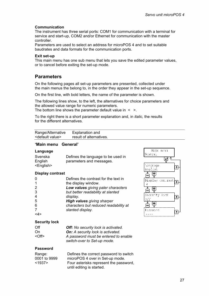
Communication The instrument has three serial ports: COM1 for communication with a terminal for service and start-up, COM2 and/or Ethernet for communication with the master controller. Parameters are used to select an address for microPOS 4 and to set suitable baudrates and data formats for the communication ports.
Exit set-up This main menu has one sub menu that lets you save the edited parameter values, or to cancel before exiting the set-up mode.
Parameters On the following pages all set-up parameters are presented, collected under the main menus the belong to, in the order they appear in the set-up sequence.
On the first line, with bold letters, the name of the parameter is shown.
The following lines show, to the left, the alternatives for choice parameters and the allowed value range for numeric parameters. The bottom line shows the parameter default value in < >.
To the right there is a short parameter explanation and, in italic, the results for the different alternatives.
Range/Alternative Explanation and <default value> result of alternatives.
‘Main menu General’
Language
Svenska English <English>
Defines the language to be used in parameters and messages.
Display contrast
0 1 2 3 4 5 6 7 <4>
Defines the contrast for the text in the display window. Low values giving paler characters but better readability at slanted display. High values giving sharper characters but reduced readability at slanted display.
Security lock
Off On <Off>
Off: No security lock is activated. On: A security lock is activated. A password must be entered to enable switch-over to Set-up mode.
Password
Range: 0001 to 9999 <1937>
Defines the correct password to switch microPOS 4 over in Set-up mode. Four asterisks represent the password, until editing is started.

Technical Manual
28
Range/Alternative Explanation and <default value> result of alternatives.
‘Main menu Communication’
Instrum. address
Range: 1 to 247 <1>
Defines the address of the microPOS 4. This parameter is used only if the communication field bus is RS-485.
COM1: Baudrate 1200 2400 4800 9600 19200 38400 57600 115200 <9600>
Defines the baud rate for the serial communication to COM1. This parameter must be set to the baud rate of the connected terminal computer.
COM1: Data format 7-none-2 7-even-1 7-even-2 7-odd-1 7-odd-2 8-none-1 8-none-2 8-even-1 8-odd-1 <8-none-1>
Defines the data format for the serial communication to COM1. This parameter must be set to the data format of the connected terminal computer.
COM2: Baudrate 4800 9600 19200 38400 57600 115200 230400 460800 921600 <9600>
Defines the baud rate for the serial communication to COM2. This parameter must be set to the baud rate of the connected master controller. This parameter is used only if the communication field bus is RS-485.
COM2: Data format 8-none-1 8-none-2 8-even-1 8-odd-1 <8-none-1>
Defines the data format for the serial communication to COM2. This parameter must be set to the data format of the connected master controller. This parameter is used only if the communication field bus is RS-485.
External IO AV No external IO available in this program.
1
9600
9600
172.021.007.250
255.255.000.000
000.000.000.000
External IOOff
IP-address
Subnet mask
Gateway address
CommunicationMain menu
Instrum.address
COM1:Baudrate
COM1:Data format8-none-1
COM2:Baudrate
COM2:Data format8-none-1
Servo unit microPOS 4
29
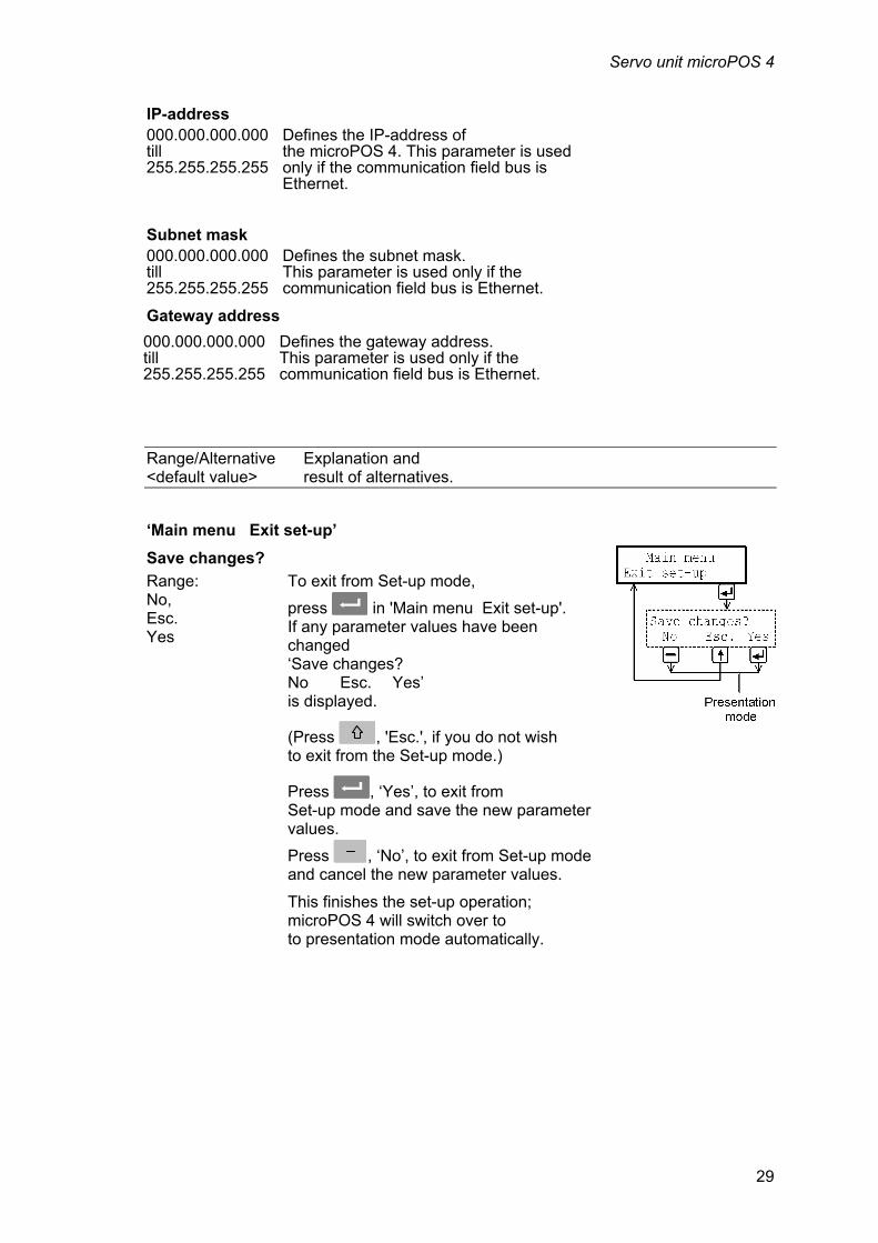
IP-address 000.000.000.000 till 255.255.255.255
Defines the IP-address of the microPOS 4. This parameter is used only if the communication field bus is Ethernet.
Subnet mask 000.000.000.000 till 255.255.255.255
Defines the subnet mask. This parameter is used only if the communication field bus is Ethernet.
Gateway address
Range/Alternative Explanation and <default value> result of alternatives.
‘Main menu Exit set-up’
Save changes?
Range: No, Esc. Yes
To exit from Set-up mode,
press in 'Main menu Exit set-up'. If any parameter values have been changed ‘Save changes? No Esc. Yes’ is displayed.
(Press , 'Esc.', if you do not wish to exit from the Set-up mode.)
Press , ‘Yes’, to exit from Set-up mode and save the new parameter values.
Press , ‘No’, to exit from Set-up mode and cancel the new parameter values.
This finishes the set-up operation; microPOS 4 will switch over to to presentation mode automatically.
000.000.000.000 till 255.255.255.255
Defines the gateway address. This parameter is used only if the communication field bus is Ethernet.

Technical Manual
30
Example of how to use the keys:
As a microPOS 4 is started for the first time the display operates in presentation mode with English language. The example below describes how to activate the Security lock (a choice parameter) and then edit the Password (numerical parameter).
* Press for 2 seconds to leave the presentation mode and go to Set-up mode. ‘Main menu General’ is displayed.
* Press to go to the first of the parameters in menu 'General'. The first parameter, ‘Language’ is displayed.
* Press several times until parameter 'Security lock' is displayed. The parameter value is displayed on the lower line. Default value is 'Off'.
* Press to make editing of the parameter value possible (two alternatives). The first digit on the lower line starts blinking. This is a cursor, indicating that the keys plus and minus can be used to search an alternative value.
* Press or until the alternative 'On' is displayed.
* Press for 2 seconds to select the displayed alternative (On). The cursor disappears and 'Security lock' is activated.
* Now the lower line has no cursor. Press several times to step forward to parameter 'Password'. The parameter value is displayed as * * * * , and should be edited.
* Press to make editing of the parameter value possible. Now the parameter value is displayed as digits, with the first digit blinking.
* Press or to change the blinking digit to the requested value.
* Press to accept the first digit. The cursor moves to the next digit. Repeat the two last points until parameter 'Password' is set to the requested value.
* Press for 2 seconds to make the new password active. The cursor disappears and the lower line displays * * * * .
* Press when the changes are finished. 'Main menu General' is displayed.
* Press a few times so that 'Main menu Exit set-up' is displayed.
* Press to finish the editing. 'Save changes? No Esc. Yes‘ is displayed.
(Now you can press , 'Esc.' if you want to continue the editing.)
* Press , 'Yes' to save the changed parameter values.
Press , 'No' to cancel the editing and return to the previous values for the parameters.
In both cases the set-up is finished and microPOS 4 returns to presentation mode.

Servo unit microPOS 4
31
Views in presentation mode Figure 4.3. As microPOS 4 is in presentation mode, the panel keys can be used to select among several available views.
Normal display This is the first view displayed after startup, reset or set-up mode.
To the left on the upper line "S12" is displayed, representing Servo 1 and 2. On the lower line the status for each servo is shown, represented by letters.
If the servo is Not installed the letter "N" is shown. If the servo is installed, three letters are possible: O = Parameter Servo status is On (Servo output is On) F = Parameter Servo status is Off (Servo output is Off) S = Parameter Servo status is Simulation (Servo output is Off)
Flashing texts COM1 and COM2 indicate communication to the unit.
COM1 indicates bytes received from the PC with servoTERM.
COM2 indicates correctly received messages via Modbus.
To the right on the lower line the Modbus address for the unit is shown.
Servo 1 / Servo 2 These two views show actual set value and position value for each one of the servos.
Pressing key will open another view for the actual servo. The upper line indicates actual servo status with the following codes: INPO = servo in position, CONTR = servo active, ERR = program error.
The lower line indicates which digital inputs are active for the servo: PFr = Position freeze CSt = Controlled stop SOn = Service ON SFr = Set value freeze HOf = Hydraulics OFF
See Menu 9, DIGITAL I/O-FUNCTIONS for more information.
Press key to return to view Servo 1 or Servo 2 respectively.
Press key or to switch between the servos.
1.SETP= 650.00mm POS.= 650.00mm
1.INPO CONTR ERR PFrCStSOnSFrHOf
INFORMATIONS12 COM1 OF COM2 003
Normal display2.SETP= 650.00mm POS.= 650.00mm
2.INPO CONTR ERR PFrCStSOnSFrHOf
DIG.INPUTS 123450=OFF 1=ON 00100
RELAYOUTP. 123450=OFF 1=ON 10110
SERIE NO XX-XXXXPROGR. XXXXXXXX
Servo 1 Servo 2 Information
Figure 4.3 As microPOS 4 is in presentation mode, these views are available.
Technical Manual
32
Information
Pressing key gives access to three information views.
The first one shows status for the digital inputs. On the upper line the inputs are given, numbered from 1 to 5. On the lower line the status for each input is shown as 0 = OFF or 1 = ON.
The second one shows the status for the relay outputs. On the upper line the outputs are given, numbered from 1 to 5. On the lower line the status for each output is shown as 0 = OFF or 1 = ON.
The third one shows the serial number and program name of the servo unit.
The keys and are used to select among the three views.
Pressing key takes you back to the view Information.

Servo unit microPOS 4
33
4.3. Settings from a PC with terminal program Servo parameters are set from a PC, connected to microPOS 4 at COM1. It is assumed that Windows 95/98/ME/NT4.0/2000/XP is installed and that terminal program servoTERM from Nobel Weighing Systems is used for operator dialogue.
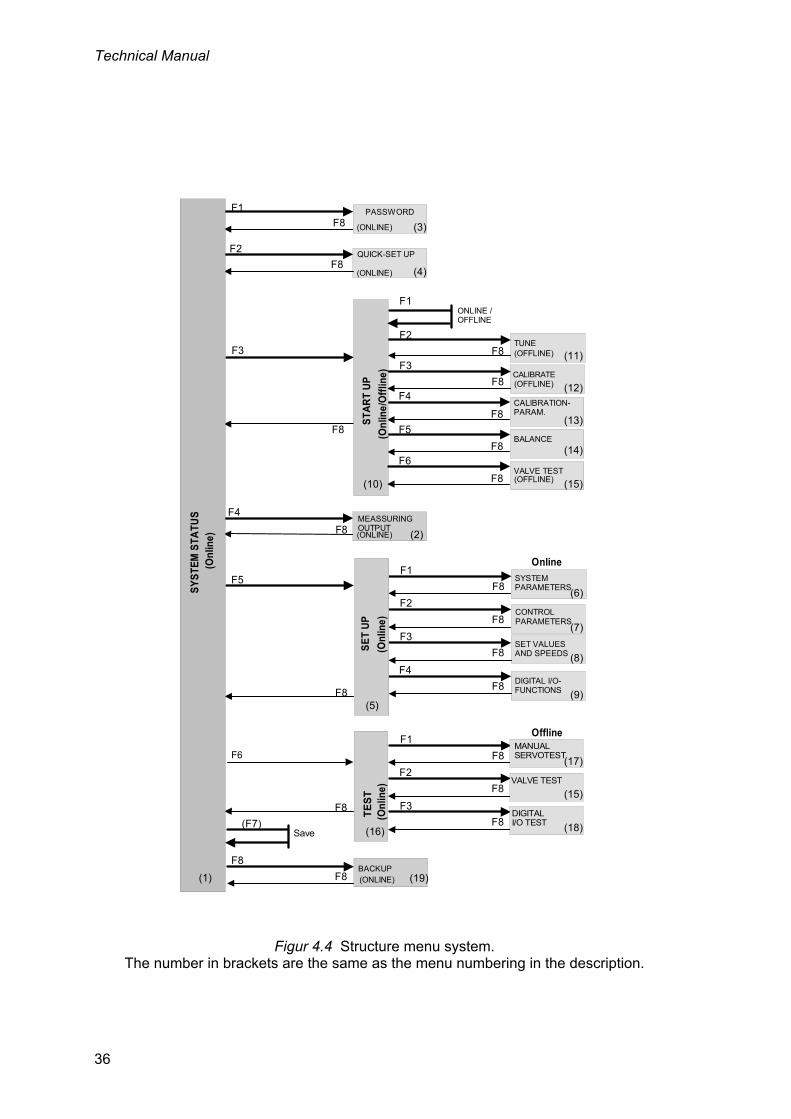
As servoTERM is activated, it starts displaying the menu SYSTEM STATUS, and from that menu the other menus can be selected with the PC function keys. See figure 4.4. The numbers in ( ) in the figure correspond to the menu.
In every cases servo parameter changes lead to changed servo properties immediately. To prevent unintentional changing of parameter values, a password must be given to open menus where parameters can be changed. This password is "1 9 3 7", and it cannot be changed.
The menus in servoTERM are of two kinds: Menus with ‘Online’ function and menus with ‘Offline’ function.
‘Online’ function means that set values from the master control unit are received (by Modbus RTU), and that changing of parameter values can be performed simultaneously.
‘Offline’ function means that the reception of external set values to the servo is interrupted. The servo will operate on the latest received set values. In some 'Offline' functions, the set value can be changed from servoTERM.

Technical Manual
34
Description of menus On the following pages, all the menus that can be used to set servo parameters in microPOS 4 are described. The bottom lines in the menus show which of the function keys F1 to F8 that are active and which function they have in the actual menu.
The key "Esc" can always be used to update the shown menu.
In the text below it is stated if the system is in online or offline mode. Online means that set value from the master control unit are received, and that changing of parameter values can be performed simultaneously. Offline means that the reception of external set values to the servo is interrupted.
Menu 1, SYSTEM STATUS (online)
A main menu, gives a survey of set point values, positions, and status. It also contains several function selections. Set value is not needed from master control.
The menu gives by entering a password possibility to change parameters. It also gives access for settings of measuring output parameters.
Menu 2, MEASURING OUTPUTS (online)
Settings for signal measurements. Used for transient examination and position accuracy checking.
Menu 3, PASSWORD (online)
This image is used for unlocking the system. In a locked system it is not allowed to see parameter values, perform storing/restoring of parameters or make changes of parameters. The password is not changeable or personal. The purpose for the password is to give a simple protection when a terminal computer is connected to microPOS. In the image, when leaving the computer unattended the system also can be locked by pressing F1. The system is automatically locked after 30 minutes of inactivity.
To unlock microPOS type 1 9 3 7 followed by enter.
Menu 4, QUICK SET-UP (online)
In most applications, only a few servo parameters need to be adjusted to attain good servo performance. These parameters are collected in "Menu 4, QUICK SET-UP (online).
Menu 19, BACKUP (online)
Storing / Restoring of set-up parameters to / from the master unit.
Menu 10, START UP (offline/online)
This display contains a number of functions (menus), which facilitate the start up and service of the system. By pressing F1 toggling between online and offline are done. Before returning to Menu 1 (system status) the system must be set to online.
The following start up menus are available under Menu 10 START UP.
Menu 11, SERVO TUNING (only available with system in offline) Setting of servo characteristics during operation. Several functions for setting of best transient behaviour are included.

Servo unit microPOS 4
35
Menu 12, CALIBRATION (only available with system in offline) of the position measurement scale. Several calibration methods are included. Extreme accuracy is obtained in a simple way.
Menu 13, CALIBRATION PARAMETERS Contains scale factors for feedback signal and offset parameters.
Menu 14, BALANCING of servo valves. Electrical adjustments of the servo valve zero setting.
Menu 15, VALVE TEST. (only available with system in offline) Breaks the servo loop, giving open control of the servo valve. A current can be generated, controlling the valve for positive or negative motion.
Menu 5, SET UP (online)
In Menu 5, SET UP it is possible to adjust all servo parameters in microPOS 4 except for calibration parameters, which are located under Menu 10, START UP.
The following menus are available under Menu 5, SET UP.
Menu 6, SYSTEM PARAMETERS (online) This menu contains parameters, which defines the system, for example actuator stroke and language.
Menu 7, CONTROL PARAMETERS (online) For setting of servo characteristics the parameters divided in 2 menus. If you are in Menu 5, SET UP and press F2=Set values both menus are available by pressing F1 and F2.
Menu 8, SET VALUES (online) This menu contains parameters, which defines set value limits, speed and acceleration.
Menu 9, DIGITAL I/O FUNCTIONS (online) Parameters here defines the function of digital inputs and relay outputs. NOTE that digital input functions are active low accept for service function which is active high.
Menu 16, TEST (online)
All menus F1-F3, which can be reached from this menu forces the system into offline mode. Offline means that set point values from the master controller have no influence on the servo. 'Menu 16, TEST' facilitates accurate testing of the positioning properties for the unit and checking of cable connections.
Menu 17, MANUAL SERVO TEST (offline) Manual servo test with manual set point generation facilitates positioning of the actuator piston by PC commands.
Menu 15, VALVE TEST. (offline) Breaks the servo loop, giving open control of the servo valve. A valve signal can be generated, controlling the valve for positive or negative motion.
Menu 18, DIGITAL I/O TEST. (offline) Displays the digital input status and performs activation or deactivation of the output relays.
The picture below shows the structure of the menu system. The figures in parenthesis are the same as the numbers on the menus in the description.
Technical Manual
36
F1
F8
F2
F8
F3
F8
CONTROLPARAMETERS
F1
F8
PASSWORD
SET VALUESAND SPEEDS
SYSTEM PARAMETERS
BACKUP
(F7)Save
F2
F8
F3
F8
F2
F8
F4
F8
F1
F3
MÄTUTTAGF4
F8
F5
F8
F8
F8
MANUAL
VALVE TEST
DIGITALI/O TEST
SERVOTEST
TE
ST
F6
F8
DIGITAL I/O-FUNCTIONS
QUICK-SET UP
F8
MEASSURINGOUTPUT
F8
CALIBRATEF3
F8
BALANCE
TUNE
F4
F8
F5
F8
F1ONLINE / OFFLINE
F2
F8
(OFFLINE)
VALVE TESTF8
(OFFLINE)
(OFFLINE)
SY
STE
M S
TATU
S
ST
AR
T U
P
F6
SE
T U
P
Online
CALIBRATION-PARAM.
(1) (19)
(5)
(16) (18)
(15)
(17)
(Onl
ine)
(15)
(14)
(13)
(12)
(11)
(10)
(3)
(2)
(4)
(9)
(8)
(7)
(6)
Offline
(ONLINE)
(ONLINE)
(ONLINE)
(Onl
ine/
Off
line)
(Onl
ine)
(Onl
ine)
(ONLINE)
Figur 4.4 Structure menu system. The number in brackets are the same as the menu numbering in the description.

Servo unit microPOS 4
37
Menu 1, SYSTEM STATUS This menu is shown after system start-up and continuously at normal operation (online).
Note1: Activated input functions for S1 (servo 1) and S2 (servo 2): PFr=position freeze, CSt=commanded stop, SFr=set value freeze, SOn=service On, HOf=hydraulics Off.
Function: The menu shows the status of the servos in microPOS 4. For each servo its status is shown as: On, Not installed, Output off or Simulation. For every installed servo its Set value, In position/Moving and actual Position are shown. Key F4 makes it possible to select set-up of the Measuring outputs. No password is needed for set up of measuring outputs. If key F1 is pressed, entering of a four-digit password (1 9 3 7) followed by Enter can be done. This gives access to the following menus. F2 QUICK SET UP (Menu 4) F3 START UP (Menu 10) F5 SET UP (Menu 5) F6 TEST (Menu 16) F8 BACKUP (Menu 19)
File W indow Communications Font size Info
SYSTEM STATUS
Servo 1: On Set value: 125.20 mm
[On these lines possible error codes or other messages are displayed ]
F1=Password (F3=Start up) (F5=Set-up) (F7=Save)
Vishay Nobel microPOS4 MxxxBxxx[On this line the activated digital input functions are displayed. See note 1]
Language Transfers
Terminal Window
In position Position: 125.45 mm
Servo 2: On Set value: 235.60 mm
Moving Position: 215.55 mm
(F2=Quick set-up) F4=Meas.outp. (F6=Test) (F8=Backup)

Technical Manual
38
Meny 2, MEASURING OUTPUTS (online) This menu is displayed as F4 is selected in Menu 1, SYSTEM STATUS
Note1: Activated input functions for S1 (servo 1) and S2 (servo 2): PFr=position freeze, CSt=commanded stop, SFr=set value freeze, SOn=service On, HOf=hydraulics Off.
Function: In this menu the measuring output parameters are handled. The parameters can be viewed and edited. From the menu two selectable dynamic values can be sent to the test outputs in real time as scaled voltages with the range +/-10 V. With oscilloscope or Y/T plotter the transient behaviour and the movement of the servo actuator can easily be registered. See the installation section for location of the test outputs.
Key F2 is used to select parameters for Test point 1 or Test point 2, the selection displayed in the menu. Switching is performed by pressing key F2.
The keys F3 or and F4 or are used to step forwards and backwards among the parameters.
Texts for the keys F5 and F6 are only displayed for parameters with choices (a number of pre-selected values). The keys F5 or and F6 or are used to step forwards and backwards among these choices. The choice values are displayed together with suitable alpha-numerical texts. A new choice value is selected by the Enter key as the wanted value is displayed.
‘Numerical’ parameter values are edited by entering of digits (possibly with minus sign and/or decimal point). The editing is finished as the Enter key is pressed.
By the key Esc the editing/entering in progress can be interrupted. In this case the actual parameter value is displayed again.
File Window Communications Font size Info
OFFLINE SET-UP MEASURING OUTPUTS
Testpoint 1
[On these lines possible error codes or other messages are displayed ]
F3=Next parm (F5=Next value)
[On this line the activated digital input functions are displayed. See note 1]
Language Transfers
Terminal Window
Parameter name: [Name]
Servo: [Servo no] Signal: [Signal, name]
F2=Testp. 1/2 F4=Prev parm (F6=Prev value) F8=Return
Parameter value: [Value (unit)]
Scale: [Value, unit] Offset: [Value, name]Min: [Value, unit] Max: [Value, name]

Servo unit microPOS 4
39
If an erroneous numerical value is entered, an error message is displayed. Following parameter names can be selected for Testpoint 1 and Testpoint 2:
Parameter name: Servo number Value range: 1, 2.
Parameter name: Signal type The signal types are indicated in the block diagram for the positioning servo in section 1 under Servo functions. Available choices: Unused, Set value, Set value for ramping, Ramped set value, Ramped velocity (active only if ‘Acceleration control’ is On), Feedback value, Proportional part, (P part) Integration part, (I part) Servo error, Control command.
Parameter name: Scale For low level signals like servo error it is useful to change the gain by scaling. Available choices: For % signals, 1 - 100 %/V. For Velocity, 1 - 100 mm/s/V. For other signals, 1 - 100 mm/V.
Parameter name: Offset If the displayed signal has an offset or is only positive or negative it can be displaced in the voltage range by this parameter. Available choices: For % signals, -1000 - +1000 %. For Velocity, -1000 - +1000 mm/s. For other signals, -1000 - +1000 mm.
F2 Testp. 1/2 Selection of testpoint. Changes between Testpoint 1 and 2.
F3 () Next parm Switches to next parameter name in the above list of parameters.
F4 () Prev parm Switches to previous parameter name in the above list of parameters.
(F5 () Next value) Switches to next value alternative (choice) when defined values (choices) for the parameter exist. Displayed only for choice parameters.
(F6 () Prev value) Switches to previous value alternative (choice) when defined values (choices) for the parameter exist. Displayed only for choice parameters.
F8 Return Returns to SYSTEM STATUS.

Technical Manual
40
Menu 3, PASSWORD (online) This menu is shown if F1 is selected in Menu 1, SYSTEM STATUS.
Note1: Activated input functions for S1 (servo 1) and S2 (servo 2): PFr=position freeze, CSt=commanded stop, SFr=set value freeze, SOn=service On, HOf=hydraulics Off.
This image is used for unlocking the system. In a locked system it is not allowed to change parameters, make backup or in other ways make changes. The password cannot be changed and is not personal. The meaning with the password is to obtain a simple protection when a PC is connected to microPOS4. In the image for password the system can easily be lock by pressing F1 if leaving the PC unattended. The system is locked automatically when it has been idle for 30 minutes. To unlock the microPOS, write 1 9 3 7 followed by ENTER.
File W indow Communications Font size Info
SYSTEM PASSWORD ENTRY
Password: ****
Entering a password will unlock the system for setup. Key in password and press Enter to continue, F8 to return.
F8=Return
Language Transfers
Terminal Window
F1=Lock

Servo unit microPOS 4
41
Menu 4, QUICK SET-UP (online) This menu is shown if F2 is selected in Menu 1, SYSTEM STATUS. And the system is unlocked with password.
Note1: Activated input functions for S1 (servo 1) and S2 (servo 2): PFr=position freeze, CSt=commanded stop, SFr=set value freeze, SOn=service On, HOf=hydraulics Off.
Function: In this menu it is possible to change a limited number of servo parameters, on condition that input PFr (position freeze) or CSt (commanded stop) is not activated.
With the arrow keys , a cursor can be moved to any parameter value. Numerical parameter values are edited by entering digits (possibly also minus sign and/or decimal point). The entering is finished by pressing the Enter key. As the cursor is moved to an ‘Acceleration control’ value, the texts On and Off are displayed for F1 and F2 and can be selected by these keys.
Pressing the key Esc cancels an editing in progress and the parameter will resume its previous value.
If a faulty numerical value is entered, an error message will be displayed.
File W indow Communications Font size Info
ONLINE QUICK SET-UP SERVO 1 SERVO 2
Cylinder value 8.205 8.205
[On these lines possible error codes or other messages are displayed ]
(F1=On) (F7=Save)
[On this line the activated digital input functions are displayed. See note 1]
Language Transfers
Terminal Window
Negative velocity 200 mm/s 200 mm/s
(F2=Off) F8=Return
Cylinder length 200 mm 200mm
Zero offset fine 0.00 mm 0.00 mm
Proportional gain 1.30 1.30 mm
Positive velocity 200 mm/s 200 mm/s
Acceleration control On OnAcceleration limit 1 400.0 mm/s2 400.0 mm/s2Acceleration limit 2 400.0 mm/s2 400.0 mm/s2
Integration factor 2.0000 /s 2.0000 /s
Inverted feedback signal No No

Technical Manual
42
The following parameters can be set for servo 1 and servo 2 respectively:
Parameter name: Cylinder length Specifies the working length of the connected servo actuator. As this parameter is edited, ”Positive and Negative setpoint limit”, ”Scale factor for feedback value”, and ”Zero offset coarse” are set to default values for the selected cylinder length and parameter ”Zero offset fine” is set to zero.
Value range: 10 - 650 mm.
Parameter name: Cylinder value Is used as the hydraulic cylinder is followed by a calibrated cylinder value. If the cylinder value is changed, parameter "Scale factor for feedback value" is influenced.
Value range: 5.000 – 13.000 mm.
Parameter name: Zero offset fine This is a parameter, used to define the location of the internal zero position. As cylinder length is selected and as calibration is performed, the parameter value is set to zero.
Value range: -100.00 - 100.00 mm.
Parameter name: Inverted feedback signal For some type of transducers with voltage output are the hydraulic actuators movement direction related to output predefined. If the movement direction in those case are wrong the parameter Inverted feedback signal shall be changed to Yes to change the movement direction. Choices: Yes and No.
Parameter name: Proportional gain Defines the wanted gain (P part) for the servo. A too high value may cause oscillation for the cylinder, so start by low values and increase gradually.
Value range: 0.00 - 51.00.
Parameter name: Integration factor Defines the wanted integration factor (I part) for the servo. A too high value may cause oscillation for the cylinder, so start by low values and increase gradually.
Value range: 0.0000 - 10.0000 /s.
Parameter name: Positive velocity Defines the wanted velocity limitation as the piston moves in increasing direction. If no limitation is wanted, enter the value 1000.
Value range: 2 - 1000 mm/s.
Parameter name: Negative velocity Defines the wanted velocity limitation as the piston moves in decreasing direction. If no limitation is wanted, enter the value 1000.
Value range: 2 - 1000 mm/s.
Parameter name: Acceleration control Defines if acceleration control shall be used or not.
Available values: On, Off.

Servo unit microPOS 4
43
Parameter name: Acceleration limit 1 Parameters ”Acceleration limit 1” and ”Acceleration limit 2” are normally set to equal values for a ‘soft’ motion. If the actuator works with heavy loads, especially in vertical direction, it may be useful to set different acceleration limits for the two cylinder areas of the actuator. See illustration below. As the force acts on the cylinder area where the smallest measure is specified the acceleration is influenced by ”Acceleration limit 1”.
Value range: 0.1 - 10 000 mm/s².
Parameter name: Acceleration limit 2 See also ”Acceleration limit 1” and illustration above. As the force acts on the cylinder area where the biggest measure is specified the acceleration is influenced by ”Acceleration limit 2”.
Value range: 0.1 - 10 000 mm/s².
(F7 Save) Saves edited values in FRAM memory, displayed only if editing has been done.
F8 Return Returns to the higher-level menu SYSTEM STATUS.
position
time0
max
Acc. limit 1 Acc. limit 1
Acc. limit 2 Acc. limit 2

Technical Manual
44
Menu 5,SET-UP (online) This menu is shown if F5 is selected in Menu 1, SYSTEM STATUS. And the system is unlocked with password
Note1: Activated input functions for S1 (servo 1) and S2 (servo 2): PFr=position freeze, CSt=commanded stop, SFr=set value freeze, SOn=service On, HOf=hydraulics Off.
Function: Using the function keys F1 – F4 a number of different set-up functions for the system can be selected. If parameters have been changed, key text for F7 or a warning message is displayed. Before any values have been changed, neither key text for F7 nor warning message is displayed.
When this menu is displayed again after some of the sub-menus (selected by key F1 – F4) and values have been changed, the key text for F7 is displayed. If key F7 is pressed, the edited values will be permanently saved in FRAM memory and the key text disappears.
If edited values are not saved and F8 is pressed, a warning is displayed in the menu. If set-up changes have been performed, key text for F7 and/or a warning message is displayed. If, on the contrary, key F8 is pressed, the edited values are not saved, resulting in that the values valid before this editing will be valid again after next power-off/power failure. The possibility to save set-up changes remains until a power-off (reset) takes place, even after switch over to other menus.
The following menus are available from this menu.
F1 SYSTEM PARAMETERS (Menu 6) F2 CONTROL PARAMETERS (Menu 7) F3 SET VALUES & SPEEDS (Menu 8) F4 DIGITAL I/O FUNCTIONS (Menu 9)
File W indow Communications Font size Info
ONLINE PARAMETER SET-UP
[On these lines possible error codes or other messages are displayed ]
F1=System parameters F3=Set values & speeds (F7=Save)
[On this line the activated digital input functions are displayed. See note 1]
Language Transfers
Terminal Window
F2=Control parameters F4=Digital I/O functions F8=Return

Servo unit microPOS 4
45
Menu 6,SYSTEM PARAMETERS (online) This menu is shown if F1 is selected in Menu 5, SET UP.
Note1: Activated input functions for S1 (servo 1) and S2 (servo 2): PFr=position freeze, CSt=commanded stop, SFr=set value freeze, SOn=service On, HOf=hydraulics Off.
Function: In this menu it is possible to change servo parameters, on condition that input PFr (position freeze) or CSt (commanded stop) is not activated.
By pressing the function keys F1 and F2 a group of parameters can be selected.
With the arrow keys , a cursor can be moved to any parameter value.
Text for key F5 and F6 is displayed only for parameters with ‘choice’ values (a limited number of pre-selected values). F5 and F6 are used to step ‘forwards’ and ‘backwards’ in these parameter values. The values are displayed with suitable alpha numerical texts. A new value is selected by pressing the key Enter as the value is displayed. Numerical parameter values are edited by entering digits (possibly also minus sign and/or decimal point). By pressing the Enter key the entering is finished.
Pressing the key Esc cancels an editing in progress and the parameter will resume its previous value.
If a faulty numerical value is entered, an error message will be displayed.
Arkiv Fönster Kommunikation Teckenstorlek Info
SYSTEM PARAMETRARS
Cylinder length 200 mm
Servo status ON
[On this line the activate digital input functions are displayed. Se not.1]
(F7=Save)
Språk Överföringar
Terminalfönster
SERVO 1 SERVO 2
200 mm
In position windowService signal 10 %External zero adjust
COMMON
Language English
F8=Return
Extern setpoint source ModbusYesServo 1 installed
0.50 mm 0.50 mm10 %
+/-10 mm +/-10 mm ON
Servo 2 installed Yes
[On these lines possible error codes or other messages are displayed]
F5=Next valueF6=Prev value
Inverted feedback signal No No

Technical Manual
46
SERVO 1 and SERVO 2
The following parameters can be set for servo 1 and servo 2 respectively: (Some of these parameters are edited in a more controlled way in Menu 7, SERVO TUNING).
Parameter name: Cylinder length Specify the working length of the connected servo actuator. As this parameter is edited, ”Positive and Negative set point limit”, ”Scale factor for feedback value” and ”Zero offset coarse” are set to default values for the selected cylinder length and parameter ”Zero offset fine” is set to zero.
Value range: 10 - 650 mm.
Parameter name: Inverted feedback signal For some type of transducers with voltage output are the hydraulic actuators movement direction related to output predefined. If the movement direction in those case are wrong the parameter Inverted feedback signal shall be changed to Yes to change the movement direction.
Choices: Yes and No.
Parameter name: In position window Specify the absolute value range for ”Set value - Position” where the indication ”In position” should be on.
Value range: 0.00 - 100.00 mm.
Parameter name: Service signal Specify the signal (controlling the velocity) that should be generated for the servo valve if the digital input for Service is activated. A positive signal should move the piston in positive direction and a negative signal should move the piston in negative direction. Normal service signal should be + or - 5 to 15 %.
Value range: -50 to 50 %.
Parameter name: External zero adjust
The following choices exist: Unused The input signal has no influence. +/- 5 mm Input signal range +/- 10 V corresponds to +/- 5 mm. +/- 10 mm Input signal range +/- 10 V corresponds to +/- 10 mm. +/- 50 mm Input signal range +/- 10 V corresponds to +/- 50 mm.
Parameter name: Servo status When a new installation is started the servo status (valve signal) is ”On”. Simulation can be used to test the servos and the master communication. At simulation the servo output will get zero signal while valve actuator and position transducer are simulated, giving a dynamic servo function. Simulation is based on actual servo settings.
NOTE! In simulation state the positions displayed in the menus does not correspond to the real servo positions.
Choices: On, Off and Simulation.

Servo unit microPOS 4
47
Common parameters
The following parameters can be set:
Parameter name: Language Choices: Swedish, English.
Parameter name: Extern setpoint source Choices: None, Modbus, (Ethernet).
Parameter name: Servo 1 installed Choices: Yes, No.
Parameter name: Servo 2 installed Choices: Yes, No.
(F5 Next value) Switches to next value alternative (choice) when defined values (choices) for the parameter exist. Displayed only as editing is allowed.
(F6 Previous value) Switches to previous value alternative (choice) when defined values (choices) for the parameter exist. Displayed only as editing is allowed.
(F7 Save) Saves edited values in FRAM memory. Displayed only if editing has been performed.
F8 Return Returns to higher-level menu SET-UP

Technical Manual
48
Menu 7,CONTROL PARAMETERS (online)
Control parameters image 1 This menu is shown if F2 is selected in Menu 5, SET UP.
Note1: Activated input functions for S1 (servo 1) and S2 (servo 2): PFr=position freeze, CSt=commanded stop, SFr=set value freeze, SOn=service On, HOf=hydraulics Off.
Function: In this menu it is possible to change servo parameters, on condition that input PFr (position freeze) or CSt (commanded stop) is not activated.
By pressing the function keys F1 and F2 a group of parameters can be selected.
With the arrow keys , a cursor can be moved to any parameter value.
Text for key F5 and F6 is displayed only for parameters with ‘choice’ values (a limited number of pre-selected values). F5 and F6 are used to step ‘forwards’ and ‘backwards’ in these parameter values. The values are displayed with suitable alpha numerical texts. A new value is selected by pressing the key Enter as the value is displayed. Numerical parameter values are edited by entering digits (possibly also minus sign and/or decimal point). By pressing the Enter key the entering is finished.
Pressing the key Esc cancels an editing in progress and the parameter will resume its previous value.
If a faulty numerical value is entered, an error message will be displayed.
Parameter name: Proportional gain Specify the wanted gain (P part) for the servo. By to high values the piston may start oscillating so start at low values and increase gradually.
Arkiv Fönster Kommunikation Teckenstorlek Info
CONTROL PARAMETERS MENU 1
Proportional gain 1.30
Integration delay 50 ms
F2=Control parameters menu 2
[On this line the activate digital input functions are displayed. Se not.1]
(F7=Save)
Språk Överföringar
Terminalfönster
SERVO 1 SERVO 2
1.30Integration factorI-activation Setv-FeedbIntegration window
F8=Return
2.0000 /s 2.0000 /sSetv-Feedb
3.00 mm 3.00 mm 50 ms
[On these lines possible error codes or other messages are displayed]
(F5=Next value) (F6=Prev value)
Offset for valve current 0.00 % 0.00 %
Positive integration limit 10 % 10 %Negative integration limit 10 % 10 %

Servo unit microPOS 4
49
Value range: 0.00 - 51.00.
Parameter name: Integration factor Specify the wanted integration factor (I part) for the servo. Too high values can cause cylinder oscillation, so start at low values and increase gradually.
Value range: 0.0000 - 10.0000 /s.
Parameter name: I-activation Integration starts as the I-activation signal value enters the integration window. For servos with slow motion the ”Servo error” can be used and the integration will reduce the position error during the motion. For servos with fast motion, ”Set value - Position” can be used and the integration will reduce the position error at the selected set value position.
Choices: Servo error, Set value - Position.
Parameter name: Integration window Specify the absolute range for ”I-activation” in which the integration should be started.
Value range: 0.00 - 40.00 mm.
Parameter name: Integration delay Specify the delay time from ”I-activation” gets within the integration window to start of the integration. If no delay is wanted, enter the value 0. The parameter value is rounded off down to closest step of 5 ms.
Value range: 0 - 1000 ms.
Parameter name: Positive integration limit Specify the maximum positive value for the integration, expressed in percent of the control current range.
Value range: 0 - 100 %.
Parameter name: Negative integration limit Specify the maximum negative value for the integration, expressed in percent of the control current range.
Value range: 0 - 100 %.
Parameter name: Offset for valve current Servo valve balancing is done by adjustment of the servo valve signal to minimise the servo error. Integration is off at servo valve balancing. If the valve has mechanical balancing means, start with a mechanical balancing with the valve control connector disconnected. Specify the offset value for minimum servo error, a value of approx. 0 %. This parameter is edited in a more controlled way in menu Balancing.
Value range: –100 - 100 %.
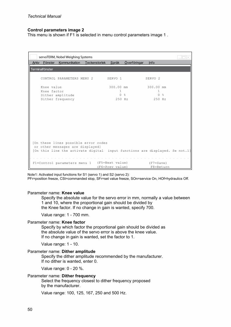
Technical Manual
50
Control parameters image 2 This menu is shown if F1 is selected in menu control parameters image 1 .
Note1: Activated input functions for S1 (servo 1) and S2 (servo 2): PFr=position freeze, CSt=commanded stop, SFr=set value freeze, SOn=service On, HOf=hydraulics Off.
Parameter name: Knee value Specify the absolute value for the servo error in mm, normally a value between 1 and 10, where the proportional gain should be divided by the Knee factor. If no change in gain is wanted, specify 700.
Value range: 1 - 700 mm.
Parameter name: Knee factor Specify by which factor the proportional gain should be divided as the absolute value of the servo error is above the knee value. If no change in gain is wanted, set the factor to 1.
Value range: 1 - 10.
Parameter name: Dither amplitude Specify the dither amplitude recommended by the manufacturer. If no dither is wanted, enter 0.
Value range: 0 - 20 %.
Parameter name: Dither frequency Select the frequency closest to dither frequency proposed by the manufacturer.
Value range: 100, 125, 167, 250 and 500 Hz.
Arkiv Fönster Kommunikation Teckenstorlek Info
CONTROL PARAMETERS MENU 2
Knee value 300.00 mm
F1=Control parameters menu 1
[On this line the activate digital input functions are displayed. Se not.1]
(F7=Save)
Språk Överföringar
Terminalfönster
SERVO 1 SERVO 2
300.00 mmKnee factorDither amplitude 0 %Dither frequency
F8=Return
1 1 0 %
250 Hz 250 Hz
[On these lines possible error codes or other messages are displayed]
(F5=Next value) (F6=Prev value)

Servo unit microPOS 4
51
(F5 Next value) Switches to next value alternative (choice) when defined values (choices) for the parameter exist. Displayed only as editing is allowed.
(F6 Previous value) Switches to previous value alternative (choice) when defined values (choices) for the parameter exist. Displayed only as editing is allowed.
(F7 Save) Saves edited values in FRAM memory. Displayed only if editing has been performed.
F8 Return Returns to higher-level menu SET-UP
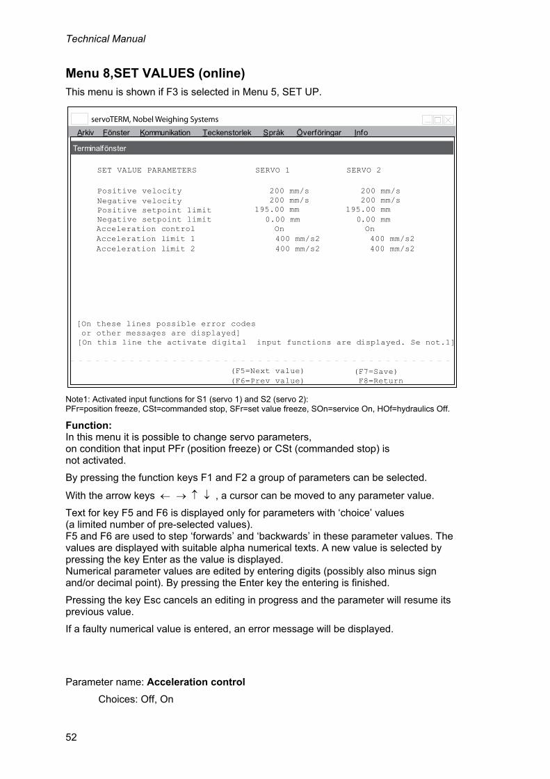
Technical Manual
52
Menu 8,SET VALUES (online) This menu is shown if F3 is selected in Menu 5, SET UP.
Note1: Activated input functions for S1 (servo 1) and S2 (servo 2): PFr=position freeze, CSt=commanded stop, SFr=set value freeze, SOn=service On, HOf=hydraulics Off.
Function: In this menu it is possible to change servo parameters, on condition that input PFr (position freeze) or CSt (commanded stop) is not activated.
By pressing the function keys F1 and F2 a group of parameters can be selected.
With the arrow keys , a cursor can be moved to any parameter value.
Text for key F5 and F6 is displayed only for parameters with ‘choice’ values (a limited number of pre-selected values). F5 and F6 are used to step ‘forwards’ and ‘backwards’ in these parameter values. The values are displayed with suitable alpha numerical texts. A new value is selected by pressing the key Enter as the value is displayed. Numerical parameter values are edited by entering digits (possibly also minus sign and/or decimal point). By pressing the Enter key the entering is finished.
Pressing the key Esc cancels an editing in progress and the parameter will resume its previous value.
If a faulty numerical value is entered, an error message will be displayed.
Parameter name: Acceleration control
Choices: Off, On
Arkiv Fönster Kommunikation Teckenstorlek Info
SET VALUE PARAMETERS
Positive velocity 200 mm/s
Acceleration control On
[On this line the activate digital input functions are displayed. Se not.1]
(F7=Save)
Språk Överföringar
Terminalfönster
SERVO 1 SERVO 2
200 mm/sNegative velocityPositive setpoint limit 195.00 mmNegative setpoint limit
F8=Return
200 mm/s 200 mm/s 195.00 mm
0.00 mm 0.00 mm On
[On these lines possible error codes or other messages are displayed]
(F5=Next value) (F6=Prev value)
Acceleration limit 1 400 mm/s2 400 mm/s2Acceleration limit 2 400 mm/s2 400 mm/s2

Servo unit microPOS 4
53
Parameter name: Acceleration limit 1 Parameters ”Acceleration limit 1” and ”Acceleration limit 2” are normally set to equal values for a ‘soft’ motion. If the actuator works with heavy loads, especially in vertical direction, it may be useful to set different acceleration limits for the two cylinder areas of the actuator. See illustration below. As the force acts on the cylinder area where the smallest measure is specified the acceleration is influenced by ”Acceleration limit 1”.
Value range: 0.1 - 10 000 mm/s².
Parameter name: Acceleration limit 2 See also ”Acceleration limit 1” and illustration above. As the force acts on the cylinder area where the biggest measure is specified the acceleration is influenced by ”Acceleration limit 2”.
Value range: 0.1 - 10 000 mm/s².
Parameter name: Positive velocity Specify the wanted velocity limit as the piston moves to bigger measures. If no limitation is wanted, enter 1000.
Value range: 2 - 1000 mm/s.
Parameter name: Negative velocity Specify the wanted velocity limit as the piston moves to smaller measures. If no limitation is wanted, enter 1000.
Value range: 2 - 1000 mm/s.
Parameter name: Positive set point limit Specify the biggest measure for the piston position. Select a suitable value to prevent the piston from touching the cylinder end. Set point values above the set point limit give a movement to the limit value only. As cylinder length is specified, a default value is generated.
Value range: 0 - 655 mm.
Parameter name: Negative set point limit Specify the smallest measure for the piston position. Select a suitable value to prevent the piston from touching the cylinder end. Set point values below the set point limit give a movement to the limit value only. As cylinder length is specified, a default value is generated.
Value range: 0 - 655.
(F5 Next value) Switches to next value alternative (choice) when defined values (choices) for the parameter exist. Displayed only as editing is allowed.
position
time0
max
Acc. limit 1 Acc. limit 1
Acc. limit 2 Acc. limit 2

Technical Manual
54
(F6 Previous value) Switches to previous value alternative (choice) when defined values (choices) for the parameter exist. Displayed only as editing is allowed.
(F7 Save) Saves edited values in FRAM memory. Displayed only if editing has been performed.
F8 Return Returns to higher-level menu SET-UP

Servo unit microPOS 4
55
Menu 9, DIGITAL I/O FUNCTIONS (online) This menu is shown if F4 is selected in Menu 5, SET UP.
Note1: Activated input functions for S1 (servo 1) and S2 (servo 2): PFr=position freeze, CSt=commanded stop, SFr=set value freeze, SOn=service On, HOf=hydraulics Off.
Function: In this menu it is possible to change servo parameters, on condition that input PFr (position freeze) or CSt (commanded stop) is not activated.
By pressing the function keys F1 and F2 a group of parameters can be selected.
With the arrow keys , a cursor can be moved to any parameter value.
F5 and F6 are used to step ‘forwards’ and ‘backwards’ in these parameter values. The values are displayed with suitable texts. A new value is selected by pressing the key Enter as the suitable text is displayed.
Arkiv Fönster Kommunikation Teckenstorlek Info
DIGITAL I/O-PARAMETERS
Digital input 1 Service, servo 1
[On this line the activated digital input functions are displayed. See not.1]
(F7=Save)
Språk Överföringar
Terminalfönster
F8=Return
[On these lines possible error codes or other messages are displayed ]
F5=Next valueF6=Prev value
Digital output 5 Unused
Digital input 2 Service, servo 2Digital input 3 Position freezing, servo 1+2
Digital input 4 UnusedDigital input 5 Unused
Digital output 4 UnusedDigital output 3 UnusedDigital output 2 In position, servo 2Digital output 1 In position, servo 1
Technical Manual
56
Parameter name: Digital input 1-5 All functions are active as the input signal is low except for the service functions which are active as the input signal is high.
As one of the five digital inputs is programmed, these choices exist:
Unused The input signal has no effect.
Position freezing (active low): servo 1 Keeps servo 1 in actual position (reading the position and setting set value = ramped set value = position). servo 2 Keeps servo 2 in actual position (reading the position and setting set value = ramped set value = position). servo 1+ 2 Keeps servo 1 and 2 in actual position (reading the position and setting set value = ramped set value = position).
Controlled stop (active low): servo 1 Retardation to zero velocity with a parameter for acceleration limitation in servo 1. servo 2 Retardation to zero velocity with a parameter for acceleration limitation in servo 2. servo 1+ 2 Retardation to zero velocity with one parameter for acceleration limitation in servo 1 and one parameter for acceleration limitation in servo 2.
Service (moving aside) (active high): servo 1 Servo 1 giving a valve control signal (±50 %), programmable in the set-up for servo 1. servo 2 Servo 2 giving a valve control signal (±50 %), programmable in the set-up for servo 2. servo 1+ 2 Servo 1 and 2 giving valve control signals, programmable in the set-up for servo 1 and servo 2.
Set value freezing (keep the value, log in the machine) (active low): servo 1 New external set values for servo 1 refused, freeze the latest set value. servo 2 New external set values for servo 2 refused, freeze the latest set value. servo 1+ 2 New external set values for servo 1 and 2 refused, freeze the latest set values.
Hydraulics off (active low): servo 1+ 2 Servo 1 and 2 giving the valve control signal zero
As a programmed input is activated, the last line in the actual menu gives a message, indicating which input functions are activated.
Zero control signal is always 0 mA or V (without possible ‘valve balance’).
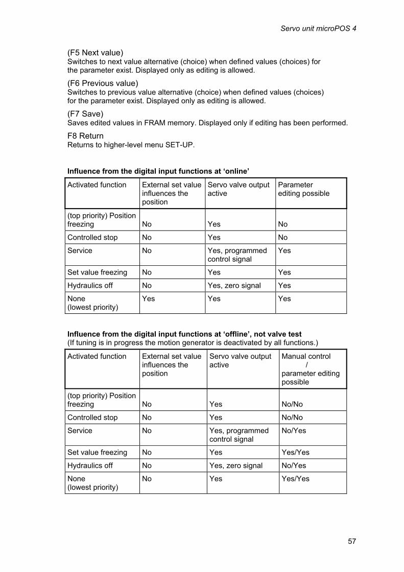
Servo unit microPOS 4
57
(F5 Next value) Switches to next value alternative (choice) when defined values (choices) for the parameter exist. Displayed only as editing is allowed.
(F6 Previous value) Switches to previous value alternative (choice) when defined values (choices) for the parameter exist. Displayed only as editing is allowed.
(F7 Save) Saves edited values in FRAM memory. Displayed only if editing has been performed.
F8 Return Returns to higher-level menu SET-UP.
Influence from the digital input functions at ‘online’
Activated function External set value influences the position
Servo valve output active
Parameter editing possible
(top priority) Position freezing
No
Yes
No
Controlled stop No Yes No
Service No Yes, programmed control signal
Yes
Set value freezing No Yes Yes
Hydraulics off No Yes, zero signal Yes
None (lowest priority)
Yes Yes Yes
Influence from the digital input functions at ‘offline’, not valve test (If tuning is in progress the motion generator is deactivated by all functions.)
Activated function External set value influences the position
Servo valve output active
Manual control / parameter editing possible
(top priority) Position freezing
No
Yes
No/No
Controlled stop No Yes No/No
Service No Yes, programmed control signal
No/Yes
Set value freezing No Yes Yes/Yes
Hydraulics off No Yes, zero signal No/Yes
None (lowest priority)
No Yes Yes/Yes

Technical Manual
58
Influence from the digital input functions at ‘offline’ by valve test
Activated function External set value influences the position
Servo valve output active
Manual control and parameter editing possible
(top priority) Position freezing
No
Yes, zero control signal 0%
No
Controlled stop No Yes, zero control signal 0%
No
Service No Yes, programmed control signal
No
Set value freezing No Yes, zero control signal 0%
No
Hydraulics off No Yes, zero control signal 0%
No
None (lowest priority)
No Yes, selected control signal balance */
Yes
*/ At reset after a function has been activated the control signal 0 % (= valve balance value).
Parameter name: Relay output 1-5
By programming of each of the five relay outputs these choices exist:
Unused The relay output is not activated (NO).
In position active = INPO servo 1 Activates the relay output as servo 1 is within the window ‘In position’ for servo 1. servo 2 Activates the relay output as servo 2 is within the window ‘In position’ for servo 2. servo 1+ 2 Activates the relay output as servo 1 is within the window ‘In position’ for servo 1 and servo 2 is within the window ‘In position’ for servo 2.
Status activated = CONTR servo 1 Activates the relay output as servo 1 is installed, in online position and no digital input for servo 1 is activated. servo 2 Activates the relay output as servo 2 is installed, in online position and no digital input for servo 2 is activated. servo 1+ 2 Activates the relay output as servo 1 is installed, in online position and as servo 2 is installed, in online position and no digital input is activated.
Error condition (Not activated = ERR) servo 1+ 2 Deactivates the relay output if a soft ware error is detected or at power failure.

Servo unit microPOS 4
59
Menu 10,START-UP (online/offline) This menu is shown if F3 is selected in Menu 1, SYSTEM STATUS. And the system is unlocked with password.
Note1: Activated input functions for S1 (servo 1) and S2 (servo 2): PFr=position freeze, CSt=commanded stop, SFr=set value freeze, SOn=service On, HOf=hydraulics Off.
NOTE. By pressing F1 toggling between offline and online can be done.
The following menus are available from this menu.
F2 TUNE (Menu 11) (only available with system offline) F3 CALIBRATE (Menu 12) (only available with system offline) F4 CALIBRATION PARAMETERS (Menu 13) F5 BALANCE (Menu 14) F6 VALVE TEST (Menu 15) (only available with system offline)
To be able to return to Menu 1, SYSTEM STATUS the system must be set to online.
File W indow Communications Font size Info
START UP
System is ONLINE
F1=Offline F3=Calibrate F5=Balance (F7=Save)
[On this line the activated digital input functions are displayed. See note 1]
Language Transfers
Terminal Window
F2=Tune F4=Calibration param. F6=Valve test F8=Return

Technical Manual
60
Menu 11, SERVO TUNING (offline) This menu is displayed as F2 is selected in Menu 10, START-UP.
Note1: Activated input functions for S1 (servo 1) and S2 (servo 2): PFr=position freeze, CSt=commanded stop, SFr=set value freeze, SOn=service On, HOf=hydraulics Off.
Function: This function is used to set some servo parameters and the parameters for a motion generator. If input PFr (position freeze) or CSt (commanded stop) is activated no values can be edited and the motion generated cannot be activated. As the motion generator is started a reciprocating motion between position S1 and S2 takes place while editing of several servo parameters is possible. Key F1 is used to alternately start and stop the motion generator, indicated by On/Off in the menu. Key F2 is used to select Servo 1 or Servo 2, the selection displayed in the menu. By key F3 or and F4 or searching forwards and backwards among the possible parameters can be performed. By key F5 or and F6 or parameter values can be changed to the choice values or in steps of 1 dB. Different texts for the keys are displayed in the two cases. Parameter values can also be entered numerically. If an erroneous parameter value is entered, an error message is displayed. Key F7 can be used to switch to a menu for setting of the motion generator parameters.
File W indow Communications Font size Info
OFFLINE START-UP - SERVO TUNING
Servo 1
[On these lines possible error codes or other messages are displayed ]
F1=Mog on/off F3=Next parm F5=Step + F7=Mog parms
[On this line the activated digital input functions are displayed. See note 1]
Language Transfers
Terminal Window
Parameter name: [Name]
Motion generator: Off
Pos: 185.55 mm S1: 20.00 mm S2: 120 mm T: 30 s
F2=Servo 1/2 F4=Prev parm F6=Step - F8=Return
Parameter value: [Value (unit)]

Servo unit microPOS 4
61
F1 Motion generator on/off Starts the motion generator by alternately giving the setpoint value = S1 or S2 and waiting the time T.
F2 Servo 1/2 Selection of the servo to tune. Switches between Servo 1 and Servo 2.
F3 () Next parameter Switches to next parameter name from the valid list of parameters.
Acceleration control, Acceleration limit 1, Acceleration limit 2, Positive velocity, Negative velocity, Proportional gain, Knee value, Knee factor, Integration window, Integration factor, Integration delay, Positive integration limit, Negative integration limit,
F4 () Previous parameter Switches to previous parameter name in the valid list of parameters.
(F5 () Next value, alt. Step+) Switches to next value alternative (choice) when defined values (choices) for the parameter exist, or increases the parameter value by 1 dB. Displayed only as editing is allowed.
(F6 () Previous value, alt. Step-) Switches to previous value alternative (choice) when defined values (choices) for the parameter exist, or decreases the parameter value by 1 dB. Displayed only as editing is allowed.
F7 Motion generator parameters Switches to a menu for setting of the two set point values and the time for the motion generated. See next page.
F8 Return Returns to higher-level menu, Menu 10, START-UP (online/offline).

Technical Manual
62
Menu for the set-up of motion generator parameters.
Note1: Activated input functions for S1 (servo 1) and S2 (servo 2): PFr=position freeze, CSt=commanded stop, SFr=set value freeze, SOn=service On, HOf=hydraulics Off.
Function: The function is used to set the motion generator parameters. If Servo tuning shall be used together with the Measuring output functions it is suitable to use two set point values in the middle of the working range, and not too far apart (5 - 10 mm). The time parameter defines the time delay between set point changes. By short time delays and big set point value changes the servo may not be able to perform the positioning completely.
F3 () Next parameter Switches to next parameter name in the list of parameters. The following parameter names exist:
Parameter name: Set value 1 Following range exists: Negative set point limit to Positive set point limit
Parameter name: Set value 2 Following range exists: Negative set point limit to Positive set point limit
Parameter name: Time delay Following values exist: 1 - 60 s.
F4 () Previous parameter Switches to previous parameter name in the list of parameters.
F8 Return Returns to higher-level menu SERVO TUNING.
File W indow Communications Font size Info
OFFLINE SETART-UP - SERVO TUNING
Servo 1
[On these lines possible error codes or other messages are displayed ]
F3=Next parm
[On this line the activated digital input functions are displayed. See note 1]
Language Transfers
Terminal Window
Motion gen. parameter name: [Name]
F4=Prev parm F8=Return
Motion gen. parameter value: [Value (unit)]

Servo unit microPOS 4
63
Menu 12, CALIBRATION (offline)
Function: The function is used for position calibration. Three different types of calibration can be performed: Cylinder value calibration (default value), Absolute two-point calibration, and Relative two-point calibration. The parameter names to set are: Scale factor for feedback (gradient), Zero offset coarse, and Zero offset fine. Type of calibration is selected by key F1. The text "Cylinder value" is shown only if Cylinder value calibration is selected.
Cylinder value calibration Cylinder value calibration is used if the hydraulic actuator has a known cylinder value. The cylinder value is a value between 5 and 13 that is entered at the given position. Then microPOS 4 converts it to a Scale factor for feedback value. As a cylinder value is entered, microPOS 4 adds the value of 'Zero offset fine' to 'Zero offset coarse' and then sets 'Zero offset fine' to zero. After that an adjustment of Zero offset coarse can be performed to get the correct position. NOTE! Cylinder value calibration should not be performed close to the end positions (set value limits).
Absolute two-point calibration Absolute two-point calibration is used when a fix point for zero position or for zero point calculation exists. It is advisable to position the zero point some mm from the front actuator end. This point constitutes the reference point for the position measurement.
Start by positioning the piston in extended position, but not in contact with the actuator front end, by entry of a numerical Set value. Measure the distance to the fix point and enter that value at Position. After the first position value is entered, Calibration menu 2 will be displayed (see next menu). Then position the piston in retracted position, but not in contact with the rear actuator end, by entry of a numerical Set value. Measure the distance to the fix point and enter the value at Position 2. As the second position value is entered, microPOS 4 will calculate the ‘Scale factor for feedback value’ and then add of the value of 'Zero offset fine' to 'Zero offset coarse'. 'Zero offset fine' is then set to zero and the first calibration menu will be displayed again. The measured and entered position values must be inside the limited range for the cylinder.
Relative two-point calibration Relative two-point calibration is used when an optional fix point exists, that can be used for position measurement. Start by positioning the piston in extended position, but not in contact with the actuator front end, by entry of a numerical Set value. Measure the distance to the fix point and enter that value at Position. After the first position value is entered Calibration menu 2 will be displayed (see next menu). Then position the piston in retracted position, but not in contact with the actuator rear end, by entry of a numerical Set value. Measure the distance to the fix point and enter the value at Position. As the second position value is entered microPOS 4 calculates the ‘Scale factor for feedback value’ and the first calibration menu will be displayed again. Finally enter a suitable numerical value at Zero offset coarse, to get the piston in correct position.

Technical Manual
64
Cylinder value calibration This menu is displayed as F3 is selected in Menu 10, START-UP.
Note1: Activated input functions for S1 (servo 1) and S2 (servo 2): PFr=position freeze, CSt=commanded stop, SFr=set value freeze, SOn=service On, HOf=hydraulics Off.
Numerical values should be entered in the shown positions. Key F3 or is used to select the correct line for entry. At "Set value" the set value for the actual servo is displayed/entered. At "Position" the actual servo position is displayed. For two-point calibration, this line is used for entry of the measured positions (referring to zero or any fix point). After entry of one new value, another menu for calibration point 2 is displayed. At the bottom line the zero offset value needed for the wanted zero position is displayed/entered.
No values can be edited if input PFr (position freeze) or CSt (controlled stop) is activated.
Editing of numerical parameters is made by entry of digits (and possible minus and/or decimal point) and finished by key Enter. An editing in progress is cancelled as the Esc key is pressed. In this case the display returns to the actual parameter value. If an erroneous parameter value is entered an error message is displayed.
F1 Calibration type Switches between the possible calibration types: Cylinder value calibration, Absolute two-point calibration, and Relative two-point calibration. The selection is displayed on line 4.
F2 Servo 1/2 Switches between Servo 1 and Servo 2. The selection is displayed in the menu.
F3 () Next line Switches between different lines in the menu.
File W indow Communications Font size Info
OFFLINE POSITION CALIBRATION
Cylinder value calibration
[On these lines possible error codes or other messages are displayed ]
F1=Cal. type F3=Next line
[On this line the activated digital input functions are displayed. See note 1]
Language Transfers
Terminal Window
Servo 1
Position: 54.62 mm
F2=Servo 1/2 F8=Return
Cylinder value: 8.207
Zero offset coarse: 100.00 mm
Set value: 54.60 mm

Servo unit microPOS 4
65
By Cylinder calibration: Cylinder value 1, Set value 1, and Zero offset coarse. By Absolute two-point calibration and Relative two-point calibration: Set value, Position, and Zero offset coarse.
F8 Return Returns to higher-level menu “Menu 10, START-UP (online/offline).
Absolute two-point calibration and Relative two-point calibration
The menu below is displayed after Position 1 has been entered in a two-point calibration.
Note1: Activated input functions for S1 (servo 1) and S2 (servo 2): PFr=position freeze, CSt=commanded stop, SFr=set value freeze, SOn=service On, HOf=hydraulics Off.
Function: Entry of calibration point 2 at two-point calibrations. Selection of line and values is performed like in the previous menu ‘Calibration menu 1’ As a new value for position 2 is entered and accepted the calibration is performed and Calibration menu 1 will be displayed again. Key F5 is used to cancel the calibration and return to Calibration menu 1 without editing.
F3 () Next line Switches between the lines Set value 2 and Position 2.
F5 Cancel calibration Returns to previous menu, (Calibration menu 1), without performing any calibration.
F8 Return Returns to higher-level menu “Menu 10, START-UP (online/offline).
File W indow Communications Font size Info
OFFLINE SET-UP POSITION CALIBRATION
Relative (Absolute) two-point calibration (example)
[On these lines possible error codes or other messages are displayed ]
F3=Next line F5=Cancel calib.
[On this line the activated digital input functions are displayed. See note 1]
Language Transfers
Terminal Window
Servo 1
Position 2: 234.42 mm
Zero offset coarse: 95.00 mm
Set value 2: 234.40 mm

Technical Manual
66
Menu 13, CALIBRATION PARAMETERS This menu is displayed as F4 is selected in Menu 10, START-UP.
Note1: Activated input functions for S1 (servo 1) and S2 (servo 2): PFr=position freeze, CSt=commanded stop, SFr=set value freeze, SOn=service On, HOf=hydraulics Off.
Parameter name: Scale factor for feedback value This is a gradient used internally to transform position transducer voltage to 1/100 mm. The specified cylinder length generates a default value. This parameter is edited in a more controlled way in menu Calibration.
Value range: 0.01000 - 1.95000.
Parameter name: Zero offset coarse This is a parameter used to specify the internal zero position. The specified cylinder length generates a default value. This parameter is edited in a more controlled way in menu Calibration.
Value range: -1000.00 - 1000.00 mm.
Parameter name: Zero offset fine This is a parameter used to specify the internal zero position. As a cylinder length is specified and by calibration this parameter is set to zero.
Value range: -100.00 - 100.00 mm.
F8 Return Returns to higher-level menu “Menu 10, START-UP (online/offline).
Arkiv Fönster Kommunikation Teckenstorlek Info
CALIBRATION PARAMETERS
Scale factor for feedback value 0.32064
[On this line the activate digital input functions are displayed. Se not.1]
(F7=Save)
Språk Överföringar
Terminalfönster
SERVO 1 SERVO 2
0.32064Zero offset coarseZero offset fine 0.00 mm
F8=Return
97.45 mm 97.45 mm 0.00 mm
[On these lines possible error codes or other messages are displayed]

Servo unit microPOS 4
67
Menu 14, BALANCING This menu is displayed as F5 is selected in Menu 10, START-UP.
Note1: Activated input functions for S1 (servo 1) and S2 (servo 2): PFr=position freeze, CSt=commanded stop, SFr=set value freeze, SOn=service On, HOf=hydraulics Off.
Function: Servo valve balancing is performed by adjusting the control signal to the valve in order to minimise the servo error. The integration is off during valve balancing. The valve balance value cannot be edited if input PFr (position freeze) or CSt (commanded stop) is activated.
If the valve has means for mechanical balancing, start by disconnecting the valve connector and make a mechanical balancing.
Correct valve balancing is essential to obtain good servo operation. The balance is temperature depending so balancing must be performed at normal operating temperature. Dither can be used to reduce the hysteresis of some valves.
Key F2 is used to select Servo 1 or Servo 2. The selection displayed in the menu.
By the keys F5 or and F6 or the valve balance value can be adjusted upwards and downwards by steps of 0.05 %.
The valve balance value can also be entered by the numerical keys. The value should be about 0 %. Value range: -100 - 100 %.
The measured deviation from zero (servo error) is always displayed in the menu.
If an erroneous numerical value is entered, an error message is displayed.
File W indow Communications Font size Info
BALANCING OF SERVO VALVE
Servo 1
[On these lines possible error codes or other messages are displayed ]
F5=Step +
[On this line the activated digital input functions are displayed. See note 1]
Language Transfers
Terminal Window
Valve balance: 0.00 %
F2=Servo 1/2 F6=Step - F8=Return
Servo error: 0.01 mm

Technical Manual
68
F2 Servo 1/2 Switches between Servo 1 and Servo 2.
F5 () Step + Steps the valve balance value upwards by 0.05 %, max = +100 %.
F6 () Step - Steps the valve balance value downwards by -0.05 %, min = -100 %.
F8 Return Returns to higher-level menu “Menu 10, START-UP (online/offline).

Servo unit microPOS 4
69
Menu 15, VALVE TEST This menu is displayed as F6 is selected in Menu 10,START-UP or if F2 is pressed in Menu 16, TEST.
Note1: Activated input functions for S1 (servo 1) and S2 (servo 2): PFr=position freeze, CSt=commanded stop, SFr=set value freeze, SOn=service On, HOf=hydraulics Off.
Function: This function is used to manually set valve control signal for the servo outputs. The menu helps check that the connections to the servo actuator are correct. If a positive control signal is set, the piston should move in positive direction and the position value should increase. If a negative control signal is set, the piston should move in negative direction.
A friction test can also be performed. Decrease the valve control signal until the piston does not move. Then increase the valve control signal slowly, check when the piston starts moving and note the control signal value (%). Decrease the valve control signal again until the piston does not move. Then decrease the valve control signal (negative) slowly, check when the piston starts moving and note the control signal value (%). The difference between the two values shows the size of the friction, and a later measurement can show if the friction has increased or decreased.
Key F2 is used to switch between Servo 1 and Servo 2.
By the keys F5 or and F6 or the value of the control signal can be adjusted upwards and downwards by the step length displayed at Step.
Entry of numerical values is preceded, if necessary, by line selection with key F3 or .
Position, measured by the system, is always displayed in the menu.
If an erroneous numerical value is entered, an error message will be displayed.
File W indow Communications Font size Info
OFFLINE START UP - VALVE TEST
Servo 1
[On these lines possible error codes or other messages are displayed ]
F3=Next line F5=Step +
[On this line the activated digital input functions are displayed. See note 1]
Language Transfers
Terminal Window
Position: 123.50 mm
F2=servo 1/2 F6=Step - F8=Return
Current: 0.00 %
Step: 0.05 %

Technical Manual
70
F2 Servo 1/2 Switches between Servo 1 and Servo 2.
F3 Next line Switches between different lines in the menu.
Switching between the lines Valve signal and Step is possible.
F5 () Step + Adds the Step value to the Valve signal value.
F6 () Step - Subtracts the Step value from the Valve signal value.
F8 Return Returns to higher-level menu, “START-UP (online/offline)” or. “TEST”.

Servo unit microPOS 4
71
Menu 16, TEST This menu is displayed as F6 is selected in Menu 1, SYSTEM STATUS, and correct password is entered.
Note1: Activated input functions for S1 (servo 1) and S2 (servo 2): PFr=position freeze, CSt=commanded stop, SFr=set value freeze, SOn=service On, HOf=hydraulics Off.
Function: By the function keys F1 – F3 a number of different test functions can be selected. When entering these functions the system goes into “offline” mode.
F1 Manual servo test Switches to Menu 17, MANUAL SERVO TEST where new set point values can be generated. See menu 17 for explanation.
F2 Valve test Switches to Menu 15, VALVE TEST where a control signal for the valve can be generated. As Valve test is activated the servo loop is broken and the servo is operated by open control. See menu 15 for explanation.
F3 Digital I/O test Switches to Menu 18, DIGITAL I/O TEST where status for inputs and outputs is shown and the outputs can be controlled. See menu 18 for explanation.
F8 Return Returns to the higher-level menu SYSTEM STATUS.
File W indow Communications Font size Info
TEST
WARNING: F1 - F3 entering offline functions. F8 to return
F1=Man servo F3=Dig I/O
[On this line the activated digital input functions are displayed. See note 1]
Language Transfers
Terminal Window
F2=Valve F8=Return

Technical Manual
72
Menu 17, MANUAL SERVO TEST (offline) This menu is displayed as F1 is selected in Menu 16, TEST.
Note1: Activated input functions for S1 (servo 1) and S2 (servo 2): PFr=position freeze, CSt=commanded stop, SFr=set value freeze, SOn=service On, HOf=hydraulics Off.
Function: Entry of a Set value for manual positioning of the servo. If Set values over the Positive set point limit or under the Negative set point limit are entered, an error message will be displayed. Set values cannot be edited if input PFr (position freeze) or CSt (commanded stop) is activated.
Key F1 is used to select positioning of Servo 1 and Servo 2 simultaneously and with the same Set value. A change in Set value for Servo 1 will result in Servo 2 having the same Set value as Servo 1.
Key F2 is used to select positioning of one servo and to switch between Servo 1 and Servo 2. As key F2 is selected, information about selected servo only is displayed.
By the keys F5 or and F6 or the Set value can be adjusted upwards and downwards by steps of the length displayed at Step.
Entry of numerical values for Position and Set value can, if required, be preceded by selection of line by key F3 or .
Positions, measured by the system, are always displayed in the menu.
File W indow Communications Font size Info
OFFLINE TEST MANUAL SERVO TEST
Servo 1+2 S1: S2:
[On these lines possible error codes or other messages are displayed ]
F1=Servo 1+2 F3=Next line F5=Step +
[On this line the activated digital input functions are displayed. See note 1]
Language Transfers
Terminal Window
Position: 123.55 mm 123.55 mm
F2=servo 1/2 F6=Step - F8=Return
Set value: 123.58 mm 123.58 mm
Step: 10.00 mm

Servo unit microPOS 4
73
F1 Servo 1+2 Key F1 is used to select positioning of Servo 1 and Servo 2 simultaneously and with the same Set value.
F2 Servo 1/2 Key F2 is used to select positioning of one servo and to switch between Servo 1 and Servo 2.
F3 () Next line Switches between different lines in the menu.
Switching between the lines Set value and Step is possible.
F5 () Step + Adds the Step value to the Set value.
F6 () Step - Subtracts the Step value from the Set value.
F8 Return Returns to higher-level Menu 16, TEST.
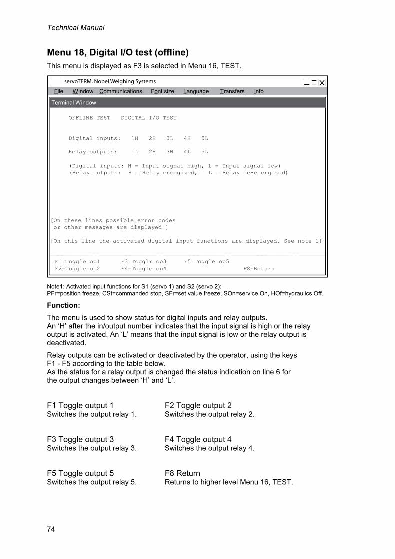
Technical Manual
74
Menu 18, Digital I/O test (offline) This menu is displayed as F3 is selected in Menu 16, TEST.
Note1: Activated input functions for S1 (servo 1) and S2 (servo 2): PFr=position freeze, CSt=commanded stop, SFr=set value freeze, SOn=service On, HOf=hydraulics Off.
Function:
The menu is used to show status for digital inputs and relay outputs. An ‘H’ after the in/output number indicates that the input signal is high or the relay output is activated. An ‘L’ means that the input signal is low or the relay output is deactivated.
Relay outputs can be activated or deactivated by the operator, using the keys F1 - F5 according to the table below. As the status for a relay output is changed the status indication on line 6 for the output changes between ‘H’ and ‘L’.
F1 Toggle output 1 F2 Toggle output 2 Switches the output relay 1. Switches the output relay 2.
F3 Toggle output 3 F4 Toggle output 4 Switches the output relay 3. Switches the output relay 4.
F5 Toggle output 5 F8 Return Switches the output relay 5. Returns to higher level Menu 16, TEST.
File Window Communications Font size Info
OFFLINE TEST DIGITAL I/O TEST
Digital inputs: 1H 2H 3L 4H 5L
[On these lines possible error codes or other messages are displayed ]
F1=Toggle op1 F3=Togglr op3 F5=Toggle op5
[On this line the activated digital input functions are displayed. See note 1]
Language Transfers
Terminal Window
Relay outputs: 1L 2H 3H 4L 5L
F2=Toggle op2 F4=Toggle op4 F8=Return
(Digital inputs: H = Input signal high, L = Input signal low)(Relay outputs: H = Relay energized, L = Relay de-energized)

Servo unit microPOS 4
75
Menu 19, BACKUP (online) This menu is displayed as F6 is selected in Menu 1, SYSTEM STATUS, and correct password is entered.
Note1: Activated input functions for S1 (servo 1) and S2 (servo 2): PFr=position freeze, CSt=commanded stop, SFr=set value freeze, SOn=service On, HOf=hydraulics Off.
Function: In this menu backup and restore of microPOS 4 servo parameters in a computer is handled. Set-up parameters are saved in the computer as an ASCII-file, using the file transfer function in the terminal program. Restore is also performed by the file transfer function the terminal program.
The backup and restore performed in this menu does not include the interface parameters, described on pages 23 to 27.
File W indow Communications Font size Info
BACKUP
[On these lines possible error codes or other messages are displayed ]
F1=Backup
[On this line the activated digital input functions are displayed. See note 1]
Language Transfers
Terminal Window
F2=Restore F8=Return
BACKUP OF SET-UP DATA ON FILE IN THE COMPUTERStart reception of set-up data (Transfers, Receive Text File...,select a destination, enter a file name (.TXT) and thenselect SAVE). Select F1 (Backup). Click the OK button when'File transfer ready' appears on the screen.
RESTORE OF SET-UP DATA FROM FILE TO microPOS
when 'File transfer ready' appears on the screen, select F3 (Ok) toaccept new set-up data or F4 (Cancel) to skip the new set-up data.
Select F2 (Restore). Start transmission of set-up data (Transfers,Send Text File..., select a file and then OPEN). Click the OK button

Technical Manual
76
Backup of set-up parameters in the computer
Select Transfers and then Receive text file from the Terminal menu.
Select a destiny map and specify a file name (.TXT). Then press "Save". Now the file transfer information is shown in a separate window.
Select function key Backup (F1). Now the number of transferred bytes will be displayed in the separate window, and the data is saved in the selected file.
As the transfer is finished, this is shown in a separate message window.
Restore of set-up parameters to microPOS 4
Select function key Restore (F2).
Select Transfers and then Send text file from the Terminal menu.
Select the wanted file name (.TXT). Then press ”Open”. Now the file transfer information is shown in a separate window.
As the file transfer is finished, this is shown in separate message window. Press OK in this window.
Select function key Ok (F3) to take the new parameter values into operation, or select function key Cancel (F4) to cancel (microPOS 4 will resume the previous parameter values).
If Ok is selected after restore of parameter values, microPOS 4 will check that the values are within limits for the parameters respectively. If a value is outside the limits an error message is given and the new value will not be used.
F1 Backup Data is sent from microPOS 4 for storing in a predefined text file.
F2 Restore Saved set-up parameters are restored in microPOS 4.
(F3 Ok) Performing Restore (F2), see description above.
(F4 Cancel) The new parameter values will not be used, microPOS 4 will continue using the present parameter values.
F8 Return Returns to the higher-level menu SET-UP (offline).

Servo unit microPOS 4
77
5. Hydraulic installation
5.1. General The hydraulic system must be dimensioned for the pressure and flow, demanded by the servo system. If large flow is needed for shorter periods an accumulator can be added to the system. The hydraulic unit must have oil filter and an air filter for the reservoir, especially in dusty environment.
It is important to keep the oil temperature constant: Install an oil cooler if high temperatures can be suspected. Install a heater in the reservoir if there is risk of low temperatures.
From the hydraulic unit the pressure (P) and reservoir (T) connections are made to ports on the servo actuator for POS 100 actuators. For POS 50 actuators, the connections are made to the servo valve manifold block, and the manifold block is connected to the servo actuator by tubes.
5.2. Flushing As new hydraulic systems, or systems that has been dismounted, are taken into operation, they must first be flushed to clean the oil from particles that could otherwise block filters or slits in the servo valve and actuator. After service and mounting there is always contamination in a hydraulic system.
Before flushing, remove the servo valve from the manifold block and replace it by a special flushing plate. For POS 50 the tubes must also be disconnected from the actuator and connected to each other with a hose for example.
The flushing should continue for 2.5 h with the oil at operating temperature. After that the servo valves can be installed again. If required, change dirty filters before the servo system is taken in operation.
See Technical data for filtering degree.

Technical Manual
78
Hydraulic system Actuator length 10 to 655 mm (may be longer with special software) Hydraulic oil Type 32 Viscosity 25 - 50 Cst at normal operating temperature Oil temperature <60 ºC Filtering degree 6 m absolute
Servo unit microPOS 4
79
6. Start-up
6.1. General Connect the PC to microPOS 4, according to the installation instructions for serial communication in chapter 3, ‘”Ethernet for Modbus-TCP’ and/or ‘RS-485 for Modbus-RTU’.
Some settings are common for the servo unit but most of the settings are separate for each servo channel. At starting up the protocols in Appendix 1 and 2 should be completed.
For microPOS 4 there are two ways to perform set-up/starting up: ‘Quick set-up’ giving a good result in most cases, ‘Advanced set-up’ giving complete access to all servo parameters. The ‘Advanced set-up’ may be required for extremely fast or heavy machines.
6.2. Preparations 1. Check that the connections are correct with respect to electronics and hydraulics.
Pull gently on the cables to check that they are properly attached.
2. Check that the hydraulic connections are properly performed and that the system has been flushed before the servo valves are installed. Insufficient flushing will reduce the duty life for the hydraulic components.
3. Check the hydraulic unit is off.
4. Check that the power supply is properly connected.
5. Start up the power supply. Connect 24 V to microPOS 4. Check that the LED at the front is lit.
6. Start up the terminal program in the PC. See section 4, Set-up.
7. Check that menu SYSTEM STATUS is displayed. Press the key Esc to refresh the display. If a sub-menu to SYSTEM STATUS is displayed, press Esc to get to the higher-level menu.
8. If ”Quick set-up” should be performed, see next heading. If ‘advanced’ set-up should be performed, follow the instructions under ”Advanced set-up” on next page.
6.3. Quick set-up In section 4, under Menu 2, QUICK SET-UP, it is explained how to use the Quick set-up menu. As the cylinder length is changed some parameters automatically get values, suitable for the selected cylinder length. Then the cylinder value is entered.

Technical Manual
80
6.4. Advanced set-up Mechanical balancing
Servo valve 1. Disconnect the cable from the servo valve.
2. Start-up the hydraulic unit and set a low pressure to avoid damage to machinery and tools.
3. Adjust the mechanical balance on the servo valve cap to make the servo actuator stationary in the working area. (Some servo valves have a different location for the balance adjustment.)
Checking the motion direction 1. Stop the hydraulic unit, connect the cable to the servo valve and go to
Menu 12, VALVE TEST.
2. Start the hydraulic unit. The piston should move towards bigger measures as the valve control signal is increased (set more positive) and towards smaller measures as the valve control signal is decreased (set more negative). If the actuator doesn't move in correct directions, the electrical connections for that servo valve must be inverted.
3. As the operating direction is correct, check that the position value increases as the piston moves towards bigger measures and decreases as the piston moves towards smaller measures. If this is not the case, the +10V and 0V connections for that position transducer must be inverted if the transducer is of potentiometer type. For other type of transducers with voltage output the parameter ‘Inverted feedback signal’ shall be changed.
4. Switch to Menu 11, MANUAL SERVO TEST. Position the piston in a central position, entering half the actuator range.
5. Set the hydraulic pressure to operating level.
Electrical balancing For balancing, switch to Menu 9, BALANCE. See section 4, Set-up.
Position calibration
General Calibration of the gain (gradient) and the offset (zero position) must be performed to achieve correct positioning from the microPOS 4 unit.
Calibration must be performed at installation of the servo system and if the position transducer (actuator) is replaced. There are three types of calibration:
Cylinder value calibration (data sheet calibration). The servo unit is calibrated, using data from the servo actuator data sheet (gain calibration).
Absolute position calibration. The system is calibrated by measuring, in two points, of the piston position related to the actuator.
Relative position calibration. The system is calibrated by measuring, in two points, of the position of the controlled machine part.
For calibration, switch to Menu 10, CALIBRATION. See section 4, Set-up.

Servo unit microPOS 4
81
Cylinder value calibration
If the servo actuator is factory calibrated, the calibration value is marked on the actuator and indicated in the data sheet and on a marking plate at the.
This calibration calculates the gain (gradient) for the servo.
Enter the calibration value, then the servo is calibrated.
If required, a zero position adjustment now can be performed.
Absolute two-point calibration
If the calibration value for the servo actuator is not known, the calibration can be performed by measuring the piston position for certain set point values.
In this calibration both gain (gradient) and offset (zero position) for the servo is calculated.
Switch to Menu 10, CALIBRATION, and select Absolute two-point calibration.
Relative two-point calibration
If the calibration value for the servo actuator is not known, the calibration can be performed by measuring the piston position for certain set point values.
In this calibration the gain (gradient) for the servo is calculated.
Switch to Menu 10, CALIBRATION, and select Relative two-point calibration.
Servo gain
General
The transient behaviour for the servo can be adjusted in Menu 7, SERVO TUNING.
By the motion generator a reciprocating motion for the piston can be generated, facilitating set-up of the servo parameters. See also instructions for Measuring outputs where setting for two Test outputs can be performed.
Normal setting
1. Set the Integration factor = 0.
2. Check the transient behaviour by changing the set point value by large steps. Increase or decrease the Proportional gain until wanted behaviour is achieved.
3. Check the transient behaviour by changing the set point value by large steps. Then adjust the Knee value until wanted behaviour is achieved.
4. Check the transient behaviour by changing the set point value by large steps. Increase the Integration factor until wanted behaviour is achieved.

Technical Manual
82

Servo unit microPOS 4
83
7. Maintenance / Fault localisation
7.1. General To give reliable function, the system needs maintenance at regular intervals. Keep essential components (e.g. electronic unit, servo valve, servo actuator and filters) in stock, to make quick exchange possible. Send faulty components to Nobel Weighing Systems for service or replacement.
7.2. Electronic unit General
Check: Cables and terminal blocks. Supply voltage 24 VDC (19 – 29 VDC). Reference voltage +10.0 V. Measure for example at terminal 1 and 4. Positioning, i.e. the piston attains the correct position. The transient behaviour of the servo.
Exchange of servo unit microPOS 4
Figure 7.1.
By servo unit exchange, a new setting of some parameters is needed. It is of great value to have documentation of the actual parameter values so that the replacement servo unit can be set in accordance. Settings only mentioned in the following instructions are found in section 6, Start-up.
1. Break the supply power to the unit. 2. Disconnect all terminal blocks. 3. Detach and exchange the servo unit. 4. Mount all jumpers from to similar positions as it was on the old unit. 5. Connect all terminal blocks. 6. Continue according to section 6 Start-up.
Zero adjust
COM.1
+
Digital inputs
FeedbackAnalogue outputs
microPOS 4
XXXXXXXX XX- XXXXmi cr oPOS 4
24V Relay outputs
P1
P2
P3
P11
P12
24V
-+ -
LED
COM.2
P4
P5
P6
Figure 7.1 Location of terminal blocks and jumpers at the servo unit.

Technical Manual
84
7.3. Mechanics Check for play and damage at the servo actuator attachments.
Clean and lubricate all guides and gliding surfaces to reduce the friction forces as much as possible.
7.4. Hydraulic system General
Figure 7.2.
Cleanliness has an important influence on the reliability and life of the hydraulic system. Breakdown and wear is often due to dirt, transported by the oil, sticking to the hydraulic components. Therefore be careful as components are exchanged or as oil is added. Dirt can enter by the actuator piston seal, by a damaged air filter on the reservoir or as oil is added.
Settings only mentioned in the following instructions are found in section 6, Start-up.
Check the hydraulic pressure and compare with the set-up protocol.
Find and take measures about possible leakage.
Keep clean at critical parts of the system, i.e. pistons and air inlets.
Check the oil level and add oil if required.
Check the oil quality. Samples can be sent to the oil supplier for analysis.
Check indicators on the oil filters once a week. If the filters have no indicators, change the filters at intervals acquired by experience.
Figure 7.2 Example of a hydraulic system.

Servo unit microPOS 4
85
Servo valve exchange
1. Disconnect 24 VDC power from microPOS 4.
2. Stop the hydraulic unit.
3. Clean for dust and dirt at the servo valve and exchange it.
4. Start the hydraulic unit.
5. Perform mechanical balancing of the servo valve.
6. Connect 24 VDC power to microPOS 4 again.
Servo actuator exchange
1. Disconnect 24 VDC power from microPOS 4.
2. Stop the hydraulic unit.
3. Clean for dust and dirt and exchange the servo actuator.
4. Start the hydraulic unit.
5. Check the mechanical balancing of the servo valve.
6. Connect 24 VDC power to microPOS 4 again.
7. Adjust the servo calibration according to section 6, Start-up, part Position calibration.
Hydraulic filter exchange
1. Stop the hydraulic unit.
2. Clean for dust and dirt at the oil filter and exchange it.
3. Start the hydraulic unit.
Piston
Piston sealTransducer
Servo valve
Spool
Servo valve
Transducerconnector
connector
Mechanical balancing
Cylinder
Figure 7.3 The parts of the servo actuator.

Technical Manual
86
7.5. Corrective maintenance Servo actuator locked in end position
Check: Supply voltage +24 VDC (19 – 29 VDC). Reference voltage +10.0 VDC. Measured at terminals 1 and 4. Possible mechanical obstacles. Oil pressure.
Remove the electrical connector from the servo valve and adjust the mechanical balance to make the servo actuator move. If the actuator does not move as the balance is adjusted, the servo valve must be replaced.
Connect a PC with a Windows program, in accordance with section 6, Start-up.
Check: The list of parameters. Valve test. Manual servo control. Balance.
The piston oscillates at the requested position
Check: Oil pressure, oil filter and friction. Damaged cables. Disturbance from power cables close to the servo unit or cables.
Connect a PC with a Windows program, in accordance with section 6, Start-up.
Check: The list of parameters. The tuning.
If the above does not help: Replace the servo valve, servo actuator or microPOS 4 module in this order.
Incorrect positioning
Check: for mechanical play or obstacles. that the correct set point value is received from the master controller.
Connect a PC with a Windows program, in accordance with section 6, Start-up.
Check: set point value and position. the list of parameters. the calibration (calibration value and offset).
If the above does not help: Replace the microPOS 4 module.

Servo unit microPOS 4
87
Low velocity at positioning
Check: Oil pressure, oil filter and friction. The control current to the valve, servo 1: Measure the voltage at terminals 19 and 20 (0 V), servo 2: Measure the voltage at terminals 21 and 22 (0 V). (10 V corresponds to max. control current.)
Connect a PC with a Windows program, in accordance with section 6, Start-up.
Check: Set point value and position. The servo parameters Proportional gain, Positive velocity and Negative velocity.
If the above does not help: Replace the servo valve.

Technical Manual
88

Servo unit microPOS 4
START-UP registration Hydraulics
Components
Pressure: ......................................................................................... Bar / MPa
Filter: ...............................................................................................
Pump: ..............................................................................................
Servo valve: ....................................................................................
Servo actuator: ................................................................................
.
Friction test Control signal for start of piston retraction: ..................................... %
Control signal for start of piston extension: ..................................... %
The friction test is performed in Menu 12, VALVE TEST.
Appendix 1Hydraulic system.Start-up protocol.
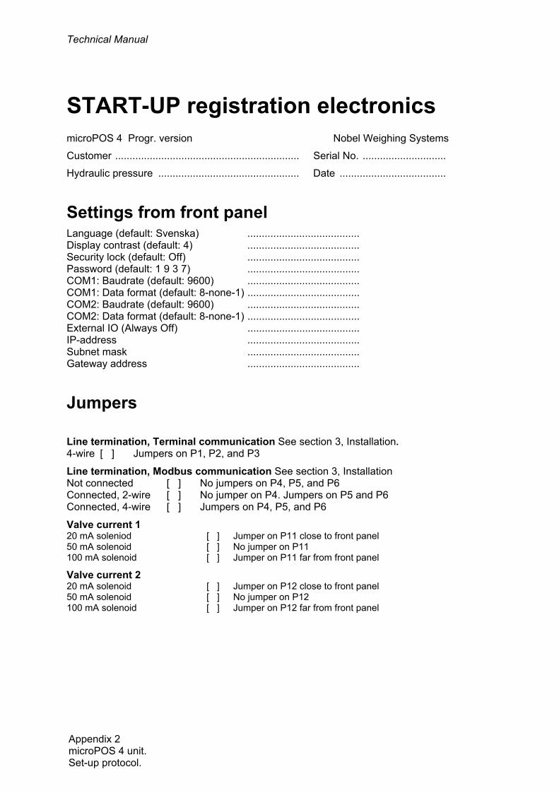
Technical Manual
START-UP registration electronics microPOS 4 Progr. version Nobel Weighing Systems
Customer ................................................................ Serial No. .............................
Hydraulic pressure ................................................. Date .....................................
Settings from front panel Language (default: Svenska) ....................................... Display contrast (default: 4) ....................................... Security lock (default: Off) ....................................... Password (default: 1 9 3 7) ....................................... COM1: Baudrate (default: 9600) ....................................... COM1: Data format (default: 8-none-1) ....................................... COM2: Baudrate (default: 9600) ....................................... COM2: Data format (default: 8-none-1) ....................................... External IO (Always Off) ....................................... IP-address ....................................... Subnet mask ....................................... Gateway address .......................................
Jumpers
Line termination, Terminal communication See section 3, Installation. 4-wire [ ] Jumpers on P1, P2, and P3
Line termination, Modbus communication See section 3, Installation Not connected [ ] No jumpers on P4, P5, and P6 Connected, 2-wire [ ] No jumper on P4. Jumpers on P5 and P6 Connected, 4-wire [ ] Jumpers on P4, P5, and P6
Valve current 1 20 mA soleniod [ ] Jumper on P11 close to front panel 50 mA solenoid [ ] No jumper on P11 100 mA solenoid [ ] Jumper on P11 far from front panel
Valve current 2 20 mA solenoid [ ] Jumper on P12 close to front panel 50 mA solenoid [ ] No jumper on P12 100 mA solenoid [ ] Jumper on P12 far from front panel
Appendix 2 microPOS 4 unit. Set-up protocol.
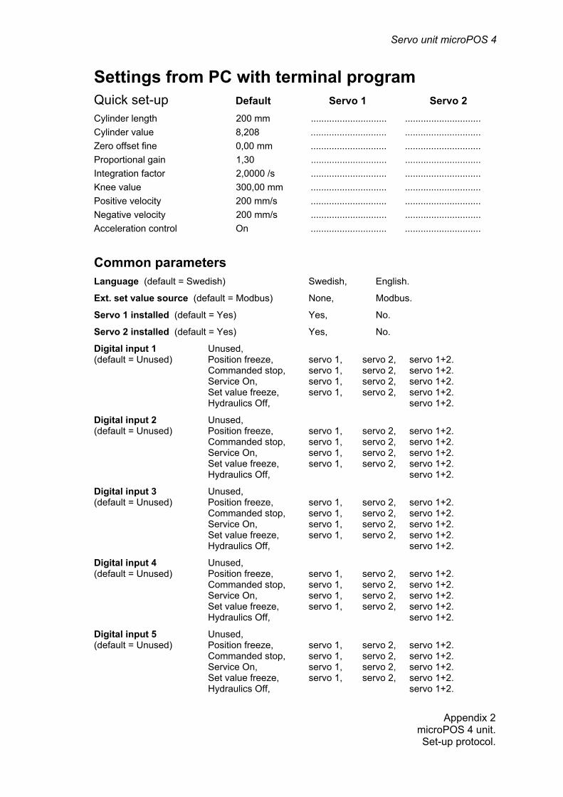
Servo unit microPOS 4
Settings from PC with terminal program Quick set-up Default Servo 1 Servo 2 Cylinder length 200 mm ............................. .............................
Cylinder value 8,208 ............................. .............................
Zero offset fine 0,00 mm ............................. .............................
Proportional gain 1,30 ............................. .............................
Integration factor 2,0000 /s ............................. .............................
Knee value 300,00 mm ............................. .............................
Positive velocity 200 mm/s ............................. .............................
Negative velocity 200 mm/s ............................. .............................
Acceleration control On ............................. .............................
Common parameters Language (default = Swedish) Swedish, English.
Ext. set value source (default = Modbus) None, Modbus.
Servo 1 installed (default = Yes) Yes, No.
Servo 2 installed (default = Yes) Yes, No.
Digital input 1 Unused, (default = Unused) Position freeze, servo 1, servo 2, servo 1+2. Commanded stop, servo 1, servo 2, servo 1+2. Service On, servo 1, servo 2, servo 1+2. Set value freeze, servo 1, servo 2, servo 1+2. Hydraulics Off, servo 1+2.
Digital input 2 Unused, (default = Unused) Position freeze, servo 1, servo 2, servo 1+2. Commanded stop, servo 1, servo 2, servo 1+2. Service On, servo 1, servo 2, servo 1+2. Set value freeze, servo 1, servo 2, servo 1+2. Hydraulics Off, servo 1+2.
Digital input 3 Unused, (default = Unused) Position freeze, servo 1, servo 2, servo 1+2. Commanded stop, servo 1, servo 2, servo 1+2. Service On, servo 1, servo 2, servo 1+2. Set value freeze, servo 1, servo 2, servo 1+2. Hydraulics Off, servo 1+2.
Digital input 4 Unused, (default = Unused) Position freeze, servo 1, servo 2, servo 1+2. Commanded stop, servo 1, servo 2, servo 1+2. Service On, servo 1, servo 2, servo 1+2. Set value freeze, servo 1, servo 2, servo 1+2. Hydraulics Off, servo 1+2.
Digital input 5 Unused, (default = Unused) Position freeze, servo 1, servo 2, servo 1+2. Commanded stop, servo 1, servo 2, servo 1+2. Service On, servo 1, servo 2, servo 1+2. Set value freeze, servo 1, servo 2, servo 1+2. Hydraulics Off, servo 1+2.
Appendix 2microPOS 4 unit. Set-up protocol.

Technical Manual
Relay output 1 Unused (default = In pos. servo 1) In position: servo 1, servo 2, servo 1+2. Status: servo 1, servo 2, servo 1+2. Error: servo 1+2.
Relay output 2 Unused (default = In pos. servo 2) In position: servo 1, servo 2, servo 1+2. Status: servo 1, servo 2, servo 1+2. Error: servo 1+2.
Relay output 3 Unused (default = Unused) In position: servo 1, servo 2, servo 1+2. Status: servo 1, servo 2, servo 1+2. Error: servo 1+2.
Relay output 4 Unused (default = Unused) In position: servo 1, servo 2, servo 1+2. Status: servo 1, servo 2, servo 1+2. Error: servo 1+2.
Relay output 5 Unused (default = Unused) In position: servo 1, servo 2, servo 1+2. Status: servo 1, servo 2, servo 1+2. Error: servo 1+2.
External zero adjusting Unused ± 5 mm, ± 10 mm, ± 50 mm, (default = Unused)
Appendix 2 microPOS 4 unit. Set-up protocol.

Servo unit microPOS 4
Individual parameters Default Servo 1 Servo 2 (Servo 1 = Servo 2)
Cylinder length 200 mm ........................... ...........................
Inverted feedback signal No ........................... ...........................
Acceleration control On ........................... ...........................
Acceleration limit 1 400,0 mm/s2 ........................... ...........................
Acceleration limit 2 400,0 mm/s2 ........................... ...........................
Positive velocity 200 mm/s ........................... ...........................
Negative velocity 200 mm/s ........................... ...........................
Positive set point limit 195,00 mm ........................... ...........................
Negative set point limit 0,00 mm ........................... ...........................
Scale factor for feedback value 0,32064 ........................... ...........................
Zero offset coarse 97,45 mm ........................... ...........................
Zero offset fine 0,00 mm ........................... ...........................
Proportional gain 1,30 ........................... ...........................
Knee value 300,00 mm ........................... ...........................
Knee factor 2 ........................... ...........................
I-activation Setv. - Pos. ........................... ...........................
Integration window 3,00 mm ........................... ...........................
Integration factor 2,0000 /s ........................... ...........................
Integration delay 50 ms ........................... ...........................
Positive integration limit 10,00 % ........................... ...........................
Negative integration limit 10,00 % ........................... ...........................
Offset for valve current 0,00 % ........................... ...........................
Dither amplitude 4 % ........................... ....... ........................
Dither frequency 250 Hz ........................... ....... ........................
In position window 0,50 mm ........................... ....... ........................
Service signal 10 % ........................... ...........................
Servo output On ........................... ...........................
External zero adjustment Off ........................... ...........................
Appendix 2microPOS 4 unit.Set-up protocol.

Technical Manual

Servo unit microPOS 4
Appendix 3microPOS 4.
Block diagram.
SERIAL COM.
A/D-BLOCK
4 INPUTS D/A-BLOCK
CURRENT andVOLTAGEVOLTAGE
INPUTS
Modbus RTU
POWERSUPPLY
Valve Output
TERMINAL
VOLTAGE
RS 485 , 2 or 4 wire
5 RELAY
OUTPUTS
5 OPTOINPUTS
+10V REF.
OUTPUT
RAM FRAM FLASH
24VDCsupply
CPU
PROCESSOR BLOCK
Internal DC supply
Servo unit microPOS 4Positioning controller
Test Outputs
+ REF
SERIAL COM. 1RS 485 , 4 wire
SERIAL COM. 2
RS 485 , 2 or 4 wire
Display
Modbus TCP Ethernet

Technical Manual

Servo unit microPOS 4
Declaration of Conformity
Appendix 4Declaration of Conformity.


Vishay Nobel AB Box 423, SE-691 27 Karlskoga, Sweden Phone +46 586 63000 · Fax +46 586 63099 [email protected] www.weighingsolutions.com
Article no. 35207 Document no. 600 540 R2 © Vishay Nobel AB, 2011-05-19 Subject to changes without notice.