program on technology innovation: impact of...
TRANSCRIPT

Program on Technology Innovation: Impact of Wireless Power Transfer Technology
Initial Market Assessment of Evolving Technologies


EPRI Project Manager H. Kamath
ELECTRIC POWER RESEARCH INSTITUTE 3420 Hillview Avenue, Palo Alto, California 94304-1338 • PO Box 10412, Palo Alto, California 94303-0813 • USA
800.313.3774 • 650.855.2121 • [email protected] • www.epri.com
Program on Technology Innovation: Impact of Wireless Power Transfer Technology Initial Market Assessment of Evolving Technologies
1020562
Final Report, December 2009

DISCLAIMER OF WARRANTIES AND LIMITATION OF LIABILITIES
THIS DOCUMENT WAS PREPARED BY THE ORGANIZATION(S) NAMED BELOW AS AN ACCOUNT OF WORK SPONSORED OR COSPONSORED BY THE ELECTRIC POWER RESEARCH INSTITUTE, INC. (EPRI). NEITHER EPRI, ANY MEMBER OF EPRI, ANY COSPONSOR, THE ORGANIZATION(S) BELOW, NOR ANY PERSON ACTING ON BEHALF OF ANY OF THEM:
(A) MAKES ANY WARRANTY OR REPRESENTATION WHATSOEVER, EXPRESS OR IMPLIED, (I) WITH RESPECT TO THE USE OF ANY INFORMATION, APPARATUS, METHOD, PROCESS, OR SIMILAR ITEM DISCLOSED IN THIS DOCUMENT, INCLUDING MERCHANTABILITY AND FITNESS FOR A PARTICULAR PURPOSE, OR (II) THAT SUCH USE DOES NOT INFRINGE ON OR INTERFERE WITH PRIVATELY OWNED RIGHTS, INCLUDING ANY PARTY'S INTELLECTUAL PROPERTY, OR (III) THAT THIS DOCUMENT IS SUITABLE TO ANY PARTICULAR USER'S CIRCUMSTANCE; OR
(B) ASSUMES RESPONSIBILITY FOR ANY DAMAGES OR OTHER LIABILITY WHATSOEVER (INCLUDING ANY CONSEQUENTIAL DAMAGES, EVEN IF EPRI OR ANY EPRI REPRESENTATIVE HAS BEEN ADVISED OF THE POSSIBILITY OF SUCH DAMAGES) RESULTING FROM YOUR SELECTION OR USE OF THIS DOCUMENT OR ANY INFORMATION, APPARATUS, METHOD, PROCESS, OR SIMILAR ITEM DISCLOSED IN THIS DOCUMENT.
ORGANIZATION(S) THAT PREPARED THIS DOCUMENT
Electric Power Research Institute (EPRI)
TEM Consulting, LP
NOTE
For further information about EPRI, call the EPRI Customer Assistance Center at 800.313.3774 or e-mail [email protected].
Electric Power Research Institute, EPRI, and TOGETHER…SHAPING THE FUTURE OF ELECTRICITY are registered service marks of the Electric Power Research Institute, Inc.
Copyright © 2009 Electric Power Research Institute, Inc. All rights reserved.

iii
CITATIONS
This report was prepared by
Electric Power Research Institute 942 Corridor Park Boulevard Knoxville, Tennessee 37932
Principal Investigator K. Gomatom
TEM Consulting, LP 140 River Rd. Georgetown, Texas 78628
Principal Investigator S. Berger
This report describes research sponsored by the Electric Power Research Institute (EPRI).
This publication is a corporate document that should be cited in the literature in the following manner:
Program on Technology Innovation: Impact of Wireless Power Transfer Technology: Initial Market Assessment of Evolving Technologies. EPRI, Palo Alto, CA: 2009. 1020562.


v
PRODUCT DESCRIPTION
This report presents an overview and analysis of wireless power transmission, also called wireless power transfer (WPT), a means of delivering power from a source to an end-use device without wires or contacts. The recent explosive growth in wireless data applications and the surge in the use of portable electronic devices has dramatically increased the market potential for wireless energy-transfer technologies. Industries are investigating the latest wireless power technologies to improve versatility, reduce costs, maintain connectivity, and eliminate the need to replace batteries. This study summarizes the current market for WPT technologies, describes commercially available products, and analyzes both the competitive potential of WPT and the risks and obstacles associated with its widespread adoption.
Results and Findings This study found that the most effective way to analyze WPT is from the viewpoint of the end user or the product designer: for the user, the WPT alternative must help solve a specific problem; for the designer, WPT must be the superior solution for a design challenge. For the electric utility industry, WPT applications are most suited for power plant monitoring and sensing, including self-powered sensors and ones that only need powering up periodically. Most WPT products on the market today use inductive coupling, with the charging and recipient device in close proximity, and are available for end-use, low-power applications only. However, inductive charging is still more expensive and less energy efficient. RF and microwave WPT offer the combined advantage and disadvantage that electromagnetic waves naturally permeate in all directions. RF radiated forms of WPT face substantial limits in environments frequented by the general public. Laser power transmission, although very focused, has its own set of safety limits. WPT can have a key environmental-impact role in significantly eliminating electronic waste worldwide. The potential health risks and electrical interference concerns of WPT should be studied and subjected to appropriate experimentation.
Challenges and Objectives Electric power plants will be most interested in WPT as a power-source alternative for sensors and transducers. The most revolutionary and rapid progress in the application and commercialization of WPT is being made in the portable electronics industry. WPT is particularly appealing for portable devices such as mobile phones, iPods, and wireless computer peripherals. WPT is viewed as a natural complement to wireless data communications, fulfilling the promising of a truly wireless device. The technology is also gaining a competitive place in the wireless power charger market. Inductive coupling, capacitive coupling, electromagnetic (EM) uses, and optical transmission are promising areas for new applications. Another market with great WPT potential is in medical sensors and implanted medical devices, such as pacemakers and defibrillators. Many challenges with WPT use are dependent on frequency. For

vi
example, health risks are minimal at low frequencies but may cause concern at higher frequencies. The frequency at which a WPT device operates will affect the distance it can propagate, the effective antenna size, and the kinds of safety concerns it may pose.
Applications, Value, and Use WPT will have market potential in any application in which power cables are inconvenient or impossible and in which it proves superior to batteries, fuel cells, solar cells, and energy harvesting. It will also find likely success in technologies in which moderate improvement would provide a compelling alternative power option, such as sensors in electric utilities. Study findings suggest several productive follow-on activities: Use cases of interest to the electric power industry could be specifically analyzed and WPT technologies compared according to both their current effectiveness and their near- and long-term future potential. Periodic report updates would provide current information on new developments. Involvement with the Wireless Power Consortium would facilitate ongoing insights into the activities of leading WPT companies. Performing an EM interference analysis would enhance understanding of RF interference, particularly with medical devices. Exploring various use cases of magnetic resonant coupling could demonstrate the viability of this promising new WPT technology. Particularly exciting is the developing use of WPT in hybrid solutions with high-capacity capacitors and fuel cells, scenarios that would allow one technology to compensate for the other’s deficiencies.
EPRI Perspective Given the enormous variety of potential products and uses for WPT, the number of niches for which it is the preferred solution will certainly expand. Development of current and new forms of WPT, and of hybrid solutions in which WPT is joined with other technologies, offer many intriguing possibilities. WPT is an exciting family of technologies that is almost certain to experience aggressive development and significant deployment as the technology becomes the preferred solution in a widening array of use scenarios.
Approach The investigators conducted an analytical overview of WPT, determining key drivers for the technology and developing a classification scheme for WPT applications in the end-use market. They also undertook a detailed product summary of currently available WPT technologies and a competitive analysis of the technology and its potential applications for the electric utility industry. The commercial WPT applications studied were based on four key technologies: electromagnetic induction, radio frequency (RF) waves, microwaves, and laser beams. The investigators categorized the technologies according to four key evaluation criteria: medium of energy transmission, method of energy transfer, range of energy transfer, and degree of maturity for end-use applications. Finally, they investigated the risks and obstacles facing the commercial adoption of WPT, including its biological and environmental impacts and its potential for interference with other electrical systems and equipment.
Keywords Wireless power transfer (WPT) Laser Radio frequency (RF) Microwave Electromagnetic (EM) Sensors Inductive coupling

vii
ABSTRACT
The report presents an overview and analysis of wireless transmission of power, also called wireless power transfer (WPT). The study presents key drivers for WPT and a classification scheme for WPT applications in the end-use market. A detailed product summary of the currently available WPT technologies, a competitive analysis of the technology and potential applications for the electric utility industry are described. The study also provides a detailed description on the risks and obstacles that WPT faces, biological and environmental impacts and scenario analyses for interference with different systems.


ix
EXECUTIVE SUMMARY
Wireless power transfer (WPT) refers to a family of techniques for delivering power without wires or contacts. The study provides a summary of the current market status of evolving wireless power transfer technologies with descriptions of some commercially available products. The report also presents a competitive analysis of WPT versus other alternatives, and the risks and obstacles that WPT must face before widespread adoption in the market place.
The report reaches the following conclusions:
1. Electric Utility Industry applications
• Wireless power transfer (WPT) applications most suited to the Electric Utility industry lie in the power plant monitoring and sensing area. Though sensor technology for condition-monitoring and asset management in industrial plants is not new, sensors powered by WPT can be explored.
• WPT applications to the electric utility industry can be of high benefit in cases where running wires and/or battery maintenance is expensive or difficult, due to site characteristics such as confined spaces or remoteness of the site.
• Sensors that only need to be powered up and interrogated periodically can be potential candidates for WPT. Sensors that need to be powered and operated only during periodic maintenance checks are also good candidates for WPT.
• Wireless charging of batteries is another application where WPT can offer benefits
• For some applications, WPT might be enabled to transfer higher power under the control of a trained operator and with appropriate safety precautions being taken.
2. Technology and market status
• WPT based products on the market today are available for end-use, low power applications only. Almost all commercially available products today, use inductive coupling with the charging and the recipient device in close proximity. Common examples include electric toothbrushes and charging pads for cell phones. Inductive coupling is a good solution for products that can be periodically or permanently placed in a charging cradle or put in close proximity to a charger. Advantages of using this form of WPT include convenience and elimination of a power connector for the product in use (such as the toothbrush). On the other hand, compared to a direct wired connection inductive charging is still more expensive and less energy efficient.
x
• Radio frequency (RF) and microwave based WPT offer the combined advantage and disadvantage that electromagnetic waves naturally permeate in all directions. This means that power is dispersed over a larger area and a receiving device can obtain power from any location. This is a significant advantage when the location of the receiving device is not known in advance or when it is moving. However, the received power will only be a fraction of the total power transmitted, precisely because the transmitted power is spread over a wide area.
• RF radiated forms of WPT face substantial limits when used in environments where the general public may be exposed to the RF energy. Received power in the mW or nW range is the limit on the amount of power that can be delivered in this manner.
• In contrast to RF forms of WPT, the power transmitted by lasers is very focused. When the relative location of the transmitter and receiver can be precisely known then the power can be directly transmitted to the receiver, with little dispersion loss. Laser transmission has its own set of safety limits just as RF transmission does.
• RF and laser wireless power transfer, may take decades to overcome some of the barriers to implementation for the higher power and longer distance technologies. The physics of electromagnetic propagation dictate a spherical expansion of energy. While high gain antennas are possible they tend to be large and expensive. It takes a very large antenna to culminate the “beam” of energy, tight enough so that it is not lost on the other end. Conversely, it takes a large antenna to capture the energy as it arrives. Also, higher frequencies have significant problems with being absorbed by physical objects in the environment. Lower frequencies propagate through material better but antenna sizes increase due to the increase in wavelength.
3. Environmental impact
WPT can play a key role in mitigating the environmental impact of producing, disposing and end-of-life management of external power supplies, potentially eliminating significant electronic waste worldwide. In 2008, 3.2 billion external power supplies were manufactured worldwide. Of these, 737 million units were shipped to the U.S. An estimated 434 million external power supplies were retired in 2008 in the U.S. alone1. The U.S. Environmental Protection Agency (EPA) estimates that in 2005, used or unwanted electronics amounted to approximately 1.9 to 2.2 million tons of which 1.5 to 1.8 million tons was primarily disposed in landfills, and only 345,000 to 379,000 tons were recycled. Only 15-20% (by weight) of electronic products including laptops and cell phones are recycled, the remaining 80-85% disposed to landfills or incinerated2.
4. Public perception, risks and safety
• The public perception of the health and safety of WPT systems is a huge factor in market adoption. The report recommends potential health risks and concerns concerning WPT systems be studied and appropriate experimentation be constructed.
• In many cases, the approach of the existing wireless industry and public alike will often be to expect that the new WPT systems will be hazardous to health and interfere with
1 Rose, William “1394 Trade Association Technical Brief: How Green is My FireWire?” WJR Consulting, Inc. http://www.1394ta.org/Press/WhitePapers/2009_Green.html 2 EPA 2005 estimate, July 2008 factsheet http://www.epa.gov/epawaste/conserve/materials/ecycling/docs/fact7-08.pdf

xi
existing biological systems. Understanding potential interference scenarios and how to test for them according to the pattern set forth in IEEE Standard 1900.2 will be critical to insuring that WPT systems can harmlessly coexist with other existing equipment.
• Wireless systems and medical equipment are particularly important to study because the consequences of interference can be significant, even life threatening. The formation of test procedures should be set in place, according to this standard, during the development phase of the technology.
5. Further development and adaptation
• WPT is likely to be successful where with moderate improvement WPT would provide a compelling option for providing power. The amount of activity going into developing WPT powered sensors is a good example. Hard wiring for a sensor network is costly and often prone to damage. With moderate development, WPT could provide a compelling alternative to power sensors and therefore development in this area is likely to be successful.
• Using the analysis presented in this report, it can be concluded that WPT will be considered in any application where power cables are inconvenient or impossible and provided that WPT as an “offering of convenience” is an advantage to the end user and to the product manufacturer. When providing a power cable is impossible some means of wireless power are an absolute requirement. In these situations WPT must prove to be the superior solution to batteries, fuel cells, solar cells, energy harvesting and other options for providing power without wires.
• A barrier for the technology to evolve to include cell phones is the common “chicken & egg” scenario. Circuitry is required in the cell phone to receive the inductive power transmission and the cell phone manufacturers are not willing to do that at this time. Beyond the coordination problem is the business issue, chargers are a big after market accessory that makes a good profit for the industry. To summarize what Intel’s CTO Justin Rattner said in August 2008 at the Intel Developer Forum, “such technologies may not be mature until the middle of this century.”3
• Given the enormous variety of products and use scenarios WPT certainly will expand the number of niches for which it is the preferred solution. The growth of WPT will follow predictable lines of development, starting in niche applications for which it currently provides a compelling option and building out to new niches with similar characteristics. Development of WPT, new forms of WPT and hybrid solutions, joining WPT with other technologies offer many exciting solution possibilities. WPT is an exciting family of technologies that are almost certain to experience aggressive development and find significant deployment as the technology becomes the preferred solution in a widening array of use scenarios.
The report offers the following recommendations
• The evolution of WPT as a potential means of power delivery is an exciting prospect for the electric power industry. To the electric utility industry in general, research and development, laboratory testing and prototype demonstration of both large scale WPT (example - space
3 http://thefutureofthings.com/news/5763/intels-wireless-power-technology-demonstrated.html

xii
power) and low power, end-use WPT (example- wireless charging of portable electronics) can be long term research activities. However, major barriers exist in the form of safety and risk perception, economics, and maturity of technology.
• The development of universal standards and protocols for wireless power transfer is significant to the electric utility industry. The wireless power consortium announced the release of a technical specification that will lead to the development of a global industry standard for supplying electricity wirelessly to low power devices (5 watts and below)4. This study recommends that the electric utility industry participate in the standards development process .WPT could potentially become the future of electronic plugged loads with electronic giants such as Intel5 and Dell getting involved in the wireless charging market6.
• WPT for end-use applications (such as portable electronics) needs to mature considerably to demonstrate reliable and safe power transfer and/or achieve significant market penetration, for it to excite the electric utility industry. The perception of safety and health risk associated with WPT could be an initial deterrent for electric utilities to get involved.
• Testing and pilot demonstrations of WPT for equipment monitoring, sensing and other power plant applications hold promise. Laboratory testing of promising WPT technologies such as magnetic resonant coupling should be undertaken and the risk impacts measured.
The report suggests the below-mentioned follow-on activities:
• More specific use case analysis
• Continued monitoring of the technology and periodic updating of this report
• Performing an EM Interference Analysis of WPT to understand the potential for interference problems
• Undertaking a demonstration project for magnetic resonant coupling, one of the most promising WPT solutions
• Further exploration of hybrid solutions, using WPT in combination with other solutions.
4 Wireless Power Consortium http://www.wirelesspowerconsortium.com/news/press-releases/release-of-specification-and-logo.html 5http://blogs.intel.com/research/2008/10/rattner_the_promise_of_wireles.php 6 http://www.popsci.com/gear-amp-gadgets/article/2009-09/dells-latitude-z-brings-wireless-charging-laptops

xiii
CONTENTS
1 INTRODUCTION .................................................................................................................... 1-1
Definition and Properties ....................................................................................................... 1-2
Frequency Effects ................................................................................................................. 1-2
Use of Electromagnetic Spectrum in this Report .............................................................. 1-2
2 CURRENT STATUS OF WIRELESS POWER TRANSMISSION (WPT) ............................... 2-1
Commercial Technologies ..................................................................................................... 2-1
Technology Overview ............................................................................................................ 2-1
Medium of Transmission .................................................................................................. 2-2
Method of Transmission ................................................................................................... 2-3
Range of Transmission ..................................................................................................... 2-4
Maturity of Technology ..................................................................................................... 2-5
Product Status ....................................................................................................................... 2-7
Electromagnetic Induction ..................................................................................................... 2-8
Induction Cooking ............................................................................................................. 2-8
Inductive Charging ............................................................................................................ 2-9
Fulton Innovation ......................................................................................................... 2-9
eCoupled Technologies ........................................................................................ 2-10
Splashpower ......................................................................................................... 2-10
Powermat Solutions ................................................................................................... 2-11
WiPower Technology ................................................................................................. 2-11
MIT’s Strongly Coupled Magnetic Resonance Design ............................................... 2-12
Tokyo Tower Magnetic Resonance Demonstration ................................................... 2-14
RF Transmission ................................................................................................................. 2-15
Powercast LLC .......................................................................................................... 2-15
Laser Transmission ............................................................................................................. 2-16
PowerBeam ............................................................................................................... 2-16
Wireless Power Consortium ................................................................................................ 2-17

xiv
3 TECHNOLOGY AND COMPETITIVE ASSESSMENT ........................................................... 3-1
Distinctive Characteristics or Properties ................................................................................ 3-1
Drivers ................................................................................................................................... 3-2
Environmental Impact ....................................................................................................... 3-4
Benefits and Competing Technologies ............................................................................. 3-5
Development of Competing Solutions .............................................................................. 3-6
Connector Innovation ................................................................................................... 3-7
Energy Harvesting ....................................................................................................... 3-7
Solar Cells ................................................................................................................... 3-8
Enabling Technologies .......................................................................................................... 3-8
Fuel Cells .......................................................................................................................... 3-8
Computer Technology ...................................................................................................... 3-9
MANET Networks ............................................................................................................. 3-9
Utility Applications ............................................................................................................... 3-10
Monitoring Equipment Condition .................................................................................... 3-10
Miniature Sensors ........................................................................................................... 3-10
Self-Powered Sensors .................................................................................................... 3-10
Data Aggregation and Analysis ...................................................................................... 3-11
4 RISKS AND OBSTACLES ..................................................................................................... 4-1
Stability and Reliability .......................................................................................................... 4-2
RF Safety .............................................................................................................................. 4-3
Safety Limits for Human Exposure ................................................................................... 4-3
Uncontrolled Environments .......................................................................................... 4-4
Non-Thermal and Secondary Effects ............................................................................... 4-7
Impact of RF Safety Limits ........................................................................................... 4-8
Combinatorial Exposure ................................................................................................. 4-11
Testing for RF Safety ...................................................................................................... 4-12
Other Biological Risks .................................................................................................... 4-13
Environmental Impact ..................................................................................................... 4-14
Public Perception of Radio Frequency (RF) Safety or Environmental Impact ..................... 4-14
WPT and Medical Devices .................................................................................................. 4-16
Radio Frequency (RF) Interference ..................................................................................... 4-17
IEEE Standard 1900.2 .................................................................................................... 4-18
Impact of Circuit Design ................................................................................................. 4-19

xv
Scenario 1: Magnetic Interference with Pacemakers .................................................... 4-21
Scenario Definition ..................................................................................................... 4-21
Criteria Selection........................................................................................................ 4-22
Definition of Variables ................................................................................................ 4-23
Analysis ..................................................................................................................... 4-23
Scenario 2: Mimicking Biological Signatures .................................................................. 4-23
Scenario Definition ..................................................................................................... 4-23
Criteria Selection........................................................................................................ 4-24
Definition of Variables ................................................................................................ 4-25
Analysis ..................................................................................................................... 4-25
Scenario 3: Harmonic Interference ................................................................................. 4-25
Scenario Definition ..................................................................................................... 4-25
Criteria Selection........................................................................................................ 4-26
Definition of Variables ................................................................................................ 4-26
Analysis ..................................................................................................................... 4-27
Scenario 4: Interference with Bluetooth ......................................................................... 4-27
Scenario Definition ..................................................................................................... 4-27
Criteria Selection........................................................................................................ 4-27
Definition of Variables ................................................................................................ 4-28
Analysis ..................................................................................................................... 4-28
Scenario 5: Radar Interference in the 915 MHz ISM Band ........................................... 4-28
Scenario Definition ..................................................................................................... 4-28
Criteria Selection........................................................................................................ 4-29
Definition of Variables ................................................................................................ 4-29
Analysis ..................................................................................................................... 4-29
Recommendations .......................................................................................................... 4-30
Regulatory Status ................................................................................................................ 4-30
5 CONCLUSION ........................................................................................................................ 5-1
Probable Future of WPT........................................................................................................ 5-4
Next Steps ............................................................................................................................. 5-5
Use Case Analysis ........................................................................................................... 5-5
Periodic Updating ............................................................................................................. 5-5
Interference Analysis ........................................................................................................ 5-6
Demonstration of Magnetic Resonant Coupling ............................................................... 5-6

xvi
Hybrid Solutions ............................................................................................................... 5-7
A HISTORY AND CONNECTION TO WIRELESS COMMUNICATIONS ................................ A-1
History of Wireless Power Transfer ...................................................................................... A-1
Electromagnetic Waves ................................................................................................... A-1
Microwave ....................................................................................................................... A-2
Solar Power Satellite (SPS) ........................................................................................ A-4
Stationary High Altitude Relay Platform (SHARP) ........................................................... A-4
Lunar Solar Power (LSP) ............................................................................................ A-5
Power beaming by Lasers ............................................................................................... A-5
B RADIO FREQUENCY ID (RFID) ........................................................................................... B-1
Radio Frequency ID (RFID) .................................................................................................. B-1
Passive Low Frequency (LF) RFID ................................................................................. B-2
Passive High Frequency (HF) RFID ................................................................................ B-2
C FCC PART 18: TECHNICAL STANDARDS ......................................................................... C-1
Subpart C—Technical Standards ......................................................................................... C-1
§ 18.301 Operating frequencies. ................................................................................... C-1
§ 18.303 Prohibited frequency bands. ........................................................................... C-2
§ 18.305 Field strength limits. ........................................................................................ C-2
§ 18.307 Conduction limits. ........................................................................................... C-4
§ 18.309 Frequency range of measurements. ............................................................... C-6
§ 18.311 Methods of measurements. ............................................................................ C-6
xvii
LIST OF FIGURES
Figure 1-1 Frequency Effects Explained Using a Sine Wave .................................................... 1-4
Figure 1-2 U.S Frequency Allocations for the Radio Spectrum ................................................. 1-5
Figure 2-1 Classification of Wireless Power Transfer Technologies for End-Use Applications ........................................................................................................................ 2-2
Figure 2-2 WPT Technologies for End-Use Applications According to Medium of Transmission ...................................................................................................................... 2-3
Figure 2-3 WPT Technologies for End-Use Applications According to Method of Transmission ...................................................................................................................... 2-4
Figure 2-4 WPT Technologies for End-Use Applications According to Range of Transmission ...................................................................................................................... 2-5
Figure 2-5 WPT Technologies for End-Use Applications According to Maturity of Technology ......................................................................................................................... 2-6
Figure 2-6 Induction Coupling Block Diagram ......................................................................... 2-13
Figure 2-7 PowerBeam Concept Show Powering Lighting (Left) and Speakers (Right) .......... 2-17
Figure 3-1 Market Drivers .......................................................................................................... 3-4
Figure 4-1 Assessment Process for Interference, Reprinted from IEEE 1900.2 ...................... 4-18
Figure A-1 System Block Diagram of Microwave Wireless Power Transmission ................... A-3
Figure B-1 Schematic of a Typical RFID System .................................................................... B-2


xix
LIST OF TABLES
Table 1-1 Comparison of US and EU Adaption of ITU-R Recommendations for ISM Frequency Bands ............................................................................................................... 1-6
Table 2-1 Market Introduction of WPT Technology ................................................................... 2-7
Table 3-1 Worldwide embedded energy to produce, ship and dispose external power supplies .............................................................................................................................. 3-5
Table 4-1 Limits for Uncontrolled Environments as a Function of Frequency........................... 4-5
Table 4-2 Maximum Permissible Exposure (MPE) Limits for Occupational/Controlled Exposure ............................................................................................................................ 4-6
Table 4-3 Maximum Permissible Exposure (MPE) Limits for General Population/Uncontrolled Exposure ..................................................................................... 4-6
Table 4-4 Maximum Transmitted Power Set by RF Exposure Limits ........................................ 4-9
Table 4-5 Maximum Received Power Set by RF Exposure Limits .......................................... 4-11
Table 4-6 4-7.0 - 2.4 GHz Harmonic Frequencies and Associated Spectrum Allocations ...... 4-26

1-1
1 INTRODUCTION
Wireless transmission of power, also called wireless power transfer (WPT), is a means of delivering power to an end-use device without wires or contacts. One of the oldest known power transmission technologies, WPT is seeing a resurgence of interest. Scientists and engineers have known over the past century that transferring electric power does not require wires to be in physical contact. Wires typically allowed devices to receive both power and communicate with other devices. As wireless data transmission eliminates the need for wires to carry data, there is a growing need to find ways to provide power without wires making devices truly portable and mobile. With the explosive growth in wireless data applications, the market potential for wireless energy transfer technologies has seen a dramatic increase.
Transformers couple power between closely spaced windings inductively, using magnetic coupling. Electric motors and power transformers contain coils that transmit energy to each other by the phenomenon of electromagnetic induction. A current running in an emitting coil induces another current in a receiving coil; the two coils are in close proximity, but they do not touch.
Capacitors transfer power between plates, using the electric field. Capacitive transfer of energy is widely used in circuit design because of its frequency selective aspects. Capacitors inherently will transfer higher frequency energy but block lower frequency energy.
Electromagnetic (EM) traveling waves, often in the RF or microwave spectrum, can also be used and have been used to transmit power. Radio waves, and especially microwaves, can be used to transfer energy, which can then be picked up with an antenna. But transferring energy from one point to another through ordinary electromagnetic radiation is typically very inefficient because radiated energy tends to scatter in all directions in free space7, and thus only a small portion reaches the intended destination.
Energy transfer by light is a fast growing industry as evidenced by the increasingly dynamic growth of the solar power industry. Light can also be concentrated in the form of laser beams and transferred either through space or in optical fiber cables. Laser transmissions can transmit substantial amounts of power without wires and do not necessarily require an optical fiber.
Each of these methods mentioned above: inductive coupling, capacitive coupling, EM and optical transmission are being explored for new applications. The wide-scale proliferation of portable electronic devices (such as laptop computers, hand-held internet phones, portable music/video players etc.) is creating a growing need to provide a more accessible method for simultaneously powering multiple devices. Advances in medical sensors and implanted medical 7 This phenomenon is primarily due to the interaction of magnetic fields with almost every known material, in varying degrees, depending on the magnetic properties. In other words, there is no known material that can behave as a perfect “insulator” to magnetic fields.

Introduction
1-2
devices, like pacemakers and implantable defibrillators, are other applications where WPT has great potential. New applications such as sensor networks are exploring and in a few cases using WPT to satisfy their unique needs. Radio Frequency Identification or RFID’s can be viewed as a specialized type of sensor and is a technology being aggressively deployed to provide remote power to sensors.
Definition and Properties
A wireless power transmission (WPT) system, sometimes called ‘wireless energy transmission’, is defined as one which efficiently transmits electric power from one point to another without the use of metallic wires. In most forms of WPT, there is no requirement for any physical contact. Wireless power transmission is distinguished from communication systems by the relatively higher levels of power being transferred. The purpose of WPT is the transfer of energy from a source (where energy is supplied) to a load (where useful work is done) without wires, contacts or physical media. Because its purpose is the transfer of energy, in contrast to a communication system whose purpose is the transmission of information, the primary metric of WPT is the efficiency of energy delivered from the source to the load. This efficiency can be measured in several ways. The most complete measure is the percentage of energy used by the source to that used by the load to do useful work. This is sometimes called the ‘plug to bulb’ efficiency. The efficiency can also be evaluated more specifically as the loss during transmission, ignoring losses at the source to convert electrical energy to electromagnetic energy and the reverse conversion at the receiving end.
Frequency Effects
Many issues with wireless power transmission (WPT) are dependent on the frequency of use. Different frequencies bands have different regulatory requirements. There are also physical differences between frequencies such as their wavelength. Any frequency can be used to transmit power. In the vacuum of space there is no transmission loss at any frequency. In the earth's atmosphere and most environments there will be attenuation, particularly at the higher frequencies. There can be reliability considerations when the higher frequencies are used. The cost and efficiency of the transmitting and receiving components will always be better at lower frequencies. On the other hand, the use of the lower frequencies will necessitate large transmitting and receiving aperture sizes which are not attractive for some applications8.
This section discusses the impact of frequency in a general way, to give an orientation to how some issues become more or less relevant, depending on the frequency proposed for use by WPT.
Use of Electromagnetic Spectrum in this Report
The electromagnetic spectrum is a continuum without sharp boundaries. RF, microwaves, heat, visible light all describe regions in the electromagnetic spectrum. These different regions have different physical properties. However, the transitions are not sharp and differences only become
8 William.C.Brown, The history of wireless power transmission, Solar Energy, Vol .56,No.1,pp. 3-21, 1996
Introduction
1-3
pronounced when comparing very widely separated areas of the electromagnetic spectrum. In this report, wireless power transmission (WPT) is treated as the use of electromagnetic energy to transfer power. From this viewpoint inductive coupling, RF, microwave and light are simply using the different areas of the electromagnetic spectrum for the properties that are useful. Because there are no sharp boundaries, this report will not differentiate sharply between these different areas. Hence, RF and microwave WPT are not described as distinct entities. RF WPT is a lower frequency version of microwave WPT.
Inductive coupling, the most developed form of WPT, operates in the lowest region of the electromagnetic spectrum. At these low frequencies components are very inexpensive and the phenomenon is very well studied. Counterbalancing these positive attributes is the fact that wavelengths are very large, meaning that antennas will only capture a small percentage of a wavelength, tending to make them inefficient. Transmission takes place in the near-field, which gives it a different set of properties from far-field transmission.
RF and then microwave by contrast have much smaller wavelengths. Transmission will usually be in the far-field, meaning that a propagating wave with a fixed relationship between the electric and magnetic components of the electromagnetic wave will exist. At higher frequencies directional antennas become possible. However, components become more expensive and design of devices is generally more challenging.
Use of light, visible light, infrared or ultraviolet in turn has its own set of characteristics and attributes.
The challenge for the wireless power transmission (WPT) system designer is to find a region of the electromagnetic spectrum where the characteristics of the spectrum and the physical attributes provide a good solution for the application.
A basic property of frequency is that wavelength is inversely proportional to frequency. The following formula gives the wavelength, in meters, as a function of frequency, in MHz.
f300=λ
From the formula it can be seen that the wavelength at 1 GHz (1000 MHz) is 0.3 m, or 30 cm. At 100 MHz the wavelength is 3 m. At 1 MHz the wavelength is 300 m.
For a physical structure, antenna or human body, that is receiving or absorbing energy from an EM field, this means that fraction of a wavelength that the structure represents goes up as frequency increases. Figure 1-1 illustrates the concept with a sine wave that makes it easy to see that a physical structure which is ½ of a wavelength can have the greatest energy difference over its length because it can have the peak of the wave at one end and the minimum at the other.

Introduction
1-4
Figure 1-1 Frequency Effects Explained Using a Sine Wave
On a practical level this means that a human that is 2 m tall (about 6’) will be able to have a maximum coupling from a 4 m wavelength, which occurs at 75 MHz. At 1 MHz the same 2 m tall person only 1/150 of a wavelength and so cannot couple much of the energy from the wave into the body.
What this means is that low frequencies tend to go through physical objects and travel long distances. Higher frequencies tend to be absorbed and often have trouble communicating over long distances as a result.
Another effect is that at some frequencies a physical structure can resonate, like a tuning fork. At resonance a significant amount of energy can be received or absorbed out of an EM field. For issues like biological hazard and human safety, the frequencies where the body or some parts of the body can resonate are of particular concern because at those frequencies significant energy can be absorbed into the human body. This means that there may be very little chance that there is a health risk at low frequencies but a good reason to be cautious at higher frequencies. Accordingly, as frequencies go up even higher, they will tend to be absorbed very quickly in the skin and surface tissue and not penetrate into the body well. So at very high frequencies the concern might be about skin and surface effects but little concern about adverse effects to parts of the body further from the surface.
Therefore, the frequency at which a WPT operates will affect how far it is likely to propagate, how large an antenna will be needed to receive it effectively, and what kinds of safety concerns there might be.
Another effect of frequency arises from the way the spectrum is managed. In the U.S., the radio spectrum as shown in Figure 1-1, is managed by the FCC for civilian use and the NTIA for government use. The FCC and NTIA coordinate their activities to assure coordination of frequency use.
Spectrum use is coordinated internationally by the ITU. Representatives of different countries of the world meet every four (4) years at the World Radio Conference, to plan their use of the spectrum and to carefully coordinate spectrum allocations to achieve global harmonization for frequency allocation.

Introduction
1-5
Figure 1-2 U.S Frequency Allocations for the Radio Spectrum9
9 http://www.ntia.doc.gov/osmhome/allochrt.pdf
Introduction
1-6
For WPT the spectrum allocation structure means that only certain frequency bands are available for use and that each of those bands puts WPT into a fixed relationship with other services. This relative placement creates or avoids the potential for various kinds of interference depending on the frequency band selected for use by WPT designers.
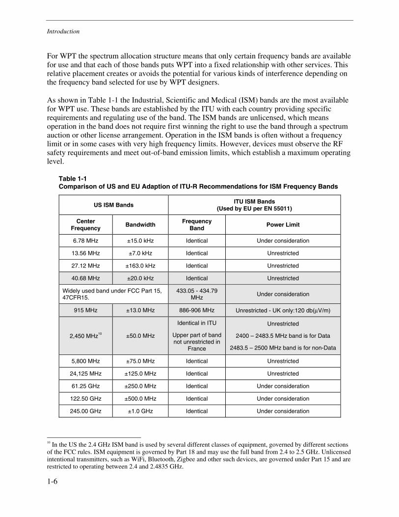
As shown in Table 1-1 the Industrial, Scientific and Medical (ISM) bands are the most available for WPT use. These bands are established by the ITU with each country providing specific requirements and regulating use of the band. The ISM bands are unlicensed, which means operation in the band does not require first winning the right to use the band through a spectrum auction or other license arrangement. Operation in the ISM bands is often without a frequency limit or in some cases with very high frequency limits. However, devices must observe the RF safety requirements and meet out-of-band emission limits, which establish a maximum operating level.
Table 1-1 Comparison of US and EU Adaption of ITU-R Recommendations for ISM Frequency Bands
US ISM Bands ITU ISM Bands (Used by EU per EN 55011)
Center Frequency
Bandwidth Frequency Band
Power Limit
6.78 MHz ±15.0 kHz Identical Under consideration
13.56 MHz ±7.0 kHz Identical Unrestricted
27.12 MHz ±163.0 kHz Identical Unrestricted
40.68 MHz ±20.0 kHz Identical Unrestricted
Widely used band under FCC Part 15, 47CFR15.
433.05 - 434.79 MHz
Under consideration
915 MHz ±13.0 MHz 886-906 MHz Unrestricted - UK only:120 db(μV/m)
2,450 MHz10 ±50.0 MHz
Identical in ITU
Upper part of band not unrestricted in
France
Unrestricted
2400 – 2483.5 MHz band is for Data
2483.5 – 2500 MHz band is for non-Data
5,800 MHz ±75.0 MHz Identical Unrestricted
24,125 MHz ±125.0 MHz Identical Unrestricted
61.25 GHz ±250.0 MHz Identical Under consideration
122.50 GHz ±500.0 MHz Identical Under consideration
245.00 GHz ±1.0 GHz Identical Under consideration
10 In the US the 2.4 GHz ISM band is used by several different classes of equipment, governed by different sections of the FCC rules. ISM equipment is governed by Part 18 and may use the full band from 2.4 to 2.5 GHz. Unlicensed intentional transmitters, such as WiFi, Bluetooth, Zigbee and other such devices, are governed under Part 15 and are restricted to operating between 2.4 and 2.4835 GHz.

Introduction
1-7
Each ISM band is shared, often with multiple other services. Different services are given a priority and lower priority services are required to protect higher priority services from interference. Unlicensed operation is typically the lowest priority of service, which means that unlicensed devices must protect higher priority services from interference, but unlicensed devices must accept any interference that higher priority services may impose on them.
For a device that uses wireless power transmission (WPT), the frequency of operation will bring benefits and consequences from the physical characteristics of that frequency and from the spectrum management allocation. Some frequencies will support more efficient coupling and power transfer, than the other. At some frequencies different kinds of health and safety issues become of greater or lesser importance. The potential for interference with other kinds of equipment varies based on the frequency of operation. For a WPT technology survey this means that many statements about the technology must be frequency specific and may be very significant at one frequency but completely irrelevant at the other. These differences will be introduced in the discussions to follow, but a full treatment requires examination of specific WPT implementations.


2-1
2 CURRENT STATUS OF WIRELESS POWER TRANSMISSION (WPT)
Industries are investigating the latest wireless power technologies to improve versatility, reduce costs, maintain connectivity, and eliminate the need to replace batteries.11 More than one industrial and end-use applications are evaluating WPT. One such end-use application is induction cooking which utilizes WPT, or a variant of WPT, due to a range of reasons such as better operation, cost-effectiveness and energy efficiency. Large and continually operating industries such as electric power plants are interested in evaluating WPT as a power source alternative for sensors and transducers. The portable electronics industry is perhaps the most revolutionary in terms of the rapid progress in the application and commercialization of WPT. A subset of portable devices that utilize wireless data communications such as mobile phones, iPods, and wireless computer peripherals, find WPT particularly appealing. WPT is seen as a natural complement to wireless data communications, completing the promising of a truly wireless device. The wireless power charger market is becoming competitive, with several companies developing commercial devices and retrofit gadgets for powering portable electronics.12 The surge in the growth of mobile electronics in the past decade has greatly enhanced the market potential for wireless power chargers.
Commercial Technologies
This section addresses commercial wireless energy transfer applications based on the technologies identified in Section 1 namely Electromagnetic Induction, Radio frequency (RF) waves, Microwave and Laser beams. This section categorizes the use by technology. In the following section, which provides a competitive analysis, the organizing principle will be end-use application.
Technology Overview
Based on information compiled through primary research, different types of commercial and “near-commercial” WPT technologies exist for application to end-use systems. For the purpose of this report, WPT technologies are categorized based on four key evaluation criteria - medium of energy transmission, method of energy transfer, range of energy transfer and maturity of technology for end-use applications. Each of the classification schemes covers all the WPT technologies based on one specific criterion. The classification schemes are mutually-exclusive and demonstrate the complexity of classifying WPT technologies. 11 Neufeld R, Contactless energy transfer: Mobile power on the go, Plant Engineering, January 2007. 12 Foxnews, Wireless Power Chargers About to Hit Market, April 2007; http://www.foxnews.com/story/0,2933,263707,00.html

Current Status of Wireless Power Transmission (WPT)
2-2
Figure 2-1 Classification of Wireless Power Transfer Technologies for End-Use Applications
Medium of Transmission
The medium of transmission refers to the material substance (solid, liquid or gas) that propagates energy waves. Figure 2-2 shows currently available commercial and “near-commercial” WPT technologies classified according to the medium of transmission. It is important to note that WPT technologies employed for end-use applications today are based on short-distance media only (up to 5 meters).13 Electromagnetic induction (or inductive transfer) and radio frequency waves are being used currently as short-distance media based WPT technologies. Examples of WPT over long distance media, include microwave and laser beams. Currently, laser beams are being used both as a short distance and a long distance medium-based WPT technology.
13 For the technologies currently available, the incremental cost per unit efficiency (to transfer energy over long distances ) is significant

Current Status of Wireless Power Transmission (WPT)
2-3
Figure 2-2 WPT Technologies for End-Use Applications According to Medium of Transmission
Method of Transmission
The method of transmission refers to the method of conveyance of energy from one point to the other. Currently available WPT technologies (commercial and “near-commercial”) are either radiative or non-radiative as shown in Figure 2-2. Radiative transfer (for example, electromagnetic radiation) is typically very inefficient, and can be hazardous because the waves of energy tend to spread in all directions, tending to lose most of the energy to the environment. Electromagnetic induction (or inductive transfer) and Radio Frequency waves are radiative WPT technologies. Non-radiative transfer, which was a relatively unexplored method for short-distance transmission until recently, employs a specially designed emitter- receiver combination to transfer energy back and forth, with minimal interaction with the surrounding environment. “Resonant coupling” and Laser beaming are two examples of non-radiative WPT technologies. A “Resonant coupling” based WPT system was first developed and demonstrated by the Massachusetts Institute of Technology (MIT) in 2005-2006.14 In general a “resonant coupling” based WPT consists of a transmitter and a receiver tuned to a specific resonant frequency. Instead of irradiating the environment with electromagnetic waves, the transmitter fills the space around it with a non-radiative, “evanescent”15 field which can only be picked up by the receiver tuned to 'resonate' with the field. Most of the energy that remains unabsorbed by the receiver is reabsorbed by the emitter, resulting into lower losses. It is important to note here that the classification of “resonant coupling” as a non-radiative technology is solely based on MIT’s 14 Karalis, A, Joannopoulos J D, Soljacic M , Efficient wireless non-radiative mid-range energy transfer, Annals of Physics, vol. 323, no. 1, pp 34-48, Jan 2008. 15 Time-dependent (oscillating) electromagnetic field without having an energy flow to far distances

Current Status of Wireless Power Transmission (WPT)
2-4
research and test findings. Apart from MIT’s demonstration of the “resonant coupling” no additional test data or empirical findings is available about the performance of the “resonant coupling” based WPT system, specifically the non-radiative nature of the “resonant coupling.” Another non-radiative transfer based WPT technology is laser beaming, which is currently used in at least one commercially available technology.
Figure 2-3 WPT Technologies for End-Use Applications According to Method of Transmission
Range of Transmission
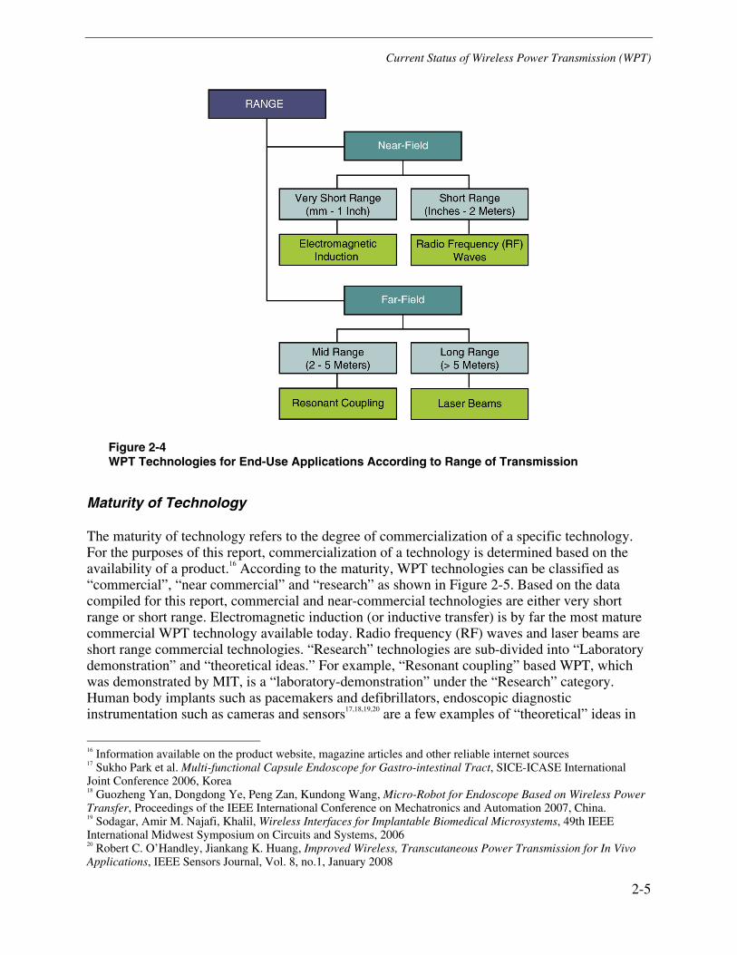
The range of transmission refers to the distance over which energy can be reliably transferred. By range of transmission, WPT technologies which are currently available (commercial and “near-commercial”) can be classified as – “near-field” or “far-field as shown in Figure 2-4. “Near field” based technologies have a short range (up to 2 meters) while “far-field” based technologies typically have a longer range (more than 2 meters). “Near-field” technologies can be further sub-divided into very short range (mm-1 inch) and short range (inches-2 meters). Power transfer via electromagnetic induction (or inductive transfer) is over a very short range and energy transfer via Radio Frequency (RF) waves is over a short range. “Far-field” technologies can be further sub-divided into mid range (2-5 meters) and long range (greater than 5 meters). “Resonant coupling” is a mid range technology and laser beaming is a long range WPT technology, as per the range of transmission classification.
Current Status of Wireless Power Transmission (WPT)
2-5
Figure 2-4 WPT Technologies for End-Use Applications According to Range of Transmission
Maturity of Technology
The maturity of technology refers to the degree of commercialization of a specific technology. For the purposes of this report, commercialization of a technology is determined based on the availability of a product.16 According to the maturity, WPT technologies can be classified as “commercial”, “near commercial” and “research” as shown in Figure 2-5. Based on the data compiled for this report, commercial and near-commercial technologies are either very short range or short range. Electromagnetic induction (or inductive transfer) is by far the most mature commercial WPT technology available today. Radio frequency (RF) waves and laser beams are short range commercial technologies. “Research” technologies are sub-divided into “Laboratory demonstration” and “theoretical ideas.” For example, “Resonant coupling” based WPT, which was demonstrated by MIT, is a “laboratory-demonstration” under the “Research” category. Human body implants such as pacemakers and defibrillators, endoscopic diagnostic instrumentation such as cameras and sensors17,18,19,20 are a few examples of “theoretical” ideas in
16 Information available on the product website, magazine articles and other reliable internet sources 17 Sukho Park et al. Multi-functional Capsule Endoscope for Gastro-intestinal Tract, SICE-ICASE International Joint Conference 2006, Korea 18 Guozheng Yan, Dongdong Ye, Peng Zan, Kundong Wang, Micro-Robot for Endoscope Based on Wireless Power Transfer, Proceedings of the IEEE International Conference on Mechatronics and Automation 2007, China. 19 Sodagar, Amir M. Najafi, Khalil, Wireless Interfaces for Implantable Biomedical Microsystems, 49th IEEE International Midwest Symposium on Circuits and Systems, 2006 20 Robert C. O’Handley, Jiankang K. Huang, Improved Wireless, Transcutaneous Power Transmission for In Vivo Applications, IEEE Sensors Journal, Vol. 8, no.1, January 2008

Current Status of Wireless Power Transmission (WPT)
2-6
the biological sector. Similar “theoretical” WPT ideas in industrial applications include micro-robots, contactless motor drives and automated material handling systems.21,22,23 Several general applications for WPT have been proposed such as wireless LED lighting and intelligent battery chargers.24, 25
Figure 2-5 WPT Technologies for End-Use Applications According to Maturity of Technology
21 Gao, J., Inductive power transmission for untethered micro-robots, 31st Annual Conference of IEEE Industrial Electronics Society (IECON) 2005 22 Junji Hirai, Tae-Woong Kim, Wireless Transmission of Power and Information and Information for Cableless Linear Motor Drive, IEEE Transactions on Power electronics, Vol. 15, no. 1, January 2000. 23 Alexander H. Slocum, Shorya Awtar Simplified Automated Material Handling System: Magnetic Wheels based Overhead Transportation Concept, Mechanical Engineering, Precision Engineering Research Group, Massachusetts Institute of Technology 24 Jonathan S. Shipley, Incorporating WPT in an LED lighting application, M.S thesis, Brigham Young University, 2006 25 Junji Hirai, Tae-Woong Kim, Study on Intelligent Battery Charging Using Inductive Transmission of Power and Information, IEEE Transactions on Power electronics, Vol. 15, no. 2, March 2000

Current Status of Wireless Power Transmission (WPT)
2-7
Product Status
This section explores the current maturity of the technologies as reflected by its use in products on the market. Some of the most prominent WPT vendors are listed below along with their primary product focus.
An important information source for this table is the FCC Equipment Grant Database. Any product that uses RF for WPT must get an FCC equipment grant. A necessary first step in the process is the manufacturer obtaining a manufacturer’s ID. For many WPT startups the company does not yet have its manufacturer’s ID let alone equipment grants for products. Using the FCC database is a very good way to separate hype from reality. Products with an FCC equipment ID are approved to be marketed in the US. Products that do not have an equipment grant are at some stage of development or may be just conceptual. However, they are not ready to market.
Table 2-1 Market Introduction of WPT Technology
Company Commercialized Product
Power Cast Technology license only (One product found – Philips Christmas Tree)
Powermat Commercial product in the market.
Energizer Nintendo Wii inductive Charger
Wipower Charging pad -- but mainly seeks OEM license opportunities.
Fulton Innovation
“eCoupled” Technology has been used in water filters for 6 year but products were not found in other application areas. (eCoupled is a technology Owned by Fulton and offered for License.)
Splashpower Splashpower was bought by Fulton Innovation in 2008.
Wildcharge or Wildcharger Charging pad (Not wireless – it has charging pins on the “adapter”.
Powerbeam Laser power to Picture frame, light, and speakers.
Intel (Another FYI) No product. R&D at Intel Labs and MIT 2006 and 2007
Seiko Epson Corporation Wireless Power Transmission Module26, 27
RTX Consumer Products Hong Kong Ltd Inductive battery charger28, 29 for their IP Phone
Marconi Circuit Technology Corporation Inductive battery charger30
26 To view FCC equipment grant and related submission documents go to URL: https://fjallfoss.fcc.gov/oetcf/eas/reports/GenericSearch.cfm and search under: Grantee Code: BKM and Product Code: DGE001 27 http://www.acte.dk/log/media/Pdf/AT25.pdf 28 To view FCC equipment grant and related submission documents go to URL: https://fjallfoss.fcc.gov/oetcf/eas/reports/GenericSearch.cfm and search under: Grantee Code: T7H and Product Code: CH8050 29 http://www.rtx.dk/Files/Filer/PDF/8050_small.pdf
Current Status of Wireless Power Transmission (WPT)
2-8
Although inductive battery chargers have been on the market for a long time and most of the technology is understood, there are few other products that an individual can purchase off the shelf. Several companies offer technology for license, but those tend to be out-dated inductive coupling with some enhancements, such as device recognition and “requirement-querying” to determine voltage and capacity of the device to be charged.
Examples of common products utilizing inductive coupled charging are powered toothbrushes and electric razors. In recent years some success has been achieved with so called, “charging pads.” These charging pads typically utilize magnetic coupling technology (either directed or non-directed) to transmit energy from a transmitting coil to a receiving coil in the target device.
Electromagnetic Induction
Electromagnetic induction is the most common form of wireless energy transfer (also termed inductive energy transfer). Induction, a very short-range, radiative type energy transfer has been known since Faraday’s discovery in 1831. In its simplest form, electromagnetic induction is the production of an electromotive force (or voltage) across a conductor, which is placed in a changing magnetic field or a conductor moving through a stationary magnetic field. The induced electromotive force is proportional to the rate of change of the magnetic flux cutting across the circuit. Induction is used in a wide variety of applications in industrial, commercial and residential sectors. Generators, motors and transformers used in power generation, transmission and distribution, operate based on the principle of induction.
Some of the popular commercial, end-use applications based on inductive wireless energy transfer are induction cooking and induction battery charging.
Induction Cooking
An induction cooker uses wireless transfer of energy through induction heating for cooking applications. Induction cookers consist of a stovetop (hob) that contains one or more coils made of ferromagnetic material.31 When an alternating current is passed through these coils, a magnetic field of the same frequency is produced. If a magnetic pot (ferromagnetic or ferrimagnetic-coated) is placed on the hob, the magnetic field induces a current in the pot. The internal resistance of the pot causes heat to be dissipated, following the Joule effect. Thus it is the pot itself, and not the stovetop, that heats up and cooks the food.
Induction cookers are faster, more controllable, more energy-efficient and safer than traditional stovetops. Changing cooking temperatures is achieved quickly because there is no wait for the hob to heat up, only the pan. Since there is no transfer of heat energy between the hob and the pan, less heat is lost into the air, resulting in a more efficient means of cooking and an agreeable cooking environment. Energy transfer stops the instant the pot is removed from the stovetop, reducing radiative losses. Induction heating is a “flame-less” method of cooking in which it is
30 To view FCC equipment grant and related submission documents go to URL: https://fjallfoss.fcc.gov/oetcf/eas/reports/GenericSearch.cfm and search under: Grantee Code: JI7 and Product Code: CT5006 31 Refer illustration of induction cooktop www.messenger.com.au/InductionCookTop/default.htm

Current Status of Wireless Power Transmission (WPT)
2-9
nearly impossible to start a fire by forgetting to turn off the stove. Parents will not have to worry about their child touching a hot burner because the stovetop surface remains cool. This type of stovetop does not work with non-ferromagnetic cookware such as glass, aluminum, and most stainless steel, or with ferromagnetic material covered with a conductive layer, such as a copper-bottomed pan.32
In an interesting counter-trend example, induction cooking is more energy-efficient than its traditional rival. In a report prepared for the U.S. Department of Energy, Lawrence Berkeley National laboratory reports that the typical efficiency of induction cook tops is 84%, while that of gas cook tops is 40%.33 The comparison is relevant because induction cook tops have properties that are usually associated with gas cook tops and thus seen as competition for them. The primary advantages of induction cook tops are their fast response, control of the heat source, ease of cleaning, and their ability to heat vessels that are not flat. Looking more widely at other cooking options, electric coil cook tops have an efficiency of approximately 74%.
Inductive Charging
Use of inductive coupling to power devices and charge batteries is an attractive application. Potential applications include the convenience of charging portal electronic devices or the ability to charge implanted medical devices. A number of companies have and continue to develop solutions for their own products or for incorporation into the products of other OEM’s (original equipment manufacturer).
Fulton Innovation
Fulton Innovation, as subsidiary of Alticor Inc., has two initiatives in the WPT arena. eCoupled is a technology effort Fulton Innovation has had for some time. On May 5, 2008 Fulton Innovation acquired the assets of Splashpower Ltd., discussed later in this report. eCoupled Technology has reportedly been used in Alticor water coolers and other industrial products for the past six years. The latest application reported is the Dell Latitude Z laptop which can be pre-installed with eCoupled charging technology.34 In December 2008, Fulton along with other electronics companies such as Texas Instruments, Philips, and Sanyo announced the formation of the world's first Wireless Power Consortium to establish a global standard for wireless power delivery.35
Fulton had its WPT products on display at the 2009 Consumer Electronics Show (CES).36,37,38 The company, with partners like Energizer, Bosch and Motorola, demonstrated working products, and a number of working real-world examples of their technology in action. Examples included a
32 Refer illustration on how induction cooking works http://theinductionsite.com/how-induction-works.shtml 33 Technical Support Document For Residential Cooking Products, (Docket Number EE-RM-S-97-700) available
at:http://theinductionsite.com/manuals/cookgtsd.pdf 34 http://www.popsci.com/gear-amp-gadgets/article/2009-09/dells-latitude-z-brings-wireless-charging-laptops 35 http://www.pcworld.com/article/155766/wireless_power_consortium_to_unleash_electronic_gadgets.html 36 Fulton Innovation’s eCoupled Technology currently is featuring videos of their CES 2009 demonstrations on the first page of their website: http://www.ecoupled.com/ 37 http://www.enduserblog.com/2009/01/ces-2009-fulton-innovation-brings-wireless-power-to-the-masses.html 38 http://www.engadget.com/2009/01/08/fulton-innovation-has-a-wireless-power-coming-out-party-at-ces/
Current Status of Wireless Power Transmission (WPT)
2-10
Dish DVR that automatically turned itself on and off when the remote was placed on top of it to charge up. The remote featured super-capacitors instead of batteries that charge fully in 10 seconds.
eCoupled Technologies
eCoupled39 technology enhances inductive coupling using resonance and dynamic load adaptation. Its objective is to optimize power transfer under multiple, varying load conditions and spatial configurations.40 Its solution supports both power and data transmission. The core of eCoupled technology is an inductively coupled power circuit that dynamically seeks resonance, allowing the primary supply circuit to adapt its operation to match the needs of the devices it supplies. It accomplishes this by communicating with each recipient device individually in real time. Information is obtained about the device’s power needs and other information, such as the age of a battery or device and its charging lifecycles.
The company claims to overcome the limitations of spatial rigidity, static loads and unacceptable power losses, by intelligently adapting to multiple loads. It also claims to be able to provide power into the kilowatts. Energy transfer efficiencies by up to 98% are also claimed.
On December 11, 2008 Fulton Innovation announced that it is working with AVID Technologies, Inc. (AVID) to assist Fulton licensees in the development of wireless power and charging solutions utilizing Fulton’s eCoupled Technology. The announcement said that AVID has been working with Fulton in the development of eCoupled wireless power technology for over five years and will be providing design, development, and integration services to Fulton licensees seeking to utilize eCoupled Technology in their products.
It was also stated in the announcement that AVID and Fulton are working to develop an eCoupled technology evaluation and development kit. The eCoupled “Evaluation Kit” is currently scheduled to be available for sale during 2009 with the eCoupled “Development Kit” to follow shortly thereafter.41
Splashpower
Splashpower's42 technology also uses inductive coupling to transfer power wirelessly. The company has been working in the WPT area for about six years and claims patented IP of its technology.43 Among the innovations claimed are:
• High efficiency receiver which can be configured to match device charge specifications.
• Real time device detection
• Automatic low power down, meeting European EnergyStar guidelines
39 http://www.ecoupled.com/index.html 40 For illustration see online: http://www.tfot.info/news/1099/ecoupleds-wireless-power.html 41 http://ecoupled.com/press_release/working-together-to-provide-accessibility-to-wireless-power.html 42 http://www.splashpower.com/Technology 43 Illustration of a Splashpower mat http://electronics.howstuffworks.com/wireless-power1.htm

Current Status of Wireless Power Transmission (WPT)
2-11
• Topologies with scaleable magnetics to support immediate and future product markets
The company offers after market adaptation for current products. They claim rapid, low cost integration in many devices by modifying the plastic "caseworks" to afford internal space for the small receiver. For some products this may be possible without re-design of the device PCB.
Powermat Solutions
Powermat44 USA is a joint venture firm between HoMedics and Israel-based PowerMat,Ltd. Powermat Ltd. was established in mid-2006 to develop wireless transfer technology.
Powermat Surface Connect TechnologyTM also utilizes principles of inductive coupling. The Powermat product uses a thin mat to transmit electrical power. The mat is multi-layered and combines organic and inorganic (printed) electronics. This manufacturing technique allows for mass-production of flexible mats that can be fit to size and installed on/in any surface type. This includes furniture, construction materials and surface-covering materials. The mat is designed to be customized and manufactured to fit specific surface coverage needs.
Powermat wireless products such as portable charging mats,45,46 are available for consumers to purchase.
WiPower Technology
WiPower47 Inc. is another developer of inductive coupling based WPT. Their system was designed at the University of Florida, and the company claims it is one of the most efficient, highest capacity systems available.48 The WiPower system has the following features:
• Active Tuning to operate at a resonant frequency.
• Broad Tuning Range to support a wide variety of loading conditions. The system operates between 75 and 150 kHz.
• Coreless Architecture to avoid the weight and cost of a ferromagnetic core.
• Maximum charging range of up to 8 cm.
• Efficiency up to 80% DC in to DC out.
• Output Power up to 100W.
• Power availability ± 10% maximum power regardless of receiver position
• Ambient Temperature Range of 0 – 400 C
44 http://www.powermat.com/us/home/ 45 http://news.cnet.com/8301-17938_105-10372245-1.html 46http://www.amazon.com/Powermat-Home-Office-Mat-Black/dp/B002JCSAWW 47 http://www.wipowerinc.com/devices.htm 48 WiPower product illustration http://www.engadget.com/2007/09/24/wipower-touts-breakthrough-in-wireless-power

Current Status of Wireless Power Transmission (WPT)
2-12
The base can be sized for a single device or large enough to accommodate 10 or more devices. It may be a stand alone device or integrated into desks, coffee tables, glove boxes, etc. transforming any surface into a potential charging platform.
The form factor of their current product is:
• Platform area: 9cm2 to 1600 cm2
• Receiver area: 6cm2 + secondary coil
• Receiver thickness: 1 – 2mm
The company has developed an open loop and closed loop version.49 WiPower currently has a wireless power design kit available for purchase, to research the power requirements and design alternatives, using WiPower technology.50
The closed loop system allows users to charge one or more devices. This system is more flexible than the open loop system. The system will operate at high efficiency across a broad range of output conditions.
MIT’s Strongly Coupled Magnetic Resonance Design
Using self-resonant coils, a form of inductive coupling, in a strongly coupled regime,51 physicists from MIT experimentally demonstrated efficient non-radiative power transfer over distances up to 8 times the radius of the coils. The MIT scientists were able to transfer 60 watts with close to 40% efficiency over distances in excess of 2 meters.
Two resonant objects of the same resonant frequency tend to exchange energy efficiently, while interacting weakly with extraneous off-resonant objects. A child on a swing is a good example of this. A swing is a type of mechanical resonance, so only when the child pumps her legs at the natural frequency of the swing is she able to impart substantial energy. Another example involves acoustic resonances. Imagine a room with 100 identical wine glasses, each filled with wine up to a different level, so they all have different resonant frequencies. If an opera singer sings a sufficiently loud single note inside the room, a glass of the corresponding frequency might accumulate sufficient energy to even explode, while not influencing the other glasses. In any system of coupled resonators there often exists a so-called “strongly coupled” regime of operation. If one ensures to operate in that regime in a given system, the energy transfer can be very efficient.
While these considerations are universal, applying to all kinds of resonances (e.g., acoustic, mechanical, electromagnetic, etc.), the MIT team focused on one particular type: magnetically coupled resonators. The team explored a system of two electro-magnetic resonators coupled mostly through their magnetic fields; they were able to identify the strongly coupled regime in
49 Illustration of the WiPower open loop system http://www.wipower.com/press/WiPower_DataSheet_Multi-Device_Open_Loop.pdf 50 WiPower design kit illustration http://www.wipower.com/product.php 51 Wireless power transfer via strongly coupled magnetic resonances, André Kurs, et al. DOI: 10.1126/science.1143254 Science 317, 83 (2007)
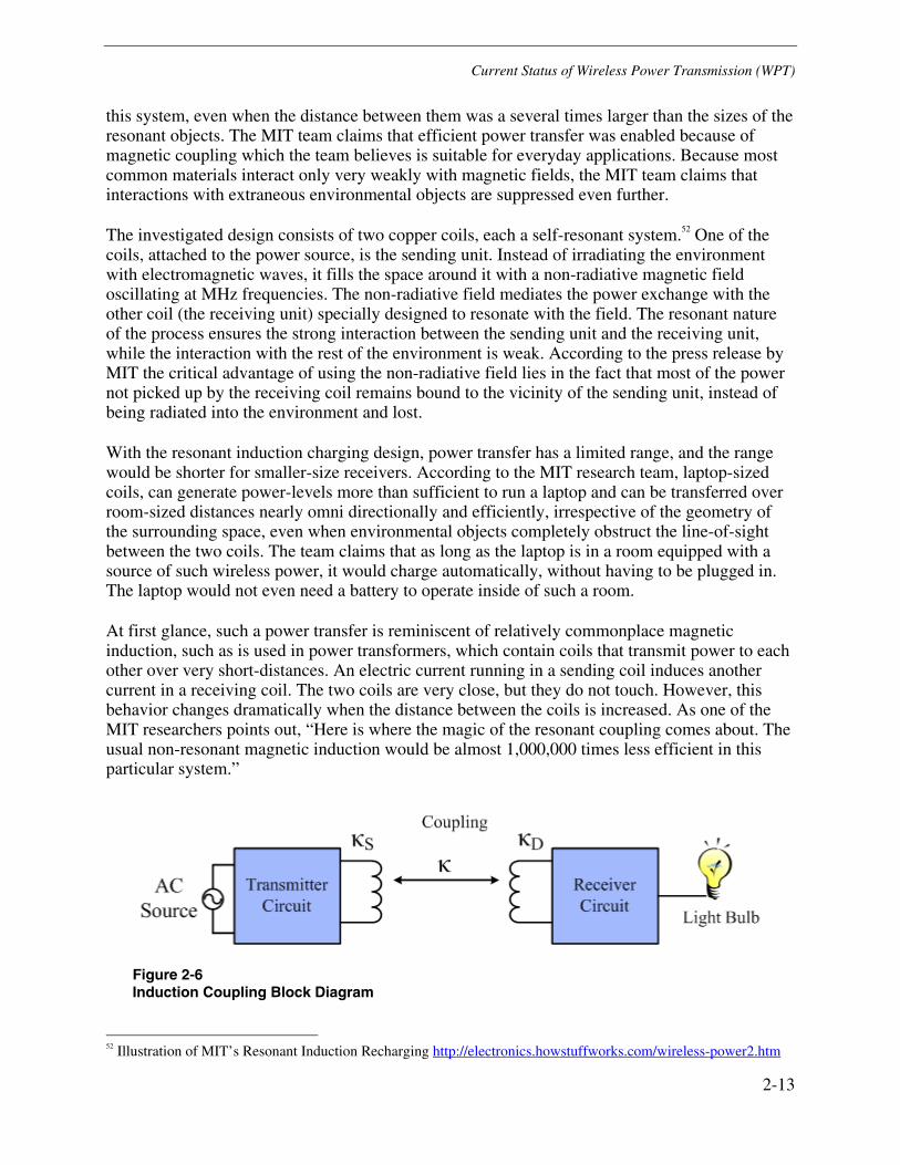
Current Status of Wireless Power Transmission (WPT)
2-13
this system, even when the distance between them was a several times larger than the sizes of the resonant objects. The MIT team claims that efficient power transfer was enabled because of magnetic coupling which the team believes is suitable for everyday applications. Because most common materials interact only very weakly with magnetic fields, the MIT team claims that interactions with extraneous environmental objects are suppressed even further.
The investigated design consists of two copper coils, each a self-resonant system.52 One of the coils, attached to the power source, is the sending unit. Instead of irradiating the environment with electromagnetic waves, it fills the space around it with a non-radiative magnetic field oscillating at MHz frequencies. The non-radiative field mediates the power exchange with the other coil (the receiving unit) specially designed to resonate with the field. The resonant nature of the process ensures the strong interaction between the sending unit and the receiving unit, while the interaction with the rest of the environment is weak. According to the press release by MIT the critical advantage of using the non-radiative field lies in the fact that most of the power not picked up by the receiving coil remains bound to the vicinity of the sending unit, instead of being radiated into the environment and lost.
With the resonant induction charging design, power transfer has a limited range, and the range would be shorter for smaller-size receivers. According to the MIT research team, laptop-sized coils, can generate power-levels more than sufficient to run a laptop and can be transferred over room-sized distances nearly omni directionally and efficiently, irrespective of the geometry of the surrounding space, even when environmental objects completely obstruct the line-of-sight between the two coils. The team claims that as long as the laptop is in a room equipped with a source of such wireless power, it would charge automatically, without having to be plugged in. The laptop would not even need a battery to operate inside of such a room.
At first glance, such a power transfer is reminiscent of relatively commonplace magnetic induction, such as is used in power transformers, which contain coils that transmit power to each other over very short-distances. An electric current running in a sending coil induces another current in a receiving coil. The two coils are very close, but they do not touch. However, this behavior changes dramatically when the distance between the coils is increased. As one of the MIT researchers points out, “Here is where the magic of the resonant coupling comes about. The usual non-resonant magnetic induction would be almost 1,000,000 times less efficient in this particular system.”
Figure 2-6 Induction Coupling Block Diagram
52 Illustration of MIT’s Resonant Induction Recharging http://electronics.howstuffworks.com/wireless-power2.htm
Current Status of Wireless Power Transmission (WPT)
2-14
The MIT prototype demonstrates wireless power transfer over a two-meter distance, powering a 60W light bulb.53 In the illustration, members of the team that performed the experiment are obstructing the direct line of sight between the coils.
The MIT research team found magnetic resonance a promising means of electricity transfer because magnetic fields travel freely through air and yet have little effect on the environment or, at the appropriate frequencies, on living beings. The researchers built two resonant copper coils and hung them from the ceiling, about two meters apart.54 When they plugged one coil into the wall, alternating current flowed through it, creating a magnetic field. The second coil, tuned to the same frequency and hooked to a light bulb, resonated with the magnetic field, generating an electric current that lit up the bulb, even with a thin wall between the coils. The MIT team claims that the set up is the most efficient, consisting of 60-centimeter copper coils and a 10-megahertz magnetic field. The power transfer achieved was about 50 percent efficiency over a distance of two meters. The team is looking at silver and other materials to decrease coil size and boost efficiency. The team claims that, realistically 70 to 80 percent could be possible for a typical application
The MIT work has attracted the attention of consumer-electronics companies and the auto industry. The U.S. Department of Defense, which is funding the research, hopes it will also give soldiers a way to automatically recharge batteries. However, at the time of compiling this report, the research team’s lead Marin Solja i remained tight-lipped about possible industry collaborations.
Tokyo Tower Magnetic Resonance Demonstration
Japanese scientists are reportedly ready to illuminate the Tokyo tower using a tesla-like transmitter, implementing inductive resonance. The Tokyo tower, the largest man made structure in Japan, at 1100 feet tall, is the scene for the nighttime experiment.55 The intention is to illuminate the top spire of the steel structure as a demonstration of the use of wireless electricity transfer. The test is designed to transfer about 1200 watts of power at a range of 100 feet and will be the first of its kind system. Japanese scientists plan to develop a WPT system to transmit power at distances they hope could reach 300 feet. The system is based on magnetically coupled resonance, in a strongly coupled regime.
The use scenario connected with the story of this experiment has nothing to do with providing power to buildings. The Japanese Government is said to believe the first application would be electric vehicle charging. Chargers could be embedded into parking spaces, the vehicles would automatically charge without requiring a physical connection. To promote this idea the Japanese government envisions thousands of free charging spaces located around Tokyo.
The experiment shows two developments of inductive coupling. The first is to expand the usable range of inductive coupling from 1-2 m to perhaps 100 m. If successful the expanded range
53 MIT Wireless power transfer illustration http://www.sciencedaily.com/releases/2007/06/070607171130.htm 54 Illustration of Magnetic resonance coupling http://www.technologyreview.com/read_article.aspx?id=20248&ch=specialsections&sc=emerging08&pg=2 55 Illustration of the first commercial wireless electricity experiment in Japan http://www.nextenergynews.com/news1/next-energy-news-tesla-wireless-japan-1.31d.html

Current Status of Wireless Power Transmission (WPT)
2-15
would capture many more potential use cases. The second innovation is to improve the transfer efficiency through the employment of resonance. A much higher percentage of the transmitted power is delivered to the recipient device. It is instructive that those closest to the technology are envisioning implementation in electric vehicles at much more moderate distances. This may be an indicator of the near term potential of their innovations.
RF Transmission
Radiative charging using RF to transmit power is another concept but as evidenced by the search for technology and products is far less developed than inductive coupling. Powercast seems to be the one company with developed or near complete products.
Powercast LLC
Powercast56 Corporation, based in Pittsburgh, Pa., was founded in 2003. It has developed a transmitter module, called a Powercaster™ and a receiver module called the Powerharvester™. The company has previously demonstrated LED-based wireless lighting and recharging of consumer electronic devices such as mobile phones, but their current focus is on powering wireless sensors for applications such as building automation, energy management, and industrial process monitoring
This product concept consists of an RF transmitter that plugs into the wall socket and broadcasts RF. The company claims an efficiency of up to 70% of the radio signal’s energy. That energy is converted into DC power for use in the device. Using RF energy to power electronic devices is not a particularly new idea, the company claims its patented approach is unique and can harvest up to 50-70% of the energy transmitted compared to traditional methods with typically efficiencies of 10% or less. While conceptually possible it is likely that the efficiency claim is only possible over very defined distances and with other limiting configuration specifications.
The Powercast display at the CES 2009 booth, however, showed the technology powering up only small devices such as low wattage lighting products. In addition to that, Powercast’s technology is a uni-directional beaming of EM waves that allows the transfer of power. Move the transreceiver away from the beam, the power reportedly decays to zero.57
Currently the Powercast solution is designed to operate in the 900-MHz band ISM band. The Powercast’s system delivers 1-2 watts of power at 915 MHz.58 The technology will be able to "trickle charge" a variety of electronics over a period of time in order to provide their power requirements. According to the company, the wireless power platform can harvest a few milliwatts of energy within a meter of the source, in this case the transmitter. That is enough energy to charge a single depleted cell phone battery about half way overnight, according to the company. The solution will also be ideal for devices with small batteries such as watches, hearing aids, wireless keyboards and mice, and game controllers, all of which could be continuously charged.
56 http://www.powercastco.com/?page=home 57 http://tech.firdooze.com/2008/01/10/ces-showcasing-the-best-of-wireless-charging/ 58 Powercast product data sheets http://www.powercastco.com/technology/development-kits/
Current Status of Wireless Power Transmission (WPT)
2-16
But there are limits to the charging capabilities of the Powercast platform. At the 2007 Consumer Electronics Show (CES) demonstrated an implementation that recharges AA, AAA and other small batteries continuously without a plugged-in charger. In its CES demonstration, Powercast transmitted a few kilowatts over a distance of one meter.
Larger devices such as laptops will not be able to make use of the company's solution simply because they require too much power. In fact, the size limit at this time seems to be at the cell phone level for effective charging, company executives say.
The technology offers some food for thought as battery recharging is likely to become a growing challenge in the years ahead. According to Freedonia Group, a market research firm in Cleveland, the worldwide battery market was $52.6 billion in 2005. Half, $27.1 billion was consumer batteries, according to Ken Long, a Freedonia analyst. And half the consumer market was rechargables, $13.6 billion. Long says the rechargeable market is expected to grow the fastest of any segment, rising to $33.1 billion by 2015. By comparison, disposable consumer battery market is expected to grow from $13.4 billion in 2005 to $24.6 billion in 2015.
Laser Transmission
Transmission of power by laser is another concept being developed.
PowerBeam
PowerBeam59 is developing power transmission through eye-safe laser transmission; also referred to as optical transmission. The transmitter consists of variable number of laser diodes, computer control, with safety electronics. A key to PowerBeam’s concept is their patented safety system, which is designed to insure that no person ever comes in contact with significant amounts of power. Each laser diode is capable of operating CW at 1W-5W. Current wall plug efficiencies are 30 percent to 60 percent, depending on the application. The laser beams are intentionally spread for safety such that the power density averages 1mW/mm2 to 10mW/mm2. PowerBeam uses Infrared Lasers that are completely invisible to the human eye and therefore eye-safe.
The receiver consists of several photovoltaic detectors, usually with lenses in front of them, and electronics for handshaking, safety, and power conversion. The receiver has a low-power IRDA laser to create a back channel to the transmitter. This back channel is used for handshaking and safety. The detector is designed to be physically easy to recognize by a transmitter that is constantly looking to acquire a target to charge. Generally the detector dimensions are larger than the PowerBeams by 20 mm. This allows slop and margin for safety.
59 http://www.powerbeaminc.com/technology.php

Current Status of Wireless Power Transmission (WPT)
2-17
Figure 2-7 PowerBeam Concept Show Powering Lighting (Left) and Speakers (Right)60
PowerBeam’s patent-pending safety system uses a series of techniques to be certain that human exposure remains below FDA laser safety requirements. If a person or animal attempts to break the beam, the transmission is shut off immediately and the power transfer ceases. A buffer battery is used to power the device while the system is off. With no power being transmitted over the beam, no harm can be done. Additionally, a series of other safety methods assure that no light will be reflected to an unacceptable direction and will only be absorbed by the receiver.
PowerBeam increasingly claims significant efficiency improvements. Detectors are said to usually achieve 40% - 50%. Lasers are 30% to 60%, depending on the application. There is little conversion loss, as the output is DC as are most loads and there is no significant loss over distance. The company claims one can expect wall-plug efficiencies anywhere from 15% - 30%, depending on the application. The probable limit of improvement is 35%. This is highly efficient compared to light bulbs and motors.
Camera and Security Sensor are two of PowerBeam’s target applications. Other applications are digital picture frames, audio speaker and lighting.
Wireless Power Consortium
On July 31, 2008 the Wireless Power Consortium was formed.61 Formation of consortia are actions typically seen with promising technologies where companies seek to share cost and explore other advantages of cooperative action to nurture a promising innovation. The wireless power consortium will focus on a wireless power technology that transmits power only to a product which is in close proximity of the charging station. This is perhaps an indicator that those closest to the technology see its near-term potential as only for closer applications.
60 Photo courtesy PowerBeam Inc. 61 http://www.wirelesspowerconsortium.com/news/press-releases/first-international-wireless-power-consortium-pursues-standard.html
Current Status of Wireless Power Transmission (WPT)
2-18
The Consortium plans to develop a standard for low power electronic devices using 5 watts and below, such as mobile phones, music and video players, computer and game accessories. A standard is then planned for higher power portable electronics and electrical equipment. Potentially the use of the technology to recharge electric vehicles may also be in view.
Current members of the consortium62 are:
• ConvenientPower: http://www.convenientpower.com
• Fulton Innovation: http://www.fultoninnovation.com
• Logitech: http://www.logitech.com
• National Semiconductor: http://www.national.com
• Olympus: http://www.olympus.com
• Philips: http://www.philips.com
• Sanyo: http://www.sanyo.com
• Sang Fei: http://www.sangfei.com
• Texas Instruments: http://www.ti.com
62 http://www.wirelesspowerconsortium.com/about/our-members.html
3-1
3 TECHNOLOGY AND COMPETITIVE ASSESSMENT
Distinctive Characteristics or Properties
A mature wireless power transfer (WPT) technology implemented to power a device, in theory depicts a unique set of properties, that sets it apart from wireless communication systems such as radios and cell phones, self-contained power storage and delivery devices such as batteries, solar powered devices and others that may not need wires or cables for power supply or delivery. The following characteristics differentiate mature wireless power transfer technology from other methods that seem “wireless” and involve power consumption or power delivery.
1. Power charger : A conventional power supply charger63 or equivalent thereof, is not required for normal operation
2. Energy storage : Energy storage (external or internal) or equivalent thereof is not required for operation
3. Speed of energy transfer: Energy transfer can occur at the velocity of light unlike traditional forms of transfer (wired and wireless networks can be subject to network delays or bandwidth limitations).
4. Pointed power delivery to mobile loads: WPT implementations, like laser transfer, can deliver power to a specific point, quickly changing direction to follow the device being powered. This may be an advantage where the delivery of power needs to be effective to the recipient device only.
5. Accessibility: Some WPT implementations, like RF, can put power into a wide area and even into hidden and inaccessible locations. Recipient devices can ‘find’ power no matter where they are or how inaccessible their location is. Energy can be delivered to inaccessible spots or even within special environments, like explosive atmospheres.
6. Power on-demand: WPT systems can be designed to supply power only when needed. For resonant coupled devices, when no receiver is nearby, no power is expended in magnetic coupling systems. Electromagnetic (EM) transmission systems can also be controlled in this way if the receiving device is designed so as to communicate its need for power to the transmitting device. Prevalent designs have the EM transmission constantly ON, which causes energy to be transmitted continually into free space and must be captured or lost if not used.
Each of the above mentioned properties can provide a compelling reason to use WPT.
63 Refers to the power supply “brick” that in most cases contains circuitry for AC to DC power conversion

Technology and Competitive Assessment
3-2
The primary benefit of WPT is that it eliminates the need for wires. This can significantly reduce the cost of installation for some kinds of devices. It can improve reliability, if there is a significant risk that the power wiring may be damaged or broken. It can be convenient, for example, in charging portable devices. It can eliminate other problems in applications where the power wiring presents a problem. If a device needs to be in motion, WPT can deliver power without restricting the movement of the device. If the use environment presents particular hazards that could damage wires, WPT can be a solution by eliminating the need for wires. If sparks are a particular risk, WPT can deliver power without the potential for sparks as plugs are connected or disconnected.
With WPT, no mass, either in the form of wires, batteries or ferrying vehicles, is required between the source of energy and the point of consumption. For applications where weight and size is critical, WPT can provide a compelling solution.
The primary competing technology to WPT is wired power. Solar power is another competing technology to WPT. Batteries are also a competitor. Particularly in applications where batteries may give long life, in some cases even years, the attractiveness of WPT is diminished. Improvements in battery performance will increase the number of applications for which WPT is less appealing. Yet another competitor is energy harvesting in various forms. Solar cells are one specific form of energy harvesting. Vibration harvesting is another technique, which uses vibration from smooth rotating machinery to power sensors.64 Each of these types of wireless power transfer has unique characteristics and competes with each other in applications where more than one WPT type is viable.
Wireless or inductive power solutions have been developed in the past, but in each case the limitations or implementation costs diminished the potential gains of the system. As a result, a household today might contain only a few systems utilizing inductively coupled power, devices such as cordless shavers and toothbrushes. These applications are typically low power and require a fixed spatial relationship between the charger and the device65.
Drivers
The market potential for wireless energy transfer technologies has improved in recent times due to development in technology and due to the increasing market for mobile devices. As shown in Figure 3-1, three key motivating factors explain why manufacturers and researchers are increasingly interested in WPT applications for mobile electronics.66
• Market growth – refers to the enormous surge in quantity, variety and usage of battery- powered, mobile, electronic devices. Until about five years ago, the market for low-power mobile electronics such as notebook PCs, small mobile phones and digital cameras was relatively small. In the past five years, the market growth in mobile electronics has been significant and this steady growth is expected to continue through the next five years.67
64 Electronic Design, “Energy Harvester Perpetually Powers Wireless Sensors”, by Pierre Mars , ED Online ID
#20033, November 17, 2008. http://electronicdesign.com/Articles/Index.cfm?ArticleID=20033&bypass=1 65 http://www.appliancedesign.com/CDA/Articles/Electronics/6379de6c31b5d010VgnVCM100000f932a8c0____ 66 Techon magazine http://techon.nikkeibp.co.jp/article/HONSHI/20070530/133362/ 67 Business wire, April 2008 http://findarticles.com/p/articles/mi_m0EIN/is_2008_April_2/ai_n24967975

Technology and Competitive Assessment
3-3
According to In-stat, a market research group, shipments of personal computers and peripherals, traditional consumer electronics products, and communications products will grow from 2.7 billion units in 2007 to 3.1 billion units in 2011.68 With more than a billion cell phones, audio players, personal digital assistants (PDA’s), and digital cameras shipped each year; tremendous opportunities exist for wireless power transfer technologies to deliver “true” convenience and mobility while driving greater device usage and airtime.
• Developments in technology – Key technological developments have propelled the rapid progress of wireless power transfer for low power applications. For example, non-contact charging technologies in the past were capable of receiving 10% to 20% of transmitted power, but in the last year or two, this has increased to 60% and in select low voltage applications even more. In addition to non-contact charging there are also technologies capable of charging mobile devices over a few meters. Beaming power to mobile devices at distances of up to approximately 10m, (albeit at only low voltages) is one such technology being commercialized.
• Limits (delays) to competing technologies –The widespread adoption of mobile devices has pushed the development of battery technology, close to its limit. Batteries are a reliable source of power for mobile applications and are a competing technology to wireless power transfer technologies. Batteries enjoy a large global market. The annual global market for Lithium batteries, which are most commonly used in mobile electronics, is worth $6 billion and is growing at 10-15 percent annually.69 At the same time, the demand on power and battery performance continues to grow, especially with the advent of 3G mobile devices. “Power-hungry” functions and features in devices such as 3G cell phones70 and an increase in the average usage times due to mobile applications such as email, games, video, etc. are pushing the energy demand on batteries to higher limits. Because of battery design limitations (for mobile applications) such as foot print, weight, life and duration for full charge, and delays in technology advancements, battery charge might affect consumer behavior by the adoption and usage of advanced features and new applications in mobile devices. A mature, wireless power transfer technology capable of delivering energy reliably can augment battery charge or replace battery technology for mobile applications.
• User expectation –Today, most rechargeable, portable electronic devices come with their own proprietary charger and cable(s). An average user of mobile electronic devices carries at least three different chargers and at least an equal number of cables for energy charging and data transfer functions. New portable devices equipped with infrared (IR)71 or Bluetooth72 technologies (or both in some cases) provide options to enable inter-device data transfer
68 In-Stat: Consumer electronics market to continue expansion through 2011 http://www.macsimumnews.com/index.php/archive/in_stat_consumer_electronics_market_to_continue_expansion_through_2011/ 69 http://www.m2epower.com/about/overview.htm 70 A typical next-generation 3G mobile phone includes capabilities such as LCD touch screen display, internet browsing, television on-demand, high-resolution camera, FM radio/transmitter, MP3 player, video/audio recording, GPS services support, Bluetooth technology, voice-driven menus and Infra red ports. 71 A cell phone that features an infrared port uses a beam of invisible light to transmit wireless information to such devices as a PC. Cell-phone infrared technology is used for a variety of applications, including using the phone to link your PC to the Internet, or transmitting wireless information to other infrared-equipped cell phones. 72 Bluetooth is a popular short-range wireless technology able to connect devices like cell phones, headsets, printers, laptops, etc., in order to transmit or synchronize data. Bluetooth-enabled cell phones may have different capabilities, depending on the level of sophistication. The most basic level is the capability for the cell phone to transmit a signal to a wireless headset (the common "Bluetooth" headset) or to a car-kit, enabling “hands-free” use of a cell phone.

Technology and Competitive Assessment
3-4
wirelessly. Wondering whether a battery is charged, when and how to recharge it, what applications to use with the remaining battery charge and how long to use it is a near-constant hassle for users of mobile electronic devices. Some 20% of cell phone users lose battery power at least once per week.73 Cell phone consumer frustration encompasses not only the inability to make or receive a call because of a dead battery but also addressing the added cost and inconvenience of juggling multiple chargers (at home, in the car, at the office, etc.). This has lead to changing consumer expectations to charge mobile devices wirelessly, potentially eliminate the use of cables and chargers, and help mitigate the “inconvenience” associated with carrying external chargers and cables.
Figure 3-1 Market Drivers
Environmental Impact
WPT could be a valuable technology from the environment impact and associated carbon cost standpoint. According to the 1394 Trade Association Technical brief, conventional external power supplies, chargers and many other “wall-connected” electronic devices use linear power supplies which are only about 30-40% efficient. Unfortunately, the electronic devices continue to consume power in spite of being turned off, while they are plugged in the wall socket. The combined cost of the 60-70% wasted energy, and the environmental impacts associated thereof could be significant. Moreover, the environmental cost of producing, packaging, distributing and the end of life (disposal) of millions of conventional power supplies, is also significant. Table 3-1 shows the embedded energy requirement and the associated environmental impacts/costs, of external power supplies (not including external disk drive power supplies) worldwide.
73 Business wire http://www.businesswire.com/portal/site/home/permalink/?ndmViewId=news_view&newsId=20080825005135&newsLang=en

Technology and Competitive Assessment
3-5
Table 3-1 Worldwide embedded energy to produce, ship and dispose external power supplies
Product Embedded Energy†(PJ)*
CO2 Emissions†† (Million Metric Tons)
# 100 MW Power Plants
Cell Phone 21 4.2 7
DECT Phone 5 1.0 2
Digital camera 2 0.4 1
Set Top box 5 1.0 2
Personal Care 1 0.2 0
Standard battery charger 3 0.6 1
Power Tool charger 4 0.8 1
Printer 4 0.8 1
Laptop 2 0.4 1
Other 10 2.0 3
† Embedded energy refers to the total energy consumed for production, packaging, distribution and end of life (disposal) ††CO2 generated as attributed to the energy generated by coal burning power plants to meet the embedded energy needs * 1 Petajoule (PJ) = 109 million joules = 277.77 million kWh
Thus WPT can play a key role in mitigating the environmental impact of producing and disposing and end-of-life management of external power supplies, eliminating significant electronic waste. In 2008, 3.2 billion external power supplies were manufactured worldwide. Of these, 737 million units were shipped to the US. An estimated 434 million external power supplies were retired in 2008 in the US,74 of which only 15-20% (by weight) will be recycled, the remaining 80-85% disposed to landfills and incineration.75These power supplies are made with toxic materials and don't have a lot of salvageable components making them unattractive to recyclers.76
Benefits and Competing Technologies
WPT eliminates the need for wires to transmit power to a device. This feature provides convenience in some situations and overcomes a number of other obstacles that arise in various other scenarios. When the ability to power a device without wires becomes the primary metric in choosing a power transfer technology, then WPT becomes competitive and in some scenarios is the superior solution.
Perhaps the most useful way to analyze WPT against other choices for providing power to devices, is by means of ‘jobs a user needs to do.’ This metric takes a customer oriented viewpoint and puts WPT in competition with some alternatives which initially may not appear to 74 Rose, William “1394 Trade Association Technical Brief: How Green is My FireWire?” WJR Consulting, Inc. http://www.1394ta.org/Press/WhitePapers/2009_Green.html 75 EPA 2005 estimate, July 2008 factsheet http://www.epa.gov/epawaste/conserve/materials/ecycling/docs/fact7-08.pdf 76 http://www.demo.com/community/?q=node/30926

Technology and Competitive Assessment
3-6
be competing technologies. .For example, an owner of multiple wireless devices may want to conveniently charge them every night. This customer might be a business traveler who would also like to eliminate the weight and inconvenience of carrying multiple chargers and then finding sockets for them in a hotel room. In this scenario WPT would compete with a single charger that had multiple connections, allowing simultaneous charging of multiple portable devices. The growing use of small battery powered devices and the use of rechargeable batteries in these devices creates a market for WPT.
Another example of a job a customer is trying to get done is providing power to a device where wall sockets are either inconvenient or totally unavailable; examples would be sensors in a large warehouse or satellites. For the satellite, solar power would be a significant competitor to WPT, and for the warehouse both solar power and long life batteries would be competitors. WPT will be a competitive or even the preferred solution when its combined benefits and risks are superior or clearly superior to alterative choices. WPT has several inherent weaknesses. WPT will always introduce additional cost because there must be circuitry to create the transmitted energy and circuitry to receive the energy. These conversions also assure that there will always be additional energy loss with WPT because every conversion of energy has some loss. The various kinds of WPT boost a variety of efficiency levels but none rival the efficiency of wired delivery of power which can approach 99%.
A special and promising category for WPT is in implantable medical devices like pacemakers. Such devices will always have a difficult time locating a wall plug and replacing batteries is particularly inconvenient. Therefore recharging batteries wirelessly becomes very attractive.
The various forms of WPT compete with each other in applications for which several are viable options. For example, at small distances inductive coupling, RF and laser transfer are all viable solutions. Thus WPT can be considered as a set of options that is introduced into a wider range of options. Product designers and then consumers will decide the best solution for a given application. A competitive analysis of WPT should consider each technology individually, identify the use scenarios for which the technology is competitive, and then assess the market opportunity presented.
Development of Competing Solutions
There will be improvements in competing technologies, as companies try and overcome their deficiencies for various applications. When making a competitive analysis of WPT it is therefore important to compare it to the current condition of alternative solutions and their foreseeable development.
Batteries, both rechargeable and single use, are a competing solution to WPT in many applications. Batteries have and continue to improve, making them better solutions in a growing number of applications.
Technology and Competitive Assessment
3-7
Connector Innovation
Another example of development of a competing technology is improvement in connectors. One advantage of WPT is that it eliminates the need for wires and a connector. However, companies are making connectors more convenient and less obtrusive. Arizona-based Wildcharge is an example in this category. The company demonstrated its technology at this year's CES and is currently developing a line of charging pads that can wirelessly transfer power via direct contact between a smaller adapter fitted on a device and the pad itself. The company offers adapters for the Motorola Razr, Blackberry Pearl and Curve. Unlike many WPT solutions that are only in the concept stage, Wildcharge offers their products for sale on their website.77
Wildcharge’s solution works through electrical contacts on the device’ adapter that come in direct contact with the pad’s surface. Power is then transferred from the energized pad’s surface to the cell phone. This conductive solution looks and acts much like inductive coupled charging pads and therefore is a competitive alternative to them. Their charging pad can detect and distinguish between objects placed on it, charging only devices with one of their adapters. Hence, by form factor and features Wildcharge has made a ‘connector’ that mimics inductive coupling for many applications and therefore offers a competitive solution to WPT.
Energy Harvesting
Energy harvesting is an area of research that is both competing and potentially synergistic with WPT. The core idea of energy harvesting is to capture and convert energy present in the environment to power a device. Environmental energy can take many forms, electromagnetic, sound, light, heat, movement, such as vibration or flow of liquid or air. Each of these can be converted to electrical energy and used either directly or to recharge a battery that then powers a device.
The power being harvested may be intermittently available, such as wind or light, but in other cases may be reliably available, such as vibration from an operating generator or engine. When energy is reliably available energy harvesting becomes a competitive alternative to WPT. The analysis will focus on question such as the relative cost of a harvesting a WPT solution, whether there is enough energy to be harvested to satisfy the power demands of the application. When the energy to be harvested is not reliable the possibility arises for a hybrid system with WPT. In a hybrid system WPT provides enough power to assure a minimum supply of power and harvested energy supplements the power available, potentially reducing cost and providing other benefits.
A use scenario that might be explored for a hybrid system would be sensors in a power plant. In a power plant vibration and significant magnetic fields, from current flowing in cables, will be present and might be harvested to power sensors. Magnetic fields will also be always present in the power grid and could be used to power sensors monitoring the grid. The problem becomes what happens when the plant is not operating or there is damage to the grid? The first answer will be that power is provided by the energy storage component of the energy harvesting system. Energy can be stored in batteries, high value capacitors or hydrogen for fuel cells. During
77Refer Illustrations at http://www.shoppureenergy.com/wire-free-solutions/
Technology and Competitive Assessment
3-8
periods of power disruption these sources could supply the power needed for the sensors to operate and communicate their data.
Solar Cells
Solar cells and solar power continue to receive a lot of attention and will be a significant competitor for other forms of WPT. In one way solar cells can be viewed as a variety of WPT in which the source is the sun and the delivery mechanism is light. If the sun were not available then light could be delivered from another source, such as a regular light or even laser. Currently the cost of installed solar energy conversion systems is between $0.25 - 0.40/kW hr. To be competitive in the current energy market it will need to come down to $0.02 - 0.10/kW hr.78 While the cost of energy is not always the deciding factor in what energy delivery technology will be selected, it is an important metric, and often is the deciding factor. Other WPT technologies will be compared based on the cost of energy delivery and for many applications this will be the deciding factor in what solution is adopted.
Enabling Technologies
WPT has become viable in many applications due to improvements in enabling technologies. This trend is likely to continue. As other technologies improve the combination of WPT with another technology will create compelling solutions in a growing number of applications. This section discusses a few of these as examples of some of the more important technologies to monitor in order to predict when WPT will become a preferred solution in an application.
Fuel Cells
Fuel cell technology is an exciting technology that is seeing a lot of development. It is currently in deployment or field trial for applications like providing local power generation or vehicular power. Conceptually it is being considered as a battery replacement technology for applications like laptop batteries.
From the viewpoint of WPT fuel cells can be seen as a competitive threat and also an enabling technology. Competitively, as fuel cells become viable replacements for batteries in some applications the potential for WPT to service those applications decreases.
Fuel cells can be an enabling technology for WPT. WPT and fuel cells can be used together to create new solution possibilities. Exploring this thought WPT can be the final delivery link from a fuel cell to the point of use. For example, fuel cells offer the possibility of power generation in remote or difficult environments for the power grid to service. In many of those same environments distributing the power from a fuel cell to end use devices is problematic. Hence, a combination of fuel cell and WPT can be a very attractive solution for situations where the power grid has difficulty reaching and where wiring is expensive or inconvenient to install.
78 http://web.mit.edu/mitpep/pi/courses/solar_energy.html

Technology and Competitive Assessment
3-9
In a different configuration WT can deliver power that is stored in a form that can be used by the fuel cell to deliver power when needed. Recent work at MIT has made significant progress in combining fuel cells with solar cells in a process that mimics photosynthesis.79 MIT researchers are exploring a simple, inexpensive, highly efficient process for storing energy. The energy gathered from a solar cell is used to break down water into hydrogen and oxygen. These gases are then stored, to be used by a fuel cell when power is needed. The concept at MIT is that this storage mechanism allows power gathered during the day to be available at night. Conceptually the system can be a self-contained closed loop as the fuel cell produces energy by recombining hydrogen and oxygen, forming water that can then be divided again. Essentially simple water and its constituent gases become the energy storage mechanism. While MIT is focused on solar cells as the energy gathering mechanism any WPT technology could be used in that role. In an environment where light was not available or where solar cells could not produce enough energy other WPT options could be recruited.
The primary discovery of the MIT researchers is a new catalyst, consisting of cobalt metal, phosphate and an electrode. When the catalyst is placed in water and electricity runs through the electrode, oxygen gas is produced. The companion catalyst, using platinum, produces hydrogen gas. The oxygen and hydrogen can be combined inside a fuel cell, creating carbon-free electricity to power a house or an electric car, day or night.
Computer Technology
A great many of the improvements in WPT, like the delivery on demand of inductive coupling systems and the safety technologies being coupled with laser transfer, are enabled by computer technology. Further improvements will make additional improvements viable. Developments like fuzzy logic, now being used in many home appliances, will be important to monitor in order to assess when current limitations of WPT might be overcome.
MANET Networks
In the realm of wireless technology MANET (Mobile Ad Hoc Networks) are being aggressively developed. MANET’s are intended to standardize IP routing protocol functionality suitable for wireless routing application within static and dynamic topologies with increased dynamics due to node motion or other factors. MANET networks offer two advantages to WPT systems. First, sensors can be configured to relay data from more distant sensors, through the grid of sensors to the data collector. This significantly reduces the power required in each individual sensor radio. A second opportunity for sensors that only need to be queried periodically is that WPT can power an area of sensors which then report their data. In this configuration, the WPT becomes both the power source and the ‘on switch’ for a set of sensors that then operate for the period of time required.
79 For illustrations see online: http://web.mit.edu/newsoffice/2008/oxygen-0731.html

Technology and Competitive Assessment
3-10
Utility Applications
Monitoring Equipment Condition
Sensor technology has advanced to the place where the condition of equipment can be actively monitored during operation. Information about equipment condition allows for timely maintenance before a relatively minor failure cascades into a major breakdown. In the best situations sensors can predict a failure before it occurs, allowing preventative maintenance to be performed in a timely fashion.
New software and emerging technologies are simplifying condition monitoring and predictive maintenance. Success in a predictive maintenance program might be jeopardized if the technician must rely on indirect or imprecise measurements, if the batteries in the measuring equipment fail, or if data communications are limited. Gradually such constraints are being overcome. New software and emerging technologies are simplifying condition monitoring and streamlining the process of predictive maintenance.
Miniature Sensors
Purdue University researchers, working with the U.S. Air Force, are using microelectromechanical systems (MEMS) technology to detect when critical jet engine bearings are close to failing. The miniaturized wireless sensors directly monitor engine bearing temperature. Data generated indicates whether the bearing is about to fail and predicts how long it will last before failure. The sensors have been shown to detect impending temperature-induced bearing failure significantly earlier than conventional sensors which indirectly monitor bearings using the temperature of engine oil. The MEMS-based sensors operate without batteries -- they are powered through inductive coupling -- and temperature data is wirelessly transmitted. To support military applications, the devices are being designed to withstand temperatures as high as 300°C (572°F).
Sensors that only need to be powered up and interrogated periodically can be applications that are well suited for WPT. Sensors can be poured into concrete of bridges and only periodically powered and interrogated to report the internal condition of the structure. Sensors can be built into machinery and industrial plants where they would be powered and operate only during periodic maintenance checks. In such applications WPT offers many advantages by eliminating the need for wires or batteries. Further, under these kinds of scenarios WPT might be able to be operated under higher power conditions under the control of a trained operator and with special safety precautions being taken.
Self-Powered Sensors
Battery maintenance can be costly and difficult when condition-monitoring sensors are installed in confined spaces or at remote locations. Clarkson University researchers have developed a bridge monitoring sensor technology that generates its own energy from the vibrations of passing vehicles. The hermetically-sealed wireless sensor eliminates the need for batteries and can conceivably remain on a bridge for decades without requiring maintenance.

Technology and Competitive Assessment
3-11
New York State Route 11 Bridge was the test platform. An electromagnetic generator installed on steel bridge girder harvests energy at the bridge. When vehicles pass, the structure vibrates and the generator produces electrical energy to power the wireless sensor. Typically, each bridge requires several sensors to monitor structural integrity and other variables, and report changes that could indicate a potential failure. Replacing battery-powered sensors with self-powered sensors can eliminate substantial battery and maintenance labor costs and the risk of communication gaps caused by dead batteries.
In addition to bridges, the researchers are applying the energy-harvesting technology to power sensors in passenger cars. The concept also can be used in the industrial sector for continuous monitoring and proactive maintenance of critical vibrating applications, including lift trucks and rotating machinery such as motors, pumps, fans and turbines.
KCF Technologies, for instance, is developing vibration-energy-harvesting devices to power wireless sensor nodes for use in industrial production lines, power generation systems, vehicles and buildings. The company anticipates the technology will expand the use of wireless sensors, generating benefits such as reduced industrial pollution and energy consumption in addition to eliminating battery replacement costs. Perpetuum is another vendor that has commercial vibration energy harvesting sensors, applicable to industrial markets. Overall, this technology has potential for application in electric power generation plants.
Data Aggregation and Analysis
Equipment condition data generated by sensors and other sources is most useful if it can be easily aggregated, analyzed and logged. The InFusion Condition Manager from Invensys was recently upgraded to display equipment condition and maintenance information on plant process control and engineering HMI workstations, rather than solely on the Invensys Avantis.PRO enterprise asset management system. InFusion v. 2.2 also can feed data to a variety of plant historian packages, making the data and actions available to other plant and enterprise systems.
The system collects and analyzes real-time diagnostics from any plant production asset – for example sensors, actuators, motors, dryers and compressors. It captures data originating from an array of sources, including intelligent instrumentation, fluid and vibration analysis, advanced process control and loop tuning software. It then triggers the necessary maintenance operations or engineering actions based on rules, conditions and customer-defined algorithms and models.
Web Services technology allows InFusion Condition Manager to communicate with enterprise systems such as ERP, EAM and MES. Microsoft NET technology is leveraged to provide the asset and business intelligence information.80
80 http://www.plantservices.com/articles/2008/003.html


4-1
4 RISKS AND OBSTACLES
The following are the risks associated with WPT that may impede the adoption of wireless power transfer technology and/or initial deployment. The full impact of some of these risks has not been completely explored and further investigation is recommended.
1. Stability and reliability of WPT. One issue with reliability is fluctuations in power due to changes in the transmission path which could affect the performance of wirelessly powered devices.
2. Radio frequency (RF) safety is a significant concern.
a) Human safety is protected by the Federal Communications Commission (FCC) and other agencies. However, new technologies require reevaluation to assure that the regulations accurately cover all concerns appropriately.
b) Secondary and non-thermal effects are an additional area of uncertainty and risk. Current safety regulations address only thermal effects. For non-ionizing radiation, thermal effects are the only scientifically proven health risk. Most regulations essentially can be analyzed in humans as limiting the temperature rise in the eye to less than 0.5°C in the eye. The human eye has been shown to be the most sensitive part of the human body to temperature rise due to RF. However, there have been and continue to be active speculation and research into non-thermal effects and the potential for RF effects in special situations or as a secondary contributor to a combined effect. While nothing in this area has been proven to date, research and speculation continues.
c) Testing for human safety must also be addressed. Having limits for RF safety is a related but separate issue from what is required to show compliance to those limits. Absence of test standards can slow regulatory approval for new types of devices and creates uncertainty about their compliance with requirements. That uncertainty could potentially manifest itself into business risk as either legal liability or the potential that in the future new procedures will find deployed products non-compliant, requiring a recall.
d) Beyond human safety is a concern for the biological safety of other living organisms such as pets and livestock. These topics have been far less studied and therefore represent a relatively unknown business risk.
e) Environmental impact is also a relatively unstudied area and an area in which future findings could have an adverse impact on WPT.
3. Public perception of RF biological safety is listed as a separate issue because it may be addressed as a public relations issue rather than a scientific issue. In Europe this concern is sometimes termed “electrophobia”. It is often fueled by rumors, articles and books written

Risks and Obstacles
4-2
for popular consumption with little scientific basis. Industries can be required to spend significant amount of money to address public concerns as has been demonstrated by concerns about childhood leukemia from power lines and brain cancer from cell phones.
4. RF interference with other electronic equipment is another area of risk. Given the variety of electronics and environments some interference is nearly inevitable. Fortunately, the IEEE recently published a standard, IEEE 1900.2-2008, which gives guidance on how to analyze the potential of such interference. Performing a careful analysis of the potential for RF interference is a significant and demanding task, which is beyond the scope of this study. However, it can be said that almost always there will be some RF interference issues, given the many types of equipment and environments that exist today.
a) A particular and important subset of the RF interference issue is the potential for there to be interference with medial equipment. Implanted medical devices such as pacemakers are one particular area to be evaluated.
b) Other RF interference concerns will be frequency specific and heavily influenced by the proposed technology and frequencies being proposed for use by WPT.
c) RF interference can be divided into interference to equipment that does not intentionally use the RF spectrum, and equipment that does use the RF spectrum such as other wireless devices. Interference problems in either area are of concern, but the analysis of the potential for interference must be done separately.
d) Fears of whether electricity can be transferred to any metallic object in the vicinity of the source, especially for the products that uses magnetic coupling, is another area of concern. The risk here is that WPT could induce currents creating a shock or a spark hazard. The concern that cell phones could produce a spark that ignites gasoline while motorists were refueling has now been disproved but is a good example of such a concern.
e) WPT that creates significant magnetic fields would be of concern for equipment, such as HDD (Hard Disk Drives), credit cards or other devices using magnetic strips because of the potential impact from magnetic fields.
5. Regulatory risks are another issue for WPT technologies. Deployment of WPT technologies requires regulatory approval. Regulators must address the public concern issues and develop rules to govern new technologies. The development and implementation of such rules takes time and can be a significant impediment to the introduction of a new technology. In the U.S., the FCC has demonstrated acceptance of very close WPT applications, but acceptance of WPT that operates over moderate to long distances is unsettled.
Stability and Reliability
The stability and reliability of WPT is a primary factor when considering the viability of WPT for a given application. Wired power delivery will always be superior in these areas to WPT except in scenarios where there is the potential for damage to wiring. Similarly WPT will be more reliable than solar power in most applications because with WPT the source is controlled while with solar power, the sun is not always available and its availability does not ensure the same power level at all times.

Risks and Obstacles
4-3
The various forms of WPT have individual problems with stability and reliability. The use of WPT for transmitting power over a distance has risks due to changes in the environment. Devices may move, relative to each other. Other devices may come into the environment and block the transmission. Reflections can create a multipath environment in which reflections of the WPT transmission create nulls through phase cancellation. For some applications these can be serious considerations and at times critical barriers to the use of WPT.
RF Safety
Safety Limits for Human Exposure
Concern about the safety of RF energy has resulted in several national and international organizations establishing guidelines for human exposure to RF energy. The most prominent of these guidelines are:
1. IEEE C95.1 standard81
2. The recommendations of the National Council on Radiation Protection and Measurements (NCRP)82
3. The International Commission on Non-Ionizing Radiation Protection (ICNIRP)83
4. The National Radiation Protection Board (NRPB) in the United Kingdom84
While the recommendations of these guidelines are similar, there are differences which can affect the evaluation of product safety. However, all the guidelines are united in determining that there are levels below which there is not a health concern for humans.
In the U.S., the FCC has published the following policy statement on RF Safety:
FCC Policy on Human Exposure to Radiofrequency Electromagnetic Fields
The FCC is required by the National Environmental Policy Act of 1969, among other things, to evaluate the effect of emissions from FCC-regulated transmitters on the quality of the human environment. Several organizations, such as the American National Standards Institute (ANSI), the Institute of Electrical and Electronics Engineers, Inc. (IEEE), and the National Council on Radiation Protection and Measurements (NCRP) have issued recommendations for human exposure to RF electromagnetic fields. On August 1, 1996, the Commission adopted the NCRP's recommended Maximum Permissible Exposure limits for field strength and power density for the transmitters operating at frequencies of 300 kHz to 100 GHz. In addition, the Commission adopted the
81 IEEE C95.1-1991: "Safety Levels with Respect to Human Exposure to Radio Frequency Electromagnetic Fields, 3 kHz to 300 GHz," IEEE, Piscataway, NJ, 1992. This standard is available at: http://standards.ieee.org. 82 NCRP: Biological effects and exposure criteria for radio frequency electromagnetic fields, Report 86, (Bethesda, MD National Council on Radiation Protection and Measurements) 1-382, 1986. 83 ICNIRP: Guidelines for limiting exposure to time-varying electric, magnetic and electromagnetic fields (up to 300GHz), Health Physics, 74(4): 494-522, 1998. 84 NRPB: Board Statement on Restrictions on Human Exposure to Static and Time-Varying Electromagnetic Fields, Documents of the PRPB, Vol. 4, No. 5, National Radiological Protection Board, Chilton, Didcot, Oxon, UK, 1993.

Risks and Obstacles
4-4
specific absorption rate (SAR) limits for devices operating within close proximity to the body as specified within the ANSI/IEEE C95.1-1992 guidelines. (See Report and Order, FCC 96-326). The Commission's requirements are detailed in Parts 1 and 2 of the FCC's Rules and Regulations [47 C.F.R. 1.1307(b), 1.1310, 2.1091, 2.1093]. The potential hazards associated with RF electromagnetic fields are discussed in OET Bulletin No. 56, "Questions and Answers About the Biological Effects and Potential Hazards of Radiofrequency Electromagnetic Fields."85
IEEE C95.1-1999, IEEE Standard for Safety Levels with respect to human exposure to radio frequency electromagnetic fields, 3 kHz to 300 GHz , provides limits for human exposure to electromagnetic energy in uncontrolled environments. The limits, termed Maximum Permissible Exposure (MPE), are given in terms of rms electric field strengths (E), magnetic field strengths (H), and equivalent plane-wave free-space power densities (S). Limits are also provided for the induced currents (I) in the body that can be associated with exposure to such fields or contact with objects exposed to such fields.
Uncontrolled Environments
Separate limits are given for controlled and uncontrolled environments. The limits for uncontrolled environments are focused on in this report because they are more stringent than those for controlled environments and because meeting them opens up more potential uses for WPT. Uncontrolled environments are defined by IEEE C95.1 as “Locations where there is the exposure of individuals who have no knowledge or control of their exposure.” Table 4-1 contains quotes from IEEE C95.1-1999 and gives the limits for uncontrolled environments as a function of frequency.
85 http://www.fcc.gov/oet/rfsafety/

Risks and Obstacles
4-5
Table 4-1 Limits for Uncontrolled Environments as a Function of Frequency
The exposure values in terms of electric and magnetic field strengths are the mean values obtained by spatially averaging the squares of the fields over an area equivalent to the vertical cross section of the human body (projected area). These plane-wave equivalent power density values, although not appropriate for near-field conditions, are commonly used as a convenient comparison with MPEs at higher frequencies and are displayed on some instruments in use.
.
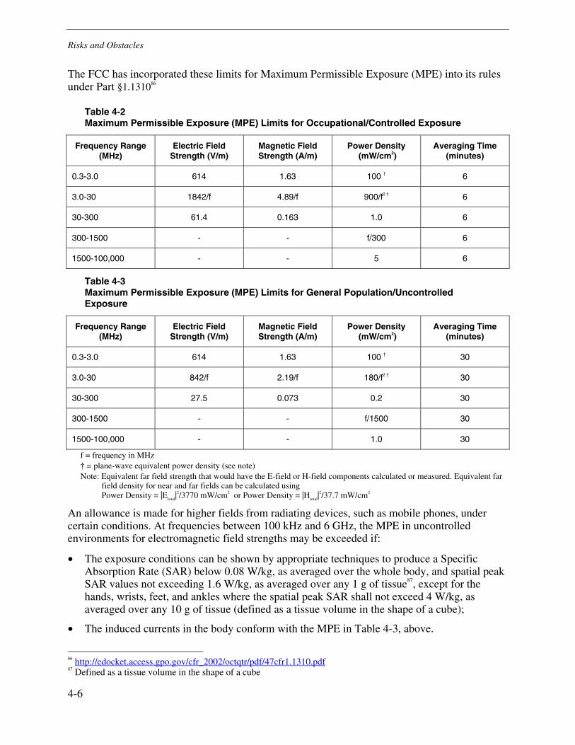
Risks and Obstacles
4-6
The FCC has incorporated these limits for Maximum Permissible Exposure (MPE) into its rules under Part §1.131086
Table 4-2 Maximum Permissible Exposure (MPE) Limits for Occupational/Controlled Exposure
Frequency Range (MHz)
Electric Field Strength (V/m)
Magnetic Field Strength (A/m)
Power Density (mW/cm2)
Averaging Time (minutes)
0.3-3.0 614 1.63 100 † 6
3.0-30 1842/f 4.89/f 900/f2 † 6
30-300 61.4 0.163 1.0 6
300-1500 - - f/300 6
1500-100,000 - - 5 6
Table 4-3 Maximum Permissible Exposure (MPE) Limits for General Population/Uncontrolled Exposure
Frequency Range (MHz)
Electric Field Strength (V/m)
Magnetic Field Strength (A/m)
Power Density (mW/cm2)
Averaging Time (minutes)
0.3-3.0 614 1.63 100 † 30
3.0-30 842/f 2.19/f 180/f2 † 30
30-300 27.5 0.073 0.2 30
300-1500 - - f/1500 30
1500-100,000 - - 1.0 30
f = frequency in MHz † = plane-wave equivalent power density (see note) Note: Equivalent far field strength that would have the E-field or H-field components calculated or measured. Equivalent far
field density for near and far fields can be calculated using Power Density = |E
total|2/3770 mW/cm2 or Power Density = |H
total|2/37.7 mW/cm2
An allowance is made for higher fields from radiating devices, such as mobile phones, under certain conditions. At frequencies between 100 kHz and 6 GHz, the MPE in uncontrolled environments for electromagnetic field strengths may be exceeded if:
• The exposure conditions can be shown by appropriate techniques to produce a Specific Absorption Rate (SAR) below 0.08 W/kg, as averaged over the whole body, and spatial peak SAR values not exceeding 1.6 W/kg, as averaged over any 1 g of tissue87, except for the hands, wrists, feet, and ankles where the spatial peak SAR shall not exceed 4 W/kg, as averaged over any 10 g of tissue (defined as a tissue volume in the shape of a cube);
• The induced currents in the body conform with the MPE in Table 4-3, above.
86 http://edocket.access.gpo.gov/cfr_2002/octqtr/pdf/47cfr1.1310.pdf 87 Defined as a tissue volume in the shape of a cube

Risks and Obstacles
4-7
Recognition must be given to regions of the body where a 1 or 10 cm3 volume would contain a
mass significantly less than 1 or 10 g, respectively, because of enclosed voids (air). For these regions, the absorbed power should be divided by the actual mass within that volume to obtain the spatial peak SARs.
The averaging time for SARs is as indicated in Table 4-3. Above 6 GHz, the relaxation of the MPE under partial body exposure conditions is permitted. At frequencies between 0.003 and 0.1 MHz, the SAR exclusion rule does not apply. However, the MPE in uncontrolled environments can still be exceeded if it can be shown that the peak rms current density, as averaged over any 1 cm2 area of tissue in 1 s, does not exceed 15.7f mA/cm2, where f is the frequency in MHz.
Non-Thermal and Secondary Effects
Current RF exposure limits, such as those in IEEE C95.1, are developed from the single proven RF safety issue for non-ionizing radiation, which is thermal heating of tissue. While these safety limits have been carefully developed and are solidly scientifically based, active research continues to look at non-thermal effects and secondary issues.88
The response of the human body to electromagnetic (EM) fields varies based on the frequency and characteristics of those EM fields. Magnetic fields penetrate the body much more effectively than do electric fields. This means that magnetic fields will tend to pass into the body, having more impact inside the body but less impact on the surface. Electric fields tend to ‘short out’ near the surface of the body and so while they do not penetrate far they have more effect on the skin and surface tissue.
The frequency of the EM field is another important variable. When the frequencies use is near the body's natural resonant frequency, energy absorption is more efficient. In adults the whole body resonates at about 35 MHz for a person that is grounded; and about 70 MHz if the person's body is insulated from the ground. Individual body parts have their own resonances; the adult head, for example, is resonant around 400 MHz, while a baby's head resonates near 700 MHz. Water has a natural resonance at around 2.45 GHz, which is why that frequency is used by microwave ovens to heat food. Because of resonance frequencies, the impact of EM fields can be very different at different frequencies and the area of the body for which there is concern can change.
Research into non-thermal effects has been conducted using epidemiological research and laboratory research methods. Each approach has its own strengths and weaknesses. Epidemiological research can identify issues that may be otherwise missed. A weakness of epidemiological research can be that it finds correlated factors that are not causal. An example might be finding that red cars are involved in more accidents. The conclusion that red cars are unsafe would not be true. Rather, the causal factor might be that red cars are more often bought by people who on average tend to drive faster. The causal factor for the accidents would be excessive speed and not the color of the car. In contrast, laboratory research is very good at documenting the linkage between various factors, but may miss very important issues that the research was not designed to examine. 88 The Amateur Radio Relay League, ARRL, maintains a safety committee that is responsible for monitoring research findings and providing its membership with current information. Their summary of current findings is found at: http://www.arrl.org/news/rfsafety/hbkrf.html.

Risks and Obstacles
4-8
An example of a non-thermal effect is the influence of EM fields on the permeability of cell membranes, which is an example of a non-thermal effect of EM fields.
Impact of RF Safety Limits
The RF safety limits set concrete limits on the amount of RF power that can be transmitted. This can be seen by analyzing currently used products and by analyzing the potential impact to future products.
In analyzing the impact of RF safety limits it is important to remember that the limits apply differently to different kinds of products. For example, cell phones are consumer products designed to be held to the head. Most cell phones are near a safety limit of 1.4 W/kg with 600 mW of transmitted RF power for CDMA and 1-2 W of transmitted RF power for GSM.89
For a device classified as portable, and for which a 20 cm separation distance from the user applies a set of limits can be calculated by first determining the maximum transmitted power than can be used and still meet the safety limit. Knowing the maximum transmitted power then allows calculation of the maximum received energy at a given separation distance between the transmitting and receiving antenna.
As an example, we will assume the limit of 27.5 V/m at 20 cm from the transmitting product. Table 4-4 shows the maximum transmitted power allowed for 30 and 300 MHz.
The calculation of maximum transmit power, in dBm, given a field strength, V/m, can be calculated from the well-known transmitter conversion equations. However, there are assumptions that must be made. The separation distance of 20 cm is well into the near-field for frequencies below 1.5 GHz. The calculation here is performed to give a general estimate and set forth the methodology. A more accurate analysis would require having more detail for the antenna to be used and performing a numeric computation of the near-field, field strength. However, with those assumptions being understood, the calculation provided is as follows:
dBmd 20 log Vm( )⋅ 13+ AF−:= , where Equation 4-1
• dBmd = the value of field strength power measurement relative to 1 milliwatt, • Vm = the value of the field strength power measurement given in Volts per meter, and • AF is given by the equation:
AF 20 logf
1000000
⋅ Grx− 29.78−:=, where Equation 4-2
• AF = the Antenna Factor, • f = the frequency of the transmission in MHz, and • Gtx = the gain of the transmitting antenna relative to isotropic (dBi)
89 An example the RIM GSM Smartphone reports a SAR of 0.93 W/kg with a transmit ERP power of 759 mW. The SAR report is available under FCC Equipment ID L6ARBW70CW at URL: https://fjallfoss.fcc.gov/oetcf/eas

Risks and Obstacles
4-9
Accuracy of Equation 4-1 was verified by taking a second approach that lead to:
dBmd = (20*(LOG(Vm))+44.94-(20*(LOG(f)))), where Equation 4-3
• Vm = the value of the field strength power measurement given in Volts per meter and • f = the frequency of the transmission in MHz, and
Substituting the values:
• Vm = 27.5, • Gtx = 2.14, and (or) • f = as appropriate 30 or 300
into the equations above resulted in the values for dBm given in Table 4-4
The path loss is calculated using the formula:
PL 2 20 logf
1000000
⋅ 20 logm im
1000
⋅+ 32.4+
:=, where Equation 4-4
• PL2 = the path loss over the 20 cm • f = frequency of transmission mim = is the 20 cm distance
It is important to note that the power levels given in Table 4-4 are for transmitted RF power. There are conversion losses of 25-75% in the power amplifier and between the power feed to the antenna and the actual power transmitted. Taken together the total power used to power received, end-to-end efficiency will be significantly lower.
Table 4-4 Maximum Transmitted Power Set by RF Exposure Limits
Fc (MHz) Maximum Transmitted Power
(dBm) (W)
300.00 37.2 5.2
30.00 54.2 262.1

Risks and Obstacles
4-10
Friis’ transmission formula can then be used to calculate the received power from the transmitted power.90, 91
2)4/( RGGPP batr πλ= Equation 4-5
Pr – Power received Pt – Power transmitted Ga – Gain of antenna a (transmitting antenna) Gb – Gain of antenna b (receiving antenna) λ – Wavelength R – Distance separating the antennas
This equation can be transformed to:
22RAAPP trtr λ= Equation 4-6
Pr – Power received Pt – Power transmitted Ar – Effective area of the receiving antenna) At – Effective area of the transmitting antenna) λ – Wavelength R – Distance separating the antennas
For a perfect isotropic antenna, assuming no heat loss, A = 0.08λ2. For a perfect half-wave dipole, assuming no heat loss, A = 0.13λ2.92 The maximum received power can then be calculated for various transmission distances.
90 Constantine A Balanis, Antenna Theory Analysis and Design, Harper & Row, Publishers, New York, 1982. 91 Berger, Stephen, “Conversion Factors for Site Attenuation Measurements, ITEM, 1986. This article provides a treatment of how to use the basic transmission formulas for calculating path attenuation. 92 Reference Data for Engineers: Radio, Electronics, Computer, and Communications, 8th Edition, Prentice Hall Computer Publishing, 1993

Risks and Obstacles
4-11
Table 4-5 Maximum Received Power Set by RF Exposure Limits
Fc (MHz) Maximum Received Power
Distance (m) Power (W)
30.00 1.0 165.5
30.00 3.0 18.4
30.00 10.0 1.6
300.00 1.0 0.0330
300.00 3.0 0.0036
300.00 10.0 0.0003
The values reported in Table 4-5 are subject to many simplifying solutions. Exact values would require more detailed analysis and greater definition of the devices that will be implementing WPT. However, the values are useful for giving an order of magnitude estimate of what power transfer can be expected from radiated WPT. It is clear that radiated WPT will not be delivering kW of power over large distances in situations where people may be exposed to the transmission.
Remembering that the wavelength at 30 MHz is 10 m, a half-wave dipole would be 5 m in length. The conclusion made from this exercise is that unless it is practical to have large antennas close to each other there will be considerable transmission loss for WPT. These realities help define the use scenarios where WPT is feasible:
• WPT would be useful in situations where large antennas could be closely spaced but where a physical connection is difficult or impossible.
• WPT would be useful in situations where received power in the mW or nW levels is sufficient.
• WPT would be practical in situations such as specialized, controlled environments, where the RF safety limits are not a concern.
Combinatorial Exposure
There exists a possibility that WPT devices will be used in environments with other sources of EM energy. The safety limits are written to be applied to a single transmitter. Safety margins are built into the limits. However, those margins are intended to provide additional protection and may not be assumed as a basis for violating the limit. Most intentional RF emitters transmit at levels that are far below the safety levels or, like mobile phones, are used only periodically with localized high fields. WPT devices, in some embodiments, would be planned to provide significant power continuously over a wide area. In such cases the possibility exists, that several WPT devices might be used in close proximity. It is possible that several WPT devices could be installed in close proximity in an office or an apartment complex. What then is the RF exposure

Risks and Obstacles
4-12
delivered to the inhabitants? It would seem possible that if multiple WPT devices were installed in close proximity then the maximum permissible exposure would be exceeded. If this fact was only discovered after some period of time, perhaps when some actual health problems were reported (note that the health problems need not be proven to be related to RF exposure), then what is the potential liability to the manufacturer and installer of any one of the WPT devices? In this scenario each individual device meets all required safety standards, but used in combination they potentially create an unsafe environment.
Other environments exist where a similar situation could be created. The upper floors of almost any tall, downtown office building will have high RF fields due to the common placement of rooftop transmit antennas, such as those for FM radio stations. Fields in the area of 5 – 20 V/m can be commonly measured in such an environment. These environments can be characterized as being ‘pre-loaded’ with RF energy. Can a WPT device then be safely introduced, adding to the total RF energy in the environment?
Testing for RF Safety
Testing for RF safety introduces risks which are separate from biological hazard concerns. The primary testing risks are:
1. Availability of standardized test methods
2. Instrumentation uncertainty
3. Compliance uncertainty
Standardized test methods do not exist for many types of devices. This is a particular concern for devices worn on the body or used in close proximity to the body. Standardized methods exist for devices designed to be used at some distance from people standardized methods do exist.93 For mobile phones and other hand-held wireless transceivers operating between 300 MHz and 3 GHz IEEE 1528, "Recommended Practice for Determining the Peak Spatial-Average Specific Absorption Rate (SAR) in the Human Head from Wireless Communications Devices: Measurement Techniques," specifies experimental protocols, and measurement and validation methods. IEEE 1528 was published in 2003 to help wireless device manufacturers and regulators assess compliance with the requirements of the U.S. Federal Communications Commission (FCC) and similar government agencies in other countries. The IEEE’s International Committee on Electromagnetic Safety (ICES) is working on additional test methods, however, such work typically takes years to produce and currently the only active committee is the one working on test procedures for mobile phones.94
The risk of not having standardized test methods is that different test methods could produce different conclusions about the RF safety of a device. For a manufacturer of the device, this opens up exposure to either liability or the potential to recall a product. Recognized standard test methods reduce these risks significantly.
93 The FCC has published guidelines for evaluating the RF safety of various kinds of products. U.S. Federal Communications Commission, Office of Engineering and Technology, "Evaluating Compliance with FCC-Specified Guidelines for Human Exposure to Radiofrequency Electromagnetic Fields," OET Bulletin 65, August 1997. 94 http://www.ices-emfsafety.org/index.php5
Risks and Obstacles
4-13
Instrumentation uncertainty is the uncertainty introduced by the instruments used to measure the RF safety of a product. All instruments have an uncertainty associated with them. The fundamental units, maintained by bodies such as NIST (National Institute of Standards and Technology), all have a precision associated with them. Each step away from these fundamental units decreases that precision. When NIST provides a calibration of an instrument to a calibration lab, there is a decrease in the precision due to variables associated with the transfer of the standard. When the calibration laboratory then calibrates an instrument to be used in a measurement, an additional uncertainty is introduced. CISPR 16-4-2:200395 finds the uncertainty of an RF emission measurement in a well run laboratory, to be in the area of 5 dB. A 5 dB measurement uncertainty means that if one laboratory finds a device exactly at the required safety limit another laboratory might find the same device at 1.77 over the limit or 0.56 under the limit. Device manufacturers must then either design their products with a safety margin or accept the attending risk that another laboratory might quite legitimately find their product to be non-compliant.
Compliance uncertainty introduces additional factors to the uncertainty of the measurement due to instrumentation. There will be variability in individual units, either over time as various components age, or due to other factors such as temperature. Other variables are introduced if the device could be setup in different ways for testing, or if there are operating configuration options. The RF level emitted from the device can be expected to vary somewhat from measurement to measurement or over time. Beyond factors that may introduce variance in measuring a specific device, there is manufacturing variance over the population of manufactured devices. For some types of produces variations in installation and use environments may also be factors. All of these factors introduce risks that manufacturers of wireless devices now face and future manufacturers of WPT devices will similarly contend with.
Other Biological Risks
While the RF safety for humans has been well studied, the risk for other living things is much less known. The risks presented by RF and EM fields to pets, livestock, wildlife, or plants, has received relatively little study as compared to the study of human exposure. In general, animals are smaller than humans and therefore will absorb less energy from radiated fields. Further, RF and EM fields have been in wide use for many decades. If there were significant effects it might be assumed that these would have been identified and reported. However, the chance exists that some, currently unidentified, effects on animals or plants will be identified in the future. Such a possibility represents a risk that cannot be determined at this time.
95 CISPR 16-4-2 (2003-11) Specification for radio disturbance and immunity measuring apparatus and methods - Part 4-2: Uncertainties, statistics and limit modeling - Uncertainty in EMC measurements CISPR standards are available at: http://www.iec.ch/

Risks and Obstacles
4-14
Environmental Impact
The possibility of environmental impact from WPT devices can be conceived of in three areas:
• Localized environmental impact
• Cumulative, widespread impact
• Consequential impact
Localized impact on the environment would be created if the operation of a WPT device has some effect. Transmitted WPT energy will be absorbed with physical objects and turned into heat. The incremental heating could make some marginal difference over time that would evidence itself as an environmental impact. Another potential area of impact would be disruption of the earth’s natural magnetic field. The naturally occurring magnetic field is what allows a compass to work. It has been hypothesized that the earth’s magnetic field has other biological and environmental effects. Therefore, it is may be possible that localized disruption would have a negative impact. The potential for localized environmental impact is one area where research would be helpful to identify potential risks and either eliminate them as a reason for concern or identify safe operating levels or other mitigation techniques.
Additionally, there is the possibility that individual WPT devices are perfectly safe but in widespread distribution some cumulative and widespread impacts may be created. Such an impact might be conceived of as comparable to water pollution. A single source of pollution into a river or ocean would have little if any impact. However, over time and with many sources of pollution, very significant, negative effects may be seen.
Impacts arise indirectly from WPT. One example that WPT will share with other electronics is how the equipment can be safely disposed of after its useful life is over.9697 Other consequential impacts could arise if hazardous materials become required for manufacturing processes that are unique to WPT. There may also be an aspect of the installation or use of WPT has an unintended impact.
Public Perception of Radio Frequency (RF) Safety or Environmental Impact
History has demonstrated that the scientific assessment of RF safety and public perception of RF safety are separate but interactive issues. The scientific assessment of RF safety is managed through scientific research and peer-reviewed literature that lays a foundation for development of standards and regulatory requirements. The scientific assessment and regulatory treatment of RF safety has been discussed in this report. The issues related to RF safety and demonstrating compliance with RF safety limits has been presented.
96 Electronic Design, “Parting With Old Electronics Can Be Hazardous To Someone's Health” editorial by Joseph Desposito, ED Online ID #19969, November 7, 2008. http://electronicdesign.com/Articles/Index.cfm?ArticleID=19969 97 Business Week, “E-Waste: The Dirty Secret of Recycling Electronics”, by Ellen Gibson & Brian Grow, http://www.businessweek.com/magazine/content/08_43/b4105000160974.htm

Risks and Obstacles
4-15
The public’s perception of RF safety must be viewed as a separate issue simply because regardless of the science, if there is a significant public concern about safety there can be significant consequences to a technology.
A special class of public perception is the perception from other industries when an interference problem arises. As will be made clear in the section on RF interference, avoidance of all interference is not possible. Energy from one device will affect another device. However, it is possible to keep that impact under levels where it is deemed to be harmful interference. While careful analysis of the potential for interference is demanded as part of due-diligence when introducing a technology like WPT, some interference is virtually assured. An important issue will be the perception of those affected by interference.
The situation that arose with hearing aid manufacturers when digital cell phones were introduced is a good example. When digital cell phones were first introduced in the mid-90’s it was discovered that they cause interference with almost all hearing aids being manufactured at the time. The situation rose to such a level that then FCC Chairman Reed Hunt called for a Summit on Hearing Aid Interference. The initial attitude from hearing aid manufacturers was that there was no interference before digital cell phones came along and so it was a cell phone manufacturer’s problem. Further, the hearing aid industry was miniscule as compared to the size and revenue of cell phone manufacturers and service providers. So hearing aid manufacturers felt that the cell phone manufacturers should deal with the problem. The problem was that cell phones had to transmit. Transmitting was the core function of cell phones and this is similar to the situation WPT manufacturers will face. The problem was eventually solved, largely through the development of a joint industry standard on hearing aid compatibility. However, before the technical work could be accomplished the perceptual issue had to be overcome so that both industries would contribute to a feasible solution.98
It is a given that there will be public concern about the safety of WPT systems. The dynamics of the popular media, liability litigation and research funding virtually guarantee this outcome. The unknown is how widespread that concern will be and how successfully these forces will influence the development of WPT.
A cottage industry has grown up supporting what some term ‘electrophobia.’ There are authors and publications that routinely write that all kinds of electricity, RF and microwaves adversely affect human health and the environment. The mainstream media regularly popularizes topics from this literature when looking for a counter view for a story or to provide a topic for a sensationalistic exposure. The mainstream media’s own economics is driven by ratings and sensationalism sells. WPT will receive its share of attention and some of these allegations will be picked up by the mainstream press and reported in one of the proven formulas for such stories. The pattern of such stories around new technologies, particularly those that cannot be seen or easily understood, like WPT, is well established.
A dynamic that feeds this genre is the way research is funded. To explain this it is important to understand the distinction between a research finding and a health effect. When doing research some effect may be observed. This effect may or may not be significant, it is simply an
98 The standard that was developed is ANSI C63.19, “Method of Measurements for Compatibility between Wireless Communications Devices and Hearing Aids”.

Risks and Obstacles
4-16
observation and typically researchers want to study those findings further. A health effect in contrast, is a proven risk to human health. About 40% of research studies in the area of RF safety come back with research findings. Typically these findings are reported at the end of a problem and used in applications for further research funding. In 40% of studies researchers report a finding that they believe needs further study to fully understand. With predictable regularity some of these findings get picked up with the popular media and reported as proven health effects. In case after case researchers withdraw their conclusions once their studies are subject to peer-review. This is why peer-review is done, so that researchers can present their work to their peers and see if their methods and data can support their conclusions under the challenge of informed review. The dynamic then is that a percentage of studies will report findings. Some of these studies may be picked up by the media, misreporting them as health effects, and companies with products on the market could be impacted by those reports.
A third dynamic is created by the legal liability process. At this point the effort to successfully win liability suits against products that are within the established safety limits has been unsuccessful. Almost all cases have been dismissed in pre-trial phases for lack of sufficient scientific evidence to justify a trial. A review of liability cases dealing with RF safety reveals a developing pattern of exploring different legal strategies. Attorneys learn from previous cases. Some firms make such liability cases a specialty and patterns of exploration can be observed. New legal strategies are devised from learning and adapting from past failures. Whether future strategies will be successful is unknown. However, it is likely that attorneys will develop successful liability strategies in the future.
WPT is a set of technologies that could be subject to these three dynamics. The technology is invisible and for the non-scientist, can be hard to understand. It can be predicted that developers of WPT products will be subject to public concern about the safety of their products. There will be research that reports positive findings and some of those findings may be misreported as proven health risks. There may be attempts to bring liability suits. A component then of developing a WPT technology must be a strategy to deal with these dynamics and be successful in the face of these risks.
WPT and Medical Devices
WPT has special significance in relation to medical devices where there is great potential for beneficial use. WPT offers promise for recharging batteries in implanted medical devices like pacemakers, implanted defibrillators, and infusion pumps. It also offers great promise for powering sensors on a patient and eliminating many wires that are both inconvenient and subject to accidental disconnection.
Interference from WPT to medical devices is a very serious concern. WPT can interfere with a medical device when its power exceeds the immunity of the medical device. A second, and less commonly appreciated concern, is that WPT might mimic a biological signature and when imposed on a medical device cause false readings. In the RF interference section, examples of each of these types of interference will be provided as an illustration of the need for careful study of this potential risk.

Risks and Obstacles
4-17
It is important to bear in mind that no area of technology is static. Medical devices are aggressively pursuing new technologies and introducing innovations. It is therefore important not only to evaluate WPT for its potential benefits and risks with current medical devices but also with those that are in development and approaching market introduction.
Radio Frequency (RF) Interference
In the U.S., WPT equipment will operate under either Part 15 or Part 18 of the FCC rules.99 The FCC Part 18 rules state:
…irrespective of whether the equipment otherwise complies with the rules in this part, the operator of ISM equipment that causes harmful interference to any authorized radio service shall promptly take whatever steps may be necessary to eliminate the interference.100, 101
Similar requirements are found in Part 15:
(b) Operation of an intentional, unintentional, or incidental radiator is subject to the conditions that no harmful interference is caused…102
(c) The operator of a radio frequency device shall be required to cease operating the device upon notification by a Commission representative that the device is causing harmful interference. Operation shall not resume until the condition causing the harmful interference has been corrected.103
The consequence of these requirements is that equipment may be required to cease operation irrespective of compliance with the technical requirements of the FCC. This, with the potential legal liability, customer satisfaction and public relations risk, makes concern about the potential for harmful interference from WPT equipment a serious concern.
The possibility that WPT could become a widely used method of power delivery within the next several years raises concern about the possibilities of interference. This section outlines a process that should be used for testing interference for wireless power scenarios. The approach outlined in this section makes use of the Institute of Electrical and Electronics Engineers (IEEE) Standard 1900.2-2008,104 “IEEE Recommended Practice for the Analysis of In-Band and Adjacent Band Interference and Coexistence between Radio Systems.”
99 Much of the information in the section on RF interference came from a technical memo on the impact of device selection and common design practices on RF interference by Dr. Charles Baylis, assistant professor of electrical and computer engineering at Baylor University. Additional information was provided by Stephen Berger who chairs the IEEE 1900.2 committee on interference analysis, the ANSI C63.19 committee on hearing aid interference, and the ANSI C63.9 committee on interference with office equipment. 100 47CFR18.111 101 47CFR18.115 Elimination and Investigation of Harmful Interference. 102 47CFR15.5(b) 103 47CFR15.5(c) 104 Please see Institute of Electrical and Electronics Engineers Standard 1900.2.

Risks and Obstacles
4-18
IEEE Standard 1900.2
IEEE Standard 1900.2 defines a process for interference assessment in radio systems. The standard attempts to develop a process that can be used to determine whether two systems are in satisfactory coexistence or interference. To answer this question, it is necessary to define and quantify acceptable levels of interference. This is performed through an interference and coexistence analysis using a source (generator of electromagnetic energy) and recipient (the device whose behavior could potentially be compromised due to interference from the source). An interference analysis uses a stimulus at the source and then tests the affect of the source on the recipient; a coexistence analysis focuses on assessing the ability of the recipient to perform its function in an environment containing interference. Both types of analyses are helpful in determining the effects of interference on the system. Interference events should be isolated (i.e. the cause) and the level at which harmful interference is deemed to occur should be quantified to allow appropriate analysis.
The 1900.2 suggests a four-phased interference analysis process: (1) Scenario definition, (2) Establishment of interference and coexistence criteria for the recipient system, (3) Definition of variables or behavior used in modeling, and (4) Analysis (modeling, measurement, testing, etc.) Figure 4-1 (reprinted from IEEE 1900.2) shows the progression of this four-phased process.
Figure 4-1 Assessment Process for Interference, Reprinted from IEEE 1900.2

Risks and Obstacles
4-19
In brief, the scenario definition stage can be thought of as the definition of a potential problem to be evaluated. In this section, a small number of potential scenario definitions will be attempted. The scenario definition arises from a thoughtful consideration of the environment, devices operating in the environment, and the spectral content of the signals pertaining to the source and recipient devices. Often a scenario is a new idea, system, or policy that is being examined to determine whether its operation is viable in an existing environment. The scenario considers, in most cases, the potential negative impact of this new device, technology, or standard on its surrounding environment; it is essentially the “potential problem” definition.
The criteria establishment stage takes the scenario definition and attempts to determine what a negative outcome would look like for the interference scenario. Often this may be expressed in terms of measurable parameters. In this stage, the statement of the “potential problem” would be taken and criteria established to determine whether or not the scenario really does present a viable problem to the recipients. This stage may address the measurement procedure and the entities for measurement, as well as measured quantities necessary to constitute interference and harmful interference. Thus, this stage asks the question, “What will be impacted?” and “How will we know it has been impacted?” Measurement events, and specific sampling of data used to determine whether criteria have been met, will be determined.
The definition of variables and behaviors stage defines variables and behaviors representing the scenarios and criteria. The purpose of this stage is to take the potential problems and criteria, as defined at a higher level, and translate them into measurable variables that will be associated with the criteria and that will allow determination of scenario pertinence. The variables are often the measurable parameters that are accessible through the fourth stage of analysis. However, it is often true that these variables are not independent of each other; rather, they are often dependent on other variables and system settings. Variables usually exist in either the logical domain or the physical domain.
Finally, the analysis stage often takes place through modeling, measurement, and testing. Based on the establishment of criteria and the measurement, simulation, modeling, or calculation assessment of the variables, a decision can be made as to whether interference and/or harmful interference have occurred. The analysis tends to be most solid when multiple methods of assessment are used. For example, when both measurement and simulations can be used and point to the same result, this analysis may be more viable than if only a measurement or only a simulation is used.
The upcoming sections discuss a rationale for the application of the 1900.2 approach to the assessment of interference due to WPT.
Impact of Circuit Design
As a prelude to examining potential cases of interference for WPT, a discussion of the properties of the WPT signal is appropriate. Unlike wireless communications, no message is necessarily contained in a WPT signal. The signal can be strictly sinusoidal and hence is narrowband (theoretically an impulse function). Theoretically, the band needs only to be wide enough to accommodate drift and phase noise of the transmitter source (which is related to properties of the solid-state devices used in the transmitter). While these statements are true for the core mission
Risks and Obstacles
4-20
of power transfer WPT systems often will incorporate data transfer. The communication may be limited, such as to initiate a power transfer or report state of charge at the recipient device. Dual use opportunities can also be envisioned in which the same transmission provides power and a communication link. A class of modulation that may be overlooked is a metered WPT system in which the charging transmission is turned on and off at either a set or variable rate. The act of turning the transmission on and off creates an impulse which will have a rich spectrum content and will demodulate into a baseband signal which could cause audio or other kinds of interference problems.
Efficiency is the primary goal of the WPT system. The efficiency of the transmission amplifier is essential to the efficiency of the entire system. Amplifier power-added efficiency (PAE) is defined as:
DC
RFinRFout
PPP
PAE ,, −=
Equation 4-7
indicates what percentage of the DC power is converted into RF gain. The theoretical efficiency limit for Class A operation is 25 percent, while the limit for Class B operation is 78.5 percent.105,106 When a Class-A amplifier is designed, the output signal contains lower levels in the harmonics than a Class-B amplifier. Class B amplifiers are likely to be selected by product designers because of their superior efficiency. This causes a question to be raised concerning harmonic content interfering with other bands. However, it is thought that it may be a worthy tradeoff to accept harmonic content to allow amplifier efficiencies to be high. In addition, it may be worth it to attempt to not only secure the fundamental band, but to secure the harmonic bands also and to harvest the harmonic energy at the receiver using a rectifying antenna (rectenna). This would allow for improved overall transmission efficiency. On the downside, however, a potential scenario will arrive involving the interference of harmonics with other existing communication applications.
In the upcoming sections, several scenarios are examined against the backdrop of the four-step analysis framework set by IEEE Std. 1900.2. The first two are based on documented cases of interference with medical devices and explore the potential of WPT systems to have similar problems. The other three examples explore particular problems that may arise due to the frequency of operation selected for WPT. It is important to note that these examples are illustrative and not exhaustive. A full analysis, following the guidelines of IEEE Std. 1900.2, should be performed for each specific implementation of WPT in order to foresee and avoid interference problems. As both experience and IEEE Std. 1900.2 make clear, avoiding interference all together is not possible. What is possible is the management of interference so as to avoid harmful interference and to work with the manufacturers to assure products are developed so as to coexist.
105 J. Walker, High Power GaAs FET Amplifiers, Artech House, 1993. 106 Sedra and K. Smith, Microelectronic Circuits, Fourth Edition, Oxford University Press, 1998.

Risks and Obstacles
4-21
Scenario 1: Magnetic Interference with Pacemakers
Scenario Definition
This scenario assumes that WPT devices will be used around people who have pacemakers and other implantable medical devices. Concern about the potential for interference with such devices exists in any use scenario where people will be exposed to the EM energy coming from a WPT device.
This scenario is based upon a recently reported research that found that headsets or MP3 players could interfere with pacemakers and defibrillators.107 Dr William Maisel, of the Medical Device Safety Institute at Beth Israel Medical Centre in Boston performed the study which resulted in a statement by the AHA (American Heart Association).
Pacemakers and implantable cardio defibrillators (ICDs) are often designed with a reed switch that is intended to be used by a doctor to put the device into test mode. The doctor puts a magnet on the patient’s chest, over the device, activating the reed switch and putting the device into test mode. The test mode that is used for follow up visits to detect battery status. A Pacemaker will continue pacing in test mode but in asynchronous mode, not using its sensing information to synchronize with the patient’s natural rhythm. An ICD will not respond to its sensing data and do will not respond if the patient requires defibrillation. This is potentially life threatening if a patient with an ICD requires defibrillation but a magnetic field has the ICD in test mode, and it does not treat the patient. However, as soon as the source is removed, the response inhibition goes away.
The magnetic field delivered to the ICD must be strong enough to reach the activation threshold of the reed switch. The strength of the magnetic field typically decays exponentially and so small increases in distance bring large reductions in the magnetic field. By FDA requirement and industry practice technical and patient manuals have warnings about magnets, as a patient may encounter them in daily life. Lately manufacturers report seeing quite a proliferation of magnets on pins, badges, etc., so this problem would by no means be unique to WPT. Further, the EMC standard AAMI (Association for the Advancement of Medical Instrumentation) PC69, 2nd edition published in 2007108 has testing with static magnetic fields. This test is also included in ISO and CENELEC standards.
In an Annex giving the rationale for the 2007 revision AAMI PC69 states:
[4.6] Ensures protection from exposure to weak magnetic fields. If the DUT contains a magnetic switch, this switch should not be activated by weak, static magnetic fields with which the patient may come in contact. An example is the magnetic strip used to seal refrigerator doors. Traditionally, this field limit has been set at 1 mT (10 gauss).
107 For more information, please see http://www.dailymail.co.uk/health/article-1084346/MP3-earphones-prove-fatal-heart-patients-says-report.html 108 ANSI/AAMI PC69:2007, 2nd edition “Active implantable medical devices — Electromagnetic compatibility — EMC test protocols for implantable cardiac pacemakers and implantable cardioverter defibrillators”
Risks and Obstacles
4-22
[4.7] Defines protection from exposure to stronger (50 mT) static magnetic fields. These magnetic fields have the potential to permanently disrupt the operation of an implantable pulse generator. If the DUT contains a magnetic switch, the behavior of the device will probably be altered in the presence of the magnetic field. For example, telemetry could be activated or therapy could be deactivated. The manufacturer must assess the hazard to the patient that could result from the inadvertent closure of the magnetic switch as part of an overall risk assessment. However, once the strong magnetic field is removed, the DUT must function as prior to the exposure without adjustment. Therefore, a change in DUT operation which could be resolved by programming would be considered a failure of this test.109
So while there are a number of mitigating factors and the reports in the popular media may be sensationalized, there does appear to be a credible risk. In particular the concern would be that a particular WPT implementation might create a magnetic field that would exceed the activation threshold of the reed switch over a large area.
Criteria Selection
For this scenario the criteria is that the activation threshold of the reed switch is exceeded outside the protection distance. 1 mT (10 gauss) is selected as the threshold of concern, consistent with the guidance of ANSI/AAMI PC69, to activate the switch in the pacemaker. By way of reference manufacturers of headsets have reported that with careful positioning headphones can produce 35-60 Gauss in close proximity to a sensor.
A quantity that is unknown at this time is the frequency of the magnetic field to which the reed switch circuitry used in implanted devices will respond. This will be important information. These circuits are designed to respond to static magnetic fields. Their response to magnetic fields at different frequencies will be important to understanding the magnitude of the risk represented. As inductive coupling operates primarily by coupling energy through the magnetic field, it will be important to know if these fields represent a risk over some distance from these devices. It may be that the reed switch circuit in implantable devices does not respond to magnetic fields above some low frequency threshold. At this time this is an unknown but could diminish this risk substantially.
Patient warnings typically instruct them to keep electronics that could potentially be a problem more than 6 inches away.110, 111 To be consistent with this warning but to provide some further margin of protect it is suggested that the magnetic threshold should not be exceeded at 1 to 3 inches.
109 ibid 110 The FDA provides the following information to pacemaker users about the potential for interference from cell phones on their website: http://www.fda.gov/cdrh/wireless/health-interference.html 111 On its website the FDA offers the following general advice to pacemaker patients: http://www.fda.gov/hearthealth/treatments/medicaldevices/cardiacpacemakerimplanted.html#whatarerisks

Risks and Obstacles
4-23
Definition of Variables
To test for interference and coexistence, IEEE Std. 1900.2 directs that the criteria selection must be converted into a set of measurable variables. For this scenario the variables of interest would include (a) typical and minimum distance from a user to the source (WPT transmitter), (b) power of WPT, (c) frequency used by the WPT, (d) prevalence of implanted devices that use a reed switch to place the device into test mode, and (e) variability in design of reed switches and their associated circuitry.
Analysis
An analysis would require specifying the type of WPT device to be evaluated and also greater knowledge about the test circuits in implantable medical devices. Given the potential seriousness of the consequences of interference both computational analysis and experimentation would seem to be justified. Another approach that could be taken is to identify other types of equipment with EM characteristics similar to various forms of WPT and explore whether there is a history of reported problems with those kinds of devices. To the degree other types of equipment can be identified with similar EM characteristics, then some early understanding could be gained as to the reality of the risk for WPT devices. It would be very important to carefully study whether there is anything different about WPT devices, their deployment, or use that might materially create a different or even unique situation.
Scenario 2: Mimicking Biological Signatures
Scenario Definition
The concern in this scenario is that an implementation of a WPT device might utilize a waveform that could radiate or be conducted into a medical device and be mistaken for a biological signature. The risk is that the medical device might take that interfering signal as valid data and respond inappropriately, potentially with severe consequences.
Given the rapid developments in medical technology and the resulting increasing use of medical technology, this use scenario is applicable, anywhere that people might be exposed to the EM energy produced by a WPT device. Scenario 1 was specifically looking at the possibility of interaction with the reed switch in pacemakers and other implantable medical devices. In this scenario external medical devices are also of concern. Home TeleHealth is a growing trend with a variety of medical devices being used by patients to monitor their medical condition at home and work, avoiding many doctor visits. As an example, some special conditions, like sleep apnea in infants, have monitors that are used to protect a patient’s health.
The specific risk being examined is that a WPT device might be introduced to a medical device by radiating into it or being conducted over wires, and be misinterpreted as valid biological data.

Risks and Obstacles
4-24
Criteria Selection
For this scenario the potential for audio interference is subsumed under the broader category of biological data. This is done for several reasons. First, information from medial devices is often delivered audibly and audio RF interference may interfere with use of the device or detection of audible warnings. Second, biological signatures, such as heartbeat, breathing rate, and other body rhythms fall in or just below the audio band. Finally, the audio band is well known and well defined, whereas a catalog of biological waveforms is not very well documented. Therefore the criteria are signals that will demodulate with significant energy below 20 kHz. A lower frequency bound would require further study. A continuous wave (CW) signal, that would demodulate as a DC voltage is not of concern in this scenario. The frequency at which a demodulated signal may be judged to be essentially a DC signal and unlikely to mimic a biological signature will require further study. However, because heart beats often occur in the 50-70 beats/minute, approximately 1 Hz, the lower threshold will be somewhere below 1 Hz.
A second issue must be how the depth of modulation is to be assessed. The most common modulation used in testing is 80% amplitude modulation (AM). This modulation is required by IEC112 and most other RF immunity test standards.113 Therefore the demodulated waveform should be normalized in reference to the energy produced by a demodulated 80% AM waveform.
Finally a field strength threshold must be established. IEC 61000-4-3 sets 3 V/m as the recommended immunity level for general use and 10 V/m for industrial environments. To be consistent then the same levels are proposed for use in this evaluation, 3 V/m for general use equipment and 10 V/m for industrial equipment.
A protection distance from the WPT device is then required. For consistency with the RF exposure standards 20 cm from the device is selected for any device except those designed to be worn on the body or held near or against the body during normal use.
To summarize, a WPT device would be judged to fail this criteria if its demodulated waveform delivered more energy, measured 20 cm from the device, than an 80% AM modulated signal at 3 V/m for general use or 10 V/m for industrial use.
The fact that these levels are significantly below the RF exposure safety level, for example of 27.5 V/m for 30 to 300 MHz, requires some discussion. The RF exposure levels are set based on heating of tissue and therefore are determined by long term averages and total power delivered. The type of interference which is of concern here tends to respond more to the envelope characteristics and the peak amplitude in the waveform, instead of the average power. However, for WPT systems that intend on using a waveform that has significant amplitude variation this concern rather than the RF safety levels may set a practical limit on the amount of power that can be transmitted. Much depends on the specifics of the equipment and the interference produced. It can be said that significant interference with commonly used medical equipment probably could not be tolerated and therefore would set a limit on the amount of power that could be transmitted.
112 IEC 61000-4-3, edition 3.1 (2008-04), Electromagnetic compatibility (EMC) - Part 4-3: Testing and measurement techniques - Radiated, radio-frequency, electromagnetic field immunity test 113 EN 55024, edition 98 (02/29/08), Information Technology Equipment - Immunity Characteristics - Limits And Methods Of Measurement
Risks and Obstacles
4-25
Definition of Variables
For this scenario the variables of interest would include (a) typical and minimum distance from a user to the source (WPT transmitter), (b) power of WPT, (c) frequency used by the WPT, (d) type of modulation used and its characteristics, and (e) potential for interference with medical devices for which the demodulated waveform could be mistaken as valid data.
Analysis
The potential for this type of interference has been documented with RFID, which could be viewed as an implementation of WPT. In laboratory testing supporting the development of the AAMI PC69 2007 revision, the potential for some types of RFID to interfere with pacemakers was identified. The tested RFID waveform tested could be demodulated into a signal that could be misidentified as a heart beat. The RFID in question was then sent to Mt. Sinai in Miami for testing with actual pacemakers. Interference with pacemakers was observed and reported to the AAMI committee.114
A theoretical analysis can quickly conclude that WPT devices that do not modulate their signal and do not pulse the transmission are not at risk for this issue. If WPT devices do implement a modulation or pulsed operation, turning their transmitter on and off, then further analysis will be necessary. It can also be concluded that the depth of modulation and the frequency components in the modulation will be very relevant to whether this problem is a real risk. It is known from field incidents that this kind of interference is both possible and has occurred with other kinds of equipment.
Scenario 3: Harmonic Interference
Scenario Definition
Because large amounts of DC power will be used to power the transmitter amplifiers, it will be desirable to cause the transmitter amplifiers to run with as high of a PAE as possible. This will cause a resort to high-efficiency amplifier modes, such as Classes B, C, E, and F. Assume Class B operation for this argument. In a Class B amplifier, the output waveform is clipped. An input sinusoid is “chopped” into an output half-sinusoid. While higher PAE (up to 78.5 percent) can be obtained, the resulting waveform possesses significant harmonic content. Because power levels of this transmission are likely to be significant in a WPT system, the levels of the WPT harmonic content will also be substantial and will fall within different bands.
For the sake of argument, it will be assumed that the WPT transmission will occur at 2.4 GHz in the industrial, scientific, and medical (ISM) band. If a Class B amplifier is used for the transmission, significant harmonic content is likely to be generated at 4.8 (second harmonic), 7.2
114 The laboratory testing was performed by Stephen Berger of TEM Consulting. Dr. Roger Carillo performed the testing at Mt. Sinai. The reports of there are among the contributions to the AAMI committee and were part of the reason for changes to the RF immunity requirements made in the 2007 version of that standard.

Risks and Obstacles
4-26
(third), 9.6 (fourth), 12 (fifth), and 14.4 (sixth) GHz. Table 4-6 shows a list of the harmonic frequencies and their allocations given by the FCC Spectrum Allocation Chart.115
Table 4-6 4-7.0 - 2.4 GHz Harmonic Frequencies and Associated Spectrum Allocations
Harmonic Number
Frequency (GHz)
Allocated Use(s)
1 2.4 Industrial/Scientific/Medical, Amateur Radio
2 4.8 Fixed and Mobile Radio Services
3 7.2 Fixed Radio Services, Space Research
4 9.6 Radiolocation
5 12.0 Fixed Satellite, Mobile Radio Services
The scenario can thus be defined in several sub-scenarios; each one pertaining to a different harmonic of the 2.4 GHz fundamental. For each case, in general, an application-specific recipient should be selected for the scenario. For example, in the space research band, sensitive instrumentation may be set up to detect distant objects in space from their frequency emissions. Transmission of a significant third harmonic may cause erroneous results and readings from the space research instrumentation.
Criteria Selection
For each harmonic frequency and associated resident application, the criteria should be established for both interference and harmful interference. In the case of space research, the detection of a distant microwave signal at a certain power may be deemed as the minimum signal that should be adequately detected. This signal would be transmitted at a certain dBm power at a certain distance in miles and would likely be related to the local power detection (at the recipient) requirements to observe the space phenomena. Interference would constitute the simultaneous detection of the power signal along with the phenomenological signal, while harmful interference would likely be defined by the inability to detect the phenomenological signal.
Definition of Variables
To test for interference and coexistence, the criteria selection must be converted into a set of measurable variables. These would include (a) distance from the source (WPT transmitter) to the recipient (space detection equipment), (b) power of WPT, (c) power of “phenomenon” transmission, and (d) distance of “phenomenon” origin from the recipient. Appropriate sets of conditions based on the space research needs would be set up for the variables and measurements.
115 “United States Frequency Allocations: The Radio Spectrum,” United States Department of Commerce, October 2003, from http://www.ntia.doc.gov/osmhome/allochrt.pdf
Risks and Obstacles
4-27
Analysis
Analysis would, in this case, likely consist of measurements, although initial calculations using the Friis transmission equation116 and other theoretical considerations could be performed to develop reasonable expectations for the measurement results. A minimum power level would be set for a detectable signal from a “phenomenon” source a certain distance away in the presence of the interference source (WPT transmitter), also a certain specified distance away from the recipient.
It is likely that multiple tests would be performed in this section. The WPT transmitter would need to be placed at different distances from the recipient, and the “phenomenon” source should also be placed different distances from the recipient.
The process given above should be repeated for all harmonics in which a reasonable signal content is expected. If interference with existing bands is determined to be a problem, it may be advantageous to block out the harmonic frequencies and to harvest the harmonic energy with a series of rectennas. This would likely improve the overall system efficiency.
Scenario 4: Interference with Bluetooth
Scenario Definition
In Bluetooth systems, which operate in the 2.4 GHZ ISM band, the operation frequency moves in a procedure known as “frequency hopping.” The potential problem that could be encountered is that the frequency in which WPT is occurring could be selected for momentary operation by the Bluetooth system. The probability of such a choice and the results of the Bluetooth system choosing the WPT channel must be determined.
Frequency hopping is often implemented using a method known as adaptive frequency hopping (AFH), which is performed using one of two methods: (1) received signal strength indication (RSSI) or (2) packet error rate (PER). The goal of adaptive frequency hopping is for the system to identify frequencies at which interference would occur and avoid these frequencies.117 While adaptive frequency hopping may solve the problem, it is possible that many Bluetooth systems will either (1) not employ AFH, (2) the AFH method will not detect the wireless power signal and it will interfere anyway, or (3) the WPT signal will drive the system into saturation due to its large power content, causing the nearby, but not overlapping, Bluetooth signal to be undetected.
Criteria Selection
Each scenario given in the above subsection should be addressed individually. The first scenario deals with the case where the WPT frequency is selected by the Bluetooth system. This problem should be addressed by implementing a matrix of tests in which a Bluetooth system is placed at 116 D. Pozar, Microwave Engineering, Second Edition, John Wiley and Sons, 1998. 117 C. Hogdon, “Adaptive Frequency Hopping for Reduced Interference Between Bluetooth and Wireless LAN” from D&R Industry Articles, http://www.design-reuse.com/articles/5715/adaptive-frequency-hopping-for-reduced-interference-between-bluetooth-and-wireless-lan.html .

Risks and Obstacles
4-28
varying distances from the WPT transmitter. In this case, the WPT system is the source and the Bluetooth system is the recipient. A second test should be performed in which the WPT frequency is near at least one of the Bluetooth frequencies and the received signal by the Bluetooth system should be examined for interference (detectable interference) and harmful interference (causing bit errors).
In addition, the two methods of adaptive frequency hopping – Received Signal Strength Indication (RSSI) and PER (Packet Error Rate) should be examined to see which is more prone to interference from WPT
Definition of Variables
The variables in the first examination would be the distance between the WPT transmitter (source) and Bluetooth receiver (recipient), the WPT frequency, and the adaptive frequency hopping algorithm used (RSSI or PER). An additional variable would be the power transmitted by the WPT transmitter. Bit error rate of the Bluetooth receiver would likely be a variable that would serve as a key indicator of whether the Bluetooth system is receiving interference and/or harmful interference.
Analysis
This scenario will likely benefit from the use of both simulations and measurements. Spectrum analyzer measurements of power versus frequency at the Bluetooth receiver may be helpful for diagnostic purposes. In addition, end-result measurements of the bit-error rate of the Bluetooth system for different powers and proximities of the WPT transmitter will be helpful in setting boundaries and understanding the relationship between physical parameters (power, distance) and harmful interference.
Following measurements, simulations can be performed using appropriate software tools and channel models to assess the potential of errors. Simulations using the adaptive frequency hopping techniques with different WPT transmission frequencies should produce a rate of harmful interference occurrences that, for a long enough sample “time”, should coincide with the measurement data.
Scenario 5: Radar Interference in the 915 MHz ISM Band
Scenario Definition
The frequency allocation chart (Figure 1-2) shows the part of the ISM band at 915 MHz that is devoted to radiolocation, which includes radar systems. Because WPT has been designated for placement in the ISM bands, a potential problem is lurking. It is likely that the significant strength of the WPT signal in this band will overwhelm radar systems. This problem could have increased importance in coastal areas where Naval radar systems have been placed to detect potentially dangerous enemy activity on the seas. In addition, the 9.6 GHz band, which is in the

Risks and Obstacles
4-29
range of the fourth harmonic of the WPT transmission with a fundamental frequency of 2.4 GHz, is also used for radiolocation. The same problem may arise in this case.
While the problem is very important in coastal areas, radar plays an important part in everyday life across the country. Radar is used for air traffic control, for weather, and for police detection of speeding vehicles. Interference of WPT signals with radar bands could have dangerous results in some cases.
Criteria Selection
Many of the tests run will be application-specific in determining whether interference and/or harmful interference have occurred. Interference would be constituted by the detection of the WPT signal on a radar system, and harmful interference would be constituted by missed detection of objects by the radar system due to the WPT signal. It is very likely that the strong WPT signal will overwhelm the low-noise amplifier of the radar receiver and drive it into saturation, causing a nonlinear response of the system and removing the ability of the system to discern objects.
These tests would have to be run with the source (WPT transmitter) and the recipient (radar receiver) in different proximities to each other and different orientations with respect to each other. A matrix of test conditions could be formulated, including directions of both the WPT transmitter and the radar receiver. There may be considerations that can be adopted regarding the relative directions of the WPT transmitter and radar receiver that will allow the coexistence of these systems. In addition, each test should be performed over different power levels of the WPT transmitter, variation of the radar transmit power should also be attempted. The radar system should be used to measure known objects and the difference between the results with and without the WPT transmitter operating should be assessed.
Definition of Variables
In this case, several variables will need to be defined for the tests. The power output of the WPT transmitter, the distance from the WPT transmitter to the radar receiver, the distance between the WPT transmitter and radar receiver, the distance from the detected object to the radar system, and the distance from the detected object to the WPT transmitter, etc. In addition, angular variables should be defined (likely with either the WPT transmitter or radar system as the reference) to allow definition of beam directions for both the radar and WPT systems. A matrix of tests should be constructed. In this case, the matrix will be rather large, so an analysis should be performed to see which tests will give the most immediate indicators of potential interference. Based on the results of these tests, further measurements can be performed.
Analysis
Calculations using the radar and Friis transmission equations can be used to predict the power at the radar receiver in each configuration. These calculations can be done before the tests, providing an expectation of the test results. If the initial test results coincide with the calculated data, it may be possible to omit some of the testing and test the most critical variable
Risks and Obstacles
4-30
combinations. In addition, simulations using a channel model may be helpful as well. Of course, measurements will be the most critical part of the analysis, and it will be necessary to perform measurements of power at the radar receiver for variations of radar transmitter power level, WPT transmitter power level, object distance from radar transmitter, object distance from WPT transmitter, and relative angles between the three objects. The configurations in which harmful interference occur will dictate whether it is workable to place the WPT system in the same band as the radar system. There is high concern that this will be a problem, so thorough testing should be performed to disprove this hypothesis.
Recommendations
Interference is of high concern in the process of developing and introducing wireless power transmission systems. The goal of this memo has been to provide a context for analyzing potential interference problems in the context of IEEE Standard 1900.2, dealing with in-band and adjacent-band interference and coexistence for radio systems. This standard provides a four-step method for analyzing potential interference issues: (1) Define the scenario, (2) Select criteria, (3) Define variables, and (4) Analyze.
The example scenarios of probable concern have been examined at a top-level to understand how this four-step method can be applied to analyzing potential interference problems in WPT systems. Because the WPT signal is often sinusoidal and will likely be nonlinear due to biasing for amplifier efficiency, consideration must not only be given to interference from the fundamental frequency of the WPT signal, but to interference from its harmonics as well. Harmonics of the ISM bands often contain sensitive applications including space research (9.2 GHz, third harmonic of 2.4 GHz). The WPT signal could interfere with Bluetooth frequency hopping in the 2.4 GHz ISM band especially in the case where the hopping could land at or near the WPT frequency. While adaptive hopping may alleviate this, concern remains that the strength of the WPT will overwhelm the low-noise amplifier (LNA) of the Bluetooth receiver, sending it into nonlinear operation and causing erroneous reception. Finally, the concern of interference with radar systems in the 915 MHz ISM band was addressed. This issue may be difficult to fix if seen by testing to be a problem, and may require reconsideration of the frequency allocation to WPT, as radar systems abound for both military (i.e. Naval radar systems in coastal areas), government (car speed detectors), and civilian (air traffic control) applications.
It appears that generating the framework for interference testing will be workable; however, the results of this testing may provide reasonable evidence that WPT frequencies need to be changed. It is expected that a thorough testing of interference properties will assist in optimizing the setup (frequency, power, location, etc.) for WPT systems.
Regulatory Status
Some types of WPT have already been introduced and as a result there is some precedent for the regulatory requirements that will apply to WPT systems. The regulatory treatment is less certain for technologies that are yet to be incorporated into commercial products. What is clear is that the primary concern of regulators is for human safety, the potential for interference with other
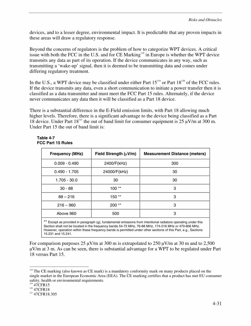
Risks and Obstacles
4-31
devices, and to a lesser degree, environmental impact. It is predictable that any proven impacts in these areas will draw a regulatory response.
Beyond the concerns of regulators is the problem of how to categorize WPT devices. A critical issue with both the FCC in the U.S. and for CE Marking118 in Europe is whether the WPT device transmits any data as part of its operation. If the device communicates in any way, such as transmitting a ‘wake-up’ signal, then it is deemed to be transmitting data and comes under differing regulatory treatment.
In the U.S., a WPT device may be classified under either Part 15119 or Part 18120 of the FCC rules. If the device transmits any data, even a short communication to initiate a power transfer then it is classified as a data transmitter and must meet the FCC Part 15 rules. Alternately, if the device never communicates any data then it will be classified as a Part 18 device.
There is a substantial difference in the E-Field emission limits, with Part 18 allowing much higher levels. Therefore, there is a significant advantage to the device being classified as a Part 18 device. Under Part 18121 the out of band limit for consumer equipment is 25 µV/m at 300 m. Under Part 15 the out of band limit is:
Table 4-7 FCC Part 15 Rules
Frequency (MHz) Field Strength (μV/m) Measurement Distance (meters)
0.009 - 0.490 2400/F(kHz) 300
0.490 - 1.705 24000/F(kHz) 30
1.705 - 30.0 30 30
30 - 88 100 ** 3
88 – 216 150 ** 3
216 – 960 200 ** 3
Above 960 500 3
** Except as provided in paragraph (g), fundamental emissions from intentional radiators operating under this Section shall not be located in the frequency bands 54-72 MHz, 76-88 MHz, 174-216 MHz or 470-806 MHz. However, operation within these frequency bands is permitted under other sections of this Part, e.g., Sections 15.231 and 15.241.
For comparison purposes 25 µV/m at 300 m is extrapolated to 250 µV/m at 30 m and to 2,500 µV/m at 3 m. As can be seen, there is substantial advantage for a WPT to be regulated under Part 18 versus Part 15.
118 The CE marking (also known as CE mark) is a mandatory conformity mark on many products placed on the single market in the European Economic Area (EEA). The CE marking certifies that a product has met EU consumer safety, health or environmental requirements. 119 47CFR15 120 47CFR18 121 47CFR18.305
Risks and Obstacles
4-32
In Europe a similar issue exists. Two EU Directives apply to the Remote Power and/or Contact Power products under investigation:
• 73/23/EEC Low voltage (LV)
• 89/336/EEC Electromagnetic compatibility (EMC)
A third EU Directive would apply if the equipment were to transmit any data at the power delivery frequency:
• 99/5/EC Radio and telecommunications terminal equipment (R&TTE)
Not being considered a radio and therefore not being covered by the R&TTE directive eliminates a number of requirements that otherwise would apply. This not only allows for greater design flexibility but also reduces the regulatory cost of introducing a product to market.
It is important to note that the distinction applies only to the frequency being used for power transmission. A device could have a second radio, for example a Bluetooth or WiFi transmitter, besides its WPT transmitter. Two WPT could communicate data over the other frequency and so long as no data was transmitted over the WPT link, the WPT link would be exempt from the additional regulations. Of course, the second radio would be covered and need to comply with all the regulations that apply. However, because the second radio is only being used as a communication link then its power would be far less than the WPT link and compliance accordingly would be routine as for any similar radio. From a regulatory viewpoint a device that had a WPT transmitter and a second data communication link would be considered to have two radios in it, each treated separately, with different regulations.

5-1
5 CONCLUSION
This report has surveyed the current state of development of WPT (wireless power transfer). The following conclusions are reached:
1. Wireless power transfer (WPT) applications most suited to the Electric Utility industry lie in the power plant monitoring and sensing area. Sensor technology for condition-monitoring and asset management in industrial plants is not new. Self-powered sensors using WPT can be explored. WPT applications can be of high benefit in cases where running wires and battery maintenance is expensive or is difficult, due to confined spaces or remoteness of the site. Sensors that only need to be powered up and interrogated periodically can be applications that are well suited for WPT. Another application of interest could be sensors powered and operated only during periodic maintenance checks. Wireless battery charging is another application worth exploring. In all the above applications, WPT offers the advantage of eliminating the need for wires or batteries. Further, under these scenarios WPT might be enabled to be operated under higher power conditions under the control of a trained operator and with special safety precautions being taken. This report concludes that the best framework for predicting the viability of WPT is to look at the technology from the viewpoint of jobs the end user is doing. End users of products are trying to do something and are looking for solutions with attributes that solve their problem. When one of the forms of WPT gives the best total solution for the user’s application then it is likely to be selected.
2. WPT is currently being used where it provides the best set of attributes, particularly for the requirements of most importance to the user. An example is given in the next conclusion were it is concluded that inductive charging is used in many electric toothbrushes because it was very important to eliminate any openings that might allow water to get into the toothbrush. Inductive charging allows a sealed housing to be used and so it a common solution used in these products.
3. Further development and adaptation of WPT is likely to be successful where with moderate improvement WPT would provide a compelling option for providing power. The amount of activity going into developing WPT powered sensors is a good example. Hard wiring for a sensor network is costly and often prone to damage. With moderate development, WPT could provide a compelling alternative to power sensors and therefore development in this area is likely to be successful.
4. Most WPT products on the market today, use inductive coupling with the charging and recipient device in close proximity. Products that use inductive coupling to recharge batteries have been on the market for some time. An example is electric toothbrushes, which have been on the market for some time. Inductive couple for electric toothbrushes avoids the opening necessary for a connector,

Conclusion
5-2
eliminating the need for a connector altogether.122 The problem of water seeping into the unit, corroding the connector or doing internal damage to the unit is effectively solved. Other rechargeable devices use inductive charging to solve similar problems. From the fact of market success it is clear that inductive coupling is cost competitive in the very price sensitive consumer electronics market. Technologically it is clearly a solution with acceptable reliability and manufacturability. To abstract the significances of these conclusions it can be said that for products that can be periodically or permanently placed in a charging cradle or put in close proximity to a charger, inductive coupling is a potential solution. Its advantages are convenience and elimination of a power connector. On the down side, compared to a direct wired connection, inductive charging is still more expensive and less energy efficient. Further developments of this technique are being actively refined. Multiple innovations are being explored and show promise for near term implementation in products. Among those innovations are sensing of a recipient device, providing power only when a recipient device is within range. A further innovation is sensing of the charge state of a recipient device, delivering metered power on demand. Other improvements involved coupling and transfer efficiency.
5. RF and microwave WPT offer the combined advantage and disadvantage that electromagnetic waves naturally go in all directions. This means that power is dispersed over a larger area and a receiving device can obtain power from any location. This is a significant advantage when the location of the receiving device is not known in advance or when it is moving. However, the received power will only be a fraction of the total power transmitted, precisely because the transmitted power is spread over a wide area. RF radiated forms of WPT face substantial limits when used in environments where the general public may be exposed to the RF energy. Receive power in the mW or nW range is the limit on the amount of power that can be delivered in this manner. The limitation on power delivery using RF transmission can be mitigated in several ways:
a. Access to the hazardous area can be restricted. The highest power is closest to the transmitting antenna. If people can be prevented from coming into the area where the RF safety level is exceeded then higher power can be used.
b. Another technique is to use higher power only in areas where personnel are never present.
c. A third is to use higher power only in areas classified as occupational exposure. The limits for occupational exposure are higher than those for the general population. The reason is that it is expected that under such conditions personnel will be given training to assure their safety and other safeguards can be implemented.
d. A very provocative mitigation is applying this method to applications where the recipient device only operates periodically. When a recipient device only operates periodically it can accumulate power over time and use the accumulated power over its operational period. To qualify for using WPT a designer must know how much power the device will
122 For illustration see online: http://electronics.howstuffworks.com/wireless-power1.htm

Conclusion
5-3
use when it operates and what the minimum time is between operations. If the WPT system can provide the amount of power between operating states so that the accumulated power will supply the power needs of the device then WPT is a candidate. The challenge then becomes to assure that average power usage is below the average WPT power delivered, even though peak usage may be much higher.
From the conclusions above the attributes of uses cases for which RF radiated WPT can be a solution are:
• RF radiated WPT can be a solution in controlled environments or where human exposure is not a possibility.
• RF radiated WPT can be a solution in environments where the transmit and receive antennas can be spaced very closely, meaning a fraction of a wavelength, from each other.
• RF radiated WPT can be a solution in environments where the recipient device power requirements are small.
• RF radiated WPT can be a solution in environments where the recipient devce only operates periodically and use of power, averaged over time is in the mW or nW range.
6. In contrast to RF forms of WPT, the power transmitted by lasers is very focused. When the relative location of the transmitter and receiver can be precisely known then the power can be directly transmitted to the receiver, with little dispersion loss. Laser transmission has its own set of safety limits just as RF transmission does. PowerBeam has developed a sophisticated safety system to assure power is not transmitted when a person may be affected. RF and microwave systems could also develop comparable protection systems, using any of several types of intrusion detection. Using such a method a system could be devised where higher power was only delivered when people were not in the area.
7. Concerns related to the interaction of WPT with its environment must be addressed. Included are the following:
a. Potential health risks and concerns of WPT systems should be studied and appropriate experimentation constructed.
b. The public perception of the health and safety of WPT systems must be assessed. In many cases, the approach of the existing wireless industry and public alike will often be to expect that the new WPT systems will be hazardous to health and interfere with existing biological systems. In line with the results found in addressing the actual health risks, an attempt must be made to satisfy wireless industries and the general public alike that WPT is safe and can coexist with existing wireless technologies used for medical applications.
c. Understanding potential interference scenarios and how to test for them according to the pattern set forth in IEEE Standard 1900.2 will be critical to insuring that WPT systems will harmlessly coexist with other existing equipment. Wireless systems and medical equipment are particularly important to study. Wireless systems are important because they use spectrum to transmit and can be very sensitive to anything that influences their RF environment. Medical equipment is important because the consequences of

Conclusion
5-4
interference can be so significant, even life threatening. The formation of test procedures should be set in place, according to this standard, during the development phase of the technology.
Probable Future of WPT
This report proposed that the most effective way to analyze WPT is from the viewpoint of the end user or the product designer. When the characteristics of a WPT solution give a user a product with features that help him solve a problem, it will be used. From the product designer’s viewpoint WPT is an option and when its characteristics make it the superior solution for a design challenge then it will be used.
A corollary is that WPT must provide a compelling business case for the product designer and a price competitive solution for the consumer. The interests of the product manufactures and those of the consumer are not necessarily identical. When WPT fails to offer a business advantage for the product manufacturer it is unlikely to be included in a product and offered to the consumer.
Using this framing for an analysis it can be concluded that WPT will be considered in any application where power cables are inconvenient or impossible, provided that offering that convenience is an advantage for the product manufacturer. When providing a power cable is impossible some means of wireless power are an absolute requirement. In these situations WPT must prove to be the superior solution to batteries, fuel cells, solar cells, energy harvesting and other options for providing wireless power.
Barriers for the technology to evolve to include cell phones is the common “chicken & egg” scenario. Circuitry is required in the cell phone to receive the inductive power transmission and the cell phone manufacturers are not willing to do that at this time. Beyond the coordination problem is the business issue, chargers are a big market accessory that make a good profit for the industry. For WPT to be attractive it must offer a superior revenue opportunity, otherwise, why would a company implement it? Some gadgets are likely, but to gain widespread use in very high volume devices like cell phones and notebook computers, the technology leaders will have to do some pretty tricky lobbying with the OEMs to integrate the necessary components. To summarize what Intel’s CTO Justin Rattner said in August 2008 at the Intel Developer Forum, “such technologies may not be mature until the middle of this century.”123
Similarly for RF WT, it may also take decades to overcome some of the barriers to implementation for the higher power and longer distance technologies. The physics of electromagnetic propagation dictate a spherical expansion of energy. While high gain antennas are possible they tend to be large and expensive. It takes a very large antenna to culminate the “beam” of energy tight enough so that it is not lost on the other end. Conversely, it takes a large antenna to capture the energy as it arrives. Also, higher frequencies have significant problems with being absorbed by physical objects in the environment. Lower frequencies propagate through material better but antenna sizes increase due to the increase in wavelength.
123 http://thefutureofthings.com/news/5763/intels-wireless-power-technology-demonstrated.html

Conclusion
5-5
However, given the enormous variety of products and use scenarios WPT has and certainly will expand the number of niches for which it is the preferred solution. The growth of WPT will follow predictable lines of development, starting in niche applications for which it currently provides a compelling option and building out to new niches with similar characteristics. Development of WPT, new forms of WPT and hybrid solutions, joining WPT with other technologies offer many exciting solution possibilities. WPT is an exciting family of technologies that are almost certain to experience aggressive development and find significant deployment as the technology becomes the preferred solution in a widening array of use scenarios.
Next Steps
A number of productive follow-on activities are possible, building on the findings of this report. The following are a few of the extensions and demonstrations that can be envisioned to further study and garner the benefits of WPT.
Use Case Analysis
A very productive follow-on would be to list a set of possible use cases of interest to the electrical power industry. Each use case would be analyzed as to the characteristics it ideally would have in a power delivery technology. Those characteristics would then the prioritized and quantified. Specifications would be developed for such items as power required, both average and peak, distance from charging source, cost target, energy efficiency required.
A corresponding characterization would then be developed of the various forms of WPT. Current and potential specifications would be delivered. What the various WPT technologies can currently deliver and potentially could deliver in the future would be quantified.
The delivery of this activity would be an analysis of each use case, analyzing the various power delivery technologies that are viable candidates for the application. Such a comparison grid would show the use cases for which WPT is currently an effective solution, those for which it might be in the near future and those which have potential if various research efforts prove successful.
This information would be quite useful in guiding decisions about use of WPT. For use cases where WPT technology is currently a competitive solution but is not yet implemented development efforts might be recommended to capture the benefits of WPT. For use cases where the current state of WPT technology offers a near term potential, participation in the culminating research could speed its completion and support early deployment. Alternatively, where WPT shows longer term potential, appropriate engagement may be planned.
Periodic Updating
Given the dramatic developments on many fronts a periodic update and expansion of this report is another possible action. The report could be kept current by quarterly updates on new developments, recent research reports and other activities. Involvement in the Wireless Power

Conclusion
5-6
Consortium would be one way to stay involved with the technology and have ongoing insight into the activities of the leading companies involved.
Interference Analysis
As stated in the report, RF interference, particularly with medical devices, is a significant concern for WPT. On December 15, 2008 the FDA sponsored a workshop at Villanova University on the impact of wireless technology in healthcare. A series of such workshop is planned so as to understand the potential benefits of wireless technology in healthcare but also to identify risks and problems that could result. Involvement in these workshops to explore the potential of WPT is one way of understanding the risks and mitigations available.
Even more important would be the development of a comprehensive interference analysis following the guidance of IEEE 1900.2. For promising use scenarios the potential for interference must be understood. It is particularly important to understand the interference potential with medical devices, especially for use cases that have WPT in widespread deployment. Once the problems are known mitigations can be identified, so that when the technology is deployed that deployment includes the mitigating actions that avoid interference problems.
Demonstration of Magnetic Resonant Coupling
Inductive coupling is clearly the leading WPT technology. The enhancement of WPT using magnetic resonant coupling is very promising. As reported Fulton Innovations, as well as other companies, are demonstrating a variety of implementations using the technology. A demonstration project could select three use cases. A low, medium and high power use case could be explored to demonstrate the viability of the technology.
Low power uses of the technology are on the market and new innovations are making it more appealing. The low power use case would seek to identify an application of interest to the industry in which WPT is not being used and, by means of a proof-of-concept demonstration, understand the path to implementation.
The medium power use case would seek to extend the technology to its limits and understand those limits and what range of applications the technology current can viably service.
A high powered use case, such as recharging an electric car, offers very exciting but probably longer term potential.
Through the development of proof-of-concept demonstrations an in-depth understanding of the technology can be captured, supporting a path toward implementing the technology in a wide variety of applications.

Conclusion
5-7
Hybrid Solutions
The use of WPT in hybrid solutions is particularly exciting because one technology can supplement or compensate for deficiencies in the other. Two such hybrid solutions appear particularly exciting, the use of WPT with high capacity capacitors to power sensors and the use of WPT with fuel cells. A demonstration project of each hybrid would be very instructive to understanding the potential and obstacles to deployment.
The use of WPT with high capacity capacitors is a particularly promising development. Use of high capacity capacitors with an energy harvesting system to power sensors in power plants is being demonstrated by GE in Sweden. The technology is showing promise. The potential for use with WPT, both to replace the vibration energy harvester but potential also to supplement it is a very interesting possibility. Further tests and additional demonstration projects could only help understand the remaining challenges and potential for this application of the technology.
The research at MIT that marries WPT with a fuel cell is a second very exciting application. The fuel cell is logically an alternative to a rechargeable battery. Understanding the comparison of fuel cells to rechargeable batteries is a study in its own right. One clear difference is that with a fuel cell the length of time it can deliver power is a function of the fuel available. Larger fuel tanks create the potential for longer periods between recharging cycles. This results in the potential for services periods of significant operation followed by long quiescent periods during which the WPT could replenish the fuel supply using low levels of energy transfer. Emergency power systems might be envisioned in which the hybrid system provides power for sensor networks and other backup power equipment.


A-1
A HISTORY AND CONNECTION TO WIRELESS COMMUNICATIONS
History of Wireless Power Transfer
The concept of wireless power transmission has a long history, going back almost one hundred years to Heinrich Hertz and the very beginning of radio in 1888. In 1888, Hertz experimented with pulsed power transmission at 500 megacycles per second.
The development of wireless energy transfer began in earnest with the lectures and patents of electricity pioneer Nikola Tesla in the early 1900s. Tesla’s idea was to develop a transmitter of great power to establish the laws of propagation through the earth and the atmosphere.124,125 The magnifying transmitter was Tesla’s concept to build a “world telegraphy center,” a base station that was 57 meters high and 37 meters underground.126
Inductive coupling is another WPT method with a long history. Inductive coupling has been used for many years in transformers to couple energy between closely spaced coils of wire. By use of a new inductive coupling technology, the wireless concept can be extended to power systems, giving design engineers a new path for creating innovative household devices.
Electromagnetic Waves
The use of electromagnetic waves for transmission of energy has been researched and tested since 1900, over different ranges of distance. In experiments around 1899, Tesla was able to illuminate lamps filled with gas (similar to neon) over 25 miles away without using wires using twice doesn’t sound right high frequency current. During his experiments in Colorado, he lit ordinary incandescent lamps at full candle-power by currents induced in a local loop consisting of a single wire forming a square of fifty feet each side, which includes the lamps, and which was at a distance of one hundred feet from the primary circuit energized by the oscillator.127
In the early 1900s, long before the power grid made electricity widely available, Nikola Tesla devised a grand scheme to transfer large amounts of power over long distances from a tall tower.
124 For illustration see: Nikola Tesla, “Apparatus for Transmission of Electrical Energy,” United States patent no. 649621, May 1900. 125 For illustration see: Nikola Tesla, “Apparatus for Transmission of Electrical Energy,” United States patent no. 1119732, Dec 1914. 126 Nikola Tesla, compilation by Steven R Elswick , Tesla's views on the wireless transmission of power1900-1934 , Security, CO : Exotic Research, c1995 127 Century Magazine, June 1900

History and Connection to Wireless Communications
A-2
The plan was to build a global wireless energy distribution system called the Wardenclyffe Tower, a sprawling 180-foot structure based in Shoreham, Long Island, which would serve to send information and electricity globally via the earth as a giant conductor.128 Though the idea was good, it was never implemented because the project had to be abandoned due to lack of funds. The Wardenclyffe facility was meant to be the start of a national (and later global) system of towers broadcasting power to users as electromagnetic waves.129 There is some evidence that Wardenclyffe might have used extremely low frequency signals combined with higher frequency signals. In practice, the transmitter electrically influences both the earth and the space above it. Tesla believed that energy could be efficiently transmitted from the facility via longitudinal "non-Hertzian" (or maxwellian) waves. Powered by an industrial alternator, the tower was apparently intended to inject large amounts of energy into a natural earth circuit, using the earth‘s ionosphere network as the transmission circuit. Tesla called his wireless technique the "disturbed charge of ground and air method."
In various writings, Tesla explained that the earth itself would behave as a resonant LC circuit that could be electrically excited at predefined frequencies. According to Tesla, the planet's large cross-sectional area provides a low resistance path for the flow of earth currents.130
Energy can be transmitted via electromagnetic waves, over short distances, depending on the frequency of transmission. Extremely low to super low frequency (3-300 Hz) transmission enables significantly large amounts of energy (megaWatts) to be transferred over a very small range (milliMeters) as is the case of inductive transfer (example- 60 Hz transformers, motors etc.). Low frequency to Ultra high frequency (300 Hz- 3 GHz) transmission enables small amounts of energy (milliWatts to few Watts) to be transferred over long distances (thousands of kilometers) as is the case in AM/FM radios, maritime and aviation communications, mobile telephones and microwave ovens. The range and the energy content associated with the transmission, is limited due to interference, and safety and health hazards to humans and biological environments. Due to these limitations, wireless energy transfer using electromagnetic “radiative” fields is limited to short distances.
Microwave
A more recent wireless power transmission method researched and tested is microwave power transmission typically referred to as “power beaming.” Microwave power transmission can be used to transfer energy over very long distances, such as beaming energy from space to earth and vice-versa, remote sensing, navigation and control of advanced weapons systems etc. However, microwave transmission involving energy transfer is understood to be efficient only over long distances such as from outer space to earth.
As semiconductor technologies have advanced in the past several decades, microwave tubes were replaced by compound semiconductor power devices. This makes it feasible to have a
128 Nikola Tesla, The transmission of electrical energy without wires, Electrical world and engineer, March 5, 1904 http://www.tfcbooks.com/tesla/1904-03-05.htm 129 Milos D Ercegovac, UCLA, Omnipresence of Tesla’s work and ideas http://www.cs.ucla.edu/~milos/TeslaTalk6-07F.pdf 130 Tesla, Nikola compilation by Elswick, Steven R Tesla's views on the wireless transmission of power1900-1934 , Security, CO : Exotic Research, c1995
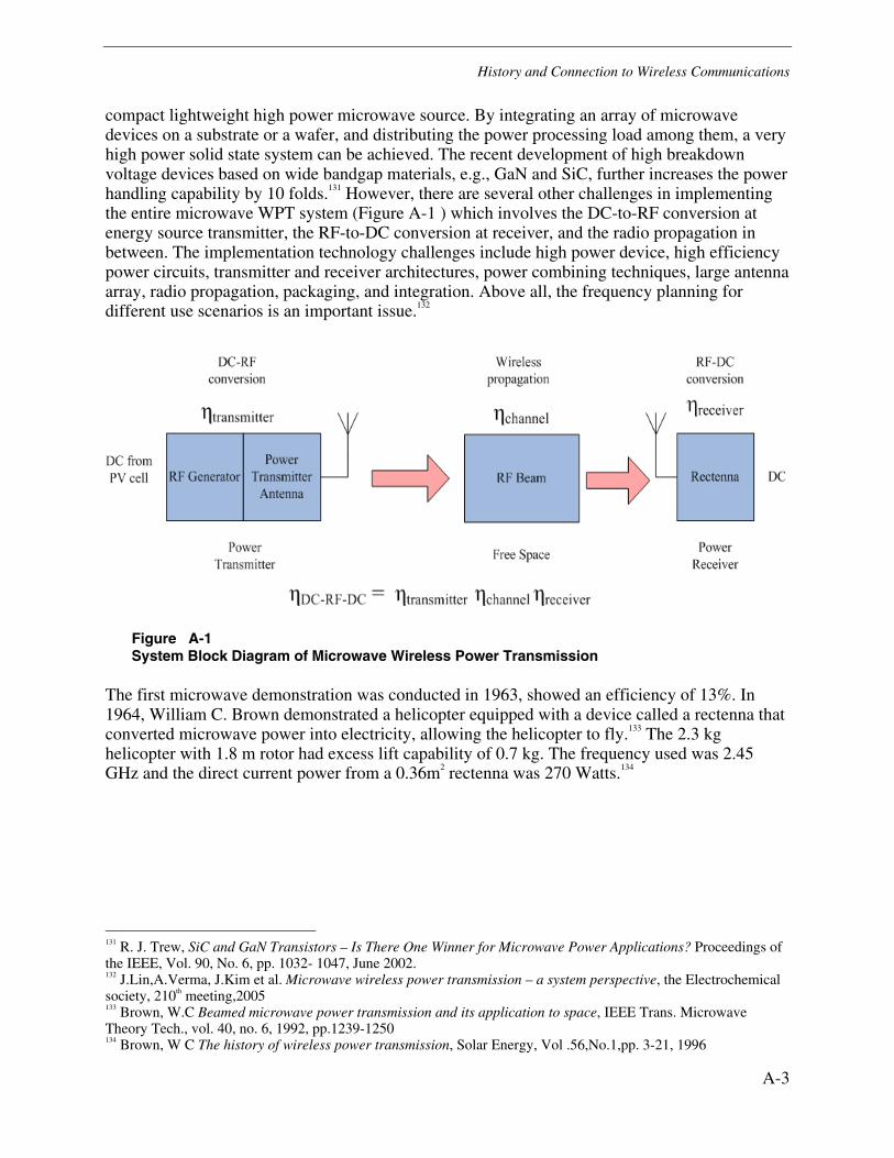
History and Connection to Wireless Communications
A-3
compact lightweight high power microwave source. By integrating an array of microwave devices on a substrate or a wafer, and distributing the power processing load among them, a very high power solid state system can be achieved. The recent development of high breakdown voltage devices based on wide bandgap materials, e.g., GaN and SiC, further increases the power handling capability by 10 folds.131 However, there are several other challenges in implementing the entire microwave WPT system (Figure A-1 ) which involves the DC-to-RF conversion at energy source transmitter, the RF-to-DC conversion at receiver, and the radio propagation in between. The implementation technology challenges include high power device, high efficiency power circuits, transmitter and receiver architectures, power combining techniques, large antenna array, radio propagation, packaging, and integration. Above all, the frequency planning for different use scenarios is an important issue.132
Figure A-1 System Block Diagram of Microwave Wireless Power Transmission
The first microwave demonstration was conducted in 1963, showed an efficiency of 13%. In 1964, William C. Brown demonstrated a helicopter equipped with a device called a rectenna that converted microwave power into electricity, allowing the helicopter to fly.133 The 2.3 kg helicopter with 1.8 m rotor had excess lift capability of 0.7 kg. The frequency used was 2.45 GHz and the direct current power from a 0.36m2 rectenna was 270 Watts.134
131 R. J. Trew, SiC and GaN Transistors – Is There One Winner for Microwave Power Applications? Proceedings of the IEEE, Vol. 90, No. 6, pp. 1032- 1047, June 2002. 132 J.Lin,A.Verma, J.Kim et al. Microwave wireless power transmission – a system perspective, the Electrochemical society, 210th meeting,2005 133 Brown, W.C Beamed microwave power transmission and its application to space, IEEE Trans. Microwave Theory Tech., vol. 40, no. 6, 1992, pp.1239-1250 134 Brown, W C The history of wireless power transmission, Solar Energy, Vol .56,No.1,pp. 3-21, 1996

History and Connection to Wireless Communications
A-4
Solar Power Satellite (SPS)
The SPS concept, first described in November 1968 was proposed to be a satellite built in high earth orbits that could electromagnetically beam gigawatts of solar energy back to ground-based receivers, where it would then be converted to electricity and transferred to power grids.135 Microwave power transmission to beam solar power is one of the ways suggested. Advantages of placing the solar collectors in geosynchronous orbits in space 22,000 miles away, include the unobstructed view of the sun, unaffected by the day/night cycle, weather, or seasons. The unique property to transfer energy across gravitational barriers makes high efficiency energy transfer possible through SPS systems, at least in theory. At first it was regarded as impractical due to the lack of a workable method of sending power collected down to the earth's surface. This changed in 1973 when Peter Glaser was granted a U.S. patent number for his method of transmitting power over long distances (eg, from an SPS to the earth's surface) using microwaves from approximately a square kilometer sized antenna on the satellite to a much larger one on the ground, which came to be known as a rectennae. Glaser lead four other companies in a broader study in 1974 that concluded that the concept had several major problems -chiefly the expense of putting the required materials in orbit and the lack of experience on projects of this scale in space. During the period from 1978 - 1981 the US Congress authorized DOE and NASA to jointly investigate the SPS concept. They organized the Satellite Power System Concept Development and Evaluation Program. Several reports have since been published, addressing various issues, along with investigations for such an engineering project.136
In a recent report released in 2007, the Pentagon's National Security Space Office encouraged the U.S. government to spearhead the development of space power systems. The report states that Russia, China, India and the European Union, are interested in the concept. And Japan, which has been pouring millions of dollars into space power studies for decades, is working toward testing a small-scale demonstration in the near future. However, a number of obstacles still remain before solar satellites actually get off the ground. One major barrier is a lack of cheap and reliable access to space, a necessity for launching hundreds of components to build what will be miles-long platforms. Developing robotic technology to piece the structures together high above Earth will also be a challenge in addition to the cost, which could be at least a billion dollars137.
Stationary High Altitude Relay Platform (SHARP)
In the 1980s, Canada's Communications Research Centre created a small airplane that could run off power beamed from the earth. The unmanned plane, called the Stationary High Altitude Relay Platform (SHARP), was designed as a communications relay. Rather than flying from point to point, the SHARP could fly in circles two kilometers in diameter at an altitude of about 13 miles (21 kilometers). Most importantly, the aircraft could fly for months at a time because of a large, ground-based microwave transmitter. The power beam would be accurately focused onto the airplane. A rectenna (rectifying antenna), mounted on the lower surfaces of the aircraft would
135 For illustration see online: http://www.maficstudios.com/gallery_sbsp.html 136 Nagatomo, M et al. Conceptual study of Solar Power Satellite, SPS 2000 http://www.spacefuture.com/archive/conceptual_study_of_a_solar_power_satellite_sps_2000.shtml 137 CNN news article How to harvest solar power? Beam it down from space! May 2008 http://www.cnn.com/2008/TECH/science/05/30/space.solar/index.html

History and Connection to Wireless Communications
A-5
receive and convert microwave power to DC power. The DC power would be used to drive electric motors on the airplane for propulsion, to power the payload and control systems and to charge standby energy storage units.138
Potential commercial communications services include mobile and personal communications, broadband fixed radio, and direct-to-home multi-channel television and sound broadcasting. Non-communications services include surveillance (example- terrestrial waters), environmental monitoring (without contributing to pollution) and remote sensing. Because of SHARP's considerable payload weight and power capacity, these services can be offered on an integrated basis. Because of its proximity to earth, the two-way time delay for traffic to-and-from a SHARP platform will be negligible compared to those for satellite links.139
A major factor that has delayed the further development of microwave wireless power transmission systems, whose next learning step would logically be a high altitude microwave powered aircraft, is the perceived high cost of building an earth-based electronically steerable phased array of substantial physical dimensions at 2.45 GHz.
Lunar Solar Power (LSP)
Lunar Solar Power systems are an unconventional long-range wireless power transmission technology proposed by David Criswell of the Institute for Space Systems Operations, University of Houston in 1999-2000.140 The LSP system proposes the use of microwaves to transmit electricity to earth from solar power stations on the moon. Tens of thousands of receivers on earth would capture this energy, and rectenna would convert it to electricity.141 The process, as claimed by researchers, is efficient because microwaves pass through the atmosphere easily, and rectenna rectify microwaves into electricity very efficiently. In addition, scientists researching the LSP concept believe that earth-based rectenna could be constructed with a mesh-like framework, allowing the sun and rain to reach the ground underneath and minimizing the environmental impact. Such a setup could provide a clean source of power.
Overall, wireless power transmission (using microwaves) is well proven. Experiments in the tens of kilowatts have been performed at Goldstone in California in 1975 and more recently in 1977 at Grand Bassin on Reunion Island.142 These methods achieve distances on the order of a kilometer.
Power beaming by Lasers
One other method of wireless energy transfer that has been demonstrated is the use of light in the form of laser beams. Power can be transmitted by converting electricity into a laser beam that is then fired at a solar cell receiver. This is known as "power beaming" by lasers. Researchers at 138 For illustration see online: Friends of CRC, SHARP http://www.friendsofcrc.ca/Projects/SHARP/sharp.html 139 Friends of CRC, SHARP http://www.friendsofcrc.ca/Projects/SHARP/sharp.html 140 For illustration see online: www.howstuffworks.com 141 Criswell, David R. Lunar Solar Power System for Energy Prosperity within the 21st Century http://217.206.197.194:8190/wec-geis/publications/default/tech_papers/17th_congress/4_1_33.asp 142 Lan Sun Luk J.D, et al. - University of La Réunion , Point-to-point wireless power transportation in Reunion Island, 48th International Astronautical Congress, Turin, Italy, 6-10 October 1997.
History and Connection to Wireless Communications
A-6
NASA's Marshall Space Flight Center, Huntsville, Alabama, and Dryden Flight Research Center, Edwards, CA, and the University of Alabama in Huntsville have flight-demonstrated a small-scale aircraft that flies solely by means of propulsive power from an invisible, ground-based infrared laser. Flights of the lightweight, radio-controlled model airplane inside a large building at NASA Marshall are believed to be the first time that an aircraft has been powered only by laser energy. The demonstration was a key step toward the capability to beam power to an aircraft, allowing it to stay in flight indefinitely, a concept with potential for the scientific community as well as the remote sensing and telecommunications industries.143
During the flight demonstration in September 2003, an engineer manually directed the 1 kW laser's energy from a central platform at a panel of infrared-sensitive photovoltaic cells mounted on the bottom of the aircraft to power its tiny six-watt motor as it flew circles inside the building.144 As a precursor to the laser beamed-power flights, a similar demonstration using a large theatrical spotlight was flown in the summer of 2002 at NASA Dryden, proving that beamed visible light could power the 11-ounce aircraft. The two lightweight model aircrafts used for these demonstrations were designed and built in the NASA Dryden model shop, and were controlled using the same over-the-counter radio control instrumentation available to model aircraft hobby enthusiasts. Two months after the initial laser-powered flight demonstrations, the team used the same laser system on a rotorcraft version that operated along guide wires. Several attempts were then made to fly the original aircraft, now modified with two motors for additional power, outside on a laser range on the U.S. Army's Redstone Arsenal near NASA Marshall Space Flight Center. These attempts were not successful, due to the aircraft's light weight and low power being unable to overcome the effects of gusty winds.
143 Landis, G.A Applications for Space Power by Laser Transmission SPIE Optics, Electro-optics & Laser Conference, Los Angeles CA, January 24-28 1994; Laser Power Beaming, SPIE Proceedings Vol. 2121, 252-255. 144 144 NASA Dryden Flight Research Center Photo collection http://www.nasa.gov/centers/dryden/news/FactSheets/FS-087-DFRC.html

B-1
B RADIO FREQUENCY ID (RFID)
Radio Frequency ID (RFID)
Radio Frequency ID (RFID) is an example of a technology that provides both wireless power and data communications. With passive RFID a reader sends out an electromagnetic pulse that powers a sensor, turning it on and causing it to send its information back to the reader. RFID is a technology that offers identification such as bar coding and magnetic stripe and several other benefits. RFID is not a recent technology but has been rapidly emerging in applications throughout the world. Originally, implemented during World War II to identify and authenticate allied planes, RFID is still being used today for the same purposes in military and aviation applications.
The main component of this technology is the transponder/tag145 which in most cases comprises of a chip and antenna mounted onto a substrate or an enclosure. The chip consists of a processor, memory and radio transmitter. These transponders communicate via radio frequency to a reader, which has its own antennas. The readers can interface through wired or wireless medium to a main computer. Transponders are also known as smart or radio tags. The memory will vary, depending on the manufacturer, from just a few characters to kilobytes.
The two most common types of RFID technologies are Active RFID and Passive RFID. Active RFID transponders are self powered and tend to be more expensive than Passive. Having power on board allows the tag to have greater communication distance and usually larger memory capacity. The most common application for Active RFID is for highway tolls such as the Highway 407 in Toronto.
Passive RFID’s can operate in different frequency bands. These are often referred to as low frequency (LF) RFID, operating in the kHz range, and high frequency (HF) RFID, operating in the MHz range. Both low and high frequency RFID operate on the inductive coupling principle. That is, the energy is transferred from the reader to the tag through a shared magnetic field. The amount of transferred energy is proportional to the size of the transmitting and receiving antennas as well as the tag ability to operate at the resonance frequency. The resonant frequency is a state in which the impedance is at its minimum, allowing for maximum current flow in the circuit. The resonance frequency is a function of the inductance and capacitance of the tag circuit. The quality of a resonant circuit is measured by Q factor. The higher the Q factor, the higher the amount of energy transfer. Although higher energy transfer is desirable, the higher Q factor results in reduced bandwidth.
145 "Transponder" and "Tag" are interchangeably used. "Transponder" is a technical reference to an electronic circuit comprised of a transceiver (transmitter/receiver) and the supporting circuitry and memory structure. "Tag" is the more commonly used term in the RFID market.

Radio Frequency ID (RFID)
B-2
Figure B-1 Schematic of a Typical RFID System
Passive Low Frequency (LF) RFID
Low Frequency (LF) RFID has been utilized in several industries for many years. The most common frequencies used are 125 and 134.2 kHz. One of the key features of LF RFID is that it is not as affected by surrounding metals. This makes it ideal for identifying metal items such as vehicles, equipment, tools and metal containers. The reading range can vary from a few centimeters to a couple of meters depending on the size of the transponders and the reader being used. LF RFID also penetrates most materials, such as water and body tissue. The limitations are that if used in industrial environments, electric motors may interfere with the LF system. Due to the size of the antenna required, the LF transponders are typically more expensive than High Frequency transponders. This limits the frequency to applications where the transponders can be re-used.
Currently most access control systems are based on LF, contact-less cards or key fobs for security. A read only card can be used simply as identification or a read-write card can be used to maintain access or security information. The largest user for LF RFID is the automotive industry. Currently all car immobilizers (key) use a LF transponder embedded into a car key with a reader mounted in the ignition. Other applications are vehicle identification for highway and parking lot access.
Passive High Frequency (HF) RFID
Passive High Frequency (HF) operates in 13.56 MHz ISM band, which, because it is established by the ITU-R, is globally accepted. This means that any system operating at HF can be used worldwide, though there are some differences with regulations in the different regions of the

Radio Frequency ID (RFID)
B-3
world. These differences pertain primarily to power and bandwidth. In the US the FCC (Federal Communications Commission) and in Canada, IC (Industry Canada) limits the reader antenna power to three watts while in Europe the regulations allow for four watts.
With HF, the signal travels well through most materials including water and body tissue. It is however, more affected by surrounding metals compared to Low frequency (LF). In comparison to LF, the benefits of HF are lower tag costs, better communication speed and the ability to read multiple tags at once. The length of the antenna is based on the length of the signal wave, thus the higher the frequency the shorter the wavelength. For this reason, there is the flexibility that an antenna for a HF tag is small enough that it can be produced by printing it onto a substrate, using conductive ink and then affixing the chip.
The higher the frequency, the higher the data throughput and the faster the communications will be between the reader and the tags. This increase in speed allows for the reader to communicate with multiple tags at once. The process of communication with multiple tags is known as Anti-Collision and at HF, a reader can read up to 50 tags per second.


C-1
C FCC PART 18: TECHNICAL STANDARDS
The technical standards from FCC Part 18146 are reproduced here for reference.
Subpart C—Technical Standards
§ 18.301 Operating frequencies.
ISM equipment may be operated on any frequency above 9 kHz except as indicated in §18.303. The following frequency bands, in accordance with §2.106 of the rules, are allocated for use by ISM equipment:
ISM frequency Tolerance
6.78 MHz ±15.0 kHz
13.56 MHz ±7.0 kHz
27.12 MHz ±163.0 kHz
40.68 MHz ±20.0 kHz
915 MHz ±13.0 MHz
2,450 MHz ±50.0 MHz
5,800 MHz ±75.0 MHz
24,125 MHz ±125.0 MHz
61.25 GHz ±250.0 MHz
122.50 GHz ±500.0 MHz
245.00 GHz ±1.0 GHz
Note: The use of the 6.78 MHz ±15 kHz frequency band is subject to the conditions of footnote 524 of the Table of Allocations. See §2.106.
146 47CFR18

FCC Part 18: Technical Standards
C-2
§ 18.303 Prohibited frequency bands.
Operation of ISM equipment within the following safety, search and rescue frequency bands is prohibited: 490–510 kHz, 2170–2194 kHz, 8354–8374 kHz, 121.4–121.6 MHz, 156.7–156.9 MHz, and 242.8–243.2 MHz.
§ 18.305 Field strength limits.
(a) ISM equipment operating on a frequency specified in §18.301 is permitted unlimited radiated energy in the band specified for that frequency.
(b) The field strength levels of emissions which lie outside the bands specified in §18.301, unless otherwise indicated, shall not exceed the following:
Equipment Operating frequency
RF Power generated by
equipment (watts) Field strength limit
(uV/m) Distance (meters)
Any type unless otherwise specified (miscellaneous)
Any ISM frequency Below 500 500 or more
25 25×SQRT(power/500)
300 1300
Any non-ISM frequency
Below 500 500 or more
15 15×SQRT(power/500)
300 1300
Industrial heaters and RF stabilized arc welders
On or below 5,725 MHz Above 5,725 MHz
Any Any
10 (2)
1,600 (2)
Medical diathermy Any ISM frequency Any non-ISM frequency
Any Any
25 15
300 300
Any type unless otherwise specified (miscellaneous)
Any ISM frequency Below 500 500 or more
25 25×SQRT(power/500)
300 1300
Any non-ISM frequency
Below 500 500 or more
15 15×SQRT(power/500)
300 1300
Industrial heaters and RF stabilized arc welders
On or below 5,725 MHz Above 5,725 MHz
Any Any
10 (2)
1,600 (2)
Ultrasonic Below 490 kHz Below 500 500 or more
2,400/F(kHz) 2,400/F(kHz)× SQRT(power/500)
300 3300
490 to 1,600 kHz Above 1,600 kHz
Any Any
24,000/F(kHz) 15
30 30
Induction cooking ranges
Below 90 kHz On or above 90 kHz
Any Any
1,500 300
430 430
1Field strength may not exceed 10 μV/m at 1600 meters. Consumer equipment operating below 1000 MHz is not permitted the increase in field strength otherwise permitted here for power over 500 watts. 2Reduced to the greatest extent possible. 3Field strength may not exceed 10 μV/m at 1600 meters. Consumer equipment is not permitted the increase in field strength otherwise permitted here for over 500 watts. 4Induction cooking ranges manufactured prior to February 1, 1980, shall be subject to the field strength limits for miscellaneous ISM equipment.

FCC Part 18: Technical Standards
C-3
(c) The field strength limits for RF lighting devices shall be the following:
Frequency (MHz) Field strength limit at 30 meters
(μV/m)
Non-consumer equipment:
30–88 30
88–216 50
216–1000 70
Consumer equipment:
30–88 10
88–216 15
216–1000 20
Notes
1. The tighter limit shall apply at the boundary between two frequency ranges.
2. Testing for compliance with these limits may be made at closer distances, provided a sufficient number of measurements are taken to plot the radiation pattern, to determine the major lobes of radiation, and to determine the expected field strength level at 30, 300, or 1600 meters. Alternatively, if measurements are made at only one closer fixed distance, then the permissible field strength limits shall be adjusted using 1/d as an attenuation factor.
[50 FR 36070, Sept. 5, 1985, as amended at 51 FR 17970, May 16, 1986; 52 FR 43197, Nov. 10, 1987]
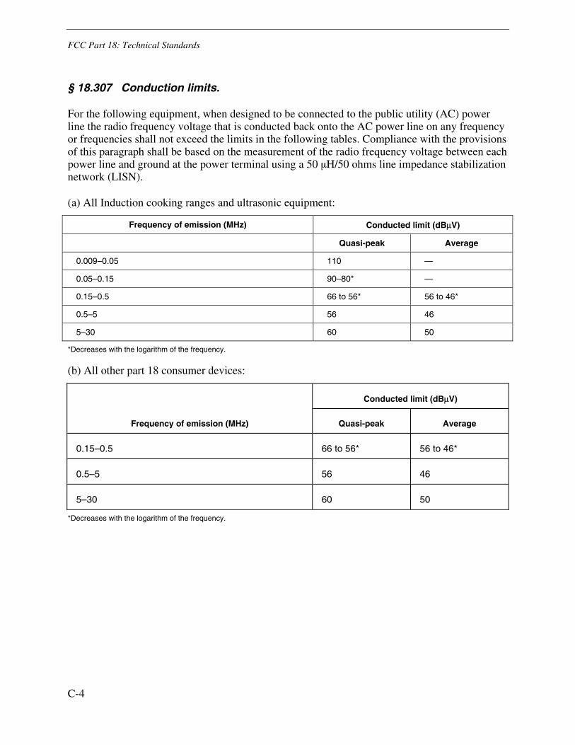
FCC Part 18: Technical Standards
C-4
§ 18.307 Conduction limits.
For the following equipment, when designed to be connected to the public utility (AC) power line the radio frequency voltage that is conducted back onto the AC power line on any frequency or frequencies shall not exceed the limits in the following tables. Compliance with the provisions of this paragraph shall be based on the measurement of the radio frequency voltage between each power line and ground at the power terminal using a 50 µH/50 ohms line impedance stabilization network (LISN).
(a) All Induction cooking ranges and ultrasonic equipment:
Frequency of emission (MHz) Conducted limit (dBμV)
Quasi-peak Average
0.009–0.05 110 —
0.05–0.15 90–80* —
0.15–0.5 66 to 56* 56 to 46*
0.5–5 56 46
5–30 60 50
*Decreases with the logarithm of the frequency.
(b) All other part 18 consumer devices:
Frequency of emission (MHz)
Conducted limit (dBμV)
Quasi-peak Average
0.15–0.5 66 to 56* 56 to 46*
0.5–5 56 46
5–30 60 50
*Decreases with the logarithm of the frequency.

FCC Part 18: Technical Standards
C-5
(c) RF lighting devices:
Frequency (MHz) Maximum RF line voltage measured with a
50 uH/50 ohm LISN (uV)
Non-consumer equipment:
0.45 to 1.6 1,000
1.6 to 30 3,000
Consumer equipment:
0.45 to 2.51 250
2.51 to 3.0 3,000
3.0 to 30 250
(d) If testing with a quasi-peak detector demonstrates that the equipment complies with the average limits specified in the appropriate table in this section, additional testing to demonstrate compliance using an average detector is not required.
(e) These conduction limits shall apply only outside of the frequency bands specified in §18.301.
(f) For ultrasonic equipment, compliance with the conducted limits shall preclude the need to show compliance with the field strength limits below 30 MHz unless requested by the Commission.
(g) The tighter limits shall apply at the boundary between two frequency ranges.
[50 FR 36067, Sept. 5, 1985, as amended at 52 FR 43198, Nov. 10, 1987; 64 FR 37419, July 12, 1999; 67 FR 45671, July 10, 2002]
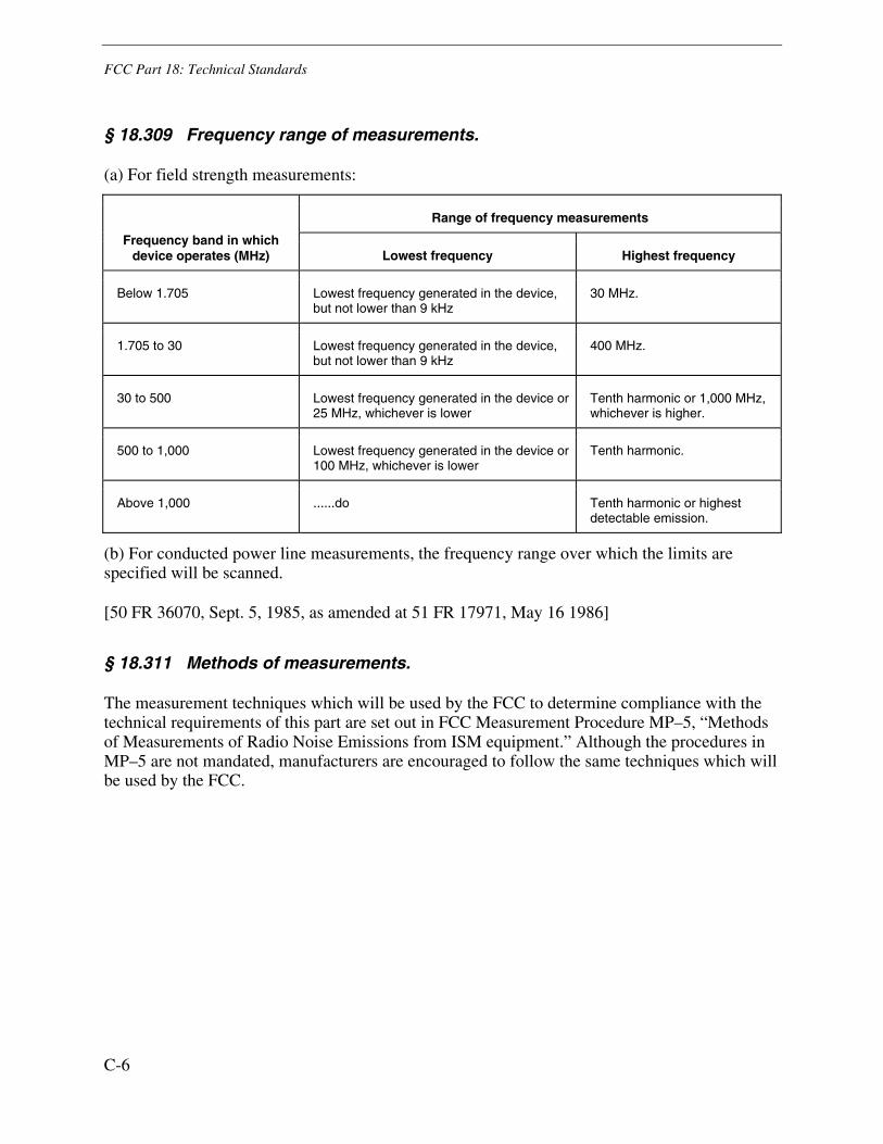
FCC Part 18: Technical Standards
C-6
§ 18.309 Frequency range of measurements.
(a) For field strength measurements:
Frequency band in which device operates (MHz)
Range of frequency measurements
Lowest frequency Highest frequency
Below 1.705 Lowest frequency generated in the device, but not lower than 9 kHz
30 MHz.
1.705 to 30 Lowest frequency generated in the device, but not lower than 9 kHz
400 MHz.
30 to 500 Lowest frequency generated in the device or 25 MHz, whichever is lower
Tenth harmonic or 1,000 MHz, whichever is higher.
500 to 1,000 Lowest frequency generated in the device or 100 MHz, whichever is lower
Tenth harmonic.
Above 1,000 ......do Tenth harmonic or highest detectable emission.
(b) For conducted power line measurements, the frequency range over which the limits are specified will be scanned.
[50 FR 36070, Sept. 5, 1985, as amended at 51 FR 17971, May 16 1986]
§ 18.311 Methods of measurements.
The measurement techniques which will be used by the FCC to determine compliance with the technical requirements of this part are set out in FCC Measurement Procedure MP–5, “Methods of Measurements of Radio Noise Emissions from ISM equipment.” Although the procedures in MP–5 are not mandated, manufacturers are encouraged to follow the same techniques which will be used by the FCC.


Electric Power Research Institute3420 Hillview Avenue, Palo Alto, California 94304-1338 • PO Box 10412, Palo Alto, California 94303-0813 USA
800.313.3774 • 650.855.2121 • [email protected] • www.epri.com
The Electric Power Research Institute Inc., (EPRI, www.epri.com)
conducts research and development relating to the generation, delivery
and use of electricity for the benefit of the public. An independent,
nonprofit organization, EPRI brings together its scientists and engineers
as well as experts from academia and industry to help address challenges
in electricity, including reliability, efficiency, health, safety and the
environment. EPRI also provides technology, policy and economic
analyses to drive long-range research and development planning, and
supports research in emerging technologies. EPRI’s members represent
more than 90 percent of the electricity generated and delivered in the
United States, and international participation extends to 40 countries.
EPRI’s principal offices and laboratories are located in Palo Alto, Calif.;
Charlotte, N.C.; Knoxville, Tenn.; and Lenox, Mass.
Together...Shaping the Future of Electricity
© 2009 Electric Power Research Institute (EPRI), Inc. All rights reserved. Electric Power Research Institute, EPRI, and TOGETHER...SHAPING THE FUTURE OF ELECTRICITY are registered service marks of the Electric Power Research Institute, Inc.
Export Control RestrictionsAccess to and use of EPRI Intellectual Property is granted with the spe-
cifi c understanding and requirement that responsibility for ensuring full
compliance with all applicable U.S. and foreign export laws and regu-
lations is being undertaken by you and your company. This includes
an obligation to ensure that any individual receiving access hereunder
who is not a U.S. citizen or permanent U.S. resident is permitted access
under applicable U.S. and foreign export laws and regulations. In the
event you are uncertain whether you or your company may lawfully
obtain access to this EPRI Intellectual Property, you acknowledge that it
is your obligation to consult with your company’s legal counsel to deter-
mine whether this access is lawful. Although EPRI may make available
on a case-by-case basis an informal assessment of the applicable U.S.
export classifi cation for specifi c EPRI Intellectual Property, you and your
company acknowledge that this assessment is solely for informational
purposes and not for reliance purposes. You and your company ac-
knowledge that it is still the obligation of you and your company to make
your own assessment of the applicable U.S. export classifi cation and
ensure compliance accordingly. You and your company understand and
acknowledge your obligations to make a prompt report to EPRI and the
appropriate authorities regarding any access to or use of EPRI Intellec-
tual Property hereunder that may be in violation of applicable U.S. or
foreign export laws or regulations.
Program:
Technology Innovation
1020562