programmable battery charger.doc
TRANSCRIPT
ABSTRACT
This project provides a careful treatment on construction of intelligent battery
charger which the principal tasks undertaken are the performance of a control
program which involves sensing and monitoring of voltage. An intelligent battery
charger may monitor the battery’s voltage, temperature and/or time under charge to
determine the optimum charge current at that instant.
In the first and second chapters, the introduction and the deep concept of intelligent
battery charger are explicitly explained. The third and fourth chapters show cased
the component descriptions used in this project and the working principal
operation. Finally, in the chapter five, a conclusion was drawn and
recommendations made for real and extensive wide usage.
1
TABLE OF CONTENTS
CONTENTS PAGE
TITLE PAGE i
APPROVAL PAGE ii
DEDICATION iii
ACKNOWLEDGEMENT iv
ABSTRACT v
TABLE OF CONTENTS vi
CHAPTER ONE
INTRODUCTION 1
1.1 WHAT IS A BATTERY CHARGER
1.2 WHAT IS AN INTELLIGENT BATTERY CHARGER
1.3 OTHER TYPE OF BATTERY CHARGERS 2- 3
CHAPTER TWO
LITERATURE REVIEW 4-5
CHAPTER THREE
COMPONENT DESCRIPTION 6-9
3.1 ATMEL 8952 MICROCONTROLLER
3.2 MICROCONTROLLER SECTION 10-14
3.3 RESISTOR 14-15
3.4 TRANSISTOR 16
3.5 SEVEN SEGMENT DISPLAY 17-18
2
3.6 CAPACITORS 19-20
3.7 TRANSFORMER 21
3.8 DIODES 22
CHAPTER FOUR
PRINCIPLE OF OPERATION 23
4.1 INTELLIGENT BATTERY CHARGER 23
4.2 VOLTAGE COMPARATOR 24-25
4.3 MICROCONTROLLER SECTION 26
4.4 DISPLAY SECTION 26-27
THE CIRCUIT DIAGRAM 28
COMPONENT LIST 29
CONTROLER PROGRAM 30
CHAPTER FIVE
5.1 CONCLUSION 31
5.2 RECOMMENDATION 32
REFERENCES 33
3
CHAPTER ONE
INTRODUCTION
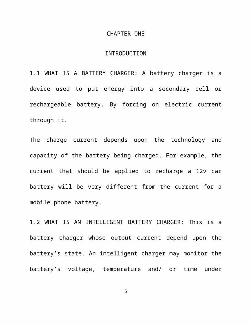
1.1 WHAT IS A BATTERY CHARGER: A battery charger is a device used to
put energy into a secondary cell or rechargeable battery. By forcing on electric
current through it.
The charge current depends upon the technology and capacity of the battery being
charged. For example, the current that should be applied to recharge a 12v car
battery will be very different from the current for a mobile phone battery.
1.2 WHAT IS AN INTELLIGENT BATTERY CHARGER: This is a battery
charger whose output current depend upon the battery’s state. An intelligent
charger may monitor the battery’s voltage, temperature and/ or time under charge
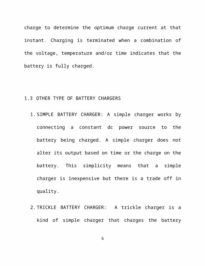
to determine the optimum charge current at that instant. Charging is terminated
when a combination of the voltage, temperature and/or time indicates that the
battery is fully charged.
1.3 OTHER TYPE OF BATTERY CHARGERS
4
1. SIMPLE BATTERY CHARGER: A simple charger works by connecting a
constant dc power source to the battery being charged. A simple charger
does not alter its output based on time or the charge on the battery. This
simplicity means that a simple charger is inexpensive but there is a trade off
in quality.
2. TRICKLE BATTERY CHARGER: A trickle charger is a kind of simple
charger that charges the battery slowly, at the self-discharge rate. A trickle
charger is the slowest kind of battery charger.
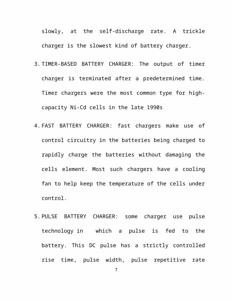
3. TIMER-BASED BATTERY CHARGER: The output of timer charger is
terminated after a predetermined time. Timer chargers were the most
common type for high-capacity Ni-Cd cells in the late 1990s
4. FAST BATTERY CHARGER: fast chargers make use of control circuitry
in the batteries being charged to rapidly charge the batteries without
damaging the cells element. Most such chargers have a cooling fan to help
keep the temperature of the cells under control.
5. PULSE BATTERY CHARGER: some charger use pulse technology in
which a pulse is fed to the battery. This DC pulse has a strictly
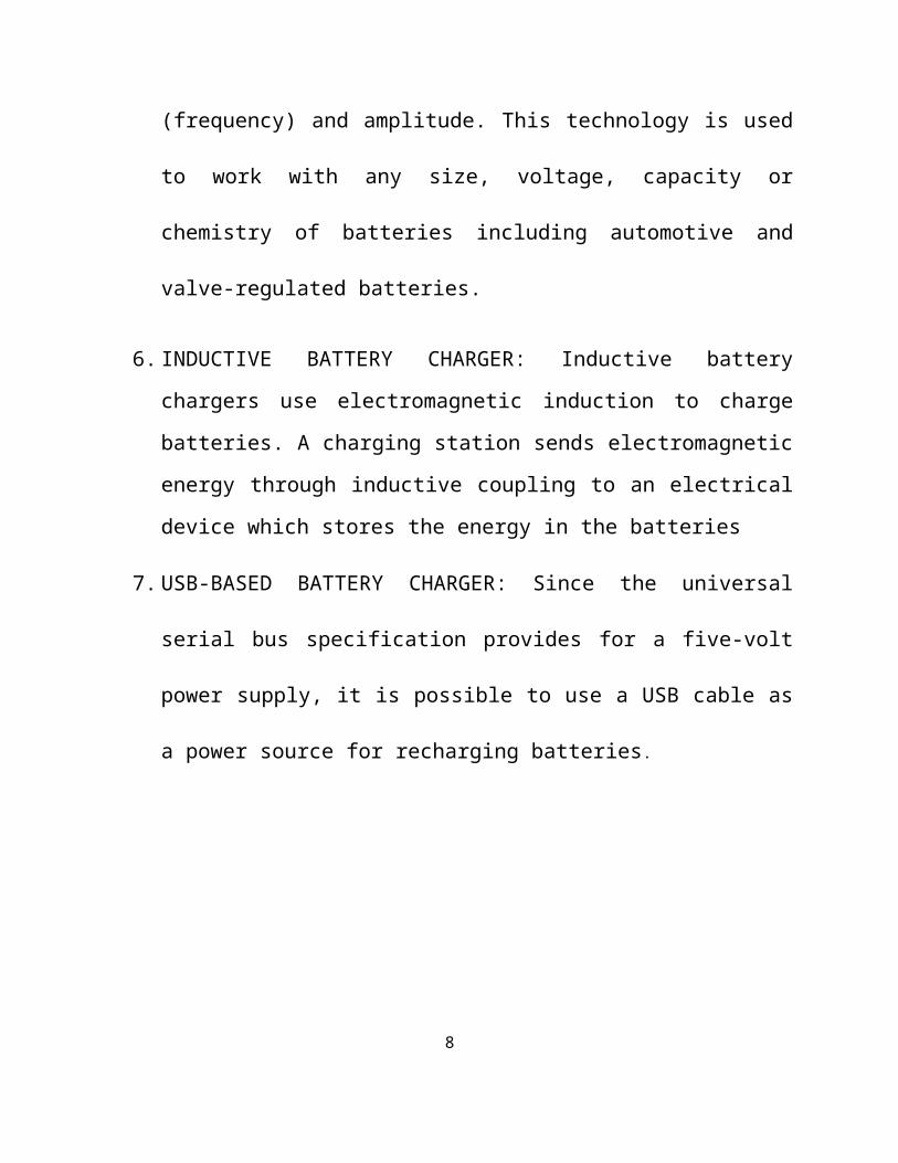
controlled rise time, pulse width, pulse repetitive rate (frequency) and
5
amplitude. This technology is used to work with any size, voltage, capacity
or chemistry of batteries including automotive and valve-regulated batteries.
6. INDUCTIVE BATTERY CHARGER: Inductive battery chargers use
electromagnetic induction to charge batteries. A charging station sends
electromagnetic energy through inductive coupling to an electrical device
which stores the energy in the batteries
7. USB-BASED BATTERY CHARGER: Since the universal serial bus
specification provides for a five-volt power supply, it is possible to use a
USB cable as a power source for recharging batteries.
CHAPTER TWO
LITERATURE REVIEW6
One of the most important discovering in the last 400 years has been electricity.
Electricity consists of charge carried by electrons, protons and other particles.
Electric charge comes in two forms; positive and negative.
In 1800, Alessandro Volta (1745-1827) invented the first modern electric
battery. Volta demonstrated that an electrical current is generated when metal
and chemicals come into contact. Other discoveries on battery were made, but
were all primary cells, meaning that they could not be recharged.
In 1859, French physicist Gaston plante invented the first rechargeable
battery. This secondary battery was based on lead acid, chemistry that is still
used today. Michael faraday in 1831, enunciated the principle of
electromagnetic induction. Thomas Edwin in 1883, discovered the thermionic
valve while developing the light bulb.
J.A. Fleming in 1904, took over from where Edison stopped. He found out that
when he passed alternating current through the valve (diode), it was converted
to pulsating direct current.
The combination of Faraday’s invention in 1831 and the findings of Fleming in
1904 gave rise to do D.c voltage exciter (charger). it is important to note that a
battery charging circuit has the same circuit as a D.C power supply.
7
According to “The Art of Electronics” by Paul Horowitz and “Electrical
Technology” by B.L. Theraja and A.K Theraja, These books recommend the
full wave bridge circuit as the best. The rectifier comes as a pre-packaged
module, which make connection and circuit design easy and simple.
CHAPTER THREE
COMPONENT DESCRIPTION
3.1 ATMEL 8952 MICROCONTROLLER
What are micro controllers and what are they used for?
As all other good things, this powerful component is basically very simple and is
obtained by uniting tested and high- quality "ingredients" (components) as per
following receipt:
1. The simplest computer’s processor is used as a "brain" of the future system.
8
2. Depending on the taste of the producer, it is added: a bit of memory, a few
A/D converters, timers, input/output lines etc.
3. It is all placed in one of standard packages.
4. Simple software that will be able to control it all and about which everyone
will be able to learn has been developed.
Three things have had a crucial impact on such a success of the micro controllers:
Powerful and intelligently chosen electronics embedded in the
microcontrollers can via input/output devices (switches, push buttons,
sensors, LCD displays, relays…) control various processes and devices such
as: industrial automatics, electric current, temperature, engine performance
etc.
A very low price enables them to be embedded in such devices in which,
until recent time it was not worth embedding anything. Thanks to that, the
world is overwhelmed today with cheap automatic devices and various
“intelligent” appliances.
Prior knowledge is hardly needed for programming. It is sufficient to have
any kind of PC (software in use is not demanding at all and it is easy to learn
9
to work on it) and one simple device (programmer) used for “transferring”
completed programs into the microcontroller.
Therefore, if you are infected with a virus called electronics, there is nothing left
for you to do but to learn how to control its power and how to direct it at the right
course.
How does microcontroller operate?
Even though there is a great number of various microcontrollers and even greater
number of programs designed for the microcontrollers’ use only, all of them have
many things in common. That means that if you learn to handle one of them you
will be able to handle them all. A typical scenario on whose basis it all functions is
as follows:
1. Power supply is turned off and everything is so still…chip is programmed,
everything is in place, nothing indicates what is to come…
2. Power supply connectors are connected to the power supply source and
everything starts to happen at high speed! The control logic registers what is
going on first. It enables only quartz oscillator to operate. While the first
preparations are in progress and parasite capacities are being charged, the
first milliseconds go by.
10
3. Power supply connectors are connected to the power supply source and
everything starts to happen at high speed! The control logic registers what is
going on first. It enables only quartz oscillator to work. While the first
preparations are in progress and parasite capacities are being charged, the
first milliseconds go by.
4. Voltage level has reached its full value and frequency of oscillator has
become stable. The bits are being written to the SFRs, showing the state of
all peripherals and all pins are configured as outputs. Everything occurs in
harmony to the pulses’ rhythm and the overall electronics starts operating.
Since this moment the time is measured in micro and nanoseconds.
5. Program Counter is reset to zero address of the program memory. Instruction
from that address is sent to instruction decoder where its meaning is
recognized and it is executed with immediate effect.
6. The value of the Program Counter is being incremented by 1 and the whole
process is being repeated...several million times per second.
11
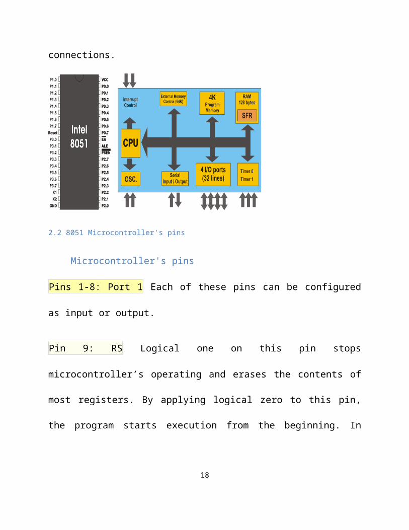
3.2 Microcontroller section: the chief component in this section is the Intel 8051
chip. It has 40 pins in all with 32 of them dedicated for input and output
connections.
2.2 8051 Microcontroller's pins
Microcontroller's pins
Pins 1-8: Port 1 Each of these pins can be configured as input or output.
Pin 9: RS Logical one on this pin stops microcontroller’s operating and erases the
contents of most registers. By applying logical zero to this pin, the program starts
execution from the beginning. In other words, a positive voltage pulse on this pin
resets the microcontroller.
Pins10-17: Port 3 Similar to port 1, each of these pins can serve as universal input
or output. Besides, all of them have alternative functions:
12
Pin 10: RXD Serial asynchronous communication input or Serial synchronous
communication output.
Pin 11: TXD Serial asynchronous communication output or Serial synchronous
communication clock output.
Pin 12: INT0 Interrupt 0 input
Pin 13: INT1 Interrupt 1 input
Pin 14: T0 Counter 0 clock input
Pin 15: T1 Counter 1 clock input
Pin 16: WR Signal for writing to external (additional) RAM
Pin 17: RD Signal for reading from external RAM
Pin 18, 19: X2, X1 Internal oscillator input and output. A quartz crystal which
determines operating frequency is usually connected to these pins. Instead of
quartz crystal, the miniature ceramics resonators can be also used for frequency
stabilization. Later versions of the microcontrollers operate at a frequency of 0 Hz
up to over 50 Hz.
13
Pin 20: GND Ground
Pin 21-28: Port 2 If there is no intention to use external memory then these port
pins are configured as universal inputs/outputs. In case external memory is used
then the higher address byte, i.e. addresses A8-A15 will appear on this port. It is
important to know that even memory with capacity of 64Kb is not used ( i.e. note
all bits on port are used for memory addressing) the rest of bits are not available as
inputs or outputs.
Pin 29: PSEN If external ROM is used for storing program then it has a logic-0
value every time the microcontroller reads a byte from memory.
Pin 30: ALE Prior to each reading from external memory, the microcontroller will
set the lower address byte (A0-A7) on P0 and immediately after that activates the
output ALE. Upon receiving signal from the ALE pin, the external register
(74HCT373 or 74HCT375 circuit is usually embedded) memorizes the state of P0
and uses it as an address for memory chip. In the second part of the
microcontroller’s machine cycle, a signal on this pin stops being emitted and P0 is
used now for data transmission (Data Bus). In this way, by means of only one
additional (and cheap) integrated circuit, data multiplexing from the port is
performed. This port at the same time used for data and address transmission.
14
Pin 31: EA By applying logic zero to this pin, P2 and P3 are used for data and
address transmission with no regard to whether there is internal memory or not.
That means that even there is a program written to the microcontroller, it will not
be executed, the program written to external ROM will be used instead. Otherwise,
by applying logic one to the EA pin, the microcontroller will use both memories,
first internal and afterwards external (if it exists), up to end of address space.
Pin 32-39: Port 0 Similar to port 2, if external memory is not used, these pins can
be used as universal inputs or outputs. Otherwise, P0 is configured as address
output (A0-A7) when the ALE pin is at high level (1) and as data output (Data
Bus), when logic zero (0) is applied to the ALE pin.
Pin 40: VCC Power supply +5V
3.3 RESISTOR
Resistors are one of the most common components in an electronic circuit. The
basic operation is to limit the flow of current in the circuit. Many resistor values
were used in this project. Some of them include 1KΩ, 10kΩ, 100Ω and the 330Ω
used to limit the current that flows to the seven segment display.
How to read Resistor Color Codes
15
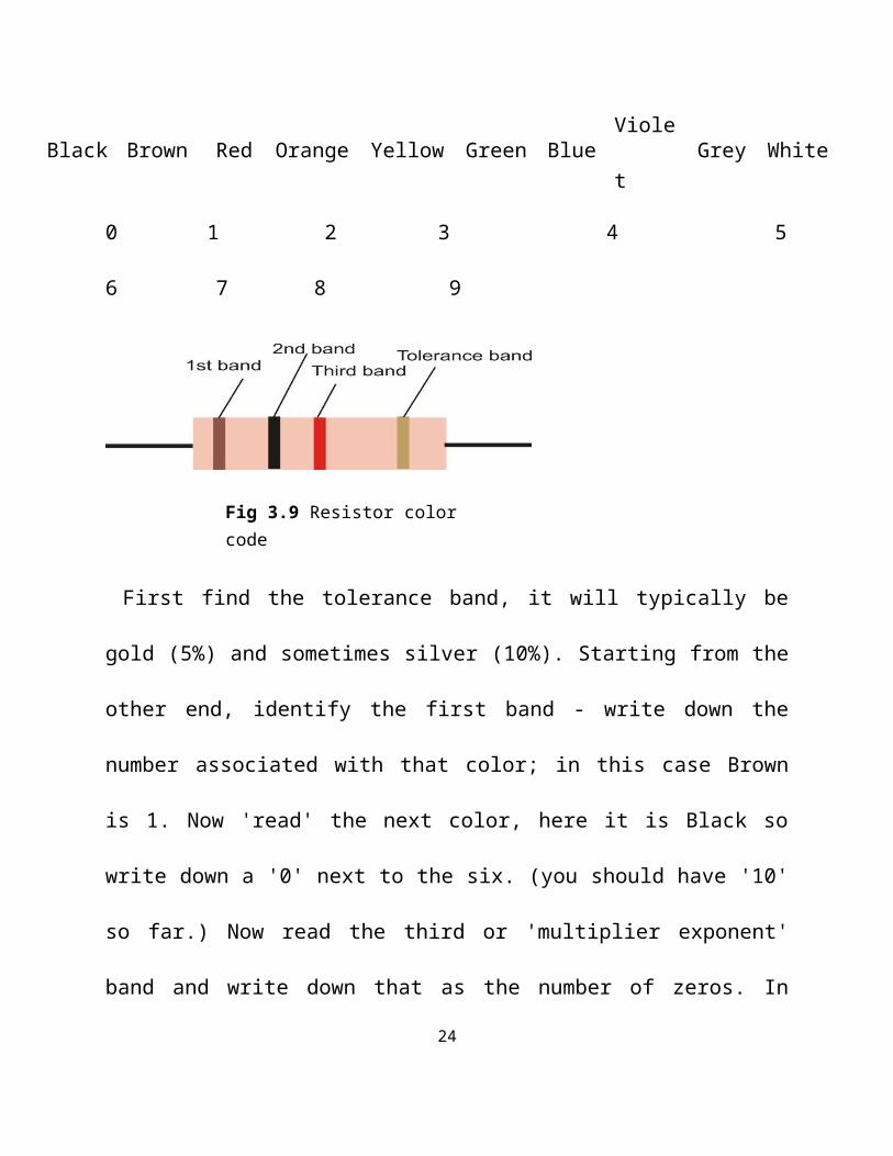
Black Brown Red Orange Yellow Green Blue Violet Grey White
0 1 2 3 4 5 6 7 8 9
First find the tolerance band, it will typically be gold (5%) and sometimes silver
(10%). Starting from the other end, identify the first band - write down the number
associated with that color; in this case Brown is 1. Now 'read' the next color, here it
is Black so write down a '0' next to the six. (you should have '10' so far.) Now read
the third or 'multiplier exponent' band and write down that as the number of zeros.
In this example it is two so we get '1000'. If the 'multiplier exponent' band is Black
(for zero) don't write any zeros down.
If the 'multiplier exponent' band is Gold move the decimal point one to the left. If
the 'multiplier exponent' band is Silver move the decimal point two places to the
left. If the resistor has one more band past the tolerance band it is a quality band.
3.4 TRANSISTORS: Transistors are made from semiconductors. These are
materials, such as silicon or germanium, that are “doped” (have minute amounts of 16
Fig 3.9 Resistor color code
foreign elements added) so that either an abundance or a lack of free electrons
exists. In the former case, the semiconductor is called n-type, and in the latter case,
p-type. By combining n-type and p-type materials, a diode can be produced. When
this diode is connected to a battery so that the p-type material is positive and the n-
type negative, electrons are repelled from the negative battery terminal and pass
unimpeded to the p-region, which lacks electrons. With battery reversed, the
electrons arriving in the p-material can pass only with difficulty to the n-material,
which is already filled with free electrons, and the current is almost zero.
3.5 SEVEN SEGMENT DISPLAY
One common requirement for many different digital devices is a visual numeric
display. Individual LEDs can of course display the binary states of a set of latches
or flip-flops. However, we're far more used to thinking and dealing with decimal
numbers. To this end, we want a display of some kind that can clearly represent
decimal numbers without any requirement of translating binary to decimal or any
other format
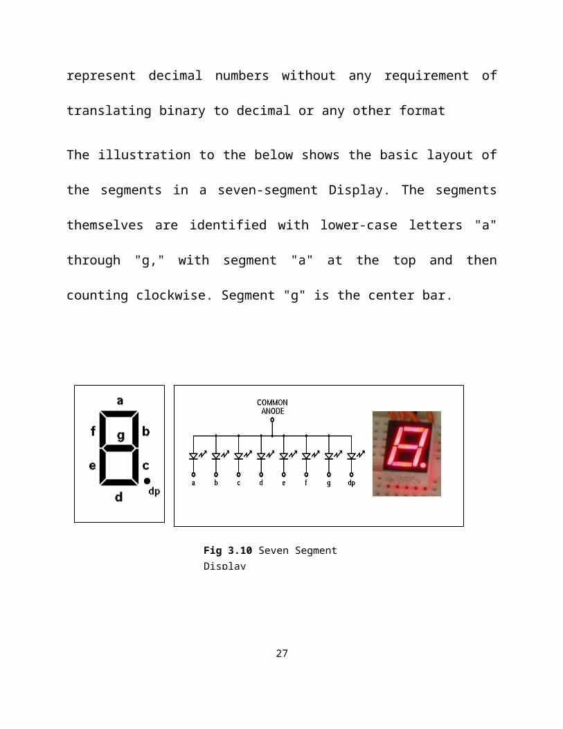
The illustration to the below shows the basic layout of the segments in a seven-
segment Display. The segments themselves are identified with lower-case letters
17
"a" through "g," with segment "a" at the top and then counting clockwise. Segment
"g" is the center bar.
Most seven-segment digits also include a decimal point ("dp"), and some also
include an extra triangle to turn the decimal point into a comma. This improves
readability of large numbers on a calculator, for example. The decimal point is
shown here on the right, but some display units put it on the left, or have a decimal
point on each side.
In addition, most displays are actually slanted a bit, making them look as if they
were in italics. This arrangement allows us to turn one digit upside down and place
it next to another, so that the two decimal points look like a colon between the two
digits. The technique is commonly used in LED clock displays.
18
Fig 3.10 Seven Segment Display
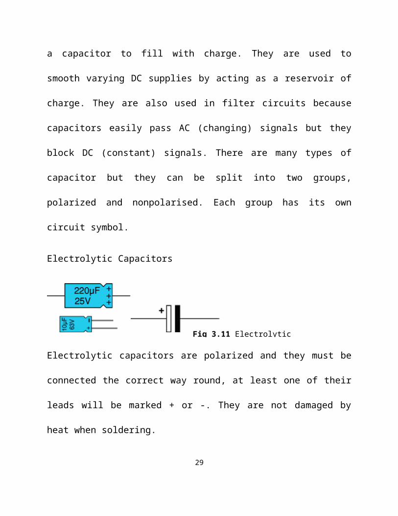
3.6 CAPACITOR
Capacitors store electric charge. They are used with resistors in timing circuits
because it takes time for a capacitor to fill with charge. They are used to smooth
varying DC supplies by acting as a reservoir of charge. They are also used in filter
circuits because capacitors easily pass AC (changing) signals but they block DC
(constant) signals. There are many types of capacitor but they can be split into two
groups, polarized and nonpolarised. Each group has its own circuit symbol.
Electrolytic Capacitors
Electrolytic capacitors are polarized and they must be connected the correct way
round, at least one of their leads will be marked + or -. They are not damaged by
heat when soldering.
There are two designs of electrolytic capacitors; axial where the leads are attached
to each end (220µF in picture) and radial where both leads are at the same end
(10µF in picture). Radial capacitors tend to be a little smaller and they stand
upright on the circuit board.
19
Fig 3.11 Electrolytic
It is easy to find the value of electrolytic capacitors because they are clearly printed
with their capacitance and voltage rating. The voltage rating can be quite low (6V
for example) and it should always be checked when selecting an electrolytic
capacitor.
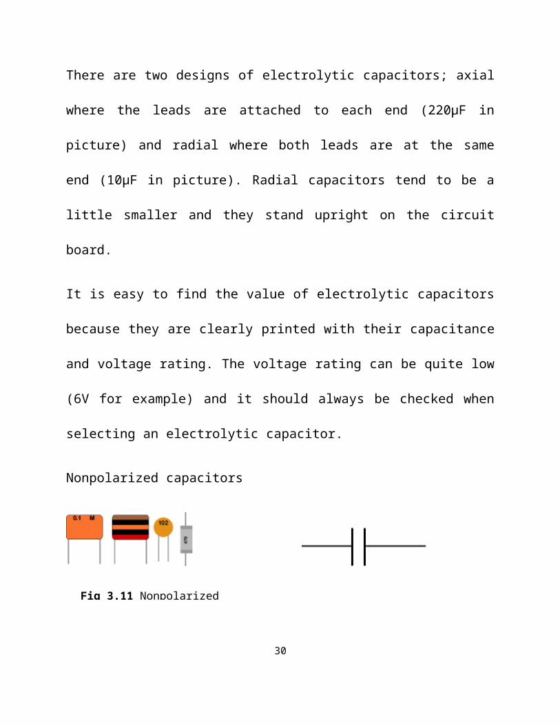
Nonpolarized capacitors
Small value capacitors are nonpolarized and may be connected either way round.
They are not damaged by heat when soldering, except for one unusual type
(polystyrene). They have high voltage ratings of at least 50V, usually 250V or so.
It can be difficult to find the values of these small capacitors because there are
many types of them and several different labeling systems!
Many small value capacitors have their value printed but without a multiplier, so
you need to use experience to work out what the multiplier should be. For example
0.1 means 0.1µF
20
Fig 3.11 Nonpolarized
3.7 TRANSFORMER
A transformer is a device used for stepping up or down of an alternating voltage.
For the purpose of this project, we used a step-down transformer. This transformer
consists of a primary winding and secondary winding.
An A.C applied at the terminals of the primary winding sets up an alternating
magnetic flux in the core. This induces an e.m.f in the secondary winding. The
induced e.m.f at the secondary coil depends on the number of turns at the
secondary coil.
Secondary EMF number of turns in the secondary coil
Primary EMF number of turns in the primary coil
3.8 DIODES
A diode is a very important two terminal passive and non- linear device used in
electrical and electronics application, but in this case the diodes were connected to
form a bridge rectifier circuit.
The rectifier circuit changes alternating current to direct current, which is one of
the simplest and most important applications of diodes.
The ac voltage, which serves as an input to the diodes, is usually provided by a
transformer powered from the ac power source. If we think of the diodes as a one-
21
=
way conductor, we would not have any problem understanding how the circuit
works.
For the purpose of this project, the rectifier circuit used is a fall-wave bridge
rectifier circuit because all of the input wave form is used.
CHAPTER FOUR
PRINCIPLE OF OPERATION
4.1 (Intelligent Battery charger)
The circuit functions to charge 12v battery, sense and display the voltage
level of the connected battery on a display device. The sensing is done with
a circuit made up of the ATMEL 8952 microcontroller, Lm358 comparator
and other external components. The microcontroller displays its derived
information on a seven segment display module connected to its output port
terminals.
The entire circuit is divided into four major sections (sub circuits) which are:
1. Battery charger section
2. Voltage comparator section
3. Microcontroller section
22
4. Display section
The transformer (T1) above is a step down type, which steps down the incoming
220v to 15v. The output of the transformer connects to a bridge rectifier network
made up of four diodes connected as in the circuit above. The diode network
hereby rectifiers the incoming 15v ac waveform to a 15v dc which connects to the
battery through a capacitor filter. The capacitor here functions as a filter to remove
ripples present in the dc waveform.
4.2 VOLTAGE COMPARATOR: The major component in this section is the
LM358 operational amplifier (OP-AMP) IC functioning as a voltage comparator.
23
BATTERY CHARGER
12V
DCD2
D4
D1
D3
T1220V AC
The 3.3v zener diode seen in the diagram above sets a reference voltage at the Pin
1 terminal of the Lm358. the 20k variable resistor is used to adjust the threshold
voltage to be compared by the comparator. For instance, taking 12v as a threshold,
it means that an 11.9v battery will be connected to the terminal A and the resistor
varied until there is no output at B. Again, a 12.1v battery will also be connected
and the resistor varied until there is a voltage output at B. Therefore, the circuit
will give no output when terminal A is connected to a battery whose voltage is less
than 12v and will give an output when terminal A is connected to a battery whose
voltage is greater than 12v.
24
Vcc Vcc
53
4
LM358-
+2
1
3.3V
20K
A
B
4.3 MICROCONTROLLER SECTION: This section is made up of the
ATMEL 8952 microcontroller chip which gets logical information from the
voltage comparator, processes this information based on a written and stored
program, then gives an output information across its output port terminals. The
above mentioned program was written in assembly language, compiled and stored
in the microcontroller memory. A logic O information from the comparator
triggers the pin 16 of the micro controller so that a seven bit binary information is
received at its output port terminals. This seven bit information is different from
that received when a logic 1 comes from the comparator to trigger the controller.
4.4 DISPLAY SECTION: The seven bit information at the output port of the
microcontroller is amplified by a lamp drive IC (ULN 2003). The output of the
amplifier is connected to the seven terminals of a seven-segment display. The
binary information received at the output port of the controller when triggered with
logic O displays LO on the seven- segment display. On the other hand, when logic
1 triggers the controller, the information gotten at the output displays FL on the
seven-segment display.
25
26
ATMEL
8951
1
2
3
4
5
6
7
8
9
10
11
12
40
39
38
37
36
35
34
33
32
31
30
29
ULN
200
3
Vcc
a
b
c
d
Vcc
470
470
Q1
Q2
4.0mHz
Vcc
10k
3.3vTo positive terminal of charger
20k
-
+
Lm
358
To 220 ac power supply
To terminal
s of battery
+
-
30v
2200uf
THE CIRCUIT DIAGRAM
Component list
Quantity Part no Description
1 220v/15v Transformer
4 IN400B Diodes
2 C1815 Transistor
1 30v/2200uf Capacitor
2 470K Resistor
1 10k Resistor
1 20k Resistor
1 3.3v Zener diode
1 Lm 358 Comparator
1 Atmel 8951 Micro controller
1 ULN 2003 Integrated circuit (IC)
CHAPTER FIVE
27
5.1 CONCLUSION
The importance of an intelligent battery charger cannot be over-emphasized
since there is a high level of inconsistency in other types of battery charger. This is
seen in the over charging of battery which is not a good and healthy practices.
This necessitates the need to use an intelligent battery charger as it disengages the
battery from the charging circuit once the battery is fully charged.
5.2 RECOMMENDATIONS
28
Due to the economic and technical advantage of a rechargeable battery
system over dry cells, we recommend that it should be the pre dominant battery
in use for all system.
We recommend that full wave bridge rectifier be used since it requires a
smaller transformer without centre tapping. Also the full wave bridge rectifier
circuit has less peak reverse voltage (PRV) and it is suitable for high voltage
application.
Finally, intelligent charger fast charges a battery up to about 83% of it
maximum capacity in less than an hour, then other types of charger. Hence we
recommend its wide usage.
REFERENCES
1. Amadi J.N (2001) “Electronic design and drafting for project
building”, Wolix Vintage, Nigeria.
29
2. Hughes, Edward. (2005) “Electrical and Electronic technology” 8th
Edition, saurahh printers, India.
3. Theraja and Theraja B.L (2002) “Electrical and Electronics
technology”, S. Schand and company, India.
4. Robert J. Kaka lee It Al, 1979, New technology for Battery charging
Rectifiers, Bell laboratories Record.
5. John Williams. E, Frederick .E, and Clark Metcalfe H. (1976)”
Modern physics”, Holt, Rinehart and Winston,
New York
6. www.en.wikipedia . Org/wiki/counter
7. www. Google. Com.
30