programmable controller fp sigma
TRANSCRIPT
8/21/2019 Programmable Controller FP Sigma
http://slidepdf.com/reader/full/programmable-controller-fp-sigma 1/318
PROGRAMMABLE CONTROLLER
FPÉ
User's Manual
This manual was created using Adobe Acrobat. Adobe, the Adobe logo, and Acrobat are trademarksof Adobe Systems Incorporated.
FPÉUser's Manual
ARCT1F333E-3 ’04.05
http://www.naisplc.com/

8/21/2019 Programmable Controller FP Sigma
http://slidepdf.com/reader/full/programmable-controller-fp-sigma 2/318
8/21/2019 Programmable Controller FP Sigma
http://slidepdf.com/reader/full/programmable-controller-fp-sigma 3/318
Table of Contents
Before You Start
1 Functions and Restrictions of the Unit ---------------------------------------1-1
1.1 Features and Functions of the Unit -----------------------------------------------------------------1-2
1.2 Unit Types ---------------------------------------------------------------------------------------------------1-6
1.2.1 FPΣ Control Unit -----------------------------------------------1-6
1.2.2 FPΣ Expansion Unit -----------------------------------------------1-6
1.2.3 FP0 Expansion Unit -----------------------------------------------1-7
1.2.4 Communication Cassette -----------------------------------------------1-7
1.3 Restrictions on Unit Combinations -----------------------------------------------1-8
1.3.1 Restrictions on FP0 Expansion Unit -----------------------------------------------1-8
1.4 Programming Tools -----------------------------------------------1-10
1.4.1 Tools Needed for Programming -----------------------------------------------1-10
1.4.2 Software Environment and Suitable Cable -----------------------------------------------1-10
2 Specifications and Functions of the Unit--------------------------------------2-1
2.1 Parts and Functions -----------------------------------------------2-2
2.2 Input and Output Specifications -----------------------------------------------2-6
2.2.1 Input Specif ications -----------------------------------------------2-6
2.2.2 Output Specifications -----------------------------------------------2-8
2.3 Terminal Layout Diagram -----------------------------------------------2-11
8/21/2019 Programmable Controller FP Sigma
http://slidepdf.com/reader/full/programmable-controller-fp-sigma 4/318
2.3.1 Control Unit (for C32) -----------------------------------------------2-11
2.3.2 Control Unit (for C28) -----------------------------------------------2-122.3.3 Control Unit (for C24) -----------------------------------------------2-12
2.4 Analog Potentiometer -----------------------------------------------2-13
2.4.1 Overview of Analog Potentiometer -----------------------------------------------2-13
2.5 Thermister Input (Only for TM type) -----------------------------------------------2-14
2.5.1 Overview of Thermister Input -----------------------------------------------2-14
2.5.2 Loading of Thermister Temperature Data -----------------------------------------------2-16
2.6 Calendar Timer -----------------------------------------------2-17
2.6.1 Area for Clock/Calendar Function -----------------------------------------------2-17
2.6.2 Setting of Clock/Calendar Function -----------------------------------------------2-17
2.6.3 Example Showing the Clock/Calendar being Used------------------------------------------2-18
2.6.4 30-second Compensation Sample Program ---------------------------------------------2-19
3 Expansion -----------------------------------------------3-1
3.1 Type of Expansion Unit -----------------------------------------------3-2
3.2 Expansion Method of Units for FP0 and FPΣ -----------------------------------------------3-3
3.3 Expansion Method of FPΣ Expansion Unit -----------------------------------------------3-4
3.4 Specifications of FPΣ Expansion Unit -----------------------------------------------3-5
3.4.1 FPΣ Expansion Unit -----------------------------------------------3-5
3.4.2 FPΣ Expansion Data Memory Unit -----------------------------------------------3-9
3.4.3 Other Expansion Units -----------------------------------------------3-12
4 I/O Allocation -----------------------------------------------4-1
I/O Allocation -----------------------------------------------4-2
8/21/2019 Programmable Controller FP Sigma
http://slidepdf.com/reader/full/programmable-controller-fp-sigma 5/318
4.2 Allocation of FPΣ Control Unit -----------------------------------------------4-3
4.3 Allocation of FPΣ Expansion Unit -----------------------------------------------4-4
4.3.1 I/O Numbers of FPΣ Expansion Unit -----------------------------------------------4-4
4.4 Allocation of FP0 Expansion Unit -----------------------------------------------4-5
4.4.1 I/O Numbers of FP0 Expansion Unit -----------------------------------------------4-5
5 Installation and Wiring -----------------------------------------------5-1
5.1 Installation -----------------------------------------------5-2
5.1.1 Installation Environment and Space -----------------------------------------------5-2
5.1.3 Installation Using the Optional Mounting Plate -----------------------------------------------5-5
5.2 Wiring of Power Supply -----------------------------------------------5-8
5.2.1 Wiring of Power Supply -----------------------------------------------5-8
5.2.2 Grounding -----------------------------------------------5-10
5.3 Wiring of Input and Output -----------------------------------------------5-11
5.3.1 Input Wiring -----------------------------------------------5-11
5.3.2 Output Wiring -----------------------------------------------5-13
5.3.3 Precautions Regarding Input and Output Wirings -------------------------------------------5-14
5.4 Wiring of MIL Connector Type -----------------------------------------------5-15
5.5 Wiring of Terminal Block Type -----------------------------------------------5-17
5.6 Safety Measures -----------------------------------------------5-19
5.6.1 Safety Measures -----------------------------------------------5-19
5.6.2 Momentary Power Failures -----------------------------------------------5-19
5.6.3 Protection of Power Supply and Output Sections---------------------------------------------5-20
5.7 Installation and Setting of Backup Battery -----------------------------------------------5-21
8/21/2019 Programmable Controller FP Sigma
http://slidepdf.com/reader/full/programmable-controller-fp-sigma 6/318
5.7.1 Installation of Backup Battery -----------------------------------------------5-21
5.7.2 System Register Setting -----------------------------------------------5-225.7.3 Time for Replacement of Backup Battery -----------------------------------------------5-22
5.7.4 Lifetime of Backup Battery -----------------------------------------------5-23
6 High-speed counter, Pulse Output and PWM Output functions--------6-1
6.1 Overview of Each Functions -----------------------------------------------6-2
6.1.1 Three Functions that Use Built-in High-speed Counter---------------------------------------6-2
6.1.2 Performance of Built-in High-speed Counter -----------------------------------------------6-3
6.2.1 Specifications -----------------------------------------------6-4
6.2.2 Functions Used and Restrictions -----------------------------------------------6-6
6.2.3 Booting Time -----------------------------------------------6-8
6.3 High-speed Counter Function -----------------------------------------------6-9
6.3.1 Overview of High-speed Counter Function -----------------------------------------------6-9
6.3.2 Input Modes and Count -----------------------------------------------6-9
6.3.3 Minimum Input Pulse Width -----------------------------------------------6-10
6.3.4 I/O Allocation -----------------------------------------------6-11
6.3.5 Instructions used with High-speed Counter Function -----------------------------------6-11
6.3.6 Sample program -----------------------------------------------6-14
6.4 Pulse Output Function -----------------------------------------------6-17
6.4.1 Overview of Pulse Output Function -----------------------------------------------6-17
6.4.2 Types of Pulse Output Method and Operation Modes--------------------------------------6-18
6.4.3 I/O Allocation -----------------------------------------------6-20
6.4.4 Pulse output control instructions (F0) (F1) -----------------------------------------------6-21
6.4.5 Positioning Control Instruction F171 - Trapezoidal Control (Common to Transistor type)
6-24
6.4.6 Positioning Control Instruction F171 – Home Return (Common to Transistor type)-6-29
6.4.7 Pulse Output Instruction F172 – JOG operation (Common to Transistor type)-------6-35
8/21/2019 Programmable Controller FP Sigma
http://slidepdf.com/reader/full/programmable-controller-fp-sigma 7/318
6.4.8 Positioning Control Instruction F174 – Data Table Contro. ---------------------------------6-39
6.4.9 Action of the Flag concerning Linear Interpolation and Circular Interpolation (C32T2 andC28P2 only) -----------------------------------------------6-41
6.4.10 Pulse Output Instruction F175 – Linear Interpolation (Only for C32T2 and C28P2)--6-47
6.4.11 Pulse Output Instruction F176 – Circular Interpolation (Only for C32T2 and C28P2)6-49
6.5 PWM Output Function -----------------------------------------------6-58
6.5.1 Overview -----------------------------------------------6-58
6.5.2 PWM Output Instruction F173 -----------------------------------------------6-58
7 Communication Cassette ------------------------------------------------7-1
7.1 Functions and Types -----------------------------------------------7-3
7.1.1 Functions of Communication Cassette -----------------------------------------------7-3
7.1.2 Types of Communication Cassette -----------------------------------------------7-6
7.1.3 Names and Principle Applications of the Ports -----------------------------------------------7-9
7.1.4 Setting of AFPG806 Switch -----------------------------------------------7-9
7.2 Communication Specifications -----------------------------------------------7-10
7.2.1 Precaution When Using RS485 Port -----------------------------------------------7-12
7.3 Installation and Wiring -----------------------------------------------7-14
7.3.1 Installation of Communication Cassette -----------------------------------------------7-14
7.3.2 Wiring -----------------------------------------------7-15
7.3.3 Cables -----------------------------------------------7-17
7.4 Communication Function 1: Computer Link -----------------------------------------------7-18
7.4.1 Computer Link -----------------------------------------------7-18
7.4.2 1:1 Communication (Computer link) -----------------------------------------------7-25
7.4.3 1:N Communication (Computer Link) -----------------------------------------------7-28
7.5 Communication Function: General-purpose Serial Communication----------------------7-33

8/21/2019 Programmable Controller FP Sigma
http://slidepdf.com/reader/full/programmable-controller-fp-sigma 8/318
7.5.1 General-purpose Serial Communication -----------------------------------------------7-33
7.5.2 Communication with External Devices -----------------------------------------------7-367.5.3 Connection with 1:1 Communication (General-purpose serial communication)------7-46
7.5.4 1:N Communication (General-purpose Serial Communication) --------------------------7-58
7.6 Communication Function 3: PLC Link -----------------------------------------------7-59
7.6.1 PLC Link -----------------------------------------------7-59
7.6.2 Setting Communication Parameters -----------------------------------------------7-61
7.6.3 Monitoring -----------------------------------------------7-69
7.6.4 Connection Example of PLC Link -----------------------------------------------7-70
7.6.5 PLC Link Response Time -----------------------------------------------7-74
8 Self-Diagnostic and Troubleshooting------------------------------------------8-1
8.1 Self-Diagnostic function ------------------------------------------8-2
8.1.1 LED Display for Status Condition ------------------------------------------8-2
8.1.2 Operation on Error ------------------------------------------8-2
8.2 Troubleshooting ------------------------------------------8-3
8.2.1 If ERROR/ALARM LED is Flashing ------------------------------------------8-3
8.2.2 If ERROR/ALARM LED is ON ------------------------------------------8-4
8.2.3 ALL LEDs are OFF ------------------------------------------8-5
8.2.4 Diagnosing Output Malfunction ------------------------------------------8-6
8.2.5 A Protect Error Message Appears ------------------------------------------8-7
8.2.6 PROG Mode does not Change to RUN ------------------------------------------8-7
8.2.7 A Transmission Error has Occurred through RS485------------------------------------------8-8
8.2.8 No Communication is Available through RS232C---------------------------------------------8-8
9 Specifications ------------------------------------------9-1
9.1 Table of Specifications ------------------------------------------9-2
8/21/2019 Programmable Controller FP Sigma
http://slidepdf.com/reader/full/programmable-controller-fp-sigma 9/318
9.1.1 General Specifications ------------------------------------------9-2
9.1.2 Performance Specifications ------------------------------------------9-5
9.2 I/O No. Allocation ------------------------------------------9-10
9.3 Relays, Memory Areas and Constants ------------------------------------------9-12
9.4 Table of System Registers ------------------------------------------9-14
9.4.1 System Registers ------------------------------------------9-14
9.4.2 Table of System Registers ------------------------------------------9-16
9.5 Table of Special Internal Relays ------------------------------------------9-21
9.6 Table of Special Data Registers ------------------------------------------9-28
9.7 Table of Error codes ------------------------------------------9-42
9.7.1 Table of Syntax Check Error ------------------------------------------9-44
9.7.2 Table of Self-Diagnostic Error ------------------------------------------9-46
9.7.3 Table of MEWTOCOL-COM Communication Error------------------------------------------9-53
9.8 Table of Instructions ------------------------------------------9-55
9.8.1 Table of Basic Instructions ------------------------------------------9-55
9.9 MEWTOCOL-COM Communication Commands ------------------------------------------9-77
9.10 Hexadecimal/Binary/BCD ------------------------------------------9-78
9.11 ASCII Codes ------------------------------------------9-79
10 Dimensions ------------------------------------------10-1
10.1 Dimensions ------------------------------------------10-2
10.1.1 Control Unit (Transistor Output Type) ------------------------------------------10-2
10.1.2 Control Unit (Relay Output Type) ------------------------------------------10-3

8/21/2019 Programmable Controller FP Sigma
http://slidepdf.com/reader/full/programmable-controller-fp-sigma 10/318
10.1.3 Expansion Unit ------------------------------------------10-4
10.2 Connection Diagram with Motor Driver ------------------------------------------10-5
10.2.1 Matsushita Electric Industrial Co., Ltd. MINAS A-series, AIII-series-------------------10-5
10.2.2 Matsushita Electric Industrial Co., Ltd. MINAS Sseries, E-series-----------------------10-5
10.2.3 Power Supply Specification ------------------------------------------10-6
8/21/2019 Programmable Controller FP Sigma
http://slidepdf.com/reader/full/programmable-controller-fp-sigma 11/318
i
Before You Start
Installation environment
Do not use the FPΣ unit where it will be exposed to the following:
• Direct sunlight and ambient temperatures outside the range of 0°C to 55°C /32°F to 131°F.
• Ambient humidity outside the range of 30% to 85% RH and sudden temperature changes causing
condensation.
• Inflammable or corrosive gas.
• Excessive vibration or shock.
• Excessive airborne dust, metal particles or salts.
• Water, oil or chemicals in any from including spray or mist.
• Benzine, paint thinner, , alcohol or other organic solvents or strong alkaline solutions such as ammonia
or caustic soda.
• Influence from power transmission lines, high voltage equipment, power cables, power equipment,radio transmitters, or any other equipment that would generate high switching surges.
Static electricity
• Before touching the unit, always touch a grounded piece of metal in order to discharge static electricity.
• In dry locations, excessive static electricity can cause problems.
Cleaning
• Do not use thinner based cleaners because they deform the unit case and fade colors.
Power supplies
• An insulated power supply with an internal protective circuit should be used. The power suppy for thecontrol unit operation is a non-insulated circuit, so if an incorrect voltage is directly applied, the internal
circuit may be damaged or destroyed.
• If using a power supply without a protective circuit, power should be supplied through a protective
element such as a fuse.
Power supply sequence
• Have the power supply sequence such that the power supply of the control unit turns off before the
power supply for input and output.
• If the power supply for input and output is turned off before the power supply of the control unit, the
control unit will detect the input fluctuations and may begin an unscheduled operation.
Before turning on the power
When turning on the power for the first time, be sure to take the precautions given below.
• When performing installation, check to make sure that there are no scraps of wiring, particularly
conductive fragments, adhering to the unit.
• Verify that the power supply wiring, I/O wiring, and power supply voltage are all correct.
• Sufficiently tighten the installation screws and terminal screws.
• Set the mode selector to PROG. Mode.
8/21/2019 Programmable Controller FP Sigma
http://slidepdf.com/reader/full/programmable-controller-fp-sigma 12/318
ii
Before entering a program
Be sure to perform a program clear operation before entering a program.
Operation procedure when using FPWIN GR Ver.2
Select “Online Edit Mode” on the FPWIN GR “On line” menu.Select “Clear Program” on the “Edit” menu.
When the confirmation dialog box is displayed, click on “Yes” to clear the program.
Request concerning program storage
To prevent the accidental loss of programs, the user should consider the following measures.
• Drafting of documents
- To avoid accidentally losing programs, destroying files, or overwriting the contents of a file, documents
should be printed out and then saved.
• Specifying the password carefully
- The password setting is designed to avoid programs being accidentally overwritten. If the password is
forgotten, however, it will be impossible to overwrite the program even if you want to. Also, if apossword is forcibly bypassed, the program is deleted. When specifying the password, note it in the
specifications manual or in another safe location in case it is forgotten at some point.
Operation procedure when using FPWIN GR Ver.2
Select “Online Edit Mode” on the FPWIN GR “On line” menu.
Select “Clear Program” on the “Edit” menu.
Battery
Do not install the battery when it is not used.
There is a possibility of leak if the battery remains discharged.
8/21/2019 Programmable Controller FP Sigma
http://slidepdf.com/reader/full/programmable-controller-fp-sigma 13/318
iii
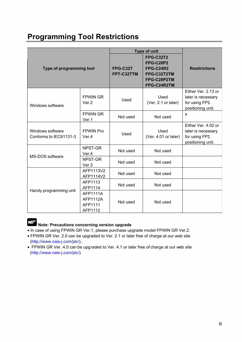
Programming Tool Restrictions
Type of unit
Type of programming tool FPG-C32T
FPT-C32TTM
FPG-C32T2
FPG-C28P2
FPG-C24R2
FPG-C32T2TM
FPG-C28P2TM
FPG-C24R2TM
Restirictions
FPWIN GR
Ver.2Used
Used
(Ver. 2.1 or later)
Either Ver. 2.13 or
later is necessary
for using FPΣ
positioning unit.Windows software
FPWIN GR
Ver.1Not used Not used
s
Windows software
Conforms to IEC61131-3
FPWIN Pro
Ver.4Used
Used
(Ver. 4.01 or later)
Either Ver. 4.02 or
later is necessary
for using FPΣ
positioning unit.
NPST-GR
Ver.4Not used Not used
MS-DOS softwareNPST-GR
Ver.3Not used Not used
AFP1113V2
AFP1114V2Not used Not used
AFP1113
AFP1114Not used Not used
Handy programming unit AFP1111A
AFP1112A
AFP1111
AFP1112
Not used Not used
Note: Precautions concerning version upgrade
• In case of using FPWIN GR Ver.1, please purchase upgrade model FPWIN GR Ver.2.
• FPWIN GR Ver. 2.0 can be upgraded to Ver. 2.1 or later free of charge at our web site
(http://www.nais-j.com/plc/).
• FPWIN GR Ver. 4.0 can be upgraded to Ver. 4.1 or later free of charge at our web site
(http://www.nais-j.com/plc/).
8/21/2019 Programmable Controller FP Sigma
http://slidepdf.com/reader/full/programmable-controller-fp-sigma 14/318
iv
Compatibility with FP0
Program compatibility
The following points require attention if using FP0 programs on the FPΣ.
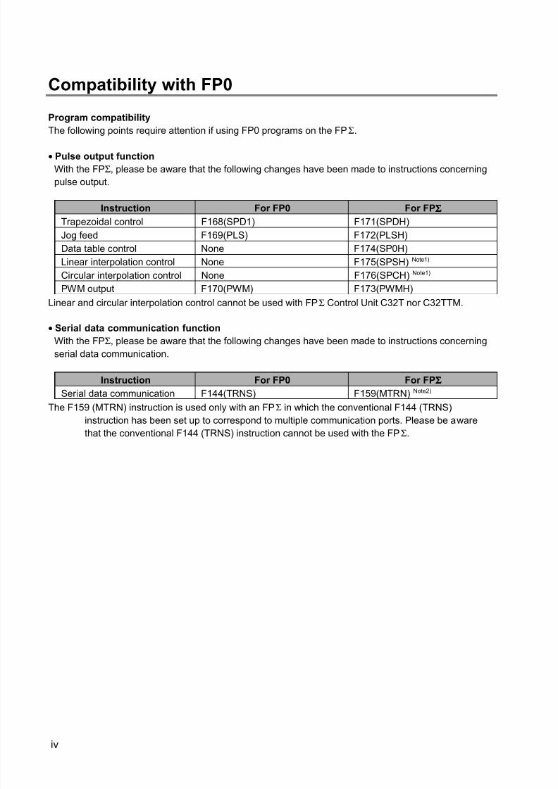
• Pulse output function
With the FPΣ, please be aware that the following changes have been made to instructions concerning
pulse output.
Instruction For FP0 For FPΣΣΣΣ
Trapezoidal control F168(SPD1) F171(SPDH)
Jog feed F169(PLS) F172(PLSH)
Data table control None F174(SP0H)
Linear interpolation control None F175(SPSH) Note1)
Circular interpolation control None F176(SPCH)Note1)
PWM output F170(PWM) F173(PWMH)
Linear and circular interpolation control cannot be used with FPΣ Control Unit C32T nor C32TTM.
• Serial data communication function
With the FPΣ, please be aware that the following changes have been made to instructions concerning
serial data communication.
Instruction For FP0 For FPΣΣΣΣ
Serial data communication F144(TRNS) F159(MTRN) Note2)
The F159 (MTRN) instruction is used only with an FPΣ in which the conventional F144 (TRNS)
instruction has been set up to correspond to multiple communication ports. Please be aware
that the conventional F144 (TRNS) instruction cannot be used with the FPΣ.

8/21/2019 Programmable Controller FP Sigma
http://slidepdf.com/reader/full/programmable-controller-fp-sigma 15/318
Chapter 1
Functions and Restrictions of the Unit
8/21/2019 Programmable Controller FP Sigma
http://slidepdf.com/reader/full/programmable-controller-fp-sigma 16/318
1-2
1.1 Features and Functions of the Unit
Powerful control capabilities
All of the functions of a mid-scale PLC are packed into the compact body size of the 32-pont type FP0. A
program capacity of 12k steps is provided as a standard feature, so you never have to worry about howmuch memory is left as you’re programming. In addition, 32k words are reserved for data registers, so
large volumes of data can be compiled and multiple operations can be processed without running out of
memory.
A full range of communication functions
Using the Tool port (RS232C) provided as a standard feature on the main unit, communication can be
carried out with a display panel or computer. Additionally, communication cassettes with RS232C and
RS485 interfaces are available as an option. Installing a 2-channel RS232C type communication
cassette in the FPΣ makes it possible to connect two devices with RS232C port. A full lineup of
communication functions means you can also work with 1:N communication (up to 99 units) and PLC link
function (up to 16 units).
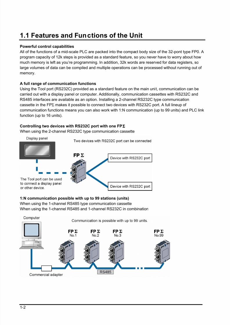
Controlling two devices with RS232C port with one FPΣΣΣΣ
When using the 2-channel RS232C type communication cassette
1:N communication possible with up to 99 stations (units)
When using the 1-channel RS485 type communication cassette
When using the 1-channel RS485 and 1-channel RS232C in combination
8/21/2019 Programmable Controller FP Sigma
http://slidepdf.com/reader/full/programmable-controller-fp-sigma 17/318
1-3
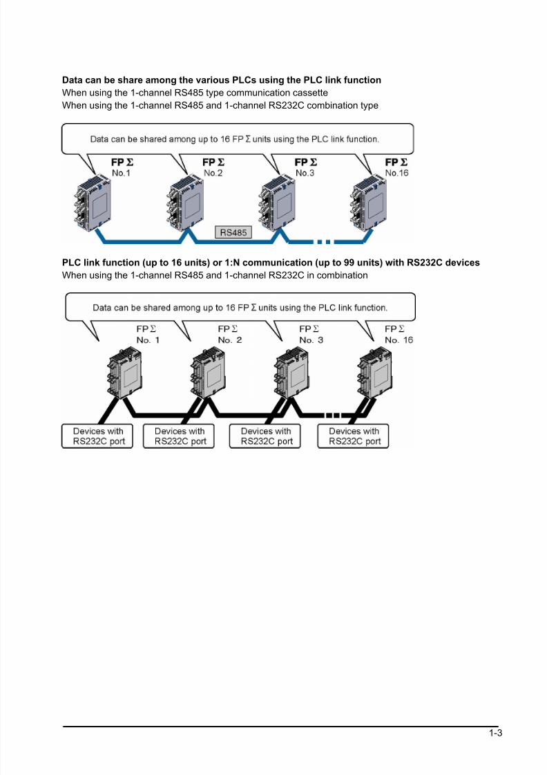
Data can be share among the various PLCs using the PLC link function
When using the 1-channel RS485 type communication cassette
When using the 1-channel RS485 and 1-channel RS232C combination type
PLC link function (up to 16 units) or 1:N communication (up to 99 units) with RS232C devices
When using the 1-channel RS485 and 1-channel RS232C in combination
8/21/2019 Programmable Controller FP Sigma
http://slidepdf.com/reader/full/programmable-controller-fp-sigma 18/318
1-4
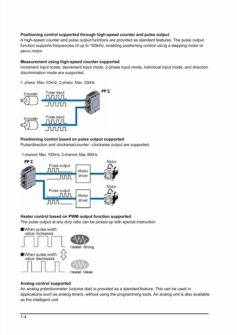
Positioning control supported through high-speed counter and pulse output
A high-speed counter and pulse output functions are provided as standard features. The pulse output
function supports frequencies of up to 100kHz, enabling positioning control using a stepping motor or
servo motor.
Measurement using high-speed counter supported
Increment input mode, decrement input mode, 2-phase input mode, individual input mode, and direction
discrimination mode are supported.
Positioning control based on pulse output supported
Pulse/direction and clockwise/counter –clockwise output are supported.
Heater control based on PWM output function supported
The pulse output at any duty ratio can be picked up with special instruction.
Analog control supported
An analog potentionmeter (volume dial) is provided as a standard feature. This can be used in
applications such as analog timers, without using the programming tools. An analog unit is also availableas the intelligent unit.

8/21/2019 Programmable Controller FP Sigma
http://slidepdf.com/reader/full/programmable-controller-fp-sigma 19/318
1-5
Type with thermister input function
For the units of which part numbers or product numbers end in “TM”, the leader line which enables the
thermister input is equipped instead of an analog potetionmeter. The change of the resistance value of
the thermister can be taken in as an analog value.
(The thermister of which resistance value is from 200 to 75 kΩ
can be used.)
Calender timer function can be added
Optional backup battery enables the calender timer function.
8/21/2019 Programmable Controller FP Sigma
http://slidepdf.com/reader/full/programmable-controller-fp-sigma 20/318
1-6
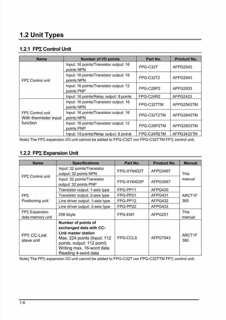
1.2 Unit Types
1.2.1 FPΣΣΣΣ Control Unit
Name Number of I/O points Part No. Product No.
Input: 16 points/Transistor output: 16
points NPNFPG-C32T AFPG2543
Input: 16 points/Transistor output: 16
points NPNFPG-C32T2 AFPG2643
Input: 16 points/Transistor output: 12
points PNPFPG-C28P2 AFPG2653
FPΣ Control unit
Input: 16 points/Relay output: 8 points FPG-C24R2 AFPG2423
Input: 16 points/Transistor output: 16
points NPNFPG-C32TTM AFPG2543TM
Input: 16 points/Transistor output: 16points NPN
FPG-C32T2TM AFPG2643TM
Input: 16 points/Transistor output: 12
points PNPFPG-C28P2TM AFPG2653TM
FPΣ Control unitWith thermister inputfunction
Input: 16 points/Relay output: 8 points FPG-C24R2TM AFPG2423TM
Note) The FPΣ expansion I/O unit cannot be added to FPG-C32T nor FPG-C32TTM FPΣ control unit.
1.2.2 FPΣΣΣΣ Expansion Unit
Name Specifications Part No. Product No. Manual
Input: 32 points/Transistor output: 32 points NPN
FPG-XY64D2T AFPG3467
FPΣ Control unitInput: 32 points/Transistor
output: 32 points PNPFPG-XY64D2P AFPG3567
This
manual
Transistor output: 1-axis type FPG-PP11 AFPG430
Transistor output: 2-axis type FPG-PP21 AFPG431
Line driver output: 1-axis type FPG-PP12 AFPG432
FPΣ
Positioning unit
Line driver output: 2-axis type FPG-PP22 AFPG433
ARCT1F
365
FPΣ Expansion
data memory unit256 kbyte FPG-EM1 AFPG201
This
manual
FPΣ CC-Linkslave unit
Number of points of exchanged data with CC-
Link master station
Max. 224 points (Input: 112points, output: 112 point)Writing max. 16-word dataReading 4-word data
FPG-CCLS AFPG7943 ARCT1F
380
Note) The FPΣ expansion I/O unit cannot be added to FPG-C32T nor FPG-C32TTM FPΣ control unit.
8/21/2019 Programmable Controller FP Sigma
http://slidepdf.com/reader/full/programmable-controller-fp-sigma 21/318
1-7
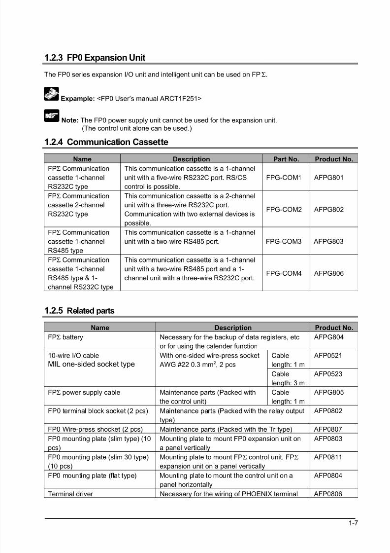
1.2.3 FP0 Expansion Unit
The FP0 series expansion I/O unit and intelligent unit can be used on FPΣ.
Expample: <FP0 User’s manual ARCT1F251>
Note: The FP0 power supply unit cannot be used for the expansion unit.
(The control unit alone can be used.)
1.2.4 Communication Cassette
Name Description Part No. Product No.
FPΣ Communication
cassette 1-channel
RS232C type
This communication cassette is a 1-channel
unit with a five-wire RS232C port. RS/CS
control is possible.
FPG-COM1 AFPG801
FPΣ Communication
cassette 2-channel
RS232C type
This communication cassette is a 2-channel
unit with a three-wire RS232C port.
Communication with two external devices is
possible.
FPG-COM2 AFPG802
FPΣ Communication
cassette 1-channel
RS485 type
This communication cassette is a 1-channel
unit with a two-wire RS485 port. FPG-COM3 AFPG803
FPΣ Communication
cassette 1-channel
RS485 type & 1-
channel RS232C type
This communication cassette is a 1-channel
unit with a two-wire RS485 port and a 1-
channel unit with a three-wire RS232C port.FPG-COM4 AFPG806
1.2.5 Related parts
Name Description Product No.
FPΣ battery Necessary for the backup of data registers, etc
or for using the calender function
AFPG804
Cable
length: 1 m
AFP052110-wire I/O cable
MIL one-sided socket type
With one-sided wire-press socket
AWG #22 0.3 mm2, 2 pcs
Cable
length: 3 m
AFP0523
FPΣ power supply cable Maintenance parts (Packed with
the control unit)
Cable
length: 1 m
AFPG805
FP0 terminal block socket (2 pcs) Maintenance parts (Packed with the relay output
type)
AFP0802
FP0 Wire-press shocket (2 pcs) Maintenance parts (Packed with the Tr type) AFP0807
FP0 mounting plate (slim type) (10
pcs)
Mounting plate to mount FP0 expansion unit on
a panel vertically
AFP0803
FP0 mounting plate (slim 30 type)
(10 pcs)
Mounting plate to mount FPΣ control unit, FPΣ
expansion unit on a panel vertically
AFP0811
FP0 mounting plate (flat type) Mounting plate to mount the control unit on a
panel horizontally
AFP0804
Terminal driver Necessary for the wiring of PHOENIX terminal AFP0806
8/21/2019 Programmable Controller FP Sigma
http://slidepdf.com/reader/full/programmable-controller-fp-sigma 22/318
1-8
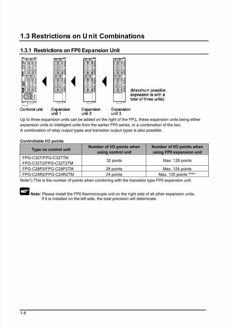
1.3 Restrictions on U nit Combinations
1.3.1 Restrictions on FP0 Expansion Unit
Up to three expansion units can be added on the right of the FPΣ, these expansion units being either
expansion units or intelligent units from the earlier FP0 series, or a combination of the two.
A combination of relay output types and transistor output types is also possible.
Controllable I/O points
Type os control unitNumber of I/O points when
using control unit
Number of I/O points when
using FP0 expansion unit
FPG-C32T/FPG-C32TTM
FPG-C32T2/FPG-C32T2TM32 ponts Max. 128 points
FPG-C28P2/FPG-C28P2TM 28 points Max. 124 points
FPG-C24R2/FPG-C24R2TM 24 points Max. 120 points Note1)
Note1) This is the number of points when combining with the transistor type FP0 expansion unit.
Note: Please install the FP0 thermocouple unit on the right side of all other expansion units. If it is installed on the left side, the total precision will deteriorate.
8/21/2019 Programmable Controller FP Sigma
http://slidepdf.com/reader/full/programmable-controller-fp-sigma 23/318
1-9
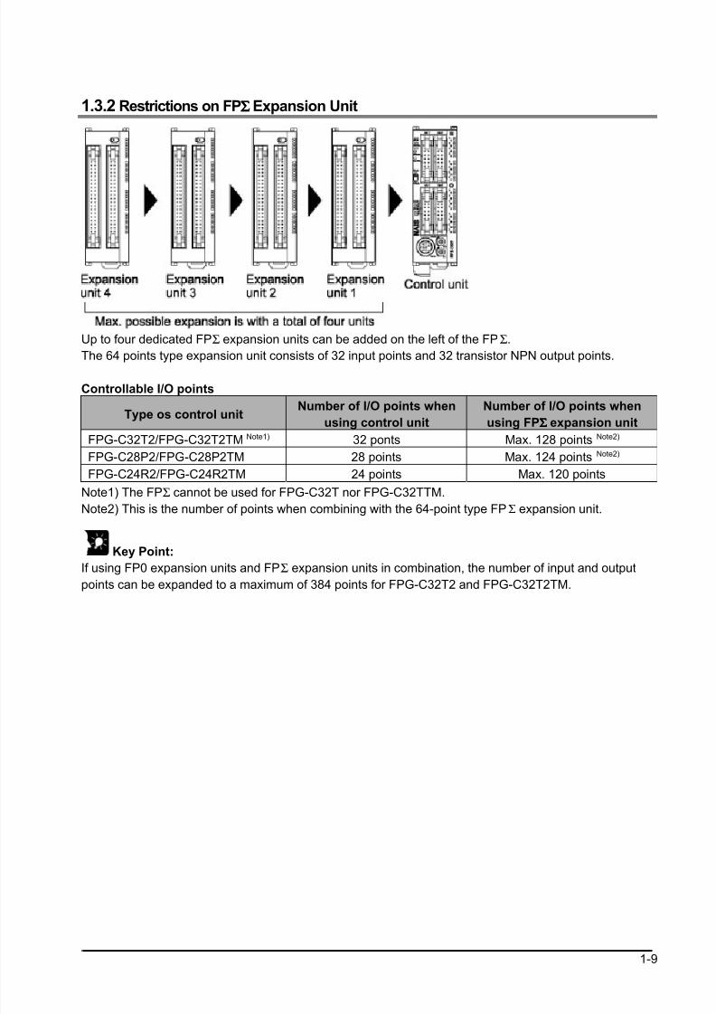
1.3.2 Restrictions on FPΣΣΣΣ Expansion Unit
Up to four dedicated FPΣ expansion units can be added on the left of the FPΣ.
The 64 points type expansion unit consists of 32 input points and 32 transistor NPN output points.
Controllable I/O points
Type os control unitNumber of I/O points when
using control unit
Number of I/O points when
using FPΣΣΣΣ expansion unit
FPG-C32T2/FPG-C32T2TM Note1) 32 ponts Max. 128 points Note2)
FPG-C28P2/FPG-C28P2TM 28 points Max. 124 points Note2)
FPG-C24R2/FPG-C24R2TM 24 points Max. 120 points
Note1) The FPΣ cannot be used for FPG-C32T nor FPG-C32TTM.
Note2) This is the number of points when combining with the 64-point type FPΣ expansion unit.
Key Point:
If using FP0 expansion units and FPΣ expansion units in combination, the number of input and output
points can be expanded to a maximum of 384 points for FPG-C32T2 and FPG-C32T2TM.
8/21/2019 Programmable Controller FP Sigma
http://slidepdf.com/reader/full/programmable-controller-fp-sigma 24/318
1-10
1.4 Programming Tools
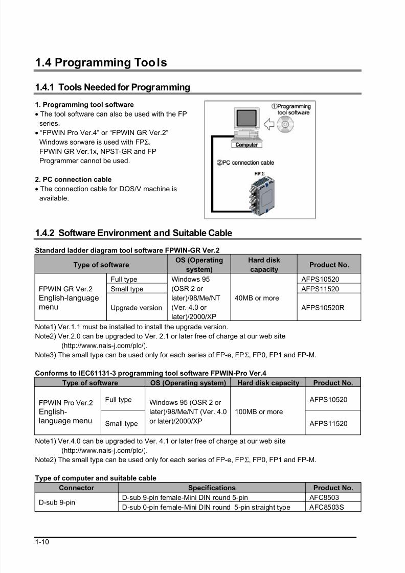
1.4.1 Tools Needed for Programming
1. Programming tool software
• The tool software can also be used with the FP
series.
• “FPWIN Pro Ver.4” or “FPWIN GR Ver.2”
Windows sorware is used with FPΣ.
FPWIN GR Ver.1x, NPST-GR and FP
Programmer cannot be used.
2. PC connection cable
• The connection cable for DOS/V machine is
available.
1.4.2 Software Environment and Suitable Cable
Standard ladder diagram tool software FPWIN-GR Ver.2
Type of softwareOS (Operating
system)
Hard disk
capacityProduct No.
Full type AFPS10520
Small type AFPS11520FPWIN GR Ver.2
English-languagemenu Upgrade version
Windows 95
(OSR 2 or
later)/98/Me/NT(Ver. 4.0 or
later)/2000/XP
40MB or more AFPS10520R
Note1) Ver.1.1 must be installed to install the upgrade version.
Note2) Ver.2.0 can be upgraded to Ver. 2.1 or later free of charge at our web site
(http://www.nais-j.com/plc/).
Note3) The small type can be used only for each series of FP-e, FPΣ, FP0, FP1 and FP-M.
Conforms to IEC61131-3 programming tool software FPWIN-Pro Ver.4
Type of software OS (Operating system) Hard disk capacity Product No.
Full type AFPS10520FPWIN Pro Ver.2English-language menu Small type
Windows 95 (OSR 2 or later)/98/Me/NT (Ver. 4.0
or later)/2000/XP
100MB or more
AFPS11520
Note1) Ver.4.0 can be upgraded to Ver. 4.1 or later free of charge at our web site
(http://www.nais-j.com/plc/).
Note2) The small type can be used only for each series of FP-e, FPΣ, FP0, FP1 and FP-M.
Type of computer and suitable cable
Connector Specifications Product No.
D-sub 9-pin female-Mini DIN round 5-pin AFC8503D-sub 9-pin D-sub 0-pin female-Mini DIN round 5-pin straight type AFC8503S

8/21/2019 Programmable Controller FP Sigma
http://slidepdf.com/reader/full/programmable-controller-fp-sigma 25/318
Chapter 2
Specifications and Functions of the Unit
8/21/2019 Programmable Controller FP Sigma
http://slidepdf.com/reader/full/programmable-controller-fp-sigma 26/318
2-2
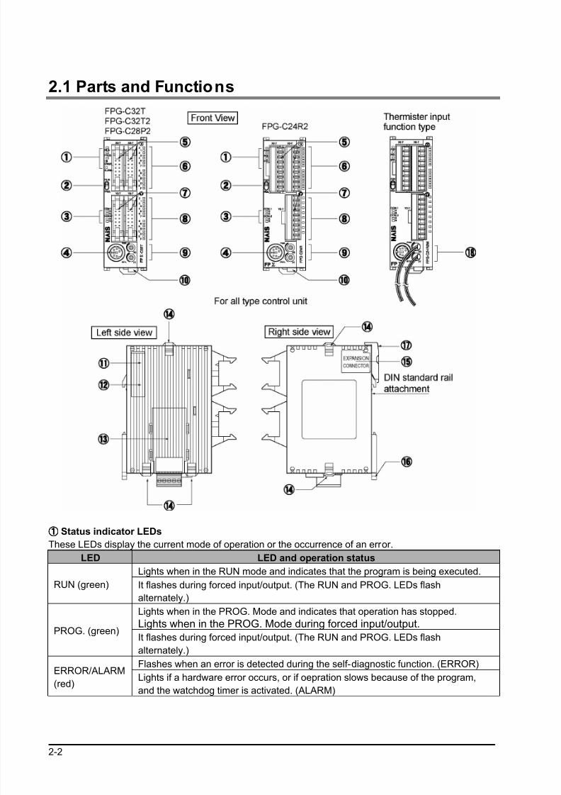
2.1 Parts and Functions
①①①① Status indicator LEDs
These LEDs display the current mode of operation or the occurrence of an error.
LED LED and operation statusLights when in the RUN mode and indicates that the program is being executed.
RUN (green) It flashes during forced input/output. (The RUN and PROG. LEDs flash
alternately.)
Lights when in the PROG. Mode and indicates that operation has stopped.
Lights when in the PROG. Mode during forced input/output.PROG. (green)
It flashes during forced input/output. (The RUN and PROG. LEDs flash
alternately.)
Flashes when an error is detected during the self-diagnostic function. (ERROR)ERROR/ALARM
(red)Lights if a hardware error occurs, or if oepration slows because of the program,
and the watchdog timer is activated. (ALARM)
8/21/2019 Programmable Controller FP Sigma
http://slidepdf.com/reader/full/programmable-controller-fp-sigma 27/318
2-3
②②②② RUN/PROG. mode switch
This switch is used to change the operation mode of the PLC.
Switch position Operation mode
RUN (upward)This sets the RUN mode. The program is executed is executed and operation
begins.
PROG. (downword)This sets the PROG. mode. The operation stops. In this mode, programming
can be done using tools.
• The remote switching operation from the programming tool is operable.
• When performing remote switching from the programming tool, the setting of the mode switch and the
actual mode of operation may differ. Verify the mode with the status indicator LED.
• Restart FPΣ to operate in the mode set with the RUN/PROG. mode switch.
③③③③ Communication status LEDs
These LEDs display the communication status of the COM.1 and COM.2 ports.
LED LED and communication status
Flashes while data is being transmitted.S Transmitted datamonitor Goes out when no data is being transmitted.
Flashes while data is being received.COM.1
RReceived data
monitor Goes out when no data is being received.
Flashes while data is being transmitted.
(In case of 1-channel RS232C1 type, lights when the RS signal
is ON.)S
Transmitted data
monitor
Goes out when no data is being received.
Flashes while data is being received.
(In case of 1-channel RS232C1 type, lights when the CSsignal is ON.)
COM.2
RReceived data
monitor Goes out when no data is being received.
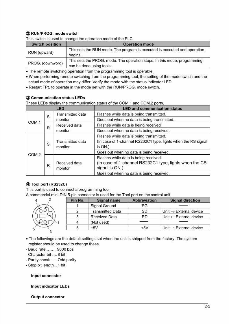
④④④④ Tool port (RS232C)
This port is used to connect a programming tool.
A commercial mini-DIN 5-pin connector is used for the Tool port on the control unit.
Pin No. Signal name Abbreviation Signal direction
1 Signal Ground SG
2 Transmitted Data SD Unit → External device
3 Received Data RD Unit ← External device
4 (Not used)
5 +5V +5V Unit → External device
• The followings are the default settings set when the unit is shipped from the factory. The system
register should be used to change these.
- Baud rate …….. 9600 bps
- Character bit ….8 bit
- Parity check ….. Odd parity
- Stop bit length .. 1 bit
Input connector
Input indicator LEDs
Output connector

8/21/2019 Programmable Controller FP Sigma
http://slidepdf.com/reader/full/programmable-controller-fp-sigma 28/318
2-4
⑧⑧⑧⑧ Output indicator LEDs
Analog potentiometer (analog dial)
(excluding the type of which part No. and product No. ends in TM)
Turning this dial chanes the values of special data register DT90040 and DT90041 within the range of K0 to K1000. It can be used for analog timers and other applications.
Expample: <2.4 Analog potentiometer>
⑩⑩⑩⑩ Power supply connector (24V DC)
Supply 24V DC. It is connected using the power supply cable (AFPG805) that comes with the unit.
⑪⑪⑪⑪ Left-side connector for FPΣΣΣΣ expansion
This is used to connect dedicated FPΣ expansion unit on the left side of the control unit with the internal
circuit.
Note) FPG-C32T nor FPG-C32TTM control units are not equipped with this connector.
⑫⑫⑫⑫ Unit No. (Station No.) setting switch
This unit No. (station No.) is specified when using the communication functions provided on the optional
communication cassettes. The unit No. (station No.) of the tool port cannot be specified. Also, in case of
using a 2-channel cassette, the same station No. is specified for both channels.
(It is possible to set individually for the setting with the system register.)
The unit No. (station No.) setting switch is located under the cover on the back of the unit. Specify the unit (station) No. using the selector switch and the dial.
⑬⑬⑬⑬ Communication cassette (option)
This is the optional cassette type adapter used when communication is carried out. Any one of the
following cassette types may be installed.
- 1-channel RS232C type
- 2-channel RS232C type
- 1-channel RS485 type
- 1-channel RS485 and 1-channel RS232C type in combination
Expample: <Chapter 7, Communication Cassette >
⑭⑭⑭⑭ Expansion hook
This hook is used to secure expansion units. The hook on the right side is also used for installation on
flat type mounting plate (AFP0804).
⑮⑮⑮⑮ Right-side connector for FP0 expansion
This is used to connect an expansion unit to the internal circuit of the control unit.
(The connector is located under the seal.)
8/21/2019 Programmable Controller FP Sigma
http://slidepdf.com/reader/full/programmable-controller-fp-sigma 29/318
2-5
⑯⑯⑯⑯ DIN rail attachment lever
The FPΣ unit enables attachment at a touch to a DIN rail. The lever is also used for installation on slim
30 type mounting plate (AFP0811).
⑰⑰⑰⑰ Battery cover This is uncovered to mount the backup battery sold separately.
The backup of the calendar timer function or data register is possible with the backup battery.
Expample: <5.7 Installation and setting of backup battery>
<2.6 Calendar timer>
⑱⑱⑱⑱ Thermister input line (The end of part No. and product No. is TM type only)
It is used to connect the thermister to read the change in the resistance value of the thermister as analog
input values.
Expample: <2.5 Thermister input>
8/21/2019 Programmable Controller FP Sigma
http://slidepdf.com/reader/full/programmable-controller-fp-sigma 30/318
2-6
2.2 Input and Output Specifications
2.2.1 Input Specif ications
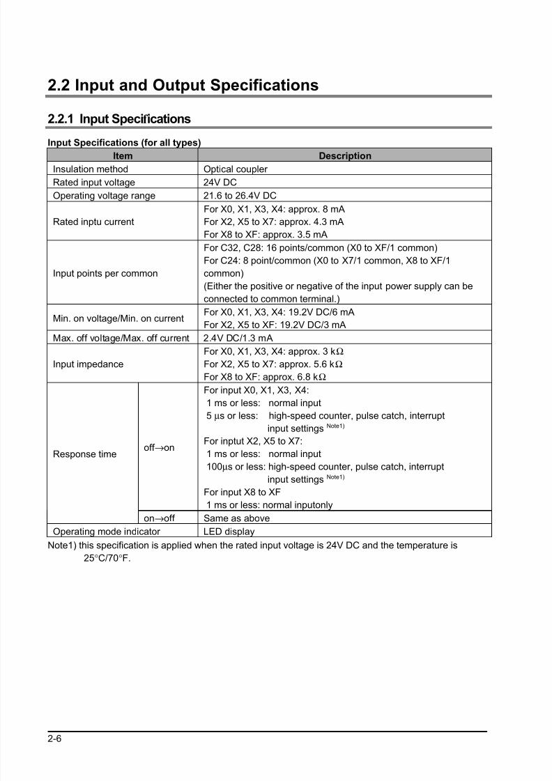
Input Specifications (for all types)
Item Description
Insulation method Optical coupler
Rated input voltage 24V DC
Operating voltage range 21.6 to 26.4V DC
Rated inptu current
For X0, X1, X3, X4: approx. 8 mA
For X2, X5 to X7: approx. 4.3 mA
For X8 to XF: approx. 3.5 mA
Input points per common
For C32, C28: 16 points/common (X0 to XF/1 common)
For C24: 8 point/common (X0 to X7/1 common, X8 to XF/1
common)(Either the positive or negative of the input power supply can be
connected to common terminal.)
Min. on voltage/Min. on currentFor X0, X1, X3, X4: 19.2V DC/6 mA
For X2, X5 to XF: 19.2V DC/3 mA
Max. off voltage/Max. off current 2.4V DC/1.3 mA
Input impedance
For X0, X1, X3, X4: approx. 3 kΩ
For X2, X5 to X7: approx. 5.6 kΩ
For X8 to XF: approx. 6.8 kΩ
off →on
For input X0, X1, X3, X4:
1 ms or less: normal input
5 µs or less: high-speed counter, pulse catch, interrupt
input settings Note1)
For inptut X2, X5 to X7:
1 ms or less: normal input
100µs or less: high-speed counter, pulse catch, interrupt
input settings Note1)
For input X8 to XF
1 ms or less: normal inputonly
Response time
on→off Same as above
Operating mode indicator LED display
Note1) this specification is applied when the rated input voltage is 24V DC and the temperature is25°C/70°F.
8/21/2019 Programmable Controller FP Sigma
http://slidepdf.com/reader/full/programmable-controller-fp-sigma 31/318
2-7
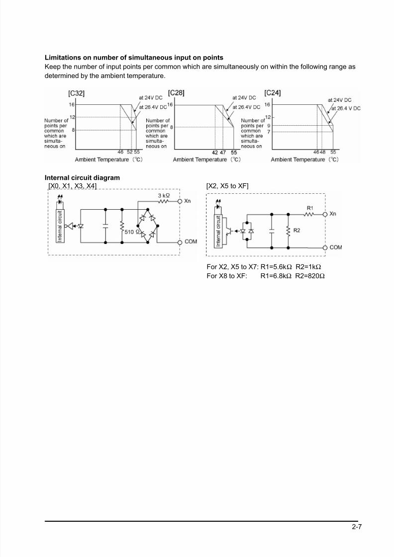
Limitations on number of simultaneous input on points
Keep the number of input points per common which are simultaneously on within the following range as
determined by the ambient temperature.
Internal circuit diagram
[X0, X1, X3, X4] [X2, X5 to XF]
For X2, X5 to X7: R1=5.6kΩ R2=1kΩ
For X8 to XF: R1=6.8kΩ R2=820Ω
8/21/2019 Programmable Controller FP Sigma
http://slidepdf.com/reader/full/programmable-controller-fp-sigma 32/318
2-8
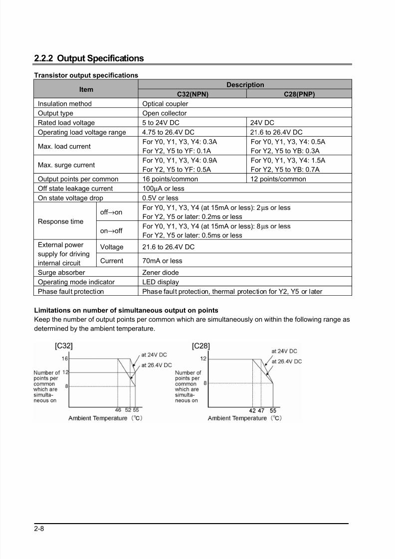
2.2.2 Output Specifications
Transistor output specifications
DescriptionItem
C32(NPN) C28(PNP)Insulation method Optical coupler
Output type Open collector
Rated load voltage 5 to 24V DC 24V DC
Operating load voltage range 4.75 to 26.4V DC 21.6 to 26.4V DC
Max. load currentFor Y0, Y1, Y3, Y4: 0.3A
For Y2, Y5 to YF: 0.1A
For Y0, Y1, Y3, Y4: 0.5A
For Y2, Y5 to YB: 0.3A
Max. surge currentFor Y0, Y1, Y3, Y4: 0.9A
For Y2, Y5 to YF: 0.5A
For Y0, Y1, Y3, Y4: 1.5A
For Y2, Y5 to YB: 0.7A
Output points per common 16 points/common 12 points/common
Off state leakage current 100µ A or less
On state voltage drop 0.5V or less
off →onFor Y0, Y1, Y3, Y4 (at 15mA or less): 2µs or less
For Y2, Y5 or later: 0.2ms or lessResponse time
on→off For Y0, Y1, Y3, Y4 (at 15mA or less): 8µs or less
For Y2, Y5 or later: 0.5ms or less
Voltage 21.6 to 26.4V DCExternal power
supply for driving
internal circuit Current 70mA or less
Surge absorber Zener diode
Operating mode indicator LED display
Phase fault protection Phase fault protection, thermal protection for Y2, Y5 or later
Limitations on number of simultaneous output on points
Keep the number of output points per common which are simultaneously on within the following range as
determined by the ambient temperature.
8/21/2019 Programmable Controller FP Sigma
http://slidepdf.com/reader/full/programmable-controller-fp-sigma 33/318
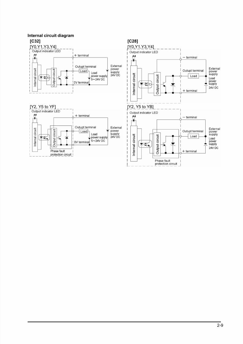
2-9
Internal circuit diagram
[C32]
[Y0,Y1,Y3,Y4]
[C28]
[Y0,Y1,Y3,Y4]
[Y2, Y5 to YF] [Y2, Y5 to YB]
8/21/2019 Programmable Controller FP Sigma
http://slidepdf.com/reader/full/programmable-controller-fp-sigma 34/318
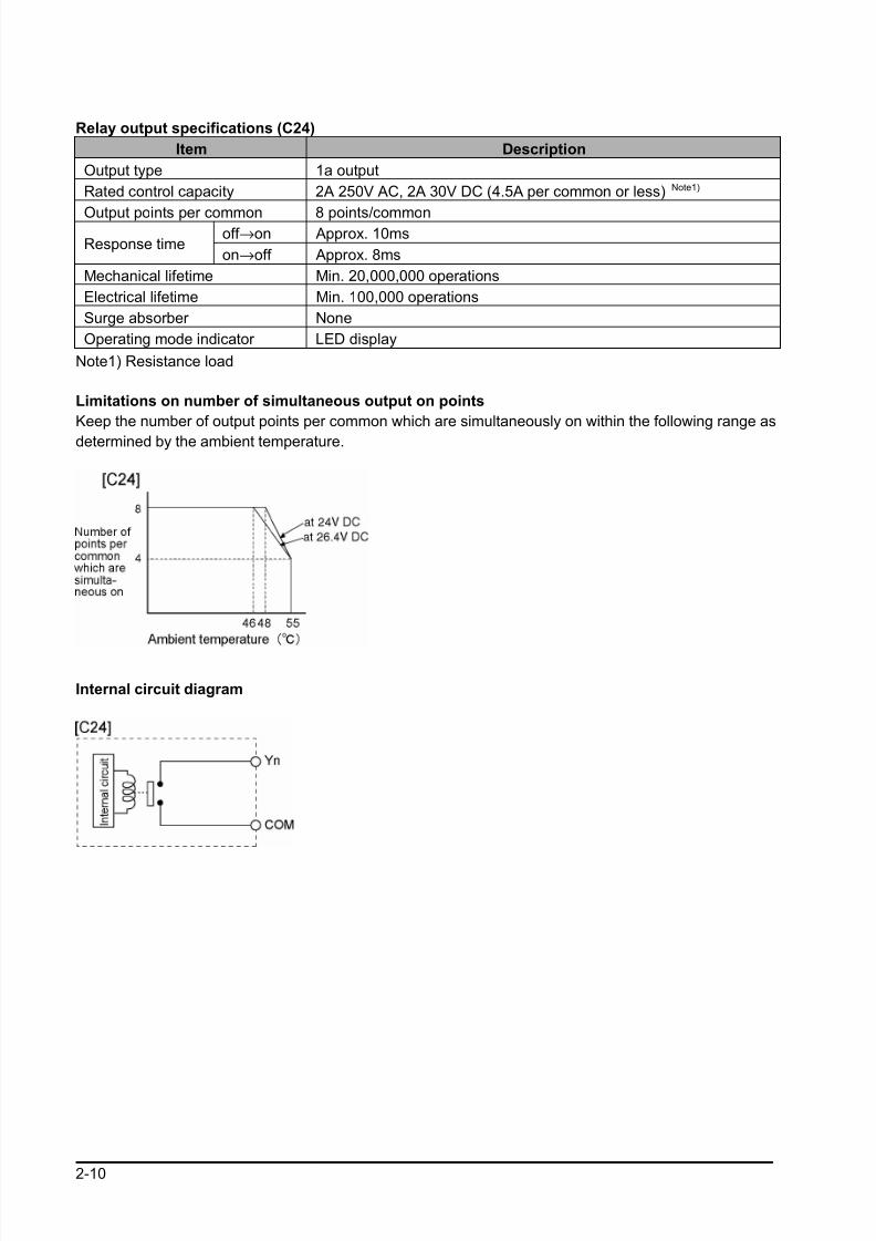
2-10
Relay output specifications (C24)
Item Description
Output type 1a output
Rated control capacity 2A 250V AC, 2A 30V DC (4.5A per common or less) Note1)
Output points per common 8 points/commonoff →on Approx. 10ms
Response timeon→off Approx. 8ms
Mechanical lifetime Min. 20,000,000 operations
Electrical lifetime Min. 100,000 operations
Surge absorber None
Operating mode indicator LED display
Note1) Resistance load
Limitations on number of simultaneous output on points
Keep the number of output points per common which are simultaneously on within the following range as
determined by the ambient temperature.
Internal circuit diagram
8/21/2019 Programmable Controller FP Sigma
http://slidepdf.com/reader/full/programmable-controller-fp-sigma 35/318
2-11
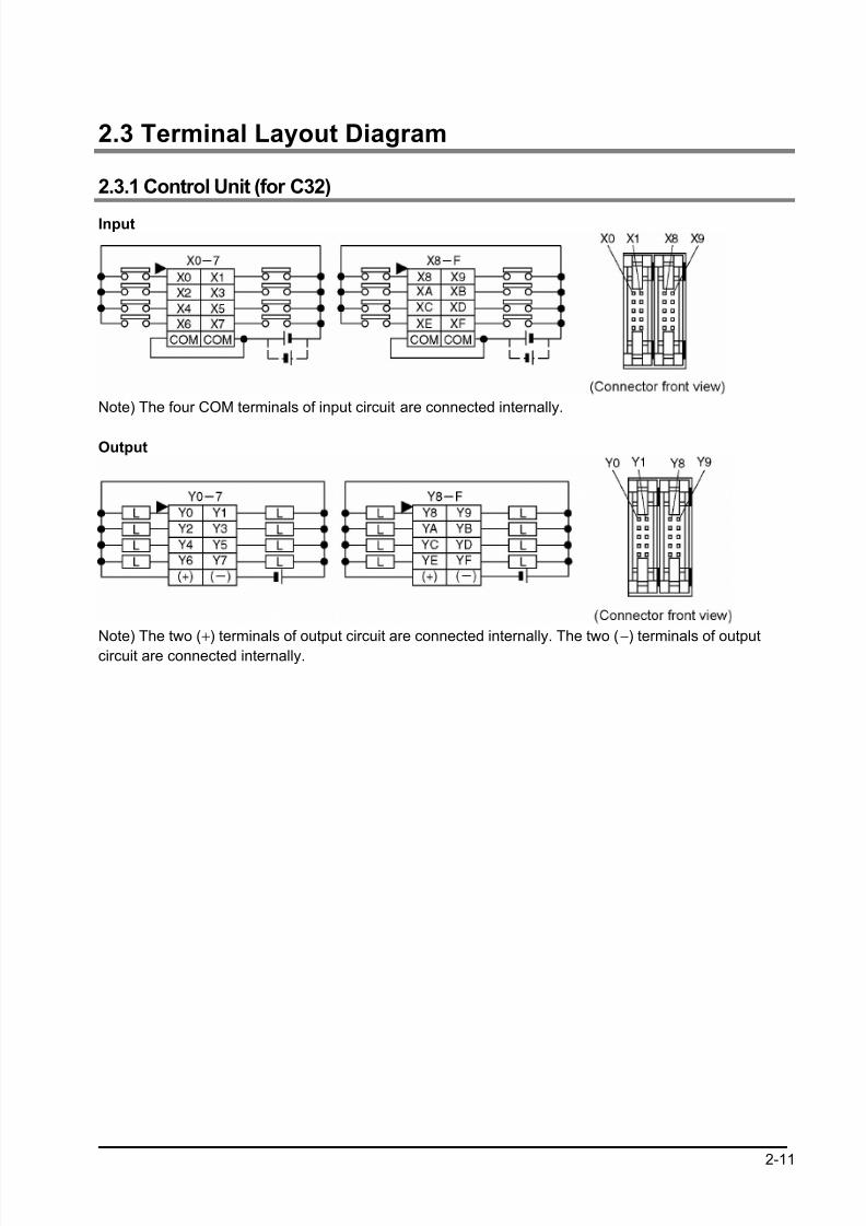
2.3 Terminal Layout Diagram
2.3.1 Control Unit (for C32)
Input
Note) The four COM terminals of input circuit are connected internally.
Output
Note) The two (+) terminals of output circuit are connected internally. The two (−) terminals of output
circuit are connected internally.
8/21/2019 Programmable Controller FP Sigma
http://slidepdf.com/reader/full/programmable-controller-fp-sigma 36/318
2-12
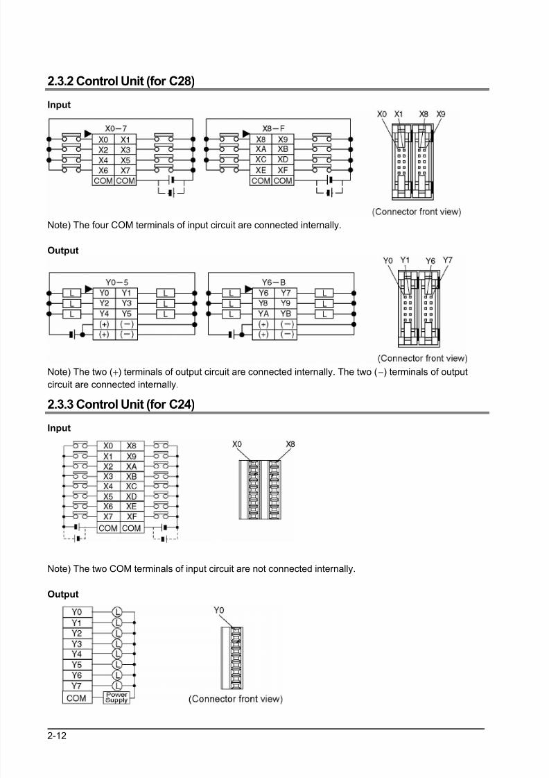
2.3.2 Control Unit (for C28)
Input
Note) The four COM terminals of input circuit are connected internally.
Output
Note) The two (+) terminals of output circuit are connected internally. The two (−) terminals of output
circuit are connected internally.
2.3.3 Control Unit (for C24)Input
Note) The two COM terminals of input circuit are not connected internally.
Output
8/21/2019 Programmable Controller FP Sigma
http://slidepdf.com/reader/full/programmable-controller-fp-sigma 37/318
2-13
2.4 Analog Potentiometer
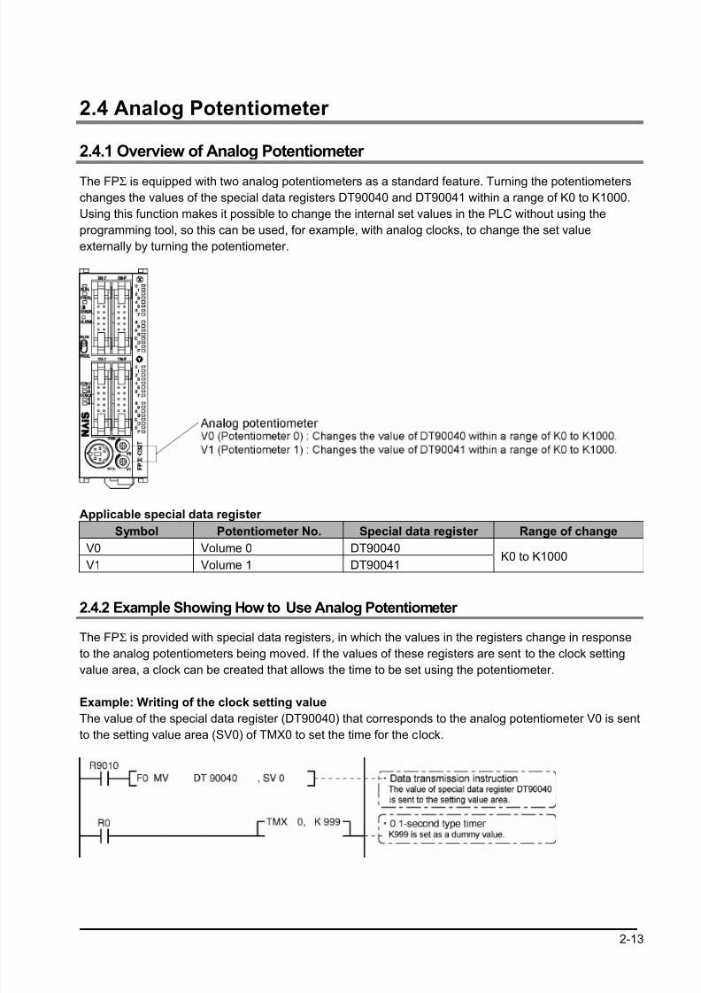
2.4.1 Overview of Analog Potentiometer
The FPΣ is equipped with two analog potentiometers as a standard feature. Turning the potentiometers
changes the values of the special data registers DT90040 and DT90041 within a range of K0 to K1000.
Using this function makes it possible to change the internal set values in the PLC without using the
programming tool, so this can be used, for example, with analog clocks, to change the set value
externally by turning the potentiometer.
Applicable special data register
Symbol Potentiometer No. Special data register Range of change
V0 Volume 0 DT90040
V1 Volume 1 DT90041K0 to K1000
2.4.2 Example Showing How to Use Analog Potentiometer
The FPΣ is provided with special data registers, in which the values in the registers change in response
to the analog potentiometers being moved. If the values of these registers are sent to the clock setting
value area, a clock can be created that allows the time to be set using the potentiometer.
Example: Writing of the clock setting value
The value of the special data register (DT90040) that corresponds to the analog potentiometer V0 is sent
to the setting value area (SV0) of TMX0 to set the time for the clock.
8/21/2019 Programmable Controller FP Sigma
http://slidepdf.com/reader/full/programmable-controller-fp-sigma 38/318
2-14
2.5 Thermister Input (Only for TM type)
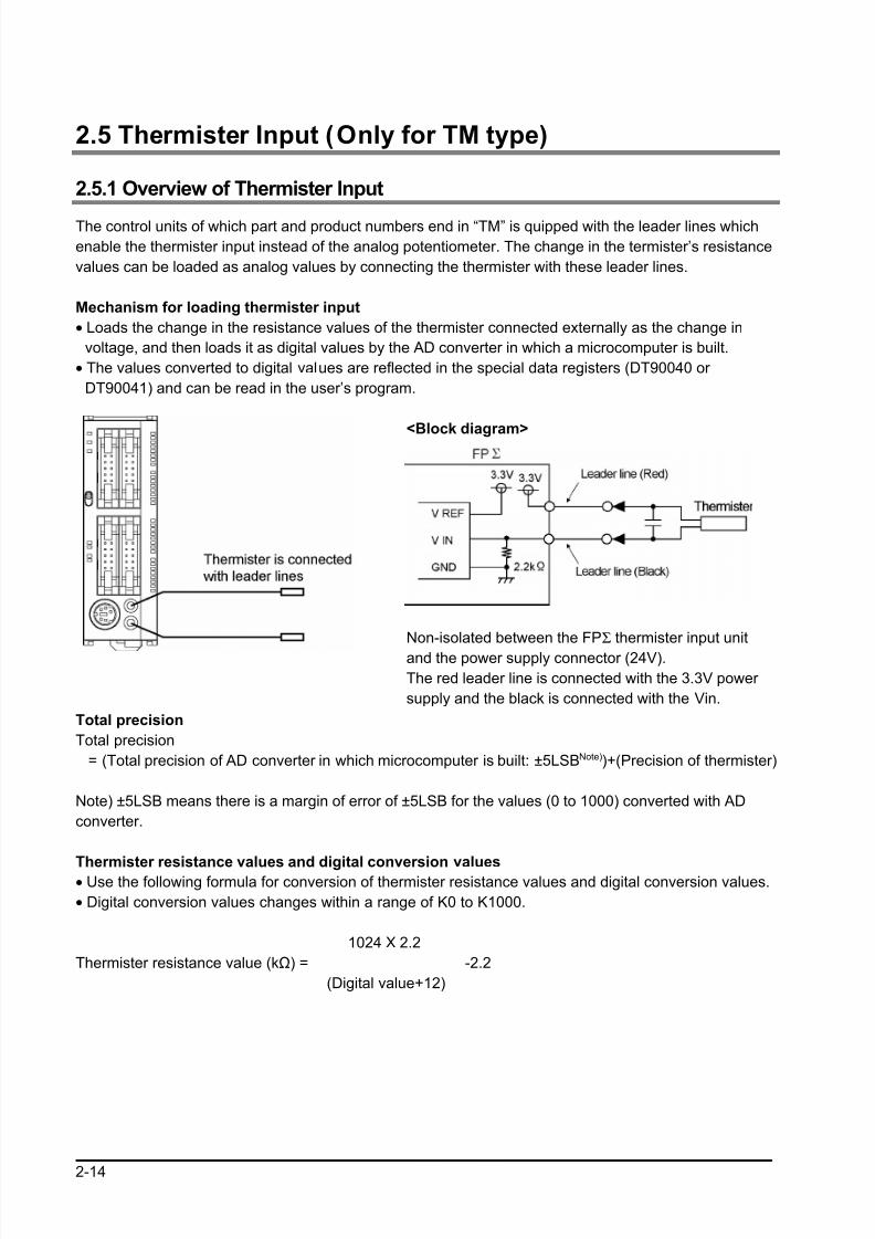
2.5.1 Overview of Thermister Input
The control units of which part and product numbers end in “TM” is quipped with the leader lines which
enable the thermister input instead of the analog potentiometer. The change in the termister’s resistance
values can be loaded as analog values by connecting the thermister with these leader lines.
Mechanism for loading thermister input
• Loads the change in the resistance values of the thermister connected externally as the change in
voltage, and then loads it as digital values by the AD converter in which a microcomputer is built.
• The values converted to digital values are reflected in the special data registers (DT90040 or
DT90041) and can be read in the user’s program.
<Block diagram>
Non-isolated between the FPΣ thermister input unit
and the power supply connector (24V).
The red leader line is connected with the 3.3V power
supply and the black is connected with the Vin.
Total precision
Total precision
= (Total precision of AD converter in which microcomputer is built: ±5LSBNote))+(Precision of thermister)
Note) ±5LSB means there is a margin of error of ±5LSB for the values (0 to 1000) converted with AD
converter.
Thermister resistance values and digital conversion values• Use the following formula for conversion of thermister resistance values and digital conversion values.
• Digital conversion values changes within a range of K0 to K1000.
1024 X 2.2
Thermister resistance value (kΩ) = -2.2
(Digital value+12)
8/21/2019 Programmable Controller FP Sigma
http://slidepdf.com/reader/full/programmable-controller-fp-sigma 39/318
2-15
Usable thermister
• Thermisters of which resistance values are within a range of 200Ω to 75kΩ.
Manufacturer Thermister type (B constant) Guide for Measuring range (°°°°C)
3390 K -50 to +100 °C
3450 K 50 to +150 °C4300 K +100 to +200 °C
ShibauraElectronics Co., Ltd.
5133 K +150 to +300 °C
Note:
• The length of the wiring between the FPΣ control unit and the thermister should be less than 10m.
• A thin wire (AWG28, length: 150 mm) is used for the leader line. Connect and bundle the wire without
any stress.
• It is recommended to mount parts such as condensers externally if the converted value is unstable.
8/21/2019 Programmable Controller FP Sigma
http://slidepdf.com/reader/full/programmable-controller-fp-sigma 40/318
2-16
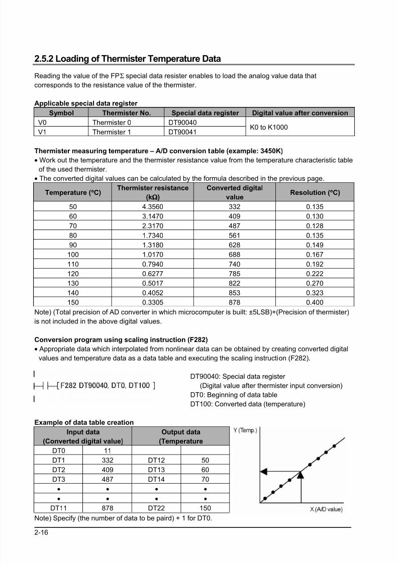
2.5.2 Loading of Thermister Temperature Data
Reading the value of the FPΣ special data resister enables to load the analog value data that
corresponds to the resistance value of the thermister.
Applicable special data register
Symbol Thermister No. Special data register Digital value after conversion
V0 Thermister 0 DT90040
V1 Thermister 1 DT90041K0 to K1000
Thermister measuring temperature – A/D conversion table (example: 3450K)
• Work out the temperature and the thermister resistance value from the temperature characteristic table
of the used thermister.
• The converted digital values can be calculated by the formula described in the previous page.
Temperature (°°°°C)Thermister resistance
(kΩΩΩΩ)
Converted digital
valueResolution (°°°°C)
50 4.3560 332 0.135
60 3.1470 409 0.130
70 2.3170 487 0.128
80 1.7340 561 0.135
90 1.3180 628 0.149
100 1.0170 688 0.167
110 0.7940 740 0.192
120 0.6277 785 0.222
130 0.5017 822 0.270
140 0.4052 853 0.323150 0.3305 878 0.400
Note) (Total precision of AD converter in which microcomputer is built: ±5LSB)+(Precision of thermister)
is not included in the above digital values.
Conversion program using scaling instruction (F282)
• Appropriate data which interpolated from nonlinear data can be obtained by creating converted digital
values and temperature data as a data table and executing the scaling instruction (F282).
DT90040: Special data register
(Digital value after thermister input conversion)
DT0: Beginning of data tableDT100: Converted data (temperature)
Example of data table creation
Input data
(Converted digital value)
Output data
(Temperature
DT0 11
DT1 332 DT12 50
DT2 409 DT13 60
DT3 487 DT14 70
• • • •
• • • •
DT11 878 DT22 150
Note) Specify (the number of data to be paird) + 1 for DT0.
8/21/2019 Programmable Controller FP Sigma
http://slidepdf.com/reader/full/programmable-controller-fp-sigma 41/318
2-17
2.6 Calendar Timer
If a backup battery is installed in the FP∑, the clock/calendar function can be used. This funcation cannot
be used without a backup battery.
Example: <5.7 Installation and setting of backup battery>
2.6.1 Area for Clock/Calendar Function
With the clock/calendar function, data indicating the hour, minute, second, day, year and other
information stored in the special data registers DT90053 to DT90057 can be read using the transmission
instruction and used in sequence programs.
Special data
Register No.Upper byte Lower byte Reading Writing
DT90053Hour data
H00 to H23
Minute data
H00 to H59 Available Not available
DT90054Minute data
H00 to H59
Second data
H00 to H59 Available Available
DT90055Day data
H01 to H31
Hour data
H00 to H23 Available Available
DT90056Year data
H00 to H99
Month data
H01 to H12 Available Available
DT90057 -Day-of-the-week data
H00 to H06 Available Available
2.6.2 Setting of Clock/Calendar FunctionThere are two ways to set the clock/calendar function, as described below.
Setting using FPWIN GR
1. Press the [CTRL] and [F2] keys at the same time, to switch to the [Online] screen.
2. Select “Set PLC Date and Time” under “Tool” on the menu bar.
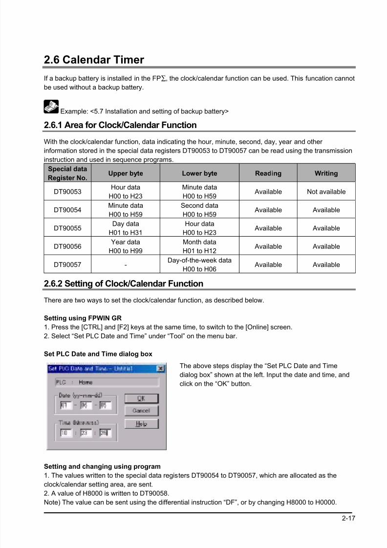
Set PLC Date and Time dialog box
The above steps display the “Set PLC Date and Time
dialog box” shown at the left. Input the date and time, and
click on the “OK” button.
Setting and changing using program
1. The values written to the special data registers DT90054 to DT90057, which are allocated as the
clock/calendar setting area, are sent.
2. A value of H8000 is written to DT90058.
Note) The value can be sent using the differential instruction “DF”, or by changing H8000 to H0000.
8/21/2019 Programmable Controller FP Sigma
http://slidepdf.com/reader/full/programmable-controller-fp-sigma 42/318
2-18
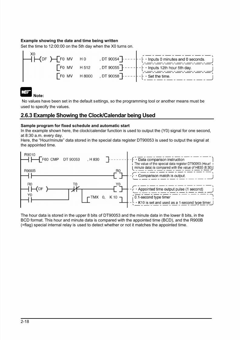
Example showing the date and time being written
Set the time to 12:00:00 on the 5th day when the X0 turns on.
Note:
No values have been set in the default settings, so the programming tool or another means must be
used to specify the values.
2.6.3 Example Showing the Clock/Calendar being Used
Sample program for fixed schedule and automatic start
In the example shown here, the clock/calendar function is used to output the (Y0) signal for one second,at 8:30 a.m. every day.Here, the “Hour/minute” data stored in the special data register DT90053 is used to output the signal atthe appointed time.
The hour data is stored in the upper 8 bits of DT90053 and the minute data in the lower 8 bits, in theBCD format. This hour and minute data is compared with the appointed time (BCD), and the R900B(=flag) special internal relay is used to detect whether or not it matches the appointed time.
8/21/2019 Programmable Controller FP Sigma
http://slidepdf.com/reader/full/programmable-controller-fp-sigma 43/318
2-19
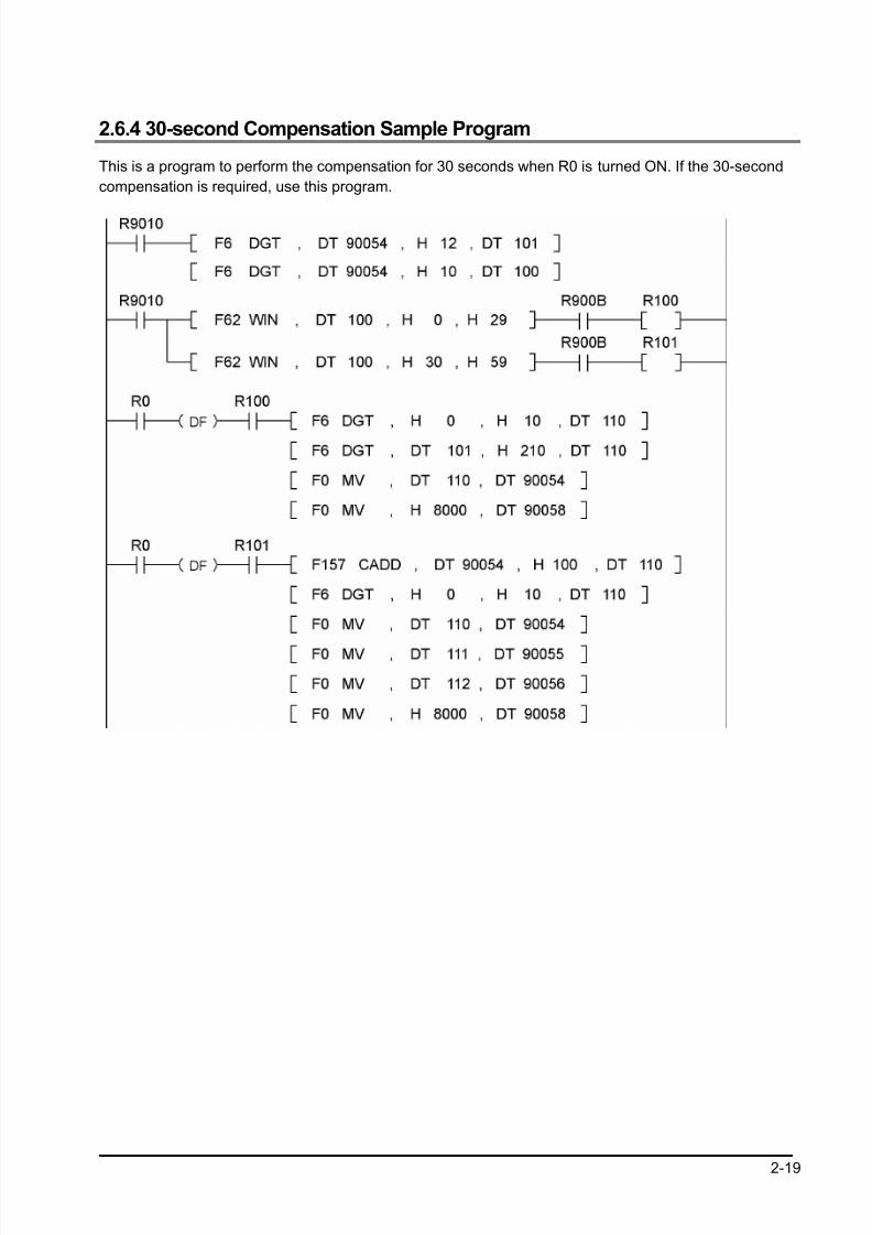
2.6.4 30-second Compensation Sample Program
This is a program to perform the compensation for 30 seconds when R0 is turned ON. If the 30-second
compensation is required, use this program.

8/21/2019 Programmable Controller FP Sigma
http://slidepdf.com/reader/full/programmable-controller-fp-sigma 44/318
2-20

8/21/2019 Programmable Controller FP Sigma
http://slidepdf.com/reader/full/programmable-controller-fp-sigma 45/318
Chapter 3
Expansion
8/21/2019 Programmable Controller FP Sigma
http://slidepdf.com/reader/full/programmable-controller-fp-sigma 46/318
3-2
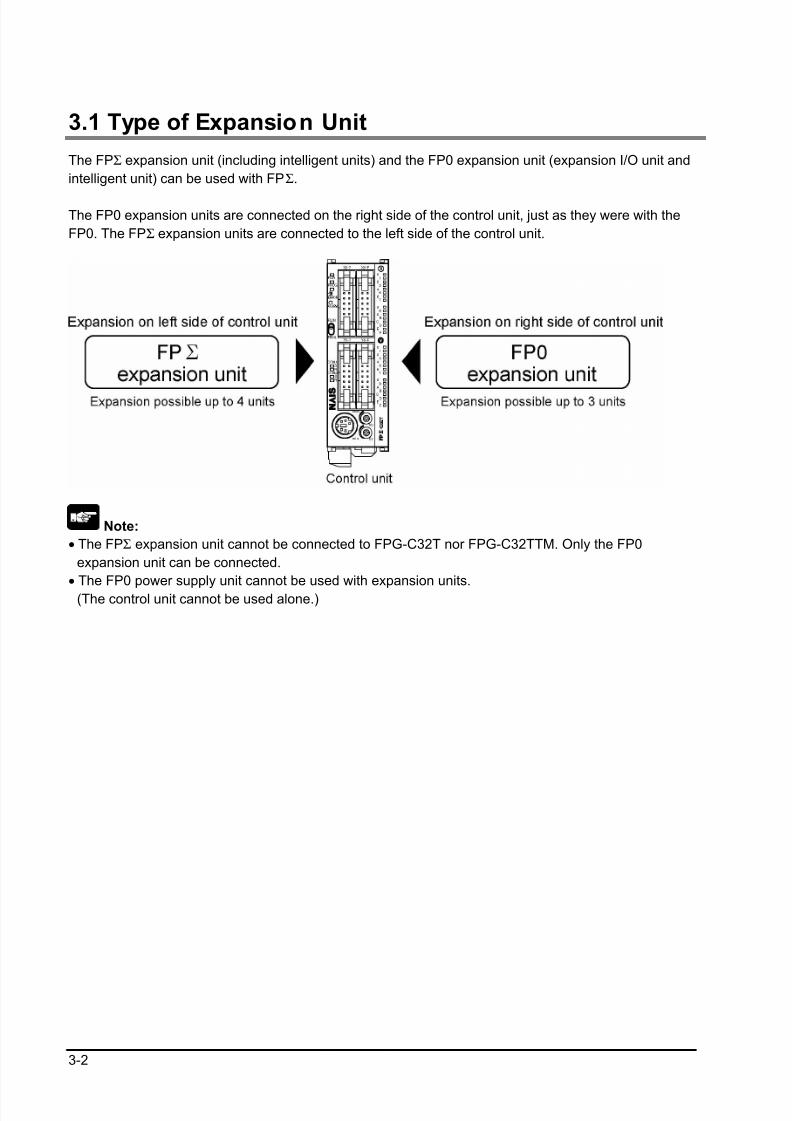
3.1 Type of Expansion Unit
The FPΣ expansion unit (including intelligent units) and the FP0 expansion unit (expansion I/O unit and
intelligent unit) can be used with FPΣ.
The FP0 expansion units are connected on the right side of the control unit, just as they were with the
FP0. The FPΣ expansion units are connected to the left side of the control unit.
Note:
• The FPΣ expansion unit cannot be connected to FPG-C32T nor FPG-C32TTM. Only the FP0
expansion unit can be connected.
• The FP0 power supply unit cannot be used with expansion units.
(The control unit cannot be used alone.)
8/21/2019 Programmable Controller FP Sigma
http://slidepdf.com/reader/full/programmable-controller-fp-sigma 47/318
3-3
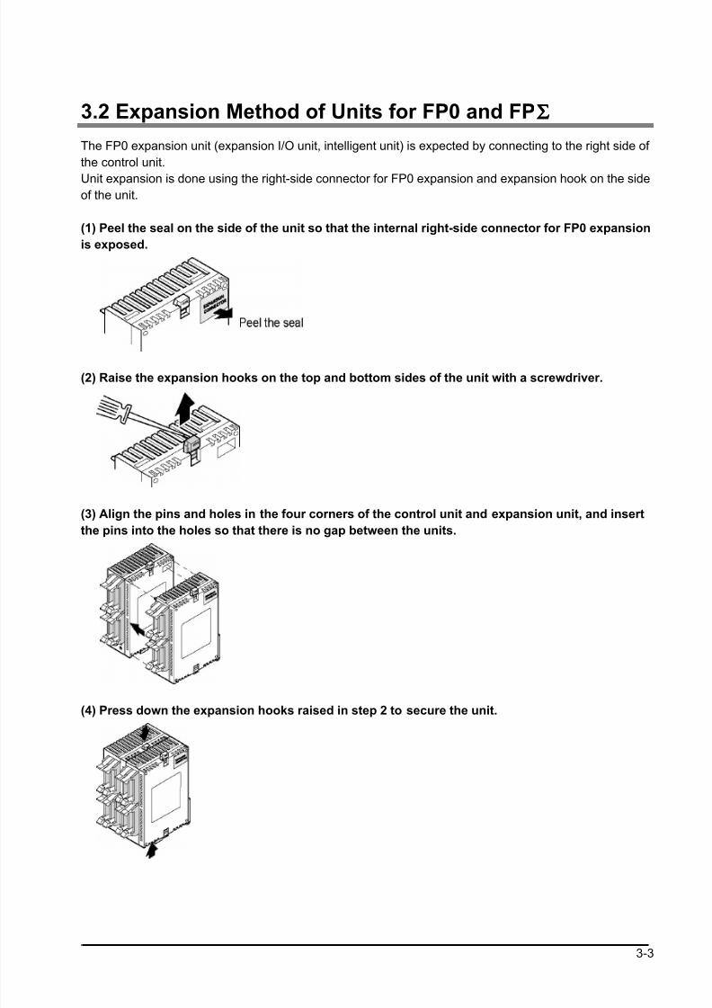
3.2 Expansion Method of Units for FP0 and FPΣΣΣΣ
The FP0 expansion unit (expansion I/O unit, intelligent unit) is expected by connecting to the right side of
the control unit.
Unit expansion is done using the right-side connector for FP0 expansion and expansion hook on the sideof the unit.
(1) Peel the seal on the side of the unit so that the internal right-side connector for FP0 expansion
is exposed.
(2) Raise the expansion hooks on the top and bottom sides of the unit with a screwdriver.
(3) Align the pins and holes in the four corners of the control unit and expansion unit, and insert
the pins into the holes so that there is no gap between the units.
(4) Press down the expansion hooks raised in step 2 to secure the unit.
8/21/2019 Programmable Controller FP Sigma
http://slidepdf.com/reader/full/programmable-controller-fp-sigma 48/318
3-4
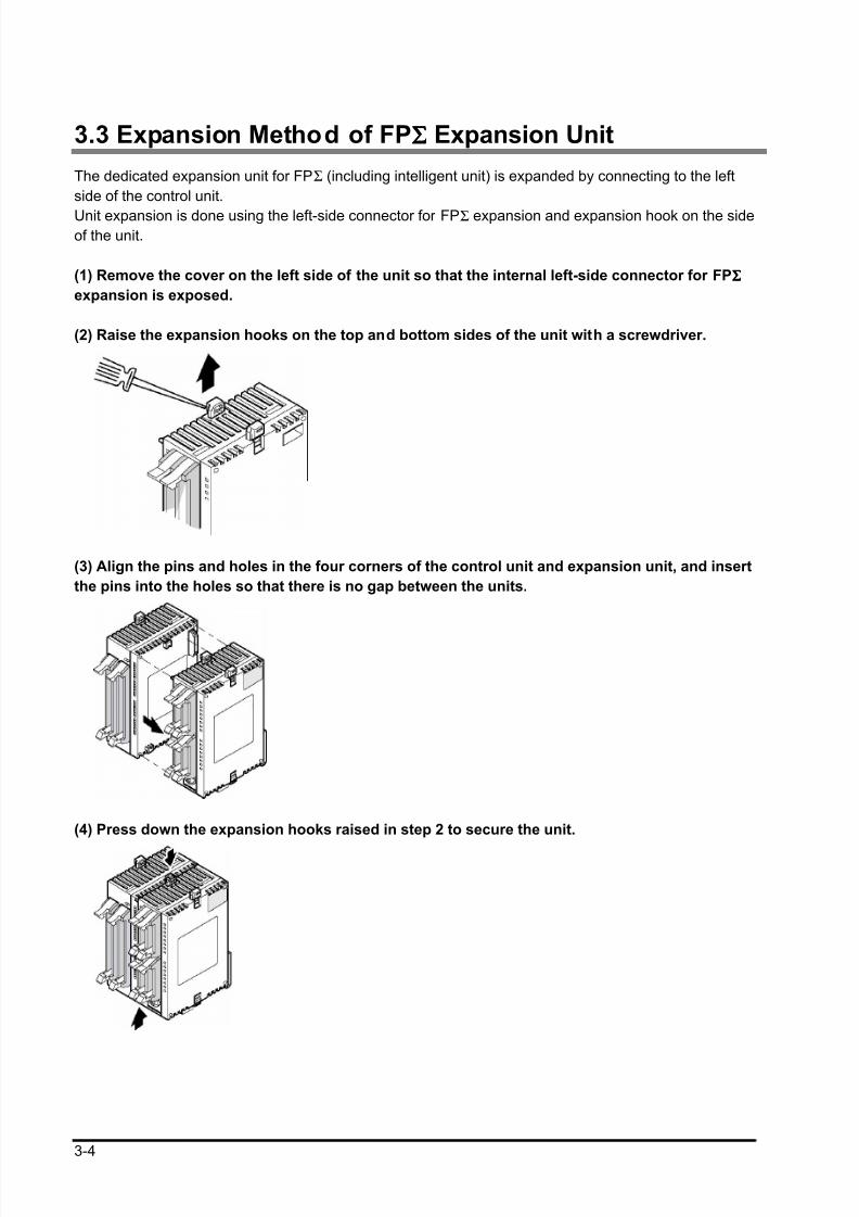
3.3 Expansion Method of FPΣΣΣΣ Expansion Unit
The dedicated expansion unit for FPΣ (including intelligent unit) is expanded by connecting to the left
side of the control unit.
Unit expansion is done using the left-side connector for FPΣ expansion and expansion hook on the sideof the unit.
(1) Remove the cover on the left side of the unit so that the internal left-side connector for FPΣΣΣΣ
expansion is exposed.
(2) Raise the expansion hooks on the top and bottom sides of the unit with a screwdriver.
(3) Align the pins and holes in the four corners of the control unit and expansion unit, and insert
the pins into the holes so that there is no gap between the units.
(4) Press down the expansion hooks raised in step 2 to secure the unit.
8/21/2019 Programmable Controller FP Sigma
http://slidepdf.com/reader/full/programmable-controller-fp-sigma 49/318
3-5
3.4 Specifications of FPΣΣΣΣ Expansion Unit
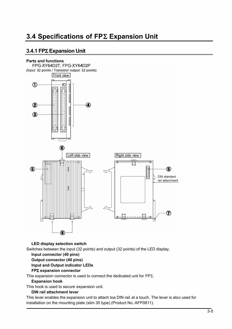
3.4.1 FPΣΣΣΣ Expansion Unit
Parts and functions
LED display selection switch
Switches between the input (32 points) and output (32 points) of the LED display.
Input connector (40 pins)
Output connector (40 pins)
Input and Output indicator LEDs
FPΣΣΣΣ expansion connector
This expansion connector is used to connect the dedicated unit for FPΣ.
Expansion hook
This hook is used to secure expansion unit. DIN rail attachment lever
This lever enables the expansion unit to attach toa DIN rail at a touch. The lever is also used for
installation on the mounting plate (slim 30 type) (Product No.:AFP0811).
8/21/2019 Programmable Controller FP Sigma
http://slidepdf.com/reader/full/programmable-controller-fp-sigma 50/318
3-6
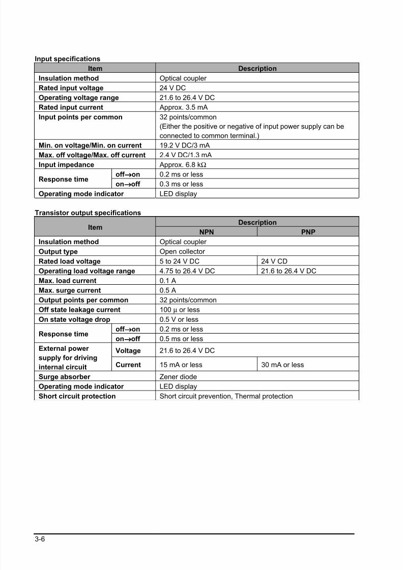
Input specifications
Item Description
Insulation method Optical coupler
Rated input voltage 24 V DC
Operating voltage range 21.6 to 26.4 V DCRated input current Approx. 3.5 mA
Input points per common 32 points/common
(Either the positive or negative of input power supply can be
connected to common terminal.)
Min. on voltage/Min. on current 19.2 V DC/3 mA
Max. off voltage/Max. off current 2.4 V DC/1.3 mA
Input impedance Approx. 6.8 kΩ
off →→→→on 0.2 ms or lessResponse time
on→→→→off 0.3 ms or less
Operating mode indicator LED display
Transistor output specifications
DescriptionItem
NPN PNP
Insulation method Optical coupler
Output type Open collector
Rated load voltage 5 to 24 V DC 24 V CD
Operating load voltage range 4.75 to 26.4 V DC 21.6 to 26.4 V DC
Max. load current 0.1 A
Max. surge current 0.5 A
Output points per common 32 points/commonOff state leakage current 100 µ or less
On state voltage drop 0.5 V or less
off →→→→on 0.2 ms or lessResponse time
on→→→→off 0.5 ms or less
Voltage 21.6 to 26.4 V DCExternal power
supply for driving
internal circuit Current 15 mA or less 30 mA or less
Surge absorber Zener diode
Operating mode indicator LED display
Short circuit protection Short circuit prevention, Thermal protection
8/21/2019 Programmable Controller FP Sigma
http://slidepdf.com/reader/full/programmable-controller-fp-sigma 51/318
3-7
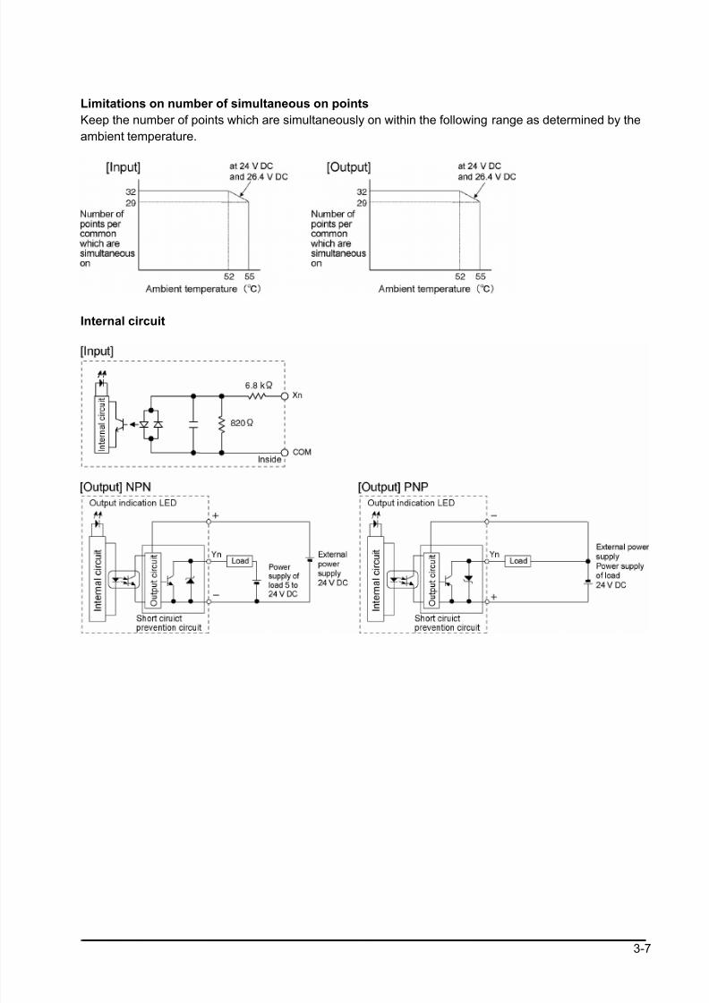
Limitations on number of simultaneous on points
Keep the number of points which are simultaneously on within the following range as determined by the
ambient temperature.
Internal circuit
8/21/2019 Programmable Controller FP Sigma
http://slidepdf.com/reader/full/programmable-controller-fp-sigma 52/318
3-8
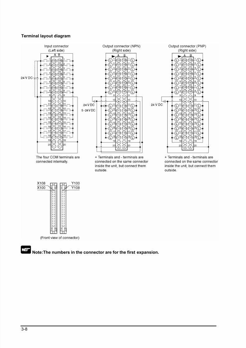
Terminal layout diagram
Note:The numbers in the connector are for the first expansion.
8/21/2019 Programmable Controller FP Sigma
http://slidepdf.com/reader/full/programmable-controller-fp-sigma 53/318
3-9
3.4.2 FPΣΣΣΣ Expansion Data Memory Unit
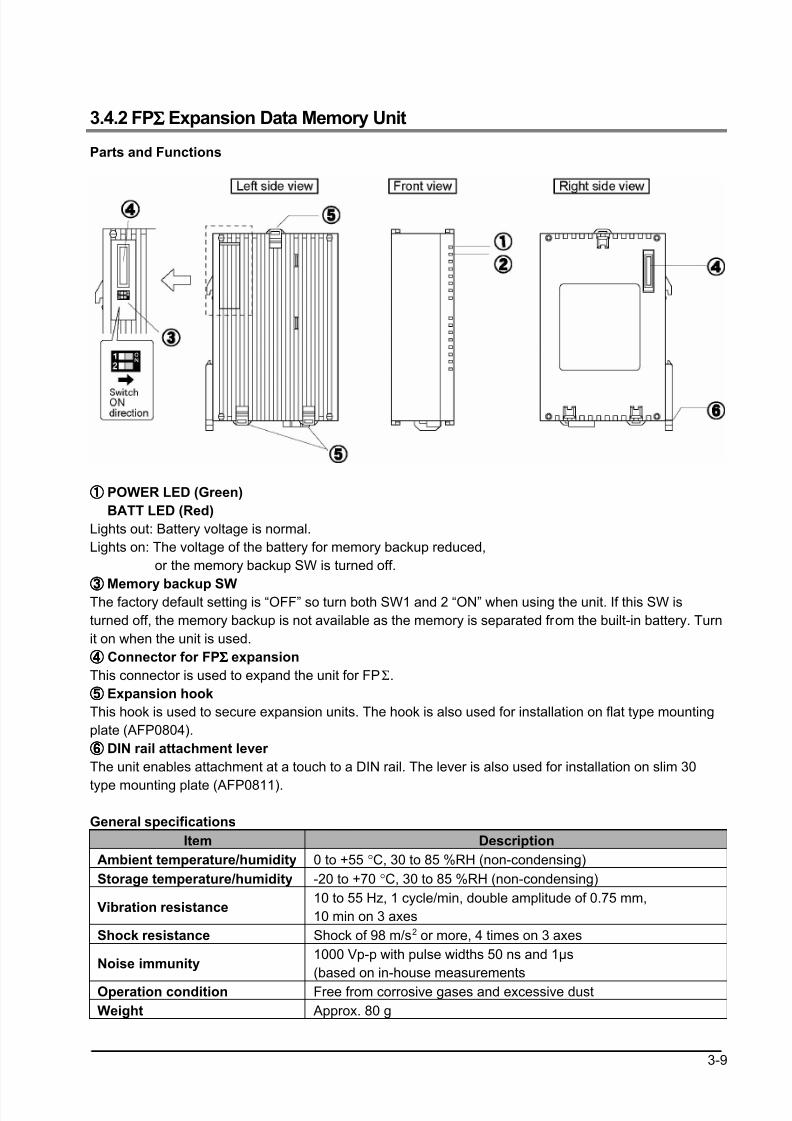
Parts and Functions
①①①① POWER LED (Green)
BATT LED (Red)
Lights out: Battery voltage is normal.
Lights on: The voltage of the battery for memory backup reduced,
or the memory backup SW is turned off.
③③③③ Memory backup SWThe factory default setting is “OFF” so turn both SW1 and 2 “ON” when using the unit. If this SW is
turned off, the memory backup is not available as the memory is separated from the built-in battery. Turn
it on when the unit is used.
④④④④ Connector for FPΣΣΣΣ expansion
This connector is used to expand the unit for FPΣ.
⑤⑤⑤⑤ Expansion hook
This hook is used to secure expansion units. The hook is also used for installation on flat type mounting
plate (AFP0804).
⑥⑥⑥⑥ DIN rail attachment lever
The unit enables attachment at a touch to a DIN rail. The lever is also used for installation on slim 30
type mounting plate (AFP0811).
General specifications
Item Description
Ambient temperature/humidity 0 to +55 °C, 30 to 85 %RH (non-condensing)
Storage temperature/humidity -20 to +70 °C, 30 to 85 %RH (non-condensing)
Vibration resistance10 to 55 Hz, 1 cycle/min, double amplitude of 0.75 mm,
10 min on 3 axes
Shock resistance Shock of 98 m/s2 or more, 4 times on 3 axes
Noise immunity1000 Vp-p with pulse widths 50 ns and 1µs
(based on in-house measurements
Operation condition Free from corrosive gases and excessive dust
Weight Approx. 80 g
8/21/2019 Programmable Controller FP Sigma
http://slidepdf.com/reader/full/programmable-controller-fp-sigma 54/318
3-10
Performance specifications
Item Description
Memory 256 k words (1k word x 256 banks)
Battery life 5 years or more
Consumption current (5V) 100 mA or lessNo of occupied I/O points Input 16 points
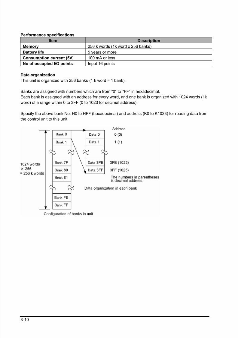
Data organization
This unit is organized with 256 banks (1 k word = 1 bank).
Banks are assigned with numbers which are from “0” to “FF” in hexadecimal.
Each bank is assigned with an address for every word, and one bank is organized with 1024 words (1k
word) of a range within 0 to 3FF (0 to 1023 for decimal address).
Specify the above bank No. H0 to HFF (hexadecimal) and address (K0 to K1023) for reading data from
the control unit to this unit.
8/21/2019 Programmable Controller FP Sigma
http://slidepdf.com/reader/full/programmable-controller-fp-sigma 55/318
3-11
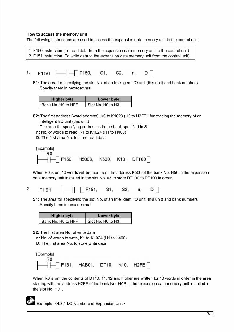
How to access the memory unit
The following instructions are used to access the expansion data memory unit to the control unit.
1. F150 instruction (To read data from the expansion data memory unit to the control unit)
2. F151 instruction (To write data to the expansion data memory unit from the control unit)
1.
S1: The area for specifying the slot No. of an Intelligent I/O unit (this unit) and bank numbers
Specify them in hexadecimal.
Higher byte Lower byte
Bank No. H0 to HFF Slot No. H0 to H3
S2: The first address (word address), K0 to K1023 (H0 to H3FF), for reading the memory of anintelligent I/O unit (this unit)
The area for specifying addresses in the bank specified in S1
n: No. of words to read, K1 to K1024 (H1 to H400)
D: The first area No. to store read data
[Example]
When R0 is on, 10 words will be read from the address K500 of the bank No. H50 in the expansiondata memory unit installed in the slot No. 03 to store DT100 to DT109 in order.
2.
S1: The area for specifying the slot No. of an Intelligent I/O unit (this unit) and bank numbers
Specify them in hexadecimal.
Higher byte Lower byte
Bank No. H0 to HFF Slot No. H0 to H3
S2: The first area No. of write datan: No. of words to write, K1 to K1024 (H1 to H400)
D: The first area No. to store write data
[Example]
When R0 is on, the contents of DT10, 11, 12 and higher are written for 10 words in order in the area
starting with the address H2FE of the bank No. HAB in the expansion data memory unit installed in
the slot No. H01.
Example: <4.3.1 I/O Numbers of Expansion Unit>
8/21/2019 Programmable Controller FP Sigma
http://slidepdf.com/reader/full/programmable-controller-fp-sigma 56/318
3-12
Note:
• The operating time for the instructions is as follows.
F150 READ : 16.19+(0.84 x No. of words to read) µs
F151 WRITE : 17.88+(0.77 x No. of words to write) µs
• If all areas are read and written in one scan, the scanning time may be over.• If you try to READ/WRITE data in multiple addresses in one scan, arrange the instructions using the
above operating time as a guide.
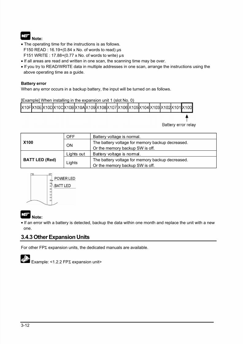
Battery error
When any error occurs in a backup battery, the input will be turned on as follows.
[Example] When installing in the expansion unit 1 (slot No. 0)
OFF Battery voltage is normal.
X100ON
The battery voltage for memory backup decreased.
Or the memory backup SW is off.
Lights out Battery voltage is normal.
BATT LED (Red)Lights
The battery voltage for memory backup decreased.
Or the memory backup SW is off.
Note:
• If an error with a battery is detected, backup the data within one month and replace the unit with a new
one.
3.4.3 Other Expansion Units
For other FPΣ expansion units, the dedicated manuals are available.
Example: <1.2.2 FPΣ expansion unit>

8/21/2019 Programmable Controller FP Sigma
http://slidepdf.com/reader/full/programmable-controller-fp-sigma 57/318
Chapter 4
I/O Allocation
8/21/2019 Programmable Controller FP Sigma
http://slidepdf.com/reader/full/programmable-controller-fp-sigma 58/318
4-2
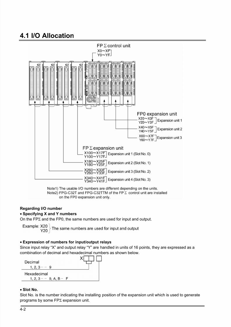
4.1 I/O Allocation
Regarding I/O number
• Specifying X and Y numbers
On the FPΣ and the FP0, the same numbers are used for input and output.
• Expression of numbers for input/output relays
Since input relay “X” and output relay “Y” are handled in units of 16 points, they are expressed as a
combination of decimal and hexadecimal numbers as shown below.
• Slot No.
Slot No. is the number indicating the installing position of the expansion unit which is used to generate
programs by some FPΣ expansion unit.
8/21/2019 Programmable Controller FP Sigma
http://slidepdf.com/reader/full/programmable-controller-fp-sigma 59/318
4-3
4.2 Allocation of FPΣΣΣΣ Control Unit
4.2.1 I /O Number of FPΣΣΣΣ Control Unit
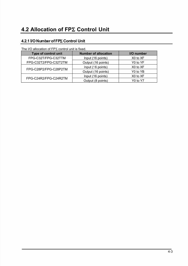
The I/O allocation of FPΣ control unit is fixed.
Type of control unit Number of allocation I/O number
Input (16 points) X0 to XFFPG-C32T/FPG-C32TTM
FPG-C32T2/FPG-C32T2TM Output (16 points) Y0 to YF
Input (16 points) X0 to XFFPG-C28P2/FPG-C28P2TM
Output (16 points) Y0 to YB
Input (16 points) X0 to XFFPG-C24R2/FPG-C24R2TM
Output (8 points) Y0 to Y7
8/21/2019 Programmable Controller FP Sigma
http://slidepdf.com/reader/full/programmable-controller-fp-sigma 60/318
4-4
4.3 Allocation of FPΣΣΣΣ Expansion Unit
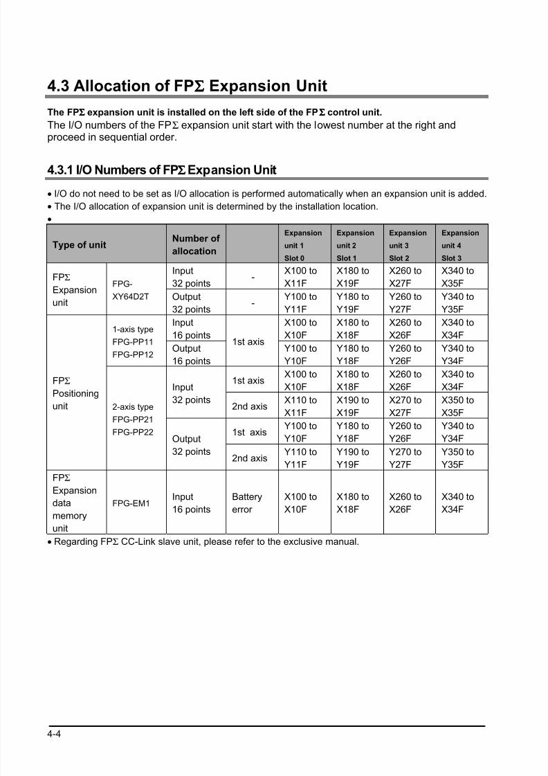
The FPΣΣΣΣ expansion unit is installed on the left side of the FPΣΣΣΣ control unit.
The I/O numbers of the FPΣ expansion unit start with the lowest number at the right and
proceed in sequential order.
4.3.1 I/O Numbers of FPΣΣΣΣ Expansion Unit
• I/O do not need to be set as I/O allocation is performed automatically when an expansion unit is added.
• The I/O allocation of expansion unit is determined by the installation location.
•
Type of unitNumber of
allocation
Expansion
unit 1
Slot 0
Expansion
unit 2
Slot 1
Expansion
unit 3
Slot 2
Expansion
unit 4
Slot 3
Input32 points
- X100 toX11F
X180 toX19F
X260 toX27F
X340 toX35F
FPΣ
Expansion
unit
FPG-
XY64D2T Output
32 points-
Y100 to
Y11F
Y180 to
Y19F
Y260 to
Y27F
Y340 to
Y35F
Input
16 points
X100 to
X10F
X180 to
X18F
X260 to
X26F
X340 to
X34F1-axis type
FPG-PP11
FPG-PP12Output
16 points
1st axisY100 to
Y10F
Y180 to
Y18F
Y260 to
Y26F
Y340 to
Y34F
1st axisX100 to
X10F
X180 to
X18F
X260 to
X26F
X340 to
X34FInput
32 points
2nd axis
X110 to
X11F
X190 to
X19F
X270 to
X27F
X350 to
X35F
1st axisY100 to
Y10F
Y180 to
Y18F
Y260 to
Y26F
Y340 to
Y34F
FPΣ
Positioning
unit 2-axis typeFPG-PP21
FPG-PP22Output
32 points2nd axis
Y110 to
Y11F
Y190 to
Y19F
Y270 to
Y27F
Y350 to
Y35F
FPΣ
Expansion
data
memory
unit
FPG-EM1Input
16 points
Battery
error
X100 to
X10F
X180 to
X18F
X260 to
X26F
X340 to
X34F
• Regarding FPΣ CC-Link slave unit, please refer to the exclusive manual.
8/21/2019 Programmable Controller FP Sigma
http://slidepdf.com/reader/full/programmable-controller-fp-sigma 61/318
4-5
4.4 Allocation of FP0 Expansion Unit
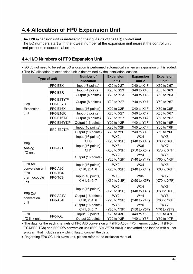
The FP0 expansion unit is installed on the right side of the FPΣΣΣΣ control unit.
The I/O numbers start with the lowest number at the expansion unit nearest the control unit
and proceed in sequential order.
4.4.1 I/O Numbers of FP0 Expansion Unit
• I/O do not need to be set as I/O allocation is performed automatically when an expansion unit is added.
• The I/O allocation of expansion unit is determined by the installation location.
Type of unitNumber of
allocation
Expansion
unit 1
Expansion
unit 2
Expansion
unit 3
FP0-E8X Input (8 points) X20 to X27 X40 to X47 X60 to X67
Input (4 points) X20 to X23 X40 to X43 X60 to X63FP0-E8R
Output (4 points) Y20 to Y23 Y40 to Y43 Y60 to Y63FP0-E8TY/P
FP0-E8YROutput (8 points) Y20 to Y27 Y40 to Y47 Y60 to Y67
FP0-E16X Input (16 points) X20 to X2F X40 to X4F X60 to X6F
Input (8 points) X20 to X27 X40 to X47 X60 to X67FP0-E16R
FP0-E16T/P Output (8 points) Y20 to Y27 Y40 to Y47 Y60 to Y67
FP0-E16YT/P Output (16 points) Y20 to Y2F Y40 to Y4F Y60 to Y6F
Input (16 points) X20 to X2F X40 to X4F Y60 to Y6F
FP0
Expansion
unit
EP0-E32T/POutput (16 points) Y20 to Y2F Y40 to Y4F Y60 to Y6F
Input (16 points)
CH0
WX2
(X20 to X2F)
WX4
(X40 to X4F)
WX6
(X60 to X6F)
Input (16 points)
CH1
WX3
(X30 to X3F)
WX5
(X50 to X5F)
WX7
(X70 to X7F)
FP0 Analog
I/O unit
FP0-A21
Output (16 points)WY2
(Y20 to Y2F)
WY4
(Y40 to Y4F)
WY6
(Y60 to Y6F)
Input (16 points)
CH0, 2, 4, 6
WX2
(X20 to X2F)
WX4
(X40 to X4F)
WX6
(X60 to X6F)
FP0 A/D
conversion unit
FP0
thermocouple
unit
FP0-A80
FP0-TC4
FP0-TC8 Input (16 points)
CH1, 3, 5, 7
WX3
(X30 to X3F)
WX5
(X50 to X5F)
WX7
(X70 to X7F)
Input (16 points)WX2
(X20 to X2F)
WX4
(X40 to X4F)
WX6
(X60 to X6F)Output (16 points)
CH0, 2, 4, 6
WY2
(Y20 to Y2F)
WY4
(Y40 to Y4F)
WY6
(Y60 to Y6F)
FP0 D/A
conversion
unit
FP0-A04V
FP0-A04I
Output (16 points)
CH1, 3, 5, 7
WY3
(Y30 to Y3F)
WY5
(Y50 to Y5F)
WY7
Y70 to Y7F)
Input 32 points X20 to X3F X40 to X5F X60 to X7FFP0
I/O link unitFP0-IOL
Output 32 points Y20 to Y3F Y40 to Y5F Y60 to Y7F
• The data for the each channels of FP0 A/D conversion unit (FP0-A80), FP0 thermocouple unit (FP0-
TC4/FP0-TC8) and FP0 D/A conversion unit (FP0-A04V/FP0-A04I) is converted and loaded with a user
program that includes a switching flag to convert the data.
• Regarding FP0 CC-Link slave unit, please refer to the exclusive manual.

8/21/2019 Programmable Controller FP Sigma
http://slidepdf.com/reader/full/programmable-controller-fp-sigma 62/318
4-6

8/21/2019 Programmable Controller FP Sigma
http://slidepdf.com/reader/full/programmable-controller-fp-sigma 63/318
Chapter 5
Installation and Wiring
8/21/2019 Programmable Controller FP Sigma
http://slidepdf.com/reader/full/programmable-controller-fp-sigma 64/318
5-2
5.1 Installation
5.1.1 Installation Environment and Space
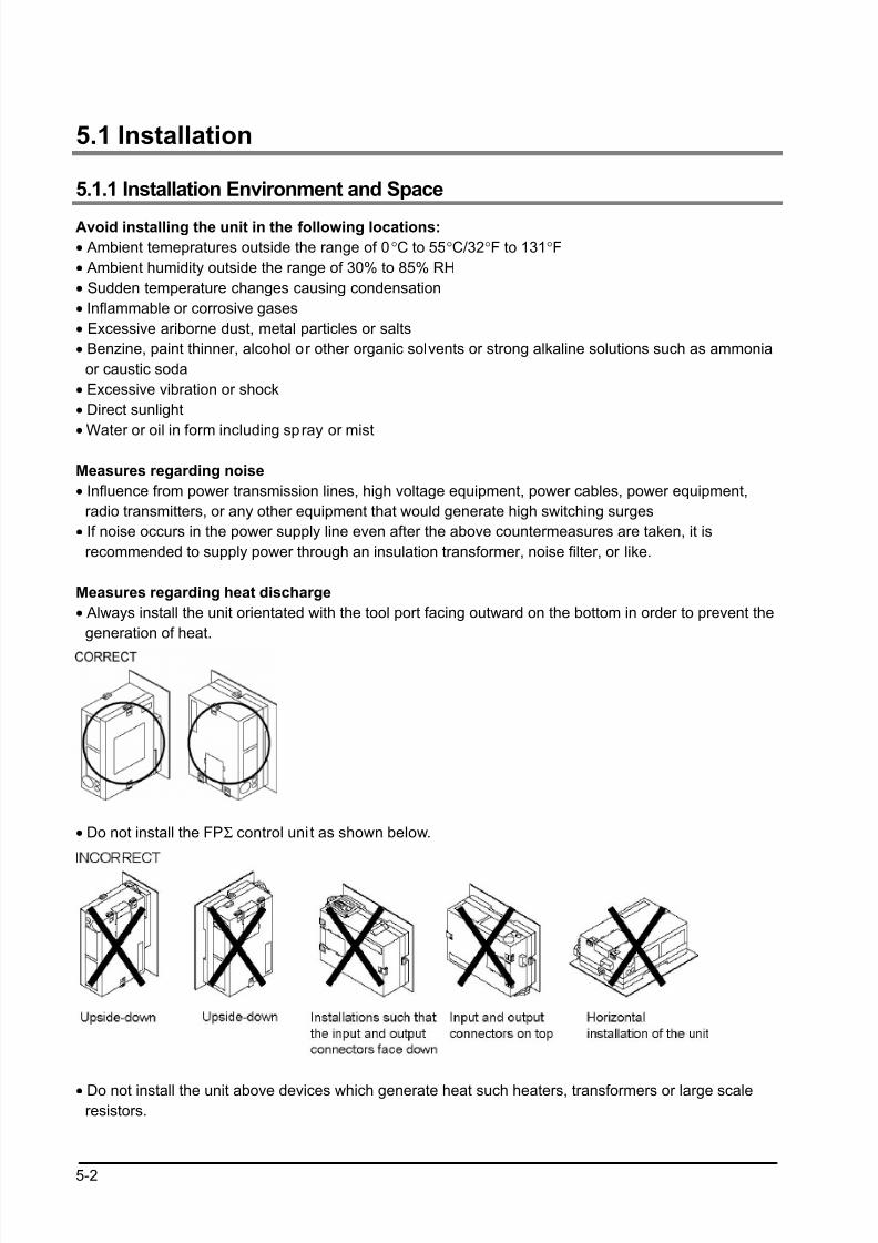
Avoid installing the unit in the following locations:
• Ambient temepratures outside the range of 0°C to 55°C/32°F to 131°F
• Ambient humidity outside the range of 30% to 85% RH
• Sudden temperature changes causing condensation
• Inflammable or corrosive gases
• Excessive ariborne dust, metal particles or salts
• Benzine, paint thinner, alcohol or other organic solvents or strong alkaline solutions such as ammonia
or caustic soda
• Excessive vibration or shock
• Direct sunlight
• Water or oil in form including spray or mist
Measures regarding noise
• Influence from power transmission lines, high voltage equipment, power cables, power equipment,
radio transmitters, or any other equipment that would generate high switching surges
• If noise occurs in the power supply line even after the above countermeasures are taken, it is
recommended to supply power through an insulation transformer, noise filter, or like.
Measures regarding heat discharge
• Always install the unit orientated with the tool port facing outward on the bottom in order to prevent the
generation of heat.
• Do not install the FPΣ control uni t as shown below.
• Do not install the unit above devices which generate heat such heaters, transformers or large scaleresistors.
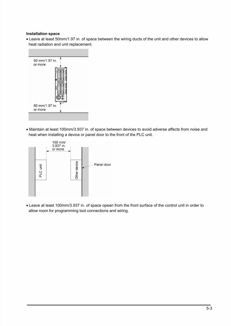
8/21/2019 Programmable Controller FP Sigma
http://slidepdf.com/reader/full/programmable-controller-fp-sigma 65/318
5-3
Installation space
• Leave at least 50mm/1.97 in. of space between the wiring ducts of the unit and other devices to allow
heat radiation and unit replacement.
• Maintain at least 100mm/3.937 in. of space between devices to avoid adverse affects from noise and
heat when installing a device or panel door to the front of the PLC unit.
• Leave at least 100mm/3.937 in. of space opean from the front surface of the control unit in order to
allow room for programming tool connections and wiring.
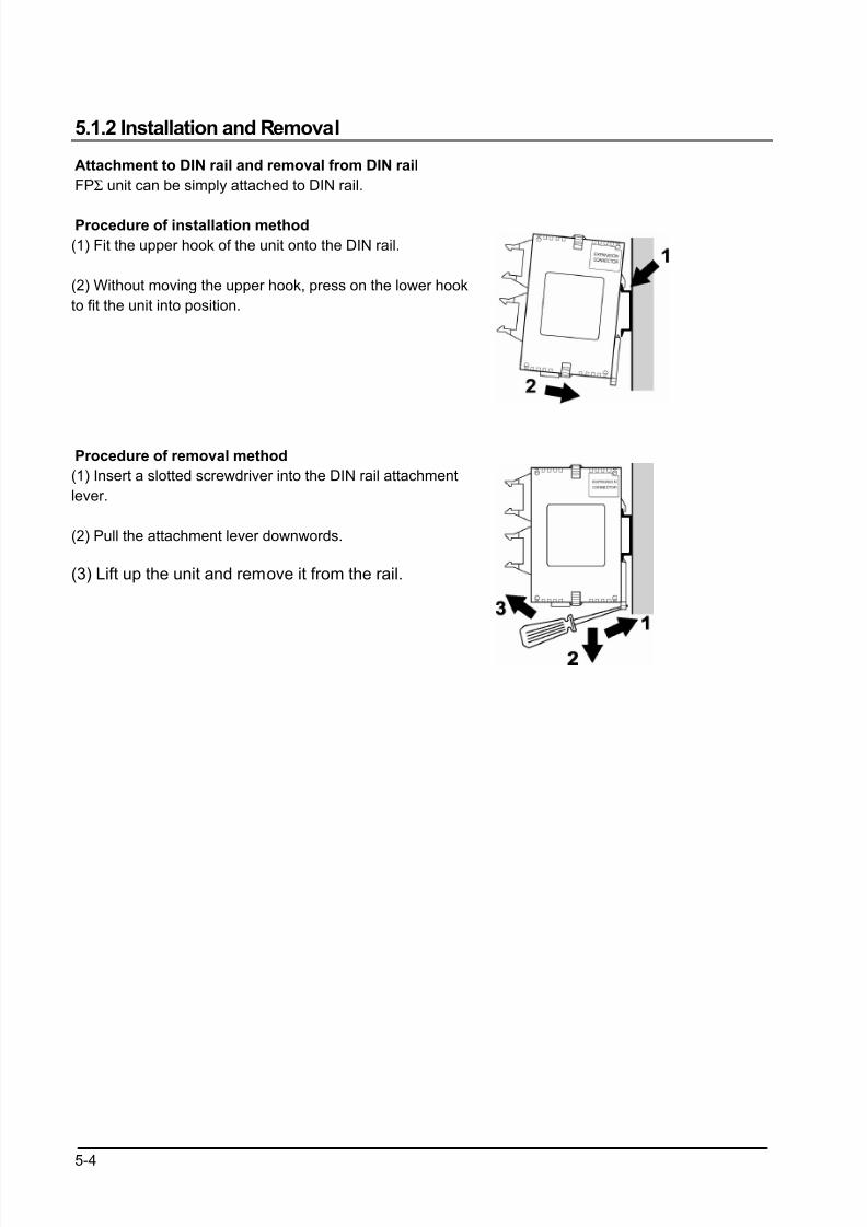
8/21/2019 Programmable Controller FP Sigma
http://slidepdf.com/reader/full/programmable-controller-fp-sigma 66/318
5-4
5.1.2 Installation and Removal
Attachment to DIN rail and removal from DIN rail
FPΣ unit can be simply attached to DIN rail.
Procedure of installation method
(1) Fit the upper hook of the unit onto the DIN rail.
(2) Without moving the upper hook, press on the lower hook
to fit the unit into position.
Procedure of removal method
(1) Insert a slotted screwdriver into the DIN rail attachment
lever.
(2) Pull the attachment lever downwords.
(3) Lift up the unit and remove it from the rail.
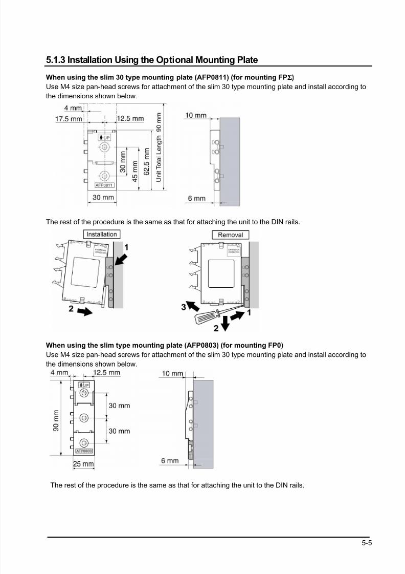
8/21/2019 Programmable Controller FP Sigma
http://slidepdf.com/reader/full/programmable-controller-fp-sigma 67/318
5-5
5.1.3 Installation Using the Optional Mounting Plate
When using the slim 30 type mounting plate (AFP0811) (for mounting FPΣΣΣΣ)
Use M4 size pan-head screws for attachment of the slim 30 type mounting plate and install according to
the dimensions shown below.
The rest of the procedure is the same as that for attaching the unit to the DIN rails.
When using the slim type mounting plate (AFP0803) (for mounting FP0)
Use M4 size pan-head screws for attachment of the slim 30 type mounting plate and install according to
the dimensions shown below.
The rest of the procedure is the same as that for attaching the unit to the DIN rails.
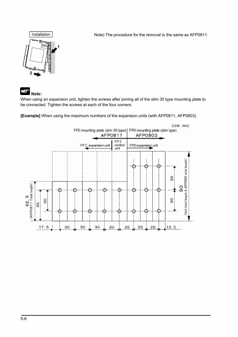
8/21/2019 Programmable Controller FP Sigma
http://slidepdf.com/reader/full/programmable-controller-fp-sigma 68/318
5-6
Note) The procedure for the removal is the same as AFP0811.
Note:
When using an expansion unit, tighten the screws after joining all of the slim 30 type mounting plate to
be connected. Tighten the screws at each of the four corners.
[Example] When using the maximum numbers of the expansion units (with AFP0811, AFP0803)
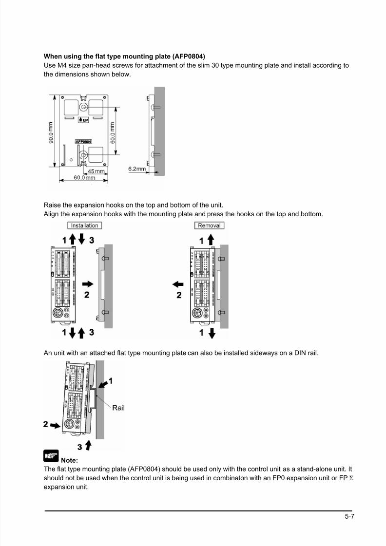
8/21/2019 Programmable Controller FP Sigma
http://slidepdf.com/reader/full/programmable-controller-fp-sigma 69/318
5-7
When using the flat type mounting plate (AFP0804)
Use M4 size pan-head screws for attachment of the slim 30 type mounting plate and install according to
the dimensions shown below.
Raise the expansion hooks on the top and bottom of the unit.
Align the expansion hooks with the mounting plate and press the hooks on the top and bottom.
An unit with an attached flat type mounting plate can also be installed sideways on a DIN rail.
Note:
The flat type mounting plate (AFP0804) should be used only with the control unit as a stand-alone unit. It
should not be used when the control unit is being used in combinaton with an FP0 expansion unit or FPΣ
expansion unit.
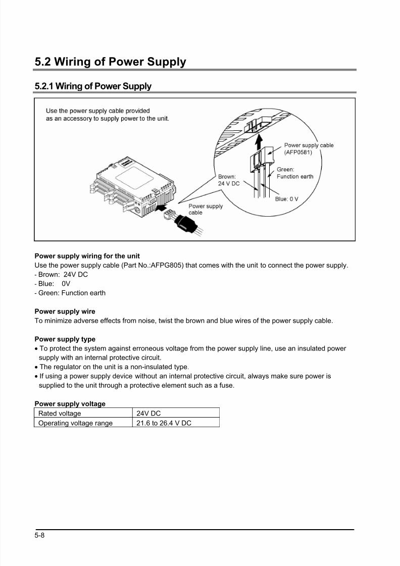
8/21/2019 Programmable Controller FP Sigma
http://slidepdf.com/reader/full/programmable-controller-fp-sigma 70/318
5-8
5.2 Wiring of Power Supply
5.2.1 Wiring of Power Supply
Power supply wiring for the unit
Use the power supply cable (Part No.:AFPG805) that comes with the unit to connect the power supply.
- Brown: 24V DC
- Blue: 0V
- Green: Function earth
Power supply wire
To minimize adverse effects from noise, twist the brown and blue wires of the power supply cable.
Power supply type
• To protect the system against erroneous voltage from the power supply line, use an insulated power
supply with an internal protective circuit.
• The regulator on the unit is a non-insulated type.
• If using a power supply device without an internal protective circuit, always make sure power is
supplied to the unit through a protective element such as a fuse.
Power supply voltage
Rated voltage 24V DC
Operating voltage range 21.6 to 26.4 V DC
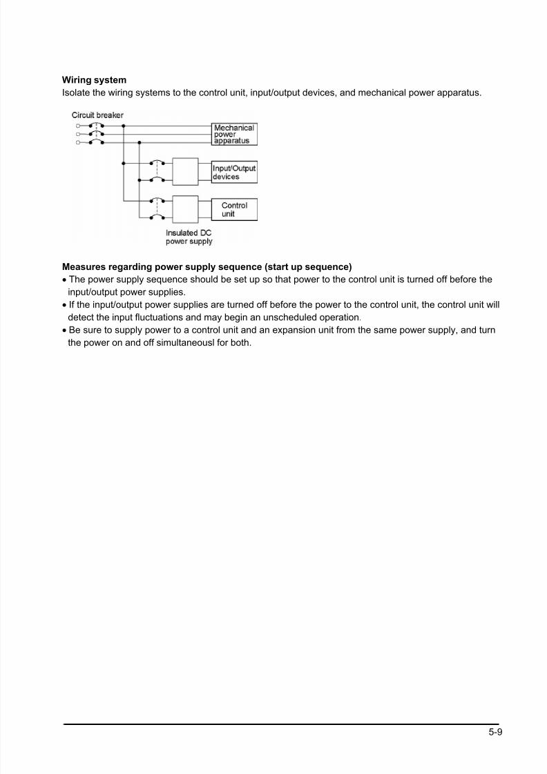
8/21/2019 Programmable Controller FP Sigma
http://slidepdf.com/reader/full/programmable-controller-fp-sigma 71/318
5-9
Wiring system
Isolate the wiring systems to the control unit, input/output devices, and mechanical power apparatus.
Measures regarding power supply sequence (start up sequence)• The power supply sequence should be set up so that power to the control unit is turned off before the
input/output power supplies.
• If the input/output power supplies are turned off before the power to the control unit, the control unit will
detect the input fluctuations and may begin an unscheduled operation.
• Be sure to supply power to a control unit and an expansion unit from the same power supply, and turn
the power on and off simultaneousl for both.
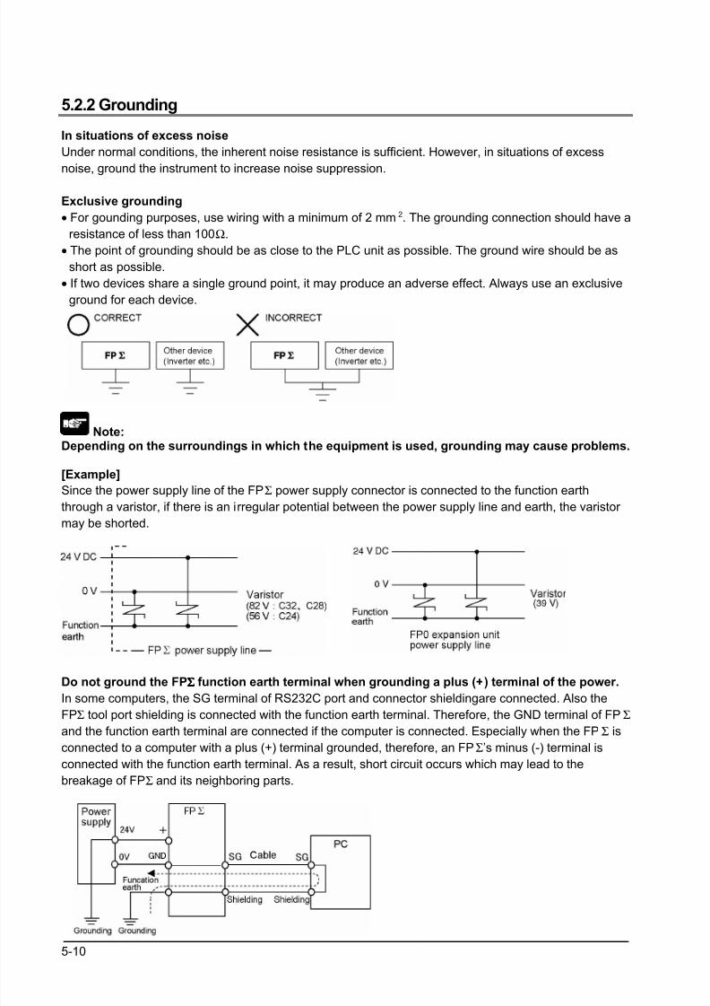
8/21/2019 Programmable Controller FP Sigma
http://slidepdf.com/reader/full/programmable-controller-fp-sigma 72/318
5-10
5.2.2 Grounding
In situations of excess noise
Under normal conditions, the inherent noise resistance is sufficient. However, in situations of excess
noise, ground the instrument to increase noise suppression.
Exclusive grounding
• For gounding purposes, use wiring with a minimum of 2 mm 2. The grounding connection should have a
resistance of less than 100Ω.
• The point of grounding should be as close to the PLC unit as possible. The ground wire should be as
short as possible.
• If two devices share a single ground point, it may produce an adverse effect. Always use an exclusive
ground for each device.
Note:Depending on the surroundings in which the equipment is used, grounding may cause problems.
[Example]
Since the power supply line of the FPΣ power supply connector is connected to the function earth
through a varistor, if there is an irregular potential between the power supply line and earth, the varistor
may be shorted.
Do not ground the FPΣΣΣΣ function earth terminal when grounding a plus (+) terminal of the power.
In some computers, the SG terminal of RS232C port and connector shieldingare connected. Also the
FPΣ tool port shielding is connected with the function earth terminal. Therefore, the GND terminal of FPΣ
and the function earth terminal are connected if the computer is connected. Especially when the FPΣ is
connected to a computer with a plus (+) terminal grounded, therefore, an FPΣ’s minus (-) terminal is
connected with the function earth terminal. As a result, short circuit occurs which may lead to the
breakage of FPΣ and its neighboring parts.
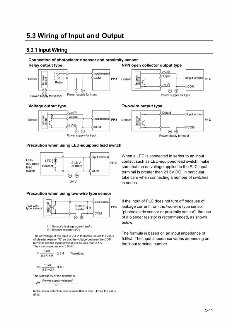
8/21/2019 Programmable Controller FP Sigma
http://slidepdf.com/reader/full/programmable-controller-fp-sigma 73/318
5-11
5.3 Wiring of Input and Output
5.3.1 Input Wiring
Connection of photoelectric sensor and proximity sensor
Relay output type NPN open collector output type
Voltage output type Two-wire output type
Precaution when using LED-equipped lead switch
When a LED is connected in series to an input
contact such as LED-equipped lead switch, make
sure that the on voltage applied to the PLC input
terminal is greater than 21.6V DC. In particular,take care when connecting a number of switches
in series.
Precaution when using two-wire type sensor
If the input of PLC does not turn off because of
leakage current from the two-wire type sensor
“photoelectric sensor or proximity sensor”, the use
of a bleeder resistor is recommended, as shown
below.
The formula is based on an input impedance of
5.6kΩ. The input impedance varies depending on
the input terminal number.
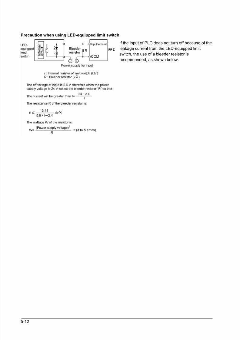
8/21/2019 Programmable Controller FP Sigma
http://slidepdf.com/reader/full/programmable-controller-fp-sigma 74/318
5-12
Precaution when using LED-equipped limit switch
If the input of PLC does not turn off because of the
leakage current from the LED-equipped limit
switch, the use of a bleeder resistor is
recommended, as shown below.
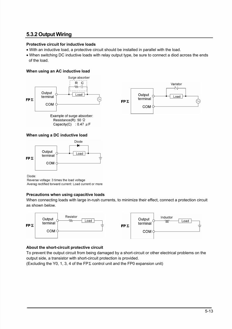
8/21/2019 Programmable Controller FP Sigma
http://slidepdf.com/reader/full/programmable-controller-fp-sigma 75/318
5-13
5.3.2 Output Wiring
Protective circuit for inductive loads
• With an inductive load, a protective circuit should be installed in parallel with the load.
• When switching DC inductive loads with relay output type, be sure to connect a diod across the ends
of the load.
When using an AC inductive load
When using a DC inductive load
Precautions when using capacitive loads
When connecting loads with large in-rush currents, to minimize their effect, connect a protection circuit
as shown below.
About the short-circuit protective circuit
To prevent the output circuit from being damaged by a short-circuit or other electrical problems on the
output side, a transistor with short-circuit protection is provided.
(Excluding the Y0, 1, 3, 4 of the FPΣ control unit and the FP0 expansion unit)

8/21/2019 Programmable Controller FP Sigma
http://slidepdf.com/reader/full/programmable-controller-fp-sigma 76/318
5-14
5.3.3 Precautions Regarding Input and Output Wirings
• Be sure to select the thickness (dia.) of the input and output wires while taking into consideration the
required current capacity.
• Arrange the wiring so that the input and output wiring are separated, and these wirings are separated
from the power wiring, as much as possible. Do not route them through the same duct or wrap them up
together.
• Separate the input/output wires from the power and high voltage wires by at least 100mm/3.937 in.
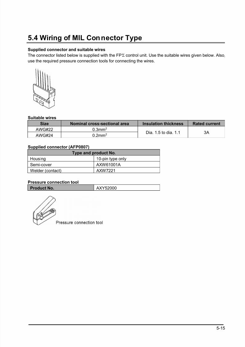
8/21/2019 Programmable Controller FP Sigma
http://slidepdf.com/reader/full/programmable-controller-fp-sigma 77/318
5-15
5.4 Wiring of MIL Connector Type
Supplied connector and suitable wires
The connector listed below is supplied with the FPΣ control unit. Use the suitable wires given below. Also,
use the required pressure connection tools for connecting the wires.
Suitable wires
Size Nominal cross-sectional area Insulation thickness Rated current
AWG#22 0.3mm2
AWG#24 0.2mm2Dia. 1.5 to dia. 1.1 3A
Supplied connector (AFP0807)
Type and product No.
Housing 10-pin type only
Semi-cover AXW61001A
Welder (contact) AXW7221
Pressure connection toolProduct No. AXY52000
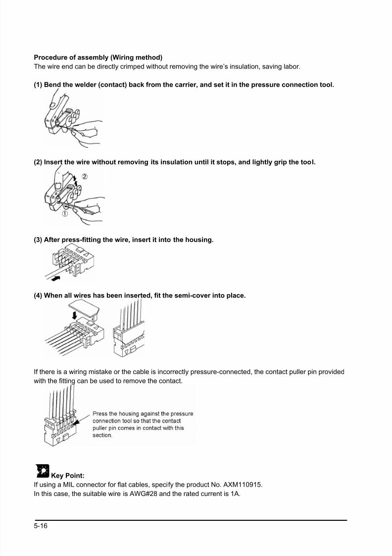
8/21/2019 Programmable Controller FP Sigma
http://slidepdf.com/reader/full/programmable-controller-fp-sigma 78/318
5-16
Procedure of assembly (Wiring method)
The wire end can be directly crimped without removing the wire’s insulation, saving labor.
(1) Bend the welder (contact) back from the carrier, and set it in the pressure connection tool.
(2) Insert the wire without removing its insulation until it stops, and lightly grip the tool.
(3) After press-fitting the wire, insert it into the housing.
(4) When all wires has been inserted, fit the semi-cover into place.
If there is a wiring mistake or the cable is incorrectly pressure-connected, the contact puller pin provided
with the fitting can be used to remove the contact.
Key Point:
If using a MIL connector for flat cables, specify the product No. AXM110915.In this case, the suitable wire is AWG#28 and the rated current is 1A.

8/21/2019 Programmable Controller FP Sigma
http://slidepdf.com/reader/full/programmable-controller-fp-sigma 79/318
5-17
5.5 Wiring of Terminal Block Type
A screw-down connection type for terminal block is used. The suitable wires are given below.
Terminal block socket
Item Description
Number of pin 9 pins
Manufacturer Phoenix Contact Co.
Model No. MC1,5/9-ST-3,5
Product No. 1840434
Suitable wires
Size Nominal cross-sectional area
AWG #22 0.3mm2
AWG #24 to 16 0.2 to 1.25mm2
Pole terminal with a compatible insulation sleeve
If a pole terminal is being used, the following models manufactured by Phoenix Contact Co. should be
used.Manufacturer Cross-sectional area (mm2) Size Part No.
0.25 AWG #24 AI 0,25 – 6 YE
0.50 AWG #20 AI 0,5 – 6 WH
0.75 AWG #18 AI 0,75 – 6 GY
1.00 AWG #18 AI 1 – 6 RD
Phoenix Contact
Co.
0.5×2 AWG #20 (for 2 pcs) AI – TWIN 2×0.5 – 8 WH
Pressure welding tool for pole terminals
Manufacturer Part No. Product No.
Phoenix Contact Co. CRIMPFOX UD6 1204436
For tightening the terminal block
When tightening the terminals of the terminal block, use a screwdriver (Phoenix contact Co., Product No.
1205037) with a blade size of 0.4 × 2.5 (Part No. SZS 0,4×2,5).
The tightening torque should be 0.22 to 0.25 N m (2.3 to 2.5 kgf cm) or less.
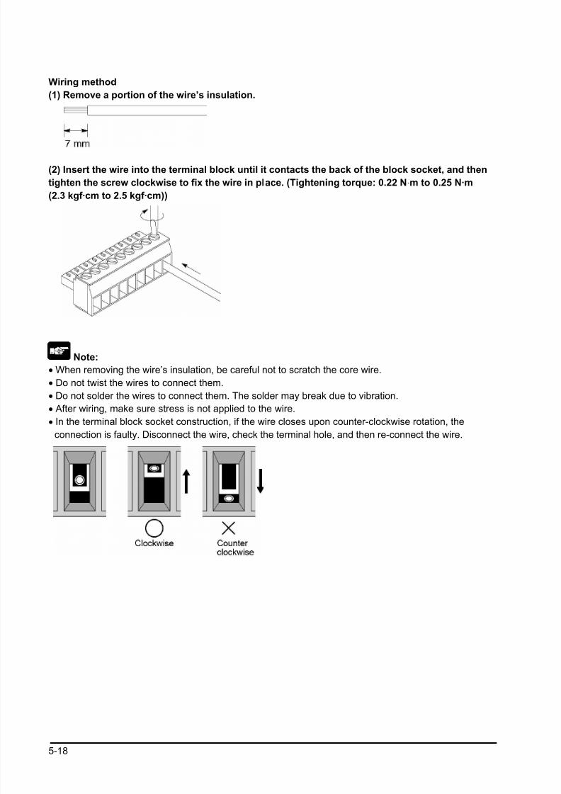
8/21/2019 Programmable Controller FP Sigma
http://slidepdf.com/reader/full/programmable-controller-fp-sigma 80/318
5-18
Wiring method
(1) Remove a portion of the wire’s insulation.
(2) Insert the wire into the terminal block until it contacts the back of the block socket, and then
tighten the screw clockwise to fix the wire in place. (Tightening torque: 0.22 N·m to 0.25 N·m
(2.3 kgf·cm to 2.5 kgf·cm))
Note:
• When removing the wire’s insulation, be careful not to scratch the core wire.
• Do not twist the wires to connect them.
• Do not solder the wires to connect them. The solder may break due to vibration.
• After wiring, make sure stress is not applied to the wire.
• In the terminal block socket construction, if the wire closes upon counter-clockwise rotation, the
connection is faulty. Disconnect the wire, check the terminal hole, and then re-connect the wire.
8/21/2019 Programmable Controller FP Sigma
http://slidepdf.com/reader/full/programmable-controller-fp-sigma 81/318
5-19
5.6 Safety Measures
5.6.1 Safety Measures
Precautions regarding system design
In certain applications, malfunction may occur for the following reasons:
• Power on timing differences between the PLC system and input/output or mechanical power apparatus.
• Response time lag when a momentary power drop occurs.
• Abnormality in the PLC unit, external power supply, or other devices.
In order to prevent a malfunction resulting in system shutdown choose the adequate safety measures
listed in the following:
Interlock circuitWhen a motor clockwise/counter-clockwise operation is controlled, provide an interlock circuit externally.
Emergency stop circuit
Provide an emergency stop circuit to the PLC externally to turn off the power supply of the output device.
Start up sequence
The PLC should be operated after all of the outside devices are energized. To keep this sequence, the
following measures are recommended:
• Turn on the PLC with the mode selector set to the PROG. mode, and then switch to the RUN mode.
• Program the PLC so as to disregard the inputs and outputs until the outside devices are energized.
Note) In case of stopping the operation of the PLC also, have the input/output devices turned off after
the PLC has stopped operating.
Grounding
When installing the PLC next to devices that generate high voltages from switching, such as inverters,
do not ground them together. Use an exclusive ground for each device.
5.6.2 Momentary Power Failures
Operation of momentary power failuresIf the duration of the power failure is less than 3 ms, the FPΣ continues to operate. If the power is off for
3 ms or longer, operation changes depending on the combination of units, the power supply voltage, and
other factors. (In some cases, operation may be the same as that for a power supply reset.)

8/21/2019 Programmable Controller FP Sigma
http://slidepdf.com/reader/full/programmable-controller-fp-sigma 82/318
5-20
5.6.3 Protection of Power Supply and Output Sections
Power supply
An insulated power supply with an internal protective circuit should be used. The power supply for the
control unit operation is a non-insulated circuit, so if an incorrect voltage is directly applied, the internal
circuit may be damaged or destroyed. If using a power supply without a protective circuit, power should
be supplied through a protective element such as a fuse.
Protection of output
If current exceeding the rated control capacity is being supplied in the form of a motor lock current or a
coil shorting in an electromagnetic device, a protective element such as a fuse should be attached
externally.
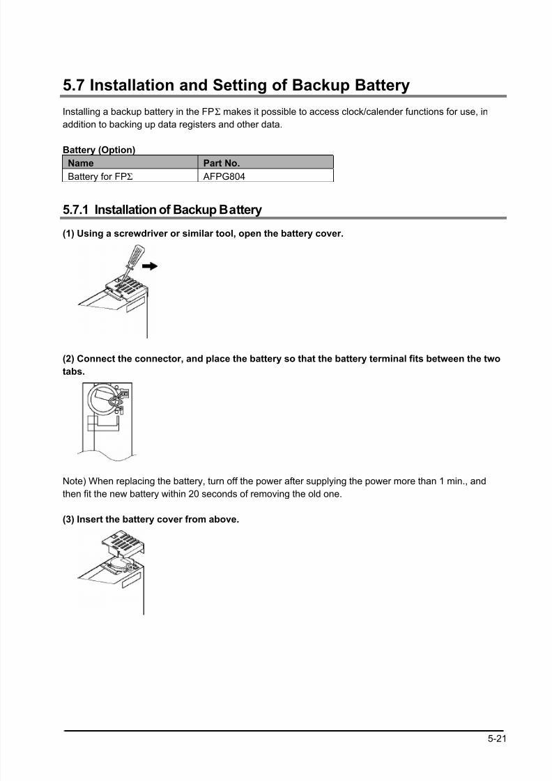
8/21/2019 Programmable Controller FP Sigma
http://slidepdf.com/reader/full/programmable-controller-fp-sigma 83/318
5-21
5.7 Installation and Setting of Backup Battery
Installing a backup battery in the FPΣ makes it possible to access clock/calender functions for use, in
addition to backing up data registers and other data.
Battery (Option)
Name Part No.
Battery for FPΣ AFPG804
5.7.1 Installation of Backup Battery
(1) Using a screwdriver or similar tool, open the battery cover.
(2) Connect the connector, and place the battery so that the battery terminal fits between the two
tabs.
Note) When replacing the battery, turn off the power after supplying the power more than 1 min., and
then fit the new battery within 20 seconds of removing the old one.
(3) Insert the battery cover from above.
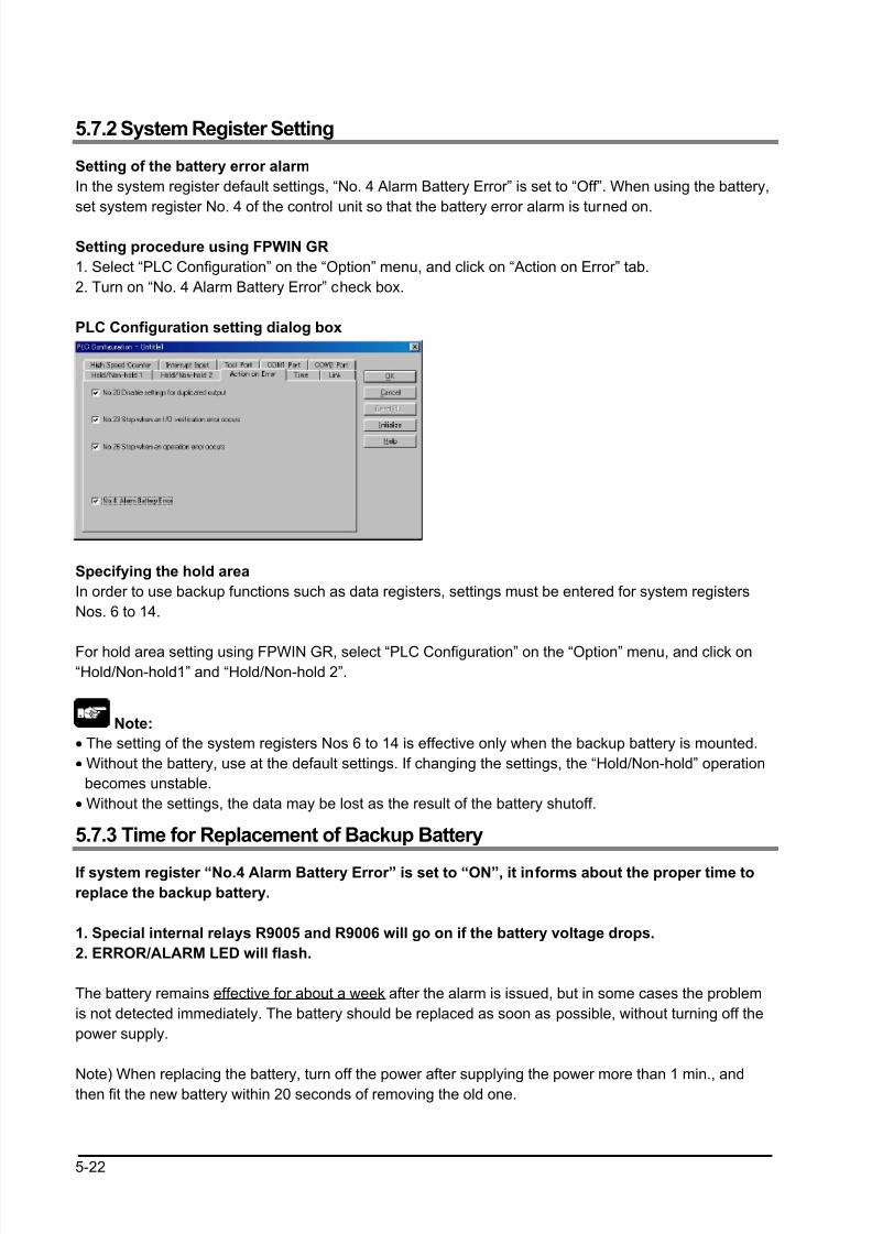
8/21/2019 Programmable Controller FP Sigma
http://slidepdf.com/reader/full/programmable-controller-fp-sigma 84/318
5-22
5.7.2 System Register Setting
Setting of the battery error alarm
In the system register default settings, “No. 4 Alarm Battery Error” is set to “Off”. When using the battery,
set system register No. 4 of the control unit so that the battery error alarm is turned on.
Setting procedure using FPWIN GR
1. Select “PLC Configuration” on the “Option” menu, and click on “Action on Error” tab.
2. Turn on “No. 4 Alarm Battery Error” check box.
PLC Configuration setting dialog box
Specifying the hold area
In order to use backup functions such as data registers, settings must be entered for system registers
Nos. 6 to 14.
For hold area setting using FPWIN GR, select “PLC Configuration” on the “Option” menu, and click on“Hold/Non-hold1” and “Hold/Non-hold 2”.
Note:
• The setting of the system registers Nos 6 to 14 is effective only when the backup battery is mounted.
• Without the battery, use at the default settings. If changing the settings, the “Hold/Non-hold” operation
becomes unstable.
• Without the settings, the data may be lost as the result of the battery shutoff.
5.7.3 Time for Replacement of Backup Battery
If system register “No.4 Alarm Battery Error” is set to “ON”, it informs about the proper time to
replace the backup battery.
1. Special internal relays R9005 and R9006 will go on if the battery voltage drops.
2. ERROR/ALARM LED will flash.
The battery remains effective for about a week after the alarm is issued, but in some cases the problem
is not detected immediately. The battery should be replaced as soon as possible, without turning off the
power supply.
Note) When replacing the battery, turn off the power after supplying the power more than 1 min., andthen fit the new battery within 20 seconds of removing the old one.
8/21/2019 Programmable Controller FP Sigma
http://slidepdf.com/reader/full/programmable-controller-fp-sigma 85/318
5-23
5.7.4 Lifetime of Backup Battery
The life of the backup battery will eventually expire and therefore it is important to replace it with a new
battery periodically. Refer to the table below for a guide as to when to replace the battery.
Item Description
Battery lifetime 220 days or more (typical lifetime in actual use: approx. 840 days at
25°C/70°F) (Suggested replacement interval: 1 year)
(Value when no power at all is supplied)

8/21/2019 Programmable Controller FP Sigma
http://slidepdf.com/reader/full/programmable-controller-fp-sigma 86/318
5-24

8/21/2019 Programmable Controller FP Sigma
http://slidepdf.com/reader/full/programmable-controller-fp-sigma 87/318
Chapter 6
High-speed counter, Pulse Output andPWM Output functions
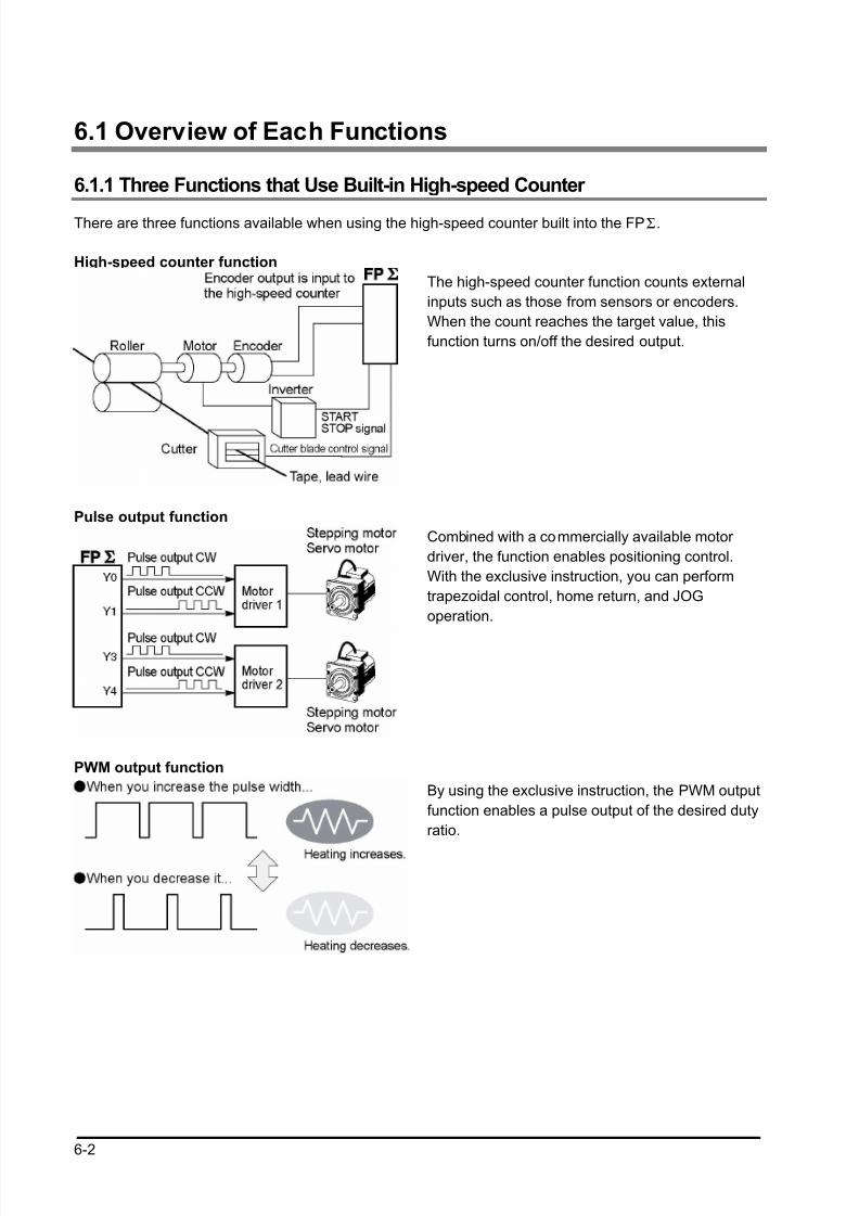
8/21/2019 Programmable Controller FP Sigma
http://slidepdf.com/reader/full/programmable-controller-fp-sigma 88/318
6-2
6.1 Overview of Each Functions
6.1.1 Three Functions that Use Built-in High-speed Counter
There are three functions available when using the high-speed counter built into the FPΣ.
High-speed counter function
The high-speed counter function counts external
inputs such as those from sensors or encoders.
When the count reaches the target value, this
function turns on/off the desired output.
Pulse output function
Combined with a commercially available motor
driver, the function enables positioning control.
With the exclusive instruction, you can perform
trapezoidal control, home return, and JOG
operation.
PWM output function
By using the exclusive instruction, the PWM output
function enables a pulse output of the desired duty
ratio.
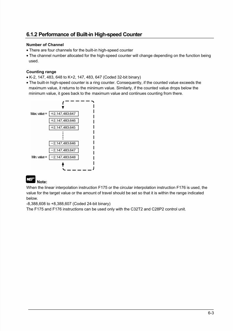
8/21/2019 Programmable Controller FP Sigma
http://slidepdf.com/reader/full/programmable-controller-fp-sigma 89/318
6-3
6.1.2 Performance of Built-in High-speed Counter
Number of Channel
• There are four channels for the built-in high-speed counter
• The channel number allocated for the high-speed counter will change depending on the function being
used.
Counting range
• K-2, 147, 483, 648 to K+2, 147, 483, 647 (Coded 32-bit binary)
• The built-in high-speed counter is a ring counter. Consequently, if the counted value exceeds the
maximum value, it returns to the minimum value. Similarly, if the counted value drops below the
minimum value, it goes back to the maximum value and continues counting from there.
Note:
When the linear interpolation instruction F175 or the circular interpolation instruction F176 is used, the
value for the target value or the amount of travel should be set so that it is within the range indicated
below.
-8,388,608 to +8,388,607 (Coded 24-bit binary)
The F175 and F176 instructions can be used only with the C32T2 and C28P2 control unit.
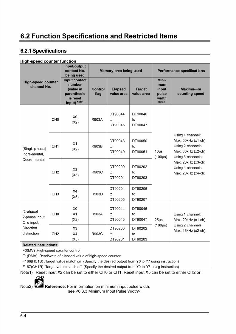
8/21/2019 Programmable Controller FP Sigma
http://slidepdf.com/reader/full/programmable-controller-fp-sigma 90/318
6-4
6.2 Function Specifications and Restricted Items
6.2.1 Specifications
High-speed counter function
Input/output
contact No.
being used
Memory area being used Performance specifications
High-speed counter
channel No.
Input contact
number
(value in
parenthesis
is reset
input) Note1)
Control
flag
Elapsed
value area
Target
value area
Mini-
mum
input
pulse
widthNote2)
Maximu←m
counting speed
CH0 X0(X2)
R903A
DT90044
to
DT90045
DT90046
to
DT90047
CH1X1
(X2)R903B
DT90048
to
DT90049
DT90050
to
DT90051
CH2X3
(X5)
R903C
DT90200
to
DT90201
DT90202
to
DT90203
[Single p hase]
Incre-mental,
Decre-mental
CH3X4
(X5)R903D
DT90204
to
DT90205
DT90206
to
DT90207
10µs
(100µs)
Using 1 channel:
Max. 50kHz (x1-ch)
Using 2 channels:
Max. 30kHz (x2-ch)
Using 3 channels:
Max. 20kHz (x3-ch)
Using 4 channels:
Max. 20kHz (x4-ch)
CH0
X0
X1
(X2)
R903A
DT90044
to
DT90045
DT90046
to
DT90047
[2-phase]
2-phase input
One input,
Direction
distinction CH2
X3
X4(X5)
R903C
DT90200
toDT90201
DT90202
toDT90203
25µs
(100µs)
Using 1 channel:
Max. 20kHz (x1-ch)
Using 2 channels:
Max. 15kHz (x2-ch)
Related instructions:
F0(MV) :High-speed counter control
F1(DMV) :Read/write of elapsed value of high-speed counter
F166(HC1S) :Target value match on (Specify the desired output from Y0 to Y7 using instruction)
F167(CH1R) :Target value match off (Specify the desired output from Y0 to Y7 using instruction)
Note1) Reset input X2 can be set to either CH0 or CH1. Reset input X5 can be set to either CH2 or
CH3.
Note2) Reference: For information on minimum input pulse width,
see <6.3.3 Minimum Input Pulse Width>.
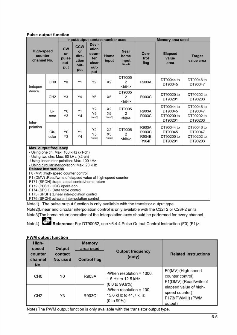
8/21/2019 Programmable Controller FP Sigma
http://slidepdf.com/reader/full/programmable-controller-fp-sigma 91/318
6-5
Pulse output functionInput/output contact number used Memory area used
High-speed
counter
channel No.
CW
or
pulseout-
put
CCW
or
dire-
ction
out-
put
Devi-
ation
coun-
ter clear
out-
put
Home
input
Near
home
inputNote4)
Con-
trolflag
Elapsed
valuearea
Target
value area
CH0 Y0 Y1 Y2 X2
DT9005
2
<bit4>
R903ADT90044 to
DT90045
DT90046 to
DT90047Indepen-
dence
CH2 Y3 Y4 Y5 X5
DT9005
2
<bit4>
R903CDT90020 to
DT90201
DT90202 to
DT90203
Li-
near
Y0
Y3
Y1
Y4
Y2
Y5
Note3)
X2
X5
Note3)
DT9005
2
<bit4>
R903A
R903C
DT90044 to
DT90045
DT90200 toDT90201
DT90046 to
DT90047
DT90202 toDT90203Inter-
polation
Cir-
cular
Y0
Y3
Y1
Y4
Y2
Y5Note3)
X2
X5Note3)
DT9005
2
<bit4>
R903A
R903C
R904E
R904F
DT90044 to
DT90045
DT90200 to
DT90201
DT90046 to
DT90047
DT90202 to
DT90203
Max. output frequency
- Using one ch: Max. 100 kHz (x1-ch)
- Using two chs: Max. 60 kHz (x2-ch)-Using linear inter-polation: Max. 100 kHz
- Using circular iner-polation: Max. 20 kHzRelated instructions
F0 (MV) :high-speed counter control
F1 (DMV) :Read/write of elapsed value of high-speed counter F171 (SPDH) :trape-zoidal control/home return
F172 (PLSH) :JOG opera-tionF174 (SP0H) :Data table controlF175 (SPSH) :Linear inter-polation control
F176 (SPCH) :circular inter-polation control
Note1) The pulse output function is only available with the transistor output type.
Note2)Linear and circular interpolation control is only available with the C32T2 or C28P2 units.
Note3)The home return operation of the interpolation axes should be performed for every channel.
Note4) Reference: For DT90052, see <6.4.4 Pulse Output Control Instruction (F0) (F1)>.
PWM output function
Memory
area used
High-
speed
counter
channel
No.
Output
contact
No. used Control flag
Output frequency
(duty)Related instructions
CH0 Y0 R903A
CH2 Y3 R903C
-When resolution = 1000,
1.5 Hz to 12.5 kHz
(0.0 to 99.9%)
-When resolution = 100,
15.6 kHz to 41.7 kHz
(0 to 99%)
F0(MV) (High-speed
counter control)
F1(DMV) (Read/write of
elapsed value of high-
speed counter)F173(PWMH) (PWM
output)
Note) The PWM output function is only available with the transistor output type.
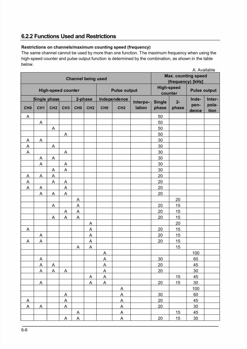
8/21/2019 Programmable Controller FP Sigma
http://slidepdf.com/reader/full/programmable-controller-fp-sigma 92/318
6-6
6.2.2 Functions Used and Restrictions
Restrictions on channels/maximum counting speed (frequency)
The same channel cannot be used by more than one function. The maximum frequency when using the
high-speed counter and pulse output function is determined by the combination, as shown in the table
below.
A: Available
Channel being usedMax. counting speed
(frequency) [kHz]
High-speed counter Pulse outputHigh-speed
counter Pulse output
Single phase 2-phase Independence
CH0 CH1 CH2 CH3 CH0 CH2 CH0 CH2
Interpo-
lation
Single
phase
2-
phase
Inde-
pen-
dence
Inter-
pola-
tion
A 50
A 50 A 50
A 50
A A 30
A A 30
A A 30
A A 30
A A 30
A A 30
A A A 20
A A A 20 A A A 20
A A A 20
A 20
A A 20 15
A A 20 15
A A A 20 15
A 20
A A 20 15
A A 20 15
A A A 20 15
A A 15
A 100
A A 30 60
A A A 20 45
A A A A 20 30
A A 15 45
A A A 20 15 30
A 100
A A 30 60
A A A 20 45
A A A A 20 30 A A 15 45
A A A 20 15 30
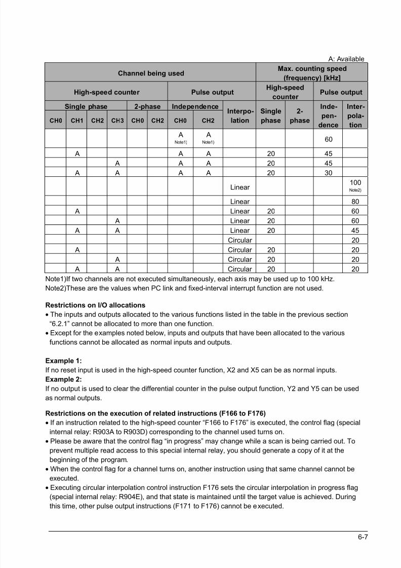
8/21/2019 Programmable Controller FP Sigma
http://slidepdf.com/reader/full/programmable-controller-fp-sigma 93/318
6-7
A: Available
Channel being usedMax. counting speed
(frequency) [kHz]
High-speed counter Pulse outputHigh-speed
counter
Pulse output
Single phase 2-phase Independence
CH0 CH1 CH2 CH3 CH0 CH2 CH0 CH2
Interpo-
lation
Single
phase
2-
phase
Inde-
pen-
dence
Inter-
pola-
tion
ANote1)
ANote1)
60
A A A 20 45
A A A 20 45
A A A A 20 30
Linear 100Note2)
Linear 80
A Linear 20 60
A Linear 20 60
A A Linear 20 45
Circular 20
A Circular 20 20
A Circular 20 20
A A Circular 20 20
Note1)If two channels are not executed simultaneously, each axis may be used up to 100 kHz.
Note2)These are the values when PC link and fixed-interval interrupt function are not used.
Restrictions on I/O allocations
• The inputs and outputs allocated to the various functions listed in the table in the previous section
“6.2.1” cannot be allocated to more than one function.
• Except for the examples noted below, inputs and outputs that have been allocated to the various
functions cannot be allocated as normal inputs and outputs.
Example 1:
If no reset input is used in the high-speed counter function, X2 and X5 can be as normal inputs.
Example 2:
If no output is used to clear the differential counter in the pulse output function, Y2 and Y5 can be used
as normal outputs.
Restrictions on the execution of related instructions (F166 to F176)
• If an instruction related to the high-speed counter “F166 to F176” is executed, the control flag (special
internal relay: R903A to R903D) corresponding to the channel used turns on.
• Please be aware that the control flag “in progress” may change while a scan is being carried out. To
prevent multiple read access to this special internal relay, you should generate a copy of it at the
beginning of the program.
• When the control flag for a channel turns on, another instruction using that same channel cannot be
executed.
• Executing circular interpolation control instruction F176 sets the circular interpolation in progress flag
(special internal relay: R904E), and that state is maintained until the target value is achieved. Duringthis time, other pulse output instructions (F171 to F176) cannot be executed.
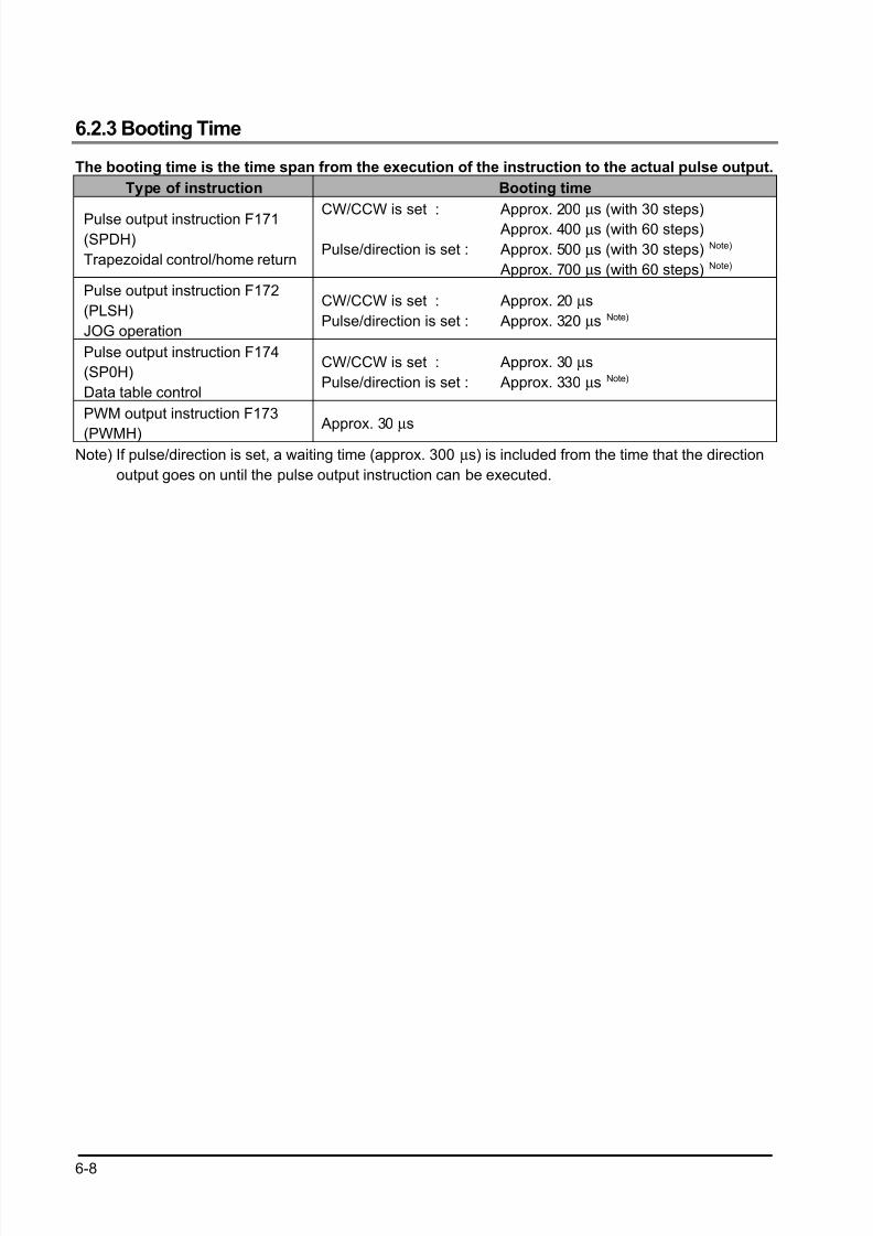
8/21/2019 Programmable Controller FP Sigma
http://slidepdf.com/reader/full/programmable-controller-fp-sigma 94/318
6-8
6.2.3 Booting Time
The booting time is the time span from the execution of the instruction to the actual pulse output.
Type of instruction Booting time
Pulse output instruction F171(SPDH)
Trapezoidal control/home return
CW/CCW is set :
Pulse/direction is set :
Approx. 200 µs (with 30 steps) Approx. 400 µs (with 60 steps)
Approx. 500 µs (with 30 steps) Note)
Approx. 700 µs (with 60 steps) Note)
Pulse output instruction F172
(PLSH)
JOG operation
CW/CCW is set :
Pulse/direction is set :
Approx. 20 µs
Approx. 320 µs Note)
Pulse output instruction F174
(SP0H)
Data table control
CW/CCW is set :
Pulse/direction is set :
Approx. 30 µs
Approx. 330 µs Note)
PWM output instruction F173
(PWMH) Approx. 30 µs
Note) If pulse/direction is set, a waiting time (approx. 300 µs) is included from the time that the direction
output goes on until the pulse output instruction can be executed.
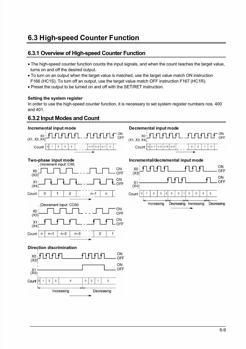
8/21/2019 Programmable Controller FP Sigma
http://slidepdf.com/reader/full/programmable-controller-fp-sigma 95/318
6-9
6.3 High-speed Counter Function
6.3.1 Overview of High-speed Counter Function
• The high-speed counter function counts the input signals, and when the count reaches the target value,
turns on and off the desired output.
• To turn on an output when the target value is matched, use the target value match ON instruction
F166 (HC1S). To turn off an output, use the target value match OFF instruction F167 (HC1R).
• Preset the output to be turned on and off with the SET/RET instruction.
Setting the system register
In order to use the high-speed counter function, it is necessary to set system register numbers nos. 400
and 401.
6.3.2 Input Modes and Count
Incremental input mode Decremental input mode
Two-phase input mode Incremental/decremental input mode
Direction discrimination
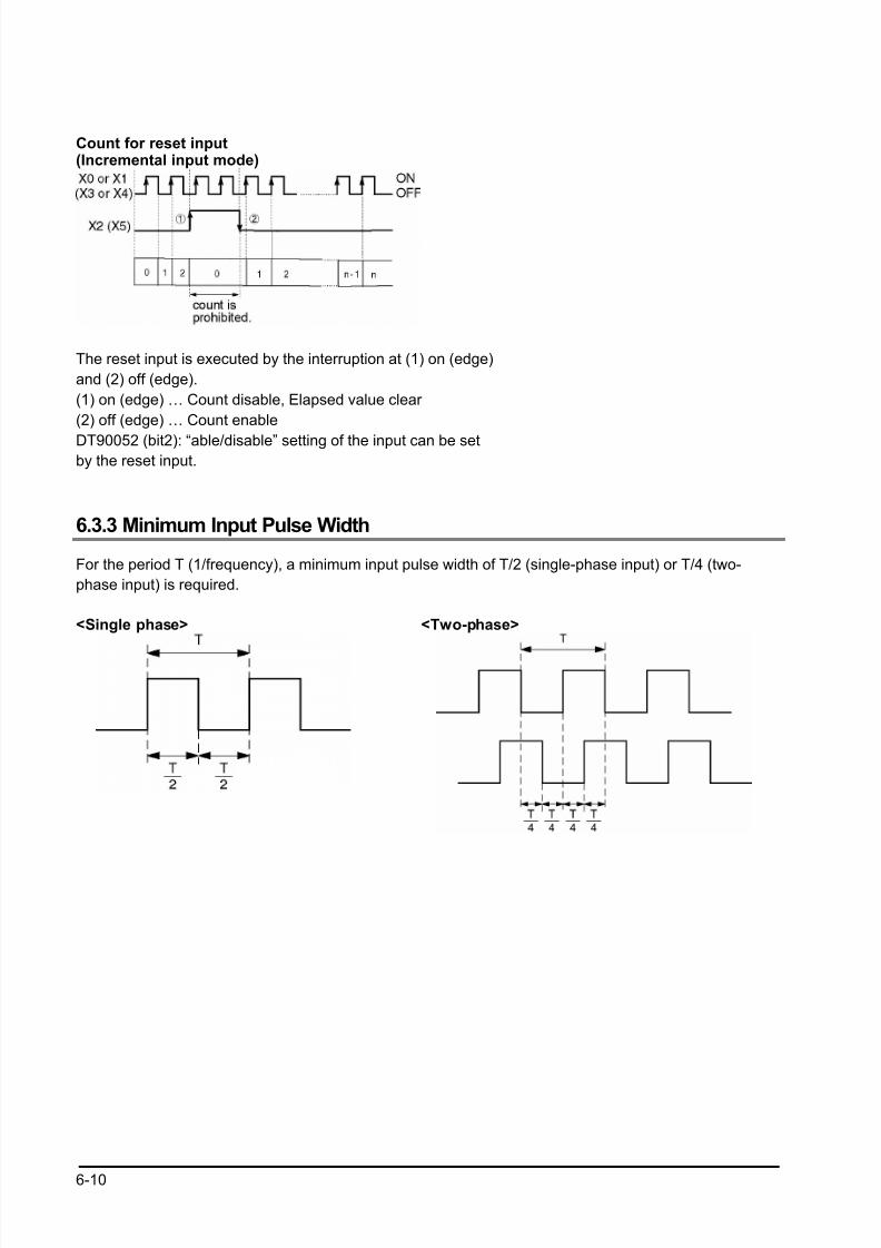
8/21/2019 Programmable Controller FP Sigma
http://slidepdf.com/reader/full/programmable-controller-fp-sigma 96/318
6-10
Count for reset input(Incremental input mode)
The reset input is executed by the interruption at (1) on (edge)
and (2) off (edge).
(1) on (edge) … Count disable, Elapsed value clear
(2) off (edge) … Count enable
DT90052 (bit2): “able/disable” setting of the input can be setby the reset input.
6.3.3 Minimum Input Pulse Width
For the period T (1/frequency), a minimum input pulse width of T/2 (single-phase input) or T/4 (two-
phase input) is required.
<Single phase> <Two-phase>
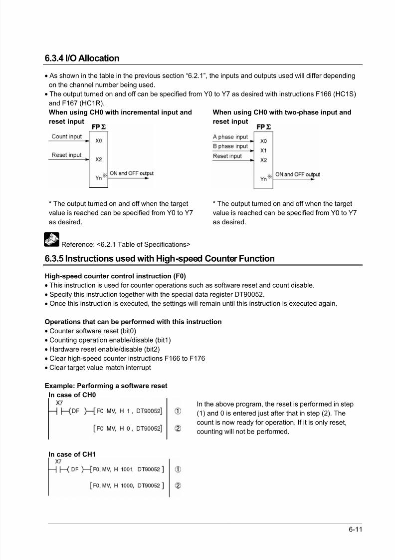
8/21/2019 Programmable Controller FP Sigma
http://slidepdf.com/reader/full/programmable-controller-fp-sigma 97/318
6-11
6.3.4 I/O Allocation
• As shown in the table in the previous section “6.2.1”, the inputs and outputs used will differ depending
on the channel number being used.
• The output turned on and off can be specified from Y0 to Y7 as desired with instructions F166 (HC1S)
and F167 (HC1R).
When using CH0 with incremental input and
reset input
When using CH0 with two-phase input and
reset input
* The output turned on and off when the target
value is reached can be specified from Y0 to Y7
as desired.
* The output turned on and off when the target
value is reached can be specified from Y0 to Y7
as desired.
Reference: <6.2.1 Table of Specifications>
6.3.5 Instructions used with High-speed Counter Function
High-speed counter control instruction (F0)
• This instruction is used for counter operations such as software reset and count disable.
• Specify this instruction together with the special data register DT90052.• Once this instruction is executed, the settings will remain until this instruction is executed again.
Operations that can be performed with this instruction
• Counter software reset (bit0)
• Counting operation enable/disable (bit1)
• Hardware reset enable/disable (bit2)
• Clear high-speed counter instructions F166 to F176
• Clear target value match interrupt
Example: Performing a software reset
In case of CH0
In the above program, the reset is performed in step
(1) and 0 is entered just after that in step (2). The
count is now ready for operation. If it is only reset,
counting will not be performed.
In case of CH1
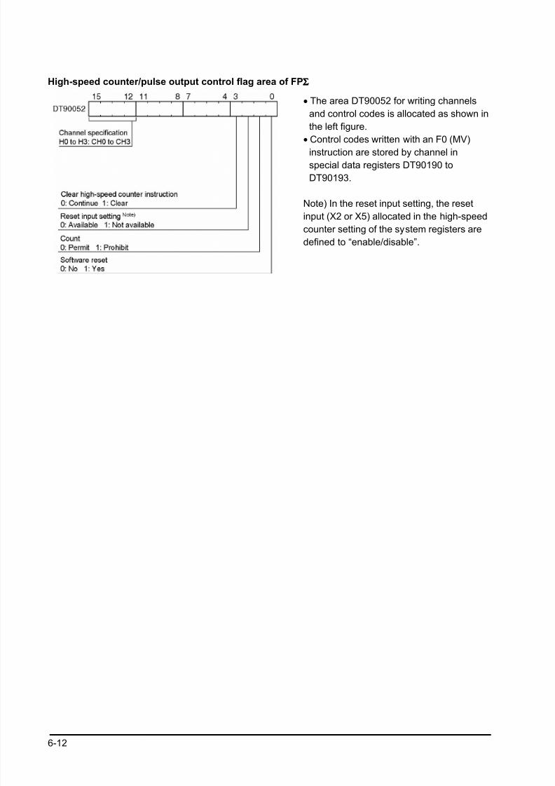
8/21/2019 Programmable Controller FP Sigma
http://slidepdf.com/reader/full/programmable-controller-fp-sigma 98/318
6-12
High-speed counter/pulse output control flag area of FPΣΣΣΣ
• The area DT90052 for writing channels
and control codes is allocated as shown in
the left figure.
• Control codes written with an F0 (MV)instruction are stored by channel in
special data registers DT90190 to
DT90193.
Note) In the reset input setting, the reset
input (X2 or X5) allocated in the high-speed
counter setting of the system registers are
defined to “enable/disable”.
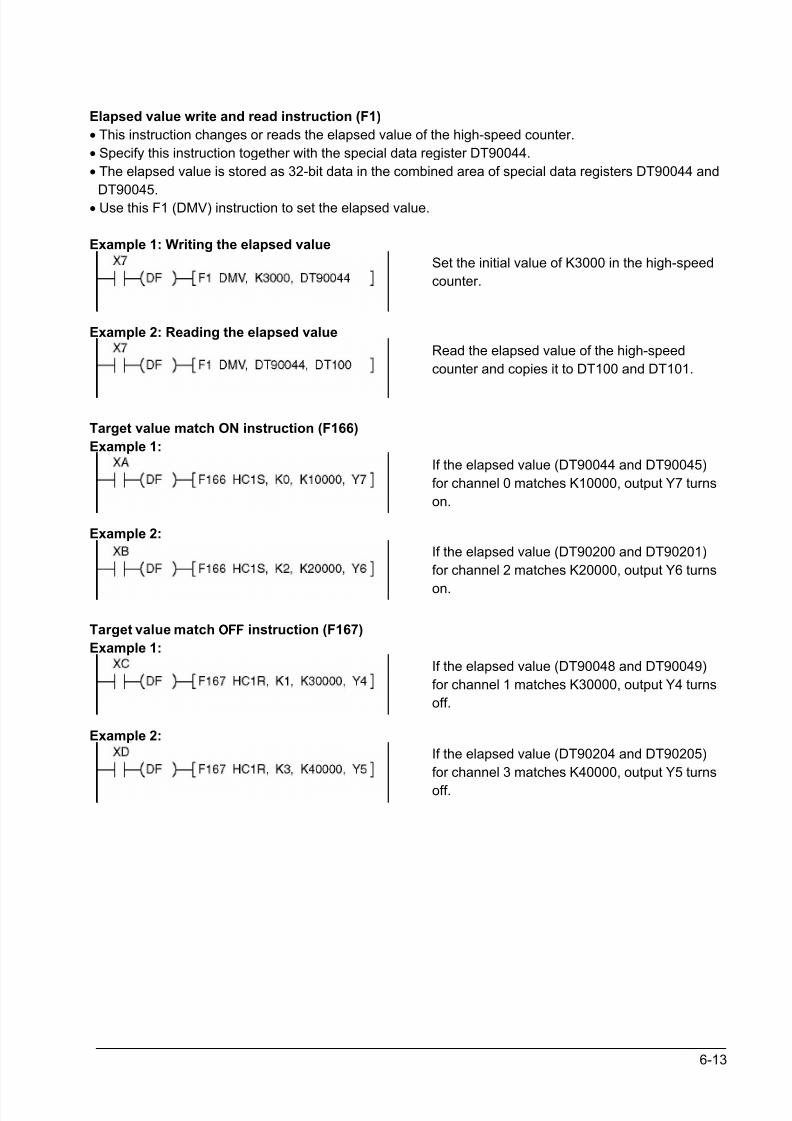
8/21/2019 Programmable Controller FP Sigma
http://slidepdf.com/reader/full/programmable-controller-fp-sigma 99/318
6-13
Elapsed value write and read instruction (F1)
• This instruction changes or reads the elapsed value of the high-speed counter.
• Specify this instruction together with the special data register DT90044.
• The elapsed value is stored as 32-bit data in the combined area of special data registers DT90044 and
DT90045.• Use this F1 (DMV) instruction to set the elapsed value.
Example 1: Writing the elapsed value
Set the initial value of K3000 in the high-speed
counter.
Example 2: Reading the elapsed value
Read the elapsed value of the high-speed
counter and copies it to DT100 and DT101.
Target value match ON instruction (F166)
Example 1:
If the elapsed value (DT90044 and DT90045)
for channel 0 matches K10000, output Y7 turns
on.
Example 2:
If the elapsed value (DT90200 and DT90201)
for channel 2 matches K20000, output Y6 turns
on.
Target value match OFFOFFOFFOFF instruction (F167)
Example 1:
If the elapsed value (DT90048 and DT90049)
for channel 1 matches K30000, output Y4 turns
off.
Example 2:
If the elapsed value (DT90204 and DT90205)
for channel 3 matches K40000, output Y5 turns
off.
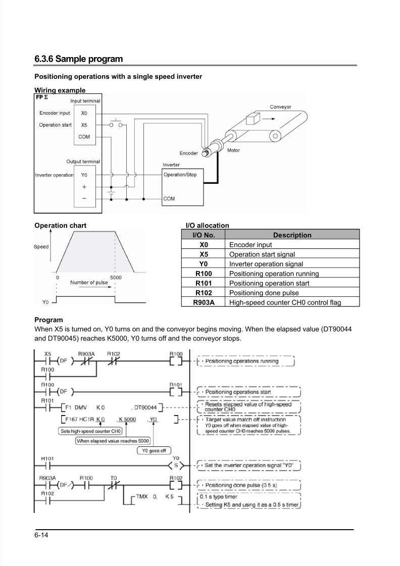
8/21/2019 Programmable Controller FP Sigma
http://slidepdf.com/reader/full/programmable-controller-fp-sigma 100/318
6-14
6.3.6 Sample program
Positioning operations with a single speed inverter
Wiring example
Operation chart I/O allocation
I/O No. Description
X0 Encoder input
X5 Operation start signal
Y0 Inverter operation signal
R100 Positioning operation running
R101 Positioning operation start
R102 Positioning done pulse
R903A High-speed counter CH0 control flag
Program
When X5 is turned on, Y0 turns on and the conveyor begins moving. When the elapsed value (DT90044
and DT90045) reaches K5000, Y0 turns off and the conveyor stops.
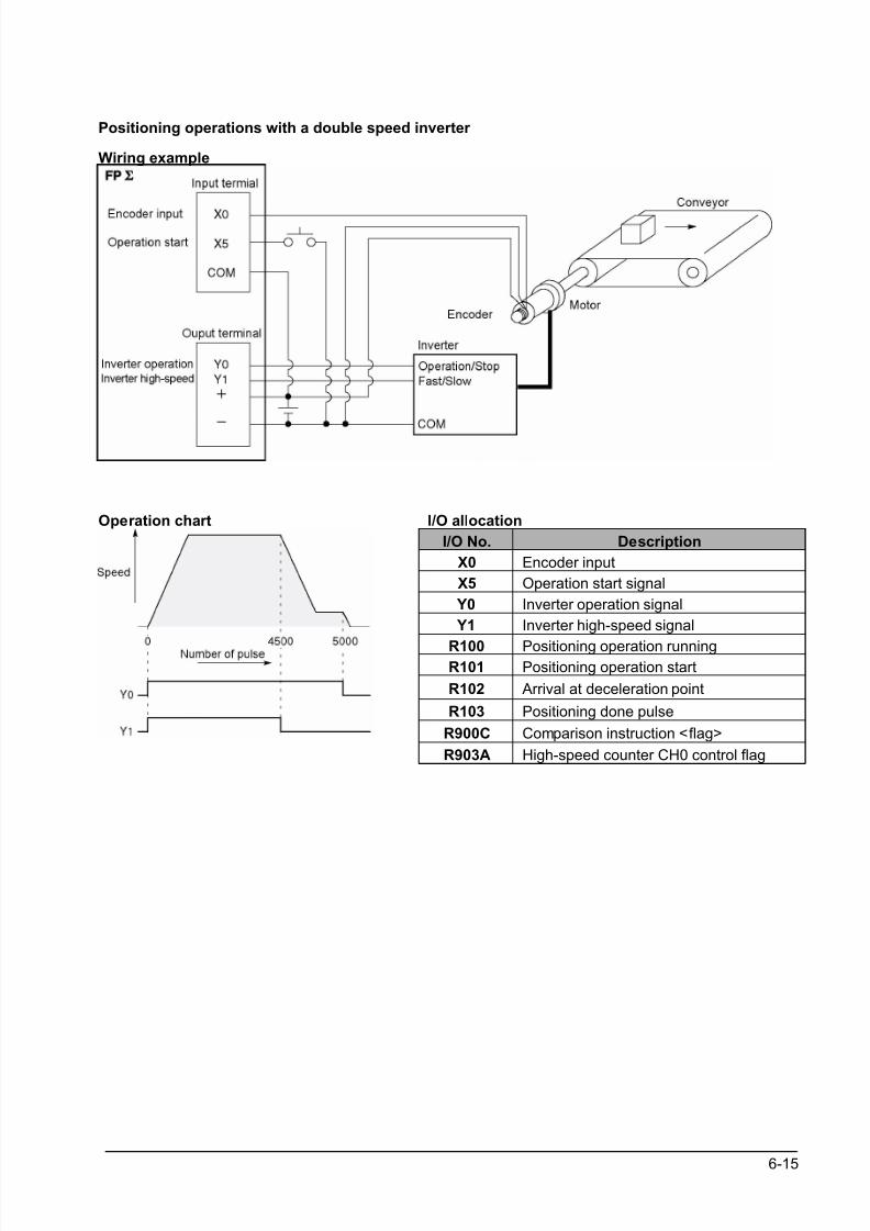
8/21/2019 Programmable Controller FP Sigma
http://slidepdf.com/reader/full/programmable-controller-fp-sigma 101/318
6-15
Positioning operations with a double speed inverter
Wiring example
Operation chart I/O allocation
I/O No. Description
X0 Encoder input
X5 Operation start signal
Y0 Inverter operation signal
Y1 Inverter high-speed signal
R100 Positioning operation runningR101 Positioning operation start
R102 Arrival at deceleration point
R103 Positioning done pulse
R900C Comparison instruction <flag>
R903A High-speed counter CH0 control flag
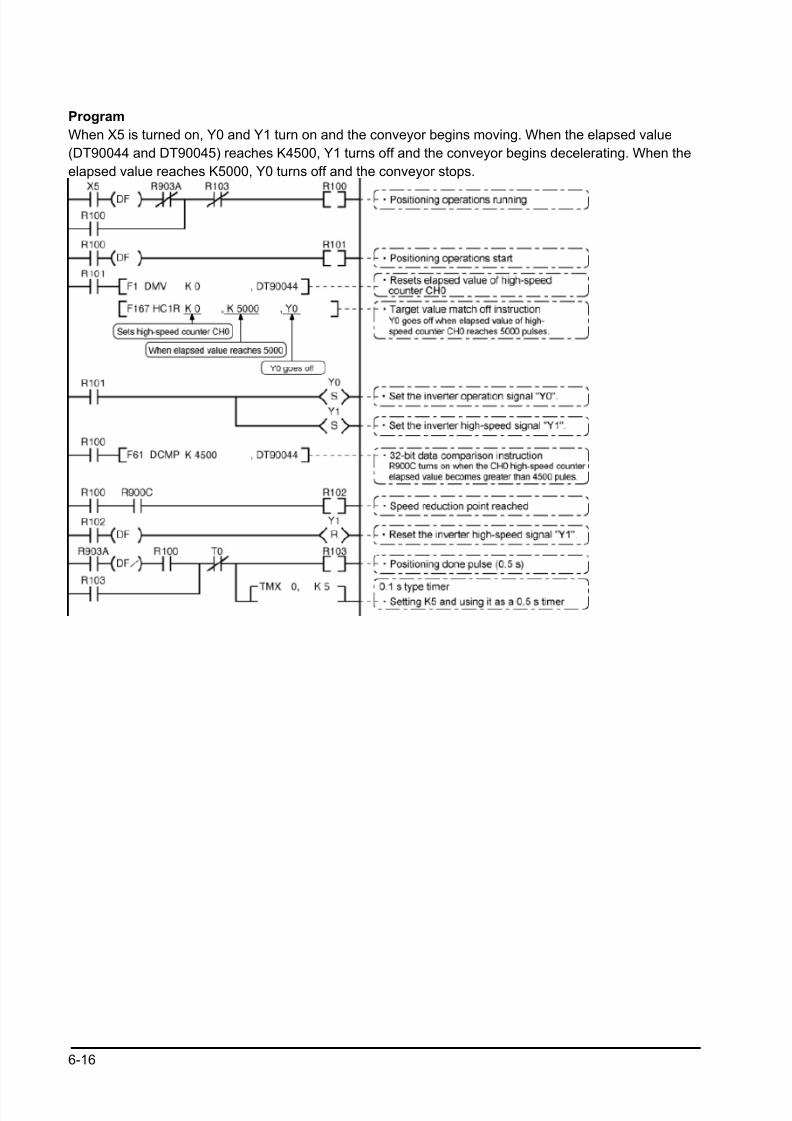
8/21/2019 Programmable Controller FP Sigma
http://slidepdf.com/reader/full/programmable-controller-fp-sigma 102/318
6-16
Program
When X5 is turned on, Y0 and Y1 turn on and the conveyor begins moving. When the elapsed value
(DT90044 and DT90045) reaches K4500, Y1 turns off and the conveyor begins decelerating. When the
elapsed value reaches K5000, Y0 turns off and the conveyor stops.
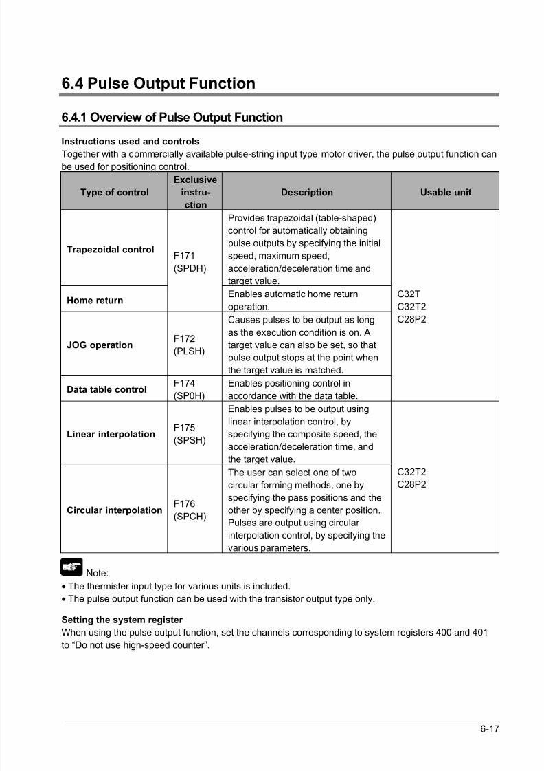
8/21/2019 Programmable Controller FP Sigma
http://slidepdf.com/reader/full/programmable-controller-fp-sigma 103/318
6-17
6.4 Pulse Output Function
6.4.1 Overview of Pulse Output Function
Instructions used and controls
Together with a commercially available pulse-string input type motor driver, the pulse output function can
be used for positioning control.
Type of control
Exclusive
instru-
ction
Description Usable unit
Trapezoidal control
Provides trapezoidal (table-shaped)
control for automatically obtaining
pulse outputs by specifying the initial
speed, maximum speed,
acceleration/deceleration time andtarget value.
Home return
F171
(SPDH)
Enables automatic home return
operation.
JOG operationF172
(PLSH)
Causes pulses to be output as long
as the execution condition is on. A
target value can also be set, so that
pulse output stops at the point when
the target value is matched.
Data table controlF174
(SP0H)
Enables positioning control in
accordance with the data table.
C32T
C32T2
C28P2
Linear interpolationF175
(SPSH)
Enables pulses to be output using
linear interpolation control, by
specifying the composite speed, the
acceleration/deceleration time, and
the target value.
Circular interpolationF176
(SPCH)
The user can select one of two
circular forming methods, one by
specifying the pass positions and the
other by specifying a center position.
Pulses are output using circular
interpolation control, by specifying the
various parameters.
C32T2
C28P2
Note:
• The thermister input type for various units is included.
• The pulse output function can be used with the transistor output type only.
Setting the system register
When using the pulse output function, set the channels corresponding to system registers 400 and 401
to “Do not use high-speed counter”.
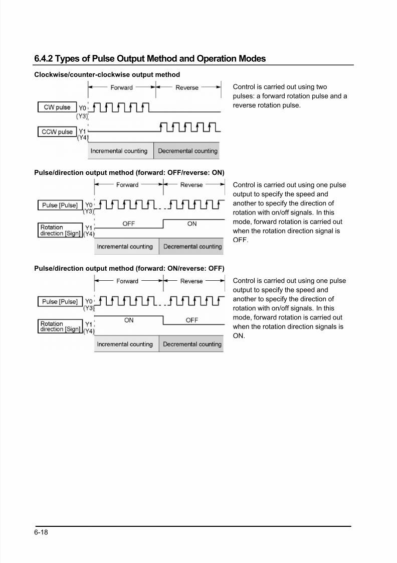
8/21/2019 Programmable Controller FP Sigma
http://slidepdf.com/reader/full/programmable-controller-fp-sigma 104/318
6-18
6.4.2 Types of Pulse Output Method and Operation Modes
Clockwise/counter-clockwise output method
Control is carried out using two
pulses: a forward rotation pulse and areverse rotation pulse.
Pulse/direction output method (forward: OFF/reverse: ON)
Control is carried out using one pulse
output to specify the speed andanother to specify the direction of
rotation with on/off signals. In this
mode, forward rotation is carried out
when the rotation direction signal is
OFF.
Pulse/direction output method (forward: ON/reverse: OFF)
Control is carried out using one pulse
output to specify the speed and
another to specify the direction of
rotation with on/off signals. In this
mode, forward rotation is carried out
when the rotation direction signals is
ON.
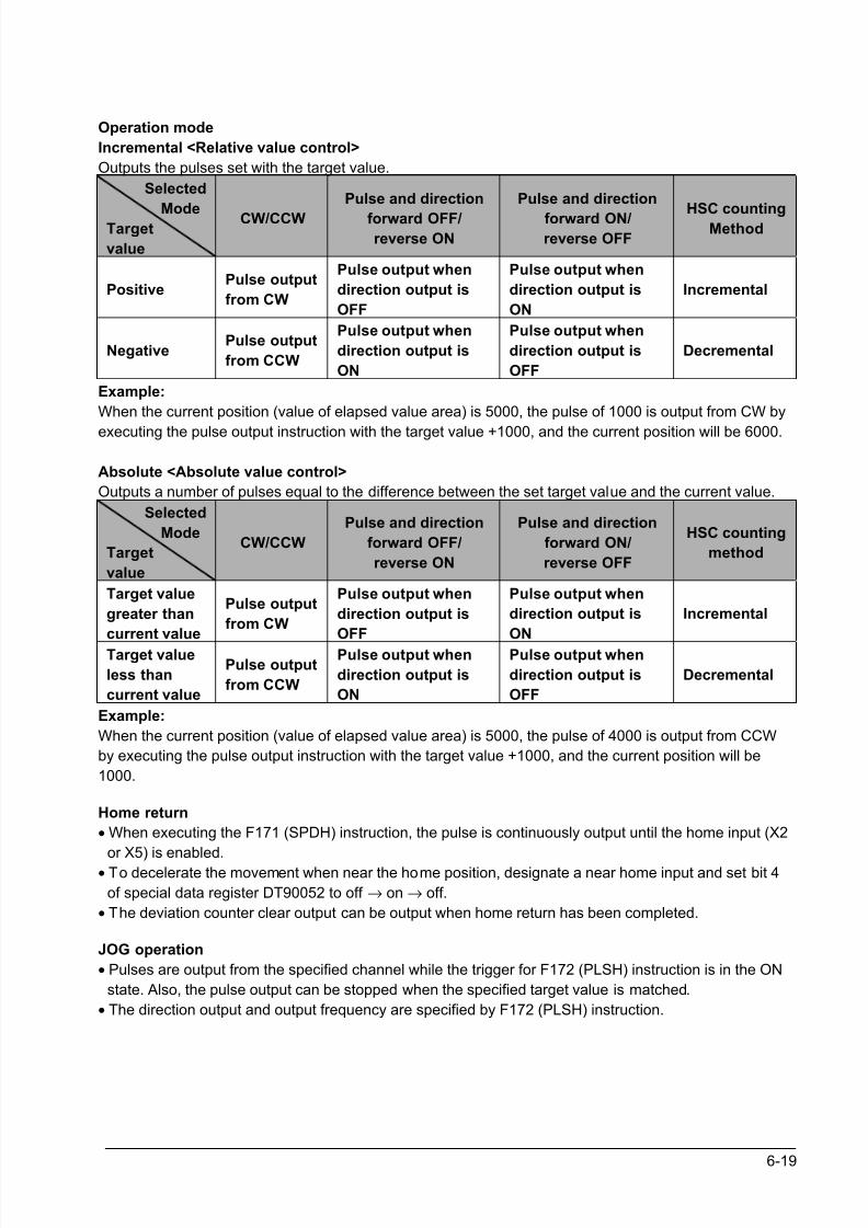
8/21/2019 Programmable Controller FP Sigma
http://slidepdf.com/reader/full/programmable-controller-fp-sigma 105/318
6-19
Operation mode
Incremental <Relative value control>
Outputs the pulses set with the target value.
Selected
ModeTarget
value
CW/CCW
Pulse and direction
forward OFF/reverse ON
Pulse and direction
forward ON/reverse OFF
HSC countingMethod
PositivePulse output
from CW
Pulse output when
direction output is
OFF
Pulse output when
direction output is
ON
Incremental
NegativePulse output
from CCW
Pulse output when
direction output is
ON
Pulse output when
direction output is
OFF
Decremental
Example:
When the current position (value of elapsed value area) is 5000, the pulse of 1000 is output from CW by
executing the pulse output instruction with the target value +1000, and the current position will be 6000.
Absolute <Absolute value control>
Outputs a number of pulses equal to the difference between the set target value and the current value.
Selected
Mode
Target
value
CW/CCW
Pulse and direction
forward OFF/
reverse ON
Pulse and direction
forward ON/
reverse OFF
HSC counting
method
Target value
greater than
current value
Pulse output
from CW
Pulse output when
direction output is
OFF
Pulse output when
direction output is
ON
Incremental
Target value
less than
current value
Pulse output
from CCW
Pulse output when
direction output is
ON
Pulse output when
direction output is
OFF
Decremental
Example:
When the current position (value of elapsed value area) is 5000, the pulse of 4000 is output from CCW
by executing the pulse output instruction with the target value +1000, and the current position will be
1000.
Home return
• When executing the F171 (SPDH) instruction, the pulse is continuously output until the home input (X2
or X5) is enabled.
• To decelerate the movement when near the home position, designate a near home input and set bit 4
of special data register DT90052 to off → on → off.
• The deviation counter clear output can be output when home return has been completed.
JOG operation
• Pulses are output from the specified channel while the trigger for F172 (PLSH) instruction is in the ON
state. Also, the pulse output can be stopped when the specified target value is matched.
• The direction output and output frequency are specified by F172 (PLSH) instruction.
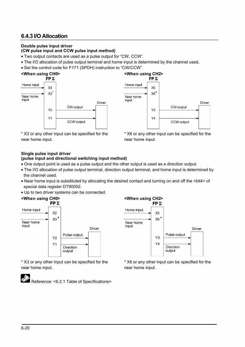
8/21/2019 Programmable Controller FP Sigma
http://slidepdf.com/reader/full/programmable-controller-fp-sigma 106/318
6-20
6.4.3 I/O Allocation
Double pulse input driver (CW pulse input and CCW pulse input method)
• Two output contacts are used as a pulse output for “CW, CCW”.
• The I/O allocation of pulse output terminal and home input is determined by the channel used.
• Set the control code for F171 (SPDH) instruction to “CW/CCW”.
<When using CH0> <When using CH2>
* X3 or any other input can be specified for the
near home input.
* X6 or any other input can be specified for the
near home input.
Single pulse input driver (pulse input and directional switching input method)
• One output point is used as a pulse output and the other output is used as a direction output.
• The I/O allocation of pulse output terminal, direction output terminal, and home input is determined by
the channel used.
• Near home input is substituted by allocating the desired contact and turning on and off the <bit4> of special data register DT90052.
• Up to two driver systems can be connected.
<When using CH0> <When using CH2>
* X3 or any other input can be specified for the
near home input.
* X6 or any other input can be specified for the
near home input.
Reference: <6.2.1 Table of Specifications>
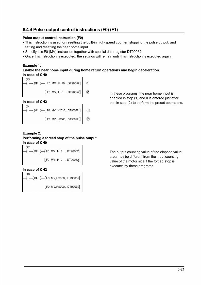
8/21/2019 Programmable Controller FP Sigma
http://slidepdf.com/reader/full/programmable-controller-fp-sigma 107/318
6-21
6.4.4 Pulse output control instructions (F0) (F1)
Pulse output control instruction (F0)
• This instruction is used for resetting the built-in high-speed counter, stopping the pulse output, and
setting and resetting the near home input.
• Specify this F0 (MV) instruction together with special data register DT90052.
• Once this instruction is executed, the settings will remain until this instruction is executed again.
Example 1:
Enable the near home input during home return operations and begin deceleration.
In case of CH0
In case of CH2
In these programs, the near home input is
enabled in step (1) and 0 is entered just after that in step (2) to perform the preset operations.
Example 2:
Performing a forced stop of the pulse output.
In case of CH0
In case of CH2
The output counting value of the elapsed value
area may be different from the input counting
value of the motor side if the forced stop is
executed by these programs.
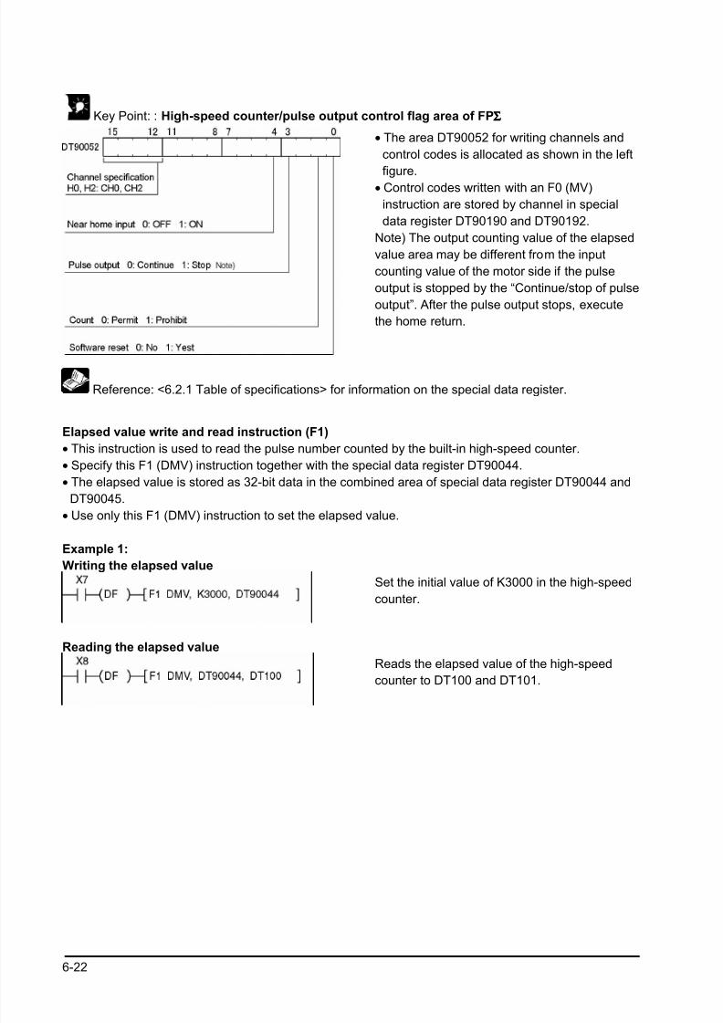
8/21/2019 Programmable Controller FP Sigma
http://slidepdf.com/reader/full/programmable-controller-fp-sigma 108/318
6-22
Key Point: : High-speed counter/pulse output control flag area of FPΣΣΣΣ
• The area DT90052 for writing channels and
control codes is allocated as shown in the left
figure.
• Control codes written with an F0 (MV)
instruction are stored by channel in special
data register DT90190 and DT90192.
Note) The output counting value of the elapsed
value area may be different from the input
counting value of the motor side if the pulse
output is stopped by the “Continue/stop of pulse
output”. After the pulse output stops, execute
the home return.
Reference: <6.2.1 Table of specifications> for information on the special data register.
Elapsed value write and read instruction (F1)
• This instruction is used to read the pulse number counted by the built-in high-speed counter.
• Specify this F1 (DMV) instruction together with the special data register DT90044.
• The elapsed value is stored as 32-bit data in the combined area of special data register DT90044 and
DT90045.
• Use only this F1 (DMV) instruction to set the elapsed value.
Example 1:
Writing the elapsed value
Set the initial value of K3000 in the high-speed
counter.
Reading the elapsed value
Reads the elapsed value of the high-speed
counter to DT100 and DT101.
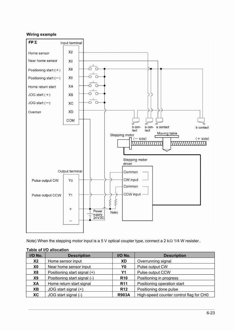
8/21/2019 Programmable Controller FP Sigma
http://slidepdf.com/reader/full/programmable-controller-fp-sigma 109/318
6-23
Wiring example
Note) When the stepping motor input is a 5 V optical coupler type, connect a 2 kΩ 1/4 W resister..
Table of I/O allocation
I/O No. Description I/O No. Description
X2 Home sensor input XD Overrunning signal
X0 Near home sensor input Y0 Pulse output CW
X8 Positioning start signal (+) Y1 Pulse output CCW
X9 Positioning start signal (-) R10 Positioning in progress
XA Home return start signal R11 Positioning operation start
XB JOG start signal (+) R12 Positioning done pulseXC JOG start signal (-) R903A High-speed counter control flag for CH0
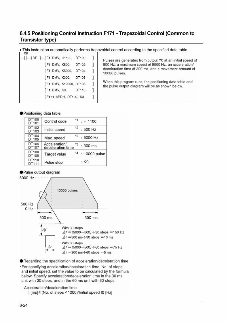
8/21/2019 Programmable Controller FP Sigma
http://slidepdf.com/reader/full/programmable-controller-fp-sigma 110/318
6-24
6.4.5 Positioning Control Instruction F171 - Trapezoidal Control (Common to
Transistor type)
• This instruction automatically performs trapezoidal control according to the specified data table.
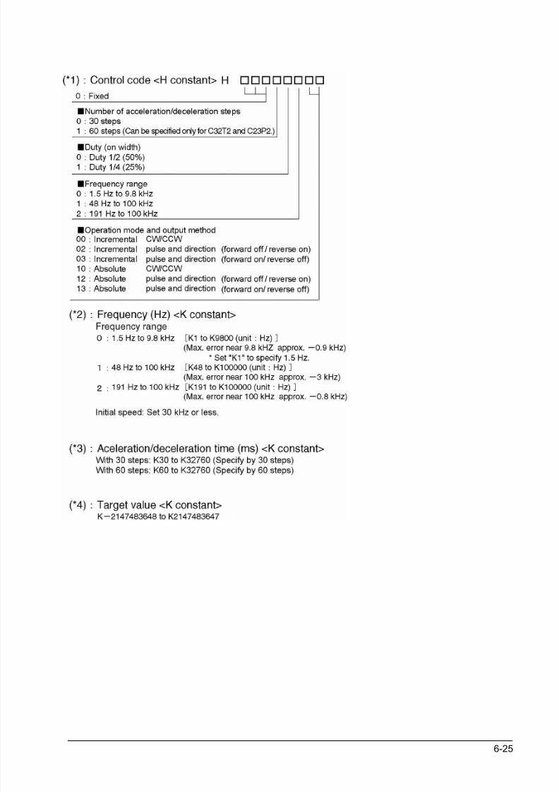
8/21/2019 Programmable Controller FP Sigma
http://slidepdf.com/reader/full/programmable-controller-fp-sigma 111/318
6-25
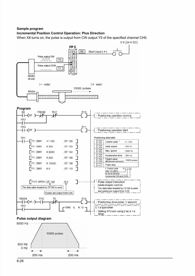
8/21/2019 Programmable Controller FP Sigma
http://slidepdf.com/reader/full/programmable-controller-fp-sigma 112/318
6-26
Sample program
Incremental Position Control Operation: Plus Direction
When X8 turns on, the pulse is output from CW output Y0 of the specified channel CH0.
Program
Pulse output diagram
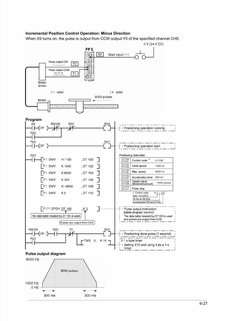
8/21/2019 Programmable Controller FP Sigma
http://slidepdf.com/reader/full/programmable-controller-fp-sigma 113/318
6-27
Incremental Position Control Operation: Minus Direction
When X9 turns on, the pulse is output from CCW output Y0 of the specified channel CH0.
Program
Pulse output diagram
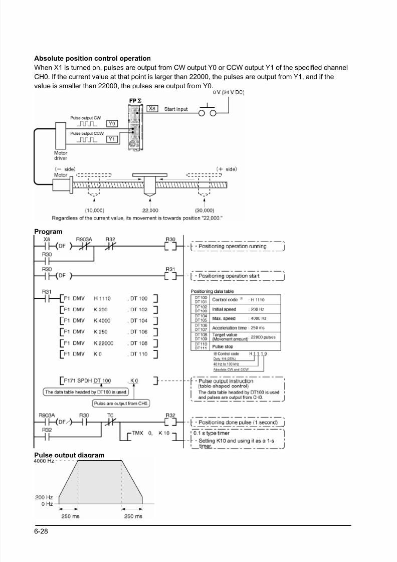
8/21/2019 Programmable Controller FP Sigma
http://slidepdf.com/reader/full/programmable-controller-fp-sigma 114/318
6-28
Absolute position control operation
When X1 is turned on, pulses are output from CW output Y0 or CCW output Y1 of the specified channel
CH0. If the current value at that point is larger than 22000, the pulses are output from Y1, and if the
value is smaller than 22000, the pulses are output from Y0.
Program
Pulse output diagram
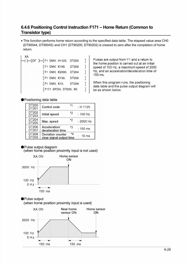
8/21/2019 Programmable Controller FP Sigma
http://slidepdf.com/reader/full/programmable-controller-fp-sigma 115/318
6-29
6.4.6 Positioning Control Instruction F171 – Home Return (Common to
Transistor type)
• This function performs home return according to the specified data table. The elapsed value area CH0
(DT90044, DT90045) and CH1 (DT90200, DT90202) is cleared to zero after the completion of homereturn.
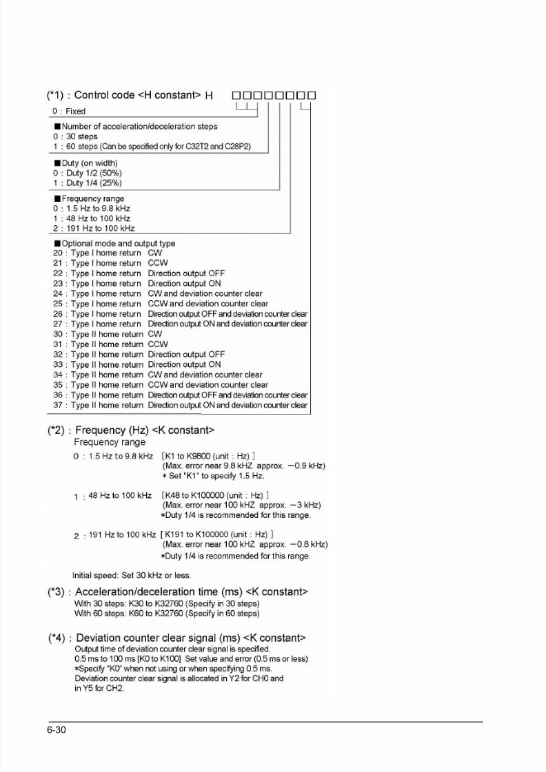
8/21/2019 Programmable Controller FP Sigma
http://slidepdf.com/reader/full/programmable-controller-fp-sigma 116/318
6-30
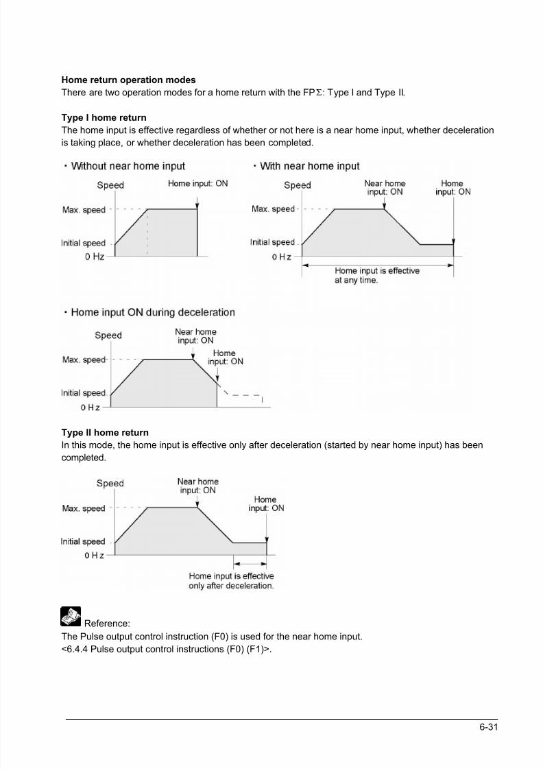
8/21/2019 Programmable Controller FP Sigma
http://slidepdf.com/reader/full/programmable-controller-fp-sigma 117/318
6-31
Home return operation modes
There are two operation modes for a home return with the FPΣ: Type I and Type II.
Type I home return
The home input is effective regardless of whether or not here is a near home input, whether decelerationis taking place, or whether deceleration has been completed.
Type II home return
In this mode, the home input is effective only after deceleration (started by near home input) has been
completed.
Reference:
The Pulse output control instruction (F0) is used for the near home input.
<6.4.4 Pulse output control instructions (F0) (F1)>.
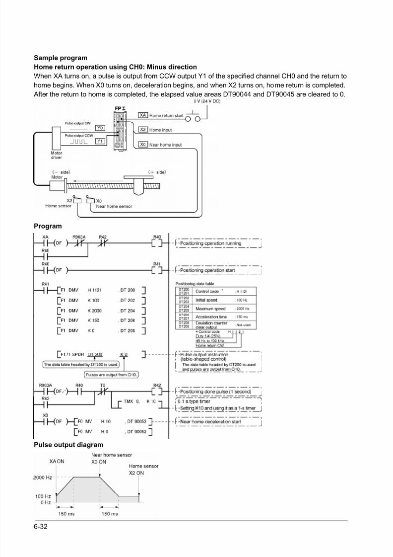
8/21/2019 Programmable Controller FP Sigma
http://slidepdf.com/reader/full/programmable-controller-fp-sigma 118/318
6-32
Sample program
Home return operation using CH0: Minus direction
When XA turns on, a pulse is output from CCW output Y1 of the specified channel CH0 and the return to
home begins. When X0 turns on, deceleration begins, and when X2 turns on, home return is completed.
After the return to home is completed, the elapsed value areas DT90044 and DT90045 are cleared to 0.
Program
Pulse output diagram
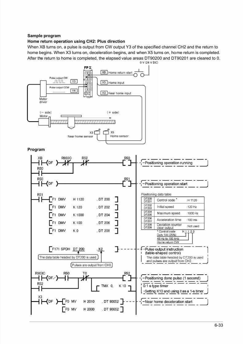
8/21/2019 Programmable Controller FP Sigma
http://slidepdf.com/reader/full/programmable-controller-fp-sigma 119/318
6-33
Sample program
Home return operation using CH2: Plus direction
When XB turns on, a pulse is output from CW output Y3 of the specified channel CH2 and the return to
home begins. When X3 turns on, deceleration begins, and when X5 turns on, home return is completed.
After the return to home is completed, the elapsed value areas DT90200 and DT90201 are cleared to 0.
Program

8/21/2019 Programmable Controller FP Sigma
http://slidepdf.com/reader/full/programmable-controller-fp-sigma 120/318
6-34
Pulse output diagram
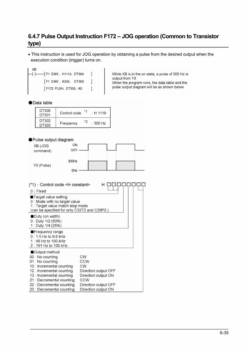
8/21/2019 Programmable Controller FP Sigma
http://slidepdf.com/reader/full/programmable-controller-fp-sigma 121/318
6-35
6.4.7 Pulse Output Instruction F172 – JOG operation (Common to Transistor
type)
• This instruction is used for JOG operation by obtaining a pulse from the desired output when the
execution condition (trigger) turns on.
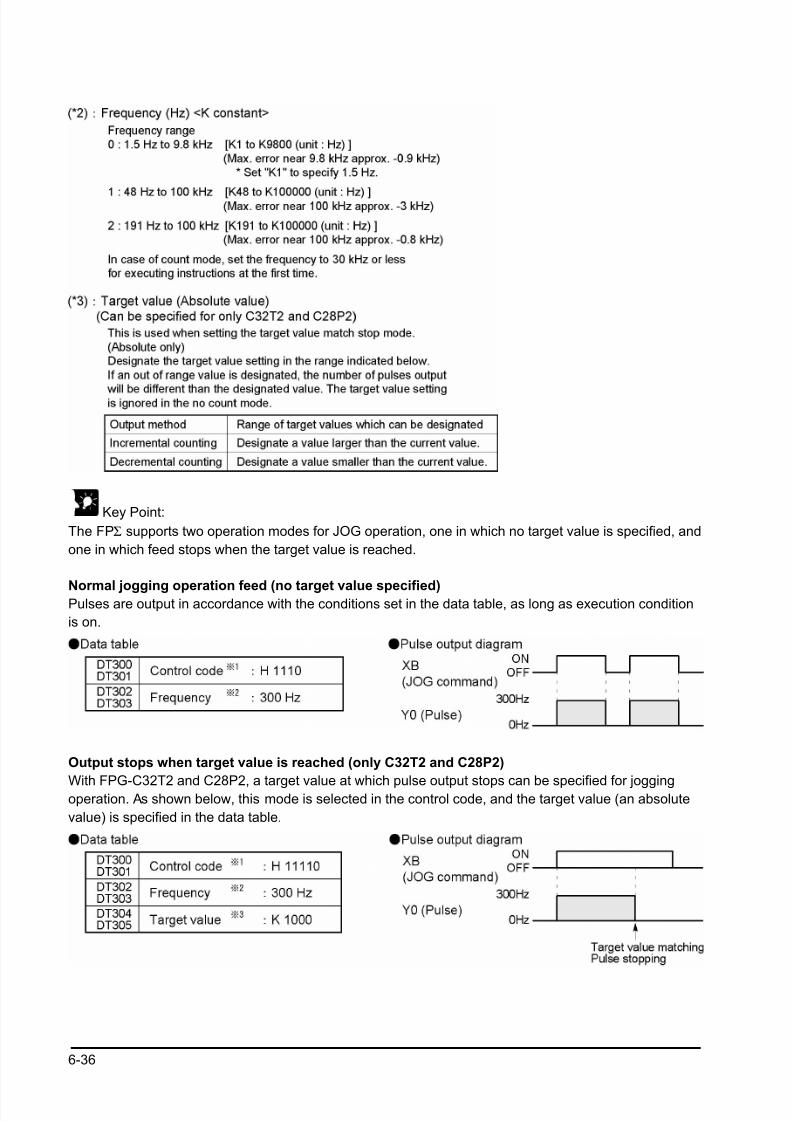
8/21/2019 Programmable Controller FP Sigma
http://slidepdf.com/reader/full/programmable-controller-fp-sigma 122/318
6-36
Key Point:
The FPΣ supports two operation modes for JOG operation, one in which no target value is specified, and
one in which feed stops when the target value is reached.
Normal jogging operation feed (no target value specified)Pulses are output in accordance with the conditions set in the data table, as long as execution condition
is on.
Output stops when target value is reached (only C32T2 and C28P2)
With FPG-C32T2 and C28P2, a target value at which pulse output stops can be specified for joggingoperation. As shown below, this mode is selected in the control code, and the target value (an absolute
value) is specified in the data table.
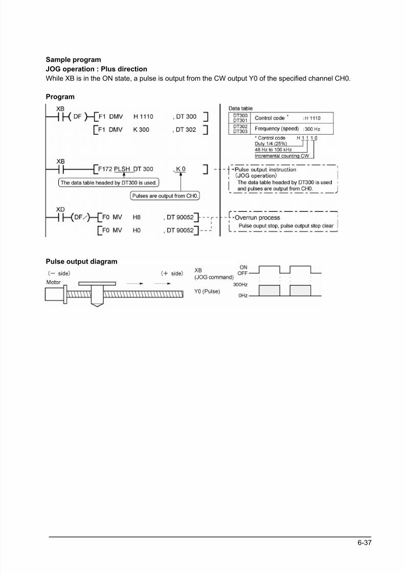
8/21/2019 Programmable Controller FP Sigma
http://slidepdf.com/reader/full/programmable-controller-fp-sigma 123/318
6-37
Sample program
JOG operation : Plus direction
While XB is in the ON state, a pulse is output from the CW output Y0 of the specified channel CH0.
Program
Pulse output diagram
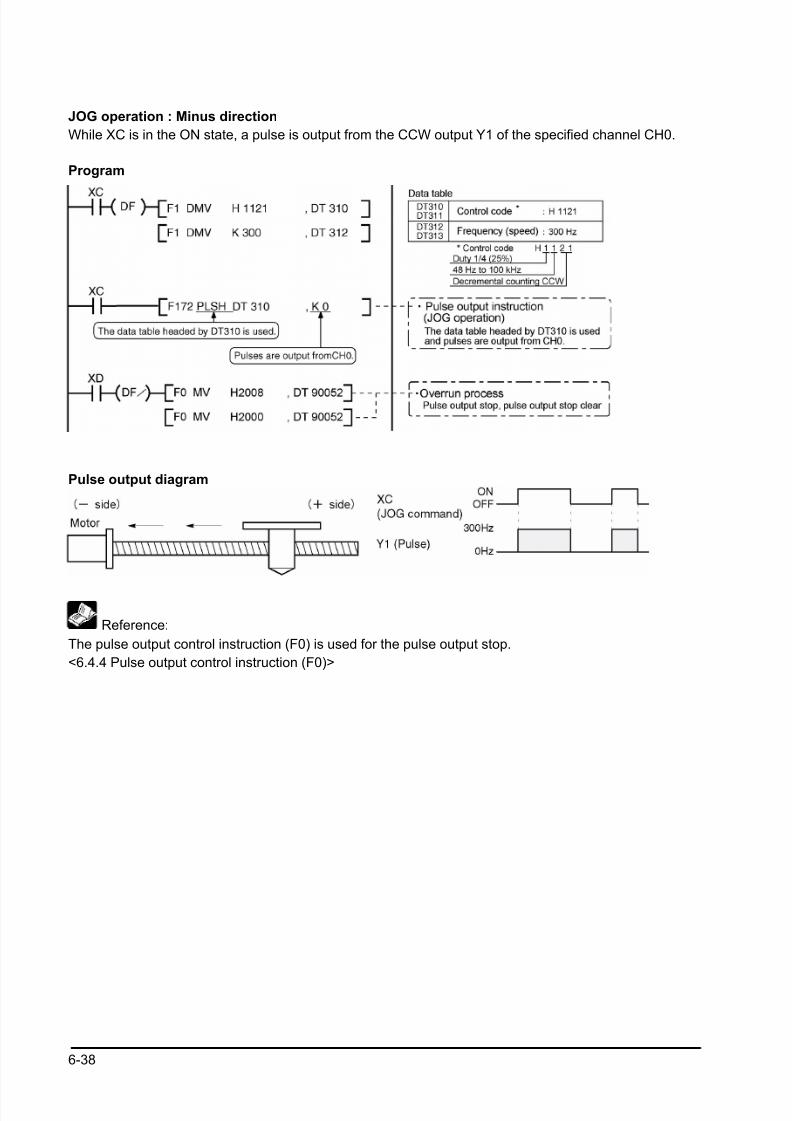
8/21/2019 Programmable Controller FP Sigma
http://slidepdf.com/reader/full/programmable-controller-fp-sigma 124/318
6-38
JOG operation : Minus direction
While XC is in the ON state, a pulse is output from the CCW output Y1 of the specified channel CH0.
Program
Pulse output diagram
Reference:
The pulse output control instruction (F0) is used for the pulse output stop.
<6.4.4 Pulse output control instruction (F0)>
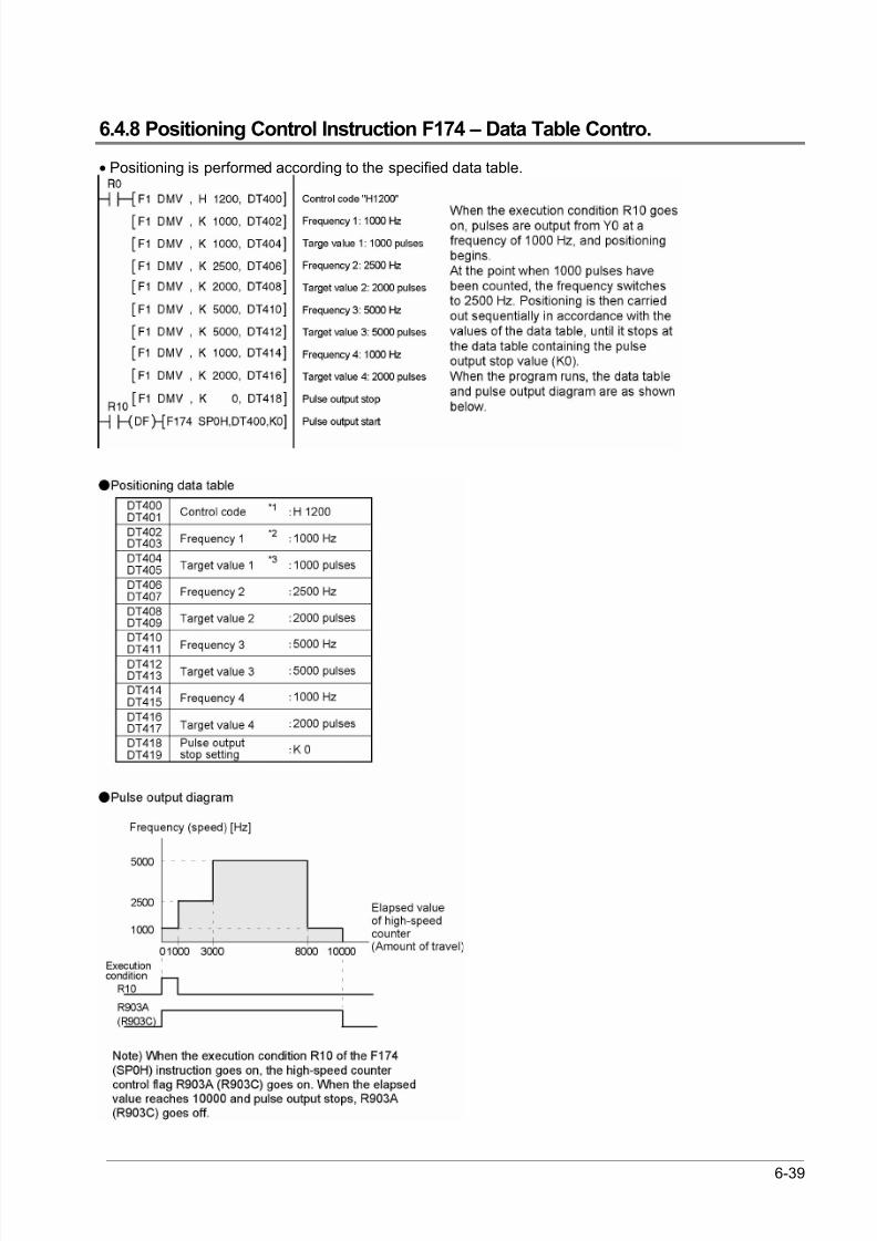
8/21/2019 Programmable Controller FP Sigma
http://slidepdf.com/reader/full/programmable-controller-fp-sigma 125/318
6-39
6.4.8 Positioning Control Instruction F174 – Data Table Contro.
• Positioning is performed according to the specified data table.
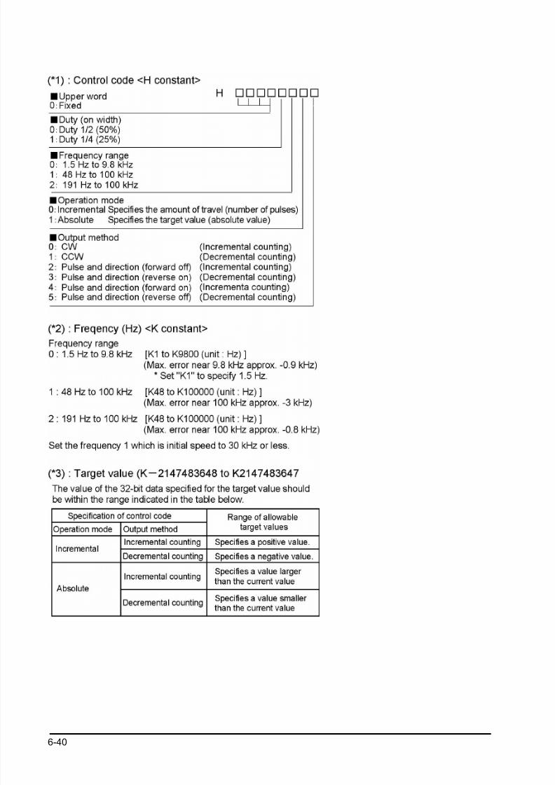
8/21/2019 Programmable Controller FP Sigma
http://slidepdf.com/reader/full/programmable-controller-fp-sigma 126/318
6-40
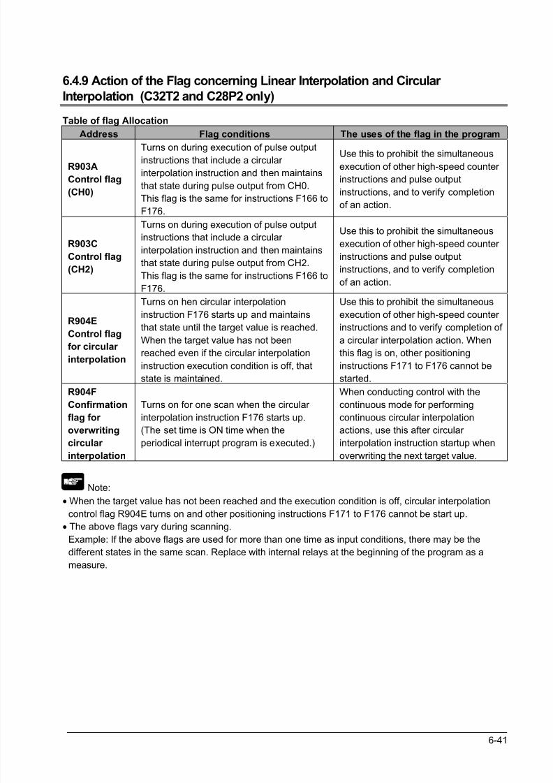
8/21/2019 Programmable Controller FP Sigma
http://slidepdf.com/reader/full/programmable-controller-fp-sigma 127/318
6-41
6.4.9 Action of the Flag concerning Linear Interpolation and Circular
Interpolation (C32T2 and C28P2 only)
Table of flag Allocation
Address Flag conditions The uses of the flag in the program
R903A
Control flag
(CH0)
Turns on during execution of pulse output
instructions that include a circular
interpolation instruction and then maintains
that state during pulse output from CH0.
This flag is the same for instructions F166 to
F176.
Use this to prohibit the simultaneous
execution of other high-speed counter
instructions and pulse output
instructions, and to verify completion
of an action.
R903C
Control flag
(CH2)
Turns on during execution of pulse output
instructions that include a circular
interpolation instruction and then maintains
that state during pulse output from CH2.
This flag is the same for instructions F166 toF176.
Use this to prohibit the simultaneous
execution of other high-speed counter
instructions and pulse output
instructions, and to verify completionof an action.
R904E
Control flag
for circular
interpolation
Turns on hen circular interpolation
instruction F176 starts up and maintains
that state until the target value is reached.
When the target value has not been
reached even if the circular interpolation
instruction execution condition is off, that
state is maintained.
Use this to prohibit the simultaneous
execution of other high-speed counter
instructions and to verify completion of
a circular interpolation action. When
this flag is on, other positioning
instructions F171 to F176 cannot be
started.
R904F
Confirmation
flag for
overwriting
circular
interpolation
Turns on for one scan when the circular
interpolation instruction F176 starts up.
(The set time is ON time when the
periodical interrupt program is executed.)
When conducting control with the
continuous mode for performing
continuous circular interpolation
actions, use this after circular
interpolation instruction startup when
overwriting the next target value.
Note:
• When the target value has not been reached and the execution condition is off, circular interpolation
control flag R904E turns on and other positioning instructions F171 to F176 cannot be start up.
• The above flags vary during scanning.
Example: If the above flags are used for more than one time as input conditions, there may be the
different states in the same scan. Replace with internal relays at the beginning of the program as a
measure.
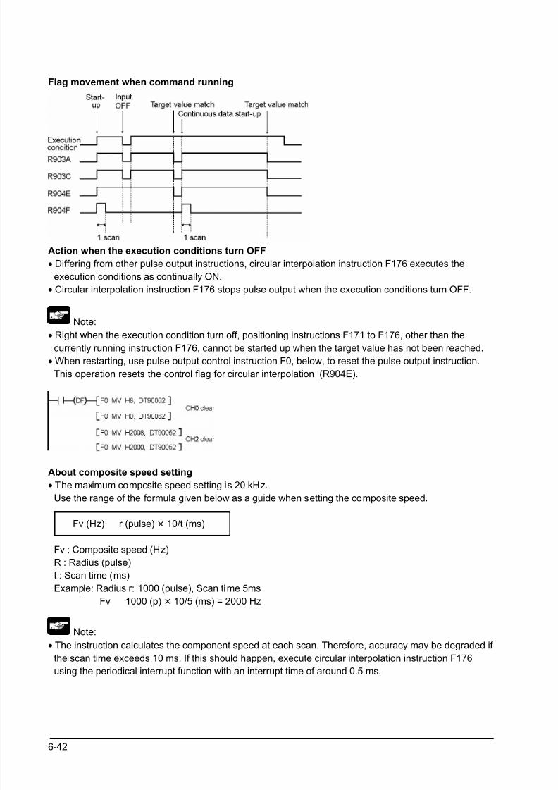
8/21/2019 Programmable Controller FP Sigma
http://slidepdf.com/reader/full/programmable-controller-fp-sigma 128/318
6-42
Flag movement when command running
Action when the execution conditions turn OFF
• Differing from other pulse output instructions, circular interpolation instruction F176 executes the
execution conditions as continually ON.• Circular interpolation instruction F176 stops pulse output when the execution conditions turn OFF.
Note:
• Right when the execution condition turn off, positioning instructions F171 to F176, other than the
currently running instruction F176, cannot be started up when the target value has not been reached.
• When restarting, use pulse output control instruction F0, below, to reset the pulse output instruction.
This operation resets the control flag for circular interpolation (R904E).
About composite speed setting
• The maximum composite speed setting is 20 kHz.
Use the range of the formula given below as a guide when setting the composite speed.
Fv (Hz) r (pulse) × 10/t (ms)
Fv : Composite speed (Hz)R : Radius (pulse)
t : Scan time (ms)
Example: Radius r: 1000 (pulse), Scan time 5ms
Fv 1000 (p) × 10/5 (ms) = 2000 Hz
Note:
• The instruction calculates the component speed at each scan. Therefore, accuracy may be degraded if
the scan time exceeds 10 ms. If this should happen, execute circular interpolation instruction F176
using the periodical interrupt function with an interrupt time of around 0.5 ms.

8/21/2019 Programmable Controller FP Sigma
http://slidepdf.com/reader/full/programmable-controller-fp-sigma 129/318
6-43
Restrictions on positioning data setting
• Designate settings for the target position, pass position and center position so they are within the
following range.
Allowable range: -8,388,608 to +8,388,608
•
When using in combination with other positioning instructions like F171, designate so the target valueis within the above range, even in those instructions.
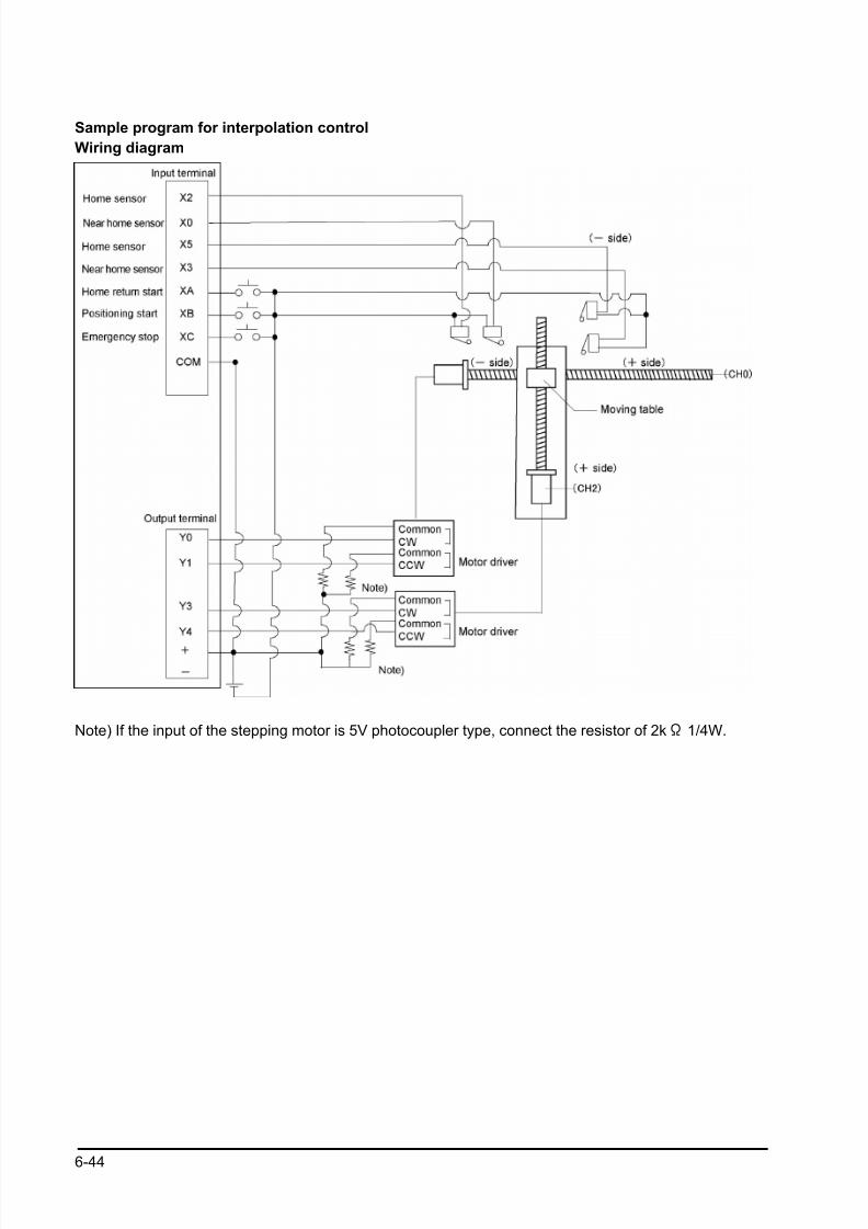
8/21/2019 Programmable Controller FP Sigma
http://slidepdf.com/reader/full/programmable-controller-fp-sigma 130/318
6-44
Sample program for interpolation control
Wiring diagram
Note) If the input of the stepping motor is 5V photocoupler type, connect the resistor of 2kΩ 1/4W.
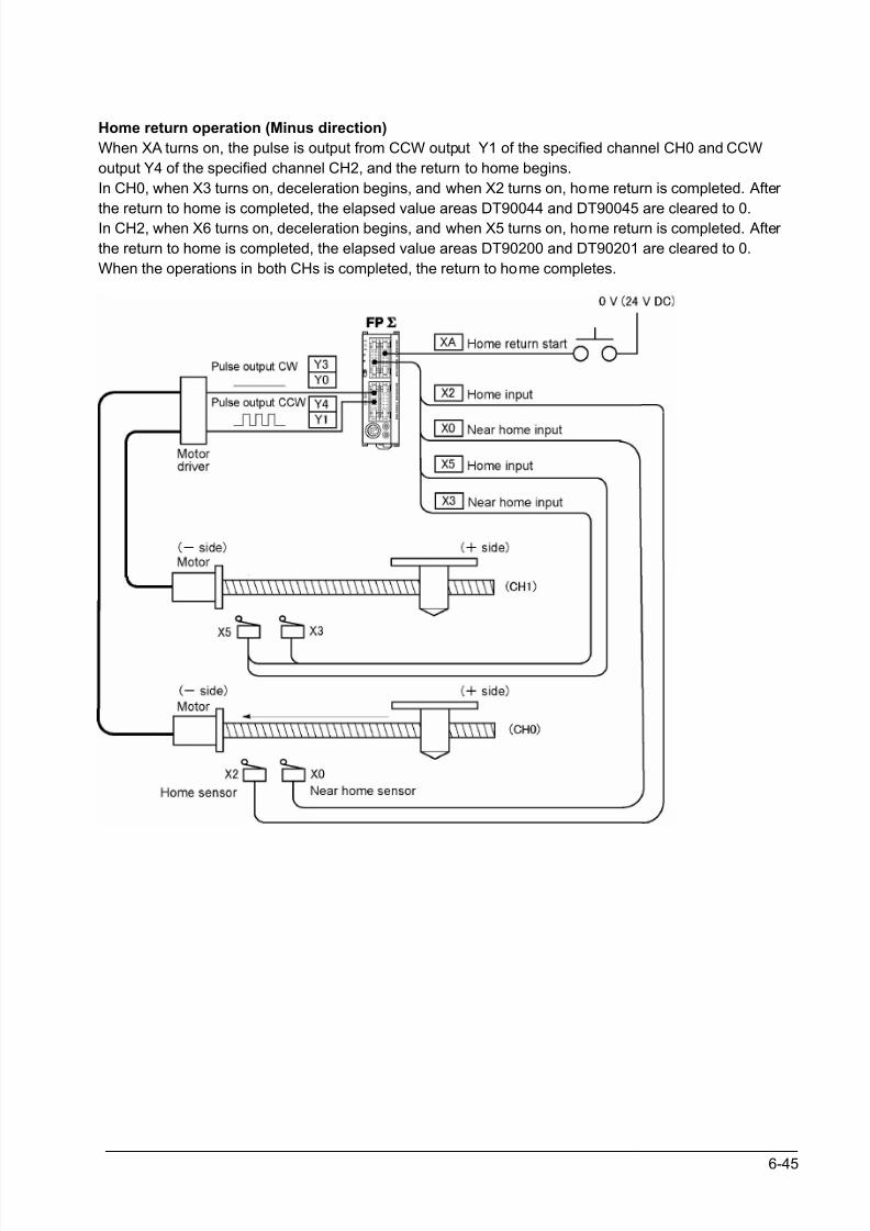
8/21/2019 Programmable Controller FP Sigma
http://slidepdf.com/reader/full/programmable-controller-fp-sigma 131/318
6-45
Home return operation (Minus direction)
When XA turns on, the pulse is output from CCW output Y1 of the specified channel CH0 and CCW
output Y4 of the specified channel CH2, and the return to home begins.
In CH0, when X3 turns on, deceleration begins, and when X2 turns on, home return is completed. After
the return to home is completed, the elapsed value areas DT90044 and DT90045 are cleared to 0.In CH2, when X6 turns on, deceleration begins, and when X5 turns on, home return is completed. After
the return to home is completed, the elapsed value areas DT90200 and DT90201 are cleared to 0.
When the operations in both CHs is completed, the return to home completes.
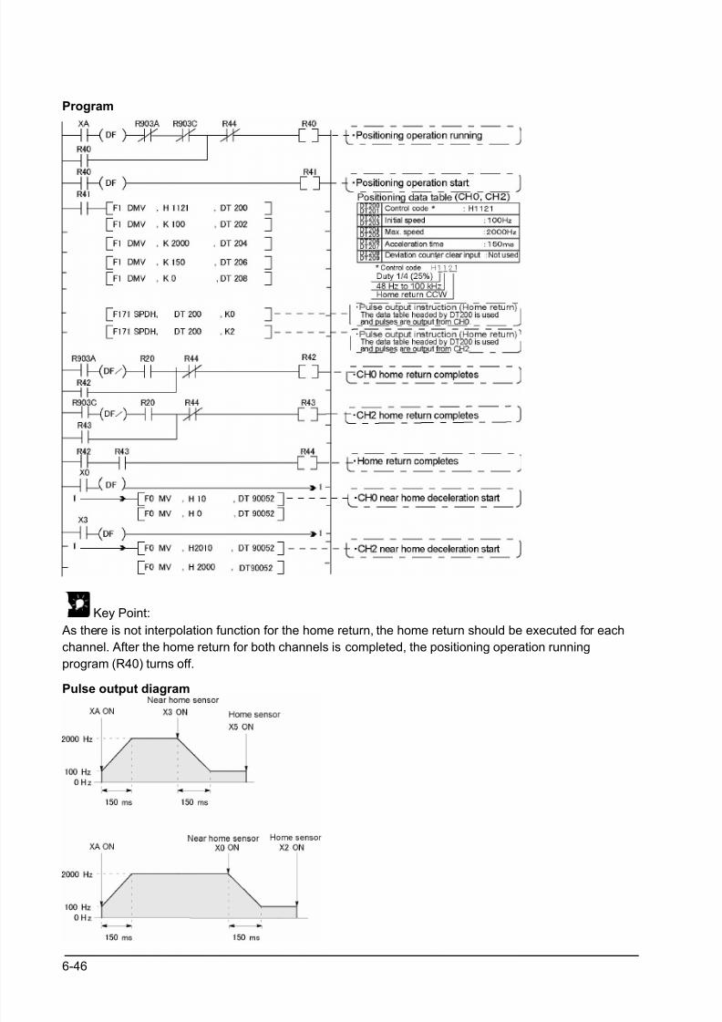
8/21/2019 Programmable Controller FP Sigma
http://slidepdf.com/reader/full/programmable-controller-fp-sigma 132/318
6-46
Program
Key Point:
As there is not interpolation function for the home return, the home return should be executed for each
channel. After the home return for both channels is completed, the positioning operation running
program (R40) turns off.
Pulse output diagram
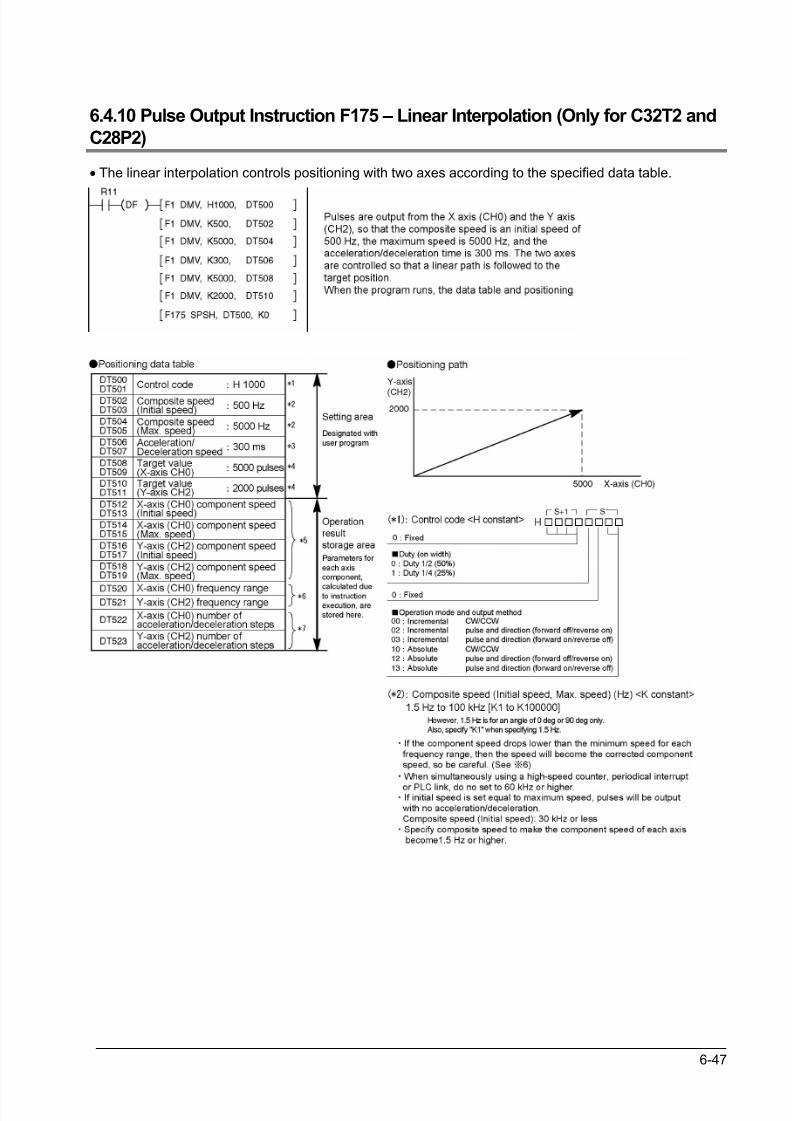
8/21/2019 Programmable Controller FP Sigma
http://slidepdf.com/reader/full/programmable-controller-fp-sigma 133/318
6-47
6.4.10 Pulse Output Instruction F175 – Linear Interpolation (Only for C32T2 and
C28P2)
• The linear interpolation controls positioning with two axes according to the specified data table.
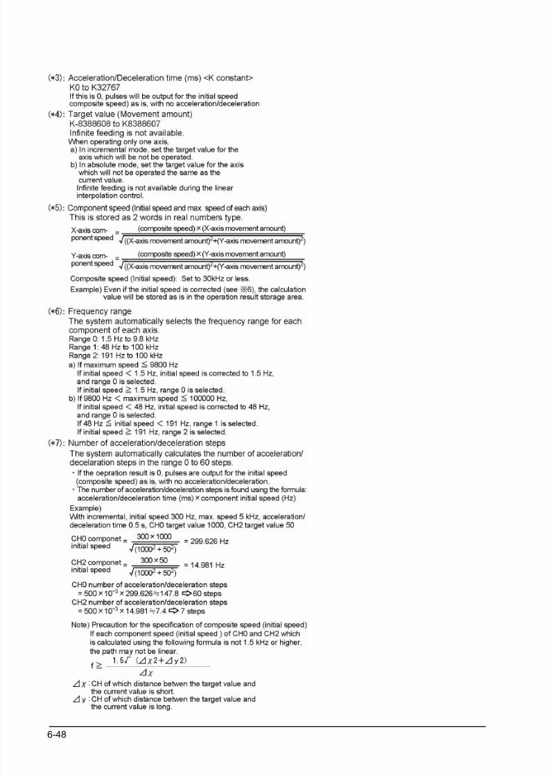
8/21/2019 Programmable Controller FP Sigma
http://slidepdf.com/reader/full/programmable-controller-fp-sigma 134/318
6-48
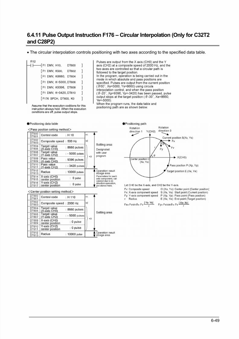
8/21/2019 Programmable Controller FP Sigma
http://slidepdf.com/reader/full/programmable-controller-fp-sigma 135/318
6-49
6.4.11 Pulse Output Instruction F176 – Circular Interpolation (Only for C32T2
and C28P2)
• The circular interpolation controls positioning with two axes according to the specified data table.
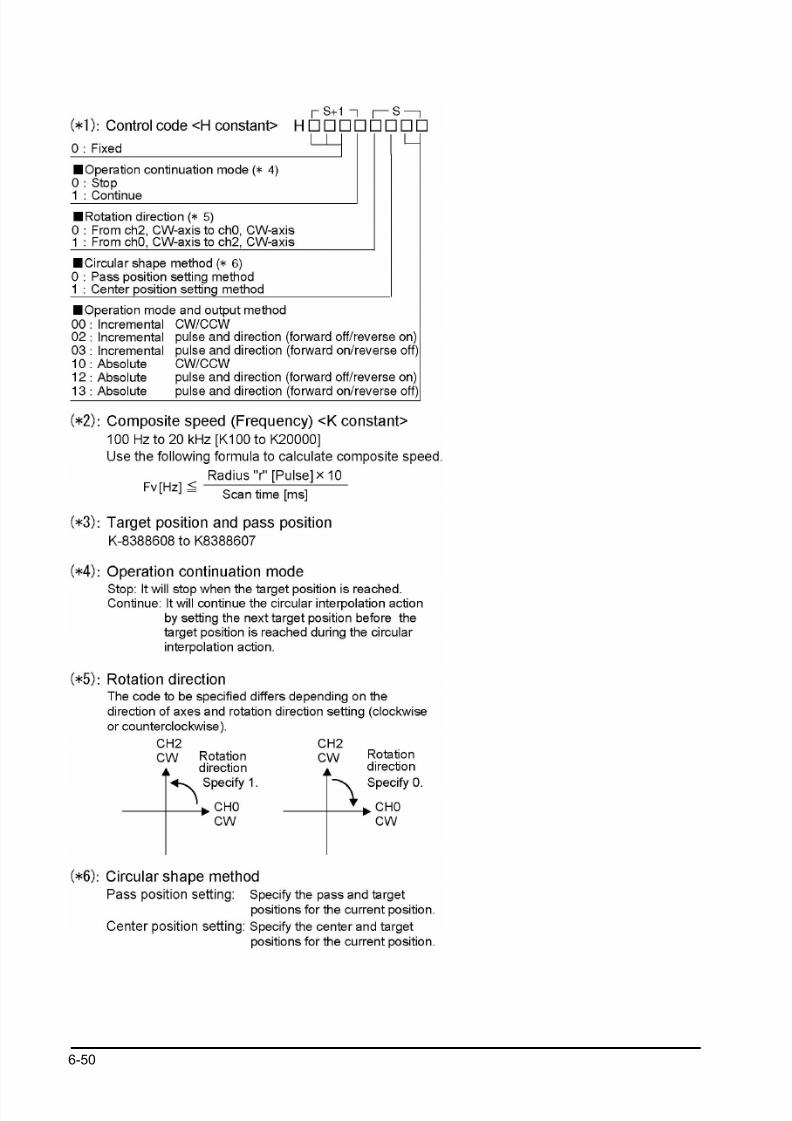
8/21/2019 Programmable Controller FP Sigma
http://slidepdf.com/reader/full/programmable-controller-fp-sigma 136/318
6-50
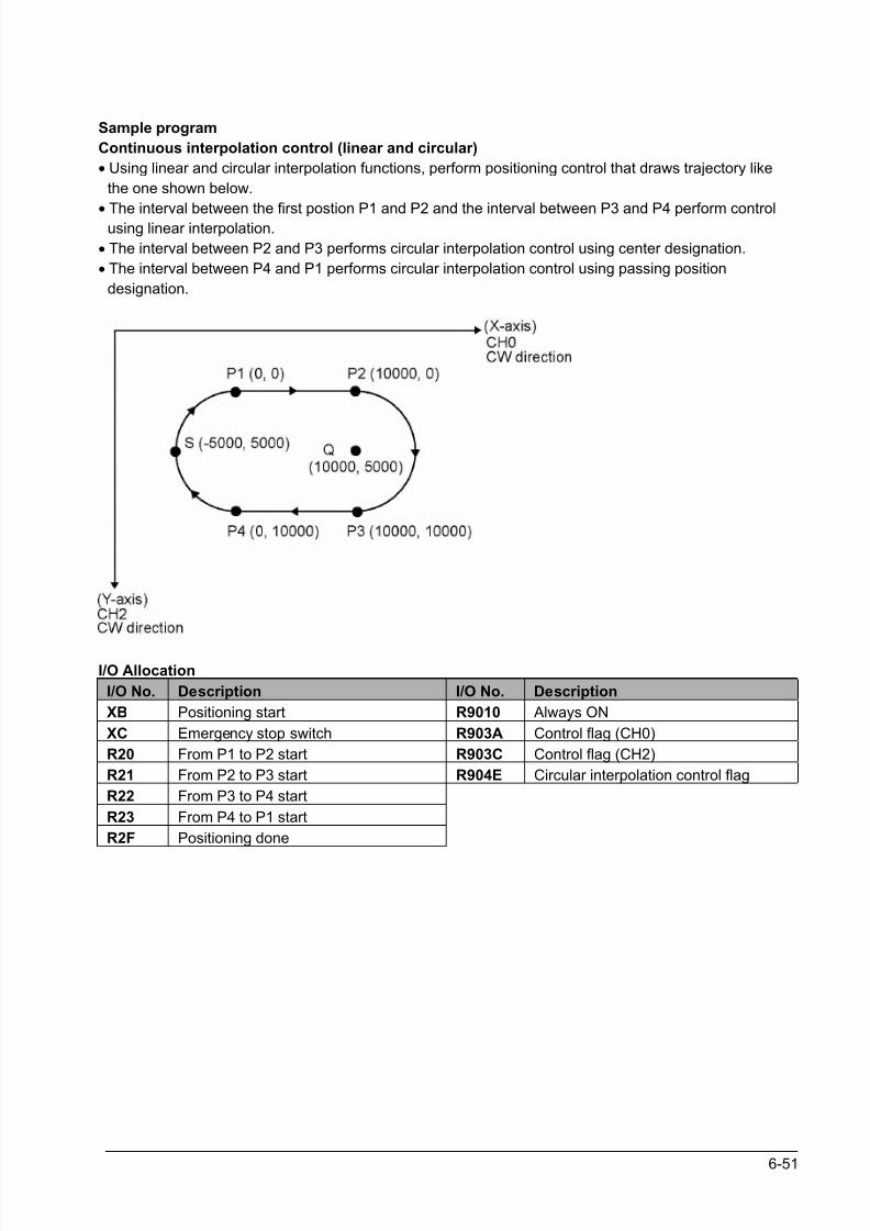
8/21/2019 Programmable Controller FP Sigma
http://slidepdf.com/reader/full/programmable-controller-fp-sigma 137/318
6-51
Sample program
Continuous interpolation control (linear and circular)
• Using linear and circular interpolation functions, perform positioning control that draws trajectory like
the one shown below.
•
The interval between the first postion P1 and P2 and the interval between P3 and P4 perform controlusing linear interpolation.
• The interval between P2 and P3 performs circular interpolation control using center designation.
• The interval between P4 and P1 performs circular interpolation control using passing position
designation.
I/O Allocation
I/O No. Description I/O No. Description
XB Positioning start R9010 Always ON
XC Emergency stop switch R903A Control flag (CH0)
R20 From P1 to P2 start R903C Control flag (CH2)
R21 From P2 to P3 start R904E Circular interpolation control flag
R22 From P3 to P4 start
R23 From P4 to P1 start
R2F Positioning done
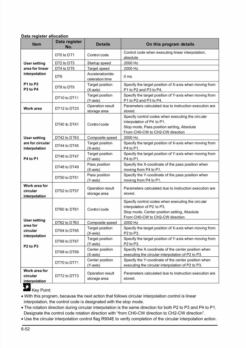
8/21/2019 Programmable Controller FP Sigma
http://slidepdf.com/reader/full/programmable-controller-fp-sigma 138/318
6-52
Data register allocation
ItemData register
No.Details On this program details
DT0 to DT1 Control codeControl code when executing linear interpolation,
absolute
DT2 to DT3 Startup speed 2000 Hz
DT4 to DT5 Target speed 2000 Hz
DT6 Acceleration/de-
celeration time0 ms
DT8 to DT9Target position
(X-axis)
Specify the target position of X-axis when moving from
P1 to P2 and P3 to P4.
User setting
area for linear
interpolation
P1 to P2
P3 to P4
DT10 to DT11Target position
(Y-axis)
Specify the target position of Y-axis when moving from
P1 to P2 and P3 to P4.
Work area DT12 to DT23Operation result
storage area
Parameters calculated due to instruction execution are
stored.
DT40 to DT41 Contro l code
Specify control codes when executing the circular
interpolation of P4 to P1.Stop mode, Pass position setting, Absolute
From CH0-CW to CH2-CW direction
DT42 to D T43 Composite speed 2000 Hz
DT44 to DT45Target position
(X-axis)
Specify the target position of X-axis when moving from
P4 to P1.
DT46 to DT47Target position
(Y-axis)
Specify the target position of Y-axis when moving from
P4 to P1.
DT48 to DT49Pass position
(X-axis)
Specify the X-coodinate of the pass position when
moving from P4 to P1.
User setting
are for circular
interpolation
P4 to P1
DT50 to DT51Pass position
(Y-axis)
Specify the Y-coodinate of the pass position when
moving from P4 to P1.
Work area for
circular
interpolation
DT52 to DT57Operation result
storage area
Parameters calculated due to instruction execution are
stored.
DT60 to DT61 Contro l code
Specify control codes when executing the circular
interpolation of P2 to P3.
Stop mode, Center position setting, Absolute
From CH0-CW to CH2-CW direction
DT62 to D T63 Composite speed 2000 Hz
DT64 to DT65Target position
(X-axis)
Specify the target position of X-axis when moving from
P2 to P3.
DT66 to DT67Target position
(Y-axis)
Specify the target position of Y-axis when moving from
P2 to P3.
DT68 to DT69Center position
(X-axis)
Specify the X-coodinate of the center position when
executing the circular interpolation of P2 to P3.
User setting
area for
circular
interpolation
P2 to P3
DT70 to DT71Center position
(Y-axis)
Specify the Y-coodinate of the center position when
executing the circular interpolation of P2 to P3.
Work area for
circular
interpolation
DT72 to DT73Operation result
storage area
Parameters calculated due to instruction execution are
stored.
Key Point:
• With this program, because the next action that follows circular interpolation control is linear
interpolation, the control code is designated with the stop mode.
• The rotation direction during circular interpolation is the same direction for both P2 to P3 and P4 to P1.
Designate the control code rotation direction with “from CH0-CW direction to CH2-CW direction”.
• Use the circular interpolation control flag R904E to verify completion of the circular interpolation action.
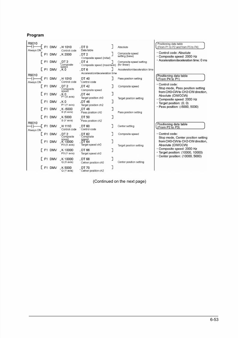
8/21/2019 Programmable Controller FP Sigma
http://slidepdf.com/reader/full/programmable-controller-fp-sigma 139/318
6-53
Program
(Continued on the next page)
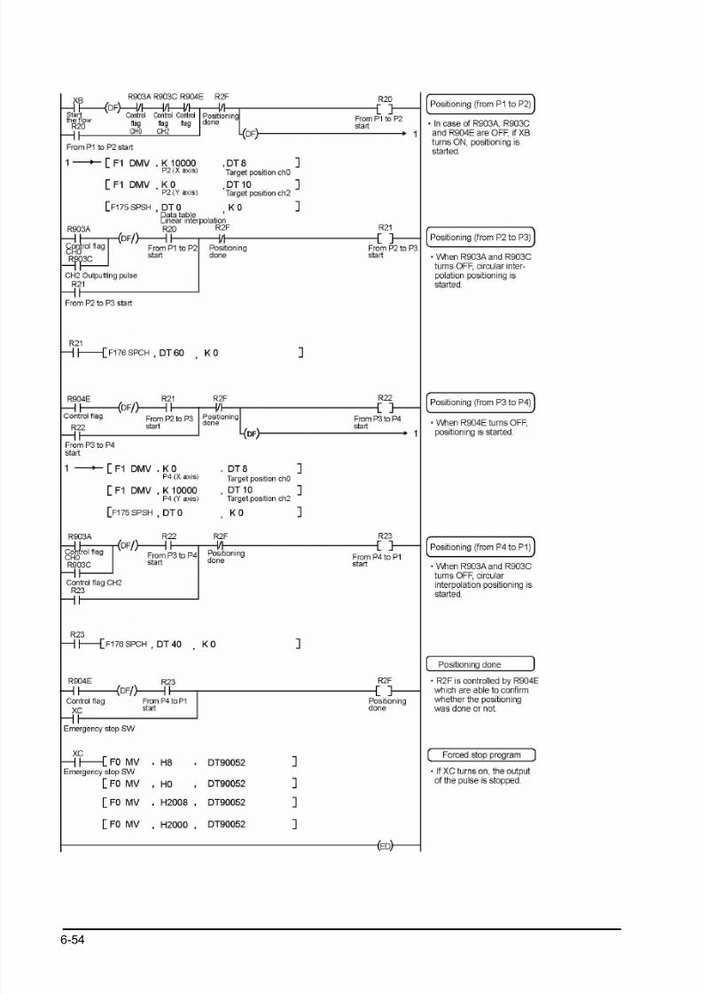
8/21/2019 Programmable Controller FP Sigma
http://slidepdf.com/reader/full/programmable-controller-fp-sigma 140/318
6-54
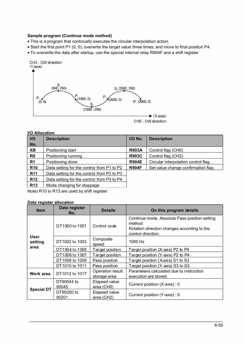
8/21/2019 Programmable Controller FP Sigma
http://slidepdf.com/reader/full/programmable-controller-fp-sigma 141/318
6-55
Sample program (Continue mode method)
• This is a program that continually executes the circular interpolation action.
• Start the first point P1 (0, 0), overwrite the target value three times, and move to final position P4.
• To overwrite the data after startup, use the special internal relay R904F and a shift register.
I/O Allocation
I/O
No.
Description I/O No. Description
XB Positioning start R903A Control flag (CH0)
R0 Positioning running R903C Control flag (CH2)
R1 Positioning done R904E Circular interpolation control flag
R10 Data setting for the control from P1 to P2 R904F Set value change confirmation flag
R11 Data setting for the control from P2 to P3
R12 Data setting for the control from P3 to P4R13 Mode changing for stoppage
Note) R10 to R13 are used by shift register.
Data register allocation
ItemData register
No.Details On this program details
DT1000 to 1001 Control code
Continue mode, Absolute Pass position setting
method
Rotation direction changes according to the
control direction.
DT1002 to 1003 Compositespeed 1000 Hz
DT1004 to 1005 Target position Target position (X-axis) P2 to P4
DT1006 to 1007 Target position Target position (Y-axis) P2 to P4
DT1008 to 1009 Pass position Target position (X-axis) S1 to S3
User
settingarea
DT1010 to 1011 Pass position Target position (Y-axis) S3 to S3
Work area DT1012 to 1017Operation result
storage area
Parameters calculated due to instruction
execution are stored.
DT90044 to
90045
Elapsed value
area (CH0)Current position (X-axis) : 0
Special DTDT90200 to
90201
Elapsed value
area (CH2)Current position (Y-axis) : 0
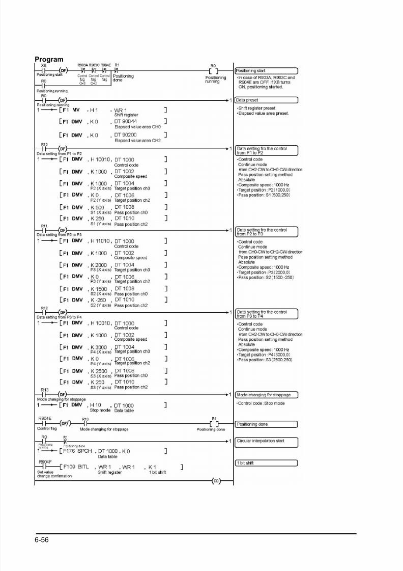
8/21/2019 Programmable Controller FP Sigma
http://slidepdf.com/reader/full/programmable-controller-fp-sigma 142/318
6-56
Program

8/21/2019 Programmable Controller FP Sigma
http://slidepdf.com/reader/full/programmable-controller-fp-sigma 143/318
6-57
Key Point:
• To overwrite the data after startup use the circular interpolation data overwrite permission flag R904F.
• In control that heads toward final point P4, designate by switching the control code to the stop mode.
• In this example, since the rotation direction changes for each positioning point, designation of the
control code rotation direction is as follows.
Between P1 and P2: From CH2-CW to CH0-CW direction
Between P2 and P3: From CH0-CW to CH2-CW direction
Between P3 and P4: From CH2-CW to CH0-CW direction
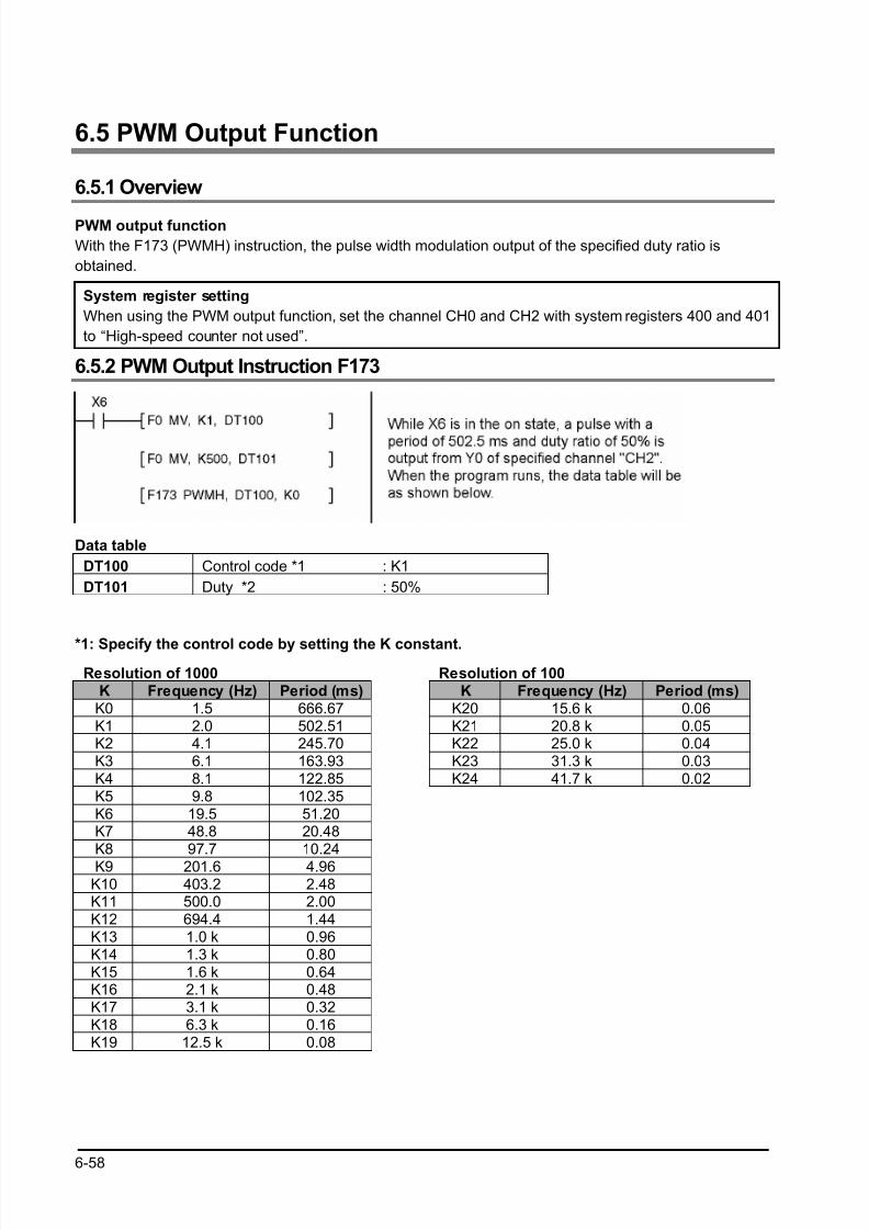
8/21/2019 Programmable Controller FP Sigma
http://slidepdf.com/reader/full/programmable-controller-fp-sigma 144/318
6-58
6.5 PWM Output Function
6.5.1 Overview
PWM output function
With the F173 (PWMH) instruction, the pulse width modulation output of the specified duty ratio is
obtained.
System register setting
When using the PWM output function, set the channel CH0 and CH2 with system registers 400 and 401
to “High-speed counter not used”.
6.5.2 PWM Output Instruction F173
Data table
DT100 Control code *1 : K1
DT101 Duty *2 : 50%
*1: Specify the control code by setting the K constant.
Resolution of 1000 Resolution of 100K Frequency (Hz) Period (ms) K Frequency (Hz) Period (ms)
K0 1.5 666.67 K20 15.6 k 0.06K1 2.0 502.51 K21 20.8 k 0.05K2 4.1 245.70 K22 25.0 k 0.04K3 6.1 163.93 K23 31.3 k 0.03K4 8.1 122.85 K24 41.7 k 0.02K5 9.8 102.35K6 19.5 51.20K7 48.8 20.48K8 97.7 10.24
K9 201.6 4.96K10 403.2 2.48K11 500.0 2.00K12 694.4 1.44K13 1.0 k 0.96K14 1.3 k 0.80K15 1.6 k 0.64K16 2.1 k 0.48K17 3.1 k 0.32K18 6.3 k 0.16K19 12.5 k 0.08

8/21/2019 Programmable Controller FP Sigma
http://slidepdf.com/reader/full/programmable-controller-fp-sigma 145/318
6-59
*2: specification of duty (specify using K constant)
If the control code is K0 to K19, the duty is K0 to K999 (0.0% to 99.9%).
If the control code is K20 to K24, the duty is K0 to K990 (0% to 99%).
Values are specified in units of 1% (K10) (digits behind the decimal point are rounded off).
Note:
• If a value outside the specified range is written to the duty area while the instruction is being executed,
a frequency corrected to the maximum value is output. If written when instruction execution is started,
an operation error is occurred.

8/21/2019 Programmable Controller FP Sigma
http://slidepdf.com/reader/full/programmable-controller-fp-sigma 146/318
6-60

8/21/2019 Programmable Controller FP Sigma
http://slidepdf.com/reader/full/programmable-controller-fp-sigma 147/318
Chapter 7
Communication Cassette

8/21/2019 Programmable Controller FP Sigma
http://slidepdf.com/reader/full/programmable-controller-fp-sigma 148/318
7-2
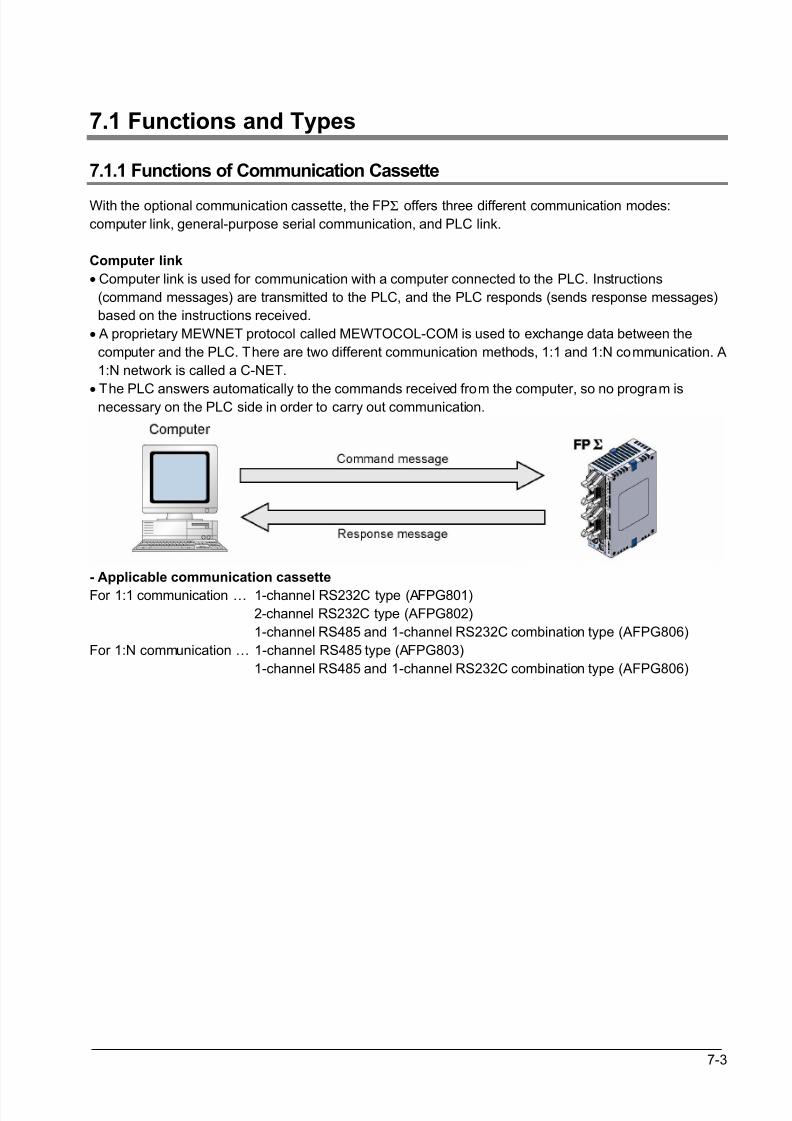
8/21/2019 Programmable Controller FP Sigma
http://slidepdf.com/reader/full/programmable-controller-fp-sigma 149/318
7-3
7.1 Functions and Types
7.1.1 Functions of Communication Cassette
With the optional communication cassette, the FPΣ offers three different communication modes:
computer link, general-purpose serial communication, and PLC link.
Computer link
• Computer link is used for communication with a computer connected to the PLC. Instructions
(command messages) are transmitted to the PLC, and the PLC responds (sends response messages)
based on the instructions received.
• A proprietary MEWNET protocol called MEWTOCOL-COM is used to exchange data between the
computer and the PLC. There are two different communication methods, 1:1 and 1:N communication. A
1:N network is called a C-NET.
• The PLC answers automatically to the commands received from the computer, so no program isnecessary on the PLC side in order to carry out communication.
- Applicable communication cassette
For 1:1 communication … 1-channel RS232C type (AFPG801)
2-channel RS232C type (AFPG802)
1-channel RS485 and 1-channel RS232C combination type (AFPG806)
For 1:N communication … 1-channel RS485 type (AFPG803)
1-channel RS485 and 1-channel RS232C combination type (AFPG806)
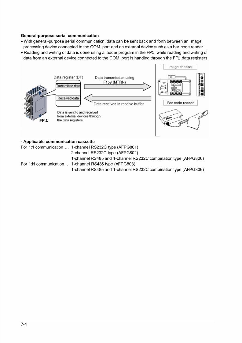
8/21/2019 Programmable Controller FP Sigma
http://slidepdf.com/reader/full/programmable-controller-fp-sigma 150/318
7-4
General-purpose serial communication
• With general-purpose serial communication, data can be sent back and forth between an image
processing device connected to the COM. port and an external device such as a bar code reader.
• Reading and writing of data is done using a ladder program in the FPΣ, while reading and writing of
data from an external device connected to the COM. port is handled through the FPΣ
data registers.
- Applicable communication cassette
For 1:1 communication … 1-channel RS232C type (AFPG801)
2-channel RS232C type (AFPG802)
1-channel RS485 and 1-channel RS232C combination type (AFPG806)
For 1:N communication … 1-channel RS485 type (AFPG803)
1-channel RS485 and 1-channel RS232C combination type (AFPG806)
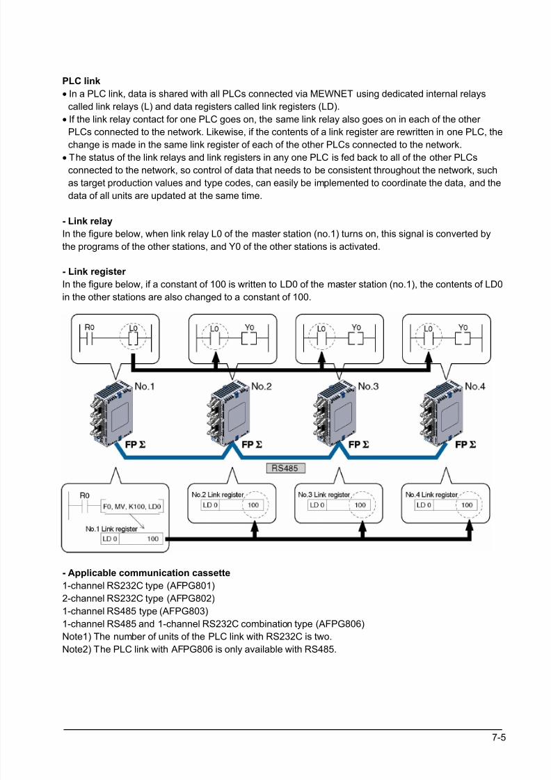
8/21/2019 Programmable Controller FP Sigma
http://slidepdf.com/reader/full/programmable-controller-fp-sigma 151/318
7-5
PLC link
• In a PLC link, data is shared with all PLCs connected via MEWNET using dedicated internal relays
called link relays (L) and data registers called link registers (LD).
• If the link relay contact for one PLC goes on, the same link relay also goes on in each of the other
PLCs connected to the network. Likewise, if the contents of a link register are rewritten in one PLC, thechange is made in the same link register of each of the other PLCs connected to the network.
• The status of the link relays and link registers in any one PLC is fed back to all of the other PLCs
connected to the network, so control of data that needs to be consistent throughout the network, such
as target production values and type codes, can easily be implemented to coordinate the data, and the
data of all units are updated at the same time.
- Link relay
In the figure below, when link relay L0 of the master station (no.1) turns on, this signal is converted by
the programs of the other stations, and Y0 of the other stations is activated.
- Link register In the figure below, if a constant of 100 is written to LD0 of the master station (no.1), the contents of LD0
in the other stations are also changed to a constant of 100.
- Applicable communication cassette
1-channel RS232C type (AFPG801)
2-channel RS232C type (AFPG802)
1-channel RS485 type (AFPG803)
1-channel RS485 and 1-channel RS232C combination type (AFPG806)
Note1) The number of units of the PLC link with RS232C is two.
Note2) The PLC link with AFPG806 is only available with RS485.
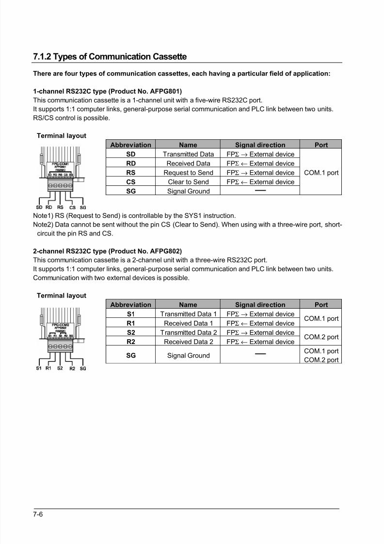
8/21/2019 Programmable Controller FP Sigma
http://slidepdf.com/reader/full/programmable-controller-fp-sigma 152/318
7-6
7.1.2 Types of Communication Cassette
There are four types of communication cassettes, each having a particular field of application:
1-channel RS232C type (Product No. AFPG801)
This communication cassette is a 1-channel unit with a five-wire RS232C port.
It supports 1:1 computer links, general-purpose serial communication and PLC link between two units.
RS/CS control is possible.
Terminal layout
Abbreviation Name Signal direction Port
SD Transmitted Data FPΣ → External device
RD Received Data FPΣ ← External device
RS Request to Send FPΣ → External device
CS Clear to Send FPΣ ← External device
SG Signal Ground
COM.1 port
Note1) RS (Request to Send) is controllable by the SYS1 instruction.
Note2) Data cannot be sent without the pin CS (Clear to Send). When using with a three-wire port, short-
circuit the pin RS and CS.
2-channel RS232C type (Product No. AFPG802)
This communication cassette is a 2-channel unit with a three-wire RS232C port.
It supports 1:1 computer links, general-purpose serial communication and PLC link between two units.
Communication with two external devices is possible.
Terminal layout
Abbreviation Name Signal direction Port
S1 Transmitted Data 1 FPΣ → External device
R1 Received Data 1 FPΣ ← External deviceCOM.1 port
S2 Transmitted Data 2 FPΣ → External device
R2 Received Data 2 FPΣ ← External deviceCOM.2 port
SG Signal GroundCOM.1 port
COM.2 port
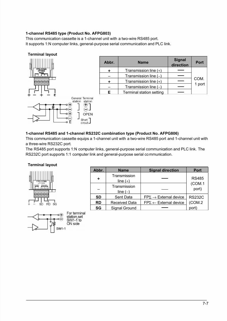
8/21/2019 Programmable Controller FP Sigma
http://slidepdf.com/reader/full/programmable-controller-fp-sigma 153/318
7-7
1-channel RS485 type (Product No. AFPG803)
This communication cassette is a 1-channel unit with a two-wire RS485 port.
It supports 1:N computer links, general-purpose serial communication and PLC link.
Terminal layoutAbbr. Name
Signal
directionPort
++++ Transmission line (+)
−−−− Transmission line (−)
++++ Transmission line (+)
−−−− Transmission line (−)
E Terminal station setting
COM.
1 port
1-channel RS485 and 1-channel RS232C combination type (Product No. AFPG806)
This communication cassette equips a 1-channel unit with a two-wire RS485 port and 1-channel unit with
a three-wire RS232C port.
The RS485 port supports 1:N computer links, general-purpose serial communication and PLC link. The
RS232C port supports 1:1 computer link and general-purpose serial communication.
Terminal layout
Abbr. Name Signal direction Port
++++Transmission
line (+)
−−−−Transmission
line (−)
RS485
(COM.1
port)
SD Sent Data FPΣ → External device
RD Received Data FPΣ ← External device
SG Signal Ground
RS232C
(COM.2
port)
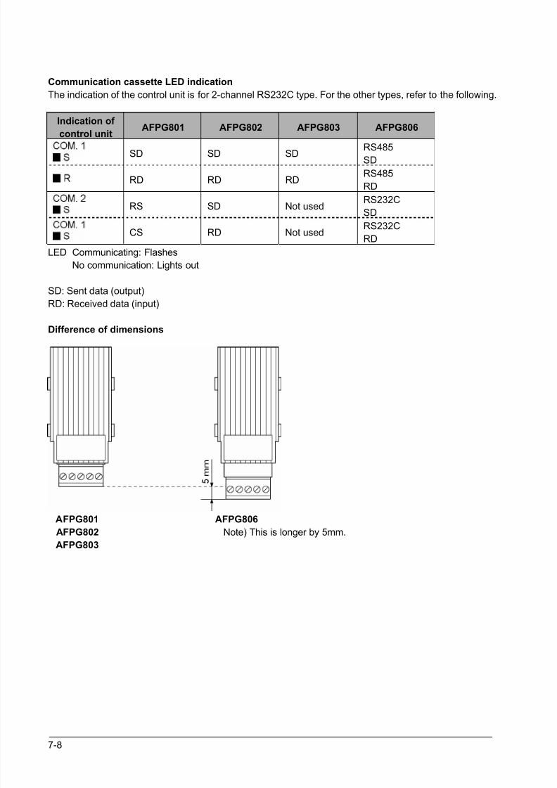
8/21/2019 Programmable Controller FP Sigma
http://slidepdf.com/reader/full/programmable-controller-fp-sigma 154/318
7-8
Communication cassette LED indication
The indication of the control unit is for 2-channel RS232C type. For the other types, refer to the following.
Indication of
control unit
AFPG801 AFPG802 AFPG803 AFPG806
SD SD SDRS485
SD
RD RD RDRS485
RD
RS SD Not usedRS232C
SD
CS RD Not usedRS232C
RD
LED Communicating: Flashes
No communication: Lights out
SD: Sent data (output)
RD: Received data (input)
Difference of dimensions
AFPG801 AFPG806
AFPG802 Note) This is longer by 5mm.
AFPG803
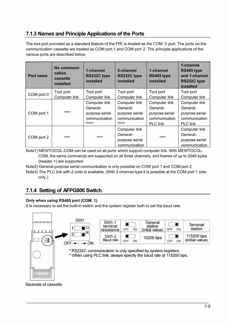
8/21/2019 Programmable Controller FP Sigma
http://slidepdf.com/reader/full/programmable-controller-fp-sigma 155/318
7-9
7.1.3 Names and Principle Applications of the Ports
The tool port provided as a standard feature of the FPΣ is treated as the COM. 0 port. The ports on the
communication cassette are treated as COM port 1 and COM port 2. The principle applications of the
various ports are described below.
Port name
No communi-
cation
cassette
installed
1-channel
RS232C type
installed
2-channel
RS232C type
installed
1-channel
RS485 type
installed
1-channle
RS485 type
and 1-channel
RS232C type
installed
COM port 0Tool port
Computer link
Tool port
Computer link
Tool port
Computer link
Tool port
Computer link
Tool port
Computer link
COM port 1
Computer link
General-
purpose serialcommunicationNote3)
Computer link
General-
purpose serialcommunicationNote3)
Computer link
General-
purpose serialcommunication
PLC link
Computer link
General-
purpose serialcommunication
PLC link
COM port 2
Computer link
General-
purpose serial
communication
Computer link
General-
purpose serial
communication
Note1) MEWTOCOL-COM can be used on all ports which support computer link. With MEWTOCOL-
COM, the same commands are supported on all three channels, and frames of up to 2048 bytes
(header <) are supported.
Note2) General-purpose serial communication is only possible on COM port 1 and COM port 2.
Note3) The PLC link with 2 units is available. (With 2-channel type it is possible at the COM port 1 side
only.)
7.1.4 Setting of AFPG806 Switch
Only when using RS485 port (COM. 1)
It is necessary to set the built-in switch and the system register both to set the baud rate.
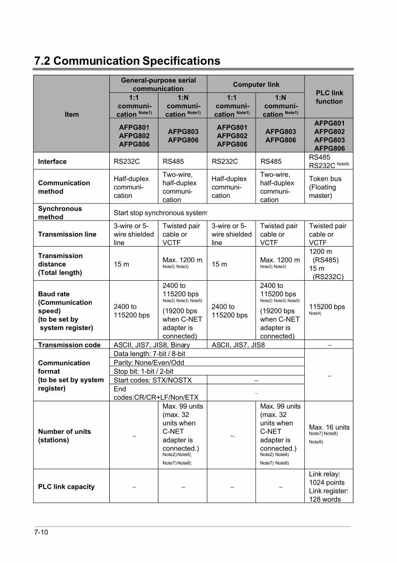
8/21/2019 Programmable Controller FP Sigma
http://slidepdf.com/reader/full/programmable-controller-fp-sigma 156/318
7-10
7.2 Communication Specifications
General-purpose serial
communicationComputer link
1:1communi-
cation Note1)
1:Ncommuni-
cation Note1)
1:1communi-
cation Note1)
1:Ncommuni-
cation Note1)
PLC link
function
Item
AFPG801
AFPG802
AFPG806
AFPG803
AFPG806
AFPG801
AFPG802
AFPG806
AFPG803
AFPG806
AFPG801
AFPG802
AFPG803
AFPG806
Interface RS232C RS485 RS232C RS485RS485RS232C Note9)
Communication
method
Half-duplexcommuni-
cation
Two-wire,half-duplexcommuni-
cation
Half-duplexcommuni-
cation
Two-wire,half-duplexcommuni-
cation
Token bus(Floating
master)Synchronous
methodStart stop synchronous system
Transmission line
3-wire or 5-wire shieldedline
Twisted pair cable or VCTF
3-wire or 5-wire shieldedline
Twisted pair cable or VCTF
Twisted pair cable or VCTF
Transmission
distance
(Total length)
15 mMax. 1200 mNote2) Note3) 15 m
Max. 1200 mNote2) Note3)
1200 m (RS485)15 m (RS232C)
Baud rate(Communication
speed)
(to be set by
system register)
2400 to115200 bps
2400 to
115200 bpsNote2) Note3) Note5)
(19200 bpswhen C-NETadapter isconnected)
2400 to115200 bps
2400 to
115200 bpsNote2) Note3) Note5)
(19200 bpswhen C-NETadapter isconnected)
115200 bpsNote4)
Transmission code ASCII, JIS7, JIS8, Binary ASCII, JIS7, JIS8 −
Data length: 7-bit / 8-bit
Parity: None/Even/Odd
Stop bit: 1-bit / 2-bit
Start codes: STX/NOSTX −
Communication
format
(to be set by system
register) End
codes:CR/CR+LF/Non/ETX −
−
Number of units
(stations) −
Max. 99 units(max. 32units whenC-NETadapter isconnected.)Note2) Note6)
Note7) Note8)
−
Max. 99 units(max. 32units whenC-NETadapter isconnected.)Note2) Note6)
Note7) Note8)
Max. 16 unitsNote7) Note8)
Note9)
PLC link capacity − − − −
Link relay:1024 points
Link register:128 words
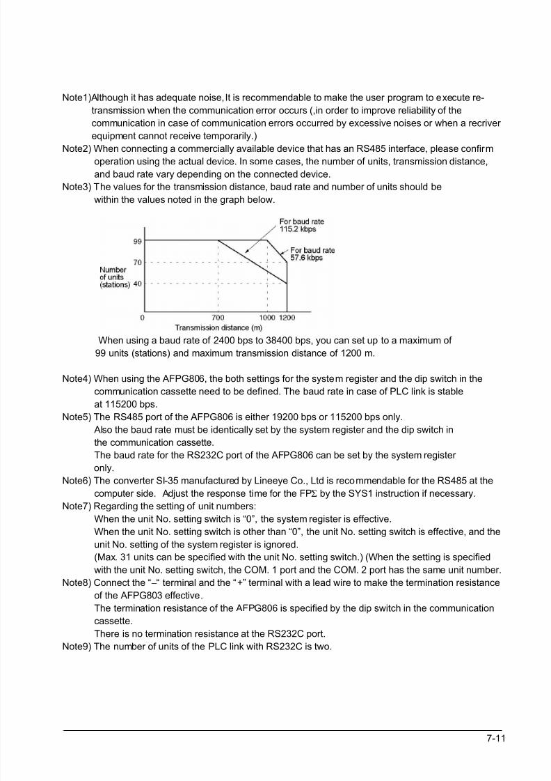
8/21/2019 Programmable Controller FP Sigma
http://slidepdf.com/reader/full/programmable-controller-fp-sigma 157/318
7-11
Note1)Although it has adequate noise,It is recommendable to make the user program to execute re-
transmission when the communication error occurs (,in order to improve reliability of the
communication in case of communication errors occurred by excessive noises or when a recriver
equipment cannot receive temporarily.)Note2) When connecting a commercially available device that has an RS485 interface, please confirm
operation using the actual device. In some cases, the number of units, transmission distance,
and baud rate vary depending on the connected device.
Note3) The values for the transmission distance, baud rate and number of units should be
within the values noted in the graph below.
When using a baud rate of 2400 bps to 38400 bps, you can set up to a maximum of
99 units (stations) and maximum transmission distance of 1200 m.
Note4) When using the AFPG806, the both settings for the system register and the dip switch in the
communication cassette need to be defined. The baud rate in case of PLC link is stable
at 115200 bps.
Note5) The RS485 port of the AFPG806 is either 19200 bps or 115200 bps only.
Also the baud rate must be identically set by the system register and the dip switch in
the communication cassette.
The baud rate for the RS232C port of the AFPG806 can be set by the system register
only.
Note6) The converter SI-35 manufactured by Lineeye Co., Ltd is recommendable for the RS485 at the
computer side. Adjust the response time for the FPΣ by the SYS1 instruction if necessary.
Note7) Regarding the setting of unit numbers:
When the unit No. setting switch is “0”, the system register is effective.
When the unit No. setting switch is other than “0”, the unit No. setting switch is effective, and the
unit No. setting of the system register is ignored. (Max. 31 units can be specified with the unit No. setting switch.) (When the setting is specified
with the unit No. setting switch, the COM. 1 port and the COM. 2 port has the same unit number.
Note8) Connect the “−“ terminal and the “+” terminal with a lead wire to make the termination resistance
of the AFPG803 effective.
The termination resistance of the AFPG806 is specified by the dip switch in the communication
cassette.
There is no termination resistance at the RS232C port.
Note9) The number of units of the PLC link with RS232C is two.
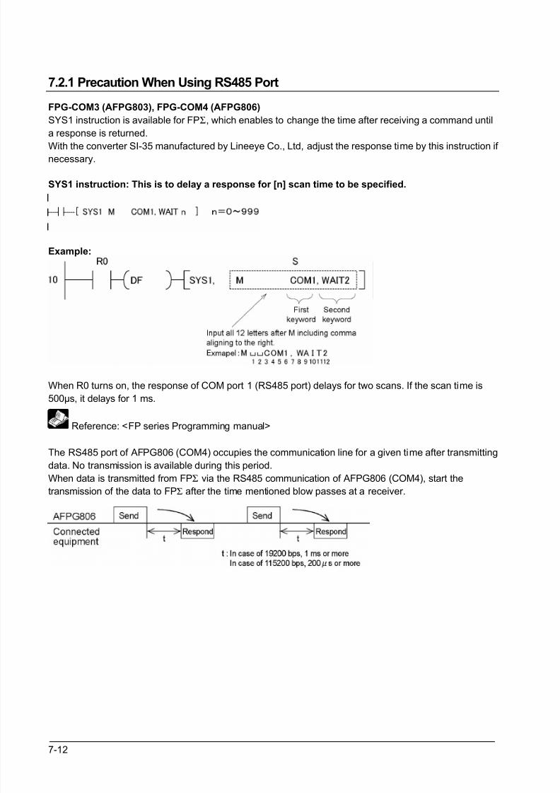
8/21/2019 Programmable Controller FP Sigma
http://slidepdf.com/reader/full/programmable-controller-fp-sigma 158/318
7-12
7.2.1 Precaution When Using RS485 Port
FPG-COM3 (AFPG803), FPG-COM4 (AFPG806)
SYS1 instruction is available for FPΣ, which enables to change the time after receiving a command until
a response is returned.
With the converter SI-35 manufactured by Lineeye Co., Ltd, adjust the response time by this instruction if
necessary.
SYS1 instruction: This is to delay a response for [n] scan time to be specified.
Example:
When R0 turns on, the response of COM port 1 (RS485 port) delays for two scans. If the scan time is
500µs, it delays for 1 ms.
Reference: <FP series Programming manual>
The RS485 port of AFPG806 (COM4) occupies the communication line for a given time after transmitting
data. No transmission is available during this period.
When data is transmitted from FPΣ via the RS485 communication of AFPG806 (COM4), start the
transmission of the data to FPΣ after the time mentioned blow passes at a receiver.
8/21/2019 Programmable Controller FP Sigma
http://slidepdf.com/reader/full/programmable-controller-fp-sigma 159/318
7-13
Following adjustments are required depending on the types of connected equipment.
1. With FPΣΣΣΣ (when the connected equipment are also the combination of FPΣΣΣΣ and AFPG806)
• When PLC link mode: Adjustment is not required.
• When general communication mode: Adjust timing by ladder program.
•
When computer link mode: Adjust timing by SYS1 instruction.
2. With other PLC
• When PLC link mode: Not used.
• When general communication mode: Adjust timing by ladder program.
3. With computer
• Adjust timing by wait instruction system.
4. With other equipment’s
• Confirm the time after receiving data until a transmission starts with makers.
• KT temperature controller and inverters (VF-7E and VF-8X) can be used without any adjustment, asthe time taken up to a response is more than 1 ms.
• GT series indicator cannot be used.
• With GV series indicator, set the transmission delay time (communication parameter) to 1 ms or more.
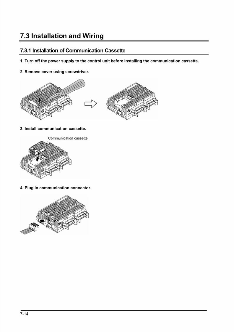
8/21/2019 Programmable Controller FP Sigma
http://slidepdf.com/reader/full/programmable-controller-fp-sigma 160/318
7-14
7.3 Installation and Wiring
7.3.1 Installation of Communication Cassette
1. Turn off the power supply to the control unit before installing the communication cassette.
2. Remove cover using screwdriver.
3. Install communication cassette.
4. Plug in communication connector.
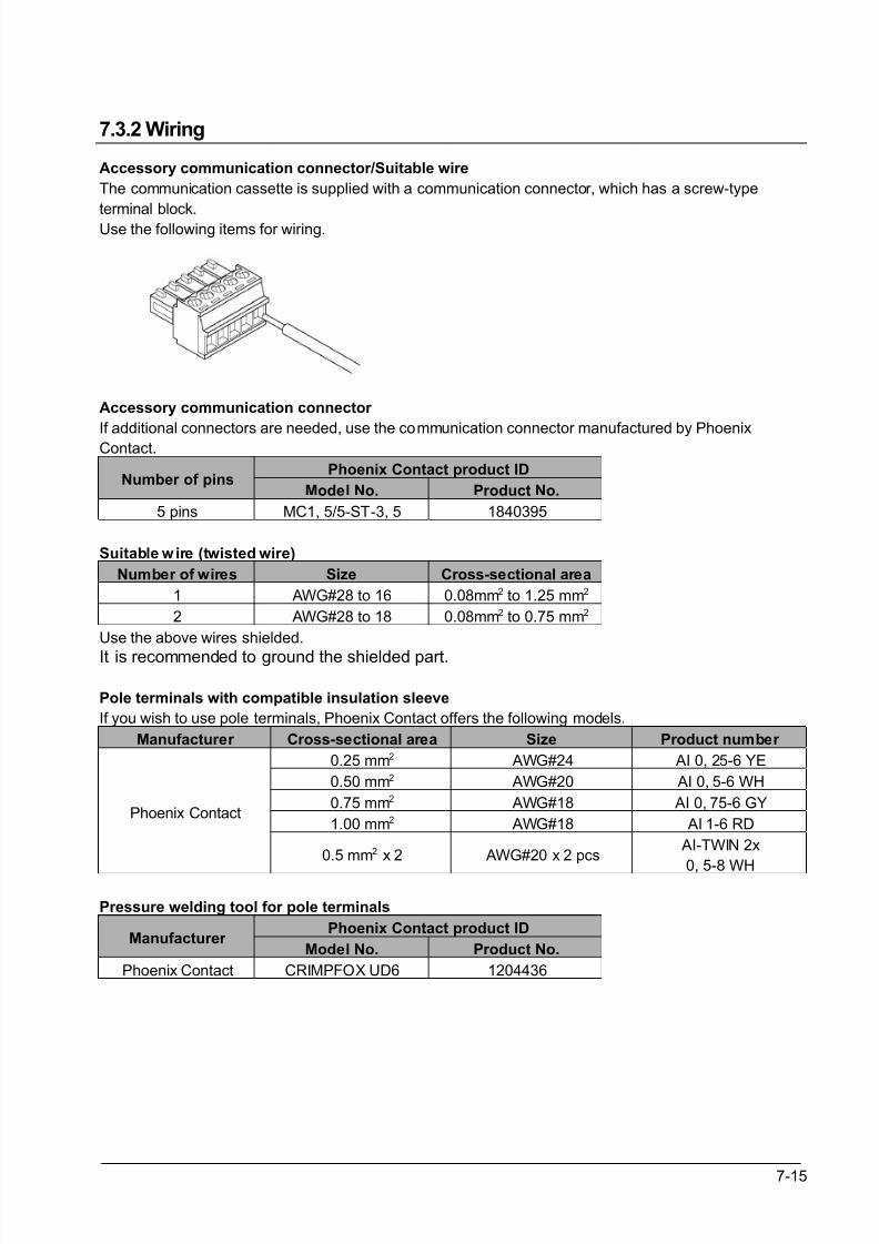
8/21/2019 Programmable Controller FP Sigma
http://slidepdf.com/reader/full/programmable-controller-fp-sigma 161/318
7-15
7.3.2 Wiring
Accessory communication connector/Suitable wire
The communication cassette is supplied with a communication connector, which has a screw-type
terminal block.
Use the following items for wiring.
Accessory communication connector
If additional connectors are needed, use the communication connector manufactured by PhoenixContact.
Phoenix Contact product IDNumber of pins
Model No. Product No.
5 pins MC1, 5/5-ST-3, 5 1840395
Suitable wire (twisted wire)
Number of wires Size Cross-sectional area
1 AWG#28 to 16 0.08mm2 to 1.25 mm2
2 AWG#28 to 18 0.08mm2 to 0.75 mm2
Use the above wires shielded.
It is recommended to ground the shielded part.
Pole terminals with compatible insulation sleeve
If you wish to use pole terminals, Phoenix Contact offers the following models.
Manufacturer Cross-sectional area Size Product number
0.25 mm2 AWG#24 AI 0, 25-6 YE
0.50 mm2 AWG#20 AI 0, 5-6 WH
0.75 mm2 AWG#18 AI 0, 75-6 GY
1.00 mm2 AWG#18 AI 1-6 RDPhoenix Contact
0.5 mm2 x 2 AWG#20 x 2 pcs AI-TWIN 2x
0, 5-8 WH
Pressure welding tool for pole terminals
Phoenix Contact product IDManufacturer
Model No. Product No.
Phoenix Contact CRIMPFOX UD6 1204436
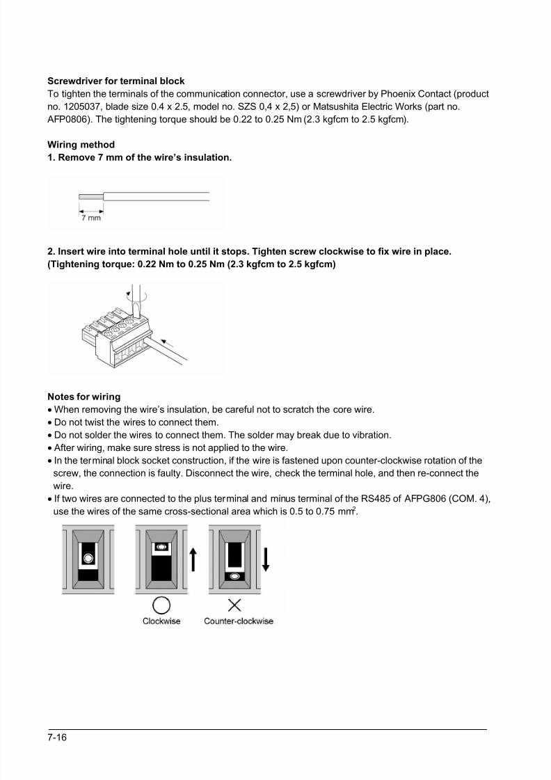
8/21/2019 Programmable Controller FP Sigma
http://slidepdf.com/reader/full/programmable-controller-fp-sigma 162/318
7-16
Screwdriver for terminal block
To tighten the terminals of the communication connector, use a screwdriver by Phoenix Contact (product
no. 1205037, blade size 0.4 x 2.5, model no. SZS 0,4 x 2,5) or Matsushita Electric Works (part no.
AFP0806). The tightening torque should be 0.22 to 0.25 Nm (2.3 kgfcm to 2.5 kgfcm).
Wiring method
1. Remove 7 mm of the wire’s insulation.
2. Insert wire into terminal hole until it stops. Tighten screw clockwise to fix wire in place.
(Tightening torque: 0.22 Nm to 0.25 Nm (2.3 kgfcm to 2.5 kgfcm)
Notes for wiring
• When removing the wire’s insulation, be careful not to scratch the core wire.• Do not twist the wires to connect them.
• Do not solder the wires to connect them. The solder may break due to vibration.
• After wiring, make sure stress is not applied to the wire.
• In the terminal block socket construction, if the wire is fastened upon counter-clockwise rotation of the
screw, the connection is faulty. Disconnect the wire, check the terminal hole, and then re-connect the
wire.
• If two wires are connected to the plus terminal and minus terminal of the RS485 of AFPG806 (COM. 4),
use the wires of the same cross-sectional area which is 0.5 to 0.75 mm2.
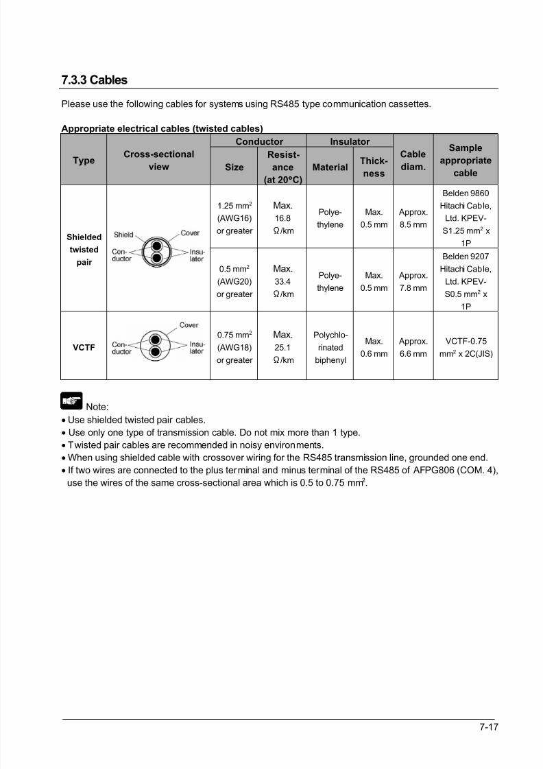
8/21/2019 Programmable Controller FP Sigma
http://slidepdf.com/reader/full/programmable-controller-fp-sigma 163/318
7-17
7.3.3 Cables
Please use the following cables for systems using RS485 type communication cassettes.
Appropriate electrical cables (twisted cables)
Conductor Insulator
TypeCross-sectional
view Size
Resist-
ance
(at 20°°°°C)
MaterialThick-
ness
Cable
diam.
Sample
appropriate
cable
1.25 mm2
(AWG16)
or greater
Max.
16.8
Ω/km
Polye-
thylene
Max.
0.5 mm
Approx.
8.5 mm
Belden 9860
Hitachi Cable,
Ltd. KPEV-
S1.25 mm2 x
1PShielded
twisted
pair
0.5 mm2
(AWG20)
or greater
Max.33.4
Ω/km
Polye-
thylene
Max.
0.5 mm
Approx.
7.8 mm
Belden 9207
Hitachi Cable,Ltd. KPEV-
S0.5 mm2 x
1P
VCTF
0.75 mm2
(AWG18)
or greater
Max.
25.1
Ω/km
Polychlo-
rinated
biphenyl
Max.
0.6 mm
Approx.
6.6 mm
VCTF-0.75
mm2 x 2C(JIS)
Note:• Use shielded twisted pair cables.
• Use only one type of transmission cable. Do not mix more than 1 type.
• Twisted pair cables are recommended in noisy environments.
• When using shielded cable with crossover wiring for the RS485 transmission line, grounded one end.
• If two wires are connected to the plus terminal and minus terminal of the RS485 of AFPG806 (COM. 4),
use the wires of the same cross-sectional area which is 0.5 to 0.75 mm2.
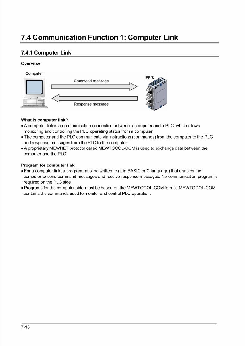
8/21/2019 Programmable Controller FP Sigma
http://slidepdf.com/reader/full/programmable-controller-fp-sigma 164/318
7-18
7.4 Communication Function 1: Computer Link
7.4.1 Computer Link
Overview
What is computer link?• A computer link is a communication connection between a computer and a PLC, which allows
monitoring and controlling the PLC operating status from a computer.
• The computer and the PLC communicate via instructions (commands) from the computer to the PLC
and response messages from the PLC to the computer.
• A proprietary MEWNET protocol called MEWTOCOL-COM is used to exchange data between the
computer and the PLC.
Program for computer link
• For a computer link, a program must be written (e.g. in BASIC or C language) that enables the
computer to send command messages and receive response messages. No communication program is
required on the PLC side.• Programs for the computer side must be based on the MEWTOCOL-COM format. MEWTOCOL-COM
contains the commands used to monitor and control PLC operation.
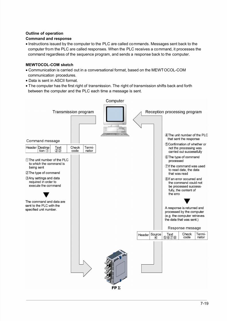
8/21/2019 Programmable Controller FP Sigma
http://slidepdf.com/reader/full/programmable-controller-fp-sigma 165/318
7-19
Outline of operation
Command and response
• Instructions issued by the computer to the PLC are called commands. Messages sent back to the
computer from the PLC are called responses. When the PLC receives a command, it processes the
command regardless of the sequence program, and sends a response back to the computer.
MEWTOCOL-COM sketch
• Communication is carried out in a conversational format, based on the MEWTOCOL-COM
communication procedures.
• Data is sent in ASCII format.
• The computer has the first right of transmission. The right of transmission shifts back and forth
between the computer and the PLC each time a message is sent.
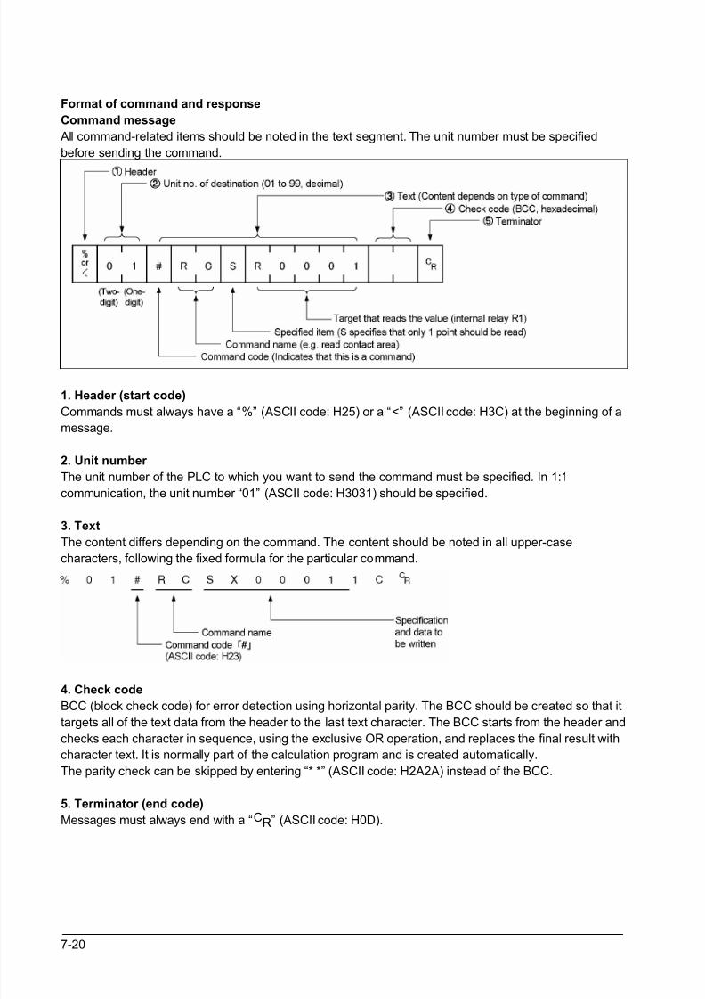
8/21/2019 Programmable Controller FP Sigma
http://slidepdf.com/reader/full/programmable-controller-fp-sigma 166/318
7-20
Format of command and response
Command message
All command-related items should be noted in the text segment. The unit number must be specified
before sending the command.
1. Header (start code)
Commands must always have a “%” (ASCII code: H25) or a “<” (ASCII code: H3C) at the beginning of a
message.
2. Unit number
The unit number of the PLC to which you want to send the command must be specified. In 1:1
communication, the unit number “01” (ASCII code: H3031) should be specified.
3. TextThe content differs depending on the command. The content should be noted in all upper-case
characters, following the fixed formula for the particular command.
4. Check code
BCC (block check code) for error detection using horizontal parity. The BCC should be created so that it
targets all of the text data from the header to the last text character. The BCC starts from the header and
checks each character in sequence, using the exclusive OR operation, and replaces the final result with
character text. It is normally part of the calculation program and is created automatically.
The parity check can be skipped by entering “* *” (ASCII code: H2A2A) instead of the BCC.
5. Terminator (end code)
Messages must always end with a “CR” (ASCII code: H0D).
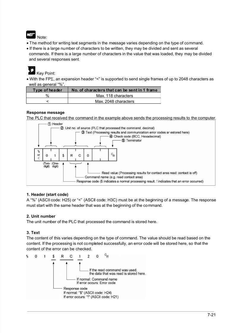
8/21/2019 Programmable Controller FP Sigma
http://slidepdf.com/reader/full/programmable-controller-fp-sigma 167/318
7-21
Note:
• The method for writing text segments in the message varies depending on the type of command.
• If there is a large number of characters to be written, they may be divided and sent as several
commands. If there is a large number of characters in the value that was loaded, they may be divided
and several responses sent.
Key Point:
• With the FPΣ, an expansion header “<” is supported to send single frames of up to 2048 characters as
well as general “%”.
Type of header No. of characters that can be sent in 1 frame
% Max. 118 characters
< Max. 2048 characters
Response message
The PLC that received the command in the example above sends the processing results to the computer.
1. Header (start code)
A “%” (ASCII code: H25) or “<” (ASCII code: H3C) must be at the beginning of a message. The response
must start with the same header that was at the beginning of the command.
2. Unit number
The unit number of the PLC that processed the command is stored here.
3. TextThe content of this varies depending on the type of command. The value should be read based on the
content. If the processing is not completed successfully, an error code will be stored here, so that the
content of the error can be checked.
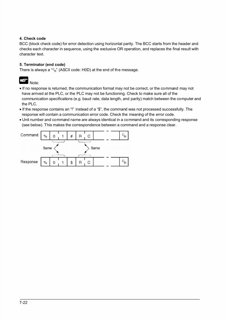
8/21/2019 Programmable Controller FP Sigma
http://slidepdf.com/reader/full/programmable-controller-fp-sigma 168/318
7-22
4. Check code
BCC (block check code) for error detection using horizontal parity. The BCC starts from the header and
checks each character in sequence, using the exclusive OR operation, and replaces the final result with
character text.
5. Terminator (end code)
There is always a “CR” (ASCII code: H0D) at the end of the message.
Note:
• If no response is returned, the communication format may not be correct, or the command may not
have arrived at the PLC, or the PLC may not be functioning. Check to make sure all of the
communication specifications (e.g. baud rate, data length, and parity) match between the computer and
the PLC.
• If the response contains an “!” instead of a “$”, the command was not processed successfully. The
response will contain a communication error code. Check the meaning of the error code.
• Unit number and command name are always identical in a command and its corresponding response
(see below). This makes the correspondence between a command and a response clear.
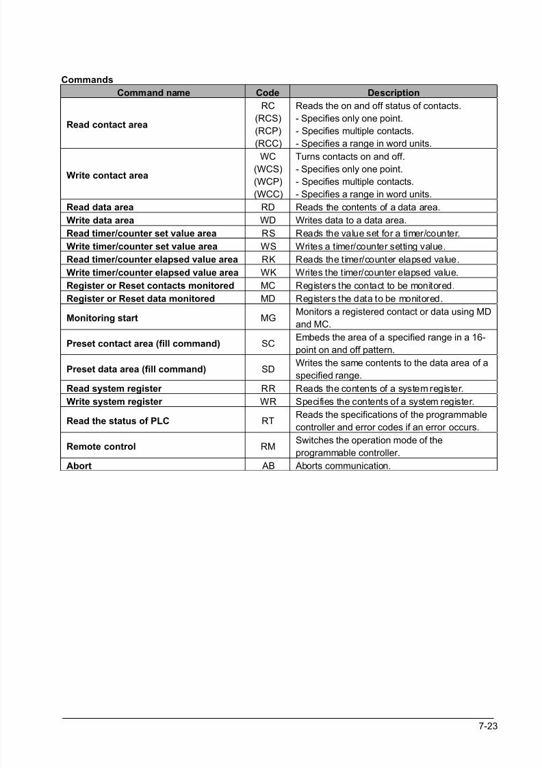
8/21/2019 Programmable Controller FP Sigma
http://slidepdf.com/reader/full/programmable-controller-fp-sigma 169/318
7-23
Commands
Command name Code Description
Read contact area
RC
(RCS)
(RCP)(RCC)
Reads the on and off status of contacts.
- Specifies only one point.
- Specifies multiple contacts.- Specifies a range in word units.
Write contact area
WC
(WCS)
(WCP)
(WCC)
Turns contacts on and off.
- Specifies only one point.
- Specifies multiple contacts.
- Specifies a range in word units.
Read data area RD Reads the contents of a data area.
Write data area WD Writes data to a data area.
Read timer/counter set value area RS Reads the value set for a timer/counter.
Write timer/counter set value area WS Writes a timer/counter setting value.
Read timer/counter elapsed value area RK Reads the timer/counter elapsed value.
Write timer/counter elapsed value area WK Writes the timer/counter elapsed value.
Register or Reset contacts monitored MC Registers the contact to be monitored.
Register or Reset data monitored MD Registers the data to be monitored.
Monitoring start MGMonitors a registered contact or data using MD
and MC.
Preset contact area (fill command) SCEmbeds the area of a specified range in a 16-
point on and off pattern.
Preset data area (fill command) SDWrites the same contents to the data area of a
specified range.
Read system register RR Reads the contents of a system register.
Write system register WR Specifies the contents of a system register.
Read the status of PLC RTReads the specifications of the programmable
controller and error codes if an error occurs.
Remote control RMSwitches the operation mode of the
programmable controller.
Abort AB Aborts communication.
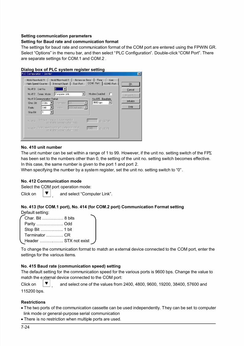
8/21/2019 Programmable Controller FP Sigma
http://slidepdf.com/reader/full/programmable-controller-fp-sigma 170/318
7-24
Setting communication parameters
Setting for Baud rate and communication format
The settings for baud rate and communication format of the COM port are entered using the FPWIN GR.
Select “Options” in the menu bar, and then select “PLC Configuration”. Double-click “COM Port”. There
are separate settings for COM.1 and COM.2 .
Dialog box of PLC system register setting
No. 410 unit number
The unit number can be set within a range of 1 to 99. However, if the unit no. setting switch of the FPΣ
has been set to the numbers other than 0, the setting of the unit no. setting switch becomes effective.
In this case, the same number is given to the port 1 and port 2.
When specifying the number by a system register, set the unit no. setting switch to “0” .
No. 412 Communication modeSelect the COM port operation mode:
Click on , and select “Computer Link”.
No. 413 (for COM.1 port), No. 414 (for COM.2 port) Communication Format setting
Default setting:
Char. Bit …………… 8 bits
Parity ………………. Odd
Stop Bit ……………. 1 bit
Terminator ………… CR
Header …………….. STX not existTo change the communication format to match an external device connected to the COM port, enter the
settings for the various items.
No. 415 Baud rate (communication speed) setting
The default setting for the communication speed for the various ports is 9600 bps. Change the value to
match the external device connected to the COM port:
Click on , and select one of the values from 2400, 4800, 9600, 19200, 38400, 57600 and
115200 bps.
Restrictions• The two ports of the communication cassette can be used independently. They can be set to computer
link mode or general-purpose serial communication
• There is no restriction when multiple ports are used.
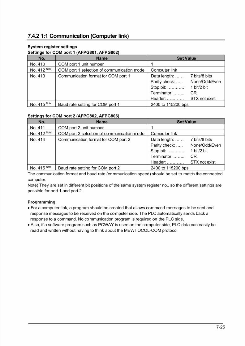
8/21/2019 Programmable Controller FP Sigma
http://slidepdf.com/reader/full/programmable-controller-fp-sigma 171/318
7-25
7.4.2 1:1 Communication (Computer link)
System register settings
Settings for COM port 1 (AFPG801, AFPG802)
No. Name Set Value
No. 410 COM port 1 unit number 1
No. 412 Note) COM port 1 selection of communication mode Computer link
No. 413 Communication format for COM port 1 Data length: ……
Parity check: …..
Stop bit: …………
Terminator: ……..
Header: …………
7 bits/8 bits
None/Odd/Even
1 bit/2 bit
CR
STX not exist
No. 415 Note) Baud rate setting for COM port 1 2400 to 115200 bps
Settings for COM port 2 (AFPG802, AFPG806)
No. Name Set ValueNo. 411 COM port 2 unit number 1
No. 412 Note) COM port 2 selection of communication mode Computer link
No. 414 Communication format for COM port 2 Data length: ……
Parity check: …..
Stop bit: …………
Terminator: ……..
Header: …………
7 bits/8 bits
None/Odd/Even
1 bit/2 bit
CR
STX not exist
No. 415 Note) Baud rate setting for COM port 2 2400 to 115200 bps
The communication format and baud rate (communication speed) should be set to match the connected
computer.
Note) They are set in different bit positions of the same system register no., so the different settings are
possible for port 1 and port 2.
Programming
• For a computer link, a program should be created that allows command messages to be sent and
response messages to be received on the computer side. The PLC automatically sends back a
response to a command. No communication program is required on the PLC side.
• Also, if a software program such as PCWAY is used on the computer side, PLC data can easily be
read and written without having to think about the MEWTOCOL-COM protocol
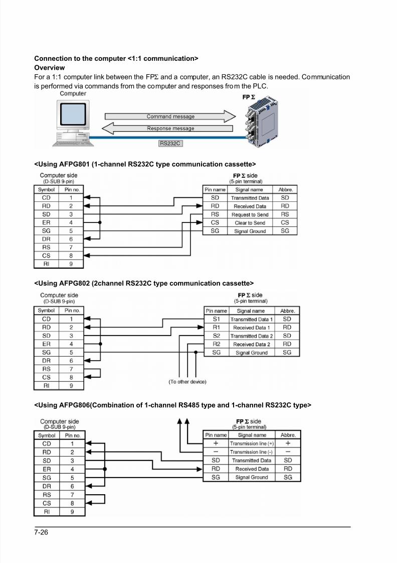
8/21/2019 Programmable Controller FP Sigma
http://slidepdf.com/reader/full/programmable-controller-fp-sigma 172/318
7-26
Connection to the computer <1:1 communication>
Overview
For a 1:1 computer link between the FPΣ and a computer, an RS232C cable is needed. Communication
is performed via commands from the computer and responses from the PLC.
<Using AFPG801 (1-channel RS232C type communication cassette>
<Using AFPG802 (2channel RS232C type communication cassette>
<Using AFPG806(Combination of 1-channel RS485 type and 1-channel RS232C type>
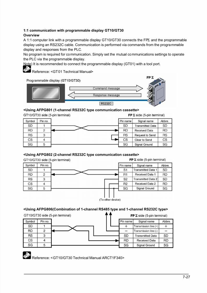
8/21/2019 Programmable Controller FP Sigma
http://slidepdf.com/reader/full/programmable-controller-fp-sigma 173/318
7-27
1:1 communication with programmable display GT10/GT30
Overview
A 1:1 computer link with a programmable display GT10/GT30 connects the FPΣ and the programmable
display using an RS232C cable. Communication is performed via commands from the programmable
display and responses from the PLC.No program is required for communication. Simply set the mutual communications settings to operate
the PLC via the programmable display.
Note) It is recommended to connect the programmable display (GT01) with a tool port.
Reference: <GT01 Technical Manual>
<Using AFPG801 (1-channel RS232C type communication cassette>
<Using AFPG802 (2-channel RS232C type communication cassette>
<Using AFPG806(Combination of 1-channel RS485 type and 1-channel RS232C type>
Reference: <GT10/GT30 Technical Manual ARCT1F340>
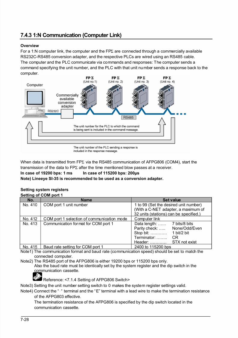
8/21/2019 Programmable Controller FP Sigma
http://slidepdf.com/reader/full/programmable-controller-fp-sigma 174/318
7-28
7.4.3 1:N Communication (Computer Link)
Overview
For a 1:N computer link, the computer and the FPΣ are connected through a commercially available
RS232C-RS485 conversion adapter, and the respective PLCs are wired using an RS485 cable.
The computer and the PLC communicate via commands and responses: The computer sends a
command specifying the unit number, and the PLC with that unit number sends a response back to the
computer.
When data is transmitted from FPΣ via the RS485 communication of AFPG806 (COM4), start the
transmission of the data to FPΣ after the time mentioned blow passes at a receiver.
In case of 19200 bps: 1 ms In case of 115200 bps: 200µs
Note) Lineeye SI-35 is recommended to be used as a conversion adapter.
Setting system registers
Setting of COM port 1No. Name Set value
No. 410 COM port 1 unit number 1 to 99 (Set the desired unit number)(With a C-NET adapter, a maximum of 32 units (stations) can be specified.)
No. 412 COM port 1 selection of communication mode Computer linkNo. 413 Communication format for COM port 1 Data length: ……
Parity check: …..Stop bit: …………
Terminator: ……..Header: …………
7 bits/8 bitsNone/Odd/Even1 bit/2 bit
CRSTX not exist
No. 415 Baud rate setting for COM port 1 2400 to 115200 bpsNote1) The communication format and baud rate (communication speed) should be set to match the connected computer.Note2) The RS485 port of the AFPG806 is either 19200 bps or 115200 bps only. Also the baud rate must be identically set by the system register and the dip switch in the communication cassette.
Reference: <7.1.4 Setting of AFPG806 Switch>
Note3) Setting the unit number setting switch to 0 makes the system register settings valid.
Note4) Connect the “−“ terminal and the “E” terminal with a lead wire to make the termination resistance
of the AFPG803 effective. The termination resistance of the AFPG806 is specified by the dip switch located in the
communication cassette.
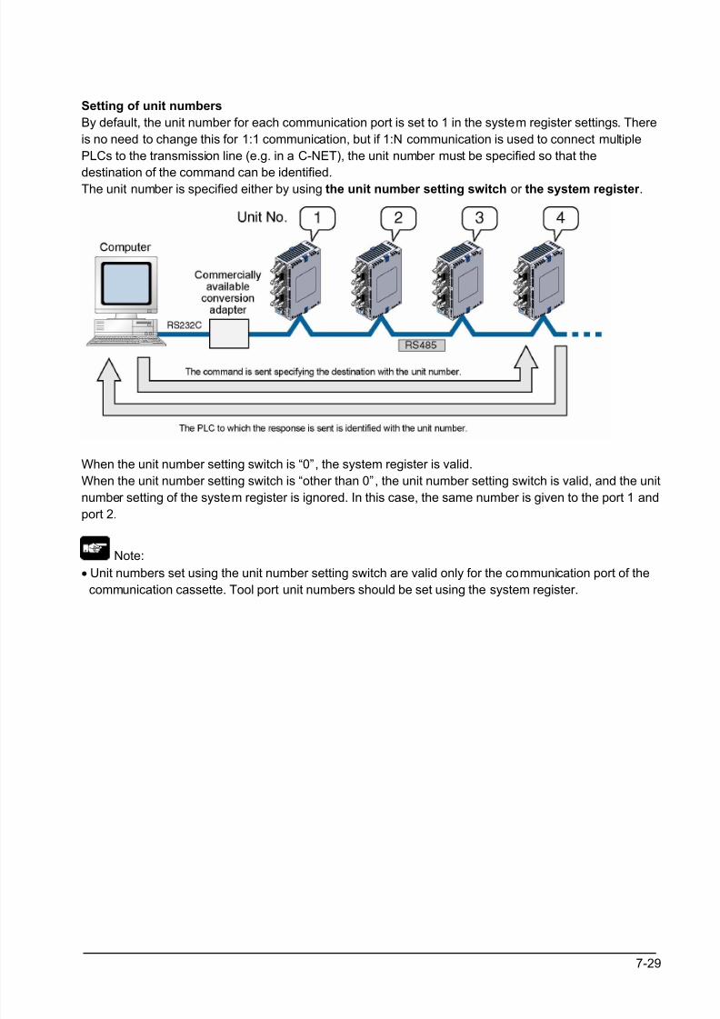
8/21/2019 Programmable Controller FP Sigma
http://slidepdf.com/reader/full/programmable-controller-fp-sigma 175/318
7-29
Setting of unit numbers
By default, the unit number for each communication port is set to 1 in the system register settings. There
is no need to change this for 1:1 communication, but if 1:N communication is used to connect multiple
PLCs to the transmission line (e.g. in a C-NET), the unit number must be specified so that the
destination of the command can be identified.The unit number is specified either by using the unit number setting switch or the system register .
When the unit number setting switch is “0”, the system register is valid.
When the unit number setting switch is “other than 0”, the unit number setting switch is valid, and the unit
number setting of the system register is ignored. In this case, the same number is given to the port 1 and
port 2.
Note:
• Unit numbers set using the unit number setting switch are valid only for the communication port of the
communication cassette. Tool port unit numbers should be set using the system register.
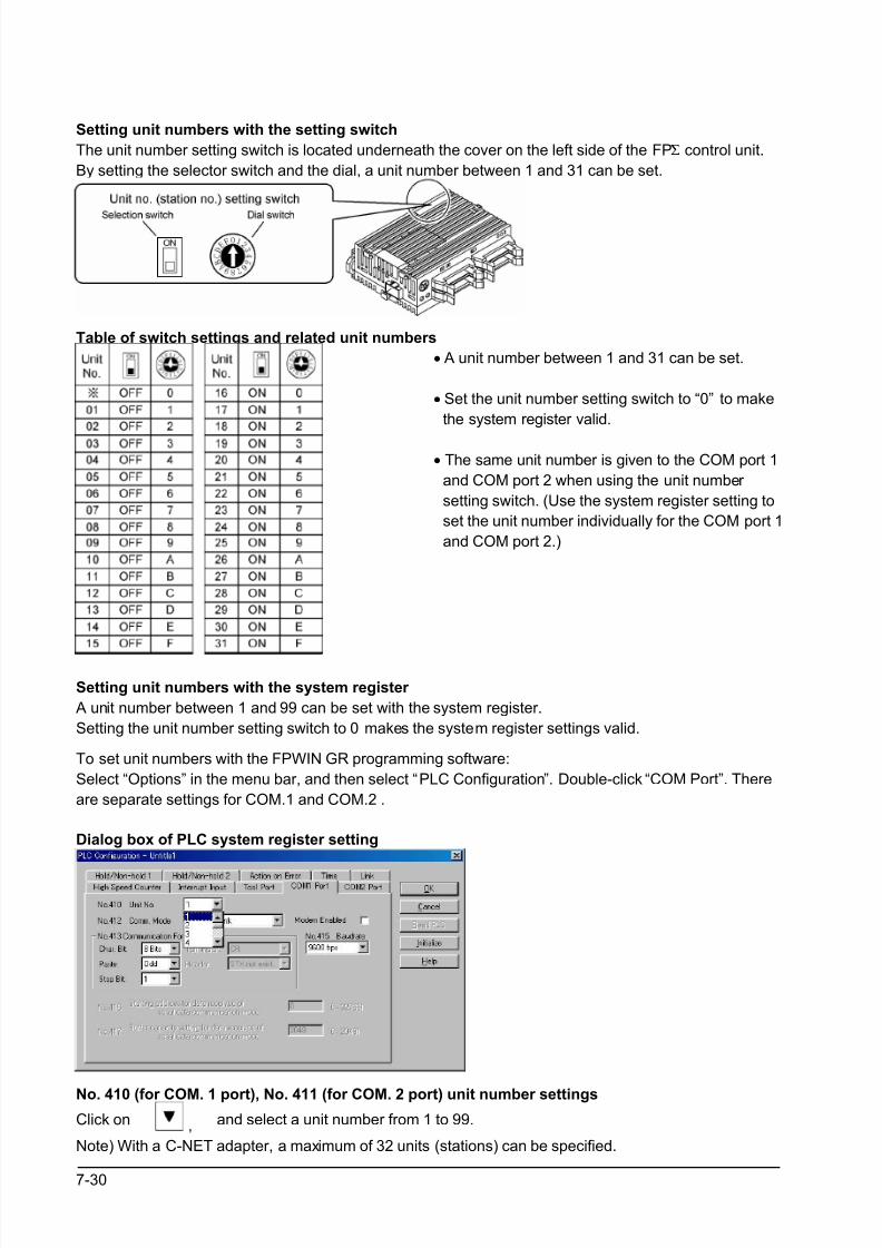
8/21/2019 Programmable Controller FP Sigma
http://slidepdf.com/reader/full/programmable-controller-fp-sigma 176/318
7-30
Setting unit numbers with the setting switch
The unit number setting switch is located underneath the cover on the left side of the FPΣ control unit.
By setting the selector switch and the dial, a unit number between 1 and 31 can be set.
Table of switch settings and related unit numbers
• A unit number between 1 and 31 can be set.
• Set the unit number setting switch to “0” to make
the system register valid.
• The same unit number is given to the COM port 1
and COM port 2 when using the unit number
setting switch. (Use the system register setting to
set the unit number individually for the COM port 1
and COM port 2.)
Setting unit numbers with the system register
A unit number between 1 and 99 can be set with the system register.
Setting the unit number setting switch to 0 makes the system register settings valid.
To set unit numbers with the FPWIN GR programming software:
Select “Options” in the menu bar, and then select “PLC Configuration”. Double-click “COM Port”. There
are separate settings for COM.1 and COM.2 .
Dialog box of PLC system register setting
No. 410 (for COM. 1 port), No. 411 (for COM. 2 port) unit number settings
Click on , and select a unit number from 1 to 99.
Note) With a C-NET adapter, a maximum of 32 units (stations) can be specified.
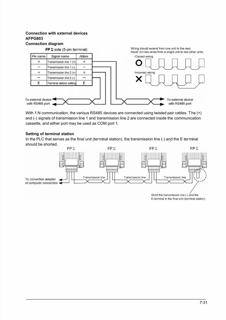
8/21/2019 Programmable Controller FP Sigma
http://slidepdf.com/reader/full/programmable-controller-fp-sigma 177/318
7-31
Connection with external devices
AFPG803
Connection diagram
With 1:N communication, the various RS485 devices are connected using twisted pair cables. The (+)and (-) signals of transmission line 1 and transmission line 2 are connected inside the communication
cassette, and either port may be used as COM port 1.
Setting of terminal station
In the PLC that serves as the final unit (terminal station), the transmission line (-) and the E terminal
should be shorted.
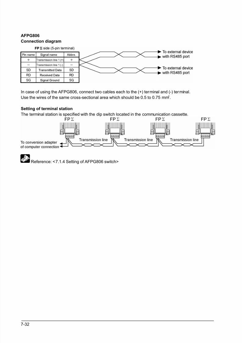
8/21/2019 Programmable Controller FP Sigma
http://slidepdf.com/reader/full/programmable-controller-fp-sigma 178/318
7-32
AFPG806
Connection diagram
In case of using the AFPG806, connect two cables each to the (+) terminal and (-) terminal.
Use the wires of the same cross-sectional area which should be 0.5 to 0.75 mm2.
Setting of terminal station
The terminal station is specified with the dip switch located in the communication cassette.
Reference: <7.1.4 Setting of AFPG806 switch>
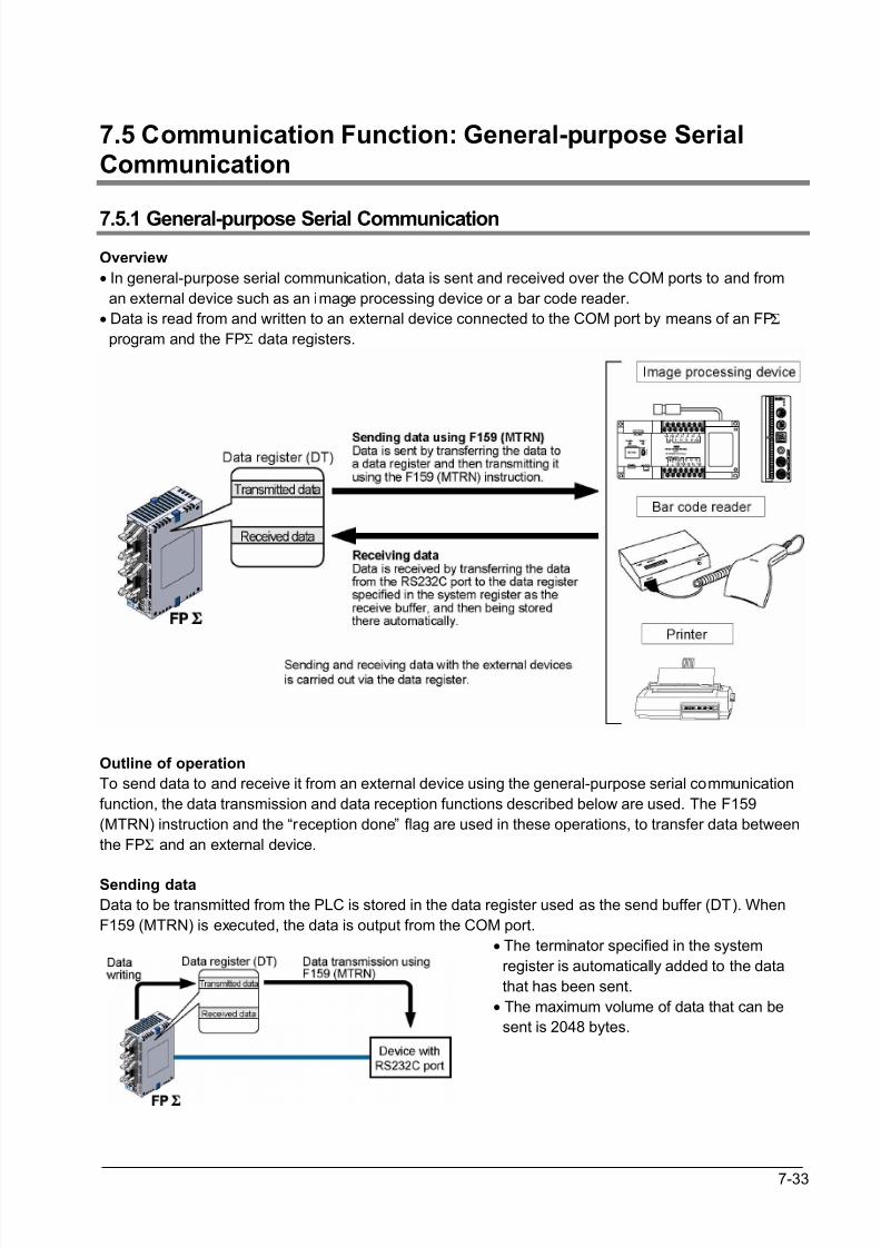
8/21/2019 Programmable Controller FP Sigma
http://slidepdf.com/reader/full/programmable-controller-fp-sigma 179/318
7-33
7.5 Communication Function: General-purpose SerialCommunication
7.5.1 General-purpose Serial Communication
Overview
• In general-purpose serial communication, data is sent and received over the COM ports to and from
an external device such as an image processing device or a bar code reader.
• Data is read from and written to an external device connected to the COM port by means of an FPΣ
program and the FPΣ data registers.
Outline of operation
To send data to and receive it from an external device using the general-purpose serial communication
function, the data transmission and data reception functions described below are used. The F159
(MTRN) instruction and the “reception done” flag are used in these operations, to transfer data between
the FPΣ and an external device.
Sending data
Data to be transmitted from the PLC is stored in the data register used as the send buffer (DT). When
F159 (MTRN) is executed, the data is output from the COM port.
• The terminator specified in the system
register is automatically added to the data
that has been sent.
• The maximum volume of data that can be
sent is 2048 bytes.
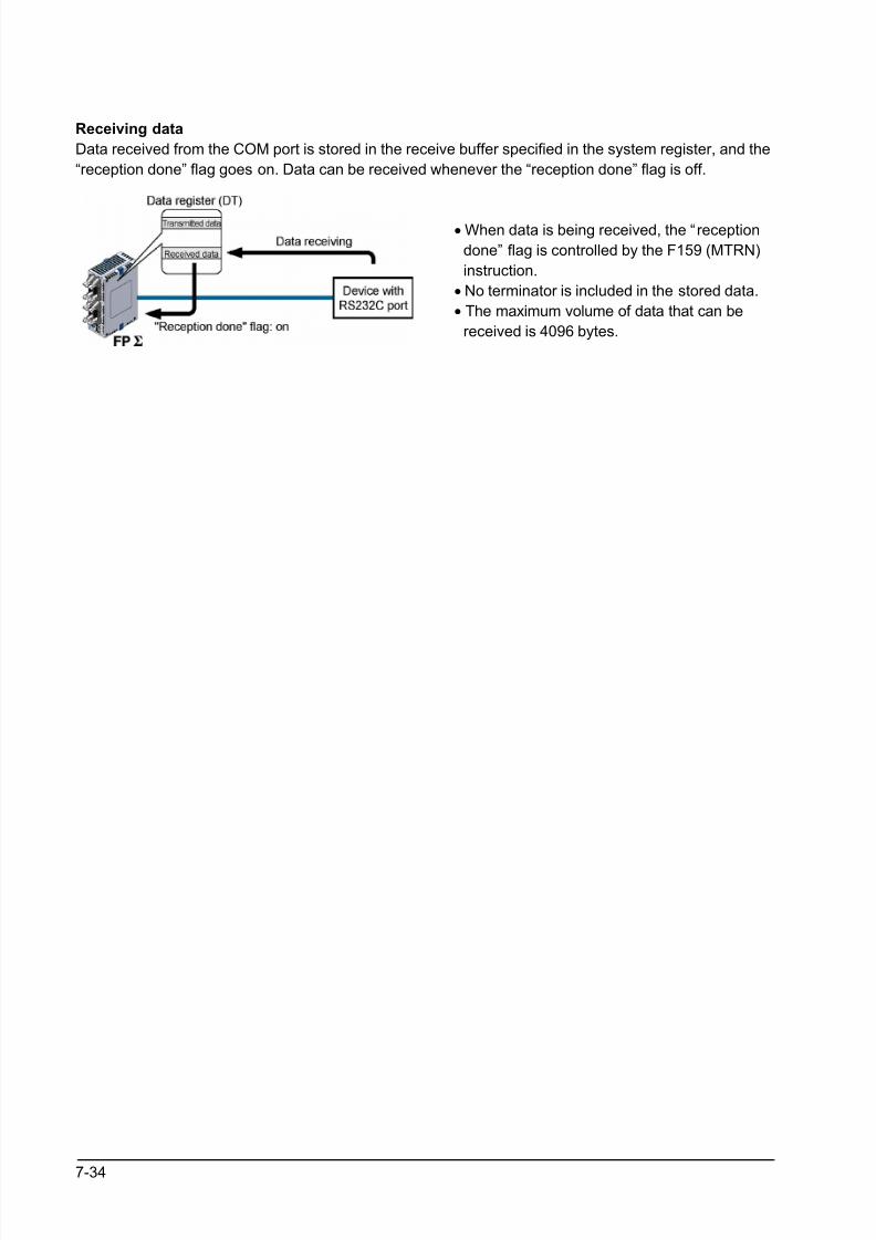
8/21/2019 Programmable Controller FP Sigma
http://slidepdf.com/reader/full/programmable-controller-fp-sigma 180/318
7-34
Receiving data
Data received from the COM port is stored in the receive buffer specified in the system register, and the
“reception done” flag goes on. Data can be received whenever the “reception done” flag is off.
• When data is being received, the “reception
done” flag is controlled by the F159 (MTRN)
instruction.
• No terminator is included in the stored data.
• The maximum volume of data that can be
received is 4096 bytes.
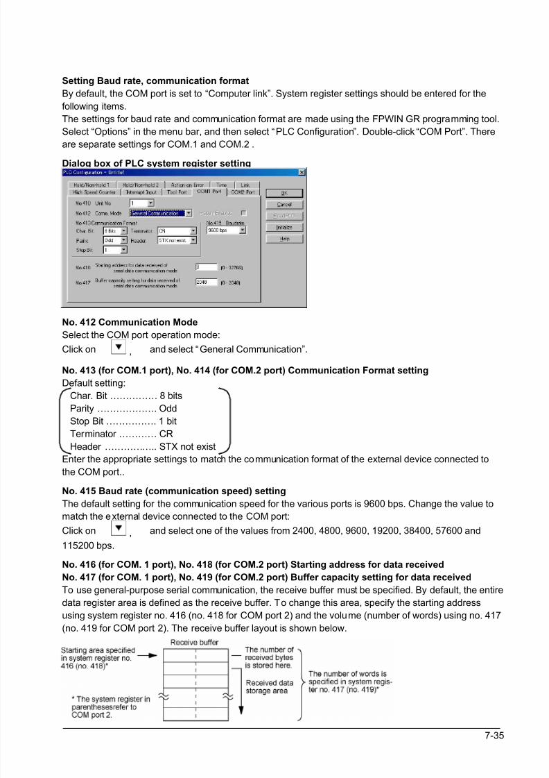
8/21/2019 Programmable Controller FP Sigma
http://slidepdf.com/reader/full/programmable-controller-fp-sigma 181/318
7-35
Setting Baud rate, communication format
By default, the COM port is set to “Computer link”. System register settings should be entered for the
following items.
The settings for baud rate and communication format are made using the FPWIN GR programming tool.
Select “Options” in the menu bar, and then select “PLC Configuration”. Double-click “COM Port”. Thereare separate settings for COM.1 and COM.2 .
Dialog box of PLC system register setting
No. 412 Communication Mode
Select the COM port operation mode:
Click on , and select “General Communication”.
No. 413 (for COM.1 port), No. 414 (for COM.2 port) Communication Format setting
Default setting:
Char. Bit …………… 8 bits
Parity ………………. Odd Stop Bit ……………. 1 bit
Terminator ………… CR
Header …………….. STX not exist
Enter the appropriate settings to match the communication format of the external device connected to
the COM port..
No. 415 Baud rate (communication speed) setting
The default setting for the communication speed for the various ports is 9600 bps. Change the value to
match the external device connected to the COM port:
Click on , and select one of the values from 2400, 4800, 9600, 19200, 38400, 57600 and
115200 bps.
No. 416 (for COM. 1 port), No. 418 (for COM.2 port) Starting address for data received
No. 417 (for COM. 1 port), No. 419 (for COM.2 port) Buffer capacity setting for data received
To use general-purpose serial communication, the receive buffer must be specified. By default, the entire
data register area is defined as the receive buffer. To change this area, specify the starting address
using system register no. 416 (no. 418 for COM port 2) and the volume (number of words) using no. 417
(no. 419 for COM port 2). The receive buffer layout is shown below.
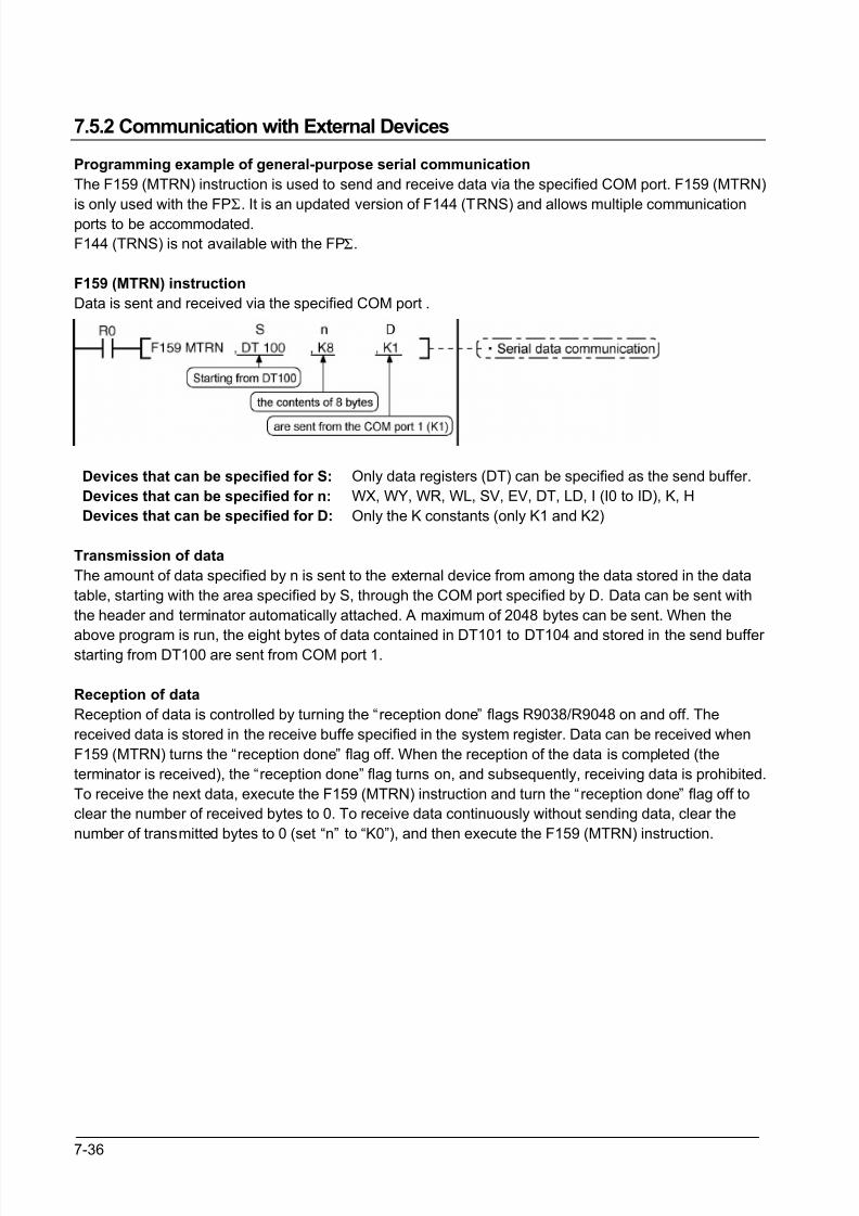
8/21/2019 Programmable Controller FP Sigma
http://slidepdf.com/reader/full/programmable-controller-fp-sigma 182/318
7-36
7.5.2 Communication with External Devices
Programming example of general-purpose serial communication
The F159 (MTRN) instruction is used to send and receive data via the specified COM port. F159 (MTRN)
is only used with the FPΣ. It is an updated version of F144 (TRNS) and allows multiple communication
ports to be accommodated.
F144 (TRNS) is not available with the FPΣ.
F159 (MTRN) instruction
Data is sent and received via the specified COM port .
Devices that can be specified for S:
Devices that can be specified for n:
Devices that can be specified for D:
Only data registers (DT) can be specified as the send buffer.
WX, WY, WR, WL, SV, EV, DT, LD, I (I0 to ID), K, H
Only the K constants (only K1 and K2)
Transmission of data
The amount of data specified by n is sent to the external device from among the data stored in the data
table, starting with the area specified by S, through the COM port specified by D. Data can be sent with
the header and terminator automatically attached. A maximum of 2048 bytes can be sent. When the
above program is run, the eight bytes of data contained in DT101 to DT104 and stored in the send buffer starting from DT100 are sent from COM port 1.
Reception of data
Reception of data is controlled by turning the “reception done” flags R9038/R9048 on and off. The
received data is stored in the receive buffe specified in the system register. Data can be received when
F159 (MTRN) turns the “reception done” flag off. When the reception of the data is completed (the
terminator is received), the “reception done” flag turns on, and subsequently, receiving data is prohibited.
To receive the next data, execute the F159 (MTRN) instruction and turn the “reception done” flag off to
clear the number of received bytes to 0. To receive data continuously without sending data, clear the
number of transmitted bytes to 0 (set “n” to “K0”), and then execute the F159 (MTRN) instruction.
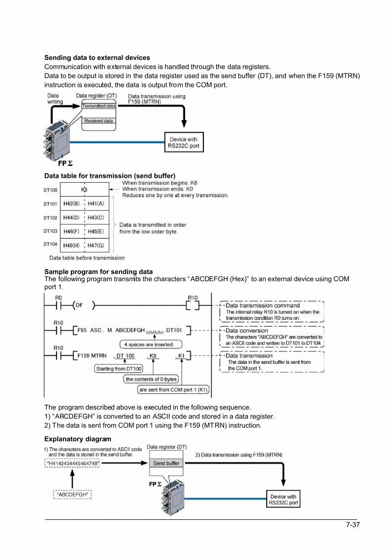
8/21/2019 Programmable Controller FP Sigma
http://slidepdf.com/reader/full/programmable-controller-fp-sigma 183/318
7-37
Sending data to external devices
Communication with external devices is handled through the data registers.
Data to be output is stored in the data register used as the send buffer (DT), and when the F159 (MTRN)
instruction is executed, the data is output from the COM port.
Data table for transmission (send buffer)
Sample program for sending dataThe following program transmits the characters “ABCDEFGH (Hex)” to an external device using COMport 1.
The program described above is executed in the following sequence.
1) “ABCDEFGH” is converted to an ASCII code and stored in a data register.
2) The data is sent from COM port 1 using the F159 (MTRN) instruction.
Explanatory diagram
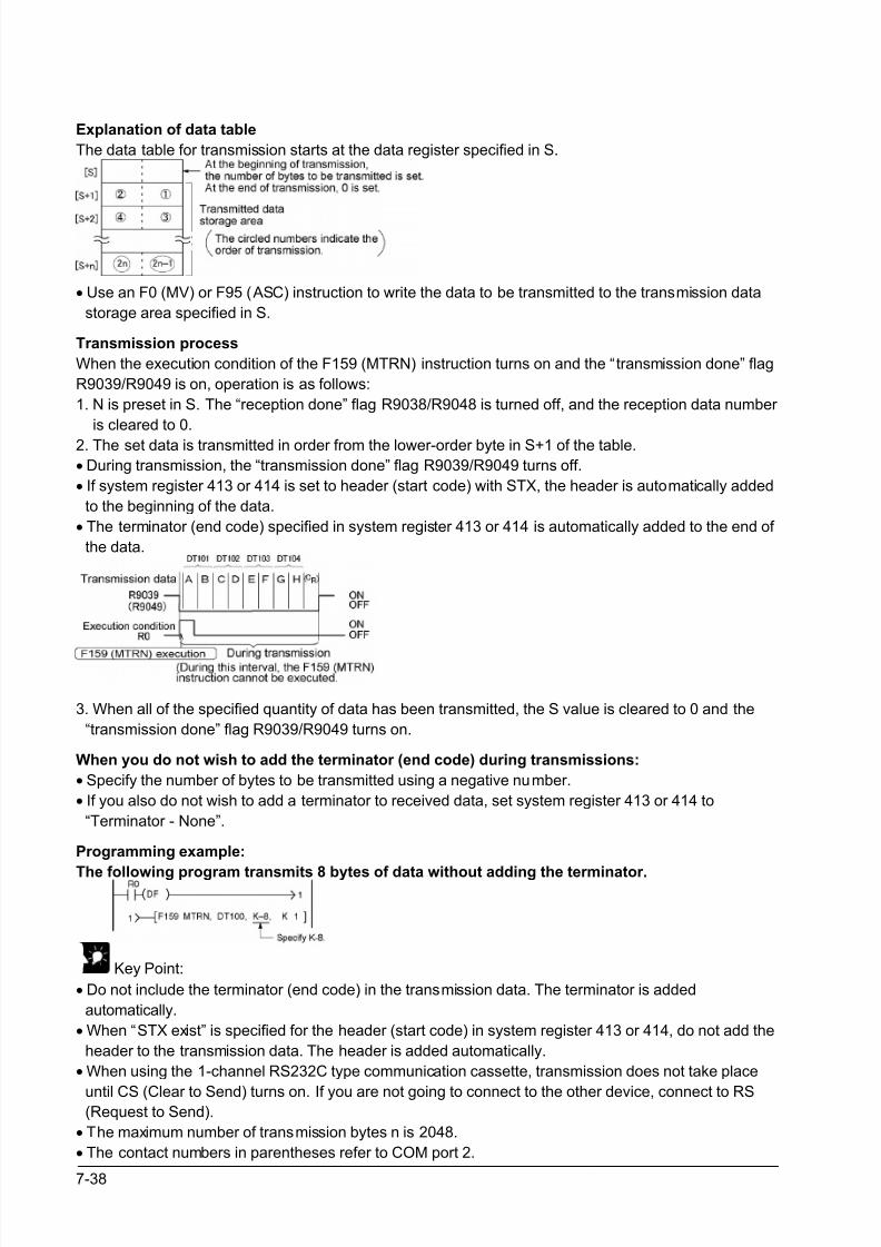
8/21/2019 Programmable Controller FP Sigma
http://slidepdf.com/reader/full/programmable-controller-fp-sigma 184/318
7-38
Explanation of data table
The data table for transmission starts at the data register specified in S.
• Use an F0 (MV) or F95 (ASC) instruction to write the data to be transmitted to the transmission data
storage area specified in S.
Transmission process
When the execution condition of the F159 (MTRN) instruction turns on and the “transmission done” flag
R9039/R9049 is on, operation is as follows:
1. N is preset in S. The “reception done” flag R9038/R9048 is turned off, and the reception data number
is cleared to 0.
2. The set data is transmitted in order from the lower-order byte in S+1 of the table.
• During transmission, the “transmission done” flag R9039/R9049 turns off.
• If system register 413 or 414 is set to header (start code) with STX, the header is automatically added
to the beginning of the data.
• The terminator (end code) specified in system register 413 or 414 is automatically added to the end of
the data.
3. When all of the specified quantity of data has been transmitted, the S value is cleared to 0 and the
“transmission done” flag R9039/R9049 turns on.
When you do not wish to add the terminator (end code) during transmissions:
• Specify the number of bytes to be transmitted using a negative number.
• If you also do not wish to add a terminator to received data, set system register 413 or 414 to
“Terminator - None”.
Programming example:
The following program transmits 8 bytes of data without adding the terminator.
Key Point:
• Do not include the terminator (end code) in the transmission data. The terminator is added
automatically.
• When “STX exist” is specified for the header (start code) in system register 413 or 414, do not add the
header to the transmission data. The header is added automatically.
• When using the 1-channel RS232C type communication cassette, transmission does not take place
until CS (Clear to Send) turns on. If you are not going to connect to the other device, connect to RS(Request to Send).
• The maximum number of transmission bytes n is 2048.
• The contact numbers in parentheses refer to COM port 2.
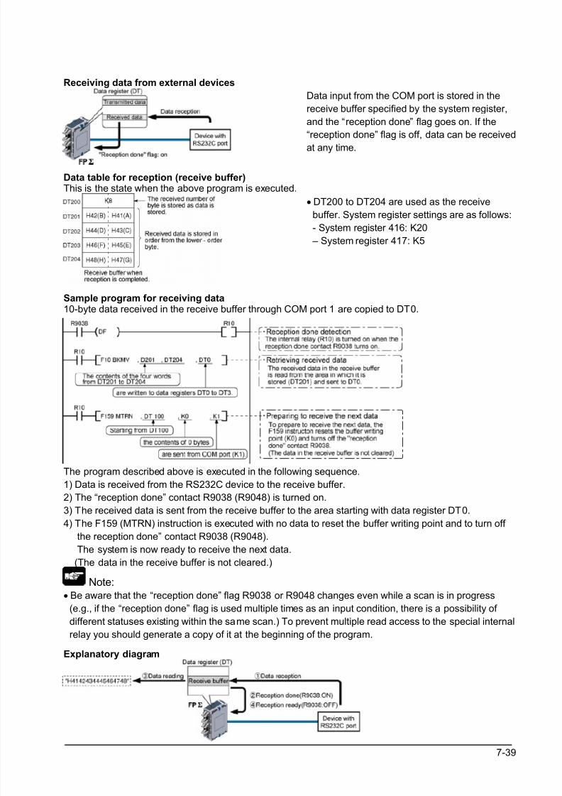
8/21/2019 Programmable Controller FP Sigma
http://slidepdf.com/reader/full/programmable-controller-fp-sigma 185/318
7-39
Receiving data from external devices
Data input from the COM port is stored in the
receive buffer specified by the system register,
and the “reception done” flag goes on. If the
“reception done” flag is off, data can be receivedat any time.
Data table for reception (receive buffer)This is the state when the above program is executed.
• DT200 to DT204 are used as the receive
buffer. System register settings are as follows:
- System register 416: K20
– System register 417: K5
Sample program for receiving data10-byte data received in the receive buffer through COM port 1 are copied to DT0.
The program described above is executed in the following sequence.
1) Data is received from the RS232C device to the receive buffer.
2) The “reception done” contact R9038 (R9048) is turned on.
3) The received data is sent from the receive buffer to the area starting with data register DT0.
4) The F159 (MTRN) instruction is executed with no data to reset the buffer writing point and to turn off
the reception done” contact R9038 (R9048).
The system is now ready to receive the next data.
(The data in the receive buffer is not cleared.)
Note:• Be aware that the “reception done” flag R9038 or R9048 changes even while a scan is in progress
(e.g., if the “reception done” flag is used multiple times as an input condition, there is a possibility of
different statuses existing within the same scan.) To prevent multiple read access to the special internal
relay you should generate a copy of it at the beginning of the program.
Explanatory diagram

8/21/2019 Programmable Controller FP Sigma
http://slidepdf.com/reader/full/programmable-controller-fp-sigma 186/318
7-40
Explanation of data table
Data sent from an external device connected to the RS232C port is stored in the data registers that have
been set as the receive buffer.
• Specify the data registers in system register 416 to
419.• The number of bytes of data received is stored in the
starting address of the receive buffer. The initial value
is 0.
• Received data is stored in the received data storage
area in order from the lower -order byte.
Reception process
When the “reception done” flag R9038 (R9048) is off, operation takes place as follows when data is sent
from an external device. (The R9038 (R9048) flag is off during the first scan after RUN).
1. Incoming data is stored in order from the lower-order byte of the 2nd-word area of the receive buffer. Header and terminator (start and end codes) are not stored.
2. When the terminator (end code) is received, the “reception done” flag R9038 (R9048) turns on.
Reception of any further data is prohibited.
3. When an F159 (MTRN) instruction is executed, the “reception done” flag R9038 (R9048) turns off, the
number of received bytes is cleared, and subsequent data is stored in order from the lower-order byte.
For repeated reception of data, perform the following steps:
1. Receive data
2. Reception done (R9038/R9048: on, reception prohibited)
3. Process received data
4. Execute F159 (MTRN) (R9038/R9048: off, reception possible)
5. Receive subsequent data
Prepare for reception
• The “reception done” flag R9038 (R9048) turns on when
data reception from the external device is completed.
Reception of any further data is prohibited.
• To receive subsequent data, you must execute the F159
(MTRN) instruction to turn off the “reception done” flag
R9038 (R9048).
Key Point:• The contact numbers in parentheses refer to COM port 2.
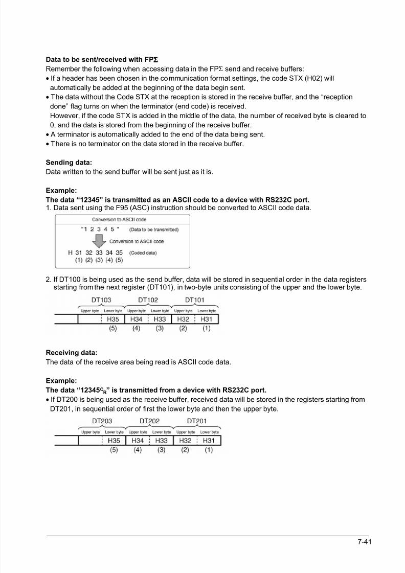
8/21/2019 Programmable Controller FP Sigma
http://slidepdf.com/reader/full/programmable-controller-fp-sigma 187/318
7-41
Data to be sent/received with FPΣΣΣΣ
Remember the following when accessing data in the FPΣ send and receive buffers:
• If a header has been chosen in the communication format settings, the code STX (H02) will
automatically be added at the beginning of the data begin sent.
•
The data without the Code STX at the reception is stored in the receive buffer, and the “receptiondone” flag turns on when the terminator (end code) is received.
However, if the code STX is added in the middle of the data, the number of received byte is cleared to
0, and the data is stored from the beginning of the receive buffer.
• A terminator is automatically added to the end of the data being sent.
• There is no terminator on the data stored in the receive buffer.
Sending data:
Data written to the send buffer will be sent just as it is.
Example:
The data “12345” is transmitted as an ASCII code to a device with RS232C port.1. Data sent using the F95 (ASC) instruction should be converted to ASCII code data.
2. If DT100 is being used as the send buffer, data will be stored in sequential order in the data registers starting from the next register (DT101), in two-byte units consisting of the upper and the lower byte.
Receiving data:
The data of the receive area being read is ASCII code data.
Example:
The data “12345CR” is transmitted from a device with RS232C port.
• If DT200 is being used as the receive buffer, received data will be stored in the registers starting fromDT201, in sequential order of first the lower byte and then the upper byte.
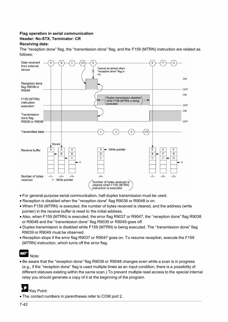
8/21/2019 Programmable Controller FP Sigma
http://slidepdf.com/reader/full/programmable-controller-fp-sigma 188/318
7-42
Flag operation in serial communication
Header: No-STX, Terminator: CR
Receiving data:
The “reception done” flag, the “transmission done” flag, and the F159 (MTRN) instruction are related as
follows:
• For general-purpose serial communication, half-duplex transmission must be used.
• Reception is disabled when the “reception done” flag R9038 or R9048 is on.
• When F159 (MTRN) is executed, the number of bytes received is cleared, and the address (write
pointer) in the receive buffer is reset to the initial address.
• Also, when F159 (MTRN) is executed, the error flag R9037 or R9047, the “ reception done” flag R9038
or R9048 and the “ transmission done” flag R9039 or R9049 goes off.
• Duplex transmission is disabled while F159 (MTRN) is being executed. The “transmission done” flagR9039 or R9049 must be observed.
• Reception stops if the error flag R9037 or R9047 goes on. To resume reception, execute the F159
(MTRN) instruction, which turns off the error flag.
Note:
• Be aware that the “reception done” flag R9038 or R9048 changes even while a scan is in progress
(e.g., if the “reception done” flag is used multiple times as an input condition, there is a possibility of
different statuses existing within the same scan.) To prevent multiple read access to the special internal
relay you should generate a copy of it at the beginning of the program.
Key Point:
• The contact numbers in parentheses refer to COM port 2.
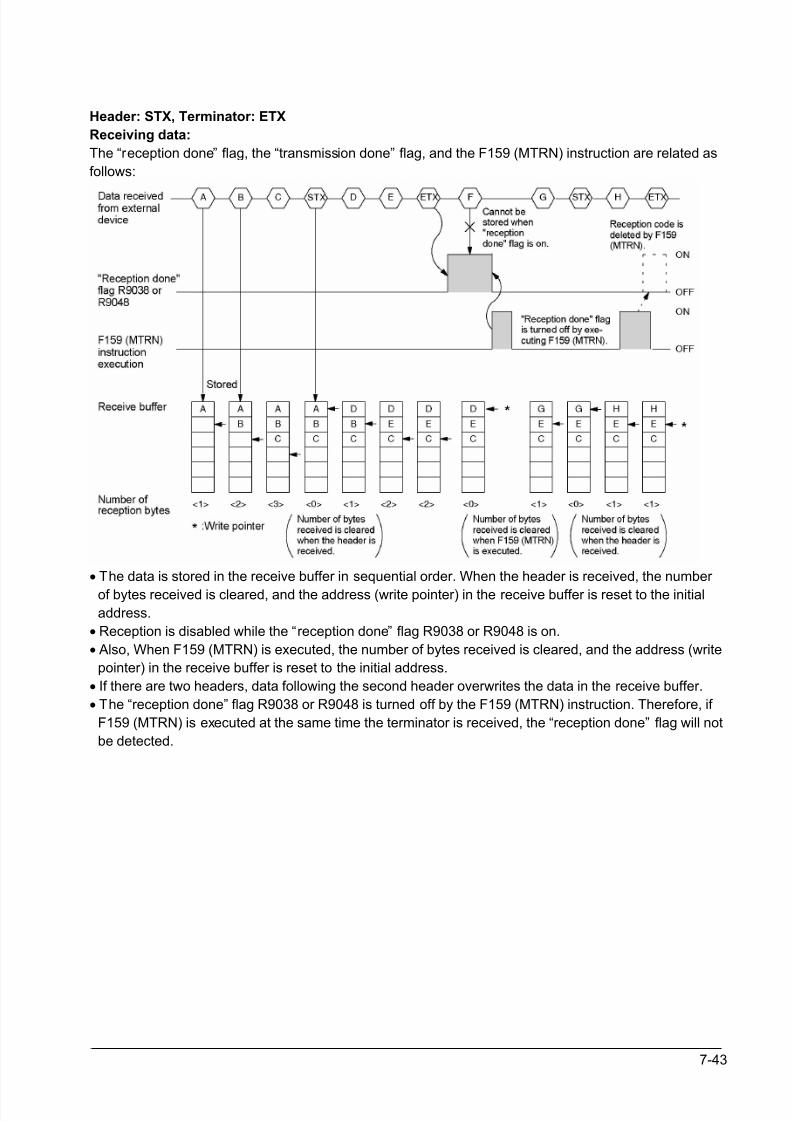
8/21/2019 Programmable Controller FP Sigma
http://slidepdf.com/reader/full/programmable-controller-fp-sigma 189/318
7-43
Header: STX, Terminator: ETX
Receiving data:
The “reception done” flag, the “transmission done” flag, and the F159 (MTRN) instruction are related as
follows:
• The data is stored in the receive buffer in sequential order. When the header is received, the number
of bytes received is cleared, and the address (write pointer) in the receive buffer is reset to the initial
address.
• Reception is disabled while the “reception done” flag R9038 or R9048 is on.
• Also, When F159 (MTRN) is executed, the number of bytes received is cleared, and the address (write
pointer) in the receive buffer is reset to the initial address.
• If there are two headers, data following the second header overwrites the data in the receive buffer.
• The “reception done” flag R9038 or R9048 is turned off by the F159 (MTRN) instruction. Therefore, if
F159 (MTRN) is executed at the same time the terminator is received, the “reception done” flag will not
be detected.
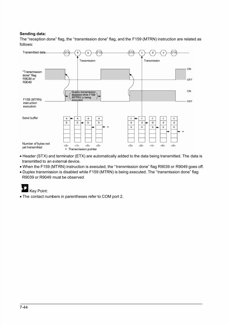
8/21/2019 Programmable Controller FP Sigma
http://slidepdf.com/reader/full/programmable-controller-fp-sigma 190/318
7-44
Sending data:
The “reception done” flag, the “transmission done” flag, and the F159 (MTRN) instruction are related as
follows:
• Header (STX) and terminator (ETX) are automatically added to the data being transmitted. The data is
transmitted to an external device.
• When the F159 (MTRN) instruction is executed, the “transmission done” flag R9039 or R9049 goes off.
• Duplex transmission is disabled while F159 (MTRN) is being executed. The “transmission done” flagR9039 or R9049 must be observed.
Key Point:
• The contact numbers in parentheses refer to COM port 2.
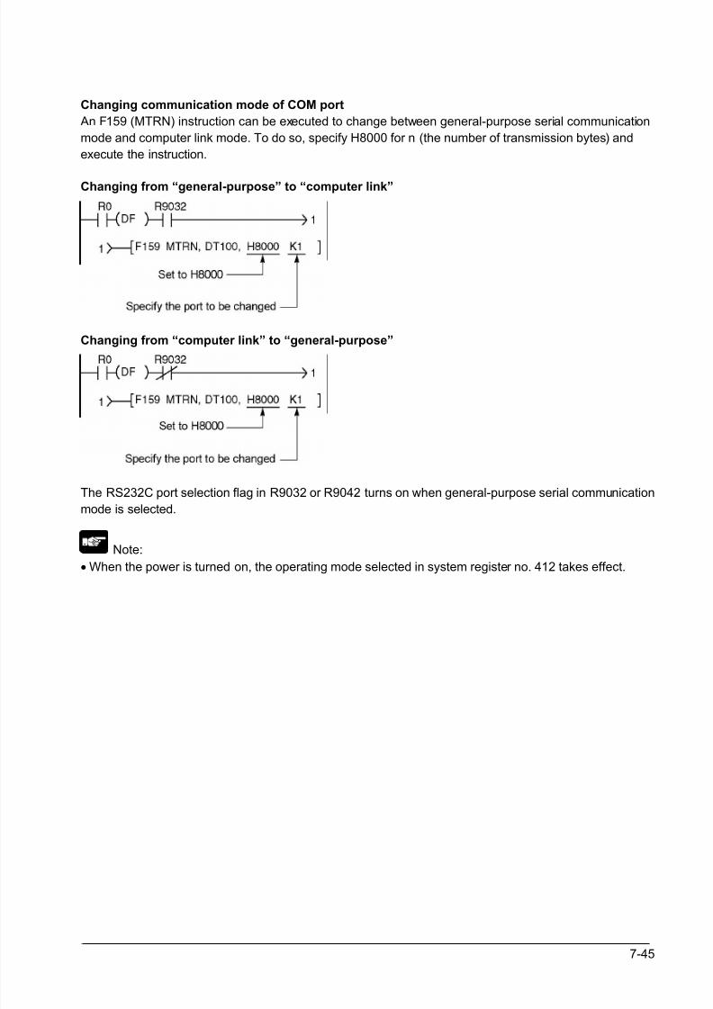
8/21/2019 Programmable Controller FP Sigma
http://slidepdf.com/reader/full/programmable-controller-fp-sigma 191/318
7-45
Changing communication mode of COM port
An F159 (MTRN) instruction can be executed to change between general-purpose serial communication
mode and computer link mode. To do so, specify H8000 for n (the number of transmission bytes) and
execute the instruction.
Changing from “general-purpose” to “computer link”
Changing from “computer link” to “general-purpose”
The RS232C port selection flag in R9032 or R9042 turns on when general-purpose serial communication
mode is selected.
Note:
• When the power is turned on, the operating mode selected in system register no. 412 takes effect.
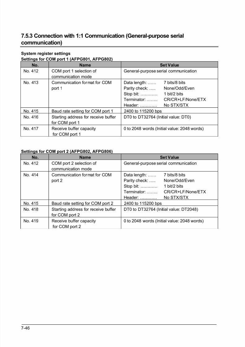
8/21/2019 Programmable Controller FP Sigma
http://slidepdf.com/reader/full/programmable-controller-fp-sigma 192/318
7-46
7.5.3 Connection with 1:1 Communication (General-purpose serial
communication)
System register settings
Settings for COM port 1 (AFPG801, AFPG802)No. Name Set Value
No. 412 COM port 1 selection of
communication mode
General-purpose serial communication
No. 413 Communication format for COM
port 1
Data length: ……
Parity check: …..
Stop bit: …………
Terminator: ……..
Header: …………
7 bits/8 bits
None/Odd/Even
1 bit/2 bits
CR/CR+LF/None/ETX
No STX/STX
No. 415 Baud rate setting for COM port 1 2400 to 115200 bps
No. 416 Starting address for receive buffer
for COM port 1
DT0 to DT32764 (Initial value: DT0)
No. 417 Receive buffer capacity
for COM port 1
0 to 2048 words (Initial value: 2048 words)
Settings for COM port 2 (AFPG802, AFPG806)
No. Name Set Value
No. 412 COM port 2 selection of
communication mode
General-purpose serial communication
No. 414 Communication format for COM
port 2
Data length: ……
Parity check: …..Stop bit: …………
Terminator: ……..
Header: …………
7 bits/8 bits
None/Odd/Even1 bit/2 bits
CR/CR+LF/None/ETX
No STX/STX
No. 415 Baud rate setting for COM port 2 2400 to 115200 bps
No. 418 Starting address for receive buffer
for COM port 2
DT0 to DT32764 (Initial value: DT2048)
No. 419 Receive buffer capacity
for COM port 2
0 to 2048 words (Initial value: 2048 words)
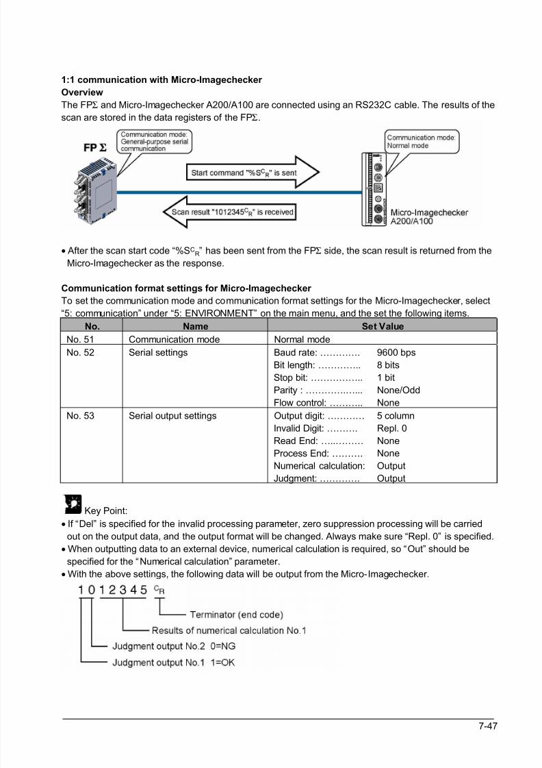
8/21/2019 Programmable Controller FP Sigma
http://slidepdf.com/reader/full/programmable-controller-fp-sigma 193/318
7-47
1:1 communication with Micro-Imagechecker
Overview
The FPΣ and Micro-Imagechecker A200/A100 are connected using an RS232C cable. The results of the
scan are stored in the data registers of the FPΣ.
• After the scan start code “%SCR” has been sent from the FPΣ side, the scan result is returned from the
Micro-Imagechecker as the response.
Communication format settings for Micro-Imagechecker
To set the communication mode and communication format settings for the Micro-Imagechecker, select
“5: communication” under “5: ENVIRONMENT” on the main menu, and the set the following items.
No. Name Set Value
No. 51 Communication mode Normal mode
No. 52 Serial settings Baud rate: ………….
Bit length: …………..
Stop bit: ……………..
Parity : ………….…...
Flow control: ………..
9600 bps
8 bits
1 bit
None/Odd
NoneNo. 53 Serial output settings Output digit: …………
Invalid Digit: ……….
Read End: …..………
Process End: ……….
Numerical calculation:
Judgment: ………….
5 column
Repl. 0
None
None
Output
Output
Key Point:
• If “Del” is specified for the invalid processing parameter, zero suppression processing will be carried
out on the output data, and the output format will be changed. Always make sure “Repl. 0” is specified.• When outputting data to an external device, numerical calculation is required, so “Out” should be
specified for the “Numerical calculation” parameter.
• With the above settings, the following data will be output from the Micro-Imagechecker.
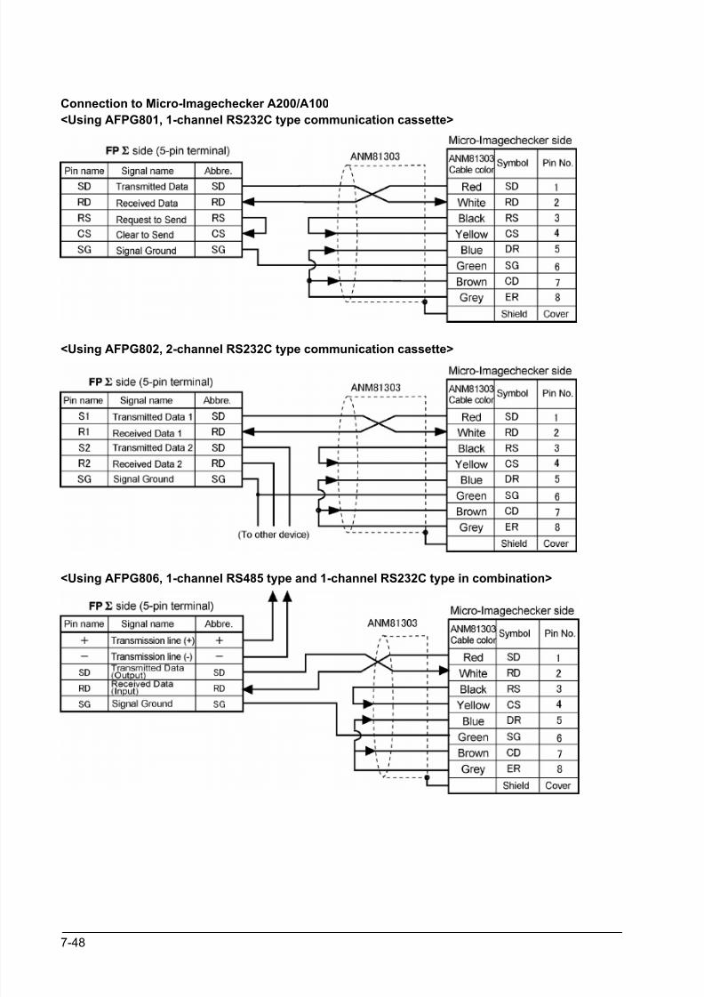
8/21/2019 Programmable Controller FP Sigma
http://slidepdf.com/reader/full/programmable-controller-fp-sigma 194/318
7-48
Connection to Micro-Imagechecker A200/A100
<Using AFPG801, 1-channel RS232C type communication cassette>
<Using AFPG802, 2-channel RS232C type communication cassette>
<Using AFPG806, 1-channel RS485 type and 1-channel RS232C type in combination>

8/21/2019 Programmable Controller FP Sigma
http://slidepdf.com/reader/full/programmable-controller-fp-sigma 195/318
7-49
Procedure of communication
In the following example, the Micro-Imagechecker is connected to COM port 1.
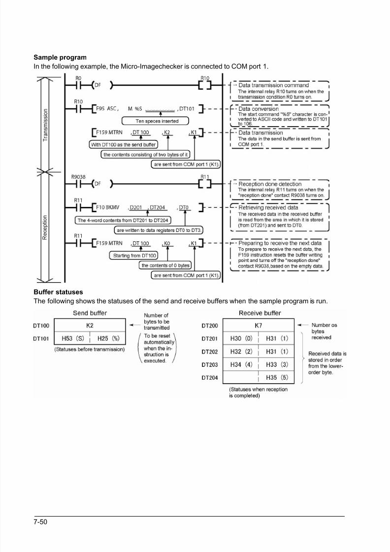
8/21/2019 Programmable Controller FP Sigma
http://slidepdf.com/reader/full/programmable-controller-fp-sigma 196/318
7-50
Sample program
In the following example, the Micro-Imagechecker is connected to COM port 1.
Buffer statuses
The following shows the statuses of the send and receive buffers when the sample program is run.
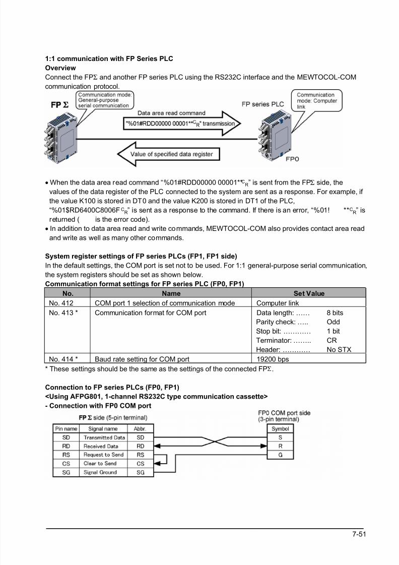
8/21/2019 Programmable Controller FP Sigma
http://slidepdf.com/reader/full/programmable-controller-fp-sigma 197/318
7-51
1:1 communication with FP Series PLC
Overview
Connect the FPΣ and another FP series PLC using the RS232C interface and the MEWTOCOL-COM
communication protocol.
• When the data area read command “%01#RDD00000 00001**CR” is sent from the FPΣ side, the
values of the data register of the PLC connected to the system are sent as a response. For example, if
the value K100 is stored in DT0 and the value K200 is stored in DT1 of the PLC,
“%01$RD6400C8006F CR” is sent as a response to the command. If there is an error, “%01! ** C
R” is
returned ( is the error code).
• In addition to data area read and write commands, MEWTOCOL-COM also provides contact area read
and write as well as many other commands.
System register settings of FP series PLCs (FP1, FP1 side)
In the default settings, the COM port is set not to be used. For 1:1 general-purpose serial communication,
the system registers should be set as shown below.
Communication format settings for FP series PLC (FP0, FP1)
No. Name Set ValueNo. 412 COM port 1 selection of communication mode Computer link
No. 413 * Communication format for COM port Data length: ……
Parity check: …..
Stop bit: …………
Terminator: ……..
Header: …………
8 bits
Odd
1 bit
CR
No STX
No. 414 * Baud rate setting for COM port 19200 bps
* These settings should be the same as the settings of the connected FPΣ.
Connection to FP series PLCs (FP0, FP1)
<Using AFPG801, 1-channel RS232C type communication cassette>- Connection with FP0 COM port
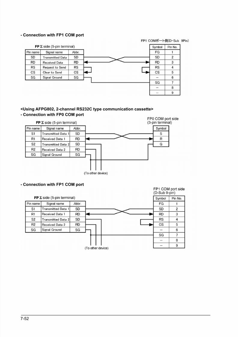
8/21/2019 Programmable Controller FP Sigma
http://slidepdf.com/reader/full/programmable-controller-fp-sigma 198/318
7-52
- Connection with FP1 COM port
<Using AFPG802, 2-channel RS232C type communication cassette>
- Connection with FP0 COM port
- Connection with FP1 COM port
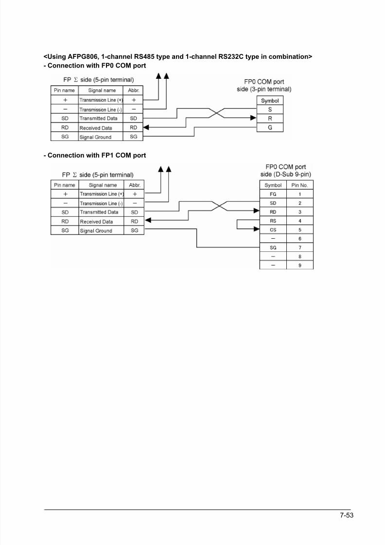
8/21/2019 Programmable Controller FP Sigma
http://slidepdf.com/reader/full/programmable-controller-fp-sigma 199/318
7-53
<Using AFPG806, 1-channel RS485 type and 1-channel RS232C type in combination>
- Connection with FP0 COM port
- Connection with FP1 COM port
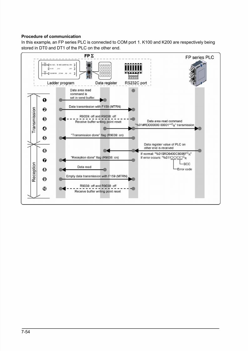
8/21/2019 Programmable Controller FP Sigma
http://slidepdf.com/reader/full/programmable-controller-fp-sigma 200/318
7-54
Procedure of communication
In this example, an FP series PLC is connected to COM port 1. K100 and K200 are respectively being
stored in DT0 and DT1 of the PLC on the other end.
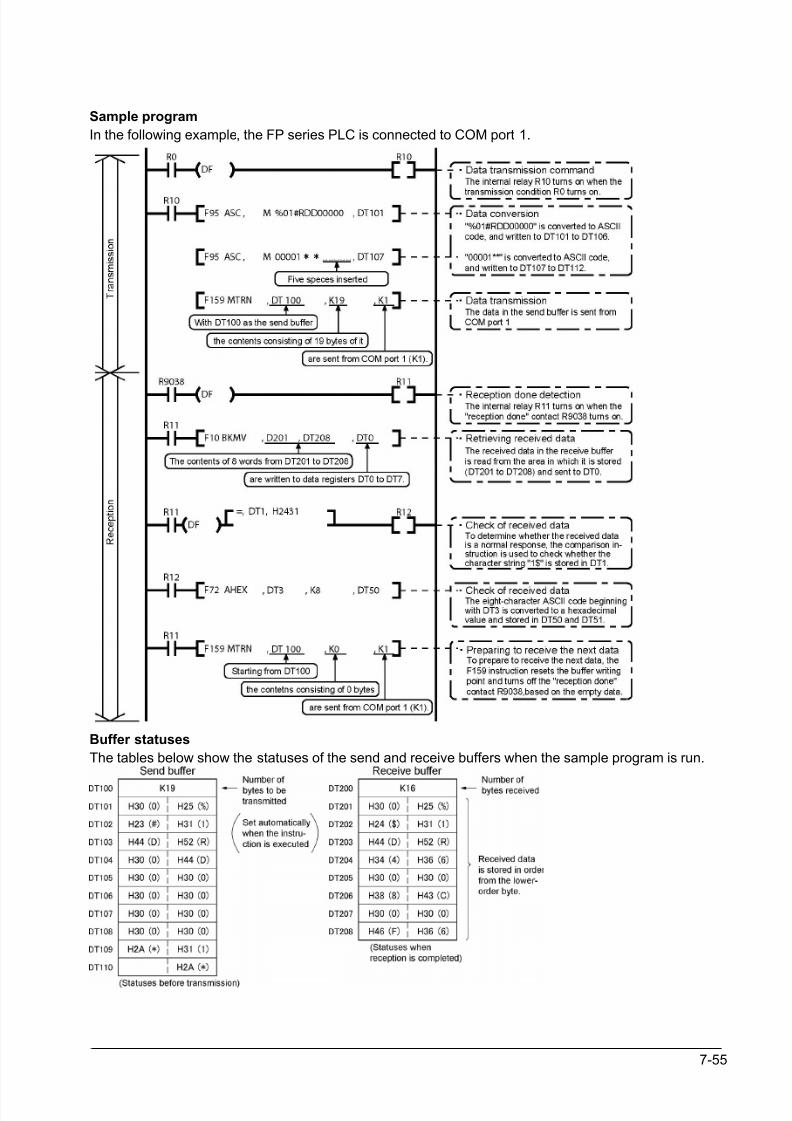
8/21/2019 Programmable Controller FP Sigma
http://slidepdf.com/reader/full/programmable-controller-fp-sigma 201/318
7-55
Sample program
In the following example, the FP series PLC is connected to COM port 1.
Buffer statuses
The tables below show the statuses of the send and receive buffers when the sample program is run.
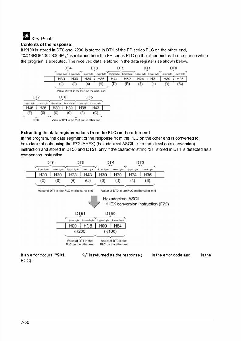
8/21/2019 Programmable Controller FP Sigma
http://slidepdf.com/reader/full/programmable-controller-fp-sigma 202/318
7-56
Key Point:Contents of the response:
If K100 is stored in DT0 and K200 is stored in DT1 of the FP series PLC on the other end,
“%01$RD6400C8006FCR” is returned from the FP series PLC on the other end as the response when
the program is executed. The received data is stored in the data registers as shown below.
Extracting the data register values from the PLC on the other end
In the program, the data segment of the response from the PLC on the other end is converted to
hexadecimal data using the F72 (AHEX) (hexadecimal ASCII → hexadecimal data conversion)
instruction and stored in DT50 and DT51, only if the character string “$1” stored in DT1 is detected as a
comparison instruction
If an error occurs, “%01! CR” is returned as the response ( is the error code and is the
BCC).
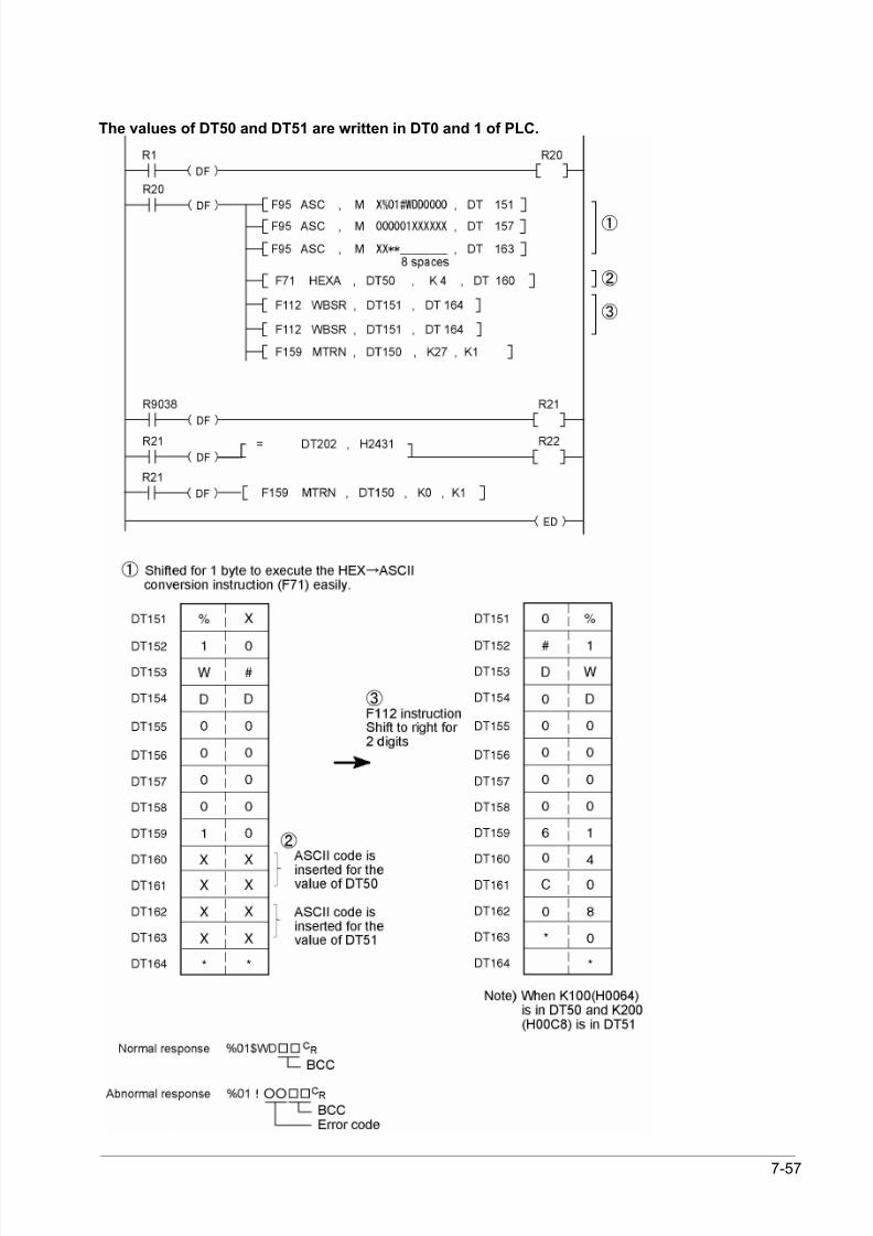
8/21/2019 Programmable Controller FP Sigma
http://slidepdf.com/reader/full/programmable-controller-fp-sigma 203/318
7-57
The values of DT50 and DT51 are written in DT0 and 1 of PLC.
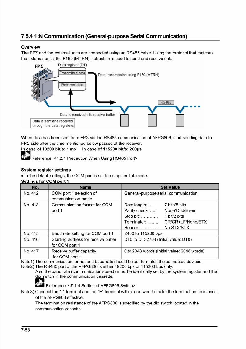
8/21/2019 Programmable Controller FP Sigma
http://slidepdf.com/reader/full/programmable-controller-fp-sigma 204/318
7-58
7.5.4 1:N Communication (General-purpose Serial Communication)
Overview
The FPΣ and the external units are connected using an RS485 cable. Using the protocol that matches
the external units, the F159 (MTRN) instruction is used to send and receive data.
When data has been sent from FPΣ via the RS485 communication of AFPG806, start sending data to
FPΣ side after the time mentioned below passed at the receiver.
In case of 19200 bit/s: 1 ms In case of 115200 bit/s: 200µs
Reference: <7.2.1 Precaution When Using RS485 Port>
System register settings
• In the default settings, the COM port is set to computer link mode.
Settings for COM port 1No. Name Set Value
No. 412 COM port 1 selection of
communication mode
General-purpose serial communication
No. 413 Communication format for COM
port 1
Data length: ……
Parity check: …..
Stop bit: …………
Terminator: ……..
Header: …………
7 bits/8 bits
None/Odd/Even
1 bit/2 bits
CR/CR+LF/None/ETX
No STX/STX
No. 415 Baud rate setting for COM port 1 2400 to 115200 bps
No. 416 Starting address for receive buffer
for COM port 1
DT0 to DT32764 (Initial value: DT0)
No. 417 Receive buffer capacity
for COM port 1
0 to 2048 words (Initial value: 2048 words)
Note1) The communication format and baud rate should be set to match the connected devices.Note2) The RS485 port of the AFPG806 is either 19200 bps or 115200 bps only. Also the baud rate (communication speed) must be identically set by the system register and the dip switch in the communication cassette.
Reference: <7.1.4 Setting of AFPG806 Switch>
Note3) Connect the “−“ terminal and the “E” terminal with a lead wire to make the termination resistance
of the AFPG803 effective.
The termination resistance of the AFPG806 is specified by the dip switch located in the
communication cassette.
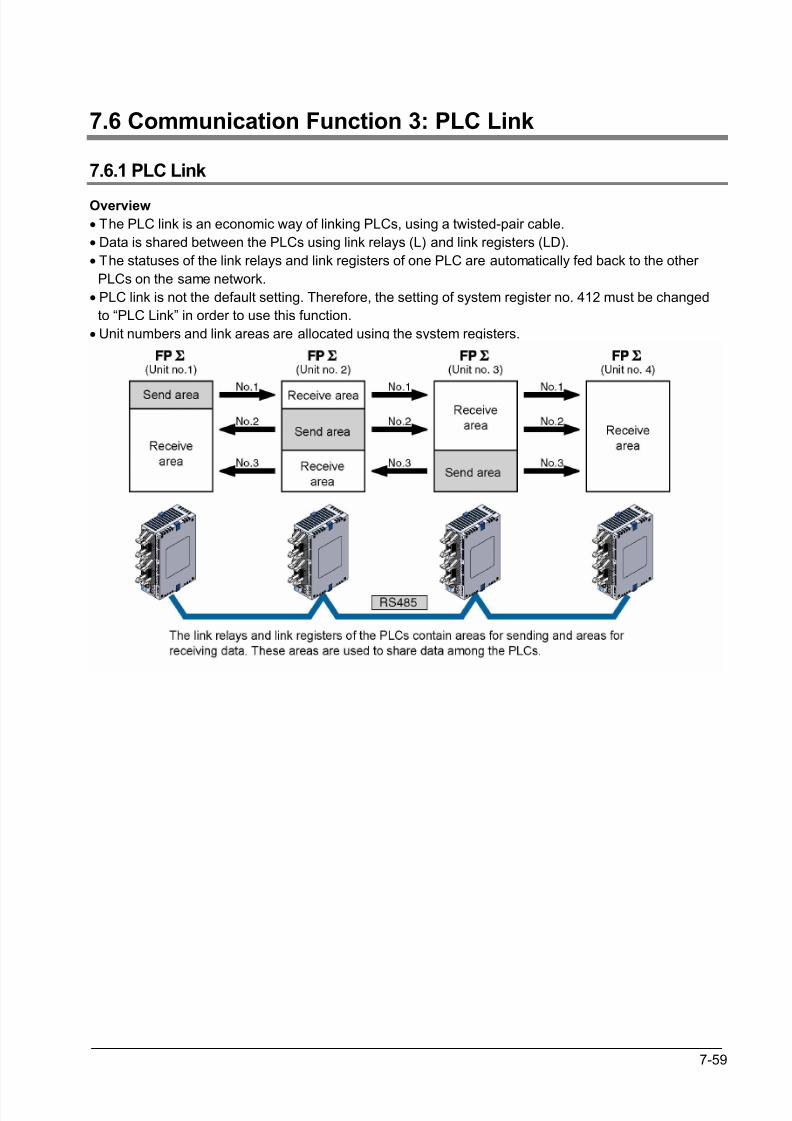
8/21/2019 Programmable Controller FP Sigma
http://slidepdf.com/reader/full/programmable-controller-fp-sigma 205/318
7-59
7.6 Communication Function 3: PLC Link
7.6.1 PLC Link
Overview
• The PLC link is an economic way of linking PLCs, using a twisted-pair cable.
• Data is shared between the PLCs using link relays (L) and link registers (LD).
• The statuses of the link relays and link registers of one PLC are automatically fed back to the other
PLCs on the same network.
• PLC link is not the default setting. Therefore, the setting of system register no. 412 must be changed
to “PLC Link” in order to use this function.
• Unit numbers and link areas are allocated using the system registers.
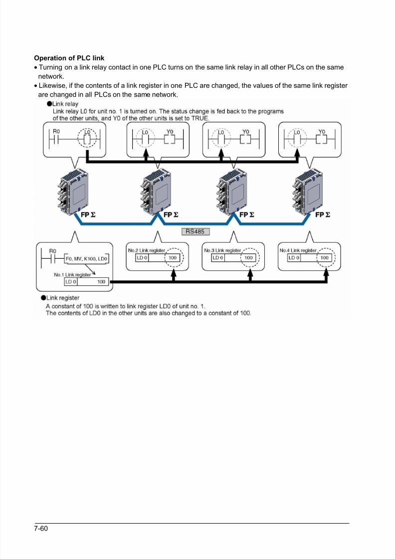
8/21/2019 Programmable Controller FP Sigma
http://slidepdf.com/reader/full/programmable-controller-fp-sigma 206/318
7-60
Operation of PLC link
• Turning on a link relay contact in one PLC turns on the same link relay in all other PLCs on the same
network.
• Likewise, if the contents of a link register in one PLC are changed, the values of the same link register
are changed in all PLCs on the same network.
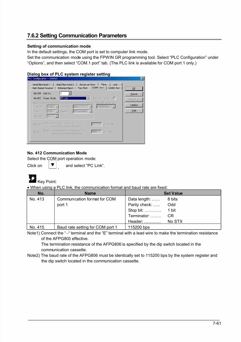
8/21/2019 Programmable Controller FP Sigma
http://slidepdf.com/reader/full/programmable-controller-fp-sigma 207/318
7-61
7.6.2 Setting Communication Parameters
Setting of communication mode
In the default settings, the COM port is set to computer link mode.
Set the communication mode using the FPWIN GR programming tool. Select “PLC Configuration” under
“Options”, and then select “COM.1 port” tab. (The PLC link is available for COM port 1 only.)
Dialog box of PLC system register setting
No. 412 Communication Mode
Select the COM port operation mode:
Click on , and select “PC Link”.
Key Point:
• When using a PLC link, the communication format and baud rate are fixed:
No. Name Set Value
No. 413 Communication format for COM
port 1
Data length: ……
Parity check: …..
Stop bit: …………
Terminator: ……..
Header: …………
8 bits
Odd
1 bit
CR
No STX
No. 415 Baud rate setting for COM port 1 115200 bps
Note1) Connect the “−“ terminal and the “E” terminal with a lead wire to make the termination resistance
of the AFPG803 effective. The termination resistance of the AFPG806 is specified by the dip switch located in the
communication cassette.
Note2) The baud rate of the AFPG806 must be identically set to 115200 bps by the system register and
the dip switch located in the communication cassette.
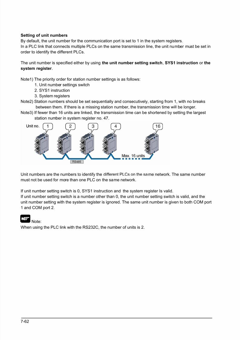
8/21/2019 Programmable Controller FP Sigma
http://slidepdf.com/reader/full/programmable-controller-fp-sigma 208/318
7-62
Setting of unit numbers
By default, the unit number for the communication port is set to 1 in the system registers.
In a PLC link that connects multiple PLCs on the same transmission line, the unit number must be set in
order to identify the different PLCs.
The unit number is specified either by using the unit number setting switch, SYS1 instruction or the
system register .
Note1) The priority order for station number settings is as follows:
1. Unit number settings switch
2. SYS1 instruction
3. System registers
Note2) Station numbers should be set sequentially and consecutively, starting from 1, with no breaks
between them. If there is a missing station number, the transmission time will be longer.
Note3) If fewer than 16 units are linked, the transmission time can be shortened by setting the largest
station number in system register no. 47.
Unit numbers are the numbers to identify the different PLCs on the same network. The same number
must not be used for more than one PLC on the same network.
If unit number setting switch is 0, SYS1 instruction and the system register Is valid.
If unit number setting switch is a number other than 0, the unit number setting switch is valid, and the
unit number setting with the system register is ignored. The same unit number is given to both COM port
1 and COM port 2.
Note:
When using the PLC link with the RS232C, the number of units is 2.
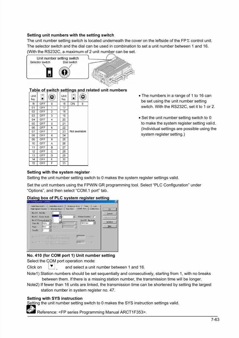
8/21/2019 Programmable Controller FP Sigma
http://slidepdf.com/reader/full/programmable-controller-fp-sigma 209/318
7-63
Setting unit numbers with the setting switch
The unit number setting switch is located underneath the cover on the leftside of the FPΣ control unit.
The selector switch and the dial can be used in combination to set a unit number between 1 and 16.
(With the RS232C, a maximum of 2 unit number can be set.
Table of switch settings and related unit numbers
• The numbers in a range of 1 to 16 can
be set using the unit number setting
switch. With the RS232C, set it to 1 or 2.
• Set the unit number setting switch to 0to make the system register setting valid.
(Individual settings are possible using the
system register setting.)
Setting with the system register
Setting the unit number setting switch to 0 makes the system register settings valid.
Set the unit numbers using the FPWIN GR programming tool. Select “PLC Configuration” under
“Options”, and then select “COM.1 port” tab.
Dialog box of PLC system register setting
No. 410 (for COM port 1) Unit number setting
Select the COM port operation mode:
Click on , and select a unit number between 1 and 16.
Note1) Station numbers should be set sequentially and consecutively, starting from 1, with no breaks
between them. If there is a missing station number, the transmission time will be longer.
Note2) If fewer than 16 units are linked, the transmission time can be shortened by setting the largest
station number in system register no. 47.
Setting with SYS instructionSetting the unit number setting switch to 0 makes the SYS instruction settings valid.
Reference: <FP series Programming Manual ARCT1F353>.
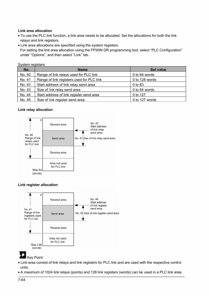
8/21/2019 Programmable Controller FP Sigma
http://slidepdf.com/reader/full/programmable-controller-fp-sigma 210/318
7-64
Link area allocation
• To use the PLC link function, a link area needs to be allocated. Set the allocations for both the link
relays and link registers.
• Link area allocations are specified using the system registers.
For setting the link area allocation using the FPWIN GR programming tool, select “PLC Configuration”under “Options”, and then select “Link” tab.
System registers
No. Name Set value
No. 40 Range of link relays used for PLC link 0 to 64 words
No. 41 Range of link registers used for PLC link 0 to 128 words
No. 42 Start address of link relay send area 0 to 63
No. 43 Size of link relay send area 0 to 64 words
No. 44 Start address of link register send area 0 to 127
No. 45 Size of link register send area 0 to 127 words
Link relay allocation
Link register allocation
Key Point:• Link area consist of link relays and link registers for PLC link and are used with the respective control
units.
• A maximum of 1024 link relays (points) and 128 link registers (words) can be used in a PLC link area.
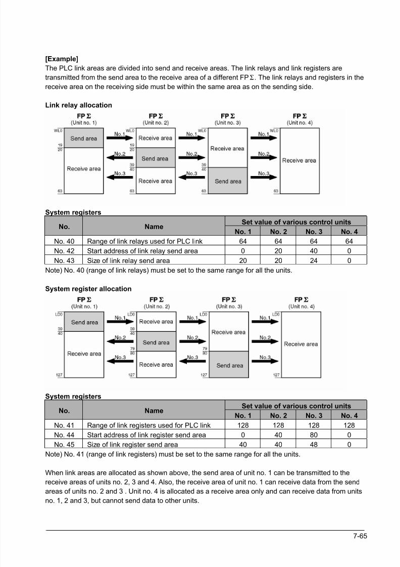
8/21/2019 Programmable Controller FP Sigma
http://slidepdf.com/reader/full/programmable-controller-fp-sigma 211/318
7-65
[Example]
The PLC link areas are divided into send and receive areas. The link relays and link registers are
transmitted from the send area to the receive area of a different FPΣ. The link relays and registers in the
receive area on the receiving side must be within the same area as on the sending side.
Link relay allocation
System registers
Set value of various control unitsNo. Name
No. 1 No. 2 No. 3 No. 4
No. 40 Range of link relays used for PLC link 64 64 64 64
No. 42 Start address of link relay send area 0 20 40 0
No. 43 Size of link relay send area 20 20 24 0
Note) No. 40 (range of link relays) must be set to the same range for all the units.
System register allocation
System registersSet value of various control units
No. NameNo. 1 No. 2 No. 3 No. 4
No. 41 Range of link registers used for PLC link 128 128 128 128
No. 44 Start address of link register send area 0 40 80 0
No. 45 Size of link register send area 40 40 48 0
Note) No. 41 (range of link registers) must be set to the same range for all the units.
When link areas are allocated as shown above, the send area of unit no. 1 can be transmitted to the
receive areas of units no. 2, 3 and 4. Also, the receive area of unit no. 1 can receive data from the send
areas of units no. 2 and 3 . Unit no. 4 is allocated as a receive area only and can receive data from units
no. 1, 2 and 3, but cannot send data to other units.
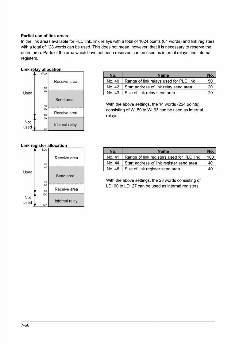
8/21/2019 Programmable Controller FP Sigma
http://slidepdf.com/reader/full/programmable-controller-fp-sigma 212/318
7-66
Partial use of link areas
In the link areas available for PLC link, link relays with a total of 1024 points (64 words) and link registers
with a total of 128 words can be used. This does not mean, however, that it is necessary to reserve the
entire area. Parts of the area which have not been reserved can be used as internal relays and internal
registers.
Link relay allocation
No. Name No.
No. 40 Range of link relays used for PLC link 50
No. 42 Start address of link relay send area 20
No. 43 Size of link relay send area 20
With the above settings, the 14 words (224 points)
consisting of WL50 to WL63 can be used as internal
relays.
Link register allocation
No. Name No.
No. 41 Range of link registers used for PLC link 100
No. 44 Start address of link register send area 40
No. 45 Size of link register send area 40
With the above settings, the 28 words consisting of LD100 to LD127 can be used as internal registers.
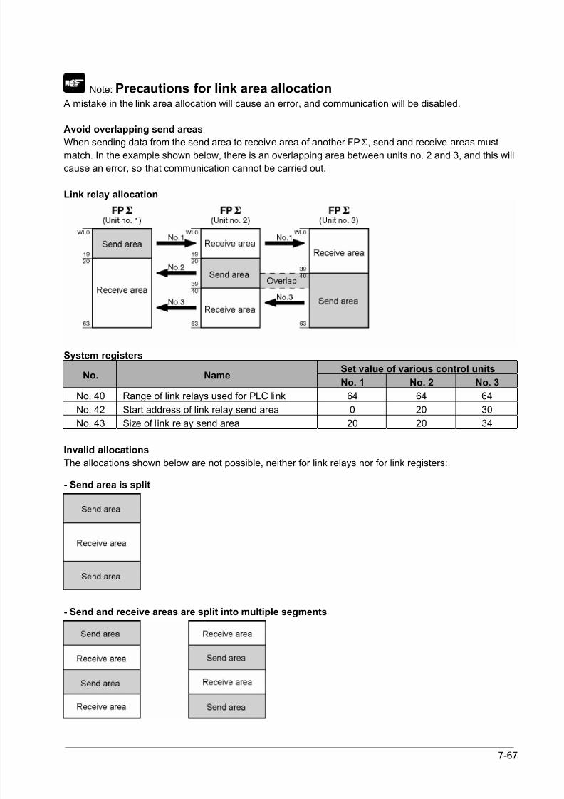
8/21/2019 Programmable Controller FP Sigma
http://slidepdf.com/reader/full/programmable-controller-fp-sigma 213/318
7-67
Note: Precautions for link area allocation A mistake in the link area allocation will cause an error, and communication will be disabled.
Avoid overlapping send areas
When sending data from the send area to receive area of another FPΣ, send and receive areas mustmatch. In the example shown below, there is an overlapping area between units no. 2 and 3, and this will
cause an error, so that communication cannot be carried out.
Link relay allocation
System registers
Set value of various control unitsNo. Name
No. 1 No. 2 No. 3
No. 40 Range of link relays used for PLC link 64 64 64
No. 42 Start address of link relay send area 0 20 30
No. 43 Size of link relay send area 20 20 34
Invalid allocations
The allocations shown below are not possible, neither for link relays nor for link registers:
- Send area is split
- Send and receive areas are split into multiple segments
8/21/2019 Programmable Controller FP Sigma
http://slidepdf.com/reader/full/programmable-controller-fp-sigma 214/318
7-68
Setting the largest unit number for a PLC link
The largest unit number can be set using system register no. 47.
[Sample setting]
No. of units linked Setting contents2 1st unit: Unit no. 1 is set
2nd unit: Unit no. 2 is set
A largest unit no. of 2 is set for each.
4 1st unit: Unit no. 1 is set
2nd unit: Unit no. 2 is set
3rd unit: Unit no. 3 is set
4th unit: Unit no. 4 is set
A largest unit no. of 4 is set for each.
n Nth unit: Unit no. n is set
A largest unit no. of n is set for each.
Note:
• Unit numbers should be set sequentially and consecutively, starting from 1, with no breaks between
them. If there is a missing unit number, the transmission time will be longer.
• If fewer than 16 units are linked, the transmission time can be shortened by setting the largest unit
number in system register no. 47.
• For all PLCs which are linked, the same value should be set for the largest unit number.
• If there are fewer than 16 units linked and the largest unit number has not been set (default=16), or the
largest unit number has been set but the unit number settings are not consecutive, or the unit number
settings are consecutive but there is a unit for which the power supply has not been turned on, the
response time for the PLC link (the link transmission cycle) will be longer.
Reference: <7.6.5 PLC Link Response Time>.
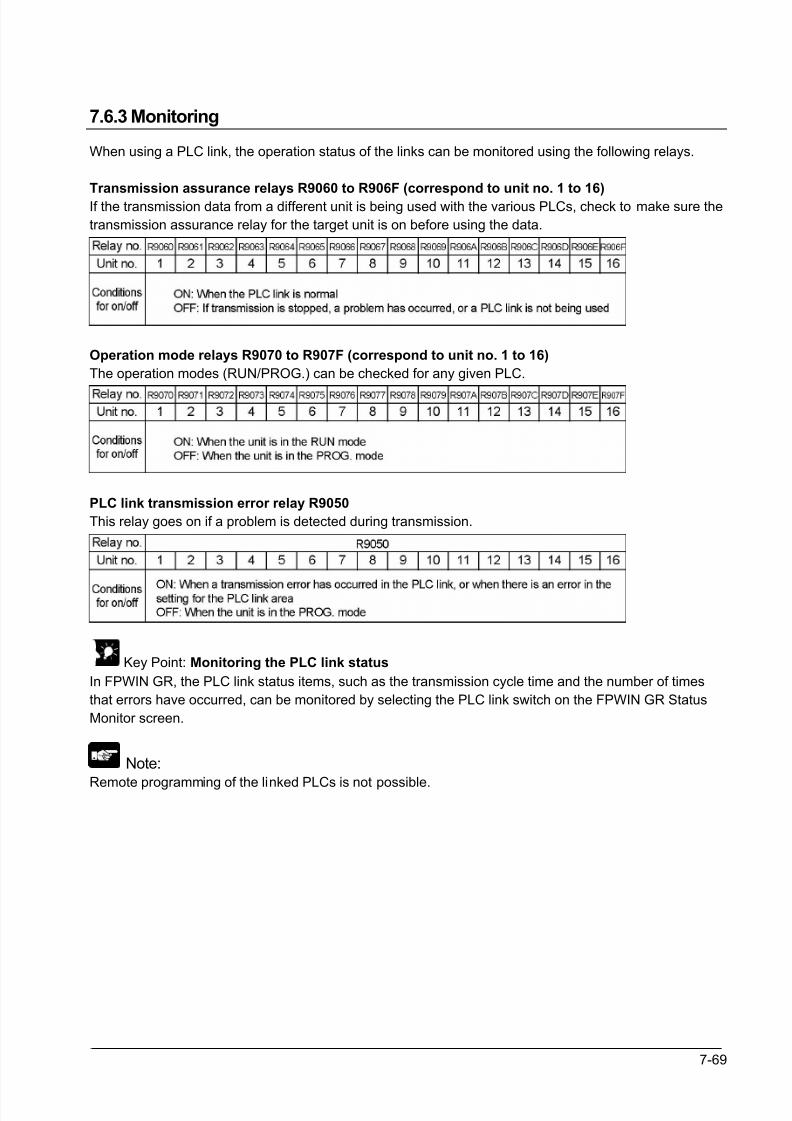
8/21/2019 Programmable Controller FP Sigma
http://slidepdf.com/reader/full/programmable-controller-fp-sigma 215/318
7-69
7.6.3 Monitoring
When using a PLC link, the operation status of the links can be monitored using the following relays.
Transmission assurance relays R9060 to R906F (correspond to unit no. 1 to 16)
If the transmission data from a different unit is being used with the various PLCs, check to make sure the
transmission assurance relay for the target unit is on before using the data.
Operation mode relays R9070 to R907F (correspond to unit no. 1 to 16)
The operation modes (RUN/PROG.) can be checked for any given PLC.
PLC link transmission error relay R9050
This relay goes on if a problem is detected during transmission.
Key Point: Monitoring the PLC link status
In FPWIN GR, the PLC link status items, such as the transmission cycle time and the number of times
that errors have occurred, can be monitored by selecting the PLC link switch on the FPWIN GR Status
Monitor screen.
Note:
Remote programming of the linked PLCs is not possible.
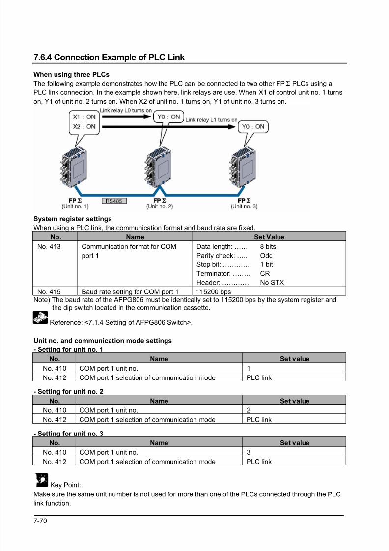
8/21/2019 Programmable Controller FP Sigma
http://slidepdf.com/reader/full/programmable-controller-fp-sigma 216/318
7-70
7.6.4 Connection Example of PLC Link
When using three PLCs
The following example demonstrates how the PLC can be connected to two other FPΣ PLCs using a
PLC link connection. In the example shown here, link relays are use. When X1 of control unit no. 1 turns
on, Y1 of unit no. 2 turns on. When X2 of unit no. 1 turns on, Y1 of unit no. 3 turns on.
System register settings
When using a PLC link, the communication format and baud rate are fixed.
No. Name Set Value
No. 413 Communication format for COM
port 1
Data length: ……
Parity check: …..
Stop bit: …………
Terminator: ……..
Header: …………
8 bits
Odd
1 bit
CR
No STX
No. 415 Baud rate setting for COM port 1 115200 bpsNote) The baud rate of the AFPG806 must be identically set to 115200 bps by the system register and the dip switch located in the communication cassette.
Reference: <7.1.4 Setting of AFPG806 Switch>.
Unit no. and communication mode settings
- Setting for unit no. 1
No. Name Set value
No. 410 COM port 1 unit no. 1
No. 412 COM port 1 selection of communication mode PLC link
- Setting for unit no. 2
No. Name Set value
No. 410 COM port 1 unit no. 2
No. 412 COM port 1 selection of communication mode PLC link
- Setting for unit no. 3
No. Name Set value
No. 410 COM port 1 unit no. 3
No. 412 COM port 1 selection of communication mode PLC link
Key Point:
Make sure the same unit number is not used for more than one of the PLCs connected through the PLC
link function.
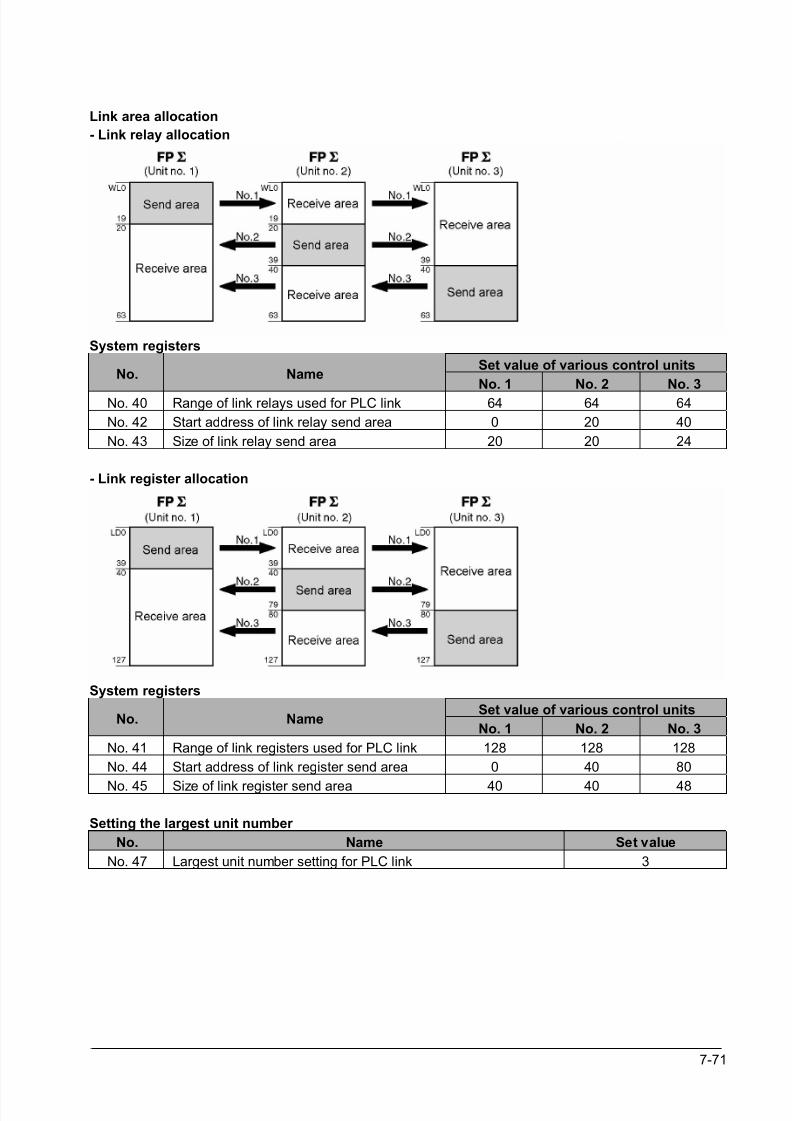
8/21/2019 Programmable Controller FP Sigma
http://slidepdf.com/reader/full/programmable-controller-fp-sigma 217/318
7-71
Link area allocation
- Link relay allocation
System registers
Set value of various control unitsNo. Name
No. 1 No. 2 No. 3
No. 40 Range of link relays used for PLC link 64 64 64
No. 42 Start address of link relay send area 0 20 40
No. 43 Size of link relay send area 20 20 24
- Link register allocation
System registers
Set value of various control unitsNo. Name
No. 1 No. 2 No. 3
No. 41 Range of link registers used for PLC link 128 128 128
No. 44 Start address of link register send area 0 40 80
No. 45 Size of link register send area 40 40 48
Setting the largest unit number
No. Name Set value
No. 47 Largest unit number setting for PLC link 3
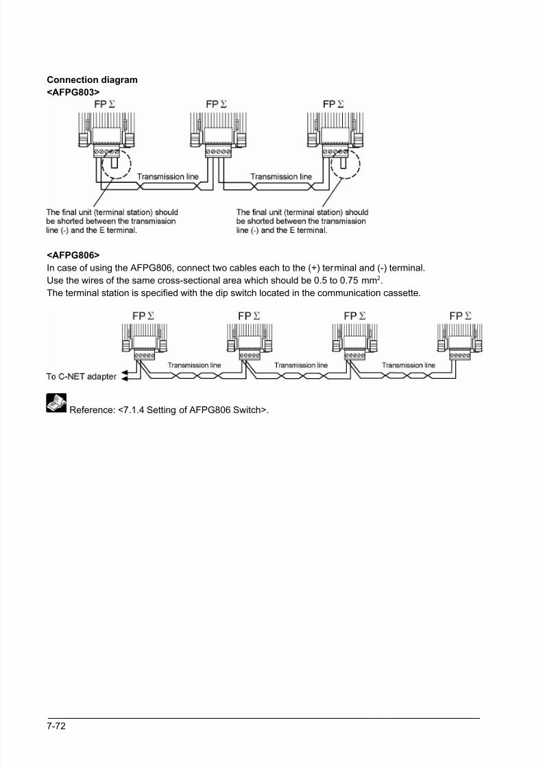
8/21/2019 Programmable Controller FP Sigma
http://slidepdf.com/reader/full/programmable-controller-fp-sigma 218/318
7-72
Connection diagram
<AFPG803>
<AFPG806>
In case of using the AFPG806, connect two cables each to the (+) terminal and (-) terminal.Use the wires of the same cross-sectional area which should be 0.5 to 0.75 mm2.
The terminal station is specified with the dip switch located in the communication cassette.
Reference: <7.1.4 Setting of AFPG806 Switch>.
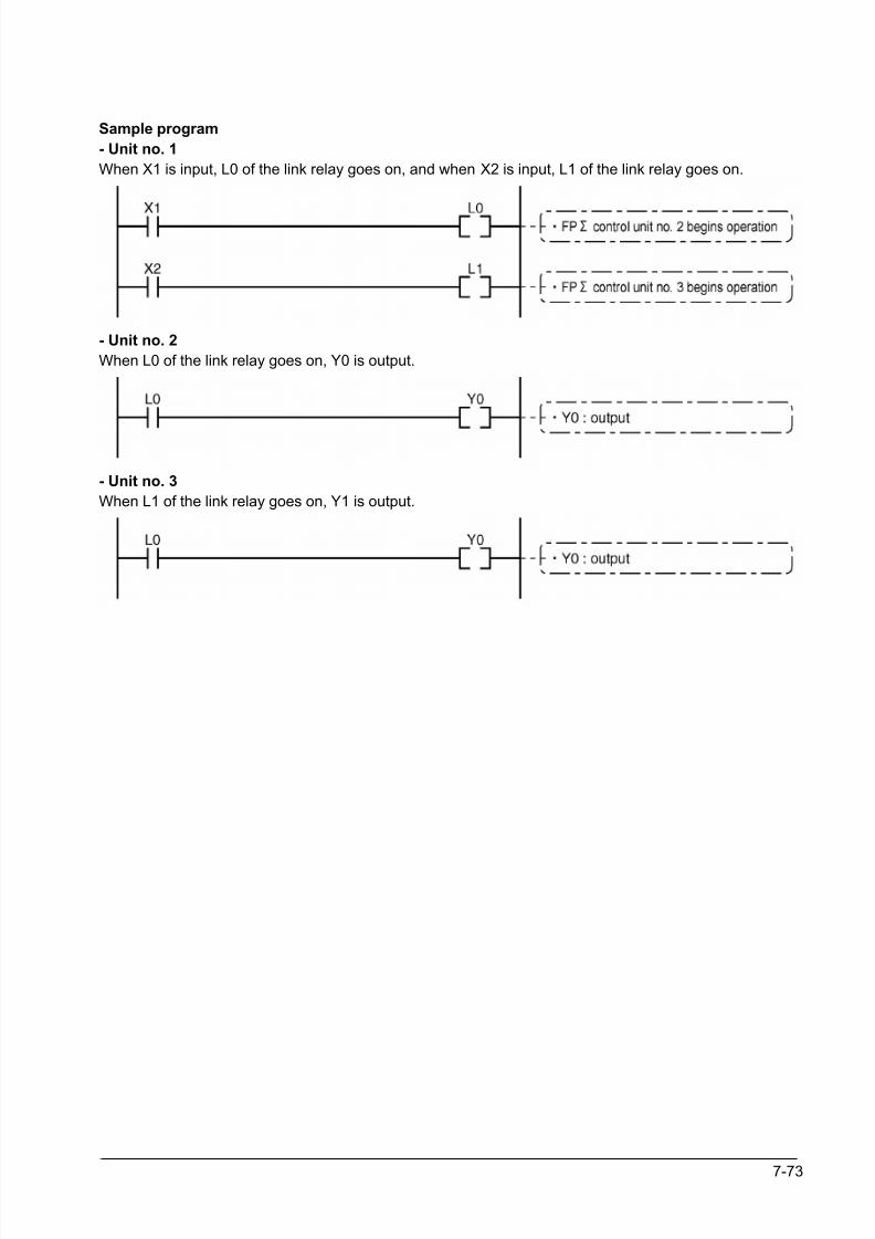
8/21/2019 Programmable Controller FP Sigma
http://slidepdf.com/reader/full/programmable-controller-fp-sigma 219/318
7-73
Sample program
- Unit no. 1
When X1 is input, L0 of the link relay goes on, and when X2 is input, L1 of the link relay goes on.
- Unit no. 2
When L0 of the link relay goes on, Y0 is output.
- Unit no. 3
When L1 of the link relay goes on, Y1 is output.
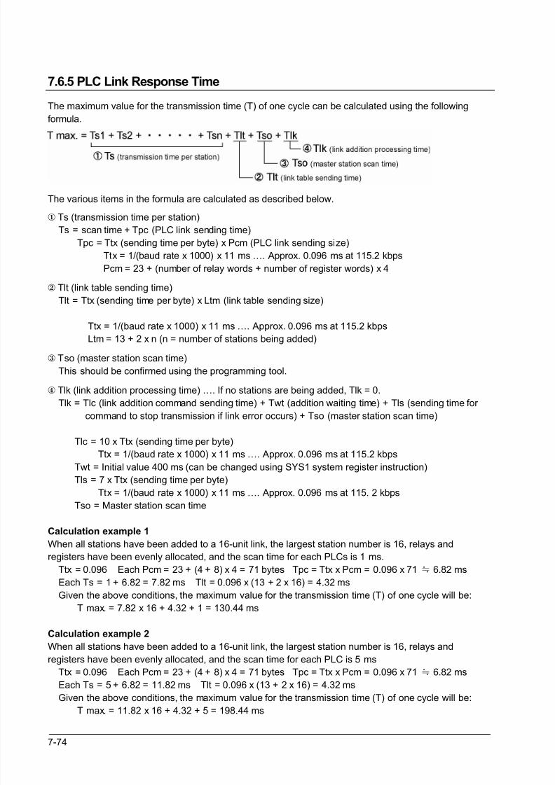
8/21/2019 Programmable Controller FP Sigma
http://slidepdf.com/reader/full/programmable-controller-fp-sigma 220/318
7-74
7.6.5 PLC Link Response Time
The maximum value for the transmission time (T) of one cycle can be calculated using the following
formula.
The various items in the formula are calculated as described below.
Ts (transmission time per station)
Ts = scan time + Tpc (PLC link sending time)
Tpc = Ttx (sending time per byte) x Pcm (PLC link sending size)
Ttx = 1/(baud rate x 1000) x 11 ms …. Approx. 0.096 ms at 115.2 kbps
Pcm = 23 + (number of relay words + number of register words) x 4
Tlt (link table sending time)
Tlt = Ttx (sending time per byte) x Ltm (link table sending size)
Ttx = 1/(baud rate x 1000) x 11 ms …. Approx. 0.096 ms at 115.2 kbps
Ltm = 13 + 2 x n (n = number of stations being added)
Tso (master station scan time)
This should be confirmed using the programming tool.
Tlk (link addition processing time) …. If no stations are being added, Tlk = 0.
Tlk = Tlc (link addition command sending time) + Twt (addition waiting time) + Tls (sending time for
command to stop transmission if link error occurs) + Tso (master station scan time)
Tlc = 10 x Ttx (sending time per byte)
Ttx = 1/(baud rate x 1000) x 11 ms …. Approx. 0.096 ms at 115.2 kbps
Twt = Initial value 400 ms (can be changed using SYS1 system register instruction)
Tls = 7 x Ttx (sending time per byte)
Ttx = 1/(baud rate x 1000) x 11 ms …. Approx. 0.096 ms at 115. 2 kbps
Tso = Master station scan time
Calculation example 1
When all stations have been added to a 16-unit link, the largest station number is 16, relays and
registers have been evenly allocated, and the scan time for each PLCs is 1 ms.
Ttx = 0.096 Each Pcm = 23 + (4 + 8) x 4 = 71 bytes Tpc = Ttx x Pcm = 0.096 x 71≒ 6.82 ms
Each Ts = 1 + 6.82 = 7.82 ms Tlt = 0.096 x (13 + 2 x 16) = 4.32 ms
Given the above conditions, the maximum value for the transmission time (T) of one cycle will be:
T max. = 7.82 x 16 + 4.32 + 1 = 130.44 ms
Calculation example 2
When all stations have been added to a 16-unit link, the largest station number is 16, relays and
registers have been evenly allocated, and the scan time for each PLC is 5 ms
Ttx = 0.096 Each Pcm = 23 + (4 + 8) x 4 = 71 bytes Tpc = Ttx x Pcm = 0.096 x 71≒ 6.82 ms
Each Ts = 5 + 6.82 = 11.82 ms Tlt = 0.096 x (13 + 2 x 16) = 4.32 ms Given the above conditions, the maximum value for the transmission time (T) of one cycle will be:
T max. = 11.82 x 16 + 4.32 + 5 = 198.44 ms
8/21/2019 Programmable Controller FP Sigma
http://slidepdf.com/reader/full/programmable-controller-fp-sigma 221/318
7-75
Calculation example 3
When all but one station have been added to a 16-unit link, the largest station number is 16, relays and
registers have been allocated evenly, and the scan time for each PLC is 5 ms.
Ttx = 0.096 Each Ts = 5 + 6.82 = 11.82 ms
Tlt = 0.096 x (13 + 2 x 15)≒
4.13 ms Tlk = 0.96 + 400 + 0.67 + 5≒407 ms
Note: The default value for the addition waiting time is 400 ms.
Given the above conditions, the maximum value for the transmission time (T) of one cycle will be:
T max. = 11.82 x 15 + 4.13 + 5 + 407 = 593.43 ms
Calculation example 4
When all stations have been added to an 8-unit link, the largest station number is 8, relays and register
have been evenly allocated, and the scan time for each PLC is 5 ms.
Ttx = 0.096 Each Pcm = 23 + (8 + 16) x 4 = 119 bytes
Tpc = Ttx x Pcm = 0.096 x 119≒ 11.43 ms Each Ts = 5 + 11.43 = 16.43 ms Tlt = 0.096 x (13 + 2 x 8)≒
2.79 ms
Given the above conditions, the maximum value for the transmission time (T) of one cycle will be:
T max. = 16.43 x 8 + 2.79 + 5 = 139.23 ms
Calculation example 5
When all stations have been added to a 2-unit link, the largest station number is 2, relays and registers
have been evenly allocated, and the scan time for each PLC is 5 ms.
Ttx = 0.096 Each Pcm = 23 + (32 + 64) x 4 = 407 bytes
Tpc = Ttx x Pcm = 0.096 x 407≒ 39.072 ms
Each Ts = 5 + 39.072 = 44.072 ms Tlt = 0.096 x (13 + 2 x 2)≒
1.632 ms
Given the above conditions, the maximum value for the transmission time (T) of one cycle will be:
T max. = 44.072 x 2 + 1.632 + 5 = 94.776 ms
Calculation example 6
When all stations have been added to a 2-unit link, the largest station number is 2, 32 relays and 2
register words have been evenly allocated, and the scan time for each PLC is 1 ms.
Ttx = 0.096 Each Pcm = 23 + (1 + 1) x 4 = 31 bytes
Tpc = Ttx x Pcm = 0.096 x 31≒ 2.976 ms
Each Ts = 1 + 2.976 = 3.976 ms Tlt = 0.096 x (13 + 2 x 2)≒ 1.632 ms
Given the above conditions, the maximum value for the transmission time (T) of one cycle will be:
T max. = 3.976 x 2 + 1.632 + 1 = 10.584 ms
Note:
• In the description, “stations that have been added” refers to stations which are connected between
station no. 1 and the largest station number and for which the power supply has been turned on.
• Comparing examples 2 and 3, the transmission cycle time is longer if there is one station that has not
been added to the link. As a result the PLC link response time is longer.
• The SYS1 instruction can be used to minimize thte transmission cycle time even if there are one or
more stations that have not been added to the link.
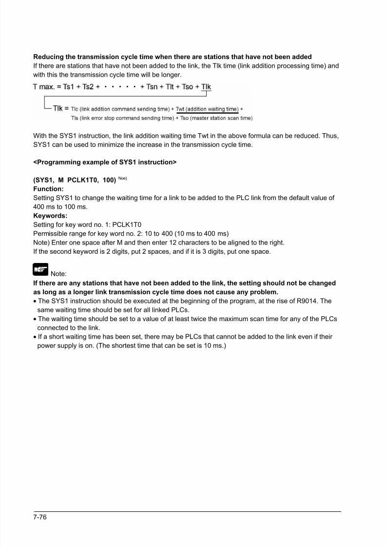
8/21/2019 Programmable Controller FP Sigma
http://slidepdf.com/reader/full/programmable-controller-fp-sigma 222/318
7-76
Reducing the transmission cycle time when there are stations that have not been added
If there are stations that have not been added to the link, the Tlk time (link addition processing time) and
with this the transmission cycle time will be longer.
With the SYS1 instruction, the link addition waiting time Twt in the above formula can be reduced. Thus,
SYS1 can be used to minimize the increase in the transmission cycle time.
<Programming example of SYS1 instruction>
(SYS1, M PCLK1T0, 100) Noe)
Function:Setting SYS1 to change the waiting time for a link to be added to the PLC link from the default value of
400 ms to 100 ms.
Keywords:
Setting for key word no. 1: PCLK1T0
Permissible range for key word no. 2: 10 to 400 (10 ms to 400 ms)
Note) Enter one space after M and then enter 12 characters to be aligned to the right.
If the second keyword is 2 digits, put 2 spaces, and if it is 3 digits, put one space.
Note:
If there are any stations that have not been added to the link, the setting should not be changed
as long as a longer link transmission cycle time does not cause any problem.
• The SYS1 instruction should be executed at the beginning of the program, at the rise of R9014. The
same waiting time should be set for all linked PLCs.
• The waiting time should be set to a value of at least twice the maximum scan time for any of the PLCs
connected to the link.
• If a short waiting time has been set, there may be PLCs that cannot be added to the link even if their
power supply is on. (The shortest time that can be set is 10 ms.)
8/21/2019 Programmable Controller FP Sigma
http://slidepdf.com/reader/full/programmable-controller-fp-sigma 223/318
7-77
Error detection time for transmission assurance relays
The power supply of any given PLC fails or is turned off, it takes (as a default value) 6.4 seconds for the
transmission assurance relay of the PLC to be turned off at the other stations. This time period can be
shortened using the SYS1 instruction.
<Programming example of SYS1 instruction>
(SYS1, M PCLK1T1, 100) Note)
Function:
Setting SYS1 to change the time that the PLC link transmission assurance is off from the default value of
6400 ms to 100 ms.
Keywords:
Setting for key word no. 1: PCLK1T1
Permissible range for key word no. 2: 100 to 6400 (100 ms to 6400 ms)
Note) Enter one space after M and then enter 12 characters to be aligned to the right.
If the second keyword is 3 digits, put 2 spaces, and if it is 4 digits, no space is needed.
Note:
The setting should not be changed as long as a longer transmission assurance relay detection
time does not cause any problems.
• The SYS1 instruction should be executed at the beginning of the program, at the rise of R9014. The
same time should be set for all linked PLCs.
• The time should be set to a value of at least twice the maximum transmission cycle time when all of
the PLCs are connected to the link.
• If short time has been set, the transmission assurance relay may not function properly. (The shortest
time that can be set is 100 ms.)

8/21/2019 Programmable Controller FP Sigma
http://slidepdf.com/reader/full/programmable-controller-fp-sigma 224/318
7-78

8/21/2019 Programmable Controller FP Sigma
http://slidepdf.com/reader/full/programmable-controller-fp-sigma 225/318
Chapter 8
Self-Diagnostic and Troubleshooting

8/21/2019 Programmable Controller FP Sigma
http://slidepdf.com/reader/full/programmable-controller-fp-sigma 226/318
8-2
8.1 Self-Diagnostic function
8.1.1 LED Display for Status Condition
Status indicator LEDs on control unit
LED status
RUN PROG.ERROR/
ALARM
DescriptionOperation
statuss
Light (on) Off Off Normal operation Operation
Off Light (on) Off PROG. mode StopNormal
conditionFlashes Flashes Off Forcing on/off in Run mode Operation
Light (on) Off FlashesWhen a self-diagnostic error
occursOperation
Off Light (on) FlashesShen a self-diagnostic error
occursStop
Abnormal
condition
Light (on)System watchdog timer has
been activatedStop
• The control unit has a self-diagnostic function which
identifies errors and stops operation if necessary.
• When an error occurs, the status of the status indicator
LEDs on the control unit vary, as shown in the table above.
8.1.2 Operation on Error
• Normally, when an error occurs, the operation stops.
• The user may select wheter operation is to be continued or stopped when a duplicated output error or
operation error occurs, by setting the system registers. You can set the error which operation is to be
continued or stopped using the programming toolshoftware as shown below.
“PLC System Register” setting menue on programming tool software
To specify the steps to be taken by the FPWIN GR if a PLC error occurs, select “PLC System Register
setting” under “Option” on the menu bar, and click on the “Action on Error” tab.
The screen shown below is displayed.
Example1]: When allowing duplicated
output
Turn off the check box for No. 20. When
operation is resumed, it will not be handled
as an error.
[Example2]: When continuing operation
even a calculation error has occurred
Turn off the check box for No. 26. When
operation is resumed, it will be continued, butwill be handled as an error.
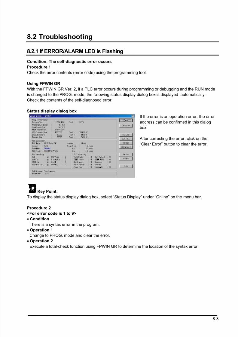
8/21/2019 Programmable Controller FP Sigma
http://slidepdf.com/reader/full/programmable-controller-fp-sigma 227/318
8-3
8.2 Troubleshooting
8.2.1 If ERROR/ALARM LED is Flashing
Condition: The self-diagnostic error occurs
Procedure 1
Check the error contents (error code) using the programming tool.
Using FPWIN GR
With the FPWIN GR Ver. 2, if a PLC error occurs during programming or debugging and the RUN mode
is changed to the PROG. mode, the following status display dialog box is displayed automatically.
Check the contents of the self-diagnosed error.
Status display dialog box
If the error is an operation error, the error address can be confirmed in this dialog
box.
After correcting the error, click on the
“Clear Error” button to clear the error.
Key Point:
To display the status display dialog box, select “Status Display” under “Online” on the menu bar.
Procedure 2
<For error code is 1 to 9>
• Condition
There is a syntax error in the program.
• Operation 1
Change to PROG. mode and clear the error.• Operation 2
Execute a total-check function using FPWIN GR to determine the location of the syntax error.
8/21/2019 Programmable Controller FP Sigma
http://slidepdf.com/reader/full/programmable-controller-fp-sigma 228/318
8-4
<For error code is 20 or higher>
• Condition
A self-diagnostic error other than a syntax error has occurred.
• Operation 1
Use the programming tool in PROG. mode to clear the error.Using FPWIN GR
Click on the “Clear Error” button in the “Status display dialog box”. Error code 43 and higher can be
cleared.
• In the PROG. mode, the power supply can be turned off and then on again to clear the error, but all of
the contents of the operation memory except hold type data arecleared.
• An error can also be cleared by executing a self-diagnostic error set instruction F148 (ERR).
• If the mode selector switch has been set to the “RUN” position, the error is cleared and at the same
time operation is enabled. If the problem that caused the error has not been eliminated, it may look in
some cases as though the error has not been cleared.
Key Point:
When an operation error (error code 45) occurs, the address at which the error occurred is stored in
special data registers DT90017 and DT90018. If this happens, click on the “Operation Err” button in the
“Status display dialog box” and confirm the address at which the error occurred before cancelling the
error.
8.2.2 If ERROR/ALARM LED is ON
Condition: The system watchdog timer has been activated and the operation of PLC has been
activated.
Procedure 1
Set the mode selector of PLC from RUN to PROG. mode and turn the power off and then on.
• If the ERROR/ALARM LED is turned on again, there is probably an abnormality in the FPΣ control unit.
Please contact your dealer.
• If the ERROR/ALARM LED is flashed, go to chapter 8.2.1.
Procedure 2
Set the mode selector from PROG. to RUN mode.
• If the ERROR/ALARM LED is turned on, the program execution time is too long. Check the program.
Check
(1)Check if instructions such as “JMP” or “LOOP” are pgrogrammed in such a way that a scan never
finish.
(2)Check that interrupt instructions are executed in succession.
8/21/2019 Programmable Controller FP Sigma
http://slidepdf.com/reader/full/programmable-controller-fp-sigma 229/318
8-5
8.2.3 ALL LEDs are OFF
Procedure 1
Check wiring of power supply.
Procedure 2
Check if the power supplied to the FPΣ control unit is in the range of the rating.
• Be sure to check the fluctuation in the power supply.
Procedure 3
Disconnect the power supply wiring to the other devices if the power supplied to the FPΣ control unit is
shared with them.
• If the LED on the control unit turn on at this moment, increase the capacity of the power supply or
prepare another power supply for other devices.
• Please contact your dealer for further questions.
8/21/2019 Programmable Controller FP Sigma
http://slidepdf.com/reader/full/programmable-controller-fp-sigma 230/318
8-6
8.2.4 Diagnosing Output Malfunction
Proceed from the check of the output side to the check of the input side.
Check of output condition 1: Output indicator LEDs are on
Procedure 1
Check the wiring of the loads.
Procedure 2
Check if the power is properly supplied to the loads.
• If the power is properly supplied to the load, there is probably an abnormality in the load. Check the
load again.
• If the power is not supplied to the load, there is probably an abnormality in the output section. Please
contact your dealer.
Check of output condition 2: Output indicator LEDS are off
Procedure 1Monitor the output condition using a programming tool.
• If the output monitored is turned on, there is probably a duplicated output error.
Procedure 2
Forcing on the output using forcing input/output function.
• If the output indicator LED is turned on, go to input condition check.
• If the output indicator LED remains off, there is probably an abnormality in the output unit. Please
contact your dealer.
Check of input condition 1: Input indicator LEDs are off
Procedure 1
Check the wiring of the input devices.Procedure 2
Check that the power is properly supplied to the input terminals.
• If the power is properly supplied to the input terminal, there is probably an abnoramlity in the input unit.
Please contact your dealer.
• If the power is not supplied to the input terminal, there is probably an abnormality in the input device or
input power supply. Check the input device and input power supply.
Check of input condition 2: Input indicator LEDs are on
Procedure
Monitor the input condition using a programming tool.
• If the input monitored is off, there is probably an abnormality with the input unit. Please contact your
dealer.
• If the input monitored is on, check the leakage current at the input devices (e.g., two-wire type sensor)
and check the program again.
Check
(1)Check for the duplicated use of output and for the output using the high-level instruction.
(2)Check the program flow when a control instruction such as MCR or JMP is used.
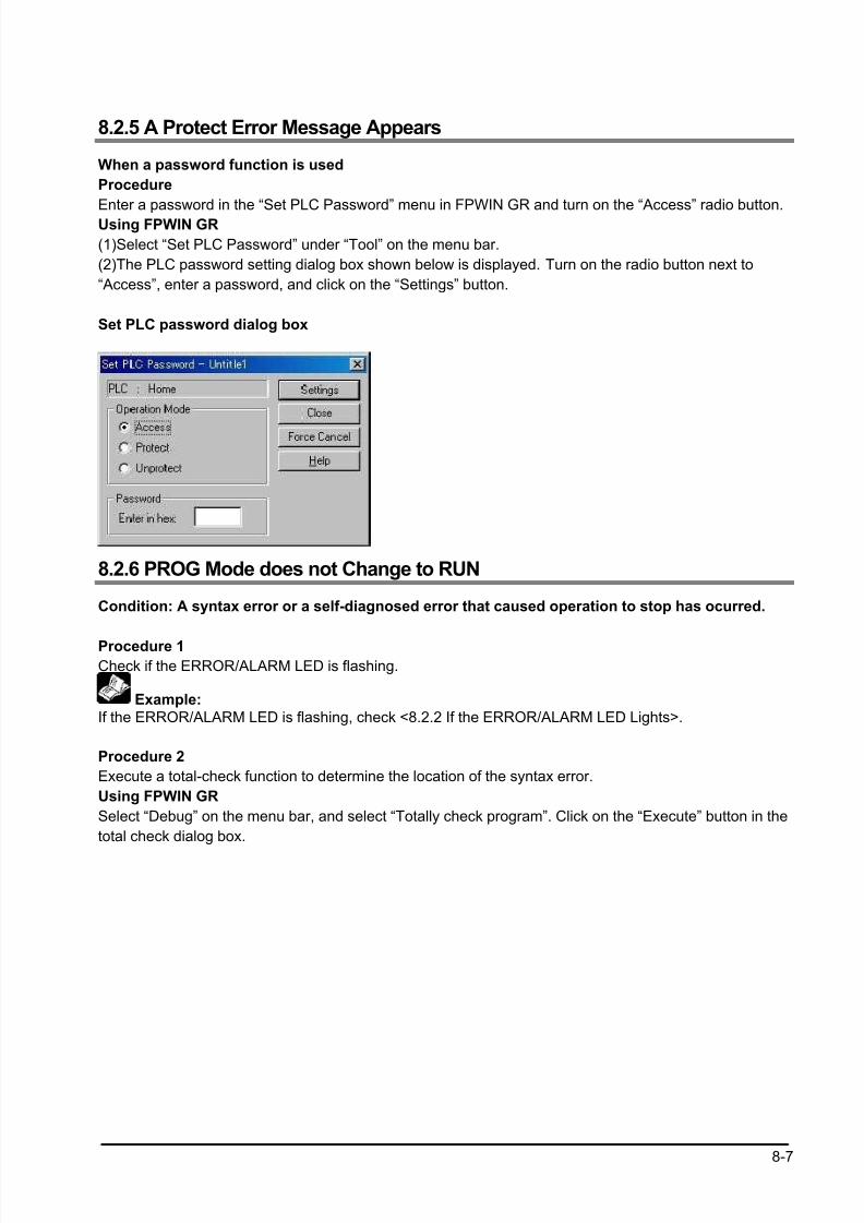
8/21/2019 Programmable Controller FP Sigma
http://slidepdf.com/reader/full/programmable-controller-fp-sigma 231/318
8-7
8.2.5 A Protect Error Message Appears
When a password function is used
Procedure
Enter a password in the “Set PLC Password” menu in FPWIN GR and turn on the “Access” radio button.
Using FPWIN GR
(1)Select “Set PLC Password” under “Tool” on the menu bar.
(2)The PLC password setting dialog box shown below is displayed. Turn on the radio button next to
“Access”, enter a password, and click on the “Settings” button.
Set PLC password dialog box
8.2.6 PROG Mode does not Change to RUN
Condition: A syntax error or a self-diagnosed error that caused operation to stop has ocurred.
Procedure 1Check if the ERROR/ALARM LED is flashing.
Example:
If the ERROR/ALARM LED is flashing, check <8.2.2 If the ERROR/ALARM LED Lights>.
Procedure 2
Execute a total-check function to determine the location of the syntax error.
Using FPWIN GR
Select “Debug” on the menu bar, and select “Totally check program”. Click on the “Execute” button in the
total check dialog box.

8/21/2019 Programmable Controller FP Sigma
http://slidepdf.com/reader/full/programmable-controller-fp-sigma 232/318
8-8
8.2.7 A Transmission Error has Occurred through RS485
Procedure 1
Check to make sure the transmission cables have been securely connected between the two (+)
terminals and two (−) terminals of the units, and that the final unit has been correctly connected.
Procedure 2
Check if the transmission cables are within the specifications range. At this point, make sure all of the
cables in the link are of the same type, and that multiple types of cables are not being used.
• Do not designate any unit other than those at both ends of the network as a terminal station.
Example:
For the specifications range of the transmission cables, refer to <7.3.3 Selection of TransmissionCables>.
Procedure 3
Check that link areas do not overlap.
8.2.8 No Communication is Available through RS232C
Condition: No communciation with 1-channel type RS232C cassette
Procedure 1
Check if the CS signal is on.
When the “COM.2 R” of the communication cassette LED does not light, the CS signal is not on.
If the three-wire type is used, connect the RS signal and the CS signal of the communication cassette,
and turn the CS signal on.
Example: <7.1.2 Types of Communication Cassette>

8/21/2019 Programmable Controller FP Sigma
http://slidepdf.com/reader/full/programmable-controller-fp-sigma 233/318
Chapter 9
Specifications
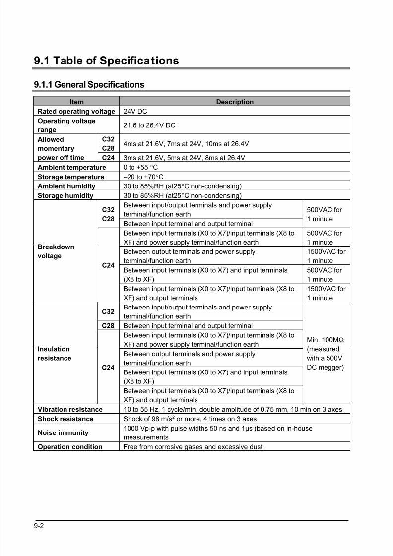
8/21/2019 Programmable Controller FP Sigma
http://slidepdf.com/reader/full/programmable-controller-fp-sigma 234/318
9-2
9.1 Table of Specifications
9.1.1 General Specifications
Item Description
Rated operating voltage 24V DC
Operating voltage
range21.6 to 26.4V DC
C32
C284ms at 21.6V, 7ms at 24V, 10ms at 26.4V
Allowed
momentary
power off time C24 3ms at 21.6V, 5ms at 24V, 8ms at 26.4V
Ambient temperature 0 to +55 °C
Storage temperature −20 to +70°C
Ambient humidity 30 to 85%RH (at25°C non-condensing)
Storage humidity 30 to 85%RH (at25°C non-condensing)Between input/output terminals and power supply
terminal/function earthC32
C28Between input terminal and output terminal
500VAC for
1 minute
Between input terminals (X0 to X7)/input terminals (X8 to
XF) and power supply terminal/function earth
500VAC for
1 minute
Between output terminals and power supply
terminal/function earth
1500VAC for
1 minute
Between input terminals (X0 to X7) and input terminals
(X8 to XF)
500VAC for
1 minute
Breakdown
voltage
C24
Between input terminals (X0 to X7)/input terminals (X8 toXF) and output terminals 1500VAC for 1 minute
C32Between input/output terminals and power supply
terminal/function earth
C28 Between input terminal and output terminal
Between input terminals (X0 to X7)/input terminals (X8 to
XF) and power supply terminal/function earth
Between output terminals and power supply
terminal/function earth
Between input terminals (X0 to X7) and input terminals
(X8 to XF)
Insulation
resistance
C24
Between input terminals (X0 to X7)/input terminals (X8 toXF) and output terminals
Min. 100MΩ
(measured
with a 500V
DC megger)
Vibration resistance 10 to 55 Hz, 1 cycle/min, double amplitude of 0.75 mm, 10 min on 3 axes
Shock resistance Shock of 98 m/s2 or more, 4 times on 3 axes
Noise immunity1000 Vp-p with pulse widths 50 ns and 1µs (based on in-house
measurements
Operation condition Free from corrosive gases and excessive dust
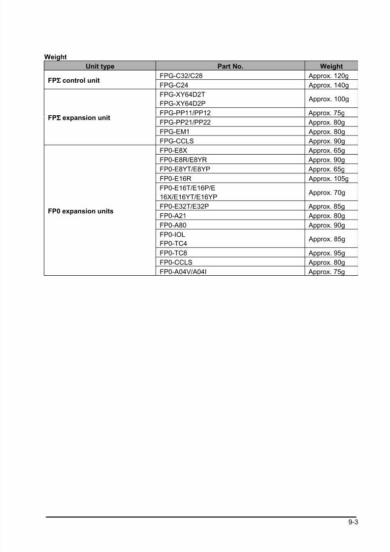
8/21/2019 Programmable Controller FP Sigma
http://slidepdf.com/reader/full/programmable-controller-fp-sigma 235/318
9-3
Weight
Unit type Part No. Weight
FPG-C32/C28 Approx. 120gFPΣΣΣΣ control unit
FPG-C24 Approx. 140g
FPG-XY64D2TFPG-XY64D2P
Approx. 100g
FPG-PP11/PP12 Approx. 75g
FPG-PP21/PP22 Approx. 80g
FPG-EM1 Approx. 80g
FPΣΣΣΣ expansion unit
FPG-CCLS Approx. 90g
FP0-E8X Approx. 65g
FP0-E8R/E8YR Approx. 90g
FP0-E8YT/E8YP Approx. 65g
FP0-E16R Approx. 105g
FP0-E16T/E16P/E
16X/E16YT/E16YP Approx. 70g
FP0-E32T/E32P Approx. 85g
FP0-A21 Approx. 80g
FP0-A80 Approx. 90g
FP0-IOL
FP0-TC4 Approx. 85g
FP0-TC8 Approx. 95g
FP0-CCLS Approx. 80g
FP0 expansion units
FP0-A04V/A04I Approx. 75g

8/21/2019 Programmable Controller FP Sigma
http://slidepdf.com/reader/full/programmable-controller-fp-sigma 236/318
9-4
Unit’s current consumption table
Control unitcurrentconsumption
Expansionunit currentconsumption
Input circuitcurrentconsumption
Output circuitcurrentconsumption
Unit type
This is the
currentconsumed form
the control unit
power supply
connector. If
expansion units
or intelligent
units are added,
the current is
increased by the
value indicated
below.
This is the
currentconsumed from
the expansion
unit power
supply
connector. If a
unit is not listed
below, it means
that it has no
power supply
connector
This is the
current cosumedby the input
circuits of the
various units.
This value
indicates the
current that flows
into the input
circuit. “n”
indicates the
numbser of
points that are
on.
This is the current
consumed by theoutput circuits of the
various units. This
value indicates the
current used to drive
the output circuits.
“n” indicates the
number of points
that are on. This
value does not
include the load
current vaule.
FPG-C32FPG-C28
90mA or less − 77.2mA or less 70mA or lessFPΣ
control
unit FPG-C24 160mA or less − 77.2mA or less None
FPΣ
expan-
sion unit
FPG-XY64D2T
FPG-
XY64D2P
35mA or less − 112mA or less 15mA or less
FPG-PP11
FPG-PP1250mA or less 20mA or less − −
FPG-PP21
FPG-PP2270mA or less 35mA or less − −
FPG-EM1 35mA or less − − −
FPΣ
intelligent
unit
FPG-CCLS 40mA or less 40mA or less − −
FP0-E8X 10mA or less 34.4mA or less −
FP0-E8R 15mA or less 50mA or less 17.2mA or less −
FP0-E8YR 10mA or less 100mA or less − −
FP0-E8YT/P 15mA or less − − 24mA or less
FP0-E16X 20mA or less − 68.8mA or less −
FP0-E16R 20mA or less 100mA or less 34.4mA or less −
FP0-E16T/P 25mA or less − 34.4ma or less 24mA or less
FP0-E16YT/P 25mA or less − − 48mA or less
FP0
expan-
sion unit
FP0-E32T/P 40mA or less − 68.8mA or less 48mA or less
FP0-A21 20mA or less 100mA or less − −
FP0-A80 20mA or less 60mA or less − −
FP0-A04V 20mA or less 100mA or less − −
FP0-A04I 20mA or less 130mA or less − −
FP0-TC4
FP0-TC825mA or less − − −
FP0-IOL 30mA or less 40mA or less − −
FP0
intelligent
unit
FP0-CCLS 40mA or less 40mA or less − −
FPG-COM1
FPG-COM220mA or less − − −Communi
cation
cassetteFPG-COM3
FPG-COM425mA or less − − −
Indicator
GT01
AIGT0030B1
AIGT0030H1 80mA or less − − −
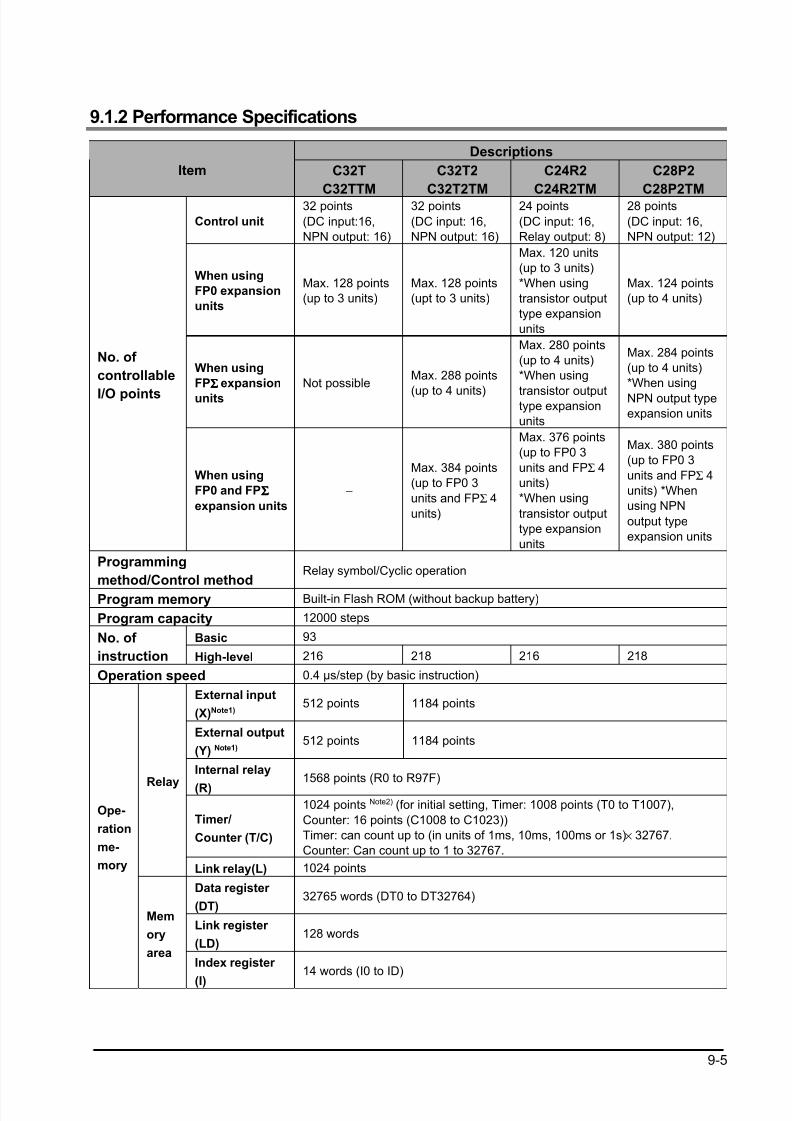
8/21/2019 Programmable Controller FP Sigma
http://slidepdf.com/reader/full/programmable-controller-fp-sigma 237/318
9-5
9.1.2 Performance Specifications
Descriptions
Item C32T
C32TTM
C32T2
C32T2TM
C24R2
C24R2TM
C28P2
C28P2TM
Control unit
32 points
(DC input:16,
NPN output: 16)
32 points
(DC input: 16,
NPN output: 16)
24 points
(DC input: 16,
Relay output: 8)
28 points
(DC input: 16,
NPN output: 12)
When using
FP0 expansion
units
Max. 128 points
(up to 3 units)
Max. 128 points
(upt to 3 units)
Max. 120 units
(up to 3 units)
*When using
transistor output
type expansion
units
Max. 124 points
(up to 4 units)
When using
FPΣΣΣΣ expansion
units
Not possibleMax. 288 points
(up to 4 units)
Max. 280 points
(up to 4 units)
*When using
transistor outputtype expansion
units
Max. 284 points
(up to 4 units)
*When using
NPN output type
expansion units
No. of
controllable
I/O points
When using
FP0 and FPΣΣΣΣ
expansion units
−
Max. 384 points
(up to FP0 3
units and FPΣ 4
units)
Max. 376 points
(up to FP0 3
units and FPΣ 4
units)
*When using
transistor output
type expansion
units
Max. 380 points
(up to FP0 3
units and FPΣ 4
units) *When
using NPN
output type
expansion units
Programming
method/Control methodRelay symbol/Cyclic operation
Program memory Built-in Flash ROM (without backup battery)
Program capacity 12000 steps
Basic 93No. of
instruction High-level 216 218 216 218
Operation speed 0.4 µs/step (by basic instruction)
External input
(X)Note1)512 points 1184 points
External output
(Y) Note1)512 points 1184 points
Internal relay
(R)1568 points (R0 to R97F)
Timer/
Counter (T/C)
1024 points Note2) (for initial setting, Timer: 1008 points (T0 to T1007),
Counter: 16 points (C1008 to C1023))
Timer: can count up to (in units of 1ms, 10ms, 100ms or 1s)× 32767.
Counter: Can count up to 1 to 32767.
Relay
Link relay(L) 1024 points
Data register
(DT)32765 words (DT0 to DT32764)
Link register
(LD)128 words
Ope-
ration
me-
mory
Mem
ory
areaIndex register
(I)
14 words (I0 to ID)
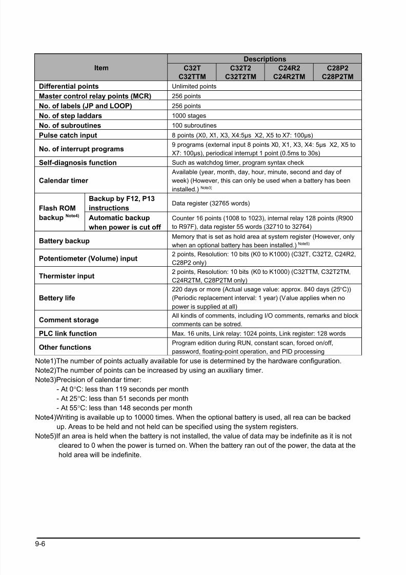
8/21/2019 Programmable Controller FP Sigma
http://slidepdf.com/reader/full/programmable-controller-fp-sigma 238/318
9-6
Descriptions
Item C32T
C32TTM
C32T2
C32T2TM
C24R2
C24R2TM
C28P2
C28P2TM
Differential points Unlimited points
Master control relay points (MCR) 256 points
No. of labels (JP and LOOP) 256 points
No. of step laddars 1000 stages
No. of subroutines 100 subroutines
Pulse catch input 8 points (X0, X1, X3, X4:5µs X2, X5 to X7: 100µs)
No. of interrupt programs9 programs (external input 8 points X0, X1, X3, X4: 5µs X2, X5 to
X7: 100µs), periodical interrupt 1 point (0.5ms to 30s)
Self-diagnosis function Such as watchdog timer, program syntax check
Calendar timer
Available (year, month, day, hour, minute, second and day of
week) (However, this can only be used when a battery has been
installed.) Note3)
Backup by F12, P13instructions
Data register (32765 words)Flash ROM
backup Note4) Automatic backup
when power is cut off
Counter 16 points (1008 to 1023), internal relay 128 points (R900
to R97F), data register 55 words (32710 to 32764)
Battery backupMemory that is set as hold area at system register (However, only
when an optional battery has been installed.) Note5)
Potentiometer (Volume) input2 points, Resolution: 10 bits (K0 to K1000) (C32T, C32T2, C24R2,
C28P2 only)
Thermister input2 points, Resolution: 10 bits (K0 to K1000) (C32TTM, C32T2TM,
C24R2TM, C28P2TM only)
Bettery life
220 days or more (Actual usage value: approx. 840 days (25°C))
(Periodic replacement interval: 1 year) (Value applies when no
power is supplied at all)
Comment storage All kindls of comments, including I/O comments, remarks and block
comments can be sotred.
PLC link function Max. 16 units, Link relay: 1024 points, Link register: 128 words
Other functionsProgram edition during RUN, constant scan, forced on/off,
password, floating-point operation, and PID processing
Note1)The number of points actually available for use is determined by the hardware configuration.
Note2)The number of points can be increased by using an auxiliary timer.
Note3)Precision of calendar timer:
- At 0°C: less than 119 seconds per month
- At 25°C: less than 51 seconds per month
- At 55°C: less than 148 seconds per month
Note4)Writing is available up to 10000 times. When the optional battery is used, all rea can be backed
up. Areas to be held and not held can be specified using the system registers.
Note5)If an area is held when the battery is not installed, the value of data may be indefinite as it is not
cleared to 0 when the power is turned on. When the battery ran out of the power, the data at the
hold area will be indefinite.
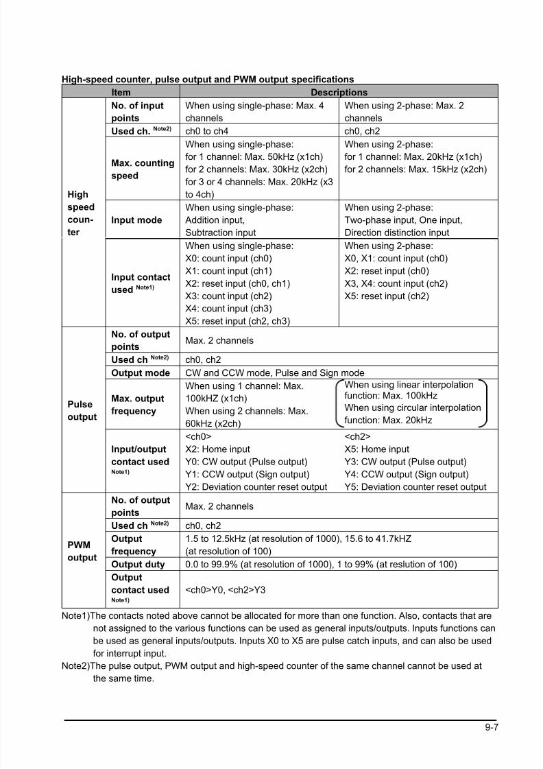
8/21/2019 Programmable Controller FP Sigma
http://slidepdf.com/reader/full/programmable-controller-fp-sigma 239/318
9-7
High-speed counter, pulse output and PWM output specifications
Item Descriptions
No. of input
points
When using single-phase: Max. 4
channels
When using 2-phase: Max. 2
channels
Used ch.Note2)
ch0 to ch4 ch0, ch2
Max. counting
speed
When using single-phase:
for 1 channel: Max. 50kHz (x1ch)
for 2 channels: Max. 30kHz (x2ch)
for 3 or 4 channels: Max. 20kHz (x3
to 4ch)
When using 2-phase:
for 1 channel: Max. 20kHz (x1ch)
for 2 channels: Max. 15kHz (x2ch)
Input mode
When using single-phase:
Addition input,
Subtraction input
When using 2-phase:
Two-phase input, One input,
Direction distinction input
High
speed
coun-
ter
Input contact
used Note1)
When using single-phase:
X0: count input (ch0)
X1: count input (ch1)X2: reset input (ch0, ch1)
X3: count input (ch2)
X4: count input (ch3)
X5: reset input (ch2, ch3)
When using 2-phase:
X0, X1: count input (ch0)
X2: reset input (ch0)X3, X4: count input (ch2)
X5: reset input (ch2)
No. of output
pointsMax. 2 channels
Used ch Note2) ch0, ch2
Output mode CW and CCW mode, Pulse and Sign mode
Max. output
frequency
When using 1 channel: Max.
100kHZ (x1ch)
When using 2 channels: Max.
60kHz (x2ch)
When using linear interpolationfunction: Max. 100kHz
When using circular interpolation
function: Max. 20kHz
Pulseoutput
Input/output
contact usedNote1)
<ch0>
X2: Home input
Y0: CW output (Pulse output)
Y1: CCW output (Sign output)
Y2: Deviation counter reset output
<ch2>
X5: Home input
Y3: CW output (Pulse output)
Y4: CCW output (Sign output)
Y5: Deviation counter reset output
No. of output
pointsMax. 2 channels
Used ch Note2) ch0, ch2
Outputfrequency
1.5 to 12.5kHz (at resolution of 1000), 15.6 to 41.7kHZ(at resolution of 100)
Output duty 0.0 to 99.9% (at resolution of 1000), 1 to 99% (at reslution of 100)
PWM
output
Output
contact usedNote1)
<ch0>Y0, <ch2>Y3
Note1)The contacts noted above cannot be allocated for more than one function. Also, contacts that are
not assigned to the various functions can be used as general inputs/outputs. Inputs functions can
be used as general inputs/outputs. Inputs X0 to X5 are pulse catch inputs, and can also be used
for interrupt input.
Note2)The pulse output, PWM output and high-speed counter of the same channel cannot be used at
the same time.
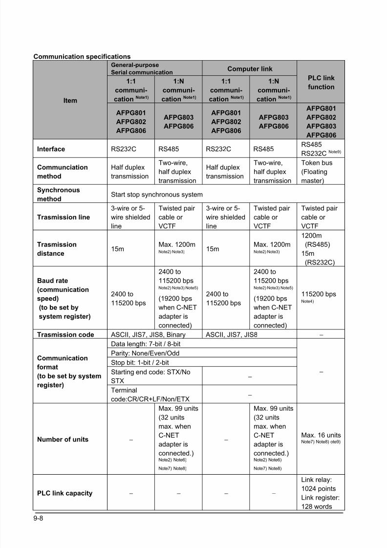
8/21/2019 Programmable Controller FP Sigma
http://slidepdf.com/reader/full/programmable-controller-fp-sigma 240/318
9-8
Communication specifications
General-purpose
Serial communicationComputer link
1:1
communi-
cation Note1)
1:N
communi-
cation Note1)
1:1
communi-
cation Note1)
1:N
communi-
cation Note1)
PLC link
function
Item
AFPG801
AFPG802
AFPG806
AFPG803
AFPG806
AFPG801
AFPG802
AFPG806
AFPG803
AFPG806
AFPG801
AFPG802
AFPG803
AFPG806
Interface RS232C RS485 RS232C RS485RS485
RS232C Note9)
Communciation
method
Half duplex
transmission
Two-wire,
half duplex
transmission
Half duplex
transmission
Two-wire,
half duplex
transmission
Token bus
(Floating
master)
Synchronousmethod
Start stop synchronous system
Trasmission line
3-wire or 5-
wire shielded
line
Twisted pair
cable or
VCTF
3-wire or 5-
wire shielded
line
Twisted pair
cable or
VCTF
Twisted pair
cable or
VCTF
Trasmission
distance15m
Max. 1200mNote2) Note3)
15mMax. 1200mNote2) Note3)
1200m
(RS485)
15m
(RS232C)
Baud rate
(communicationspeed)
(to be set by
system register)
2400 to
115200 bps
2400 to
115200 bps
Note2) Note3) Note5)
(19200 bps
when C-NET
adapter is
connected)
2400 to
115200 bps
2400 to
115200 bps
Note2) Note3) Note5)
(19200 bps
when C-NET
adapter is
connected)
115200 bpsNote4)
Trasmission code ASCII, JIS7, JIS8, Binary ASCII, JIS7, JIS8 −
Data length: 7-bit / 8-bit
Parity: None/Even/Odd
Stop bit: 1-bit / 2-bit
Starting end code: STX/No
STX
−
Communication
format
(to be set by system
register)Terminal
code:CR/CR+LF/Non/ETX −
−
Number of units −
Max. 99 units
(32 units
max. when
C-NET
adapter is
connected.)Note2) Note6)
Note7) Note8)
−
Max. 99 units
(32 units
max. when
C-NET
adapter is
connected.)Note2) Note6)
Note7) Note8)
Max. 16 unitsNote7) Note8) ote9)
PLC link capacity − − − −
Link relay:1024 points
Link register:
128 words
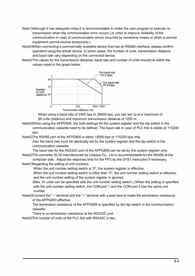
8/21/2019 Programmable Controller FP Sigma
http://slidepdf.com/reader/full/programmable-controller-fp-sigma 241/318
9-9
Note1)Although it has adequate noise,It is recommendable to make the user program to execute re-
transmission when the communication error occurs (,in order to improve reliability of the
communication in case of communication errors occurred by excessive noises or when a recriver
equipment cannot receive temporarily.)
Nore2)When connecting a commercially available device that has an RS485 interface, please confirm operation using the actual device. In some cases, the number of units, transmission distance,
and baud rate vary depending on the connected device.
Note3)The values for the transmission distance, baud rate and number of units should be within the
values noted in the graph below.
When using a baud rate of 2400 bps to 38400 bps, you can set up to a maximum of
99 units (stations) and maximum transmission distance of 1200 m.
Note4)When using the AFPG806, the both settings for the system register and the dip switch in the
communication cassette need to be defined. The baud rate in case of PLC link is stable at 115200
bps.
Note5)The RS485 port of the AFPG806 is either 19200 bps or 115200 bps only.
Also the baud rate must be identically set by the system register and the dip switch in the
communication cassette.
The baud rate for the RS232C port of the AFPG806 can be set by the system register only.
Note6)The converter SI-35 manufactured by Lineeye Co., Ltd is recommendable for the RS485 at the
computer side. Adjust the response time for the FPΣ by the SYS1 instruction if necessary.
Note7)Regarding the setting of unit numbers:
When the unit number setting switch is “0”, the system register is effective.
When the unit number setting switch is other than “0”, the unit number setting switch is effective,
and the unit number setting of the system register is ignored.
(Max. 31 units can be specified with the unit number setting switch.) (When the setting is specified
with the unit number setting switch, the COM port 1 and the COM port 2 has the same unit
number.
Note8)Connect the “−“ terminal and the “+” terminal with a lead wire to make the termination resistance
of the AFPG803 effective.
The termination resistance of the AFPG806 is specified by the dip switch in the communication
cassette.
There is no termination resistance at the RS232C port.
Note9)The number of units of the PLC link with RS232C is two.
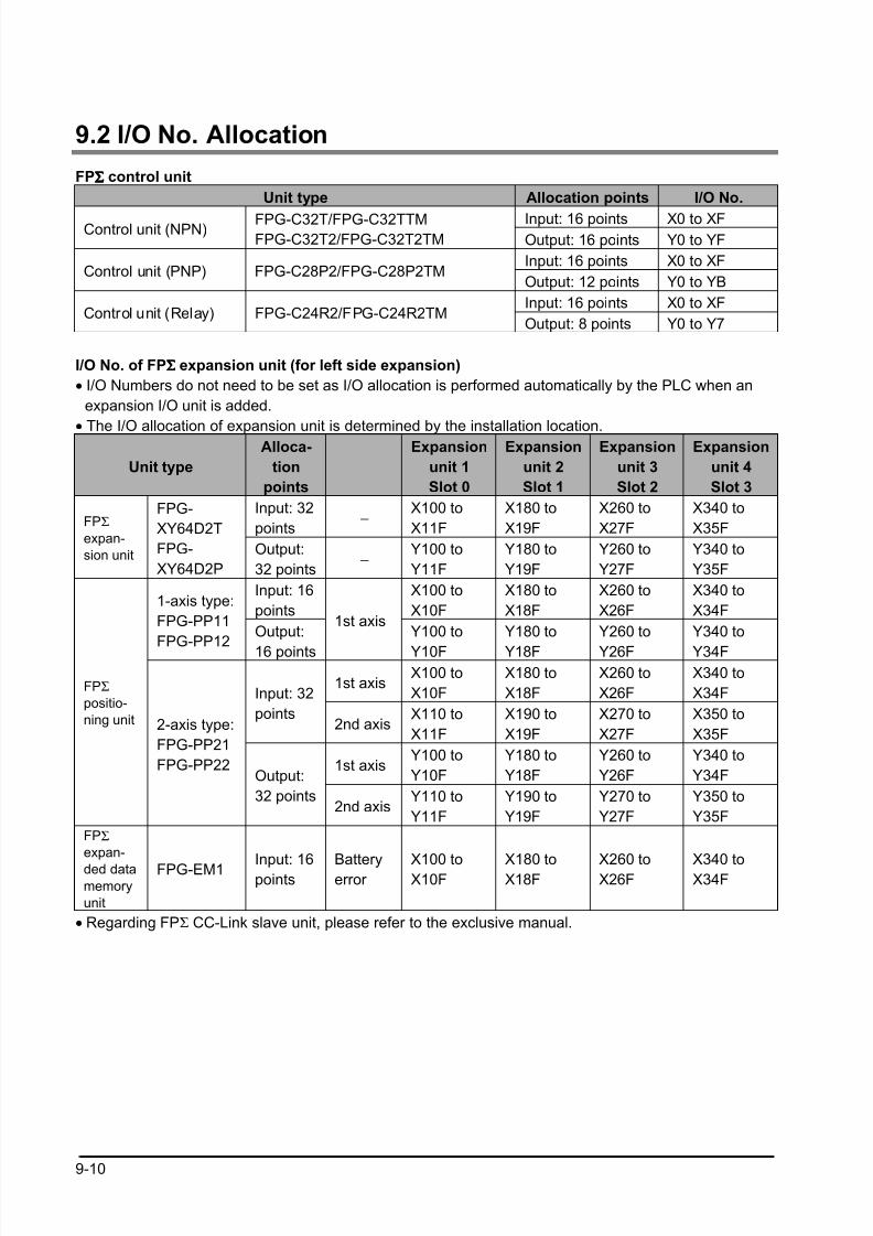
8/21/2019 Programmable Controller FP Sigma
http://slidepdf.com/reader/full/programmable-controller-fp-sigma 242/318
9-10
9.2 I/O No. Allocation
FPΣΣΣΣ control unit
Unit type Allocation points I/O No.
Input: 16 points X0 to XFControl unit (NPN) FPG-C32T/FPG-C32TTMFPG-C32T2/FPG-C32T2TM Output: 16 points Y0 to YF
Input: 16 points X0 to XFControl unit (PNP) FPG-C28P2/FPG-C28P2TM
Output: 12 points Y0 to YB
Input: 16 points X0 to XFControl unit (Relay) FPG-C24R2/FPG-C24R2TM
Output: 8 points Y0 to Y7
I/O No. of FPΣΣΣΣ expansion unit (for left side expansion)
• I/O Numbers do not need to be set as I/O allocation is performed automatically by the PLC when an
expansion I/O unit is added.
• The I/O allocation of expansion unit is determined by the installation location.
Unit type
Alloca-
tion
points
Expansion
unit 1
Slot 0
Expansion
unit 2
Slot 1
Expansion
unit 3
Slot 2
Expansion
unit 4
Slot 3
Input: 32
points −
X100 to
X11F
X180 to
X19F
X260 to
X27F
X340 to
X35FFPΣ
expan-
sion unit
FPG-
XY64D2T
FPG-
XY64D2P
Output:
32 points −
Y100 to
Y11F
Y180 to
Y19F
Y260 to
Y27F
Y340 to
Y35F
Input: 16
points
X100 to
X10F
X180 to
X18F
X260 to
X26F
X340 to
X34F1-axis type:
FPG-PP11
FPG-PP12Output:
16 points
1st axisY100 to
Y10F
Y180 to
Y18F
Y260 to
Y26F
Y340 to
Y34F
1st axisX100 to
X10F
X180 to
X18F
X260 to
X26F
X340 to
X34FInput: 32
points2nd axis
X110 to
X11F
X190 to
X19F
X270 to
X27F
X350 to
X35F
1st axisY100 to
Y10F
Y180 to
Y18F
Y260 to
Y26F
Y340 to
Y34F
FPΣ
positio-
ning unit 2-axis type:
FPG-PP21
FPG-PP22Output:
32 points2nd axis
Y110 to
Y11F
Y190 to
Y19F
Y270 to
Y27F
Y350 to
Y35F
FPΣ
expan-
ded datamemory
unit
FPG-EM1 Input: 16points
Batteryerror
X100 toX10F
X180 toX18F
X260 toX26F
X340 toX34F
• Regarding FPΣ CC-Link slave unit, please refer to the exclusive manual.
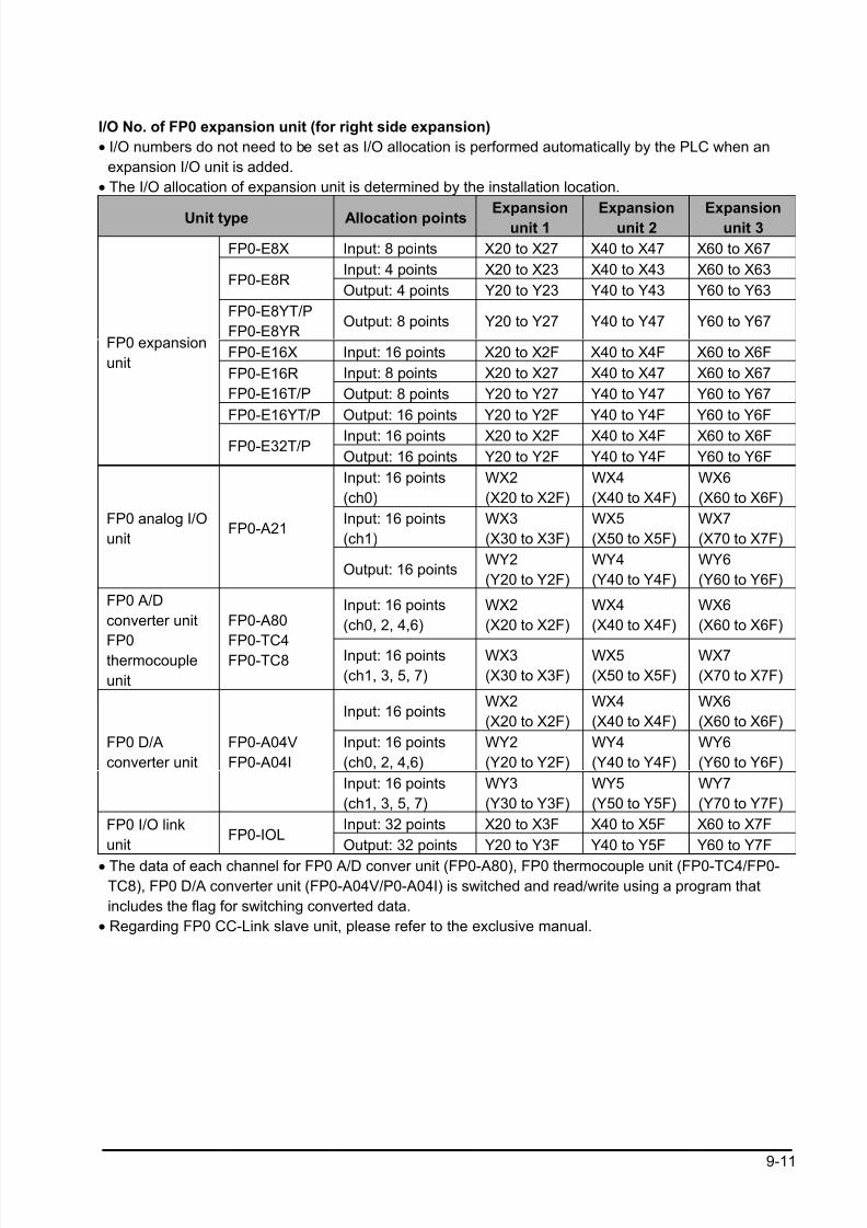
8/21/2019 Programmable Controller FP Sigma
http://slidepdf.com/reader/full/programmable-controller-fp-sigma 243/318
9-11
I/O No. of FP0 expansion unit (for right side expansion)
• I/O numbers do not need to be set as I/O allocation is performed automatically by the PLC when an
expansion I/O unit is added.
• The I/O allocation of expansion unit is determined by the installation location.
Unit type Allocation points Expansionunit 1 Expansionunit 2 Expansionunit 3
FP0-E8X Input: 8 points X20 to X27 X40 to X47 X60 to X67
Input: 4 points X20 to X23 X40 to X43 X60 to X63FP0-E8R
Output: 4 points Y20 to Y23 Y40 to Y43 Y60 to Y63
FP0-E8YT/P
FP0-E8YROutput: 8 points Y20 to Y27 Y40 to Y47 Y60 to Y67
FP0-E16X Input: 16 points X20 to X2F X40 to X4F X60 to X6F
Input: 8 points X20 to X27 X40 to X47 X60 to X67FP0-E16R
FP0-E16T/P Output: 8 points Y20 to Y27 Y40 to Y47 Y60 to Y67
FP0-E16YT/P Output: 16 points Y20 to Y2F Y40 to Y4F Y60 to Y6F
Input: 16 points X20 to X2F X40 to X4F X60 to X6F
FP0 expansion
unit
FP0-E32T/POutput: 16 points Y20 to Y2F Y40 to Y4F Y60 to Y6F
Input: 16 points
(ch0)
WX2
(X20 to X2F)
WX4
(X40 to X4F)
WX6
(X60 to X6F)
Input: 16 points
(ch1)
WX3
(X30 to X3F)
WX5
(X50 to X5F)
WX7
(X70 to X7F)
FP0 analog I/O
unitFP0-A21
Output: 16 pointsWY2
(Y20 to Y2F)
WY4
(Y40 to Y4F)
WY6
(Y60 to Y6F)
Input: 16 points
(ch0, 2, 4,6)
WX2
(X20 to X2F)
WX4
(X40 to X4F)
WX6
(X60 to X6F)
FP0 A/D
converter unit
FP0thermocouple
unit
FP0-A80
FP0-TC4FP0-TC8 Input: 16 points
(ch1, 3, 5, 7)
WX3
(X30 to X3F)
WX5
(X50 to X5F)
WX7
(X70 to X7F)
Input: 16 pointsWX2
(X20 to X2F)
WX4
(X40 to X4F)
WX6
(X60 to X6F)
Input: 16 points
(ch0, 2, 4,6)
WY2
(Y20 to Y2F)
WY4
(Y40 to Y4F)
WY6
(Y60 to Y6F)
FP0 D/A
converter unit
FP0-A04V
FP0-A04I
Input: 16 points
(ch1, 3, 5, 7)
WY3
(Y30 to Y3F)
WY5
(Y50 to Y5F)
WY7
(Y70 to Y7F)
Input: 32 points X20 to X3F X40 to X5F X60 to X7FFP0 I/O link
unitFP0-IOL
Output: 32 points Y20 to Y3F Y40 to Y5F Y60 to Y7F
• The data of each channel for FP0 A/D conver unit (FP0-A80), FP0 thermocouple unit (FP0-TC4/FP0-
TC8), FP0 D/A converter unit (FP0-A04V/P0-A04I) is switched and read/write using a program that
includes the flag for switching converted data.
• Regarding FP0 CC-Link slave unit, please refer to the exclusive manual.
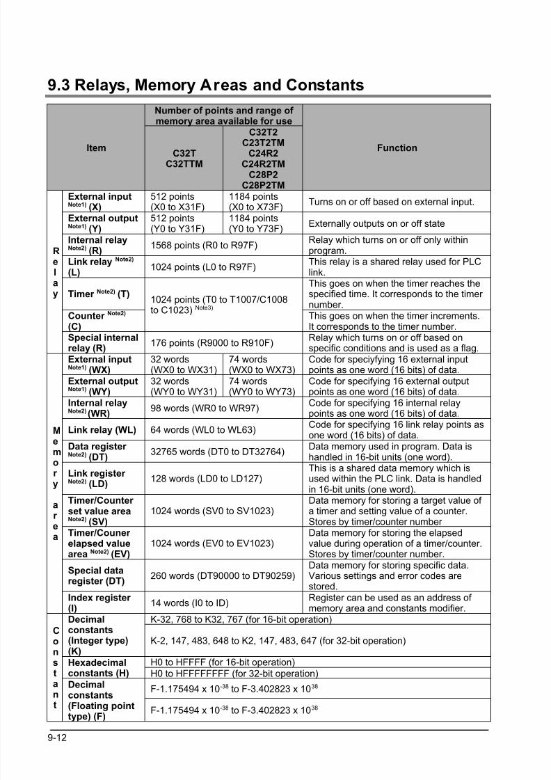
8/21/2019 Programmable Controller FP Sigma
http://slidepdf.com/reader/full/programmable-controller-fp-sigma 244/318
9-12
9.3 Relays, Memory Areas and Constants
Number of points and range of memory area available for use
ItemC32T
C32TTM
C32T2C23T2TMC24R2
C24R2TMC28P2
C28P2TM
Function
External inputNote1) (X)
512 points(X0 to X31F)
1184 points(X0 to X73F)
Turns on or off based on external input.
External outputNote1) (Y)
512 points(Y0 to Y31F)
1184 points(Y0 to Y73F)
Externally outputs on or off state
Internal relayNote2) (R)
1568 points (R0 to R97F)Relay which turns on or off only withinprogram.
Link relay Note2)
(L)1024 points (L0 to R97F)
This relay is a shared relay used for PLC
link.
Timer Note2) (T)This goes on when the timer reaches thespecified time. It corresponds to the timer number.
Counter Note2)
(C)
1024 points (T0 to T1007/C1008to C1023) Note3)
This goes on when the timer increments.It corresponds to the timer number.
Re
lay
Special internalrelay (R)
176 points (R9000 to R910F)Relay which turns on or off based onspecific conditions and is used as a flag.
External inputNote1) (WX)
32 words(WX0 to WX31)
74 words(WX0 to WX73)
Code for speciyfying 16 external inputpoints as one word (16 bits) of data.
External outputNote1) (WY)
32 words(WY0 to WY31)
74 words(WY0 to WY73)
Code for specifying 16 external outputpoints as one word (16 bits) of data.
Internal relayNote2) (WR) 98 words (WR0 to WR97)
Code for specifying 16 internal relaypoints as one word (16 bits) of data.
Link relay (WL) 64 words (WL0 to WL63)Code for specifying 16 link relay points asone word (16 bits) of data.
Data register Note2) (DT)
32765 words (DT0 to DT32764)Data memory used in program. Data ishandled in 16-bit units (one word).
Link register Note2) (LD)
128 words (LD0 to LD127)This is a shared data memory which isused within the PLC link. Data is handledin 16-bit units (one word).
Timer/Counter set value areaNote2) (SV)
1024 words (SV0 to SV1023)Data memory for storing a target value of a timer and setting value of a counter.Stores by timer/counter number
Timer/Couner
elapsed valuearea Note2) (EV) 1024 words (EV0 to EV1023)
Data memory for storing the elapsed
value during operation of a timer/counter.Stores by timer/counter number.
Special dataregister (DT)
260 words (DT90000 to DT90259)Data memory for storing specific data.Various settings and error codes arestored.
Memor y
ar ea
Index register (I)
14 words (I0 to ID)Register can be used as an address of memory area and constants modifier.
K-32, 768 to K32, 767 (for 16-bit operation)Decimalconstants(Integer type)(K)
K-2, 147, 483, 648 to K2, 147, 483, 647 (for 32-bit operation)
H0 to HFFFF (for 16-bit operation)Hexadecimalconstants (H) H0 to HFFFFFFFF (for 32-bit operation)
F-1.175494 x 10-38 to F-3.402823 x 1038
Const
ant
Decimalconstants(Floating pointtype) (F)
F-1.175494 x 10-38 to F-3.402823 x 1038

8/21/2019 Programmable Controller FP Sigma
http://slidepdf.com/reader/full/programmable-controller-fp-sigma 245/318
9-13
Note1)The number of points noted above is the number reserved as the calculation memory. The actual
number of points available for use is determined by the hardware configuration.
Note2)If no battery is ued, only the fixed area is backed up. (counters 16 points: C1008 to C1023,
internal relays 128 points: R900 to R97F, data registers 55 words: DT32710 to DT32764). Writing is available up to 10000 times. Then the optional battery is used, all area can be backed up.
Areas to be held and not held can be specified using the system registers. If an area is held when
the battery is not installed, the value of data may be indefinite as it is not cleared to 0 when the
power is turned on. When the battery ran out of the power, the data at the hold area will be
indefinite.
Note3)The points for the timer and counter can be changed by the setting of system register 5. The
number given in the table are the numbers when system register 5 is at its default setting.
8/21/2019 Programmable Controller FP Sigma
http://slidepdf.com/reader/full/programmable-controller-fp-sigma 246/318
9-14
9.4 Table of System Registers
9.4.1 System Registers
What is the system register area
• System registers are used to set values (parameters) which determine operation ranges and functions
used. Set values based on the use and specifications of your program.
• There is no need to set system registers for functions which will not be used.
Type of system registers
(1) Hold/non-hold type setting (System registers 5 to 8, 10, 12 and 14)
The values for the timer and counter can be specified by using system reister No. 5 to specify the first
number of the counter. System registers No. 6 to 8, 10, 12 and 14 are used to specify the area to be held
when a battery is used.
(2) Operation mode setting on error (System registers 4, 20, 23 and 26)
Set the operation mode when errors such as battery error, duplicated use of output, I/O verification error
and operation error occur.
(3) Time settings (System registers 31, 34)
Set time-out error detection time and the constant scan time.
(4) MEWNET-W0 PLC link settings (System registers 40 to 45 and 47)
These settings are for using link relays and link registers for MEWNET-W0 PLC link communication.
Note) The default value setting is “no PLC link communication”.
(5) Input settings (System registesr 400 to 403)
When using the high-speed counter function, pulse catch function or interrupt function, set the operation
mode and the input number to be used for the function.
(6) Tool and COM. ports communication settings (System registers 410 to 419)
Set these registers when the Tool port,and COM1 and COM2 ports are to be used for computer link,
general-purpose serial communication,PLC link, and modem communication.Note that thedefault setting is computer link mode.
Note) The default value setting is “Computer link” mode.The transmission speed of the RS485 port (COM.1) of AFPG806 must be identically set by the system
register and the dip switch in the communication cassette.
Checking and changing the set value of system register
1. Set the control unit in the PROG mode.
2.Option ->PLC Configuration3.When the function for which setting are to be entered is selected in the PLC Configuration dialog box,the value and setting status for the selected system register are displayed. To change the value and setting status,write in the new value and /or select the setting status.
4.To register these settings,choose OK

8/21/2019 Programmable Controller FP Sigma
http://slidepdf.com/reader/full/programmable-controller-fp-sigma 247/318
9-15
Precautions for system register setting
• System register settings are effective from the time they are set.
However, MEWNET-W0 PLC link settings, input settings, tool and COM. ports communication settings
become effective when the mode is changed from PROG. to RUN. With regard to the modem
connection setting, when the power is turned off and on or when the mode is changed from PROG. toRUN, the controller sends a command to the modem which enables it for reception.
• When the initialized operation is performed, all set system register values (parameters) will be
initialized.
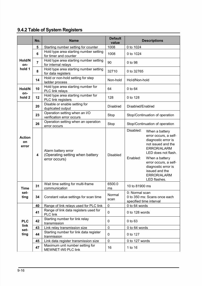
8/21/2019 Programmable Controller FP Sigma
http://slidepdf.com/reader/full/programmable-controller-fp-sigma 248/318
9-16
9.4.2 Table of System Registers
No. NameDefault
valueDescriptions
5 Starting number setting for counter 1008 0 to 1024
6Hold type area starting number setting
for timer and counter 1008 0 to 1024
7Hold type area starting number setting
for internal relays90 0 to 98
8Hold type area starting number setting
for data registers32710 0 to 32765
Hold/N
on-
hold 1
14Hold or non-hold setting for step
ladder processNon-hold Hold/Non-hold
10Hold type area starting number for
PLC link relays64 0 to 64Hold/N
on-
hold 2 12Hold type area starting number for
PLC link registers128 0 to 128
20Disable or enable setting for
duplicated outputDisabled Disabled/Enabled
23Operation setting when an I/O
verification error occursStop Stop/Continuation of operation
26Operation setting when an operation
error occursStop Stop/Continuation of operation
Disabled: When a battery
error occurs, a self-
diagnostic error is
not issued and the
ERROR/ALARM
LED does not flash.
Action
on
error
4 Alarm battery error (Operating setting when batteryerror occurs)
DisabledEnabled: When a battery
error occurs, a self-
diagnostic error is
issued and the
ERROR/ALARM
LED flashes.
31Wait time setting for multi-frame
communication
6500.0
ms10 to 81900 ms
Time
set-
ting 34 Constant value settings for scan timeNormal
scan
0: Normal scan
0 to 350 ms: Scans once each
specified time interval40 Range of link relays used for PLC link 0 0 to 64 words
41Range of link data registers used for
PLC link0 0 to 128 words
42Starting number for link relay
transmission0 0 to 63
43 Link relay transmission size 0 0 to 64 words
44Starting number for link data register
tranmission0 0 to 127
45 Link data register transmission size 0 0 to 127 words
PLC
link
set-
ting
47Maximum unit number setting for
MEWNET-W0 PLC link
16 1 to 16
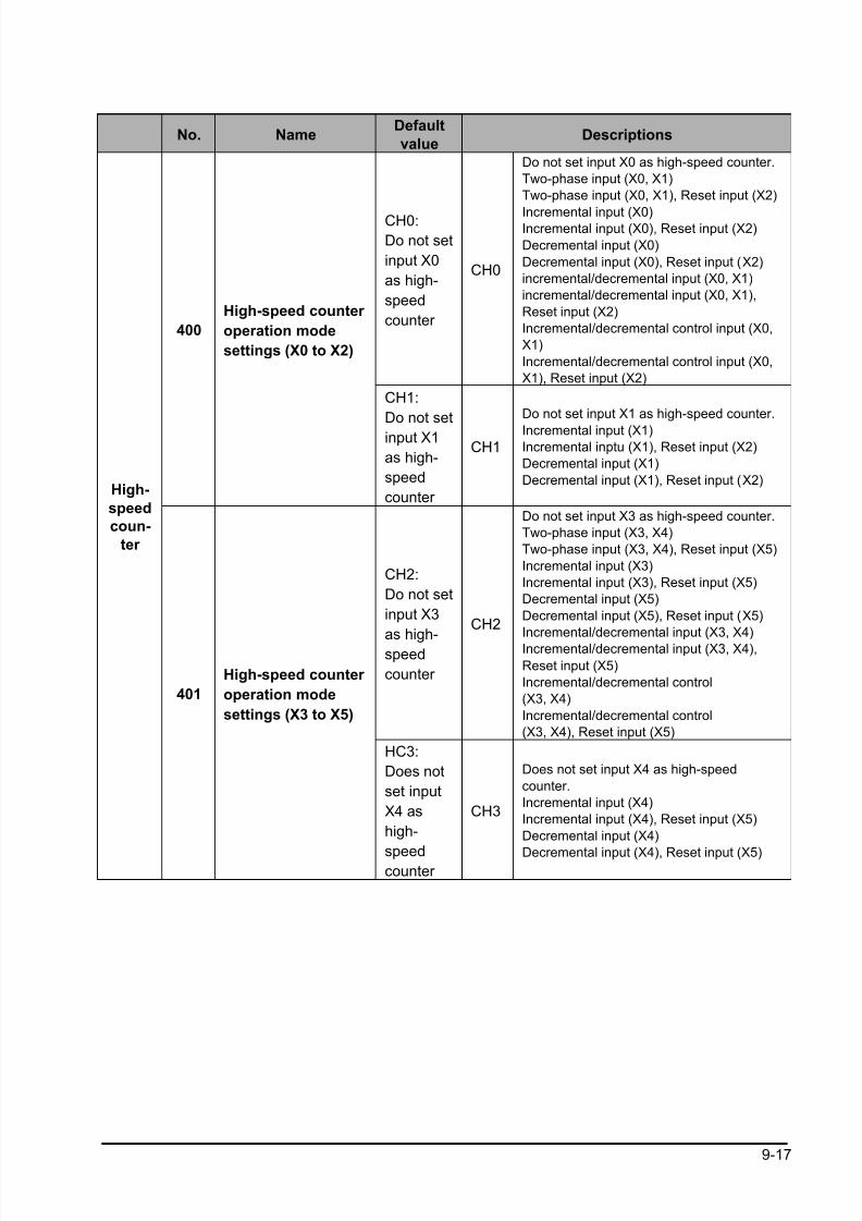
8/21/2019 Programmable Controller FP Sigma
http://slidepdf.com/reader/full/programmable-controller-fp-sigma 249/318
9-17
No. NameDefault
valueDescriptions
CH0:
Do not set
input X0
as high-
speed
counter
CH0
Do not set input X0 as high-speed counter.
Two-phase input (X0, X1)
Two-phase input (X0, X1), Reset input (X2)
Incremental input (X0)Incremental input (X0), Reset input (X2)
Decremental input (X0)
Decremental input (X0), Reset input (X2)
incremental/decremental input (X0, X1)
incremental/decremental input (X0, X1),
Reset input (X2)
Incremental/decremental control input (X0,
X1)
Incremental/decremental control input (X0,
X1), Reset input (X2)
400
High-speed counter
operation mode
settings (X0 to X2)
CH1:
Do not set
input X1
as high-
speed
counter
CH1
Do not set input X1 as high-speed counter.
Incremental input (X1)Incremental inptu (X1), Reset input (X2)
Decremental input (X1)
Decremental input (X1), Reset input (X2)
CH2:
Do not set
input X3
as high-speed
counter
CH2
Do not set input X3 as high-speed counter.
Two-phase input (X3, X4)
Two-phase input (X3, X4), Reset input (X5)
Incremental input (X3)
Incremental input (X3), Reset input (X5)
Decremental input (X5)
Decremental input (X5), Reset input (X5)
Incremental/decremental input (X3, X4)
Incremental/decremental input (X3, X4),
Reset input (X5)
Incremental/decremental control
(X3, X4)
Incremental/decremental control
(X3, X4), Reset input (X5)
High-
speed
coun-
ter
401
High-speed counter
operation mode
settings (X3 to X5)
HC3:
Does not
set input
X4 as
high-
speedcounter
CH3
Does not set input X4 as high-speed
counter.
Incremental input (X4)
Incremental input (X4), Reset input (X5)
Decremental input (X4)
Decremental input (X4), Reset input (X5)
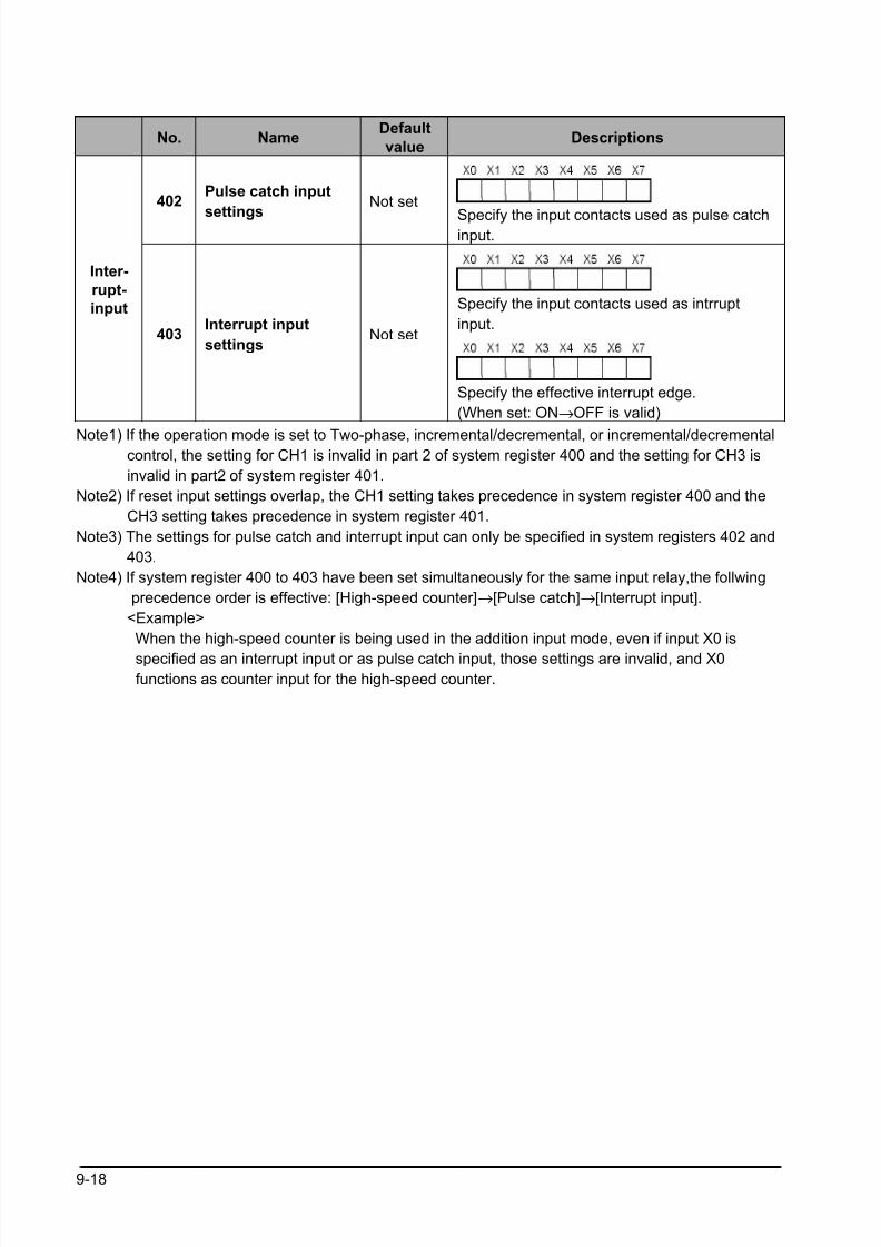
8/21/2019 Programmable Controller FP Sigma
http://slidepdf.com/reader/full/programmable-controller-fp-sigma 250/318
9-18
No. NameDefault
valueDescriptions
402Pulse catch input
settings
Not set
Specify the input contacts used as pulse catchinput.
Specify the input contacts used as intrrupt
input.
Inter-
rupt-
input
403Interrupt input
settingsNot set
Specify the effective interrupt edge.
(When set: ON→OFF is valid)
Note1) If the operation mode is set to Two-phase, incremental/decremental, or incremental/decremental control, the setting for CH1 is invalid in part 2 of system register 400 and the setting for CH3 is
invalid in part2 of system register 401.
Note2) If reset input settings overlap, the CH1 setting takes precedence in system register 400 and the
CH3 setting takes precedence in system register 401.
Note3) The settings for pulse catch and interrupt input can only be specified in system registers 402 and
403.
Note4) If system register 400 to 403 have been set simultaneously for the same input relay,the follwing
precedence order is effective: [High-speed counter]→[Pulse catch]→[Interrupt input].
<Example>
When the high-speed counter is being used in the addition input mode, even if input X0 is
specified as an interrupt input or as pulse catch input, those settings are invalid, and X0 functions as counter input for the high-speed counter.
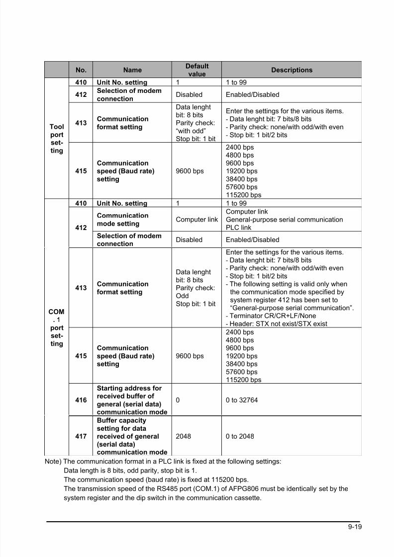
8/21/2019 Programmable Controller FP Sigma
http://slidepdf.com/reader/full/programmable-controller-fp-sigma 251/318
9-19
No. NameDefaultvalue
Descriptions
410 Unit No. setting 1 1 to 99
412
Selection of modem
connection Disabled Enabled/Disabled
413Communication
format setting
Data lenghtbit: 8 bitsParity check:
“with odd”Stop bit: 1 bit
Enter the settings for the various items.
- Data lenght bit: 7 bits/8 bits- Parity check: none/with odd/with even- Stop bit: 1 bit/2 bits
Toolportset-ting
415Communicationspeed (Baud rate)
setting
9600 bps
2400 bps4800 bps9600 bps19200 bps
38400 bps57600 bps
115200 bps410 Unit No. setting 1 1 to 99
Communication
mode settingComputer link
Computer linkGeneral-purpose serial communicationPLC link412
Selection of modemconnection
Disabled Enabled/Disabled
413Communication
format setting
Data lenghtbit: 8 bitsParity check:OddStop bit: 1 bit
Enter the settings for the various items.- Data lenght bit: 7 bits/8 bits- Parity check: none/with odd/with even
- Stop bit: 1 bit/2 bits- The following setting is valid only when
the communication mode specified bysystem register 412 has been set to“General-purpose serial communication”.
- Terminator CR/CR+LF/None- Header: STX not exist/STX exist
415Communication
speed (Baud rate)setting
9600 bps
2400 bps4800 bps9600 bps
19200 bps38400 bps57600 bps115200 bps
416Starting address for received buffer of
general (serial data)communication mode
0 0 to 32764
COM. 1
portset-ting
417
Buffer capacity
setting for datareceived of general(serial data)communication mode
2048 0 to 2048
Note) The communication format in a PLC link is fixed at the following settings:
Data length is 8 bits, odd parity, stop bit is 1.
The communication speed (baud rate) is fixed at 115200 bps.
The transmission speed of the RS485 port (COM.1) of AFPG806 must be identically set by thesystem register and the dip switch in the communication cassette.
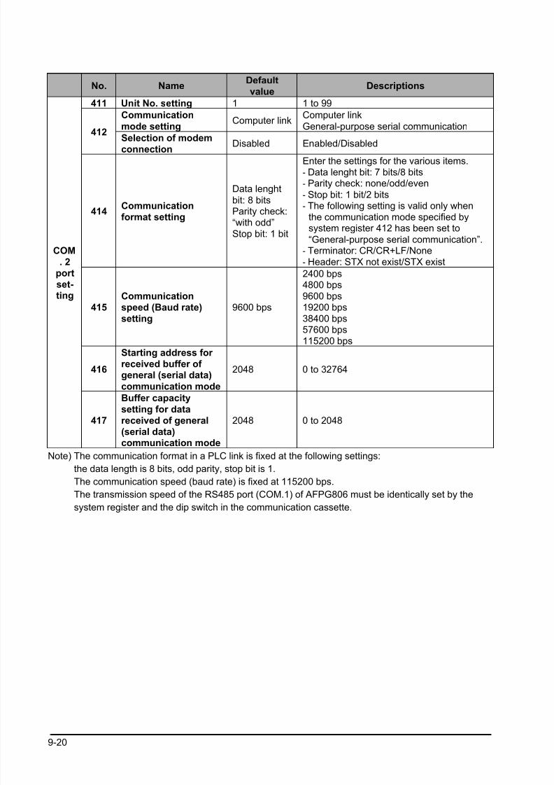
8/21/2019 Programmable Controller FP Sigma
http://slidepdf.com/reader/full/programmable-controller-fp-sigma 252/318
9-20
No. NameDefaultvalue
Descriptions
411 Unit No. setting 1 1 to 99
Communication
mode settingComputer link
Computer link
General-purpose serial communication412
Selection of modemconnection
Disabled Enabled/Disabled
414Communicationformat setting
Data lenght
bit: 8 bitsParity check:“with odd”Stop bit: 1 bit
Enter the settings for the various items.- Data lenght bit: 7 bits/8 bits- Parity check: none/odd/even
- Stop bit: 1 bit/2 bits- The following setting is valid only when
the communication mode specified bysystem register 412 has been set to
“General-purpose serial communication”.- Terminator: CR/CR+LF/None- Header: STX not exist/STX exist
415Communicationspeed (Baud rate)setting
9600 bps
2400 bps4800 bps9600 bps19200 bps38400 bps57600 bps115200 bps
416
Starting address for received buffer of general (serial data)
communication mode
2048 0 to 32764
COM. 2
portset-ting
417
Buffer capacity
setting for datareceived of general(serial data)communication mode
2048 0 to 2048
Note) The communication format in a PLC link is fixed at the following settings:
the data length is 8 bits, odd parity, stop bit is 1.
The communication speed (baud rate) is fixed at 115200 bps.
The transmission speed of the RS485 port (COM.1) of AFPG806 must be identically set by the
system register and the dip switch in the communication cassette.
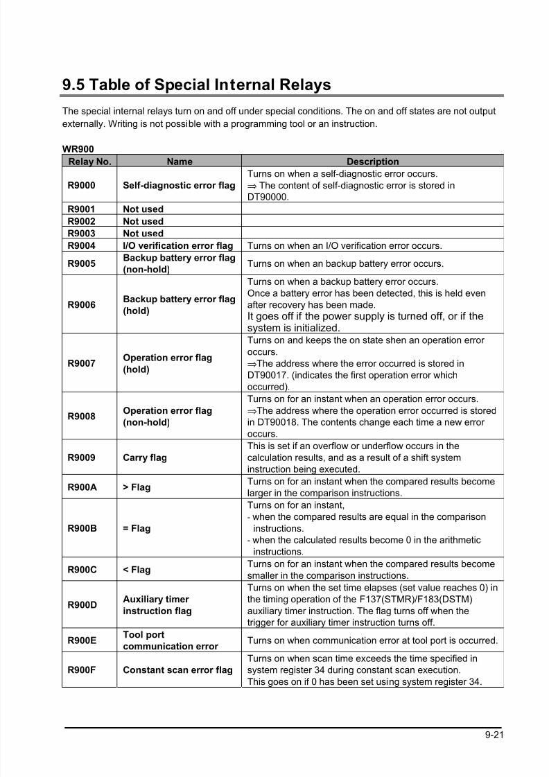
8/21/2019 Programmable Controller FP Sigma
http://slidepdf.com/reader/full/programmable-controller-fp-sigma 253/318
9-21
9.5 Table of Special Internal Relays
The special internal relays turn on and off under special conditions. The on and off states are not output
externally. Writing is not possible with a programming tool or an instruction.
WR900
Relay No. Name Description
R9000 Self-diagnostic error flag
Turns on when a self-diagnostic error occurs.
⇒ The content of self-diagnostic error is stored in
DT90000.
R9001 Not used
R9002 Not used
R9003 Not used
R9004 I/O verification error flag Turns on when an I/O verification error occurs.
R9005Backup battery error flag
(non-hold)
Turns on when an backup battery error occurs.
R9006Backup battery error flag
(hold)
Turns on when a backup battery error occurs.
Once a battery error has been detected, this is held even
after recovery has been made.
It goes off if the power supply is turned off, or if thesystem is initialized.
R9007Operation error flag
(hold)
Turns on and keeps the on state shen an operation error
occurs.
⇒The address where the error occurred is stored in
DT90017. (indicates the first operation error which
occurred).
R9008 Operation error flag(non-hold)
Turns on for an instant when an operation error occurs.
⇒The address where the operation error occurred is storedin DT90018. The contents change each time a new error
occurs.
R9009 Carry flag
This is set if an overflow or underflow occurs in the
calculation results, and as a result of a shift system
instruction being executed.
R900A > FlagTurns on for an instant when the compared results become
larger in the comparison instructions.
R900B = Flag
Turns on for an instant,
- when the compared results are equal in the comparison
instructions.
- when the calculated results become 0 in the arithmeticinstructions.
R900C < FlagTurns on for an instant when the compared results become
smaller in the comparison instructions.
R900DAuxiliary timer
instruction flag
Turns on when the set time elapses (set value reaches 0) in
the timing operation of the F137(STMR)/F183(DSTM)
auxiliary timer instruction. The flag turns off when the
trigger for auxiliary timer instruction turns off.
R900ETool port
communication error Turns on when communication error at tool port is occurred.
R900F Constant scan error flag
Turns on when scan time exceeds the time specified in
system register 34 during constant scan execution.
This goes on if 0 has been set using system register 34.
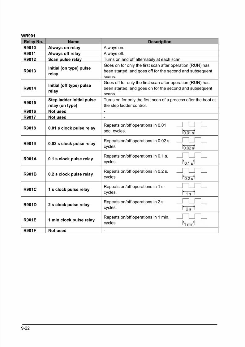
8/21/2019 Programmable Controller FP Sigma
http://slidepdf.com/reader/full/programmable-controller-fp-sigma 254/318
9-22
WR901
Relay No. Name Description
R9010 Always on relay Always on.
R9011 Always off relay Always off.
R9012 Scan pulse relay Turns on and off alternately at each scan.
R9013Initial (on type) pulse
relay
Goes on for only the first scan after operation (RUN) has
been started, and goes off for the second and subsequent
scans.
R9014Initial (off type) pulse
relay
Goes off for only the first scan after operation (RUN) has
been started, and goes on for the second and subsequent
scans.
R9015Step ladder initial pulse
relay (on type)
Turns on for only the first scan of a process after the boot at
the step ladder control.
R9016 Not used -
R9017 Not used -
R9018 0.01 s clock pulse relayRepeats on/off operations in 0.01
sec. cycles.
R9019 0.02 s clock pulse relayRepeats on/off operations in 0.02 s.
cycles.
R901A 0.1 s clock pulse relayRepeats on/off operations in 0.1 s.
cycles.
R901B 0.2 s clock pulse relayRepeats on/off operations in 0.2 s.
cycles.
R901C 1 s clock pulse relayRepeats on/off operations in 1 s.
cycles.
R901D 2 s clock pulse relayRepeats on/off operations in 2 s.
cycles.
R901E 1 min clock pulse relayRepeats on/off operations in 1 min.
cycles.
R901F Not used -
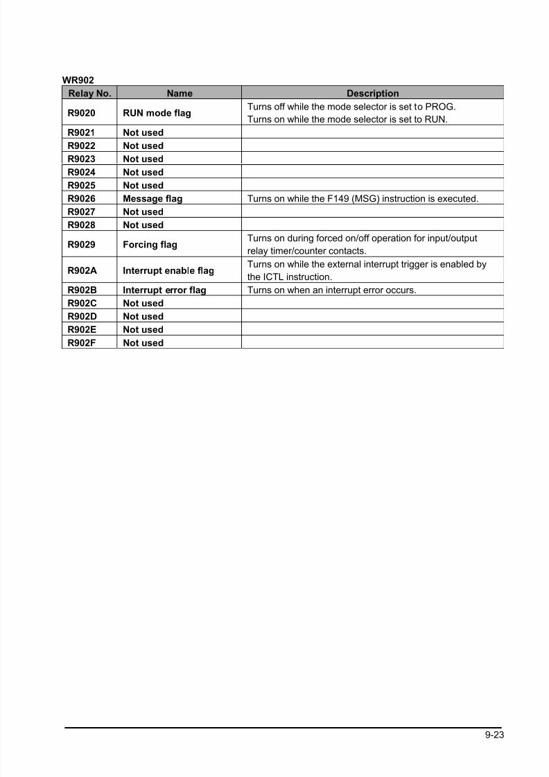
8/21/2019 Programmable Controller FP Sigma
http://slidepdf.com/reader/full/programmable-controller-fp-sigma 255/318
9-23
WR902
Relay No. Name Description
R9020 RUN mode flagTurns off while the mode selector is set to PROG.
Turns on while the mode selector is set to RUN.
R9021 Not usedR9022 Not used
R9023 Not used
R9024 Not used
R9025 Not used
R9026 Message flag Turns on while the F149 (MSG) instruction is executed.
R9027 Not used
R9028 Not used
R9029 Forcing flagTurns on during forced on/off operation for input/output
relay timer/counter contacts.
R902A Interrupt enable flag
Turns on while the external interrupt trigger is enabled by
the ICTL instruction.
R902B Interrupt error flag Turns on when an interrupt error occurs.
R902C Not used
R902D Not used
R902E Not used
R902F Not used
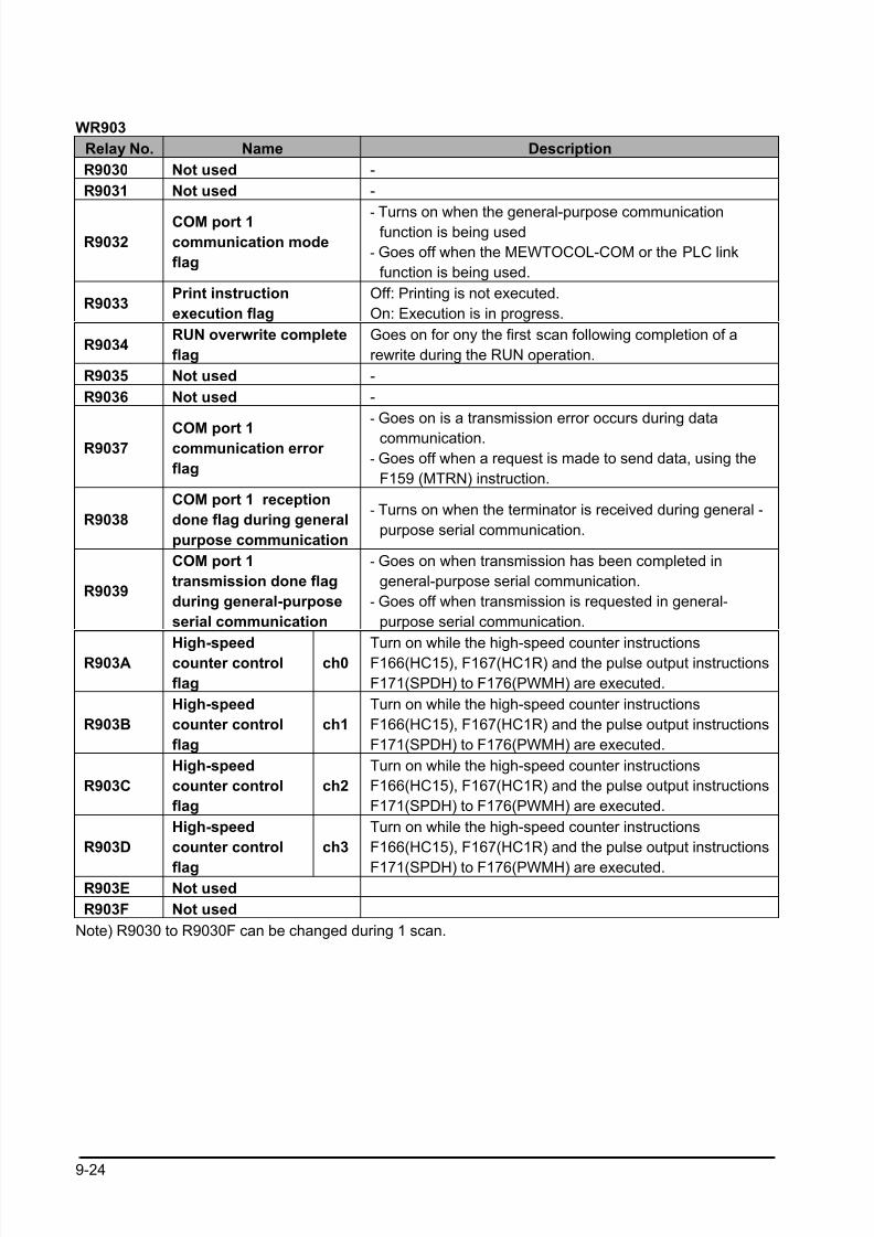
8/21/2019 Programmable Controller FP Sigma
http://slidepdf.com/reader/full/programmable-controller-fp-sigma 256/318
9-24
WR903
Relay No. Name Description
R9030 Not used -
R9031 Not used -
R9032
COM port 1
communication mode
flag
- Turns on when the general-purpose communicationfunction is being used
- Goes off when the MEWTOCOL-COM or the PLC link
function is being used.
R9033Print instruction
execution flag
Off: Printing is not executed.
On: Execution is in progress.
R9034RUN overwrite complete
flag
Goes on for ony the first scan following completion of a
rewrite during the RUN operation.
R9035 Not used -
R9036 Not used -
R9037COM port 1communication error
flag
- Goes on is a transmission error occurs during data
communication.
- Goes off when a request is made to send data, using the
F159 (MTRN) instruction.
R9038
COM port 1 reception
done flag during general
purpose communication
- Turns on when the terminator is received during general -
purpose serial communication.
R9039
COM port 1
transmission done flag
during general-purpose
serial communication
- Goes on when transmission has been completed in
general-purpose serial communication.
- Goes off when transmission is requested in general-
purpose serial communication.
R903A High-speedcounter control
flag
ch0 Turn on while the high-speed counter instructionsF166(HC15), F167(HC1R) and the pulse output instructions
F171(SPDH) to F176(PWMH) are executed.
R903B
High-speed
counter control
flag
ch1
Turn on while the high-speed counter instructions
F166(HC15), F167(HC1R) and the pulse output instructions
F171(SPDH) to F176(PWMH) are executed.
R903C
High-speed
counter control
flag
ch2
Turn on while the high-speed counter instructions
F166(HC15), F167(HC1R) and the pulse output instructions
F171(SPDH) to F176(PWMH) are executed.
R903D
High-speed
counter control
flag
ch3
Turn on while the high-speed counter instructions
F166(HC15), F167(HC1R) and the pulse output instructions
F171(SPDH) to F176(PWMH) are executed.R903E Not used
R903F Not used
Note) R9030 to R9030F can be changed during 1 scan.
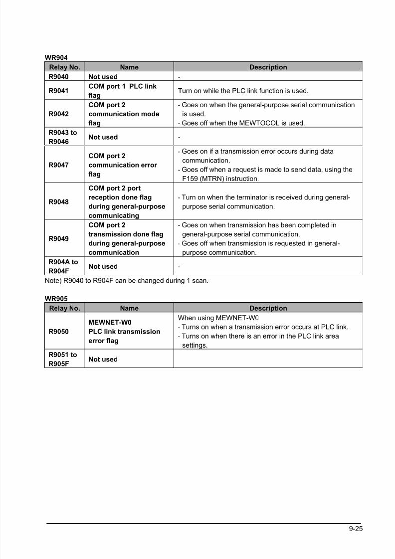
8/21/2019 Programmable Controller FP Sigma
http://slidepdf.com/reader/full/programmable-controller-fp-sigma 257/318
9-25
WR904
Relay No. Name Description
R9040 Not used -
R9041COM port 1 PLC link
flag
Turn on while the PLC link function is used.
R9042
COM port 2
communication mode
flag
- Goes on when the general-purpose serial communication
is used.
- Goes off when the MEWTOCOL is used.
R9043 to
R9046Not used -
R9047
COM port 2
communication error
flag
- Goes on if a transmission error occurs during data
communication.
- Goes off when a request is made to send data, using the
F159 (MTRN) instruction.
R9048
COM port 2 port
reception done flagduring general-purpose
communicating
- Turn on when the terminator is received during general-purpose serial communication.
R9049
COM port 2
transmission done flag
during general-purpose
communication
- Goes on when transmission has been completed in
general-purpose serial communication.
- Goes off when transmission is requested in general-
purpose communication.
R904A to
R904FNot used -
Note) R9040 to R904F can be changed during 1 scan.
WR905
Relay No. Name Description
R9050
MEWNET-W0
PLC link transmission
error flag
When using MEWNET-W0
- Turns on when a transmission error occurs at PLC link.
- Turns on when there is an error in the PLC link area
settings.
R9051 to
R905FNot used
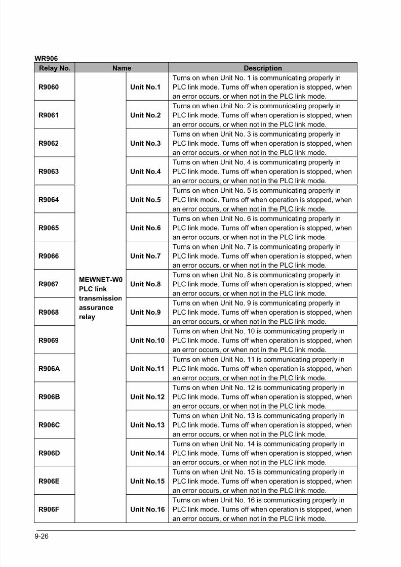
8/21/2019 Programmable Controller FP Sigma
http://slidepdf.com/reader/full/programmable-controller-fp-sigma 258/318
9-26
WR906
Relay No. Name Description
R9060 Unit No.1
Turns on when Unit No. 1 is communicating properly in
PLC link mode. Turns off when operation is stopped, when
an error occurs, or when not in the PLC link mode.
R9061 Unit No.2
Turns on when Unit No. 2 is communicating properly in
PLC link mode. Turns off when operation is stopped, when
an error occurs, or when not in the PLC link mode.
R9062 Unit No.3
Turns on when Unit No. 3 is communicating properly in
PLC link mode. Turns off when operation is stopped, when
an error occurs, or when not in the PLC link mode.
R9063 Unit No.4
Turns on when Unit No. 4 is communicating properly in
PLC link mode. Turns off when operation is stopped, when
an error occurs, or when not in the PLC link mode.
R9064 Unit No.5
Turns on when Unit No. 5 is communicating properly in
PLC link mode. Turns off when operation is stopped, whenan error occurs, or when not in the PLC link mode.
R9065 Unit No.6
Turns on when Unit No. 6 is communicating properly in
PLC link mode. Turns off when operation is stopped, when
an error occurs, or when not in the PLC link mode.
R9066 Unit No.7
Turns on when Unit No. 7 is communicating properly in
PLC link mode. Turns off when operation is stopped, when
an error occurs, or when not in the PLC link mode.
R9067 Unit No.8
Turns on when Unit No. 8 is communicating properly in
PLC link mode. Turns off when operation is stopped, when
an error occurs, or when not in the PLC link mode.
R9068 Unit No.9
Turns on when Unit No. 9 is communicating properly in
PLC link mode. Turns off when operation is stopped, when
an error occurs, or when not in the PLC link mode.
R9069 Unit No.10
Turns on when Unit No. 10 is communicating properly in
PLC link mode. Turns off when operation is stopped, when
an error occurs, or when not in the PLC link mode.
R906A Unit No.11
Turns on when Unit No. 11 is communicating properly in
PLC link mode. Turns off when operation is stopped, when
an error occurs, or when not in the PLC link mode.
R906B Unit No.12
Turns on when Unit No. 12 is communicating properly in
PLC link mode. Turns off when operation is stopped, whenan error occurs, or when not in the PLC link mode.
R906C Unit No.13
Turns on when Unit No. 13 is communicating properly in
PLC link mode. Turns off when operation is stopped, when
an error occurs, or when not in the PLC link mode.
R906D Unit No.14
Turns on when Unit No. 14 is communicating properly in
PLC link mode. Turns off when operation is stopped, when
an error occurs, or when not in the PLC link mode.
R906E Unit No.15
Turns on when Unit No. 15 is communicating properly in
PLC link mode. Turns off when operation is stopped, when
an error occurs, or when not in the PLC link mode.
R906F
MEWNET-W0
PLC link
transmissionassurance
relay
Unit No.16
Turns on when Unit No. 16 is communicating properly in
PLC link mode. Turns off when operation is stopped, when
an error occurs, or when not in the PLC link mode.
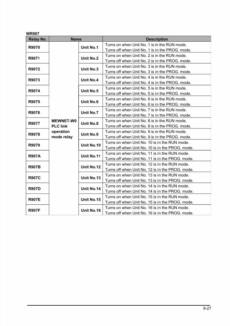
8/21/2019 Programmable Controller FP Sigma
http://slidepdf.com/reader/full/programmable-controller-fp-sigma 259/318
9-27
WR907
Relay No. Name Description
R9070 Unit No.1Turns on when Unit No. 1 is in the RUN mode.
Turns off when Unit No. 1 is in the PROG. mode.
R9071 Unit No.2 Turns on when Unit No. 2 is in the RUN mode.Turns off when Unit No. 2 is in the PROG. mode.
R9072 Unit No.3Turns on when Unit No. 3 is in the RUN mode.
Turns off when Unit No. 3 is in the PROG. mode.
R9073 Unit No.4Turns on when Unit No. 4 is in the RUN mode.
Turns off when Unit No. 4 is in the PROG. mode.
R9074 Unit No.5Turns on when Unit No. 5 is in the RUN mode.
Turns off when Unit No. 5 is in the PROG. mode.
R9075 Unit No.6Turns on when Unit No. 6 is in the RUN mode.
Turns off when Unit No. 6 is in the PROG. mode.
R9076 Unit No.7
Turns on when Unit No. 7 is in the RUN mode.
Turns off when Unit No. 7 is in the PROG. mode.
R9077 Unit No.8Turns on when Unit No. 8 is in the RUN mode.
Turns off when Unit No. 8 is in the PROG. mode.
R9078 Unit No.9Turns on when Unit No. 9 is in the RUN mode.
Turns off when Unit No. 9 is in the PROG. mode.
R9079 Unit No.10Turns on when Unit No. 10 is in the RUN mode.
Turns off when Unit No. 10 is in the PROG. mode.
R907A Unit No.11Turns on when Unit No. 11 is in the RUN mode.
Turns off when Unit No. 11 is in the PROG. mode.
R907B Unit No.12Turns on when Unit No. 12 is in the RUN mode.
Turns off when Unit No. 12 is in the PROG. mode.
R907C Unit No.13Turns on when Unit No. 13 is in the RUN mode.
Turns off when Unit No. 13 is in the PROG. mode.
R907D Unit No.14Turns on when Unit No. 14 is in the RUN mode.
Turns off when Unit No. 14 is in the PROG. mode.
R907E Unit No.15Turns on when Unit No. 15 is in the RUN mode.
Turns off when Unit No. 15 is in the PROG. mode.
R907F
MEWNET-W0
PLC link
operation
mode relay
Unit No.16Turns on when Unit No. 16 is in the RUN mode.
Turns off when Unit No. 16 is in the PROG. mode.
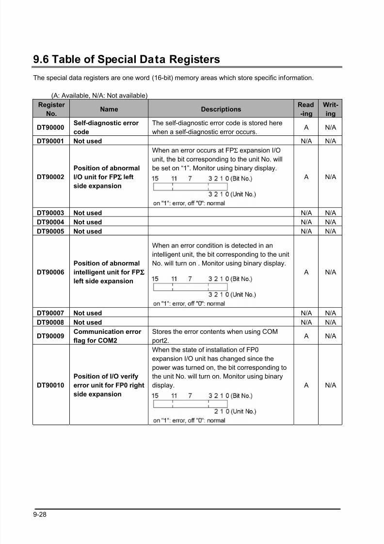
8/21/2019 Programmable Controller FP Sigma
http://slidepdf.com/reader/full/programmable-controller-fp-sigma 260/318
9-28
9.6 Table of Special Data Registers
The special data registers are one word (16-bit) memory areas which store specific information.
(A: Available, N/A: Not available)Register
No.Name Descriptions
Read
-ing
Writ-
ing
DT90000Self-diagnostic error
code
The self-diagnostic error code is stored here
when a self-diagnostic error occurs. A N/A
DT90001 Not used N/A N/A
When an error occurs at FPΣ expansion I/O
unit, the bit corresponding to the unit No. will
be set on “1”. Monitor using binary display.
DT90002
Position of abnormal
I/O unit for FPΣΣΣΣ left
side expansion
A N/A
DT90003 Not used N/A N/A
DT90004 Not used N/A N/A
DT90005 Not used N/A N/A
When an error condition is detected in an
intelligent unit, the bit corresponding to the unit
No. will turn on . Monitor using binary display.
DT90006
Position of abnormal
intelligent unit for FPΣΣΣΣ
left side expansion
A N/A
DT90007 Not used N/A N/A
DT90008 Not used N/A N/A
DT90009Communication error
flag for COM2
Stores the error contents when using COM
port2. A N/A
When the state of installation of FP0
expansion I/O unit has changed since the
power was turned on, the bit corresponding to
the unit No. will turn on. Monitor using binary
display.DT90010
Position of I/O verify
error unit for FP0 right
side expansion
A N/A
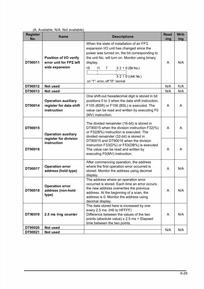
8/21/2019 Programmable Controller FP Sigma
http://slidepdf.com/reader/full/programmable-controller-fp-sigma 261/318
9-29
(A: Available, N/A: Not available)
Register
No.Name Descriptions
Read
-ing
Writ-
ing
When the state of installation of an FPΣ
expansion I/O unit has changed since the
power was turned on, the bit corresponding to
the unit No. will turn on. Monitor using binary
display.DT90011
Position of I/O verify
error unit for FPΣΣΣΣ left
side expansion
A N/A
DT90012 Not used N/A N/A
DT90013 Not used N/A N/A
DT90014Operation auxiliaryregister for data shift
instruction
One shift-out hexadecimal digit is stored in bit
positions 0 to 3 when the data shift instruction,F105 (BSR) or F106 (BSL) is executed. The
value can be read and written by executing F0
(MV) instruction.
A A
DT90015 A A
DT90016
Operation auxiliary
register for division
instruction
The divided remainder (16-bit) is stored in
DT90015 when the division instruction F32(%)
or F52(B%) instruction is executed. The
divided remainder (32-bit) is stored in
DT90015 and DT90016 when the division
instruction F33(D%) or F53(DB%) is executed.
The value can be read and written by
executing F0(MV) instruction.
A A
DT90017Operation error
address (hold type)
After commencing operation, the address
where the first operation error occurred is
stored. Monitor the address using decimal
display.
A N/A
DT90018
Operation error
address (non-hold
type)
The address where an operation error
occurred is stored. Each time an error occurs,
the new address overwrites the previous
address. At the beginning of a scan, the
address is 0. Monitor the address using
decimal display.
A N/A
DT90019 2.5 ms ring counter
The data stored here is increased by one
every 2.5 ms. (H0 to HFFFF)
Difference between the values of the two
points (absolute value) x 2.5 ms = Elapsed
time between the two points.
A N/A
DT90020 Not used
DT90021 Not usedN/A N/A
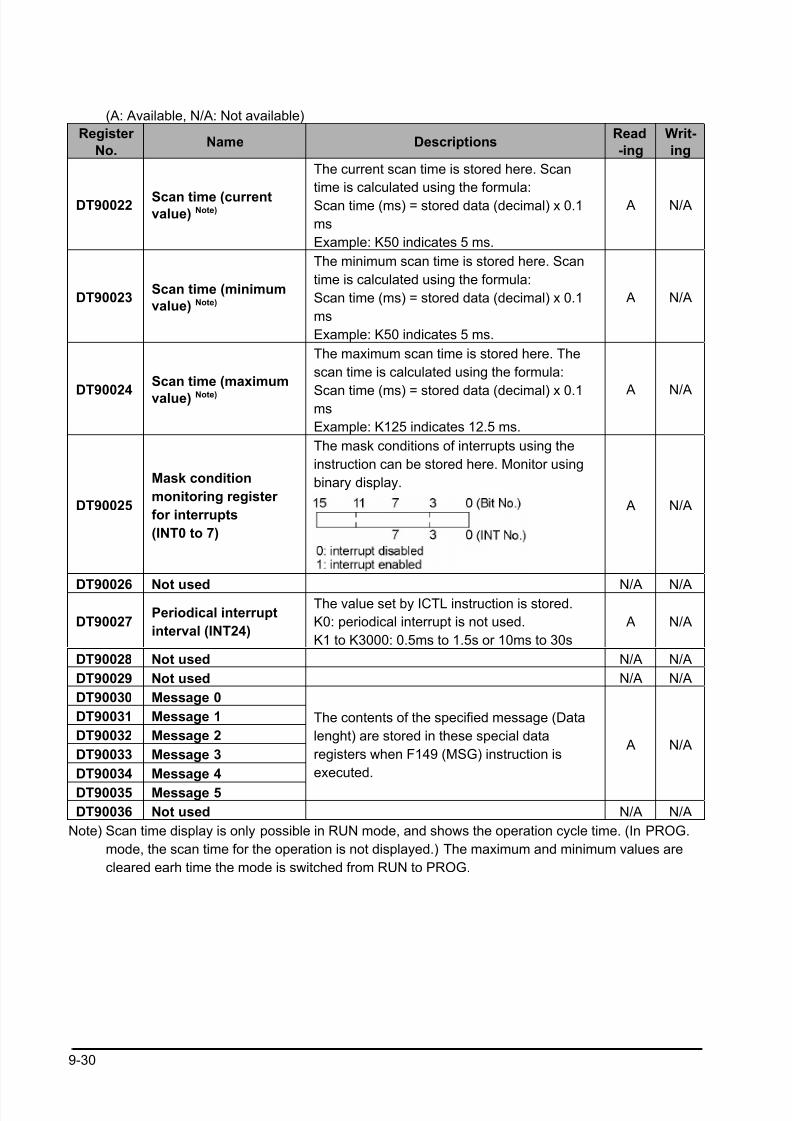
8/21/2019 Programmable Controller FP Sigma
http://slidepdf.com/reader/full/programmable-controller-fp-sigma 262/318
9-30
(A: Available, N/A: Not available)
Register
No.Name Descriptions
Read
-ing
Writ-
ing
DT90022 Scan time (currentvalue) Note)
The current scan time is stored here. Scan
time is calculated using the formula:
Scan time (ms) = stored data (decimal) x 0.1
ms
Example: K50 indicates 5 ms.
A N/A
DT90023Scan time (minimum
value) Note)
The minimum scan time is stored here. Scan
time is calculated using the formula:
Scan time (ms) = stored data (decimal) x 0.1
ms
Example: K50 indicates 5 ms.
A N/A
DT90024
Scan time (maximum
value) Note)
The maximum scan time is stored here. The
scan time is calculated using the formula:
Scan time (ms) = stored data (decimal) x 0.1ms
Example: K125 indicates 12.5 ms.
A N/A
DT90025
Mask condition
monitoring register
for interrupts
(INT0 to 7)
The mask conditions of interrupts using the
instruction can be stored here. Monitor using
binary display.
A N/A
DT90026 Not used N/A N/A
DT90027Periodical interrupt
interval (INT24)
The value set by ICTL instruction is stored.
K0: periodical interrupt is not used.
K1 to K3000: 0.5ms to 1.5s or 10ms to 30s
A N/A
DT90028 Not used N/A N/A
DT90029 Not used N/A N/A
DT90030 Message 0
DT90031 Message 1
DT90032 Message 2
DT90033 Message 3
DT90034 Message 4
DT90035 Message 5
The contents of the specified message (Data
lenght) are stored in these special data
registers when F149 (MSG) instruction is
executed.
A N/A
DT90036 Not used N/A N/A
Note) Scan time display is only possible in RUN mode, and shows the operation cycle time. (In PROG.
mode, the scan time for the operation is not displayed.) The maximum and minimum values are
cleared earh time the mode is switched from RUN to PROG.

8/21/2019 Programmable Controller FP Sigma
http://slidepdf.com/reader/full/programmable-controller-fp-sigma 263/318
9-31
(A: Available, N/A: Not available)
Register
No.Name Descriptions
Read-
ing
Writ-
ing
DT90037
Operation auxiliary
register for search
instruction F96(SRC)
The number of data that match the searched
data is stored here when F96 (SRC)
insturction is executed.
A N/A
DT90038
Operation auxiliary
register for search
instruction F96(SRC)
The position of the first matching data is
stored here when an F96 (SRC) instruction is
executed.
A N/A
DT90039 Not used N/A N/A
DT90040Potentiometer
(volume) input V0
DT90041Potentiometer
(volume) input V1
The potentiometer value (K0 to K1000) is
stored here. This value can be used in analog
tiemrs and other applications by using the
program to read this value to a data register.
V0→DT90040
V1→DT90041
A N/A
DT90042 Used by the system. N/A N/A
DT90043 Used by the system. N/A N/A
DT90044
DT90045
High-speed
counter
elapsed value
For
CH0
The elapsed value (32-bit data) of the high-
speed counter is stored here. The value can
be read or written by executing F1 (DMV)
instruction.
A A
DT90046
DT90047
High-speed
counter target
value
For CH0
The targe value (32-bit data) of the high-
speed counter specified by the high-speed
counter instruction is stored here. Target
values have been preset for the variousinstructions to be used when the high-speed
counter related instruction F166, F167, F171,
F175 or F176 is executed. The value can be
read by executing F1 (DMV) instruction.
A N/A
DT90048
DT90049
High-speed
counter
elapsed value
area
For
CH1
The elapsed value (32-bit data) of the high-
speed counter is stored here. The value can
be read and written by executing F1 (DMV)
instruction.
A A
DT90050
DT90051
High-speed
counter target
value area
For
CH1
The target value (32-bit data) of the high-
speed counter specified by the high-speedcounter instruction is stored here. Target
values have been preset for the various
instructions to be used when the high-speed
counter related instruction F166 or F167 is
executed. The value can be read by
executing F1 (DMV) instruction.
A N/A
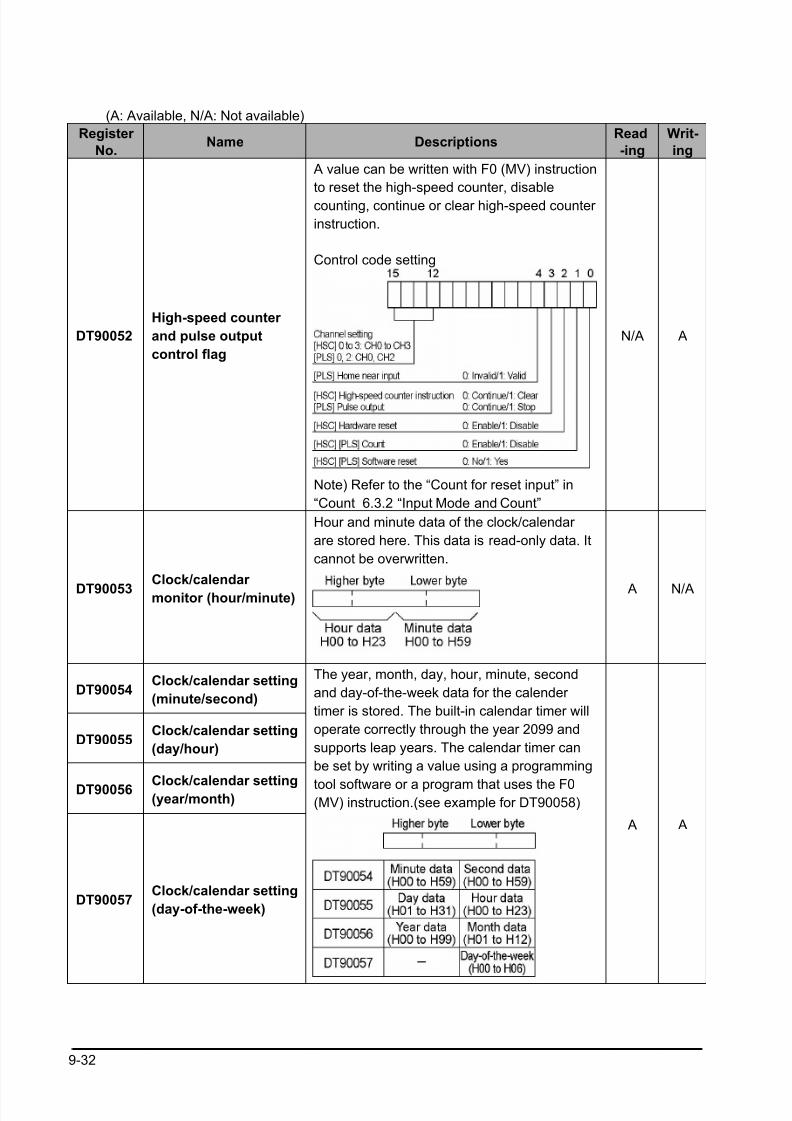
8/21/2019 Programmable Controller FP Sigma
http://slidepdf.com/reader/full/programmable-controller-fp-sigma 264/318
9-32
(A: Available, N/A: Not available)
Register
No.Name Descriptions
Read
-ing
Writ-
ing
DT90052
High-speed counter
and pulse output
control flag
A value can be written with F0 (MV) instruction
to reset the high-speed counter, disable
counting, continue or clear high-speed counter
instruction.
Control code setting
Note) Refer to the “Count for reset input” in
“Count 6.3.2 “Input Mode and Count”
N/A A
DT90053Clock/calendar
monitor (hour/minute)
Hour and minute data of the clock/calendar
are stored here. This data is read-only data. It
cannot be overwritten.
A N/A
DT90054Clock/calendar setting
(minute/second)
DT90055Clock/calendar setting
(day/hour)
DT90056 Clock/calendar setting(year/month)
DT90057Clock/calendar setting
(day-of-the-week)
The year, month, day, hour, minute, second
and day-of-the-week data for the calender
timer is stored. The built-in calendar timer will
operate correctly through the year 2099 and
supports leap years. The calendar timer can
be set by writing a value using a programming
tool software or a program that uses the F0(MV) instruction.(see example for DT90058)
A A
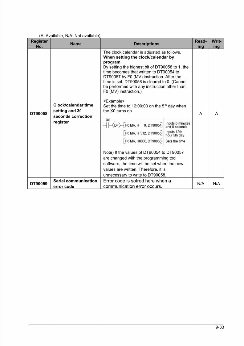
8/21/2019 Programmable Controller FP Sigma
http://slidepdf.com/reader/full/programmable-controller-fp-sigma 265/318
9-33
(A: Available, N/A: Not available)
Register
No.Name Descriptions
Read-
ing
Writ-
ing
DT90058
Clock/calendar time
setting and 30
seconds correction
register
The clock calendar is adjusted as follows.When setting the clock/calendar by
programBy setting the highest bit of DT90058 to 1, thetime becomes that written to DT90054 toDT90057 by F0 (MV) instruction. After thetime is set, DT90058 is cleared to 0. (Cannotbe performed with any instruction other thanF0 (MV) instruction.)
<Example>Set the time to 12:00:00 on the 5th day whenthe X0 turns on.
Note) If the values of DT90054 to DT90057
are changed with the programming tool
software, the time will be set when the new
values are written. Therefore, it is
unnecessary to write to DT90058.
A A
DT90059 Serial communicationerror code
Error code is sotred here when acommunication error occurs.
N/A N/A
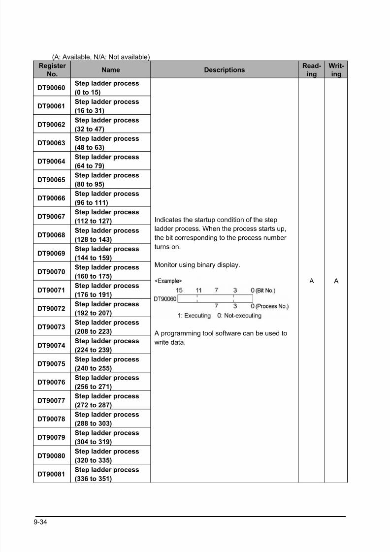
8/21/2019 Programmable Controller FP Sigma
http://slidepdf.com/reader/full/programmable-controller-fp-sigma 266/318
9-34
(A: Available, N/A: Not available)
Register
No.Name Descriptions
Read-
ing
Writ-
ing
DT90060Step ladder process
(0 to 15)
DT90061Step ladder process
(16 to 31)
DT90062Step ladder process
(32 to 47)
DT90063Step ladder process
(48 to 63)
DT90064Step ladder process
(64 to 79)
DT90065Step ladder process
(80 to 95)
DT90066 Step ladder process(96 to 111)
DT90067Step ladder process
(112 to 127)
DT90068Step ladder process
(128 to 143)
DT90069Step ladder process
(144 to 159)
DT90070Step ladder process
(160 to 175)
DT90071Step ladder process
(176 to 191)
DT90072Step ladder process
(192 to 207)
DT90073Step ladder process
(208 to 223)
DT90074Step ladder process
(224 to 239)
DT90075Step ladder process
(240 to 255)
DT90076Step ladder process
(256 to 271)
DT90077Step ladder process
(272 to 287)
DT90078Step ladder process
(288 to 303)
DT90079Step ladder process
(304 to 319)
DT90080Step ladder process
(320 to 335)
DT90081Step ladder process
(336 to 351)
Indicates the startup condition of the step
ladder process. When the process starts up,
the bit corresponding to the process number
turns on.
Monitor using binary display.
A programming tool software can be used to
write data.
A A
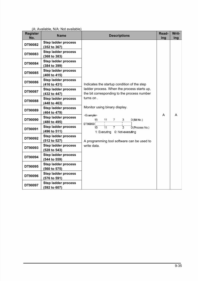
8/21/2019 Programmable Controller FP Sigma
http://slidepdf.com/reader/full/programmable-controller-fp-sigma 267/318
9-35
(A: Available, N/A: Not available)
Register
No.Name Descriptions
Read-
ing
Writ-
ing
DT90082Step ladder process
(352 to 367)
DT90083Step ladder process
(368 to 383)
DT90084Step ladder process
(384 to 399)
DT90085Step ladder process
(400 to 415)
DT90086Step ladder process
(416 to 431)
DT90087Step ladder process
(432 to 447)
DT90088 Step ladder process(448 to 463)
DT90089Step ladder process
(464 to 479)
DT90090Step ladder process
(480 to 495)
DT90091Step ladder process
(496 to 511)
DT90092Step ladder process
(512 to 527)
DT90093Step ladder process
(528 to 543)
DT90094Step ladder process
(544 to 559)
DT90095Step ladder process
(560 to 575)
DT90096Step ladder process
(576 to 591)
DT90097Step ladder process
(592 to 607)
Indicates the startup condition of the step
ladder process. When the process starts up,
the bit corresponding to the process number
turns on .
Monitor using binary display.
A programming tool software can be used to
write data.
A A
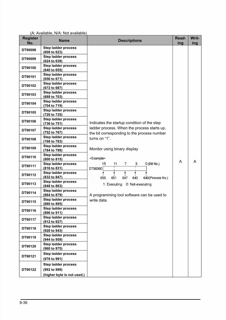
8/21/2019 Programmable Controller FP Sigma
http://slidepdf.com/reader/full/programmable-controller-fp-sigma 268/318
9-36
(A: Available, N/A: Not available)
Register
No.Name Descriptions
Read-
ing
Writ-
ing
DT90098Step ladder process
(608 to 623)
DT90099 Step ladder process(624 to 639)
DT90100Step ladder process
(640 to 655)
DT90101Step ladder process
(656 to 671)
DT90102Step ladder process
(672 to 687)
DT90103Step ladder process
(688 to 703)
DT90104Step ladder process
(704 to 719)
DT90105Step ladder process
(720 to 735)
DT90106Step ladder process
(736 to 751)
DT90107Step ladder process
(752 to 767)
DT90108Step ladder process
(768 to 783)
DT90109Step ladder process
(784 to 799)
DT90110Step ladder process
(800 to 815)
DT90111Step ladder process
(816 to 831)
DT90112Step ladder process
(832 to 847)
DT90113Step ladder process
(848 to 863)
DT90114Step ladder process
(864 to 879)
DT90115Step ladder process
(880 to 895)
DT90116Step ladder process
(896 to 911)
DT90117Step ladder process
(912 to 927)
DT90118Step ladder process
(928 to 943)
DT90119Step ladder process
(944 to 959)
DT90120Step ladder process
(960 to 975)
DT90121Step ladder process
(976 to 991)
DT90122
Step ladder process
(992 to 999)
(higher byte is not used.)
Indicates the startup condition of the step
ladder process. When the process starts up,
the bit corresponding to the process number
turns on “1”.
Monitor using binary display
A programming tool software can be used to
write data.
A A
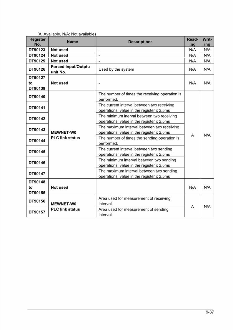
8/21/2019 Programmable Controller FP Sigma
http://slidepdf.com/reader/full/programmable-controller-fp-sigma 269/318
9-37
(A: Available, N/A: Not available)
Register
No.Name Descriptions
Read-
ing
Writ-
ing
DT90123 Not used - N/A N/A
DT90124 Not used - N/A N/A
DT90125 Not used - N/A N/A
DT90126Forced Input/Outptu
unit No.Used by the system N/A N/A
DT90127
to
DT90139
Not used - N/A N/A
DT90140The number of times the receiving operation is
performed.
DT90141The current interval between two receiving
operations: value in the register x 2.5ms
DT90142 The minimum inerval between two receivingoperations: value in the register x 2.5ms
DT90143The maximum interval between two receiving
operations: value in the register x 2.5ms
DT90144The number of times the sending operation is
performed.
DT90145The current interval between two sending
operations: value in the register x 2.5ms
DT90146The minimum interval between two sending
operations: value in the register x 2.5ms
DT90147
MEWNET-W0
PLC link status
The maximum interval between two sending
operations: value in the register x 2.5ms
A N/A
DT90148
to
DT90155
Not used N/A N/A
DT90156 Area used for measurement of receiving
interval.
DT90157
MEWNET-W0
PLC link status Area used for measurement of sending
interval.
A N/A
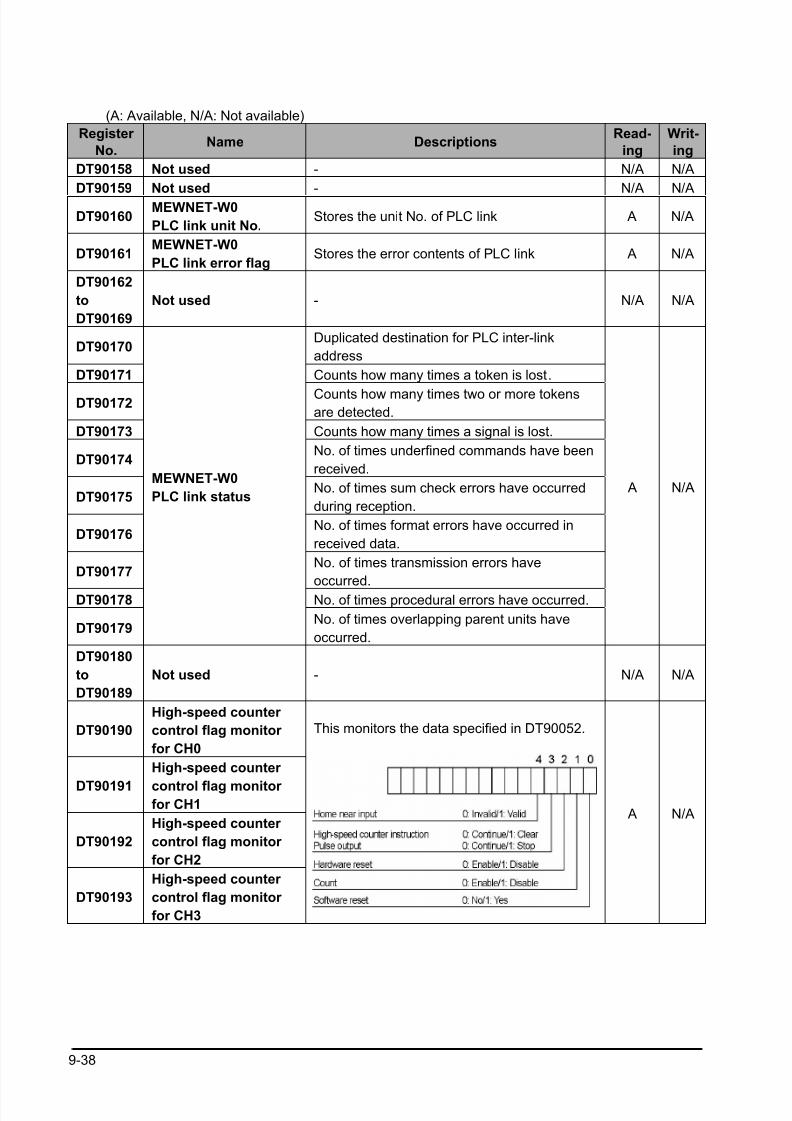
8/21/2019 Programmable Controller FP Sigma
http://slidepdf.com/reader/full/programmable-controller-fp-sigma 270/318
9-38
(A: Available, N/A: Not available)
Register
No.Name Descriptions
Read-
ing
Writ-
ing
DT90158 Not used - N/A N/A
DT90159 Not used - N/A N/A
DT90160MEWNET-W0
PLC link unit No.Stores the unit No. of PLC link A N/A
DT90161MEWNET-W0
PLC link error flagStores the error contents of PLC link A N/A
DT90162
to
DT90169
Not used - N/A N/A
DT90170Duplicated destination for PLC inter-link
address
DT90171 Counts how many times a token is lost.
DT90172 Counts how many times two or more tokensare detected.
DT90173 Counts how many times a signal is lost.
DT90174No. of times underfined commands have been
received.
DT90175No. of times sum check errors have occurred
during reception.
DT90176No. of times format errors have occurred in
received data.
DT90177No. of times transmission errors have
occurred.
DT90178 No. of times procedural errors have occurred.
DT90179
MEWNET-W0
PLC link status
No. of times overlapping parent units have
occurred.
A N/A
DT90180
to
DT90189
Not used - N/A N/A
DT90190
High-speed counter
control flag monitor
for CH0
DT90191
High-speed counter
control flag monitor for CH1
DT90192
High-speed counter
control flag monitor
for CH2
DT90193
High-speed counter
control flag monitor
for CH3
This monitors the data specified in DT90052.
A N/A

8/21/2019 Programmable Controller FP Sigma
http://slidepdf.com/reader/full/programmable-controller-fp-sigma 271/318
9-39
(A: Available, N/A: Not available)
Register
No.Name Descriptions
Read-
ing
Writ-
ing
DT90194
to
DT90199
Not used - N/A N/A
DT90200
DT90201
High-speed
counter
elapsed value
For
CH2
The elapsed value (32-bit data) for the high-
speed counter is stored here. The value can
be read and written by executing the F1 (DMV)
instruction.
A A
DT90202
DT90203
High-speed
counter target
value
For
CH2
The targe value (32-bit data) of the high-speed
counter specified by the high-speed counter
instruction is stored here. Target values have
been preset for the various instructions, to be
used when the high-speed counter related
instruction F166, F167, F171, F175 or F176 is
executed. The value can be read by executing
F1 (DMV) instruction.
A N/A
DT90204
DT90205
High-speed
counter
elapsed value
For
CH3
The elapsed value (32-bit data) for the high-
speed counter is stored here. The value can
be read and written by executing F1 (DMV)
instruction.
A A
DT90206
DT90207
High-speed
counter target
value
For
CH3
The target value (32-bit data) of the high-
speed counter specified by the high-speed
counter instruction is stored here. Targetvalues have been preset for the various
instructions, to be used when the high-speed
counter related instruction F166 or F167 is
executed. The value can be read by executing
the F1 (DMV) instruction.
A N/A
DT90208
to
DT90218
Not used N/A N/A
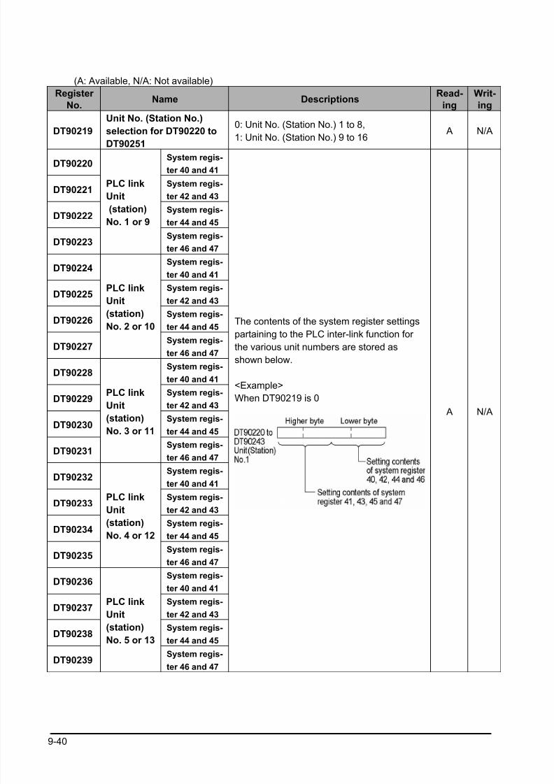
8/21/2019 Programmable Controller FP Sigma
http://slidepdf.com/reader/full/programmable-controller-fp-sigma 272/318
9-40
(A: Available, N/A: Not available)
Register
No.Name Descriptions
Read-
ing
Writ-
ing
DT90219
Unit No. (Station No.)
selection for DT90220 to
DT90251
0: Unit No. (Station No.) 1 to 8,
1: Unit No. (Station No.) 9 to 16 A N/A
DT90220System regis-
ter 40 and 41
DT90221System regis-
ter 42 and 43
DT90222System regis-
ter 44 and 45
DT90223
PLC link
Unit
(station)
No. 1 or 9
System regis-
ter 46 and 47
DT90224System regis-
ter 40 and 41
DT90225System regis-
ter 42 and 43
DT90226System regis-
ter 44 and 45
DT90227
PLC link
Unit
(station)
No. 2 or 10
System regis-
ter 46 and 47
DT90228System regis-
ter 40 and 41
DT90229System regis-
ter 42 and 43
DT90230System regis-
ter 44 and 45
DT90231
PLC link
Unit
(station)
No. 3 or 11
System regis-
ter 46 and 47
DT90232System regis-
ter 40 and 41
DT90233System regis-
ter 42 and 43
DT90234System regis-
ter 44 and 45
DT90235
PLC link
Unit
(station)
No. 4 or 12
System regis-ter 46 and 47
DT90236System regis-
ter 40 and 41
DT90237System regis-
ter 42 and 43
DT90238System regis-
ter 44 and 45
DT90239
PLC link
Unit
(station)
No. 5 or 13
System regis-
ter 46 and 47
The contents of the system register settings
partaining to the PLC inter-link function for
the various unit numbers are stored as
shown below.
<Example>
When DT90219 is 0
A N/A
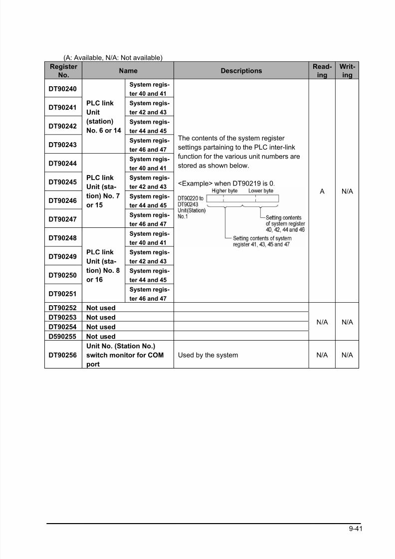
8/21/2019 Programmable Controller FP Sigma
http://slidepdf.com/reader/full/programmable-controller-fp-sigma 273/318
9-41
(A: Available, N/A: Not available)
Register
No.Name Descriptions
Read-
ing
Writ-
ing
DT90240System regis-
ter 40 and 41
DT90241System regis-
ter 42 and 43
DT90242System regis-
ter 44 and 45
DT90243
PLC link
Unit
(station)
No. 6 or 14
System regis-
ter 46 and 47
DT90244System regis-
ter 40 and 41
DT90245System regis-
ter 42 and 43
DT90246 System regis-ter 44 and 45
DT90247
PLC link
Unit (sta-
tion) No. 7or 15
System regis-
ter 46 and 47
DT90248System regis-
ter 40 and 41
DT90249System regis-
ter 42 and 43
DT90250System regis-
ter 44 and 45
DT90251
PLC link
Unit (sta-
tion) No. 8
or 16
System regis-
ter 46 and 47
The contents of the system register
settings partaining to the PLC inter-link
function for the various unit numbers are
stored as shown below.
<Example> when DT90219 is 0. A N/A
DT90252 Not used
DT90253 Not used
DT90254 Not used
D590255 Not used
N/A N/A
DT90256
Unit No. (Station No.)
switch monitor for COM
port
Used by the system N/A N/A
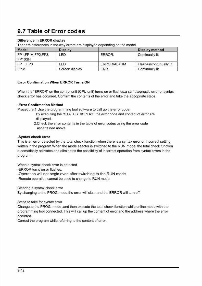
8/21/2019 Programmable Controller FP Sigma
http://slidepdf.com/reader/full/programmable-controller-fp-sigma 274/318
9-42
9.7 Table of Error codes
Difference in ERROR display
Ther are differences in the way errors are displayed depending on the model.
Model Display Display methodFP1,FP-M,FP2,FP3,
FP10SH
LED ERROR. Continually lit
FP ,FP0 LED ERROR/ALARM Flashes/contunually lit
FP-e Screen display ERR. Continually lit
Error Confirmation When ERROR Turns ON
When the “ERROR” on the control unit (CPU unit) turns on or flashes,a self-diagnostic error or syntax
check error has occurred. Confirm the contents of the error and take the appopriate steps.
-Error Confirmation Method
Procedure:1.Use the programming tool software to call up the error code.
By executing the “STATUS DISPLAY”.the error code and content of error are
displayed.
2.Check the error contents in the table of error codes using the error code
ascertained above.
-Syntax check error
This is an error detected by the total check function when there is a syntax error or incorrect setting
written in the program.When the mode seector is switched to the RUN mode, the total check function
automatically activates and eliminates the possibility of incorrect operation from syntax errors in theprogram.
When a syntax check error is detected
-ERROR turns on or flashes.
-Operation will not begin even after swirching to the RUN mode.
-Remote operation cannot be used to change to RUN mode.
Clearing a syntax check error
By changing to the PROG.mode,the error will clear and the ERROR will turn off.
Steps to take for syntax error
Change to the PROG. mode ,and then execute the total check function while online mode with the
programming tool connected. This will call up the content of error and the address where the error
occurred.
Correct the program while referring to the content of error.
8/21/2019 Programmable Controller FP Sigma
http://slidepdf.com/reader/full/programmable-controller-fp-sigma 275/318
9-43
-Self-diagnostic Error
This error occurs when the control unit (CPU unit) self-diagnostic function detects the occurrence of an
abnormality in the system. The self-diagnostic function monitors the memory abnormal detection,I/O
abnomal detection,and other devices.
When a self-diagnostic error occurs
The ERROR turns on or flashes.
The operation of the control unit (CPU unit) might stop depending on the contect of error and the system
register setting.
The error codes will be stored in the special data register DT9000(DT90000).
In the case of operation error, the error address will stored in the DT9017(DT90017) and
DT9018(DT90018).
Clearing the self-diagnostic error
At the “STATUS DISPLAY”,execute the “error clear”.Error codes 43 and higher can be cleared.-You can use the initialize/test switch to clear an error.However,this will also clear the contents of
operation memory.
-Errors can also be cleared by turning off and on the power while in the PROG.mode.
However,the contents of operation memory ,not stored with the hold type data,will also be cleared.
-The error can also be cleared depending on the self-diagnostic error set instruction F148(ERR).
Steps to take for self-diagnostic error
The steps to be taken will differ depending on the error contents. For more details,use the error code
obtained above and consult the table of aself-diagnostic error codes.
MEWTOCOL-COM Transmission Errors
These are error codes from a PC or other computer device that occur during an abnormal response
when communicating with a PLC using MEWTOCOL-COM.
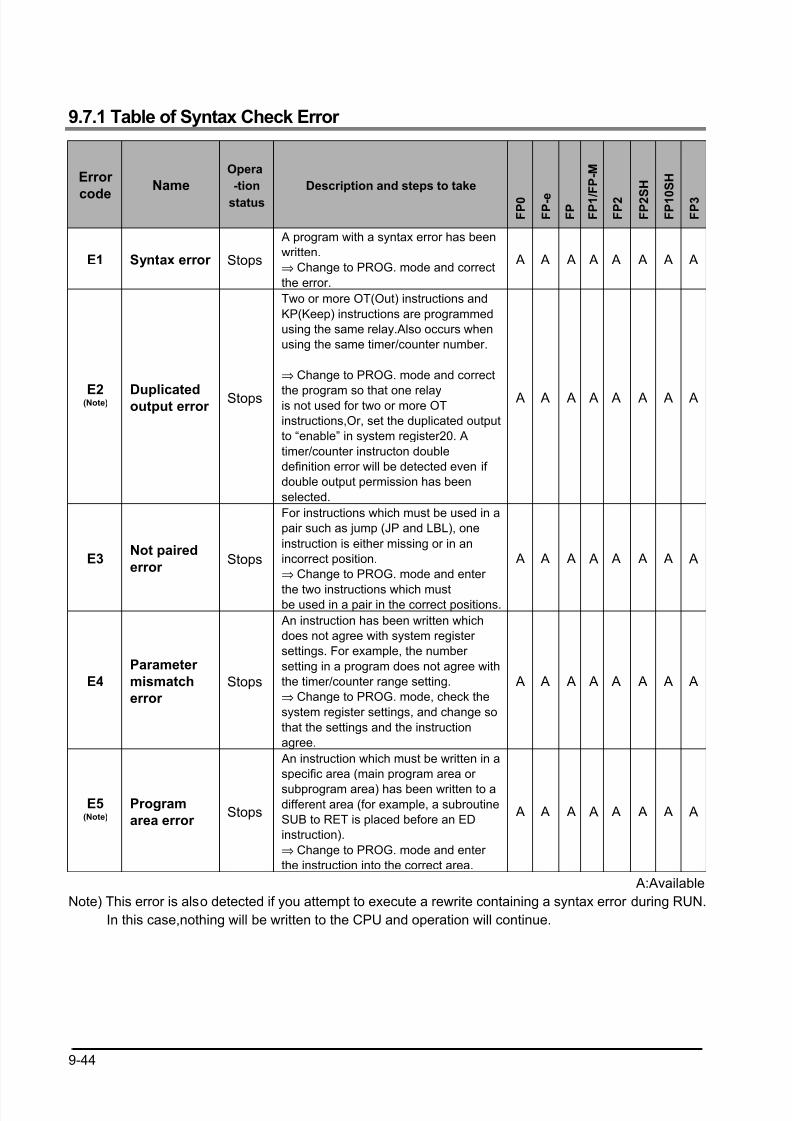
8/21/2019 Programmable Controller FP Sigma
http://slidepdf.com/reader/full/programmable-controller-fp-sigma 276/318
9-44
9.7.1 Table of Syntax Check Error
Error
code
Name
Opera
-tion
status
Description and steps to take
F P 0
F P - e
F P
F P 1 /
F P - M
F P 2
F P 2 S
H
F P 1 0
S H
F P 3
E1 Syntax error Stops
A program with a syntax error has been
written.
⇒ Change to PROG. mode and correct
the error.
A A A A A A A A
E2(Note) Duplicatedoutput error
Stops
Two or more OT(Out) instructions and
KP(Keep) instructions are programmed
using the same relay.Also occurs when
using the same timer/counter number.
⇒ Change to PROG. mode and correct
the program so that one relayis not used for two or more OT
instructions,Or, set the duplicated output
to “enable” in system register20. A
timer/counter instructon double
definition error will be detected even if
double output permission has been
selected.
A A A A A A A A
E3Not paired
error Stops
For instructions which must be used in a
pair such as jump (JP and LBL), one
instruction is either missing or in an
incorrect position.
⇒ Change to PROG. mode and enter
the two instructions which mustbe used in a pair in the correct positions.
A A A A A A A A
E4
Parameter
mismatch
error
Stops
An instruction has been written which
does not agree with system register
settings. For example, the number
setting in a program does not agree with
the timer/counter range setting.
⇒ Change to PROG. mode, check the
system register settings, and change so
that the settings and the instruction
agree.
A A A A A A A A
E5(Note)
Program
area error Stops
An instruction which must be written in a
specific area (main program area or
subprogram area) has been written to adifferent area (for example, a subroutine
SUB to RET is placed before an ED
instruction).
⇒ Change to PROG. mode and enter
the instruction into the correct area.
A A A A A A A A
A:Available
Note) This error is also detected if you attempt to execute a rewrite containing a syntax error during RUN.
In this case,nothing will be written to the CPU and operation will continue.

8/21/2019 Programmable Controller FP Sigma
http://slidepdf.com/reader/full/programmable-controller-fp-sigma 277/318
9-45
Error
codeName
Opera
-tion
status
Description and steps to take
F P 0
F P - e
F P
F P 1 / F P - M
F P 2
F P 2 S H
F P 1 0 S H
F P 3
E6
Compile
memory full
error
Stops
The program is too large to compile in
the program memory.
⇒ Change to PROG. mode and reduce
the total number of steps for the
program.
-FP2SH and FP10SH
If memory expansion is
possible,compilation will become
possible when the memory is expanded.
A A A A A A
E7
High-level
instruction
type error
Stops
In the program, high-level instructions,
which execute in every scan and at the
leading edge of the trigger, are
programmed to be triggered by one
contact. (e.g. F0 (MV) and P0 (PMV) are
programmed using the same trigger
continuously.)
⇒ Correct the program so that the high-
level instructions executed in every scan
and only at the leading edge are
triggered separately.
A A A A A
E8
High-level
instruction
operand
combination
error
Stops
There is an incorrect operand in an
instruction which requires a specific
combination operands (for example, the
operands must all be of a certain type).
⇒ Enter the correct combination of
operands.
A A A A A A A A
E9
No
progra
error
StopsProgram may be damaged.
⇒Try to send the program again. A A
E10
Rewrite
during
RUN
syntax
error
Conti-
nues
When inputting with the programming
tool software,a delection,addition or
change of order of an
instruction(ED,LBL,SUB,RET,INT,IRET,
SSTP,and STPE) that cannot perform a
rewrite during RUN is being attempted.
Nothing is written to the CPU.
A A A A
A:Available
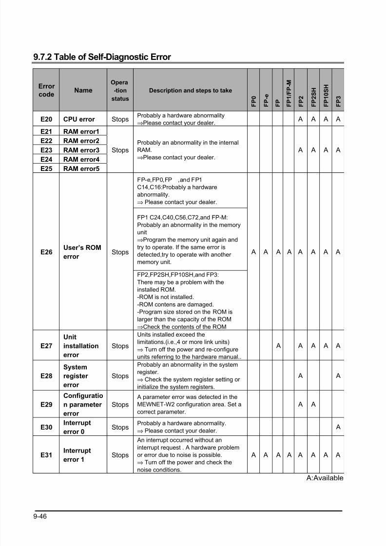
8/21/2019 Programmable Controller FP Sigma
http://slidepdf.com/reader/full/programmable-controller-fp-sigma 278/318
9-46
9.7.2 Table of Self-Diagnostic Error
Error
code
Name
Opera
-tion
status
Description and steps to take
F P 0
F P - e
F P
F P 1 /
F P - M
F P 2
F P 2 S
H
F P 1 0
S H
F P 3
E20 CPU error StopsProbably a hardware abnormality
⇒Please contact your dealer. A A A A
E21 RAM error1
E22 RAM error2
E23 RAM error3
E24 RAM error4
E25 RAM error5
StopsProbably an abnormality in the internal
RAM.
⇒Please contact your dealer.
A A A A
FP-e,FP0,FP ,and FP1
C14,C16:Probably a hardware
abnormality.
⇒ Please contact your dealer.
FP1 C24,C40,C56,C72,and FP-M:
Probably an abnormality in the memory
unit
⇒Program the memory unit again and
try to operate. If the same error is
detected,try to operate with another
memory unit.
E26User’s ROM
error Stops
FP2,FP2SH,FP10SH,and FP3:
There may be a problem with the
installed ROM.
-ROM is not installed.
-ROM contens are damaged.
-Program size stored on the ROM is
larger than the capacity of the ROM
⇒Check the contents of the ROM
A A A A A A A A
E27
Unit
installation
error
Stops
Units installed exceed the
limitations.(i.e.,4 or more link units)
⇒ Turn off the power and re-configure
units referring to the hardware manual..
A A A A A
E28
System
register
error
Stops
Probably an abnormality in the system
register.
⇒ Check the system register setting or
initialize the system registers.
A A
E29
Configuratio
n parameter
error
Stops A parameter error was detected in the
MEWNET-W2 configuration area. Set a
correct parameter.
A A
E30Interrupt
error 0Stops
Probably a hardware abnormality.
⇒ Please contact your dealer. A
E31Interrupt
error 1Stops
An interrupt occurred without an
interrupt request . A hardware problem
or error due to noise is possible.
⇒ Turn off the power and check the
noise conditions.
A A A A A A A A
A:Available
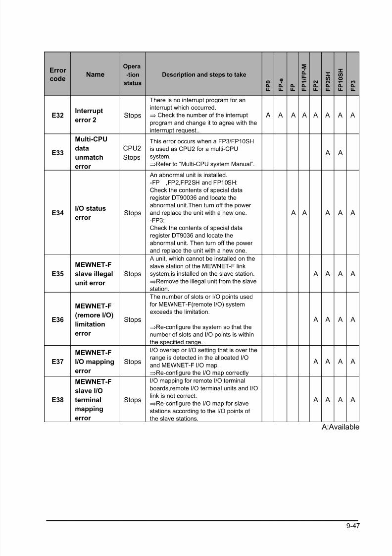
8/21/2019 Programmable Controller FP Sigma
http://slidepdf.com/reader/full/programmable-controller-fp-sigma 279/318
9-47
Error
codeName
Opera
-tion
status
Description and steps to take
F P 0
F P - e
F P
F P 1 / F P - M
F P 2
F P 2 S H
F P 1 0 S H
F P 3
E32Interrupt
error 2Stops
There is no interrupt program for an
interrupt which occurred.
⇒ Check the number of the interrupt
program and change it to agree with the
interrrupt request..
A A A A A A A A
E33
Multi-CPU
data
unmatch
error
CPU2
Stops
This error occurs when a FP3/FP10SH
is used as CPU2 for a multi-CPU
system.
⇒Refer to “Multi-CPU system Manual”.
A A
E34I/O status
error Stops
An abnormal unit is installed.
-FP ,FP2,FP2SH and FP10SH:
Check the contents of special data
register DT90036 and locate the
abnormal unit.Then turn off the power
and replace the unit with a new one.
-FP3:
Check the contents of special data
register DT9036 and locate the
abnormal unit. Then turn off the power
and replace the unit with a new one.
A A A A A
E35
MEWNET-F
slave illegal
unit error
Stops
A unit, which cannot be installed on the
slave station of the MEWNET-F link
system,is installed on the slave station.
⇒Remove the illegal unit from the slave
station.
A A A A
E36
MEWNET-F
(remore I/O)
limitation
error
Stops
The number of slots or I/O points used
for MEWNET-F(remote I/O) system
exceeds the limitation.
⇒Re-configure the system so that the
number of slots and I/O points is within
the specified range.
A A A A
E37
MEWNET-F
I/O mapping
error
Stops
I/O overlap or I/O setting that is over the
range is detected in the allocated I/O
and MEWNET-F I/O map.
⇒Re-configure the I/O map correctly
A A A A
E38
MEWNET-F
slave I/Oterminal
mapping
error
Stops
I/O mapping for remote I/O terminal
boards,remote I/O terminal units and I/Olink is not correct.
⇒Re-configure the I/O map for slave
stations according to the I/O points of
the slave stations.
A A A A
A:Available
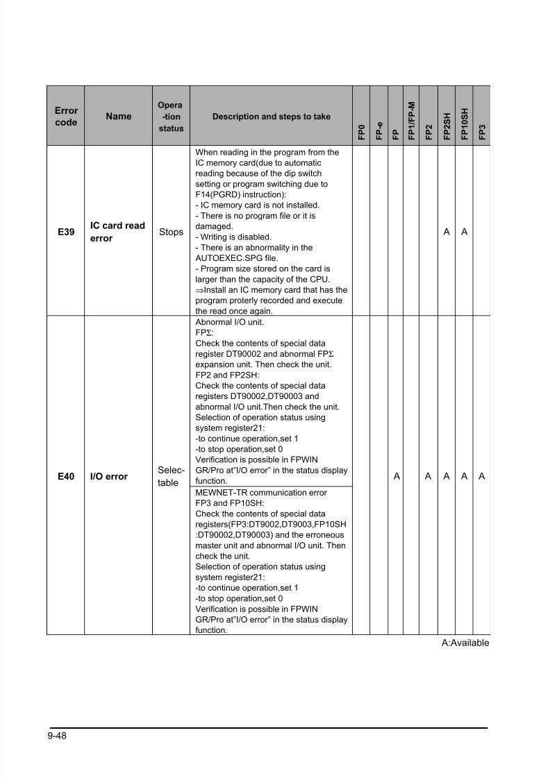
8/21/2019 Programmable Controller FP Sigma
http://slidepdf.com/reader/full/programmable-controller-fp-sigma 280/318
9-48
Error
codeName
Opera
-tion
status
Description and steps to take
F P 0
F P - e
F P
F P 1 / F P - M
F P 2
F P 2 S H
F P 1 0 S H
F P 3
E39IC card read
error Stops
When reading in the program from the
IC memory card(due to automatic
reading because of the dip switch
setting or program switching due to
F14(PGRD) instruction):
- IC memory card is not installed.
- There is no program file or it is
damaged.
- Writing is disabled.
- There is an abnormality in the
AUTOEXEC.SPG file.
- Program size stored on the card islarger than the capacity of the CPU.
⇒Install an IC memory card that has the
program proterly recorded and execute
the read once again.
A A
Abnormal I/O unit.
FPΣ:
Check the contents of special data
register DT90002 and abnormal FPΣ
expansion unit. Then check the unit.
FP2 and FP2SH:
Check the contents of special data
registers DT90002,DT90003 and
abnormal I/O unit.Then check the unit.Selection of operation status using
system register21:
-to continue operation,set 1
-to stop operation,set 0
Verification is possible in FPWIN
GR/Pro at”I/O error” in the status display
function.E40 I/O error
Selec-
tableMEWNET-TR communication error
FP3 and FP10SH:
Check the contents of special data
registers(FP3:DT9002,DT9003,FP10SH
:DT90002,DT90003) and the erroneous
master unit and abnormal I/O unit. Thencheck the unit.
Selection of operation status using
system register21:
-to continue operation,set 1
-to stop operation,set 0
Verification is possible in FPWIN
GR/Pro at”I/O error” in the status display
function.
A A A A A
A:Available
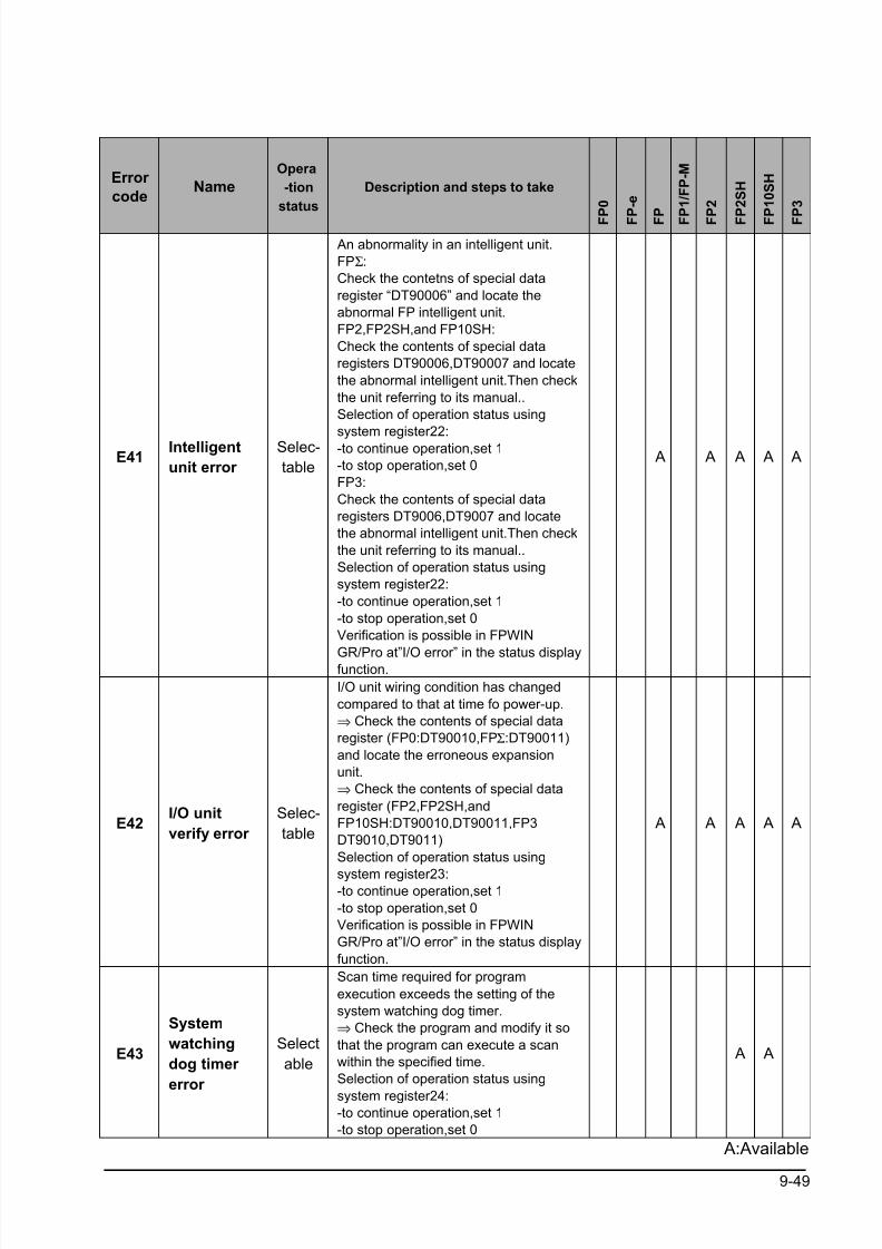
8/21/2019 Programmable Controller FP Sigma
http://slidepdf.com/reader/full/programmable-controller-fp-sigma 281/318
9-49
Error
codeName
Opera
-tion
status
Description and steps to take
F P 0
F P - e
F P
F P 1 / F P - M
F P 2
F P 2 S H
F P 1 0 S H
F P 3
E41Intelligent
unit error
Selec-
table
An abnormality in an intelligent unit.
FPΣ:
Check the contetns of special data
register “DT90006” and locate the
abnormal FP intelligent unit.
FP2,FP2SH,and FP10SH:
Check the contents of special data
registers DT90006,DT90007 and locate
the abnormal intelligent unit.Then check
the unit referring to its manual..
Selection of operation status using
system register22:-to continue operation,set 1
-to stop operation,set 0
FP3:
Check the contents of special data
registers DT9006,DT9007 and locate
the abnormal intelligent unit.Then check
the unit referring to its manual..
Selection of operation status using
system register22:
-to continue operation,set 1
-to stop operation,set 0
Verification is possible in FPWIN
GR/Pro at”I/O error” in the status displayfunction.
A A A A A
E42I/O unit
verify error
Selec-
table
I/O unit wiring condition has changed
compared to that at time fo power-up.
⇒ Check the contents of special data
register (FP0:DT90010,FPΣ:DT90011)
and locate the erroneous expansion
unit.
⇒ Check the contents of special data
register (FP2,FP2SH,and
FP10SH:DT90010,DT90011,FP3
DT9010,DT9011)
Selection of operation status using
system register23:-to continue operation,set 1
-to stop operation,set 0
Verification is possible in FPWIN
GR/Pro at”I/O error” in the status display
function.
A A A A A
E43
System
watching
dog timer
error
Select
able
Scan time required for program
execution exceeds the setting of the
system watching dog timer.
⇒ Check the program and modify it so
that the program can execute a scan
within the specified time.
Selection of operation status using
system register24:-to continue operation,set 1
-to stop operation,set 0
A A
A:Available
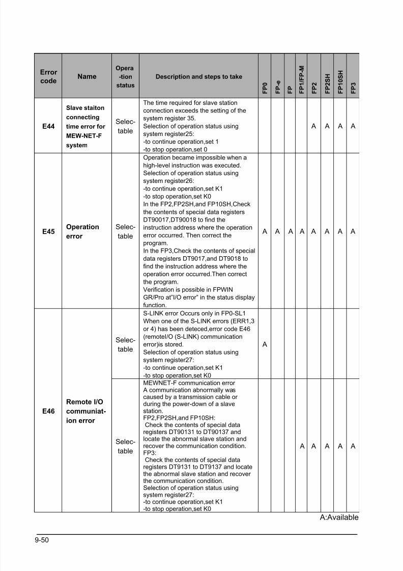
8/21/2019 Programmable Controller FP Sigma
http://slidepdf.com/reader/full/programmable-controller-fp-sigma 282/318
9-50
Error
codeName
Opera
-tion
status
Description and steps to take
F P 0
F P - e
F P
F P 1 / F P - M
F P 2
F P 2 S H
F P 1 0 S H
F P 3
E44
Slave staiton
connecting
time error for
MEW-NET-F
system
Selec-
table
The time required for slave station
connection exceeds the setting of the
system register 35.
Selection of operation status using
system register25:
-to continue operation,set 1
-to stop operation,set 0
A A A A
E45Operation
error
Selec-
table
Operation became impossible when a
high-level instruction was executed.
Selection of operation status using
system register26:
-to continue operation,set K1
-to stop operation,set K0
In the FP2,FP2SH,and FP10SH,Check
the contents of special data registers
DT90017,DT90018 to find the
instruction address where the operation
error occurred. Then correct the
program.
In the FP3,Check the contents of special
data registers DT9017,and DT9018 to
find the instruction address where the
operation error occurred.Then correct
the program.
Verification is possible in FPWIN
GR/Pro at”I/O error” in the status displayfunction.
A A A A A A A A
Selec-
table
S-LINK error Occurs only in FP0-SL1
When one of the S-LINK errors (ERR1,3
or 4) has been deteced,error code E46
(remoteI/O (S-LINK) communication
error)is stored.
Selection of operation status using
system register27:
-to continue operation,set K1
-to stop operation,set K0
A
E46Remote I/Ocommuniat-
ion error
Selec-
table
MEWNET-F communication error A communication abnormally was
caused by a transmission cable or during the power-down of a slavestation.FP2,FP2SH,and FP10SH: Check the contents of special dataregisters DT90131 to DT90137 andlocate the abnormal slave station andrecover the communication condition.FP3: Check the contents of special dataregisters DT9131 to DT9137 and locatethe abnormal slave station and recover the communication condition.Selection of operation status usingsystem register27:
-to continue operation,set K1-to stop operation,set K0
A A A A A
A:Available
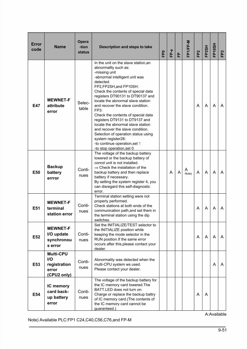
8/21/2019 Programmable Controller FP Sigma
http://slidepdf.com/reader/full/programmable-controller-fp-sigma 283/318
9-51
Error
codeName
Opera
-tion
status
Description and steps to take
F P 0
F P - e
F P
F P 1 / F P - M
F P 2
F P 2 S H
F P 1 0 S H
F P 3
E47
MEWNET-F
attribute
error
Selec-
table
In the unit on the slave station,an
abnormallty such as:
-missing unit
-abnormal intelligent unit was
detected.
FP2,FP2SH,and FP10SH:
Check the contents of special data
registers DT90131 to DT90137 and
locate the abnormal slave station
and recover the slave condition.
FP3:
Check the contents of special data
registers DT9131 to DT9137 and
locate the abnormal slave station
and recover the slave condition.
Selection of operation status using
system register28:
-to continue operation,set 1
-to stop operation,set 0
A A A A
E50
Backup
battery
errror
Conti-
nues
The voltage of the backup battery
lowered or the backup battery of
conrol unit is not installed.
⇒ Check the installation of the
backup battery and then replace
battery if necessary.
By setting the system register 4, youcan disregard this self-diagnostic
error.
A A ANote) A A A A
E51
MEWNET-F
terminal
station error
Conti-
nues
Terminal station setting were not
properly performed.
Check stations at both ends of the
communication path,and set them in
the terminal station using the dip
switches.
A A A A
E52
MEWNET-F
I/O update
synchronou
s error
Conti-
nues
Set the INITIALIZE/TEST selector to
the INITIALIZE position while
keeping the mode selector in the
RUN position.If the same error
occurs after this,please contact your dealer.
A A A A
E53
Multi-CPU
I/O
registration
error
(CPU2 only)
Conti-
nues
Abnormality was detected when the
multi-CPU system ws used.
Please contact your dealer.
A A
E54
IC memory
card back-
up battery
error
Conti-
nues
The voltage of the backup battery for
the IC memory card lowered.The
BATT.LED does not turn on.
Charge or replace the backup battry
of IC memory card.(The contents of
the IC memory card cannot beguaranteed.)
A A
A:Available
Note) Available PLC:FP1 C24,C40,C56,C76,and FP-M
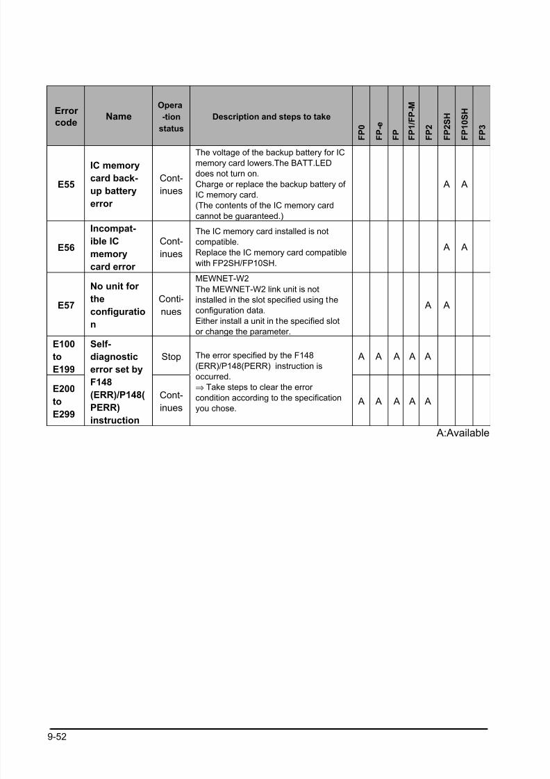
8/21/2019 Programmable Controller FP Sigma
http://slidepdf.com/reader/full/programmable-controller-fp-sigma 284/318
9-52
Error
codeName
Opera
-tion
status
Description and steps to take
F P 0
F P - e
F P
F P 1 / F P - M
F P 2
F P 2 S H
F P 1 0 S H
F P 3
E55
IC memory
card back-
up battery
error
Cont-
inues
The voltage of the backup battery for IC
memory card lowers.The BATT.LED
does not turn on.
Charge or replace the backup battery of
IC memory card.
(The contents of the IC memory card
cannot be guaranteed.)
A A
E56
Incompat-
ible IC
memory
card error
Cont-
inues
The IC memory card installed is not
compatible.
Replace the IC memory card compatible
with FP2SH/FP10SH.
A A
E57
No unit for
the
configuratio
n
Conti-
nues
MEWNET-W2
The MEWNET-W2 link unit is not
installed in the slot specified using the
configuration data.
Either install a unit in the specified slot
or change the parameter.
A A
E100
to
E199
Stop A A A A A
E200
to
E299
Self-
diagnostic
error set by
F148
(ERR)/P148(
PERR)instruction
Cont-
inues
The error specified by the F148
(ERR)/P148(PERR) instruction is
occurred.
⇒ Take steps to clear the error
condition according to the specification
you chose.
A A A A A
A:Available
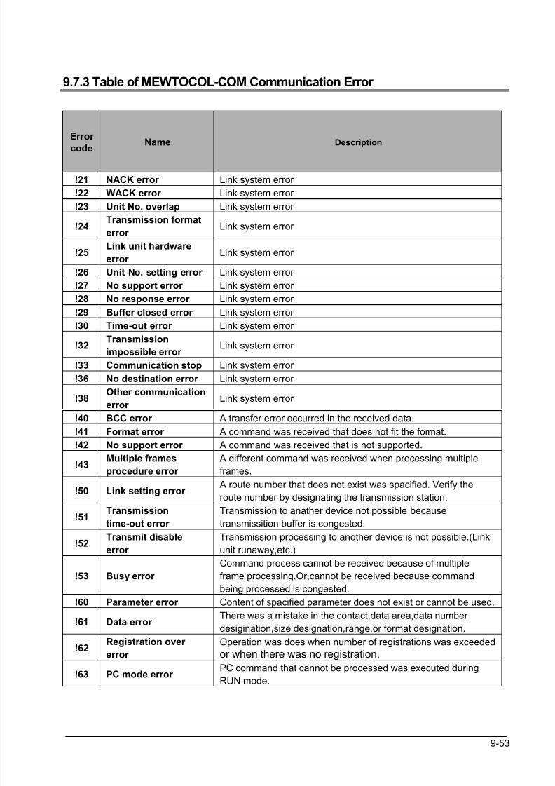
8/21/2019 Programmable Controller FP Sigma
http://slidepdf.com/reader/full/programmable-controller-fp-sigma 285/318
9-53
9.7.3 Table of MEWTOCOL-COM Communication Error
Error code
Name Description
!21 NACK error Link system error
!22 WACK error Link system error
!23 Unit No. overlap Link system error
!24Transmission format
error Link system error
!25Link unit hardware
error Link system error
!26 Unit No. setting error Link system error !27 No support error Link system error
!28 No response error Link system error
!29 Buffer closed error Link system error
!30 Time-out error Link system error
!32Transmission
impossible error Link system error
!33 Communication stop Link system error
!36 No destination error Link system error
!38Other communication
error Link system error
!40 BCC error A transfer error occurred in the received data.
!41 Format error A command was received that does not fit the format.
!42 No support error A command was received that is not supported.
!43Multiple frames
procedure error
A different command was received when processing multiple
frames.
!50 Link setting error A route number that does not exist was spacified. Verify the
route number by designating the transmission station.
!51Transmission
time-out error
Transmission to anather device not possible because
transmissition buffer is congested.
!52Transmit disable
error
Transmission processing to another device is not possible.(Link
unit runaway,etc.)
!53 Busy error
Command process cannot be received because of multiple
frame processing.Or,cannot be received because command
being processed is congested.
!60 Parameter error Content of spacified parameter does not exist or cannot be used.
!61 Data error There was a mistake in the contact,data area,data number
desigination,size designation,range,or format designation.
!62Registration over
error
Operation was does when number of registrations was exceeded
or when there was no registration.
!63 PC mode error PC command that cannot be processed was executed during
RUN mode.
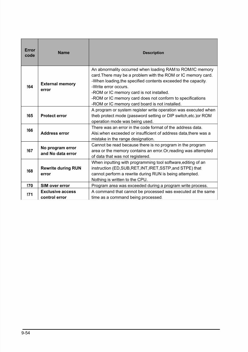
8/21/2019 Programmable Controller FP Sigma
http://slidepdf.com/reader/full/programmable-controller-fp-sigma 286/318
9-54
Error
codeName Description
!64External memory
error
An abnormality occurred when loading RAM to ROM/IC memory
card.There may be a problem with the ROM or IC memory card.
-When loading,the specified contents exceeded the capacity.
-Write error occurs.
-ROM or IC memory card is not installed.
-ROM or IC memory card does not conform to specifications
-ROM or IC memory card board is not installed.
!65 Protect error
A program or system register write operation was executed when
theb protect mode (password setting or DIP switch,etc.)or ROM
operation mode was being used.
!66Address error
There was an error in the code format of the address data.
Alsi.when exceeded or insufficient of address data,there was a
mistake in the range designation.
!67No program error
and No data error
Cannot be read because there is no program in the program
area or the memory contains an error.Or,reading was attempted
of data that was not registered.
!68Rewrite during RUN
error
When inputting with programming tool software,editing of an
instruction (ED,SUB,RET,INT,IRET,SSTP,and STPE) that
cannot perform a rewrite during RUN is being attempted.
Nothing is written to the CPU.
!70 SIM over error Program area was exceeded during a program write process.
!71Exclusive access
control error
A command that cannot be processed was executed at the same
time as a command being processed.
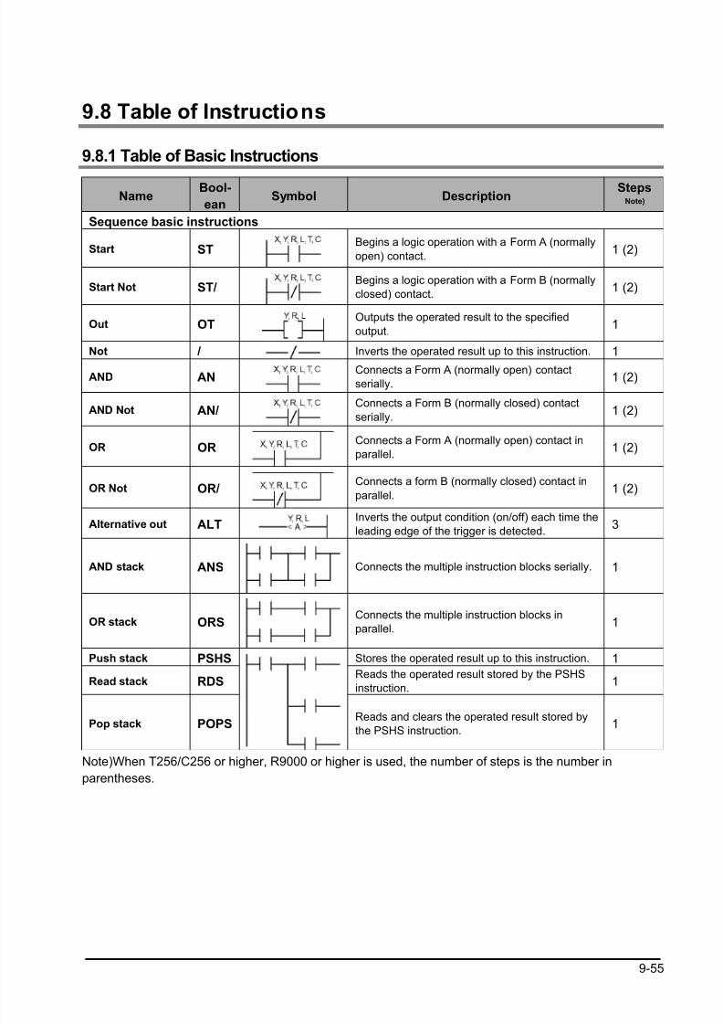
8/21/2019 Programmable Controller FP Sigma
http://slidepdf.com/reader/full/programmable-controller-fp-sigma 287/318
9-55
9.8 Table of Instructions
9.8.1 Table of Basic Instructions
NameBool-
eanSymbol Description
StepsNote)
Sequence basic instructions
Start STBegins a logic operation with a Form A (normally
open) contact.1 (2)
Start Not ST/Begins a logic operation with a Form B (normally
closed) contact.1 (2)
Out OTOutputs the operated result to the specified
output.1
Not / Inverts the operated result up to this instruction. 1
AND ANConnects a Form A (normally open) contact
serially.1 (2)
AND Not AN/Connects a Form B (normally closed) contact
serially.1 (2)
OR ORConnects a Form A (normally open) contact in
parallel.1 (2)
OR Not OR/Connects a form B (normally closed) contact in
parallel.1 (2)
Alternative out ALTInverts the output condition (on/off) each time the
leading edge of the trigger is detected.3
AND stack ANS Connects the multiple instruction blocks serially. 1
OR stack ORSConnects the multiple instruction blocks in
parallel.1
Push stack PSHS Stores the operated result up to this instruction. 1
Read stack RDSReads the operated result stored by the PSHS
instruction.1
Pop stack POPS Reads and clears the operated result stored bythe PSHS instruction.
1
Note)When T256/C256 or higher, R9000 or higher is used, the number of steps is the number in
parentheses.
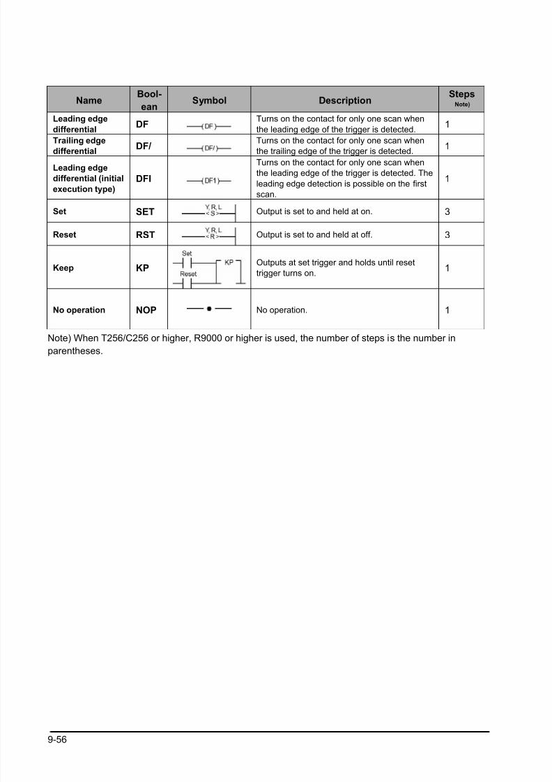
8/21/2019 Programmable Controller FP Sigma
http://slidepdf.com/reader/full/programmable-controller-fp-sigma 288/318
9-56
NameBool-
eanSymbol Description
StepsNote)
Leading edge
differentialDF
Turns on the contact for only one scan when
the leading edge of the trigger is detected.1
Trailing edge
differentialDF/
Turns on the contact for only one scan when
the trailing edge of the trigger is detected.1
Leading edge
differential (initial
execution type)
DFI
Turns on the contact for only one scan when
the leading edge of the trigger is detected. The
leading edge detection is possible on the first
scan.
1
Set SET Output is set to and held at on. 3
Reset RST Output is set to and held at off. 3
Keep KPOutputs at set trigger and holds until reset
trigger turns on.1
No operation NOP No operation. 1
Note) When T256/C256 or higher, R9000 or higher is used, the number of steps is the number in
parentheses.
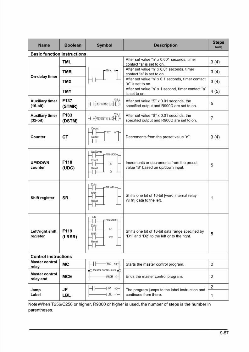
8/21/2019 Programmable Controller FP Sigma
http://slidepdf.com/reader/full/programmable-controller-fp-sigma 289/318
9-57
Name Boolean Symbol DescriptionSteps
Note)
Basic function instructions
TML After set value “n” x 0.001 seconds, timer
contact “a” is set to on. 3 (4)
TMR After set value “n” x 0.01 seconds, timer
contact “a” is set to on.3 (4)
TMX After set value “n” x 0.1 seconds, timer contact
“a” is set to on.3 (4)
On-delay timer
TMY After set value “n” x 1 second, timer contact “a”
is set to on.4 (5)
Auxiliary timer
(16-bit)
F137
(STMR)
After set value “S” x 0.01 seconds, the
specified output and R900D are set to on.5
Auxiliary timer
(32-bit)
F183
(DSTM)
After set value “S” x 0.01 seconds, the
specified output and R900D are set to on.7
Counter CT Decrements from the preset value “n”. 3 (4)
UP/DOWN
counter
F118
(UDC)
Increments or decrements from the preset
value “S” based on up/down input.5
Shift register SRShifts one bit of 16-bit [word internal relay
WRn] data to the left.1
Left/right shift
register
F119
(LRSR)
Shifts one bit of 16-bit data range specified by
“D1” and “D2” to the left or to the right.5
Control instructions
Master control
relayMC Starts the master control program. 2
Master control
relay endMCE Ends the master control program. 2
2Jamp
Label
JP
LBL
The program jumps to the label instruction and
continues from there. 1
Note)When T256/C256 or higher, R9000 or higher is used, the number of steps is the number in
parentheses.
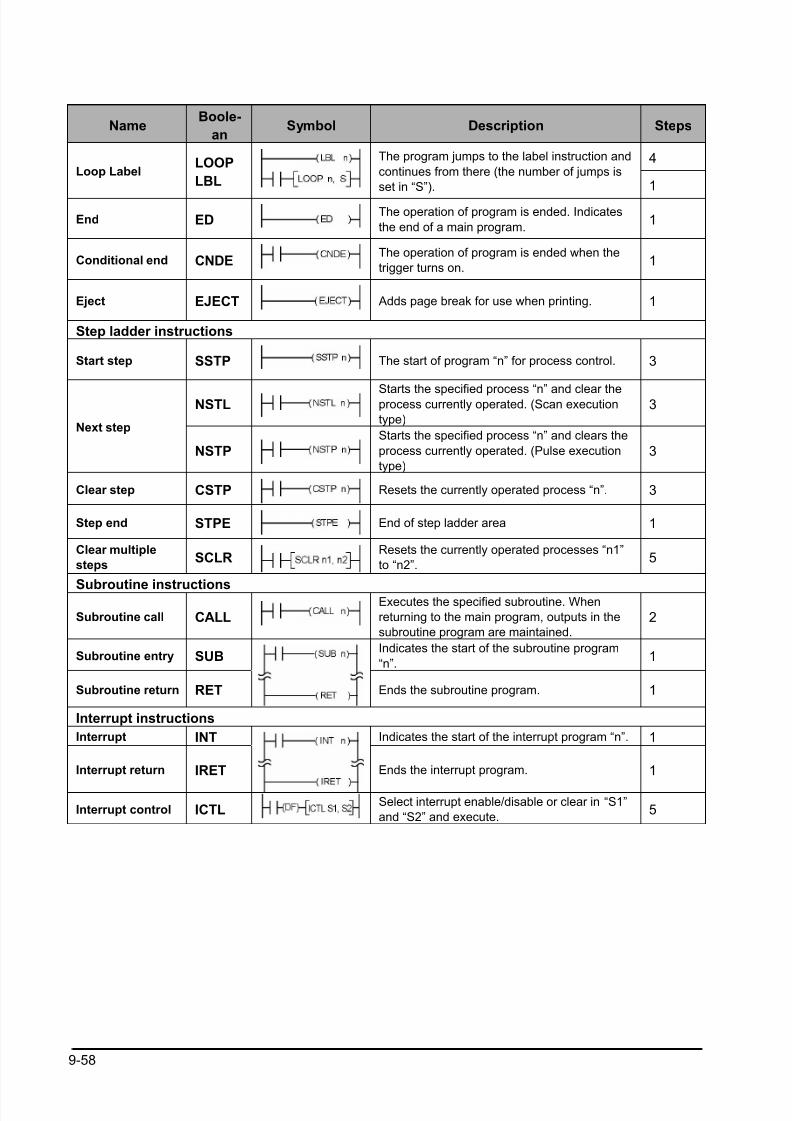
8/21/2019 Programmable Controller FP Sigma
http://slidepdf.com/reader/full/programmable-controller-fp-sigma 290/318
9-58
NameBoole-
anSymbol Description Steps
4Loop Label
LOOP
LBL
The program jumps to the label instruction and
continues from there (the number of jumps is
set in “S”). 1
End EDThe operation of program is ended. Indicates
the end of a main program.1
Conditional end CNDEThe operation of program is ended when the
trigger turns on.1
Eject EJECT Adds page break for use when printing. 1
Step ladder instructions
Start step SSTP The start of program “n” for process control. 3
NSTLStarts the specified process “n” and clear theprocess currently operated. (Scan execution
type)
3
Next step
NSTPStarts the specified process “n” and clears the
process currently operated. (Pulse execution
type)
3
Clear step CSTP Resets the currently operated process “n”. 3
Step end STPE End of step ladder area 1
Clear multiple
stepsSCLR
Resets the currently operated processes “n1”
to “n2”.5
Subroutine instructions
Subroutine call CALLExecutes the specified subroutine. When
returning to the main program, outputs in the
subroutine program are maintained.
2
Subroutine entry SUBIndicates the start of the subroutine program
“n”.1
Subroutine return RET Ends the subroutine program. 1
Interrupt instructions
Interrupt INT Indicates the start of the interrupt program “n”. 1
Interrupt return IRET Ends the interrupt program. 1
Interrupt control ICTLSelect interrupt enable/disable or clear in “S1”
and “S2” and execute.5
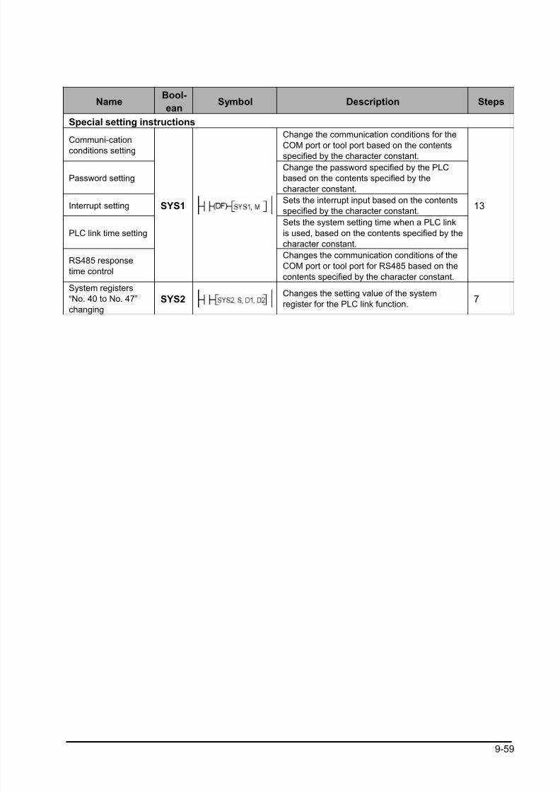
8/21/2019 Programmable Controller FP Sigma
http://slidepdf.com/reader/full/programmable-controller-fp-sigma 291/318
9-59
NameBool-
eanSymbol Description Steps
Special setting instructions
Communi-cationconditions setting
Change the communication conditions for theCOM port or tool port based on the contents
specified by the character constant.
Password setting
Change the password specified by the PLC
based on the contents specified by the
character constant.
Interrupt settingSets the interrupt input based on the contents
specified by the character constant.
PLC link time setting
Sets the system setting time when a PLC link
is used, based on the contents specified by the
character constant.
RS485 response
time control
SYS1
Changes the communication conditions of the
COM port or tool port for RS485 based on the
contents specified by the character constant.
13
System registers
“No. 40 to No. 47”
changingSYS2
Changes the setting value of the system
register for the PLC link function.7

8/21/2019 Programmable Controller FP Sigma
http://slidepdf.com/reader/full/programmable-controller-fp-sigma 292/318
9-60
Name Boolean Symbol Description Steps
Data comparison instructions
ST=Begins a logic operation by comparing two 16-
bit data in the comparative condition “S1=S2”.
5
ST<>Begins a logic operation by comparing two 16-
bit data in the comparative condition “S1≠S2”.5
ST>Begins a logic operation by comparing two 16-
bit data in the comparative condition “S1>S2”.5
ST>=Begins a logic operation by comparing two 16-
bit data in the comparative condition “S1 S2”.5
ST<Begins a logic operation by comparing two 16-
bit data in the comparative condition “S1<S2”.5
16-bit data
comparison
(Start)
ST<=Begins a logic operation by comparing two 16-
bit data in the comparative condition “S1 S2”. 5
AN=Connects a contact serially by comparing two
16-bit data in the comparative condition
“S1=S2”.
5
AN<>Connects a contact serially by comparing two
16-bit data in the comparative condition
“S1≠S2”.
5
AN>Connects a contact serially by comparing two
16-bit data in the comparative condition
“S1>S2”.
5
AN>=Connects a contact serially by comparing two
16-bit data in the comparative condition
“S1 S2”.
5
AN<Connects a contact serially by comparing two
16-bit data in the comparative condition
“S1<S2”.
5
16-bit data
comparison
(AND)
AN<=Connects a contact serially by comparing two
16-bit data in the comparative condition
“S1 S2”.
5
OR=Connects a contact in parallel by comparing
two 16-bit data in the comparative condition
“S1=S2”.
5
OR<>
Connects a contact in parallel by comparing
two 16-bit data in the comparative condition
“S1≠
S2”.
5
OR>Connects a contact in parallel by comparing
two 16-bit data in the comparative condition
“S1>S2”.
5
OR>=Connects a contact in parallel by comparing
two 16-bit data in the comparative condition
“S1 S2”.
5
OR<Connects a contact in parallel by comparing
two 16-bit data in the comparative condition
“S1<S2”.
5
16-bit data
comparison
(OR)
OR<=Connects a contact in parallel by comparing
two 16-bit data in the comparative condition
“S1 S2”.
5
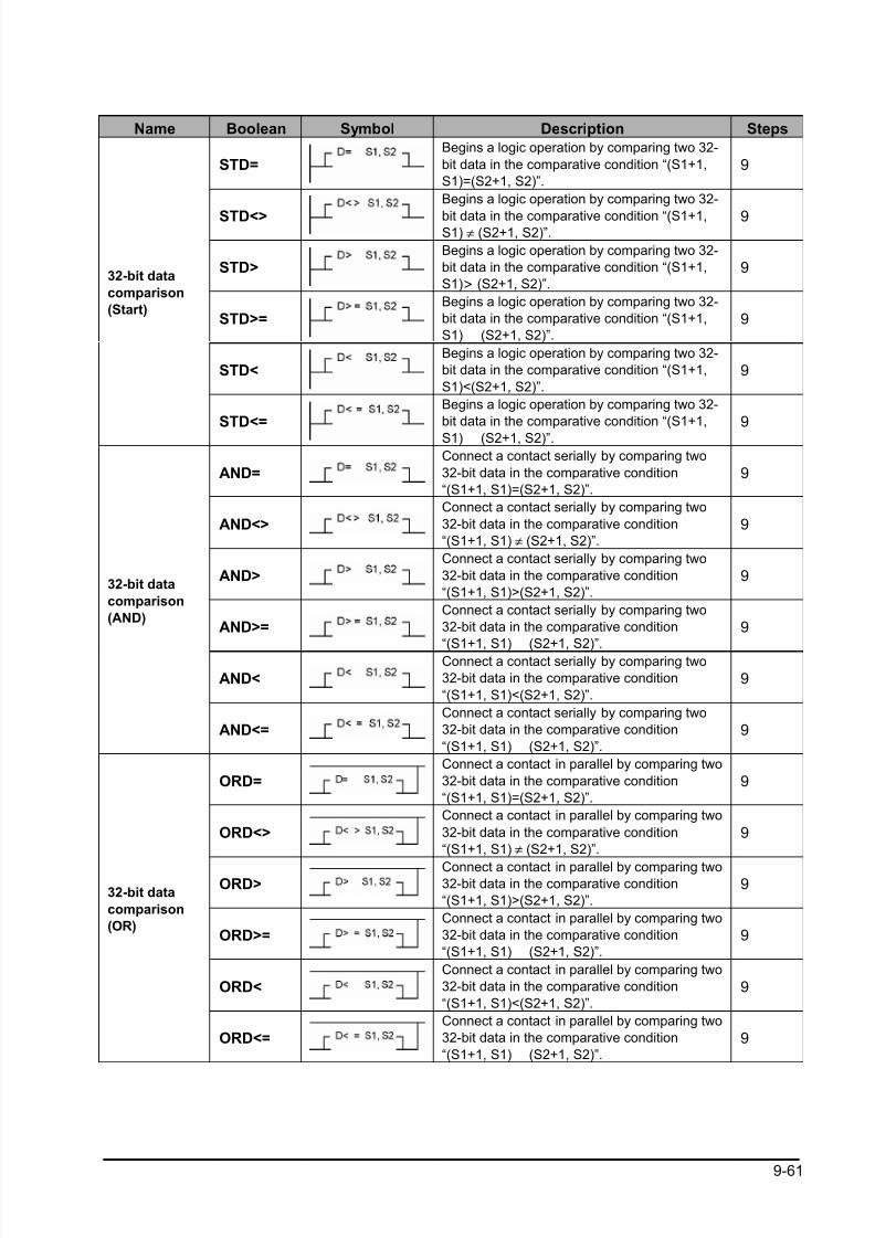
8/21/2019 Programmable Controller FP Sigma
http://slidepdf.com/reader/full/programmable-controller-fp-sigma 293/318
9-61
Name Boolean Symbol Description Steps
STD=Begins a logic operation by comparing two 32-
bit data in the comparative condition “(S1+1,
S1)=(S2+1, S2)”.
9
STD<>
Begins a logic operation by comparing two 32-
bit data in the comparative condition “(S1+1,S1) ≠ (S2+1, S2)”.
9
STD>Begins a logic operation by comparing two 32-
bit data in the comparative condition “(S1+1,
S1) > (S2+1, S2)”.
9
STD>=Begins a logic operation by comparing two 32-
bit data in the comparative condition “(S1+1,
S1) (S2+1, S2)”.9
STD<Begins a logic operation by comparing two 32-
bit data in the comparative condition “(S1+1,
S1)<(S2+1, S2)”.
9
32-bit data
comparison
(Start)
STD<=Begins a logic operation by comparing two 32-
bit data in the comparative condition “(S1+1,
S1) (S2+1, S2)”.
9
AND=Connect a contact serially by comparing two
32-bit data in the comparative condition
“(S1+1, S1)=(S2+1, S2)”.
9
AND<>Connect a contact serially by comparing two
32-bit data in the comparative condition
“(S1+1, S1) ≠ (S2+1, S2)”.
9
AND>Connect a contact serially by comparing two
32-bit data in the comparative condition
“(S1+1, S1)>(S2+1, S2)”.
9
AND>=Connect a contact serially by comparing two
32-bit data in the comparative condition
“(S1+1, S1)
(S2+1, S2)”.
9
AND<Connect a contact serially by comparing two
32-bit data in the comparative condition
“(S1+1, S1)<(S2+1, S2)”.
9
32-bit data
comparison
(AND)
AND<=Connect a contact serially by comparing two
32-bit data in the comparative condition
“(S1+1, S1) (S2+1, S2)”.
9
ORD=Connect a contact in parallel by comparing two
32-bit data in the comparative condition
“(S1+1, S1)=(S2+1, S2)”.
9
ORD<>
Connect a contact in parallel by comparing two
32-bit data in the comparative condition
“(S1+1, S1) ≠ (S2+1, S2)”.
9
ORD>Connect a contact in parallel by comparing two32-bit data in the comparative condition
“(S1+1, S1)>(S2+1, S2)”.
9
ORD>=Connect a contact in parallel by comparing two
32-bit data in the comparative condition
“(S1+1, S1) (S2+1, S2)”.
9
ORD<Connect a contact in parallel by comparing two
32-bit data in the comparative condition
“(S1+1, S1)<(S2+1, S2)”.
9
32-bit data
comparison
(OR)
ORD<=Connect a contact in parallel by comparing two
32-bit data in the comparative condition
“(S1+1, S1) (S2+1, S2)”.
9

8/21/2019 Programmable Controller FP Sigma
http://slidepdf.com/reader/full/programmable-controller-fp-sigma 294/318
9-62
Table of High-level Instructions
No. Name Boolean Operand Description Steps
Data transfer instructions
0 16-bit data move MV S, D (S)→(D) 5
1 32-bit data move DMV S, D (S+1, S)→
(D+1, D) 72
16-bit data in-
vert and moveMV/ S, D (S)→(D) 5
332-bit data in-
vert and moveDMV/ S, D (S+1, S)→(D+1, D) 7
5 Bit data move BTM S, n, DThe specified one bit in “S” is transferred to the
specified one bit in “D”. The bit is specified by
“n”.
7
6Hexadecimal
digit (4-bit) data
move
DGT S, n, DThe specified one digit in “S” is transferred to the
specified one digit in “D”. The digit is specified by
“n”.
7
7Two 16-bit data
moveMV2 S1, S2, D (S1)→(D), (S2)→(D+1) 7
8Two 32-bit datamove
DMV2 S1, S2, D(S1+1, S1)→(D+1, D),(S2+1, S2)→(D+3, D+2)
11
10 Block move BKMV S1, S2, DThe data between “S1” and “S2” is transferred to
the area starting at “D”.7
11 Block copy COPY S, D1, D2The data of “S” is transferred to the all area
between “D1” and “D2”.7
12Data read from
F-ROMICRD S1, S2, D
The data stored in the F-ROM specified by “S1”
and “S2” are transferred to the area starting at
“D”.
11
13Data write to F-
ROMPICWT S1, S2, D
The data specified by “S1” and “S2” are
transferred to the F-ROM starting at “D”.11
1516-bit data
exchange
XCH D1, D2 (D1)→(D2), (D2)→(D1) 5
1632-bit data
exchangeDXCH D1, D2
(D1+1, D1)→(D2+1, D2)
(D2+1, D2)→(D1+1, D1)5
17Higher/lower
byte in 16-bit
data exchange
SWAP DThe higher byte and lower byte of “D” are
exchanged.3
1816-bit data block
exchangeBXCH
D1, D2,
D3
Exchanges the data between “D1” and “D2” with
the data specified by “D3”.7

8/21/2019 Programmable Controller FP Sigma
http://slidepdf.com/reader/full/programmable-controller-fp-sigma 295/318
9-63
No. Name Boolean Operand Description Steps
Binary arithmetic instructions
2016-bit data
addition+ S, D (D)+(S)→(D) 5
2132-bit data
additionD+ S, D (D+1, D)+(S+1, S)→(D+1, D) 7
22
16-bit data
addition
(Destination
setting)
+ S1, S2, D (S1)+(S2)→(D) 7
23
32-bit data
addition
(Destination
setting)
D+ S1, S2, D (S1+1, S1)+(S2+1, S2)→(D+1, D) 11
2516-bit data
subtraction −−−− S, D (D)−(S)→(D) 5
26 32-bit datasubtraction D−−−− S, D (D+1, D)−(S+1, S)→(D+1, D) 7
27
16-bit data
subtraction
(Destination
setting)
−−−− S1, S2, D (S1)−(S2)→(D) 7
28
32-bit data
subtraction
(Destination
setting)
D−−−− S1, S2, D (S1+1, S1)−(S2+1, S2)→(D+1, D) 11
3016-bit data
multiplication ∗∗∗∗ S1, S2, D (S1)x(S2)→(D+1, D) 7
31
32-bit data
multiplication D∗∗∗∗
S1, S2, D(S1+1, S1)x(S2+1, S2)→(D+3,D+2,D+1,D)
11
3216-bit data
division% S1, S2, D
(S1)÷(S2)→quotient (D)
remainder (DT90015)7
3332-bit data
divisionD% S1, S2, D
(S1+1, S1)÷(S2+1, S2)→quotient (D+1, D)
remainder (DT90016, DT90015)11
34
16-bit data
multiplication
(result in one
word)
∗∗∗∗W S1, S2, D (S1)x(S2)→(D) 7
3516-bit data
increment+1 D (D)+1→(D) 3
3632-bit data
incrementD+1 D (D+1, D)+1→(D+1, D) 3
3716-bit data
decrement −−−−1 D (D) −1→(D) 3
3832-bit data
decrementD−−−−1 D (D+1, D) −1→(D+1, D) 3
39
32-bit data
multiplication
(result in two
words)
D∗∗∗∗D S1, S2, D (S1+1, S1)x(S2+1, S2)→(D+1, D) 11
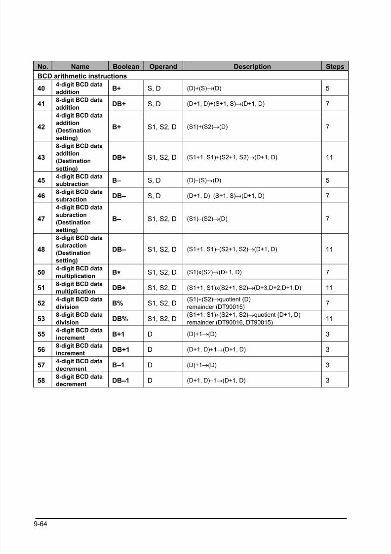
8/21/2019 Programmable Controller FP Sigma
http://slidepdf.com/reader/full/programmable-controller-fp-sigma 296/318
9-64
No. Name Boolean Operand Description Steps
BCD arithmetic instructions
404-digit BCD data
additionB+ S, D (D)+(S)→(D) 5
418-digit BCD data
additionDB+ S, D (D+1, D)+(S+1, S)→(D+1, D) 7
42
4-digit BCD data
addition
(Destination
setting)
B+ S1, S2, D (S1)+(S2)→(D) 7
43
8-digit BCD data
addition
(Destination
setting)
DB+ S1, S2, D (S1+1, S1)+(S2+1, S2)→(D+1, D) 11
454-digit BCD data
subtractionB−−−− S, D (D)−(S)→(D) 5
46 8-digit BCD datasubraction DB−−−− S, D (D+1, D)−(S+1, S)→(D+1, D) 7
47
4-digit BCD data
subraction
(Destination
setting)
B−−−− S1, S2, D (S1)−(S2)→(D) 7
48
8-digit BCD data
subraction
(Destination
setting)
DB−−−− S1, S2, D (S1+1, S1)−(S2+1, S2)→(D+1, D) 11
504-digit BCD data
multiplicationB∗∗∗∗ S1, S2, D (S1)x(S2)→(D+1, D) 7
51
8-digit BCD data
multiplication DB∗∗∗∗
S1, S2, D(S1+1, S1)x(S2+1, S2)→(D+3,D+2,D+1,D)
11
524-digit BCD data
divisionB% S1, S2, D
(S1)÷(S2)→quotient (D)
remainder (DT90015)7
538-digit BCD data
divisionDB% S1, S2, D
(S1+1, S1)÷(S2+1, S2)→quotient (D+1, D)
remainder (DT90016, DT90015)11
554-digit BCD data
incrementB+1 D (D)+1→(D) 3
568-digit BCD data
incrementDB+1 D (D+1, D)+1→(D+1, D) 3
574-digit BCD data
decrementB−−−−1 D (D)+1→(D) 3
588-digit BCD data
decrementDB−−−−1 D (D+1, D)−1→(D+1, D) 3
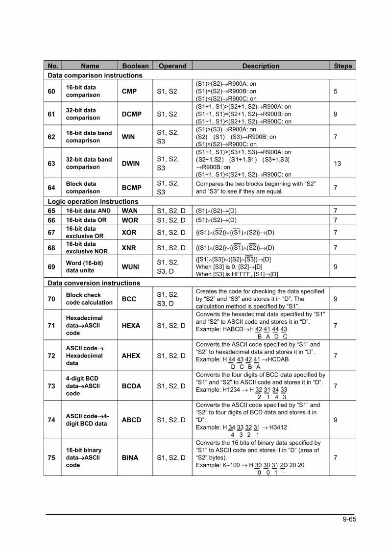
8/21/2019 Programmable Controller FP Sigma
http://slidepdf.com/reader/full/programmable-controller-fp-sigma 297/318
9-65
No. Name Boolean Operand Description Steps
Data comparison instructions
6016-bit data
comparisonCMP S1, S2
(S1)>(S2)→R900A: on
(S1)=(S2)→R900B: on
(S1)<(S2)→R900C: on
5
6132-bit data
comparisonDCMP S1, S2
(S1+1, S1)>(S2+1, S2)→R900A: on
(S1+1, S1)=(S2+1, S2)→R900B: on
(S1+1, S1)<(S2+1, S2)→R900C: on
9
6216-bit data band
comaprisonWIN
S1, S2,
S3
(S1)>(S3)→R900A: on
(S2) (S1) (S3)→R900B: on
(S1)<(S2)→R900C: on
7
6332-bit data band
comparisonDWIN
S1, S2,
S3
(S1+1, S1)>(S3+1, S3)→R900A: on
(S2+1,S2) (S1+1,S1) (S3+1,S3)
→R900B: on
(S1+1, S1)<(S2+1, S2)→R900C: on
13
64Block data
comparisonBCMP
S1, S2,
S3
Compares the two blocks beginning with “S2”
and “S3” to see if they are equal.7
Logic operation instructions
65 16-bit data AND WAN S1, S2, D (S1)∧(S2)→(D) 7
66 16-bit data OR WOR S1, S2, D (S1)∨(S2)→(D) 7
6716-bit data
exclusive ORXOR S1, S2, D (S1)∧(S2)∨(S1)∧(S2)→(D) 7
6816-bit data
exclusive NORXNR S1, S2, D (S1)∧(S2)∨(S1)∧(S2)→(D) 7
69Word (16-bit)
data uniteWUNI
S1, S2,
S3, D
([S1]∧[S3])∨([S2]∧[S3])→[D]
When [S3] is 0, [S2]→[D]
When [S3] is HFFFF, [S1]→[D]
9
Data conversion instructions
70Block check
code calculationBCC
S1, S2,
S3, D
Creates the code for checking the data specified
by “S2” and “S3” and stores it in “D”. The
calculation method is specified by “S1”.
9
71Hexadecimal
data→→→→ASCII
code
HEXA S1, S2, D
Converts the hexadecimal data specified by “S1”
and “S2” to ASCII code and stores it in “D”.
Example: HABCD→H 42 41 44 43
B A D C
7
72ASCII code→→→→
Hexadecimal
data
AHEX S1, S2, D
Converts the ASCII code specified by “S1” and
“S2” to hexadecimal data and stores it in “D”.
Example: H 44 43 42 41 →HCDAB
D C B A
7
73
4-digit BCD
data→→→→ASCIIcode
BCDA S1, S2, D
Converts the four digits of BCD data specified by
“S1” and “S2” to ASCII code and stores it in “D”.Example: H1234 → H 32 31 34 33
2 1 4 3
7
74ASCII code→→→→4-
digit BCD dataABCD S1, S2, D
Converts the ASCII code specified by “S1” and
“S2” to four digits of BCD data and stores it in
“D”.
Example: H 34 33 32 31 → H3412
4 3 2 1
9
7516-bit binary
data→→→→ASCII
code
BINA S1, S2, D
Converts the 16 bits of binary data specified by
“S1” to ASCII code and stores it in “D” (area of
“S2” bytes).
Example: K−100 → H 30 30 31 2D 20 20
0 0 1 −
7
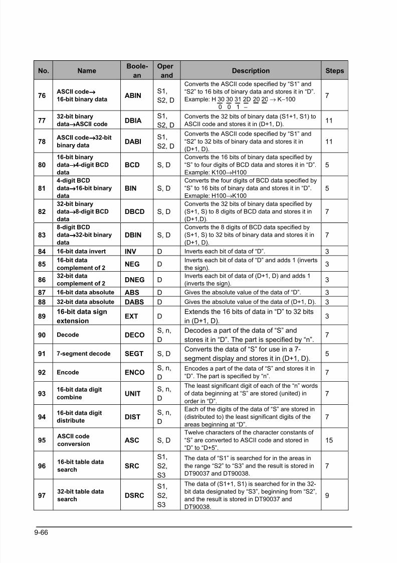
8/21/2019 Programmable Controller FP Sigma
http://slidepdf.com/reader/full/programmable-controller-fp-sigma 298/318
9-66
No. NameBoole-
an
Oper
andDescription Steps
76
ASCII code→→→→
16-bit binary data ABIN
S1,
S2, D
Converts the ASCII code specified by “S1” and
“S2” to 16 bits of binary data and stores it in “D”.
Example: H 30 30 31 2D 20 20 → K−100 0 0 1 −
7
7732-bit binary
data→→→→ASCII codeDBIA
S1,
S2, D
Converts the 32 bits of binary data (S1+1, S1) to
ASCII code and stores it in (D+1, D).11
78ASCII code→→→→32-bit
binary dataDABI
S1,
S2, D
Converts the ASCII code specified by “S1” and
“S2” to 32 bits of binary data and stores it in
(D+1, D).
11
8016-bit binary
data→→→→4-digit BCD
data
BCD S, DConverts the 16 bits of binary data specified by
“S” to four digits of BCD data and stores it in “D”.
Example: K100→H100
5
814-digit BCD
data→→→→16-bit binary
data
BIN S, DConverts the four digits of BCD data specified by
“S” to 16 bits of binary data and stores it in “D”.
Exmaple: H100→K100
5
8232-bit binary
data→→→→8-digit BCD
data
DBCD S, DConverts the 32 bits of binary data specified by
(S+1, S) to 8 digits of BCD data and stores it in
(D+1,D).
7
838-digit BCD
data→→→→32-bit binary
data
DBIN S, DConverts the 8 digits of BCD data specified by
(S+1, S) to 32 bits of binary data and stores it in
(D+1, D).
7
84 16-bit data invert INV D Inverts each bit of data of “D”. 3
8516-bit data
complement of 2NEG D
Inverts each bit of data of “D” and adds 1 (inverts
the sign).3
8632-bit data
complement of 2DNEG D
Inverts each bit of data of (D+1, D) and adds 1
(inverts the sign).3
8716-bit data absolute
ABS DGives the absolute value of the data of “D”.
388 32-bit data absolute DABS D Gives the absolute value of the data of (D+1, D). 3
8916-bit data sign
extensionEXT D
Extends the 16 bits of data in “D” to 32 bits
in (D+1, D).3
90 Decode DECOS, n,
D
Decodes a part of the data of “S” and
stores it in “D”. The part is specified by “n”.7
91 7-segment decode SEGT S, DConverts the data of “S” for use in a 7-
segment display and stores it in (D+1, D).5
92 Encode ENCOS, n,
D
Encodes a part of the data of “S” and stores it in
“D”. The part is specified by “n”.7
9316-bit data digit
combine UNIT
S, n,
D
The least significant digit of each of the “n” words
of data beginning at “S” are stored (united) inorder in “D”.
7
9416-bit data digit
distributeDIST
S, n,
D
Each of the digits of the data of “S” are stored in
(distributed to) the least significant digits of the
areas beginning at “D”.
7
95ASCII code
conversionASC S, D
Twelve characters of the character constants of
“S” are converted to ASCII code and stored in
“D” to “D+5”.
15
9616-bit table data
searchSRC
S1,
S2,
S3
The data of “S1” is searched for in the areas in
the range “S2” to “S3” and the result is stored in
DT90037 and DT90038.
7
97 32-bit table datasearch
DSRC
S1,
S2,
S3
The data of (S1+1, S1) is searched for in the 32-
bit data designated by “S3”, beginning from “S2”,and the result is stored in DT90037 and
DT90038.
9
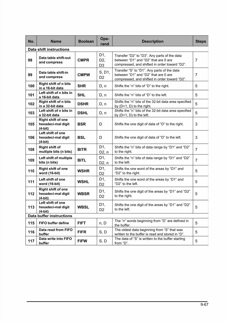
8/21/2019 Programmable Controller FP Sigma
http://slidepdf.com/reader/full/programmable-controller-fp-sigma 299/318
9-67
No. Name BooleanOpe-
randDescription Steps
Data shift instructions
98Data table shift-out
and compressCMPR
D1,D2,
D3
Transfer “D2” to “D3”. Any parts of the databetween “D1” and “D2” that are 0 are
compressed, and shifted in order toward “D2”.
7
99Data table shift-in
and compressCMPW
S, D1,
D2
Transfer “S” to “D1”. Any parts of the data
between “D1” and “D2” that are 0 are
compressed, and shifted in order toward “D2”.
7
100Right shift of n bits
in a 16-bit dataSHR D, n Shifts the “n” bits of “D” to the right. 5
101Left shift of n bits in
a 16-bit dataSHL D, n Shifts the “n” bits of “D” to the left. 5
102Right shift of n bits
in a 32-bit dataDSHR D, n
Shifts the “n” bits of the 32-bit data area specified
by (D+1, D) to the right.5
103Left shift of n bits in
a 32-bit data DSHL D, nShifts the “n” bits of the 32-bit data area specified
by (D+1, D) to the left. 5
105Right shift of one
hexadeci-mal digit
(4-bit)
BSR D Shifts the one digit of data of “D” to the right. 3
106Left shift of one
hexadeci-mal digit
(4-bit)
BSL D Shifts the one digit of data of “D” to the left. 3
108Right shift of
multiple bits (n bits)BITR
D1,
D2, n
Shifts the “n” bits of data range by “D1” and “D2”
to the right.7
109Left shift of multiple
bits (n bits)BITL
D1,
D2, n
Shifts the “n” bits of data range by “D1” and “D2”
to the left.7
110 Right shift of oneword (16-bit)
WSHR D1,D2
Shifts the one word of the areas by “D1” and“D2” to the right.
5
111Left shift of one
word (16-bit)WSHL
D1,
D2
Shifts the one word of the areas by “D1” and
“D2” to the left.5
112
Right shift of one
hexadeci-mal digit
(4-bit)
WBSRD1,
D2
Shifts the one digit of the areas by “D1” and “D2”
to the right.5
113Left shift of one
hexadeci-mal digit
(4-bit)
WBSLD1,
D2
Shifts the one digit of the areas by “D1” and “D2”
to the left.5
Data buffer instructions
115 FIFO buffer define FIFT n, DThe “n” words beginning from “D” are defined in
the buffer.5
116Data read from FIFO
buffer FIFR S, D
The oldest data beginning from “S” that was
written to the buffer is read and stored in “D”.5
117Data write into FIFO
buffer FIFW S, D
The data of “S” is written to the buffer starting
from “D”.5
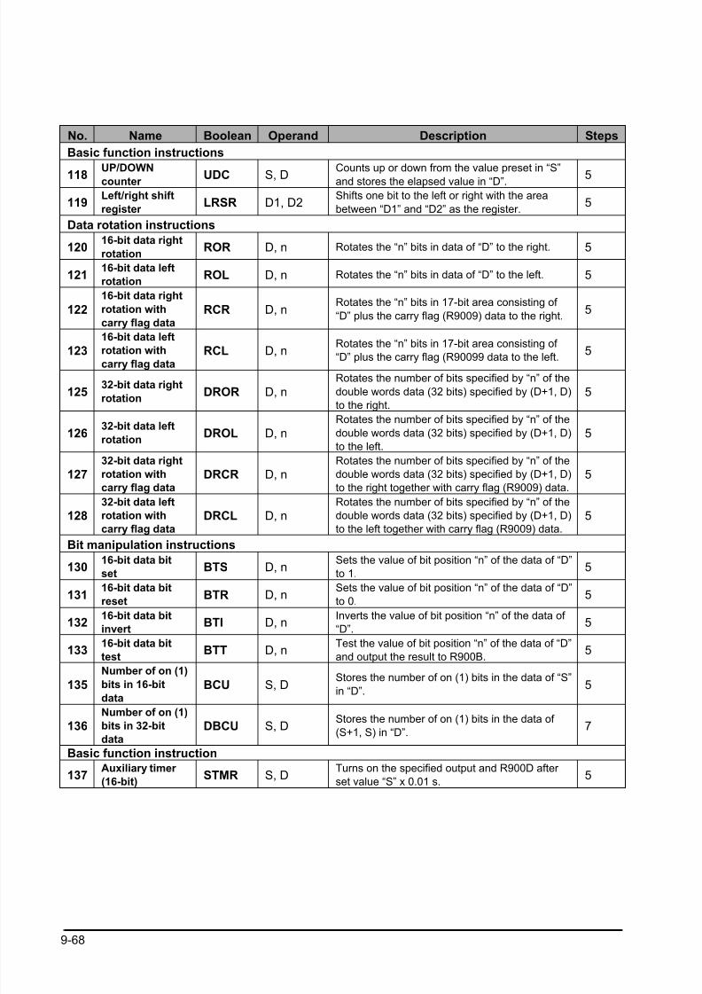
8/21/2019 Programmable Controller FP Sigma
http://slidepdf.com/reader/full/programmable-controller-fp-sigma 300/318
9-68
No. Name Boolean Operand Description Steps
Basic function instructions
118UP/DOWN
counter UDC S, DCounts up or down from the value preset in “S”
and stores the elapsed value in “D”. 5
119Left/right shift
register LRSR D1, D2
Shifts one bit to the left or right with the area
between “D1” and “D2” as the register.5
Data rotation instructions
12016-bit data right
rotationROR D, n Rotates the “n” bits in data of “D” to the right. 5
12116-bit data left
rotationROL D, n Rotates the “n” bits in data of “D” to the left. 5
122
16-bit data right
rotation with
carry flag data
RCR D, nRotates the “n” bits in 17-bit area consisting of
“D” plus the carry flag (R9009) data to the right.5
123
16-bit data left
rotation withcarry flag data
RCL D, n Rotates the “n” bits in 17-bit area consisting of “D” plus the carry flag (R90099 data to the left. 5
12532-bit data right
rotationDROR D, n
Rotates the number of bits specified by “n” of the
double words data (32 bits) specified by (D+1, D)
to the right.
5
12632-bit data left
rotationDROL D, n
Rotates the number of bits specified by “n” of the
double words data (32 bits) specified by (D+1, D)
to the left.
5
12732-bit data right
rotation with
carry flag data
DRCR D, nRotates the number of bits specified by “n” of the
double words data (32 bits) specified by (D+1, D)
to the right together with carry flag (R9009) data.
5
12832-bit data left
rotation with
carry flag data
DRCL D, nRotates the number of bits specified by “n” of the
double words data (32 bits) specified by (D+1, D)
to the left together with carry flag (R9009) data.
5
Bit manipulation instructions
13016-bit data bit
setBTS D, n
Sets the value of bit position “n” of the data of “D”
to 1.5
13116-bit data bit
resetBTR D, n
Sets the value of bit position “n” of the data of “D”
to 0.5
13216-bit data bit
invertBTI D, n
Inverts the value of bit position “n” of the data of
“D”.5
13316-bit data bit
testBTT D, n
Test the value of bit position “n” of the data of “D”
and output the result to R900B.5
135
Number of on (1)
bits in 16-bit
data
BCU S, DStores the number of on (1) bits in the data of “S”
in “D”.
5
136Number of on (1)
bits in 32-bit
data
DBCU S, DStores the number of on (1) bits in the data of
(S+1, S) in “D”.7
Basic function instruction
137Auxiliary timer
(16-bit)STMR S, D
Turns on the specified output and R900D after
set value “S” x 0.01 s.5
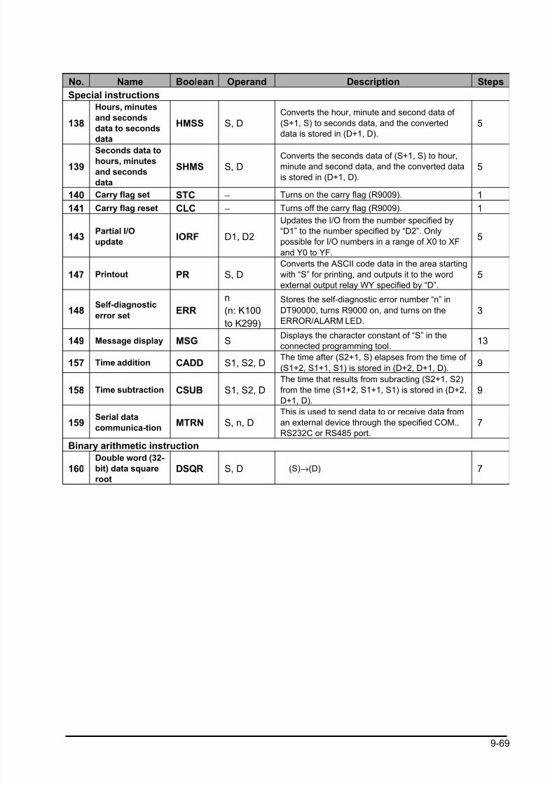
8/21/2019 Programmable Controller FP Sigma
http://slidepdf.com/reader/full/programmable-controller-fp-sigma 301/318
9-69
No. Name Boolean Operand Description Steps
Special instructions
138
Hours, minutes
and seconds
data to seconds
data
HMSS S, DConverts the hour, minute and second data of
(S+1, S) to seconds data, and the converted
data is stored in (D+1, D).
5
139
Seconds data to
hours, minutes
and seconds
data
SHMS S, DConverts the seconds data of (S+1, S) to hour,
minute and second data, and the converted data
is stored in (D+1, D).
5
140 Carry flag set STC − Turns on the carry flag (R9009). 1
141 Carry flag reset CLC − Turns off the carry flag (R9009). 1
143Partial I/O
updateIORF D1, D2
Updates the I/O from the number specified by
“D1” to the number specified by “D2”. Only
possible for I/O numbers in a range of X0 to XF
and Y0 to YF.
5
147 Printout PR S, D
Converts the ASCII code data in the area starting
with “S” for printing, and outputs it to the wordexternal output relay WY specified by “D”.
5
148Self-diagnostic
error setERR
n
(n: K100
to K299)
Stores the self-diagnostic error number “n” in
DT90000, turns R9000 on, and turns on the
ERROR/ALARM LED.
3
149 Message display MSG SDisplays the character constant of “S” in the
connected programming tool.13
157 Time addition CADD S1, S2, DThe time after (S2+1, S) elapses from the time of
(S1+2, S1+1, S1) is stored in (D+2, D+1, D).9
158 Time subtraction CSUB S1, S2, DThe time that results from subracting (S2+1, S2)
from the time (S1+2, S1+1, S1) is stored in (D+2,
D+1, D).
9
159Serial data
communica-tionMTRN S, n, D
This is used to send data to or receive data froman external device through the specified COM.,
RS232C or RS485 port.
7
Binary arithmetic instruction
160Double word (32-
bit) data square
root
DSQR S, D (S)→(D) 7
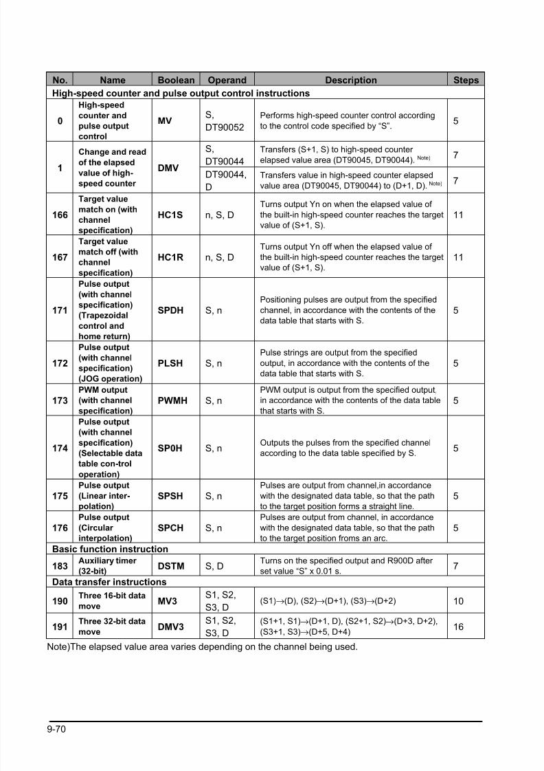
8/21/2019 Programmable Controller FP Sigma
http://slidepdf.com/reader/full/programmable-controller-fp-sigma 302/318
9-70
No. Name Boolean Operand Description Steps
High-speed counter and pulse output control instructions
0
High-speed
counter and
pulse output
control
MVS,
DT90052
Performs high-speed counter control according
to the control code specified by “S”.5
S,
DT90044
Transfers (S+1, S) to high-speed counter
elapsed value area (DT90045, DT90044). Note) 7
1
Change and read
of the elapsed
value of high-
speed counter
DMVDT90044,
D
Transfers value in high-speed counter elapsed
value area (DT90045, DT90044) to (D+1, D). Note) 7
166
Target value
match on (with
channel
specification)
HC1S n, S, DTurns output Yn on when the elapsed value of
the built-in high-speed counter reaches the target
value of (S+1, S).
11
167
Target value
match off (with
channel
specification)
HC1R n, S, DTurns output Yn off when the elapsed value of
the built-in high-speed counter reaches the target
value of (S+1, S).
11
171
Pulse output
(with channel
specification)
(Trapezoidal
control and
home return)
SPDH S, nPositioning pulses are output from the specified
channel, in accordance with the contents of the
data table that starts with S.
5
172
Pulse output
(with channel
specification)
(JOG operation)
PLSH S, nPulse strings are output from the specified
output, in accordance with the contents of the
data table that starts with S.
5
173
PWM output
(with channel
specification) PWMH S, n
PWM output is output from the specified output,
in accordance with the contents of the data table
that starts with S. 5
174
Pulse output
(with channel
specification)
(Selectable data
table con-trol
operation)
SP0H S, nOutputs the pulses from the specified channel
according to the data table specified by S.5
175Pulse output
(Linear inter-
polation)
SPSH S, nPulses are output from channel,in accordance
with the designated data table, so that the path
to the target position forms a straight line.
5
176Pulse output
(Circular
interpolation)
SPCH S, nPulses are output from channel, in accordance
with the designated data table, so that the path
to the target position froms an arc.
5
Basic function instruction
183Auxiliary timer
(32-bit)DSTM S, D
Turns on the specified output and R900D after
set value “S” x 0.01 s.7
Data transfer instructions
190Three 16-bit data
moveMV3
S1, S2,
S3, D(S1)→(D), (S2)→(D+1), (S3)→(D+2) 10
191Three 32-bit data
moveDMV3
S1, S2,
S3, D
(S1+1, S1)→(D+1, D), (S2+1, S2)→(D+3, D+2),
(S3+1, S3)→(D+5, D+4)16
Note)The elapsed value area varies depending on the channel being used.
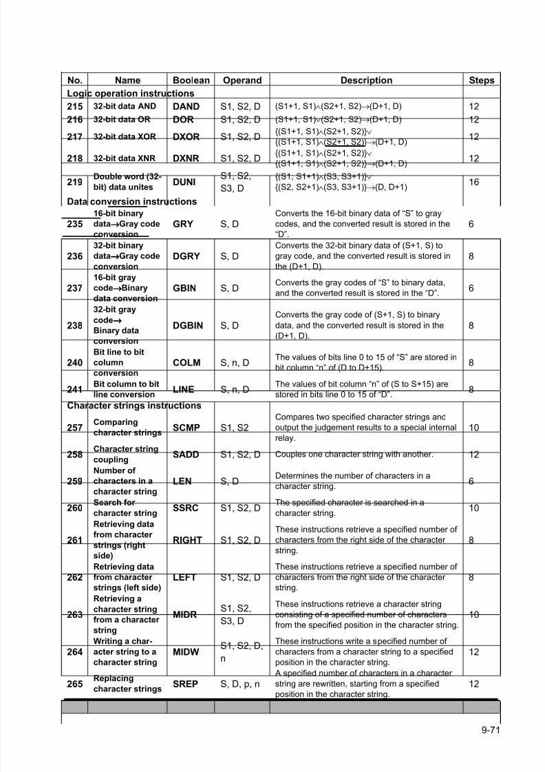
8/21/2019 Programmable Controller FP Sigma
http://slidepdf.com/reader/full/programmable-controller-fp-sigma 303/318
9-71
No. Name Boolean Operand Description Steps
Logic operation instructions
215 32-bit data AND DAND S1, S2, D (S1+1, S1)∧(S2+1, S2)→(D+1, D) 12
216 32-bit data OR DOR S1, S2, D (S1+1, S1)∨(S2+1, S2)→(D+1, D) 12
217 32-bit data XOR DXOR S1, S2, D (S1+1, S1)∧
(S2+1, S2)∨
(S1+1, S1)∧(S2+1, S2)→(D+1, D) 12
218 32-bit data XNR DXNR S1, S2, D(S1+1, S1)∧(S2+1, S2)∨
(S1+1, S1)∧(S2+1, S2)→(D+1, D)12
219Double word (32-
bit) data unitesDUNI
S1, S2,
S3, D
(S1, S1+1)∧(S3, S3+1)∨
(S2, S2+1)∧(S3, S3+1)→(D, D+1)16
Data conversion instructions
23516-bit binary
data→→→→Gray code
conversion
GRY S, DConverts the 16-bit binary data of “S” to gray
codes, and the converted result is stored in the
“D”.
6
23632-bit binary
data→→→→Gray code
conversion
DGRY S, DConverts the 32-bit binary data of (S+1, S) to
gray code, and the converted result is stored in
the (D+1, D).
8
23716-bit gray
code→→→→Binary
data conversion
GBIN S, DConverts the gray codes of “S” to binary data,
and the converted result is stored in the “D”.6
238
32-bit gray
code→→→→
Binary data
conversion
DGBIN S, D
Converts the gray code of (S+1, S) to binary
data, and the converted result is stored in the
(D+1, D).
8
240Bit line to bit
column
conversion
COLM S, n, DThe values of bits line 0 to 15 of “S” are stored in
bit column “n” of (D to D+15).8
241Bit column to bit
line conversionLINE S, n, D
The values of bit column “n” of (S to S+15) are
stored in bits line 0 to 15 of “D”.8
Character strings instructions
257Comparing
character stringsSCMP S1, S2
Compares two specified character strings and
output the judgement results to a special internal
relay.
10
258Character string
couplingSADD S1, S2, D Couples one character string with another. 12
259Number of
characters in a
character string
LEN S, DDetermines the number of characters in a
character string.6
260Search for
character stringSSRC S1, S2, D
The specified character is searched in a
character string.10
261
Retrieving data
from character
strings (right
side)
RIGHT S1, S2, D
These instructions retrieve a specified number of
characters from the right side of the character string.
8
262Retrieving data
from character
strings (left side)
LEFT S1, S2, DThese instructions retrieve a specified number of
characters from the right side of the character
string.
8
263
Retrieving a
character string
from a character
string
MIDRS1, S2,
S3, D
These instructions retrieve a character string
consisting of a specified number of characters
from the specified position in the character string.
10
264Writing a char-
acter string to a
character string
MIDWS1, S2, D,
n
These instructions write a specified number of
characters from a character string to a specified
position in the character string.
12
265Replacingcharacter strings
SREP S, D, p, n A specified number of characters in a character string are rewritten, starting from a specified
position in the character string.
12
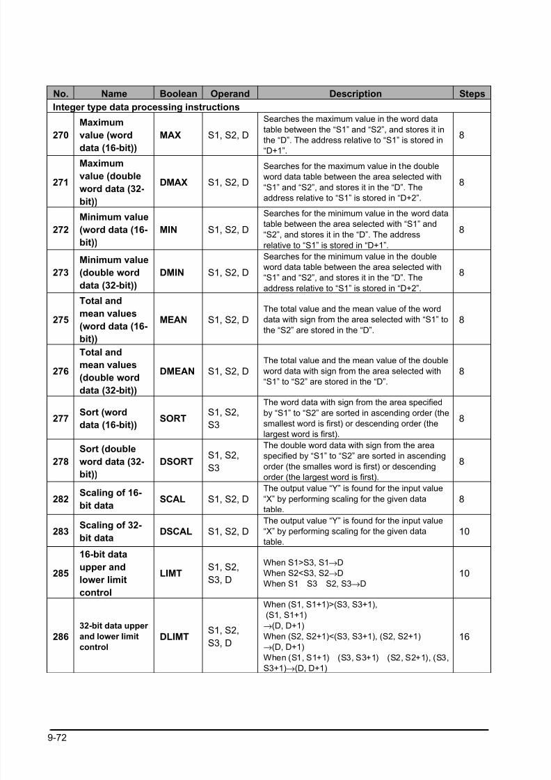
8/21/2019 Programmable Controller FP Sigma
http://slidepdf.com/reader/full/programmable-controller-fp-sigma 304/318
9-72
No. Name Boolean Operand Description Steps
Integer type data processing instructions
270
Maximum
value (worddata (16-bit))
MAX S1, S2, D
Searches the maximum value in the word data
table between the “S1” and “S2”, and stores it in
the “D”. The address relative to “S1” is stored in
“D+1”.
8
271
Maximum
value (double
word data (32-
bit))
DMAX S1, S2, D
Searches for the maximum value in the double
word data table between the area selected with
“S1” and “S2”, and stores it in the “D”. The
address relative to “S1” is stored in “D+2”.
8
272
Minimum value
(word data (16-
bit))
MIN S1, S2, D
Searches for the minimum value in the word data
table between the area selected with “S1” and
“S2”, and stores it in the “D”. The address
relative to “S1” is stored in “D+1”.
8
273
Minimum value
(double worddata (32-bit))
DMIN S1, S2, D
Searches for the minimum value in the double
word data table between the area selected with
“S1” and “S2”, and stores it in the “D”. The
address relative to “S1” is stored in “D+2”.
8
275
Total and
mean values
(word data (16-
bit))
MEAN S1, S2, DThe total value and the mean value of the word
data with sign from the area selected with “S1” to
the “S2” are stored in the “D”.
8
276
Total and
mean values
(double word
data (32-bit))
DMEAN S1, S2, DThe total value and the mean value of the double
word data with sign from the area selected with
“S1” to “S2” are stored in the “D”.
8
277Sort (worddata (16-bit))
SORTS1, S2,S3
The word data with sign from the area specified
by “S1” to “S2” are sorted in ascending order (the
smallest word is first) or descending order (the
largest word is first).
8
278
Sort (double
word data (32-
bit))
DSORTS1, S2,
S3
The double word data with sign from the area
specified by “S1” to “S2” are sorted in ascending
order (the smalles word is first) or descending
order (the largest word is first).
8
282Scaling of 16-
bit dataSCAL S1, S2, D
The output value “Y” is found for the input value
“X” by performing scaling for the given data
table.
8
283Scaling of 32-
bit dataDSCAL S1, S2, D
The output value “Y” is found for the input value
“X” by performing scaling for the given data
table.
10
285
16-bit data
upper and
lower limit
control
LIMTS1, S2,
S3, D
When S1>S3, S1→D
When S2<S3, S2→D
When S1 S3 S2, S3→D
10
286
32-bit data upper
and lower limit
control
DLIMTS1, S2,
S3, D
When (S1, S1+1)>(S3, S3+1),
(S1, S1+1)
→(D, D+1)
When (S2, S2+1)<(S3, S3+1), (S2, S2+1)
→(D, D+1)
When (S1, S1+1) (S3, S3+1) (S2, S2+1), (S3,
S3+1)→(D, D+1)
16
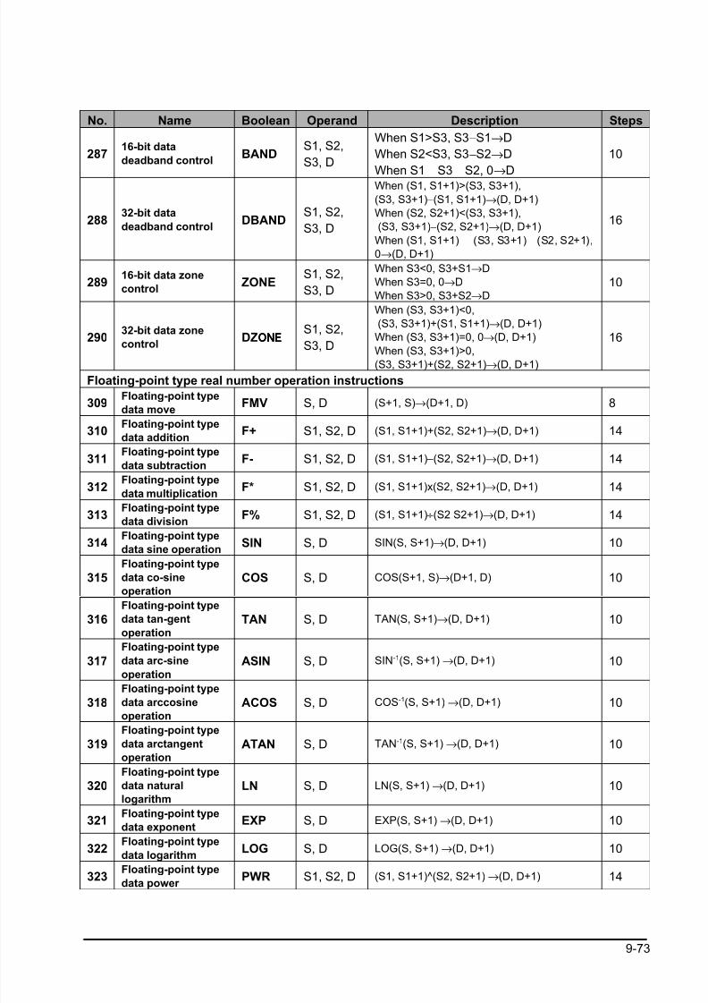
8/21/2019 Programmable Controller FP Sigma
http://slidepdf.com/reader/full/programmable-controller-fp-sigma 305/318
9-73
No. Name Boolean Operand Description Steps
28716-bit data
deadband controlBAND
S1, S2,
S3, D
When S1>S3, S3−S1→D
When S2<S3, S3−S2→D
When S1
S3
S2, 0→
D
10
28832-bit data
deadband controlDBAND
S1, S2,
S3, D
When (S1, S1+1)>(S3, S3+1),
(S3, S3+1)−(S1, S1+1)→(D, D+1)
When (S2, S2+1)<(S3, S3+1),
(S3, S3+1)−(S2, S2+1)→(D, D+1)
When (S1, S1+1) (S3, S3+1) (S2, S2+1),
0→(D, D+1)
16
28916-bit data zone
controlZONE
S1, S2,
S3, D
When S3<0, S3+S1→D
When S3=0, 0→D
When S3>0, S3+S2→D
10
29032-bit data zone
controlDZONEONEONEONE
S1, S2,
S3, D
When (S3, S3+1)<0,
(S3, S3+1)+(S1, S1+1)→(D, D+1)
When (S3, S3+1)=0, 0→(D, D+1)
When (S3, S3+1)>0,(S3, S3+1)+(S2, S2+1)→(D, D+1)
16
Floating-point type real number operation instructions
309Floating-point type
data moveFMV S, D (S+1, S)→(D+1, D) 8
310Floating-point type
data additionF+ S1, S2, D (S1, S1+1)+(S2, S2+1)→(D, D+1) 14
311Floating-point type
data subtractionF- S1, S2, D (S1, S1+1)−(S2, S2+1)→(D, D+1) 14
312Floating-point type
data multiplicationF* S1, S2, D (S1, S1+1)x(S2, S2+1)→(D, D+1) 14
313Floating-point type
data division
F% S1, S2, D (S1, S1+1)÷(S2 S2+1)→(D, D+1) 14
314Floating-point type
data sine operationSIN S, D SIN(S, S+1)→(D, D+1) 10
315Floating-point type
data co-sine
operation
COS S, D COS(S+1, S)→(D+1, D) 10
316Floating-point type
data tan-gent
operation
TAN S, D TAN(S, S+1)→(D, D+1) 10
317
Floating-point type
data arc-sine
operation
ASIN S, D SIN-1(S, S+1) →(D, D+1) 10
318
Floating-point type
data arccosineoperation
ACOS S, D COS-1(S, S+1) →(D, D+1) 10
319Floating-point type
data arctangent
operation
ATAN S, D TAN-1(S, S+1) →(D, D+1) 10
320Floating-point type
data natural
logarithm
LN S, D LN(S, S+1) →(D, D+1) 10
321Floating-point type
data exponentEXP S, D EXP(S, S+1) →(D, D+1) 10
322Floating-point type
data logarithmLOG S, D LOG(S, S+1) →(D, D+1) 10
323
Floating-point type
data power PWR S1, S2, D (S1, S1+1)^(S2, S2+1) →(D, D+1) 14
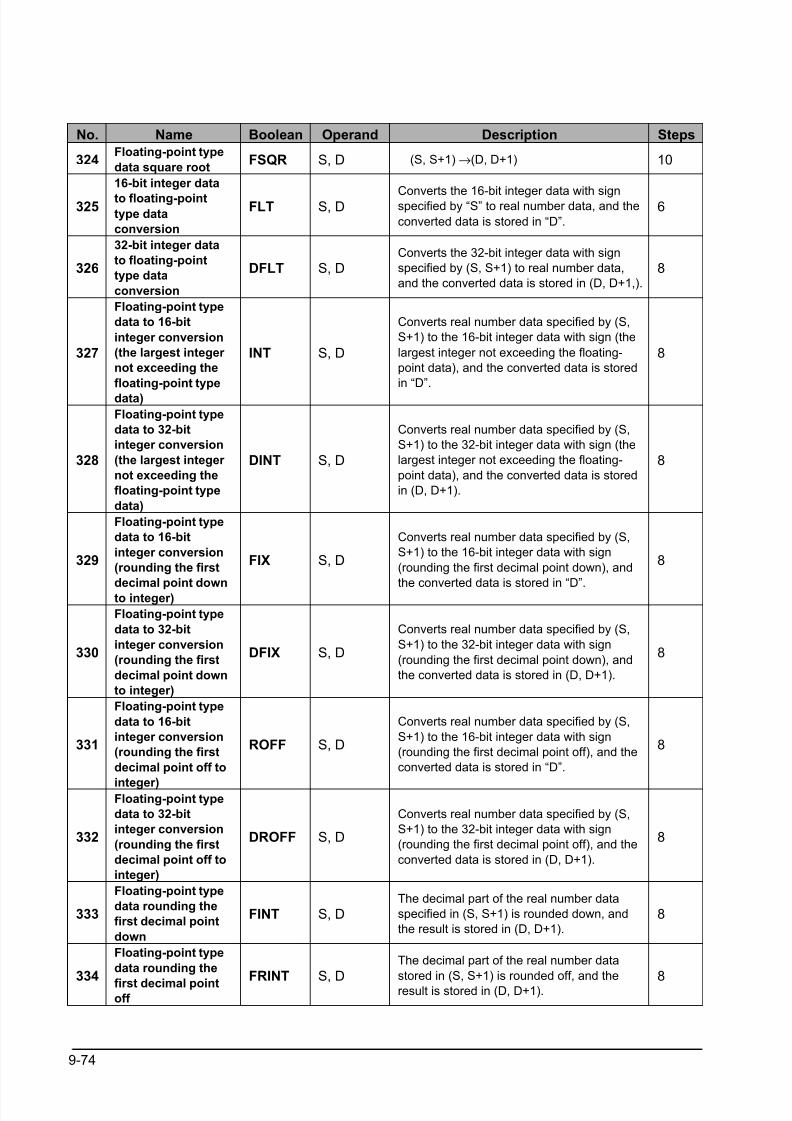
8/21/2019 Programmable Controller FP Sigma
http://slidepdf.com/reader/full/programmable-controller-fp-sigma 306/318
9-74
No. Name Boolean Operand Description Steps
324Floating-point type
data square rootFSQR S, D (S, S+1) →(D, D+1) 10
325
16-bit integer data
to floating-pointtype data
conversion
FLT S, D Converts the 16-bit integer data with signspecified by “S” to real number data, and the
converted data is stored in “D”.
6
326
32-bit integer data
to floating-point
type data
conversion
DFLT S, DConverts the 32-bit integer data with sign
specified by (S, S+1) to real number data,
and the converted data is stored in (D, D+1,).
8
327
Floating-point type
data to 16-bit
integer conversion
(the largest integer
not exceeding the
floating-point type
data)
INT S, D
Converts real number data specified by (S,
S+1) to the 16-bit integer data with sign (the
largest integer not exceeding the floating-
point data), and the converted data is stored
in “D”.
8
328
Floating-point type
data to 32-bit
integer conversion
(the largest integer
not exceeding the
floating-point type
data)
DINT S, D
Converts real number data specified by (S,
S+1) to the 32-bit integer data with sign (the
largest integer not exceeding the floating-
point data), and the converted data is stored
in (D, D+1).
8
329
Floating-point type
data to 16-bit
integer conversion
(rounding the first
decimal point downto integer)
FIX S, D
Converts real number data specified by (S,
S+1) to the 16-bit integer data with sign
(rounding the first decimal point down), and
the converted data is stored in “D”.
8
330
Floating-point type
data to 32-bit
integer conversion
(rounding the first
decimal point down
to integer)
DFIX S, D
Converts real number data specified by (S,
S+1) to the 32-bit integer data with sign
(rounding the first decimal point down), and
the converted data is stored in (D, D+1).
8
331
Floating-point type
data to 16-bit
integer conversion
(rounding the first
decimal point off to
integer)
ROFF S, D
Converts real number data specified by (S,
S+1) to the 16-bit integer data with sign
(rounding the first decimal point off), and the
converted data is stored in “D”.
8
332
Floating-point type
data to 32-bit
integer conversion
(rounding the first
decimal point off to
integer)
DROFF S, D
Converts real number data specified by (S,
S+1) to the 32-bit integer data with sign
(rounding the first decimal point off), and the
converted data is stored in (D, D+1).
8
333
Floating-point type
data rounding the
first decimal point
down
FINT S, DThe decimal part of the real number data
specified in (S, S+1) is rounded down, and
the result is stored in (D, D+1).
8
334
Floating-point type
data rounding the
first decimal pointoff
FRINT S, D
The decimal part of the real number data
stored in (S, S+1) is rounded off, and theresult is stored in (D, D+1). 8
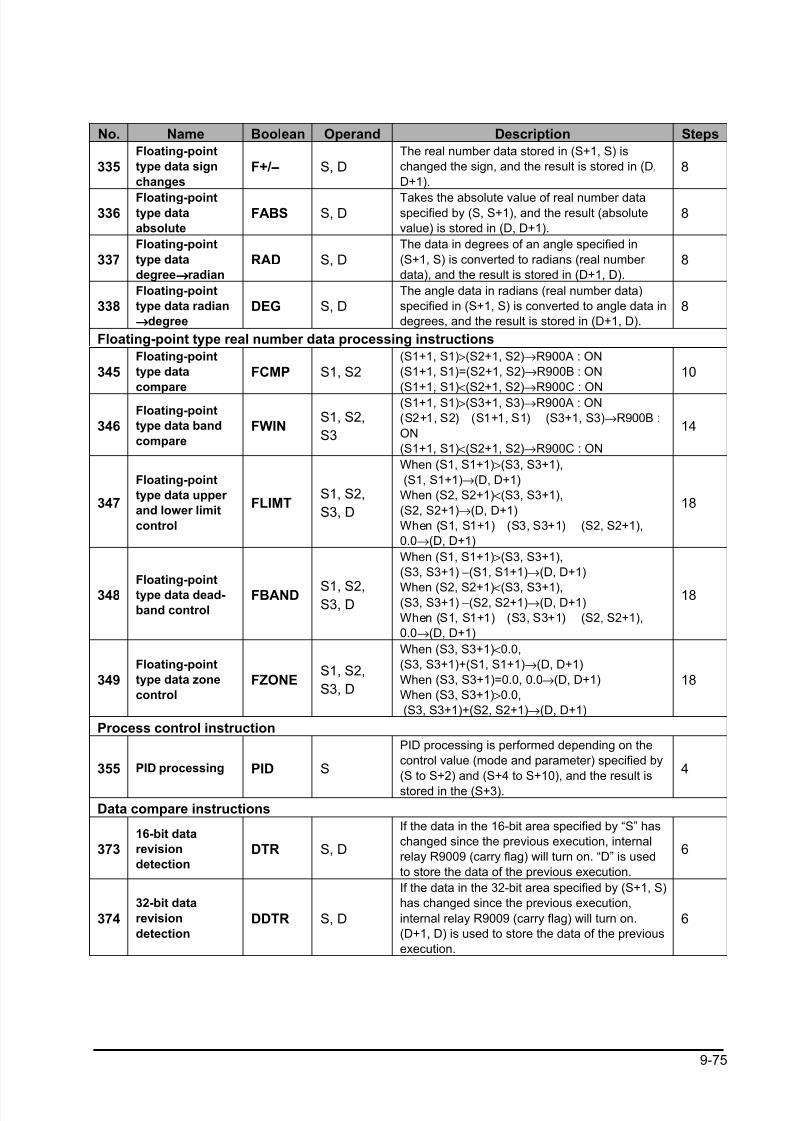
8/21/2019 Programmable Controller FP Sigma
http://slidepdf.com/reader/full/programmable-controller-fp-sigma 307/318
9-75
No. Name Boolean Operand Description Steps
335Floating-point
type data sign
changes
F+/−−−− S, DThe real number data stored in (S+1, S) is
changed the sign, and the result is stored in (D,
D+1).
8
336Floating-pointtype data
absolute
FABS S, DTakes the absolute value of real number dataspecified by (S, S+1), and the result (absolute
value) is stored in (D, D+1).
8
337Floating-point
type data
degree→→→→radian
RAD S, DThe data in degrees of an angle specified in
(S+1, S) is converted to radians (real number
data), and the result is stored in (D+1, D).
8
338Floating-point
type data radian
→→→→degree
DEG S, DThe angle data in radians (real number data)
specified in (S+1, S) is converted to angle data in
degrees, and the result is stored in (D+1, D).
8
Floating-point type real number data processing instructions
345Floating-point
type data
compare
FCMP S1, S2(S1+1, S1)>(S2+1, S2)→R900A : ON
(S1+1, S1)=(S2+1, S2)→R900B : ON
(S1+1, S1)<
(S2+1, S2)→
R900C : ON
10
346Floating-point
type data band
compare
FWINS1, S2,
S3
(S1+1, S1)>(S3+1, S3)→R900A : ON
(S2+1, S2) (S1+1, S1) (S3+1, S3)→R900B :
ON
(S1+1, S1)<(S2+1, S2)→R900C : ON
14
347
Floating-point
type data upper
and lower limit
control
FLIMTS1, S2,
S3, D
When (S1, S1+1)>(S3, S3+1),
(S1, S1+1)→(D, D+1)
When (S2, S2+1)<(S3, S3+1),
(S2, S2+1)→(D, D+1)
When (S1, S1+1) (S3, S3+1) (S2, S2+1),
0.0→(D, D+1)
18
348Floating-point
type data dead-
band control
FBAND S1, S2,S3, D
When (S1, S1+1)>(S3, S3+1),
(S3, S3+1) −(S1, S1+1)→(D, D+1)
When (S2, S2+1)<(S3, S3+1),(S3, S3+1) −(S2, S2+1)→(D, D+1)
When (S1, S1+1) (S3, S3+1) (S2, S2+1),
0.0→(D, D+1)
18
349Floating-point
type data zone
control
FZONES1, S2,
S3, D
When (S3, S3+1)<0.0,
(S3, S3+1)+(S1, S1+1)→(D, D+1)
When (S3, S3+1)=0.0, 0.0→(D, D+1)
When (S3, S3+1)>0.0,
(S3, S3+1)+(S2, S2+1)→(D, D+1)
18
Process control instruction
355 PID processing PID S
PID processing is performed depending on the
control value (mode and parameter) specified by
(S to S+2) and (S+4 to S+10), and the result is
stored in the (S+3).
4
Data compare instructions
37316-bit data
revision
detection
DTR S, D
If the data in the 16-bit area specified by “S” has
changed since the previous execution, internal
relay R9009 (carry flag) will turn on. “D” is used
to store the data of the previous execution.
6
374
32-bit data
revision
detection
DDTR S, D
If the data in the 32-bit area specified by (S+1, S)
has changed since the previous execution,
internal relay R9009 (carry flag) will turn on.
(D+1, D) is used to store the data of the previous
execution.
6
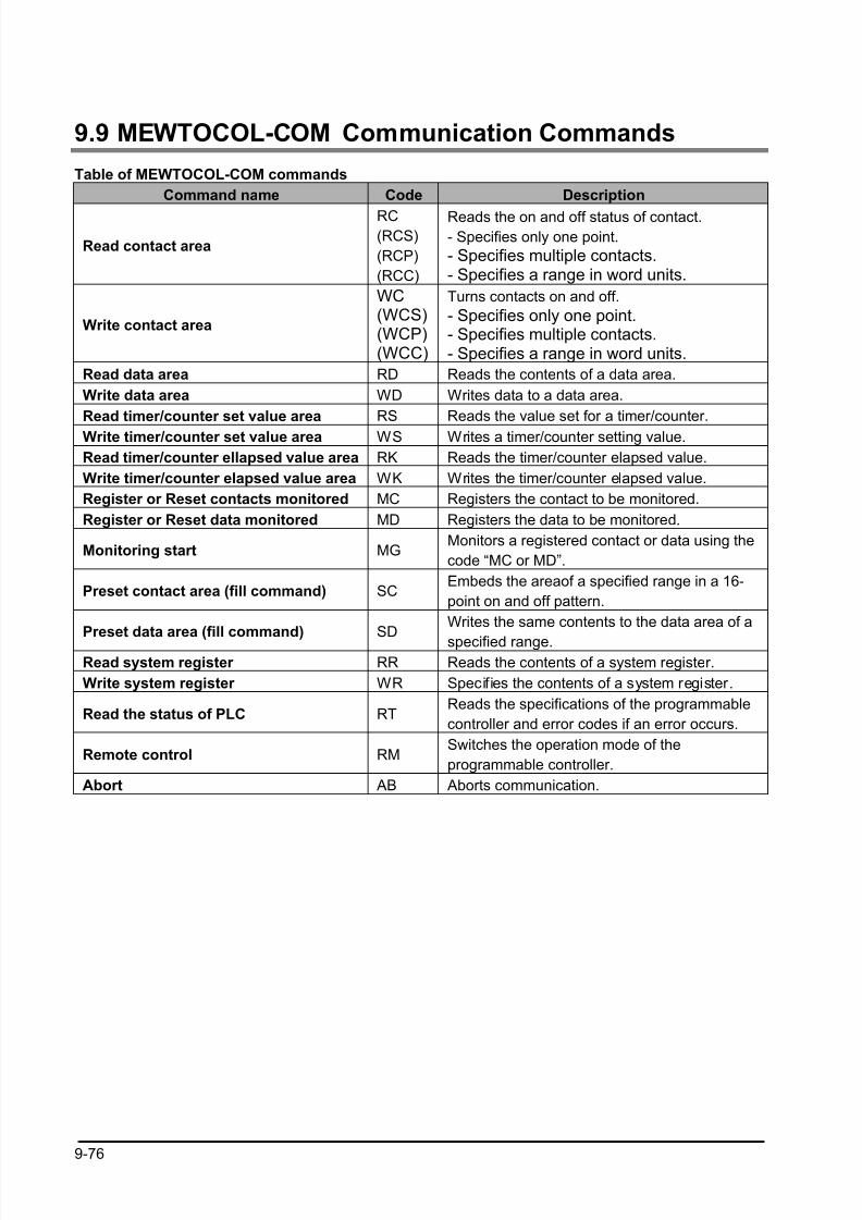
8/21/2019 Programmable Controller FP Sigma
http://slidepdf.com/reader/full/programmable-controller-fp-sigma 308/318
9-76
9.9 MEWTOCOL-COM Communication Commands
Table of MEWTOCOL-COM commands
Command name Code Description
Read contact area
RC(RCS)
(RCP)
(RCC)
Reads the on and off status of contact.- Specifies only one point.
- Specifies multiple contacts.- Specifies a range in word units.
Write contact area
WC(WCS)(WCP)(WCC)
Turns contacts on and off.
- Specifies only one point.- Specifies multiple contacts.- Specifies a range in word units.
Read data area RD Reads the contents of a data area.
Write data area WD Writes data to a data area.
Read timer/counter set value area RS Reads the value set for a timer/counter.
Write timer/counter set value area WS Writes a timer/counter setting value.
Read timer/counter ellapsed value area RK Reads the timer/counter elapsed value.
Write timer/counter elapsed value area WK Writes the timer/counter elapsed value.
Register or Reset contacts monitored MC Registers the contact to be monitored.
Register or Reset data monitored MD Registers the data to be monitored.
Monitoring start MGMonitors a registered contact or data using the
code “MC or MD”.
Preset contact area (fill command) SCEmbeds the areaof a specified range in a 16-
point on and off pattern.
Preset data area (fill command) SDWrites the same contents to the data area of a
specified range.Read system register RR Reads the contents of a system register.
Write system register WR Specifies the contents of a system register.
Read the status of PLC RTReads the specifications of the programmable
controller and error codes if an error occurs.
Remote control RMSwitches the operation mode of the
programmable controller.
Abort AB Aborts communication.
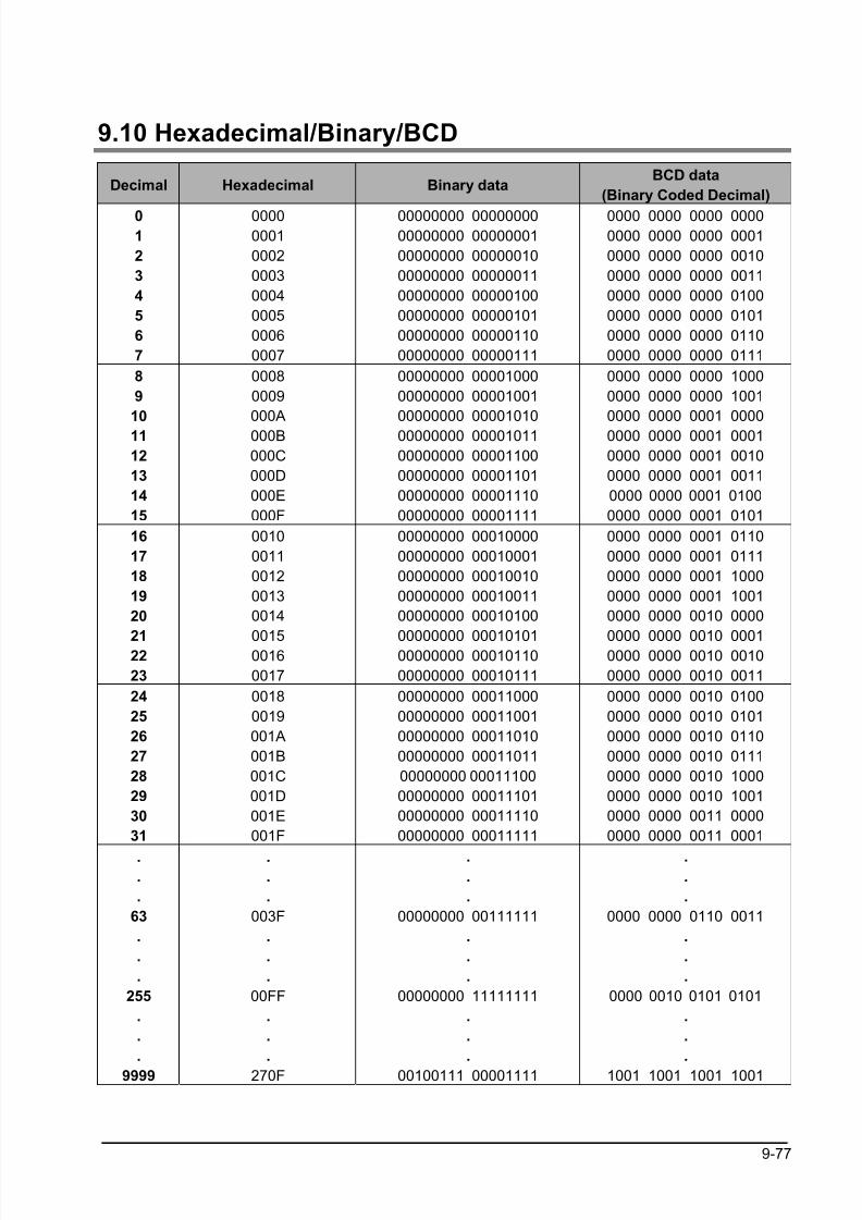
8/21/2019 Programmable Controller FP Sigma
http://slidepdf.com/reader/full/programmable-controller-fp-sigma 309/318
9-77
9.10 Hexadecimal/Binary/BCD
Decimal Hexadecimal Binary dataBCD data
(Binary Coded Decimal)
01
2
3
4
5
6
7
00000001
0002
0003
0004
0005
0006
0007
00000000 0000000000000000 00000001
00000000 00000010
00000000 00000011
00000000 00000100
00000000 00000101
00000000 00000110
00000000 00000111
0000 0000 0000 00000000 0000 0000 0001
0000 0000 0000 0010
0000 0000 0000 0011
0000 0000 0000 0100
0000 0000 0000 0101
0000 0000 0000 0110
0000 0000 0000 0111
8
9
10
11
12
13
14
15
0008
0009
000A
000B
000C
000D
000E
000F
00000000 00001000
00000000 00001001
00000000 00001010
00000000 00001011
00000000 00001100
00000000 00001101
00000000 00001110
00000000 00001111
0000 0000 0000 1000
0000 0000 0000 1001
0000 0000 0001 0000
0000 0000 0001 0001
0000 0000 0001 0010
0000 0000 0001 0011
0000 0000 0001 0100
0000 0000 0001 0101
16
17
18
19
20
2122
23
0010
0011
0012
0013
0014
00150016
0017
00000000 00010000
00000000 00010001
00000000 00010010
00000000 00010011
00000000 00010100
00000000 0001010100000000 00010110
00000000 00010111
0000 0000 0001 0110
0000 0000 0001 0111
0000 0000 0001 1000
0000 0000 0001 1001
0000 0000 0010 0000
0000 0000 0010 00010000 0000 0010 0010
0000 0000 0010 0011
24
25
26
27
28
29
30
31
0018
0019
001A
001B
001C
001D
001E
001F
00000000 00011000
00000000 00011001
00000000 00011010
00000000 00011011
00000000 00011100
00000000 00011101
00000000 00011110
00000000 00011111
0000 0000 0010 0100
0000 0000 0010 0101
0000 0000 0010 0110
0000 0000 0010 0111
0000 0000 0010 1000
0000 0000 0010 1001
0000 0000 0011 0000
0000 0000 0011 0001
.
.
.
63
.
.
.
255
.
.
.
9999
.
.
.
003F
.
.
.
00FF
.
.
.
270F
.
.
.
00000000 00111111
.
.
.
00000000 11111111
.
.
.
00100111 00001111
.
.
.
0000 0000 0110 0011
.
.
.
0000 0010 0101 0101
.
.
.
1001 1001 1001 1001
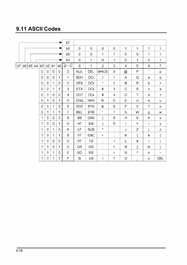
8/21/2019 Programmable Controller FP Sigma
http://slidepdf.com/reader/full/programmable-controller-fp-sigma 310/318
9-78
9.11 ASCII Codes

8/21/2019 Programmable Controller FP Sigma
http://slidepdf.com/reader/full/programmable-controller-fp-sigma 311/318
Chapter 10
Dimensions
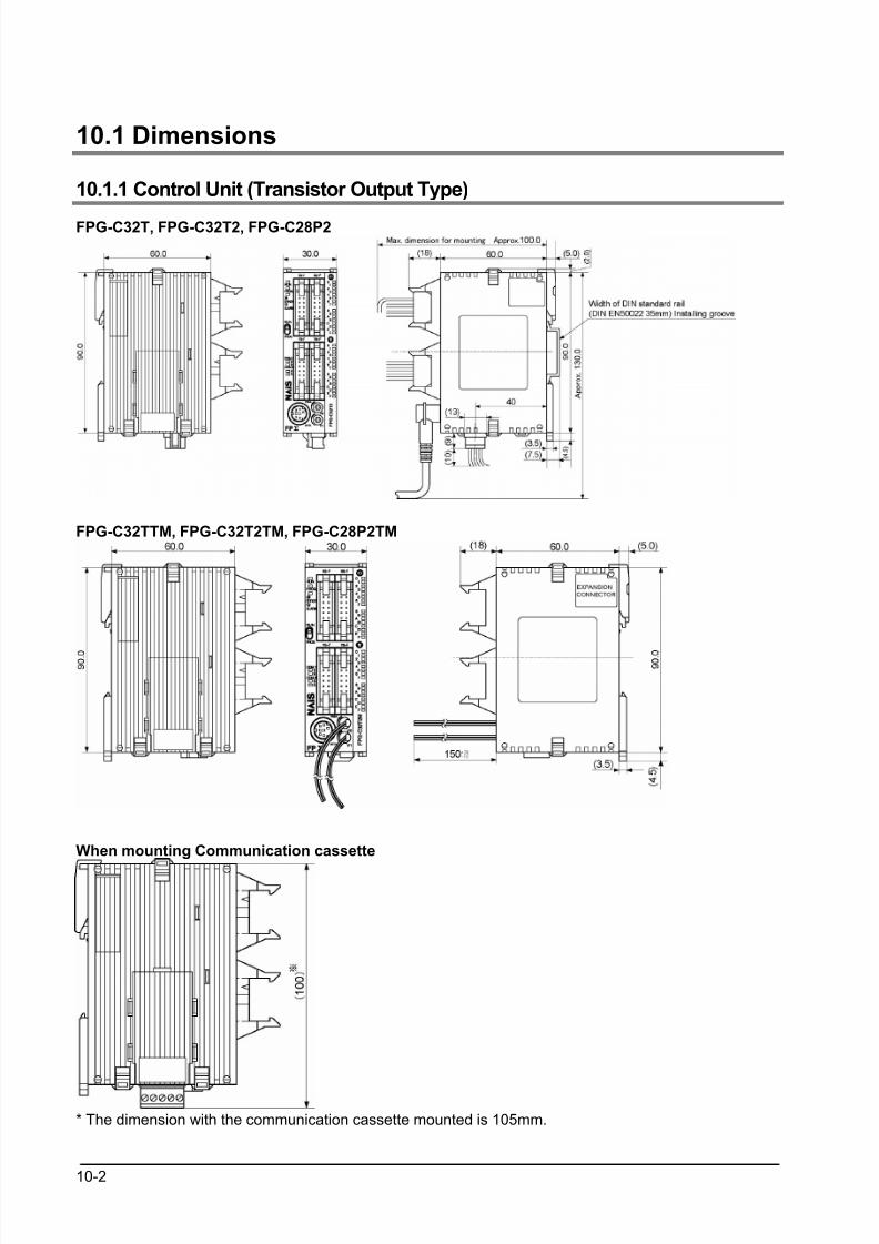
8/21/2019 Programmable Controller FP Sigma
http://slidepdf.com/reader/full/programmable-controller-fp-sigma 312/318
10-2
10.1 Dimensions
10.1.1 Control Unit (Transistor Output Type)
FPG-C32T, FPG-C32T2, FPG-C28P2
FPG-C32TTM, FPG-C32T2TM, FPG-C28P2TM
When mounting Communication cassette
* The dimension with the communication cassette mounted is 105mm.
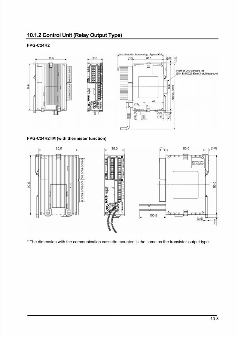
8/21/2019 Programmable Controller FP Sigma
http://slidepdf.com/reader/full/programmable-controller-fp-sigma 313/318
10-3
10.1.2 Control Unit (Relay Output Type)
FPG-C24R2
FPG-C24R2TM (with thermister function)
* The dimension with the communication cassette mounted is the same as the transistor output type.
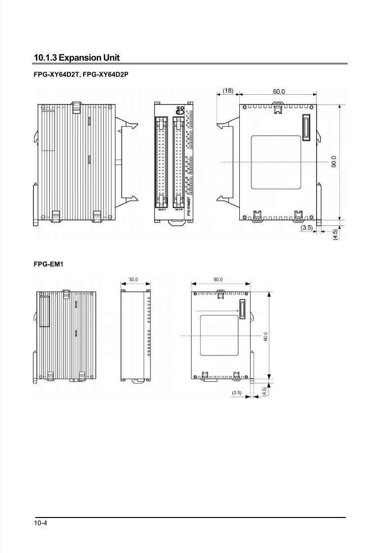
8/21/2019 Programmable Controller FP Sigma
http://slidepdf.com/reader/full/programmable-controller-fp-sigma 314/318
10-4
10.1.3 Expansion Unit
FPG-XY64D2T, FPG-XY64D2P
FPG-EM1
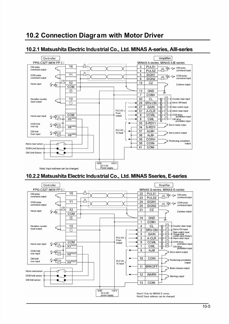
8/21/2019 Programmable Controller FP Sigma
http://slidepdf.com/reader/full/programmable-controller-fp-sigma 315/318
10-5
10.2 Connection Diagram with Motor Driver
10.2.1 Matsushita Electric Industrial Co., Ltd. MINAS A-series, AIII-series
10.2.2 Matsushita Electric Industrial Co., Ltd. MINAS Sseries, E-series
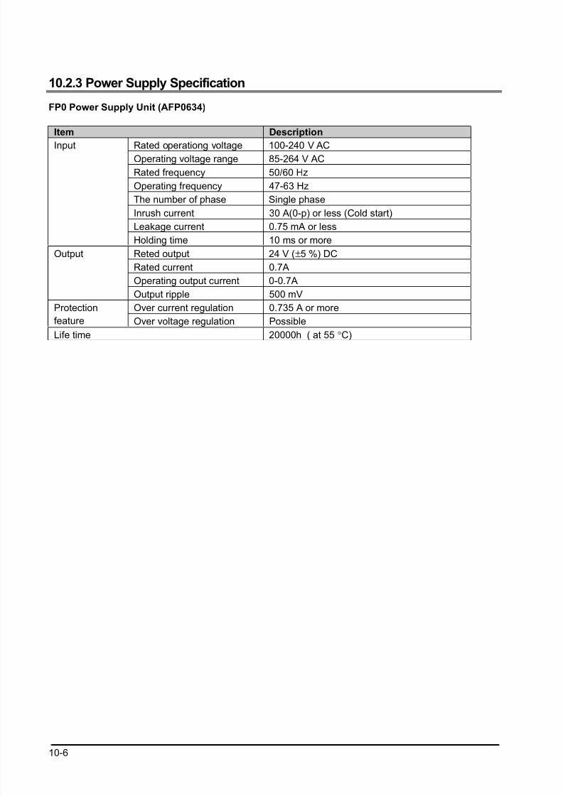
8/21/2019 Programmable Controller FP Sigma
http://slidepdf.com/reader/full/programmable-controller-fp-sigma 316/318
10-6
10.2.3 Power Supply Specification
FP0 Power Supply Unit (AFP0634)
Item Description
Rated operationg voltage 100-240 V AC
Operating voltage range 85-264 V AC
Rated frequency 50/60 Hz
Operating frequency 47-63 Hz
The number of phase Single phase
Inrush current 30 A(0-p) or less (Cold start)
Leakage current 0.75 mA or less
Input
Holding time 10 ms or more
Reted output 24 V (±5 %) DC
Rated current 0.7A
Operating output current 0-0.7A
Output
Output ripple 500 mV
Over current regulation 0.735 A or moreProtection
feature Over voltage regulation Possible
Life time 20000h ( at 55 °C)
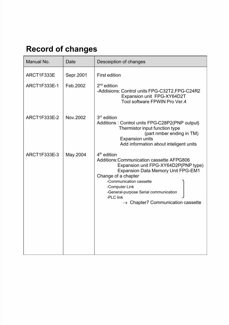
8/21/2019 Programmable Controller FP Sigma
http://slidepdf.com/reader/full/programmable-controller-fp-sigma 317/318
Record of changes
Manual No. Date Desceiption of changes
ARCT1F333E
ARCT1F333E-1
ARCT1F333E-2
ARCT1F333E-3
Sepr.2001
Feb.2002
Nov.2002
May.2004
First edition
2nd edition-Addisions: Control units FPG-C32T2,FPG-C24R2 Expansion unit FPG-XY64D2T Tool software FPWIN Pro Ver.4
3rd edition Additions : Control units FPG-C28P2(PNP output) Thermistor input function type (part nmber ending in TM) Expansion units
Add information about inteligent units
4th edition Additions:Communication cassette AFPG806 Expansion unit FPG-XY64D2P(PNP type)
Expansion Data Memory Unit FPG-EM1Change of a chapter -Communication cassette
-Computer Link
-General-purpose Serial communication
-PLC link
→ Chapter7 Communication cassette

8/21/2019 Programmable Controller FP Sigma
http://slidepdf.com/reader/full/programmable-controller-fp-sigma 318/318