programmable dc electronic load 6310 series operation ... · programmable dc electronic load 6310...
TRANSCRIPT
Programmable DC Electronic Load
6310 Series Operation & Programming
Manual
Edition May 2002
P/N A11 000078

Legal Notices The information in this document is subject to change without notice. Chroma ATE INC. makes no warranty of any kind with regard to this manual, including, but not limited to, the implied warranties of merchantability and fitness for a particular purpose. Chroma ATE INC. shall not be held liable for errors contained herein or direct, indirect, special, incidental or consequential damages in connection with the furnishing, performance, or use of this material. CHROMA ATE INC. 43 Wu-Chuan Road, Wu-Ku Industrial Park, Wu-Ku, Taipei, Taiwan Copyright Notices. Copyright 2002 Chroma ATE INC., all rights reserved. Reproduction, adaptation, or translation of this document without prior written permission is prohibited, except as allowed under the copyright laws.
ii

Warranty All Chroma instruments are warranted against defects in material and workmanship for a period of one year after date of shipment. Chroma agrees to repair or replace any assembly or component found to be defective, under normal use during this period. Chroma's obligation under this warranty is limited solely to repairing any such instrument, which in Chroma's sole opinion proves to be defective within the scope of the warranty when returned to the factory or to an authorized service center. Transportation to the factory or service center is to be prepaid by purchaser. Shipment should not be made without prior authorization by Chroma. This warranty does not apply to any products repaired or altered by persons not authorized by Chroma, or not in accordance with instructions furnished by Chroma. If the instrument is defective as a result of misuse, improper repair, or abnormal conditions or operations, repairs will be billed at cost. Chroma assumes no responsibility for its product being used in a hazardous or dangerous manner either alone or in conjunction with other equipment. High voltage used in some instruments may be dangerous if misused. Special disclaimers apply to these instruments. Chroma assumes no liability for secondary charges or consequential damages and in any event, Chroma's liability for breach of warranty under any contract or otherwise, shall not exceed the purchase price of the specific instrument shipped and against which a claim is made. Any recommendations made by Chroma for use of its products are based upon tests believed to be reliable, but Chroma makes no warranty of the results to be obtained. This warranty is in lieu of all other warranties, expressed or implied, and no representative or person is authorized to represent or assume for Chroma any liability in connection with the sale of our products other than set forth herein. CHROMA ATE INC. 43 Wu-Chuan Road, Wu-Ku Industrial Park, Wu-Ku, Taipei Hsien, Taiwan Tel: 886 -2-2298-3855 Fax: 886-2-2298-3596 http://www.chromaate.com
iii
CE-Conformity Declaration For the following equipment: Product Name: DC Electronic Load Model Name: 6314, 6312, 63101, 63102, 63103, 63105, 63106, 63107, 63108, 63112 Manufacturer’s Name: Chroma ATE Inc. Manufacturer’s Address: 43 Wu-Chuan Road, Wu-Ku Industrial Park, Wu-Ku, Taipei Hsien, Taiwan is herewith confirmed to comply with the requirements set out in the Council Directive on the Approximation of the Laws of the Member States Relating to Electromagnetic Compatibility(89/336/EEC) and electrical equipment designed for use within certain voltage limits(73/23/EEC;93/68/EEC) For electromagnetic compatibility, the following standards were applied: EMC: EN55011:1991 (Group I Class A) EN60555-2:1987--EN 61000-3-2(1995) EN60555-3:1987--EN 61000-3-3(1995) EN50082-1:1992 IEC 1000-4-2(1995):1991 - 8 kV AD, 4 kV CD (Class B) IEC 1000-4-3(1995) - 3 V/m IEC 1000-4-4(1995) - 0.5 kV Signal Lines 1 kV Power Lines For safety requirement, the following standard was applied: Safety: EN61010-1(1993)+A2(1995) Taiwan July 1999 Place Date Neng-Sung Lee/Vice President, Engineering Warning: This is a class A product. In a domestic environment this product may cause radio interference in which case the user may be required to take adequate measures.
iv
SAFETY SUMMARY
The following general safety precautions must be observed during all phases of operation, service, and repair of this instrument. Failure to comply with these precautions or specific WARNINGS given elsewhere in this manual will violate safety standards of design, manufacture, and intended use of the instrument. Chroma assumes no liability for the customer’s failure to comply with these requirements. BEFORE APPLYING POWER Verify that the product is set to match the available line voltage and the correct fuse is installed. PROTECTIVE GROUNDING Make sure to connect the protective grounding to prevent an electric shock before turning on the power. NECESSITY OF PROTECTIVE GROUNDING Never cut off the internal or external protective grounding wire, or disconnect the wiring of protective grounding terminal. Doing so will cause a potential shock hazard that may bring injury to a person. FUSES Only fuses with the required rated current, voltage, and specified type(normal blow, time delay, etc.)should be used. Do not use repaired fuses or short-circuited fuse holders. To do so could cause a shock or fire hazard. DO NOT OPERATE IN AN EXPLOSIVE ATMOSPHERE Do not operate the instrument in the presence of flammable gases or fumes. DO NOT REMOVE THE COVER OF THE INSTRUMENT Operating personnel must not remove the cover of the instrument. Component replacement and internal adjustment can only be done by qualified service personnel.
v
SAFETY SYMBOLS
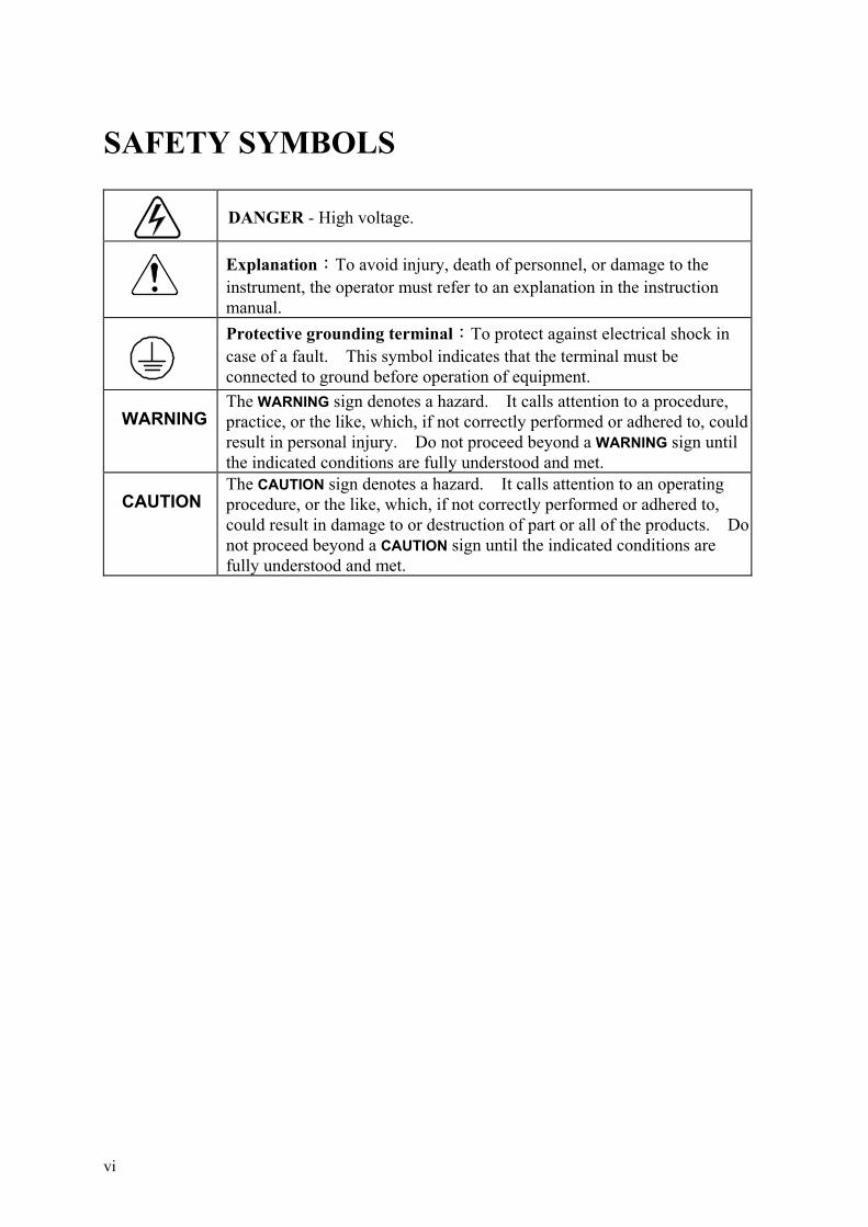
DANGER - High voltage.
Explanation:To avoid injury, death of personnel, or damage to the instrument, the operator must refer to an explanation in the instruction manual.
Protective grounding terminal:To protect against electrical shock in case of a fault. This symbol indicates that the terminal must be connected to ground before operation of equipment.
WARNING The WARNING sign denotes a hazard. It calls attention to a procedure, practice, or the like, which, if not correctly performed or adhered to, couldresult in personal injury. Do not proceed beyond a WARNING sign until the indicated conditions are fully understood and met.
CAUTION The CAUTION sign denotes a hazard. It calls attention to an operating procedure, or the like, which, if not correctly performed or adhered to, could result in damage to or destruction of part or all of the products. Do not proceed beyond a CAUTION sign until the indicated conditions are fully understood and met.
vi
Programmable DC Electronic Load 6310 Series Operation & Programming Manual
Table of Contents PART 1: Operation
1. General Information ................................................................................................ 1-1 1.1 Introduction ........................................................................................................ 1-1 1.2 Description ......................................................................................................... 1-1 1.3 Overview of Key Features.................................................................................. 1-2 1.4 Specifications ..................................................................................................... 1-2
2. Installation ................................................................................................................ 2-1 2.1 Introduction ........................................................................................................ 2-1 2.2 Inspection ........................................................................................................... 2-1 2.3 Installing the Modules........................................................................................ 2-1
2.3.1 Channel Number ........................................................................................ 2-2 2.4 Installing the Mainframe .................................................................................... 2-3
2.4.1 Changing Line Voltage .............................................................................. 2-3 2.4.2 Turn-On Self-Test ...................................................................................... 2-4
2.5 Application Connection ..................................................................................... 2-5 2.5.1 Load Connections....................................................................................... 2-5 2.5.2 Remote Sensing Connections..................................................................... 2-6 2.5.3 Parallel Connections................................................................................... 2-6
2.6 Remote Control Connection............................................................................... 2-7
3. Operation Overview................................................................................................. 3-1 3.1 Introduction ........................................................................................................ 3-1 3.2 Front Panel Description...................................................................................... 3-1 3.3 Rear Panel Description....................................................................................... 3-2 3.4 Local/Remote Control ........................................................................................ 3-3 3.5 Modes of Operation............................................................................................ 3-3
3.5.1 Constant Current Mode .............................................................................. 3-4 3.5.2 Constant Resistance Mode ......................................................................... 3-7 3.5.3 Constant Voltage Mode.............................................................................. 3-8
3.6 Load Synchronization ........................................................................................ 3-8 3.7 Measurements..................................................................................................... 3-9 3.8 Slew Rate & Minimum Transient Time............................................................. 3-9 3.9 Start/Stop Sink Current ...................................................................................... 3-9 3.10 Short On/Off..................................................................................................... 3-10 3.11 Load On/Off ..................................................................................................... 3-11 3.12 Protection Features........................................................................................... 3-11 3.13 Save/Recall Setting .......................................................................................... 3-12 3.14 Program ............................................................................................................ 3-12
4. Local Operation........................................................................................................ 4-1 4.1 Introduction ........................................................................................................ 4-1 4.2 Local Operation of Load Mainframe ................................................................. 4-1
4.2.1 Selecting the Channel................................................................................. 4-3 4.2.2 Setting the Operation Mode ....................................................................... 4-3 4.2.3 Setting the Program.................................................................................... 4-7 4.2.4 Running the Program ................................................................................. 4-9 4.2.5 Setting the Specification .......................................................................... 4-10
vii
Programmable DC Electronic Load 6310 Series Operation & Programming Manual
4.2.6 Setting the Configuration ......................................................................... 4-10 4.2.7 Recalling Files.......................................................................................... 4-15 4.2.8 Saving File/Default/Program.................................................................... 4-15 4.2.9 Going To Local ........................................................................................ 4-15 4.2.10 Lock Operation......................................................................................... 4-16 4.2.11 Setting System and RS-232C Connection................................................ 4-16 4.2.12 Connecting the GO/NG Output Port ........................................................ 4-16 4.2.13 Setting the GPIB Address ........................................................................ 4-17
4.3 Local Operation of Load Module..................................................................... 4-17 4.3.1 Local Operation of Single Channel/Module (Panel A)............................ 4-18 4.3.2 Local Operation of Double Channels/Module (Panel B) ......................... 4-20 4.3.3 Online Change Level................................................................................ 4-22
PART 2: Programming
5. General Information for Programming ................................................................. 5-1 5.1 Introduction ........................................................................................................ 5-1 5.2 DIP Switches on the GPIB Card ........................................................................ 5-1
5.2.1 GPIB Address............................................................................................. 5-1 5.2.2 Other DIP Switches.................................................................................... 5-2
5.3 GPIB Capability of the Electronic Load ............................................................ 5-2 5.4 RS232C in Remote Control................................................................................ 5-3
6. Introduction to Programming................................................................................. 6-1 6.1 Basic Definition.................................................................................................. 6-1 6.2 Numerical Data Formats .................................................................................... 6-1 6.3 Character Data Formats...................................................................................... 6-2 6.4 Separators and Terminators................................................................................ 6-3
7. Language Dictionary................................................................................................ 7-1 7.1 Common Commands.......................................................................................... 7-1 7.2 Specific Commands............................................................................................ 7-5
7.2.1 ABORT Subsystem.................................................................................... 7-5 7.2.2 CHANNEL Subsystem .............................................................................. 7-6 7.2.3 CONFIGURE Subsystem........................................................................... 7-8 7.2.4 CURRENT Subsystem............................................................................. 7-12 7.2.5 FETCH Subsystem................................................................................... 7-15 7.2.6 LOAD Subsystem .................................................................................... 7-16 7.2.7 MEASURE Subsystem ............................................................................ 7-19 7.2.8 MODE Subsystem.................................................................................... 7-21 7.2.9 PROGRAM Subsystem............................................................................ 7-22 7.2.10 RESISTANCE Subsystem ....................................................................... 7-27 7.2.11 RUN Subsystem ....................................................................................... 7-28 7.2.12 SHOW Subsystem.................................................................................... 7-28 7.2.13 SPECIFICATION Subsystem.................................................................. 7-29 7.2.14 STATUS Subsystem ................................................................................ 7-32 7.2.15 VOLTAGE Subsystem............................................................................. 7-36
8. Status Reporting....................................................................................................... 8-1 8.1 Introduction ........................................................................................................ 8-1 8.2 Register Information in Common ...................................................................... 8-1
viii

Programmable DC Electronic Load 6310 Series Operation & Programming Manual
8.3 Channel Status.................................................................................................... 8-3 8.4 Channel Summary .............................................................................................. 8-3 8.5 Questionable Status ............................................................................................ 8-4 8.6 Output Queue ..................................................................................................... 8-4 8.7 Standard Event Status ........................................................................................ 8-4 8.8 Status Byte register ............................................................................................ 8-5 8.9 Service Request Enable register......................................................................... 8-6
9. An Example of Use ................................................................................................... 9-1
ix

PART 1
Operation

General Information
1. General Information
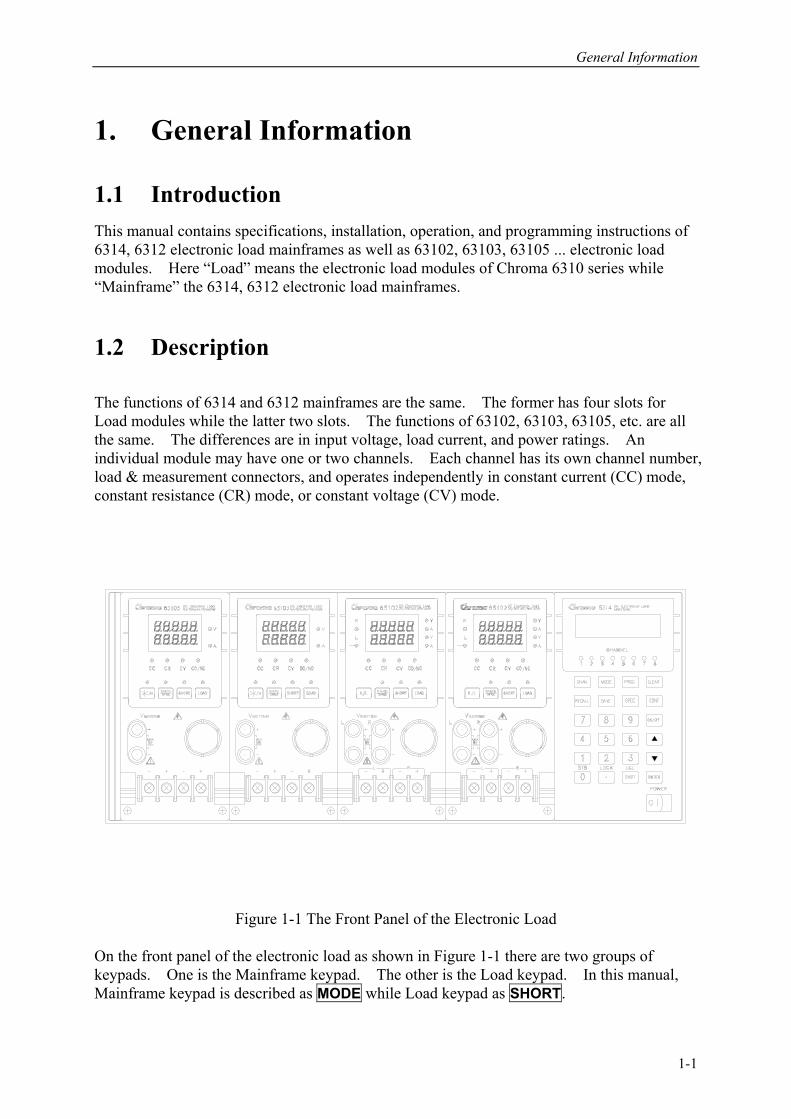
1.1 Introduction This manual contains specifications, installation, operation, and programming instructions of 6314, 6312 electronic load mainframes as well as 63102, 63103, 63105 ... electronic load modules. Here “Load” means the electronic load modules of Chroma 6310 series while “Mainframe” the 6314, 6312 electronic load mainframes. 1.2 Description The functions of 6314 and 6312 mainframes are the same. The former has four slots for Load modules while the latter two slots. The functions of 63102, 63103, 63105, etc. are all the same. The differences are in input voltage, load current, and power ratings. An individual module may have one or two channels. Each channel has its own channel number, load & measurement connectors, and operates independently in constant current (CC) mode, constant resistance (CR) mode, or constant voltage (CV) mode.
Figure 1-1 The Front Panel of the Electronic Load
On the front panel of the electronic load as shown in Figure 1-1 there are two groups of keypads. One is the Mainframe keypad. The other is the Load keypad. In this manual, Mainframe keypad is described as MODE while Load keypad as SHORT.
1-1
Programmable DC Electronic Load 6310 Series Operation & Programming Manual
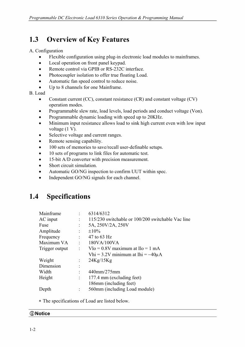
1.3 Overview of Key Features A. Configuration
• Flexible configuration using plug-in electronic load modules to mainframes. • Local operation on front panel keypad. • Remote control via GPIB or RS-232C interface. • Photocoupler isolation to offer true floating Load. • Automatic fan speed control to reduce noise. • Up to 8 channels for one Mainframe.
B. Load • Constant current (CC), constant resistance (CR) and constant voltage (CV)
operation modes. • Programmable slew rate, load levels, load periods and conduct voltage (Von). • Programmable dynamic loading with speed up to 20KHz. • Minimum input resistance allows load to sink high current even with low input
voltage (1 V). • Selective voltage and current ranges. • Remote sensing capability. • 100 sets of memories to save/recall user-definable setups. • 10 sets of programs to link files for automatic test. • 15-bit A/D converter with precision measurement. • Short circuit simulation. • Automatic GO/NG inspection to confirm UUT within spec. • Independent GO/NG signals for each channel.
1.4 Specifications
Mainframe : 6314/6312 AC input : 115/230 switchable or 100/200 switchable Vac line Fuse : 5A, 250V/2A, 250V Amplitude : ±10% Frequency : 47 to 63 Hz Maximum VA : 180VA/100VA Trigger output : Vlo = 0.8V maximum at Ilo = 1 mA
Vhi = 3.2V minimum at Ihi = −40µA Weight : 24Kg/15Kg Dimension : Width : 440mm/275mm Height : 177.4 mm (excluding feet)
186mm (including feet) Depth : 560mm (including Load module)
∗ The specifications of Load are listed below.
Notice
1-2
General Information
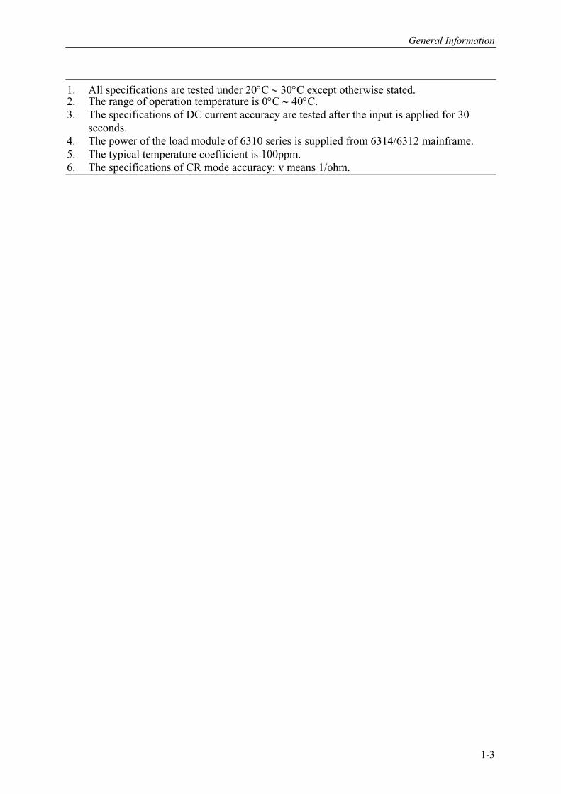
1. All specifications are tested under 20°C ∼ 30°C except otherwise stated. 2. The range of operation temperature is 0°C ∼ 40°C. 3. The specifications of DC current accuracy are tested after the input is applied for 30
seconds. 4. The power of the load module of 6310 series is supplied from 6314/6312 mainframe. 5. The typical temperature coefficient is 100ppm. 6. The specifications of CR mode accuracy: v means 1/ohm.
1-3
Programmable DC Electronic Load 6310 Series Operation & Programming Manual
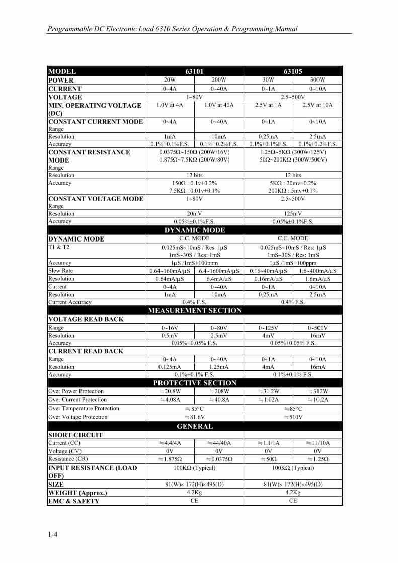
MODEL 63101 63105 POWER 20W 200W 30W 300W CURRENT 0∼4A 0∼40A 0∼1A 0∼10A VOLTAGE 1∼80V 2.5∼500V MIN. OPERATING VOLTAGE (DC)
1.0V at 4A 1.0V at 40A 2.5V at 1A 2.5V at 10A
CONSTANT CURRENT MODE Range
0∼4A 0∼40A 0∼1A 0∼10A
Resolution 1mA 10mA 0.25mA 2.5mA Accuracy 0.1%+0.1%F.S. 0.1%+0.2%F.S. 0.1%+0.1%F.S. 0.1%+0.2%F.S. CONSTANT RESISTANCE MODE Range
0.0375Ω∼150Ω (200W/16V) 1.875Ω∼7.5KΩ (200W/80V)
1.25Ω∼5KΩ (300W/125V) 50Ω∼200KΩ (300W/500V)
Resolution 12 bits 12 bits Accuracy 150Ω : 0.1v+0.2%
7.5KΩ : 0.01v+0.1% 5KΩ : 20mv+0.2% 200KΩ : 5mv+0.1%
CONSTANT VOLTAGE MODE Range
1∼80V 2.5∼500V
Resolution 20mV 125mV Accuracy 0.05%±0.1%F.S. 0.05%±0.1%F.S.
DYNAMIC MODE DYNAMIC MODE C.C. MODE C.C. MODE T1 & T2 0.025mS∼10mS / Res: 1µS
1mS∼30S / Res: 1mS 0.025mS∼10mS / Res: 1µS
1mS∼30S / Res: 1mS Accuracy 1µS /1mS+100ppm 1µS /1mS+100ppm Slew Rate 0.64∼160mA/µS 6.4∼1600mA/µS 0.16∼40mA/µS 1.6∼400mA/µS Resolution 0.64mA/µS 6.4mA/µS 0.16mA/µS 1.6mA/µS Current 0∼4A 0∼40A 0∼1A 0∼10A Resolution 1mA 10mA 0.25mA 2.5mA Current Accuracy 0.4% F.S. 0.4% F.S.
MEASUREMENT SECTION VOLTAGE READ BACK
Range 0∼16V 0∼80V 0∼125V 0∼500V Resolution 0.5mV 2.5mV 4mV 16mV Accuracy 0.05%+0.05% F.S. 0.05%+0.05% F.S. CURRENT READ BACK
Range 0∼4A 0∼40A 0∼1A 0∼10A Resolution 0.125mA 1.25mA 4mA 16mA Accuracy 0.1%+0.1% F.S. 0.1%+0.1% F.S.
PROTECTIVE SECTION Over Power Protection ≒20.8W ≒208W ≒31.2W ≒312W Over Current Protection ≒4.08A ≒40.8A ≒1.02A ≒10.2A Over Temperature Protection ≒85°C ≒85°C Over Voltage Protection ≒81.6V ≒510V
GENERAL SHORT CIRCUIT
Current (CC) ≒4.4/4A ≒44/40A ≒1.1/1A ≒11/10A Voltage (CV) 0V 0V 0V 0V Resistance (CR) ≒1.875Ω ≒0.0375Ω ≒50Ω ≒1.25Ω
INPUT RESISTANCE (LOAD OFF)
100KΩ (Typical) 100KΩ (Typical)
SIZE 81(W)× 172(H)×495(D) 81(W)× 172(H)×495(D) WEIGHT (Approx.) 4.2Kg 4.2Kg EMC & SAFETY CE CE
1-4

General Information
MODEL 63102(100W*2) 63103 POWER 20W 100W 30W 300W CURRENT 0∼2A 0∼20A 0∼6A 0∼60A VOLTAGE 1∼80V 1∼80V MIN. OPERATING VOLTAGE (DC)
1.0V at 2A 1.0V at 20A 1.0V at 6A 1.0V at 60A
CONSTANT CURRENT MODE Range
0∼2A 0∼20A 0∼6A 0∼60A
Resolution 0.5mA 5mA 1.5mA 15mA Accuracy 0.1%+0.1%F.S. 0.1%+0.2%F.S. 0.1%+0.1%F.S. 0.1%+0.2%F.S. CONSTANT RESISTANCE MODE Range
0.075Ω∼300Ω (100W/16V) 3.75Ω∼15KΩ (100W/80V)
0.025Ω∼100Ω (300W/16V) 1.25Ω∼5KΩ (300W/80V)
Resolution 12 bits 12 bits Accuracy 300Ω : 0.1v+0.2%
15KΩ : 0.01v+0.1% 100Ω : 0.1v+0.2% 5KΩ : 0.01v+0.1%
CONSTANT VOLTAGE MODE Range
1∼80V 2.5∼500V
Resolution 20mv 20mv Accuracy 0.05%±0.1%F.S. 0.05%±0.1%F.S.
DYNAMIC MODE DYNAMIC MODE C.C. MODE C.C. MODE T1 & T2 0.025mS∼10mS / Res: 1µS
1mS∼30S / Res: 1mS 0.025mS∼10mS / Res: 1µS
1mS∼30S / Res: 1mS Accuracy 1µS /1mS+100ppm 1µS /1mS+100ppm Slew Rate 0.32∼80mA/µS 3.2∼800mA/µS 0.001∼0.25A/µS 0.01∼2.5A/µS Resolution 0.32mA/µS 3.2mA/µS 0.001A/µS 0.01A/µS Current 0∼2A 0∼20A 0∼6A 0∼60A Resolution 0.5mA 5mA 1.5mA 15mA Current Accuracy 0.4% F.S. 0.4% F.S.
MEASUREMENT SECTION VOLTAGE READ BACK
Range 0∼16V 0∼80V 0∼16V 0∼80V Resolution 0.5mV 2.5mV 0.5mV 2.5mV Accuracy 0.05%+0.05% F.S. 0.05%+0.05% F.S. CURRENT READ BACK
Range 0∼2A 0∼20A 0∼6A 0∼60A Resolution 0.0625mA 0.625mA 0.1875mA 1.875mA Accuracy 0.1%+0.1% F.S. 0.1%+0.1% F.S.
PROTECTIVE SECTION Over Power Protection ≒20.8W ≒104W ≒31.2W ≒312W Over Current Protection ≒2.04A ≒20.4A ≒6.12A ≒61.2A Over Temperature Protection ≒85°C ≒85°C Over Voltage Protection ≒81.6V ≒81.6V
GENERAL SHORT CIRCUIT
Current (CC) ≒2.2/2A ≒22/20A ≒6.6/6A ≒66/60A Voltage (CV) 0V 0V 0V 0V Resistance (CR) ≒3.75Ω ≒0.075Ω ≒1.25Ω ≒0.025Ω
INPUT RESISTANCE (LOAD OFF)
100KΩ (Typical) 100KΩ (Typical)
SIZE 81(W)× 172(H)×495(D) 81(W)× 172(H)×495(D) WEIGHT (Approx.) 4.2Kg 4.2Kg EMC & SAFETY CE CE
1-5
Programmable DC Electronic Load 6310 Series Operation & Programming Manual
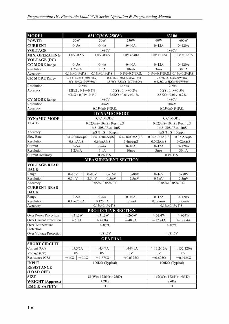
MODEL 63107(30W,250W) 63106 POWER 30W 30W 250W 60W 600W CURRENT 0∼5A 0∼4A 0∼40A 0∼12A 0∼120A VOLTAGE 1∼80V 1∼80V MIN. OPERATING VOLTAGE (DC)
1.0V at 5A 1.0V at 4A 1.0V at 40A 1.0V at 12A 1.0V at 120A
CC MODE Range 0∼5A 0∼4A 0∼40A 0∼12A 0∼120A Resolution 1.25mA 1mA 10mA 3mA 30mA Accuracy 0.1%+0.1%F.S. 0.1%+0.1%F.S. 0.1%+0.2%F.S. 0.1%+0.1%F.S. 0.1%+0.2%F.S.CR MODE Range 0.3Ω∼1.2KΩ (30W/16v)
15Ω∼60KΩ (30W/80v) 0.375Ω∼150Ω (250W/16v) 1.875Ω∼7.5KΩ (250W/80v)
12.5mΩ∼50Ω (600W/16v) 0.625Ω∼2.5KΩ (600W/80v)
Resolution 12 bits 12 bits 12 bits Accuracy 12KΩ : 0.1v+0.2%
60KΩ : 0.01v+0.1% 150Ω : 0.1v+0.2%
7.5KΩ : 0.01v+0.1% 50Ω : 0.1v+0.5%
2.5KΩ : 0.01v+0.2% CV MODE Range 1∼80V 1∼80V Resolution 20mV 20mV Accuracy 0.05%±0.1%F.S. 0.05%±0.1%F.S.
DYNAMIC MODE DYNAMIC MODE C.C. MODE C.C. MODE T1 & T2 0.025mS∼10mS / Res: 1µS
1mS∼30S / Res: 1mS 0.025mS∼10mS / Res: 1µS
1mS∼30S / Res: 1mS Accuracy 1µS /1mS+100ppm 1µS /1mS+100ppm Slew Rate 0.8∼200mA/µS 0.64∼160mA/µS 6.4∼1600mA/µS 0.002∼0.5A/µS 0.02∼5A/µS Resolution 0.8mA/µS 0.64mA/µS 6.4mA/µS 0.002A/µS 0.02A/µS Current 0∼5A 0∼4A 0∼40A 0∼12A 0∼120A Resolution 1.25mA 1mA 10mA 3mA 30mA Current Accuracy 0.4% F.S. 0.4% F.S.
MEASUREMENT SECTION VOLTAGE READ BACK
Range 0∼16V 0∼80V 0∼16V 0∼80V 0∼16V 0∼80V Resolution 0.5mV 2.5mV 0.5mV 2.5mV 0.5mV 2.5mV Accuracy 0.05%+0.05% F.S. 0.05%+0.05% F.S. CURRENT READ BACK
Range 0∼5A 0∼4A 0∼40A 0∼12A 0∼120A Resolution 0.15625mA 0.125mA 1.25mA 0.375mA 3.75mA Accuracy 0.1%+0.1% F.S. 0.1%+0.1% F.S.
PROTECTIVE SECTION Over Power Protection ≒31.2W ≒31.2W ≒260W ≒62.4W ≒624W Over Current Protection ≒5.1A ≒4.08A ≒40.8A ≒12.24A ≒122.4A Over Temperature Protection
≒85°C ≒85°C
Over Voltage Protection ≒81.6V ≒81.6V
GENERAL SHORT CIRCUIT
Current (CC) ≒5.5/5A ≒4.4/4A ≒44/40A ≒13.2/12A ≒132/120A Voltage (CV) 0V 0V 0V 0V 0V Resistance (CR) ≒15Ω ≒0.3Ω ≒1.875Ω ≒0.0375Ω ≒0.625Ω ≒0.0125Ω
INPUT RESISTANCE (LOAD OFF)
100KΩ (Typical) 100KΩ (Typical)
SIZE 81(W)× 172(H)×495(D) 162(W)× 172(H)×495(D) WEIGHT (Approx.) 4.2Kg 8.4Kg EMC & SAFETY CE CE
1-6
General Information
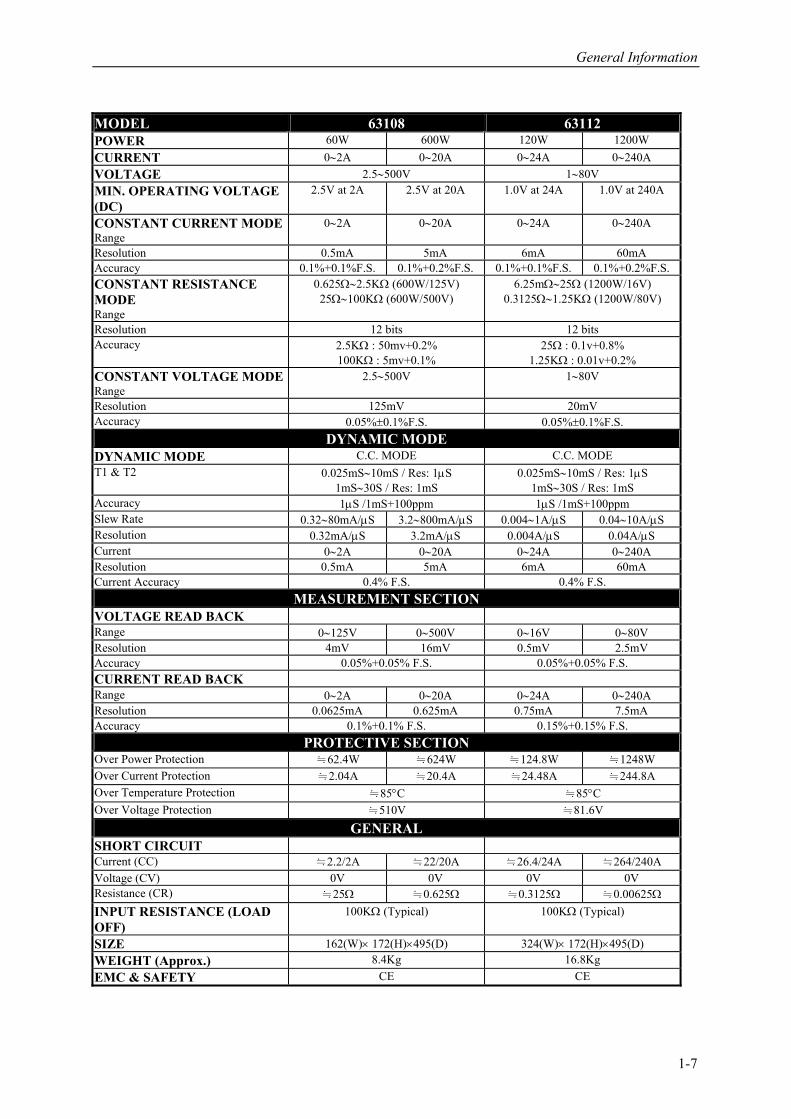
MODEL 63108 63112 POWER 60W 600W 120W 1200W CURRENT 0∼2A 0∼20A 0∼24A 0∼240A VOLTAGE 2.5∼500V 1∼80V MIN. OPERATING VOLTAGE (DC)
2.5V at 2A 2.5V at 20A 1.0V at 24A 1.0V at 240A
CONSTANT CURRENT MODE Range
0∼2A 0∼20A 0∼24A 0∼240A
Resolution 0.5mA 5mA 6mA 60mA Accuracy 0.1%+0.1%F.S. 0.1%+0.2%F.S. 0.1%+0.1%F.S. 0.1%+0.2%F.S. CONSTANT RESISTANCE MODE Range
0.625Ω∼2.5KΩ (600W/125V) 25Ω∼100KΩ (600W/500V)
6.25mΩ∼25Ω (1200W/16V) 0.3125Ω∼1.25KΩ (1200W/80V)
Resolution 12 bits 12 bits Accuracy 2.5KΩ : 50mv+0.2%
100KΩ : 5mv+0.1% 25Ω : 0.1v+0.8%
1.25KΩ : 0.01v+0.2% CONSTANT VOLTAGE MODE Range
2.5∼500V 1∼80V
Resolution 125mV 20mV Accuracy 0.05%±0.1%F.S. 0.05%±0.1%F.S.
DYNAMIC MODE DYNAMIC MODE C.C. MODE C.C. MODE T1 & T2 0.025mS∼10mS / Res: 1µS
1mS∼30S / Res: 1mS 0.025mS∼10mS / Res: 1µS
1mS∼30S / Res: 1mS Accuracy 1µS /1mS+100ppm 1µS /1mS+100ppm Slew Rate 0.32∼80mA/µS 3.2∼800mA/µS 0.004∼1A/µS 0.04∼10A/µS Resolution 0.32mA/µS 3.2mA/µS 0.004A/µS 0.04A/µS Current 0∼2A 0∼20A 0∼24A 0∼240A Resolution 0.5mA 5mA 6mA 60mA Current Accuracy 0.4% F.S. 0.4% F.S.
MEASUREMENT SECTION VOLTAGE READ BACK
Range 0∼125V 0∼500V 0∼16V 0∼80V Resolution 4mV 16mV 0.5mV 2.5mV Accuracy 0.05%+0.05% F.S. 0.05%+0.05% F.S. CURRENT READ BACK
Range 0∼2A 0∼20A 0∼24A 0∼240A Resolution 0.0625mA 0.625mA 0.75mA 7.5mA Accuracy 0.1%+0.1% F.S. 0.15%+0.15% F.S.
PROTECTIVE SECTION Over Power Protection ≒62.4W ≒624W ≒124.8W ≒1248W Over Current Protection ≒2.04A ≒20.4A ≒24.48A ≒244.8A Over Temperature Protection ≒85°C ≒85°C Over Voltage Protection ≒510V ≒81.6V
GENERAL SHORT CIRCUIT
Current (CC) ≒2.2/2A ≒22/20A ≒26.4/24A ≒264/240A Voltage (CV) 0V 0V 0V 0V Resistance (CR) ≒25Ω ≒0.625Ω ≒0.3125Ω ≒0.00625Ω
INPUT RESISTANCE (LOAD OFF)
100KΩ (Typical) 100KΩ (Typical)
SIZE 162(W)× 172(H)×495(D) 324(W)× 172(H)×495(D) WEIGHT (Approx.) 8.4Kg 16.8Kg EMC & SAFETY CE CE
1-7

Installation
2. Installation
2.1 Introduction This chapter discusses how to install the Load to Mainframe and make connections to the Loads. It discusses a turn-on check procedure and application considerations as well. 2.2 Inspection As soon as the instrument is unpacked inspect any damage that might have occurred in shipping. Keep all packing materials in case that the Load or the Mainframe has to be returned. If any damage is found, please file a claim with the carrier immediately. Do not return the instrument to Chroma without prior approval. In addition to this manual, be sure that the following items have also been received with your Mainframe and Load. Mainframe: Power Cord, Manual Load Module: Measurement and Load Cables 2.3 Installing the Modules
CAUTION Load module can be damaged by electronic discharge (static electricity). Use standard anti-static work practices when you handle and install modules. Avoid touching the connector and the circuit board. The Chroma 6314 Mainframe has room for four single-width Loads (63102, 63103), or two double-width Loads (63106). Loads can be combined in the Mainframe in any order. The Chroma 6312 mainframe has room only for two single-width Loads or one double-width Load. The procedures of the module installation in both Mainframes are the same. Only the screwdriver is required in installing Load to Mainframe. Procedures: 1. Disconnect the power cord with the Mainframe power off. 2. Remove any packing materials from the Mainframe. 3. Start installing the modules in the slot (see Figure 2-1). 4. Plug the load module into the slot of the Mainframe along the rail. 5. Lock the module in place by use of the screwdriver (see Figure 2-1). 6. Install each additional module in the slot next to the previous one likewise if applicable.
2-1
Programmable DC Electronic Load 6310 Series Operation & Programming Manual
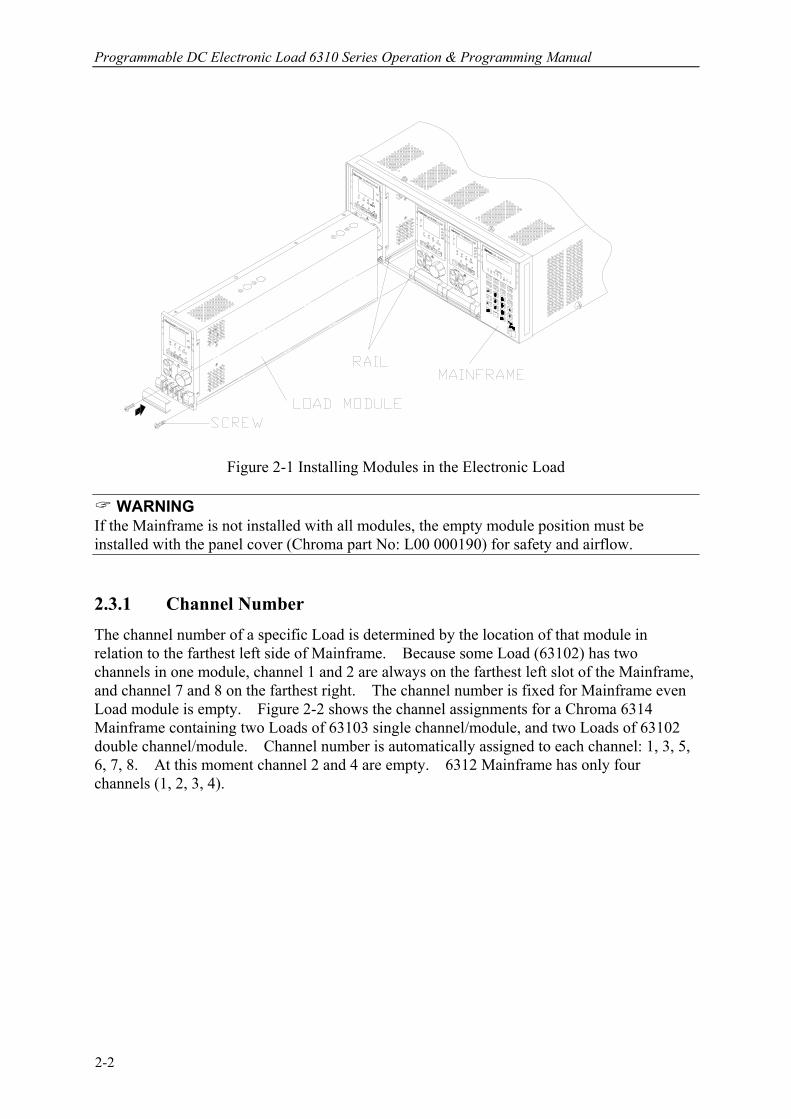
Figure 2-1 Installing Modules in the Electronic Load
WARNING If the Mainframe is not installed with all modules, the empty module position must be installed with the panel cover (Chroma part No: L00 000190) for safety and airflow. 2.3.1 Channel Number The channel number of a specific Load is determined by the location of that module in relation to the farthest left side of Mainframe. Because some Load (63102) has two channels in one module, channel 1 and 2 are always on the farthest left slot of the Mainframe, and channel 7 and 8 on the farthest right. The channel number is fixed for Mainframe even Load module is empty. Figure 2-2 shows the channel assignments for a Chroma 6314 Mainframe containing two Loads of 63103 single channel/module, and two Loads of 63102 double channel/module. Channel number is automatically assigned to each channel: 1, 3, 5, 6, 7, 8. At this moment channel 2 and 4 are empty. 6312 Mainframe has only four channels (1, 2, 3, 4).
2-2

Installation
Figure 2-2 Channel Number Example
2.4 Installing the Mainframe The electronic Load can operate well within temperature range of 0 to 40 degree C. However, you must install the electronic Load in a location that has enough space at the top, four sides, and the rear of the unit for adequate air flowing through and escaping from the back. You must leave at least 3 cm (1 inch) space above the unit for adequate air circulation. Note that the feet of the unit have enough vertical space for air circulation when it is stacked. The feet of the Mainframe can be removed for rack mounting. If you install equipment on top of your electronic Load in the cabinet, you must use a filter panel above the unit to ensure adequate air circulation. A 1U (EIA standard) panel is sufficient. 2.4.1 Changing Line Voltage The electronic Load can operate with a 115/230 Vac input as indicated on the rear LINE label. The 100/200 line voltage input model is used only in Japan. If the factory set switch on this label does not correspond to your nominal line voltage, turn the Mainframe power off, and disconnect the power cord. Set switch to the correct line voltage as shown in Figure 2-3.
Notice Line fuses do not need to be changed when the line voltage is changed. The line fuses will protect the electronic Load in any indicated voltage setting.
2-3
Programmable DC Electronic Load 6310 Series Operation & Programming Manual
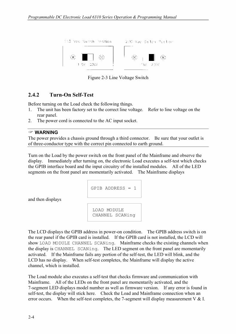
Figure 2-3 Line Voltage Switch
2.4.2 Turn-On Self-Test Before turning on the Load check the following things. 1. The unit has been factory set to the correct line voltage. Refer to line voltage on the
rear panel. 2. The power cord is connected to the AC input socket.
WARNING The power provides a chassis ground through a third connector. Be sure that your outlet is of three-conductor type with the correct pin connected to earth ground. Turn on the Load by the power switch on the front panel of the Mainframe and observe the display. Immediately after turning on, the electronic Load executes a self-test which checks the GPIB interface board and the input circuitry of the installed modules. All of the LED segments on the front panel are momentarily activated. The Mainframe displays GPIB ADDRESS = 1 and then displays LOAD MODULE CHANNEL SCANing The LCD displays the GPIB address in power-on condition. The GPIB address switch is on the rear panel if the GPIB card is installed. If the GPIB card is not installed, the LCD will show LOAD MODULE CHANNEL SCANing. Mainframe checks the existing channels when the display is CHANNEL SCANing. The LED segment on the front panel are momentarily activated. If the Mainframe fails any portion of the self-test, the LED will blink, and the LCD has no display. When self-test completes, the Mainframe will display the active channel, which is installed. The Load module also executes a self-test that checks firmware and communication with Mainframe. All of the LEDs on the front panel are momentarily activated, and the 7-segment LED displays model number as well as firmware version. If any error is found in self-test, the display will stick here. Check the Load and Mainframe connection when an error occurs. When the self-test completes, the 7-segment will display measurement V & I.
2-4
Installation
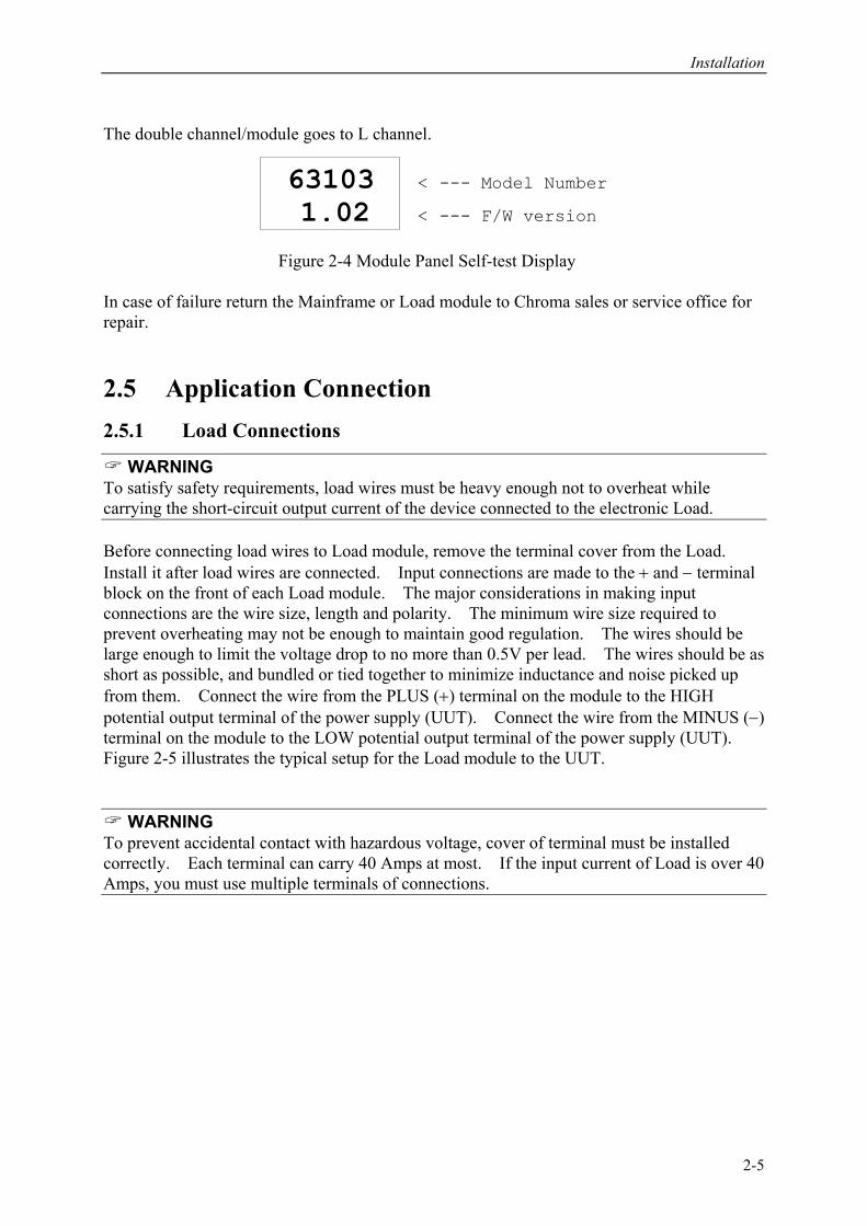
The double channel/module goes to L channel. 63103 < --- Model Number
1.02 < --- F/W version Figure 2-4 Module Panel Self-test Display In case of failure return the Mainframe or Load module to Chroma sales or service office for repair. 2.5 Application Connection 2.5.1 Load Connections
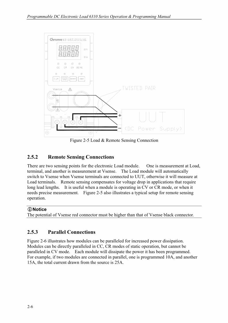
WARNING To satisfy safety requirements, load wires must be heavy enough not to overheat while carrying the short-circuit output current of the device connected to the electronic Load. Before connecting load wires to Load module, remove the terminal cover from the Load. Install it after load wires are connected. Input connections are made to the + and − terminal block on the front of each Load module. The major considerations in making input connections are the wire size, length and polarity. The minimum wire size required to prevent overheating may not be enough to maintain good regulation. The wires should be large enough to limit the voltage drop to no more than 0.5V per lead. The wires should be as short as possible, and bundled or tied together to minimize inductance and noise picked up from them. Connect the wire from the PLUS (+) terminal on the module to the HIGH potential output terminal of the power supply (UUT). Connect the wire from the MINUS (−) terminal on the module to the LOW potential output terminal of the power supply (UUT). Figure 2-5 illustrates the typical setup for the Load module to the UUT.
WARNING To prevent accidental contact with hazardous voltage, cover of terminal must be installed correctly. Each terminal can carry 40 Amps at most. If the input current of Load is over 40 Amps, you must use multiple terminals of connections.
2-5
Programmable DC Electronic Load 6310 Series Operation & Programming Manual
Figure 2-5 Load & Remote Sensing Connection
2.5.2 Remote Sensing Connections There are two sensing points for the electronic Load module. One is measurement at Load, terminal, and another is measurement at Vsense. The Load module will automatically switch to Vsense when Vsense terminals are connected to UUT, otherwise it will measure at Load terminals. Remote sensing compensates for voltage drop in applications that require long lead lengths. It is useful when a module is operating in CV or CR mode, or when it needs precise measurement. Figure 2-5 also illustrates a typical setup for remote sensing operation.
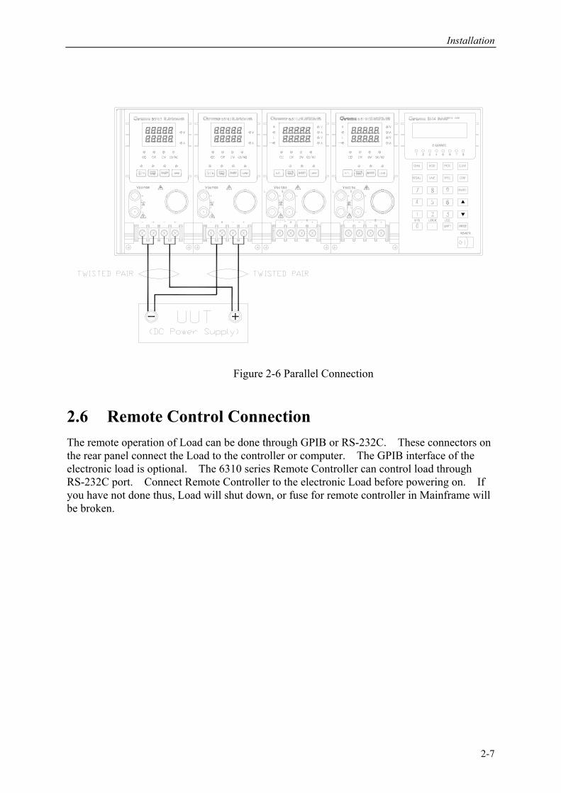
Notice The potential of Vsense red connector must be higher than that of Vsense black connector. 2.5.3 Parallel Connections Figure 2-6 illustrates how modules can be paralleled for increased power dissipation. Modules can be directly paralleled in CC, CR modes of static operation, but cannot be paralleled in CV mode. Each module will dissipate the power it has been programmed. For example, if two modules are connected in parallel, one is programmed 10A, and another 15A, the total current drawn from the source is 25A.
2-6
Installation
Figure 2-6 Parallel Connection
2.6 Remote Control Connection The remote operation of Load can be done through GPIB or RS-232C. These connectors on the rear panel connect the Load to the controller or computer. The GPIB interface of the electronic load is optional. The 6310 series Remote Controller can control load through RS-232C port. Connect Remote Controller to the electronic Load before powering on. If you have not done thus, Load will shut down, or fuse for remote controller in Mainframe will be broken.
2-7

Operation Overview
3. Operation Overview
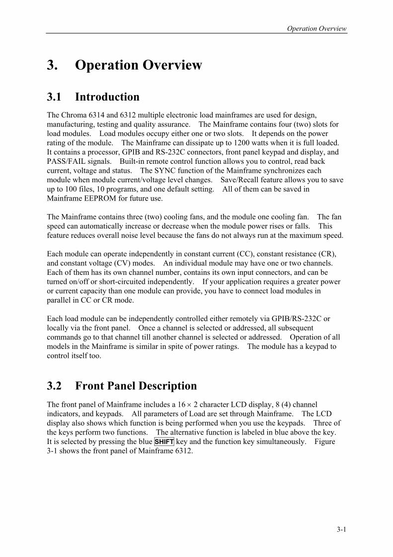
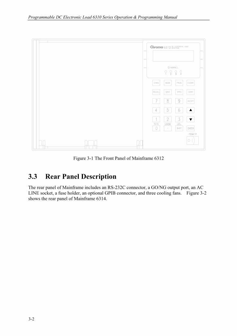
3.1 Introduction The Chroma 6314 and 6312 multiple electronic load mainframes are used for design, manufacturing, testing and quality assurance. The Mainframe contains four (two) slots for load modules. Load modules occupy either one or two slots. It depends on the power rating of the module. The Mainframe can dissipate up to 1200 watts when it is full loaded. It contains a processor, GPIB and RS-232C connectors, front panel keypad and display, and PASS/FAIL signals. Built-in remote control function allows you to control, read back current, voltage and status. The SYNC function of the Mainframe synchronizes each module when module current/voltage level changes. Save/Recall feature allows you to save up to 100 files, 10 programs, and one default setting. All of them can be saved in Mainframe EEPROM for future use. The Mainframe contains three (two) cooling fans, and the module one cooling fan. The fan speed can automatically increase or decrease when the module power rises or falls. This feature reduces overall noise level because the fans do not always run at the maximum speed. Each module can operate independently in constant current (CC), constant resistance (CR), and constant voltage (CV) modes. An individual module may have one or two channels. Each of them has its own channel number, contains its own input connectors, and can be turned on/off or short-circuited independently. If your application requires a greater power or current capacity than one module can provide, you have to connect load modules in parallel in CC or CR mode. Each load module can be independently controlled either remotely via GPIB/RS-232C or locally via the front panel. Once a channel is selected or addressed, all subsequent commands go to that channel till another channel is selected or addressed. Operation of all models in the Mainframe is similar in spite of power ratings. The module has a keypad to control itself too. 3.2 Front Panel Description The front panel of Mainframe includes a 16 × 2 character LCD display, 8 (4) channel indicators, and keypads. All parameters of Load are set through Mainframe. The LCD display also shows which function is being performed when you use the keypads. Three of the keys perform two functions. The alternative function is labeled in blue above the key. It is selected by pressing the blue SHIFT key and the function key simultaneously. Figure 3-1 shows the front panel of Mainframe 6312.
3-1
Programmable DC Electronic Load 6310 Series Operation & Programming Manual
Figure 3-1 The Front Panel of Mainframe 6312
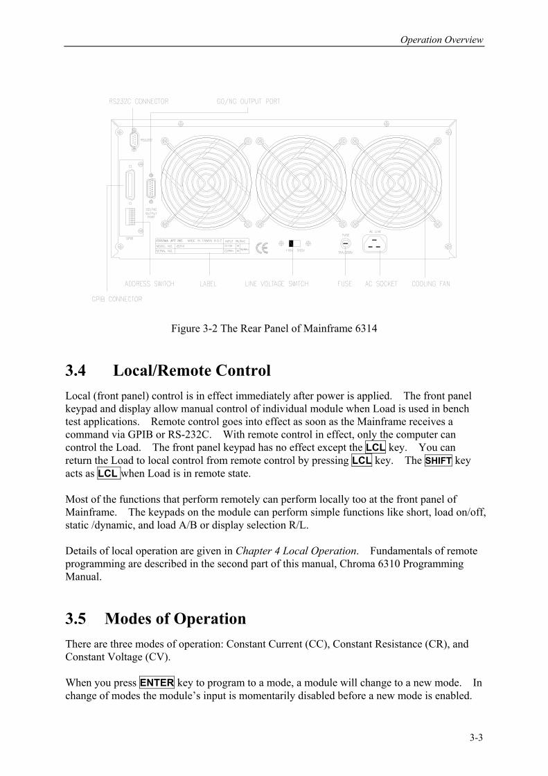
3.3 Rear Panel Description The rear panel of Mainframe includes an RS-232C connector, a GO/NG output port, an AC LINE socket, a fuse holder, an optional GPIB connector, and three cooling fans. Figure 3-2 shows the rear panel of Mainframe 6314.
3-2
Operation Overview
Figure 3-2 The Rear Panel of Mainframe 6314
3.4 Local/Remote Control Local (front panel) control is in effect immediately after power is applied. The front panel keypad and display allow manual control of individual module when Load is used in bench test applications. Remote control goes into effect as soon as the Mainframe receives a command via GPIB or RS-232C. With remote control in effect, only the computer can control the Load. The front panel keypad has no effect except the LCL key. You can return the Load to local control from remote control by pressing LCL key. The SHIFT key acts as LCL when Load is in remote state. Most of the functions that perform remotely can perform locally too at the front panel of Mainframe. The keypads on the module can perform simple functions like short, load on/off, static /dynamic, and load A/B or display selection R/L. Details of local operation are given in Chapter 4 Local Operation. Fundamentals of remote programming are described in the second part of this manual, Chroma 6310 Programming Manual. 3.5 Modes of Operation There are three modes of operation: Constant Current (CC), Constant Resistance (CR), and Constant Voltage (CV). When you press ENTER key to program to a mode, a module will change to a new mode. In change of modes the module’s input is momentarily disabled before a new mode is enabled.
3-3

Programmable DC Electronic Load 6310 Series Operation & Programming Manual
This ensures that there will be minimum overshoots in change of modes. The parameters in current, resistance or voltage mode can be programmed simply as the mode is presently selected. All data set in CC/CR/CV mode will be rescaled to fit the resolution of current/voltage levels or slew rate. In local mode any value can be set to a module from the keypad. There are no upper and lower limits that would cause an error. Mainframe automatically selects data, which are rescaled from the programmed value, truncates and checks high, low boundary before fitting memory. When programmed data are over the boundary, Mainframe will set maximum or minimum level for the Load module. In remote mode programmed value cannot be over boundary. An error will occur when data are over the maximum or minimum value. 3.5.1 Constant Current Mode
Figure 3-3 Constant Current Mode
In CC mode, the Load will sink a current in accordance with the programmed value regardless of input voltage. The CC mode can be set with front panel key MODE. When MODE SELECT is displayed, it means to select static low range CCL or static high range CCH. Current Ranges (Low, High) Current can be programmed in either of the two ranges, low range and high range. The low range provides better resolution at low current setting. If any value is over the maximum of low range, you must select the high range. Press MODE key first, then use or key to select the current range. MODE SELECT CCL Select Static Constant Current low range MODE SELECT
3-4
Operation Overview
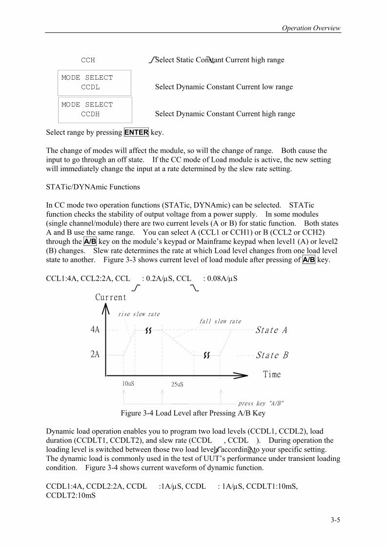
CCH Select Static Constant Current high range MODE SELECT CCDL Select Dynamic Constant Current low range MODE SELECT CCDH Select Dynamic Constant Current high range Select range by pressing ENTER key. The change of modes will affect the module, so will the change of range. Both cause the input to go through an off state. If the CC mode of Load module is active, the new setting will immediately change the input at a rate determined by the slew rate setting. STATic/DYNAmic Functions In CC mode two operation functions (STATic, DYNAmic) can be selected. STATic function checks the stability of output voltage from a power supply. In some modules (single channel/module) there are two current levels (A or B) for static function. Both states A and B use the same range. You can select A (CCL1 or CCH1) or B (CCL2 or CCH2) through the A/B key on the module’s keypad or Mainframe keypad when level1 (A) or level2 (B) changes. Slew rate determines the rate at which Load level changes from one load level state to another. Figure 3-3 shows current level of load module after pressing of A/B key. CCL1:4A, CCL2:2A, CCL : 0.2A/µS, CCL : 0.08A/µS
Time
Current
rise slew ratefall slew rate
State A
State B
4A
2A
10uS 25uS
press key "A/B" Figure 3-4 Load Level after Pressing A/B Key
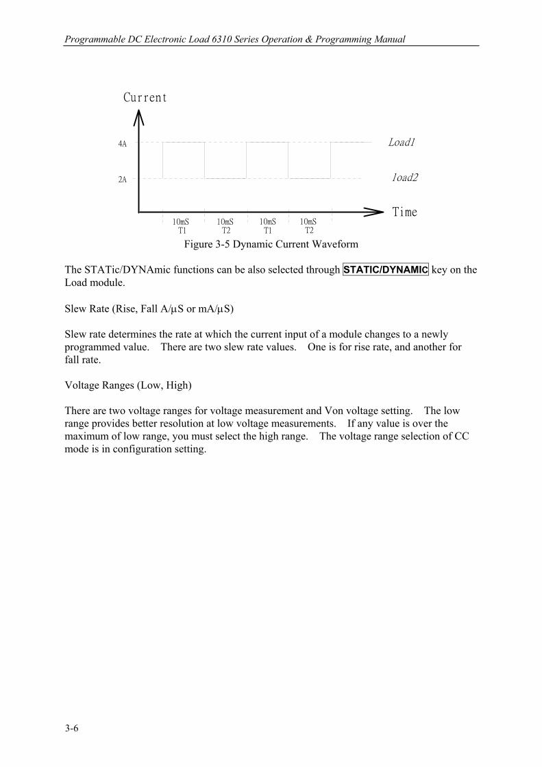
Dynamic load operation enables you to program two load levels (CCDL1, CCDL2), load duration (CCDLT1, CCDLT2), and slew rate (CCDL , CCDL ). During operation the loading level is switched between those two load levels according to your specific setting. The dynamic load is commonly used in the test of UUT’s performance under transient loading condition. Figure 3-4 shows current waveform of dynamic function. CCDL1:4A, CCDL2:2A, CCDL :1A/µS, CCDL : 1A/µS, CCDLT1:10mS, CCDLT2:10mS
3-5
Programmable DC Electronic Load 6310 Series Operation & Programming Manual
Time
Current
Load1
load2
10mS 10mS 10mS 10mS
4A
2A
T1 T2 T1 T2 Figure 3-5 Dynamic Current Waveform
The STATic/DYNAmic functions can be also selected through STATIC/DYNAMIC key on the Load module. Slew Rate (Rise, Fall A/µS or mA/µS) Slew rate determines the rate at which the current input of a module changes to a newly programmed value. There are two slew rate values. One is for rise rate, and another for fall rate. Voltage Ranges (Low, High) There are two voltage ranges for voltage measurement and Von voltage setting. The low range provides better resolution at low voltage measurements. If any value is over the maximum of low range, you must select the high range. The voltage range selection of CC mode is in configuration setting.
3-6
Operation Overview
3.5.2 Constant Resistance Mode
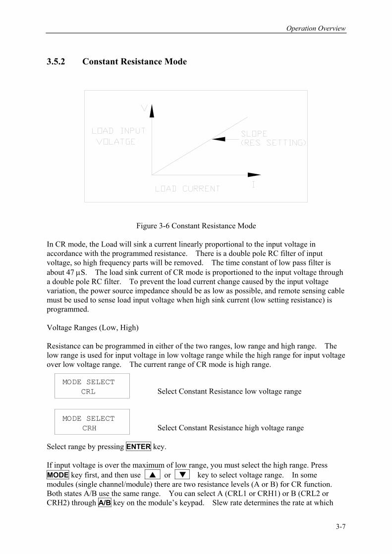
Figure 3-6 Constant Resistance Mode
In CR mode, the Load will sink a current linearly proportional to the input voltage in accordance with the programmed resistance. There is a double pole RC filter of input voltage, so high frequency parts will be removed. The time constant of low pass filter is about 47 µS. The load sink current of CR mode is proportioned to the input voltage through a double pole RC filter. To prevent the load current change caused by the input voltage variation, the power source impedance should be as low as possible, and remote sensing cable must be used to sense load input voltage when high sink current (low setting resistance) is programmed. Voltage Ranges (Low, High) Resistance can be programmed in either of the two ranges, low range and high range. The low range is used for input voltage in low voltage range while the high range for input voltage over low voltage range. The current range of CR mode is high range. MODE SELECT CRL Select Constant Resistance low voltage range MODE SELECT CRH Select Constant Resistance high voltage range Select range by pressing ENTER key. If input voltage is over the maximum of low range, you must select the high range. Press MODE key first, and then use or key to select voltage range. In some modules (single channel/module) there are two resistance levels (A or B) for CR function. Both states A/B use the same range. You can select A (CRL1 or CRH1) or B (CRL2 or CRH2) through A/B key on the module’s keypad. Slew rate determines the rate at which
3-7
Programmable DC Electronic Load 6310 Series Operation & Programming Manual
load level changes from one load level state to another. Slew Rate (Rise, Fall A/µS) Slew rate in constant resistance mode is programmed in Amps/second. 3.5.3 Constant Voltage Mode
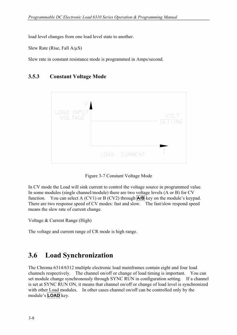
Figure 3-7 Constant Voltage Mode
In CV mode the Load will sink current to control the voltage source in programmed value. In some modules (single channel/module) there are two voltage levels (A or B) for CV function. You can select A (CV1) or B (CV2) through A/B key on the module’s keypad. There are two response speed of CV modes: fast and slow. The fast/slow respond speed means the slew rate of current change. Voltage & Current Range (High) The voltage and current range of CR mode is high range. 3.6 Load Synchronization The Chroma 6314/6312 multiple electronic load mainframes contain eight and four load channels respectively. The channel on/off or change of load timing is important. You can set module change synchronously through SYNC RUN in configuration setting. If a channel is set at SYNC RUN ON, it means that channel on/off or change of load level is synchronized with other Load modules. In other cases channel on/off can be controlled only by the module’s LOAD key.
3-8
Operation Overview
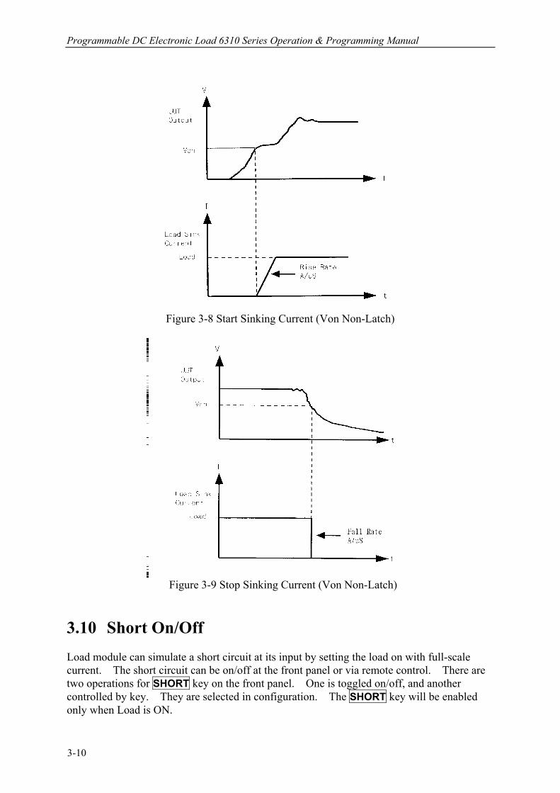
3.7 Measurements Each module measures current and voltage of the UUT. The sampling rate is about 12 mS. Voltage and current measurements are performed with a 15-bit resolution of full-scale ratings. 3.8 Slew Rate & Minimum Transient Time Slew rate is defined as the change in current over time. A programmable slew rate allows a controlled transition from one load setting to another to minimize induced voltage drops on inductive power wiring, or control induced transients on a test device. If the transient from one setting to another is large, the actual transient time can be calculated by dividing the current transition by the slew rate. The actual transition time is defined as the time required for the change of input from 10% to 90% or from 90% to 10% of the programmed excursion. If the transition from one setting to another is small, the small signal bandwidth of Load will limit the minimum transition time for all programmable slew rates. Because of the limit, the actual transition time is longer than the expected time based on the slew rate. Therefore, both minimum transition time and slew rate must be considered in the determination of actual transition time. The minimum transition time is from 24 µS to 6 mS, which depends on slew rate setting. 3.9 Start/Stop Sink Current In the simulation of transient characteristics of load to UUT, the critical problems are when and how the Load starts sinking current to UUT. You may set the conducting voltage Von to solve the problems. The Load will start or stop sinking current when the output voltage of UUT reaches the Von voltage. You can start sinking current when setting is load ON, and the input voltage of the module is over Von voltage, but stop sinking when load OFF, or the input voltage below Von voltage. For start and stop sinking current refer to Figure 3-7 and 3-8 separately. There are two operation modes for Von control. One is latch, and another non-latch. Latch means that when voltage is over Von voltage, Load will start sinking current continuously in spite that input voltage drop is below Von voltage. Non-latch means that when input voltage is below Von voltage, Load will stop sinking current. The Von voltage and operation mode of Von is set in configuration.
3-9
Programmable DC Electronic Load 6310 Series Operation & Programming Manual
Figure 3-8 Start Sinking Current (Von Non-Latch)
Figure 3-9 Stop Sinking Current (Von Non-Latch)
3.10 Short On/Off Load module can simulate a short circuit at its input by setting the load on with full-scale current. The short circuit can be on/off at the front panel or via remote control. There are two operations for SHORT key on the front panel. One is toggled on/off, and another controlled by key. They are selected in configuration. The SHORT key will be enabled only when Load is ON.
3-10
Operation Overview
Toggled on/off means pressing SHORT once to enable short circuit, and again to disable. Control by Key means pressing SHORT and holding it to enable short circuit, and releasing it to return to normal operation. The actual value of electronic short is dependent on the mode and range that are active when the short is turned on. In CC mode it is equivalent to the programming of 110% or so full-scale current about 30mS for the present current range, and then goes to rating current. In CR mode it is equivalent to the programming of the minimum resistance for the present resistance range. In CV mode it is equivalent to the programming of zero voltage. Turning on the short circuit does not affect the programmed setting, and Load input will return to the previously programmed values when the short circuit is turned off. Note that turning on the short circuit may cause the Load to sink so much current to trig protection circuit, and that will turn off the Load. 3.11 Load On/Off A module’s input can be toggled on/off through the ON/OFF key on the front panel of Mainframe, or the LOAD key on module, or the remote control. The on/off change of input is done according to the slew rate. Turning off the load does not affect the programmed setting. The load will return to the previously programmed values when the Load is turned on again. 3.12 Protection Features Each load module includes the following protection features: Overvoltage, Overcurrent, Overpower, Overtemperature, and Reverse Voltage. The appropriate bits in the Mainframe’s statue registers are set when any of the protection features mentioned above is active. Besides, the Load’s buzzer will produce beep sound to inform you till protection status is reset. When any protection occurs, it will cause the Load input to be turned off. • Overvoltage
The overvoltage protection circuit is set at a level slightly above the voltage range specified in the specification of the Load. The overvoltage (OV) and voltage fault (VF) status register bits are set when the OV condition occurs. They will remain set till they are reset. The Load module will display ovP when overvoltage protection occurs.
• Overcurrent
When Load is operating in CR or CV mode, it is possible for a module to attempt to sink current more than it is rated for. The limit level of current is set at a level slightly above the current of the Load. The overcurrent (OC) and current error (CE) status register bits are set when the OC condition occurs, and will remain set till they are reset. The Load module will display oCP when overcurrent protection occurs.
3-11
Programmable DC Electronic Load 6310 Series Operation & Programming Manual
• Overpower
The overpower protection circuit is set at a level slightly above the power range specified in the specifications of the Load. The overpower (OP) and power error (PE) status register bits are set when the OP condition occurs, and will remain set till they are reset. The Load module will display oPP when overpower protection occurs.
• Overtemperature
Each Load has an overtemperature protection circuit, which will turn off the load if internal temperature exceeds safe limit. The overtemperature (OT) and temperature error (TE) status register bits are set when the OT condition occurs, and will remain set till they are reset. The Load module will display otP when overtemperature protection occurs.
• Reverse Voltage
The Load conducts a reverse current when the polarity of UUT connection is not correct. The maximum safe reverse current is the same as the rated current of Load. If the reverse current of UUT is over the rated current of Load, the Load may be damaged. If a reverse voltage condition is detected, you must turn off power to UUT immediately, and make a correct connection. The reverse voltage (RV) and voltage fault (VF) status register bits are set when the RV condition occurs, and will remain set till they are reset. The Load module will display rEv when reverse voltage protection occurs.
All of the protection features will latch when they are tripped. When any protection occurs the module will turn off the load input, and produce beep sound till you remove the condition and reset protection by pressing LOAD key on the module.
CAUTION To protect the electronic Load from possible damage, the input voltage must not exceed the maximum input voltage rating specification. Besides, Load + terminal potential must be more than − terminal potential. 3.13 Save/Recall Setting The setting of the electronic Load for all channels can be saved and recalled for use in various test setups. This simplifies the repetitive programming of different things. The present setting of mode parameters (CC, CR, CV), programs and power on status (DEFAULT) can be saved in the EEPROM using SAVE key. Later you can recall the settings from the specified file using RECALL key. The SAVE and RECALL keys affect all channels simultaneously. 3.14 Program The program feature is so powerful. It allows you to simulate various test conditions.
3-12

Operation Overview
There are ten programs in the electronic Load. Each program has ten sequences. The setting mapping of program sequence to file is one to one. It means that program 1, sequence 1 maps to file 1, and program 3, sequence 4 maps to file 24. For setting and running the program please refer to 4.2.3 and 4.2.4.
3-13

Local Operation
4. Local Operation
4.1 Introduction This chapter describes how to operate the electronic load from the local panel in details. The descriptions include: Mainframe panel control, Module panel control and indicators. 4.2 Local Operation of Load Mainframe In order to use the front panel keys to control the electronic load, local operation must be in effect. Immediately after power is applied, local operation will be in effect. When local operation is in effect, you can select a channel, and use the display as well as keypad on the front panel to control the Load. The display of Mainframe can be used to view the programmed setting of a selected channel. The input voltage/current is displayed on module’s display. The mainframe will scan module type at power-on, and memorize it for channel setting.
Notice When you edit setting, the display will blink setting, and let you know that the active setting is to be edited or selected. In the remote state, the keys on the front panel will have no effect. Only the remote controller can program the Load. The display of module will show the present input voltage and current readings or the last display while the local state is in effect. The display of the Mainframe will show REMOTE message.
Notice In the setting of load module level the resolution of current, voltage, resistance and slew rate setting will be different from the entered values. The displayed or stored value of setting will be the actual value of D/A programmed in the load module. The current, voltage and slew rate setting will be degraded as low values are entered. The resistance setting will be degraded as higher values are entered.
4-1
Programmable DC Electronic Load 6310 Series Operation & Programming Manual
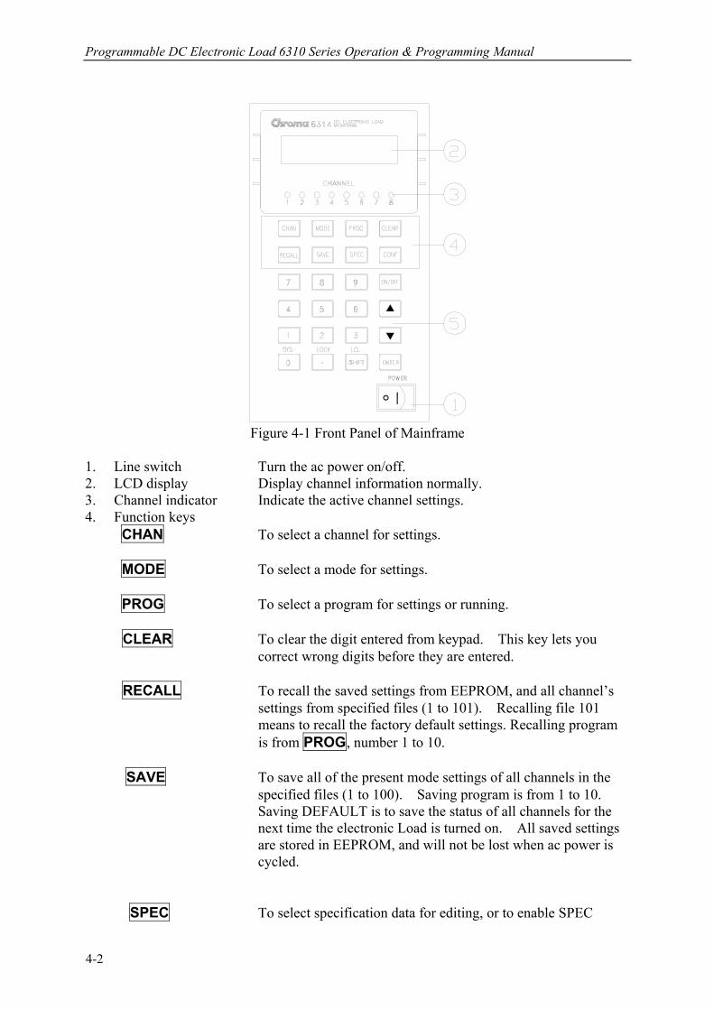
Figure 4-1 Front Panel of Mainframe
1. Line switch Turn the ac power on/off. 2. LCD display Display channel information normally. 3. Channel indicator Indicate the active channel settings. 4. Function keys CHAN To select a channel for settings. MODE To select a mode for settings. PROG To select a program for settings or running.
CLEAR To clear the digit entered from keypad. This key lets you correct wrong digits before they are entered.
RECALL To recall the saved settings from EEPROM, and all channel’s
settings from specified files (1 to 101). Recalling file 101 means to recall the factory default settings. Recalling program is from PROG, number 1 to 10.
SAVE To save all of the present mode settings of all channels in the
specified files (1 to 100). Saving program is from 1 to 10. Saving DEFAULT is to save the status of all channels for the next time the electronic Load is turned on. All saved settings are stored in EEPROM, and will not be lost when ac power is cycled.
SPEC To select specification data for editing, or to enable SPEC
4-2
Local Operation
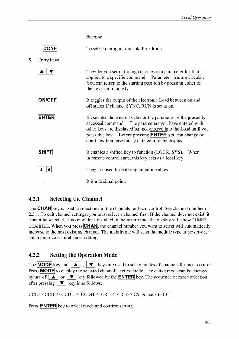
function. CONF To select configuration data for editing. 5. Entry keys
They let you scroll through choices in a parameter list that is applied to a specific command. Parameter lists are circular.
You can return to the starting position by pressing either of the keys continuously.
ON/OFF It toggles the output of the electronic Load between on and off states if channel SYNC. RUN is set at on.
ENTER It executes the entered value or the parameter of the presently accessed command. The parameters you have entered with other keys are displayed but not entered into the Load until you press this key. Before pressing ENTER you can change or abort anything previously entered into the display.
SHIFT It enables a shifted key to function (LOCK, SYS). When
in remote control state, this key acts as a local key.
0 – 9 They are used for entering numeric values.
. It is a decimal point. 4.2.1 Selecting the Channel
The CHAN key is used to select one of the channels for local control. See channel number in 2.3.1. To edit channel settings, you must select a channel first. If the channel does not exist, it cannot be selected. If no module is installed in the mainframe, the display will show DUMMY CHANNEL. When you press CHAN, the channel number you want to select will automatically increase to the next existing channel. The mainframe will scan the module type at power-on, and memorize it for channel editing. 4.2.2 Setting the Operation Mode
The MODE key and , keys are used to select modes of channels for local control. Press MODE to display the selected channel’s active mode. The active mode can be changed by use of or key followed by the ENTER key. The sequence of mode selection after pressing key is as follows: CCL -> CCH -> CCDL -> CCDH -> CRL -> CRH -> CV go back to CCL. Press ENTER key to select mode and confirm setting.
4-3

Programmable DC Electronic Load 6310 Series Operation & Programming Manual
Notice
The eight operation modes of load module settings stored in the mainframe are independent. Changing any mode setting won’t affect others. Storing the settings to EEPROM (1-100) will store only one mode setting. The load levels and slew rate are common to CC, CR modes. CV mode sets voltage level and response speed. There are two level settings for single channel/module of CC, CR, and CV modes. They can be switched by the module’s A/B key. Setting CC Values There are four modes for CC operation: CCL, CCH, CCDL, CCDH. The current levels are programmed in Amps. The slew rate levels are programmed in milliamps/µS at low range and in Amps/µS at high range. The timings are programmed in millisecond. The setting buffers of four CC modes are independent. Changing the operation range doesn’t affect the settings of other ranges. The following examples show how to set the CC values of Load module for model number 63103. Before observing the examples, select channel first. 1. Select Range/Function Press MODE, and use or key to select CCL followed by ENTER key. CCL: static low range CCH: static high range CCDL: dynamic low range CCDH: dynamic high range MODE SELECT CCL 2. Set Current Level There are 4000 discrete steps from 0 to full scale in each range. Set level1 (A) current level to 2 amps by pressing 2 , ENTER . Set level2 (B) current level to 1 amp by pressing 1 , ENTER. CCL1: 1.9995A CCL2: 0.9990A 3. Set Slew Rate There are 250 discrete steps in each range. Set the rise 50 mA/µS and fall slew rates to 50 mA/µS by pressing 5 , 0 , ENTER for rise and 6 , 0 , ENTER for fall slew rate. CCL : 50mA/µS CCL : 60mA/µS 4. Set DYNAmic Function Periods
Dynamic function has period T1 and T2 to be set. Set dynamic period 1 to 0.1 mS, period 2 to 0.2 mS by pressing 0 , . , 1 , ENTER and 0 , . , 2 , ENTER. The range of Dynamic period is from 0.025 µS to 30 Sec.
CCDLT1: 0.100mS
4-4

Local Operation
CCDLT2: 0.200mS
Notice If you press ENTER key, and the blinking data do not go to next, change configuration setting Enter Data Next to YES. Setting CR Values The CR values for the selected channel are programmed by pressing MODE, and ENTER keys. The resistance values can be programmed in low voltage (CRL) or high voltage (CRH) range. The current is always in high range. ALL resistance levels are programmed in ohms. The slew rate is in A/µS. The following examples illustrate how to set CR values of Load module for model number 63103. 1. Select Range Press MODE and use or key to select CRL followed by ENTER key. MODE SELECT CRL 2. Set Resistor Level
There are 4000 discrete steps from 0 to full scale in each range. Set the main resistor level1 (A) to 2 ohms by pressing 2 , ENTER. Set the level2 (B) resistor level to 1 ohm by pressing 1 , ENTER.
CCL1: 2.000Ω CCL2: 1.000Ω 3. Set Slew Rate
There are 250 discrete steps in each range. Set the rise and fall slew rates to 0.1 A/µS by pressing . , 1 , ENTER for rise slew rate and . , 2 , ENTER for fall slew rate.
CRL : 0.10A/µS CRL : 0.20A/µS Setting CV Values The CV values for the selected channel are programmed by pressing MODE, and ENTER keys. The voltage values can be programmed in one range. The voltage levels are programmed in volts. And the response speed is programmed in fast/slow operations. The following examples illustrate how to set CV values of Load module for model number 63103. Before observing the examples, select channel first.
4-5
Programmable DC Electronic Load 6310 Series Operation & Programming Manual
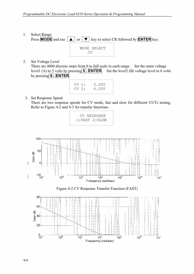
1. Select Range Press MODE and use or key to select CR followed by ENTER key. MODE SELECT CV 2. Set Voltage Level
There are 4000 discrete steps from 0 to full scale in each range. Set the main voltage level1 (A) to 5 volts by pressing 5 , ENTER. Set the level2 (B) voltage level to 6 volts by pressing 6 , ENTER.
CV 1: 5.00V CV 2: 6.00V 3. Set Response Speed
There are two response speeds for CV mode, fast and slow for different UUTs testing. Refer to Figure 4-2 and 4-3 for transfer functions.
CV RESPONSE 1:FAST 2:SLOW
Figure 4-2 CV Response Transfer Function (FAST)
4-6
Local Operation
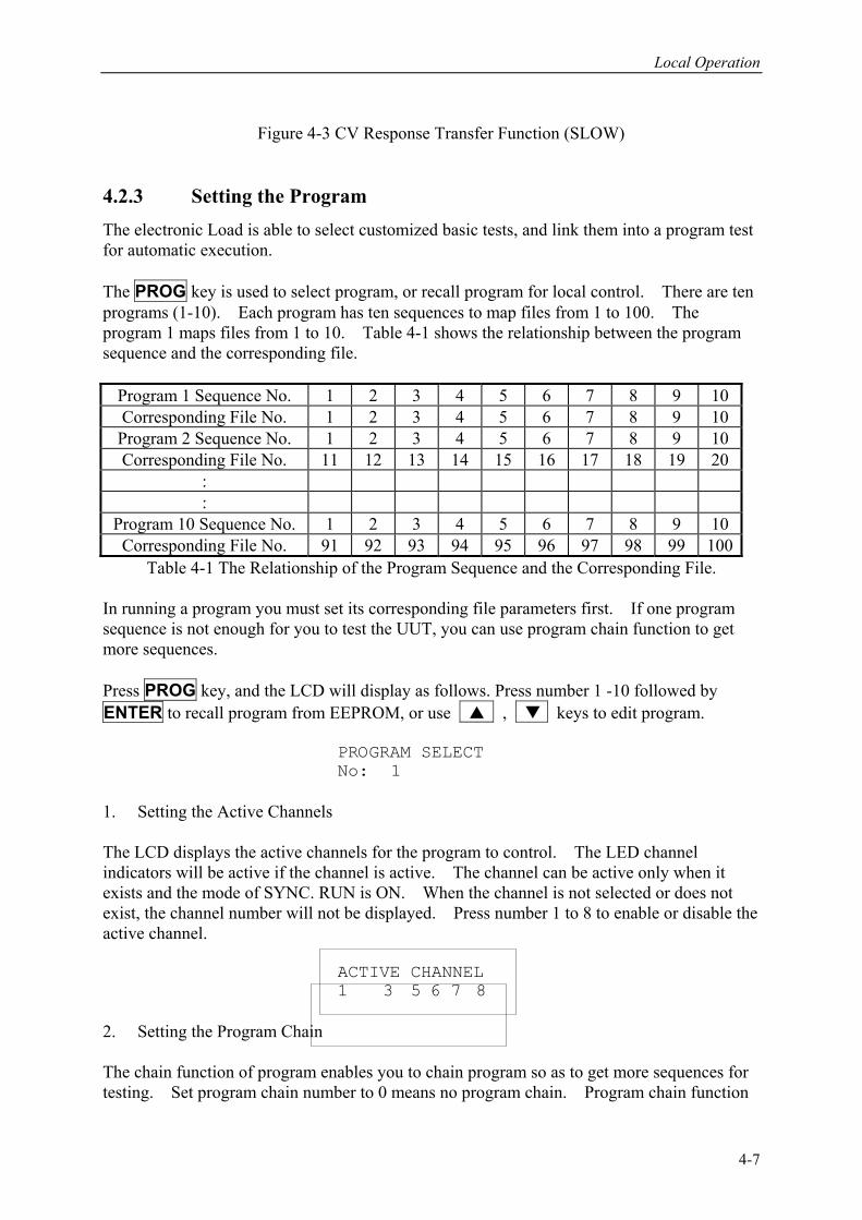
Figure 4-3 CV Response Transfer Function (SLOW)
4.2.3 Setting the Program The electronic Load is able to select customized basic tests, and link them into a program test for automatic execution. The PROG key is used to select program, or recall program for local control. There are ten programs (1-10). Each program has ten sequences to map files from 1 to 100. The program 1 maps files from 1 to 10. Table 4-1 shows the relationship between the program sequence and the corresponding file.
Program 1 Sequence No. 1 2 3 4 5 6 7 8 9 10 Corresponding File No. 1 2 3 4 5 6 7 8 9 10
Program 2 Sequence No. 1 2 3 4 5 6 7 8 9 10 Corresponding File No. 11 12 13 14 15 16 17 18 19 20
: :
Program 10 Sequence No. 1 2 3 4 5 6 7 8 9 10 Corresponding File No. 91 92 93 94 95 96 97 98 99 100
Table 4-1 The Relationship of the Program Sequence and the Corresponding File. In running a program you must set its corresponding file parameters first. If one program sequence is not enough for you to test the UUT, you can use program chain function to get more sequences. Press PROG key, and the LCD will display as follows. Press number 1 -10 followed by ENTER to recall program from EEPROM, or use , keys to edit program. PROGRAM SELECT No: 1 1. Setting the Active Channels The LCD displays the active channels for the program to control. The LED channel indicators will be active if the channel is active. The channel can be active only when it exists and the mode of SYNC. RUN is ON. When the channel is not selected or does not exist, the channel number will not be displayed. Press number 1 to 8 to enable or disable the active channel. ACTIVE CHANNEL 1 3 5 6 7 8 2. Setting the Program Chain The chain function of program enables you to chain program so as to get more sequences for testing. Set program chain number to 0 means no program chain. Program chain function
4-7
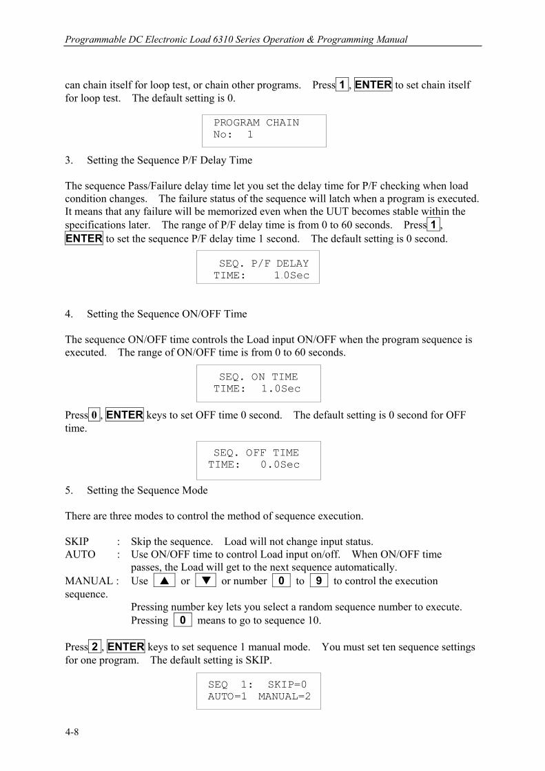
Programmable DC Electronic Load 6310 Series Operation & Programming Manual
can chain itself for loop test, or chain other programs. Press 1 , ENTER to set chain itself for loop test. The default setting is 0. PROGRAM CHAIN No: 1 3. Setting the Sequence P/F Delay Time The sequence Pass/Failure delay time let you set the delay time for P/F checking when load condition changes. The failure status of the sequence will latch when a program is executed. It means that any failure will be memorized even when the UUT becomes stable within the specifications later. The range of P/F delay time is from 0 to 60 seconds. Press 1 , ENTER to set the sequence P/F delay time 1 second. The default setting is 0 second. SEQ. P/F DELAY
TIME: 1.0Sec 4. Setting the Sequence ON/OFF Time The sequence ON/OFF time controls the Load input ON/OFF when the program sequence is executed. The range of ON/OFF time is from 0 to 60 seconds. SEQ. ON TIME TIME: 1.0Sec Press 0 , ENTER keys to set OFF time 0 second. The default setting is 0 second for OFF time. SEQ. OFF TIME TIME: 0.0Sec 5. Setting the Sequence Mode There are three modes to control the method of sequence execution. SKIP : Skip the sequence. Load will not change input status. AUTO : Use ON/OFF time to control Load input on/off. When ON/OFF time passes, the Load will get to the next sequence automatically. MANUAL : Use or or number 0 to 9 to control the execution sequence. Pressing number key lets you select a random sequence number to execute.
Pressing 0 means to go to sequence 10. Press 2 , ENTER keys to set sequence 1 manual mode. You must set ten sequence settings for one program. The default setting is SKIP. SEQ 1: SKIP=0 AUTO=1 MANUAL=2
4-8
Local Operation
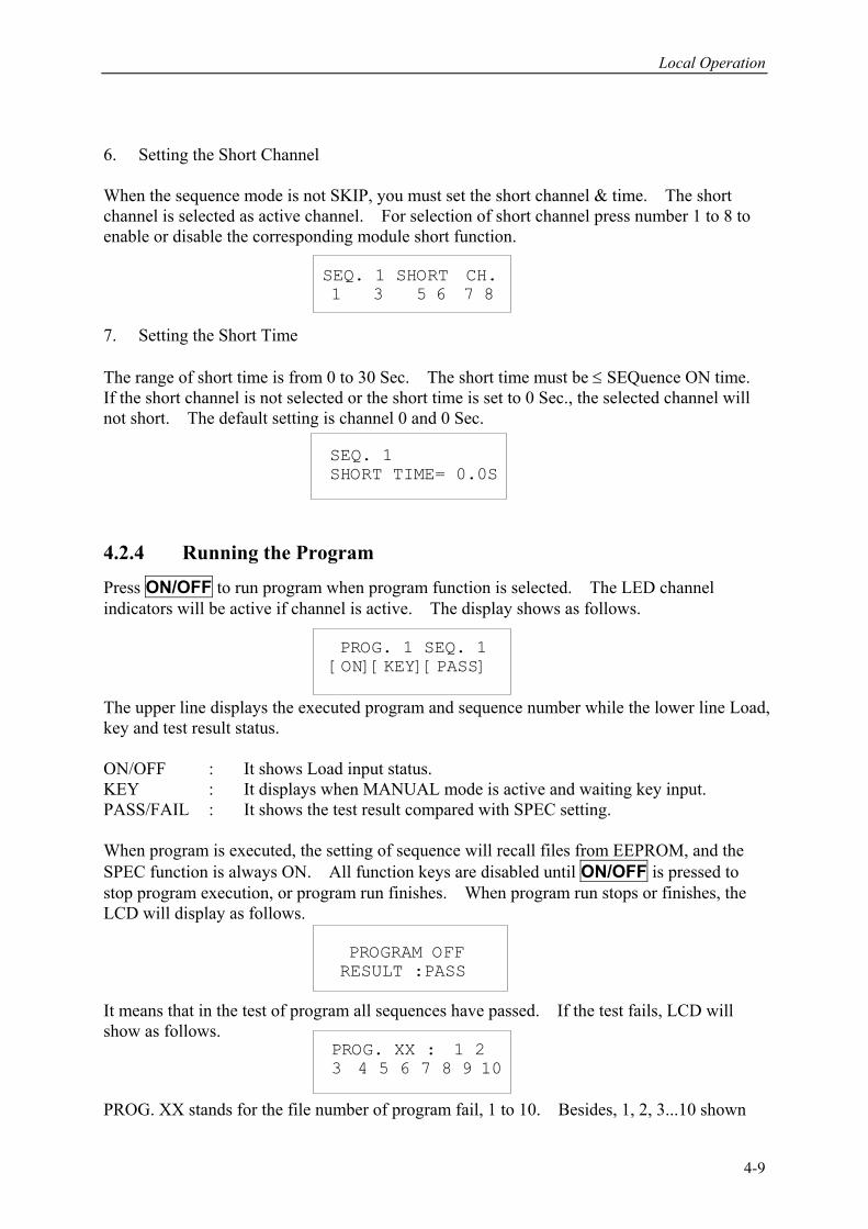
6. Setting the Short Channel When the sequence mode is not SKIP, you must set the short channel & time. The short channel is selected as active channel. For selection of short channel press number 1 to 8 to enable or disable the corresponding module short function. SEQ. 1 SHORT CH. 1 3 5 6 7 8 7. Setting the Short Time The range of short time is from 0 to 30 Sec. The short time must be ≤ SEQuence ON time. If the short channel is not selected or the short time is set to 0 Sec., the selected channel will not short. The default setting is channel 0 and 0 Sec. SEQ. 1 SHORT TIME= 0.0S 4.2.4 Running the Program
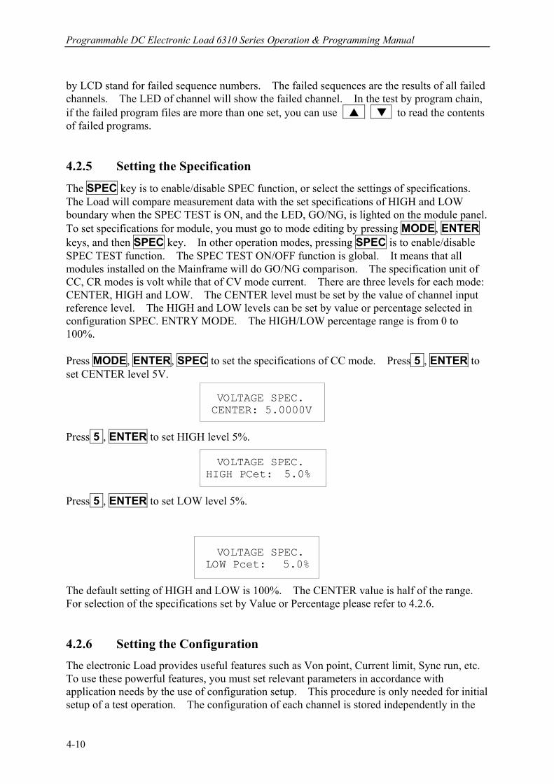
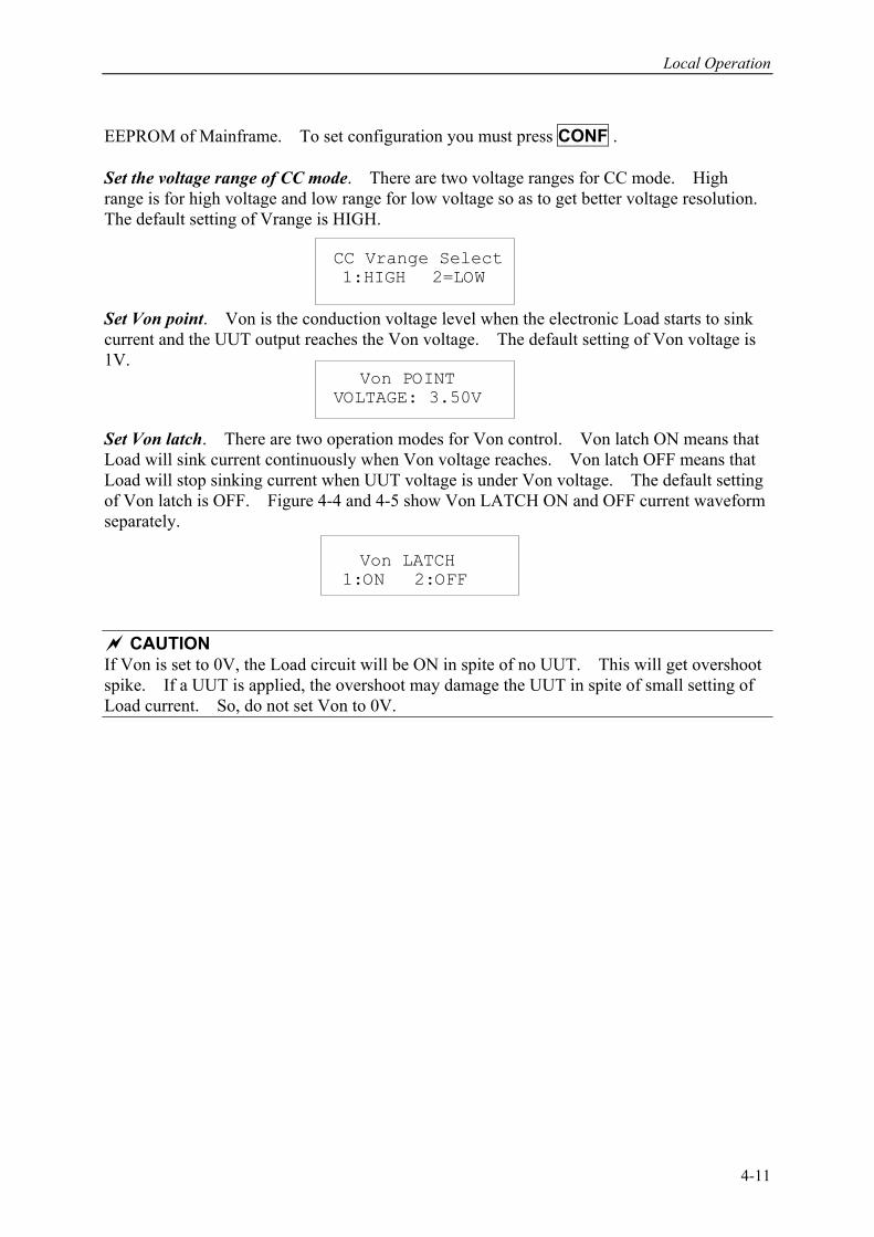
Press ON/OFF to run program when program function is selected. The LED channel indicators will be active if channel is active. The display shows as follows. PROG. 1 SEQ. 1 [ON][KEY][PASS] The upper line displays the executed program and sequence number while the lower line Load, key and test result status. ON/OFF : It shows Load input status. KEY : It displays when MANUAL mode is active and waiting key input. PASS/FAIL : It shows the test result compared with SPEC setting. When program is executed, the setting of sequence will recall files from EEPROM, and the SPEC function is always ON. All function keys are disabled until ON/OFF is pressed to stop program execution, or program run finishes. When program run stops or finishes, the LCD will display as follows. PROGRAM OFF RESULT :PASS It means that in the test of program all sequences have passed. If the test fails, LCD will show as follows. PROG. XX : 1 2 3 4 5 6 7 8 9 10 PROG. XX stands for the file number of program fail, 1 to 10. Besides, 1, 2, 3...10 shown
4-9
Programmable DC Electronic Load 6310 Series Operation & Programming Manual
by LCD stand for failed sequence numbers. The failed sequences are the results of all failed channels. The LED of channel will show the failed channel. In the test by program chain, if the failed program files are more than one set, you can use to read the contents of failed programs. 4.2.5 Setting the Specification
The SPEC key is to enable/disable SPEC function, or select the settings of specifications. The Load will compare measurement data with the set specifications of HIGH and LOW boundary when the SPEC TEST is ON, and the LED, GO/NG, is lighted on the module panel. To set specifications for module, you must go to mode editing by pressing MODE, ENTER keys, and then SPEC key. In other operation modes, pressing SPEC is to enable/disable SPEC TEST function. The SPEC TEST ON/OFF function is global. It means that all modules installed on the Mainframe will do GO/NG comparison. The specification unit of CC, CR modes is volt while that of CV mode current. There are three levels for each mode: CENTER, HIGH and LOW. The CENTER level must be set by the value of channel input reference level. The HIGH and LOW levels can be set by value or percentage selected in configuration SPEC. ENTRY MODE. The HIGH/LOW percentage range is from 0 to 100%. Press MODE, ENTER, SPEC to set the specifications of CC mode. Press 5 , ENTER to set CENTER level 5V. VOLTAGE SPEC. CENTER: 5.0000V Press 5 , ENTER to set HIGH level 5%. VOLTAGE SPEC. HIGH PCet: 5.0% Press 5 , ENTER to set LOW level 5%.
VOLTAGE SPEC. LOW Pcet: 5.0% The default setting of HIGH and LOW is 100%. The CENTER value is half of the range. For selection of the specifications set by Value or Percentage please refer to 4.2.6. 4.2.6 Setting the Configuration The electronic Load provides useful features such as Von point, Current limit, Sync run, etc. To use these powerful features, you must set relevant parameters in accordance with application needs by the use of configuration setup. This procedure is only needed for initial setup of a test operation. The configuration of each channel is stored independently in the
4-10
Local Operation
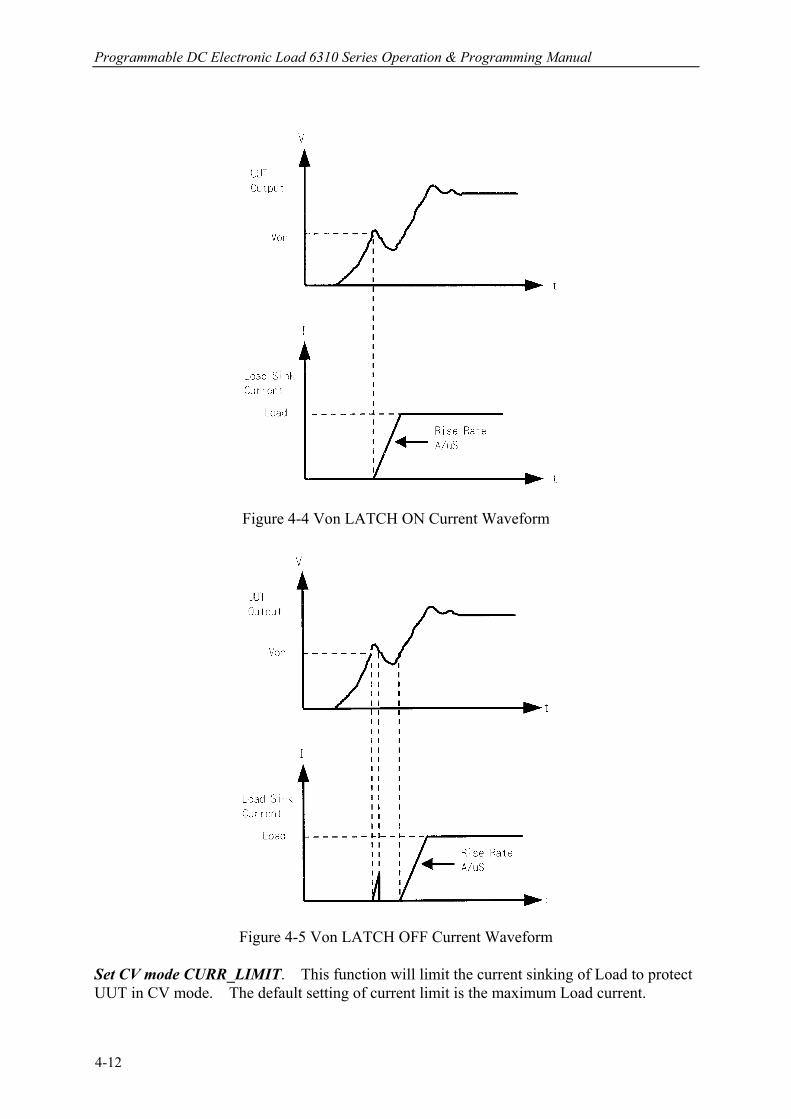
EEPROM of Mainframe. To set configuration you must press CONF . Set the voltage range of CC mode. There are two voltage ranges for CC mode. High range is for high voltage and low range for low voltage so as to get better voltage resolution. The default setting of Vrange is HIGH. CC Vrange Select 1:HIGH 2=LOW Set Von point. Von is the conduction voltage level when the electronic Load starts to sink current and the UUT output reaches the Von voltage. The default setting of Von voltage is 1V. Von POINT VOLTAGE: 3.50V Set Von latch. There are two operation modes for Von control. Von latch ON means that Load will sink current continuously when Von voltage reaches. Von latch OFF means that Load will stop sinking current when UUT voltage is under Von voltage. The default setting of Von latch is OFF. Figure 4-4 and 4-5 show Von LATCH ON and OFF current waveform separately. Von LATCH 1:ON 2:OFF
CAUTION If Von is set to 0V, the Load circuit will be ON in spite of no UUT. This will get overshoot spike. If a UUT is applied, the overshoot may damage the UUT in spite of small setting of Load current. So, do not set Von to 0V.
4-11
Programmable DC Electronic Load 6310 Series Operation & Programming Manual
Figure 4-4 Von LATCH ON Current Waveform
Figure 4-5 Von LATCH OFF Current Waveform
Set CV mode CURR_LIMIT. This function will limit the current sinking of Load to protect UUT in CV mode. The default setting of current limit is the maximum Load current.
4-12

Local Operation
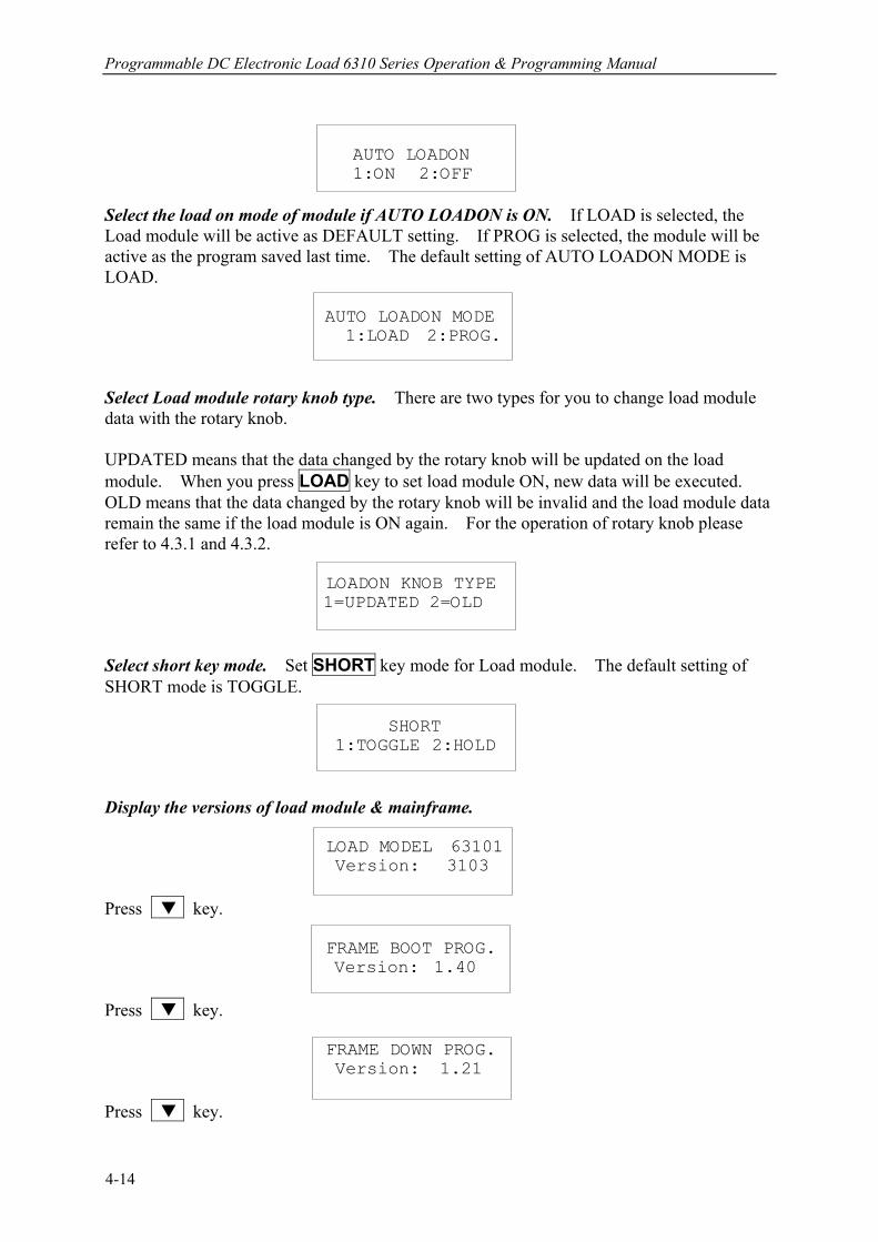
CV CURR_LIMIT CURRENT:20.000A Set sign of voltage for display. The electronic Load will show minus sign of the voltage if you select MINUS. It will not show any sign if you select PLUS. The default setting is PLUS. Selecting MINUS of SIGN OF VOLT. will occupy one digit. The displayed digits are four. SIGN OF VOLT. 1:PLUS 2:MINUS Set the specifications of entry mode. The specifications of Load can be set by VALUE or Percentage for HIGH and LOW data. The percentage values refer to CENTER value of specification. The default setting of SPEC entry mode is percentage. SPEC. ENTRY MODE 1:VALUE 2:PCet Set SYNChronous run mode. When SYNC run is set at ON, the Load on/off is controlled by ON/OFF key on the Mainframe. Under other circumstances the Load on/off is simply controlled by LOAD key on the module. The default setting of SYNC run is ON. SYNC. RUN 1:ON 2:OFF Select data entry mode by ENTER. If ON is selected for data entry, the setting will go to the next one after pressing ENTER. If OFF is selected for data entry, the setting will remain the same line for you to change it again and again. The default setting is ON. Enter Data Next 1:ON 2:OFF Select module SOUND on/off. When you press the key on the module, it will produce a sound if sound = ON. The default setting of sound is ON. SOUND 1:ON 2:OFF Select Load module input status when it is powered ON. If ON is selected, the module will be active according to AUTO LOADON mode setting. The default setting of AUTO LOADON is OFF.
4-13
Programmable DC Electronic Load 6310 Series Operation & Programming Manual
AUTO LOADON 1:ON 2:OFF Select the load on mode of module if AUTO LOADON is ON. If LOAD is selected, the Load module will be active as DEFAULT setting. If PROG is selected, the module will be active as the program saved last time. The default setting of AUTO LOADON MODE is LOAD. AUTO LOADON MODE 1:LOAD 2:PROG. Select Load module rotary knob type. There are two types for you to change load module data with the rotary knob. UPDATED means that the data changed by the rotary knob will be updated on the load module. When you press LOAD key to set load module ON, new data will be executed. OLD means that the data changed by the rotary knob will be invalid and the load module data remain the same if the load module is ON again. For the operation of rotary knob please refer to 4.3.1 and 4.3.2. LOADON KNOB TYPE 1=UPDATED 2=OLD Select short key mode. Set SHORT key mode for Load module. The default setting of SHORT mode is TOGGLE. SHORT 1:TOGGLE 2:HOLD Display the versions of load module & mainframe. LOAD MODEL 63101 Version: 3103 Press key. FRAME BOOT PROG. Version: 1.40 Press key. FRAME DOWN PROG. Version: 1.21 Press key.
4-14

Local Operation
FRAME EXEC PROG. Version: 1.41 4.2.7 Recalling Files
Press RECALL to recall files from 1 to 101. Files 1 to 100 are user data. File 101 is factor set state. After a file is recalled, the display will go to mode editor for you to edit or view the file. By pressing RECALL the display will show the file No. last recalled. The default file No. is 2 when the mainframe is powered on. Press RECALL , 3 , ENTER to recall the number 3. RECALL FILE FILE NO: 3 The data of all channels will be recalled when you execute file recall. 4.2.8 Saving File/Default/Program
There are 100 file locations (1 to 100) for you to save files. Press SAVE, 2 , 0 , ENTER to save a file to location 20. SAVE FILE FILE NO: 20 Press SAVE , until the display shows as follows. The DEFAULT states are used for electronic Load after power-on. Press 1 to save DEFAULT to EEPROM. SAVE DEFAULT 1:YES 2:NO Press SAVE, until the display shows as follows. Press 1 to save program. SAVE PROGRAM 1:YES 2:NO 4.2.9 Going To Local
The SHIFT key operates as local key, LCL when electronic Load is in remote mode. You can press LCL key to go to local operation when Load is in remote state. In local operation SHIFT key operates as shift key.
4-15
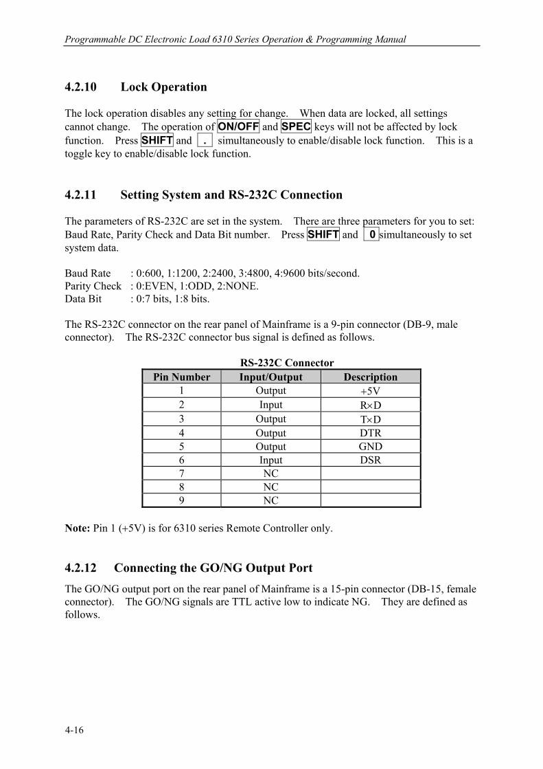
Programmable DC Electronic Load 6310 Series Operation & Programming Manual
4.2.10 Lock Operation The lock operation disables any setting for change. When data are locked, all settings cannot change. The operation of ON/OFF and SPEC keys will not be affected by lock function. Press SHIFT and . simultaneously to enable/disable lock function. This is a toggle key to enable/disable lock function. 4.2.11 Setting System and RS-232C Connection The parameters of RS-232C are set in the system. There are three parameters for you to set: Baud Rate, Parity Check and Data Bit number. Press SHIFT and 0 simultaneously to set system data. Baud Rate : 0:600, 1:1200, 2:2400, 3:4800, 4:9600 bits/second. Parity Check : 0:EVEN, 1:ODD, 2:NONE. Data Bit : 0:7 bits, 1:8 bits. The RS-232C connector on the rear panel of Mainframe is a 9-pin connector (DB-9, male connector). The RS-232C connector bus signal is defined as follows. RS-232C Connector
Pin Number Input/Output Description 1 Output +5V 2 Input R×D 3 Output T×D 4 Output DTR 5 Output GND 6 Input DSR 7 NC 8 NC 9 NC
Note: Pin 1 (+5V) is for 6310 series Remote Controller only. 4.2.12 Connecting the GO/NG Output Port The GO/NG output port on the rear panel of Mainframe is a 15-pin connector (DB-15, female connector). The GO/NG signals are TTL active low to indicate NG. They are defined as follows.
4-16
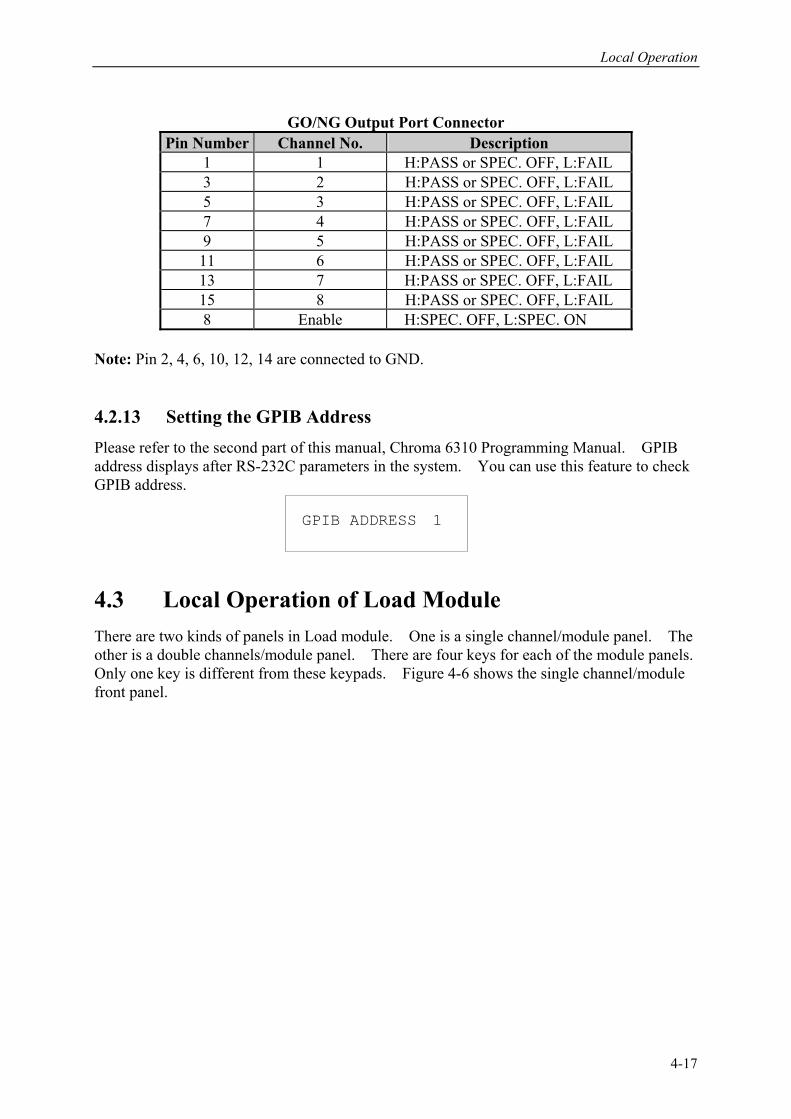
Local Operation
GO/NG Output Port Connector Pin Number Channel No. Description
1 1 H:PASS or SPEC. OFF, L:FAIL 3 2 H:PASS or SPEC. OFF, L:FAIL 5 3 H:PASS or SPEC. OFF, L:FAIL 7 4 H:PASS or SPEC. OFF, L:FAIL 9 5 H:PASS or SPEC. OFF, L:FAIL 11 6 H:PASS or SPEC. OFF, L:FAIL 13 7 H:PASS or SPEC. OFF, L:FAIL 15 8 H:PASS or SPEC. OFF, L:FAIL 8 Enable H:SPEC. OFF, L:SPEC. ON
Note: Pin 2, 4, 6, 10, 12, 14 are connected to GND. 4.2.13 Setting the GPIB Address Please refer to the second part of this manual, Chroma 6310 Programming Manual. GPIB address displays after RS-232C parameters in the system. You can use this feature to check GPIB address. GPIB ADDRESS 1 4.3 Local Operation of Load Module There are two kinds of panels in Load module. One is a single channel/module panel. The other is a double channels/module panel. There are four keys for each of the module panels. Only one key is different from these keypads. Figure 4-6 shows the single channel/module front panel.
4-17
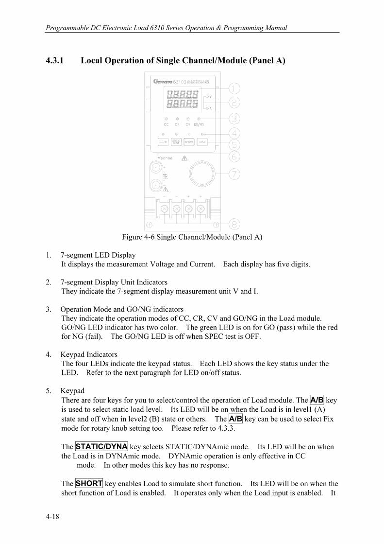
Programmable DC Electronic Load 6310 Series Operation & Programming Manual
4.3.1 Local Operation of Single Channel/Module (Panel A)
Figure 4-6 Single Channel/Module (Panel A)
1. 7-segment LED Display It displays the measurement Voltage and Current. Each display has five digits. 2. 7-segment Display Unit Indicators They indicate the 7-segment display measurement unit V and I. 3. Operation Mode and GO/NG indicators
They indicate the operation modes of CC, CR, CV and GO/NG in the Load module. GO/NG LED indicator has two color. The green LED is on for GO (pass) while the red for NG (fail). The GO/NG LED is off when SPEC test is OFF.
4. Keypad Indicators
The four LEDs indicate the keypad status. Each LED shows the key status under the LED. Refer to the next paragraph for LED on/off status.
5. Keypad
There are four keys for you to select/control the operation of Load module. The A/B key is used to select static load level. Its LED will be on when the Load is in level1 (A) state and off when in level2 (B) state or others. The A/B key can be used to select Fix mode for rotary knob setting too. Please refer to 4.3.3.
The STATIC/DYNA key selects STATIC/DYNAmic mode. Its LED will be on when the Load is in DYNAmic mode. DYNAmic operation is only effective in CC mode. In other modes this key has no response.
The SHORT key enables Load to simulate short function. Its LED will be on when the short function of Load is enabled. It operates only when the Load input is enabled. It
4-18
Local Operation
will not respond if Load input is not enabled.
The LOAD key controls the on/off of the Load module input. Its LED will be on when the Load input is enabled.
6. Vsense Connectors
These two connectors are Vsense measurement input. Refer to 2.5.2 for remote sense connections.
7. Rotary Knob
The knob changes the level when the Load input is enabled. Rotating the knob clockwise will increase level whereas counterclockwise decrease level. When you change Load level with the knob, the setting of Mainframe will not change. The changed Load level will hold unless the same setting is changed on Mainframe.
8. Load Terminals They are input connectors of the Load for connecting to the UUT. Each of them can carry 40 Amps at most. If the current is over 40 Amps, you must connect two or more terminals for load connection. The PLUS (+) must be connected to the high potential of UUT. Refer to 2.5.1 for load input connection.
Examples The following examples illustrate how to operate the module in CC mode. 1. Select Level1 (A) and Level2 (B)
There are two levels of each mode for you to select in static function. The level1 (A) and level2 (B) can be selected through A/B key. Press A/B key to select current level1 or level2. When level1 (A) is selected, the LED of A/B key will be active. Press this key again to select level2 (B), and the LED will be inactive.
2. Select Dynamic Function There are two functions for CC mode: STATIC and DYNAmic. The two functions can be selected through STATIC/DYNA key. Press STATIC/DYNA key to select Dynamic function. Press this key again to select static function. When Dynamic function is selected, the LED of DYNA will be active.
3. Short the Load Input
The Load can simulate a short circuit across the input. The short circuit will be enabled when SHORT is pressed, and Load input is active (on). If the input is shorted, the LED of short will be active. The SHORT key can be set in configuration of toggled on/off mode, or active by pressing mode.
4. Load Input On/Off
The input can be toggled on or off by pressing LOAD. When the input is turned on, the LED of load will be active.
4-19
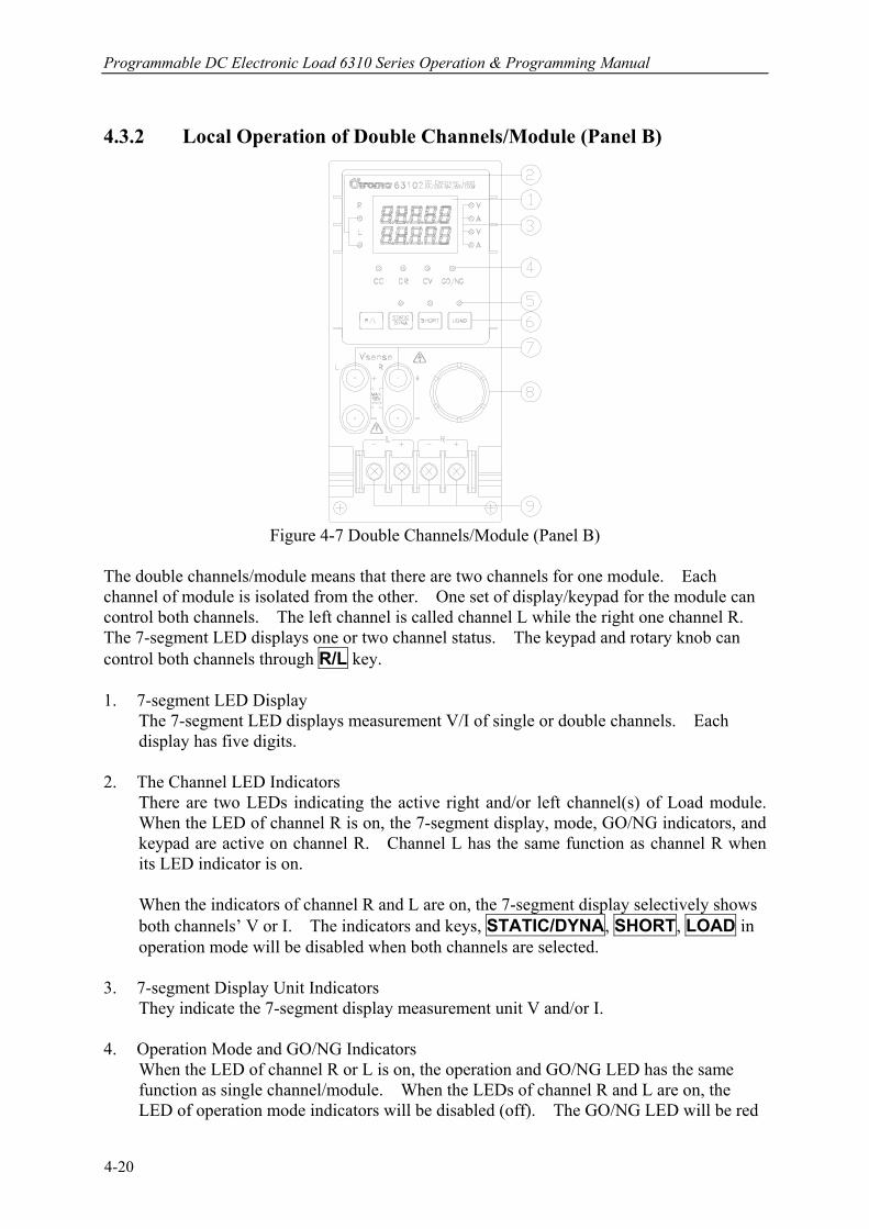
Programmable DC Electronic Load 6310 Series Operation & Programming Manual
4.3.2 Local Operation of Double Channels/Module (Panel B)
Figure 4-7 Double Channels/Module (Panel B)
The double channels/module means that there are two channels for one module. Each channel of module is isolated from the other. One set of display/keypad for the module can control both channels. The left channel is called channel L while the right one channel R. The 7-segment LED displays one or two channel status. The keypad and rotary knob can control both channels through R/L key. 1. 7-segment LED Display
The 7-segment LED displays measurement V/I of single or double channels. Each display has five digits.
2. The Channel LED Indicators
There are two LEDs indicating the active right and/or left channel(s) of Load module. When the LED of channel R is on, the 7-segment display, mode, GO/NG indicators, and keypad are active on channel R. Channel L has the same function as channel R when its LED indicator is on.
When the indicators of channel R and L are on, the 7-segment display selectively shows both channels’ V or I. The indicators and keys, STATIC/DYNA, SHORT, LOAD in operation mode will be disabled when both channels are selected.
3. 7-segment Display Unit Indicators They indicate the 7-segment display measurement unit V and/or I. 4. Operation Mode and GO/NG Indicators
When the LED of channel R or L is on, the operation and GO/NG LED has the same function as single channel/module. When the LEDs of channel R and L are on, the LED of operation mode indicators will be disabled (off). The GO/NG LED will be red
4-20
Local Operation
when the check of any channel SPEC fails. It will be green when the check of both channels SPEC is all right.
5. Keypad Indicators
There are three LEDs indicating the keypad status. Each LED shows the key status. It has the same function as single channel/module. The LED of LOAD will be active when any input of channel L or R is on.
6. Keypad
There are four keys for you to select /control the operation of Load module. The R/L key is used to select the display of 7-segment LED, and the indicators of channel R and/or L. The R/L key can be used to select Fix mode for rotary knob setting too. Please refer to 4.3.3.
7. Vsense Connectors
These four connectors are for Vsense measurement input. The two connectors on the right are for right channel while those on the left for left channel. Refer to 2.5.2 for remote sensing connections.
8. Rotary Knob
The knob has the same function as single channel/module when channel R or L is selected. If the indicators of channel R and L are on, the knob will be disabled.
9. Load Terminals
They are input connectors of the Load for connecting to the UUT. The two terminals on the left are for input of left channel while those on the right for that of right channel. The PLUS (+) sign of the input of each channel must connect the high potential. Refer to 2.5.1 for load input connections.
Examples The following examples illustrate how to select the double channels/module in CC mode.
There are two channels/module, so you have to select right or left channel for display & keypad. When channel R and L are selected, only R/L key is enabled. Other keys are disabled. During power-on, the pre-selected channel is channel L. It means that the 7-segment display, indicators and keypad are active at channel L. The double channels/module has the same function as single channel/module. But it cannot select level 2(B).
1. The display sequence of R/L key is channel L -> channel R -> channels L+R display V
-> channels L+R I back to channel L. 2. Select Dynamic Function
The static and dynamic function can be selected through the STATIC/DYNA key. Press this key to select Dynamic function, and press again to select static function. When Dynamic function is selected, the LED of DYNAmic will be active.
3. Short the Load Input
4-21
Programmable DC Electronic Load 6310 Series Operation & Programming Manual
The Load can simulate a short circuit across the input. The short circuit can be enabled when SHORT is pressed, and Load input is active. When the input is shorted, the LED of short will be active. The SHORT key can be set in configuration of toggled on/off mode, or active by pressing mode.
4. Load Input On/Off
The input can be toggled on or off by pressing LOAD. When the input is turned on, the LED of LOAD will be active.
4.3.3 Online Change Level Load module provides you with two ways of online change level. They are convenient for you to change load directly with the rotary knob in LOADON. These two operation modes are described below. Ratio Mode: In LOADON change load with the rotary knob. When the rotary knob rotates clockwise, it means as follows. CC mode: raise the current value. CR mode: raise the resistance value. CV mode: raise the voltage value. When the rotary knob rotates counterclockwise, it means as follows. CC mode: lower the current value. CR mode: lower the resistance value. CV mode: lower the voltage value. The modulation is dependent on the rotating speed of the rotary knob. Fixed Mode: In LOAD ON press A/B key (single channel/module) or R/L key
(double channel/module) for over 2.5 seconds to enter this operation mode. Now V, I will be displayed in fixed positions in this mode. Press A/B /R/L or STATIC/DYNA key to shift a digit left or right. The resolution nearest to that digit will begin to change. The changed digit will be displayed glisteningly, and modulated by the rotary knob. To exit from this mode press A/B or R/L key for more than 2.5 seconds.
Notice The value of mainframe setting will not be changed if the setting is changed by the rotary knob. Therefore, when you change the value of setting with the rotary knob, the value of load module setting and that of mainframe setting will not be the same.
4-22
PART 2
Programming

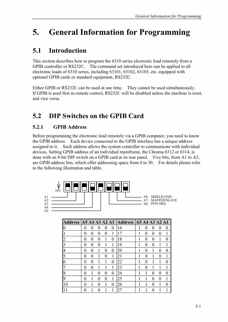
General Information for Programming
5. General Information for Programming
5.1 Introduction This section describes how to program the 6310 series electronic load remotely from a GPIB controller or RS232C. The command set introduced here can be applied to all electronic loads of 6310 series, including 63101, 63102, 63103, etc. equipped with optional GPIB cards or standard equipment, RS232C. Either GPIB or RS232C can be used at one time. They cannot be used simultaneously. If GPIB is used first in remote control, RS232C will be disabled unless the machine is reset, and vice versa. 5.2 DIP Switches on the GPIB Card 5.2.1 GPIB Address Before programming the electronic load remotely via a GPIB computer, you need to know the GPIB address. Each device connected to the GPIB interface has a unique address assigned to it. Such address allows the system controller to communicate with individual devices. Setting GPIB address of an individual mainframe, the Chroma 6312 or 6314, is done with an 8-bit DIP switch on a GPIB card at its rear panel. Five bits, from A1 to A5, are GPIB address bits, which offer addressing space from 0 to 30. For details please refer to the following illustration and table.
ON
A1A2A3A4A5
SHIELD GNDMASTER/SLAVEPON-SRQ
A8:A7:A6:
Address A5 A4 A3 A2 A1 Address A5 A4 A3 A2 A1 0 0 0 0 0 0 16 1 0 0 0 0 1 0 0 0 0 1 17 1 0 0 0 1 2 0 0 0 1 0 18 1 0 0 1 0 3 0 0 0 1 1 19 1 0 0 1 1 4 0 0 1 0 0 20 1 0 1 0 0 5 0 0 1 0 1 21 1 0 1 0 1 6 0 0 1 1 0 22 1 0 1 1 0 7 0 0 1 1 1 23 1 0 1 1 1 8 0 1 0 0 0 24 1 1 0 0 0 9 0 1 0 0 1 25 1 1 0 0 1 10 0 1 0 1 0 26 1 1 0 1 0 11 0 1 0 1 1 27 1 1 0 1 1
5-1
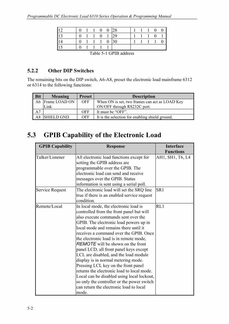
Programmable DC Electronic Load 6310 Series Operation & Programming Manual
12 0 1 1 0 0 28 1 1 1 0 0 13 0 1 1 0 1 29 1 1 1 0 1 14 0 1 1 1 0 30 1 1 1 1 0 15 0 1 1 1 1
Table 5-1 GPIB address
5.2.2 Other DIP Switches The remaining bits on the DIP switch, A6-A8, preset the electronic load mainframe 6312 or 6314 to the following functions:
Bit Meaning Preset Description A6 Frame LOAD ON
Link OFF When ON is set, two frames can act as LOAD Key
ON/OFF through RS232C port. A7 OFF It must be “OFF”. A8 SHIELD GND OFF It is the selection for enabling shield ground.
5.3 GPIB Capability of the Electronic Load
GPIB Capability Response Interface Functions
Talker/Listener All electronic load functions except for setting the GPIB address are programmable over the GPIB. The electronic load can send and receive messages over the GPIB. Status information is sent using a serial poll.
AH1, SH1, T6, L4
Service Request The electronic load will set the SRQ line true if there is an enabled service request condition.
SR1
Remote/Local In local mode, the electronic load is controlled from the front panel but will also execute commands sent over the GPIB. The electronic load powers up in local mode and remains there until it receives a command over the GPIB. Once the electronic load is in remote mode, REMOTE will be shown on the front panel LCD, all front panel keys except LCL are disabled, and the load module display is in normal metering mode. Pressing LCL key on the front panel returns the electronic load to local mode. Local can be disabled using local lockout, so only the controller or the power switch can return the electronic load to local mode.
RL1
5-2
General Information for Programming
Device Clear The electronic load responds to the Device Clear (DCL) and Selected Device Clear(SDC) interface commands. These cause the electronic load to clear any activity that may prevent it from receiving and executing a new command. DCL and SDC do not change any programmed settings.
DCL, SDC
5.4 RS232C in Remote Control When you use RS232C in remote control, you have to send the remote command of CONFigure : REMote ON first in order to let control procedure enter into remote state, and then do other command set. When control comes to an end, you have to send the command of CONFigure : REMote OFF so as to let control procedure return to the mode of local operation. The control commands of RS232C are the same as those of GPIB. When the string comes to an end in the command sending of RS232C, <nl> must be added. Its ASCII code is 0A hexadecimal (or 10 decimal).
5-3

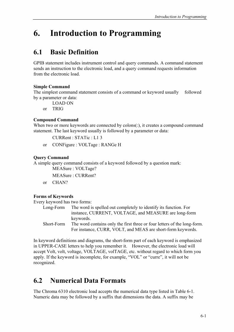
Introduction to Programming
6. Introduction to Programming
6.1 Basic Definition GPIB statement includes instrument control and query commands. A command statement sends an instruction to the electronic load, and a query command requests information from the electronic load. Simple Command The simplest command statement consists of a command or keyword usually followed by a parameter or data:
LOAD ON or TRIG
Compound Command When two or more keywords are connected by colons(:), it creates a compound command statement. The last keyword usually is followed by a parameter or data: CURRent : STATic : L1 3 or CONFigure : VOLTage : RANGe H Query Command A simple query command consists of a keyword followed by a question mark: MEASure : VOLTage? MEASure : CURRent? or CHAN? Forms of Keywords Every keyword has two forms: Long-Form The word is spelled out completely to identify its function. For instance, CURRENT, VOLTAGE, and MEASURE are long-form keywords. Short-Form The word contains only the first three or four letters of the long-form. For instance, CURR, VOLT, and MEAS are short-form keywords. In keyword definitions and diagrams, the short-form part of each keyword is emphasized in UPPER-CASE letters to help you remember it. However, the electronic load will accept Volt, volt, voltage, VOLTAGE, volTAGE, etc. without regard to which form you apply. If the keyword is incomplete, for example, “VOL” or “curre”, it will not be recognized. 6.2 Numerical Data Formats The Chroma 6310 electronic load accepts the numerical data type listed in Table 6-1. Numeric data may be followed by a suffix that dimensions the data. A suffix may be
6-1
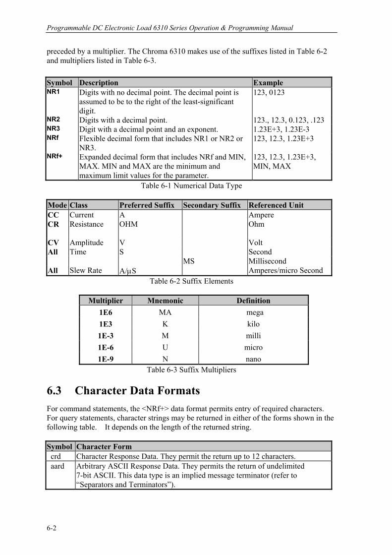
Programmable DC Electronic Load 6310 Series Operation & Programming Manual
preceded by a multiplier. The Chroma 6310 makes use of the suffixes listed in Table 6-2 and multipliers listed in Table 6-3. Symbol Description Example NR1 Digits with no decimal point. The decimal point is
assumed to be to the right of the least-significant digit.
123, 0123
NR2 Digits with a decimal point. 123., 12.3, 0.123, .123 NR3 Digit with a decimal point and an exponent. 1.23E+3, 1.23E-3 NRf Flexible decimal form that includes NR1 or NR2 or
NR3. 123, 12.3, 1.23E+3
NRf+ Expanded decimal form that includes NRf and MIN, MAX. MIN and MAX are the minimum and maximum limit values for the parameter.
123, 12.3, 1.23E+3, MIN, MAX
Table 6-1 Numerical Data Type
Mode Class Preferred Suffix Secondary Suffix Referenced Unit CC Current A Ampere CR Resistance OHM
Ohm
CV Amplitude V Volt All Time S Second MS Millisecond All Slew Rate A/µS Amperes/micro Second
Table 6-2 Suffix Elements
Multiplier Mnemonic Definition 1E6 MA mega 1E3 K kilo 1E-3 M milli 1E-6 U micro 1E-9 N nano
Table 6-3 Suffix Multipliers 6.3 Character Data Formats For command statements, the <NRf+> data format permits entry of required characters. For query statements, character strings may be returned in either of the forms shown in the following table. It depends on the length of the returned string. Symbol Character Form crd Character Response Data. They permit the return up to 12 characters. aard Arbitrary ASCII Response Data. They permits the return of undelimited
7-bit ASCII. This data type is an implied message terminator (refer to “Separators and Terminators”).
6-2
Introduction to Programming
6.4 Separators and Terminators In addition to keywords and parameters, GPIB program statements require the following: Data Separators: Data must be separated from the previous command keyword by a space. This is shown in examples as a space (CURR 3) and on diagrams by the letters SP inside a circle.
Keyword Separators: Keywords (or headers) are separated by a colon (:), a semicolon (;), or both. For example:
LOAD:SHOR ON MEAS:CURR?;VOLT? CURR:STAT:L1 3;:VOLT:L1 5
Program Line Separators: A terminator informs GPIB that it has reached the end of a statement. Normally, this is sent automatically by your GPIB programming statements. The termination also occurs with other terminator codes, such as EOI. In this manual, the terminator is assumed at the end of each example line of code. If it needs to be indicated, it is shown by the symbol <nl>, which stands for “new line” and represents the ASCII coded byte 0A hexadecimal (or 10 decimal). Traversing the Command Tree: The colon “:” separates keywords from each other which represents changes in branch
level to the next lower one. For example: CONF:VOLT:ON 5 CONF is a root-level command, VOLT is the first branch, and ON is the second branch. Each “:” moves down command interpretation to the next branch.
The semicolon “;” allows you to combine command statements into one line. It returns
the command interpretation to the previous colon. For example: Combine the following two command statements:
RES:RISE 100 <nl> and RES:L1 400 <nl>
Which can be formed into one command line as follows: RES:RISE 100;L1 400 <nl>
To return to the root-level form you can
1. Enter a new-line character. This is symbolized by “<nl>” and can be linefeed “LF” or/and end-of-line “EOL”. Or else,
2. Enter a semicolon followed by a colon “;:”.
Please refer to the following.
6-3

Programmable DC Electronic Load 6310 Series Operation & Programming Manual
1. (root):VOLT:L1: 30<nl>
Starting a New Line returns to the Root.
2. (root):SPEC:VOLT:H 30; :L 5;:
(root):RES:L1 400; :RISE 1000;:
6-4
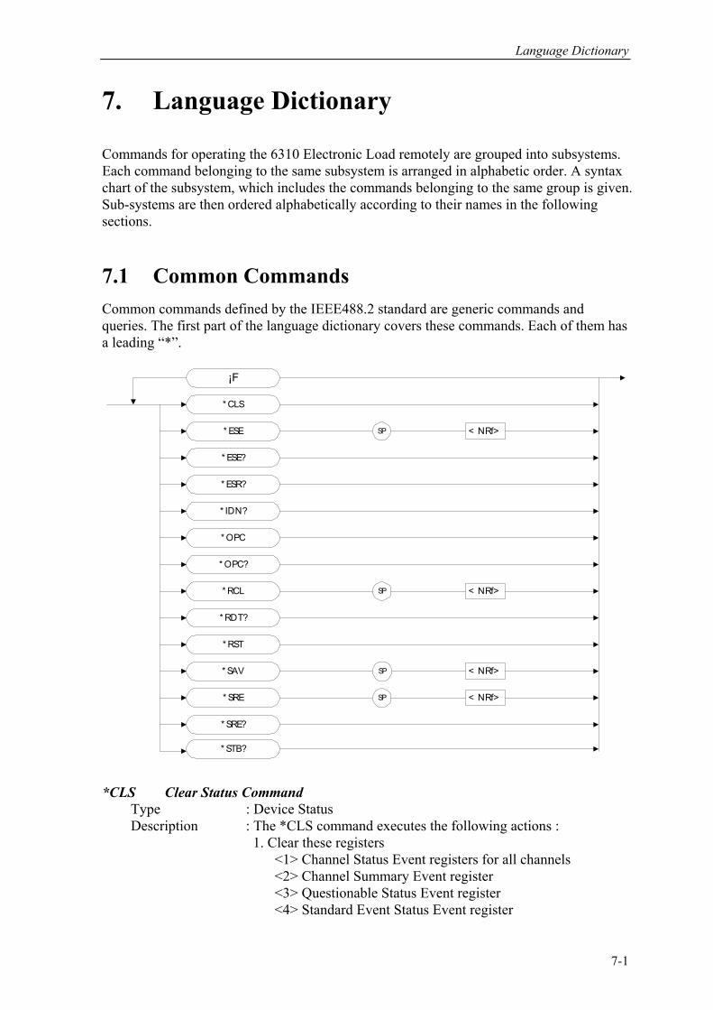
Language Dictionary
7. Language Dictionary
Commands for operating the 6310 Electronic Load remotely are grouped into subsystems. Each command belonging to the same subsystem is arranged in alphabetic order. A syntax chart of the subsystem, which includes the commands belonging to the same group is given. Sub-systems are then ordered alphabetically according to their names in the following sections. 7.1 Common Commands Common commands defined by the IEEE488.2 standard are generic commands and queries. The first part of the language dictionary covers these commands. Each of them has a leading “*”.
¡F
* CLS
* ESE?
* ESR?
* ESE
* IDN?
* RST
* SRE
* SRE?
* RCL
* SAV
SP < NRf>
SP
SP
SP
< NRf>
< NRf>
< NRf>
* RDT?
* OPC
* OPC?
* STB?
*CLS Clear Status Command Type : Device Status Description : The *CLS command executes the following actions : 1. Clear these registers <1> Channel Status Event registers for all channels <2> Channel Summary Event register <3> Questionable Status Event register <4> Standard Event Status Event register
7-1

Programmable DC Electronic Load 6310 Series Operation & Programming Manual
<5> Operation Status Event register 2. Clear the Error Queue
3. If “Clear Status Command” immediately follows a program message terminator (<nl>), the “Output Queue” and the MAV bit are also cleared.
Syntax : *CLS Parameters : nil *ESE Standard Event Status Enable Command/Query Type : Device Status Description : This command sets the condition of the Standard Event Status Enable register, which determines which events of the Standard Event Status Event register (see *ESR?)are allowed to set the ESB (Event Summary Bit) of the Status Byte register. A "1" in the bit position enables the corresponding event. All of the enable events of the Standard Event Status Event register are logically ORed to cause the ESB (bit 5) of the Status Byte register to be set. See description of all three registers in Chapter 8 Status Reporting. Syntax : *ESE <NRf> Parameters : 0 to 255 Example : *ESE 48 This command enables the CME and EXE events of the Standard Event Status Event register. Query Syntax : *ESE? Return Parameters : <NR1> Query Example : *ESE? This query returns current setting of "Standard Event Status Enable". *ESR? Standard Event Status Register Query Type : Device Status Description : This query reads the Standard Event Status register. Reading the register clears it. See detailed explanation of this register in Chapter 8 Status Reporting.
Standard Event Status Event register Bit Position 7 6 5 4 3 2 1 0Condition 0 0 CME EXE DDE QYE 0 0Bit Weight 128 64 32 16 8 4 2 1
Query Syntax : *ESR?
Return Parameters : <NR1> Query Example : *ESR? Return the status readings of Standard Event Status register. Return Example : 48 *IDN? Identification Query Type : System Interface Description : This query requests the Electronic Frame (6314) to identify
7-2

Language Dictionary
itself. Query Syntax : *IDN? Return Parameters : <aard> Query Example : *IDN? String Information CHROMA Manufacture
6314 Model 0 Always return zero
01.00 Revision level of the primary interference firmware 0 customer’s version Return Example : CHROMA 6314,0,01.00,0 *OPC Operation Complete Command Type : Device Status Description command causes the interface to set the OPC bit (bit 0) : This of the Standard Event Status register when the Electronic Frame (6314) has completed all pending operations. Syntax : *OPC Parameters : nil *OPC? Operation Complete Query Type : Device Status Description This query returns an ASCII “1” when all pending operations : are completed. Query Syntax : *OPC? Return Parameters : <NR1> Query Example : 1 *RCL Recall Instrument State Command Type : Device Status Description : This command restores the electronic load to a state that was previously stored in memory with the *SAV command to the specified location (see *SAV ). Syntax : *RCL <NRf> Parameters : 1 to 101 Example : *RCL 50 *RDT? Resource Description Transfer Query Type : System Interface Description : This command returns the types of Electronic Frame (6314). If channel does not exist, it returns 0. If channel exists, it returns the types like 63103, 63102, 63107R, 63107L... Query Syntax : *RDT? Return Parameters : <aard> Query Example : 63107L, 63107R, 63103, 0, 63102, 63102, 0, 0. *RST Rrset Command
7-3
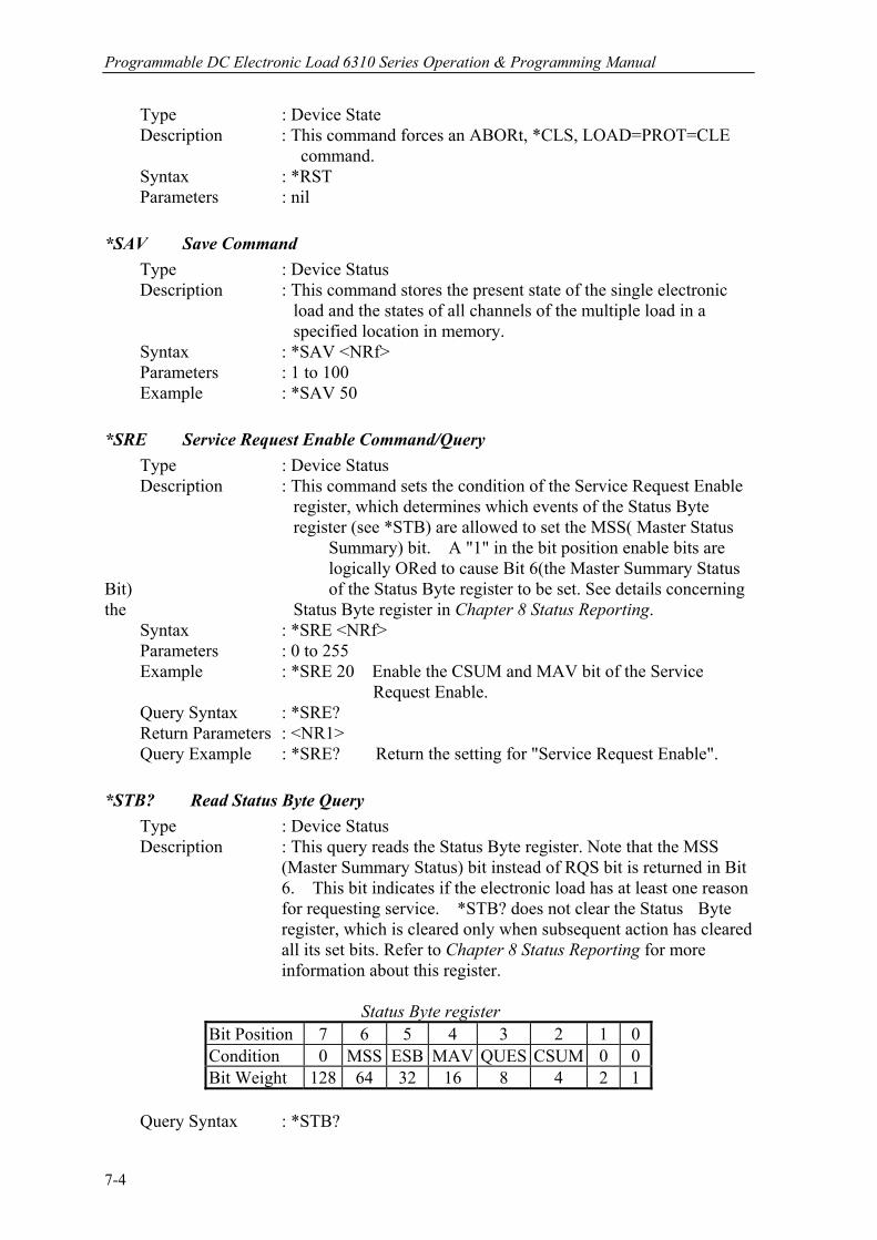
Programmable DC Electronic Load 6310 Series Operation & Programming Manual
Type : Device State Description This command forces an ABORt, *CLS, LOAD=PROT=CLE : command. Syntax : *RST Parameters : nil *SAV Save Command Type : Device Status Description : This command stores the present state of the single electronic load and the states of all channels of the multiple load in a specified location in memory. Syntax : *SAV <NRf> Parameters : 1 to 100 Example : *SAV 50 *SRE Service Request Enable Command/Query Type : Device Status Description : This command sets the condition of the Service Request Enable register, which determines which events of the Status Byte register (see *STB) are allowed to set the MSS( Master Status Summary) bit. A "1" in the bit position enable bits are logically ORed to cause Bit 6(the Master Summary Status Bit) of the Status Byte register to be set. See details concerning the Status Byte register in Chapter 8 Status Reporting. Syntax : *SRE <NRf>
Parameters : 0 to 255 Example : *SRE 20 Enable the CSUM and MAV bit of the Service
Request Enable. Query Syntax : *SRE?
Return Parameters : <NR1> Query Example : *SRE? Return the setting for "Service Request Enable". *STB? Read Status Byte Query Type : Device Status
Description : This query reads the Status Byte register. Note that the MSS
(Master Summary Status) bit instead of RQS bit is returned in Bit 6. This bit indicates if the electronic load has at least one reason for requesting service. *STB? does not clear the Status Byte register, which is cleared only when subsequent action has cleared all its set bits. Refer to Chapter 8 Status Reporting for more information about this register.
Status Byte register Bit Position 7 6 5 4 3 2 1 0 Condition 0 MSS ESB MAV QUES CSUM 0 0 Bit Weight 128 64 32 16 8 4 2 1
Query Syntax : *STB?
7-4
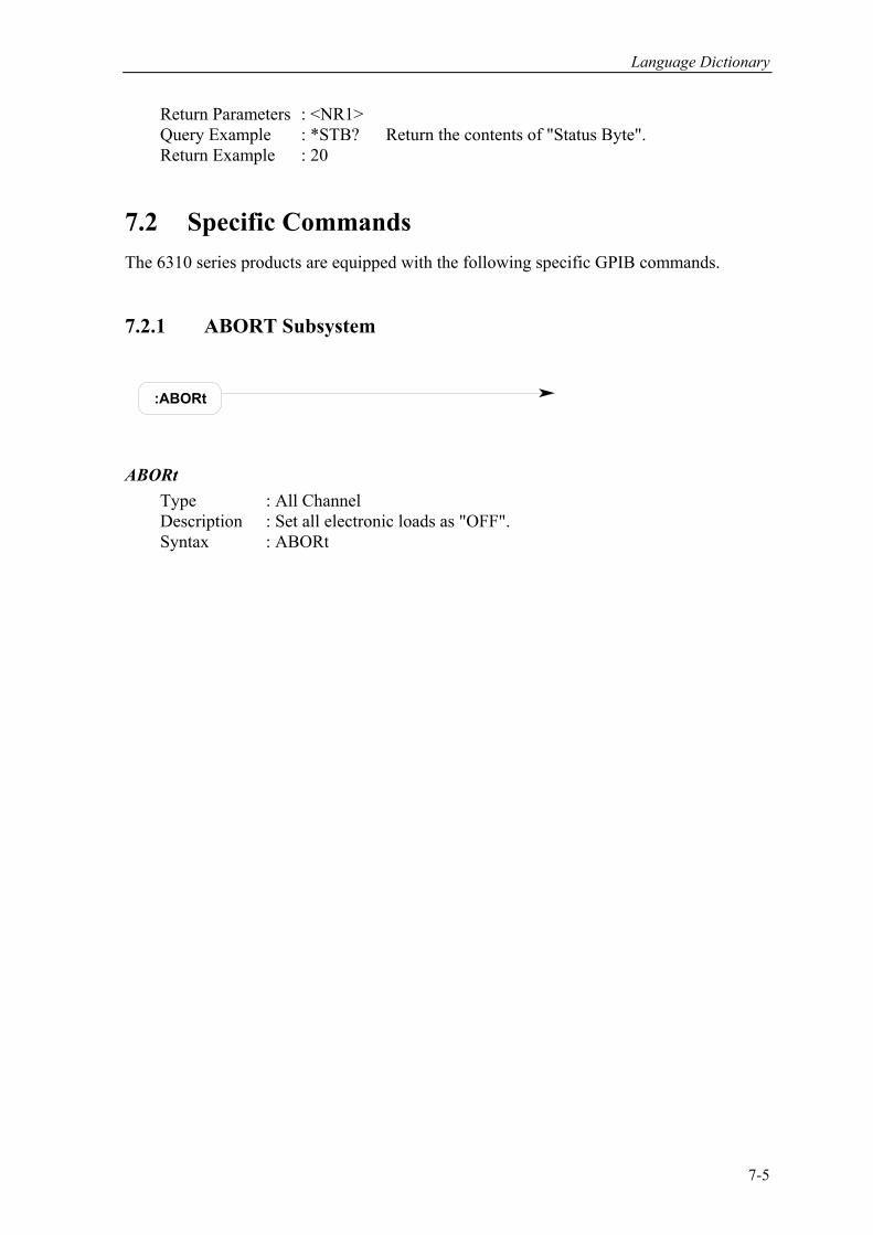
Language Dictionary
Return Parameters : <NR1> Query Example : *STB? Return the contents of "Status Byte". Return Example : 20 7.2 Specific Commands The 6310 series products are equipped with the following specific GPIB commands. 7.2.1 ABORT Subsystem
:ABORt
ABORt Type : All Channel Description : Set all electronic loads as "OFF". Syntax : ABORt
7-5
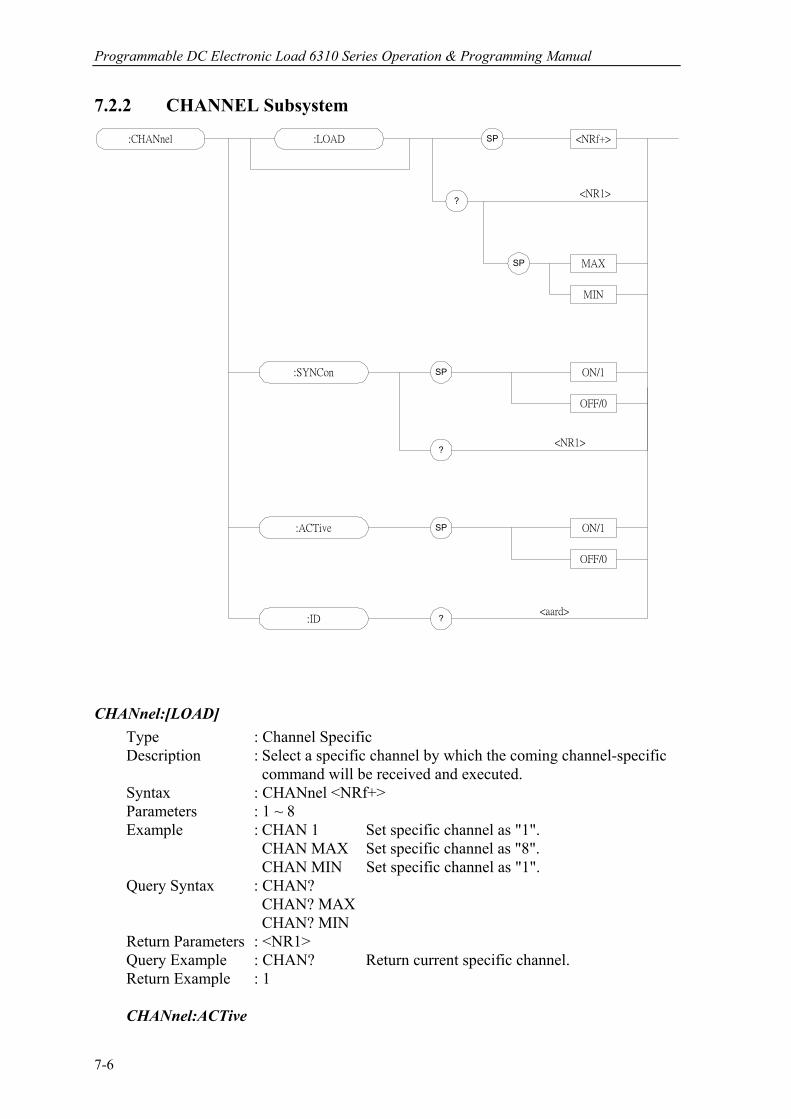
Programmable DC Electronic Load 6310 Series Operation & Programming Manual
7.2.2 CHANNEL Subsystem
:CHANnel SP <NRf+>:LOAD
?
MIN
MAXSP
:SYNCon SP
SP
ON/1
OFF/0
:ACTive ON/1
OFF/0
:ID ?
<NR1>
<aard>
?<NR1>
CHANnel:[LOAD] Type : Channel Specific Description : Select a specific channel by which the coming channel-specific
command will be received and executed. Syntax : CHANnel <NRf+> Parameters : 1 ~ 8 Example : CHAN 1 Set specific channel as "1".
CHAN MAX Set specific channel as "8". CHAN MIN Set specific channel as "1". Query Syntax : CHAN? CHAN? MAX CHAN? MIN Return Parameters : <NR1> Query Example : CHAN? Return current specific channel. Return Example : 1 CHANnel:ACTive
7-6

Language Dictionary
Type : Channel Specific Description : Enable or disable the load module. Syntax : CHANnel : ACTive ON. Enable the load module. The front panel displays the measurement of voltage and current. CHANnel : ACTive OFF. Disable the load module. LCD on the front panel displays OFF. Parameter : ON/1, OFF/0 Example : CHAN : ACT ON CHANnel:SYNCon Type : Channel Specific Description : Set the load module to receive synchronized command action of RUN ABORT or not. Syntax : CHANnel : SYNCon ON CHANnel : SYNCon OFF Parameters : ON/1, OFF/0 Example : CHAN : SYNC ON. Set the load module to receive synchronized command action. CHAN : SYNC OFF. Set the load module not to receive synchronized command action. Query Syntax : CHAN : SYNC? Return Parameters : <NR1> Query Example : CHAN : SYNC? Return to the load module and makes it receive synchronized command status. Return Example : 0 The load module does not receive synchronized command status. 1 The load module receives synchronized command status. CHAN:ID? Type : Channel-Specific Description : This query requests the module to identify itself. Query Syntax : ID? Return Parameters : <aard> Query Example : ID?
String Information CHROMA Manufacturer 6310X Model 0 Always return zero xx.xx Revision of the primary interface firmware0 Customer’s Version
Return Example : CHROMA,63102,0,01.00,0
7-7
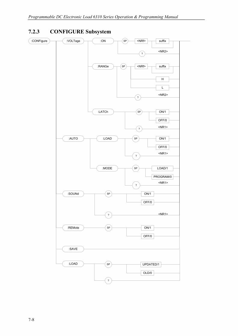
Programmable DC Electronic Load 6310 Series Operation & Programming Manual
7.2.3 CONFIGURE Subsystem :CONFigure SP <NRf>:VOLTage
SP
L
H
:ON
:RANGe
suffix
<NRf> suffix
?
:AUTO SP
OFF/0
ON/1
:SOUNd
OFF/0
ON/1SP
:REMote
OFF/0
ON/1SP
:SAVE
:LATCh ON/1
OFF/0
SP
?
<NR2>
?<NR2>
<NR1>
?
?
<NR1>
<NR1>
:LOAD
SP
PROGRAM/0
LOAD/1
?<NR1>
:MODE
:LOAD SP UPDATED/1
OLD/0
?
7-8

Language Dictionary
CONFigure:VOLTage:ON Type : Channel-Specific Description : Set voltage of sink current on.
Syntax : CONFigure:VOLTage:ON <NRf> [suffix] Parameters : For valid voltage range refer to respective specification. Example : CONF:VOLT:ON 1 Set Von=1V. CONF:VOLT:ON 300mV Set Von=300mV. Query Syntax : CONFigure:VOLTage:ON? Return Parameters : <NR2> [Unit=Voltage] Query Example : CONF:VOLT:ON? Return the setting Von value. Return Example : 3.5
CONFigure:VOLTage:RANGe Type : Channel-Specific Description : Set voltage measurement range in CC mode. Syntax : CONFigure:VOLTage:RANGEe <NRf> [suffix] Parameters : Value ranges depend on Load Module. For details refer to specification.
Example : CONF:VOLT:RANG 16 Set full-range as Low, for example, in 63103.
CONF:VOLT:RANG 80V Set full-range as High, for example, in 63103.
CONF:VOLT:RANG H Set full-range as High. CONF:VOLT:RANG L Set full-range as Low. Query Syntax : CONFigure:VOLTage:RANGe? Return Parameters : <NR2> [Unit = Voltage] Query Example : CONF:VOLT:RANG? Return Voltage range. Return Example : 16
CONFigure:VOLTage:LATCh Type : Channel-Specific Description : Set the action type of Von. Syntax : CONFigure:VOLTage:LATch ON CONFigure:VOLTage:LATch OFF Parameters : ON/1, OFF/0 Example : CONF:VOLT:LAT ON Set the action type of Von as Latch. CONF:VOLT:LAT OFF Set the action type of Von as Non Latch (For detailed action refer to the user’s manual). Query Syntax : CONFigure:VOLTage:LATch? Return Parameters : <NR1> Query Example : CONF:VOLT:LAT? Return Example : 0 (non latch), 1 (latch) Return the action type of Von.
7-9
Programmable DC Electronic Load 6310 Series Operation & Programming Manual
CONFigure:AUTO:LOAD Type : All Channel Description : Set if the load module will do Auto Load On during power-on. Syntax : CONFigure:AUTO:LOAD ON CONFigure:AUTO:LOAD OFF Parameters : ON/1, OFF/0 Example : CONF:AUTO:LOAD ON Start Auto Load On during power-on. CONF:AUTO:LOAD OFF Close Auto Load On during power-on. Query Syntax : CONFigure:AUTO:LOAD? Return Parameters : <NR1> Query Example : CONF:AUTO:LOAD? Return Example : 0 or 1 Return the status of Auto Load On CONFigure:AUTO:MODE Type : All Channel Description : Set the Auto Load On to LOAD ON or PROGRAM RUN. Syntax : CONFigure:AUTO:MODE LOAD CONFigure:AUTO:MODE PROGRAM Parameters : LOAD/1, PROGRAM/0 Example : CONF:AUTO:MODE LOAD Set Auto Load On as general LOAD ON. CONF:AUTO:MODE PROGRAM Set Auto Load On as PROGRAM RUN. Query Syntax : CONFigure:AUTO:MODE? Return Parameters : <NR1> Query Example : CONF:AUTO:MODE? Return the execution Return Example : 0 or 1 type of Auto Load On. CONFigure:SOUND Type : Channel-Specific Description : Set the buffer sound of load module to ON or OFF. Syntax : CONFigure:SOUND ON CONFigure:SOUND OFF Parameters : ON/1, OFF/0 Example : CONF:SOUND ON CONF:SOUND OFF Query Syntax : CONFigure:SOUND? Return Parameters : <NR1> Query Example : CONF:SOUND? Return the control status of the load module’s buzzer sound. Return Example : 0 or 1 CONFigure:REMote Type : All Channel Description : Set the status of remote control (only effective in RS232C). Syntax : CONFigure:REMote ON CONFigure:REMote OFF
7-10
Language Dictionary
Parameters : ON/1, OFF/0 Example : CONF:REM ON Set to remote control. CONFigure:SAVE Type : All Channel Description : Store the data of CONFigure into EEPROM. Syntax : CONFigure:SAVE Parameters : none Example : CONF:SAVE CONFigure:LOAD Type : All Channel Description : The value at the setting of load module as LOADON is the one changed by the rotary knob (UPDATED/1) or the original set value (OLD/0). Syntax : CONFigure:LOAD UPDATED CONFigure:LOAD OLD Parameters : UPDATED/1, OLD/0 Example : CONF:LOAD UPDATED Set the value of LOADON as that changed by the rotary knob. CONF:LOAD OLD Set the value of LOADON as the original set value. Query Syntax : CONFigure:LOAD? Return Parameters : <NR1> Query Example : CONF:LOAD? Return Example : 1 (UPDATED) or 0 (OLD)
7-11
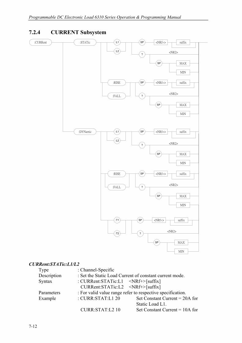
Programmable DC Electronic Load 6310 Series Operation & Programming Manual
7.2.4 CURRENT Subsystem :CURRent SP <NRf+>
MIN
MAX
suffix
?:L2
:L1
SP
<NR2>
:STATic
SP <NRf+>
MIN
MAX
suffix
?
SP
<NR2>
:RISE
:FALL
SP <NRf+>
MIN
MAX
suffix
?
:L2
:L1
SP
<NR2>
:DYNamic
SP <NRf+>
MIN
MAX
suffix
?
SP
<NR2>
:RISE
:FALL
SP <NRf+>
MIN
MAX
suffix
?
SP
<NR2>
:T1
:T2
CURRent:STATic:L1/L2 Type : Channel-Specific Description : Set the Static Load Current of constant current mode. Syntax : CURRent:STATic:L1 <NRf+> [suffix] CURRent:STATic:L2 <NRf+> [suffix] Parameters : For valid value range refer to respective specification. Example : CURR:STAT:L1 20 Set Constant Current = 20A for Static Load L1. CURR:STAT:L2 10 Set Constant Current = 10A for
7-12
Language Dictionary
Static Load L2. CURR:STAT:L1 MAX Set Constant Current = maximum value for Static Load L1. CURR:STAT:L2 MIN Set Constant Current = minimum value for Static Load L2. Query Syntax : CURRent:STATic:L1? CURRent:STATic:L2? CURRent:STATic:L1? MAX CURRent:STATic:L2? MIN Return Parameters : <NR2> [Unit=Ampere] Query Example : CURR:STAT:L1? Return set current value of the Static Load L1. Return Example : 3.12 CURRent:STATic:RISE/FALL Type : Channel-Specific Description : Set current slew rate of constant current static mode. Syntax : CURRent:STATic:RISE <NRf+> [suffix] CURRent:STATic:FALL <NRf+> [suffix] Parameters : For valid value range refer to respective specification. Example : CURR:STAT:RISE 2.5 Set rise slew rate as 2.5A/µS of static load. CURR:STAT:FALL 1A/µS Set fall slew rate as 1A/µS of static load. Query Syntax : CURRent:STATic:RISE? CURRent:STATic:FALL? CURRent:STATic:RISE? MAX CURRent:STATic:FALL? MIN Return Parameters : <NR2> [Unit=A/µS]
Query Example : CURR:STAT:RISE? Return rise slew rate of static load. Return Example : 2.5
CURRent:DYNamic:L1/L2 Type : Channel-Specific Description : Set the Dynamic Load Current during constant current mode. Syntax : CURRent:DYNamic:L1 <NRf+> [suffix] CURRent:DYNamic:L2 <NRf+> [suffix] Parameters : For valid value range refer to respective specification. Example : CURR:DYN:L1 20 Set dynamic load parameter L1 = 20A. CURR:DYN:L2 10 Set dynamic load parameter L2 = 10A. CURR:DYN:L1 MAX Set dynamic load parameter L1 = maximum value. CURR:DYN:L2 MIN Set dynamic load parameter L2 = minimum value. Query Syntax :CURRent:DYNamic:L1? CURRent:DYNamic:L2? CURRent:DYNamic:L1? MAX
7-13
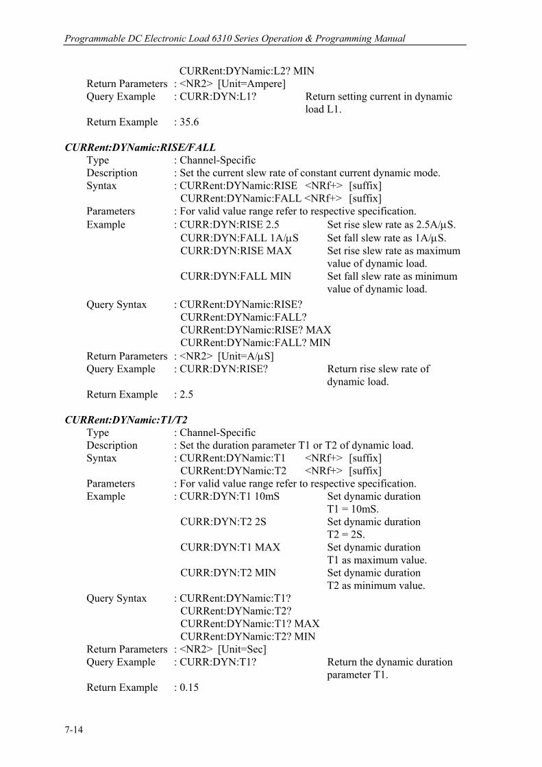
Programmable DC Electronic Load 6310 Series Operation & Programming Manual
CURRent:DYNamic:L2? MIN Return Parameters : <NR2> [Unit=Ampere] Query Example : CURR:DYN:L1? Return setting current in dynamic load L1. Return Example : 35.6 CURRent:DYNamic:RISE/FALL Type : Channel-Specific Description : Set the current slew rate of constant current dynamic mode. Syntax : CURRent:DYNamic:RISE <NRf+> [suffix] CURRent:DYNamic:FALL <NRf+> [suffix] Parameters : For valid value range refer to respective specification. Example : CURR:DYN:RISE 2.5 Set rise slew rate as 2.5A/µS. CURR:DYN:FALL 1A/µS Set fall slew rate as 1A/µS. CURR:DYN:RISE MAX Set rise slew rate as maximum value of dynamic load. CURR:DYN:FALL MIN Set fall slew rate as minimum value of dynamic load. Query Syntax : CURRent:DYNamic:RISE? CURRent:DYNamic:FALL? CURRent:DYNamic:RISE? MAX CURRent:DYNamic:FALL? MIN Return Parameters : <NR2> [Unit=A/µS] Query Example : CURR:DYN:RISE? Return rise slew rate of dynamic load. Return Example : 2.5 CURRent:DYNamic:T1/T2 Type : Channel-Specific Description : Set the duration parameter T1 or T2 of dynamic load. Syntax : CURRent:DYNamic:T1 <NRf+> [suffix] CURRent:DYNamic:T2 <NRf+> [suffix] Parameters : For valid value range refer to respective specification. Example : CURR:DYN:T1 10mS Set dynamic duration T1 = 10mS. CURR:DYN:T2 2S Set dynamic duration T2 = 2S. CURR:DYN:T1 MAX Set dynamic duration T1 as maximum value. CURR:DYN:T2 MIN Set dynamic duration T2 as minimum value. Query Syntax : CURRent:DYNamic:T1? CURRent:DYNamic:T2? CURRent:DYNamic:T1? MAX CURRent:DYNamic:T2? MIN Return Parameters : <NR2> [Unit=Sec] Query Example : CURR:DYN:T1? Return the dynamic duration parameter T1. Return Example : 0.15
7-14
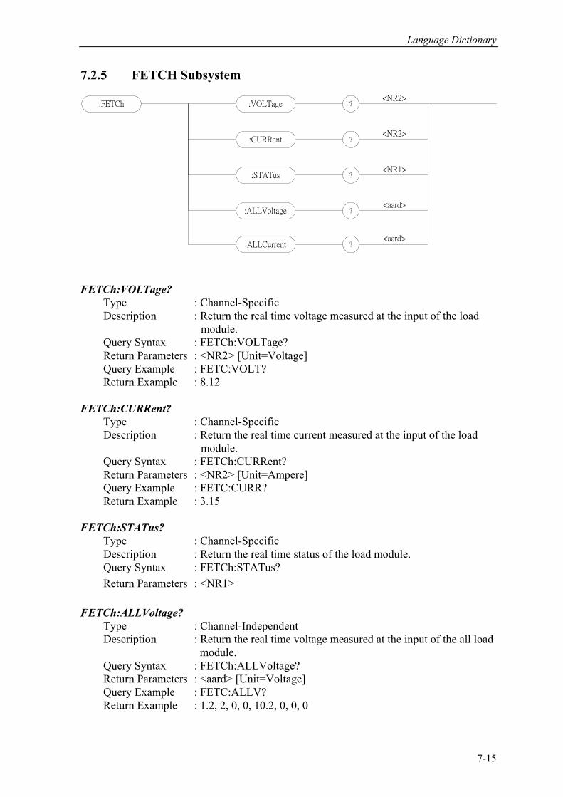
Language Dictionary
7.2.5 FETCH Subsystem
:FETCh ?:VOLTage
?:CURRent
?:STATus
<NR2>
<NR2>
<NR1>
:ALLVoltage ?<aard>
:ALLCurrent ?<aard>
FETCh:VOLTage? Type : Channel-Specific Description : Return the real time voltage measured at the input of the load module. Query Syntax : FETCh:VOLTage? Return Parameters : <NR2> [Unit=Voltage] Query Example : FETC:VOLT? Return Example : 8.12 FETCh:CURRent? Type : Channel-Specific Description : Return the real time current measured at the input of the load module. Query Syntax : FETCh:CURRent? Return Parameters : <NR2> [Unit=Ampere] Query Example : FETC:CURR? Return Example : 3.15 FETCh:STATus? Type : Channel-Specific Description : Return the real time status of the load module. Query Syntax : FETCh:STATus? Return Parameters : <NR1> FETCh:ALLVoltage? Type : Channel-Independent Description : Return the real time voltage measured at the input of the all load module. Query Syntax : FETCh:ALLVoltage? Return Parameters : <aard> [Unit=Voltage] Query Example : FETC:ALLV? Return Example : 1.2, 2, 0, 0, 10.2, 0, 0, 0
7-15
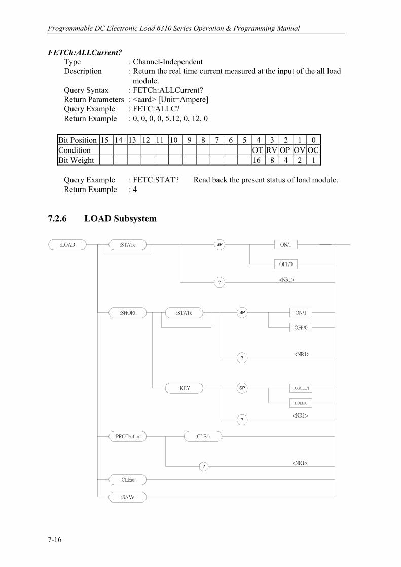
Programmable DC Electronic Load 6310 Series Operation & Programming Manual
FETCh:ALLCurrent? Type : Channel-Independent Description : Return the real time current measured at the input of the all load module. Query Syntax : FETCh:ALLCurrent? Return Parameters : <aard> [Unit=Ampere] Query Example : FETC:ALLC? Return Example : 0, 0, 0, 0, 5.12, 0, 12, 0
Bit Position 15 14 13 12 11 10 9 8 7 6 5 4 3 2 1 0 Condition OT RV OP OV OC Bit Weight 16 8 4 2 1
Query Example : FETC:STAT? Read back the present status of load module. Return Example : 4 7.2.6 LOAD Subsystem
:LOAD :STATe
OFF/0
ON/1SP
?
OFF/0
ON/1SP
?
:SHORt :STATe
:PROTection :CLEar
?
:KEY SP TOGGLE/1
HOLD/0
?
<NR1>
<NR1>
<NR1>
<NR1>
:CLEar
:SAVe
7-16

Language Dictionary
LOAD:[STATe] Type : Channel-Specific Description : The LOAD command makes the electronic load active/on or
inactive/off. Syntax : LOAD:[STATe] ON LOAD:[STATe] OFF Parameters : ON/1, OFF/0 Example : LOAD ON Activate the electronic load. LOAD OFF Inactivate the electronic load. Query Syntax : LOAD:[STATe]? Return Parameters : <NR1> Query Example : LOAD? Return if the electronic
load is active. Return Example : 1
LOAD:SHORt:[STATe] Type : Channel-Specific Description : Activate or inactivate short-circuited simulation. Syntax : LOAD:SHORt:[STATe] Example : LOAD:SHOR ON Activate short-circuited simulation. LOAD:SHOR OFF Inactivate short-circuited simulation. Parameters : ON/1, OFF/0 Query Syntax : LOAD:SHORt:[STATe]? Return Parameters : <NR1> Query Example : LOAD:SHOR? Returns the short-circuit simulation state. Return Example : 1 LOAD:SHORt:KEY Type : Channel-Specific Description : Set the mode of short key in the electronic load. Syntax : LOAD:SHORt:KEY TOGGLE Parameters : TOGGLE/1, HOLD/0 Example : LOAD:SHOR:KEY TOGGLE Set short key mode as Toggle. LOAD:SHOR:KEY HOLD Set short key mode as Hold. Query Syntax : LOAD:SHORt:KEY? Return Parameters : <NR1> Query Example : LOAD:SHOR:KEY? Return the mode of short key in the electronic load. Return Example : 1 LOAD:PROTection:CLEar Type : Channel-Specific Description : This command resets or returns status of the electronic load. Syntax : LOAD:PROTection:CLEar Parameters : For valid value range refer to respective specification.
7-17
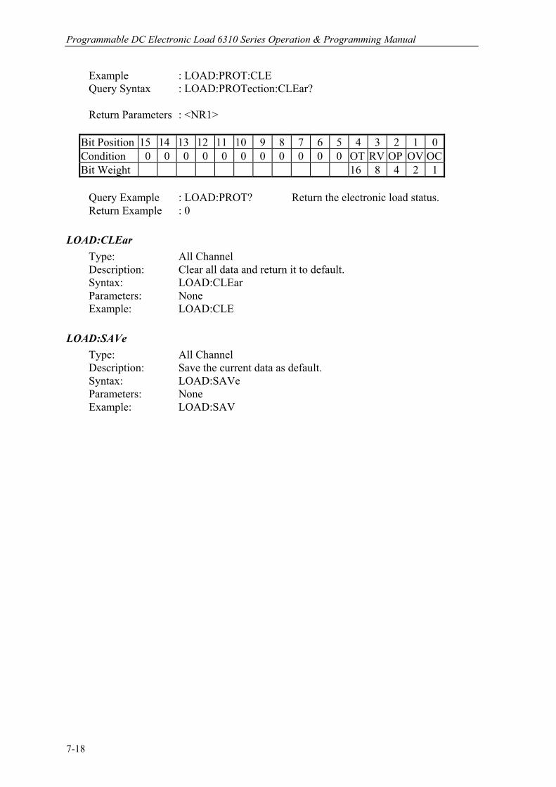
Programmable DC Electronic Load 6310 Series Operation & Programming Manual
Example : LOAD:PROT:CLE Query Syntax : LOAD:PROTection:CLEar? Return Parameters : <NR1>
Bit Position 15 14 13 12 11 10 9 8 7 6 5 4 3 2 1 0 Condition 0 0 0 0 0 0 0 0 0 0 0 OT RV OP OV OC Bit Weight 16 8 4 2 1
Query Example : LOAD:PROT? Return the electronic load status.
Return Example : 0 LOAD:CLEar Type: All Channel Description: Clear all data and return it to default. Syntax: LOAD:CLEar Parameters: None Example: LOAD:CLE LOAD:SAVe Type: All Channel Description: Save the current data as default. Syntax: LOAD:SAVe Parameters: None Example: LOAD:SAV
7-18

Language Dictionary
7.2.7 MEASURE Subsystem
:MEASure ?:VOLTage
?:CURRent
<NR2>
<NR2>
:INPut SP UUT/1
LOAD/0
?<NR1>
:SCAN SP ON/1
OFF/0
?
<arrd>
:ALLVoltage ?
:ALLCurrent ?
<arrd>
MEASure:VOLTage? Type : Channel-Specific Description : Return the voltage measured at the input of electronic load. Query Syntax : MEASure:VOLTage? Return Parameters : <NR2> [Unit=Voltge] Query Example : MEAS:VOLT? Return Example : 8.12 MEASure:CURRent? Type : Channel-Specific Description : Return the current measured at the input of electronic load. Query Syntax : MEASure:CURRent? Return Parameters : <NR2> [Unit=Ampere] Query Example : MEAS:CURR? Return Example : 3.15
7-19
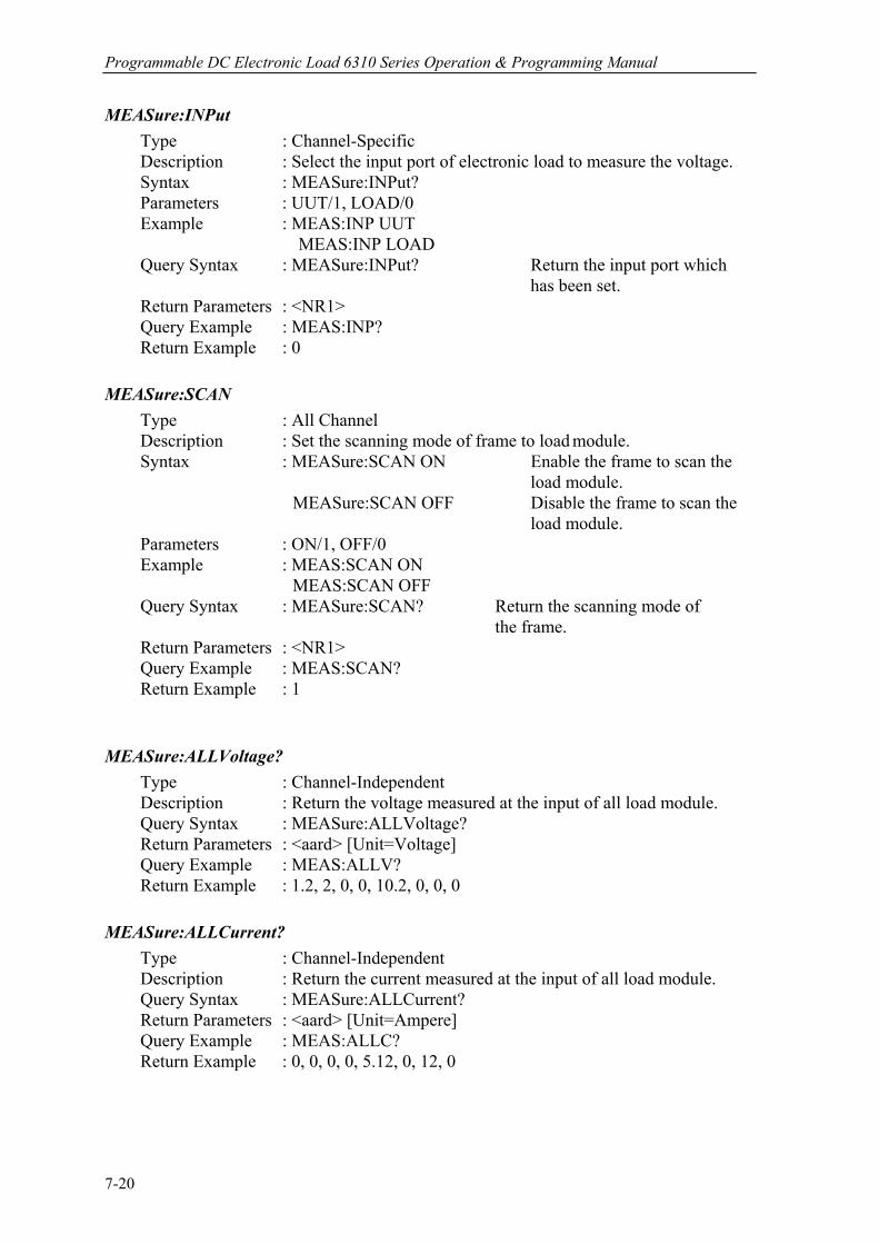
Programmable DC Electronic Load 6310 Series Operation & Programming Manual
MEASure:INPut Type : Channel-Specific Description : Select the input port of electronic load to measure the voltage. Syntax : MEASure:INPut? Parameters : UUT/1, LOAD/0 Example : MEAS:INP UUT MEAS:INP LOAD Query Syntax : MEASure:INPut? Return the input port which has been set. Return Parameters : <NR1> Query Example : MEAS:INP? Return Example : 0 MEASure:SCAN Type : All Channel Description : Set the scanning mode of frame to load module. Syntax : MEASure:SCAN ON Enable the frame to scan the load module. MEASure:SCAN OFF Disable the frame to scan the load module. Parameters : ON/1, OFF/0 Example : MEAS:SCAN ON MEAS:SCAN OFF Query Syntax : MEASure:SCAN? Return the scanning mode of the frame. Return Parameters : <NR1> Query Example : MEAS:SCAN? Return Example : 1 MEASure:ALLVoltage? Type : Channel-Independent Description : Return the voltage measured at the input of all load module. Query Syntax : MEASure:ALLVoltage? Return Parameters : <aard> [Unit=Voltage] Query Example : MEAS:ALLV? Return Example : 1.2, 2, 0, 0, 10.2, 0, 0, 0 MEASure:ALLCurrent? Type : Channel-Independent Description : Return the current measured at the input of all load module. Query Syntax : MEASure:ALLCurrent? Return Parameters : <aard> [Unit=Ampere] Query Example : MEAS:ALLC? Return Example : 0, 0, 0, 0, 5.12, 0, 12, 0
7-20
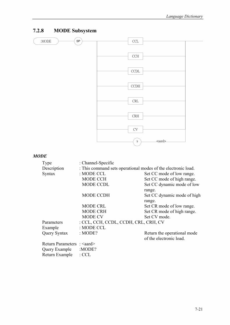
Language Dictionary
7.2.8 MODE Subsystem
:MODE SP
? <aard>
CCL
CCH
CCDL
CCDH
CRL
CRH
CV
MODE Type : Channel-Specific Description : This command sets operational modes of the electronic load. Syntax : MODE CCL Set CC mode of low range. MODE CCH Set CC mode of high range. MODE CCDL Set CC dynamic mode of low range. MODE CCDH Set CC dynamic mode of high range.
MODE CRL Set CR mode of low range. MODE CRH Set CR mode of high range. MODE CV Set CV mode. Parameters : CCL, CCH, CCDL, CCDH, CRL, CRH, CV Example : MODE CCL Query Syntax : MODE? Return the operational mode of the electronic load. Return Parameters : <aard> Query Example :MODE? Return Example : CCL
7-21
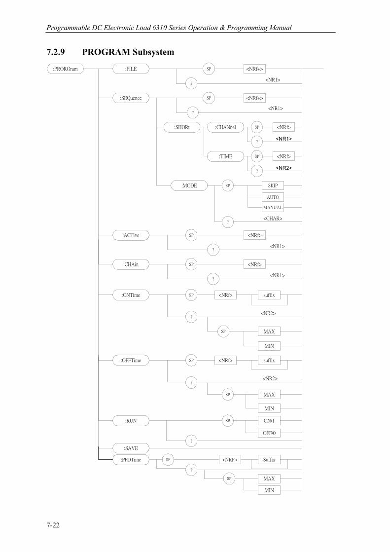
Programmable DC Electronic Load 6310 Series Operation & Programming Manual
7.2.9 PROGRAM Subsystem
:PRORGram :FILE SP <NRf+>
?
:SEQuence SP <NRf+>
?
:MODE SP SKIP
AUTO
MANUAL
:ACTive
:ONTime
SP
SP
<NRf>
<NRf>
?
:SAVE
suffix
?
MAX
MIN
SP
:OFFTime SP <NRf> suffix
?
MAX
MIN
SP
<NR2>
<NR2>
<NR1>
<NR1>
<CHAR>
:CHAin SP <NRf>
?<NR1>
?<NR1>
:RUN ON/1
OFF/0
SP
:SHORt :CHANnel
:TIME
SP <NRf>
?
SP
?
<NRf>
<NR1>
<NR2>
:PFDTime Suffix
?
<NRF>
?
SP
SP MAX
MIN
7-22
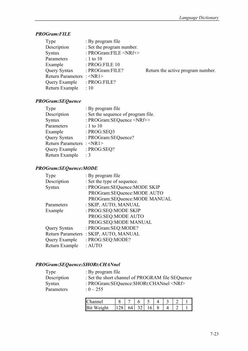
Language Dictionary
PROGram:FILE Type : By program file Description : Set the program number. Syntax : PROGram:FILE <NRf+> Parameters : 1 to 10 Example : PROG:FILE 10 Query Syntax : PROGram:FILE? Return the active program number. Return Parameters : <NR1> Query Example : PROG:FILE? Return Example : 10 PROGram:SEQuence Type : By program file Description : Set the sequence of program file. Syntax : PROGram:SEQuence <NRf+> Parameters : 1 to 10 Example : PROG:SEQ3 Query Syntax : PROGram:SEQuence? Return Parameters : <NR1> Query Example : PROG:SEQ? Return Example : 3 PROGram:SEQuence:MODE Type : By program file Description : Set the type of sequence. Syntax : PROGram:SEQuence:MODE SKIP PROGram:SEQuence:MODE AUTO PROGram:SEQuence:MODE MANUAL Parameters : SKIP, AUTO, MANUAL Example : PROG:SEQ:MODE SKIP PROG:SEQ:MODE AUTO PROG:SEQ:MODE MANUAL Query Syntax : PROGram:SEQ:MODE? Return Parameters : SKIP, AUTO, MANUAL Query Example : PROG:SEQ:MODE? Return Example : AUTO PROGram:SEQuence:SHORt:CHANnel Type : By program file Description : Set the short channel of PROGRAM file SEQuence Syntax : PROGram:SEQuence:SHORt:CHANnel <NRf> Parameters : 0 – 255
Channel 8 7 6 5 4 3 2 1 Bit Weight 128 64 32 16 8 4 2 1
7-23
Programmable DC Electronic Load 6310 Series Operation & Programming Manual
Example : PROG:SEQ:SHOR:CHAN 3 Query Syntax : PROGram:SEQuence:SHORt:CHANnel? Return Parameter : <NR1> Query Example : PROG:SEQ:SHOR:CHAN? Return Example : 3 PROGram:SEQuence:SHORt:TIME Type : By program file Description : Set the short time of PROGRAM file SEQuence. Syntax : PROGram:SEQuence:SHORt:TIME Parameters : 0 - 30.0 Example : PROG:SEQ:SHOR: TIME 10 Query Syntax : PROGram:SEQuence:SHORt:TIME? Return Parameter : <NR2> Query Example : PROG:SEQ:SHOR:TIME? Return Example : 10 PROGram:ACTive Type : By program file Description : Select the active load modules. Syntax : PROGram:ACTive <NRf> Parameters : 0 - 255
Channel 8 7 6 5 4 3 2 1 Bit Weight 128 64 32 16 8 4 2 1
Example : PROG:ACT 12 Query Syntax : PROGram:ACTive? Return Parameters : <NR1> Query Example : PROG:ACT? Return Example : 12 PROGram:CHAin Type : By program file Description : Set the type of program file in serial execution. Syntax : PROGram:CHAin <NRf> Parameters : 0 to 10 0 does not chain. Example : PROG:CHA 7 Query Syntax : PROGram:CHAin? Return Parameters : <NR1> Query Example : PROG:CHA? Return Example : 7
7-24
Language Dictionary
PROGram:ONTime Type : By program file Description : Set the load on time of program file. Syntax : PROGram:ONTime <NRf> Parameters : For valid value range refer to respective specification. Example : PROG:ONT 10 PROG:ONT 100mS Query Syntax : PROGram:ONTime? Return Parameters : <NR2> [Unit=Sec] Query Example : PROG:ONT? Return Example : 10 PROGram:OFFTime Type : By program file Description : Set the load off time of program file. Syntax : PROGram:OFFTime <NRf> Parameters : For valid value range refer to respective specification. Example : PROG:OFFT 20 PROG:OFFT 200mS Query Syntax : PROGram:OFFTime? Return Parameters : <NR2> [Unit=Sec] Query Example : PROG:OFFT? Return Example : 0.2 PROGram:PFDTime
Type : By program file Description : Set the pass/fail delay time of program file. Syntax : PROGram:PFDTime <NRf> Parameters : For valid value range refer to respective specification. Example : PROG:PFDT 1 PROG : PFDT 200mS Query Syntax : PROGram:PFDTime? Return Parameters : <NR2> [Unit=Sec] Query Example : PROG:PFDT? Return Example : 0.2
PROGram:RUN Type : By program file Description : Execute the program according to the set program file. Syntax : PROGram:RUN ON PROGram:RUN OFF Parameters : ON/1, OFF/0 Example : PROG:RUN ON
7-25
Programmable DC Electronic Load 6310 Series Operation & Programming Manual
PROGram:SAVE Type : By program file Description : Save the setting of program. Syntax : PROGram:SAVE Parameters : NONE Example : PROG:SAVE PROGram:RUN Type: By program file Description: Execute the program Syntax: PROGram:RUN ON PROGram:RUN OFF Parameters: ON/1, OFF/0 Example: PROG:RUN ON Query Syntax: PROGram:RUN? Return Parameter: <NR1> Query Example: PROGram:RUN? Return Example: 1 PROGram:KEY Type: By program file Description: Echo the manual key code Syntax: PROGram:KEY <NR1> PROGram:RUN OFF Parameters: 0 – 9 -> K0 -> K9 10 -> Kup 11 -> Kdown Example: PROG:KEY 11
7-26

Language Dictionary
7.2.10 RESISTANCE Subsystem :RESistance SP <NRf+>
MIN
MAX
suffix
?:L2
:L1
SP
<NR2>
:RISE SP <NRf+>
MIN
MAX
suffix
?
SP
<NR2>:FALL
RESistance:L1/L2 Type : Channel-Specific Description : Set static resistance level of constant resistance mode. Syntax : RESistance:L1 <NRf+> [suffix] RESistance:L2 <NRf+> [suffix] Parameters : For valid value range refer to respective specification. Example : RES:L1 20 OHM Set constant resistance = 20 ohm for Load L1.
RES:L2 10 OHM Set constant resistance = 10 ohm for Load L2. RES:L1 MAX Set constant resistance = maximum L1 value for Load L1. RES:L2 MIN Set constant resistance = minimum L2 value for Load L2. Query Syntax : RESistance:L1? RESistance:L2? RESistance:L1? MAX RESistance:L2? MIN Return Parameters : <NR2> [Unit=OHM] Query Example : RES:L1? Return the set resistance of the value of Load L1. Return Example : 10 RESistance:RISE/FALL Type : Channel-Specific Description : Set resistive slew rate of constant resistance. Syntax : RESistance:RISE <NRf+> [suffix] RESistance:FALL <NRf+> [suffix] Parameters : For valid value range refer to respective specification.
7-27

Programmable DC Electronic Load 6310 Series Operation & Programming Manual
Example : RES:RISE 2.5 Set CR rise slew rate as 2.5A/µS. RES:FALL 1A/µS Set CR fall slew rate as 1A/µS. RES:RISE MAX Set CR rise slew rate as the maximum programmable value. RES:FALL MIN Set CR fall slew rate as the minimum programmable value. Query Syntax : RESistance:RISE? RESistance:FALL? RESistance:RISE? MAX RESistance:FALL? MIN Return Parameters : <NR2> [Unit=OHM] Query Example : RES:RISE? Return CR rise slew rate. Return Example : 2.5 7.2.11 RUN Subsystem
:RUN
Type : All Channel Description : Set all electronic loads as “ON”. Syntax : RUN 7.2.12 SHOW Subsystem
:SHOW L
R
LRV
LRI
:DISPlay SP
SHOW:DISPlay Type : Channel-Specific (Double Channel Module Only) Description : Set the display mode of the electronic load. Syntax : SHOW:DISPlay L SHOW:DISPlay R SHOW:DISPlay LRV
7-28
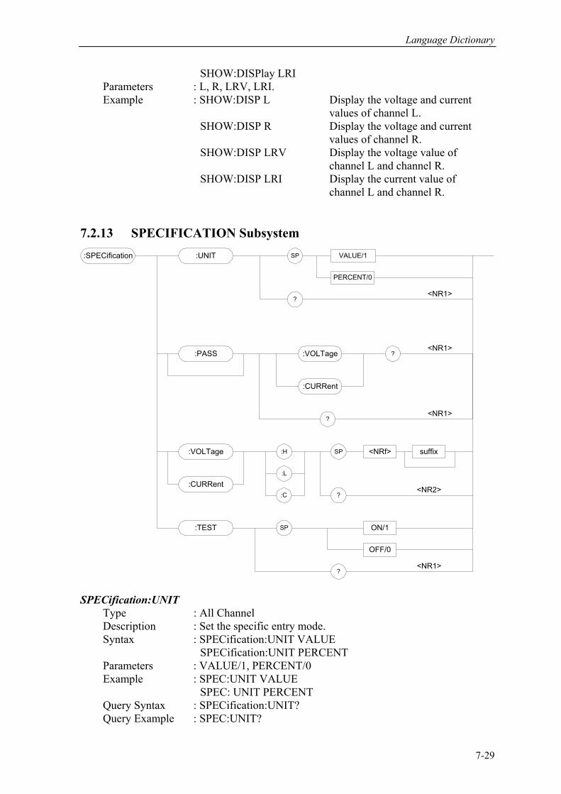
Language Dictionary
SHOW:DISPlay LRI Parameters : L, R, LRV, LRI. Example : SHOW:DISP L Display the voltage and current values of channel L.
SHOW:DISP R Display the voltage and current values of channel R. SHOW:DISP LRV Display the voltage value of channel L and channel R. SHOW:DISP LRI Display the current value of channel L and channel R. 7.2.13 SPECIFICATION Subsystem :SPECification
:PASS :VOLTage ?
:H
:CURRent
:VOLTage
:CURRent:L
:C
SP
?
<NRf> suffix
:UNIT VALUE/1SP
?
PERCENT/0
<NR1>
<NR1>
<NR2>
?<NR1>
:TEST ON/1
OFF/0
SP
?<NR1>
SPECification:UNIT Type : All Channel Description : Set the specific entry mode. Syntax : SPECification:UNIT VALUE SPECification:UNIT PERCENT Parameters : VALUE/1, PERCENT/0 Example : SPEC:UNIT VALUE
SPEC: UNIT PERCENT Query Syntax : SPECification:UNIT? Query Example : SPEC:UNIT?
7-29
Programmable DC Electronic Load 6310 Series Operation & Programming Manual
Return Parameters : <NR1> Return Example : 0 SPECification:VOLTage? Type : Channel-Specific Description : Request GO-NG result reference to voltage specification. Query Syntax : SPECification:VOLTage? Query Example : SPEC:VOLT? Returns voltage GO-NG result to CC and CR modes. Return Parameters : <NR1> Return Example : 0 (NG), 1 (GO) SPECification:CURRent? Type : Channel-Specific Description : Request GO-NG result reference to current specification. Query Syntax : SPECification:CURRent? Query Example : SPEC:CURR? Return the current GO-NG result to CC mode. Return Parameters : <NR1> Return Example : 0 (NG), 1 (GO) SPECification? Type : All Channel Description : Request GO-NG result reference to all channel specification. Query Syntax : SPECification? Query Example : SPEC? Returns all channel GO-NG result. Return Parameters : <NR1> Return Example : 0 (NG), 1 (GO) SPECification:VOLTage Type : Channel-Specific Description : Set the voltage specification. Syntax : SPECification:VOLTage:H SPECification:VOLTage:L SPECification:VOLTage:C Parameters : For valid value range refer to respective specification. Example : SPEC:VOLT:H <NRf+> [suffix] SPEC:VOLT:L <NRf+> [suffix] SPEC:VOLT:C <NRf+> [suffix] Query Syntax : SPECification:VOLTage:H? SPECification:VOLTage:L? SPECification:VOLTage:C? Query Example : SPEC:VOLT:H? Return Parameters : <NR2> [Unit=Voltage] Return Example : 4.75 SPECification:CURRent Type : Channel-Specific Description : Set the current specification. Syntax : SPECification:CURRent:H
7-30
Language Dictionary
SPECification:CURRent:L SPECification:CURRent:C Parameters : For valid value range refer to respective specification. Example : SPEC:CURR:H <NRf+> [suffix] SPEC:CURR:L <NRf+> [suffix] SPEC:CURR:C <NRf+> [suffix] Query Syntax : SPECification:CURR:H? SPECification:CURR:L? SPECification:CURR:C? Query Example : SPEC:CURR:H? Return Parameters : <NR2> [Unit=Current] Return Example : 4.75 SPECification:TEST Type : Channel-Specific Description : Start or close the specification test. Syntax : SPECification:TEST ON SPECification:TEST OFF Parameters : ON/1, OFF/0 Example : SPEC:TEST ON SPEC: TEST OFF Query Syntax : SPECification:TEST? Query Example : SPEC:TEST? Return Parameters : <NR1> Return Example : 1
7-31
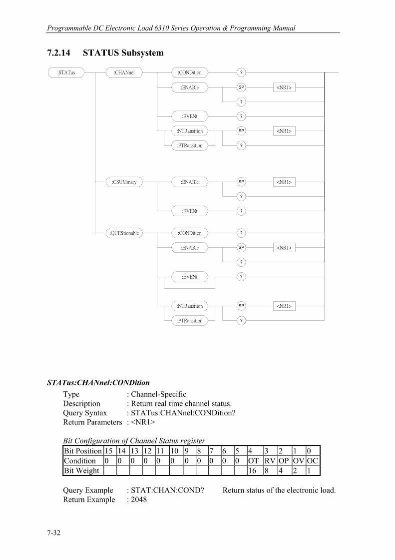
Programmable DC Electronic Load 6310 Series Operation & Programming Manual
7.2.14 STATUS Subsystem
:STATus :CHANnel ?:CONDition
:ENABle SP
?
<NR1>
?:EVENt
:NTRansition SP
?
<NR1>
:PTRansition
:CSUMmary :ENABle SP
?
<NR1>
?:EVENt
:QUEStionable ?:CONDition
:ENABle SP
?
<NR1>
?:EVENt
:NTRansition SP
?
<NR1>
:PTRansition
STATus:CHANnel:CONDition Type : Channel-Specific Description : Return real time channel status. Query Syntax : STATus:CHANnel:CONDition? Return Parameters : <NR1> Bit Configuration of Channel Status register
Bit Position 15 14 13 12 11 10 9 8 7 6 5 4 3 2 1 0 Condition 0 0 0 0 0 0 0 0 0 0 0 OT RV OP OV OC Bit Weight 16 8 4 2 1
Query Example : STAT:CHAN:COND? Return status of the electronic load.
Return Example : 2048
7-32
Language Dictionary
STATus:CHANnel:ENABle Type : Channel-Specific Description : Masks for selecting which bits in the Event register are allowed to be summed into the corresponding channel bit of the Channel Summary Event register. Syntax : STATus:CHANnel:ENABle Parameters : 0 ~ 65535 Example : STAT:CHAN:ENABl 24 Query Syntax : STATus:CHANnel:ENABle Return Parameters : <NR1>
Query Example : STAT:CHAN:ENABL? Return the contents of the Status Channel Enable register.
Return Example : 24 STATus:CHANnel:EVENt? Type : Channel-Specific
Description : Record all channel events that have occurred since last time the register was read, and resets the Channel Event register.
Query Syntax : STATus:CHANnel:EVENt? Return Parameters : <NR1> Query Example : STAT:CHAN:EVEN? Read and reset Channel Event register. Return Example : 24 STATus:CHANnel:PTRansition/NTRansition Type : Channel-Specific Description : Programmable filters that determine what type of transition (0-to-1 or 1-to-0) in the Condition register will set the corresponding bit of the Event register. Syntax : STATus:CHANnel:PTRansition/NTRansition <NRf> Parameters : 0 ~ 65535
Example : STAT:CHAN:PTR 4 Sets OP(over power bit 2) as 0-to-1. STAT:CHAN:NTR 4 Sets OP(over power bit 2) as 1-to-0. Query Syntax : STATus:CHANnel:PTRansition? STATus:CHANnel:NTRansition? Return Parameters : <NR1> Query Example : STAT:CHAN:PTR? Inquires setting of Channel PTRansition. Return Example : 4 STATus:CSUMmary:ENABle Type : Channel-Specific Description : Masks for selecting which bits in the Channel Event register are allowed to be summed into the CSUM (Channel Summary) bit of the Status Byte register. Syntax : STATus:CSUMmary:ENABle Parameters : Bit Configuration of Channel Summary register
7-33
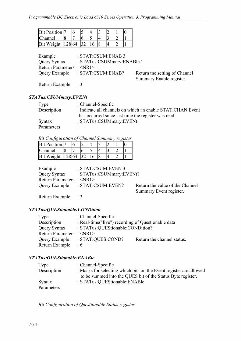
Programmable DC Electronic Load 6310 Series Operation & Programming Manual
Bit Position 7 6 5 4 3 2 1 0 Channel 8 7 6 5 4 3 2 1 Bit Weight 128 64 32 16 8 4 2 1
Example : STAT:CSUM:ENAB 3
Query Syntax : STATus:CSUMmary:ENABle? Return Parameters : <NR1>
Query Example : STAT:CSUM:ENAB? Return the setting of Channel Summary Enable register.
Return Example : 3 STATus:CSUMmary:EVENt Type : Channel-Specific Description : Indicate all channels on which an enable STAT:CHAN Event has occurred since last time the register was read. Syntax : STATus:CSUMmary:EVENt Parameters : Bit Configuration of Channel Summary register
Bit Position 7 6 5 4 3 2 1 0 Channel 8 7 6 5 4 3 2 1 Bit Weight 128 64 32 16 8 4 2 1
Example : STAT:CSUM:EVEN 3
Query Syntax : STATus:CSUMmary:EVENt? Return Parameters : <NR1>
Query Example : STAT:CSUM:EVEN? Return the value of the Channel Summary Event register.
Return Example : 3 STATus:QUEStionable:CONDition Type : Channel-Specific Description : Real-time("live") recording of Questionable data Query Syntax : STATus:QUEStionable:CONDition? Return Parameters : <NR1> Query Example : STAT:QUES:COND? Return the channel status. Return Example : 6 STATus:QUEStionable:ENABle Type : Channel-Specific Description : Masks for selecting which bits on the Event register are allowed to be summed into the QUES bit of the Status Byte register. Syntax : STATus:QUEStionable:ENABle Parameters : Bit Configuration of Questionable Status register
7-34
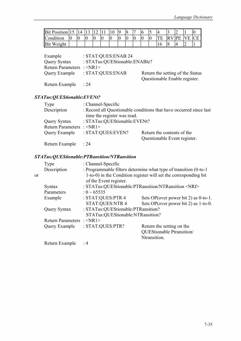
Language Dictionary
Bit Position 15 14 13 12 11 10 9 8 7 6 5 4 3 2 1 0 Condition 0 0 0 0 0 0 0 0 0 0 0 TE RV PE VE CEBit Weight 16 8 4 2 1
Example : STAT:QUES:ENAB 24
Query Syntax : STATus:QUEStionable:ENABle? Return Parameters : <NR1> Query Example : STAT:QUES:ENAB Return the setting of the Status Questionable Enable register. Return Example : 24 STATus:QUEStionable:EVENt? Type : Channel-Specific Description : Record all Questionable conditions that have occurred since last time the register was read. Query Syntax : STATus:QUEStionable:EVENt? Return Parameters : <NR1> Query Example : STAT:QUES:EVEN? Return the contents of the Questionable Event register. Return Example : 24 STATus:QUEStionable:PTRansition/NTRansition Type : Channel-Specific Description : Programmable filters determine what type of transition (0-to-1 or 1-to-0) in the Condition register will set the corresponding bit of the Event register. Syntax : STATus:QUEStionable:PTRansition/NTRansition <NRf> Parameters : 0 ~ 65535 Example : STAT:QUES:PTR 4 Sets OP(over power bit 2) as 0-to-1. STAT:QUES:NTR 4 Sets OP(over power bit 2) as 1-to-0. Query Syntax : STATus:QUEStionable:PTRansition? STATus:QUEStionable:NTRansition? Return Parameters : <NR1> Query Example : STAT:QUES:PTR? Return the setting on the QUEStionable Ptransition/ Ntransition. Return Example : 4
7-35
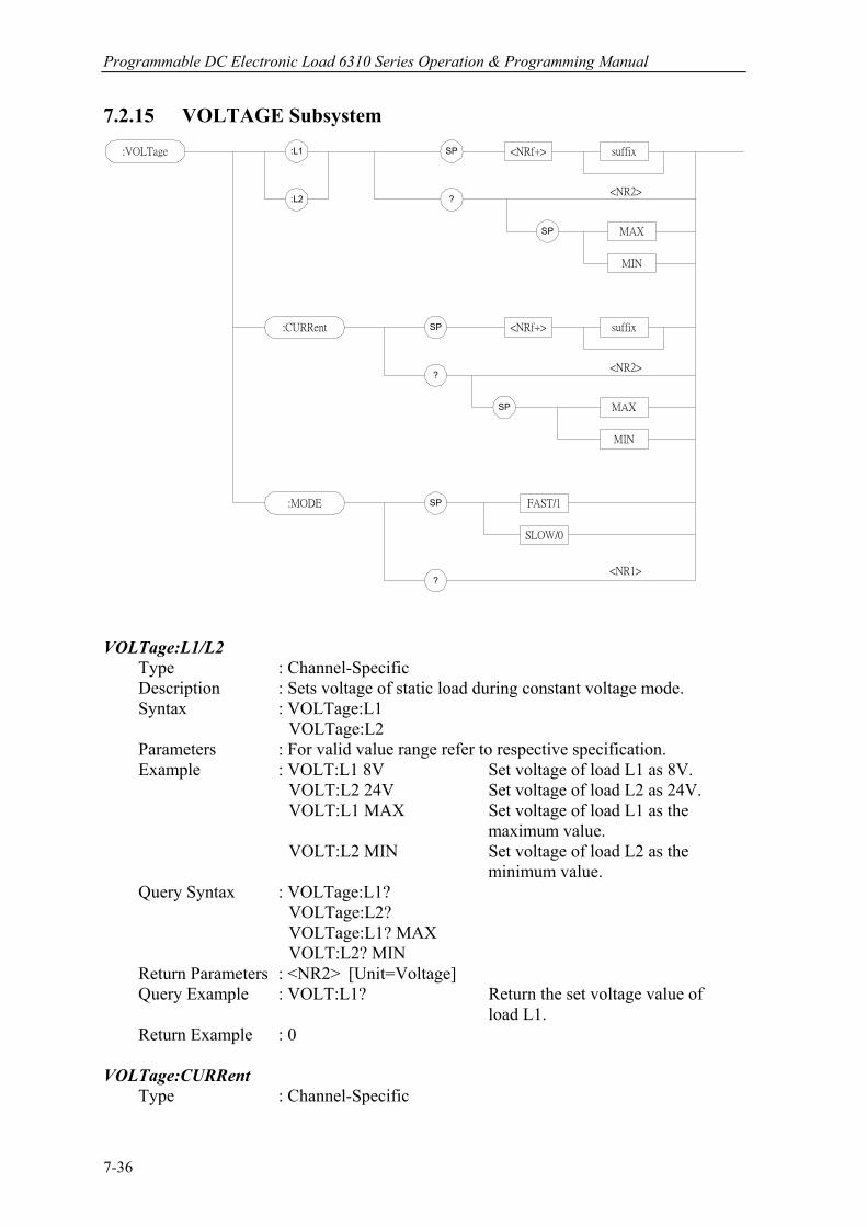
Programmable DC Electronic Load 6310 Series Operation & Programming Manual
7.2.15 VOLTAGE Subsystem :VOLTage SP <NRf+>
MIN
MAX
suffix
?:L2
:L1
SP
SP <NRf+>:CURRent
MIN
MAX
suffix
?
SP
:MODE SP FAST/1
SLOW/0
?
<NR2>
<NR2>
<NR1>
VOLTage:L1/L2 Type : Channel-Specific Description : Sets voltage of static load during constant voltage mode. Syntax : VOLTage:L1 VOLTage:L2 Parameters : For valid value range refer to respective specification. Example : VOLT:L1 8V Set voltage of load L1 as 8V.
VOLT:L2 24V Set voltage of load L2 as 24V. VOLT:L1 MAX Set voltage of load L1 as the maximum value. VOLT:L2 MIN Set voltage of load L2 as the minimum value. Query Syntax : VOLTage:L1? VOLTage:L2? VOLTage:L1? MAX VOLT:L2? MIN Return Parameters : <NR2> [Unit=Voltage] Query Example : VOLT:L1? Return the set voltage value of load L1. Return Example : 0 VOLTage:CURRent Type : Channel-Specific
7-36
Language Dictionary
Description : Set the current limit of constant voltage mode. Syntax : VOLTage:CURRent Parameters : For valid value range refer to respective specification. Example : VOLT:CURR 3 Set loading current limit as 3A during constant voltage mode.
VOLT:CURR MAX Set loading current limit as the maximum value during constant voltage mode. VOLT:CURR MIN Set loading current limit as the minimum value during constant voltage mode. Query Syntax : VOLTage:CURRent? Return Parameters : <NR2> [Unit=Amper] Query Example : VOLT:CURR? Return Example : 3 VOLTage:MODE Type : Channel-Specific Description : Sets the response speed of CV mode. Syntax : VOLTage:MODE FAST VOLTage:MODE SLOW Parameters : FAST/1, SLOW/0 Example : VOLT: MODE FAST
VOLT:MODE SLOW Query Syntax : VOLTage:MODE? Return Parameters : <NR1> Query Example : VOLT:MODE? Return Example : 0
7-37

Status Reporting
8. Status Reporting
8.1 Introduction This chapter discusses the status data structure of the Chroma 6310 series electronic load as shown in Figure 4-1(on the next page). The standard registers, such as the Event Status register group, the Output Queue, the Status Byte and Service Request Enable registers perform standard GPIB functions and are defined in IEEE-488.2 Standard Digital Interface for Programmable Instrumentation. Other status register groups implement the specific status reporting requirements of the electronic load. The Channel Status and Channel Summary groups are used by multiple channel of electronic load to enable status information to be kept at its own Status register of each channel. 8.2 Register Information in Common Condition register
The condition register represents the present status of electronic load signals. Reading the condition register does not change the state of its bits. Only changes in electronic load conditions affect the contents of this register.
PTR/NTR Filter, Event register
The Event register captures changes in conditions corresponding to condition bits in a condition register, or to a specific condition in the electronic load. An event becomes true when the associated condition makes one of the following electronic load-defined transitions:
Positive TRansition (0 - to - 1) Negative TRansition (1 - to - 0) Positive or Negative TRansition (0-to-1 or 1-to-0)
The PTR/NTR filters determine what type of condition transitions set the bits in the Event register. Channel Status, Questionable Status allow transitions to be programmed. Other register groups, i.e. Channel Summary, Standard Event Status register group use an implied Rise (0-to-1) condition transition to set bits in the Event register. Reading an Event register clears the register (all bits set to zero).
Enable register
The Enable register can be programmed to enable which bit in the corresponding Event register is logically-ORed into the Channel Summary bit.
8-1

Programmable DC Electronic Load 6310 Series Operation & Programming Manual
124816
CHANNEL STATUS (ONE CHANNEL)
CONDITION PTR/NTR EVENT ENABLE
124816
LOG
ICAL
OR
OC 0
OT 4
OV 1
RV 3 OP 2
124816
124816 CHAN 1
24 8163264128
0CHAN 2 1
234
CHAN 3CHAN 4CHAN 5CHAN 6CHAN 7CHAN 8
124 8163264128
LOG
ICAL
OR
567
CHANNEL SUMMARY
EVENT ENABLE
FROM CHAN 1FROM CHAN 2FROM CHAN 3FROM CHAN 4FROM CHAN 5FROM CHAN 6FROM CHAN 7FROM CHAN 8
LOG
ICAL
OR
QUESTIONABLE STATUS
CONDITION PTR/NTR EVENT ENABLE
124816
LOG
ICAL
OR
CE 0
TE 4
OV 1
RV 3 PE 2
124816
124816
OPC N.U. QYE
EXE
N.U.
CME
DDE
N.U. LOG
ICAL
OR
1
481632
1
481632
STANDARD EVENTSTATUS
EVENT
N.U. N.U.
CSUM
MAV ESB
QUES
MSS
LOG
ICAL
OR
48163264
481632
STATUSBYTE
SERVICEREQUEST
GENERATION
SERVICEREQUEST
GENERATION
N.U. 5-15
N.U. 5-15
OUTPUT QUEUE
ENABLE
124816
01
2
345
76
0123
56
4
DATADATADATA
N.U. 7
Figure 8-1 The Status Registers of Electronic Load
8-2
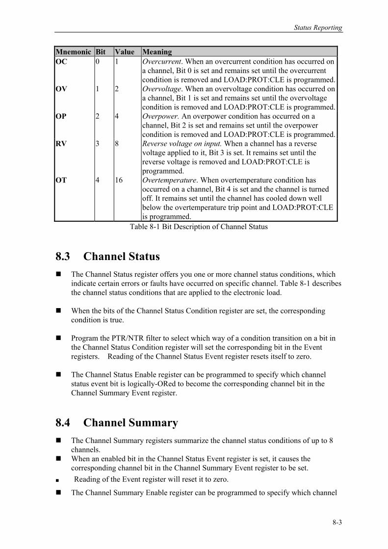
Status Reporting
Mnemonic Bit Value Meaning OC 0 1 Overcurrent. When an overcurrent condition has occurred on
a channel, Bit 0 is set and remains set until the overcurrent condition is removed and LOAD:PROT:CLE is programmed.
OV 1 2 Overvoltage. When an overvoltage condition has occurred on a channel, Bit 1 is set and remains set until the overvoltage condition is removed and LOAD:PROT:CLE is programmed.
OP 2 4 Overpower. An overpower condition has occurred on a channel, Bit 2 is set and remains set until the overpower condition is removed and LOAD:PROT:CLE is programmed.
RV 3 8 Reverse voltage on input. When a channel has a reverse voltage applied to it, Bit 3 is set. It remains set until the reverse voltage is removed and LOAD:PROT:CLE is programmed.
OT 4 16 Overtemperature. When overtemperature condition has occurred on a channel, Bit 4 is set and the channel is turned off. It remains set until the channel has cooled down well below the overtemperature trip point and LOAD:PROT:CLE is programmed.
Table 8-1 Bit Description of Channel Status
8.3 Channel Status The Channel Status register offers you one or more channel status conditions, which
indicate certain errors or faults have occurred on specific channel. Table 8-1 describes the channel status conditions that are applied to the electronic load.
When the bits of the Channel Status Condition register are set, the corresponding
condition is true. Program the PTR/NTR filter to select which way of a condition transition on a bit in
the Channel Status Condition register will set the corresponding bit in the Event registers. Reading of the Channel Status Event register resets itself to zero.
The Channel Status Enable register can be programmed to specify which channel
status event bit is logically-ORed to become the corresponding channel bit in the Channel Summary Event register.
8.4 Channel Summary The Channel Summary registers summarize the channel status conditions of up to 8
channels. When an enabled bit in the Channel Status Event register is set, it causes the
corresponding channel bit in the Channel Summary Event register to be set. Reading of the Event register will reset it to zero. The Channel Summary Enable register can be programmed to specify which channel
8-3
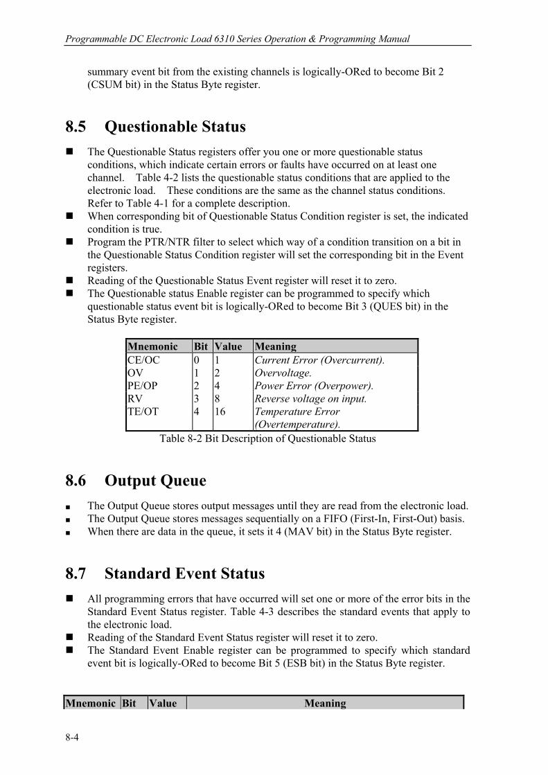
Programmable DC Electronic Load 6310 Series Operation & Programming Manual
summary event bit from the existing channels is logically-ORed to become Bit 2 (CSUM bit) in the Status Byte register.
8.5 Questionable Status The Questionable Status registers offer you one or more questionable status
conditions, which indicate certain errors or faults have occurred on at least one channel. Table 4-2 lists the questionable status conditions that are applied to the electronic load. These conditions are the same as the channel status conditions. Refer to Table 4-1 for a complete description.
When corresponding bit of Questionable Status Condition register is set, the indicated condition is true.
Program the PTR/NTR filter to select which way of a condition transition on a bit in the Questionable Status Condition register will set the corresponding bit in the Event registers.
Reading of the Questionable Status Event register will reset it to zero. The Questionable status Enable register can be programmed to specify which
questionable status event bit is logically-ORed to become Bit 3 (QUES bit) in the Status Byte register.
Mnemonic Bit Value Meaning CE/OC 0 1 Current Error (Overcurrent). OV 1 2 Overvoltage. PE/OP 2 4 Power Error (Overpower). RV 3 8 Reverse voltage on input. TE/OT 4 16 Temperature Error
(Overtemperature). Table 8-2 Bit Description of Questionable Status
8.6 Output Queue The Output Queue stores output messages until they are read from the electronic load. The Output Queue stores messages sequentially on a FIFO (First-In, First-Out) basis. When there are data in the queue, it sets it 4 (MAV bit) in the Status Byte register. 8.7 Standard Event Status All programming errors that have occurred will set one or more of the error bits in the
Standard Event Status register. Table 4-3 describes the standard events that apply to the electronic load.
Reading of the Standard Event Status register will reset it to zero. The Standard Event Enable register can be programmed to specify which standard
event bit is logically-ORed to become Bit 5 (ESB bit) in the Status Byte register.
Mnemonic Bit Value Meaning
8-4
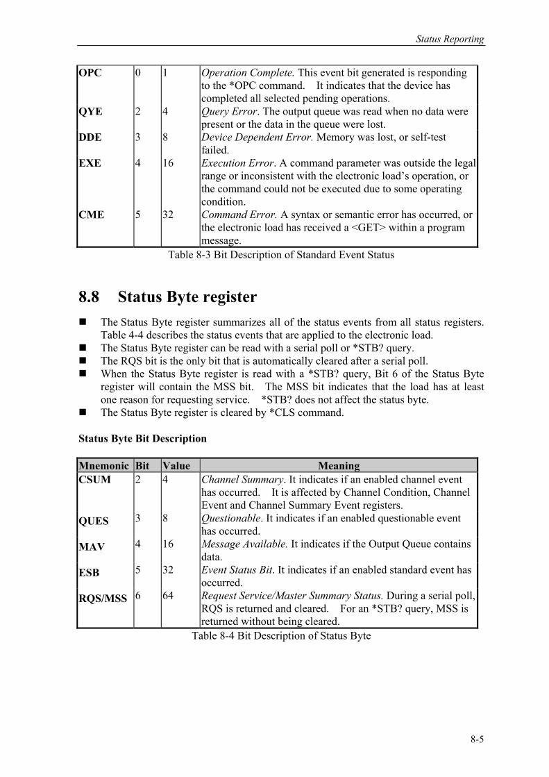
Status Reporting
OPC 0 1 Operation Complete. This event bit generated is responding to the *OPC command. It indicates that the device has completed all selected pending operations.
QYE 2 4 Query Error. The output queue was read when no data were present or the data in the queue were lost.
DDE 3 8 Device Dependent Error. Memory was lost, or self-test failed.
EXE 4 16 Execution Error. A command parameter was outside the legal range or inconsistent with the electronic load’s operation, or the command could not be executed due to some operating condition.
CME 5 32 Command Error. A syntax or semantic error has occurred, or the electronic load has received a <GET> within a program message.
Table 8-3 Bit Description of Standard Event Status
8.8 Status Byte register The Status Byte register summarizes all of the status events from all status registers.
Table 4-4 describes the status events that are applied to the electronic load. The Status Byte register can be read with a serial poll or *STB? query. The RQS bit is the only bit that is automatically cleared after a serial poll. When the Status Byte register is read with a *STB? query, Bit 6 of the Status Byte
register will contain the MSS bit. The MSS bit indicates that the load has at least one reason for requesting service. *STB? does not affect the status byte.
The Status Byte register is cleared by *CLS command. Status Byte Bit Description Mnemonic Bit Value Meaning CSUM 2
4 Channel Summary. It indicates if an enabled channel event
has occurred. It is affected by Channel Condition, Channel Event and Channel Summary Event registers.
QUES 3 8 Questionable. It indicates if an enabled questionable event has occurred.
MAV 4 16 Message Available. It indicates if the Output Queue contains data.
ESB 5 32 Event Status Bit. It indicates if an enabled standard event has occurred.
RQS/MSS 6 64 Request Service/Master Summary Status. During a serial poll, RQS is returned and cleared. For an *STB? query, MSS is returned without being cleared.
Table 8-4 Bit Description of Status Byte
8-5
Programmable DC Electronic Load 6310 Series Operation & Programming Manual
8.9 Service Request Enable register The Service Request Enable register can be programmed to specify which bit in the
Status Byte register will generate service requests.
8-6

An Example of Use
9. An Example of Use
In this chapter a basic example of controlling electronic load are provided for use of GPIB. The GPIB used here is made by NI (National Instruments). Examples: #include “dec1.h” #include <stdio.h> #include <stdlib.h> #include <sring.h> #include <iostream.h> #include <time.h> static int MTA, MLA; static int bd; const char LA = 0x20, TA = 0x40; static void setNi( int pad, char *cardName ) MTA = TA + pad; MLA = LA + pad; if ( (bd = ibfind ( cardName ) ) < 0 ) puts ( “GPIB Card Found Error” ); exit ( 1 ); if ( ibpad ( bd, pad ) & ERR ) puts ( “GPIB Card Address Assignment Error” ); exit ( 3 ); ibtmo ( bd, 10 ); ibsic ( bd ); ibsre ( bd, 1 ); static void Niwrite( int pad, char *cmdStr ) char cmd[4]; cmd[0] = UNL; cmd[1] = UNT; cmd[2] = MTA;
9-1
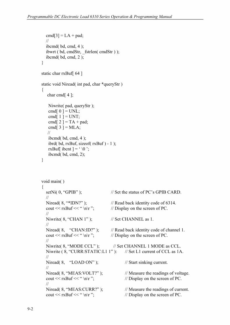
Programmable DC Electronic Load 6310 Series Operation & Programming Manual
cmd[3] = LA + pad; // ibcmd( bd, cmd, 4 ); ibwrt ( bd, cmdStr, _fstrlen( cmdStr ) ); ibcmd( bd, cmd, 2 ); static char rxBuf[ 64 ] static void Niread( int pad, char *queryStr ) char cmd[ 4 ]; Niwrite( pad, queryStr ); cmd[ 0 ] = UNL; cmd[ 1 ] = UNT; cmd[ 2 ] = TA + pad; cmd[ 3 ] = MLA; // ibcmd( bd, cmd, 4 ); ibrd( bd, rxBuf, sizeof( rxBuf ) - 1 ); rxBuf[ ibcnt ] = ‘ \0 ’; ibcmd( bd, cmd, 2); void main( ) setNi( 0, “GPIB” ); // Set the status of PC’s GPIB CARD. // Niread( 8, “*IDN?” ); // Read back identity code of 6314. cout << rxBuf << “ \n\r ”; // Display on the screen of PC. // Niwrite( 8, “CHAN 1” ); // Set CHANNEL as 1. // Niread( 8, “CHAN:ID?” ); // Read back identity code of channel 1. cout << rxBuf << “ \n\r ”; // Display on the screen of PC. // Niwrite( 8, “MODE CCL” ); // Set CHANNEL 1 MODE as CCL. Niwrite ( 8, “CURR:STATIC:L1 1” ): // Set L1 current of CCL as 1A. // Niread( 8, “LOAD ON” ); // Start sinking current. // Niread( 8, “MEAS:VOLT?” ); // Measure the readings of voltage. cout << rxBuf << “ \n\r ”; // Display on the screen of PC. // Niread( 8, “MEAS:CURR?” ); // Measure the readings of current. cout << rxBuf << “ \n\r ”; // Display on the screen of PC.
9-2
An Example of Use
Niread( 8, “LOAD OFF” ); // Stop sinking current. // ibsic ( bd ); ibon1( bd, 0 ); ibsre ( bd, 0 ); For the above example please refer to Chapter 3, and add corresponding commands according to setting and control. Example of PROGRAM RUN You can use the following control procedures to run the PROGRAM. <1> PROGram:FILE 1 // Set the PROGRAM FILE to be run <2> PROGram:ACTive 15 // Set the mapping action for Module Channel // chan 1 - chan 8 mapping value weights are // 1, 2, 4, 8, 16, 32, 64,128 <3> PROGram:CHAIN 0 // program chain file No. <4> PROGram:ONTime 3 // on time setting <5> PROGram:OFFTime 2 // off time setting <6> PROGram:SEQuence 1 // Sequence No. setting <7> PROGram:SEQuence:MODE AUTO // Sequence mode setting <8> PROGram:SEQuence:SHORt:CHANnel 1 // Sequence short channel setting <9> PROGram:SEQuence:SHORt:TIME 1 // Sequence short setting <10> PROGram:SEQuence 2 // sequence 2,sequence 3,....setting . . . <11> PROGram:SAVE // Save program setting data . . <12> PROGram:RUN // Run PROGRAM . . . <13> PROGram:RUN? // Check if PROGRAM is running
9-3
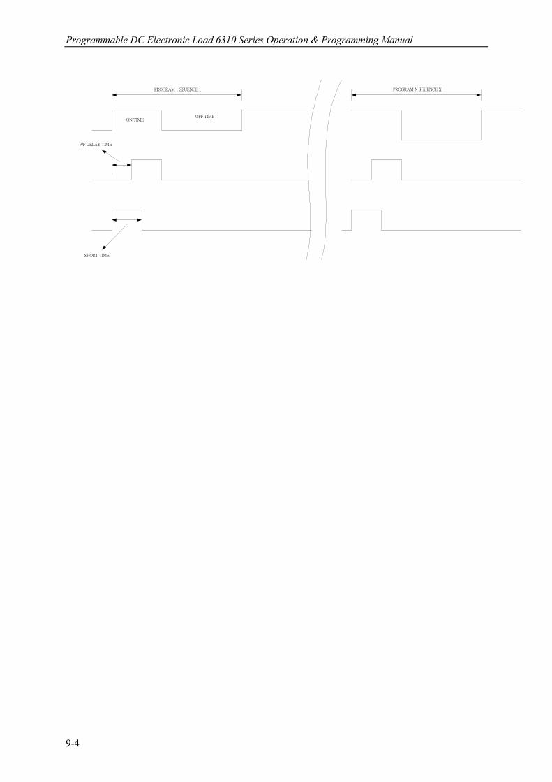
Programmable DC Electronic Load 6310 Series Operation & Programming Manual
ON TIMEOFF TIME
P/F DELAY TIME
SHORT TIME
PROGRAM 1 SEUENCE 1 PROGRAM X SEUENCE X
9-4