programmable multi-axis controller ck3m-series cpu unit ... · programmable multi-axis controller...
TRANSCRIPT

CSM_CK3M-CPU1_1_DS_E_DITA_1_2
1
Programmable Multi-Axis Controller CK3M-series CPU Unit
CK3M-CPU1@1Controls analog servo drives at high speeds of up to 50 µs/5 axes, enabling high-precision processing
Features• Controls up to eight analog servo drives via two CK3W-AX@@@@@ Axial Interface Units• The CK3M-CPU121 controls up to eight EtherCAT servo drives• G-Code/ANSI C/original programming language• EtherCAT slaves including vision and I/O can be connected• Compact design (1/3 the size of conventional models*1)• The EtherCAT network reduces wiring and machine size
*1. Compared with UMAC from OMRON’s Delta Tau Data Systems, Inc.
CK3M-CPU1@1
EtherCAT® is a registered trademark and patented technology, licensed by Beckhoff Automation GmbH, Germany.Other company names and product names in this document are the trademarks or registered trademarks of their respective companies.The product photographs and figures that are used in this catalog may vary somewhat from the actual products.PMAC is an abbreviation for Programmable Multi Axis Controller.

Programmable Multi-Axis Controller CK3M-series CPU Unit
2
System ConfigurationsBasic System Configuration
Encoder (Digital quadrature encoder, serial encoder)
Servo drive (analog input type) or Stepper motor
EtherCAT network
Support Software
PLCIndustrialEthernetswitch
Programmable terminal
Ethernet Networks
Modbus-TCP Slave terminal
Servo drive/
Encoder input
slaves
General-purposeslaves

3
Programmable Multi-Axis Controller CK3M-series CPU Unit
Network ConfigurationConnecting to the Power PMAC IDEConnect the CK3M-series CPU Unit and the Power PMAC IDE through Ethernet.
Ethernet Network ConfigurationThe Ethernet communications port on the CK3M-series CPU Unit supports the Modbus-TCP protocol.It can be connected to devices such as PLCs and programmable terminals that support the Modbus-TCP protocol.
Power PMAC IDE
CK3M-series
Ethernet
Ethernet
Built-in EtherNet port
Power Supply Unit CPU Unit
Switching hub
HMINJ-series
CK3M-series
Ethernet
Ethernet
Built-in Ethernet port
Power Supply Unit CPU Unit
Switching hub

Programmable Multi-Axis Controller CK3M-series CPU Unit
4
Ordering InformationApplicable standardsRefer to the OMRON website (www.ia.omron.com) or ask your OMRON representative for the most recent applicable standards for each model.
CK3M CPU UnitThe models and outline of specifications are given below.
*1. One CK3W-TER11 End Cover is provided with the CK3M-CPU1@1 CPU Unit.
Support SoftwareThe following table shows the Support Software used to configure, monitor, program, and debug the Motion Controller.
*1. Use Power PMAC IDE Ver.4.0 or a later version.*2. Contact your OMRON representative for information on how to procure.
EtherCAT Coupler UnitsYou can use NX Units via the EtherCAT Coupler Unit that is connected to the built-in EtherCAT port on the CPU Unit.
*1. One NX-END01 End Cover is provided with the EtherCAT Coupler Unit.*2. This depends on the specifications of the EtherCAT master.
Switching Hubs
Product name Memory capacity EtherCAT port Max. no. of controlledaxes at EtherCAT port Model
CPU Unit *1 RAM: 1 GBBuilt-In flash memory: 1 GB
None - CK3M-CPU101EtherCAT: 1 port (DC sync) 4 CK3M-CPU111
EtherCAT: 1 port (DC sync) 8 CK3M-CPU121
Configuration software Application How to Procure
Power PMAC IDE *1 This computer software is used to configure the Motion Controller,create user programs, and debug the programs. This is free software. *2
Product name Communications cycle in DC Mode Current consumption Max. I/O power supply current Model
EtherCAT Coupler Unit *1
125 to 10,000 μs *2 1.25 W max. 10 A NX-ECC203
Product name Specification Manufacturer Model
Industrial Switching Hub
3 ports. Current consumption: 0.22 APower supply connector included
OMRON Corporation
W4S1-03B
5 ports. Current consumption: 0.22 APower supply connector included W4S1-05B
5 ports. Current consumption: 0.22 AFailure detectionPower supply connector and connector for informing error included
W4S1-05C
Contact the manufacturer. Cisco Systems, Inc. -
Contact the manufacturer. CONTEC Co., Ltd. -
Contact the manufacturer. PHOENIX CONTACT -

Programmable Multi-Axis Controller CK3M-series CPU Unit
5
Recommended EtherCAT and Ethernet Communications CablesUse a straight STP (shielded twisted-pair) cable of category 5 or higher with double shielding (aluminum tape and braiding) for EtherCAT. Use an STP (shielded twisted-pair) cable of category 5 or higher for Ethernet. Products for Ethernet 100BASE-TX described in the table below can be used for both 100BASE-TX and 10BASE-T.
Cable with ConnectorsCables with Connectors (For EtherCAT only)
*1. Cables with standard RJ45 plugs are available in the following lengths: 0.2 m, 0.3 m, 0.5 m, 1 m, 1.5 m, 2 m, 3 m, 5 m, 7.5 m, 10 m, 15 m, 20 m. Cables with rugged RJ45 plugs are available in the following lengths: 0.3 m, 0.5 m, 1 m, 2 m, 3 m, 5 m, 10 m, 15 m. For details, refer to the Industrial Ethernet Connectors Catalog (Cat. No. G019).
*2. The lineup features Low Smoke Zero Halogen cables for in-cabinet use and PUR cables for out-of-cabinet use. Although the LSZH cable is single shielded, its communications and noise characteristics meet the standards.
*3. Cables colors are available in yellow, green, and blue.*4. For details, contact your OMRON representative.
Item Appearance Recommended manufacturer
Cable length(m) Model
Cable with Connectors on Both Ends(RJ45/RJ45)Standard RJ45 plugs *1
Wire gauge and number of pairs: AWG26, 4-pair cableCable sheath material: LSZH *2
Cable color: Yellow *3
OMRON
0.3 XS6W-6LSZH8SS30CM-Y
0.5 XS6W-6LSZH8SS50CM-Y
1 XS6W-6LSZH8SS100CM-Y
2 XS6W-6LSZH8SS200CM-Y
3 XS6W-6LSZH8SS300CM-Y
5 XS6W-6LSZH8SS500CM-Y
Cable with Connectors on Both Ends(RJ45/RJ45)Rugged RJ45 plugs*1
Wire gauge and number of pairs: AWG22, 2-pair cableCable color: Light blue
OMRON
0.3 XS5W-T421-AMD-K
0.5 XS5W-T421-BMD-K
1 XS5W-T421-CMD-K
2 XS5W-T421-DMD-K
5 XS5W-T421-GMD-K
10 XS5W-T421-JMD-K
Cable with Connectors on Both Ends (M12 Straight/M12 Straight)Shield strengthening connector cable *4
M12/Smartclick connectorsWire gauge and number of pairs: AWG22, 2-pair cableCable color: Black
OMRON
0.5 XS5W-T421-BM2-SS
1 XS5W-T421-CM2-SS
2 XS5W-T421-DM2-SS
3 XS5W-T421-EM2-SS
5 XS5W-T421-GM2-SS
10 XS5W-T421-JM2-SS
Cable with Connectors on Both Ends (M12 Straight/RJ45)Shield strengthening connector cable *4
M12/Smartclick connector andrugged RJ45 plugWire gauge and number of pairs: AWG22, 2-pair cableCable color: Black
OMRON
0.5 XS5W-T421-BMC-SS
1 XS5W-T421-CMC-SS
2 XS5W-T421-DMC-SS
3 XS5W-T421-EMC-SS
5 XS5W-T421-GMC-SS
10 XS5W-T421-JMC-SS

Programmable Multi-Axis Controller CK3M-series CPU Unit
6
Cables/Connectors
*1. We recommend you to use the Cable for EtherCAT or Ethernet marked with *1 and the RJ45 Connector marked with *1 together.*2. We recommend you to use the Cable for EtherCAT or Ethernet marked with *2 and the RJ45 Assembly Connector marked with *2 together.Note: Connect both ends of cable shielded wires to the connector hoods.
Optional Products/Maintenance Products/DIN Track Accessories
*1. EtherCAT junction slaves cannot be used for EtherNet/IP and Ethernet.*2. Use the CK3W-TER11 End Cover only for the CK3M-CPU1@1 CPU Unit.
Product name Recommended manufacturer Model
Products for EtherCAT or Ethernet(1000BASE-T/100BASE-TX)
Wire gauge and num-ber of pairs: AWG24, 4-pair cable
Cable
Hitachi Cable, Ltd. NETSTAR-C5E SAB0.5 x 4P CP *1
Kuramo Electric Co. KETH-SB *1
SWCC Showa Cable Systems Co. FAE-5004 *1
JMACS Japan Co., Ltd. IETP-SB *1
RJ45 Connector Panduit Corporation MPS588-C *1
Products for EtherCAT or Ethernet(100BASE-TX)
Wire gauge and num-ber of pairs: AWG22, 2-pair cable
Cable
Kuramo Electric Co. KETH-PSB-OMR *2
JMACS Japan Co., Ltd. PNET/B *2
SWCC Showa Cable Systems Co. FAE-5002 *2
RJ45 Assembly Connector
OMRON Corporation XS6G-T421-1 *2
Product name Model
EtherCAT Junction Slave *1
3 ports. Power supply voltage: 20.4 to 28.8 VDC (24 VDC -15 to +20%).Current consumption: 0.08 A GX-JC03
6 ports. Power supply voltage: 20.4 to 28.8 VDC (24 VDC -15 to +20%).Current consumption: 0.17 A GX-JC06
USB Flash DriveOMRON USB Flash Drive (2 GB) FZ-MEM2G
OMRON USB Flash Drive (8 GB) FZ-MEM8G
End Cover *2
(for CK3M-CPU1@1 CPU Unit)Must be connected to the right end of the CPU rack.One End Cover is provided with the CPU Unit. CK3W-TER11
DIN Track
Length: 0.5 m. Height: 7.3 mm PFP-50NLength: 1 m. Height: 7.3 mm PFP-100N
Length: 1 m. Height: 16 mm PFP-100N2
End Plate Stopper to prevent units from moving on the DIN track.The minimum order quantity is 10 units. PFP-M
7
Programmable Multi-Axis Controller CK3M-series CPU Unit
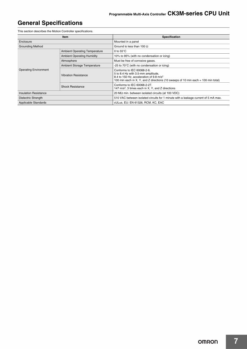
General SpecificationsThis section describes the Motion Controller specifications.
Item Specification
Enclosure Mounted in a panel
Grounding Method Ground to less than 100 Ω
Operating Environment
Ambient Operating Temperature 0 to 55°C
Ambient Operating Humidity 10% to 95% (with no condensation or icing)
Atmosphere Must be free of corrosive gases.
Ambient Storage Temperature -25 to 70°C (with no condensation or icing)
Vibration Resistance
Conforms to IEC 60068-2-6.5 to 8.4 Hz with 3.5-mm amplitude,8.4 to 150 Hz, acceleration of 9.8 m/s2
100 min each in X, Y, and Z directions (10 sweeps of 10 min each = 100 min total)
Shock Resistance Conforms to IEC 60068-2-27.147 m/s2, 3 times each in X, Y, and Z directions
Insulation Resistance 20 MΩ min. between isolated circuits (at 100 VDC)
Dielectric Strength 510 VAC between isolated circuits for 1 minute with a leakage current of 5 mA max.
Applicable Standards cULus, EU: EN 61326, RCM, KC, EAC

Programmable Multi-Axis Controller CK3M-series CPU Unit
8
Performance SpecificationsThe performance specifications are shown below.
Item CK3M-CPU101 CK3M-CPU111 CK3M-CPU121
Memory Main memory: 1 GBBuilt-In Flash Memory: 1 GB
Number of connectable CK3W-AX Unit Units 2 Units max.
External connection terminals
No EtherCAT For EtherCAT communicationsRJ45 × 1 (Shield supported)
For Ethernet communicationsRJ45 × 1 (Shield supported)
USB portFor external memory connection, USB 2.0 host × 1 Type A
Motion control
CK3W-AX Unit
Maximum number ofcontrolled axes 8 axes (when using two CK3W-AX Units)
Control method Speed and torque control using analog outputStepper motor control using pulse output
EtherCATMaximum number ofcontrolled axes None
4 axes 8 axes
Control method Issuing control commands using EtherCAT
EtherCAT communi-cationsspecifications
Communications protocol
None
EtherCAT protocol
Baud rate 100 Mbps
Physical layer 100BASE-TX (IEEE 802.3)
Topology Line, daisy chain, and branching
Transmission media Twisted-pair cable of category 5 or higher (doubleshieldedcable with aluminum tape and braiding)
Transmission distance Distance between nodes: 100 m or less
Maximum number of slaves 32
Range of node addresses that can be set 1 to 32
Ethernet communi-cationsspecifications
Baud rate 100 Mbps
Physical layer 100 BASE-TX (IEEE 802.3)
Frame length 1,514 bytes max.
Media access method CSMA/CD
Modulation Baseband
Topology Star
Transmission media Twisted-pair cable of category 5, 5e, or higher (shielded cable)
Maximum transmission distance between Ethernet switch and node 100 m
Maximum number of cascade connections There are no restrictions if an Ethernet switch is used.
USB portPhysical layer USB 2.0 compliant, type A connector. Output voltage: 5 V, 0.5 A max.
Transmission distance 3 m max.
Current consumptionCK3M-CPU101: 5 VDC 7.2 W max.CK3M-CPU111/CPU121: 5 VDC 7.8 W max.(including End Cover)
Dimensions (height × depth × width) 90 (H)/80 (D)/63.2 (W)
Weight (including End Cover) 220 g max. 230 g max.

9
Programmable Multi-Axis Controller CK3M-series CPU Unit
Part Names and FunctionsCPU Unit
Version InformationRestrictions on Using the NX-series EtherCAT Coupler UnitWhen OMRON NX-series EtherCAT Coupler Units are used as slaves with the CPU Unit as the EtherCAT master, the following models and unitversions of EtherCAT Coupler Units can be connected.
Letter Name Function
A Slider Holds the Units together.
B CPU Unit operation indicators Shows the operation status of the CPU Unit using multiple indicators.
C EtherCAT communications connector Connects to an EtherCAT network communications cable.
D EtherCAT communications port operation indicators Shows the operation status of EtherCAT.
E Unit connector Connector that connects to the Unit.
F Ethernet communications port operation indicators Shows the operation status of Ethernet.
G Ethernet communications connector Connects to an Ethernet network communications cable.
H Watchdog output terminal block Normally in ON state, and switches to OFF when watchdog is activated.
I USB 2.0 connector USB 2.0 interface connector.Connects the USB memory.
J USB connector for maintenance Do not use.
K USB connector for maintenance Do not use.
L DIN Track mounting hook Used to mount the Unit to a DIN Track.
Model Unit version Connectable/Unconnectable
NX-ECC203Ver.1.4 or later Connectable
Ver.1.3 or earlier
UnconnectableNX-ECC202 All versions
NX-ECC201 All versions
(A) (B)
(J)
(I)
(H)
(G)
(C)
(D)
(E)
(F)
(K)
(L)

Programmable Multi-Axis Controller CK3M-series CPU Unit
10
Dimensions (Unit: mm)
CPU Unit
CPU Unit
End Cover
Design Example for Width W
Model Unit width (mm)
CK3M-CPU101
63.2CK3M-CPU111
CK3M-CPU121
Model Unit width (mm)
CK3W-TER11 15.6
Name Model Unit width (mm) Qty Subtotal unit width (mm)
Power Supply Unit CK3W-PD048 45 1 45
CPU Unit CK3M-CPU101 63.2 1 63.2
Axis Interface Unit CK3W-AX1414N 130 2 260
End Cover CK3W-TER11 15.6 1 15.6
Total W = 45 + 63.2 + 130 × 2 + 15.6 383.8
8090
63.2
8090
63.2
Power Supply Unit CPU Unit Configuration Units
(Unit mm)W

11
Programmable Multi-Axis Controller CK3M-series CPU Unit
Installation DimensionsInstallation Dimensions
Installation HeightFor CK3M-series CPU Unit
Related ManualsThe following manuals are related. Use these manuals for reference. Contact your OMRON representative for information on how to procure these manuals.
DIN Track A (mm)
PFP-100N2 16
PFP-100N 7.3
PFP-50N 7.3
Manual name Cat. No. Application Description
CK3M-series Programmable Multi-Axis Controller Hardware User’s Manual
O036
Learning the basic specifications of the CK3M-series Programmable Multi-Axis Controller, including introductory information, design, installation, and maintenance.Mainly hardware information is provided.
An introduction to the entire CK3M-series system is provided along with the following information.• Features and system configuration• Introduction• Part names and functions• General specifications• Installation and wiring• Maintenance and inspection
Power PMAC User’s Manual O014Learning the features and usage examples of the CK3M-series Programmable Multi-Axis Controller.
The following information is provided on the CK3M-series Pro-grammable Multi-Axis Controller.• Basic functions• Setup examples• Programming examples
Power PMAC Software Reference Manual O015 Learning how to program a CK3M-series
Programmable Multi-Axis Controller.
The following information is provided on the CK3M-series Pro-grammable Multi-Axis Controller.• Details of commands• Details of data structure
Power PMAC IDE User Manual O016
Learning how to operate Power PMAC IDE, the integrated development environment of the Controller.
Describes the operating procedures of Power PMAC IDE, and ex-amples of how to start the system.
Power PMAC-NC16 Quick Start Manual O017 Briefly understanding the basic usage of
Power PMAC-NC16.Describes the Quick setup procedure to run Power PMAC-NC16 on a desktop PC by showing some examples.
Power PMAC-NC16 ini Configuration Manual O018 Configuring an application for CNC devices
by using Power PMAC-NC16.Describes how to set up PowerPmacNC.ini, the setup data file to be loaded when Power PMAC-NC16 starts.
27.5
35 90
A
27.5
CPU Rack
(Unit mm)
Approx. 165 to 180 mm
80mm

Programmable Multi-Axis Controller CK3M-series CPU Unit
12
Power PMAC-NC16 Software User Manual O019
Learning about usage and features of Power PMAC-NC16, Support Software required to use the Controller for CNC devices.
The following information is provided on Power PMAC-NC16.• How to use the software• Features included in the software• Features that can be customized
Power PMAC-NC16 Mill G-Code Manual O020 Creating programs for CNC devices by
using Power PMAC-NC16.Describes the basic G-code set that can be used for Power PMAC-NC16, and relevant instructions.
Manual name Cat. No. Application Description

Terms and Conditions Agreement Read and understand this catalog. Please read and understand this catalog before purchasing the products. Please consult your OMRON representative if you have any questions or comments. Warranties. (a) Exclusive Warranty. Omron’s exclusive warranty is that the Products will be free from defects in materials and workmanship for a period of twelve months from the date of sale by Omron (or such other period expressed in writing by Omron). Omron disclaims all other warranties, express or implied. (b) Limitations. OMRON MAKES NO WARRANTY OR REPRESENTATION, EXPRESS OR IMPLIED, ABOUT NON-INFRINGEMENT, MERCHANTABILITY OR FITNESS FOR A PARTICULAR PURPOSE OF THE PRODUCTS. BUYER ACKNOWLEDGES THAT IT ALONE HAS DETERMINED THAT THE PRODUCTS WILL SUITABLY MEET THE REQUIREMENTS OF THEIR INTENDED USE. Omron further disclaims all warranties and responsibility of any type for claims or expenses based on infringement by the Products or otherwise of any intellectual property right. (c) Buyer Remedy. Omron’s sole obligation hereunder shall be, at Omron’s election, to (i) replace (in the form originally shipped with Buyer responsible for labor charges for removal or replacement thereof) the non-complying Product, (ii) repair the non-complying Product, or (iii) repay or credit Buyer an amount equal to the purchase price of the non-complying Product; provided that in no event shall Omron be responsible for warranty, repair, indemnity or any other claims or expenses regarding the Products unless Omron’s analysis confirms that the Products were properly handled, stored, installed and maintained and not subject to contamination, abuse, misuse or inappropriate modification. Return of any Products by Buyer must be approved in writing by Omron before shipment. Omron Companies shall not be liable for the suitability or unsuitability or the results from the use of Products in combination with any electrical or electronic components, circuits, system assemblies or any other materials or substances or environments. Any advice, recommendations or information given orally or in writing, are not to be construed as an amendment or addition to the above warranty. See http://www.omron.com/global/ or contact your Omron representative for published information. Limitation on Liability; Etc. OMRON COMPANIES SHALL NOT BE LIABLE FOR SPECIAL, INDIRECT, INCIDENTAL, OR CONSEQUENTIAL DAMAGES, LOSS OF PROFITS OR PRODUCTION OR COMMERCIAL LOSS IN ANY WAY CONNECTED WITH THE PRODUCTS, WHETHER SUCH CLAIM IS BASED IN CONTRACT, WARRANTY, NEGLIGENCE OR STRICT LIABILITY. Further, in no event shall liability of Omron Companies exceed the individual price of the Product on which liability is asserted. Suitability of Use. Omron Companies shall not be responsible for conformity with any standards, codes or regulations which apply to the combination of the Product in the Buyer’s application or use of the Product. At Buyer’s request, Omron will provide applicable third party certification documents identifying ratings and limitations of use which apply to the Product. This information by itself is not sufficient for a complete determination of the suitability of the Product in combination with the end product, machine, system, or other application or use. Buyer shall be solely responsible for determining appropriateness of the particular Product with respect to Buyer’s application, product or system. Buyer shall take application responsibility in all cases. NEVER USE THE PRODUCT FOR AN APPLICATION INVOLVING SERIOUS RISK TO LIFE OR PROPERTY OR IN LARGE QUANTITIES WITHOUT ENSURING THAT THE SYSTEM AS A WHOLE HAS BEEN DESIGNED TO ADDRESS THE RISKS, AND THAT THE OMRON PRODUCT(S) IS PROPERLY RATED AND INSTALLED FOR THE INTENDED USE WITHIN THE OVERALL EQUIPMENT OR SYSTEM. Programmable Products. Omron Companies shall not be responsible for the user’s programming of a programmable Product, or any consequence thereof. Performance Data. Data presented in Omron Company websites, catalogs and other materials is provided as a guide for the user in determining suitability and does not constitute a warranty. It may represent the result of Omron’s test conditions, and the user must correlate it to actual application requirements. Actual performance is subject to the Omron’s Warranty and Limitations of Liability. Change in Specifications. Product specifications and accessories may be changed at any time based on improvements and other reasons. It is our practice to change part numbers when published ratings or features are changed, or when significant construction changes are made. However, some specifications of the Product may be changed without any notice. When in doubt, special part numbers may be assigned to fix or establish key specifications for your application. Please consult with your Omron’s representative at any time to confirm actual specifications of purchased Product. Errors and Omissions. Information presented by Omron Companies has been checked and is believed to be accurate; however, no responsibility is assumed for clerical, typographical or proofreading errors or omissions.
2019.1
In the interest of product improvement, specifications are subject to change without notice.
OMRON Corporation Industrial Automation Company http://www.ia.omron.com/
(c)Copyright OMRON Corporation 2019 All Right Reserved.