programming at the processor-memory-switch …wing/publications/barbacci-wing88.pdfprogramming at...
TRANSCRIPT

Programming at the Processor-Memory-Switch Level
M.R. Barbacci1y2, C.B. Weinstockl, and J.M. Wing2 Carnegie Mellon University
Pittsburgh, PA 15213, U.S.A.
Abstract
Users of networks of heterogeneous processors are concerned with allocating specialized resources to tasks of medium to large size. They need to create processes, which are instances of tasks, allocate these processes to processors, and specify the communication patterns between processes. These activities constitute Processor-Memory-Switch (PMS) Level Programming, in contrast with traditional programming activi- ties, which take place at the Instruction Set Processor (BP) Level. In this paper we describe the use of PMS-level pro- gramming in computation-intensive, real-time applications, e.g., vision, robotics, and vehicular control, that require effi- cient concurrent execution of multiple tasks, e.g., sensor data collection, obstacle recognition, and global path planning, devoted to specific pieces of the application. At CMU we are developing languages and tools for this new style of program- ming, and in this paper we describe their status.
1. Programming Heterogeneous Machines It is becoming commonplace to have a computing environment consisting of loosely-connected networks of multiple special- and general-purpose processors. We call such an environment a heterogeneous machine. These machines are of special inter- est to developers of real-time, embedded applications in which many concurrent, large-grained tasks or programs cooperate to process data obtained from physical sensors, make decisions based on these data, and send commands to control motors and other physical devices. During execution time, these tasks are instantiated as concurrent processes, running on possibly sepa- rate processors and communicating with each other by sending messages of different types.
Since the patterns of communication between these processes can vary over time and the speeds of the individual processors can differ widely, developers of applications running on a het-
The views and conclusions contained in this document are those of the authors and should not be interpreted as representin official
f. 6 expressed or implied, of the Software Engmeering nsutute, olicies., either
lon Universit arnegle Mel-
fense, or the Y’ the National Science Foundation, the Department of De-
.S. Government.
erogeneous machine need to control the allocation of proces- sors to processes in order to meet throughput requirements. Processors are not the only critical resource. In addition to special purpose processors such cs systolic arrays, and gt’tcial- purpose workstations, the resources that must be allocated in- clude fast switches, data buffers with processing capabiiities, etc., as illustrated in Figure l-l.
Currently, users of a heterogeneous machine follow the same pattern of program development as users of conventional processors: Users write individual tasks as separate programs, in the different programming languages (e.g., C, Lisp, Pascal) supported by the processors, and then hand code the allocation of resources to their application by explicitly loading specific programs to run on specific processors at specific times.
We claim that developing software for a heterogeneous ma- chine is qualitatively different from developing software for conventional processors. It requires different kinds of lan- guages, tools, and methodologies; and in this paper we address some of these issues by presenting a language, Durrs, and its support tools (compiler, scheduler, and simulator). To illustrate the main features of the language we give an example of their use for a small part of a specific real-time application, vision for an autonomous land vehicle’, on a heterogeneous machine built around a fast switch2.
To provide some context and justification for the choice of fea- tures in Durra, we first describe some assumptions we are making about the “computing engine” and the “programming style” that seem natural to users of a heterogeneous machine.
1.1. The PMS- and ISP-Levels of Hardware Descriptions
Borrowing the terminology introduced by Bell and Newell3 ::e characterize a heterogeneous machine as a Processor-Memory-Switch (PMS) level computing engine, to distinguish it from a conventional processor which can be characterized as an Instruction-Set-Processor (ISP) level com- puting engine.
PMS and ISP are the two highest levels of description in Bell and Newell’s the hierarchy of digital systems3. The PMS level describes digital systems as networks of several component types, the main ones being processors, memories, and switches (hence the name used to denote the Ievel), in addition to con- trollers, links, transducers, and data-operators. PMS compo- nents operate by transforming and transmitting data and can be connected to make digital computers and networks. In a PMS
19 0270~5257/88/000010019$01.00 O1988lEEE Recommended by: 6. Boehm and L. Osterweil

Switch
description, each component is specified in terms of its func- tion (e.g., storage), speed (e.g., bytes per second), capacity (e.g., megabytes), and other similar attributes. The nature of the data transformations performed by a PMS component, if any, are usually not specified. The ISP level describes the be- havior of a processor (one of the PMS primitive components) in terms of the nature and sequence of its operations. A de- scription at the ISP level specifies the data types (integer, float- ing point, character, etc.), the instructions (add, jump, compare, etc.), and the interpretation cycle (fetching, decoding, and ex- ecuting instructions). This is the level at which an assembly language programmer wants the processor described, and it is usually provided in a programming manual.
1.2. A Paradigm for PMS-Level Programming A significant difference between ISP and PMS, is the lack of a concept equivalent to an “instruction interpreter” in PMS. A conventional instruction set processor fetches, decodes, and ex- ecutes instructions stored in memory. Instructions are fre- quently intermingled with data and are often treated as data. On the other hand, PMS activities are mostly data driven, even if the “data” happens to be pulses from some master clock in a synchronous application; there is no fetching and decoding of instructions before deciding what to do next. Instead, the operators (processors) fetch their operands (data queue elements) whenever they are ready to process them and deliver their results to the appropriate queues to be consumed by other nodes.
At the ISP-level, the basic operations are fixed in the architec- ture of the processor. They are implemented either directly, as hardwired logic, or by microcode programs, although these im- plementation details are usually hidden from a machine lan- guage programmer. At the PMS-level, the analog of these ba-
Figure l-l : A Heterogeneous Machine
sic operations are the programs running on the various proces- sors. At this level of detail, the implementation of these pro- grams is not important and can be treated as primitive building blocks. Thus, we assume that PMS-level programmers rely on the existence of libraries of reusable programs, that is, pro- grams that can be shared across applications (e.g., ‘ ‘feature detection” routines that could be shared in a variety of vision applications). We also assume a run-time System that follows a scheduler’s directives for loading and executing the programs.
These library programs may be written in different program- ming languages (e.g., Ada, C, Common Lisp, as well as as- sembly language or even microcode) for the different proces- sors. On a high-performance processor, with multiple func- tional units, pipelines, and register sets, these programs can be very difficult to write and even more difficult to debug; but ba- sically, this is within the reach of current compiler technology, and programming these processors is not the showstopper. The major source of complexity in PMS-level programming is not implementing the basic data operations, which are hidden in the library programs, but rather in making effective use of the available resources: loading and executing programs in the different processors, reserving data buffers, routing data, etc. These are different kinds of programming activities and, to avoid confusion, we will use the term application for a PMS- level program than runs on a heterogeneous machine to distin- guish it from a conventional ISP-level program that runs on one of the processors of a heterogeneous machine.
The ISP- and PMS-levels of programming must be separated from each other. The writer of a library program that performs some basic computation (e.g., convolution) does not necessar- ily know the context in which the program will be used. The program executes on a processor that consumes data from input queues and delivers results to output queues. On the other
20
m
*-kmlhdkn &#nE.-ion B.“k
. .
r% Compiler
slwTirnP,.TL: -Qndalm5; omkyRul”tPykdmD . . . . . . . . . . . . . . . . . .
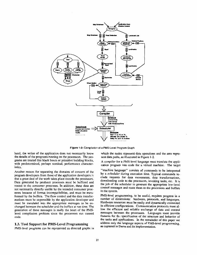
Figure 1-2: Compilation of a PMS-Level Program Graph
hand, the writer of the application does not necessarily know the details of the programs running on the processors. The pro- grams are treated like black boxes or primitive building blocks, with predetermined, perhaps nominal, performance character- istics.
Another reason for separating the domains of concern of the program developers from those of the application developers i$ that a great deal of the work takes pIace outside the processors. Data generated by producer processes must be buffered and routed to the consumer processes. In addition, these data are not necessarily directly usable by the intended consumer proc- esses because of format incompatibilities, and must be trans- formed by the buffers. The flow control and the data transfor- mations must be expressible by the application developer and must be translated into the appropriate messages to be ex- changed between the scheduler and the buffers at run time. The generation of these messages is really the heart of the PMS- level compilation problem since the processors run canned code.
1.3. Tool Support for PMS;Level Programming PMS-level programs can be represented as directed graphs in
which the nodes represent data operations and the arcs repre-
sent data paths, as illustrated in Figure l-2.
A compiler for a PMS-level language must translate the appli- cation program into code for a virtual machine. The target
“machine language” consists of commands to be interpreted by a scheduler during execution time. Typical commands in- clude requests for data movements, data transformations, downloading code to the processors, invoking tasks, etc. It is the job of the scheduler to generate the appropriate low-level control messages and route them to the processors and buffers in the system.
PMS-level programming, to be useful, requires progress in a number of dimensions: hardware, protocols, and languages. Hardware resources must be easily and dynamically connected in efficient configurations. Communication protocols must al- low the efficient and reliable exchange of data and control messages between the processors. Languages must provide features for thr: specification of the structure and behavior of the tasks and applications. In the remainder of this paper we address only the language aspects of PMS-level programming. as captured in Durra and its implementation.
21

Durra - Compiler +
Scheduler Trogram”
B Heterogeneous Machine ,\ 1
Figure 2-1: Scenario for Developing an Application
2. The Durra Language type m the application, a type description must be written in Durra and entered in the library.
Durra4y 5 is a language designed to support PMS-level pro- gramming. An application or PMS-level program is written in Durra as a set of task descriptions and type descriptions that prescribes a way to manage the resources of a heterogeneous machine. The application describes the tasks to be instantiated and executed as concurrent processes, the types of the data to be exchanged by the processes, and the intermediate queues re- quired to store the data as it moves from producer to consumer processes. Since tasks are the primary building blocks, we refer to Durra as a task-level description language. We use the term “description language” rather than “programming language” to emphasize that a Durra application is not translated into ob- ject code in some kind of executable (conventional) “machine language” (the domain of ISP) but rather it is a description of the structure and behavior of a logical machine, to be syn- thesized into resource allocation and scheduling directives, which are then interpreted by a combination of software, firmware, and hardware in each of the processors and buffers of a heterogeneous machine (the domain of PMS). This is the translation process depicted in Figure l-2.
We see three distinct phases in the process of deveIoping an application using Durra: the creation of a library of tasks, the creation of an application using library tasks, and finally, the execution of the application.
These three phases are illustrated in Figure 2- 1. During the first phase, the developer breaks the application into specific data types (image buffers, map database queries, etc.) and tasks (sensor processing, feature recognition, map database manage- ment, etc.) Type descriptions are used to specify the format and properties of the data that will be produced and consumed by the tasks in the application. As we will see later in this sec- tion, tasks communicate through typed ports; and for each data
For a given task, there may be many implementations, differing in programming language (e.g., one written in C or one written in assembly language), processor type (e.g., Motorola 68020 or IBM 1401), performance characteristics, or other attributes. As in the case of type descriptions, the developer writes a task de- scription for each implementation of a task and enters it into the library. A task description includes specifications of its performance and functionaIity, the types of data it produces or consumes, the ports it uses to communicate with other tasks, and other miscellaneous attributes of the task. During the second phase, the user writes an application description. Syntactically, an application description is a single task description and could be stored in the library as a new task. This allows writing of hierarchical application descriptions. When the application description is compiled, the compiler generates a set of resource allocation and scheduling commands to be interpreted by the scheduler.
During the last phase, the scheduler loads the task implemen- tations (i.e., code corresponding to the component tasks) to the processors and issues the appropriate commands to execute the code.
2.1. Task Descriptions Task descriptions, written and stfored in task libraries, are building blocks for applications and include the following in- formation (see Figure 2-2): (1) its interface to other tasks (ports) and to the scheduler (signals), (2) its attributes, (3) its functional and timing behavior, and (4) its internal structure, thereby allowing for hierarchical task descriptions.
2.1.1. Interface InformationInterface information de- fines the ports of the processes instantiated from the task and the signals used by these processes to communicate with the scheduler. Here is a concrete example:
22

task task-name p0rts
port&&rations signals
signal-declarations attributes
aftribufa-value-pairs behavior
requires /xedicste ensures pfadicare timing timing expression
structure process-declarations bind-declarations queue-declarations reconfiguration-sfateman~
end task-name
ports
-- Used for aomnunication betrrm a proc... and . queue
-- Unad far ccmmunication hetwasn . user proca‘s and the schaduler
-- Used to sprcify additional proprrtias of the task
-- A dmcription of tha functional and timing brhavior of tha task
-- A graph dwcribing the intumal mtructura of thr tamk -- Daclarrtion of instanc.8 of inlxmal mubtaaks
-- Yapping of intern-1 pro=... ports to this task’s ports -- nam* Of co~nication h&W~rn intmmr1 proc.*s.*
-- Dynamic modificrtions to the stxucture
Figure 2-2: A Template for Task Descriptions
inl: in heads; outl, out2: out tails;
signals stop, start, resume: in; range-error, format-error: out;
A port declaration specifies the direction and the type of the data moving through the port. An in port takes input data from a queue, an out port deposits data into a queue. A signal decla- ration specifies only the direction of the scheduler messages. An in signal is a message that a process can receive from the scheduler, an out signal is a message that a process can send to the scheduler, an in out signal is used for both directions of communication.
The data types specified in port declarations are declared inde- pendently of the tasks and are also stored in the library. In our language, these data type declarations specify scalars (of pos- sible variable length), arrays, or unions of other types, as shown in the following examples:
type packet is size 128 to 1024; -- Variable length packets. type tails is array (5 10) of packet; -- 5 by 10 arrays. type mix is union (heads, fails); -- Could be heads or tails.
2.1.2. Attribute InformationAttribute information specifies miscellaneous properties of a task. They are a means of indicating pragmas or hints to the compiler and/or scheduler. In a task description, the developer of the task lists the actual value of a property; in a task selection (to be defined in section 2.2), the user of a task lists the desired value of the property. Example attributes include: author, version number, program- ming language, file name, and processor type. Attributes are user defined, and there may be as many attributes as desired.
attributes author = “jmw”; implementation = “/usr/jmw/sample.o”; Queue Size = 25;
2.1.3. Behavioral InformationBehavioral information specifies functional and timing properties about the task. Durra uses standard axiomatic pre- and post-conditions to describe functionality and extended path expressions to describe timing. The functional information part of a task description consists of a pie-condition (requires) on what is required to be true of the data coming through the input ports, and a post-condition (ensures) on what is guaranteed to be true of the data going out through the output ports. The timing information part of a task description consists of a timing expression following the key- word timing. The timing expression describes the behavior of
the task in terms of the operations it performs on its input and output ports. The formal meaning of the behavioral information is based on first-order logic. The pre- and post-conditions constitute a simple Larch interface specificatio& 7. The Larch Shared Lan- guage is used as the assertion language in these predicates. The formal meaning of the combined functional and timing be- havior is defined using Jahanian and Mok’s Real-Time Logic8. In the following example we illustrate the nature of the be- havioral information without getting into details about their formal meaning; we encourage the reader to see9 for the full details.
Consider a matrix multiplication task (Figure 2-3) that takes in- put matrices from two input queues and places the resulting matrix on an output queue. The requires clause states that the task implementor may assume that the number of rows of the matrix entering through the port “inl”, equals the number of columns of the matrix entering through the port “in2”. The ensures clause states that the result of multiplying the two in- put matrices is output through the output port.
The timing clause states that the task does not start executing until both input queues contain data. Once that condition is sat- isfied, the task will remove its input data from both input queues concurrently, will operate on the data for between 10 and 15 seconds (this “computation” time is lumped together under the “delay” operation), and finally will deposit some output in the output queue. The when condition places a con- straint on the state of the queues (not on the state of the data in the queues).
2.1.4. Structural InformationStructud information defines a process-queue graph (see, for example, Figure l-2) and possible dynamic reconfiguration of the graph. Three kinds of declarations and one kind of statement can appear as struc- tural information. This is illustrated in Figure 2-4, which shows the Durra (i.e., textual) version of example in Figure l-2.
A process declaration of the form process-name : task task-selection
creates a process as an instance of the specified task. Since a given task (e.g., convolution) might have a number of different implementations that differ along different dimensions such as algorithm used, code version, performance, processor type, the task selection in a process declaration specifies the desirable features of a suitable implementation. The presence of task
23

task multiply ports
in1, in2: in matrix: outl: out matrix:
behsvlor requires row. (Pint (h-d) ) - ccl* (Fie.t (ina ) ensures Ins.rt(outl, Fir.t(inl) l Firmt(in2)) liming when (-isEmpty(inl) and -iaEmpty(in2)) =>
((inl.Doqurum 1, inZ.D~queue) delay[lO,15] outl.Enqueue) end multiply
Figure 2-3: The Timing of a Matrix Multiplication Task
tank ALV
port’ inl, in2: In mnp-dAt*a=e; in3: in dutination:
slntcture
-
lssk npviqtor attributes author = 'rjmr": end navigator: roadgxadictor: task roadgredictor;
1andmark~ruIictor: task landmark~rmlictor:
. . . . . - . . ctgroc.~.: task cornrr-tuming:
queue 91: nwigator.outl q2: navigator.outz
> > roadgredictor.inZ; > > landmark~rrdictor.inl:
. . . . . . . . q12:po~ition~computntion.out2> > lmdmark~radictor.in2:
blnd in1 = roadgrrdictor.inl; in2 - navigrtor.inl; in3 - navig*tor.in2;
end ALv:
Figure 2-4: Structural information
selections within task descriptions provides direct linguistic support for hierarchically structured tasks (see Section 2.2). A queue declaration of the form
queue-name [ queue-size ] : port-l > data-transformation > port-2
creates a queue through which data flows from an output port of a process (port-l) into the input port of another process (port_;?). Port names must be unique within a task description. Outside their task (e.g., in a queue declaration) ports are identi- fied by their global name, obtained by prefixing the name of a process (instance of a task) to the name of the port, for ex- ample, “pl.out2”.
Data transformations are operations applied to data coming from a source port before they are delivered to a destination port. Complicated transformations can be written as separate tasks, in which case an appropriate task must be selected and instantiated as a process, and the process name must be speci- fied in the queue declaration. Simple transformations can be specified directly in the queue declaration:
queue ql: pl > > p2 ; q2: pl z- (2 1) transpose > p2 ; q3[ 100]: pl > massage > p2 ;
In the first example two ports, “pl” and “p2”, are connected through an unbounded queue, ql, such that data flows from “pl” to “~2”. The two ports must have the same type and no data transformations are performed. In the second example the data items (assume they are two-dimensional arrays) are trans- posed while in the queue. The transpose operation permutes the dimension of an array according to an argument vector V. The i* coordinate of the input array becomes coordinate V[i] of the result. In the third example the two ports are con-
netted through a bounded (size= 100) queue, and the data items are transformed in the queue by a process “massage”. This is a user-supplied program that consumes items of the type com- ing from port “~1” and produces items of the type expected by port “p2”.
A port binding of the form taskport = procesgort
maps a port on an internal pmcess to a port defining the exter- nal interface of a task. A reconfiguration statement of the form
if condition then remove process-names process process-declarations queues queue-declarations
end if; is a directive to the scheduler. It ,is used to specify changes in the current structure, i.e., process-queue graph, of the apnlica- tion and the conditions under which these changes take effect. Typically, a number of existing processes and queues are re- placed by new processes and quenes, which are then connected to the remainder of the original graph. The reconfiguration predicate is a boolean expression involving time values, queue sizes, and other information available to the scheduler at run time.
2.2. Task Selections As illustrated in the previous section, a process is an instance of a task specified in the process declaration. Given that a num- ber of alternative task implementations might exist in the library, it is necessary to specify in the process declaration the desirable properties of the appropriate implementation. Here are some examples of process declarations, which in turn are
24
used to select tasks: process pl: task finder; p2: task finder ports foo: in heads,
bar: out tails; end finder; p3: task finder attributes author=“mrb”; end finder;
An instance of a task is bound to each process’s name. The task selection contains at least the name of a task and, option- ally, interface, attribute, and behavior requirements {i.e., any- thing but structural information) and is used to select among a number of alternative task implementations.
A task can therefore be identified and selected from the library just by its name (if the name is unique in the library), by its interface properties (e.g., port types), by its attributes (e.g., ver- sion number), by its functional or timing behavior (e.g., a pre- condition), or by any combination of these. For example, assume a declaration of a process, “p”, that in- cludes the following task specification:
process p: task t attributes author = ‘jmw”; version = “45”; end t;
The library search will proceed as follows. First, the task name, ‘9 ‘, is used to select as candidates all library task descriptions with the same name. Next, the attribute “author” in the task selection specifies the value ‘ ‘jmw”, and this further reduces the set of candidates. Finally, the attribute “version” in the task selection specifies the value “45”, and this reduces even further the remaining set of candidates. Since no additional in- formation is given in the task selection, the remaining candi- dates uniquely identify those task implementations that could be used to implement the process at run time, Obviously, a task selection could be too constraining, eliminating all pos- sible candidates; or it could be too unconstraining, yielding more that one possible matching task description (and, by im- plication, more than one task implementation). In the former case, an error is reported by the compiler. In the latter case, a random choice is made.
The rules For matching task selections with task descriptions vary depending on the construct being tested. Thus, for match- ing port types, a simple name equality is required. For match- ing attributes, the user can specify (in the task selection) con- junctions and disjunctions of attribute values (e.g., author = “rnrb” or “jmw”;). Finally, for matching behavior, the be- havioral information of a candidate task description in the library must imply that of the task selection. This task selec- tion mechanism provides flexible support for the reusability of code (task implementations) across applications.
3. Durra Tools
A prototype implementation of Durra has been developed. The implementation is divided into two pieces: the compiler and the scheduler. The compiler takes task and type descriptions from the library and produces a set of instructions for executing an application program. The scheduler uses these instructions to direct the execution of the tasks on a heterogeneous machine.
3.1. The Compiler
25
To program at the PMS level, the programmer must be able to retrieve task and type descriptions from a library. The com-
piler has three purposes: to check the syntax and static seman- tics of task and type descriptions and place correct descriptions in the library; to link a set of library descriptions together to produce a complete application description; and to translate ap- plication descriptions into a set of commands to the scheduler. In addition to the tasks descriptions stored in the libraries, the compiler also calls upon a small number of task descriptions predefined by the Dun-a language and available to all users. For example, one such task merges data coming in on two in- put ports and places the output on a single output port. These predefined tasks are known to the scheduler and execute in the buffer processors.
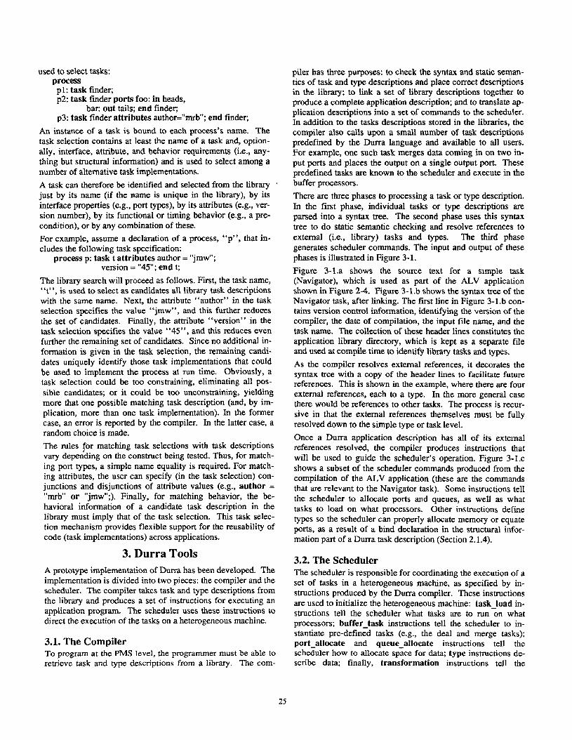
There are three phases to processing a task or type description. In the first phase, individual tasks or type descriptions are parsed into a syntax tree. The second phase uses this syntax tree to do static semantic checking and resolve references to external (i.e., library) tasks and types. The third phase generates scheduler commands. The input and output of these phases is illustrated in Figure 3-1.
Figure 3- l.a shows the source text for a simple task (Navigator), which is used as part of the ALV application shown in Figure 2-4. Figure 3-1.b shows the syntax tree of the Navigator task, after linking. The first line in Figure 3-l .b con- tains version control information, identifying the version of the compiler, tbe date of compilation, the input file name, and the task name. The collection of these header lines constitutes the application library directory, which is kept as a separate file and used at compile time to identify library tasks and types.
As the compiler resolves external references, it decorates the syntax tree with a copy of the header lines to facilitate future references. This is shown in the example, where there are four external references, each to a type. In the more general case there would be references to other tasks. The process is recur- sive in that the external references themselves must be fully resolved down to the simple type or task level.
Once a Dun-a application description has all of its external references resolved, the compiler produces instructions that will be used to guide the scheduler’s operation. Figure 3-1.~ shows a subset of the scheduler commands produced from the compilation of the ALV application (these are the commands that are relevant to the Navigator task). Some instructions tell the scheduler to allocate ports and queues, as well as what tasks to load on what processors. Other instructions define types so the scheduler can properly allocate memory or equate ports, as a result of a bind declaration in the structural infor- mation part of a Durra task description (Section 2.1.4).
3.2. The Scheduler The scheduler is responsible for coordinating the execution of a set of tasks in a heterogeneous machine, as specified by in- structions produced by the Durra compiler. These instructions are used to initialize the heterogeneous machine: task-load in- structions tell the scheduler what tasks are to run on what processors; buffer-task instructions tell the scheduler to in- stantiate pre-defined tasks (e.g., the deal and merge tasks); port-allocate and queue-allocate instructions tell the scheduler how to allocate space for data; type instructions de- scribe data; finally, transformation instructions tell the

tmk nwigator portm
inl: in mrp-&trbU*; -- An input port receiving data of typr map-database. in2: In dMtination; outl: Out road-srlmction; -- An output port mending data of type roadI-selection. out2: Out lmdmark_list;
attributea procrs.or - man; -- Thr procs.sor typa rrquirad to executa the task. imphmntation - "/u8r/durrl/nAvig8tor.o": -- The location of the object code.
end nwig∨
a: Durra Source Text for Task Navigator
--Link "0.1 5/13/1987 17:32:07 tamkOZ.durra TASK NAVIGATOR (OPATA8RDBS !1,2 NAVIGATOR (OP-PORTLIST !3,11
(OP-INPORT !3,6 IN1 MAP-DATABASE 1"--Link VO.l S/13/1907 17:28:45 typs02.durra TYPE MAP-DATABASE")
(OP-INPORT 14,6 IN2 DESTINATION ("--Link "0.1 5/13/1987 17:28:55 typa03.durra TYPE DESTINATION")
(OP-OUTPORT !5,6 OUT1 ROAD-SELECTION I"--Link VO.l S/13/1987 17:29:12 typa05.durra TYPE ROAD-SELECTION")
(OP OUTPORT !6,6 OUT2 L?,NDMARRLIST I"--Link VO.l 5/13/1987 17:29:58 typmlO.durra TYPE LANDMILRX_LIST"))
(OP-ATTRIBUTELIST !8,13 IOP ATTRIBUTE !10.16 'PR&BSSOR
SUN (OPJTTRIBWTR !11,21
IMPLEI4ENTATION “/uwr/durr~/n~vigator. 0”) ) ]
b: Syntax Tree for Task Navigator
(port-allocatm AL" IN1 MAP-DATABASE in) (typr NAP-DATABASE AERAY PIXEL 100 100) (typ9 PIXEL SIZE 8 8) (port-allocate ALV IN2 MAP-DATABASE in) (port-allocatm ALV IN3 DESTINATION in) (typr DRSTINATION AMAY PIXRL 100 100)
. . . (queue-allocatr ALV Ql NAVIGATOR OUT1 RO~PREDICTOR IN2 0 0 ROAD-SELECTION) (queue-allocat, AL" g2 NA"IGATOR OUT2 LAND=-PREDICTOR IN1 0 0 LANDMARK_LIST)
(equ.;ga;t AL" IN2 NAVIGATOR INl) (,qualgort AL" IN3 NAVIGATOR INZ)
c: Scheduler Instructions for Task Navigator Produced by Compiling Task ALV
Figure 3-l: Durra Source Text, Intermediate Syntax Tree, and Scheduler Instructions
scheduler what data each queue, if any.
transformations will be associated with
We do not expect that the languages that will be used for pro- gramming a heterogeneous machine will have constructs that map directly onto the Durra concept of a port. Instead, we pro- vide for each language a procedural interface consisting of four procedures that a task can call for sending data to and receiving data from ports: (1) PortID(name) takes a port name and returns a unique descriptor, id, to be used for further references to that port; (2) Put_Port(id,data_address,bit counr) sends data to a port; (3) Get_Port(id,data_address,u”count) gets data from a port; and, finally, (4) Test-Port(id) determines if data is available on a port.
These four procedures are the initial set provided for any pro- gramming language used to implement Durra tasks. Tasks nm- ning on the heterogeneous machine processors communicate with the scheduler by using a Remote Procedure Call (RPC) protocol.
When all the tasks are loaded and the ports and queues are al-
located, the scheduler directs them to begin execution. A task that needs input will wait for output from the task that produces it. Others will produce output, which the scheduler will pass on to waiting tasks.
3.3. Debugging Tools Testing and debugging programs running on a heterogeneous machine present many of the same problems that are found with any collection of cooperating processes running asynchronously. In our initial implementation, the problems are alleviated somewhat by the I(logically) central scheduler, which controls the passage of information between processes. Nevertheless, special-purpose tools must be provided to facil- itate testing and debugging. The primary debugging facility provided by the Durra run-time environment is the scheduler itself. It provides input and output ports, just like the normal processes, but these ports are used to communicate with the user. Specifically, through the use of these ports, the user can do the following:
26

l Watch the flow of data through queues. l Observe the status of each process. l Inspect and manipulate data coming into or going out of
specific ports. l Force reconfiguration (when reconfiguration is
implemented) Of course, Durra tasks will actually do the communication; and we expect to develop more elaborate debugging facilities using the scheduler’s ports and a flexible window manager, allowing the user to watch several processes at once.
In addition to the debugging facilities built into the scheduler, a heterogeneous machine simulator has been developed10 to aid in the design of the language and the heterogeneous machine itself. The simulator is driven by the timing expressions in- .:luded as part of the behavioral information of a task descrip- tion (Section 2.1.3) and is used to see how data flows, arriving to and departing from queues. It is not important to simulate the operations of the processors since these are usuatly execut- ing library programs. For example, typical user errors in Warp programs are data misalignments2. Thus, showing the actual values is not as important as showing the array or recurrence indices of the data elements flowing through the system. If the user’s initial specification includes assertions about alignments, the simulator could quickly check these out and detect misalignments.
As we gain experience with programming at the PMS level with Durra and with the fast switch, no doubt additional func- tions and tools will suggest themselves.
4. Related Work
Two other languages/systems, DICONl 1 and CONIC12, can be considered as PMS-level programming languages similar to Durra. Lee and Goldwasser’s DICON*l is a configuration lan- guage used to glue together a set of sequential programs writ- ten in Prolog or C to form a distributed program. DICON al- lows a close coupling of the processes, including passing of pointers to structured data (lists, trees, etc.), which are then used by the interprocess communication servers to retrieve and copy the data. Programs are not as independent from each other as they are in Durra (e.g., according toll, C programs need to know if they are communicating with a Prolog program and are restricted in the types of data they can send or receive). A DICON configuration specification includes process specifi- cations but apparently without the full flexibility of Durra to use various types of function, timing, or attribute information to characterize and retrieve library tasks. The DICON com- piler attempts to find a nearly optimal process allocation and scheduling strategy for a given configuration specification. This is in contrast to Durra, in which the allocation and scheduling strategies are under control of the application devel- oper, including the possible dynamic reconfiguration of the logical network. Magee and Kramer l2 address the problem of dynamic recon- figuration of real-time systems in the design of the CONIC lan- guage. CONIC restricts tasks to be programmed in a fixed lan- guage (an extension to Pascal with message passing primitives) running on homogeneous workstations. Belzile et al.15 introduce RNET, a facility for building disti-
buted real-time programs. An RNET program consists of a configuration specification and the procedural code, which is compiled, linked with a run-time kernel, and loaded onto the target system for execution. The language provides facilities for specifying real-time properties, such as deadlines and delays that are used for monitoring and scheduling the proc- esses. These features place RNET at a lower level of abstrac- tion, and thus RNET cannot be compared directly to Durra. Rather, it can be considered as a suitable language for devel- oping the schedulers required by Durra and other languages in which the concurrent tasks are treated as black boxes.
Mamrak et al-l4 address the need for transforming data ex- changed between heterogeneous processors. They describe a system based on canonical representations of data used as an exchange format and the desirable properties of such canonical representations. Durra is not concerned with specific data for- mats; rather, it provides a mechanism for invoking arbitrary data transformations as needed. In other words, Durra operates above the level of the canonical representation, if any, and as- sumes only that data comes in blocks of variable length, per- haps, and in arrays of such blocks. The language only provides operations for manipulating these arrays (e.g., transpose, selection). Code to transform the array elements or blocks has to be provided by the users. However, Mamrak et al. l4 describe a technique for providing a uniform frontend to tools in a distributed environment. This and other similar facil- ities could be adopted by the application developers without difficulty as Durra operates at a higher level of abstraction.
5. Status and Further Research As of this writing, a prototype of the Durra compiler is opera- tional. With the exception of dynamic reconfiguration, the en- tire language has been implemented. The scheduler is current- ly under development.
Our original motivation for designing and implementing a task- level programming environment was to fill a need of two com- munities:
1. Application developers who want to exploit the capabilities of a computing environment that includes not only standard general-purpose processors and workstations, but also high- speed special-purpose multiprocessors, all of which are net- worked together.
2. Hardware designers who provide this broad range of com- puting capabilities and need customers to use their new configurations as different processors and communication links (e.g., optical switches) become available.
What was missing was a high-level language usable by the ap- plication developers but targeted for the possibly changing hardware configurations. The language should let users focus on describing their application at a task (i.e., program) level, rather than at a procedure level, without losing the ability to exploit the special features of each processor. Moreover, the application programmers had already invested a lot of time and effort into fine-tuning their algorithms to run on individual processors. Enough “low-level” software (i.e., programs in Pascal, Common Lisp, C, and assembly language) that does number-intensive image processing or pattern recognitio, had been developed by both communities to make its reuse critical. Our task-level description language, Durra, therefore evolved
37

from this need for a language to serve as a bridge between the application and the hardware while saving the application pro- grammers the burden of reprogramming their algorithms.
Another way of viewing PMS-level programming is to recog- nize that Durra lifts the level of programming at the code level to programming at the specification level. What then con- stitutes a spec$ication (e.g., Dun-a task description) and its satisfaction (e.g., Durra task selection) determines the power of programming at the specification level. If a specification is just a list of filenames and their version numbers, then a “program” is simple, and programming is not very powerful: selection of programs from a library indexed by filename is trivial. If a specification includes semantic information, e.g., functional behavior of a task, then programming is quite com- plex: selection of programs may involve theorem-proving ca- pability. We designed Durra with the ultimate goal of exploit- ing the rich semantic information included in a task descrip- tion. For our prototype implementation, however, we have sacrificed semantic complexity in favor of simpler task selec- tion based on interface, attribute, and structural information. We gain the advantage of being able immediately to instantiate our general idea of PMS-level programming with a real envi- ronment (Durra specific tools supplemented with the Warp Programming Environment15), that supports a real application (Autonomous Land Vehicle’) and that runs on a heterogeneous machine (various Warp, Sun, and MicroVax engines currently connected via an Ethernet, later to be connected via a fast switch2). Hence, instead of a paper design, we can claim the existence of a working system.
A pragmatic significance of the Dun-a work is its role in soft- ware reuse, a topic of great interest to the software engineering community. By programming at the specification level, we au- tomatically gain the benefit of reusing code as well as the bene- fit of reusing specifications (task descriptions). In developing libraries of reusable programs, the interesting problem is not necessarily having the ability to specify and locate previously developed programs (assuming that a typical library consists of a few hundred programs, finding these is not a major problem), but rather to develop libraries of generic programs that can be instantiated by the language system to meet user or hardware requirements.
From a specification language viewpoint, a significant techni- cal contribution of our work lies in the combination of different kinds of specifications. A Durra description includes function- al, timing, and structural information. Individually, each may be meaningful, but their combination may lead to an inconsis- tent specification. For example, one could specify the func- tionality of a merge task to take two inputs and output them both on the output queue in one order, but specify the timing (inconsistently) to force the inputs to be output in the opposite orderg.
Finally, orthogonal to the issues of software specification and reuse is the applicability of Durra to real-time programming in speech, vision, and robotics. Although we have drawn our in- itial applications from real-time systems, the Durra environ- ment supports the more general idea of programming at the PMS level, regardless of the real-time constraints of the sys- tem.
1.
2.
3.
4.
5.
10.
11.
12.
13.
14.
15.
References S.A. Shafer, A. Stem, C.E. Thorpe, “An Architecture for Sensor Fusion in a Mobile Robot”, Proceedings of the International Con- ference on Robotics and Auioniarion, IE%E-Computer Society Press, San Francisco, California, April 1986, pp. 2002-2011.
H.T. Kung, “Private communication”.
C.G. Bell and Allen Newell, Computer Structures: Readings and Examples, McGraw-Hill Book Company, New York, 197 1.
MR. Barbacci and J.M. Wing, “Durra: A Task-level Description Language”, Tech. report CMU/SEI-86-TR-3. Software Engineering Institute, Carnegie Mellon University, 1986, Also Technical Report CMU-CS-86-176, Department of Computer Science, Carnegie Mel- lon University, December 1986, and NTIS Report No. AD-Al78 975
M.R. Barbacci and J.M. Wing, “Durra: A Task-level Description Language”, Proceedings of the 16th International Conference on Parallel Processing, The Pennsylvania State University, Pheasant Run Resort, St Charles, Illinois, August 1987.
J.V. Guttag, J.J. Homing, and J.M. Wing, “Larch in Five Easy Pieces”. Tech. report 5, DEC Systems Research Center, July 1985.
J.V. Guttag, J.J. Homing, and J.M. Wing, “The Larch Family of Specification Languages”, Sof&vare,Vol. 2No. 5September 1985, pp. 24-36.
F. Jahanian and A.K. Mok. “Safety Analysis of Timing Properties in Real-Time Systems”, Transactions on Software Engineering,Vol. 12No. 9September 1986, pp. 890-904.
M.R. Barbacci and J.M. Wing, Specifying Functional and Timing Behavior for Real-time Applications, Soringer-Verlae. Lecture Notes in komputer Science- Vol. 259, Pi 2,-1987. pg. 124-140, Also Technical Report CMUISEI-86-TR-4, Software Engineering Institute, and Technical Report CMU-CS-86-177, Department of Computer Science, Carnegie Mellon University, December 1986
R.G. Stockton, “The Heterogeneous Machine Simulator”, Tech. re- port CMU/SEI-86-TR-6, Software Engineering Institute, Carnegie Mellon University, 1986, Also NTIS AD-Al78 77 1
I. Lee and S.M. Goldwasser, “A Distributed Testbed for Active Sensory Processing”, 1985 International Conference on Robotics and Automation, IEEE Computer Society Press, March 1985, pp. 925-930.
J. Magee and J. Kramer, “Dynamic Configuration for Distributed Real-Time Systems”, Proceedings of the 1983 Real-Time Systems Symposium, IEEE Computer Society Press, December 1983, pp. 2771288.
__
C. Belzile, M. Coulas, G.H. McEwen, and G. Marquis, “RNET: A Hard Real Time Distributed Programming System”, Proceedings of the 1986 Real-Time Systems Symposium, IEEE Computer Society Press, December 1986, pp. 2-13.
S.A. Mamrak, H. Kuo, and D. Soni, “Supporting Existing Tools in Distributed Processing Systems: The Conversion Problem”, Proceedings of the 3rd International Conference on Distributed Computing Systems, IEEE Compiuter Society Press, October 1982, pp. 847-853. BBruegge, C. Chang, R. Cohn, T. Gross, M.Lam, P. Lieu, ANoaman, D.Yam, “The Warp Programming Environment”, Proceedings of the 1987 National Computer Conference, AFIPS Press, 1987, pp. 141-148.
28