programming guide 11/2002 edition - hillary … 840d/840di/810d fundamentals 11.02 edition...
TRANSCRIPT

Programming Guide 11/2002 Edition
FundamentalsSINUMERIK 840D/840Di/810D


SINUMERIK 840D/840Di/810D
Fundamentals
11.02 Edition
Programming Guide
FundamentalGeometrical Principles 1
FundamentalPrinciplesof NC Programming
2
Positional Data 3
Programming MotionCommands 4
Path Action 5
Frames 6
Feedrate Control andSpindle Motion 7
Tool Offsets 8
MiscellaneousFunctions 9
Arithmetic Parametersand Program Jumps 10
Subprograms andRepetition of ProgramSections
11
Tables 12
Appendix A
Valid for
Control Software VersionSINUMERIK 840D 6SINUMERIK 840DE (export version) 6SINUMERIK 840D powerline 6SINUMERIK 840DE powerline 6SINUMERIK 840Di 2SINUMERIK 840DiE (export version) 2SINUMERIK 810D 3SINUMERIK 810DE (export version) 3SINUMERIK 810D powerline 6SINUMERIK 810D powerline 6

0 Contents 11.02 0
SINUMERIK® Documentation
Printing history
Brief details of this edition and previous editions are listed below.
The status of each edition is shown by the code in the "Remarks" column.
Status code in the "Remarks" column:
A .... New documentation.B .... Unrevised edition with new order no.C .... Revised edition with new status.
If factual changes have been made on the page since the last edition, this is indicated by anew edition coding in the header on that page.
Edition Order No. Remarks02.95 6FC5298-2AB00-0BP0 A08.97 6FC5298-4AB00-0BP0 A12.95 6FC5298-3AB00-0BP0 C03.96 6FC5298-3AB00-0BP1 C08.97 6FC5298-4AB00-0BP0 C12.97 6FC5298-4AB00-0BP1 C12.98 6FC5298-5AB00-0BP0 C08.99 6FC5298-5AB00-0BP1 C04.00 6FC5298-5AB00-0BP2 C10.00 6FC5298-6AB00-0BP0 C09.01 6FC5298-6AB00-0BP1 C11.02 6FC5298-6AB00-0BP2 C
This manual is included in the documentation available on CD ROM (DOCONCD)Edition Order No. Remarks11.02 6FC5298-6CA00-0BG3 CTrademarksSIMATIC�, SIMATIC HMI�, SIMATIC NET�, SIROTEC�, SINUMERIK� and SIMODRIVE� are registeredtrademarks of Siemens AG. Other names in this publication might be trademarks whose use by a third party forhis own purposes may violate the rights of the registered holder.
Further information is available on the Internet under:http://www.ad.siemens.de/sinumerik
This publication was produced with WinWord V8.0and Designer V4.0.The reproduction, transmission or use of this document or its contents is notpermitted without express written authority. Offenders will be liable for damages.All rights, including rights created by patent grant or registration of a utility modelor design, are reserved.
© Siemens AG, 1995–2002. All rights reserved
Other functions not described in this documentation might be executable in thecontrol. This does not, however, represent an obligation to supply such functionswith a new control or when servicing.
We have checked that the contents of this document correspond to the hardwareand software described. Nonetheless, differences might exist and therefore wecannot guarantee that they are completely identical. The information given in thispublication is reviewed at regular intervals and any corrections that might benecessary are made in the subsequent printings. We welcome suggestions forimprovement.
Subject to change without prior notice
Order No. 6FC5298-6AB00-0BP2Printed in Germany
Siemens Aktiengesellschaft

Siemens AG, 2002. All rights reservedSINUMERIK 840D/840Di/810D Programming Guide Fundamentals (PG) – 11.02 Edition 0-5
0 11.02 Contents 0
Contents
Fundamental Geometrical Principles 1-21
1.1 Description of workpiece points ...................................................................................... 1-221.1.1 Workpiece coordinate systems................................................................................. 1-221.1.2 Definition of workpiece positions............................................................................... 1-231.1.3 Polar coordinates ...................................................................................................... 1-251.1.4 Absolute dimension................................................................................................... 1-261.1.5 Incremental dimension.............................................................................................. 1-271.1.6 Plane designations.................................................................................................... 1-28
1.2 Position of zero points ..................................................................................................... 1-29
1.3 Position of coordinate systems ....................................................................................... 1-291.3.1 Overview of various coordinate systems................................................................... 1-291.3.2 Machine coordinate system ...................................................................................... 1-311.3.3 Basic coordinate system ........................................................................................... 1-331.3.4 Workpiece coordinate system................................................................................... 1-341.3.5 Frame system ........................................................................................................... 1-341.3.6 Assignment of workpiece coordinate system to machine axes ................................ 1-361.3.7 Current workpiece coordinate system....................................................................... 1-36
1.4 Axes ................................................................................................................................ 1-371.4.1 Main axes/Geometry axes ........................................................................................ 1-381.4.2 Special axes.............................................................................................................. 1-391.4.3 Main spindle, master spindle..................................................................................... 1-391.4.4 Machine axes ............................................................................................................ 1-391.4.5 Channel axes ............................................................................................................ 1-391.4.6 Path axes .................................................................................................................. 1-401.4.7 Positioning axes ........................................................................................................ 1-401.4.8 Synchronized axes .................................................................................................... 1-421.4.9 Command axes......................................................................................................... 1-421.4.10 PLC axes................................................................................................................... 1-421.4.11 Link axes (SW 5 and higher)..................................................................................... 1-431.4.12 Leading link axes (SW 6 and higher) ........................................................................ 1-45
1.5 Coordinate systems and workpiece machining............................................................... 1-48
Fundamental Principles of NC Programming 2-51
2.1 Structure and contents of an NC program ...................................................................... 2-52
2.2 Language elements of the programming language ........................................................ 2-53
2.3 Programming a sample workpiece.................................................................................. 2-75
2.4 First programming example for milling application.......................................................... 2-77
2.5 Second programming example for milling application .................................................... 2-78
Siemens AG, 2002. All rights reserved0-6 SINUMERIK 840D/840Di/810D Programming Guide Fundamentals (PG) – 11.02 Edition
0 Contents 11.02 0
2.6 Programming example for turning application.................................................................2-81
Positional Data 3-83
3.1 General information.........................................................................................................3-84
3.2 Absolute/incremental dimensions, G90/G91 ...................................................................3-853.2.1 G91 extension (SW 4.3 and higher) ..........................................................................3-88
3.3 Absolute dimensions for rotary axes, DC, ACP, ACN .....................................................3-89
3.4 Metric/imperial dimensions, G70/G71/G700/G710..........................................................3-91
3.5 Zero offset (frame), G54 to G599....................................................................................3-94
3.6 Selecting the working plane, G17 to G19 ........................................................................3-99
3.7 Programmable working area limitation, G25/G26 .........................................................3-102
3.8 Reference point approach, G74 ....................................................................................3-105
Programming Motion Commands 4-107
4.1 General information.......................................................................................................4-108
4.2 Traversing commands with polar coordinates, G110, G111, G112, AP, RP ................4-110
4.3 Rapid traverse movement, G0 ......................................................................................4-114
4.4 Linear interpolation, G1 .................................................................................................4-119
4.5 Circular interpolation, G2/G3, CIP .................................................................................4-122
4.6 Helical interpolation, G2/G3, TURN...............................................................................4-135
4.7 Involute interpolation, INVCW, INVCCW ......................................................................4-137
4.8 Contour definitions.........................................................................................................4-1414.8.1 Straight line with angle ............................................................................................4-1414.8.2 Two straight lines.....................................................................................................4-1424.8.3 Three straight lines..................................................................................................4-1434.8.4 End point programming with an angle.....................................................................4-144
4.9 Thread cutting with constant lead, G33.........................................................................4-1454.9.1 Programmable run-in and run-out path (SW 5 and higher).....................................4-151
4.10 Linear progressive/degressive thread pitch change, G34, G35 (SW 5.2 and higher)...4-153
4.11 Rigid tapping, G331, G332 ............................................................................................4-155
4.12 Tapping with compensating chuck G63 ........................................................................4-157
4.13 Stop during thread cutting .............................................................................................4-159
4.14 Approaching a fixed point, G75 .....................................................................................4-161
4.15 Travel to fixed stop ........................................................................................................4-163

Siemens AG, 2002. All rights reservedSINUMERIK 840D/840Di/810D Programming Guide Fundamentals (PG) – 11.02 Edition 0-7
0 11.02 Contents 0
4.16 Special turning functions ............................................................................................... 4-1694.16.1 Position of workpiece .............................................................................................. 4-1694.16.2 Dimensions for: Radius, diameter........................................................................... 4-170
4.17 Chamfer, rounding ........................................................................................................ 4-172
Path Action 5-177
5.1 Exact stop, G60, G9, G601, G602, G603 .................................................................... 5-178
5.2 Continuous-path mode, G64, G641, G642, G643........................................................ 5-181
5.3 Acceleration pattern, BRISK, SOFT, DRIVE................................................................ 5-1905.3.1 Acceleration modes................................................................................................. 5-1905.3.2 Influence of acceleration modes on following axes................................................. 5-191
5.4 Overview of the various velocity controls ..................................................................... 5-194
5.5 Path velocity smoothing ............................................................................................... 5-195
5.6 Traversing with feedforward control, FFWON, FFWOF............................................... 5-196
5.7 Programmable contour accuracy, CPRECON, CPRECOF.......................................... 5-197
5.8 Dwell time, G4 .............................................................................................................. 5-198
5.9 Program sequence: Internal preprocessor stop........................................................... 5-199
Frames 6-201
6.1 General......................................................................................................................... 6-202
6.2 Frame instructions........................................................................................................ 6-203
6.3 Programmable zero offset............................................................................................ 6-2056.3.1 TRANS, ATRANS ................................................................................................... 6-2056.3.2 G58, G59: Axial programmable ZO (SW 5 and higher) .......................................... 6-209
6.4 Programmable rotation, ROT, AROT........................................................................... 6-212
6.5 Programmable frame rotations with solid angles, ROTS, AROTS and CROTS.......... 6-220
6.6 Programmable scale factor, SCALE, ASCALE ............................................................ 6-221
6.7 Programmable mirroring, MIRROR, AMIRROR........................................................... 6-224
6.8 Frame generation according to tool orientation, TOFRAME, TOROT ......................... 6-228
6.9 Deselect frame SUPA, DRFOF, CORROF, TRAFOOF............................................... 6-230
Feedrate Control and Spindle Motion 7-235
7.1 Feedrate ........................................................................................................................ 7-236
7.2 Traversing positioning axes, POS, POSA, POSP......................................................... 7-244
7.3 Position-controlled spindle operation, SPCON, SPCOF ............................................... 7-247
Siemens AG, 2002. All rights reserved0-8 SINUMERIK 840D/840Di/810D Programming Guide Fundamentals (PG) – 11.02 Edition
0 Contents 11.02 0
7.4 Positioning spindles (position-controlled axis operation): SPOS, M19 and SPOSA .....7-248
7.5 Milling on turned parts: TRANSMIT...............................................................................7-254
7.6 Cylinder surface transformation: TRACYL ....................................................................7-256
7.7 Feedrate for positioning axes/spindles: FA, FPR, FPRAON, FPRAOF ........................7-257
7.8 Percentage feedrate override, OVR, OVRA..................................................................7-260
7.9 Feedrate with handwheel override, FD, FDA ................................................................7-261
7.10 Percentage acceleration correction: ACC (Option) .......................................................7-265
7.11 Feedrate optimization for curved path sections, CFTCP, CFC, CFIN...........................7-266
7.12 Spindle speed S, direction of spindle rotation M3, M4, M5 ...........................................7-269
7.13 Constant cutting rate, G96, G97, LIMS .........................................................................7-272
7.14 Constant grinding wheel peripheral speed, GWPSON, GWPSOF ...............................7-274
7.15 Constant workpiece speed for centerless grinding: CLGON, CLGOF ..........................7-277
7.16 Programmable spindle speed limitation, G25, G26.......................................................7-279
7.17 Several feedrates in one block: F.., FMA.. ....................................................................7-280
7.18 Blockwise feedrate: FB... (as of SW 5.3) ......................................................................7-282
Tool Offsets 8-285
8.1 General information ......................................................................................................8-286
8.2 List of tool types............................................................................................................8-289
8.3 Tool selection/tool call T ...............................................................................................8-2938.3.1 Tool change with M06 (mill) ....................................................................................8-2938.3.2 Tool change with T command (rotate) ....................................................................8-295
8.4 Tool offset D .................................................................................................................8-297
8.5 Tool selection T with tool management........................................................................8-2998.5.1 Turning machine with circular magazine .................................................................8-2998.5.2 Milling machine with chain magazine ......................................................................8-300
8.6 Tool offset call D with tool management ......................................................................8-3028.6.1 Turning machine with circular magazine .................................................................8-3028.6.2 Milling machine with chain magazine ......................................................................8-303
8.7 Make active tool offset operative immediately..............................................................8-304
8.8 Tool radius compensation, G40, G41, G42..................................................................8-305
8.9 Approach and retract from contour, NORM, KONT, G450, G451................................8-313
8.10 Compensation at outside corners, G450, G451 ...........................................................8-316
Siemens AG, 2002. All rights reservedSINUMERIK 840D/840Di/810D Programming Guide Fundamentals (PG) – 11.02 Edition 0-9
0 11.02 Contents 0
8.11 Smooth approach and retraction.................................................................................. 8-3198.11.1 Extension approach and retract: G461/G462 (SW 5 and higher) ........................... 8-327
8.12 Collision monitoring, CDON, CDOF ............................................................................. 8-331
8.13 2 1/2 D tool offset, CUT2D, CUT2DF........................................................................... 8-333
8.14 Tool length offset for orientable tools: TCARR, TCOABS, TCOFR ............................. 8-335
8.15 Grinding-specific tool monitoring in parts program TMON, TMOF............................... 8-338
8.16 Additive offsets (SW 5 and higher)............................................................................... 8-3408.16.1 Select offset (by DL number) .................................................................................. 8-3408.16.2 Define wear and setup values................................................................................. 8-3418.16.3 Delete additive offsets (DELDL).............................................................................. 8-343
8.17 Tool offset – special features (SW 5 and higher)......................................................... 8-3448.17.1 Mirroring of tool lengths........................................................................................... 8-3458.17.2 Wear sign evaluation............................................................................................... 8-3458.17.3 Tool length and plane change................................................................................. 8-346
8.18 Tools with a relevant tool point direction (SW 5 and higher)........................................ 8-349
Miscellaneous Functions 9-351
9.1 Auxiliary function outputs ............................................................................................. 9-3529.1.1 M functions.............................................................................................................. 9-3579.1.2 H functions .............................................................................................................. 9-360
Arithmetic Parameters and Program Jumps 10-361
10.1 Arithmetic parameters R ............................................................................................ 10-362
10.2 Unconditional program jumps .................................................................................... 10-365
10.3 Conditional program jumps ........................................................................................ 10-367
Subprograms and Repetition of Program Sections 11-369
11.1 Use of subprograms................................................................................................... 11-370
11.2 Subroutine call............................................................................................................ 11-373
11.3 Subprogram with program repetition.......................................................................... 11-375
11.4 Program section repetition (SW 4.3 and higher) ........................................................ 11-376
Tables 12-385
12.1 List of statements ....................................................................................................... 12-386
12.2 List of addresses ........................................................................................................ 12-40312.2.1 Address letters ...................................................................................................... 12-40312.2.2 Fixed addresses.................................................................................................... 12-404

Siemens AG, 2002. All rights reserved0-10 SINUMERIK 840D/840Di/810D Programming Guide Fundamentals (PG) – 11.02 Edition
0 Contents 11.02 0
12.2.3 Fixed addresses with axis extension.....................................................................12-40512.2.4 Settable addresses................................................................................................12-407
12.3 List of G functions/preparatory functions....................................................................12-411
12.4 List of predefined subprograms..................................................................................12-42312.4.1 Predefined subprogram calls.................................................................................12-42412.4.2 Predefined subprogram calls in motion-synchronous actions...............................12-43412.4.3 Predefined functions..............................................................................................12-43512.4.4 Data types .............................................................................................................12-438
Appendix A-439
A Abbreviations ....................................................................................................................A-440
B Terms................................................................................................................................A-448
C References........................................................................................................................A-474
D Index .................................................................................................................................A-489
E Commands, identifiers ......................................................................................................A-496

Siemens AG, 2002. All rights reservedSINUMERIK 840D/840Di/810D Programming Guide Fundamentals (PG) – 11.02 Edition 0-11
0 11.02 PrefaceStructure of the manual 0
840DNCU 571
840DNCU 572NCU 573
810D 840Di
PrefaceOrganization of documentation
SINUMERIK documentation is organized on threedifferent levels:• General Documentation• User documentation• Manufacturer/Service Documentation
Target group
This Manual is intended for machine-tool users. Itprovides detailed information that the user requires toprogram the SINUMERIK 840D/840Di/810D controlsystem.
Standard scope
This Programming Guide describes the functionalityafforded by standard functions. Differences andadditions implemented by the machine-toolmanufacturer are documented by the machine-toolmanufacturer. More detailed information about other publicationsrelating to SINUMERIK 840D/840Di and publicationsthat apply to all SINUMERIK controls (e.g. UniversalInterface, Measuring Cycles...) can be obtained fromyour local Siemens branch office. Other functions not described in this documentationmight be executable in the control. This does not,however, represent an obligation to supply suchfunctions with a new control or when servicing.

Siemens AG, 2002. All rights reserved0-12 SINUMERIK 840D/840Di/810D Programming Guide Fundamentals (PG) – 11.02 Edition
0 Preface 11.02 Structure of the manual
0
840DNCU 571
840DNCU 572NCU 573
810D
840Di
Applicability
This Programming Guide applies to the followingcontrols:SINUMERIK 840D 6SINUMERIK 840DE (export version) 6SINUMERIK 840D powerline 6SINUMERIK 840DE powerline 6SINUMERIK 840Di 2SINUMERIK 840DiE (export version) 2SINUMERIK 810D 3SINUMERIK 810DE (export version) 3SINUMERIK 810D powerline 6SINUMERIK 810D powerline 6 with operator panels OP 010, OP 010C, OP 010S,OP 12 or OP 15 (PCU 20 or PCU 50)
SINUMERIK 840D powerline
From 09.2001 onwards, improved performanceversions of• SINUMERIK 840D powerline and• SINUMERIK 840DE powerlinewill be available. For a list of available powerlinemodules, please refer to Section 1.1 /PHD/ of thehardware description /PHD/.
SINUMERIK 810D powerline
From 12.2001 onwards, improved performanceversions of• SINUMERIK 810D powerline and• SINUMERIK 810DE powerlinewill be available. For a list of available powerlinemodules, please refer to Section 1.1 of the hardwaredescription /PHC/.
Siemens AG, 2002. All rights reservedSINUMERIK 840D/840Di/810D Programming Guide Fundamentals (PG) – 11.02 Edition 0-13
0 11.02 PrefaceStructure of the manual
0
840DNCU 571
840DNCU 572NCU 573
810D
840Di
Hotline If you have any queries, please contact the following hotline:A&D Technical Support Phone: ++49-(0)180-5050-222
Fax: ++49-(0)180-5050-223Email: [email protected]
Please send any queries about the documentation (suggestions orcorrections) to the following fax number or email address:
Fax: ++49-(0)0131-98-2176Email: [email protected]
Fax form: see feedback sheet and the end of the publication.
Internet address http://www.ad.siemens.de/sinumerik
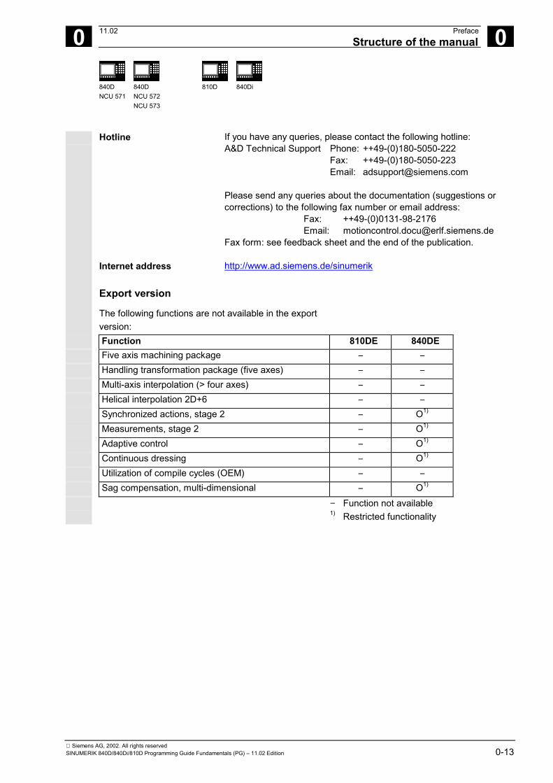
Export version
The following functions are not available in the exportversion:
Function 810DE 840DE Five axis machining package − − Handling transformation package (five axes) − − Multi-axis interpolation (> four axes) − − Helical interpolation 2D+6 − − Synchronized actions, stage 2 − O1)
Measurements, stage 2 − O1)
Adaptive control − O1)
Continuous dressing − O1)
Utilization of compile cycles (OEM) − − Sag compensation, multi-dimensional − O1)
− Function not available1) Restricted functionality

Siemens AG, 2002. All rights reserved0-14 SINUMERIK 840D/840Di/810D Programming Guide Fundamentals (PG) – 11.02 Edition
0 Preface 11.02 Structure of the manual
0
840DNCU 571
840DNCU 572NCU 573
810D
840Di
Fundamentals This Programming Guide Fundamentals is intended foruse by skilled machine operators with the appropriateexpertise in drilling, milling and turning operations. Simple programming examples are used to explain thecommands and statements which are also definedaccording to DIN 66025.
Advanced The Programming Guide "Advanced" is intended foruse by technicians with in-depth, comprehensiveprogramming knowledge. By virtue of a specialprogramming language, the SINUMERIK 840D/810Dcontrol enables the user to program complex workpieceprograms (e.g. for sculptured surfaces, channelcoordination, ...) and greatly facilitates the programmingof complicated operations. The commands and statements described in this Guideare not specific to one particular technology. They can be applied for a variety of technologies, suchas• Grinding• Cyclical machines (packaging, woodworking)• Laser power controls.

Siemens AG, 2002. All rights reservedSINUMERIK 840D/840Di/810D Programming Guide Fundamentals (PG) – 11.02 Edition 0-15
0 11.02 PrefaceStructure of the manual
0
840DNCU 571
840DNCU 572NCU 573
810D
840Di
Structure of descriptions
All cycles and programming options have beendescribed according to the same internal structure asfar as this is meaningful and practicable. The variouslevels of information have been organized such that youcan selectively access the information you need for thetask in hand.
1. A quick overview
If you look up a rarely used command or themeaning of a parameter, you can see at a glancehow the function is programmed and find helpfulexplanations of the commands and parameters. This information is always displayed at the top of thepage. Note: Due to lack of space, it has not been possible toshow all the modes of representation afforded by theprogramming language for individual commands andparameters. For this reason, we have illustratedthose command programming schemes that areused most frequently in practice in a workshopsituation.
2 Drilling cycles and drilling patterns 03.96
2.1 Drilling cycles 2
Siemens AG 1997 All rights reserved.2-36 SINUMERIK 840D/810D/FM-NC Programming Guide, Cycles (PGZ) - 08.97 Edition.
2.1.2 Drilling, centering – CYCLE81
Programming
CYCLE81 (RTP, RFP, SDIS, DP)
RTP real Retraction plane (absolute)RFP real Reference plane (absolute)SDIS real Safety clearance (enter without sign)DP real Final drilling depth (absolute)DPR real Final drilling depth relative to reference plane (enter without sign)
Function
The tool drills at the programmed spindle speed andfeedrate to the programmed final drilling depth.
X
Z
Operating sequence
Position reached before the beginning of the
cycle:The drilling position is the position in the two axes ofthe selected plane.
The cycle implements the following motion
sequence:
• Approach of the reference plane brought forwardby the safety clearance with G0
• Travel to the final drilling depth at the feedrateprogrammed in the calling program (G1)
• Retraction to retraction plane with G0

Siemens AG, 2002. All rights reserved0-16 SINUMERIK 840D/840Di/810D Programming Guide Fundamentals (PG) – 11.02 Edition
0 Preface 11.02 Structure of the manual
0
840DNCU 571
840DNCU 572NCU 573
810D
840Di
2. Detailed explanations
You will find detailed answers to the followingquestions in the theory section: Why is the command needed? What does the command do? How is it programmed and executed? What do the parameters do? What else do I need to know? The theoretical sections are primarily intended aslearning material for the NC entry-level user. Youshould work through the manual at least once to getan idea of the functional scope and capability of yourSINUMERIK control.
2 03.96 Drilling cycles and drilling patterns
2.1 Drilling cycles 2
Siemens AG 1997 All rights reserved.SINUMERIK 840D/810D/FM-NC Programming Guide, Cycles (PGZ) - 08.97 Edition. 2-37
Explanation of parameters
RFP and RTPGenerally, the reference plane (RFP) and theretraction plane (RTP) have different values. In thecycle it is assumed that the retraction plane lies infront of the reference plane. The distance betweenthe retraction plane and the final drilling depth istherefore greater than the distance between thereference plane and the final drilling depth.
SDISThe safety clearance (SDIS) refers to the referenceplane. which is brought forward by the safetyclearance. The direction in which the safetyclearance is active is automatically determined bythe cycle.
DP and DPRThe drilling depth can be defined either absolute(DP) or relative (DPR) to the reference plane.If it is entered as an absolute value, the value istraversed directly in the cycle.
G1
G0
RTP
RFP+SDISRFP
DP=RFP-DPR
X
Z
Additional notes
If a value is entered both for the DP and the DPR,the final drilling depth is derived from the DPR. If theDPR deviates from the absolute depth programmedvia the DP, the message "Depth: Corresponds tovalue for relative depth" is output in the dialog line.
3. From theory to practice
The programming examples illustrate how commandscan be applied in practice. You will find an application example for virtuallyevery command after the theoretical section.
2 Drilling cycles and drilling patterns 03.96
2.1 Drilling cycles 2
Siemens AG 1997 All rights reserved.2-38 SINUMERIK 840D/810D/FM-NC Programming Guide, Cycles (PGZ) - 08.97 Edition.
If the values for the reference plane and theretraction plane are identical, a relative depth mustnot be programmed. The error message61101 "Reference plane incorrectly defined" isoutput and the cycle is not executed. This errormessage is also output if the retraction plane liesbehind the reference plane, i.e. the distance to thefinal drilling depth is smaller.
Programming example
Drilling_centeringYou can use this program to make 3 holes using thedrilling cycle CYCLE81, whereby this cycle is calledwith different parameter settings. The drilling axis isalways the Z axis.
X
Y
40
B
90
30
0
120
35 100 108
A
A - B
Z
Y
N10 G0 G90 F200 S300 M3 Specification of the technology valuesN20 D3 T3 Z110 Traverse to retraction planeN30 X40 Y120 Traverse to first drilling positionN40 CYCLE81 (110, 100, 2, 35) Cycle call with absolute final drilling
depth, safety clearance and incompleteparameter list
N50 Y30 Traverse to next drilling positionN60 CYCLE81 (110, 102, , 35) Cycle call without safety clearanceN70 G0 G90 F180 S300 M03 Specification of the technology valuesN80 X90 Traverse to next positionN90 CYCLE81 (110, 100, 2, , 65) Cycle call with relative final drilling depth
and safety clearanceN100 M30 End of program
08.97

Siemens AG, 2002. All rights reservedSINUMERIK 840D/840Di/810D Programming Guide Fundamentals (PG) – 11.02 Edition 0-17
0 11.02 PrefaceStructure of the manual
0
840DNCU 571
840DNCU 572NCU 573
810D
840Di
Explanation of symbols
Operating sequence
Explanation
Function
Parameters
Programming example
Programming
Additional notes
Cross-references to other documentation orsections
Notes and warnings
Machine manufacturer (MH n) n= number of the note per section to whichthe machine manufacturer can refer.
Ordering data option
Siemens AG, 2002. All rights reserved0-18 SINUMERIK 840D/840Di/810D Programming Guide Fundamentals (PG) – 11.02 Edition
0 Preface 11.02 Structure of the manual
0
840DNCU 571
840DNCU 572NCU 573
810D
840Di
Principle
Your SIEMENS 840D/840Di/810D has beendesigned and constructed according to state-of-the-art technology and approved safetyregulations and standards.
Additional equipment
The applications of SIEMENS controls can beexpanded for specific purposes through the addition ofspecial add-on devices, equipment and expansionssupplied by SIEMENS.
Personnel
Only appropriately trained, authorized and reliablepersonnel may be allowed to operate this equipment.The control must never be operated, even temporarily,by anyone who is not appropriately skilled or trained. The relevant responsibilities of personnel who set up,operate and maintain the equipment must be clearlydefined; the proper fulfillment of these responsibilitiesmust be monitored.
Behavior
Before the control is started up, it must be ensured thatthe Operator's Guides have been read and understoodby the personnel responsible. The operating company isalso responsible for constantly monitoring the overalltechnical state of the control (visible faults and damage,altered service performance).
Servicing
Repairs must be carried out according to theinformation supplied in the service and maintenanceguide by personnel who are specially trained andqualified in the relevant technical subject. All relevantsafety regulations must be followed.

Siemens AG, 2002. All rights reservedSINUMERIK 840D/840Di/810D Programming Guide Fundamentals (PG) – 11.02 Edition 0-19
0 11.02 PrefaceStructure of the manual
0
840DNCU 571
840DNCU 572NCU 573
810D
840Di
Note
The following is deemed to be improper usage andexempts the manufacturer from any liability: Any application which does not comply with the rulesfor proper usage described above. If the control is not in technically perfect condition oris operated without due regard for safety regulationsand accident prevention instructions given in theInstruction Manual. If faults that might affect the safety of the equipment arenot rectified before the control is started up. Any modification, bypassing or disabling of items ofequipment on the control that are required to ensurefault-free operation, unlimited use and active andpassive safety.
Improper usage gives rise to unforeseen dangers to:• Life and limb of personnel,• The control, machine or other assets of the owner
and the user.
The following special symbols and keywords have beenused in this documentation:NotesThis symbol appears in this documentation whenever itis necessary to draw your attention to an important itemof information.In this documentation, you will find this symbol with areference to an ordering option. The function describedis executable only if the control contains the designatedoption.WarningsThe following warnings with varying degrees of severityappear in this document.DangerIndicates an imminently hazardous situation which, ifnot avoided, will result in death or serious injury or insubstantial property damage

Siemens AG, 2002. All rights reserved0-20 SINUMERIK 840D/840Di/810D Programming Guide Fundamentals (PG) – 11.02 Edition
0 Preface 11.02 Structure of the manual
0
840DNCU 571
840DNCU 572NCU 573
810D
840Di
WarningIndicates a potentially hazardous situation which, if notavoided, could result in death or serious injury or insubstantial property damage.CautionUsed with the safety alert symbol indicates a potentiallyhazardous situation which, if not avoided, may result inminor or moderate injury or in property damage.CautionUsed without safety alert symbol indicates a potentiallyhazardous situation which, if not avoided, may result inproperty damage.
NoticeUsed without the safety alert symbol indicates apotential situation which, if not avoided, may result in anundesirable result or state.

1 11.02 Fundamental Geometrical Principles 1
Siemens AG, 2002. All rights reservedSINUMERIK 840D/840Di/810D Programming Guide Fundamentals (PG) – 11.02 Edition 1-21
Fundamental Geometrical Principles
1.1 Description of workpiece points ...................................................................................... 1-221.1.1 Workpiece coordinate systems................................................................................ 1-221.1.2 Definition of workpiece positions.............................................................................. 1-231.1.3 Polar coordinates ..................................................................................................... 1-251.1.4 Absolute dimension.................................................................................................. 1-261.1.5 Incremental dimension............................................................................................. 1-271.1.6 Plane designations................................................................................................... 1-28
1.2 Position of zero points ..................................................................................................... 1-29
1.3 Position of coordinate systems ....................................................................................... 1-291.3.1 Overview of various coordinate systems ................................................................. 1-291.3.2 Machine coordinate system ..................................................................................... 1-311.3.3 Basic coordinate system .......................................................................................... 1-331.3.4 Workpiece coordinate system.................................................................................. 1-341.3.5 Frame system .......................................................................................................... 1-341.3.6 Assignment of workpiece coordinate system to machine axes ............................... 1-361.3.7 Current workpiece coordinate system...................................................................... 1-36
1.4 Axes ................................................................................................................................ 1-371.4.1 Main axes/Geometry axes ....................................................................................... 1-381.4.2 Special axes............................................................................................................. 1-391.4.3 Main spindle, master spindle ................................................................................... 1-391.4.4 Machine axes........................................................................................................... 1-391.4.5 Channel axes ........................................................................................................... 1-391.4.6 Path axes ................................................................................................................. 1-401.4.7 Positioning axes....................................................................................................... 1-401.4.8 Synchronized axes................................................................................................... 1-421.4.9 Command axes........................................................................................................ 1-421.4.10 PLC axes ................................................................................................................. 1-421.4.11 Link axes (SW 5 and higher) ................................................................................... 1-431.4.12 Leading link axes (SW 6 and higher)....................................................................... 1-45
1.5 Coordinate systems and workpiece machining............................................................... 1-48

1 Fundamental Geometrical Principles 11.021.1 Description of workpiece points 1
840DNCU 571
840DNCU 572NCU 573
810D 840Di
Siemens AG, 2002. All rights reserved1-22 SINUMERIK 840D/840Di/810D Programming Guide Fundamentals (PG) – 11.02 Edition
1.1 Description of workpiece points
1.1.1 Workpiece coordinate systemsIn order for the machine or control to operate with thespecified positions, these data must be made in areference system that corresponds to the direction ofmotion of the axis slides. A coordinate system withthe axes X, Y and Z is used for this purpose.DIN 66217 stipulates that machine tools must useright-handed, rectangular (cartesian) coordinatesystems.
The workpiece zero (W) is the origin of the workpiececoordinate system. Sometimes it is advisable or evennecessary to work with negative positional data.Positions to the left of the origin are prefixed by anegative sign (–).
Milling:
X+
X- Y+
Y-
Z+
Z -
90°
90°
90°W
Turning:
Z+
Z- X+
X-
Y+
90°
90°
90°W
Y-
1 11.02 Fundamental Geometrical Principles1.1 Description of workpiece points 1
840DNCU 571
840DNCU 572NCU 573
810D 840Di
Siemens AG, 2002. All rights reservedSINUMERIK 840D/840Di/810D Programming Guide Fundamentals (PG) – 11.02 Edition 1-23
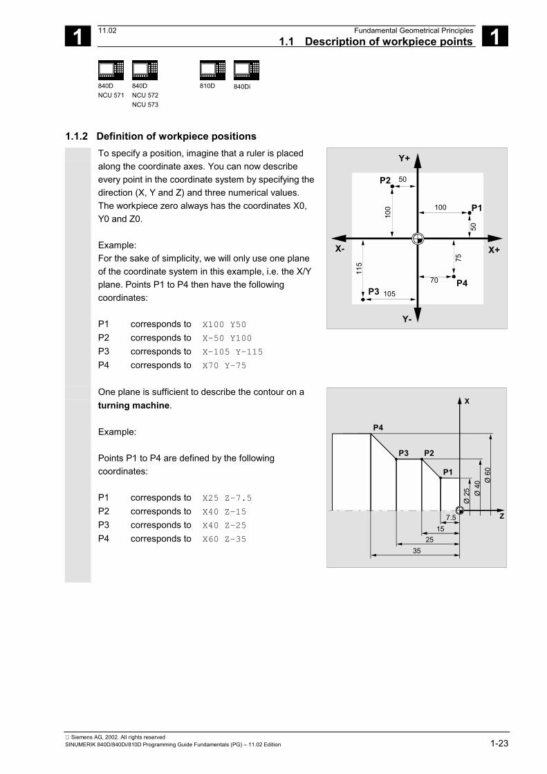
1.1.2 Definition of workpiece positionsTo specify a position, imagine that a ruler is placedalong the coordinate axes. You can now describeevery point in the coordinate system by specifying thedirection (X, Y and Z) and three numerical values.The workpiece zero always has the coordinates X0,Y0 and Z0.
Example:For the sake of simplicity, we will only use one planeof the coordinate system in this example, i.e. the X/Yplane. Points P1 to P4 then have the followingcoordinates:
P1 corresponds to X100 Y50
P2 corresponds to X-50 Y100
P3 corresponds to X-105 Y-115
P4 corresponds to X70 Y-75
X+X-
Y+
Y-
100
105
70
50
P1
P2
P3P4
115
100
50
75
One plane is sufficient to describe the contour on aturning machine.
Example:
Points P1 to P4 are defined by the followingcoordinates:
P1 corresponds to X25 Z-7.5
P2 corresponds to X40 Z-15
P3 corresponds to X40 Z-25
P4 corresponds to X60 Z-35
Z
X
7.515
2535
P4
P3 P2
P1Ø
25 Ø 4
0 Ø 6
0

1 Fundamental Geometrical Principles 11.021.1 Description of workpiece points 1
840DNCU 571
840DNCU 572NCU 573
810D 840Di
Siemens AG, 2002. All rights reserved1-24 SINUMERIK 840D/840Di/810D Programming Guide Fundamentals (PG) – 11.02 Edition
Example:Points P1 and P2 are defined by the followingcoordinates:
P1 corresponds to X-20 Y-20 Z23
P2 corresponds to X13 Y-13 Z27
X+
13
P1
20
Y+
X+
P2 1320 P1
23
P2
27
P1
Z+
The infeed depth must also be described in millingoperations. To do this, we need to specify anumerical value for the third coordinate (Z in thiscase).
Example:Points P1 to P3 are defined by the followingcoordinates:
P1 corresponds to X10 Y45 Z-5
P2 corresponds to X30 Y60 Z-20
P3 corresponds to X45 Y20 Z-15X+
Y+
Z+
Y+
45
P1P1
1520
530
10
P2 P2
P3P 3
6045
20

1 11.02 Fundamental Geometrical Principles1.1 Description of workpiece points 1
840DNCU 571
840DNCU 572NCU 573
810D 840Di
Siemens AG, 2002. All rights reservedSINUMERIK 840D/840Di/810D Programming Guide Fundamentals (PG) – 11.02 Edition 1-25
1.1.3 Polar coordinatesThe coordinates used up to this point to specify pointsin the coordinate system are called "Cartesiancoordinates".
However, there is another way to specify coordinates,namely as "polar coordinates".
It is useful to use polar coordinates in cases where aworkpiece or part of a workpiece is dimensioned byradius and angle. The origin of the dimensionalmeasurements is referred to as the "pole".
Example:The points P1 and P2 can then be described – withreference to the pole – as follows:P1 corresponds to radius =100 plus angle =30°P2 corresponds to radius =60 plus angle =75°
X
Y
P1P2
30°75°
Pole
15
30
60
100

1 Fundamental Geometrical Principles 11.021.1 Description of workpiece points 1
840DNCU 571
840DNCU 572NCU 573
810D 840Di
Siemens AG, 2002. All rights reserved1-26 SINUMERIK 840D/840Di/810D Programming Guide Fundamentals (PG) – 11.02 Edition
1.1.4 Absolute dimensionWith absolute dimensions, all the positionalparameters refer to the currently valid zero point.Applied to tool movement this means:
The absolute dimensions describe theposition to which the tool is to travel.
Example for milling:The positional parameters for points P1 to P3 inabsolute dimensions referring to the zero point arethe following:P1 corresponds to X20 Y35
P2 corresponds to X50 Y60
P3 corresponds to X70 Y20
X
Y
7050
20
P2
P3
P1
6035
20
Example for turning:The positional parameters for points P1 to P4 inabsolute dimensions referring to the zero point arethe following:P1 corresponds to X25 Z-7.5
P2 corresponds to X40 Z-15
P3 corresponds to X40 Z-25
P4 corresponds to X60 Z-35
Z
X
7.515
2535
P4
P3 P2
P1
Ø 2
5 Ø 4
0 Ø 6
0

1 11.02 Fundamental Geometrical Principles1.1 Description of workpiece points 1
840DNCU 571
840DNCU 572NCU 573
810D 840Di
Siemens AG, 2002. All rights reservedSINUMERIK 840D/840Di/810D Programming Guide Fundamentals (PG) – 11.02 Edition 1-27
1.1.5 Incremental dimensionProduction drawings are frequently encountered,however, where the dimensions refer not to the origin,but to another point on the workpiece.
In order to avoid having to convert such dimensions, itis possible to specify them in incremental dimensions.
Incremental dimensions refer to the positional data forthe previous point. Applied to tool movement thismeans:
The incremental dimensions describe the distance thetool is to travel.
Example for milling:The positional data for points P1 to P3 in incrementaldimensions are:P1 corresponds to X20 Y35 ;(with reference to the
zero point)P2 corresponds to X30 Y20 ;(with reference to P1)P3 corresponds to X20 Y-35 ;(with reference to P2)
X
Y
P1
20 2030
P2
P3
2015
20
Example for turning:The positional data for points P1 to P4 in incrementaldimensions are:G90 P1 corresponds to X25 Z-7.5
;(with reference to the zero point)
G91 P2 corresponds to X15 Z-7.5;(with reference to P1)
G91 P3 corresponds to Z-10 ;(with reference to P2)G91 P4 corresponds to X20 Z-10 ;(with reference to P3)
Z
X
7.510
P4
P3 P2
P1
7.510
Ø 6
0Ø
40
Ø 2
5
When DIAMOF or DIAM90 is active, the path setpointis programmed as a radius dimension with G91.
1 Fundamental Geometrical Principles 11.021.1 Description of workpiece points 1
840DNCU 571
840DNCU 572NCU 573
810D 840Di
Siemens AG, 2002. All rights reserved1-28 SINUMERIK 840D/840Di/810D Programming Guide Fundamentals (PG) – 11.02 Edition
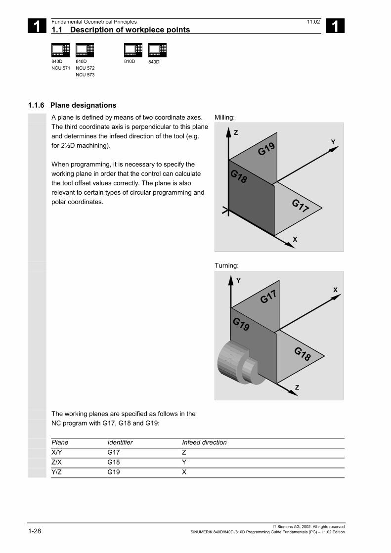
1.1.6 Plane designationsA plane is defined by means of two coordinate axes.The third coordinate axis is perpendicular to this planeand determines the infeed direction of the tool (e.g.for 2½D machining).
When programming, it is necessary to specify theworking plane in order that the control can calculatethe tool offset values correctly. The plane is alsorelevant to certain types of circular programming andpolar coordinates.
Milling:
X
YZ
G19
G18
G17
Turning:
Z
XY
G17
G18
G19
The working planes are specified as follows in theNC program with G17, G18 and G19:
Plane Identifier Infeed directionX/Y G17 ZZ/X G18 YY/Z G19 X

1 11.02 Fundamental Geometrical Principles1.2 Position of zero points 1
840DNCU 571
840DNCU 572NCU 573
810D 840Di
Siemens AG, 2002. All rights reservedSINUMERIK 840D/840Di/810D Programming Guide Fundamentals (PG) – 11.02 Edition 1-29
1.2 Position of zero pointsThe various origins and reference positions aredefined on the NC machine. They are referencepoints• for the machine to approach and• refer to programming the workpiece dimensions. They are: M = Machine zero A = Blocking point. Can coincide with the
workpiece zero (turning machines only) W = Workpiece zero = Program zero B = Start point. Can be defined for each program. Start point of the first tool for machining. R = Reference point. Position determined by cam and measuring system. The distance to
the machine zero M must be known, sothat the axis position can be set to exactly this value at this position.
The diagrams show the zero points and referencepoints for turning machines and drilling/millingmachines.
M A W
BR
X
Z
X
Y
M
W1 W2
1.3 Position of coordinate systems
1.3.1 Overview of various coordinate systems We distinguish between the following coordinate
systems:• The machine coordinate system with the machine
zero M• The basic coordinate system (this can also be the
workpiece coordinate system W)• The workpiece coordinate system with the
workpiece zero W• The current workpiece coordinate system with the
current offset workpiece zero Wa
In cases where various different machine coordinatesystems are in use (e.g. 5-axis transformation), aninternal transformation function mirrors the machinekinematics on the coordinate system currentlyselected for programming.

1 Fundamental Geometrical Principles 11.021.3 Position of coordinate systems 1
840DNCU 571
840DNCU 572NCU 573
810D 840Di
Siemens AG, 2002. All rights reserved1-30 SINUMERIK 840D/840Di/810D Programming Guide Fundamentals (PG) – 11.02 Edition
The individual axis identifiers are explained in thesubsection headed "Axis types" in this section.
Z m
Xm
Ym
Z w
Xw
YwZ a
Xa
Ya
MW Wa
WM X+
Z+
Y+

1 11.02 Fundamental Geometrical Principles1.3 Position of coordinate systems 1
840DNCU 571
840DNCU 572NCU 573
810D 840Di
Siemens AG, 2002. All rights reservedSINUMERIK 840D/840Di/810D Programming Guide Fundamentals (PG) – 11.02 Edition 1-31
1.3.2 Machine coordinate system The machine coordinate system comprises all the
physically existing machine axes. Reference points and tool and pallet changing points(fixed machine points) are defined in the machinecoordinate system. Where the machine coordinate system is used forprogramming (this is possible with some of theG functions), the physical axes of the machine areaddressed directly. No allowance is made forworkpiece clamping.
Zm
Xm
Ym
M
The location of the coordinate system relative to the
machine depends on the machine type. The axisdirections follow the so-called "three-finger rule" of theright hand (in accordance with DIN 66217). Standing in front of the machine, the middle finger ofthe right hand points away from the infeed direction ofthe main spindle. The following then applies: • The thumb points in the +X direction• The index finger points in the +Y direction• The middle finger points in the +Z direction
+Z
+Y
+X
In practice, this can look quite different on different
types of machine. The following are examples ofmachine coordinate systems for various machines.

1 Fundamental Geometrical Principles 11.021.3 Position of coordinate systems 1
840DNCU 571
840DNCU 572NCU 573
810D 840Di
Siemens AG, 2002. All rights reserved1-32 SINUMERIK 840D/840Di/810D Programming Guide Fundamentals (PG) – 11.02 Edition
B++Z
+A-A
+Z
+X +Y
B-
-B
-Y +X
-Y
+Z
+X
C+
C- X+Y+
Z+

1 11.02 Fundamental Geometrical Principles1.3 Position of coordinate systems 1
840DNCU 571
840DNCU 572NCU 573
810D 840Di
Siemens AG, 2002. All rights reservedSINUMERIK 840D/840Di/810D Programming Guide Fundamentals (PG) – 11.02 Edition 1-33
1.3.3 Basic coordinate system The basic coordinate system is a Cartesian
coordinate system, which is mirrored by kinematictransformation (for example, 5-axis transformation orby using Transmit with peripheral surfaces) onto themachine coordinate system. If there is no kinematic transformation, the basiccoordinate system differs from the machinecoordinate system only in terms of the axesdesignations. The activation of a transformation can producedeviations in the parallel orientation of the axes. Thecoordinate system does not have to be at a rightangle. Zero offset, scaling, etc. are always executed in thebasic coordinate system. The coordinates also refer to the basic coordinate system when specifying the working field limitation.
X
W Z
X
Y
Z
Y
Basic coordinate system for face end
Workpiece coordinate system for turning plane
Basic coordinate system for peripheral surface
Programmable FRAME
DRF shift, external zero offset
Y
MCS
Kinematic transformationBCS
MCS
WCS
YBCS YWCS
XMCS
X
X
BCS
WCS
Base offset (base frame)BZS
YBZS
XBZSG54...G599 settable FRAMES
SZS
YSZS
XSZS
MCS = Machine coordinate system BCS = Basic coordinate systemBZS = Basic zero system SZS = Settable zero systemWCS = Workpiece coordinate system

1 Fundamental Geometrical Principles 11.021.3 Position of coordinate systems 1
840DNCU 571
840DNCU 572NCU 573
810D 840Di
Siemens AG, 2002. All rights reserved1-34 SINUMERIK 840D/840Di/810D Programming Guide Fundamentals (PG) – 11.02 Edition
1.3.4 Workpiece coordinate system in the workpiece coordinate system. In other words,
the data in the NC program refer to the workpiececoordinate system. The workpiece coordinate system is always aCartesian coordinate system and assigned to aspecific workpiece.
Z
X
Y
1.3.5 Frame system The frame is a self-contained arithmetic rule that
transforms one Cartesian coordinate system intoanother Cartesian coordinate system. It is a: Spatial description of the workpiece coordinatesystem The following components are available within aframe: • Zero offset• Rotate• Mirror• Scale These components can be used individually or in anycombination.
X2
Y2
X1
Y1Z1=Z2
X0
Y0
Z0
Rotationaround the Z axis
Zero
offse
t
1 11.02 Fundamental Geometrical Principles1.3 Position of coordinate systems 1
840DNCU 571
840DNCU 572NCU 573
810D 840Di
Siemens AG, 2002. All rights reservedSINUMERIK 840D/840Di/810D Programming Guide Fundamentals (PG) – 11.02 Edition 1-35
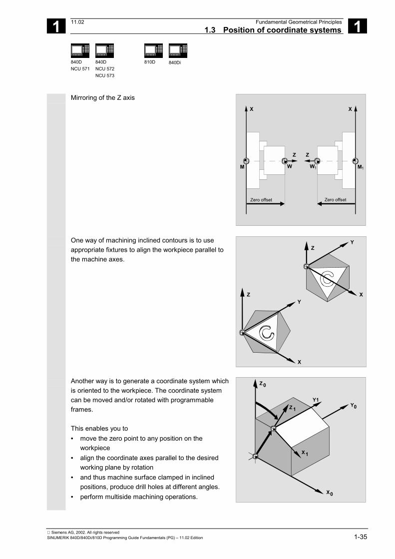
Mirroring of the Z axis
X
Z
M W
Zero offset
X
Z
MW
Zero offset
1 1
One way of machining inclined contours is to useappropriate fixtures to align the workpiece parallel tothe machine axes.
Z
X
Y
Z
X
Y
Another way is to generate a coordinate system whichis oriented to the workpiece. The coordinate systemcan be moved and/or rotated with programmableframes. This enables you to• move the zero point to any position on the
workpiece• align the coordinate axes parallel to the desired
working plane by rotation• and thus machine surface clamped in inclined
positions, produce drill holes at different angles.• perform multiside machining operations.
Z0
Y0
X0
Z 1
X1
Y1

1 Fundamental Geometrical Principles 11.021.3 Position of coordinate systems 1
840DNCU 571
840DNCU 572NCU 573
810D 840Di
Siemens AG, 2002. All rights reserved1-36 SINUMERIK 840D/840Di/810D Programming Guide Fundamentals (PG) – 11.02 Edition
Working plane, tool offsets The conventions for the working plane and the tooloffsets must be observed – in accordance with themachine kinematics – for machining operations ininclined working planes. For further information,please see Section 3.6 "Selection of working plane,G17 to G19".
1.3.6 Assignment of workpiece coordinate system to machine axes The location of the workpiece coordinate system in
relation to the basic coordinate system (or machinecoordinate system) is determined by settable frames. The settable frames are activated in the NC programby means of commands such as G54.
ZM=ZB YM=YB
XM=XB
ZW
XW
YW
M
1.3.7 Current workpiece coordinate system Sometimes it is advisable or necessary to reposition
and to rotate, mirror and/or scale the originallyselected workpiece zero within a program. The programmable frames can be used to reposition(rotate, mirror and/or scale) the current zero point at asuitable point in the workpiece coordinate system.You will thus obtain the current workpiece coordinatesystem. Several zero offsets are possible in the sameprogram.
YB
XBZB
Y1
Y2
X1
X2
Z1
Z2Frame 2
Frame 1
Workpiececoordinate system
Current workpiececoordinate system
Frame 1...settable offset and rotationFrame 2...programmable offset and rotation

1 11.02 Fundamental Geometrical Principles1.4 Axes 1
840DNCU 571
840DNCU 572NCU 573
810D 840Di
Siemens AG, 2002. All rights reservedSINUMERIK 840D/840Di/810D Programming Guide Fundamentals (PG) – 11.02 Edition 1-37
1.4 Axes A distinction is made between the following types of
axis when programming:• Machine axes• Channel axes• Geometry axes• Special axes• Path axes• Synchronized axes• Positioning axes• Command axes
(motion-synchronized axes)• PLC axes• Link axes• Leading link axes.
Geometry, synchronized and positioning axes areprogrammed. Path axes traverse with feedrate F in accordance withthe programmed travel commands. Synchronized axes traverse synchronously to pathaxes and take the same time to traverse as all pathaxes. Positioning axes traverse asynchronously to all otheraxes. These traversing movements take placeindependently of path and synchronized movements. Command axes traverse asynchronously to all otheraxes. These traversing movements take placeindependently of path and synchronized movements. PLC axes are controlled by the PLC and can traverseasynchronously to all other axes. The traversingmovements take place independently of path andsynchronized movements.
Geometry axes Positioning axes
Machine axes
Synchron.axes
Path axes PLC axesCommandaxes
Positioningaxes
transformation
Machine axes
Special axes
Channel axes
Kinematic
Geometry axes

1 Fundamental Geometrical Principles 11.021.4 Axes 1
840DNCU 571
840DNCU 572NCU 573
810D 840Di
Siemens AG, 2002. All rights reserved1-38 SINUMERIK 840D/840Di/810D Programming Guide Fundamentals (PG) – 11.02 Edition
1.4.1 Main axes/Geometry axes
The main axes define a right-angled, right-handedcoordinate system. Tool movements are programmedin this coordinate system. In NC technology, the main axes are called geometryaxes. This is the term used in this ProgrammingGuide. For turning machines: Geometry axes X and Z are used, and sometimes Y. For milling machines:Geometry axes X, Y and Z are used.
ToolsTurretswivel axis
Additionalspindle
Specialaxis
Tail-stockGeometry
axesMain spindle(master spindle)C axis
Z
X
A maximum of three geometry axes are used forprogramming frames and the workpiece geometry(contour). Identifiers: X, Y, Z The identifiers for geometry and channel axes can be the same, as long as mirroring is possible. Geometry axis and channel axis names can be thesame in any channel in order that the same programscan be executed.
The "Switchable geometry axes" function (seeAdvanced) can be used to alter the geometry axesgrouping configured by machine data. Here anygeometry axis can be replaced by a channel axisdefined as a synchronous special axis.
1 11.02 Fundamental Geometrical Principles1.4 Axes 1
840DNCU 571
840DNCU 572NCU 573
810D 840Di
Siemens AG, 2002. All rights reservedSINUMERIK 840D/840Di/810D Programming Guide Fundamentals (PG) – 11.02 Edition 1-39
1.4.2 Special axes In contrast to the geometry axes, no geometrical
relationship is defined between the special axes. Example: Turret position U, tailstock V
1.4.3 Main spindle, master spindle The machine kinematics determine which spindle is
the main spindle. This spindle is declared the masterspindle in the machine data. As a rule, the mainspindle is declared the master spindle.
This assignment can be changed with the programcommand SETMS (spindle number) (see Chapter 7). Special functions such as thread cutting apply to themaster spindle. Identifiers: S or S0
1.4.4 Machine axes The axis identifiers can be set in the machine data.
Standard identifiers: X1, Y1, Z1, A1, B1, C1, U1, V1 There are also standard axis identifiers that canalways be used: AX1, AX2, …, AXn
1.4.5 Channel axes All axes which traverse in a channel.
Identifiers: X, Y, Z, A, B, C, U, V

1 Fundamental Geometrical Principles 11.021.4 Axes 1
840DNCU 571
840DNCU 572NCU 573
810D 840Di
Siemens AG, 2002. All rights reserved1-40 SINUMERIK 840D/840Di/810D Programming Guide Fundamentals (PG) – 11.02 Edition
1.4.6 Path axes Path axes define the path and therefore the
movement of the tool in space. The programmed feedrate is active for this path. The axes involved in this path reach their position atthe same time. As a rule, these are the geometryaxes. However, default settings define which axes are thepath axes and therefore determine the velocity. Pathaxes can be specified in the NC program withFGROUP (see Chapter 5).
1.4.7 Positioning axes Positioning axes are interpolated separately, i.e. each
positioning axis has its own axis interpolator and itsown feedrate. A distinction is made between positioning axes withsynchronization at the block end or over severalblocks. POS axes: Block change occurs at the end of theblock when all the path and positioning axesprogrammed in this block have reached theirprogrammed end point. POSA axes: The movement of these positioning axescan extend over several blocks. POSP axes: The movement of these positioning axesfor approaching the end position takes place insections.
You will find further information on POS, POSA andPOSP in the section on "Traversing positioning axes,POS, POSA, POSP".

1 11.02 Fundamental Geometrical Principles1.4 Axes 1
840DNCU 571
840DNCU 572NCU 573
810D 840Di
Siemens AG, 2002. All rights reservedSINUMERIK 840D/840Di/810D Programming Guide Fundamentals (PG) – 11.02 Edition 1-41
Additional notes
Positioning axes become synchronized axes if theyare traversed without the special POS/POSAidentifier.
Continuous-path mode (G64) for path axes is onlypossible if the positioning axes (POS) reach their finalposition before the path axes. Path axes that are programmed with POS/POSA areremoved from the path axis grouping for the durationof this block. Positioning axes are traversed by the NC program orthe PLC. If an axis is to be traversed simultaneously by theNC program and the PLC, an error message appears. Typical positioning axes are:• Loaders for workpiece loading• Loaders for workpiece unloading• Tool magazine/turret.

1 Fundamental Geometrical Principles 11.021.4 Axes 1
840DNCU 571
840DNCU 572NCU 573
810D 840Di
Siemens AG, 2002. All rights reserved1-42 SINUMERIK 840D/840Di/810D Programming Guide Fundamentals (PG) – 11.02 Edition
1.4.8 Synchronized axes Synchronized axes traverse synchronously to the path
from the start position to the programmed endposition. The feedrate programmed in F applies to all the pathaxes programmed in the block, but does not apply tosynchronized axes. Synchronized axes take the sametime as the path axes to traverse. A synchronized axis can be a rotary axis which istraversed synchronously to the path interpolation.
1.4.9 Command axes Command axes are started from synchronized
actions in response to an event (command). They canbe positioned, started and stopped fully asynchronousto the parts program. An axis cannot be moved fromthe parts program and from synchronized actionssimultaneously. Command axes are interpolated separately, i.e. eachcommand axis has its own axis interpolator and itsown feedrate. References: /FBSY/, Synchronized Actions
1.4.10 PLC axes PLC axes are traversed by the PLC via special
function blocks in the basic program; their movementscan be asynchronous to all other axes. The traversingmovements take place independently of path andsynchronized movements.

1 11.02 Fundamental Geometrical Principles1.4 Axes 1
840DNCU 573
Siemens AG, 2002. All rights reservedSINUMERIK 840D/840Di/810D Programming Guide Fundamentals (PG) – 11.02 Edition 1-43
1.4.11 Link axes (SW 5 and higher) Link axes are axes which are physically connected to
another NCU and whose position is controlled fromthis NCU. Link axes can be dynamically assigned tochannels of a different NCU. Link axes are not localaxes from the perspective of a particular NCU.The dynamic changing of an assignment to an NCU isbased on the axis container concept. Axissubstitution with GET and RELEASE is not availablefor link axes from the parts program.
Preconditions: • The participating NCUs, NCU1 and NCU2, must
be connected by means of high-speedcommunication via the link module.References:/PHD/, Configuring Manual NCU 571-573.2,Link Module
• The axis must be configured appropriately bymachine data.
• The link axis option must be installed.
NCU 1 NCU 2611D 1
A1Channel 1
Channel 2
Channel 1
Link communicationLink module (HW) Link module (HW)
611D 2
B1
A2
A3
B2

1 Fundamental Geometrical Principles 11.021.4 Axes 1
840DNCU 573
Siemens AG, 2002. All rights reserved1-44 SINUMERIK 840D/840Di/810D Programming Guide Fundamentals (PG) – 11.02 Edition
Functionality
The position control is implemented on the NCU onwhich the axis is physically connected to the drive.This NCU also contains the associated axis VDIinterface. The position setpoints for link axes aregenerated on another NCU and communicated via theNCU link. The link communication must provide the means ofinteraction between the interpolators and the positioncontroller or PLC interface. The setpoints calculated bythe interpolators must be transported to the positioncontrol loop on the home NCU and, vice versa, theactual values must be returned from there back to theinterpolators.
For further information about link axes, please refer toReferences: /FB/ B3, Multiple Operator Panels andNCUs
Axis container (SW 5 and higher) An axis container is a circular buffer data structure in
which local axes and/or link axes are assigned tochannels. The entries in the circular buffer can beshifted cyclically.
In addition to the direct reference to local axes or linkaxes, the link axis configuration in the logical machineaxis image also allows references to axis containers.Such a reference consists of:
• a container number and• a slot (circular buffer location within the container)
The entry in a circular buffer location contains: • a local axis or
• a link axis
Axis container entries contain local machine axes orlink axes from the perspective of an individual NCU.The entries in the logical machine axis imageMN_AXCONF_LOGIC_MACHAX_TAB of anindividual NCU are fixed. The axis container function is described inReferences: /FB/ B3, Multiple Operator Panels andNCUs
1 11.02 Fundamental Geometrical Principles1.4 Axes 1
840DNCU 573
Siemens AG, 2002. All rights reservedSINUMERIK 840D/840Di/810D Programming Guide Fundamentals (PG) – 11.02 Edition 1-45
1.4.12 Leading link axes (SW 6 and higher) A leading link axis is one that is interpolated by one
NCU and utilized by one or several other NCUs as themaster axis for controlling slave axes.An axial position controller alarm is sent to all otherNCUs which are connected to the affected axis via aleading link axis.
NCUs that are dependent on the leading link axis canutilize the following coupling relationships with it:
- Master value (setpoint, actual value, simulated master value)
- Coupled motion
- Tangential follow-up
- Electronic gear (ELG)
- Synchronous spindle
Preconditions: • The dependent NCUs, i.e. NCU1 to NCUn (n
equals, max. of 8), must be interconnected via thelink module for high-speed communication.References:/PHD/, Configuring Manual NCU 571-573.2,Link Module
• The axis must be configured appropriately bymachine data.
• The link axis option must be installed.
• The same interpolation cycle must be configuredfor all NCUs connected to the leading link axis.

1 Fundamental Geometrical Principles 11.021.4 Axes 1
840DNCU 573
Siemens AG, 2002. All rights reserved1-46 SINUMERIK 840D/840Di/810D Programming Guide Fundamentals (PG) – 11.02 Edition
611 D
A1
NCU 1 NCU 2
Interpolator Interpolator
Servo Servo
NCU link modules
A1 setpoints
A1 real values
Influenced by
following axis/axes
611 D
B1
B2
NCU n...
Restrictions: • A master axis which is leading link axis cannot be
a link axis, i.e. it cannot be operated by otherNCUs as their home NCU.
• A master axis which is leading link axis cannot bea container axis, i.e. it cannot be addressedalternately by different NCUs.
• A leading link axis cannot be the programmedleading axis in a gantry grouping.
• Couplings with leading link axes cannot becascaded.
• Axis replacement can only be implemented withinthe home NCU of the leading link axis.
Programming: Master NCU:
Only the NCU which is physically assigned to themaster value axis can program travel motions for thisaxis. The travel program must not contain any specialfunctions or operations.
NCUs of slave axes:The travel program on the NCUs of the slave axesmust not contain any travel commands for the leadinglink axis (master value axis). If it does, an appropriatealarm will be generated.The leading link axis is addressed in the usual way viachannel axis identifiers. The states of the leading linkaxis can be accessed by means of selected systemvariables.

1 11.02 Fundamental Geometrical Principles1.4 Axes 1
840DNCU 573
Siemens AG, 2002. All rights reservedSINUMERIK 840D/840Di/810D Programming Guide Fundamentals (PG) – 11.02 Edition 1-47
System variables: The following system variables can be used in
conjunction with the channel axis identifiers of theleading link axis:$AA_LEAD_SP ; Simulated master value positionSAA_LEAD_SV ; Simulated master value velocity
If these system variables are updated by the homeNCU of the master axis, the new values are alsotransferred to any other NCUs who wish to controlslave axes as a function of this master axis.
References: /FB/ B3, Multiple Operator Panels andNCUs

1 Fundamental Geometrical Principles 11.021.5 Coordinate systems and workpiece machining 1
840DNCU 571
840DNCU 572NCU 573
810D 840Di
Siemens AG, 2002. All rights reserved1-48 SINUMERIK 840D/840Di/810D Programming Guide Fundamentals (PG) – 11.02 Edition
1.5 Coordinate systems and workpiece machining Relationship between the travel commands from
workpiece coordinates and the resulting machinemovements
Axis movement programmed in the workpiece coordinate system
Description of the workpiece geometryusing geometry axes(e.g. X, Y, Z)
Contour in Cartesiancoordinate system ofthe channel (BCS)
Frame calculation:• Translation (TRANS)• Rotation (ROT)• Scaling (SCALE)
Frame calculation:• Offset• Scaling
Description of the toolorientation by orientationvector/Euler angle
Remaining traversinginstructions using specialaxes (e.g. C, U, V)
Tool length compensation
Kinematic transformation (if active)
Movement of the machine axes of the channel abc
Tool radius compensation
Movement of the toolzeropoint in the BCS
Rotary axes with 5 axis transformator
Path calculations The path calculation determines the distance to betraversed in a block, taking into account all offsetsand compensations.

1 11.02 Fundamental Geometrical Principles1.5 Coordinate systems and workpiece machining 1
840DNCU 573
Siemens AG, 2002. All rights reservedSINUMERIK 840D/840Di/810D Programming Guide Fundamentals (PG) – 11.02 Edition 1-49
In general: Distance =setpoint - actual value + zero offset (ZO) + tool offset(TO)
X
Z
M W
ZO
Absolute position
TOSet-point
Abso
lute
posi
tionTO
Set
-po
int
T
If a new zero offset and a new tool offset areprogrammed in a new data block, the followingapplies:• With absolute dimensioning:
Distance = (absolute dimension P2 - absolute dimension P1) + (ZO P2 - ZO P1) + (TO P2 - TO P1).
• With incremental dimensioning:Distance = incremental dimension +
(ZO P2 - ZO P1) + (TO P2 - TO P1).
Abs. dim. (setpoint) for P2
Distance
Movement
Actual value 2
Actual value 1
Abs. dim.
(setpoint) for P 2
ZO P2
ZO P1 TC P1
TC P2
�

1 Fundamental Geometrical Principles 11.021.5 Coordinate systems and workpiece machining 1
840DNCU 571
840DNCU 572NCU 573
810D 840Di
Siemens AG, 2002. All rights reserved1-50 SINUMERIK 840D/840Di/810D Programming Guide Fundamentals (PG) – 11.02 Edition
Notes

2 11.02 Fundamental Principles of NC Programming 2
Siemens AG, 2002. All rights reservedSINUMERIK 840D/840Di/810D Programming Guide Fundamentals (PG) – 11.02 Edition 2-51
Fundamental Principles of NC Programming
2.1 Structure and contents of an NC program ...................................................................... 2-52
2.2 Language elements of the programming language ........................................................ 2-53
2.3 Programming a sample workpiece.................................................................................. 2-75
2.4 First programming example for milling application.......................................................... 2-77
2.5 Second programming example for milling application .................................................... 2-78
2.6 Programming example for turning application ................................................................ 2-81

2 Fundamental Principles of NC Programming 11.022.1 Structure and contents of an NC program 2840DNCU 571
840DNCU 572NCU 573
810D 840Di
Siemens AG, 2002. All rights reserved2-52 SINUMERIK 840D/840Di/810D Programming Guide Fundamentals (PG) – 11.02 Edition
2.1 Structure and contents of an NC programDIN 66025 is the guideline for designing a partsprogram.
An (NC/part) program consists of a sequence of NCblocks (see table below). Each data block representsone machining step. Instructions are written in theblocks in the form of words. The last block in theexecution sequence contains a special word for theend of program: M2, M17 or M30.
Block Word Word Word ... ;CommentBlock N10 G0 X20 ... ;1st blockBlock N20 G2 Z37 ... ;2nd blockBlock N30 G91 ... ... ;...Block N40 ... ... ...Block N50 M30 ... ... ;End of program (last block)
Program names
Each program has a different name; the name can bechosen freely during program creation (except forpunch tape format), taking the following conditions intoaccount:• The first two characters must be letters (or a letter
with an underscore character)• Otherwise: letters or numerals
Example: _MPF100 or
SHAFT or
SHAFT_2
Only the first 24 characters of a program identifier aredisplayed on the NC.

2 11.02 Fundamental Principles of NC Programming2.2 Language elements of the programming language 2
840DNCU 571
840DNCU 572NCU 573
810D 840Di
Siemens AG, 2002. All rights reservedSINUMERIK 840D/840Di/810D Programming Guide Fundamentals (PG) – 11.02 Edition 2-53
Punch tape format File names: 1. File names can contain the characters
0...9, A...Z, a...z or ____and may be up to24 characters in length.
2. File names must have a 3-digit identifier(_xxx).
3. Data in punch tape format can be createdexternally or modified using an editor. The name ofa file which is stored internally in the NC memorybegins with "_N_".A file in punch tape format begins with %<name>,"%" must appear in the first column of the first line.
Examples: %_N_SHAFT123_MPF = parts program SHAFT123 or%flange3_MPF = parts program flange3
For further information on downloading, creating and
storing parts programs, please refer to: /BA/, Operator's Guide, in the sections on the"Program" and "Services" user areas.
2.2 Language elements of the programming language Character set
The following characters are available for writing NCprograms: Upper case A, B, C, D, E, F, G, H, I, J, K, L, M,N, (O), P, Q, R, S, T, U, V, W, X, Y, Z Please note: Take care to differentiate between the letter "O" andthe numeral "0".
2 Fundamental Principles of NC Programming 11.022.2 Language elements of the programming language 2840DNCU 571
840DNCU 572NCU 573
810D 840Di
Siemens AG, 2002. All rights reserved2-54 SINUMERIK 840D/840Di/810D Programming Guide Fundamentals (PG) – 11.02 Edition
Lower case a, b, c, d, e, f, g, h, i, j, k, l, m,n, o, p, q, r, s, t, u, v, w, x, y, z Numerals 0, 1, 2, 3, 4, 5, 6, 7, 8, 9
No distinction is made between upper and lower case
letters.
Special characters % Program start character (used only for writing programs on an external PC) ( For bracketing parameters or expressions ) For bracketing parameters or expressions [ For bracketing addresses or indexes ] For bracketing addresses or indexes < Less than > Greater than : Main block, label suffix, chain operator = Assignment, part of equation / Division, block suppression * Multiplication + Addition - Subtraction, minus sign " Double quotation marks, identifier for character string ́ Single quotation marks, identifier for special numerical values: hexadecimal,
binary $ System variable identifiers _ Underscore, belonging to letters ? Reserved ! Reserved . Decimal point , Comma, parameter separator ; Comment start & Format character, same effect as space character LF Block end Tab character Separator Space character Separator (blank)
Non-printable special characters are treated like
blanks.

2 11.02 Fundamental Principles of NC Programming2.2 Language elements of the programming language 2
840DNCU 571
840DNCU 572NCU 573
810D 840Di
Siemens AG, 2002. All rights reservedSINUMERIK 840D/840Di/810D Programming Guide Fundamentals (PG) – 11.02 Edition 2-55
Words
NC programs are made up of blocks and each block ismade up of words. A word in the NC language consists of an addresscharacter and a digit or sequence of digitsrepresenting an arithmetic value. The address character of the word is usually a letter.The sequence of digits can contain a leading sign anddecimal point. The leading sign always appearsbetween the address letter and the sequence of digits.The positive leading sign (+) does not have to bespecified.
G01 X-50 S2000
Word
Add
ress
Dig
its
Block
Word Word
Add
ress
Add
ress
Dig
its
Dig
its Blocks and block format
An NC program consists of individual blocks. A blockgenerally consists of (several) words. A block should contain all the data required forperforming an operation step and is terminated withthe character "LF" (LINE FEED = new line).
The characters "LF" character does not have to be
inserted manually, it is generated automatically whenyou change lines.
Block length A block may contain• up to SW 3.x a maximum of 242 characters• SW 4 and higher a maximum of 512 characters
(including the comment and end-of-block character "LF").

2 Fundamental Principles of NC Programming 11.02 2.2 Language elements of the programming language 2
840DNCU 571
840DNCU 572NCU 573
810D
840Di
Siemens AG, 2002. All rights reserved2-56 SINUMERIK 840D/840Di/810D Programming Guide Fundamentals (PG) – 11.02 Edition
Three blocks of up to 66 characters each are normally
displayed in the current block display on the screen.Comments are also displayed. Messages aredisplayed in a separate message window.
Word sequence in blocks In order to keep the block structure as clear aspossible, the words in a block should be arranged asfollows: Example:
N10 G… X… Y… Z… F… S… T… D… M… H…
Address Definition
N Address of block number 10 Block number G Preparatory function X,Y,Z Positional data F Feed S Speed T Tool D Tool offset number M Miscellaneous function H Auxiliary function
Some addresses can be used repeatedly within a
block (e.g.: G…, M…, H…).
Main block/subblock There are two types of blocks: • Main blocks and • Subblocks. The main block must contain all the words necessaryto start the operation sequence in the program sectionbeginning with the main block.

2 11.02 Fundamental Principles of NC Programming 2.2 Language elements of the programming language 2
840DNCU 571
840DNCU 572NCU 573
810D
840Di
Siemens AG, 2002. All rights reservedSINUMERIK 840D/840Di/810D Programming Guide Fundamentals (PG) – 11.02 Edition 2-57
Main blocks can be contained in both main programs
and subprograms. The control does not check whethera main block contains all the necessary information.
Block number Main blocks are identified by a main block number. Amain block number consists of the character ":" and apositive integer (block number). The block numberalways appears at the start of a block.
Main block numbers must be unique within a program
to achieve an unambiguous result when searching.
Example: :10 D2 F200 S900 M3
Subblocks are identified by a subblock number. Asubblock number consists of the character "N" and apositive integer (block number). The block numberalways appears at the start of a block. Example: N20 G1 X14 Y35
N30 X20 Y40
Subblock numbers must be unique within a program in
order to achieve an unambiguous result whensearching.
The order of the block numbers is arbitrary, however
increasing block numbers are recommended. You can also program NC blocks without blocknumbers.

2 Fundamental Principles of NC Programming 11.02 2.2 Language elements of the programming language 2
840DNCU 571
840DNCU 572NCU 573
810D
840Di
Siemens AG, 2002. All rights reserved2-58 SINUMERIK 840D/840Di/810D Programming Guide Fundamentals (PG) – 11.02 Edition
Addresses Addresses are fixed or variable identifiers for axes (X,Y, ...) spindle speed (S), feed (F), circle radius (CR),etc. Example: N10 X100
Important addresses
Address Meaning (default setting) Remarks A=DC(...)
A=ACP(...)
A=ACN(...)
Rotary axis variable
ADIS Rounding clearance for path functions fixed B=DC(...)
B=ACP(...)
B=ACN(...)
Rotary axis variable
C=DC(...)C=ACP(...)
C=ACN(...)
Rotary axis variable
CHR=... Chamfer the contour corner fixed D... Tool number fixed F... Feed fixed FA[axis]=... or
FA[spindle]=... or[SPI(spindle)]=...
Axial feed (only if spindle no. defined by variable)
fixed
G... Preparatory function fixed H...
H=QU(...)
Auxiliary function Auxiliary function without read stop
fixed
I... Interpolation parameters variable J... Interpolation parameters variable K... Interpolation parameters variable L... Subprogram call fixed M...
M=QU(...)
Miscellaneous function Miscellaneous fct. w/o read stop
fixed
N... Subblock fixed OVR=... Path override fixed P... Number of program passes fixed

2 11.02 Fundamental Principles of NC Programming 2.2 Language elements of the programming language 2
840DNCU 571
840DNCU 572NCU 573
810D
840Di
Siemens AG, 2002. All rights reservedSINUMERIK 840D/840Di/810D Programming Guide Fundamentals (PG) – 11.02 Edition 2-59
Address Meaning (default setting) Remarks POS[axis]=... Positioning axis fixed POSA[axis]=... Positioning axis across block boundary fixed SPOS=...
SPOS[n]=...
Spindle position fixed
SPOSA=...SPOSA[n]=...
Spindle position across block boundary fixed
Q... Axis variable R0=... to Rn=...
R...
• Arithmetic parameter, n can be setvia MD (default 0-99)
• Axis (SW 5.1 and higher)
fixed variable
RND Round contour corner fixed RNDM Round contour corner (modal) fixed S... Spindle speed fixed T... Tool number fixed U... Axis variable V... Axis variable W... Axis variable X...
X=AC(...)
X=IC(...)
Axis " absolute " incremental
variable
Y...Y=AC(...)
Y=IC(...)
Axis variable
Z...Z=AC(...)
Z=IC(...)
Axis variable
AR+=... Aperture angle variable AP=... Polar angle variable CR=... Circle radius variable RP=... Polar radius variable :...: Main block fixed
"fixed"
These address names are available for a specific function.
Machine manufacturer (MH2.1)
"variable" These addresses can be assigned another name via themachine data.

2 Fundamental Principles of NC Programming 11.02 2.2 Language elements of the programming language 2
840DNCU 571
840DNCU 572NCU 573
810D
840Di
Siemens AG, 2002. All rights reserved2-60 SINUMERIK 840D/840Di/810D Programming Guide Fundamentals (PG) – 11.02 Edition
Modal/non-modal addresses Modal addresses remain valid with the programmed value(in all subsequent blocks) until a new value isprogrammed at the same address. Non-modal addresses only apply in the block in whichthey were programmed.
Example: N10 G01 F500 X10 N20 X10 ;Feed is effective until
a new value is entered.
Addresses with axial extension In addresses with axial extension, an axis name isinserted in square brackets after the address. The axisname assigns the axis. Example: FA[U]=400; Axis-specific feed for U axis
Extended addresses Extended address notation enables a larger number ofaxes and spindles to be organized in a system. Anextended address is composed of a numeric extension ora variable identifier enclosed in square brackets and anarithmetic expression assigned with an "=" sign. Example:
X7 ;No "=" required, 7 is a value, but the "=" ;character is also possible here X4=20 ;Axis X4 ("=" required) CR=7.3 ;2 letters ("=" required) S1=470 ;Speed for 1st spindle 470rpm M3=5 ;Spindle stop for 3rd spindle

2 11.02 Fundamental Principles of NC Programming 2.2 Language elements of the programming language 2
840DNCU 571
840DNCU 572NCU 573
810D
840Di
Siemens AG, 2002. All rights reservedSINUMERIK 840D/840Di/810D Programming Guide Fundamentals (PG) – 11.02 Edition 2-61
The extended address notation is only permitted for the following direct addresses:
X, Y, Z, … Axis addresses I, J, K Interpolation parameters S Spindle speed SPOS, SPOSA Spindle position M Miscellaneous functions H Auxiliary functions T Tool number F Feed The number (index) in extended address notation can
be substituted by a variable for M, H and S addressesand SPOS and SPOSA. The variable identifier isenclosed in square brackets.
Example:
S[SPINU]=470
;Speed for the spindle whose number is stored in the variable SPINU
M[SPINU]=3 ;Clockwise rotation for the spindle whose number is stored in the variable SPINU T[SPINU]=7 ;Selection of the tool for the spindle whose number is stored in the variable SPINU Fixed addresses
The following addresses are set permanently:
Address Meaning (default setting) D Tool edge number F Feed G Preparatory function H Auxiliary function L Subprogram call M Special function N Subblock P Number of program passes R Arithmetic parameter S Spindle speed T Tool number : Main block

2 Fundamental Principles of NC Programming 11.02 2.2 Language elements of the programming language 2
840DNCU 571
840DNCU 572NCU 573
810D
840Di
Siemens AG, 2002. All rights reserved2-62 SINUMERIK 840D/840Di/810D Programming Guide Fundamentals (PG) – 11.02 Edition
Example for programming: N10 G54 T9 D2
Fixed addresses with axis extension
Address Meaning (default setting) AX Axis value (variable axis programming) ACC Axial acceleration FA Axial feed FDA Axis feedrate for handwheel override FL Axial feed limit IP Interpolation parameter (variable axis programming) OVRA Axial override PO Polynomial coefficient POS Positioning axis POSA Positioning axis across block boundary Example: N10 POS[X]=100 When programming with the axis extension, the axis to be traversed is enclosed in square brackets.
You will find a complete list of all fixed addresses in
the Appendix.
Settable addresses
Addresses can be defined either as an address letter(with numerical extension if necessary) or as freelyselected identifiers.
Variable addresses must be unique within the control,
i.e. the same identifier name may not be used fordifferent address types.

2 11.02 Fundamental Principles of NC Programming 2.2 Language elements of the programming language 2
840DNCU 571
840DNCU 572NCU 573
810D
840Di
Siemens AG, 2002. All rights reservedSINUMERIK 840D/840Di/810D Programming Guide Fundamentals (PG) – 11.02 Edition 2-63
A distinction is made between the following addresstypes: • Axis values and end points • Interpolation parameters • Feeds • Approximate positioning criteria • Measurements • Axis and spindle response • …
Variable address letters are: A, B, C, E, I, J, K, Q, U, V, W, X, Y, Z
The user can change the names of the variable
addresses in the machine data.
Example:
X1, Y30, U2, I25, E25, E1=90, …
The numeric extension has one or two digits and isalways positive.
Address identifier The address notation can be expanded by addingfurther letters. Example:
CR e.g. for circle radius XPOS

2 Fundamental Principles of NC Programming 11.02 2.2 Language elements of the programming language 2
840DNCU 571
840DNCU 572NCU 573
810D
840Di
Siemens AG, 2002. All rights reserved2-64 SINUMERIK 840D/840Di/810D Programming Guide Fundamentals (PG) – 11.02 Edition
Operators/mathematical functions
+ Addition - Subtraction * Multiplication / Division
NOTICE: (Type INT)/(Type INT)=(Type REAL); e.g. 3/4 = 0.75 DIV Division, for variable type INT and REAL
NOTICE: (Type INT)DIV(Type INT)=(Type INT); e.g. 3 DIV 4 = 0 MOD Modulo division (only type INT) produces remainder of INT division, e.g. 3
MOD 4=3 : Chain operator (for FRAME variables) Sin() Sine COS() Cosine TAN() Tangent ASIN() Arcsine ACOS() Arccosine ATAN2() Arctangent2 SQRT() Square root ABS() Absolute number POT() 2nd power (square) TRUNC() Truncate to integer ROUND() Round to integer LN() Natural logarithm EXP() Exponential function
Comparison and logic operators
== Equal to <> Not equal to > Greater than < Less than >= Greater than or equal to <= Less than or equal to AND AND OR OR NOT Negation XOR Exclusive OR

2 11.02 Fundamental Principles of NC Programming 2.2 Language elements of the programming language 2
840DNCU 571
840DNCU 572NCU 573
810D
840Di
Siemens AG, 2002. All rights reservedSINUMERIK 840D/840Di/810D Programming Guide Fundamentals (PG) – 11.02 Edition 2-65
In arithmetic expressions, the execution order ofall the operators can be specified by parentheses,in order to override the normal priority rules.
Value assignments
Values can be assigned to the addresses. The method ofvalue assignment depends on the type of addressidentifier. An "=" sign must be inserted between the addressidentifier and the value if • the address identifier consists of more than one letter,
or • the value consists of more than one constant. The "="-sign can be omitted if the address identifier is asingle letter and the value consists of only one constant.Leading signs are allowed and separators are permittedafter the address letter. Examples:
X10 ;Value assignment (10) to address X, "=" not required X1=10 ;Value assignment (10) to address (X) with numeric extension (1), "="
required FGROUP(X1, Y2) ;Axis names from passed parameters AXDATA[X1] ;Axis name as an index when accessing axis data AX[X1]=10 ;Indirect axis programming X=10*(5+SIN(37.5)) ;Value assignment by means of a numeric expression, "=" required
A numeric extension must always be followed by one of
the special characters "=", "(", "[")"]", "," or an operator inorder to distinguish an address name with numericextension from an address letter with a value.

2 Fundamental Principles of NC Programming 11.02 2.2 Language elements of the programming language 2
840DNCU 571
840DNCU 572NCU 573
810D
840Di
Siemens AG, 2002. All rights reserved2-66 SINUMERIK 840D/840Di/810D Programming Guide Fundamentals (PG) – 11.02 Edition
Identifiers Identifiers can also be used to describe words (incompliance with DIN 66025). The identifiers have thesame meaning as the words within an NC block.Identifiers must be unique. Identical identifiers must notbe used for different objects. Identifiers can stand for: • Variables
- System variables - User variables
• Subprograms • Vocabulary words • DIN addresses with several letters • Jump labels Structure The identifiers are composed of up to 32 characters. Thefollowing characters may be used: • Letters • Underscores • Numerals The first two characters must be letters or underscores,separators must not be programmed between theindividual characters (see the following pages). Example: CMIRROR, CDON
Reserved vocabulary words must not be used as
identifiers. Separators are not permitted between theindividual characters.
Number of characters for each identifier:
• Program names: 24 characters • Axis identifiers: 8 characters • Variable identifiers: 31 characters

2 11.02 Fundamental Principles of NC Programming 2.2 Language elements of the programming language 2
840DNCU 571
840DNCU 572NCU 573
810D
840Di
Siemens AG, 2002. All rights reservedSINUMERIK 840D/840Di/810D Programming Guide Fundamentals (PG) – 11.02 Edition 2-67
Rules for allocating identifiers The following rules are provided in order to avoididentifier collisions: • All identifiers which begin with "CYCLE" or "_" are
reserved for SIEMENS cycles. • All identifiers which begin with "CCS" are reserved for
SIEMENS compile cycles. • User compile cycles begin with "CC". • We recommend that users select identifier names
which either begin with "U" (User) or contain theunderscore symbol, because these are not used bythe system or compile cycles or SIEMENS cycles.
Further reserved identifiers • The identifier "RL" is reserved for conventional turning
machines.• All identifiers beginning with "E_ " are reserved for
EASYSTEP programming.
Variable identifiers In variables used by the system, the first letter is replacedby the "$" character. This character may not be used foruser-defined variables. Examples (see Programming Guide "Advanced"): $P_IFRAME, $P_F Leading zeroes are ignored in variables with numericextensions (i.e. R01 is interpreted as R1). Separators areallowed before a numeric extension.

2 Fundamental Principles of NC Programming 11.02 2.2 Language elements of the programming language 2
840DNCU 571
840DNCU 572NCU 573
810D
840Di
Siemens AG, 2002. All rights reserved2-68 SINUMERIK 840D/840Di/810D Programming Guide Fundamentals (PG) – 11.02 Edition
Array identifiers The rules for elementary variables also apply to arrayidentifiers. It is possible to address arithmetic variablesas arrays. Example: R[10]=…
Data types A variable can contain a numeric value (or several) ora character (or several), e.g. an address letter. The data type permitted for the variable is determinedwhen the variable is defined. The data type for systemvariables and predefined variables is fixed. Elementary variable types/data types are:
Type Definition Value range INT Integers with leading sign ±(231 - 1) REAL Real numbers (fractions with decimal
point, LONG REAL according toIEEE)
±(10-300 … 10+300)
BOOL Boolean values: TRUE (1) andFALSE (0)
1, 0
CHAR 1 ASCII character specified by thecode
0 … 255
STRING Character string, number ofcharacters in […], maximum of 200characters
Sequence of values with 0 … 255
AXIS Axis names (axis addresses) only Any axis identifiers in the channel FRAME Geometrical parameters for
translation, rotation, scale and mirror
Identical elementary types can be combined in arrays.Up to two-dimensional arrays are possible.
2 11.02 Fundamental Principles of NC Programming 2.2 Language elements of the programming language 2
840DNCU 571
840DNCU 572NCU 573
810D
840Di
Siemens AG, 2002. All rights reservedSINUMERIK 840D/840Di/810D Programming Guide Fundamentals (PG) – 11.02 Edition 2-69
Constants Integer constants: Integer with or without leading sign, e.g. for assigninga value to an address Examples:
X100 ;Assignment of the value +100 to address X X-100 ;Assignment of the value –100 to address X
Real constants: Real number, e.g. with decimal point, with or withoutleading sign, e.g. for assigning a value to an address Example:
X10.25 ;Assignment of the value +10.25 to address X X-10.25 ;Assignment of the value –10.25 to address X X0.25 ;Assignment of the value +0.25 to address X X.25 ;Assignment of the value +0.25 to address X without leading "0" X=-.1EX-3 ;Assignment of the value –0.1*10-3 to address X
If, in an address which permits decimal point input,
more decimal places are specified than actuallyprovided for the address, then they are rounded to fitthe number of places provided.
X0 cannot be replaced with X.
Example: Do not replace G01 X0 with G01 X!

2 Fundamental Principles of NC Programming 11.02 2.2 Language elements of the programming language 2
840DNCU 571
840DNCU 572NCU 573
810D
840Di
Siemens AG, 2002. All rights reserved2-70 SINUMERIK 840D/840Di/810D Programming Guide Fundamentals (PG) – 11.02 Edition
Hexadecimal constants Constants can also be interpreted in hexadecimalformat. The letters "A" to "F" stand for the digits 10 to15. Hexadecimal constants are enclosed in singlequotation marks and start with the letter "H", followedby the value in hexadecimal notation. Separators areallowed between the letters and digits. Example for machine data (see also "Advanced"):
$MC_TOOL_MANAGEMENT_MASK='H3C7F' ;Assignment of hexadecimalvalues to machine data
The maximum number of characters is limited by thevalue range of the integer data type. Binary constants Constants can also be interpreted in binary format. Inthis case, only the digits "0" and "1" are used. Binary constants are enclosed in single quotationmarks and start with the letter "B", followed by thebinary value. Separators are allowed between thedigits. Example for machine data (see also "Advanced"):
$MN_AUXFU_GROUP_SPEC='B10000001' ;Assignment of binary constants tomachine data Bits 0 and 7 are set
The maximum number of characters is limited by thevalue range of the integer data type.
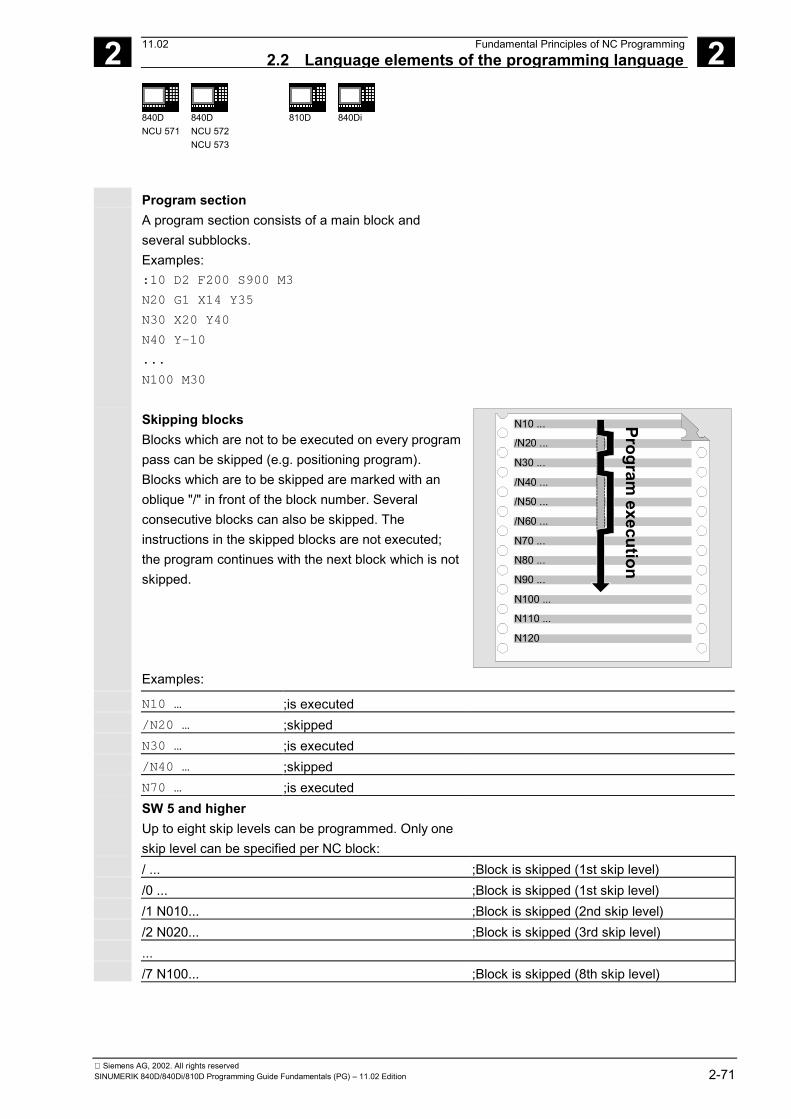
2 11.02 Fundamental Principles of NC Programming 2.2 Language elements of the programming language 2
840DNCU 571
840DNCU 572NCU 573
810D
840Di
Siemens AG, 2002. All rights reservedSINUMERIK 840D/840Di/810D Programming Guide Fundamentals (PG) – 11.02 Edition 2-71
Program section A program section consists of a main block andseveral subblocks. Examples: :10 D2 F200 S900 M3 N20 G1 X14 Y35 N30 X20 Y40 N40 Y-10 ... N100 M30
Skipping blocks Blocks which are not to be executed on every programpass can be skipped (e.g. positioning program). Blocks which are to be skipped are marked with anoblique "/" in front of the block number. Severalconsecutive blocks can also be skipped. Theinstructions in the skipped blocks are not executed;the program continues with the next block which is notskipped. Examples:
/N20 ...
N10 ...
N30 ...
/N40 ...
/N50 ...
/N60 ...
N70 ...
N80 ...
N90 ...
N100 ...
N110 ...
N120
Program execution
N10 … ;is executed /N20 … ;skipped N30 … ;is executed /N40 … ;skipped N70 … ;is executed SW 5 and higher
Up to eight skip levels can be programmed. Only oneskip level can be specified per NC block:
/ ... ;Block is skipped (1st skip level) /0 ... ;Block is skipped (1st skip level) /1 N010... ;Block is skipped (2nd skip level) /2 N020... ;Block is skipped (3rd skip level) ... /7 N100... ;Block is skipped (8th skip level)

2 Fundamental Principles of NC Programming 11.02 2.2 Language elements of the programming language 2
840DNCU 571
840DNCU 572NCU 573
810D
840Di
Siemens AG, 2002. All rights reserved2-72 SINUMERIK 840D/840Di/810D Programming Guide Fundamentals (PG) – 11.02 Edition
SW 6.3 and higher Up to ten skip levels can be programmed. Only oneskip level can be specified per NC block:
/8 N080... ;Block is skipped (9th skip level) /9 N090... ;Block is skipped (10th skip level)
Machine manufacturer (MH2.2)
The number of skip levels that can be used dependson a display MD.
Block skipping of levels /0 to /9 is activated by an
operator action (see /BA/ Operator's Guide, programcontrol menu in Machine operating area) or by theprogrammable controller.
System and user variables can also be used in
conditional jumps in order to control programexecution.
Jump destinations (labels)
Labels can be defined to jump within a program.
You will find further information in the Programming
Guide Advanced.
Label names are allocated with at least two and up to32 characters (letters, digits, underscore). The first twocharacters must be letters or underscores. The labelname is followed by a colon (":").
Labels must be unique within a program.
Labels always appear at the start of a block. If a
program number exists, the label appears immediatelyafter the block number.

2 11.02 Fundamental Principles of NC Programming 2.2 Language elements of the programming language 2
840DNCU 571
840DNCU 572NCU 573
810D
840Di
Siemens AG, 2002. All rights reservedSINUMERIK 840D/840Di/810D Programming Guide Fundamentals (PG) – 11.02 Edition 2-73
Comments To make NC programs easier to understand for otherusers and programmers, it is advisable to insertmeaningful comments in the program. Comments are appended to the end of a block and areseparated from the program section of the NC blockby a semicolon (";"). Examples:
N10 G1 F100 X10 Y20 ; Comments to explain the NC block or N10 ; G&S Co., order no. 12A71 N20 ; Program written by Bob Miller, Dept. TV 4, on 21.11.94 N50 ; Part no. 12, housing for pump type TP23A
Comments are stored and appear in the current block
display when the program is running.
Programming messages
Messages can be programmed to provide the userwith information about the current machining situationduring program execution.
A message in an NC program is generated when themessage text is typed after vocabulary word "MSG" inround parentheses "()" and quotation marks.
A message can be cleared by programming "MSG ()".
Example: N10 MSG ("Roughing the contour") ;Activate message N20 X… Y… N … N90 MSG () ;Clear message from N10

2 Fundamental Principles of NC Programming 11.02 2.2 Language elements of the programming language 2
840DNCU 571
840DNCU 572NCU 573
810D
840Di
Siemens AG, 2002. All rights reserved2-74 SINUMERIK 840D/840Di/810D Programming Guide Fundamentals (PG) – 11.02 Edition
A message text can be up to 124 characters long and
is displayed in two lines (2*62 characters).
Contents of variables can also be displayed inmessage texts.
Examples: N10 R12=$AA_IW [X] ;Current position of the X axis in R12 N20 MSG (″check position of X axis″<<R12<<″″) N … N90 MSG () ;Clear message from N20 or N20 MSG (″check position of X axis″<<$AA_IW[X]<<″″) Setting alarms
You can also set alarms in addition to messages in anNC program. Alarms are displayed in a separate fieldon the screen display. An alarm is associated with areaction on the control which depends on the alarmcategory. Alarms are programmed by writing the vocabularyword "SETAL" followed by the alarm number enclosedin brackets. The valid range for alarm numbers lies between60,000 and 69,999, whereby 60,000 to 64,999 arereserved for SIEMENS cycles and 65,000 to 69,999are available to the user.
Alarms are always programmed in a separate block.
Example:
N100 SETAL (65000) ;Set alarm no. 65,000
You will find a list of reactions associated with specificalarms in the Installation and Start-up Guide. The alarm text must be configured in the MMC.

2 11.02 Fundamental Principles of NC Programming2.3 Programming a sample workpiece 2
840DNCU 571
840DNCU 572NCU 573
810D
840Di
Siemens AG, 2002. All rights reservedSINUMERIK 840D/840Di/810D Programming Guide Fundamentals (PG) – 11.02 Edition 2-75
2.3 Programming a sample workpiece Planning the machining sequence
The actual programming of the individual operationsteps in the NC language generally only represents asmall proportion of the work in the development of anNC program. Programming of the actual instructions should bepreceded by the planning and preparation of theoperation steps. And the more accurately you considerhow the NC program is to be structured andorganized, the faster and easier it will be to produce acomplete program which is clear and free of errors.
Clearly structured programs are a particular advantage
if you need to make changes at a later date. Since different parts do not all look the same, it isnaturally inadvisable to develop every programaccording to the same method. However, certainprocedures apply in most cases and these arepresented on the following pages in the form of achecklist.

2 Fundamental Principles of NC Programming 11.02 2.3 Programming a sample workpiece 2
840DNCU 571
840DNCU 572NCU 573
810D
840Di
Siemens AG, 2002. All rights reserved2-76 SINUMERIK 840D/840Di/810D Programming Guide Fundamentals (PG) – 11.02 Edition
1. Prepare the workpiece drawing
• Define the workpiece zero • Sketch in the coordinate system • Calculate any missing coordinates 2. Define machining sequence • What tools are used when and to machine which
contour? • In what order are the individual elements of the
workpiece manufactured? • Which individual elements are repeated (or also
rotated) and should therefore be stored in asubprogram?
• Do these or similar contour sections already exist inother parts programs or subprograms which couldbe used here? Where is it advisable or necessary to perform zerooffset, rotation, mirroring or scaling (frameconcept)?
3. Create a machining plan Define all the machining processes in steps, e.g.: • Rapid traverse movements for positioning • Tool change • Tool retraction for recalibration • Switching the spindle and coolant on and off • Calling tool data • Infeed • Path correction • Approach contour • Retract from contour • etc.
4. Translate the work steps into the programminglanguage Enter each individual step in an NC block or blocks 5. Combine all the individual steps in a program

2 11.02 Fundamental Principles of NC Programming 2.4 First programming example for milling application 2
840DNCU 571
840DNCU 572NCU 573
810D
840Di
Siemens AG, 2002. All rights reservedSINUMERIK 840D/840Di/810D Programming Guide Fundamentals (PG) – 11.02 Edition 2-77
2.4 First programming example for milling application Please proceed on the NC as described below to
verify the following programming example (seeOperator's Guide): • Create a new parts program (name) • Edit parts program • Select parts program • Activate single block • Start parts program
Alarms can occur during program verification. These
alarms have to be reset first.
Machine manufacturer (MH2.3)
The MD settings must be defined correctly before theprogram can run on the machine. References: /FB/ K2, "Axes, Coordinate Systems,.."
Programming example
_MILL1_MPF ;Sample program
N10 MSG("THIS IS MY NC PROGRAM") ;MSG = Message output in an alarm line :10 F200 S900 T1 D2 M3 ;Feed, spindle, tool,
;tool offset, spindle clockwise N20 G0 X100 Y100 ;Rapid traverse to position N30 G1 X150 ;Rectangle with feed, straight line in X N40 Y120 ;Straight line in Y N50 X100 ;Straight line in X N60 Y100 ;Straight line in Y N70 G0 X0 Y0 ;Return rapid traverse movement N100 M30 ;End of block

2 Fundamental Principles of NC Programming 11.02 2.5 Second programming example for milling application 2
840DNCU 571
840DNCU 572NCU 573
810D
840Di
Siemens AG, 2002. All rights reserved2-78 SINUMERIK 840D/840Di/810D Programming Guide Fundamentals (PG) – 11.02 Edition
2.5 Second programming example for milling application This programming example contains surface and side
milling, as well as drilling.• The workpiece is intended for machining on a
vertical milling machine.• The dimensions are in inches.
Machine manufacturer (MH2.4)
The MD settings must be defined correctly before theprogram can run on the machine.References: /FB/ K2, "Axes, Coordinate Systems,.."
Programming example
%_N_RAISED_BOSS_MPF
N005 MSG ("Traverse axes to tool change location")
N010 START01:SUPA G0 G70 Z0 D0
N015 SUPA X0 Y0
;********************Tool change********************
N020 MSG ("Tool change active")
N025 T1 M6 ; d = 3 inch face cutterN030 MSG () ; clears the message from block N020N035 MSG ("Face milling Z=0 workpiece surface")
N040 G0 G54 X-2 Y.6 S800 M3 M8
N045 Z1 D1
N050 G1 Z0 F50
N055 X8 F25
N060 G0 Y3.5
N065 G1 X-2
N070 SUPA G0 Z0 D0 M5 M9
;********************Tool change********************
N075 T2 M6 ; d = 1 inch face cutterMSG ("Side machining")
N080 G0 X-1 Y.25 S1200 M3 M8
N085 Z1 D1
N090 G1 Z-.5 F50
N095 G42 X.5 F30
N100 X5.5 RNDM=-.375 ; modal rounding. Radius=0.375N105 Y3.625

2 11.02 Fundamental Principles of NC Programming2.5 Second programming example for milling application 2
840DNCU 571
840DNCU 572NCU 573
810D
840Di
Siemens AG, 2002. All rights reservedSINUMERIK 840D/840Di/810D Programming Guide Fundamentals (PG) – 11.02 Edition 2-79
N110 X.5
N115 Y.25
N120 X=IC(.375) RNDM=0 ; required for edge roundingN125 G40 G0 Y-1 M5 M9 ; rapid traverse to delete positionN130 Z1
N135 X-1 Y0
N140 Z-.25
,********************Continue to use 1-inch mill****************
MSG ("Side Cut Top Boss")
N145 G01 G41 X1 Y2
N150 G2 X1.5476 Y3.375 CR=2
N155 G3 X4.4524 CR=3
N160 G2 Y.625 CR=2
N165 G3 X1.5476 CR=3
N170 G2 X1 Y2 CR=2
N175 G0 G40 X0
N180 SUPA G0 Z0 D0 M5 M9 ; Z approaches tool change locationN185 SUPA X0 Y0 ; X and Y to the tool change location;********************Tool change********************
N190 T3 M6 ; 27/64 drillMSG ("Drill 3 holes")
N195 G0 X1.75 Y2 S1500 M3 M8 ; approach first drill holeN200 Z1 D1
N205 MCALL CYCLE81 (1,0,.1,-.5,)
N207 X1.75 ; drill first holeN210 X3 ; drill second holeN215 X4.25 ; drill third holeN220 MCALL
N221 SUPA Z0 D0 M5 M9 ; Delete modal call. Z axis traverses to machine zeroN225 SUPA X0 Y0
MSG ()
N230 M30 ; end of program

2 Fundamental Principles of NC Programming 11.02 2.5 Second programming example for milling application 2
840DNCU 571
840DNCU 572NCU 573
810D
840Di
Siemens AG, 2002. All rights reserved2-80 SINUMERIK 840D/840Di/810D Programming Guide Fundamentals (PG) – 11.02 Edition
6.05.0
4.0
3.0 R
2.0
0.75
0.375 R
0.25
0.5
2.53.5
1.25
2.0 R
1.375
1.4524 1/2-13
X 1.0 DP
0.75
Dimensions in inches
Dimension drawing of workpiece "The Raised Boss" (not to size).
0.25
0.25
Side viewDimensions in inches

2 11.02 Fundamental Principles of NC Programming 2.6 Programming example for turning application 2
840DNCU 571
840DNCU 572NCU 573
810D
840Di
Siemens AG, 2002. All rights reservedSINUMERIK 840D/840Di/810D Programming Guide Fundamentals (PG) – 11.02 Edition 2-81
2.6 Programming example for turning application
The sample program contains radiusprogramming and tool radius compensation.
Programming example
%_N_1001_MPF ;Program name
N5 G0 G53 X280 Z380 D0 ;Start pointN10 TRANS X0 Z250 ;Zero offsetN15 LIMS=4000 ;Speed limitation (G96)N20 G96 S250 M3 ;Select constant feedN25 G90 T1 D1 M8 ;Select tool and offsetN30 G0 G42 X-1.5 Z1 ;Activate tool with tool radius compensationN35 G1 X0 Z0 F0.25
N40 G3 X16 Z-4 I0 K-10 ;Rotate radius 10N45 G1 Z-12
N50 G2 X22 Z-15 CR=3 ;Rotate radius 3N55 G1 X24
N60 G3 X30 Z-18 I0 K-3 ;Rotate radius 3N65 G1 Z-20
N70 X35 Z-40
N75 Z-57
N80 G2 X41 Z-60 CR=3 ;Rotate radius 3N85 G1 X46
N90 X52 Z-63
N95 G0 G40 G97 X100 Z50 M9 ;Deselect tool radius compensation andapproach tool change location
N100 T2 D2 ;Call up tool and select offsetN105 G96 S210 M3 ;Select constant cutting speedN110 G0 G42 X50 Z-60 M8 ;Activate tool with tool radius compensationN115 G1 Z-70 F0.12 ;Rotate diameter 50N120 G2 X50 Z-80 I6.245 K-5 ;Rotate radius 8N125 G0 G40 X100 Z50 M9 ;Retract tool and deselect tool radius
compensationN130 G0 G53 X280 Z380 D0 M5 ;Move to tool change locationN135 M30 ;End of program

2 Fundamental Principles of NC Programming 11.02 2.6 Programming example for turning application 2
840DNCU 571
840DNCU 572NCU 573
810D
840Di
Siemens AG, 2002. All rights reserved2-82 SINUMERIK 840D/840Di/810D Programming Guide Fundamentals (PG) – 11.02 Edition
4
Ø 1
6
Ø 5
0Ø
35
Ø 3
0
62
60
57
40
20
18
15
12
80
70
45°
R3
R3R3
R8
R10
Z
X
Machine manufacturer (MH2.5)
The MD settings must be defined correctly before the program can run on the machine.References: /FB/ K2, "Axes, Coordinate Systems,.."
�

3 11.02 Positional Data 3
Siemens AG, 2002. All rights reservedSINUMERIK 840D/840Di/810D Programming Guide Fundamentals (PG) – 11.02 Edition 3-83
Positional Data
3.1 General information........................................................................................................ 3-84
3.2 Absolute/incremental dimensions, G90/G91.................................................................. 3-853.2.1 G91 extension (SW 4.3 and higher).......................................................................... 3-88
3.3 Absolute dimensions for rotary axes, DC, ACP, ACN.................................................... 3-89
3.4 Metric/imperial dimensions, G70/G71/G700/G710 ........................................................ 3-91
3.5 Zero offset (frame), G54 to G599................................................................................... 3-94
3.6 Selecting the working plane, G17 to G19....................................................................... 3-99
3.7 Programmable working area limitation, G25/G26 ........................................................ 3-102
3.8 Reference point approach, G74 ................................................................................... 3-105

3 Positional Data 11.023.1 General information 3
840DNCU 571
840DNCU 572NCU 573
810D 840Di
Siemens AG, 2002. All rights reserved3-84 SINUMERIK 840D/840Di/810D Programming Guide Fundamentals (PG) – 11.02 Edition
3.1 General informationIn this section you will find a description of thecommands that normally appear at the beginning ofa NC program.
The way in which these functions are combined isnot intended to be a patent remedy. For example,the choice of working plane may be made at anotherpoint in the NC program.
The real purpose of this and all the followingsections is to illustrate the conventional structure ofan NC program.

3 11.02 Positional Data3.2 Absolute/incremental dimensions, G90/G91 3
840DNCU 571
840DNCU 572NCU 573
810D 840Di
Siemens AG, 2002. All rights reservedSINUMERIK 840D/840Di/810D Programming Guide Fundamentals (PG) – 11.02 Edition 3-85
3.2 Absolute/incremental dimensions, G90/G91Programming
Absolute dimensioningG90
X=AC(…) Y=AC(…) Z=AC(…)
Incremental dimensioningG91 or
X=IC(…) Y=IC(…) Z=IC(…)
Explanation of the parameters
X Y Z Axis identifiers of the axes to be traversed=AC Absolute dimensions (non-modal)=IC Incremental dimensions (non-modal)
Function
The G90/91 commands and the non-modaldimensions AC/IC are used to define the system fordescribing the approach to setpoints.
Sequence
Absolute dimensions, G90The dimensions refer to the origin of the activecoordinate system. You program the point to whichthe tool is to travel, e.g. in the workpiece coordinatesystem.
Incremental dimensions, G91The dimensions refer to the last point approached.You program how far the tool is to travel.
Non-modal absolute or incrementaldimensioning AC, ICWhen G91 is active, AC can be used to allow entryof absolute dimensions for individual axes in aspecific block. When G90 is active, IC can be usedto allow entry of incremental dimensions forindividual axes in a specific block.
X
Y
10 50
60
85
G90
G91
G90
G91
3020
35
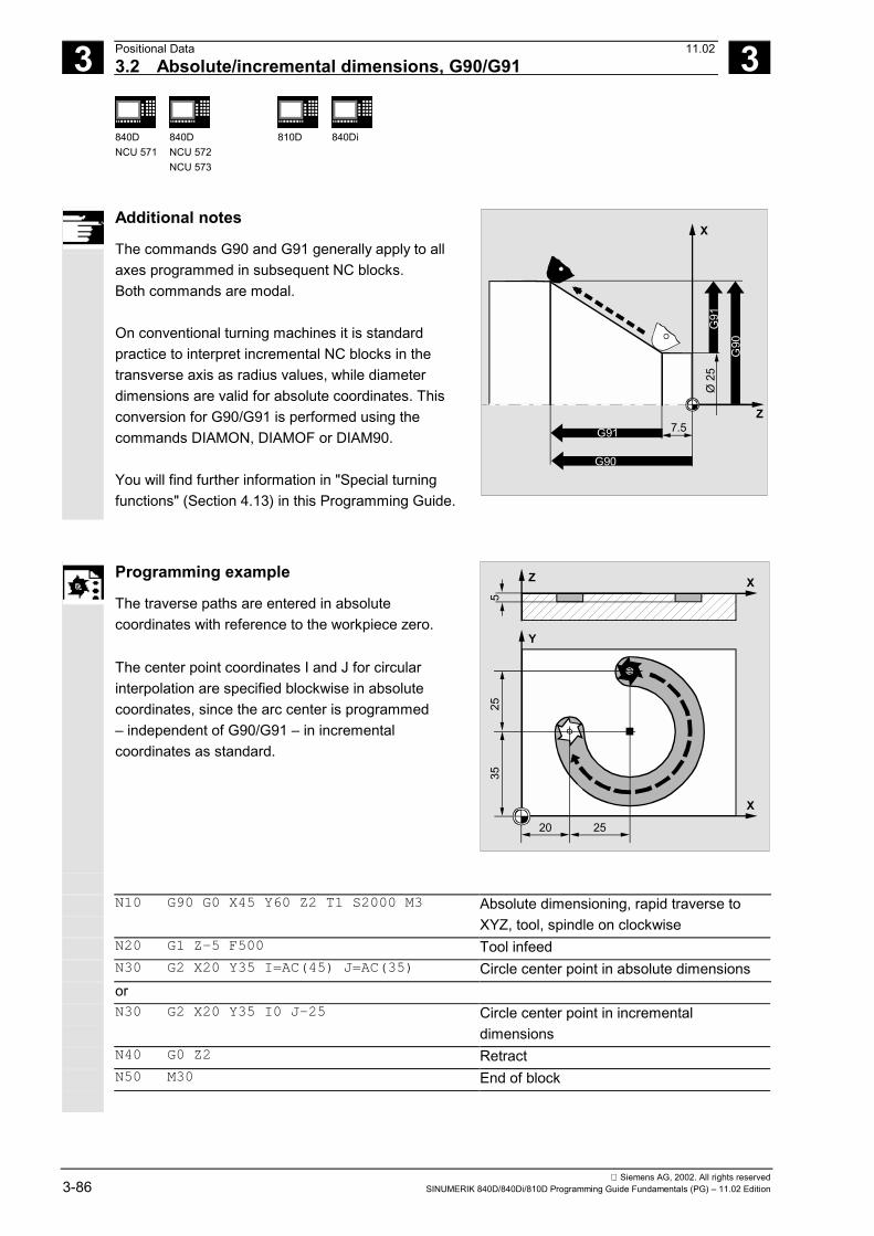
3 Positional Data 11.023.2 Absolute/incremental dimensions, G90/G91 3
840DNCU 571
840DNCU 572NCU 573
810D 840Di
Siemens AG, 2002. All rights reserved3-86 SINUMERIK 840D/840Di/810D Programming Guide Fundamentals (PG) – 11.02 Edition
Additional notes
The commands G90 and G91 generally apply to allaxes programmed in subsequent NC blocks.Both commands are modal.
On conventional turning machines it is standardpractice to interpret incremental NC blocks in thetransverse axis as radius values, while diameterdimensions are valid for absolute coordinates. Thisconversion for G90/G91 is performed using thecommands DIAMON, DIAMOF or DIAM90.
You will find further information in "Special turningfunctions" (Section 4.13) in this Programming Guide.
Z
X
7.5
Ø 2
5
G91
G90
G91
G90
Programming example
The traverse paths are entered in absolutecoordinates with reference to the workpiece zero.
The center point coordinates I and J for circularinterpolation are specified blockwise in absolutecoordinates, since the arc center is programmed– independent of G90/G91 – in incrementalcoordinates as standard.
X
Y
Z X
20 25
525
35
N10 G90 G0 X45 Y60 Z2 T1 S2000 M3 Absolute dimensioning, rapid traverse toXYZ, tool, spindle on clockwise
N20 G1 Z-5 F500 Tool infeedN30 G2 X20 Y35 I=AC(45) J=AC(35) Circle center point in absolute dimensionsorN30 G2 X20 Y35 I0 J-25 Circle center point in incremental
dimensionsN40 G0 Z2 RetractN50 M30 End of block

3 11.02 Positional Data3.2 Absolute/incremental dimensions, G90/G91 3
840DNCU 571
840DNCU 572NCU 573
810D 840Di
Siemens AG, 2002. All rights reservedSINUMERIK 840D/840Di/810D Programming Guide Fundamentals (PG) – 11.02 Edition 3-87
Z
X
15
21
27
W
2.5
Ø 1
1
N5 T1 D1 S2000 M3 Tool, spindle on clockwise
N10 G0 G90 X11 Z1 Absolute dimensioning, rapid traverse toXYZ
N20 G1 Z-15 F0.2 Tool infeedN30 G3 X11 Z-27 I=AC(-5) K=AC(-21) Circle center point in absolute dimensionsorN30 G3 X11 Z-27 I-8 K-6 Circle center point in incremental
dimensionsN40 G1 Z-40 RetractN50 M30 End of block

3 Positional Data 11.023.2 Absolute/incremental dimensions, G90/G91 3
840DNCU 571
840DNCU 572NCU 573
810D 840Di
Siemens AG, 2002. All rights reserved3-88 SINUMERIK 840D/840Di/810D Programming Guide Fundamentals (PG) – 11.02 Edition
3.2.1 G91 extension (SW 4.3 and higher)Programming
Incremental dimension data input G91 orX=IC(…) Y=IC(…) Z=IC(…)
• without traversing through the active tool offset
SD 42442 TOOL_OFFSET_INCR_PROG = 0 • without traversing through the active zero offset
SD 42440 FRAME_OFFSET_INCR_PROG = 0
Explanation of the parameters
SD 42440FRAME_OFFSET_INCR_PROG = 0
The active zero offset is not traversed.
SD 42442 TOOL_OFFSET_INCR_PROG= 0
The active tool offset is not traversed.
Function
For applications such as scratching, it is necessaryonly to traverse the path programmed in theincremental coordinates. The active zero offset ortool offset is not traversed.
This can be set separately via SDsFRAME_OFFSET_INCR_PROG (zero point) andTOOL_OFFSET_INCR_PROG (tool offset).
Programming example
• G54 contains an offset of 25 in X• SD 42440 FRAME_OFFSET_INCR_PROG = 0
(no retraction of the active zero offset) N10 G90 G0 G54 X100 N20 G1 G91 X10 Traverse X by 10mm, the offset is not
traversed N30 G90 X50 Traverse to position X75, the offset is
traversed

3 11.02 Positional Data3.3 Absolute dimensions for rotary axes, DC, ACP, ACN 3
840DNCU 571
840DNCU 572NCU 573
810D 840Di
Siemens AG, 2002. All rights reservedSINUMERIK 840D/840Di/810D Programming Guide Fundamentals (PG) – 11.02 Edition 3-89
3.3 Absolute dimensions for rotary axes, DC, ACP, ACN
Programming
A=DC(…) B=DC(…) C=DC(…) or A=ACP(…) B=ACP(…) C=ACP(…) or A=ACN(…) B=ACN(…) C=ACN(…)
Explanation of the parameters
A B C Axis identifier for rotary axis to be traversed DC Absolute dimensions, approach position directly ACP Absolute dimensions, approach position in positive direction ACN Absolute dimensions, approach position in negative direction
Function
With the above parameters you can define thedesired approach strategy for positioning rotaryaxes.
Sequence
Absolute dimensioning with The rotary axis travels to the position programmed inabsolute coordinates along the shortest direct path.The rotary axis traverses across an area of up to180°. Absolute dimensioning with ACP The rotary axis travels to the positions programmedin absolute coordinates in the positive direction ofaxis rotation (counterclockwise). Absolute dimensioning with ACN The rotary axis travels to the positions programmed inabsolute coordinates in the negative direction of axisrotation (clockwise).
DC
ACP ACN
Maximumtraversing range

3 Positional Data 11.023.3 Absolute dimensions for rotary axes, DC, ACP, ACN 3
840DNCU 571
840DNCU 572NCU 573
810D 840Di
Siemens AG, 2002. All rights reserved3-90 SINUMERIK 840D/840Di/810D Programming Guide Fundamentals (PG) – 11.02 Edition
The traversing range between 0° and 360° must beset in the machine data (modulo method) forpositioning with directional data (ACP, ACN). G91 orIC must be programmed to traverse modulo rotaryaxes by more than 360° in a block. You will findmore information on the previous pages.
The positive direction of rotation (clockwise orcounterclockwise) is set in the machine data.
Additional notes
All of the commands are modal. You can also use DC, ACP and ACN for spindlepositioning from zero speed. Example: SPOS=DC(45)
Programming example
Machining on a rotary table: The tool is stationary,the table rotates through 270° in clockwisedirection to produce a circular groove.
Z X
5
X
Y
270°
N10 SPOS=0 Spindle in position control N20 G90 G0 X-20 Y0 Z2 T1 Absolute, infeed in rapid traverse N30 G1 Z-5 F500 Reduce feed N40 C=ACP(270)
The table rotates through 270° inclockwise direction, the tool mills acircular groove
N50 G0 Z2 M30 Lift, end of program
3 11.02 Positional Data 3.4 Metric/imperial dimensions, G70/G71/G700/G710
3
840DNCU 571
840DNCU 572NCU 573
810D
840Di
Siemens AG, 2002. All rights reservedSINUMERIK 840D/840Di/810D Programming Guide Fundamentals (PG) – 11.02 Edition 3-91
3.4 Metric/imperial dimensions, G70/G71/G700/G710
Programming
Call G70 or G71 G700 or G710 SW5 and higher
Explanation of the commands
G70 Imperial measure (length [inches]) G71 Metric measure (length [mm]) G700 Imperial measure (length [inch]; feedrate [inch/min]) G710 Metric measure (length [mm]; feed [mm/min])
Function
Depending on the dimensions in the productiondrawing, you can program workpiece geometriesalternately in metric measures and inches.
In SW 5 and higher, the functionality of G70/G71 hasbeen extended with G700/G710. In addition to thegeometrical parameters, the technological parameters,such as feed F, are interpreted during parts programexecution in the system of units set in G700/G710.
Sequence
G70 or G71 You can instruct the control to convert the followinggeometrical dimensions (with necessary deviations)into the system of units not set and then enter themdirectly (see examples):
• Positional data X, Y, Z, …• Intermediate point coordinates I1, J1, K1
Interpolation parameters I, J, K and circle radiusCR in circle programming
• Thread lead• Programmable zero offset (TRANS)• Polar radius RP

3 Positional Data 11.02 3.4 Metric/imperial dimensions, G70/G71/G700/G710
3
840DNCU 571
840DNCU 572NCU 573
810D
840Di
Siemens AG, 2002. All rights reserved3-92 SINUMERIK 840D/840Di/810D Programming Guide Fundamentals (PG) – 11.02 Edition
All other parameters such as feedrates, tool offsetsor settable zero offsets are interpreted (when usingG70/G71) in the default system of units (MD 10240:SCALING_SYSTEM_IS_METRIC).
The representation of system variables and machinedata is also independent of the G70/G71 context.
G700 or G710 In SW 5 and higher, the controller interprets allfeedrates used with G700/G710 in the programmedsystem of units, unlike G70/G71. The G700/G710 codes are contained in the samegroup as G70/G71.
For information about the action of G70/G71 andG700/G710 on NC addresses, please refer toSection 12.2. "List of addresses".
The programmed feedrate value is modal and thusdoes not change automatically on subsequentG70/G71/G700/G710 selections.
If the feedrate in the G70/G71/G700/G710 context is tobe activated, a new F value must be programmedexplicitly.
All length-related NC data, machine data and settingdata for G700/G710 are always read and written in theprogrammed context of G700/G710. References: /FB, G2/, Sect. 2.2 "Metric/Inch
System of Units"

3 11.02 Positional Data 3.4 Metric/imperial dimensions, G70/G71/G700/G710
3
840DNCU 571
840DNCU 572NCU 573
810D
840Di
Siemens AG, 2002. All rights reservedSINUMERIK 840D/840Di/810D Programming Guide Fundamentals (PG) – 11.02 Edition 3-93
Synchronized actions If positioning tasks are performed in synchronizedactions and no G70/G71/G700/G710 command isprogrammed in the synchronized action itself, theG70/G71/G700/G710 context active at the time ofexecution determines which system of units is used.
References: /PGA/ Chapter 10,Motion-synchronous actions
/FBSY/ Synchronized Actions
Programming example
Change between metric and imperial input with basicsetting metric (G70/G71).
X
Y
201.18"
90
G71
G71 G70
G70
2.75"
3.54
"3.
22"
30
N10 G0 G90 X20 Y30 Z2 S2000 M3 T1 Basic setting metric N20 G1 Z-5 F500 At feed in Z [mm/min] N30 X90 N40 G70 X2.75 Y3.22 Enter destination positions in inches, G70
is active until deselected by G71 or endof program
N50 X1.18 Y3.54 N60 G71 X 20 Y30 Enter positions in mm N70 G0 Z2 M30 Retract in rapid traverse, end of program

3 Positional Data 11.02 3.5 Zero offset (frame), G54 to G599
3
840DNCU 571
840DNCU 572NCU 573
810D
840Di
Siemens AG, 2002. All rights reserved3-94 SINUMERIK 840D/840Di/810D Programming Guide Fundamentals (PG) – 11.02 Edition
3.5 Zero offset (frame), G54 to G599
Programming
Call G54 or G55 or G56 or G57 or G505 … G599 Deactivate G53 or G500 or SUPA or G153
Explanation of the commands
G53 Non-modal deactivation of current settable zero offset and programmablezero offset
G54 to G57 Call the second to fifth settable zero offset/frame G153 Non-modal suppression of settable, programmable and total basic frame G500 • G500=zero frame, default setting,
(contains no offset, rotation, mirroring or scaling)• Deactivation of settable zero offsets / frames (G54 to G599)
until the next call.• Activation of the total basic frame ($P_ACTBFRAME).
• G500 is not 0• Activation of first settable zero offset/frames ($P_UIFR[0]) and• Activation of total basic frame ($P_ACTBFRAME), or a
modified basic frame is activated. SUPA Non-modal deactivation, including programmed offsets, handwheel
offsets (DRF), external zero offset and PRESET offset. G505 ... G599 Call the 6th to the 99th settable zero offset

3 11.02 Positional Data3.5 Zero offset (frame), G54 to G599
3
840DNCU 571
840DNCU 572NCU 573
810D
840Di
Siemens AG, 2002. All rights reservedSINUMERIK 840D/840Di/810D Programming Guide Fundamentals (PG) – 11.02 Edition 3-95
Function
The settable zero offset relates the workpiece zeroon all axes to the origin of the basic coordinatesystem. It is therefore possible to call up cross-program zeropoints for different fixtures with a G command.
Milling:
Z
X
YZ
X
Y
G54
For turning, e.g. the offset value for tightening thechuck is entered in G54.
Turning:
X
Z
M W
G54

3 Positional Data 11.02 3.5 Zero offset (frame), G54 to G599
3
840DNCU 571
840DNCU 572NCU 573
810D
840Di
Siemens AG, 2002. All rights reserved3-96 SINUMERIK 840D/840Di/810D Programming Guide Fundamentals (PG) – 11.02 Edition
Sequence
Setting the offset values On the operator panel or universal interface, enterthe following values in the internal control zero offsettable: • Coordinates for the offset• Angle for rotated clamping and• Scale factors if necessary Please see the Operator’s Guide for the procedure.
X
Y
X
Y
Offset
Rotate
Scale
Activating the zero offset In the NC program, the zero offset is moved from themachine coordinate system to the workpiececoordinate system by executing commands G54 toG57. In the next NC block with a programmed movement,all of the positional parameters and thus the toolmovements refer to the workpiece zero which is nowvalid. The four available zero offsets can be used, e.g. formultiple machining operations, to describe fourworkpiece clamping positions simultaneously andexecute them in the program.
X
Y
X
Y XY
X
Y

3 11.02 Positional Data3.5 Zero offset (frame), G54 to G599
3
840DNCU 571
840DNCU 572NCU 573
810D
840Di
Siemens AG, 2002. All rights reservedSINUMERIK 840D/840Di/810D Programming Guide Fundamentals (PG) – 11.02 Edition 3-97
Further settable zero offsets, G505 to G599 Command numbers G505 to G599 are available forthis purpose. This enables you to create up to 100settable zero offsets in total, in addition to the fourdefault zero offsets G54 to G57, by using themachine data. They are stored in the zero pointmemory. Please refer to Chapter 4 for further information.
Deactivating a zero offset Command G500 activates the first settable zerooffset including basic offset, i.e. when zero frame isselected as the default, the current settable zerooffset is deactivated. G53 suppresses the programmable and settableoffset non-modally. G153 has the same effect as G53 and alsosuppresses the total basic frame. SUPA has the same effect as G153 and alsosuppresses the DRF offset, overlaid motions andexternal ZOs.
You will find more information on programmablezero offsets in Chapter 6 (frames).
Additional notes
The basic setting at program start, e.g. G54 or G500,can be set with machine data.

3 Positional Data 11.02 3.5 Zero offset (frame), G54 to G599
3
840DNCU 571
840DNCU 572NCU 573
810D
840Di
Siemens AG, 2002. All rights reserved3-98 SINUMERIK 840D/840Di/810D Programming Guide Fundamentals (PG) – 11.02 Edition
Programming example
In this example, three workpieces, arranged on apallet according to the zero offset values G54 toG56, are machined successively. The machining sequence is programmed insubprogram L47.
Y
X
G54G
56
G55
YM
X M
Y
X
Y
X
TRANS X10 M0
N10 G0 G90 X10 Y10 F500 T1 Approach N20 G54 S1000 M3 Call the first zero offset, spindle
clockwise N30 L47 Run program, in this case as a
subprogram N40 G55 G0 Z200 Call the second zero offset Z via obstacle N50 L47 Run program as subprogram N60 G56 Call third zero offset N70 L47 Run program as subprogram N80 G53 X200 Y300 M30 Suppress zero offset, end of program
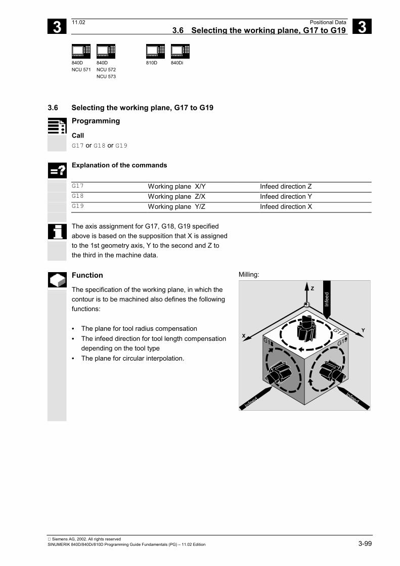
3 11.02 Positional Data3.6 Selecting the working plane, G17 to G19
3
840DNCU 571
840DNCU 572NCU 573
810D
840Di
Siemens AG, 2002. All rights reservedSINUMERIK 840D/840Di/810D Programming Guide Fundamentals (PG) – 11.02 Edition 3-99
3.6 Selecting the working plane, G17 to G19
Programming
Call G17 or G18 or G19
Explanation of the commands
G17 Working plane X/Y Infeed direction Z G18 Working plane Z/X Infeed direction Y G19 Working plane Y/Z Infeed direction X
The axis assignment for G17, G18, G19 specifiedabove is based on the supposition that X is assignedto the 1st geometry axis, Y to the second and Z tothe third in the machine data.
Function
The specification of the working plane, in which thecontour is to be machined also defines the followingfunctions: • The plane for tool radius compensation• The infeed direction for tool length compensation
depending on the tool type• The plane for circular interpolation.
Milling:
Z
YX
Infe
ed
InfeedInfeed

3 Positional Data 11.02 3.6 Selecting the working plane, G17 to G19
3
840DNCU 571
840DNCU 572NCU 573
810D
840Di
Siemens AG, 2002. All rights reserved3-100 SINUMERIK 840D/840Di/810D Programming Guide Fundamentals (PG) – 11.02 Edition
Sequence
It is advisable to define the working plane at thebeginning of the program.
The working plane must be specified when the toolpath compensation G41/G42 (see Section "Tooloffsets") is called so that the control can correct thetool length and radius. In the initial setting, G17 (X/Yplane) is defined for milling and G18 (Z/X plane) isdefined for turning.
Turning:
Z
X
Y
G17
G18
G19
Machining on inclined planesRotate the coordinate system with ROT (see Section"Coordinate system offset") to position thecoordinate axes on the inclined surface. The workingplanes rotate accordingly.
Tool length compensation in inclined planesThe tool length compensation generally alwaysrefers to the fixed, non-rotated working plane.
3 11.02 Positional Data3.6 Selecting the working plane, G17 to G19
3
840DNCU 571
840DNCU 572NCU 573
810D
840Di
Siemens AG, 2002. All rights reservedSINUMERIK 840D/840Di/810D Programming Guide Fundamentals (PG) – 11.02 Edition 3-101
NoteThe tool length components can be calculatedaccording to the rotated working planes with thefunctions for "Tool length compensation fororientable tools". For more information on thiscalculation type, please refer to Section "ToolOffsets".The offset plane is selected with CUT2D, CUT2DF.For more information see Section "Tool Offsets".
Additional notes
The control provides convenient coordinatetransformation functions for the spatial definition ofthe working plane.For further information, please refer to Section"Coordinate system offset".
Programming example
The "conventional" approach:Define the working plane, call up the tool type andtool offset values, activate the path compensation,program the traversing movements.Example for milling tool:N10 G17 T5 D8 G17 Call the working plane, in this example X/Y T, D
tool call.The length compensation is performed in the Z direction.
N20 G1 G41 X10 Y30 Z-5 F500 The radius compensation is performed in the X/Y plane.N30 G2 X22.5 Y40 I50 J40 Circular interpolation / tool radius compensation in the
X/Y plane.
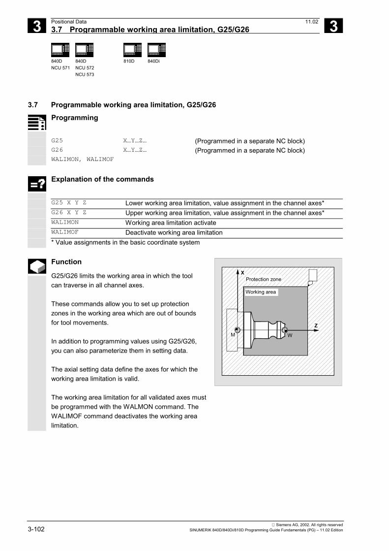
3 Positional Data 11.02 3.7 Programmable working area limitation, G25/G26
3
840DNCU 571
840DNCU 572NCU 573
810D
840Di
Siemens AG, 2002. All rights reserved3-102 SINUMERIK 840D/840Di/810D Programming Guide Fundamentals (PG) – 11.02 Edition
3.7 Programmable working area limitation, G25/G26Programming
G25 X…Y…Z… (Programmed in a separate NC block)G26 X…Y…Z… (Programmed in a separate NC block)WALIMON, WALIMOF
Explanation of the commands
G25 X Y Z Lower working area limitation, value assignment in the channel axes*G26 X Y Z Upper working area limitation, value assignment in the channel axes*WALIMON Working area limitation activateWALIMOF Deactivate working area limitation* Value assignments in the basic coordinate system
Function
G25/G26 limits the working area in which the toolcan traverse in all channel axes.
These commands allow you to set up protectionzones in the working area which are out of boundsfor tool movements.
In addition to programming values using G25/G26,you can also parameterize them in setting data.
The axial setting data define the axes for which theworking area limitation is valid.
The working area limitation for all validated axes mustbe programmed with the WALMON command. TheWALIMOF command deactivates the working arealimitation.
X
Z
Working area
Protection zone
WM

3 11.02 Positional Data 3.7 Programmable working area limitation, G25/G26
3
840DNCU 571
840DNCU 572NCU 573
810D
840Di
Siemens AG, 2002. All rights reservedSINUMERIK 840D/840Di/810D Programming Guide Fundamentals (PG) – 11.02 Edition 3-103
Sequence
Reference points on the toolWhen tool length compensation is active, thereference point is the tip of the tool, otherwise it isthe toolholder reference point. If the tool ispositioned outside the specified area or leaves thisarea, the program stops executing.
Programmable working area limitation,G25/G26An upper (G26) and lower (G25) working area limit isdefined for each axis. These values applyimmediately and are not lost on Reset and when thecontrol is switched on again.The tool (milling tool) radius can be changed in thechannel-specific machine data$MC_WORKAREA_WITH_TOOL_RADIUS (see"Advanced").
The coordinates for the individual axes apply in thebasic coordinate system!
Activate/deactivateworking area limitationThe command WALIMON activates working arealimitation for all axes with the values programmed inG25/G26.
ZY
G25Y
G25Y
G26Y
G26X
G25XG25Z
G26Z
X
Basiccoordinatesystem
WALIMON is the default setting. It therefore only hasto be programmed if working area limitation hasbeen disabled.
The command WALIMOF is used to deactivateworking area limitation for all of the axes.

3 Positional Data 11.02 3.7 Programmable working area limitation, G25/G26
3
840DNCU 571
840DNCU 572NCU 573
810D
840Di
Siemens AG, 2002. All rights reserved3-104 SINUMERIK 840D/840Di/810D Programming Guide Fundamentals (PG) – 11.02 Edition
Additional notes
G25/G26 can also be used to program limits forspindle speeds at the address S.For further information, please refer to Section "Feedcontrol and spindle motion".
Programming example
A protection zone is defined in the working area of aturning machine. This protects the surroundingequipment such as turrets, measuring stations, etc.against damage.Default setting: WALIMON
XB
X+
X-
Z B
30030
8080
Working area
Protection zone
WM
N10 G0 G90 F0.5 T1
N20 G25 X-80 Z30 Define the lower limit for the individualcoordinate axes
N30 G26 X80 Z330 Define the upper limitN40 L22 Cutting programN50 G0 G90 Z102 T2 To tool change locationN60 X0
N70 WALIMOF Deactivate working area limitation
N80 G1 Z-2 F0.5 BoringN90 G0 Z200 BackN100 WALIMON Activate working area limitationN110 X70 M30 End of program

3 11.02 Positional Data3.8 Reference point approach, G74
3
840DNCU 571
840DNCU 572NCU 573
810D
840Di
Siemens AG, 2002. All rights reservedSINUMERIK 840D/840Di/810D Programming Guide Fundamentals (PG) – 11.02 Edition 3-105
3.8 Reference point approach, G74Programming
G74 X1=0 Y1=0 Z1=0 A1=0 … (programmed in a separate NC block)
Explanation of the commands
G74 Reference point approachX1=0 Y1=0… The specified machine axis address X1, Y1... approaches the reference
point.
Function
When the machine has been powered up (whereincremental position measurement systems areused), all of the axis slides must approach theirreference point.Only then can traversing movements beprogrammed.
The reference point can be approached in theNC program with G74.
Sequence
The speed at which the axis slide travels is definedin the machine data and cannot be programmed.
The control detects the traversing directionautomatically.

3 Positional Data 11.02 3.8 Reference point approach, G74
3
840DNCU 571
840DNCU 572NCU 573
810D
840Di
Siemens AG, 2002. All rights reserved3-106 SINUMERIK 840D/840Di/810D Programming Guide Fundamentals (PG) – 11.02 Edition
The machine axis addresses are programmed (X1,Y1, Z1, etc.)!
A transformation should not be programmed for anaxis which is to approach the reference point withG74.
Deactivate transformation with the commandTRAFOOF.Programming example
When the measurement system is changed, thereference point is approached and the workpiecezero is initialized.
N10 SPOS=0 Position controlN20 G74 X1=0 Y1=0 Z1=0 C1=0 Reference point approach for linear axes
and rotary axesN30 G54 Zero offsetN40 L47 Cutting programN50 M30 End of program
�
4 11.02 Programming Motion Commands 4
Siemens AG, 2002. All rights reservedSINUMERIK 840D/840Di/810D Programming Guide Fundamentals (PG) – 11.02 Edition 4-107
Programming Motion Commands
4.1 General information...................................................................................................... 4-108
4.2 Traversing commands with polar coordinates, G110, G111, G112, AP, RP ............... 4-110
4.3 Rapid traverse movement, G0 ..................................................................................... 4-114
4.4 Linear interpolation, G1 ................................................................................................ 4-119
4.5 Circular interpolation, G2/G3, CIP................................................................................ 4-122
4.6 Helical interpolation, G2/G3, TURN ............................................................................. 4-135
4.7 Involute interpolation, INVCW, INVCCW ..................................................................... 4-137
4.8 Contour definitions ....................................................................................................... 4-1414.8.1 Straight line with angle ............................................................................................ 4-1414.8.2 Two straight lines .................................................................................................... 4-1424.8.3 Three straight lines.................................................................................................. 4-1434.8.4 End point programming with an angle..................................................................... 4-144
4.9 Thread cutting with constant lead, G33........................................................................ 4-1454.9.1 Programmable run-in and run-out path (SW 5 and higher) .................................... 4-151
4.10 Linear progressive/degressive thread pitch change, G34, G35 (SW 5.2 and higher).. 4-153
4.11 Rigid tapping, G331, G332........................................................................................... 4-155
4.12 Tapping with compensating chuck G63 ....................................................................... 4-157
4.13 Stop during thread cutting ............................................................................................ 4-159
4.14 Approaching a fixed point, G75.................................................................................... 4-161
4.15 Travel to fixed stop....................................................................................................... 4-163
4.16 Special turning functions .............................................................................................. 4-1694.16.1 Position of workpiece .............................................................................................. 4-1694.16.2 Dimensions for: Radius, diameter........................................................................... 4-170
4.17 Chamfer, rounding ....................................................................................................... 4-172

4 Programming Motion Commands 11.024.1 General information 4
840DNCU 571
840DNCU 572NCU 573
810D 840Di
Siemens AG, 2002. All rights reserved4-108 SINUMERIK 840D/840Di/810D Programming Guide Fundamentals (PG) – 11.02 Edition
4.1 General information
Motion commandsIn this section you will find a description of all thetravel commands you can use to machine workpiececontours.
You can program straight lines and arcs of a circle.A helix can be produced by combining these twoelements.
Executed in succession, these contour elementsproduce the workpiece contour.
Before a machining process is started, you need toposition the tool in such a way as to avoid anydamage to the tool or workpiece.
Start point – destination pointThe traversing movement always runs from the lastapproached position to the programmed destinationposition. This destination position is also the startposition for the next travel command.
Number of axis valuesDepending on the control configuration, you canprogram up to 8 axes per set of movements. Thesemay include path axes, synchronized axes,positioning axes and spindle oscillation mode.
Milling:
1
2
3
4
5
6

4 11.02 Programming Motion Commands4.1 General information 4
840DNCU 571
840DNCU 572NCU 573
810D 840Di
Siemens AG, 2002. All rights reservedSINUMERIK 840D/840Di/810D Programming Guide Fundamentals (PG) – 11.02 Edition 4-109
Turning:
5
4
21
3
X
Z
An axis address can only be programmed once ineach block.
These commands can be programmed in Cartesianor polar coordinates.

4 Programming Motion Commands 11.024.2 Traversing commands with polar coordinates, G110, G111 etc. 4
840DNCU 571
840DNCU 572NCU 573
810D 840Di
Siemens AG, 2002. All rights reserved4-110 SINUMERIK 840D/840Di/810D Programming Guide Fundamentals (PG) – 11.02 Edition
4.2 Traversing commands with polar coordinates, G110, G111, G112,AP, RPProgramming
Define pole:G110, G111, G112 X… Y… Z…
G110, G111, G112 AP=… RP=…
Traversing commands with polar coordinates:G0 AP=… RP=…
G1 AP=… RP=…
G2 AP=… RP=…
G3 AP=… RP=…
The new end point is defined in relationto a pole.
Explanation of the commands andparameters
G110 Pole parameter, with reference to the last approached positionG111 Pole parameter, absolute in the workpiece coordinate systemG112 Pole parameter, with reference to the last valid poleAP= Polar angle, value range ±0…360°, angle refers to horizontal axis of the
working planeRP= Polar radius in mm or inches
All the commands relating to pole input must be programmed in a separate NC block
Function
A workpiece is frequently dimensioned with a centralpoint as origin; the dimensions are given in terms ofangles and radii, e.g. in drilling patterns.
Polar coordinates can be used to program thesedimensions directly in accordance with the drawing.
X
Y
18°
90°
162°
234° 306°
m
n

4 11.02 Programming Motion Commands4.2 Traversing commands with polar coordinates, G110, G111 etc. 4
840DNCU 571
840DNCU 572NCU 573
810D 840Di
Siemens AG, 2002. All rights reservedSINUMERIK 840D/840Di/810D Programming Guide Fundamentals (PG) – 11.02 Edition 4-111
Sequence
Traversing commandsThe positions specified by polar coordinates can betraversed with G0, G1, G2 and G3.
Working planeThe polar coordinates are valid in the working planeselected with G17 to G19.
Cylindrical coordinatesThe 3rd geometry axis, which lies perpendicular tothe working plane, can also be specified in Cartesiancoordinates.This enables spatial parameters to be programmedin cylindrical coordinates.Example: G17 G0 AP… RP… Z…
Z
AP
RP
Defining the pole G110, G111, G112The pole can be specified in Cartesian or polarcoordinates.
G commands G110 to G112 are used to provide aunique definition of the reference point for dimensions.Absolute or incremental dimensioning (AC/IC)therefore has no effect on the systematics specified inthe G command.
If no pole is specified, the origin of the activeworkpiece coordinate system applies.
X
Y
G112 (Y)
G110 (Y)90.
30°
Pole 3
G110 (X)G111(X)
G111(Y)
G112 (X)
60°
Pole 2
Pole 1

4 Programming Motion Commands 11.024.2 Traversing commands with polar coordinates, G110, G111 etc. 4
840DNCU 571
840DNCU 572NCU 573
810D 840Di
Siemens AG, 2002. All rights reserved4-112 SINUMERIK 840D/840Di/810D Programming Guide Fundamentals (PG) – 11.02 Edition
Polar angle APValue range 0…±360°.With absolute input, the angle refers to the horizontalaxis of the working plane, e.g. X axis with G17. Thepositive direction of rotation runs counterclockwise.
When incremental coordinates are entered(AP=IC…), the last angle programmed is taken asthe reference.
The polar angle is stored until a new pole is definedor the working plane is changed.
Polar radius RPThe polar radius is specified in mm or inches inabsolute positive values. RP is stored until a newvalue is input.
SW 4.1 and higherIf the modally active polar radius is RP = 0The polar radius is calculated from the distancebetween the starting point vector in the polar planeand the active pole vector. The calculated polarradius is stored modally afterwards.This applies irrespective of the selected poledefinition G110, G111, G112. If both points areprogrammed identically, then this radius becomes 0and alarm 14095 is generated.If a pole angle AP is programmed with RP = 0If the current block contains a polar angle AP ratherthan a polar radius RP and if there is a differencebetween the current position and pole in workpiececoordinates, then this difference is applied as thepolar radius and stored modally.If the difference = 0, the pole coordinates arespecified again and the modal polar radius remainszero.
The following general rule applies:You must not program Cartesian coordinates, suchas interpolation parameters or axis addresses, forthe selected working plane in NC blocks with polarend position coordinates.
AP=30
AP=50
AP=IC (2
0)
30°
20°
X
Y

4 11.02 Programming Motion Commands4.2 Traversing commands with polar coordinates, G110, G111 etc. 4
840DNCU 571
840DNCU 572NCU 573
810D 840Di
Siemens AG, 2002. All rights reservedSINUMERIK 840D/840Di/810D Programming Guide Fundamentals (PG) – 11.02 Edition 4-113
Additional notes
In the NC program you can switch between polarand Cartesian coordinates, block by block.
Programming example
Making a hole pattern: The positions of the holes arespecified in polar coordinates. Each hole is machinedwith the same production sequence: Predrill, drill tosize, ream etc.The machining sequence is stored in a subprogram. 18°
72°72°
72°
43
72°
X
Y
38
30
N10 G17 G54 Working plane X/Y, workpiece zeroN20 G111 X43 Y38 Define poleN30 G0 RP=30 AP=18 Z5 Approach starting point, position in
cylindrical coordinatesN40 L10 Subprogram callN50 G91 AP=72 Approach next position in rapid traverse,
polar angle in incremental dimensions,polar radius from block N30 is still storedand does not need to be specified
N60 L10 Subprogram callN70 AP=IC(72) …N80 L10 …N90 AP=IC(72)
N100 L10 …N110 AP=IC(72)
N120 L10 …N130 G0 X300 Y200 Z100 M30 Retract tool, end of program

4 Programming Motion Commands 11.024.3 Rapid traverse movement, G0 4
840DNCU 571
840DNCU 572NCU 573
810D 840Di
Siemens AG, 2002. All rights reserved4-114 SINUMERIK 840D/840Di/810D Programming Guide Fundamentals (PG) – 11.02 Edition
4.3 Rapid traverse movement, G0
Programming
G0 X… Y… Z …
G0 AP=… RP=…
RTLIOF, RTLION (SW 6.1 and higher)
Explanation of the parameters
X Y Z End point in Cartesian coordinatesAP= End point in polar coordinates, in this case the polar angleRP= End point in polar coordinates, in this case the polar radiusRTLIOF with G0 Nonlinear interpolation (each path axis interpolates as a single axis)RTLION with G0 Linear interpolation (path axes are interpolated together)
Function
You can use the rapid traverse movements toposition the tool rapidly, to travel round theworkpiece or to approach tool change locations.
This function is not suitable for workpiece machining!
Sequence
The tool movement programmed with G0 isexecuted at the highest possible speed (rapidtraverse). The rapid traverse speed is definedseparately for each axis in machine data.
If the rapid traverse movement is executedsimultaneously on several axes, the rapid traversespeed is determined by the axis which requires thegreatest time for its section of the path.
Z
X
Y
Path of the rapid
traverse movement
Path section (X)Path section (Y)
Pathsection (Z)
Additional notes
G0 is modal.

4 11.02 Programming Motion Commands4.3 Rapid traverse movement, G0 4
840DNCU 571
840DNCU 572NCU 573
810D 840Di
Siemens AG, 2002. All rights reservedSINUMERIK 840D/840Di/810D Programming Guide Fundamentals (PG) – 11.02 Edition 4-115
Function
SW 6.1 and higherTraversing path axes as positioning axes with G0Path axes can travel in one of two different modes toexecute movements in rapid traverse:• Linear interpolation: (behavior in earlier SW
version)The path axes are interpolated together.
• Nonlinear interpolation: (SW 6 and higher)Each path axis is interpolated as an individual(positioning) axis independently of the other axesinvolved in the rapid traverse movement.
Relevant parts program commands:• RTLIOF activates nonlinear interpolation• RTLION activates linear interpolation
Linear interpolation must always be selected in thefollowing cases:• With a G code combination including G0 which
does not permit positioning movements (e.g.G40/41/42).
• With a combination of G0 and G64• When the compressor is active• When a transformation is active
With nonlinear interpolation, the setting for therelevant positioning axis BRISKA, SOFTA, DRIVEAapplies with regard to axial jerk.
Since a different contour can be traversed innonlinear interpolation mode, synchronized actionsthat refer to coordinates of the original path are notoperative in some cases!

4 Programming Motion Commands 11.024.3 Rapid traverse movement, G0 4
840DNCU 571
840DNCU 572NCU 573
810D 840Di
Siemens AG, 2002. All rights reserved4-116 SINUMERIK 840D/840Di/810D Programming Guide Fundamentals (PG) – 11.02 Edition
Sequence
Traverse path axes as positioning axes with G0Example:G0 X0 Y10
G0 G40 X20 Y20
G0 G95 X100 Z100 m3 s100
Path POS[X]=0 POS[Y]=10 is traversed in path mode.No revolutional feedrate is active if path POS[X]=100POS[Z]=100 is traversed.
Additional notes
SW 6.2 and higherSettable block change time with G0:It is possible to set a new motion end criterion, i.e.FINEA, COARSEA or IPOENDA, in single axisinterpolation mode for block changes within thebraking ramp.All axes can reach their end points independently ofone another through a combination of "Block changesettable in braking ramp of single axis interpolation"and "Traverse path axes as positioning axes with G0rapid traverse".In this way, two sequentially programmed X and Zaxes are treated like positioning axes in conjunctionwith G0. The block change to axis Z can be initiatedby axis X as a function of the braking ramp timesetting (100-0%). Axis Z starts to move while axis Xis still in motion. Both axes approach their end pointindependently of one another.You will find more information in Chapter 7.

4 11.02 Programming Motion Commands4.3 Rapid traverse movement, G0 4
840DNCU 571
840DNCU 572NCU 573
810D 840Di
Siemens AG, 2002. All rights reservedSINUMERIK 840D/840Di/810D Programming Guide Fundamentals (PG) – 11.02 Edition 4-117
Programming example
G0 is used for approaching starting positions or toolchange locations, retracting the tool, etc.
Milling:
X
Y
3080
N60
N20
6520
N10 G90 S400 M3 Absolute dimensioning, spindle clockwiseN20 G0 X30 Y20 Z2 Approach start positionN30 G1 Z-5 F1000 Tool infeedN40 X80 Y65 Travel on straight lineN50 G0 Z2
N60 G0 X-20 Y100 Z100 M30 Retract tool, end of program
Turning:
Z
XØ
25
50
Ø 6
0N80
N20
35
7.5
N10 G90 S400 M3 Absolute dimensioning, spindle clockwiseN20 G0 X25 Z5 Approach start positionN30 G1 G94 Z0 F1000 Tool infeedN40 G95 Z-7.5 F0.2
N50 X60 Z-35 Travel on straight line

4 Programming Motion Commands 11.024.3 Rapid traverse movement, G0 4
840DNCU 571
840DNCU 572NCU 573
810D 840Di
Siemens AG, 2002. All rights reserved4-118 SINUMERIK 840D/840Di/810D Programming Guide Fundamentals (PG) – 11.02 Edition
N60 Z-50
N70 G0 X62
N80 G0 X80 Z20 Retract toolN90 M30 End of program
G0 cannot be replaced with G.
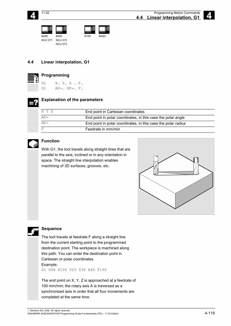
4 11.02 Programming Motion Commands4.4 Linear interpolation, G1 4
840DNCU 571
840DNCU 572NCU 573
810D 840Di
Siemens AG, 2002. All rights reservedSINUMERIK 840D/840Di/810D Programming Guide Fundamentals (PG) – 11.02 Edition 4-119
4.4 Linear interpolation, G1
Programming
G1 X… Y… Z … F…
G1 AP=… RP=… F…
Explanation of the parameters
X Y Z End point in Cartesian coordinatesAP= End point in polar coordinates, in this case the polar angleRP= End point in polar coordinates, in this case the polar radiusF Feedrate in mm/min
Function
With G1, the tool travels along straight lines that areparallel to the axis, inclined or in any orientation inspace. The straight line interpolation enablesmachining of 3D surfaces, grooves, etc.
Sequence
The tool travels at feedrate F along a straight linefrom the current starting point to the programmeddestination point. The workpiece is machined alongthis path. You can enter the destination point inCartesian or polar coordinates.Example:G1 G94 X100 Y20 Z30 A40 F100
The end point on X, Y, Z is approached at a feedrate of100 mm/min; the rotary axis A is traversed as asynchronized axis in order that all four movements arecompleted at the same time.

4 Programming Motion Commands 11.024.4 Linear interpolation, G1 4
840DNCU 571
840DNCU 572NCU 573
810D 840Di
Siemens AG, 2002. All rights reserved4-120 SINUMERIK 840D/840Di/810D Programming Guide Fundamentals (PG) – 11.02 Edition
Additional notes
G1 is modal. The spindle speed S and the directionof spindle rotation M3/M4 must be specified formachining.FGROUP can be used to define groups of axes towhich the path feed F applies.You will find more information in Chapter 5.
Programming example
Machining of a groove: The tool travels from thestarting point to the end point in the X/Y direction.Infeed takes place simultaneously in the Z direction.
Milling:
Y Y
ZX20
8015
2
80
20
N10 G17 S400 M3 Select working plane, spindle clockwiseN20 G0 X20 Y20 Z2 Approach start positionN30 G1 Z-2 F40 Tool infeedN40 X80 Y80 Z-15 Travel along inclined straight lineN50 G0 Z100 M30 Retract to tool change location
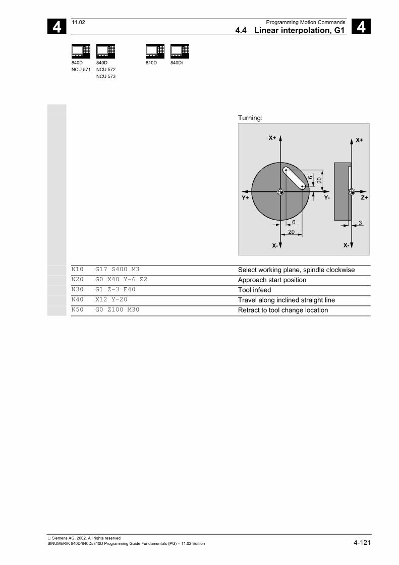
4 11.02 Programming Motion Commands4.4 Linear interpolation, G1 4
840DNCU 571
840DNCU 572NCU 573
810D 840Di
Siemens AG, 2002. All rights reservedSINUMERIK 840D/840Di/810D Programming Guide Fundamentals (PG) – 11.02 Edition 4-121
Turning:
Z+
X+
20
Y+
X+
6
6
20
3
X- X-
Y-
N10 G17 S400 M3 Select working plane, spindle clockwiseN20 G0 X40 Y-6 Z2 Approach start positionN30 G1 Z-3 F40 Tool infeedN40 X12 Y-20 Travel along inclined straight lineN50 G0 Z100 M30 Retract to tool change location

4 Programming Motion Commands 11.024.5 Circular interpolation, G2/G3, CIP 4
840DNCU 571
840DNCU 572NCU 573
810D 840Di
Siemens AG, 2002. All rights reserved4-122 SINUMERIK 840D/840Di/810D Programming Guide Fundamentals (PG) – 11.02 Edition
4.5 Circular interpolation, G2/G3, CIP
Programming
G2/G3 X… Y… Z… I… J… K…
G2/G3 AP=… RP=…
G2/G3 X… Y… Z… CR=…
G2/G3 AR=… I… J… K…
G2/G3 AR=… X… Y… Z…
CIP X… Y… Z… I1=… J1=… K1=…
CT X… Y… Z…
Explanation of the commands and parameters
G2 Travel on a circular path in clockwise directionG3 Travel on a circular path in counterclockwise directionCIP Circular interpolation through intermediate pointCT Circle with tangential transition
X Y Z End point in Cartesian coordinatesI J K Circle center point in Cartesian coordinates (in X, Y, Z direction)AP= End point in polar coordinates, in this case the polar angleRP= End point in polar coordinates, in this case polar radius corresponding to circle radiusCR= Circle radiusAR= Arc angleI1= J1= K1= Intermediate points in Cartesian coordinates (in X, Y, Z direction)
There is no practical limitation on the maximum sizeof the programmable radius.
FunctionCircular interpolation enables machining of fullcircles or arcs.
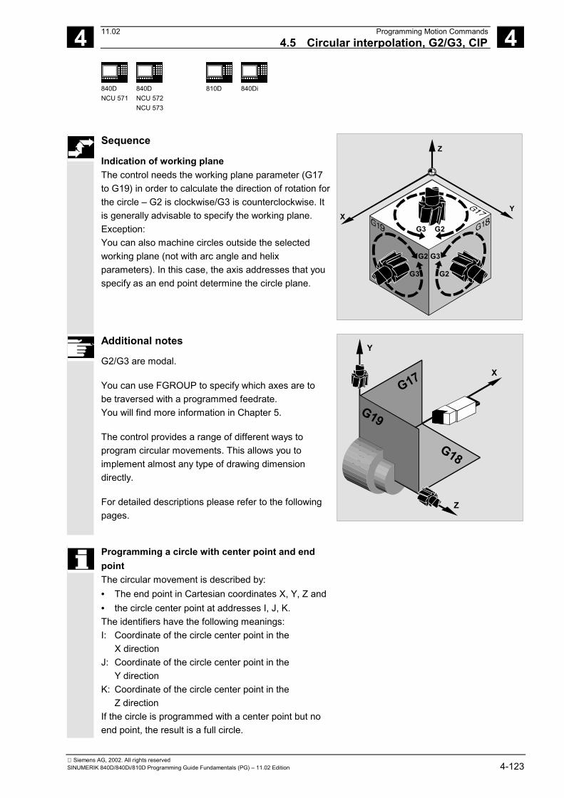
4 11.02 Programming Motion Commands4.5 Circular interpolation, G2/G3, CIP 4
840DNCU 571
840DNCU 572NCU 573
810D 840Di
Siemens AG, 2002. All rights reservedSINUMERIK 840D/840Di/810D Programming Guide Fundamentals (PG) – 11.02 Edition 4-123
Sequence
Indication of working planeThe control needs the working plane parameter (G17to G19) in order to calculate the direction of rotation forthe circle – G2 is clockwise/G3 is counterclockwise. Itis generally advisable to specify the working plane.Exception:You can also machine circles outside the selectedworking plane (not with arc angle and helixparameters). In this case, the axis addresses that youspecify as an end point determine the circle plane.
Z
YX
G2G3
G3G2
G2G3
Additional notes
G2/G3 are modal.
You can use FGROUP to specify which axes are tobe traversed with a programmed feedrate.You will find more information in Chapter 5.
The control provides a range of different ways toprogram circular movements. This allows you toimplement almost any type of drawing dimensiondirectly.
For detailed descriptions please refer to the followingpages.
Z
X
Y
G17
G18
G19
Programming a circle with center point and endpointThe circular movement is described by:• The end point in Cartesian coordinates X, Y, Z and• the circle center point at addresses I, J, K. The identifiers have the following meanings: I: Coordinate of the circle center point in the
X direction J: Coordinate of the circle center point in the
Y direction K: Coordinate of the circle center point in the
Z direction If the circle is programmed with a center point but noend point, the result is a full circle.

4 Programming Motion Commands 11.024.5 Circular interpolation, G2/G3, CIP 4
840DNCU 571
840DNCU 572NCU 573
810D 840Di
Siemens AG, 2002. All rights reserved4-124 SINUMERIK 840D/840Di/810D Programming Guide Fundamentals (PG) – 11.02 Edition
Input in absolute and incremental dimensions The defaults G90/G91 absolute or incrementalcoordinates are valid only for the circle end point.The center point coordinates I, J, K are normallyentered in incremental dimensions with reference tothe circle starting point. You program the absolute center point non-modallywith reference to the workpiece zero with: I=AC(…),J=AC(…), K=AC(…) Example for incremental dimensions: N10 G0 X67.5 Y80.211 N20 G3 X17.203 Y38.029 I–17.5 J–30.211 F500
Example for absolute dimensions: N10 G0 X67.5 Y80.211 N20 G3 X17.203 Y38.029 I=AC(50) J=AC(50)
Milling:
I
J
J =
AC(
...)
I = AC(...)
X
Y
17.203 17.500
.50.000
Circle end point
50.0
0038
.029
30.2
11
Circle startingpoint
An interpolation parameter I, J, K with value 0 can beomitted but the second associated parameter mustalways be specified.
Example for incremental dimensions: N120 G0 X12 Z0N125 G1 X40 Z-25 F0.2
N130 G3 X70 Z-75 I-3.335 K-29.25
N135 G1 Z-95
Example for absolute dimensions: N120 G0 X12 Z0N125 G1 X40 Z-25 F0.2
N130 G3 X70 Z-75 I=AC(33.33)
K=AC(-54.25)
N135 G1 Z-95
Turning:
75
Z
X
25
95
30
Ø 7
0Ø
40

4 11.02 Programming Motion Commands4.5 Circular interpolation, G2/G3, CIP 4
840DNCU 571
840DNCU 572NCU 573
810D 840Di
Siemens AG, 2002. All rights reservedSINUMERIK 840D/840Di/810D Programming Guide Fundamentals (PG) – 11.02 Edition 4-125
Programming a circle with radius and end point The circular movement is described by:• The circle radius CR= and• the end point in Cartesian coordinates X, Y, Z. In addition to the circle radius, you must also specifythe leading sign +/– to indicate whether thetraversing angle is to be greater than or less than180°. A positive leading sign can be omitted. The identifiers have the following meanings:CR=+…: Angle smaller or equal to 180° CR=–…: Angle larger than 180° Example:
Milling:
X
Y
17.20367.500
CR=34.913
CR = -...
CR = +...
80.5
11
38.0
29 N10 G0 X67.5 Y80.211
N20 G3 X17.203 Y38.029 CR=34.913 F500
You don’t need to specify the center point with thisprocedure. Full circles (traversing angle 360°) cannotbe programmed with CR=, but must be programmedusing the circle end point and interpolation parameters.
Example: N125 G1 X40 Z-25 F0.2 N130 G3 X70 Z-75 CR=30N135 G1 Z-95
Turning:
75
Z
X
25
95
30
Ø 7
0Ø
40

4 Programming Motion Commands 11.024.5 Circular interpolation, G2/G3, CIP 4
840DNCU 571
840DNCU 572NCU 573
810D 840Di
Siemens AG, 2002. All rights reserved4-126 SINUMERIK 840D/840Di/810D Programming Guide Fundamentals (PG) – 11.02 Edition
Programming a circle with arc angle and centerpoint or end point The circular movement is described by:• The arc angle AR = and• the end point in Cartesian coordinates X, Y, Z or• the circle center point at addresses I, J, K The identifiers have the following meanings: AR=: arc angle, value range 0° to 360° Please refer to the preceding pages for themeanings of I, J, K. Full circles (traversing angle 360°) cannot beprogrammed with AR=, but must be programmedusing the circle end point and interpolationparameters. Example: N10 G0 X67.5 Y80.211 N20 G3 X17.203 Y38.029 AR=140.134 F500 or N20 G3 I–17.5 J–30.211 AR=140.134 F500
Milling:
X
Y
17.203 17.50050.000
I
J
Arc angle
Circle startpoint
50.0
00
38.0
29
30.2
11
140.1
34°
Example: N125 G1 X40 Z-25 F0.2 N130 G3 X70 Z-75 AR=135.944 or N130 G3 I-3.335 K-29.25 AR=135.944 or N130 G3 I=AC(33.33) K=AC(-54.25) AR=135.944
N135 G1 Z-95
Turning:
Z
X
54.2525
95 Ø 3
3.33
30
Ø 4
0
142.326°
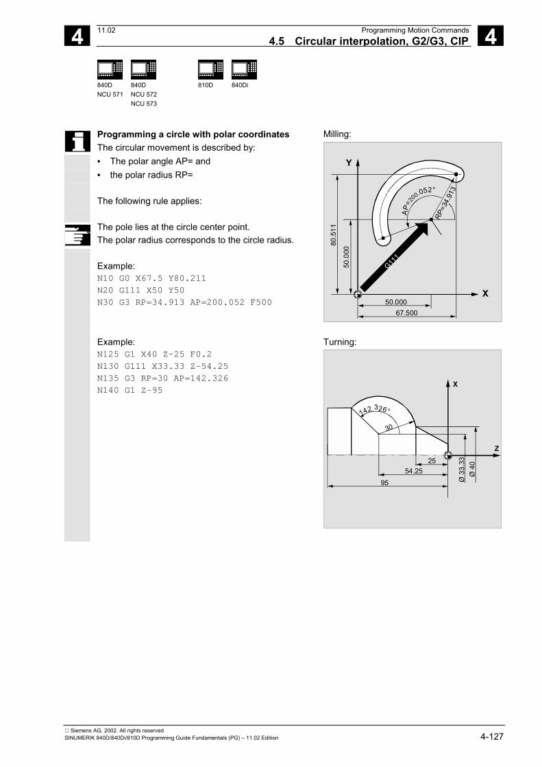
4 11.02 Programming Motion Commands4.5 Circular interpolation, G2/G3, CIP 4
840DNCU 571
840DNCU 572NCU 573
810D 840Di
Siemens AG, 2002. All rights reservedSINUMERIK 840D/840Di/810D Programming Guide Fundamentals (PG) – 11.02 Edition 4-127
Programming a circle with polar coordinates The circular movement is described by:• The polar angle AP= and• the polar radius RP= The following rule applies: The pole lies at the circle center point. The polar radius corresponds to the circle radius. Example: N10 G0 X67.5 Y80.211 N20 G111 X50 Y50 N30 G3 RP=34.913 AP=200.052 F500
Milling:
G111
X
Y
RP=3
4.91
3
50.00067.500
80.5
11
50.0
00
AP=
200.052°
Example: N125 G1 X40 Z-25 F0.2 N130 G111 X33.33 Z-54.25 N135 G3 RP=30 AP=142.326N140 G1 Z-95
Turning:
Z
X
54.2525
95 Ø 3
3.33
30
Ø 4
0
142.326°

4 Programming Motion Commands 11.024.5 Circular interpolation, G2/G3, CIP 4
840DNCU 571
840DNCU 572NCU 573
810D 840Di
Siemens AG, 2002. All rights reserved4-128 SINUMERIK 840D/840Di/810D Programming Guide Fundamentals (PG) – 11.02 Edition
Programming example
The following program lines contain an example foreach circular programming possibility. The necessarydimensions are shown in the opposite productiondrawing.
Milling:
X
I
J
Y
90
25.52
115133
269.3°
113.
370
44.4
8
50
N10 G0 G90 X133 Y44.48 S800 M3 Approach starting point N20 G17 G1 Z-5 F1000 Tool infeed N30 G2 X115 Y113.3 I-43 J25.52 Circle end point, center point in
incremental dimensions or N30 G2 X115 Y113.3 I=AC(90) J=AC(70) Circle end point, center point in absolute
dimensions or N30 G2 X115 Y113.3 CR=-50 Circle end point, circle radius or N30 G2 AR=269.31 I-43 J25.52 Arc angle, center point in incremental
dimensions or N30 G2 AR=269.31 X115 Y113.3 Arc angle, circle end point N40 M30 End of program

4 11.02 Programming Motion Commands4.5 Circular interpolation, G2/G3, CIP 4
840DNCU 571
840DNCU 572NCU 573
810D 840Di
Siemens AG, 2002. All rights reservedSINUMERIK 840D/840Di/810D Programming Guide Fundamentals (PG) – 11.02 Edition 4-129
Turning:
75
Z
X
54.2525
95
Ø 1
2Ø
33.
33
Ø 7
0Ø
40
142.326°
135.944°
30
N.. ... N120 G0 X12 Z0 N125 G1 X40 Z-25 F0.2 N130 G3 X70 Y-75 I-3.335 K-29.25 Circle end point, center point in
incremental dimensions or N130 G3 X70 Y-75 I=AC(33.33)
K=AC(-54.25) Circle end point, center point in absolutedimensions
or N130 G3 X70 Z-75 CR=30 Circle end point, circle radius or N130 G3 X70 Z-75 AR=135.944 Arc angle, circle end point or N130 G3 I-3.335 K-29.25 AR=135.944 Arc angle, center point in incremental
dimensions or N130 G3 I=AC(33.33) K=AC(-54.25)
AR=135.944 Arc angle, center point in absolutedimensions
or N130 G111 X33.33 Z-54.25 Polar coordinates N135 G3 RP=30 AP=142.326 Polar coordinates N140 G1 Z-95 N.. ...

4 Programming Motion Commands 11.024.5 Circular interpolation, G2/G3, CIP 4
840DNCU 571
840DNCU 572NCU 573
810D 840Di
Siemens AG, 2002. All rights reserved4-130 SINUMERIK 840D/840Di/810D Programming Guide Fundamentals (PG) – 11.02 Edition
Programming a circle with intermediate and endpoints You can use CIP to program arcs. These arcs canalso be inclined in space. In this case, you describethe intermediate and end points with threecoordinates. The circular movement is described by:• The intermediate point at addresses I1=, J1=, K1=
and• the end point in Cartesian coordinates X, Y, Z. The identifiers have the following meanings: I1=: Coordinate of the interm. point in the X direction J1=: Coordinate of the interm. point in the Y direction K1=: Coordinate of the interm. point in the Z direction
Input in absolute and incremental dimensions The G90/G91 defaults for absolute or incrementaldimensions are valid for the intermediate and circleend points. With G91, the circle starting point is used as thereference for the intermediate point and end point.
X
Y
I1
J1
Y
K1
Z
Intermediate point
CIP is modal. The traversing direction is determined by the orderof the starting point, intermediate point and endpoint.
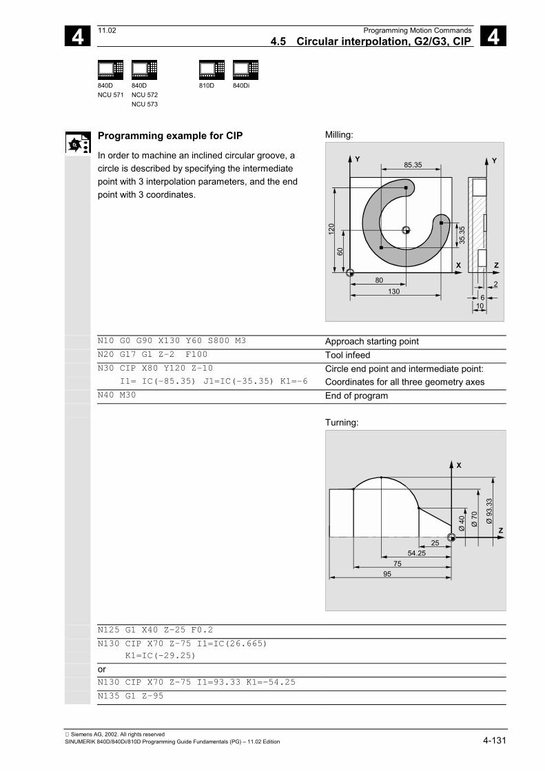
4 11.02 Programming Motion Commands4.5 Circular interpolation, G2/G3, CIP 4
840DNCU 571
840DNCU 572NCU 573
810D 840Di
Siemens AG, 2002. All rights reservedSINUMERIK 840D/840Di/810D Programming Guide Fundamentals (PG) – 11.02 Edition 4-131
Programming example for CIP
In order to machine an inclined circular groove, acircle is described by specifying the intermediatepoint with 3 interpolation parameters, and the endpoint with 3 coordinates.
Milling:
X Z
Y Y85.35
80130
106
2
120
60
35.3
5
N10 G0 G90 X130 Y60 S800 M3 Approach starting point N20 G17 G1 Z-2 F100 Tool infeed N30 CIP X80 Y120 Z-10 Circle end point and intermediate point: I1= IC(-85.35) J1=IC(-35.35) K1=-6 Coordinates for all three geometry axes N40 M30 End of program
Turning:
75
Z
X
54.2525
95
Ø 7
0
Ø 4
0 Ø 9
3.33
N125 G1 X40 Z-25 F0.2 N130 CIP X70 Z-75 I1=IC(26.665)
K1=IC(-29.25)
or N130 CIP X70 Z-75 I1=93.33 K1=-54.25 N135 G1 Z-95

4 Programming Motion Commands 11.024.5 Circular interpolation, G2/G3, CIP 4
840DNCU 571
840DNCU 572NCU 573
810D 840Di
Siemens AG, 2002. All rights reserved4-132 SINUMERIK 840D/840Di/810D Programming Guide Fundamentals (PG) – 11.02 Edition
Programming a circle with tangential transition The Tangential transition function is an expansion ofthe circle programming. The circle is defined by• the start and end point and• the tangent direction at the start point. The G code CT produces an arc that lies at atangent to the contour element programmedpreviously.
Arc S-E at a tangent to the straight line 1-2
Arcs that lie at a tangent depend on the previous contour element
CT is modal. As a rule, the direction of the tangent, as well as thestart and end point of the circle are uniquely defined.
Position of the circle plane The position of the circle plane depends on theactive plane (G17-G19). If the tangents of the previous block do not lie in theactive plane, their projection in the active plane isused. If the start and end points do not have the sameposition components perpendicular to the activeplane, a helix is produced instead of a circle. Specifying TURN=... enables you to program circleswith more than one full rotation.

4 11.02 Programming Motion Commands4.5 Circular interpolation, G2/G3, CIP 4
840DNCU 571
840DNCU 572NCU 573
810D 840Di
Siemens AG, 2002. All rights reservedSINUMERIK 840D/840Di/810D Programming Guide Fundamentals (PG) – 11.02 Edition 4-133
Determining the direction of the tangent
The direction of tangent at the start point of a CTblock is determined from the end tangent of theprogrammed contour of the previous block with atraversing movement. Any number of blocks without traversing informationmay lie between this block and the current block. In the case of splines, the tangential direction isdefined by the straight line through the last twopoints. This direction is generally not the same asthe direction at the end point of the splines for A andC splines with active ENAT or EAUTO. The transition of B splines is always tangential, thetangent direction is defined as for A or C splines andactive ETAN. Frame change If a frame change takes place between the blockdefining the tangent and the CT block, the tangent isalso subjected to this change. Limit case If the extension of the start tangent runs through theend point, a straight line is produced instead of acircle (limit case: circle with infinite radius). In thisspecial case, TURN must either not be programmedor the value must be TURN=0.
Additional notes
When the values tend towards this limit case, circleswith an unlimited radius are produced and machiningwith TURN unequal 0 is generally aborted with analarm due to violation of the software limits.

4 Programming Motion Commands 11.024.5 Circular interpolation, G2/G3, CIP 4
840DNCU 571
840DNCU 572NCU 573
810D 840Di
Siemens AG, 2002. All rights reserved4-134 SINUMERIK 840D/840Di/810D Programming Guide Fundamentals (PG) – 11.02 Edition
Programming example for CT
Mill a circular arc following a straight line:
Milling:
X
Y
30
8030
15
5060
70
with TRC
N10 G0 X0 Y0 Z0 G90 T1 D1 N20 G41 X30 Y30 G1 F1000 Activate tool radius compensation (TRC) N30 CT X50 Y15 Program circle with tangential transition N40 X60 Y-5 N50 G1 X70 N60 G0 G40 X80 Y0 Z20 N70 M30 Turning:
Z
X
4230
Ø 7
0
Ø 2
3.29
3
Ø 4
0
Ø 5
8.14
6
N110 G1 X23.293 Z0 F10 N115 X40 Z-30 F0.2 N120 CT X58.146 Z-42 Program circle with tangential transition N125 G1 X70

4 11.02 Programming Motion Commands4.6 Helical interpolation, G2/G3, TURN 4
840DNCU 571
840DNCU 572NCU 573
810D 840Di
Siemens AG, 2002. All rights reservedSINUMERIK 840D/840Di/810D Programming Guide Fundamentals (PG) – 11.02 Edition 4-135
4.6 Helical interpolation, G2/G3, TURN
Programming
G2/G3 X… Y… Z… I… J… K… TURN=
G2/G3 X… Y… Z… I… J… K… TURN=
G2/G3 AR=… I… J… K… TURN=
G2/G3 AR=… X… Y… Z… TURN=
G2/G3 AP… RP=… TURN=
Explanation of the commands and parameters
G2 Travel on a circular path in clockwise direction G3 Travel on a circular path in counterclockwise direction X Y Z End point in Cartesian coordinates I J K Circle center point in Cartesian coordinates AR Arc angle TURN= Number of additional circle passes within the range 0 to 999 AP= Polar angle RP= Polar radius
Function
Helical interpolation (Helical interpolation) can beused to manufacture threads and oil grooves, forexample.
Sequence
In helical interpolation, two movements aresuperimposed and executed in parallel:• A horizontal circular movement on which• a vertical linear movement is superimposed.The circular movement is performed on the axesspecified by the working plane.Example: Working plane G17, axes for circularinterpolation X and Y.The infeed movement is performed on theperpendicular infeed axis, in this case Z.
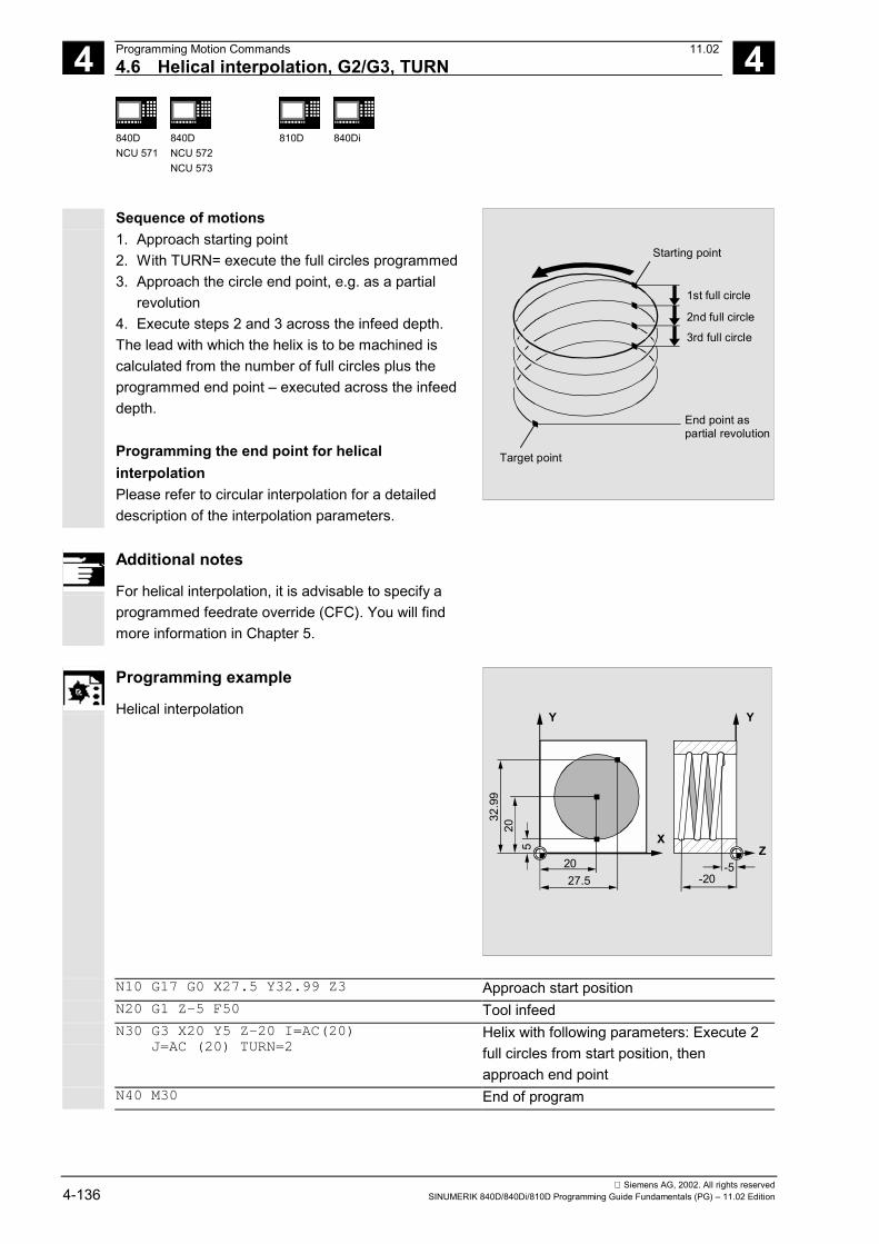
4 Programming Motion Commands 11.024.6 Helical interpolation, G2/G3, TURN 4
840DNCU 571
840DNCU 572NCU 573
810D 840Di
Siemens AG, 2002. All rights reserved4-136 SINUMERIK 840D/840Di/810D Programming Guide Fundamentals (PG) – 11.02 Edition
Sequence of motions1. Approach starting point2. With TURN= execute the full circles programmed3. Approach the circle end point, e.g. as a partial
revolution4. Execute steps 2 and 3 across the infeed depth.The lead with which the helix is to be machined iscalculated from the number of full circles plus theprogrammed end point – executed across the infeeddepth.
Programming the end point for helicalinterpolationPlease refer to circular interpolation for a detaileddescription of the interpolation parameters.
Starting point
1st full circle
2nd full circle
3rd full circle
End point aspartial revolution
Target point
Additional notes
For helical interpolation, it is advisable to specify aprogrammed feedrate override (CFC). You will findmore information in Chapter 5.
Programming example
Helical interpolation
XZ
Y Y
27.5 -20-520
32.9
920
5
N10 G17 G0 X27.5 Y32.99 Z3 Approach start positionN20 G1 Z-5 F50 Tool infeedN30 G3 X20 Y5 Z-20 I=AC(20) J=AC (20) TURN=2
Helix with following parameters: Execute 2full circles from start position, thenapproach end point
N40 M30 End of program

4 11.02 Programming Motion Commands4.7 Involute interpolation, INVCW, INVCCW 4
840DNCU 571
840DNCU 572NCU 573
810D 840Di
Siemens AG, 2002. All rights reservedSINUMERIK 840D/840Di/810D Programming Guide Fundamentals (PG) – 11.02 Edition 4-137
4.7 Involute interpolation, INVCW, INVCCW
Programming
INVCW X... Y... Z... I... J... K... CR=... INVCCW X... Y... Z... I... J... K... CR=... INVCW I... J... K... CR=... AR=... INVCCW I... J... K... CR=... AR=...
Explanation of the commands andparameters
INVCW Travel on an involute in clockwise direction INVCCW Travel on an involute path in counterclockwise direction X Y Z End point in Cartesian coordinates I J K Center point of base circle in cartesian coordinates CR= Radius of base circle AR= Arc angle (angle of rotation)
Function
The involute of the circle is a curve traced out fromthe end point on a "piece of string" unwinding fromthe curve. Involute interpolation allows trajectoriesalong an involute. When paths perpendicular to the active plane arealso programmed, it is possible to traverse aninvolute in space (comparable to helical interpolationwith circles).
Additional notes
For further information about machine data andsupplementary conditions that are relevant withrespect to involute interpolation, please seeReferences: /FB1/, A2 Subsection 2.12.2
Settings for involute interpolation.

4 Programming Motion Commands 11.024.7 Involute interpolation, INVCW, INVCCW 4
840DNCU 571
840DNCU 572NCU 573
810D 840Di
Siemens AG, 2002. All rights reserved4-138 SINUMERIK 840D/840Di/810D Programming Guide Fundamentals (PG) – 11.02 Edition
Sequence
Involute interpolation takes place in the plane inwhich the base circle is defined. Start and end pointsoutside this plane result in superimposition on acurve in space, analogous to helical interpolationwith circles.Supplementary condition
Both the start point and the end point must beoutside the area of the base circle of the involute(circle with radius CR around the center pointdetermined by I, J and K). If this condition is notfulfilled, an alarm is generated and the program runaborted.
Start point
End point
Base circle
(X,Y)
X
M: (X0,Y0)
R
φφφφφφφφ0000
Y
Programming methods1. Direct programming of the end point with X, Y orX, Y, Z
2. Programming of the angle of rotation between thestart and end vectors with AR=angle (cf. alsoprogramming of the arc angle when programmingcircles). If the angle of rotation is positive (AR > 0),the path on the involute moves away from the basecircle; with a negative angle of rotation (AR < 0), thepath on the involute moves towards the base circle.The maximum angle of rotation for AR < 0 isrestricted by the fact that the end point must alwayslie outside the base circle.Options 1. and 2. are mutually exclusive. Only one ofthese notations may be used each block.
Start point
1
2
2 1
End points
AR
21
Additional notes
There are further options when the angle of rotation isprogrammed with AR. Two involutes can beimplemented (see diagram) by specifying the radiusand center point of the base circle as well as the startpoint and direction of rotation (INVCW/INVCCW).

4 11.02 Programming Motion Commands4.7 Involute interpolation, INVCW, INVCCW 4
840DNCU 571
840DNCU 572NCU 573
810D 840Di
Siemens AG, 2002. All rights reservedSINUMERIK 840D/840Di/810D Programming Guide Fundamentals (PG) – 11.02 Edition 4-139
The selected path must be defined unambiguously bythe sign of the angle.The diagram above shows the two involutes defined bythe start point and base circle. In this example, endpoint 1 is approached when AR > 0 is programmed andend point 2 with AR < 0.Accuracy
If the programmed end point does not lie exactly onthe involute defined by the start point and basecircle, interpolation takes place between the twoinvolutes defined by the start or end point (seediagram). The maximum deviation of the end point isdetermined by a machine data. If the programmedend point deviates more in the radial direction thanthe MD setting, an alarm is generated and theprogram run aborted.
Start point
End pointBase circle
R
Max. deviation
Programming examples
Example 1Counterclockwise involute according toprogramming method 1 from start to endpoint and back again (clockwise involute)
N10 G1 X10 Y0 F5000 Approach start positionN15 G17 Select X/Y planeN20 INVCCW X32.77 Y32.77 CR=5 I-10 J0 I. counterclockwise, end point, radius,
center point relative to start pointN30 INVCW X10 Y0 CR=5 I-32.77 J-32.77 Start point is end point from N20
End point is start point from N20, radius,center point ref. to new start point is sameas old center point
...

4 Programming Motion Commands 11.024.7 Involute interpolation, INVCW, INVCCW 4
840DNCU 571
840DNCU 572NCU 573
810D 840Di
Siemens AG, 2002. All rights reserved4-140 SINUMERIK 840D/840Di/810D Programming Guide Fundamentals (PG) – 11.02 Edition
Example 2 Specification of end point via angle of rotation
N10 G1 X10 Y0 F5000 Approach start positionN15 G17 Select X/Y planeN20 INVCCW CR=5 I-10 J0 AR=360 Counterclockwise involute, away from base
circle (pos. angle setting) with one full rotation...
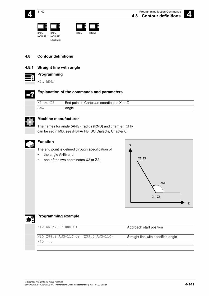
4 11.02 Programming Motion Commands4.8 Contour definitions 4
840DNCU 571
840DNCU 572NCU 573
810D 840Di
Siemens AG, 2002. All rights reservedSINUMERIK 840D/840Di/810D Programming Guide Fundamentals (PG) – 11.02 Edition 4-141
4.8 Contour definitions
4.8.1 Straight line with angleProgramming
X2… ANG…
Explanation of the commands and parameters
X2 or Z2 End point in Cartesian coordinates X or ZANG Angle
Machine manufacturer
The names for angle (ANG), radius (RND) and chamfer (CHR)can be set in MD, see /FBFA/ FB ISO Dialects, Chapter 6.
Function
The end point is defined through specification of• the angle ANG and• one of the two coordinates X2 or Z2.
ANG
X
Z
X2, Z2
X1, Z1
Programming example
N10 X5 Z70 F1000 G18 Approach start position
N20 X88.8 ANG=110 or (Z39.5 ANG=110) Straight line with specified angleN30 ...

4 Programming Motion Commands 11.024.8 Contour definitions 4
840DNCU 571
840DNCU 572NCU 573
810D 840Di
Siemens AG, 2002. All rights reserved4-142 SINUMERIK 840D/840Di/810D Programming Guide Fundamentals (PG) – 11.02 Edition
4.8.2 Two straight linesProgramming
ANG1… or X1… Z1…
X3… Z3 ANG2… X3… Z3…
Explanation of the commands and parameters
ANG1 Angle of the first straight lineANG2 Angle of the second straight lineCHR ChamferX1, Z1 Start coordinatesX2, Z2 Intersection of the two straight linesX3, Z3 End point of the second straight line
Machine manufacturer
The names for angle (ANG), radius (RND) and chamfer (CHR)can be set in MD, see /FBFA/ FB ISO Dialects, Chapter 6.
Function
The intersection of the two straight lines can bedesigned as a corner, curve or chamfer. The endpoint of the first of the two straight lines can beprogrammed by defining the coordinates orspecifying the angle.
ANG1
X
Z
X3, Z3
X1, Z1
ANG2
Can also be radius or chamfer
X2, Z2or CHR
Programming example
N10 X10 Z80 F1000 G18 Approach start positionN20 ANG1=148.65 CHR=5.5 Straight line with specified angle and chamferN30 X85 Z40 ANG2=100 Straight line with specified angle and end pointN40 ...

4 11.02 Programming Motion Commands4.8 Contour definitions 4
840DNCU 571
840DNCU 572NCU 573
810D 840Di
Siemens AG, 2002. All rights reservedSINUMERIK 840D/840Di/810D Programming Guide Fundamentals (PG) – 11.02 Edition 4-143
4.8.3 Three straight linesProgramming
X2… Z2… or ANG1…
X3… Z3… X3… Z3… ANG2…
X4… Z4… X4… Z4…
Explanation of the commands and parameters
ANG, ANG2 Angle of the first/second straight line relative to the abscissaCHR ChamferRND RoundingX1, Z1 Start coordinates of the first straight lineX2, Z2 Endpoint coordinates of the first straight line or start point of the second straight lineX3, Z3 Endpoint coordinates of the second straight line or start point of the third straight lineX4, Z4 Endpoint coordinates of the third straight lineMachine manufacturer
The names for angle (ANG), radius (RND) and chamfer (CHR)can be set in MD, see /FBFA/ FB ISO Dialects, Chapter 6.
RND function
The intersection of the straight lines can be designedas a corner, a curve or a chamfer. The end point ofthe third straight line must always be programmedas Cartesian.
ANG1
X
Z
X3, Z3
X1, Z1
ANG2
Can also beradius or chamfer
X2, Z2
X4, Z4
or RND
or CHR
Programming example
N10 X10 Z100 F1000 G18 Approach start positionN20 ANG1=140 CHR=7,5 Straight line with specified angle and
chamferN30 X80 Z70 ANG2=95.824 RND=10 Straight line on intersection with specified
angle and roundingN40 X70 Z50 Straight line on end point

4 Programming Motion Commands 11.024.8 Contour definitions 4
840DNCU 571
840DNCU 572NCU 573
810D 840Di
Siemens AG, 2002. All rights reserved4-144 SINUMERIK 840D/840Di/810D Programming Guide Fundamentals (PG) – 11.02 Edition
4.8.4 End point programming with an angle
Function
If the address letter A appears in an NC block, eithernone, one or both of the axes in the active planemay also be programmed.If none of the axes in the active plane isprogrammed, the block is either the first or secondblock of a contour consisting of two blocks. If it is thesecond block of this kind of contour, then this meansthat the start and end points in the active plane areidentical. The contour then comprises at most onemotion perpendicular to the active plane.If exactly one axis of the active plane isprogrammed, it is either a single straight line with anend point uniquely defined by the angle and theprogrammed coordinates, or the second block of acontour that consists of two blocks. In the lattercase, the missing coordinate is set to match the last(modal) position reached.If two axes are programmed in the current plane, it isthe second block of a contour that consists of twoblocks. If the current block was not preceded by ablock with angle programming and no programmedaxes in the current plane, the block in question is notpermissible.Angle A must only be programmed for linear orspline interpolation.
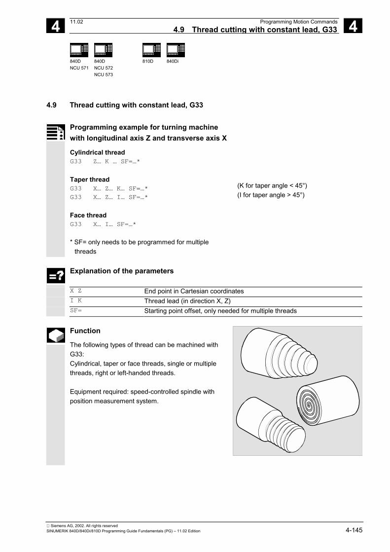
4 11.02 Programming Motion Commands4.9 Thread cutting with constant lead, G33 4
840DNCU 571
840DNCU 572NCU 573
810D 840Di
Siemens AG, 2002. All rights reservedSINUMERIK 840D/840Di/810D Programming Guide Fundamentals (PG) – 11.02 Edition 4-145
4.9 Thread cutting with constant lead, G33
Programming example for turning machinewith longitudinal axis Z and transverse axis X
Cylindrical threadG33 Z… K … SF=…*
Taper threadG33 X… Z… K… SF=…*
G33 X… Z… I… SF=…*
Face threadG33 X… I… SF=…*
* SF= only needs to be programmed for multiplethreads
(K for taper angle < 45°)(I for taper angle > 45°)
Explanation of the parameters
X Z End point in Cartesian coordinatesI K Thread lead (in direction X, Z)SF= Starting point offset, only needed for multiple threads
Function
The following types of thread can be machined withG33:Cylindrical, taper or face threads, single or multiplethreads, right or left-handed threads.
Equipment required: speed-controlled spindle withposition measurement system.

4 Programming Motion Commands 11.024.9 Thread cutting with constant lead, G33 4
840DNCU 571
840DNCU 572NCU 573
810D 840Di
Siemens AG, 2002. All rights reserved4-146 SINUMERIK 840D/840Di/810D Programming Guide Fundamentals (PG) – 11.02 Edition
Sequence
Operating principleThe control calculates the required feedrate from theprogrammed spindle speed and the thread lead. Theturning tool traverses across the length of the threadin the longitudinal and/or facing direction at thisfeedrate. The feedrate F is not considered for G33,the limitation to maximum axis speed (rapidtraverse) is monitored by the control.
Feedrate
Lead
Speed
Cylinder threadA cylinder thread is described by the thread lengthand thread lead.
The thread length is entered in absolute orincremental dimensions with one of the Cartesiancoordinates X, Y or Z. The Z direction is usedpreferentially on turning machines. Allowance mustalso be made for the run-in and run-out paths acrosswhich the feed is accelerated or decelerated.
The thread lead is entered at addresses I, J, K, onturning machines preferentially with K.
The identifiers have the following meanings:
Z
X
Z
K Run
-in p
ath
Run
-out
pat
h
I Thread lead in X directionJ Thread lead in Y directionK Thread lead in Z direction
Example: K4 means 4mm lead per revolution
Value range of lead:0.001 to 2000.00 mm/revolution
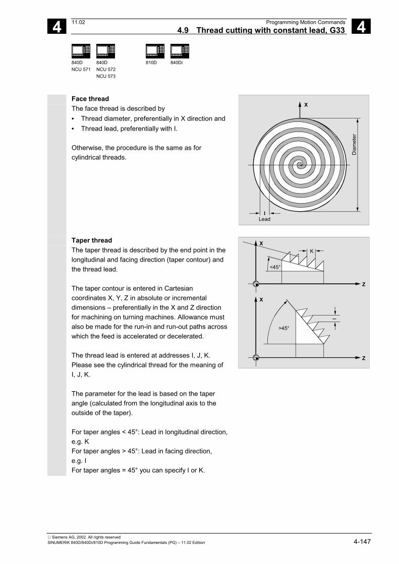
4 11.02 Programming Motion Commands4.9 Thread cutting with constant lead, G33 4
840DNCU 571
840DNCU 572NCU 573
810D 840Di
Siemens AG, 2002. All rights reservedSINUMERIK 840D/840Di/810D Programming Guide Fundamentals (PG) – 11.02 Edition 4-147
Face threadThe face thread is described by• Thread diameter, preferentially in X direction and• Thread lead, preferentially with I. Otherwise, the procedure is the same as forcylindrical threads.
I
X
Lead
Dia
met
er
Taper thread The taper thread is described by the end point in thelongitudinal and facing direction (taper contour) andthe thread lead. The taper contour is entered in Cartesiancoordinates X, Y, Z in absolute or incrementaldimensions – preferentially in the X and Z directionfor machining on turning machines. Allowance mustalso be made for the run-in and run-out paths acrosswhich the feed is accelerated or decelerated. The thread lead is entered at addresses I, J, K. Please see the cylindrical thread for the meaning ofI, J, K. The parameter for the lead is based on the taperangle (calculated from the longitudinal axis to theoutside of the taper). For taper angles < 45°: Lead in longitudinal direction,e.g. K For taper angles > 45°: Lead in facing direction, e.g. I For taper angles = 45° you can specify I or K.
Z
XK
<45°
Z
X
I>45°

4 Programming Motion Commands 11.024.9 Thread cutting with constant lead, G33 4
840DNCU 571
840DNCU 572NCU 573
810D 840Di
Siemens AG, 2002. All rights reserved4-148 SINUMERIK 840D/840Di/810D Programming Guide Fundamentals (PG) – 11.02 Edition
Start point offset SF – production of multi-turnthreads Threads with offset cuts are programmed byspecifying starting point offsets in the G33 block. The start point offset is specified as an absoluteangular position at address SF=. The associatedsetting data is changed accordingly. Example: SF=45 Meaning: Start offset 45° Value range: 0.0000 to 359.999 degrees
X
Z
Start pointoffset in °
Starting anglefor thread(setting data)
If no starting point offset is specified, the "startingangle for thread" defined in the setting data is used.
Right-hand/left-hand thread Right-hand or left-hand threads are set according tothe spindle direction: M3: Clockwise M4: Counterclockwise In addition, the desired speed is programmed at theaddress S.
The spindle speed override switch must not bechanged during thread cutting with G33 (dynamicspeed change). The feed override switch has no function in the G33block. Using a position-controlled spindle The SPCON command can be used before G33 toproduce a thread in position-control mode. You will find more information on SPCON in Chapter 7.

4 11.02 Programming Motion Commands4.9 Thread cutting with constant lead, G33 4
840DNCU 571
840DNCU 572NCU 573
810D 840Di
Siemens AG, 2002. All rights reservedSINUMERIK 840D/840Di/810D Programming Guide Fundamentals (PG) – 11.02 Edition 4-149
Thread chaining By programming several G33 blocks consecutively,you can align several sets of threads in a sequence.With G64 continuous-path mode, the blocks areinterconnected in a look ahead velocity control sothat no speed jumps are produced. You will find more information on G64 in Chapter 7.
Z
X
2nd blockwith G33
3rd blockwith G33
1st blockwith G33
Programming example
Machining a taper thread
Z
X
60
Ø 5
0Ø
110
N10 G1 X50 Z0 S500 F100 M3 Approach starting point, activate spindle N20 G33 X110 Z-60 K4 Taper thread: End point on Z and X, lead
K in Z direction, since angle < 45° N30 G0 Z0 M30 Retraction, end of program

4 Programming Motion Commands 11.024.9 Thread cutting with constant lead, G33 4
840DNCU 571
840DNCU 572NCU 573
810D 840Di
Siemens AG, 2002. All rights reserved4-150 SINUMERIK 840D/840Di/810D Programming Guide Fundamentals (PG) – 11.02 Edition
Programming example
Machining a double cylindrical thread in offset stepswith starting point offset 180°.
Z
X
100
Start point 0°
Start point 180°
Ø 1
00
10
N10 G1 G54 X99 Z10 S500 F100 M3 Zero offset, approach start point, spindle on N20 G33 Z-100 K4 Cylindrical thread: End point in Z N30 G0 X102
N40 G0 Z10
N50 G1 X99
Retract to starting position
N60 G33 Z-100 K4 SF=180 2nd cut: Starting point offset 180° N70 G0 X110 Retract tool N80 G0 Z10 End of program N90 M30
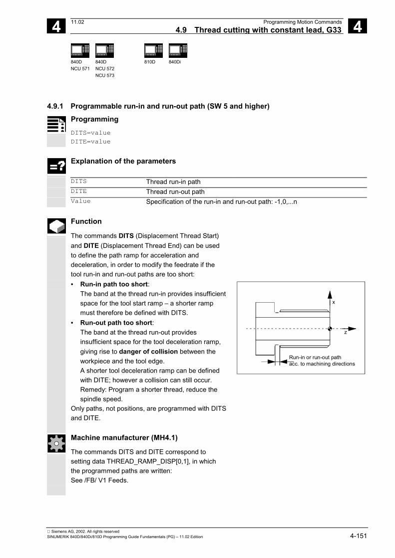
4 11.02 Programming Motion Commands4.9 Thread cutting with constant lead, G33 4
840DNCU 571
840DNCU 572NCU 573
810D 840Di
Siemens AG, 2002. All rights reservedSINUMERIK 840D/840Di/810D Programming Guide Fundamentals (PG) – 11.02 Edition 4-151
4.9.1 Programmable run-in and run-out path (SW 5 and higher)
Programming
DITS=value DITE=value
Explanation of the parameters
DITS Thread run-in path DITE Thread run-out path Value Specification of the run-in and run-out path: -1,0,...n
Function
The commands DITS (Displacement Thread Start)and DITE (Displacement Thread End) can be usedto define the path ramp for acceleration anddeceleration, in order to modify the feedrate if thetool run-in and run-out paths are too short:
• Run-in path too short:The band at the thread run-in provides insufficientspace for the tool start ramp – a shorter rampmust therefore be defined with DITS.
• Run-out path too short:The band at the thread run-out providesinsufficient space for the tool deceleration ramp,giving rise to danger of collision between theworkpiece and the tool edge.A shorter tool deceleration ramp can be definedwith DITE; however a collision can still occur.Remedy: Program a shorter thread, reduce thespindle speed.
Only paths, not positions, are programmed with DITSand DITE.
x
z
Run-in or run-out pathacc. to machining directions
Machine manufacturer (MH4.1)
The commands DITS and DITE correspond tosetting data THREAD_RAMP_DISP[0,1], in whichthe programmed paths are written:See /FB/ V1 Feeds.

4 Programming Motion Commands 11.024.9 Thread cutting with constant lead, G33 4
840DNCU 571
840DNCU 572NCU 573
810D 840Di
Siemens AG, 2002. All rights reserved4-152 SINUMERIK 840D/840Di/810D Programming Guide Fundamentals (PG) – 11.02 Edition
If the run-in and/or run-out path is very short, theacceleration of the thread axis is higher than theconfigured value. This causes an accelerationoverload on the axis. In this case, alarm 22280 "Programmed run-in pathtoo short" is output for the thread run-in (if configuredin MD 11411 ENABLE_ALARM_MASK). The alarmis purely for information and has no effect on partsprogram execution.
Additional notes
• DITE acts at the end of the thread as anapproximate distance. This achieves a smoothchange in the axis movement.
• When a block with the command DITS and/orDITE is loaded into the interpolator, the pathprogrammed in DITS is copied into SD 42010THREAD_RAMP_DISP[0] and the pathprogrammed in DITE is copied into SD 42010THREAD_RAMP_DISP[1].
• The programmed run-in path is handledaccording to the current setting (inches, metric).
Machine manufacturer (MH4.2)
If no run-in/deceleration path is programmed beforeor in the first thread block, the value is determined bythe setting in SD 42010; see References: /FB/ V1 Feeds. MD 10710: PROG_SD_RESET_SAVE_TAB is usedto set the value written by the parts program into thecorresponding setting data on RESET. That retainsthe values through a power ON.
Programming example
N... N40 G90 G0 Z100 X10 SOFT M3 S500 N50 G33 Z50 K5 SF=180 DITS=1 DITE=3 ;Start of corner rounding with Z=53 N60 G0 X20

4 11.02 Programming Motion Commands4.10 Linear progressive/degressive thread pitch change, G34, G35 4
840DNCU 571
840DNCU 572NCU 573
810D 840Di
Siemens AG, 2002. All rights reservedSINUMERIK 840D/840Di/810D Programming Guide Fundamentals (PG) – 11.02 Edition 4-153
4.10 Linear progressive/degressive thread pitch change, G34, G35(SW 5.2 and higher)
Programming
G34 X… Y… Z… I… J… K… F…
G35 X… Y… Z… I… J… K… F…
Progressive change in thread pitch(tapping with linear pitch increase) Degressive change in thread pitch(tapping with linear pitch decrease)
Explanation of the parameters
X Y Z End points in Cartesian coordinates I J K Thread lead (in X, Y, Z direction) F Thread pitch change (in mm/rev2)
Function
Functions G35/G35 can be employed to produce self-cutting threads. Both the functions G34 and G35 offer the functionalityof G33, but provide the additional option ofprogramming a pitch change under F.
Sequence
If you already know the initial and final pitch of athread, you can calculate the pitch change to beprogrammed according to the following equation: |k2
e - k2a|
F = [mm/rev2] 2*IG The identifiers have the following meanings:ke Pitch change of axis target point coordinate
[mm/rev]ka Initial thread pitch (progr. under I, J and K)
[mm/rev]IG Thread length in [mm]

4 Programming Motion Commands 11.024.10 Linear progressive/degressive thread pitch change, G34, G35 4
840DNCU 571
840DNCU 572NCU 573
810D 840Di
Siemens AG, 2002. All rights reserved4-154 SINUMERIK 840D/840Di/810D Programming Guide Fundamentals (PG) – 11.02 Edition
Programming example
N1608 M3 S10 ;Spindle speed N1609 G0 G64 Z40 X216 ;Approach start point and thread N1610 G33 Z0 K100 SF=R14 ;With constant pitch 100mm/rev N1611 G35 Z-200 K100 F17.045455 ;Pitch decrease 17.0454mm/rev2
;Pitch at block end 50mm/rev N1612 G33 Z-240 K50 ;Traverse thread block without jerk N1613 G0 X218 ; N1614 G0 Z40 ; N1615 M17 ;

4 11.02 Programming Motion Commands4.11 Rigid tapping, G331, G332 4
840DNCU 571
840DNCU 572NCU 573
810D 840Di
Siemens AG, 2002. All rights reservedSINUMERIK 840D/840Di/810D Programming Guide Fundamentals (PG) – 11.02 Edition 4-155
4.11 Rigid tapping, G331, G332
Programming
G331 X… Y… Z… I… J… K…
G332 X… Y… Z… I… J… K…
(Tapping) (Tapping retraction)
Explanation of the parameters
X Y Z Drilling depth (end point) in a Cartesian coordinate I J K Thread lead (in X, Y, Z direction)
Function
G331/G332 enable rigid tapping. Equipment required: Position-controlled spindle withposition measuring system
Sequence
The spindle must be prepared for tapping withSPOS/SPOSA. You will find more information inChapter 7. G331: Tapping Tapping is described by the drilling depth (end pointof the thread) and the lead. G332: Retraction movement This movement is described with the same lead asthe G331 movement. The reversal in the direction ofthe spindle is performed automatically. Drilling depth, thread lead Drilling in X direction, thread lead I Drilling in Y direction, thread lead J Drilling in Z direction, thread lead K Value range of lead: ±0.001 to 2000.00 mm/revolution
Z
X
Right-hand/left-hand threads
Right-hand or left-hand threads are defined in axismode by the sign qualifying the lead:

4 Programming Motion Commands 11.024.11 Rigid tapping, G331, G332 4
840DNCU 571
840DNCU 572NCU 573
810D 840Di
Siemens AG, 2002. All rights reserved4-156 SINUMERIK 840D/840Di/810D Programming Guide Fundamentals (PG) – 11.02 Edition
Positive lead, clockwise (same as M3) Negative lead, counterclockwise (same as M4) The desired speed is also programmed at address S.
Additional notes
Both functions are modal. The spindle does not operate in axis mode but as aposition-controlled spindle. You will find moreinformation on handling of the position-controlledspindle in Chapter 5.
Programming example
After G332 (retraction), the next thread can betapped with G331.
N10 SPOS[n]=0 Prepare tapping N20 G0 X0 Y0 Z2 Approach starting point N30 G331 Z-50 K-4 S200 Tapping, drilling depth 50, lead K
negative = direction of spindle rotationcounterclockwise
N40 G332 Z3 K-4 Retract, automatic reversal of direction N50 G1 F1000 X100 Y100 Z100 S300 M3 Spindle reverts to operation in spindle mode N60 M30 End of program

4 11.02 Programming Motion Commands4.12 Tapping with compensating chuck G63 4
840DNCU 571
840DNCU 572NCU 573
810D 840Di
Siemens AG, 2002. All rights reservedSINUMERIK 840D/840Di/810D Programming Guide Fundamentals (PG) – 11.02 Edition 4-157
4.12 Tapping with compensating chuck G63
Programming
G63 X… Y… Z…
Explanation of the parameters
X Y Z Drilling depth (end point, specified in Cartesian coordinates)
Function
You can use G63 to tap threads with compensatingchuck. The chuck compensates for any deviations occurringin the path.
Sequence
Tapping The following are programmed• Drilling depth in Cartesian coordinates• Spindle speed and direction• Feed Retraction movement Also programmed with G63, but with the reversedirection of spindle rotation. Feedrate
Z
X
The programmed feed must match the ratio of thespeed to the thread lead of the tap.
Thumb rule:
Feed F in mm/min = spindle speed S in rpm x thread lead in mm/rev Both the feed and the spindle speed override switchare set to 100% with G63.

4 Programming Motion Commands 11.024.12 Tapping with compensating chuck G63 4
840DNCU 571
840DNCU 572NCU 573
810D 840Di
Siemens AG, 2002. All rights reserved4-158 SINUMERIK 840D/840Di/810D Programming Guide Fundamentals (PG) – 11.02 Edition
Additional notes
G63 is modal. The last programmed interpolation command G0,G1, G2, ... is reactivated after a block withprogrammed G63.
Programming example
Tapping with compensating chuck: In this example, an M5 thread is to be drilled. Thelead of an M5 thread is 0.8 (specified in table). With a selected speed of 200rpm, the feed F is160 mm/min.
N10 G1 X0 Y0 Z2 S200 F1000 M3 Approach starting point, activate spindle N20 G63 Z-50 F160 Tap, drilling depth 50 N30 G63 Z3 M4 Retract, programmed reversal of direction N40 M30 End of program

4 11.02 Programming Motion Commands4.13 Stop during thread cutting 4
840DNCU 571
840DNCU 572NCU 573
810D 840Di
Siemens AG, 2002. All rights reservedSINUMERIK 840D/840Di/810D Programming Guide Fundamentals (PG) – 11.02 Edition 4-159
4.13 Stop during thread cutting
Programming
LFONLFOF
DILF
Explanation of the parameters
LFON Enable fast retraction for thread cutting (G33) LFOF Disable fast retraction for thread cutting (G33) DILF Determine retraction path (length)
Function
The function produces a nondestructive interruption withthread cutting (G33). The function cannot be used withtapping (G33). With mixed use of both G33 functions,the response can be parameterized for NC Stop/NCReset via the machine data.
Trigger criteria for retraction• Fast inputs, programmable with SETINT
LIFTFAST (if LIFTFAST option enabled)• NC Stop/NC Reset If fast retraction is enabled with LFON, it is active forevery retraction movement
Retraction path (DILF) The retraction path can be defined in the machine dataor by programming. After NC Reset, the value inMD 21200: LIFTFAST_DIST is still active. Retraction direction (SW 4.2 and lower) The retraction direction is determined within thethreading. Retraction is always perpendicular to thedirection of machining. ALF is not active.

4 Programming Motion Commands 11.024.13 Stop during thread cutting 4
840DNCU 571
840DNCU 572NCU 573
810D 840Di
Siemens AG, 2002. All rights reserved4-160 SINUMERIK 840D/840Di/810D Programming Guide Fundamentals (PG) – 11.02 Edition
Retraction direction (SW 4.3 and higher) The retraction direction in connection with ALF iscontrolled using the following keywords:• LFTXT
The plane in which the fast retraction is executed iscalculated from the path tangent and the tooldirection (default setting).
• LFWPThe plane in which the fast retraction is executed isthe active working plane.
The direction is programmed as before in discrete stepsof 45 degrees with ALF in the plane of the retractionmotion. With LFTXT, the retraction is defined in the tooldirection for ALF=1. With LFWP, the direction in the working plane isassigned as follows:• G17: X/Y plane ALF=1 Retraction in X direction
ALF=3 Retraction in Y direction• G18: Z/X plane ALF=1 Retraction in Z direction
ALF=3 Retraction in X direction• G19: Y/Z plane ALF=1 Retraction in Y direction
ALF=3 Retraction in Z direction Retraction speed Retraction with maximum axis speed.Can be configured via machine data. The maximum permissible acceleration/jerk values areused for traversing; they are configured via the machinedata.
Additional notes
Default settings for NC reset and/or NC start in MD20150: GCODE_RESET_VALUES
LFON or LFOF can always be programmed, they areevaluated only during thread cutting (G33).

4 11.02 Programming Motion Commands4.14 Approaching a fixed point, G75 4
840DNCU 571
840DNCU 572NCU 573
810D 840Di
Siemens AG, 2002. All rights reservedSINUMERIK 840D/840Di/810D Programming Guide Fundamentals (PG) – 11.02 Edition 4-161
Programming examples
Example 1 N55 M3 S500 G90 G18 Active machining plane ... N65 MSG ("Thread cutting") MM_THREAD: N67 $AC_LIFTFAST=0 Reset before beginning of thread N68 G0 Z5 N68 X10 N70 G33 Z30 K5 LFON DILF=10 LFWP ALF=3 Enable fast retraction for thread cutting Retraction path =10mm, retraction plane Z/X (due to G18)
Retraction direction –X (with ALF=3; retraction direction +X) N71 G33 Z55 X15 K5 N72 G1 Deactivate thread cutting N69 IF $AC_LIFTFAST GOTOB MM_THREAD If thread cutting was interrupted N90 MSG("") ... N70 M30 Example 2 N55 M3 S500 G90 G0 X0 Z0 ... N87 MSG ("Tapping") N88 LFOF Deactivate fast retraction before tapping. N89 CYCLE... Thread drilling cycle with G33 N90 MSG("") ... N99 M30
4.14 Approaching a fixed point, G75
Programming
G75 FP= X1=0 Y1=0 Z1=0 U1=0 …
Explanation of the parameters
FP= Number of fixed point to be approached X1= Y1= Z1= Machine axes to be traversed to the fixed point
4 Programming Motion Commands 11.024.14 Approaching a fixed point, G75 4
840DNCU 571
840DNCU 572NCU 573
810D 840Di
Siemens AG, 2002. All rights reserved4-162 SINUMERIK 840D/840Di/810D Programming Guide Fundamentals (PG) – 11.02 Edition
Function
G75 can be used to approach fixed points, such astool change locations, loading points, pallet changingpoints, etc. The positions of the individual points are specified inthe machine coordinate system and stored in themachine parameters. You can approach these positions from any NCprogram, irrespective of the current tool orworkpiece position.
Sequence
The fixed point approach is described by a fixedpoint and axes which are to be traversed to the fixedpoint FP. Number of the fixed point FP=… If no fixed point number is specified, fixed point 1 isautomatically approached.
Two fixed point positions per machine axis can bespecified in the machine parameters.
Machine axis addresses X1, Y1 …
Here, you specify with value 0 the axes with whichthe point is to be approached simultaneously. Eachaxis traverses at the maximum axial velocity.
Additional notes
G75 is modal. Kinematic transformation must be deselected beforefixed point approach is performed.
Programming example
The tool change location is a fixed point which isdefined in the machine data. This point can be approached in any NC programwith G75.

4 11.02 Programming Motion Commands4.15 Travel to fixed stop 4
840DNCU 571
840DNCU 572NCU 573
810D 840Di
Siemens AG, 2002. All rights reservedSINUMERIK 840D/840Di/810D Programming Guide Fundamentals (PG) – 11.02 Edition 4-163
N10 G75 FP=2 X1=0 Y1=0 Z1=0 Retract from fixed point 2 on X, Y and Z,e.g. for tool change
N20 G75 X1=0 Approach fixed point X1 N30 M30 End of program
Additional notes
SW 5.3 and higher: G75 "Approach fixed point" applies all offset values(DRF, external ZO and overlaid motion). The fixedpoint corresponds to the actual value in the MCS. Changes to the DRF and external zero offset whilethe G75 block is being preprocessed and executedin the main run are not applied. You should preventthis problem by programming STOPPRE in front ofthe G75 block.
4.15 Travel to fixed stop
Programming
FXS[axis]=… FXST[axis]=… FXSW[axis]=…
Explanation
FXS Activate/deactivate function "Travel to fixed stop" select/deselect 1 = select; 0 = deselect
FXST Setting clamping torque Specification in % of maximum drive torque, parameter optional
FXSW Window width for fixed stop monitoring in mm, inches or degrees; parameter optional
[axis] Machine axis name
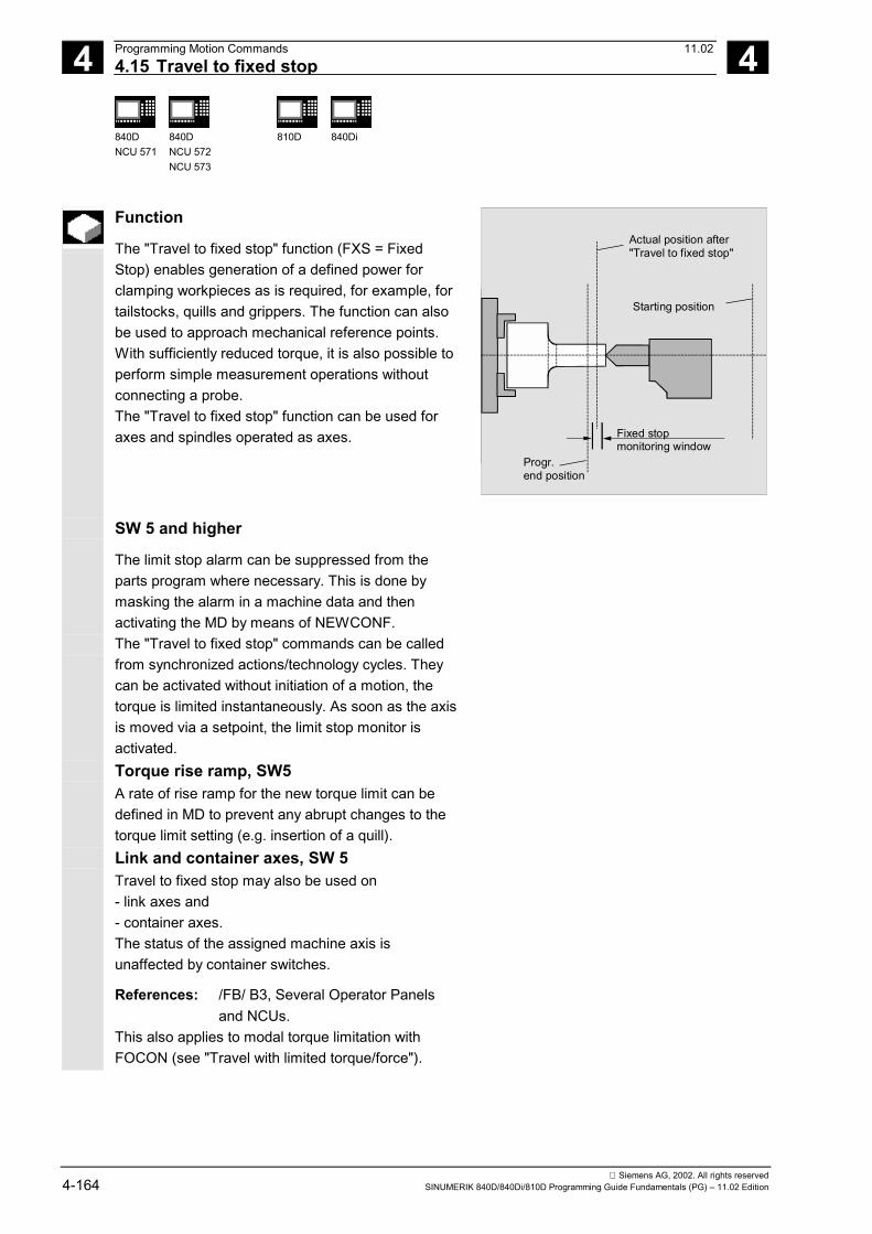
4 Programming Motion Commands 11.024.15 Travel to fixed stop 4
840DNCU 571
840DNCU 572NCU 573
810D 840Di
Siemens AG, 2002. All rights reserved4-164 SINUMERIK 840D/840Di/810D Programming Guide Fundamentals (PG) – 11.02 Edition
Function
The "Travel to fixed stop" function (FXS = FixedStop) enables generation of a defined power forclamping workpieces as is required, for example, fortailstocks, quills and grippers. The function can alsobe used to approach mechanical reference points.With sufficiently reduced torque, it is also possible toperform simple measurement operations withoutconnecting a probe. The "Travel to fixed stop" function can be used foraxes and spindles operated as axes.
Actual position after"Travel to fixed stop"
Starting position
Fixed stopmonitoring window
Progr.end position
SW 5 and higher
The limit stop alarm can be suppressed from theparts program where necessary. This is done bymasking the alarm in a machine data and thenactivating the MD by means of NEWCONF.
The "Travel to fixed stop" commands can be calledfrom synchronized actions/technology cycles. Theycan be activated without initiation of a motion, thetorque is limited instantaneously. As soon as the axisis moved via a setpoint, the limit stop monitor isactivated.Torque rise ramp, SW5A rate of rise ramp for the new torque limit can bedefined in MD to prevent any abrupt changes to thetorque limit setting (e.g. insertion of a quill).Link and container axes, SW 5Travel to fixed stop may also be used on- link axes and- container axes.The status of the assigned machine axis isunaffected by container switches.
References: /FB/ B3, Several Operator Panels and NCUs.
This also applies to modal torque limitation withFOCON (see "Travel with limited torque/force").

4 11.02 Programming Motion Commands4.15 Travel to fixed stop 4
840DNCU 571
840DNCU 572NCU 573
810D 840Di
Siemens AG, 2002. All rights reservedSINUMERIK 840D/840Di/810D Programming Guide Fundamentals (PG) – 11.02 Edition 4-165
Sequence
The commands are modal. Addresses FXST andFXSW are optional: if no parameter is specified, thelast programmed value or the value set in the machinedata apply.
Machine manufacturer (MH4.3)
Machine axes (X1, Y1, Z1 etc.) are programmed.(See machine manufacturer's specifications).
Activate travel to fixed stop FXS=1 The movement to the destination point can bedescribed as a path or positioning axis movement.With positioning axes, the function can be performedacross block boundaries. Travel to fixed stop can be performedsimultaneously for several axes and parallel to themovement of other axes. The fixed stop must belocated between the start and end positions. Example:
X250 Y100 F100 FXS[X1]=1 FXST[X1]=12.3 FXSW[X1]=2
Meaning: Axis X1 travels with feed F100 (parameter optional) todestination position X=250mm. The clamping torque is12.3% of the maximum drive torque. Monitoring isperformed in a 2mm wide window.
From the moment the "Travel to fixed point" functionis activated for an axis/spindle, you must no longerprogram a new position for this axis.
Spindles must be switched to position-controlledmode before the function is selected.
When the fixed stop has been reached:
• The distance-to-go is deleted and the positionsetpoint is manipulated,
• The drive torque increases to the programmedlimit value FXSW and then remains constant,
• Fixed stop monitoring is activated within thespecified window width.

4 Programming Motion Commands 11.024.15 Travel to fixed stop 4
840DNCU 571
840DNCU 572NCU 573
810D 840Di
Siemens AG, 2002. All rights reserved4-166 SINUMERIK 840D/840Di/810D Programming Guide Fundamentals (PG) – 11.02 Edition
Activate from synchronized actions (SW 5)
Example:If the anticipated event ($R1) occurs and travel tofixed stop is not already operative, then FXS mustbe activated for axis Y. The torque must correspondto 10% of the rated torque value. The width of themonitoring window is set to the default.
N10 IDS=1 WHENEVER (($R1=1) AND ($AA_FXS[Y]==0)) DO $R1=0 FXS[Y]=1 FXST[Y]=10
The normal parts program must ensure that $R1 is setat the desired point in time.
Deactivate function FXS=0 Deselection of the function triggers a preprocessor stop. Traversing movements may and should be programmedin a block with FXS=0.
Example:X200 Y400 G01 G94 F2000 FXS[X1] = 0
Meaning: Axis X1 is retracted from the fixed stop to positionX= 200 mm. All other parameters are optional.
The traversing movement to the retraction position mustmove away from the fixed stop, otherwise damage tothe stop or to the machine may result.
The block change takes place when the retractionposition has been reached. If no retraction position isspecified, the block change takes place immediatelythe torque limit has been deactivated.
Deactivate from synchronized actions (SW 5)
The function can be deselected from a synchronizedaction.Example:If an anticipated event ($R3) has occurred and thestatus "Limit stop contacted" (system variable$AA_FXS) is reached, then FXS must be deselected.

4 11.02 Programming Motion Commands4.15 Travel to fixed stop 4
840DNCU 571
840DNCU 572NCU 573
810D 840Di
Siemens AG, 2002. All rights reservedSINUMERIK 840D/840Di/810D Programming Guide Fundamentals (PG) – 11.02 Edition 4-167
N13 IDS=4 WHENEVER (($R3==1) AND ($AA_FXS[Y]==1))
DO FXS[Y]=0 FA[Y]=1000 POS[Y]=0
Clamping torque FXST, monitoring window FXSW A programmed torque limit FXST is effective from thestart of the block, i.e. the fixed stop is also approachedwith reduced torque.
The window must be selected such that only abreakaway from the fixed stop causes the fixed stopmonitoring to be addressed.
FXST and FXSW can be programmed or changed atany time in the parts program. Example: FXST[X1]=34.57
FXST[X1]=34.57 FXSW[X1]=5
FXSW[X1]=5
The changes take effect before traversing movementsin the same block. Programming of a new fixed stop monitoring windowcauses a change not only in the window width but alsoin the reference point for the center of the window ifthe axis has moved prior to reprogramming. Theactual position of the machine axis when the windowis changed is the new window center point.
Additional notes
Combination "Measure and delete distance-to-go" ("MEAS"command) and "Travel to fixed stop" cannot beprogrammed in the same block. Exception: One function acts on a path axis and the other on apositioning axis or both act on positioning axes.

4 Programming Motion Commands 11.024.15 Travel to fixed stop 4
840DNCU 571
840DNCU 572NCU 573
810D 840Di
Siemens AG, 2002. All rights reserved4-168 SINUMERIK 840D/840Di/810D Programming Guide Fundamentals (PG) – 11.02 Edition
Contour monitoring Contour monitoring is not performed while "Travelto fixed stop" is active. Positioning axes With "Travel to fixed stop" with POSA axes, theblock change takes place independently of thefixed stop movement. Restrictions Travel to fixed stop cannot be programmed• for vertical axes,
(function can be used with SW 2.2. and higheron 840D with 611D)
• gantry axes,• for concurrent positioning axes which are
controlled exclusively by the PLC (FXS must beselected from the NC program).
• If the torque limit is reduced too far, the axis willnot be able to follow the specified setpoint; theposition controller then goes to the limit and thecontour deviation increases. In this operatingstate, an increase in the torque limit may resultin sudden, jerky movements.To ensure that the axis can follow the setpoint,check the contour deviation to make sure it isnot greater than the deviation with an unlimitedtorque.

4 11.02 Programming Motion Commands4.16 Special turning functions
4
840DNCU 571
840DNCU 572NCU 573
FM-NC
810D
840Di
Siemens AG, 2002. All rights reservedSINUMERIK 840D/840Di/810D Programming Guide Fundamentals (PG) – 11.02 Edition 4-169
4.16 Special turning functions
4.16.1 Position of workpiece
Coordinate system The two mutually perpendicular geometry axes areusually designated as follows:• Longitudinal axis = Z axis (abscissa)• Transverse axis = X axis (ordinate) The dimensions for the facing axis are generallyspecified as diameter measurements (double pathdimension as compared to other axes). The geometry axis to be used as a transverse axis isdefined in machine data.
Z
X
D1
W
D2
M
Longitudinal axis
Tran
sver
se a
xis
Zero points Both the machine zero and the workpiece zero arepositioned on the center of rotation. The settableoffset on the X axis is thus zero. While the machine zero is fixed, you can choose theposition for the workpiece zero on the longitudinalaxis. The workpiece zero is generally located on thefront or rear side of the workpiece. The position of the workpiece zero is called withcommands G54 to G599 or TRANS.
W
G54 ... G599 or TRANS
M
Z
G54 ... G599
M
Workpiece
Machine
Workpiecezero rear
Workpiecezero front
Workpiece
Workpiece
Workpiece
MachineX
X X
X
Z
Z
or TRANS
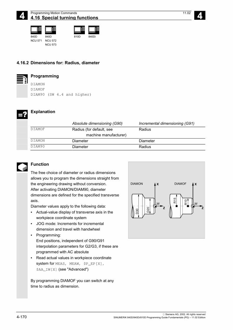
4 Programming Motion Commands 11.02 4.16 Special turning functions
4
840DNCU 571
840DNCU 572NCU 573
810D
840Di
Siemens AG, 2002. All rights reserved4-170 SINUMERIK 840D/840Di/810D Programming Guide Fundamentals (PG) – 11.02 Edition
4.16.2 Dimensions for: Radius, diameter
Programming
DIAMON DIAMOFDIAM90 (SW 4.4 and higher)
Explanation
Absolute dimensioning (G90) Incremental dimensioning (G91) DIAMOF Radius (for default, see
machine manufacturer) Radius
DIAMON Diameter Diameter DIAM90 Diameter Radius
Function
The free choice of diameter or radius dimensionsallows you to program the dimensions straight fromthe engineering drawing without conversion. After activating DIAMON/DIAM90, diameterdimensions are defined for the specified transverseaxis. Diameter values apply to the following data:• Actual-value display of transverse axis in the
workpiece coordinate system• JOG mode: Increments for incremental
dimension and travel with handwheel• Programming:
End positions, independent of G90/G91interpolation parameters for G2/G3, if these areprogrammed with AC absolute
• Read actual values in workpiece coordinatesystem for MEAS, MEAW, $P_EP[X],$AA_IW[X] (see "Advanced")
By programming DIAMOF you can switch at anytime to radius as dimension.
Z
X
D30
W
DIAMON DIAMOF
D20 Z
X
R15
R10 W

4 11.02 Programming Motion Commands4.16 Special turning functions
4
840DNCU 571
840DNCU 572NCU 573
810D
840Di
Siemens AG, 2002. All rights reservedSINUMERIK 840D/840Di/810D Programming Guide Fundamentals (PG) – 11.02 Edition 4-171
Additional notes
In SW 4.4 and higher, the command DIAM90 setsdiameter programming for G90 and radiusprogramming for G91. After DIAM90 is activated, the actual value of thetransverse axis is always displayed as a diameter,irrespective of the type of traversing (G90/G91). Thisalso applies to reading of actual values in the workpiececoordinate system with MEAS, MEAW, $P_EP[x] and$AA_IW[x].
Programming example
N10 G0 X0 Z0 Approach starting point N20 DIAMOF Diameter input off N30 G1 X30 S2000 M03 F0.7 X axis = transverse axis; radius dimensions active
Traverse to radius position X30 N40 DIAMON Diameter dimensions active N50 G1 X70 Z-20 Traverse to diameter position X70 and Z–20 N60 Z-30 N70 DIAM90 Diameter programming for absolute dimensions and
radius programming for incremental dimensions N80 G91 X10 Z-20 Increment N90 G90 X10 Absolute dimensions N100 M30 End of program

4 Programming Motion Commands 11.02 4.17 Chamfer, rounding
4
840DNCU 571
840DNCU 572NCU 573
810D
840Di
Siemens AG, 2002. All rights reserved4-172 SINUMERIK 840D/840Di/810D Programming Guide Fundamentals (PG) – 11.02 Edition
4.17 Chamfer, rounding
Programming
CHF=… CHR=… RND=… RNDM=… FRC=… FRCM=…
Explanation of the commands
CHF=… Chamfer the contour corner Value = Length of the chamfer (unit of measurement according to G70/G71)
CHR=… Chamfer the contour corner (SW 3.5 and higher). Programming the chamfer in the original direction of movement. Value = width of chamfer in direction of motion (unit of measurement as above)
RND=… Round the contour corner Value = Radius of the rounding (unit of measurement according to G70/G71)
RNDM=… Modal rounding: Rounding several consecutive contour corners in the sameway. Value = radius of roundings (unit of measurement according to G70/G71) 0: Deactivate modal rounding
FRC=… Non-modal feedrate for chamfer/roundingValue = feedrate in mm/min (G94) or mm/rev (G95); FRC > 0
FRCM=… Modal feedrate for chamfer/roundingValue = feedrate in mm/min (G94) or mm/rev (G95) 0: Feedrate programmed at F for chamfer/rounding active
Function
You can insert the following elements at a contourcorner:• Chamfer or• Rounding If you wish to round several contour cornerssequentially by the same method, use commandRNDM "Modal rounding". You can program the feedrate for the chamfer/roundingwith FRC (non-modal) or FRCM (modal). If FRC/FRCM is not programmed, then the normal pathfeedrate F is applicable.

4 11.02 Programming Motion Commands4.17 Chamfer, rounding
4
840DNCU 571
840DNCU 572NCU 573
810D
840Di
Siemens AG, 2002. All rights reservedSINUMERIK 840D/840Di/810D Programming Guide Fundamentals (PG) – 11.02 Edition 4-173
Sequence
Chamfer, CHF/CHR For the chamfer insert another linear part, thechamfer, between the linear and the circle contoursin any combination. The chamfer is inserted after theblock in which it is programmed. The chamfer isalways in the plane activated with G17 to G19. Example: N30 G1 X… Z… F… CHR=2
N40 G1 X… Z…
or
N30 G1 X… Z… F… CHF=2(cos α ·2)N40 G1 X… Z…
X
Z
G1
G1
Bisector
Chamfer
e.g. G18:
CHR
CHF
α
Rounding, RND A circle contour element can be inserted withtangential link between the linear and the circlecontours in any combination. The rounding is always in the plane activated withG17 to G19. The figure to the right shows the rounding betweentwo straight lines.
RND=...
X
Z
G1
G1
Rounding
e.g. G18:
Example: N30 G1 X… Z… F… RND=2
Here, the figure shows the rounding between astraight line and a circle. N30 G1 X… Z… F… RND=2 N40 G3 X… Z… I… K…
RND=...
X
Z
G1
G3
e.g. G18:
Rounding

4 Programming Motion Commands 11.02 4.17 Chamfer, rounding
4
840DNCU 571
840DNCU 572NCU 573
810D
840Di
Siemens AG, 2002. All rights reserved4-174 SINUMERIK 840D/840Di/810D Programming Guide Fundamentals (PG) – 11.02 Edition
Modal rounding, RNDM This address is for inserting a rounding betweenlinear and circle contours after each traversing block.This is, for example, for deburring sharp workpieceedges. Example: N30 G1 X… Z… F… RNDM=2
Rounding is deactivated with RNDM=0.
Feed FRC (non-modal), FRCM (modal) To optimize surface quality, it is possible to programa separate feedrate for the chamfer/roundingcontour elements.• FRC is non-modal in this instance,• FRCM is modal. See below for examples
Additional info about chamfer/rounding
If the programmed values for chamfer (CHF/CHR) orrounding (RND/RNDM) are too large for theassociated contour elements, then the chamfer orrounding are automatically reduced to a suitablevalue. No chamfer/rounding is inserted, if• no straight or circle is available in the plane,• a movement is taking place outside the plane,• a plane change is taking place, or• the number of blocks – which is specified in the
machine data – not containing information fortraversing (e.g. only command output), isexceeded.

4 11.02 Programming Motion Commands4.17 Chamfer, rounding
4
840DNCU 571
840DNCU 572NCU 573
810D
840Di
Siemens AG, 2002. All rights reservedSINUMERIK 840D/840Di/810D Programming Guide Fundamentals (PG) – 11.02 Edition 4-175
Additional info about FRC/FRCM
• FRC/FRCM has no effect if a chamfer is beingmachined with G0; the command can be programmedaccording to the F value without error message.
• The reference to the blocks in which chamfer androunding are programmed and to the technology is setin machine data.
• FRC is operative only if a chamfer/rounding isprogrammed in the same block or if RNDM has beenactivated.
• FRC overwrites the F or FRCM value in the currentblock.
• The feedrate programmed under FRC must be greaterthan zero.
• FRCM=0 activates the feed programmed in F for thechamfer/rounding.
• If FRCM is programmed, the FRCM value must bereprogrammed, analogous to F, on changeover G94-95 etc. If only a new F value is programmed, and ifFRCM > 0 before the feed type changes, errormessage 10860 (no feed programmed) will beactivated.
Examples
Example 1: MD CHFRND_MODE_MASK Bit 0 = 0: Accept technology from next block (default)
N10 G0 X0 Y0 G17 F100 G94
N20 G1 X10 CHF=2 ; Chamfer N20-N30 with F=100 mm/minN30 Y10 CHF=4 ; Chamfer N30-N40 with FRC=200 mm/minN40 X20 CHF=3 FRC=200 ; Chamfer N40-N60 with FRCM=50 mm/minN50 RNDM=2 FRCM=50
N60 Y20 ; Modal rounding N60-N70 with FRCM=50 mm/min
N70 X30 ; Modal rounding N70-N80 with FRCM=100 mm/min
N80 Y30 CHF=3 FRC=100 ; Chamfer N80-N90 with FRC=50 mm/min (modal)

4 Programming Motion Commands 11.02 4.17 Chamfer, rounding
4
840DNCU 571
840DNCU 572NCU 573
810D
840Di
Siemens AG, 2002. All rights reserved4-176 SINUMERIK 840D/840Di/810D Programming Guide Fundamentals (PG) – 11.02 Edition
N90 X40 ; Modal rounding N90-N100 with F=100 mm/min (deselect FRCM)
N100 Y40 FRCM=0 ; Modal rounding N100-N120 with G95 FRC=1 mm/rev
N110 S1000 M3
N120 X50 G95 F3 FRC=1
...
M02
Example 2: MD CHFRND_MODE_MASK Bit 0 = 1: Accept technology from preceding block(recommended)N10 G0 X0 Y0 G17 F100 G94
N20 G1 X10 CHF=2 ; Chamfer N20-N30 with F=100 mm/minN30 Y10 CHF=4 FRC=120 ; Chamfer N30-N40 with FRC=120 mm/minN40 X20 CHF=3 FRC=200 ; Chamfer N40-N60 with FRCM=200 mm/minN50 RNDM=2 FRCM=50
N60 Y20 ; Modal rounding N60-N70 with FRCM=50 mm/min
N70 X30 ; Modal rounding N70-N80 with FRCM=50 mm/min
N80 Y30 CHF=3 FRC=100 ; Chamfer N80-N90 with FRC=100 mm/minN90 X40 ; Modal rounding N90-N100
with FRCM=50 mm/minN100 Y40 FRCM=0 ; Modal rounding N100-N120
with F=100 mm/minN110 S1000 M3
N120 X50 CHF=4 G95 F3 FRC=1 ; Chamfer N120-N130 with G95 FRC= 1 mm/rev
N130 Y50 ; Modal rounding N130-N140 with F=3 mm/rev
N140 X60
...
M02
�

5 11.02 Path action 5
Siemens AG, 2002. All rights reservedSINUMERIK 840D/840Di/810D Programming Guide Fundamentals (PG) – 11.02 Edition 5-177
Path action
5.1 Exact stop, G60, G9, G601, G602, G603 ..................................................................... 5-178
5.2 Continuous-path mode, G64, G641, G642, G643......................................................... 5-181
5.3 Acceleration pattern, BRISK, SOFT, DRIVE................................................................. 5-1905.3.1 Acceleration modes ............................................................................................... 5-1905.3.2 Influence of acceleration modes on following axes ............................................... 5-191
5.4 Overview of the various velocity controls ...................................................................... 5-194
5.5 Path velocity smoothing ................................................................................................ 5-195
5.6 Traversing with feedforward control, FFWON, FFWOF ............................................... 5-196
5.7 Programmable contour accuracy, CPRECON, CPRECOF .......................................... 5-197
5.8 Dwell time, G4............................................................................................................... 5-198
5.9 Program sequence: Internal preprocessor stop............................................................ 5-199

5 Path action 11.025.1 Exact stop, G60, G9, G601, G602, G603 5
840DNCU 571
840DNCU 572NCU 573
810D 840Di
Siemens AG, 2002. All rights reserved5-178 SINUMERIK 840D/840Di/810D Programming Guide Fundamentals (PG) – 11.02 Edition
5.1 Exact stop, G60, G9, G601, G602, G603
Explanation of the commands
G60 Exact stop, modalG9 Exact stop, non-modalG601 Step enable if positioning window fine reachedG602 Step enable if positioning window coarse reachedG603 Step enable if setpoint (end of interpolation) reached
Function
The exact positioning stop functions are used tomachine sharp outside corners or for finishing insidecorners to size.
Sequence
Exact stop, G60, G9G9 generates the exact stop in the current block.G60 generates the exact stop in the current blockand all subsequent blocks.G60 is deactivated by the continuous-path modefunctions G64 or G641. Positioning window.
G601/G602The movement is decelerated and stopped briefly atthe corner point. With the exact stop criteria G601and G602, you determine how accurately the cornerpoint is approached and when the change to thenext block takes place.
Exact stops fine and coarse can be defined for eachaxis in machine data.
G601
G602
Block step enable

5 11.02 Path action5.1 Exact stop, G60, G9, G601, G602, G603 5
840DNCU 571
840DNCU 572NCU 573
810D 840Di
Siemens AG, 2002. All rights reservedSINUMERIK 840D/840Di/810D Programming Guide Fundamentals (PG) – 11.02 Edition 5-179
Note: Set the exact stop limits no tighter than yourequire.The tighter the limits, the longer it takes to positionand approach the target position.
End of interpolation, G603The block change is initiated when the control hascalculated a set speed of zero for the axes involved.At this point, the actual value lags behind by aproportionate factor depending on the dynamicresponse of the axes and the path velocity. Theworkpiece corners can now be rounded.
Command outputIn all three cases the following applies:The auxiliary functions programmed in the NC blockare enabled after the end of the movement.
Block change
Programmed path
Traversedpathwith F1
Traversedpathwith F2
F1 < F2
G601, G602 and G603 are only effective if G60 orG9 are active.
Example:N10 G601
…
N50 G1 G60 X… Y…

5 Path action 11.025.1 Exact stop, G60, G9, G601, G602, G603 5
840DNCU 571
840DNCU 572NCU 573
810D 840Di
Siemens AG, 2002. All rights reserved5-180 SINUMERIK 840D/840Di/810D Programming Guide Fundamentals (PG) – 11.02 Edition
In SW version 6 and higher, a machine data can beset for specific channels which determines that thedefault exact stop criteria, which deviate from theprogrammed criteria, will be applied automatically.These are given priority over the programmedcriteria in some cases. Criteria for G0 and the otherG commands in the 1st G code group can be storedseparately.See Description of Functions, Part1, B1.

5 11.02 Path action5.2 Continuous-path mode, G64, G641, G642, G643 5
840DNCU 571
840DNCU 572NCU 573
810D 840Di
Siemens AG, 2002. All rights reservedSINUMERIK 840D/840Di/810D Programming Guide Fundamentals (PG) – 11.02 Edition 5-181
5.2 Continuous-path mode, G64, G641, G642, G643Programming
G64
G641 AIDS=…
G641 ADISPOS=…
G642
G643
Explanation of the commands
G64 Continuous-path modeG641 Continuous-path mode with programmable transition roundingG642 Rounding with axial toleranceG643 Block-internal corner roundingAIDS= Rounding clearance for path functions G1, G2, G3, …ADIPOSE= Approximate distance for rapid traverse G0
Function
In continuous-path mode, the contour is machinedwith a constant path velocity.
The uniform velocity also establishes better cuttingconditions, improves the surface quality and reducesthe machining time.
In continuous-path mode, travel does not take placeexactly to the programmed contour transitions. Youcan generate sharp corners with G60 or G09. Thecontinuous-path mode is interrupted by text outputswith "MSG" and blocks that implicitly trigger apreprocessor stop (e.g. access to certain machinestatus data ($A...)). The same applies to auxiliaryfunction outputs; see Chapter 9 Special Functions.
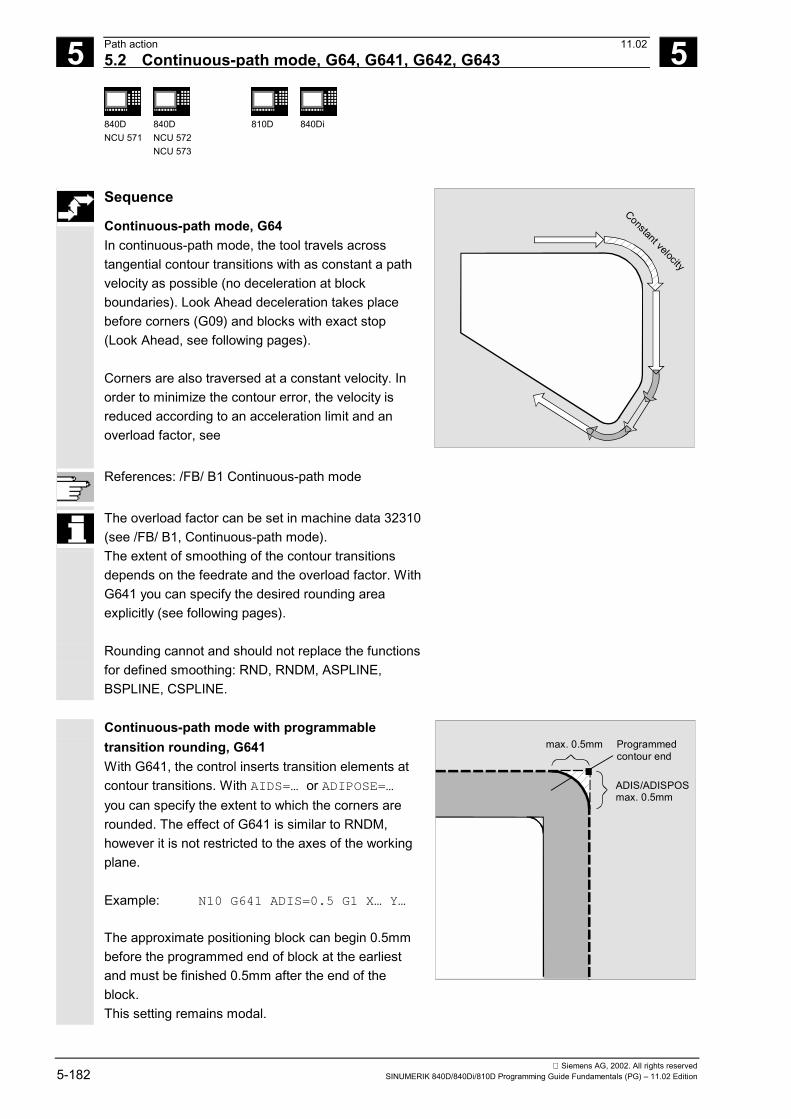
5 Path action 11.025.2 Continuous-path mode, G64, G641, G642, G643 5
840DNCU 571
840DNCU 572NCU 573
810D 840Di
Siemens AG, 2002. All rights reserved5-182 SINUMERIK 840D/840Di/810D Programming Guide Fundamentals (PG) – 11.02 Edition
Sequence
Continuous-path mode, G64In continuous-path mode, the tool travels acrosstangential contour transitions with as constant a pathvelocity as possible (no deceleration at blockboundaries). Look Ahead deceleration takes placebefore corners (G09) and blocks with exact stop(Look Ahead, see following pages).
Corners are also traversed at a constant velocity. Inorder to minimize the contour error, the velocity isreduced according to an acceleration limit and anoverload factor, see
Constant velocity
References: /FB/ B1 Continuous-path mode
The overload factor can be set in machine data 32310(see /FB/ B1, Continuous-path mode).The extent of smoothing of the contour transitionsdepends on the feedrate and the overload factor. WithG641 you can specify the desired rounding areaexplicitly (see following pages).
Rounding cannot and should not replace the functionsfor defined smoothing: RND, RNDM, ASPLINE,BSPLINE, CSPLINE.
Continuous-path mode with programmabletransition rounding, G641With G641, the control inserts transition elements atcontour transitions. With AIDS=… or ADIPOSE=…you can specify the extent to which the corners arerounded. The effect of G641 is similar to RNDM,however it is not restricted to the axes of the workingplane.
Example: N10 G641 ADIS=0.5 G1 X… Y…
The approximate positioning block can begin 0.5mmbefore the programmed end of block at the earliestand must be finished 0.5mm after the end of theblock.This setting remains modal.
max. 0.5mm Programmedcontour end
ADIS/ADISPOSmax. 0.5mm

5 11.02 Path action5.2 Continuous-path mode, G64, G641, G642, G643 5
840DNCU 571
840DNCU 572NCU 573
810D 840Di
Siemens AG, 2002. All rights reservedSINUMERIK 840D/840Di/810D Programming Guide Fundamentals (PG) – 11.02 Edition 5-183
G641 also operates with Look Ahead speed control(see following pages). Corner rounding blocks with ahigh degree of curvature are approached at reducedvelocity.
Additional notes
Rounding cannot be used as a substitute forsmoothing (RND). The user should not make anyassumptions with respect to the appearance of thecontour within the rounding area. The type ofrounding can depend on dynamic conditions, e.g. onthe tool path velocity. Rounding on the contour istherefore only practical with small AIDS values.RND must be used if a defined contour is to befollowed at the corner in all circumstances.ADIPOSE is used between G0 blocks. This enablesthe axis movement to be smoothed substantially andthe traversing time to be reduced during positioning.If ADIS/ADISPOS is not programmed, the value zerois valid and therefore the same traverse behavior as ofG64. With shorter paths, the approximate distance isreduced automatically (up to max. 36%).Continuous-path mode G64/G641 over more thanone blockThe following points should be noted, in order toprevent an undesired stop in the path motion (backingoff):• Auxiliary function outputs trigger a stop (exception:
high-speed auxiliary functions and auxiliaryfunctions during movements)
• Intermediate blocks which contain only comments,calculation blocks or subprogram calls do not affectthe movement.
Extension of corner rounding
If FGROUP does not contain all the path axes, thereis often a step change in the velocity at blockboundaries for those axes excluded from FGROUP;the control limits this change in velocity to thepermissible values set in MD 32300:
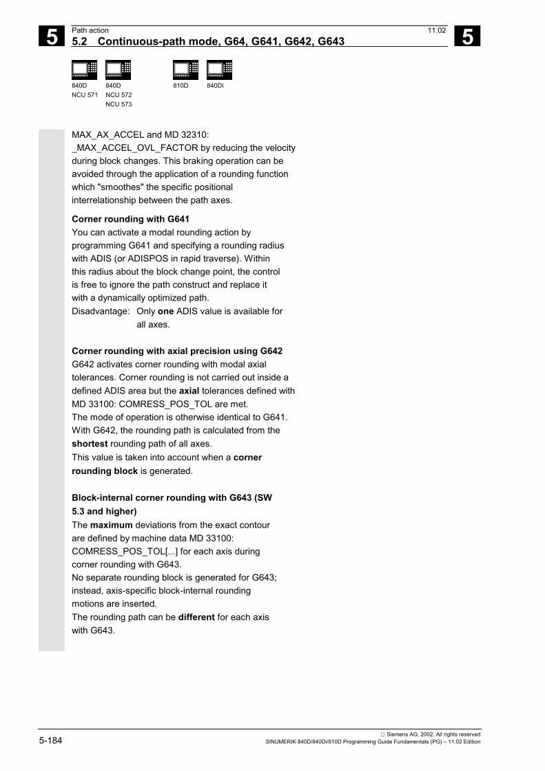
5 Path action 11.025.2 Continuous-path mode, G64, G641, G642, G643 5
840DNCU 571
840DNCU 572NCU 573
810D 840Di
Siemens AG, 2002. All rights reserved5-184 SINUMERIK 840D/840Di/810D Programming Guide Fundamentals (PG) – 11.02 Edition
MAX_AX_ACCEL and MD 32310:_MAX_ACCEL_OVL_FACTOR by reducing the velocityduring block changes. This braking operation can beavoided through the application of a rounding functionwhich "smoothes" the specific positionalinterrelationship between the path axes.
Corner rounding with G641You can activate a modal rounding action byprogramming G641 and specifying a rounding radiuswith ADIS (or ADISPOS in rapid traverse). Withinthis radius about the block change point, the controlis free to ignore the path construct and replace itwith a dynamically optimized path.Disadvantage: Only one ADIS value is available for
all axes.
Corner rounding with axial precision using G642G642 activates corner rounding with modal axialtolerances. Corner rounding is not carried out inside adefined ADIS area but the axial tolerances defined withMD 33100: COMRESS_POS_TOL are met.The mode of operation is otherwise identical to G641.With G642, the rounding path is calculated from theshortest rounding path of all axes.This value is taken into account when a cornerrounding block is generated.
Block-internal corner rounding with G643 (SW5.3 and higher)The maximum deviations from the exact contourare defined by machine data MD 33100:COMRESS_POS_TOL[...] for each axis duringcorner rounding with G643.No separate rounding block is generated for G643;instead, axis-specific block-internal roundingmotions are inserted.The rounding path can be different for each axiswith G643.

5 11.02 Path action5.2 Continuous-path mode, G64, G641, G642, G643 5
840DNCU 571
840DNCU 572NCU 573
810D 840Di
Siemens AG, 2002. All rights reservedSINUMERIK 840D/840Di/810D Programming Guide Fundamentals (PG) – 11.02 Edition 5-185
Example for corner rounding with G643, see also:References /PGA/ Programming Guide Advanced,Chapter 5, Settable Path Reference, SPATH, UPATH
Extension of corner rounding with SW 6
The functional extensions described below refine theaction of G642 and G643 and incorporate a newfunction, i.e.corner rounding with contour tolerance. Withcorner rounding in conjunction with G642 and G643,the permissible deviations for each axis are normallyspecified.With machine dataMD 20480: SMOOTHING_MODEit is possible to configure rounding with G642 andG643 in such a way that a contour tolerance and anorientation tolerance can be specified instead of theaxial tolerances. In this case, the tolerance for thecontour and the orientation are set with twomutually independent setting data that can beprogrammed in the NC program; the settings cantherefore be programmed differently for each blocktransition.Setting data:SD 42465: SMOOTH_CONTUR_TOLThis setting data defines the maximum roundingtolerance for the contour.
SD 42466: SMOOTH_ORI_TOLThis setting data defines the maximum roundingtolerance for the tool orientation (angulardisplacement).This data is operative only if an orientationtransformation is also active.Large differences in the settings for the contourtolerance and tool orientation tolerance willonly have an effect in conjunction with G643.
References: /FB/, B1, Continuous-path Mode,Exact Stop and Look Ahead

5 Path action 11.025.2 Continuous-path mode, G64, G641, G642, G643 5
840DNCU 571
840DNCU 572NCU 573
810D 840Di
Siemens AG, 2002. All rights reserved5-186 SINUMERIK 840D/840Di/810D Programming Guide Fundamentals (PG) – 11.02 Edition
No rounding block/no rounding motionNo corner rounding is performed in the followingthree situations:1. A halt is made between the two blocks. This
occurs when ...• The following block contains an auxiliary
function output before the movement.• The following block does not contain a path
movement.• An axis is traversed for the first time as a path
axis for the following block and it waspreviously a positioning axis.
• An axis is traversed for the first time as apositioning axis for the following block and itwas previously a path axis.
• The previous block traverses geo axes andthe following block does not (this is no longerthe case in SW 4 and higher).
• Prior to thread cutting: The following block hasG33 as a preparatory function and theprevious block does not.
• A changeover between BRISK and SOFT occurs.• Axes involved in the transformation are not
completely assigned to the path motion (e.g.for oscillation, positioning axes).
2. The rounding block would slow down partsprogram execution. This occurs when ...• A rounding block is inserted between very short
blocks. Since each block requires at least oneinterpolation cycle, the added intermediate blockwould double the machining time.
• A block transition G64 (continuous-path modewithout rounding) can be traversed withoutspeed reduction. Rounding would increase themachining time.This means that the value of the permissibleoverload factor (MD 32310:MAX_ACCEL_OVL_FACTOR) would partlydetermine whether or not a block transition isrounded. The overload factor is taken intoaccount only in conjunction with G641/G642.

5 11.02 Path action5.2 Continuous-path mode, G64, G641, G642, G643 5
840DNCU 571
840DNCU 572NCU 573
810D 840Di
Siemens AG, 2002. All rights reservedSINUMERIK 840D/840Di/810D Programming Guide Fundamentals (PG) – 11.02 Edition 5-187
The overload factor is ignored in cornerrounding with G643.
• In SW version 6 and higher, MD 20490:IGNORE_OVL_FACTOR_FOR_ADIS can beset to TRUE to ignore the overload factor inconnection with G654 and G642 as well.
3. Rounding is not parameterized.This occurs with G641 when ...• ADIPOSE == 0 in G0 blocks (default!)• AIDS == 0 in non-G0 blocks (default!)• For transition from G0 to non-G0 or non-G0 to
G0, the smaller value of ADIPOSE and AIDSapplies.
With G642/G643, when all axis-specifictolerances equal zero.
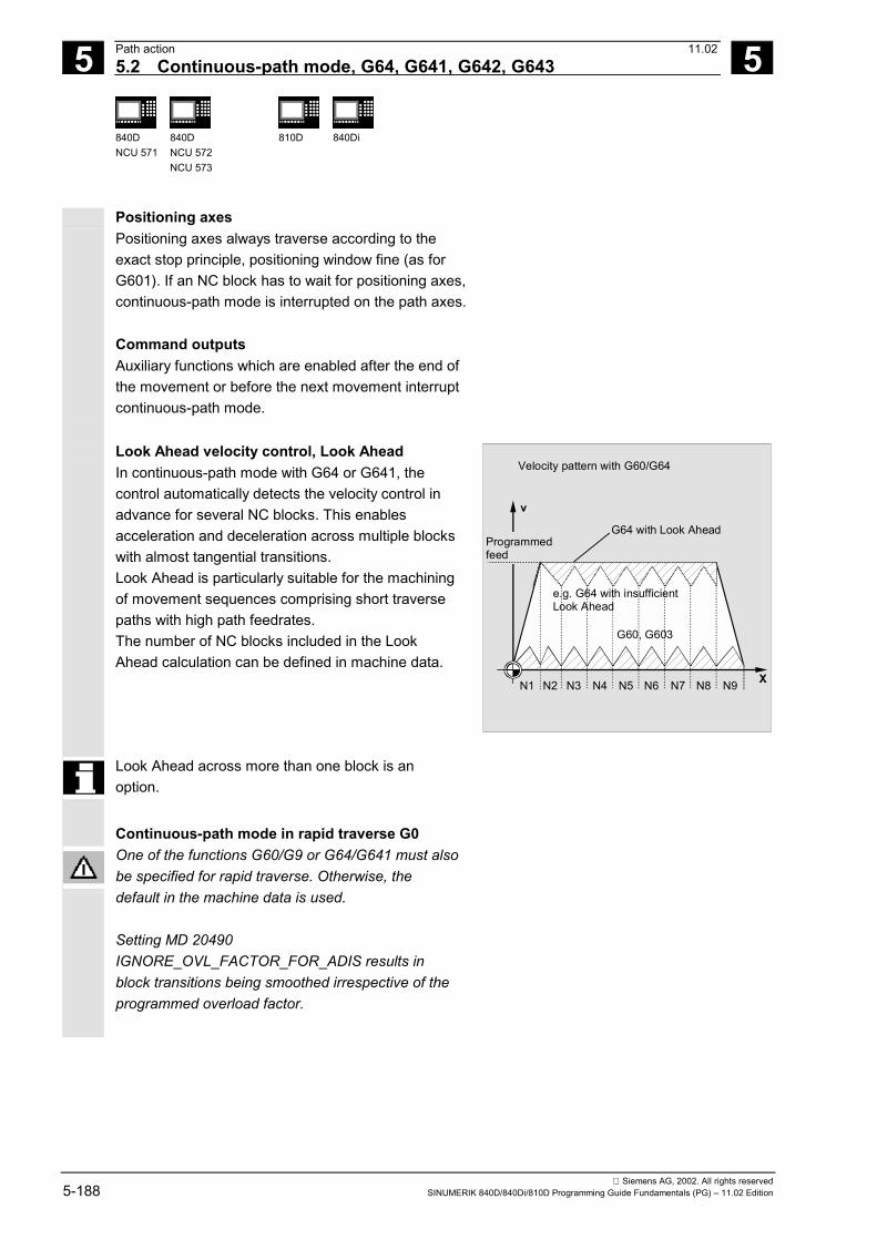
5 Path action 11.025.2 Continuous-path mode, G64, G641, G642, G643 5
840DNCU 571
840DNCU 572NCU 573
810D 840Di
Siemens AG, 2002. All rights reserved5-188 SINUMERIK 840D/840Di/810D Programming Guide Fundamentals (PG) – 11.02 Edition
Positioning axesPositioning axes always traverse according to theexact stop principle, positioning window fine (as forG601). If an NC block has to wait for positioning axes,continuous-path mode is interrupted on the path axes.
Command outputsAuxiliary functions which are enabled after the end ofthe movement or before the next movement interruptcontinuous-path mode.
Look Ahead velocity control, Look AheadIn continuous-path mode with G64 or G641, thecontrol automatically detects the velocity control inadvance for several NC blocks. This enablesacceleration and deceleration across multiple blockswith almost tangential transitions.Look Ahead is particularly suitable for the machiningof movement sequences comprising short traversepaths with high path feedrates.The number of NC blocks included in the LookAhead calculation can be defined in machine data.
X
v
N1 N2 N3 N4 N5 N6 N7 N8 N9
Velocity pattern with G60/G64
G64 with Look AheadProgrammed feed
G60, G603
e.g. G64 with insufficientLook Ahead
Look Ahead across more than one block is anoption.
Continuous-path mode in rapid traverse G0One of the functions G60/G9 or G64/G641 must alsobe specified for rapid traverse. Otherwise, thedefault in the machine data is used.
Setting MD 20490IGNORE_OVL_FACTOR_FOR_ADIS results inblock transitions being smoothed irrespective of theprogrammed overload factor.

5 11.02 Path action5.2 Continuous-path mode, G64, G641, G642, G643 5
840DNCU 571
840DNCU 572NCU 573
810D 840Di
Siemens AG, 2002. All rights reservedSINUMERIK 840D/840Di/810D Programming Guide Fundamentals (PG) – 11.02 Edition 5-189
Programming example
With this workpiece, the two outside corners at thegroove are approached exactly. All other machiningtakes place in continuous-path mode.
7
X
Y
1060
80100
Z
Y
7050 40
10
Exact stopfine
N05 DIAMOF Radius as dimensionN10 G17 T1 G41 G0 X10 Y10 Z2 S300 M3 Approach starting position, activate
spindle, path compensationN20 G1 Z-7 F8000 Tool infeedN30 G641 ADIS=0.5 Contour transitions are smoothedN40 Y40
N50 X60 Y70 G60 G601 Approach exact position with exact stopfine
N60 Y50
N70 X80
N80 Y70
N90 G641 ADIS=0.5 X100 Y40 Contour transitions are smoothedN100 X80 Y 10
N110 X10
N120 G40 G0 X-20 Deactivate path compensationN130 Z10 M30 Retract tool, end of program

5 Path action 11.025.3 Acceleration pattern, BRISK, SOFT, DRIVE 5
840DNCU 571
840DNCU 572NCU 573
810D 840Di
Siemens AG, 2002. All rights reserved5-190 SINUMERIK 840D/840Di/810D Programming Guide Fundamentals (PG) – 11.02 Edition
5.3 Acceleration pattern, BRISK, SOFT, DRIVE
5.3.1 Acceleration modes
Explanation of the commands
BRISK Brisk acceleration of path axesBRISKA(axis1,axis2,…) Switch on brisk axis acceleration for the programmed axesSOFT Soft acceleration of path axesSOFTA(axis1,axis2,…) Switch on soft axis acceleration for the programmed axesDRIVE Reduction of acceleration above a speed for path axes that can
be set in $MA_ACCEL_REDUCTION_SPEED_POINT (onlyapplicable for FM-NC)
DRIVEA(axis1,axis2,…) Reduction of acceleration above a speed for programmed axesthat can be set in $MA_ACCEL_REDUCTION_SPEED_POINT(only applicable for FM-NC)
JERKA(axis1,axis2,…) The acceleration behavior set in machine data $MA_POS_ANDJOG_JERK_ENABLE or $MA_ACCEL_TYPE_DRIVE is active forthe programmed axes
Function
BRISK, BRISKAThe axis slides travel with maximum accelerationuntil the feedrate is reached. BRISK enables time-optimized machining, but with jumps in theacceleration curve.
SOFT, SOFTAThe axis slides travel with constant acceleration untilthe feedrate is reached.Soft acceleration enables higher path accuracy andless wear and tear on the machine.
Example: N10 G1 X… Y… F900 SOFT
N20 BRISKA(AX5,AX6)
BRISK(time-optimized)
SOFT(reduced wear on mechanicalequipment)
Setpoint
Path
vel
octit
y
Time

5 11.02 Path action5.3 Acceleration pattern, BRISK, SOFT, DRIVE 5
840DNCU 571
840DNCU 572NCU 573
810D 840Di
Siemens AG, 2002. All rights reservedSINUMERIK 840D/840Di/810D Programming Guide Fundamentals (PG) – 11.02 Edition 5-191
Additional notes
A change between BRISK and SOFT causes a stopat the block transition. The acceleration response forthe path axes can be defined in machine data.
Function
DRIVE, DRIVEAThe axis slides traverse at the maximum accelerationrate up to the speed limit set in the machine data. Theacceleration rate is then reduced according tomachine data until the feedrate speed is reached.This function allows the acceleration characteristic tobe optimally adapted to a specific motor characteristic,for example, for stepper motor applications.
Example: N05 DRIVE
N10 G1 X… Y… F1000
N20 DRIVEA (AX4, AX6)
Setpoint
Limit ofconstantacceleration
Time
Path
vel
ocity
5.3.2 Influence of acceleration modes on following axesProgramming
VELOLIMA[AX4]=75 75 % of the maximum axial velocitystored in the machine data
ACCLIMA[AX4]=50 50 % of the maximum axial accelerationstored in the machine data

5 Path action 11.025.3 Acceleration pattern, BRISK, SOFT, DRIVE 5
840DNCU 571
840DNCU 572NCU 573
810D 840Di
Siemens AG, 2002. All rights reserved5-192 SINUMERIK 840D/840Di/810D Programming Guide Fundamentals (PG) – 11.02 Edition
Explanation of the commands
VELOLIMA[Ax] Change to limit for maximum velocity forfollowing axis
ACCLIMA[Ax] Change to limit for maximumacceleration for following axis
Function
The coupled axes described in the ProgrammingGuide Advanced Chapter 9 and Chapter 13.3, 13.4:Tangential correction, coupled-motion axes, mastervalue coupling, and electronic gearbox have theproperty following axes/spindles are moved independence on one or more leading axes/spindles.
The commands for correction of limitation for thedynamic response of the following axis must begiven from the parts program or from synchronousactions. The commands for correction of limitationsof the following axis can already be given while axiscoupling is active.
Additional notes
Details about the function are described inReferences: /FB/, M3 Axis Coupling and ESR
/FB/, S3 Synchronous Spindles

5 11.02 Path action5.3 Acceleration pattern, BRISK, SOFT, DRIVE 5
840DNCU 571
840DNCU 572NCU 573
810D 840Di
Siemens AG, 2002. All rights reservedSINUMERIK 840D/840Di/810D Programming Guide Fundamentals (PG) – 11.02 Edition 5-193
Programming example 1 Electronic gear
Axis 4 is coupled to axis X via an electronic gearcoupling. The acceleration capability of the followingaxis is limited to 70% of maximum acceleration. Themaximum permissible velocity is limited to 50% ofmaximum velocity. After successful switch-on ofcoupling, the maximum permissible velocity is set to100% again....
N120 ACCLIMA[AX4]=70
N130 VELOLIMA[AX4]=50
...
N150 EGON(AX4, "FINE", X, 1, 2)
...
N200 VELOLIMA[AX4]=100
Reduced maximum accelerationReduced maximum velocity
Switch-on of the EG coupling
Maximum velocity
Programming example 2 Master value coupling with influence bystatic synchronized action
Axis 4 is coupled to X by master value coupling. Theacceleration response is limited to 80% by staticsynchronized action 2 from position 100....
N1220 IDS=2 WHENEVER $AA_IM[AX4] > 100
DO ACCLIMA[AX4]=80
N130 LEADON(AX4, X, 2)
Synchronized action
Master value coupling on

5 Path action 11.025.4 Overview of the various velocity controls 5
840DNCU 571
840DNCU 572NCU 573
810D 840Di
Siemens AG, 2002. All rights reserved5-194 SINUMERIK 840D/840Di/810D Programming Guide Fundamentals (PG) – 11.02 Edition
5.4 Overview of the various velocity controls
= Pa th velocity
N1, G1
N1
N2, G3
N2
N3, G1
N3
N4, G3
N4
N5, G2
N5
N6, G1
N6
N7, G0
N7
Z
X
N1 N2 N3 N4 N5 N6 N7
N1 N2 N3 N4 N5 N6 N7t
t
F
F
F
F
t
N1 N2 N3 N4 N5 N6 N7t
G64 SOFT
G64 BRISK
G60 G603 (W ithout wait time)
Contour curve
VPath
VPath
VPath
Rapidtraverse
V Path
G60 G601 (W ait time with G60)
5 11.02 Path action5.5 Path velocity smoothing 5
840DNCU 571
840DNCU 572NCU 573
810D 840Di
Siemens AG, 2002. All rights reservedSINUMERIK 840D/840Di/810D Programming Guide Fundamentals (PG) – 11.02 Edition 5-195
5.5 Path velocity smoothingFunction
The velocity control function utilizes the specifiedaxial dynamic response. If an axis cannot reach theprogrammed feedrate, the path velocity is controlledaccording to the parameterized, axial limit valuesand the path-specific limits (i.e. velocity, accelerationand jerk). This action can give rise to frequentbraking and acceleration on the path.If, for example, during a machining operation at ahigh path velocity, the axis accelerates briefly, butbrakes again almost immediately afterwards, themachining time will not be significantly reduced.Acceleration of this kind can, however, haveundesirable effects if, for example, it results inmachine resonance. A smoother path velocity profilecan be achieved with the "Path velocity smoothing"function which allows special machine data and thecharacter of the parts program to be taken intoaccount.Additional notes
References: /FB/, B1, "Path Velocity Smoothing(SW 5.3 and higher)"

5 Path action 11.025.6 Traversing with feedforward control, FFWON, FFWOF 5
840DNCU 571
840DNCU 572NCU 573
810D 840Di
Siemens AG, 2002. All rights reserved5-196 SINUMERIK 840D/840Di/810D Programming Guide Fundamentals (PG) – 11.02 Edition
5.6 Traversing with feedforward control, FFWON, FFWOF
Explanation of the commands
FFWON Activate feedforward controlFFWOF Deactivate feedforward control
Function
Feedforward control reduces the speed-dependentovertravel when contouring towards zero.Traversing with feedforward control permits higherpath accuracy and thus improved machining results.
Example: N10 FFWON
N20 G1 X… Y… F900 SOFT
Additional notes
The type of feedforward control and which path axes feedforward traversing is to be applied to aredetermined via machine data.
Default: Velocity-dependent feedforward controlOptional: Acceleration-dependent feedforward control (not possible with FM-NC, 810D)

5 11.02 Path action5.7 Programmable contour accuracy, CPRECON, CPRECOF 5
840DNCU 571
840DNCU 572NCU 573
810D 840Di
Siemens AG, 2002. All rights reservedSINUMERIK 840D/840Di/810D Programming Guide Fundamentals (PG) – 11.02 Edition 5-197
5.7 Programmable contour accuracy, CPRECON, CPRECOF
Explanation of the commands
CPRECON Activate programmable contour accuracyCPRECOF Deactivate programmable contour accuracy
Function
In machining operations without feedforward control(FFWON), errors may occur on curved contours as theresult of speed-related differences between setpointand actual positions.The programmable contour accuracy functionCPRECON makes it possible to store a maximumpermissible contour error in the NC program whichmust never be smoothed. The magnitude of thecontour error is specified with setting data$SC_CONTPREC.On the basis of this data and the servo gain factor(speed / following error ratio) of the path axesconcerned, the control calculates the maximum pathspeed at which the contour error produced by theovertravel does not exceed the minimum value storedin the setting data.The Look Ahead function allows the entire path to betraversed with the programmed contour accuracy.
Example:N10 X0 Y0 G0
N20 CPRECON ;Activate contour accuracyN30 F10000 G1 G64 X100 ;Machine contour at 10 m/min in
continuous-path modeN40 G3 Y20 J10 ;Automatic feed limitation in circle blockN50 X0 ;Feed without limitation to 10 m/min
Additional notes
A minimum velocity can be defined in the setting data$SC_MINFEED; the feed must not be less than thisvalue.

5 Path action 11.025.8 Dwell time, G4 5
840DNCU 571
840DNCU 572NCU 573
810D 840Di
Siemens AG, 2002. All rights reserved5-198 SINUMERIK 840D/840Di/810D Programming Guide Fundamentals (PG) – 11.02 Edition
5.8 Dwell time, G4
Programming
G4 F…
G4 S…
(Programmed in a separate NC block)
Explanation of the commands
G4 Activate dwell timeF… Time specified in secondsS… Time specified in revolutions of the master spindle
Function
You can use G4 to interrupt workpiece machiningbetween two NC blocks for the programmed lengthof time, e.g. for relief cutting.
Sequence
Example:N10 G1 F200 Z-5 S300 M3
;Feed F, spindle speed SN20 G4 F3 ;Dwell time 3sN30 X40 Y10
N40 G4 S30 ;Dwell for 30 revolutions ofspindle, with S=300rpm and 100% speed override, equals: t=0.1min
N40 X... ;Feed and spindle speed still active
The words with F... and S... are used for timespecifications in the block with G4 only.Any previously programmed feed F and spindlespeed S remain valid.
5 11.02 Path action5.9 Program sequence: Internal preprocessor stop 5
840DNCU 571
840DNCU 572NCU 573
810D 840Di
Siemens AG, 2002. All rights reservedSINUMERIK 840D/840Di/810D Programming Guide Fundamentals (PG) – 11.02 Edition 5-199
5.9 Program sequence: Internal preprocessor stop
Function
The control generates an internal preprocessor stopon access to machine status data ($A…).If a command which generates an implicitpreprocessor stop is read in the following block, thefollowing block is not executed until all previouslyprepared and stored blocks have been processedcompletely. The preceding block is halted in anexact stop (as for G9).
Example:N40 POSA[X]=100
N50 IF $AA_IM[X]==R100 GOTOF LABEL1
N60 G0 Y100
N70 WAITP(X)
N80 LABEL1:
Machining stops in block N50.
; Access to machine status data ($A), thecontrol generates an internalpreprocessor stop
�

5 Path action 11.025.9 Program sequence: Internal preprocessor stop 5
840DNCU 571
840DNCU 572NCU 573
810D 840Di
Siemens AG, 2002. All rights reserved5-200 SINUMERIK 840D/840Di/810D Programming Guide Fundamentals (PG) – 11.02 Edition

6 11.02 Frames 6
Siemens AG, 2002. All rights reservedSINUMERIK 840D/840Di/810D Programming Guide Fundamentals (PG) – 11.02 Edition 6-201
Frames
6.1 General.......................................................................................................................... 6-202
6.2 Frame instructions......................................................................................................... 6-203
6.3 Programmable zero offset............................................................................................. 6-2056.3.1 TRANS, ATRANS .................................................................................................. 6-2056.3.2 G58, G59: Axial programmable ZO (SW 5 and higher)......................................... 6-209
6.4 Programmable rotation, ROT, AROT............................................................................ 6-212
6.5 Programmable frame rotations with solid angles, ROTS, AROTS and CROTS........... 6-220
6.6 Programmable scale factor, SCALE, ASCALE ............................................................. 6-221
6.7 Programmable mirroring, MIRROR, AMIRROR............................................................ 6-224
6.8 Frame generation according to tool orientation, TOFRAME, TOROT .......................... 6-228
6.9 Deselect frame SUPA, DRFOF, CORROF, TRAFOOF................................................ 6-230
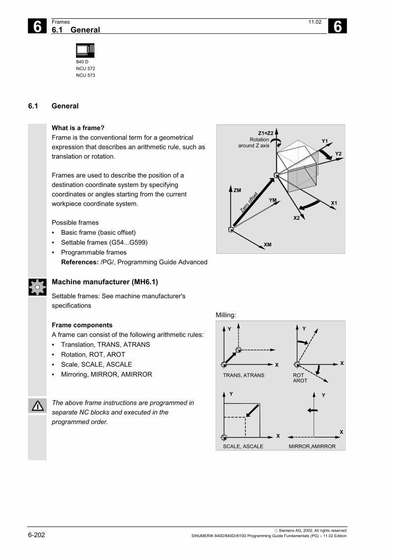
6 Frames 11.02 6.1 General
6
840 DNCU 572NCU 573
Siemens AG, 2002. All rights reserved6-202 SINUMERIK 840D/840Di/810D Programming Guide Fundamentals (PG) – 11.02 Edition
6.1 General
What is a frame?Frame is the conventional term for a geometricalexpression that describes an arithmetic rule, such astranslation or rotation.
Frames are used to describe the position of adestination coordinate system by specifyingcoordinates or angles starting from the currentworkpiece coordinate system.
Possible frames• Basic frame (basic offset)• Settable frames (G54...G599)• Programmable frames References: /PG/, Programming Guide Advanced
X2
Y2
X1
Y1Z1=Z2
XM
YM
ZM
Zero
offse
t
Rotationaround Z axis
Machine manufacturer (MH6.1)
Settable frames: See machine manufacturer'sspecifications
Frame components A frame can consist of the following arithmetic rules:• Translation, TRANS, ATRANS• Rotation, ROT, AROT• Scale, SCALE, ASCALE• Mirroring, MIRROR, AMIRROR The above frame instructions are programmed inseparate NC blocks and executed in theprogrammed order.
Milling:
TRANS, ATRANS
SCALE, ASCALE MIRROR,AMIRROR
ROTAROT
Y
X
Y
X
Y
X
Y
X
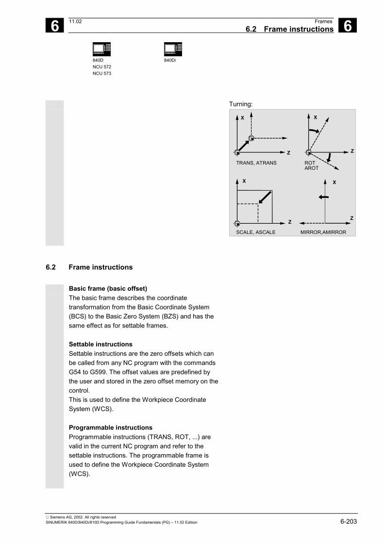
6 11.02 Frames6.2 Frame instructions
6
840DNCU 572NCU 573
840Di
Siemens AG, 2002. All rights reservedSINUMERIK 840D/840Di/810D Programming Guide Fundamentals (PG) – 11.02 Edition 6-203
Turning:
TRANS, ATRANS
SCALE, ASCALE MIRROR,AMIRROR
ROTAROT
X
Z
X
Z
X
Z
X
Z
6.2 Frame instructions Basic frame (basic offset)
The basic frame describes the coordinatetransformation from the Basic Coordinate System(BCS) to the Basic Zero System (BZS) and has thesame effect as for settable frames. Settable instructions Settable instructions are the zero offsets which canbe called from any NC program with the commandsG54 to G599. The offset values are predefined bythe user and stored in the zero offset memory on thecontrol. This is used to define the Workpiece CoordinateSystem (WCS). Programmable instructions Programmable instructions (TRANS, ROT, ...) arevalid in the current NC program and refer to thesettable instructions. The programmable frame isused to define the Workpiece Coordinate System(WCS).

6 Frames 11.02 6.2 Frame instructions
6
840 DNCU 572NCU 573
Siemens AG, 2002. All rights reserved6-204 SINUMERIK 840D/840Di/810D Programming Guide Fundamentals (PG) – 11.02 Edition
Substituting instructions TRANS, ROT, SCALE and MIRROR are substitutinginstructions. This means that each of these instructions cancelsall other previously programmed frame instructions. The last called settable zero offset G54 to G599is used as the reference.
TRANS
TRANS
Additive instructions ATRANS, AROT, ASCALE and AMIRROR areadditive instructions. The currently set zero point or the last workpiecezero to be programmed with frame instructions isused as the reference. The above instructions areadded to existing frames. Note: Additive instructions are frequently used insubprograms. The basic functions defined in themain program are not lost after the end of thesubprogram if the subprogram has beenprogrammed with the SAVE attribute.
TRANS
ATRANS
References
/PGA/ Programming Guide Advanced, Section"Subroutines, Macros"
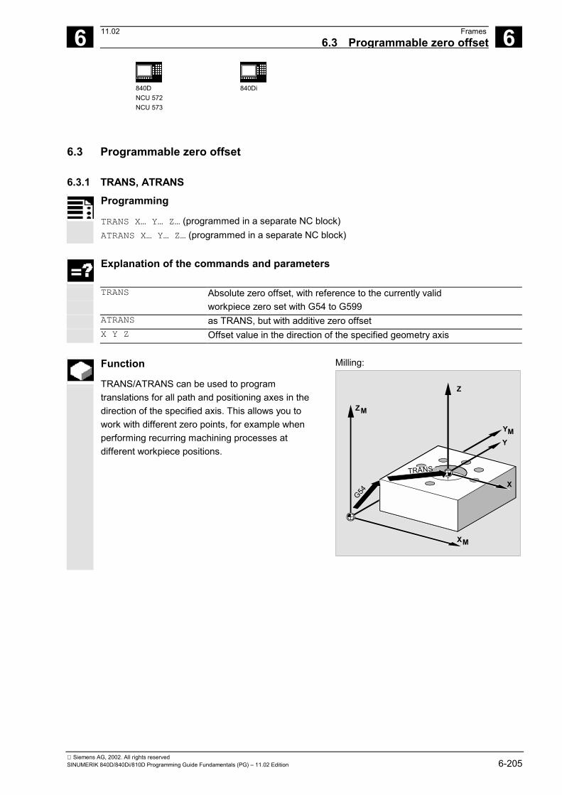
6 11.02 Frames6.3 Programmable zero offset
6
840DNCU 572NCU 573
840Di
Siemens AG, 2002. All rights reservedSINUMERIK 840D/840Di/810D Programming Guide Fundamentals (PG) – 11.02 Edition 6-205
6.3 Programmable zero offset
6.3.1 TRANS, ATRANS
Programming
TRANS X… Y… Z… (programmed in a separate NC block) ATRANS X… Y… Z… (programmed in a separate NC block)
Explanation of the commands and parameters
TRANS Absolute zero offset, with reference to the currently valid workpiece zero set with G54 to G599
ATRANS as TRANS, but with additive zero offset X Y Z Offset value in the direction of the specified geometry axis
Function
TRANS/ATRANS can be used to programtranslations for all path and positioning axes in thedirection of the specified axis. This allows you towork with different zero points, for example whenperforming recurring machining processes atdifferent workpiece positions.
Milling:
ZM
Z
YMY
XM
X
G54
TRANS

6 Frames 11.02 6.3 Programmable zero offset
6
840 DNCU 572NCU 573
Siemens AG, 2002. All rights reserved6-206 SINUMERIK 840D/840Di/810D Programming Guide Fundamentals (PG) – 11.02 Edition
Turning:
X
Z
M W
G54
TRANS
Sequence
Substituting instruction, TRANS X Y Z Translation through the offset values programmed inthe specified axis directions (path, synchronized axesand positioning axes). The last specified settable zero offset (G54 to G599) isused as a reference. The TRANS command cancels all frame componentsof the previously activated programmable frame. You can use ATRANS to program a translation whichis to be added to existing frames.
TRANS
TRANS

6 11.02 Frames6.3 Programmable zero offset
6
840DNCU 572NCU 573
840Di
Siemens AG, 2002. All rights reservedSINUMERIK 840D/840Di/810D Programming Guide Fundamentals (PG) – 11.02 Edition 6-207
Additive instruction, ATRANS X Y Z Translation through the offset values programmed inthe specified axis directions. The currently set or last programmed zero point isused as the reference. Deactivate programmable zero offset For all axes: TRANS (without axis parameter)
TRANS
ATRANS
Here, all previously programmed frames are canceled.The settable zero offset remains programmed.
Programming example
With this workpiece, the illustrated shapes recurseveral times in the same program. The machining sequence for this shape is stored ina subprogram. You use the translation to set only those workpiecezeroes and then call up the subprogram.
Milling:
Y
X
YM
X M
Y
X
Y
X
G54
1050
1050
N10 G1 G54 Working plane X/Y, workpiece zero N20 G0 X0 Y0 Z2 Approach starting point N30 TRANS X10 Y10 Absolute offset N40 L10 Subprogram call N50 TRANS X50 Y10 Absolute offset N60 L10 Subprogram call N70 M30 End of program

6 Frames 11.02 6.3 Programmable zero offset
6
840 DNCU 572NCU 573
Siemens AG, 2002. All rights reserved6-208 SINUMERIK 840D/840Di/810D Programming Guide Fundamentals (PG) – 11.02 Edition
Turning:
X
Z
M W
140130
150
N.. ... N10 TRANS X0 Z150 Absolute offset N15 L20 Subprogram call N20 TRANS X0 Z140 (or ATRANS Z-10) Absolute offset N25 L20 Subprogram call N30 TRANS X0 Z130 (or ATRANS Z-10) Absolute offset N35 L20 Subprogram call N.. ...

6 11.02 Frames6.3 Programmable zero offset
6
840DNCU 572NCU 573
840Di
Siemens AG, 2002. All rights reservedSINUMERIK 840D/840Di/810D Programming Guide Fundamentals (PG) – 11.02 Edition 6-209
6.3.2 G58, G59: Axial programmable ZO (SW 5 and higher)
Programming
G58 X… Y… Z… A… (programmed in a separate NC block) G59 X… Y… Z… A… (programmed in a separate NC block)
Explanation of the commands and parameters
G58 Replaces the absolute translation component of the programmable zerooffset for the specified axis, but the programmed additive offset remainsvalid, (in relation to the workpiece zero set with G54 to G599)
G59 Replaces the absolute translation component of the programmable zerooffset for the specified axis, but the programmed absolute offsetremains valid
X Y Z Offset value in the direction of the specified geometry axis
Function
G58 and G59 allow translation components of theprogrammable zero offset (frame) to be replaced forspecific axes. The translation function comprises the• absolute component (G58, coarse offset)• additive component (G59, fine offset) These functions can only be used when the fineoffset is configured. If G58 or G59 is used without a configured fineoffset, alarm "18312 channel %1 block %2 frame:Fine offset not configured" is output.
ZM
Z
YM
Y
XM
X
G54
Translation
Additive tra.G59ATRANS
Machine manufacturer (MH6.2)
The fine offset must be configured via MD for thisfunction.
Note MD24000:FRAME_ADD_COMPONENTS=1, or else an alarm isgenerated in response to G58, G59.
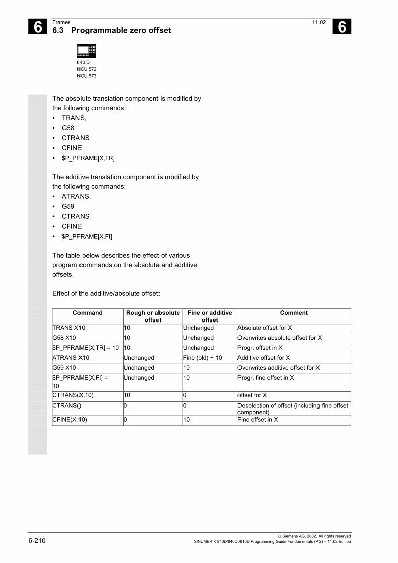
6 Frames 11.02 6.3 Programmable zero offset
6
840 DNCU 572NCU 573
Siemens AG, 2002. All rights reserved6-210 SINUMERIK 840D/840Di/810D Programming Guide Fundamentals (PG) – 11.02 Edition
The absolute translation component is modified bythe following commands:• TRANS,• G58• CTRANS• CFINE• $P_PFRAME[X,TR]
The additive translation component is modified bythe following commands:• ATRANS,• G59• CTRANS• CFINE• $P_PFRAME[X,FI]
The table below describes the effect of variousprogram commands on the absolute and additiveoffsets.
Effect of the additive/absolute offset:
Command Rough or absoluteoffset
Fine or additiveoffset
Comment
TRANS X10 10 Unchanged Absolute offset for XG58 X10 10 Unchanged Overwrites absolute offset for X$P_PFRAME[X,TR] = 10 10 Unchanged Progr. offset in XATRANS X10 Unchanged Fine (old) + 10 Additive offset for XG59 X10 Unchanged 10 Overwrites additive offset for X$P_PFRAME[X,FI] =10
Unchanged 10 Progr. fine offset in X
CTRANS(X,10) 10 0 offset for XCTRANS() 0 0 Deselection of offset (including fine offset
component)CFINE(X,10) 0 10 Fine offset in X

6 11.02 Frames6.3 Programmable zero offset
6
840DNCU 572NCU 573
840Di
Siemens AG, 2002. All rights reservedSINUMERIK 840D/840Di/810D Programming Guide Fundamentals (PG) – 11.02 Edition 6-211
Programming example
N...
N50 TRANS X10 Y10 Z10 ; absolute translation component X10 Y10 Z10
N60 ATRANS X5 Y5 ; additive translation component X5 Y5= total offset X15 Y15 Z10
N70 G58 X20 ; absolute translation component X20 + addit. X5 Y5= total offset X25 Y15 Z10
N80 G59 X10 Y10 ; additive translation component X10 Y10 + absoluteX20 Y 10
= total offset X30 Y20 Z10
N...

6 Frames 11.02 6.4 Programmable rotation, ROT, AROT
6
840 DNCU 572NCU 573
Siemens AG, 2002. All rights reserved6-212 SINUMERIK 840D/840Di/810D Programming Guide Fundamentals (PG) – 11.02 Edition
6.4 Programmable rotation, ROT, AROTProgramming
ROT X… Y… Z…
ROT RPL=…
AROTX… Y… Z…
AROT RPL=…
Each instruction must be programmed in a separateNC block.
Explanation of the commands and parameters
ROT Absolute rotation with reference to the currently valid workpiece zero setwith G54 to G599
AROT Additive rotation with reference to the currently valid set or programmedzero point
X Y Z Rotation in space: geometry axes around which the rotation takes placeRPL Rotation in the plane: Angle through which the coordinate system is rotated
(plane set with G17-G19)
Function
ROT/AROT can be used to rotate the workpiececoordinate system around each of the geometryaxes X, Y, Z or through an angle RPL in the selectedworking plane G17 to G19 (or around theperpendicular infeed axis).
This allows inclined surfaces or several workpiecesides to be machined in one setting.

6 11.02 Frames6.4 Programmable rotation, ROT, AROT
6
840DNCU 572NCU 573
840Di
Siemens AG, 2002. All rights reservedSINUMERIK 840D/840Di/810D Programming Guide Fundamentals (PG) – 11.02 Edition 6-213
Sequence: Rotation in space
Substituting instruction, ROT X Y ZThe coordinate system is rotated through theprogrammed angle around the specified axes.The center of rotation is the last specified settablezero offset (G54 to G599).
The ROT command cancels all frame components ofthe previously activated programmable frame.
A new rotation based on existing frames isprogrammed with AROT.
Y
X
Additive instruction, AROT X Y ZRotation through the angle values programmed inthe axis direction parameters.
The center of rotation is the currently set or lastprogrammed zero point. AROT
ROT
Y
X
Note
For both instructions, please note the order anddirection of rotation in which the rotations areperformed (see next page)!

6 Frames 11.02 6.4 Programmable rotation, ROT, AROT
6
840 DNCU 572NCU 573
Siemens AG, 2002. All rights reserved6-214 SINUMERIK 840D/840Di/810D Programming Guide Fundamentals (PG) – 11.02 Edition
Direction of rotationThe following is defined as the positive direction ofrotation:The view in the direction of the positive coordinateaxis and clockwise rotation.
Order of rotation
You can rotate up to three geometry axessimultaneously in one NC block.
Z
Y
X+
-
+
+ -
-
The order of the RPY notation (= Roll, Pitch, Yaw) orEuler angle through which the rotations are performedcan be defined in machine data.
MD 10600: FRAME_ANGLE_INPUT_MODE =• 1: RPY notation• 2: Euler angle
RPY notation is the default setting. After that, thesequence Z, Y, Z of the rotation is defined asfollows:1. Rotation around the 3rd geometry axis (Z)2. Rotation around the 2nd geometry axis (Y)3. Rotation around the 1st geometry axis (X)
Z
Y
0
1
2X
This order applies if the geometry axes areprogrammed in a single block. It also appliesirrespective of the input sequence.If only two axes are to be rotated, the parameter forthe 3rd axis (value zero) can be omitted.
Value range with RPY angleThe angles are only defined ambiguously in thefollowing value ranges:Rotation around 1st geometry axis: –180° ≤ X ≤ +180°Rotation around 2nd geometry axis: –90° < Y < +90°Rotation around 3rd geometry axis: –180° ≤ Z ≤ +180°

6 11.02 Frames6.4 Programmable rotation, ROT, AROT
6
840DNCU 572NCU 573
840Di
Siemens AG, 2002. All rights reservedSINUMERIK 840D/840Di/810D Programming Guide Fundamentals (PG) – 11.02 Edition 6-215
All possible rotations can be represented with this valuerange. Values outside the range are normalized by thecontrol into the above range during writing and reading.This value range applies to all frame variables.
Examples of reading back in RPY$P_UIFR[1] = CROT(X, 10, Y, 90, Z, 40)returns on reading back$P_UIFR[1] = CROT(X, 0, Y, 90, Z, 30)
$P_UIFR[1] = CROT(X, 190, Y, 0, Z, -200)returns on reading back$P_UIFR[1] = CROT(X, -170, Y, 0, Z, 160)On writing and reading frame rotation components,the limits of the value range must be observed sothe same results are achieved on writing andreading, or on repeated writing.
Value range with Euler angleThe angles are only defined ambiguously in thefollowing value ranges:Rotation around 1st geometry axis: 0° < X < +180°Rotation around 2nd geometry axis: –180° ≤ Y ≤ +180°Rotation around 3rd geometry axis: –180° ≤ Z ≤ +180°All possible rotations can be represented with this valuerange. Values outside the range are normalized by thecontrol into the above range. This value range appliesto all frame variables.
To ensure the angles written are read backunambiguously, it is necessary to observe the definedvalues ranges.
If you want to define the order of the rotationsindividually, program the desired rotation successivelyfor each axis with AROT.
References
/FB1/ Function Description of the Basic Machine,Chapter "Frames"

6 Frames 11.02 6.4 Programmable rotation, ROT, AROT
6
840 DNCU 572NCU 573
Siemens AG, 2002. All rights reserved6-216 SINUMERIK 840D/840Di/810D Programming Guide Fundamentals (PG) – 11.02 Edition
The working plane also rotatesThe working plane defined with G17, G18 or G19rotates with the spatial rotation.
Example:Working plane G17 X/Y, the workpiece coordinatesystem is positioned on the top surface of theworkpiece. Translation and rotation is used to movethe coordinate system to one of the side surfaces.Working plane G17 also rotates.
This feature can be used to program planedestination positions in X/Y coordinates and theinfeed in the Z direction.
Z
Z
X
X
Y
Y
G17
G17
Precondition:The tool must be positioned perpendicular to theworking plane. The positive direction of the infeed axispoints in the direction of the toolholder. SpecifyingCUT2DF activates the tool radius compensation in therotated plane. For more information please refer toSection "2 1/2 D Tool Compensation, CUT2DCUT2DF".
Sequence: Rotation in the plane
The coordinate system is rotated in the planeselected with G17 to G19.
Substituting instruction, ROT RPLAdditive instruction, AROT RPLThe coordinate system is rotated through the angleprogrammed with RPL= in the current plane.
See "Rotation in space" for more information.Z
X
Y
G17
G18
G19
Z X
Y
Z
G17G19
G18
ROT

6 11.02 Frames6.4 Programmable rotation, ROT, AROT
6
840DNCU 572NCU 573
840Di
Siemens AG, 2002. All rights reservedSINUMERIK 840D/840Di/810D Programming Guide Fundamentals (PG) – 11.02 Edition 6-217
Change of planeIf you program a change of plane (G17 to G19) aftera rotation, the angles of rotation programmed for theaxes are retained and continue to apply in the newworking plane.It is therefore advisable to deactivate the rotationbefore a change of plane.Deactivate rotationFor all axes:ROT (without axis parameter)
In both cases, all frame components of thepreviously programmed frame are reset.
Programming example: Rotation in theplane
With this workpiece, the illustrated shapes recurseveral times in the same program.Rotations have to be performed in addition to thetranslation, because the shapes are not arrangedparallel to the axes.
X
Y
30
60°45°
7
2055
10
3540
r7
128
N10 G17 G54 Working plane X/Y, workpiece zeroN20 TRANS X20 Y10 Absolute offsetN30 L10 Subprogram callN40 TRANS X55 Y35 Absolute offsetN50 AROT RPL=45 Rotation of the coordinate system through
45°N60 L10 Subprogram callN70 TRANS X20 Y40 Absolute offset (cancels all previous
offsets)N80 AROT RPL=60 Additive rotation through 60°N90 L10 Subprogram callN100 G0 X100 Y100 RetractionN110 M30 End of program

6 Frames 11.02 6.4 Programmable rotation, ROT, AROT
6
840 DNCU 572NCU 573
Siemens AG, 2002. All rights reserved6-218 SINUMERIK 840D/840Di/810D Programming Guide Fundamentals (PG) – 11.02 Edition
Programming example:3D rotation
In this example, paraxial and inclined workpiecesurfaces are to be machined in one setting.Precondition: The tool must be aligned perpendicularto the inclined surface in the rotated Z direction.
X
Z
30°
X
Y
r7
30
7
1045
2010
128
5
N10 G17 G54 Working plane X/Y, workpiece zeroN20 TRANS X10 Y10 Absolute offsetN30 L10 Subprogram callN40 ATRANS X35 Additive offsetN50 AROT Y30 Rotation through the Y axisN60 ATRANS X5 Additive offsetN70 L10 Subprogram callN80 G0 X300 Y100 M30 Retraction, end of program

6 11.02 Frames6.4 Programmable rotation, ROT, AROT
6
840DNCU 572NCU 573
840Di
Siemens AG, 2002. All rights reservedSINUMERIK 840D/840Di/810D Programming Guide Fundamentals (PG) – 11.02 Edition 6-219
Programming example:Multi-face machining
In this example, identical shapes on two perpendicularworkpiece surfaces are machined by usingsubprograms.The setup of the infeed direction, working plane andzero point in the new coordinate system on the right-hand workpiece surface matches that of the topsurface.The conditions required for subprogram executionapply as before: working plane G17, coordinateplane X/Y, infeed direction Z.
Z
Z
X
X
Y
Y
G17
G17
N10 G17 G54 Working plane X/Y, workpiece zeroN20 L10 Subprogram callN30 TRANS X100 Z-100 Absolute offset
Z
X
Y
Z
X
Y-100
100
TRANS
N40 AROT Y90 Rotation of the coordinate systemthrough Y
Z
X
Y
Z
X
Y
AROT Y90
N50 AROT Z90 Rotation of the coordinate systemthrough Z
Z
X
Y
Z
X
Y
AROT Z90
N60 L10 Subprogram callN70 G0 X300 Y100 M30 Retraction, end of program

6 Frames 11.02 6.5 Programmable frame rotations with solid angels, ROTS, AROTS etc.
6
840 DNCU 572NCU 573
Siemens AG, 2002. All rights reserved6-220 SINUMERIK 840D/840Di/810D Programming Guide Fundamentals (PG) – 11.02 Edition
6.5 Programmable frame rotations with solid angles, ROTS, AROTS and CROTS
Programming
ROTS X... Y... AROTS X... Y... CROTS X... Y...
When solid angles X and Y areprogrammed, the new X axis is located inthe old Z-X plane (SW 5.3 and higher).
ROTS Z... X... AROTS Z... X... CROTS Z... X...
When solid angles Z and X areprogrammed, the new Z axis is located inthe old Y-Z plane (SW 5.3 and higher).
ROTS Y... Z... AROTS Y... Z... CROTS Y... Z...
When solid angles Y and Z areprogrammed, the new X axis is located inthe old X-Y plane (SW 5.3 and higher).
Explanation of the commands and parameters
ROTS Frame rotations with solid angles for spatial orientation of a planeabsolute, referred to the currently valid frame with set workpiece zero forG54 to G599.
AROTS Frame rotations with solid angles for spatial orientation of a plane additive,referred to the currently valid frame with set or programmed zero point.
CROTS Frame rotations with solid angles for spatial orientation of a plane, referred tothe valid frame in the data management with rotation in the specified axes.
X Y Z A maximum of two solid angles may be specifiedRPL Rotation in the plane: Angle through which the coordinate system is rotated
(plane set with G17-G19)
Function
Spatial orientations can be defined via frame rotationswith solid angles ROTS, AROTS, CROTS. Programming commands ROTS and AROTS behaveanalogously to ROT and AROT.

6 11.02 Frames 6.6 Programmable scale factor, SCALE, ASCALE
6
840DNCU 572NCU 573
840Di
Siemens AG, 2002. All rights reservedSINUMERIK 840D/840Di/810D Programming Guide Fundamentals (PG) – 11.02 Edition 6-221
6.6 Programmable scale factor, SCALE, ASCALE
Programming
SCALE X… Y… Z… (programmed in a separate NC block)ASCALE X… Y… Z… (programmed in a separate NC block)
Explanation of the commands and parameters
SCALE Absolute enlargement/reduction with reference to the currently validcoordinate system set with G54 to G599
ASCALE Additive enlargement/reduction with reference to the currently valid setor programmed coordinate system
X Y Z Scale factor in the direction of the specified geometry axis
Function
SCALE/ASCALE enables you to program scalingfactors in the direction of the axis specified for allpath, synchronous and positioning axes.This enables the size of a shape to be changed. Youcan thus program similar geometrical shapes indifferent sizes.
Sequence
Substituting instruction, SCALE X Y ZYou can specify an individual scale factor for eachaxes, by which the shape is to be reduced orenlarged. The scale refers to the workpiececoordinate system set with G54 to G57.
The SCALE command cancels all frame componentsof the previously activated programmable frame.
X
Z
Y
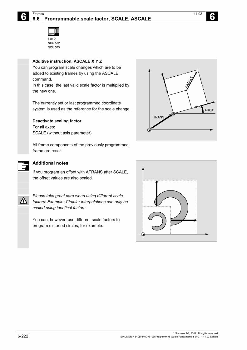
6 Frames 11.02 6.6 Programmable scale factor, SCALE, ASCALE
6
840 DNCU 572NCU 573
Siemens AG, 2002. All rights reserved6-222 SINUMERIK 840D/840Di/810D Programming Guide Fundamentals (PG) – 11.02 Edition
Additive instruction, ASCALE X Y ZYou can program scale changes which are to beadded to existing frames by using the ASCALEcommand.In this case, the last valid scale factor is multiplied bythe new one.
The currently set or last programmed coordinatesystem is used as the reference for the scale change.
Deactivate scaling factorFor all axes:SCALE (without axis parameter)
All frame components of the previously programmedframe are reset.
AROT
TRANS
ASCA
LE
Additional notes
If you program an offset with ATRANS after SCALE,the offset values are also scaled.
Please take great care when using different scalefactors! Example: Circular interpolations can only bescaled using identical factors.
You can, however, use different scale factors toprogram distorted circles, for example.

6 11.02 Frames 6.6 Programmable scale factor, SCALE, ASCALE
6
840DNCU 572NCU 573
840Di
Siemens AG, 2002. All rights reservedSINUMERIK 840D/840Di/810D Programming Guide Fundamentals (PG) – 11.02 Edition 6-223
Programming example
With this workpiece, the two pockets occur twice, butin different sizes and at different angles to eachother.
The machining sequence is stored in a subprogram.
Use translation and rotation to set each of theworkpiece zeroes, reduce the contour with a scaleand then call the subprogram up again.
X
Y
1540
35°
1520
N10 G17 G54 Working plane X/Y, workpiece zeroN20 TRANS X15 Y15 Absolute offsetN30 L10 Machine large pocketN40 TRANS X40 Y20 Absolute offsetN50 AROT RPL=35 Rotation in the plane through 35°N60 ASCALE X0.7 Y0.7 Scale factor for the small pocketN70 L10 Machine small pocketN80 G0 X300 Y100 M30 Retraction, end of program

6 Frames 11.02 6.7 Programmable mirroring, MIRROR, AMIRROR
6
840 DNCU 572NCU 573
Siemens AG, 2002. All rights reserved6-224 SINUMERIK 840D/840Di/810D Programming Guide Fundamentals (PG) – 11.02 Edition
6.7 Programmable mirroring, MIRROR, AMIRROR
Programming
MIRROR X0 Y0 Z0 (programmed in a separate NC block)AMIRROR X0 Y0 Z0 (programmed in a separate NC block)
Explanation of the commands and parameters
MIRROR Absolute mirror image with reference to the currently valid coordinate system setwith G54 to G599
AMIRROR Additive mirror image with reference to the currently valid set or programmedcoordinate system
X Y Z Geometry axis whose direction is to be changed. The value specified here can bechosen freely, e.g. X0 Y0 Z0
Function
MIRROR/AMIRROR can be used to mirrorworkpiece shapes on coordinate axes. All traversingmovements which are programmed after the mirrorcall, e.g. in the subprogram, are executed in themirror image.
Sequence
Substituting instruction, MIRROR X Y ZThe mirror is programmed by means of an axialchange of direction in the selected working plane.
Example: working plane G17 X/YThe mirror (on the Y axis) requires a change ofdirection on X and is subsequently programmed withMIRROR X0.
The contour is then mirrored on the opposite side ofthe mirror axis Y.
X
YMIRROR X
MIRROR Y

6 11.02 Frames 6.7 Programmable mirroring, MIRROR, AMIRROR
6
840DNCU 572NCU 573
840Di
Siemens AG, 2002. All rights reservedSINUMERIK 840D/840Di/810D Programming Guide Fundamentals (PG) – 11.02 Edition 6-225
The mirror image refers to the coordinate axes setwith G54 to G57.
The MIRROR command cancels all previously setprogrammable frames.
Additive instruction, AMIRROR X Y ZA mirror image which is to be added to an existingtransformation is programmed with AMIRROR.
The currently set or last programmed coordinatesystem is used as the reference.
Deactivate mirroringFor all axes:MIRROR (without axis parameter)
All frame components of the previously programmedframe are reset.
TRANS
AMIRROR
Additional notes
The mirror command causes the control toautomatically change the path compensationcommands (G41/G42 or G42/G41) according to thenew machining direction.
The same applies to the direction of circle rotation(G2/G3 or G3/G2).
If you program an additive rotation with AROT afterMIRROR, you may have to work with reverseddirections of rotation (positive/negative ornegative/positive).Mirrors on the geometry axes are convertedautomatically by the control into rotations and, whereappropriate, mirrors on the mirror axis specified inthe machine data. This also applies to settable zerooffsets.
X
Y
G42
MIRROR X
G41
G02G03
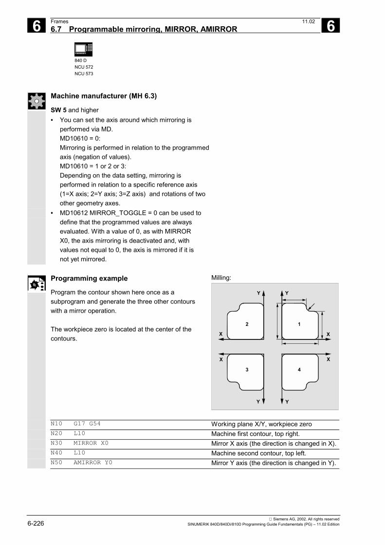
6 Frames 11.02 6.7 Programmable mirroring, MIRROR, AMIRROR
6
840 DNCU 572NCU 573
Siemens AG, 2002. All rights reserved6-226 SINUMERIK 840D/840Di/810D Programming Guide Fundamentals (PG) – 11.02 Edition
Machine manufacturer (MH 6.3)
SW 5 and higher• You can set the axis around which mirroring is
performed via MD.MD10610 = 0: Mirroring is performed in relation to the programmedaxis (negation of values).MD10610 = 1 or 2 or 3:Depending on the data setting, mirroring isperformed in relation to a specific reference axis(1=X axis; 2=Y axis; 3=Z axis) and rotations of twoother geometry axes.
• MD10612 MIRROR_TOGGLE = 0 can be used todefine that the programmed values are alwaysevaluated. With a value of 0, as with MIRRORX0, the axis mirroring is deactivated and, withvalues not equal to 0, the axis is mirrored if it isnot yet mirrored.
Programming example
Program the contour shown here once as asubprogram and generate the three other contourswith a mirror operation. The workpiece zero is located at the center of thecontours.
Milling:
Y
X
12
43
Y
Y Y
X
X X
N10 G17 G54 Working plane X/Y, workpiece zero N20 L10 Machine first contour, top right. N30 MIRROR X0 Mirror X axis (the direction is changed in X). N40 L10 Machine second contour, top left. N50 AMIRROR Y0 Mirror Y axis (the direction is changed in Y).

6 11.02 Frames 6.7 Programmable mirroring, MIRROR, AMIRROR
6
840DNCU 572NCU 573
840Di
Siemens AG, 2002. All rights reservedSINUMERIK 840D/840Di/810D Programming Guide Fundamentals (PG) – 11.02 Edition 6-227
N60 L10 Machine third contour, bottom left N70 MIRROR Y0 MIRROR cancels previous frames. Mirror
Y axis (the direction is changed in Y). N80 L10 Machine fourth contour, bottom right. N90 MIRROR Deactivate mirroring. N100 G0 X300 Y100 M30 Retraction, end of program Turning:
X
Z
M W
X
Z
MW1 1
140 120600
Spindle 1 Spindle 2
N10 TRANS X0 Z140 Zero offset to W N.. ... Machine first side with spindle 1 N30 TRANS X0 Z600 Zero offset to spindle 2 N40 AMIRROR Z0 Mirroring of the Z axis N50 ATRANS Z120 Zero offset to W1
N.. ... Machine second side with spindle 2

6 Frames 11.02 6.8 Frame generation according to tool orientation, TOFRAME, TOROT
6
840 DNCU 572NCU 573
Siemens AG, 2002. All rights reserved6-228 SINUMERIK 840D/840Di/810D Programming Guide Fundamentals (PG) – 11.02 Edition
6.8 Frame generation according to tool orientation, TOFRAME, TOROT
Programming
TOFRAME TOROT
Explanation
The new frame, whose Z axis is pointing in the tooldirection, is applicable after the block containingTOFRAME. The rotation defined by TOROT is the same as forTOFRAME.
Function
TOFRAME generates a rectangular frame whose Zaxis coincides with the current tool orientation. You can use this function to retract the tool after atool breakage in a 5-axis program without collisionsimply by retracting the Z axis. The resulting frame describing the orientation iswritten in the system variable for the programmableframe $P_PFRAME. Only the rotation component is overwritten withTOROT in the programmed frame. All othercomponents remain unchanged. The position of the two axes X and Y can be definedin MD21110: X_AXES_IN_OLD_X_Z_PLANE; X isrotated about Z in the previous X-Z plane.
Z'
X'
Generated frame
Tool retraction along Z axis
YBasic
Z
X
YBasic
Basic
Basic
45°
Z'
X''
Y'
Modified in MD 21110: X'' is again located in the previous X-Z plane
Example:
N100 G0 G53 X100 Z100 D0 N120 TOFRAME N140 G91 Z20 N160 X50 ...
; Frame TOFRAME is included; all programmed geometryaxis movements refer to TOFRAME

6 11.02 Frames 6.8 Frame generation according to tool orientation, TOFRAME, TOROT
6
840DNCU 572NCU 573
840Di
Siemens AG, 2002. All rights reservedSINUMERIK 840D/840Di/810D Programming Guide Fundamentals (PG) – 11.02 Edition 6-229
Additional notes
After tool orientation has been programmed withTOFRAME, all the programmed geometry axismovements refer to the frame generated by thisprogramming. SW 6.1 and higher Separate system frame for TOFRAME or TOROT.The frames generated by TOFRAME or TOROT can bewritten to a separate system frame $P_TOOLFRAME. Bit 3 in machine data MD 28082:MM_SYSTEM_FRAME_MASK must be set for thispurpose. The programmable frame remains unchanged.Differences occur when the programmable frame isprocessed further elsewhere.
NC command TOROT ensures consistentprogramming with active orientable tool carriers foreach kinematic type. See also the description of NCcommand PAROT.
References
/PGA/ Programming Guide Advanced, Section "ToolOrientation"

6 Frames 11.02 6.9 Deselect frame SUPA, DRFOF, CORROF, TRAFOOF
6
840DNCU 571
840DNCU 572NCU 573
810D
840Di
Siemens AG, 2002. All rights reserved6-230 SINUMERIK 840D/840Di/810D Programming Guide Fundamentals (PG) – 11.02 Edition
6.9 Deselect frame SUPA, DRFOF, CORROF, TRAFOOF
Programming
CORROF(axis,string[axis,string])orCORROF(axis,string) orCORROF(axis) or CORROF()
Explanation of the commands
Deactivate coordinate transformation A distinction must be made here between• non-modal deactivation and• modal deactivation.
Non-modal deactivation:G53 of all programmable and settable framesG153 of all programmable, settable and basic framesSUPA of all programmable, settable frames, DRF handwheel offsets, external
zero offsets and preset offsetModal deactivation:
G500 Deactivate all settable frames if G500 does not contain a valueDRFOF Deactivation (deselection) of DRF handwheel offsets for all active axes
in the channelCORROF(axis,DRF[
AXIS,AA_OFF])Deactivation (deselection) of axial DRF offsets and the position offsetfor individual axes as a result of $AA_OFF (SW 6 and higher)
CORROF(axis) All active overlaid motions are deselected (SW 6 and higher)CORROF() All active overlaid motions for all channel axes are deselected (SW 6
and higher)TRAFOOF Deactivate transformation
Explanation of the parameters
Axis Axis identifiers for (channel, geometry or machine axis)String == DRF DRF_offsets of axis are deselectedString == AA_OFF Position offset of axis is deselected due to $AA_OFF
The following expansions are possible:String == ETRANS An active zero offset is deselectedString == FTOCOF Acts like FTOCOF (deactivate online tool offset)TRANS, ROT,
SCALE, MIRRORDelete programmable frames without axis specification
6 11.02 Frames 6.9 Deselect frame SUPA, DRFOF, CORROF, TRAFOOF
6
840DNCU 571
840DNCU 572NCU 573
810D
Siemens AG, 2002. All rights reservedSINUMERIK 840D/840Di/810D Programming Guide Fundamentals (PG) – 11.02 Edition 6-231
Sequence
SW 6 and higher CORROFA preprocessing stop is initiated and the positioncomponent of the deselected overlaid motion (DRFoffset or position offset) is transferred to the positionin the basic coordinate system. Since no axis istraversed, the value of $AA_IM[axis] does notchange. Owing to the deselected overlaid motion,only the value of system variable $AA_IW[axis] isaltered.
After the position offset, e.g. for one axis, has beendeselected by $AA_OFF, the system variable$AA_OFF_VAL of this axis is zero.
In JOG mode as well, it is possible to activateinterpolation of the position offset as an overlaidmotion when $AA_OFF changes by setting bit 2 = 1of MD 36750: AA_OFF_MODE.
Additional notes
CORROF is possible only from the parts program,not via synchronized actions.
Alarm 21660 is output if a synchronized action isactive when the position offset is deselected viaparts program command CORROF(axis,"AA_OFF").$AA_OFF is deselected simultaneously and not setagain. If the synchronized action becomes activelater in the block after CORROF, $AA_OFF remainsset and a position offset is interpolated.
If CORROF has been programmed for an axis that isactive in another channel, then this axis is fetched tothe other channel with MD 30552:AUTO_GET_TYPE = 0 on axis exchange. Thiscauses the DRF offset and any other position offsetto be deselected.
The programmable frames are cleared by specifyingthe TRANS, ROT, SCALE, MIRROR componentwithout an axis.
6 Frames 11.02 6.9 Deselect frame SUPA, DRFOF, CORROF, TRAFOOF
6
840DNCU 571
840DNCU 572NCU 573
810D
840Di
Siemens AG, 2002. All rights reserved6-232 SINUMERIK 840D/840Di/810D Programming Guide Fundamentals (PG) – 11.02 Edition
For more information about TRAFOOFsee /PGA/ Programming Guide Advanced,Chapter 7 "5-Axis Transformation".
Programming examples
• Axial DRF deselectionA DRF offset is generated in the X axis by DRFhandwheel traversal.No DRF offsets are operative for any other axes inthe channel.
N10 CORROF(X,"DRF") acts like DRFOF( )
A DRF offset is generated in the X and Y axes byDRF handwheel traversal.No DRF offsets are operative for any other axes inthe channel.
N10 CORROF(X,"DRF") Only the DRF offset of the X axis isdeselected, the X axis does not movethe DRF offset of the Y axis is retainedboth offsets would have been deselectedwith DRFOF()
• Axial DRF selection and $AA_OFFdeselection
A DRF offset is generated in the X axis by DRFhandwheel traversal.No DRF offsets are operative for any other axes inthe channel.
N10 WHEN TRUE DO $AA_OFF[X] = 10
G4 F5A position offset == 10 is interpolated forthe X axis
N70 CORROF(X,"DRF",X,"AA_OFF") Only the DRF offset of the X axis isdeselected, the X axis does not movethe DRF offset of the Y axis is retained
6 11.02 Frames 6.9 Deselect frame SUPA, DRFOF, CORROF, TRAFOOF
6
840DNCU 571
840DNCU 572NCU 573
810D
Siemens AG, 2002. All rights reservedSINUMERIK 840D/840Di/810D Programming Guide Fundamentals (PG) – 11.02 Edition 6-233
• $AA_OFF deselection
A position offset of the X axis is deselected with:CORROF(X,"AA_OFF") with $AA_OFF[X] = 0 andadded to the current position of the X axis.
The following programming example shows therelevant programming examples for the X axis thatwas previously interpolated with a position offset of 10:
N10 WHEN TRUE DO $AA_OFF[X] = 10
G4 F5A position offset == 10 is interpolated forthe X axis
N80 CORROF(X,"AA_OFF") Delete position offset of X axisthe X axis does not move
�

6 Frames 11.02 6.9 Deselect frame SUPA, DRFOF, CORROF, TRAFOOF
6
840DNCU 571
840DNCU 572NCU 573
810D
840Di
Siemens AG, 2002. All rights reserved6-234 SINUMERIK 840D/840Di/810D Programming Guide Fundamentals (PG) – 11.02 Edition

7 11.02 Feedrate Control and Spindle Motion 7
Siemens AG, 2002. All rights reservedSINUMERIK 840D/840Di/810D Programming Guide Fundamentals (PG) – 11.02 Edition 7-235
Feedrate Control and Spindle Motion
7.1 Feedrate ........................................................................................................................ 7-236
7.2 Traversing positioning axes, POS, POSA, POSP......................................................... 7-244
7.3 Position-controlled spindle operation, SPCON, SPCOF ............................................... 7-247
7.4 Positioning spindles (position-controlled axis operation): SPOS, M19 and SPOSA ..... 7-248
7.5 Milling on turned parts: TRANSMIT .............................................................................. 7-254
7.6 Cylinder surface transformation: TRACYL.................................................................... 7-256
7.7 Feedrate for positioning axes/spindles: FA, FPR, FPRAON, FPRAOF ........................ 7-257
7.8 Percentage feedrate override, OVR, OVRA.................................................................. 7-260
7.9 Feedrate with handwheel override, FD, FDA ................................................................ 7-261
7.10 Percentage acceleration correction: ACC (Option) ....................................................... 7-265
7.11 Feedrate optimization for curved path sections, CFTCP, CFC, CFIN .......................... 7-266
7.12 Spindle speed S, direction of spindle rotation M3, M4, M5 ........................................... 7-269
7.13 Constant cutting rate, G96, G97, LIMS ......................................................................... 7-272
7.14 Constant grinding wheel peripheral speed, GWPSON, GWPSOF ............................... 7-274
7.15 Constant workpiece speed for centerless grinding, CLGON, CLGOF.......................... 7-277
7.16 Programmable spindle speed limitation, G25, G26....................................................... 7-279
7.17 Several feedrates in one block: F.., FMA.. .................................................................... 7-280
7.18 Blockwise feedrate: FB... (SW 5.3 and higher) ............................................................. 7-282

7 Feedrate Control and Spindle Motion 11.027.1 Feedrate 7
840DNCU 571
840DNCU 572NCU 573
810D 840Di
Siemens AG, 2002. All rights reserved7-236 SINUMERIK 840D/840Di/810D Programming Guide Fundamentals (PG) – 11.02 Edition
7.1 FeedrateProgramming
G93 or G94 or G95F…
FGROUP(X, Y, Z, A, B, …)
FL[axis]=…
FGREF[axis name]=reference radius (SW 5
and higher)
Explanation of the commands
G93 Inverse-time feedrate in rpm(SW 5.2 and higher on 840D NCU 572/573 and SW 3.2 and higher on810D CCU2)
G94 Feedrate in mm/min or inches/min or in deg/minG95 Feedrate in mm/rev or inches/revF… Feedrate value in unit defined by G93, G94, G95FGROUP Feedrate value F valid for all axes specified in FGROUPFGREF Effective radius (reference radius) for the rotary axes entered in FGROUP
(SW 5 and higher)FL Limit speed for synchronized axes; the unit set with G94 applies (max.
rapid traverse)Axis Channel axes or geometry axes
Function
You can use the above commands to set thefeedrates in the NC program for all axes participatingin the machining sequence.
The path feed is generally composed of theindividual speed components of all geometry axesparticipating in the movement and refers to thecenter point of the cutter or the tip of the turning tool.
X
Y
FMovement on Y
Movement on X
Note:The inverse-time feedrate rpm G93 is not implementedfor 802D and up to SW 3.1 for 810D CCU1.

7 11.02 Feedrate Control and Spindle Motion7.1 Feedrate 7
840DNCU 571
840DNCU 572NCU 573
810D 840Di
Siemens AG, 2002. All rights reservedSINUMERIK 840D/840Di/810D Programming Guide Fundamentals (PG) – 11.02 Edition 7-237
Sequence
Units of measurement for feedrate FYou can use the following G commands to define theunits of measurement for the feed input. All of thecommands are modal. Input is in mm or inches,according to the default setting in the machine data.Feed parameters are not affected by G70/G71.
With G700/G710 in SW 5 and higher, feed values Fare interpreted like geometrical parameters in thesystem of units set by G function (G700: [inch/min];G710: [mm/min]).
Feedrate G93Unit rpm. The inverse-time feedrate specifies thetime required to execute the motion commands in ablock.Example:N10 G93 G01 X100 F2 means: the programmedpath is traversed in 0.5min.
Note: If the path lengths vary greatly from block toblock, a new F value should be specified in eachblock with G93. The feed can also be specified indeg/rev when machining with rotary axes.
X
Y
G93 X... F2
0.5 min
Feedrate G94mm/min or inches/min and deg/min
Feedrate G95mm/rev or inches/rev with reference to the speed ofthe master spindle – generally the cutting spindle orthe main spindle on the turning machine.
7 Feedrate Control and Spindle Motion 11.027.1 Feedrate 7
840DNCU 571
840DNCU 572NCU 573
810D 840Di
Siemens AG, 2002. All rights reserved7-238 SINUMERIK 840D/840Di/810D Programming Guide Fundamentals (PG) – 11.02 Edition
If the G feedrate command is switched betweenG93, G94 or G95 the path feedrate must bereprogrammed.The feed can also be specified in deg/rev whenmachining with rotary axes.
Feedrate F for path axesThe feedrate is specified with address F. OneF value can be programmed per NC block. The unitfor the feedrate is defined in one of the aboveG commands.The feed F acts only on path axes and remainsactive until a new feedrate is programmed.Separators are permitted after address F.Example:F100 or F 100 or F.5 or F=2*FEEDFeedrate for synchronized axesThe feed F programmed at address F applies to allthe path axes programmed in the block, but not tosynchronized axes.
The synchronized axes are controlled such that theyrequire the same time for their path as the pathaxes, and all axes reach their end point at the sametime.
Traverse synchronized axes with path velocity F,FGROUPWith FGROUP, you define whether a path axis is tobe traversed with path feed or as a synchronizedaxis.In helical interpolation, for example, you can define thatonly two geometry axes, X and Y, are to be traversed atthe programmed feedrate.The infeed axis Z is the synchronized axis in thiscase.
Example: N10 FGROUP(X, Y)

7 11.02 Feedrate Control and Spindle Motion7.1 Feedrate 7
840DNCU 571
840DNCU 572NCU 573
810D 840Di
Siemens AG, 2002. All rights reservedSINUMERIK 840D/840Di/810D Programming Guide Fundamentals (PG) – 11.02 Edition 7-239
Change FGROUP1. By reprogramming another FGROUP instruction.Example: FGROUP(X, Y, Z)
2. With FGROUP () without axis parameter
Afterwards, the initial setting in the machine dataapplies – the geometry axes again traverse in thepath axis grouping.
You must program channel axis names withFGROUP.
Machine manufacturer (MH7.1)
See machine manufacturer's specifications
Unit of measurement for rotary and linear axesFor linear and rotary axes which are combined withFGROUP and traverse a path together, the feed isinterpreted in the unit of measurement of the linearaxes.Depending on the default for G94/G95: mm/min orinch/min and mm/rev or inch/rev.
The tangential velocity of the rotary axis in mm/minor inch/min is calculated according to the followingformula:
F[mm/min] =[degree] 360
D[mm]* * n][degree/miF' π
F: Tangential velocityF': Angular velocityπ : Circle constantD: Diameter
D
F
F'

7 Feedrate Control and Spindle Motion 11.027.1 Feedrate 7
840DNCU 571
840DNCU 572NCU 573
810D 840Di
Siemens AG, 2002. All rights reserved7-240 SINUMERIK 840D/840Di/810D Programming Guide Fundamentals (PG) – 11.02 Edition
Traverse rotary axes with path velocity F, FGREF(SW 5 and higher)For machining operations in which the tool or theworkpiece or both are moved by a rotary axis, theeffective machining feedrate is to be interpreted as apath feed in the usual way by reference to the F value.This requires the specification of an effective radius(reference radius) FGREF for each of the rotaryaxes involved.
The unit of the reference radius depends on theG70/G71/G700/G710 setting.
All axes involved must be included in the FGROUPcommand, as before, in order to be evaluated in thecalculation of the path feed.
In order to maintain compatibility with the behaviorwithout FGREF programming, the following setting isactivated after system power-up and on RESET:1 degree = 1mm.This corresponds to a reference radius of
FGREF=360mm/(2π)=57.296mm.
This default setting is independent of the activebasic system MD 10240:SCALING_SYSTEM_IS_METRIC and of thecurrently active inch/metric G code.
Special situations:With the following programming:N100 FGROUP(X,Y,Z,A)
N110 G1 G91 A10 F100
N120 G1 G91 A10 X0.0001 F100
the F value programmed in N110 is evaluated as arotary axis feedrate in deg/min, while the feedrateweighting in N120 is either 100inch/min or 100mm/mindepending on the currently active inch/metric setting.

7 11.02 Feedrate Control and Spindle Motion7.1 Feedrate 7
840DNCU 571
840DNCU 572NCU 573
810D 840Di
Siemens AG, 2002. All rights reservedSINUMERIK 840D/840Di/810D Programming Guide Fundamentals (PG) – 11.02 Edition 7-241
The FGREF evaluation is active even if only rotary axesare programmed in the block. The normal F-valueinterpretation as degree/min applies in this case only ifthe radius reference corresponds to the FGREGdefault, i.e.• G71/G710: FGREF[A]=57.296• G70/G700: FGREF[A]=57.296/25.4 The following example illustrates the effect ofFGROUP on the path and the path feedrate. The variable $AC_TIME contains the time from thestart of the block in seconds. It can be used only insynchronized actions. See /FBSY/, SynchronizedActions
Example N100 G0 X0 A0 N110 FGROUP(X,A) N120 G91 G1 G710 F100 Feed=100 mm/min or 100 deg/min N130 DO $R1=$AC_TIME N140 X10 Feed=100 mm/min Path=10mm R1=approx. 6s N150 DO $R2=$AC_TIME N160 X10 A10 Feed=100 mm/min Path=14.14mm R2=approx. 8s N170 DO $R3=$AC_TIME N180 A10 Feed=100 deg/min Path=10 degrees R3=approx. 6s N190 DO $R4=$AC_TIME N200 X0.001 A10 Feed=100 mm/min Path=10mm R4=approx. 6s
N210 G700 F100 Feed=2540 mm/min or 100 deg/min N220 DO $R5=$AC_TIME N230 X10 Feed=2540 mm/min Path=254mm R5=approx. 6s N240 DO $R6=$AC_TIME N250 X10 A10 Feed=2540 mm/min Path=254.2mm R6=approx. 6s N260 DO $R7=$AC_TIME N270 A10 Feed=100 deg/min Path=10 degrees R7=approx. 6s N280 DO $R8=$AC_TIME N290 X0.001 A10 Feed=2540 mm/min Path=10mm R8=approx. 0.288s
N300 FGREF[A]=360/(2*$PI) Set 1 degree=1 inch via the effective radius N310 DO $R9=$AC_TIME N320 X0.001 A10 Feed=2540 mm/min Path=254mm R9=approx. 6s
N330 M30

7 Feedrate Control and Spindle Motion 11.027.1 Feedrate 7
840DNCU 571
840DNCU 572NCU 573
810D 840Di
Siemens AG, 2002. All rights reserved7-242 SINUMERIK 840D/840Di/810D Programming Guide Fundamentals (PG) – 11.02 Edition
Traverse synchronized axes with limit speed FL With this command, synchronized/path axes aretraversed at their limit speed FL. The path velocity ofthe path axes is reduced if the synchronized axisreaches the limit speed. Example, Z is a synchronized axis: N10 G0 X0 Y0 N20 FGROUP(X) N30 G1 X1000 Y1000 G94 F1000 FL[Y]=500 N40 Z-50 One FL value can be programmed per axis. The axisidentifiers of the basic coordinate system must beused (channel axes or geometry axes). The unit ofmeasurement set for F (G70/G71) using the Gcommand is also valid for FL. If no FL is programmed,the rapid traverse velocity applies. FL is deselected byassignment to MD $MA_AX_VELO_LIMIT.
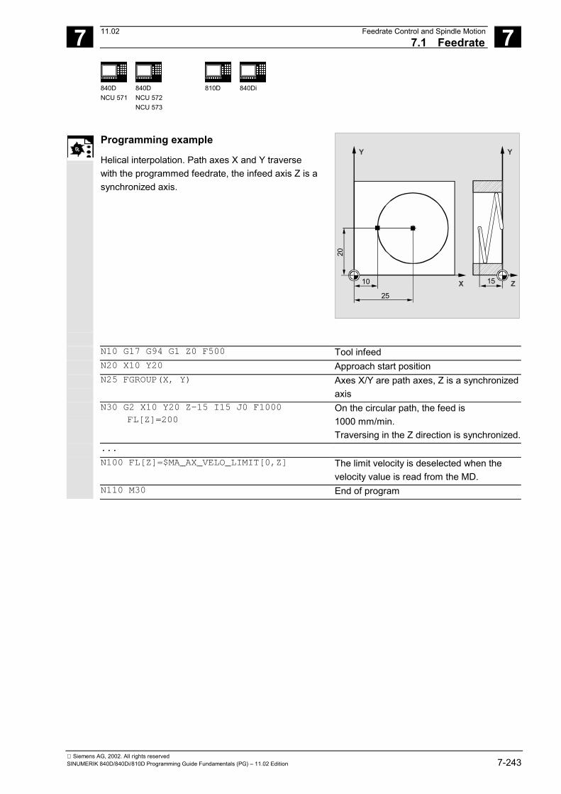
7 11.02 Feedrate Control and Spindle Motion7.1 Feedrate 7
840DNCU 571
840DNCU 572NCU 573
810D 840Di
Siemens AG, 2002. All rights reservedSINUMERIK 840D/840Di/810D Programming Guide Fundamentals (PG) – 11.02 Edition 7-243
Programming example
Helical interpolation. Path axes X and Y traversewith the programmed feedrate, the infeed axis Z is asynchronized axis.
X
Y
Z
Y
10
25
15
20 N10 G17 G94 G1 Z0 F500 Tool infeed N20 X10 Y20 Approach start position N25 FGROUP(X, Y) Axes X/Y are path axes, Z is a synchronized
axis N30 G2 X10 Y20 Z-15 I15 J0 F1000
FL[Z]=200 On the circular path, the feed is1000 mm/min.Traversing in the Z direction is synchronized.
... N100 FL[Z]=$MA_AX_VELO_LIMIT[0,Z] The limit velocity is deselected when the
velocity value is read from the MD. N110 M30 End of program
7 Feedrate Control and Spindle Motion 11.027.2 Traversing positioning axes, POS, POSA, POSP 7
840DNCU 571
840DNCU 572NCU 573
810D 840Di
Siemens AG, 2002. All rights reserved7-244 SINUMERIK 840D/840Di/810D Programming Guide Fundamentals (PG) – 11.02 Edition
7.2 Traversing positioning axes, POS, POSA, POSP
Programming
POS[axis]=… POSA[axis]=… POSP[axis]=(…,…,…) FA[axis]=… WAITP(axis)=… (programmed in a separate NC block) WAITMC(mark)=...
Explanation of the commands
POS [axis]= Position the axis; the next NC block is not enabled until the positionhas been reached
POSA [axis]= Position the axis; the next NC block is enabled, even if the positionhas not been reached
POSP [axis]=(,,) Approach end position in sections. The first value indicates the endposition; the second the length of the section. Approaching the endposition is defined in the third value with 0 or 1
FA[axis]= Feedrate for the positioning axis, up to 5 per NC block WAITP(axis) Wait for the axis to finish traversing; WAITP must be programmed in a
separate NC block WAITMC(marker) During the braking ramp, WAIITMC loads the next NC block
immediately when the WAIT marker is received. Axis Channel axes or geometry axes Mark, , An axis is only decelerated if the marker has not yet been reached or
if an different search criteria prevents the block change.
Function
Positioning axes are traversed independently of thepath axes at a separate, axis-specific feedrate.There are no interpolation commands. Example for positioning axes: Pallet feedingmechanisms, measuring stations, etc.
Sequence
With the POS/POSA/POSP commands, thepositioning axes are traversed and the sequence ofmotions coordinated at the same time.

7 11.02 Feedrate Control and Spindle Motion7.2 Traversing positioning axes, POS, POSA, POSP 7
840DNCU 571
840DNCU 572NCU 573
810D 840Di
Siemens AG, 2002. All rights reservedSINUMERIK 840D/840Di/810D Programming Guide Fundamentals (PG) – 11.02 Edition 7-245
Traveling with POSA[…]= The axis indicated in brackets is traversed to the endposition. The block step enable or programexecution is not affected by POSA. The movementto the end position can be performed duringexecution of subsequent blocks.
Internal preprocessor stop
If a command which generates an implicitpreprocessor stop is read in the following block, thefollowing block is not executed until all previouslyprepared and stored blocks have been processedcompletely. The preceding block is halted in anexact stop (as for G9).
Example: N40 POSA[X]=100 N50 IF $AA_IM[X]==R100 GOTOF LABEL1
; On accessing status data of the machine($A...), the control generates an internalpreprocessing stop, processing is halted untilall previously prepared and stored blockshave been executed in full.
N60 G0 Y100 N70 WAITP(X) N80 LABEL1:N..
Traveling with POS[…]=
The next block is only executed when all axesprogrammed under POS have reached their endpositions. Traveling with POSP[…]= POSP is used specifically for programming oscillatingmovements(see /PGA/ Programming Guide Advanced,Chapter 11).
Wait for end of travel with WAITP(…) WAITP can be used for:• Identifying a position in the NC program where
the program is to wait until an axis programmedwith POSA in a previous NC block has reachedits end position.

7 Feedrate Control and Spindle Motion 11.027.2 Traversing positioning axes, POS, POSA, POSP 7
840DNCU 571
840DNCU 572NCU 573
810D 840Di
Siemens AG, 2002. All rights reserved7-246 SINUMERIK 840D/840Di/810D Programming Guide Fundamentals (PG) – 11.02 Edition
• Making an axis available as a reciprocating axis.• Making an axis available for traversing as a
concurrent positioning axis (by PLC). After WAITP, assignment of the axis to the NCprogram is no longer valid; this applies until the axis isprogrammed again. This axis can then be operated as a positioning axisthrough the PLC, or as a reciprocating axis from theNC program/PLC or MMC.
Programming example
Axis U: Pallet store, transporting the pallet to theworking area Axis V: Transfer line to a measuring station, wheresampling controls are carried out.
N10 FA[U]=100 FA[V]=100 Axis-specific feed functions for eachpositioning axis U and V
N20 POSA[V]=90 POSA[U]=100 G0 X50 Y70 Traverse positioning and path axes N50 WAITP(U) Execution of the program is only
continued when axis U has reached theend position programmed in N20.
N60 … Block change in the braking ramp with IPOBRKA
and WAITMC(…) In SW 6.4 and higher, WAITMC can be used to• to load the next NC block immeditaely when the
wait marker is received.• to decelerate an axis only if the marker has not
yet been reached or if an different search criteriaprevents the block change.
After a WAITMC, the axes start immediately if no othersearch criterion prevent block change.
7 11.02 Feedrate Control and Spindle Motion7.3 Position-controlled spindle operation, SPCON, SPCOF
7
840DNCU 571
840DNCU 572NCU 573
810D
840Di
Siemens AG, 2002. All rights reservedSINUMERIK 840D/840Di/810D Programming Guide Fundamentals (PG) – 11.02 Edition 7-247
7.3 Position-controlled spindle operation, SPCON, SPCOF
Programming
SPCON or SPCON(n) SPCOF or SPCOF(n)
Explanation of the commands
SPCON SPCON(n)
Switch master spindle or spindle number n from speed control to position control
SPCOF SPCOF(n)
Switch master spindle or spindle number n back from position control to speed control
SPCON SPCON(n, m, 0)
SW 3.5 and higher: Several spindles with number n can be switchedfrom closed-loop speed control to position control in one block
SPCOF SPCOF(n, m, 0)
SW 3.5 and higher: Several spindles with number n can be switchedfrom closed-loop position control back to speed control in one block
n m
Integers from 1 ... n Integers from 1 ... m
Function
In certain cases, it is practical to operate the spindlein position control mode. For example, a higher quality can be achieved forthread cutting operations with G33 and a large pitch. Note The command requires up to three interpolationcycles.
Sequence
The speed is specified with S... M3, M4 and M5 apply tothe directions of rotation and spindle stop. SPCON ismodal and remains active until SPCOF.
Additional notes
With synchronized spindle setpoint value linkage, themaster spindle must be operated in position controlmode.

7 Feedrate Control and Spindle Motion 11.02 7.4 Positioning spindles (position-controlled axis operation):
7
840DNCU 571
840DNCU 572NCU 573
810D
840Di
Siemens AG, 2002. All rights reserved7-248 SINUMERIK 840D/840Di/810D Programming Guide Fundamentals (PG) – 11.02 Edition
7.4 Positioning spindles (position-controlled axis operation):SPOS, M19 and SPOSA
Programming
SPOS=… or SPOS[n]=… M19 or M[n]=19 SPOSA=… or SPOSA[n]=… M70 or Mn=70 FINEA=… or FINEA[n]=… COARSEA=… or COARSEA[n]=… IPOENDA=… or IPOENDA[n]=… IPOBRKA=… or IPOBRKA(axis[,REAL]) (programming in a separate NC block) WAITS or WAITS(n,m) (programmed in a separate NC block)
Explanation of the commands
SPOS= SPOS[n]=
Position master spindle (SPOS) or spindle number n (SPOS[n]); the next NCblock is not enabled until the position has been reached
M19 M[n]=19
Position master spindle (M19) or spindle number n (M[n]=19); the next NCblock is not enabled until the position has been reached. (SW 5.3 and higher)
SPOSA= SPOSA[n]=
Position master spindle with SPOSA or spindle number n (SPOSA[n]). The nextNC block is enabled, even if the position has not been reached
M70 Mn=70
Switch over master spindle (M70) or spindle number n (Mn=70) to axisoperation. No defined position is approached. The NC block is enabled after theswitchover has been performed.
FINEA= FINEA[Sn]=
End of motion when "Exact stop fine" is reached (SW 5.1 and higher)
COARSEA= COARSEA[Sn]=
End of motion when "Exact stop coarse" is reached (SW 5.1 and higher)
IPOENDA= IPOENDA[Sn]=
End of motion when "IPO stop" is reached (SW 5.1 and higher)
IPOBRKA= IPOBRKA(axis[,real])=
End of motion criterion from moment of application of braking ramp at 100%down to end of braking ramp at 0% and identical to IPOENDA (as of SW 6) IPOBKRA must be programmed in round parenthesis "()".
WAITS WAITS(n,m)
Wait for spindle position to be reached. WAITS applies to the master spindle orthe specified spindle numbers
n m Sn Axis Real
Integers from 1 ... n Integers from 1 ... m nth Spindle number, 0 to max. spindle number Channel identifier Percentage specification 100-0% referred to the braking ramp for blockchanges. If no % is specified, the current value of the setting data is applied.

7 11.02 Feedrate Control and Spindle Motion 7.4 Positioning spindles (position-controlled axis operation):
7
840DNCU 571
840DNCU 572NCU 573
810D
840Di
Siemens AG, 2002. All rights reservedSINUMERIK 840D/840Di/810D Programming Guide Fundamentals (PG) – 11.02 Edition 7-249
Function
SPOS, M19 and SPOSA can be used to positionspindles at specific angles, e.g. for tool-changingoperations. The spindle can also be operated as apath axis, synchronized axis or positioning axis at theaddress defined in the machine data. When the axisidentifier is specified, the spindle is in axis mode. M70switches the spindle directly to axis mode. Example:
Angle position
N10 M3 S500 ... N90 SPOS[2]=0 or Position control on, spindle 2 positioned
to 0, axis mode can be used in the nextblock
M2=70 Spindle 2 is switched to axis mode N100 X50 C180 Spindle 2 (C axis) is traversed with linear
interpolation synchronous to X. N110 Z20 SPOS[2]=90 Spindle 2 is positioned to 90 degrees.
Sequence
Precondition The spindle must be capable of operation in positioncontrol mode. Position with SPOSA=, SPOSA[n]= The block step enable or program execution is notaffected by SPOSA. The spindle positioning can beperformed during execution of subsequent blocks. The program moves onto the next block if all thefunctions (except for spindle) programmed in thecurrent block have reached their block end criterion.The spindle positioning operation may beprogrammed over several blocks (see WAITS).
A
If a command which implicitly causes a preprocessorstop is read in a subsequent block, execution of thisblock is delayed until all positioning spindles arestationary.

7 Feedrate Control and Spindle Motion 11.02 7.4 Positioning spindles (position-controlled axis operation):
7
840DNCU 571
840DNCU 572NCU 573
810D
840Di
Siemens AG, 2002. All rights reserved7-250 SINUMERIK 840D/840Di/810D Programming Guide Fundamentals (PG) – 11.02 Edition
Position with SPOS=, SPOS[n]= andposition with M19=, M19[n]= The block step enabling condition is fulfilled when allfunctions programmed in the block have reachedtheir block end criterion (e.g. all auxiliary functionsacknowledged by the PLC, all axes have reachedend point) and the spindle has reached theprogrammed position. Speed of the movements The speed or delay response for positioning is stored inthe machine data and can be programmed.
Specify spindle position
The spindle position is specified in degrees. Sincethe commands G90/G91 do not apply here, thefollowing explicit references apply: AC(…) Absolute dimensions IC(…) Incremental dimensions DC(…) Approach absolute value directly ACN(…) Absolute dimensions, approach in negative direction ACP(…) Absolute dimensions, approach in positive direction With IC, spindle positioning can take place overseveral revolutions. Example: Position spindle 2 at 250° in negative direction ofrotation.
X
0°250°
AC (250)
DC (250)
N10 SPOSA[2]=ACN(250) The spindle decelerates if necessary and accelerates in theopposite direction to the positioning movement (SW 4 and higher)
If nothing is specified, traversing automatically takesplace as for DC. Three spindle positions are possiblefor each NC block.
Value range Absolute dimensions AC: 0…359.9999 degrees Incremental dimensions IC: 0…±99,999.999 degrees

7 11.02 Feedrate Control and Spindle Motion 7.4 Positioning spindles (position-controlled axis operation):
7
840DNCU 571
840DNCU 572NCU 573
810D
840Di
Siemens AG, 2002. All rights reservedSINUMERIK 840D/840Di/810D Programming Guide Fundamentals (PG) – 11.02 Edition 7-251
End of positioning (SW 5.1 and higher)Programmable by means of the following commands:FINEA[Sn], COARSEA[Sn], IPOENDA[Sn].
Settable block change time (SW 6 and higher)
For single axis interpolation mode, a new end of motioncan be set in addition to the existing end of motioncriteria based on FINEA, COARSEA, IPOENDA.The new criterion can be set within the braking ramp(100-0%) using IPOBRKA.The program advances to the next block if the end ofmotion criteria for all spindles or axes programmedin the current block plus the block change criterionfor path interpolation are fulfilled.
Example: N10 POS[X]=100
N20 IPOBRKA(X,100)
N30 POS[X]=200
N40 POS[X]=250
N50 POS[X]=0
N60 X10 F100
N70 M30 Block changes if the X axis has reached position100 and exact stop fine. Activate block change criterion IPOBRKA brakingramp. Block change commences as soon as the Xaxis starts to decelerate. The X axis does not brake at position 200, butmoves on to position 250; as soon as the X axisstarts to brake, the block changes. The X axis brakes and returns to position 0, theblock is changed at position 0 and exact stop fine.
Deactivate
SPOS, M19 and SPOSA cause a temporarychangeover to position-control mode until the nextM3 or M4 or M5 or M41 to M45. If the positioncontrol was activated with SPCON prior to SPOS,then this remains active until SPCOF is issued.
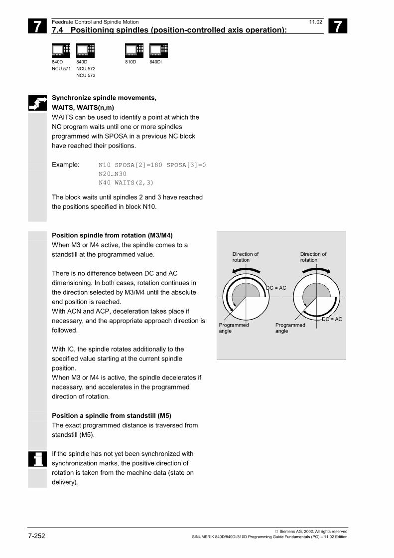
7 Feedrate Control and Spindle Motion 11.02 7.4 Positioning spindles (position-controlled axis operation):
7
840DNCU 571
840DNCU 572NCU 573
810D
840Di
Siemens AG, 2002. All rights reserved7-252 SINUMERIK 840D/840Di/810D Programming Guide Fundamentals (PG) – 11.02 Edition
Synchronize spindle movements, WAITS, WAITS(n,m) WAITS can be used to identify a point at which theNC program waits until one or more spindlesprogrammed with SPOSA in a previous NC blockhave reached their positions.
Example: N10 SPOSA[2]=180 SPOSA[3]=0
N20…N30
N40 WAITS(2,3) The block waits until spindles 2 and 3 have reachedthe positions specified in block N10.
Position spindle from rotation (M3/M4) When M3 or M4 active, the spindle comes to astandstill at the programmed value. There is no difference between DC and ACdimensioning. In both cases, rotation continues inthe direction selected by M3/M4 until the absoluteend position is reached. With ACN and ACP, deceleration takes place ifnecessary, and the appropriate approach direction isfollowed. With IC, the spindle rotates additionally to thespecified value starting at the current spindleposition. When M3 or M4 is active, the spindle decelerates ifnecessary, and accelerates in the programmeddirection of rotation.
DC = AC
DC = AC
Direction ofrotation
Direction ofrotation
Programmedangle
Programmedangle
Position a spindle from standstill (M5) The exact programmed distance is traversed fromstandstill (M5).
If the spindle has not yet been synchronized withsynchronization marks, the positive direction ofrotation is taken from the machine data (state ondelivery).

7 11.02 Feedrate Control and Spindle Motion 7.4 Positioning spindles (position-controlled axis operation):
7
840DNCU 571
840DNCU 572NCU 573
810D
840Di
Siemens AG, 2002. All rights reservedSINUMERIK 840D/840Di/810D Programming Guide Fundamentals (PG) – 11.02 Edition 7-253
Programming example
Cross holes are to be drilled in this turned part. The running drive spindle (master spindle) isstopped at zero degrees and then successivelyturned through 90°, stopped and so on.
Z
X X
.... N110 S2=1000 M2=3 ; switch on cross drilling attachment
N120 SPOSA=DC(0) ; position main spindle directly at 0°, the program will advance to thenext block immediately
N125 G0 X34 Z-35 ; switch on the drill while the spindle is being positioned
N130 WAITS ; wait until the main spindle reaches its position
N135 G1 G94 X10 F250 ; feedrate in mm/min (G96 is suitable only for the multi-edge turning tooland synchronous spindle, but not for power tools on the cross slide)
N140 G0 X34 N145 SPOS=IC(90) ; the spindle is positioned through 90° with read halt in a positive direction
N150 G1 X10 N155 G0 X34 N160 SPOS=AC(180) ; the spindle is positioned at 180° with respect to the spindle zero point
N165 G1 X10 N170 G0 X34 N175 SPOS=IC(90) ; the spindle turns in a positive direction through 90° from the absolute
180° position, ending up in the absolute 270° position N180 G1 X10 N185 G0 X50 ...

7 Feedrate Control and Spindle Motion 11.02 7.5 Milling on turned parts: TRANSMIT
7
840DNCU 571
840DNCU 572NCU 573
810D
840Di
Siemens AG, 2002. All rights reserved7-254 SINUMERIK 840D/840Di/810D Programming Guide Fundamentals (PG) – 11.02 Edition
7.5 Milling on turned parts: TRANSMIT
Programming
TRANSMIT or TRANSMIT(n) TRAFOOF
Explanation of the commands
TRANSMIT Activates the first declared TRANSMIT function TRANSMIT(n) Activates the nth declared TRANSMIT function; n can be up to 2
(TRANSMIT(1) is the same as TRANSMIT). TRAFOOF Deactivates an active transformation
An active TRANSMIT transformation is likewisedeactivated if one of the other transformations isactivated in the relevant channel (e.g. TRACYL,TRAANG, TRAORI).
The TRANSMIT function enables the following:• Face machining on turned parts in the turning
clamp (drill-holes, contours).• A Cartesian coordinate system can be used to
program these operations.• The control maps the programmed traversing
movements of the Cartesian coordinate systemonto the traversing movements of the realmachine axes (standard situation): – Rotary axis – Infeed axis perpendicular to the axis of rotation
– Longitudinal axis parallel to the axis of rotationThe linear axes are perpendicular to each other.
• A tool center offset relative to the turning center ispermitted.
• The velocity control makes allowance for the limitsdefined for the rotations.

7 11.02 Feedrate Control and Spindle Motion7.5 Milling on turned parts: TRANSMIT
7
840DNCU 571
840DNCU 572NCU 573
810D
840Di
Siemens AG, 2002. All rights reservedSINUMERIK 840D/840Di/810D Programming Guide Fundamentals (PG) – 11.02 Edition 7-255
Programming example
Y
Z
X
N10 T1 D1 G54 G17 G90 F5000 G94 Tool selection N20 G0 X20 Z10 SPOS=45 Approach start position N30 TRANSMIT Activate TRANSMIT function N40 ROT RPL=–45
N50 ATRANS X–2 Y10 Set frame
N60 G1 X10 Y–10 G41 N70 X–10 N80 Y10 N90 X10 N100 Y–10N110 ...
Four-edge roughing
References
/PGA/ Programming Guide Advanced, Section"Transformations"

7 Feedrate Control and Spindle Motion 11.02 7.6 Cylinder surface transformation: TRACYL
7
840DNCU 571
840DNCU 572NCU 573
810D
840Di
Siemens AG, 2002. All rights reserved7-256 SINUMERIK 840D/840Di/810D Programming Guide Fundamentals (PG) – 11.02 Edition
7.6 Cylinder surface transformation: TRACYL
Programming
TRACYL(d) or TRACYL(d,t) TRAFOOF
Explanation of thecommands
TRACYL(d) Activates the first declared TRACYL function TRACYL(d,n) Activates the nth declared TRACYL function. N can be up to 2,
TRACYL(d,1) is the same as TRACYL(d). d Value for the current diameter of the cylinder to be machined. TRAFOOF Transformation off
An active TRACYL transformation is likewisedeactivated if one of the other transformations isactivated in the relevant channel(e.g. TRANSMIT, TRAANG, TRAORI).
Function
Cylinder surface transformation TRACYL The TRACYL cylinder surface transformationfunction can be used to Machine• longitudinal grooves on cylindrical bodies,• transverse grooves on cylindrical bodies,• grooves with any path on cylindrical bodies. The path of the grooves is programmed withreference to the unwrapped, level surface of thecylinder.
X
Z
Y
Workpiece coordinate system
References
/PGA/ Programming Guide Advanced, Section"Transformations"
7 11.02 Feedrate Control and Spindle Motion 7.7 Feedrate for positioning axes/spindles: FA, FPR, FPRAON, FPRAOF
7
840DNCU 571
840DNCU 572NCU 573
810D
840Di
Siemens AG, 2002. All rights reservedSINUMERIK 840D/840Di/810D Programming Guide Fundamentals (PG) – 11.02 Edition 7-257
7.7 Feedrate for positioning axes/spindles: FA, FPR, FPRAON, FPRAOF
Programming
FA[axis]= FA[SPI(spindle)]=… or FA[S…]=… FPR (rotary axis) or FPR(SPI(spindle)) or FPR(S…) FPRAON (axis,rotary axis) or FPRAON(axis,SPI(spindle)) or FPRAON(axis,S…) orFPRAON(SPI(spindle),rotary axis) or FPRAON(S…,rotary axis) or FPRAON(SPI(spindle),SPI(spindle)) or FPRAON(S…,S…) or FPRAOF(axis,SPI(spindle),…) or FPRAOF(axis,S…,…)
Explanation of the commands
FA[axis] Feedrate for the specified positioning axis in mm/min or inch/min ordeg/min
FA[SPI(spindle)] FA[S…]
Positioning velocity (axial feed) for the specified spindles in deg/min
FPR Identification of the rotary axis or spindle whose revolutional feedrateprogrammed in G95 is to be used as the basis for the revolutionalfeedrate of the path and synchronized axes.
FPRAON Activate revolutional feedrate for positioning axes and spindlesaxially. The first command identifies the positioning axis/spindlethat is to be traversed at a revolutional feedrate. The second commandidentifies the rotary axis/spindle from which the feedrate must bederived.
FPRAOF Deactivate revolutional feedrate. Specification of axis or spindle thatis to stop traversing at a revolutional feedrate.
SPI Converts the spindle number into an axis identifier; the transferparameter must contain a valid spindle number. SPI is used for theindirect definition of a spindle number.
Axis Positioning axes or geometry axes
Function
Positioning axes, such as workpiece transport systems,tool turrets and end supports, are traversedindependently of the path and synchronized axes. Aseparate feed is therefore defined for each positioningaxis. Example: FA[A1]=500

7 Feedrate Control and Spindle Motion 11.02 7.7 Feedrate for positioning axes/spindles: FA, FPR, FPRAON, FPRAOF
7
840DNCU 571
840DNCU 572NCU 573
810D
840Di
Siemens AG, 2002. All rights reserved7-258 SINUMERIK 840D/840Di/810D Programming Guide Fundamentals (PG) – 11.02 Edition
With synchronous spindle link, the positioning speedof the following spindle can be programmedindependently of the master spindle – for example,for positioning operations. Example: FA[S2]=100
The spindle identifiers SPI(...) and S... are identicalin terms of function.
Sequence
Feed FA[…] The programmed feed is modal. The feed is alwaysG94. When G70/G71 is active, the unit of measurement ismetric/inches according to the default setting in themachine data. G700/G710 can be used to modifythe unit of measurement in the program.
If no FA is programmed, the value defined in themachine data applies.
Up to 5 feeds for positioning axes or spindles can beprogrammed in each NC block. Value range 0.001…999,999.999mm/min, deg/min 0.001…39,999.9999inch/min
Feed FPR(…)
As an extension of the G95 command (revolutionalfeedrate referring to the master spindle), FPR allowsthe revolutional feedrate to be derived from anychosen spindle or rotary axis. G95 FPR(...) is valid for path and synchronized axes. If the rotary axis/spindle specified in the FPRcommand is operating on position control, then thesetpoint linkage is active. Otherwise the actual-valuelinkage is effective. The derived feedrate is calculated according to thefollowing formula: Derived feedrate =programmed feedrate * Absolute master feedrate

7 11.02 Feedrate Control and Spindle Motion 7.7 Feedrate for positioning axes/spindles: FA, FPR, FPRAON, FPRAOF
7
840DNCU 571
840DNCU 572NCU 573
810D
840Di
Siemens AG, 2002. All rights reservedSINUMERIK 840D/840Di/810D Programming Guide Fundamentals (PG) – 11.02 Edition 7-259
Example: Path axes X, Y must be traversed at the revolutionalfeedrate derived from rotary axis A: N40 FPR(A)
N50 G95 X50 Y50 F500
Feed FPRAON(…,…), FPRAOF(…,…) The FPRAON command makes it possible to derivethe revolutional feedrate for specific positioning axesand spindles from the current feedrate of anotherrotary axis or spindle. The first command identifies the axis/spindle thatmust be traversed at a revolutional feedrate. Thesecond command identifies the rotary axis/spindlethat is to supply the feedrate. The command neednot be specified a second time. If it is not, thefeedrate is derived from the master spindle. The revolutional feedrate can be deactivated for oneor several axes/spindles simultaneously with theFPRAOF command. The feedrate is calculated in the same way as forFPR(…). Examples: The revolutional feedrate for master spindle 1 mustbe derived from spindle 2. N30 FPRAON(S1,S2) N40 SPOS=150 N50 FPRAOF(S1) The revolutional feedrate for positioning axis X mustbe derived from the master spindle. The positioningaxis is traversing at 500 mm/revolution of the masterspindle. N30 FPRAON(X) N40 POS[X]=50 FA[X]=500 N50 FPRAOF(S1)

7 Feedrate Control and Spindle Motion 11.02 7.8 Percentage feedrate override, OVR, OVRA
7
840DNCU 571
840DNCU 572NCU 573
810D
840Di
Siemens AG, 2002. All rights reserved7-260 SINUMERIK 840D/840Di/810D Programming Guide Fundamentals (PG) – 11.02 Edition
7.8 Percentage feedrate override, OVR, OVRA
Programming
OVR=… OVRA[axis]=… OVRA[SPI(spindle)]=… or OVRA[S…]=…
Explanation of the command
OVR Feed change in percent for path feed F OVRA Feed change in percent for positioning feed FA or
for spindle speed S SPI Converts the spindle number into an axis identifier; the transfer parameter must
contain a valid spindle number.The spindle identifiers SPI(...) and S... are identical in terms of function.
Axis Positioning axes or geometry axes
Function
You can use the programmable feedrate override tochange the velocity/speed of path axes, positioningaxes and spindles via a command in the NC program. Example:N10 OVR=25 OVRA[A1]=70
N20 OVRA[SPI(1)]=35orN20 OVRA[S1]=35
; Path feed 25%,Positioning feed for A1 70%.; Spindle speed for spindle 1 35%.
Sequence
The programmed feed change refers to or is combinedwith the feed override set on the machine control panel. Example: Set feed override 80% Programmed feed override OVR=50 The programmed path feed F1000 is changed to F400(1000 * 0.8 * 0.5).

7 11.02 Feedrate Control and Spindle Motion 7.9 Feedrate with handwheel override, FD, FDA
7
840DNCU 571
840DNCU 572NCU 573
810D
840Di
Siemens AG, 2002. All rights reservedSINUMERIK 840D/840Di/810D Programming Guide Fundamentals (PG) – 11.02 Edition 7-261
Value range 1…200%, integers; with path and rapid traverseoverride, the maximum velocities set in the machinedata are not exceeded.
7.9 Feedrate with handwheel override, FD, FDA
Programming
FD=… FDA[axis]=0 or FDA[axis]=…
Explanation of the command
FD=… Handwheel travel for path axes with feed override FDA [axis]=0 Handwheel travel for positioning axes according to position parameter FDA[axis]=… Handwheel travel for positioning axes with feed override Axis Positioning axes or geometry axes
Function
With these functions, you can use the handwheel totraverse path and positioning axes (positionparameter) or change the axis velocities (speedoverride) during program execution. The handwheel override is frequently used forgrinding operations. Example for position parameter: The grinding wheel oscillating in the Z direction ismoved to the workpiece in the X direction using thehandwheel. The operator can then adjust theposition of the tool until the spark generation isconstant. When "Delete distance-to-go" is activated,the program goes to the next NC block andmachining continues in NC mode.
Z
X
Only speed override can be used for path axes.

7 Feedrate Control and Spindle Motion 11.02 7.9 Feedrate with handwheel override, FD, FDA
7
840DNCU 571
840DNCU 572NCU 573
810D
840Di
Siemens AG, 2002. All rights reserved7-262 SINUMERIK 840D/840Di/810D Programming Guide Fundamentals (PG) – 11.02 Edition
Sequence
Preconditions
A handwheel must be assigned to the axes to betraversed for the handwheel override function.Please see the Operator’s Guide for the procedure.The number of handwheel pulses per graduatedposition is defined in machine data.
Non-modal operation The handwheel override function is non-modal. Thefunction is deactivated in the next NC block and theNC program continues to be executed. Handwheel travel with path default for positioningaxes, FDA[axis]=0 In NC blocks with programmed FDA[axis]=0, thefeed is set to zero in order that the program does notgenerate any travel movement. The programmedtravel movement to the target position is nowcontrolled exclusively by the operator rotating thehandwheel. Example: N20 POS[V]=90 FDA[V]=0
The automatic travel movement is stopped in blockN20. The operator can now move the axis manuallyusing the handwheel.
Direction of movement, travel velocity
The axes accurately follow the path set by thehandwheel in the direction of the leading sign.Depending on the direction of rotation, you can travelforwards or backwards – the faster you turn thehandwheel, the higher the travel velocity. Traversing range The traversing range is limited by the starting positionand the end point programmed with the positioningcommand.

7 11.02 Feedrate Control and Spindle Motion 7.9 Feedrate with handwheel override, FD, FDA
7
840DNCU 571
840DNCU 572NCU 573
810D
840Di
Siemens AG, 2002. All rights reservedSINUMERIK 840D/840Di/810D Programming Guide Fundamentals (PG) – 11.02 Edition 7-263
Handwheel travel with velocity overlay,FDA[axis]=… Where FDA[…]=… is programmed in an NC block, thefeed from the last programmed FA value is acceleratedor reduced to the value programmed at FDA. Starting with the current feed FDA, you can accelerateor reduce the programmed travel to zero by rotating thehandwheel. The values defined in the machine data areused for the maximum velocity. Example: N10 POS[U]=10 FDA[U]=100
POSA[V]=20 FDA[V]=150
Traverse path axes with handwheel override, FD
The following preconditions apply to handwheeloverrides for path axes: In the NC block with the programmed handwheeloverride• an active G1, G2 or G3 motion command must be
active,• exact stop G60 must be switched on, and• the path feedrate must be specified with G94
mm/min or inch/min.
The path feed F and the handwheel override FDmay not be programmed in the same NC block.
Feedrate override The feed override acts only on the programmed feed,not on the travel movement generated with thehandwheel (except if feed override = 0). Example: N10 G1 X… Y… F500…
N50 X… Y… FD=700
The feedrate is accelerated to 700 mm/min in blockN50. The path velocity can be increased or reducedaccording to the direction of rotation on the handwheel.
It is not possible to traverse in the opposite direction.

7 Feedrate Control and Spindle Motion 11.02 7.9 Feedrate with handwheel override, FD, FDA
7
840DNCU 571
840DNCU 572NCU 573
810D
840Di
Siemens AG, 2002. All rights reserved7-264 SINUMERIK 840D/840Di/810D Programming Guide Fundamentals (PG) – 11.02 Edition
Note With velocity override of path axes, you always control the path velocity with the handwheel of the1st geometry axis. Traversing range The traversing range is limited by the startingposition and the programmed end point.
Manual override in automatic mode
The manual override function in automatic mode forPOS/A axes has two different effects that areanalogous to Jog functions.1. Path override: FDA [ax] = 0The axis does not move. Handwheel pulses receivedfor each IPO cycle are traversed direction-independent and accurate to the path. When thetarget position is reached, the axis brakes.2. Velocity override FDA [ax] > 0The axis moves to the target position at theprogrammed velocity. The destination is thusreached even without handwheel pulses.Pulses received for each IPO cycle are converted toan accumulative change in the existing velocity.Pulses in the traversing direction increase thespeed; the limit is MAX_AX_VELO.Pulses in the opposite direction reduce the speed.The minimum speed limit is 0.

7 11.02 Feedrate Control and Spindle Motion 7.10 Percentage acceleration correction: ACC (Option)
7
840DNCU 571
840DNCU 572NCU 573
810D
840Di
Siemens AG, 2002. All rights reservedSINUMERIK 840D/840Di/810D Programming Guide Fundamentals (PG) – 11.02 Edition 7-265
7.10 Percentage acceleration correction: ACC (Option)
Programming
ACC[axis]=… ACC[SPI(spindle)]=… or ACC(S…)
Explanation of the command
ACC Change in acceleration in percent for the specified path axis or change in speedfor the specified spindle
SPI Converts the spindle number into an axis identifier; the transfer parameter mustcontain a valid spindle number.The spindle identifiers SPI(...) and S... are identical in terms of function.
Axis Channel axis name of path axis
Function
In critical program sections, it may be necessary to limitthe acceleration to below the maximum values, e.g. toprevent mechanical vibrations from occurring.
Sequence
You can use the programmable acceleration overrideto change the acceleration for each path axis or spindlevia a command in the NC program. The limit iseffective for all types of interpolation. The valuesdefined in the machine data determine the 100%acceleration. Example N50 ACC[X]=80
Meaning Traverse the axis slide in the X direction withonly 80% acceleration. N60 ACC[SPI(1)]=50 or ACC[S1]=50 Meaning Accelerate or decelerate spindle 1 with only50% of the maximum acceleration. The spindleidentifiers SPI(...) and S... are identical in terms offunction. Value range 1…200%, integers Deactivate ACC[axis]=100, program start, reset

7 Feedrate Control and Spindle Motion 11.02 7.11 Feedrate optimization for curved path sections, CFTCP, CFC, CFIN
7
840DNCU 571
840DNCU 572NCU 573
810D
840Di
Siemens AG, 2002. All rights reserved7-266 SINUMERIK 840D/840Di/810D Programming Guide Fundamentals (PG) – 11.02 Edition
Additional notes
Please note that the maximum permissible values ofthe machine manufacturer can be exceeded with ahigher acceleration rate.
SW 5.1 and higherThe defined acceleration can also be changed viasynchronized actions.See /FBSY/, Synchronized ActionsExample
N100 EVERY $A_IN[1] DO POS[X]=50 FA[X]=2000 ACC[X]=140
The last programmed value is retained after RESET. The current acceleration value can be polled using
the system variables $AA_ACC[<Axis>].
7.11 Feedrate optimization for curved path sections, CFTCP, CFC, CFIN
Programming
CFTCPCFC
CFIN
Explanation of the commands
CFTCP Constant feed at cutter center path CFC Constant feed at contour (tool edge) CFIN Constant feed at tool edge for concave contours only, otherwise on the
cutter center path

7 11.02 Feedrate Control and Spindle Motion 7.11 Feedrate optimization for curved path sections, CFTCP, CFC, CFIN
7
840DNCU 571
840DNCU 572NCU 573
810D
840Di
Siemens AG, 2002. All rights reservedSINUMERIK 840D/840Di/810D Programming Guide Fundamentals (PG) – 11.02 Edition 7-267
Function
The programmed feedrate initially refers to the cuttercenter path when the G41/G42 override is activatedfor the cutter radius (cf. Chapter 6). When you mill a circle – the same applies topolynomial and spline interpolation – the extent of thechange in feedrate at the cutter edge is such that itcan have a considerable effect on the quality of themachined part. Example: you are milling a small external radius with alarge tool. The distance that the outer side of the cutterhas to cover is much larger than the distance along thecontour. You therefore work with a very small feed onthe contour. In order to avoid effects like this, you should regulate thefeedrate for curved contours accordingly.
Tool path
Contour
Sequence
Constant feedrate on center-point path,deactivate feedrate override, CFTCP The control keeps the feedrate constant, feed overridesare deactivated.
Constant feedrate on contour, CFC The feedrate is reduced for inside radii andincreased for outside radii. This ensures a constantspeed at the tool edge and thus at the contour. This function is set as the default. Constant feed only at inside radii, CFIN The feedrate is reduced for inside radii but notincreased for outside radii; the cutter center applies.
cons
tant
constant
reduced
increased

7 Feedrate Control and Spindle Motion 11.02 7.11 Feedrate optimization for curved path sections, CFTCP, CFC, CFIN
7
840DNCU 571
840DNCU 572NCU 573
810D
840Di
Siemens AG, 2002. All rights reserved7-268 SINUMERIK 840D/840Di/810D Programming Guide Fundamentals (PG) – 11.02 Edition
Programming example
In this example, the contour is first machined with aCFC-compensated feed. During finishing, the cutting base is additionallymachined with CFIN. This prevents the cutting basefrom being damaged at outside radii by too high afeedrate.
X
Y
2010
20
55 3040
10
N10 G17 G54 G64 T1 M6 N20 S3000 M3 CFC F500 G41 N30 G0 X-10 N40 Y0 Z-10 Infeed to first cutting depth N50 CONTOUR1 Subprogram call N40 CFIN Z-25 Infeed to second cutting depth N50 CONTOUR1 Subprogram call N60 Y120 N70 X200 M30
7 11.02 Feedrate Control and Spindle Motion 7.12 Spindle speed S, direction of spindle rotation M3, M4, M5
7
840DNCU 571
840DNCU 572NCU 573
810D
840Di
Siemens AG, 2002. All rights reservedSINUMERIK 840D/840Di/810D Programming Guide Fundamentals (PG) – 11.02 Edition 7-269
7.12 Spindle speed S, direction of spindle rotation M3, M4, M5
Programming
M3 or M4 or M5 M1=3 or M1=4 or M1=5 S… Sn=… SETMS(n) or SETMS
Explanation of the commands
M1=3 M1=4 M1=5 Spindle rotation clockwise/counterclockwise, spindle stop for spindle 1.Other spindles are defined according to M2=… M3=…
M3 Direction of spindle rotation clockwise for master spindle M4 Direction of spindle rotation counterclockwise for master spindle M5 Spindle stop for master spindle Sn=… Spindle speed in rpm for spindle n S… Spindle speed in rpm for the master spindle SETMS(n) Set spindle specified in n as master spindle SETMS Reset to the master spindle defined in machine data
Function
The above functions are used to• switch on the spindle,• specify the required direction of spindle rotation, and• define the counterspindle or an actuated tool as the
master spindle, e.g. on turning machines The following programming commands are valid for themaster spindle: G95, G96, G97, G33, G331.(see also Chapter 1, "Main spindle, master spindle").
Machine manufacturer (MH7.2)
Definition as master spindle is also possible viamachine data (default).
Sequence
Preset M commands, M3, M4, M5 In a block with axis commands, the above mentionedfunctions are activated before the axis movementscommence (basic settings on the control).

7 Feedrate Control and Spindle Motion 11.02 7.12 Spindle speed S, direction of spindle rotation M3, M4, M5
7
840DNCU 571
840DNCU 572NCU 573
810D
840Di
Siemens AG, 2002. All rights reserved7-270 SINUMERIK 840D/840Di/810D Programming Guide Fundamentals (PG) – 11.02 Edition
Example: N10 G1 F500 X70 Y20 S270 M3
N100 G0 Z150 M5
N10: the spindle accelerates to 270rpm, then themovements are performed on X and Y. N100: spindle stop before the retraction movementon Z.
A machine data can be set to determine whether theaxis motions are delayed until the spindle has run upand reached setpoint speedor stopped, or whether theyare executed immediately after the programmedswitching operations. Spindle speed S The speed specified with S... or S0=... applies to themaster spindle. You specify the corresponding numberfor additional spindles: =…, S2=… Three S values can be programmed per NC block.
Working with multiple spindles Up to five spindles – master spindle plus fouradditional spindles, two spindles on the SINUMERIKFM-NC– can be configured in the same channel. One of the spindles is defined in machine data asthe master spindle. Special functions apply to thisspindle, such as thread cutting, tapping, revolutionalfeed, dwell time. The numbers must be specified with the speed andthe direction of rotation/spindle stop for the otherspindles, e.g. for a second spindle and actuated tool. Example: N10 S300 M3 S2=780 M2=4
Master spindle 300rpm, clockwise rotation 2nd spindle 780rpm, counterclockwise rotation
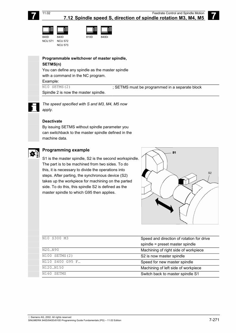
7 11.02 Feedrate Control and Spindle Motion 7.12 Spindle speed S, direction of spindle rotation M3, M4, M5
7
840DNCU 571
840DNCU 572NCU 573
810D
840Di
Siemens AG, 2002. All rights reservedSINUMERIK 840D/840Di/810D Programming Guide Fundamentals (PG) – 11.02 Edition 7-271
Programmable switchover of master spindle,SETMS(n) You can define any spindle as the master spindlewith a command in the NC program. Example:
N10 SETMS(2) Spindle 2 is now the master spindle.
; SETMS must be programmed in a separate block
The speed specified with S and M3, M4, M5 nowapply.
Deactivate By issuing SETMS without spindle parameter youcan switchback to the master spindle defined in themachine data.
Programming example
S1 is the master spindle, S2 is the second workspindle. The part is to be machined from two sides. To dothis, it is necessary to divide the operations intosteps. After parting, the synchronous device (S2)takes up the workpiece for machining on the partedside. To do this, this spindle S2 is defined as themaster spindle to which G95 then applies.
S2
N10 S300 M3 Speed and direction of rotation for drive
spindle = preset master spindle N20…N90 Machining of right side of workpiece N100 SETMS(2) S2 is now master spindle N110 S400 G95 F… Speed for new master spindle N120…N150 Machining of left side of workpiece N160 SETMS Switch back to master spindle S1
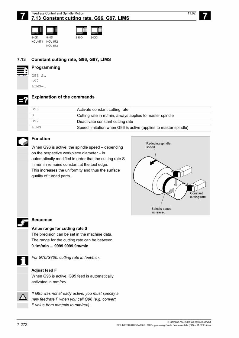
7 Feedrate Control and Spindle Motion 11.02 7.13 Constant cutting rate, G96, G97, LIMS
7
840DNCU 571
840DNCU 572NCU 573
810D
840Di
Siemens AG, 2002. All rights reserved7-272 SINUMERIK 840D/840Di/810D Programming Guide Fundamentals (PG) – 11.02 Edition
7.13 Constant cutting rate, G96, G97, LIMS
Programming
G96 S… G97 LIMS=…
Explanation of the commands
G96 Activate constant cutting rate S Cutting rate in m/min, always applies to master spindle G97 Deactivate constant cutting rate LIMS Speed limitation when G96 is active (applies to master spindle)
Function
When G96 is active, the spindle speed – dependingon the respective workpiece diameter – isautomatically modified in order that the cutting rate Sin m/min remains constant at the tool edge. This increases the uniformity and thus the surfacequality of turned parts.
Reducing spindlespeed
Constantcutting rate
Spindle speedincreased
Sequence
Value range for cutting rate S The precision can be set in the machine data. The range for the cutting rate can be between0.1m/min ... 9999 9999.9m/min.
For G70/G700: cutting rate in feet/min.
Adjust feed F When G96 is active, G95 feed is automaticallyactivated in mm/rev.
If G95 was not already active, you must specify anew feedrate F when you call G96 (e.g. convertF value from mm/min to mm/rev).

7 11.02 Feedrate Control and Spindle Motion7.13 Constant cutting rate, G96, G97, LIMS
7
840DNCU 571
840DNCU 572NCU 573
810D
840Di
Siemens AG, 2002. All rights reservedSINUMERIK 840D/840Di/810D Programming Guide Fundamentals (PG) – 11.02 Edition 7-273
Upper speed limit LIMS If you machine a workpiece that varies greatly indiameter, it is advisable to specify a speed limit forthe spindle. This prevents excessively high speedswith small diameters. LIMS is active with G96 and G97. Example: N10 SETMS(3)N20 G96 S100 LIMS=2500
Limit speed to 2500rpm The speed limit programmed with G26 or defined inmachine data cannot be exceeded with LIMS. Rapid traverse With rapid traverse G0, there is no change in speed. Exception: If the contour is approached in rapidtraverse and the next NC block contains a G1, G2,G3 ... path command, the speed is adjusted in theG0 approach block for the next path command. Deactivate constant cutting rate, G97 After G97, the control interprets an S word again asa spindle speed in rpm. If you do not specify a new spindle speed, the lastspeed set with G96 is retained.
LIMS
Additional notes
• The G96 function can also be deactivated withG94 or G95.In this case, the last programmed speed S isused for further machining operations.
• In SW 4.2 and higher, G97 can also beprogrammed without preceding it by G96. Thefunction then has the same effect as G95; LIMScan also be programmed.
The transverse axis must be defined in machinedata.

7 Feedrate Control and Spindle Motion 11.02 7.14 Constant grinding wheel peripheral speed, GWPSON, GWPSOF
7
840DNCU 571
840DNCU 572NCU 573
810D
840Di
Siemens AG, 2002. All rights reserved7-274 SINUMERIK 840D/840Di/810D Programming Guide Fundamentals (PG) – 11.02 Edition
7.14 Constant grinding wheel peripheral speed, GWPSON, GWPSOF
Programming
GWPSON(T No.) GWPSOF(T No.) S… S1…
Explanation of the commands and parameters
GWPSON(T No.) Select constant grinding wheel peripheral speed GWPS It is only necessary to specify the T number if the tool with this Tnumber is not active.
GWPSOF(T No.) Deselect GWPS; the T number only need be specified if the tool withthis T number is not active
S… S1…
Program GWPS; value for peripheral speed in m/s or ft/s S… SUG for master spindle; S1… SUG for spindle 1
Function
With the function "Constant grinding wheel peripheralspeed" (=GWPS) you can set the grinding wheelspeed such that, taking account of the current radius,the grinding wheel peripheral speed remains constant.
The GWPS can only be selected for grinding tools(types 400–499).
Additional notes
To be able to activate the "Constant peripheral speed"function, the tool-specific grinding data $TC_TPG1,$TC_TPG8 and $TC_TPG9 must be set accordingly.When the GWPS function is active, even online offsetvalues (= wear parameters; cf. Sect. 6 PUTFTOC,PUTFTOCF) are taken into account with regard tospeed variations!
7 11.02 Feedrate Control and Spindle Motion 7.14 Constant grinding wheel peripheral speed, GWPSON, GWPSOF
7
840DNCU 571
840DNCU 572NCU 573
810D
840Di
Siemens AG, 2002. All rights reservedSINUMERIK 840D/840Di/810D Programming Guide Fundamentals (PG) – 11.02 Edition 7-275
Select GWPS GWPSON, program GWPS After activation of GWPSON, each subsequentS value for this spindle is interpreted as a grindingwheel peripheral speed. Selection of grinding wheel peripheral speed withGWPSON does not cause the automatic activation oftool length compensation or tool monitoring. The GWPS can be active for several spindles on achannel with different tool numbers. If GWPS is to be selected for a new tool on a spindlewhere GWPS is already active, the active GWPS mustfirst be deselected with GWPSOF. Deactivate GWPS GWPSOF When the GWPS is deselected with GWPSOF, thelast speed determined is retained as set speed. GWPS programming is reset at the end of the partsprogram or on RESET. Query active GWPS $P_GWPS[spindle no.] This system variable can be used to query from theparts program whether the GWPS is active for aspecific spindle. TRUE GWPS is active. FALSE GWPS is not active.

7 Feedrate Control and Spindle Motion 11.02 7.14 Constant grinding wheel peripheral speed, GWPSON, GWPSOF
7
840DNCU 571
840DNCU 572NCU 573
810D
840Di
Siemens AG, 2002. All rights reserved7-276 SINUMERIK 840D/840Di/810D Programming Guide Fundamentals (PG) – 11.02 Edition
Programming example
A constant grinding wheel peripheral speed is to beused for grinding tools T1 and T5. T1 is the active tool.
Programming
N20 T1 D1 Select T1 and D1 N25 S1=1000 M1=3 1000rpm for spindle 1 N30 S2=1500 M2=3 1500rpm for spindle 2 … N40 GWPSON GWPS selection for active tool T1 N45 S1 = 60 Set GWPS for active tool to 60m/s … N50 GWPSON(5) Select GWPS for tool 5 (2nd spindle) N55 S2 = 40 Set GWPS for spindle 2 to 40m/s … N60 GWPSOF Deactivate GWPS for active tool N65 GWPSOF(5) Deactivate GWPS for tool 5 (spindle 2) …

7 11.02 Feedrate Control and Spindle Motion 7.15 Constant workpiece speed for centerless grinding:
7
840DNCU 572NCU 573
840Di
Siemens AG, 2002. All rights reservedSINUMERIK 840D/840Di/810D Programming Guide Fundamentals (PG) – 11.02 Edition 7-277
7.15 Constant workpiece speed for centerless grinding:CLGON, CLGOF
Programming
CLGON(set)CLGOF
Explanation of the commands
CLGON(set) Activate "Constant workpiece speed for centerless grinding" function;specify speed setpoint (set) for workpiece in rpm
CLGOF Deactivate function
Function
When the "Constant workpiece speed for centerlessgrinding" function is active, the speed of themachined part is kept constant. The speed of theregulating wheel reduces as the diameter of themachined part decreases. Sequence
Preconditions for CLGON The axes of the regulating and grinding wheels andthe work blade must be in a position that enablesgrinding of the workpiece from the initial to thefinishing dimension. CLGON acts only if the spindle of the regulatingwheel is running in speed mode. An actual positionsensor is not required. G functions G94, G95, G96 and G97 can be activeat the same time as CLGON. These functions haveno effect on the spindle of the regulating wheel.
R1
A
X
YQ2
Q1
r
r
n = const1
n 2
Regulating wheel
Workpiece
Workblade
Regulating wheel
Workpiece
Grindingwheel
If the regulating wheel is running is a master spindle,G96 and CLGON cancel each other.
Additional notes The following are stored in the channel-specificmachine data ($MC_TRACLG…)• The spindle numbers of the regulating and
grinding wheels• Geometrical parameters (axis numbers, direction
vector of the work blade, etc.)• Response on reset and end of program

7 Feedrate Control and Spindle Motion 11.02 7.15 Constant workpiece speed for centerless grinding:
7
840DNCU 572NCU 573
840Di
Siemens AG, 2002. All rights reserved7-278 SINUMERIK 840D/840Di/810D Programming Guide Fundamentals (PG) – 11.02 Edition
Calculation of the regulating wheel speedThe speed of the regulating wheel is calculated fromthe set speed of the workpiece:S
Regulating wheel = r
Workpiece/r
Regulating wheel • S
prog
The radius of the workpiece rWorkpiece
is calculated as
the radius of the circle touching the grinding wheel,regulating wheel and work blade.
Offset data for CLGONThe radii of the grinding and regulating wheels aretaken from the current offset data for T1, D1 (grindingwheel) and T2, D1 (regulating wheel). Changes to theonline tool offset (PUTFTOCF, FTOCON, FTOCOF)are taken into account.
Response on transition of traversing blocksCLGON is only active in traversing blocks without G0(traverse with path feed).If a transition takes place from a G0 block to atraversing block without G0, the speed of theregulating wheel during the G0 block is set to thedesired starting speed of the next block.
R1
A
X
YQ2
Q1
r
r
n = const1
n 2
Regulating wheel
Workpiece
Workblade
Regulating wheel
Workpiece
Grindingwheel
If a G0 block follows a traversing block without G0, thespeed is frozen at the end of the block before G0. Thisdoes not apply if the G0 block is followed by a motionblock without G0 in which a new set speed isprogrammed.
Gear stagesThe gear stages must be selected in such a mannerthat the regulating wheel can cover the entire speedrange required.
MonitoringSpeed monitoring defined with G25 and G26 isactive.The range of the work blade, in which the calculatedtangent of the workpiece lies, is monitored. It isdefined in machine data.

7 11.02 Feedrate Control and Spindle Motion7.16 Programmable spindle speed limitation, G25, G26 7
840DNCU 571
840DNCU 572NCU 573
810D 840Di
Siemens AG, 2002. All rights reservedSINUMERIK 840D/840Di/810D Programming Guide Fundamentals (PG) – 11.02 Edition 7-279
7.16 Programmable spindle speed limitation, G25, G26
Programming
G25 S… S1=… S2=…
G26 S… S1=… S2=…
Explanation of the commands
G25 Lower spindle speed limitationG26 Upper spindle speed limitationS S1=… S2=… Minimum or maximum speed
Function
You can use a command in the NC program tochange the minimum and maximum spindle speedsdefined in the machine data and setting data.
Sequence
It is possible to program spindle speed limitations forall spindles on the channel.
Example:N10 G26 S1400 S2=350 S3=600
Upper speed limitation for master spindle, spindle 2and spindle 3.Value rangeValue assignment for the spindle speed can bebetween 0.1rpm ... 9999 9999.9rpm.
A spindle speed limitation programmed with G25 orG26 overwrites the speed limitations in the settingdata and thus remains stored after the end of theprogram.

7 Feedrate Control and Spindle Motion 11.027.17 Several feedrates in one block: F.., FMA.. 7
840DNCU 571
840DNCU 572NCU 573
810D 840Di
Siemens AG, 2002. All rights reserved7-280 SINUMERIK 840D/840Di/810D Programming Guide Fundamentals (PG) – 11.02 Edition
7.17 Several feedrates in one block: F.., FMA..Programming
F2=... to F7=...
ST=...
SR=...
Several path movements in one block
FMA[2,x]=... to FMA[7,x]=...
STA=...
SRA=...
Several axial movements in one block
Explanation of the commands
F2=... to F7=... In addition to the path feed, you can program up to 6 further feedrates inthe block; non modal
ST=... Dwell time (for technology grinding: sparking out time); non modalSR=... Return path; non modalFMA[2,x]=... to
FMA[7,x]=...In addition to the path feed, you can program up to 6 further feedratesper axis in the block; non modal
STA=... Axis-spec. dwell time (for grinding technology: sparking out time); nonmodal
SRA=... Axis-spec. return path; non modal
Function
The function "Several feedrates in one block" can beused independent of external analog and/or digitalinputs to activate• 6 different feedrates of an NC block,• 1 dwell time and• 1 return pathin synchronism with the movement.The HW inputs signals are combined in one inputbyte, see description in:/FB/ A2, Various Interface Signals.
Sequence
Programming the path motionThe path feedrate is programmed under the addressA, which remains valid provided that no input signalis present. The numerical extension is indicated bythe bit number of the input, whose change activatesthe feedrate:

7 11.02 Feedrate Control and Spindle Motion7.17 Several feedrates in one block: F.., FMA.. 7
840DNCU 571
840DNCU 572NCU 573
810D 840Di
Siemens AG, 2002. All rights reservedSINUMERIK 840D/840Di/810D Programming Guide Fundamentals (PG) – 11.02 Edition 7-281
e.g.F7=1000 ; 7 corresponds to input bit 7.F2=20 ; 2 corresponds to input bit 2.ST=1 ; dwell time (s) input bit 1SR=0.5 ; return path (mm) input bit 0
Programming the axial motionThe axial path feedrate is programmed under theaddress FA, which remains valid provided that noinput signal is present.FMA[7,x]=... to FMA[2,x]=... can also be used toprogram up to 6 further feedrates per axis in theblock. The first expression in the square bracketsindicate the bit number of the input; the second theaxis for which the feedrate is to applye.g. FMA[3,y]=1000 ; axial feedrate with the value 1000 for Y
axis, 3 corresponds to input bit 3.Dwell time and return path are programmed underthe additional addressesSTA[x]=... Dwell time (s) bit 1 andSRA[x]=... Return path (mm) bit 0.
Additional notes
• The axial feedrate/path feedrate (F value)corresponds to 100% feedrate. The function"Several feedrates in one block" can be used toimplement feedrates which are less than or equalto the axial feedrate/path feedrate.
• If feedrates, swell time or return path areprogrammed for an axis on account of anexternal input, this axis must in this block mustnot be programmed as POSA axis (positioningaxis over multiple blocks).
• If input bit 1 is activated for the dwell time or bit 0for the return path, the distance to go for the pathaxes or the relevant single axes is deleted andthe dwell time or return started.
• The unit for the return path is relative to thecurrently valid unit of measurement (mm or inch).
7 Feedrate Control and Spindle Motion 11.027.18 Blockwise feedrate: FB... (as of SW 5.3) 7
840DNCU 571
840DNCU 572NCU 573
810D 840Di
Siemens AG, 2002. All rights reserved7-282 SINUMERIK 840D/840Di/810D Programming Guide Fundamentals (PG) – 11.02 Edition
• Look-ahead is also active for several feedrates inone block. In this way, you can use the look-ahead function to restrict the current feedrate.
Programming
N20 T1 D1 F500 G0 X100 Start position N25 G1 X105 F=20 F7=5 F3=2.5 F2=0.5 ST=1.5 SR= 0.5 ;
Standard feedrate with F, roughing with F7, finish cut with F3, smooth-finishing with F2,dwell 1.5s, return path 0.5mm
N30 ... …
7.18 Blockwise feedrate: FB... (as of SW 5.3)Programming
FB=... Feed motion only in one block
Explanation of the commands
FB=... Instead of the modal feedrate active in the previous block, you canprogram a separate feedrate for this block; in the block that follows, thepreviously active modal feedrate applies.
Function
You can use the function "Blockwise feedrate" todefine a separate feedrate for a single block.
Sequence
The address FB is used to define the feedrate onlyfor the current block. After this block, the previouslyactive modal feedrate is active.
The feedrate is interpreted according to the activefeedrate type:• G94: feedrate in mm/min or °/min• G95: feedrate in mm/rev. or inch/rev.• G96: constant cutting speed
7 11.02 Feedrate Control and Spindle Motion7.18 Blockwise feedrate: FB... (as of SW 5.3) 7
840DNCU 571
840DNCU 572NCU 573
810D 840Di
Siemens AG, 2002. All rights reservedSINUMERIK 840D/840Di/810D Programming Guide Fundamentals (PG) – 11.02 Edition 7-283
References: Description of Functions, V1 Feedrates
Additional notes
• The feedrate programmed value of FB=<value>must be greater than zero.
• If no traversing motion is programmed in theblock (e.g. computation block), the FB has noeffect.
• If no explicit feedrate is programmed forchamfer/rounding, the value of FB also appliesfor a chamfer/rounding contour element in thisblock.
• Feedrate interpolations FLIN, FCUB, etc. are alsopossible without restriction.
• Simultaneous programming of FB and FD(handwheel traversing with handwheel override)or F (modal path feed) is not possible.
Programming
N10 G0 X0 Y0 G17 F100 G94; Start position N20 G1 X10; Feedrate 100 mm/min N30 X20 FB=80; Feedrate 80 mm/min N40 X30; Feedrate is 100 mm/min again N50 ... …
�

7 Feedrate Control and Spindle Motion 11.027.18 Blockwise feedrate: FB... (as of SW 5.3) 7
840DNCU 571
840DNCU 572NCU 573
810D 840Di
Siemens AG, 2002. All rights reserved7-284 SINUMERIK 840D/840Di/810D Programming Guide Fundamentals (PG) – 11.02 Edition

8 11.02 Tool Offsets 8
Siemens AG, 2002. All rights reservedSINUMERIK 840D/840Di/810D Programming Guide Fundamentals (PG) – 11.02 Edition 8-285
Tool Offsets
8.1 General information....................................................................................................... 8-286
8.2 List of tool types ............................................................................................................ 8-289
8.3 Tool selection/tool call T................................................................................................ 8-2938.3.1 Tool change with M06 (mill) .................................................................................... 8-2938.3.2 Tool change with T command (rotate) .................................................................... 8-295
8.4 Tool offset D.................................................................................................................. 8-297
8.5 Tool selection T with tool management......................................................................... 8-2998.5.1 Turning machine with circular magazine................................................................. 8-2998.5.2 Milling machine with chain magazine...................................................................... 8-300
8.6 Tool offset call D with tool management ....................................................................... 8-3028.6.1 Turning machine with circular magazine................................................................. 8-3028.6.2 Milling machine with chain magazine...................................................................... 8-303
8.7 Make active tool offset operative immediately .............................................................. 8-304
8.8 Tool radius compensation, G40, G41, G42................................................................... 8-305
8.9 Approach and retract from contour, NORM, KONT, G450, G451................................. 8-313
8.10 Compensation at outside corners, G450, G451............................................................ 8-316
8.11 Smooth approach and retraction................................................................................... 8-3198.11.1 Extension approach and retract: G461/G462 (SW 5 and higher) ........................... 8-327
8.12 Collision monitoring, CDON, CDOF .............................................................................. 8-331
8.13 2 1/2 D tool offset, CUT2D, CUT2DF............................................................................ 8-333
8.14 Tool length offset for orientable tools: TCARR, TCOABS, TCOFR .............................. 8-335
8.15 Grinding-specific tool monitoring in parts program TMON, TMOF ............................... 8-338
8.16 Additive offsets (SW 5 and higher) ............................................................................... 8-3408.16.1 Select offset (by DL number) .................................................................................. 8-3408.16.2 Define wear and setup values................................................................................. 8-3418.16.3 Delete additive offsets (DELDL).............................................................................. 8-343
8.17 Tool offset – special features (SW 5 and higher).......................................................... 8-3448.17.1 Mirroring of tool lengths........................................................................................... 8-3458.17.2 Wear sign evaluation............................................................................................... 8-3458.17.3 Tool length and plane change................................................................................. 8-346
8.18 Tools with a relevant tool point direction (SW 5 and higher)......................................... 8-349
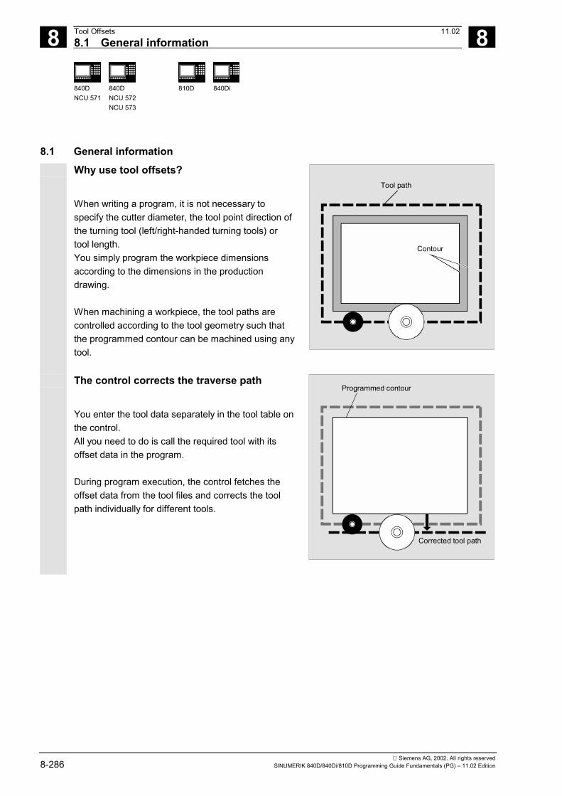
8 Tool Offsets 11.028.1 General information 8
840DNCU 571
840DNCU 572NCU 573
810D 840Di
Siemens AG, 2002. All rights reserved8-286 SINUMERIK 840D/840Di/810D Programming Guide Fundamentals (PG) – 11.02 Edition
8.1 General informationWhy use tool offsets?
When writing a program, it is not necessary tospecify the cutter diameter, the tool point direction ofthe turning tool (left/right-handed turning tools) ortool length.You simply program the workpiece dimensionsaccording to the dimensions in the productiondrawing.
When machining a workpiece, the tool paths arecontrolled according to the tool geometry such thatthe programmed contour can be machined using anytool.
Tool path
Contour
The control corrects the traverse path
You enter the tool data separately in the tool table onthe control.All you need to do is call the required tool with itsoffset data in the program.
During program execution, the control fetches theoffset data from the tool files and corrects the toolpath individually for different tools.
Corrected tool path
Programmed contour

8 11.02 Tool Offsets8.1 General information
8
840DNCU 571
840DNCU 572NCU 573
810D
840Di
Siemens AG, 2002. All rights reservedSINUMERIK 840D/840Di/810D Programming Guide Fundamentals (PG) – 11.02 Edition 8-287
Which tool offsets are stored in thecontrol's compensation memory?
In the compensation memory enter the following:• Geometrical dimensions: Length, radius.
They consist of several components (geometry,wear). The control computes the components toa certain dimension (e.g. overall length 1, totalradius). The respective overall dimensionbecomes effective when the compensationmemory is activated.These values are calculated in the axesaccording to the tool type and the current planeG17, G18, G19.
• Tool typeThe type determines which geometry axes areneeded and how they are calculated (drill ormilling tool or turning tool).
• Tool point direction
Tool parametersThe following section "List of tool types" describesthe individual tool parameters in the display. Therelevant tool parameters must be entered in theinput fields with "DP...". Any unneeded toolparameters must be set to "zero".
Radius
Leng
th
L1L2
F
R S
P
R = RadiusS = Cutting edge center
P = Tool tip
Caution
Values that have been entered once in thecompensation memory are included in theprocessing for each tool numbered.
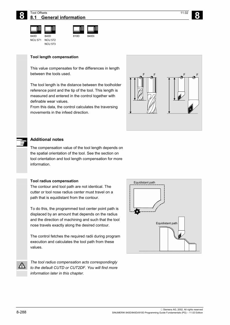
8 Tool Offsets 11.02 8.1 General information
8
840DNCU 571
840DNCU 572NCU 573
810D
840Di
Siemens AG, 2002. All rights reserved8-288 SINUMERIK 840D/840Di/810D Programming Guide Fundamentals (PG) – 11.02 Edition
Tool length compensation
This value compensates for the differences in lengthbetween the tools used.
The tool length is the distance between the toolholderreference point and the tip of the tool. This length ismeasured and entered in the control together withdefinable wear values.From this data, the control calculates the traversingmovements in the infeed direction.
F FFF
Additional notes
The compensation value of the tool length depends onthe spatial orientation of the tool. See the section ontool orientation and tool length compensation for moreinformation.
Tool radius compensationThe contour and tool path are not identical. Thecutter or tool nose radius center must travel on apath that is equidistant from the contour.
To do this, the programmed tool center point path isdisplaced by an amount that depends on the radiusand the direction of machining and such that the toolnose travels exactly along the desired contour.
The control fetches the required radii during programexecution and calculates the tool path from thesevalues.
Equidistant path
Equidistant path
The tool radius compensation acts correspondinglyto the default CUTD or CUT2DF. You will find moreinformation later in this chapter.

8 11.02 Tool Offsets8.2 List of tool types
8
840DNCU 571
840DNCU 572NCU 573
810D
840Di
Siemens AG, 2002. All rights reservedSINUMERIK 840D/840Di/810D Programming Guide Fundamentals (PG) – 11.02 Edition 8-289
8.2 List of tool typesCoding of tool types for milling tools
Group with type 1xy (milling tool):100 Milling tool according to CLDATA110 Ball end mill
(cylindrical die mill)111 Ball end mill
(conical die mill)120 End mill
(without fillet)121 End mill
(with fillet)130 Angle head cutter
(without fillet)131 Angle head cutter
(with fillet)140 Facing tool
FF'Entries intool parameters
DP3
DP6
DP21
Length 1 -Geometry
Radius -Geometry
Length -Adapter
Wear valuesas required
Set remainingvalues to 0
DP1 1xy
G17:
G18:
G19:
Length 1 in ZRadius in X/YLength 1 in YRadius in Z/XLength 1 in XRadius in Y/Z
F´-Toolholder reference point
F-Reference point adapter (with tool inserted =toolholder reference point)
Effect
Length 1
Length 1 Total
Length 1 Adapter
In SW 5 and higher, a fixed assignment is possible for G17, G18, G19 e.g. length1=X, length2=Z, length3=Y (see /FB1/ W1 Tool compens.)
145 Thread cutter150 Side mill151 Saw155 Bevel cutter
(without corner rounding)156 Bevel cutter
(with corner rounding)160 Drill and thread milling cutter
X
Y
Z
Z
X
Y
Y
Z
XWear valuesas required
Set remainingvalues to 0
Effect
G17:
G18:
G19:
Length 1 in YLength 2 in XLength 3 in ZRadius in X/YLength 1 in XLength 2 in ZLength 3 in YRadius in Z/X
Length 1 in ZLength 2 in YLength 3 in XRadius in Y/Z
Entries intool parametersDP1
DP6
DP3
DP21DP22DP23
1xy
Length 1 - Geometry
Radius - Geometry
Length 1 - Base
Length 2 - Base
Length 3 - Base
F'
F
Base dimensionLength 3
Base dimension Length 2
Base
dim
.Le
ngth
1F´- Toolholder reference pointF - Toolholder reference point
Radius
In SW 5 and higher, a fixed assignment is possible for G17, G18, G19e.g. length 1 = X, length 2 = Y, length 3 = Z (see /FB1/W1 Tool compensation)

8 Tool Offsets 11.02 8.2 List of tool types
8
840DNCU 571
840DNCU 572NCU 573
810D
840Di
Siemens AG, 2002. All rights reserved8-290 SINUMERIK 840D/840Di/810D Programming Guide Fundamentals (PG) – 11.02 Edition
Coding of tool types for drillsGroup type 2xy (drills):200 Twist drill205 Solid drill210 Boring rod220 Center drill230 Countersink231 Counterbore240 Tapping regular thread241 Tapping fine thread242 Tapping Whitworth thread250 Reamer
F
Entries intool parametersDP1
DP3
2xy
Length 1
Wear valuesas required
Set remaining values to 0
G17: Length 1 in ZLength 1 in Y
Length 1 in X
G18:
G19:
F - toolholder reference point
Length 1
Effect
Coding of tool types for grinding toolsGroup type 4xy (grinding tools):400 Surface grinding wheel401 Surface grinding wheel with
monitoring403 Surface grinding wheel with
monitoring without tool basedimension for grinding wheelperipheral speed GWPS
410 Facing wheel411 Facing wheel with monitoring413 Facing wheel with monitoring
without tool base dimension forgrinding wheel peripheral speedGWPS
490 Dresser
F'
F
Entries intool parametersDP1
DP3DP4DP6
403
Length 1Length 2Radius
TPG1TPG2
TPG4TPG5TPG6TPG7TPG8
TPG3
TPG9
Spindle numberChaining ruleMinimum wheel radiusMinimum wheel widthCurrent wheel widthMaximum speedMax. peripheral speedAngle of the inclined wheelParameter no. f. radius calculationWear values
as required
Set remaining values to 0
Effect
G17:
G18:
G19:
Length 1 in YLength 2 in XRadius in X/YLength 1 in XLength 2 in ZRadius in Z/XLength 1 in ZLength 2 in YRadius in Y/Z
F - Toolholder reference point
Radius
GeometryLength 2
Base Length 2
Base
Leng
th 1
Geo
met
ryLe
ngth
1
∝
DP2 Position*)
*) Tool nose position
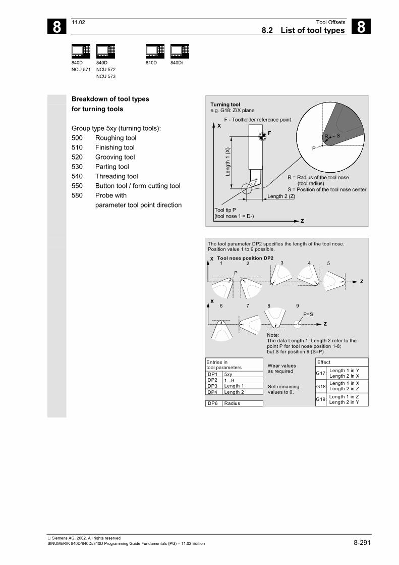
8 11.02 Tool Offsets8.2 List of tool types
8
840DNCU 571
840DNCU 572NCU 573
810D
840Di
Siemens AG, 2002. All rights reservedSINUMERIK 840D/840Di/810D Programming Guide Fundamentals (PG) – 11.02 Edition 8-291
Breakdown of tool typesfor turning tools
Group type 5xy (turning tools):500 Roughing tool510 Finishing tool520 Grooving tool530 Parting tool540 Threading tool550 Button tool / form cutting tool580 Probe with
parameter tool point direction
Z
XF R S
P
Turning toole.g. G18: Z/X plane
F - Toolholder reference point
Length 2 (Z)
Tool tip P(tool nose 1 = Dn)
Leng
th 1
(X)
R = Radius of the tool nose (tool radius)S = Position of the tool nose center
Z
X1 2 4 5
P
Z
X76 8 9
P=S
3
Entries in tool parametersDP1DP2DP3DP4
DP6
5xy1...9Length 1Length 2
Radius
Effect
G17:
G18:
G19:
Length 1 in YLength 2 in XLength 1 in XLength 2 in ZLength 1 in ZLength 2 in Y
Wear values as required
Set remainingvalues to 0.
The tool parameter DP2 specifies the length of the tool nose.Position value 1 to 9 possible.
Tool nose position DP2
Note:The data Length 1, Length 2 refer to the point P for tool nose position 1-8;but S for position 9 (S=P)
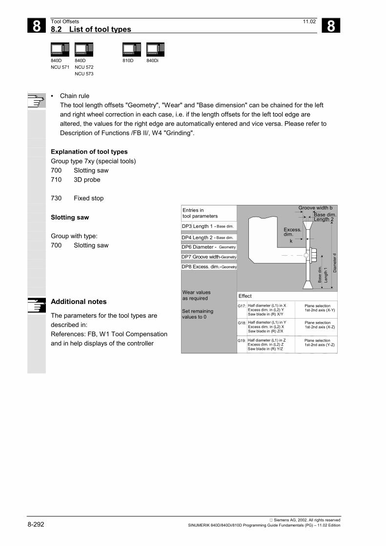
8 Tool Offsets 11.02 8.2 List of tool types
8
840DNCU 571
840DNCU 572NCU 573
810D
840Di
Siemens AG, 2002. All rights reserved8-292 SINUMERIK 840D/840Di/810D Programming Guide Fundamentals (PG) – 11.02 Edition
• Chain ruleThe tool length offsets "Geometry", "Wear" and "Base dimension" can be chained for the leftand right wheel correction in each case, i.e. if the length offsets for the left tool edge arealtered, the values for the right edge are automatically entered and vice versa. Please refer toDescription of Functions /FB II/, W4 "Grinding".
Explanation of tool typesGroup type 7xy (special tools)700 Slotting saw710 3D probe
730 Fixed stop
Slotting saw
Group with type:700 Slotting saw
Additional notes
The parameters for the tool types aredescribed in:References: FB, W1 Tool Compensationand in help displays of the controller
k
Leng
th 1 Dia
met
er d
Entries intool parameters
DP3 Length 1 - Base dim.
DP4 Length 2 - Base dim.
DP6 Diameter -
DP7 Groove width-
DP8 Excess. dim.-
Geometry
Geometry
Geometry
Wear valuesas required
Set remainingvalues to 0
Effect
Excess. dim.
Groove width bBase dim.Length 2
Base
dim
.
Half diameter (L1) in XExcess dim. in (L2) YSaw blade in (R) X/Y
Plane selection1st-2nd axis (X-Y)
G17:
Half diameter (L1) in YExcess dim. in (L2) XSaw blade in (R) Z/X
Plane selection1st-2nd axis (X-Z)
G18:
Half diameter (L1) in ZExcess dim. in (L2) ZSaw blade in (R) Y/Z
Plane selection1st-2nd axis (Y-Z)
G19:

8 11.02 Tool Offsets8.3 Tool selection/tool call T
8
840DNCU 571
840DNCU 572NCU 573
810D
840Di
Siemens AG, 2002. All rights reservedSINUMERIK 840D/840Di/810D Programming Guide Fundamentals (PG) – 11.02 Edition 8-293
8.3 Tool selection/tool call T
8.3.1 Tool change with M06 (mill)Programming
Tx orT=x orTy=X
T0
M06
Explanation of the parameters
Tx or T=x or
Ty=xTool selection with T No.
x x stands for T No.: 0-32000T0 Tool deselectionM06 Tool change, then tool T… and tool offset D are active
Number of tools: 600, as of SW 5: 1200(depending on the machine manufacturer's configuration)
Function
Tool selection takes place when the T word isprogrammed.1. Tool selection without TOOLMAN
• Free selection of D No. (flat D No.) relative tocutting edges T... [8-digit]
1D 2D 3D • • • D32000
• Tabular D No.: D1 ... D8
T1 1D 2D 3D • • • D8 T2 1D T3 1D T6 1D 2D 3D T9 1D 2D 1D 3D • • T... 1D 2D
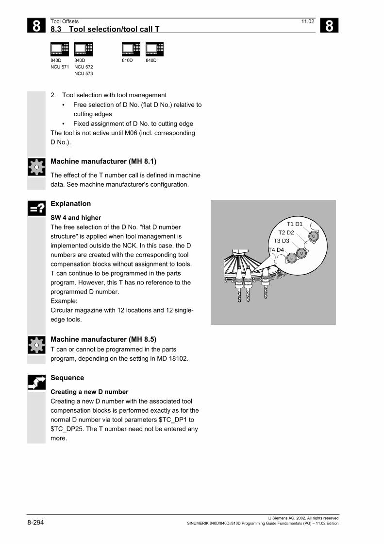
8 Tool Offsets 11.02 8.3 Tool selection/tool call T
8
840DNCU 571
840DNCU 572NCU 573
810D
840Di
Siemens AG, 2002. All rights reserved8-294 SINUMERIK 840D/840Di/810D Programming Guide Fundamentals (PG) – 11.02 Edition
2. Tool selection with tool management• Free selection of D No. (flat D No.) relative to
cutting edges• Fixed assignment of D No. to cutting edge
The tool is not active until M06 (incl. correspondingD No.).
Machine manufacturer (MH 8.1)
The effect of the T number call is defined in machinedata. See machine manufacturer's configuration.
Explanation
SW 4 and higher The free selection of the D No. "flat D numberstructure" is applied when tool management isimplemented outside the NCK. In this case, the Dnumbers are created with the corresponding toolcompensation blocks without assignment to tools. T can continue to be programmed in the partsprogram. However, this T has no reference to theprogrammed D number. Example: Circular magazine with 12 locations and 12 single-edge tools.
T4 D4
T3 D3T2 D2
T1 D1
Machine manufacturer (MH 8.5) T can or cannot be programmed in the partsprogram, depending on the setting in MD 18102.
Sequence
Creating a new D number Creating a new D number with the associated toolcompensation blocks is performed exactly as for thenormal D number via tool parameters $TC_DP1 to$TC_DP25. The T number need not be entered anymore.

8 11.02 Tool Offsets8.3 Tool selection/tool call T
8
840DNCU 571
840DNCU 572NCU 573
810D
840Di
Siemens AG, 2002. All rights reservedSINUMERIK 840D/840Di/810D Programming Guide Fundamentals (PG) – 11.02 Edition 8-295
Machine manufacturer (MH 8.6) The type of D number management is defined inthe machine data. There are two settings availablefor programming D numbers in the "flat D numberstructure":• Flat D number structure with direct programming• Flat D number structure with indirect programming
(SW5 and higher).
8.3.2 Tool change with T command (rotate)Programming
Tx or T=xor Ty=XT0Explanation of the parameters
Tx or T=x or
Ty=xTool selection with T No. including tool change (active tool), tool offset isactive
x x stands for T No.: 0-32000T0 Tool deselection
Number of tools: 600, as of SW 5: 1200(depending on the machine manufacturer's configuration)
Function
A direct tool change takes place when the T word isprogrammed.1. Tool selection without TOOLMAN
• Free selection of D No. (flat D No.) relative tocutting edges
• Tabular D No.: D1 ... D8
2. Tool selection with tool management• Free selection of D No. (flat D No.) relative to
cutting edges• Fixed assignment of D No. to the cutting edges

8 Tool Offsets 11.02 8.3 Tool selection/tool call T
8
840DNCU 571
840DNCU 572NCU 573
810D
840Di
Siemens AG, 2002. All rights reserved8-296 SINUMERIK 840D/840Di/810D Programming Guide Fundamentals (PG) – 11.02 Edition
Machine manufacturer (MH 8.1)
The effect of the T number call is defined in machinedata. See machine manufacturer's configuration.

8 11.02 Tool Offsets8.4 Tool offset D
8
840DNCU 571
840DNCU 572NCU 573
810D
840Di
Siemens AG, 2002. All rights reservedSINUMERIK 840D/840Di/810D Programming Guide Fundamentals (PG) – 11.02 Edition 8-297
8.4 Tool offset D
Programming
D...
D0 Explanation of the parameters
Dx Tool offset number: without T 1–8 or
with T (as of SW5) 1–12x x stands for the D No.: 0-32000D0 Deselect tool offset, no offsets active
Function
It is possible to assign between 1 and 8 (12) tool noseswith different tool compensation blocks to a specifictool. This allows you to define various cutting edges forone tool, which you can call as required in the NCprogram. Different offset values could be used, forexample, for the left and right cutting edge of agrooving tool. When D is called, the tool lengthcompensation for a specific tool nose is activated.When D0 is programmed, offsets for the tool areineffective. If no D word is programmed, the defaultsetting from the machine data is valid for tool change. Tool length compensations take immediate effectif the D number is programmed.A tool radius offset must also be activated by G41/G42.
N40...D6 Z-5N30 G1 D1 X10
Z
X
N20 G0N10 T2
X35 Z-20
-5-20
10
8 Tool Offsets 11.02 8.4 Tool offset D
8
840DNCU 571
840DNCU 572NCU 573
810D
840Di
Siemens AG, 2002. All rights reserved8-298 SINUMERIK 840D/840Di/810D Programming Guide Fundamentals (PG) – 11.02 Edition
Machine manufacturer (MH 8.10)
Default setting by machine manufacturer, e.g.: D1,i.e. without D programming, D1 is activated/selectedwhen the tool is changed (M06).The tools are activated with T programming (seemachine manufacturer's specifications).
The compensation is performed with the firstprogrammed traversing of the respective tool lengthcompensation axis.
The required D number must always be programmedbefore the tool length compensation can be selected.The tool length compensation is also effective if thecompensation is set in the machine data.
Working without tool offsets, D0
D0 is the default setting after start-up of the control.If you do not enter a D number you work without atool offset.
The modified values do not become active until theT or D number is next programmed.
Programming example(turning: tool change with T command)
N10 T1 D1 Tool T1 is replaced and activated withassociated D1
N11 G0 X... Z... The length offsets are traversed N50 T4 D2 Load tool T4, D2 from T4 is active ... N70 G0 Z... D1 Other cutting edge D1 is activated for tool
T4

8 11.02 Tool Offsets8.5 Tool selection T with tool management 8
840DNCU 571
840DNCU 572NCU 573
810D 840Di
Siemens AG, 2002. All rights reservedSINUMERIK 840D/840Di/810D Programming Guide Fundamentals (PG) – 11.02 Edition 8-299
8.5 Tool selection T with tool managementExample
A magazine has locations 1 to 20:Location 1 is taken up by drilling tool, duplo no.=1,T15, disabledLocation 2 is not occupiedLocation 3 is taken up by drilling tool, duplo no.=2,T10, enabledLocation 4 is taken up by drilling tool, duplo no.=3,T1, activeLocations 5 to 20 are not occupied
1. Programming of T1 or T=1:Location number 1 of the magazine associated withthe toolholder is selected.
12
345
20
2. Identifier "Drill" of tool in location is determined.The selection procedure is completed.
3. It is followed by the tool change procedure:On completion of tool search strategy "Take the firstavailable tool from group", T10 is loaded becauseT15 is disabled.
4. On completion of tool search strategy "Take thefirst tool with status "active" from group", T1 isloaded.
8.5.1 Turning machine with circular magazine
Programming
The following procedure usually applies: T = slot or T = identifier
T triggers the tool change D... Tool offset number: 1...32000 (max., see machine manufacturer's specifications)
D0: no offset active!
8 Tool Offsets 11.028.5 Tool selection T with tool management 8
840DNCU 571
840DNCU 572NCU 573
810D 840Di
Siemens AG, 2002. All rights reserved8-300 SINUMERIK 840D/840Di/810D Programming Guide Fundamentals (PG) – 11.02 Edition
Sequence
The following procedure usually applies:T = slot,
T triggers the tool changeD = offsets 1 to n (n ≤ 32000)If the relative D No. structure with internal referenceto the associated tools is used, replacement toolmanagement and monitoring function are possible.
Note: When calling the tool, the• tool offset values stored under a D number must
be activated.• the appropriate working plane (system setting:
G18) must be programmed. This ensures that thelength compensation is assigned to the correctaxis.
If the selected magazine location is not occupied in aselected magazine location, the tool command has thesame effect as T0. Selection of the unoccupiedmagazine location can be used for positioning theempty location.
Machine manufacturer (MH 8.2)
Tool management: See machine manufacturer'sconfiguration.
8.5.2 Milling machine with chain magazine
Sequence
The following procedure usually applies: T = "Ident" or T = No. or T=Duplo no.,
M06 triggers the tool change D = offset 1 to nth edge no.
(n ≤ 8, SW 5:12 and higher) Selection:• With integrated tool management (inside NC)
relative D no. structure with internal reference tothe associated tools (e.g. replacement toolmanagement and monitoring function possible)

8 11.02 Tool Offsets8.5 Tool selection T with tool management 8
840DNCU 571
840DNCU 572NCU 573
810D 840Di
Siemens AG, 2002. All rights reservedSINUMERIK 840D/840Di/810D Programming Guide Fundamentals (PG) – 11.02 Edition 8-301
• Without integrated tool management (outside NC)flat D no. structure without internal reference toassociated tools
Machine manufacturer (MH 8.3)
Tool management: See machine manufacturer'sconfiguration.
Tool magazine The T number preselects the tool, e.g. positioningthe magazine to the tool change position. The actualtool change is triggered by M6. The M number forthe tool change is set via the machine data. (Seealso the section on miscellaneous functions M). Onlythen do the new tool offsets apply.
Note: When calling the tool, the• Tool offset values stored under a D number must
be activated.• The appropriate working plane (system setting:
G17) must be programmed. This ensures that thelength compensation is assigned to the correctaxis.
If the selected magazine location is not occupied in aselected magazine location, the tool command has thesame effect as T0. Selection of the unoccupiedmagazine location can be used for positioning theempty location.

8 Tool Offsets 11.028.6 Tool offset call D with tool management 8
840DNCU 571
840DNCU 572NCU 573
810D 840Di
Siemens AG, 2002. All rights reserved8-302 SINUMERIK 840D/840Di/810D Programming Guide Fundamentals (PG) – 11.02 Edition
8.6 Tool offset call D with tool management
Machine manufacturer (MH 8.4)
See machine manufacturer's configuration.
8.6.1 Turning machine with circular magazine
Programming
The following procedure usually applies: T = slot or T = identifier or T=Duplo no.,
T triggers the tool change D... Tool offset number: 1...32000 (max., see machine manufacturer's specifications)
D0: no offset active! Direct, absolute programming
Programming is performed with the D numberstructure. The compensation blocks to be used arecalled directly via their D number. Assignment of the D number to a specific tool doesnot take place in the NC kernel.
Machine manufacturer (MH 8.7)
Direct programming is defined by MD.
Programming example
$MC_TOOL_CHANGE_MODE=0 MD20270 CUTTING_EDGE_DEFAULT = 1 ... D92 Traverse with tool offsets from D92 ... T17 Select T17, traverse with tool offsets from D92 ... D16 Traverse with tool offsets from D16 ... D32000 Traverse with tool offsets from D32000 ... T29000500 Select T29000500, traverse with tool offsets from
D32000 ... D1 Traverse with tool offsets from D1

8 11.02 Tool Offsets8.6 Tool offset call D with tool management 8
840DNCU 571
840DNCU 572NCU 573
810D 840Di
Siemens AG, 2002. All rights reservedSINUMERIK 840D/840Di/810D Programming Guide Fundamentals (PG) – 11.02 Edition 8-303
8.6.2 Milling machine with chain magazine
Sequence
The following procedure usually applies: T= identifier or T= identifier or
T= Duplo no.,M06 triggers the tool change
D = offset 1 to nth edge no.(n ≤ 8 or 12, SW 5 and higher)
Selection:• with integrated tool management (inside NC)
relative D no. structure with internal reference tothe associated tools (e.g. replacement toolmanagement and monitoring function possible)
• without integrated tool management (outside NC)flat D no. structure without internal reference toassociated tools
Machine manufacturer (MH 8.9)
Tool management: See machine manufacturer'sspecifications
Function
It is possible to assign between 1 and 8 (12) tool noseswith different tool compensation blocks to a specifictool. When D is called, the tool length compensation fora specific tool nose is activated. When D0 isprogrammed, offsets for the tool are ineffective. If no Dword is programmed, the default setting from themachine data is valid for tool change. Tool length compensations take immediate effect if theD number is programmed.A tool radius offset must also be activated by G41/G42.

8 Tool Offsets 11.028.7 Make active tool offset operative immediately 8
840DNCU 571
840DNCU 572NCU 573
810D 840Di
Siemens AG, 2002. All rights reserved8-304 SINUMERIK 840D/840Di/810D Programming Guide Fundamentals (PG) – 11.02 Edition
8.7 Make active tool offset operative immediatelyFunction
MD $MM_ACTIVATE_SEL_USER_DATA can beused to define that the active tool offset can beactivated immediately if the parts program is in"stop" mode.
/FB/, Description of Functions, Fundamentals, K2Axes, Coordinate Systems...
Danger
The offset is backed out the next time the partsprogram is started.

8 11.02 Tool Offsets8.8 Tool radius compensation, G40, G41, G42 8
840DNCU 571
840DNCU 572NCU 573
810D 840Di
Siemens AG, 2002. All rights reservedSINUMERIK 840D/840Di/810D Programming Guide Fundamentals (PG) – 11.02 Edition 8-305
8.8 Tool radius compensation, G40, G41, G42Programming
G40
G41
G42
OFFN=
Explanation of the commands
G40 Deactivate tool radius compensationG41 Activate tool radius compensation; tool operates in machining direction to
the left of the contour.G42 Activate tool radius compensation, tool operates in machining direction to
the right of the contour.OFFN= Allowance on the programmed contour (normal contour offset)
Function
When tool radius compensation is active, the controlautomatically calculates the equidistant tool paths fordifferent tools.
You can generate equidistant paths with OFFN, e.g.for rough-finishing.
Equidistant path
Equidistant path

8 Tool Offsets 11.028.8 Tool radius compensation, G40, G41, G42 8
840DNCU 571
840DNCU 572NCU 573
810D 840Di
Siemens AG, 2002. All rights reserved8-306 SINUMERIK 840D/840Di/810D Programming Guide Fundamentals (PG) – 11.02 Edition
Sequence
The control requires the following information inorder to calculate the tool paths:
1. Tool number T/edge number DWhere appropriate, a tool offset number D is alsorequired. The distance between the tool path and theworkpiece contour is calculated from the cutter and tooledge radii and the tool point direction parameters.With flat D number structure it is only necessary toprogram the D number.
2. Direction of machining G41, G42From this information, the control detects the directionin which the tool path is to be displaced.
Note:A negative offset value is the same as a change ofoffset side (G41, G42).
G42
G42
G41
G41
G41
3. Working plane G17 toG19From this information, the control detects the planeand therefore the axis directions for compensation.
Example: Milling cuttersN10 G17 G41 …
The tool radius compensation is performed in the X/Yplane, the tool length compensation is performed in theZ direction.
Note:On 2-axis machines, the tool radius compensation isonly possible in "real" planes, in general with G18(see tool length compensation table).
Milling:
+Z +X
+YLength Length
Radius
Radius Radius

8 11.02 Tool Offsets8.8 Tool radius compensation, G40, G41, G42 8
840DNCU 571
840DNCU 572NCU 573
810D 840Di
Siemens AG, 2002. All rights reservedSINUMERIK 840D/840Di/810D Programming Guide Fundamentals (PG) – 11.02 Edition 8-307
Tool length compensationThe wear parameter assigned to the diameter axison tool selection can be defined as the diametervalue (MD). This assignment is not automaticallyaltered when the plane is subsequently changed. Todo this, the tool must be selected again after theplane has been changed.
Turning:
Z
X
Y
Radius
Length
Radiu
s
Leng
th
Length 2
Length 1

8 Tool Offsets 11.028.8 Tool radius compensation, G40, G41, G42 8
840DNCU 571
840DNCU 572NCU 573
810D 840Di
Siemens AG, 2002. All rights reserved8-308 SINUMERIK 840D/840Di/810D Programming Guide Fundamentals (PG) – 11.02 Edition
Activation/deactivation of tool radiuscompensationA travel command must be programmed with G0 orG1 in an NC block with G40, G41 or G42. This travelcommand must specify at least one axis in theselected working plane.
If you only specify one axis on activation, the lastposition on the second axis is added automaticallyand traversed with both axes.
Example:N10 G0 X50 T1 D1
N20 G1 G41 Y50 F200
N30 Y100
Only tool length compensation is activated in blockN10. X50 is approached without compensation.In block N20, the radius compensation is activated,point X50/Y50 is approached with compensation.
Milling:
X
Y
50
N10
N20
50
Compensation on Y
Compensation on X
Example:N20 T1 D1
N30 G0 X100 Z20
N40 G42 X20 Z1
N50 G1 Z-20 F0.2
Only tool length compensation is activated in blockN20. X100 Z20 is approached without compensationin block N30.In block N40, the radius compensation is activated,point X20/Z1 is approached with compensation.
Turning:
Z
X
Ø 2
0
Ø 1
0020
20 1
Using NORM and KONT you can determine the toolpath for activation/deactivation of compensation mode(see Section 8.10 Contour approach and retraction,NORM, KONT, G450, G451).

8 11.02 Tool Offsets8.8 Tool radius compensation, G40, G41, G42 8
840DNCU 571
840DNCU 572NCU 573
810D 840Di
Siemens AG, 2002. All rights reservedSINUMERIK 840D/840Di/810D Programming Guide Fundamentals (PG) – 11.02 Edition 8-309
Changing the direction of compensationG41/G42, G42/G41 can be programmed without anintermediate G40.
Changing the working planeIt is not possible to change the working plane G17 toG19 when G41/G42 is active.
G41
G42
Changing the offset number DThe offset number D can be changed in compensationmode.A modified tool radius is active with effect from theblock in which the new D number is programmed.
The radius change or compensation movement isperformed across the entire block and only reachesthe new equidistance at the programmed end point.
With linear movements, the tool travels along aninclined path between the starting point and endpoint; with circular interpolation spiral movementsare produced.
Changing the tool radiusThis can be achieved, for example, using systemvariables. The execution is the same as for changesin the D number.
NC block with modified radius compensation
Traverse path
Programmed path
The modified values only take effect the next timeT or D is programmed. The change only applies witheffect from the next block.
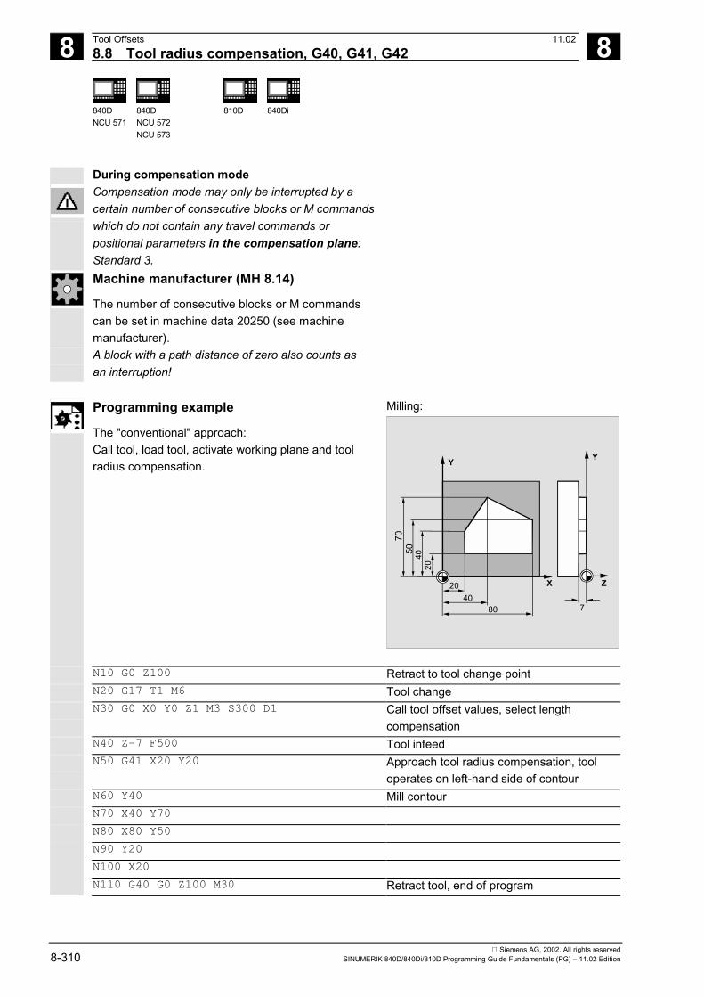
8 Tool Offsets 11.028.8 Tool radius compensation, G40, G41, G42 8
840DNCU 571
840DNCU 572NCU 573
810D 840Di
Siemens AG, 2002. All rights reserved8-310 SINUMERIK 840D/840Di/810D Programming Guide Fundamentals (PG) – 11.02 Edition
During compensation modeCompensation mode may only be interrupted by acertain number of consecutive blocks or M commandswhich do not contain any travel commands orpositional parameters in the compensation plane:Standard 3.Machine manufacturer (MH 8.14)
The number of consecutive blocks or M commandscan be set in machine data 20250 (see machinemanufacturer).A block with a path distance of zero also counts asan interruption!
Programming example
The "conventional" approach:Call tool, load tool, activate working plane and toolradius compensation.
Milling:
X
Y
20
740
80
Z
Y
204050
70
N10 G0 Z100 Retract to tool change pointN20 G17 T1 M6 Tool changeN30 G0 X0 Y0 Z1 M3 S300 D1 Call tool offset values, select length
compensationN40 Z-7 F500 Tool infeedN50 G41 X20 Y20 Approach tool radius compensation, tool
operates on left-hand side of contourN60 Y40 Mill contourN70 X40 Y70
N80 X80 Y50
N90 Y20
N100 X20
N110 G40 G0 Z100 M30 Retract tool, end of program

8 11.02 Tool Offsets8.8 Tool radius compensation, G40, G41, G42 8
840DNCU 571
840DNCU 572NCU 573
810D 840Di
Siemens AG, 2002. All rights reservedSINUMERIK 840D/840Di/810D Programming Guide Fundamentals (PG) – 11.02 Edition 8-311
Turning:
4
16
503530
62
60
57
40
20
18
15
12
80
70
45°
R3
R3R3
R8
R10
Z
X
%_N_1001_MPF ;Program nameN5 G0 G53 X280 Z380 D0 ;Start pointN10 TRANS X0 Z250 ;Zero offsetN15 LIMS=4000 ;Speed limitation (G96)N20 G96 S250 M3 ;Select constant feedN25 G90 T1 D1 M8 ;Select tool and offsetN30 G0 G42 X-1.5 Z1 ;Activate tool with tool radius compensationN35 G1 X0 Z0 F0.25
N40 G3 X16 Z-4 I0 K-10 ;Rotate radius 10N45 G1 Z-12

8 Tool Offsets 11.028.8 Tool radius compensation, G40, G41, G42 8
840DNCU 571
840DNCU 572NCU 573
810D 840Di
Siemens AG, 2002. All rights reserved8-312 SINUMERIK 840D/840Di/810D Programming Guide Fundamentals (PG) – 11.02 Edition
N50 G2 X22 Z-15 CR=3 ;Rotate radius 3N55 G1 X24
N60 G3 X30 Z-18 I0 K-3 ;Rotate radius 3N65 G1 Z-20
N70 X35 Z-40
N75 Z-57
N80 G2 X41 Z-60 CR=3 ;Rotate radius 3N85 G1 X46
N90 X52 Z-63
N95 G0 G40 G97 X100 Z50 M9 ;Deselect tool radius compensation andapproach tool change location
N100 T2 D2 ;Call up tool and select offsetN105 G96 S210 M3 ;Select constant cutting speedN110 G0 G42 X50 Z-60 M8 ;Activate tool with tool radius compensationN115 G1 Z-70 F0.12 ;Rotate diameter 50N120 G2 X50 Z-80 I6.245 K-5 ;Rotate radius 8N125 G0 G40 X100 Z50 M9 ;Retract tool and deselect tool radius
compensationN130 G0 G53 X280 Z380 D0 M5 ;Move to tool change locationN135 M30 ;End of program

8 11.02 Tool Offsets8.9 Approach and retract from contour, NORM, KONT, G450, G451 8
840DNCU 571
840DNCU 572NCU 573
810D 840Di
Siemens AG, 2002. All rights reservedSINUMERIK 840D/840Di/810D Programming Guide Fundamentals (PG) – 11.02 Edition 8-313
8.9 Approach and retract from contour, NORM, KONT, G450, G451Programming
NORM
KONTG450
KONT G451
Explanation of the parameters
NORM The tool travels directly in a straight line and is positioned perpendicular to thecontour point
KONT The tool traverses the contour point according to the programmed cornerbehavior G450 or G451
Function
You can use these functions to adapt the approachand retraction paths, for example, according to thedesired contour or shape of the blanks.
Sequence
Direct approach to perpendicular position,G41, G42, NORMThe tool travels in a straight line directly to thecontour and is positioned perpendicular to the pathtangent at the starting point.
Selection of the approach pointWhen NORM is active, the tool travels directly to thecompensated starting position irrespective of theapproach angle programmed for the travel movement(see diagram).
G42
Compensatedtool path
Compensatedtool path
Tangent
Radius
G42
Machine manufacturer (MH 8.15)
Initial status see machine manufacturer'sspecifications.

8 Tool Offsets 11.028.9 Approach and retract from contour, NORM, KONT, G450, G451 8
840DNCU 571
840DNCU 572NCU 573
810D 840Di
Siemens AG, 2002. All rights reserved8-314 SINUMERIK 840D/840Di/810D Programming Guide Fundamentals (PG) – 11.02 Edition
Deactivate compensation mode, G40, NORMThe tool is positioned perpendicular to the lastcompensated path end point and then travels directlyin a straight line to the next uncompensated position,e.g. to the tool change location.
Choosing the retraction pointWhen NORM is active, the tool travels directly to theuncompensated position irrespective of the approachangle programmed for the travel movement (seediagram).
G41G4
1
RadiusTangent
The following applies to approach and retractionmovements:You should make allowance for the modified angle oftravel when programming in order to avoid collisions.
Travel round contour at starting point,G41, G42, KONTTwo cases are distinguished here:
Starting point lies in front of the contourThe approach strategy is the same as with NORM.The path tangent at the starting point serves as adividing line between the front and rear of thecontour.
Starting point
Behind contour
In front of contour
Path tangent
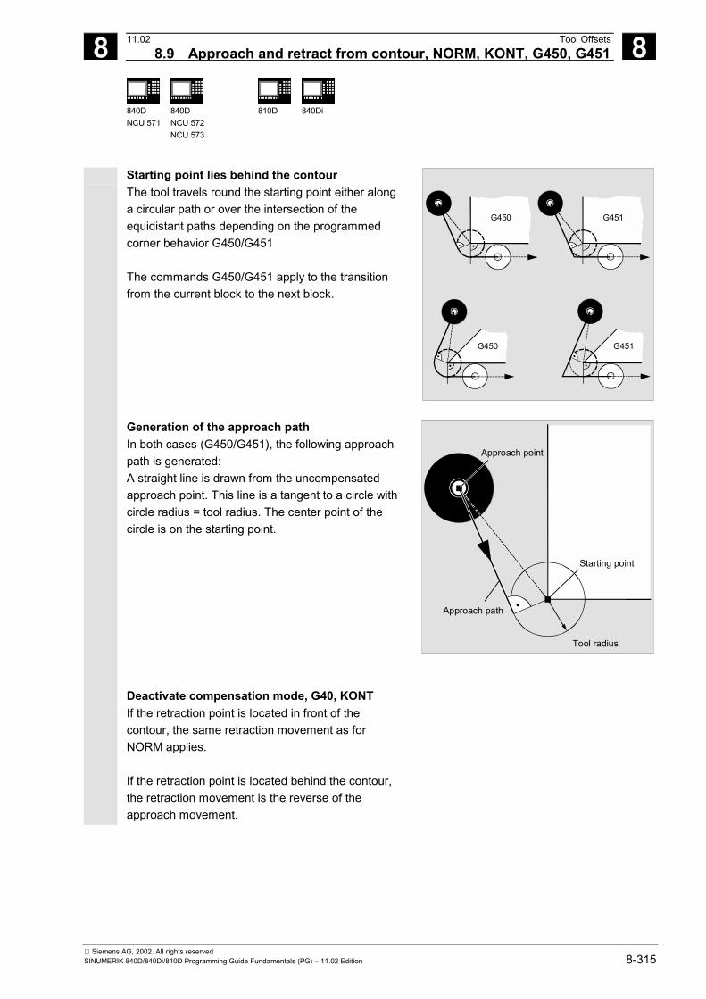
8 11.02 Tool Offsets8.9 Approach and retract from contour, NORM, KONT, G450, G451 8
840DNCU 571
840DNCU 572NCU 573
810D 840Di
Siemens AG, 2002. All rights reservedSINUMERIK 840D/840Di/810D Programming Guide Fundamentals (PG) – 11.02 Edition 8-315
Starting point lies behind the contourThe tool travels round the starting point either alonga circular path or over the intersection of theequidistant paths depending on the programmedcorner behavior G450/G451
The commands G450/G451 apply to the transitionfrom the current block to the next block.
G450
G450 G451
G451
Generation of the approach pathIn both cases (G450/G451), the following approachpath is generated:A straight line is drawn from the uncompensatedapproach point. This line is a tangent to a circle withcircle radius = tool radius. The center point of thecircle is on the starting point.
Approach point
Approach path
Starting point
Tool radius
Deactivate compensation mode, G40, KONTIf the retraction point is located in front of thecontour, the same retraction movement as forNORM applies.
If the retraction point is located behind the contour,the retraction movement is the reverse of theapproach movement.
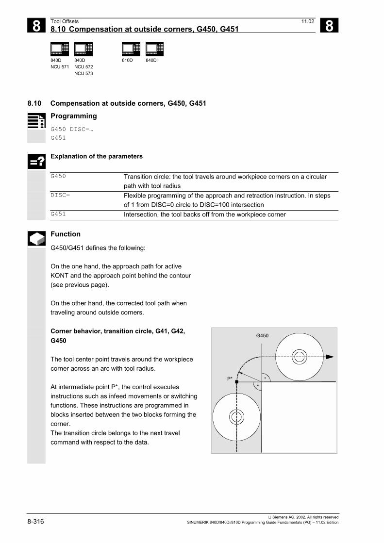
8 Tool Offsets 11.028.10 Compensation at outside corners, G450, G451 8
840DNCU 571
840DNCU 572NCU 573
810D 840Di
Siemens AG, 2002. All rights reserved8-316 SINUMERIK 840D/840Di/810D Programming Guide Fundamentals (PG) – 11.02 Edition
8.10 Compensation at outside corners, G450, G451Programming
G450 DISC=…
G451
Explanation of the parameters
G450 Transition circle: the tool travels around workpiece corners on a circularpath with tool radius
DISC= Flexible programming of the approach and retraction instruction. In stepsof 1 from DISC=0 circle to DISC=100 intersection
G451 Intersection, the tool backs off from the workpiece corner
Function
G450/G451 defines the following:
On the one hand, the approach path for activeKONT and the approach point behind the contour(see previous page).
On the other hand, the corrected tool path whentraveling around outside corners.
Corner behavior, transition circle, G41, G42,G450
The tool center point travels around the workpiececorner across an arc with tool radius.
At intermediate point P*, the control executesinstructions such as infeed movements or switchingfunctions. These instructions are programmed inblocks inserted between the two blocks forming thecorner.The transition circle belongs to the next travelcommand with respect to the data.
G450
P*

8 11.02 Tool Offsets8.10 Compensation at outside corners, G450, G451 8
840DNCU 571
840DNCU 572NCU 573
810D 840Di
Siemens AG, 2002. All rights reservedSINUMERIK 840D/840Di/810D Programming Guide Fundamentals (PG) – 11.02 Edition 8-317
Corner behavior, selectable transitionsG41, G42, G450 DISC=…
DISC distorts the transition circle, thus creatingsharp contour corners.
The values have the following meanings:DISC=0 transition circleDISC=100 intersection of the equidistant paths(theoretical value)DISC is programmed in steps of 1.
When DISC values greater than 0 are specified,intermediate circles are shown with a magnifiedheight – the result is transition ellipses or parabolasor hyperbolas.
DISC 100
DISC 0
An upper limit can be defined in machine data –generally DISC=50.
DISC=… is effective only when G450 is called, but canbe programmed in a preceding block without G450.Both commands are modal.
Path action, depending on DISC valuesand contour angle
Depending on the angle of the contour that istraversed, with acute contour angles and high DISCvalues the tool is lifted off the contour at the corners.With angles of 120° and more, the contour istraversed evenly (see adjacent table).
030 60 90 120 150 180
0.2
0.45040302010
0.6
0.8
1.0
DISC=DISC=100
S/R
R - Tool radius S - Traversed overshootS/R - Scaled overshoot (with reference to the tool radius)
Contour angle (degrees)
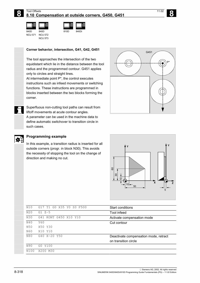
8 Tool Offsets 11.028.10 Compensation at outside corners, G450, G451 8
840DNCU 571
840DNCU 572NCU 573
810D 840Di
Siemens AG, 2002. All rights reserved8-318 SINUMERIK 840D/840Di/810D Programming Guide Fundamentals (PG) – 11.02 Edition
Corner behavior, intersection, G41, G42, G451
The tool approaches the intersection of the twoequidistant which lie in the distance between the toolradius and the programmed contour. G451 appliesonly to circles and straight lines.At intermediate point P*, the control executesinstructions such as infeed movements or switchingfunctions. These instructions are programmed inblocks inserted between the two blocks forming thecorner.
Superfluous non-cutting tool paths can result fromliftoff movements at acute contour angles.A parameter can be used in the machine data todefine automatic switchover to transition circle insuch cases.
G451
P*
Programming example
In this example, a transition radius is inserted for alloutside corners (progr. in block N30). This avoidsthe necessity of stopping the tool on the change ofdirection and making no cut.
X
Y
1050
5
Z
Y
10
3060
N10 G17 T1 G0 X35 Y0 Z0 F500 Start conditionsN20 G1 Z-5 Tool infeedN30 G41 KONT G450 X10 Y10 Activate compensation modeN40 Y60
N50 X50 Y30
N60 X10 Y10
Cut contour
N80 G40 X-20 Y50 Deactivate compensation mode, retracton transition circle
N90 G0 Y100
N100 X200 M30

8 11.02 Tool Offsets8.11 Smooth approach and retraction 8
840DNCU 571
840DNCU 572NCU 573
810D 840Di
Siemens AG, 2002. All rights reservedSINUMERIK 840D/840Di/810D Programming Guide Fundamentals (PG) – 11.02 Edition 8-319
8.11 Smooth approach and retractionProgramming
G140 to G143, G147, G148
G247, G248, G347, G348G340, G341
DISR=..., DISCL=...FAD=...
Explanation of the parameters
G140 Approach and retraction direction independent of the currentcompensation side (basic setting)
G141 Approach from the left or retraction to the leftG142 Approach from the right or retraction to the rightG143 Approach and retraction direction depends on the relative position of the
start and end point with respect to the tangent directionG147 Approach with a straight lineG148 Retraction with a straight lineG247 Approach with a quadrantG248 Retraction with a quadrantG347 Approach with a semicircleG348 Retraction with a semicircleG340 Approach and retraction in space (basic setting)G341 Approach and retraction in the planeDISR • Approach and retraction with straight line (G147/G148)
Distance from the mill edge to the start point of the contour• Approach and retraction with circles (G247, G347/G248, G348)
Radius of the tool center point pathCaution: In the case of REPOS with a semicircle, DISR is thediameter of the circle
DISCL DISCL=... Distance from the end point of the fast infeed motionto the machining plane
DISCL=AC(...) Specifies the absolute position of the end point ofthe fast infeed motion
FAD Speed of the slow infeed motionFAD=... The programmed value acts in accordance with the
G code of group 15 (feedrate; G93, G94 etc.)FAD=PM(...) The programmed value is interpreted as a linear
feedrate (like G94) independently of the activeG code of group 15
FAD=PR(...) The programmed value is interpreted as arevolutional feedrate (like G95) independentlyof the active G code of group 15
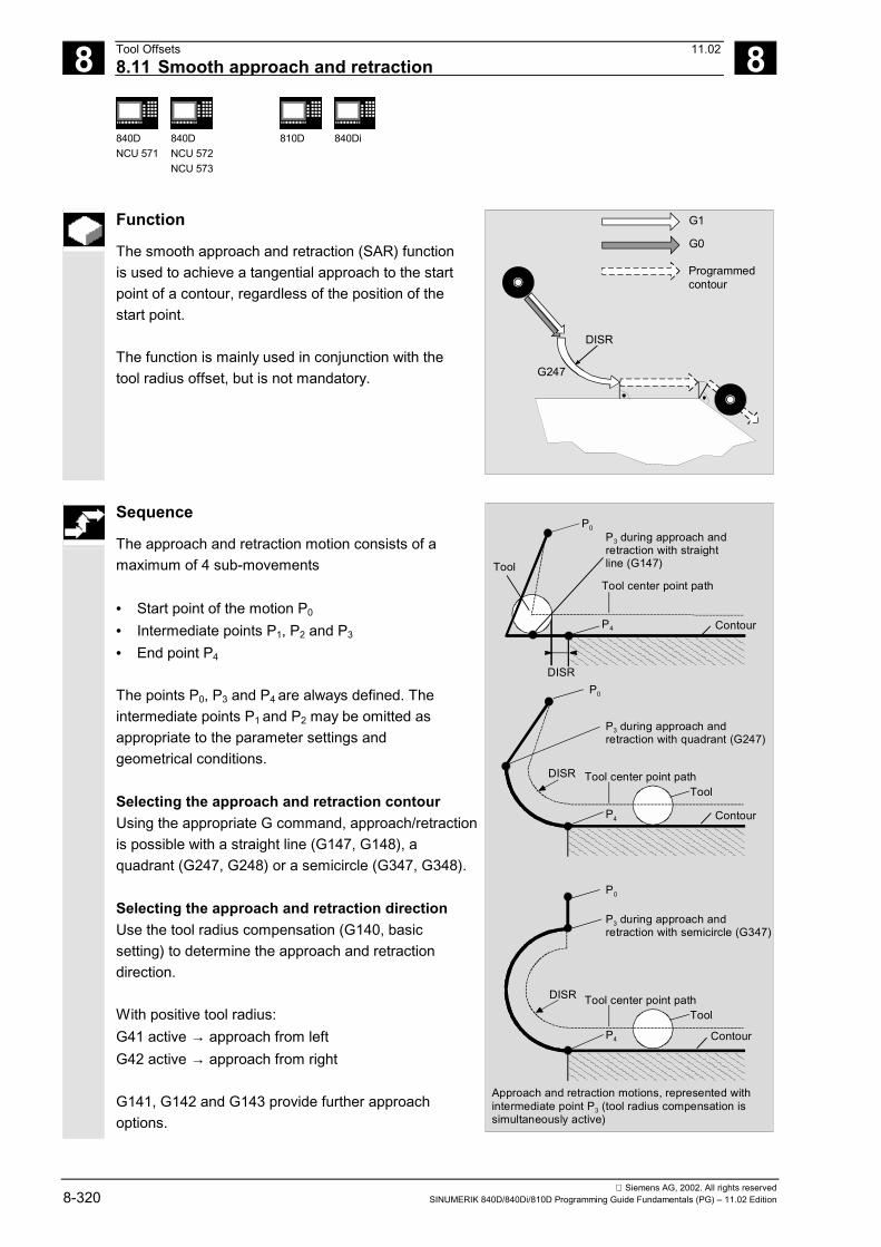
8 Tool Offsets 11.028.11 Smooth approach and retraction 8
840DNCU 571
840DNCU 572NCU 573
810D 840Di
Siemens AG, 2002. All rights reserved8-320 SINUMERIK 840D/840Di/810D Programming Guide Fundamentals (PG) – 11.02 Edition
Function
The smooth approach and retraction (SAR) functionis used to achieve a tangential approach to the startpoint of a contour, regardless of the position of thestart point.
The function is mainly used in conjunction with thetool radius offset, but is not mandatory.
G1
DISR
G0
Programmedcontour
G247
Sequence
The approach and retraction motion consists of amaximum of 4 sub-movements
• Start point of the motion P0
• Intermediate points P1, P2 and P3
• End point P4
The points P0, P3 and P4 are always defined. Theintermediate points P1 and P2 may be omitted asappropriate to the parameter settings andgeometrical conditions.
Selecting the approach and retraction contourUsing the appropriate G command, approach/retractionis possible with a straight line (G147, G148), aquadrant (G247, G248) or a semicircle (G347, G348).
Selecting the approach and retraction directionUse the tool radius compensation (G140, basicsetting) to determine the approach and retractiondirection.
With positive tool radius:G41 active → approach from leftG42 active → approach from right
G141, G142 and G143 provide further approachoptions.
P0P3 during approach andretraction with straightline (G147)
P4 Contour
DISR
Approach and retraction motions, represented withintermediate point P3 (tool radius compensation issimultaneously active)
P0
P3 during approach andretraction with quadrant (G247)
P4 Contour
P0
P3 during approach andretraction with semicircle (G347)
P4 Contour
DISR
DISR
Tool center point pathTool
Tool center point pathTool
Tool center point pathTool

8 11.02 Tool Offsets8.11 Smooth approach and retraction 8
840DNCU 571
840DNCU 572NCU 573
810D 840Di
Siemens AG, 2002. All rights reservedSINUMERIK 840D/840Di/810D Programming Guide Fundamentals (PG) – 11.02 Edition 8-321
The G codes are only significant when the approachcontour is a quadrant or a semicircle.
Motion steps between start point and end point(G340 and G341)The characteristic approach to P0 to P4 is shown inadjacent the figure.
In cases which include the position of the active planeG17 to G19 (circular plane, helical axis, infeed motionperpendicular to the active plane), any active rotatingFRAME is taken into account.
Length of the approach straight line or radius forapproach circles (DISR) (see figure for sequence)
P4
Machining plane
DISCL DISCL
G340 G341
P4
P2
P1P0P1P0
P2, P3
Infeed motion
Straight line,circle or helix
Straight lineor circle
Approach motion depending on G340/G341
P3
• Approach/retract with straight lineDISR specifies the distance of the cutter edgefrom the starting point of the contour, i.e. thelength of the straight line when TRC is active isthe sum of the tool radius and the programmedvalue of DISR. The tool radius is only consideredif it is positive.The resultant line length must be positive, i.e.negative values for DISR are allowed providedthat the absolute value of DISR is less than thetool radius.
• Approach/retraction with circlesDISR indicates the radius of the tool center pointpath. If TRC is activated, a circle is produced witha radius that results in the tool center point pathwith the programmed radius.
Distance between the point and the machiningplane (DISCL) (see figure for sequence)If the position of the point P2 is to be specified as anabsolute value on the axis perpendicular to thecircular plane, the value must be programmed in theform DISCL=AC(...).

8 Tool Offsets 11.028.11 Smooth approach and retraction 8
840DNCU 571
840DNCU 572NCU 573
810D 840Di
Siemens AG, 2002. All rights reserved8-322 SINUMERIK 840D/840Di/810D Programming Guide Fundamentals (PG) – 11.02 Edition
The following applies for DISCL=0:• With G340: The entire approach motion consists
of only two blocks (P1, P2 and P3 are combined).The approach contour is obtained from P1 to P4.
• With G341: The entire approach motion consistsof three blocks (P2 and P3 are combined). If P0
and P4 lie in the same plane, only two blocks areproduced (infeed motion of P1 to P3 is omitted).
The point defined by DISCL is monitored to ensurethat it is located between P1 and P3 , i.e. the signmust be identical for the component perpendicular tothe machining plane in all motions which possesssuch a component.On detection of a direction reversal, a tolerancedefined by the machine dataSAR_CLEARANCE_TOLERANCE is permitted.
Programming the end point P4 for approach or P0
for retraction The end point is generally programmed with X... Y...Z....• Programming during approach
- P4 in the SAR block- P4 is defined by the end point of the next
traversing blockFurther blocks can be inserted between the SARblock and the next traversing block without movingthe geometry axes.

8 11.02 Tool Offsets8.11 Smooth approach and retraction 8
840DNCU 571
840DNCU 572NCU 573
810D 840Di
Siemens AG, 2002. All rights reservedSINUMERIK 840D/840Di/810D Programming Guide Fundamentals (PG) – 11.02 Edition 8-323
Example:$TC_DP1[1,1]=120 ;Milling tool T1/D1$TC_DP6[1,1]=7 ;Tool with 7mm radiusN10 G90 G0 X0 Y0 Z30 D1 T1
N20 X10
N30 G41 G147 DISCL=3 DISR=13 Z=0 F1000
N40 G1 X40 Y-10
N50 G1 X50
...
...
N30/N40 can be replaced by:1.N30 G41 G147 DISCL=3 DISR=13 X40 Y-10
Z0 F1000
or2.N30 G41 G147 DISCL=3 DISR=13 F1000
N40 G1 X40 Y-10 Z0
DISR=13
P4
Z=30Z=3 Z=0
Machining up to this pointwith GO, after that G1 F1000
ContourX
Y
0 10
-10
50403020
• Programming during retraction- For a SAR block without programmed
geometry axis, the contour ends in P2. Theposition in the axes that form the machiningplane are obtained from the retraction contour.The axes components perpendicular to this aredefined by DISCL. If DISCL=0, the entiremotion is in the plane.
- If only the axis perpendicular to the machining plane is programmed, the contour ends in P1. The position of the other axes is obtained as described previously. If the SAR block is also the deactivation block of the TRC, an additional path from P1 to P0 is added so that there is nomotion at the end of the contour on deactivation of the TRC.
- If there is only one machining plane programmed,the missing 2nd axis is added modally taken fromits last position in the previous block.
P4
Contour (previous block)
P1
P0
Tool
Tool center point path
Following block(without offset)
SAR block(G248 G40 ...)
Retraction with SAR with TRC simultaneouslydeactivated

8 Tool Offsets 11.028.11 Smooth approach and retraction 8
840DNCU 571
840DNCU 572NCU 573
810D 840Di
Siemens AG, 2002. All rights reserved8-324 SINUMERIK 840D/840Di/810D Programming Guide Fundamentals (PG) – 11.02 Edition
Approach and retraction velocities• Speed of the previous block (G0):
All motions from P0 up to P2 are executed at thisspeed, i.e. the motion parallel to the machiningplane and the part of the infeed motion up to thesafety clearance.
• Programming with FAD:Specify the feedrate for- G341: infeed motion perpendicular to the
machining plane from P2 to P3
- G340: from point P2 or P3 to P4
If FAD is not programmed, this part of thecontour is also traversed at the modally activespeed of the previous block, if no F word isprogrammed in the SAR block.
• Programmed feedrate F:This feedrate is active from P3 or P2, if FAD is notprogrammed. If no F word is programmed in theSAR block, the speed of the previous block isactive.
Example: $TC_DP1[1,1]=120 ;Milling tool T1/D1$TC_DP6[1,1]=7 ;Tool with 7mm radius
N10 G90 G0 X0 Y0 Z20 D1 T1
N20 G41 G341 G247 DISCL=AC(5) DISR=13
FAD 500 X40 Y-10 Z=0 F200
N30 X50
N40 X60
...
010 20 30 40 50
X
-10
Y
0 X
Z
10
20
G0
F500
G0
F2000 F2000
5
60
P0 P1
P2
P3P4
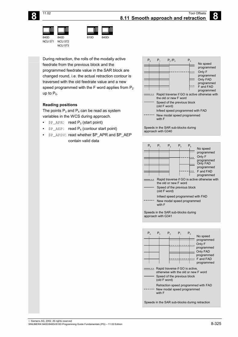
8 11.02 Tool Offsets8.11 Smooth approach and retraction 8
840DNCU 571
840DNCU 572NCU 573
810D 840Di
Siemens AG, 2002. All rights reservedSINUMERIK 840D/840Di/810D Programming Guide Fundamentals (PG) – 11.02 Edition 8-325
During retraction, the rolls of the modally activefeedrate from the previous block and theprogrammed feedrate value in the SAR block arechanged round, i.e. the actual retraction contour istraversed with the old feedrate value and a newspeed programmed with the F word applies from P2
up to P0. Reading positions The points P3 and P4 can be read as systemvariables in the WCS during approach.• $P_APR: read P3 (start point)• $P_AEP: read P4 (contour start point)• $P_APDV: read whether $P_APR and $P_AEP
contain valid data
No speedprogrammedOnly Fprogrammed
F and FAD programmed
P0 P1 P2 /P3 P4
Rapid traverse if GO is active otherwise withthe old or new F wordSpeed of the previous block(old F word)Infeed speed programmed with FADNew modal speed programmedwith F
Speeds in the SAR sub-blocks duringapproach with G340
Only FADprogrammed
P0 P1 P2 P3 P4No speedprogrammedOnly FprogrammedOnly FADprogrammedF and FAD programmed
Rapid traverse if GO is active otherwise withthe old or new F wordSpeed of the previous block(old F word)Infeed speed programmed with FADNew modal speed programmedwith F
Speeds in the SAR sub-blocks duringapproach with G341
P4 P3 P2 P1 P0No speedprogrammedOnly FprogrammedOnly FADprogrammedF and FAD programmed
Speed of the previous block(old F word)
Retraction speed programmed with FADNew modal speed programmedwith F
Rapid traverse if GO is active,otherwise with the old or new F word
Speeds in the SAR sub-blocks during retraction

8 Tool Offsets 11.028.11 Smooth approach and retraction 8
840DNCU 571
840DNCU 572NCU 573
810D 840Di
Siemens AG, 2002. All rights reserved8-326 SINUMERIK 840D/840Di/810D Programming Guide Fundamentals (PG) – 11.02 Edition
Programming example
• Smooth approach (block N20 activated)• Approach motion with quadrant (G247)• Approach direction not programmed, G140 is
operative, i.e. TRC is active (G41)• Contour offset OFFN=5 (N10)• Current tool radius=10; thus the effective offset
radius for TRC=15, the radius of the SARcontour=25, so that the radius of the tool centerpoint path is then DISR=10
• The end point of the circle is obtained from N30,since only the Z position is programmed in N20
• Infeed motion– from Z20 to Z7 (DISCL=AC(7)) in rapid traverse– then to Z0 with FAD=200– approach circle in X-Y plane and following blocks with F1500 (for this speed to be active in the following blocks, the active G0 in N30 must be overwritten with G1; otherwise, the contour would be machined further with G0.)
• Smooth retraction (block N60 active)• Retraction motion with quadrant (G248) and helix
(G340)• FAD not programmed, since irrelevant for G340• Z=2 in the start point; Z=8 in the end point, since
DISCL=6• When DISR=5, the radius of SAR contour=20; that
of the tool center point path=5• Retraction motions from Z8 to Z20 and the motion
parallel to X-Y plane to X70 Y0.
y
x20 40 60 80
20
Tool
Tool center point path
Semicircle HelixP3app
P4app
P0app
P4retr
P3retr
P0retr
5
30 50
Contour
$TC_DP1[1,1]=120 Tool definition T1/D1$TC_DP6[1,1]=10 RadiusN10 G0 X0 Y0 Z20 G64 D1 T1 OFFN = 5 (P0app)N20 G41 G247 G341 Z0 DISCL = AC(7)
DISR = 10 F1500 FAD=200Approach (P3app)
N30 G1 X30 Y-10 (P4app)N40 X40 Z2
N50 X50 (P4retr)N60 G248 G340 X70 Y0 Z20 DISCL = 6
DISR = 5 G40 F10000Retraction (P3retr)
N70 X80 Y0 (P0retr)N80 M30

8 11.02 Tool Offsets8.11 Smooth approach and retraction 8
840DNCU 571
840DNCU 572NCU 573
810D 840Di
Siemens AG, 2002. All rights reservedSINUMERIK 840D/840Di/810D Programming Guide Fundamentals (PG) – 11.02 Edition 8-327
8.11.1 Extension approach and retract: G461/G462 (SW 5 and higher)
Programming
G460
G461
G462
Explanation
G460 As before (activation of collision monitoring for approach and retractionblock)
G461 Insertion of a circle in the TRC block, if no intersection point is possible,whose center point is at the end point of the uncorrected block andwhose radius is equal to the tool radius.
G462 Insertion of a straight line in the TRC block if no intersection point ispossible; the block is extended by its end tangent (default setting)
Function
In certain special geometrical situations, extendedapproach and retraction strategies, compared withthe previous implementation, are required in order toactivate or deactivate tool radius compensation (seefigure below).
The following example describes only the situationfor deactivation of tool radius compensation. Thebehavior for approach is the same.
Example:G42 D1 T1 ; Tool radius 20mm
...
G1 X110 Y0
N10 X0
N20 Y10
N30 G40 X50 Y50
20
10
10050
N20
N30
N10
X
Y
Center point path withtool radius compensation
Programmedcontour
Tool radius
10
Retraction behavior with G460(identical to behavior with SW 4.x andlower)
The last block with active tool radius compensation(N20) is so short that an intersection no longer existsbetween the offset curve and the preceding block (ora previous block) for the current tool radius.

8 Tool Offsets 11.028.11 Smooth approach and retraction 8
840DNCU 571
840DNCU 572NCU 573
810D 840Di
Siemens AG, 2002. All rights reserved8-328 SINUMERIK 840D/840Di/810D Programming Guide Fundamentals (PG) – 11.02 Edition
An attempt is therefore made to find an intersectionbetween the offset curves of the following block andthe preceding block, i.e. in the example betweenN10 and N30. The curve used for the retractionblock is not a real offset curve, but is a straight linefrom the offset point at the end point of block N20 tothe programmed end point of N30. If an intersectionis found, it is approached. In this case, the shadedarea in the figure is not machined, although thiswould be possible with the tool used.
G461If no intersection is possible between the last TRCblock and a preceding block, the offset curve of thisblock is extended with a circle whose center pointlies at the end point of the uncorrected block andwhose radius is equal to the tool radius.The control attempts to cut this circle with one of thepreceding blocks.
0 20
10
100
N20
N30
N10
X
YAuxiliary curve
Center point path withtool radius compensation
Programmedcontour
10
X
50
Retraction behavior with G461(see example at the end of this section)
If CDOF is active (see Section 8.12), the search isaborted when an intersection is found, i.e. thesystem does not check whether further intersectionswith previous blocks exist.If CDON is active, the search continues for furtherintersections after the first intersection is found.An intersection point which is found in this way is thenew end point of a preceding block and the startpoint of the deactivation block. The inserted circle isused exclusively to calculate the intersection anddoes not produce a traversing movement.
If no intersection is found, alarm 10751 (collisiondanger) is output.

8 11.02 Tool Offsets8.11 Smooth approach and retraction 8
840DNCU 571
840DNCU 572NCU 573
810D 840Di
Siemens AG, 2002. All rights reservedSINUMERIK 840D/840Di/810D Programming Guide Fundamentals (PG) – 11.02 Edition 8-329
G462If no intersection is possible between the last TRCblock and a preceding block, a straight line isinserted, on retraction with G462 (initial setting), atthe end point of the last block with tool radiuscompensation (the block is extended by its endtangent).The search for the intersection is then identical tothe procedure for G461.
0 20
10
100
N20
N30
N10
X
YAuxiliary curve
Center point path(compensated path)
Programmedcontour
10 50
Retraction behavior with G462(see example at the end of this section)
With G462, the corner generated by N10 and N20 inthe example program is not machined to the fullextent actually possible with the tool used. However,this behavior may be necessary if the part contour(as distinct from the programmed contour), to the leftof N20 in the example, is not permitted to be violatedeven with y values greater than 10mm.If KONT is active (travel round contour at start orend point), the behavior differs according to whetherthe end point is in front of or behind the contour.
End point in front of contourIf the end point is in front of the contour, theretraction behavior is the same as with NORM. Thisproperty does not change even if the last contourblock for G451 is extended with a straight line or acircle. Additional circumnavigation strategies to avoida contour violation in the vicinity of the contour endpoint are therefore not required.
End point behind contourIf the end point is behind the contour, a circle orstraight line is always inserted depending on G450 /G451. In this case, G460-462 has no effect.If, in this situation, the last traversing block has nointersection with a preceding block, an intersectionwith the inserted contour element or with the linearsection from the end point of the circumnavigationcircle to the programmed end point can result.

8 Tool Offsets 11.028.11 Smooth approach and retraction 8
840DNCU 571
840DNCU 572NCU 573
810D 840Di
Siemens AG, 2002. All rights reserved8-330 SINUMERIK 840D/840Di/810D Programming Guide Fundamentals (PG) – 11.02 Edition
If the inserted contour element is a circle (G450),and it intersects with the preceding block, this is thesame as the intersection which would be producedwith NORM and G461. In general, however, aremaining section of the circle still has to betraversed. An intersection calculation is no longerrequired for the linear section of the retraction block.In the second case (if no intersection is foundbetween the inserted contour element and thepreceding blocks), the intersection between theretraction straight line and a preceding block isapproached.Therefore, when G461 or G462 is active, a behaviordifferent to G460 can only arise if NORM is active orif the behavior with KONT is identical to NORM dueto the geometrical conditions.
Additional notes
The approach behavior is symmetrical to theretraction behavior.The approach/retraction behavior is determined by thestate of the G command in the approach/retractionblock. The approach behavior can therefore be setindependently of the retraction behavior.
Programming example
G461 for approachN10 $TC_DP1[1,1]=120 ; Tool type mill
N20 $TC_DP6[1,1]=10 ; Radius
N30 X0 Y0 F10000 T1 D1
N40 Y20
N50 G42 X50 Y5 G461
N60 Y0 F600
N70 X30
N80 X20 Y-5
N90 X0 Y0 G40
N100 M30
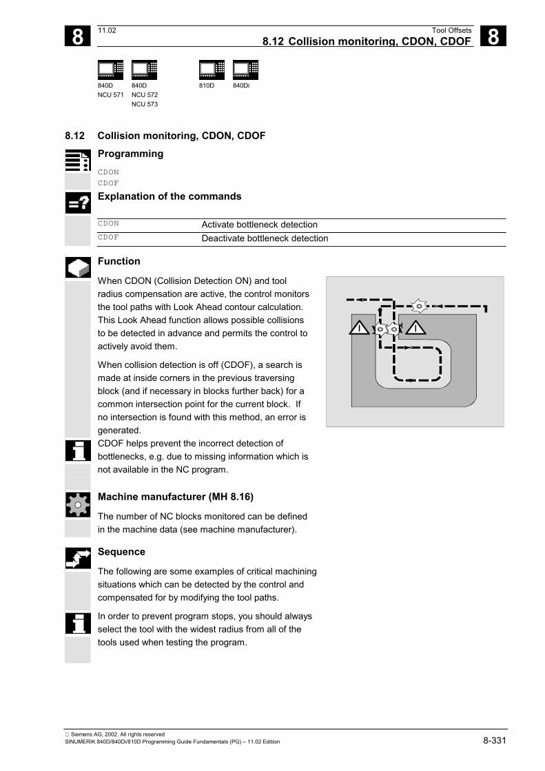
8 11.02 Tool Offsets8.12 Collision monitoring, CDON, CDOF 8
840DNCU 571
840DNCU 572NCU 573
810D 840Di
Siemens AG, 2002. All rights reservedSINUMERIK 840D/840Di/810D Programming Guide Fundamentals (PG) – 11.02 Edition 8-331
8.12 Collision monitoring, CDON, CDOFProgrammingCDON
CDOF
Explanation of the commands
CDON Activate bottleneck detectionCDOF Deactivate bottleneck detection
Function
When CDON (Collision Detection ON) and toolradius compensation are active, the control monitorsthe tool paths with Look Ahead contour calculation.This Look Ahead function allows possible collisionsto be detected in advance and permits the control toactively avoid them.
When collision detection is off (CDOF), a search ismade at inside corners in the previous traversingblock (and if necessary in blocks further back) for acommon intersection point for the current block. Ifno intersection is found with this method, an error isgenerated.CDOF helps prevent the incorrect detection ofbottlenecks, e.g. due to missing information which isnot available in the NC program.
Machine manufacturer (MH 8.16)
The number of NC blocks monitored can be definedin the machine data (see machine manufacturer).
Sequence
The following are some examples of critical machiningsituations which can be detected by the control andcompensated for by modifying the tool paths.
In order to prevent program stops, you should alwaysselect the tool with the widest radius from all of thetools used when testing the program.

8 Tool Offsets 11.028.12 Collision monitoring, CDON, CDOF 8
840DNCU 571
840DNCU 572NCU 573
810D 840Di
Siemens AG, 2002. All rights reserved8-332 SINUMERIK 840D/840Di/810D Programming Guide Fundamentals (PG) – 11.02 Edition
In each of the following examples a tool with toowide a radius was selected for machining thecontour.
Bottleneck detection
Since the tool radius selected is too wide to machinethis inside contour, the "bottleneck" is bypassed.An alarm is output.
Programmed contour
Tool path
Contour path shorter than tool radius
The tool travels round the workpiece corner on atransition circle and then continues to follow theprogrammed contour exactly.
Programmed contour
Tool path
Tool radius too wide for inside machining
In such cases, machining of the contours is performedonly as far as is possible without causing damage tothe contour.
Programmedcontour
Tool path

8 11.02 Tool Offsets8.13 2 1/2 D tool offset, CUT2D, CUT2DF 8
840DNCU 571
840DNCU 572NCU 573
810D 840Di
Siemens AG, 2002. All rights reservedSINUMERIK 840D/840Di/810D Programming Guide Fundamentals (PG) – 11.02 Edition 8-333
8.13 2 1/2 D tool offset, CUT2D, CUT2DFProgramming
CUT2D
CUT2DF
Explanation
CUT2D Activate 2 1/2 D radius compensation (default)CUT2DF Activate 2 1/2 D radius compensation, tool radius compensation relative to
the current frame or to inclined planes
Function
With CUT2D or CUT2DF you define how the toolradius compensation is to act or to be interpretedwhen machining in inclined planes.
Sequence
Tool length compensationTool length compensation is generally calculatedaccording to the non-rotated working plane fixed inspace.
Tool radius compensation, CUT2DAs for many applications, tool length compensationand tool radius compensation are calculated in thefixed working plane specified with G17 to G19.
Example for G17 (X/Y plane):Tool radius compensation is active in the non-rotatedX/Y plane, tool length compensation in the Z direction.
X
X
Z Z

8 Tool Offsets 11.028.13 2 1/2 D tool offset, CUT2D, CUT2DF 8
840DNCU 571
840DNCU 572NCU 573
810D 840Di
Siemens AG, 2002. All rights reserved8-334 SINUMERIK 840D/840Di/810D Programming Guide Fundamentals (PG) – 11.02 Edition
For machining on inclined surfaces, the toolcompensation values have to be defined accordingly,or be calculated using the functions for "Tool lengthcompensation for orientable tools". For moreinformation on this calculation method, see Section"Tool orientation and tool length compensation".
CUT2D is used when the orientation of the toolcannot be changed and the workpiece is rotated formachining on inclined surfaces.CUT2D is generally the standard setting and doesnot therefore have to be specified explicitly.
Tool radius compensation, CUT2DFIn this case, it is possible to arrange the tool orientationperpendicular to the inclined working plane on themachine.
If a frame containing a rotation is programmed, thecompensation plane is also rotated with CUT2DF.The tool radius compensation is calculated in therotated machining plane.
The tool length compensation continues to be activerelative to the non-rotated working plane.
X
X
Z Z

8 11.02 Tool Offsets8.14 Tool length offset for orientable tools: TCARR, TCOABS, TCOFR 8
840DNCU 571
840DNCU 572NCU 573
810D 840Di
Siemens AG, 2002. All rights reservedSINUMERIK 840D/840Di/810D Programming Guide Fundamentals (PG) – 11.02 Edition 8-335
8.14 Tool length offset for orientable tools: TCARR, TCOABS, TCOFRProgramming
TCARR=[m]
TCOABS
TCOFR
Explanation
TCARR=[m] Request toolholder with the number "m"TCOABS Determine tool length components from the orientation of the current
toolholder.TCOFR Determine tool length components from the orientation of the active frame.
Function
When the spatial orientation of the tool changes, itstool length components also change.After a reset, e.g. through manual setting or change ofthe toolholder with a fixed spatial orientation, the toollength components also have to be determined again.This is performed using the TCOABS and TCOFR pathcommands.
VU
ab
ZX
Y
l
l
l
ZZ«
X«X
Sequence
Request toolholder TCARRWith TCARR the toolholder number m is requested withits geometry data (offset memory).With m=0, the active toolholder is deselected.
8 Tool Offsets 11.028.14 Tool length offset for orientable tools: TCARR, TCOABS, TCOFR 8
840DNCU 571
840DNCU 572NCU 573
810D 840Di
Siemens AG, 2002. All rights reserved8-336 SINUMERIK 840D/840Di/810D Programming Guide Fundamentals (PG) – 11.02 Edition
Additional notes
The geometry data of the toolholder only become activeafter a tool is called. The selected tool remains activeafter a toolholder change has taken place.
The current geometry data for the toolholder can alsobe defined in the parts program via the correspondingsystem variables.
For a definition of toolholder kinematics with systemvariables, seeReferences: /PGA/, "Programming Guide Advanced"
Section "Toolholder kinematics"
Determine tool length compensation from theorientation of the toolholder, TCOABSTCOABS calculates the tool length compensation fromthe current orientation angles of the toolholder; storedin system variables $TC_CARR13 and $TC_CARR14.
In order to make a new calculation of the tool lengthcompensation when frames are changed, the toolhas to be selected again.
Additional notes
The tool orientation must be manually adapted to theactive frame.
When the tool length compensation is calculated, theangle of rotation of the toolholder is calculated in anintermediate step. With toolholders with two rotaryaxes, there are generally two sets of rotation angleswhich can be used to adapt the tool orientation to theactive frame; therefore, the rotation angle values storedin the system variables must at least correspondapproximately to the mechanically set rotation angles.
8 11.02 Tool Offsets8.14 Tool length offset for orientable tools: TCARR, TCOABS, TCOFR 8
840DNCU 571
840DNCU 572NCU 573
810D 840Di
Siemens AG, 2002. All rights reservedSINUMERIK 840D/840Di/810D Programming Guide Fundamentals (PG) – 11.02 Edition 8-337
Additional notes
It is not possible for the control to check whether therotation angles calculated by means of the frameorientation are settable on the machine.
If the rotary axes of the toolholder are arranged suchthat the tool orientation calculated by means of theframe orientation cannot be reached, then an alarmis output.If there is a switchover between TCOFR and TCABS,the tool length compensation is calculated again.
The combination of tool precision compensation andthe functions for tool length compensation on movabletoolholders is not permissible. If both functions arecalled simultaneously, an error message is issued.
The TOFRAME function allows a frame to be definedon the basis of the direction of orientation of theselected toolholder. For more detailed informationplease refer to the Programming Guide Fundamentalsin Section "Frames".
When orientation transformation is active (3, 4 or 5-axistransformation), it is possible to select a toolholder withan orientation deviating from the zero position withoutcausing output of an alarm.

8 Tool Offsets 11.028.15 Grinding-specific tool monitoring in parts program TMON, TMOF 8
840DNCU 571
840DNCU 572NCU 573
810D 840Di
Siemens AG, 2002. All rights reserved8-338 SINUMERIK 840D/840Di/810D Programming Guide Fundamentals (PG) – 11.02 Edition
8.15 Grinding-specific tool monitoring in parts program TMON, TMOFAssignment of tool-specific parameters
Further tool-specific parameters can beset up in the machine data and assignedby the user.
Parameter Meaning Data type
Tool-specific parameters
$TC_TPG1 Spindle number Integer
$TC_TPG2 Chaining ruleThe parameters are automaticallykept identical for the left and rightside of the wheel.
Integer
$TC_TPG3 Minimum wheel radius Real
$TC_TPG4 Minimum wheel width Real
$TC_TPG5 Current wheel width Real
$TC_TPG6 Maximum speed Real
$TC_TPG7 Maximum peripheral speed Real
$TC_TPG8 Angle of inclined wheel Real
$TC_TPG9 Parameter number for radiuscalculation
Integer
Programming
TMON (T No.)
TMOF (T No.)
Explanation of the commands
TMON (T No.) Activate tool monitoring It is only necessary to specify the TTMOF (T No.) Deselect tool monitoring
T No. = 0: Deactivate monitoringfor all tools
number if the tool with this numberis not active.

8 11.02 Tool Offsets8.15 Grinding-specific tool monitoring in parts program TMON, TMOF 8
840DNCU 571
840DNCU 572NCU 573
810D 840Di
Siemens AG, 2002. All rights reservedSINUMERIK 840D/840Di/810D Programming Guide Fundamentals (PG) – 11.02 Edition 8-339
Function
The command TMON is used to activate geometry andspeed monitoring for grinding tools (types 400–499) inthe NC parts program. Monitoring remains active until itis deactivated in the parts program with TMOF.
Additional notes
You can only activate tool monitoring if the toolspecificgrinding data $TC_TPG1 to $TC_TPG9(see Programming Guide Advanced) are set.According to the machine data settings, toolmonitoring for the grinding tools (types 400–499) canbe automatically activated when the tool selection isactivated.Only one monitoring routine can be active at any onetime for each spindle.
Geometry monitoringThe current wheel radius and the current width aremonitored.
The set speed is monitored against the speed limitationcyclically with allowance for the spindle override.The speed limit is the smaller value resulting from acomparison of the maximum speed with the speedcalculated from the maximum wheel peripheralspeed and the current wheel radius.
Working without a T or D number
In the machine data, a default T and D number can beset; they no longer have to be programmed andbecome active after Power On / Reset. Example:All machining is performed with the same grindingwheel. Machine data can be set to keep the current tool activeafter Reset;see /PGA/ Programming Guide "Advanced".

8 Tool Offsets 11.028.16 Additive offsets (SW 5 and higher) 8
840DNCU 571
840DNCU 572NCU 573
810D 840Di
Siemens AG, 2002. All rights reserved8-340 SINUMERIK 840D/840Di/810D Programming Guide Fundamentals (PG) – 11.02 Edition
Machine manufacturer (MH 8.11)
See machine manufacturer's specifications.
8.16 Additive offsets (SW 5 and higher) Additive offsets are essentially process offsets which
can be programmed during machining. They refer tothe geometrical data of a tool edge and are thuscomponents of the tool edge data. The data of an additive offset are addressed via aDL number (DL: location-dependent; offsets relativeto relevant location) and enter tool offset viaparameter display in the Parameter area.
8.16.1 Select offset (by DL number)
Programming
DL=x additive offset selection, x = 1 to 6
Explanation
• Up to 6 additive offsets can be activated perD number(saved under the respective DL numbers).
• You can distinguish between setup and wearvalues.
• DL=1 is activated when a D number is called.

8 11.02 Tool Offsets8.16 Additive offsets (SW 5 and higher) 8
840DNCU 571
840DNCU 572NCU 573
810D 840Di
Siemens AG, 2002. All rights reservedSINUMERIK 840D/840Di/810D Programming Guide Fundamentals (PG) – 11.02 Edition 8-341
Function
Setup value: The setup value is defined optionally by the machinemanufacturer by MD. Same tool edge: The same tool edge is used for 2 bearing seats (seeexample). Compensation can be made for a location-dependent measurement error occurring as a result ofmachining forces, etc. Fine offset: Location-dependent allowances can be made forover/under-dimensioning.
Z
X
-5-20 -15
10
Location 1Location 2
D7D7 DL2
Machine manufacturer (MH 8.13)
Machine data are used to activate and define thenumber of additive offsets. See machine manufacturer's specifications.
Programming example
N110 T7 D7 The tool turret is positioned at location 7.D7 and DL=1 are activated and traversed in thenext block
N120 G0 X10 Z1 N120 retracted N130 G1 Z-6 N140 G0 DL=2 Z-14 DL=2 is activated in addition to D7 and traversed
in the next block N150 G1 Z-21 N160 G0 X200 Z200 Approach tool change position ...
8.16.2 Define wear and setup values Wear and setup values can be read and written via
system parameters and the corresponding OPIservices. The logic is based on the logic of the correspondingsystem parameters for tools and tool edges.

8 Tool Offsets 11.028.16 Additive offsets (SW 5 and higher) 8
840DNCU 571
840DNCU 572NCU 573
810D 840Di
Siemens AG, 2002. All rights reserved8-342 SINUMERIK 840D/840Di/810D Programming Guide Fundamentals (PG) – 11.02 Edition
Programming
$TC_SCPxy[t,d] $TC_ECPxy[t,d]
Wear values Setup values
Explanation of the parameters
$TC_SCPxy Wear values are assigned to the corresponding geometry parameters via xy,where x is the number of the wear value and y is the reference to the geometryparameter.
$TC_ECPxy Setup values are assigned to the corresponding geometry parameters via xy,where x is the number of the setup value and y is the reference to the geometryparameter.
t T number of the tool d D number of the tool edge
Function
System parameters $TC_DP3 - $TC_DP11 describethe tool geometry. In addition to the parameters forthe physical wear ($TC_DP12 - $TC_DP20), up tosix wear values ($TC_SCP1y - $TC_SCP6y) and upto six setup values ($TC_ECP1y - $TC_ECP6y) canbe assigned to each geometry parameter. Example: Parameters: $TC_DP3 (Length 1, for rotary tools) Wear values: $TC_SCP13 - $TC_SCP63 Setup values: $TC_ECP13 - $TC_ECP63 $TC_SCP43 [t, d] = 1.0 The wear value of length 1 is set to the value 1.0 forthe tool edge (D number d) of the tool (t).
Note
The defined wear and setup values are added to thegeometry parameters and the other offset parameters(D numbers).
8 11.02 Tool Offsets8.16 Additive offsets (SW 5 and higher) 8
840DNCU 571
840DNCU 572NCU 573
810D 840Di
Siemens AG, 2002. All rights reservedSINUMERIK 840D/840Di/810D Programming Guide Fundamentals (PG) – 11.02 Edition 8-343
8.16.3 Delete additive offsets (DELDL)
Programming
status = DELDL[t,d]
Explanation of the parameters
DELDL[t,d] All additive offsets of the tool edge with D number d of tool t are deleted. DELDL[t] All additive offsets of all tool edges of tool t are deleted. DELDL All additive offsets of the tool edges of all tools of the TO-unit are deleted (for
the channel in which the command is programmed). status 0: Deletion was successful.
–1: Deletion could not be performed (if the parameters describe only one tooledge), or deletion was not complete (if the parameters describe severaltool edges).
Function
DELDL is used to delete the additive offsets for thetool edge of a tool (in order to release memory).Both the defined wear values and the setup valuesare deleted.
Additional notes
The wear and setup values of active tools cannot bedeleted (similar to deletion of D offsets or tool data).

8 Tool Offsets 11.028.17 Tool offset – special features (SW 5 and higher) 8
840DNCU 572NCU 573
840Di
Siemens AG, 2002. All rights reserved8-344 SINUMERIK 840D/840Di/810D Programming Guide Fundamentals (PG) – 11.02 Edition
8.17 Tool offset – special features (SW 5 and higher)
Function
Setting data SD 42900 – SD 42940 can be used tocontrol the evaluation of the sign for tool length andwear. The same applies to the behavior of the wearcomponents when mirroring geometry axes orchanging the machining plane.
Where reference is made below to wear values, thismeans in each case the sum of the actual wearvalues ($TC_DP12 to $TC_DP20) and the totaloffsets with the wear ($SCPX3 to $SCPX11) andsetup values ($ECPX3 to $ECPX11). You will find more information on resulting offsets in/FBW/, Description of Functions, Tool Management.
See also:• /PGA/, Programming Guide Advanced, Chapter 8• /PG/, Programming Guide Fundamentals, Chapter 8• Description of Functions, Basic Machine (Part 1), Tool Compensation (W1)
Required setting data
SD42900 MIRROR_TOOL_LENGTH Mirroring of tool length components and components ofthe tool base dimension
SD42910 MIRROR_TOOL_WEAR Mirroring of wear values of the tool length componentsSD42920 WEAR_SIGN_CUTPOS Sign evaluation of the wear components depending on the
tool point directionSD42930 WEAR_SIGN Inverts the sign of the wear dimensionsSD42940 TOOL_LENGTH_CONST Assignment of tool length components to geometry
axes

8 11.02 Tool Offsets8.17 Tool offset – special features (SW 5 and higher) 8
840DNCU 572NCU 573
840Di
Siemens AG, 2002. All rights reservedSINUMERIK 840D/840Di/810D Programming Guide Fundamentals (PG) – 11.02 Edition 8-345
8.17.1 Mirroring of tool lengthsSD 42900 MIRROR_TOOL_LENGTHSetting data not equal to zero:The tool length components ($TC_DP3, $TC_DP4and $TC_DP5) and the components of the tool basedimensions ($TC_DP21, $TC_DP22 and$TC_DP23), whose associated axes are mirrored,are also mirrored – through sign inversion.The wear values are not mirrored. If these are also tobe mirrored, setting data$SC_MIRROR_TOOL_WEAR must be enabled.
X
Z
M W
WCS 1D13 with SL3
X
Z
MW1 1
WCS 2D13 with SL4
D13
SD 42910 MIRROR_TOOL_WEARSetting data not equal to zero:The wear values of the tool length components, whoseassociated axes are mirrored, are also mirrored by signinversion.
8.17.2 Wear sign evaluationSD 42920 WEAR_SIGN_CUTPOSSetting data not equal to zero:In the case of tools with a relevant tool point direction(turning and grinding tools – tool types 400–599), thesign evaluation of the wear components depends on thetool point direction in the machining plane. This settingdata has no effect on tool types which do not have arelevant tool point direction.In the following table, the dimensions whose sign isinverted by SD 42920 (not equal to 0) are marked withan X:
Tool point direction Length 1 Length 212 X3 X X4 X567 X8 X9

8 Tool Offsets 11.028.17 Tool offset – special features (SW 5 and higher) 8
840DNCU 572NCU 573
840Di
Siemens AG, 2002. All rights reserved8-346 SINUMERIK 840D/840Di/810D Programming Guide Fundamentals (PG) – 11.02 Edition
Additional notes
The sign settings of SD 42920 and 42910 areindependent. For example, if the sign of a dimensionalparameter is changed by both setting data, theresulting sign is unchanged.
SD 42930 WEAR_SIGNSetting data not equal to zero:Inverts the sign of all wear dimensions. It acts both onthe tool length and on other quantities such as toolradius, rounding radius, etc.If a positive wear dimension is entered, the toolbecomes "shorter" and "thinner".Example: See following section "Activation of modifiedsetting data".
8.17.3 Tool length and plane changeSD 42940 TOOL_LENGTH_CONSTSetting data not equal to zero:The assignment between the tool lengthcomponents (length, wear and tool base dimension)and the geometry axes is not modified when themachining plane is changed (G17–19).
The following table shows the assignment betweenthe tool length components and the geometry axesfor turning and grinding tools (tool types 400 to 599):
Contents Length 1 Length 2 Length 317 Y X Z
18*) X Z Y19 Z Y X-17 X Y Z-18 Z X Y-19 Y Z X
*) Each value not equal to 0 which is not equal to one ofthe six listed values is evaluated like value 18.

8 11.02 Tool Offsets8.17 Tool offset – special features (SW 5 and higher) 8
840DNCU 572NCU 573
840Di
Siemens AG, 2002. All rights reservedSINUMERIK 840D/840Di/810D Programming Guide Fundamentals (PG) – 11.02 Edition 8-347
The following table shows the assignment betweenthe tool length components and the geometry axesfor all other tools (tool types < 400 and > 599):
Machiningplane
Length 1 Length 2 Length 3
17*) Z Y X18 Y X Z19 X Z Y-17 Z X Y-18 Y Z X-19 X Y Z
*) Each value not equal to 0 which is not equal to one ofthe six listed values is evaluated as value 17.
Additional notes
For representation in tables, it is assumed thatgeometry axes 1 to 3 are named X, Y, Z. The axisorder and not the axis identifier determines theassignment between an offset and an axis.
Activation of modified setting dataFunction
When the setting data described above aremodified, the tool components are not reevaluateduntil the next time a tool edge is selected. If a tool isalready active and the data of this tool are to bereevaluated, the tool must be selected again.
The same applies in the event that the resulting toollength is modified due to a change in the mirroringstatus of an axis. The tool must be selected againafter the mirror command, in order to activate themodified tool length components.

8 Tool Offsets 11.028.17 Tool offset – special features (SW 5 and higher) 8
840DNCU 572NCU 573
840Di
Siemens AG, 2002. All rights reserved8-348 SINUMERIK 840D/840Di/810D Programming Guide Fundamentals (PG) – 11.02 Edition
Orientable toolholders and new setting dataFunction
Setting data SD 42900–42940 have no effect on thecomponents of an active orientable toolholder.However, the calculation with an orientabletoolholder always allows for a tool with its totalresulting length (tool length + wear + tool basedimension). All modifications initiated by the settingdata are included in the calculation of the resultingtotal length; i.e. vectors of the orientable toolholderare independent of the machining plane.
Additional notes
When orientable toolholders are used, it is frequentlypractical to define all tools for a non-mirrored basicsystem, even those which are only used for mirroredmachining. When machining with mirrored axes, thetoolholder is then rotated such that the actualposition of the tool is described correctly. All toollength components then automatically act in thecorrect direction, dispensing with the need for controlof individual component evaluation via setting data,depending on the mirroring status of individual axes.
The "orientable toolholder" functionality can also beuseful on machines which have no physical meansof turning tools but which feature permanentlyinstalled tools with different orientations. In this case,tools can be uniformly dimensioned in a basicorientation; the dimensions relevant to the machiningoperation are acquired by rotating a virtualtoolholder.

8 11.02 Tool Offsets8.18 Tools with a relevant tool point direction (SW 5 and higher) 8
840DNCU 572NCU 573
840Di
Siemens AG, 2002. All rights reservedSINUMERIK 840D/840Di/810D Programming Guide Fundamentals (PG) – 11.02 Edition 8-349
8.18 Tools with a relevant tool point direction (SW 5 and higher)Function
Up to SW 4.xIn the case of tools with a relevant tool point direction(turning and grinding tools – tool types 400–599; seeSubsection 8.17.2), a change from G40 to G41/G42 orvice-versa is treated as a tool change. If atransformation is active (e.g. TRANSMIT), this leads toa preprocessor stop (decoding stop) and hencepossibly to deviations from the intended part contour.
SW 5 and higherThe following changes have been made:
1. A change from G40 to G41/G42 and vice-versa isno longer treated as a tool change. A preprocessorstop therefore no longer occurs with Transmit.
2. The straight line between the tool edge centerpoints at the block start and block end is used tocalculate intersection points with the approach andretraction block. The difference between the tooledge reference point and the tool edge centerpoint is superimposed on this movement.During approach and retraction with KONT (tooltravels around the contour point; see Section 8.9),superimposing takes place in the linear subblockof the approach or retraction movement. Thegeometrical relationships are therefore identical fortools with and without a relevant tool pointdirection. Differences from the previous behavioroccur only in relatively rare situations where theapproach or retraction block does not intersectwith an adjacent motion block, see diagram below.

8 Tool Offsets 11.028.18 Tools with a relevant tool point direction (SW 5 and higher) 8
840DNCU 572NCU 573
840Di
Siemens AG, 2002. All rights reserved8-350 SINUMERIK 840D/840Di/810D Programming Guide Fundamentals (PG) – 11.02 Edition
Last position of tool edge center pointat the contour (SW 5 and higher)
Programmed retraction block
Block withoutpoint of intersectionwith previous block
Tool edge reference point
Tool edge center point
Tool end position
Tool edge reference point
Center point path
Last position of tool edge center pointat the contour (up to SW 4.x)
3. In circle blocks and in motion blocks containingrational polynomials with a denominator degree >4, it is not permitted to change a tool with activetool radius compensation in cases where thedistance between the tool edge center point andthe tool edge reference point changes. With othertypes of interpolation, it is now possible to changewhen a transformation is active (e.g. Transmit).
4. For tool radius compensation with variable toolorientation, the transformation from the tool edgereference point to the tool edge center point can nolonger be performed by means of a simple zerooffset. Tools with a relevant tool point direction aretherefore not permitted for 3D peripheral milling (analarm is output).
Additional notes
This subject has no relevance with respect to facemilling operations, since only defined tool types withoutrelevant tool point direction have been permitted forthese to date anyway. (Tools with a tool type that is notexpressly permissible are treated like a ball end millwith the specified radius). A tool point directionparameter is ignored).
�

9 11.02 Miscellaneous functions 9
Siemens AG, 2002. All rights reservedSINUMERIK 840D/840Di/810D Programming Guide Fundamentals (PG) – 11.02 Edition 9-351
Miscellaneous functions
9.1 Auxiliary function outputs .............................................................................................. 9-3529.1.1 M functions............................................................................................................. 9-3579.1.2 H functions ............................................................................................................. 9-360

9 Miscellaneous functions 11.029.1 Auxiliary function outputs 9
840DNCU 571
840DNCU 572NCU 573
810D 840Di
Siemens AG, 2002. All rights reserved9-352 SINUMERIK 840D/840Di/810D Programming Guide Fundamentals (PG) – 11.02 Edition
9.1 Auxiliary function outputsFunction
The auxiliary function output sends information tothe PLC indicating when the NC program needs thePLC to perform specific switching operations on themachine tool. The auxiliary functions are output,together with their parameters, to the PLC interface.The values and signals must be processed by thePLC user program.
Function outputsThe following functions can be downloaded to theprogrammable controller:• Select tool T• Tool offset D, DL (SW 5.2 and higher)• Feed F / FA• Spindle speed S• H functions• M functions. For the above-mentioned functions it is possible todefine whether they are to be transferred during themachining sequence, and which reactions are to beactivated.
For each function group or individual function,machine data define whether the output is initiated• before the traversing movement,• with the traversing movement or• after the traversing movement.
The PLC can be programmed to acknowledgeauxiliary function outputs in various ways.

9 11.02 Miscellaneous functions9.1 Auxiliary function outputs 9
840DNCU 571
840DNCU 572NCU 573
810D 840Di
Siemens AG, 2002. All rights reservedSINUMERIK 840D/840Di/810D Programming Guide Fundamentals (PG) – 11.02 Edition 9-353
Programming
Letter[address extension]=Value
Explanation
The letters which can be used for auxiliaryfunctions are:M, S, H, T, D, DL, F.
DL in SW 5.2 and higher
In the following table you will find informationabout the meaning and value ranges for theaddress extension and the value in auxiliaryfunction outputs. The maximum number ofauxiliary functions of the same type per block isalso specified.

9 Miscellaneous functions 11.029.1 Auxiliary function outputs 9
840DNCU 571
840DNCU 572NCU 573
810D 840Di
Siemens AG, 2002. All rights reserved9-354 SINUMERIK 840D/840Di/810D Programming Guide Fundamentals (PG) – 11.02 Edition
Overview of auxiliary functions, programming Func-
tion Address extension
(integer) Value
Explanation Number
perblock
Meaning Range Range Type Meaning - implicit
0 0–99 INT Function The address extension is 0 for
the value range between 00and 99. M0, M1, M2, M17, M30must be used without anaddress extension.
5
Spindleno.
1–12 1–99 Function M3, M4, M5, M19, M70 withaddress extension spindle No.,for example, M5 for spindle 2:M2=5. Master spindle is used ifno spindle is specified.
M
Any 0–99 100– (max.INT value)
Function User M function
S Spindleno.
1–12 0–�3.4028ex 38
REAL Spindlespeed
Without spindle no. for masterspindle
3
H Any 0–99 �(max. INTvalue)
�3.4028 ex38
INT(SW5)REAL
Any Functions have no effect in theNCK; only to be implementedon the PLC
3
T Spindleno.(withactivetoolmanage-ment)
1–12 0–32000(or toolnameswith activetoolmanage-ment)
INT Toolselection
Tool names are not passed tothe PLC interface.
1
D 0–9 INT Tool offsetselection
D0 deselection,D1 default
1
DL Location-dependentoffset
1–6�3.4028 ex 38 REAL See tool fine
offsetselection/FBW/
Refers to previously selectedD number
1
F Pathfeedrate
0 0.001–999 999.999
Pathfeedrates
(FA) Axis No. 1–31 0.001–999 999.999
REAL
Axisfeedrates
6
Number of functions output per NC block Up to ten function outputs can be programmed inone NC block.
The highest number for a type specifiedin the table must not be exceeded.
Auxiliary functions can also be output from the actioncomponent of synchronized actions. See /FBSY/.

9 11.02 Miscellaneous functions9.1 Auxiliary function outputs 9
840DNCU 571
840DNCU 572NCU 573
810D 840Di
Siemens AG, 2002. All rights reservedSINUMERIK 840D/840Di/810D Programming Guide Fundamentals (PG) – 11.02 Edition 9-355
Grouping The above-mentioned functions can be groupedtogether. Group assignment is predefined for someM commands. The acknowledgment behavior can bedefined by the grouping.
Acknowledgments High-speed function outputs, QU
Functions which have not been programmed ashigh-speed outputs can be defined as high-speedoutputs for individual outputs with the keyword QU.Program execution continues without waiting for theacknowledgment of the miscellaneous function (theprogram waits for the transport acknowledgment). This helps avoid unnecessary stoppages andinterruptions to traversing movements.
Machine manufacturer (MH9.1)
The appropriate MD must be set for "high-speedfunction outputs". (see /FB/, H2, FB Auxiliary Function Output).
Programming
M=QU(…) H=QU(…) Examples: N10 H=QU(735) N10 G1 F300 X10 Y20 G64 N20 X8 Y90 M=QU(7) M7 was programmed as a high-speed output, socontinuous-path mode (G64) is not interrupted.
;High-speed output for H735
You should only use this function in individual cases,because it can affect the time synchronization as aresult of interaction with other function outputs.

9 Miscellaneous functions 11.029.1 Auxiliary function outputs 9
840DNCU 571
840DNCU 572NCU 573
810D 840Di
Siemens AG, 2002. All rights reserved9-356 SINUMERIK 840D/840Di/810D Programming Guide Fundamentals (PG) – 11.02 Edition
Function outputs for travel commands Time is needed to transfer information and wait for acorresponding response, and this has an impact onthe travel movements.
High-speed acknowledgment without block
change delay
In SW 5 and higher, the block change behavior canbe controlled by machine data. When the "withoutblock change delay" setting is selected, the systemresponse with respect to high-speed auxiliaryfunctions is as follows:
Auxiliary function
output Behavior
Before the movement The block transition between blocks with high-speed auxiliary functionstakes place with no interruption and with no reduction in speed. Theauxiliary function output takes place in the first interpolation cycle of theblock. The following block is executed with no acknowledgment delay.
During the movement The block transition between blocks with high-speed auxiliary functionstakes place with no interruption and with no reduction in speed. Theauxiliary function output takes place during the block. The followingblock is executed with no acknowledgment delay.
After the movement The movement stops at the end of the block. The auxiliary functionoutput takes place at the end of the block. The following block isexecuted with no acknowledgment delay.
Function outputs in continuous-path mode
Function outputs before the traversing movementsinterrupt continuous-path mode (G64/G641) andgenerate an exact stop for the previous block.
Function outputs after the traversing movementsinterrupt continuous-path mode (G64/G641) andgenerate an exact stop for the current block.
A wait for an outstanding acknowledgment signalfrom the PLC can also cause an interruption tocontinuous-path mode, e.g. M command sequencesin blocks with extremely short path lengths.

9 11.02 Miscellaneous functions9.1 Auxiliary function outputs 9
840DNCU 571
840DNCU 572NCU 573
810D 840Di
Siemens AG, 2002. All rights reservedSINUMERIK 840D/840Di/810D Programming Guide Fundamentals (PG) – 11.02 Edition 9-357
9.1.1 M functions
Programming
M... Possible values 0 to 9999 9999, integers (Max. INT value in SW 5 and higher)
Function
M functions initiate, for example, switchingoperations such as "Coolant ON/OFF" and otheroperations on the machine. Permanent functionshave already been assigned to some of the Mfunctions by the control manufacturer (see followinglist).
List of predefined M functions
M0* Programmed stop M1* Optional stop M2* End of main program with return to beginning of program M30* End of program, same effect as M2 M17* End of subprogram M3 Spindle clockwise M4 Spindle counterclockwise M5 Spindle stop M6 Tool change (default setting) M70 Spindle is switched to axis mode M40 Automatic gear change M41 Gear step 1 M42 Gear step 2 M43 Gear step 3 M44 Gear step 4 M45 Gear step 5
Extended address notation cannot be used for thefunctions marked with *.

9 Miscellaneous functions 11.029.1 Auxiliary function outputs 9
840DNCU 571
840DNCU 572NCU 573
810D 840Di
Siemens AG, 2002. All rights reserved9-358 SINUMERIK 840D/840Di/810D Programming Guide Fundamentals (PG) – 11.02 Edition
Machine manufacturer (MH9.2)
All free M function numbers can be assigned by themachine manufacturer, e.g. with switching functionsfor controlling clamping fixtures or for activating/deactivating other machine functions, etc.
Machine manufacturer (MH9.3)
See machine manufacturer's specifications
The commands M0, M1, M2, M17 and M30 arealways initiated after the traversing movement.
Predefined M commands
Certain important M functions for program executionare supplied as standard with the control:
Programmed stop, M0 Machining stops in the NC block with M0. You cannow, for example, remove swarf, remeasure, etc.

9 11.02 Miscellaneous functions9.1 Auxiliary function outputs 9
840DNCU 571
840DNCU 572NCU 573
810D 840Di
Siemens AG, 2002. All rights reservedSINUMERIK 840D/840Di/810D Programming Guide Fundamentals (PG) – 11.02 Edition 9-359
Optional stop, M1 M1 can be set with• MMC/dialog "Program Control"• or the VDI interface.
End of program, M2, M17, M30A program is terminated with M2, M17 or M30 andreset to the beginning of the program. If the mainprogram is called from another program (as asubroutine), M2/M30 has the same effect as M17and vice versa, i.e. M17 has the same effect in themain program as M2/M30.
Spindle functions, M3, M4, M5, M19, M70The extended address notation with spindle numberis used for all spindle functions.Example:M2=3 means CW spindle rotation for the secondspindle. If no address extension is programmed, thefunction applies to the master spindle.
Programming exampleN10 S...
N20 X... M3 M function in the block with axismovement, spindle accelerates beforethe X axis movement
N180 M789 M1767 M100 M102 M376 Max. of 5 M functions in the block

9 Miscellaneous functions 11.029.1 Auxiliary function outputs 9
840DNCU 571
840DNCU 572NCU 573
810D 840Di
Siemens AG, 2002. All rights reserved9-360 SINUMERIK 840D/840Di/810D Programming Guide Fundamentals (PG) – 11.02 Edition
9.1.2 H functions
Programming
N10 G0 X20 Y50 H3=–11.3
Function
H functions are used to transfer information to the PLC(programmable logic controller), in order to activatespecific switching operations. H functions are REALvalues.
Machine manufacturer (MH9.4)
The meaning of the functions is determined by themanufacturer.
Sequence
Number of functions per NC blockUp to three H functions can be programmed in oneNC block.
�

10 11.02 Arithmetic Parameters and Program Jumps 10
Siemens AG, 2002. All rights reservedSINUMERIK 840D/840Di/810D Programming Guide Fundamentals (PG) – 11.02 Edition 10-361
Arithmetic Parameters and Program Jumps
10.1 Arithmetic parameters R ............................................................................................. 10-362
10.2 Unconditional program jumps ..................................................................................... 10-365
10.3 Conditional program jumps ......................................................................................... 10-367
10 Arithmetic Parameters and Program Jumps 11.0210.1 Arithmetic parameters R 10
840DNCU 571
840DNCU 572NCU 573
810D 840Di
Siemens AG, 2002. All rights reserved10-362 SINUMERIK 840D/840Di/810D Programming Guide Fundamentals (PG) – 11.02 Edition
10.1 Arithmetic parameters RProgramming
Rn=...
Explanation
R Arithmetic parametern Number of the arithmetic parameter, n= 0 to max. See machine data or
machine manufacturer for max.; default setting: max = 0–99
Machine manufacturer (MH10.1)
The number of R parameters is set in the machinedata, or see specifications of machine manufacturer.
Function
The arithmetic parameters are used, for example, ifan NC program is not only to be valid for valuesassigned once, or if you need to calculate values.The required values can be set or calculated by thecontrol during program execution. Another possibilityconsists of setting the arithmetic parameter valuesthrough operation. If values have been assigned tothe arithmetic parameters, they can be assigned toother NC addresses in the program. The value ofthese addresses should be flexible.
Value assignmentsYou can assign values in the following range to thearithmetic parameters:
±(0.000 0001 ... 9999 9999)(8 decimal places and sign and decimal point).• The decimal point can be omitted for integer
values.• A positive leading sign can always be omitted.
10 11.02 Arithmetic Parameters and Program Jumps10.1 Arithmetic parameters R 10
840DNCU 571
840DNCU 572NCU 573
810D 840Di
Siemens AG, 2002. All rights reservedSINUMERIK 840D/840Di/810D Programming Guide Fundamentals (PG) – 11.02 Edition 10-363
Example: R0=3.5678 R1=-37.3 R2=2 R3=-7 R4=-45678.1234 It is possible to assign an extended numerical rangeby using exponential notation:
Example: ± (10-300 ... 10+300) The value of the exponent is written after the EXcharacters; maximum total number of characters: 10(including leading signs and decimal point) Value range of EX: –300 to +300
Example: R0=-0.1EX-5 ;Meaning: R0 = –0.000 001 R1=1.874EX8 ;Meaning: R1 = 187 400 000
Note:• There can be several assignments in one block;
or assignments of expressions.• Value assignment must be in a separate block.
Assignments to other addressesThe flexibility of an NC program lies in assigningthese arithmetic parameters or expressions witharithmetic parameters to other NC addresses.Values, expressions and arithmetic parameters canbe assigned to all addresses;Exception: address N, G and L.

10 Arithmetic Parameters and Program Jumps 11.0210.1 Arithmetic parameters R 10
840DNCU 571
840DNCU 572NCU 573
810D 840Di
Siemens AG, 2002. All rights reserved10-364 SINUMERIK 840D/840Di/810D Programming Guide Fundamentals (PG) – 11.02 Edition
When assigning, write the character " = " after theaddress character.It is also possible to have an assignment with anegative leading sign.A separate block is required for assignments to axisaddresses (traversing instructions).Example:N10 G0 X=R2 ;Assignment to X axis
Arithmetic operations and functionsWhen operators/arithmetic functions are used, it isnecessary to use the conventional mathematicalnotation. Machining priorities are set by parentheses.Otherwise, multiplication and division takeprecedence over addition and subtraction.Degrees are used for the trigonometrical functions.
Programming example: R parameter
N10 R1= R1+1 The new R1 is calculated from the old R1plus 1
N20 R1=R2+R3 R4=R5-R6 R7=R8* R9
R10=R11/R12
N30 R13=SIN(25.3) R13 equals sine of 25.3 degreesN40 R14=R1*R2+R3 Multiplication or division takes
precedence over addition or subtractionR14=(R1*R2)+R3
N50 R14=R3+R2*R1 Result, the same as block N40N60 R15=SQRT(R1*R1+R2*R2) Meaning: R15=square root of R12+R22
Programming example:Assignment of axis values
N10 G1 G91 X=R1 Z=R2 F300
N20 Z=R3
N30 X=-R4
N40 Z=-R5
...
10 11.02 Arithmetic Parameters and Program Jumps10.2 Unconditional program jumps 10
840DNCU 571
840DNCU 572NCU 573
810D 840Di
Siemens AG, 2002. All rights reservedSINUMERIK 840D/840Di/810D Programming Guide Fundamentals (PG) – 11.02 Edition 10-365
10.2 Unconditional program jumps
Programming
GOTOB<Jump destination specification>
GOTOF<Jump destination specification>
GOTO/GOTOC < Jump destination variable>
Explanation
GOTOB "Jump instruction" with backward destination(toward beginning of program)
GOTOF Jump instruction with forward jump destination (towards program end)GOTO Jump instruction with destination search going forward than backward
(first toward end of program then toward beginning of program)GOTOC Suppress Alarm 14080 "Destination not found". Jump instruction with
destination search first forward then backward (first toward end ofprogram and then toward beginning of program)
<Jump destination
specification>Destination parameters for label, block number, or string variable
Label Destination for a jump commandLabel: Labeling of destination within the programBlock number Destination as main block or subblock number (e.g. : 200, N300)String variable Variable of type string containing a label or block number.
Function
By default, main programs, subprograms, cycles andinterrupt routines execute the blocks in the sequencein which they were programmed.Program jumps can be used to modify thissequence.
Sequence
Jump destinations with user-defined names can beprogrammed in a routine. The command GOTOF orGOTOB can be used to branch to a jump destinationfrom any other point within the same program. Theprogram then resumes execution at the instructionimmediately following the jump destination.

10 Arithmetic Parameters and Program Jumps 11.0210.2 Unconditional program jumps 10
840DNCU 571
840DNCU 572NCU 573
810D 840Di
Siemens AG, 2002. All rights reserved10-366 SINUMERIK 840D/840Di/810D Programming Guide Fundamentals (PG) – 11.02 Edition
Destination not foundIf the destination is not found, program execution isterminated with Alarm 14080 "Destination not found".Command GOTOC suppresses this alarm. Programexecution is resumed at the line following theGOTOC command.
Destination backward1. Jump with label
Label_1: ;Destination....
GOTOB Label_1
Jump forward2. Jump with block number
GOTOF N100
....
N100 ;Destination Indirect jumps3. Jump to block number
N5 R10=100
N10 GOTOF "N"<<R10 ;Jump to the block whose number is in R10
N90
N100 ;DestinationN110
4. Jump to labelsDEF STRING[20] DEST
DEST = "Label2" ;Jump withGOTOF DEST variables destinationLabel1: T="Drill1"
....
Label2: T="Drill2" ;Destination
Additional notes
The unconditional jump must be programmed in aseparate block.
In programs with unconditional jumps, the end ofprogram M2/M30 does not have to appear at the endof the program.

10 11.02 Arithmetic Parameters and Program Jumps10.3 Conditional program jumps 10
840DNCU 571
840DNCU 572NCU 573
810D 840Di
Siemens AG, 2002. All rights reservedSINUMERIK 840D/840Di/810D Programming Guide Fundamentals (PG) – 11.02 Edition 10-367
Programming examples
N10 …
N20 GOTOF LABEL_0 ;Jump forward to LABEL_0N30 …
N40 LABEL_1: R1=R2+R3 ;Destination LABEL_1N50 …
N60 LABEL_0: ;Destination LABEL_0N70 …
N80 GOTOB LABEL_1 ;Jump backward to LABEL_1N90 …
10.3 Conditional program jumpsProgramming
IF expression GOTOB <Jump destinationspecification>
IF expression GOTOF <Jump destinationspecification>
IF expression GOTO/GOTOC <Jumpdestination specification>
Explanation of the commands
IF Keyword for conditionGOTOB "Jump instruction" with backward destination
(toward beginning of program)GOTOF Jump instruction with forward jump destination (towards program end)GOTO Jump instruction with destination search going forward than backward
(first toward end of program then toward beginning of program)GOTOC Suppress Alarm 14080 "Destination not found". Jump instruction with
destination search first forward then backward (first toward end ofprogram and then toward beginning of program)
<destination> Destination parameters for label, block number, or string variableLabel Destination for a jump commandLabel: Labeling of destination within the programBlock number Destination as main block or subblock number (e.g. : 200, N300)String variable Variable of type string containing a label or block number.

10 Arithmetic Parameters and Program Jumps 11.0210.3 Conditional program jumps 10
840DNCU 571
840DNCU 572NCU 573
810D 840Di
Siemens AG, 2002. All rights reserved10-368 SINUMERIK 840D/840Di/810D Programming Guide Fundamentals (PG) – 11.02 Edition
Comparison and logical operands
== Equal to<> Not equal to> Greater than< Less than>= Greater than or equal to<= Less than or equal to
For further information, see /PGA/ Chapter 1 "Flexible NC programming"
Function
Jump conditions can be formulated using IFinstructions. The jump to the programmed jumpdestination is only performed if the jump condition isfulfilled.
Sequence
The jump condition can be programmed with anycomparison or logic operation (result: TRUE or FALSE).The program jump is executed if the result of theoperation is TRUE.
The jump destination can only be a block with a labelor block number that appears within the program.
Several conditional jumps can be formulated in thesame block.
Programming example
N40 R1=30 R2=60 R3=10 R4=11 R5=50
R6=20Assignment of initial values
N41 MA1: G0 X=R2*COS(R1)+R5 ->
-> Y=R2*SIN(R1)+R6Calculation and assignment to axis address
N42 R1=R1+R3 R4=R4-1 Specification of variableN43 IF R4>0 GOTOB MA1 Jump instruction with labelN44 M30 End of program
�
11 11.02 Subprograms and Repetition of Program Sections 11
Siemens AG, 2002. All rights reservedSINUMERIK 840D/840Di/810D Programming Guide Fundamentals (PG) – 11.02 Edition 11-369
Subprograms and Repetition of Program Sections
11.1 Use of subprograms.................................................................................................... 11-370
11.2 Subroutine call............................................................................................................. 11-373
11.3 Subprogram with program repetition........................................................................... 11-375
11.4 Program section repetition (SW 4.3 and higher)......................................................... 11-376
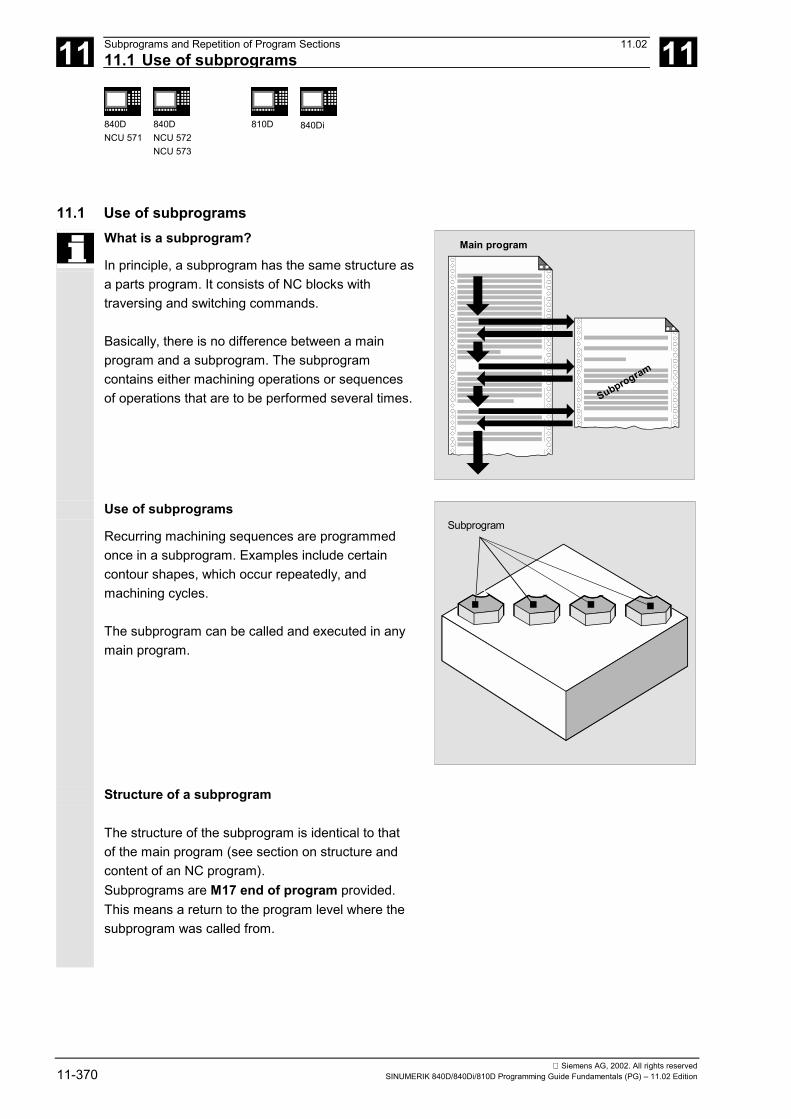
11 Subprograms and Repetition of Program Sections 11.0211.1 Use of subprograms 11
840DNCU 571
840DNCU 572NCU 573
810D 840Di
Siemens AG, 2002. All rights reserved11-370 SINUMERIK 840D/840Di/810D Programming Guide Fundamentals (PG) – 11.02 Edition
11.1 Use of subprogramsWhat is a subprogram?
In principle, a subprogram has the same structure asa parts program. It consists of NC blocks withtraversing and switching commands.
Basically, there is no difference between a mainprogram and a subprogram. The subprogramcontains either machining operations or sequencesof operations that are to be performed several times.
Main program
Subprogram
Use of subprograms
Recurring machining sequences are programmedonce in a subprogram. Examples include certaincontour shapes, which occur repeatedly, andmachining cycles.
The subprogram can be called and executed in anymain program.
Subprogram
Structure of a subprogram
The structure of the subprogram is identical to thatof the main program (see section on structure andcontent of an NC program).Subprograms are M17 end of program provided.This means a return to the program level where thesubprogram was called from.
11 11.02 Subprograms and Repetition of Program Sections11.1 Use of subprograms 11
840DNCU 571
840DNCU 572NCU 573
810D 840Di
Siemens AG, 2002. All rights reservedSINUMERIK 840D/840Di/810D Programming Guide Fundamentals (PG) – 11.02 Edition 11-371
Explanation
It is possible to suppress this end of program M17 inthe machine data (e.g.: to achieve a better runningtime).
Additional notes
A program header with parameter definitions canalso be programmed in the subprogram. You will finda more detailed description in the ProgrammingGuide "Advanced".
End of subprogram with RET
The instruction RET can also be used insubprograms as a substitute for the backward jumpwith M17.RET must be programmed in a separate block.The RET statement is used when G64 continuous-path mode is not to be interrupted by a return. Thisis only possible if the subprogram has no SAVEattribute.
If M17 is programmed in a separate block, G64 isinterrupted and an exact stop generated.Remedy:Do not write M17 in a subprogram block on its own,instead use it with, for example, a traverse path:G1 X=YY M17 must be set in the machine data:"No M17 from PLC".
Subprogram name
The subprogram is given a name allowing it to beselected from among the others. The name can befreely chosen during program creation, taking thefollowing conventions into account:• The first two characters must be letters.• The others can be letters, numerals or
underscore characters• A maximum of 31 characters can be used• No separators are to be used (see the section on
"Language elements of the programminglanguage")

11 Subprograms and Repetition of Program Sections 11.0211.1 Use of subprograms 11
840DNCU 571
840DNCU 572NCU 573
810D 840Di
Siemens AG, 2002. All rights reserved11-372 SINUMERIK 840D/840Di/810D Programming Guide Fundamentals (PG) – 11.02 Edition
The same rules apply as to the names of mainprograms.
Example:N10 POCKET1
It is also possible to use the address word L... insubprograms. The value can have 7 decimal places(integers only).Note: With address L, leading zeros aremeaningful for differentiation.
Example:
N10 L123
N20 L0123
N30 L00123
There are three different subprograms in thisexample.
Nesting depth
Subprograms can also be called from a subprogram,not only from a main program.In total, up to 12 program levels are available for thistype of nested call, including the main program level.
This means:Up to 11 nested subprogram calls can be issuedfrom the main program.
Mainprogram
Sub-program
Sub-program
Sub-program
max.11
Note:If you are working with SIEMENS machining andmeasuring cycles, then three levels are required. If acycle is to be called from a subprogram, this callcannot be issued from beyond level 9.

11 11.02 Subprograms and Repetition of Program Sections11.2 Subroutine call 11
840DNCU 571
840DNCU 572NCU 573
810D 840Di
Siemens AG, 2002. All rights reservedSINUMERIK 840D/840Di/810D Programming Guide Fundamentals (PG) – 11.02 Edition 11-373
11.2 Subroutine callSubprogram callYou call the subprogram in the main program eitherwith address L and the subprogram number or byspecifying the subprogram name.
Example:...
N120 L100 Subprogram call "L100.SPF":N10 MSG (DIN subroutine")
N20 G1 G91...
...
N60 M17 ;End of subprogram
N160 M30 End of main program
Example with transfer of R parameter:
N10 G0 X0 Y0 G90 T1 Tool T1 in rapid traverse to the firstposition, absolute dimension
N20 R10=10 R11=20 Describe arithmetic parameters R10 andR11
N30 RECTANGLE Call the rectangle subprogram"RECTANGLE.SPF" with transfer of Rparameters:N15 G1 X=R10 G91 F500
N25 Y=R11
N35 X=-R10
N45 Y=-R11
N55 M17 ;End of subprogram
N40 G0 X50 Y50 G90 Position tool at the next machiningposition
N50 RECTANGLE Call the rectangle subprogram"RECTANGLE.SPF" withtransfer of R parameters:
N60 M30
End of main program

11 Subprograms and Repetition of Program Sections 11.0211.2 Subroutine call 11
840DNCU 571
840DNCU 572NCU 573
810D 840Di
Siemens AG, 2002. All rights reserved11-374 SINUMERIK 840D/840Di/810D Programming Guide Fundamentals (PG) – 11.02 Edition
Call main program as subprogramA main program can also be called as a subprogram.The end of program set in the main program M30 isevaluated as M17 in this case (end of program withreturn to calling program).
You program the call specifying the program name.
Example:N10 MPF739 orN10 SHAFT3
Main program
N10 MPF739orN10SHAFT3
Furthermain program
N10......N50 M30
A subprogram can also be started as a mainprogram.
Additional notes
Search strategy of the control:1. Are there any *_MPF ?2. Are there any *_SPF ?This means: if the name of the subprogram to becalled is identical to the name of the main program,the main program that issues the call is called again.This is generally an undesirable effect and must beavoided by assigning unique names to subprogramsand main programs.
Call the subprograms with the INI file
Subprograms that do not require parameterassignment can be called from an initialization file:
Example:N10 MYINISUB1 ;Subprogram call
without parameters

11 11.02 Subprograms and Repetition of Program Sections11.3 Subprogram with program repetition 11
840DNCU 571
840DNCU 572NCU 573
810D 840Di
Siemens AG, 2002. All rights reservedSINUMERIK 840D/840Di/810D Programming Guide Fundamentals (PG) – 11.02 Edition 11-375
11.3 Subprogram with program repetitionProgram repetition, PIf a subprogram is to be executed several times insuccession, the desired number of programrepetitions can be entered at address P in the blockwith the subprogram call.
Example:N40 FRAME P3
The subprogram FRAME must be executed 3 timesin succession.
Value rangeP: 1…9999
The following applies to every subprogram call:
1 2 3
Main program
N40 FRAME P3Subprogram
The subprogram call must always be programmed ina separate NC block.
Subprogram call with program repetitionand parameter transferParameters are transferred only when the programis called, i.e. on the first run. The parameters remainunchanged for the remaining repetitions.
If you want to change the parameters duringprogram repetitions, you must make the appropriateprovision in the subprogram.

11 Subprograms and Repetition of Program Sections 11.0211.4 Program section repetition (SW 4.3 and higher) 11
840DNCU 571
840DNCU 572NCU 573
810D 840Di
Siemens AG, 2002. All rights reserved11-376 SINUMERIK 840D/840Di/810D Programming Guide Fundamentals (PG) – 11.02 Edition
11.4 Program section repetition (SW 4.3 and higher)
Function
As compared with subprogram technology, programsection repetition allows the repetition of existingprogram sections in any combination.The block or program sections to be repeated areidentified by labels.
For more information on labels, please see:References: /PG/, Programming Guide
Fundamentals, Section 2.2/PGA/, Programming Guide AdvancedSection 1.11, 1.12
Explanation
LABEL: Jump destination; the name of the jump destination is followed by a colonREPEAT Repeat (repeat several lines)REPEATB Repeat block (repeat one line only)
Programming
Repeat blockLABEL: xxx
yyy
REPEATB LABEL P=n
zzz
The program line identified by a label is repeatedP=n times.If P is not specified, the program section is repeatedexactly once. After the last repetition, the program iscontinued at the line zzz following the REPEATB line.
The block identified by the label can appear beforeor after the REPEATB statement.The search initially commences towards the start ofthe program.If the label is not found in this direction, the searchcontinues towards the end of the program.

11 11.02 Subprograms and Repetition of Program Sections11.4 Program section repetition (SW 4.3 and higher) 11
840DNCU 571
840DNCU 572NCU 573
810D 840Di
Siemens AG, 2002. All rights reservedSINUMERIK 840D/840Di/810D Programming Guide Fundamentals (PG) – 11.02 Edition 11-377
Programming example
Repetition of positionsN10 POSITION1: X10 Y20
N20 POSITION2: CYCLE(0,,9,8) Position cycleN30 ...
N40 REPEATB POSITION1 P=5 Execute block N10 five timesN50 REPEATB POSITION2 Execute block N20 onceN60 ...
N70 M30
Programming
Repeat area starting at labelLABEL: xxx
yyy
REPEAT LABEL P=n
zzz
The program section between the label with any nameand the REPEAT statement is repeated P=n times.If the block with the label contains further statements,these are executed again on each repetition.If P is not specified, the program section is repeatedexactly once.After the last repetition, the program is continued atthe line zzz following the REPEAT line.
The label must appear before the REPEAT statement.The search is performed towards the start of theprogram only.

11 Subprograms and Repetition of Program Sections 11.0211.4 Program section repetition (SW 4.3 and higher) 11
840DNCU 571
840DNCU 572NCU 573
810D 840Di
Siemens AG, 2002. All rights reserved11-378 SINUMERIK 840D/840Di/810D Programming Guide Fundamentals (PG) – 11.02 Edition
Programming example
5 squares with increasing width are to be producedN5 R10=15
N10 Begin: R10=R10+1 WidthN20 Z=10-R10
N30 G1 X=R10 F200
N40 Y=R10
N50 X=-R10
N60 Y=-R10
N70 Z=10+R10
N80 REPEAT BEGIN P=4 Execute area from N10 to N70 four timesN90 Z10
N100 M30
Programming
Repeat area between two labelsSTART_LABEL: xxx
ooo
END_LABEL: yyy
ppp
REPEAT START_LABEL END_LABEL P=n
zzz
The area between the two labels is repeated P=ntimes. User-defined names can be assigned to thelabels.The first line of the repetition contains the start label,the last line contains the end label. If the linecontaining the start or end label contains furtherstatements, these are executed again on each pass.If P is not specified, the program section is repeatedonce. After the last repetition, the program iscontinued at the line zzz following the REPEAT line.
The program section to be repeated can appearbefore or after the REPEAT statement. The searchinitially commences towards the start of the program.If the start label is not found in this direction, thesearch resumes from the REPEAT statementtowards the end of the program.

11 11.02 Subprograms and Repetition of Program Sections11.4 Program section repetition (SW 4.3 and higher) 11
840DNCU 571
840DNCU 572NCU 573
810D 840Di
Siemens AG, 2002. All rights reservedSINUMERIK 840D/840Di/810D Programming Guide Fundamentals (PG) – 11.02 Edition 11-379
It is not possible to nest the REPEAT statement withthe two labels within parentheses. If the start label isfound before the REPEAT statement and the endlabel is not reached before the REPEAT statement,the repetition is performed on the section betweenthe start label and the REPEAT statement.
Programming example
Repeat program section from BEGIN to ENDN5 R10=15
N10 Begin: R10=R10+1 WidthN20 Z=10-R10
N30 G1 X=R10 F200
N40 Y=R10
N50 X=-R10
N60 Y=-R10
N70 END:Z=10
N80 Z10
N90 CYCLE(10,20,30)
N100 REPEAT BEGIN END P=3 Execute area from N10 to N70 three timesN110 Z10
N120 M30
Programming
Repeat an area between a label and the end labelLABEL: xxx
ooo
ENDLABEL: yyy
REPEAT LABEL P=n
zzz
ENDLABEL is a predefined label with a fixed name.ENDLABEL marks the end of a program section andcan be used multiple times in the program.The block marked by ENDLABEL can contain furtherstatements.

11 Subprograms and Repetition of Program Sections 11.0211.4 Program section repetition (SW 4.3 and higher) 11
840DNCU 571
840DNCU 572NCU 573
810D 840Di
Siemens AG, 2002. All rights reserved11-380 SINUMERIK 840D/840Di/810D Programming Guide Fundamentals (PG) – 11.02 Edition
The area between a label and the followingENDLABEL is repeated P=n times. Any name canbe used to define the start label.If the block with the start label or ENDLABELcontains further statements, these are executed oneach repetition.
If no ENDLABEL is found between the start labeland the block with the REPEAT call, the loop endsbefore the REPEAT line. The construct thereforehas the same effect as described above in "repeatarea from label".If P is not specified, the program section is repeatedonce.After the last repetition, the program is continued atthe line zzz following the REPEAT line.
Programming example
N10 G1 F300 Z-10
N20 BEGIN1:
N30 X10
N40 Y10
N50 BEGIN2:
N60 X20
N70 Y30
N80 ENDLABEL: Z10
N90 X0 Y0 Z0
N100 Z-10
N110 BEGIN3: X20
N120 Y30
N130 REPEAT BEGIN3 P=3 Execute area from N110 to N120 three timesN140 REPEAT BEGIN2 P=2 Execute area from N50 to N80 twiceN150 M100
N160 REPEAT BEGIN1 P=2 Execute area from N20 to N80 twiceN170 Z10
N180 X0 Y0
N190 M30

11 11.02 Subprograms and Repetition of Program Sections11.4 Program section repetition (SW 4.3 and higher) 11
840DNCU 571
840DNCU 572NCU 573
810D 840Di
Siemens AG, 2002. All rights reservedSINUMERIK 840D/840Di/810D Programming Guide Fundamentals (PG) – 11.02 Edition 11-381
Preconditions• Program section repetitions can be nested. Each
call uses a subprogram level.• If M17 or RET is programmed during processing
of a program section repetition, the repetition isaborted. The program is resumed at the blockfollowing the REPEAT line.
• In the actual program display, the programsection repetition is displayed as a separatesubprogram level.
• If the level is canceled during the programsection repetition, the program resumes at thepoint after the program section repetition call.
Example:N5 R10=15
N10 BEGIN: R10=R10+1
N20 Z=10-R10
N30 G1 X=R10 F200
N40 Y=R10
N50 X=-R10
N60 Y=-R10
N70 END: Z10
N80 Z10
N90 CYCLE(10,20,30)
N100 REPEAT BEGIN END P=3
N120 Z10
N130 M30
Width Level cancellation Resume program processing
• Control structures and program section repetitionscan be used in combination.There should be no overlap between the two,however.A program section repetition should appear within acontrol structure branch or a control structureshould appear within a program section repetition.
11 Subprograms and Repetition of Program Sections 11.0211.4 Program section repetition (SW 4.3 and higher) 11
840DNCU 571
840DNCU 572NCU 573
810D 840Di
Siemens AG, 2002. All rights reserved11-382 SINUMERIK 840D/840Di/810D Programming Guide Fundamentals (PG) – 11.02 Edition
• If jumps and program section repetitions are mixed,the blocks are executed purely sequentially.For example, if a jump is performed from aprogram section repetition, processing continuesuntil the programmed end of the program sectionis found.
Example:N10 G1 F300 Z-10
N20 BEGIN1:
N30 X10
N40 Y10
N50 GOTOF BEGIN2
N60 ENDLABEL:
N70 BEGIN2:
N80 X20
N90 Y30
N100 ENDLABEL: Z10
N110 X0 Y0 Z0
N120 Z-10
N130 REPEAT BEGIN1 P=2
N140 Z10
N150 X0 Y0
N160 M30
ActivationProgram section repetition is activated by programming.
The REPEAT instruction should be placed behindthe traveling blocks.

11 11.02 Subprograms and Repetition of Program Sections11.4 Program section repetition (SW 4.3 and higher) 11
840DNCU 571
840DNCU 572NCU 573
810D 840Di
Siemens AG, 2002. All rights reservedSINUMERIK 840D/840Di/810D Programming Guide Fundamentals (PG) – 11.02 Edition 11-383
Programming example
Milling: Machine drill position with differenttechnologiesN10 CENTER DRILL() Load center drillN20 POS_1: Drill positions 1N30 X1 Y1
N40 X2
N50 Y2
N60 X3 Y3
N70 ENDLABEL:
N80 POS_2: Drill positions 2N90 X10 Y5
N100 X9 Y-5
N110 X3 Y3
N120 ENDLABEL:
N130 DRILL() Change drill and drilling cycleN140 THREAD(6) Load tap M6 and threading cycleN150 REPEAT POS_1 Repeat program section once from
POS_1 up to ENDLABELN160 DRILL() Change drill and drilling cycleN170 THREAD(8) Load tap M8 and threading cycleN180 REPEAT POS_2 Repeat program section once from
POS_2 up to ENDLABELN190 M30
�

11 Subprograms and Repetition of Program Sections 11.0211.4 Program section repetition (SW 4.3 and higher) 11
840DNCU 571
840DNCU 572NCU 573
810D 840Di
Siemens AG, 2002. All rights reserved11-384 SINUMERIK 840D/840Di/810D Programming Guide Fundamentals (PG) – 11.02 Edition
Notes

12 11.02 Tables 12
Siemens AG, 2002. All rights reservedSINUMERIK 840D/840Di/810D Programming Guide Fundamentals (PG) – 11.02 Edition 12-385
Tables
12.1 List of statements ........................................................................................................ 12-386
12.2 List of addresses ......................................................................................................... 12-40312.2.1 Address letters ..................................................................................................... 12-40312.2.2 Fixed addresses................................................................................................... 12-40412.2.3 Fixed addresses with axis extension ................................................................... 12-40512.2.4 Settable addresses .............................................................................................. 12-407
12.3 List of G functions/preparatory functions..................................................................... 12-411
12.4 List of predefined subprograms................................................................................... 12-42312.4.1 Predefined subprogram calls ............................................................................... 12-42412.4.2 Predefined subprogram calls in motion-synchronous actions ............................. 12-43412.4.3 Predefined functions ............................................................................................ 12-43512.4.4 Data types ............................................................................................................ 12-438

12 Tables 11.0212.1 List of statements 12
840 DNCU 571
840 DNCU 572NCU 573
810D 840Di
Siemens AG, 2002. All rights reserved12-386 SINUMERIK 840D/840Di/810D Programming Guide Fundamentals (PG) – 11.02 Edition
12.1 List of statements
Legend:1 Default setting at beginning of program (factory settings of the control, if nothing else programmed).2 The groups are numbered according to the table headed "List of G functions/preparatory functions" in Section 12.33 Absolute end points: modal; incremental end points: non-modal; otherwise modal/non-modal (m, s) depending on syntax of G function.4 As arc centers, IPO parameters act incrementally. They can be programmed in absolute mode with AC. With other meanings (e.g. pitch), the address modification is ignored.5 The vocabulary word is not valid for SINUMERIK FM-NC/810D6 The vocabulary word is not valid for SINUMERIK FM-NC/810D/NCU5717 The vocabulary word is not valid for SINUMERIK 810D8 The OEM can add two extra interpolation types. The names can be changed by the OEM.9 The vocabulary word is only valid for SINUMERIK FM-NC10 Extended address notation cannot be used for these functions.
Name Definition Valueassignment
Description,comment
Syntax Modal/non-modal
Group 2
: Block number - main block (see N) 0 ...9999 9999integersonly, withoutsigns
Special blockidentification -instead of N... ;this block shouldcontain allstatements for acompletesubsequentmachining section
e.g.. :20
A Axis Real m,s 3
A2 5 Tool orientation: Euler angles Real s
A3 5 Tool orientation: Direction vectorcomponent
Real s
A4 5 Tool orientation for start of block Real s
A5 5 Tool orientation for end of block;normal vector component
Real s
AC Input of absolute dimensions 0, ...,359.9999°
X=AC(100) s
ACC 5 Axial acceleration Real, w/osigns
m
ACN Absolute dimensions for rotary axes,approach position in negative direction
A=ACN(...) B=ACN(...)C=ACN(...)
s
ACP Absolute dimensions for rotary axes,approach position in positive direction
A=ACP(...) B=ACP(...)C=ACP(...)
s
ADIS Approximate distance for path functionsG1, G2, G3, ...
Real, w/osigns
m
ADISPOS Approximate distance for rapid traverseG0
Real, w/osigns
m
ALF Angle tilt fast Integer, w/osigns
m

12 11.02 Tables12.1 List of statements 12
840 DNCU 571
840 DNCU 572NCU 573
810D 840Di
Siemens AG, 2002. All rights reservedSINUMERIK 840D/840Di/810D Programming Guide Fundamentals (PG) – 11.02 Edition 12-387
Name Definition Valueassignment
Description,comment
Syntax Modal/non-modal
Group 2
AMIRROR Programmable mirroring (additive mirror) AMIRROR X0 Y0 Z0; separate block
s 3
ANG Contour angle s
AP Angle polar 0, ..., ± 360° m,s 3
AR Aperture angle (angle circular) 0, ..., 360° m,s 3
AROT Programmable rotation(additive rotation)
Rotationaround 1stgeo. axis:-180o .. 180°2nd geo.axis:-89.999° ... 90°3rd geo.axis:-180° .. 180°
AROT X... Y... Z... ;SeparateAROT RPL= block
s 3
AROTS Programmable frame rotations with solid angles(additive rotation)
AROTS X... Y...AROTS Z... X...AROTS Y... Z... ;separateAROTS RPL= block
s 3
ASCALE Programmable scaling (additive scale) ASCALE X... Y... Z...; separate block
s 3
ASPLINE Akima spline m 1
ATRANS Additive programmable shift(additive translation)
ATRANS X... Y... Z...; separate block
s 3
AX Variable axis identifier Real m,s 3
AXCTSWE Advance container axis AXCTSWE(CTi) 25
B Axis Real m,s 3
B2 5 Tool orientation:Euler angles
Real s
B3 5 Tool orientation:Direction vector component
Real s
B4 5 Tool orientation for start of block Real s
B5 5 Tool orientation for end of block;normal vector component
Real s
BAUTO Definition of first spline segment by the following 3points (begin not a knot)
m 19
BNAT 1 Natural transition to first spline block (begin natural) m 19
BRISK 1 Brisk path acceleration m 21
BRISKA Switch on brisk path acceleration for the programmedaxes
BSPLINE B spline m 1
BTAN Tangential transition to first spline block(begin tangential)
m 19
C Axis Real m,s 3
C2 5 Tool orientation: Euler angles Real s
C35 Tool orientation:Direction vector component
Real s

12 Tables 11.0212.1 List of statements 12
840 DNCU 571
840 DNCU 572NCU 573
810D 840Di
Siemens AG, 2002. All rights reserved12-388 SINUMERIK 840D/840Di/810D Programming Guide Fundamentals (PG) – 11.02 Edition
Name Definition Valueassignment
Description,comment
Syntax Modal/non-modal
Group 2
C4 5 Tool orientation for start of block Real s
C5 5 Tool orientation for end of block;normal vector component
Real s
CDOF 1 Collision detection OFF m 23
CDON Collision detection ON m 23
CDOF2 Collision detection OFF For CUT3DC only m 23
CFC 1 Constant feed at contour m 16
CFTCP Constant feed in tool edge reference point (center-pointpath)
m 16
CFIN Constant feed at internal radius only,not at external radius
m 16
CHFSW 3.5 andhigherCHR
Chamfer; value = length of chamfer
Chamfer; value = width of chamfer indirection of movement (chamfer)
Real, w/o signs S
CHKDNO Check for unique D numbers
CIP Circular interpolation through intermediatepoint
CIP X... Y... Z...I1=... J1=... K1=...
m 1
CLGOF Const. workpiece speed for centerless grinding OFF
CLGON Const. workpiece speed for centerless grinding ON
COMPOF 1,6 Compressor OFF m 30
COMPON 6 Compressor ON m 30COMPCURV Compressor ON: polynomials with constant curvature m 30
COMPCAD Compressor ON: Surface quality CAD program m 30
CP Continuous path; path motion m 49
CPRECOF1,6 Programmable contour precision OFF m 39
CPRECON 6 Programmable contour precision ON m 39
CR Circle radius Real, w/o signs S
CROTS Programmable frame rotations with solid angles(rotation in the specified axes)
CROTS X... Y...CROTS Z... X...CROTS Y... Z... ;separateCROTS RPL= block
S
CSPLINE Cubic spline m 1
CT Circle with tangential transition CT X... Y.... Z... m 1
CUT2D 1 2 ½D cutter compensation type 2-dimensional m 22
CUT2DF 2 ½D cutter compensation type 2-dimensional frame;Tool compensation is effective in relation to the currentframe (inclined plane)
m 22
CUT3DC 5 3D cutter compensation type 3-dimensionalcircumference milling
m 22
CUT3DCC 5 Cutter compensation type 3-dimensional circumferencemilling with limit surfaces
m 22

12 11.02 Tables12.1 List of statements 12
840 DNCU 571
840 DNCU 572NCU 573
810D 840Di
Siemens AG, 2002. All rights reservedSINUMERIK 840D/840Di/810D Programming Guide Fundamentals (PG) – 11.02 Edition 12-389
Name Definition Valueassignment
Description,comment
Syntax Modal/non-modal
Group 2
CUT3DCCD 5 Cutter compensation type 3-dimensional circumferencemilling with limit surfaces with differential tool
m 22
CUT3DF 5 3D cutter compensation type 3-dimensional face milling m 22
CUT3DFF 5 3D cutter compensation type 3-dimensional face millingwith constant tool orientation dependent on the currentframe
m 22
CUT3DFS 5 3D cutter compensation type 3-dimensional face millingwith constant tool orientation independent of the currentframe
m 22
CUTCONOF 1 Constant radius compensation OFF m 40CUTCONON Constant radius compensation ON m 40
D Tool offset number 1, ..., 9
in SW 3.5and higher1, ... 32 000
contains offsetdata for a specifictool T... ; D0 →Offset values for atool
D...
DC Absolute dimensions for rotary axes,approach position directly
A=DC(...) B=DC(...)C=DC(...)SPOS=DC(...)
s
DIAMCYCOF Radius programming for G90/G91: ON. The G-code ofthis group that was last active remains active for display
Radius program-ming last activeG-code
m 29
DIAMOF 1 Diameter programming: OFF Radius program-ming for G90/G91
m 29
DIAMON Diametral programming: ON Diameter progr.for G90/G91
m 29
DIAM90 Diametral programming: for G90, radius progr. For G91 m 29
DILF Length for lift fast mDISC Transition circle overshoot - radius
compensation0, ..., 100 m
DISPR Distance for repositioning Real, w/osigns
S
DISR Distance for repositioning Real, w/osigns
S
DITE Thread run-out path Real m
DITS Thread run-in path Real m
DL Total tool offset INT m
DRFOF Deactivate the handwheel offsets (DRF) m
DRIVE 9 Velocity-dependent path acceleration m 21
EAUTO Definition of last spline section by the last 3 points (endnot a knot)
m 20
ENAT 1 Natural transition to next traversing block (end natural) m 20
ETAN Tangential transition to next traversing block at splineend (end tangential)
m 20

12 Tables 11.0212.1 List of statements 12
840 DNCU 571
840 DNCU 572NCU 573
810D 840Di
Siemens AG, 2002. All rights reserved12-390 SINUMERIK 840D/840Di/810D Programming Guide Fundamentals (PG) – 11.02 Edition
Name Definition Valueassignment
Description,comment
Syntax Modal/non-modal
Group 2
F Feed value(in conjunction with G4 the dwell time isalso programmed in F)
0.001, ...,99 999.999
Tool/workpiecepath feedrate;unit of measure-ment in mm/min ormm/rev dependenton G94 or G95
F=100 G1 ...
FA Axial feed 0.001, ...,999999.999mm/min,degr./min;0.001, ...,39999.9999inch/min
FA[X]=100 m
FCUB 6 Feedrate variable according to cubic spline(feed cubic)
m 37
FD Path feed for handwheel override(feed DRF)
Real, w/osigns
S
FDA Axial feed for handwheel override(feed DRF axial)
Real, w/osigns
S
FENDNORM Corner deceleration OFF m 57
FFWOF 1 Feedforward control OFF (feed forward OFF) m 24
FFWON Feedforward control ON (feed forward ON) m 24
FGREF Reference radius m
FGROUP Definition of axis/axes with path feed F applies for axesspecified underFGROUP
FGROUP (axis1, [axis2], ...)
FIFOCTRL Preprocessing memory control m 4
FL Speed limit for synchronized axes(feed limit)
Real, w/osigns
The unit set withG93, G94, G95 isapplicable (max.rapid traverse)
FL [axis] =... m
FLIN 6 Feed linear variable (feed linear) m 37
FMA Feed multiple axial Real, w/osigns
m
FNORM 1,6 Feed normal to DIN 66025 m 37
FORI1 Feed for rotating orientation vector on large circle m
FORI2 Feed for rotation superimposed on rotated orientationvector
m
FP Fixed point: number of fixed point to beapproached
Integer, w/osigns
G75 FP=1 S
FPR Identification for rotary axis 0.001 ...999999.999
FPR (rotary axis)
FPRAOF Deactivate revolutional feedrate
FPRAON Activate revolutional feedrate
FRC Feed for radius and chamfer s
FRCM Feed for radius and chamfer, modal m
FTOCOF 1,6 Online fine tool offset OFF m 33
FTOCON 6 Online fine tool offset ON m 33
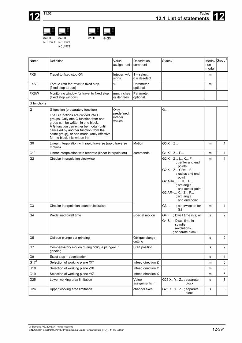
12 11.02 Tables12.1 List of statements 12
840 DNCU 571
840 DNCU 572NCU 573
810D 840Di
Siemens AG, 2002. All rights reservedSINUMERIK 840D/840Di/810D Programming Guide Fundamentals (PG) – 11.02 Edition 12-391
Name Definition Valueassignment
Description,comment
Syntax Modal/non-modal
Group 2
FXS Travel to fixed stop ON Integer, w/osigns
1 = select,0 = deselect
m
FXST Torque limit for travel to fixed stop(fixed stop torque)
% Parameteroptional
m
FXSW Monitoring window for travel to fixed stop(fixed stop window)
mm, inchesor degrees
Parameteroptional
G functions
G G function (preparatory function)The G functions are divided into Ggroups. Only one G function from onegroup can be written in one block.A G function can either be modal (untilcanceled by another function from thesame group), or non-modal (only effectivefor the block it is written in).
Onlypredefined,integervalues
G...
G0 Linear interpolation with rapid traverse (rapid traversemotion)
Motion G0 X... Z... m 1
G11 Linear interpolation with feedrate (linear interpolation) commands G1 X... Z... F... m 1
G2 Circular interpolation clockwise G2 X... Z... I... K... F... ; center and end points
G2 X... Z... CR=... F...; radius and end point
G2 AR=... I... K... F...; arc angle and center point
G2 AR=... X... Z... F...; arc angle and end point
m 1
G3 Circular interpolation counterclockwise G3 ... ; otherwise as for G2
m 1
G4 Predefined dwell time Special motion G4 F... ; Dwell time in s, orG4 S... ; Dwell time in
spindle revolutions.; separate block
s 2
G5 Oblique plunge-cut grinding Oblique plunge-cutting
s 2
G7 Compensatory motion during oblique plunge-cutgrinding
Start position s 2
G9 Exact stop – deceleration s 11
G171 Selection of working plane X/Y Infeed direction Z m 6
G18 Selection of working plane Z/X Infeed direction Y m 6
G19 Selection of working plane Y/Z Infeed direction X m 6
G25 Lower working area limitation Valueassignments in
G25 X.. Y.. Z.. ; separate block
s 3
G26 Upper working area limitation channel axes G26 X.. Y.. Z.. ; separate block
s 3

12 Tables 11.0212.1 List of statements 12
840 DNCU 571
840 DNCU 572NCU 573
810D 840Di
Siemens AG, 2002. All rights reserved12-392 SINUMERIK 840D/840Di/810D Programming Guide Fundamentals (PG) – 11.02 Edition
Name Definition Valueassignment
Description,comment
Syntax Modal/non-modal
Group 2
G33 Thread interpolation with constant pitch 0.001, ...,2000.00mm/rev
Motion command G33 Z... K... SF=... ; cylinder thread
G33 X... I... SF=... ; cross thread
G33 Z... X... K... SF=...; taper thread (in Z axis path greater than in X axis)
G33 Z... X... I... SF=... ; taper thread (in X axis path greater than in Z axis)
m 1
G34 Linear degressive speed change [mm/rev2] Motion command G34 X.. Y.. Z.. I.. J.. K.. F.. m 1
G35 Linear progressive speed change [mm/rev2] Motion command G35 X.. Y.. Z.. I.. J.. K.. F.. m 1
G40 1 Tool radius compensation OFF m 7
G41 Tool radius compensation to left of contour m 7
G42 Tool radius compensation to right of contour m 7
G53 Suppression of current zero offset (non-modal) incl. programmedoffsets
s 9
G54 1st settable zero offset m 8
G55 2nd settable zero offset m 8
G56 3rd settable zero offset m 8
G57 4th settable zero offset m 8
G58 Axial programmable zero offset, absolute s 3
G59 Axial programmable zero offset, additive s 3
G60 1 Exact stop - deceleration m 10
G62 Corner deceleration at inside corners when tool radiusoffset is active (G41, G42)
Only in conjunc-tion with contin-uous-path mode
G62 Z... G1 m 57
G63 Tapping with compensating chuck G63 Z... G1 s 2
G64 Exact stop - continuous-path mode m 10
G70 Dimension in inches (lengths) m 13
G71 1 Metric dimension (lengths) m 13
G74 Reference point approach G74 X... Z...; separate block s 2
G75 Fixed point approach Machine axes G75 FP=.. X1=... Z1=...;separate block
s 2
G90 1 Absolute dimensions G90 X... Y... Z...(...)Y=AC(...) orX=AC Z=AC(...)
ms
14
G91 Incremental dimensions G91 X... Y... Z... orX=IC(...) Y=IC(...) Z=IC(...)
ms
14
G93 Inverse-time feedrate rpm Execution of ablock: Time
G93 G01 X... F... m 15
G94 1 Linear feedrate F in mm/min or inch/min and °/min m 15
G95 Revolutional feedrate F in mm/rev or inches/rev m 15
G96 Constant cutting speed (as for G95) ON G96 S... LIMS=... F... m 15
G97 Constant cutting speed (as for G95) OFF m 15

12 11.02 Tables12.1 List of statements 12
840 DNCU 571
840 DNCU 572NCU 573
810D 840Di
Siemens AG, 2002. All rights reservedSINUMERIK 840D/840Di/810D Programming Guide Fundamentals (PG) – 11.02 Edition 12-393
Name Definition Valueassignment
Description,comment
Syntax Modal/non-modal
Group 2
G110 Polar programming relative to last programmed setposition
G110 X.. Y.. Z.. s 3
G111 Polar programming relative to origin of currentworkpiece coordinate system
G110 X.. Y.. Z.. s 3
G112 Polar programming relative to last valid pole G110 X.. Y.. Z.. s 3
G140 1 SAR approach direction defined by G41/G42 m 43
G141 SAR approach direction to left of contour m 43
G142 SAR approach direction to right of contour m 43
G143 SAR approach direction tangent-dependent m 43
G147 Soft approach with straight line s 2
G148 Soft retraction with straight line s 2
G153 Suppress current frames including base frame incl. system frame s 9
G247 Soft approach with quadrant s 2
G248 Soft retraction with quadrant s 2
G290 Switch to SINUMERIK mode ON m 47
G291 Switch to FANUC mode ON m 47
G331 Tapping ±0.001, ..., Motion m 1
G332 Retraction (tapping) 2000.00mm/rev
commands m 1
G340 1 Spatial approach block (depth and in plane(helix))
Effective duringsoft approach/retraction
m 44
G341 Initial infeed on perpendicular axis (z), thenapproach in plane
Effective duringsoft approach/retraction
m 44
G347 Soft approach with semicircle s 2
G348 Soft retraction with semicircle s 2
G450 1 Transition circle Tool radius comp. m 18
G451 Intersection of equidistant paths Resp. at corners m 18
G460 1 Collision monitoring for approach and retraction block on m 48
G461 Extend border block with arc if m 48
G462 Extend border block with line if
no intersection inTRC block m 48
G500 1 Deactivate all settable frames if G500 does not containa value
m 8
G505.... G599
5. ... 99. Settable zero offset m 8
G601 1 Block change on exact stop fine m 12
G602 Block change at stop exact coarse m 12
G603 Block change at IPO - end of block m 12
G641 Exact stop - continuous-path mode G641 ADIS=... m 10
G642 Corner rounding with axial precision
Only effective withactive G60 or G9with program-mable transitionrounding m 10
G643 Block-internal corner rounding m 10
G644 Corner rounding with specified axis dynamics m 10
G621 Corner deceleration at all corners Only in conjunc-tion with contin-uous-path mode
G621 ADIS=... m 57

12 Tables 11.0212.1 List of statements 12
840 DNCU 571
840 DNCU 572NCU 573
810D 840Di
Siemens AG, 2002. All rights reserved12-394 SINUMERIK 840D/840Di/810D Programming Guide Fundamentals (PG) – 11.02 Edition
Name Definition Valueassignment
Description,comment
Syntax Modal/non-modal
Group 2
G700 Dimension in inches and inch/min(lengths + velocities + system variable)
m 13
G710 1 Metric dimension in mm and mm/min(lengths + velocities + system variable)
m 13
G8101, ...,G819
G group reserved for the OEM 31
G8201, ...,G829
G group reserved for the OEM 32
G931 Feedrate specified by travel time Travel time m 15
G942 Freeze linear feedrate and constant cutting rate orspindle speed
m 15
G952 Freeze revolutional feedrate and constant cutting rate orspindle speed
m 15
G961 Constant cutting speed (as for G94) ON G961 S... LIMS=... F... m 15
G962 Linear or revolutional feedrate and constant cutting rate m 15
G971 Constant cutting speed (as for G94) OFF m 15
G972 Freeze linear or revolutional feedrate and constantspindle speed
m 15
GOTOF Jump forwards (towards the end of the program)
GOTOB Jump backwards (towards the start of the program)
GWPSOF Deselect constant grinding wheelperipheral speed (GWPS)
GWPSOF(T No.) s
GWPSON Select constant grinding wheel peripheralspeed (GWPS)
GWPSON (T No.) s
H... Auxiliary function output to PLC Real/INTProgram:REAL :±3.4028ex38INT:-2147483648+2147483648Display:±999 999999.9999
Can be set by MD(machinemanufacturer)
H100 or H2=100
I 4 Interpolation parameters Real s
I1 Intermediate point coordinate Real s
IC Input of incremental dimensions 0, ...,±99999.999°
X=IC(10) s
INCW Travel on a circle involute in CW directionwith interpolation of involute byG17/G18/G19
Real m 1
INCCW Travel on a circle involute in CCWdirection with interpolation of involute byG17/G18/G19
Real
End point:Center point:Radius with CR >0:Angle of rotationin degreesbetween start andend vectors
INCW/INCCW X... Y... Z...INCW/INCCW I... J... K...INCW/INCCW CR=... AR...Direct programming:INCW/INCCW I... J... K...CR=... AR=...
m 1
ISD Insertion depth Real m
J 4 Interpolation parameters Real s
J1 Intermediate point coordinate Real s
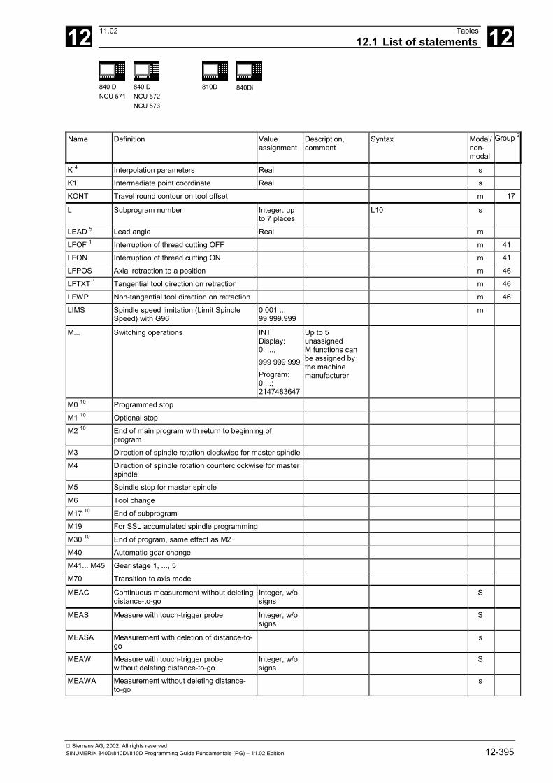
12 11.02 Tables12.1 List of statements 12
840 DNCU 571
840 DNCU 572NCU 573
810D 840Di
Siemens AG, 2002. All rights reservedSINUMERIK 840D/840Di/810D Programming Guide Fundamentals (PG) – 11.02 Edition 12-395
Name Definition Valueassignment
Description,comment
Syntax Modal/non-modal
Group 2
K 4 Interpolation parameters Real s
K1 Intermediate point coordinate Real s
KONT Travel round contour on tool offset m 17
L Subprogram number Integer, upto 7 places
L10 s
LEAD 5 Lead angle Real m
LFOF 1 Interruption of thread cutting OFF m 41
LFON Interruption of thread cutting ON m 41
LFPOS Axial retraction to a position m 46
LFTXT 1 Tangential tool direction on retraction m 46
LFWP Non-tangential tool direction on retraction m 46
LIMS Spindle speed limitation (Limit SpindleSpeed) with G96
0.001 ...99 999.999
m
M... Switching operations INTDisplay:0, ...,999 999 999Program:0;...;2147483647
Up to 5unassignedM functions canbe assigned bythe machinemanufacturer
M0 10 Programmed stop
M1 10 Optional stop
M2 10 End of main program with return to beginning ofprogram
M3 Direction of spindle rotation clockwise for master spindle
M4 Direction of spindle rotation counterclockwise for masterspindle
M5 Spindle stop for master spindle
M6 Tool change
M17 10 End of subprogram
M19 For SSL accumulated spindle programming
M30 10 End of program, same effect as M2
M40 Automatic gear change
M41... M45 Gear stage 1, ..., 5
M70 Transition to axis mode
MEAC Continuous measurement without deletingdistance-to-go
Integer, w/osigns
S
MEAS Measure with touch-trigger probe Integer, w/osigns
S
MEASA Measurement with deletion of distance-to-go
s
MEAW Measure with touch-trigger probewithout deleting distance-to-go
Integer, w/osigns
S
MEAWA Measurement without deleting distance-to-go
s

12 Tables 11.0212.1 List of statements 12
840 DNCU 571
840 DNCU 572NCU 573
810D 840Di
Siemens AG, 2002. All rights reserved12-396 SINUMERIK 840D/840Di/810D Programming Guide Fundamentals (PG) – 11.02 Edition
Name Definition Valueassignment
Description,comment
Syntax Modal/non-modal
Group 2
MIRROR Programmable mirror MIRROR X0 Y0 Z0; separate block
s 3
MOV
MSG Programmable messages MSG("message") m
N Block number - subblock 0, ...,9999 9999integersonly, w/osigns
Can be used toidentify blocks bymeans of anumber; written atbeginning of block
e.g. N20
NORM 1 Standard setting in starting point and end point with tooloffset
m 17
OEMIPO1 6,8 OEM interpolation 1 m 1
OEMIPO2 6,8 OEM interpolation 2 m 1
OFFN Allowance on the programmed contour OFFN=5
OMA1 6 OEM address 1 Real m
OMA2 6 OEM address 2 Real m
OMA3 6 OEM address 3 Real m
OMA4 6 OEM address 4 Real m
OMA5 6 OEM address 5 Real m
OFFN Offset - normal Real m
ORIC 1,6 Orientation changes at outside corners aresuperimposed on the circle block to be inserted(orientation change continuously)
m 27
ORID 6 Orientation changes are performed before the circleblock (orientation change discontinuously)
m 27
ORIAXPOS Orientation angle via virtual orientation axes with rotaryaxis positions
m 50
ORIEULER Orientation angle via Euler angle m 50
ORIAXES Linear interpolation of machine axes or orientation axes m 51
ORICONCW
Interpolation on a circular peripheral surface in CWdirection
m 51
ORICONCCW
Interpolation on a circular peripheral surface in CCWdirection
m 51
ORICONIO Interpolation on a circular peripheral surface withintermediate orientation setting
m 51
ORICONTO Interpolation on a circular peripheral surface intangential transition
m 51
ORICURVE Interpolation of orientation with specification of motion oftwo contact points of tool
m 51
ORIPLANE Interpolation in a plane (corresponds to ORIVECT)large-radius circular interpolation
Final orientation:Vectorspecification A3,B3, C3 orEuler/RPY angleA2, B2, C2Additional inputs:Rotational vectorsA6, B6, C6Arc angle of taperin degrees 0 <SLOT <180degreesIntermediate vec-tors: A7, B7, C72nd contact pointof tool: XH, YH,ZH,
Parameter settings asfollows:Direction vectorsnormalized A6=0 B6=0C6=1Arc angle implemented astravel angle withSLOT=...SLOT=+... at ≤ 180 degreesSLOT= -... at ≥ 180 degreesIntermediate orientationnormalized A7=0 B7=0C7=1 m 51
ORIPATH Tool orientation trajectory referred to path Transformationpackage handling,see /FB/, TE4
m 51
ORIROTA Angle of rotation in relation to absolute direction ofrotation
m 54

12 11.02 Tables12.1 List of statements 12
840 DNCU 571
840 DNCU 572NCU 573
810D 840Di
Siemens AG, 2002. All rights reservedSINUMERIK 840D/840Di/810D Programming Guide Fundamentals (PG) – 11.02 Edition 12-397
Name Definition Valueassignment
Description,comment
Syntax Modal/non-modal
Group 2
ORIROTR Angle of rotation relative to plane between start and endorientations
m 54
ORIROTT Angle of rotation relative to change in orientation vector m 54
ORIRPY Orientation angle via RPY angle m 50
ORIS 5 Orientation modification(orientation smoothing factor)
Real Referring to thepath
m
ORIVECT Large-radius circular interpolation (identical toORIPLANE)
m 51
ORIVIRT1 Orientation angle via virtual orientation axes (definition 1) m 50
ORIVIRT2 Orientation angle via virtual orientation axes (definition 1) m 50
ORIMKS 6 Tool orientation in the machine coordinate system m 25
ORIWKS 1,6 Tool orientation in the workpiece coordinate system m 25
OS Oscillation on/off Integer, w/osigns
OSC 6 Continuous tool orientation smoothing m 34
OSCILL Axis assignment for oscillation -activate oscillation
Axis: 1–3 infeedaxes
m
OSCTRL Oscillation control options Integer, w/osigns
m
OSE Oscillating: End point m
OSNSC Oscillating: Number of spark-out cycles number spark out cycles)
m
OSOF 1,6 Tool orientation smoothing OFF m 34
OSP1 Oscillating: Left reversal point(oscillating: position 1)
Real m
OSP2 Oscillating: Right reversal point(oscillating: position 2)
Real m
OSS 6 Tool orientation smoothing at end of block m 34
OSSE 6 Tool orientation smoothing at start and end of block m 34
OST1 Oscillating: Stop at left reversal point Real m
OST2 Oscillating: Stop at right reversal point Real m
OVR Speed override 1, ..., 200% m
OVRA Axial speed override 1, ..., 200% m
P Number of subprogram passes 1 ... 9999,integers w/osigns
e.g. L781 P...; separate block
PAROTOF Deactivate workpiece-related frame rotation m 52
PAROT Align workpiece coordinate system on workpiece m 52
PDELAY-OF 6
Punch with delay OFF m 36
PDELAY-ON 1,6
Punch with delay ON m 36
PL Parameter interval length Real, w/osigns
S
POLY 5 Polynomial interpolation m 1
PON 6 Punch ON m 35

12 Tables 11.0212.1 List of statements 12
840 DNCU 571
840 DNCU 572NCU 573
810D 840Di
Siemens AG, 2002. All rights reserved12-398 SINUMERIK 840D/840Di/810D Programming Guide Fundamentals (PG) – 11.02 Edition
Name Definition Valueassignment
Description,comment
Syntax Modal/non-modal
Group 2
PONS 6 Punch ON in IPO cycle (punch ON slow) m 35
POS Position axis POS[X]=20
POSA Position axis across block boundary POSA[Y]=20
POLF LIFTFAST position mPRESETON Sets the actual value for programmed axes An axis identifier
is programmedwith thecorrespondingvalue in the nextparameter.Up to 8 axespossible
PRESETON(X,10,Y,4.5)
PTP Point to point Synchronized axis m 49
PUTFTOC PutFineToolCorrection:Fine tool correction for continuous dressing
PUTFTOCF PutFineToolCorrectionFunctionDependent:Fine tool correction depending on a function defined byFCtDEF for continuous dressing
PW Point weight Real, w/osigns
S
R... Arithmetic parametersSW 5 and higher:also as settable address identifier andwith numerical extension
±0.0000001,...,9999 9999
Number of Rparameters can beset by MD
R10=3 ;R parameterassignmentX=R10 ;axis valueR[R10]=6 ;indirect prog.
REPOSA Repositioning linear all axes:Linear repositioning with all axes
s 2
REPOSH Repositioning semicircle:Repositioning in semicircle
s 2
REPOSHA Repositioning semicircle all axes:Repositioning with all axes; geometry axes in semicircle
s 2
REPOSL Repositioning linear:Linear repositioning
s 2
REPOSQ Repositioning quarter-circle:Return to contour in a quarter-circle
s 2
REPOSQA Repositioning quarter-circle all axes:Return to contour linear all axes; geometry axes inquarter-circle
s 2
RET End of subprogram Use in place ofM17 – withoutfunction output toPLC
RET
RMB Repositioning at beginning of block(Repos mode begin of block)
m 26
RME Repositioning at end of block(Repos mode end of block)
m 26
RMI 1 Repositioning at interruption point(Repos mode interrupt)
m 26
RMN Reapproach to nearest path point(Repos mode of nearest orbital block)
m 26

12 11.02 Tables12.1 List of statements 12
840 DNCU 571
840 DNCU 572NCU 573
810D 840Di
Siemens AG, 2002. All rights reservedSINUMERIK 840D/840Di/810D Programming Guide Fundamentals (PG) – 11.02 Edition 12-399
Name Definition Valueassignment
Description,comment
Syntax Modal/non-modal
Group 2
RND Round contour corner Real, w/osigns
RND=... s
RNDM Modal rounding Real, w/osigns
RNDM=...RNDM=0: switch off m.r.
m
ROT Programmable rotation Rotationaround1st geometryaxis:-180° .. 180°2nd geoaxis:-89.999°,..., 90°3rd geo axis:-180° .. 180°
ROT X... Y... Z...ROT RPL= ;separate
block
s 3
ROTS Programmable frame rotations with solid angles(rotation)
ROTS X... Y...ROTS Z... X...ROTS Y... Z... ;separateROTS RPL= block
s 3
RP Polar radius Real m,s 3
RPL Rotation in the plane Real, w/osigns
S
RTLION G0 with linear interpolation m 55
RTLIOF G0 without linear interpolation (single-axis interpolation) m 55
S Spindle speed or(with G4, G96) other meaning
REALDisplay:±999 999999.9999Program:±3.4028ex38
Spindle speed inrpmG4: dwell time inspindle revolutionsG96: cuttingspeed in m/min
S...: speed for master spindle
S1...: speed for spindle 1
m, s
SCALE Programmable scaling (scale) SCALE X... Y... Z...; separate block
s 3
SD Spline degree Integer, w/osigns
S
SETMS Reset to the master spindle defined in machine data
SETMS(n) Set spindle n as master spindle
SF Starting point offset for thread cutting(spline offset)
0.0000, ...,359.999°
m
SOFT Soft acceleration with jerk limitation m 21
SON 6 Nibbling ON (stroke ON) m 35
SONS 6 Nibbling ON in IPO cycle (stroke ON slow) m 35
SPATH 1 Path reference for FGROUP axes is arc length m 45
SPCOF Switch master spindle or spindle(s) from speed controlto position control
SPCONSPCON (n)
SPCON Switch master spindle or spindle(s) from position controlto speed control
SPCONSPCON (n)
SPIF1 1,6 Fast NCK inputs/outputs for punching/nibbling byte 1(stroke/punch interface 1)
m 38
SPIF2 6 Fast NCK inputs/outputs for punching/nibbling byte 2(stroke/punch interface 2)
m 38

12 Tables 11.0212.1 List of statements 12
840 DNCU 571
840 DNCU 572NCU 573
810D 840Di
Siemens AG, 2002. All rights reserved12-400 SINUMERIK 840D/840Di/810D Programming Guide Fundamentals (PG) – 11.02 Edition
Name Definition Valueassignment
Description,comment
Syntax Modal/non-modal
Group 2
SPLINE-PATH
Define spline grouping Max. of 8 axes
SPOF 1,6 Stroke OFF, punching, nibbling OFF m 35
SPN 6 Number of path sections per block(stroke/punch number)
Integer s
SPP 6 Length of path section(stroke/punch path)
Integer m
SPOS Spindle position SPOS=10 or SPOS[n]=10 m
SPOSA Spindle position across block boundaries SPOSA=5 or SPOSA[n]=5 m
SR Retraction path (sparking out retract path) Real, w/osigns
S
SRA Retraction path axial with external input(sparking out retract)
SRA[Y]=0.2 m
ST Sparking out time Real, w/osigns
S
STA Sparking out time axial m
STAT Position of joints Integer sSTARTFIFO 1 Execute; simultaneously fill preprocessing memory m 4
STOPFIFO Stop machining; fill preprocessing memory untilSTARTFIFO is detected, FIFO full or end of program
m 4
SUPA Suppression of current zero offset, includingprogrammed offsets, system frames, handwheel offsets(DRF), external zero offset and overlaid motion
s 9
T Call tool(only change if specified in machine data;otherwise M6 command necessary)
1 ... 32 000 Call via T no.:or via toolidentifier:
e.g. T3 or T=3
e.g. T="DRILL"
TCARR Request toolholder (number "m") Integer m=0: deselectactive toolholder
TCARR=1
TCOABS 1 Determine tool length components from the current toolorientation
Necessary afterreset, e.g. through
m 42
TCOFR Determine tool length components from the orientationof the active frame
manual setting m 42
TCOFRX Determine tool orientation of an active frame onselection of tool, tool points in X direction
Tool perpendicularto inclined surface
m 42
TCOFRY Determine tool orientation of an active frame onselection of tool, tool points in Y direction
Tool perpendicularto inclined surface
m 42
TCOFRZ Determine tool orientation of an active frame onselection of tool, tool points in Z direction
Tool perpendicularto inclined surface
m 42
TILT 5 Tilt angle Real m
TMOF Deselect tool monitoring T no. is onlynecessary if thetool with thisnumber is notactive.
TMOF (T no.)
TMON Select tool monitoring T No. = 0:Deactivatemonitoring for alltools
TMON (T no.)

12 11.02 Tables12.1 List of statements 12
840 DNCU 571
840 DNCU 572NCU 573
810D 840Di
Siemens AG, 2002. All rights reservedSINUMERIK 840D/840Di/810D Programming Guide Fundamentals (PG) – 11.02 Edition 12-401
Name Definition Valueassignment
Description,comment
Syntax Modal/non-modal
Group 2
TOFRAME Set current programmable frame to tool coordinatesystem
m 53
TOFRAMEX X axis parallel to tool direction, secondary axis Y, Z m 53
TOFRAMEY Y axis parallel to tool direction, secondary axis Z, X m 53
TOFRAMEZ Z axis parallel to tool direction, secondary axis X, Y
Frame rotation intool direction
m 53
TOROTOF Frame rotations in tool direction OFF m 53
TOROT Z axis parallel to tool orientation m 53
TOROTX X axis parallel to tool orientation m 53
TOROTY Y axis parallel to tool orientation m 53
TOROTZ Z axis parallel to tool orientation
Frame rotationsONRotationcomponent ofprogrammableframe m 53
TOWSTD Initial setting value for offsets in tool length m 56
TOWBCS Wear values in basic coordinate system (BCS) m 56
TOWKCS Wear values in the coordinate system of the tool headfor kinetic transformation (differs from MCS by toolrotation)
m 56
TOWMCS Wear values in machine coordinate system (MCS) m 56
TOWTCS Wear values in the tool coordinate system (tool carrierref. point T at the tool holder)
m 56
TOWWCS Wear values in workpiece coordinate system (WCS)
Inclusion of toolwear
m 56
TRAFOOF Deactivate transformation TRAFOOF( )
TRANS Programmable translation TRANS X... Y... Z...; separate block
s 3
TU Axis angle Integer TU=2 s
TURN Number of turns for helix 0, ..., 999 s
UPATH Path reference for FGROUP axes is curveparameter
m 45
WAITM Wait for marker in specified channel; endprevious block with exact stop
WAITM(1,1,2)
WAITMC Wait for marker in specified channel; exactstop only if the other channels have not yetreached the marker
WAITMC(1,1,2)
WAITP Wait for end of traversing WAITP(X) ; separate block
WAITS Waiting to reach spindle position WAITS (main spindle)WAITS (n,n,n)
WALIMOF Working area limitation OFF ; separate block m 28
WALIMON1 Working area limitation ON ; separate block m 28
X Axis Real m,s 3
Y Axis Real m,s 3
Z Axis Real m,s 3
12 Tables 11.0212.1 List of statements 12
840 DNCU 571
840 DNCU 572NCU 573
810D 840Di
Siemens AG, 2002. All rights reserved12-402 SINUMERIK 840D/840Di/810D Programming Guide Fundamentals (PG) – 11.02 Edition
Legend:1 Default setting at beginning of program (factory settings of the control, if nothing else programmed).2 The group numbering corresponds to the table "Overview of statements" in Section 11.33 Absolute end points: modal; incremental end points: non-modal; otherwise modal/non-modal (m, s) depending on syntax of G function.4 As arc centers, IPO parameters act incrementally. They can be programmed in absolute mode with AC. With other meanings (e.g. pitch), the address modification is ignored.5 The vocabulary word is not valid for SINUMERIK FM-NC/810D6 The vocabulary word is not valid for SINUMERIK FM-NC/810D/NCU5717 The vocabulary word is not valid for SINUMERIK 810D8 The OEM can add two extra interpolation types. The names can be changed by the OEM.9 The vocabulary word is only valid for SINUMERIK FM-NC10 Extended address notation cannot be used for these functions.

12 11.02 Tables12.2 List of addresses 12
840 DNCU 571
840 DNCU 572NCU 573
810D 840Di
Siemens AG, 2002. All rights reservedSINUMERIK 840D/840Di/810D Programming Guide Fundamentals (PG) – 11.02 Edition 12-403
12.2 List of addresses
12.2.1 Address lettersLetter Definition Numeric
extensionA Settable address identifier x
B Settable address identifier x
C Settable address identifier x
D Selection/deselection of tool length compensation, tool cutting edge
E Settable address identifier
F FeedDwell time is seconds
x
G G function
H H function x
I Settable address identifier x
J Settable address identifier x
K Settable address identifier x
L Subprograms, subprogram call
M M function x
N Subblock number
O Not assigned
P Program pass number
Q Settable address identifier x
R Variable identifier (arithmetic parameter) / variable address identifier without numerical extension x
S Spindle valueDwell time in spindle revolutions
xx
T Tool number x
U Settable address identifier x
V Settable address identifier x
W Settable address identifier x
X Settable address identifier x
Y Settable address identifier x
Z Settable address identifier x
% Start character and separator for file transfer
: Main block number
/ Skip identifier
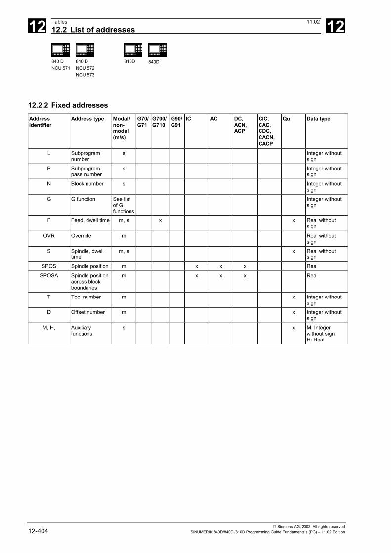
12 Tables 11.0212.2 List of addresses 12
840 DNCU 571
840 DNCU 572NCU 573
810D 840Di
Siemens AG, 2002. All rights reserved12-404 SINUMERIK 840D/840Di/810D Programming Guide Fundamentals (PG) – 11.02 Edition
12.2.2 Fixed addressesAddressidentifier
Address type Modal/non-modal(m/s)
G70/G71
G700/G710
G90/G91
IC AC DC,ACN,ACP
CIC,CAC,CDC,CACN,CACP
Qu Data type
L Subprogramnumber
s Integer withoutsign
P Subprogrampass number
s Integer withoutsign
N Block number s Integer withoutsign
G G function See listof Gfunctions
Integer withoutsign
F Feed, dwell time m, s x x Real withoutsign
OVR Override m Real withoutsign
S Spindle, dwelltime
m, s x Real withoutsign
SPOS Spindle position m x x x Real
SPOSA Spindle positionacross blockboundaries
m x x x Real
T Tool number m x Integer withoutsign
D Offset number m x Integer withoutsign
M, H, Auxiliaryfunctions
s x M: Integerwithout signH: Real

12 11.02 Tables12.2 List of addresses 12
840 DNCU 571
840 DNCU 572NCU 573
810D 840Di
Siemens AG, 2002. All rights reservedSINUMERIK 840D/840Di/810D Programming Guide Fundamentals (PG) – 11.02 Edition 12-405
12.2.3 Fixed addresses with axis extensionAddressidentifier
Address type Modal/non-modal(m/s)
G70/G71
G700/G7100
G90/G91
IC AC DC,ACN,ACP
CIC,CAC,CDC,CACN,CACP
Qu Data type
AX: Axis Variable axisidentifier
*) x x x x x x Real
IP:InterpolationParameter
Variableinterpolationparameter
s x x x x x Real
POS:Positioning axis
Positioning axis m x x x x x x x Real
POSA:Positioning axisabove end ofblock
Positioning axisacross blockboundaries
m x x x x x x x Real
POSP:Positioning axisin parts
Positioning axisin parts(oscillation)
m x x x x x x Real: endposition/Real: partiallengthInteger: option
PO: Polynomial1)
Polynomialcoefficient
s x x Real withoutsign1 - 8 times
FA: Feed axial Axial feed m x x Real withoutsign
FL: Feed limit Axial feed limit m x Real withoutsign
OVRA: Override Axial override m Real withoutsign
ACC 2):Accelerationaxial
Axialacceleration
m Real withoutsign
FMA: Feedmultiple axial
Synchronizedfeed axial
m x Real withoutsign
STA: Sparking-out time axial
Sparking outtime axial
m Real withoutsign
SRA: Sparkingout retract
Retraction pathon external inputaxial
m x x Real withoutsign
OS:Oscillating on/off
Oscillation on/off m Integer withoutsign
OST1:Oscillatingtime 1
Stopping time atleft reversal point(oscillation)
m Real
OST2:Oscillatingtime 2
Stopping time atright reversalpoint (oscillation)
m Real
OSP1:OscillatingPosition 1
Left reversalpoint (oscillation)
m x x x x x x Real
OSP2:OscillatingPosition 2
Right reversalpoint (oscillation)
m x x x x x x Real

12 Tables 11.0212.2 List of addresses 12
840 DNCU 571
840 DNCU 572NCU 573
810D 840Di
Siemens AG, 2002. All rights reserved12-406 SINUMERIK 840D/840Di/810D Programming Guide Fundamentals (PG) – 11.02 Edition
Addressidentifier
Address type Modal/non-modal(m/s)
G70/G71
G700/G7100
G90/G91
IC AC DC,ACN,ACP
CIC,CAC,CDC,CACN,CACP
Qu Data type
OSE: Oscillatingend position
Oscillation endposition
m x x x x x x Real
OSNSC:Oscillating:number sparkout cycles
Oscillating:number of sparkout cycles
m Integer withoutsign
OSCTRL:Oscillatingcontrol
Oscillationcontrol options
m Integer withoutsign: set options,integer withoutsign: resetoptions
OSCILL:Oscillating
Axis assignmentfor oscillation,activateoscillation
m Axis: 1 - 3 infeedaxes
FDA:Feed DRF axial
Axis feedrate forhandwheeloverride
s x Real withoutsign
FGREF Referenceradius
m x x Real withoutsign
POLF LIFTFASTposition
m x x Real withoutsign
FXS:Fixed stop
Activate travel tofixed stop
m Integer withoutsign
FXST:Fixed stoptorque
Torque limit fortravel to fixedstop
m Real
FXSW:Fixed stopwindow
Monitoringwindow for travelto fixed stop
m Real
In these addresses, an axis or an expression of axis type is specified in square brackets. The data type in the above column shows the type of value assigned.*) Absolute end points: modal, incremental end points: non-modal, otherwise modal/non-modal depending on syntax of G function.
1) The vocabulary word is not valid for SINUMERIK FM-NC.
2) The vocabulary word is not valid for SINUMERIK FM-NC/810D.
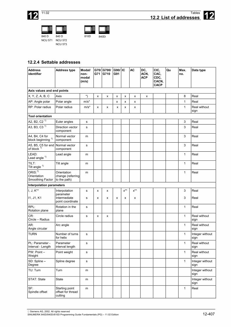
12 11.02 Tables12.2 List of addresses 12
840 DNCU 571
840 DNCU 572NCU 573
810D 840Di
Siemens AG, 2002. All rights reservedSINUMERIK 840D/840Di/810D Programming Guide Fundamentals (PG) – 11.02 Edition 12-407
12.2.4 Settable addressesAddressidentifier
Address type Modal/non-modal(m/s)
G70/G71
G700/G710
G90/G91
IC AC DC,ACN,ACP
CIC,CAC,CDC,CACN,CACP
Qu Max.no.
Data type
Axis values and end pointsX, Y, Z, A, B, C Axis *) x x x x x x 8 Real
AP: Angle polar Polar angle m/s* x x x 1 Real
RP: Polar radius Polar radius m/s* x x x x x 1 Real withoutsign
Tool orientationA2, B2, C2 1) Euler angles s 3 Real
A3, B3, C3 1) Direction vectorcomponent
s 3 Real
A4, B4, C4 forblock beginning 1)
Normal vectorcomponent
m 3 Real
A5, B5, C5 for endof block 1)
Normal vectorcomponent
s 3 Real
LEAD:Lead angle 1)
Lead angle m 1 Real
TILT:Tilt angle 1)
Tilt angle m 1 Real
ORIS:1)
OrientationSmoothing Factor
Orientationchange (referringto the path)
m 1 Real
Interpolation parametersI, J, K**
I1, J1, K1
InterpolationparameterIntermediatepoint coordinate
s
s
x
x
x
x x
x**
x
x**
x
3
3
Real
Real
RPL:Rotation plane
Rotation in theplane
s 1 Real
CR:Circle – Radius
Circle radius s x x 1 Real withoutsign
AR:Angle circular
Arc angle 1 Real withoutsign
TURN Number of turnsfor helix
s 1 Integer withoutsign
PL: Parameter -Interval - Length
Parameterinterval length
s 1 Real withoutsign
PW: Point –Weight
Point weight s 1 Real withoutsign
SD: Spline –Degree
Spline degree s 1 Integer withoutsign
TU: Turn Turn m Integer withoutsign
STAT: State State m Integer withoutsign
SF:Spindle offset
Starting pointoffset for threadcutting
m 1 Real

12 Tables 11.0212.2 List of addresses 12
840 DNCU 571
840 DNCU 572NCU 573
810D 840Di
Siemens AG, 2002. All rights reserved12-408 SINUMERIK 840D/840Di/810D Programming Guide Fundamentals (PG) – 11.02 Edition
Addressidentifier
Address type Modal/non-modal(m/s)
G70/G71
G700/G710
G90/G91
IC AC DC,ACN,ACP
CIC,CAC,CDC,CACN,CACP
Qu Max.no.
Data type
DISR: Distance forrepositioning
Distance forrepositioning
s x x 1 Real withoutsign
DISPR:Distance path forrepositioning
Distance forrepositioning
s x x 1 Real withoutsign
ALF:Angle lift fast
Angle for lift fast m 1 Integer withoutsign
DILF:Distance lift fast
Distance for liftfast
m x x 1 Real
FP Fixed point:Number of fixedpoint to beapproached
s 1 Integer withoutsign
RNDM:Round modal
Modal rounding m x x 1 Real withoutsign
RND:Round
Non-modalrounding
s x x 1 Real withoutsign
CHF: Chamfer Chamfer non-modal
s x x 1 Real withoutsign
CHR: Chamfer Chamfer in theoriginal directionof movement
s x x 1 Real withoutsign
ANG: Angle Contour angle s 1 Real
ISD:Insertion depth
Insertion depth m x x 1 Real
DISC:Distance
Transition circleovershoot in toolradiuscompensation
m x x 1 Real withoutsign
OFFN Offset contour -normal
m x x 1 Real
DITS Thread run-inpath
m x x 1 Real
DITE Thread run-outpath
m x x 1 Real
Nibbling/punchingSPN:Stroke/PunchNumber 2)
Number of pathsections perblock
s 1 INT
SPP: Stroke/Punch Path 2)
Length of a pathsection
m 1 Real
GrindingST: Sparking outtime
Sparking-outtime
s 1 Real withoutsign
SR: Sparking outretract path
Retraction path s x x 1 Real withoutsign
Approximate positioning criteriaADIS Approximate
distancem x x 1 Real without
sign
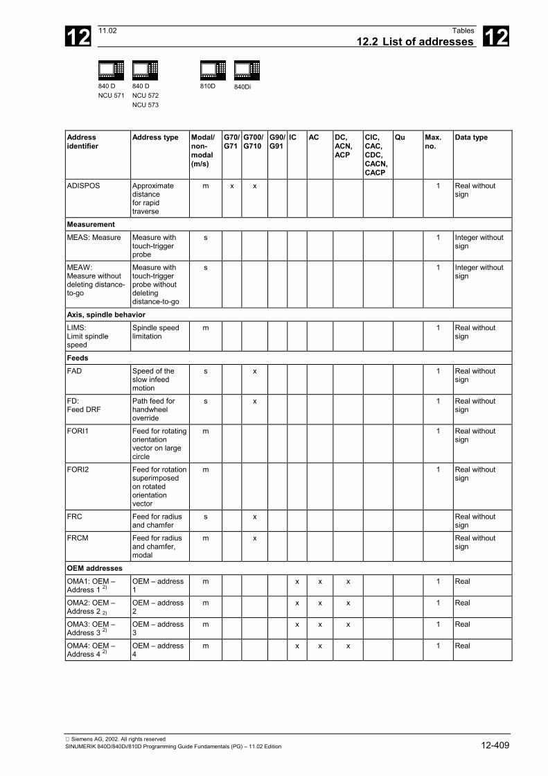
12 11.02 Tables12.2 List of addresses 12
840 DNCU 571
840 DNCU 572NCU 573
810D 840Di
Siemens AG, 2002. All rights reservedSINUMERIK 840D/840Di/810D Programming Guide Fundamentals (PG) – 11.02 Edition 12-409
Addressidentifier
Address type Modal/non-modal(m/s)
G70/G71
G700/G710
G90/G91
IC AC DC,ACN,ACP
CIC,CAC,CDC,CACN,CACP
Qu Max.no.
Data type
ADISPOS Approximatedistancefor rapidtraverse
m x x 1 Real withoutsign
MeasurementMEAS: Measure Measure with
touch-triggerprobe
s 1 Integer withoutsign
MEAW:Measure withoutdeleting distance-to-go
Measure withtouch-triggerprobe withoutdeletingdistance-to-go
s 1 Integer withoutsign
Axis, spindle behaviorLIMS:Limit spindlespeed
Spindle speedlimitation
m 1 Real withoutsign
FeedsFAD Speed of the
slow infeedmotion
s x 1 Real withoutsign
FD:Feed DRF
Path feed forhandwheeloverride
s x 1 Real withoutsign
FORI1 Feed for rotatingorientationvector on largecircle
m 1 Real withoutsign
FORI2 Feed for rotationsuperimposedon rotatedorientationvector
m 1 Real withoutsign
FRC Feed for radiusand chamfer
s x Real withoutsign
FRCM Feed for radiusand chamfer,modal
m x Real withoutsign
OEM addressesOMA1: OEM –Address 1 2)
OEM – address1
m x x x 1 Real
OMA2: OEM –Address 2 2)
OEM – address2
m x x x 1 Real
OMA3: OEM –Address 3 2)
OEM – address3
m x x x 1 Real
OMA4: OEM –Address 4 2)
OEM – address4
m x x x 1 Real

12 Tables 11.0212.2 List of addresses 12
840 DNCU 571
840 DNCU 572NCU 573
810D 840Di
Siemens AG, 2002. All rights reserved12-410 SINUMERIK 840D/840Di/810D Programming Guide Fundamentals (PG) – 11.02 Edition
Addressidentifier
Address type Modal/non-modal(m/s)
G70/G71
G700/G710
G90/G91
IC AC DC,ACN,ACP
CIC,CAC,CDC,CACN,CACP
Qu Max.no.
Data type
OMA5: OEM –Address 5 2)
OEM – address5
m x x x 1 Real
*) Absolute end points: modal, incremental end points: non-modal, otherwise modal/non-modal depending on syntax of G function.
**) As circle center points, IPO parameters act incrementally. They can be programmed in absolute mode with AC. The address modification is ignored when the parameters have other meanings (e.g. thread pitch).
1) The vocabulary word is not valid for SINUMERIK FM-NC/810 D
2) The vocabulary word is not valid for SINUMERIK FM-NC/810D/NCU571.

12 11.02 Tables12.3 List of G functions/preparatory functions 12
840 DNCU 571
840 DNCU 572NCU 573
810D 840Di
Siemens AG, 2002. All rights reservedSINUMERIK 840D/840Di/810D Programming Guide Fundamentals (PG) – 11.02 Edition 12-411
12.3 List of G functions/preparatory functionsLegend for describing the G groups
No.: internal number, for e.g. m: Modal Def.: Default setting Siemens AG (SAG)PLC interface see: Non-modal F : Milling, D : Turning or other settings
X: No. for GCODE_RESET_VALUES not permitted MH.: Default setting, see data supplied by machine manufacturer
Group 1: Modally active motion commands
Name No. Definition X m/s SAG MHG0 1. Rapid traverse m G1 2. Linear interpolation (linear interpolation) m Default G2 3. Circular interpolation clockwise m G3 4. Circular interpolation counterclockwise m CIP 5. Circle through points: Circular interpolation through intermediate point m ASPLINE 6. Akima spline m BSPLINE 7. B spline m CSPLINE 8. Cubic spline m POLY # 9. Polynomial: Polynomial interpolation m G33 10. Thread cutting with constant lead m G331 11. Tapping m G332 12. Retraction (tapping) m OEMIPO1 ## 13. OEM interpolation 1 *) m OEMIPO2 ## 14. OEM interpolation 2 *) m CT 15. Circle with tangential transition m G34 16. Increase in thread pitch (progressive change) m G35 17. Decrease in thread pitch (degressive change) m INVCW 18. Involute interpolation in CW direction m
INVCCW 19. Involute interpolation in CCW direction m*) The OEM can incorporate two additional interpolation modes. The names can be changed by the OEM.If no function from the group is programmed with modal G functions, the default setting (which can be changed in the machine data) applies: $MC_GCODE_RESET_VALUES# The vocabulary word is not valid for SINUMERIK FM-NC.## The vocabulary word is not valid for SINUMERIK FM-NC/810D/NCU571.
Group 2: Non-modally active movements, dwell time
G4 1. Predefined dwell time X s G63 2. Tapping without synchronization X s G74 3. Reference point approach with synchronization X s G75 4. Fixed point approach X s REPOSL 5. Repositioning linear: Linear repositioning X s REPOSQ 6. Repositioning quadrant: Repositioning in a quadrant X s REPOSH 7. Repositioning semicircle: Repositioning in semicircle X s REPOSA 8. Repositioning linear all axis: Linear repositioning with all axes X s REPOSQA 9. Repositioning quadrant all axes: Linear repositioning with all axes, geometry
axes in quadrant X s

12 Tables 11.0212.3 List of G functions/preparatory functions 12
840 DNCU 571
840 DNCU 572NCU 573
810D 840Di
Siemens AG, 2002. All rights reserved12-412 SINUMERIK 840D/840Di/810D Programming Guide Fundamentals (PG) – 11.02 Edition
Group 2: Non-modally active movements, dwell time
REPOSHA 10. Repositioning semicircle all axes: Repositioning with all axes; geometry axes insemicircle
X s
G147 11. Soft approach with straight line X s G247 12. Soft approach with quadrant X s G347 13. Soft approach with semicircle X s G148 14. Soft retraction with straight line X s G248 15. Soft retraction with quadrant X s G348 16. Soft retraction with semicircle X s
G05 17. Oblique plunge-cut grinding X s
G07 18. Compensatory motion during oblique plunge-cut grinding X s
Group 3: Programmable frame, working area limitation and pole programming
Name No. Definition X m/s SAG MHTRANS 1. TRANSLATION: programmable translation X s ROT 2. ROTATION: programmable rotation X s SCALE 3. SCALE: programmable scale X s MIRROR 4. MIRROR: Programmable mirror X s ATRANS 5. Additive TRANSLATION: programmable additive translation X s AROT 6. Additive ROTATION: programmable rotation X s ASCALE 7. Additive SCALE: programmable scale X s AMIRROR 8. Additive MIRROR: Programmable mirror X s 9. Not assigned G25 10. Minimum working area limitation/spindle speed limit X s G26 11. Maximum working area limitation/spindle X s G110 12. Polar programming relative to last programmed set position X s G111 13. Polar programming relative to origin of current workpiece coordinate system X s G112 14. Polar programming relative to last valid pole X s G58 15. Programmable offset, absolute axial substitution X s G59 16. Programmable offset, additive axial substitution X s
ROTS 17. Rotation with solid angles X s
AROTS 18. Additive rotation with solid angles X s
Group 4: FIFO
STARTFIFO 1. Start FIFOExecute and simultaneously fill preprocessing memory
m Default
STOPFIFO 2. STOP FIFOStop machining; fill preprocessing memory until STARTFIFO is detected, FIFOfull or end of program
m
FIFOCTRL 3. FIFO CTRL,Proprocessing memory control
m

12 11.02 Tables12.3 List of G functions/preparatory functions 12
840 DNCU 571
840 DNCU 572NCU 573
810D 840Di
Siemens AG, 2002. All rights reservedSINUMERIK 840D/840Di/810D Programming Guide Fundamentals (PG) – 11.02 Edition 12-413
Group 6: Plane selection
Name No. Definition X m/s SAG MHG17 1. Plane selection 1st - 2nd geometry axis m Default G18 2. Plane selection 3rd - 1st geometry axis m G19 3. Plane selection 2nd - 3rd geometry axis m
Group 7: Tool radius compensation
G40 1. No tool radius compensation m Default G41 2. Tool radius compensation to left of contour X m G42 3. Tool radius compensation to right of contour X m
Group 8: Settable zero offset
G500 1. Deactivate all settable G54-G57 frames if G500 does not contain a value m Default
G54 2. 1st settable zero offset m
G55 3. 2nd settable zero offset m
G56 4. 3rd settable zero offset m
G57 5. 4th settable zero offset m
G505 6. 5th settable zero offset m
G5xx n+1 nth settable zero offset ng m
G599 100. 99th settable zero offset m
The G functions of this group activate a settable user – frame $P_UIFR[ ].G54 corresponds to frame SP_UIFR[1], G505 corresponds to frame SP_UIFR[5].The number of settable user frames and therefore the number of G functions in this group can be configured in the machine data SMC_MM_NUM_USER_FRAMES.
Group 9: Frame suppression
G53 1. Suppression of current frames:Programmable frame includingsystem frame for TOROT and TOFRAME andactive settable frame G54 ... G599
X s
SUPA 2. Suppression as for G153 and includingsystem frames for actual-value setting, scratching, ext. zero offset, PAROT,including handwheel offsets (DRF), [external zero offset], overlaid motion
X s
G153 3. Suppression as for G53 andincluding all channel-specific and / or NCU-global basic frame
X s
Group 10: Exact stop – continuous-path mode
G60 1. Deceleration, exact stop m Default
G64 2. Continuous-path mode m
G641 3. Continuous-path mode (G64) with programmable approximate distance m
G642 4. Corner rounding with axial precision m
G643 5. Block-internal axial corner rounding m
G644 6. Corner rounding with specified axis dynamics m
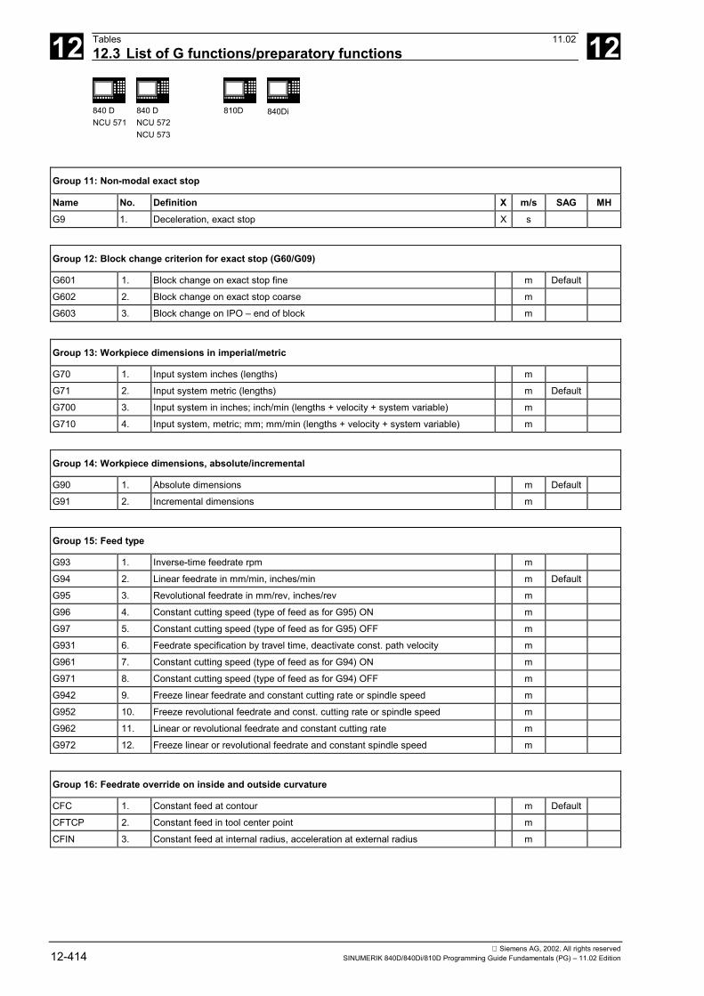
12 Tables 11.0212.3 List of G functions/preparatory functions 12
840 DNCU 571
840 DNCU 572NCU 573
810D 840Di
Siemens AG, 2002. All rights reserved12-414 SINUMERIK 840D/840Di/810D Programming Guide Fundamentals (PG) – 11.02 Edition
Group 11: Non-modal exact stop
Name No. Definition X m/s SAG MHG9 1. Deceleration, exact stop X s
Group 12: Block change criterion for exact stop (G60/G09)
G601 1. Block change on exact stop fine m Default G602 2. Block change on exact stop coarse m G603 3. Block change on IPO – end of block m
Group 13: Workpiece dimensions in imperial/metric
G70 1. Input system inches (lengths) m G71 2. Input system metric (lengths) m Default G700 3. Input system in inches; inch/min (lengths + velocity + system variable) m G710 4. Input system, metric; mm; mm/min (lengths + velocity + system variable) m
Group 14: Workpiece dimensions, absolute/incremental
G90 1. Absolute dimensions m Default G91 2. Incremental dimensions m
Group 15: Feed type
G93 1. Inverse-time feedrate rpm m G94 2. Linear feedrate in mm/min, inches/min m Default G95 3. Revolutional feedrate in mm/rev, inches/rev m G96 4. Constant cutting speed (type of feed as for G95) ON m G97 5. Constant cutting speed (type of feed as for G95) OFF m
G931 6. Feedrate specification by travel time, deactivate const. path velocity m
G961 7. Constant cutting speed (type of feed as for G94) ON m
G971 8. Constant cutting speed (type of feed as for G94) OFF m
G942 9. Freeze linear feedrate and constant cutting rate or spindle speed m
G952 10. Freeze revolutional feedrate and const. cutting rate or spindle speed m
G962 11. Linear or revolutional feedrate and constant cutting rate m
G972 12. Freeze linear or revolutional feedrate and constant spindle speed m
Group 16: Feedrate override on inside and outside curvature
CFC 1. Constant feed at contour m Default CFTCP 2. Constant feed in tool center point m CFIN 3. Constant feed at internal radius, acceleration at external radius m
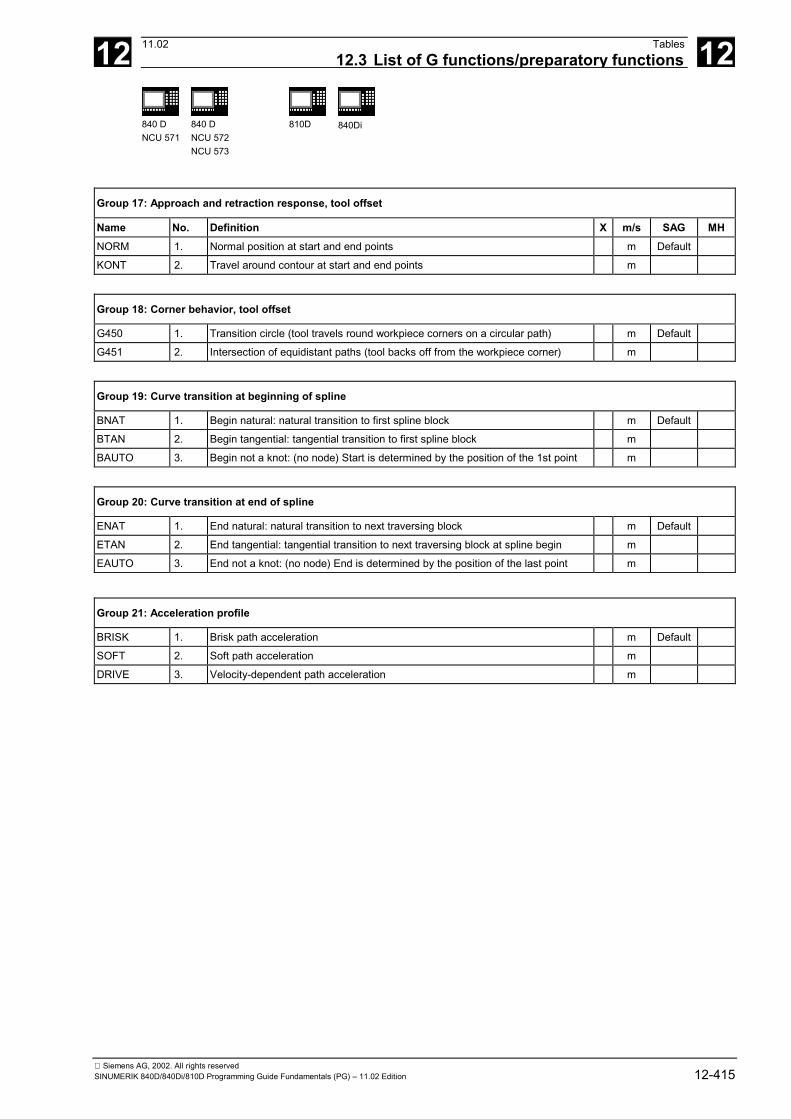
12 11.02 Tables12.3 List of G functions/preparatory functions 12
840 DNCU 571
840 DNCU 572NCU 573
810D 840Di
Siemens AG, 2002. All rights reservedSINUMERIK 840D/840Di/810D Programming Guide Fundamentals (PG) – 11.02 Edition 12-415
Group 17: Approach and retraction response, tool offset
Name No. Definition X m/s SAG MHNORM 1. Normal position at start and end points m Default KONT 2. Travel around contour at start and end points m
Group 18: Corner behavior, tool offset
G450 1. Transition circle (tool travels round workpiece corners on a circular path) m Default G451 2. Intersection of equidistant paths (tool backs off from the workpiece corner) m
Group 19: Curve transition at beginning of spline
BNAT 1. Begin natural: natural transition to first spline block m Default BTAN 2. Begin tangential: tangential transition to first spline block m BAUTO 3. Begin not a knot: (no node) Start is determined by the position of the 1st point m
Group 20: Curve transition at end of spline
ENAT 1. End natural: natural transition to next traversing block m Default ETAN 2. End tangential: tangential transition to next traversing block at spline begin m EAUTO 3. End not a knot: (no node) End is determined by the position of the last point m
Group 21: Acceleration profile
BRISK 1. Brisk path acceleration m Default SOFT 2. Soft path acceleration m DRIVE 3. Velocity-dependent path acceleration m

12 Tables 11.0212.3 List of G functions/preparatory functions 12
840 DNCU 571
840 DNCU 572NCU 573
810D 840Di
Siemens AG, 2002. All rights reserved12-416 SINUMERIK 840D/840Di/810D Programming Guide Fundamentals (PG) – 11.02 Edition
# The vocabulary word is not valid for SINUMERIK 810D/NCU571.
Group 22: Tool offset types
CUT2D 1. Cutter – compensation – type 2-dimensional 2 1/2D tool offset determined byG17 – G19
m Default
CUT2DF 2. Cutter – compensation – type 2-dimensional frame – relative: 2 1/2D tool offsetdetermined by frameThe tool offset is effective in relation to the current frame (inclined plane)
m
CUT3DC # 3. Cutter – compensation – type 3-dimensional circumference: 3D toolcompensation circumference milling
m
CUT3DF # 4. Cutter – compensation – type 3-dimensional face: 3D tool offset with inconstanttool orientation
m
CUT3DFS # 5. Cutter – compensation – type 3-dimensional face: 3D tool offset face milling withconstant tool orientation independent of active frame
m
CUT3DFF # 6. Cutter – compensation – type 3-dimensional face frame: 3D tool offset facemilling with constant tool orientation dependent on active frame
m
CUT3DCC # 7. Cutter – compensation – type 3-dimensional circumference: with limit surfaces m
CUT3DCCD # 8. Cutter – compensation – type 3-dimensional circumference: with limit surfaceswith differential tool
m
Group 23: Collision monitoring on inside contours
Name No. Definition X m/s SAG MHCDOF 1. Collision detection OFF: Collision monitoring OFF m Default CDON 2. Collision detection ON: Collision monitoring ON m
CDOF2 3. Collision detection OFF: (currently for CUT3DC only) m
Group 24: Feedforward control
FFWOF 1. Feedforward control OFF m Default FFWON 2. Feedforward control ON m
Group 25: Tool orientation reference
ORIWKS # 1. Tool – orientation in workpiece coordinate system Tool orientation in workpiececoordinate system (WCS)
m Default
ORIMKS # 2. Tool – orientation in machine coordinate system Tool orientation in machinecoordinate system (MCS)
m
# The vocabulary word is not valid for SINUMERIK 810D/NCU571.
Group 26: Repositioning point for REPOS
RMB 1. REPOS mode beginning of block: Reapproach to start of block position m RMI 2. REPOS – Mode interrupt: Reapproach to interruption point m Default RME 3. REPOS – Mode end of block: Reapproach to end of block position m
RMN 4. Repos – Mode end of nearest orbital block: Reapproach to nearest path point m

12 11.02 Tables12.3 List of G functions/preparatory functions 12
840 DNCU 571
840 DNCU 572NCU 573
810D 840Di
Siemens AG, 2002. All rights reservedSINUMERIK 840D/840Di/810D Programming Guide Fundamentals (PG) – 11.02 Edition 12-417
Group 27: Tool offset for change in orientation at outside corners
ORIC # 1. Orientation change continuously: Orientation changes at outside corners aresuperimposed on the circle block to be inserted
m Default
ORID # 2. Orientation change discontinuously: Orientation changes are performed beforethe circle block
m
# The vocabulary word is not valid for SINUMERIK 810D/NCU571.
Group 28: Working area limitation ON/OFF
WALIMON 1. Working area limitation ON m Default WALIMOF 2. Working area limitation OFF m
Group 29: Radius – diameter
DIAMOF 1. Diametral Diameter programming OFF; Radius programming for G90/G91 m Default DIAMON 2. Diametral Diameter programming ON for G90/G91 m DIAM90 3. Diametral programming G90: Diameter programming for G90; Radius
programming for G91m
DIAMCYCOF 4. Diametral Radius programming for G90/G91: ON. The G-code of this group thatwas last active remains active for display
m
Group 30: Compressor ON/OFF
Name No. Definition X m/s SAG MHCOMPOF # 1. Compressor OFF m Default COMPON # 2. Compressor ON m COMPCURV # 3. Compressor ON: polynomials with constant curvature m
COMPCAD # 4. Compressor ON: Optimized surface quality CAD program (SW 6 and higher) m

12 Tables 11.0212.3 List of G functions/preparatory functions 12
840 DNCU 571
840 DNCU 572NCU 573
810D 840Di
Siemens AG, 2002. All rights reserved12-418 SINUMERIK 840D/840Di/810D Programming Guide Fundamentals (PG) – 11.02 Edition
Group 31: OEM – G group
G810 # 1. OEM – G function Default G811 # 2. OEM – G function G812 # 3. OEM – G function G813 # 4. OEM – G function G814 # 5. OEM – G function G815 # 6. OEM – G function G816 # 7. OEM – G function G817 # 8. OEM – G function G818 # 9. OEM – G function G819 # 10. OEM – G function
Two G groups are reserved for the OEM. This enables the OEM to program functions that can be customized.# The vocabulary word is not valid for SINUMERIK 810D/NCU571.
Group 32: OEM G group
G820 # 1. OEM – G function Default G821 # 2. OEM – G function G822 # 3. OEM – G function G823 # 4. OEM – G function G824 # 5. OEM – G function G825 # 6. OEM – G function G826 # 7. OEM – G function G827 # 8. OEM – G function G828 # 9. OEM – G function G829 # 10. OEM – G function
Two G groups are reserved for the OEM. This enables the OEM to program functions that can be customized.
Group 33: Settable fine tool offset
FTOCOF # 1. Fine tool offset compensation OFF: Online fine tool offset OFF m Default FTOCON # 2. Fine tool offset compensation on: Online fine tool offset ON X m
Group 34: Tool orientation smoothing
Name No. Definition X m/s SAG MHOSOF # 1. Tool orientation smoothing OFF m Default OSC # 2. Continuous tool orientation smoothing m OSS # 3. Tool orientation smoothing at end of block m OSSE # 4. Tool orientation smoothing at start and end of block m
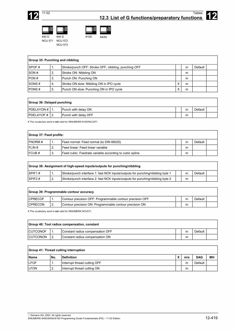
12 11.02 Tables12.3 List of G functions/preparatory functions 12
840 DNCU 571
840 DNCU 572NCU 573
810D 840Di
Siemens AG, 2002. All rights reservedSINUMERIK 840D/840Di/810D Programming Guide Fundamentals (PG) – 11.02 Edition 12-419
Group 35: Punching and nibbling
SPOF # 1. Stroke/punch OFF: Stroke OFF, nibbling, punching OFF m Default SON # 2. Stroke ON: Nibbling ON m PON # 3. Punch ON: Punching ON m SONS # 4. Stroke ON slow: Nibbling ON in IPO cycle X m PONS # 5. Punch ON slow: Punching ON in IPO cycle X m
Group 36: Delayed punching
PDELAYON # 1. Punch with delay ON m Default PDELAYOF # 2. Punch with delay OFF m
# The vocabulary word is not valid for SINUMERIK 810D/NCU571.
Group 37: Feed profile:
FNORM # 1. Feed normal: Feed normal (to DIN 66025) m Default FLIN # 2. Feed linear: Feed linear variable m FCUB # 3. Feed cubic: Feedrate variable according to cubic spline m
Group 38: Assignment of high-speed inputs/outputs for punching/nibbling
SPIF1 # 1. Stroke/punch interface 1: fast NCK inputs/outputs for punching/nibbling byte 1 m Default SPIF2 # 2. Stroke/punch interface 2: fast NCK inputs/outputs for punching/nibbling byte 2 m
Group 39: Programmable contour accuracy
CPRECOF 1. Contour precision OFF: Programmable contour precision OFF m Default CPRECON 2. Contour precision ON: Programmable contour precision ON m
# The vocabulary word is not valid for SINUMERIK NCU571.
Group 40: Tool radius compensation, constant
CUTCONOF 1. Constant radius compensation OFF m Default CUTCONON 2. Constant radius compensation ON m
Group 41: Thread cutting interruption
Name No. Definition X m/s SAG MHLFOF 1. Interrupt thread cutting OFF m Default LFON 2. Interrupt thread cutting ON m
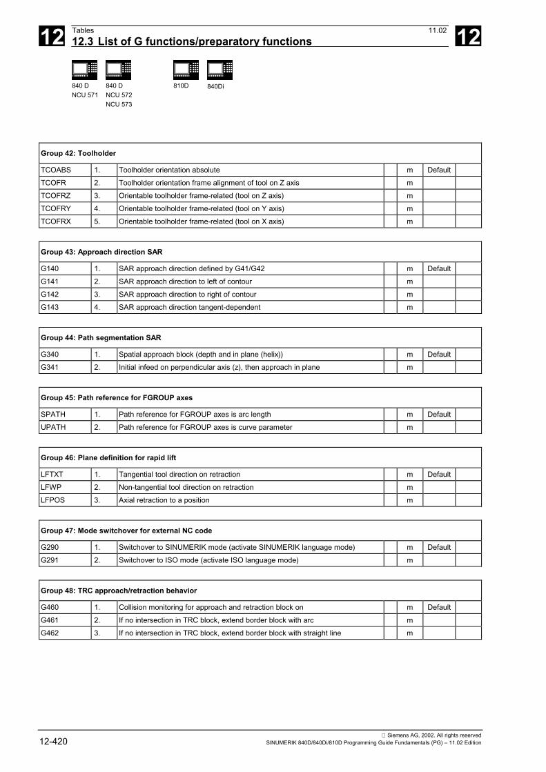
12 Tables 11.0212.3 List of G functions/preparatory functions 12
840 DNCU 571
840 DNCU 572NCU 573
810D 840Di
Siemens AG, 2002. All rights reserved12-420 SINUMERIK 840D/840Di/810D Programming Guide Fundamentals (PG) – 11.02 Edition
Group 42: Toolholder
TCOABS 1. Toolholder orientation absolute m Default TCOFR 2. Toolholder orientation frame alignment of tool on Z axis m
TCOFRZ 3. Orientable toolholder frame-related (tool on Z axis) m
TCOFRY 4. Orientable toolholder frame-related (tool on Y axis) m
TCOFRX 5. Orientable toolholder frame-related (tool on X axis) m
Group 43: Approach direction SAR
G140 1. SAR approach direction defined by G41/G42 m Default G141 2. SAR approach direction to left of contour m G142 3. SAR approach direction to right of contour m G143 4. SAR approach direction tangent-dependent m
Group 44: Path segmentation SAR
G340 1. Spatial approach block (depth and in plane (helix)) m Default G341 2. Initial infeed on perpendicular axis (z), then approach in plane m
Group 45: Path reference for FGROUP axes
SPATH 1. Path reference for FGROUP axes is arc length m Default UPATH 2. Path reference for FGROUP axes is curve parameter m
Group 46: Plane definition for rapid lift
LFTXT 1. Tangential tool direction on retraction m Default LFWP 2. Non-tangential tool direction on retraction m LFPOS 3. Axial retraction to a position m
Group 47: Mode switchover for external NC code
G290 1. Switchover to SINUMERIK mode (activate SINUMERIK language mode) m Default G291 2. Switchover to ISO mode (activate ISO language mode) m
Group 48: TRC approach/retraction behavior
G460 1. Collision monitoring for approach and retraction block on m Default G461 2. If no intersection in TRC block, extend border block with arc m G462 3. If no intersection in TRC block, extend border block with straight line m

12 11.02 Tables12.3 List of G functions/preparatory functions 12
840 DNCU 571
840 DNCU 572NCU 573
810D 840Di
Siemens AG, 2002. All rights reservedSINUMERIK 840D/840Di/810D Programming Guide Fundamentals (PG) – 11.02 Edition 12-421
Group 49: Point-to-point movement TRC
Name No. Definition X m/s SAG MHCP 1. Continuous path; path motion m Default PTP 2. point to point; Point-to-point motion (synchronized axis motion) m
Group 50: Orientation programming
ORIEULER 1. Orientation angle via Euler angle m Default ORIRPY 2. Orientation angle via RPY angle m ORIVIRT1 3. Orientation angle via virtual orientation axes (definition 1) m ORIVIRT2 4. Orientation angle via virtual orientation axes (definition 2) m
ORIAXPOS 5. Orientation angle via virtual orientation axes with rotary axis positions m
Group 51: Orientation interpolation
ORIVECT 1. Large-radius circular interpolation (identical to ORIPLANE) m Default ORIAXES 2. Linear interpolation of machine axes or orientation axes m ORIPATH 3. Tool orientation trajectory referred to path m ORIPLANE 4. Interpolation in plane (identical to ORIVECT) m ORICONCW 5. Interpolation on a circular peripheral surface in CW direction m ORICONCCW 6. Interpolation on a conical peripheral surface in CCW direction m ORICONIO 7. Interpolation on a conical peripheral surface with intermediate orientation setting m ORICONTO 8. Interpolation on a conical peripheral surface in tangential transition m ORICURVE 9. Interpolation with additional space curve for orientation m
Group 52: Workpiece-related WCS
PAROTOF 1. Deactivate workpiece-related frame rotation m Default PAROT 2. Align workpiece coordinate system (WCS) on workpiece m
Group 53: Frame rotations in tool direction
TOROTOF 1. Frame rotation in tool direction OFF m Default TOROT 2. Frame rotation ON Z axis parallel to tool orientation m TOROTZ 3. Frame rotation ON Z axis parallel to tool orientation m TOROTY 4. Frame rotation ON Y axis parallel to tool orientation m TOROTX 5. Frame rotation ON X axis parallel to tool orientation m TOFRAME 6. Frame rotation in tool direction Z axis parallel to tool orientation m TOFRAMEZ 7. Frame rotation in tool direction Z axis parallel to tool orientation m TOFRAMEY 8. Frame rotation in tool direction Y axis parallel to tool orientation m TOFRAMEX 9. Frame rotation in tool direction X axis parallel to tool orientation m

12 Tables 11.0212.3 List of G functions/preparatory functions 12
840 DNCU 571
840 DNCU 572NCU 573
810D 840Di
Siemens AG, 2002. All rights reserved12-422 SINUMERIK 840D/840Di/810D Programming Guide Fundamentals (PG) – 11.02 Edition
Group 54: Interpolation of rotational vector
Name No. Definition X m/s SAG MH ORIROTA 1. Orientation rotation absolute: Angle of rotation in relation to absolute direction
of rotation m Default
ORIROTR 2. Orientation rotation relative: Angle of rotation relative to plane between startand end orientations
m
ORIROTT 3. Orientation rotation tangential: Angle of rotation relative to change in orientationvector
m
Group 55: Rapid traverse with/without linear interpolation
RTLION 1. Rapid traverse (G0) with linear interpolation On: G0 with linear interpolation m Default RTLIOF 2. Rapid traverse (G0) with linear interpolation Off: G0 without linear interpolation
(single-axis interpolation)m
Group 56: Inclusion of tool wear
TOWSTD 1. Tool wear default initial setting value for offsets in tool length m Default TOWMCS 2. Tool WearCoard MCS:Wear values in machine coordinate system (MCS) m TOWWCS 3. Tool WearCoard WCS:Wear values in workpiece coordinate system (WCS) m
TOWBCS 4. Tool WearCoard BCS:Wear values in basic coordinate system (MCS) m
TOWTCS 5. Tool WearCoard TCS:Wear values in the tool coordinate system (tool carrier ref.point T at the tool holder)
m
TOWKCS 6. Wear values in the coordinate system of the tool head for kinetic transformation(differs from MCS by tool rotation)
m
Group 57: Automatic corner override
FENDNORM 1. Corner deceleration deactivated m Default
G62 2. Corner deceleration at inside coners when tool radiuse offset is active m
G621 3. Corner deceleration at all corners m
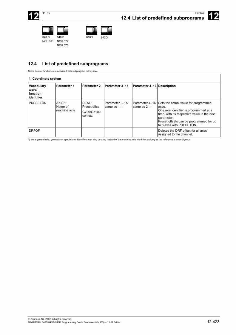
12 11.02 Tables12.4 List of predefined subprograms 12
840 DNCU 571
840 DNCU 572NCU 573
810D 840Di
Siemens AG, 2002. All rights reservedSINUMERIK 840D/840Di/810D Programming Guide Fundamentals (PG) – 11.02 Edition 12-423
12.4 List of predefined subprogramsSome control functions are activated with subprogram call syntax.
1. Coordinate system
Vocabularyword/functionidentifier
Parameter 1 Parameter 2 Parameter 3–15 Parameter 4–16 Description
PRESETON AXIS*:Name ofmachine axis
REAL:Preset offsetG700/G7100context
Parameter 3–15same as 1 ...
Parameter 4–16same as 2 ...
Sets the actual value for programmedaxes.One axis identifier is programmed at atime, with its respective value in the nextparameter.Preset offsets can be programmed for upto 8 axes with PRESETON.
DRFOF Deletes the DRF offset for all axesassigned to the channel.
*) As a general rule, geometry or special axis identifiers can also be used instead of the machine axis identifier, as long as the reference is unambiguous.

12 Tables 11.0212.4 List of predefined subprograms 12
840 DNCU 571
840 DNCU 572NCU 573
810D 840Di
Siemens AG, 2002. All rights reserved12-424 SINUMERIK 840D/840Di/810D Programming Guide Fundamentals (PG) – 11.02 Edition
12.4.1 Predefined subprogram calls
2. Axis groups
Parameter 1–8 DescriptionFGROUP Channel axis
identifierVariable F value reference: defines the axes to which the path feed refers.Maximum number of axes: 8The default setting for the F value reference is activated with FGROUP ( ) without parameters.
CLGON # REAL:Max. speed ofregulating wheel
Centerless grinding ON
CLGOF # Centerless grinding OFF
Parameter 1–8 Parameter 2–9 DescriptionSPLINEPATH INT: spline group
(must be 1)AXIS:Geometry orspecial axisidentifier
Definition of the spline groupMaximum number of axes: 8
BRISKA AXIS Switch on brisk axis acceleration for the programmed axes
SOFTA AXIS Switch on jerk limited axis acceleration for programmed axes
DRIVEA ### AXIS Switch on knee-shaped acceleration characteristic for programmed axes
JERKA AXIS The acceleration behavior set in machine data $MA_AX_JERK_ENABLE isactive for the programmed axes.
# The vocabulary word is not valid for SINUMERIK FM-NC/810D/NCU571.# The vocabulary word is not valid for SINUMERIK 810D.### The vocabulary word is only valid for SINUMERIK FM-NC.
3. Coupled motion
Vocabularyword/subprogramidentifier
Parameter 1 Parameter 2 Parameter 3 Para-meter 4
Parameter 5 Description
TANG # AXIS: Axisidentifier followingaxis
REAL:Master axis 1
AXIS:Master axis2
REAL:Couplingfactor
CHAR:Optional:"B": follow-up inbasic coordinatesystem"W": follow-up inworkpiececoordinate system
Preparatory instruction for thedefinition of a tangential follow-up:The tangent for the follow-up isdetermined by the two master axesspecified. The coupling factor spe-cifies the relationship between achange in the angle of tangent andthe following axis. It is usually 1.
TANGON # AXIS: Axisidentifier followingaxis
REAL: Offsetangle
Tangential follow-up mode ON
TANGOF # AXIS: Axisidentifier followingaxis
Tangential follow-up mode OFF
TLIFT # AXIS: Followingaxis
REAL:Distance
Tangential lift: Tangential follow-up mode ON
TRAILON AXIS: Followingaxis
AXIS:Leading axis
REAL:Couplingfactor
Trailing ON: Asynchronouscoupled motion ON
TRAILOF AXIS: Followingaxis
AXIS:Leading axis
Trailing OFF: Asynchronouscoupled motion OFF
# The vocabulary word is not valid for SINUMERIK FM-NC/NCU571.
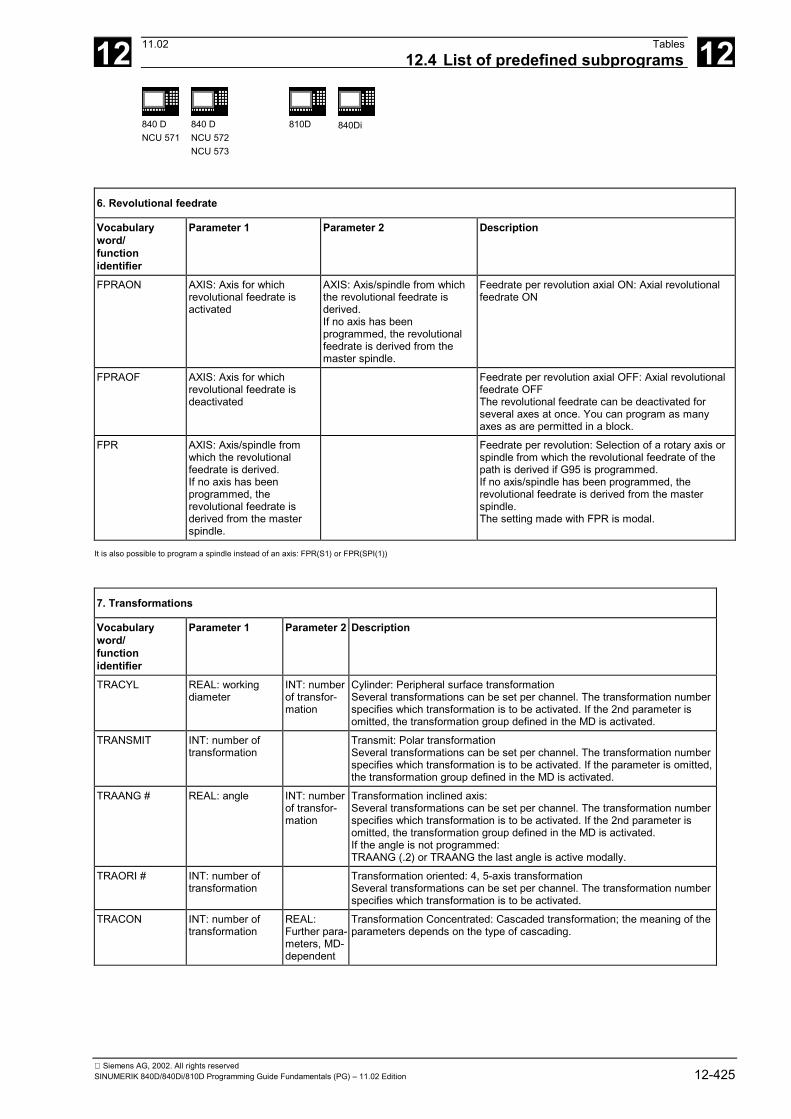
12 11.02 Tables12.4 List of predefined subprograms 12
840 DNCU 571
840 DNCU 572NCU 573
810D 840Di
Siemens AG, 2002. All rights reservedSINUMERIK 840D/840Di/810D Programming Guide Fundamentals (PG) – 11.02 Edition 12-425
6. Revolutional feedrate
Vocabularyword/functionidentifier
Parameter 1 Parameter 2 Description
FPRAON AXIS: Axis for whichrevolutional feedrate isactivated
AXIS: Axis/spindle from whichthe revolutional feedrate isderived.If no axis has beenprogrammed, the revolutionalfeedrate is derived from themaster spindle.
Feedrate per revolution axial ON: Axial revolutionalfeedrate ON
FPRAOF AXIS: Axis for whichrevolutional feedrate isdeactivated
Feedrate per revolution axial OFF: Axial revolutionalfeedrate OFFThe revolutional feedrate can be deactivated forseveral axes at once. You can program as manyaxes as are permitted in a block.
FPR AXIS: Axis/spindle fromwhich the revolutionalfeedrate is derived.If no axis has beenprogrammed, therevolutional feedrate isderived from the masterspindle.
Feedrate per revolution: Selection of a rotary axis orspindle from which the revolutional feedrate of thepath is derived if G95 is programmed.If no axis/spindle has been programmed, therevolutional feedrate is derived from the masterspindle.The setting made with FPR is modal.
It is also possible to program a spindle instead of an axis: FPR(S1) or FPR(SPI(1))
7. Transformations
Vocabularyword/functionidentifier
Parameter 1 Parameter 2 Description
TRACYL REAL: workingdiameter
INT: numberof transfor-mation
Cylinder: Peripheral surface transformationSeveral transformations can be set per channel. The transformation numberspecifies which transformation is to be activated. If the 2nd parameter isomitted, the transformation group defined in the MD is activated.
TRANSMIT INT: number oftransformation
Transmit: Polar transformationSeveral transformations can be set per channel. The transformation numberspecifies which transformation is to be activated. If the parameter is omitted,the transformation group defined in the MD is activated.
TRAANG # REAL: angle INT: numberof transfor-mation
Transformation inclined axis:Several transformations can be set per channel. The transformation numberspecifies which transformation is to be activated. If the 2nd parameter isomitted, the transformation group defined in the MD is activated.If the angle is not programmed:TRAANG (.2) or TRAANG the last angle is active modally.
TRAORI # INT: number oftransformation
Transformation oriented: 4, 5-axis transformationSeveral transformations can be set per channel. The transformation numberspecifies which transformation is to be activated.
TRACON INT: number oftransformation
REAL:Further para-meters, MD-dependent
Transformation Concentrated: Cascaded transformation; the meaning of theparameters depends on the type of cascading.

12 Tables 11.0212.4 List of predefined subprograms 12
840 DNCU 571
840 DNCU 572NCU 573
810D 840Di
Siemens AG, 2002. All rights reserved12-426 SINUMERIK 840D/840Di/810D Programming Guide Fundamentals (PG) – 11.02 Edition
7. Transformations
Vocabularyword/functionidentifier
Parameter 1 Parameter 2 Description
TRAFOOF Deactivate transformation
For each transformation type, there is one command for one transformation per channel. If there are several transformations of the same transformation type per channel, thetransformation can be selected with the corresponding command and parameters. It is possible to deselect the transformation by a transformation change or an explicitdeselection.
#) The vocabulary word is not valid for SINUMERIK FM-NC/NCU571.
8. Spindle
Vocabularyword/subprogramidentifier
Parameter 1 Parameter 2 andothers
Description
SPCON INT: spindlenumber
INT: spindlenumber
Spindle position control ON: Switch to position-controlled spindleoperation
SPCOF INT: spindlenumber
INT: spindlenumber
Spindle position control OFF: Switch to speed-controlled spindleoperation
SETMS INT: spindlenumber
Set master spindle: declare the spindle master spindle for the currentchannel.SETMS( ) without parameters activates the default setting in themachine data.
9. Grinding
Vocabularyword/subprogramidentifier
Parameter 1 Description
GWPSON INT: spindlenumber
Grinding wheel peripheral speed ON: Constant grinding wheel peripheral speed ONIf the spindle number is not programmed, then grinding wheel peripheral speed is selected forthe spindle of the active tool.
GWPSOF INT: spindlenumber
Grinding wheel peripheral speed OFF. Constant grinding wheel peripheral speed OFF. If thespindle number is not programmed, grinding wheel peripheral speed is deselected for thespindle of the active tool.
TMON INT: spindlenumber
Tool monitoring ON: If no T number is programmed, monitoring is activated for the active tool.
TMOF INT: T number Tool monitoring OFF: If no T number is programmed, monitoring is deactivated for the activetool.
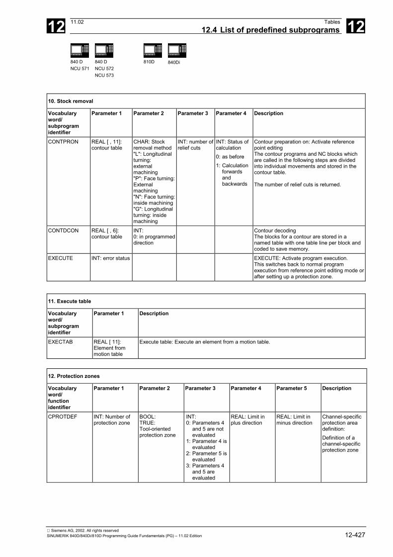
12 11.02 Tables12.4 List of predefined subprograms 12
840 DNCU 571
840 DNCU 572NCU 573
810D 840Di
Siemens AG, 2002. All rights reservedSINUMERIK 840D/840Di/810D Programming Guide Fundamentals (PG) – 11.02 Edition 12-427
10. Stock removal
Vocabularyword/subprogramidentifier
Parameter 1 Parameter 2 Parameter 3 Parameter 4 Description
CONTPRON REAL [ , 11]:contour table
CHAR: Stockremoval method"L": Longitudinalturning:externalmachining"P": Face turning:Externalmachining"N": Face turning:inside machining"G": Longitudinalturning: insidemachining
INT: number ofrelief cuts
INT: Status ofcalculation0: as before1: Calculation
forwardsand backwards
Contour preparation on: Activate referencepoint editingThe contour programs and NC blocks whichare called in the following steps are dividedinto individual movements and stored in thecontour table.
The number of relief cuts is returned.
CONTDCON REAL [ , 6]:contour table
INT:0: in programmeddirection
Contour decodingThe blocks for a contour are stored in anamed table with one table line per block andcoded to save memory.
EXECUTE INT: error status EXECUTE: Activate program execution.This switches back to normal programexecution from reference point editing mode orafter setting up a protection zone.
11. Execute table
Vocabularyword/subprogramidentifier
Parameter 1 Description
EXECTAB REAL [ 11]:Element frommotion table
Execute table: Execute an element from a motion table.
12. Protection zones
Vocabularyword/functionidentifier
Parameter 1 Parameter 2 Parameter 3 Parameter 4 Parameter 5 Description
CPROTDEF INT: Number ofprotection zone
BOOL:TRUE:Tool-orientedprotection zone
INT:0: Parameters 4
and 5 are notevaluated
1: Parameter 4 isevaluated
2: Parameter 5 isevaluated
3: Parameters 4and 5 areevaluated
REAL: Limit inplus direction
REAL: Limit inminus direction
Channel-specificprotection areadefinition:Definition of achannel-specificprotection zone

12 Tables 11.0212.4 List of predefined subprograms 12
840 DNCU 571
840 DNCU 572NCU 573
810D 840Di
Siemens AG, 2002. All rights reserved12-428 SINUMERIK 840D/840Di/810D Programming Guide Fundamentals (PG) – 11.02 Edition
12. Protection zones
Vocabularyword/functionidentifier
Parameter 1 Parameter 2 Parameter 3 Parameter 4 Parameter 5 Description
NPROTDEF INT: Number ofprotection zone
BOOL:TRUE:Tool-orientedprotection zone
INT:0: Parameters 4
and 5 are notevaluated
1: Parameter 4 isevaluated
2: Parameter 5 isevaluated
3: Parameters 4and 5 areevaluated
REAL: Limit inplus direction
REAL: Limit inminus direction
NCK-specificprotection areadefinition:Definition of amachine-specificprotection zone
CPROT INT: Number ofprotection zone
INT: option0:Protection zone
off1:Preactivate
protection zone2: Protection zone
ON
REAL: Offset forprotection zoneon 1st channelaxis (= axis onwhich thegeometry axesare mapped)
REAL: Offset ofprotection zone in2nd channel axis
REAL: Offset ofprotection zone in3rd channel axis
Channel-specificprotection zoneON/OFF
NPROT INT: Number ofprotection zone
INT: option0:Protection zone
off1:Preactivate
protection zone2:Protection zone
on
REAL: Offset forprotection zoneon 1st channelaxis (= axis onwhich thegeometry axesare mapped)
REAL: Offset ofprotection zone in2nd channel axis
REAL: Offset ofprotection zone in3rd channel axis
Machine-specificprotection zoneON/OFF
EXECUTE VAR INT: errorstatus
EXECUTE: Activate program execution. This switches back to normal program execution fromreference point editing mode or after setting up a protection zone.
13. Preprocessing/single block
STOPRE Stop processing: Stop preprocessing until all prepared blocks are executed in main run.
14. Interrupts
Vocabularyword/functionidentifier
Parameter 1 Description
ENABLE # INT: Number ofinterrupt input
Activate interrupt: Activates the interrupt routine assigned to the hardware input with thespecified number. An interrupt is enabled after the SETINT instruction.
DISABLE # INT: Number ofinterrupt input
Deactivate interrupt: Deactivates the interrupt routine assigned to the hardware input with thespecified number. Fast retraction is not executed. The assignment between the hardware inputand the interrupt routine made with SETINT remains valid and can be reactivated with ENABLE.
CLRINT # INT: Number ofinterrupt input
Select interrupt: Cancel the assignment of interrupt routines and attributes to an interrupt input.The interrupt routine is deactivated and no reaction occurs when the interrupt is generated.
# The vocabulary word is not valid for SINUMERIK FM-NC/810D.

12 11.02 Tables12.4 List of predefined subprograms 12
840 DNCU 571
840 DNCU 572NCU 573
810D 840Di
Siemens AG, 2002. All rights reservedSINUMERIK 840D/840Di/810D Programming Guide Fundamentals (PG) – 11.02 Edition 12-429
15. Motion synchronization
CANCEL INT: number ofsynchronizedaction
Aborts the modal motion-synchronous action with the specified ID
16. Function definition
Parameter 1 Parameter 2 Parameter 3 Parameter 4–7 DescriptionFCTDEF INT: Function
numberREAL: Lower limitvalue
REAL: Upper limitvalue
REAL:Coefficientsa0 – a3
Define polynomial. This is evaluatedin SYFCT or PUTFTOCF.
#) The vocabulary word is not valid for SINUMERIK FM-NC.
17. Communication
Vocabularyword/subprogramidentifier
Parameter 1 Parameter 2 Description
MMC # STRING:Command
CHAR:Acknowledgment mode**
"N": without acknowledgment"S": synchronous acknowledgment"A": asynchronous acknowledgment
MMC command: Command ONMMC command interpreter for the configuration ofwindows via NC programsee /AM/ IM1 Start-Up Functions for the MMC
#) The vocabulary word is not valid for SINUMERIK FM-NC/810D.**) Acknowledgment mode:Commands are acknowledged on request from the executing component (channel, NC, ...).Without acknowledgment: Program execution is continued when the command has been transmitted. The sender is not informed if the command cannot be executedsuccessfully.
18. Program coordination
Vocabularyword/sub-programidentifier
Parameter 1 Parameter 2 Parameter 3 Parameter 4 Para-meter 5
Para-meter6–8
Description
INIT # INT:Channelnumber
STRING:Path
CHAR:Acknowledgement mode**
Selection of a module for executionin a channel.
START # INT:Channelnumber
INT:Channelnumber
Starts selected programssimultaneously on multiplechannels from running program.The command has no effect on theexisting channel.1 : 1st channel;2 : 2nd channel.
WAITE # INT:Channelnumber
INT:Channelnumber
Wait for end of program: Wait forend of program on another channel
WAITM # INT: Markernumber 0–9
INT:Channelnumber
INT:Channelnumber
INT:Channelnumber
Wait: Wait for a marker to bereached in other channels. Theprogram waits until the WAITM withthe relevant marker has beenreached in the other channel. Thenumber of the own channel canalso be specified.
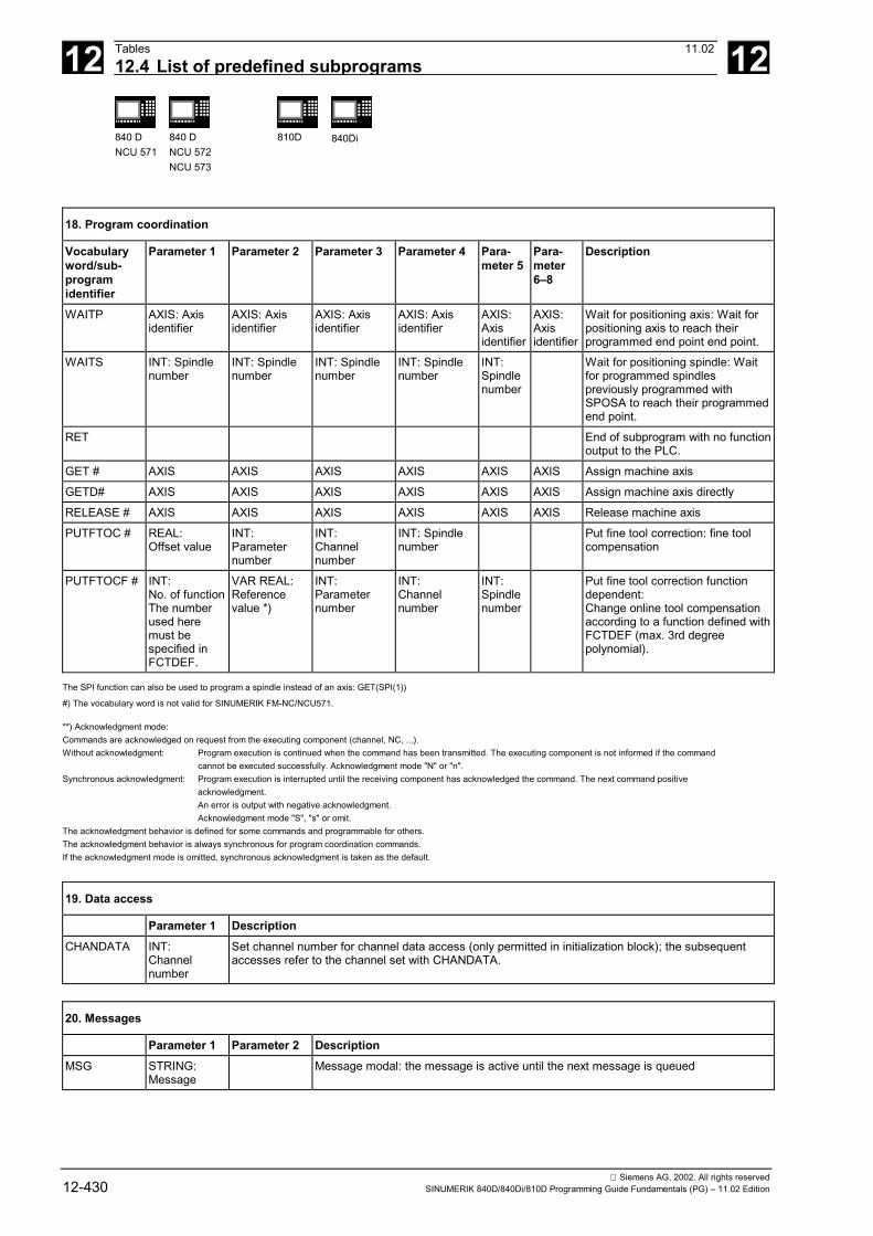
12 Tables 11.0212.4 List of predefined subprograms 12
840 DNCU 571
840 DNCU 572NCU 573
810D 840Di
Siemens AG, 2002. All rights reserved12-430 SINUMERIK 840D/840Di/810D Programming Guide Fundamentals (PG) – 11.02 Edition
18. Program coordination
Vocabularyword/sub-programidentifier
Parameter 1 Parameter 2 Parameter 3 Parameter 4 Para-meter 5
Para-meter6–8
Description
WAITP AXIS: Axisidentifier
AXIS: Axisidentifier
AXIS: Axisidentifier
AXIS: Axisidentifier
AXIS:Axisidentifier
AXIS:Axisidentifier
Wait for positioning axis: Wait forpositioning axis to reach theirprogrammed end point end point.
WAITS INT: Spindlenumber
INT: Spindlenumber
INT: Spindlenumber
INT: Spindlenumber
INT:Spindlenumber
Wait for positioning spindle: Waitfor programmed spindlespreviously programmed withSPOSA to reach their programmedend point.
RET End of subprogram with no functionoutput to the PLC.
GET # AXIS AXIS AXIS AXIS AXIS AXIS Assign machine axis
GETD# AXIS AXIS AXIS AXIS AXIS AXIS Assign machine axis directly
RELEASE # AXIS AXIS AXIS AXIS AXIS AXIS Release machine axis
PUTFTOC # REAL:Offset value
INT:Parameternumber
INT:Channelnumber
INT: Spindlenumber
Put fine tool correction: fine toolcompensation
PUTFTOCF # INT:No. of functionThe numberused heremust bespecified inFCTDEF.
VAR REAL:Referencevalue *)
INT:Parameternumber
INT:Channelnumber
INT:Spindlenumber
Put fine tool correction functiondependent:Change online tool compensationaccording to a function defined withFCTDEF (max. 3rd degreepolynomial).
The SPI function can also be used to program a spindle instead of an axis: GET(SPI(1))
#) The vocabulary word is not valid for SINUMERIK FM-NC/NCU571.
**) Acknowledgment mode:Commands are acknowledged on request from the executing component (channel, NC, ...).Without acknowledgment: Program execution is continued when the command has been transmitted. The executing component is not informed if the command
cannot be executed successfully. Acknowledgment mode "N" or "n".Synchronous acknowledgment: Program execution is interrupted until the receiving component has acknowledged the command. The next command positive
acknowledgment.An error is output with negative acknowledgment.Acknowledgment mode "S", "s" or omit.
The acknowledgment behavior is defined for some commands and programmable for others.The acknowledgment behavior is always synchronous for program coordination commands.If the acknowledgment mode is omitted, synchronous acknowledgment is taken as the default.
19. Data access
Parameter 1 DescriptionCHANDATA INT:
Channelnumber
Set channel number for channel data access (only permitted in initialization block); the subsequentaccesses refer to the channel set with CHANDATA.
20. Messages
Parameter 1 Parameter 2 DescriptionMSG STRING:
MessageMessage modal: the message is active until the next message is queued

12 11.02 Tables12.4 List of predefined subprograms 12
840 DNCU 571
840 DNCU 572NCU 573
810D 840Di
Siemens AG, 2002. All rights reservedSINUMERIK 840D/840Di/810D Programming Guide Fundamentals (PG) – 11.02 Edition 12-431
22. Alarms
Parameter 1 Parameter 2 DescriptionSETAL INT: Alarm
number (cyclealarms)
Set alarm set alarm
23. Compensation
Vocabularyword/sub-programidentifier
Parameter1–4
Description
QECLRNON # AXIS: Axisnumber
Quadrant error compensation learning ON
QECLRNOF # Quadrant error compensation learning OFF
#) The vocabulary word is not valid for SINUMERIK FM-NC.
24. Tool management
Parameter 1 Parameter 2 Parameter 3 DescriptionDELT # STRING [32]:
Tool nameINT: Duplonumber
Delete tool. Duplo number can beomitted.
GETSELT # VAR INT:T number (returnvalue)
INT: Spindlenumber
Get selected T number. If no spindlenumber is specified, the command forthe master spindle applies.
SETPIECE # INT: Workpiece count INT: Spindlenumber
Set number of workpieces for all toolsassigned to the spindle.If the spindle number is omitted, thecommand applies to the master spindle.
SETDNO INT: Tool no. T INT: Tool edgeno.
INT: D no. Set D no. of tool (T) and its tool edge tonew
DZERO Set D numbers of all tools of the TO unitassigned to the channel to invalid
DELDL INT: Tool no. T INT: D no. Delete all additive offsets of the tooledge (or of a tool if D is not specified)
SETMTH INT: Toolholder no. Set toolholder no.
POSM INT: Location no. forpositioning
INT: No. of themagazine to bemoved
INT: Locationnumber of theinternalmagazine
INT: Magazinenumber of theinternalmagazine
Position magazine
SETTIA VAR INT:Status=result ofoperation (returnvalue)
INT: Magazineno.
INT: Weargroup no.
Deactivate tool from wear group
SETTA VAR INT:Status=result ofoperation (returnvalue)
INT: Magazineno.
INT: Weargroup no.
Activate tool from wear group
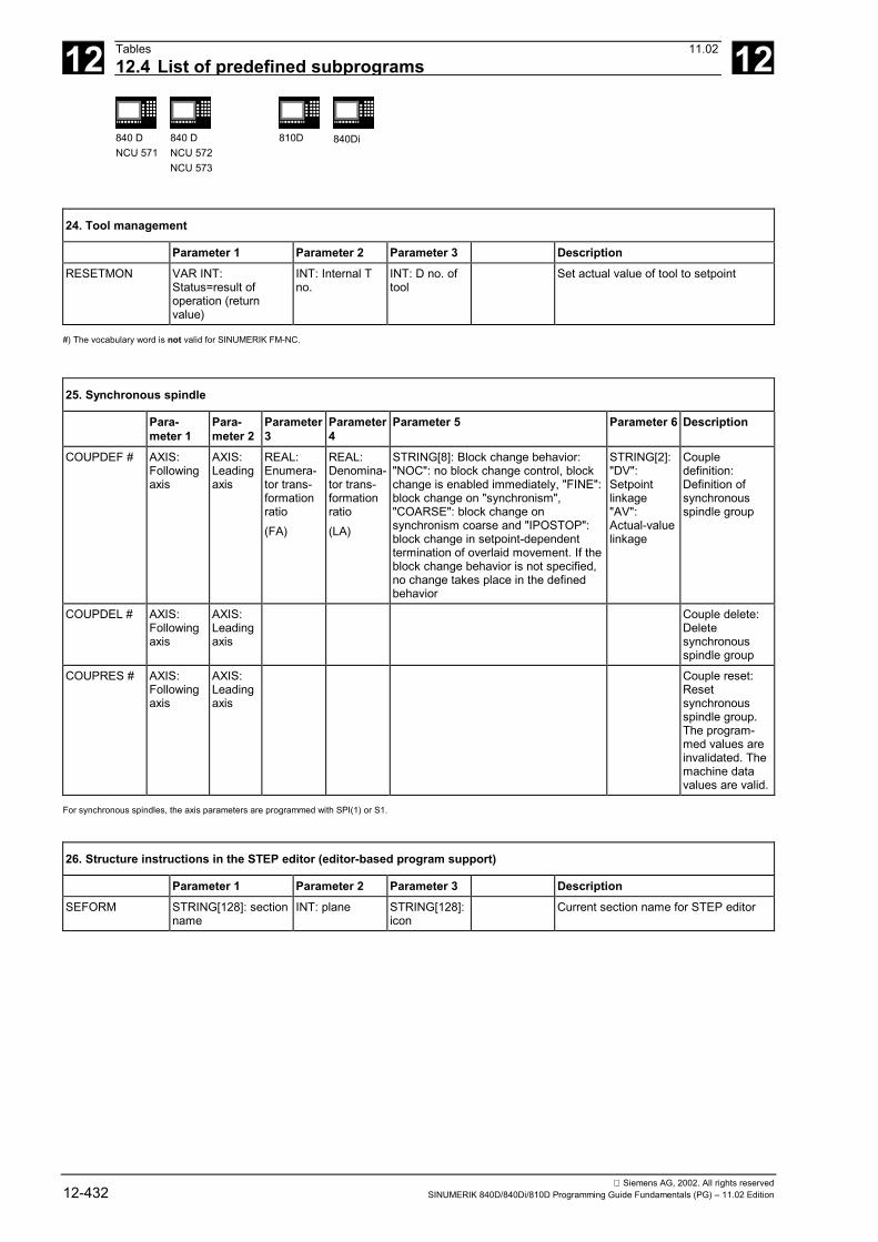
12 Tables 11.0212.4 List of predefined subprograms 12
840 DNCU 571
840 DNCU 572NCU 573
810D 840Di
Siemens AG, 2002. All rights reserved12-432 SINUMERIK 840D/840Di/810D Programming Guide Fundamentals (PG) – 11.02 Edition
24. Tool management
Parameter 1 Parameter 2 Parameter 3 DescriptionRESETMON VAR INT:
Status=result ofoperation (returnvalue)
INT: Internal Tno.
INT: D no. oftool
Set actual value of tool to setpoint
#) The vocabulary word is not valid for SINUMERIK FM-NC.
25. Synchronous spindle
Para-meter 1
Para-meter 2
Parameter3
Parameter4
Parameter 5 Parameter 6 Description
COUPDEF # AXIS:Followingaxis
AXIS:Leadingaxis
REAL:Enumera-tor trans-formationratio(FA)
REAL:Denomina-tor trans-formationratio(LA)
STRING[8]: Block change behavior:"NOC": no block change control, blockchange is enabled immediately, "FINE":block change on "synchronism","COARSE": block change onsynchronism coarse and "IPOSTOP":block change in setpoint-dependenttermination of overlaid movement. If theblock change behavior is not specified,no change takes place in the definedbehavior
STRING[2]:"DV":Setpointlinkage"AV":Actual-valuelinkage
Coupledefinition:Definition ofsynchronousspindle group
COUPDEL # AXIS:Followingaxis
AXIS:Leadingaxis
Couple delete:Deletesynchronousspindle group
COUPRES # AXIS:Followingaxis
AXIS:Leadingaxis
Couple reset:Resetsynchronousspindle group.The program-med values areinvalidated. Themachine datavalues are valid.
For synchronous spindles, the axis parameters are programmed with SPI(1) or S1.
26. Structure instructions in the STEP editor (editor-based program support)
Parameter 1 Parameter 2 Parameter 3 DescriptionSEFORM STRING[128]: section
nameINT: plane STRING[128]:
iconCurrent section name for STEP editor

12 11.02 Tables12.4 List of predefined subprograms 12
840 DNCU 571
840 DNCU 572NCU 573
810D 840Di
Siemens AG, 2002. All rights reservedSINUMERIK 840D/840Di/810D Programming Guide Fundamentals (PG) – 11.02 Edition 12-433
#) The vocabulary word is not valid for SINUMERIK 810 D.
Vocabularyword/sub-programidentifier
Parameter 1 Parameter 2 Parameter 3 Parameter 4 Description
COUPON # AXIS:Following axis
AXIS: Leadingaxis
REAL:Activationposition offollowing axis
Couple on:Activate ELG group/synchronous spindle pair. If noactivation positions are specified, the couple isactivated as quickly as possible (ramp). If an activationposition is specified for the following axis or spindle,this refers absolutely or incrementally to the leadingaxis/spindle.Only if the 3rd parameter is specified doparameters 4 and 5 have to be programmed.
COUPOF # AXIS:Following axis
AXIS: Leadingaxis
REAL:Deactivationposition offollowing axis(absolute)
REAL:Deactivationposition offollowing axis(absolute)
Couple off:Deactivate ELG group/synchronous spindle pair. Thecouple parameters are retained. If positions arespecified, the couple is only canceled when all thespecified positions have been overtraveled. Thefollowing spindle continues to revolve at the last speedprogrammed before deactivation of the couple.
WAITC # AXIS:Axis/spindle
STRING[8]:Block changecriterion
AXIS:Axis/spindle
STRING[8]:Block changecriterion
Wait for couple condition:Wait until couple block change conditions have beenmet for the axes/spindles.Up to 2 axes/spindles can be programmed.Block change condition:"NOC": no block change control, block change isenabled immediately,"FINE": block change on "synchronism fine"."COARSE": block change on "synchronism coarse" and"IPOSTOP": block change in setpoint-dependenttermination of overlaid movement.If the block change behavior is not specified, the setbehavior is applicable and there is no change.
AXCTSWE AXIS:Axis/spindle
Advance container axis
#)The vocabulary word is not valid for SINUMERIK 810D.

12 Tables 11.0212.4 List of predefined subprograms 12
840 DNCU 571
840 DNCU 572NCU 573
810D 840Di
Siemens AG, 2002. All rights reserved12-434 SINUMERIK 840D/840Di/810D Programming Guide Fundamentals (PG) – 11.02 Edition
12.4.2 Predefined subprogram calls in motion-synchronous actionsThe following predefined subprograms appear exclusively in motion-synchronous actions.
27. Synchronous procedures
Vocabularyword/functionidentifier
Parameter 1 Parameter 2 Parameter 3 to 5 Description
STOPREOF Stop preparation OFF:A synchronized action with a STOPREOF commandcauses a preprocessing stop after the next output block(= block for the main run). The preprocessing stop iscanceled with the end of the output block or when theSTOPREOF condition is fulfilled. All synchronized actioninstructions with the STOPREOF command are thereforeinterpreted as having been executed.
RDISABLE Read-in disable
DELDTG AXIS: Axis foraxial deletedistance-to-go(optional). If theaxis is omitted,delete distance-to-go is triggeredfor the pathdistance
Delete distance-to-goA synchronized action with the DELDTG commandcauses a preprocessing stop after the next output block(= block for the main run). The preprocessing stop iscanceled with the end of the output block or when thefirst DELDTG condition is fulfilled. The axial distance tothe destination point on an axial delete distance-to-go isstored in $AA_DELT[<axis>]; the distance-to-go is storedin $AC_DELT.
SYNFCT INT: Number ofpolynomialfunction definedwith FCTDEF.
VAR REAL:Result variable *)
VAR REAL:Input variable **)
If the condition in the motion synchronous action isfulfilled, the polynomial determined by the firstexpression is evaluated at the input variable. The upperand lower range of the value is limited and the inputvariable is assigned.
FTOC INT: Number ofpolynomialfunction definedwith FCTDEF.
VAR REAL:Input variable **)
INT: Length 1, 2,3INT: ChannelnumberINT: spindlenumber
Modify tool fine compensation according to a functiondefined with FCTDEF (polynomial no higher than 3rddegree).The number used here must be specified in FCTDEF.
*) Only special system variables can be used for the result variable. These are described in the Programming Guide Advanced in the section on "Write main run variable".
**) Only special system variables can be used for the result variable. These variables are described in the Programming Guide Advanced in the list of system variables.

12 11.02 Tables12.4 List of predefined subprograms 12
840 DNCU 571
840 DNCU 572NCU 573
810D 840Di
Siemens AG, 2002. All rights reservedSINUMERIK 840D/840Di/810D Programming Guide Fundamentals (PG) – 11.02 Edition 12-435
12.4.3 Predefined functionsPredefined functions are invoked by means of a function call. Function calls return a value. They can be included as an operand in an expression.
1. Coordinate system
Vocabularyword/functionidentifier
Result Parameter 1 Parameter 2 Description
CTRANS FRAME AXIS REAL: Offset Parameter 3–15same as 1 ...
Parameter 4–16same as 2 ...
Translation: Zero offset formultiple axis.One axis identifier isprogrammed at a time, withits respective value in thenext parameter.CTRANS can be used toprogram offset for up to 8axes.
CROT FRAME AXIS REAL:Rotation
Parameter 3/5same as 1 ...
Parameter 4/6same as 2 ...
Rotation: Rotation of thecurrent coordinate system.Maximum number ofparameters: 6 (one axisidentifier and one value pergeometry axis).
CSCALE FRAME AXIS REAL: Scalefactor
Parameter 3–15same as 1 ...
Parameter 4–16same as 2 ...
Scale: Scale factor formultiple axes.The maximum number ofparameters is 2 * maximumnumber of axes (axisidentifier and valuerespectively).One axis identifier isprogrammed at a time, withits respective value in thenext parameter.CSCALE can be used toprogram scale factors forup to 8 axes.
CMIRROR FRAME AXIS Parameter 2–8same as 1 ...
Mirror: Mirror on acoordinate axis
MEAFRAME FRAME 2-dim. REALarray
2-dim. REALarray
Parameter 3:REAL variable
Frame calculation from 3measuring points in space
Frame functions CTRANS, CSCALE, CROT and CMIRROR are used to generate frame expressions.
2. Geometry functions
Vocabularyword/functionidentifier
Result Parameter 1 Parameter 2 Parameter 3 Description
CALCDAT BOOL:Error status
VAR REAL [,2]:Table with inputpoints (abscissaand ordinate forpoints 1, 2, 3 etc.)
INT: Number ofinput points forcalculation(3 or 4)
VAR REAL [3]:Result: Abscissa,ordinate andradius ofcalculated circlecenter point
CALCDAT: calculate circle dataCalculates radius and center point ofa circle from 3 or 4 points (accordingto parameter 1) which must lie on acircle. The points must be different.

12 Tables 11.0212.4 List of predefined subprograms 12
840 DNCU 571
840 DNCU 572NCU 573
810D 840Di
Siemens AG, 2002. All rights reserved12-436 SINUMERIK 840D/840Di/810D Programming Guide Fundamentals (PG) – 11.02 Edition
2. Geometry functions
Vocabularyword/functionidentifier
Result Parameter 1 Parameter 2 Parameter 3 Description
INTERSEC BOOL:Error status
VAR REAL [11]:First contourelement
VAR REAL [11]:Second contourelement
VAR REAL [2]:Result vector:intersectioncoordinate,abscissa andordinate
Intersection: Calculation ofintersectionThe intersection between two contourelements is calculated. Theintersection coordinates are returnvalues. The error status indicateswhether an intersection was found.
3. Axis functions
Result Parameter 1 Parameter 2 DescriptionAXNAME AXIS:
Axis identifierSTRING [ ]:Input string
AXNAME: Get axis identifierConverts the input string to an axis identifier. An alarm isgenerated if the input string does not contain a valid axisidentifier.
SPI AXIS:Axis identifier
INT: Axis number SPI: Convert spindle to axisConverts a spindle number to an axis identifier. An alarmis generated if the passed parameter does not contain avalid spindle number.
ISAXIS BOOLTRUE:Axis exists:Otherwise:FALSE
INT:Number of thegeometry axis(1 to 3)
Check whether the geometry axis 1 to 3 specified asparameter exists in accordance with$MC_AXCONF_GEOAX_ASSIGN_TAB.
AXSTRING STRING AXIS Convert axis identifier into string.
4. Tool management
Result Parameter 1 Parameter 2 DescriptionNEWT # INT: T number STRING [32]:
Tool identifierINT: Duplonumber
Create new tool (prepare tool data). The duplo numbercan be omitted.
GETT # INT: T number STRING [32]:Tool identifier
INT: Duplonumber
Get T number for tool identifier
GETACTT # INT: Status INT:T number
STRING [32]: toolname
Get active tool from a group of tools with the same name
#) The vocabulary word is not valid for SINUMERIK FM-NC.
5. Arithmetics
Result Parameter 1 Parameter 2 DescriptionSIN REAL REAL Sine
ASIN REAL REAL Arcsine
COS REAL REAL CosineACOS REAL REAL Arccosine
TAN REAL REAL Tangent
ATAN2 REAL REAL REAL Arctangent 2
SQRT REAL REAL Square root
POT REAL REAL Square

12 11.02 Tables12.4 List of predefined subprograms 12
840 DNCU 571
840 DNCU 572NCU 573
810D 840Di
Siemens AG, 2002. All rights reservedSINUMERIK 840D/840Di/810D Programming Guide Fundamentals (PG) – 11.02 Edition 12-437
5. Arithmetics
Result Parameter 1 Parameter 2 DescriptionTRUNC REAL REAL Truncate decimal places
ROUND REAL REAL Round decimal places
ABS REAL REAL Generate absolute value
LN REAL REAL Natural logarithm
EXP REAL REAL Exponential function ex
6. String functions
Result Parameter 1 Parameter 2 to 3 Description
ISNUMBER BOOL STRING Check whether the input string can be converted to anumber.Result is TRUE if conversion is possible.
ISVAR BOOL STRING Check whether the transfer parameter contains avariable known in the NC. (Machine data, setting data,system variable, general variables like GUD´sResult is TRUE, if all the following check produce apositive results according to the (STRING) transferparameter:– the identifier exists– it is a 1- or 2-dimensional array– an array index is allowedFor axial variables, the axis names are accepted as anindex but not checked.
NUMBER REAL STRING Convert the input string into a number.
TOUPPER STRING STRING Convert all alphabetic characters in the input string toupper case.
TOLOWER STRING STRING Convert all alphabetic characters in the input string tolower case.
STRLEN INT STRING Result is the length of the input string up to the end ofthe string (0).
INDEX INT STRING CHAR Find the character (2nd parameter) in the input string (1stparameter). The reply gives the place at which thecharacter was first found. The search is from left to right.The 1st character in the string has the index 0.
RINDEX INT STRING CHAR Find the character (2nd parameter) in the input string (1stparameter). The reply gives the place at which thecharacter was first found. The search is from right to left.The 1st character in the string has the index 0.
MINDEX INT STRING STRING Find one of the characters specified in the 2ndparameter in the input string (1st parameter). The placewhere one of the characters was first found is output.The search is from left to right.The first character in the string has the index 0.
SUBSTR STRING STRING INT Returns the substring of the input string (1st parameter)defined by the start character (2nd parameter) andnumber of characters (3rd parameter).Example:SUBSTR("Hello world",1,5) returns "ello"

12 Tables 11.0212.4 List of predefined subprograms 12
840 DNCU 571
840 DNCU 572NCU 573
810D 840Di
Siemens AG, 2002. All rights reserved12-438 SINUMERIK 840D/840Di/810D Programming Guide Fundamentals (PG) – 11.02 Edition
12.4.4 Data typesData types
Type Comment Value rangeINT Integers with sign ± (231 –1)
REAL Real numbers (fractions with decimal point, LONG REALto IEEE)
± (10–300 ... 10+300)
BOOL Boolean value TRUE, FALSE or 1, 0 1, 0
CHAR 1 character in ASCII code 0 ... 255
STRING Character string, number of characters in [...] (max. of200 characters)
Sequence of values with 0 ... 255
AXIS Axis identifiers only (axis addresses) All axis identifiers available on the channel
FRAME Geometrical parameters for translation, rotation, scale,mirror
—
�

A 11.02 Appendix A
Siemens AG, 2002. All rights reservedSINUMERIK 840D/840Di/810D Programming Guide Fundamentals (PG) – 11.02 Edition A-439
Appendix
A Abbreviations ....................................................................................................................A-440
B Terms................................................................................................................................A-448
C References .......................................................................................................................A-474
D Index .................................................................................................................................A-489
E Commands, identifier........................................................................................................A-496

A Appendix 11.02Abbreviations A
840DNCU 571
840DNCU 572NCU 573
810D 840Di
Siemens AG, 2002. All rights reservedA-440 SINUMERIK 840D/840Di/810D Programming Guide Fundamentals (PG) – 11.02 Edition
A AbbreviationsASCII American Standard Code for Information Interchange
ASUB Asynchronous Subroutine
BA Mode of operation
BAG Mode Group
BCD Binary Coded Decimals
BCS Basic Coordinate System
BIN Binary Files
BP Basic Program
C Bus Communication Bus
C1 .. C4 Channel 1 to channel 4
CAD Computer-Aided Design
CAM Computer-Aided Manufacturing
CNC Computerized Numerical Control
COM Communication
COR Coordinate Rotation
CPU Central Processing Unit
CR Carriage Return
CSF Control System Flowchart (PLC programming method)
CTS Clear To Send (serial data interfaces)
CUTOM Cutter Radius Compensation (Tool radius compensation)
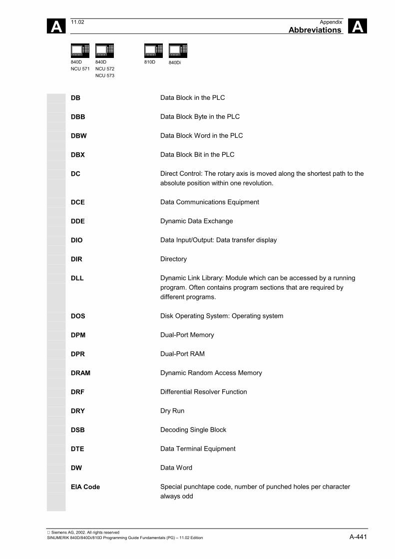
A 11.02 AppendixAbbreviations A
840DNCU 571
840DNCU 572NCU 573
810D 840Di
Siemens AG, 2002. All rights reservedSINUMERIK 840D/840Di/810D Programming Guide Fundamentals (PG) – 11.02 Edition A-441
DB Data Block in the PLC
DBB Data Block Byte in the PLC
DBW Data Block Word in the PLC
DBX Data Block Bit in the PLC
DC Direct Control: The rotary axis is moved along the shortest path to theabsolute position within one revolution.
DCE Data Communications Equipment
DDE Dynamic Data Exchange
DIO Data Input/Output: Data transfer display
DIR Directory
DLL Dynamic Link Library: Module which can be accessed by a runningprogram. Often contains program sections that are required bydifferent programs.
DOS Disk Operating System: Operating system
DPM Dual-Port Memory
DPR Dual-Port RAM
DRAM Dynamic Random Access Memory
DRF Differential Resolver Function
DRY Dry Run
DSB Decoding Single Block
DTE Data Terminal Equipment
DW Data Word
EIA Code Special punchtape code, number of punched holes per characteralways odd

A Appendix 11.02Abbreviations A
840DNCU 571
840DNCU 572NCU 573
810D 840Di
Siemens AG, 2002. All rights reservedA-442 SINUMERIK 840D/840Di/810D Programming Guide Fundamentals (PG) – 11.02 Edition
ENC Encoder
EPROM Erasable Programmable Read Only Memory
FB Function Block
FC Function Call: Function block in the PLC
FDD Feed Drive
FDD Floppy Disk Drive
FEPROM Flash EPROM
FIFO First-In-First-Out: Memory which operates without addressspecification from which data are read in the same order as they arestored.
FM Function Module
FM-NC Function Module – Numerical Control
FPU Floating Point Unit
FRA Frame Block
FRAME Data Record (frame)
FST Feed Stop
GUD Global User Data
HD Hard Disk
HEX Abbreviation for hexadecimal
HHU Handheld Unit
HMI Human Machine Interface: SINUMERIK operating functions foroperator control, programming and simulation. MMC and HMI areidentical in meaning.
HW Hardware
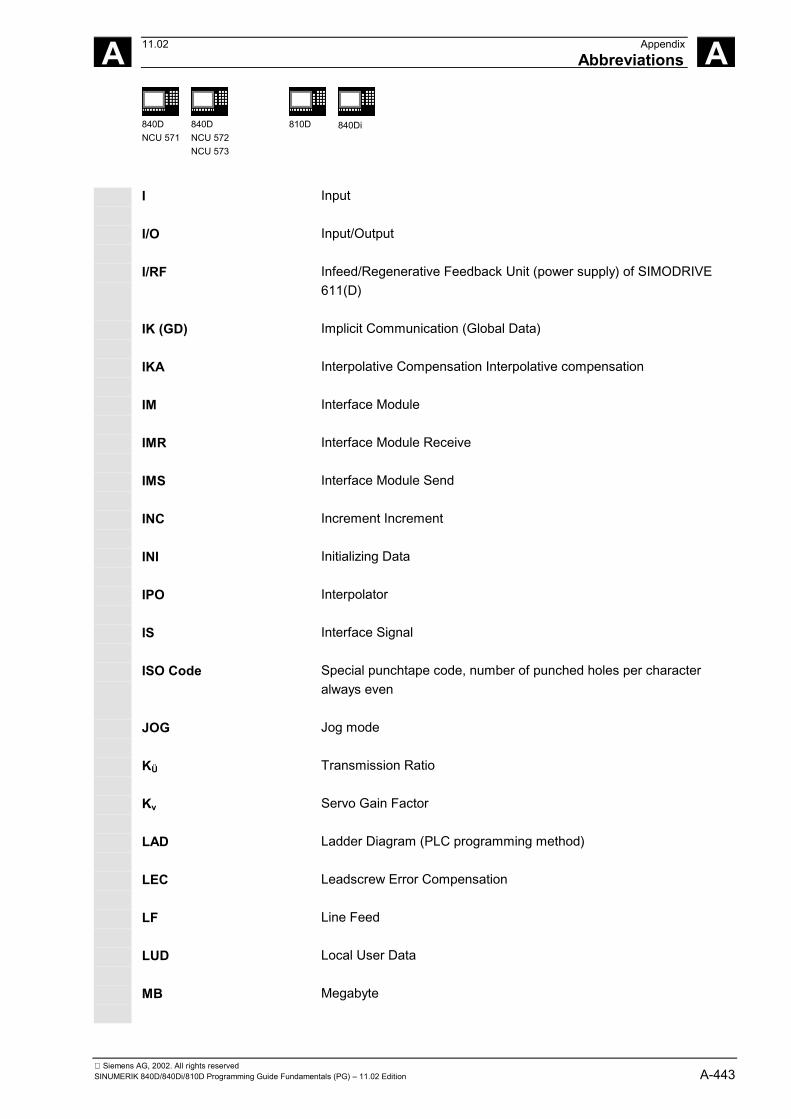
A 11.02 AppendixAbbreviations A
840DNCU 571
840DNCU 572NCU 573
810D 840Di
Siemens AG, 2002. All rights reservedSINUMERIK 840D/840Di/810D Programming Guide Fundamentals (PG) – 11.02 Edition A-443
I Input
I/O Input/Output
I/RF Infeed/Regenerative Feedback Unit (power supply) of SIMODRIVE611(D)
IK (GD) Implicit Communication (Global Data)
IKA Interpolative Compensation Interpolative compensation
IM Interface Module
IMR Interface Module Receive
IMS Interface Module Send
INC Increment Increment
INI Initializing Data
IPO Interpolator
IS Interface Signal
ISO Code Special punchtape code, number of punched holes per characteralways even
JOG Jog mode
KÜ Transmission Ratio
Kv Servo Gain Factor
LAD Ladder Diagram (PLC programming method)
LEC Leadscrew Error Compensation
LF Line Feed
LUD Local User Data
MB Megabyte

A Appendix 11.02Abbreviations A
840DNCU 571
840DNCU 572NCU 573
810D 840Di
Siemens AG, 2002. All rights reservedA-444 SINUMERIK 840D/840Di/810D Programming Guide Fundamentals (PG) – 11.02 Edition
MC Measuring Circuit
MCP Machine Control Panel
MCS Machine Coordinate System (Machine)
MD Machine Data
MDA Manual Data Automatic (MDI)
MMC Human Machine Communication: User interface on numerical controlsystems for operator control, programming and simulation. MMC andHMI are identical in meaning.
MPF Main Program File: NC parts program (main program)
MPI Multi Port Interface
MSD Main Spindle Drive
NC Numerical Control
NCK Numerical Control Kernel (with block preparation, traversing range,etc.)
NCU Numerical Control Unit: Hardware unit of the NCK
NURBS Non Uniform Rational B-Spline
O Output
OB Organization Block in the PLC
OEM Original Equipment Manufacturer: The manufacturer of equipment thatis marketed by another vendor, typically under a different name.
OI Operator Interface
OP Operator Panel
OP Operator Panel
OPI Operator Panel Interface
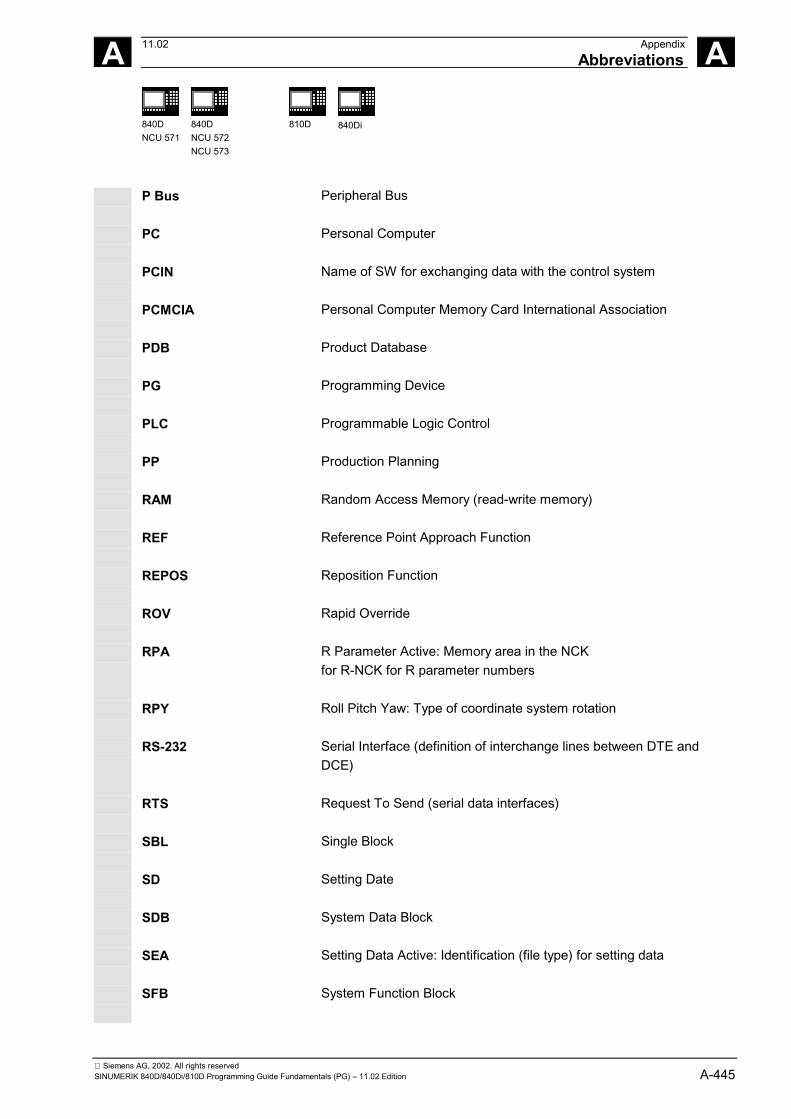
A 11.02 AppendixAbbreviations A
840DNCU 571
840DNCU 572NCU 573
810D 840Di
Siemens AG, 2002. All rights reservedSINUMERIK 840D/840Di/810D Programming Guide Fundamentals (PG) – 11.02 Edition A-445
P Bus Peripheral Bus
PC Personal Computer
PCIN Name of SW for exchanging data with the control system
PCMCIA Personal Computer Memory Card International Association
PDB Product Database
PG Programming Device
PLC Programmable Logic Control
PP Production Planning
RAM Random Access Memory (read-write memory)
REF Reference Point Approach Function
REPOS Reposition Function
ROV Rapid Override
RPA R Parameter Active: Memory area in the NCKfor R-NCK for R parameter numbers
RPY Roll Pitch Yaw: Type of coordinate system rotation
RS-232 Serial Interface (definition of interchange lines between DTE andDCE)
RTS Request To Send (serial data interfaces)
SBL Single Block
SD Setting Date
SDB System Data Block
SEA Setting Data Active: Identification (file type) for setting data
SFB System Function Block

A Appendix 11.02Abbreviations A
840DNCU 571
840DNCU 572NCU 573
810D 840Di
Siemens AG, 2002. All rights reservedA-446 SINUMERIK 840D/840Di/810D Programming Guide Fundamentals (PG) – 11.02 Edition
SFC System Function Call
SK Softkey
SKP Skip Block
SM Stepper Motor
SOP Shopfloor-Oriented Programming
SPF Sub-Program File (subroutine file)
SR Subroutine
SRK Cutter Radius Compensation
SRAM Static RAM (battery-backed)
SSI Serial Synchronous Interface
STL Statement List
SW Software
SYF System Files
T Tool
TC Tool Change
TEA Testing Data Active: Identifier for machine data
TLC Tool Length Compensation
TNRC Tool Nose Radius Compensation
TO Tool Offset
TOA Tool Offset Active: Identification (file type) for tool offsets
A 11.02 AppendixAbbreviations A
840DNCU 571
840DNCU 572NCU 573
810D 840Di
Siemens AG, 2002. All rights reservedSINUMERIK 840D/840Di/810D Programming Guide Fundamentals (PG) – 11.02 Edition A-447
TRANSMIT Transform Milling into Turning: Coordinate conversion on turningmachines for milling operations
TRC Tool Radius Compensation
UFR User Frame: Zero offset
WCS Workpiece Coordinate System (Work)
WOA Work Offset Active
WPD Workpiece Directory
WO Work Offset
ZO Zero Offset (WO)
ZOA Zero Offset Active (WOA): Identification (file type) for zero offset data

A Appendix 11.02Terms A
840DNCU 571
840DNCU 572NCU 573
810D 840Di
Siemens AG, 2002. All rights reservedA-448 SINUMERIK 840D/840Di/810D Programming Guide Fundamentals (PG) – 11.02 Edition
B TermsImportant terms are listed below in alphabetical order, accompaniedby explanations. Cross-references to other entries in this glossary areindicated by the symbol "->".
A
A spline The A spline runs tangentially through the programmed interpolationpoints (3rd degree polynomial).
Absolute dimension A destination for an axis movement is defined by a dimension thatrefers to the origin of the currently active coordinate system. See also-> incremental dimension.
AC control(Adaptive Control)
A process variable (e.g. path-specific or axial feedrate) can becontrolled as a function of another, measured process variable (e.g.spindle current). Typical application: To maintain a constant chipremoval volume during grinding.
Acceleration with jerklimitation
In order to obtain the optimum acceleration gradient for the machinewhile providing effective protection for the mechanical components,the machining program offers a choice between instantaneousacceleration and continuous (smooth) acceleration.
Access rights The CNC program blocks and data are protected by a 7-level systemof access restrictions:• Three password levels for system manufacturers, machine
manufacturers and users and• Four keyswitch settings which can be evaluated via the PLC.
Activate/deactivate Working area limitation is a means of restricting the axis movementover and above the restrictions imposed by the limit switches. A pair ofvalues delimiting the protected zone area can be specified for eachaxis.
Address Addresses are fixed or variable identifiers for axes (X, Y, ...), spindlespeed (S), feedrate (F), circle radius (CR), etc.

A 11.02 AppendixTerms A
840DNCU 571
840DNCU 572NCU 573
810D 840Di
Siemens AG, 2002. All rights reservedSINUMERIK 840D/840Di/810D Programming Guide Fundamentals (PG) – 11.02 Edition A-449
Alarms All -> messages and alarms are displayed in plain text on the operatorpanel. Alarm text also includes the date, time and correspondingsymbol for the reset criterion.Alarms and messages are displayed separately.1. Alarms and messages in the parts program
Alarms and messages can be displayed directly from the partsprogram in plaintext.
2. Alarms and messages from PLCAlarms and messages relating to the machine can bedisplayed from the PLC program in plaintext. No additional functionblock packages are required for this purpose.
Analog input/outputmodule
Analog input/output modules are signal transducers for analogprocess signals.Analog input modules convert analog measured values into digitalvalues that can be processed in the CPU.Analog output modules convert digital values into manipulatedvariables.
Approach fixed machinepoint
Approach motion towards one of the predefined -> fixed machinepoints.
Archiving Exporting files and/or directories to an external storage device.
Asynchronoussubroutine
• A parts program that can be started asynchronously (orindependently) by means of an interrupt signal (e.g. "High-speedNC input" signal) while the parts program is active (SW package 3and lower).
• A parts program that can be started asynchronously (or
independently) of the current program status by means of aninterrupt signal (e.g. "High-speed NC input" signal) (SW package 4and higher).
Automatic Control system operating mode (block-sequential to DIN): Mode in NCsystems in which a -> parts program is selected and continuouslyexecuted.
Auxiliary functions Auxiliary functions can be used to pass -> parameters to the -> PLC in-> parts programs, triggering reactions there which are defined by themachine manufacturer.

A Appendix 11.02Terms A
840DNCU 571
840DNCU 572NCU 573
810D 840Di
Siemens AG, 2002. All rights reservedA-450 SINUMERIK 840D/840Di/810D Programming Guide Fundamentals (PG) – 11.02 Edition
Axes CNC axes are classified according to their functional scope as:• Axes: Interpolative path axes• Positioning axes: Non-interpolative infeed and positioning axes with
axis-specific feedrates; axes can move across block limits.Positioning axes need not be involved in workpiece machining assuch and include tool feeders, tool magazines, etc.
Axis address See -> axis identifier
Axis identifier In compliance with DIN 66217, axes are identified as X, Y and Z for aright-handed rectangular -> coordinate system.-> Rotary axes rotating around X, Y, Z are assigned the identifiers A,B, C. Additional axes, which are parallel to those specified, can beidentified with other letters.
Axis name See -> axis identifier
Axis/spindle replacement An axis/spindle is permanently assigned to a particular channel viamachine data. This MD assignment can be "undone" by programcommands and the axis/spindle then assigned to another channel.
B
B spline The programmed positions for the B spline are not interpolation points,but merely "check points". The curve generated does not pass directlythrough these check points, but only in their vicinity (1st, 2nd or 3rddegree polynomial).
Back up A copy of the memory contents (hard disk) stored on an externaldevice for data backup and/or archiving.
Backlash compensation Compensation of a mechanical machine backlash, e.g. backlash dueto reversal of leadscrews. The backlash compensation can be enteredseparately for each axis.
Backup battery The backup battery provides non-volatile storage for the -> userprogram in the -> CPU and ensures that defined data areas and flags,timers and counters are retentive.
Base axis Axis whose setpoint or actual value is employed in calculating acompensatory value.
A 11.02 AppendixTerms A
840DNCU 571
840DNCU 572NCU 573
810D 840Di
Siemens AG, 2002. All rights reservedSINUMERIK 840D/840Di/810D Programming Guide Fundamentals (PG) – 11.02 Edition A-451
Basic coordinate system Cartesian coordinate system, is mapped onto machine coordinatesystem by means of transformation.In the -> parts program, the programmer uses the axis names of thebasic coordinate system. The basic coordinate system exists inparallel to the -> machine coordinate system when no ->transformation is active. The difference between the systems relatesonly to the axis identifiers.
Baud rate Rate at which data transmission takes place (bit/s).
Blank The unmachined workpiece.
Block All files required for programming and program execution are knownas blocks.
Block A section of a -> parts program terminated with a line feed.A distinction is made between -> main blocks and -> subblocks.
Block search The block search function allows selection of any point in the partsprogram at which machining must start or be continued. The functionis provided for the purpose of testing parts programs or continuingmachining after an interruption.
Booting Loading the system program after Power ON.
Bus connector A bus connector is an S7-300 accessory that is supplied with the ->I/O modules. The bus connector extends the -> S7-300 bus from the-> CPU or an I/O module to the next adjacent I/O module.
C
C axis Axis about which the tool spindle describes a controlled rotational andpositioning movement.
C spline The C spline is the best known and the most widely used spline. Thespline passes through each of the interpolation points at a tangent andalong the axis of curvature. 3rd-degree polynomials are used.
Channel structure The channel structure makes it possible to process the -> programs ofindividual channels simultaneously and asynchronously.

A Appendix 11.02Terms A
840DNCU 571
840DNCU 572NCU 573
810D 840Di
Siemens AG, 2002. All rights reservedA-452 SINUMERIK 840D/840Di/810D Programming Guide Fundamentals (PG) – 11.02 Edition
Circular interpolation The -> tool is required to travel in a circle between defined points onthe contour at a specified feed while machining the workpiece.
Clearance control (3D),sensor-driven
A position offset for a specific axis can be controlled as a function of ameasured process variable (e.g. analog input, spindle current...). Thisfunction can automatically maintain a constant clearance to meet thetechnological requirements of the machining operation.
CNC -> NC
CNC high-level language The high-level language offers: -> user variables, -> predefined uservariables, -> system variables, -> indirect programming, -> arithmeticand angular functions, -> relational and logic operations, -> programjumps and branches, -> program coordination (SINUMERIK 840D),-> macros.
CNC programminglanguage
The CNC programming language is based on DIN 66025 with high-level language expansions. The -> CNC programming language and-> high-level language expansions support the definition of macros(sequenced statements).
COM Numerical control component for the implementation and coordinationof communication.
Command axis Command axes are started from synchronized actions in response toan event (command). They can be positioned, started and stoppedfully asynchronous to the parts program.
Compensation axis Axis having a setpoint or actual value modified by the compensationvalue.
Compensation table Table of interpolation points. It supplies the compensation values ofthe compensation axis for selected positions of the base axis.
Compensation value Difference between the axis position measured by the position sensorand the desired, programmed axis position.
Connecting cables Connecting cables are pre-assembled or user-assembled 2-wirecables with a connector at each end. They are used to connect the ->CPU via the -> multipoint interface (MPI) to a -> programming deviceor to other CPUs.

A 11.02 AppendixTerms A
840DNCU 571
840DNCU 572NCU 573
810D 840Di
Siemens AG, 2002. All rights reservedSINUMERIK 840D/840Di/810D Programming Guide Fundamentals (PG) – 11.02 Edition A-453
Continuous-path mode The purpose of continuous-path mode is to avoid rapid deceleration-> of the path axes at parts program block boundaries and to makethe transition to the next block at as constant a velocity as possible.
Contour Outline of a -> workpiece.
Contour monitoring The following error is monitored within a definable tolerance band as ameasure of contour accuracy. Overloading of the drive, for example,may result in an unacceptably large following error. In such cases, analarm is output and the axes stopped.
Coordinate system See -> machine coordinate system, -> workpiece coordinate system
CPU Central Processor Unit -> programmable controller
Cycle Protected subroutine for executing a recurring machining operation onthe -> workpiece.
Cycles support The available cycles are listed in menu "Cycle support" in the"Program" operating area. Once the desired machining cycle has beenselected, the parameters required for assigning values are displayedin plaintext.
D
Data block 1. Data unit of the -> PLC which can be accessed by -> HIGHSTEPprograms.
2. Data unit of the -> NC: Data blocks contain data definitions forglobal user data. These data can be initialized directly when theyare defined.
Data transfer programPCIN
PCIN is a routine for transmitting and receiving CNC user data, e.g.parts programs, tool offsets, etc. via the serial interface. The PCINprogram can run under MS-DOS on standard industrial PCs.
Data word A data unit, two bytes in size, within a -> PLC data block.
Deletion of distance-to-go
Command in parts program which stops machining and clears theremaining path distance to go.
Design • The SINUMERIK FM-NC is installed in the CPU tierof the SIMATIC S7-300. The 200mm wide, fully encapsulatedmodule has the same external design as the SIMATIC S7-300modules.

A Appendix 11.02Terms A
840DNCU 571
840DNCU 572NCU 573
810D 840Di
Siemens AG, 2002. All rights reservedA-454 SINUMERIK 840D/840Di/810D Programming Guide Fundamentals (PG) – 11.02 Edition
• The SINUMERIK 840D is installed as a compact module in theSIMODRIVE 611D converter system. It has the same dimensionsas a 50mm wide SIMODRIVE 611D module. The SINUMERIK840D comprises the NCU module and the NCU box.
• The SINUMERIK 810D has the same design as the SIMODRIVE611D with a width of 150mm. The following components areintegrated: SIMATIC S7-CPU, 5 digital servo drive controls and 3SIMODRIVE 611D power modules.
Diagnosis 1. Control operating area2. The control incorporates a self-diagnosis program and test routines
for servicing: Status, alarm and service displays.
Digital input/outputmodule
Digital modules are signal transducers for binary process signals.
Dimensions in metricand inch systems
Position and lead/pitch values can be programmed in inches in themachining program. The control is set to a basic system regardless ofthe programmable unit of measure (G70/G71).
DRF Differential Resolver Function NC function which generates anincremental zero offset in AUTOMATIC mode in conjunction with anelectronic handwheel.
Drift compensation When the CNC axes are in the constant motion phase, automatic driftcompensation is implemented in the analog speed control.
Drive • SINUMERIK FM-NC has an analog +10V interface to theSIMODRIVE 611A converter system.
• The SINUMERIK 840D control system is linked to the SIMODRIVE611D converter system via a high-speed digital parallel bus.
Editor The editor makes it possible to create, modify, extend, join and insertprograms/texts/program blocks.
Electronic handwheel Electronic handwheels can be used to traverse the selected axessimultaneously in manual mode. The handwheel clicks are analyzedby the increment analyzer.

A 11.02 AppendixTerms A
840DNCU 571
840DNCU 572NCU 573
810D 840Di
Siemens AG, 2002. All rights reservedSINUMERIK 840D/840Di/810D Programming Guide Fundamentals (PG) – 11.02 Edition A-455
Exact stop When an exact stop is programmed, a position specified in the blockis approached accurately and, where appropriate, very slowly. In orderto reduce the approach time, -> exact stop limits are defined forrapid traverse and feed.
Exact stop limit When all path axes reach their exact stop limits, the control respondsas if it had reached its destination point precisely. The -> partsprogram continues execution at the next block.
External zero offset A zero offset specified by the -> PLC.
F
Fast retraction fromcontour
When an interrupt is received, it is possible to initiate a motion via theCNC machining program which allows the tool to be retracted quicklyfrom the workpiece contour currently being machined. The retractionangle and the distance retracted can also be parameterized. Aninterrupt routine can be executed after the rapid retraction.(SINUMERIK 840D, 840Di, 810D).
Feedforward control,dynamic
Contour inaccuracies resulting from following errors can be almostcompletely eliminated by the dynamic, acceleration-dependentfeedforward control function. Feedforward control ensures an excellentdegree of machining accuracy even at high tool path velocities.Feedforward control can only be selected or deselected for all axestogether via the parts program.
Feedrate override The current feedrate setting entered via the control panel or by thePLC is overlaid on the programmed feedrate (0–200%). The feedratecan also be corrected by a programmable percentage factor (1–200%)in the machining program.An offset can also be applied via motion-synchronous actionsindependently of the running program.
Finished-part contour Contour of the finished workpiece. See also -> blank.
Fixed machine point A point defined uniquely by the machine tool, such as the referencepoint.

A Appendix 11.02Terms A
840DNCU 571
840DNCU 572NCU 573
810D 840Di
Siemens AG, 2002. All rights reservedA-456 SINUMERIK 840D/840Di/810D Programming Guide Fundamentals (PG) – 11.02 Edition
Fixed-point approach Machine tools can execute defined approaches to fixed points such astool-change points, loading points, pallet-change points, etc. Thecoordinates of these points are stored on the control. Where possible,the control moves these axes in -> rapid traverse.
Frame A frame is a calculation rule that translates one Cartesian coordinatesystem into another Cartesian coordinate system. A frame containsthe components -> zero offset, -> rotation, -> scaling and -> mirroring.
G
General reset The following memories of the -> CPU are erased by a general resetoperation:
• -> Working memory• Read/write area of the -> load memory• -> System memory• -> Backup memory
Geometry Description of a -> workpiece in the -> workpiece coordinate system.
Geometry axis Geometry axes are used to describe a 2- or 3-dimensional area in theworkpiece coordinate system.
Global mainrun/subroutine
Each global main run/subroutine can be stored only once under itsname in the directory. However, the same name can be used indifferent directories.
Ground "Ground" is the term applied to all the electrically inactive,interconnected parts of a piece of equipment which cannot carry anyhazardous contact voltage even in the event of a fault.
H
Helical interpolation The helical interpolation function is ideal for machining internal andexternal threads using form milling cutters and for milling lubricationgrooves. The helix comprises two movements:1. Circular movement in one plane2. Linear movement perpendicular to this plane.

A 11.02 AppendixTerms A
840DNCU 571
840DNCU 572NCU 573
810D 840Di
Siemens AG, 2002. All rights reservedSINUMERIK 840D/840Di/810D Programming Guide Fundamentals (PG) – 11.02 Edition A-457
High-speed digitalinputs/outputs
As an example, high-speed CNC program routines (interrupt routines)can be started via the digital inputs. High-speed, program-drivenswitching functions can be initiated via the digital CNC outputs(SINUMERIK 840D).
HIGHSTEP Combination of the programming features for the -> PLC in theS7-300/400 range.
I
I/O module I/O modules create the link between the CPU and the process. I/Omodules are:• ->Digital input/output modules• ->Analog input/output modules• ->Simulator modules
Identifier In accordance with DIN 66025, identifiers (names) for variables(arithmetic variables, system variables, user variables), forsubroutines, for vocabulary words and for words can contain severaladdress letters. These letters have the same meaning as the words inthe block syntax. Identifiers must be unique. Identical identifiers mustnot be used for different objects.
Inch system ofmeasurement
System of measurement that defines distances in "inches" andfractions thereof.
Inclined axis Fixed angular interpolation with allowance for an inclined infeed axis orgrinding wheel through specification of the angle. The axes areprogrammed and displayed in the Cartesian coordinate system.
Increment Travel path length specification based on number of increments. Thenumber of increments can be stored as a -> setting data or selectedwith keys labeled with 10, 100, 1000, 10 000.
Incremental dimension A destination for axis traversal is defined by a distance to be coveredand a direction referenced to a point already reached. See also ->absolute dimension.

A Appendix 11.02Terms A
840DNCU 571
840DNCU 572NCU 573
810D 840Di
Siemens AG, 2002. All rights reservedA-458 SINUMERIK 840D/840Di/810D Programming Guide Fundamentals (PG) – 11.02 Edition
Initialization block Initialization blocks are special -> program blocks. They contain valueswhich must be assigned before the program is executed.Initialization blocks are used primarily for initializing predefined data orglobal user data.
Initialization file An initialization file can be created for each -> workpiece. In it, thevarious variable value instructions which apply exclusively to oneworkpiece can be stored.
Intermediate blocks Movements with selected tool offset (G41/G42) can be interrupted bya limited number of intermediate blocks (blocks without axis motions inthe offset plane). When such blocks are used, the tool offset can stillbe calculated correctly. The permissible number of intermediateblocks read in advance by the control can be set via systemparameters.
Interpolation cycle The interpolation cycle is a multiple of the basic system cycle. Itspecifies the cycle time for updating the setpoint interface to theposition controllers. The interpolation cycle determines the resolutionof the velocity profiles.
Interpolativecompensation
Interpolative compensation provides a means of compensating forleadscrew errors (LEC) and measuring-system errors (MSEC)resulting from the production process.
Interpolator Logical unit of the -> NCK which determines intermediate values forthe movements to be traversed on the individual axes on the basis ofdestination positions specified in the parts program.
Interrupt routine Interrupt routines are special -> subroutines which can be started byevents (external signals) in the machining process. The parts programblock being processed is aborted and the axis position at the instant ofinterruption is stored automatically.See -> ASUB
Inverse-time feedrate On SINUMERIK 840D controls, it is possible to program the timerequired to traverse the path of a block instead of the feedrate speedfor the axis movement (G93).

A 11.02 AppendixTerms A
840DNCU 571
840DNCU 572NCU 573
810D 840Di
Siemens AG, 2002. All rights reservedSINUMERIK 840D/840Di/810D Programming Guide Fundamentals (PG) – 11.02 Edition A-459
J
JOG Control system operating mode (setup): The machine can be set up inJog mode. Individual axes and spindles can be jogged by means ofdirection keys. Other functions in Jog mode are -> reference pointapproach, -> Repos and -> Preset -> (set actual value).
K
Keyswitch 1. S7-300: The keyswitch is the mode selector switch on the-> CPU. The keyswitch is operated by means of a removable key.
2. 840D: The keyswitch on the -> machine control panel has 4positions which are assigned functions by the operating system ofthe control. There are also three keys of different colors belongingto the keyswitch that can be removed in the specified positions.
KÜ Transmission Ratio
Kv Servo gain factor, control variable of a control loop
L
Languages The user interface texts, system messages and alarms are availablein five system languages (floppy disk):English, French, German, Italian and Spanish.The user can select two of the listed languages at a time in thecontrol.
Leadscrew errorcompensation
Compensation of mechanical inaccuracies in a leadscrew involved inthe feed motion. Errors are compensated by the control based onstored deviation measurements.
Limit speed Minimum/maximum (spindle) speed: The maximum speed of a spindlecan be limited by values defined in the machine data, the -> PLC or ->setting data.
Linear axis The linear axis is an axis which, in contrast to a rotary axis, describesa straight line.
Linear interpolation The tool travels along a straight line to the destination point whilemachining the workpiece.
Look Ahead The Look Ahead function is a means of optimizing the machiningvelocity by looking ahead over a parameterizable number of traversingblocks.

A Appendix 11.02Terms A
840DNCU 571
840DNCU 572NCU 573
810D 840Di
Siemens AG, 2002. All rights reservedA-460 SINUMERIK 840D/840Di/810D Programming Guide Fundamentals (PG) – 11.02 Edition
Look Ahead for contourviolations
The control detects and reports the following types of collision:1. Path is shorter than tool radius.2. Width of inside corner is less than the tool diameter.
M
Machine Control operating area
Machine axes Axes which exist physically on the machine tool.
Machine control panel An operator panel on a machine tool with operating elements such askeys, rotary switches, etc. and simple indicators such as LEDs. It isused for direct control of the machine tool via the PLC.
Machine coordinatesystem
System of coordinates based on the axes of the machine tool.
Machine zero A fixed point on the machine tool which can be referenced by all(derived) measurement systems.
Machining channel A channel structure makes it possible to reduce downtimes byallowing sequences of motions to be executed in parallel. Forexample, a loading gantry can execute its movements during amachining operation. In this case, a CNC channel ranks as anautonomous CNC control complete with decoding, block preparationand interpolation.
Macros Multiple programming language instructions can be combined in asingle statement. This abbreviated sequence of instructions is called inthe CNC program under a user-defined name. The macro executesthe instructions sequentially.
Main block A block prefixed by ":" containing all the parameters required to startexecution of a -> parts program.
Main program -> Parts program identified by a number or name in which other mainprograms, subroutines or -> cycles may be called.
Main run Parts program blocks which have been decoded and prepared by thepreprocessor are executed during the "main run".

A 11.02 AppendixTerms A
840DNCU 571
840DNCU 572NCU 573
810D 840Di
Siemens AG, 2002. All rights reservedSINUMERIK 840D/840Di/810D Programming Guide Fundamentals (PG) – 11.02 Edition A-461
MDA Control system operating mode: Manual Data Automatic. In the MDAmode, individual program blocks or block sequences with no referenceto a main program or subroutine can be input and executedimmediately afterwards through actuation of the NC Start key.
Measuring circuits • SINUMERIK FM-NC: The requisite control circuits for axes andspindles are integrated in the control module as standard. Amaximum total of 4 axes and spindles can be implemented, with nomore than 2 spindles.
• SINUMERIK 840D: The signals from the sensors are analyzed inthe SIMODRIVE 611D drive modules. The maximum configurationdepends on the HW and/or SW of the control. Up to 12 axes andspindles are permissible per channel.A maximum of 31 axes or 20 spindles are permissible per NCU.
Messages All messages programmed in the parts program and -> alarmsdetected by the system are displayed in plain text on the operatorpanel. Alarms and messages are displayed separately.
Metric system Standardized system of units for lengths in millimeters (mm), meters(m), etc.
Mirroring Mirroring exchanges the leading signs of the coordinate values of acontour in relation to an axis. Analogously, several axes can bemirrored simultaneously.
Mode An operating concept on a SINUMERIK control. The modes -> Jog, ->MDA, -> Automatic are defined.
Mode group All axes/spindles are assigned to one and only one channel at anygiven time. Each channel is assigned to a mode groupThe same -> mode is always assigned to the channels of a modegroup.
Motion synchronization This function can be used to initiate actions that are synchronized withthe machining operation. The starting point of the actions is defined bya condition (e.g. status of a PLC input, time elapsed since beginning ofa block). The start of motion-synchronous actions is not tied to blockboundaries. Examples of typical motion-synchronous actions are:Transfer M and H auxiliary functions to the PLC or deletion ofdistance-to-go for specific axes.
A Appendix 11.02Terms A
840DNCU 571
840DNCU 572NCU 573
810D 840Di
Siemens AG, 2002. All rights reservedA-462 SINUMERIK 840D/840Di/810D Programming Guide Fundamentals (PG) – 11.02 Edition
Multipoint interface The multipoint interface (MPI) is a 9-pin sub-D port. A parameterizablenumber of devices can be connected to an MPI for the purpose ofcommunicating with one another:• Programming devices• MMI (HMI) systems• Other automation systemsThe "Multipoint Interface MPI" parameter block of the CPU containsthe -> parameters which define the properties of the multipointinterface.
N
NC Numerical Control It incorporates all the components of the machinetool control system: -> NCK, -> PLC, -> MMC, -> COM.Note: CNC (computerized numerical control) would be a moreappropriate description for the SINUMERIK 840/840iD or 810Dcontrols. computerized numerical control.
NCK Numerical Control Kernel: Component of the NC control whichexecutes -> parts programs and essentially coordinates themovements on the machine tool.
Network A network is the interconnection of several S7-300s and other terminaldevices such as a programming device, for example, interlinked bymeans of -> connecting cables. The networked devices interchangedata via the network.
Node number The node number is the "contact address" of a -> CPU or the ->programming device or another intelligent I/O module if these devicesare exchanging data with one another via a -> network. The nodenumber is assigned to the CPU or the programming deviceby the S7 tool -> "S7 Configuration".
NRK Numeric Robotic Kernel (operating system of the -> NCK)
NURBS Motion control and path interpolation are implemented internally in thecontrol on the basis of NURBS (Non-Uniform Rational B Splines). Astandard procedure is thus available (SINUMERIK 840D/840iD) as aninternal control function for all modes of interpolation.

A 11.02 AppendixTerms A
840DNCU 571
840DNCU 572NCU 573
810D 840Di
Siemens AG, 2002. All rights reservedSINUMERIK 840D/840Di/810D Programming Guide Fundamentals (PG) – 11.02 Edition A-463
O
Oblique-plane machining Drilling and milling operations on workpiece surfaces which areoblique to the coordinate planes of the machine are supported by the"Oblique surface machining" function. The position of the obliqueplane can be defined by inclining the coordinate system (see FRAMEprogramming).
OEM The scope for implementing individual solutions (OEM applications) forthe SINUMERIK 840D has been provided for machine manufacturerswho wish to create their own operator interface or integrate process-oriented functions in the control.
Offset memory Data area in the control in which tool offset data are stored.
Online tool offset This function can be used for grinding tools only.The reduction in size of the grinding wheel resulting from dressing istransferred as a tool offset to the currently active tool and immediatelyapplied.
Operator interface The operator interface (OI) is the human-machine interface of a CNC.It takes the form of a screen and has eight horizontal and eight verticalsoftkeys.
Oriented spindle stop Stops the workpiece spindle at a specified orientation angle, e.g. toperform an additional machining operation at a specific position.
Oriented tool retraction RETTOOL: If machining is interrupted (e.g. when a tool breaks), aprogram command can be used to retract the tool in a user-specifiedorientation by a defined distance.
Override Manual or programmable control feature which enables the user tooverride programmed feedrates or speeds in order to adapt them to aspecific workpiece or material.
P
Parameters 1. S7-300: The S7-300 uses two types of parameter:- Parameter of a STEP7 statement
A parameter of a STEP7 statement is the address of theoperand to be processed or a constant.
- Parameter of a -> parameter blockA parameter of a parameter block determines the behaviorof a module.

A Appendix 11.02Terms A
840DNCU 571
840DNCU 572NCU 573
810D 840Di
Siemens AG, 2002. All rights reservedA-464 SINUMERIK 840D/840Di/810D Programming Guide Fundamentals (PG) – 11.02 Edition
2. 840D/840Di/810D:- Control operating area- Computation parameter, can be set any number
of times or queried by the programmer for any purpose inthe parts program.
Parts program A sequence of instructions to the NC control which combine toproduce a specific -> workpiece by performing certain machiningoperations on a given -> blank.
Parts programmanagement
The parts program management function can be organized accordingto -> workpieces. The quantity of programs and data to be managed isdependent on the control memory capacity and can also be configuredvia MD settings. Each file (programs and data) can be given a nameconsisting of a maximum of 16 alphanumeric characters.
Path axis Path axes are all the machining axes in the -> channel which arecontrolled by the -> interpolator such that they start, accelerate, stopand reach their end positions simultaneously.
Path feed The path feed acts on -> path axes. It represents the geometrical sumof the feeds on the participating -> path axes.
Path velocity The maximum programmable path velocity depends on the inputresolution. With a resolution of 0.1mm, for example, the maximumprogrammable path velocity is 1000 m/min.
PG Programming Device
PLC Programmable Logic Control Component of the -> NC:Programmable controller for processing the control logic on themachine tool.
PLC program memory • SINUMERIK 840D/840Di:The PLC user program, the user data and the basic PLC programare stored together in the PLC user memory. The PLC usermemory can be expanded using additional memory module
• SINUMERIK 810D:The PLC user program, the user data and the basic PLC programare stored together in the PLC user memory on the CPU. Anoptional memory expansion is available for the user memoryprovided in the basic configuration of the S/-CPU.

A 11.02 AppendixTerms A
840DNCU 571
840DNCU 572NCU 573
810D 840Di
Siemens AG, 2002. All rights reservedSINUMERIK 840D/840Di/810D Programming Guide Fundamentals (PG) – 11.02 Edition A-465
PLC programming The PLC is programmed with the STEP7 software. The STEP 7programming software is based on the standard WINDOWS operatingsystem and incorporates the functionality of STEP5 programming withinnovative expansions and developments.
Polar coordinates A coordinate system which defines the position of a point on a plane interms of its distance from the origin and the angle formed by theradius vector with a defined axis.
Polynomial interpolation Polynomial interpolation provides a means of generating a very widerange of curves, including straight-line, parabolic and exponentialfunctions (SINUMERIK 840D/840Di/810D).
Positioning axis An axis which performs an auxiliary movement on a machine tool (e.g.tool magazine, pallet transport). Positioning axes are axes that do notinterpolate with the -> path axes.
Power ON The action of switching the control off and then on again.
Preprocessing memory,dynamic
The traversing blocks are preprocessed prior to execution and storedin a "preprocessing memory". Block sequences can be executed at avery fast rate from the memory. Blocks are uploaded continuously tothe preprocessing memory during machining.
Preprocessing stop Program command. The next block in a parts program is not executeduntil all other blocks which have already been preprocessed andstored in the preprocessing memory have been executed -> "mainrun".
Preset The control zero point can be redefined in the machine coordinatesystem by means of the Preset function. Preset does not cause theaxes to move; instead, a new position value is entered for the currentaxis positions.
Program 1. Control operating area2. Sequence of instructions to the control system.
Programmable frames Programmable -> frames can be used to define new coordinatesystem starting points dynamically while the parts program is running.A distinction is made between absolute definition using a new frameand additive definition with reference to an existing starting point.

A Appendix 11.02Terms A
840DNCU 571
840DNCU 572NCU 573
810D 840Di
Siemens AG, 2002. All rights reservedA-466 SINUMERIK 840D/840Di/810D Programming Guide Fundamentals (PG) – 11.02 Edition
Programmable logiccontroller
Programmable logic controllers (PLC) are electronic controllers whosefunctions are stored as a program in the control unit. The design andwiring of the unit are not, therefore, dependent on the controlfunctions. Programmable logic controllers have the same structure asa computer, i.e. they consist of a CPU with memory, input/outputmodules and an internal bus system. The I/Os and programminglanguage are selected according to the requirements of the controltechnology involved.
Programmable workingarea limitation
Limitation of the movement area of the tool to within defined,programmable limits.
Programming key Characters and character sequences which have a defined meaning inthe programming language for -> parts programs (see ProgrammingGuide).
Protection zone Three-dimensional area within a -> working area which the tool tip isnot permitted to enter (programmable via MD).
Q
Quadrant errorcompensation
Contour errors on quadrant transitions caused by frictional fluctuationson guideways can be largely eliminated by means of quadrant errorcompensation. A circularity test is performed to parameterize thequadrant error compensation function.
R
R parameter Calculation parameter. The programmer can assign or request thevalues of the R parameter in the -> parts program as required (Rvariable).
Rail This rail is used to mount the modules of the S7-300 system.
Rapid traverse The highest traversing speed of an axis used, for example, to bringthe tool from an idle position to the -> workpiece contour or retract itfrom the workpiece contour.

A 11.02 AppendixTerms A
840DNCU 571
840DNCU 572NCU 573
810D 840Di
Siemens AG, 2002. All rights reservedSINUMERIK 840D/840Di/810D Programming Guide Fundamentals (PG) – 11.02 Edition A-467
Reference point Point on the machine tool with which the measuring system of the -> machine axes is referenced.
Reference pointapproach
If the position measuring system used is not an absolute-valueencoder, then a reference point approach operation is required toensure that the actual values supplied by the measuring system are inaccordance with the machine coordinate values.
REPOS 1. Reapproach contour, triggered by operatorREPOS allows the tool to be returned to the interrupt position bymeans of the direction keys.
2. Programmed contour reapproachA selection of approach strategies are available in the form ofprogram commands: Approach point of interruption, approach startof block, approach end of block, approach a point on the pathbetween start of block and interruption.
Revolutional feedrate The axis feedrate is adjusted as a function of the speed of the masterspindle in the channel (programmed with G95).
Rigid tapping This function is used to tap holes without the use of a compensatingchuck. The spindle is controlled as an interpolative rotary axis and drillaxis, with the result that threads are tapped precisely to the finaldrilling depth, for example, in blind tapped holes (precondition: Spindleaxis mode).
Rotary axis Rotary axes cause the tool or workpiece to rotate to a specified angleposition.
Rotary axis,continuously turning
The range of motion of a rotary axis can be set to a modulo value (inmachine data) or defined as continuous in both directions, dependingon the application. Continuously turning rotary axes are used, forexample, for eccentric machining, grinding and winding.
Rotation Component of a -> frame which defines a rotation of the coordinatesystem through a specific angle.
Rounding axis Rounding axes cause the workpiece or tool to rotate to an angleposition described on a graduated grid. When the grid position hasbeen reached, the axis is "in position".

A Appendix 11.02Terms A
840DNCU 571
840DNCU 572NCU 573
810D 840Di
Siemens AG, 2002. All rights reservedA-468 SINUMERIK 840D/840Di/810D Programming Guide Fundamentals (PG) – 11.02 Edition
S
S7 Configuration S7 Configuration is a tool for parameterizing modules. S7Configuration is used to set a variety of-> parameter blocks of the -> CPU and the I/O modules on the-> programming device. These parameters are uploaded to the CPU.
S7-300 bus The S7-300 bus is a serial data bus which supplies modules with theappropriate voltage and via which they exchange data with oneanother. The connection between the modules is made by means of-> bus connectors.
Safety functions The control includes continuously active monitoring functions whichdetect faults in the -> CNC, the programmable controller (-> PLC) andthe machine so early that damage to the workpiece, tool or machinerarely occurs. In the event of a fault, the machining operation isinterrupted and the drives stopped. The cause of the malfunction islogged and an alarm issued. At the same time, the PLC is notified thata CNC alarm is pending.
Scaling Component of a -> frame which causes axis-specific scale alterations.
Serial RS-232 interface For data input/output, HMI Advanced with PCU 50 and HMIEmbedded with PCU 20 has two serial RS-232 interfaces COM 1 andCOM 2.Machining programs and manufacturer and user data can be importedand exported via these interfaces.
Services Control operating area
Setting data Data which provide the control with information about properties of themachine tool in a way defined by the system software.Unlike -> machine data, setting data can be modified by the user.
Softkey A key whose name appears on an area of the screen. The choice ofsoftkeys displayed is adapted dynamically to the operating situation.The freely assignable function keys (softkeys) are assigned tofunctions defined in the software.
Software limit switches Software limit switches define the limits of the travel range of an axisand prevent the slide contacting the hardware limit switches. Two pairsof values can be assigned per axis and activated separately via the ->PLC.

A 11.02 AppendixTerms A
840DNCU 571
840DNCU 572NCU 573
810D 840Di
Siemens AG, 2002. All rights reservedSINUMERIK 840D/840Di/810D Programming Guide Fundamentals (PG) – 11.02 Edition A-469
Spindles The spindle functionality is a two-level construct:
1. Spindles: Speed-controlled or position-controlled spindle drives forSINUMERIK 840D/840Di or 810D.
2. Auxiliary spindles: Speed-controlled spindle drives without actualposition sensor, e.g. for power tools. "Auxiliary spindle" functionpackage, e.g. for power tools.
Spline interpolation Using the spline interpolation function, the control is able to generate asmooth curve from just a small number of specified interpolationpoints along a setpoint contour.
Standard cycles Standard cycles are used to program machining operations whichrepeat frequently:• For drilling/milling• For measuring tools and workpieces• For turning (SINUMERIK FM-NC 840D)The available cycles are listed in menu "Cycle support" in the"Program" operating area. Once the desired machining cycle has beenselected, the parameters required for assigning values are displayedin plaintext.
Subblock Block prefixed by "N" containing information for a machining step suchas a position parameter.
Subroutine A sequence of instructions of a -> parts program which can be calledrepeatedly with different initial parameters. A subroutine is called fromwithin a main program. Each subroutine can be blocked againstunauthorized output and display with MMC 102/103 or HMIAdvanced/Embedded. -> Cycles are a type of subroutine.
Synchronization Instructions in -> parts programs for coordination of the operations indifferent -> channels at specific machining points.
Synchronized actions 1. Auxiliary function outputWhile a workpiece is being machined, technological functions (->auxiliary functions) can be output from the CNC program to thePLC. These auxiliary functions control, for example, ancillaryequipment on the machine tool such as the sleeve, gripper, chuck,etc.

A Appendix 11.02Terms A
840DNCU 571
840DNCU 572NCU 573
810D 840Di
Siemens AG, 2002. All rights reservedA-470 SINUMERIK 840D/840Di/810D Programming Guide Fundamentals (PG) – 11.02 Edition
2. High-speed auxiliary function outputThe acknowledgement times for the -> auxiliary functions can beminimized and unnecessary halts in the machining processavoided for time-critical switching functions.
Synchronized actions can be combined to form programs (technologycycles). Axis programs can be started in the same IPO cycle, forexample, by scanning digital inputs.
Synchronized axes Synchronized axes require the same amount of time to traverse theirpath as -> geometry axes for their path.
Synchronous spindle Accurate angular synchronism between one master spindle and oneor more slave spindles. Enables flying transfer of a workpiece fromspindle 1 to spindle 2 on turning machines.In addition to speed synchronism, it is also possible to program therelative angular positions of the spindles, e.g. on-the-fly, position-oriented transfer of inclined workpieces.Several pairs of synchronous spindles can be implemented.
System variable A variable which exists although it has not been programmed by the ->parts program programmer. It is defined by the data type and thevariable name, which is prefixed with $. See also -> User-definedvariable.
T
Teach In Teach In is a means of creating or correcting parts programs. Theindividual program blocks can be input via the keyboard and executedimmediately.Positions approached via the direction keys or handwheel can also bestored.Additional information such as G functions, feedrates or M functionscan be entered in the same block.
Text editor -> Editor
Tool Tool required for machining workpieces, e.g. drill, miller, etc.
Tool A tool employed to shape the workpiece, for example, a turning tool,milling cutter, drill, laser beam, grinding wheel, etc.
A 11.02 AppendixTerms A
840DNCU 571
840DNCU 572NCU 573
810D 840Di
Siemens AG, 2002. All rights reservedSINUMERIK 840D/840Di/810D Programming Guide Fundamentals (PG) – 11.02 Edition A-471
Tool nose radiuscompensation
A contour is programmed on the assumption that a pointed tool will beused. Since this is not always the case in practice, the curvatureradius of the tool being used is specified so that the control can makeallowance for it. The curvature center point is guided equidistantly tothe contour at an offset corresponding to the curvature radius.
Tool offset A tool is selected by programming a T function (5 decades, integer) inthe block. Up to nine tool edges (D addresses) can be assigned toeach T number.The number of tools to be managed in the control is set inparameterization.Tool length compensation is selected by programming D numbers.
Tool radiuscompensation
In order to program a desired -> workpiece contour directly, the controlmust traverse a path equidistant to the programmed contour, takinginto account the radius of the tool used (G41/G42).
Transformation Programming in a Cartesian coordinate system, execution in a non-Cartesian coordinate system (e.g. with machine axes as rotary axes).Employed in conjunction with Transmit, Inclined Axis, 5-AxisTransformation.
Transmit This function is used to mill the outside contours on turned parts, e.g.four-sided parts (linear axis with rotary axis). 3D interpolation with twolinear axes and one rotary axis is also possible.
This function brings the following benefits:• Simplified programming• Improved machine efficiency through complete machining:
Turning and milling on the same machine without reclamping.
Travel to fixed stop This function allows axes (tailstocks, sleeves) to be traversed to afixed stop position in order, for example, to clamp workpieces. Thecontact pressure can be defined in the parts program.
Traversing range The maximum permissible travel range for linear axes is ± 9 decades.The absolute value depends on the selected input and position controlresolution and the unit of measurement (inch or metric).
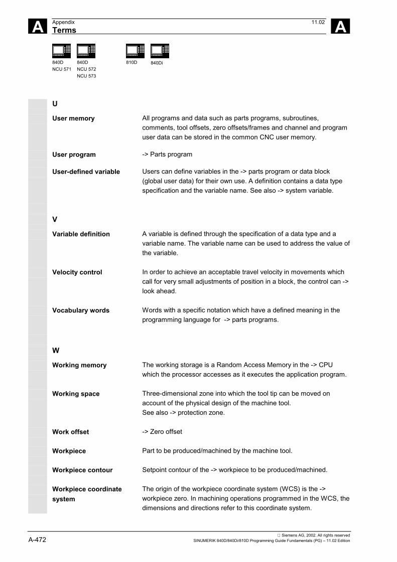
A Appendix 11.02Terms A
840DNCU 571
840DNCU 572NCU 573
810D 840Di
Siemens AG, 2002. All rights reservedA-472 SINUMERIK 840D/840Di/810D Programming Guide Fundamentals (PG) – 11.02 Edition
U
User memory All programs and data such as parts programs, subroutines,comments, tool offsets, zero offsets/frames and channel and programuser data can be stored in the common CNC user memory.
User program -> Parts program
User-defined variable Users can define variables in the -> parts program or data block(global user data) for their own use. A definition contains a data typespecification and the variable name. See also -> system variable.
V
Variable definition A variable is defined through the specification of a data type and avariable name. The variable name can be used to address the value ofthe variable.
Velocity control In order to achieve an acceptable travel velocity in movements whichcall for very small adjustments of position in a block, the control can ->look ahead.
Vocabulary words Words with a specific notation which have a defined meaning in theprogramming language for -> parts programs.
W
Working memory The working storage is a Random Access Memory in the -> CPUwhich the processor accesses as it executes the application program.
Working space Three-dimensional zone into which the tool tip can be moved onaccount of the physical design of the machine tool.See also -> protection zone.
Work offset -> Zero offset
Workpiece Part to be produced/machined by the machine tool.
Workpiece contour Setpoint contour of the -> workpiece to be produced/machined.
Workpiece coordinatesystem
The origin of the workpiece coordinate system (WCS) is the ->workpiece zero. In machining operations programmed in the WCS, thedimensions and directions refer to this coordinate system.

A 11.02 AppendixTerms A
840DNCU 571
840DNCU 572NCU 573
810D 840Di
Siemens AG, 2002. All rights reservedSINUMERIK 840D/840Di/810D Programming Guide Fundamentals (PG) – 11.02 Edition A-473
Workpiece zero The workpiece zero (W) forms the starting point for the ->workpiece coordinate system and defines this WCS in relation to themachine zero (M).
X
Y
Z
Zero offset Specification of a new reference point for a coordinate system throughreference to an existing zero and a -> frame.-> Work offset1. Settable
SINUMERIK 840D/840Di: A parameterizable number of settablezero offsets is available for each CNC axis. Each of the zerooffsets can be selected by G functions and selection is exclusive.
2. ExternalAll offsets which define the position of the workpiece zero can beoverlaid with an external zero offset- defined by handwheel (DRF offset) or- defined by the PLC.
3. ProgrammableZero offsets can be programmed for all path and positioning axesby means of the TRANS instruction.

A Appendix 11.02References A
840DNCU 571
840DNCU 572NCU 573
810D 840Di
Siemens AG, 2002. All rights reservedA-474 SINUMERIK 840D/840Di/810D Programming Guide Fundamentals (PG) – 11.02 Edition
C References
General Documentation
/BU/ SINUMERIK 840D/840Di/810D/802S, C, DOrdering InformationCatalog NC 60Order number: E86060-K4460-A101-A9-7600
/ST7/ SIMATICSIMATIC S7 Programmable Logic ControllersCatalog ST 70Order number: E86060-K4670-A111-A3
/Z/ SINUMERIK, SIROTEC, SIMODRIVEConnections & System ComponentsCatalog NC ZOrder number: E86060-K4490-A001-A8-7600
Electronic Documentation
/CD1/ The SINUMERIK System (11.02 Edition)DOC ON CD(includes all SINUMERIK 840D/840Di/810D/802 and SIMODRIVE publications)Order number: 6FC5 298-6CA00-0BG3

A 11.02 AppendixReferences A
840DNCU 571
840DNCU 572NCU 573
810D 840Di
Siemens AG, 2002. All rights reservedSINUMERIK 840D/840Di/810D Programming Guide Fundamentals (PG) – 11.02 Edition A-475
User Documentation
/AUK/ SINUMERIK 840D/810DAutoTurn Short Operating Guide (10.02 Edition)Order number: 6FC5 298-4AA30-0BP3
/AUP/ SINUMERIK 840D/810DAutoTurn Graphic Programming System (02.02 Edition)Operator's GuideProgramming/SetupOrder number: 6FC5 298-4AA40-0BP3
/BA/ SINUMERIK 840D/810DOperator's Guide MMC (10.00 Edition)Order number: 6FC5 298-6AA00-0BP0
/BAD/ SINUMERIK 840D/840Di/810DOperator's Guide: HMI Advanced (11.02 Edition)Order number: 6FC5 298-6AF00-0BP2
/BEM/ SINUMERIK 840D/810DOperator's Guide: HMI Embedded (11.02 Edition)Order number: 6FC5 298-6AC00-0BP2
/BAH/ SINUMERIK 840D/840Di/810DOperator's Guide HT 6 (HPU New) (06.02 Edition)Order number: 6FC5 298-0AD60-0BP2
/BAK/ SINUMERIK 840D/840Di/810DShort Operating Guide (02.01 Edition)Order number: 6FC5 298-6AA10-0BP0
/BAM/ SINUMERIK 810D/840DOperator's Guide ManualTurn (08.02 Edition)Order number: 6FC5 298-6AD00-0BP0
/BAS/ SINUMERIK 840D/810DOperator's Guide ShopMill (11.02 Edition)Order number: 6FC5 298-6AD10-0BP1

A Appendix 11.02References A
840DNCU 571
840DNCU 572NCU 573
810D 840Di
Siemens AG, 2002. All rights reservedA-476 SINUMERIK 840D/840Di/810D Programming Guide Fundamentals (PG) – 11.02 Edition
/BAT/ SINUMERIK 810D/840DOperator's Guide ShopTurn (03.03 Edition)Order number: 6FC5 298-6AD50-0BP2
/BNM/ SINUMERIK 840D/840Di/810DUser's Guide Measuring Cycles (11.02 Edition)Order number: 6FC5 298-6AA70-0BP2
/CAD/ SINUMERIK 840D/840Di/810DOperator's Guide CAD Reader (03.02 Edition)Order number: (is part of the online help)
/DA/ SINUMERIK 840D/840Di/810DDiagnostics Guide (11.02 Edition)Order number: 6FC5 298-6AA20-0BP3
/KAM/ SINUMERIK 840D/810DShort Guide ManualTurn (04.01 Edition)Order number: 6FC5 298-5AD40-0BP0
/KAS/ SINUMERIK 840D/810DShort Guide ShopMill (04.01 Edition)Order number: 6FC5 298-5AD30-0BP0
/KAT/ SINUMERIK 840D/810DShort Guide ShopTurn (07.01 Edition)Order number: 6FC5 298-6AF20-0BP0
/PG/ SINUMERIK 840D/840Di/810DProgramming Guide Fundamentals (11.02 Edition)Order number: 6FC5 298-6AB00-0BP2
/PGA/ SINUMERIK 840D/840Di/810DProgramming Guide Advanced (11.02 Edition)Order number: 6FC5 298-6AB10-0BP2
/PGK/ SINUMERIK 840D/840Di/810DShort Guide Programming (02.01 Edition)Order number: 6FC5 298-6AB30-0BP1
/PGM/ SINUMERIK 840D/840Di/810DProgramming Guide ISO Milling (11.02 Edition)Order number: 6FC5 298-6AC20-0BP2

A 11.02 AppendixReferences A
840DNCU 571
840DNCU 572NCU 573
810D 840Di
Siemens AG, 2002. All rights reservedSINUMERIK 840D/840Di/810D Programming Guide Fundamentals (PG) – 11.02 Edition A-477
/PGT/ SINUMERIK 840D/840Di/810DProgramming Guide ISO Turning (11.02 Edition)Order number: 6FC5 298-6AC10-0BP2
/PGZ/ SINUMERIK 840D/840Di/810DProgramming Guide Cycles (11.02 Edition)Order number: 6FC5 298-6AB40-0BP2
/PI/ PCIN 4.4Software for Data Transfer to/from MMC ModuleOrder number: 6FX2 060-4AA00-4XB0 (English, French, German)Order from: WK Fürth
/SYI/ SINUMERIK 840DiSystem Overview (02.01 Edition)Order number: 6FC5 298-6AE40-0BP0
Manufacturer/Service Documentation
a) Lists/LIS/ SINUMERIK 840D/840Di/810D
SIMODRIVE 611DLists (11.02 Edition)Order number: 6FC5 297-6AB70-0BP3

A Appendix 11.02References A
840DNCU 571
840DNCU 572NCU 573
810D 840Di
Siemens AG, 2002. All rights reservedA-478 SINUMERIK 840D/840Di/810D Programming Guide Fundamentals (PG) – 11.02 Edition
b) Hardware/BH/ SINUMERIK 840D/840Di/810D
Operator Components Manual (HW) (11.02 Edition)Order number: 6FC5 297-6AA50-0BP2
/BHA/ SIMODRIVE SensorAbsolute Encoder with PROFIBUS DPUser's Guide (HW) (02.99 Edition)Order number: 6SN1 197-0AB10-0YP1
/EMV/ SINUMERIK, SIROTEC, SIMODRIVEEMC Installation Guideline (06.99 Edition)Planning Guide (HW)Order number: 6FC5 297-0AD30-0BP1
/GHA/ ADI4 - Analog Drive Interface for 4 Axes (09.02 Edition)Equipment ManualOrder number: 6FC5 297-0BA01-0BP0
/PHC/ SINUMERIK 810DConfiguring Manual (HW) (03.02 Edition)Order number: 6FC5 297-6AD10-0BP0
/PHD/ SINUMERIK 840DConfiguring Manual NCU 561.2-573.4 (HW) (10.02 Edition)Order number: 6FC5 297-6AC10-0BP2
/PMH/ SIMODRIVE SensorHollow-Shaft Measuring System SIMAG HConfiguring/Installation Guide (HW) (07.02 Edition)Order number: 6SN1197-0AB30-0BP1

A 11.02 AppendixReferences A
840DNCU 571
840DNCU 572NCU 573
810D 840Di
Siemens AG, 2002. All rights reservedSINUMERIK 840D/840Di/810D Programming Guide Fundamentals (PG) – 11.02 Edition A-479
c) Software/FB1/ SINUMERIK 840D/840Di/810D
Description of Functions, Basic Machine (Part 1) (11.02 Edition)(the various manuals are listed below)Order number: 6FC5 297-6AC20-0BP2
A2 Various Interface SignalsA3 Axis Monitoring, Protection ZonesB1 Continuous Path Mode, Exact Stop and Look AheadB2 AccelerationD1 Diagnostic ToolsD2 Interactive ProgrammingF1 Travel to Fixed StopG2 Velocities, Setpoint/Actual Value Systems, Closed-Loop ControlH2 Output of Auxiliary Functions to PLCK1 Mode Group, Channels, Program Operation ModeK2 Coordinate Systems, Axis Types, Axis Configurations,
Actual-Value System for Workpiece, External Zero OffsetK4 CommunicationN2 EMERGENCY STOPP1 Transverse AxesP3 Basic PLC ProgramR1 Reference Point ApproachS1 SpindlesV1 FeedsW1 Tool Compensation

A Appendix 11.02References A
840DNCU 571
840DNCU 572NCU 573
810D 840Di
Siemens AG, 2002. All rights reservedA-480 SINUMERIK 840D/840Di/810D Programming Guide Fundamentals (PG) – 11.02 Edition
/FB2/ SINUMERIK 840D/840Di/810DDescription of Functions, Extended Functions (Part 2) (11.02 Edition)including FM-NC: Turning, Stepping Motor(the various manuals are listed below)Order number: 6FC5 297-6AC30-0BP2
A4 Digital and Analog NCK I/OsB3 Several Operator Panels and NCUsB4 Operation via PG/PCF3 Remote DiagnosticsH1 Jog with/without HandwheelK3 CompensationsK5 Mode Groups, Channels, Axis ReplacementL1 FM-NC Local BusM1 Kinematic TransformationM5 MeasurementsN3 Software Cams, Position Switching SignalsN4 Punching and NibblingP2 Positioning AxesP5 OscillationR2 Rotary AxesS3 Synchronous SpindlesS5 Synchronized Actions (SW 3 and lower, higher /FBSY/)S6 Stepper Motor ControlS7 Memory ConfigurationT1 Indexing AxesW3 Tool ChangeW4 Grinding

A 11.02 AppendixReferences A
840DNCU 571
840DNCU 572NCU 573
810D 840Di
Siemens AG, 2002. All rights reservedSINUMERIK 840D/840Di/810D Programming Guide Fundamentals (PG) – 11.02 Edition A-481
/FB3/ SINUMERIK 840D/840Di/810DDescription of Functions Special Functions (Part 3) (11.02 Edition)(the various manuals are listed below)Order number: 6FC5 297-6AC80-0BP2
F2 3-Axis to 5-Axis TransformationG1 Gantry AxesG3 Cycle TimesK6 Contour Tunnel MonitoringM3 Coupled Axes and ESR (previously Coupled Motion and Master/Slave
Couplings)S8 Constant Workpiece Speed for Centerless GrindingT3 Tangential ControlTE0 Installation and Activation of Compile CyclesTE1 Clearance ControlTE2 Analog AxisTE3 Speed/Torque Coupling Master-SlaveTE4 Transformation Package HandlingTE5 Setpoint ExchangeTE6 MCS CouplingTE7 Retrace SupportTE8 Unclocked Path-Synchronous Switching Signal OutputV2 PreprocessingW3 3D Tool Radius Compensation
/FBA/ SIMODRIVE 611D/SINUMERIK 840D/810DDescription of Functions, Drive Functions (11.02 Edition)(the various sections are listed below)Order number: 6SN1 197-0AA80-0BP9
DB1 Operational Messages/Alarm ReactionsDD1 Diagnostic FunctionsDD2 Speed Control LoopDE1 Extended Drive FunctionsDF1 Enable CommandsDG1 Encoder ParameterizationDL1 Linear Motor MDDM1 Calculation of Motor/Power Section Parameters and Controller DataDS1 Current Control LoopDÜ1 Monitors/Limitations

A Appendix 11.02References A
840DNCU 571
840DNCU 572NCU 573
810D 840Di
Siemens AG, 2002. All rights reservedA-482 SINUMERIK 840D/840Di/810D Programming Guide Fundamentals (PG) – 11.02 Edition
/FBAN/ SINUMERIK 840D/SIMODRIVE 611 DIGITALDescription of FunctionsANA-MODULE (02.00 Edition)Order number: 6SN1 197-0AB80-0BP0
/FBD/ SINUMERIK 840DDescription of Functions Digitizing (07.99 Edition)Order number: 6FC5 297-4AC50-0BP0DI1 Start-UpDI2 Scanning with Tactile Sensors (scancad scan)DI3 Scanning with Lasers (scancad laser)DI4 Milling Program Generation (scancad mill)
/FBDN/ IT SolutionsNC Data Management Server (DNC NT-2000) (01.02 Edition)Description of FunctionsOrder number: 6FC5 297-5AE50-0BP2
/FBDT/ SINUMERIK 840D/840Di/810DIT SolutionsSinDNC Data Transfer via Network (09.02 Edition)Description of FunctionsOrder number: 6FC5 297-5AE70-0BP0
/FBFA/ SINUMERIK 840D/840Di/810DDescription of FunctionsISO Dialects for SINUMERIK (11.02 Edition)Order number: 6FC5 297-6AE10-0BP2
/FBFE/ SINUMERIK 840D/840Di/810DDescription of Functions Remote Diagnostics (11.02 Edition)Order number: 6FC5 297-0AF00-0BP2
/FBH/ SINUMERIK 840D/840Di/810DHMI Programming Package (11.02 Edition)Orcer number: (is part of the SW delivery)Part 1 User's GuidePart 2 Description of Functions
/FBHLA/ SINUMERIK 840D/SIMODRIVE 611 digitalDescription of FunctionsHLA Module (04.00 Edition)Order number: 6SN1 197-0AB60-0BP2

A 11.02 AppendixReferences A
840DNCU 571
840DNCU 572NCU 573
810D 840Di
Siemens AG, 2002. All rights reservedSINUMERIK 840D/840Di/810D Programming Guide Fundamentals (PG) – 11.02 Edition A-483
/FBMA/ SINUMERIK 840D/810DDescription of Functions ManualTurn (08.02 Edition)Order number: 6FC5 297-5AD50-0BP2
/FBO/ SINUMERIK 840D/810DDescription of FunctionsConfiguring of OP 030 Operator Interface (09.01 Edition)(the various sections are listed below)Order number: 6FC5 297-6AC40-0BP0
BA Operator's GuideEU Development Environment (Configuring Package)PS Online only: Configuring Syntax (Configuring Package)PSE Introduction to Configuring of Operator InterfaceIK Screen Kit: Software Update and Configuration
/FBP/ SINUMERIK 840DDescription of Functions C-PLC Programming (03.96 Edition)Order number: 6FC5 297-3AB60-0BP0
/FBR/ SINUMERIK 840D/810DIT SolutionsDescription of Functions Computer Link (SINCOM) (09.01 Edition)Order number: 6FC5 297-6AD60-0BP0
NFL Host Computer InterfaceNPL PLC/NCK Interface
/FBSI/ SINUMERIK 840D/SIMODRIVEDescription of Functions SINUMERIK Safety Integrated (09.02 Edition)Order number: 6FC5 297-6AB80-0BP1
/FBSP/ SINUMERIK 840D/810DDescription of Functions ShopMill (11.02 Edition)Order number: 6FC5 297-6AD80-0BP1
/FBST/ SIMATICDescription of Functions FM STEPDRIVE/SIMOSTEP (01.01 Edition)Order number: 6SN1 197-0AA70-0YP4

A Appendix 11.02References A
840DNCU 571
840DNCU 572NCU 573
810D 840Di
Siemens AG, 2002. All rights reservedA-484 SINUMERIK 840D/840Di/810D Programming Guide Fundamentals (PG) – 11.02 Edition
/FBSY/ SINUMERIK 840D/810DDescription of Functions Synchronized Actions (10.02 Edition)for Wood, Glass, Ceramics and PressesOrder number: 6FC5 297-6AD40-0BP2
/FBT/ SINUMERIK 840D/810DDescription of Functions ShopTurn (03.03 Edition)Order number: 6FC5 297-6AD70-0BP2
/FBTC/ SINUMERIK 840D/810DIT SolutionsSINUMERIK Tool Data Communication SinTDC (01.02 Edition)Description of FunctionBestellnummer: 6FC5 297-5AF30-0BP0
/FBTD/ SINUMERIK 840D/810DIT SolutionsTool Information System (SinTDI) with Online Help (03.01 Edition)Description of FunctionsOrder number: 6FC5 297-6AE00-0BP0
/FBU/ SIMODRIVE 611 universal / universal EClosed-Loop Control Component for Speed Control and PositioningDescription of Functions (02.02 Edition)Order number: 6SN1 197-0AB20-0BP5
/FBW/ SINUMERIK 840D/840Di/810DDescription of Functions Tool Management (10.02 Edition)Order number: 6FC5 297-6AC60-0BP1
/FBWI/ SINUMERIK 840D/840Di/810DDescription of Functions WinTPM (02.02 Edition)Order number: This document is part of the software
/HBA/ SINUMERIK 840D/840Di/810DManual @Event (03.02 Edition)Order number: 6AU1900-0CL20-0AA0
/HBI/ SINUMERIK 840DiManual (09.02 Edition)Order number: 6FC5 297-6AE60-0BP1

A 11.02 AppendixReferences A
840DNCU 571
840DNCU 572NCU 573
810D 840Di
Siemens AG, 2002. All rights reservedSINUMERIK 840D/840Di/810D Programming Guide Fundamentals (PG) – 11.02 Edition A-485
/INC/ SINUMERIK 840D840Di//810DCommissioning Tool SINUMERIK SinuCOM NC (02.02 Edition)System DescriptionOrder number: (an integral part of the online Help for the start-up tool)
/PAP/ SIMODRIVE SensorAbsolute Encoder with PROFIBUS DPUser's Guide (02.99 Edition)Order number: 6SN1 197-0AB10-0YP1
/PFK/ SIMODRIVEPlanning Guide 1FT5/1FT6/1FK6 Motors (12.01 Edition)AC Servo Motors for Feedrate andMain Spindle DrivesOrder number: 6SN1 197-0AC20-0BP0
/PJE/ SINUMERIK 840D/810DHMI Embedded Configuring Package (08.01 Edition)Description of Functions: Software Update, Configuration,InstallationOrder number: 6FC5 297-6EA10-0BP0(the document PS Configuring Syntax is supplied with the softwareand available as a pdf file)
/PJFE/ SIMODRIVEPlanning Guide Built-In Synchronous Motors 1FE1Three-Phase AC Motors for Main Spindle Drives (09.01 Edition)Order number: 6SN1 197-0AC00-0BP1
/PJLM/ SIMODRIVEPlanning Guide Linear Motors 1FN1, 1FN3 (11.01 Edition)ALL General Information about Linear Motors1FN1 1FN1 Three-Phase Linear Motor1FN3 1FN3 Three-Phase Linear MotorCON ConnectionsOrder number: 6SN1 197-0AB70-0BP2

A Appendix 11.02References A
840DNCU 571
840DNCU 572NCU 573
810D 840Di
Siemens AG, 2002. All rights reservedA-486 SINUMERIK 840D/840Di/810D Programming Guide Fundamentals (PG) – 11.02 Edition
/PJM/ SIMODRIVEPlanning Guide Motors (11.00 Edition)Three-Phase AC Motors for Feed and Main Spindle DrivesOrder number: 6SN1 197-0AA20-0BP5
/PJU/ SIMODRIVE 611Planning Guide Inverters (08.02 Edition)Order number: 6SN1 197-0AA00-0BP6
/PMS/ SIMODRIVE (04.02 Edition)Planning Guide ECO Motor Spindle for Main Spindle DrivesOrder number: 6SN1 197-0AD04-0BP0
/POS1/ SIMODRIVE POSMO AUser's Guide (08.02 Edition)Distributed Positioning Motor on PROFIBUS DPOrder number: 6SN2 197-0AA00-0BP3
/POS2/ SIMODRIVE POSMO AInstallation Instructions (enclosed with POSMO A)
/POS3/ SIMODRIVE POSMO SI/CD/CA (08.02 Edition)Operator's GuideDistributed Servo Drive SystemsOrder number: 6SN2 197-0AA20-0BP3
/PPH/ SIMODRIVEPlanning Guide 1PH2/1PH4/1PH7 Motors (12.01 Edition)AC Induction Motors for Main Spindle DrivesOrder number: 6SN1 197-0AC60-0BP0
/PPM/ SIMODRIVEPlanning Guide Hollow-Shaft Motors (10.01 Edition)Hollow-Shaft Motors for Main Spindle Drives1PM4 and 1PM6Order number: 6SN1 197-0AD03-0BP0
/S7H/ SIMATIC S7-300- Reference Manual: CPU Data (HW Description) (2002 Edition)- Reference Manual: Module Data- Technological Functions Manual- Installation ManualOrder number: 6ES7 398-8FA10-8AA0

A 11.02 AppendixReferences A
840DNCU 571
840DNCU 572NCU 573
810D 840Di
Siemens AG, 2002. All rights reservedSINUMERIK 840D/840Di/810D Programming Guide Fundamentals (PG) – 11.02 Edition A-487
/S7HT/ SIMATIC S7-300Manual STEP 7, Fundamentals, V. 3.1 (03.97 Edition)Order number: 6ES7 810-4CA02-8AA0
/S7HR/ SIMATIC S7-300Manual (03.97 Edition)STEP7, Reference Manuals, V3.1Order number: 6ES7 810-4CA02-8AR0
/S7S/ SIMATIC S7-300FM 353 Stepper Drive Positioning Module (04.97 Edition)Order in conjunction with configuring package
/S7L/ SIMATIC S7-300FM 354 Positioning Module for Servo Drive (04.97 Edition)Order together with configuring package
/S7M/ SIMATIC S7-300FM 357.2 Multimodule for Servo and Stepper Drives (01.01 Edition)Order together with configuring package
/SP/ SIMODRIVE 611-A/611-D,SimoPro 3.1Program for Configuring Machine-Tool DrivesOrder number: 6SC6 111-6PC00-0AA❏
Order from: WK Fürth

A Appendix 11.02References A
840DNCU 571
840DNCU 572NCU 573
810D 840Di
Siemens AG, 2002. All rights reservedA-488 SINUMERIK 840D/840Di/810D Programming Guide Fundamentals (PG) – 11.02 Edition
d) Installationand Start-Up/IAA/ SIMODRIVE 611A
Installation and Start-Up Guide (10.00 Edition)Order number: 6SN 1197-0AA60-0BP6
/IAC/ SINUMERIK 810DInstallation and Start-Up Guide (03.02 Edition)(including description of SIMODRIVE 611D start-upsoftware)Order number: 6FC5 297-6AD20-0BP0
/IAD/ SINUMERIK 840D/SIMODRIVE 611DInstallation and Start-Up Guide (11.02 Edition)(including description of SIMODRIVE 611D start-up software)Order number: 6FC5 297-6AB10-0BP2
/IAM/ SINUMERIK 840D/840Di/810DHMI/MMC Installation and Start-Up Guide (11.02 Edition)Order number: 6FC5 297-6AE20-0BP2
AE1 Updates/OptionsBE1 Expand the operator interfaceHE1 Online HelpIM2 Start-Up HMI EmbeddedIM4 Start-Up HMI AdvancedTX1 Setting Foreign Language Texts
■

A 11.02 AppendixIndex A
840DNCU 571
840DNCU 572NCU 573
810D 840Di
Siemens AG, 2002. All rights reservedSINUMERIK 840D/840Di/810D Programming Guide Fundamentals (PG) – 11.02 Edition A-489
D Index
$$AA_ACC 7-266$AA_OFF deselection 6-233$P_GWPS 7-275$TC_ECPxy 8-343$TC_SCPxy 8-343$TC_TPG1, ..., ...9 8-340$TC_TPG1/...8/...9 7-274
22 straight lines 4-142
33 straight lines 4-143
AAbsolute dimension 1-26Absolute dimensioning 3-85Acceleration
Pattern 5-190Activate/deactivate function "Travel to fixed stop
4-163Additive offsets
Delete 8-344Select 8-341
Address letters 12-403Address of block number N 2-56Addresses 2-58
Extended addresses 2-60Fixed addresses 2-61, 12-404Fixed addresses with axis extension 2-62Modal/non-modal addresses 2-60Settable addresses 2-62
Value assignments 2-65with axial extension 2-60
AlarmNumber 2-74Text 2-74
Aperture angle AC 2-59Approach and retraction paths 8-313Approach and retraction velocities 8-324Approach point/angle 8-313Approaching a fixed point 4-161Arithmetic parameter R 2-59Arithmetic parameters R 10-362ATRANS 6-205, 6-209, 10-362Auxiliary function H 2-56, 2-58Axial DRF deselection 6-232Axial DRF deselection and $AA_OFF deselection
6-232Axis Q 2-59Axis types
Channel axes 1-39Machine axes 1-39Main spindle 1-39Path axes 1-40Positioning axes 1-40Special axes 1-39Synchronized axes 1-42
Axis U, V, W, X, Y, Z 2-59
BBasic coordinate system 1-33Blank 8-313Block number 2-57Block number 2-56Blocks 2-55
Block format 2-55Block length 2-55Block number 2-57Comments 2-73Main block/subblock 2-56Skipping blocks 2-71

A Appendix 11.02Index A
840DNCU 571
840DNCU 572NCU 573
810D 840Di
Siemens AG, 2002. All rights reservedA-490 SINUMERIK 840D/840Di/810D Programming Guide Fundamentals (PG) – 11.02 Edition
Word sequence in blocks 2-56Bottleneck detection 8-332
CCenterless grinding 7-277
Constant workpiece speed 7-277Chamfer 4-172Chamfer the contour corner 4-172Change of direction 8-318Channel axes 1-39Character set 2-53Circle
Radius CR 2-58Circle radius CR 2-59Circular interpolation 4-122
Helical interpolation 4-135Indication of working plane 4-123Programming a circle
with arc angle and center point 4-126with center point and end point 4-123with intermediate and end points 4-130with polar coordinates 4-127with radius and end point 4-125with tangential transition 4-132
Circular magazine 8-299Clamping torque FXST 4-167COARSEA 7-251Collision Detection ON (CDON)/OFF (CDOF)
8-331Collision monitoring 8-331Collisions 8-314Command axes 1-42Comments 2-73Compensation plane 8-334Constant
Cutting rate 7-272Grinding wheel peripheral speed 7-274Workpiece speed 7-277
Constants 2-69Binary constants 2-70Hexadecimal constants 2-70Integer constants 2-69Real constants 2-69
Continuous-path mode 5-178, 5-181, 5-182Look Ahead 5-188with programmable transition rounding 5-181
ContourApproach, retract 8-313Point 8-313Roughing 2-73Violation 8-332
Contour accuracy, programmable 5-197Contour definitions 4-141Coordinate systems 1-22
Absolute dimension 1-26Basic coordinate system 1-33Incremental dimension 1-27Machine coordinate system 1-31Overview 1-29Plane designations 1-28Polar coordinates 1-25Workpiece coordinate system 1-34
Coordinate systems and workpiece machining1-48
Corner behaviorIntersection 8-318Selectable transitions 8-317Transition circle 8-316
Corner rounding 5-183, 5-185CORROF 6-231Cutting rate, constant 7-273Cylinder surface transformation 7-256Cylinder thread 4-146Cylindrical coordinates 4-111
DData types 2-68
Constants 2-69Deactivate compensation mode
G40 8-314G40, KONT 8-315
Definition of workpiece positions 1-23Deselect frame 6-230Destination 10-365, 10-367Dimensioning
Absolute dimensioning 3-85

A 11.02 AppendixIndex A
840DNCU 571
840DNCU 572NCU 573
810D 840Di
Siemens AG, 2002. All rights reservedSINUMERIK 840D/840Di/810D Programming Guide Fundamentals (PG) – 11.02 Edition A-491
Dimensions 3-91Absolute/relative 3-88Absolute/relative 3-85Incremental dimensioning 3-85, 3-88Metric/imperial, G70/G71 3-91Metric/imperial, G700/G710 3-91Rotary axes and spindles 3-89
DL number 8-341Dwell time 5-198
EEnd of block LF 2-54End of program, M2, M17, M30 9-359End of program,M2,M17,M30 2-52End point programming 8-322Exact positioning
Command output 5-179Exact stipend of interpolation 5-179Exact stop 5-178
Positioning window 5-178
FFace thread 4-147Facing axis
Zero points 4-169Feed
Axial feed FA 2-58FPRAON, FPRAOFF 7-259G95 FPR(…) 7-258
Feed F 2-56, 2-58Feedforward control 5-196Feedrate 7-236
for path axes, F 7-238for positioning axes 7-257for synchronized axes 7-238Modal 4-172Optimization example 7-268Optimization for curved path sections, CFTCP,
CFC, CFIN 7-266Override 7-263Programmed 4-172Units of measurement 7-237with handwheel override, FD, FDA 7-261
Feedrate non-modal 4-172Feedrate override, per cent, OVR,OVRA 7-260Feedrates in one block 7-280FINEA 7-251Fixed stop
Clamping torque 4-167Monitoring window 4-167Travel to fixed stop 4-163
Flat D number structure 8-294Frame generation according to tool orientation,
TOFRAME 6-228Frame instructions
Additive instructions 6-204Programmable mirroring 6-224Programmable rotation 6-212Programmable scale factor 6-221Programmable zero offset 6-205, 6-209Settable and programmable instructions 6-203
Frame system 1-34, 6-202Function outputs
in continuous-path mode 9-356Function outputs for travel commands 9-356
GG function list 12-411G34 4-153G35 4-153G642 5-181, 5-184G643 5-181, 5-184G644 5-181G70 3-91G700 3-92G71 3-91G710 3-92Geometry axes 1-38
Switchable 1-38Geometry/speed monitoring 8-340Grinding wheel peripheral speed 7-274Grinding wheel peripheral speed, constant 7-274Grinding-specific tool monitoring 8-339
HH functions 9-360

A Appendix 11.02Index A
840DNCU 571
840DNCU 572NCU 573
810D 840Di
Siemens AG, 2002. All rights reservedA-492 SINUMERIK 840D/840Di/810D Programming Guide Fundamentals (PG) – 11.02 Edition
High-speed function outputs, QU 9-355Handwheel override 7-261Handwheel travel
with path default 7-262with velocity overlay 7-262
Helical interpolation 4-135, 4-137Programming the end point 4-136Sequence of motions 4-136, 4-138
High-speed function outputs, QU 9-355HMI A-442
IIdentifier
For character string 2-54Identifier for special numerical values 2-54Identifier for system variables 2-54Identifiers 2-66
Array identifiers 2-68Identifier name 2-67Variable identifiers 2-67
Incremental dimension 1-27Incremental dimensioning 3-85, 3-88Infeed movements 8-316Inside contour 8-332Internal preprocessor stop 5-199, 7-245Interpolation parameter IP, J, K 2-61Interpolation parameters IP, J, K 2-58INVCCW 4-137INVCW 4-137IPOENDA 7-251
JJerk limitation 5-190, 5-192Jump destinations 2-72Jump instruction 10-365, 10-367
LLINE FEED 2-55Linear interpolation 4-119Linear interpolation: 4-115Linear progressive and degressive thread pitch
change 4-153List
of predefined subprograms 12-423of preparatory functions (G functions) 12-411of statements 12-386
Lists 12-385Look Ahead 5-188
MM command sequence 9-356M functions 9-357
End of program, M2, M17, M30 9-359Optional stop 9-359Programmed stop, MO 9-358
M6 8-293, 8-295Machine axes 1-39Machine coordinate system 1-31Main axes 1-38Main block 2-56Main block 2-59Main spindle 1-39Make active tool offset operative immediately
8-304Master spindle 1-39Messages 2-73Miscellaneous function M 2-56, 2-58MMC A-442Modal feedrate 4-172Modal rounding 4-172Monitoring window FXSW 4-167Motion commands 4-108
Programming motion commands 4-108
NNC program 2-52Non-cutting tool path 8-318Nonlinear interpolation 4-115Non-modal feedrate 4-172
OOffset memory 8-335Operators 2-64Overview of coordinate systems 1-29

A 11.02 AppendixIndex A
840DNCU 571
840DNCU 572NCU 573
810D 840Di
Siemens AG, 2002. All rights reservedSINUMERIK 840D/840Di/810D Programming Guide Fundamentals (PG) – 11.02 Edition A-493
PPath action 5-177Path action, depending on DISC values 8-317Path axes
Traverse with handwheel override 7-263Path axes 1-40Path commands
Number of axis values 4-108Start point - destination point 4-108
Path override OVR 2-58Path tangent 8-314Plane designations 1-28PLC axes 1-42, 1-43, 1-45Polar
Angle AP 2-59Radius RP 2-59
Polar coordinates 1-25, 4-110Cylindrical coordinates 4-111Defining the pole 4-111Polar angle AP 4-112Polar radius RP 4-112Working plane 4-111
Polar radius RP = 0 4-112Positional
Data X, Y, Z 2-56Position-controlled spindle operation 7-247Positioning axes 1-40
Traversing 7-244Positioning axis POS 2-59Positioning position-controlled spindles
Position a rotating spindle 7-248Position a spindle from standstill 7-252
PreparatoryFunction G 2-56
Preparatory function G 2-58Preprocessor stop 7-245Program
Identifier 2-52Name 2-52Programming messages 2-73Setting alarms 2-74
Program jumps, conditional 10-367Program jumps, unconditional 10-365Program passes, number P 2-58
Program repetition 11-375Program section 2-71Program section repetition 11-376Programmable contour accuracy 5-197Programmable frame rotations with solid angles
6-220Programmable mirroring, MIRROR, AMIRROR
6-224Programmable rotation
Change of plane 6-217Direction of rotation 6-214ROT, AROT 6-212
Programmable rotation in space 6-213Programmable scale factor, SCALE, ASCALE
6-221Programmable zero offset
TRANS, ATRANS 6-205Programmable zero offset
G58, G59 6-209Programmed feedrate 4-172Programmed rotation in the plane 6-216Programmed stop, M0 9-358Programming language
Addresses 2-58Blocks 2-55Character set 2-53Data types 2-68Identifiers 2-66Variable name 2-60Words 2-55
RRapid traverse movement 4-114Reading positions 8-325Reference point approach 3-105Retraction direction 4-159Retraction speed 4-160Rotary axis A, B, C 2-58Rounding 4-172Round the contour corner 4-172Rounding 4-172
Modal 4-172Run-in and run-out paths, programmable 4-151

A Appendix 11.02Index A
840DNCU 571
840DNCU 572NCU 573
810D 840Di
Siemens AG, 2002. All rights reservedA-494 SINUMERIK 840D/840Di/810D Programming Guide Fundamentals (PG) – 11.02 Edition
SSettable block change time with G0 4-116Settable zero offsets 3-94Setting alarms 2-74Setting clamping torque 4-163Setup value 8-342Several feedrates in one block 7-280SIEMENS cycles 2-74Skip block
Eight skip levels 2-71Ten skip levels 2-72
Skip levels 2-71, 2-72Smooth approach and retraction 8-320Special axes 1-39Special characters 2-54Speed S 2-56Spindle 7-269
Direction of spindle rotation 7-269Position SPOS 2-61Position-controlled spindle operation 7-247Positioning spindles for position-controlled axis
operation 7-248Speed S 2-58, 2-61Spindle speed 7-270working with several spindles 7-270
Spindle position across block boundary SPOSA2-59
Spindle position SPOS 2-59Spindle speed limitation 7-279, 7-280, 7-282Spindle speed S 2-59Start point offset SF 4-148Statement list 12-386Straight line with angle 4-141Subblock N 2-58Subprogram
Call L 2-58Subprogram list 12-423Subprograms 11-370
Program repetition 11-375Subroutine,call 11-373Synchronized axes 1-42
TT0 8-293, 8-295Tables 12-385Taper thread 4-147Tapping
Rigid 4-155Right-hand/left-hand threads 4-155
with compensating chuck 4-157Thread chaining 4-149Thread cutting 4-145, 4-159
Cylinder thread 4-146Right-hand/left-hand thread 4-148Start point offset 4-148Taper thread 4-147Thread chaining 4-149With constant lead 4-145
TOFRAME 8-338Tool
Movements 3-83, 4-107Number T 2-59Offset number D 2-56
Tool change point 8-314Tool edge reference point 8-350Tool length
CompensationFrom toolholder orientation, TCOABS 8-336
Components 8-335Tool lengths
Offset 8-335Tool monitoring
Activate/deactivate 8-339Deactivate 8-339
Tool number D 2-58Tool offset, CUT2D, CUT2DF 8-333Tool offsets
Approach and retract from contour 8-313Compensation at outside corners 8-316Smooth approach and retraction (SAR) 8-319Tool radius compensation 8-288
Tool Offsets 8-285Tool point direction
Relevant 8-350Tool radius compensation 8-305, 8-345
Changing

A 11.02 AppendixIndex A
840DNCU 571
840DNCU 572NCU 573
810D 840Di
Siemens AG, 2002. All rights reservedSINUMERIK 840D/840Di/810D Programming Guide Fundamentals (PG) – 11.02 Edition A-495
Offset number D 8-309Changing the compensation direction 8-309Corner behavior 8-317
Intersection 8-318Selectable transitions 8-317Transition circle 8-316
CUT2D 8-333CUT2DF 8-334
Tool T 2-56Tool type
Slotted saw 8-292Tool types 8-339Tool types 8-289Toolholder
Request 8-335Toolholder 8-335Tools with a relevant tool point direction 8-350TRACYL transformation 7-256Transformation TRAORI 6-230Transition
Circle 8-316, circle 8-332Ellipse/parabola/hyperbola 8-317Radius 8-318
Transition current/next block 8-315TRANSMIT transformation 7-254Transverse axis
Dimensions for the transverse axis 4-170Transverse axis (facing axis)
Coordinate system 4-169Travel to fixed stop 4-163Traversing path axes as positioning axes with G0
4-115
Traversing with feedforward control 5-196Turning functions
Chamfer, rounding 4-173Dimensions for the transverse axis 4-170
VValue range 2-68Variable name 2-60Velocity controls 5-194
WWear value 8-342Window width for fixed stop monitoring 4-163Words 2-55Working area limitation
Activate/deactivate 3-102Reference points on the tool 3-103
Working plane, G17 to G19 3-99Workpiece coordinate system 1-34
ZZero frame 3-94Zero offset
Activating the zero offset 3-96Deactivating a zero offset 3-97G54 to G599 3-95Setting offset values 3-96
Zero points 1-29
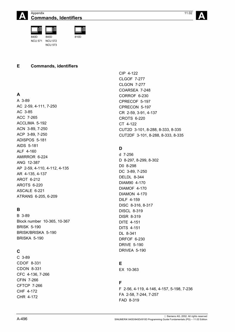
A Appendix 11.02Commands, Identifiers A
840DNCU 571
840DNCU 572NCU 573
810D
Siemens AG, 2002. All rights reservedA-496 SINUMERIK 840D/840Di/810D Programming Guide Fundamentals (PG) – 11.02 Edition
E Commands, identifiers
AA 3-89AC 2-59, 4-111, 7-250AC 3-85ACC 7-265ACCLIMA 5-192ACN 3-89, 7-250ACP 3-89, 7-250ADISPOS 5-181AIDS 5-181ALF 4-160AMIRROR 6-224ANG 12-387AP 2-59, 4-110, 4-112, 4-135AR 4-135, 4-137AROT 6-212AROTS 6-220ASCALE 6-221ATRANS 6-205, 6-209
BB 3-89Block number 10-365, 10-367BRISK 5-190BRISK/BRISKA 5-190BRISKA 5-190
CC 3-89CDOF 8-331CDON 8-331CFC 4-136, 7-266CFIN 7-266CFTCP 7-266CHF 4-172CHR 4-172
CIP 4-122CLGOF 7-277CLGON 7-277COARSEA 7-248CORROF 6-230CPRECOF 5-197CPRECON 5-197CR 2-59, 3-91, 4-137CROTS 6-220CT 4-122CUT2D 3-101, 8-288, 8-333, 8-335CUT2DF 3-101, 8-288, 8-333, 8-335
Dd 7-256D 8-297, 8-299, 8-302D0 8-298DC 3-89, 7-250DELDL 8-344DIAM90 4-170DIAMOF 4-170DIAMON 4-170DILF 4-159DISC 8-316, 8-317DISCL 8-319DISR 8-319DITE 4-151DITS 4-151DL 8-341DRFOF 6-230DRIVE 5-190DRIVEA 5-190
EEX 10-363
FF 2-56, 4-119, 4-146, 4-157, 5-198, 7-236FA 2-58, 7-244, 7-257FAD 8-319

A 11.02 AppendixCommands, Identifiers A
840DNCU 571
840DNCU 572NCU 573
810D 840Di
Siemens AG, 2002. All rights reservedSINUMERIK 840D/840Di/810D Programming Guide Fundamentals (PG) – 11.02 Edition A-497
FALSE 2-68FD 7-261FDA 7-261FFWOF 5-196FFWON 5-196FGREF 7-236FGROUP 4-123, 7-236FINEA 7-248FL 7-236FMA 7-280, 12-390FP 4-161FPR 7-257FPRAOF 7-257FPRAON 7-257FRC 4-172, 12-390FRCM 4-172, 12-390FTOCOF 7-278FTOCON 7-278FXS 4-163FXST 4-163FXSW 4-163
GG 2-56, 2-58, 10-363G0 4-113, 4-114, 5-181, 5-188G1 4-117, 4-119G110 4-110G111 4-110G112 4-110G140 8-319G141 8-319G142 8-319G143 8-319G147 8-319G148 8-319G153 3-94, 6-230G17 3-99, 3-100, 8-287, 8-306, 8-333G18 3-99, 8-287G19 3-99, 8-287, 8-306, 8-333G2 4-122, 4-135, 4-170G247 8-319G248 8-319G25 3-102, 7-279
G26 3-102, 7-279G3 4-122, 4-135, 4-170G33 4-145, 4-148G331 4-155G332 4-155G34 4-153G340 8-319G341 8-319G347 8-319G348 8-319G35 4-153G4 5-198G40 8-305, 8-314, 8-345G41 3-100, 8-297, 8-303, 8-305, 8-313G42 3-100, 8-297, 8-303, 8-305, 8-313, 8-345G450 8-313, 8-316G451 8-313, 8-316G460 8-327G461 8-327G462 8-327G500 3-94, 6-230G505 3-94, 3-97G53 3-94, 6-230G54 3-94G55 3-94G57 3-94G58 6-209G59 6-209G599 3-94, 3-97G60 5-178G601 5-178, 5-188G602 5-178G603 5-178G63 4-157G64 4-149, 5-178, 5-181, 11-371G64,G641 9-356G641 5-181G641 ADISPOS 5-181G641 AIDS 5-181G642 5-181G70 3-91G700 3-91G71 3-91G710 3-91
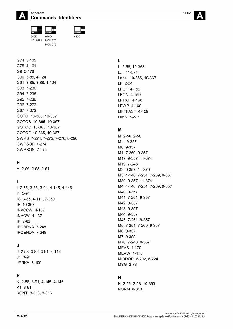
A Appendix 11.02Commands, Identifiers A
840DNCU 571
840DNCU 572NCU 573
810D
Siemens AG, 2002. All rights reservedA-498 SINUMERIK 840D/840Di/810D Programming Guide Fundamentals (PG) – 11.02 Edition
G74 3-105G75 4-161G9 5-178G90 3-85, 4-124G91 3-85, 3-88, 4-124G93 7-236G94 7-236G95 7-236G96 7-272G97 7-272GOTO 10-365, 10-367GOTOB 10-365, 10-367GOTOC 10-365, 10-367GOTOF 10-365, 10-367GWPS 7-274, 7-275, 7-276, 8-290GWPSOF 7-274GWPSON 7-274
HH 2-56, 2-58, 2-61
II 2-58, 3-86, 3-91, 4-145, 4-146I1 3-91IC 3-85, 4-111, 7-250IF 10-367INVCCW 4-137INVCW 4-137IP 2-62IPOBRKA 7-248IPOENDA 7-248
JJ 2-58, 3-86, 3-91, 4-146J1 3-91JERKA 5-190
KK 2-58, 3-91, 4-145, 4-146K1 3-91KONT 8-313, 8-316
LL 2-58, 10-363L... 11-371Label 10-365, 10-367LF 2-54LFOF 4-159LFON 4-159LFTXT 4-160LFWP 4-160LIFTFAST 4-159LIMS 7-272
MM 2-56, 2-58M... 9-357M0 9-357M1 7-269, 9-357M17 9-357, 11-374M19 7-248M2 9-357, 11-370M3 4-148, 7-251, 7-269, 9-357M30 9-357, 11-374M4 4-148, 7-251, 7-269, 9-357M40 9-357M41 7-251, 9-357M42 9-357M43 9-357M44 9-357M45 7-251, 9-357M5 7-251, 7-269, 9-357M6 9-357M7 9-355M70 7-248, 9-357MEAS 4-170MEAW 4-170MIRROR 6-202, 6-224MSG 2-73
NN 2-56, 2-58, 10-363NORM 8-313

A 11.02 AppendixCommands, Identifiers A
840DNCU 571
840DNCU 572NCU 573
810D 840Di
Siemens AG, 2002. All rights reservedSINUMERIK 840D/840Di/810D Programming Guide Fundamentals (PG) – 11.02 Edition A-499
OOFFN 8-305ORIPATH 12-396OVR 2-58, 7-260OVRA 7-260
PP 2-58PM 8-319POS 2-59, 7-244, 7-259POSA 2-59, 7-244POSP 7-244PR 8-319PUTFTOC 7-274, 7-278PUTFTOCF 7-274, 7-278
QQ 2-59QU 9-355
RR 2-59R... 10-362REPEAT 11-376REPEATB 11-376RET 11-371RND 4-172RNDM 4-172ROT 3-100, 6-212ROTS 6-220RP 2-59, 3-91, 4-110, 4-135RPL 6-212RTLIOF 4-114, 4-115RTLION 4-114RTLION 4-115
SS 2-56, 2-59, 2-61, 4-148, 4-157, 5-198, 7-269, 7-
272, 7-274S1 7-269, 7-270, 7-274, 7-279S2 7-269, 7-270, 7-271, 7-279SCALE 6-221
SETAL 2-74SETMS 7-269SOFT 5-190SOFTA 5-190SPCOF 7-247SPCON 4-148, 7-247SPI 7-257SPINU 2-61SPOS 2-59, 3-90, 4-155, 7-248, 7-259SPOS, SPOSA 2-61SPOSA 2-59, 4-155, 7-248, 7-250SR 7-280SRA 7-280ST 7-280STA 7-280String variable 10-365, 10-367SUG 7-274SUPA 3-94, 6-230
TT 2-56, 2-59, 2-61TCARR 8-335TCOABS 8-335TCOFR 8-335TMOF 8-339TMON 8-339TOFRAME 6-228TOROT 6-228TRAANG 7-256TRACYL 7-254, 7-256TRAFOOF 3-106, 6-230, 7-254, 7-256TRANS 3-91, 6-205, 6-209, 10-362TRANSMIT 7-254TRUE 2-68TURN 4-135
UU 2-59
VV 2-59VELOLIMA 5-192

A Appendix 11.02Commands, Identifiers A
840DNCU 571
840DNCU 572NCU 573
810D
Siemens AG, 2002. All rights reservedA-500 SINUMERIK 840D/840Di/810D Programming Guide Fundamentals (PG) – 11.02 Edition
WW 2-59WAITP 7-244WAITS 7-248WALIMOF 3-102WALIMON 3-102
XX 2-56, 2-59, 3-85X 3-91X1 3-105, 4-162
YY 2-56, 2-59, 3-85, 3-88, 3-91Y1 3-105, 4-162
ZZ 2-56, 2-59, 3-85, 3-88, 3-91
ToSIEMENS AG
Suggestions
CorrectionsA&D MC BMSP.O. Box 3180D-91050 Erlangen, GermanyPhone: ++49-(0)180-5050-222 [Hotline]Fax: ++49-(0)9131-98-2176 [Documentation]Email: [email protected]
For publication:
SINUMERIK 840D/840Di/810D
Fundamentals
User Documentation
From
NameCompany/Dept.
Address:
Zip Code: Town:
Phone: /
Fax: /
Programming Guide
Order No.: 6FC5298-6AB00-0BP2Edition: 11.02
Should you come across any printing errors whenreading this publication, please notify us on this sheet.Suggestions for improvement are also welcome.
Suggestions and/or corrections

User Documentation
SINUMERIK
840D/810D
SINUMERIK
Overview of SINUMERIK 840D/840Di/810D Documentation (11.2002)
Brochure Catalog Ordering Info.NC 60 *)
Description of Functions Drive Functions *)
Description of Functions– Basic Machine *) – Extended Functions– Special Functions
611D840D/810D
SINUMERIK
840D/840Di/810D
Accessories
CatalogAccessoriesNC-Z
SINUMERIKSIROTECSIMODRIVE
840D/840Di810D
Lists *)Installation &Start-Up Guide *)– 810D– 840D/611D– HMI
SINUMERIK
840D
Description of FunctionsDigitizing
611D
SINUMERIK
SINUMERIK
840D/810D
Configuring Kit HMI Embedded
SINUMERIK
840D/840Di/810D
SINUMERIK
840D/840Di/810D
Description of FunctionsSINUMERIKSafety Integrated
SINUMERIKSIMODRIVE
SINUMERIK
840D/840Di/810D611, Motors
SIMODRIVE
DOC ON CD *)The SINUMERIK System
General Documentation
Electronic Documentation
Manufacturer/Service Documentation
Manufacturer/Service Documentation
SINUMERIK
840D/810D/FM-NC
SINUMERIK
840D/840Di/810D
User Documentation
DiagnosticsGuide *)
Operator’s Guide – HT 6
AutoTurn– Short Guide– Programming/ Setup
SINUMERIK
840D/840Di/810D
Program. Guide– Short Guide– Fundamentals *)– Advanced *)– Cycles– Measuring Cycles– ISO Turning/Milling
Operator Components(HW) *)
Description ofFunctionsSynchronized Actions
840D/810D
SINUMERIK
Operator’s Guide– ManualTurn– Short Guide ManualTurn– ShopMill– Short Guide ShopMill– ShopTurn– Short Guide ShopTurn
840D/810D
Manufacturer/Service Documentation
*) These documents are a minimum requirement
Operator’s Guide *)– Short Guide– HMI Embedded– HMI Advanced
SINUMERIK
840D/840Di/810D
Configuring (HW) *)– 810D– 840D
SINUMERIK
SINUMERIK
840D/840Di/810D
SINUMERIK
840D/810D
Description of FunctionsOperator InterfaceOP 030
Description ofFunctionsTool Manage-ment
SINUMERIKSIMODRIVE
SINUMERIKSIMODRIVE
SINUMERIKSIMODRIVE
SINUMERIKSIMODRIVE
SINUMERIKSIMODRIVE
840D611D
840D611D
Description ofFunctionsLinear Motor
Description of Functions– Hydraulics Module– Analog Module
SINUMERIKSIMODRIVESIROTEC
EMCGuidelines
Manufacturer/Service Documentation
SINUMERIK
Description of FunctionsISO Dialects for SINUMERIK
840D/840Di/810D
SINUMERIK
Manual(HW + Installationand Start-Up)
840Di
SINUMERIK
System Overview
840Di
840D/840Di/810D/
SINUMERIK
Description of FunctionsRemote Diagnosis
840D/810D
SINUMERIK
840D/810D
IT Solutions– Computer Link– Tool Data Information System– NC Data Management– NC Data Transfer– Tool Data Communication
SINUMERIK
Description ofFunctions– ManualTurn– ShopMill– ShopTurn
840D/840Di/810D
SINUMERIK
840D/840Di/810D
Manual@ Event

© Siemens AG, 2002Subject to change without prior notice
Order No.: 6FC5298-6AB00-0BP2
Printed in Germany
Siemens AGAutomation & DrivesMotion Control SystemsP.O. Box 3180, D-91050 ErlangenGermany
www.ad.siemens.de