progress in mig/mag-welding with the help of … · today, developing modern welding power sources...
TRANSCRIPT

© 2000 EWM HIGHTEC WELDING GmbH 1/9 WM009001.doc; 08.00
Progress In MIG/MAG-Welding With The Help Of Modern Multi-ProcessWelding Power SourcesDipl.-Ing. D. Dzelnitzki, Mündersbach1 Introduction
Today, developing modern welding power sourcesdoes not only mean to react to the requirements of thewelding-related market, but also to develop forward-looking technologies independently and to offer thempractically.Welding is one of the most demanding fabricationprocesses. The combination of the different fields,reaching from material and process engineering toelectrical engineering, entails very complex problemsthat each of these fields has to face.Traditionally, we relied on specialised power sourceswhen using different welding techniques. But the evermore quickly changing needs of the market and itsproducts require flexible fabrication processes, whichcan be realised very easily with the help of multi-process welding power sources. The growingcompetition forces us to keep the cost for buyingcapital goods on a moderate level. Of course, theproduct �weld� has to meet fixed quality requirements.What becomes the decisive criterion is fulfilling thistask as efficiently as possible and at high qualities.
2 Characteristics of multi-process weldingpower sources
2.1 Requirements
Different and new materials have to be processed atsmaller lot sizes. A combination of different weldingprocesses can be realised, e.g. TIG or MMA rootwelding, MIG/MAG interpass and cover pass. Anotherarea of application is coupling with high-performanceprocesses such as laser welding. By combiningprocess variants, for example� laser and plasma,� laser and MIG/MAG,� laser and TIG,power and quality increases can be achieved withalready existing laser welding devices.
2.2 Working principle
The possibility to realise different welding processeswith one power source makes high demands ontechnology. Here, three components constitute thebasis of this system:� the power module,� the control module,� the torch-connection module.
Fig. 1. Example of a foil keyboard for MIG/MAG, MMA and TIGwelding
In recent years, the inverter has become the mostimportant power module, the �heart� of the powersource. Advantages of this principle are the relativelysmall dimensions, the high efficiency, the insensitivitytowards mains voltage fluctuations and, inconsequence, the very good reproducibility of thewelding parameters. The �brain� of the power source -the control unit - must be able to switch different staticload characteristics together with the power module,such as� constant-current characteristic for MMA, TIG
and plasma welding,� constant-voltage characteristic for MIG/MAG
welding.Furthermore, the control unit stores the given weldingparameters. Of course, the system consisting ofinverter and control unit also determines the ability ofthe arc to react very quickly to different influences inorder to keep the parameters on a constant level,irrespective of the cable length in the welding circuit.But above all, the control unit is that part of the powersource that enables humans to manage this system.Easy handling is possible because of the dialoguebetween display (multilingual) and controls, Fig. 1.Ideally, only the operating elements for the respectivewelding process are activeThe �tool� arc is guided by the torch-connectionmodule, the �arm�, and optimised for the respectiveapplication by the torch. This way, a compact systemof independent modules develops, which form onepower source by cooperating. The combination ofindividual elements determines the welding process

© 2000 EWM HIGHTEC WELDING GmbH 2/9 WM009001.doc; 08.00
3 Examples of use in practice
3.1 The ����Integral���� power-source concept
3.1.1 Power source and work ranges
The �Integral MIG/TIG 500 Puls� power source, Fig. 2,is designed for standard and pulsed MIG/MAGwelding, TIG direct-current welding and MMA welding.The user arranges his or her optimal welding deviceconsisting of the individual components.
Fig. 2. Multi-process welding power sourceintegralMIG/TIG 500 puls
The integral system consists of three different powermodules: 250 A/350 A/500 A (60%ED). All thesemodules have, however, the same control module.After selecting a power module, the user cangenerally choose between three operating modulesthat can be interchanged at any time. Each modulehas several jobs. These jobs are characterised by aspecial combination of materials, wire-electrodediameter and shielding gas.Jobs for the area of the standard ( short, semishortcircuiting and spray arc) arc as well as for the area ofthe pulsed arc are stored. All these arc types haveimportant areas of application:
� short arcThe material transfer from the wire electrode tothe workpiece takes place because of theinfluence of gravity and under short-circuitformation. At each droplet detachment the arcis interrupted, Fig. 3. The entailed low heatinput is an advantage for welding small materialthicknesses and root passes.
Fig. 3. Current/time characteristic of the short arc
� Semishort circuiting arcWhen the welding current is increased, shortcircuits occur more scarcely because of astronger repulse effect, Fig. 4.
Fig. 4. Current/time characteristic of the semishort circuiting arc
This irregular arc covers the working rangebetween short and spray arc. The spattering isa disadvantage. In order to be able to use thisworking range in the best way possible in spiteof this, the pulsed arc has been developed.
� Pulsed arcThe material transfer between wire electrodeand workpiece takes place by suddenlychanging the arc-force formation by pulseheterodyning of the welding current, Fig. 5. Thepulsed arc can only be formed with argon orshielding gases containing a high percentage ofargon (CO2 percentage below 18%).The material transfer takes place without shortcircuits and almost without spattering.

© 2000 EWM HIGHTEC WELDING GmbH 3/9 WM009001.doc; 08.00
Fig. 5. Current/ time characteristic of the pulsed arc
The application area of the pulsed arc reachesfrom low- and high-alloy steels and aluminium-and nickel-based alloys to copper and its alloys.
� Spray arcThe material transfer from the wire electrode tothe workpiece takes place with a shower ofsmall, fine droplets and without short circuits.Because of the high welding current, theaccelerating forces on the relatively smalldroplets are so strong that the droplets arehurled onto the workpiece in any desireddirection, Fig. 6.
Fig. 6. Current/time characteristice of the spray arc
This arc can only be formed with theappropriate shielding gases (argon or mixedgases containing argon and a CO2 percentagebelow 20%) with sufficiently high current andvoltage values. The advantages are thedirected, concentrated energy flow for thematerial transfer and a very stable arc. It can beapplied from the area of medium platethicknesses.
With the help of the foil keyboard, the user calls thesuitable job for his or her welding task, and the powersource automatically selects the right weldingparameters.To fulfill the general welding tasks including TIG andMMA, the power source has fixed programmed jobs.To solve special welding problems, the user cancreate welding parameters with freely-programmablejobs according to his or her requirements.
3.1.2 Control units
To guarantee full use as a multi-process weldingdevice, the �PROGRESS 4���� operating module hasbeen developed. While the ����PROGRESS���� module,Fig. 1, has all functions of modern pulsed-weldingpower sources for MIG/MAG welding, such as ignitionreliability by ignition voltage pulse, downslope to fillend craters and droplet detachment to achieve asharp wire-electrode end and to guarantee reliable re-ignition, the ����PROGRESS 4���� module can do muchmore. With this module the user is able to call differentworking points by the torch trigger. At the example ofa weldment, this ability will be explained.To face the well-known problem of an initial lack offusion because of quick heat dissipation, the welderstarts with a high-power working point (P1). Thus themolten state of the parent material is quickly reached.With letting-go the torch trigger at this moment, the�Integral� device provides the second working point(P2) - with less power, accordingly to the materialthickness. Then the power source welds under theparameters that are required for this weld. If thematerial thickness changes, the welder can reactimmediately by pushing the torch trigger. The powersource then provides a third working point, adjusted tomore or less power (P3). By pushing the torch trigger,the user is able to switch between these two workingpoints during the welding process. To fill the endcrater, a fourth working point is called by pushing thetrigger for a while (P4), Fig. 7.

© 2000 EWM HIGHTEC WELDING GmbH 4/9 WM009001.doc; 08.00
To extend the device to a full TIG direct-currentsource, a high-voltage igniting module must beinstalled.Any TIG torch can be connected to the device, andthe ����PROGRESS 4���� operating module then providescomplete control of the TIG cycle, Fig. 8.In the case of MMA welding, the display of courseallows the operator to set the hotstart current and timefreely.The wire feed also consists of different modules andcan thus be ajusted to the different conditions.Concerning MIG/MAG welding, for instance, a push-pull torch, an interdrive as well as a torch withpotentiometers for the power setting can beconnected at any time. Additionally, the power sourcecan operate with two wire feeds that are equipped fordifferent processes such as steel/aluminium and thatcan be activated by the torch trigger.The superPuls SP10 remote control is a particularlyinteresting accessory. It combines the quickness ofMIG/MAG welding with the quality of TIG welding. Asthe wire electrode pulsates accordingly to the weldingposition, an optimised result can be achieved,especially in the thin-sheet range and in out-of-position welding, because of the reduced heat input,see Fig. 16 (course of welding current, voltage andwire feed).
3.1.3 Heavy-duty MAG welding
To make the power source meet the requirements ofincreased efficiency, the �HIGH-SPEED���� wire-feedmodule has been developed.This way, solid and cored wires can be welded atwire-feed rates of up to 30m/min in the MAG high-performance range. The �HIGH SPEED���� processstarts in the upper spray-arc ranges and continues inthe lower ranges of the rotating arc, Fig. 9.
100 200 300 400 500
10
20
30
40
50
wel
ding
vol
tage
[V]
Welding current [A]
wire feed speed [m/min]2,5 6 12 20 30
KLB (MLB) K-SLB R-SLB
KLBshort - arc
MLBintermediate shortcircuiting - arc
K-SLBconventional spray - arc
R-SLBrotating spray - arc
15mm 20mm 30mm stickout
Fig. 9. Working ranges of the arc types
Although this range of the rotating arc has beenknown since the beginnings of MIG/MAG welding, itturned out that it can only be mastered with the help ofcomplex power-source technology.High wire-feed rates, high current densities and thelong wire stick-out put such a heavy strain on the wireelectrode that the electro-magnetic forces lead themelting end of the elctrode and the arc to execute a
t
welding power
P
1.Step 3.Step
preflow weldingcurrent P2
weldingcurrent P2
postflow
time
2.Step 4.Step
burnback
reduced weldingcurrent P3
end cratercurrent P4
startcurrent
P1
Fig. 7. Cycle control of the ����PROGRESS 4���� module, MIG/MAG
t
Welding current
I1
ststep 2
ndstep 3
rdstep 4
thstep
Gas pre-flow time
Welding current P2 Weldingcurrent
P2
Down-slope Gas post-flow timeUp-slope
P3
reducedWeldingcurrent
Final cratercurrent P4
Startingcurrent
P1
Fig. 8. Cycle control of the �PROGRESS 4���� module, TIG

© 2000 EWM HIGHTEC WELDING GmbH 5/9 WM009001.doc; 08.00
circular rotational move at rotating speeds of approx.800-1000 turns per second. The rotation causes abowl-shaped, wide penetration, Fig. 10.
Fig. 10. Transverse section of a fillet weld����HIGH-SPEED���� welding, parent material: S235JR,s = 20mm filler material: SG 2, d = 1,2mm,welding speed: 40cm/minshielding gas: 96%Ar / 4%O2welding current: 500A; welding voltage: 44V
What is the distinguishing mark of the rotating arc isthe result: a notch-free transition between parentmaterial and weld and a smooth weld surface.Standard two-compnonent (e.g. 92%Ar/8%CO2 ,96%Ar/4%O2) or multi-component gases consisting ofargon, helium carbon dioxide and/or oxygen are used.The �PROGRESS 4���� operating module again fulfills itstask exactly with the help of the reduced starting-current and end-crater filling-current fuctions.But as these applications are only sensible for thickermaterials, a quickly variable torch with two availableequipping sets (�High- Speed� and Standard) fits intothe modular concept
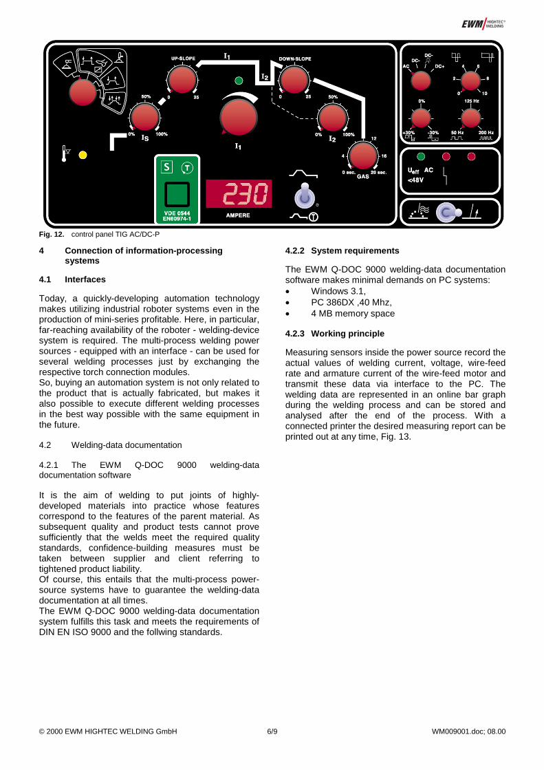
3.2 ����AC/DC- Plasma���� power-source concept
The �TIG AC/DC-P� power source represents awelding device that covers the complete range ofMMA, TIG as well as plasma welding, Fig. 11.
Fig. 11. Multi-process welding power source TIG 350 AC/DC-P
This power-source configuration only allows to realiseseveral welding processes by connecting differenttorches. Equipped with a polarity switch, the electrodepolarity can easily be switched or alternating-currentoperation can be chosen. Low- and high-alloy steels,exotic metals and aluminium-based alloys can bewelded. The power module has three steps: 250A/350 A/450 A (60% ED). In this case, the powersource is again completed with a control andoperating module that has all required operatingfunctions, Fig. 12.What attracts the attention is the availability of plasmawelding at the negative pole for aluminium-basedalloys. Certainly, there are many advantages ofalternating-current welding because of its easierhandling and the lower electrode load. But thepossibility to use the plasma process at the positivepole just by exchanging the torch gives theadvantages of this - unfortunately somewhatneglected - process new importance. A constricted arcwith a very good cleaning effect produces highexternal weld quality. The increase in the weldingspeed in the thin-sheet range at extremely reducednoise pollution must be underlined. By exchanging thetorch equipment plasma welding at the negative polecan be applied very easy as wellThis power-source concept is completed by severalremote control units, hotstart for MMA, pulsed or foot-operated remote control, for instance.
© 2000 EWM HIGHTEC WELDING GmbH 6/9 WM009001.doc; 08.00
4 Connection of information-processingsystems
4.1 Interfaces
Today, a quickly-developing automation technologymakes utilizing industrial roboter systems even in theproduction of mini-series profitable. Here, in particular,far-reaching availability of the roboter - welding-devicesystem is required. The multi-process welding powersources - equipped with an interface - can be used forseveral welding processes just by exchanging therespective torch connection modules.So, buying an automation system is not only related tothe product that is actually fabricated, but makes italso possible to execute different welding processesin the best way possible with the same equipment inthe future.
4.2 Welding-data documentation
4.2.1 The EWM Q-DOC 9000 welding-datadocumentation software
It is the aim of welding to put joints of highly-developed materials into practice whose featurescorrespond to the features of the parent material. Assubsequent quality and product tests cannot provesufficiently that the welds meet the required qualitystandards, confidence-building measures must betaken between supplier and client referring totightened product liability.Of course, this entails that the multi-process power-source systems have to guarantee the welding-datadocumentation at all times.The EWM Q-DOC 9000 welding-data documentationsystem fulfills this task and meets the requirements ofDIN EN ISO 9000 and the follwing standards.
4.2.2 System requirements
The EWM Q-DOC 9000 welding-data documentationsoftware makes minimal demands on PC systems:� Windows 3.1,� PC 386DX ,40 Mhz,� 4 MB memory space
4.2.3 Working principle
Measuring sensors inside the power source record theactual values of welding current, voltage, wire-feedrate and armature current of the wire-feed motor andtransmit these data via interface to the PC. Thewelding data are represented in an online bar graphduring the welding process and can be stored andanalysed after the end of the process. With aconnected printer the desired measuring report can beprinted out at any time, Fig. 13.
Fig. 12. control panel TIG AC/DC-P

© 2000 EWM HIGHTEC WELDING GmbH 7/9 WM009001.doc; 08.00
One hour of recorded welding data only takes up 0.25MB memory space.In order to be able to reproduce the welding processfor recurring welding tasks or later liability cases, adetailed description of all process-related parametersis necessary. Among the head data are generalinformation concerning date, time, client,constructional drawing and welder. Via a selectionmenu the whole welding task is described (e.g.welding process, parent materials, filler metals andshielding gases), Fig. 14.
Windows SoftwareQ - DOC 9000
InterfacePC INT 1,2,3
Connecting cablewith plug
Linking cable(blue-marked plug at the Interface)
Printer for theDokumentationPower source
Bild 13. Welding-data documentation
Fig. 14. Welding-data description (excerpt)

© 2000 EWM HIGHTEC WELDING GmbH 8/9 WM009001.doc; 08.00
During the welding process, all actual values can bemonitored permanently, Fig. 15. If tolerances thathave been fixed by the welder are exceeded, this isshown on the screen: the bar of the respectiveparameter turns red.
The measured parameters can be analysed in agraphical representation as a function of time, Fig. 16.The absolute values of each parameter can be calledfor any point of time. Reference welds and tolerancedivergences can be put on the screen.
Fig. 16. Graphical representation of the welding parameters
Fig. 15. Online weld

© 2000 EWM HIGHTEC WELDING GmbH 9/9 WM009001.doc; 08.00
4.2.4 Areas of application of the EWMQ-DOC 9000 software
Practical application in� gas-shielded metal arc welding,� tungsten-inert gas welding,� plasma welding and� manual metal arc weldingas� a means of quality control in welding
production,� an instrument for drawing-up and documenting
welding instructions (WPS),� a supporting means for welding-process checks
and their documentation,� a means of post-calcualtion of the welding
production,� an important instrument in welder training.
5 Prospects
In the future, multi-process welding power sources willdevelop into a centre of interest in welding-relatedproduction.In consequence, the manufacturers will have to offermodular power-source systems. The user canconfigurate his or her welding device by arranging andcomposing the individual modules, the device can beupdated with software modules and extended at anytime. There, torch systems will be useful that haveconnections that can be used variably.An example of today will show this trend. Theinteresting TIG direct-current welding technology withhigh-frequency pulses is realised via a standardpower unit; an additional module with a remote controlenables the system to pulse the welding current up to8 kHz. The purpose of this process is to increase thewelding speed of TIG welding in automatic fabrication.The arc and the molten bath are stabilised with thismethod and cause a concentrated penetration, Fig.17.This shows that - to turn such a technologysuccessfully into practice - the intense integration ofpower-source technology, on the one hand, andprocess engineering, on the other hand, is required.The multi-process welding power source is animportant element of such a concept.
Fig. 17 Transverse section of a butt weld, TIG welding,parent material: 1.4301, s = 2 mm, no filler material,welding speed: 2,7 m/min