progress in the development of lightweight nickel …...progress in the national development of...
TRANSCRIPT

NASA Technical Memorandum 105593
Progress in the Development of Lightweight Nickel Electrode for Aerospace Applications
Doris L. Britton Lewis Research Center Cleveland, Ohio
Prepared for the Third International Rechargeable Battery Seminar sponsored by the Ansum Enterprises, Inc. Deerfield Beach, Florida, March 2-4, 1992
https://ntrs.nasa.gov/search.jsp?R=19920011251 2020-04-21T02:59:11+00:00Z

Trade names or manufacturers’ names are used in this report for identification only. This usage doer not constitute an official endorsement, either expressed or implied, by the National Aeronautics and Space Administration.

PROGRESS IN THE
National
DEVELOPMENT OF LIGHTWEIGHT NICKEL ELECTRODE FOR AEROSPACE APPLICATIONS
Doris L. Britton
Lewis Research Center Cleveland, Ohio 44135
Aeronautics and Space Administration
ABSTRACT
The NASA Lewis Research Center (LeRC) is currently developing nickel electrodes for nickel-hydrogen (Ni-H,) cells and batteries. These electrodes are lighter in weight and have higher specific energy than the heavy sintered state-of-the art (SOA) nickel electrodes.
In the present approach, lightweight materials or plaques are used as conductive supports for the nickel hydroxide active material. These plaques (fiber, felt, and nickel plated plastic) are fabricated into nickel electrodes by electrochemi- cally impregnating themwith active material. Initial performance tests include capacity measurements at five discharge levels, Cl2, l.OC, 1.37C. 2.0C, and 2.74C. The electrodes that pass the initial tests are life cycle tested at 40 and 80% depths-of-discharge (DOD).
Different formulations of nickel fiber materials obtained from several manufacturers are currently being tested as possible candidates for nickel electrodes. Over 7000 cycles in life cycle testing have been accumulated at 40% DOD, using the lightweight fiber electrode, in a boiler plate Ni-H, cell with stable voltage.
INTRODUCTION
As part of the Ni-H, cell technology development program at NASA LeRC, an advanced Ni-H, cell design was developed. One specific goal was to improve the specific energy of the SOA Ni-H, cell from 50 Wh/kg to 100 Wh/kg. One of the components needed to accomplished this goal was to develop a better performing and lighter weight nickel electrode which, in addition to being identified as the critical component, has also been identified as the heaviest component of the Ni- H cell. The SOA nickel plaque is made by sintering fine nickel powder onto a wire screen at elevated temperature (lOOO°C) in a reducing atmosphere. This plaque has the advantage of providing a highly conductive and porous substrate f o r the active material but has the disadvantage of being very heavy. The nickel hydroxide active material is deposited into the pores of the plaque either by chemical or electrochemical methods.
2
The use of a lightweight nickel plaque in place of the heavy SOA sintered nickel plaque is expected to lead to improvements in weight and performance of the nickel electrode. After some preliminary experiments, the Fibrex' fiber plaque from National Standard was selected as one of the most promising support candidates for the nickel hydroxide (Ni(0H) ) active material. The Fibrex material is formed by reducing and sintering gibers extruded from a mixture of
'Trademark of National Standard Company, Niles, Michigan
1

n i c k e l oxide and binding agents (1). A s p e c i a l type of F ibrex mat layered w i t h carbonyl n i c k e l and c o b a l t powder i s c u r r e n t l y being t e s t e d . This s p e c i a l type of m a t e r i a l contains 50 p a r t s n i c k e l f i b e r , 35 p a r t s n i c k e l powder, and 15 p a r t s c o b a l t powder. The plaques a r e a v a i l a b l e i n d i f f e r e n t t h i cknesses , p o r o s i t i e s and d e n s i t i e s .
EXPERIMENTAL
Nickel Plaques
Poros i ty and th ickness of n i c k e l e l ec t rodes a f f e c t t h e s p e c i f i c energy, i n i t i a l performance and cyc le l i f e of the N i - H 2 c e l l . One advantage of t h e l igh tweight plaques over the SOA s i n t e r e d plaque i s t h a t t h e l igh tweight plaques can e a s i l y be manufactured wi th much l a r g e r p o r o s i t i e s than t h e SOA plaques. F ibrex f iber /powder s t r u c t u r e s a r e commercially a v a i l a b l e i n p o r o s i t i e s up t o 98% whi le commercial SOA s i n t e r e d n i c k e l plaques a r e a v a i l a b l e i n p o r o s i t i e s of 80 t o 86%.
The Fibrex plaques repor ted i n t h i s s tudy a r e the 30 m i l t h i c k , 85% porous plaque: t h e 30 m i l t h i c k , 93% porous plaque; and the 80 m i l t h i c k , 90% porous plaque.
30 m i l t h i c k , 851 porous p l a q u e s
Prel iminary t e s t s were performed us ing e l ec t rodes made from 30 m i l t h i c k , 85% poros i ty Fibrex plaques. The c a l c u l a t e d s p e c i f i c energy of a 48 Ahr N i - H 2 c e l l us ing t h i s Fibrex e l e c t r o d e (61 Whr/kg) i s about 9% h ighe r than t h a t u s ing the SOAelectrode (56 Whr/kg) wi th s i m i l a r t h i ckness , p o r o s i t y and loading l e v e l (1 .6 g/cm3 void volume).
30 m i l t h i c k , 93X porous p l a q u e s
One f a c t o r a f f e c t i n g t h e s p e c i f i c energy of a N i - H , c e l l i s t h e po ros i ty of t h e n i c k e l e l ec t rode . For example, t he c a l c u l a t e d s p e c i f i c energy of a 48 Ahr N i - H 2 c e l l i nc reases from 56 Wh/kg t o 66 Wh/kg, an 18% improvement, by r ep lac ing the n i c k e l e l ec t rode made from an 85% porous SOA plaque w i t h t h e l igh tweight n i c k e l e l ec t rode made from a 93% porous Fibrex plaque, w i t h t h e same th ickness and loading l e v e l of 1 .6 g/cm3 void volume.
80 m i l t h i c k , 9OK porous p l a q u e s
Another approach t h a t w i l l r e s u l t i n a h igher s p e c i f i c energy of t he N i - H 2 c e l l i s t he use of t h i ck n i c k e l e l e c t r o d e s . U t i l i z i n g fewer t h i c k n i c k e l e l e c t r o d e s w i l l reduce the number of o t h e r components, e . g . , hydrogen e l e c t r o d e s and sepa ra to r s . The c a l c u l a t e d s p e c i f i c energy of a 48 Ahr N i - H 2 c e l l us ing an 80 m i l t h i c k e l ec t rode made from a 90% porous p laque , which i s loaded t o 1 .6 g/cm3 void volume, i s 77 Whrlkg.
Electrochemical Impregnation
The plaques a r e p r e t r e a t e d p r i o r t o impregnation i n o r d e r t o e l imina te any su r face contaminants t h a t were obta ined du r ing handl ing and s to rage . The pre t rea tment procedure used i n t h i s study i s t h e wet o x i d a t i o n c l ean ing t rea tment
2

(2 ) which consists of heating the wet plaque at 350' C in air for 20 minutes. The cleaned plaques are thenmeasured, weighed, and electrochemically impregnated in an aqueous bath containing 1.5M Ni(N03),, 0.175M CO(NO~)~, and 0.075M NaNOZ made acidic by the addition of SOX nitric acid (3). The bath is maintained at a constant temperature of 95-100' C and a pH of 3 - 4 .
The plaques are impregnated for various periods of time (2 to 5 hours) and current densities (50 to 93 mA/cmz) to determine the conditions needed to obtain the optimum loading level. The plaques are impregnated in a reaction vessel which consists of a 600 ml beaker containing a 400 ml aqueous bath. The plaques are placed between two standard nickel counterelectrodes in a teflon holder.
After impregnation, the electrodes are rinsed in deionized water and are formed using the Eagle-Picher formation procedure ( 4 ) . The procedure consists of eight cycles of 20 min charge and 20 min discharge at a current density of 70 mA/cmz in 26X potassium hydroxide (KOH) solution. After formation, the electrodes are thoroughly rinsed in deionized water, dried at a temperature of 60' C for 4 hr and weighed. The theoretical capacity is determined from the weight of the active material in the electrode using the electrochemical equivalent of 0.289 Ahrlg of Ni(OH)2.
Cycle L i f e
Initial evaluation of the cycle life of the lightweight nickel electrodes are conducted in a half-cell configuration. cell using the lightweight electrodes, additional cycle testing is conductea using a 2- by 2-inch boilerplate cell.
To validate the performance of a Ni-H
H a l f - Cell Cycle Te s t
The components and configuration of the half-cell test vessel are illustrated in figures 1 through 3. Figure 1 shows the components of the test cell which consist of a 1-inch diameter lightweight nickel electrode as the cathode, a 1- inch diameter standard nickel counterelectrode as the anode, a single layer each of 1-inch diameter asbestos and polypropylene as the separator, and a mercury/mercuric oxide (HglHgO) as the reference electrode. These components are assembled in the test configuration, as shown in figure 2, with nickel sheets, placed at the ends of the stack, which serve as current collectors. The stack is packaged in a test cell, as shown in figure 3, and filled with an excess of 26% KOH.
The cycling tests are in a LEO regime (55 minute charge, 35 minute discharge) at 80% DOD. The voltage as a function of time is plotted continuously. Approximately every 1000 cycles, capacity measurements are made by discharging to -0.2 volts (versus a Hg/HgO reference electrode) at a 1.37C rate after charging for 80 minutes at a C rate. The percent utilization of the electrode is calculated by using the ratio of the measured capacity to the theoretically calculated capacity based on the weight of the active material deposited. End of life or failure is defined as the point where the discharge voltage degrades to -0.2 V versus a Hg/HgO electrode.
3
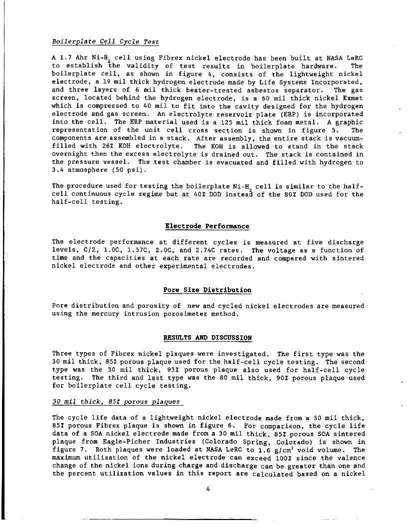
B o i l e r p l a t e Cel l Cycle T e s t
A 1 .7 Ahr N i - H 2 c e l l us ing Fibrex n i c k e l e l e c t r o d e has been b u i l t a t NASA LeRC t o e s t a b l i s h t h e v a l i d i t y of t e s t r e s u l t s i n b o i l e r p l a t e hardware. The b o i l e r p l a t e c e l l , as shown i n f i g u r e 4 , c o n s i s t s of t h e l igh tweight n i c k e l e l e c t r o d e , a 1 9 m i l t h i c k hydrogen e l ec t rode made by L i f e Systems Incorpora ted , and t h r e e l aye r s of 6 m i l t h i c k b e a t e r - t r e a t e d a sbes tos sepa ra to r . The gas screen , loca ted behind the hydrogen e l e c t r o d e , i s a 60 m i l t h i c k n i c k e l Exmet which i s compressed t o 40 m i l t o f i t i n t o the c a v i t y designed f o r t h e hydrogen e l ec t rode and gas screen . An e l e c t r o l y t e r e s e r v o i r p l a t e (ERP) i s incorpora ted i n t o the c e l l . A graphic r ep resen ta t ion of t h e u n i t c e l l c r o s s s e c t i o n i s shown i n f i g u r e 5. The components a r e assembled i n a s t a c k . Af t e r assembly, t h e e n t i r e s t a c k i s vacuum- f i l l e d wi th 26% KOH e l e c t r o l y t e . The ROH i s allowed t o s tand i n t h e s t a c k overnight then t h e excess e l e c t r o l y t e i s dra ined ou t . The s t ack i s conta ined i n t h e p re s su re ves se l . The t e s t chamber i s evacuated and f i l l e d w i t h hydrogen t o 3.4 atmosphere (50 p s i ) .
The ERP m a t e r i a l used i s a 125 m i l t h i c k foam metal.
The procedure used f o r t e s t i n g t h e b o i l e r p l a t e N i - H c e l l i s s imilar t o the h a l f - c e l l continuous cyc le regime but a t 40% DOD i n s t e a 8 of t h e 80% DOD used f o r t h e h a l f - c e l l t e s t i n g .
Electrode Performance
The e l e c t r o d e performance a t d i f f e r e n t cyc le s i s measured a t f i v e d ischarge l e v e l s , C/2, l . O C , 1 . 3 7 C , 2.0C, and 2.74C r a t e s . The vo l t age as a func t ion of time and t h e c a p a c i t i e s a t each r a t e a r e recorded and compared w i t h s i n t e r e d n i c k e l e l ec t rode and o t h e r experimental e l e c t r o d e s .
Pore Size Distribution
Pore d i s t r i b u t i o n and po ros i ty of new and cyc led n i c k e l e l e c t r o d e s a r e measured us ing the mercury i n t r u s i o n porosimeter method.
RESULTS AND DISCUSSION
Three types of Fibrex n i c k e l plaques were i n v e s t i g a t e d . The f i r s t type was the 30 m i l t h i c k , 85% porous plaque used f o r the h a l f - c e l l cyc le t e s t i n g . The second type was the 30 m i l t h i c k , 93% porous plaque a l s o used f o r h a l f - c e l l cyc le t e s t i n g . The t h i r d and l a s t type was t he 80 m i l t h i c k , 90% porous plaque used f o r b o i l e r p l a t e c e l l cyc le t e s t i n g .
30 mil t h i ck , 85% porous p laques
The cyc le l i f e data of a l i gh twe igh t n i c k e l e l e c t r o d e made from a 30 m i l t h i c k , 85% porous Fibrex plaque i s shown i n f i g u r e 6 . For comparison, t h e cyc le l i f e da t a of a SOA n i cke l e l e c t r o d e made from a 30 m i l t h i c k , 85% porous SOA s i n t e r e d plaque from Eagle-Picher I n d u s t r i e s (Colorado Spr ing , Colorado) i s shown i n f i g u r e 7 . The maximum u t i l i z a t i o n of t h e n i c k e l e l e c t r o d e can exceed 100% s i n c e t h e valence change of t he n i cke l ions dur ing charge and d i scha rge can be g r e a t e r t han one and the percent u t i l i z a t i o n va lues i n t h i s r epor t are c a l c u l a t e d based on a n i c k e l
Both plaques were loaded a t NASA LeRC t o 1 . 6 g/cm3 vo id volume.
4
ion valence change of one. The i n i t i a l u t i l i z a t i o n of t h e F ibrex and SOA e lec t rodes a r e 75 and 102% r e spec t ive ly . The Fibrex e l e c t r o d e shows a reg ion of i nc reas ing u t i l i z a t i o n during the i n i t i a l 1 5 0 cyc le s followed by a r e l a t i v e l y cons tan t p l a t eau region. A gradual performance decrease i s then observed a s t h e number of cyc le s i s f u r t h e r increased .
The Fibrex n i c k e l e l e c t r o d e reached i t s maximum u t i l i z a t i o n a f t e r about 2100 cycles and continued t o cyc le f o r a t o t a l of 4534 cyc le s before i t reached i t s end of l i f e as shown i n f i g u r e 6 . The capac i ty of t h i s e l ec t rode had decreased by 30% a t the end of t he cyc le t e s t . The th ickness of t he e l e c t r o d e measured a f t e r t he cyc le l i f e t e s t showed an inc rease of about 8% over t h e i n i t i a l e l e c t r o d e th ickness measured a f t e r the impregnation and formation procedures .
On the o the r hand, t h e SOA e lec t rode reached i t s maximum u t i l i z a t i o n a t cyc le 500 , as shown i n f i g u r e 7 . A t t h e end of t h e cyc le t e s t (about 4500 c y c l e s ) , t h e capac i ty of t he SOA e lec t rode decreased by 35% w i t h an e l e c t r o d e expansion of about 1 0 % .
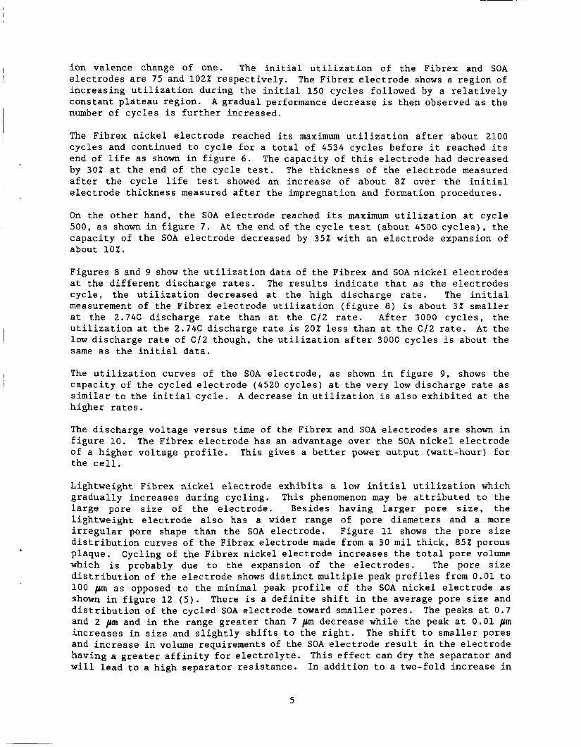
Figures 8 and 9 show t h e u t i l i z a t i o n data of t h e F ibrex and SOA n i c k e l e l e c t r o d e s a t t he d i f f e r e n t d i scharge r a t e s . The r e s u l t s i n d i c a t e t h a t a s the e l e c t r o d e s cyc le , t he u t i l i z a t i o n decreased a t the h igh d ischarge r a t e . The i n i t i a l measurement of t he F ibrex e l ec t rode u t i l i z a t i o n ( f i g u r e 8) i s about 3% smaller a t t he 2.74C discharge r a t e than a t t he C / 2 r a t e . A f t e r 3000 c y c l e s , t h e u t i l i z a t i o n a t t he 2.74C discharge r a t e i s 20% l e s s than a t t h e C / 2 r a t e . A t t h e low d ischarge r a t e of C / 2 though, t h e u t i l i z a t i o n a f t e r 300C cyc le s i s about t h e same a s t h e i n i t i a l d a t a .
The u t i l i z a t i o n curves of t h e SOA e l ec t rode , as shown i n f i g u r e 9 , shows t h e capac i ty of t h e cycled e l e c t r o d e (4520 cyc le s ) a t t h e very low d ischarge r a t e as s imilar t o the i n i t i a l cyc le . A decrease i n u t i l i z a t i o n i s a l s o exh ib i t ed a t t he h ighe r r a t e s .
The d ischarge vo l t age versus time of the Fibrex and SOA e l ec t rodes a r e shown i n f i g u r e 10 . The Fibrex e l e c t r o d e has an advantage over t he SOA n i c k e l e l e c t r o d e of a h ighe r vo l t age p r o f i l e . This gives a b e t t e r power output (wat t -hour) f o r t h e c e l l .
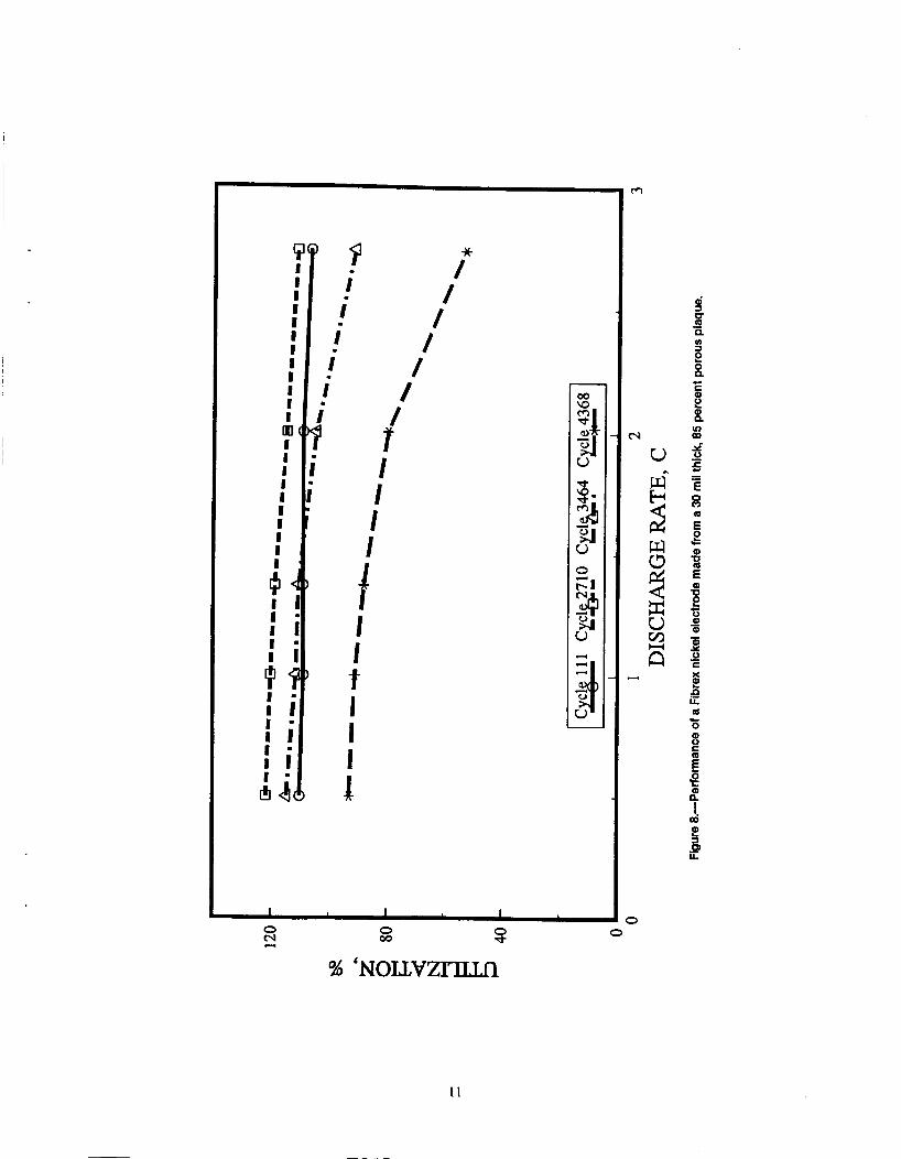
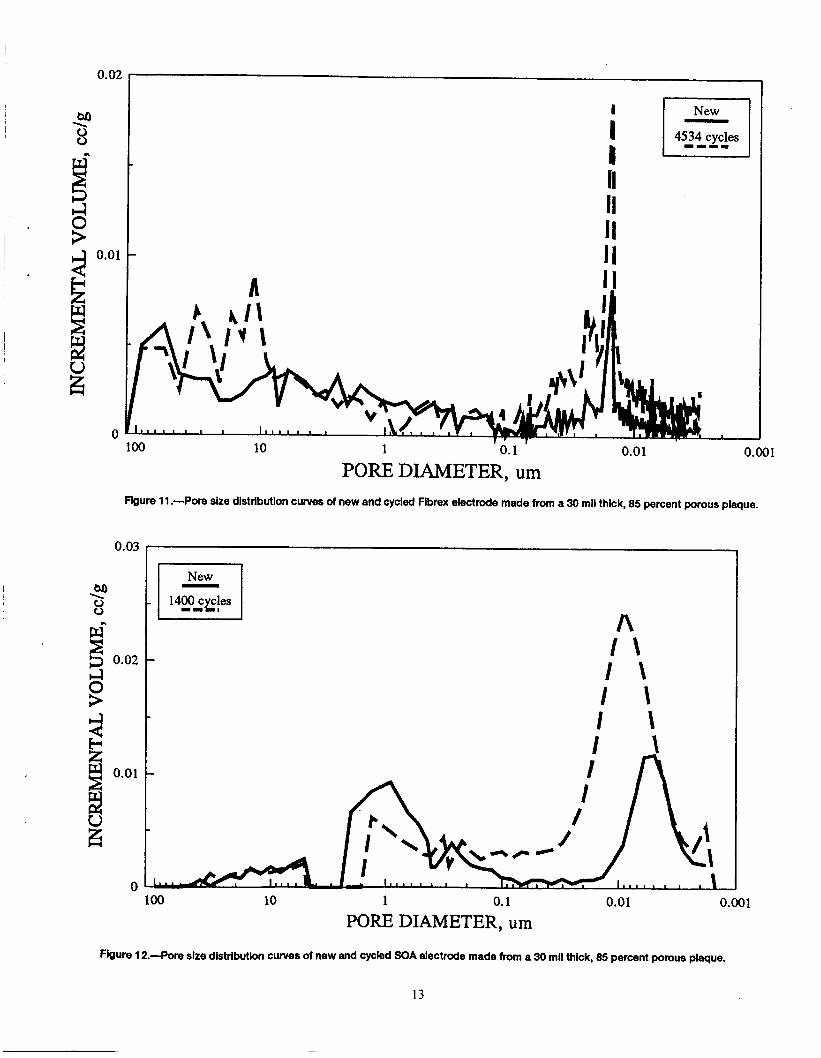
Lightweight F ibrex n i c k e l e l ec t rode e x h i b i t s a low i n i t i a l u t i l i z a t i o n which g radua l ly inc reases during cyc l ing . This phenomenon may be a t t r i b u t e d t o the l a r g e pore s i z e of t h e e l e c t r o d e . Besides having l a r g e r pore s i z e , t he l i gh twe igh t e l ec t rode a l s o has a wider range of pore diameters and a more i r r e g u l a r pore shape than the SOA e lec t rode . Figure 11 shows t h e pore s i z e d i s t r i b u t i o n curves of the Fibrex e l ec t rode made from a 30 m i l t h i c k , 85X porous p laque . Cycling of t h e F ibrex n i c k e l e l ec t rode inc reases the t o t a l pore volume which i s probably due t o t h e expansion of t h e e l e c t r o d e s . The pore s i z e d i s t r i b u t i o n of t h e e l e c t r o d e shows d i s t i n c t m u l t i p l e peak p r o f i l e s from 0 . 0 1 t o 1 0 0 pm as opposed t o t h e minimal peak p r o f i l e of t h e SOA n i c k e l e l e c t r o d e as shown i n f i g u r e 1 2 ( 5 ) . There i s a d e f i n i t e s h i f t i n t h e average pore s i z e and d i s t r i b u t i o n of t he cycled SOA e l ec t rode toward smaller pores . The peaks a t 0 .7 and 2 pm and i n the range g r e a t e r than 7 pm decrease whi le the peak a t 0 . 0 1 pm i n c r e a s e s i n s i z e and s l i g h t l y s h i f t s t o t h e r i g h t . The s h i f t t o smaller pores and i n c r e a s e i n volume requirements of the SOA e l e c t r o d e r e s u l t i n t h e e l e c t r o d e having a g r e a t e r a f f i n i t y f o r e l e c t r o l y t e . This e f f e c t can dry t h e sepa ra to r and w i l l l e a d t o a h igh sepa ra to r r e s i s t ance . I n a d d i t i o n t o a two-fold inc rease i n
5

volume of the micropores of t he cyc led Fibrex e l ec t rode ( f i g u r e l l), the volume of the l a r g e r pores (over 9 pm) i nc reases 2 t o 4 times.
More d a t a i s needed t o c o r r e l a t e t h e r e s u l t i n g pore s i z e d i s t r i b u t i o n of t h e s e l igh tweight e l ec t rodes wi th t h e e l e c t r o l y t e management i n t h e N i - H , c e l l .
30 mil thick, 93% p o r o s i t y p l a q u e s
A Fibrex n i c k e l plaque, w i th 30 m i l t h i c k and 93 percent p o r o s i t y , was loaded wi th a c t i v e ma te r i a l t o 1 .8 g/cm3 void volume. The cyc le l i f e d a t a i s shown i n f i g u r e 1 3 . Over 5800 cyc le s had been a t t a i n e d a t 80% DOD by t h i s porous F ibrex n i c k e l e l ec t rode . This e l e c t r o d e has the longes t cyc le l i f e , a t 80% DOD, of any of t he l igh tweight n i c k e l e l e c t r o d e developed in-house. The u t i l i z a t i o n of t h e e l ec t rode reached i t s maximum value a f t e r 1500 cyc le s , followed by a r e l a t i v e l y cons tan t p la teau region t o 5000 cyc le s a t which po in t a decrease i n u t i l i z a t i o n was observed. The l i f e cyc le t e s t i n g was terminated due t o a vo l t age d e c l i n e . Figure 1 4 shows the u t i l i z a t i o n of t h e 30 m i l t h i c k , 93% porous F ibrex e l e c t r o d e a t t h e d i f f e r e n t d i scharge r a t e s . The r e s u l t s i nd ica t ed a low u t i l i z a t i o n a t t h e beginning of the cyc le l i f e t e s t . A d r a s t i c i nc rease i n t h e u t i l i z a t i o n w a s observed a f t e r 3800 cyc le s .
The pore s i z e d i s t r i b u t i o n of t h e new and cyc led Fibrex e l e c t r o d e made from a 30 m i l t h i c k , 93% porous plaque i s p l o t t e d i n Figure 15 . Cycling of t h e e l e c t r o d e changed the t o t a l pore volume and d i s t r i b u t i o n . Again, t h e pore s i z e d i s t r i b u t i o n s of t he e l ec t rode show d i s t i n c t mu l t ip l e peak p r o f i l e s from 0.003 t o 100 pm. There a r e pronounced inc reases i n volume between 0.01 t o O.1pm and 2 t o 50 pm wi th cyc l ing .
80 mil thick, 901 porosity p laque
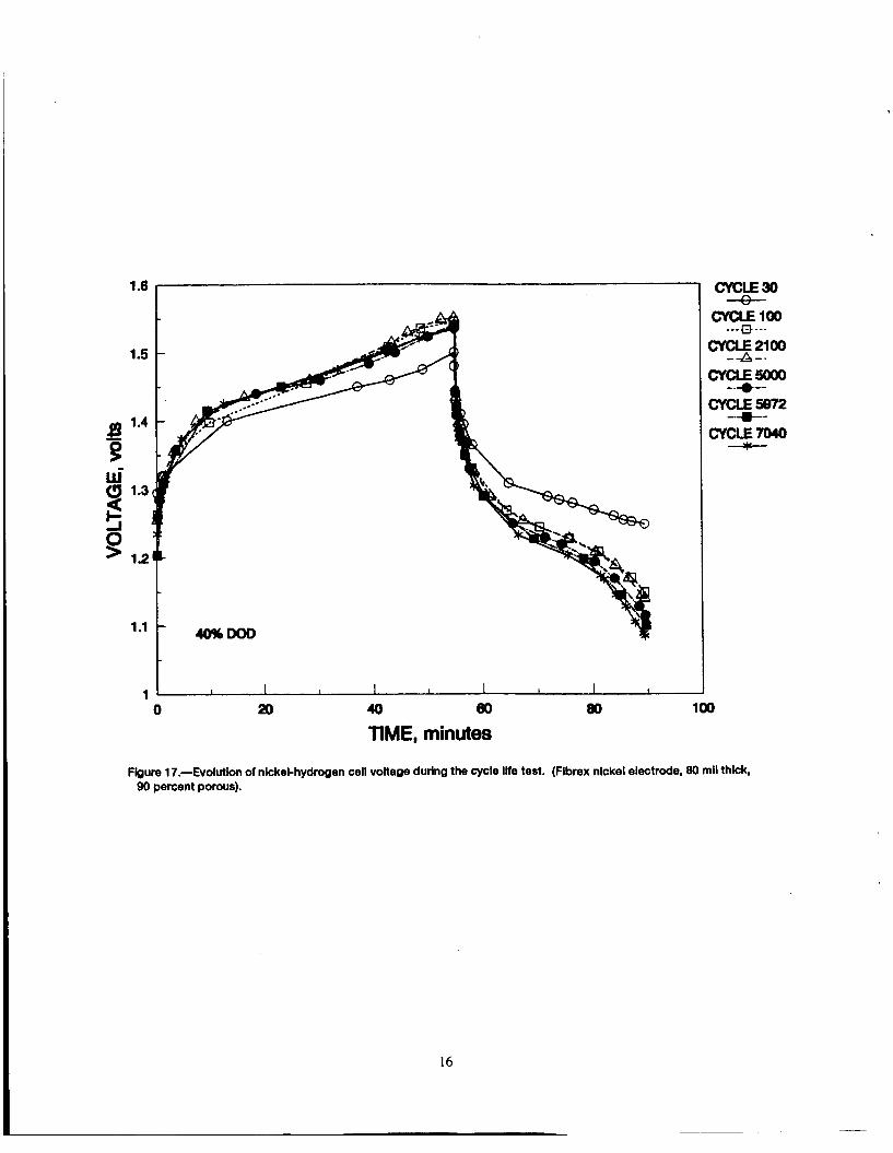
The b o i l e r p l a t e N i - H , c e l l cyc le t e s t d a t a , a t 40% DOD, of t h e l igh tweight n i c k e l e l e c t r o d e made from an 80 m i l t h i c k , 90% porous F ibrex plaque i s shown i n f i g u r e 16. Figure 1 7 shows t h e c e l l vo l t age c h a r a c t e r i s t i c s dur ing t h e charge and d ischarge cyc les . Over 7000 cyc le s have a l r eady been achieved wi thout a d r a s t i c decrease i n performance as shown i n f i g u r e 18 . The end-of-discharge vo l t age (EODV) remained a l m o s t c o n s t a n t f o r t h e f i r s t 4000 cyc le s and g radua l ly decreased on f u r t h e r cyc l ing . A f t e r 7000 c y c l e s , t he EODV had decreased t o 1.1 v o l t s . The end-of-charge vol tage (EOCV) remained s t a b l e a t 1.54 v o l t s . The cyc le t e s t i n g of t h i s c e l l w i l l be cont inued u n t i l f a i l u r e . A p o s t - t e s t c e l l teardown and f a i l u r e ana lys i s w i l l be conducted t o eva lua te t h e cause f o r f a i l u r e .
CONCLUSION
Fabr i ca t ion and l i f e cyc le t e s t i n g of l igh tweight f i b e r n i c k e l e l e c t r o d e s have demonstrated the f e a s i b i l i t y of an improved n i c k e l e l e c t r o d e . These s t u d i e s i n d i c a t e a 37% improvement i n s p e c i f i c energy f o r t h e N i - H , c e l l u s ing F ibrex n i c k e l e l ec t rode over SOA e l e c t r o d e .
Using l igh tweight , t h i c k and h igh ly porous n i c k e l e l e c t r o d e s i s expected t o a l s o improve t h e s p e c i f i c energy of t h e N i - H , c e l l . A g r e a t e r improvement i s a l s o poss ib l e by increas ing the loading l e v e l t o over 1 . 6 g/cm3 void volume. However, t h i c k e r and /o r heavi ly loaded SOA s i n t e r e d e l e c t r o d e s r e s u l t s i n premature e l ec t rode f a i l u r e due t o swel l ing on long c y c l i n g which l eads t o s h o r t e r l i f e
6

(6,7,8,9). Research directed at achieving the required active material utilization and long cycle life in the highly porous, heavily loaded and/or thick fibrous nickel electrodes will be actively pursued.
REFERENCES
1.
2.
3.
4.
5.
6.
7.
8.
9.
Colucci, S. L.: System for Stretch Casting Filamentary Shaped Bodies. U.S. Patent 4,312,670, Jan. 26, 1982.
Beauchamp, R.L. ; Maurer, D.W. ; and O’Sullivan, T.D. : Methods of Producing Electrodes for Alkaline Batteries. U.S. Patent 4,032,697, June 28, 1977.
Britton, D.L.: Lightweight Nickel Electrode for Nickel Hydrogen Cells and Batteries. Proceedings of the 32nd International Power Sources Symposium, pp.420 - 428, June, 1986.
Bleser, C.: Positive Electrode Processing for Hughes NiHz cells. Proceedings of the Goddard Space Flight Center Battery Workshop, pp. 471 - 480, 1981. Thaller, L.H; Manzo, M.A.; and Gonzalez-Sanabria, O.D.: Design Principles for Nickel-Hydrogen Cells and Batteries. NASA TM-87037, 1985.
Pickett, D.F.; Martin, U.D.; iogsdon, J.W.; and Leonard, J.F.: Pilot Production and Cycle Life Performance of the Nickel Oxide Electrodes. Proceedings of the 27th Power Sources Symposium, pp. 120-123, June, 1976.
Seiger, H.N.; Puglisi, V.L.; and Ritterman, P.F.: High Energy Density Sintered Plate Type Sealed Nickel Cadmium Battery Cells. Part I. The Positive ElectrodelPlaque Relationships. Proceedings of the 9th IECEC Conference, pp. 868-872, 1974.
Ford, F.E. and Baer, D.A.: Design and Manufacturing Changes Incorporated in the Nickel-Cadmium Space Cell During the Past Decade. Battery Design and Optimization, ed. S. Gross. The Electrochemical Society, Inc., NJ, pp. 114-127, 1979.
Pickett, D.F. : Recent Trends in Design and Manufacturing of Nickel Oxide Electrodes for Space Applications. Proceedings of the Symposium on Porous Electrodes: Theory and Practice, ed. H. Maru, T. Katan, and M. Klein. The Electrochemical Society, Inc., NJ, pp. 12-31, 1984.
7

ORIGINAL PAGE BLACK AND WHITE PHOTOGRAPH
1 ”
C-83-2205
Figure 1 .-Components of the test cell.
3
Figure 2.-Components of the assembled cell in a test configuration.
4
Figure 3.-Test cell with 26 percent KOH electrolyte.
8

ORIGINAL PAGE i3LACK AND WHITE PHOTOGRAPh
3
Figure 4.4ornponents of the nickel-hydrogen boilerplate cell.
CURRENT COLLECTOR
GAS SCREEN HOUSING
I \ HYDROGEN ELECTRODE ~
SEPARATOR / NICKEL ELECTRODE
ELECTROLYTE RESERVOIR ?LATE (ERP)
CURRENT COLLECTOR
Figure 5.4ross sectional unit of the nickel-hydrogen boilerplate cell.
9

120
#
0 5 80 N
z
2 5
40 I
1.1C Charge rate 1.37C Discharge rate
0 lo00 2000 3000 4000 5000
NUMBER OF CYCLES Figure 6.-Utlllzatlon versus number of cycles of a Flbrex nickel electrode made from a 30 mil thick, 85 percent porous plaque
(1.6 a/cc void loading).
120
80
40
1.1C Charge rate 1.37C Discharge rate
.
0 lo00 2000 3000 4000 So00 NUMBER OF CYCLES
Figure 7.-Utlllzatlon versus number of cycles of a SOA nickel electrode made from a 30 mil thick, 85 percent porous plaque (1.6 Ucc void loading).
i P P I
I
I
I
0 / m /
I / I - 1 1 /
I I I I 1 1
1 1 / 1 1 mc
1 1
I f
I =
I 1 .
t / I
I ; I I 1 .
I I d 4 d‘) I I : i I
I t I i ;
; ; I : ; I A dl3 4
6
% ‘NOLL-
1 1

I20
80
40
0
E B W’
3 5 0 >
I Cycle 1 Cycle 4520 I - + 1 2
DISCHARGE RATE, C Figure g.-Perfonnance of the SOA nickel electrode.
0.6
0.4
0 2
0
I \ \
1 I I I A
0 10 M m 40 50 TIME, minutes
(0.2)
3
Flgure 10.-Discharge voltage versus time of Fibrex and SOA nickel electrodes made from 30 mil thick, 85 percent porous plaques.
12
0.02
I
I I II II I I II
1 - 1 4534 cycles
0
PORE DIAMETER, urn Figure 11 .-Pore size distribution curves of new and cycled Flbrex electrode made from a 30 mil thick, 85 percent porous plaque.
A I \ I \ I \ I \
, . , I I t I I
100 10 1 0.1 0.01 0.001 PORE DIAMETER, urn
Figure 12.-Pore size distribution curves of new and cycled SOA electrode made from a 30 mil thick, 85 percent porous plaque.
13

160
0
1.1C Charge rate 1.37C Discharge rate
0 lo00 2000 3000 4000
NUMBER OF CYCLES Figure 13.-Utiiization vemus number of cycles of a Fibrex nickel electrode made from a 30 mil thick, 93 percent porous plaque
(1.8 Q/CC void loading).
200
150 €R
0
4. 9 -‘ ’. *‘-
I I
0 1 2 DISCHARGE RATE, C
3
Figure 14.-Performance of a Fibrex nickel electrode made from a 30 mil thick, 93 percent porous plaque.
14

0.01
120
110
kR
0 zi- 100
0
-
-
e J
I 5872 1-11 CYCLES I I
r
n / I
1'. I I
n p872 CYCLES I I
r
100 10 1 0.1 0.01 0.001 PORE DIAMETER, urn
Figure 15.-POre size distribution curves of new and cycled Fibrex electrode made from a 30 mil thick, 93 percent porous plaque.
40% DOD 8o F
I I I I
0 1000 2000 3000 4000 5000 m 7000 8000 NUMBER OF CYCLES
Figure 16.-UtilIzatlon versus number of cycles of a nickel-hydrogen boilerplate cell using Flbrex nickel electrode
15
(80 mll thick, 90 percent porous).
1.6
t 1 1 I I I I I I I I I
0 20 40 Bo 80 100
TIME, minutes
Figure 17.-Evolutlon of nickel-hydrogen cell voltage during the cycle IHe test. (Flbrex nickel electrode, 80 mil thlck, 90 percent porous).
16

1.8
1.7
1.6 >
1.5 Q, tu c, - >” 1.4
d 0 T;! 1.3 c w
1.2
1 .l
1
Charge
I I I I I I I
1000 2000 3000 4000 5000 6000 7000 8000 0
Number of Cycles
Figure 1 &-End of charge and discharge voltages Venus number of cycles at 40 percent DOD for nickel-hydrogen cell using Fibrex nickel electrode.
17

REPORT DOCUMENTATION PAGE
I
4. TITLE AND SUBTITLE
Progress in the Development of Lightweight Nickel Electrode for Aerospace Applications
Form Approved OMB NO. 0704-0188
6. AUTHOR(S)
Doris L. Britton
1. AGENCY USE ONLY (Leave blank)
7. PERFORMING ORGANIZATION NAME(S) AND ADDRESS(ES)
2. REPORT DATE 3. REPORT TYPE AND DATES COVERED
March 1992 Technical Memorandum
National Aeronautics and Space Administration Lewis Research Center Cleveland, Ohio 44 135 - 3 19 1
12a. DlSTRIBUTION/AVAILABILlTY STATEMENT
9. SPONSORING/MONITORING AGENCY NAMES(S) AND ADDRESS(ES)
12b. DISTRIBUTION CODE
National Aeronautics and Space Administration Washington, D.C. 20546-0001
17. SECURITY CLASSIFICATION 18. SECURITY CLASSIFICATION 19. SECURlTy CLASSlFlCAnON OF REPORT OF THIS PAGE OF ABSTRACT
Unclassified Unclassified Unclassified
5. FUNDING NUMBERS
WU - 506-4 1-2 1
A03 20. LIMITATION OF ABSTRACT
8. PERFORMING ORGANIZATION REPORT NUMBER
E - 6922
10. SPONSORING/MONITORING AGENCY REPORT NUMBER
NASA TM- 105591
11. SUPPLEMENTARY NOTES
Prepared for the Third International Rechargeable Battery Seminar, Deerfield Beach, Florida. March 2-4, 1992, sponsored by the Ansum Enterprises, Inc., Doris L. Britton, NASA Lewis Research Center.
13. ABSTRACT (Maximum 200 words)
The NASA Lewis Research Center (LeRC) is currently developing nickel electrodes for nickel-hydrogen (Ni-H2) cells and batteries. These electrodes are lighter in weight and have higher specific energy than the heavy sintered state-of-the-art (SOA) nickel electrodes. In the present approach, lightweight materials or plaques are used as conductive supports for the nickel hydroxide active material. These plaques (fiber, felt, and nickel plated plastic) are fabricated into nickel electrodes by electrochemically impregnating them with active material. Initial performance tests include capacity measurements at five discharge levels, C/2, l.OC, 1.37C, 2.W, and 2.74C. The electrodes that pass the initial tests are life cycle tested at 40 and 80% depths-of-discharge (DOD). Different formulations of nickel fiber materials obtained from several manufacturers are currently being tested as possible candidates for nickel electrodes. Over 7000 cycles in life cycle testing have been accumulated at 40% DOD, using the lightweight fiber electrode, in a boiler plate Ni-H2 cell with stable voltage.
18 16. PRICE CODE
14. SUBJECT TERMS 115. NUMBER OF PAGES
Lightweight; Nickel, Ni-H2; Specific energy; 100 W k g