progress toward ignition and burn ... - u of t physicsphy189h1/ignition and inertial... · laser e...
TRANSCRIPT
PROGRESS TOWARD IGNITIONAND BURN PROPAGATION ININERTIAL CONFINEMENT FUSION
To achieve efficient inertial confinement fusion one mustproduce a small hot spot within the imploding targetfrom which thermonuclear burn can ignite.
John D. Lindl, Robert L McCrory and E. Michael Campbell
For the past four decades, scientists throughout the worldhave pursued the dream of controlled thermonuclearfusion. The attraction of this goal is the enormous energythat is potentially available in fusion fuels and the view offusion as a safe, clean energy source. The fusion reactionwith the highest cross section uses the deuterium andtritium isotopes of hydrogen, and D-T would be the fuel ofchoice for the first generation of fusion reactors. (See thearticle by J. Geoffrey Cordey, Robert J. Goldston andRonald R. Parker, January, page 22.)
Development of an economically viable fusion reactorwould literally give us the energy equivalent of oceans ofoil. Because seawater contains about 40 g of deuteriumand 0.1 g of lithium per tonne, every barrel of seawatercontains the energy equivalent of almost 30 barrels of oilin deuterium fuel and about one-fifth of a barrel of oil inD-T fuel (where tritium is obtained from neutron reac-tions on lithium). A volume of seawater equal to the topmeter of the Earth's oceans would yield enough fuel tosupply D-T fusion reactors for thousands of years ofelectricity production at today's rate of usage.
The two primary approaches to developing fusion aremagnetic confinement fusion, reviewed in the Januaryissue of PHYSICS TODAY, and inertial confinement fusion,1reviewed in this article and the article by William J.Hogan, Roger Bangerter and Gerald L. Kulcinski on page42. Significant elements of the work presented here werecarried out under classified Department of Energy pro-grams and have been only recently declassified. In itsreview of ICF2 carried out in 1990, the National Academyof Sciences found the DOE classification guidelines for ICF
John Lindl is the ICF target physics program leader atLawrence Livermore National Laboratory, in Livermore,California. Robert McCrory is director of the Laboratory forLaser Energetics at the University of Rochester, in Rochester,New York. Michael Campbell is deputy associate directorand ICF program leader at Lawrence Livermore.
to be excessive and recommended that DOE review themand schedule further declassification of target physics.DOE is continuing to review its classification policy.
For D-T fuel, both the magnetic and inertial ap-proaches require a fuel temperature in excess of 100million K and a fuel particle density n and confinementtime r such that TIT = 1014-1015 sec/cm3. Magnetic con-finement fusion operates in a regime with r ~ l sec andn=:1014 cm"3. For magnetic confinement fusion, thedensity is limited by the maximum magnetic field that canbe generated, which is determined by the strength of thematerial of the confinement vessels. Inertial confinementfusion relies on the inertia of an imploding target toprovide confinement.1 Confinement times are less than10 10 sec, and particle densities in the fuel are typicallygreater than 1025 cm 3.
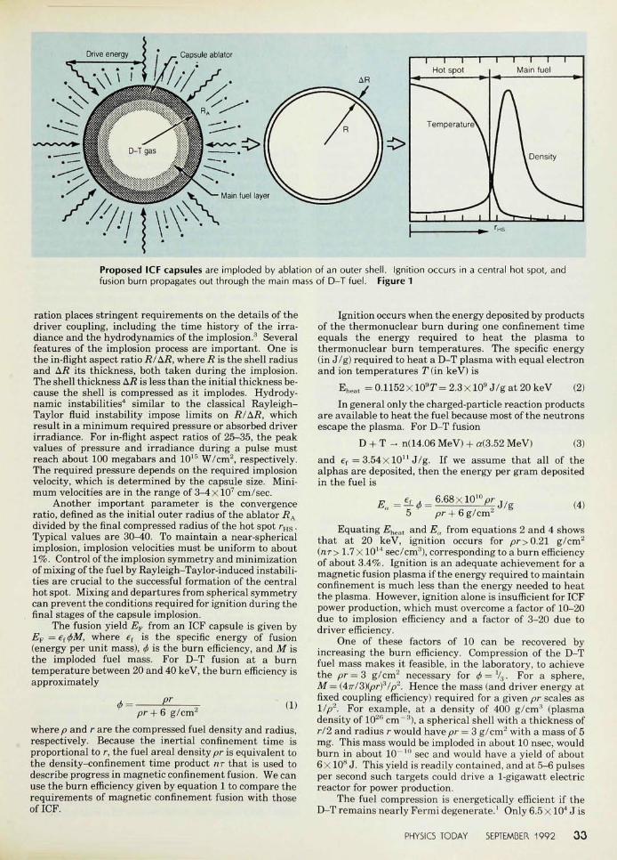
Implosion ond burn of ICF forgetsHigh-gain ICF targets have features similar to thoseshown in figure 1. These capsules consist of a sphericalshell filled with low-density (S1.0 mg/cm3) equimolardeuterium-tritium gas. The shell is composed of anablator and an inner region of D-T, which forms the mainfuel. Energy from a driver is rapidly delivered to theablator, which heats up and expands. As the ablatorexpands outward, the rest of the shell is forced inward toconserve momentum. The capsule behaves as a spherical,ablation-driven rocket.
The fusion fuel is imploded with a typical efficiency of5-15%. That is, 5-15% of the total absorbed energy goesinto the fuel. In its final configuration, the fuel is nearlyisobaric at pressures up to about 200 gigabars but consistsof two effectively distinct regions: a central hot spot,containing about 2-5% of the fuel, and a dense main fuelregion (the "cold fuel pusher"). Fusion begins in thecentral hot spot, and a thermonuclear burn front propa-gates rapidly outward into the main fuel, producing highgain.
The efficient arrangement of the fuel in this configu-
3 2 PHYSICS TODAY SEPTEMBER 1992 © 1992 Americon Insrirure of Physics
/''//I \ \\Y-\
t i l lHot spot
Temperature\
1 1 1 1
1 1 1 1 1Main fuel
1 \ Density
Proposed ICF capsules are imploded by ablation of an outer shell. Ignition occurs in a central hot spot, andfusion burn propagates out through the main mass of D-T fuel. Figure 1
ration places stringent requirements on the details of thedriver coupling, including the time history of the irra-diance and the hydrodynamics of the implosion.3 Severalfeatures of the implosion process are important. One isthe in-flight aspect ratio RlLR, where R is the shell radiusand Aif its thickness, both taken during the implosion.The shell thickness Ai? is less than the initial thickness be-cause the shell is compressed as it implodes. Hydrody-namic instabilities4 similar to the classical Rayleigh-Taylor fluid instability impose limits on R/hR, whichresult in a minimum required pressure or absorbed driverirradiance. For in-flight aspect ratios of 25-35, the peakvalues of pressure and irradiance during a pulse mustreach about 100 megabars and 1015 W/cm2, respectively.The required pressure depends on the required implosionvelocity, which is determined by the capsule size. Mini-mum velocities are in the range of 3-4 x 107 cm/sec.
Another important parameter is the convergenceratio, denned as the initial outer radius of the ablator RAdivided by the final compressed radius of the hot spot rHS.Typical values are 30-40. To maintain a near-sphericalimplosion, implosion velocities must be uniform to about1%. Control of the implosion symmetry and minimizationof mixing of the fuel by Rayleigh-Taylor-induced instabili-ties are crucial to the successful formation of the centralhot spot. Mixing and departures from spherical symmetrycan prevent the conditions required for ignition during thefinal stages of the capsule implosion.
The fusion yield EF from an ICF capsule is given byEF = ef<f>M, where ef is the specific energy of fusion(energy per unit mass), <f> is the burn efficiency, and M isthe imploded fuel mass. For D-T fusion at a burntemperature between 20 and 40 keV, the burn efficiency isapproximately
pr + 6 g/cm2 (1)
where p and r are the compressed fuel density and radius,respectively. Because the inertial confinement time isproportional to r, the fuel areal density pr is equivalent tothe density-confinement time product nr that is used todescribe progress in magnetic confinement fusion. We canuse the burn efficiency given by equation 1 to compare therequirements of magnetic confinement fusion with thoseof ICF.
Ignition occurs when the energy deposited by productsof the thermonuclear burn during one confinement timeequals the energy required to heat the plasma tothermonuclear burn temperatures. The specific energy(in J/g) required to heat a D-T plasma with equal electronand ion temperatures T (in keV) is
Eheat = 0.1152 xlO9T= 2.3 xlO9 J/g at 20 keV (2)In general only the charged-particle reaction products
are available to heat the fuel because most of the neutronsescape the plasma. For D-T fusion
D + T - n(14.06 MeV) + a(3.52 MeV) (3)and er = 3.54x10" J/g. If we assume that all of thealphas are deposited, then the energy per gram depositedin the fuel is
6.68x10"pr + 6 g/cm (4)
Equating £heat and Eu from equations 2 and 4 showsthat at 20 keV, ignition occurs for pr>0.21 g/cm2
(nr > 1.7 X10¹⁴ sec/cm3), corresponding to a burn efficiencyof about 3.4%. Ignition is an adequate achievement for amagnetic fusion plasma if the energy required to maintainconfinement is much less than the energy needed to heatthe plasma. However, ignition alone is insufficient for ICFpower production, which must overcome a factor of 10-20due to implosion efficiency and a factor of 3-20 due todriver efficiency.
One of these factors of 10 can be recovered byincreasing the burn efficiency. Compression of the D-Tfuel mass makes it feasible, in the laboratory, to achievethe pr = 3 g/cm2 necessary for (/>=%. For a sphere,M = (4Tr/3){prf/p2. Hence the mass (and driver energy atfixed coupling efficiency) required for a given pr scales as1/p2. For example, at a density of 400 g/cm;! (plasmadensity of 102fi cm"3), a spherical shell with a thickness ofr/2 and radius r would have pr = 3 g/cm2 with a mass of 5mg. This mass would be imploded in about 10 nsec, wouldburn in about 10"'" sec and would have a yield of about6 X 10* J. This yield is readily contained, and at 5-6 pulsesper second such targets could drive a 1-gigawatt electricreactor for power production.
The fuel compression is energetically efficient if theD-T remains nearly Fermi degenerate.' Only 6.5 X10⁴ J is
PHYSICS TODAY SEPTEMBER, 1992 33

required to compress 5 mg of fuel to 400 g/cm3 in this case,but the fuel remains too cold to burn during the inertialconfinement time. Thus high gain also requires hot-spotignition. To heat the entire 5 mg mass to 5 keV would re-quire 3.0 x 10⁶ J, and with an implosion efficiency of 5%the driver would need to deliver 6 x 10⁷ J. This is near theupper limit of what could be considered for a laboratorydriver, yet for a burn efficiency of % the target gain wouldonly be 10. (Target gain is defined as the thermonuclearyield divided by the driver energy delivered to the target.)
However, if the target can be ignited from a centralhot spot that contains about 2% of the total mass, then theenergy required to heat this mass is comparable to theenergy required to compress the remaining fuel. The hotspot forms during compression if the energy gained due toboth the PdV work from the implosion and charged-particle energy deposition exceeds the energy lost due toradiation and electron thermal conduction.3 For effectiveself-heating, the hot spot's areal density pr must becomparable to the alpha-particle range, which is about 0.3g/cm2 at an ignition temperature of 10 keV. Theformation of a hot spot within the cold main fuel is the keyscientific issue for ICF.
With a 2% hot spot, the total energy invested incompression and ignition of the 5-mg fuel mass would beabout 1.25 X10⁵ J. This implies a specific energy of about2.5 X107 J/g and an implosion velocity greater than2.3 X107 cm/sec. The driver size would be 2.5 x 10⁶ J, and again greater than 200 would be achieved. Target gains of40 or greater are generally required for most ICFapplications.
Direct and indirect driveICF implosions fall into two classes, known as direct drive
Laser beams *
Absorber/radiator
V
\Heavy-ion beams
Hohlraums for indirect-drive ICF use lasersin a and heavy-ion beams in b. The capsulesare imploded by x rays produced by thehohlraums. Figure 2
and indirect drive. (See the article by John H. Nuckolls inPHYSICS TODAY, September 1982, page 24.) Direct drive ischaracterized by laser beams or charged-particle beamsbeing incident on the fusion capsule. For indirect drivethe laser beams or charged-particle beams are firstabsorbed in a high-Z enclosure, a hohlraum, whichsurrounds the capsule. The hohlraum emits x rays, whichdrive the capsule implosion. (See figure 2.) For planartargets, up to 70-80% of the absorbed energy can beconverted to x rays. While such conversion efficiencieshave been demonstrated with lasers, the efficient genera-tion of x rays with ion beams requires minimum irra-diances of 1014-1015 W/cm2 for typical ion energies, whichrange from 30 MeV to 10 GeV, depending on ion mass.The primary challenge for ion beams has been andcontinues to be achieving the required focused intensity.(The article by Hogan, Bangerter and Kulcinski discussesthe status of programs to develop the heavy-ion and light-ion drivers.
Direct drive is more efficient in transporting driverenergy to the fusion capsule but is sensitive to the spatialquality of the illuminating radiation. Indirect drive hasthe advantage of being less sensitive to the details of the ir-radiating beams. In addition, implosions using x-ray-driven ablation are more stable hydrodynamically. Indi-rect drive, however, generates a large volume of plasmathrough which the laser must propagate and thus may bemore susceptible to laser-driven parametric instabilities.
Over the last ten years, significant progress has beenmade toward demonstrating the requirements for ignitionand high gain with both indirectly and directly driven ICFtargets.
The ICF program has used data from both laboratoryexperiments and underground nuclear explosion experi-ments at the Nevada Test Site. The latter program, calledHalite/Centurion and conducted jointly by LawrenceLivermore and Los Alamos National Laboratories, demon-strated excellent performance, putting to rest fundamen-tal questions about the basic feasibility of achieving highgain. The Halite/Centurion program performed experi-ments at higher energies than those available in thelaboratory. The NAS review of the ICF program conclud-ed that the Halite/Centurion experiments had met theirobjectives and that further uncertainties in achievingignition could best be studied in laboratory experiments.2Because of this recommendation, DOE has scheduled nomore experiments in the Halite/Centurion program. Thedetails of these experiments remain classified.
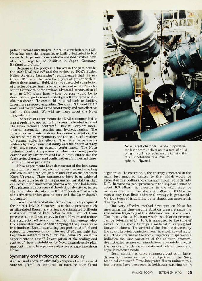
NovoMost indirect-drive laser experiments in the US have beendone on Livermore's 10-beam Nd:glass Nova laser, whoseexperimental area is shown5 in figure 3. Nova's potas-sium-dihydrogen-phosphate crystal arrays can efficientlyconvert the 1054-nm fundamental laser wavelength toeither its 2nd or 3rd harmonic.6 Most hohlraum experi-ments are conducted at the 3rd harmonic (351 nm) tocontrol laser-plasma interaction instabilities." Nova candeliver up to 40 kJ of 351-nm light in a 1-nsec pulse onto atarget. This energy can be delivered with a wide variety of
3 4 PHYSICS TODAY SEPTEMBER 1992
pulse durations and shapes. Since its completion in 1985,Nova has been the largest laser facility dedicated to ICFresearch. Experiments on radiation-heated cavities havealso been reported at facilities in Japan, Germany,England and China.8
Because of the progress achieved in the past decade,the 1990 NAS review2 and the review by DOE's FusionPolicy Advisory Committee9 recommended that the na-tion's ICF program focus on the physics of ignition with in-direct-drive targets. Subject to the successful completionof a series of experiments to be carried out on the Nova la-ser at Livermore, these reviews advocated construction ofa 1- to 2-MJ glass laser whose purpose would be todemonstrate ignition and modest-gain ICF targets withinabout a decade. To create this national ignition facility,Livermore proposed upgrading Nova, and NAS and FPACendorsed the proposal as the most timely and cost-effectivepath to this goal. We will say more about the NovaUpgrade later.
The series of experiments that NAS recommended asa prerequisite to upgrading Nova constitute what is calledthe Nova technical contract.2 They will explore laser-plasma interaction physics and hydrodynamics. Theformer experiments address hohlraum energetics, thecontrol of implosion symmetry and the scaling of a varietyof plasma collective effects. The latter experimentsaddress hydrodynamic instability and the effects of x-raydrive asymmetry on capsule performance. The Novatechnical contract experiments, which are being jointlycarried out by Livermore and Los Alamos, emphasize thefurther development and confirmation of numerical simu-lations of the experiments.
Nova experiments have demonstrated the hohlraumradiation temperatures, ablation pressures and couplingefficiencies required for ignition and gain on the proposedNova Upgrade. These parameters have been achievedwith acceptable levels of the parametric instabilities thatcan occur in the underdense plasma within the hohlraum.(The plasma is underdense if the electron density ne is lessthan the critical density nc = 1021 X "2(/im) cm"3 at whichthe refractive index goes to zero and the laser doesn'tpropagate.)
To achieve the radiation drive and symmetry requiredfor indirect-drive ICF, energy losses due to processes suchas stimulated Raman scattering and stimulated Brillouinscattering7 must be kept below 5-10%. Both of theseprocesses can redirect energy in the hohlraum and reducethe absorption efficiency. In addition, high-energy elec-trons generated from Landau damping of the plasma wavein stimulated Raman scattering can preheat the fuel andreduce its compressibility. The use of 351-nm light haskept these instabilities to a low level (below 5%) on Novaexperiments to date.10 Investigation of the scaling andcontrol of these instabilities for Nova-Upgrade-scale plas-mas continues to be a primary objective of experiments onNova.
Symmetry and hydrodynamic instabilityAs discussed above, to efficiently compress D-T to severalhundred g/cm3, the compression must be near Fermi
Nova target chamber. When in operation,ten laser beams deliver up to a total of 40 kjof light in a 1-nsec pulse onto a target withinthis 16-foot-diameter aluminumsphere. Figure 3
degenerate. To ensure this, the entropy generated in themain fuel must be limited to that which would begenerated by a 1-Mbar shock passing through solid densityD-T. Because the peak pressures in the implosion must beabout 100 Mbar, the pressure in the shell must beincreased from an initial shock of 1 Mbar to 100 Mbar insuch a way that little additional entropy is generated.3Various types of irradiating pulse shapes can accomplishthis objective.
One very effective method developed on Nova formeasuring the time-varying ablation pressure maps thespace-time trajectory of the ablation-driven shock wave.The shock velocity Vs, from which the ablation pressurecan be determined CPoc Fs
2), is measured by the time ofarrival of the shock through a material of varying butknown thickness. The arrival of the shock is detected bythe near-ultraviolet emission from the shock-heated mate-rial. The curvature of the shock trajectory in space-timeindicates the time variation of the ablation pressure.Sophisticated numerical simulations accurately predictthe results of such experiments and related x-ray andcapsule measurements.
Demonstration of drive symmetry control in laser-driven hohlraums is a primary objective of the Novatechnical contract.2 Time-integrated fluxes uniform to afew percent have been seen in hohlraum experiments in
PHYSICS TODAY SEPTEMBER 1992 3 5
which the compressed fuel region of an x-ray-drivenimplosion is imaged. The capsule convergence amplifiesthe flux uniformity, allowing flux nonuniformities smallerthan 2% to be measured.
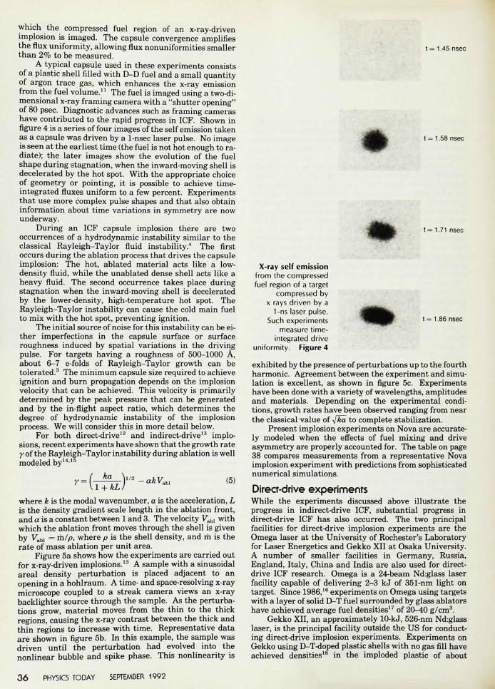
A typical capsule used in these experiments consistsof a plastic shell filled with D-D fuel and a small quantityof argon trace gas, which enhances the x-ray emissionfrom the fuel volume.1' The fuel is imaged using a two-di-mensional x-ray framing camera with a "shutter opening"of 80 psec. Diagnostic advances such as framing camerashave contributed to the rapid progress in ICF. Shown infigure 4 is a series of four images of the self emission takenas a capsule was driven by a 1-nsec laser pulse. No imageis seen at the earliest time (the fuel is not hot enough to ra-diate); the later images show the evolution of the fuelshape during stagnation, when the inward-moving shell isdecelerated by the hot spot. With the appropriate choiceof geometry or pointing, it is possible to achieve time-integrated fluxes uniform to a few percent. Experimentsthat use more complex pulse shapes and that also obtaininformation about time variations in symmetry are nowunderway.
During an ICF capsule implosion there are twooccurrences of a hydrodynamic instability similar to theclassical Rayleigh-Taylor fluid instability.4 The firstoccurs during the ablation process that drives the capsuleimplosion: The hot, ablated material acts like a low-density fluid, while the unablated dense shell acts like aheavy fluid. The second occurrence takes place duringstagnation when the inward-moving shell is deceleratedby the lower-density, high-temperature hot spot. TheRayleigh-Taylor instability can cause the cold main fuelto mix with the hot spot, preventing ignition.
The initial source of noise for this instability can be ei-ther imperfections in the capsule surface or surfaceroughness induced by spatial variations in the drivingpulse. For targets having a roughness of 500-1000 A,about 6-7 e-folds of Rayleigh-Taylor growth can betolerated.3 The minimum capsule size required to achieveignition and burn propagation depends on the implosionvelocity that can be achieved. This velocity is primarilydetermined by the peak pressure that can be generatedand by the in-flight aspect ratio, which determines thedegree of hydrodynamic instability of the implosionprocess. We will consider this in more detail below.
For both direct-drive12 and indirect-drive13 implo-sions, recent experiments have shown that the growth ratey of the Rayleigh-Taylor instability during ablation is wellmodeled by1415
I(5)
where k is the modal wavenumber, a is the acceleration, Lis the density gradient scale length in the ablation front,and a is a constant between 1 and 3. The velocity Fabl withwhich the ablation front moves through the shell is givenby Kbi = m//°> where p is the shell density, and rh is therate of mass ablation per unit area.
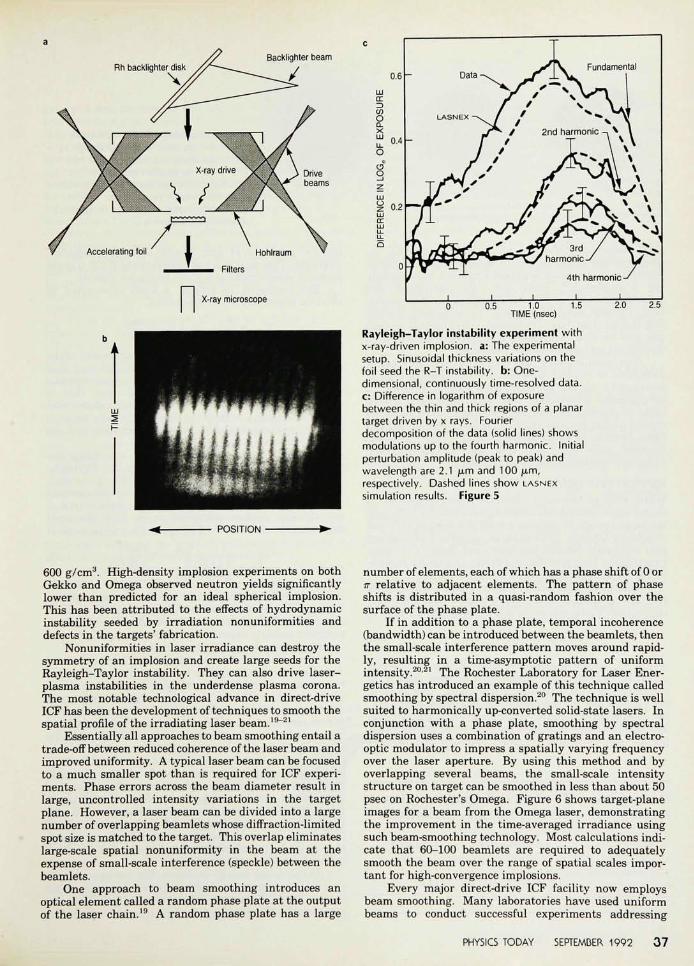
Figure 5a shows how the experiments are carried outfor x-ray-driven implosions.13 A sample with a sinusoidalareal density perturbation is placed adjacent to anopening in a hohlraum. A time- and space-resolving x-raymicroscope coupled to a streak camera views an x-raybacklighter source through the sample. As the perturba-tions grow, material moves from the thin to the thickregions, causing the x-ray contrast between the thick andthin regions to increase with time. Representative dataare shown in figure 5b. In this example, the sample wasdriven until the perturbation had evolved into thenonlinear bubble and spike phase. This nonlinearity is
t = 1.45 nsec
t = 1.58 nsec
m t = 1.71 nsec
t =1.86 nsec
X-ray self emissionfrom the compressedfuel region of a target
compressed byx rays driven by a
1-ns laser pulse.Such experiments
measure time-integrated drive
uniformity. Figure 4
exhibited by the presence of perturbations up to the fourthharmonic. Agreement between the experiment and simu-lation is excellent, as shown in figure 5c. Experimentshave been done with a variety of wavelengths, amplitudesand materials. Depending on the experimental condi-tions, growth rates have been observed ranging from nearthe classical value of -fka to complete stabilization.
Present implosion experiments on Nova are accurate-ly modeled when the effects of fuel mixing and driveasymmetry are properly accounted for. The table on page38 compares measurements from a representative Novaimplosion experiment with predictions from sophisticatednumerical simulations.
Direct-drive experimentsWhile the experiments discussed above illustrate theprogress in indirect-drive ICF, substantial progress indirect-drive ICF has also occurred. The two principalfacilities for direct-drive implosion experiments are theOmega laser at the University of Rochester's Laboratoryfor Laser Energetics and Gekko XII at Osaka University.A number of smaller facilities in Germany, Russia,England, Italy, China and India are also used for direct-drive ICF research. Omega is a 24-beam Nd:glass laserfacility capable of delivering 2-3 kJ of 351-nm light ontarget. Since 1986,16 experiments on Omega using targetswith a layer of solid D-T fuel surrounded by glass ablatorshave achieved average fuel densities17 of 20-40 g/cm3.
Gekko XII, an approximately 10-kJ, 526-nm Nd:glasslaser, is the principal facility outside the US for conduct-ing direct-drive implosion experiments. Experiments onGekko using D-T-doped plastic shells with no gas fill haveachieved densities18 in the imploded plastic of about
3 6 PHYSICS TODAY SEPTEMBER 1992
Rh backlighter disk\
Backlighter beam
0.6 -Fundamental
0.5 1.0TIME (nsec)
1.5 2.0 2.5
Rayleigh-Taylor instability experiment withx-ray-driven implosion, a: The experimentalsetup. Sinusoidal thickness variations on thefoil seed the R-T instability, b: One-dimensional, continuously time-resolved data.c: Difference in logarithm of exposurebetween the thin and thick regions of a planartarget driven by x rays. Fourierdecomposition of the data (solid lines) showsmodulations up to the fourth harmonic. Initialperturbation amplitude (peak to peak) andwavelength are 2.1 fim and 100 jam,respectively. Dashed lines show LASNEXsimulation results. Figure 5
POSITION
600 g/cm3. High-density implosion experiments on bothGekko and Omega observed neutron yields significantlylower than predicted for an ideal spherical implosion.This has been attributed to the effects of hydrodynamicinstability seeded by irradiation nonuniformities anddefects in the targets' fabrication.
Nonuniformities in laser irradiance can destroy thesymmetry of an implosion and create large seeds for theRayleigh-Taylor instability. They can also drive laser-plasma instabilities in the underdense plasma corona.The most notable technological advance in direct-driveICF has been the development of techniques to smooth thespatial profile of the irradiating laser beam.19"21
Essentially all approaches to beam smoothing entail atrade-off between reduced coherence of the laser beam andimproved uniformity. A typical laser beam can be focusedto a much smaller spot than is required for ICF experi-ments. Phase errors across the beam diameter result inlarge, uncontrolled intensity variations in the targetplane. However, a laser beam can be divided into a largenumber of overlapping beamlets whose diffraction-limitedspot size is matched to the target. This overlap eliminateslarge-scale spatial nonuniformity in the beam at theexpense of small-scale interference (speckle) between thebeamlets.
One approach to beam smoothing introduces anoptical element called a random phase plate at the outputof the laser chain.19 A random phase plate has a large
number of elements, each of which has a phase shift of 0 orir relative to adjacent elements. The pattern of phaseshifts is distributed in a quasi-random fashion over thesurface of the phase plate.
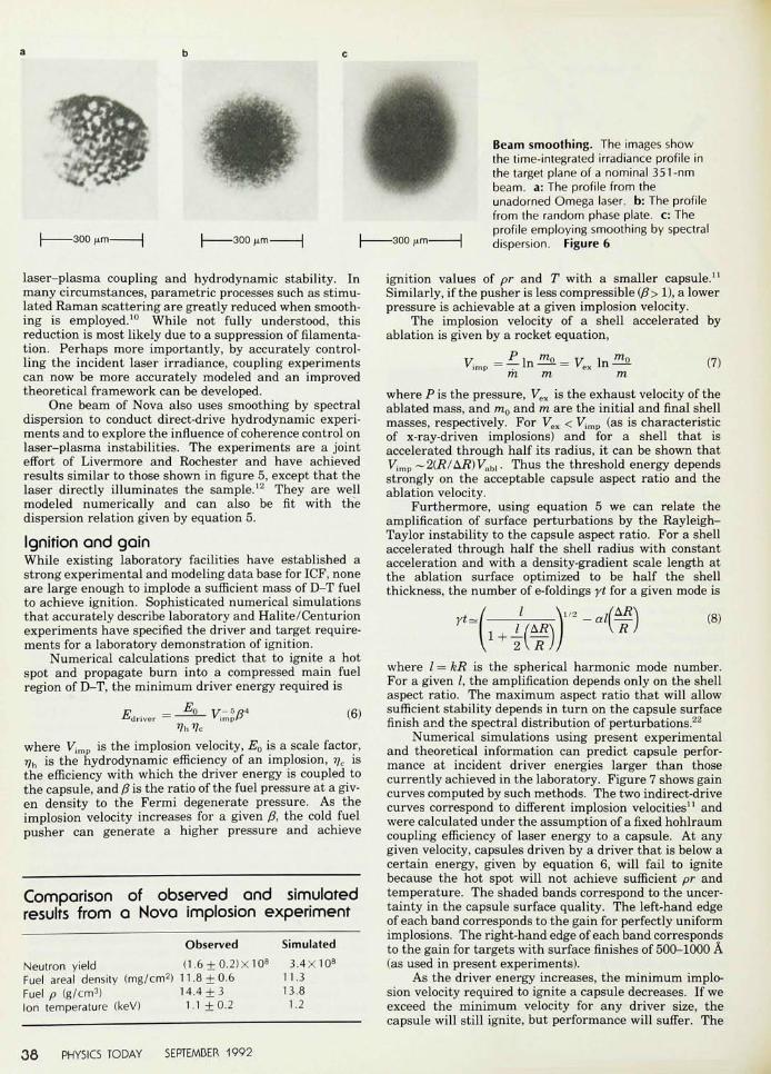
If in addition to a phase plate, temporal incoherence(bandwidth) can be introduced between the beamlets, thenthe small-scale interference pattern moves around rapid-ly, resulting in a time-asymptotic pattern of uniformintensity.2021 The Rochester Laboratory for Laser Ener-getics has introduced an example of this technique calledsmoothing by spectral dispersion.20 The technique is wellsuited to harmonically up-converted solid-state lasers. Inconjunction with a phase plate, smoothing by spectraldispersion uses a combination of gratings and an electro-optic modulator to impress a spatially varying frequencyover the laser aperture. By using this method and byoverlapping several beams, the small-scale intensitystructure on target can be smoothed in less than about 50psec on Rochester's Omega. Figure 6 shows target-planeimages for a beam from the Omega laser, demonstratingthe improvement in the time-averaged irradiance usingsuch beam-smoothing technology. Most calculations indi-cate that 60-100 beamlets are required to adequatelysmooth the beam over the range of spatial scales impor-tant for high-convergence implosions.
Every major direct-drive ICF facility now employsbeam smoothing. Many laboratories have used uniformbeams to conduct successful experiments addressing
PHYSICS TODAY SEPTEMBER 1992 3 7
-300 |um-
Beam smoothing. The images showthe time-integrated irradiance profile inthe target plane of a nominal 351-nmbeam, a: The profile from theunadorned Omega laser, b: The profilefrom the random phase plate, c: Theprofile employing smoothing by spectraldispersion. Figure 6
laser-plasma coupling and hydrodynamic stability. Inmany circumstances, parametric processes such as stimu-lated Raman scattering are greatly reduced when smooth-ing is employed.10 While not fully understood, thisreduction is most likely due to a suppression of filamenta-tion. Perhaps more importantly, by accurately control-ling the incident laser irradiance, coupling experimentscan now be more accurately modeled and an improvedtheoretical framework can be developed.
One beam of Nova also uses smoothing by spectraldispersion to conduct direct-drive hydrodynamic experi-ments and to explore the influence of coherence control onlaser-plasma instabilities. The experiments are a jointeffort of Livermore and Rochester and have achievedresults similar to those shown in figure 5, except that thelaser directly illuminates the sample.12 They are wellmodeled numerically and can also be fit with thedispersion relation given by equation 5.
Ignition and gainWhile existing laboratory facilities have established astrong experimental and modeling data base for ICF, noneare large enough to implode a sufficient mass of D-T fuelto achieve ignition. Sophisticated numerical simulationsthat accurately describe laboratory and Halite/Centurionexperiments have specified the driver and target require-ments for a laboratory demonstration of ignition.
Numerical calculations predict that to ignite a hotspot and propagate burn into a compressed main fuelregion of D-T, the minimum driver energy required is
F — oVhVc
V-J.P* (6)
where Vimp is the implosion velocity, Eo is a scale factor,ijh is the hydrodynamic efficiency of an implosion, TJC isthe efficiency with which the driver energy is coupled tothe capsule, and fi is the ratio of the fuel pressure at a giv-en density to the Fermi degenerate pressure. As theimplosion velocity increases for a given (5, the cold fuelpusher can generate a higher pressure and achieve
Comparison of observed and simulatedresults from a Nova implosion experiment
Observed SimulatedNeutron yield (1.6 ± 0.2)x 108 3.4X10⁸
Fuel areal density (mg/cm2) 11.8 + 0.6 11.3Fuel p (g/cm3) 14.4 + 3 13.8Ion temperature (keV) 1.1 ±0.2 1.2
ignition values of pr and T with a smaller capsule.11
Similarly, if the pusher is less compressible (/?> 1), a lowerpressure is achievable at a given implosion velocity.
The implosion velocity of a shell accelerated byablation is given by a rocket equation,
' imp — . l n
mm(7)
where P is the pressure, Vex is the exhaust velocity of theablated mass, and m0 and m are the initial and final shellmasses, respectively. For Vex < Vimp (as is characteristicof x-ray-driven implosions) and for a shell that isaccelerated through half its radius, it can be shown thatV,mp ~2CR/Ai?)Vabl. Thus the threshold energy dependsstrongly on the acceptable capsule aspect ratio and theablation velocity.
Furthermore, using equation 5 we can relate theamplification of surface perturbations by the Rayleigh-Taylor instability to the capsule aspect ratio. For a shellaccelerated through half the shell radius with constantacceleration and with a density-gradient scale length atthe ablation surface optimized to be half the shellthickness, the number of e-foldings yt for a given mode is
(8)
where / = kR is the spherical harmonic mode number.For a given I, the amplification depends only on the shellaspect ratio. The maximum aspect ratio that will allowsufficient stability depends in turn on the capsule surfacefinish and the spectral distribution of perturbations.22
Numerical simulations using present experimentaland theoretical information can predict capsule perfor-mance at incident driver energies larger than thosecurrently achieved in the laboratory. Figure 7 shows gaincurves computed by such methods. The two indirect-drivecurves correspond to different implosion velocities11 andwere calculated under the assumption of a fixed hohlraumcoupling efficiency of laser energy to a capsule. At anygiven velocity, capsules driven by a driver that is below acertain energy, given by equation 6, will fail to ignitebecause the hot spot will not achieve sufficient pr andtemperature. The shaded bands correspond to the uncer-tainty in the capsule surface quality. The left-hand edgeof each band corresponds to the gain for perfectly uniformimplosions. The right-hand edge of each band correspondsto the gain for targets with surface finishes of 500-1000 A(as used in present experiments).
As the driver energy increases, the minimum implo-sion velocity required to ignite a capsule decreases. If weexceed the minimum velocity for any driver size, thecapsule will still ignite, but performance will suffer. The
3 8 PHYSICS TODAY SEPTEMBER 1992
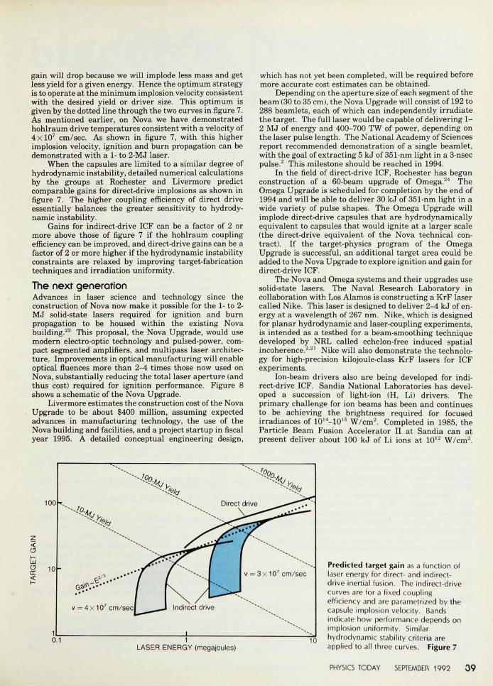
gain will drop because we will implode less mass and getless yield for a given energy. Hence the optimum strategyis to operate at the minimum implosion velocity consistentwith the desired yield or driver size. This optimum isgiven by the dotted line through the two curves in figure 7.As mentioned earlier, on Nova we have demonstratedhohlraum drive temperatures consistent with a velocity of4xlO7 cm/sec. As shown in figure 7, with this higherimplosion velocity, ignition and burn propagation can bedemonstrated with a 1- to 2-MJ laser.
When the capsules are limited to a similar degree ofhydrodynamic instability, detailed numerical calculationsby the groups at Rochester and Livermore predictcomparable gains for direct-drive implosions as shown infigure 7. The higher coupling efficiency of direct driveessentially balances the greater sensitivity to hydrody-namic instability.
Gains for indirect-drive ICF can be a factor of 2 ormore above those of figure 7 if the hohlraum couplingefficiency can be improved, and direct-drive gains can be afactor of 2 or more higher if the hydrodynamic instabilityconstraints are relaxed by improving target-fabricationtechniques and irradiation uniformity.
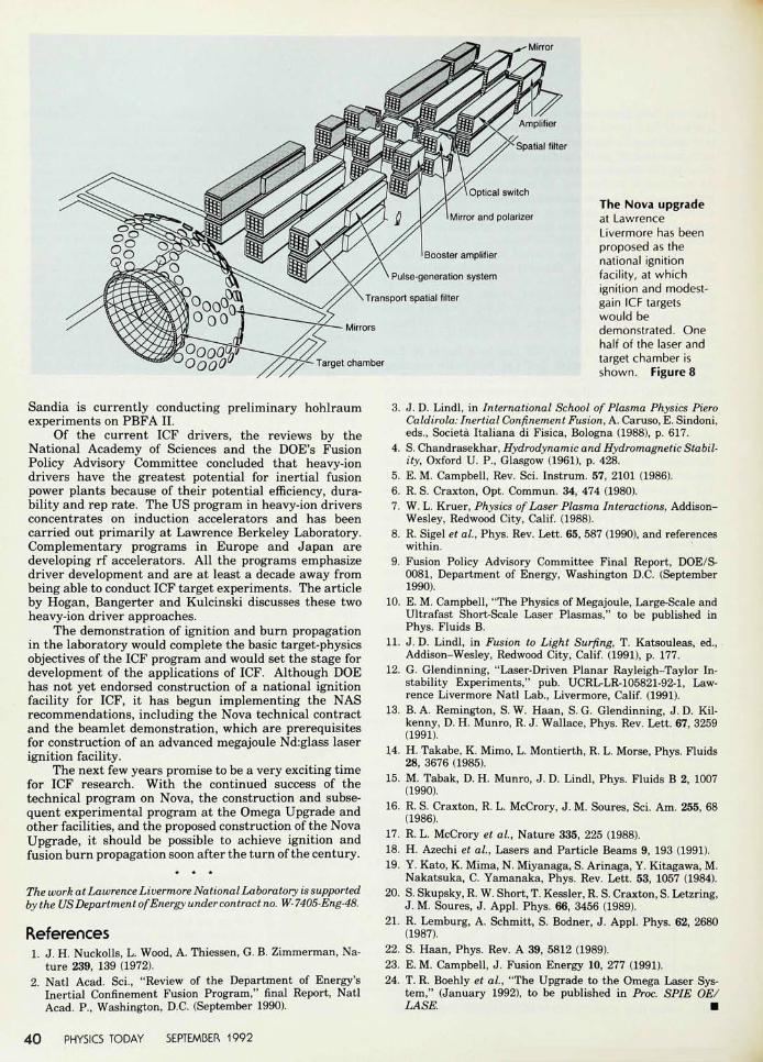
The next generationAdvances in laser science and technology since theconstruction of Nova now make it possible for the 1- to 2-MJ solid-state lasers required for ignition and burnpropagation to be housed within the existing Novabuilding.23 This proposal, the Nova Upgrade, would usemodern electro-optic technology and pulsed-power, com-pact segmented amplifiers, and multipass laser architec-ture. Improvements in optical manufacturing will enableoptical fluences more than 2-4 times those now used onNova, substantially reducing the total laser aperture (andthus cost) required for ignition performance. Figure 8shows a schematic of the Nova Upgrade.
Livermore estimates the construction cost of the NovaUpgrade to be about $400 million, assuming expectedadvances in manufacturing technology, the use of theNova building and facilities, and a project startup in fiscalyear 1995. A detailed conceptual engineering design,
which has not yet been completed, will be required beforemore accurate cost estimates can be obtained.
Depending on the aperture size of each segment of thebeam (30 to 35 cm), the Nova Upgrade will consist of 192 to288 beamlets, each of which can independently irradiatethe target. The full laser would be capable of delivering 1-2 MJ of energy and 400-700 TW of power, depending onthe laser pulse length. The National Academy of Sciencesreport recommended demonstration of a single beamlet,with the goal of extracting 5 kJ of 351-nm light in a 3-nsecpulse.2 This milestone should be reached in 1994.
In the field of direct-drive ICF, Rochester has begunconstruction of a 60-beam upgrade of Omega.24 TheOmega Upgrade is scheduled for completion by the end of1994 and will be able to deliver 30 kJ of 351-nm light in awide variety of pulse shapes. The Omega Upgrade willimplode direct-drive capsules that are hydrodynamicallyequivalent to capsules that would ignite at a larger scale(the direct-drive equivalent of the Nova technical con-tract). If the target-physics program of the OmegaUpgrade is successful, an additional target area could beadded to the Nova Upgrade to explore ignition and gain fordirect-drive ICF.
The Nova and Omega systems and their upgrades usesolid-state lasers. The Naval Research Laboratory incollaboration with Los Alamos is constructing a KrF lasercalled Nike. This laser is designed to deliver 2—4 kJ of en-ergy at a wavelength of 267 nm. Nike, which is designedfor planar hydrodynamic and laser-coupling experiments,is intended as a testbed for a beam-smoothing techniquedeveloped by NRL called echelon-free induced spatialincoherence.2-21 Nike will also demonstrate the technolo-gy for high-precision kilojoule-class KrF lasers for ICFexperiments.
Ion-beam drivers also are being developed for indi-rect-drive ICF. Sandia National Laboratories has devel-oped a succession of light-ion (H, Li) drivers. Theprimary challenge for ion beams has been and continuesto be achieving the brightness required for focusedirradiances of 1014-1015 W/cm2. Completed in 1985, theParticle Beam Fusion Accelerator II at Sandia can atpresent deliver about 100 kJ of Li ions at 1012 W/cm2.
100
C5
LJJoen<10
= 4x107cm/sec|
v = 3 x 107 cm/sec
Indirect drive
10.1 LASER ENERGY (megajoules)
10
Predicted target gain as a function oflaser energy for direct- and indirect-drive inertial fusion. The indirect-drivecurves are for a fixed couplingefficiency and are parametrized by thecapsule implosion velocity. Bandsindicate how performance depends onimplosion uniformity. Similarhydrodynamic stability criteria areapplied to all three curves. Figure 7
PHYSICS TODAY SEPTEMBER 1992 3 9
Mirror
Optical switch
Mirror and polarizer
Booster amplifier
Pulse-generation system
Transport spatial filter
Mirrors
Target chamber
The Nova upgradeat LawrenceLivermore has beenproposed as thenational ignitionfacility, at whichignition and modest-gain ICF targetswould bedemonstrated. Onehalf of the laser andtarget chamber isshown. Figure 8
Sandia is currently conducting preliminary hohlraumexperiments on PBFA II.
Of the current ICF drivers, the reviews by theNational Academy of Sciences and the DOE's FusionPolicy Advisory Committee concluded that heavy-iondrivers have the greatest potential for inertial fusionpower plants because of their potential efficiency, dura-bility and rep rate. The US program in heavy-ion driversconcentrates on induction accelerators and has beencarried out primarily at Lawrence Berkeley Laboratory.Complementary programs in Europe and Japan aredeveloping rf accelerators. All the programs emphasizedriver development and are at least a decade away frombeing able to conduct ICF target experiments. The articleby Hogan, Bangerter and Kulcinski discusses these twoheavy-ion driver approaches.
The demonstration of ignition and burn propagationin the laboratory would complete the basic target-physicsobjectives of the ICF program and would set the stage fordevelopment of the applications of ICF. Although DOEhas not yet endorsed construction of a national ignitionfacility for ICF, it has begun implementing the NASrecommendations, including the Nova technical contractand the beamlet demonstration, which are prerequisitesfor construction of an advanced megajoule Nd:glass laserignition facility.
The next few years promise to be a very exciting timefor ICF research. With the continued success of thetechnical program on Nova, the construction and subse-quent experimental program at the Omega Upgrade andother facilities, and the proposed construction of the NovaUpgrade, it should be possible to achieve ignition andfusion burn propagation soon after the turn of the century.
The work at Lawrence Livermore National Laboratory is supportedby the US Department of Energy under contract no. W-7405-Eng-48.
References1. J. H. Nuckolls, L. Wood, A. Thiessen, G. B. Zimmerman, Na-
ture 239, 139 (1972).2. Natl Acad. Sci., "Review of the Department of Energy's
Inertial Confinement Fusion Program," final Report, NatlAcad. P., Washington, D.C. (September 1990).
3. J. D. Lindl, in International School of Plasma Physics PieroCaldirola: Inertial Confinement Fusion, A. Caruso, E. Sindoni,eds., Societa Italiana di Fisica, Bologna (1988), p. 617.
4. S. Chandrasekhar, Hydrodynamic and Hydromagnetic Stabil-ity, Oxford U. P., Glasgow (1961), p. 428.
5. E. M. Campbell, Rev. Sci. Instrum. 57, 2101 (1986).6. R. S. Craxton, Opt. Commun. 34, 474 (1980).7. W. L. Kruer, Physics of Laser Plasma Interactions, Addison-
Wesley, Redwood City, Calif. (1988).8. R. Sigel et al, Phys. Rev. Lett. 65, 587 (1990), and references
within.9. Fusion Policy Advisory Committee Final Report, DOE/S-
0081, Department of Energy, Washington D.C. (September1990).
10. E. M. Campbell, "The Physics of Megajoule, Large-Scale andUltrafast Short-Scale Laser Plasmas," to be published inPhys. Fluids B.
11. J. D. Lindl, in Fusion to Light Surfing, T. Katsouleas, ed.,Addison-Wesley, Redwood City, Calif. (1991), p. 177.
12. G. Glendinning, "Laser-Driven Planar Rayleigh-Taylor In-stability Experiments," pub. UCRL-LR-105821-92-1, Law-rence Livermore Natl Lab., Livermore, Calif. (1991).
13. B. A. Remington, S. W. Haan, S. G. Glendinning, J. D. Kil-kenny, D. H. Munro, R. J. Wallace, Phys. Rev. Lett. 67, 3259(1991).
14. H. Takabe, K. Mimo, L. Montierth, R. L. Morse, Phys. Fluids28, 3676 (1985).
15. M. Tabak, D. H. Munro, J. D. Lindl, Phys. Fluids B 2, 1007(1990).
16. R. S. Craxton, R. L. McCrory, J. M. Soures, Sci. Am. 255, 68(1986).
17. R. L. McCrory et al., Nature 335, 225 (1988).18. H. Azechi et al., Lasers and Particle Beams 9, 193 (1991).19. Y. Kato, K. Mima, N. Miyanaga, S. Arinaga, Y. Kitagawa, M.
Nakatsuka, C. Yamanaka, Phys. Rev. Lett. 53, 1057 (1984).20. S. Skupsky, R. W. Short, T. Kessler, R. S. Craxton, S. Letzring,
J. M. Soures, J. Appl. Phys. 66, 3456 (1989).21. R. Lemburg, A. Schmitt, S. Bodner, J. Appl. Phys. 62, 2680
(1987).22. S. Haan, Phys. Rev. A 39, 5812 (1989).23. E. M. Campbell, J. Fusion Energy 10, 277 (1991).24. T. R. Boehly et al, "The Upgrade to the Omega Laser Sys-
tem," (January 1992), to be published in Proc. SPIE OE/LASE. *
4 0 PHYSICS TODAY SEPTEMBER 1992