progression of structural design approaches: working
TRANSCRIPT

Progression of Structural Design Approaches: Working Stress Design to Consequence-
Based Engineering
Naveed Anwar, Ph.D Executive Director, AIT Consulting
Affiliated faculty, School of Engineering and Technology (SET)
Asian Institute of Technology (AIT), Thailand
Fawad Ahmed Najam PhD Candidate, School of Engineering and Technology (SET)
Asian Institute of Technology (AIT), Thailand
ABSTRACT: Since the start of the formal approaches and procedures for carrying out the structural design,
there have been many developments in the underlying principles, and the implicit and explicit design
objectives. Starting with putting limits in the allowable, working stresses in various materials to achieve in-
direct safety factors, to more explicit consideration of different load and capacity factors, to the limit state
design principles, to the formulation of ultimate strength concepts, based on strain and deformation
limits. Then the recognition of the difference between brittle and ductile failure, and the introduction of
capacity based design approaches, leading to the more comprehensive performance design using high level
of analysis sophistication, and more explicit linkage between demand and performance. The recent
emphasis on risk based design, and a more integrated and holistic approach towards consequence based
engineering. This paper presents a brief account of the progression of these design approaches, and their
impact on the cost, performance and the final objective of public safety, as well as the related tools and
technologies to carry out such analysis. The paper also discusses the role of various design codes in this
progression.
1. BACKGROUND
Structural design is a systematic investigation of
the stability, strength and rigidity of structures.
The basic objective is to produce a structure
capable of resisting all applied loads without
failure and excessive deformations during its
anticipated life. The very first output of any
engineering design process is a description of
what is to be manufactured or built, what
materials are to be used, what construction
techniques are to be employed and an account of
all necessary specifications as well as dimensions
(which are usually presented in the form of
drawings). The second output is a rational
justification or explanation of the design proposal
developed based on either full-scale tests,
experiments on small physical models, or the
mathematical solution of detailed analytical
models representing the behavior of real
structures.
Perhaps the first ever achievement in the history
of structural design was the “confidence” by
virtue of which, early builders were able to
convince themselves that the resulting structure
could, indeed, be built and perform the intended
function for whole of its intended life. Hence the
job of very first engineers can be think of “to
create the confidence to start building.” (Addis
2003). Over the course of history, various
scientists, mathematicians and natural
philosophers presented revolutionary ideas which
resulted in improved understanding of structures
and built environment. With the developments in
different areas of practical sciences, the task of
building design was gradually divided among
more and more professionals depending upon
aesthetic considerations, intended functions,
materials, optimum utilization of space, lighting,
ventilation and acoustic preferences. The visual
appearance, sense of space and function (or the
architecture) became a distinct concern during the
15th and 16th centuries. About a century later,
designers first began to think about the load-
bearing aspects of structures in terms of self-
weight and other sources of expected loading.
Thinking separately about the role of individual
materials and resulting structures grew during the

late 17th and 18th centuries following Galileo's
work. The idea that the aesthetics should be given
proper importance independent of the materials
and load-bearing characteristics of the structure,
prevailed during the late 19th and early 20th
centuries.
Table 1 presents a brief timeline of some of the
major developments which led to modern
computational tools and methodologies for
analyzing and designing structures.
Table 1. Important historical developments related to
structural analysis and design.
Year
(CE) Development
1452–
1519
Earliest contributions from Leonardo da Vinci.
1638 Galileo Galilei examined the failure of simple
structures and published his book "Two New
Sciences".
1660 Robert Hooke presented the Hooke's law which
is the basis for elastic structural analysis.
1687 Isaac Newton published his document “Principia
Mathematica” containing the famous Newton's
laws of motion.
1750 Leonhard Euler and Daniel Bernoulli developed
Euler–Bernoulli beam theory. 1700–
1782
Daniel Bernoulli introduced the principle
of virtual work.
1707–
1783
Leonhard Euler developed the theory of
buckling of columns.
1826 Claude-Louis Navier published a document
analyzing the elastic behavior of structures.
1873 Carlo Alberto Castigliano presented his theorem
for computing displacement as partial derivative
of the strain energy.
1874 Otto Mohr formalized the idea of a statically
indeterminate structures.
1922 Timoshenko corrects the Euler-Bernoulli beam
equation and presented “Timoshenko’s Beam
Theory”
1936 Hardy Cross developed the moment distribution
method, an important innovation in the analysis
and design of continuous frames. 1941 Alexander Hrennikoff solved the discretization
of plane elasticity problems using the lattice
framework.
1942 R. Courant divided a domain into finite sub-
regions.
1956 J. Turner, R. W. Clough, H. C. Martin, and L. J.
Topp's introduces the term “finite-element
method” and published work which is widely
recognized as the first comprehensive treatment
of the method.
It is worth noting that historically, an
understanding of how structures work, was never
a phenomenon that require detailed knowledge of
mathematical procedures and laws of mechanics.
A common misconception is that various new
structural forms and shapes were first devised by
mathematicians (and experts of geometry) and
later taken up by builders and engineers. In fact,
the opposite is true, with perhaps just one
exception i.e. the hyperbolic paraboloid (whose
structural properties were discovered in 1930s). In
last few centuries, artists, sculptors and builders
have displayed a remarkable understanding and
skill of converting materials in to structures (some
of which are still standing today remarking the
testimony of their expertise).
Engineering profession has passed through a long
and still continuous phase of improvements,
modifications and breakthroughs in its various
research areas. The structural analysis and design
philosophies for new and existing buildings have a
fascinating history. This paper presents a review
of how various approaches for structural analysis
and design evolve over the course of time.
2. THE ROLE OF BUILDING CODES
A building code is a properly documented set of
rules and guidelines specifying the minimum
standards for constructed facilities. The main
purpose of building codes is to protect public
health, ensure safety and general welfare as they
directly govern the construction and occupancy of
buildings and other structures. The building code
becomes law of a particular jurisdiction when
formally enacted by the appropriate governmental
or private authority. The complete process of
planning, design, construction and operation of
buildings are guided by various building
standards, guidelines, codes and design aids.
Improving a building code quality in terms of
addressing real-life problems and enforcement
would directly help cities to improve their
environmental sustainability and disaster
resilience.
2.1 Historical Development
The earliest known written building code was the
Babylonian law of ancient Mesopotamia (also
known as the code of King Hammurabi who ruled
Babylon from 1792 BC to 1750 BC). It was found
in 1901 in what is now Khuzestan, Iran.
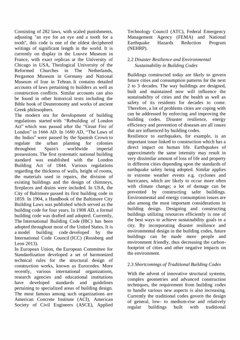
Consisting of 282 laws, with scaled punishments,
adjusting "an eye for an eye and a tooth for a
tooth", this code is one of the oldest deciphered
writings of significant length in the world. It is
currently on display in the Louvre Museum in
France, with exact replicas at the University of
Chicago in USA, Theological University of the
Reformed Churches in The Netherlands,
Pergamon Museum in Germany and National
Museum of Iran in Tehran. It contains detailed
accounts of laws pertaining to builders as well as
construction conflicts. Similar accounts can also
be found in other historical texts including the
Bible book of Deuteronomy and works of ancient
Greek philosophers.
The modern era for development of building
regulations started with “Rebuilding of London
Act” which was passed after the “Great Fire of
London” in 1666 AD. In 1680 AD, “The Laws of
the Indies” were passed by the Spanish Crown to
regulate the urban planning for colonies
throughout Spain's worldwide imperial
possessions. The first systematic national building
standard was established with the London
Building Act of 1844. Various regulations
regarding the thickness of walls, height of rooms,
the materials used in repairs, the division of
existing buildings and the design of chimneys,
fireplaces and drains were included. In USA, the
City of Baltimore passed its first building code in
1859. In 1904, a Handbook of the Baltimore City
Building Laws was published which served as the
building code for four years. In 1908 AD, a formal
building code was drafted and adopted. Currently,
The International Building Code (IBC) has been
adopted throughout most of the United States. It is
a model building code developed by the
International Code Council (ICC) (Rossberg and
Leon 2013).
In European Union, the European Committee for
Standardization developed a set of harmonized
technical rules for the structural design of
construction works, known as Eurocodes. More
recently, various international organizations,
research agencies and educational institutions
have developed standards and guidelines
pertaining to specialized areas of building design.
The most famous among such organizations are
American Concrete Institute (ACI), American
Society of Civil Engineers (ASCE), Applied
Technology Council (ATC), Federal Emergency
Management Agency (FEMA) and National
Earthquake Hazards Reduction Program
(NEHRP).
2.2 Disaster Resilience and Environmental
Sustainability in Building Codes
Buildings constructed today are likely to govern
future cities and consumption patterns for the next
2 to 3 decades. The way buildings are designed,
built and maintained now will influence the
sustainability of cities and the health as well as
safety of its residents for decades to come.
Therefore, a lot of problems cities are coping with
can be addressed by enforcing and improving the
building codes. Disaster resilience, energy
efficiency and prevention of diseases are all issues
that are influenced by building codes.
Resilience to earthquakes, for example, is an
important issue linked to construction which has a
direct impact on human life. Earthquakes of
approximately the same intensity may result in
very dissimilar amount of loss of life and property
in different cities depending upon the standards of
earthquake safety being adopted. Similar applies
to extreme weather events e.g. cyclones and
hurricanes, which are likely to occur more often
with climate change; a lot of damage can be
prevented by constructing safer buildings.
Environmental and energy consumption issues are
also among the most important considerations in
building design. Designing and constructing
buildings utilizing resources efficiently is one of
the best ways to achieve sustainability goals in a
city. By incorporating disaster resilience and
environmental design in the building codes, future
buildings can be made more people and
environment friendly, thus decreasing the carbon-
footprint of cities and other negative impacts on
the environment.
2.3 Shortcomings of Traditional Building Codes
With the advent of innovative structural systems,
complex geometries and advanced construction
techniques, the requirement from building codes
to handle various new aspects is also increasing.
Currently the traditional codes govern the design
of general, low- to medium-rise and relatively
regular buildings built with traditional

construction materials. They are not specifically
developed for tall buildings (having total height >
50 m). Moreover they are prescriptive in nature
with no explicit check on intended outcome. They
are also not expected to cover new structural
systems and shapes. Mostly, the prescribed
analysis and design procedures are based on
elastic theory neglecting some of the key aspects
of nonlinearity e.g. realistic demand distribution
etc. The intention to propose simplest and cook-
book type procedures doesn’t provide the
opportunity to exploit the potentials of recent
computing tools.
An important shortcoming of traditional building
codes (for seismic design) is that the performance
objectives are considered implicitly. The structure
is expected to resist minor earthquake without
damage, which is anticipated to occur several
times during the life of a building, without
damage to structural and non-structural
components. For design level earthquake, some
damage is allowed without causing loss of life and
for strongest earthquake, substantial damage is
allowed with a very low probability of collapse.
There is no explicit verification specified or
required in traditional building codes whether
these performance objectives are achieved or not.
3. TRADITIONAL APPROACHES TO
STRUCTURAL DESIGN
Loads are the actual physical excitations that may
act on the structure e.g. gravity, wind pressure,
dynamic and inertial effects, retention of liquids,
etc. Loads and its effects can lead to actions,
(which are basically the idealized forces acting on
the members) e.g. bending moment, shear force
etc. Actions can lead to deformations, which again
are idealized into various components such as
rotation, shortening, shearing angle etc.
Deformations cause strains which are basically
normalized deformation at the cross-section
material or fiber level. Strains may lead to stresses
in material fibers, which generally have a
correspondence with the strain through material
stress-strain model. The stresses can be summed
up in any particular manner to determine the
internal stress resultants.
In general, for a structure to be in static or
dynamic equilibrium, the internal stress resultants
should be in equilibrium with the actions due to
loads. An alternative way of looking at the same
linkage is that the actions cause stresses in the
member cross-sections. These stresses cause
strains, which can be summed-up to determine
deformations. So the relationships between
actions, deformations, strains, and stresses can be
used in many ways to solve the particular
problems at hand. Figure 1 illustrates this whole
process starting from loads and ending on stress
resultants. However it is worthwhile to note here
that there is an alternate (in fact reverse) approach
also, which starts with known materials response
at hand and ends up in determination of load
capacity (as illustrated in figure 2). The design
process can proceed in any one of the two ways.
The first one starting from the loads and ending at
the determination of stresses and strains and
complying with certain limit imposed on these and
other response quantities determined during the
process. The second approach is to start with the
known limits and capacities of the material
stresses, strains and workout the capacities of
sections, members and the structure and determine
the load carrying capacities. These calculated
load carrying capacities can then be compared
with applied loading directly with the provision of
an adequate factor of safety. This first process is
typically used in the traditional design of new
structures while the second one is used in
evaluation of existing structures, or for the
verification of design (especially in capacity-
based design). Each of the step in figure 2 is in
fact a sub-process comprising of several steps. For
example, the determination of the “Actions” for
member design from loads requires definition of
several load cases, load combinations, result
envelopes, actions sets etc.
Figure 3 illustrates various levels of structural
design based on the order of rigor used or
depending upon degree of sophistication in
computations, starting from rigorous analytical to
simplified empirical procedures including shortcut
methods using convenient-to-use design aids. The
theoretical structural response can often be
described through partial or complete differential
equations, and considerations for equilibrium.
These, procedures are however complex and
limited in applications, hence leading to the
development of semi-analytical, closed form
equations and solutions, developed and simplified
for particular applications. However, with the
advent of computers and latest computational
tools, rigorous numerical procedures were
developed using full three dimensional analysis
capabilities. These were implemented in various
forms, some simplified for adoption to early
computers with limited capabilities, and some for
specific applications. The design codes and
guidelines have traditionally provided equations,
charts, tables, graphs etc. derived from analytical
as well as physical tests to aid the structural
engineers in their routine design work. Moreover,
advance software tools are allowing practicing
engineers to simulate the structural behavior as
close as the actual physical structures however,
there is always a quest to develop simplified
procedures for wider applicability and
convenience. A typical structural design process
(as shown in figure 4) comprises of 3 phases.
a) Conceptual Design
b) Modeling and Analysis
c) Design and Detailing
The process starts with conceptual design
involving primary shape and form of structural as
well as selection of gravity and lateral load
structural systems. Complete architectural
functional plan is developed in this phase. The
next stage is to determine the expected response
of structure under all kinds of loadings. Trial
sections are assumed to start the process and an
idealized model is prepared using commercially
available computer software. The level of
sophistication in development of computer model
is a major consideration starting from fully
idealized elastic finite element model to a
complicated nonlinear model with specialized
inelastic components. The selection of analysis
procedure is another important decision to make.
Various codes and standards guide the practicing
engineers about both modeling and analysis in
terms of do’s and don’ts. The last phase comprises
of detailing and connection design in the light of
results obtained from analysis. Construction
drawings and complete plan are prepared for
sending to site engineers for proper on-site
implementation. In this section, 3 design
approaches will be discussed as follows.
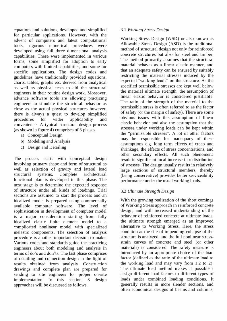
3.1 Working Stress Design
Working Stress Design (WSD) or also known as
Allowable Stress Design (ASD) is the traditional
method of structural design not only for reinforced
concrete structures but also for steel and timber.
The method primarily assumes that the structural
material behaves as a linear elastic manner, and
that an adequate safety can be ensured by suitably
restricting the material stresses induced by the
expected “working loads” on the structure. As the
specified permissible stresses are kept well below
the material ultimate strength, the assumption of
linear elastic behavior is considered justifiable.
The ratio of the strength of the material to the
permissible stress is often referred to as the factor
of safety (or the margin of safety). There are some
obvious issues with this assumption of linear
elastic behavior and also the assumption that the
stresses under working loads can be kept within
the “permissible stresses”. A lot of other factors
may be responsible for inadequacy of these
assumptions e.g. long term effects of creep and
shrinkage, the effects of stress concentrations, and
other secondary effects. All such phenomena
result in significant local increase in redistribution
of stresses. The design usually results in relatively
large sections of structural members, thereby
(being conservative) provides better serviceability
performance under the usual working loads.
3.2 Ultimate Strength Design
With the growing realization of the short comings
of Working Stress approach in reinforced concrete
design, and with increased understanding of the
behavior of reinforced concrete at ultimate loads,
the ultimate strength emerged as an improved
alternative to Working Stress. Here, the stress
condition at the site of impending collapse of the
structure is analyzed, and the full nonlinear stress-
strain curves of concrete and steel (or other
materials) is considered. The safety measure is
introduced by an appropriate choice of the load
factor (defined as the ratio of the ultimate load to
the working load and may vary from 1.2 to 2).
The ultimate load method makes it possible t
assign different load factors to different types of
loads under combined loading conditions. It
generally results in more slender sections, and
often economical designs of beams and columns,
particularly when high strength reinforcing steel
and concrete are used. However, the satisfactory
strength performance at ultimate loads does not
guarantee satisfactory serviceability performance
at the normal service loads. The designs
sometimes may result in excessive deflections and
crack widths under service loads, due to the
slender sections resulting from the use of high
strength materials.
3.3 Limit State Design Concept
Limit State Design concept is an advancement
over both Working Stress and Ultimate Strength
design approaches. This approach, unlike
Working Stress Design (which is based on
calculations at service load conditions only) and
Ultimate Load design (which is based on
calculations at ultimate load conditions only),
aims for a comprehensive and rational solution to
the design problem, by ensuring safety at ultimate
loads and serviceability at working loads. This
philosophy uses more than one safety factors
attempting to provide adequate safety at ultimate
loads as well as satisfactory serviceability
performance at service loads, by considering all
possible failure modes. The term “Limit State”
refers to a state of impending failure, beyond
which a structure ceases to perform its intended
function satisfactorily, in terms of either safety or
serviceability (i.e. it either collapses or becomes
unserviceable). So there are two types of limit
states, (a) Ultimate limit states (which deal with
strength, overturning, sliding, buckling and
fatigue fracture etc.) and (b) Serviceability limit
states (which deals with discomfort to occupancy
and/or malfunction, caused by excessive
deflection, crack width, vibration leakage and loss
of durability etc.). Table 2 below presents some of
the commonly used limit states in design of steel
and reinforced concrete structures.
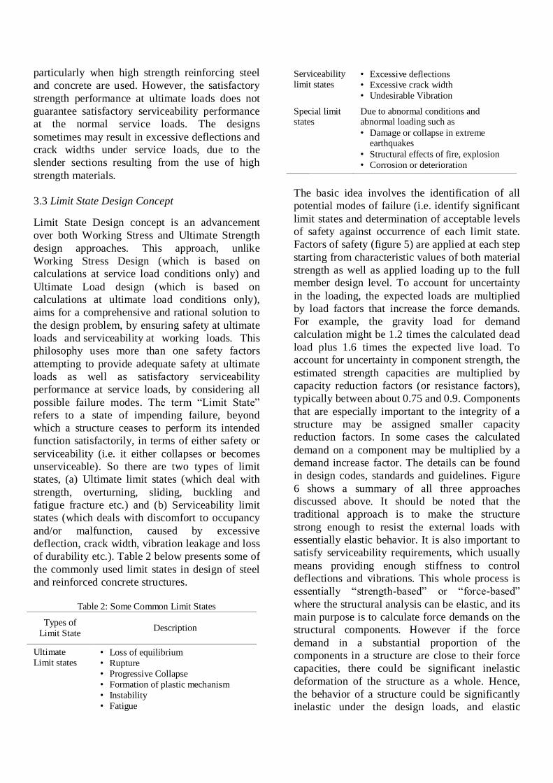
Table 2: Some Common Limit States
Types of
Limit State Description
Ultimate
Limit states • Loss of equilibrium
• Rupture
• Progressive Collapse
• Formation of plastic mechanism
• Instability
• Fatigue
Serviceability
limit states • Excessive deflections
• Excessive crack width
• Undesirable Vibration
Special limit states
Due to abnormal conditions and abnormal loading such as
• Damage or collapse in extreme earthquakes
• Structural effects of fire, explosion
• Corrosion or deterioration
The basic idea involves the identification of all
potential modes of failure (i.e. identify significant
limit states and determination of acceptable levels
of safety against occurrence of each limit state.
Factors of safety (figure 5) are applied at each step
starting from characteristic values of both material
strength as well as applied loading up to the full
member design level. To account for uncertainty
in the loading, the expected loads are multiplied
by load factors that increase the force demands.
For example, the gravity load for demand
calculation might be 1.2 times the calculated dead
load plus 1.6 times the expected live load. To
account for uncertainty in component strength, the
estimated strength capacities are multiplied by
capacity reduction factors (or resistance factors),
typically between about 0.75 and 0.9. Components
that are especially important to the integrity of a
structure may be assigned smaller capacity
reduction factors. In some cases the calculated
demand on a component may be multiplied by a
demand increase factor. The details can be found
in design codes, standards and guidelines. Figure
6 shows a summary of all three approaches
discussed above. It should be noted that the
traditional approach is to make the structure
strong enough to resist the external loads with
essentially elastic behavior. It is also important to
satisfy serviceability requirements, which usually
means providing enough stiffness to control
deflections and vibrations. This whole process is
essentially “strength-based” or “force-based”
where the structural analysis can be elastic, and its
main purpose is to calculate force demands on the
structural components. However if the force
demand in a substantial proportion of the
components in a structure are close to their force
capacities, there could be significant inelastic
deformation of the structure as a whole. Hence,
the behavior of a structure could be significantly
inelastic under the design loads, and elastic

analysis is not necessarily accurate. Next section
discusses a transition from this force-based
approach to a rather reverse notion known as
“Displacement-based Design”.
4. FROM FORCE-BASED DESIGN TO
DISPLACEMENT-BASED DESIGN
For structural design against lateral dynamic
loading (earthquakes and strong winds), there is a
high probability that a small earthquake will occur
during the life of the structure, and a low
probability of a large earthquake. For a small
earthquake, it seems reasonable to design the
structure to remain essentially elastic. However,
for a high intensity earthquake it is uneconomical
to design the structure to remain elastic and a
common practice is to allow substantial inelastic
behavior. Hence, for a large earthquake, the
elastic strength demand on a structure is likely to
exceed its strength capacity. However, the
maximum displacement of the structure may still
be acceptable, and although some structural
components become inelastic, the structure can
perform satisfactorily. For those components that
become inelastic the concern for design is
deformation, not strength. For satisfactory
performance, the deformation demand on an
inelastic component must usually be smaller than
its ductility limit (Powell 2010). In “Direct
Displacement-based Design”, a practicing
engineer starts with displacement as a basic input
(not forces) and determines back the maximum
allowable forces and capacities. However, in
“Capacity Design”, the force demands must be
calculated for those components that are required
to remain elastic. Demand-to-capacity (D/C)
ratios for those components which are allowed to
yield are determined in terms of displacements (or
deformations).
With the advent of all these ideas, the
deformation-based approach gained popularity as
it provides a clear interpretation of structure’s
condition and the results are physically more
meaningful. The quest of explicitly achieving the
design goals soon led the profession to what is
now called “Performance-based design” and is
discussed in next section.
5. PERFORMANCE-BASED DESIGN
As mentioned in section 2.3, an important
shortcoming of traditional building codes (for
seismic design) is that the performance objectives
are considered implicitly. It should be noted that
satisfying one design level does not ensure that
other design levels will be satisfied as well.
Serviceability design only ensures that deflections
and vibrations etc. for service loads are within
limits but provides no information whatsoever
about strength. Similarly strength design ensures
that a certain factor of safety against overload is
available within a member or a cross-section but
says nothing about what will happen if load
exceeds the design level (figure 7). Practicing
engineers started to realize the importance of a
methodology focusing rigorously on achieving the
intended performance instead of fulfilling definite
rules to implicitly account for desired
functionality.
This realization has led to a relatively recent
paradigm shift in current approach towards
analysis and design of building structures, termed
in latest guidelines and standards as
“Performance-based Design (PBD)”. It refers to
the methodology in which structural design
criteria are expressed in terms of achieving a set
of performance objectives. It ensures that the
structure as a whole reaches a specified demand
level including both service and strength design
levels. It is the practice of thinking and working in
terms of ends rather than means. Here, owners and
engineers can work together to achieve the best
possible balance between construction costs and
structure’s ultimate performance (figure 8). The
basic idea is to relate the level of structure’s
damage to measurable engineering demand
parameters. It is similar to associating “numbers,
which can be crunched” with “physical extent of
damage”. For example, the performance
objectives set for a building can be related to the
level of its damage, which in turn, can be related
to its displacements and drift values. Although it
is not always possible to quantify the damage as it
is greatly influenced by a lot of other factors,
mostly displacements and drifts serve as a
reasonable indicators. That’s why sometimes
engineers also use the term “displacement-based
design” in place of PBD (which ideally should be
thought of as a subset of PBD because the
performance target can be any response parameter
attached to a certain threshold). Since the
approach gained popularity among engineering
community around a decade ago, there have been
a lot of attempts to develop procedures to
correlate damage of various structural systems to
response quantities taking into account possible
uncertainties and ground motion characteristics.
This approach requires the structural designers to
go beyond code’s cook-book prescriptions and
make them able to predict structure’s response in
case of future extreme events. This also requires
sophisticated structural modeling and simulation
using state-of-the-art computer software, and
sometimes laboratory testing also. While
earthquake engineers are sufficiently contributing
and exploiting the potentials of this design
philosophy, it can also be applied to floods,
hurricane and other natural disasters.
Usually the process starts with analyzing a linear
elastic model for code-based design loadings. The
structure is initially designed to remain elastic
under a lower level of intended loading termed as
design-basis load. Then a nonlinear computer
model is prepared representing a real building
capable of going in to nonlinear range depending
upon given inelastic behavior. A nonlinear finite
element model requires far more expertise,
engineering judgment and skills compared to
linear elastic model. Special modeling
considerations and their justifications for each
structural component are necessary to simulate
actual behavior of buildings under expected loads.
For earthquake analysis, ground motion
accelerograms are selected based on predefined
criteria (site conditions, magnitude, source-to-site
distance, soil-type and fault-type etc.) and scaled
to MCE level spectrum (which is taken as 1.5
times DBE level spectrum, as recommended by
Tall Buildings Initiative (TBI) guidelines). A full
nonlinear response history analysis (NLRHA) is
performed for a suit of 7 ground motions and an
average of peak response quantities from all
ground motions are extracted. This is the most
cumbersome part in whole process which may
take several days for a tall building. The analysis
itself may take more than 10 hours to complete for
one ground motion (on a 3.10 GHz processor with
8 GB RAM) depending upon total duration or
earthquake, time step of analysis and structure’s
complexity. The process of results extraction,
processing and converting them in to presentable
form takes additional time. The last stage of the
process is results interpretation i.e. converting
“numbers we have already crunched” in to
“meaningful outcome for decision-making”.
ASCE 41-06 provides acceptance criteria in terms
of plastic rotations and other demand parameters
for each member type, analysis type and for each
performance level (Immediate Occupancy, Life
Safety and Collapse Prevention). Since each of
these performance levels are associated with a
physical description of damage, obtained results
are compared and evaluated based on this criteria
to get performance insight.
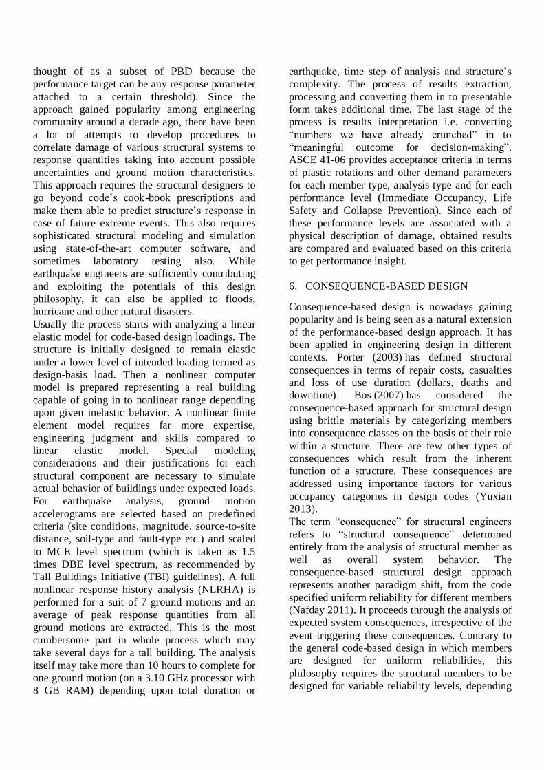
6. CONSEQUENCE-BASED DESIGN
Consequence-based design is nowadays gaining
popularity and is being seen as a natural extension
of the performance-based design approach. It has
been applied in engineering design in different
contexts. Porter (2003) has defined structural
consequences in terms of repair costs, casualties
and loss of use duration (dollars, deaths and
downtime). Bos (2007) has considered the
consequence-based approach for structural design
using brittle materials by categorizing members
into consequence classes on the basis of their role
within a structure. There are few other types of
consequences which result from the inherent
function of a structure. These consequences are
addressed using importance factors for various
occupancy categories in design codes (Yuxian
2013).
The term “consequence” for structural engineers
refers to “structural consequence” determined
entirely from the analysis of structural member as
well as overall system behavior. The
consequence-based structural design approach
represents another paradigm shift, from the code
specified uniform reliability for different members
(Nafday 2011). It proceeds through the analysis of
expected system consequences, irrespective of the
event triggering these consequences. Contrary to
the general code-based design in which members
are designed for uniform reliabilities, this
philosophy requires the structural members to be
designed for variable reliability levels, depending
upon their contribution in causing adverse system
consequences. The aim is to ensure general
system integrity and prevent structural collapse in
case of any unforeseen causal event. The
consequence factors ranging between 0 and 1 are
used for determining a member’s contribution
towards adverse system response. Global safety
depends on the safety of all members against local
failures as well as on the system response or
consequences resulting from local failures. While
the probabilistic demand oriented member designs
in current codes deal with the primary design, the
consequence-based approach implements the
secondary design for the system using member
consequence factor as an additional partial factor
on the resistance side of the member design
equations (Nafday 2011).
7. CONCLUSIONS
This paper presents a brief overview and evolution
of various structural design approaches and
philosophies starting from Working Stress Method
to Performance-based and Consequence-based
approaches. These latest design philosophies may
not be a guarantee (of structural safety) in itself,
but are a successful attempt to answer “What will
happen if…???” type questions. These novel
ideas coupled with advance computational tools
have taken structural engineering practice to an
advance level of creating optimized, reliable and
cost- effective structures. The long asked question
of “Is my structure safe?” can now suitably
transformed into an optimization problem which
can be answered with the help of smart decision-
making tools and techniques for consequence
evaluation and assessment of large systems of
structures subjected to damaging loading. The
profession is ready to embrace rapid
advancements in computational and technological
fields. It is ready to transform the art of living and
to shape the future of human civilization. The
story which started with Hammurabi’s code still
has a long way to go. It is a never ending story, of
our survival against disasters, of our great
civilizations and collective intellect, and to say the
least, of our daily lives.
8. REFERENCES
Bill Addis. 2003. Inventing a history for structural
engineering design. In Proceedings of the First International
Congress on Construction History, Madrid, 20th-24th
January 2003, ed. S. Huerta, Madrid: I. Juan de Herrera,
SEdHC, ETSAM, A. E. Benvenuto, COAM, F. Dragados.
Jim Rossberg, Roberto T. Leon. 2013. Evolution of Codes in
the USA. Accessed at http://www.nehrp.gov/. USA.
Powell, G. H. 2010. Modeling for structural analysis: behavior and basics. Computers and Structures. USA.
Porter Keith A. 2003. An overview of PEER’s performance-
based earthquake engineering methodology. In Ninth
international conference on applications of statistics and
probability in civil engineering (ICASP9). San Francisco.
P.P. Bos. 2007. Towards a combined probabilistic or
consequence-based safety approach of structural glass
members, HERON, 52 (1/2)
Hu Yuxian. 2003. Application of consequence-based design
criteria in regions of moderate seismicity. Earthquake
Engineering and Engineering Vibration, Vol. 2, No. 1,
Article ID: 1671-3664(2003)01-0035-04
Avinash M. Nafday. 2011. Consequence-based structural
design approach for black swan events. Structural Safety,
Volume 33, Issue 1, Pages 108-114, ISSN 0167-4730,
http://dx.doi.org/10.1016/j.strusafe.2010.09.003.

Figure 1: Loads and Stress Resultants
Figure 2: The Response and Design
Figure 3: Various Design Levels
Applied Loads
Building Analysis
Member Actions
Cross-Section Actions
Material Stress/Strain
Material Response
Section Response
Member Response
Building Response
Load Capacity
Fro
m L
oads
to
Mat
eria
lsF
rom M
aterials to L
oad C
apacity
Rigorous Analytical
Semi Analytical
Rigorous Numerical
Simplified Numerical
Specified Procedures
Partial Differential Equations
Closed Form with
Approximations
Full 3D, Nonlinear, Inelastic
Dynamic FEA
2D/3D Linear Static
FEA/Matrix
Equations, Charts, Tables, Rules, Limits

Figure 4: An Overview of Structural Design Process
Figure 5: Safety Factors
Figure 6: Proportioning for Safety
Co
nce
ptu
al
De
sig
n
Mo
de
lin
g a
nd
A
na
lysi
sD
esig
n a
nd
D
eta
iling
NO
YES
Architectural
Functional Plan
Structural System
Trial Sections
Modeling
Analysis
Revise Sections
Final Design
Member Design
Acceptable
Connection Design
Detailing
Characteristic value of
material basic strength Design Strength
Design member
capacity
Characteristic value of
LoadDesign load
Design member
capacity
Ym Yb
Yf Ya
Verification
Yi
S > A
S
FOSA
Working Strength DesignS
FOSA FOS
s
L
•Ultimate Strength Design•Limit State Design•Partial FOS Design
S A FOS
Load Factor Design
• A = Actions due to loads
• S = Strength of member
• FOS = Factor of safety
Material safety Factor Member Factor
Structural Analysis
Factor
Structure
Factor
Load Factor

Figure 7: From Serviceability to Performance
Figure 8: Performance-based Design Approach
Allowable
material
Control on
deformation
limits for design
loads
Material failure
criteria
Section capacity
for factored
loads
Ductility
considerations
Deformation
capacity
Load Capacity at
large
deformations
Extraordinary
load
considerations
Serviceability
Ability
Strength
Design
Performance
Design
Client Designer
Independent Engineer
Guidelines: PEER, TBI, ATC, FEMA, CTBUH, etc.
What to expect?
How to achieve this kind of approach?
Knowledge – Skills – Tools