project design and surface treatment plan
TRANSCRIPT

[FINAL]
Eldorado – Lugo – Mohave Series Capacitor Project
Project Design and Surface Treatment Plan
Prepared for Southern California Edison
2244 Walnut Grove Avenue Rosemead, CA 91770
March 2021
Prepared By
Beta Engineering
Applicable agencies Bureau of Land Management National Park Service California Public Utilities Commission

Final Project Design and Surface Treatment Plan Page i
CONTENTS
1 INTRODUCTION .......................................................................................................................... 1
1.1 Project Description .................................................................................................................... 1 1.2 Project Location and Environment ............................................................................................ 2 1.3 Lead, Cooperating, and Consulting Agencies ............................................................................ 3
1.3.1 Lead Agencies ............................................................................................................... 3 1.3.2 Cooperating Agencies ................................................................................................... 3 1.3.3 Consulting Agencies ..................................................................................................... 3
2 MITIGATION MEASURES ............................................................................................................. 4
3 SURFACE TREATMENT METHODS ................................................................................................ 5
3.1 New 500 kV Mid-line Series Capacitors and Associated Facilities ............................................ 5 3.1.1 New Fiber Optic Repeater Facilities and Associated Facilities ..................................... 6
3.2 Modification of Existing Transmission, Subtransmission, and Distribution Facilities ............... 7 3.3 Optical Ground Wire ................................................................................................................. 7 3.4 Modifications within the Existing Eldorado, Lugo, and Mohave Substations ........................... 8 3.5 Construction Yards, Staging Areas, and Material and Equipment Storage Areas ..................... 8 3.6 Construction Yards, Staging Areas, and Material and Equipment Storage Areas ..................... 9 3.7 Surface Treatment Maintenance ............................................................................................ 10
Appendix A Project Feature Layouts and Visual Simulations Appendix B Bureau of Land Management Standard Color Chart CC-001
FIGURES Figure A-1. Typical Mid-Line Series Capacitor Layout ....................................................................... A-1 Figure A-2. Typical Mid-Line Series Capacitor Profile ....................................................................... A-2 Figure A-3. Typical Site Plan for the Fiber Optic Repeater Sites ....................................................... A-3 Figure A-4. Typical Elevation for the Fiber Optic Repeater Sites ...................................................... A-4 Figure A-5. KOP 3 Existing View ........................................................................................................ A-5 Figure A-6. KOP 3 Visual Simulation .................................................................................................. A-6 Figure A-7. KOP 4 Existing View ........................................................................................................ A-7 Figure A-8. KOP 4 Visual Simulation .................................................................................................. A-8 Figure A-9. KOP 2 Existing View ........................................................................................................ A-9 Figure A-10. KOP 2 Visual Simulation ................................................................................................ A-10 Figure A-11. KOP 5 Existing View ...................................................................................................... A-11 Figure A-12. KOP 5 Visual Simulation ................................................................................................ A-12 Figure A-13. KOP 6 Existing View ...................................................................................................... A-13 Figure A-14. KOP 6 Visual Simulation ................................................................................................ A-14 Figure A-16. KOP 1 Visual Simulation ................................................................................................ A-16

Final Project Design and Surface Treatment Plan Page ii
TABLES Table 1 New Temporary Staging Area/laydown Yard ..................................................................... 9

Final Project Design and Surface Treatment Plan Page iii
Acronyms and Abbreviations
ANSI American National Standards Institute BLM Bureau of Land Management CEQA California Environmental Quality Act CPUC California Public Utilities Commission HRRP Habitat Restoration and Revegetation Plan kV Kilovolt KOP Key Observation Point LST Lattice steel tower MEER Mechanical Electrical Equipment Room MM Mitigation Measure NPS National Park Service OHGW Overhead ground wire OPGW Optical ground wire Plan Project Design and Surface Treatment Plan Project Eldorado-Lugo-Mohave Series Capacitor Project ROW Right-of-way SCE Southern California Edison TSP Tubular steel poles VRM Visual Resource Management

Final Project Design and Surface Treatment Plan Page 1
1 Introduction
Southern California Edison (SCE) is proposing to construct two new mid-line series capacitors, replace the existing ground wire with a new optical ground wire (OPGW), install fiber optic repeater facilities, and make other improvements to increase reliability, capacity, and power flow along three existing 500-kilovolt (kV) transmission lines under the Eldorado-Lugo-Mohave Series Capacitor Project (Project) extending from California to Nevada. This Project Design and Surface Treatment Plan (Plan) has been prepared as required by the California Environmental Quality Act (CEQA) Mitigation Measure (MM) AES-1 Minimize Visual Contrast in Project Design and National Environmental Policy Act MM RW-1. The purpose of the Plan is to specify siting, placement, and other design considerations to be employed in order to minimize Project contrast.
The SCE Project consists of constructing new facilities along the existing 500 kV transmission lines. The specific project components that may be affected in this Plan are addressed in Section 2 below.
1.1 Project Description
This Project will increase capacity and power flow between SCE’s existing Eldorado, Lugo, and Mohave Substations to safely deliver renewable power to the Los Angeles Basin from the Eldorado and Mohave Substations. SCE’s Proposed Project would:
• Construct 2 new 500-kilovolt (kV) mid-line series capacitors (i.e., the proposed Newberry Springs Series Capacitor and Ludlow Series Capacitor) and associated equipment.
• Provide 2 communication paths between the series capacitor sites.
o Install approximately 2 miles of overhead and 700 feet of underground telecommunications facilities as one path to connect the proposed series capacitors to SCE’s existing communication system.
o Install approximately 2 miles of underground telecommunications facilities as a second communication path to connect the series capacitors to SCE’s existing communication system.
• Provide station light and power to the proposed series capacitors by extending and/or rerouting existing lines to create approximately 2 miles of overhead and 700 feet of underground 12 kV distribution circuits. (The new distribution poles would support overhead telecommunication facilities as well as the electric distribution lines.)
• Construct 3 new fiber optic repeater facilities (Barstow, Kelbaker, and Lanfair) within the Lugo-Mohave right-of-way (ROW).
• Install distribution lines for light and power at the 3 proposed fiber optic repeater sites.
• Install underground telecommunications facilities from existing transmission structures to the Barstow, Kelbaker, and Lanfair fiber optic repeater sites.
• Address 16 potential overhead clearance discrepancies at 14 locations by:
o Relocating, replacing, or modifying existing transmission, subtransmission, and distribution facilities at approximately 12 locations along the Eldorado-Lugo, Eldorado-Mohave, and Lugo-Mohave 500 kV transmission lines to address 14 of the overhead clearance discrepancies.

Final Project Design and Surface Treatment Plan Page 2
Tower modifications would include raising 9 towers up to approximately 18.5 feet by inserting new lattice-steel sections in tower bodies.
o Performing minor grading at 2 locations along the Lugo-Mohave 500 kV transmission line to address 2 of the overhead clearance discrepancies.
• Install approximately 232 miles of optical ground wire (OPGW) (approximately 59 miles on the Eldorado-Mohave transmission line and approximately 173 miles on the Lugo-Mohave transmission line and approximately 3 miles of underground telecommunications facilities in the vicinity of the Mohave Substation).
• Modify and strengthen the ground wire peak of existing suspension towers where OPGW splices would occur. (Some of these towers would also require minor modifications to the steel in the tower body.)
• Install approximately 2,000 feet of underground telecommunications facilities within the existing Lugo, Mohave, and Eldorado substations.
• Within Lugo Substation, perform modifications on the existing series capacitors and install new terminating equipment and remove 2 existing tubular steel poles (TSP) and install 2 new TSPs on the Eldorado-Lugo and Lugo-Mohave 500 kV transmission lines.
• Within the Eldorado Substation, perform modifications on the existing series capacitors and upgrade the terminal equipment on the Eldorado-Lugo 500 kV transmission line.
• Within the Mohave Substation, replace existing series capacitors on the Lugo-Mohave 500 kV transmission line and install new terminal equipment on the Eldorado-Mohave and Lugo-Mohave 500 kV transmission lines.
• Install (if necessary) cathodic protection on approximately 60 miles of SoCalGas’s natural gas pipelines parallel to SCE’s Lugo-Mohave 500 kV transmission line and on other pipelines as needed.
1.2 Project Location and Environment
The Project is located in San Bernardino County, California and Clark County, Nevada, and includes activities on private, state, and federal lands. It crosses the unincorporated communities of Lucerne Valley in California and Searchlight and Laughlin in Nevada. In San Bernardino County, portions of the Project also cross the incorporated City of Hesperia. The Project crosses lands under the jurisdiction of the Bureau of Land Management (BLM), the National Park Service (NPS), the Bureau of Reclamation, the Department of Defense, and state lands managed by the California State Lands Commission.
The Project is located within a Basin and Range geomorphic province, which is characterized by mountain ranges that generally run north to south with nearly flat valleys in between. In addition, the entire Project is located within the Mojave Desert with vegetation characterized by the dominance of creosote bush (Larrea tridentata) shrubs, although other shrubs and emergent trees may be present at low densities. The Project area is sparsely vegetated except within linear washes or creosote groupings. The visual aspect of the Mohave Desert is characterized by rugged dark hued mountains and light, sandy-colored plains and bajadas. Vegetation is generally dark in color due to the dominance of creosote.

Final Project Design and Surface Treatment Plan Page 3
1.3 Lead, Cooperating, and Consulting Agencies
1.3.1 Lead Agencies
Lead agencies have discretionary approval over the Project and are responsible for reviewing aspects of the measures documented in this Plan. The California Public Utilities Commission (CPUC) is California’s lead agency responsible for compliance with the CEQA for Project areas located on non-federal lands. The CPUC issued an Initial Study/Mitigated Negative Declaration for the Project under CEQA. The BLM Desert District Office is the federal lead agency responsible for compliance with the National Environmental Policy Act for Project areas located on federal lands.
Through the BLM’s land use planning process, as described in BLM Manual 8410-1, Visual Resource Management (VRM) objectives are established based on consideration of the allowable levels of disturbance (i.e. visual contrast and noticeability). VRM Objectives are defined as: Class I – Preserve the existing character of the landscape; Class II – Retain the existing character of the landscape; Class III – Partially retain the existing character of the landscape; and Class IV – Provide for management activities allowing major modifications to dominate the view and be the major focus of viewer attention. However, every attempt should be made to minimize the impacts of these activities through careful location, minimal disturbance, and repeating basic elements.
The Barstow Fiber Optic Repeater Site, Newberry Springs Series Capacitor, Ludlow Series Capacitor, and Barstow Fiber Optic Repeater Site (as represented by Key Observation Points (KOP) A-2 through A-6 in Appendix A) are all located within VRM Class III landscapes.
1.3.2 Cooperating Agencies
Because the Project crosses the Mojave National Preserve and Bureau of Reclamation land, the NPS elected to participate as a cooperating agency for the environmental review of the Project. Although the existing transmission lines associated with the Project also cross lands administered by the Bureau of Reclamation and the Department of Defense, the NPS represents the only federal cooperating agency at this time.
The NPS uses Visual Resource Inventory methodology to establish a Scenic Quality Rating and View Importance Rating, which are used to establish a Scenic Inventory Value. However, the NPS methodology is currently under development. Therefore, the BLM methodology was used on BLM and NPS lands, as well as on private land. The Kelbaker and Lanfair Fiber Optic Repeater sites are located on NPS land and for the purposes of the Aesthetics Study, were assigned a VRM Class III designation.
1.3.3 Consulting Agencies
Consulting agencies are public agencies, other than the lead agencies, that may provide guidance or information needed to satisfy the requirements of the measures contained in this Plan.

Final Project Design and Surface Treatment Plan Page 4
2 Mitigation Measures
This Plan addresses specific mitigation measures as defined in the Final Mitigated Negative Declaration (Application No. A.1805007) and Environmental Assessment (DOI-BLM-CA-2020-0010-EA) (BLM 2020).
The following measures relate to the Plan:
MM AES-1 Minimize visual contrast in project design. In the final design of approved project structures, SCE shall use design fundamentals that reduce the visual contrast of new facilities with the characteristic landscape. These include surface treatments; siting and location; reduction of visibility; repetition of form, line, color, and texture of the landscape; and reduction of unnecessary disturbance. New and modified transmission structures shall be of a dulled galvanized steel consistent with that of existing structures. SCE shall treat the surfaces of other structures and new buildings visible to the public such that: (a) their colors minimize visual contrast by blending with the characteristic landscape colors; and (b) their colors and finishes do not create excessive glare. The steel used to repair or strengthen structures, new steel structures, and conductors, and optical ground wire shall have surfaces that are non-specular and non-reflective. Project elements with colored surfaces shall be in hues and tones that do not contrast with the surrounding landscape and are consistent with the palette of natural colors that occur in the area.
SCE shall provide the CPUC, BLM, and NPS, a draft Project Design and Surface Treatment Plan for approval describing the siting, placement, and other design considerations to be employed to minimize Proposed Project contrast. The draft plan must explain how the design will minimize visual intrusion and contrast by effectively blending earthwork, vegetation manipulation, and facilities with the landscape. The Project Design and Project Design and Surface Treatment Plan shall describe the colors and textures to be applied to all new facility structures, buildings, walls, fences, and components to be constructed.
The draft Project Design and Project Design and Surface Treatment Plan shall be submitted at least 60 days prior to the start of construction. If a reviewing agency notifies SCE that revisions to the plan are needed before the plan can be approved, within 30 days of receiving that notification, SCE shall prepare and submit for review and approval a revised plan.
MM AES-2 Screen construction activities from view. To reduce significant impacts associated with construction yards, staging areas, and material and equipment storage, areas shall be visually screened using temporary screening fencing, with the exception of construction yards, staging areas, and material and equipment storage areas on existing substation properties. Fencing will be of an appropriate structure, material, and color for each specific location. This requirement shall not apply if SCE can demonstrate that construction yards are located away from areas of high public visibility including public roads, residential areas, and public recreational facilities or the yards are in areas where high winds pose a risk of the screening detaching and creating a hazard. For any site that SCE proposes to exempt from the screening requirement, SCE shall define the site on a detailed map demonstrating its visibility from nearby roads, residences, or recreational facilities to the agency having jurisdiction over the land (CPUC, BLM, or NPS) for review and approval at least 60 days prior to the start of construction at that site.
MM AES-3 Minimize vegetation removal and ground disturbance. Only the minimum amount of vegetation necessary for the construction of structures and facilities shall be removed during construction. In particular, vegetation within the ROW and ground clearing at the foot of each tower and between towers shall be limited to the clearing necessary to comply with requirements of CPUC General Order 95 and other regulatory requirements. Scars from temporary work areas and access road may be

Final Project Design and Surface Treatment Plan Page 5
highly visible when located on hill slopes and along ridges or when visible from elevated vantage points. In order to reduce visual impacts, the boundaries of all areas to be disturbed shall be delineated consistent with the requirements of Biological Resources Mitigation Measure BR-3. Staking, flagging, or other appropriate means shall define construction work areas, such as capacitor site grading areas, staging yards, and pulling sites. Stakes and flagging shall be installed before construction and in consultation with the Project Biologist and the agency’s Environmental Monitor or Visual Specialist. Areas staked or flagged shall be as small as possible in order to minimize the visibility of ground disturbance from sensitive viewing locations such as roads, trails, residences, and recreation facilities and areas. Parking areas and staging and disposal site locations shall be similarly located in areas approved by the Project Biologist and the agency’s Environmental Monitor or Visual Specialist prior to the start of construction. All disturbances by Proposed Project vehicles and equipment shall be confined to the staked and flagged areas.
BLM MM RW-1. A Project Design and Surface Treatment Plan will be prepared and implemented. See LUPA VRM-3.
3 Surface Treatment Methods
The following sections describe the methods SCE will use to reduce the Project’s visual contrast of new facilities with the characteristic landscape. The project components include the series capacitors, fiber optic repeater sites, upgrades to existing transmission structures, and substations. The proposed mid-line series capacitors and fiber optic repeater sites will be located within existing ROWs that include existing access roads, substations, transmission lines, and lattice steel towers (LST). The proposed facilities will be relatively small in comparison to the mountains in the background and will not impede on the views of the mountains. Facility structures and equipment that have the potential to have reflective surfaces or to be of colors that would contrast with their surrounding visual environment will be treated to blend with the hues of the surrounding landscape. Steel and other surfaces will be treated to minimize reflectance and match existing materials. The new facilities will be visually consistent with applicable VRM classes and objectives.
3.1 New 500 kV Mid-line Series Capacitors and Associated Facilities
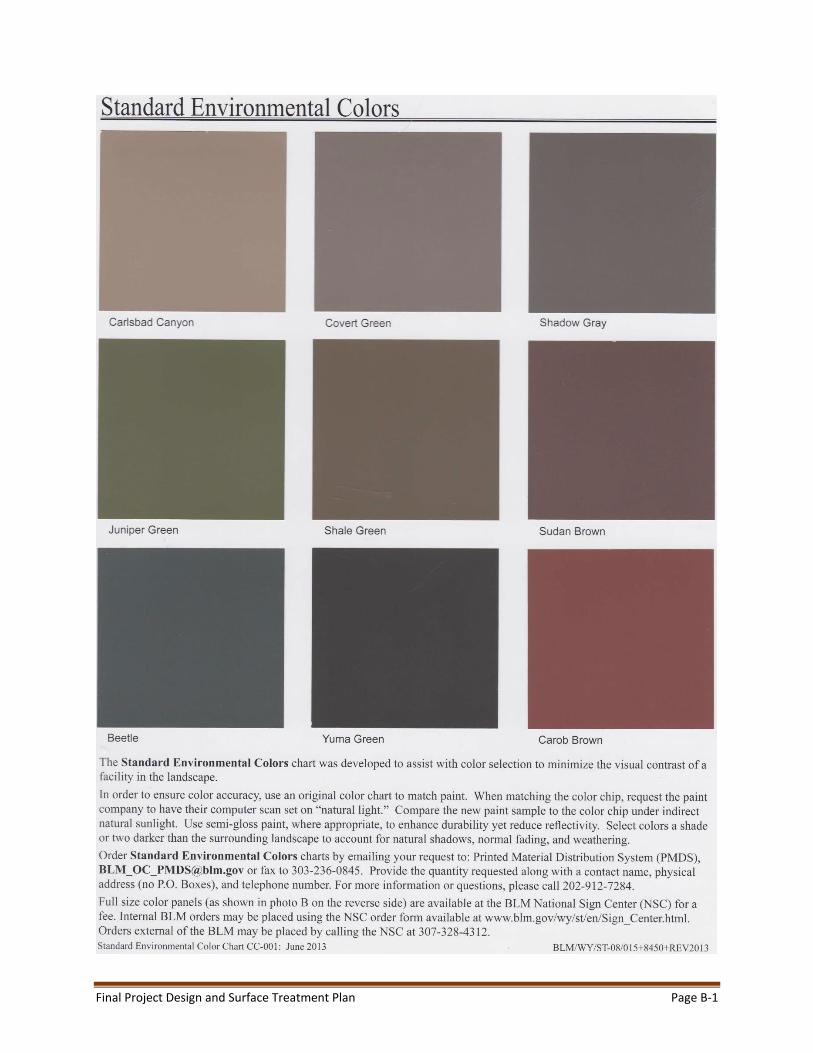
The Newberry Springs and Ludlow Series Capacitors will both be constructed largely within the Eldorado-Lugo and Lugo-Mohave 500 kV Transmission Line ROWs and will occupy approximately 1.67 acres each. Each series capacitor site will include a 500 kV capacitor bank with platforms and associated equipment, bus work, switches, conductor, and other electrical equipment (Appendix A, Figures A-1 and A-2). The sites will also include a Mechanical Electrical Equipment Room (MEER) building constructed of steel, a propane emergency generator, and a 1,000-gallon propane fuel tank protected by an Amico or similar ballistic fence on all four sides. The MEER structure and fencing around the propane tank will be painted to match the surrounding environment. The color selected by SCE to blend best with the surrounding environment based upon visual simulations is “Carlsbad Canyon” on BLM’s Standard Color Chart CC-001 (June 2013), included in Appendix B. A chain-link fence and gates will be installed around the series capacitor bank, and chain-link fence and gates with appropriate top guard (e.g., castle spikes, barbed wire, and/or razor wire) will be installed along the perimeter of the facility. Chain link fences and gates will be gray in color with a nonspecular finish.
The electrical equipment in the series capacitors sites (e.g., bushings, cabinets, insulators, painted surfaces) will be similar in color to an American National Standards Institute (ANSI) 70 grey finish. The galvanized steel surfaces of the transmission structures inside the series capacitor sites will be treated to

Final Project Design and Surface Treatment Plan Page 6
achieve a dulled finish. The galvanized steel of the lower structures within the series capacitor facility will not be treated with a dulled finish, as they will not be visible to the public. Figures A-5 through A-8 (Appendix A) are the original views and visual simulations of the Newberry Springs and Ludlow Series Capacitors prepared for the visual analysis from the nearest public viewpoint.
The Newberry Springs Series Capacitor will be located within the transmission ROW near an existing substation and multiple LSTs. The facility will include elements that currently exist and repeat in the current viewshed. The facility will not be a source of glare as the equipment will be grey, the MEER structure will be a neutral tan color, and the transmission steel surfaces will reflect light diffusely and evenly from surfaces. As such, the new features will integrate into the existing surroundings and will not contrast with the visual character of the surrounding landscape.
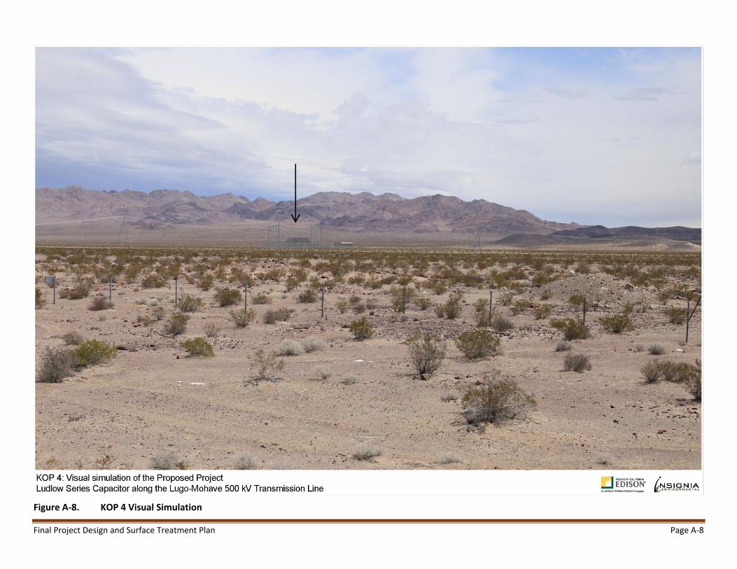
The Ludlow Series Capacitor site is located approximately 1.3 miles east of the Newberry Springs Capacitor site. The new facility will also be visible within the transmission line ROW where existing LSTs of the Lugo-Mohave 500 kV transmission line are also visible. There are no residences or roads in close proximity to the site. Views of the surrounding mountains will not be affected due to their distance from the site and its relatively low profile against the mountainous backdrop. Like the Newberry Springs Capacitor, Ludlow will not be a source of glare as the equipment will be grey, the structures will be a neutral tan color, and the transmission steel surfaces will be nonspecular.
Due to the location of the proposed facilities within the ROW, in line with repeated existing LSTs, and installed with muted color treatments stated above, the proposed facilities will integrate into the existing surroundings and will not contrast with the visual character of the surrounding landscape. The facilities will be consistent with the VRM Class III objective, partially maintaining the character of the landscape and allowing management changes that repeat the basic element found in the existing environment.
3.1.1 New Fiber Optic Repeater Facilities and Associated Facilities
The Barstow, Kelbaker, and Lanfair fiber optic repeater sites will be approximately 70 feet by 35 feet (Kelbaker and Lanfair) and approximately 101 feet by 57 feet (Barstow) and will be surrounded by a chain-link fence and appropriate top guard (e.g., castle spikes, barbed wire, and/or razor wire). Chain link fence and gates will be grey in color with a nonspecular finish. The repeater sites will include a prefabricated building, an emergency generator, an above-ground propane tank surrounded by a block wall, and underground telecommunication facilities. Distribution facilities will be installed on wood poles to provide light and power at all three of the sites. The MEER buildings will have exterior lighting that will only be used when a technician is on-site. The lights will be on a 60-minute timer, so that they cannot be left on accidentally. Light fixtures will have cutoff angles sufficient to prevent lamps and reflectors from being visible beyond the project facility boundary. Lighted nighttime maintenance will be minimized as a routine practice and typically only occur during emergencies. The electrical equipment in the repeater facilities will be similar in color to an ANSI 70 grey finish. The prefabricated building and block walls around the propane tank will be painted to match the surrounding environment. The color selected by SCE to blend best with the surrounding environment based upon visual simulations is “Carlsbad Canyon” on the BLM’s Standard Color Chart CC-001 (June 2013) included in Appendix B. Figures A-3 and A-4 (Appendix A) show typical site plans and elevations for the fiber optic repeater site. Figures A-9 through A-14 (Appendix A) are the original views and visual simulations of the Barstow, Kelbaker, and Lanfair fiber optic repeater sites.

Final Project Design and Surface Treatment Plan Page 7
The Kelbaker and Lanfair Fiber Optic Repeater sites will be located along the Lugo-Mohave 500 kV transmission line, within the Mojave National Preserve approximately 0.2 miles east of Kelbaker Road and 0.4 miles east of Lanfair Road, which are both County of San Bernardino-designated scenic routes. The Barstow Fiber Optic Repeater site will be also be located along the transmission line ROW, approximately 0.4 miles from SR-247, which is also a designated scenic route. The proposed facilities will be visible for short durations, to motorists traveling the routes. In all three cases, views of the mountains will not be impacted by the sites due to the relatively small size and low profile of the facilities and their distance from the mountains.
Due to the locations of the sites within the ROW, in line with repeated existing LSTs, and installed with the muted color treatments and nonspecular finishes stated above, the proposed facilities will integrate into the existing surroundings and will not contrast with the visual character of the surrounding landscape. The facilities will be consistent with the VRM Class III objective, partially maintaining the character of the landscape and allowing management changes that repeat the basic element found in the existing environment.
3.2 Modification of Existing Transmission, Subtransmission, and Distribution Facilities
Approximately nine existing 500 kV LSTs will be raised to address overhead clearance discrepancies. This will be achieved by installing extensions in the tower body that match the existing structures’ surface, which have a dulled galvanized finish. Steel tower modifications will be completed using dulled grey steel in order to match the existing structure steel. Figures A-15 and A-16 (Appendix A) are the original view and a simulation of a raised 500 kV lattice steel tower.
The modified towers will be taller but will continue the form, color, and pattern of the existing transmission lines and result in low contrast with existing conditions using the dulled grey steel. No new lighting is required on the existing towers. Tower raisings will occur in largely undeveloped areas and will be in line with similar LSTs supporting the transmission line, consistent with the VRM Class III objective, partially maintaining the character of the landscape while allowing management changes that repeat the basic element found in the existing environment.
Subtransmission modification for the Project consists of reframing two existing wooden poles to address a clearance discrepancy with the overhead 500 kV line. Finally, approximately 100 wooden distribution poles will be installed at various locations along the Project. No surface treatments are proposed for wood structures used in subtransmission or distribution, as these are considered minor changes in the landscape that would create minimal to no visual change in existing views at these locations, which are dominated by existing LSTs, conductors, and access roads in the ROW.
3.3 Optical Ground Wire
The installation of OPGW on existing transmission structures will require removing the existing overhead ground wire (OHGW) and installing approximately 235 miles of OPGW. The OPGW has a fiber optic cable core surrounded by strands of steel and aluminum wire. The OPGW is compliant to the Aluminum Association Standard AAC7-69 for a non-specular finish. It is similar in color to the OHGW currently on the transmission structures. Approximately 60 structures will require minor modifications, including ground wire peak modification on 60 structures, body modifications on 27 structures, and bent steel repair on 4 structures. The modifications will include adding steel members to strengthen the body and peak of the

Final Project Design and Surface Treatment Plan Page 8
towers to handle the load of the OPGW. Steel used in structure modifications will be dulled grey to match the existing structure steel. The modified steel will continue the form, color, and pattern of the existing transmission lines and result in low contrast with existing conditions, consistent with the VRM Class III objective, partially maintaining the character of the landscape while allowing management changes that repeat the basic element found in the existing environment.
3.4 Modifications within the Existing Eldorado, Lugo, and Mohave Substations
Modifications and additions of facilities within the existing Eldorado, Lugo, and Mohave substations will include modifying or replacing series capacitors and upgrading or replacing the terminal equipment. No modifications will be made to existing buildings. The Mohave Substation will include a new MEER building constructed of steel. No new buildings will be constructed at the Eldorado or Lugo substations. Within the Lugo Substation, two existing tubular steel poles will be replaced on the Eldorado-Lugo and Lugo-Mohave 500 kV transmission lines.
The painted electrical equipment in the substation sites will be similar in color to an ANSI 70 grey finish and the new tubular steel poles will be galvanized steel treated to give it a dulled finish, so their colors and finishes do not create excessive glare. The new MEER building will be painted Carlsbad Canyon (refer to BLM Standard Color Chart CC-001 [June 2013] included in Appendix B) to blend with the surrounding environment. No additional surface treatment is proposed for the existing substations.
3.5 Construction Yards, Staging Areas, and Material and Equipment Storage Areas
The Project includes 17 temporary staging areas/laydown yards. Temporary staging areas/laydown yards will have minimal vegetation removal to reduce visual effects of disturbance. Vegetation clearing will be limited to the extent of the area needed for the staging area/laydown yard footprint. Yard boundaries will be staked and approved by the Project biologist and the agency’s Environmental Monitor or visual specialist before vegetation removal commences. Revegetation of temporary disturbance areas after completion of construction will reduce visual contrast and be performed in accordance with the approved Project Habitat Restoration and Revegetation Plan (HRRP).
Construction yards, staging areas, and material and equipment storage areas located outside of existing substations will be surrounded by a chain-link fence. Chain link fence and gates will be grey in color.
To reduce significant impacts associated with construction yards, MM AES-2 requires that staging areas and material and equipment storage areas that are not located on existing substation properties or that are located in areas of high public visibility, including public roads, residential areas, and public recreational facilities, be visually screened. During construction of the Project, screened fencing will be installed around six staging areas/laydown yards located outside of existing substation properties to screen the yard from areas of high public visibility. The temporary screen will consist of fabric wind screening attached to chain-link fencing. The fabric color will be tan to blend with the surrounding environment.
Eight of the seventeen temporary staging areas/laydown yards are located within existing substations and, therefore, do not require screened fencing. Two yards, the Newberry Springs Series Capacitor and Ludlow Series Capacitor yards, are located away from areas of high public visibility and will be co-located

Final Project Design and Surface Treatment Plan Page 9
with the series capacitor construction sites and are therefore exempt from the screening requirement. Figures A-5 and A-6 (Appendix A) show the existing and simulated views of the Newberry Springs Series Capacitor site from I-15, the nearest high public visibility area, located 0.7 miles away. Figures A-7 and A-8 (Appendix A) show the view of the Ludlow Series Capacitor site from I-40, the nearest high public visibility area, located 0.6 miles away.
Table 1 lists the 17 staging areas/laydown yards and identifies the proposed screening treatment or rationale for the applicable screening exemption (i.e., located within an existing substation or are located away from areas of high public visibility).
Table 1 New Temporary Staging Area/Laydown Yard
Temporary Staging Area/ Laydown Yard Name
Approximate Size/ Dimensions
Screening Treatment/Rationale
Newberry Springs Series Capacitor
450’ x 575’ No screening- yard located away from areas of high public visibility (0.7 miles) (see Appendix A, Figures A-5 and A-6, and for view from I-40)
Ludlow Series Capacitor 600’ x 350’ No screening- yard located away from areas of high public visibility (0.6 miles) (see Appendix A, Figures A-7 and A-8, for view from I-40)
Ludlow Laydown Yard 375’ x 225’ Temporary screen fencing
Goffs 650’ x 400’ Temporary screen fencing
Goffs (alternate) 300’ x 530’ Temporary screen fencing
Arrowhead Lake Road 500’ x 450’ Temporary screen fencing
Bear Valley 400’ x 500’ Temporary screen fencing
Barstow Road 1,000’ x 400’ Temporary screen fencing
Coolwater 1,000’ x 1,000’ Temporary screen Fencing
Lugo II 550’ x 550’ No screening- located within the Lugo Substation
Lugo III 250’ x 200’ No screening- located within the Lugo Substation
Lugo IV 1,500’ x 400’ No screening- located within the Lugo Substation
El Dorado 400’-wide L-shaped 1,300’ x 1,300’
No screening- located within the El Dorado Substation
El Dorado II 500’ x 500’ No screening- located within El Dorado Substation
South Eldorado 250’ x 500’ No screening- located within El Dorado Substation
Mohave 800’ x 425’ No screening- located within the Mohave Substation
Mohave II 200’ x 250’ No screening- located within the Mohave Substation
3.6 Construction Yards, Staging Areas, and Material and Equipment Storage Areas
To reduce impacts associated with post-construction demobilization and clean-up, post-construction restoration or revegetation of temporary disturbance areas will be implemented. Temporary disturbance areas, including all yards in this plan, will be restored or revegetated per the procedures and success criteria established in the Project HRRP. Post-construction restoration monitoring and reporting will be implemented per the HRRP, including data and results of the monitoring year, completed reclamation and restoration activities, remedial activities, progression of the restoration site with respect to success criteria, and recommended future remedial activities (adaptive management). Temporary disturbance areas that are barren at preconstruction may not be subject to revegetation requirements; however, site stabilization measures will be implemented at those sites in accordance

Final Project Design and Surface Treatment Plan Page 10
with the Project Storm Water Pollution Prevention Plan. Temporary impacts on private lands will be restored in accordance with landowner requirements.
3.7 Surface Treatment Maintenance
Maintenance of project components for color and dulled finish is not expected. Transmission structure steel, insulators, conductors, and fiber optic wire are expected to dull over time which would further reduce contrast. Color walled buildings are also not expected to require repainting. For this reason, paint color selection will be compatible with the surrounding landscape may be a shade or two darker than the surrounding landscape in anticipation of fading over time.
SCE will attempt to avoid treatment during and after tower construction to limit the use of liquids that may be potentially hazardous to the environment. SCE does not anticipate using this method; however, it is a potential contingency should in-field treatment be necessary. Applicable BMPs will be implemented in these cases.

Appendix A. Project Feature Layouts and Visual Simulations

Final Project Design and Surface Treatment Plan Page A-1
Figure A-1. Typical Mid-Line Series Capacitor Layout Source: SCE 2017

Final Project Design and Surface Treatment Plan Page A-2
Figure A-2. Typical Mid-Line Series Capacitor Profile Source: SCE 2017

Final Project Design and Surface Treatment Plan Page A-3
Figure A-3. Typical Site Plan for the Fiber Optic Repeater Sites Source: SCE 2017

Final Project Design and Surface Treatment Plan Page A-4
Figure A-4. Typical Elevation for the Fiber Optic Repeater Sites Source: SCE 2017

Final Project Design and Surface Treatment Plan Page A-5
Figure A-5. KOP 3 Existing View

Final Project Design and Surface Treatment Plan Page A-6
Figure A-6. KOP 3 Visual Simulation

Final Project Design and Surface Treatment Plan Page A-7
Figure A-7. KOP 4 Existing View
Final Project Design and Surface Treatment Plan Page A-8
Figure A-8. KOP 4 Visual Simulation

Final Project Design and Surface Treatment Plan Page A-9
Figure A-9. KOP 2 Existing View

Final Project Design and Surface Treatment Plan Page A-10
Figure A-10. KOP 2 Visual Simulation

Final Project Design and Surface Treatment Plan Page A-11
Figure A-11. KOP 5 Existing View

Final Project Design and Surface Treatment Plan Page A-12
Figure A-12. KOP 5 Visual Simulation

Final Project Design and Surface Treatment Plan Page A-13
Figure A-13. KOP 6 Existing View

Final Project Design and Surface Treatment Plan Page A-14
Figure A-14. KOP 6 Visual Simulation

Final Project Design and Surface Treatment Plan Page A-15
Figure A-15. KOP 1 Existing View

Final Project Design and Surface Treatment Plan Page A-16
Figure A-16. KOP 1 Visual Simulation

Appendix B. Bureau of Land Management Standard Color Chart CC-001
Final Project Design and Surface Treatment Plan Page B-1

Final Project Design and Surface Treatment Plan Page B-2