project design document - grand valley state university
TRANSCRIPT

Project Design Document
Project: PV Emergency Back-up System
Prepared By: Walter Bartek
Sofia Fanourakis Patrick McCarthy
Submitted to: Dr. Heidi Jiao EGR 657 Course Project
Winter 2016 March 18, 2016

Design Document Page ii
Contents
Abstract ........................................................................................................................................................ iv
1.0 Introduction and Design Background ............................................................................................... 1
2.0 Requirements and Functional Specifications .................................................................................... 1
3.0 System Architecture .......................................................................................................................... 3
3.1 Hardware Specifications ............................................................................................................... 3
3.1.1 Incoming Power .................................................................................................................... 4
3.1.2 Case ....................................................................................................................................... 4
3.1.3 External Loads and Accessories............................................................................................ 4
4.0 System Design .................................................................................................................................. 4
4.1 Energy Requirement of Loads ...................................................................................................... 4
4.1.1 Suction Machine ................................................................................................................... 5
4.1.2 Lights .................................................................................................................................... 5
4.1.3 Consumer Devices ................................................................................................................ 5
4.1.4 Total Energy Requirements .................................................................................................. 6
4.2 Sizing of Batteries ........................................................................................................................ 6
4.3 Sizing of Solar Panels ................................................................................................................... 7
4.4 Sizing of the Charge Controller .................................................................................................... 8
4.5 Cables and Wires .......................................................................................................................... 8
5.0 Validation ........................................................................................................................................ 10
5.1.1 Solar Panel Power Test ....................................................................................................... 10
5.1.2 AC Input Power Test........................................................................................................... 11
5.1.3 Battery Charge and Discharge Test..................................................................................... 11
5.1.4 Output Ports Voltages Test ................................................................................................. 11
5.1.5 Battery Charge Indicator Test ............................................................................................. 11
6.0 Conclusions ..................................................................................................................................... 11
7.0 Project Budget and Schedule .......................................................................................................... 13
7.1 Budget ......................................................................................................................................... 13

Design Document Page iii
7.2 Schedule...................................................................................................................................... 13
8.0 Revision History ............................................................................................................................. 14
Appendix A – System Schematics ................................................................................................................ A
Appendix B – Bill of Materials ..................................................................................................................... B
Appendix C – Mechanical Drawings ............................................................................................................ D
Appendix D – Testing: Charging .................................................................................................................. E
Appendix E – Testing: Discharging ............................................................................................................... I
Design Document Page iv
Abstract
Malawi, Africa, is the poorest country in the world. At the Embangweni Mission Hospital in northern Malawi, brownouts and power outages lasting days at a time are frequent occurrences. Without consistent and reliable power for necessary medical equipment such as suction machines and lights, human lives are endangered and lost. An emergency backup power device has been requested for the hospital that can provide two days of autonomous power for a suction machine, lighting, as well as recharge consumer electronic devices such as phones or tablets. The device is to be used during times when standard wall power is unavailable. This device is referred to as the Solar Surgery Suction System, or the S4. The S4 is recharged via a solar panel or wall power over no more than two days. It is approximately the size of a suitcase and can be moved from its charging location to a room for use as necessary. Included with the S4 are two lights to provide lighting during medical procedures. The developed S4 is paired with an included suction machine and solar panel. Ultimately, the S4 and its associated parts will be delivered to and installed at the Embangweni Mission Hospital in Malawi to provide emergency backup power during critical medical operations.

Design Document Page 1
1.0 Introduction and Design Background
In Malawi reliable power is not a reality. Those living there are faced with inconsistent power; brownouts and blackouts last for days at a time. For many this is merely an inconvenience, but in some situations it can be dangerous. This is especially true in hospitals where an unexpected power outage can happen in the middle of a surgery. Because of this, emergency power supplies that do not rely on the grid are needed. The purpose of this project is to build a solar powered emergency power solution for use in a hospital. There are several objectives for this project. The system is to store solar or grid power in a lead-acid battery. Over a period of two days, it is to supply power to two LED lights for 12 hours each per day, a suction machine for four hours per day, and two additional 12 VDC car sockets (up to 2.1A) for three hours per day. The system is monitored through the use of a status display. The system is compliant with international travel check-in luggage size requirements. The system consists of the following parts: solar panel, charge storage, power output receptacles, and a charge controller with a status display. Ultimately, students from the class will hand deliver and install the developed backup power system to the Embangweni Mission Hospital in Malawi, Africa. In order to design the system the load requirements for the above components were calculated. The size of the battery (110 Ah) was selected based on the ability to sustain power to the system’s loads for two days. The panel was selected (100 W) based on the worst case solar irradiance of the region of use as well as the daily power requirements.
2.0 Requirements and Functional Specifications
The S4’s have the option to be powered and charged using solar energy or through the use of an electrical outlet. During power outages the system will provide power to a portable suction machine (provided with the system), two lights (provided with the system), and up to two tablets or phones. Table 2.1 shows details on the requirements and specifications of the system.

Design Document Page 2
Table 2.1: S4 Requirements and Specifications
# Requirement name Requirement Statement 1.00 Mechanical Requirement 1.10 Weight The device shall weigh ≤ 100 lbs* 1.11 Dimensions The device’s linear dimensions (L+H+W) shall be ≤ 62 in* 2.00 Component Requirement 2.10 Solar panel The system shall include a solar panel 2.20 Suction machine The system shall include a suction machine
2.30 Portable power box The system shall include a box containing all components except solar panel, suction device, and external cables
2.31 Battery The system shall include a lead-acid AGM battery. 2.32 LED lights The system shall include two LED rechargeable flashlights
2.40 Light mount The system shall include a mounting device for the LED flashlights
2.50 Cables
The system shall include: panel to power box cables, flashlight and suction machine charging cable (DC and AC), power box charging cable (AC to DC)
3.00 Electrical Requirement
3.10 Solar Panel Power A solar panel will be provided that is able to fully charge the battery within 2 days
3.11 AC Input Power The AC input power shall be converted to DC and be able to charge the battery within 2 days
3.20 Input charging The device shall be charged using either a solar panel or a wall outlet (220V/50Hz)
3.21 Input connectors Input power shall be supplied to the charge controller using MC4 connectors
3.22 Battery charge The charge controller shall output power to charge a lead-acid AGM battery and shall have LDO capabilities
3.23 Battery discharge The battery shall be able to power the suction machine and 2 tablets 3h/day and two LED lights 12h/day for 2 days
3.30 Output Ports The device shall have five charge ports (max 60 W) (auxiliary power socket part number: 39048-8)
3.31 Output Port Volts The output ports shall output 12V
3.40 Battery charge indicator The device shall have a display indicating charging levels of the lead-acid battery
*Measurement does not include the solar panel, suction machine, light fixtures, and external cables.

Design Document Page 3
3.0 System Architecture
3.1 Hardware Specifications A high level block diagram (Figure 3.1) was designed to ensure the necessary components are included in the system.
Figure 3.1: High Level Block Diagram of the S4

Design Document Page 4
3.1.1 Incoming Power Power is supplied using either a solar panel or AC power from a wall outlet. The solar panel must be able to supply at least 100W in order to charge the battery within the allotted time of two days.
3.1.2 Case The case contains the main system for supplying power to the load. The input power from the AC wall outlet will connect to a battery charger inside the case which will connect to a 110 Ah AGM battery. The input power from the solar panel is regulated by a charge controller which is used to charge the battery or provide power to the load directly. Load power is supplied from the charge controller to five 12 VDC car charge ports. One of the charge ports is designated for the suction machine. Two of the charge ports are designated for the lights. The remaining two EW for charging either phones or tablets. The charge controller has a display that shows the battery charge level and other relevant status information.
3.1.3 External Loads and Accessories A connector from the suction machine charge port to the suction machine is provided. Connectors from the light charge ports to the lights are provided as well. Any external load requiring a voltage up to 12 VDC and 2.1 A maximum may be connected to phone/tablet charge ports. Two car charge port to USB connectors are provided as well as two car charge port to micro USB connectors.
4.0 System Design
4.1 Energy Requirement of Loads The S4 has five loads: The suction machine, two lights, and two consumer electronic devices such as cell phones or tablets. As all five loads can be operated with 12V DC power, the system is designed for five outputs in the form of 12V DC auxiliary car sockets. These loads are to be powered for two days at the requested number of hours per day as outlined in Table 4.1.
Table 4.1: Daily hour usage of each output device

Design Document Page 5
Output Device Hours of Usage per Day Suction Machine 3 Hours Light #1 12 Hours Light #2 12 Hours Phone/Tablet #1 3 Hours Phone/Tablet #2 3 Hours
4.1.1 Suction Machine The power specifications for the selected suction machine that can be powered by a 12V DC car socket. Its maximum power consumption is 48 W making the current draw 4 A. The suction machine is requested to run for 3 hours per day, for a total of 6 hours. The daily energy consumption of the suction machine is 144 Wh.
4.1.2 Lights The two lights are to be approximately 5W each. At 12V this is approximately 0.417 amps. Each light is to run for 12 hours per day, or 24 hours total per light. The daily energy consumption of both lights is 120 Wh.
4.1.3 Consumer Devices The system is to be capable of charging two consumer electronic devices such as cell phones or tablets. Many chargers that fit into a car socket and use 12V DC are available nearly worldwide. Though these chargers plug into 12V DC, most output 5V DC as they charge a USB device. A common “quick charger” (high amperage charger) for phones charges at 5V and 2.1A. However, most chargers draw less than one ampere. Due to the voltage drop from 12V to 5V there is a significant efficiency loss. This efficiency loss is difficult to predict as the end user may plug in a variety of chargers. To account for the unpredictability and efficiency loss, the devices are considered to be operating at 12V. Each charger is to be used to charge a 2.1 A device for 3 hours per day, or 6 hours total each. The daily energy consumption if both chargers are connected is 151.2 Wh.

Design Document Page 6
4.1.4 Total Energy Requirements Table 4.2 shows the total energy requirements based on each load.
Table 4.2: Load Energy Requirements
Device Voltage [V]
Amperage [A]
Wattage [W]
Daily Hours of Operation
Necessary Amp Hours [Ah]
Necessary Watt Hours per Day [Wh]
Suction Machine 12 4 48 3 12 144 Light 1 12 0.417 5 12 10 60 Light 2 12 0.417 5 12 10 60 Consumer Device 1 12 2.1 25.2 3 6.3 75.6 Consumer Device 2 12 2.1 25.2 3 6.3 75.6 Total 9.03 415.2
From Table 4.2, the total daily energy consumption from the loads is 379.2 Wh. The maximum current draw at any time is 8.03 A.
4.2 Sizing of Batteries The S4’s power loads are summarized in Table 4.3.
Table 4.3: Load Energy consumption for battery sizing
Device Voltage
[V] Amperage
[A] Wattage
[W] Total Hours of Operation
Necessary Amp Hours [Ah]
Suction Machine 12 4 48 6 24 Light 1 12 0.417 5 24 10 Light 2 12 0.417 5 24 10 Consumer Device 1 12 2.1 25.2 6 12.6 Consumer Device 2 12 2.1 25.2 6 12.6 Total 69.2 Total with 80% DOD and 85% overall efficiency 101.76

Design Document Page 7
The total necessary amp hours to power the S4’s loads for two days is 69.2 Ah. Accounting for a maximum 80% battery discharge the battery needs to be able to provide 86.5 Ah. However, a reasonable assumption of power loss within the system is an efficiency of around 85%. This indicates that the battery powering the S4’s loads should provide approximately 101.76 Ah. It is safe to state that the battery powering the S4’s load may be a 110 Ah battery that provides 12 V DC as a 102 Ah battery is not commonly found for purchase.
4.3 Sizing of Solar Panels In order to size the panel the Global Horizontal Irradiance (GHI) was researched for various regions of Malawi. Data was available for the regions shown in Table 4.4.
Table 4.4: GHI Data for cities in Malawi
The closest city to Embangweni is Mizmba. Thus, the GHI data of Mzimba was considered for sizing the solar panel. The worst case scenario GHI was found to be the minimum value of GHI during the month of March (4.27 kWh/m2). Thus, the peak sun hours are 4.27 hours per day. Table 4.5 shows the panel sizing calculations based on the required load and GHI.

Design Document Page 8
Table 4.5: Solar Panel Sizing Calculations
Total Wh per day required by the load [Wh] 415.2 Worst case GHI [kWh/m2] 4.27 Worst case peak sun hours for Malawi near the Hospital (Mzimba) [Hours] 4.27 Minimum Panel Size [W] 97.24 Account for possible shading effects, reduce efficiency to 98%: ~100 W
The minimum solar panel size was found to be approximately 97.24 W. However, accounting for shading effects and overall system efficiency losses the solar panel efficiency is adjusted to 98%. Thus, a 100 W solar panel will be used to supply sufficient power to the system.
4.4 Sizing of the Charge Controller The charge controller should be able to supply at least 9 A to the load. Additionally, it should be able to handle up to 21.6 V and 6.1 A from the solar panel since the selected solar panel has an open circuit voltage of approximately 21.6 V and a maximum short circuit current of approximately 6.1 A. If the battery is to charge within the allotted time of two days the current to the battery has to be approximately 2.3 A on average for the full 48 hour period.
4.5 Cables and Wires The maximum load current is 9 A. Therefore, a 16 AWG wire is sufficient in handling the maximum load current. The cables connecting the solar panel to the charge controller will need to support up to 10 A. Thus, a 14 AWG wire can be used. However, the standard solar cable is 12 AWG and includes the necessary connectors to and from the solar panel. Therefore, the standard 12 AWG will be used to connect the solar panel to the charge controller. The cable will need to be at least 30 ft. to account for the location of the panel. Additional cables will be purchased in accordance with the devices used. Table 4.6 shows the necessary cables that are included in the system.

Design Document Page 9
Table 4.6: Cable and wire description and sizing
Cable/Wire Gauge [AWG] Description/Comments Solar Panel to Charge Controller
12 50’, includes MC4 connectors
Battery to charge controller 14 Internal wiring 16 Socket to Suction Machine - Included with suction machine
purchase Socket to lights #1 and #2 - Included with flashlight purchase Socket to aux device #1 (phone)
- Universal phone charging cable
Socket to aux device #2 (tablet)
- USB to mini USB cable
Design Document Page 10
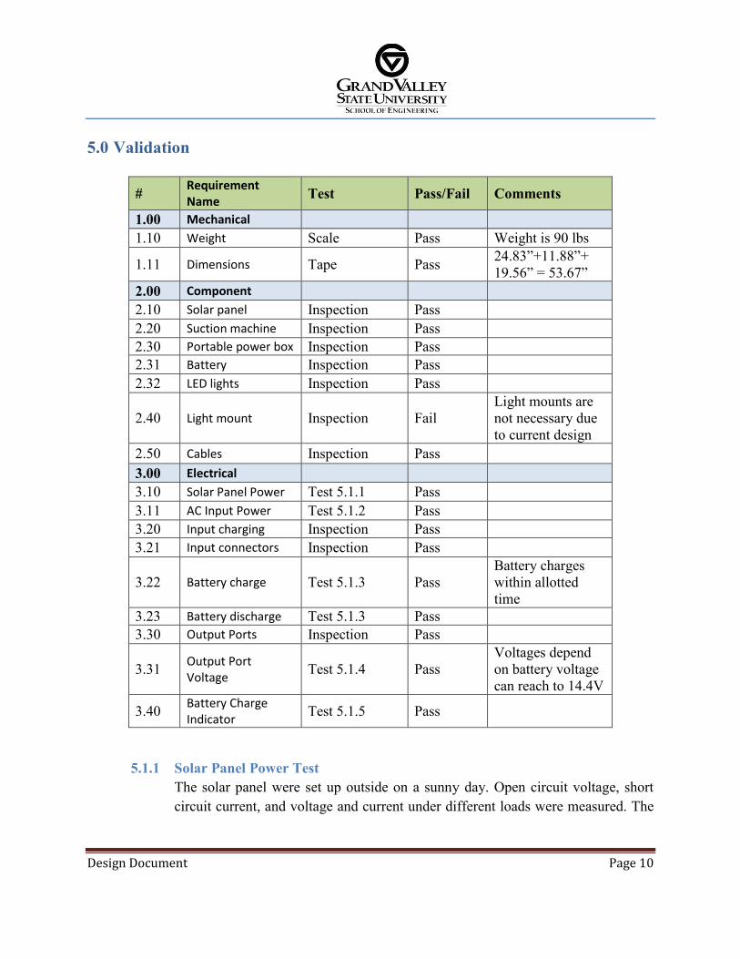
5.0 Validation
# Requirement Name Test Pass/Fail Comments
1.00 Mechanical 1.10 Weight Scale Pass Weight is 90 lbs
1.11 Dimensions Tape Pass 24.83”+11.88”+ 19.56” = 53.67”
2.00 Component 2.10 Solar panel Inspection Pass 2.20 Suction machine Inspection Pass 2.30 Portable power box Inspection Pass 2.31 Battery Inspection Pass 2.32 LED lights Inspection Pass
2.40 Light mount Inspection Fail Light mounts are not necessary due to current design
2.50 Cables Inspection Pass 3.00 Electrical 3.10 Solar Panel Power Test 5.1.1 Pass 3.11 AC Input Power Test 5.1.2 Pass 3.20 Input charging Inspection Pass 3.21 Input connectors Inspection Pass
3.22 Battery charge Test 5.1.3 Pass Battery charges within allotted time
3.23 Battery discharge Test 5.1.3 Pass 3.30 Output Ports Inspection Pass
3.31 Output Port Voltage Test 5.1.4 Pass
Voltages depend on battery voltage can reach to 14.4V
3.40 Battery Charge Indicator Test 5.1.5 Pass
5.1.1 Solar Panel Power Test The solar panel were set up outside on a sunny day. Open circuit voltage, short circuit current, and voltage and current under different loads were measured. The

Design Document Page 11
measurement values were compared to the requirements. Relevant charge data is located in Appendix D.
5.1.2 AC Input Power Test Voltage and current drawn under load were measured at the charging side of the battery charger. The measurement values were compared to the requirements.
5.1.3 Battery Charge and Discharge Test The battery was charged and charge time, open circuit voltage, short circuit current, and voltage and current under load (as per load requirements) were measured. The battery was discharged and discharge time, open circuit voltage, short circuit current, and voltage and current under load (as per load requirements) were measured. The measurement values were compared to the requirements. Relevant discharge and charge data are located in Appendix D and E, respectively.
5.1.4 Output Ports Voltages Test The voltages at the output ports were measured. The measurement values were compared to the requirements.
5.1.5 Battery Charge Indicator Test With the system fully assembled, the battery was charged and the charge indicator was observed. The system was discharged and the charge indicator was observed. Relevant discharge and charge data are located in Appendix D and E.
6.0 Conclusions
This design meets the requirements laid out by the Embangweni Mission Hospital staff. The battery was specified to be able to provide sufficient power to run the requested equipment for two days. Two rechargeable LED lights are able to supply 12 hours of light per day each. A suction machine powered by a 12VDC supply is able to operate for 3 hours per day. Consumer electronics can be powered by 12VDC, and two 12VDC to 5VDC adapters are included with the system. The system is capable of powering two such devices at 5VDC and 2.1A for 3 hours per day each. The solar panel is specified to recharge the system in two days under expected solar conditions at the hospital. The AC powered battery charger is to be used to charge the battery during the rainy season, and can fully recharge the system in two days. Collectively, the system and its peripherals meet the requirements laid out by the Embangweni Mission Hospital staff, and at present will be implemented on-site in August of 2016.

Design Document Page 12

Design Document Page 13
7.0 Project Budget and Schedule
7.1 Budget A detailed Bill of Materials and final costs showing all items can be found in Appendix B.
Component Allocated Price Solar Panel + extension cable $160.00 Solar Panel Mounting brackets $10.00 Charge Controller $60.00 110Ah AGM Battery $160.00 Battery Charger $50.00 Suction Machine $250 Lights $80 Light Mounts $20 Wiring (16 AWG, 14 AWG) $0 (lab support) Fuse Box $10 Receptacles, and Switches $15 Auxiliary Accessories $50 Case $135 Total $1000
7.2 Schedule
Project Component Tentative Completion Dates Functional Requirements Document February 12, 2016 Design Document Rough Draft February 26,2016 Design Review March 18, 2016 Ordering of Parts within Budget Requirements March 23, 2016 Constructed System April 21, 2016 Presentation April 21, 2016 System Testing April 22-27, 2016 Final Design Document April 28, 2016

Design Document Page 14
8.0 Revision History
Revision Number Date Author Changes 0.0 3/18/
16 SF, WB, PM Draft Design Document
1.0 4/28/16
SF, WB, PM Final Design Document

Design Document Page A
Appendix A – System Schematics
Figure A-1: High Level schematic

Design Document Page B
Appendix B – Bill of Materials
Table B-1: Detailed BOM
Item Vendor Price
Pelican Case Adorama 175.00
Solar Panel* Amazon 131.00
Solar Cable (200ft)* Amazon 49.99
Mounting Brackets Amazon 7.00
MC4 connectors Amazon 6.67
Fuses (5x5A, 3x15A) Amazon 7.33
Charge Controller Amazon 60.00
AGM Battery Cabelas 160.00
Battery Charger Battery Space 39.95
Suction Machine Amazon 227.32
Headlight Amazon 21.99
Sticklight Amazon 30.00
Fuse Box Amazon 9.18
Car socket (x5), 12V Amazon 16.99
Car Charger (x2), USB, 2.1A Amazon 9.99
Bus Bar (x2) Amazon 9.90
ABS 1/4" Black Grainger Industrial Supply
35.73
Terminal Connectors Meijer 2.30
Velcro Meijer 2.99
Cable 14 AWG Self-provided 0.00
Cable 16 AWG Self-provided 0.00 Total 1003.35
*A package of 2 panels + 50 ft. cable, a package of 1 panel + 50 ft. cable, and a package of 200 ft. of cable were ordered for three groups.

Design Document Page C
Table B-2: BOM Summary Table
Item Vendor Price
Pelican Case Adorama 175.00
Solar Panel Amazon 131.00
Mounting Brackets Amazon 7.00
Charge Controller Amazon 60.00
AGM Battery Cabelas 160.00
Battery Charger Battery Space 39.95
Suction Machine Amazon 227.32
ABS 1/4" Black Grainger Industrial Supply
35.73
Lights Amazon 51.99
Sockets and chargers Amazon 26.98 Cables, Connectors, Organizational Units, and System Protection
Various 88.36

Design Document Page D
Appendix C – Mechanical Drawings
Figure C-1: Faceplate Mechanical Dimensions

Design Document Page E
Appendix D – Testing: Charging Table D-1: Charging Tests April 23rd, 2016 in Grand Rapids, MI
Time Log
Panel Voltage
(V)
Panel Current
(A)
Battery Voltage
(V)
Battery Current
(A)
Load Voltage
(V)
Load Current
(A)
SOC (%) Load Notes
1334 n/a n/a n/a n/a n/a n/a n/a n/a Measured PV: Voc = 20.97 Isc = 5.09
1336 13.4 4.8 13.6 4.7 13.8 0 58
Car Adapter (Has blue LED indicating power)
Green PV indicator light ON
1339 13.9 4.6 14 3.4 14 1.3 68
Car Adapter, 2x DC Motors (Rated at 13.7V)
1340 16.4 2.9 14.4 3 14.5 0 82 Car Adapter
1419 18.2 1.5 Car Adapter
PV rotated to align long edge tangential to sun, new alignment
1420 18.5 1.5 14.4 1.5 0 0 91 Car Adapter
PV temporarily tilted to face directly at sun for this reading
1437 18.4 1.3 14.5 1.3 0 0 95 Car Adapter
1440 -
Loads found to be not active. Menu -> Load Set -> Manual -> ON. Enabled loads.
1448 18.3 1.3 14.4 1.3 14.4 0 94 Car Adapter
1450 16.5 2.7 14.4 1.3 14.5 1.4 96 Car Adapter, 2x DC Motors
1509 16.5 2.6 14.4 1.3 14.4 1.3 95 " 1541 16.5 2.6 14.4 1.3 14.4 1.3 99 "
1554 16.5 2.4 13.8 1 13.9 1.4 100 " 1602 16.2 2.4 13.8 1 13.8 1.4 100 "
1605 18.3 1 13.8 1 13.8 0 100 None "Batt: Float/Normal"
1608 17.2 1.7 13.8 1 13.8 0.7 100 Car Adapter, 1x DC Motor

Design Document Page F
Table D-1 (cont.): Charging Tests April 23rd, 2016 in Grand Rapids, MI
Time Log
Panel Voltage
(V)
Panel Current
(A)
Battery Voltage
(V)
Battery Current
(A)
Load Voltage
(V)
Load Current
(A)
SOC (%) Load Notes
1622 17.9 1.7 13.8 1 13.8 0.7 100 " PV temporarily tilted toward sun for this reading
1625 17.1 1.7 13.9 1 13.9 0.7 100 " Removed loads (Motor getting warm)
1658 18.3 0.8 13.8 0.8 13.8 0 100 None 1709 18.4 0.9 13.9 0.9 13.9 0 100 " 1721 15.8 0.8 13.8 0.8 13.8 0 100 "
1723 13.2 1.1 13.4 -0.3 13.3 1.4 100 Car Adapter, 2x DC Motors
1731 6.3 0 12.9 -1.3 12.9 1.3 93 "
PV physically fully shaded, Green PV indicator light OFF, Batt icon FULL and static
1743 5.1 0 12.8 -1.4 12.8 1.4 62 "
"PV:Disconnect" noted on CC. PV then physically disconnected (Limited sun available)
1745 0 0 12.8 -1.4 12.8 1.4 61 " 1805
1806 0 0 12.7 -1.4 12.7 1.4 59 " Fuse test successful: Fuse on port #3 blown
1820 1821 0 0 12.7 -1.4 12.7 1.4 57 " 1833 0 0 12.7 -1.4 12.7 1.4 56 " 1908 0 0 12.6 -1.4 12.6 1.4 53 " 1937 0 0 12.6 -1.4 12.6 1.4 50 " 1959 0 0 12.5 -1.4 12.5 1.4 48 " 2059 0 0 12.5 -1.4 12.5 1.4 45 " 2127 0 0 12.5 -1.4 12.5 1.4 44 "

Design Document Page G
Table D-1 (cont.): Charging Tests April 23rd, 2016 in Grand Rapids, MI
Time Log
Panel Voltage
(V)
Panel Current
(A)
Battery Voltage
(V)
Battery Current
(A)
Load Voltage
(V)
Load Current
(A)
SOC (%) Load Notes
2156 0 0 12.5 -1.7 12.5 1.7 44 Car Adapter, 2x DC Motors, PC Fan
2204 None Loads disconnected
Table D-2: Charging Tests April 24th, 2016 in Grand Rapids, MI
Time Log
Panel Voltage
(V)
Panel Current
(A)
Battery Voltage
(V)
Battery Current
(A)
Load Voltage
(V)
Load Current
(A) Temp. (°C)
SOC (%) Load Notes
1133
1144 Cloudy day
1145 12.6 2.9 12.7 1 12.7 1.9 21.9 30
Car Adapter, 2x DC Motors, PC Fan
1148 13.2 2.7 13.5 0.8 13.7 1.9 22 30 "
Battery Charger Connected (In addition to PV)
1150 13.8 2.9 14 2.9 14 0 22.1 34 None
1152 0 0 13.9 0 13.9 0 22.3 42 - Disconnected PV Panel
1210 0 0 13.9 0 13.9 0 22.8 100 -
1212 0 0 13.2 0 - - 22.9 96 -
Battery Charger Disconnected
1213 0 0 13.9 0 23.2 94 -
Battery Charger Reconnected
1225 0 0 14 0 - - - 100 -
Battery Charger Disconnected
1226 0 0 13.2 -

Design Document Page H
Table D-2 (cont.): Charging Tests April 24th, 2016 in Grand Rapids, MI
Time Log
Panel Voltage
(V)
Panel Current
(A)
Battery Voltage
(V)
Battery Current
(A)
Load Voltage
(V)
Load Current
(A) Temp. (°C)
SOC (%) Load Notes
1227 13.8 5.8 14 5.8 14 0 24 90 - PV Connected
1252 13.7 2.9 13.8 2.9 13.8 0 24.6 68 -
1318 13.6 2.4 13.7 2.4 13.7 0 23.8 64 -
Cloudy outside. Noted "Batt:Boost/Normal"
1413 13.5 1.3 13.7 1.3 13.7 0 23.1 64 -
Battery Charger Connected
1452 13.3 0.8 13.5 0.8 13.5 0 22.2 53 -
1505 14.1 0.7 14.3 0.7 14.3 0 22.3 85 -
1522 13.7 1.3 13.8 1.3 13.8 0 22.7 81 -
1544 13.6 1.6 13.8 1.6 13.8 0 23.3 65
1607 17.9 1.6 14.4 1.6 14.4 0 23.6 91 -
1650 18 1.2 14.4 1.2 14.4 0 23.5 92 -
1704 15.2 1.1 14.4 1.1 14.4 0 23.8 89 -
Battery Charger Disconnected
1721 16.2 1 14.4 1 14.4 0 23.7 91 -
1816 13.3 0.5 13.5 0.5 13.5 0 23.2 56 -
1841 13.3 0.4 13.5 0.4 13.5 0 23.2 54 -
Design Document Page I
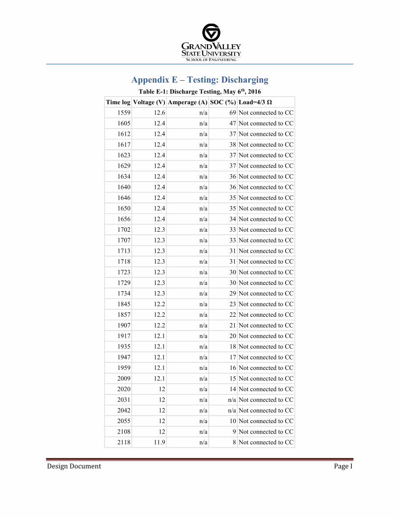
Appendix E – Testing: Discharging Table E-1: Discharge Testing, May 6th, 2016
Time log Voltage (V) Amperage (A) SOC (%) Load=4/3 Ω 1559 12.6 n/a 69 Not connected to CC 1605 12.4 n/a 47 Not connected to CC 1612 12.4 n/a 37 Not connected to CC 1617 12.4 n/a 38 Not connected to CC 1623 12.4 n/a 37 Not connected to CC 1629 12.4 n/a 37 Not connected to CC
1634 12.4 n/a 36 Not connected to CC 1640 12.4 n/a 36 Not connected to CC 1646 12.4 n/a 35 Not connected to CC 1650 12.4 n/a 35 Not connected to CC 1656 12.4 n/a 34 Not connected to CC 1702 12.3 n/a 33 Not connected to CC 1707 12.3 n/a 33 Not connected to CC 1713 12.3 n/a 31 Not connected to CC 1718 12.3 n/a 31 Not connected to CC 1723 12.3 n/a 30 Not connected to CC 1729 12.3 n/a 30 Not connected to CC 1734 12.3 n/a 29 Not connected to CC 1845 12.2 n/a 23 Not connected to CC 1857 12.2 n/a 22 Not connected to CC 1907 12.2 n/a 21 Not connected to CC 1917 12.1 n/a 20 Not connected to CC 1935 12.1 n/a 18 Not connected to CC 1947 12.1 n/a 17 Not connected to CC 1959 12.1 n/a 16 Not connected to CC 2009 12.1 n/a 15 Not connected to CC 2020 12 n/a 14 Not connected to CC 2031 12 n/a n/a Not connected to CC 2042 12 n/a n/a Not connected to CC 2055 12 n/a 10 Not connected to CC 2108 12 n/a 9 Not connected to CC 2118 11.9 n/a 8 Not connected to CC

Design Document Page J
Table E-1 (cont.): Discharge Testing, May 6th, 2016 Time log Voltage (V) Amperage (A) SOC (%) Load=4/3 Ω
2126 11.9 n/a 7 Not connected to CC 2142 11.9 n/a 5 Not connected to CC 2146 11.7 8.4 14 Connected to CC 2200 11.6 8.4 10 Connected to CC 2211 11.6 8.4 n/a Connected to CC 2222 11.6 8.4 7 Connected to CC 2234 11.6 8.3 n/a Connected to CC 2244 11.5 8.3 5 Connected to CC 2255 11.5 8.3 3 Connected to CC 2306 11.5 8.3 2 Connected to CC 2316 11.5 8.3 1 Connected to CC 2325 11.4 8.3 n/a Connected to CC 2335 11.4 8.2 0 Connected to CC 2345 11.4 8.2 n/a Connected to CC 2355 11.4 8.2 0 Connected to CC 0008 11.3 8.2 0 Connected to CC 0016 11.3 8.2 0 Connected to CC 0024 11.3 8.2 0 Connected to CC 0033 11.3 8.1 0 Connected to CC 0039 11.2 8.1 0 Connected to CC 0047 11.2 8.1 0 Connected to CC 0100 11.2 8.1 0 Connected to CC 0108 11.2 8.1 0 Connected to CC 0116 11.1 8 0 Connected to CC 0124 11.6 0 n/a Connected to CC