project manual - riverbanks zoo manual . riverbanks zoo ... shall be capable of sustaining and...
TRANSCRIPT

Project Manual
Riverbanks Zoo & Garden 500 Wildlife Parkway
Columbia, SC
Solicitation: B18001-02/15/2018 Design, Furnish and Install Standby Power System for Bird House Building
and ARC TECHNICAL SPECIFICATIONS
Project Number: C17045
Riverbanks Zoo & Garden Generator Additions

Part 1
Standby Power System
Technical Specifications

Riverbanks Zoo & Gardens Generator Additions SECTION 26 32 13 Columbia, South Carolina STANDBY POWER SYSTEM
STANDYBY POWER SYSTEM 26 3213 - Page 1 of 10
PART 1 - GENERAL REQUIREMENTS
1-01 SCOPE OF WORK
This specification applies to two separate generator sets, Generator 1 for the Bird House Building, Generator 2 for the ARC Building.
WORK INCLUDED: Furnish and install all necessary labor, material plant, and equipment, including materials and equipment not specifically mentioned but necessary to complete the work in a neat, correct, and workmanlike manner, to include:
1) Engine Generator Set.2) Automatic Transfer Switch.3) Weatherproof Steel Housing.4) Concrete Mounting Pads.5) Accessories as Specified.
1-02 GENERAL REQUIREMENTS
SUPPLIER: The supplier of the engine generator set shall be acceptable to the Engineer and shall have service facilities and spare parts stock within 90 minutes travel time of Columbia, South Carolina, by normal ground transportation.
RESPONSIBILITY: This system shall be built, tested, and shipped by one supplier, who has been regularly engaged in the sales and servicing of engine generator sets and associated controls for a minimum of five (5) years, so there is one source of supply and responsibility.
WARRANTY: The complete standby electric power system equipment (Generator, Transfer Switch, and associated equipment) shall be warranted for a period of five (5) years or fifteen hundred (1500) running hours, whichever occurs first, from the date of Owner's acceptance. Labor allowance shall be provided for the first two (2) years or fifteen hundred (1500) hours, whichever comes first. The warranty must be provided by the system supplier. Multiple warranties for individual components will not be acceptable. Satisfactory warranty documents shall be delivered with the standby power set.
PREVENTATIVE MAINTENANCE: The local authorized service representative shall supply for a period of two (2) years from the date of Start-up, a preventative maintenance program or agreement to be performed quarterly at no additional cost to the Owner.
SHOP DRAWINGS: Within thirty (30) days after award of contract, submit six (6) sets of Shop Drawings for Engineer's review. Include manufacturer's model numbers, dimensions, and operating data for the engine generator set, silencer, day tank, automatic transfer switch, battery charger, batteries and major equipment, schematic and interconnection wiring diagrams identifying by terminal number each required interconnection between the generator set, the transfer switch, and other remote devices.
MANUALS: Provide Owner with two (2) copies of instruction manuals for operating and maintaining the engine generator system. Manuals shall be bound in hardback binders and shall include recommended spare parts lists and vendors, troubleshooting guides, and maintenance instructions and recommended servicing periods. A 24-hour, 7-day answering service number for the service and repair organization for the set shall be included in the binder.
TESTING: Manufacturer shall conduct testing of prototype equipment (but not equipment which is to be supplied) in accordance with all requirements of NFPA-110. Provide copies of the factory Load Bank Test Report with each O&M manual.
Riverbanks Zoo & Gardens Generator Additions SECTION 26 32 13 Columbia, South Carolina STANDBY POWER SYSTEM
STANDYBY POWER SYSTEM 26 3213 - Page 2 of 10
1-03 CODES AND STANDARDS
A. The generator set, it’s installation, and on-site testing shall conform to the requirements of the following codes and standards:
1) IEEE446- Recommended Practice for Emergency and Standby Power Systems forCommercial and Industrial Applications.
2) IEEE587- Voltage Surge Resistance3) Nema ICS10-1993- AC Generator Sets4) NFPA 70- National Electrical Code. Equipment shall be suitable for use in systems
compliant with Articles 700, 701, and 702.5) NFPA 110-Emergency and Standby Power Systems. The generator set shall meet all
requirements for Level 1 systems. Level 1 prototype tests required by this standard shallhave been performed on a complete and functional unit. Component level type tests willnot substitute for this equipment.
6) UL508- The entire control system of the generator set shall be UL508 listed and labeled.
B. The generator set manufacturer shall be certified to ISO 9001 International Quality Standard and shall have third party certification verifying quality assurance in design/development, production, installation, and service in accordance with ISO 9001.
PART 2 - MATERIALS
2-01 ENGINE GENERATOR SET
BASIC REQUIREMENTS: Base rating of engine on plant site elevation of 750 feet above mean sea level and an atmospheric temperature of 95-Degrees F.
ACCEPTABLE MANUFACTURERS: Kohler, Caterpillar, Generac or acceptable equivalent of Cummins or MTU.
RATING: See below, 120/208 volts, 3 phase, 4 wire, 60 HZ. Capacity specified shall be for continuous standby service for the duration of any power outage. The generator set shall also be capable of satisfactorily carrying a load 100 percent of the net rated generating capacity at 0.8 power. The set shall provide a Permanent Magnet Generator (PMG) to ensure reliable source of excitation power for optimum motor starting and short circuit performance. The PMG and controls shall be capable of sustaining and regulating current supplied in a single phase or three phase fault at approximately 250% of the rated current for at least 10 seconds.
Bird House Building:500KW ARC BUILDING: 350KW Motor Starting Capacity: Gen-set shall be capable of starting and operating the total motor and miscellaneous load. In this instance "starting" means bringing motors, drivers, and their driven components from zero rpm up to rated rpm's while the driven components are subjected to service conditions.
Computations: The manufacturer shall submit computations indicating that the unit furnished will satisfactorily operate with the equipment to be connected. This is to ensure the rating of the generator will supply the listed loads and not to just supply a generator with KW model # to match the specification. The generator may not be ordered until these calculations have been submitted to and reviewed by the Engineer.
Voltage Dip: The voltage dip, when the gen-set experiences its maximum loading condition, shall not exceed 25% at 0.8 power factor as measured by a light beam recorder.

Riverbanks Zoo & Gardens Generator Additions SECTION 26 32 13 Columbia, South Carolina STANDBY POWER SYSTEM
STANDYBY POWER SYSTEM 26 3213 - Page 3 of 10
ENGINE (Diesel): The engine shall be Diesel, 4 cycle, radiator and fan cooled. The horsepower rating of the engine at its minimum tolerance level shall be sufficient to drive the alternator and all connected accessories. Two cycle engines are not acceptable. Engine accessories and features shall include:
1) Isochronous governor.2) Skid-mounted radiator and cooling system rated for full load operation in 122 degrees F (50
degrees C) ambient as measured at the generator air inlet, and based on 0.5” water columnexternal static head. Radiator shall be sized based on a core temperature which is 20degrees F higher than the rated operation temperature. The cooling system shall be filledwith a 50/50 ethylene glycol/water mixture.
3) Electric starter(s) capable of three complete cranking cycles without overheating.4) Positive displacement, mechanical, full pressure, lubrication oil pump.5) Full flow lubrication oil filters with replaceable spin-on canister elements and dipstick oil
level indicator.6) An engine driven, mechanical, positive displacement fuel pump. Fuel filter with replaceable
spin-on canister element.7) Replaceable dry element air cleaner.8) Flexible supply and return fuel lines.9) Engine-mounted battery charging alternator, 40-ampere minimum and solid-state voltage
regulator.10) Engine-mounted coolant heater, thermostatically controlled. The coolant heater shall be
UL499 listed and labeled.11) Provide vibration isolators, seismic zone 4.12) The engine shall be equipped with automatic safety controls which will shut down the engine
in the event of low oil pressure, over-crank, high water temperature, low water and engineover-speed.
ALTERNATOR: NEMA Standard MGI, reconnectable, 12-lead, self ventilated, drip-proof construction, 4 Pole, revolving field design with temperature compensated solid state voltage regulator and brushless rotating rectifier exciter system. No brushes shall be allowed. The rotor shall be driven through a semiflexible driving flange to insure permanent alignment. The insulation system shall be Class H as defined by MGI-22.40 and 16.40. Temperature rise shall be 125-Degrees C. within NEMA MGI-22.40 definition.
LOAD CIRCUIT BREAKERS: Provide unit mounted load circuit breakers for the alternator. Circuit breakers shall be sized at not less than 100 per cent of the alternator full load current, and not more than 125 per cent of the alternator full load current. Circuit breaker voltage rating shall be 240 volt, unless otherwise specified. Breaker shall be rated for 65K RMS symmetrical amperes symmetrical. The Generator shall have bussing and space for a second circuit breaker.
VOLTAGE REGULATION: Voltage regulation shall be within (plus or minus) 1 percent of rated voltage from no load to full load. The instantaneous voltage dip shall be less than 20 percent of rated voltage when full 3 Phase load and rated power factor is applied to the alternator. Recovery to stable operation shall occur within 3 seconds. Stable operation is defined as operating with terminal voltage remaining constant within 1 percent of rated voltage. A rheostat shall provide a minimum of ± 5 percent voltage adjustment from rated voltage.
ALTERNATOR INSTRUMENTS: The alternator instrument panel shall be wired, tested and shock mounted on the generating set. It shall contain:
Panel Lighting. Frequency Meter. Elapsed Time Meter. Voltage Adjusting Rheostat. AC Voltmeter (3.5-inch, dual range).

Riverbanks Zoo & Gardens Generator Additions SECTION 26 32 13 Columbia, South Carolina STANDBY POWER SYSTEM
STANDYBY POWER SYSTEM 26 3213 - Page 4 of 10
AC Ammeter (3.5-inch, dual range). Voltage-ammeter Phase Selector Switch with OFF position.
ENGINE INSTRUMENTS AND CONTROLS: Provide panel mounted oil pressure gage, coolant temperature gage, and battery charge rate ammeter. Provide start-stop control that starts engine on closing contact and stops engine on opening contact. Provide cranking cycler with 15-second ON and OFF cycles, and limiter to open the starting circuit if the engine is not started within 75 seconds. Provide three position RUN-STOP-REMOTE Selector Switch. Comply with NFPA 110 for Level 1 systems. Provide engine shutdown for high coolant temperature, low oil pressure, and over-speed.
REMOTE MANUAL STOP STATION: In accordance with 5.6.5.6 of NFPA 110 – 2010, all installations shall have a remote manual stop station of a type to prevent inadvertent or unintentional operation located outside the room housing the prime mover, where so installed, or elsewhere on the premises where the prime mover is located outside the building. For systems located outdoors, the manual shutdown should be located external to the weatherproof enclosure behind a clear weatherproof cover, and should be appropriately identified. The remote manual stop station shall be labeled.
ENGINE SET ANNUNCIATOR: Provide panel mounted annunciator/shutdown panel with indicating lights as follows. The engine battery shall provide power to operate the annunciator. The annunciator shall have terminals for remote annunciator of each following condition and a common alarm contact for a remote 1-light alarm contact. Indicating lights shall include:
Not-in-Auto (red, flashing). Overcrank (red). Emergency Stop (red). High Engine Temperature/Low Coolant Level (red). Overspeed (red). Low Oil Pressure (red). Battery Charge Malfunction (red). Low Battery Voltage (red). Low Fuel (red). System Ready (green). Pre-alarm High Engine Temperature (yellow). Pre-alarm Low Oil Pressure (yellow). Low Coolant Temperature (red).
REMOTE ANNUNCIATOR: Provide a networkable remote flush mounted alarm panel that contains lights duplicating all indicating lights on the engine mounted annunciator panel. Locate in administration area of building, field verify location with Owner prior to rough-in. Furnish and install all necessary outlet boxes, wiring and conduit. Provide one remote annunciator for each generator.
ACCESSORIES: All accessories needed for the proper operation shall be furnished, to include:
Seamless, Stainless Steel Flexible Exhaust Connection. Batteries, Cables, and Battery Rack. LaMarche Fully Automatic Dual Rate Battery Charger (10 Amp capacity at high charge rate) with Ammeter. Engine Block Heater with Thermostat to maintain 90-Degree F. engine temperature. Anti-Condensate Heater inside Alternator Housing (250-watt, 120 volt). Radiator Fill of Glycol Base All Weather Coolant. Crankcase Fill of Manufacturer's Recommended Lube Oil. Flexible Duct Connection to Exhaust Air Louver. Detailed Operations and Maintenance Manuals with Parts List. Load Circuit Breaker.

Riverbanks Zoo & Gardens Generator Additions SECTION 26 32 13 Columbia, South Carolina STANDBY POWER SYSTEM
STANDYBY POWER SYSTEM 26 3213 - Page 5 of 10
NAMEPLATE: Provide large engraved nameplate, 1/4" white letters on red field, at the building service-entrance equipment indicating type and location of on-site emergency power source (refer to NEC 700.8, 701.9, and 702.8). Example:
EMERGENCY POWER: 500KW, 120/208V, 3PH
DIESEL EMERGENCY GENERATOR LOCATED IN THE NORTHWEST
CORNER OF THE MAIN PARKING LOT
2-02 AUTOMATIC TRANSFER SWITCH FOR EQUIPMENT
Refer to drawings for quantities, sizes, and locations of Automatic Transfer Switches for this project.
Furnish and install an exterior rated, automatic transfer switch system(s) with 3-Pole / 4-Wire, Solid Neutral, 1600 Amps, 208V/60Hz. Each automatic transfer switch shall consist of an inherently double throw power transfer switch mechanism and a microprocessor controller to provide automatic operation. All transfer switches and controllers shall be the products of the same manufacturer.
Automatic transfer switches shall be Bypass/Isolation – Open Transition. Any alternate shall be submitted for approval to the consulting engineer at least 10 days prior to bid date. Alternate bids shall include a line-by-line clarification of the specification marked with "D" for deviation; "E" for exception, and "C" for comply.
FUNCTIONAL REQUIREMENTS:
1) Upon utility line outage, automatically start the engine generator set and, when the set attainsnormal speed and voltage, disconnect the load circuit from the normal line and transfer it to theemergency line.
2) Upon utility line return, transfer the load circuit back to the normal line and stop the enginegenerator set.
STANDARDS: The automatic transfer switches and accessories shall conform to the requirements of the following codes and standards:
1) UL 1008- Standard for Automatic Transfer Switches2) NFPA 70- National Electric Code3) IEEE Standard 446- IEEE Recommended Practice for Emergency and Standby Power
Systems for Commercial and Industrial Applications4) NEMA Standard ICS10-1993- AC Automatic Transfer Switches5) NEC Articles 517, 700, 701, & 702.6) International Standards Organization ISO 9001: 2000
Voltage and Current rating shall be as specified on the drawings. Automatic transfer switch shall be provided by the generator Supplier as part of the standby power system
Provide 3 pole switch with solid neutral as shown on drawings
GENERAL AUTOMATIC TRANSFER SWITCH PRODUCT REQUIREMENTS:
A. Indicated Current Ratings: Apply as defined in UL 1008 for continuous loading and total system retransfer, including tungsten filament lamp loads not exceeding 30 percent of switch ampere rating, unless otherwise indicated.

Riverbanks Zoo & Gardens Generator Additions SECTION 26 32 13 Columbia, South Carolina STANDBY POWER SYSTEM
STANDYBY POWER SYSTEM 26 3213 - Page 6 of 10
B. Tested Fault-Current Closing and Withstand Ratings: Adequate for duty imposed by protective devices at installation locations in Project under the fault conditions indicated, based on testing according to UL 1008.
1) Where transfer switch includes internal fault-current protection, rating of switch and tripunit combination shall exceed indicated fault-current value at installation location.
C. Solid-State Controls: Repetitive accuracy of all settings shall be plus or minus 2 percent or better over an operating temperature range of minus 20 to plus 70 deg C.
D. Resistance to Damage by Voltage Transients: Components shall meet or exceed voltage surge withstand capability requirements when tested according to IEEE C62.41. Components shall meet or exceed voltage-impulse withstand test of NEMA ICS 1.
E. Electrical Operation: Accomplish by a non-fused, momentarily energized solenoid or electric-motor-operated mechanism, mechanically and electrically interlocked in both directions.
F. Switch Characteristics: Designed for continuous-duty repetitive transfer of full-rated current between active power sources.
1) Limitation: Switches using molded-case switches or circuit breakers or insulated-casecircuit-breaker components are not acceptable.
2) Switch Action: Double throw; mechanically held in both directions.3) Contacts: Silver composition or silver alloy for load-current switching. Conventional
automatic transfer switch units, rated 225 A and higher, shall have separate arcingcontacts.
G. Neutral Terminal: Solid and fully rated, unless otherwise indicated.
H. Factory Wiring:
1) Designated Terminals: Pressure type, suitable for types and sizes of field wiringindicated.
2) Power-Terminal Arrangement and Field-Wiring Space: Suitable for top, side, or bottomentrance of feeder conductors as indicated.
3) Control Wiring: Equipped with lugs suitable for connection to terminal strips.
I. Enclosures: NEMA 3R, complying with NEMA ICS 6 and UL 508, unless otherwise indicated.
ACCESSORIES:
1) NEMA 1 Gasketed Enclosure.2) Test Switch to simulate outage, momentary contact.3) Time Delay on Engine Start, Adjustable 0.5 - 6 Seconds, set at 3 seconds.4) Time Delay on Emergency to Normal Retransfer, Adjustable 0 - 30 minutes, set at 5
minutes.5) Time Delay for Engine Cool-Off (unloaded running), Adjustable 0 - 5 minutes, set at 5
minutes.6) Frequency/Voltage Sensing Relay for Emergency Source.7) Transfer Override switch.8) Engine Start Contacts.9) Transfer Switch Position & Source availability lights; Red-Emergency, Green-Normal.10) Two (2) NO and two (2) NC Auxiliary Contacts.11) (2) Emergency Side Auxiliary Contact Relay, SPDT.12) Plant Exerciser with 2-position (Load/No Load) selector switch.

Riverbanks Zoo & Gardens Generator Additions SECTION 26 32 13 Columbia, South Carolina STANDBY POWER SYSTEM
STANDYBY POWER SYSTEM 26 3213 - Page 7 of 10
13) In-phase power monitor to insure emergency and normal power sources are in phase priorto transfer from emergency to normal.
14) Operator's Manual - Installation and Operating Instructions. (Provide two (2) copies.)15) Microprocessor Controls.16) Solid Neutral.17) Engine Starting Contacts.18) Engine Shutdown Contacts.
NAMEPLATE: Provide red engraved nameplate for each ATS identifying name, voltage, phase, and fed-from identification. Example:
ATS-1 120/208V, 3PH
FED FROM MSB-1 AND GENERATOR
2-03 FUEL SYSTEM - DIESEL
FUEL TANK: Fuel Tank shall be sub-base mounted steel tank. Tank shall be sized to operate emergency generator at full load for a minimum forty-eight (48) hours. Tank shall be supplied with 2-inch fill cap and locking cover, 2-inch vent pipe and mushroom cap, fuel level fitting, fuel supply and return fittings, and fuel tank drain fitting with valve. Factory installed and piped, corrosion resistant, double-wall containment, UL listed and labeled fuel tank. Provide with tank level indicator and vandal resistant fill cap. Include rupture basin alarm and low fuel alarm and wired to generator set control panel. Provide permanent nameplate indicating the standard used as a basis for design and flow rates.
The sub-base fuel tank shall be UL142 listed and labeled. Installation shall be in compliance to NFPA37. Include the minimum following features:
1. Emergency tank and basin vents.2. Mechanical level gauge.3. Fuel supply and return lines, connected to generator set with flexible fuel lines as
recommended by the engine manufacturer and in compliance to NFPA 37requirements.
4. Leak detection provisions, wired to the generator set control for local and remote alarmindication.
5. Low level float switch to indicate fuel level. Wire switch to generator control for localand remote indication of fuel level
6. Integral lifting provisions.
FUEL GAUGE: Fuel tank gauge shall be direct indicating type, calibrated in 1/4 full increments, with low level fuel alarm switch for the remote annunciator.
FUEL PIPING: Fuel piping shall be Schedule 40, ASTM A 53 or ASTM A 120, black steel pipe with screwed black malleable iron fittings. Apply acceptable pipe joint compound to male threads only. Install in accordance with engine manufacturer's instructions and in accordance with NFPA 37. Provide flexible bronze or stainless-steel piping connectors with single braid at each piping connection to diesel engine. Do not use copper tubing on diesel fuel piping. Coordinate fuel piping size with fuel consumption data provided with generator.
PRIMING PUMP: A manual pump for priming the fuel system shall be provided to facilitate easy starting.

Riverbanks Zoo & Gardens Generator Additions SECTION 26 32 13 Columbia, South Carolina STANDBY POWER SYSTEM
STANDYBY POWER SYSTEM 26 3213 - Page 8 of 10
MAIN VALVE: Furnish and install a full-sized quarter-turn ball valve in the fuel supply line to the engine for emergency fuel shutoff. Valve shall be conspicuously identified with an engraved 3-ply laminated plastic nameplate (Red field, 3/8" High White Letters).
2-04 EXHAUST SYSTEM
EMISSIONS: EPA Emissions Certification shall be minimum TIER 3.
PIPING: Schedule 40 black steel piping with welded or screwed fittings.
Provide quiet operating, residential / critical type silencer, companion flanges, and flexible stainless-steel exhaust fitting properly sized shall be furnished and installed according to the manufacturer's recommendation.
Silencer shall be mounted so that its weight is not supported by the engine nor will exhaust system growth due to thermal expansion be imposed on the engine. Exhaust pipe size shall be sufficient to ensure that exhaust backpressure does not exceed the maximum limitations specified by the engine manufacturer.
The muffler and all interior exhaust piping shall maintain a surface temperature not to exceed 150 ºF. The insulation shall be installed so that it does not interfere with the functioning of the flexible exhaust fitting.
2-05 WEATHERPROOF ENCLOSURE
Furnish and install a weatherproof enclosure constructed of zinc coated or phosphatized and shop primed 16-gauge minimum sheet steel in accordance with the manufacturer's standard design. Provide a complete, weatherproof enclosure for the engine, generator, control panel, tanks and accessories. The housing shall have sufficient louvered openings to allow entrance of outside air for engine and generator cooling at full load. There shall be properly arranged and sized, hinged panels in the enclosure to allow convenient access to the engine, generator and control equipment for maintenance and operational procedures. Hinged panels shall be provided with locking spring type latches. Structural design of the enclosure package shall be based on the Seismic Design Category, as stated in the latest edition of the International Building Code and meet applicable NEC and NFPA code requirements relating to clearances of all items included with the generator set.
The package shall comply with the requirements of the National Electrical Code for all wiring materials and component spacing. Housing shall provide ample airflow for generator set operation at rated load in an ambient temperature of 100F. The housing shall have hinged access doors as required to maintain easy access for all operating and service functions. All doors shall be lockable, and include retainers to hold the door open during service. Openings shall be screened to limit access of rodents into the enclosure. All electrical power and control interconnections shall be made within the perimeter of the enclosure.
All hardware and hinges shall be stainless steel.
A factory-mounted exhaust silencer shall be installed inside the enclosure. The exhaust shall exit the enclosure through a rain collar and terminate with a rain cap. Exhaust connections to the generator set shall be through seamless flexible connections. Enclosure shall contain front radiator discharge louver and two aluminum fixed intake louvers with bird screen.

Riverbanks Zoo & Gardens Generator Additions SECTION 26 32 13 Columbia, South Carolina STANDBY POWER SYSTEM
STANDYBY POWER SYSTEM 26 3213 - Page 9 of 10
The generator enclosure shall be a sound-attenuated housing reducing the overall sound by minimum 25dBA measured at 7 meters (Level 2) from the generator set in a free field environment. The enclosure shall contain 1.5” sound material with perforated aluminum lining.
Provide additional sets of keys and turn over to Owner prior to substantial completion of project.
Exterior enclosure color: Allow for custom color. Submit factory standard colors for review and final selection.
All hinges and latches shall be rust resistant and doors shall be equipped with rubber seals. A lockable service access cover shall be provided for easy access to the radiator fill cap.
The enclosure shall be painted utilizing electrostatically applied powder baked paint.
Painting of hoses, clamps, wiring harnesses, and other non-metallic service parts is not permitted. Fasteners used shall be corrosion resistant, and designed to minimize marring to the painted surface when removed for normal installation or service work.
PART 3 - INSTALLATION
3-01 ENGINE GENERATOR SET
Engine generator set shall be mounted to a concrete pad and shall be structurally isolated from the pad with vibration isolators and isolation pads placed between the steel channel sub-base and the engine-generator mounts. Anchor sub-base to concrete with anchor bolts set in epoxy grout. Make all connections for power and control wiring and other accessories in accordance with manufacturer's instructions. Install exhaust piping and silencer in accordance with manufacturer's instructions.
Provide 1 1/2" of calcium silicate insulation and aluminum sheet metal over and completely around all exhaust pipe and muffler.
3-02 AUTOMATIC TRANSFER SWITCH
Install automatic transfer switch as indicated on the drawings and per manufacturer's instructions. Connect unit per manufacturer's wiring diagrams.
3-03 START-UP
The Contractor shall furnish the services of a qualified factory trained start-up technician, regularly employed by the generator set supplier. The start-up services shall include supervising the initial installation site start-up and the field testing of each generator set and associated supporting equipment. The technician shall be present at each generator set installation site, full-time, while initial start-up and final field-testing are being conducted.
3-04 TESTING
OPERATIONAL TEST: Operational tests of the Standby Power System shall be conducted by a technician of the equipment supplier in the presence of the Engineer and Operating Personnel. Tests will monitor generator performance under actual operating conditions from no load to full load. Contractor and Manufacturer's Representative will perform test and will assist Engineer in and recording data during testing. Perform tests recommended by manufacturer and each electrical test and visual and mechanical inspection (except those indicated to be optional) for "AC Generators and for Emergency Systems" specified in NETA Acceptance Testing Specification. Certify compliance with test parameters.

Riverbanks Zoo & Gardens Generator Additions SECTION 26 32 13 Columbia, South Carolina STANDBY POWER SYSTEM
STANDYBY POWER SYSTEM 26 3213 - Page 10 of 10
NFPA 110 ACCEPTANCE TESTS: Perform tests required by NFPA 110 that are additional to those specified here including, but not limited to, single-step full-load pickup test. Provide a 100% load test on the engine-generator for six (6) consecutive hours.
Tests shall be conducted on site, unless waived by the Owner. Contractor shall furnish all manpower, instruments, and fuel for the test. If the engine should fail to successfully complete the test, the Contractor shall correct the deficiencies, then, at his own expense, completely re-test the set, including the 6-hour load test. Additional re-tests will be performed by the Contractor until the set successfully completes the load test.
3-05 COMPLETION OF WORK
Leave system in a clean, complete, and satisfactory operating condition; full lube oil and coolant; clean filters; battery fully charged and filled with electrolyte.
END OF SECTION 263213
Part 2
Electrical Basic Materials and Methods
Technical Specifications

Riverbanks Zoo & Garden Generator Additions SECTION 26 05 00 Columbia, South Carolina ELECTRICAL BASIC MATERIALS AND METHODS
ELECTRICAL BASIC MATERIALS AND METHODS 26 0500 - Page 1 of 13
PART 1 - GENERAL REQUIREMENTS
1-01 SCOPE OF WORK
WORK INCLUDED: Furnish all necessary labor, material, plant and equipment, including materials and equipment not specifically mentioned but necessary to complete the work in a neat, correct, and workmanlike manner, to include:
1) Electrical service, complete to the point of connection with the utility company's facilities.2) Service entrance equipment.3) Feeders and distribution equipment.4) Complete branch circuit wiring system for receptacles, equipment, and outlets as required.5) Line voltage connections to equipment furnished under other Sections of these specifications,
including disconnects, where indicated.6) Hangers and Supports for Electrical Systems, see Section 260529.7) Vibration and Seismic Controls for Electrical Systems, see Section 260548.8) Emergency Power System, see Section 263213.9) Surge Suppression Device (SPD), see Section 264313.
SPECIAL NOTE: The provisions of the Instructions to Bidders, General Conditions, Supplementary General Conditions and all applicable requirements of Division 1 shall govern the work under this Division the same as if incorporated herein.
1-02 EQUIPMENT WIRING
Furnish and install power circuits to and line voltage connections to all equipment furnished and installed by other trades, including disconnects, where indicated. Disconnect switches to be furnished, installed, and wired under Division 26 unless noted otherwise in the Design Documents.
Furnish and install receptacles for equipment furnished with cord and plug, such as electric water coolers, kitchen equipment with cord and plug, computer and data processing equipment, portable welders, shop equipment, and other equipment indicated on the drawings.
VOLTAGE: The Electrical Contractor shall supply power to equipment at the voltage indicated on the electrical drawings. The Electrical Contractor and the other applicable trades will be held responsible for coordinating the equipment voltages, the control equipment wiring, and the location and type of disconnect required to comply with the equipment manufacturer's requirements, the National Electric Code, and applicable local building codes. IF EQUIPMENT IS SUPPLIED AT A VOLTAGE OTHER THAN THAT PROVIDED, THE GENERAL CONTRACTOR AND SUBCONTRACTORS WILL BE HELD RESPONSIBLE FOR MAKING ANY NECESSARY ADJUSTMENTS TO CORRECT THE CONFLICT, AT NO COST TO THE OWNER, TO THE SATISFACTION OF THE ELECTRICAL ENGINEER.
1-03 EXISTING CONDITIONS
The Contractor will be held responsible for having visited the site and having familiarized himself with the existing conditions prior to submitting his bid.
1-04 COORDINATION
OTHER TRADES: All work under this Section shall be coordinated with other trades to ensure proper location of outlets and equipment connections, and to minimize conflicts with structural members, duct work, piping, etc. Conflicts between equipment and/or material locations shall be corrected as directed by the Architect-Engineer at no additional cost to the Owner.

Riverbanks Zoo & Garden Generator Additions SECTION 26 05 00 Columbia, South Carolina ELECTRICAL BASIC MATERIALS AND METHODS
ELECTRICAL BASIC MATERIALS AND METHODS 26 0500 - Page 2 of 13
UTILITIES: The service locations, arrangement and metering for electrical and telephone service entrances shall be coordinated in detail with those utilities. All provisions necessary for these services shall be provided in the Electrical Contractor's bid, unless otherwise indicated.
1-05 CODES AND PERMITS
Installation and materials shall be in accordance with the applicable versions of the National Electrical Code, the International Building Code, and all local codes. Apply and pay for all permits and fees required for this construction.
1-06 DRAWINGS
The drawings and specifications shall be considered as complementary, one to the other, so that materials and labor indicated, called for, or implied by either shall be furnished and installed as if required by both. Where a disagreement exists between the plans and specifications, the item or arrangements of better quality, greater quantity, or higher cost shall be included in the base bid. Any discrepancies between the drawings, specifications, and field conditions shall be resolved with the Engineer prior to commencing work. All agreements shall be verified in writing.
RECORD DRAWINGS: The Contractor shall maintain one set of clean blueprints for "RECORD" drawings. All changes, revisions, or modifications to the project shall be recorded daily on these drawings with redline pencil. Upon completion of the project, these redline drawings shall be turned over to the Engineer for preparation of final Record Drawings. All changes, revisions, or modifications on the redline drawings provided to the Engineer shall be noted in red or shall be highlighted in yellow. Failure to comply with the above criteria may result in rejection of the Record Drawings by the Architect-Engineer.
1-07 MAINTENANCE AND OPERATING MANUALS
The Contractor shall furnish the Owner two (2) complete maintenance and operating manuals for each piece of equipment and material furnished under this project. These manuals shall be bound in hard cover binders with tabs for each section item or piece of equipment. The manuals shall be furnished to the Engineer prior to the final observation, and final acceptance shall not be given until the Owner's maintenance personnel are instructed in maintenance and operation of all systems.
1-08 GUARANTEE
All materials and labor furnished under this Section of the specifications shall be guaranteed by the Contractor to be free from defects for a period of one year from the date of acceptance. The Contractor shall repair or replace any deficiencies reported in the guarantee period promptly after notification, without any additional compensation from the Owner. LED lamps are included in this warranty. Incandescent, fluorescent, & HID lamps are excluded from this warranty, except that all lamps shall be operational on the date of acceptance.
1-09 MATERIALS
UL LISTING: All materials shall be listed by Underwriter's Laboratories, or an approved equal testing laboratory, and shall bear the "UL" Label, where applicable.
SUBSTITUTIONS: Specific reference in the specifications to any article, device, product, material, fixture, form or type of construction, etc., by name, make or catalog number, with or without the words "or equal" shall be interpreted as establishing a standard of quality and shall not be construed as limiting competition and the Contractor in such cases may, at his option, use any article, device, product, material, fixture, form or type of construction, which in the judgment of the Architect-Engineer, expressed in writing prior to bidding as specified below, is equal to that herein named.

Riverbanks Zoo & Garden Generator Additions SECTION 26 05 00 Columbia, South Carolina ELECTRICAL BASIC MATERIALS AND METHODS
ELECTRICAL BASIC MATERIALS AND METHODS 26 0500 - Page 3 of 13
Requests to substitute materials or equipment considered by the Contractor as equal to those specified shall be submitted for review to the Architect-Engineer ten (10) days before bids are taken. Requests shall be accompanied by samples, descriptive literature, and engineering information, as necessary to fully identify and appraise the product. No increase in the contract sum will be considered when requests are not accepted. If the item is found to be equal, the Architect-Engineer will issue an Addendum making it a part of the Contract Documents prior to bidding.
1-10 SUBMITTALS
Electrical shop drawings shall be submitted in one complete package containing all items required by this specification and all other Division 26-28 specifications. Partial shop drawing submittals may be rejected by the Architect-Engineer.
Refer to Section 260510 - Electrical Submittals for additional information.
PART 2 - MATERIALS
2-01 GENERAL REQUIREMENTS
COORDINATION: Coordinate arrangement, mounting, and support of electrical equipment to allow maximum possible headroom (unless specific mounting heights that reduce headroom are indicated), to provide for ease of disconnecting the equipment with minimum interference to other installations, to allow right of way for piping and conduit installed at required slope, and so connecting raceways, cables, wireways, cable trays, and busways will be clear of obstructions and of the working and access space of other equipment.
ELECTRICAL ROOM LAYOUT: Submit an Electrical Room layout drawing for each Electrical Room reflecting dimensions of actual equipment provided. Provide clearances per table 110.26(a)(1) of the NEC.
2-02 GROUNDING
INSULATED CONDUCTORS: Copper wire or cable insulated for 600 V unless otherwise required by applicable Code or authorities having jurisdiction.
BARE COPPER CONDUCTORS:
1) Solid Conductors: ASTM B3.2) Stranded Conductors: ASTM B8.3) Tinned Conductors: ASTM B33.4) Bonding Cable: 28 kcmil, 14 strands of No. 17 AWG conductor, 1/4 inch in diameter.5) Bonding Conductor: No. 4 or No. 6 AWG, stranded conductor.6) Bonding Jumper: Copper tape, braided conductors, terminated with copper ferrules; 1-5/8
inches wide and 1/16 inch thick.7) Tinned Bonding Jumper: Tinned-copper tape, braided conductors, terminated with copper
ferrules; 1-5/8 inches wide and 1/16 inch thick.
GROUNDING BUS: Rectangular bars of annealed copper, 1/4 by 2 inches in cross section, unless otherwise indicated; with insulators.
BOLTED CONNECTORS FOR CONDUCTORS AND PIPES: Copper or copper alloy, bolted pressure-type, with at least two bolts.

Riverbanks Zoo & Garden Generator Additions SECTION 26 05 00 Columbia, South Carolina ELECTRICAL BASIC MATERIALS AND METHODS
ELECTRICAL BASIC MATERIALS AND METHODS 26 0500 - Page 4 of 13
WELDED CONNECTORS: Exothermic-welding kits of types recommended by kit manufacturer for materials being joined and installation conditions.
GROUND RODS: Copper-clad steel; 3/4 inch by10 feet in diameter.
2-03 RACEWAYS AND FITTINGS
GALVANIZED RIGID CONDUIT (GRC): UL 6 and ANSI C80.1 with full weight screwed fittings. Bushings shall be malleable iron. Bushings 1 1/4" and larger shall have insulated throat and grounding lug.
INTERMEDIATE GRADE METALLIC CONDUIT (IMC): UL 1242 and ANSI C80.6, galvanized, with full weight screwed fittings. Bushings shall be as specified above.
ELECTRICAL METALLIC TUBING (EMT): UL 797 and ANSI C80.3 with steel compression or set-screw type fittings. Die-cast fittings are not acceptable. Fittings 1 1/4" and larger shall have nylon insulated throat. Indented or drive-on fittings are not acceptable. Conduit used for Fire Alarm System wiring shall be red, similar to Allied Fire Alarm EMT.
FLEXIBLE STEEL CONDUIT (GREENFIELD): UL 1. Fittings shall be steel.
LIQUIDTIGHT FLEXIBLE STEEL CONDUIT (SEALTITE): UL 360. Fittings shall be steel compression type.
PLASTIC CONDUIT (PVC): Schedule 40 polyvinylchloride. NEMA Standard TC-2 and TC-3 and UL Standards. Conduit, solvent, and fittings shall all be supplied by the same manufacturer. PVC is not permitted above grade.
2-04 WIRE AND CABLE
UL STANDARDS: UL 44 and UL 83.
CONDUCTOR: Copper, soft drawn, per ASTM B3 and comply with NEMA WC 70. Sizes No. 12 and 10 shall be solid conductor. Sizes No. 8 and larger shall have Class B concentric stranding per ASTM B8. Stranded conductors may not be used on No. 12 and No. 10 circuits.
INSULATION: 600 Volt, 90ºC rated, comply with NEMA WC 70. Type THHN-THWN-MTW, unless noted otherwise.
SPLICING MATERIALS:
No. 10 and smaller: Acceptable wire nuts or insulated crimped splice caps. No. 8 and larger: Bronze or copper split bolts, or tinned compression connectors. (Polaris insulated splice blocks may not be used on this project).
Insulation shall be Scotch No. 23 rubber tape and Scotch No. 33 plastic tape, or approved equivalent method.
Power feeders shall not be spliced.
TYPE MC CABLE: Metal-clad cable, Type MC, rated 600 V or less, UL 1569, RoHS compliant, as manufactured by AFC, Encore Wire, or acceptable equivalent.
2-05 BOXES AND WIREWAYS

Riverbanks Zoo & Garden Generator Additions SECTION 26 05 00 Columbia, South Carolina ELECTRICAL BASIC MATERIALS AND METHODS
ELECTRICAL BASIC MATERIALS AND METHODS 26 0500 - Page 5 of 13
OUTLET BOXES: Galvanized sheet steel per UL 514. "Through-wall" boxes SHALL NOT BE USED. Back-to-back mounting of boxes is not permitted. All outlet boxes 4"x4" or smaller located on opposite sides of a rated wall shall have a minimum of 24" horizontal spacing or shall be protected with listed putty pads. All outlet boxes larger than 4"x4" (communications outlets, etc.) located in rated walls shall be protected with listed putty pads. Box sizes shall be as follows:
1) Wall Receptacle Outlets: 4" square by 2 1/8" deep with plaster ring as required. 2) Wall Communications and Computer Outlets: 4 11/16" square by 2 1/8" deep with one gang
plaster ring. Provide box with 1 ¼” conduit knockouts. 3) Indoor Surface Mounted Outlets: Wiremold V5744S-2 surface metal box unless noted
otherwise on the drawings (steel boxes and EMT conduit may be used in equipment rooms, janitor’s closets, storage rooms).
4) Exposed Outlets: Malleable iron or heavy duty cast aluminum with threaded hubs, Type FS, FD, or GS. Manufactured by Crouse Hinds, Appleton, Killark, or approved equal. Die cast boxes are not acceptable.
SUPPORT FOR RECESSED BOXES IN MASONRY WALLS: Saw-cut opening for box in center of cell of masonry block, and install box flush with surface of wall. SUPPORT FOR RECESSED BOXES IN STUD WALLS: Support boxes from more than one side by spanning two framing members or mounting on brackets specifically designed for the purpose. Box brackets reliant on support legs pressed against back of opposing wall are not acceptable. WIREWAYS, PULL BOXES AND JUNCTION BOXES: UL 50. NEMA 250, Type 12 unless otherwise indicated. Code gage galvanized sheet steel, aluminum, or steel primed and painted after fabrication. Manufactured by Square D, Austin Berryhill, Hoffman Engineering, B-Line Systems, or approved equal. Wireways shall have hinged covers. HANDHOLES: Polymer Concrete unless otherwise indicated, see details on drawings. As manufactured by Hubbell (Quazite), Armorcast, CDR Systems, or acceptable equivalent.
2-06 WIRING DEVICES
MANUFACTURERS: All wiring devices shall be Hubbell Extra Heavy-Duty Specification Grade Series or equivalent of Arrow Hart Premium Industrial Spec Grade, Pass and Seymour Industrial Extra Heavy-Duty Spec Grade, or Leviton Industrial Spec Grade, unless specifically noted otherwise. If devices not meeting the specifications are supplied, they shall be removed, discarded, and new devices meeting the specification shall be furnished & installed by the Electrical Contractor at no cost to the Owner or the Engineer.
RECEPTACLES: 20A, 125V, 3 wire grounding, NEMA 5-20R, side and back wired, with impact resistant nylon face and standard color as selected by Architect.
"TR" denotes Tamper-Resistant receptacle. Tamper Resistant receptacles shall be listed Tamper-Resistant receptacles per NEC Article 406.11, typical for receptacles in Dwelling Units, Kindergartens, and Childcare Areas.
"CR" denotes indoor Corrosion Resistant receptacle. Indoor Corrosion Resistant receptacles shall be listed Weather/Corrosion Resistant receptacles per NEC Article 406.8.
"WR" denotes weather-resistant receptacle. Weather-resistant receptacles shall be listed Weather/Corrosion Resistant receptacles per NEC Article 406.8 and shall include a standard flat wet location cover.
"WP" denotes weatherproof receptacle. Weatherproof receptacles shall be listed Weather/Corrosion Resistant receptacles per NEC Article 406.8 and shall include an “In-Use” style wet location cover.

Riverbanks Zoo & Garden Generator Additions SECTION 26 05 00 Columbia, South Carolina ELECTRICAL BASIC MATERIALS AND METHODS
ELECTRICAL BASIC MATERIALS AND METHODS 26 0500 - Page 6 of 13
1) Duplex Receptacle: P&S 5362A-X or Hubbell HBL-5362-X 2) Duplex Receptacle, Tamper Resistant (NEC 406.11): P&S TR63-X or Hubbell HBL-5362-X-TR 3) Duplex Receptacle, Corrosion Resistant (NEC 406.8): P&S WR5362-X or Hubbell HBL-
5362-X-WR 4) Single Receptacle: P&S 5361-X or Hubbell HBL-5361-X 5) Isolated Ground Duplex Receptacle: P&S IG5362-X or Hubbell IG-5362-X GFCI RECEPTACLES: Feed Thru type, 20A, 125V, NEMA 5-20R, standard color as selected by Architect. All GFCI Receptacles shall be listed Tamper Resistant (NEC 406.11) and Weather Resistant (NEC 406.8).
1) GFCI Duplex Receptacle: P&S 2097TR-X or Hubbell GFR5362SG-X or Hubbell GFTRST20-X. 2) Faceless GFCI: P&S 2087-X or Hubbell GFSTBF20-X
SWITCHES: 20A, 120/277V, side and back wired, ivory color. Single pole, double pole, three way, or four way, as indicated on the drawings. Standard color as selected by Architect.
1) Single Pole Switch: P&S PS20AC1-X or Hubbell HBL-1221-X 2) Double Pole Switch: P&S PS20AC2-X or Hubbell HBL-1222-X 3) Three Way Switch: P&S PS20AC3-X or Hubbell HBL-1223-X 4) Four Way Switch: P&S PS20AC4-X or Hubbell HBL-1224-X
SPECIAL RECEPTACLES: Specification grade, rating as specified on the drawings.
COVER PLATES: Provide plates to suit the devices.
1) Finished interior walls: Jumbo Stainless Steel.
Receptacles noted on drawings as dedicated for computers shall include a factory engraved jumbo stainless steel coverplate labeled “COMPUTER”. See Electrical Symbols and Power Plans on drawings to identify dedicated computer receptacle.
2) Exposed outlets: Galvanized steel. 3) Wet and damp locations: Weatherproof “In Use” type with shallow lockable cover, Legrand
WIUCED Series or equivalent. Provide plate kits to suite devices. 2-07 SAFETY SWITCHES AND FUSES
SWITCHES: NEMA Standard HD, heavy-duty type, 3 pole, 480 or 240 volt, as indicated, with Class R fuse clips. Manufactured by Square D, General Electric, or Eaton.
FUSES: Time delay type, UL Class RK5. Bussman Fusetrons, or approved equal of Chase-Shawmut or General Electric.
NAMEPLATE: Provide engraved nameplate for each safety switch identifying load served, voltage, and fed-from identification.
2-08 PANELBOARDS
STANDARDS: UL 67 and NEMA PB-1.
MANUFACTURERS: Square D, General Electric only.
CONSTRUCTION: Code gage cabinet with clamping trim cover and locking doors, keyed alike. Cabinets shall be minimum 20" wide with hinged trim (door-in-door). Busses shall be for bolt-in breakers with full sized neutral bus. Provide ground bus in each panelboard. Provide separate insulated ground bus where indicated on the drawings (Isolated Ground panelboards).

Riverbanks Zoo & Garden Generator Additions SECTION 26 05 00 Columbia, South Carolina ELECTRICAL BASIC MATERIALS AND METHODS
ELECTRICAL BASIC MATERIALS AND METHODS 26 0500 - Page 7 of 13
ENCLOSURE: Flush or surface mounted, NEMA 1, NEMA 3R, or NEMA 4X as indicated on drawings. 1) Front: Surface-mounted fronts, match box dimensions; Flush-mounted fronts, overlap box. 2) Directory Card: Inside panelboard door, mounted in metal frame with transparent protective
cover. Provide typewritten circuit directory for each panel identifying load served and room location. Identify spares in pencil.
3) Panels and Trim Finishes: Galvanized steel, factory finished immediately after cleaning and pretreating with manufacturer's standard two (2) coat, baked-on finish consisting of prime coat and thermosetting topcoat.
4) Hinged Trim (Door-In-Door).
CIRCUIT BREAKERS: Molded case bolt in type. Breakers shall be rated for the specified panelboard interrupting capacity rating in RMS symmetrical amperes. Two and three pole breakers shall have common internal trip. Branch mounted main breakers are not permitted unless specifically noted on the drawings.
CIRCUIT NUMBERING: Circuit numbering and breaker layout to match Contract Documents. Where circuit numbering is not permanently engraved, the manufacturer’s plastic numbering strips shall be used. Paper numbers are not acceptable and may not be used.
BREAKER COORDINATION: Manufacturer shall provide coordination between feeder breakers and upstream devices. These coordination settings shall be made in the field by a manufacturer's field technician and documented. A letter confirming the setting and providing the setting information shall be provided prior to energization of the switchboard.
NAMEPLATE: Provide engraved nameplate for each panel identifying panel name, voltage, phase, and fed-from identification.
2-09 NAMEPLATES AND WARNING SIGNS
NAMEPLATE: Provide engraved 3-ply laminated plastic nameplates for each panelboard, safety switch, enclosed circuit breaker, and contactor. Attach to equipment cover using metal screws, rivets, or industrial epoxy cement. Manufacturer's sticky-back adhesive is not acceptable. Use 1/4" white letters on black field for normal power items. Use 1/4" white letters on red field for emergency power items (generator). METAL-BACKED, BUTYRATE WARNING SIGNS: Weather-resistant, nonfading, preprinted, celluloseacetate butyrate signs with 0.0396-inch galvanized-steel backing; and with colors, legend, and size required for application. 1/4-inch grommets in corners for mounting. Nominal size, 10 by 14 inches.
PART 3 - EXECUTION 3-01 GENERAL REQUIREMENTS
WORKMANSHIP: All work shall be installed in a neat and orderly manner. Devices, cabinets, covers, fixtures, exposed raceways, etc., shall be aligned parallel or perpendicular to the building walls, ceiling, and floor. Wiring in panelboards and cabinets shall be neatly looped and laced, and not wadded. The Owner reserves the right to require repair or replacement of defective workmanship and material without additional compensation to the Contractor.

Riverbanks Zoo & Garden Generator Additions SECTION 26 05 00 Columbia, South Carolina ELECTRICAL BASIC MATERIALS AND METHODS
ELECTRICAL BASIC MATERIALS AND METHODS 26 0500 - Page 8 of 13
SUPPORTS: Conduits, boxes, cabinets, enclosures, etc., shall be securely supported by structural members or structural walls at intervals required by the NEC or as recommended by the manufacturer. Plaster, gypsum board, acoustical tile, and other ceiling and wall finish materials shall not be used for support.
Recessed light fixtures and recessed ceiling speakers shall be independently supported by two (2) or four (4) #12 steel hanger wires. Hanger wires shall be hung within 10 degrees of plumb, and shall be securely tied to structural members such as steel joists or beams, or to steel angles or tubing which bridge structural members. In addition to hanger wires, recessed light fixtures shall be securely fastened to the ceiling framing member per the requirements of NEC 410.36(B). All wiring located above fire rated assemblies must comply with the requirements of NEC 300.11(A)(1).
CUTTING, PATCHING, AND PAINTING: The Electrical Contractor shall perform all boring, drilling, and cutting of walls, ceilings, and floors as required to install and support his raceways and equipment. Provide rough patching to seal penetrations through walls, ceilings, and floors. Finish patching and painting will be performed by the General Contractor.
FIRE WALL PENETRATIONS: Penetrations through fire rated walls and floors shall be sealed to maintain the integrity of the fire rating. Raceways through penetrations shall be in metal raceways. Penetration openings shall be sealed after the installation of the raceway with UL-49 listed fire retardant material in accordance with Section 078413. Through penetrations of conduits and cables of fire resistance rated walls must comply with Section 714.3.1 of the IBC. Through penetrations of fire resistance ceiling assemblies must comply with section 714.4.1.1 of the IBC. Firestopping for this project to be performed by a single firestopping subcontractor, refer to Section 078413 – PENETRATION FIRESTOPPING. Where cable trays and/or signal cables penetrate rated walls the Electrical Contractor shall furnish and install a UL Listed rated assembly, Specified Technology, Inc. (STI) EZ-Path Triple Cable Pathway System, or equivalent system by Legrand, Cooper, Metacaulk, 3M, or Hilti. See details on drawings.
ROOF PENETRATIONS: Do not penetrate roof or flashing unless permitted, in writing, by the Architect-Engineer.
TRENCHING AND BACKFILL: The Electrical Contractor shall perform all excavation, trenching, and backfilling necessary to install his work. Trenches shall be run after final grades are established, and shall be run at 24 inches minimum depth from finished grades. Contact all underground utilities (electric, telephone, cable TV, gas, water, sewer) and establish locations of underground utilities prior to digging. Damages to underground utilities will be repaired by the Owner of the line, and the Contractor responsible for such damage will pay all costs of repairs. After completion of backfilling operations, restore the disturbed areas to their original condition by leveling, raking, seeding and mulching.
3-02 GROUNDING
CODE: Entire system shall be grounded and bonded in accordance with the requirements of Article 250 of the National Electrical Code. Comply with UL 467 for grounding and bonding materials and equipment. Comply with IEEE C2 grounding requirements. GROUNDING CONDUCTORS: Route along shortest and straightest paths possible, unless otherwise indicated or required by Code. Avoid obstructing access or placing conductors where they may be subjected to strain, impact, or damage. Install solid conductor for No. 8 AWG and smaller, and stranded conductors for No. 6 AWG and larger, unless otherwise indicated. GROUND RODS: Drive rods until tops are 2 inches below finished floor or final grade, unless otherwise indicated.

Riverbanks Zoo & Garden Generator Additions SECTION 26 05 00 Columbia, South Carolina ELECTRICAL BASIC MATERIALS AND METHODS
ELECTRICAL BASIC MATERIALS AND METHODS 26 0500 - Page 9 of 13
GROUNDING BUS: Install in electrical and telephone equipment rooms, in rooms housing service equipment, and elsewhere as indicated. Install bus on insulated spacers 1 inch, minimum, from wall 6 inches above finished floor, unless otherwise indicated. MAIN SERVICE: Electrical service shall be grounded to the building structural steel, to the main cold water pipe within 5-feet of entrance to the building (or to the nearest indoor metal water piping when the main is PVC), and to driven ground rods as required by the National Electrical Code. Grounding point shall be inside the Main service equipment.
FEEDERS AND BRANCH CIRCUITS: Each feeder raceway shall be bonded to every cabinet, pull box, etc., to which it is connected by grounding bushings and bonding jumpers sized per NEC Table 250.122. Each branch circuit raceway must be connected to every cabinet, pull box, outlet box, etc., with double locknuts. Separate grounding conductors shall be installed on all feeders and on all equipment branch circuits, whether indicated on the drawings or not. Size per NEC 250.122.
GROUND ROD TESTS: Prior to connecting ground rods to ground ring or grounding conductor, each ground rod shall be tested for earth resistance. Test method shall be Biddle fall of potential method, or approved equivalent method. Notify Engineer seven (7) calendar days prior to performing testing. Tests shall not be performed within seven (7) days of measurable rainfall (greater than 0.01 inches). Should the resistance of any ground rod exceed 25 ohms, or lesser value when specified, notify Engineer for further action. Furnish to the Engineer a written certification of the testing, listing each ground rod as identified in the Drawings, and the resulting value of resistance, and any further corrective action taken.
3-03 RACEWAYS
WIRING: All wiring shall be installed in raceways, unless noted. Raceways shall be run concealed, unless noted.
UNDERGROUND FEEDER CONDUIT, COMMUNICATIONS CONDUIT, AND DUCT BANKS: 1) Use GRC or PVC schedule 40 for underground conduit and duct bank installations. 2) Where required concrete encasement shall be either 2000 psi or 3000 psi. 3) Red colored concrete encasement, where required, shall use a red pigment integrally mixed
into the concrete. Dry shake or broadcast coloring agents are not to be used. 4) For concrete encased conduits use manufactured PVC spacers and mounts for support and
spacing of the conduits. Do not use concrete blocks, pipes, or other means to support and space conduits that are to receive concrete encasement.
5) A metallic backed marking tape shall be installed 12” above all underground feeder conduits, service entrance communications conduit, and duct banks.
MAIN SERVICE: 1) Main Service shall be run in GRC where run exposed or concealed in walls or ceilings. 2) Main Service shall be run in GRC or Schedule 40 PVC where run underground. 3) Where PVC is used, elbows for turn-outs and risers shall be GRC. 4) PVC is not permitted above grade. 5) Metal conduits installed in contact with earth shall be painted with 2 coats Rustoleum paint or
other acceptable preservative.
FEEDERS: 1) Feeders shall be run in GRC, IMC, or EMT where run exposed. 2) Feeders shall be run in GRC, IMC, or EMT where run concealed in walls or ceilings 3) Feeders shall be run in GRC or PVC where run underground.

Riverbanks Zoo & Garden Generator Additions SECTION 26 05 00 Columbia, South Carolina ELECTRICAL BASIC MATERIALS AND METHODS
ELECTRICAL BASIC MATERIALS AND METHODS 26 0500 - Page 10 of 13
4) Where PVC is used, elbows for turn-outs and risers shall be GRC. 5) PVC is not permitted above grade. 6) Metal conduits installed in contact with earth shall be painted with 2 coats Rustoleum paint or
other acceptable preservative.
BRANCH CIRCUITS: 1) Branch circuits shall be run concealed where practical. 2) Branch circuits run concealed in walls or ceilings shall be run in EMT, GRC, or IMC, except that
Type MC Cable and Type MC-PCS Cable may be used for branch circuits as indicated on electrical drawings.
3) Branch circuits run exposed to weather (wet or damp location) on exterior walls, canopies, ceilings, or on roofs shall be run in GRC or IMC with screwed fittings.
4) Branch circuits run exposed in dry, finished spaces shall be run in Wiremold surface metal raceway.
5) Branch circuits run exposed in interior damp locations, unfinished spaces (attics), and unoccupied spaces (storage room, equipment rooms, janitor’s closet) may be run in EMT in lieu of Wiremold.
6) Branch circuits run underground shall be run in GRC, IMC, or Schedule 40 PVC plastic conduit. 7) All interior conduit homeruns to panelboards shall be run overhead in EMT, GRC, or IMC
unless noted otherwise on the drawings. 8) Underground conduits shall be run 24" minimum below grade. 9) Metal conduits installed in contact with earth shall be painted with 2 coats Rustoleum paint or
other acceptable preservative. 10) Where plastic conduits are indicated, transition from plastic to GRC or IMC below grade or slab
and rise with GRC or IMC. PVC is not permitted above grade. EXCEPTION 1: Plastic conduit may enter floor mounted switchboards. EXCEPTION 2: Plastic conduit risers are acceptable where run concealed from under floor
conduit to a receptacle or switch box in a masonry wall that is no more than 60” above finished floor.
Final connections to motors, motor driven equipment, and vibrating equipment shall be made thru flexible conduit, 36" maximum length. "Sealtite" flexible metal conduit shall be installed outdoors, in equipment rooms, and in wet locations.
PULL WIRES: Raceways for wiring by others or for future shall contain a No. 14 galvanized steel pull wire or equivalent plastic cord with 200 lb. tensile strength.
INSTALLATION: Ream raceways, butt ends into couplings, 3 quarter bends per run maximum, plug raceways until wiring is pulled in place. Exposed conduits shall be run parallel and perpendicular to walls, floor, and ceiling. Multiple conduit runs shall be racked using Unistrut or Kindorf channels and pipe clamps. Install conduits in concrete slabs between the top and bottom layers of reinforcing steel. Maximum size of conduits in slabs is 1 inch. Crossing of conduits in slabs shall be avoided, if possible.
PULL BOXES: Maximum length between pull points shall be 200 ft. for pulls with two 90 degree bends, and 100 ft for pulls with three 90 degree bends. Furnish and install pullboxes, junction boxes, handholes, or conduit bodies where bends or pulling lengths exceed these specifications.
EXPANSION JOINTS: Furnish and install expansion joints where conduit crosses building expansion joints and for straight runs exceeding 100 ft. in length.
PLASTIC CONDUIT: Do not damage conduit while making field bends and offsets, cutting and joining conduit. Use GRC elbows where length between pulls exceeds 100 ft. Clean conduit prior to applying solvent. Ensure that conduit extends fully into coupling or fitting when making joints.
Riverbanks Zoo & Garden Generator Additions SECTION 26 05 00 Columbia, South Carolina ELECTRICAL BASIC MATERIALS AND METHODS
ELECTRICAL BASIC MATERIALS AND METHODS 26 0500 - Page 11 of 13
MINIMUM SIZE: Home runs to panelboards shall be 3/4" minimum, otherwise raceways shall be 1/2" minimum, except that flexible conduit shall be 3/8" minimum. FIRESTOPPING: Apply firestopping to electrical penetrations of fire-rated floor and wall assemblies to restore original fire-resistance rating of assembly. Firestopping materials and installation requirements are specified in Division 07 Section "Penetration Firestopping." TEST AND INSPECTIONS: After installing conductors and cables and before electrical circuitry has been energized, test service entrance and feeder conductors for compliance with requirements. Perform each visual and mechanical inspection and electrical test stated in NETA Acceptance Testing Specification. Certify compliance with test parameters.
3-04 WIRE AND CABLE
MINIMUM SIZE: No. 12 for power circuits, No. 16 for control circuits, unless noted. Where home run exceeds 75 ft. length on 120 volt circuits, use No. 10 minimum.
COLOR CODE: No. 12 and No. 10 shall have color-coded insulation. No. 8 and larger shall be marked at all terminals and joints with color-coded tape. Color code as follows:
Voltage Phase A Phase B Phase C Neutral Grounding 208/120 Black Red Blue White Green
INSTALLATION: Ensure that raceway system is complete and that conductors will be free from moisture or physical damage prior to installing conductors. Install all conductors at the same time. Do not exceed cable manufacturer's recommended pulling tension for conductors. Where required, lubricate cables with Ideal Yellow 77, Burndy Slikon, or other acceptable cable lubricant. Do not use lubricants that are not acceptable to the Architect-Engineer.
SPLICING: Splices on Sizes No. 10 and smaller shall be made with wire nuts. Splices on Sizes No. 8 and larger shall be made with split bolt connectors, compression connectors, or solderless lugs. Splices shall be insulated with two or more layers of Scotch 23 rubber tape covered with two or more layers of Scotch 33 plastic tape, or acceptable equivalent method. CONNECTIONS: Tighten electrical connectors and terminals according to manufacturer’s published torque-tightening values. Absent published values, use those specified in IL 486A and UL 486B. MULTIWIRE BRANCH CIRCUITS: Shared or common neutrals are not permitted on this project for multiwire branch circuits. The Contractor shall pull a separate neutral for all 120V & 277V circuits. TYPE MC CABLE: Type MC Cable may be used for interior, concealed branch circuits located above accessible lay-in ceilings, except that circuiting between spaces and homeruns to panelboards shall be in EMT, circuiting for lights in corridors and lights in stairs shall be in EMT, and Type MC Cable may not penetrate rated walls or floors. Type MC Cable shall be supported in accordance with the requirements of NEC 330.30.
3-05 BOXES
WALL OUTLETS: Flush mounted, unless noted. Boxes shall be securely mounted to wall studs or be grouted in masonry. Boxes shall have single or multi-gang plaster rings, as required. "Through-wall" boxes SHALL NOT BE USED. Back-to-back mounting of boxes is not permitted. Boxes on opposite sides of a rated wall shall have a minimum of 24" horizontal spacing or shall be protected with listed putty pads. Locate boxes so that cover or plate will not span different building finishes.

Riverbanks Zoo & Garden Generator Additions SECTION 26 05 00 Columbia, South Carolina ELECTRICAL BASIC MATERIALS AND METHODS
ELECTRICAL BASIC MATERIALS AND METHODS 26 0500 - Page 12 of 13
RECESSED BOXES IN MASONRY WALLS: Saw-cut opening for box in center of cell of masonry block, and install box flush with surface of wall. Prepare block surfaces to provide a flat surface for a raintight connection between the box and cover plate or the supported equipment and box.
RECESSED BOXES IN STUD WALLS: Support boxes from more than one side by spanning two framing members or mounting on brackets specifically designed for the purpose.
CEILING OUTLETS: Flush mounted or concealed above ceiling. Boxes for fixture support shall have studs or ears as required and shall be securely supported by adjustable bar hangers or steel angle.
JUNCTION BOXES, PULL BOXES, AND WIREWAYS: Shall be sized and installed as indicated on the drawings or where required by NEC for pulling or splicing wiring. All junction boxes and pull boxes shall be accessible. Junction boxes and pull boxes shall not be located above inaccessible ceilings. HANDHOLES: See details on drawings.
LOCATIONS: Verify door swings and mount switches on strike side, 6" from jamb. Verify counter heights and arrangement prior to setting boxes. The Owner reserves the right to move any outlet by as much as 10 ft. from its indicated location at no additional cost, provided the Contractor is notified prior to roughing in.
3-06 WIRING DEVICES
INSTALLATION: Devices shall be installed as indicated on the drawings and wired in accordance with the manufacturer's instructions. Install conductors at each outlet with at least 6-inches of slack.
MASKING: Devices shall be masked to prevent painting of faces and handles during construction. Do not install cover plates until clean-up has been completed.
COVER PLATES: Cover plates shall be installed on all wiring devices, telephone and computer outlets, junction boxes, and outlet connections.
3-07 SAFETY SWITCHES
LOCATION: Mount switches where shown on drawings and within sight of equipment served. Mount in a readily accessible location unless noted. Verify fuse sizes with equipment manufacturer's requirements.
3-08 PANELBOARDS
INSTALLATION: Mount panelboards so that the center grip of the operating handle of the highest circuit breaker in the panelboard is not more than 6’-7” (2.0 meters) above the floor when in its highest position per the requirements of NEC 240.24(A). Bottom of panelboard to be a minimum of 12” above the floor except where a lower height is required to comply with NEC 240.24(A). Connect circuits as indicated on the drawings, observing correct color code and numbering. Mark all wires in panelboard with circuit number.
DIRECTORY: Provide typewritten circuit directory for each panel identifying load served and room location. Identify spares in pencil. Panelboard schedules must comply with NEC 408.4, including listing room description and room number for each load. Turn all spare breakers off. ARC-FLASH HAZARD WARNING LABELS: Provide warning labels for all panels, switchboards, switchgear, and industrial control panels per the requirements of NEC 110.16. Labels to read,

Riverbanks Zoo & Garden Generator Additions SECTION 26 05 00 Columbia, South Carolina ELECTRICAL BASIC MATERIALS AND METHODS
ELECTRICAL BASIC MATERIALS AND METHODS 26 0500 - Page 13 of 13
DANGER ARC FLASH & SHOCK HAZARD APPROPRIATE PERSONAL PROTECTION
EQUIPMENT REQUIRED 3-09 NAMEPLATES AND WARNING SIGNS
INSTALLATION: Verify identity of each item before installing identification products. Install identification materials and devices at locations for most convenient viewing without interference with operation and maintenance of equipment.
3-10 COMPLETION OF WORK
TESTS AND FINAL REVIEW: Upon completion of work, the entire system shall be completely operational and tested to conform with these specifications and drawings, and shall be reviewed by the Architect-Engineer. All defects in workmanship and material shall be immediately corrected without additional compensation to the Contractor. The final review of the electrical installation by the Engineer cannot be provided until the following items have been submitted to the Engineer for review: 1) Letter from the Electrical Contractor on company letterhead indicating that the installation is
complete and ready for a final review. 2) Breaker Coordination letter confirming the setting and providing the setting information of circuit
breakers in accordance with the design documents. 3) Written certification of the ground rod testing, listing each ground rod as identified in the
Drawings, and the resulting value of resistance, and any further corrective action taken. Failure to submit the above documentation prior to requesting the Engineer's Final Review of the project may result in delays in providing the final review. The Engineer assumes no liability for delays in the project resulting from failure to provide the proper documentation. The system will not be considered complete until Record Documents are provided and training of facility personnel on the system operation is complete. This facet of the services to be provided by the Contractor is deemed very important to the satisfactory completion of the contract and the installation cannot be deemed complete until these services have been provided in accordance with the Contract Documents. CLEAN UP: Upon completion of all installations and prior to final acceptance by the Owner, remove all debris from the site. Clean and touch up paint on fixture lenses and trims, cabinets, enclosures, cover plates, etc.
END OF SECTION 260500
Part 3
Electrical Submittals
Technical Specifications

Riverbanks Zoo & Garden Generator Additions SECTION 26 05 10 Columbia, South Carolina ELECTRICAL SUBMITTALS
ELECTRICAL SUBMITTALS 26 0510 - Page 1 of 3
PART 1 - GENERAL REQUIREMENTS 1-01 SUMMARY
Section includes requirements for the submittal schedule and administrative and procedural requirements for submitting Shop Drawings, Product Data, Samples, and other submittals.
1-02 ELECTRICAL SUBMITTALS
Electrical shop drawings shall be submitted in one complete package containing all items required by this specification and all other Division 26-28 specifications. Partial shop drawing submittals may be rejected by the Architect-Engineer.
1-03 ELECTRICAL SUBMITTAL FORMAT
FILE TYPE: Electrical submittals to be submitted digitally and shall be pdf documents divided into categories as indicated below. SUBMITTAL TRANSMITTAL LETTER: The submittal package shall include a single transmittal letter saved as a separate pdf file indicating the following:
The project name and address The date of submission The Electrical Contractor name and address The General Contractor name and address The Construction Manager name and address (if applicable) A list of each submittals category (use categories listed below) Any applicable remarks and/or comments Signature of transmitter
SUBMITTAL CATEGORY COVER SHEET: The digital submittal shall be divided into submittal categories as indicated below. Each submittal category shall be saved as a separate pdf file with a cover sheet indicating the following:
The project name The submittal category (category names to match those listed below where applicable) The date of submission The Electrical Contractor name and address The name and address of the firm or entity that prepared the submittal. Any applicable remarks and/or comments
Submittals not meeting the above criteria may be rejected. Refer to the sample Category Cover Sheet at the end of this specification section. ELECTRICAL SUBMITTAL CATEGORIES: Within 30 days after award of contract and before any materials are delivered to the site, submit a digital set of Electrical Submittals in pdf format to the Architect-Engineer on each of the following categories/materials:
1) Section 260500, 2-01: Submit a generator yard layout drawing for each building reflecting dimensions of actual equipment provided. Provide clearances per Table 110.26(a)(1) of the NEC.
2) Section 260500, 2-02: Grounding and Ground Rod Test Method/Equipment. 3) Section 260500, 2-03: Raceways and Fittings. 4) Section 260500, 2-04: Wire and Cable. 5) Section 260500, 2-05: Boxes and Wireways.

Riverbanks Zoo & Garden Generator Additions SECTION 26 05 10 Columbia, South Carolina ELECTRICAL SUBMITTALS
ELECTRICAL SUBMITTALS 26 0510 - Page 2 of 3
6) Section 260500, 2-06: Wiring Devices. 7) Section 260500, 2-07, 2-08: Electrical Equipment (Disconnect Switches, Panelboards). 8) Section 260500, 2-09: Nameplates. 9) Section 260529: Hangers and Supports for Electrical Systems (Including Engineer's
calculations where required). 10) Section 260548: Vibration and Seismic Controls for Electrical Systems. 11) Section 263213: Standby Power System Equipment 12) Section 264313: Surge Protection Device (SPD).
OPTIONAL FEATURES: Clearly identify options requiring selection by Architect/Engineer. RESUBMITTALS: Make resubmittals in same format as initial submittal. Note date and content of previous submittal. Note date and content of revision in label or title block and clearly indicate extent of revision. DISTRIBUTION: Furnish copies of final reviewed submittals to manufacturers, subcontractors, suppliers, fabricators, installers, authorities having jurisdiction, and others as necessary for performance of construction activities. Show distribution on transmittal forms where applicable. USE FOR CONSTRUCTION: Retain complete copies of submittals on Project site (either a digital copy or a hard copy is acceptable provided it is readily accessible). Use only final action submittals that are marked as such from the Engineer's action stamp.
1-04 ELECTRICAL SUBMITTAL SCHEDULE
SCHEDULE: Within 45 days after award of contract and before any materials are delivered to the site, submit a digital set of Electrical Submittals in pdf format to the Architect-Engineer. If additional time is needed, submit a written request to Architect/Engineer for extension with a timeline schedule indicating revised submittal date.
No extension of the Contract Time will be authorized because of failure to transmit submittals enough in advance of the Work to permit processing, including resubmittals. No extension of the Contract Time will be authorized because of failure to transmit submittals in the proper format.
1-05 ELECTRICAL SUBMITTAL REJECTION
Failure to comply with the above criteria may result in rejection of the submittal by the Architect-Engineer. Refer to Division 1 for additional Submittal requirements.
PART 2 - NOT APPLICABLE PART 3 - EXECUTION 3-01 CONTRACTOR’S ACTIONS
GENERAL: The pr imary purpose of submitting electrical shop drawings is to demonstrate the way by which the Contractor proposes to comply with the design concept expressed in the Contract Documents for the portions of work that require submittals. CONTRACTOR REVIEW: Prior to submittal to the Engineer, the Contractor shall review shop drawings for compliance with the Contract Documents. No electrical equipment or materials shall be ordered or installed by the Contractor prior to receipt of properly reviewed shop drawings. The Contractor may not perform any portion of the work for

Riverbanks Zoo & Garden Generator Additions SECTION 26 05 10 Columbia, South Carolina ELECTRICAL SUBMITTALS
ELECTRICAL SUBMITTALS 26 0510 - Page 3 of 3
which the Contract Documents require submittal and review of shop drawings prior to receipt of properly reviewed shop drawings. Failure to comply with the above criteria may require the removal by the Contractor of any equipment or materials installed prior to receipt of properly reviewed electrical shop drawings, at no cost to the Owner or the Architect/Engineer.
3-02 ENGINEER’S ACTIONS
GENERAL: Engineer will not review submittals that do not bear Contractor's approval/acceptance stamp and will return them without action.
ELECTRICAL SUBMITTALS: Engineer will review each submittal, make marks to indicate corrections or revisions required, and return it. Engineer will stamp each submittal with an action stamp and will mark stamp appropriately to indicate actions required.
INCOMPLETE OR PARTIAL SUBMITTALS: Incomplete or partial submittals are unacceptable, will be considered nonresponsive, and will be returned for resubmittal without review. Submittals not required by the Contract Documents may not be reviewed and may be discarded.
END OF SECTION 260510
ELECTRICAL SUBMITTAL CATEGORY COVER SHEET PROJECT NAME: Sample Project Middle School SUBMITTAL CATEGORY: Section 260500, 2-05 & 2-06 - Lighting Fixtures (Including Lamps and
Ballasts) DATE OF SUBMISSION: May 01, 2017 ELECTRICAL CONTRACTOR: ABCD Electrical Contractor, 123 Main Street, Anywhere, SC 29999 SUBMITTAL PREPARER: WXYZ Lighting, Inc. 456 Elm Street Somewhere, SC 21111 REMARKS/COMMENTS: Color selections needed for types C1 and W4 fixtures.

Part 4
Seismic
Technical Specifications
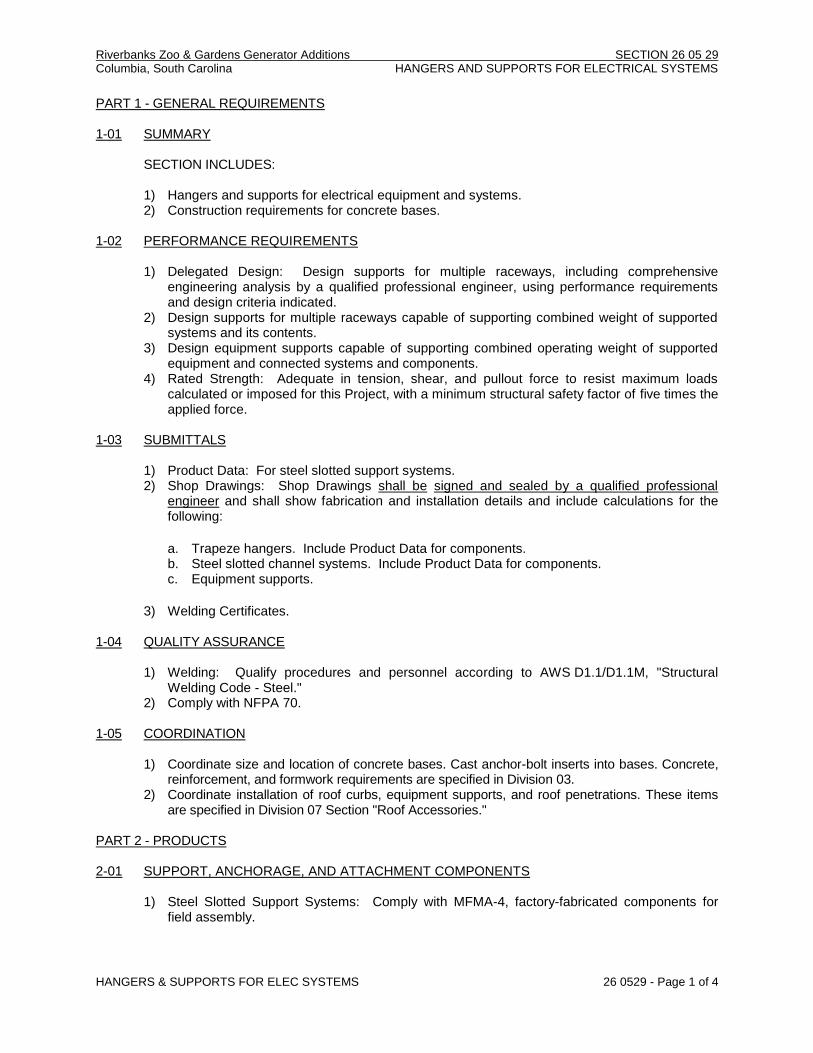
Riverbanks Zoo & Gardens Generator Additions SECTION 26 05 29 Columbia, South Carolina HANGERS AND SUPPORTS FOR ELECTRICAL SYSTEMS
HANGERS & SUPPORTS FOR ELEC SYSTEMS 26 0529 - Page 1 of 4
PART 1 - GENERAL REQUIREMENTS 1-01 SUMMARY
SECTION INCLUDES: 1) Hangers and supports for electrical equipment and systems. 2) Construction requirements for concrete bases.
1-02 PERFORMANCE REQUIREMENTS
1) Delegated Design: Design supports for multiple raceways, including comprehensive engineering analysis by a qualified professional engineer, using performance requirements and design criteria indicated.
2) Design supports for multiple raceways capable of supporting combined weight of supported systems and its contents.
3) Design equipment supports capable of supporting combined operating weight of supported equipment and connected systems and components.
4) Rated Strength: Adequate in tension, shear, and pullout force to resist maximum loads calculated or imposed for this Project, with a minimum structural safety factor of five times the applied force.
1-03 SUBMITTALS
1) Product Data: For steel slotted support systems. 2) Shop Drawings: Shop Drawings shall be signed and sealed by a qualified professional
engineer and shall show fabrication and installation details and include calculations for the following:
a. Trapeze hangers. Include Product Data for components. b. Steel slotted channel systems. Include Product Data for components. c. Equipment supports.
3) Welding Certificates.
1-04 QUALITY ASSURANCE
1) Welding: Qualify procedures and personnel according to AWS D1.1/D1.1M, "Structural Welding Code - Steel."
2) Comply with NFPA 70. 1-05 COORDINATION
1) Coordinate size and location of concrete bases. Cast anchor-bolt inserts into bases. Concrete, reinforcement, and formwork requirements are specified in Division 03.
2) Coordinate installation of roof curbs, equipment supports, and roof penetrations. These items are specified in Division 07 Section "Roof Accessories."
PART 2 - PRODUCTS 2-01 SUPPORT, ANCHORAGE, AND ATTACHMENT COMPONENTS
1) Steel Slotted Support Systems: Comply with MFMA-4, factory-fabricated components for
field assembly.
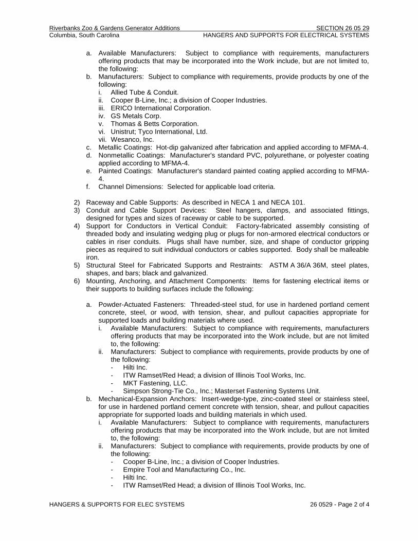
Riverbanks Zoo & Gardens Generator Additions SECTION 26 05 29 Columbia, South Carolina HANGERS AND SUPPORTS FOR ELECTRICAL SYSTEMS
HANGERS & SUPPORTS FOR ELEC SYSTEMS 26 0529 - Page 2 of 4
a. Available Manufacturers: Subject to compliance with requirements, manufacturers offering products that may be incorporated into the Work include, but are not limited to, the following:
b. Manufacturers: Subject to compliance with requirements, provide products by one of the following: i. Allied Tube & Conduit. ii. Cooper B-Line, Inc.; a division of Cooper Industries. iii. ERICO International Corporation. iv. GS Metals Corp. v. Thomas & Betts Corporation. vi. Unistrut; Tyco International, Ltd. vii. Wesanco, Inc.
c. Metallic Coatings: Hot-dip galvanized after fabrication and applied according to MFMA-4. d. Nonmetallic Coatings: Manufacturer's standard PVC, polyurethane, or polyester coating
applied according to MFMA-4. e. Painted Coatings: Manufacturer's standard painted coating applied according to MFMA-
4. f. Channel Dimensions: Selected for applicable load criteria.
2) Raceway and Cable Supports: As described in NECA 1 and NECA 101. 3) Conduit and Cable Support Devices: Steel hangers, clamps, and associated fittings,
designed for types and sizes of raceway or cable to be supported. 4) Support for Conductors in Vertical Conduit: Factory-fabricated assembly consisting of
threaded body and insulating wedging plug or plugs for non-armored electrical conductors or cables in riser conduits. Plugs shall have number, size, and shape of conductor gripping pieces as required to suit individual conductors or cables supported. Body shall be malleable iron.
5) Structural Steel for Fabricated Supports and Restraints: ASTM A 36/A 36M, steel plates, shapes, and bars; black and galvanized.
6) Mounting, Anchoring, and Attachment Components: Items for fastening electrical items or their supports to building surfaces include the following:
a. Powder-Actuated Fasteners: Threaded-steel stud, for use in hardened portland cement
concrete, steel, or wood, with tension, shear, and pullout capacities appropriate for supported loads and building materials where used. i. Available Manufacturers: Subject to compliance with requirements, manufacturers
offering products that may be incorporated into the Work include, but are not limited to, the following:
ii. Manufacturers: Subject to compliance with requirements, provide products by one of the following: - Hilti Inc. - ITW Ramset/Red Head; a division of Illinois Tool Works, Inc. - MKT Fastening, LLC. - Simpson Strong-Tie Co., Inc.; Masterset Fastening Systems Unit.
b. Mechanical-Expansion Anchors: Insert-wedge-type, zinc-coated steel or stainless steel, for use in hardened portland cement concrete with tension, shear, and pullout capacities appropriate for supported loads and building materials in which used. i. Available Manufacturers: Subject to compliance with requirements, manufacturers
offering products that may be incorporated into the Work include, but are not limited to, the following:
ii. Manufacturers: Subject to compliance with requirements, provide products by one of the following: - Cooper B-Line, Inc.; a division of Cooper Industries. - Empire Tool and Manufacturing Co., Inc. - Hilti Inc. - ITW Ramset/Red Head; a division of Illinois Tool Works, Inc.

Riverbanks Zoo & Gardens Generator Additions SECTION 26 05 29 Columbia, South Carolina HANGERS AND SUPPORTS FOR ELECTRICAL SYSTEMS
HANGERS & SUPPORTS FOR ELEC SYSTEMS 26 0529 - Page 3 of 4
- MKT Fastening, LLC. c. Concrete Inserts: Steel or malleable-iron, slotted support system units similar to MSS
Type 18; complying with MFMA-4 or MSS SP-58. d. Clamps for Attachment to Steel Structural Elements: MSS SP-58, type suitable for
attached structural element. e. Through Bolts: Structural type, hex head, and high strength. Comply with ASTM A 325. f. Toggle Bolts: All-steel springhead type. g. Hanger Rods: Threaded steel.
2-02 FABRICATED METAL EQUIPMENT SUPPORT ASSEMBLIES
1) Description: Welded or bolted, structural-steel shapes, shop or field fabricated to fit
dimensions of supported equipment. 2) Materials: Comply with requirements in Division 05 Section "Metal Fabrications" for steel
shapes and plates. PART 3 - EXECUTION 3-01 APPLICATION
1) Comply with NECA 1 and NECA 101 for application of hangers and supports for electrical
equipment and systems except if requirements in this Section are stricter. 2) Maximum Support Spacing and Minimum Hanger Rod Size for Raceway: Space supports for
EMT, IMC, and RMC as required by NFPA 70. Minimum rod size shall be 1/4 inch (6 mm) in diameter.
3) Multiple Raceways or Cables: Install trapeze-type supports fabricated with steel slotted or other support system, sized so capacity can be increased by at least 25 percent in future without exceeding specified design load limits. a. Secure raceways and cables to these supports with two-bolt conduit clamps.
4) Spring-steel clamps designed for supporting single conduits without bolts may be used for 1-1/2-inch (38-mm) and smaller raceways serving branch circuits and communication systems above suspended ceilings and for fastening raceways to trapeze supports.
3-02 SUPPORT INSTALLATION
1) Comply with NECA 1 and NECA 101 for installation requirements except as specified in this
Article. 2) Raceway Support Methods: In addition to methods described in NECA 1, EMT, IMC, and
RMC may be supported by openings through structure members, as permitted in NFPA 70. 3) Strength of Support Assemblies: Where not indicated, select sizes of components so
strength will be adequate to carry present and future static loads within specified loading limits. Minimum static design load used for strength determination shall be weight of supported components plus 200 lb (90 kg).
4) Mounting and Anchorage of Surface-Mounted Equipment and Components: Anchor and fasten electrical items and their supports to building structural elements by the following methods unless otherwise indicated by code: a. To Wood: Fasten with lag screws or through bolts. b. To New Concrete: Bolt to concrete inserts. c. To Masonry: Approved toggle-type bolts on hollow masonry units and expansion anchor
fasteners on solid masonry units. d. To Existing Concrete: Expansion anchor fasteners. e. Instead of expansion anchors, powder-actuated driven threaded studs provided with lock
washers and nuts may be used in existing standard-weight concrete 4 inches (100 mm) thick or greater. Do not use for anchorage to lightweight-aggregate concrete or for slabs less than 4 inches (100 mm) thick.

Riverbanks Zoo & Gardens Generator Additions SECTION 26 05 29 Columbia, South Carolina HANGERS AND SUPPORTS FOR ELECTRICAL SYSTEMS
HANGERS & SUPPORTS FOR ELEC SYSTEMS 26 0529 - Page 4 of 4
f. To Steel: Welded threaded studs complying with AWS D1.1/D1.1M, with lock washers and nuts; beam clamps (MSS Type 19, 21, 23, 25, or 27) complying with MSS SP-69; or spring-tension clamps.
g. To Light Steel: Sheet metal screws. h. Items Mounted on Hollow Walls and Nonstructural Building Surfaces: Mount cabinets,
panelboards, disconnect switches, control enclosures, pull and junction boxes, transformers, and other devices on slotted-channel racks attached to substrate by means that meet seismic-restraint strength and anchorage requirements.
5) Drill holes for expansion anchors in concrete at locations and to depths that avoid reinforcing bars.
3-03 INSTALLATION OF FABRICATED METAL SUPPORTS
1) Comply with installation requirements in Division 05 Section "Metal Fabrications" for site-
fabricated metal supports. 2) Cut, fit, and place miscellaneous metal supports accurately in location, alignment, and
elevation to support and anchor electrical materials and equipment. 3) Field Welding: Comply with AWS D1.1/D1.1M.
3-04 CONCRETE BASES 1) Construct concrete bases of dimensions indicated but not less than 4 inches (100 mm) larger
in both directions than supported unit, and so anchors will be a minimum of 10 bolt diameters from edge of the base.
2) Use 3000-psi, 28-day compressive-strength concrete. 3) Anchor equipment to concrete base.
a. Place and secure anchorage devices. Use supported equipment manufacturer's setting drawings, templates, diagrams, instructions, and directions furnished with items to be embedded.
b. Install anchor bolts to elevations required for proper attachment to supported equipment. c. Install anchor bolts according to anchor-bolt manufacturer's written instructions.
3-05 PAINTING
1) Touchup: Clean field welds and abraded areas of shop paint. Paint exposed areas
immediately after erecting hangers and supports. Use same materials as used for shop painting. Comply with SSPC-PA 1 requirements for touching up field-painted surfaces. Apply paint by brush or spray to provide minimum dry film thickness of 2.0 mils.
2) Touchup: Comply with requirements in Division 09 for cleaning and touchup painting of field welds, bolted connections, and abraded areas of shop paint on miscellaneous metal.
3) Galvanized Surfaces: Clean welds, bolted connections, and abraded areas and apply galvanizing-repair paint to comply with ASTM A 780.
END OF SECTION 260529

Part 5
Vibration and Seismic Controls for Electrical System
Technical Specifications

Riverbanks Zoo & Gardens Generator Additions SECTION 26 05 48 Columbia, South Carolina VIBRATION AND SEISMIC CONTROLS FOR ELECTRICAL SYSTEMS
VIBRATION & SEISMIC CONTROLS FOR ELEC SYSTEMS 26 0548 - Page 1 of 5
PART 1 - GENERAL REQUIREMENTS 1-01 SUMMARY
SECTION INCLUDES: 1) Isolation pads. 2) Spring isolators. 3) Restrained spring isolators. 4) Channel support systems. 5) Restraint cables. 6) Hanger rod stiffeners. 7) Anchorage bushings and washers.
1-02 PERFORMANCE REQUIREMENTS
Seismic-Restraint:Site Class as Defined in the IBC: D.
1) Design supports for multiple raceways capable of supporting combined weight of supported systems and its contents.
2) Design equipment supports capable of supporting combined operating weight of supported equipment and connected systems and components.
3) Rated Strength: Adequate in tension, shear, and pullout force to resist maximum loads calculated or imposed for this Project, with a minimum structural safety factor of five times the applied force.
A. The Electrical Contractor shall be responsible for providing restraints to resist the earthquake
effects on the electrical system. The requirements for these restraints are found in the International Building Code and ASCE 7.
B. The Electrical Contractor shall refer to the latest edition of the "Seismic Restraint Manual Guidelines for Mechanical System" published by SMACNA for guidelines to determine the correct restraints for sheet metal ducts, piping, and conduit, etc.
C. The Electrical Contractor shall retain the services of a Professional Structural Engineer registered in the State, to design seismic restraint elements required for this project. The engineer's computations, bearing his professional seal, shall accompany shop drawings which show Code compliance. Computations and shop drawings shall be submitted for review prior to the purchasing of materials, equipment systems, and assemblies.
1-03 ACTION SUBMITTALS
1) Product Data: For the following:
a. Include rated load, rated deflection, and overload capacity for each vibration isolation
device. b. Illustrate and indicate style, material, strength, fastening provision, and finish for each
type and size of seismic-restraint component used. i. Tabulate types and sizes of seismic restraints, complete with report numbers and
rated strength in tension and shear as evaluated by an agency acceptable to authorities having jurisdiction.
ii. Annotate to indicate application of each product submitted and compliance with requirements.
c. Restrained-Isolation Devices: Include ratings for horizontal, vertical, and combined loads.

Riverbanks Zoo & Gardens Generator Additions SECTION 26 05 48 Columbia, South Carolina VIBRATION AND SEISMIC CONTROLS FOR ELECTRICAL SYSTEMS
VIBRATION & SEISMIC CONTROLS FOR ELEC SYSTEMS 26 0548 - Page 2 of 5
2) Delegated-Design Submittal: For vibration isolation and seismic-restraint details indicated to comply with performance requirements and design criteria, including analysis data signed and sealed by the qualified professional engineer responsible for their preparation.
a. Design Calculations: Calculate static and dynamic loading due to equipment weight and
operation, seismic forces required to select vibration isolators and seismic restraints. i. Coordinate design calculations with wind-load calculations required for equipment
mounted outdoors. Comply with requirements in other electrical Sections for equipment mounted outdoors.
b. Indicate materials and dimensions and identify hardware, including attachment and anchorage devices.
c. Field-fabricated supports. d. Seismic-Restraint Details:
i. Design Analysis: To support selection and arrangement of seismic restraints. Include calculations of combined tensile and shear loads.
ii. Details: Indicate fabrication and arrangement. Detail attachments of restraints to the restrained items and to the structure. Show attachment locations, methods, and spacings. Identify components, list their strengths, and indicate directions and values of forces transmitted to the structure during seismic events.
1-04 INFORMATIONAL SUBMITTALS
1) Welding certificates. 2) Field quality-control test reports.
1-05 QUALITY ASSURANCE
1) Comply with seismic-restraint requirements in the IBC unless requirements in this Section are more stringent.
2) Welding Qualifications: Qualify procedures and personnel according to AWS D1.1/D1.1M, "Structural Welding Code - Steel."
3) Seismic-restraint devices shall have horizontal and vertical load testing and analysis and shall bear anchorage preapproval OPA number from OSHPD, preapproval by ICC-ES, or preapproval by another agency acceptable to authorities having jurisdiction, showing maximum seismic-restraint ratings. Ratings based on independent testing are preferred to ratings based on calculations. If preapproved ratings are not available, submittals based on independent testing are preferred. Calculations (including combining shear and tensile loads) to support seismic-restraint designs must be signed and sealed by a qualified professional engineer.
4) Comply with NFPA 70. PART 2 - PRODUCTS 2-01 VIBRATION ISOLATORS
1) Manufacturers: Subject to compliance with requirements, provide products by one of the
following: a. Ace Mountings Co., Inc. b. Amber/Booth Company, Inc. c. California Dynamics Corporation. d. Isolation Technology, Inc. e. Kinetics Noise Control. f. Mason Industries. g. Vibration Eliminator Co., Inc. h. Vibration Isolation. i. Vibration Mountings & Controls, Inc.
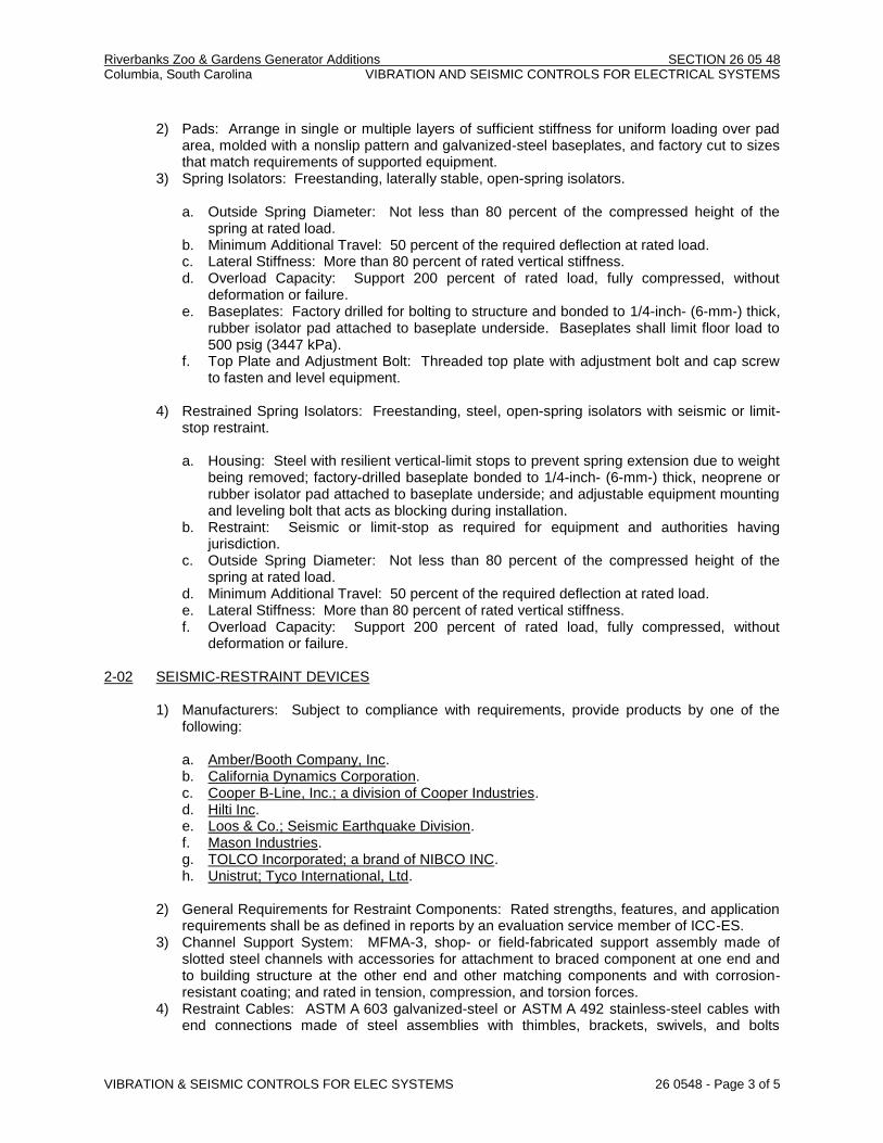
Riverbanks Zoo & Gardens Generator Additions SECTION 26 05 48 Columbia, South Carolina VIBRATION AND SEISMIC CONTROLS FOR ELECTRICAL SYSTEMS
VIBRATION & SEISMIC CONTROLS FOR ELEC SYSTEMS 26 0548 - Page 3 of 5
2) Pads: Arrange in single or multiple layers of sufficient stiffness for uniform loading over pad
area, molded with a nonslip pattern and galvanized-steel baseplates, and factory cut to sizes that match requirements of supported equipment.
3) Spring Isolators: Freestanding, laterally stable, open-spring isolators. a. Outside Spring Diameter: Not less than 80 percent of the compressed height of the
spring at rated load. b. Minimum Additional Travel: 50 percent of the required deflection at rated load. c. Lateral Stiffness: More than 80 percent of rated vertical stiffness. d. Overload Capacity: Support 200 percent of rated load, fully compressed, without
deformation or failure. e. Baseplates: Factory drilled for bolting to structure and bonded to 1/4-inch- (6-mm-) thick,
rubber isolator pad attached to baseplate underside. Baseplates shall limit floor load to 500 psig (3447 kPa).
f. Top Plate and Adjustment Bolt: Threaded top plate with adjustment bolt and cap screw to fasten and level equipment.
4) Restrained Spring Isolators: Freestanding, steel, open-spring isolators with seismic or limit-stop restraint. a. Housing: Steel with resilient vertical-limit stops to prevent spring extension due to weight
being removed; factory-drilled baseplate bonded to 1/4-inch- (6-mm-) thick, neoprene or rubber isolator pad attached to baseplate underside; and adjustable equipment mounting and leveling bolt that acts as blocking during installation.
b. Restraint: Seismic or limit-stop as required for equipment and authorities having jurisdiction.
c. Outside Spring Diameter: Not less than 80 percent of the compressed height of the spring at rated load.
d. Minimum Additional Travel: 50 percent of the required deflection at rated load. e. Lateral Stiffness: More than 80 percent of rated vertical stiffness. f. Overload Capacity: Support 200 percent of rated load, fully compressed, without
deformation or failure.
2-02 SEISMIC-RESTRAINT DEVICES 1) Manufacturers: Subject to compliance with requirements, provide products by one of the
following:
a. Amber/Booth Company, Inc. b. California Dynamics Corporation. c. Cooper B-Line, Inc.; a division of Cooper Industries. d. Hilti Inc. e. Loos & Co.; Seismic Earthquake Division. f. Mason Industries. g. TOLCO Incorporated; a brand of NIBCO INC. h. Unistrut; Tyco International, Ltd.
2) General Requirements for Restraint Components: Rated strengths, features, and application
requirements shall be as defined in reports by an evaluation service member of ICC-ES. 3) Channel Support System: MFMA-3, shop- or field-fabricated support assembly made of
slotted steel channels with accessories for attachment to braced component at one end and to building structure at the other end and other matching components and with corrosion-resistant coating; and rated in tension, compression, and torsion forces.
4) Restraint Cables: ASTM A 603 galvanized-steel or ASTM A 492 stainless-steel cables with end connections made of steel assemblies with thimbles, brackets, swivels, and bolts

Riverbanks Zoo & Gardens Generator Additions SECTION 26 05 48 Columbia, South Carolina VIBRATION AND SEISMIC CONTROLS FOR ELECTRICAL SYSTEMS
VIBRATION & SEISMIC CONTROLS FOR ELEC SYSTEMS 26 0548 - Page 4 of 5
designed for restraining cable service; and with a minimum of two clamping bolts for cable engagement.
5) Hanger Rod Stiffener: Steel tube or steel slotted-support-system sleeve with internally bolted connections of reinforcing steel angle clamped to hanger rod. Do not weld stiffeners to rods.
6) Bushings for Floor-Mounted Equipment Anchor: Neoprene bushings designed for rigid equipment mountings, and matched to type and size of anchors and studs.
7) Bushing Assemblies for Wall-Mounted Equipment Anchorage: Assemblies of neoprene elements and steel sleeves designed for rigid equipment mountings, and matched to type and size of attachment devices.
8) Resilient Isolation Washers and Bushings: One-piece, molded, oil- and water-resistant neoprene, with a flat washer face.
9) Mechanical Anchor: Drilled-in and stud-wedge or female-wedge type in zinc-coated steel for interior applications and stainless steel for exterior applications. Select anchors with strength required for anchor and as tested according to ASTM E 488. Minimum length of eight times diameter.
10) Adhesive Anchor: Drilled-in and capsule anchor system containing polyvinyl or urethane methacrylate-based resin and accelerator, or injected polymer or hybrid mortar adhesive. Provide anchor bolts and hardware with zinc-coated steel for interior applications and stainless steel for exterior applications. Select anchor bolts with strength required for anchor and as tested according to ASTM E 488.
PART 3 - EXECUTION 3-01 APPLICATIONS
1) Multiple Raceways or Cables: Secure raceways and cables to trapeze member with clamps
approved for application by an evaluation service member of ICC-ES or other agency acceptable to authorities having jurisdiction.
2) Hanger Rod Stiffeners: Install hanger rod stiffeners where indicated or scheduled on Drawings to receive them and where required to prevent buckling of hanger rods due to seismic forces.
3) Strength of Support and Seismic-Restraint Assemblies: Where not indicated, select sizes of components so strength will be adequate to carry present and future static and seismic loads within specified loading limits.
3-02 SEISMIC-RESTRAINT DEVICE INSTALLATION
1) Equipment and Hanger Restraints:
a. Install restrained isolators on electrical equipment. b. Install resilient, bolt-isolation washers on equipment anchor bolts where clearance
between anchor and adjacent surface exceeds 0.125 inch (3.2 mm). c. Install seismic-restraint devices using methods approved by an evaluation service
member of ICC-ES or an agency acceptable to authorities having jurisdiction providing required submittals for component.
2) Install bushing assemblies for mounting bolts for wall-mounted equipment, arranged to
provide resilient media where equipment or equipment-mounting channels are attached to wall.
3) Attachment to Structure: If specific attachment is not indicated, anchor bracing to structure at flanges of beams, at upper truss chords of bar joists, or at concrete members.
4) Drilled-in Anchors: a. Identify position of reinforcing steel and other embedded items prior to drilling holes for
anchors. Do not damage existing reinforcing or embedded items during coring or drilling. Notify the structural engineer if reinforcing steel or other embedded items are

Riverbanks Zoo & Gardens Generator Additions SECTION 26 05 48 Columbia, South Carolina VIBRATION AND SEISMIC CONTROLS FOR ELECTRICAL SYSTEMS
VIBRATION & SEISMIC CONTROLS FOR ELEC SYSTEMS 26 0548 - Page 5 of 5
encountered during drilling. Locate and avoid pre-stressed tendons, electrical and telecommunications conduit, and gas lines.
b. Do not drill holes in concrete or masonry until concrete, mortar, or grout has achieved full design strength.
c. Wedge Anchors: Protect threads from damage during anchor installation. Heavy-duty sleeve anchors shall be installed with sleeve fully engaged in the structural element to which anchor is to be fastened.
d. Adhesive Anchors: Clean holes to remove loose material and drilling dust prior to installation of adhesive. Place adhesive in holes proceeding from the bottom of the hole and progressing toward the surface in such a manner as to avoid introduction of air pockets in the adhesive.
e. Set anchors to manufacturer's recommended torque, using a torque wrench. f. Install zinc-coated steel anchors for interior and stainless-steel anchors for exterior
applications.
3-03 ACCOMMODATION OF DIFFERENTIAL SEISMIC MOTION 1) Install flexible connections in runs of raceways, cables, wireways, cable trays, and busways
where they cross seismic joints, where adjacent sections or branches are supported by different structural elements, and where they terminate with connection to equipment that is anchored to a different structural element from the one supporting them as they approach equipment.
3-04 FIELD QUALITY CONTROL
1) Tests and Inspections:
a. Obtain Architect's approval before transmitting test loads to structure. Provide temporary
load-spreading members. b. Test at least four of each type and size of installed anchors and fasteners selected by
Architect. c. Test to 90 percent of rated proof load of device. d. Measure isolator restraint clearance. e. Measure isolator deflection. f. Verify snubber minimum clearances. g. If a device fails test, modify all installations of same type and retest until satisfactory
results are achieved.
2) Remove and replace malfunctioning units and retest as specified above. 3) Prepare test and inspection reports.
3-05 ADJUSTING
1) Adjust isolators after isolated equipment is at operating weight. 2) Adjust limit stops on restrained spring isolators to mount equipment at normal operating
height. After equipment installation is complete, adjust limit stops so they are out of contact during normal operation.
3) Adjust active height of spring isolators. 4) Adjust restraints to permit free movement of equipment within normal mode of operation.
END OF SECTION 260548

Part 6
Surge Protection Device
Technical Specifications

Riverbanks Zoo & Gardens Generator Additions SECTION 26 43 13 Columbia, South Carolina SURGE PROTECTION DEVICE (SPD)
SURGE PROTECTION DEVICE (SPD) 26 4313 - Page 1 of 3
PART 1 - GENERAL REQUIREMENTS 1-01 SCOPE OF WORK
WORK INCLUDED: Furnish all necessary labor, material, plant and equipment, including materials and equipment not specifically mentioned but necessary to complete the work in a neat, correct, and workmanlike manner.
1-02 CODES AND STANDARDS
All work shall comply with the requirements of Section 260500 – Electrical Basic Materials and Methods. Each surge suppressor shall be UL 1449-Fourth Edition and UL 1283 listed.
1-03 WARRANTY
Each surge suppressor shall have a minimum 20-year warranty. 1-04 SUBMITTALS
Within thirty (30) days after the award of the contract, submit six (6) sets of shop drawings and equipment specifications to the Architect-Engineer for review. Shop drawings shall include specification sheets on all surge suppressors to be furnished.
Submittals shall include UL 1449 4th Edition Listing documentation verifiable by visiting www.UL.com, clicking “Certifications” link, searching using UL Category Code: VZCA and VZCA2:
1. Short Circuit Current Rating (SCCR) 2. Voltage Protection Ratings (VPRs) for all modes 3. Maximum Continuous Operating Voltage rating (MCOV) 4. I-nominal rating (I-n) 5. SPD shall be UL listed and labeled as Type 1 or Type 2 applications
PART 2 - PRODUCTS 2-01 SURGE SUPPRESSOR FOR COMPUTER PANELBOARDS MANUFACTURERS: Innovative Technology, EFI Electronics, Square D, Eaton, Liebert, SSI, or
APT.
SURGE PROTECTIVE DEVICE FEATURES
A. SPD shall be UL 1449 4th Edition listed and labeled verifiable by visiting www.UL.com,
clicking “Certifications” link, searching using UL Category Code: VZCA.
B. SPD shall be UL 1449 listed and labeled with 200kA Short Circuit Current Rating (SCCR). Fuse ratings shall not be considered in lieu of demonstrated withstand testing of SPD, per NEC 285.6.
C. SPD shall be UL 1449 labeled as Type 1 intended for use without need for external or supplemental overcurrent controls. Every suppression component of every mode, including N-G, shall be protected by internal overcurrent and thermal over temperature controls. SPDs relying upon external or supplementary installed safety disconnectors do not meet the intent of this specification.
D. SPD shall be UL 1449 labeled with 20kA I-nominal (I-n) (verifiable at UL.com) as recommended for UL 96A Lightning Protection Master Label and NFPA 780.

Riverbanks Zoo & Gardens Generator Additions SECTION 26 43 13 Columbia, South Carolina SURGE PROTECTION DEVICE (SPD)
SURGE PROTECTION DEVICE (SPD) 26 4313 - Page 2 of 3
E. Suppression components shall utilize heavy duty Metal Oxide Varistor (MOV) technology.
F. True 10-Mode Protection paths: SPD shall provide “directly connected protection elements” between all possible modes of protection: L-N, L-G, L-L, and N-G for Wye systems.
G. If a dedicated breaker for the SPD is not provided in the switchboard, the service entrance SPD shall include an integral UL Recognized disconnect switch. A dedicated breaker shall serve as a means of disconnect for distribution SPDs.
H. SPD shall meet or exceed the following criteria:
1. Minimum surge current capability (single pulse rated) per phase shall be:
a. Service Entrance, Emergency Power Switchboards, and MCC applications: Innovative Technologies PTE-240 Series or equal with 10-Mode protection. Minimum surge current capability shall be 240 KA per phase.
b. Lighting and Power Distribution panelboards 400 amps. and above:
Innovative Technologies PTE160 Series with minimum surge current capability of 160 KA per phase
c. Lighting and Power branch panelboards below 400 amps: Innovative
Technologies PTE080 with minimum surge current capability of 80 KA per phase
2. UL 1449 Listed Voltage Protection Ratings (VPRs) shall not exceed the following:
VOLTAGE L-N L-G N-G
208Y/120V 700V 700V 700V
480Y/277V 1000V 1000V 1000V
3. UL 1449 Listed Maximum Continuous Operating Voltage (MCOV) for L-N, L-G, and N-G modes of protection (verifiable at UL.com):
System Voltage Allowable System Voltage Fluctuation (%)
MCOV
208Y/120V 25% 150V
480Y/277V 20% 320V
I. SPD shall include a serviceable, replaceable module (excluding Distribution).
J. Service Entrance SPD shall be complimentary UL 1283 listed for EMI/RFI filtering with minimum attenuation of up to 50dB from 10kHz - 100MHz.
K. SPD shall have a warranty for a period of twenty (20) years, incorporating unlimited replacements of suppressor parts if they are destroyed by transients during the warranty period.
L. Service Entrance SPDs shall be equipped with the following diagnostics:
1. Visual LED diagnostics including a minimum of one green LED indicator per phase, and one red service LED.
2. Audible alarm with on/off silence function and diagnostic test function (excluding branch).
3. Form C dry contacts 4. Surge Counter 5. No other test equipment shall be required for SPD monitoring or testing
before or after installation.

Riverbanks Zoo & Gardens Generator Additions SECTION 26 43 13 Columbia, South Carolina SURGE PROTECTION DEVICE (SPD)
SURGE PROTECTION DEVICE (SPD) 26 4313 - Page 3 of 3
M. Distribution Panels SPDs shall be equipped with the following diagnostics:
1. Visual LED diagnostics including a minimum of one green LED indicator
per phase, and one red service LED. 2. Audible alarm with on/off silence function and diagnostic test function
(excluding branch). 3. Form C dry contacts 4. No other test equipment shall be required for SPD monitoring or testing
before or after installation.
LEADS: #10 THHN. For optimum performance, mount surge arrestor adjacent to the panel so that leads are kept as short as possible, straight, and tightly taped. ENCLOSURE: NEMA 4 or NEMA 12 steel enclosure, locknut and washer included.
PART 3 - EXECUTION 3-01 INSTALLATION
Furnish and install systems in accordance with the plans and specifications, all applicable codes and the manufacturer's recommendations. All wiring shall be installed in strict compliance with all the provisions of Section 260500.
3-02 CONDUIT AND WIRING
See Section 260500, Basic Materials and Methods. All wiring shall be run in raceways. 3-03 COMPLETION OF WORK
Upon completion of work, the entire system shall be completely operational and tested to conform to these specifications and drawings, and shall be reviewed by the Architect-Engineer. All defects in workmanship and material shall be immediately corrected without additional compensation to the Contractor.
END OF SECTION 264313

Part 7
Electrical Plans

ww
w.s
imsg
roupusa
.com
Irm
o, South
Caro
lina 2
9063
800 C
olu
mbia
na D
rive, Suite 2
08
sims
grou
pSIM
S G
RO
UP E
NG
INEER
S, IN
C.
Phone: (8
03)
765-1
007 Fax: (8
03)
765-1
030
RIV
ERBA
NKS
ZO
O &
GAR
DEN
EMER
GEN
CY G
ENER
ATO
R A
DD
ITIO
NS
COLU
MBI
A, S
OUT
H C
ARO
LIN
A
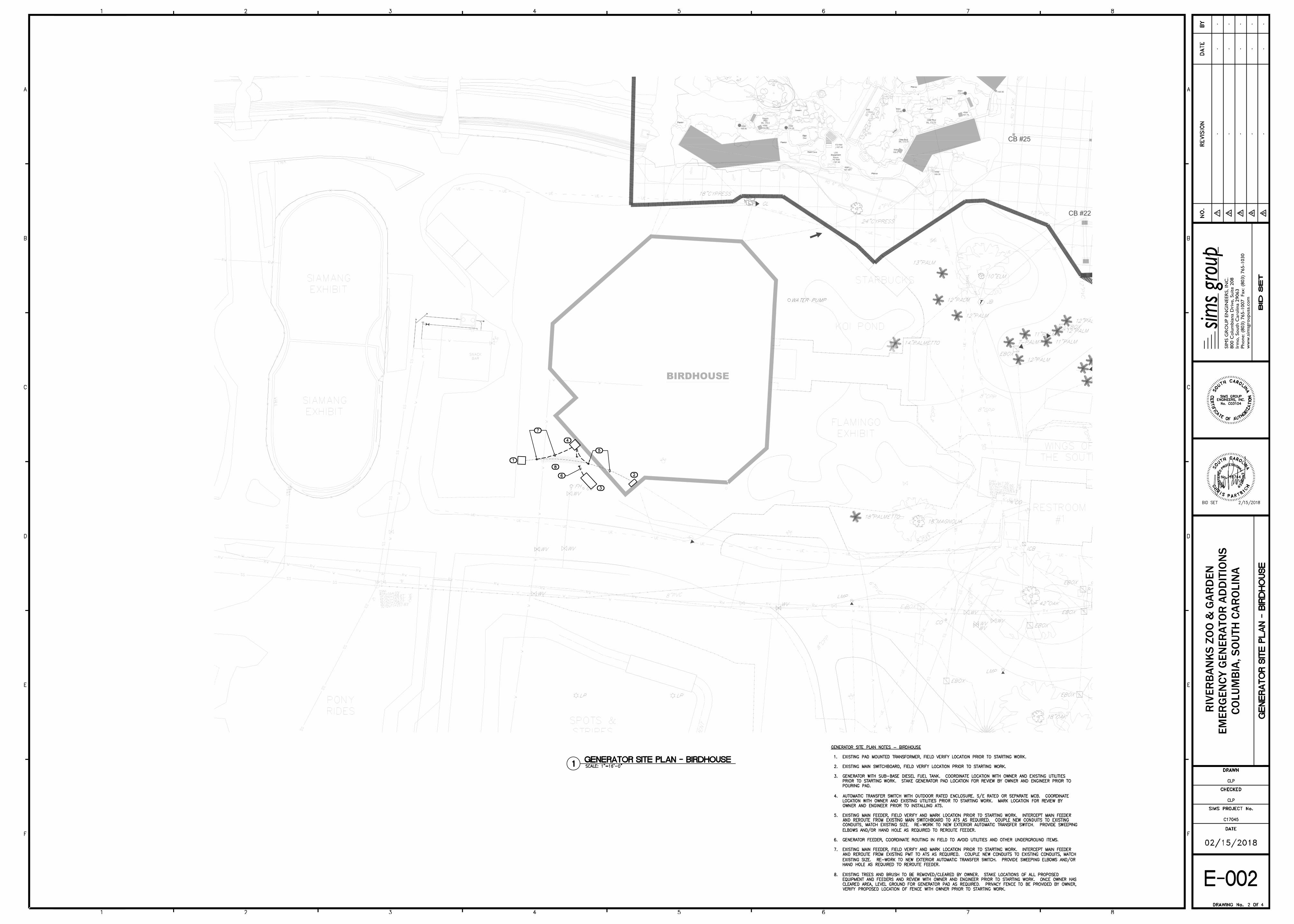
GRIZZLY VIEW SHELTER
A630
OTTER VIEW SHELTER
A530
BIRDHOUSE
CB #25
CB #22
CB #21
U
E
U
E
U
E
U
E
U
E
U
E
U
E
U
E
U
E
U
E
U
E
U
E
U
E
U
E
U
E
U
E
U
E
U
E
UE
U
E
U
E
U
E
U
E
U
E
U
E
UE
U
E
UE
U
E
U
E
U
E
U
E
UE
U
E
U
E
U
E
U
E
UE
U
E
UE
U
E
U
E
UE
U
E
UE
U
E
U
E
U
E
U
E
U
E
U
E
U
E
U
E
U
E
U
E
U
E
U
E
U
E
U
E
U
E
U
E
U
E
U
E
UE
UE
UE
UE
UE
UE
UE
UE
U
E
U
E
U
E
UE
UE
UE
UE
UE
UE
UE
UE
UE
UE
UE
UE
U
E
UE
U
E
U
E
U
E
U
E
U
E
U
E
UE
UE
UE
UE
UE
UE
UE
UE
UE
UE
UE
UE
UE
U
E
U
E
U
E
U
E
U
E
U
E
U
E
U
E
U
E
UE
UE
UE
U
E
U
E
U
E
U
E
U
E
U
E
U
E
U
E
U
E
U
E
U
E
U
E
U
E
U
E
UE
U
E
U
E
U
E
U
E
U
E
U
E
U
E
UE
UE
UE
UE
UE
UE
UE
UE
UE
UE
UE
UE
UE
U
E
U
E
U
E
U
E
U
E
U
E
U
E
U
E
U
E
U
E
U
E
U
E
UE
UE
UE
UE
UE
UE
UE
UE
UE
UE
UE
UE
UE
U
E
U
E
U
E
U
E
U
E
U
E
U
E
U
E
U
E
U
E
U
E
U
E
U
E
U
E
U
E
U
E
U
E
U
E
U
E
U
E
U
E
U
E
U
E
U
E
U
E
U
E
U
E
UE
UE
U
E
U
E
U
E
U
E
U
E
U
E
UE
UE
UE
UE
UE
UE
UE
UE
UE
UE
UE
UE
UE
U
E
U
E
U
E
U
E
U
E
U
E
U
E
U
E
U
E
U
E
U
E
U
E
U
E
U
E
U
E
U
E
U
E
U
E
U
E
U
E
U
E
U
E
U
E
U
E
U
E
U
E
U
E
U
E
U
E
U
E
U
E
U
E
U
E
U
E
U
E
U
E
U
E
U
E
U
E
U
E
U
E
U
E
U
E
U
E
U
E
U
E
U
E
U
E
U
E
U
E
UE
UE
UE
UE
UE
UE
UE
UE
UE
UE
UE
U
E
U
E
U
E
U
E
U
E
U
E
U
E
U
E
U
E
UE
UE
U
E
U
E
U
E
U
E
U
E
U
E
U
E
U
E
U
E
U
E
U
E
U
E
U
E
U
E
UE
U
E
U
E
U
E
U
E
UE
UE
UE
UE
U
E
U
E
U
E
U
E
UE
UE
UE
UE
U
E
U
T
U
T
U
T
U
T
U
T
U
T
U
T
U
T
U
T
U
T
U
T
U
T
U
T
U
T
U
T
U
T
U
T
U
T
U
T
U
T
U
T
U
T
U
T
U
T
U
T
U
T
U
T
U
T
U
T
U
T
U
T
U
T
U
T
U
T
U
T
U
T
U
T
UT
UT
U
T
U
T
UT
UT
U
T
U
T
UT
UT
UT
UT
UT
UT
UT
UT
UT
UT
UT
UT
UT
UT
UT
UT
UT
UT
UT
UT
UT
UT
U
T
U
T
U
T
UT
UT
UT
UT
UT
UT
U
T
U
T
U
T
U
T
U
T
U
T
UT
U
T
U
T
UT
U
T
U
T
U
T
UT
UT
UT
U
T
U
T
U
T
U
T
UT
UT
UT
U
T
U
T
U
T
UT
UT
UT
UT
U
T
U
T
U
T
U
T
U
T
U
T
U
T
U
T
U
T
U
T
U
T
U
T
W
W
W
W
W
W
W
W
W
W
W
W
W
W
W
W
W
W
W
W
W
W
W
W
W
W
W
W
W
W
W
W
W
WW
W
W
W
W
W
W
W
W
W
W
W
W
W
W
U
E
U
E
U
E
U
E
U
E
U
E
U
E
U
E
U
E
U
E
U
E
U
E
UE
UE
UE
UE
UE
UE
UE
UE
UE
UE
U
T
U
T
U
T
U
T
U
T
U
T
U
T
U
T
U
T
U
T
U
T
U
T
U
T
U
T
U
T
U
T
U
T
U
T
U
T
U
T
U
T
U
T
U
T
U
T
U
T
U
T
U
T
U
T
U
T
U
T
U
T
U
T
U
T
U
T
U
T
U
T
U
T
U
T
U
T
U
T
U
T
UE
UE
UE
UE
UE
UE
UE
X
X
X
X
X
X
X
X
X
X
X
X
X
X
X
X
X
X
X
X
X
X
X
X
X
X
X
X
X
X
X
X
X
X
X
X
X
X
X
X X
X
X
XX
X
X
X
X
X
X
X
X
X
X
X
X
X
X
X
X
X
X
X
X
X
X
X
X
X
X
X
X
X
X
X
X
X
X
X
X
X
X
X
X
X
X
X
X
X
X
X
X
X
X
X
X
X
X
X
X
XX
X
X
XX
X
X
X
X
X
X
X
X
X
X
X
X
X
X
X
X
X
X
X
X
X
X
X
X
X
X
X
X
X
X
X
X
X
X
X
X
X
X
X
X
X
X
X
X
X
X
X
X
X
X
X
X
X
X
X
X
X
X
X
X
X
X
X
X
X
X
X
X
X
X
X
X
X
X
X
X
X
X
X
X
X
X
X
X
X
X
X
X
X
X
X
X
X
X
X
X
X
X
X
X
X
X
X
XX
X
X
X
X
X
X
X
X
X
X
X
X
X
X
X
X
X
X
X
X
X
X
X
X
X
X
X
X
X
X
X
X
X
X
X
X
X
X
X
X
XXX
XX
X
X
X
X
X
X
X
X
X
X
X
X
X
X
X
X
X
X
X
X
X
X
X
X
X
X
X
X
X
X
X
X
X
X
X
X
X
X
X
X
X
X
X
X
X
X
X
X
X
X
X
X
X
X
X
X
X
X
X
X
X
X
X
X
X
X
X
X
X
X
X
X
X
X
X
X
X
X
X
X
X
X
X
X
X
X
X
UE
U
E
UE
UE
UE
UE
UE
U
E
U
E
U
E
U
E
U
E
U
E
U
E
U
E
U
E
U
E
U
E
U
E
U
E
UE
UE
UE
UE
UE
UE
U
E
U
E
U
E
U
E
U
E
U
E
U
E
U
E
U
E
U
E
U
E
U
E
U
E
U
E
U
E
U
E
U
E
U
E
U
E
U
E
U
E
U
E
U
E
U
E
U
E
G
G
G
G
G
G
G
G
G
G
G
G
G
G
G
G
G
G
G
G
G
G
G
G
G
G
G
G
G
G
G
G
G
G
G
G
G
G
G
G
G
G
G
G
G
G
G
G
G
G
G
G
G
G
G
G
G
G
G
G
G
G
G
U
T
U
T
U
T
U
T
U
T
U
T
U
T
U
T
U
T
U
T
U
T
U
T
U
T
U
T
U
T
U
T
U
T
U
T
U
T
U
T
U
T
U
T
U
T
U
T
U
T
U
T
U
T
U
T
U
T
U
T
U
T
U
T
U
T
U
T
U
T
U
T
U
T
U
T
U
T
U
T
U
T
U
T
U
T
U
T
U
T
U
T
U
T
U
T
U
T
U
T
U
T
U
T
U
T
U
T
U
T
U
T
U
T
U
T
U
T
U
T
U
T
U
T
U
T
U
T
U
T
U
T
U
T
U
T
U
T
U
T
U
T
U
T
U
T
U
T
U
T
U
T
U
T
W
W
W
W
W
W
W
W
W
W
W
W
W
W
W
W
W
W
W
W
W
W
W
W
W
W
W
W
W
W
W
W
W
W
W
W
W
W
W
W
W
W
W
W
W
W
W
W
W
W
W
W
W
W
W
W
W
W
W
W
W
W
W
W
UE
UE
UE
U
E
U
E
U
E
U
E
UE
UE
U
E
U
E
U
E
U
E
U
E
U
E
U
E
U
E
U
E
U
E
UE
UE
UE
UE
U
E
U
E
U
E
U
E
U
E
U
E
U
E
U
E
U
E
U
E
U
E
U
E
U
E
U
E
U
E
U
E
U
E
U
E
U
E
G
G
G
G
G
G
G
G
G
G
G
G
G
G
W
W
W
W
W
W
W
W
W
W
W
W
W
W
W
W
W
W
W
W
W
W
W
W
W
W
W
W
W
W
W
W
W
W
B
e
a
c
h
Beach
Tunnel
Planter
Planter
View Cave
LSS
Equipment
Room
Grizzly
Pool
Otter Pool
Stream
Bear
Den
Otter Pool
Planter
Beach
Beach
Tunnel
Planter
Planter
View Cave
LSS Equipment Room
Grizzly
Pool
Otter Pool
Stream
Bear
Den
Otter Pool
Planter
HB
HB
PlanterPlanter
LX
LX
RIM
+170.0
+RIM
169.90
RIM+
168.0
+RIM
169.30
RIM+
167.42
RIM+
173.45
RIM+
173.05
+RIM
167.75
FD RIM
+167.40
+RIM
170.35
+RIM
164.50
FD RIM
+167.40
WL 170.0
WL 173.75
WL 172.75
+169.90
ww
w.s
imsg
roupusa
.com
Irm
o, South
Caro
lina 2
9063
800 C
olu
mbia
na D
rive, Suite 2
08
sims
grou
pSIM
S G
RO
UP E
NG
INEER
S, IN
C.
Phone: (8
03)
765-1
007 Fax: (8
03)
765-1
030
RIV
ERBA
NKS
ZO
O &
GAR
DEN
EMER
GEN
CY G
ENER
ATO
R A
DD
ITIO
NS
COLU
MBI
A, S
OUT
H C
ARO
LIN
A
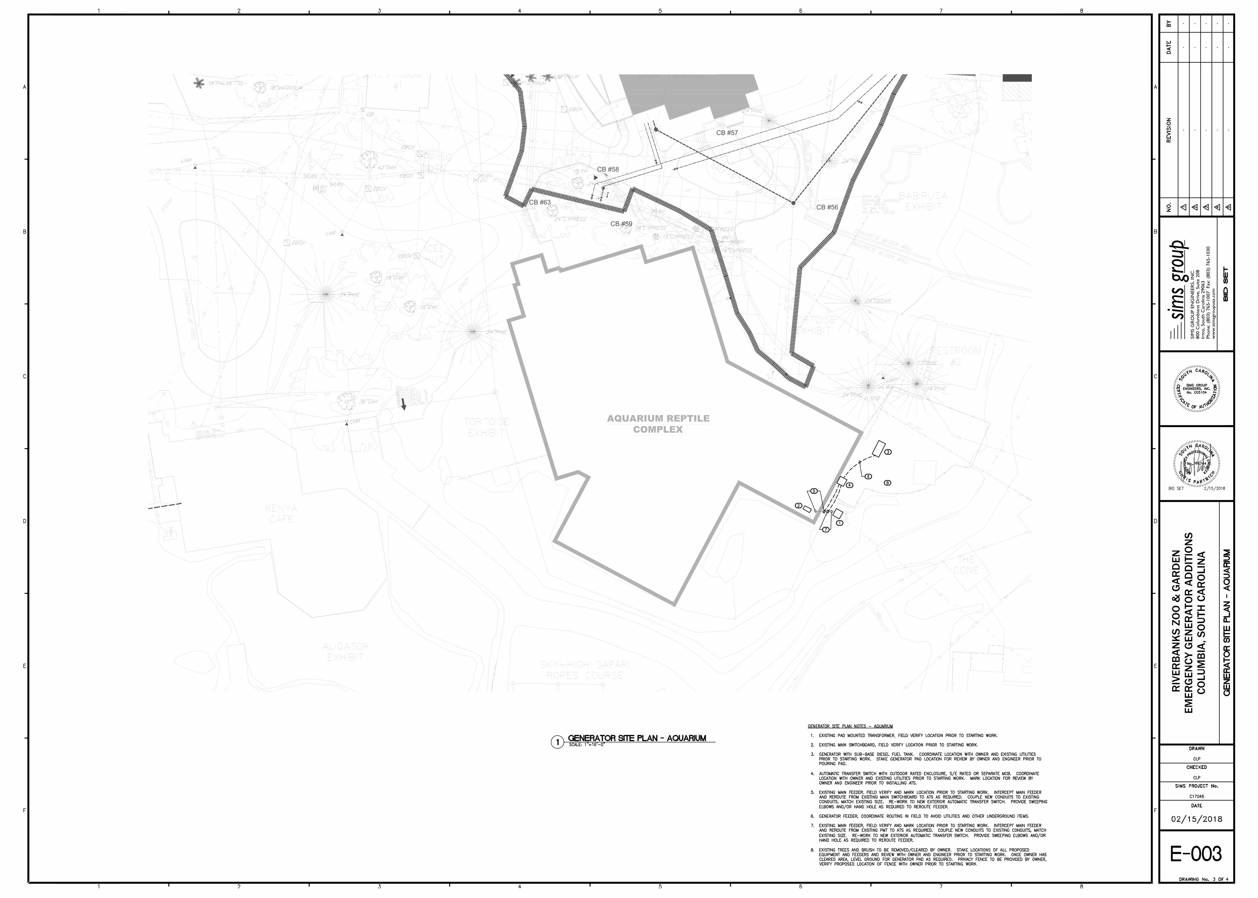
AQUARIUM REPTILE
COMPLEX
U
E
U
E
U
E
U
E
U
E
UE
UE
UE
UE
UE
UE
UE
UE
U
E
U
E
U
E
UE
UE
UE
UE
UE
UE
UE
UE
UE
U
E
UE
U
E
UE
UE
UE
UE
UE
UE
UE
UE
UE
U
E
U
E
U
E
U
E
U
E
U
E
UE
UE
UE
UE
UE
UE
UE
UE
UE
UE
UE
UE
U
E
U
E
U
E
U
E
U
E
U
E
U
E
U
E
U
E
UE
UE
UE
U
E
U
E
U
E
U
E
U
E
U
E
U
E
U
E
U
E
U
E
U
E
U
E
U
E
UE
U
E
UE
U
E
U
E
U
E
U
E
U
E
U
E
UE
UE
UE
UE
UE
UE
UE
UE
UE
UE
UE
UE
UE
U
E
U
E
U
E
U
E
U
E
U
E
U
E
U
E
U
E
U
E
U
E
U
E
UE
UE
U
E
U
E
UE
UE
UE
UE
UE
UE
UE
UE
UE
UE
UE
U
E
U
E
U
E
U
E
U
E
U
E
U
E
U
E
U
E
U
E
U
E
U
E
U
E
U
E
U
E
UE
U
E
U
E
UE
U
E
U
E
U
E
U
E
U
E
U
E
U
E
U
E
U
E
U
E
U
E
U
E
U
E
U
E
U
E
U
E
U
E
U
E
U
E
U
E
U
E
U
E
U
E
U
E
U
E
U
E
U
E
U
E
U
E
U
E
U
E
U
E
U
E
U
E
U
E
U
E
U
E
U
E
UE
UE
UE
UE
UE
UE
UE
UE
UE
UE
UE
UE
UE
U
E
U
E
U
E
U
E
U
E
U
E
U
E
U
E
U
E
U
E
U
E
U
E
U
E
U
E
U
E
U
E
U
E
U
E
U
E
U
E
U
E
U
E
U
E
U
E
U
E
U
E
U
E
U
E
U
E
U
E
U
E
U
E
U
E
U
E
U
E
U
E
U
E
U
E
U
E
U
E
U
E
U
E
U
E
U
E
U
E
U
E
U
E
U
E
U
E
U
E
U
E
U
E
UE
U
E
U
E
G
G
G
G
G
G
G
G
G
G
G
G
G
U
T
U
T
U
T
UT
UT
U
T
U
T
UT
UT
U
T
U
T
UT
UT
UT
UT
UT
UT
UT
UT
UT
UT
UT
UT
UT
UT
UT
UT
UT
UT
UT
UT
UT
UT
U
T
U
T
U
T
UT
UT
UT
UT
UT
UT
U
T
U
T
U
T
U
T
U
T
U
T
UT
U
T
U
T
U
T
UT
U
T
U
T
UT
U
T
U
T
U
T
UT
U
T
U
T
U
T
UT
U
T
U
T
UT
U
T
U
T
U
T
UT
U
T
U
T
U
T
UT
U
T
U
T
U
T
U
T
UT
UT
UT
U
T
U
T
U
T
UT
UT
UT
U
T
U
T
U
T
U
T
U
T
U
T
U
T
U
T
U
T
U
T
U
T
U
T
U
T
U
T
U
E
U
E
U
E
U
E
U
E
U
E
U
E
U
E
U
E
U
E
U
E
U
E
U
E
U
E
U
E
U
E
U
E
U
E
U
E
UE U
E
U
E
U
E
U
E
U
E
U
E
U
E
W
W
W
W
W
W
W
W
W
W
W
W
W
W
W
W
W
W
W
W
W
W
W
W
W
W
W
W
W
W
W
W
W
W
W
W
W
W
W
W
W
W
W
W
W
W
W
W
W
W
W
W
W
W
W
W
W
W
W
W
W
W
W
W
W
W
W
W
W
W
W
W
W
W
W
W
W
W
W
W
W
W
W
W
W
UE
UE
UE
UE
UE
UE
UE
X
X
X
X
X
X
X
X
X
X
X
X
X
X
X
X
X
X
X
X
X
X
X
X
X
X
X
X
X
X
X
X
X
X
X
X
X
X
X
X
X
X
X
X
X
X
X
X
X
X
X
X
X
X
X
X
X
X
X
X
X
X
X
X
X
X
X
X
X
X
X
X
X
X
X
X
X
X
X
X
X
X
X
X
X
X
X
X
X
X
X
X
X
X
X
X
X
X
X
X
X
X
X
X
X
X
X
X
X
X
X
X
X
X
X
X
X
X
X
X
X
X
X
X
X
X
X
X
X
X
X
X
X
X
X
X
X
X
X
X
X
X
X
X
UE
U
E
UE
UE
UE
UE
UE
U
E
U
E
U
E
U
E
U
E
U
E
U
E
U
E
U
E
U
E
U
E
U
E
U
E
UE
UE
U
E
U
E
U
E
U
E
U
E
U
E
U
E
U
E
U
E
U
E
U
E
U
E
U
E
U
E
G
G
G
G
G
G
G
G
G
G
G
G
G
G
G
G
G
G
G
G
G
G
G
G
G
G
G
G
G
G
G
G
G
G
G
G
G
G
G
G
G
G
G
G
U
T
U
T
U
T
U
T
U
T
U
T
U
T
U
T
U
T
U
T
U
T
U
T
U
T
U
T
U
T
U
T
U
T
UT
UT
UT
UT
UT
UT
UT
UT
UT
UT
UT
UT
UT
U
T
U
T
U
T
U
T
U
T
U
T
U
T
U
T
U
T
U
T
U
T
U
T
U
T
U
T
U
T
U
T
U
T
U
T
U
T
U
T
U
T
U
T
U
T
U
T
U
T
U
T
U
T
U
T
U
T
U
T
U
T
U
T
U
T
U
T
U
T
U
T
U
T
U
T
U
T
U
T
U
T
U
T
U
T
W
W
W
W
W
W
W
W
W
W
W
W
W
W
W
W
W
W
W
W
W
W
W
W
W
W
WW
WW
WW
W
WW
WW
W
W
W
W
W
W
W
W
W
W
W
W
W
W
W
W
W
W
W
W
W
W
W
W
W
W
W
W
W
W
W
W
W
W
W
W
W
W
W
W
W
W
W
W
W
W
W
W W W W
W
W
U
E
U
E
U
E
U
E
U
E
U
E
U
E
U
E
U
E
U
E
U
E
U
E
U
E
U
E
U
E
U
E
U
E
U
E
U
E
U
E
U
E
U
E
U
E
U
E
U
E
U
E
U
E
U
E
U
E
U
E
U
E
U
E
U
E
U
E
U
E
U
E
G
G
G
G
G
G
G
G
G
G
G
G
G
G
G
G
G
G
G
G
G
G
G
G
G
G
G
G
G
G
G
G
G
G
G
G
G
G
G
G
G
G
G
G
G
G
G
G
G
G
G
G
G
G
G
G
G
G
G
G
G
G
G
G
G
G
G
G
G
G
G
G
G
G
G
G
G
G
G
G
G
G
G
G
G
G
G
G
CB #56
CB #57
CB #58
CB #63
CB #59
ww
w.s
imsg
roupusa
.com
Irm
o, South
Caro
lina 2
9063
800 C
olu
mbia
na D
rive, Suite 2
08
sims
grou
pSIM
S G
RO
UP E
NG
INEER
S, IN
C.
Phone: (8
03)
765-1
007 Fax: (8
03)
765-1
030
RIV
ERBA
NKS
ZO
O &
GAR
DEN
EMER
GEN
CY G
ENER
ATO
R A
DD
ITIO
NS
COLU
MBI
A, S
OUT
H C
ARO
LIN
A
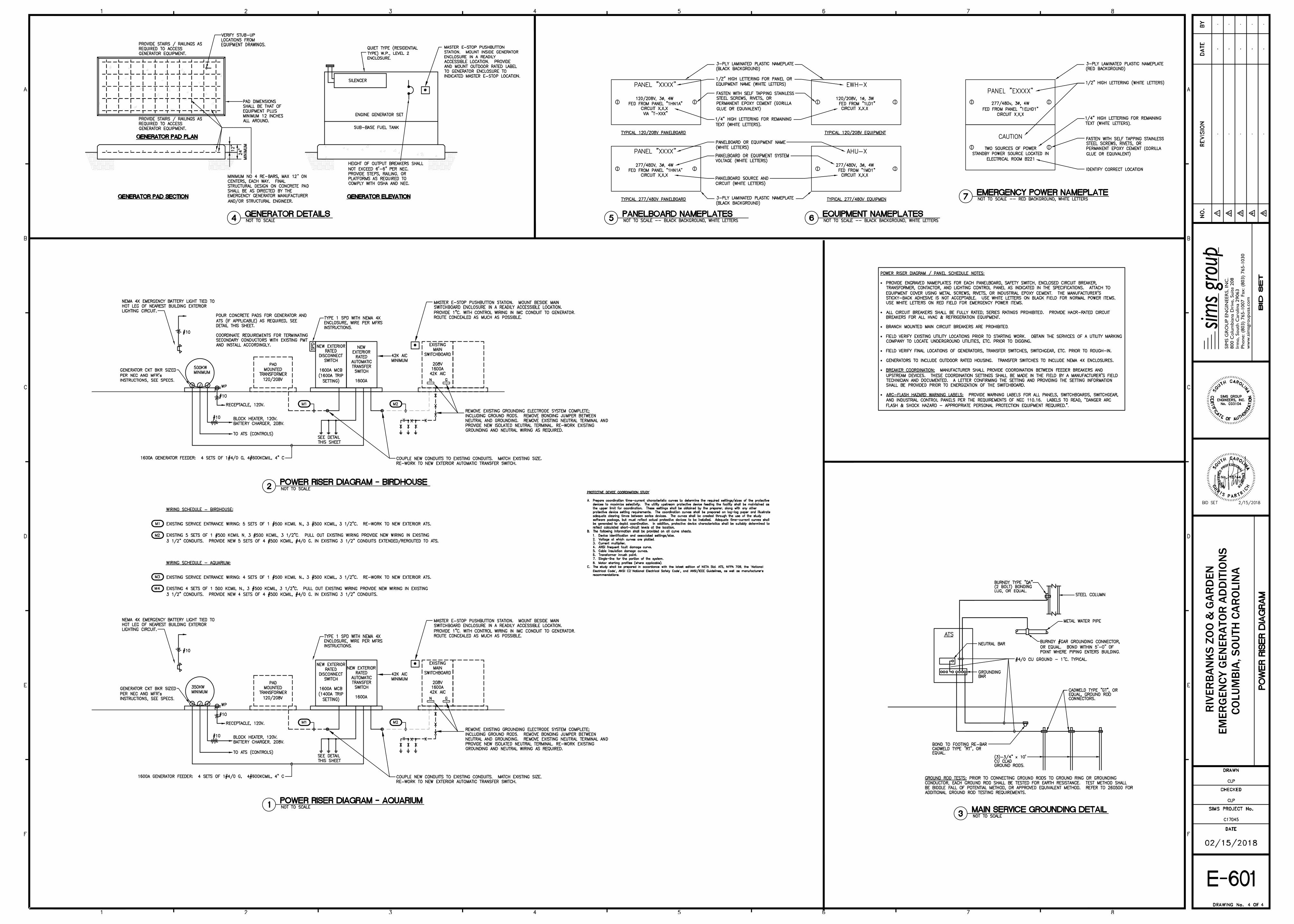
·
·
·
·
·
·
·
·
“
” ” ” ’
ww
w.s
imsg
roupusa
.com
Irm
o, South
Caro
lina 2
9063
800 C
olu
mbia
na D
rive, Suite 2
08
sims
grou
pSIM
S G
RO
UP E
NG
INEER
S, IN
C.
Phone: (8
03)
765-1
007 Fax: (8
03)
765-1
030
RIV
ERBA
NKS
ZO
O &
GAR
DEN
EMER
GEN
CY G
ENER
ATO
R A
DD
ITIO
NS
COLU
MBI
A, S
OUT
H C
ARO
LIN
A