project no. 528a5-18-512 roof replacement for connecting
TRANSCRIPT

SCOPE OF WORK
Project No. 528A5-18-512
Roof Replacement for Connecting Corridors, Building 39 and Flat Roofs Canandaigua, VA Medical Center,
400 Fort Hill Avenue Canandaigua, NY 14424
The general scope of this project is to replace existing roof systems on 10 connecting corridors (CC), and Building 39 roof and replace or provide roof repairs to five (5) EPDM flat roofs on Buildings 1, 5, and 7 of the VA Medical Center, Canandaigua, NY. Provide a schedule of values for each of the following:
1. Ten (10) connecting corridors2. Building 39 (nurses barn)3. South end and South West flat roofs Building 14. North flat roof Building 55. South West and North West flat roof Building 7
A. EXISTING CONDITIONS
The Canandaigua VAMC is a campus facility with many (more than 30) buildings located on over 150 acres. Many of the facility buildings are eligible for inclusion on the historic register. These buildings and roofs match the existing structures and must be replaced and repaired to maintain conformity.
There are ten (10) connecting corridors (CC), one (1) standalone building, and four (4) flat roofs on three different buildings in this scope consisting of a mixture of natural slate shingle sloped roofs, Built Up Roofing over wood deck, and EPDM flat roofs. The breakdown of the roofing type and materials are listed as follows:
Existing Condition 1 Natural Slate Roof at Connecting Corridors:
Eight connecting corridors throughout the campus ranging from approximately 6-30 squares each consist of natural slate shingles over wood decking. The roof eaves range from approximately 4’ above finish grade to 12’ above finish grade. The existing roofing system is approximately 80 years old and has started to fail. Ventilation is achieved by a ridge vent at the peak, and rectangular aluminum vents cut into the wall under the eaves.
Existing Condition 2 EPDM Roof above Natural Slate:
The corridor connecting buildings 4 and 5 was renovated to allow access to both the ground floor and first floor of building 5. The corridor was extended to be double the width, with a natural slate roof on the lower portion, and EPDM flat roof over the top. The EPDM flat roof is fully adhered over polyisocyanurate attached to a wood deck.

Existing Condition 3 EPDM Roof at parapet:
The majority of connecting corridors have EPDM flat roofs at either end where they connect to the respective buildings. The EPDM is fully adhered over polyisocyanurate; adhered to a concrete deck. There is a combination of scuppers and roof drains to remove the rain water from the roofing system.
Existing Condition Building 39
Building 39 is an unoccupied, non-climate controlled storage garage. The existing roof system is 1 layer built up roof system approximately 25 years old over a wood deck. Water infiltration has led to some roof deck degradation.
Existing conditions EPDM roofs Buildings 1, 5, and 7
EPDM roof systems on buildings 1, 5, and 7 range from approximately 10 to 20 years old. Current roof system is a fully adhered EPDM with polyisocyanurate insulation over a concrete roof deck. All roofs are surrounded by parapet walls. Building 1 flat roofs have HVAC equipment mounted onto curbs. Roofs are currently leaking. It is expected that some or all insulation will need to be replaced. A combination of scuppers and roof drains are installed to remove rain water from the roofing system.
B. GENERAL REQUIREMENTS:
1. Contractor is encouraged to and responsible for field verifying all existing conditions, and dimension pre-bid and pre-construction. Every effort has been made to provide accurate drawings and dimensions to the greatest extent possible. Any and all dimensions provided are for reference only and should be verified by the bidding contractor.
2. For bidding purposes, bidder should assume 20% of all wood deck will need to be repaired or replaced. After award, Contractor shall include in their schedule of values the cost per square foot for replacing wood decking. Contractor will be responsible for scheduling inspections of decking with COR and agree upon areas that will need to be replaced prior to installing any new materials.
3. Connecting Corridors
a. Remove all natural slate shingles from above listed connecting corridors and dispose of, inspect, roof deck, flashings, facia, and ventilation.
b. Replace any damaged roof decking or flashing as necessary.
c. Install Ice and Water Protection over entire roof deck.
d. Install new aluminum drip and rake edge.
e. Install Ecostar synthetic slate shingles or equivalent. Shingle color to match adjacent buildings.
f. Install copper snow guards above any entry ways or walk areas.
g. Install attic guard ventilation where necessary.

4. EPDM over wood deck
a. Remove existing membrane and insulation and dispose of, inspect roof deck and flashings.
b. Replace any damaged roof deck and flashing as necessary.
c. Install by mechanically fastening new polyisocyanurate insulation. Insulation thickness and R value shall match existing unless additional requirements by building codes or manufacturer.
d. Install new drip edge, gravel stop, or termination as required.
e. Install fully adhered .060 non-reinforced EPDM roof system.
f. Install all flashings and accessories as specified in drawings, specifications, or by manufacturer.
g. Provide 10 year manufacturer's labor and material warranty.
5. EPDM over concrete deck Buildings 1,5,7 and Connecting Corridors
a. Remove existing membrane and insulation and dispose of, inspect roof deck and flashings.
b. Clean or prepare concrete roof deck to meet manufacturer’s specifications.
c. Install new polyisocyanurate insulation. Insulation thickness and R value shall match existing unless additional requirements by building codes or manufacturer.
d. Install new drip edge, gravel stop, or termination as required.
e. Install fully adhered .060 non-reinforced EPDM roof system.
f. Install all flashings and accessories as specified in drawings, specifications, or by manufacturer.
g. Provide 10 year manufacturer's labor and material warranty.
6. Steel panel over wood deck (Building 39)
a. Remove existing built-up-roofing, underlayment and inspect roof deck.
b. Replace any damaged decking.
c. Install underlayment per manufacturer’s recommendations.
d. Install steel roofing and accessories.
7. All roof systems in this scope of work shall be designed and installed to withstand a minimum of a 100 MPH wind load.

8. All flashing and products will be installed per manufacturer's recommendations and contract drawings.
9. Unless otherwise stated, the contractor will provide a 2 year full repair/replace warranty and a 25 year manufacturer warranty. Warranty shall cover all material, parts, labor, freight and equipment. Note - see"Warranty of Construction" under General Conditions in the solicitation/contract document.
10. The contractor will construct all structural members, sheeting, roof insulation, and EPDM rubberized roof membrane and sealants.
11. The contractor will supply and ship to the job site all construction materials. The contractor shall supply all construction equipment.
12. The contractor will provide and deliver adequate waste dumpsters. All construction waste, scrap, demolished and removed materials shall be removed and hauled from the VAMC water treatment plant property and properly disposed of by the contractor.
13. The Contractor is responsible for transporting both demolished and new material to and from the work area. VAMC elevators may not be used to transport material and equipment without prior written permission from VAMC Engineering and COR.
14. The contractor will provide and enforce the use of and all required safety equipment, personal protective equipment (PPE), all fall protection equipment, and all fire extinguishing equipment.
15. Contractor shall adhere to all building codes current at time of design and/or construction.
16. The contractor shall supply the VAMC Engineering department with all shop drawings in the latest AutoCAD version.
17. The Contractor shall secure the immediate work area to insure the safety of the VAMC staff and to ensure the necessary work area is available. Barricade the parking lot as required for construction, material storage and deliveries.
18. The installation, equipment, materials, workmanship, examination, inspection and testing shall be in strict accordance with the following:
19. The Project Specifications and The Department of Veterans Affairs VHA Master Construction Specifications# supersede any and all drawings. The contractor will, at minimum, meet all specifications and requirements of NEC, NEMA, and NFPA.
20. In addition to the preceding, all contractors will meet or exceed The Department of Veterans Affairs VHA Master Construction Specifications[A]. All work shall meet the following conditions:
A. All applicable federal, state and local codes including:
B. National Electrical Code (NEC)
C. NFPA (National Fire Protection Association)

D. NEMA (National Electrical Manufacturers Association)
E. ANSI - American National Standards Institute
F. UL (Underwriters Laboratories)
G. OSHA (Occupational Safety and Health Administration) standards.
H. Section FSB1: Permit Required Work§.
I. Section FS13: Installation Requirements: Proximity to Fire Suppression Systems#
J. [A] The Department of Veterans Affairs VHA Master Construction specifications:
The contractor shall design, construct and perform all work in compliance with The Department of Veterans Affairs VHA Master Construction specifications:
1. Permits are required for all work that will penetrate or disturb existing smoke and firebarriers. Prior to performing work, the Contractor will obtain a Smoke and Fire BarrierPermit issued by The V.A.M.C. Fire Department. Fire and smoke barriers may be identifiedin a number of ways including decals on walls and surfaces or by other means includingdrawings, site surveys, scope of work, pictures, and/or diagrams.) All work performedunder The Smoke and Fire Barrier Permit is subject to inspection and approval by TheV.A.M.C. Fire Department. The V.A.M.C. Fire Department issues and closes The Smokeand Fire Barrier Permit.
2. The contractor will install all systems including piping, conduit, wiring and ductwork tomaintain a minimum clearance from all existing and installed sprinkler heads. The contractorwill ensure that all installations provide the correct clearance (distance from) per NFPACode 13. Any obstructions at or below the sprinkler head must not impede the spray patternof the head from developing.

05-01-17
00 01 10-1
DEPARTMENT OF VETERANS AFFAIRSVHA MASTER SPECIFICATIONS
TABLE OF CONTENTSSection 00 01 10
DIVISION 00 - SPECIAL SECTIONS DATE
00 01 15 List of Drawing Sheets 07-15
DIVISION 01 - GENERAL REQUIREMENTS
01 00 00 General Requirements 11-1501 32 16.15 Project Schedules (Small Projects) 02-1501 33 23 Shop Drawings, Product Data, and Samples 05-1701 35 26 Safety Requirements 02-1701 42 19 Reference Standards 05-1601 74 19 Construction Waste Management 09-1301 81 13.02 Sustainability Certification Requirements – LEED NC V4 09-15
DIVISION 02 – EXISTING CONDITIONS
02 41 00 Demolition 02-15DIVISION 06 – WOOD,PLASTICS AND COMPOSITES
06 10 00 Rough Carpentry 10-15
DIVISION 07 - THERMAL AND MOISTURE PROTECTION
07 01 50.19 Preparation for Re-Roofing 02-1607 22 00 Roof and Deck Insulation 02-1607 31 26 Slate Shingles 02-1607 53 23 Ethylene-Propylene-Diene-Monomer Roofing 02-1607 60 00 Flashing and Sheet Metal 07-1407 71 00 Roof Specialties 10-1507 72 00 Roof Accessories 10-1507 84 00 Firestopping 02-1607 92 00 Joint Sealants 10-1507 95 13 Expansion Joint Cover Assemblies 02-16

07-01-15
00 01 15 - 1
SECTION 00 01 15 LIST OF DRAWING SHEETS
The drawings listed below accompanying this specification form a part of
the contract.
Drawing No. Title
GI-001 COVER SHEET & DRAWING INDEX
GI101 GENERAL INFORMATION
GI102 GENERAL NOTES & SYMBOLS
A-101 CONNECTING COORIDOR 4/5 PLANS & SECTIONS
A-102 CONNECTING COORIDOR 5/6 PLANS & SECTIONS
A-103 CONNECTING COORIDOR 6/7 PLANS & SECTIONS
A-104 CONNECTING COORIDOR 7/8 PLANS & SECTIONS
A-105 CONNECTING COORIDOR 8/37/9 PLANS & SECTIONS
A-106 CONNECTING COORIDOR 2/4 PLANS & SECTIONS
A-107 CONNECTING COORIDOR 2/3 PLANS & SECTIONS
A-108 CONNECTING COORIDOR 9/33/3 PLANS & SECTIONS
A-109 CONNECTING COORIDOR 37-36 & 118/36 PLANS
A-110 BILDING 39
A-111 BUILDINGS 1,5,&7 FLAT ROOFS
A-501 ROOF DETAILS
A-502 EPDM DETAILS
- - - END - - -

11-01-15
i
SECTION 01 00 00 GENERAL REQUIREMENTS
TABLE OF CONTENTS
1.1 SAFETY REQUIREMENTS .............................................. 1
1.2 GENERAL INTENTION .................................................................................................................... 1
1.3 STATEMENT OF BID ITEM(S) ................................................................................................... 1
1.4 SPECIFICATIONS AND DRAWINGS FOR CONTRACTOR ........................................................ 2
1.5 CONSTRUCTION SECURITY REQUIREMENTS ............................................................................ 2
1.6 OPERATIONS AND STORAGE AREAS .......................................................................................... 4
1.7 ALTERATIONS ................................................................................................................................. 10
1.8 DISPOSAL AND RETENTION ...................................................................................................... 11
1.9 PROTECTION OF EXISTING VEGETATION, STRUCTURES, EQUIPMENT,
UTILITIES, AND IMPROVEMENTS .......................................................................................... 12
1.10 RESTORATION .............................................................................................................................. 12
1.14 AS-BUILT DRAWINGS ................................................................................................................ 13
1.15 USE OF ROADWAYS ..................................................................................................................... 14
1.23 TESTS............................................................................................................................................. 14
1.24 INSTRUCTIONS ............................................................................................................................ 14
1.32 HISTORIC PRESERVATION ...................................................................................................... 16

11-01-15
01 00 00 -1
SECTION 01 00 00 GENERAL REQUIREMENTS
1.1 SAFETY REQUIREMENTS
Refer to section 01 35 26, SAFETY REQUIREMENTS for safety and infection
control requirements.
1.2 GENERAL INTENTION
A. Contractor shall completely prepare site for building operations,
including demolition and removal of existing structures, and furnish
labor and materials and perform work for the replacement of roofs on 6
connecting corridors as required by drawings and specifications.
B. Visits to the site by Bidders may be made only during the scheduled site visit
as outlined in the solicitation documents.
E. All employees of general contractor and subcontractors shall comply
with VA security management program and obtain permission of the VA
police, be identified by project and employer, and restricted from
unauthorized access.
1.3 STATEMENT OF BID ITEM(S)
A. ITEM I, Provide all materials, equipment, and labor to:
1. Remove and replace existing Natural slate from six (6)Connecting
Corridors (4/5, 5/6, 6/7, 7/8, 8/9-37, and 9/3-33) repair decking,
install underlayment, flashings, and synthetic slate shingles in
order to provide a complete water tight assembly.
2. Remove and replace EPDM roofing on Connecting Corridor 4/5

11-01-15
01 00 00 -2
3. Remove existing Built-Up-Roofing from Building 39 repair roof deck,
install underlayment, metal roof panels, and accessories.
4. Repair 4 flat roofs on buildings 1,5, and 7.
B. ALTERNATE NO.1: Provide all materials, equipment, and labor to:
1. Remove and replace existing Natural slate from connecting corridors
2/3, 2/4, 36/37.
C. ALTERNATE NO. 2 Provide all materials, equipment, and labor to:
1. Fully Replace 4 flat roofs on buildings 1,5, and 7.
2. Inspect and repair as necessary connecting corridor 36/118.
D. ALTERNATE NO. 3 Provide all materials, equipment, and labor to:
1. Fully replace South West flat roof on Building 1.
1.4 SPECIFICATIONS AND DRAWINGS FOR CONTRACTOR
A. Drawings and contract documents may be obtained from the website where
the solicitation is posted. Additional copies will be at Contractor's
expense,.
1.5 CONSTRUCTION SECURITY REQUIREMENTS
A. Security Plan:
1. The security plan defines both physical and administrative security
procedures that will remain effective for the entire duration of the
project.

11-01-15
01 00 00 -3
2. The General Contractor is responsible for assuring that all sub-
contractors working on the project and their employees also comply
with these regulations.
B. Security Procedures:
1. General Contractor’s employees shall not enter the project site
without appropriate badge. They may also be subject to inspection
of their personal effects when entering or leaving the project site.
2. Before starting work the General Contractor shall give one week’s
notice to the Contracting Officer so that security arrangements can
be provided for the employees. This notice is separate from any
notices required for utility shutdown described later in this
section.
3. No photography of VA premises is allowed without written permission
of the Contracting Officer.
4. VA reserves the right to close down or shut down the project site
and order General Contractor’s employees off the premises in the
event of a national emergency. The General Contractor may return to
the site only with the written approval of the Contracting Officer.
D. Key Control:
1. The General Contractor shall provide duplicate keys and lock
combinations to the Contracting officers representative (CORfor the
purpose of security inspections of every area of project.
E. Document Control:
1. Before starting any work, the General Contractor/Sub Contractors
shall submit an electronic security memorandum describing the
approach to following goals and maintaining confidentiality of
“sensitive information”.
2. The General Contractor is responsible for safekeeping of all
drawings, project manual and other project information. This
information shall be shared only with those with a specific need to
accomplish the project.

11-01-15
01 00 00 -4
3. Certain documents, sketches, videos or photographs and drawings may
be marked “Law Enforcement Sensitive” or “Sensitive Unclassified”.
Secure such information in separate containers and limit the access
to only those who will need it for the project. Return the
information to the Contracting Officer upon request.
4. These security documents shall not be removed or transmitted from
the project site without the written approval of Contracting
Officer.
5. All paper waste or electronic media such as CD’s and diskettes shall
be shredded and destroyed in a manner acceptable to the VA.
6. Notify Contracting Officer and Site Security Officer immediately
when there is a loss or compromise of “sensitive information”.
7. All electronic information shall be stored in specified location
following VA standards and procedures using an Engineering Document
Management Software (EDMS).
a. Security, access and maintenance of all project drawings, both
scanned and electronic shall be performed and tracked through the
EDMS system.
b. “Sensitive information” including drawings and other documents
may be attached to e-mail provided all VA encryption procedures
are followed.
F. Motor Vehicle Restrictions
1. Vehicle authorization request shall be required for any vehicle
entering the site and such request shall be submitted 24 hours
before the date and time of access. Access shall be restricted to
picking up and dropping off materials and supplies.
2. A limited number of (2 to 5) permits shall be issued for General
Contractor and its employees for parking in designated areas only.
1.6 OPERATIONS AND STORAGE AREAS
A. The Contractor shall confine all operations (including storage of
materials) on Government premises to areas authorized or approved by

11-01-15
01 00 00 -5
the Contracting Officer. The Contractor shall hold and save the
Government, its officers and agents, free and harmless from liability
of any nature occasioned by the Contractor's performance.
B. Temporary buildings (e.g., storage sheds, shops, offices) and utilities
may be erected by the Contractor only with the approval of the
Contracting Officer and shall be built with labor and materials
furnished by the Contractor without expense to the Government. The
temporary buildings and utilities shall remain the property of the
Contractor and shall be removed by the Contractor at its expense upon
completion of the work. With the written consent of the Contracting
Officer, the buildings and utilities may be abandoned and need not be
removed.
C. The Contractor shall, under regulations prescribed by the Contracting
Officer, use only established roadways, or use temporary roadways
constructed by the Contractor when and as authorized by the Contracting
Officer. When materials are transported in prosecuting the work,
vehicles shall not be loaded beyond the loading capacity recommended by
the manufacturer of the vehicle or prescribed by any Federal, State, or
local law or regulation. When it is necessary to cross curbs or
sidewalks, the Contractor shall protect them from damage. The
Contractor shall repair or pay for the repair of any damaged curbs,
sidewalks, or roads.
D. Working space and space available for storing materials shall be as
shown on the drawings. E. Workmen are subject to rules of Medical
applicable to their conduct.
E*. Execute work in such a manner as to interfere as little as possible with
work being done by others. Keep roads clear of construction materials,
debris, standing construction equipment and vehicles at all times.
F. Execute work so as to interfere as little as possible with normal
functioning of the Medical Center as a whole, including operations of
utility services, fire protection systems and any existing equipment,
and with work being done by others. Use of equipment and tools that
transmit vibrations and noises through the building structure, are not
permitted in buildings that are occupied, during construction, jointly
11-01-15
01 00 00 -6
by patients or medical personnel, and Contractor's personnel, except as
permitted by the COR.
1. Do not store materials and equipment in other than assigned areas.
2. Schedule delivery of materials and equipment to immediate
construction working areas within buildings in use by Department of
Veterans Affairs in quantities sufficient for not more than five
work days. Provide unobstructed access to Medical Center areas
required to remain in operation.
3. Where access by Medical Center personnel to vacated portions of
buildings is not required, storage of Contractor's materials and
equipment will be permitted subject to fire and safety requirements.
F*. Utilities Services: Where necessary to cut existing pipes, electrical
wires, conduits, cables, etc., of utility services, or of fire
protection systems or communications systems (except telephone), they
shall be cut and capped at suitable places where shown; or, in absence
of such indication, where directed by the COR. All such actions shall
be coordinated with the COR or Utility Company involved:
1. Whenever it is required that a connection fee be paid to a public
utility provider for new permanent service to the construction
project, for such items as water, sewer, electricity, gas or steam,
payment of such fee shall be the responsibility of the Government
and not the Contractor.
G. Phasing:
The Medical Center must maintain its operation 24 hours a day 7 days a
week. Therefore, any interruption in service must be scheduled and
coordinated with the COR to ensure that no lapses in operation occur.
It is the CONTRACTOR'S responsibility to develop a work plan and
schedule detailing, at a minimum, the procedures to be employed, the
equipment and materials to be used, the interim life safety measure to
be used during the work, and a schedule defining the duration of the
work with milestone subtasks. The work to be outlined shall include,
but not be limited to:

11-01-15
01 00 00 -7
To insure such executions, Contractor shall furnish the COR with a
schedule of approximate phasing dates on which the Contractor intends
to accomplish work in each specific area of site, building or portion
thereof. In addition, Contractor shall notify the COR two weeks in
advance of the proposed date of starting work in each specific area of
site, building or portion thereof. Arrange such phasing to insure
accomplishment of this work in successive phases mutually agreeable to
COR and Contractor, as follows:
Phase I:
Phase II:
H. All connecting corridors may be occupied during performance of work;
however exterior areas around buildings may be coordined off as
necessary.
Contractor shall take all measures and provide all material
necessary for protecting existing equipment and property in affected
areas of construction against dust and debris, so that equipment and
affected areas to be used in the Medical Centers operations will not
be hindered. Contractor shall permit access to Department of
Veterans Affairs personnel and patients through other construction
areas which serve as routes of access to such affected areas and
equipment. These routes whether access or egress shall be isolated
from the construction area by temporary partitions and have walking
surfaces, lighting etc to facilitate patient and staff access.
Coordinate alteration work in areas occupied by Department of
Veterans Affairs so that Medical Center operations will continue
during the construction period.
2. Immediate areas of alterations not mentioned in preceding
Subparagraph 1 will be temporarily vacated while alterations are
performed.

11-01-15
01 00 00 -8
I. Construction Fence: Before construction operations begin, Contractor
shall provide a chain link construction fence, 6 ft (six feet) minimum
height, around the construction area indicated on the drawings. Provide
gates as required for access with necessary hardware, including hasps
and padlocks. Fasten fence fabric to terminal posts with tension bands
and to line posts and top and bottom rails with tie wires spaced at
maximum 375mm (15 inches). Bottom of fences shall extend to 25mm (one
inch) above grade. Remove the fence when directed by COR.
J. When a building and/or construction site is turned over to Contractor,
Contractor shall accept entire responsibility including upkeep and
maintenance therefore:
2. Contractor shall maintain in operating condition existing fire
protection and alarm equipment. In connection with fire alarm
equipment, Contractor shall make arrangements for pre-inspection of
site with Fire Department or Company (Department of Veterans Affairs
or municipal) whichever will be required to respond to an alarm from
Contractor's employee or watchman.
K. Utilities Services: Maintain existing utility services for Medical
Center at all times. Provide temporary facilities, labor, materials,
equipment, connections, and utilities to assure uninterrupted services.
Where necessary to cut existing water, steam, gases, sewer or air
pipes, or conduits, wires, cables, etc. of utility services or of fire
protection systems and communications systems (including telephone),
they shall be cut and capped at suitable places where shown; or, in
absence of such indication, where directed by COR.
1. No utility service such as water, gas, steam, sewers or electricity,
or fire protection systems and communications systems may be
interrupted without prior approval of COR. Electrical work shall be
accomplished with all affected circuits or equipment de-energized.
When an electrical outage cannot be accomplished, work on any
energized circuits or equipment shall not commence without a
detailed work plan, the Medical Center Director’s prior knowledge
and written approval. Refer to specification Sections 26 05 11,

11-01-15
01 00 00 -9
REQUIREMENTS FOR ELECTRICAL INSTALLATIONS, 27 05 11 REQUIREMENTS FOR
COMMUNICATIONS INSTALLATIONS and 28 05 00, COMMON WORK RESULTS FOR
ELECTRONIC SAFETY AND SECURITY for additional requirements.
2. Contractor shall submit a request to interrupt any such services to
COR, in writing, 7 days in advance of proposed interruption. Request
shall state reason, date, exact time of, and approximate duration of
such interruption.
3. Contractor will be advised (in writing) of approval of request, or
of which other date and/or time such interruption will cause least
inconvenience to operations of Medical Center. Interruption time
approved by Medical Center may occur at other than Contractor's
normal working hours.
4. Major interruptions of any system must be requested, in writing, at
least 15 calendar days prior to the desired time and shall be
performed as directed by the COR.
5. In case of a contract construction emergency, service will be
interrupted on approval of COR. Such approval will be confirmed in
writing as soon as practical.
6. Whenever it is required that a connection fee be paid to a public
utility provider for new permanent service to the construction
project, for such items as water, sewer, electricity, gas or steam,
payment of such fee shall be the responsibility of the Government
and not the Contractor.
L. Abandoned Lines: All service lines such as wires, cables, conduits,
ducts, pipes and the like, and their hangers or supports, which are to
be abandoned but are not required to be entirely removed, shall be
sealed, capped or plugged at the main, branch or panel they originate
from. The lines shall not be capped in finished areas, but shall be
removed and sealed, capped or plugged in ceilings, within furred
spaces, in unfinished areas, or within walls or partitions; so that
they are completely behind the finished surfaces.
M. To minimize interference of construction activities with flow of
Medical Center traffic, comply with the following:

11-01-15
01 00 00 -10
1. Keep roads, walks and entrances to grounds, to parking and to
occupied areas of buildings clear of construction materials, debris
and standing construction equipment and vehicles.
N. Coordinate the work for this contract with other construction
operations as directed by COR. This includes the scheduling of traffic
and the use of roadways, as specified in Article, USE OF ROADWAYS.
1.7 ALTERATIONS
A. Survey: Before any work is started, the Contractor shall make a
thorough survey with the COR all areas in which alterations occur and
areas which are anticipated routes of access, and furnish a report,
signed by both Contractor and COR, and provide to the Contracting
Officer. This report shall list by areas:
1. Existing condition of all work areas, storage/laydown areas, and
travel routes.
3. Shall note any discrepancies between drawings and existing
conditions at site.
4. Shall designate areas for working space, materials storage and
routes of access to areas within buildings where alterations occur
and which have been agreed upon by Contractor and COR.
B. Any items required by drawings to be either reused or relocated or
both, found during this survey to be nonexistent, or in opinion of COR,
to be in such condition that their use is impossible or impractical,
shall be furnished and/or replaced by Contractor with new items in
accordance with specifications which will be furnished by Government.
Provided the contract work is changed by reason of this subparagraph B,
the contract will be modified accordingly, under provisions of clause
entitled "DIFFERING SITE CONDITIONS" (FAR 52.236-2) and "CHANGES" (FAR
52.243-4 and VAAR 852.236-88).
C. Re-Survey: Thirty days before expected partial or final inspection
date, the Contractor and COR together shall make a thorough re-survey
of the areas of buildings involved. They shall furnish a report on

11-01-15
01 00 00 -11
conditions then existing, of resilient flooring, doors, windows, walls
and other surfaces as compared with conditions of same as noted in
first condition survey report:
1. Re-survey report shall also list any damage caused by Contractor to
such flooring and other surfaces, despite protection measures; and,
will form basis for determining extent of repair work required of
Contractor to restore damage caused by Contractor's workmen in
executing work of this contract.
D. Protection: Provide the following protective measures:
1. Wherever existing roof surfaces are disturbed they shall be
protected against water infiltration. In case of leaks, they shall
be repaired immediately upon discovery.
2. Temporary protection against damage for portions of existing
structures and grounds where work is to be done, materials handled
and equipment moved and/or relocated.
3. Protection of interior of existing structures at all times, from
damage, dust and weather inclemency. Wherever work is performed,
floor surfaces that are to remain in place shall be adequately
protected prior to starting work, and this protection shall be
maintained intact until all work in the area is completed.
1.8 DISPOSAL AND RETENTION
A. Materials and equipment accruing from work removed and from demolition
of buildings or structures, or parts thereof, shall be disposed of as
follows:
2. Items not reserved shall become property of the Contractor and be
removed by Contractor from Medical Center.

11-01-15
01 00 00 -12
1.9 PROTECTION OF EXISTING VEGETATION, STRUCTURES, EQUIPMENT, UTILITIES, AND IMPROVEMENTS
A. The Contractor shall preserve and protect all structures, equipment,
and vegetation (such as trees, shrubs, and grass) on or adjacent to the
work site, which are not to be removed and which do not unreasonably
interfere with the work required under this contract. The Contractor
shall only remove trees when specifically authorized to do so, and
shall avoid damaging vegetation that will remain in place. If any limbs
or branches of trees are broken during contract performance, or by the
careless operation of equipment, or by workmen, the Contractor shall
trim those limbs or branches with a clean cut and paint the cut with a
tree-pruning compound as directed by the Contracting Officer.
B. The Contractor shall protect from damage all existing improvements and
utilities at or near the work site and on adjacent property of a third
party, the locations of which are made known to or should be known by
the Contractor. The Contractor shall repair any damage to those
facilities, including those that are the property of a third party,
resulting from failure to comply with the requirements of this contract
or failure to exercise reasonable care in performing the work. If the
Contractor fails or refuses to repair the damage promptly, the
Contracting Officer may have the necessary work performed and charge
the cost to the Contractor.
(FAR 52.236-9)
C. Refer to Section 01 57 19, TEMPORARY ENVIRONMENTAL CONTROLS, for
additional requirements on protecting vegetation, soils and the
environment. Refer to Articles, "Alterations", "Restoration", and
"Operations and Storage Areas" for additional instructions concerning
repair of damage to structures and site improvements.
1.10 RESTORATION
A. Remove, cut, alter, replace, patch and repair existing work as
necessary to install new work. Except as otherwise shown or specified,
do not cut, alter or remove any structural work, and do not disturb any
ducts, plumbing, steam, gas, or electric work without approval of the
COR. Existing work to be altered or extended and that is found to be

11-01-15
01 00 00 -13
defective in any way, shall be reported to the COR before it is
disturbed. Materials and workmanship used in restoring work, shall
conform in type and quality to that of original existing construction,
except as otherwise shown or specified.
B. Upon completion of contract, deliver work complete and undamaged.
Existing work (walls, ceilings, partitions, floors, mechanical and
electrical work, lawns, paving, roads, walks, etc.) disturbed or
removed as a result of performing required new work, shall be patched,
repaired, reinstalled, or replaced with new work, and refinished and
left in as good condition as existed before commencing work.
C. At Contractor's own expense, Contractor shall immediately restore to
service and repair any damage caused by Contractor's workmen to
existing piping and conduits, wires, cables, etc., of utility services
or of fire protection systems and communications systems (including
telephone) which are not scheduled for discontinuance or abandonment.
D. Expense of repairs to such utilities and systems not shown on drawings
or locations of which are unknown will be covered by adjustment to
contract time and price in accordance with clause entitled "CHANGES"
(FAR 52.243-4 and VAAR 852.236-88) and "DIFFERING SITE CONDITIONS" (FAR
52.236-2).
.
1.14 AS-BUILT DRAWINGS
A. The contractor shall maintain two full size sets of as-built drawings
which will be kept current during construction of the project, to
include all contract changes, modifications and clarifications.
B. All variations shall be shown in the same general detail as used in the
contract drawings. To insure compliance, as-built drawings shall be
made available for the COR’s review, as often as requested and will be
reviewed with all payment requests.

11-01-15
01 00 00 -14
C. Contractor shall deliver two approved completed sets of as-built
drawings in the electronic version (scanned PDF) to the COR within 15
calendar days after each completed phase and after the acceptance of
the project by the COR.
D. Paragraphs A, B, & C shall also apply to all shop drawings.
1.15 USE OF ROADWAYS
A. For hauling, use only established public roads and roads on the Medical
Center property and, when authorized by the COR, such temporary roads
which are necessary in the performance of contract work. Temporary
roads shall be constructed and restoration performed by the Contractor
at Contractor's expense. When necessary to cross curbing, sidewalks, or
similar construction, they must be protected by well-constructed
bridges.
B. When new permanent roads are to be a part of this contract, Contractor
may construct them immediately for use to facilitate building
operations. These roads may be used by all who have business thereon
within zone of building operations.
C. When certain buildings (or parts of certain buildings) are required to
be completed in advance of general date of completion, all roads
leading thereto must be completed and available for use at time set for
completion of such buildings or parts thereof.
1.23 TESTS
1.24 INSTRUCTIONS
A. Contractor shall furnish Maintenance and Operating manuals (hard copies
and electronic) and verbal instructions when required by the various
sections of the specifications and as hereinafter specified.
B. Manuals: Maintenance and operating manuals and one compact disc (four
hard copies and one electronic copy each) for each separate piece of
equipment shall be delivered to the COR coincidental with the delivery
of the equipment to the job site. Manuals shall be complete, detailed
11-01-15
01 00 00 -15
guides for the maintenance and operation of equipment. They shall
include complete information necessary for starting, adjusting,
maintaining in continuous operation for long periods of time and
dismantling and reassembling of the complete units and sub-assembly
components. Manuals shall include an index covering all component parts
clearly cross-referenced to diagrams and illustrations. Illustrations
shall include "exploded" views showing and identifying each separate
item. Emphasis shall be placed on the use of special tools and
instruments. The function of each piece of equipment, component,
accessory and control shall be clearly and thoroughly explained. All
necessary precautions for the operation of the equipment and the reason
for each precaution shall be clearly set forth. Manuals must reference
the exact model, style and size of the piece of equipment and system
being furnished. Manuals referencing equipment similar to but of a
different model, style, and size than that furnished will not be
accepted.
C. Instructions: Contractor shall provide qualified, factory-trained
manufacturers' representatives to give detailed training to assigned
Department of Veterans Affairs personnel in the operation and complete
maintenance for each piece of equipment. All such training will be at
the job site. These requirements are more specifically detailed in the
various technical sections. Instructions for different items of
equipment that are component parts of a complete system, shall be given
in an integrated, progressive manner. All instructors for every piece
of component equipment in a system shall be available until
instructions for all items included in the system have been completed.
This is to assure proper instruction in the operation of inter-related
systems. All instruction periods shall be at such times as scheduled by
the COR and shall be considered concluded only when the COR is
satisfied in regard to complete and thorough coverage. The contractor
shall submit a course outline with associated material to the COR for
review and approval prior to scheduling training to ensure the subject
matter covers the expectations of the VA and the contractual
requirements. The Department of Veterans Affairs reserves the right to
request the removal of, and substitution for, any instructor who, in
the opinion of the COR, does not demonstrate sufficient qualifications
in accordance with requirements for instructors above.

11-01-15
01 00 00 -16
1.32 HISTORIC PRESERVATION
Where the Contractor or any of the Contractor's employees, prior to, or
during the construction work, are advised of or discover any possible
archeological, historical and/or cultural resources, the Contractor
shall immediately notify the COR verbally, and then with a written
follow up.
- - - E N D - - -

05-01-17
01 33 23 - 1
SECTION 01 33 23
SHOP DRAWINGS, PRODUCT DATA, AND SAMPLES
PART 1 – GENERAL
1.1 DESCRIPTION
A. This specification defines the general requirements and procedures for
submittals. A submittal is information submitted for VA review to
establish compliance with the contract documents.
B. Detailed submittal requirements are found in the technical sections of
the contract specifications. The Contracting Officer may request
submittals in addition to those specified when deemed necessary to
adequately describe the work covered in the respective technical
specifications at no additional cost to the government.
C. VA approval of a submittal does not relieve the Contractor of the
responsibility for any error which may exist. The Contractor is
responsible for fully complying with all contract requirements and the
satisfactory construction of all work, including the need to check,
confirm, and coordinate the work of all subcontractors for the project.
Non-compliant material incorporated in the work will be removed and
replaced at the Contractor’s expense.
1.2 DEFINITIONS
A. Preconstruction Submittals: Submittals which are required prior to
issuing contract notice to proceed or starting construction. For
example, Certificates of insurance; Surety bonds; Site-specific safety
plan; Construction progress schedule; Schedule of values; Submittal
register; List of proposed subcontractors.
B. Shop Drawings: Drawings, diagrams, and schedules specifically prepared
to illustrate some portion of the work. Drawings prepared by or for
the Contractor to show how multiple systems and interdisciplinary work
will be integrated and coordinated.
C. Product Data: Catalog cuts, illustrations, schedules, diagrams,
performance charts, instructions, and brochures, which describe and
illustrate size, physical appearance, and other characteristics of
materials, systems, or equipment for some portion of the work. Samples
of warranty language when the contract requires extended product
warranties.

05-01-17
01 33 23 - 2
D. Samples: Physical examples of materials, equipment, or workmanship that
illustrate functional and aesthetic characteristics of a material or
product and establish standards by which the work can be judged. Color
samples from the manufacturer's standard line (or custom color samples
if specified) to be used in selecting or approving colors for the
project. Field samples and mock-ups constructed to establish standards
by which the ensuing work can be judged.
E. Design Data: Calculations, mix designs, analyses, or other data
pertaining to a part of work.
F. Test Reports: Report which includes findings of a test required to be
performed by the Contractor on an actual portion of the work. Report
which includes finding of a test made at the job site or on sample taken
from the job site, on portion of work during or after installation.
G. Certificates: Document required of Contractor, or of a manufacturer,
supplier, installer, or subcontractor through Contractor. The purpose
is to document procedures, acceptability of methods, or personnel
qualifications for a portion of the work.
H. Manufacturer's Instructions: Pre-printed material describing
installation of a product, system, or material, including special
notices and MSDS concerning impedances, hazards, and safety precautions.
I. Manufacturer's Field Reports: Documentation of the testing and
verification actions taken by manufacturer's representative at the job
site on a portion of the work, during or after installation, to confirm
compliance with manufacturer's standards or instructions. The
documentation must indicate whether the material, product, or system has
passed or failed the test.
J. Operation and Maintenance Data: Manufacturer data that is required to
operate, maintain, troubleshoot, and repair equipment, including
manufacturer's help, parts list, and product line documentation. This
data shall be incorporated in an operations and maintenance manual.
K. Closeout Submittals: Documentation necessary to properly close out a
construction contract. For example, Record Drawings and as-built
drawings. Also, submittal requirements necessary to properly close out
a phase of construction on a multi-phase contract.
1.3 SUBMITTAL REGISTER
A. The submittal register will list items of equipment and materials for
which submittals are required by the specifications. This list may not

05-01-17
01 33 23 - 3
be all inclusive and additional submittals may be required by the
specifications. The Contractor is not relieved from supplying
submittals required by the contract documents but which have been
omitted from the submittal register.
B. The submittal register will serve as a scheduling document for
submittals and will be used to control submittal actions throughout the
contract period.
C. The VA will provide the initial submittal register in electronic
format. Thereafter, the Contractor shall track all submittals by
maintaining a complete list, including completion of all data columns,
including dates on which submittals are received and returned by the
VA.
D. The Contractor shall update the submittal register as submittal actions
occur and maintain the submittal register at the project site until
final acceptance of all work by Contracting Officer.
E. The Contractor shall submit formal monthly updates to the submittal
register in electronic format. Each monthly update shall document
actual submission and approval dates for each submittal.
1.4 SUBMITTAL SCHEDULING
A. Submittals are to be scheduled, submitted, reviewed, and approved prior
to the acquisition of the material or equipment.
B. Coordinate scheduling, sequencing, preparing, and processing of
submittals with performance of work so that work will not be delayed by
submittal processing. Allow time for potential resubmittal.
C. No delay costs or time extensions will be allowed for time lost in late
submittals or resubmittals.
D. All submittals are required to be approved prior to the start of the
specified work activity.
1.5 SUBMITTAL PREPARATION
A. Each submittal is to be complete and in sufficient detail to allow ready
determination of compliance with contract requirements.
B. Collect required data for each specific material, product, unit of work,
or system into a single submittal. Prominently mark choices, options,
and portions applicable to the submittal. Partial submittals will not be
accepted for expedition of construction effort. Submittal will be
returned without review if incomplete.

05-01-17
01 33 23 - 4
C. If available product data is incomplete, provide Contractor-prepared
documentation to supplement product data and satisfy submittal
requirements.
D. All irrelevant or unnecessary data shall be removed from the submittal
to facilitate accuracy and timely processing. Submittals that contain
the excessive amount of irrelevant or unnecessary data will be returned
with review.
E. Provide a transmittal form for each submittal with the following
information:
1. Project title, location and number.
2. Construction contract number.
3. Date of the drawings and revisions.
4. Name, address, and telephone number of subcontractor, supplier,
manufacturer, and any other subcontractor associated with the
submittal.
5. List paragraph number of the specification section and sheet number
of the contract drawings by which the submittal is required.
6. When a resubmission, add alphabetic suffix on submittal description.
For example, submittal 18 would become 18A, to indicate
resubmission.
7. Product identification and location in project.
F. The Contractor is responsible for reviewing and certifying that all
submittals are in compliance with contract requirements before
submitting for VA review. Proposed deviations from the contract
requirements are to be clearly identified. All deviations submitted must
include a side by side comparison of item being proposed against item
specified. Failure to point out deviations will result in the VA
requiring removal and replacement of such work at the Contractor's
expense.
G. Stamp, sign, and date each submittal transmittal form indicating action
taken.
H. Stamp used by the Contractor on the submittal transmittal form to certify
that the submittal meets contract requirements is to be similar to the
following:

05-01-17
01 33 23 - 5
| CONTRACTOR |
| |
| (Firm Name) |
| |
| |
| |
| Approved |
| |
| |
| Approved with corrections as noted on submittal data and/or |
| attached sheets(s) |
| |
| |
| |
| SIGNATURE: |
| |
| TITLE: |
| |
| DATE: |
| |
| |
1.6 SUBMITTAL FORMAT AND TRANSMISSION
A. Provide submittals in electronic format, with the exception of material
samples. Use PDF as the electronic format, unless otherwise specified
or directed by the Contracting Officer.
B. Compile the electronic submittal file as a single, complete document.
Name the electronic submittal file specifically according to its
contents.
C. Electronic files must be of sufficient quality that all information is
legible. Generate PDF files from original documents so that the text
included in the PDF file is both searchable and can be copied. If
documents are scanned, Optical Character Resolution (OCR) routines are
required.
05-01-17
01 33 23 - 6
D. E-mail electronic submittal documents smaller than 5MB in size to e-mail
addresses as directed by the Contracting Officer.
E. Provide electronic documents over 5MB through an electronic FTP file
sharing system. Confirm that the electronic FTP file sharing system can
be accessed from the VA computer network. The Contractor is
responsible for setting up, providing, and maintaining the electronic
FTP file sharing system for the construction contract period of
performance.
F. Provide hard copies of submittals when requested by the Contracting
Officer. Up to 3 additional hard copies of any submittal may be
requested at the discretion of the Contracting Officer, at no additional
cost to the VA.
1.7 SAMPLES
A. Submit two sets of physical samples showing range of variation, for
each required item.
B. Where samples are specified for selection of color, finish, pattern, or
texture, submit the full set of available choices for the material or
product specified.
C. When color, texture, or pattern is specified by naming a particular
manufacturer and style, include one sample of that manufacturer and
style, for comparison.
D. Before submitting samples, the Contractor is to ensure that the
materials or equipment will be available in quantities required in the
project. No change or substitution will be permitted after a sample
has been approved.
E. The VA reserves the right to disapprove any material or equipment which
previously has proven unsatisfactory in service.
F. Physical samples supplied maybe requested back for use in the project
after reviewed and approved.
1.8 OPERATION AND MAINTENANCE DATA
A. Submit data specified for a given item within 30 calendar days after the
item is delivered to the contract site.
B. In the event the Contractor fails to deliver O&M Data within the time
limits specified, the Contracting Officer may withhold from progress
payments 50 percent of the price of the item with which such O&M Data
are applicable.

05-01-17
01 33 23 - 7
1.9 TEST REPORTS
SRE may require specific test after work has been installed or
completed which could require contractor to repair test area at no
additional cost to contract.
1.10 VA REVIEW OF SUBMITTALS AND RFIS
A. The VA will review all submittals for compliance with the technical
requirements of the contract documents. The Architect-Engineer for this
project will assist the VA in reviewing all submittals and determining
contractual compliance. Review will be only for conformance with the
applicable codes, standards and contract requirements.
B. Period of review for submittals begins when the VA COR receives
submittal from the Contractor.
C. Period of review for each resubmittal is the same as for initial
submittal.
D. VA review period is 15 working days for submittals.
E. VA review period is 10 working days for RFIs.
F. The VA will return submittals to the Contractor with the following
notations:
1. "Approved": authorizes the Contractor to proceed with the work
covered.
2. "Approved as noted": authorizes the Contractor to proceed with the
work covered provided the Contractor incorporates the noted comments
and makes the noted corrections.
3. "Disapproved, revise and resubmit": indicates noncompliance with
the contract requirements or that submittal is incomplete. Resubmit
with appropriate changes and corrections. No work shall proceed for
this item until resubmittal is approved.
4. "Not reviewed": indicates submittal does not have evidence of being
reviewed and approved by Contractor or is not complete. A submittal
marked "not reviewed" will be returned with an explanation of the
reason it is not reviewed. Resubmit submittals after taking
appropriate action.
1.11 APPROVED SUBMITTALS
A. The VA approval of submittals is not to be construed as a complete
check, and indicates only that the general method of construction,
materials, detailing, and other information are satisfactory.

05-01-17
01 33 23 - 8
B. VA approval of a submittal does not relieve the Contractor of the
responsibility for any error which may exist. The Contractor is
responsible for fully complying with all contract requirements and the
satisfactory construction of all work, including the need to check,
confirm, and coordinate the work of all subcontractors for the project.
Non-compliant material incorporated in the work will be removed and
replaced at the Contractor’s expense.
C. After submittals have been approved, no resubmittal for the purpose of
substituting materials or equipment will be considered unless
accompanied by an explanation of why a substitution is necessary.
D. Retain a copy of all approved submittals at project site, including
approved samples.
1.12 WITHHOLDING OF PAYMENT
Payment for materials incorporated in the work will not be made if
required approvals have not been obtained.
- - - E N D - - -

02-01-17
01 35 26 -1
SECTION 01 35 26 SAFETY REQUIREMENTS
TABLE OF CONTENTS
1.1 APPLICABLE PUBLICATIONS ................................................................................................... 3
1.2 DEFINITIONS ................................................................................................................................ 4
1.3 REGULATORY REQUIREMENTS ................................................................................................... 6
1.4 ACCIDENT PREVENTION PLAN (APP) ................................................................................... 6
1.5 ACTIVITY HAZARD ANALYSES (AHAs) .............................................................................. 12
1.6 PRECONSTRUCTION CONFERENCE .......................................................................................... 14
1.7 “SITE SAFETY AND HEALTH OFFICER” (SSHO) and “COMPETENT PERSON” (CP) ........................................................................................................................................................ 14
1.8 TRAINING ..................................................................................................................................... 15
1.9 INSPECTIONS .............................................................................................................................. 16
1.10 ACCIDENTS, OSHA 300 LOGS, AND MAN-HOURS ....................................................... 17
1.11 PERSONAL PROTECTIVE EQUIPMENT (PPE) ................................................................. 18
1.12 INFECTION CONTROL ............................................................................................................ 18
1.14 FIRE SAFETY .......................................................................................................................... 19
1.15 ELECTRICAL ............................................................................................................................. 21
1.16 FALL PROTECTION ................................................................................................................. 23
1.17 SCAFFOLDS AND OTHER WORK PLATFORMS ................................................................... 23
1.19 CRANES ...................................................................................................................................... 24
1.20 CONTROL OF HAZARDOUS ENERGY (LOCKOUT/TAGOUT) ........................................... 25
1.21 CONFINED SPACE ENTRY ..................................................................................................... 25
1.23 LADDERS .................................................................................................................................... 25
1.24 FLOOR & WALL OPENINGS .................................................................................................. 26

02-01-17
01 35 26 -2

02-01-17
01 35 26 -3
SECTION 01 35 26 SAFETY REQUIREMENTS
1.1 APPLICABLE PUBLICATIONS:
A. Latest publications listed below form part of this Article to extent
referenced. Publications are referenced in text by basic designations
only.
B. American Society of Safety Engineers (ASSE):
A10.1-2011...........Pre-Project & Pre-Task Safety and Health
Planning
A10.34-2012..........Protection of the Public on or Adjacent to
Construction Sites
A10.38-2013..........Basic Elements of an Employer’s Program to
Provide a Safe and Healthful Work Environment
American National Standard Construction and
Demolition Operations
C. American Society for Testing and Materials (ASTM):
E84-2013.............Surface Burning Characteristics of Building
Materials
D. The Facilities Guidelines Institute (FGI):
FGI Guidelines-2010Guidelines for Design and Construction of
Healthcare Facilities
E. National Fire Protection Association (NFPA):
10-2013..............Standard for Portable Fire Extinguishers
30-2012..............Flammable and Combustible Liquids Code
51B-2014.............Standard for Fire Prevention During Welding,
Cutting and Other Hot Work
70-2014..............National Electrical Code

02-01-17
01 35 26 -4
70B-2013.............Recommended Practice for Electrical Equipment
Maintenance
70E-2015 ............Standard for Electrical Safety in the Workplace
99-2012..............Health Care Facilities Code
241-2013.............Standard for Safeguarding Construction,
Alteration, and Demolition Operations
F. The Joint Commission (TJC)
TJC Manual ..........Comprehensive Accreditation and Certification
Manual
G. U.S. Nuclear Regulatory Commission
10 CFR 20 ...........Standards for Protection Against Radiation
H. U.S. Occupational Safety and Health Administration (OSHA):
29 CFR 1904 .........Reporting and Recording Injuries & Illnesses
29 CFR 1910 .........Safety and Health Regulations for General
Industry
29 CFR 1926 .........Safety and Health Regulations for Construction
Industry
CPL 2-0.124..........Multi-Employer Citation Policy
I. VHA Directive 2005-007
1.2 DEFINITIONS:
A. Critical Lift. A lift with the hoisted load exceeding 75% of the
crane’s maximum capacity; lifts made out of the view of the operator
(blind picks); lifts involving two or more cranes; personnel being
hoisted; and special hazards such as lifts over occupied facilities,
loads lifted close to power-lines, and lifts in high winds or where
other adverse environmental conditions exist; and any lift which the
crane operator believes is critical.
B. OSHA “Competent Person” (CP). One who is capable of identifying existing
and predictable hazards in the surroundings and working conditions which
02-01-17
01 35 26 -5
are unsanitary, hazardous or dangerous to employees, and who has the
authorization to take prompt corrective measures to eliminate them (see 29
CFR 1926.32(f)).
C. "Qualified Person" means one who, by possession of a recognized degree,
certificate, or professional standing, or who by extensive knowledge,
training and experience, has successfully demonstrated his ability to
solve or resolve problems relating to the subject matter, the work, or
the project.
D. High Visibility Accident. Any mishap which may generate publicity or
high visibility.
E. Accident/Incident Criticality Categories:
No impact – near miss incidents that should be investigated but are not
required to be reported to the VA;
Minor incident/impact – incidents that require first aid or result in
minor equipment damage (less than $5000). These incidents must be
investigated but are not required to be reported to the VA;
Moderate incident/impact – Any work-related injury or illness that
results in:
1. Days away from work (any time lost after day of
injury/illness onset);
2. Restricted work;
3. Transfer to another job;
4. Medical treatment beyond first aid;
5. Loss of consciousness;
6. A significant injury or illness diagnosed by a physician or
other licensed health care professional, even if it did not
result in (1) through (5) above or,
7. any incident that leads to major equipment damage (greater
than $5000).

02-01-17
01 35 26 -6
These incidents must be investigated and are required to be reported to
the VA;
Major incident/impact – Any mishap that leads to fatalities,
hospitalizations, amputations, and losses of an eye as a result of
contractors’ activities. Or any incident which leads to major property
damage (greater than $20,000) and/or may generate publicity or high
visibility. These incidents must be investigated and are required to be
reported to the VA as soon as practical, but not later than 2 hours
after the incident.
E. Medical Treatment. Treatment administered by a physician or by
registered professional personnel under the standing orders of a
physician. Medical treatment does not include first aid treatment even
through provided by a physician or registered personnel.
F.
1.3 REGULATORY REQUIREMENTS:
A. In addition to the detailed requirements included in the provisions of
this contract, comply with 29 CFR 1926, comply with 29 CFR 1910 as
incorporated by reference within 29 CFR 1926, comply with ASSE A10.34,
and all applicable [federal, state, and local] laws, ordinances,
criteria, rules and regulations [_____]. Submit matters of
interpretation of standards for resolution before starting work. Where
the requirements of this specification, applicable laws, criteria,
ordinances, regulations, and referenced documents vary, the most
stringent requirements govern except with specific approval and
acceptance by the Contracting Officer Representative.
1.4 ACCIDENT PREVENTION PLAN (APP):
A. The APP (aka Construction Safety & Health Plan) shall interface with
the Contractor's overall safety and health program. Include any
portions of the Contractor's overall safety and health program
referenced in the APP in the applicable APP element and ensure it is

02-01-17
01 35 26 -7
site-specific. The Government considers the Prime Contractor to be the
"controlling authority" for all worksite safety and health of each
subcontractor(s). Contractors are responsible for informing their
subcontractors of the safety provisions under the terms of the contract
and the penalties for noncompliance, coordinating the work to prevent
one craft from interfering with or creating hazardous working
conditions for other crafts, and inspecting subcontractor operations to
ensure that accident prevention responsibilities are being carried out.
B. The APP shall be prepared as follows:
1. Written in English by a qualified person who is employed by the
Prime Contractor articulating the specific work and hazards
pertaining to the contract (model language can be found in ASSE
A10.33). Specifically articulating the safety requirements found
within these VA contract safety specifications.
2. Address both the Prime Contractors and the subcontractors work
operations.
3. State measures to be taken to control hazards associated with
materials, services, or equipment provided by suppliers.
4. Address all the elements/sub-elements and in order as follows:
a. SIGNATURE SHEET. Title, signature, and phone number of the
following:
1) Plan preparer (Qualified Person such as corporate safety staff
person or contracted Certified Safety Professional with
construction safety experience);
2) Plan approver (company/corporate officers authorized to
obligate the company);
3) Plan concurrence (e.g., Chief of Operations, Corporate Chief
of Safety, Corporate Industrial Hygienist, project manager or
superintendent, project safety professional). Provide
concurrence of other applicable corporate and project
personnel (Contractor).
b. BACKGROUND INFORMATION. List the following:

02-01-17
01 35 26 -8
1) Contractor;
2) Contract number;
3) Project name;
4) Brief project description, description of work to be
performed, and location; phases of work anticipated (these
will require an AHA).
c. STATEMENT OF SAFETY AND HEALTH POLICY. Provide a copy of current
corporate/company Safety and Health Policy Statement, detailing
commitment to providing a safe and healthful workplace for all
employees. The Contractor’s written safety program goals,
objectives, and accident experience goals for this contract
should be provided.
d. RESPONSIBILITIES AND LINES OF AUTHORITIES. Provide the following:
1) A statement of the employer’s ultimate responsibility for the
implementation of his SOH program;
2) Identification and accountability of personnel responsible for
safety at both corporate and project level. Contracts
specifically requiring safety or industrial hygiene personnel
shall include a copy of their resumes.
3) The names of Competent and/or Qualified Person(s) and proof of
competency/qualification to meet specific OSHA
Competent/Qualified Person(s) requirements must be attached.;
4) Requirements that no work shall be performed unless a
designated competent person is present on the job site;
5) Requirements for pre-task Activity Hazard Analysis (AHAs);
6) Lines of authority;
7) Policies and procedures regarding noncompliance with safety
requirements (to include disciplinary actions for violation of
safety requirements) should be identified;

02-01-17
01 35 26 -9
e. SUBCONTRACTORS AND SUPPLIERS. If applicable, provide procedures
for coordinating SOH activities with other employers on the job
site:
1) Identification of subcontractors and suppliers (if known);
2) Safety responsibilities of subcontractors and suppliers.
f. TRAINING.
1) Site-specific SOH orientation training at the time of initial
hire or assignment to the project for every employee before
working on the project site is required.
2) Mandatory training and certifications that are applicable to
this project (e.g., explosive actuated tools, crane operator,
rigger, crane signal person, fall protection, electrical
lockout/NFPA 70E, machine/equipment lockout, confined space,
etc…) and any requirements for periodic
retraining/recertification are required.
3) Procedures for ongoing safety and health training for
supervisors and employees shall be established to address
changes in site hazards/conditions.
4) OSHA 10-hour training is required for all workers on site and
the OSHA 30-hour training is required for Trade Competent
Persons (CPs)
g. SAFETY AND HEALTH INSPECTIONS.
1) Specific assignment of responsibilities for a minimum daily
job site safety and health inspection during periods of work
activity: Who will conduct (e.g., “Site Safety and Health
CP”), proof of inspector’s training/qualifications, when
inspections will be conducted, procedures for documentation,
deficiency tracking system, and follow-up procedures.
2) Any external inspections/certifications that may be required
(e.g., contracted CSP or CSHT)

02-01-17
01 35 26 -10
h. ACCIDENT/INCIDENT INVESTIGATION & REPORTING. The Contractor shall
conduct mishap investigations of all Moderate and Major as well
as all High Visibility Incidents. The APP shall include
accident/incident investigation procedure and identify person(s)
responsible to provide the following to the Contracting Officer
Representative:
1) Exposure data (man-hours worked);
2) Accident investigation reports;
3) Project site injury and illness logs.
i. PLANS (PROGRAMS, PROCEDURES) REQUIRED. Based on a risk assessment
of contracted activities and on mandatory OSHA compliance
programs, the Contractor shall address all applicable
occupational, patient, and public safety risks in site-specific
compliance and accident prevention plans. These Plans shall
include but are not be limited to procedures for addressing the
risks associates with the following:
1) Emergency response;
2) Contingency for severe weather;
3) Fire Prevention;
4) Medical Support;
5) Posting of emergency telephone numbers;
6) Prevention of alcohol and drug abuse;
7) Site sanitation(housekeeping, drinking water, toilets);
8) Night operations and lighting;
9) Hazard communication program;
10) Welding/Cutting “Hot” work;
11) Electrical Safe Work Practices (Electrical LOTO/NFPA 70E);
12) General Electrical Safety;

02-01-17
01 35 26 -11
13) Hazardous energy control (Machine LOTO);
14) Site-Specific Fall Protection & Prevention;
15) Excavation/trenching;
16) Asbestos abatement;
17) Lead abatement;
18) Crane Critical lift;
19) Respiratory protection;
20) Health hazard control program;
21) Radiation Safety Program;
22) Abrasive blasting;
23) Heat/Cold Stress Monitoring;
24) Crystalline Silica Monitoring (Assessment);
25) Demolition plan (to include engineering survey);
26) Formwork and shoring erection and removal;
27) PreCast Concrete;
28) Public (Mandatory compliance with ANSI/ASSE A10.34-2012).
C. Submit the APP to the Contracting Officer Representative for review for
compliance with contract requirements in accordance with Section 01 33
23, SHOP DRAWINGS, PRODUCT DATA AND SAMPLES 15 15 calendar days prior
to the date of the preconstruction conference for acceptance. Work
cannot proceed without an accepted APP.
D. Once accepted by the Contracting, the APP and attachments will be
enforced as part of the contract. Disregarding the provisions of this
contract or the accepted APP will be cause for stopping of work, at the
discretion of the Contracting Officer in accordance with FAR Clause
52.236-13, Accident Prevention, until the matter has been rectified.

02-01-17
01 35 26 -12
E. Once work begins, changes to the accepted APP shall be made with the
knowledge and concurrence of the Contracting Officer Representative.
Should any severe hazard exposure, i.e. imminent danger, become
evident, stop work in the area, secure the area, and develop a plan to
remove the exposure and control the hazard. Notify the Contracting
Officer within 24 hours of discovery. Eliminate/remove the hazard. In
the interim, take all necessary action to restore and maintain safe
working conditions in order to safeguard onsite personnel, visitors,
the public and the environment.
1.5 ACTIVITY HAZARD ANALYSES (AHAS):
A. AHAs are also known as Job Hazard Analyses, Job Safety Analyses, and
Activity Safety Analyses. Before beginning each work activity
involving a type of work presenting hazards not experienced in previous
project operations or where a new work crew or sub-contractor is to
perform the work, the Contractor(s) performing that work activity shall
prepare an AHA (Example electronic AHA forms can be found on the US
Army Corps of Engineers web site)
B. AHAs shall define the activities being performed and identify the work
sequences, the specific anticipated hazards, site conditions,
equipment, materials, and the control measures to be implemented to
eliminate or reduce each hazard to an acceptable level of risk.
C. Work shall not begin until the AHA for the work activity has been
accepted by the Contracting Officer Representative and discussed with
all engaged in the activity, including the Contractor,
subcontractor(s), and Government on-site representatives at preparatory
and initial control phase meetings.
1. The names of the Competent/Qualified Person(s) required for a
particular activity (for example, excavations, scaffolding, fall
protection, other activities as specified by OSHA and/or other State
and Local agencies) shall be identified and included in the AHA.
Certification of their competency/qualification shall be submitted
to the Government Designated Authority (GDA) for acceptance prior to
the start of that work activity.
02-01-17
01 35 26 -13
2. The AHA shall be reviewed and modified as necessary to address
changing site conditions, operations, or change of
competent/qualified person(s).
a. If more than one Competent/Qualified Person is used on the AHA
activity, a list of names shall be submitted as an attachment to
the AHA. Those listed must be Competent/Qualified for the type of
work involved in the AHA and familiar with current site safety
issues.
b. If a new Competent/Qualified Person (not on the original list) is
added, the list shall be updated (an administrative action not
requiring an updated AHA). The new person shall acknowledge in
writing that he or she has reviewed the AHA and is familiar with
current site safety issues.
3. Submit AHAs to the Contracting Officer Representative for review for
compliance with contract requirements in accordance with Section 01
33 23, SHOP DRAWINGS, PRODUCT DATA AND SAMPLES for review at least
15 7 calendar days prior to the start of each phase. Subsequent AHAs
as shall be formatted as amendments to the APP. The analysis should
be used during daily inspections to ensure the implementation and
effectiveness of the activity's safety and health controls.
4. The AHA list will be reviewed periodically (at least monthly) at the
Contractor supervisory safety meeting and updated as necessary when
procedures, scheduling, or hazards change.
5. Develop the activity hazard analyses using the project schedule as
the basis for the activities performed. All activities listed on the
project schedule will require an AHA. The AHAs will be developed by
the contractor, supplier, or subcontractor and provided to the prime
contractor for review and approval and then submitted to the
Contracting Officer Representative.

02-01-17
01 35 26 -14
1.6 PRECONSTRUCTION CONFERENCE:
A. Contractor representatives who have a responsibility or significant
role in implementation of the accident prevention program, as required
by 29 CFR 1926.20(b)(1), on the project shall attend the
preconstruction conference to gain a mutual understanding of its
implementation. This includes the project superintendent, subcontractor
superintendents, and any other assigned safety and health
professionals.
B. Discuss the details of the submitted APP to include incorporated plans,
programs, procedures and a listing of anticipated AHAs that will be
developed and implemented during the performance of the contract. This
list of proposed AHAs will be reviewed at the conference and an
agreement will be reached between the Contractor and the Contracting
Officer's representative as to which phases will require an analysis.
In addition, establish a schedule for the preparation, submittal,
review, and acceptance of AHAs to preclude project delays.
1.7 “SITE SAFETY AND HEALTH OFFICER” (SSHO) AND “COMPETENT PERSON” (CP):
A. The Prime Contractor shall designate a minimum of one SSHO at each
project site that will be identified as the SSHO to administer the
Contractor's safety program and government-accepted Accident Prevention
Plan. Each subcontractor shall designate a minimum of one CP in
compliance with 29 CFR 1926.20 (b)(2) that will be identified as a CP
to administer their individual safety programs.
B. Further, all specialized Competent Persons for the work crews will be
supplied by the respective contractor as required by 29 CFR 1926 (i.e.
Asbestos, Electrical, Cranes, & Derricks, Demolition, Fall Protection,
Fire Safety/Life Safety, Ladder, Rigging, Scaffolds, and
Trenches/Excavations).
C. These Competent Persons can have collateral duties as the
subcontractor’s superintendent and/or work crew lead persons as well as
fill more than one specialized CP role (i.e. Asbestos, Electrical,

02-01-17
01 35 26 -15
Cranes, & Derricks, Demolition, Fall Protection, Fire Safety/Life
Safety, Ladder, Rigging, Scaffolds, and Trenches/Excavations).
However, the SSHO has be a separate qualified individual from the Prime
Contractor’s Superintendent and/or Quality Control Manager with duties
only as the SSHO
D. The SSHO or an equally-qualified Designated Representative/alternate
will maintain a presence on the site during construction operations in
accordance with FAR Clause 52.236-6: Superintendence by the Contractor.
CPs will maintain presence during their construction activities in
accordance with above mentioned clause. A listing of the designated
SSHO and all known CPs shall be submitted prior to the start of work as
part of the APP with the training documentation and/or AHA as listed in
Section 1.8 below.
E. The repeated presence of uncontrolled hazards during a contractor’s
work operations will result in the designated CP as being deemed
incompetent and result in the required removal of the employee in
accordance with FAR Clause 52.236-5: Material and Workmanship,
Paragraph (c).
1.8 TRAINING:
A. The designated Prime Contractor SSHO must meet the requirements of all
applicable OSHA standards and be capable (through training, experience,
and qualifications) of ensuring that the requirements of 29 CFR 1926.16
and other appropriate Federal, State and local requirements are met for
the project. As a minimum the SSHO must have completed the OSHA 30-hour
Construction Safety class and have five (5) years of construction
industry safety experience or three (3) years if he/she possesses a
Certified Safety Professional (CSP) or certified Construction Safety
and Health Technician (CSHT) certification or have a safety and health
degree from an accredited university or college.
B. All designated CPs shall have completed the OSHA 30-hour Construction
Safety course within the past 5 years.
C. In addition to the OSHA 30 Hour Construction Safety Course, all CPs
with high hazard work operations such as operations involving asbestos,
electrical, cranes, demolition, work at heights/fall protection, fire
safety/life safety, ladder, rigging, scaffolds, and

02-01-17
01 35 26 -16
trenches/excavations shall have a specialized formal course in the
hazard recognition & control associated with those high hazard work
operations. Documented “repeat” deficiencies in the execution of safety
requirements will require retaking the requisite formal course.
D. All other construction workers shall have the OSHA 10-hour Construction
Safety Outreach course and any necessary safety training to be able to
identify hazards within their work environment.
E. Submit training records associated with the above training requirements
to the Contracting Officer Representative for review for compliance
with contract requirements in accordance with Section 01 33 23, SHOP
DRAWINGS, PRODUCT DATA AND SAMPLES 15 calendar days prior to the date
of the preconstruction conference for acceptance.
F. Prior to any worker for the contractor or subcontractors beginning
work, they shall undergo a safety briefing provided by the SSHO or
his/her designated representative. As a minimum, this briefing shall
include information on the site-specific hazards, construction limits,
VAMC safety guidelines, means of egress, break areas, work hours,
locations of restrooms, use of VAMC equipment, emergency procedures,
accident reporting etc... Documentation shall be provided to the COR
that individuals have undergone contractor’s safety briefing.
G. Ongoing safety training will be accomplished in the form of weekly
documented safety meeting. A meeting request will be sent to the COR no
less than 24 hours in advance of all safety training.
1.9 INSPECTIONS:
A. The SSHO shall conduct frequent and regular safety inspections (daily)
of the site and each of the subcontractors CPs shall conduct frequent
and regular safety inspections (daily) of the their work operations as
required by 29 CFR 1926.20(b)(2). Each week, the SSHO shall conduct a
formal documented inspection of the entire construction areas with the
subcontractors’ “Trade Safety and Health CPs” present in their work
areas. Coordinate with, and report findings and corrective actions
weekly to Contracting Officer.
02-01-17
01 35 26 -17
1.10 ACCIDENTS, OSHA 300 LOGS, AND MAN-HOURS:
A. The prime contractor shall establish and maintain an accident
reporting, recordkeeping, and analysis system to track and analyze all
injuries and illnesses, high visibility incidents, and accidental
property damage (both government and contractor) that occur on site.
Notify the Facility Safety and Contracting Officer Representative as
soon as practical, but no more than four hours after any accident
meeting the definition of a Moderate or Major incidents, High
Visibility Incidents, , or any weight handling and hoisting equipment
accident. Within notification include contractor name; contract title;
type of contract; name of activity, installation or location where
accident occurred; date and time of accident; names of personnel
injured; extent of property damage, if any; extent of injury, if known,
and brief description of accident (to include type of construction
equipment used, PPE used, etc.). Preserve the conditions and evidence
on the accident site until the Facility Safety and Contracting Officer
Representative determine whether a government investigation will be
conducted.
B. Conduct an accident investigation for all Minor, Moderate and Major
incidents as defined in paragraph DEFINITIONS, and property damage
accidents resulting in at least $20,000 in damages, to establish the
root cause(s) of the accident. Complete the VA Form 2162 (or
equivalent) , and provide the report to the Facility Safety and
Contracting Officer Representative within 5 calendar days of the
accident. The Contracting Officer Representative will provide copies of
any required or special forms.
C. A summation of all man-hours worked by the contractor and associated
sub-contractors for each month will be reported to the Contracting
Officer Representative monthly and with each payment request.
D. A summation of all Minor, Moderate, and Major incidents experienced on
site by the contractor and associated sub-contractors for each month
will be provided to the Contracting Officer Representative monthly.
The contractor and associated sub-contractors’ OSHA 300 logs will be
made available to the Contracting Officer Representative as requested.

02-01-17
01 35 26 -18
1.11 PERSONAL PROTECTIVE EQUIPMENT (PPE):
A. PPE is governed in all areas by the nature of the work the employee is
performing. For example, specific PPE required for performing work on
electrical equipment is identified in NFPA 70E, Standard for Electrical
Safety in the Workplace.
B. Mandatory PPE includes:
1. Hard Hats – unless written authorization is given by the Facility
Safety and Contracting Officer Representative in circumstances of
work operations that have limited potential for falling object
hazards such as during finishing work or minor remodeling. With
authorization to relax the requirement of hard hats, if a worker
becomes exposed to an overhead falling object hazard, then hard hats
would be required in accordance with the OSHA regulations.
2. Safety glasses - unless written authorization is given by the
Facility Safety and Contracting Officer Representative in
circumstances of no eye hazards, appropriate safety glasses meeting
the ANSI Z.87.1 standard must be worn by each person on site.
3. Appropriate Safety Shoes – based on the hazards present, safety
shoes meeting the requirements of ASTM F2413-11 shall be worn by
each person on site unless written authorization is given by the
Facility Safety and Contracting Officer Representative in
circumstances of no foot hazards.
4. Hearing protection - Use personal hearing protection at all times in
designated noise hazardous areas or when performing noise hazardous
tasks.
1.12 INFECTION CONTROL
A. Infection Control is critical in all medical center facilities.
Interior construction activities causing disturbance of existing dust,
or creating new dust, must be conducted within ventilation-controlled
areas that minimize the flow of airborne particles into patient areas.

02-01-17
01 35 26 -19
Exterior construction activities causing disturbance of soil or creates
dust in some other manner must be controlled.
I. Exterior Construction
1. Contractor shall verify that dust will not be introduced into the
medical center through intake vents, or building openings. HEPA
filtration on intake vents is required where dust may be introduced.
2. Dust created from disturbance of soil such as from vehicle movement
will be wetted with use of a water truck as necessary
3. All cutting, drilling, grinding, sanding, or disturbance of
materials shall be accomplished with tools equipped with either
local exhaust ventilation (i.e. vacuum systems) or wet suppression
controls.
1.14 FIRE SAFETY
A. Fire Safety Plan: Establish and maintain a site-specific fire
protection program in accordance with 29 CFR 1926. Prior to start of
work, prepare a plan detailing project-specific fire safety measures,
including periodic status reports, and submit to Contracting Officer
Representative for review for compliance with contract requirements in
accordance with Section 01 33 23, SHOP DRAWINGS, PRODUCT DATA AND
SAMPLES. This plan may be an element of the Accident Prevention Plan.
B. Site and Building Access: Maintain free and unobstructed access to
facility emergency services and for fire, police and other emergency
response forces in accordance with NFPA 241.

02-01-17
01 35 26 -20
C. Separate temporary facilities, such as trailers, storage sheds, and
dumpsters, from existing buildings and new construction by distances in
accordance with NFPA 241. For small facilities with less than 6 m (20
feet) exposing overall length, separate by 3m (10 feet).
E. Temporary Heating and Electrical: Install, use and maintain
installations in accordance with 29 CFR 1926, NFPA 241 and NFPA 70.
F. Means of Egress: Do not block exiting for occupied buildings, including
paths from exits to roads. Minimize disruptions and coordinate with
Contracting Officer Representative.
G. Egress Routes for Construction Workers: Maintain free and unobstructed
egress. Inspect daily. Report findings and corrective actions weekly
Contracting Officer Representative.
H. Fire Extinguishers: Provide and maintain extinguishers in construction
areas and temporary storage areas in accordance with 29 CFR 1926, NFPA
241 and NFPA 10.
I. Flammable and Combustible Liquids: Store, dispense and use liquids in
accordance with 29 CFR 1926, NFPA 241 and NFPA 30.
J. Standpipes: Install and extend standpipes up with each floor in
accordance with 29 CFR 1926 and NFPA 241.
L. Existing Fire Protection: Do not impair automatic sprinklers, smoke and
heat detection, and fire alarm systems, except for portions immediately
under construction, and temporarily for connections. Provide fire watch
for impairments more than 4 hours in a 24-hour period. Request
interruptions in accordance with Article, OPERATIONS AND STORAGE AREAS,
and coordinate with Contracting Officer Representative. All existing or
temporary fire protection systems (fire alarms, sprinklers) located in
construction areas shall be tested as coordinated with the medical
center. Parameters for the testing and results of any tests performed
shall be recorded by the medical center and copies provided to the COR.
N. Hot Work: Perform and safeguard hot work operations in accordance with
NFPA 241 and NFPA 51B. Coordinate with Facility Safety Office. Obtain

02-01-17
01 35 26 -21
permits from facility Safety Officer at least __72__ hours in advance
. Designate contractor's responsible project-site fire prevention
program manager to permit hot work.
O. Fire Hazard Prevention and Safety Inspections: Inspect entire
construction areas weekly. Coordinate with, and report findings and
corrective actions weekly to Contracting Officer Representative.
P. Smoking: Smoking is prohibited in and adjacent to construction areas
inside existing buildings and additions under construction. In separate
and detached buildings under construction, smoking is prohibited except
in designated smoking rest areas.
Q. Dispose of waste and debris in accordance with NFPA 241. Remove from
buildings daily.
1.15 ELECTRICAL
A. All electrical work shall comply with NFPA 70 (NEC), NFPA 70B, NFPA
70E, 29 CFR Part 1910 Subpart J – General Environmental Controls, 29
CFR Part 1910 Subpart S – Electrical, and 29 CFR 1926 Subpart K in
addition to other references required by contract.
B. All qualified persons performing electrical work under this contract
shall be licensed journeyman or master electricians. All apprentice
electricians performing under this contract shall be deemed unqualified
persons unless they are working under the immediate supervision of a
licensed electrician or master electrician.
C. All electrical work will be accomplished de-energized and in the
Electrically Safe Work Condition ( refer to NFPA 70E for Work Involving
Electrical Hazards, including Exemptions to Work Permit). Any
Contractor, subcontractor or temporary worker who fails to fully comply
with this requirement is subject to immediate termination in accordance
with FAR clause 52.236-5(c). Only in rare circumstance where achieving
an electrically safe work condition prior to beginning work would
increase or cause additional hazards, or is infeasible due to equipment
design or operational limitations is energized work permitted.
Contracting Officer Representative with approval of the Medical Center
Director will make the determination if the circumstances would meet

02-01-17
01 35 26 -22
the exception outlined above. An AHA and permit specific to energized
work activities will be developed, reviewed, and accepted by the VA
prior to the start of that activity.
1. Development of a Hazardous Electrical Energy Control Procedure is
required prior to de-energization. A single Simple Lockout/Tagout
Procedure for multiple work operations can only be used for work
involving qualified person(s) de-energizing one set of conductors or
circuit part source. Task specific Complex Lockout/Tagout
Procedures are required at all other times.
2. Verification of the absence of voltage after de-energization and
lockout/tagout is considered “energized electrical work” (live work)
under NFPA 70E, and shall only be performed by qualified persons
wearing appropriate shock protective (voltage rated) gloves and arc
rate personal protective clothing and equipment, using Underwriters
Laboratories (UL) tested and appropriately rated contact electrical
testing instruments or equipment appropriate for the environment in
which they will be used.
3. Personal Protective Equipment (PPE) and electrical testing
instruments will be readily available for inspection by the The
Contracting Officer Representative.
D. Before beginning any electrical work, an Activity Hazard Analysis (AHA)
will be conducted to include Shock Hazard and Arc Flash Hazard analyses
(NFPA Tables can be used only as a last alterative and it is strongly
suggested a full Arc Flash Hazard Analyses be conducted). Work shall
not begin until the AHA for the work activity and permit for energized
work has been reviewed and accepted by the Contracting Officer
Representative and discussed with all engaged in the activity,
including the Contractor, subcontractor(s), and Government on-site
representatives at preparatory and initial control phase meetings.
E. Ground-fault circuit interrupters. GFCI protection shall be provided
where an employee is operating or using cord- and plug-connected tools
related to construction activity supplied by 125-volt, 15-, 20-, or 30-
ampere circuits. Where employees operate or use equipment supplied by
greater than 125-volt, 15-, 20-, or 30- ampere circuits, GFCI
protection or an assured equipment grounding conductor program shall be

02-01-17
01 35 26 -23
implemented in accordance with NFPA 70E - 2015, Chapter 1, Article
110.4(C)(2)..
1.16 FALL PROTECTION
A. The fall protection (FP) threshold height requirement is 6 ft (1.8 m)
for ALL WORK, unless specified differently or the OSHA 29 CFR 1926
requirements are more stringent, to include steel erection activities,
systems-engineered activities (prefabricated) metal buildings,
residential (wood) construction and scaffolding work.
1. The use of a Safety Monitoring System (SMS) as a fall protection
method is prohibited.
2. The use of Controlled Access Zone (CAZ) as a fall protection method
is prohibited.
3. A Warning Line System (WLS) may ONLY be used on floors or flat or
low-sloped roofs (between 0 - 18.4 degrees or 4:12 slope) and shall
be erected around all sides of the work area (See 29 CFR 1926.502(f)
for construction of WLS requirements). Working within the WLS does
not require FP. No worker shall be allowed in the area between the
roof or floor edge and the WLS without FP. FP is required when
working outside the WLS.
4. Fall protection while using a ladder will be governed by the OSHA
requirements.
1.17 SCAFFOLDS AND OTHER WORK PLATFORMS
A. All scaffolds and other work platforms construction activities shall
comply with 29 CFR 1926 Subpart L.
B. The fall protection (FP) threshold height requirement is 6 ft (1.8 m)
as stated in Section 1.16.
C. The following hierarchy and prohibitions shall be followed in selecting
appropriate work platforms.
1. Scaffolds, platforms, or temporary floors shall be provided for all
work except that can be performed safely from the ground or similar
footing.

02-01-17
01 35 26 -24
2. Ladders less than 20 feet may be used as work platforms only when
use of small hand tools or handling of light material is involved.
3. Ladder jacks, lean-to, and prop-scaffolds are prohibited.
4. Emergency descent devices shall not be used as working platforms.
D. Contractors shall use a scaffold tagging system in which all scaffolds
are tagged by the Competent Person. Tags shall be color-coded: green
indicates the scaffold has been inspected and is safe to use; red
indicates the scaffold is unsafe to use. Tags shall be readily visible,
made of materials that will withstand the environment in which they are
used, be legible and shall include:
1. The Competent Person’s name and signature;
2. Dates of initial and last inspections.
E. Mast Climbing work platforms: When access ladders, including masts
designed as ladders, exceed 20 ft (6 m) in height, positive fall
protection shall be used.
1.19 CRANES
A. All crane work shall comply with 29 CFR 1926 Subpart CC.
B. Prior to operating a crane, the operator must be licensed, qualified or
certified to operate the crane. Thus, all the provisions contained
with Subpart CC are effective and there is no “Phase In” date.
C. A detailed lift plan for all lifts shall be submitted to the
Contracting Officer Representative 14 days prior to the scheduled lift
complete with route for truck carrying load, crane load analysis,
siting of crane and path of swing and all other elements of a critical
lift plan where the lift meets the definition of a critical lift.
Critical lifts require a more comprehensive lift plan to minimize the
potential of crane failure and/or catastrophic loss. The plan must be
reviewed and accepted by the General Contractor before being submitted
to the VA for review. The lift will not be allowed to proceed without
prior acceptance of this document.

02-01-17
01 35 26 -25
D. Crane operators shall not carry loads
1. over the general public or VAMC personnel
2. over any occupied building unless
a. the top two floors are vacated
b. or overhead protection with a design live load of 300 psf is
provided
1.20 CONTROL OF HAZARDOUS ENERGY (LOCKOUT/TAGOUT)
A. All installation, maintenance, and servicing of equipment or machinery
shall comply with 29 CFR 1910.147 except for specifically referenced
operations in 29 CFR 1926 such as concrete & masonry equipment
[1926.702(j)], heavy machinery & equipment [1926.600(a)(3)(i)], and
process safety management of highly hazardous chemicals (1926.64).
Control of hazardous electrical energy during the installation,
maintenance, or servicing of electrical equipment shall comply with
Section 1.15 to include NFPA 70E and other VA specific requirements
discussed in the section.
1.21 CONFINED SPACE ENTRY
A. All confined space entry shall comply with 29 CFR 1926, Subpart AA
except for specifically referenced operations in 29 CFR 1926 such as
excavations/trenches [1926.651(g)].
B. A site-specific Confined Space Entry Plan (including permitting
process) shall be developed and submitted to the Facility Safety
Manager.
1.23 LADDERS
A. All Ladder use shall comply with 29 CFR 1926 Subpart X.
B. All portable ladders shall be of sufficient length and shall be placed
so that workers will not stretch or assume a hazardous position.
C. Manufacturer safety labels shall be in place on ladders
D. Step Ladders shall not be used in the closed position
E. Top steps or cap of step ladders shall not be used as a step

02-01-17
01 35 26 -26
F. Portable ladders, used as temporary access, shall extend at least 3 ft
(0.9 m) above the upper landing surface.
1. When a 3 ft (0.9-m) extension is not possible, a grasping device
(such as a grab rail) shall be provided to assist workers in
mounting and dismounting the ladder.
2. In no case shall the length of the ladder be such that ladder
deflection under a load would, by itself, cause the ladder to slip
from its support.
G. Ladders shall be inspected for visible defects on a daily basis and
after any occurrence that could affect their safe use. Broken or
damaged ladders shall be immediately tagged "DO NOT USE," or with
similar wording, and withdrawn from service until restored to a
condition meeting their original design.
1.24 FLOOR & WALL OPENINGS
A. All floor and wall openings shall comply with 29 CFR 1926 Subpart M.
B. Floor and roof holes/openings are any that measure over 2 in (51 mm) in
any direction of a walking/working surface which persons may trip or
fall into or where objects may fall to the level below. Skylights
located in floors or roofs are considered floor or roof hole/openings.
C. All floor, roof openings or hole into which a person can accidentally
walk or fall through shall be guarded either by a railing system with
toeboards along all exposed sides or a load-bearing cover. When the
cover is not in place, the opening or hole shall be protected by a
removable guardrail system or shall be attended when the guarding
system has been removed, or other fall protection system.
1. Covers shall be capable of supporting, without failure, at least
twice the weight of the worker, equipment and material combined.
2. Covers shall be secured when installed, clearly marked with the word
“HOLE”, “COVER” or “Danger, Roof Opening-Do Not Remove” or color-
coded or equivalent methods (e.g., red or orange “X”). Workers must
be made aware of the meaning for color coding and equivalent
methods.
02-01-17
01 35 26 -27
3. Roofing material, such as roofing membrane, insulation or felts,
covering or partly covering openings or holes, shall be immediately
cut out. No hole or opening shall be left unattended unless covered.
4. Non-load-bearing skylights shall be guarded by a load-bearing
skylight screen, cover, or railing system along all exposed sides.
5. Workers are prohibited from standing/walking on skylights.
- - - E N D - - -
05-01-16
01 42 19 - 1
SECTION 01 42 19 REFERENCE STANDARDS
PART 1 - GENERAL
1.1 DESCRIPTION
This section specifies the availability and source of references and
standards specified in the project manual under paragraphs APPLICABLE
PUBLICATIONS and/or shown on the drawings.
1.2 AVAILABILITY OF SPECIFICATIONS LISTED IN THE GSA INDEX OF FEDERAL SPECIFICATIONS, STANDARDS AND COMMERCIAL ITEM DESCRIPTIONS FPMR PART 101-29 (FAR 52.211-1) (AUG 1998)
A. The GSA Index of Federal Specifications, Standards and Commercial Item
Descriptions, FPMR Part 101-29 and copies of specifications, standards,
and commercial item descriptions cited in the solicitation may be
obtained for a fee by submitting a request to – GSA Federal Supply
Service, Specifications Section, Suite 8100, 470 East L’Enfant Plaza,
SW, Washington, DC 20407, Telephone (202) 619-8925, Facsimile (202)
619-8978.
B. If the General Services Administration, Department of Agriculture, or
Department of Veterans Affairs issued this solicitation, a single copy
of specifications, standards, and commercial item descriptions cited in
this solicitation may be obtained free of charge by submitting a
request to the addressee in paragraph (a) of this provision. Additional
copies will be issued for a fee.
1.3 AVAILABILITY FOR EXAMINATION OF SPECIFICATIONS NOT LISTED IN THE GSA INDEX OF FEDERAL SPECIFICATIONS, STANDARDS AND COMMERCIAL ITEM DESCRIPTIONS (FAR 52.211-4) (JUN 1988)
The specifications and standards cited in this solicitation can be
examined at the following location:
DEPARMENT OF VETERANS AFFAIRS
Office of Construction & Facilities Management
Facilities Quality Service (00CFM1A)
425 Eye Street N.W, (sixth floor)
Washington, DC 20001
Telephone Numbers: (202) 632-5249 or (202) 632-5178
Between 9:00 AM - 3:00 PM

05-01-16
01 42 19 - 2
1.4 AVAILABILITY OF SPECIFICATIONS NOT LISTED IN THE GSA INDEX OF FEDERAL SPECIFICATIONS, STANDARDS AND COMMERCIAL ITEM DESCRIPTIONS (FAR 52.211-3) (JUN 1988)
The specifications cited in this solicitation may be obtained from the
associations or organizations listed below.
AA Aluminum Association Inc.
http://www.aluminum.org
AABC Associated Air Balance Council
http://www.aabchq.com
AAMA American Architectural Manufacturer's Association
http://www.aamanet.org
AAN American Nursery and Landscape Association
http://www.anla.org
AASHTO American Association of State Highway and Transportation
Officials
http://www.aashto.org
AATCC American Association of Textile Chemists and Colorists
http://www.aatcc.org
ACGIH American Conference of Governmental Industrial Hygienists
http://www.acgih.org
ACI American Concrete Institute
http://www.aci-int.net
ACPA American Concrete Pipe Association
http://www.concrete-pipe.org
ACPPA American Concrete Pressure Pipe Association
http://www.acppa.org
ADC Air Diffusion Council
http://flexibleduct.org
AGA American Gas Association
http://www.aga.org

05-01-16
01 42 19 - 3
AGC Associated General Contractors of America
http://www.agc.org
AGMA American Gear Manufacturers Association, Inc.
http://www.agma.org
AHAM Association of Home Appliance Manufacturers
http://www.aham.org
AIA American Institute of Architects
http://www.aia.org
AISC American Institute of Steel Construction
http://www.aisc.org
AISI American Iron and Steel Institute
http://www.steel.org
AITC American Institute of Timber Construction
http://www.aitc-glulam.org
AMCA Air Movement and Control Association, Inc.
http://www.amca.org
ANLA American Nursery & Landscape Association
http://www.anla.org
ANSI American National Standards Institute, Inc.
http://www.ansi.org
APA The Engineered Wood Association
http://www.apawood.org
ARI Air-Conditioning and Refrigeration Institute
http://www.ari.org
ASAE American Society of Agricultural Engineers
http://www.asae.org
ASCE American Society of Civil Engineers
http://www.asce.org

05-01-16
01 42 19 - 4
ASHRAE American Society of Heating, Refrigerating, and
Air-Conditioning Engineers
http://www.ashrae.org
ASME American Society of Mechanical Engineers
http://www.asme.org
ASSE American Society of Sanitary Engineering
http://www.asse-plumbing.org
ASTM American Society for Testing and Materials
http://www.astm.org
AWI Architectural Woodwork Institute
http://www.awinet.org
AWS American Welding Society
http://www.aws.org
AWWA American Water Works Association
http://www.awwa.org
BHMA Builders Hardware Manufacturers Association
http://www.buildershardware.com
BIA Brick Institute of America
http://www.bia.org
CAGI Compressed Air and Gas Institute
http://www.cagi.org
CGA Compressed Gas Association, Inc.
http://www.cganet.com
CI The Chlorine Institute, Inc.
http://www.chlorineinstitute.org
CISCA Ceilings and Interior Systems Construction Association
http://www.cisca.org
CISPI Cast Iron Soil Pipe Institute
http://www.cispi.org

05-01-16
01 42 19 - 5
CLFMI Chain Link Fence Manufacturers Institute
http://www.chainlinkinfo.org
CPMB Concrete Plant Manufacturers Bureau
http://www.cpmb.org
CRA California Redwood Association
http://www.calredwood.org
CRSI Concrete Reinforcing Steel Institute
http://www.crsi.org
CTI Cooling Technology Institute
http://www.cti.org
DHI Door and Hardware Institute
http://www.dhi.org
EGSA Electrical Generating Systems Association
http://www.egsa.org
EEI Edison Electric Institute
http://www.eei.org
EPA Environmental Protection Agency
http://www.epa.gov
ETL ETL Testing Laboratories, Inc.
http://www.et1.com
FAA Federal Aviation Administration
http://www.faa.gov
FCC Federal Communications Commission
http://www.fcc.gov
FPS The Forest Products Society
http://www.forestprod.org
GANA Glass Association of North America
http://www.cssinfo.com/info/gana.html/
FM Factory Mutual Insurance
http://www.fmglobal.com

05-01-16
01 42 19 - 6
GA Gypsum Association
http://www.gypsum.org
GSA General Services Administration
http://www.gsa.gov
HI Hydraulic Institute
http://www.pumps.org
HPVA Hardwood Plywood & Veneer Association
http://www.hpva.org
ICBO International Conference of Building Officials
http://www.icbo.org
ICEA Insulated Cable Engineers Association Inc.
http://www.icea.net
\ICAC Institute of Clean Air Companies
http://www.icac.com
IEEE Institute of Electrical and Electronics Engineers
http://www.ieee.org\
IMSA International Municipal Signal Association
http://www.imsasafety.org
IPCEA Insulated Power Cable Engineers Association
NBMA Metal Buildings Manufacturers Association
http://www.mbma.com
MSS Manufacturers Standardization Society of the Valve and Fittings
Industry Inc.
http://www.mss-hq.com
NAAMM National Association of Architectural Metal Manufacturers
http://www.naamm.org
NAPHCC Plumbing-Heating-Cooling Contractors Association
http://www.phccweb.org.org
NBS National Bureau of Standards
See - NIST

05-01-16
01 42 19 - 7
NBBPVI National Board of Boiler and Pressure Vessel Inspectors
http://www.nationboard.org
NEC National Electric Code
See - NFPA National Fire Protection Association
NEMA National Electrical Manufacturers Association
http://www.nema.org
NFPA National Fire Protection Association
http://www.nfpa.org
NHLA National Hardwood Lumber Association
http://www.natlhardwood.org
NIH National Institute of Health
http://www.nih.gov
NIST National Institute of Standards and Technology
http://www.nist.gov
NLMA Northeastern Lumber Manufacturers Association, Inc.
http://www.nelma.org
NPA National Particleboard Association
18928 Premiere Court
Gaithersburg, MD 20879
(301) 670-0604
NSF National Sanitation Foundation
http://www.nsf.org
NWWDA Window and Door Manufacturers Association
http://www.nwwda.org
OSHA Occupational Safety and Health Administration
Department of Labor
http://www.osha.gov
PCA Portland Cement Association
http://www.portcement.org
05-01-16
01 42 19 - 8
PCI Precast Prestressed Concrete Institute
http://www.pci.org
PPI The Plastic Pipe Institute
http://www.plasticpipe.org
PEI Porcelain Enamel Institute, Inc.
http://www.porcelainenamel.com
PTI Post-Tensioning Institute
http://www.post-tensioning.org
RFCI The Resilient Floor Covering Institute
http://www.rfci.com
RIS Redwood Inspection Service
See - CRA
RMA Rubber Manufacturers Association, Inc.
http://www.rma.org
SCMA Southern Cypress Manufacturers Association
http://www.cypressinfo.org
SDI Steel Door Institute
http://www.steeldoor.org
SOI Secretary of the Interior
http://www.cr.nps.gov/local-law/arch_stnds_8_2.htm
IGMA Insulating Glass Manufacturers Alliance
http://www.igmaonline.org
SJI Steel Joist Institute
http://www.steeljoist.org
SMACNA Sheet Metal and Air-Conditioning Contractors
National Association, Inc.
http://www.smacna.org
SSPC The Society for Protective Coatings
http://www.sspc.org

05-01-16
01 42 19 - 9
STI Steel Tank Institute
http://www.steeltank.com
SWI Steel Window Institute
http://www.steelwindows.com
TCA Tile Council of America, Inc.
http://www.tileusa.com
TEMA Tubular Exchange Manufacturers Association
http://www.tema.org
TPI Truss Plate Institute, Inc.
583 D'Onofrio Drive; Suite 200
Madison, WI 53719
(608) 833-5900
UBC The Uniform Building Code
See ICBO
UL Underwriters' Laboratories Incorporated
http://www.ul.com
ULC Underwriters' Laboratories of Canada
http://www.ulc.ca
WCLIB West Coast Lumber Inspection Bureau
6980 SW Varns Road, P.O. Box 23145
Portland, OR 97223
(503) 639-0651
WRCLA Western Red Cedar Lumber Association
P.O. Box 120786
New Brighton, MN 55112
(612) 633-4334
WWPA Western Wood Products Association
http://www.wwpa.org
- - - E N D - - -

09-01-13
01 74 19 - 1
MODIFICATION
06-01-12 CONTENT REVISED IN REFERENCE TO REQUIREMENT FOR RECYCLING OF CONSTRUCTION AND DEMOLITION WASTE.
09-01-13
01 74 19 - 2
SECTION 01 74 19 CONSTRUCTION WASTE MANAGEMENT
PART 1 – GENERAL
1.1 DESCRIPTION
A. This section specifies the requirements for the management of non-
hazardous building construction and demolition waste.
B. Waste disposal in landfills shall be minimized to the greatest extent
possible. Of the inevitable waste that is generated, as much of the
waste material as economically feasible shall be salvaged, recycled or
reused.
C. Contractor shall use all reasonable means to divert construction and
demolition waste from landfills and incinerators, and facilitate their
salvage and recycle not limited to the following:
1. Waste Management Plan development and implementation.
2. Techniques to minimize waste generation.
3. Sorting and separating of waste materials.
4. Salvage of existing materials and items for reuse or resale.
5. Recycling of materials that cannot be reused or sold.
D. At a minimum the following waste categories shall be diverted from
landfills:
1. Soil.
2. Inerts (eg, concrete, masonry and asphalt).
3. Clean dimensional wood and palette wood.
4. Green waste (biodegradable landscaping materials).
5. Engineered wood products (plywood, particle board and I-joists,
etc).
6. Metal products (eg, steel, wire, beverage containers, copper, etc).
7. Cardboard, paper and packaging.
8. Bitumen roofing materials.
9. Plastics (eg, ABS, PVC).
10. Carpet and/or pad.
11. Gypsum board.
12. Insulation.
13. Paint.
14. Fluorescent lamps.
1.2 RELATED WORK
A. Section 02 41 00, DEMOLITION.
B. Section 01 00 00, GENERAL REQUIREMENTS.

09-01-13
01 74 19 - 3
C. Lead Paint: Section 02 83 33.13, LEAD BASED PAINT REMOVAL AND DISPOSAL.
1.3 QUALITY ASSURANCE
A. Contractor shall practice efficient waste management when sizing,
cutting and installing building products. Processes shall be employed
to ensure the generation of as little waste as possible. Construction
/Demolition waste includes products of the following:
1. Excess or unusable construction materials.
2. Packaging used for construction products.
3. Poor planning and/or layout.
4. Construction error.
5. Over ordering.
6. Weather damage.
7. Contamination.
8. Mishandling.
9. Breakage.
B. Establish and maintain the management of non-hazardous building
construction and demolition waste set forth herein. Conduct a site
assessment to estimate the types of materials that will be generated by
demolition and construction.
C. Contractor shall develop and implement procedures to recycle
construction and demolition waste to a minimum of 50 percent.
D. Contractor shall be responsible for implementation of any special
programs involving rebates or similar incentives related to recycling.
Any revenues or savings obtained from salvage or recycling shall accrue
to the contractor.
E. Contractor shall provide all demolition, removal and legal disposal of
materials. Contractor shall ensure that facilities used for recycling,
reuse and disposal shall be permitted for the intended use to the
extent required by local, state, federal regulations. The Whole
Building Design Guide website http://www.wbdg.org/tools/cwm.php
provides a Construction Waste Management Database that contains
information on companies that haul, collect, and process recyclable
debris from construction projects.
F. Contractor shall assign a specific area to facilitate separation of
materials for reuse, salvage, recycling, and return. Such areas are to
be kept neat and clean and clearly marked in order to avoid
contamination or mixing of materials.
09-01-13
01 74 19 - 4
G. Contractor shall provide on-site instructions and supervision of
separation, handling, salvaging, recycling, reuse and return methods to
be used by all parties during waste generating stages.
H. Record on daily reports any problems in complying with laws,
regulations and ordinances with corrective action taken.
1.4 TERMINOLOGY
A. Class III Landfill: A landfill that accepts non-hazardous resources
such as household, commercial and industrial waste resulting from
construction, remodeling, repair and demolition operations.
B. Clean: Untreated and unpainted; uncontaminated with adhesives, oils,
solvents, mastics and like products.
C. Construction and Demolition Waste: Includes all non-hazardous resources
resulting from construction, remodeling, alterations, repair and
demolition operations.
D. Dismantle: The process of parting out a building in such a way as to
preserve the usefulness of its materials and components.
E. Disposal: Acceptance of solid wastes at a legally operating facility
for the purpose of land filling (includes Class III landfills and inert
fills).
F. Inert Backfill Site: A location, other than inert fill or other
disposal facility, to which inert materials are taken for the purpose
of filling an excavation, shoring or other soil engineering operation.
G. Inert Fill: A facility that can legally accept inert waste, such as
asphalt and concrete exclusively for the purpose of disposal.
H. Inert Solids/Inert Waste: Non-liquid solid resources including, but not
limited to, soil and concrete that does not contain hazardous waste or
soluble pollutants at concentrations in excess of water-quality
objectives established by a regional water board, and does not contain
significant quantities of decomposable solid resources.
I. Mixed Debris: Loads that include commingled recyclable and non-
recyclable materials generated at the construction site.
J. Mixed Debris Recycling Facility: A solid resource processing facility
that accepts loads of mixed construction and demolition debris for the
purpose of recovering re-usable and recyclable materials and disposing
non-recyclable materials.
K. Permitted Waste Hauler: A company that holds a valid permit to collect
and transport solid wastes from individuals or businesses for the
purpose of recycling or disposal.
09-01-13
01 74 19 - 5
L. Recycling: The process of sorting, cleansing, treating, and
reconstituting materials for the purpose of using the altered form in
the manufacture of a new product. Recycling does not include burning,
incinerating or thermally destroying solid waste.
1. On-site Recycling – Materials that are sorted and processed on site
for use in an altered state in the work, i.e. concrete crushed for
use as a sub-base in paving.
2. Off-site Recycling – Materials hauled to a location and used in an
altered form in the manufacture of new products.
M. Recycling Facility: An operation that can legally accept materials for
the purpose of processing the materials into an altered form for the
manufacture of new products. Depending on the types of materials
accepted and operating procedures, a recycling facility may or may not
be required to have a solid waste facilities permit or be regulated by
the local enforcement agency.
N. Reuse: Materials that are recovered for use in the same form, on-site
or off-site.
O. Return: To give back reusable items or unused products to vendors for
credit.
P. Salvage: To remove waste materials from the site for resale or re-use
by a third party.
Q. Source-Separated Materials: Materials that are sorted by type at the
site for the purpose of reuse and recycling.
R. Solid Waste: Materials that have been designated as non-recyclable and
are discarded for the purposes of disposal.
S. Transfer Station: A facility that can legally accept solid waste for
the purpose of temporarily storing the materials for re-loading onto
other trucks and transporting them to a landfill for disposal, or
recovering some materials for re-use or recycling.
1.5 SUBMITTALS
A. In accordance with Section 01 33 23, SHOP DRAWINGS, PRODUCT DATA, and
SAMPLES, furnish the following:
B. Prepare and submit to the COR a written demolition debris management
plan. The plan shall include, but not be limited to, the following
information:
1. Procedures to be used for debris management.
2. Techniques to be used to minimize waste generation.
3. Analysis of the estimated job site waste to be generated:

09-01-13
01 74 19 - 6
a. List of each material and quantity to be salvaged, reused,
recycled.
b. List of each material and quantity proposed to be taken to a
landfill.
4. Detailed description of the Means/Methods to be used for material
handling.
a. On site: Material separation, storage, protection where
applicable.
b. Off site: Transportation means and destination. Include list of
materials.
1) Description of materials to be site-separated and self-hauled
to designated facilities.
2) Description of mixed materials to be collected by designated
waste haulers and removed from the site.
c. The names and locations of mixed debris reuse and recycling
facilities or sites.
d. The names and locations of trash disposal landfill facilities or
sites.
e. Documentation that the facilities or sites are approved to
receive the materials.
C. Designated Manager responsible for instructing personnel, supervising,
documenting and administer over meetings relevant to the Waste
Management Plan.
D. Monthly summary of construction and demolition debris diversion and
disposal, quantifying all materials generated at the work site and
disposed of or diverted from disposal through recycling.
1.6 APPLICABLE PUBLICATIONS
A Publications listed below form a part of this specification to the
extent referenced. Publications are referenced by the basic designation
only. In the event that criteria requirements conflict, the most
stringent requirements shall be met.
B. U.S. Green Building Council (USGBC):
LEED Green Building Rating System for New Construction
1.7 RECORDS
Maintain records to document the quantity of waste generated; the
quantity of waste diverted through sale, reuse, or recycling; and the
quantity of waste disposed by landfill or incineration. Records shall
be kept in accordance with the LEED Reference Guide and LEED Template.

09-01-13
01 74 19 - 7
PART 2 - PRODUCTS
2.1 MATERIALS
A. List of each material and quantity to be salvaged, recycled, reused.
B. List of each material and quantity proposed to be taken to a landfill.
C. Material tracking data: Receiving parties, dates removed,
transportation costs, weight tickets, tipping fees, manifests,
invoices, net total costs or savings.
PART 3 - EXECUTION
3.1 COLLECTION
A. Provide all necessary containers, bins and storage areas to facilitate
effective waste management.
B. Clearly identify containers, bins and storage areas so that recyclable
materials are separated from trash and can be transported to respective
recycling facility for processing.
C. Hazardous wastes shall be separated, stored, disposed of according to
local, state, federal regulations.
3.2 DISPOSAL
A. Contractor shall be responsible for transporting and disposing of
materials that cannot be delivered to a source-separated or mixed
materials recycling facility to a transfer station or disposal facility
that can accept the materials in accordance with state and federal
regulations.
B. Construction or demolition materials with no practical reuse or that
cannot be salvaged or recycled shall be disposed of at a landfill or
incinerator.
3.3 REPORT
A. With each application for progress payment, submit a summary of
construction and demolition debris diversion and disposal including
beginning and ending dates of period covered.
B. Quantify all materials diverted from landfill disposal through salvage
or recycling during the period with the receiving parties, dates
removed, transportation costs, weight tickets, manifests, invoices.
Include the net total costs or savings for each salvaged or recycled
material.
C. Quantify all materials disposed of during the period with the receiving
parties, dates removed, transportation costs, weight tickets, tipping
fees, manifests, invoices. Include the net total costs for each
disposal.

09-01-13
01 74 19 - 8
- - - E N D - - -
02-01-15
02 41 00 - 1
SECTION 02 41 00 DEMOLITION
PART 1 - GENERAL
1.1 DESCRIPTION:
This section specifies demolition and removal of buildings, portions of
buildings, utilities, other structures and debris from trash dumps
shown.
1.2 RELATED WORK:
A. Demolition and removal of roads, walks, curbs, and on-grade slabs
outside buildings to be demolished: Roofing of six (6) connecting
corridors.
B. Safety Requirements: Section 01 35 26 Safety Requirements Article,
ACCIDENT PREVENTION PLAN (APP).
C. Disconnecting utility services prior to demolition: Section 01 00 00,
GENERAL REQUIREMENTS.
D. Reserved items that are to remain the property of the Government:
Section 01 00 00, GENERAL REQUIREMENTS.
E. Asbestos Removal: Section 02 82 11, TRADITIONAL ASBESTOS ABATEMENT.
F. Lead Paint: Section 02 83 33.13, LEAD-BASED PAINT REMOVAL AND DISPOSAL.
G. Environmental Protection: Section 01 57 19, TEMPORARY ENVIRONMENTAL
CONTROLS.
H. Construction Waste Management: Section 017419 CONSTRUCTION WASTE
MANAGEMENT.
I. Infectious Control: Section 01 00 00, GENERAL REQUIREMENTS, Article
1.7, INFECTION PREVENTION MEASURES.
1.3 PROTECTION:
A. Perform demolition in such manner as to eliminate hazards to persons
and property; to minimize interference with use of adjacent areas,
utilities and structures or interruption of use of such utilities; and
to provide free passage to and from such adjacent areas of structures.
Comply with requirements of GENERAL CONDITIONS Article, ACCIDENT
PREVENTION.
B. Provide safeguards, including warning signs, barricades, temporary
fences, warning lights, and other similar items that are required for
protection of all personnel during demolition and removal operations.
Comply with requirements of Section 01 00 00, GENERAL REQUIREMENTS,

02-01-15
02 41 00 - 2
Article PROTECTION OF EXISTING VEGETATION, STRUCTURES, EQUIPMENT,
UTILITIES AND IMPROVEMENTS.
C. Maintain fences, barricades, lights, and other similar items around
exposed excavations until such excavations have been completely filled.
D. Provide enclosed dust chutes with control gates from each floor to
carry debris to truck beds and govern flow of material into truck.
Provide overhead bridges of tight board or prefabricated metal
construction at dust chutes to protect persons and property from
falling debris.
E. Prevent spread of flying particles and dust. Sprinkle rubbish and
debris with water to keep dust to a minimum. Do not use water if it
results in hazardous or objectionable condition such as, but not
limited to; ice, flooding, or pollution. Vacuum and dust the work area
daily.
G. Before beginning any demolition work, the Contractor shall survey the
site and examine the drawings and specifications to determine the
extent of the work. The contractor shall take necessary precautions to
avoid damages to existing items to remain in place, to be reused, or to
remain the property of the Medical Center; any damaged items shall be
repaired or replaced as approved by the Resident Engineer. The
Contractor shall coordinate the work of this section with all other
work and shall construct and maintain shoring, bracing, and supports as
required. The Contractor shall ensure that structural elements are not
overloaded and shall be responsible for increasing structural supports
or adding new supports as may be required as a result of any cutting,
removal, or demolition work performed under this contract. Do not
overload structural elements. Provide new supports and reinforcement
for existing construction weakened by demolition or removal works.
Repairs, reinforcement, or structural replacement must have Resident
Engineer’s approval.
H. The work shall comply with the requirements of Section 01 57 19,
TEMPORARY ENVIRONMENTAL CONTROLS.
I. The work shall comply with the requirements of Section 01 00 00,
GENERAL REQUIREMENTS, Article 1.7 INFECTION PREVENTION MEASURES.
PART 2 - PRODUCTS (NOT USED)
PART 3 – EXECUTION
3.1 DEMOLITION:

02-01-15
02 41 00 - 3
B. Debris, including brick, concrete, stone, metals and similar materials
shall become property of Contractor and shall be disposed of by him
daily, off the Medical Center to avoid accumulation at the demolition
site. Materials that cannot be removed daily shall be stored in areas
specified by the Resident Engineer. Break up concrete slabs below grade
that do not require removal from present location into pieces not
exceeding 600 mm (24 inches) square to permit drainage. Contractor
shall dispose debris in compliance with applicable federal, state or
local permits, rules and/or regulations.
D. Remove and legally dispose of all materials, other than earth to remain
as part of project work, from any trash dumps shown. Materials removed
shall become property of contractor and shall be disposed of in
compliance with applicable federal, state or local permits, rules
and/or regulations. The removal of hazardous material shall be referred
to Hazardous Materials specifications.
3.2 CLEAN-UP:
On completion of work of this section and after removal of all debris,
leave site in clean condition satisfactory to Resident Engineer.
Clean-up shall include off the Medical Center disposal of all items
and materials not required to remain property of the Government as well
as all debris and rubbish resulting from demolition operations.
- - - E N D - - -

10-01-15
06 10 00 - 1
SECTION 06 10 00 ROUGH CARPENTRY
PART 1 - GENERAL
1.1 DESCRIPTION:
A. This section specifies wood blocking, framing, sheathing, furring,
nailers, sub-flooring, rough hardware, and light wood construction.
1.2 RELATED WORK:
A. Sustainable design requirements: Section 01 81 13, SUSTAINABLE
CONSTRUCTION REQUIREMENTS.
B. Milled woodwork: Section 06 20 00, FINISH CARPENTRY.
C. Gypsum sheathing: Section 09 29 00, GYPSUM BOARD.
D. Cement board sheathing: Section 06 16 63, CEMENTITIOUS SHEATHING.
1.3 SUBMITTALS:
A. Submit in accordance with Section 01 33 23, SHOP DRAWINGS, PRODUCT
DATA, AND SAMPLES.
B. Sustainable Design Submittals, as described below:
1. Postconsumer and preconsumer recycled content as specified in
PART 2 - PRODUCTS.
2. Volatile organic compounds per volume as specified in
PART 2 - PRODUCTS. 3. For composite wood products, submit
documentation indicating that product contains no added urea
formaldehyde.
C. Shop Drawings showing framing connection details, fasteners,
connections and dimensions.
D. Manufacturer’s Literature and Data:
1. Submit data for lumber, panels, hardware and adhesives.
2. Submit data for wood-preservative treatment from chemical treatment
manufacturer and certification from treating plants that treated
materials comply with requirements. Indicate type of preservative
used and net amount of preservative retained.
3. Submit data for fire retardant treatment from chemical treatment
manufacturer and certification by treating plant that treated
materials comply with requirements. Include physical properties of
treated materials based on testing by a qualified independent
testing agency.

10-01-15
06 10 00 - 2
4. For products receiving a waterborne treatment, submit statement that
moisture content of treated materials was reduced to levels
specified before shipment to project site.
E. Manufacturer’s certificate for unmarked lumber.
1.4 PRODUCT DELIVERY, STORAGE AND HANDLING:
A. Protect lumber and other products from dampness both during and after
delivery at site.
B. Pile lumber in stacks in such manner as to provide air circulation
around surfaces of each piece.
C. Stack plywood and other board products so as to prevent warping.
D. Locate stacks on well drained areas, supported at least 152 mm
(6 inches) above grade and cover with well-ventilated sheds having
firmly constructed over hanging roof with sufficient end wall to
protect lumber from driving rain.
1.5 QUALITY ASSURANCE:
A. Installer: A firm with a minimum of three (3) years’ experience in the
type of work required by this section.
1.6 GRADING AND MARKINGS:
A. Any unmarked lumber or plywood panel for its grade and species will not
be allowed on VA Construction sites for lumber and material not
normally grade marked, provide manufacturer’s certificates (approved by
an American Lumber Standards approved agency) attesting that lumber and
material meet the specified the specified requirements.
1.7 APPLICABLE PUBLICATIONS:
A. Publications listed below form a part of this specification to extent
referenced. Publications are referenced in the text by basic
designation only.
B. American Forest and Paper Association (AFPA):
NDS-15..................National Design Specification for Wood
Construction
WCD1-01.................Details for Conventional Wood Frame
Construction
C. American Institute of Timber Construction (AITC):
A190.1-07...............Structural Glued Laminated Timber
D. American Society of Mechanical Engineers (ASME):
B18.2.1-12(R2013).......Square and Hex Bolts and Screws
B18.2.2-10..............Square and Hex Nuts
B18.6.1-81(R2008).......Wood Screws

10-01-15
06 10 00 - 3
E. American Plywood Association (APA):
E30-11..................Engineered Wood Construction Guide
F. ASTM International (ASTM):
A653/A653M-13...........Steel Sheet Zinc-Coated (Galvanized) or Zinc-
Iron Alloy Coated (Galvannealed) by the Hot Dip
Process
C954-11.................Steel Drill Screws for the Application of
Gypsum Board or Metal Plaster Bases to Steel
Studs from 0.033 inch (2.24 mm) to 0.112-inch
(2.84 mm) in thickness
C1002-14................Steel Self-Piercing Tapping Screws for the
Application of Gypsum Panel Products or Metal
Plaster Bases to Wood Studs or Metal Studs
D198-14.................Test Methods of Static Tests of Lumber in
Structural Sizes
D2344/D2344M-13.........Test Method for Short-Beam Strength of Polymer
Matrix Composite Materials and Their Laminates
D2559-12a...............Adhesives for Structural Laminated Wood
Products for Use Under Exterior (Wet Use)
Exposure Conditions
D3498-03(R2011).........Adhesives for Field-Gluing Plywood to Lumber
Framing for Floor Systems
D6108-13................Test Method for Compressive Properties of
Plastic Lumber and Shapes
D6109-13................Test Methods for Flexural Properties of
Unreinforced and Reinforced Plastic Lumber and
Related Products
D6111-13a...............Test Method for Bulk Density and Specific
Gravity of Plastic Lumber and Shapes by
Displacement
D6112-13................Test Methods for Compressive and Flexural Creep
and Creep-Rupture of Plastic Lumber and Shapes
F844-07a(R2013).........Washers, Steel, Plan (Flat) Unhardened for
General Use
F1667-13................Nails, Spikes, and Staples
G. American Wood Protection Association (AWPA):
AWPA Book of Standards
H. Commercial Item Description (CID):

10-01-15
06 10 00 - 4
A-A-55615...............Shield, Expansion (Wood Screw and Lag Bolt Self
Threading Anchors)
I. Forest Stewardship Council (FSC):
FSC-STD-01-001(Ver. 4-0)FSC Principles and Criteria for Forest
Stewardship
J. Military Specification (Mil. Spec.):
MIL-L-19140E............Lumber and Plywood, Fire-Retardant Treated
K. Environmental Protection Agency (EPA):
40 CFR 59(2014).........National Volatile Organic Compound Emission
Standards for Consumer and Commercial Products
L. Truss Plate Institute (TPI):
TPI-85..................Metal Plate Connected Wood Trusses
M. U.S. Department of Commerce Product Standard (PS)
PS 1-95.................Construction and Industrial Plywood
PS 20-10................American Softwood Lumber Standard
N. ICC Evaluation Service (ICC ES):
AC09....................Quality Control of Wood Shakes and Shingles
AC174...................Deck Board Span Ratings and Guardrail Systems
(Guards and Handrails)
PART 2 - PRODUCTS
2.1 LUMBER:
A. Unless otherwise specified, each piece of lumber must bear grade mark,
stamp, or other identifying marks indicating grades of material, and
rules or standards under which produced.
1. Identifying marks are to be in accordance with rule or standard
under which material is produced, including requirements for
qualifications and authority of the inspection organization, usage
of authorized identification, and information included in the
identification.
2. Inspection agency for lumber approved by the Board of Review,
American Lumber Standards Committee, to grade species used.
B. Structural Members: Species and grade as listed in the AFPA NDS having
design stresses as shown.
C. Lumber Other Than Structural:
1. Unless otherwise specified, species graded under the grading rules
of an inspection agency approved by Board of Review, American Lumber
Standards Committee.

10-01-15
06 10 00 - 5
2. Framing lumber: Minimum extreme fiber stress in bending of 7584 kPa
(1100 PSI).
3. Furring, blocking, nailers and similar items 101 mm (4 inches) and
narrower Standard Grade; and, members 152 mm (6 inches) and wider,
Number 2 Grade.
4. Board Sub-flooring: Shiplap edge, 25 mm (1 inch) thick, not less
than 203 mm (8 inches) wide.
D. Sizes:
1. Conforming to PS 20.
2. Size references are nominal sizes, unless otherwise specified,
actual sizes within manufacturing tolerances allowed by standard
under which produced.
E. Moisture Content:
1. Maximum moisture content of wood products is to be as follows at the
time of delivery to site.
a. Boards and lumber 50 mm (2 inches) and less in thickness: 19
percent or less.
b. Lumber over 50 mm (2 inches) thick: 25 percent or less.
F. Fire Retardant Treatment:
1. Comply with Mil Spec. MIL-L-19140.
2. Treatment and performance inspection, by an independent and
qualified testing agency that establishes performance ratings.
G. Preservative Treatment:
1. Do not treat Heart Redwood and Western Red Cedar.
2. Treat wood members and plywood exposed to weather or in contact with
plaster, masonry or concrete, including framing of open roofed
structures; sills, sole plates, furring, and sleepers that are less
than 610 mm (24 inches) from ground; nailers, edge strips, blocking,
crickets, curbs, cant, vent strips and other members provided in
connection with roofing and flashing materials.
3. Treat other members specified as preservative treated (PT).
4. Preservative treat by the pressure method complying with AWPA Book
use category system standards U1 and T1, except any process
involving the use of Chromated Copper Arsenate (CCA) or other agents
classified as carcinogenic for pressure treating wood is not
permitted.

10-01-15
06 10 00 - 6
2.3 PLYWOOD:
A. Comply with PS 1.
B. Bear the mark of a recognized association or independent inspection
agency that maintains continuing control over quality of plywood which
identifies compliance by veneer grade, group number, span rating where
applicable, and glue type.
C. Sheathing:
1. APA rated Exposure 1 or Exterior; panel grade CD or better.
2. Wall sheathing:
a. Minimum 9 mm (11/32 inch) thick with supports 406 mm (16 inches)
on center and 12 mm (15/32 inch) thick with supports 610 mm
(24 inches) on center unless specified otherwise.
b. Minimum 1200 mm (48 inches) wide at corners without corner
bracing of framing.
3. Roof sheathing:
a. Minimum 9 mm (11/32 inch) thick with span rating 24/0 or 12 mm
(15/32 inch) thick with span rating for supports 406 mm
(16 inches) on center unless specified otherwise.
b. Minimum 15 mm (19/32 inch) thick or span rating of 40/20 or 18 mm
(23/32 inch) thick or span rating of 48/24 for supports 610 mm
(24 inches) on center.
2.4 STRUCTURAL-USE PANELS:
A. Comply with APA E30.
B. Bearing the mark of a recognized association or independent agency that
maintains continuing control over quality of panel which identifies
compliance by end use, Span Rating, and exposure durability
classification.
C. Wall and Roof Sheathing:
1. APA Rated sheathing panels, durability classification of Exposure 1
or Exterior Span Rating of 16/0 or greater for supports 406 mm
(16 inches) on center and 24/0 or greater for supports 610 mm
(24 inches) on center.
D. Subflooring:
1. Under finish wood flooring or underlayment:
a. APA rated sheathing panels, durability classification of Exposure
1 or Exterior.
b. Span Rating of 24/16 or greater for supports 406 mm (16 inches).

10-01-15
06 10 00 - 7
2. Under resilient floor or carpet.
a. APA rated combination subfloor-underlayment grade panels,
durability classification of Exposure 1 or Exterior T and G.
b. Span Rating of 16 or greater for supports 406 mm (16 inches) on
center and 24 or greater for supports 610 mm (24 inches) on
center.
E. Underlayment:
1. APA rated Exposure l.
2. Minimum 6 mm (1/4 inch) thick or greater over subfloor.
F. Wood "I" Beam Members:
1. Size and Shape as indicated in contract documents.
2. Cambered and marked "TOP UP".
3. Plywood webs: PS-1, minimum 9 mm (3/8 inch) thick, unless shown
otherwise.
4. Flanges: Kiln dried stress rated dense lumber minimum 38 mm
(1-1/2 inch) thick, width as indicated on contract documents.
5. Plywood web fitted into flanges and joined with ASTM D2559 adhesive
to form "I" beam section unless shown otherwise.
G. Laminated Veneer Lumber (LVL):
1. Bonded jointed wood veneers with ASTM D2559 adhesive.
2. Scarf jointed wood veneers with grain of wood parallel.
3. Size as indicated on contract documents.
2.5 ROUGH HARDWARE AND ADHESIVES:
A. Anchor Bolts:
1. ASME B18.2.1 and ASME B18.2.2 galvanized, 13 mm (1/2 inch) unless
shown otherwise.
2. Extend at least 203 mm (8 inches) into masonry or concrete with ends
bent 50 mm (2 inches).
B. Miscellaneous Bolts: Expansion Bolts: C1D A-A-55615; lag bolt, long
enough to extend at least 65 mm (2-1/2 inches) into masonry or
concrete. Provide 13 mm (1/2 inch) bolt unless shown otherwise.
C. Washers
1. ASTM F844.
2. Provide zinc or cadmium coated steel or cast iron for washers
exposed to weather.
D. Screws:
1. Wood to Wood: ASME B18.6.1 or ASTM C1002.

10-01-15
06 10 00 - 8
2. Wood to Steel: ASTM C954, or ASTM C1002.
E. Nails:
1. Size and type best suited for purpose unless noted otherwise.
Provide aluminum-alloy nails, plated nails, or zinc-coated nails,
for nailing wood work exposed to weather and on roof blocking.
2. ASTM F1667:
a. Common: Type I, Style 10.
b. Concrete: Type I, Style 11.
c. Barbed: Type I, Style 26.
d. Underlayment: Type I, Style 25.
e. Masonry: Type I, Style 27.
f. Provide special nails designed for use with ties, strap anchors,
framing connectors, joists hangers, and similar items. Nails not
less than 32 mm (1-1/4 inches) long, 8d and deformed or annular
ring shank.
F. Framing and Timber Connectors:
1. Fabricate of ASTM A653/A653M, Grade A; steel sheet not less than
1.3 mm (0.052 inch) thick unless specified otherwise. Apply standard
plating to steel timber connectors after punching, forming and
assembly of parts.
2. Framing Angles: Angle designed with bendable legs to provide
three (3) way anchors.
3. Straps:
a. Designed to provide wind and seismic ties with sizes as shown or
specified.
b. Strap ties not less than 32 mm (1-1/4 inches) wide.
c. Punched for fastener.
PART 3 - EXECUTION
3.1 INSTALLATION OF FRAMING AND MISCELLANEOUS WOOD MEMBERS:
A. Conform to applicable requirements of the following:
1. AFPA NDS for timber connectors.
2. AITC A190.1 Timber Construction Manual for heavy timber
construction.
3. AFPA WCD1 for nailing and framing unless specified otherwise.
4. APA for installation of plywood or structural use panels.
5. TPI for metal plate connected wood trusses.
B. Fasteners:

10-01-15
06 10 00 - 9
1. Nails.
a. Nail in accordance with the Recommended Nailing Schedule as
specified in AFPA WCD1 where detailed nailing requirements are
not specified in nailing schedule. Select nail size and nail
spacing sufficient to develop adequate strength for the
connection without splitting the members.
b. Use special nails with framing connectors.
c. For sheathing and subflooring, select length of nails sufficient
to extend 25 mm (1 inch) into supports.
d. Use 8d or larger nails for nailing through 25 mm (1 inch) thick
lumber and for toe nailing 50 mm (2 inch) thick lumber.
e. Use 16d or larger nails for nailing through 50 mm (2 inch) thick
lumber.
f. Select the size and number of nails in accordance with the
Nailing Schedule except for special nails with framing anchors.
g. Nailing Schedule; Using Common Nails:
1) Joist bearing on sill or girder, toe nail three (3) 8d nails
or framing anchor.
2) Bridging to joist, toe nail each end two (2) 8d nails.
3) Ledger strip to beam or girder three (3) 16d nails under each
joint.
4) Subflooring or Sheathing:
a) 152 mm (6 inch) wide or less to each joist face nail
two (2) 8d nails.
b) Subflooring, more than 152 mm (6 inches) wide, to each stud
or joint, face nail three (3) 8d nails.
c) Plywood or structural use panel to each stud or joist face
nail 8d, at supported edges 152 mm (6 inches) on center and
at intermediate supports 254 mm (10 inches) on center. When
gluing plywood to joint framing increase nail spacing to
305 mm (12 inches) at supported edges and 508 mm
(20 inches) o.c. at intermediate supports.
5) Sole plate to joist or blocking, through sub floor face nail
20d nails, 406 mm (16 inches) on center.
6) Top plate to stud, end nail two (2) 16d nails.
7) Stud to sole plate, toe nail or framing anchor. Four (4) 8d
nails.
8) Doubled studs, face nail 16d at 610 mm (24 inches) on center.

10-01-15
06 10 00 - 10
9) Built-up corner studs 16d at 610 mm (24 inches) (24 inches) on
center.
10) Doubled top plates, face nails 16d at 406 mm (16 inches) on
center.
11) Top plates, laps, and intersections, face nail two (2) 16d.
12) Continuous header, two pieces 16d at 406 mm (16 inches) on
center along each edge.
13) Ceiling joists to plate, toenail three (3) 8d or framing
anchor.
14) Continuous header to stud, four (4) 16d.
15) Ceiling joists, laps over partitions, face nail three (3) 16d
or framing anchor.
16) Ceiling joists, to parallel rafters, face nail three (3) 16d.
17) Rafter to plate, toe nail three (3) 8d or framing anchor.
Brace 25 mm (1 inch) thick board to each stud and plate, face
nail three (3) 8d.
18) Built-up girders and beams 20d at 812 mm (32 inches) on center
along each edge.
2. Bolts:
a. Fit bolt heads and nuts bearing on wood with washers.
b. Countersink bolt heads flush with the surface of nailers.
c. Embed in concrete and solid masonry or provide expansion bolts.
Special bolts or screws designed for anchor to solid masonry or
concrete in drilled holes may be used.
d. Provide toggle bolts to hollow masonry or sheet metal.
e. Provide bolts to steel over 2.84 mm (0.112 inch, 11 gage) in
thickness. Secure wood nailers to vertical structural steel
members with bolts, placed one at ends of nailer and 610 mm
(24 inch) intervals between end bolts. Provide clips to beam
flanges.
3. Drill Screws to steel less than 2.84 mm (0.112 inch) thick.
a. ASTM C1002 for steel less than 0.84 mm (0.033 inch) thick.
b. ASTM C954 for steel over 0.84 mm (0.033 inch) thick.
4. Power actuated drive pins may be provided where practical to anchor
to solid masonry, concrete, or steel.
5. Do not anchor to wood plugs or nailing blocks in masonry or
concrete. Provide metal plugs, inserts or similar fastening.
6. Screws to Join Wood:
10-01-15
06 10 00 - 11
a. Where shown or option to nails.
b. ASTM C1002, sized to provide not less than 25 mm (1 inch)
penetration into anchorage member.
c. Spaced same as nails.
7. Installation of Timber Connectors:
a. Conform to applicable requirements of the AFPA NDS.
b. Fit wood to connectors and drill holes for fasteners so wood is
not split.
C. Set sills or plates level in full bed of mortar on masonry or concrete
walls.
1. Space anchor bolts 1219 mm (4 feet) on centers between ends and
within 152 mm (6 inches) of end. Stagger bolts from side to side on
plates over 178 mm (7 inches) in width.
2. Provide shims of slate, tile or similar approved material to level
wood members resting on concrete or masonry. Do not use wood shims
or wedges.
3. Closely fit, and set to required lines.
D. Cut notch, or bore in accordance with AFPA WCD1 passage of ducts wires,
bolts, pipes, conduits and to accommodate other work. Repair or replace
miscut, misfit or damaged work.
E. Blocking Nailers, and Furring:
1. Install furring, blocking, nailers, and grounds where shown.
2. Provide longest lengths practicable.
3. Provide fire retardant treated wood blocking where shown at openings
and where shown or specified.
4. Layers of Blocking or Plates:
a. Stagger end joints between upper and lower pieces.
b. Nail at ends and not over 610 mm (24 inches) between ends.
c. Stagger nails from side to side of wood member over 127 mm
(5 inches) in width.
H. Roof Framing:
1. Set rafters with crown edge up.
2. Form a true plane at tops of rafters.
3. Valley, Ridge, and Hip Members:
a. Size for depth of cut on rafters.

10-01-15
06 10 00 - 12
b. Straight and true intersections of roof planes.
c. Secure hip and valley rafters to wall plates by using framing
connectors.
d. Double valley rafters longer than the available lumber, with
pieces lapped not less than 1219 mm (4 feet) and spiked together.
e. Butt joint and scab hip rafters longer than the available lumber.
4. Spike to wall plate and to ceiling joists except when secured with
framing connectors.
5. Frame openings in roof with headers and trimmer rafters. Double
headers carrying more than one (1) rafter unless shown otherwise.
6. Install 50 mm by 101 mm (2 inch by 4 inch) strut between roof
rafters and ceiling joists at 1219 mm (4 feet) on center unless
shown otherwise.
I. Framing of Dormers:
1. Frame as indicated in contract documents, with top edge of ridge
beveled to pitch of roof header.
2. Set studs on doubled trimmer rafters.
3. Double studs at corners of dormers.
4. Double plate on studs and notch rafters over plate and bear at least
75 mm (3 inches) on plates.
5. Frame opening to receive window frame or louver frame.
J. Partition and Wall Framing:
1. Provide 50 mm by 101 mm (2 inch by 4 inch) studs spaced 406 mm
(16 inches) on centers; unless otherwise indicated on contract
documents.
2. Install double studs at openings and triple studs at corners.
3. Installation of sole plate:
a. Anchor plates of walls or partitions resting on concrete floors
in place with expansion bolts, one (1) near ends of piece and at
intermediate intervals of not more than 1219 mm (4 feet) or with
power actuated drive pins with threaded ends of suitable type and
size, spaced 610 mm (2 feet) on center unless shown otherwise.
b. Nail plates to wood framing through subfloor as specified in
nailing schedule.
4. Headers or Lintels:
a. Make headers for openings of two (2) pieces of 50 mm (2 inch)
thick lumber of size shown with plywood filler to finish flush
with face of studs or solid lumber of equivalent size.
10-01-15
06 10 00 - 13
b. Support ends of headers on top of stud cut for height of opening.
Spike cut stud to adjacent stud. Spike adjacent stud to header.
5. Provide double top plates, with members lapped at least 610 mm (2-
feet) spiked together.
6. Install intermediate cut studs over headers and under sills to
maintain uniformity of stud spacing.
7. Provide single sill plates at bottom of opening unless otherwise
indicated in contract documents. Toe nail to end stud, face nail to
intermediate studs.
8. Install 50 mm (2 inch) blocking for firestopping so that maximum
dimension of any concealed space is not over 2438 mm (8 feet) in
accordance with AFPA WCD1.
9. Install corner bracing when plywood or structured use panel
sheathing is not used.
a. Let corner bracing into exterior surfaces of studs at an angle of
approximately 45 degrees, extended completely over walls plates,
and secured at bearing with two (2) nails.
b. Provide 25 mm by 101 mm (1 inch by 4 inch) corner bracing.
K. Rough Bucks:
1. Install rough wood bucks at opening in masonry or concrete where
wood frames or trim occur.
2. Brace and maintain bucks plumb and true until masonry has been built
around them or concrete cast in place.
3. Cut rough bucks from 50 mm (2 inch) thick stock, of same width as
partitions in which they occur and of width shown in exterior walls.
4. Extend bucks full height of openings and across head of openings;
fasten securely with anchors specified.
N. Sheathing:
1. Provide plywood or structural-use panels for sheathing.
2. Lay panels with joints staggered, with edge and ends 3 mm (1/8 inch)
apart and nailed over bearings as specified.
3. Set nails not less than 9 mm (3/8 inch) from edges.
4. Install 50 mm by 101 mm (2 inch by 4 inch) blocking spiked between
joists, rafters and studs to support edge or end joints of panels.
5. Match and align sheathing which is an extension of work in place to
existing.
- - - E N D - - -

02-01-16
07 22 00 - 1
SECTION 07 22 00 ROOF AND DECK INSULATION
PART 1 - GENERAL
1.1 SUMMARY
A. Section Includes:
B. Roof and deck insulation, substrate board, vapor retarder, and cover
board on new and old concrete and wood decks; substrates ready to
receive roofing or waterproofing membrane.
C. Repairs and alteration work to existing roof insulation.
1.2 RELATED REQUIREMENTS
A. Non-Flooring Adhesives and Sealants VOC Limits: Section 01 81 13,
SUSTAINABLE CONSTRUCTION REQUIREMENTS.
B. Wood Cants, Blocking, and Edge Strips: Section 06 10 00, ROUGH
CARPENTRY.
1.3 APPLICABLE PUBLICATIONS
A. Comply with references to extent specified in this section.
B. American Society of Heating, Refrigeration and Air Conditioning
(ASHRAE):
1. Standard 90.1-13 - Energy Standard for Buildings Except Low-Rise
Residential Buildings.
C. ASTM International (ASTM):
1. C208-12 - Cellulosic Fiber Insulating Board.
2. C552-15 - Cellular Glass Thermal Insulation.
3. C726-05 - Mineral Fiber Roof Insulation Board.
4. C728-15 - Perlite Thermal Insulation Board.
5. C1177/C1177M-13 - Glass Mat Gypsum Substrate for Use as Sheathing.
6. C1278/C1278M-07a(2015) - Fiber-Reinforced Gypsum Panel.
7. C1289-15 - Faced Rigid Cellular Polyisocyanurate Thermal Insulation
Board.
8. C1396/C1396M-14a - Gypsum Board.
9. D41/D41M-11 - Asphalt Primer Used in Roofing, Damp proofing, and
Waterproofing.
10. D312-06 - Asphalt Used in Roofing.
11. D1970/D1970M-15 - Self-Adhering Polymer Modified Bituminous Sheet
Materials Used as Steep Roofing Underlayment for Ice Dam Protection.
12. D2178/D2178M-15 - Asphalt Glass Felt Used in Roofing and
Waterproofing.

02-01-16
07 22 00 - 2
13. D2822/D2822M-11 - Asphalt Roof Cement, Asbestos Containing.
14. D4586/D4586M-07(2012)e1 - Asphalt Roof Cement, Asbestos-Free.
15. E84-15a - Surface Burning Characteristics of Building Materials.
16. F1667-15 - Driven Fasteners: Nails, Spikes, and Staples.
D. National Roofing Contractors Association (NRCA):
1. Manual-15 - The NRCA Roofing Manual: Membrane Roof Systems.
E. U.S. Department of Agriculture (USDA):
1. USDA Bio Preferred Program Catalog.
F. UL LLC (UL):
1. Listed - Online Certifications Directory.
G. U.S. Department of Commerce National Institute of Standards and
Technology (NIST):
1. DOC PS 1-09 - Structural Plywood.
2. DOC PS 2-04 - Performance Standard for Wood-Based Structural-Use
Panels.
1.4 SUBMITTALS
A. Submittal Procedures: Section 01 33 23, SHOP DRAWINGS, PRODUCT DATA,
AND SAMPLES.
B. Submittal Drawings:
1. Show size, configuration, and installation details.
a. Nailers, cants, and terminations.
b. Layout of insulation showing slopes, tapers, penetrations, and
edge conditions.
C. Manufacturer's Literature and Data:
1. Description of each product.
D. Samples:
1. Roof insulation, each type.
2. Fasteners, each type.
E. Sustainable Construction Submittals:
1. Recycled Content: Identify post-consumer and pre-consumer recycled
content percentage by weight.
2. Biobased Content:
a. Show type and quantity for each product.
3. Low Pollutant-Emitting Materials:
a. Show volatile organic compound types and quantities.

02-01-16
07 22 00 - 3
b. Certify each agrifiber product contain no added urea
formaldehyde.
F. Qualifications: Substantiate qualifications meet specifications.
1. Installer.
1.5 QUALITY ASSURANCE
A. Installer Qualifications: Same installer as Division 07 roofing section
installer.
1.6 DELIVERY
A. Comply with recommendations of NRCA Manual.
B. Deliver products in manufacturer's original sealed packaging.
C. Mark packaging, legibly. Indicate manufacturer's name or brand, type,
and manufacture date.
D. Before installation, return or dispose of products within distorted,
damaged, or opened packaging.
1.7 STORAGE AND HANDLING
A. Comply with recommendations of NRCA Manual.
B. Store products indoors in dry, weathertight facility.
C. Protect products from damage during handling and construction
operations.
1.8 FIELD CONDITIONS
A. Environment:
1. Install products when existing and forecasted weather permit
installation according to manufacturer's instructions.
1.9 WARRANTY
A. Construction Warranty: FAR clause 52.246-21, "Warranty of
Construction."
B. Manufacturer's Warranty: Warrant substrate board, vapor retarder,
insulation, and cover board against material and manufacturing defects
as part of Division 07 roofing system warranty.
PART 2 - PRODUCTS
2.1 SYSTEM PERFORMANCE
A. Insulation Thermal Performance:
1. Overall Average R-Value: RSI-57 (R-33), minimum.
2. Any Location R-Value: RSI-17 (R-10), minimum.

02-01-16
07 22 00 - 4
B. Fire and Wind Uplift Resistance: Provide roof insulation complying with
requirements specified in Division 07 roofing section.
C. Insulation on Combustible Decking: UL labeled indicating compliance
with one of the following:
1. UL Listed.
2. Insulation Surface Burning Characteristics: When tested according to
ASTM E84.
a. Flame Spread Rating: 75 maximum.
b. Smoke Developed Rating: 150 maximum.
2.2 PRODUCTS - GENERAL
A. Provide each product from one manufacturer.
B. Sustainable Construction Requirements:
1. Insulation Recycled Content:
a. Mineral Fiber: 75 percent total recycled content, minimum.
b. Fiberglass: 20 percent total recycled content, minimum.
c. Cellulose: 75 percent post-consumer recycled content, minimum.
d. Perlite Composite Board: 23 percent post-consumer recycled
content, minimum.
e. Rigid Foam: 9 percent total recycled content, minimum.
f. Glass Fiber Reinforced Rigid Foam: 6 percent total recycled
content, minimum.
2. Low Pollutant-Emitting Materials: Comply with VOC limits specified
in Section 01 81 13, SUSTAINABLE CONSTRUCTION REQUIREMENTS for the
following products:
a. Non-flooring adhesives and sealants.
b. Composite wood and agrifiber.
3. Bio-Based Materials: Where applicable, provide products designated
by USDA and meeting or exceeding USDA recommendations for bio-based
content, and products meeting Rapidly Renewable Materials and
certified sustainable wood content definitions; refer to
www.biopreferred.gov.
2.3 ADHESIVES
A. Primer: ASTM D41/D41M.
02-01-16
07 22 00 - 5
B. Asphalt: ASTM D312, Type III or IV for vapor retarders and insulation.
C. Modified Asphaltic Insulation Adhesive: Insulation manufacturer's
recommended modified asphaltic, asbestos-free, cold-applied adhesive
formulated to adhere roof insulation to substrate or to another
insulation layer.
D. Bead-Applied Urethane Insulation Adhesive: Insulation manufacturer's
recommended bead-applied, low-rise, one- or multicomponent urethane
adhesive formulated to adhere roof insulation to substrate or to
another insulation layer.
E. Full-Spread Applied Urethane Insulation Adhesive: Insulation
manufacturer's recommended spray-applied, low-rise, two-component
urethane adhesive formulated to adhere roof insulation to substrate or
to another insulation layer.
F. Roof Cement: Asbestos free, ASTM D2822/D2822M, Type I or Type II; or,
ASTM D4586/D4586M, Type I or Type II.
2.4 ROOF AND DECK INSULATION
A. Roof and Deck Insulation, General: Preformed roof insulation boards
approved by roofing manufacturer.
B. Polyisocyanurate Board Insulation: ASTM C1289, Type II, Class 1, Grade
2, faced with glass fiber reinforced cellulosic felt facers on both
major surfaces of the core foam.
C. Tapered Roof Insulation System:
1. Fabricate of mineral fiberboard, polyisocyanurate, perlite board, or
cellular glass. Use only one insulation material for tapered
sections. Use only factory-tapered insulation.
2. Cut to provide high and low points with crickets and slopes as
shown.
3. Minimum thickness of tapered sections; 38 mm (1-1/2 inch).
4. Minimum slope 1/48 (1/4 inch per 12 inches).
2.5 INSULATION ACCESSORIES
A. Glass (Felt): ASTM D2178/D2178M, Type VI, heavy duty ply sheet.
B. Cants and Tapered Edge Strips:
1. Wood Cant Strips: Refer to Section 06 10 00, ROUGH CARPENTRY.
2. Insulation Cant Strips: ASTM C208, Type II, Grade 1,
cellulosic-fiber insulation board.
3. Tapered Edge Strips: 1/12 (1 inch per 12 inches), from 0 mm
(0 inches), 300 mm to 450 mm (12 inches to 18 inches) wide.

02-01-16
07 22 00 - 6
a. Cellulosic Fiberboard: ASTM C208.
b. Mineral Fiberboard: ASTM C726.
c. Perlite Board: ASTM C728.
C. Vapor Retarder:
1. Glass-Fiber Felts: ASTM D2178/D2178M, Type IV, asphalt impregnated.
2. Self-Adhering Sheet Vapor Retarder: ASTM D1970/D1970M, minimum
1.0 mm (40 mils) thick membrane of HDPE film fully coated with
asphalt adhesive, or 0.76 to 1.0 mm (30 to 40 mils) thick membrane
of butyl rubber based adhesive backed by a layer of high density
cross-laminated polyethylene; maximum permeance rating of
6 ng/Pa/s/sq. m (0.1 perms).
3.
2.6 ACCESSORIES
A. Fasteners: Corrosion-resistant carbon steel fasteners and
galvalume-coated steel or plastic round plates for fastening substrate
board and insulation to roof deck.
B. Nails: ASTM F1667; type to suit application.
PART 3 - EXECUTION
3.1 EXAMINATION
A. Comply with requirements of Division 07 roofing section.
3.2 PREPARATION
A. Examine and verify substrate suitability for product installation.
B. Protect existing construction and completed work from damage.
3.3 INSTALLATION - GENERAL
A. Install products according to manufacturer's instructions.
1. When manufacturer's instructions deviate from specifications, submit
proposed resolution for Contracting Officer's Representative
consideration.
B. Comply with requirements of UL for insulated steel roof deck.
C. Attach substrate board and other products to meet requirements of
Division 07 roofing section.
3.4 SUBSTRATE BOARD INSTALLATION
A. Fasten substrate board to top flanges of steel decking to resist uplift
pressures according requirements for specified roofing system.

02-01-16
07 22 00 - 7
1. Locate the long dimension edge joints solidly bearing on top of
decking ribs.
3.5 VAPOR RETARDER INSTALLATION
A. Vapor Retarder Installation, General:
1. Install continuous vapor retarder on roof decks where indicated.
2. At vertical surfaces, turn up vapor retarder to top of insulation or
base flashing.
3. Seal penetrations through vapor retarder with roof cement to prevent
moisture entry from below.
B. Cast in Place Concrete Decks, Except Insulating Concrete:
1. Prime deck as specified.
2. Apply two plies of asphalt saturated felt mopped down to deck.
C. Precast Concrete Unit Decks Without Concrete Topping:
1. Prime deck as specified.
2. Apply two plies of asphalt saturated felt.
3. Mop to deck, keeping bitumen 100 mm (4 inches) away from joints of
precast units. Bridge joints with felt. Mop between plies as
specified.
3.6 INSULATION INSTALLATION
A. Insulation Installation, General:
1. Base Sheet: Where required by roofing system, install one lapped
base sheet specified in Division 07 roofing section by mechanically
fastening to roofing substrate before installation of insulation.
2. Cant Strips: Install preformed insulation cant strips or wood cant
strips specified in Section 06 10 00 ROUGH CARPENTRY at junctures
of roofing system with vertical construction.
3. Use same insulation as existing for roof repair and alterations
unless specified otherwise.
B. Insulation Thickness:
1. Thickness of roof insulation shown on drawings is nominal. Provide
thickness required to comply with specified thermal performance.
2. When actual insulation thickness differs from drawings, coordinate
alignment and location of roof drains, flashing, gravel stops,
fascias and similar items.

02-01-16
07 22 00 - 8
3. Where tapered insulation is used, maintain insulation thickness at
high points and roof edges shown on drawings.
a. Low Point Thickness: Minimum 38 mm (1-1/2 inches).
4. Use minimum two layers of insulation when required thickness is
68 mm (2.7 inch) or greater.
C. Lay insulating units with close joints, in regular courses and with end
joints staggered.
1. Stagger joints between layers minimum 150 mm (6 inches).
D. Lay units with long dimension perpendicular to the rolled
(longitudinal) direction of the roofing felt.
E. Seal cut edges at penetrations and at edges against blocking with
bitumen or roof cement.
F. Cut to fit tightly against blocking or penetrations.
G. Cover all insulation installed on the same day; comply with temporary
protection requirements of Division 07 roofing section.
H. Installation Method:
1. Adhered Insulation:
a. Prime substrate as required.
b. Set each layer of insulation firmly in solid mopping of hot
asphalt.
c. Set each layer of insulation firmly in ribbons of bead-applied
insulation adhesive.
d. Set each layer of insulation firmly in uniform application of
full-spread insulation adhesive.
2. Mechanically Fastened Insulation:
a. Fasten insulation according to requirements in Division 07
roofing section.
b. Fasten insulation to resist uplift pressures specified in
Division 07 roofing section.
3. Mechanically Fastened and Adhered Insulation:
a. Fasten first layer of insulation according to "Mechanically
Fastened Insulation" requirements.
b. Fasten each subsequent layer of insulation according to "Adhered
Insulation" requirements.

02-01-16
07 22 00 - 9
3.7 COVER BOARD INSTALLATION
A. Install cover boards over insulation with long joints in continuous
straight lines with staggered end joints.
B. Offset cover board joints from insulation joints 150 mm (6 inches),
minimum.
C. Secure cover boards according to "Adhered Insulation" or "Mechanically
Fastened Insulation" requirements.
- - E N D - -

02-01-16
07 31 26 - 1
SECTION 07 31 26 SLATE SHINGLES
PART 1 - GENERAL
1.1 SUMMARY
A. Section Includes:
1. Synthetic slate shingles over underlayment nailed to roof sheathing.
1.2 RELATED REQUIREMENTS
A. Counterflashing and Flashing of Roof Projections: Section 07 60 00,
FLASHING AND SHEET METAL.
B. Roof Hatches (Scuttles) and Roof Vents: Section 07 71 00, ROOF
SPECIALTIES.
C. Slate Color: Section 09 06 00, SCHEDULE FOR FINISHES.
1.3 APPLICABLE PUBLICATIONS
A. Comply with references to extent specified in this section.
B. ASTM International (ASTM):
1. C406/C406M-15 - Roofing Slate.
2. D226/D226M-09 - Asphalt-Saturated Organic Felt Used in Roofing and
Waterproofing.
3. D1970/D1970M-15a - Self-Adhering Polymer Modified Bituminous Sheet
Materials Used as Steep Roofing Underlayment for Ice Dam Protection.
4. D4586/D4586M-07(2012)e1 - Asphalt Roof Cement, Asbestos-Free.
5. F1667-15 - Driven Fasteners: Nails, Spikes, and Staples.
1.4 PREINSTALLATION MEETINGS
A. Conduct pre-installation meeting at project site minimum 30 days before
beginning Work of this section.
1. Required Participants:
a. Contracting Officer's Representative.
b. Contractor.
c. Installer.
2. Manufacturer's field representative. Meeting Agenda: Distribute
agenda to participants minimum 3 days before meeting.
a. Installation schedule.
b. Installation sequence.
c. Preparatory work.
d. Protection before, during, and after installation.
e. Installation.
f. Terminations.

02-01-16
07 31 26 - 2
g. Transitions and connections to other work.
h. Other items affecting successful completion.
i. Inspections
3. Document and distribute meeting minutes to participants to record
decisions affecting installation.
1.5 SUBMITTALS
A. Submittal Procedures: Section 01 33 23, SHOP DRAWINGS, PRODUCT DATA,
AND SAMPLES.
B. Manufacturer's Literature and Data:
1. Description of each product.
2. Installation instructions.
C. Samples:
1. Shingles: Full sized, each type and color. Submit quantity required
to show full color and texture range.
D. Qualifications: Substantiate qualifications comply with specifications.
1. Installer with project experience list .
1.6 QUALITY ASSURANCE
A. Installer Qualifications:
1. Regularly installs specified products.
2. Installed specified products with satisfactory service on five
similar installations.
a. Project Experience List: Provide contact names and addresses
for completed projects.
1.7 DELIVERY
A. Deliver products in manufacturer's original sealed packaging.
B. Mark packaging, legibly. Indicate manufacturer's name or brand, type,
production run number, and manufacture date.
C. Before installation, return or dispose of products within distorted,
damaged, or opened packaging.
1.8 STORAGE AND HANDLING
A. Protect products from damage during handling and construction
operations.
1.9 WARRANTY
A. Construction Warranty: FAR clause 52.246-21, "Warranty of
Construction."

02-01-16
07 31 26 - 3
PART 2 - PRODUCTS
2.1 PRODUCTS - GENERAL
A. Basis of Design: Section 09 06 00, SCHEDULE FOR FINISHES.
B. Provide each product from one manufacturer.
2.2 SYNTHETIC SLATE SHINGLES
A. Synthetic Slate Shingles: Provide synthetic slate shingle to match
adjacent building structures as listed on contract drawings or
equivalent.
2.3 ROOFING NAILS
A. Roofing Nails:
1. Nails for Slate Shingles: ASTM F1667, Type 1, Style 23 copper
slating nails, 25 mm (1 inch) longer than thickness of slate.
2. Nails for Felt: ASTM F1667, Type I, Style 20, galvanized steel,
smooth shanks.
2.4 ROOFING UNDERLAYMENT
A. Organic Felt: ASTM D226/D226M, Type II, No. 30.
B. Self-Adhering Modified Bituminous Underlayment: ASTM D1970/D1970M.
2.5 METAL FLASHING
A. Provide metal roof flashings, including apron flashings, step
flashings, valley flashings, drip edges, and vent pipe flashings
specified in Section 07 60 00, FLASHING AND SHEET METAL.
1. Metal: Copper.
a. Valleys: 1 mm (20 oz., 0.039 inches).
b. Other Locations: 0.55 mm (16 oz., 0.022 inches).
2.6 RIDGE VENTS
A. Ridge Vents: Manufacturer's standard ridge vent intended for long-term
use under slate shingles.
1. Provide ridge vents with internal filters, internal baffles, or
external baffles, for weather protection.
2. Free Area: Minimum 25400 square mm net free area per meter length
(12 square inches per foot).
2.7 SNOW GUARDS
A. Snow Guards: Individual copper snow guards, designed not to penetrate
slate shingles.

02-01-16
07 31 26 - 4
2.8 ACCESSORIES
A. Asphalt Roof Cement: ASTM D4586/D4586M.
PART 3 - EXECUTION
3.1 PREPARATION
A. Examine and verify substrate suitability for roofing installation.
1. Verify roof substrates are sound, within manufacturer's tolerances,
and free from defects which would interfere with roofing
installation.
2. Verify roof accessories, vent pipes and other projections through
roof are in place and roof flashing is installed, or ready for
installation, before installing shingles.
B. Protect existing construction and completed work from damage.
3.2 INSTALLATION - GENERAL
A. Install products according to manufacturer's instructions.
1. When manufacturer's instructions deviate from specifications, submit
proposed resolution for Contracting Officer's Representative
consideration.
3.3 METAL DRIP EDGE INSTALLATION
A. At eaves and rakes, install aluminum drip edges specified in Section
07 60 00, FLASHING AND SHEET METAL.
1. Eaves: Install metal drip edge before underlayment.
2. Rakes: Install metal drip edge after underlayment.
B. Secure metal drip edges with compatible nails spaced minimum 250 mm
(10 inches) on center along inner edges.
3.4 FLASHING INSTALLATION
A. Install copper flashings at intersections of roofs, adjoining walls,
roof slope changes, under ridges, hips, and valleys, and at projections
through deck such as chimneys and vent stacks. Install metal flashings
to comply with requirements in Section 07 60 00, FLASHING AND SHEET
METAL.
B. Install step flashing at intersections with vertical surfaces.
1. Length: Length of shingle plus 50 mm (2 inches).
2. Vertical Leg Height: 200 mm (8 inches) minimum.
3. Horizontal Leg Width: 150 mm (6 inches) minimum.
C. Valley Flashing: Shingle type, as shown and as specified in Section
07 60 00, FLASHING AND SHEET METAL.

02-01-16
07 31 26 - 5
1. Secure valley flashing according to shingle manufacturer's
instructions.
2. Width: 300 mm (12 inches) minimum, both sides of valley.
D. Hip and Ridge Flashing: Step flashing.
1. Length: Length of shingle plus 50 mm (2 inches).
2. Width: 13 mm (1/2 inch) less than shingle on both sides of hip or
ridge.
3. Install step flashing as each course of slate shingles is installed.
Extend upper edge of flashing 50 mm (2 inches) minimum above each
course of shingles. Extend lower edge 13 mm (1/2 inch) above butt of
shingle forming next course.
3.5 UNDERLAYMENT INSTALLATION
A. Install self-adhering sheet underlayment, working from low point to
high point. Lap sides 90 mm (3-1/2 inches) minimum, and lap ends 150 mm
(6 inches) minimum. Install at the following locations:
B. Minimum 6’ from eves.
3.6 ROOF ACCESSORY INSTALLATION
A. Lap underlayment and slate shingles over upslope base flanges of roof
accessory flashings.
B. Install underlayment and slate shingles over side slope base flanges of
roof accessory flashings.
C. Install downslope base flanges of roof accessories over slate shingles.
3.7 SLATE SHINGLE INSTALLATION
A. Install starter course of roof shingles with 50 mm (2 inch) overhang at
eaves. Install first course over starter course.
B. At rake, overhang roof edge 25 mm (1 inch).
C. Install shingles with specified head lap.
D. Fasten shingles using two nails per shingle, concealed by head lap.
E. Valleys: Open , to match existing .
3.8 RIDGE VENT INSTALLATION
A. Construct ridge vents. Fasten with roofing nails to penetrate through
roof sheathing.
1. Extent: Continuous along ridges extending to within <distance> of
rakes.
3.9 HIP AND RIDGE SHINGLE INSTALLATION
A. Fasten nailing strips to both sides of hip and ridge.

02-01-16
07 31 26 - 6
B. Install step flashing at hips and ridges.
1. Begin ridge shingle installation at leeward end of ridge. Cover
ridge vents with step flashing and shingles. Do not cover ridge vent
openings with ridge shingles.
2. Begin hip shingle installation at eave.
C. Install hip and ridge shingles in pairs, over step flashing. Butt
shingles together, nail in place, then install the next course of
flashing.
D. Seal ridge joint with asphalt roof cement.
3.10 SNOW GUARD INSTALLATION
A. Install snow guards in layout recommended by manufacturer.
1. Fasten snow guards with fasteners concealed by shingles. Do not
penetrate shingles.
3.11 PROTECTION
A. Protect slate shingles from construction operations.
B. Repair damage.
- - E N D - -

02-01-16
07 53 23 - 1
SECTION 07 53 23 ETHYLENE-PROPYLENE-DIENE-MONOMER ROOFING
PART 1 - GENERAL
1.1 SUMMARY
A. Section Includes:
1. Ethylene Propylene Diene Monomer (EPDM) sheet roofing adhered and
mechanically fastened to insulated concrete and wood roof decks.
2. Fire rated roof system.
1.2 RELATED REQUIREMENTS
A. Non-Flooring Adhesives and Sealants VOC Limits: Section 01 81 13,
SUSTAINABLE CONSTRUCTION REQUIREMENTS.
B. Preparation of Existing Membrane Roofs and Repair Areas: Section
07 01 50.19, PREPARATION FOR REROOFING.
C. Substrate Board, Vapor Retarder, Roof Insulation, and Cover Board:
Section 07 22 00, ROOF AND DECK INSULATION.
D. Roof Membrane Color: Section 09 06 00, SCHEDULE FOR FINISHES.
1.3 APPLICABLE PUBLICATIONS
A. Comply with references to extent specified in this section.
B. American National Standards Institute/Single-Ply Roofing Institute
(ANSI/SPRI):
1. FX-1-01(R2006) - Standard Field Test Procedure for Determining the
Withdrawal Resistance of Roofing Fasteners.
2. RP-4 2013 - Wind Design Standard for Ballasted Single-ply Roofing
Systems.
C. American Society of Civil Engineers/Structural Engineering Institute
(ASCE/SEI):
1. 7-10 - Minimum Design Loads For Buildings and Other Structures.
D. American Society of Heating, Refrigerating and Air-Conditioning
Engineers, Inc. (ASHRAE):
1. 90.1-13 - Energy Standard for Buildings Except Low-Rise Residential
Buildings.
E. ASTM International (ASTM):
1. A276/A276M-15 - Stainless Steel Bars and Shapes.
2. B209-14 - Aluminum and Aluminum-Alloy Sheet and Plate.
3. B209M-14 - Aluminum and Aluminum-Alloy Sheet and Plate (Metric).
4. C67-14 - Sampling and Testing Brick and Structural Clay Tile.

02-01-16
07 53 23 - 2
5. C140/C140M-15 - Sampling and Testing Concrete Masonry Units and
Related Units.
6. C936/C936M-15 - Solid Concrete Interlocking Paving Units.
7. C1371-15 - Determination of Emittance of Materials Near Room
Temperature Using Portable Emissometers.
8. C1549-09(2014) - Determination of Solar Reflectance Near Ambient
Temperature Using a Portable Solar Reflectometer.
9. D751-06(2011) - Coated Fabrics.
10. D1248-12 - Polyethylene Plastics Extrusion Materials for Wire and
Cable.
11. D1876-08(2015)e1 - Peel Resistance of Adhesives (T-Peel Test).
12. D2103-15 - Polyethylene Film and Sheeting.
13. D2240-05(2010) - Rubber Property-Durometer Hardness.
14. D3884-09(2013)e1 - Abrasion Resistance of Textile Fabrics (Rotary
Platform, Double-Head Method).
15. D4263-83(2012) - Indicating Moisture in Concrete by the Plastic
Sheet Method.
16. D4586/D4586M-07(2012)e1 - Asphalt Roof Cement, Asbestos-Free.
17. D4637/D4637M-14e1 - EPDM Sheet Used In Single-Ply Roof Membrane.
18. E96/E96M-15 - Water Vapor Transmission of Materials.
19. E408-99(2015) - Total Normal Emittance of Surfaces Using
Inspection-Meter Techniques.
20. E1918-06(2015) - Measuring Solar Reflectance of Horizontal and
Low-Sloped Surfaces in the Field.
21. E1980-11 - Measuring Solar Reflectance of Horizontal and Low-Sloped
Surfaces in the Field.
22. G21-15 - Resistance of Synthetic Polymeric Materials to Fungi.
F. Cool Roof Rating Council (CRRC):
1. 1-15 - Product Rating Program.
G. Federal Specifications (Fed. Spec.):
1. UU-B-790A - Building Paper, Vegetable Fiber: (Kraft, Waterproofed,
Water Repellent and Fire Resistant).
H. Florida Department of Business and Professional Regulation (FL):
1. Approved - Product Approval.
I. National Roofing Contractors Association (NRCA):
1. Manual-15 - The NRCA Roofing Manual: Membrane Roof Systems.
J. U.S. Department of Agriculture (USDA): USDA BioPreferred Catalog.
K. UL LLC (UL):
02-01-16
07 53 23 - 3
1. 580-06 - Tests for Uplift Resistance of Roof Assemblies.
2. 1897-15 - Uplift Tests for Roof Covering Systems.
L. U.S. Department of Commerce National Institute of Standards and
Technology (NIST):
1. DOC PS 1-09 - Structural Plywood.
2. DOC PS 2-04 - Performance Standard for Wood-Based Structural-Use
Panels.
M. U.S. Environmental Protection Agency (EPA):
1. Energy Star - ENERGY STAR Program Requirements for Roof Products
Version 3.0.
1.4 PREINSTALLATION MEETINGS
A. Conduct pre-installation meeting at the Project site minimum 30 days
before beginning Work of this section.
1. Required Participants:
a. Contracting Officer's Representative.
b. Inspection and Testing Agency.
c. Contractor.
d. Installer.
2. Manufacturer's field representative. Meeting Agenda: Distribute
agenda to participants minimum 3 days before meeting.
a. Installation schedule.
b. Installation sequence.
c. Preparatory work.
d. Protection before, during, and after installation.
e. Installation.
f. Terminations.
g. Transitions and connections to other work.
h. Inspecting and testing.
i. Other items affecting successful completion.
j. Pull out test of fasteners.
k. Material storage, including roof deck load limitations.
3. Document and distribute meeting minutes to participants to record
decisions affecting installation.
1.5 SUBMITTALS
A. Submittal Procedures: Section 01 33 23, SHOP DRAWINGS, PRODUCT DATA,
AND SAMPLES.
B. Submittal Drawings:

02-01-16
07 53 23 - 4
1. Roofing membrane layout.
2. Roofing membrane fastener pattern and spacing.
3. Roofing membrane seaming and joint details.
4. Roof membrane penetration details.
5. Base flashing and termination details.
6. Ballast layout.
7. Paver anchoring locations and details.
C. Manufacturer's Literature and Data:
1. Description of each product.
2. Minimum fastener pull out resistance.
3. Installation instructions.
4. Warranty.
5. Product Data for Federally-Mandated Bio-Based Materials: For roof
materials, indicating USDA designation and compliance with
definitions for bio-based products, Rapidly Renewable Materials, and
certified sustainable wood content.
D. Sustainable Construction Submittals:
1. Solar Reflectance Index (SRI) for roofing membrane.
2. Low Pollutant-Emitting Materials:
a. Show volatile organic compound types and quantities.
3. Energy Star label for roofing membrane.
E. Samples:
1. Roofing Membrane: 150 mm (6 inch) square.
2. Base Flashing: 150 mm (6 inch) square.
3. Fasteners: Each type.
4. Roofing Membrane Seam: 300 mm (12 inches) square.
F. Certificates: Certify products comply with specifications.
1. Fire and windstorm classification.
G. Qualifications: Substantiate qualifications comply with specifications.
1. Installer, including supervisors with project experience list .
2. Manufacturer's field representative.
H. Field quality control reports.
I. Temporary protection plan. Include list of proposed temporary
materials.

02-01-16
07 53 23 - 5
J. Operation and Maintenance Data:
1. Maintenance manuals.
1.6 QUALITY ASSURANCE
A. Installer Qualifications:
1. Approved by roofing system manufacturer as installer for roofing
system with specified warranty.
2. Regularly installs specified products.
3. Installed specified products with satisfactory service on five
similar installations for minimum five years.
a. Project Experience List: Provide contact names and addresses for
completed projects.
4. Employs full-time supervisors experienced installing specified
system and able to communicate with Contracting Officer's
Representative and installer's personnel.
B. Manufacturer's Field Representative:
1. Manufacturer's full-time technical employee or independent roofing
inspector.
2. Individual certified by Roof Consultants Institute as Registered
Roof Observer.
1.7 DELIVERY
A. Deliver products in manufacturer's original sealed packaging.
B. Mark packaging, legibly. Indicate manufacturer's name or brand, type,
and manufacture date.
C. Before installation, return or dispose of products within distorted,
damaged, or opened packaging.
1.8 STORAGE AND HANDLING
A. Comply with NRCA Manual storage and handling requirements.
B. Store products indoors in dry, weathertight facility.
C. Store adhesives according to manufacturer's instructions.
D. Protect products from damage during handling and construction
operations.
E. Products stored on the roof deck must not cause permanent deck
deflection.
1.9 FIELD CONDITIONS
A. Environment:
1. Product Temperature: Minimum 4 degrees C (40 degrees F) and rising
before installation.

02-01-16
07 53 23 - 6
2. Weather Limitations: Install roofing only during dry current and
forecasted weather conditions.
1.10 WARRANTY
A. Construction Warranty: FAR clause 52.246-21, "Warranty of
Construction."
B. Manufacturer's Warranty: Warrant roofing system against material and
manufacturing defects and agree to repair any leak caused by a defect
in the roofing system materials or workmanship of the installer.
1. Warranty Period: 10 years.
PART 2 - PRODUCTS
2.1 SYSTEM DESCRIPTION
A. Roofing System: Adhered and Mechanically fastened roofing membrane,
base flashing, roof insulation, fasteners, cover boards, substrate
boards.
2.2 SYSTEM PERFORMANCE
A. Design roofing system meeting specified performance:
1. Load Resistance: ASCE/SEI 7; Design criteria as indicated on
Drawings.
Roof system must be warrantied against and able to with stand
100 MPH wind speeds.
2. Energy Performance:
2.3 PRODUCTS - GENERAL
A. Basis of Design: Section 09 06 00, SCHEDULE FOR FINISHES.
B. Provide roof system components from one manufacturer.
C. Sustainable Construction Requirements:
1. Low Pollutant-Emitting Materials: Comply with VOC limits specified
in Section 01 81 13, SUSTAINABLE CONSTRUCTION REQUIREMENTS for the
following products:
a. Non-flooring adhesives and sealants.
2.4 EPDM ROOFING MEMBRANE
A. EPDM Sheet: ASTM D4637/D4637M, Type I - non-reinforced.
1. Thickness: 1.5 mm (60 mils).

02-01-16
07 53 23 - 7
2. Color: See Section 09 06 00, SCHEDULE OF FINISHES.
B. Additional Properties:
PROPERTY TEST METHOD REQUIREMENT
Shore A Hardness ASTM D2240 55 to 75 Durometer
Water Vapor
Permeance
ASTM E96/E96M Minimum 8 ng/Pa/s/sq. m
(0.14 perms) Water
Method
Fungi Resistance ASTM G21 After 21 days, no
sustained growth or
discoloration.
1. Use fire retardant membrane when not protected by ballast or pavers.
Verify for UL or approval.
2.5 MEMBRANE ACCESSORY MATERIALS
A. Sheet roofing manufacturer's specified products.
B. Flashing Sheet: Manufacturer's standard; same material, and color as
roofing membrane.
1. Self-curing EPDM flashing adaptable to irregular shapes and
surfaces.
2. Minimum Thickness: 1.5 mm (0.060 inch).
C. Factory Formed Flashings: Inside and outside corners, pipe boots, and
other special flashing shapes to minimize field fabrication.
D. Splice Adhesive or Tape: Manufacturer's standard for roofing membrane
and flashing sheet.
E. Splice Lap Sealant: Liquid EPDM rubber for exposed lap edge.
F. Bonding Adhesive: Manufacturer's standard, water based, to suit
substrates.
G. Termination Bars: Manufacturer's standard, stainless steel or aluminum,
25 mm wide by 3 mm thick (1 inch wide by 1/8 inch thick) factory
drilled for fasteners.
H. Battens: Manufacturer's standard, galvannealed or galvanized steel, 25
mm wide by 1.3 mm thick (1 inch wide by 0.05 inch thick), factory
punched for fasteners.
I. Pipe Compression Clamp:

02-01-16
07 53 23 - 8
1. Stainless steel drawband.
2. Worm drive clamp device.
J. Fasteners: Manufacturer's standard coated steel with metal or plastic
plates, to suit application.
K. Fastener Sealer: One part elastomeric adhesive sealant.
L. Temporary Closure Sealers (Night Sealant): Polyurethane two part
sealer.
M. Primers, Splice Tapes, Cleaners, and Butyl Rubber Seals: As specified
by roof membrane manufacturer.
N. Asphalt Roof Cement: ASTM D4586/D4586M.
2.6 FASTENERS
A. Fasteners and washers required for securing pavers together with straps
and to walls or other anchorage:
1. Straps for Securing Pavers Together:
a. Stainless Steel: ASTM A276/A276M, Type 302 or 304, minimum
0.46 mm (0.018 inch) thick.
b. Aluminum Strap: ASTM B209/B209M, minimum 2.39 mm (0.094 inch)
thick.
c. Round corners on straps.
d. Form straps 38 mm (1-1/2 inches) wide, 3 m (10 feet) maximum
length with 6 by 10 mm (1/4 by 3/8 inch) punched slotted holes
at 100 mm (4 inch) centers centered on width of strap. Punch
hole size 2 mm (1/16 inch) larger than fastener shank when shank
is thicker than 5 mm (3/16 inch).
B. Fasteners or Connectors for Pavers:
1. For Concrete Pavers: Extruded interlocking hollow shape polyethylene
connector:
a. ASTM D1248, Type 1, low density, Class C, black weather
resistant, Grade E6, tensile strength 15 MPa (2200 psi), Shore D
hardness of 4, brittleness low temperature - 82 degrees C
(180 degrees F), softening temperature above 80 degrees C
(176 degrees F).
b. Length: 50 mm (2 inches), with center stop and insert leg with
ribs to resist withdrawal; minimum 1.3 mm (0.05 inch) thick.
2. Fasteners for Pavers Straps:
a. Stainless steel as recommended by manufacturer of paver in which
fastener is anchored.
b. Fasteners that are not acceptable include:

02-01-16
07 53 23 - 9
Impact or power actuated fasteners.
Fasteners that do not require a predrilled pilot hole.
Fasteners with lead or white metal anchors.
Plastic anchors not stabilized against ultraviolet light.
2.7 SEPARATION SHEET
A. Polyethylene Film: ASTM D2103, 0.2 mm (6 mils) thick.
B. Building Paper: Fed. Spec. UU-B-790.
1. Water Vapor Resistance: Type I, Grade A, Style 4, reinforced.
2. Water Vapor Permeable: Type I, Grade D, Style 4, reinforced.
2.8 FLEXIBLE TUBING
A. Closed cell neoprene, butyl polyethylene, vinyl, or polyethylene tube
or rod.
B. Diameter approximately 1-1/2 times joint width.
2.9 WALKWAY PADS
A. Manufacturer's standard, slip resistant, approximately 450 mm by 450 mm
(30 by 30 inches) square and 5 mm (3/16 inch) thick with rounded
corners.
2.10 PROTECTION MAT OR SEPARATOR SHEET
A. Protection Mat:
1. Water pervious; either woven or non-woven sheet of long chain
polymeric filaments or yarns such as polypropylene, black
polyethylene, polyester, or polyamide; or, polyvinylidene-chloride
formed into a pattern with distinct and measurable openings.
2. Filter fabric equivalent opening size (EOS): Not finer than the
U.S.A. Standard Sieve Number 120 and not coarser than the U.S.A.
Standard Sieve Number 100. EOS is defined as the number of the
U.S.A. Standard Sieve having openings closest in size to the filter
cloth openings.
3. Edges of fabric selvaged or otherwise finished to prevent raveling.
4. Abrasion Resistance:
a. After being abraded in conformance with ASTM D3884 using
rubber-hose abrasive wheels with one kg load per wheel and 1000
revolutions, perform tensile strength test as specified in
ASTM D1682, paragraph.
b. Result: 25 kg (55 lbs.) minimum in any principle direction.
5. Puncture Strength:

02-01-16
07 53 23 - 10
a. ASTM D751 tension testing machine with ring clamp; steel ball
replaced with an 8 mm (5/16 inch) diameter solid steel cylinder
with a hemispherical tip centered within the ring clamp.
b. Result: 57 kg (125 lbs.) minimum.
6. Non-degrading under a wet or humid condition within minimum
4 degrees C (40 degrees F) to maximum 66 degrees C (150 degrees F)
when exposed to ultraviolet light.
7. Minimum Sheet Width: 2400 mm (8 feet).
2.11 ACCESSORIES
A. Temporary Protection Materials:
1. Expanded Polystyrene (EPS) Insulation: ASTM C578.
2. Plywood: NIST DOC PS 1, Grade CD Exposure 1.
3. Oriented Strand Board (OSB): NIST DOC PS 2, Exposure 1.
PART 3 - EXECUTION
3.1 EXAMINATION
A. Examine and verify substrate suitability for product installation with
roofing installer and roofing inspector present.
1. Verify roof penetrations are complete, secured against movement, and
fire stopped.
2. Verify roof deck is adequately secured to resist wind uplift.
3. Verify roof deck is clean, dry, and in-plane ready to receive
roofing system.
B. Correct unsatisfactory conditions before beginning roofing work.
3.2 PREPARATION
A. Complete roof deck construction before beginning roofing work:
1. Curbs, blocking, edge strips, and other components to which roofing
and base flashing is attached in place ready to receive insulation
and roofing.
2. Coordinate roofing membrane installation with flashing work and roof
insulation work so insulation and flashing are installed
concurrently to permit continuous roofing operations.
3. Complete installation of flashing, insulation, and roofing in same
day except for the area where temporary protection is required when
work is stopped for inclement weather or end of work day.

02-01-16
07 53 23 - 11
B. Dry out surfaces that become wet from any cause during progress of the
work before roofing work is resumed. Apply materials to dry substrates,
only.
C. Broom clean roof decks. Remove dust, dirt and debris.
D. Remove projections capable of damaging roofing materials.
E. Concrete Decks, except Insulating Concrete:
1. Test concrete decks for moisture according to ASTM D4263 before
installing roofing materials.
2. Prime concrete decks. Keep primer back 100 mm (f4our inches) from
precast concrete deck joints.
3. Allow primer to dry before application of bitumen.
F. Insulating Concrete Decks:
1. Allow deck to dry out minimum five days after installation before
installing roofing materials.
2. Allow additional drying time when precipitation occurs before
installing roofing materials.
G. Existing Membrane Roofs and Repair Areas:
1. Comply with Section 07 01 50.19 PREPARATION FOR REROOFING.
3.3 TEMPORARY PROTECTION
A. Install temporary protection consisting of a temporary seal and water
cut-offs at the end of each day's work and when work is halted for an
indefinite period or work is stopped when precipitation is imminent.
B. Install temporary cap flashing over top of base flashings where
permanent flashings are not in place to protect against water intrusion
into roofing system. Securely anchor in place to prevent blow off and
damage by construction activities.
C. Temporarily seal exposed insulation surfaces within roofing membrane.
1. Apply temporary seal and water cut off by extending roofing membrane
beyond insulation and securely embedding edge of the roofing
membrane in 6 mm (1/4 inch) thick by 50 mm (2 inches) wide strip of
temporary closure sealant. Weight roofing membrane edge with
sandbags, to prevent displacement; space sandbags maximum 2400 mm
(8 feet) on center.
2. Direct water away from work. Provide drainage, preventing water
accumulation.
3. Check daily to ensure temporary seal remains watertight. Reseal open
areas and weight down.

02-01-16
07 53 23 - 12
D. Before the work resumes, cut off and discard portions of roof membrane
in contact with temporary seal.
1. Cut minimum 150 mm (6 inches) back from sealed edges and surfaces.
E. Remove sandbags and store for reuse.
3.4 INSTALLATION, GENERAL
A. Install products according to manufacturer's instructions and approved
submittal drawings .
1. When manufacturer's instructions deviate from specifications, submit
proposed resolution for Contracting Officer's Representative
consideration.
B. Comply with NRCA Manual installation requirements.
C. Comply with UL 580 for uplift resistance.
D. Do not allow membrane and flashing to contact surfaces contaminated
with asphalt, coal tar, oil, grease, or other substances incompatible
with EPDM.
3.5 ROOFING INSTALLATION
A. Install membrane perpendicular to long dimension of insulation boards.
B. Begin membrane installation at roof low point and work towards high
point. Lap membrane shingled in water flow direction.
C. Position membrane free of buckles and wrinkles.
D. Roll membrane out; inspect for defects as membrane is unrolled. Remove
defective areas:
1. Allow 30 minutes for membrane to relax before proceeding.
2. Lap edges and ends minimum 75 mm (3 inches). Clean lap surfaces.
3. Install seam adhesive or tape, unless furnished with factory applied
adhesive strips. Apply pressure to develop full adhesion.
4. Check seams to ensure continuous adhesion and correct defects.
5. Finish seam edges with beveled bead of lap sealant.
6. Finish seams same day as membrane is installed.
7. Anchor membrane perimeter to roof deck and parapet wall as indicated
on drawings.
E. Membrane Perimeter Anchorage:
1. Install batten with fasteners at perimeter of each roof area, curb
flashing, expansion joints and similar penetrations on top of roof
membrane as indicated on drawings.
2. Mechanical Fastening:

02-01-16
07 53 23 - 13
a. Space fasteners maximum 300 mm (12 inches) on center, starting
25 mm (1 inch) from ends.
b. When battens are cut, round edge and corners before installing.
c. Set fasteners in lap sealant and cover fastener head with
fastener sealer, including batten.
d. Stop batten where batten interferes with drainage. Space ends of
batten 150 mm (6 inch) apart.
e. Cover batten with 225 mm (9 inch) wide strip of flashing sheet.
Seal laps with lap seam adhesive and finish edges with lap
sealant.
f. At gravel stops and fascia-cants turn roofing membrane down
over front edge of blocking, cant, or nailer. Secure roofing
membrane to vertical portion of nailer; with fasteners spaced
maximum 150 mm (6 inches) on centers.
g. At parapet walls intersecting building walls and curbs, secure
roofing membrane to structural deck with fasteners 150 mm
(6 inches) on center or as shown in NRCA Manual.
F. Adhered System Installation:
1. Apply bonding adhesive in quantities required by roofing membrane
manufacturer.
2. Fold sheet back on itself, clean and coat the bottom side of the
membrane and the top of substrate with adhesive. Do not coat the lap
joint area.
3. After adhesive has set according to adhesive manufacturer's
instructions, roll roofing membrane into adhesive minimizing voids
and wrinkles.
4. Repeat for other half of sheet.
5. Cut voids and wrinkles to lay flat. Clean and patch cut area.
G. Mechanical Fastened System Installation:
1. Secure roofing membrane to structural deck with fasteners through
battens to achieve specified wind uplift performance.
a. Drill pilot holes for fasteners installed into cast-in-place
concrete. Drill hole minimum 10 mm (3/8 inch) deeper than
fastener penetration.
2. When fasteners are installed within membrane laps, locate battens
minimum 13 mm (1/2 inch) from edge of sheets.
3. Apply lap sealant under battens and anchor to deck while lap sealant
is still fluid. Cover fastener head with fastener sealer.

02-01-16
07 53 23 - 14
4. Where fasteners are installed over roofing membrane after seams are
welded, cover fasteners with minimum 200 mm (8 inch) diameter EPDM
membrane cap centered over fasteners. Where battens are used cover
battens with minimum 200 mm (8 inch) wide EPDM strip cap centered
over batten. Splice caps to roofing membrane and finish edges with
lap sealant.
H. Loosely Laid and Ballasted System Installation:
1. Loosely lay roofing membrane.
2. Adhere membrane to comply with ANSI/SPRI RP-4 requirements.
3.6 FLASHING INSTALLATION
A. Install flashings on same day as roofing membrane is installed. When
flashing cannot be completely installed in one day, complete
installation until flashing is watertight and provide temporary covers
or seals.
B. Flashing Roof Drains:
1. Install roof drain flashing according to roofing membrane
manufacturer's instructions.
a. Coordinate to set the metal drain flashing in asphalt roof
cement, holding cement back from the edge of the metal flange.
b. Do not allow roof cement to contact EPDM roofing membrane.
c. Adhere roofing membrane to metal flashing with bonding adhesive.
2. Turn metal drain flashing and roofing membrane down into drain body.
Install clamping ring and strainer.
C. Installing Base Flashing and Pipe Flashing:
1. Install flashing sheet to pipes, walls and curbs to minimum 200 mm
(8 inches) height above roof surfaces and extend roofing
manufacturer's standard lap dimension onto roofing membranes.
a. Adhere flashing with bonding adhesive.
b. Form inside and outside corners of flashing sheet according to
NRCA Manual. Form pipe flashing according to NRCA Manual.
c. Lap ends roofing manufacturer's standard dimension.
d. Adhesively splice flashing sheets together, and adhesively
splice flashing sheets to roofing membranes. Finish exposed
edges with lap sealant.
2. Anchor top of flashing to walls and curbs with fasteners spaced
maximum 150 mm (6 inches) on center. Use surface mounted fastening
strip with sealant on ducts. Use pipe clamps on pipes or other round
penetrations.
02-01-16
07 53 23 - 15
3. Apply sealant to top edge of flashing.
D. Installing Building Expansion Joints:
1. Install base flashing on curbs as specified.
2. Coordinate installation with roof expansion joint system .
3. Install flexible tubing 1-1/2 times width of joint centered over
joint. Cover tubing with flashing sheet adhered to base flashing and
lapping base flashing roofing manufacturer's standard dimension.
Finish edges of laps with lap sealant.
E. Repairs to Membrane and Flashings:
1. Remove sections of roofing membrane or flashing sheet that are
creased, wrinkled, or fish mouthed.
2. Cover removed areas, cuts and damaged areas with patch extending
100 mm (4 inches) beyond damaged, cut, or removed area. Adhesively
splice patch to roofing membrane or flashing sheet. Finish edge of
lap with lap sealant.
3.7 WALKWAY PAD INSTALLATION
A. Clean membrane where pads are applied.
B. Adhere pads to membrane with splicing cement.
C. Layout with minimum 25 mm (1 inch) and maximum 50 mm (2 inch) space
between pads.
3.8 BALLAST AND PAVER INSTALLATION
A. Install ballast and pavers as soon as roof membrane is installed.
B. Protective underlayment installation under ballast:
1. Loose lay protection mat or separator sheet over roofing membrane
smooth and free of tension and stress without wrinkles. Do not
stretch sheet.
2. Use full sheet width at perimeters with end laps held back minimum
3 m (10 feet) from roof edge at corners.
3. Lap ends minimum 300 mm (one foot).
4. Extend 50 to 75 mm (2 to 3 inches) above ballast at perimeter and
penetrations.
C. Paver Installation:
1. Saw cut or core drill pavers for cut units.

02-01-16
07 53 23 - 16
2. Install pavers with butt joints in running bond with minimum one
half-length units at ends.
a. Stagger end joints; generally locate joints near midpoint of
adjacent rows, except where end joints occur in valleys. Miter
end joints to fit in valleys.
b. Cut to fit within 13 mm (1/2 inch) of penetrations.
3. Install interlocking connectors in channel units for complete tie in
of units, including cut units. Use corner spacings for distance of
1200 mm (4 feet) or more around roof drains, penetrations, and other
vertical surfaces in field of roof area.
a. Install pavers under perimeter retainer as shown on drawings.
4. Install strapping where shown.
a. Limit strap lengths to maximum of 9 m (30 feet).
b. Install straps at corner connection to perimeter retainer at
approximately 45 degree angle at approximately 3 to 3.6 m (10 to
12 feet) from corner.
c. Install straps on both sides of valleys, hips, and ridges, with
cross straps spaced maximum 1200 mm (4 feet) on center between
end straps.
d. Install straps at perimeter of penetrations more than two pavers
in width or length.
e. Anchor straps to each paver with two fasteners per unit.
f. Pre-drill holes for fasteners in pavers.
3.9 FIELD QUALITY CONTROL
A. Field Tests: Performed by testing laboratory specified in Section
01 45 29, TESTING LABORATORY SERVICES.
1. Fastener Pull Out Tests: ANSI/SPRI FX-1; one test for every
230 sq. m (2,500 sq. ft.) of deck. Perform tests for each
combination of fastener type and roof deck type before installing
roof insulation.
a. Test at locations selected by Contracting Officer's
Representative.
b. Do not proceed with roofing work when pull out resistance is
less than manufacturer's required resistance.
c. Test Results:
Repeat tests using different fastener type or use additional
fasteners achieve pull out resistance required to meet
specified wind uplift performance.

02-01-16
07 53 23 - 17
Patch cementitious deck to repair areas of fastener tests holes.
2. Examine and probe roofing membrane and flashing seams in presence of
Contracting Officer's Representative and Manufacturer's field
representative.
3. Probe seams to detect marginal bonds, voids, skips, and fish mouths.
4. Cut 100 mm (4 inch) wide by 300 mm (12 inch) long samples through
seams where directed by Contracting Officer's Representative.
5. Cut one sample for every 450 m (1500 feet) of seams.
6. Cut samples perpendicular to seams.
7. Failure of samples to pass ASTM D1876 test will be cause for
rejection of work.
8. Repair areas where samples are taken and where marginal bond, voids,
and skips occur.
9. Repair fish mouths and wrinkles by cutting to lay flat. Install
patch over cut area extending 100 mm (4 inches) beyond cut.
B. Manufacturer Services:
1. Inspect initial installation, installation in progress, and
completed work.
2. Issue supplemental installation instructions necessitated by field
conditions.
3. Prepare and submit inspection reports.
4. Certify completed installation complies with manufacturer's
instructions and warranty requirements.
3.10 CLEANING
A. Remove excess adhesive before adhesive sets.
B. Clean exposed roofing surfaces. Remove contaminants and stains to
comply with specified solar reflectance performance.
3.11 PROTECTION
A. Protect roofing system from traffic and construction operations.
1. Protect roofing system when used for subsequent work platform,
materials storage, or staging.
2. Distribute scaffolding loads to exert maximum 50 percent roofing
system materials compressive strength.
B. Loose lay temporary insulation board overlaid with plywood or OSB.
1. Weight boards to secure against wind uplift.
C. Remove protection when no longer required.
D. Repair damage.

02-01-16
07 53 23 - 18
- - E N D - -

07-01-14
07 60 00 - 1
SECTION 07 60 00 FLASHING AND SHEET METAL
PART 1 - GENERAL
1.1 DESCRIPTION
Formed sheet metal work for wall and roof flashing, copings, roof edge
metal, fasciae, drainage specialties, and formed expansion joint covers
are specified in this section.
1.2 RELATED WORK
A. Manufactured flashing, copings, roof edge metal, and fasciae: Section
07 71 00 ROOF SPECIALTIES.
B. Membrane base flashings and stripping:
C. Flashing components of factory finished roofing and wall systems:
Division 07 roofing and wall system sections.
D. Joint Sealants: Section 07 92 00, JOINT SEALANTS.
E. Color of factory coated exterior architectural metal and anodized
aluminum items: Section 09 06 00, SCHEDULE FOR FINISHES.
F. Integral flashing components of manufactured roof specialties and
accessories or equipment:
G. Paint materials and application: Section 09 91 00, PAINTING.
H. Flashing and sheet metal in connection with prefabricated metal
buildings: Section 13 34 19, METAL BUILDING SYSTEMS.
I. Flashing of Roof Drains: Section 22 14 00, FACILITY STORM DRAINAGE .
1.3 APPLICABLE PUBLICATIONS
A. Publications listed below form a part of this specification to the
extent referenced. Publications are referenced in the text by the basic
designation only. Editions of applicable publications current on date
of issue of bidding documents apply unless otherwise indicated.
B. Aluminum Association (AA):
AA-C22A41...............Aluminum Chemically etched medium matte, with
clear anodic coating, Class I Architectural,
0.7-mil thick
AA-C22A42...............Chemically etched medium matte, with integrally
colored anodic coating, Class I Architectural,
0.7 mils thick

07-01-14
07 60 00 - 2
AA-C22A44...............Chemically etched medium matte with
electrolytically deposited metallic compound,
integrally colored coating Class I
Architectural, 0.7-mil thick finish
C. American National Standards Institute/Single-Ply Roofing Institute
(ANSI/SPRI):
ANSI/SPRI ES-1-03.......Wind Design Standard for Edge Systems Used with
Low Slope Roofing Systems
D. American Architectural Manufacturers Association (AAMA):
AAMA 620................Voluntary Specification for High Performance
Organic Coatings on Coil Coated Architectural
Aluminum
AAMA 621................Voluntary Specification for High Performance
Organic Coatings on Coil Coated Architectural
Hot Dipped Galvanized (HDG) and Zinc-Aluminum
Coated Steel Substrates
E. ASTM International (ASTM):
A240/A240M-14...........Standard Specification for Chromium and
Chromium-Nickel Stainless Steel Plate, Sheet
and Strip for Pressure Vessels and for General
Applications.
A653/A653M-11...........Steel Sheet Zinc-Coated (Galvanized) or Zinc
Alloy Coated (Galvanized) by the Hot- Dip
Process
B32-08..................Solder Metal
B209-10.................Aluminum and Aluminum-Alloy Sheet and Plate
B370-12.................Copper Sheet and Strip for Building
Construction
D173-03(R2011)..........Bitumen-Saturated Cotton Fabrics Used in
Roofing and Waterproofing
D412-06(R2013)..........Vulcanized Rubber and Thermoplastic Elastomers-
Tension
D1187-97(R2011).........Asphalt Base Emulsions for Use as Protective
Coatings for Metal
D1784-11................Rigid Poly (Vinyl Chloride) (PVC) Compounds and
Chlorinated Poly (Vinyl Chloride) (CPVC)
Compounds
07-01-14
07 60 00 - 3
D3656-07................Insect Screening and Louver Cloth Woven from
Vinyl-Coated Glass Yarns
D4586-07................Asphalt Roof Cement, Asbestos Free
F. Sheet Metal and Air Conditioning Contractors National Association
(SMACNA): Architectural Sheet Metal Manual.
G. National Association of Architectural Metal Manufacturers (NAAMM):
AMP 500-06..............Metal Finishes Manual
H. Federal Specification (Fed. Spec):
A-A-1925A...............Shield, Expansion; (Nail Anchors)
UU-B-790A...............Building Paper, Vegetable Fiber
I. International Code Commission (ICC): International Building Code,
Current Edition
1.4 PERFORMANCE REQUIREMENTS
A. Wind Uplift Forces: Resist the following forces per FM Approvals 1-49:
1. Wind Zone 1: 0.48 to 0.96 kPa (10 to 20 lbf/sq. ft.): 1.92-kPa
(40-lbf/sq. ft.) perimeter uplift force, 2.87-kPa (60-lbf/sq. ft.)
corner uplift force, and 0.96-kPa (20-lbf/sq. ft.) outward force.
2. Wind Zone 1: 1.00 to 1.44 kPa (21 to 30 lbf/sq. ft.): 2.87-kPa
(60-lbf/sq. ft.) perimeter uplift force, 4.31-kPa (90-lbf/sq. ft.)
corner uplift force, and 1.44-kPa (30-lbf/sq. ft.) outward force.
3. Wind Zone 2: 1.48 to 2.15 kPa (31 to 45 lbf/sq. ft.): 4.31-kPa
(90-lbf/sq. ft.) perimeter uplift force, 5.74-kPa (120-lbf/sq. ft.)
corner uplift force, and 2.15-kPa (45-lbf/sq. ft.) outward force.
4. Wind Zone 3: 2.20 to 4.98 kPa (46 to 104 lbf/sq. ft.): 9.96-kPa
(208-lbf/sq. ft.) perimeter uplift force, 14.94-kPa (312-lbf/sq.
ft.) corner uplift force, and 4.98-kPa (104-lbf/sq. ft.) outward
force.
B. Wind Design Standard: Fabricate and install copings and roof-edge
flashings tested per ANSI/SPRI ES-1 to resist design pressure .
1.5 SUBMITTALS
A. Submit in accordance with Section 01 33 23, SHOP DRAWINGS, PRODUCT
DATA, AND SAMPLES.
B. Shop Drawings: For all specified items, including:
1. Flashings
2. Copings

07-01-14
07 60 00 - 4
3. Gravel Stop-Fascia
4. Gutter and Conductors
5. Expansion joints
6. Fascia-cant
C. Manufacturer's Literature and Data: For all specified items, including:
1. Two-piece counterflashing
2. Thru wall flashing
3. Expansion joint cover, each type
4. Nonreinforced, elastomeric sheeting
5. Copper clad stainless steel
6. Polyethylene coated copper
7. Bituminous coated copper
8. Copper covered paper
9. Fascia-cant
D. Certificates: Indicating compliance with specified finishing
requirements, from applicator and contractor.
PART 2 - PRODUCTS
2.1 FLASHING AND SHEET METAL MATERIALS
B. Copper ASTM B370, cold-rolled temper.
F. Aluminum Sheet: ASTM B209, alloy 3003-H14 except alloy used for color
anodized aluminum shall be as required to produce specified color.
Alloy required to produce specified color shall have the same
structural properties as alloy 3003-H14.
G. Galvanized Sheet: ASTM, A653.
H. Nonreinforced, Elastomeric Sheeting: Elastomeric substances reduced to
thermoplastic state and extruded into continuous homogenous sheet
(0.056 inch) thick. Sheeting shall have not less than 7 MPa (1,000 psi)
tensile strength and not more than seven percent tension-set at 50
percent elongation when tested in accordance with ASTM D412. Sheeting
shall show no cracking or flaking when bent through 180 degrees over a
1 mm (1/32 inch) diameter mandrel and then bent at same point over same
size mandrel in opposite direction through 360 degrees at temperature
of -30°C (-20 °F).

07-01-14
07 60 00 - 5
2.2 FLASHING ACCESSORIES
A. Solder: ASTM B32; flux type and alloy composition as required for use
with metals to be soldered.
B. Rosin Paper: Fed-Spec. UU-B-790, Type I, Grade D, Style 1b, Rosin-sized
sheathing paper, weighing approximately 3 Kg/10 m²( 6 lbs/100 sf).
C. Bituminous Paint: ASTM D1187, Type I.
D. Fasteners:
1. Use copper, copper alloy, bronze, brass, or stainless steel for
copper and copper clad stainless steel, and stainless steel for
stainless steel and aluminum alloy. Use galvanized steel or
stainless steel for galvanized steel.
2. Nails:
a. Minimum diameter for copper nails: 3 mm (0.109 inch).
b. Minimum diameter for aluminum nails 3 mm (0.105 inch).
c. Minimum diameter for stainless steel nails: 2 mm (0.095 inch) and
annular threaded.
d. Length to provide not less than 22 mm (7/8 inch) penetration into
anchorage.
3. Rivets: Not less than 3 mm (1/8 inch) diameter.
4. Expansion Shields: Fed Spec A-A-1925A.
E. Sealant: As specified in Section 07 92 00, JOINT SEALANTS for exterior
locations.
F. Insect Screening: ASTM D3656, 18 by 18 regular mesh.
G. Roof Cement: ASTM D4586.
2.3 SHEET METAL THICKNESS
A. Except as otherwise shown or specified use thickness or weight of sheet
metal as follows:
B. Concealed Locations (Built into Construction):
1. Copper: 30g (10 oz) minimum 0.33 mm (0.013 inch thick).
2. Stainless steel: 0.25 mm (0.010 inch) thick.
3. Copper clad stainless steel: 0.25 mm (0.010 inch) thick.
4. Galvanized steel: 0.5 mm (0.021 inch) thick.
C. Exposed Locations:
1. Copper: 0.4 Kg (16 oz).
2. Stainless steel: 0.4 mm (0.015 inch).
3. Copper clad stainless steel: 0.4 mm (0.015 inch).
D. Thickness of aluminum or galvanized steel is specified with each item.

07-01-14
07 60 00 - 6
2.4 FABRICATION, GENERAL
A. Jointing:
1. In general, copper, stainless steel and copper clad stainless steel
joints, except expansion and contraction joints, shall be locked and
soldered.
2. Jointing of copper over 0.5 Kg (20 oz) weight or stainless steel
over 0.45 mm (0.018 inch) thick shall be done by lapping, riveting
and soldering.
3. Joints shall conform to following requirements:
a. Flat-lock joints shall finish not less than 19 mm (3/4 inch)
wide.
b. Lap joints subject to stress shall finish not less than 25 mm
(one inch) wide and shall be soldered and riveted.
c. Unsoldered lap joints shall finish not less than 100 mm (4
inches) wide.
4. Flat and lap joints shall be made in direction of flow.
5. Edges of bituminous coated copper, copper covered paper,
nonreinforced elastomeric sheeting and polyethylene coated copper
shall be jointed by lapping not less than 100 mm (4 inches) in the
direction of flow and cementing with asphalt roof cement or sealant
as required by the manufacturer's printed instructions.
6. Soldering:
a. Pre tin both mating surfaces with solder for a width not less
than 38 mm (1 1/2 inches) of uncoated copper, stainless steel,
and copper clad stainless steel.
b. Wire brush to produce a bright surface before soldering lead
coated copper.
c. Treat in accordance with metal producers recommendations other
sheet metal required to be soldered.
d. Completely remove acid and flux after soldering is completed.
B. Expansion and Contraction Joints:
1. Fabricate in accordance with the Architectural Sheet Metal Manual
recommendations for expansion and contraction of sheet metal work in
continuous runs.
2. Space joints as shown or as specified.
3. Space expansion and contraction joints for copper, stainless steel,
and copper clad stainless steel at intervals not exceeding 7200 mm
(24 feet).

07-01-14
07 60 00 - 7
4. Space expansion and contraction joints for aluminum at intervals not
exceeding 5400 mm (18 feet), except do not exceed 3000 mm (10 feet)
for gravel stops and fascia-cant systems.
5. Fabricate slip-type or loose locked joints and fill with sealant
unless otherwise specified.
6. Fabricate joint covers of same thickness material as sheet metal
served.
C. Cleats:
1. Fabricate cleats to secure flashings and sheet metal work over 300
mm (12 inches) wide and where specified.
2. Provide cleats for maximum spacing of 300 mm (12 inch) centers
unless specified otherwise.
3. Form cleats of same metal and weights or thickness as the sheet
metal being installed unless specified otherwise.
4. Fabricate cleats from 50 mm (2 inch) wide strip. Form end with not
less than 19 mm (3/4 inch) wide loose lock to item for anchorage.
Form other end of length to receive nails free of item to be
anchored and end edge to be folded over and cover nail heads.
D. Edge Strips or Continuous Cleats:
1. Fabricate continuous edge strips where shown and specified to secure
loose edges of the sheet metal work.
2. Except as otherwise specified, fabricate edge strips or minimum 0.6
Kg (24 ounce)copper.
3. Use material compatible with sheet metal to be secured by the edge
strip.
4. Fabricate in 3000 mm (10 feet) maximum lengths with not less than 19
mm (3/4 inch) loose lock into metal secured by edge strip.
5. Fabricate Strips for fascia anchorage to extend below the supporting
wood construction to form a drip and to allow the flashing to be
hooked over the lower edge at least 19 mm (3/4-inch).
6. Fabricate anchor edge maximum width of 75 mm (3 inches) or of
sufficient width to provide adequate bearing area to insure a rigid
installation using 1 Kg (32 oz) copper.
E. Drips:
1. Form drips at lower edge of sheet metal counter-flashings (cap
flashings), fascias, gravel stops, wall copings, by folding edge
back 13 mm (1/2 inch) and bending out 45 degrees from vertical to
carry water away from the wall.

07-01-14
07 60 00 - 8
2. Form drip to provide hook to engage cleat or edge strip for
fastening for not less than 19 mm (3/4 inch) loose lock where shown.
F. Edges:
1. Edges of flashings concealed in masonry joints opposite drain side
shall be turned up 6 mm (1/4 inch) to form dam, unless otherwise
specified or shown otherwise.
2. Finish exposed edges of flashing with a 6 mm (1/4 inch) hem formed
by folding edge of flashing back on itself when not hooked to edge
strip or cleat. Use 6 mm (1/4 inch) minimum penetration beyond wall
face with drip for through-wall flashing exposed edge.
3. All metal roof edges shall meet requirements of IBC, current
edition.
G. Metal Options:
1. Where options are permitted for different metals use only one metal
throughout.
2. Stainless steel may be used in concealed locations for fasteners of
other metals exposed to view.
3. Where copper gravel stops, copings and flashings will carry water
onto cast stone, stone, or architectural concrete, or stainless
steel.
2.5 FINISHES
A. Use same finish on adjacent metal or components and exposed metal
surfaces unless specified or shown otherwise.
B. In accordance with NAAMM Metal Finishes Manual AMP 500, unless
otherwise specified.
C. Finish exposed metal surfaces as follows, unless specified otherwise:
1. Copper: Mill finish.
2. Stainless Steel: Finish No. 2B or 2D.
3. Aluminum:
a. Clear Finish: AA-C22A41 medium matte, clear anodic coating, Class
1 Architectural, 18 mm (0.7 mils) thick.
b. Colored Finish: AA-C22A42 (anodized) or AA-C22A44
(electrolytically deposited metallic compound) medium matte,

07-01-14
07 60 00 - 9
integrally colored coating, Class 1 Architectural, 18 mm (0.7
mils) thick. Dyes will not be accepted.
c. Fluorocarbon Finish: AAMA 620, high performance organic coating.
d. Mill finish.
4. Steel and Galvanized Steel:
a. Finish painted under Section 09 91 00, PAINTING unless specified
as prefinished item.
b. Manufacturer's finish:
1) Baked on prime coat over a phosphate coating.
2) Baked-on prime and finish coat over a phosphate coating.
3) Fluorocarbon Finish: AAMA 621, high performance organic
coating.
2.6 THROUGH-WALL FLASHINGS
A. Form through-wall flashing to provide a mechanical bond or key against
lateral movement in all directions. Install a sheet having 2 mm (1/16
inch) deep transverse channels spaced four to every 25 mm (one inch),
or ribbed diagonal pattern, or having other deformation unless
specified otherwise.
1. Fabricate in not less than 2400 mm (8 feet) lengths; 3000 mm (10
feet) maximum lengths.
2. Fabricate so keying nests at overlaps.
B. For Masonry Work When Concealed Except for Drip:
1. Either copper, stainless steel, or copper clad stainless steel.
2. Form an integral dam at least 5 mm (3/16 inch) high at back edge.
3. Form exposed portions of flashing with drip, approximately 6 mm (1/4
inch) projection beyond wall face.
C. For Masonry Work When Exposed Edge Forms a Receiver for Counter
Flashing:
1. Use same metal and thickness as counter flashing.
2. Form an integral dam at least 5 mm (3/16 inch) high at back edge.
3. Form exposed portion as snap lock receiver for counter flashing
upper edge.
D. For Flashing at Architectural Precast Concrete Panels or Stone Panels.
1. Use plan flat sheet of stainless steel.
2. Form exposed portions with drip as specified or receiver.
E. Window Sill Flashing and Lintel Flashing:

07-01-14
07 60 00 - 10
1. Use either copper, stainless steel, copper clad stainless steel
plane flat sheet, or nonreinforced elastomeric sheeting, bituminous
coated copper, copper covered paper, or polyethylene coated copper.
2. Fabricate flashing at ends with folded corners to turn up 5 mm (3/16
inch) in first vertical masonry joint beyond masonry opening.
3. Turn up back edge as shown.
4. Form exposed portion with drip as specified or receiver.
F. Door Sill Flashing:
1. Where concealed, use either 0.5 Kg (20 oz) copper, 0.5 mm (0.018
inch) thick stainless steel, or 0.5 mm (0.018 inch) thick copper
clad stainless steel.
2. Where shown on drawings as combined counter flashing under
threshold, sill plate, door sill, or where subject to foot traffic,
use either 0.6 Kg (24 ounce) copper, 0.6 mm (0.024 inch) stainless
steel, or 0.6 mm (0.024 inch) thick stainless steel.
3. Fabricate flashing at ends to turn up 5 mm (3/16 inch) in first
vertical masonry joint beyond masonry opening with folded corners.
2.7 BASE FLASHING
A. Use metal base flashing at vertical surfaces intersecting built-up
roofing without cant strips or where shown.
1. Use either copper, or stainless steel, thickness specified unless
specified otherwise.
2. When flashing is over 250 mm (10 inches) in vertical height or
horizontal width use either 0.5 Kg (20 oz) copper or 0.5 mm (0.018
inch) stainless steel.
3. Use stainless steel at aluminum roof curbs where flashing contacts
the aluminum.
4. Use either copper, or stainless steel at pipe flashings.
B. Fabricate metal base flashing up vertical surfaces not less than 200 mm
(8 inch) nor more than 400 mm (16 inch).
C. Fabricate roof flange not less than 100 mm (4 inches) wide unless shown
otherwise. When base flashing length exceeds 2400 mm (8 feet) form
flange edge with 13 mm (1/2 inch) hem to receive cleats.
D. Form base flashing bent from strip except pipe flashing. Fabricate ends
for riveted soldered lap seam joints. Fabricate expansion joint ends as
specified.
E. Pipe Flashing: (Other than engine exhaust or flue stack)

07-01-14
07 60 00 - 11
1. Fabricate roof flange not less than 100 mm (4 inches) beyond sleeve
on all sides.
2. Extend sleeve up and around pipe and flange out at bottom not less
than 13 mm (1/2 inch) and solder to flange and sleeve seam to make
watertight.
3. At low pipes 200 mm (8 inch) to 450 mm (18 inch) above roof:
a. Form top of sleeve to turn down into the pipe at least 25 mm (one
inch).
b. Allow for loose fit around and into the pipe.
4. At high pipes and pipes with goosenecks or other obstructions which
would prevent turning the flashing down into the pipe:
a. Extend sleeve up not less than 300 mm (12 inch) above roofing.
b. Allow for loose fit around pipe.
2.8 COUNTERFLASHING (CAP FLASHING OR HOODS)
A. Either copper or stainless steel, unless specified otherwise.
B. Fabricate to lap base flashing a minimum of 100 mm (4 inches) with
drip:
1. Form lock seams for outside corners. Allow for lap joints at ends
and inside corners.
2. In general, form flashing in lengths not less than 2400 mm (8 feet)
and not more than 3000 mm (10 feet).
3. Two-piece, lock in type flashing may be used in-lieu-of one piece
counter-flashing.
4. Manufactured assemblies may be used.
5. Where counterflashing is installed at new work use an integral
flange at the top designed to be extended into the masonry joint or
reglet in concrete.
6. Where counterflashing is installed at existing work use surface
applied type, formed to provide a space for the application of
sealant at the top edge.
C. One-piece Counterflashing:
1. Back edge turned up and fabricate to lock into reglet in concrete.
2. Upper edge formed to extend full depth of masonry unit in mortar
joint with back edge turned up 6 mm (1/4 inch).
D. Two-Piece Counterflashing:

07-01-14
07 60 00 - 12
1. Receiver to extend into masonry wall depth of masonry unit with back
edge turned up 6 mm (1/4 inch) and exposed edge designed to receive
and lock counterflashing upper edge when inserted.
2. Counterflashing upper edge designed to snap lock into receiver.
E. Surface Mounted Counterflashing; one or two piece:
1. Use at existing or new surfaces where flashing can not be inserted
in vertical surface.
2. One piece fabricate upper edge folded double for 65 mm (2 1/2
inches) with top 19 mm (3/4 inch) bent out to form "V" joint sealant
pocket with vertical surface. Perforate flat double area against
vertical surface with horizontally slotted fastener holes at 400 mm
(16 inch) centers between end holes. Option: One piece surface
mounted counter-flashing (cap flashing) may be used. Fabricate as
detailed on Plate 51 of SMACNA Architectural Sheet Metal Manual.
3. Two pieces: Fabricate upper edge to lock into surface mounted
receiver. Fabricate receiver joint sealant pocket on upper edge and
lower edge to receive counterflashing, with slotted fastener holes
at 400 mm (16 inch) centers between upper and lower edge.
F. Pipe Counterflashing:
1. Form flashing for water-tight umbrella with upper portion against
pipe to receive a draw band and upper edge to form a "V" joint
sealant receiver approximately 19 mm (3/4 inch) deep.
2. Fabricate 100 mm (4 inch) over lap at end.
3. Fabricate draw band of same metal as counter flashing. Use 0.6 Kg
(24 oz) copper or 0.33 mm (0.013 inch) thick stainless steel or
copper coated stainless steel.
4. Use stainless steel bolt on draw band tightening assembly.
5. Vent pipe counter flashing may be fabricated to omit draw band and
turn down 25 mm (one inch) inside vent pipe.
G. Where vented edge decks intersect vertical surfaces, form in one piece,
shape to slope down to a point level with and in front of edge-set
notched plank; then, down vertically, overlapping base flashing.
2.9 GRAVEL STOPS
A. General:
1. Fabricate in lengths not less than 2400 mm (8 feet) long and maximum
of 3000 mm (10 feet).
07-01-14
07 60 00 - 13
2. Fabricate internal and external corners as one-piece with legs not
less than 600 mm (2 feet) or more than 1200 mm (4 feet) long.
3. Fabricate roof flange not less than 100 mm (4 inches) wide.
4. Fabricate top edge to extend above roof not less than 25 mm (one
inch) for embedded gravel aggregate and not less than 100 mm (4
inches) for loose laid ballast.
5. Fabricate lower edge outward at an angle of 45 degrees to form drip
and as fascia or as counter flashing as shown:
a. Fabricate of one-piece material of suitable width for fascia
height of 250 mm (10 inch) maximum or counterflashing lap of not
less than 100 mm (4 inch) over base flashing.
b. Fabricate bottom edge of formed fascia to receive edge strip.
c. When fascia bottom edge forms counter flashing over roofing lap
roofing not less than 150 mm (6 inches).
B. Formed Flat Sheet Metal Gravel Stops and Fascia:
1. Fabricate as shown of 0.5 Kg (20 ounce)copperor 1.25 mm (0.050 inch)
thick aluminum.
2. When fascia exceeds 150 mm (6 inches) in depth, form one or more
horizontal stops not less than 13 mm (1/2 inch) high in the fascia.
3. Fabricate as two-piece fascia when fascia depth exceeds 250 mm (10
inches).
4. At joint between ends of sheets, provide a concealed clip soldered
or welded near one end of each sheet to hold the adjoining sheet in
lapped position. The clip shall be approximately 100 mm (4 inches)
wide and shall be the full depth of the fascia less 25 mm (one inch)
at top and bottom. Clip shall be of the same thickness as the
fascia.
5. Provide edge strip as specified with lower hooked edge bent outward
at an angle of 45 degrees.
C. Formed (Corrugated Sheet) Sheet Metal Gravel Stops and Fascia:
1. Fabricate as shown of 0.5 Kg (16 ounce) copperor 0.8 mm (0.032 inch)
thick aluminum.
2. Sheets shall have 2 mm (1/16 inch) deep corrugations either
transversely or diagonally rolled into the sheet. Crimped sheets are
not acceptable.
3. Factory fabricate prepackaged system, complete with fastenings.

07-01-14
07 60 00 - 14
4. Provide concealed flashing splice plate at joints not less than 150
mm (6 inches) long and continuous edge strip at lower edge of fascia
made from same metal.
5. Fabricate as two-piece fascia when fascia depth exceeds 175 mm (7
inches).
2.10 BITUMEN STOPS
A. Fabricate bitumen stops for bituminous roofing edges for use with
formed sheet metal gravel stops, pipe penetrations, and other
penetrations through roof deck without a curb.
B. Fabricate with 19 mm (3/4 inch) vertical legs and 75 mm (3 inch)
horizontal legs.
C. When used with gravel stop or metal base flashing use same metal for
bitumen stop in thickness specified for concealed locations.
2.11 HANGING GUTTERS
2.14 REGLETS
A. Fabricate reglets of one of the following materials:
1. 0.4 Kg (16 ounce) copper.
2. Stainless steel, not less than 0.3 mm (0.012 inch) thick.
3. Plastic coated extruded aluminum, not less than 1.4 mm (0.055 inch)
thick prefilled with butyl rubber sealer and complete with plastic
wedges inserted at 1000 mm (40 inches) on centers.
4. Plastic, ASTM D1784, Type II, not less than 2 mm (0.075 inch) thick.
B. Fill open-type reglets with fiberboard or other suitable separator, to
prevent crushing of the slot during installation.
C. Bend edges of reglets for setting into concrete to an angle of not less
than 45 degrees, and make wide enough to provide firm anchorage in the
concrete.
D. Fabricate reglets for building into horizontal masonry mortar joints
not less than 19 mm (3/4 inch) deep, nor more than 25 mm (one inch)
deep.
E. Fabricate mitered corners, fittings, and special shapes as may be
required by details.
F. Reglets for concrete may be formed to receive flashing and have a 10 mm
(3/8 inch), 45 degree snap lock.

07-01-14
07 60 00 - 15
2.15 INSULATED EXPANSION JOINT COVERS
A. Either type optional, use only one type throughout.
B. Types:
1. Construct of two preformed, stainless steel strips, not less than
0.4 mm (0.015 inch) thick, mechanically and adhesively bonded to
both sides of a 2 mm (1/16 inch) thick neoprene or butyl sheet, or
to a 0.4 mm (32 mil) thick reinforced chlorinated polyethylene
sheet. Adhesively attach a 10 mm (3/8 inch) thick sheet of closed
cell, neoprene foam insulation, to the underside of the neoprene,
butyl, or chlorinated polyethylene sheet.
2. Constructed of a 2 mm (1/16 inch) thick vinyl sheet, flanged at both
sides with stainless steel strips not less than 0.4 mm (0.015 inch)
thick. Vinyl sheet locked and encased by the stainless steel strip
and prepunched for nailing. A 10 mm (3/8 inch) thick closed cell
polyvinyl chloride foam insulating strip shall be heat laminated to
the underside of the vinyl sheet between the stainless steel strips.
C. Expansion joint covers shall have factory fabricated mitered corners,
crossing tees, and other necessary accessories. Furnish in the longest
available lengths.
D. Metal flange of sufficient width to extend over the top of the curb and
down curb sides 50 mm (2 inches) with hemmed edge for lock to edge
strip.
2.16 ENGINE EXHAUST PIPE OR FLUE OR STACK FLASHING
A. Flashing at penetrations through roofing shall consist of a metal
collar, sheet metal flashing sleeve and hood.
B. Fabricate collar with roof flange of 1.2 mm (0.047 inch) minimum thick
black iron or galvanized steel sheet.
1. Fabricate inside diameter of collar 100 mm (4 inches) larger than
the outside diameter of the item penetration the roofing.
2. Extend collar height from structural roof deck to not less than 350
mm (14 inches) above roof surface.
3. Fabricate collar roof flange not less than 100 mm (4 inches) wide.
4. Option: Collar may be of steel tubing 3 mm (0.125 inch) minimum wall
thickness, with not less than four, 50 mm x 100 mm x 3 mm (2 inch by
4 inch by 0.125 inch) thick tabs bottom edge evenly spaced around
tube in lieu of continuous roof flange. Full butt weld joints of
collar.

07-01-14
07 60 00 - 16
C. Fabricate sleeve base flashing with roof flange of either copper,
stainless steel, or copper clad stainless steel.
1. Fabricate sleeve roof flange not less than 100 mm (4 inches) wide.
2. Extend sleeve around collar up to top of collar.
3. Flange bottom of sleeve out not less than 13 mm (1/24 inch) and
soldered to 100 mm (4 inch) wide flange to make watertight.
4. Fabricate interior diameter 50 mm (2 inch) greater than collar.
D. Fabricate hood counter flashing from same material and thickness as
sleeve.
1. Fabricate the same as pipe counter flashing except allow not less
than 100 mm (4 inch) lap below top of sleeve and to form vent space
minimum of 100 mm (4 inch) wide.
2. Hem bottom edge of hood 13 mm (1/2 inch).
3. Provide a 50 mm (2 inch) deep drawband.
E. Fabricate insect screen closure between sleeve and hood. Secure screen
to sleeve with sheet metal screws.
2.17 SCUPPERS
A. Fabricate scuppers with minimum of 100 mm (4 inch) wide flange.
B. Provide flange at top on through wall scupper to extend to top of base
flashing.
C. Fabricate exterior wall side to project not less than 13 mm (1/2 inch)
beyond face of wall with drip at bottom outlet edge.
D. Fabricate not less than 100 mm (4 inch) wide flange to lap behind
gravel stop fascia.
E. Fabricate exterior wall flange for through wall scupper not less than
25 mm (one inch) wide on top and sides with edges hemmed.
F. Fabricate gravel stop bar of 25 mm x 25 mm (one by one inch) angle
strip soldered to bottom of scupper.
G. Fabricate scupper not less than 200 mm (8 inch) wide and not less than
125 mm (5 inch) high for through wall scupper.
H. Solder joints watertight.
2.18 GOOSENECK ROOF VENTILATORS
A. Form of 1.3 mm (0.0508 inch) thick sheet aluminum, reinforce as
necessary for rigidity, stiffness, and connection to curb, and to be
watertight.
1. Form lower-edge to sleeve to curb.
2. Curb:

07-01-14
07 60 00 - 17
a. Form for 100 mm (4 inch) high sleeve to ventilator.
b. Form for concealed anchorage to structural curb and to bear on
structural curb.
c. Form bottom edge of curb as counterflashing to lap base flashing.
B. Provide open end with 1.6 mm (16 gage), stainless steel wire guard of
13 mm (1/2 inch) square mesh.
1. Construct suitable aluminum angle frame to retain wire guard.
2. Rivet angle frame to end of gooseneck.
PART 3 - EXECUTION
3.1 INSTALLATION
A. General:
1. Install flashing and sheet metal items as shown in Sheet Metal and
Air Conditioning Contractors National Association, Inc.,
publication, ARCHITECTURAL SHEET METAL MANUAL, except as otherwise
shown or specified.
2. Apply Sealant as specified in Section 07 92 00, JOINT SEALANTS.
3. Apply sheet metal and other flashing material to surfaces which are
smooth, sound, clean, dry and free from defects that might affect
the application.
4. Remove projections which would puncture the materials and fill holes
and depressions with material compatible with the substrate. Cover
holes or cracks in wood wider than 6 mm (1/4 inch) with sheet metal
compatible with the roofing and flashing material used.
5. Coordinate with masonry work for the application of a skim coat of
mortar to surfaces of unit masonry to receive flashing material
before the application of flashing.
6. Apply a layer of 7 Kg (15 pound) saturated felt followed by a layer
of rosin paper to wood surfaces to be covered with copper. Lap each
ply 50 mm (2 inch) with the slope and nail with large headed copper
nails.
7. Confine direct nailing of sheet metal to strips 300 mm (12 inch) or
less wide. Nail flashing along one edge only. Space nail not over
100 mm (4 inches) on center unless specified otherwise.
8. Install bolts, rivets, and screws where indicated, specified, or
required in accordance with the SMACNA Sheet Metal Manual. Space
rivets at 75 mm (3 inch) on centers in two rows in a staggered

07-01-14
07 60 00 - 18
position. Use neoprene washers under fastener heads when fastener
head is exposed.
9. Coordinate with roofing work for the installation of metal base
flashings and other metal items having roof flanges for anchorage
and watertight installation.
10. Nail continuous cleats on 75 mm (3 inch) on centers in two rows in a
staggered position.
11. Nail individual cleats with two nails and bend end tab over nail
heads. Lock other end of cleat into hemmed edge.
12. Install flashings in conjunction with other trades so that flashings
are inserted in other materials and joined together to provide a
water tight installation.
13. Where required to prevent galvanic action between dissimilar metal
isolate the contact areas of dissimilar metal with sheet lead,
waterproof building paper, or a coat of bituminous paint.
14. Isolate aluminum in contact with dissimilar metals others than
stainless steel, white bronze or other metal compatible with
aluminum by:
a. Paint dissimilar metal with a prime coat of zinc-chromate or
other suitable primer, followed by two coats of aluminum paint.
b. Paint dissimilar metal with a coat of bituminous paint.
c. Apply an approved caulking material between aluminum and
dissimilar metal.
15. Paint aluminum in contact with or built into mortar, concrete,
plaster, or other masonry materials with a coat of bituminous paint.
16. Paint aluminum in contact with absorptive materials that may become
repeatedly wet with two coats of bituminous paint or two coats of
aluminum paint.
17. Bitumen Stops:
a. Install bitumen stops for built-up roof opening penetrations
through deck and at formed sheet metal gravel stops.
b. Nail leg of bitumen stop at 300 mm (12 inch) intervals to nailing
strip at roof edge before roofing material is installed.
3.2 THROUGH-WALL FLASHING
A. General:
1. Install continuous through-wall flashing between top of concrete
foundation walls and bottom of masonry building walls; at top of

07-01-14
07 60 00 - 19
concrete floors; under masonry, concrete, or stone copings and
elsewhere as shown.
2. Where exposed portions are used as a counterflashings, lap base
flashings at least 100 mm (4 inches)and use thickness of metal as
specified for exposed locations.
3. Exposed edge of flashing may be formed as a receiver for two piece
counter flashing as specified.
4. Terminate exterior edge beyond face of wall approximately 6 mm (1/4
inch) with drip edge where not part of counter flashing.
5. Turn back edge up 6 mm (1/4 inch) unless noted otherwise where
flashing terminates in mortar joint or hollow masonry unit joint.
6. Terminate interior raised edge in masonry backup unit approximately
38 mm (1 1/2 inch) into unit unless shown otherwise.
7. Under copings terminate both edges beyond face of wall approximately
6 mm (1/4 inch) with drip edge.
8. Lap end joints at least two corrugations, but not less than 100 mm
(4 inches). Seal laps with sealant.
9. Where dowels, reinforcing bars and fastening devices penetrate
flashing, seal penetration with sealing compound. Sealing compound
is specified in Section 07 92 00, JOINT SEALANTS.
10. Coordinate with other work to set in a bed of mortar above and below
flashing so that total thickness of the two layers of mortar and
flashing are same as regular mortar joint.
11. Where ends of flashing terminate turn ends up 25 mm (1 inch) and
fold corners to form dam extending to wall face in vertical mortar
or veneer joint.
12. Turn flashing up not less than 200 mm (8 inch) between masonry or
behind exterior veneer.
13. When flashing terminates in reglet extend flashing full depth into
reglet and secure with lead or plastic wedges spaced 150 mm (6 inch)
on center.
14. Continue flashing around columns:
a. Where flashing cannot be inserted in column reglet hold flashing
vertical leg against column.
b. Counterflash top edge with 75 mm (3 inch) wide strip of saturated
cotton unless shown otherwise. Secure cotton strip with roof
cement to column. Lap base flashing with cotton strip 38 mm (1
1/2 inch).

07-01-14
07 60 00 - 20
B. Flashing at Top of Concrete Foundation Walls Where concrete is exposed.
Turn up not less than 200 mm (8 inch) high and into masonry backup
mortar joint or reglet in concrete backup as specified.
C. Flashing at Top of Concrete Floors (except where shelf angles occur):
Place flashing in horizontal masonry joint not less than 200 mm (8
inch) below floor slab and extend into backup masonry joint at floor
slab 38 mm (1 1/2 inch).
D. Flashing at Cavity Wall Construction: Where flashing occurs in cavity
walls turn vertical portion up against backup under waterproofing, if
any, into mortar joint. Turn up over insulation, if any, and
horizontally through insulation into mortar joint.
E. Flashing at Veneer Walls:
1. Install near line of finish floors over shelf angles or where shown.
2. Turn up against sheathing.
3. At stud framing, hem top edge 19 mm (3/4 inch) and secure to each
stud with stainless steel fasteners through sheathing.
4. At concrete backing, extend flashing into reglet as specified.
5. Coordinate with installation of waterproofing or asphalt felt for
lap over top of flashing.
F. Lintel Flashing when not part of shelf angle flashing:
1. Install flashing full length of lintel to nearest vertical joint in
masonry over veneer.
2. Turn ends up 25 mm (one inch) and fold corners to form dam and
extend end to face of wall.
3. Turn back edge up to top of lintel; terminate back edge as specified
for back-up wall.
G. Window Sill Flashing:
1. Install flashing to extend not less than 100 mm (4 inch) beyond ends
of sill into vertical joint of masonry or veneer.
2. Turn back edge up to terminate under window frame.
3. Turn ends up 25 mm (one inch) and fold corners to form dam and
extend to face of wall.
H. Door Sill Flashing:
1. Install flashing under bottom of plate sills of doors over curbs
opening onto roofs. Extend flashing out to form counter flashing or
receiver for counter flashing over base flashing. Set in sealant.

07-01-14
07 60 00 - 21
2. Extend sill flashing 200 mm (8 inch) beyond jamb opening. Turn ends
up one inch in vertical masonry joint, extend end to face of wall.
Join to counter flashing for water tight joint.
3. Where doors thresholds cover over waterproof membranes install sill
flashing over water proof membrane under thresholds. Extend beyond
opening to cover exposed portion of waterproof membrane and not less
than 150 mm (6 inch) beyond door jamb opening at ends. Turn up
approximately 6 mm (1/4 inch) under threshold.
I. Flashing at Masonry, Stone, or Precast Concrete Copings:
1. Install flashing with drips on both wall faces unless shown
otherwise.
2. Form penetration openings to fit tight against dowel or other item
with edge turned up. Seal penetrations with sealant.
3.3 BASE FLASHING
A. Install where roof membrane type base flashing is not used and where
shown.
1. Install flashing at intersections of roofs with vertical surfaces or
at penetrations through roofs, to provide watertight construction.
2. Install metal flashings and accessories having flanges extending out
on top of the built-up roofing before final bituminous coat and roof
aggregate is applied.
3. Set flanges in heavy trowel coat of roof cement and nail through
flanges into wood nailers over bituminous roofing.
4. Secure flange by nailing through roofing into wood blocking with
nails spaced 75 mm (3 inch) on centers or, when flange over 100 mm
(4 inch) wide terminate in a 13 mm (1/2 inch) folded edge anchored
with cleats spaced 200 mm (8 inch) on center. Secure one end of
cleat over nail heads. Lock other end into the seam.
B. For long runs of base flashings install in lengths of not less than
2400 mm (8 feet) nor more than 3000 mm (ten feet). Install a 75 mm (3
inch) wide slip type, loose lock expansion joint filled with sealant in
joints of base flashing sections over 2400 mm (8 feet) in length. Lock
and solder corner joints at corners.
C. Extend base flashing up under counter flashing of roof specialties and
accessories or equipment not less than 75 mm (3 inch).
3.4 COUNTERFLASHING (CAP FLASHING OR HOODS)
A. General:
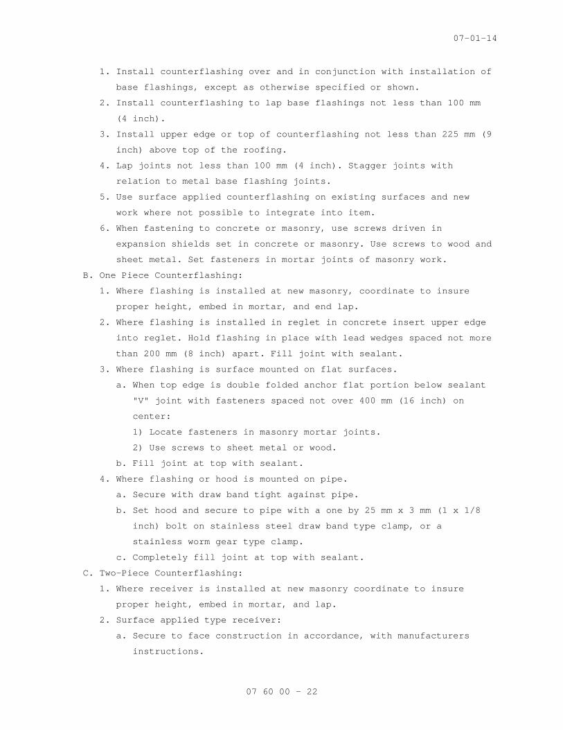
07-01-14
07 60 00 - 22
1. Install counterflashing over and in conjunction with installation of
base flashings, except as otherwise specified or shown.
2. Install counterflashing to lap base flashings not less than 100 mm
(4 inch).
3. Install upper edge or top of counterflashing not less than 225 mm (9
inch) above top of the roofing.
4. Lap joints not less than 100 mm (4 inch). Stagger joints with
relation to metal base flashing joints.
5. Use surface applied counterflashing on existing surfaces and new
work where not possible to integrate into item.
6. When fastening to concrete or masonry, use screws driven in
expansion shields set in concrete or masonry. Use screws to wood and
sheet metal. Set fasteners in mortar joints of masonry work.
B. One Piece Counterflashing:
1. Where flashing is installed at new masonry, coordinate to insure
proper height, embed in mortar, and end lap.
2. Where flashing is installed in reglet in concrete insert upper edge
into reglet. Hold flashing in place with lead wedges spaced not more
than 200 mm (8 inch) apart. Fill joint with sealant.
3. Where flashing is surface mounted on flat surfaces.
a. When top edge is double folded anchor flat portion below sealant
"V" joint with fasteners spaced not over 400 mm (16 inch) on
center:
1) Locate fasteners in masonry mortar joints.
2) Use screws to sheet metal or wood.
b. Fill joint at top with sealant.
4. Where flashing or hood is mounted on pipe.
a. Secure with draw band tight against pipe.
b. Set hood and secure to pipe with a one by 25 mm x 3 mm (1 x 1/8
inch) bolt on stainless steel draw band type clamp, or a
stainless worm gear type clamp.
c. Completely fill joint at top with sealant.
C. Two-Piece Counterflashing:
1. Where receiver is installed at new masonry coordinate to insure
proper height, embed in mortar, and lap.
2. Surface applied type receiver:
a. Secure to face construction in accordance, with manufacturers
instructions.

07-01-14
07 60 00 - 23
b. Completely fill space at the top edge of receiver with sealant.
3. Insert counter flashing in receiver in accordance with fabricator or
manufacturer's instructions and to fit tight against base flashing.
D. Where vented edge occur install so lower edge of counterflashing is
against base flashing.
E. When counter flashing is a component of other flashing install as
shown.
3.5 REGLETS
A. Install reglets in a manner to provide a watertight installation.
B. Locate reglets not less than 225 mm (9 inch) nor more than 400 mm (16
inch) above roofing, and not less than 125 mm (5 inch) nor more than
325 mm (13 inch) above cant strip.
C. Butt and align end joints or each section of reglet and securely hold
in position until concrete or mortar are hardened:
1. Coordinate reglets for anchorage into concrete with formwork
construction.
2. Coordinate reglets for masonry to locate horizontally into mortar
joints.
3.6 GRAVEL STOPS
A. General:
1. Install gravel stops and fascias with allowance for expansion at
each joint; minimum of 6 mm (1/4 inch).
2. Extend roof flange of gravel stop and splice plates not less than
four inches out over roofing and nail or screw to wood nailers.
Space fasteners on 75 mm (3 inch) centers in staggered pattern.
3. Install continuous cleat for fascia drip edge. Secure with fasteners
as close to lower edge as possible on 75 mm (3 inch) centers.
4. Where ends of gravel stops and fascias abut a vertical wall, provide
a watertight, flashed and sealant filled joint.
5. Set flange in roof cement when installed over built-up roofing.
6. Edge securement for low-slope roofs: Low-slope membrane roof systems
metal edge securement, except gutters, shall be designed in
accordance with ANSI/SPRI ES-1, except the basic wind speed shall be
determined from Figure 1609, of IBC 2003.
B. Sheet metal gravel stops and fascia:
1. Install with end joints of splice plates sheets lapped three inches.
2. Hook the lower edge of fascia into a continuous edge strip.

07-01-14
07 60 00 - 24
3. Lock top section to bottom section for two piece fascia.
C. Corrugated sheet gravel stops and fascia:
1. Install 300 mm (12 inch) wide sheet flashing centered under joint. A
combination bottom and cover plate, extending above and beneath the
joint, may be used.
2. Hook lower edge of fascia into a continuous edge strip.
D. Scuppers:
1. Install scupper with flange behind gravel stops; leave 6 mm (1/4
inch) joint to gravel stop.
2. Set scupper at roof water line and fasten to wood blocking.
3. Use sealant to seal joint with fascia gravel stops at ends.
4. Coordinate to lap over conductor head and to discharge water into
conductor head.
3.8 EXPANSION JOINT COVERS, INSULATED
A. Install insulated expansion joint covers at locations shown on curbs
not less than 200 mm (8 inch) high above roof surface.
B. Install continuous edge strips of same metal as expansion joint flange,
nailed at not less than 75 mm (3 inch) centers.
C. Install insulated expansion joint covers in accordance with
manufacturer's directions locking edges to edge strips.
3.9 ENGINE EXHAUST PIPE OR STACK FLASHING
A. Set collar where shown and secure roof tabs or flange of collar to
structural deck with 13 mm (1/2 inch) diameter bolts.
B. Set flange of sleeve base flashing not less than 100 mm (4 inch) beyond
collar on all sides as specified for base flashing.
C. Install hood to above the top of the sleeve 50 mm (2 inch) and to
extend from sleeve same distance as space between collar and sleeve
beyond edge not sleeve:
1. Install insect screen to fit between bottom edge of hood and side of
sleeve.
2. Set collar of hood in high temperature sealant and secure with one
by 3 mm (1/8 inch) bolt on stainless steel draw band type, or
stainless steel worm gear type clamp. Install sealant at top of
head.

07-01-14
07 60 00 - 25
3.11 CONDUCTORS (DOWNSPOUTS)
A. Where scuppers discharge into downspouts install conductor head to
receive discharge with back edge up behind drip edge of scupper. Fasten
and seal joint. Sleeve conductors to gutter outlet tubes and fasten
joint and joints between sections.
B. Set conductors plumb and clear of wall, and anchor to wall with two
anchor straps, located near top and bottom of each section of
conductor. Strap at top shall be fixed to downspout, intermediate
straps and strap at bottom shall be slotted to allow not less than 13
mm (1/2 inch) movement for each 3000 mm (10 feet) of downspout.
C. Install elbows, offsets and shoes where shown and required. Slope not
less than 45 degrees.
3.12 SPLASH PANS
A. Install where downspouts discharge on low slope roofs unless shown
otherwise.
B. Set in roof cement prior to pour coat installation or sealant
compatible with single ply roofing membrane.
3.13 GOOSENECK ROOF VENTILATORS
A. Install on structural curb not less than 200 mm (8 inch) high above
roof surface.
B. Securely anchor ventilator curb to structural curb with fasteners
spaced not over 300 mm (12 inch) on center.
C. Anchor gooseneck to curb with screws having nonprene washers at 150 mm
(6 inch) on center.
- - - E N D - - -
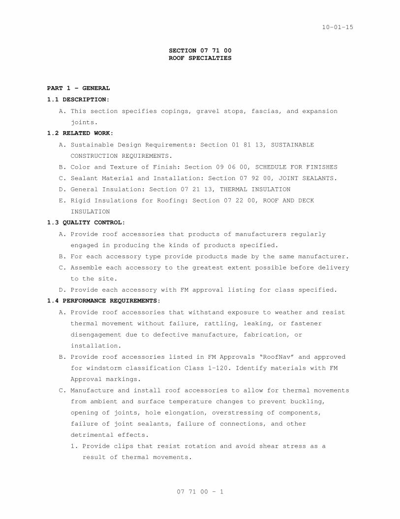
10-01-15
07 71 00 - 1
SECTION 07 71 00 ROOF SPECIALTIES
PART 1 - GENERAL
1.1 DESCRIPTION:
A. This section specifies copings, gravel stops, fascias, and expansion
joints.
1.2 RELATED WORK:
A. Sustainable Design Requirements: Section 01 81 13, SUSTAINABLE
CONSTRUCTION REQUIREMENTS.
B. Color and Texture of Finish: Section 09 06 00, SCHEDULE FOR FINISHES
C. Sealant Material and Installation: Section 07 92 00, JOINT SEALANTS.
D. General Insulation: Section 07 21 13, THERMAL INSULATION
E. Rigid Insulations for Roofing: Section 07 22 00, ROOF AND DECK
INSULATION
1.3 QUALITY CONTROL:
A. Provide roof accessories that products of manufacturers regularly
engaged in producing the kinds of products specified.
B. For each accessory type provide products made by the same manufacturer.
C. Assemble each accessory to the greatest extent possible before delivery
to the site.
D. Provide each accessory with FM approval listing for class specified.
1.4 PERFORMANCE REQUIREMENTS:
A. Provide roof accessories that withstand exposure to weather and resist
thermal movement without failure, rattling, leaking, or fastener
disengagement due to defective manufacture, fabrication, or
installation.
B. Provide roof accessories listed in FM Approvals “RoofNav” and approved
for windstorm classification Class 1-120. Identify materials with FM
Approval markings.
C. Manufacture and install roof accessories to allow for thermal movements
from ambient and surface temperature changes to prevent buckling,
opening of joints, hole elongation, overstressing of components,
failure of joint sealants, failure of connections, and other
detrimental effects.
1. Provide clips that resist rotation and avoid shear stress as a
result of thermal movements.

10-01-15
07 71 00 - 2
2. For design purposes, base provisions for thermal movement on assumed
ambient temperature (range) from minus 18 degrees C (0 degrees F),
ambient to 82 degrees C (180 degrees F).
1.5 SUBMITTALS:
A. Submit in accordance with Section 01 33 23, SHOP DRAWINGS, PRODUCT
DATA, AND SAMPLES.
B. Sustainable Design Submittals, as described below:
C. Samples: Representative sample panel of color-anodized aluminum not
less than 101 x 101 mm (4 x 4 inches), except extrusions are to be of a
width not less than section to be used. Submit sample that shows
coating with integral color and texture. Include manufacturer's
identifying label.
D. Shop Drawings: Each item specified showing design, details of
construction, installation and fastenings.
E. Manufacturer's Literature and Data: Each item specified.
F. Certificates: Stating that aluminum has been given specified thickness
of anodizing.
1.6 APPLICABLE PUBLICATIONS:
A. The publications listed below form a part of this specification to the
extent referenced. The publications are referenced in the text by the
basic designation only.
B. ASTM International (ASTM):
A240/A240M-14...........Chromium and Chromium-Nickel Stainless Steel
Plate, Sheet, and Strip for Pressure Vessels
and for General Applications
A653/A653M-13...........Steel Sheet Zinc-Coated (Galvanized) or
Zinc-Iron Alloy Coated (Galvannealed) by the
Hot Dip Process
A666-10.................Annealed or Cold-Worked Austenitic Stainless
Steel Sheet, Strip, Plate, and Flat Bar
B209-14.................Aluminum and Aluminum Alloy-Sheet and Plate
B209M-14................Aluminum and Aluminum Alloy-Sheet and Plate
(Metric)
B221-14.................Aluminum-Alloy Extruded Bars, Rods, Wire,
Shapes, and Tubes
B221M-13................Aluminum-Alloy Extruded Bars, Rods, Wire,
Shapes, and Tubes (Metric)
B32-08(R2014)...........Solder Metal

10-01-15
07 71 00 - 3
B370-12.................Copper Sheet and Strip for Building
Construction
B882-10.................Pre-Patinated Copper for Architectural
Applications
C612-14.................Mineral Fiber Block and Board Thermal
Insulation
D1187/D1187M-97 (R2011).Asphalt-Base Emulsions for Use as Protective
Coatings for Metal
D1970/D1970M-14.........Self-Adhering Polymer Modified Bituminous Sheet
Materials Used as Steep Roofing Underlayment
for Ice Dam Protection
D226/D226M-09...........Asphalt-Saturated Organic Felt Used in Roofing
and Waterproofing
D4869/D4969M-05(R2011)..Asphalt-Saturated Organic Felt Underlayment
Used In Steep Slope Roofing
C. National Association of Architectural Metal Manufacturers (NAAMM):
AMP 500-06..............Metal Finishes Manual
D. American Architectural Manufacturers Association (AAMA):
2605-11.................High Performance Organic Coatings on
Architectural Extrusions and Panels.
611-14..................Anodized Architectural Aluminum
E. FM Global (FM):
RoofNav.................Approved Roofing Assemblies and Products
PART 2 - PRODUCTS
2.1 MATERIALS:
A. Aluminum, Extruded: ASTM B221M (B221).
B. Aluminum Sheet: ASTM B209M (B209).
C. Galvanized Sheet Steel: ASTM A653/A653M; G-90 coating.
D. Stainless-Steel Sheet: ASTM A240/A240M or ASTM A666, Type 304.
E. Copper Sheet: ASTM B370, cold-rolled copper sheet, H00 or H01 temper.
G. Insulation: ASTM C612, Class 1 or 2.
H. Asphalt Coating: ASTM D1187, Type I, quick setting.
2.2 UNDERLAYMENT:
A. Self-Adhering Modified Bitumen Underlayment:
1. Provide self-adhering modified bitumen membrane underlayment
material in compliance with ASTM D1970/D1970M, suitable for use as
underlayment for metal copings and fascias.

10-01-15
07 71 00 - 4
2. Provide membrane resistant to cyclical elevated temperatures for
extended period of time in high heat service conditions (stable
after testing at 116 degrees C (240 degrees F)).
3. Provide membrane with integral non-tacking top surface of
polyethylene film or other surface material to serve as separator
between bituminous material and metal products to be applied above.
4. Provide primer.
B. Felt Underlayment: Provide No. 30 asphalt saturated organic,
non-perforated felt underlayment in compliance with ASTM D226/D226M,
Type II, or ASTM D4869/D4869M.
C. Slip Sheet: Provide 0.24 kg per square meter (5 pounds per 100 sf)
rosin sized unsaturated building paper for slip sheet.
2.3 SOLDER:
A. Copper Solder conforming to ASTM B32, lead-free solder.
2.4 COPINGS:
A. Fabricate of aluminum sheet not less than 0.063 thick; 16 oz. copper
B. Turn outer edges down each face of wall as shown on construction
documents.
C. Maximum lengths of 3.05 M (10 feet).
D. Shop fabricate external and internal corners as one-piece assemblies
with not less than 305 mm (12 inch) leg lengths.
E. Provide 101 mm (4 inch) wide 0.81 mm (0.032 inch) thick watertight
joint covers.
F. Provide anchor gutter bar of 0.81 mm (0.032 inch) thick with anchor
holes formed for underside of joint.
G. Provide concealed guttered splice plate of 0.81 mm (0.032 inch) thick
with butyl or other resilient seal strips anchored to splice plate for
underside of joint. Use galvanized steel anchor plate providing
compression spring anchoring of coping cover.
H. Finish: Color as specified.
2.5 EXTRUDED ALUMINUM GRAVEL STOPS AND FASCIAS:
A. Fabricate of aluminum not less than 2 mm (0.078 inch) thick.
B. Turn fascia down face of wall and up above roof as shown in
construction documents.
C. Maximum lengths of 3.05 M (10-feet).
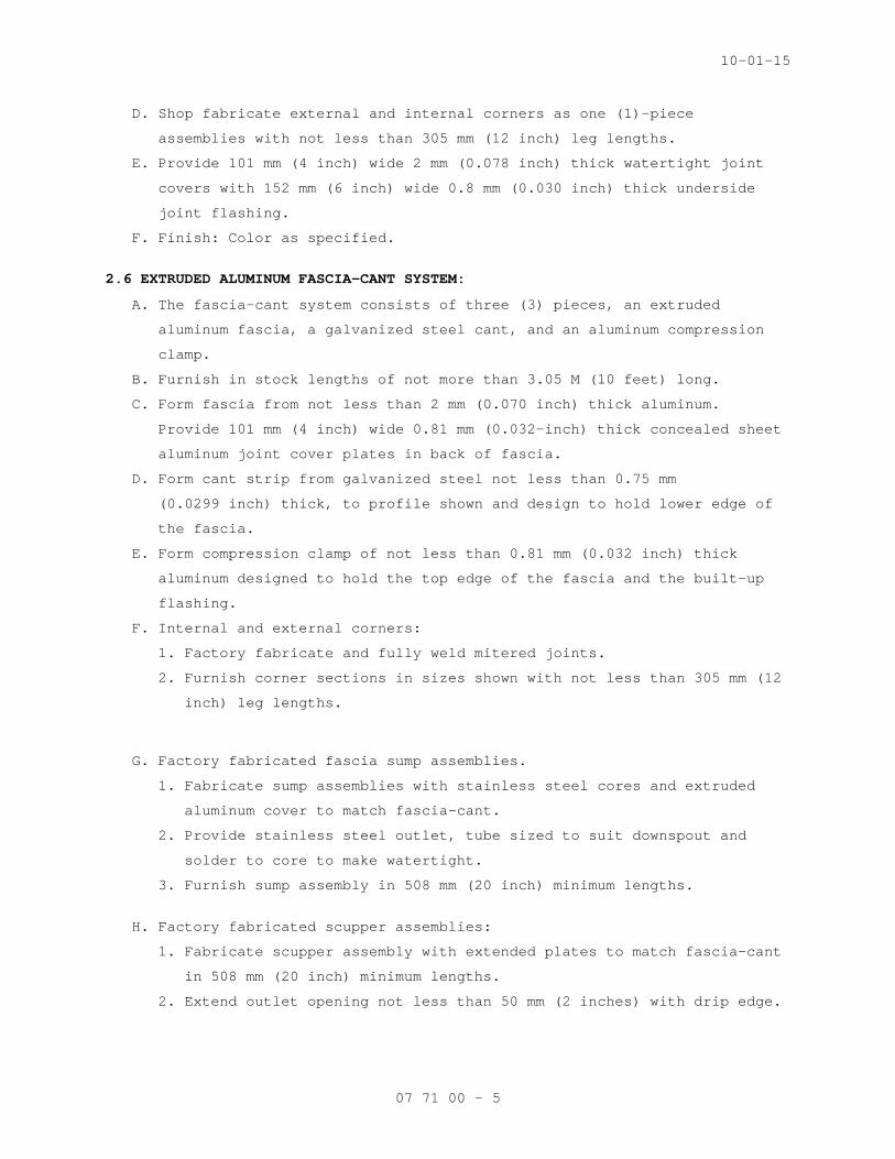
10-01-15
07 71 00 - 5
D. Shop fabricate external and internal corners as one (1)-piece
assemblies with not less than 305 mm (12 inch) leg lengths.
E. Provide 101 mm (4 inch) wide 2 mm (0.078 inch) thick watertight joint
covers with 152 mm (6 inch) wide 0.8 mm (0.030 inch) thick underside
joint flashing.
F. Finish: Color as specified.
2.6 EXTRUDED ALUMINUM FASCIA-CANT SYSTEM:
A. The fascia-cant system consists of three (3) pieces, an extruded
aluminum fascia, a galvanized steel cant, and an aluminum compression
clamp.
B. Furnish in stock lengths of not more than 3.05 M (10 feet) long.
C. Form fascia from not less than 2 mm (0.070 inch) thick aluminum.
Provide 101 mm (4 inch) wide 0.81 mm (0.032-inch) thick concealed sheet
aluminum joint cover plates in back of fascia.
D. Form cant strip from galvanized steel not less than 0.75 mm
(0.0299 inch) thick, to profile shown and design to hold lower edge of
the fascia.
E. Form compression clamp of not less than 0.81 mm (0.032 inch) thick
aluminum designed to hold the top edge of the fascia and the built-up
flashing.
F. Internal and external corners:
1. Factory fabricate and fully weld mitered joints.
2. Furnish corner sections in sizes shown with not less than 305 mm (12
inch) leg lengths.
G. Factory fabricated fascia sump assemblies.
1. Fabricate sump assemblies with stainless steel cores and extruded
aluminum cover to match fascia-cant.
2. Provide stainless steel outlet, tube sized to suit downspout and
solder to core to make watertight.
3. Furnish sump assembly in 508 mm (20 inch) minimum lengths.
H. Factory fabricated scupper assemblies:
1. Fabricate scupper assembly with extended plates to match fascia-cant
in 508 mm (20 inch) minimum lengths.
2. Extend outlet opening not less than 50 mm (2 inches) with drip edge.

10-01-15
07 71 00 - 6
3. Fabricate with stainless steel core or sleeve to drain water from
toe of cant and flash in to built-up roofing with 101 mm (4 inch)
wide flange.
I. Finish on aluminum: Color as specified.
2.7 EXTRUDED ALUMINUM ROOF EXPANSION JOINT COVERS:
A. Fabricate in 3.0 M (10 foot) lengths with fastener openings slotting
for expansion not over 610 mm (24 inch) centers.
B. Provide four-way expansion, for joint widths shown on construction
documents.
C. Mill finish.
D. Form waterstop or moisture seals of continuous sheets of neoprene, not
less than 0.81 mm (0.032 inch) thick.
E. Fabricate corners as one (1) piece assembly with mitered and welded
joint and least dimension legs not less than 300 mm (12 inches) long.
F. Factory fabricate end caps and transitions to insure waterproof
assembly.
G. Five (5) piece assembly:
1. Roof expansion joint cover system consists of an extruded aluminum
cover, extruded frame or curb vertical section, galvanized steel
cant, and aluminum compression clamp counter flashing, complete with
moisture seals. Form cover and vertical section from extruded
aluminum, 2 mm (0.080 inch) minimum thickness with spring stainless
steel tension or pivot bar.
2. Form cant from galvanized steel not less than 0.8 mm (0.029 inch)
thick formed to profile shown on construction documents.
3. Form splice plates of not less than 0.81 mm (0.032 inch) thick
aluminum sheet.
4. Form counter flashing member of 1.3 mm (0.050 inch) thick sheet
aluminum, secured with screws to the top edge of the vertical
section and providing compression clamp over base flashing.
5. Provide compression gasket separating cover from curb bearing.
H. Two (2) piece assembly:
1. Roof expansion joint system consists of an extruded aluminum cover
combination extruded aluminum frame or curb with integral adjustable
counter flashing flange, and moisture seals.
2. Form cover from extruded aluminum 2 mm (0.078 inch) minimum
thickness.

10-01-15
07 71 00 - 7
3. Form cover anchor system of stainless steel pivot bar.
4. Form frame assembly of not less than 2 mm (0.076 inch) aluminum
except for flashing portion.
5. Provide compression gasket separating cover from curb at bearing.
PART 3 - EXECUTION
3.1 INSTALLATION:
A. Examine substrates, areas, and conditions, to verify actual locations,
dimensions, and other conditions affecting performance of the Work.
B. Verify that substrate is sound, dry, smooth, clean, sloped for drainage
where applicable, and securely anchored.
C. Underlayment Installation:
1. Self-Adhering Sheet Underlayment:
a. Apply primer as required by manufacturer.
b. Comply with temperature restrictions of underlayment manufacturer
for installation.
c. Apply wrinkle free, in shingle fashion to shed water, and with
end laps of not less than 152 mm (6 inches) staggered 610 mm (24
inches) between courses.
d. Overlap side edges not less than 89 mm (3-1/2 inches). Roll laps
with roller.
e. Cover underlayment within 14 days.
f. Apply continuously under copings and roof-edge fascias and gravel
stops.
g. Coordinate application of self-adhering sheet underlayment under
roof specialties with requirements for continuity with adjacent
air barrier materials.
2. Felt Underlayment:
a. Install with adhesive for temporary anchorage to minimize use of
mechanical fasteners under roof specialties.
b. Apply in shingle fashion to shed water, with lapped joints of not
less than 50 mm (2 inches).
3. Slip Sheet:
a. Install with tape or adhesive for temporary anchorage to minimize
use of mechanical fasteners under roof specialties.
b. Apply in shingle fashion to shed water, with lapped joints of not
less than 50 mm (2 inches).

10-01-15
07 71 00 - 8
D. Install roof accessories where indicated in construction documents.
E. Secure with fasteners in accordance with manufacture's printed
installation instructions and approved shop drawings unless shown
otherwise. Provide fasteners suitable for application, for metal types
being secured and designed to meet performance requirements.
F. Where soldered joints are required, clean surfaces to be soldered,
removing oils and foreign matter.
1. Pre-tin edges of sheets to be soldered to a width of 38 mm
(1-1/2 inches).
2. Reduce pre-tinning where pre-tinned surface would show in completed
work.
3. Tin edges of uncoated copper sheets using solder for copper.
4. Do not use torches for soldering.
5. Heat surfaces to receive solder and flow solder into joint.
6. Fill joint completely.
7. Completely remove flux and spatter from exposed surfaces.
G. Coordinate to install insulation where shown; see Section 07 21 13,
THERMAL INSULATION and Section 07 22 00, ROOF AND DECK INSULATION.
H. Comply with section 07 92 00, JOINT SEALANTS to install sealants where
required by manufactures installation instructions.
I. Coordinate with roofing work for installation of items in sequence to
prevent water infiltration.
J. Gravel Stops and Fascias:
1. Install gravel stops and fascia with butt joints with approximately
6 mm (1/4 inch) space for expansion.
2. Over each joint provide cover plates of sheet aluminum, complete
with concealed sheet aluminum flashing, centered under each joint.
3. Provide lap cover plates and concealed flashing over the gravel stop
and fascia not less than 101 mm (4 inches).
4. Extend concealed flashing over built-up roofing, embed in roof
cement and turn down over face of blocking at roof edge.
K. Aluminum Coping:
1. Install sections of coping with approximately 6 mm (1/4-inch) space
between ends of sections.
2. Center joint gutter bar and covers at joints and lock in place.
3. When snap-on system is installed ensure front and back edges are
locked in place.

10-01-15
07 71 00 - 9
L. Fascia-Cant System:
1. Install galvanized steel cant; coordinate with roofing work and
after completion of roofing work install extruded aluminum fascia,
concealed joint cover plate, and aluminum compression clamp, where
shown in construction documents.
2. Install system to allow for expansion and contraction with 6 mm
(1/4 inch) space between extruded aluminum members and galvanized
steel cant as required by manufacturer of system.
3. Offset joints in extruded aluminum members from galvanized steel
cant joints.
M. Expansion Joint Covers:
1. Install to terminate base flashing 203 mm (8 inches) above roof.
2. Install moisture seals to drain water to outlets that do not permit
water to enter building.
3. Provide stainless steel screws when exposed.
4. Three piece assembly:
a. Install curb section with screws to wood blocking, allowing 6 mm
(1/4 inch) at butt joints between sections with splice plate at
joint.
b. Install cant to wood blocking by nailing along horizontal flange
every 152 mm (6 inches), with galvanized roofing nails 25 mm (1
inch) long.
c. After completion of base flashing install cap flashing and
compression clamp and fasten to the curb or metal cant with
stainless steel self-tapping screws with neoprene washers under
head spaced approximately 457 mm (18 inches) on center.
d. Install expansion joint cover with a 6 mm (1/4 inch) wide end
joints.
e. Install over end joint a cover plate complete with concealed
aluminum flashing, centered under each joint. Fabricate flashing
to lap cover not less than 101 mm (4 inches.
5. Two piece assembly:
a. Install curb section with screws allowing 6 mm (1/4 inch) space
at end joints with splice plate at joint.
b. After completion of base flashing bend down cap flashing flange
and secure to blocking with screws.
c. Install expansion joint cover with 6 mm (1/4 inch) wide space at
end joints and tension bars at 610 mm (24 inches) on center.

10-01-15
07 71 00 - 10
d. Install cover plates with formed aluminum flashing concealed and
centered on joint. Flashing to lap cover not less than 101 mm
(4 inches).
3.2 PROTECTION OF ALUMINUM:
A. Provide protection for aluminum against galvanic action wherever
dissimilar materials are in contact, by painting the contact surfaces
of the dissimilar material with two (2) coats of asphalt coating
(complete coverage), or by separating the contact surfaces with a
preformed neoprene tape having pressure sensitive adhesive coating on
one (1) side.
B. Paint aluminum in contact with wood, concrete and masonry, or other
absorptive materials, that may become repeatedly wet, with two (2)
coats of asphalt coating.
3.3 ADJUSTING:
A. Adjust expansion joints to close tightly and be watertight; insuring
maximum allowance for building movement.
3.4 PROTECTION:
A. Protect roof accessories from damage during installation and after
completion of the work from subsequent construction.
- - - E N D - - -

10-01-15
07 72 00 - 1
SECTION 07 72 00 ROOF ACCESSORIES
PART 1 - GENERAL
1.1 DESCRIPTION:
A. This section specifies roof hatches; equipment supports; gravity
ventilators; and metal grating roof walkway system.
1.2 RELATED WORK:
A. Sustainable Design Requirements: Section 01 81 13, SUSTAINABLE
CONSTRUCTION REQUIREMENTS.
B. Color and texture of finish: Section 09 06 00, SCHEDULE FOR FINISHES.
C. Sealant material and installation: Section 07 92 00, JOINT SEALANTS.
D. General insulation: Section 07 21 13, THERMAL INSULATION. Rigid
insulations for roofing: Section 07 22 00, ROOF AND DECK INSULATION
1.3 QUALITY ASSURANCE:
A. Provide roof accessories that are the products of manufacturers
regularly engaged in producing the kinds of products specified.
B. For each accessory type provide the same product made by the same
manufacturer.
C. Assemble each accessory to the greatest extent possible before delivery
to the site.
1.4 SUBMITTALS:
A. Submit in accordance with Section 01 33 23, SHOP DRAWINGS, PRODUCT
DATA, AND SAMPLES.
B. Sustainable Design Submittals, as described below:
1. Postconsumer and preconsumer recycled content as specified in
PART 2 - PRODUCTS.
C. Samples: Submit representative sample panel of color anodized aluminum
not less than 101 x 101 mm (4 x 4 inches). For extrusions, submit width
not less than section to be installed. Show coating with integral color
and texture and include manufacturer's identifying label.
D. Shop Drawings: Each item specified showing design, details of
construction, installation and fastenings.
E. Manufacturer's Literature and Data: Each item specified.
F. Certificates: Stating that aluminum has been given specified thickness
of anodizing.

10-01-15
07 72 00 - 2
1.5 APPLICABLE PUBLICATIONS:
A. The publications listed below form a part of this specification to the
extend referenced. The publications are referenced in the text by the
basic designation only.
B. Federal Specifications (Fed. Spec.):
RR-G-1602D..............Grating, Metal, Other Than Bar Type (Floor,
Except for Naval Vessels)
C. ASTM International (ASTM):
A653/A653M-10...........Steel Sheet, Zinc-Coated (Galvanized) or Zinc-
Iron Alloy-Coated (Galvannealed) By the Hot-Dip
Process
B209-14.................Aluminum and Aluminum Alloy-Sheet and Plate
B209M-14................Aluminum and Aluminum-Alloy Sheet and Plate
(Metric)
B221-14.................Aluminum-Alloy Extruded Bars, Rods, Wire,
Shapes, and Tubes
B221M-13................Aluminum and Aluminum-Alloy Extruded Bars,
Rods, Wire, Shapes, and Tubes (Metric)
C726-12.................Mineral Wool Roof Insulation Board
C1289-14a...............Faced Rigid Cellular Polyisocyanurate Thermal
Insulation Board
D1187/D1187M-97(R2011)..Asphalt-Base Emulsions for Use as Protective
Coatings for Metal
D. National Association of Architectural Metal Manufacturers (NAAMM):
AMP 500 Series..........Metal Finishes Manual
E. American Architectural Manufacturers Association (AAMA):
2603-13.................Performance Requirements and Test Procedures
for Pigmented Organic Coatings on Aluminum
Extrusions and Panels
2605-13.................High Performance Organic Coatings on
Architectural Extrusions and Panels.
611-14..................Anodized Architectural Aluminum
621-02..................High Performance Organic Coatings on Coil
Coated Architectural Hot Dipped Galvanized
(HDG) and Zinc-Aluminum Coated Steel Substrates
F. American Society of Civil Engineers (ASCE):
ASCE 7-10...............Minimum Design Loads for Buildings and Other
Structures

10-01-15
07 72 00 - 3
G. U.S. National Archives and Records Administration (NARA):
29 CFR 1910.23..........Guarding Floor and Wall Openings and Holes
PART 2 - PRODUCTS
2.1 MATERIALS:
A. Aluminum, Extruded: ASTM B221M (B221).
B. Aluminum Sheet: ASTM B209M (B209).
C. Galvanized Sheet Steel: ASTM A653/A653M; G-90 coating.
D. Metal Grating for Roof Walkway: Fed. Spec. RR-G-1602.
E. Recycled Content of Metal Products: Postconsumer recycled content plus
one-half of preconsumer recycled content not less than 30 percent.
F. Asphalt Coating: ASTM D1187/D1187M, Type I, quick setting.
2.2 ROOF HATCH (SCUTTLE):
A. Performance Characteristics:
1. Cover to be reinforced to support a minimum live load of 195 kg per
sq. m (40 lb. per sq. ft.) with a maximum deflection of 1/150th of
the span or 97 kg per sq. m (20 lb. per sq. ft.) wind uplift.
2. Operation of the Cover: Smooth and easy with controlled operation
throughout the entire arc of opening and closing.
3. Operation of the Cover: Not affected by temperature.
4. Entire Hatch: Weathertight with fully welded corner joints on cover
and curb.
B. Shop fabricate from aluminum with mill finish.
C. Curb and Cover:
1. Exterior facing: Minimum 2.3 mm (0.09 inch) thick sheet aluminum
with mill finish.
2. Interior facing: Minimum 1 mm (0.04 inch) thick sheet aluminum.
3. Minimum of 50 mm (2 inch) thick polyisocyanurate insulation
(ASTM C1289) with a U-value = 0.47 W/m2 K (R-value = 12) between
facings of cover and over exterior face of curb.
4. Form exterior curb facing with an integral 76 mm (3 inch) wide roof
flange and cap flashing minimum 2.3 mm (0.09 inch) thick sheet
aluminum.
5. Make curb 305 mm (12 inches) above finish roof surface.
6. Form cover to lap curb and cap flashing.
7. Size opening as shown on construction documents.

10-01-15
07 72 00 - 4
D. Hardware:
1. Provide spring snap latch with inside and outside operating handles
and padlock hasp on inside. Provide two snap latches when hinge side
is over 2100 mm (7 feet) long. Bolt hardware into heavy gauge
channel reinforcement welded to the underside of the cover and
concealed within the insulation space.
2. Provide heavy duty pintle hinges.
3. Provide automatic hold open and operating arm with enclosed torsion
or compression spring lifting mechanism.
4. Latch Strike: Stamped component bolted or welded to the curb
assembly.
5. Automatically lock in the open position at not less than 70 degrees.
6. Provide weatherstripping at cover closure.
7. Galvanize all hardware items.
E. Assembly:
1. Shop assemble roof scuttle.
2. Weld joints exposed to the weather and built into the roofing.
3. Finish weld smooth where exposed.
F. Safety Accessories:
1. Ladder Assist Post: Provide a telescoping tubular section that locks
automatically when fully extended. Control upward and downward
movement by a stainless steel spring balancing mechanism. Provide
unit completely assembled with fasteners for securing to the ladder
rungs in accordance with the manufacturer’s instructions.
2. Safety Railing: Provide a fixed, attached to the roof hatch railing
assembly including rails, clamps, fasteners, safety barrier at
railing opening, and accessories required for a complete
installation; complying with 29 CFR 1910.23 requirements.
3.2 PROTECTION OF ALUMINUM:
A. Provide protection for aluminum against galvanic action wherever
dissimilar materials are in contact, by painting the contact surfaces
of the dissimilar material with two (2) coats of asphalt coating
(complete coverage), or by separating the contact surfaces with a
preformed neoprene tape having pressure sensitive adhesive coating on
side.
B. Paint aluminum in contact with wood, concrete and masonry, or other
absorptive materials, that may become repeatedly wet, with two coats of
asphalt coating.

10-01-15
07 72 00 - 5
3.3 ADJUSTING:
A. Adjust roof hatch hardware to operate freely and so that cover will
operate without binding, close tightly at perimeter, and latch
securely.
3.4 PROTECTION:
A. Protect roof accessories from damage during installation and after
completion of the work from subsequent construction.
- - - E N D - - -

02-01-16
07 84 00 - 1
SECTION 07 84 00 FIRESTOPPING
PART 1 - GENERAL
1.1 DESCRIPTION:
A. Provide UL or equivalent approved firestopping system for the closures
of openings in walls, floors, and roof decks against penetration of
flame, heat, and smoke or gases in fire resistant rated construction.
B. Provide UL or equivalent approved firestopping system for the closure
of openings in walls against penetration of gases or smoke in smoke
partitions.
1.2 RELATED WORK:
A. Sustainable Design Requirements: Section 01 81 13, SUSTAINABLE
CONSTRUCTION REQUIREMENTS.
B. Expansion and seismic joint firestopping: Section 07 95 13, EXPANSION
JOINT COVER ASSEMBLIES.
C. Spray applied fireproofing: Section 07 81 00, APPLIED FIREPROOFING
D. Sealants and application: Section 07 92 00, JOINT SEALANTS.
E. Fire and smoke damper assemblies in ductwork: Section 23 31 00, HVAC
DUCTS AND CASINGS Section 23 37 00, AIR OUTLETS AND INLETS.
1.3 SUBMITTALS:
A. Submit in accordance with Section 01 33 23, SHOP DRAWINGS, PRODUCT
DATA, AND SAMPLES.
B. Sustainable Design Submittals, as described below:
1. Volatile organic compounds per volume as specified in
PART 2 - PRODUCTS
C. Installer qualifications.
D. Inspector qualifications.
E. Manufacturers literature, data, and installation instructions for types
of firestopping and smoke stopping used.
F. List of FM, UL, or WH classification number of systems installed.
G. Certified laboratory test reports for ASTM E814 tests for systems not
listed by FM, UL, or WH proposed for use.
H. Submit certificates from manufacturer attesting that firestopping
materials comply with the specified requirements.
1.4 DELIVERY AND STORAGE:
A. Deliver materials in their original unopened containers with
manufacturer’s name and product identification.

02-01-16
07 84 00 - 2
B. Store in a location providing protection from damage and exposure to
the elements.
1.5 QUALITY ASSURANCE:
A. FM, UL, or WH or other approved laboratory tested products will be
acceptable.
B. Installer Qualifications: A firm that has been approved by FM Global
according to FM Global 4991 or been evaluated by UL and found to comply
with UL’s “Qualified Firestop Contractor Program Requirements.” Submit
qualification data.
C. Inspector Qualifications: Contractor to engage a qualified inspector to
perform inspections and final reports. The inspector to meet the
criteria contained in ASTM E699 for agencies involved in quality
assurance and to have a minimum of two years’ experience in
construction field inspections of firestopping systems, products, and
assemblies. The inspector to be completely independent of, and divested
from, the Contractor, the installer, the manufacturer, and the supplier
of material or item being inspected. Submit inspector qualifications.
1.6 APPLICABLE PUBLICATIONS
A. Publications listed below form a part of this specification to the
extent referenced. Publications are referenced in the text by the basic
designation only.
B. ASTM International (ASTM):
E84-14..................Surface Burning Characteristics of Building
Materials
E699-09.................Standard Practice for Evaluation of Agencies
Involved in Testing, Quality Assurance, and
Evaluating of Building Components
E814-13a................Fire Tests of Through-Penetration Fire Stops
E2174-14................Standard Practice for On-Site Inspection of
Installed Firestops
E2393-10a...............Standard Practice for On-Site Inspection of
Installed Fire Resistive Joint Systems and
Perimeter Fire Barriers
C. FM Global (FM):
Annual Issue Approval Guide Building Materials
4991-13.................Approval of Firestop Contractors
D. Underwriters Laboratories, Inc. (UL):
Annual Issue Building Materials Directory

02-01-16
07 84 00 - 3
Annual Issue Fire Resistance Directory
723-10(2008)............Standard for Test for Surface Burning
Characteristics of Building Materials
1479-04(R2014)..........Fire Tests of Through-Penetration Firestops
E. Intertek Testing Services - Warnock Hersey (ITS-WH):
Annual Issue Certification Listings
F. Environmental Protection Agency (EPA):
40 CFR 59(2014).........National Volatile Organic Compound Emission
Standards for Consumer and Commercial Products
PART 2 - PRODUCTS
2.1 FIRESTOP SYSTEMS:
A. Provide either factory built (Firestop Devices) or field erected
(through-Penetration Firestop Systems) to form a specific building
system maintaining required integrity of the fire barrier and stop the
passage of gases or smoke. Firestop systems to accommodate building
movements without impairing their integrity.
B. Through-penetration firestop systems and firestop devices tested in
accordance with ASTM E814 or UL 1479 using the "F" or "T" rating to
maintain the same rating and integrity as the fire barrier being
sealed. "T" ratings are not required for penetrations smaller than or
equal to 101 mm (4 in.) nominal pipe or 0.01 sq. m (16 sq. in.) in
overall cross sectional area.
C. Firestop sealants used for firestopping or smoke sealing to have the
following properties:
1. Contain no flammable or toxic solvents.
2. Release no dangerous or flammable out gassing during the drying or
curing of products.
3. Water-resistant after drying or curing and unaffected by high
humidity, condensation or transient water exposure.
4. When installed in exposed areas, capable of being sanded and
finished with similar surface treatments as used on the surrounding
wall or floor surface.
5. VOC Content: Firestopping sealants and sealant primers to comply
with the following limits for VOC content when calculated according
to 40 CFR 59, (EPA Method 24):
a. Sealants: 250 g/L.
b. Sealant Primers for Nonporous Substrates: 250 g/L.
c. Sealant Primers for Porous Substrates: 775 g/L.

02-01-16
07 84 00 - 4
D. Firestopping system or devices used for penetrations by glass pipe,
plastic pipe or conduits, unenclosed cables, or other non-metallic
materials to have following properties:
1. Classified for use with the particular type of penetrating material
used.
2. Penetrations containing loose electrical cables, computer data
cables, and communications cables protected using firestopping
systems that allow unrestricted cable changes without damage to the
seal.
E. Maximum flame spread of 25 and smoke development of 50 when tested in
accordance with ASTM E84 or UL 723. Material to be an approved
firestopping material as listed in UL Fire Resistance Directory or by a
nationally recognized testing laboratory.
F. FM, UL, or WH rated or tested by an approved laboratory in accordance
with ASTM E814.
G. Materials to be nontoxic and noncarcinogen at all stages of
application or during fire conditions and to not contain hazardous
chemicals. Provide firestop material that is free from Ethylene Glycol,
PCB, MEK, and asbestos.
H. For firestopping exposed to view, traffic, moisture, and physical
damage, provide products that do not deteriorate when exposed to these
conditions.
1. For piping penetrations for plumbing and wet-pipe sprinkler systems,
provide moisture-resistant through-penetration firestop systems.
2. For floor penetrations with annular spaces exceeding 101 mm (4 in.)
or more in width and exposed to possible loading and traffic,
provide firestop systems capable of supporting the floor loads
involved either by installing floor plates or by other means
acceptable to the firestop manufacturer.
3. For penetrations involving insulated piping, provide through-
penetration firestop systems not requiring removal of insulation.
2.2 SMOKE STOPPING IN SMOKE PARTITIONS:
A. Provide silicone sealant in smoke partitions as specified in Section
07 92 00, JOINT SEALANTS.
B. Provide mineral fiber filler and bond breaker behind sealant.
C. Sealants to have a maximum flame spread of 25 and smoke developed of 50
when tested in accordance with ASTM E84.
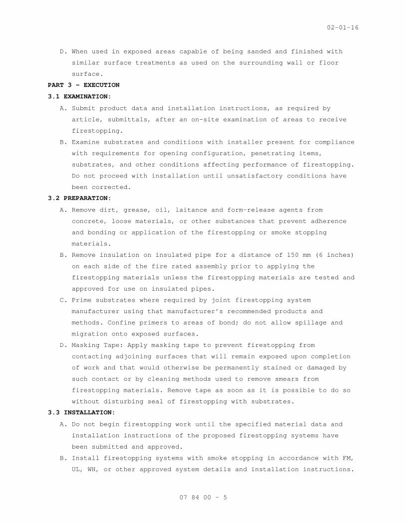
02-01-16
07 84 00 - 5
D. When used in exposed areas capable of being sanded and finished with
similar surface treatments as used on the surrounding wall or floor
surface.
PART 3 - EXECUTION
3.1 EXAMINATION:
A. Submit product data and installation instructions, as required by
article, submittals, after an on-site examination of areas to receive
firestopping.
B. Examine substrates and conditions with installer present for compliance
with requirements for opening configuration, penetrating items,
substrates, and other conditions affecting performance of firestopping.
Do not proceed with installation until unsatisfactory conditions have
been corrected.
3.2 PREPARATION:
A. Remove dirt, grease, oil, laitance and form-release agents from
concrete, loose materials, or other substances that prevent adherence
and bonding or application of the firestopping or smoke stopping
materials.
B. Remove insulation on insulated pipe for a distance of 150 mm (6 inches)
on each side of the fire rated assembly prior to applying the
firestopping materials unless the firestopping materials are tested and
approved for use on insulated pipes.
C. Prime substrates where required by joint firestopping system
manufacturer using that manufacturer’s recommended products and
methods. Confine primers to areas of bond; do not allow spillage and
migration onto exposed surfaces.
D. Masking Tape: Apply masking tape to prevent firestopping from
contacting adjoining surfaces that will remain exposed upon completion
of work and that would otherwise be permanently stained or damaged by
such contact or by cleaning methods used to remove smears from
firestopping materials. Remove tape as soon as it is possible to do so
without disturbing seal of firestopping with substrates.
3.3 INSTALLATION:
A. Do not begin firestopping work until the specified material data and
installation instructions of the proposed firestopping systems have
been submitted and approved.
B. Install firestopping systems with smoke stopping in accordance with FM,
UL, WH, or other approved system details and installation instructions.
02-01-16
07 84 00 - 6
C. Install smoke stopping seals in smoke partitions.
3.4 CLEAN-UP:
A. As work on each floor is completed, remove materials, litter, and
debris.
B. Clean up spills of liquid type materials.
C. Clean off excess fill materials and sealants adjacent to openings and
joints as work progresses by methods and with cleaning materials
approved by manufacturers of firestopping products and of products in
which opening and joints occur.
D. Protect firestopping during and after curing period from contact with
contaminating substances or from damage resulting from construction
operations or other causes so that they are without deterioration or
damage at time of Substantial Completion. If, despite such protection,
damage or deterioration occurs, cut out and remove damaged or
deteriorated firestopping immediately and install new materials to
provide firestopping complying with specified requirements.
3.5 INSPECTIONS AND ACCEPTANCE OF WORK:
A. Do not conceal or enclose firestop assemblies until inspection is
complete and approved by the Contracting Officer Representative (COR).
B. Furnish service of approved inspector to inspect firestopping in
accordance with ASTM E2393 and ASTM E2174 for firestop inspection, and
document inspection results. Submit written reports indicating
locations of and types of penetrations and type of firestopping used at
each location; type is to be recorded by UL listed printed numbers.
- - - E N D - - -

10-01-15
07 92 00 - 1
SECTION 07 92 00 JOINT SEALANTS
PART 1 - GENERAL
1.1 DESCRIPTION:
A. This section covers interior and exterior sealant and their
application, wherever required for complete installation of building
materials or systems.
1.2 RELATED WORK (INCLUDING BUT NOT LIMITED TO THE FOLLOWING):
A. Sustainable Design Requirements: Section 01 81 13, SUSTAINABLE
CONSTRUCTION REQUIREMENTS.
D. Firestopping Penetrations: Section 07 84 00, FIRESTOPPING.
1.3 QUALITY ASSURANCE:
A. Installer Qualifications: An experienced installer with a minimum of
three (3) years’ experience and who has specialized in installing joint
sealants similar in material, design, and extent to those indicated for
this Project and whose work has resulted in joint-sealant installations
with a record of successful in-service performance. Submit
qualification.
B. Source Limitations: Obtain each type of joint sealant through one (1)
source from a single manufacturer.
C. Product Testing: Obtain test results from a qualified testing agency
based on testing current sealant formulations within a 12-month period.
1. Testing Agency Qualifications: An independent testing agency
qualified according to ASTM C1021.
2. Test elastomeric joint sealants for compliance with requirements
specified by reference to ASTM C920, and where applicable, to other
standard test methods.
3. Test elastomeric joint sealants according to SWRI’s Sealant
Validation Program for compliance with requirements specified by
reference to ASTM C920 for adhesion and cohesion under cyclic
movement, adhesion-in peel, and indentation hardness.
4. Test other joint sealants for compliance with requirements indicated
by referencing standard specifications and test methods.
D. Lab Tests: Submit samples of materials that will be in contact or
affect joint sealants to joint sealant manufacturers for tests as
follows:

10-01-15
07 92 00 - 2
1. Adhesion Testing: Before installing elastomeric sealants, test their
adhesion to protect joint substrates according to the method in
ASTM C794 to determine if primer or other specific joint preparation
techniques are required.
2. Compatibility Testing: Before installing elastomeric sealants,
determine compatibility when in contact with glazing and gasket
materials.
3. Stain Testing: Perform testing per ASTM C1248 on interior and
exterior sealants to determine if sealants or primers will stain
adjacent surfaces. No sealant work is to start until results of
these tests have been submitted to the Contracting Officer
Representative (COR) and the COR has given written approval to
proceed with the work.
1.4 CERTIFICATION:
A. Contractor is to submit to the COR written certification that joints
are of the proper size and design, that the materials supplied are
compatible with adjacent materials and backing, that the materials will
properly perform to provide permanent watertight, airtight or vapor
tight seals (as applicable), and that materials supplied meet specified
performance requirements.
1.5 SUBMITTALS:
A. Submit in accordance with Section 01 33 23, SHOP DRAWINGS, PRODUCT
DATA, AND SAMPLES.
B. Sustainable Design Submittals, as described below:
1. Volatile organic compounds per volume as specified in
PART 2 - PRODUCTS.
C. Installer qualifications.
D. Contractor certification.
E. Manufacturer's installation instructions for each product used.
F. Cured samples of exposed sealants for each color.
G. Manufacturer's Literature and Data:
1. Primers
2. Sealing compound, each type, including compatibility when different
sealants are in contact with each other.
H. Manufacturer warranty.
1.6 PROJECT CONDITIONS:
A. Environmental Limitations:
10-01-15
07 92 00 - 3
1. Do not proceed with installation of joint sealants under following
conditions:
a. When ambient and substrate temperature conditions are outside
limits permitted by joint sealant manufacturer or are below
4.4 degrees C (40 degrees F).
b. When joint substrates are wet.
B. Joint-Width Conditions:
1. Do not proceed with installation of joint sealants where joint
widths are less than those allowed by joint sealant manufacturer for
applications indicated.
C. Joint-Substrate Conditions:
1. Do not proceed with installation of joint sealants until
contaminants capable of interfering with adhesion are removed from
joint substrates.
1.7 DELIVERY, HANDLING, AND STORAGE:
A. Deliver materials in manufacturers' original unopened containers, with
brand names, date of manufacture, shelf life, and material designation
clearly marked thereon.
B. Carefully handle and store to prevent inclusion of foreign materials.
C. Do not subject to sustained temperatures exceeding 32 degrees C (90
degrees F) or less than 5 degrees C (40 degrees F).
1.8 DEFINITIONS:
A. Definitions of terms in accordance with ASTM C717 and as specified.
B. Backing Rod: A type of sealant backing.
C. Bond Breakers: A type of sealant backing.
D. Filler: A sealant backing used behind a back-up rod.
1.9 WARRANTY:
A. Construction Warranty: Comply with FAR clause 52.246-21 "Warranty of
Construction".
B. Manufacturer Warranty: Manufacturer shall warranty their sealant for a
minimum of five (5) years from the date of installation and final
acceptance by the Government. Submit manufacturer warranty.
1.10 APPLICABLE PUBLICATIONS:
A. Publications listed below form a part of this specification to extent
referenced. Publications are referenced in text by basic designation
only.
B. ASTM International (ASTM):
10-01-15
07 92 00 - 4
C509-06.................Elastomeric Cellular Preformed Gasket and
Sealing Material
C612-14.................Mineral Fiber Block and Board Thermal
Insulation
C717-14a................Standard Terminology of Building Seals and
Sealants
C734-06(R2012)..........Test Method for Low-Temperature Flexibility of
Latex Sealants after Artificial Weathering
C794-10.................Test Method for Adhesion-in-Peel of Elastomeric
Joint Sealants
C919-12.................Use of Sealants in Acoustical Applications.
C920-14a................Elastomeric Joint Sealants.
C1021-08(R2014).........Laboratories Engaged in Testing of Building
Sealants
C1193-13................Standard Guide for Use of Joint Sealants.
C1248-08(R2012).........Test Method for Staining of Porous Substrate by
Joint Sealants
C1330-02(R2013).........Cylindrical Sealant Backing for Use with Cold
Liquid Applied Sealants
C1521-13................Standard Practice for Evaluating Adhesion of
Installed Weatherproofing Sealant Joints
D217-10.................Test Methods for Cone Penetration of
Lubricating Grease
D412-06a(R2013).........Test Methods for Vulcanized Rubber and
Thermoplastic Elastomers-Tension
D1056-14................Specification for Flexible Cellular Materials—
Sponge or Expanded Rubber
E84-09..................Surface Burning Characteristics of Building
Materials
C. Sealant, Waterproofing and Restoration Institute (SWRI).
The Professionals’ Guide
D. Environmental Protection Agency (EPA):
40 CFR 59(2014).........National Volatile Organic Compound Emission
Standards for Consumer and Commercial Products
PART 2 - PRODUCTS
2.1 SEALANTS:
A. Exterior Sealants:

10-01-15
07 92 00 - 5
1. Vertical surfaces, provide non-staining ASTM C920, Type S or M,
Grade NS, Class 25,.
2Horizontal surfaces, provide ASTM C920, Type S or M, Grade P, Class
25, Use T.
3. Provide location(s) of exterior sealant as follows:
a. Joints formed where frames and subsills of windows, doors,
louvers, and vents adjoin masonry, concrete, or metal frames.
Provide sealant at exterior surfaces of exterior wall
penetrations.
b. Metal to metal.
c. Masonry to masonry or stone.
d. Stone to stone.
e. Cast stone to cast stone.
f. Masonry expansion and control joints.
g. Wood to masonry.
h. Masonry joints where shelf angles occur.
i. Voids where items penetrate exterior walls.
j. Metal reglets, where flashing is inserted into masonry joints,
and where flashing is penetrated by coping dowels.
2.2 COLOR:
A. Sealants used with exposed masonry are to match color of mortar joints.
B. Sealants used with unpainted concrete are to match color of adjacent
concrete.
C. Color of sealants for other locations to be light gray or aluminum,
unless otherwise indicated in construction documents.
2.3 JOINT SEALANT BACKING:
A. General: Provide sealant backings of material and type that are
nonstaining; are compatible with joint substrates, sealants, primers,
and other joint fillers; and are approved for applications indicated by
sealant manufacturer based on field experience and laboratory testing.
B. Cylindrical Sealant Backings: ASTM C1330, of type indicated below and
of size and density to control sealant depth and otherwise contribute
to producing optimum sealant performance:
1. Type C: Closed-cell material with a surface skin.
C. Elastomeric Tubing Sealant Backings: Neoprene, butyl, EPDM, or silicone
tubing complying with ASTM D1056 or synthetic rubber (ASTM C509),
nonabsorbent to water and gas, and capable of remaining resilient at
temperatures down to minus 32 degrees C (minus 26 degrees F). Provide

10-01-15
07 92 00 - 6
products with low compression set and of size and shape to provide a
secondary seal, to control sealant depth, and otherwise contribute to
optimum sealant performance.
D. Bond-Breaker Tape: Polyethylene tape or other plastic tape recommended
by sealant manufacturer for preventing sealant from adhering to rigid,
inflexible joint-filler materials or joint surfaces at back of joint
where such adhesion would result in sealant failure. Provide self-
adhesive tape where applicable.
2.4 WEEPS:
A. Weep/Vent Products: Provide the following unless otherwise indicated or
approved.
1. Round Plastic Tubing: Medium-density polyethylene, 10 mm (3/8-inch)
OD by thickness of stone or masonry veneer.
2.5 FILLER:
A. Mineral fiberboard: ASTM C612, Class 1.
B. Thickness same as joint width.
C. Depth to fill void completely behind back-up rod.
2.6 PRIMER:
A. As recommended by manufacturer of caulking or sealant material.
B. Stain free type.
2.7 CLEANERS-NON POROUS SURFACES:
A. Chemical cleaners compatible with sealant and acceptable to
manufacturer of sealants and sealant backing material. Cleaners to be
free of oily residues and other substances capable of staining or
harming joint substrates and adjacent non-porous surfaces and
formulated to promote adhesion of sealant and substrates.
PART 3 - EXECUTION
3.1 INSPECTION:
A. Inspect substrate surface for bond breaker contamination and unsound
materials at adherent faces of sealant.
B. Coordinate for repair and resolution of unsound substrate materials.
C. Inspect for uniform joint widths and that dimensions are within
tolerance established by sealant manufacturer.
3.2 PREPARATIONS:
A. Prepare joints in accordance with manufacturer's instructions and
SWRI (The Professionals’ Guide).
B. Clean surfaces of joint to receive caulking or sealants leaving joint
dry to the touch, free from frost, moisture, grease, oil, wax, lacquer

10-01-15
07 92 00 - 7
paint, or other foreign matter that would tend to destroy or impair
adhesion.
1. Clean porous joint substrate surfaces by brushing, grinding, blast
cleaning, mechanical abrading, or a combination of these methods to
produce a clean, sound substrate capable of developing optimum bond
with joint sealants.
2. Remove loose particles remaining from above cleaning operations by
vacuuming or blowing out joints with oil-free compressed air. Porous
joint surfaces include but are not limited to the following:
a. Concrete.
b. Masonry.
c. Unglazed surfaces of ceramic tile.
3. Remove laitance and form-release agents from concrete.
4. Clean nonporous surfaces with chemical cleaners or other means that
do not stain, harm substrates, or leave residues capable of
interfering with adhesion of joint sealants. Nonporous surfaces
include but are not limited to the following:
a. Metal.
b. Glass.
c. Porcelain enamel.
d. Glazed surfaces of ceramic tile.
C. Do not cut or damage joint edges.
D. Apply non-staining masking tape to face of surfaces adjacent to joints
before applying primers, caulking, or sealing compounds.
1. Do not leave gaps between ends of sealant backings.
2. Do not stretch, twist, puncture, or tear sealant backings.
3. Remove absorbent sealant backings that have become wet before
sealant application and replace them with dry materials.
E. Apply primer to sides of joints wherever required by compound
manufacturer's printed instructions or as indicated by pre-construction
joint sealant substrate test.
1. Apply primer prior to installation of back-up rod or bond breaker
tape.
2. Use brush or other approved means that will reach all parts of
joints. Avoid application to or spillage onto adjacent substrate
surfaces.

10-01-15
07 92 00 - 8
3.3 BACKING INSTALLATION:
A. Install backing material, to form joints enclosed on three sides as
required for specified depth of sealant.
B. Where deep joints occur, install filler to fill space behind the
backing rod and position the rod at proper depth.
C. Cut fillers installed by others to proper depth for installation of
backing rod and sealants.
D. Install backing rod, without puncturing the material, to a uniform
depth, within plus or minus 3 mm (1/8 inch) for sealant depths
specified.
E. Where space for backing rod does not exist, install bond breaker tape
strip at bottom (or back) of joint so sealant bonds only to two
opposing surfaces.
3.4 SEALANT DEPTHS AND GEOMETRY:
A. At widths up to 6 mm (1/4 inch), sealant depth equal to width.
B. At widths over 6 mm (1/4 inch), sealant depth 1/2 of width up to 13 mm
(1/2 inch) maximum depth at center of joint with sealant thickness at
center of joint approximately 1/2 of depth at adhesion surface.
3.5 INSTALLATION:
A. General:
1. Apply sealants and caulking only when ambient temperature is between
5 degrees C and 38 degrees C (40 degrees and 100 degrees F).
2. Do not install polysulfide base sealants where sealant may be
exposed to fumes from bituminous materials, or where water vapor in
continuous contact with cementitious materials may be present.
3. Do not install sealant type listed by manufacture as not suitable
for use in locations specified.
4. Apply caulking and sealing compound in accordance with
manufacturer's printed instructions.
5. Avoid dropping or smearing compound on adjacent surfaces.
6. Fill joints solidly with compound and finish compound smooth.
7. Tool exposed joints to form smooth and uniform beds, with slightly
concave surface conforming to joint configuration per Figure 5A in
ASTM C1193 unless shown or specified otherwise in construction
documents. Remove masking tape immediately after tooling of sealant
and before sealant face starts to “skin” over. Remove any excess
10-01-15
07 92 00 - 9
sealant from adjacent surfaces of joint, leaving the working in a
clean finished condition.
8. Finish paving or floor joints flush unless joint is otherwise
detailed.
9. Apply compounds with nozzle size to fit joint width.
10. Test sealants for compatibility with each other and substrate. Use
only compatible sealant. Submit test reports.
11. Replace sealant which is damaged during construction process.
B. Weeps: Place weep holes and vents in joints where moisture may
accumulate, including at base of cavity walls, above shelf angles, at
all flashing, and as indicated on construction documents.
1. Use round plastic tubing to form weep holes.
2. Space weep holes formed from plastic tubing not more than 406 mm
(16 inches) o.c.
3. Trim tubing material used in weep holes flush with exterior wall
face after sealant has set.
C. For application of sealants, follow requirements of ASTM C1193 unless
specified otherwise. Take all necessary steps to prevent three-sided
adhesion of sealants.
D. Interior Sealants: Where gypsum board partitions are of sound rated,
fire rated, or smoke barrier construction, follow requirements of ASTM
C919 only to seal all cut-outs and intersections with the adjoining
construction unless specified otherwise.
1. Apply a 6 mm (1/4 inch) minimum bead of sealant each side of runners
(tracks), including those used at partition intersections with
dissimilar wall construction.
2. Coordinate with application of gypsum board to install sealant
immediately prior to application of gypsum board.
3. Partition intersections: Seal edges of face layer of gypsum board
abutting intersecting partitions, before taping and finishing or
application of veneer plaster-joint reinforcing.
4. Openings: Apply a 6 mm (1/4 inch) bead of sealant around all cutouts
to seal openings of electrical boxes, ducts, pipes and similar
penetrations. To seal electrical boxes, seal sides and backs.
5. Control Joints: Before control joints are installed, apply sealant
in back of control joint to reduce flanking path for sound through
control joint.
10-01-15
07 92 00 - 10
3.6 FIELD QUALITY CONTROL:
A. Field-Adhesion Testing: Field-test joint-sealant adhesion to joint
substrates according to Method A, Field-Applied Sealant Joint Hand
Pull Tab, in Appendix X1 in ASTM C1193 or Method A, Tail Procedure, in
ASTM C1521.
1. Extent of Testing: Test completed elastomeric sealant joints as
follows:
a. Perform 10 tests for first 305 m (1000 feet) of joint length for
each type of elastomeric sealant and joint substrate.
b. Perform one test for each 305 m (1000 feet) of joint length
thereafter or one test per each floor per elevation.
B. Inspect joints for complete fill, for absence of voids, and for joint
configuration complying with specified requirements. Record results in
a field adhesion test log.
C. Inspect tested joints and report on following:
1. Whether sealants in joints connected to pulled-out portion failed to
adhere to joint substrates or tore cohesively. Include data on pull
distance used to test each type of product and joint substrate.
2. Compare these results to determine if adhesion passes sealant
manufacturer’s field-adhesion hand-pull test criteria.
3. Whether sealants filled joint cavities and are free from voids.
4. Whether sealant dimensions and configurations comply with specified
requirements.
D. Record test results in a field adhesion test log. Include dates when
sealants were installed, names of persons who installed sealants, test
dates, test locations, whether joints were primed, adhesion results and
percent elongations, sealant fill, sealant configuration, and sealant
dimensions.
E. Repair sealants pulled from test area by applying new sealants
following same procedures used to originally seal joints. Ensure that
original sealant surfaces are clean and new sealant contacts original
sealant.
F. Evaluation of Field-Test Results: Sealants not evidencing adhesive
failure from testing or noncompliance with other indicated
requirements, will be considered satisfactory. Remove sealants that
fail to adhere to joint substrates during testing or to comply with
10-01-15
07 92 00 - 11
other requirements. Retest failed applications until test results prove
sealants comply with indicated requirements.
3.7 CLEANING:
A. Fresh compound accidentally smeared on adjoining surfaces: Scrape off
immediately and rub clean with a solvent as recommended by manufacturer
of the adjacent material or if not otherwise indicated by the caulking
or sealant manufacturer.
B. Leave adjacent surfaces in a clean and unstained condition.
- - - E N D - - -

02-01-15
01 32 16.15 - 1
SECTION 01 32 16.15 PROJECT SCHEDULES
PART 1- GENERAL
1.1 DESCRIPTION:
A. The Contractor shall develop a Critical Path Method (CPM) plan and
schedule demonstrating fulfillment of the contract requirements
(Project Schedule), and shall keep the Project Schedule up-to-date in
accordance with the requirements of this section and shall utilize the
plan for scheduling, coordinating and monitoring work under this
contract (including all activities of subcontractors, equipment vendors
and suppliers). Conventional Critical Path Method (CPM) technique shall
be utilized to satisfy both time and cost applications.
1.2 CONTRACTOR'S REPRESENTATIVE:
A. The Contractor shall designate an authorized representative responsible
for the Project Schedule including preparation, review and progress
reporting with and to the Contracting Officer's Representative (COTR).
B. The Contractor's representative shall have direct project control and
complete authority to act on behalf of the Contractor in fulfilling the
requirements of this specification section.
C. The Contractor’s representative shall have the option of developing the
project schedule within their organization or to engage the services of
an outside consultant. If an outside scheduling consultant is
utilized, Section 1.3 of this specification will apply.
1.3 CONTRACTOR'S CONSULTANT:
A. The Contractor shall submit a qualification proposal to the COTR,
within 10 days of bid acceptance. The qualification proposal shall
include:
1. The name and address of the proposed consultant.
2. Information to show that the proposed consultant has the
qualifications to meet the requirements specified in the preceding
paragraph.
3. A representative sample of prior construction projects, which the
proposed consultant has performed complete project scheduling
services. These representative samples shall be of similar size and
scope.
B. The Contracting Officer has the right to approve or disapprove the
proposed consultant, and will notify the Contractor of the VA decision
within seven calendar days from receipt of the qualification proposal.

02-01-15
01 32 16.15 - 2
In case of disapproval, the Contractor shall resubmit another
consultant within 10 calendar days for renewed consideration. The
Contractor shall have their scheduling consultant approved prior to
submitting any schedule for approval.
1.4 COMPUTER PRODUCED SCHEDULES
A. The contractor shall provide monthly, to the Department of Veterans
Affairs (VA), all computer-produced time/cost schedules and reports
generated from monthly project updates. This monthly computer service
will include: three copies of up to five different reports (inclusive
of all pages) available within the user defined reports of the
scheduling software approved by the Contracting Officer; a hard copy
listing of all project schedule changes, and associated data, made at
the update and an electronic file of this data; and the resulting
monthly updated schedule in PDM format. These must be submitted with
and substantively support the contractor’s monthly payment request and
the signed look ahead report. The COTR shall identify the five
different report formats that the contractor shall provide.
B. The contractor shall be responsible for the correctness and timeliness
of the computer-produced reports. The Contractor shall also responsible
for the accurate and timely submittal of the updated project schedule
and all CPM data necessary to produce the computer reports and payment
request that is specified.
C. The VA will report errors in computer-produced reports to the
Contractor’s representative within ten calendar days from receipt of
reports. The Contractor shall reprocess the computer-produced reports
and associated diskette(s), when requested by the Contracting Officer’s
representative, to correct errors which affect the payment and schedule
for the project.
1.5 THE COMPLETE PROJECT SCHEDULE SUBMITTAL
A. Within 45 calendar days after receipt of Notice to Proceed, the
Contractor shall submit for the Contracting Officer's review; three
blue line copies of the interim schedule on sheets of paper 765 x 1070
mm (30 x 42 inches) and an electronic file in the previously approved
CPM schedule program. The submittal shall also include three copies of
a computer-produced activity/event ID schedule showing project
duration; phase completion dates; and other data, including event cost.
Each activity/event on the computer-produced schedule shall contain as
a minimum, but not limited to, activity/event ID, activity/event

02-01-15
01 32 16.15 - 3
description, duration, budget amount, early start date, early finish
date, late start date, late finish date and total float. Work
activity/event relationships shall be restricted to finish-to-start or
start-to-start without lead or lag constraints. Activity/event date
constraints, not required by the contract, will not be accepted unless
submitted to and approved by the Contracting Officer. The contractor
shall make a separate written detailed request to the Contracting
Officer identifying these date constraints and secure the Contracting
Officer’s written approval before incorporating them into the network
diagram. The Contracting Officer’s separate approval of the Project
Schedule shall not excuse the contractor of this requirement. Logic
events (non-work) will be permitted where necessary to reflect proper
logic among work events, but must have zero duration. The complete
working schedule shall reflect the Contractor's approach to scheduling
the complete project. The final Project Schedule in its original form
shall contain no contract changes or delays which may have been
incurred during the final network diagram development period and shall
reflect the entire contract duration as defined in the bid documents.
These changes/delays shall be entered at the first update after the
final Project Schedule has been approved. The Contractor should provide
their requests for time and supporting time extension analysis for
contract time as a result of contract changes/delays, after this
update, and in accordance with Article, ADJUSTMENT OF CONTRACT
COMPLETION.
D. Within 30 calendar days after receipt of the complete project interim
Project Schedule and the complete final Project Schedule, the
Contracting Officer or his representative, will do one or both of the
following:
1. Notify the Contractor concerning his actions, opinions, and
objections.
2. A meeting with the Contractor at or near the job site for joint
review, correction or adjustment of the proposed plan will be
scheduled if required. Within 14 calendar days after the joint
review, the Contractor shall revise and shall submit three blue line
copies of the revised Project Schedule, three copies of the revised
computer-produced activity/event ID schedule and a revised
electronic file as specified by the Contracting Officer. The revised

02-01-15
01 32 16.15 - 4
submission will be reviewed by the Contracting Officer and, if found
to be as previously agreed upon, will be approved.
E. The approved baseline schedule and the computer-produced schedule(s)
generated there from shall constitute the approved baseline schedule
until subsequently revised in accordance with the requirements of this
section.
F. The Complete Project Schedule shall contain approximately ________work
activities/events.
1.6 WORK ACTIVITY/EVENT COST DATA
A. The Contractor shall cost load all work activities/events except
procurement activities. The cumulative amount of all cost loaded work
activities/events (including alternates) shall equal the total contract
price. Prorate overhead, profit and general conditions on all work
activities/events for the entire project length. The contractor shall
generate from this information cash flow curves indicating graphically
the total percentage of work activity/event dollar value scheduled to
be in place on early finish, late finish. These cash flow curves will
be used by the Contracting Officer to assist him in determining
approval or disapproval of the cost loading. Negative work
activity/event cost data will not be acceptable, except on VA issued
contract changes.
B. The Contractor shall cost load work activities/events for guarantee
period services, test, balance and adjust various systems in accordance
with the provisions in Article, FAR 52.232 – 5 (PAYMENT UNDER
FIXED-PRICE CONSTRUCTION CONTRACTS) and VAAR 852.236 – 83 (PAYMENT
UNDER FIXED-PRICE CONSTRUCTION CONTRACTS).
C. In accordance with FAR 52.236 – 1 (PERFORMANCE OF WORK BY THE
CONTRACTOR) and VAAR 852.236 – 72 (PERFORMANCE OF WORK BY THE
CONTRACTOR), the Contractor shall submit, simultaneously with the cost
per work activity/event of the construction schedule required by this
Section, a responsibility code for all activities/events of the project
for which the Contractor's forces will perform the work.
D. The Contractor shall cost load work activities/events for all BID ITEMS
including ASBESTOS ABATEMENT. The sum of each BID ITEM work shall equal
the value of the bid item in the Contractors' bid.

02-01-15
01 32 16.15 - 5
1.7 PROJECT SCHEDULE REQUIREMENTS
A. Show on the project schedule the sequence of work activities/events
required for complete performance of all items of work. The Contractor
Shall:
1. Show activities/events as:
a. Contractor's time required for submittal of shop drawings,
templates, fabrication, delivery and similar pre-construction
work.
b. Contracting Officer's and Architect-Engineer's review and
approval of shop drawings, equipment schedules, samples,
template, or similar items.
c. Interruption of VA Facilities utilities, delivery of Government
furnished equipment, and rough-in drawings, project phasing and
any other specification requirements.
d. Test, balance and adjust various systems and pieces of equipment,
maintenance and operation manuals, instructions and preventive
maintenance tasks.
e. VA inspection and acceptance activity/event with a minimum
duration of five work days at the end of each phase and
immediately preceding any VA move activity/event required by the
contract phasing for that phase.
2. Show not only the activities/events for actual construction work for
each trade category of the project, but also trade relationships to
indicate the movement of trades from one area, floor, or building,
to another area, floor, or building, for at least five trades who
are performing major work under this contract.
3. Break up the work into activities/events of a duration no longer
than 20 work days each or one reporting period, except as to
non-construction activities/events (i.e., procurement of materials,
delivery of equipment, concrete and asphalt curing) and any other
activities/events for which the COTR may approve the showing of a
longer duration. The duration for VA approval of any required
submittal, shop drawing, or other submittals will not be less than
20 work days.
4. Describe work activities/events clearly, so the work is readily
identifiable for assessment of completion. Activities/events labeled
"start," "continue," or "completion," are not specific and will not
be allowed. Lead and lag time activities will not be acceptable.
02-01-15
01 32 16.15 - 6
5. The schedule shall be generally numbered in such a way to reflect
either discipline, phase or location of the work.
B. The Contractor shall submit the following supporting data in addition
to the project schedule:
1. The appropriate project calendar including working days and
holidays.
2. The planned number of shifts per day.
3. The number of hours per shift.
Failure of the Contractor to include this data shall delay the review
of the submittal until the Contracting Officer is in receipt of the
missing data.
C. To the extent that the Project Schedule or any revised Project Schedule
shows anything not jointly agreed upon, it shall not be deemed to have
been approved by the COTR. Failure to include any element of work
required for the performance of this contract shall not excuse the
Contractor from completing all work required within any applicable
completion date of each phase regardless of the COTR’s approval of the
Project Schedule.
D. Compact Disk Requirements and CPM Activity/Event Record Specifications:
Submit to the VA an electronic file(s) containing one file of the data
required to produce a schedule, reflecting all the activities/events of
the complete project schedule being submitted.
1.8 PAYMENT TO THE CONTRACTOR:
A. Monthly, the contractor shall submit an application and certificate for
payment using VA Form 10-6001a reflecting updated schedule activities
and cost data in accordance with the provisions of the following
Article, PAYMENT AND PROGRESS REPORTING, as the basis upon which
progress payments will be made pursuant to Article, FAR 52.232 – 5
(PAYMENT UNDER FIXED-PRICE CONSTRUCTION CONTRACTS) and VAAR 852.236 –
83 (PAYMENT UNDER FIXED-PRICE CONSTRUCTION CONTRACTS). The Contractor
shall be entitled to a monthly progress payment upon approval of
estimates as determined from the currently approved updated project
schedule. Monthly payment requests shall include: a listing of all
agreed upon project schedule changes and associated data; and an
electronic file (s) of the resulting monthly updated schedule.
B. Approval of the Contractor’s monthly Application for Payment shall be
contingent, among other factors, on the submittal of a satisfactory
monthly update of the project schedule.

02-01-15
01 32 16.15 - 7
1.9 PAYMENT AND PROGRESS REPORTING
A. Monthly schedule update meetings will be held on dates mutually agreed
to by the COTR and the Contractor. Contractor and their CPM consultant
(if applicable) shall attend all monthly schedule update meetings. The
Contractor shall accurately update the Project Schedule and all other
data required and provide this information to the COTR three work days
in advance of the schedule update meeting. Job progress will be
reviewed to verify:
1. Actual start and/or finish dates for updated/completed
activities/events.
2. Remaining duration for each activity/event started, or scheduled to
start, but not completed.
3. Logic, time and cost data for change orders, and supplemental
agreements that are to be incorporated into the Project Schedule.
4. Changes in activity/event sequence and/or duration which have been
made, pursuant to the provisions of following Article, ADJUSTMENT OF
CONTRACT COMPLETION.
5. Completion percentage for all completed and partially completed
activities/events.
6. Logic and duration revisions required by this section of the
specifications.
7. Activity/event duration and percent complete shall be updated
independently.
B. After completion of the joint review, the contractor shall generate an
updated computer-produced calendar-dated schedule and supply the
Contracting Officer’s representative with reports in accordance with
the Article, COMPUTER PRODUCED SCHEDULES, specified.
C. After completing the monthly schedule update, the contractor’s
representative or scheduling consultant shall rerun all current period
contract change(s) against the prior approved monthly project schedule.
The analysis shall only include original workday durations and schedule
logic agreed upon by the contractor and resident engineer for the
contract change(s). When there is a disagreement on logic and/or
durations, the Contractor shall use the schedule logic and/or durations
provided and approved by the resident engineer. After each rerun
update, the resulting electronic project schedule data file shall be
appropriately identified and submitted to the VA in accordance to the
requirements listed in articles 1.4 and 1.7. This electronic submission

02-01-15
01 32 16.15 - 8
is separate from the regular monthly project schedule update
requirements and shall be submitted to the resident engineer within
fourteen (14) calendar days of completing the regular schedule update.
Before inserting the contract changes durations, care must be taken to
ensure that only the original durations will be used for the analysis,
not the reported durations after progress. In addition, once the final
network diagram is approved, the contractor must recreate all manual
progress payment updates on this approved network diagram and
associated reruns for contract changes in each of these update periods
as outlined above for regular update periods. This will require
detailed record keeping for each of the manual progress payment
updates.
D. Following approval of the CPM schedule, the VA, the General Contractor,
its approved CPM Consultant, RE office representatives, and all
subcontractors needed, as determined by the SRE, shall meet to discuss
the monthly updated schedule. The main emphasis shall be to address
work activities to avoid slippage of project schedule and to identify
any necessary actions required to maintain project schedule during the
reporting period. The Government representatives and the Contractor
should conclude the meeting with a clear understanding of those work
and administrative actions necessary to maintain project schedule
status during the reporting period. This schedule coordination meeting
will occur after each monthly project schedule update meeting utilizing
the resulting schedule reports from that schedule update. If the
project is behind schedule, discussions should include ways to prevent
further slippage as well as ways to improve the project schedule
status, when appropriate.
1.10 RESPONSIBILITY FOR COMPLETION
A. If it becomes apparent from the current revised monthly progress
schedule that phasing or contract completion dates will not be met, the
Contractor shall execute some or all of the following remedial actions:
1. Increase construction manpower in such quantities and crafts as
necessary to eliminate the backlog of work.
2. Increase the number of working hours per shift, shifts per working
day, working days per week, the amount of construction equipment, or
any combination of the foregoing to eliminate the backlog of work.
3. Reschedule the work in conformance with the specification
requirements.

02-01-15
01 32 16.15 - 9
B. Prior to proceeding with any of the above actions, the Contractor shall
notify and obtain approval from the COTR for the proposed schedule
changes. If such actions are approved, the representative schedule
revisions shall be incorporated by the Contractor into the Project
Schedule before the next update, at no additional cost to the
Government.
1.11 CHANGES TO THE SCHEDULE
A. Within 30 calendar days after VA acceptance and approval of any updated
project schedule, the Contractor shall submit a revised electronic file
(s) and a list of any activity/event changes including predecessors and
successors for any of the following reasons:
1. Delay in completion of any activity/event or group of
activities/events, which may be involved with contract changes,
strikes, unusual weather, and other delays will not relieve the
Contractor from the requirements specified unless the conditions are
shown on the CPM as the direct cause for delaying the project beyond
the acceptable limits.
2. Delays in submittals, or deliveries, or work stoppage are
encountered which make rescheduling of the work necessary.
3. The schedule does not represent the actual prosecution and progress
of the project.
4. When there is, or has been, a substantial revision to the
activity/event costs regardless of the cause for these revisions.
B. CPM revisions made under this paragraph which affect the previously
approved computer-produced schedules for Government furnished
equipment, vacating of areas by the VA Facility, contract phase(s) and
sub phase(s), utilities furnished by the Government to the Contractor,
or any other previously contracted item, shall be furnished in writing
to the Contracting Officer for approval.
C. Contracting Officer's approval for the revised project schedule and all
relevant data is contingent upon compliance with all other paragraphs
of this section and any other previous agreements by the Contracting
Officer or the VA representative.
D. The cost of revisions to the project schedule resulting from contract
changes will be included in the proposal for changes in work as
specified in FAR 52.243 – 4 (Changes) and VAAR 852.236 – 88 (Changes –
Supplemental), and will be based on the complexity of the revision or

02-01-15
01 32 16.15 - 10
contract change, man hours expended in analyzing the change, and the
total cost of the change.
E. The cost of revisions to the Project Schedule not resulting from
contract changes is the responsibility of the Contractor.
1.12 ADJUSTMENT OF CONTRACT COMPLETION
A. The contract completion time will be adjusted only for causes specified
in this contract. Request for an extension of the contract completion
date by the Contractor shall be supported with a justification, CPM
data and supporting evidence as the COTR may deem necessary for
determination as to whether or not the Contractor is entitled to an
extension of time under the provisions of the contract. Submission of
proof based on revised activity/event logic, durations (in work days)
and costs is obligatory to any approvals. The schedule must clearly
display that the Contractor has used, in full, all the float time
available for the work involved in this request. The Contracting
Officer's determination as to the total number of days of contract
extension will be based upon the current computer-produced
calendar-dated schedule for the time period in question and all other
relevant information.
B. Actual delays in activities/events which, according to the
computer- produced calendar-dated schedule, do not affect the extended
and predicted contract completion dates shown by the critical path in
the network, will not be the basis for a change to the contract
completion date. The Contracting Officer will within a reasonable time
after receipt of such justification and supporting evidence, review the
facts and advise the Contractor in writing of the Contracting Officer's
decision.
C. The Contractor shall submit each request for a change in the contract
completion date to the Contracting Officer in accordance with the
provisions specified under FAR 52.243 – 4 (Changes) and VAAR 852.236 –
88 (Changes – Supplemental). The Contractor shall include, as a part of
each change order proposal, a sketch showing all CPM logic revisions,
duration (in work days) changes, and cost changes, for work in question
and its relationship to other activities on the approved network
diagram.
D. All delays due to non-work activities/events such as RFI’s, WEATHER,
STRIKES, and similar non-work activities/events shall be analyzed on a
month by month basis.

02-01-15
01 32 16.15 - 11
- - - E N D - - -

09-01-15
01 81 81.02 - 1
SECTION 01 81 13.02
SUSTAINABILITY CERTIFICATION REQUIREMENTS – LEED NC V4
PART 1 - GENERAL
1.1 DESCRIPTION
A. This section describes requirements and procedures which are additive
to and compatible with 01 81 13 SUSTAINABLE CONSTRUCTION REQUIREMENTS,
and necessary to contribute to sustainability certification under the
LEED v4 for New Construction and Major Renovations rating system (LEED
NC v4).
B. Refer to the ‘Guiding Principles Checklist LEED v4 for New Construction
and Major Renovations’ for mandatory credits.
C. A copy of the LEED NC v4 Project Checklist is attached at the end of
this section.
1.2 RELATED WORK
A. Section 01 81 13 SUSTAINABLE CONSTRUCTION REQUIREMENTS.
1.3 DEFINITIONS
A. Chain-of-Custody Certificates: Certificates signed by manufacturers
certifying that wood used to make products was obtained from forests
certified by an FSC-accredited certification body to comply with FSC
STD-01-001, "FSC Principles and Criteria for Forest Stewardship."
Certificates must include evidence that manufacturer is certified for
chain of custody by an FSC-accredited certification body.
B. Regional Materials: Materials that have been extracted, harvested, or
recovered, as well as manufactured, within 500 miles (800 km) of
project site. If only a fraction of a product or material is extracted
or harvested or recovered and manufactured locally, then only that
percentage (by weight) must contribute to regional value.
C. Biobased Material: Products which meet the Sustainable Agriculture
Network’s Sustainable Agriculture Standard. Biobased raw materials must
be tested using ASTM Test Method D6866 and be legally harvested, as
defined by the exporting and receiving country. Exclude hide products,
such as leather and other animal skin material.
D. Salvaged or reused materials: Construction materials recovered from
existing buildings or construction sites and reused. Common salvaged
materials include structural beams and post, flooring, doors,
cabinetry, brick, and decorative items.

09-01-15
01 81 81.02 - 2
E. Refurbished materials: Products that could have been disposed of as
solid waste. These products have completed their life cycle as consumer
items and are then refurbished for reuse without substantial alteration
of their form. Refurbishing includes renovating, repairing, restoring
or generally improving appearance, performance, quality, functionality,
or value of a product.
F. Environmental Product Declaration (EPD): A compliant EPD is a third-
party declaration with external verification; is product-specific (not
industry-wide); conforms to ISO 14025, 14040, 14044, and EN 15804 or
ISO 21930; and has at least a cradle-to-gate scope.
G. Health Product Declaration (HPD): A compliant HPD provides full
disclosure of known hazards and demonstrates chemical inventory of the
product to at least 0.1 percent (1000 ppm).
H. Extended producer responsibility: An environmental policy approach in
which a producer’s responsibility for a product is extended to the
postconsumer stage of the product’s lifecycle. An extended producer
responsibility policy shifts responsibility (physically and/or
economically, fully or partially) upstream toward the producer and away
from municipalities; and creates incentives for producers to take into
account environmental considerations when designing their products.
1.4 SUBMITTALS
A. Additional Sustainability Action Plan requirements.
B. Erosion and Sedimentation Control Plan which conforms to erosion and
sedimentation requirements of the 2012 EPA Construction General Permit
or local standards and codes, whichever is more stringent. The plan
must describe measures implemented to accomplish the following
objectives:
1. To prevent loss of soil during construction by stormwater runoff and
wind erosion, including protecting topsoil by stockpiling for reuse.
2. To prevent sedimentation of storm sewers or receiving streams.
3. To prevent pollution of air with dust and particulate matter.
C. Additional inclusions in Sustainable Construction Progress Reports:
1. Inspection report or date-stamped photos confirming compliance with
the Erosion and Sedimentation Control Plan
2. Provide updated information submittal using LEED Online forms and
USGBC-provided spreadsheets for the following LEED Credits sought
for Project.
09-01-15
01 81 81.02 - 3
D. Receipts for salvaged and refurbished materials used for Project,
indicating sources and costs for salvaged and refurbished materials.
E. Additional Product Submittals to be provided with manufacturer
documentation:
1. Life-cycle assessment conforming to ISO 14044 with cradle to gate
scope.
2. Environmental Product Declaration.
3. Corporate Sustainability Report.
4. Evidence of manufacturer participation in an extended producer
responsibility program.
5. Health Product Declaration.
6. Regional Materials: Indicate location and distance from project site
of material manufacturer and point of extraction, harvest, or
recovery for each raw material. Include statement indicating cost
for each regional material and fraction by weight that is considered
regional.
7. Biobased Materials: Indicate percent of biobased content. Include
statement indicating cost of each relevant product and fraction by
weight that is considered biobased material.
8. Provide chain-of-custody certificates for products containing
certified wood. Include statement indicating cost for each product
with certified wood and fraction by weight that is certified wood.
9. For paints and coatings applied on site within the weatherproofing
membrane provide documentation of compliance with low-emitting
materials requirements:
a. The manufacturer or third-party certification must state the
exposure scenario used to determine compliance. Claims of
compliance for wet-applied products must state the amount applied
in mass per surface area.
b. Manufacturers’ claims of compliance with the California
Department of Public Health (CDPH) Standard Method v1.1-2010 must
also state range of total VOCs after 14 days (336 hours),
measured as specified in the CDPH Standard Manual v1.1: 0.5
mg/cubic meter or less; between 0.5 and 5.0 mg/cubic meter; or
5.0 mg/cubic meter or more.
c. VOC content for each product.

09-01-15
01 81 81.02 - 4
10. For adhesives and sealants applied on site within the
weatherproofing membrane provide documentation of compliance with
low-emitting material requirements:
a. The manufacturer or third-party certification must state the
exposure scenario used to determine compliance. Claims of
compliance for wet-applied products must state the amount applied
in mass per surface area.
b. Manufacturers’ claims of compliance with the California
Department of Public Health (CDPH) Standard Method v1.1-2010 must
also state the range of total VOCs after 14 days (336 hours),
measured as specified in the CDPH Standard Manual v1.1: 0.5
mg/cubic meter or less; between 0.5 and 5.0 mg/cubic meter; or
5.0 mg/cubic meter or more.
c. VOC content for each product.
11. For flooring installed on site within the weatherproofing membrane
provide documentation of compliance with low-emitting material
requirements:
a. Manufacturers’ claims or third-party certification of compliance
with the California Department of Public Health (CDPH) Standard
Method v1.1-2010 which states the exposure scenario used to
determine compliance.
12. Composite wood products: manufacturer documentation which confirms
low formaldehyde emissions that meet the California Air Resources
Board Composite Wood Products Airborne Toxic Control Measures (ATCM)
for formaldehyde requirements for ultra-low-emitting formaldehyde
(ULEF) resins or no added formaldehyde resins (NAUF).
13. Ceiling, wall, thermal and acoustic insulation products:
a. Manufacturers’ claims or third-party certification of compliance
with the California Department of Public Health (CDPH) Standard
Method v1.1-2010 which states the exposure scenario used to
determine compliance.
14. Exterior applied adhesives, sealants, coatings, roofing, and
waterproofing materials applied on site:
a. Manufacturer documentation demonstrating compliance with VOC
limits of California Air Resources Board (CARB) 2007 Suggested
Control Measure (SCM) for Architectural Coatings and South Coast
Air Quality Management District (SCAQMD) Rule 1168, effective
July 1, 2005.

09-01-15
01 81 81.02 - 5
b. A statement confirming that roofing installations did not use
hot-mopped asphalt installation techniques.
c. A statement confirming that parking lots and other paved surfaces
did not use coal tar sealants.
F. Additional Closeout Submittals
1. LEED Online: Final completed LEED Online forms and associated
required documentation uploaded to LEED Online for the following
prerequisites and credits:
a. Construction activity pollution prevention.
b. Construction and demolition waste management planning.
c. Building product disclosure and optimization – environmental
product declaration.
d. Building product disclosure and optimization – sourcing of raw
materials.
e. Building product disclosure and optimization – material
ingredients.
f. Construction and demolition waste management.
g. Low-emitting materials.
h. Construction indoor air quality management plan.
i. Indoor air quality assessment.
2. Report from testing and inspecting agency indicating results of
indoor-air-quality testing and documentation showing compliance with
indoor-air-quality testing procedures and requirements.
1.5 APPLICABLE PUBLICATIONS
A. LEED v4 for New Construction and Major Renovations Rating System.
B. LEED Reference Guide for Building Design and Construction, 2013
Edition.
C. Forest Stewardship Council Principles and Criteria for Forest
Stewardship (FSC STD-01-001).
D. Sustainable Agriculture Network’s Sustainable Agriculture Standard.
E. 2012 EPA Construction General Permit.
F. California Department of Public Health Standard Method for the Testing
and Evaluation of Volatile Organic Chemical Emissions from Indoor
Sources Using Environmental Chambers, Version 1.1, Emission Testing
method for California Specification 01350 (CDPH Standard Method V1.1-
2010).
G. California Air Resources Board Composite Wood Products Airborne Toxic
Control Measures (ATCM).

09-01-15
01 81 81.02 - 6
H. California Air Resources Board (CARB) 2007 Suggested Control Measure
(SCM) for Architectural Coatings.
I. ANSI/BIFMA Standard Method M7.1-2011.
J. ANSI/BIFMA e3-2011 Furniture Sustainability Standard, Sections 7.6.1
and 7.6.2.
K. South Coast Air Quality Management District (SCAQMD) Rule 1168, July 1,
2005 and rule amendment date of January 7, 2005.
L. Global Reporting Initiative (GRI) Sustainability Report.
M. Organisation for Economic Co-operation and Development (OECD)
Guidelines for Multinational Enterprises.
N. U.N. Global Compact: Communication of Progress.
O. ISO 26000: 2010 Guidance on Social Responsibility.
P. Chemical Abstract Service Registration Number (CASRN).
Q. Health Product Declaration open Standard.
R. Cradle to Cradle Certified.
S. GreenScreen v1.2 Benchmark.
T. GreenScreen List Translator.
U. REACH Optimization.
V. EPA's "Compendium of Methods for the Determination of Air Pollutants in
Indoor Air".
PART 2 - PRODUCTS
2.1 PERFORMANCE CRITERIA
A. At least 20 permanently installed products from at least 5 different
manufacturers must have one of the following:
1. Publicly available, critically reviewed life-cycle assessment
conforming to ISO 14044 that has at least a cradle to gate scope.
For credit calculation purposes, this is valued at one quarter of a
product.
2. Environmental Product Declarations (EPD):
a. Industry-wide (generic) EPD – Products with third-party
certification (Type III), including external verification in
which the manufacturer is explicitly recognized as a participant
by the program operator are valued as one half of a product for
the purposes of credit achievement calculation.
b. Product-specific Type III EPD – Products with third-party
certification (Type III), including external verification, in
which the manufacturer is explicitly recognized as the

09-01-15
01 81 81.02 - 7
participant by the program operator are valued as one whole
product for the purposes of credit achievement calculation. [OR]
B. Products that comply with one of the criteria below account for at
least 50 percent by cost of total value of permanently installed
products:
1. Third party certified products that demonstrate impact reduction
below industry average in at least three of the following
categories:
a. Global warming potential (greenhouse gases), in CO2e.
b. Depletion of stratospheric ozone layer, in kg CFC-11.
c. Acidification of land and water sources, in moles H+ or kg SO2.
d. Eutrophication, in kg nitrogen or kg phosphate.
e. Formation of tropospheric ozone, in kg NOx, kg O3 eq, or kg
ethane.
f. Depletion of nonrenewable energy resources, in MJ.
2. For Credit achievement calculation, these products are valued at 100
percent of their cost for credit achievement calculations. Products
sourced (extracted, manufactured, purchased) within 100 miles (160
km) of project site are valued at 200 percent of their base
contributing cost.
3. Structure and enclosure materials may not constitute more than 30
percent of value of compliant building products.
C. At least 20 permanently installed products from at least 5 different
manufacturers must have publicly released a report from their raw
material suppliers which include raw material supplier extraction
locations, a commitment to long-term ecologically responsible land use,
a commitment to reducing environmental harms from extraction and
manufacturing processes, and a commitment to meeting applicable
standards or programs voluntarily that address responsible sourcing
criteria.
1. Products sourced from manufacturers with self-declared reports are
valued as one half (1/2) of a product for credit achievement.
2. Third-party verified corporate sustainability reports (CSR) which
include environmental impacts of extraction operations and
activities associated with the manufacturer’s product and the
product’s supply chain, are valued as one whole product for credit
achievement calculation. Acceptable CSR frameworks include the
following:

09-01-15
01 81 81.02 - 8
a. Global Reporting Initiative (GRI) Sustainability Report.
b. Organisation for Economic Co-operation and Development (OECD)
Guidelines for Multinational Enterprises.
c. U.N. Global Compact: Communication of Progress.
d. ISO 26000: 2010 Guidance on Social Responsibility.
e. USGBC approved program: Other USGBC approved programs meeting CSR
criteria.
f. [OR]
D. Products that meet at least one of the responsible extraction criteria
below account for at least 25 percent by cost of total value of
permanently installed products:
1. Responsible extraction criteria:
a. Extended producer responsibility. Products purchased from a
manufacturer (producer) that participates in an extended producer
responsibility program or is directly responsible for extended
producer responsibility. Products meeting extended producer
responsibility criteria are valued at 50 percent of their cost
for the purposes of credit achievement calculation.
b. Biobased materials. Biobased products must meet the Sustainable
Agriculture Network’s Sustainable Agriculture Standard. Biobased
raw materials must be tested using ASTM Test Method D6866 and be
legally harvested, as defined by the exporting and receiving
country. Exclude hide products, such as leather and other animal
skin material. Products meeting biobased materials criteria are
valued at 100 percent of their cost for the purposes of credit
achievement calculation.
c. Wood products. Wood products must be certified by the Forest
Stewardship Council or USGBC-approved equivalent. Products
meeting wood products criteria are valued at 100 percent of their
cost for the purposes of credit achievement calculation.
d. Materials reuse. Reuse includes salvaged, refurbished, or reused
products. Products meeting materials reuse criteria are valued at
100 percent of their cost for the purposes of credit achievement
calculation.
e. Recycled content. Recycled content is the sum of postconsumer
recycled content plus one-half the pre-consumer recycled content,
based on cost. Products meeting recycled content criteria are

09-01-15
01 81 81.02 - 9
valued at 100 percent of their cost for the purposes of credit
achievement calculation.
f. USGBC approved program. Other USGBC approved programs meeting
leadership extraction criteria.
2. For credit achievement calculation, products sourced (extracted,
manufactured, and purchased) within 100 miles (160 km) of project
site are valued at 200 percent of their base contributing cost. For
credit achievement calculation, the base contributing cost of
individual products compliant with multiple responsible extraction
criteria is not permitted to exceed 100 percent its total actual
cost (before regional multipliers) and double counting of single
product components compliant with multiple responsible extraction
criteria is not permitted and in no case is a product permitted to
contribute more than 200 percent of its total actual cost.
3. Structure and enclosure materials may not constitute more than 30
percent of value of compliant building products.
E. (Option 1) At least 20 permanently installed products from at least 5
different manufacturers must use any of the following programs to
demonstrate chemical inventory of the product to at least 0.1 percent
(1000 ppm).
1. Manufacturer Inventory. The manufacturer has published complete
content inventory for the product following these guidelines:
a. A publicly available inventory of ingredients identified by name
and Chemical Abstract Service Registration Number (CASRN).
b. Materials defined as trade secret or intellectual property may
withhold the name and CASRN but must disclose role, amount and
GreenScreen benchmark, as defined in GreenScreen v1.2.
c. Health Product Declaration. The end use product has a published,
complete Health Product Declaration with full disclosure of known
hazards in compliance with the Health Product Declaration open
Standard.
d. Cradle to Cradle. The end use product has been certified at the
Cradle to Cradle v2 Basic level or Cradle to Cradle v3 Bronze
level.
e. USGBC-approved program. Other USGBC-approved programs meeting the
material ingredient reporting criteria.
f. [OR]

09-01-15
01 81 81.02 - 10
F. (Option 2) Products that document their material ingredient
optimization using paths below for at least 25 percent by cost of total
value of permanently installed products:
1. GreenScreen v1.2 Benchmark. Products that have fully inventoried
chemical ingredients to 100 ppm that have no Benchmark 1 hazards:
a. If any ingredients are assessed with the GreenScreen List
Translator, value these products at 100 percent of cost.
b. If ingredients have undergone a full GreenScreen Assessment,
value these products at 150 percent of cost.
2. Cradle-to-Cradle Certified. End use products are certified Cradle to
Cradle. Products will be valued as follows:
a. Cradle to Cradle v2 Gold: 100 percent of cost.
b. Cradle to Cradle v2 Platinum: 150 percent of cost.
c. Cradle to Cradle v3 Silver: 100 percent of cost.
d. Cradle to Cradle v3 Gold or Platinum: 150 percent of cost.
3. International Alternative Compliance Path – REACH Optimization. End
use products and materials that do not contain substances that meet
REACH criteria for substances of very high concern. If the product
contains no ingredients listed on the REACH Authorization or
Candidate list, value at 100 percent of cost.
4. USGBC-approved program. Products that comply with USGBC approved
building product optimization criteria.
[OR]
G. (Option 3) Use building products for at least 25 percent, by cost, of
total value of permanently installed products in Project that meet the
following criteria:
1. Products are sourced from product manufacturers who engage in
validated and robust safety, health, hazard, and risk programs which
at a minimum document at least 99 percent (by weight) of the
ingredients used to make the building product or building material.
2. Products are sourced from product manufacturers with independent
third party verification of their supply chain that at a minimum
verifies:
a. Processes are in place to communicate and transparently
prioritize chemical ingredients along the supply chain according
to available hazard, exposure and use information to identify
those that require more detailed evaluation.

09-01-15
01 81 81.02 - 11
b. Processes are in place to identify, document, and communicate
information on health, safety and environmental characteristics
of chemical ingredients.
c. Processes are in place to implement measures to manage health,
safety and environmental hazard and risk of chemical ingredients.
d. Processes are in place to optimize health, safety and
environmental impacts when designing and improving chemical
ingredients.
e. Processes are in place to communicate, receive and evaluate
chemical ingredient safety and stewardship information along the
supply chain.
f. Safety and stewardship information about the chemical ingredients
is publicly available from all points along the supply chain.
3. Products meeting Option 3 criteria are valued at 100 percent of
their cost for the purposes of credit achievement calculation.
4. For credit achievement calculation of options 2 and 3, products
sourced (extracted, manufactured, purchased) within 100 miles (160
km) of project site are valued at 200 percent of their base
contributing cost. For credit achievement calculation, the value of
individual products compliant with either option 2 or 3 can be
combined to reach the 25 percent threshold but products compliant
with both option 2 and 3 may only be counted once.
5. Structure and enclosure materials may not constitute more than 30
percent of value of compliant building products.
H. Low Pollutant-Emitting Materials additional requirements:
1. Paints and coatings applied on site within the weatherproofing
membrane must comply with the following criteria:
a. 90 percent by volume of interior paints and coatings applied to
walls, floors, and ceilings must be tested and determined
compliant in accordance with California Department of Public
Health (CDPH) Standard Method v1.1-2010, using the applicable
exposure scenario.
b. 100 percent of products must meet the applicable VOC limits of
the California Air Resources Board (CARB) 2007, Suggested Control
Measure (SCM) for Architectural Coatings, or the South Coast Air
Quality Management District (SCAQMD) Rule 1113, effective June 3,
2011:
1) Anti-Corrosive/Antirust Paints: 100 g/L.

09-01-15
01 81 81.02 - 12
2) Clear Wood Finish, Lacquer: 275 g/L.
3) Clear Wood Finish, Sanding Sealer: 275 g/L.
4) Clear Wood Finish, Varnish: 275 g/L.
5) Floor Coating: 50 g/L.
6) Interior Flat Paint, Coating or Primer: 50 g/L.
7) Interior Non-Flat Paint, Coating or Primer: 50 g/L.
8) Shellac, Clear: 730 g/L.
9) Shellac, Pigmented: 550 g/L.
10) Stain: 250 g/L.
11) Concrete Curing Compounds: 100 g/L.
12) Japans/Faux Finishing Coatings: 350 g/L.
13) Magnesite Cement Coatings: 450 g/L.
14) Waterproofing Sealers: 100 g/L.
15) Wood Preservatives: 350 g/L.
16) Low-Solids Coatings: 120 g/L.
2. Each flooring element installed in the building interior which is
not inherently non-emitting (stone, ceramic, powder-coated metals,
plated or anodized metal, glass, concrete, clay brick, and
unfinished or untreated solid wood flooring) must be tested and
determined compliant in accordance with California Department of
Public Health (CDPH) Standard Method v1.1-2010, using the applicable
exposure scenario.
3. Composite wood products within the weatherproofing membrane must be
documented to have low formaldehyde emissions that meet the
California Air Resources Board ATCM for formaldehyde requirements
for ultra-low-emitting formaldehyde (ULEF) resins or no added
formaldehyde resins (NAUF).
4. Ceiling, wall, thermal and acoustic insulation products which are
not inherently non-emitting (stone, ceramic, powder-coated metals,
plated or anodized metal, glass, concrete, clay brick, and
unfinished or untreated solid wood flooring) must be tested and
determined compliant in accordance with California Department of
Public Health (CDPH) Standard Method v1.1-2010, using the applicable
exposure scenario.
5. Furniture: 90 percent, by cost, of new furniture and furnishing
items must be tested in accordance with ANSI/BIFMA Standard Method
M7.1-2011, and comply with ANSI/BIFMA e3-2011 Furniture
Sustainability Standard, Sections 7.6.1 and 7.6.2 using either the

09-01-15
01 81 81.02 - 13
concentration modeling approach or the emissions factor approach,
using the appropriate modeling scenario.
PART 3 - EXECUTION
3.1 SPECIAL REQUIREMENTS
A. Construction Indoor Air Quality Management additional requirement:
1. Perform air quality testing.
a. Conduct baseline indoor-air-quality testing, after construction
ends and prior to occupancy, using testing protocols consistent
with the EPA's "Compendium of Methods for the Determination of
Air Pollutants in Indoor Air," and as additionally detailed in
the LEED Reference Guide for Building Design and Construction,
2013 Edition.
b. Demonstrate that contaminant maximum concentrations listed below
are not exceeded:
1) Formaldehyde: 27 ppb.
2) Particulates (PM10): 50 micrograms/cu. m.
3) Ozone (for buildings in EPA nonattainment areas): 0.075 ppm.
4) Total Volatile Organic Compounds (TVOC): 500 micrograms/cu.
m.
5) Target chemicals listed in CDPH Standard Method v1.1, Table 4-
1, except formaldehyde: CDPH Standard Method v1.1-2010,
Allowable Concentrations, Table 4-1.
6) Carbon Monoxide: 9 ppm and no greater than 2 ppm above
outdoor levels.
c. For each sampling point where maximum concentration limits are
exceeded, conduct additional flush-out with outside air and
retest the specific parameter(s) exceeded to indicate the
requirements are achieved. Repeat procedure until all
requirements have been met. When retesting non-complying
building areas, take samples from same locations as in the first
test.
d. Air-sample testing must be conducted as follows:
1) Measurements must be conducted prior to occupancy but during
normal occupied hours, and with building ventilation system
starting at the normal daily start time and operated at
minimum outside air flow rate for occupied mode throughout
duration of air testing.

09-01-15
01 81 81.02 - 14
2) Building must have all interior finishes installed including
millwork, doors, paint, carpet, and acoustic tiles. Non-fixed
furnishings such as workstations and partitions are
encouraged, but not required, to be in place for testing.
3) Number of sampling locations varies depending on size of
building and number of ventilation systems. For each portion
of building served by a separate ventilation system, number of
sampling points must not be less than one per 25,000 sq. ft.
(2300 sq. m) or for each contiguous floor area, whichever is
larger, and must include areas with the least ventilation and
greatest presumed source strength.
4) Air samples must be collected between 3 and 6 feet (0.9 and
1.8 m) from the floor to represent the breathing zone of
occupants, and over a minimum four-hour period.
3.2 ATTACHMENTS
A. LEED NC v4 Project Checklist
-----END----

02-01-16
07 01 50.19 - 1
SECTION 07 01 50.19 PREPARATION FOR RE-ROOFING
PART 1 - GENERAL
1.1 SUMMARY
A. Section Includes:
1. Complete roof removal for new roof system installation.
2. Partial roof removal for new roof system installation.
3. Roofing membrane and selective roofing system component removal for
new roof membrane installation.
4. Existing roofing membrane preparation for new roofing installation.
B. Existing Roofing System: Slate, EPDM. System components include:
1. Roof insulation.
2. Roofing membrane.
3. Cover board.
4. Roof insulation.
5. Vapor retarder.
6. Substrate board.
1.2 RELATED REQUIREMENTS
A. Replacement Roof Deck: Section 05 31 00, STEEL DECKING.
B. Replacement Roof Deck and Parapet Sheathing: Section 06 10 00, ROUGH
CARPENTRY.
C. New Roofing System: Section 07 54 23, THERMOPLASTIC POLYOLEFIN (TPO)
ROOFING
D. Sheet Metal Counterflashing: Section 07 60 00, SHEET METAL FLASHING AND
TRIM.
1.3 APPLICABLE PUBLICATIONS
A. Comply with references to extent specified in this section.
B. American National Standards Institute/Single-Ply Roofing Institute
(ANSI/SPRI):
1. FX-1-01(R2006) Standard Field Test Procedure for Determining the
Withdrawal Resistance of Roofing Fasteners.
C. American Society for Nondestructive Testing (ASNT):
1. SNT-TC-1A - Personnel Qualification and Certification for
Nondestructive Testing.
D. ASTM International (ASTM):
1. C208-12 - Cellulosic Fiber Insulating Board.
2. C578-15 - Rigid, Cellular Polystyrene Thermal Insulation.

02-01-16
07 01 50.19 - 2
3. C728-15 - Perlite Thermal Insulation Board.
4. C1177/C1177M-13 - Glass Mat Gypsum Substrate for Use as Sheathing.
5. C1153-97(2003)e1 - Location of Wet Insulation in Roofing Systems
Using Infrared Imaging.
6. C1278/C1278M-07a(2015) - Fiber-Reinforced Gypsum Panel.
7. D4263-83(2012) - Indicating Moisture in Concrete by the Plastic
Sheet Method.
E. U.S. Department of Commerce National Institute of Standards and
Technology (NIST):
1. DOC PS 1-09 - Structural Plywood.
2. DOC PS 2-04 - Performance Standard for Wood-Based Structural-Use
Panels.
1.4 PREINSTALLATION MEETINGS
A. Conduct preinstallation meeting minimum 30 days before beginning Work
of this section.
SPEC WRITER NOTE: Edit participant list to ensure entities influencing outcome attend.
1. Required Participants:
a. Contracting Officer's Representative.
b. Contractor.
c. Installer.
d. Manufacturer's field representative.
e. Other installers responsible for adjacent and intersecting work,
including mechanical and electrical equipment installers.
2. Meeting Agenda: Distribute agenda to participants minimum 3 days
before meeting.
a. Removal and installation schedule.
b. Removal and installation sequence.
c. Preparatory work.
d. Protection before, during, and after installation.
e. Removal and installation.
f. Temporary roofing including daily terminations.
g. Transitions and connections to other work.
h. Inspecting and testing.

02-01-16
07 01 50.19 - 3
i. Other items affecting successful completion.
3. Document and distribute meeting minutes to participants to record
decisions affecting installation.
1.5 SUBMITTALS
A. Submittal Procedures: Section 01 33 23, SHOP DRAWINGS, PRODUCT DATA,
AND SAMPLES.
B. Submittal Drawings:
1. Show size, configuration, and installation details.
C. Manufacturer's Literature and Data:
1. Description of each product.
2. Description of temporary roof system and components.
3. List of patching materials.
4. Recover board fastening requirements.
5. Temporary roofing installation instructions and removal
instructions. Preparation instructions to receive new roofing.
D. Photographs: Document existing conditions potentially affected by
roofing operations before work begins.
1.6 QUALITY ASSURANCE
A. Installer Qualifications:
1. Same installer as Section 07 53 23, ETHYLENE-PROPYLENE-DIENE-MONOMER
ROOFING, THERMOPLASTIC POLYOLEFIN (TPO) ROOFING
2. Approved by existing roofing system warrantor when work affects
existing roofing system under warranty.
1.7 FIELD CONDITIONS
A. Building Occupancy: Perform work to minimize disruption to normal
building operations.
1. Provide notice minimum 72 hours before beginning activities
affecting normal building operations.
B. Existing Roofing Available Information:
1. The following are available for Contractor reference:
a. Roof moisture survey.
b. Test cores analysis.
c. Construction drawings and project manual.
2. Examine available information before beginning work of this section.
C. Weather Limitations: Proceed with reroofing preparation only during dry
weather conditions as specified for new roofing installation in Section

02-01-16
07 01 50.19 - 4
07 53 23, ETHYLENE-PROPYLENE-DIENE-MONOMER ROOFING, THERMOPLASTIC
POLYOLEFIN (TPO) ROOFING.
1. Remove only as much roofing in one day as can be made watertight in
same day.
D. Hazardous materials are not expected in existing roofing system.
1. Known hazardous materials were removed before start of work.
2. Do not disturb suspected hazardous materials. When discovered,
notify Contracting Officer's Representative.
3. Hazardous materials discovered during execution of the work will be
removed by Government as work of a separate contract.
1.8 WARRANTY
A. Construction Warranty: FAR clause 52.246-21, "Warranty of
Construction."
PART 2 - PRODUCTS
2.1 MATERIALS
A. Patching Materials: Match existing roofing system materials.
B. Plywood Sheathing: See Section 06 10 00, ROUGH CARPENTRY.
C. Metal Flashing: See Section 07 60 00, SHEET METAL FLASHING AND TRIM.
D. Temporary Protection Materials:
1. Expanded Polystyrene (EPS) Insulation: ASTM C578.
2. Plywood: NIST DOC PS 1, Grade CD Exposure 1.
3. Oriented Strand Board (OSB): NIST DOC PS 2, Exposure 1.
E. Temporary Roofing System Materials: Contractor's option.
F. Recover Board: One of the following:
1. Insulation: See Section 07 22 00, ROOF AND DECK INSULATION.
2. Fiber Board: ASTM C208, Type II, fiber board; 13 mm (1/2 inch)
thick.
G. Fasteners: Type and size required by roof membrane manufacturer to
resist wind uplift.
PART 3 - EXECUTION
3.1 EXAMINATION
A. Infrared Roof Moisture Survey: Ground-based, walk-over type performed
according to ASTM C1153.
02-01-16
07 01 50.19 - 5
1. Record the entire survey on DVD and provide one copy to Contracting
Officer's Representative with report.
2. Include in report thermograms of suspect areas and corresponding
daytime photos of same locations.
3. Conduct inspection by NDT test technician certified to at least
Level 2 in Thermal/Infrared test method according to ASNT SNT-TC-1A.
4. Mark out roof areas determined to be wet to indicate areas to be
removed.
3.2 PREPARATION
A. Examine and verify substrate suitability for product installation.
B. Protect existing roofing system indicated to remain.
1. Cover roof membrane with temporary protection materials without
impeding drainage.
2. Limit traffic and material storage to protected areas.
3. Maintain temporary protection until replacement roofing is
completed.
C. Protect existing construction and completed work from damage.
D. Protect landscaping from damage.
E. Maintain access to existing walkways and adjacent occupied facilities.
F. Coordinate use of rooftop fresh air intakes with Contracting Officer's
Representative to minimize effect on indoor air quality.
G. Ensure temporary protection materials are available for immediate use
in case of unexpected rain.
H. Ensure roof drainage remains functional.
1. Keep drainage systems clear of debris.
2. Prevent water from entering building and existing roofing system.
I. Coordinate rooftop utilities remaining active during roofing work with
Contacting Officer's Representative.
3.3 RE-ROOFING PREPARATION - GENERAL
A. Notify Contacting Officer's Representative of planned operations,
daily.
1. Identify location and extent of roofing removal.
2. Request authorization to proceed.
3.4 COMPLETE ROOFING SYSTEM REMOVAL
A. Remove existing roofing system completely, exposing structural roof
deck.
1. Remove roof insulation.

02-01-16
07 01 50.19 - 6
2. Remove or cut-off roofing system fasteners.
3.5 PARTIAL ROOFING SYSTEM REMOVAL
A. Remove existing roofing completely, exposing structural roof deck at
locations and to extent indicated on drawings.
1. Remove cover board, roof insulation, and substrate board .
2. Remove or cut-off roofing system fasteners.
3.6 ROOFING MEMBRANE AND SELECTIVE ROOFING SYSTEM COMPONENT REMOVAL
A. Remove existing roofing membrane, only, in locations and to extent
indicated on drawings.
B. Visually inspect roof insulation, for moisture immediately after roof
membrane removal.
1. Coordinate with Contracting Officer's Representative to observe
inspections.
2. Identify wet roofing system components required to be removed.
3. Mark roofing system removal locations and extents.
C. Remove wet roofing system components.
1. Remove or cut-off roofing system fasteners when removals expose
structural roof deck.
D. Patch selective roofing system removals immediately after inspection
and repair.
E. Install patching materials to match existing roofing system.
F. Patch roofing membrane to maintain building watertight, unless new
roofing membrane is installed same day as removal and repair.
3.7 DECK PREPARATION
A. Inspect structural roof deck after roofing system removal.
B. Concrete Roof Decks:
1. Visually confirm concrete roof deck is dry.
2. Perform moisture test according to ASTM D4263 each day for each
separate roof area.
a. Proceed with roofing work only when moisture is not observed.
3.8 TEMPORARY ROOFING
A. Install temporary roofing to maintain building watertight.
B. Remove temporary roofing before installing new roofing.
C. Prepare temporary roofing to receive new roofing.

02-01-16
07 01 50.19 - 7
3.9 EXISTING MEMBRANE PREPARATION FOR NEW ROOFING
A. Remove existing roofing surface projections and irregularities. Produce
smooth surface to receive recover boards.
1. Broom clean existing surface.
3.10 BASE FLASHING REMOVAL
A. Expose base flashings to permit removal.
1. Two-Piece Counterflashings: Remove cap flashing and store for reuse.
2. Single Piece Counterflashings: Carefully bend counterflashing.
3. Metal Copings: Remove decorative cap and store for reuse.
B. Remove existing base flashings.
1. Clean substrates to receive new flashings.
C. Replace counterflashings damaged during removal.
1. Counterflashings: See Section 07 60 00 SHEET METAL FLASHING AND
TRIM.
D. Remove existing parapet sheathing and inspect parapet framing.
1. Notify Contracting Officer's Representative of damaged framing.
E. Install exterior fire-retardant-treated plywood sheathing, 15 mm
(19/32 inch) thick.
3.11 RECOVER BOARD INSTALLATION
A. Install recover boards over existing roof insulation with butted
joints. Stagger end joints in adjacent rows.
B. Fasten recover boards to resist wind-uplift.
1. Fastening Requirements: See Section 07 53 23,
ETHYLENE-PROPYLENE-DIENE-MONOMER ROOFING
2. Uplift Resistance: Base on pull out resistance determined by
specified field testing.
3.12 FIELD QUALITY CONTROL
A. Field Tests: Performed by testing laboratory specified in Section
01 45 29, TESTING LABORATORY SERVICES.
(
1. Fastener Pull Out Tests: ANSI/SPRI FX-1.
B. Existing Roofing System Warrantor Services:
1. Inspect reroofing preparation and roofing installation to verify
compliance with existing warranty conditions.
2. Submit reports of field inspections, and supplemental instructions
issued during inspections.

02-01-16
07 01 50.19 - 8
3.13 DISPOSAL
A. Collect waste materials in containers.
B. Remove waste materials from project site, regularly, to prevent
accumulation.
C. Legally dispose of waste materials.
- - E N D - -