project no. tip5-ct-2006-031415 innotrack · 2.3.2 structure of wp2.3 ... task 2.3.2 design and...
TRANSCRIPT

Project no. TIP5-CT-2006-031415
INNOTRACK Integrated Project (IP)
Thematic Priority 6: Sustainable Development, Global Change and Ecosystems
Task 2.3.4 Testing of the Innovative BB ERS Trackform
Due date of deliverable: 2009-06-30
Actual submission date: 2009-10-16
Start date of project: 1 September 2006 Duration: 36 months
Organisation name of lead contractor for this deliverable: Balfour Beatty Rail Projects
Revision [Final]
Project co-funded by the European Commission within the Sixth Framework Programme (2002-2006)
Dissemination Level
PU Public x
PP Restricted to other programme participants (including the Commission Services)
RE Restricted to a group specified by the consortium (including the Commission Services)
CO Confidential, only for members of the consortium (including the Commission Services)

D2.3.4 TESTING OF THE INNOVATIVE BB ERS TRACKFORM INNOTRACK TIP5-CT-2006-031415 D234-F3_TESTING_OF_THE_INNOVATIVE_BB_ERS_TRACKFORM.DOC 2009-10-16
INNOTRACK Confidential Page 1
Table of Contents
Glossary ........................................... ...................................................................................................... 3
1. Executive Summary.................................. ..................................................................................... 4
2. Introduction ....................................... ............................................................................................. 5
2.1 INNOTRACK ........................................................................................................................ 5 2.2 Sub-project 2 – Support ....................................................................................................... 5 2.3 Workpackage 2.3 – Superstructure improvements .............................................................. 6
2.3.1 Objectives ......................................................................................................................... 6 2.3.2 Structure of WP2.3 ........................................................................................................... 6 2.3.3 Description of WP2.3 activities ......................................................................................... 6
3. BALFOUR BEATTY EMBEDDED RAIL SYSTEM................ ......................................................... 7
3.1 Background .......................................................................................................................... 7 3.2 BB ERS System Details ....................................................................................................... 8
4. TESTING OF THE INNOVATIVE BB ERS TRACKFORM......... .................................................. 10
4.1 Introduction......................................................................................................................... 10 4.2 Scope ................................................................................................................................. 11 4.3 Test Preparation ................................................................................................................. 12 4.4 Clamping Force Tests ........................................................................................................ 14
4.4.1 Principle .......................................................................................................................... 14 4.4.2 Objective ......................................................................................................................... 14 4.4.3 Test Equipment............................................................................................................... 14 4.4.4 Test Procedure ............................................................................................................... 14 4.4.5 Reporting ........................................................................................................................ 16
4.5 Longitudinal Rail Restraint Tests........................................................................................ 17 4.5.1 Principle .......................................................................................................................... 17 4.5.2 Objective ......................................................................................................................... 17 4.5.3 Test Equipment............................................................................................................... 17 4.5.4 Test Procedure ............................................................................................................... 17 4.5.5 Reporting ........................................................................................................................ 19
4.6 Vertical Stiffness Tests....................................................................................................... 20 4.6.1 Principle .......................................................................................................................... 20 4.6.2 Objective ......................................................................................................................... 20 4.6.3 Test Equipment............................................................................................................... 20 4.6.4 Test Procedure ............................................................................................................... 20 4.6.5 Reporting ........................................................................................................................ 21
4.7 Repeat Loading Tests ........................................................................................................ 22 4.7.1 Principle .......................................................................................................................... 22 4.7.2 Objective ......................................................................................................................... 22 4.7.3 Test Equipment............................................................................................................... 22 4.7.4 Test Procedure ............................................................................................................... 22 4.7.5 Reporting ........................................................................................................................ 24
4.8 Post-Repeat Loading Tests and Requirements ................................................................. 25
5. Testing Results .................................... ........................................................................................ 26
5.1 Photographs of Testing ...................................................................................................... 26 5.1.1 Clamping Force Tests..................................................................................................... 26 5.1.2 Longitudinal Rail Restraint Tests .................................................................................... 27 5.1.3 Vertical Stiffness ............................................................................................................. 27 5.1.4 Repeat Load Testing ...................................................................................................... 28
5.2 Summary of Results ........................................................................................................... 29 5.3 Comparison of Results ....................................................................................................... 31
D2.3.4 TESTING OF THE INNOVATIVE BB ERS TRACKFORM INNOTRACK TIP5-CT-2006-031415 D234-F3_TESTING_OF_THE_INNOVATIVE_BB_ERS_TRACKFORM.DOC 2009-10-16
INNOTRACK Confidential Page 2
6. DISCUSSION................................................................................................................................. 32
6.1 Longitudinal Restraint......................................................................................................... 32 6.2 Vertical Stiffness................................................................................................................. 33 6.3 Clamping Force .................................................................................................................. 34
6.3.1 Prevention of Rail Buckling............................................................................................. 34 6.3.2 Prevention of Rail Jacking .............................................................................................. 35
6.4 Repeat Loading .................................................................................................................. 36
7. CONCLUSIONS ............................................................................................................................ 37
7.1 Recommendations ............................................................................................................. 37
8. Bibliography ....................................... .......................................................................................... 38
8.1 List of References .............................................................................................................. 38
9. Annexes ............................................ ............................................................................................ 39
Annex A Report No. LU/BBRT/01C – University of Loug hborough – 08 October 2009 40
Annex B Report No. 2524 – Technical University of M unich – 28 April 2009 62
Annex C Report No. BBRP/STS/TEST/5913 Extract – Mot t MacDonald – July 2001 77

D2.3.4 TESTING OF THE INNOVATIVE BB ERS TRACKFORM INNOTRACK TIP5-CT-2006-031415 D234-F3_TESTING_OF_THE_INNOVATIVE_BB_ERS_TRACKFORM.DOC 2009-10-16
INNOTRACK Confidential Page 3
Glossary
Abbreviation/acronym Description
BB Balfour Beatty
CEN Comité Européen de Normalisation (European Standards Committee)
EN European Norm
ERS Embedded Rail System
INNOTRACK Innovative track systems project
LCC Life Cycle Costing
PEEL-PLY Roughened surface on exterior of BB ERS shell that provides improved bonding performance with the grout
SP Sub-project
TUM Technische Universität München (Technical University of Munich)
WP Workpackage

D2.3.4 TESTING OF THE INNOVATIVE BB ERS TRACKFORM INNOTRACK TIP5-CT-2006-031415 D234-F3_TESTING_OF_THE_INNOVATIVE_BB_ERS_TRACKFORM.DOC 2009-10-16
INNOTRACK Confidential Page 4
1. Executive Summary
Our fundamental task is to support Innotrack in their endeavours to deliver to the Commission, proof that track infrastructure can be both manufactured and installed at an Life Cycle Cost (LCC) 30% less than currently available in the marketplace. We have demonstrated that the essential elements of such a solution now exist. In the first phase of this project, we have analysed an existing concept and modified the design to deliver low manufacturing and low installation costs. Then we have validated the optimised components through rail fastening tests. The solution has been developed from proven engineering principles to be simpler, easier, quicker and cheaper both to manufacture and to install. This report documents the series of tests that were undertaken in order to quantify the performance of the Balfour Beatty Embedded Rail System (BB ERS). A combination of Loughborough University and the Technical University of Munich (TUM) have carried out the testing. European Standards EN 13146: 2002 and EN 13481-5: 2002 have been used to quantify the performance the BB ERS; they are applicable to main line track with a minimum radius of curvature of 150m and maximum design axle load of 260kN. Three main performance criteria for a rail sub-system are defined by the standards; rail clamping force, longitudinal rail restraint and vertical stiffness. Since the Balfour Beatty Embedded Rail System is continuously supported, a test piece length of one sleeper spacing (650mm) was used in testing. The test methods documented in the above European Standards have been fully complied with where possible. Where it was not possible (clamping force), the test has been modified slightly to keep as close as possible to the original intent of the EN. A full suite of static tests (clamping force, longitudinal rail restraint and vertical stiffness) were completed on three new BB ERS test pieces. The sub-system was then subjected to a repeat load test to simulate in-service railway loads and stresses. The static test suite was then repeated and the results compared against the results from the initial suite. EN 13481-5:2002 stipulates that the maximum deviation between the initial and final static test suites are as follows;
- Clamping force – maximum change ≤ 20%
- Longitudinal rail restraint – maximum change ≤ 20%
- Vertical stiffness – maximum change ≤ 25%
The prototype samples have met the requirements specified in the referenced European Standards, proving that the BB ERS system works not only as a concept, but also as a manufactured test length. In addition, the maximum change between initial and final tests were all within the above limits defined by the Euronorm for slabtrack fastening systems. The trackform has been tested to measure its performance in the following system parameters;
- Vertical stiffness
- Longitudinal restraint
- Clamping force
- Track quality retention The clamping force test results have also been compared against external analysis of the theoretical restraint required in order to prevent rail buckling. For a rail temperature increase of 100°C, the sy stem has a factor of safety of over 30 against vertical rail buckling.

D2.3.4 TESTING OF THE INNOVATIVE BB ERS TRACKFORM INNOTRACK TIP5-CT-2006-031415 D234-F3_TESTING_OF_THE_INNOVATIVE_BB_ERS_TRACKFORM.DOC 2009-10-16
INNOTRACK Confidential Page 5
2. Introduction
Balfour Beatty Rail have been invited to work with a European-lead project that will undertake research with an aim of reducing the life cycle costing (LCC) of rail infrastructure.
2.1 INNOTRACK
The ‘Innovative Track Systems’ project (INNOTRACK) provides an opportunity for infrastructure controllers and industry suppliers to work together with an aim to reduce the life cycle costs of the rail infrastructure.
The main objectives of INNOTRACK are to reduce track life cycle costs by 30%, double passenger traffic and triple freight traffic by 2020. This is in order to improve the business case for rail transportation when compared against other modes of transportation.
These intentions will place greater demands on the track, resulting in more track damage and an increased maintenance schedule. As a result, the Innotrack project’s main focus is innovation, rather than infrastructure investment alone.
INNOTRACK has been split into sub-projects and then further broken down into workpackages. Balfour Beatty Rail are primarily involved with Sub-project 2 and Workpackage 2.3.
2.2 Sub-project 2 – Support
Sub-project 2 is primarily involved in investigating the steps required to enable the track system to withstand the demands of increased traffic density and higher performance vehicles. The sub-grade and superstructure influence both rail stresses and the tracks ability to maintain correct geometry.
The greater demands imposed on the superstructure will also affect the track maintenance schedule, so research will be undertaken into new track concepts that reduce both the frequency and number of tasks involved in maintenance work.
Objectives - Distinct decisions (based on LCC and duty recommendations), whether construction work is
necessary and, if so, how much - Low maintenance tracks (less activities, easier/automatic/self-inspection, diagnosis and
monitoring) - Changes in track-structure to provide better load distributions and/or higher load carrying
capacities - Cheaper materials (e.g. in new build formation) - Cheaper construction - Shorter construction time - Reduced renewal possession - Maintenance with minimal traffic interruptions

D2.3.4 TESTING OF THE INNOVATIVE BB ERS TRACKFORM INNOTRACK TIP5-CT-2006-031415 D234-F3_TESTING_OF_THE_INNOVATIVE_BB_ERS_TRACKFORM.DOC 2009-10-16
INNOTRACK Confidential Page 6
2.3 Workpackage 2.3 – Superstructure improvements
Workpackage 2.3 concentrates on optimising the design of innovative trackforms and its components. The continuously supported rail concept, of which the Balfour Beatty Embedded Rail System (BB ERS) is an example, has been put forward for development and evaluation.
2.3.1 Objectives
The objectives are; optimisation, validation and implementation of innovative solutions for superstructure improvement
2.3.2 Structure of WP2.3
2.3.3 Description of WP2.3 activities
Task 2.3.2 Design and modelling of the innovative BB ERS track form
Design and development of components for cost effective manufacture and installation
Task 2.3.3 Testing of the innovative BB ERS trackfo rm
Testing of prototypes to confirm performance and support LCC
Task 2.3.4 LCC evaluation
Identification and evaluation of key elements for SP6
WP 2.3 – Superstructure optimisation
Evaluation Methodology
Subgrade capacity &
requirements
Proposed innovative improvements
Balfour Beatty Embedded Rail System
Optimisation
Evaluation
Real scale evaluation
Comparison of solutions
Steel-concrete-steel
sandwich structure
Track components & sleepers
Innotrack Phase 1 M1-M18
Innotrack Phase 2 M19-M36

D2.3.4 TESTING OF THE INNOVATIVE BB ERS TRACKFORM INNOTRACK TIP5-CT-2006-031415 D234-F3_TESTING_OF_THE_INNOVATIVE_BB_ERS_TRACKFORM.DOC 2009-10-16
INNOTRACK Confidential Page 7
3. BALFOUR BEATTY EMBEDDED RAIL SYSTEM
3.1 Background
The concept of ballasted track has been around since the birth of the railway. The design has evolved over the years but the current trackform is still highly recognisable as a descendant of the original. The problem with basing an infrastructure system on a 200 year old idea is that development of installation, maintenance and inspection procedures is severely limited. A fundamental design change is required in order to enjoy a reduction in life cycle costs.
Therefore, an innovative solution is required that has realistic installation and maintenance costs. A solution that has been engineered from the ground up, incorporating the latest advances in materials technology will provide both cost savings and performance improvements.
If rail transport were to be invented today it is reasonable to say that the track form would be very different. The Balfour Beatty Embedded Rail System is the first significant main line variant from the classical track forms still generally in use. This variance is best illustrated by the unique rail section which is designed as part of a holistic systems approach rather than the evolution of an individual component. This system is inherently a low risk, high quality, high performance, simple engineered product.
Figure 3.1-1 MkI BB ERS trial length installed on West Coast Main Line in Crewe, UK

D2.3.4 TESTING OF THE INNOVATIVE BB ERS TRACKFORM INNOTRACK TIP5-CT-2006-031415 D234-F3_TESTING_OF_THE_INNOVATIVE_BB_ERS_TRACKFORM.DOC 2009-10-16
INNOTRACK Confidential Page 8
3.2 BB ERS System Details
Key
1 Concrete slab
2 Rail
3 Pad
4 Shell
5 Grout
Figure 3.2-1 Cross section of MkII BB ERS system
The simplistic design and small number of parts that make up the BB ERS sub-system means that it is a very low maintenance trackform. The continuously supported rail provides an optimum, reliable and repeatable wheel/rail interaction.
No fastenings are required for BB ERS. The shell is set in grout accurately (+/-1mm) and when the pad and rail are installed a designed “restraining” load is applied to the rail.
Resilience in the system is provided by the pad. This pad is the heart of the system and provides the unique performance. A key aspect of the pad design is its load distributing structure which can accommodate both softer sub-grades and the forces involved in higher axle loads.
Track support can be achieved by a number of options, based on a slab, beam or a plate approach maximising the designer’s ability to provide the optimum support structure.

D2.3.4 TESTING OF THE INNOVATIVE BB ERS TRACKFORM INNOTRACK TIP5-CT-2006-031415 D234-F3_TESTING_OF_THE_INNOVATIVE_BB_ERS_TRACKFORM.DOC 2009-10-16
INNOTRACK Confidential Page 9
Figure 3.2-2 Short visualisation length of BB ERS components
Track quality performance is better than alternatives which require two layers of resilience to overcome the problem of clamping a rail directly onto a concrete support and thus losing the resilience of the rail pad. The rail shape and embedment are very effective in reducing noise.
The capital cost of the embedded rail system will be less than any equivalent slab track form. This is because fewer components are required and site activities are minimised. The use of standard civil engineering plant and processes also reduces specialist railway costs. The BB ERS will also offer savings on construction time and thus minimise disruption to operations. In given circumstances the construction cost will be less than that for ballasted track. Please refer to the Innotrack Life Cycle Cost report for justification of BB ERS cost savings.
The BB ERS scores highly on reliability, primarily because failure modes have been designed out of the system. Traffic can pass over a rail break (in the unlikely event that one occurs) as the rail is deemed to be permanently clamped, disruption to traffic is thus minimised. Additionally, the slab can be produced to protect against the potentially disastrous consequences of derailment.
Figure 3.2-3 Visualisation and testing of BB ERS derailment protection

D2.3.4 TESTING OF THE INNOVATIVE BB ERS TRACKFORM INNOTRACK TIP5-CT-2006-031415 D234-F3_TESTING_OF_THE_INNOVATIVE_BB_ERS_TRACKFORM.DOC 2009-10-16
INNOTRACK Confidential Page 10
4. TESTING OF THE INNOVATIVE BB ERS TRACKFORM
4.1 Introduction
A series of tests were undertaken in order to quantify the performance of the Balfour Beatty Embedded Rail System (BB ERS). A combination of Loughborough University and the Technical University of Munich (TUM) have carried out the testing.
The following European Standards quantify the performance of discrete railway fastening systems;
EN 13146-1: 2002 Railway applications – Track – Test methods for fastening systems
Part 1: Determination of longitudinal rail restraint
EN 13146-4: 2002 Railway applications – Track – Test methods for fastening systems
Part 4: Effect of repeated loading
EN 13146-7: 2002 Railway applications – Track – Test methods for fastening systems
Part 7: Determination of clamping force
EN 13481-5: 2002 Railway applications – Track – Performance requirements for fastening systems
Part 5: Fastening systems for slab track
The above European Standards are applicable to main line track with a minimum radius of curvature of 150m and maximum design axle load of 260kN. Three main performance criteria for a rail sub-system are defined by the standards; rail clamping force, longitudinal rail restraint and vertical stiffness.
Since the Balfour Beatty Embedded Rail System is continuously supported, a test piece length of one sleeper spacing (650mm) was used in testing. The test methods documented in the above European Standards have been fully complied with where possible. Where it was not possible (clamping force), the test has been modified slightly to keep as close as possible to the original intent of the EN.
A full suite of static tests (clamping force, longitudinal rail restraint and vertical stiffness) were completed on three new BB ERS test pieces. The sub-system was then subjected to a repeat load test to simulate in-service railway loads and stresses. The static test suite was then repeated and the results compared against the results from the initial suite.
EN 13481-5:2002 stipulates that the maximum deviation between the initial and final static test suites are as follows;
Clamping force – maximum change ≤ 20%
Longitudinal rail restraint – maximum change ≤ 20%
Vertical stiffness – maximum change ≤ 25%

D2.3.4 TESTING OF THE INNOVATIVE BB ERS TRACKFORM INNOTRACK TIP5-CT-2006-031415 D234-F3_TESTING_OF_THE_INNOVATIVE_BB_ERS_TRACKFORM.DOC 2009-10-16
INNOTRACK Confidential Page 11
4.2 Scope
European Standard EN 13481-5:2002 requires that three samples be tested in the following manner;
1. Clamping force
2. Longitudinal rail restraint
3. Vertical stiffness
-----------------------------------------
4. Repeat loading test
-----------------------------------------
5. Post-repeat loading vertical stiffness
6. Post-repeat loading longitudinal rail restraint
7. Post-repeat loading clamping force

D2.3.4 TESTING OF THE INNOVATIVE BB ERS TRACKFORM INNOTRACK TIP5-CT-2006-031415 D234-F3_TESTING_OF_THE_INNOVATIVE_BB_ERS_TRACKFORM.DOC 2009-10-16
INNOTRACK Confidential Page 12
4.3 Test Preparation
A steel jig was fabricated to contain the BB ERS subsystem. In order to follow the full scale installation procedure, a concrete slab was first cast into the jig and formwork was installed to produce a slot cut-out in the slab.
Figure 4.3-1 Slot formwork installed in jig Figure 4.3-2 Cured concrete slab
Once the slab had cured, the BB ERS clipped lid was first attached to the shell. The shell was then aligned at the correct inclination, with the interior width of the shell being set by the clipped lid. Following the application of mastic to seal the formwork, the sub-system was then set into the concrete slab with non-shrink cementitious grout and allowed to cure.
Figure 4.3-3 Shell and clipped lid set to level
Figure 4.3-4 Grout cured

D2.3.4 TESTING OF THE INNOVATIVE BB ERS TRACKFORM INNOTRACK TIP5-CT-2006-031415 D234-F3_TESTING_OF_THE_INNOVATIVE_BB_ERS_TRACKFORM.DOC 2009-10-16
INNOTRACK Confidential Page 13
Once the grout was cured, the clipped lid was removed and a length of elastomeric pad was clipped into the shell. A one metre length of BB ERS rail was then installed into the 650mm length of BB ERS subsystem. The rail was checked to ensure no lamination, loose surface rust or polishing on the foot from repeated testing.
A vertical hydraulic ram was used to push the rail into the ERS sub-system (Figure 4.3-5). A load cell was also in place to monitor the installation forces.
Figure 4.3-5 Installation of BB ERS rail
Figure 4.3-6 Rail installed to complete BB ERS sample

D2.3.4 TESTING OF THE INNOVATIVE BB ERS TRACKFORM INNOTRACK TIP5-CT-2006-031415 D234-F3_TESTING_OF_THE_INNOVATIVE_BB_ERS_TRACKFORM.DOC 2009-10-16
INNOTRACK Confidential Page 14
4.4 Clamping Force Tests
4.4.1 Principle
The BB ERS clamping force is provided by both the geometric interlock between the rail foot, pad and shell and the friction provided by the pre-compressed pad walls against the rail web. The rail is designed to be removable from the pad and shell without damaging any component. This requires the pad to provide vertical resistance to a limit and then deform to allow rail removal. Resistance to vertical movement determines the ability of the system to resist vertical buckling and deformation by side loads applied to the rail.
The method in EN 13146-7 for assemblies incorporating a rail pad requires removal of the pad during the test. This is not possible with BB ERS and so a version of the method for assemblies not incorporating a rail pad is used. This states;
“Apply an increasing tensile load P to the rail until there is clear space under the rail which is just sufficient to allow insertion of four steel shims under the rail, one at each corner of the railseat. Reduce the load P to zero and then reapply an increasing load until a value is reached at which it is just possible to move all the shims by hand.”
However, since the BB ERS is a continuously supported system it is difficult to insert steel under the entirety of the pad. Therefore, this test will regard a permanent vertical deflection (when load P is at zero) of the thickness of a steel shim as the benchmark.
4.4.2 Objective
The purpose of this test is to determine the degree and extent of the elasticity of the vertical restraint, i.e. the load-displacement relationship and the point of maximum load such that when applied to the rail and released, the rail returns to its original position in the pad and shell.
A vertical tensile load is applied to the BB ERS rail whilst the subsystem is restrained. Vertical movement of the rail relative to the subsystem is recorded whilst the load is incrementally increased until the limit of elasticity of the system is overcome. This is defined by a permanent vertical deflection of at least the thickness of the steel shims (0.2mm) defined in EN 13146-7.
4.4.3 Test Equipment
The equipment shall measure the applied load with an accuracy of ±0.1kN and the vertical displacement with an accuracy of ±0.05mm. Corresponding load and displacement measurements shall be taken at a minimum frequency of 5Hz. The instrumentation shall be capable of both plotting load/deflection curves and exporting recorded data in a format compatible with Microsoft Excel.
If the vertical displacement is not to be measured integrally, then it shall be done at two rail head positions, equidistant from the each end of the rail and the average value shall be used.
All measuring and loading equipment shall have current calibration certification and details shall be recorded in the test report.
4.4.4 Test Procedure
The tests will be carried out in a room maintained at a temperature of (20±5ºC) and the test samples maintained at this temperature for no less than four hours before the tests are carried out.
The test shall be set up as shown in Figure 4.4-1. The loading device shall be controlled to apply load at a constant rate of 10kN/min. This shall either apply a vertical uplift load to the centre of the head of the rail or to points at each end of the rail, providing a link is provided to ensure that the load is applied evenly.

D2.3.4 TESTING OF THE INNOVATIVE BB ERS TRACKFORM INNOTRACK TIP5-CT-2006-031415 D234-F3_TESTING_OF_THE_INNOVATIVE_BB_ERS_TRACKFORM.DOC 2009-10-16
INNOTRACK Confidential Page 15
The load shall be raised to and then released from increasing load levels. Intervals of load level shall be 0.5kN up to 10kN and thereafter in 1kN increments until the maximum recoverable load is achieved. After the elastic limit has been determined, the load shall then be applied uniformly to 30kN or until 10mm vertical movement has occurred, whichever is first.
Figure 4.4-1 Clamping force test setup
At each interval, the load and vertical displacement of the rail relative to the concrete block shall be measured and recorded. If digital recording instruments are not used the maximum load shall be held for longer than the time interval to permit measurement of the maximum value.
The test shall be repeated three times for each sample to ensure the accuracy and repeatability of the test and the results presented shall be the average and minimum initial elasticity and elastic limit of vertical load and the corresponding displacement for each loading sequence.
The applied load shall be plotted against rail displacement for each cycle as shown in Figure 4.4-2.
Figure 4.4-2 Example output from clamping force testing (not actual test results)

D2.3.4 TESTING OF THE INNOVATIVE BB ERS TRACKFORM INNOTRACK TIP5-CT-2006-031415 D234-F3_TESTING_OF_THE_INNOVATIVE_BB_ERS_TRACKFORM.DOC 2009-10-16
INNOTRACK Confidential Page 16
4.4.5 Reporting
The test report shall include the description of the test and physical observations of the test. The raw load and displacement data shall be shown in tabular form and provided in electronic copy (.xls or .csv format) and also graphically (format to be agreed with Balfour Beatty Rail Technologies).
It should also include the following details as described in EN 13146-7:2002;
1. Number, date of issue and reference to EN 13146-7:2002
2. Name and address of the laboratory performing the test
3. Date test performed
4. Name, designation and description of fastening assembly, including individual components tested
5. Origin of test specimens
6. Rail section used in test
7. Test procedure used
8. Mean clamping force established through the average elastic limits
Digital photographs shall be taken of the complete test rig and of the measuring devices and their output scales and devices to illustrate the principle of the test procedure carried out. These photographs shall be labelled and dated and presented in the report and provided in electronic copy.

D2.3.4 TESTING OF THE INNOVATIVE BB ERS TRACKFORM INNOTRACK TIP5-CT-2006-031415 D234-F3_TESTING_OF_THE_INNOVATIVE_BB_ERS_TRACKFORM.DOC 2009-10-16
INNOTRACK Confidential Page 17
4.5 Longitudinal Rail Restraint Tests
4.5.1 Principle
Longitudinal restraint in BB ERS is provided by the pre-compressed resilient pad exerting a frictional force on both sides of the rail web. The system is designed such that that the rail can be both installed and removed from the sub-system without causing damage to any components. Therefore, the pad will resist movement to a defined limit and then deform to allow rail removal.
The longitudinal restraint testing procedure shall be based on the method described in EN 13146-1. The performance requirements for a European test is set out in EN 13481-5:2002 which states;
“The longitudinal rail restraint shall not be less than 7kN when measured by the procedure in EN 13146-1. For use in high speed tracks (>250km/h) the longitudinal rail restraint shall not be less than 9kN”.
However, the cross sectional area of the BB14072 rail is approximately 22% larger than the CEN 60 rail which these standards use as a basis. A minimum longitudinal restraint therefore of 8.6kN/650mm is required, or 11.1kN/650mm for high speed tracks. The reasoning behind this requirement is the need to constrain of the size of gap between rail ends in the event of a rail break.
For the BB ERS system this requirement is less significant in reality because the rail is continuously supported and is constrained laterally by being embedded. Specifying this higher level of restraint for the BB ERS system is therefore a conservative requirement.
4.5.2 Objective
The purpose of this test is to determine the level of longitudinal restraint that BB ERS provides, i.e. the load-displacement relationship and the maximum load which can be applied without permanent displacement of rail relative to subsystem.
A longitudinal load is applied by pulling/pushing a rail embedded in BB ERS whilst the subsystem is restrained. Movement of the rail relative to the subsystem is recorded and the maximum load found from a plot of load against displacement.
4.5.3 Test Equipment
The equipment shall measure the applied load with an accuracy of ±0.1kN and the longitudinal displacement with an accuracy of ±0.05mm. Corresponding load and displacement measurements shall be taken at a minimum frequency of 5Hz. The instrumentation shall be capable of both plotting load/deflection curves and exporting recorded data in a format compatible with Microsoft Excel.
All measuring and loading equipment shall have current calibration certification and details shall be recorded in the test report.
4.5.4 Test Procedure
The tests will be carried out in a room maintained at a temperature of (20±5ºC) and the test samples maintained at this temperature for no less than four hours before the tests are carried out.
The test shall be set up as shown in Figure 4.5-1. A tensile load of (2.5±0.3kN) shall be applied at a rate of (10±5kN/min) on the longitudinal axis of the rail to one end of the rail and maintained for 30 seconds, then increased in further increments of (2.5±0.3kN) with constant load intervals of 30 seconds between each increment.

D2.3.4 TESTING OF THE INNOVATIVE BB ERS TRACKFORM INNOTRACK TIP5-CT-2006-031415 D234-F3_TESTING_OF_THE_INNOVATIVE_BB_ERS_TRACKFORM.DOC 2009-10-16
INNOTRACK Confidential Page 18
Figure 4.5-1 Longitudinal restraint test setup
At each interval, the load and longitudinal displacement of the rail relative to the concrete block shall be measured and recorded. If digital recording instruments are not used the maximum load shall be held for longer than the time interval to permit measurement of the maximum value.
When the rail slips in the fastening assembly, or if the load is more than four times the performance requirement (required restraint is 11.1kN/650mm), the load shall be rapidly reduced to zero and the rail displacement continued to be measured for two minutes. Without removing or adjusting the fastening assembly in any way the above cycle shall be repeated a further three times with three-minute intervals in the unloaded condition between each cycle for each of the samples.
The applied load shall be plotted against rail displacement for each cycle as shown in Figure 4.5-2.
Figure 4.5-2 Example output from longitudinal rail restraint testing (not actual test results)
If D2 ≤0.5 mm and the force does not exceed four times the performance requirement, the loading cycle is invalid and the test shall be repeated. From each load displacement diagram determine D1 and D2. Then D3 is calculated by; D3 = D1-D2
From each curve the value of “F” is determined as the force required to produce an initial elastic displacement of D3. Discard the first value of “F” (Figure 4.5-2) and from the remaining three values calculate the mean and report as the longitudinal rail restraint in kN. If the loading cycles are stopped when the force is greater than or equal to four times the specified value, “F” is the maximum value tested.
Longitudinal Restraint

D2.3.4 TESTING OF THE INNOVATIVE BB ERS TRACKFORM INNOTRACK TIP5-CT-2006-031415 D234-F3_TESTING_OF_THE_INNOVATIVE_BB_ERS_TRACKFORM.DOC 2009-10-16
INNOTRACK Confidential Page 19
4.5.5 Reporting
The test report shall include the description of the test and physical observations of the test. The raw load and displacement data shall be shown in tabular form and provided in electronic copy (xls or csv format) and also graphically (format to be agreed with Balfour Beatty Rail Technologies).
It should also include the following details as described in EN 13146-1:2002;
1. Number, date of issue and reference to EN 13146-1 and EN 13481-5
2. Name and address of laboratory performing the test
3. Date test performed
4. Name, designation and description of fastening assembly, including individual components
5. Origin of test specimens
6. Rail section used in test
7. Mean longitudinal rail restraint
Digital photographs shall be taken of the complete test rig and of the measuring devices and their output scales and devices to illustrate the principle of the test procedure carried out. These photographs shall be labelled and dated and presented in the report and provided in electronic copy.

D2.3.4 TESTING OF THE INNOVATIVE BB ERS TRACKFORM INNOTRACK TIP5-CT-2006-031415 D234-F3_TESTING_OF_THE_INNOVATIVE_BB_ERS_TRACKFORM.DOC 2009-10-16
INNOTRACK Confidential Page 20
4.6 Vertical Stiffness Tests
4.6.1 Principle
The vertical stiffness testing procedure shall be based on the method described in EN 13146-4. A resilient pad surrounds the rail sides and base and is continually embedded in a shell grouted into a concrete trough. The vertical stiffness therefore is directly related to the stiffness of the resilient pad.
4.6.2 Objective
The purpose of this test is to determine the degree and extent of the vertical stiffness of the system, i.e. the load-displacement relationship. The load, position and line of application to be used in the repeat loading tests is determined by the vertical stiffness of the fastening system.
4.6.3 Test Equipment
The equipment shall measure the applied load with an accuracy of ±0.1kN and the vertical displacement with an accuracy of ±0.05mm. Corresponding load and displacement measurements shall be taken at a minimum frequency of 5Hz. The instrumentation shall be capable of both plotting load/deflection curves and exporting recorded data in a format compatible with Microsoft Excel.
All measuring and loading equipment shall have current calibration certification and details shall be recorded in the test report.
4.6.4 Test Procedure
The tests will be carried out in a room maintained at a temperature of (20±5ºC) and the test samples maintained at this temperature for no less than four hours before the tests are carried out.
If the vertical displacement is not to be measured integrally, then it shall be done at two rail head positions, equidistant from the each end of the rail and the average value shall be used.
The test shall be set up as shown in Figure 4.6-1. The sample is held on a horizontal surface and a vertical load of 85kN applied at a rate of (50±5kN/min) to the centre of the railhead. The load will be applied six times and then allowed to return to zero after each cycle.
Figure 4.6-1 Location of displacement transducers
During the sixth loading the load and vertical displacement of the rail relative to the concrete block shall be measured and recorded. If digital recording instruments are not used the maximum load shall be held for longer than the time interval to permit measurement of the maximum value.

D2.3.4 TESTING OF THE INNOVATIVE BB ERS TRACKFORM INNOTRACK TIP5-CT-2006-031415 D234-F3_TESTING_OF_THE_INNOVATIVE_BB_ERS_TRACKFORM.DOC 2009-10-16
INNOTRACK Confidential Page 21
The secant modulus (k) can then be calculated for the system between 5kN and 80kN using the mean rail displacement. The result will be presented as for the 650mm sample length as an equivalent to the “rail seat” required by the standard, due to the continuously supported nature of the system.
The applied load shall be plotted against rail displacement for each cycle as shown in Figure 4.6-2.
Figure 4.6-2 Example output from vertical stiffness testing (not actual test results)
4.6.5 Reporting
The test report shall include the description of the test and physical observations of the test. The raw load and displacement data shall be shown in tabular form and provided in electronic copy (.xls or .csv format) and also graphically (format to be agreed with Balfour Beatty Rail Technologies).
It should also include the following details as described in EN 13146-4:2002;
1. Number, date of issue and reference to EN 13146-4:2002
2. Name and address of the laboratory performing the test
3. Date test performed
4. Name, designation and description of fastening assembly, including individual components tested
5. Origin of test specimens
6. Rail section used in test
7. Test procedure used
8. Mean vertical stiffness
Digital photographs shall be taken of the complete test rig and of the measuring devices and their output scales and devices to illustrate the principle of the test procedure carried out. These photographs shall be labelled and dated and presented in the report and provided in electronic copy.

D2.3.4 TESTING OF THE INNOVATIVE BB ERS TRACKFORM INNOTRACK TIP5-CT-2006-031415 D234-F3_TESTING_OF_THE_INNOVATIVE_BB_ERS_TRACKFORM.DOC 2009-10-16
INNOTRACK Confidential Page 22
4.7 Repeat Loading Tests
4.7.1 Principle
A resilient pad surrounds the rail sides and base and is continually embedded in a shell grouted into a concrete trough. The capacity of the system for repeat loading resistance is therefore directly related to the performance of the resilient pad.
The repeat loading test procedure shall be based on the method described in EN 13146-4 which states;
“A constant amplitude, cyclic force is applied by a single actuator at a predetermined load line and position on the rail head. The load, position and line of application to be used are determined from the vertical stiffness of the fastening system.”
4.7.2 Objective
The purpose of this test is to apply repeated displacement cycles that represent the displacements caused by traffic on railway track. It is used for assessing the long term performance of direct fastening systems. Performance is determined by the change in clamping force, longitudinal restraint, vertical stiffness and rail position, and visual inspection of the components during test.
4.7.3 Test Equipment
The actuator must be capable of generating a load of up to 95kN in a cyclic manner at a frequency of 4±1 Hz.
The equipment shall measure the applied load with an accuracy of ± 0.1kN and the vertical displacement with an accuracy of ±0.05mm. Corresponding load and displacement measurements shall be taken at a minimum frequency of 5Hz. The instrumentation shall be capable of both plotting load/deflection curves and exporting recorded data in a format compatible with Microsoft Excel.
All measuring and loading equipment shall have current calibration certification and details shall be recorded in the test report.
4.7.4 Test Procedure
The tests will be carried out in a room maintained at a temperature of (20 ± 5ºC) and the test samples maintained at this temperature for no less than four hours before the tests are carried out.
The test shall be set up as in Figure 4.7-1. Dynamic displacement of the rail relative to the concrete block at each measuring point shown in Figure 4.6-1, along with any lateral displacement for at least one loading cycle, shall be measured. Location of applied load values a and X as defined in Table 1 and are to be recorded.
D2.3.4 TESTING OF THE INNOVATIVE BB ERS TRACKFORM INNOTRACK TIP5-CT-2006-031415 D234-F3_TESTING_OF_THE_INNOVATIVE_BB_ERS_TRACKFORM.DOC 2009-10-16
INNOTRACK Confidential Page 23
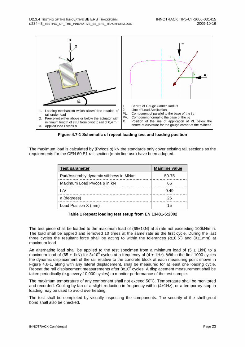
Figure 4.7-1 Schematic of repeat loading test and loading position
The maximum load is calculated by (Pv/cos α) kN the standards only cover existing rail sections so the requirements for the CEN 60 E1 rail section (main line use) have been adopted.
Test parameter Mainline value
Pad/Assembly dynamic stiffness in MN/m 50-75
Maximum Load Pv/cos α in kN 65
L/V 0.49
a (degrees) 26
Load Position X (mm) 15
Table 1 Repeat loading test setup from EN 13481-5:2002
The test piece shall be loaded to the maximum load of (65±1kN) at a rate not exceeding 100kN/min. The load shall be applied and removed 10 times at the same rate as the first cycle. During the last three cycles the resultant force shall be acting to within the tolerances (α±0.5˚) and (X±1mm) at maximum load.
An alternating load shall be applied to the test specimen from a minimum load of (5 ± 1kN) to a maximum load of (65 ± 1kN) for 3x10⁶ cycles at a frequency of (4 ± 1Hz). Within the first 1000 cycles the dynamic displacement of the rail relative to the concrete block at each measuring point shown in Figure 4.6-1, along with any lateral displacement, shall be measured for at least one loading cycle. Repeat the rail displacement measurements after 3x10⁶ cycles. A displacement measurement shall be taken periodically (e.g. every 10,000 cycles) to monitor performance of the test sample.
The maximum temperature of any component shall not exceed 50˚C. Temperature shall be monitored and recorded. Cooling by fan or a slight reduction in frequency within (4±1Hz), or a temporary stop in loading may be used to avoid overheating.
The test shall be completed by visually inspecting the components. The security of the shell-grout bond shall also be checked.
1. Centre of Gauge Corner Radius 2. Line of Load Application PL. Component of parallel to the base of the jig PV. Component normal to the base of the jig X. Position of the line of application of PL below the
centre of curvature for the gauge corner of the railhead
1. Loading mechanism which allows free rotation of rail under load
2. Free pivot either above or below the actuator with minimum length of strut from pivot to rail of 0,4 m
3. Applied load Pv/cos α

D2.3.4 TESTING OF THE INNOVATIVE BB ERS TRACKFORM INNOTRACK TIP5-CT-2006-031415 D234-F3_TESTING_OF_THE_INNOVATIVE_BB_ERS_TRACKFORM.DOC 2009-10-16
INNOTRACK Confidential Page 24
4.7.5 Reporting
The test report shall include the description of the test and physical observations of the test. The raw load and displacement data shall be shown in tabular form and provided in electronic copy (.xls or .csv format) and also graphically (format to be agreed with Balfour Beatty Rail Technologies).
It should also include the following details as described in EN 13146-4:2002;
1. number, date of issue and reference to EN 13146-4:2002
2. name and address of the laboratory performing the test
3. date test performed
4. name, designation and description of fastening assembly, including individual components tested
5. origin of test specimens
6. rail section used in test
7. test arrangement and values of Pv , cos α, R, X and α
8. result of visual inspection after test (photographic evidence)
9. mean vertical static stiffness before and after cyclic loading
10. clamping force before and after cyclic loading
11. mean dynamic rail displacement at the beginning and end of the repeated load test
12. mean residual displacement at the beginning and end of the repeated load test
Digital photographs shall be taken of the complete test rig and of the measuring devices and their output scales and devices to illustrate the principle of the test procedure carried out. These photographs shall be labelled and dated and presented in the report and provided in electronic copy.

D2.3.4 TESTING OF THE INNOVATIVE BB ERS TRACKFORM INNOTRACK TIP5-CT-2006-031415 D234-F3_TESTING_OF_THE_INNOVATIVE_BB_ERS_TRACKFORM.DOC 2009-10-16
INNOTRACK Confidential Page 25
4.8 Post-Repeat Loading Tests and Requirements
Following completion of the repeat loading tests, the tests defined in Sections 4.4, 4.5 and 4.6 shall be repeated. The tests must meet the requirements defined in EN 13481-5:2002;
Vertical stiffness – maximum change ≤ 25%
Longitudinal rail restraint – maximum change ≤ 20%
Clamping force – maximum change ≤ 20%

D2.3.4 TESTING OF THE INNOVATIVE BB ERS TRACKFORM INNOTRACK TIP5-CT-2006-031415 D234-F3_TESTING_OF_THE_INNOVATIVE_BB_ERS_TRACKFORM.DOC 2009-10-16
INNOTRACK Confidential Page 26
5. Testing Results
5.1 Photographs of Testing
5.1.1 Clamping Force Tests
Figure 5.1-1 Photographs taken during clamping force testing

D2.3.4 TESTING OF THE INNOVATIVE BB ERS TRACKFORM INNOTRACK TIP5-CT-2006-031415 D234-F3_TESTING_OF_THE_INNOVATIVE_BB_ERS_TRACKFORM.DOC 2009-10-16
INNOTRACK Confidential Page 27
5.1.2 Longitudinal Rail Restraint Tests
Figure 5.1-2 Photographs taken during longitudinal restraint testing
5.1.3 Vertical Stiffness
Figure 5.1-3 Photograph taken during vertical stiffness testing

D2.3.4 TESTING OF THE INNOVATIVE BB ERS TRACKFORM INNOTRACK TIP5-CT-2006-031415 D234-F3_TESTING_OF_THE_INNOVATIVE_BB_ERS_TRACKFORM.DOC 2009-10-16
INNOTRACK Confidential Page 28
5.1.4 Repeat Load Testing
Figure 5.1-4 Photographs of repeat load testing

D2.3.4 TESTING OF THE INNOVATIVE BB ERS TRACKFORM INNOTRACK TIP5-CT-2006-031415 D234-F3_TESTING_OF_THE_INNOVATIVE_BB_ERS_TRACKFORM.DOC 2009-10-16
INNOTRACK Confidential Page 29
5.2 Summary of Results
Following completion of the repeat loading tests, a summary of all test results can be seen below. All tests are in compliance with EN 13481-5;
CLAMPING FORCE (kN/0.2mm/650mm)
Initial testing Post-repeat load testing
Sample 1 Sample 2 Sample 3 Sample 1 Sample 2 Sample 3
Test 1 7.0 5.0 4.5 5.0 5.5 5.5
Test 2 7.5 6.0 - 7.0 7.0 -
Test 3 7.0 7.0 - 6.0 5.5 -
Sample Average 7.2 6.0 4.5 6.0 6.0 5.5
Test Average 5.9 kN/0.2mm/650mm 5.8 kN/0.2mm/650mm
NB. Three tests were completed on samples 1 and 2 to quantify the sample variance. The Euronorm requirement is a single test
Table 2 Clamping force test results
PULL-OUT FORCE (kN/10mm/650mm)
Initial testing Post-repeat load testing
Sample 1 Sample 2 Sample 3 Sample 1 Sample 2 Sample 3
Test 1 14.5 14.2 17.3 16.1 14.1 17.3
Test 2 14.5 14.2 - 16.1 13.9 -
Test 3 14.5 14.2 - 16.1 13.5 -
Sample Average 14.5 14.2 17.3 16.1 13.8 17.3
Test Average 15.3 kN/10mm/650mm 15.7 kN/10mm/650mm
NB. Three tests were completed on samples 1 and 2 to quantify the sample variance. The Euronorm requirement is a single test
Table 3 Pull-out force test results

D2.3.4 TESTING OF THE INNOVATIVE BB ERS TRACKFORM INNOTRACK TIP5-CT-2006-031415 D234-F3_TESTING_OF_THE_INNOVATIVE_BB_ERS_TRACKFORM.DOC 2009-10-16
INNOTRACK Confidential Page 30
LONGITUDINAL RAIL RESTRAINT (kN/650mm)
Initial testing Post-repeat load testing
Sample 1 Sample 2 Sample 3 Sample 1 Sample 2 Sample 3
Test 2 12.1 9.9 12.2 14.0 9.9 7.2
Test 3 11.6 10.4 11.1 13.6 9.9 6.7
Test 4 11.4 10.8 10.9 12.5 9.9 7.3
Test 5 - 9.9 - - - -
Sample Average 11.7 10.3 11.4 13.4 9.9 7.1
Test Average 11.1 kN/650mm 10.1 kN/650mm
NB. Test 5 was undertaken during the initial testing of sample 2 since there was an issue with the logging of results from test 3
Table 4 Longitudinal rail restraint test results
VERTICAL STIFFNESS (kN/mm/650mm)
Initial testing Post-repeat load testing
Sample 1 Sample 2 Sample 3 Sample 1 Sample 2 Sample 3
Test 6 24.1 25.3 27.8 31.1 29.8 31.5
Test Average 25.7 kN/mm/650mm 30.8 kN/mm/650mm
Table 5 Vertical stiffness test results

D2.3.4 TESTING OF THE INNOVATIVE BB ERS TRACKFORM INNOTRACK TIP5-CT-2006-031415 D234-F3_TESTING_OF_THE_INNOVATIVE_BB_ERS_TRACKFORM.DOC 2009-10-16
INNOTRACK Confidential Page 31
5.3 Comparison of Results
In order to comply with EN13481-5, the results from the post-repeat loading tests must not differ from the initial test results by more than the following;
Clamping force – maximum change ≤ 20%
Longitudinal rail restraint – maximum change ≤ 20%
Vertical stiffness – maximum change ≤ 25%
Test Initial testing Post-repeat loading % Change
Clamping force 5.9 kN/650mm 5.8 kN/650mm 2% decrease
Pull-out force 15.3 kN/650mm 15.7 kN/650mm 3% increase
Longitudinal rail restraint 11.1 kN/650mm 10.1 kN/650mm 11% decrease
Vertical stiffness 25.7 kN/mm/650mm 30.8 kN/mm/650mm 20% increase
Table 6 Comparison of average test results for the BB ERS

D2.3.4 TESTING OF THE INNOVATIVE BB ERS TRACKFORM INNOTRACK TIP5-CT-2006-031415 D234-F3_TESTING_OF_THE_INNOVATIVE_BB_ERS_TRACKFORM.DOC 2009-10-16
INNOTRACK Confidential Page 32
6. DISCUSSION
Table 6 in Section 5.3 shows that the Balfour Beatty Embedded Rail System has met the requirements specified by the European standard EN13481-5:2002.
6.1 Longitudinal Restraint
The longitudinal restraint requirement of 9.0kN/650mm (13.9kN/m) as specified by EN13481-5 has been exceeded, with an average of 11.1kN/650mm (17.1kN/m) when new and 10.1kN/650mm (15.5kN/m) after repeat loading.
The BB ERS also initially met the more conservative 11.1kN/650mm (17.1kN/m) as specified by Balfour Beatty Rail. As described in Section 4.5.1, the requirement specified by Balfour Beatty Rail is to provide additional constraint of the rail ends during a rail break but is not stipulated by any Euronorm. This requirement is less significant in reality since the BB ERS rail is both continuously supported and constrained laterally by being embedded. This higher level of restraint is therefore a conservative requirement.
Additional rail break / derailment protection can also be designed into the BB ERS slab design (Figure 6.1-1), meaning that the consequences of a rail break are far less severe since traffic can still pass over the broken rail. Sufficient steel reinforcement is included in the slab design to enable the derailment protection to withstand the impact from a train. The height of the derailment protection can also be tailored to suit the infrastructure and kinematic envelopes used.
Figure 6.1-1 BB ERS slab design with derailment protection
Analysing each test sample individually, it is clear that the performance of sample three had a significant effect on the post-repeat loading results. On inspection of the sample it was apparent that the shell had partly de-bonded from the grout. Possible causes for this occurrence may be an incorrect grout mixture or non-ideal curing conditions since sample three was the first to be grouted. A poor grout mixture would allow the grout to shrink during curing and thus reduce the bonding characteristics around the installed shell. However, shrinkage problems would have also been evident in the bond between grout and concrete, which remained strong throughout testing.

D2.3.4 TESTING OF THE INNOVATIVE BB ERS TRACKFORM INNOTRACK TIP5-CT-2006-031415 D234-F3_TESTING_OF_THE_INNOVATIVE_BB_ERS_TRACKFORM.DOC 2009-10-16
INNOTRACK Confidential Page 33
The more likely explanation for the de-bonding was a manufacturing error. Following testing, the sample was removed from the grout and fully inspected for any manufacturing defects, where an inconsistency was identified on the shell. The shell has a roughened surface on its exterior, known as ‘peel-ply’, that provides improved bonding performance with the grout. It was apparent that sample three had been manufactured with a peel-ply that was not appropriate for the application and so had de-bonded when exposed to the test loading conditions.
The shell manufacturing error was identified prior to the testing of samples one and two. A new batch of BB ERS shell was therefore manufactured with the correct peel-ply and installed into the test sample moulds. The bond between the shell and grout was monitored closely during initial rail installation and throughout all tests; there was no visible de-bonding.
As a result of this discovery, a more thorough quality assurance procedure has been put in place with the manufacturer. It was not previously envisaged that a slight change in specification would have such an effect on the bonding performance of the shell. It should be noted that sample three nevertheless still met the performance requirements for longitudinal rail restraint during initial testing.
6.2 Vertical Stiffness
The average vertical stiffness of the BB ERS was measured to be 25.7kN/mm/650mm for initial tests and 30.8kN/mm/650mm for post-repeat loading tests. This equates to a 20% change in system performance and is therefore within the 25% limits set by the Euronorm.
The Technical University of Munich performed a post-repeat loading stiffness test on sample one to verify the results from the University of Loughborough. The stiffness was calculated to be 28.4kN/mm/650mm, indicating that the results from Loughborough are slightly conservative.
The BB ERS stiffness results can be compared against existing rail fastening systems by converting them to a more universal output. Pad stiffness values are generally displayed in the units of N/mm/mm, equating to an initial average test result of 39.5N/mm/mm for the BB ERS. Ref1 states; “typical rail pad stiffness can vary from 40N/mm/mm to over 150N/mm/mm”, highlighting that the performance of the BB ERS is towards the lower end of the stiffness range.
The primary requirement of this testing suite was to comply with the safety related performance criteria as defined by the referenced Euronorms (longitudinal restraint, clamping force). Now that the BB ERS has been proven to effectively resist longitudinal rail movement and prevent rail buckling, the system properties can be fine-tuned to meet stiffness requirements of specific track design.
The vertical stiffness characteristics of the Balfour Beatty Embedded Rail System can be adjusted by simply changing the density of the elastomeric pad. It can therefore be tuned to precisely suit specific track and vehicle designs and the requirements of Infrastructure Managers.
The vertical stiffness can be varied over a wide range because the action of longitudinally restraining the rail is separate from the job of rail suspension. Traditional ballast fastening systems use the rail pad to act both as a suspension component and as a medium which the rail is fastened against. As a result, the range of stiffness available to discrete fastening systems is limited because of the need to provide sufficient longitudinal rail restraint. In addition, surface mounted rails cannot have very soft pads since they allow excessive rail head movement.
1 2.2, PG 6, TRACK ENGINEERING SEMINAR: THE TRACK AS A STRUCTURE, G A HUNT, AEA TECHNOLOGY, ISSUE 1, MAY 1998

D2.3.4 TESTING OF THE INNOVATIVE BB ERS TRACKFORM INNOTRACK TIP5-CT-2006-031415 D234-F3_TESTING_OF_THE_INNOVATIVE_BB_ERS_TRACKFORM.DOC 2009-10-16
INNOTRACK Confidential Page 34
6.3 Clamping Force
The average clamping force for the BB ERS was measured to be 5.9kN/650mm when new and 5.8kN/650mm after repeat loading. This equates to only a 2% change in system performance with time and traffic, thereby well under the 20% ceiling defined by the EN.
Owing to the fundamental difference between conventional discrete fastening systems and the BB ERS, the clamping force test is not wholly representative as a way to measure the performance of the embedded rail system. Other than the weight of the rail, there is no component acting to compress the rail firmly against the pad foot.
As a result, a very small degree of vertical flexibility is built into the system before the geometric interlock and shear resistance in the pad prevent further rail movement. This is one of the major advantages of the BB ERS since it facilitates the use of a much wider range of pad stiffnesses. The system can thus be tailored to meet specific infrastructure requirements.
Consequently the BB ERS was taken on beyond the original 0.2mm specification until the rail was displaced by 10mm, as designated in the results of the pull-out tests. In line with the clamping force tests, the change in pull-out results was also very small, at only 3% between new and post-repeat loading conditions.
6.3.1 Prevention of Rail Buckling
Clearly the embedded rail cannot buckle sideways or downwards. The only option available to the rail is to buckle vertically upwards. Therefore, the significance of the clamping force test is to prove the performance of the fastening system in preventing the rail from coming loose from the sub-system during vehicle trafficking and rail buckling situations. The results from the clamping force tests have been related back to the potential loads applied to the subsystem from both a vehicle interaction and a thermo-mechanical point of view.
An external consultant2 investigated the required vertical restraint required to avoid rail buckle under a 50°C temperature rise. This investigation also incl uded calculations for a safety factor of 2 (equivalent to 100°C temperature rise).
From these calculations (see Annex C), a required “foundation modulus against uplift” value of 0.4 N/mm/mm was defined. The foundation modulus is the limit of a system to provide elastic resistance against uplift. Applying this theory to the BB ERS, Ref3 writes;
“Most elastomeric materials do not strictly obey Hooke’s Law, and they tend to get stiffer with increasing stress. It is however possible to apply the principles of simple elastic theory, as a reasonable approximation of the behaviour of such a material.”
Therefore, the point at which the pull-out graph for BB ERS becomes non-linear, or ‘yields’, can be taken as the foundation modulus.
2 2.4.1, PG 16, BBRP/STS/TEST/5913 DESIGN REPORT - GIF DUAL GAUGE CONFIGURATION, REVISION C, JULY 2001 3 11.6.2, PG 231, BRITISH RAILWAY TRACK DESIGN, CONSTRUCTION AND MAINTENANCE, GEOFFREY H. COPE, THE PERMANENT WAY INSTITUTION, SIXTH EDITION, 1993

D2.3.4 TESTING OF THE INNOVATIVE BB ERS TRACKFORM INNOTRACK TIP5-CT-2006-031415 D234-F3_TESTING_OF_THE_INNOVATIVE_BB_ERS_TRACKFORM.DOC 2009-10-16
INNOTRACK Confidential Page 35
Figure 6.3-1 Pull-out results for all samples - post repeat loading
Figure 6.3-1 is a compilation of all pull-out testing results for post-repeat loading. Sample ‘3 test 1’ in Figure 6.3-1 has the steepest linear gradient and therefore the lowest foundation modulus against uplift. Taking this as the most conservative result, it shows that the BB ERS has a “foundation modulus against uplift” value of 8.04 kN/mm/650mm, or 12.37N/mm/mm.
Comparing this result against the ‘foundation modulus against uplift’ value of 0.4N/mm/mm calculations in Annex C, the Balfour Beatty Embedded Rail System has a worst case factor of safety against vertical rail buckle of over 30 when exposed to a rail temperature increase of over 100°C.
6.3.2 Prevention of Rail Jacking
It is theoretically potentially possible for contaminants to find a way into the Embedded Rail System and lodge themselves between the rail and the elastomer pad. This pocket of debris could potentially lift up the rail, thereby encouraging further debris to be pulled into the system and could eventually cause the rail to be ‘jacked’ out of the sub-system.
There are two possible scenarios that would allow contaminants to enter under the ERS rail;
1) By way of gap between pad sections.
The ERS pad seal is designed to overlap onto the next section of pad in order to provide cover and therefore minimise any potential ingress point.
2) By seeping down the interface between rail and pad.
This problem is more related to water and liquids rather than solid debris. If water could seep under the rail its volume would be so small that any expansion would compress the pad in preference to raising the rail.
It should be noted that the lateral pre-compression of the elastomeric pad provides the system with very high resistance against contaminant ingress.
Further mitigation against rail jacking is the high resistance against vertical buckling inherent in the system (Section 6.3.1). The only instance when a gap can exist between rail and pad is when the system is in a state of buckling. The large factor of safety against rail buckling (over 30) means that a
0
1
2
3
4
5
6
7
8
9
10
0 2 4 6 8 10 12 14 16 18
Load (kN)
Dis
plac
emen
t (m
m) 1 test 1
1 test 2
1 test 3
2 test 1
2 test 2
2 test 3
3 test 1
LIMIT OF ELASTICITY
Displacement = 1.27mm
Load = 10.21kN

D2.3.4 TESTING OF THE INNOVATIVE BB ERS TRACKFORM INNOTRACK TIP5-CT-2006-031415 D234-F3_TESTING_OF_THE_INNOVATIVE_BB_ERS_TRACKFORM.DOC 2009-10-16
INNOTRACK Confidential Page 36
gap will only be present when the rail at very high temperature, i.e. temperatures much greater than the melting point of ice.
6.4 Repeat Loading
Sample three was the first sample to undergo repeat load testing and was managed by the University of Loughborough (see Annex A). Unfortunately it became apparent that the test specification was on the capacity limit for the hydraulic system in the laboratory. As a result, the University of Munich was employed to complete the repeat loading testing for samples one and two.
The maximum vertical displacement for the gauge side of the rail was 2.8mm, with 3.6mm displacement at the field side. The corresponding maximum lateral displacement for the rail head was 2.3mm, with 0.7mm displacement at the rail foot. This indicating that the BB ERS has a very good resistance to railhead rotation.
The characteristic of the BB ERS elastomeric pad is to stiffen up over an initial work-hardening period of approximately 350,000 loading cycles, and then remain at a given stiffness for the remaining life of the pad (pg 3 of Annex B). Traditional discrete fastening systems used in ballasted track and other slabtrack systems have a tendency to continue to stiffen up over time and use, sometimes by up to a factor of 30%.
The maximum temperature of the interface between foot and pad was measured to be 35°C during testing, below the limit of 50°C set by the standar d. The large pad surface area provides a good capacity for heat dissipation.
It is interesting to note that the TUM report (Annex B) highlights a plastic vertical displacement of approx 1mm in the static re-calibration tests after the repeat loading. However, this did not seem to noticeably affect the static tests completed by the University of Loughborough. The vertical stiffness test results do not indicate such a large change. It should also be noted that the test results for the clamping force, which are most likely to be affected by a permanent displacement of the rail, have only a very small change in performance.

D2.3.4 TESTING OF THE INNOVATIVE BB ERS TRACKFORM INNOTRACK TIP5-CT-2006-031415 D234-F3_TESTING_OF_THE_INNOVATIVE_BB_ERS_TRACKFORM.DOC 2009-10-16
INNOTRACK Confidential Page 37
7. CONCLUSIONS
Testing of the innovative Balfour Beatty Embedded Rail System trackform is complete. The prototype samples have met the requirements specified in current European standards, proving that the BB ERS system works not only as a concept, but also as a manufactured test length.
The trackform has been tested to measure its performance in the following system parameters;
- vertical stiffness,
- longitudinal restraint,
- clamping force and
- track quality retention.
The tests were completed for the system in an ‘as new’ state and also after being subjected to a repeat loading cycle. The percentage change between initial and final tests were all within the limits defined by the Euronorm for slabtrack fastening systems.
The clamping force test results have also been compared against external analysis of the theoretical restraint required in order to prevent rail buckling. For a rail temperature increase of 100°C, the sy stem has a factor of safety of over 30 against vertical rail buckling.
7.1 Recommendations
It is recommended that the following tests be considered to provide a more comprehensive understanding of the Balfour Beatty Embedded Rail System;
- Further tests to determine the full range of stiffnesses available to the ERS
- Vertical compression tests to measure the system resistance against contaminant ingress
- Low temperature performance tests
- Full scale track installation of MkII system to verify laboratory test results

D2.3.4 TESTING OF THE INNOVATIVE BB ERS TRACKFORM INNOTRACK TIP5-CT-2006-031415 D234-F3_TESTING_OF_THE_INNOVATIVE_BB_ERS_TRACKFORM.DOC 2009-10-16
INNOTRACK Confidential Page 38
8. Bibliography
EN 13146-1: 2002 Railway applications – Track – Test methods for fastening systems Part 1: Determination of longitudinal rail restraint
EN 13146-4: 2002 Railway applications – Track – Test methods for fastening systems Part 4: Effect of repeated loading
EN 13146-7: 2002 Railway applications – Track – Test methods for fastening systems Part 7: Determination of clamping force
EN 13481-5: 2002 Railway applications – Track – Performance requirements for fastening systems Part 5: Fastening systems for slab track
8.1 List of References 1 2.2, PG 6, TRACK ENGINEERING SEMINAR: THE TRACK AS A STRUCTURE, G A HUNT, AEA TECHNOLOGY, ISSUE 1, MAY 1998 2 2.4.1, PG 16, BBRP/STS/TEST/5913 DESIGN REPORT - GIF DUAL GAUGE CONFIGURATION, REVISION C, JULY 2001
3 11.6.2, PG 231, BRITISH RAILWAY TRACK DESIGN, CONSTRUCTION AND MAINTENANCE, GEOFFREY H. COPE, THE PERMANENT WAY INSTITUTION, SIXTH EDITION, 1993

D2.3.4 TESTING OF THE INNOVATIVE BB ERS TRACKFORM INNOTRACK TIP5-CT-2006-031415 D234-F3_TESTING_OF_THE_INNOVATIVE_BB_ERS_TRACKFORM.DOC 2009-10-16
INNOTRACK Confidential Page 39
9. Annexes
In 3 separate documents.