project number: contract number: infso-ict-224287+_d2.2_final.pdf · figure 9: huawei ims network...
TRANSCRIPT
Page 1 of 90
Project Number: Contract Number: INFSO-ICT-224287
Project acronym:
VITAL++
Project Title: Embedding P2P Technology in Next Generation Networks: A New Communication Paradigm & Experimentation Infrastructure
Title of Report VITAL++ Trial network description
Instrument: STREP
Theme: ICT-2-1.6
Report Due: M9
Report Delivered: M11
Lead Contractor for this deliverable: FOKUS
Contributors to this deliverable: Jens Fiedler (FOKUS), Odysseas Koufopavlou (UoP), Charalabos Skianis (UoP), Nikolaos Efthymiopoulos (UoP), Spryos Denazis (UoP), George Karidis (BCT), Konstantinos Koutsopoulos (BCT), George Kapelios (VoG), Shane Dempsey (WIT), Jose Luis Pena (TID), Juana Sanchez (TID), Wolfgang Brandstätter (TA), E. Pallis (CTRC)
Estimated person Months: 18
Start date of project: 1st June 2008
Project duration 30 months
Revision: Version 1.4
Dissemination Level: PU - Public

Deliverable D2.2: VITAL++ Trial network description
Page 2 of 90
This page intentionally blank
Deliverable D2.2: VITAL++ Trial network description
Page 3 of 90
1 Table of Contents
1 Table of Contents .............................................................................. 3
2 List of Figures ................................................................................... 7
3 Document History .............................................................................. 9
4 Executive summary .......................................................................... 11
5 Introduction ..................................................................................... 13
6 IMS Standardisation – State of the Art ................................................ 15
6.1 The IP Multimedia Subsystem (IMS) ............................................... 15
6.1.1 The RACS ............................................................................ 18
6.1.2 The NASS ............................................................................ 20
6.2 IMS Standardisation ..................................................................... 22
6.2.1 3GPP IMS Releases ............................................................... 22
6.2.2 ETSI TISPAN ........................................................................ 25
7 VITAL++ IMS Requirements .............................................................. 27
7.1 Authentication ............................................................................. 27
7.2 Authorization ............................................................................... 27
7.3 Accounting .................................................................................. 27
7.4 Network Topology Information ....................................................... 28
7.5 User profiles ................................................................................ 28
7.6 IMS Application Server (AS) .......................................................... 28
7.7 Quality of Service ........................................................................ 29
8 Industrial IMS Solutions .................................................................... 31
8.1 Ericsson IMS ............................................................................... 31
8.1.1 Architecture ......................................................................... 31
8.1.2 Access Networks .................................................................. 35
8.2 Alcatel-Lucent ............................................................................. 36
8.2.1 Architecture ......................................................................... 36
8.2.2 Access Networks .................................................................. 38
8.3 Nortel ......................................................................................... 40
8.3.1 Architecture ......................................................................... 40
8.3.2 Access Networks .................................................................. 42
8.4 Huawei ....................................................................................... 42
8.4.1 Architecture ......................................................................... 42
8.5 NEC ........................................................................................... 45
8.6 Sonus Networks ........................................................................... 46
8.6.1 Architecture ......................................................................... 46
Deliverable D2.2: VITAL++ Trial network description
Page 4 of 90
8.7 Summary of Industrial IMS Solutions ............................................. 48
9 Network Operators Scenarios ............................................................. 51
9.1 Telefonica Testbed ....................................................................... 51
9.1.1 Administrative Overview ....................................................... 51
9.1.2 Technical Information ........................................................... 52
9.1.3 Vendors implied ................................................................... 52
9.1.4 Architecture ......................................................................... 53
9.2 Telekom Austria Testbed ............................................................... 54
9.2.1 Administrative Overview ....................................................... 54
9.2.2 Technical Information ........................................................... 55
9.2.3 Operational information ........................................................ 57
9.3 Voiceglobe Testbed ...................................................................... 57
9.3.1 Administrative Overview ....................................................... 58
9.3.2 Technical Information ........................................................... 58
9.3.3 Functionality ........................................................................ 59
9.4 IMS Testbed at University of Patras ................................................ 60
9.4.1 Administrative Overview ....................................................... 61
9.4.2 Technical Information ........................................................... 61
9.4.3 Vendors implied ................................................................... 62
9.4.4 Architecture ......................................................................... 63
9.5 IMS Playground at Fraunhofer FOKUS ............................................. 64
9.5.1 Administrative Overview ....................................................... 64
9.5.2 Technical Information ........................................................... 65
9.5.3 Operational information ........................................................ 67
9.5.4 Target Market ...................................................................... 68
9.5.5 Unique offering .................................................................... 69
10 Analysis of IMS Scenarios ................................................................ 71
11 VITAL++ Integration Description ...................................................... 75
11.1 Network Entities and Interfaces ................................................... 75
11.1.1 P2P Authentication ............................................................... 75
11.1.2 Content Security .................................................................. 77
11.1.3 Overlay Maintenance ............................................................ 80
11.1.4 Content Indexing ................................................................. 82
11.2 Integration of Sub-Architectures ................................................. 83
11.2.1 Content Publication and Discovery .......................................... 84
11.2.2 Overlay Management ............................................................ 84
11.2.3 Identification of Peers ........................................................... 85

Deliverable D2.2: VITAL++ Trial network description
Page 5 of 90
11.2.4 Enhanced Media Publication ................................................... 86
11.3 Integration Plan ........................................................................ 87
12 Conclusions ................................................................................... 89

Deliverable D2.2: VITAL++ Trial network description
Page 6 of 90
This page intentionally blank
Deliverable D2.2: VITAL++ Trial network description
Page 7 of 90
2 List of Figures
Figure 1 IMS Layered Architecture ............................................................ 15Figure 2 IMS Functions and Reference Points ............................................. 16Figure 3: RACS Architecture .................................................................... 18Figure 4: Architecture of the NASS ........................................................... 20Figure 5: IMS Standardisation Timeline ..................................................... 22Figure 6: Industrial IMS solution provided by Alcatel-Lucent ........................ 37Figure 7: "2 VC" concept on the ADSL access network ................................ 39Figure 8: Nortel IMS Network Element ...................................................... 40Figure 9: Huawei IMS Network Architecture ............................................... 42Figure 10: NEC's layered approach for their IMS product portfolio ................ 45Figure 11: Sonus IMS Architecture ........................................................... 46Figure 12: VoiceGlobe SIP based VoIP network .......................................... 59Figure 13: P2P Authentication Sub-architecture ......................................... 75Figure 14: Content Security Sub-Architecture ............................................ 78Figure 15: Overlay Maintenance Sub-Architecture ...................................... 80Figure 16: Content Indexing Sub-Architecture ........................................... 82Figure 17: Introduction of CI-SA .............................................................. 84Figure 18: Introduction of OM-SA ............................................................. 85Figure 19: Introduction of P2PA-SA .......................................................... 86Figure 20: Integration of sub-architectures ............................................... 86Figure 21: VITAL++ AS integration plan ................................................... 88

Deliverable D2.2: VITAL++ Trial network description
Page 8 of 90
This page intentionally blank
Deliverable D2.2: VITAL++ Trial network description
Page 9 of 90
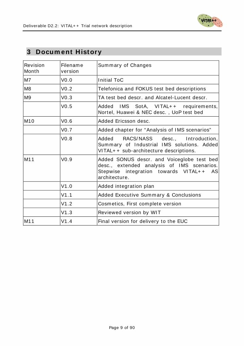
3 Document History
Revision Month
Filename version
Summary of Changes
M7 V0.0 Initial ToC
M8 V0.2 Telefonica and FOKUS test bed descriptions
M9 V0.3 TA test bed descr. and Alcatel-Lucent descr.
V0.5 Added IMS SotA, VITAL++ requirements, Nortel, Huawei & NEC desc. , UoP test bed
M10 V0.6 Added Ericsson desc.
V0.7 Added chapter for “Analysis of IMS scenarios”
V0.8 Added RACS/NASS desc., Introduction, Summary of Industrial IMS solutions. Added VITAL++ sub-architecture descriptions.
M11 V0.9 Added SONUS descr. and Voiceglobe test bed desc., extended analysis of IMS scenarios. Stepwise integration towards VITAL++ AS architecture.
V1.0 Added integration plan
V1.1 Added Executive Summary & Conclusions
V1.2 Cosmetics, First complete version
V1.3 Reviewed version by WIT
M11 V1.4 Final version for delivery to the EUC

Deliverable D2.2: VITAL++ Trial network description
Page 10 of 90
This page intentionally blank
Deliverable D2.2: VITAL++ Trial network description
Page 11 of 90
4 Executive Summary
In this deliverable, The IMS/NGN aspects of the project requirements and architecture are discussed. A list of requirements is derived from the overall requirements of the envisaged VITAL++ scenarios (Live-TV, Video-on-demand, File sharing). The requirements, which could be solved by NGN technology, are authentication, authorization, accounting, provision of network attachment and topology information, user profile storage and Quality of Service. The state of the art analysis has shown that the most relevant parts of an IMS network are the core (Call/Session Control Functions), the Resource Admission and Control Sub-System (RACS) and the Network Attachment Sub-System (NASS). Also, the relevant standardization body is ETSI TISPAN, because of the fact that fixed terminals are the main focus of the VITAL++ project. A number of selected IMS equipment vendors (Ericsson, Huawei, NEC, Alcatel-Lucent, Nortel and Sonus Networks) have been reviewed according to the components they offer. The offered solutions vary and have great differences in completeness, focus and performance. Only NEC and Huawei name the NASS as explicit element of their architectures, as well as the RACS. Also, a number of IMS testbeds (Voiceglobe, Fraunhofer FOKUS, Telefonica, Telekom Austria and University of Patras) have been described and compared according to the introduced requirements. The result was similar as with the industrial IMS vendors, which is that the support for RACS and NASS is either limited or not present. Due to the lack of availability of both RACS and NASS, it is advisable to realize QoS and network topology awareness in WP3 and WP4 in a hybrid way, which does not rely on those elements. Nevertheless, RACS and NASS are components which will become more available in the future and must therefore be taken into account for the project. The proposed IMS side of the VITAL++ architecture has been defined in four sub-architectures, namely the Peer-to-peer Authentication Sub-architecture (P2PA-SA), the Content Security sub-architecture (CS-SA), the Overlay Management sub-architecture (OM-SA) and the Content Indexing sub-architecture (CI-SA). These four sub-architectures have defined interfaces between them and other IMS components and are going to be implemented in the role of one or multiple IMS application server, but not necessarily in one node. Architectural refinements (e.g. protocols and functional composition) are to be done in WP3 and WP4. The integration plan envisages the basic implementation to be finished by September 2009 and the integration of the single components (sub-architectures and client) by December 2009.

Deliverable D2.2: VITAL++ Trial network description
Page 12 of 90
This page intentionally blank
Deliverable D2.2: VITAL++ Trial network description
Page 13 of 90
5 Introduction
In the scope of the VITAL++ project, a hybrid architecture shall be developed, which can be utilized to realize the target scenarios, which are Live-TV streaming, Video on demand and Static content sharing. The core idea of the project is to combine the strong aspects of two different paradigms, Peer-to-peer (P2P) media delivery and the IP multimedia subsystem (IMS), in order to achieve more flexible, secure and reliable multimedia services for users. In the deliverable 2.1, we have discussed the P2P aspects of the project. The purpose of this deliverable is to discuss the IMS aspects of the project. The main drawbacks of a pure P2P system are can be summarised as two salient issues. The missing initial trust between peers, which do not know each other and have not pre-established security context, e.g. in the form of a shared secret. This results in the basic problem that peers cannot trust each other, which means that trust based services, like accounting, authorization or charging cannot be realized in pure P2P scenarios. The other drawback is the fact that end-user peers cannot reserve bandwidth in the routers between them, which results in a pure network of best-effort connections, granting to quality of service. The technical solutions which exist (IntServ, DiffServ) require specific knowledge of the network and give opportunities for abuse, e.g. by intentional flagging traffic as important while best effort would also work sufficiently. Also, the central availability of information related to the network attachment of user equipment can come in handy when constructing topology aware overlays. The purpose of this deliverable is to identify the relevant IMS components for the VITAL++ project. The structure of this deliverable is outlined by the following. In chapter 6 we will give an introduction to the IMS, its architecture and intended purpose (state of the art), followed by an overview of the ongoing standardisation activities for the IMS. In chapter 7, we will refine the requirements to the IMS part of the envisaged VITAL++ architecture and why they are relevant to the project. Chapter 8 discusses industrial IMS solutions from selected vendors. Chapter 9 depicts several IMS implementation scenarios, which are analysed, evaluated and compared in chapter 10. In chapter 11, we will introduce the architectural components for the IMS side of the VITAL++ architecture and give an outline for the integration strategy. Finally in chapter 12, conclusions for the relevance of the discussed topics for the future development in the VITAL++ project are drawn.

Deliverable D2.2: VITAL++ Trial network description
Page 14 of 90
This page intentionally blank
Deliverable D2.2: VITAL++ Trial network description
Page 15 of 90
6 IMS Standardisation – State of the Art
In this section we will give a comprehensive overview of the ongoing standardisation process of the IP multimedia subsystem (IMS) in the relevant standardisation consortia. The section begins with a short introduction to the IMS, explaining its architecture, functions and reference points.
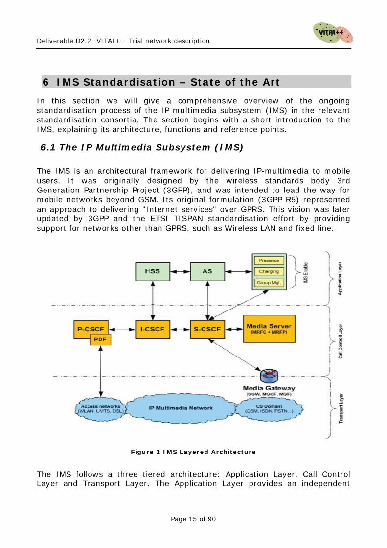
6.1 The IP Multimedia Subsystem (IMS) The IMS is an architectural framework for delivering IP-multimedia to mobile users. It was originally designed by the wireless standards body 3rd Generation Partnership Project (3GPP), and was intended to lead the way for mobile networks beyond GSM. Its original formulation (3GPP R5) represented an approach to delivering "Internet services" over GPRS. This vision was later updated by 3GPP and the ETSI TISPAN standardisation effort by providing support for networks other than GPRS, such as Wireless LAN and fixed line.
Figure 1 IMS Layered Architecture
The IMS follows a three tiered architecture: Application Layer, Call Control Layer and Transport Layer. The Application Layer provides an independent
Deliverable D2.2: VITAL++ Trial network description
Page 16 of 90
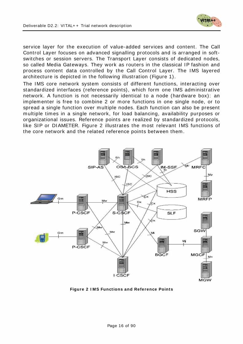
service layer for the execution of value-added services and content. The Call Control Layer focuses on advanced signalling protocols and is arranged in soft-switches or session servers. The Transport Layer consists of dedicated nodes, so called Media Gateways. They work as routers in the classical IP fashion and process content data controlled by the Call Control Layer. The IMS layered architecture is depicted in the following illustration (Figure 1). The IMS core network system consists of different functions, interacting over standardized interfaces (reference points), which form one IMS administrative network. A function is not necessarily identical to a node (hardware box): an implementer is free to combine 2 or more functions in one single node, or to spread a single function over multiple nodes. Each function can also be present multiple times in a single network, for load balancing, availability purposes or organizational issues. Reference points are realized by standardized protocols, like SIP or DIAMETER. Figure 2 illustrates the most relevant IMS functions of the core network and the related reference points between them.
Figure 2 IMS Functions and Reference Points
Deliverable D2.2: VITAL++ Trial network description
Page 17 of 90
The Home Subscriber Server (HSS) is the master database for a given user. It is the entity containing the subscription-related information to support the network entities actually handling calls/sessions. The HSS is responsible for holding user related information as:
• User Identification: Numbering and addressing information • User Security information: Network access control information for
authentication and authorization • User Location information at inter-system level: the HSS supports the
user registration, and stores inter-system location information, etc. • User profile information: E.g. subscribed services, etc.
The Application Server (AS) is an IMS entity that hosts and executes IP multimedia services. The AS is the “expansion slot” for an IMS network. Here, 3rd party products and services are located. The AS can operate in three different modes:
• SIP proxy mode • SIP user agent (User Agent Client, UAC, and User Agent Server, UAS) • SIP back-to-back-user-agent (B2BUA)
IMS enablers are special application servers with generic functions which perform functionalities like Presence, Group Management or Charging. The Policy Decision Function (PDF) is responsible for making policy decisions based on session and media-related information obtained from the P-CSCF. The term “Policy decision” refers in this case to QoS control. The Proxy-Call Session Control Function (P-CSCF) is the first contact point for users within the IMS. All SIP signaling tracks from or to the UE goes via the P-CSCF. The P-CSCF validates the request, forwards it to selected destinations and processes and forwards the response. The Interrogating-CSCF (I-CSCF) is a contact point within an operator's network for all connections destined to a subscriber of that network operator. The I-CSCF interacts with the HSS to obtain the name of the S-CSCF that is serving a user and forwarding a SIP request or response to the S-CSCF. The I-CSCF provides a hiding functionality. The I-CSCF may contain functionality called the Topology Hiding Inter-network Gateway (THIG). THIG could be used to hide the configuration, capacity and topology of the network from outside an operator's network The Serving-CSCF (S-CSCF) is the heart of the IMS. It is located in the home network and performs session control and registration services for UEs. While UE is engaged in a session, the S-CSCF maintains a session state and interacts with service platforms and charging functions as needed by the network operator for support of the services. There may be multiple S-CSCFs, and S-CSCFs may have different functionalities within an operator's network.
Deliverable D2.2: VITAL++ Trial network description
Page 18 of 90
The Media Server (MS) is an IMS entity that consists of functional components: Multimedia Resource Function Controller (MRFC) and The Multimedia Resource Function Processor (MRFP). The MRFC is needed to support bearer related services, such as conferencing, announcements to a user or bearer transcoding. The MRFP provides user-plane resources that are requested and instructed by the MRFC. The MRFP performs the following functions:
• Mixing of incoming media streams (e.g., for multiple parties) • Media stream source (for multimedia announcements) • Media stream processing (e.g., audio transcoding, media analysis)
The Media Gateway consists of three essential IMS components: • Media Gateway Control Function (MGCF) • Signaling Gateway (SGW) • Multimedia Gateway Function (MGF).
So the Media Gateway enables communication between IMS and circuit switched (CS) users.
6.1.1 The RACS
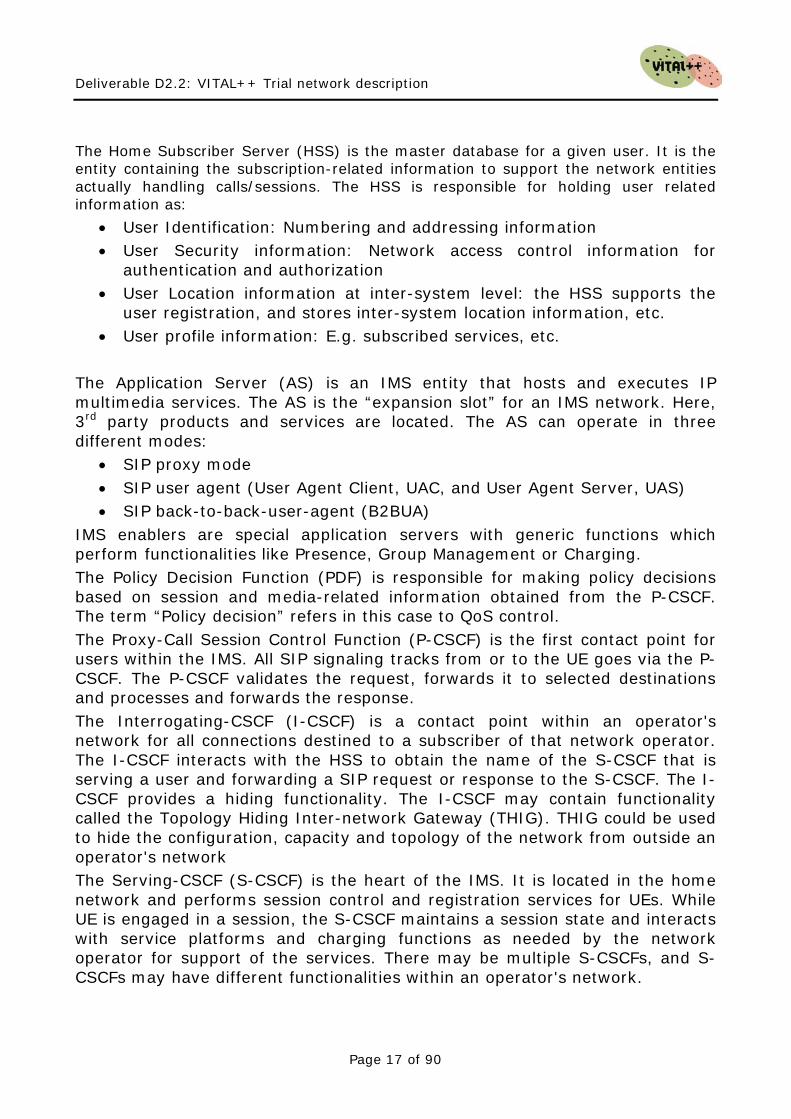
The Resource and Admission Control Sub-System (RACS) is defined by the ETSI TISPAN and is the related NGN Sub-System to enable Quality of Service between end devices. This is done by resource reservation in the Transport Functions of the network. The following figure illustrates the RACS and its components.
X-RACF SPDF
TPF
AF
ANCPE
Rre4
Rq
Gq‘
Rd‘Ri‘
IaRe RACS
NASS
Figure 3: RACS Architecture
Deliverable D2.2: VITAL++ Trial network description
Page 19 of 90
By the following, the most important functions of the RACS are explained, followed by two use cases, illustrating how resource reservation works with the RACS. The Application Function (AF) issues resource reservation requests (push model) or authorized subsequent resource reservation attempts from the CPEs (pull model). A typical AF is the IMS P-CSCF. The Service Policy Decision Function (SPDF) is a Functional Entity that acts as a final Policy Decision Point for Service-Based Policy control (SBP) for each administrative domain it resides in. It may also communicate with an interconnected SPDF located in an adjacent administrative domain for a reservation request. The SPDF hides the underlying network topology from applications and from interconnected SPDFs. This allows the SPDF to offer a common view to the AF and/or the interconnected SPDF regardless of the underlying network topology and particular access technology in use. The Generic Resource Admission Control Function (X-RACF) is a Functional Entity that acts as a Local Policy Decision Point (PDP) in terms of subscriber access admission control, as well as in terms of resource handling control. However, the final Policy Decision Point of the overall RACS framework is the SPDF. The generic Resource Admission Control Function receives requests for QoS resources from the SPDF via the Rq reference point, indicating the desired QoS characteristics (e.g. bandwidth). The Transport Processing Functions (TPF) reflect the transport network entities, which are responsible for multi- and unicast traffic forwarding. Those entities are able to interact with the RACS and reserve resources as requested for media streams. TPFs are not session aware, only stream aware. The Customers Premises Equipment (CPE) represents the user’s terminal, e.g. a phone or computer, which is connected via an access node (AN) with the NGN infrastructure of an operator. Two different models for resource reservation are supported by the RACS: policy-push and policy-pull. For policy-push, the CPE issues its service request to the AF, which performs the whole resource reservation with the RACS. This has the advantage that the CPE does not need to be aware of any QoS mechanisms. For policy-pull, the CPE also issues its service request to the AF, which only informs the RACS that a further QoS request may come from the CPE and authorizes this. When the CPE then requires QoS characteristics, it can reserve resources directly with the network. This allows a more dynamic resource reservation, as a client can adjust its QoS requirements regarding to the actual media stream properties.
Deliverable D2.2: VITAL++ Trial network description
Page 20 of 90
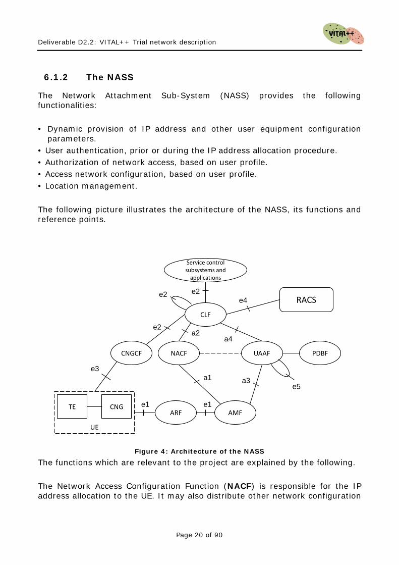
6.1.2 The NASS
The Network Attachment Sub-System (NASS) provides the following functionalities: • Dynamic provision of IP address and other user equipment configuration
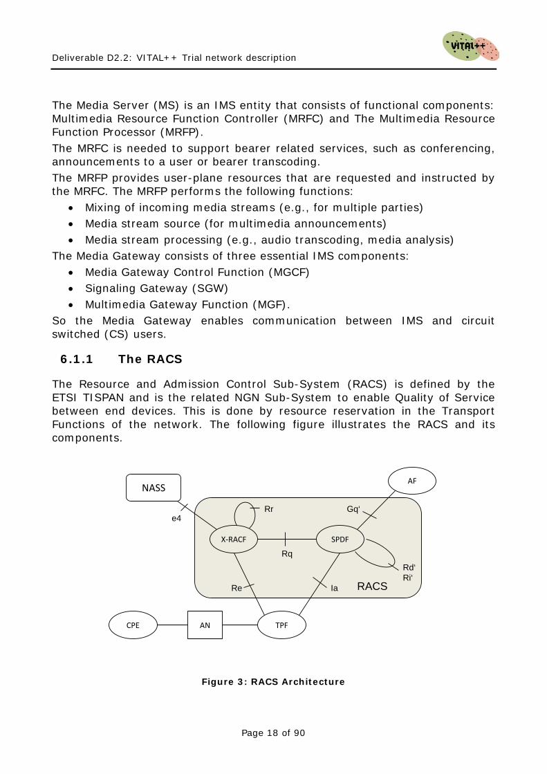
parameters. • User authentication, prior or during the IP address allocation procedure. • Authorization of network access, based on user profile. • Access network configuration, based on user profile. • Location management. The following picture illustrates the architecture of the NASS, its functions and reference points.
NACF UAAF
AMF
CNGCF
Service controlsubsystems and
applications
TEARF
e3
e4
a3
CNG
UE
CLF
PDBF
RACS
e1 e1
e2
e5
a4a2
a1
e2
e2
Figure 4: Architecture of the NASS
The functions which are relevant to the project are explained by the following. The Network Access Configuration Function (NACF) is responsible for the IP address allocation to the UE. It may also distribute other network configuration
Deliverable D2.2: VITAL++ Trial network description
Page 21 of 90
parameters such as address of DNS server(s), address of signalling proxies for specific protocols (e.g. address of the P-CSCF when accessing to the IMS). The NACF should be able to provide to the UE an access network identifier. This information uniquely identifies the access network to which the UE is attached. The UE may send this information to applications as a hint to locate the Connectivity session Location & repository Function (CLF). The User Authentication and Authorization Function (UAAF) performs NASS User authentication, as well as authorization checking, based on NASS User profiles, for network access. For each NASS User, the UAAF retrieves authentication data and access authorization information from the NASS User network profile information contained in the PDBF. The UAAF may also perform the collection of accounting data for each NASS User authenticated by NASS. The Profile Data Base Function (PDBF) is the functional entity that contains NASS User authentication data (NASS User identity, list of supported authentication methods, key materials etc.) and information related to the required network access configuration: This data is called "NASS User network profile". The NASS User network profile may be sub-divided into sub-profiles, each of which is associated to one or more Logical Access ID. Support of the Logical Access ID is optional. The Connectivity session Location and repository Function (CLF) registers the association between the IP address allocated to the UE and related network location information provided by the NACF, i.e.: access transport equipment characteristics, line identifier (Logical Access ID), IP Edge identity, etc. The CLF registers the association between network location information received from the NACF and geographical location information. The CLF may also store the identity of the NASS User to which the IP address has been allocated (information received from the UAAF), as well as the associated network QoS profile and preferences regarding the privacy of location information. In case the CLF does not store the identity/profile of the NASS User, the CLF shall be able to retrieve this information from the UAAF. The CLF responds to location queries from service control subsystems and applications. The actual information delivered by the CLF may take various forms (e.g. network location, geographical coordinates, post mail address etc.), depending on agreements with the requestor and on NASS User preferences regarding the privacy of its location.
Deliverable D2.2: VITAL++ Trial network description
Page 22 of 90
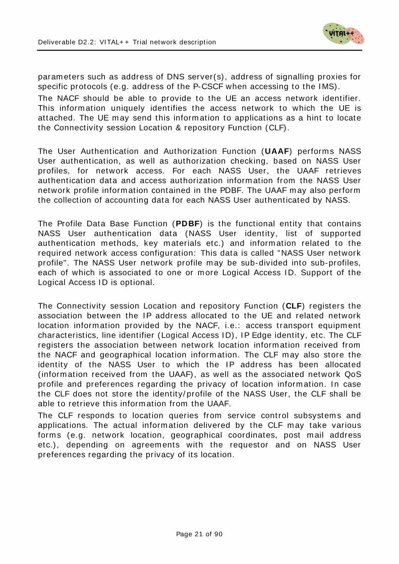
6.2 IMS Standardisation In this section, we will give an overview of the ongoing IMS standardisation in standardisation bodies relevant to the European area, which are the 3rd Generation Partnership Project (3GPP) and the technical committee for Telecoms & Internet converged Services & Protocols for Advanced Network (TISPAN) at the European Telecommunications Standards Institute (ETSI). Figure 5: IMS Standardisation Timeline gives an overview of the evolution of the IMS throughout all the standardisation bodies.
Figure 5: IMS Standardisation Timeline
TISPAN and 3GPP coordinate their work in order to avoid contradicting activities
6.2.1 3GPP IMS Releases
The standardisation work of the 3GPP focuses on the mobile world. There, IMS was first standardized in 3GPP Release 5. It then experienced multiple extensions, expansions, updates and spinoffs. The following table gives an overview of the different 3GPP IMS releases and their related features.

Deliverable D2.2: VITAL++ Trial network description
Page 23 of 90
Release 5 • VoIP, IM, Presence support on top of GPRS • IMS Architecture: IMS Architecture, network entities,
reference points (interfaces) between the network entities.
• User Identities: Public/Private User Identity, usage of the SIP-URI and TEL-URI, ISIM, the use of the USIM instead of the ISIM.
• IMS Session Control: o IMS Registration o IMS Session Routing o Session- Modification and Teardown o SIP Signaling Compression
• IMS Service Control: o invocation/control of IMS Application Servers
based on Filter Criteria in the CSCF o IM-SSF and there-use of CAMEL Services o Interconnect with the OSA-GW and the use of OSA
services • QoS Mechanisms:
o QoS Preconditions o QoS/Media Authorization based on the PDF
• Security Mechanisms: o IMS User Authentication o Message Integrity Protection, o IMS Network Domain Security
Release 6 • QoS, PoC support • IMS SIM cards • IPv6 deployment • IMS Interworking:
o With the CS-Domain (more details for CS and PSTN)
o With SIP Clients in the Internet (IPv4/v6 Interworking)
o WLAN access to the IMS (not completed) • IMS Session Control:
o multiple registrations o routing of group identities
• Security Mechanisms:
Deliverable D2.2: VITAL++ Trial network description
Page 24 of 90
o confidentiality protection of SIP messages o use of public key infrastructure o Ut-interface security o early IMS security
• IMS Services: o Presence o Instant Messaging o Conferencing o Group management
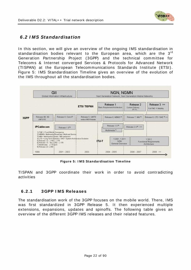
Release 7 • Identification of Communication Services in IMS • Supporting Globally Routable User Agent URIs in IMS • IMS Support of Conferencing and Messaging Group
Management • Location Services enhancements (LCS3) • Advanced Global Navigation Satellite System (A-GNSS)
concept (LCS3-AGNSS) • Enhancements for fixed broadband access to IMS • Access Class Barring and Overload Protection • Protocol-related new Features
o DIAMETER on the GGSN Gi interface o DIAMETER on the PDG Wi inteface
• Support of SMS over generic 3GPP IP access • Dynamic and Interactive Multimedia Scenes (DIMS) • Personal Network Management (PNM) • WLAN-UMTS Interworking Phase 2
Release 8 • SAE for LTE access • InterWorking Function (IWF) between MAP based and
Diameter based interfaces • Flexible Alerting • Support of Packet Cable access • corporate network access • Interworking between User-to-User Signalling (UUS) and
SIP • Earthquake and Tsunami Warning System • Customized Alerting Tone (CAT) Service • Value-Added Services for Short Message Service • 3G Long Term Evolution - Evolved Packet System (RAN)
Deliverable D2.2: VITAL++ Trial network description
Page 25 of 90
Release 9 • Services Alignment and Migration • Registration in Densely-populated area (RED) • End-User Identity • Public Warning System • Support of Personal Area Networks (PAN) • User Data Convergence • Protection against Unsolicited Communication for IMS
(PUCI) • Machine-type Communications
Table 1 3GPP IMS Releases - Feature List
6.2.2 ETSI TISPAN
TISPAN is the ETSI technical committee for fixed networks and for migration from switched circuit networks to packet-based networks with an architecture spanning both and serving to create the Next Generation Network. Building upon the work already done by 3GPP in creating the SIP-based IMS (IP Multimedia Subsystem), TISPAN and 3GPP are now working together to define a harmonized IMS-centric core for both wireless and wireline networks. This harmonized ALL-IP network has the potential to provide a completely new telecom business model for both fixed and mobile network operators. Access independent IMS will be a key enabler for fixed/mobile convergence, reducing network installation and maintenance costs, and allowing new services to be rapidly developed and deployed to satisfy new market demands. TISPAN considers effective cooperation with external bodies as essential to the coordination of the global message and further globalization of the TISPAN NGN product. 6.2.2.1 Release 1 NGN Release 1 was launched by TISPAN in December 2005, providing the robust and open standards that industry can use as a reliable basis for the development and implementation of the first generation of NGN systems. The addressed features are:
• Overall NGN Stage 1&2 • Network Attachment Subsystem (NASS) • Resource and Admission Control Subsystem (RACS) • PSTN/ISDN Emulation Subsystem (PES) • PSTN/ISDN Simulation Subsystem (PSS)
Deliverable D2.2: VITAL++ Trial network description
Page 26 of 90
• IMS-simulated PSTN/ISDN Supplementary Services (PSS) o Videotelephony over NGN o Emergency services
• IMS-specific Supplementary Services (ISS) o Presence Service (Presence) o IMS Messaging
• Interworking NGN – CS networks – IP networks – IMS • NGN management
6.2.2.2 Release 2 TISPAN has published Release 2, with a focus on enhanced mobility, new services and content delivery with improved security and network management. The addressed features in Release 2 are:
• IMS-specific Supplementary Services (ISS) o SMS over NGN IMS o Direct Communication (DC) Service
• IP Television (IPTV) • Fixed Mobile Convergence (FMC) • Corporate Network • Customer Network Gateway (CNG) • Overload and Congestion Control (OCC) • NGN Subscription Management (SM)
6.2.2.3 Release 3 Currently, ETSI TISPAN is working on release 3 of the specifications and standards. As this work is quite new, only enhancements and improvements of already existing features from releases 1 and 2 are on the work plan.
Deliverable D2.2: VITAL++ Trial network description
Page 27 of 90
7 VITAL++ IMS Requirements
The strength of a centralistic architecture like IMS is that it underlies the administration of an identifiable organisation (operator) to whom a client has an association, based on a contract or other verifiable agreement. Even the interaction between different IMS operators is standardised and services can follow a user who is roaming between the networks. This makes IMS relevant to any operation which needs a maximum degree of trust, e.g. authentication, or which require generic functional extensions in terms of services. In the following we will identify aspects of the IMS, which are relevant to the VITAL++ project. All these aspects must be understood as requirements for a VITAL++ architecture and test bed. Thus, professional IMS installations and industrial IMS solutions will be analyzed, regarding to these requirements.
7.1 Authentication A very important feature of a centralistic system, like the IMS, is that clients (users) need to perform an initial authentication phase, which establishes a security context between the client and the selected IMS core. This can be described as initial point of trust, from which it is possible to establish further trust relations, even between peers, and enable secure communication between them. Also, IMS utilizes the IPSec for trusted communication between the IMS core and the clients, allowing security sensitive information to be shipped between those entities. This is a feature, which might be of relevance to the VITAL++ final architecture, e.g. if peers need to determine the identity of other peers, e.g. for trusted overlay construction, when only authorized peers are allowed in an overlay, or for charging for value added services, offered by user peers.
7.2 Authorization If a trusted P2P media delivery overlay shall be constructed, solely consisting of peers, which are authorized to receive and forward a media stream, peers must be able to check for proper authorization. Another example is the delivery of DRM licenses, which must not be done to peers which are not authorized. Thus, authorization is a very important feature, as the question “Am I allowed to do this” will arise very often in IMS-P2P operations (between client and IMS functions), as well as in P2P-P2P (client to client) operations.
7.3 Accounting Accounting is one of the key features that IMS has above P2P, as accounting is related to charging and billing. Whenever value added services shall be provided and used, accounting will be necessary in order to perform correct charging and billing. This makes accounting an important feature, which will be one of the key-benefits from IMS towards common VITAL++ architecture.
Deliverable D2.2: VITAL++ Trial network description
Page 28 of 90
7.4 Network Topology Information The first point of SIP information exchange between an IMS core and every IMS client is the Proxy- Call/Session Control Function (P-CSCF). This function can insert user specific access network information (P-Access-Network-Info header field) into the SIP communication, allowing the IMS core to gain knowledge about the topological distribution of peers. This knowledge can then be utilized for the construction of topology aware overlays, minimizing backbone- and inter-operator traffic. In order to obtain information about the access network and user connection profile information, at least connectivity to a NASS should be available.
7.5 User profiles The IMS holds a profile for each user in the home subscriber server (HSS), a highly scalable central database. Additional information from the authentication phase (like network identifiers) can be stored there and used for P2P overlay planning, e.g. to optimize data paths in the overlays, which is extremely important for streaming overlays (e.g. for the Live-TV scenario). Also, additional data concerning users (e.g. public/private key pairs) can be stored in that database.
7.6 IMS Application Server (AS) The application server is the intended point for IMS extensions (enablers) and 3rd party service deployment. As additional information is going to be deployed to the VITAL++ clients), it is suitable to use the function of an application server to realise such additional services. Currently, the following features may become relevant to the VITAL++ architecture and could then be realized as application servers, or functional blocks within an application server.
• P2P authentication After the registration phase, such an application server could generate, manage and distribute public/private keys to a clients or a DHT, which can then be used to build further authentication schemes between peers.
• Media Overlay information If an overlay is to be planned, e.g. from central topology information, this can also be managed from an application server. Clients can ask the corresponding AS to join an overlay, receiving a list of peers, already in the overlay.
• Content index information Clients need to publish and discover content. A simple, but flexible approach can be to utilize an application server for storing content lists, for searching in content lists and for retrieving found matches to the querying peer.
• DRM licence management
Deliverable D2.2: VITAL++ Trial network description
Page 29 of 90
Clients, who need to decipher encrypted content need to obtain decryption keys. This can also be done by using an application server, which generates license/rights objects, distributes them to clients and generates charging events.
7.7 Quality of Service The IMS defines functional blocks, which also include routers in the Transport Stratum in the TISPAN architecture. The Resource and Admission Control Subsystem (RACS) is responsible for the interaction between the IMS core and the Transport Stratum. So, if an overload situation occurs where even the best P2P scheduling cannot achieve a sufficient level of quality, session control can be done additionally by the IMS. Sessions initiated over the IMS can include bandwidth requirements, which will result in a granted bandwidth relation, pushing aside non-reserved traffic. As one of the main objectives is media streaming, QoS aspects in terms of bandwidth and latency are relevant.

Deliverable D2.2: VITAL++ Trial network description
Page 30 of 90
This page intentionally blank

Deliverable D2.2: VITAL++ Trial network description
Page 31 of 90
8 Industrial IMS Solutions
In this chapter we describe industrial IMS components and solutions from different vendors. The vendors were chosen to be representative for the IMS deployment situation among big telecommunication companies. The purpose of this examination is to gain an overview of the capabilities of the single solutions and their relevance to the VITAL++ project.
8.1 Ericsson IMS This section details the Ericsson IMS product-line available at Waterford Institute of Technology’s Irish National NGN Test Centre in Ireland. It corresponds to a particular release of the IMS core (ICS v 4.1) and is not intended to be a canonical overview of all current Ericsson IMS infrastructure or future developments. However, the infrastructure available at the Irish National NGN Test Centre is both carrier-grade and comprehensive.
8.1.1 Architecture
The specific features described here relate to the Ericsson ICS 4.1: this is the first version to consolidate fixed and mobile IMS networks into a single network that provide different user services, with telecom grade Quality of Service, over both fixed and mobile accesses. Compared to the previous 4.0 version, ICS 4.1 provides further alignment with standards like 3GPP Rel 6 and Rel 7, improved system characteristics and focus on Network Convergence. In ICS 4.1, the users can access the applications from both fixed and mobile devices but the User Identity is tied to the access type used by the device. This implies that a certain User Identity can not alter between different accesses (the user needs a unique User Identity per access type). Different solutions, such as PTT, WeShare, MMTel and IMT, shall be able to execute their respective traffic simultaneously in the same shared ICS 4.1 network. The IMS core includes the gateway functionalities required for the interconnection with a circuit switched network (PSTN/PLMN); this integration is currently out of scope for Phase 1 of the project and will be completed when a connection to PSTN/PLMN is available at WIT The following logical components are included in the ICS 4.1 solution:
• CSCF 4.1 • HSS 4.1 • SAPC 3.0 • IPworks 5.0 for eDNS, iDNS and ENUM functions • A-SBG 3.0 • IS-MGC 5.1 • IS-MGw 1.2
Deliverable D2.2: VITAL++ Trial network description
Page 32 of 90
• OSS RC 6.1 • Multi Mediation (MM) 6.0
8.1.1.1 Ericsson ICS IMS Common System is an infrastructure that brings a SIP based horizontal network architecture, with IMS core components for managing sessions, addressing, subscription, IMS inter-working components with relevant gateways for connectivity to other networks; the IMS deployment for WIT includes also IMS support systems for handling provisioning, charging, device configuration and operation & Maintenance. The comprehensive set of features and capabilities are made available to both wireline and wireless networks, enabling the use of IMS Common System as a platform for convergence for networks and services. The main purpose of the system is to provide end-users with advanced multimedia services, such as conference calling and handling of presence information. SIP protocol is used for control signalling. For media transportation, support is provided for, but not limited to, Real-time Transport Protocol (RTP) and Message Session Relay Protocol (MSRP). The ICS provides IMS Call Control and Routing according to the 3GPP specifications. Every IMS subscriber must be provisioned and registered in the IMS system to originate or terminate multimedia session (for example to make or receive calls). Each session may involve the invocation of one or more Application Servers, depending on the profile of the users involved in the session and on the service request.
8.1.1.2 Deployed Nodes A single CSCF node is deployed including: Proxy-CSCF (P-CSCF), Interrogating-CSCF (I-CSCF), Serving-CSCF (S-CSCF) and Emerging-CSCF (E-CSCF) components. The CSCF manages SIP interfaces towards the SBG in the access, possible AS, and the MGC towards PSTN/PLMN. The Diameter interface between the CSCF and HSS is internal in the TSP platform, as the two logical nodes are co-located. The Ericsson Service Aware Policy Controller (SAPC) provides the PCRF capabilities according to 3GPP Release 7 standard for Policy Control. The functionality is collocated with the P-CSCF; the integration of this logical component is planned for future use and requires the availability of wireless access nodes (such as GGSN) supporting the Gx+ interface
Deliverable D2.2: VITAL++ Trial network description
Page 33 of 90
The ENUM database is deployed on the external DNS (eDNS) node. The ENUM is queried by the CSCF (and optionally by the MGC) for translating E.164 to SIP URI; the eDNS is available for IMS client to solve for example the FQDN of the SBG, while the internal DNS (iDNS) is used internally to resolve the IP address of different nodes. The MGC and MGW are available to ensure the interworking with circuit switched network: the MGC provides SIP-ISUP interworking and pilots the MGw to setup the proper bearer requested for each session; the MGW ensures the translation of audio and video flows between RTP packets and the TDM channel. However, the interconnection with PSTN is also planned for future phases: this is subject to the availability of ISUP/SS7 links towards any PSTN or PLMN. The OSS-RC communicates with all the IMS nodes through dedicated management interface and provides a centralized point of control for Fault, Configuration and Performance Management. The Multi Mediation (MM) platform may receive charging record from the CSCF, the MGC and optionally the SBG, and can generate CDR according to the desired format.
8.1.1.3 Application Servers The ISc interface of the Ericsson ICS 4.1 has been tested against several application servers including:
• Ericsson Service Development Studio (SDS) server; • BEA WebLogic (BEA WL) server. • Ericsson Sailfin (Glassfish open source codebase)
These application servers are available for client developers in the Irish National NGN Test Centre, located in WIT.
8.1.1.4 Client Compatibility The IMS clients are an important part of the solution, as they set the capabilities not only for specific applications, but also for the type of devices and access that can be tested with the IMS system. Typical IMS clients include:
• SIP Phone • IMS software client running on PC (Ethernet connection); • IMS software client running on a WiFi enabled device; • IMS-enabled phone with 3G (HSDPA) interface.
Deliverable D2.2: VITAL++ Trial network description
Page 34 of 90
The Ericsson ICS 4.1 has already been tested against software clients for PC, Mac, Linux and mobile devices including:
• Sleipner • X-Lite • Movial
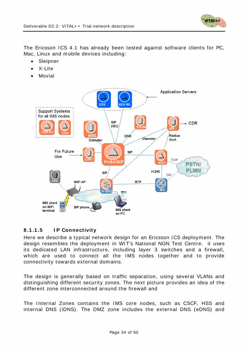
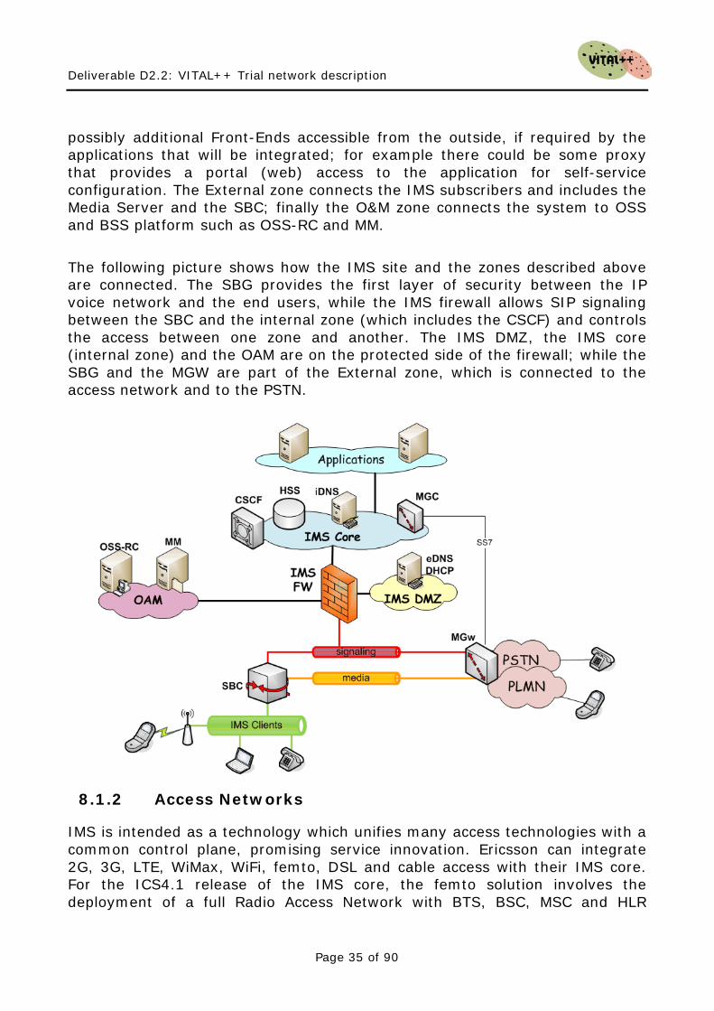
8.1.1.5 IP Connectivity Here we describe a typical network design for an Ericsson ICS deployment. The design resembles the deployment in WIT’s National NGN Test Centre. it uses its dedicated LAN infrastructure, including layer 3 switches and a firewall, which are used to connect all the IMS nodes together and to provide connectivity towards external domains. The design is generally based on traffic separation, using several VLANs and distinguishing different security zones. The next picture provides an idea of the different zone interconnected around the firewall and The Internal Zones contains the IMS core nodes, such as CSCF, HSS and internal DNS (iDNS). The DMZ zone includes the external DNS (eDNS) and
Deliverable D2.2: VITAL++ Trial network description
Page 35 of 90
possibly additional Front-Ends accessible from the outside, if required by the applications that will be integrated; for example there could be some proxy that provides a portal (web) access to the application for self-service configuration. The External zone connects the IMS subscribers and includes the Media Server and the SBC; finally the O&M zone connects the system to OSS and BSS platform such as OSS-RC and MM. The following picture shows how the IMS site and the zones described above are connected. The SBG provides the first layer of security between the IP voice network and the end users, while the IMS firewall allows SIP signaling between the SBC and the internal zone (which includes the CSCF) and controls the access between one zone and another. The IMS DMZ, the IMS core (internal zone) and the OAM are on the protected side of the firewall; while the SBG and the MGW are part of the External zone, which is connected to the access network and to the PSTN.
8.1.2 Access Networks
IMS is intended as a technology which unifies many access technologies with a common control plane, promising service innovation. Ericsson can integrate 2G, 3G, LTE, WiMax, WiFi, femto, DSL and cable access with their IMS core. For the ICS4.1 release of the IMS core, the femto solution involves the deployment of a full Radio Access Network with BTS, BSC, MSC and HLR
Deliverable D2.2: VITAL++ Trial network description
Page 36 of 90
nodes. In future releases, we understand that the recently ratified femto specification in 3GPP release 8 will be available. This permits transcoding of GSM signalling to SIP at the AP and is hence more cost effective to deploy. The National NGN Test Centre hopes to add this functionality over the next 2 years.
8.1.2.1 Access Control The Ericsson SBG may allow the interconnection of SIP clients behind a NAT device or a firewall (FW). It ensures that signaling and media bound for the UE can traverse the NAT or FW device located at customer premises. The possibility to connect IMS clients behind NAT and firewall devices is affected by the device itself. A brief explanation of the mechanisms available in the SBG to manage NAT/Firewall devices in the access is provided below. The SBG detects that there is a NAT/FW to be traversed when the A-ALG receives a SIP REGISTER message from the UE with different source addresses in the IP and SIP headers. To keep the pinhole open for signalling requests coming in from the IMS core network, occasional packets must flow via the signalling pinhole through the remote NAT/FW. The integrated A-ALG node supports several methods involving “heartbeat” signals sent using empty UDP/TCP packets or dummy sip messages for REGISTER or NOTIFY. In the simple case the access network is made of a simple LAN with IMS clients accessing the system via the SBG; however more complex architecture for wireless access could be integrated (wireless packet core, femtocell, WiMax, etc.). The current design doesn’t take into account the introduction of these nodes, which could access the IMS network via the SBG or pointing directly to the P-CSCF.
8.2 Alcatel-Lucent This chapter introduces an industrial IMS solution provided by Alcatel-Lucent. The platform has been installed for Telekom Austria as an IMS trial platform with the intention to offer a VoIP service to Telekom Austria's residential customers.
8.2.1 Architecture
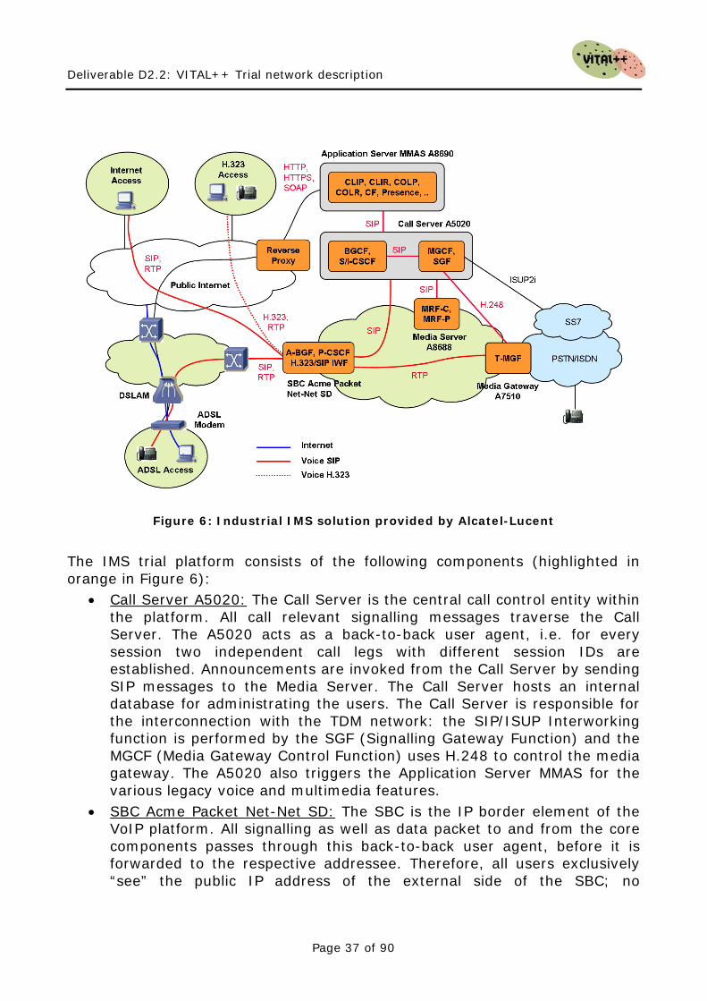
Figure 6 shows the architecture of the IMS trial platform, the IMS functions are mapped to the different Alcatel-Lucent products.
Deliverable D2.2: VITAL++ Trial network description
Page 37 of 90
Figure 6: Industrial IMS solution provided by Alcatel-Lucent
The IMS trial platform consists of the following components (highlighted in orange in Figure 6):
• Call Server A5020:
•
The Call Server is the central call control entity within the platform. All call relevant signalling messages traverse the Call Server. The A5020 acts as a back-to-back user agent, i.e. for every session two independent call legs with different session IDs are established. Announcements are invoked from the Call Server by sending SIP messages to the Media Server. The Call Server hosts an internal database for administrating the users. The Call Server is responsible for the interconnection with the TDM network: the SIP/ISUP Interworking function is performed by the SGF (Signalling Gateway Function) and the MGCF (Media Gateway Control Function) uses H.248 to control the media gateway. The A5020 also triggers the Application Server MMAS for the various legacy voice and multimedia features. SBC Acme Packet Net-Net SD: The SBC is the IP border element of the VoIP platform. All signalling as well as data packet to and from the core components passes through this back-to-back user agent, before it is forwarded to the respective addressee. Therefore, all users exclusively “see” the public IP address of the external side of the SBC; no

Deliverable D2.2: VITAL++ Trial network description
Page 38 of 90
information about the network architecture or topology is accessible from outside (topology hiding). The IP network at the inner side of the SBC is configured as trusted zone and the exterior side provides for the untrusted part. All traffic between the users themselves as well as between the users and the core components traverses the SBC. In this way, the SBC is able to detect disrupted RTP streams (session monitoring). As soon as such an interruption is occurring, the SBC informs the Call Server by sending out an adequate SIP message. The Call Server releases the session and, thus, the generated CDR are more accurate. The SBC also supports a hosted NAT traversal solution, which is able to cope with various types of NAT functions. Finally, the SBC also provides the security functions DoS protection, access control, topology hiding, privacy, VPN separation und fraud prevention.
• Media Gateway A7510:
•
The Media Gateway resides between the PSTN/ISDN and the IP network. It converts the RTP packets on the IP side into G.711 samples transported within timeslots on the TDM side and vice versa. The A7510 is controlled by the Call Server by means of the H.248 protocol. Application Server MMAS A8690:
•
The Application Server hosts the supplementary services Call Hold, Call Waiting, Call Forwarding, CLIP, CLIR, COLP, COLR, Incoming Call Screening and Outgoing Call Barring. Softclient and multimedia features like buddy lists and presence are provided, as well. Like the Call Server and the SBC, the Application Server acts as a back-to-back user agent. SIP INVITE messages arriving at the A5020 always trigger the Application Server in order to get the specific user’s service settings. Thus, beside the Call Server, every user has to be provisioned on the Application Server, as well. The MMAS hosts a customer self care web portal through which all the services can be configured by the user, e.g. each supplementary service can be activated or deactivated or the destination of call forwarding scenarios can be entered via this user interface. Media Server A8688:
• The Media Server provides the announcements.
Reverse Proxy Server:
The reverse proxy server is a security device for the Customer Self Care function hosted on the MMAS. It terminates HTTP and HTTPS requests from the users before forwarding them to the MMAS.
8.2.2 Access Networks
The IMS trial platform provides • two best effort access variants (Internet and H.323) and • one QoS assured access network (ADSL).

Deliverable D2.2: VITAL++ Trial network description
Page 39 of 90
The variants are discussed in the following chapters.
8.2.2.1 Internet Access The Internet access is configured on a dedicated port on the SBC, which offers access to the platform for any authorised user on the Internet. SIP user agent clients like SIP softphones can register and are able to use the platform. The Internet access offers a best effort type of service.
8.2.2.2 H.323 Access H.323 access networks are connected to the platform via the H.323/SIP IWF (Interworking Function) of the SBC. The H.323/SIP IWF operates as back-to-back Gateway, i.e. on both sides, the SIP and H.323 one, the IWF appears as virtual Gateway, respectively. The mapping between the H.323 and SIP messages is configured on the SBC. Moreover, a H.323 Gatekeeper is required on the H.323 access network for the H.323 terminals to register, because a direct connection of H.323 terminals is not supported by the SBC. The H.323 access offers a best effort type of service.
8.2.2.3 ADSL Access Lines With QoS Assurance Figure 7 shows the "2 VC" (Virtual Channel) concept implemented on the ADSL access network. On the ATM layer, two separate VC are pre-configured between the ADSL modem and the corresponding DSLAM. One VC is reserved for voice and the other one for high-speed Internet traffic. The RT-VBR (Real Time Variable Bit Rate) ATM service class guarantees the QoS requirements for the voice path, while the Internet data transmission is based on UBR (Unspecified Bit Rate).
Figure 7: "2 VC" concept on the ADSL access network
Deliverable D2.2: VITAL++ Trial network description
Page 40 of 90
In case of simultaneous outgoing traffic pending on both VC at the ADSL modem, ATM cells on the voice channel are prioritized over Internet data cells. In this way, the required QoS for the voice path is assured and achieved. The ADSL access is attached to the SBC of Telekom Austria’s VoIP platform by means of an ATM aggregation network.
8.3 Nortel This chapter introduces an industrial IMS solution provided by Nortel.
8.3.1 Architecture
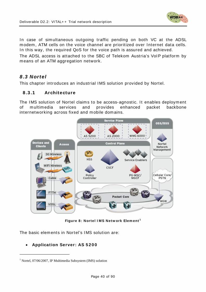
The IMS solution of Nortel claims to be access-agnostic. It enables deployment of multimedia services and provides enhanced packet backbone internetworking across fixed and mobile domains.
Figure 8: Nortel IMS Network Element1
• Application Server: AS 5200
The basic elements in Nortel’s IMS solution are:
1 Nortel, 07/06/2007, IP Multimedia Subsystem (IMS) solution
Deliverable D2.2: VITAL++ Trial network description
Page 41 of 90
It is a SIP-based media and application server designed to enable enhanced communications regardless of location, access type or media. It allows carriers to offer SIP-based multimedia services, including desktop video calling, instant messaging, and point-to-multipoint application sharing. Among other it supports: various Voice Call features (Calling Line ID (w/ Name, Number & Subject), Call Waiting, Call Forward, Call Transfer, Call Hold, Call Mute), Call Management (Click to Call, Microsoft OutlookTM Integration, Voice Mail Indicator, Personal & Group Directories, Dynamic Call Handling, Picture ID, Dynamic Presence, Incoming Call Logs, Outgoing Call Logs, Ad-hoc and Meet-me Audio Conferencing), Web Portal features (Call Screening, Find Me/Follow Me, One Number Service, Sequential Ringing, One Mailbox), Web Services based on Parlay X)
• Wireless Mobility Gateway 6000 The WMG6000 is designed to allow service providers to bridge 3G wireless networks and WLAN networks to provide a more seamless and secure communication experience for consumers and enterprise users. It is compliant with the IMS Voice Call Continuity (VCC) standards
• Home Subscriber Server 1000 A centralized subscriber database that securely manages subscriber profiles in a single database. The Nortel HSS 1000 supports multiple authentication schemes and service profiles.
• Call Session Controller 1000 It supports service control capabilities that allow for integration of elements from different applications and exploitation of a variety of information, such as access type, presence, location and device type.
• Media Gateway Controller (MGC) The MGC interacts with the Nortel Session Controller and Media Gateways to control sessions that cross the CMS network boundary into pre-existing networks and services. It also performs signalling protocol conversion between SIP and ISUP for instance.
• Policy Controller The Policy Controller is responsible for coordinating the set up of bearers with session setup. It supports correlation of application layer and bearer layer billing IDs for billing consolidation.
Deliverable D2.2: VITAL++ Trial network description
Page 42 of 90
8.3.2 Access Networks
Aligned with a communications business model that focuses on subscriber centric services rather than access centric ones, Nortel IMS solution aims at enabling a single service provider to offer services to many segments, namely: GSM/UMTS CDMA Wireline Cable
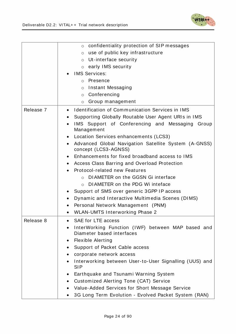
8.4 Huawei This chapter introduces an industrial IMS solution provided by Huawei.
8.4.1 Architecture
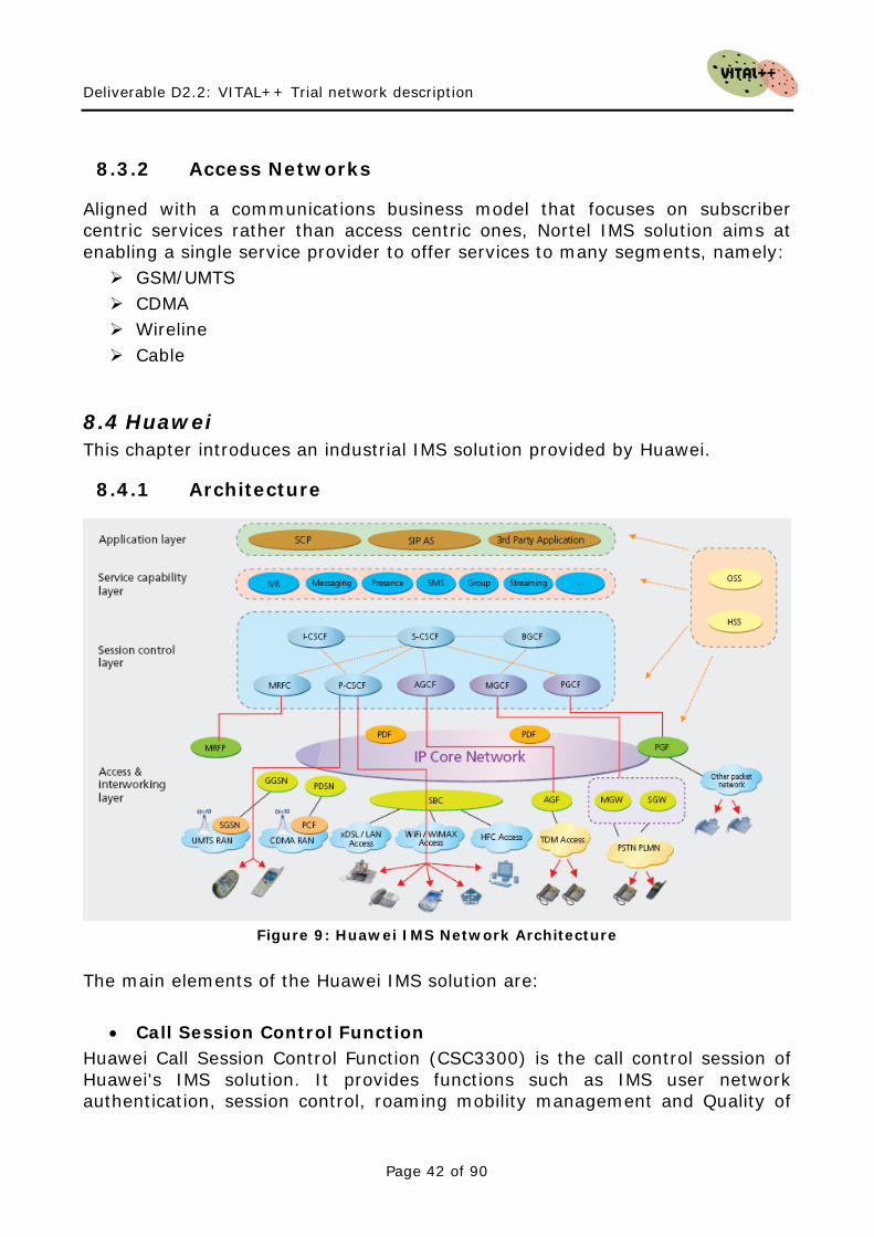
Figure 9: Huawei IMS Network Architecture
The main elements of the Huawei IMS solution are:
• Call Session Control Function Huawei Call Session Control Function (CSC3300) is the call control session of Huawei's IMS solution. It provides functions such as IMS user network authentication, session control, roaming mobility management and Quality of
Deliverable D2.2: VITAL++ Trial network description
Page 43 of 90
Service (QoS) control of the IMS bearer plane. The CSC3300 supports many logical functional entities, including P-CSCF, I-CSCF, S-CSCF, BGCF and OCG. The BGCF is used to select the egress from the IMS to CS domain. The OCG is used to realize the online charging function. The CSC3300 supports many authentication modes, which allows all terminals with non-IMS AKA authentication modes to access the IMS network.
• Home Subscriber Server Huawei Home Subscriber Server, the HSS9820, integrates the functions of HSS and SLF of IMS. And it is the core database to store the subscriber information in the IMS subscriber home network. The HSS9820 adopts an advanced distributed structure. The subscriber capacity can be adjusted by adding or removing modules. Huawei state that the system supports a capacity of up to 10 million subscribers. The HSS9820 can work with the ATS9900 (Huawei universal voice service server) to provide basic voice service and supplementary services, or work with other application server (AS) to support Presence, Messaging and Push-to-talk over Cellular (PoC) and other value-added services. In addition, it also supports the network and applications with the third party AS through the open capability of standard interfaces.
• Voice Call Continuity Application Server The VCC is a fixed and mobile integration service defined within 3GPP specifications. The VCC provides the session at service layer with the bidirectional switch between IMS domain (such as Wi-Fi access) and 2G/3G CS domain to ensure the service continuity, and improve customer satisfaction. The terminal users can ensure the service continuity and avoid accidental conversation interruption due to wireless coverage during the conversation after using the VCC service. Users can also select the call service provided by a cellular network (2G/3G) or IMS network according to the charge schedule, wireless coverage and QoS required. The VCC AS of Huawei is the CSE9600.
• Telephony Application Server The ATS9900 is a SIP AS for telecom services and providing basic voice services, supplementary services and IP Centrex services. The ATS9900 provides rich service functions, including basic and many supplementary services. In addition, it supports all PES and PSS services, SIP forking function, and third-party registration service. The S-CSCF takes advantage of this service to report the registration status of ATS9900 subscribers.
• Policy Decision Function The RM9000 is the large capacity resource management device of Huawei. It satisfies all requirements of 3GPP R6/3GPP R7/TISPAN for the
Deliverable D2.2: VITAL++ Trial network description
Page 44 of 90
PDF/PCRF/SPDF/A-RACF. It provides QoS policy and resource admission control for the IMS.
• Network Attachment Subsystem Huawei utilizes the ETSI TISPAN Network Attachment Subsystem (NASS) architecture for the fixed network subscribers to access the IMS network. The AIM6300 realizes the function of NACF and CLF in NASS architecture. The AIM6300 belongs to the access internetworking layer. It provides the location management, network access configuration and user information storage of the fixed network to realize the validity check, network parameter distribution and physical position location of the terminal equipment.
• Media Resource Server The Huawei Media Resource Controller (MRC6600) realizes the function of MRFC network element in the IMS network. The Media Resources Processor (MRP6600) realizes the function of MRFP network element. The MRFC works together with the MRFP to separate media resource control from the bearer, which can meet the need of media functions, such as audio conference, video conference, voice mailbox, video mailbox, multimedia ring back tone/picture and Push-to-talk over Cellular (PoC). The MRC6600/MRP6600 supports the media control and process function under the RFC4240 and MSML standard. It provides rich functions such as audio, video, conference, IVR, recording and codec conversion. It supports the following audio formats: G.711A, G.711µ, AMR and AMR-WB. The supportive video formats are as follow: H.263 and MPEG4. In addition, it supports the adjustable frame rate. To aid resilience and high-performance, all the hardware elements are based on ATCA (Advanced Telecommunications Computing Architecture) standard architecture, which complies with the Network Equipment Building System (NEBS) and European Telecommunications Standards Institute (ETSI) standards.
Deliverable D2.2: VITAL++ Trial network description
Page 45 of 90
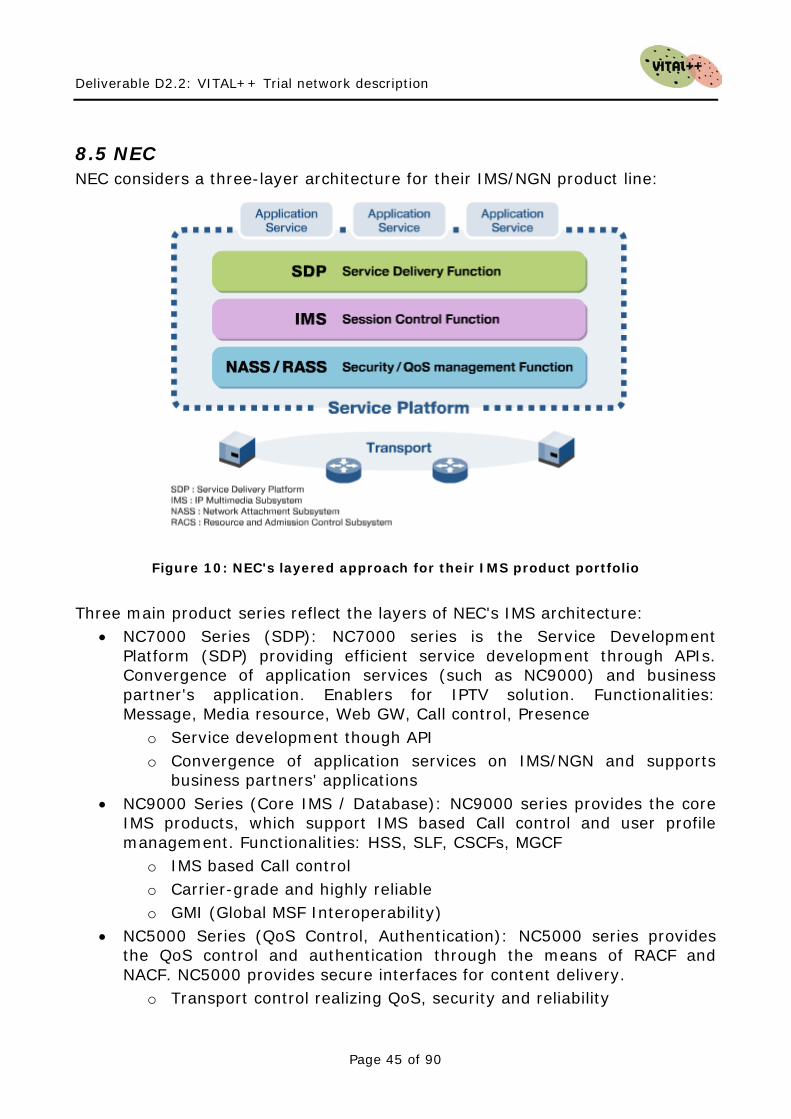
8.5 NEC NEC considers a three-layer architecture for their IMS/NGN product line:
Figure 10: NEC's layered approach for their IMS product portfolio
Three main product series reflect the layers of NEC's IMS architecture:
• NC7000 Series (SDP): NC7000 series is the Service Development Platform (SDP) providing efficient service development through APIs. Convergence of application services (such as NC9000) and business partner's application. Enablers for IPTV solution. Functionalities: Message, Media resource, Web GW, Call control, Presence
o Service development though API o Convergence of application services on IMS/NGN and supports
business partners' applications • NC9000 Series (Core IMS / Database): NC9000 series provides the core
IMS products, which support IMS based Call control and user profile management. Functionalities: HSS, SLF, CSCFs, MGCF
o IMS based Call control o Carrier-grade and highly reliable o GMI (Global MSF Interoperability)
• NC5000 Series (QoS Control, Authentication): NC5000 series provides the QoS control and authentication through the means of RACF and NACF. NC5000 provides secure interfaces for content delivery.
o Transport control realizing QoS, security and reliability
Deliverable D2.2: VITAL++ Trial network description
Page 46 of 90
o Decision of control information regarding band assurance & priority control for each service, QoS control for the transport nodes
8.6 Sonus Networks This chapter introduces an industrial IMS solution provided by Sonus Networks.
8.6.1 Architecture
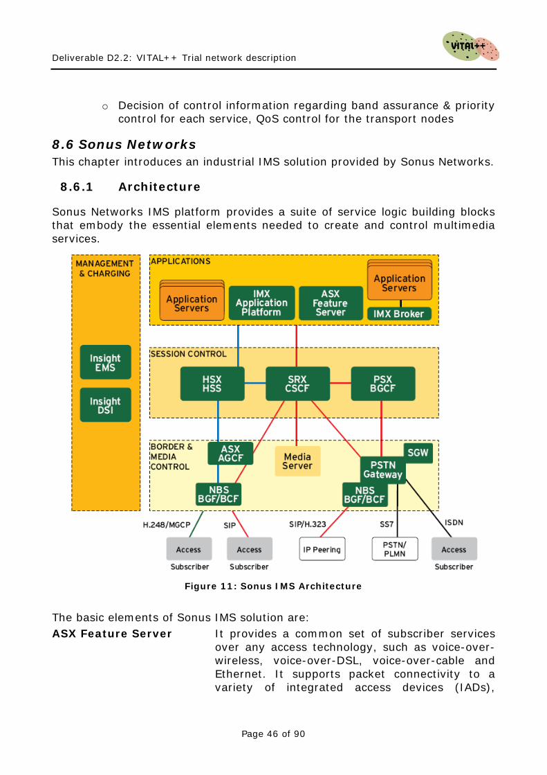
Sonus Networks IMS platform provides a suite of service logic building blocks that embody the essential elements needed to create and control multimedia services.
Figure 11: Sonus IMS Architecture
The basic elements of Sonus IMS solution are: ASX Feature Server It provides a common set of subscriber services
over any access technology, such as voice-over-wireless, voice-over-DSL, voice-over-cable and Ethernet. It supports packet connectivity to a variety of integrated access devices (IADs),
Deliverable D2.2: VITAL++ Trial network description
Page 47 of 90
gateways, next generation digital loop carriers (DLCs), softphones and other Internet Protocol (IP) endpoints. It acts as a feature server working with other IMS components, such as the Serving Call Session Control Function (S-CSCF).
IMX Application Platform It operates as an integral component of the Sonus Networks IP Multimedia Subsystem (IMS), where it functions as a SIP application server.
HSX HSS It uses the IETF DIAMETER protocol to communicate with other network elements. It supports: Subscriber profiles (criteria used to determine which component will handle the subscriber’s sessions and the application layer components used to provide services) and Subscriber status (indicates whether the subscriber is registered on the network and which IMS Serving Call Session Control Function (S-CSCF) is currently supporting that subscriber).
SRX S-CSCF It is based on the industry-standard Session Initiation Protocol (SIP). It serves as the SIP registrar for IMS subscribers. It retrieves user profile information from the Home Subscriber Server (HSS) and coordinates sessions with one or more application servers used to deliver service.
PSX BGCF It fills the role of the IMS-defined Breakout Gateway Control Function (BGCF), which is responsible for routing calls from the IMS network to other networks (e.g., between IP-voice and TDM networks). The PSX supports routing for a wide range of applications: Long distance/international, Tandem switching, Business PBX access, Residential/Centrex access, IP-voice termination (e.g., H.323, SIP), Gateway MSC, Direct Voice over BroadBand (e.g., Cable, DSL), Direct voice or wireless (e.g., Wi-Fi, WiMAX), Voice VPN, Value Added Enhanced Services, Internet Call Diversion.
Network Border Switch Based on the Sonus GSX9000 platform, the Sonus Network Border Switch (NBS) provides IP-to-IP border control and PSTN media gateway capabilities – integrating security, session control and media control.
Deliverable D2.2: VITAL++ Trial network description
Page 48 of 90
EMS The Sonus Insight Element Management System is a full-featured, flexible management system for the Sonus IMS architecture and other network components, such as Sun Netra™ platforms and Ethernet switches. The EMS seamlessly integrates with existing back office systems, eliminating the need to alternate between independent systems.
DSI The DataStream Integrator (DSI) is a module within the Sonus Insight Management System that provides advanced billing mediation with powerful, programmable tools that simplify and expedite network data integration.
8.7 Summary of Industrial IMS Solutions In this section, a comparative summary of the presented industrial IMS solutions is given, regarding to the introduced requirements to the VITAL++ architecture from chapter 7. AAA All the introduced solutions have support for Authentication, Authorization and Accounting on session level, as these are the core features for every IMS network. Network topology information The question, if network topology information can be provided is closely related to the question, whether a working NASS is provided by the vendor. The available network topology information is expected to be at least the following:
• Internet address • Access-Network ID • Contract bandwidths (upload and download).
All of the above information can be retrieved by the IMS core by querying the NASS for that information. This behaviour is standardized, so all introduced solutions which feature a NASS should provide this information. But as no explicit statement has been found, we need to take the availability of such information as optional. The solutions from NEC and Huawei are the solutions which explicitly name the NASS as part of their solution.
Deliverable D2.2: VITAL++ Trial network description
Page 49 of 90
User profiles All of the introduced solutions are featuring a Home Subscriber Server (HSS), which is responsible for storing User related data, like profiles, access information, contact information or generic data, provided by application servers or other entities. IMS Application Server All of the introduced solutions provide either an own application server, which enables specific services, or have at least support for the required reference points in order to support a 3rd party AS, which can then be programmed to realize VITAL++ specific tasks. Quality of Service The envisaged QoS solution for VITAL++ is partially based on the RACS and requires, at a minimum, the ability to request QoS levels across the access network. Thus, only IMS solutions, which are able to provide the appropriate functions, are of interest to the project. Huawei and NEC, both provide a RACS for QoS resource reservation, while the QoS solution from Alcatel-Lucent is limited to VoIP calls and is based on a privileged ATM VC in the access network.

Deliverable D2.2: VITAL++ Trial network description
Page 50 of 90
This page intentionally blank

Deliverable D2.2: VITAL++ Trial network description
Page 51 of 90
9 Network Operators Scenarios
In this chapter, IMS scenarios of network operators are introduced and compared. This shall reveal possible mechanisms for later VITAL++ architectural recommendations, i.e. how to integrate VITAL++ IMS-sided functionalities. The comparison includes the basic architecture, the deployed IMS functions, supported protocols and conforming standards.
9.1 Telefonica Testbed This chapter describes the testbed deployed in Telefonica I+D labs. The testbed has two differentiated and interconnected IMS cores, apolo.imscore and poseidon.imscore. Thus, one core can be stable permanently to test other services and the other one is for testing inside the core, besides roaming and interconnections scenarios can be tested.
9.1.1 Administrative Overview
The following table gives the most important administrative information.
Name of the testbed IMS TID Labs
Principal organisation that operates the testbed
Telefónica I+D
Type of organisation Large enterprise
Principal area of activity Research
Principal sector of activity Telecommunications
Address of principal office of the testbed
Emilio Vargas 6, 28043 Madrid, Spain
Administrative contact person
Manuel Núñez Tel.: +34 91 337 46 38 Email: [email protected]
Technical contact person Manuel Núñez Tel.: +34 91 337 46 38 Email: [email protected]
Permanent employees 4
Funding model Project based
Access policies Open access Table 2: Open IMS PG - Administrative Overview
Deliverable D2.2: VITAL++ Trial network description
Page 52 of 90
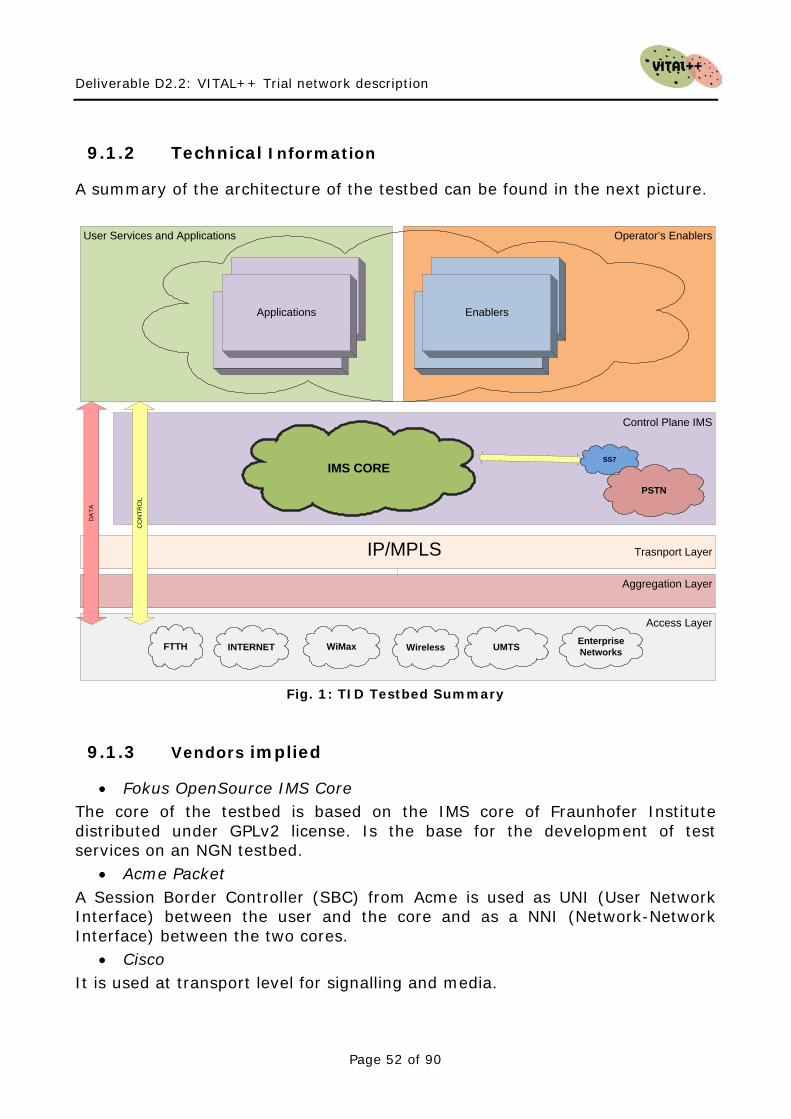
9.1.2 Technical Information
A summary of the architecture of the testbed can be found in the next picture.
Access Layer
Aggregation Layer
IP/MPLS Trasnport Layer
Control Plane IMS
Operator’s EnablersUser Services and Applications
Applications Enablers
IMS CORE
CO
NTR
OL
DA
TA
SS7
PSTN
FTTH WirelessINTERNET WiMax UMTS Enterprise Networks
Fig. 1: TID Testbed Summary
9.1.3 Vendors implied
• Fokus OpenSource IMS Core The core of the testbed is based on the IMS core of Fraunhofer Institute distributed under GPLv2 license. Is the base for the development of test services on an NGN testbed.
• Acme Packet A Session Border Controller (SBC) from Acme is used as UNI (User Network Interface) between the user and the core and as a NNI (Network-Network Interface) between the two cores.
• Cisco It is used at transport level for signalling and media.
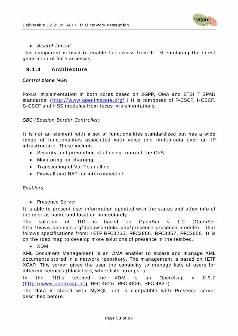
Deliverable D2.2: VITAL++ Trial network description
Page 53 of 90
• Alcatel-Lucent This equipment is used to enable the access from FTTH emulating the latest generation of fibre accesses.
9.1.4 Architecture
Control plane NGN Fokus implementation in both cores based on 3GPP, OMA and ETSI TISPAN standards. (http://www.openimscore.org/ ) It is composed of P-CSCF, I-CSCF. S-CSCF and HSS modules from focus implementations. SBC (Session Border Controller) It is not an element with a set of functionalities standardized but has a wide range of functionalities associated with voice and multimedia over an IP infrastructure. These include:
• Security and prevention of abusing to grant the QoS • Monitoring for charging. • Transcoding of VoIP signalling • Firewall and NAT for interconnection.
Enablers
• Presence Server It is able to present user information updated with the status and other info of the user as name and location immediately. The solution of TID is based on OpenSer v 1.2 (OpenSer http://www.openser.org/dokuwiki/doku.php/presence:presence-module) that follows specifications from: IETF RFC3265, RFC3856, RFC3857, RFC3858. It is on the road map to develop more solutions of presence in the testbed.
• XDM XML Document Management is an OMA enabler to access and manage XML documents stored in a network repository. The management is based on IETF XCAP. This server gives the user the capability to manage lists of users for different services (black lists, white lists, groups…). In the TID’s testbed the XDM is an OpenXcap v 0.9.7 (http://www.openxcap.org RFC 4825, RFC 4826, RFC 4827) The data is stored with MySQL and is compatible with Presence server described before.
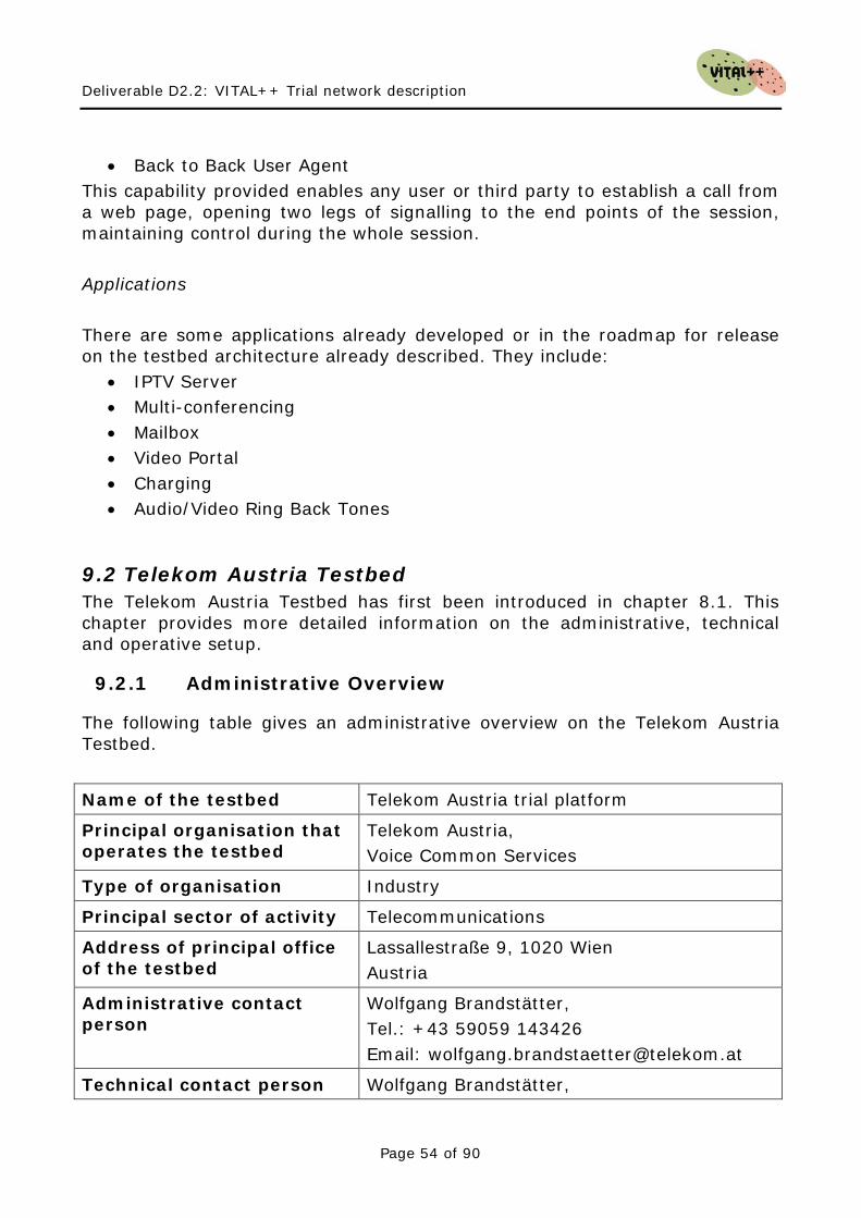
Deliverable D2.2: VITAL++ Trial network description
Page 54 of 90
• Back to Back User Agent This capability provided enables any user or third party to establish a call from a web page, opening two legs of signalling to the end points of the session, maintaining control during the whole session. Applications There are some applications already developed or in the roadmap for release on the testbed architecture already described. They include:
• IPTV Server • Multi-conferencing • Mailbox • Video Portal • Charging • Audio/Video Ring Back Tones
9.2 Telekom Austria Testbed The Telekom Austria Testbed has first been introduced in chapter 8.1. This chapter provides more detailed information on the administrative, technical and operative setup.
9.2.1 Administrative Overview
The following table gives an administrative overview on the Telekom Austria Testbed.
Name of the testbed Telekom Austria trial platform
Principal organisation that operates the testbed
Telekom Austria, Voice Common Services
Type of organisation Industry
Principal sector of activity Telecommunications
Address of principal office of the testbed
Lassallestraße 9, 1020 Wien Austria
Administrative contact person
Wolfgang Brandstätter, Tel.: +43 59059 143426 Email: [email protected]
Technical contact person Wolfgang Brandstätter,
Deliverable D2.2: VITAL++ Trial network description
Page 55 of 90
Tel.: +43 59059 143426 Email: [email protected]
Permanent employees 14
Funding model n/a
Access policies Restricted access
IPR handling Owned by Alcatel-Lucent
Table 3: Telekom Austria Trial Platform - Administrative Overview
9.2.2 Technical Information
The following table gives a technical overview on the Telekom Austria trial platform (see
Overview
Figure 6).
Classification IMS/NGN/SIP/VoIP
Components P-CSCF, S-CSCF, I-CSCF, MGW, Media Server, AS, Presence Server, SBC
Access Networks ADSL, WiFi, Ethernet, H.323
Remote secure access
VPN, IPSec, SSH
Application Keywords
VoIP, Conferencing, Basic Call, Internet, Messaging, Presence, QoS, click2dial, HTTP, SIP
Testing Keywords Conformance, Functionality, Interoperability, Performance, Measurement, Other
Testing resources Empirix Hammer, Interwatch, Acacia Clarinet, SIPp
Main standards ETSI, TISPAN, IETF
Table 4: Telekom Austria Trial Platform - Technical information
• RFC 2046: Multipurpose Internet Mail Extensions (MIME) Part Two: Media Types
Standards The following RFC’s are supported by the Telekom Austria Testbed:
• RFC 2327: SDP: Session Description Protocol • RFC 2806: URLs for Telephone Calls
Deliverable D2.2: VITAL++ Trial network description
Page 56 of 90
• RFC 2976: The SIP INFO Method • RFC 3204: MIME media types for ISUP and QSIG Objects • RFC 3261: SIP: Session Initiation Protocol • RFC 3264: An Offer/Answer Model with the Session Description Protocol
(SDP) • RFC 3265: Session Initiation Protocol (SIP)-Specific Event Notification • RFC 3323: A Privacy Mechanism for the SIP • RFC 3325: Private Extensions to the SIP for Asserted Identity within
Trusted Networks • RFC 3326: The Reason Header Field for the SIP • RFC 3856: A Presence Event Package for the Session Initiation Protocol
(SIP) • draft-levy-sip-diversion-08.txt: Diversion Indication in SIP
The ISUP/SIP Interworking function is based on the following standards:
• Q.1912.5: Interworking between SIP and BICC protocol or ISUP • EN 383001: TISPAN - Interworking between SIP and BICC Protocol or
ISUP Media Gateway control:
• H.248.1: Gateway control protocol: Version 3 Signalling in TDM network:
• ISUP 2i (also known as ISUP Whitebook or ISUP 92): Q.764: Signalling System No. 7 - ISDN User Part signalling procedures
The H.323 implementation of the SBC’s SIP/H.323 IWF complies with:
• H.323 V4: Packet-based multimedia communications systems • H.225: Call signalling protocols and media stream packetization for
packet-based multimedia communication systems • H.245: Control protocol for multimedia communication • H.245 tunnelling: encapsulates H.245 messages within H.225/Q.931
messages. • Fast start with parallel H.245 • H.323 Annex E support for UDP signalling
Services Supported
Deliverable D2.2: VITAL++ Trial network description
Page 57 of 90
The Application Server of the Telekom Austria Testbed provides the following PSTN/ISDN simulation services:
• Call Hold • Call Waiting • Call Forwarding • CLIP (Calling Line Identification Presentation) • CLIR (Calling Line Identification Restriction) • COLP (Connected Line Identification Presentation) • COLR (Connected Line Identification Restriction) • Incoming Call Screening (Black/White List) • Outgoing Call Barring • Fixed length announcements
Additionally, the following set of features for softclients is implemented:
• Video Chat for up to 4 participants • Personal Directory • Presence • Click-to-VoIP • Call Logs
9.2.3 Operational information
The Telekom Austria trial platform has been deployed for several VoIP trials, offering best effort as well as QoS assured types of services. The platform paves the way for a triple play offer for the residential consumer market, which is exclusively based on ADSL broadband lines. Some enhancements are still required in order to cover the regulatory requirements such as lawful intercept or routing of emergency calls.
9.3 Voiceglobe Testbed Voiceglobe network comprises a comprehensive set of fixed and wireless broadband interfaces over which a number of Voice-over-IP, Fax-over-IP, and Video-over-IP services are being provided including point-to-point, point-to-multipoint and conference calls. The network is fully inter-workable with legacy PSTN, ISDN and mobile networks. Voiceglobe aims at enhancing the functionality of its core network components and VoIP services so that to be fully compatible with IMS. In addition
Deliverable D2.2: VITAL++ Trial network description
Page 58 of 90
Voiceglobe is interested in acquiring insight with respect to IMS applications and measure their compatibility with current VoIP services technology.
9.3.1 Administrative Overview
The following table gives the most important administrative information.
Name of the testbed Voiceglobe Network
Principal organisation that operates the testbed
Voiceglobe
Type of organisation Next Generation Internet Telephony Provider
Principal area of activity Telecommunications
Principal sector of activity Innovative Voice and Advanced Real Time Communication Services Over the Public Internet
Address of principal office of the testbed
Avenue Louise 149 /24, 1050, Brussels, BE
Administrative contact person
George Kapelios
Technical contact person George Kapelios
Permanent employees
Funding model
Access policies Table 5: Voiceglobe Network - Administrative Overview
9.3.2 Technical Information
The various components of Voiceglobe VoIP architecture are described in the following figure:
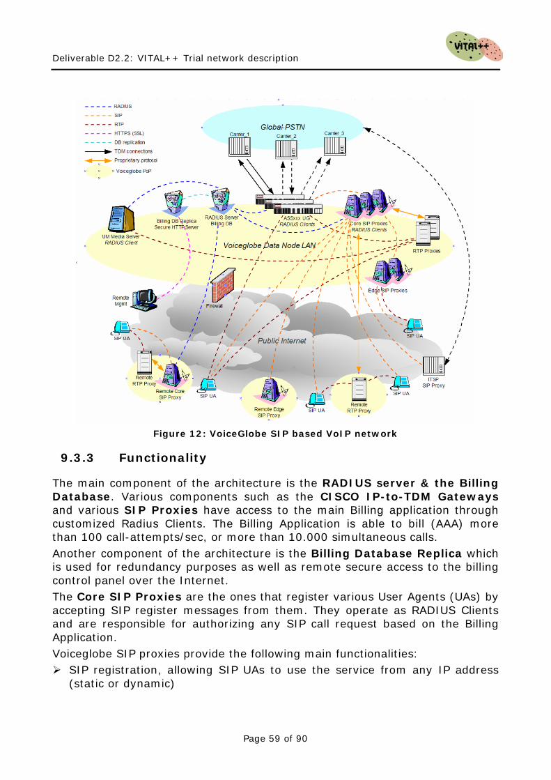
Deliverable D2.2: VITAL++ Trial network description
Page 59 of 90
Figure 12: VoiceGlobe SIP based VoIP network
9.3.3 Functionality
The main component of the architecture is the RADIUS server & the Billing Database. Various components such as the CISCO IP-to-TDM Gateways and various SIP Proxies have access to the main Billing application through customized Radius Clients. The Billing Application is able to bill (AAA) more than 100 call-attempts/sec, or more than 10.000 simultaneous calls. Another component of the architecture is the Billing Database Replica which is used for redundancy purposes as well as remote secure access to the billing control panel over the Internet. The Core SIP Proxies are the ones that register various User Agents (UAs) by accepting SIP register messages from them. They operate as RADIUS Clients and are responsible for authorizing any SIP call request based on the Billing Application. Voiceglobe SIP proxies provide the following main functionalities: SIP registration, allowing SIP UAs to use the service from any IP address
(static or dynamic)

Deliverable D2.2: VITAL++ Trial network description
Page 60 of 90
Customizable greeting upon successful service activation Authorization for all incoming calls Customer numbering plans to ensure correct phone number translation Facilitation of communication between SIP phones behind NAT Error announcements from media server Automatic disconnect of calls when maximum credit time is reached Automatic disconnect of calls when one of the parties goes offline due to a
network outage Various IP Centrex features:
o Call waiting o Call hold o Music on hold o Abbreviated dialling o Follow-me
Fail-over routing (a list of routes arranged according to cost, preference and customer routing plan is supplied by PortaBilling100)
Forwards calls to the Unified Messaging service if a SIP phone is not available
The Edge SIP Proxies are non-RADIUS clients that are interconnected with VG main Proxy Servers via SIP Trunks (SIP_NNI). They mainly serve special customers (e.g. domestic or regional IP2IP VoIP traffic). They are also used for the implementation of special codecs (e.g. iLBC) as well as RTP packetization in different sizes for cases where xDSL infrastructures pose problems such as limited packets per second. The RTP Proxies provide transparent NAT traversal services for UAs behind NAT. The Cisco AS5xxx series Universal Gateways operates as RADIUS Clients for IP-to-PSTN (egress) and PSTN-to-IP (ingress) traffic transmission and are connected with a number of E1 PRI connections to several international telephony carriers (e.g. Verizon Business, Colt, Versatel). The codecs they support are the following: G.711a/u, G.729, G.723, G.726 The UM Media Server operates as RADIUS Client and provides Unified Messaging services by integrating Voicemail, Auto-attendant, Email and Fax (FoIP) services under a common mailbox.
9.4 IMS Testbed at University of Patras This chapter describes the testbed deployed in University of Patras lab. The testbed has two differentiated IMS cores, vital.ece.upatras.gr and ims.ece.upatars.gr. It remains for the two different IMS to be interconnected in order to support roaming and interconnections scenarios.
Deliverable D2.2: VITAL++ Trial network description
Page 61 of 90
9.4.1 Administrative Overview
The following table gives the most important administrative information.
Name of the testbed IMS UoP Lab
Principal organisation that operates the testbed
University of Patras
Type of organisation Academic Institute
Principal area of activity Research
Principal sector of activity Telecommunications
Address of principal office of the testbed
University of Patras, 26500 Rio, Greece
Administrative contact person
Dionissys Anyfantis Tel.: +30 2610 997379 Email: [email protected]
Technical contact person Dionissys Anyfantis Tel.: +30 2610 997379 Email: [email protected]
Permanent employees 1
Funding model Project based
Access policies Restricted access Table 6: Open IMS PG - Administrative Overview
9.4.2 Technical Information
A summary of the architecture of the testbed can be found in the next picture.
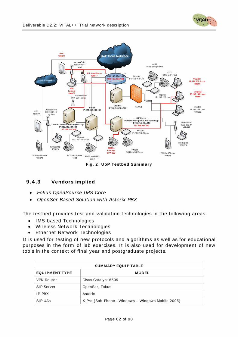
Deliverable D2.2: VITAL++ Trial network description
Page 62 of 90
Fig. 2: UoP Testbed Summary
9.4.3 Vendors implied
• Fokus OpenSource IMS Core • OpenSer Based Solution with Asterix PBX
The testbed provides test and validation technologies in the following areas:
• IMS-based Technologies • Wireless Network Technologies • Ethernet Network Technologies
It is used for testing of new protocols and algorithms as well as for educational purposes in the form of lab exercises. It is also used for development of new tools in the context of final year and postgraduate projects.
SUMMARY EQUIP TABLE
EQUIPMENT TYPE MODEL
VPN Router Cisco Catalyst 6509
SIP Server OpenSer, Fokus
IP-PBX Asterix
SIP UAs X-Pro (Soft Phone –Windows – Windows Mobile 2005)
Deliverable D2.2: VITAL++ Trial network description
Page 63 of 90
X-Lite-eyeBeam (Soft Phone -Windows) eStara (Soft Phone -Windows) LIPZ4 (Soft Phone -Linux) sJPhone (Soft Phone –Windows – Windows Mobile 2005) cornFed (Soft Phone -Linux) Linksys SPA-922, Sipura/Linksys VoIP ATA (Adapters for Phones) Wifi HardPhone - WIP 330 LinkSys Fokus IMS Clients
WiFi-WiMax Cisco - 3Com -LinkSys Wireless-G Access Points
9.4.4 Architecture
Control plane NGN Fokus implementation is based on 3GPP, OMA and ETSI TISPAN standards. (http://www.openimscore.org/ ) It is composed of P-CSCF, I-CSCF. S-CSCF and HSS modules from focus implementations. The deployed OpenSer can be used as :
• SIP registrar server • SIP router / proxy (lcr, dynamic routing, dialplan features) • SIP redirect server • SIP presence agent (to be deployed ... ) • SIP IM server (chat and end-2-end IM) (to be deployed ... ) • SIP to SMS gateway (bidirectional) (to be deployed ... ) • SIP to XMPP gateway for presence and IM (bidirectional) (to be deployed
... ) • SIP front end for gateways/asterisk • SIP NAT traversal unit • SIP application server
Applications The Testbed is fully connected with the PSTN network of the Campus, thus it can support all the classic PSTN scenarios, moreover it is connected with a Sip Proxy server an there exist an interconnection with the PSTN network through a IP-PBX server. In general the scenarios that can be realized right now are:
• Calls from/to the PSTN network to any PSTN number (including international, and mobile numbers)
Deliverable D2.2: VITAL++ Trial network description
Page 64 of 90
• Calls from/to IP Phones to any PSTN number (including international, and mobile numbers)
Secondly, the testbed is connected to Voiceglobe IMS System with the interconnection of Sip Proxies thus providing an alternate route establishment path, and giving us the opportunity to exploit more complicate scenarios, such as:
• Calls to GSM phones from/to PSTN • Calls to GSM phones from/to IP Phones
Service offerings
• Interconnection of testbeds • Demo development • Benchmarking • Conformance and Interoperability Testing
9.5 IMS Playground at Fraunhofer FOKUS In this section we describe the Open IMS Playground at the Fraunhofer FOKUS Competence Centre for Next Generation Network Infrastructures (NGNI). First we will give an administrative overview, followed by detailed technical and operational information, envisaged target market and its unique offerings.
9.5.1 Administrative Overview
The following table gives the most important administrative information.
Name of the testbed Open IMS Playground
Principal organisation that operates the testbed
Fraunhofer FOKUS, NGNI
Type of organisation Academic Institute
Principal area of activity Research
Principal sector of activity Telecommunications
Address of principal office of the testbed
Kaiserin-Auguista-Allee 31, 10589 Berlin, Germany
Administrative contact person
Sebastian Wahle, Tel.: +49 30 34637365 Email: [email protected]
Technical contact person Sebastian Wahle,
Deliverable D2.2: VITAL++ Trial network description
Page 65 of 90
Tel.: +49 30 34637365 Email: [email protected]
Permanent employees 5
Funding model Project based
Access policies Open access
IPR handling NDAs with specific partners Table 7: Open IMS PG - Administrative Overview
9.5.2 Technical Information
Open testbeds have played a major role for Fokus’ research activities in terms of result validation and prototype development. The term “Playground” was introduced to hide the complexity of such a laboratory even in its name. Fokus’ aim is to facilitate the usage of latest technologies in the field of IMS, NGN, SOA, and IPTV. Fokus wants to provide an easy and early access, especially for smaller players that enable them to bring their ideas to life. It is OPEN in a sense that it is in a constant process of evolving. It is open to new partners, new components, new technologies, as well as new concepts and paradigms. It is IMS (IP Multimedia Subsystem) centric. This means that it contains the latest IMS technology, conforms to the latest IMS specifications, and generally reflects the current state of the art in the field of IMS. It is a PLAYGROUND. Fokus sees a Playground as a technology focused test environment, where they can "play" around with the latest technology. However, this is more than something to toy around with. It is a mature testbed, a test laboratory, where benchmarking, conformance tests and interoperability tests are carried out for testbed partners, and where components resulting from own development can be deployed and operated. Driven by market needs and partner’s requirements, the Open IMS Playground has evolved to a known test laboratory which is used in many national and international projects from industry and academia. Around the Playground Fokus offers services such as prototyping, proof-of-concept implementations, benchmarking and consulting. The Playground includes an Open Source Project which focuses on the development of the IMS core network (HSS and CSCFs). Based on this Open Source Initiative (OSIMS) Fokus offers the instantiation of a full IMS Playground in an organization. Fuelled with add-on components, interconnection to the Open IMS Playground, and our experience, you can benefit from the potential of an own IMS test environment located at your own facilities. The following picture gives a graphical overview of the Open IMS Playground testbed.
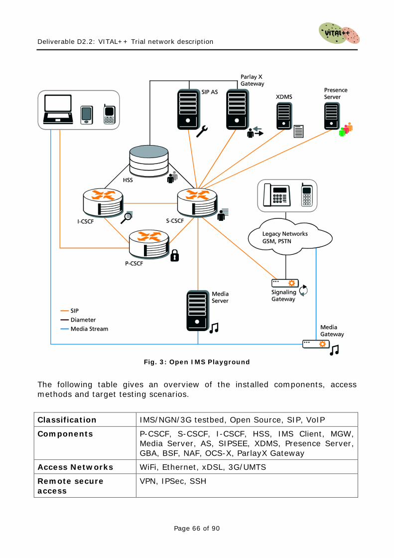
Deliverable D2.2: VITAL++ Trial network description
Page 66 of 90
Fig. 3: Open IMS Playground
The following table gives an overview of the installed components, access methods and target testing scenarios.
Classification IMS/NGN/3G testbed, Open Source, SIP, VoIP
Components P-CSCF, S-CSCF, I-CSCF, HSS, IMS Client, MGW, Media Server, AS, SIPSEE, XDMS, Presence Server, GBA, BSF, NAF, OCS-X, ParlayX Gateway
Access Networks WiFi, Ethernet, xDSL, 3G/UMTS
Remote secure access
VPN, IPSec, SSH
Deliverable D2.2: VITAL++ Trial network description
Page 67 of 90
Application Keywords
SMS, VoIP, Streaming, Conferencing, Call, Internet, Messaging, E-Mail, Presence, QoS, click2dial, IPTV, Web2.0, SOA, ESP, OpenID, Cardspace, Liberty Alliance, servlets, HTTP, SIP, converged servlets, Web Services.
Testing Keywords Conformance, Functionality, Interoperability, Performance, Benchmarking, Measurement, Other
Testing resources TTCN Simulation tool, SIP Tools, SIP Nuke, Benchmarking, Network Measurement
Main standards 3GPP, ETSI, TISPAN, OMA, IEEE Table 8: Open IMS PG - Technical information
9.5.3 Operational information
In this section, we will provide a description of the services offered by the testbed, followed by the planned evolution of those.
9.5.3.1 Description of the services offered:
• Prototyping Fokus delivers prototype component implementations related to IMS and NGN technology based on customer requirements.
• Instantiation of the Open IMS Playground
Fokus can equip an organization with a full IMS test environment to allow them run their own IMS and NGN related test scenarios.
• Interconnection of testbeds
An organisation’s IMS test environment can be connected to the Open IMS Playground to test advanced deployment scenarios.
• Demo development
Development of demonstrations of specific NGN and IMS technology such as Fixed Mobile Convergence Demos (FMC), Triple Play Demos (3P) and more.
• Proof-of-concept implementations
Fokus shows that your ideas have the potential to become a success.
Deliverable D2.2: VITAL++ Trial network description
Page 68 of 90
• Benchmarking Is there someone that performs better than you? Can your component handle the load we generate? Quality management and quality improvement rely on benchmarking. We carry out performance comparison for your selected NGN / IMS / SIP components based on the new ETSI TISPAN benchmarking standard.
• Conformance and Interoperability Testing
Is your component conforming to the latest specifications? Does it work together with our partner components?
• Coaching / Tutorials
Based on the tremendous and recognized experience in the field of NGN and IMS, we offer different coaching and tutorial sessions to let you benefit from our knowledge.
• Consulting / Studies
Is there something about IMS and NGNs you need to know in detail? Do you need to know it fast? We’ll provide you with scientific studies and consulting.
• Comprehensive Testbed Projects
Being a partner in many international projects in industry and academia we gathered considerable experience in terms of project management and long term project contributions.
9.5.3.2 Planned evolution The planned evolution of the testbed will point towards Web2.0, SOA and Future Internet. Open testbeds have ever since played a major role for our research activities in terms of result validation and prototype development. Our aim is to facilitate the usage of latest technologies in the field of IMS, NGN, SOA, and IPTV. We want to provide an easy and early access, especially for smaller players that enable them to bring their ideas to life. We provide Open Source components.
9.5.4 Target Market
• Telecommunication Industry For the telecommunication industry, competition has always been a major driving factor for product development. The Open IMS Playground
Deliverable D2.2: VITAL++ Trial network description
Page 69 of 90
gives the opportunity to gain measurements about performance and interoperability before going to the market.
• Operators and Integrators For operators and integrators it is quite interesting, whether new services and models will technically work, before deploying them in their own productive networks. The Open IMS playground can be used as a sandbox for new components.
• Application Developers, Developers will find a rich NGN environment to play around with in their own applications without having to setup an expensive testbed themselves.
• Academia For academia, a natural testbed will provide a realistic environment for new ideas, algorithms and architectures, giving a point of first deployment of new technologies under development.
9.5.5 Unique offering
FOKUS is an independent research organisation. Thus, no vendor lock-in exists. For most of the components two solutions are provided:
• FOKUS in-house developments, for which Open Source licenses are available (Application Server, XDMS, Presence Server, IMS Client, IMS-Core, etc.)
• Commercial products from our partners. FOKUS employs the developers and can provide first hand know-how for installation, scenario setups and site design. FOKUS has not only developed the Open Source IMS Core but has also built the community around it2
2 http://www.openimscore.org
.

Deliverable D2.2: VITAL++ Trial network description
Page 70 of 90
This page intentionally blank

Deliverable D2.2: VITAL++ Trial network description
Page 71 of 90
10 Analysis of IMS Scenarios
In chapter 9 the network operator testbeds from Telefonica, Telekom Austria, Voiceglobe, University of Patras and Fraunhofer FOKUS have been described in detail. Table 8 compares the testbeds among themselves with respect to the pre-defined criteria introduced in chapter 6: Telefonica Telekom
Austria Voice-globe
University of Patras
FOKUS
Architecture
IMS 3G - - - Y Y
IMS TISPAN Y Y - Y Y
Open Source Y - - Y Y
IETF SIP Y Y Y Y Y
VoIP Softswitch - Y Y Y Y
Components
P/S/I-CSCF Y Y - Y Y
HSS Y - - Y Y
Media Gateway 1) - Y - - (Y)
Media Server 2) - Y - - (Y)
PDF - - - - Y
Application Server Y Y Y Y Y
Access Networks
WiFi Y Y Not access network
dependent
Y Y
xDSL - Y - -
3G/UMTS - - - -
Ethernet Y Y Y Y
Clients
IMS Clients Y Y Experimental Y Y
SIP Clients - Y Y Y Y
Table 9: Classification of the VITAL++ testbeds Note 1) Media Gateway comprises BGCF, SGF, MGCF and MGF
Note 2) Media Server comprises MRFC and MRFP
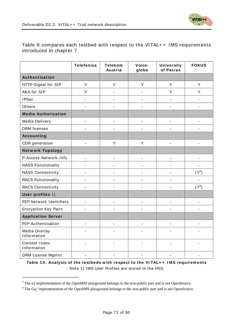
Deliverable D2.2: VITAL++ Trial network description
Page 72 of 90
Table 9 compares each testbed with respect to the VITAL++ IMS requirements introduced in chapter 7. Telefonica Telekom
Austria Voice-globe
University of Patras
FOKUS
Authentication
HTTP Digest for SIP Y Y Y Y Y
AKA for SIP Y - - Y Y
IPSec - - - - -
Others - - - - -
Media Authorization
Media Delivery - - - - -
DRM licenses - - - - -
Accounting
CDR generation - Y Y - -
Network Topology
P-Access-Network-Info - - - - -
NASS Functionality - - - - -
NASS Connectivity - - - - (Y3)
RACS Functionality - - - - -
RACS Connectivity - - - - (Y4)
User profiles 1)
P2P Network Identifiers - - - - -
Encryption Key Pairs - - - - -
Application Server
P2P Authentication - - - - -
Media Overlay Information
- - - - -
Content Index Information
- - - - -
DRM License Mgmnt. - - - - -
Table 10: Analysis of the testbeds with respect to the VITAL++ IMS requirements Note 1) IMS User Profiles are stored in the HSS
3 The e2 implementation of the OpenIMS playground belongs to the non-public part and is not OpenSource. 4 The Gq’ implementation of the OpenIMS playground belongs to the non-public part and is not OpenSource.
Deliverable D2.2: VITAL++ Trial network description
Page 73 of 90
Table 9 points out that the main IMS functionalities required for the VITAL++ usage scenarios are yet not available on the various network operator testbeds. In particular, the media authorization, network topology, user profiles and other AS-related functionalities are completely missing. However, table 8 shows that the basic IMS functions for the integration of the AS are already there. Therefore, we propose to implement common AS for the required IMS functionalities within the scope of VITAL++. We also recommend an overall design, which does not rely on the presence of NASS/RACS in the hosting testbed, but a hybrid design, which allows the usage of these components if they are present. Also, the AS design approach will enable easy deployment of the VITAL++ functionalities in other testbeds with different network environments, even other than the presented ones, as long as the relevant interfaces are supported. The sub-architectures for the various AS including the functional blocks and the network interfaces to the IMS core are described in detail in chapter 11. The corresponding interfaces to the VITAL++ client are part of D2.3.

Deliverable D2.2: VITAL++ Trial network description
Page 74 of 90
This page intentionally blank
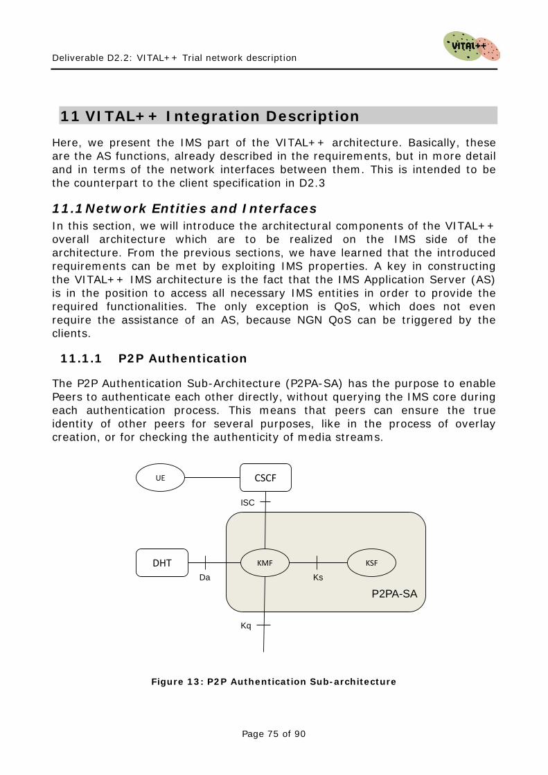
Deliverable D2.2: VITAL++ Trial network description
Page 75 of 90
11 VITAL++ Integration Description
Here, we present the IMS part of the VITAL++ architecture. Basically, these are the AS functions, already described in the requirements, but in more detail and in terms of the network interfaces between them. This is intended to be the counterpart to the client specification in D2.3
11.1 Network Entities and Interfaces In this section, we will introduce the architectural components of the VITAL++ overall architecture which are to be realized on the IMS side of the architecture. From the previous sections, we have learned that the introduced requirements can be met by exploiting IMS properties. A key in constructing the VITAL++ IMS architecture is the fact that the IMS Application Server (AS) is in the position to access all necessary IMS entities in order to provide the required functionalities. The only exception is QoS, which does not even require the assistance of an AS, because NGN QoS can be triggered by the clients.
11.1.1 P2P Authentication
The P2P Authentication Sub-Architecture (P2PA-SA) has the purpose to enable Peers to authenticate each other directly, without querying the IMS core during each authentication process. This means that peers can ensure the true identity of other peers for several purposes, like in the process of overlay creation, or for checking the authenticity of media streams.
KMF KSF
ISC
Ks
Kq
P2PA-SA
CSCFUE
DHTDa
Figure 13: P2P Authentication Sub-architecture
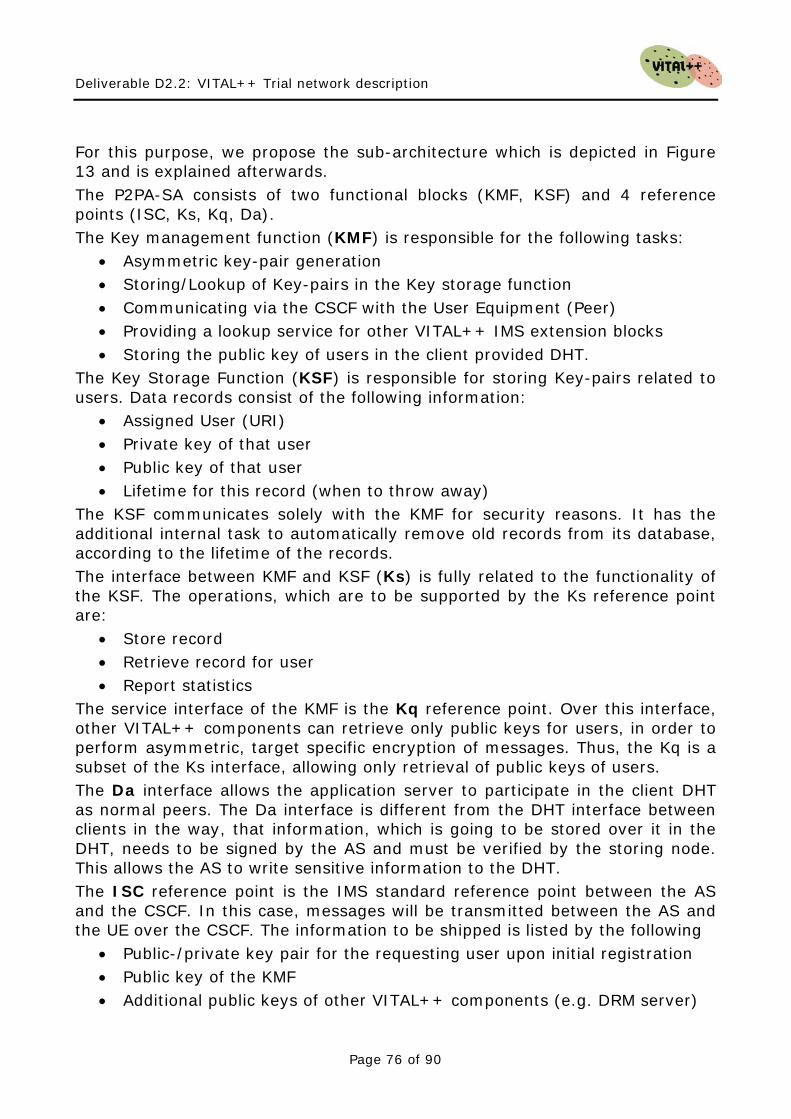
Deliverable D2.2: VITAL++ Trial network description
Page 76 of 90
For this purpose, we propose the sub-architecture which is depicted in Figure 13 and is explained afterwards. The P2PA-SA consists of two functional blocks (KMF, KSF) and 4 reference points (ISC, Ks, Kq, Da). The Key management function (KMF) is responsible for the following tasks:
• Asymmetric key-pair generation • Storing/Lookup of Key-pairs in the Key storage function • Communicating via the CSCF with the User Equipment (Peer) • Providing a lookup service for other VITAL++ IMS extension blocks • Storing the public key of users in the client provided DHT.
The Key Storage Function (KSF) is responsible for storing Key-pairs related to users. Data records consist of the following information:
• Assigned User (URI) • Private key of that user • Public key of that user • Lifetime for this record (when to throw away)
The KSF communicates solely with the KMF for security reasons. It has the additional internal task to automatically remove old records from its database, according to the lifetime of the records. The interface between KMF and KSF (Ks) is fully related to the functionality of the KSF. The operations, which are to be supported by the Ks reference point are:
• Store record • Retrieve record for user • Report statistics
The service interface of the KMF is the Kq reference point. Over this interface, other VITAL++ components can retrieve only public keys for users, in order to perform asymmetric, target specific encryption of messages. Thus, the Kq is a subset of the Ks interface, allowing only retrieval of public keys of users. The Da interface allows the application server to participate in the client DHT as normal peers. The Da interface is different from the DHT interface between clients in the way, that information, which is going to be stored over it in the DHT, needs to be signed by the AS and must be verified by the storing node. This allows the AS to write sensitive information to the DHT. The ISC reference point is the IMS standard reference point between the AS and the CSCF. In this case, messages will be transmitted between the AS and the UE over the CSCF. The information to be shipped is listed by the following
• Public-/private key pair for the requesting user upon initial registration • Public key of the KMF • Additional public keys of other VITAL++ components (e.g. DRM server)
Deliverable D2.2: VITAL++ Trial network description
Page 77 of 90
The ISC communication is triggered by enabling the VITAL++ service in the corresponding user’s HSS-profiles. This results in an initial filter criteria, which causes the S-CSCF to notify the KMF via ISC upon user registration. Thus, additionally the following information is going to be exchange over the ISC interface:
• User registration notification The P2PA-SA is therefore responsible for asymmetric key management, generation, storage and availability to peers and other architectural components.
11.1.2 Content Security
The Content Security Sub-Architecture (CS-SA) is going to be defined to tackle the following issues in content distribution.
1. Illegal Content Access The intended purpose is to prohibit illegal content access. Therefore, content needs to be encrypted. Only authorized peers must be able to decipher and use the related content, while peers, who are not authorized, do not receive decryption keys.
2. Accounting for Content Access The publication of content as well as the consumption of content using the VITAL++ P2P operator service can optionally be charged by the operator.
The general principle of the CS-SA envisages enabling users to perform the following procedures:
1. Media Publishing Whenever a content issuer wants to publish a Media Object (MO), may it be a file or stream, he first has to register this MO with the CS-SA. This makes the content and its issuer known to the architecture.
2. Content Key Registration
Optionally, a content issuer can register a cryptographic key, which can be used to decipher encrypted content at the users end equipment. This key is then associated with the formerly registered MO.
3. Rights publishing
Deliverable D2.2: VITAL++ Trial network description
Page 78 of 90
The Content issuer must define how other users are allowed to use his content by registering one or more root rights objects (RO). These are then associated with the content and serve as template for derived ROs which can be used by customers.
4. Rights requesting
A user, who wants to consume registered content, can request an RO from the CS-SA. This provides him with a license, defining the limits of content usage and cryptographic information on how to decipher the content.
The CS-SA strongly cooperates with the P2PA-SA for asymmetric key lookups. It can also generate events for online- and offline charging. The following figure gives an overview of the proposed CS-SA and its functions and interfaces, which are explained afterwards.
MOC
ROC
ISC
CS-SA
CSCFUE
P2PA-SAKq
MKOR
ROR
Charging
Dq
Rf, Ro
Figure 14: Content Security Sub-Architecture
The CS-SA is composed of 4 functional blocks, the Rights Objects Controller (ROC), the Rights Objects Repository, The Media Object Controller (MOC) and the Media and Key Objects Repository (MKOR). The CS-SA uses the ISC interface to the IMS CSCFs, the Rf and Ro interfaces to the charging sub-systems and the Kq interface to the P2PA-SA. It defines the Dq interface to enable other VITAL++ entities to access MO details. The internal interfaces between ROC and ROR, ROC and MKOR as wells as between MOC and MKOR
Deliverable D2.2: VITAL++ Trial network description
Page 79 of 90
are not defined here, as it can be expected that those components are realized within the same node. This leaves these interfaces as implementation details. The MOC is responsible for administrating the repository of MOs and the related cryptographic information in the MKOR. It gets contacted by a user over the ISC interface to store, change or delete information about MOs and related cryptographic information. It uses the Kq interface to obtain public keys for the peers it communicates with in order to check signatures, e.g. on MO registration. The ROC is the entity which controls ROs. Over the ISC, content issuers can create/modify/delete root ROs, while consumers can obtain personal derived ROs for content usage. The ROC can generate charging events over the Ro (online) and Rf (offline) charging interfaces. It needs to obtain asymmetric public keys (Kq) in order to encrypt ROs for the single peers. It maintains all ROs in a private database, the ROR. The ROC queries the MKOR and the ROR for MOs and root ROs in order to generate user ROs, which are then shipped to the consumer. The ROR is basically a database, which stores ROs. An RO is composed of at least the following elements:
• Exactly one MO descriptor The media object descriptor uniquely describes a media object, so that the MO descriptor can be used to identify a MO.
• One or multiple instances of pairs of function and limiter. o The function reflects the right, which is going to be limited. These
can be functions like “play”, “store” or “forward”. o The limiter can appear as time based limit or as a counter.
An example is “The content may be played between 18:00 and 20:00”. Thus, a request for the content to be played between 18:30 and 19:30 would be answered with a positive answer.
The MKOR is also a database. This one holds all registered MOs and the related content encryption information. Each MO record consists of, at least, the following elements:
• A unique Digital Object Identifier This identifier is generated by the MOC and transmitted to the user when he registers a Media Object.
• Content Issuer (by its SIP-URI) This identifies the Content Issuer.
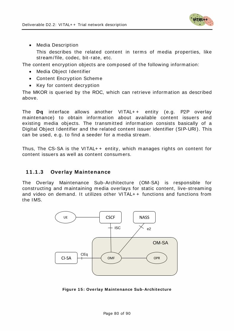
Deliverable D2.2: VITAL++ Trial network description
Page 80 of 90
• Media Description This describes the related content in terms of media properties, like stream/file, codec, bit-rate, etc.
The content encryption objects are composed of the following information: • Media Object Identifier • Content Encryption Scheme • Key for content decryption
The MKOR is queried by the ROC, which can retrieve information as described above. The Dq interface allows another VITAL++ entity (e.g. P2P overlay maintenance) to obtain information about available content issuers and existing media objects. The transmitted information consists basically of a Digital Object Identifier and the related content issuer identifier (SIP-URI). This can be used, e.g. to find a seeder for a media stream. Thus, The CS-SA is the VITAL++ entity, which manages rights on content for content issuers as well as content consumers.
11.1.3 Overlay Maintenance
The Overlay Maintenance Sub-Architecture (OM-SA) is responsible for constructing and maintaining media overlays for static content, live-streaming and video on demand. It utilizes other VITAL++ functions and functions from the IMS.
OMF
ISC
OM-SA
CSCFUE
CI-SACEq
OPR
NASS
e2
Figure 15: Overlay Maintenance Sub-Architecture
Deliverable D2.2: VITAL++ Trial network description
Page 81 of 90
Figure 15 gives an overview of the OM-SA and its functional blocks and interfaces, which are explained afterwards. The Overlay and Peers Repository (OPR) holds information about all currently active overlays and also information about the currently participating peers. Each overlay is thereby defined by the following parameters:
• Overlay Type (Static, Live-Stream, VoD-Stream) • Overlay Type specific parameters (File size, service rate for a stream,
etc.) • Overlay Construction Algorithm • Overlay Algorithm specific parameters. • Unique Content Identifier
o Each registered content must have its own unique identifier. It is generated during the process of registering content. This identifier is being used for assigning relations to other VITAL++ components, like overlays, peers, etc. dealing with the same content.
• Unique Overlay Identifier Additionally, information about each participating peer in each overlay shall be stored. The elements of a peer-record shall be at least the following:
• The peer’s IP address • The peer’s SIP-URI • Information about the peers connectivity (e.g. bandwidth) • Network position information (if available) • Overlay Algorithm specific parameters (e.g. Super-/Normal Peer)
Each Peer-record is thereby assigned to a single overlay. If a peer participates in more than one overlay, it is required to have multiple peer records, each linked to the specific overlay structure. The most important function of the OM-SA is the Overlay Maintenance Function (OMF). The OMF hosts at least one overlay construction/maintenance algorithm for each envisaged content overlay type (static, live, vod). The OMF communicates with the OPR in order to keep track of existing overlays and lists of peers. The OMF is responsible for the communication with the peers when they join or leave a media overlay. When a peers enters a media overlay, it basically receives a list of peers, and instructions on how to communicate with them (e.g. upload/download) in order to become a member of the overlay in the desired way. The same procedures are to be performed when a peer orderly leaves an overlay.
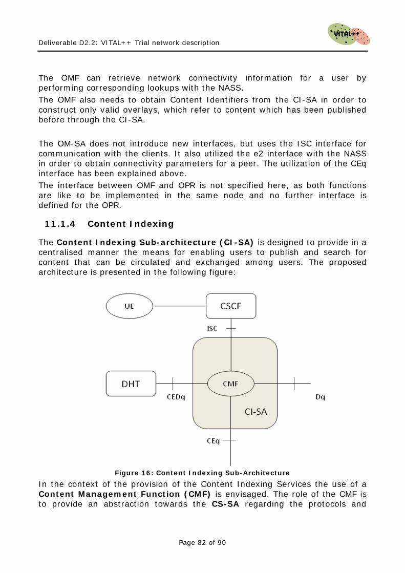
Deliverable D2.2: VITAL++ Trial network description
Page 82 of 90
The OMF can retrieve network connectivity information for a user by performing corresponding lookups with the NASS. The OMF also needs to obtain Content Identifiers from the CI-SA in order to construct only valid overlays, which refer to content which has been published before through the CI-SA. The OM-SA does not introduce new interfaces, but uses the ISC interface for communication with the clients. It also utilized the e2 interface with the NASS in order to obtain connectivity parameters for a peer. The utilization of the CEq interface has been explained above. The interface between OMF and OPR is not specified here, as both functions are like to be implemented in the same node and no further interface is defined for the OPR.
11.1.4 Content Indexing
The Content Indexing Sub-architecture (CI-SA) is designed to provide in a centralised manner the means for enabling users to publish and search for content that can be circulated and exchanged among users. The proposed architecture is presented in the following figure:
Figure 16: Content Indexing Sub-Architecture
In the context of the provision of the Content Indexing Services the use of a Content Management Function (CMF) is envisaged. The role of the CMF is to provide an abstraction towards the CS-SA regarding the protocols and
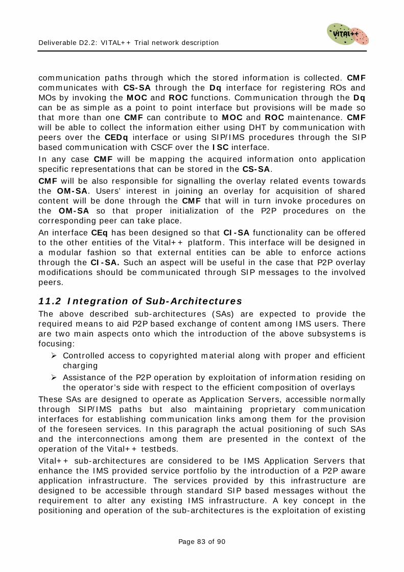
Deliverable D2.2: VITAL++ Trial network description
Page 83 of 90
communication paths through which the stored information is collected. CMF communicates with CS-SA through the Dq interface for registering ROs and MOs by invoking the MOC and ROC functions. Communication through the Dq can be as simple as a point to point interface but provisions will be made so that more than one CMF can contribute to MOC and ROC maintenance. CMF will be able to collect the information either using DHT by communication with peers over the CEDq interface or using SIP/IMS procedures through the SIP based communication with CSCF over the ISC interface. In any case CMF will be mapping the acquired information onto application specific representations that can be stored in the CS-SA. CMF will be also responsible for signalling the overlay related events towards the OM-SA. Users’ interest in joining an overlay for acquisition of shared content will be done through the CMF that will in turn invoke procedures on the OM-SA so that proper initialization of the P2P procedures on the corresponding peer can take place. An interface CEq has been designed so that CI-SA functionality can be offered to the other entities of the Vital++ platform. This interface will be designed in a modular fashion so that external entities can be able to enforce actions through the CI-SA. Such an aspect will be useful in the case that P2P overlay modifications should be communicated through SIP messages to the involved peers.
11.2 Integration of Sub-Architectures The above described sub-architectures (SAs) are expected to provide the required means to aid P2P based exchange of content among IMS users. There are two main aspects onto which the introduction of the above subsystems is focusing: Controlled access to copyrighted material along with proper and efficient
charging Assistance of the P2P operation by exploitation of information residing on
the operator’s side with respect to the efficient composition of overlays These SAs are designed to operate as Application Servers, accessible normally through SIP/IMS paths but also maintaining proprietary communication interfaces for establishing communication links among them for the provision of the foreseen services. In this paragraph the actual positioning of such SAs and the interconnections among them are presented in the context of the operation of the Vital++ testbeds. Vital++ sub-architectures are considered to be IMS Application Servers that enhance the IMS provided service portfolio by the introduction of a P2P aware application infrastructure. The services provided by this infrastructure are designed to be accessible through standard SIP based messages without the requirement to alter any existing IMS infrastructure. A key concept in the positioning and operation of the sub-architectures is the exploitation of existing

Deliverable D2.2: VITAL++ Trial network description
Page 84 of 90
features and information such as access control and access network. Vital++ AS will be able process information collected by the IMS and access network so that P2P procedures can be driven under a more controllable scheme. Additionally, P2P aspects such as overlay management and maintenance are expected to benefit from the most proper evaluation of the network topology by the Vital++ AS. In the context of the definition of the Vital++ scenarios gradual steps have been identified so that certain combinations of application logic aspects can be evaluated. These steps are presented in the sequel.
11.2.1 Content Publication and Discovery
The initial step towards IMS-P2P integration regards the provision by the IMS network of means that aid the publication and discovery of content. Using SIP messages (Instant Messaging) as a way to carry Content Indexing specific details the CI-SA is introduced as SIP AS connected to the IMS network through ICS. Using a proprietary protocol carried in SIP IMs the CI-SA aggregates all the content publications that originate from content sources. In this first step the information is stored in a database and a scheme identifying categories and subcategories is established. In the same way the CI-SA accepts queries from User Agents (UAs) that are trying to locate content. The queries are translated and executed against the stored information and the results are provided to the UAs.
CMF
ISC
CI-SA
CSCFUE
Database access
CR
Figure 17: Introduction of CI-SA
11.2.2 Overlay Management
Once a UA has located an interesting item that is provided through P2P procedures the next step is the discovery of an initial overlay. In this step the OM-SA is introduced.
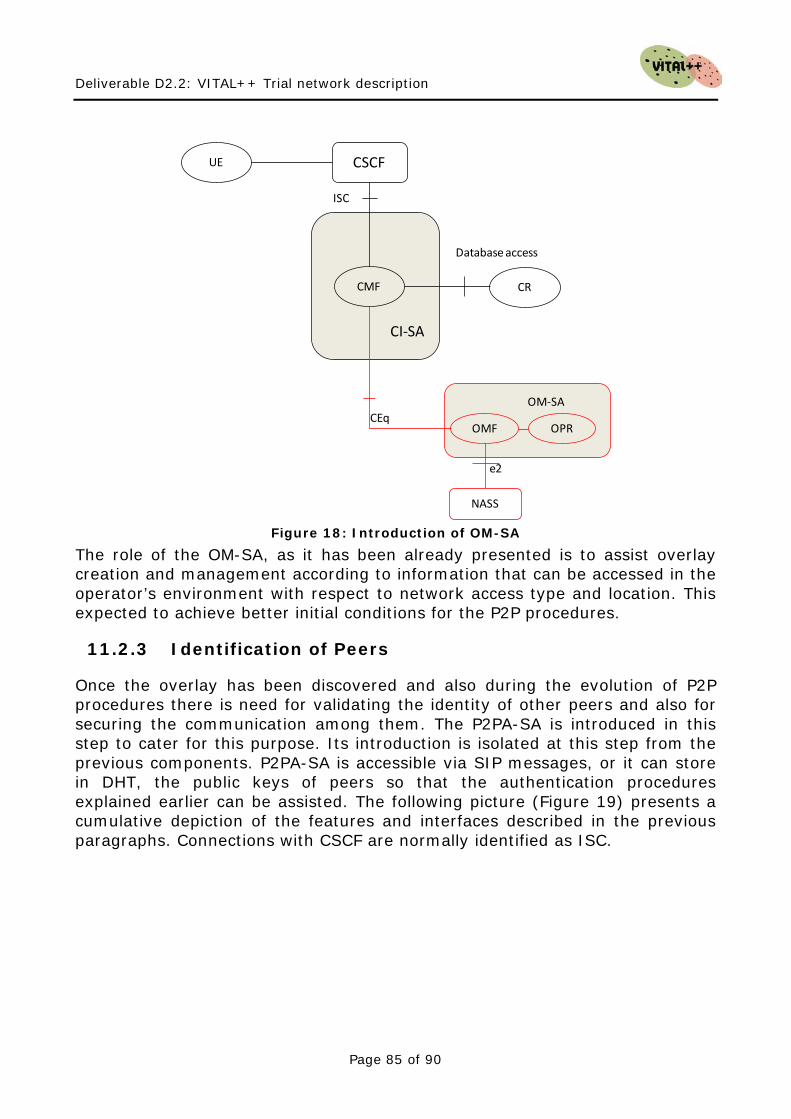
Deliverable D2.2: VITAL++ Trial network description
Page 85 of 90
CEqOMF
OM-SA
OPR
NASS
e2
CMF
ISC
CI-SA
CSCFUE
Database access
CR
Figure 18: Introduction of OM-SA
The role of the OM-SA, as it has been already presented is to assist overlay creation and management according to information that can be accessed in the operator’s environment with respect to network access type and location. This expected to achieve better initial conditions for the P2P procedures.
11.2.3 Identification of Peers
Once the overlay has been discovered and also during the evolution of P2P procedures there is need for validating the identity of other peers and also for securing the communication among them. The P2PA-SA is introduced in this step to cater for this purpose. Its introduction is isolated at this step from the previous components. P2PA-SA is accessible via SIP messages, or it can store in DHT, the public keys of peers so that the authentication procedures explained earlier can be assisted. The following picture (Figure 19) presents a cumulative depiction of the features and interfaces described in the previous paragraphs. Connections with CSCF are normally identified as ISC.
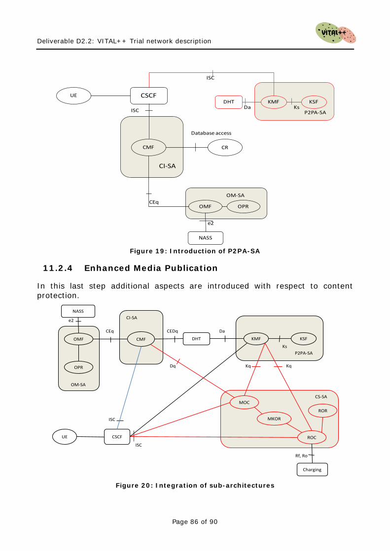
Deliverable D2.2: VITAL++ Trial network description
Page 86 of 90
KMF KSF
ISC
KsP2PA-SA
DHTDa
CEqOMF
OM-SA
OPR
NASS
e2
CMF
ISC
CI-SA
CSCFUE
Database access
CR
Figure 19: Introduction of P2PA-SA
11.2.4 Enhanced Media Publication
In this last step additional aspects are introduced with respect to content protection.
KMF KSF
ISC
KsP2PA-SA
DHT
Da
ROC
MOCCS-SA
Kq
MKOR
ROR
Charging
Rf, Ro
CMF
CEq
CI-SA
CEDq
Dq
UE
OMF
OM-SA
OPR
NASS
e2
CSCF
ISC
Kq
Figure 20: Integration of sub-architectures
Deliverable D2.2: VITAL++ Trial network description
Page 87 of 90
The CS-SA provides the required media publication storage along with provision of access rights and licensing schemes. This last step results in the final VITAL++ AS architecture. Figure 20 illustrates this.
11.3 Integration Plan In the scope of this deliverable, the NGN-sided part of the VITAL++ architecture has been specified in terms of functional blocks and interfaces and information exchanged. In WP3, the architecture is going to be refined in terms of standard and VITAL++ protocols. Also, the boundaries of functional elements may be redefined for the purpose of simplicity and efficiency of the final solution. In WP4, the ways of using the architecture for the VITAL++ scenarios is going to be defined. In this chapter, we are proposing a timeline which identifies phases for the realization of this architecture. The integration plan is split into five phases:
Phase I: Refinement of architecture In this phase, the presented interfaces are defined in terms of protocols, methods. Also, the presented functional blocks are defined in more detail and whether they are realized in the same node or spread over different nodes. The outcome of Phase I is an implementation plan. Phase II: Implementation During this phase, the refined architecture is implemented by the corresponding partners. Phase III: Sub-architecture interoperation In phase III, the interoperation between the single sub architectures is tested and if necessary revised in order to fit the requirements for the VITAL++ scenarios. At the end of phase III, the VITAL++ AS is being expected to be complete. Phase IV: Client interoperation In this phase, interoperability is tested with the VITAL++ client, which is being developed in parallel. Again, if necessary adaptations become required, they are to be realized during this phase. Phase V: Finalization
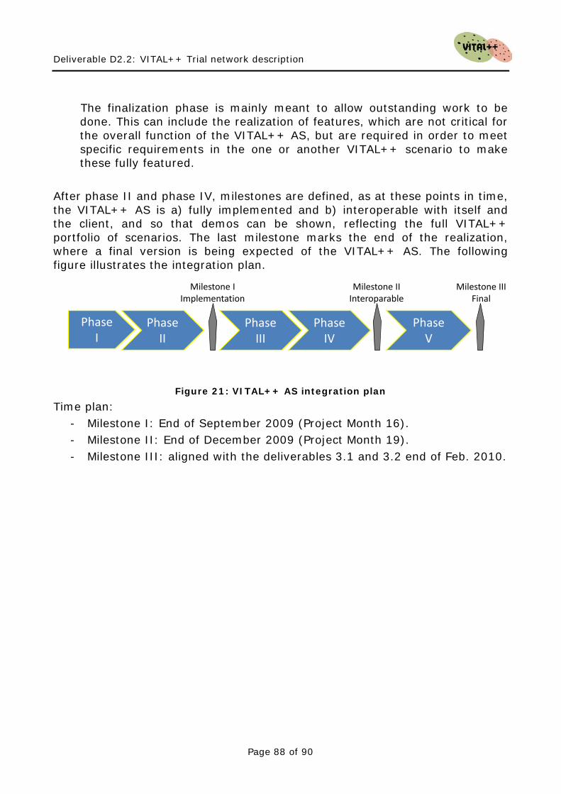
Deliverable D2.2: VITAL++ Trial network description
Page 88 of 90
The finalization phase is mainly meant to allow outstanding work to be done. This can include the realization of features, which are not critical for the overall function of the VITAL++ AS, but are required in order to meet specific requirements in the one or another VITAL++ scenario to make these fully featured.
After phase II and phase IV, milestones are defined, as at these points in time, the VITAL++ AS is a) fully implemented and b) interoperable with itself and the client, and so that demos can be shown, reflecting the full VITAL++ portfolio of scenarios. The last milestone marks the end of the realization, where a final version is being expected of the VITAL++ AS. The following figure illustrates the integration plan.
PhaseI
Phase II
Phase V
Milestone IImplementation
Milestone IIInteroparable
Phase III
Phase IV
Milestone IIIFinal
Figure 21: VITAL++ AS integration plan
Time plan: - Milestone I: End of September 2009 (Project Month 16). - Milestone II: End of December 2009 (Project Month 19). - Milestone III: aligned with the deliverables 3.1 and 3.2 end of Feb. 2010.

Deliverable D2.2: VITAL++ Trial network description
Page 89 of 90
12 Conclusions
In this deliverable, the IMS part of the VITAL++ architecture has been defined. Four sub-architectures have been defined and the necessary interfaces have been identified and explained. Further work will refine this architecture in WP3 in terms of protocols and precise network protocol operations and implementations. Also, in WP4 the introduced components will be orchestrated to realize VITAL++ services, like Content integrity, etc. Content integrity can now easily be done by signing emitted frames with a private key, assuming that the corresponding public key is available to every participating peer. Also, the construction of network topology and excess bandwidth aware overlays is possible more easily because the relevant information is available to the overlay planning instances directly. Also peers, forming an overlay, can be instructed to authenticate each other in order to identify misbehaving nodes, e.g. during P2P stream sharing. One insight during this deliverable was the poor availability of RACS and NASS, in professional industrial solutions, as well as in existing testbeds. It is therefore advisable to realize QoS and network topology awareness in WP3 and WP4 in a hybrid way, which does not rely on those elements, but uses them if they are present. Nevertheless, RACS and NASS are components which will become more available in the future and must therefore be taken into account for the project. The proposed architecture should be able to provide all necessary functions, which are required to realize the envisaged VITAL++ scenarios, which are Live-streaming, video-on-demand and File-sharing. All those scenarios underlie the demand for QoS, Content security and user identification. Also the requirement for topology awareness has been addressed, along with the possibility to centrally construct overlays. The architecture presented in this deliverable reflects the top-down approach for defining functional blocks and interfaces. Requirements of identified service scenarios have been mapped to relatively coarse-grained architectural subsystems. In WP3, the architecture will be refined from a practical point of view, reflecting the bottom-up approach. WP4 will define how to use the functional blocks in order to realize VITAL++ services and scenarios. The integration plan envisages two major phases, which are the refinement & implementation and the integration of the single sub-architectures and the client.

Deliverable D2.2: VITAL++ Trial network description
Page 90 of 90
- End of document -