project p 0010(00)18 index of sheets 25, 28, 37,...
TRANSCRIPT

M A R S H A L L
D A Y
G R A N T
C L A R K
20
1 5
1 5
1 09
1 23
20
1 0
1 0
27
27
25
25
25
25
1 27
1 06
1 27
1 2
1 2
29
29
R O B E R T S
20
Kidder
Hillhead
Veblen
Amherst
Langford
Lake City
BRITTON
Eden
Pierpont
Roslyn
Grenville
Andover
Bristol
Holmquist
WaubayOrtley
Butler
Lily
Crandall
WEBSTER
CrockerBradley
Wallace Florence
South
Shore
Summit
Marvin
Twin
Brooks
Stockholm
Strandburg
Labolt
Albee
Revillo
MILBANK
Corona
Claire
City
HammerEffington
NewVictor
Rosholt
White
Rock
SISSETON
Peever
WilmotHartford
Beach
Dahlberg
1 58
Lake
Tra
verse
Big
Sio
ux
River
C O D I N G T O N
D E U E LH A M L I N
29
21 221 2
81
2
28
28 28
21
22 22
1 5
20
Raymond
HenryCLARK
Carpenter
Bryant
Vienna
Naples
Hazel
Thomas
WATERTOWN
KranzburgGoodwin
Bemis
AltamontMoritz
Brandt
Toronto AstoriaEstelline
Dempster
Castlewood
HAYTI
Gary
Rauville Waverly
Garden
City
Willow
Lake
Lake
CLEAR
LAKE
11 0
M c P H E R S O N
B R O W N
S P I N K
F A U L K
E D M U N D S
45
45
20
20
37
37
37
1 2
1 2
28
28
281
1
1
1 0
1 0
239
45
247
Hillsview
Long Lake
LEOLA
Wetonka
Barnard
Westport
Putney
Houghton
Hecla
Claremont
Bath
Columbia
Ordway
Groton
Stratford
Warner Ferney
Verdon
CondeBrentford
Turton
ABERDEENCraven
IPSWICHRoscoe
Mina
253
Hosmer
Loyalton
Seneca
FAULKTON
Onaka
Wecota
Cresbard Chelsa
Northville
Mellette
Mansfield
Athol
Sand Lake Nat'l
Wildlife Refuge
Columbia
Road Res.
Mud
Lake
Res.
28
37
47
Tulare
REDFIELD
Doland
Rockham Zell
Miranda
Orient
Ashton
Frankfort
1 22
1 22
Ja
mes
River
Frederick
Grover
Ja
mes
River
Big Stone
City
1 2
Stone
Bridge
Norden
45
N
S
EW
INDEX OF SHEETS
Bridge Details
Traffic Control
Plan Notes
Environmental Commitments
Estimate of Quantities
Title Sheet and Layout Map
Sheet 8 - 24
Sheet 6 & 7
Sheet 4 & 5
Sheet 3
Sheet 2
Sheet 1
1
2
3
4 5
6 7
8
9
10
1112
13
14
PROJECT
REPAIR BRIDGE RAILING
STATE OF SOUTH DAKOTA
DEPARTMENT OF TRANSPORTATION
PLANS FOR PROPOSED
CLAY UNION
BON HOMME YANKTON
CHARLES MIX DOUGLAS HUTCHINSON TURNER LINCOLN
MINNEHAHAMcCOOKHANSONDAVISON
AURORABRULE
BUFFALO JERAULD SANBORN MINER LAKE MOODY
BROOKINGSKINGSBURY
BEADLE
HYDE HAND
HUGHES
SULLY
POTTER FAULK SPINK
CLARK CODINGTON
HAMLIN
DEUEL
GRANT
DAYEDMUNDSWALWORTH
CAMPBELL McPHERSON BROWN MARSHALL ROBERTS
HARDINGPERKINS
CORSON
ZIEBACH DEWEY
MEADE
BUTTE
LAWRENCE
PENNINGTON
HAAKON
JACKSON
STANLEY
JONESLYMAN
GREGORY
TRIPP
MELLETTE
TODDBENNETT
OGLALA LAKOTA
CUSTER
FALL RIVER
PCN 04UV
PROJECT P 0010(00)18
(None Required)
STORM WATER PERMIT
STATE OFSHEET
NO.
TOTAL
SHEETSPROJECT
SOUTH
DAKOTA
STATE OFSHEET
NO.
TOTAL
SHEETSPROJECT
SOUTH
DAKOTA
04/20/2018Plotting Date:
TR
AB10200
1:80000
1
Plotted
Fro
m -
Plot
Scale -
File - ...\
Duel04
UV\04
UV_
TI
TL
E
SH
EE
T.dgn
Plot
Na
me -
P 0010(00)18
25, 28, 37, & 106S.D. HIGHWAYS 20, 22,
& SPINK COUNTIESDEUEL, FAULK, ROBERTS
1 24
1

ESTIMATE OF QUANTITIES PROJECTSTATE OFSOUTH
DAKOTA P 0010(00)18SHEET TOTAL
SHEETS
GENERAL QUANTITIES
Str. No. 20-201-280 – SD 28 – MRM 375.67
Str. No. 20-211-165 – SD 22 – MRM 382.10
Str. No. 25-298-060 – SD 20 – MRM 299.51
Str. No. 55-060-047 – SD 25 – MRM 236.78
Str. No. 55-068-060 – SD 106 – MRM 334.32
Str. No. 58-043-060 – SD 20 – MRM 315.95
Str. No. 58-079-060 – SD 20 – MRM 319.56
Str. No. 58-300-011 – SD 37 – MRM 192.31
Str. No. 58-300-043 – SD 37 – MRM 189.14
SPECIFICATIONS
Standard Specifications for Roads and Bridges, 2015 Edition and Required Provisions, Supplemental Specifications, and Special Provisions as included in the Proposal.
Str. No. 58-300-068 – SD 20 – MRM 342.36
Str. No. 58-300-109 – SD 37 – MRM 182.66
Str. No. 58-300-124 – SD 37 – MRM 181.02
Str. No. 58-300-163 – SD 37 – MRM 177.29
Str. No. 58-300-176 – SD 37 – MRM 175.86
2 24

ENVIRONMENTAL COMMITMENTS PROJECTSTATE OFSOUTH
DAKOTA P 0010(00(18)SHEET TOTAL
SHEETS
ENVIRONMENTAL COMMITMENTS
The SDDOT is committed to protecting the environment and uses Section A Environmental Commitments as a communication tool for the Engineer and Contractor to ensure that attention is given to avoid, minimize, and/or mitigate an environmental impact. Environmental commitments to various agencies and the public have been made to secure approval of this project. An agency with permitting authority can delay a project if identified environmental impacts have not been adequately addressed. Unless otherwise designated, the Contractor’s primary contact regarding matters associated with these commitments will be the Project Engineer. These environmental commitments are not subject to change without prior written approval from the SDDOT Environmental Office.
Additional guidance on SDDOT’s Environmental Commitments can be accessed through the Environmental Procedures Manual found at: http://www.sddot.com/resources/Manuals/EnvironProcManual.pdf
For questions regarding change orders in the field that may have an effect on an Environmental Commitment, the Project Engineer will contact the Environmental Office at 605-773-3098 or 605-773-4336 to determine whether an environmental analysis and/or resource agency coordination is necessary.
COMMITMENT B: FEDERALLY THREATENED, ENDANGERED, AND PROTECTED SPECIES
COMMITMENT B2: WHOOPING CRANE
The Whooping Crane is a spring and fall migratory bird in South Dakota that is about 5 feet tall and typically stops on wetlands, rivers, and agricultural lands along their migration route. An adult Whooping Crane is white with a red crown and a long, dark, pointed bill. Immature Whooping Cranes are cinnamon brown. While in flight, their long necks are kept straight and their long dark legs trail behind. Adult Whooping Cranes' black wing tips are visible during flight.
Action Taken/Required:
Harassment or other measures to cause the Whooping Crane to leave the site is a violation of the Endangered Species Act. If a Whooping Crane is sighted roosting in the vicinity of the project, borrow pits, or staging areas associated with the project, cease construction activities in the affected area until the Whooping Crane departs and immediately contact the Project Engineer. The Project Engineer will contact the Environmental Office so that the sighting can be reported to USFWS.
COMMITMENT B4: BALD EAGLE
Bald eagles are known to occur in this area.
Action Taken/Required:
If a nest is observed within one mile of the project site, notify the Project Engineer immediately so that he/she can consult with the Environmental Office for an appropriate course of action.
COMMITMENT E: STORM WATER
Construction activities constitute less than 1 acre of disturbance.
Action Taken/Required:
At a minimum and regardless of project size, appropriate erosion and sediment control measures must be installed to control the discharge of pollutants from the construction site.
COMMITMENT H: WASTE DISPOSAL SITE
The Contractor will furnish a site(s) for the disposal of construction and/or demolition debris generated by this project.
Action Taken/Required:
Construction and/or demolition debris may not be disposed of within the Public ROW.
The waste disposal site(s) will be managed and reclaimed in accordance with the following from the General Permit for Construction/Demolition Debris Disposal Under the South Dakota Waste Management Program issued by the Department of Environment and Natural Resources.
The waste disposal site(s) will not be located in a wetland, within 200 feet of surface water, or in an area that adversely affects wildlife, recreation, aesthetic value of an area, or any threatened or endangered species, as approved by the Environmental Office and the Project Engineer.
If the waste disposal site(s) is located such that it is within view of any ROW, the following additional requirements will apply:
1. Construction and/or demolition debris consisting of concrete, asphalt concrete, or other similar materials will be buried in a trench completely separate from wood debris. The final cover over the construction and/or demolition debris will consist of a minimum of 1 foot of soil capable of supporting vegetation. Waste disposal sites provided outside of the Public ROW will be seeded in accordance with Natural Resources Conservation Service recommendations. The seeding recommendations may be obtained through the appropriate County NRCS Office. The Contractor will control the access to waste disposal sites not within the Public ROW with fences, gates, and placement of a sign or signs at the entrance to the site stating “No Dumping Allowed”.
2. Concrete and asphalt concrete debris may be stockpiled within view of the ROW for a period of time not to exceed the duration of the project. Prior to project completion, the waste shall be removed from view of the ROW or buried and the waste disposal site reclaimed as noted above.
The above requirements will not apply to waste disposal sites that are covered by an individual solid waste permit as specified in SDCL 34A-6-58, SDCL 34A-6-1.13, and ARSD 74:27:10:06.
Failure to comply with the requirements stated above may result in civil penalties in accordance with South Dakota Solid Waste Law, SDCL 34A-6-1.31.
All costs associated with furnishing waste disposal site(s), disposing of waste, maintaining control of access (fence, gates, and signs), and reclamation of the waste disposal site(s) will be incidental to the various contract items.
COMMITMENT I: HISTORICAL PRESERVATION OFFICE CLEARANCES
State Historical Preservation Office (SHPO or THPO) concurrence has not been obtained for this project.
Action Taken/Required:
All earth disturbing activities not designated within the plans require a cultural resource review prior to scheduling the pre-construction meeting. This work includes, but is not limited to: Contractor furnished material sources, material processing sites, stockpile sites, storage areas, plant sites, and waste areas.
The Contractor will arrange and pay for a record search and when necessary, a cultural resource survey. The Contractor has the option to contact the state Archaeological Research Center (ARC) at 605-394-1936 or another qualified archaeologist, to obtain either a records search or a cultural resources survey. A record search might be sufficient for review if the site was previously surveyed; however, a cultural resources survey may need to be conducted by a qualified archaeologist.
The Contractor will provide ARC with the following: a topographical map or aerial view of which the site is clearly outlined, site dimensions, project number, and PCN. If applicable, provide evidence that the site has been previously disturbed by farming, mining, or construction activities with a landowner statement that artifacts have not been found on the site.
The Contractor will submit the cultural resources survey report to SDDOT Environmental Office, 700 East Broadway Avenue, Pierre, SD 57501-2586. SDDOT will submit the information to the appropriate SHPO/THPO. Allow 30 Days from the date this information is submitted to the Environmental Engineer for SHPO/THPO review.
In the event of an inadvertent discovery of human remains, funerary objects, or if evidence of cultural resources is identified during project construction activities, then such activities will immediately cease and the Project Engineer will be immediately notified. The Project Engineer will contact the SDDOT Environmental Office to determine an appropriate course of action.
SHPO/THPO review does not relieve the Contractor of the responsibility.The Contractor is responsible for obtaining any additional permits and clearances for Contractor furnished material sources, material processing sites, stockpile sites, storage areas, plant sites, and waste areas that affect wetlands, threatened and endangered species, or waterways. The Contractor will not utilize a site known or suspected of having contaminated soil or water. The Contractor will provide the required permits and clearances to the Project Engineer at the preconstruction meeting.
3 24

PROJECTSTATE OFSOUTH
DAKOTA P 0010(00)18SHEET TOTAL
SHEETS
SCOPE OF WORK
Work on this project includes replacement of Wooden Bridge Rail Spacer Blocks.
SEQUENCE OF OPERATIONS
1. Install traffic control.2. Remove W Beam Rail for Reset.3. Install new Beam Guardrail Blocks.4. Reset W Beam Rail.5. Replace removed guardrail before the end of each working day.6. Take down traffic control.7. Repeat steps 1 through 6 for each structure.
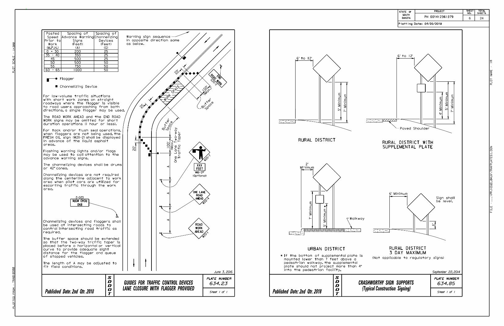
TRAFFIC CONTROL
One lane of traffic shall be maintained across the bridge at all times.
Removing, relocating, covering, salvaging and resetting of existing traffic control devices, including delineation, shall be the responsibility of the Contractor. Cost of this work shall be incidental to the various contract bid items unless otherwise specified in the plans. Delineators and signs damaged or lost shall be replaced by the Contractor at no cost to the State
Work activities are to be performed during daylight hours only.
The bottom of signs on portable or temporary supports shall not be less than seven feet above the pavement in urban areas and one foot above the pavement in rural areas. Portable sign supports may be used as long as the duration is less than 3 days. If the duration is more than 3 days the signs shall be on fixed location supports.
Traffic Control signs, as shown in the Estimate of Quantities, are estimates. Traffic control signs will be paid for once per structure. Contractor’s operation may require adjustments in quantities, either more or less. Payment will be for those signs actually ordered by the Engineer and used.
Any guardrail rail removed shall be replaced before the end of the working day.
Traffic control devices are to be removed at the end of each working day.
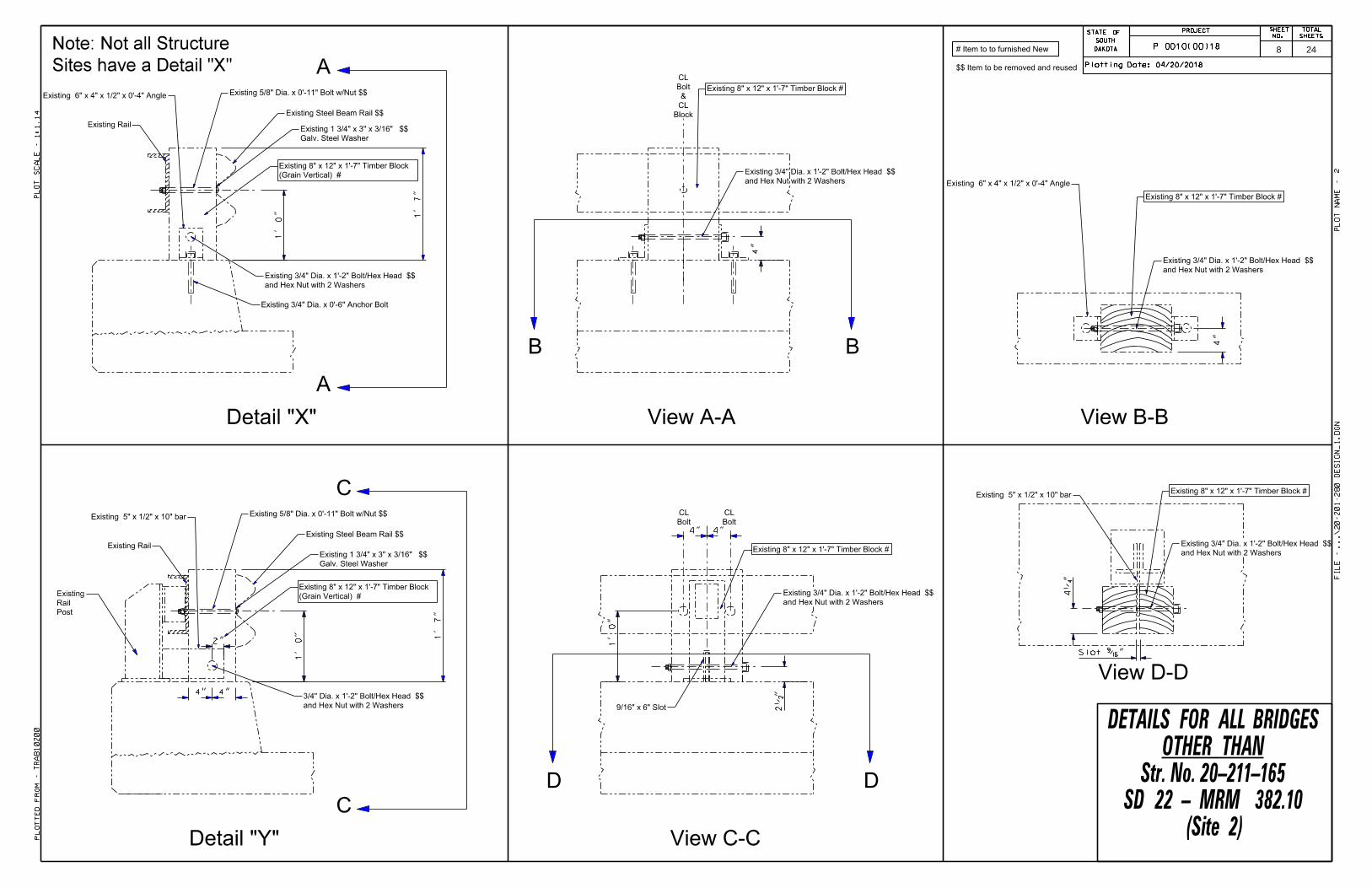
REMOVE AND RESET BRIDGE RAIL
The existing guardrail wooden spacer blocks will be removed and replaced. It will be necessary to disassemble the in-place W-beam rail in order to complete the work required by these plans. After new spacer blocks are installed, the existing W-beam rail shall be placed at the existing mounting height from the surface of the bridge deck.
Wooden spacer blocks shall be in conformance with Section 630.2 A of the Specifications.
Timber blocks shall be Douglas Fir or Pine from sound seasoned stock.
The preservative treatment of the wood spacer blocks shall be in conformance with Section 950 of the Specifications. Wood spacer blocks that are trimmed, notched, or cut in the field will have the cut surfaces retreated in accordance with Section 630.3 B.
Removed wood spacer blocks shall be disposed of by the Contractor. Any disposal of discarded material shall be in accordance with the Construction Specifications.
Reuse the previously field drilled holes in the existing steel rail and field drill new holes in the new wood spacer blocks at locations approved by the Engineer. 5/8” diameter bolts are allowed with a 3/4” field drilled holes through the wood blocks.
Reassembled guardrail shall have all guardrail splices lapped in the direction of traffic.
No measurement shall be required for the contract items REMOVE W BEAM GUARDRAIL FOR RESET and RESET W BEAM RAIL. Payment shall be based on the plan shown quantity.
All costs associated with disassembling the existing rail, removing the existing wood spacer blocks, disposing of the existing wood spacer blocks including all labor, equipment, and incidentals shall be incidental to the contract unit price per foot for REMOVE W BEAM GUARDRAIL FOR RESET.
All costs associated with furnishing new wood spacer blocks and notching and dapping the new wood spacers to allow for installation, including all equipment and labor, shall be incidental to the contract unit price per each for BEAM GUARDRAIL BLOCK.
All costs associated with the preservative treatment of the wood spacer blocks shall be incidental to the contract unit price per each for BEAM GUARDRAIL BLOCK.
One section of 12.5 foot W beam rail is included in the Estimate of Quantities for each structure for replacement of rail due to traffic damage at the discretion of the Engineer.
All of the existing hardware used to attach the wood spacers to the steel channel rail and W-beam shall be salvaged for use in the new construction. If any of the existing hardware cannot be salvaged for use in the new construction, the Contractor shall immediately inform the Engineer and shall wait for instructions from the Engineer before proceeding.
The following are requirements for Hardware Items that may Need Replacement
A. The 5/8” diameter bolts shall conform to ASTM A307.
B. All bolts and washers shall be galvanized in accordance with ASTM Specifications A153, except as noted otherwise herein.
C. It is possible that some of the existing wedge anchor bolts may need to be replaced due to broken concrete or because the bolts are loose and cannot be tightened. If the anchor bolts need replacing then the ¾” diameter wedge-type anchor bolts, nuts, and washers shall be supplied by one of the following and with the minimum embedment noted.
a. ITW Ramset/Redhead Trubolt Wedge Anchors(Galvanized or Stainless Steel)6 5/8” minimum embedmentITW Commercial Construction1765 Holmes RoadElgin, Illinois 60123Phone: (630) 825-7900Fax: (630) 893-1270Website: www.ramset-redhead.com
b. Hilti Kwik Bolt II (Stainless Steel)4 3/4” minimum embedmentHilti, Inc.5400 South 122nd East Ave.Tulsa, Oklahoma 74146Phone: (800) 879-8000Fax: (800) 879-7000Website: www.hilti.com
c. Power Bolt (Stainless Steel)7” minimum embedmentPowers Fasteners, Inc.2 Powers SquareBrewster, NY 10509Phone: (914) 235-6300Fax: (914) 576-6483Website: www.powers.com
d. Wej-it Wedge Anchors (Galvanized)Ankr-tite/Stud Anchors (Galvanized)3 3/4” minimum embedmentWej-it / TOGGLER110 Richards AveNorwalk, CT 06854Phone: (888) 864-4537Fax: (203) 857-2201Website: www.ankr-tite.com
e. Wedge-All TM Wedge Anchors (Stainless Steel)5” minimum embedmentSimpson Strong-Tie Company, Inc.4120 Dublin Blvd., Suite 400Dublin, CA 94568Phone: (925)-560-9000Website: www.strongtie.com
D. The wedge-type anchors shall be set in concrete in accordance with the recommendations of the manufacturer with the minimum embedment shown. The Contractor shall obtain from the manufacturer and submit to the Engineer, certification indicating the material is either Stainless Steel or the finish is Galvanized. The cost of furnishing and installing the anchor bolts shall be incidental to the contract unit price per foot for REMOVE W BEAM GUARDRAIL FOR RESET.
E. All holes drilled in the existing concrete curbs for the anchor bolts, which secure the fabricated support brackets, shall be to the size and depth as recommended by the Manufacturer. Holes are to be drilled true and normal to the curbs, with care taken to minimize the damage to existing reinforcing steel. Prior to the start of drilling any holes in the concrete curbs for the anchor bolts, an effort will be made by the Contractor to determine and mark on the curb surface the locations of the in place reinforcing bars. If it is found that the in-place reinforcing bars will interfere with the drilling of the holes at their plan shown locations, the entire hole group for a rail post may be shifted slightly as approved by the Engineer so that the drill bit will clear the reinforcing bars of the curb. However, in spite of the efforts made to locate the reinforcing steel, the Contractor can still expect to encounter some reinforcing steel when drilling holes for the anchor bolts. Any drilling through such reinforcing steel to satisfactorily complete this work shall be done by the Contractor at no additional compensation.
4 24

PROJECTSTATE OFSOUTH
DAKOTA P 0010(00)18SHEET TOTAL
SHEETS
5 24
STATE OFSHEET
NO.
TOTAL
SHEETSPROJECT
SOUTH
DAKOTA
STATE OFSHEET
NO.
TOTAL
SHEETSPROJECT
SOUTH
DAKOTA
04/20/2018Plotting Date:
TR
AB10200
1:200
18
Plotted
Fro
m -
Plot
Scale -
File - ...\prj\
Duel04
UV\
Traf
Plates1.dgn
Plot
Na
me -
PH 0014(236)379 6 24

STATE OFSHEET
NO.
TOTAL
SHEETSPROJECT
SOUTH
DAKOTA
STATE OFSHEET
NO.
TOTAL
SHEETSPROJECT
SOUTH
DAKOTA
04/20/2018Plotting Date:
TR
AB10200
1:200
19
Plotted
Fro
m -
Plot
Scale -
File - ...\prj\
Duel04
UV\
Traf
Plates2.dgn
Plot
Na
me -
PH 0014(236)379
ITEMIZED LIST FOR TRAFFIC CONTROL SIGNSCONVENTIONAL ROAD
SIGNCODE SIGN DESCRIPTION NUMBER SIGN SIZE SQFT
PER SIGN SQFT0.000001
W20-1 ROAD WORK AHEAD 2 48'' x 48'' 16.0 32.0W20-4 ONE LANE ROAD AHEAD 2 48'' x 48'' 16.0 32.0W20-7 FLAGGER (symbol) 2 48'' x 48'' 16.0 32.0G20-2 END ROAD WORK 2 36'' x 18'' 4.5 9.0 0.000001
CONVENTIONAL ROADTRAFFIC CONTROL SIGNS SQFT 105.0
1
7 24
1' 0" 1' 7"
Existing Rail
Existing 6" x 4" x 1/2" x 0'-4" Angle
(Grain Vertical) #
Existing 8" x 12" x 1'-7" Timber Block
Block
CL
&
Bolt
CL
Detail "X" View A-A
A
A
4"
B B
View B-B
Existing 6" x 4" x 1/2" x 0'-4" Angle
1' 0" 1' 7"
Existing Rail
Detail "Y" View C-C
C
C
2•
"D D
Existing 5" x 1/2" x 10" bar
1' 0"
4" 4"
Bolt
CL
Bolt
CL
and Hex Nut with 2 Washers
Existing 3/4" Dia. x 1'-2" Bolt/Hex Head $$
View D-D
4‚
"
and Hex Nut with 2 Washers
Existing 3/4" Dia. x 1'-2" Bolt/Hex Head $$
Existing 8" x 12" x 1'-7" Timber Block #Existing 5" x 1/2" x 10" bar
Existing 8" x 12" x 1'-7" Timber Block #
Existing 8" x 12" x 1'-7" Timber Block #
Existing 8" x 12" x 1'-7" Timber Block #
Post
Rail
Existing
and Hex Nut with 2 Washers
Existing 3/4" Dia. x 1'-2" Bolt/Hex Head $$
Existing 3/4" Dia. x 0'-6" Anchor Bolt
(Grain Vertical) #
Existing 8" x 12" x 1'-7" Timber Block
4"
4" 4"
9/16" x 6" Slot
2"
Galv. Steel Washer
Existing 1 3/4" x 3" x 3/16" $$
Existing 5/8" Dia. x 0'-11" Bolt w/Nut $$
Existing Steel Beam Rail $$
and Hex Nut with 2 Washers
3/4" Dia. x 1'-2" Bolt/Hex Head $$
Galv. Steel Washer
Existing 1 3/4" x 3" x 3/16" $$
Existing Steel Beam Rail $$
Existing 5/8" Dia. x 0'-11" Bolt w/Nut $$
$$ Item to be removed and reused
# Item to to furnished New
Slot Œ"
Sites have a Detail "X"
Note: Not all Structure
and Hex Nut with 2 Washers
Existing 3/4" Dia. x 1'-2" Bolt/Hex Head $$
and Hex Nut with 2 Washers
Existing 3/4" Dia. x 1'-2" Bolt/Hex Head $$
STATE OFSHEET
NO.
TOTAL
SHEETSPROJECT
SOUTH
DAKOTA
STATE OFSHEET
NO.
TOTAL
SHEETSPROJECT
SOUTH
DAKOTA
04/20/2018Plotting Date:
TR
AB10200
1:1.14
2
Plotted
Fro
m -
Plot
Scale -
File - ...\20-201-280 design_1.dgn
Plot
Na
me -
P 0010(00)18
(Site 2)SD 22 - MRM 382.10
Str. No. 20-211-165OTHER THAN
DETAILS FOR ALL BRIDGES
8 24

1' 0" 1' 7"
Existing Rail
Existing 6" x 4" x 1/2" x 0'-4" Angle
(Grain Vertical) #
Existing 8" x 12" x 1'-7" Timber Block
$$ Item to be removed and reused
# Item to to furnished New
Block
CL
&
Bolt
CL
Detail "X" View A-A
A
A
4"
B B
View B-B
Existing 6" x 4" x 1/2" x 0'-4" Angle
1' 0" 1' 7"
Existing Rail
Detail "Y" View C-C
C
C
2•
"D D
Existing 5" x 1/2" x 10" bar
1' 0"
4" 4"
Bolt
CL
Bolt
CL
and Hex Nut with 2 Washers
Existing 3/4" Dia. x 1'-2" Bolt/Hex Head $$
9/16" x 5 1/2" Slot
View D-D
4‚
"
and Hex Nut with 2 Washers
Existing 3/4" Dia. x 1'-2" Bolt/Hex Head $$
Existing 8" x 12" x 1'-7" Timber Block #Existing 5" x 1/2" x 10" bar
Existing 8" x 12" x 1'-7" Timber Block #
Existing 8" x 12" x 1'-7" Timber Block #
Existing 8" x 12" x 1'-7" Timber Block #
Post
Rail
Existing
and Hex Nut with 2 Washers
Existing 3/4" Dia. x 1'-2" Bolt/Hex Head $$
Existing 3/4" Dia. x 0'-6" Anchor Bolt
(Grain Vertical) #
Existing 8" x 12" x 1'-7" Timber Block
Galv. Steel Washer
Existing 1 3/4" x 3" x 3/16" $$
Existing 5/8" Dia. x 0'-11" Bolt w/Nut $$
Existing Steel Beam Rail $$
Galv. Steel Washer
Existing 1 3/4" x 3" x 3/16" $$
and Hex Nut with 2 Washers
3/4" Dia. x 1'-2" Bolt/Hex Head $$
Existing 5/8" Dia. x 0'-11" Bolt w/Nut $$
Existing Steel Beam Rail $$
4"
Slot Œ"
and Hex Nut with 2 Washers
Existing 3/4" Dia. x 1'-2" Bolt/Hex Head $$
and Hex Nut with 2 Washers
Existing 3/4" Dia. x 1'-2" Bolt/Hex Head $$
STATE OFSHEET
NO.
TOTAL
SHEETSPROJECT
SOUTH
DAKOTA
STATE OFSHEET
NO.
TOTAL
SHEETSPROJECT
SOUTH
DAKOTA
04/20/2018Plotting Date:
TR
AB10200
1:1.14
3
Plotted
Fro
m -
Plot
Scale -
File - ...\20-211-165 design_2.dgn
Plot
Na
me -
P 0010(00)18
(Site 2)SD 22 - MRM 382.10
Str. No. 20-211-165DETAILS FOR
9 24

HALF PLAN VIEW
See Detail "Y"
36 - Detail "Y"
26 - Detail "X"
62 Total Replacement Locations
FOR INFORMATIONAL PURPOSES ONLY
(Site 1)SD 28 - MRM 375.67
Str. No. 20-201-280BRIDGE LAYOUT
STATE OFSHEET
NO.
TOTAL
SHEETSPROJECT
SOUTH
DAKOTA
STATE OFSHEET
NO.
TOTAL
SHEETSPROJECT
SOUTH
DAKOTA
04/20/2018Plotting Date:
TR
AB10200
1:6.78851
4
Plotted
Fro
m -
Plot
Scale -
File - ...\20-201-280 design_1.dgn
Plot
Na
me -
P 0010(00)18
B2/B5 = Bents
A1/A6 = Abutments
KEY
7' 3" 7' 3"
1' 9"
3' 7•" 3' 1"
1' 6"
Begin or End Bridge
A1/A6 B2/B5BRIDGE
C/L
See Detail "X"
1' 6"
6' 2" 6' 2"
3' 1"3' 1"3' 1"3' 1"3' 1"3' 1"
1' 6"
3' 7•"3' 7•"3' 7•"
6' 2"
1' 6"
3' 1"3' 1"
6' 2"
B3/B4
10' 0"20' 0"17' 0"
10 24

HALF PLAN VIEW
See Detail "Y"
36 - Detail "Y"
30 - Detail "X"
66 Total Replacement Locations
FOR INFORMATIONAL PURPOSES ONLY
(Site 2)SD 22 - MRM 382.10
Str. No. 20-211-165BRIDGE LAYOUT
STATE OFSHEET
NO.
TOTAL
SHEETSPROJECT
SOUTH
DAKOTA
STATE OFSHEET
NO.
TOTAL
SHEETSPROJECT
SOUTH
DAKOTA
04/20/2018Plotting Date:
TR
AB10200
1:6.78851
5
Plotted
Fro
m -
Plot
Scale -
File - ...\20-211-165 design_2.dgn
Plot
Na
me -
P 0010(00)18
B2/B3 = Bents
A1/A4 = Abutments
KEY
22' 0"44' 9"
8' 6" 8' 6"
1' 6"
8' 6"
4' 3" 4' 3"4' 3"4' 3"4' 3"4' 3"4' 3"4' 3"4' 3"4' 3"
8' 6" 4' 3"8' 6"8' 6"
4' 3"4' 3"4' 3"4' 3"
8' 6"
1' 6"
Begin or End Bridge
A1/A4 B2/B3BRIDGE
C/L
See Detail "X"
1' 6"
4' 3"
11 24
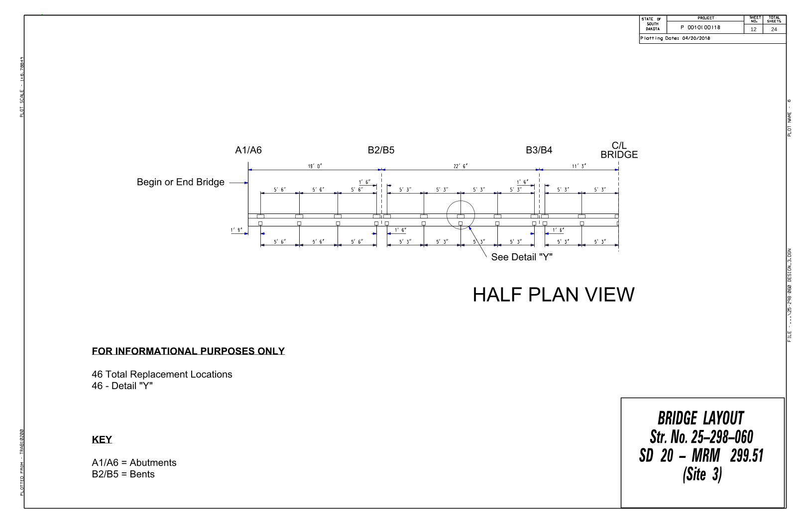
B2/B5 = Bents
A1/A6 = Abutments
KEY
46 - Detail "Y"
46 Total Replacement Locations
FOR INFORMATIONAL PURPOSES ONLY
STATE OFSHEET
NO.
TOTAL
SHEETSPROJECT
SOUTH
DAKOTA
STATE OFSHEET
NO.
TOTAL
SHEETSPROJECT
SOUTH
DAKOTA
04/20/2018Plotting Date:
TR
AB10200
1:6.78849
6
Plotted
Fro
m -
Plot
Scale -
File - ...\25-298-060 design_3.dgn
Plot
Na
me -
P 0010(00)18
(Site 3)SD 20 - MRM 299.51
Str. No. 25-298-060BRIDGE LAYOUT
HALF PLAN VIEW
See Detail "Y"
A1/A6 B2/B5BRIDGE
C/L
5' 6"
1' 9"
5' 3"
5' 6"
5' 3"
1' 6"
Begin or End Bridge
5' 6" 5' 6"
1' 6"
5' 3"5' 3"5' 3"5' 3"
1' 6"
5' 6"5' 6"
1' 6"
5' 3" 5' 3"
5' 3"5' 3"
11' 3"22' 6"19' 0"
B3/B4
5' 3"5' 3"
12 24

HALF PLAN VIEW
32 - Detail "Y"
26 - Detail "X"
58 Total Replacement Locations
FOR INFORMATIONAL PURPOSES ONLY
(Site 4)SD 25 - MRM 236.78
Str. No. 55-060-047BRIDGE LAYOUT
STATE OFSHEET
NO.
TOTAL
SHEETSPROJECT
SOUTH
DAKOTA
STATE OFSHEET
NO.
TOTAL
SHEETSPROJECT
SOUTH
DAKOTA
04/20/2018Plotting Date:
TR
AB10200
1:6.78849
7
Plotted
Fro
m -
Plot
Scale -
File - ...\55-060-047 design_4.dgn
Plot
Na
me -
P 0010(00)18
B2/B3 = Bents
A1/A4 = Abutments
KEY
18' 9"31' 0"
7' 2…"7' 1•"
1' 9"
7' 1•"
3' 6ƒ" 3' 7‰"
1' 6"
3' 6ƒ"3' 6ƒ"3' 6ƒ"3' 6ƒ"3' 6ƒ"3' 6ƒ"3' 6ƒ"
7' 1•"
3' 7‰"3' 7‰"3' 7‰"3' 7‰"
7' 1•"
1' 6"
Begin or End Bridge
A1/A4 B2/B3BRIDGE
C/L
7' 2…"
See Detail "Y"See Detail "X"
13 24

HALF PLAN VIEW
See Detail "Y"
38 - Detail "Y"
32 - Detail "X"
70 Total Replacement Locations
FOR INFORMATIONAL PURPOSES ONLY
(Site 5)SD 106 - MRM 334.32
Str. No. 55-068-060BRIDGE LAYOUT
STATE OFSHEET
NO.
TOTAL
SHEETSPROJECT
SOUTH
DAKOTA
STATE OFSHEET
NO.
TOTAL
SHEETSPROJECT
SOUTH
DAKOTA
04/20/2018Plotting Date:
TR
AB10200
1:6.78849
8
Plotted
Fro
m -
Plot
Scale -
File - ...\55-068-060 design_5.dgn
Plot
Na
me -
P 0010(00)18
B2/B3 = Bents
A1/A4 = Abutments
KEY
6' 10ƒ" 6' 10ƒ"
1' 9"
6' 10ƒ"
3' 5…"
6' 10ƒ"6' 10ƒ"
1' 6"
Begin or End Bridge
A1/A4 B2/B3BRIDGE
C/L
See Detail "X"
3' 7•"3' 7•"3' 7•"
1' 6"
3' 5…"3' 5…"3' 5…"3' 5…"3' 5…"3' 5…"3' 5…"3' 5…"3' 5…"
7' 3" 7' 3" 7' 3"
3' 7•"3' 7•"3' 7•"
22' 6"37' 0"37' 0"
14 24
HALF PLAN VIEW
See Detail "Y"
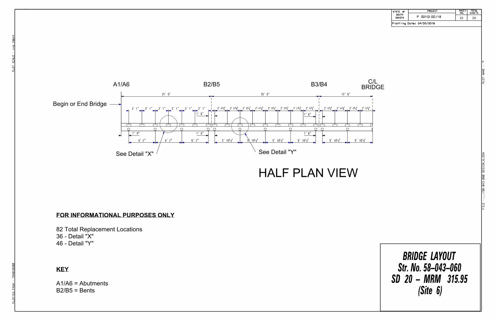
46 - Detail "Y"
36 - Detail "X"
82 Total Replacement Locations
FOR INFORMATIONAL PURPOSES ONLY
(Site 6)SD 20 - MRM 315.95
Str. No. 58-043-060BRIDGE LAYOUT
STATE OFSHEET
NO.
TOTAL
SHEETSPROJECT
SOUTH
DAKOTA
STATE OFSHEET
NO.
TOTAL
SHEETSPROJECT
SOUTH
DAKOTA
04/20/2018Plotting Date:
TR
AB10200
1:6.78849
9
Plotted
Fro
m -
Plot
Scale -
File - ...\58-043-060 design_6.dgn
Plot
Na
me -
P 0010(00)18
B2/B5 = Bents
A1/A6 = Abutments
KEY
6' 2" 6' 2"
1' 9"
5' 10•"
3' 1"
5' 10•"6' 2"
1' 6"
Begin or End Bridge
A1/A6 B3/B4BRIDGE
C/L
See Detail "X"
1' 6"
3' 1"3' 1"3' 1"3' 1"3' 1"
1' 6"
2' 11‚"
1' 6"
2' 11‚" 2' 11‚" 2' 11‚" 2' 11‚" 2' 11‚" 2' 11‚" 2' 11‚" 2' 11‚" 2' 11‚" 2' 11‚" 2' 11‚"
5' 10•" 5' 10•" 5' 10•" 5' 10•"
12' 6"25' 0"21' 0"
B2/B5
15 24

HALF PLAN VIEW
See Detail "Y"
7' 3"
1' 9"
6' 2" 7' 3"
BRIDGEC/L
(Site 7)SD 20 - MRM 319.56
Str. No. 58-079-060BRIDGE LAYOUT
A1
7' 3" 7' 3"
1' 9"1' 6"
6' 2" 6' 2"
1' 6"
17' 0"20' 0"17' 0"
B2 B3 A4
B2/B3 = Bents
A1/A4 = Abutments
KEY
20 - Detail "Y"
20 Total Replacement Locations
FOR INFORMATIONAL PURPOSES ONLY
STATE OFSHEET
NO.
TOTAL
SHEETSPROJECT
SOUTH
DAKOTA
STATE OFSHEET
NO.
TOTAL
SHEETSPROJECT
SOUTH
DAKOTA
04/20/2018Plotting Date:
TR
AB10200
1:6.78849
10
Plotted
Fro
m -
Plot
Scale -
File - ...\58-079-060 design_7.dgn
Plot
Na
me -
P 0010(00)18
Begin Bridge End Bridge
16 24

38 - Detail "Y"
32 - Detail "X"
70 Total Replacement Locations
FOR INFORMATIONAL PURPOSES ONLY
(Site 8)SD 37 - MRM 192.31
Str. No. 58-300-011BRIDGE LAYOUT
STATE OFSHEET
NO.
TOTAL
SHEETSPROJECT
SOUTH
DAKOTA
STATE OFSHEET
NO.
TOTAL
SHEETSPROJECT
SOUTH
DAKOTA
04/20/2018Plotting Date:
TR
AB10200
1:6.78849
11
Plotted
Fro
m -
Plot
Scale -
File - ...\58-300-011 design_8.dgn
Plot
Na
me -
P 0010(00)18
B2/B3 = Bents
A1/A4 = Abutments
KEY
HALF PLAN VIEW
See Detail "Y"
20' 0"33' 0"
6' 1‚" 6' 1‚"
1' 9"
6' 1‚" 6' 1‚" 6' 5" 6' 5" 6' 5"6' 1‚"
Begin or End Bridge
A1/A4 B2/B3BRIDGE
C/L
See Detail "X"
1' 6"
1' 6"
3' †" 3' †" 3' †" 3' †" 3' †" 3' †" 3' †" 3' †" 3' †" 3' †" 3' 2•" 3' 2•" 3' 2•" 3' 2•" 3' 2•" 3' 2•"
17 24

HALF PLAN VIEW
See Detail "Y"
7' 3" 7' 3" 6' 2"
3' 7•"
6' 2"
3' 7•"3' 7•"3' 7•"3' 7•"
6' 2"
BRIDGEC/L
See Detail "X"
20 - Detail "Y"
14 - Detail "X"
34 Total Replacement Locations
FOR INFORMATIONAL PURPOSES ONLY
(Site 9)SD 37 - MRM 189.14
Str. No. 58-300-043BRIDGE LAYOUT
1' 6" 1' 6"
1' 6"
7' 3" 7' 3"
3' 1"3' 1"3' 1"3' 1"3' 1"3' 1"
1' 6"
3' 7•"3' 7•"3' 7•"
A1 B2 B3 A4
Begin Bridge End Bridge
1' 9"
17' 0"20' 0"17' 0"
1' 9"
STATE OFSHEET
NO.
TOTAL
SHEETSPROJECT
SOUTH
DAKOTA
STATE OFSHEET
NO.
TOTAL
SHEETSPROJECT
SOUTH
DAKOTA
04/20/2018Plotting Date:
TR
AB10200
1:6.78849
12
Plotted
Fro
m -
Plot
Scale -
File - ...\58-300-043 design_9.dgn
Plot
Na
me -
P 0010(00)18
B2/B3 = Bents
A1/A4 = Abutments
KEY
18 24

32 - Detail "Y"
26 - Detail "X"
58 Total Replacement Locations
FOR INFORMATIONAL PURPOSES ONLY
(Site 10)SD 20 - MRM 342.39
Str. No. 58-300-068BRIDGE LAYOUT
STATE OFSHEET
NO.
TOTAL
SHEETSPROJECT
SOUTH
DAKOTA
STATE OFSHEET
NO.
TOTAL
SHEETSPROJECT
SOUTH
DAKOTA
04/20/2018Plotting Date:
TR
AB10200
1:6.78849
13
Plotted
Fro
m -
Plot
Scale -
File - ...\58-300-068 design_10.dgn
Plot
Na
me -
P 0010(00)18
KEY
A1/A4 = Abutments
B2/B3 = Bents
HALF PLAN VIEW
See Detail "Y"
16' 3"27' 0"
6' 1•" 6' 1•"
1' 9"
6' 1•"6' 1•"
Begin or End Bridge
A1/A4 B2/B3BRIDGE
C/L
See Detail "X"
1' 6"
1' 6"
3' 1‰" 3' 1‰" 3' 1‰" 3' 1‰" 3' 1‰"
6' 2…"6' 2…"
3' ƒ" 3' ƒ" 3' ƒ" 3' ƒ" 3' ƒ" 3' ƒ" 3' ƒ" 3' ƒ"
19 24

HALF PLAN VIEW
See Detail "Y"
5' 6" 5' 6"
1' 9"
5' 3" 5' 3"5' 6"
1' 6"
Begin or End Bridge
A1/A6 B2/B5BRIDGE
C/L
5' 3" 5' 3"
1' 6"
5' 3" 5' 3"
11' 3"22' 6"19' 0"
B3/B4
B2/B5 = Bents
A1/A6 = Abutments
KEY
(Site 11)SD 37 - MRM 182.66
Str. No. 58-300-109BRIDGE LAYOUT
46 - Detail "Y"
46 Total Replacement Locations
FOR INFORMATIONAL PURPOSES ONLY
STATE OFSHEET
NO.
TOTAL
SHEETSPROJECT
SOUTH
DAKOTA
STATE OFSHEET
NO.
TOTAL
SHEETSPROJECT
SOUTH
DAKOTA
04/20/2018Plotting Date:
TR
AB10200
1:6.78849
14
Plotted
Fro
m -
Plot
Scale -
File - ...\58-300-109 design_11.dgn
Plot
Na
me -
P 0010(00)18 20 24
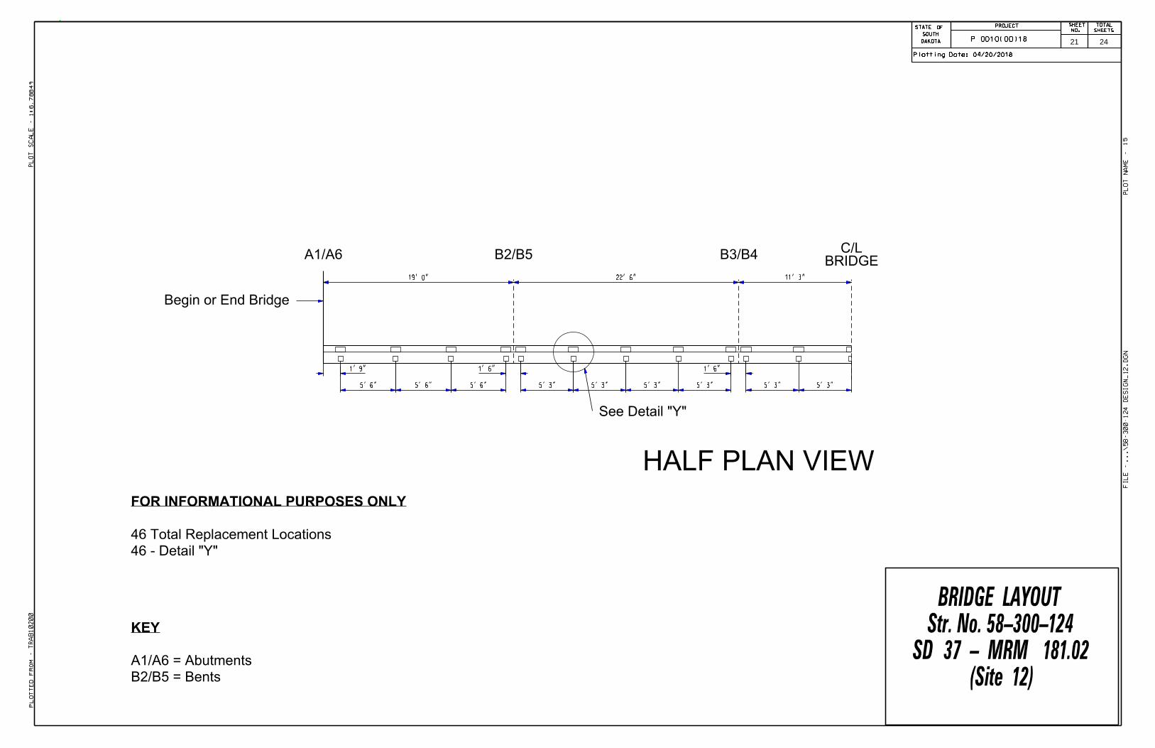
HALF PLAN VIEW
See Detail "Y"
5' 6" 5' 6"
1' 9"
5' 3" 5' 3"5' 6"
1' 6"
Begin or End Bridge
A1/A6 B2/B5BRIDGE
C/L
5' 3" 5' 3"
1' 6"
5' 3" 5' 3"
11' 3"22' 6"19' 0"
B3/B4
B2/B5 = Bents
A1/A6 = Abutments
KEY
(Site 12)SD 37 - MRM 181.02
Str. No. 58-300-124BRIDGE LAYOUT
46 - Detail "Y"
46 Total Replacement Locations
FOR INFORMATIONAL PURPOSES ONLY
STATE OFSHEET
NO.
TOTAL
SHEETSPROJECT
SOUTH
DAKOTA
STATE OFSHEET
NO.
TOTAL
SHEETSPROJECT
SOUTH
DAKOTA
04/20/2018Plotting Date:
TR
AB10200
1:6.78849
15
Plotted
Fro
m -
Plot
Scale -
File - ...\58-300-124 design_12.dgn
Plot
Na
me -
P 0010(00)18 21 24
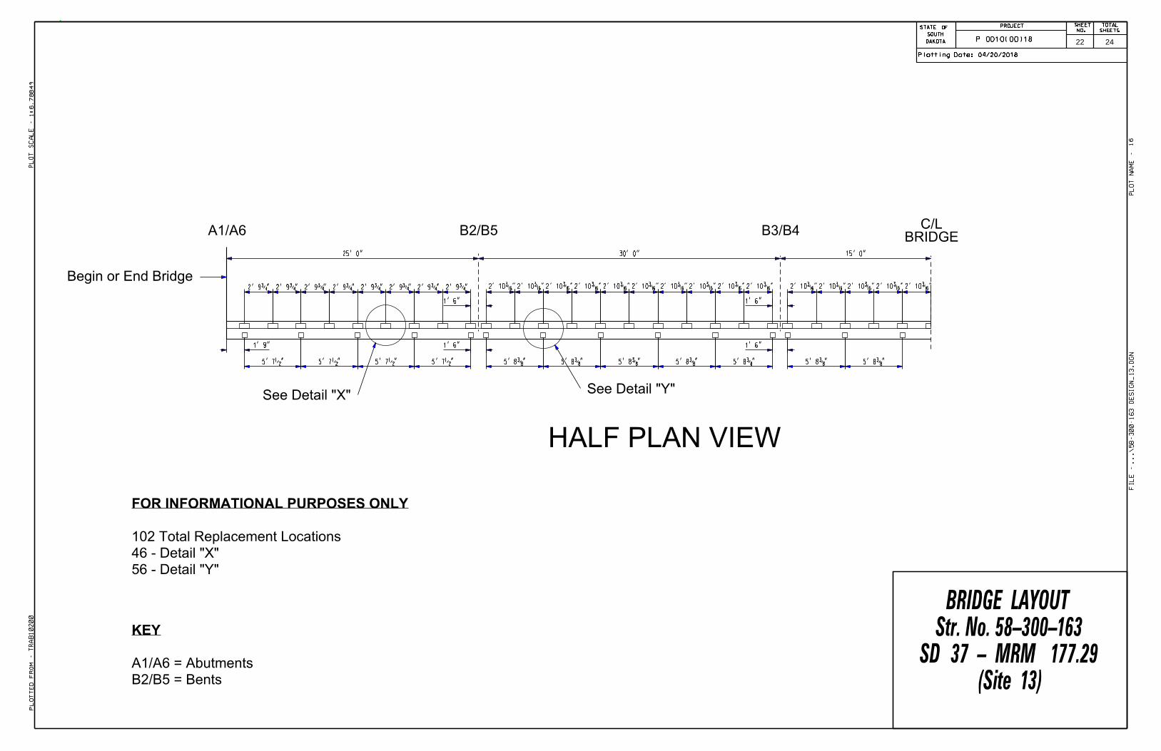
HALF PLAN VIEW
See Detail "Y"
5' 7•" 5' 7•"
1' 9"
5' 7•" 5' 8…"5' 7•"
Begin or End Bridge
A1/A6 B2/B5BRIDGE
C/L
See Detail "X"
56 - Detail "Y"
46 - Detail "X"
102 Total Replacement Locations
FOR INFORMATIONAL PURPOSES ONLY
B2/B5 = Bents
A1/A6 = Abutments
KEY
2' 9ƒ" 2' 9ƒ" 2' 9ƒ" 2' 9ƒ" 2' 9ƒ" 2' 9ƒ" 2' 9ƒ" 2' 9ƒ"
1' 6"
1' 6"
2' 10‰" 2' 10‰" 2' 10‰" 2' 10‰"
5' 8…"
2' 10‰" 2' 10‰"
5' 8…"
2' 10‰" 2' 10‰"
5' 8…"
2' 10‰" 2' 10‰"
5' 8…"
1' 6"
1' 6"
2' 10‰" 2' 10‰"
5' 8…"
2' 10‰" 2' 10‰"
5' 8…"
2' 10‰"
15' 0"30' 0"25' 0"
B3/B4
(Site 13)SD 37 - MRM 177.29
Str. No. 58-300-163BRIDGE LAYOUT
STATE OFSHEET
NO.
TOTAL
SHEETSPROJECT
SOUTH
DAKOTA
STATE OFSHEET
NO.
TOTAL
SHEETSPROJECT
SOUTH
DAKOTA
04/20/2018Plotting Date:
TR
AB10200
1:6.78849
16
Plotted
Fro
m -
Plot
Scale -
File - ...\58-300-163 design_13.dgn
Plot
Na
me -
P 0010(00)18 22 24

HALF PLAN VIEW
See Detail "Y"
6' 2" 6' 2"
1' 9"
3' 1"
5' 10•" 6' 2" 6' 2" 6' 2"6' 2"
BRIDGEC/L
26 - Detail "Y"
20 - Detail "X"
46 Total Replacement Locations
FOR INFORMATIONAL PURPOSES ONLY
1' 6"
1' 6"
3' 1"3' 1"3' 1"3' 1"3' 1" 2' 11‚" 2' 11‚"
5' 10•"
2' 11‚" 2' 11‚"
5' 10•"
2' 11‚" 2' 11‚"
5' 10•"
2' 11‚" 2' 11‚"
1' 6"
1' 6" 1' 9"
3' 1"3' 1"3' 1"3' 1"3' 1"3' 1"
A1
21' 0"25' 0"21' 0"
B2 B3 A4
Begin Bridge End Bridge
B2/B3 = Bents
A1/A4 = Abutments
KEY
(Site 14)SD 37 - MRM 175.86
Str. No. 58-300-176BRIDGE LAYOUT
STATE OFSHEET
NO.
TOTAL
SHEETSPROJECT
SOUTH
DAKOTA
STATE OFSHEET
NO.
TOTAL
SHEETSPROJECT
SOUTH
DAKOTA
04/20/2018Plotting Date:
TR
AB10200
1:6.78849
17
Plotted
Fro
m -
Plot
Scale -
File - ...\58-300-176 design_14.dgn
Plot
Na
me -
P 0010(00)18
See Detail "X"
23 24

STATE OFSHEET
NO.
TOTAL
SHEETSPROJECT
SOUTH
DAKOTA
STATE OFSHEET
NO.
TOTAL
SHEETSPROJECT
SOUTH
DAKOTA
04/20/2018Plotting Date:
TR
AB10200
1:200
20
Plotted
Fro
m -
Plot
Scale -
File - ...\prj\
Duel04
UV\
Std
Plates.dgn
Plot
Na
me -
P 0010(00)18 24 24