project periscope
TRANSCRIPT

i
Project Periscope By
Michael Congdon
Siddharth Murali
Aabhas Sharma
Final Report for ECE 445, Senior Design, Fall 2015
TA: Ankit Jain
9 December 2015
Project No. 11
ii
Abstract
Project Periscope is an attempt to scale the idea of a Periscope to modern day dimensions. We aimed to
achieve this using Virtual Reality. The system consists of a camera, an Oculus Rift and a Swivel Arm that
acts as a mount for the camera. On this system, the live camera feed is viewed on the Oculus Rift
display, while at the same time, the swivel arm directs the camera in the same direction as the
orientation of the Oculus Rift headset. The resulting system enables the user to have eyes in a remote
location – with a real time field of vision without having to be physically present.
This paper details our ideas, design, progress, results and findings. It also documents the ethical
constraints we were working under as well as an appendix providing the sources of our research
information and detailed schematics of the various module components.

iii
Table of Contents 1. Introduction .............................................................................................................................................. 1
1.1 Design Overview ................................................................................................................................. 1
2. Design ........................................................................................................................................................ 2
2.1 Camera Module .................................................................................................................................. 3
2.2 Oculus Rift Unit ................................................................................................................................... 5
2.3 Swivel Arm Module ............................................................................................................................. 7
2.3.1 Motors .......................................................................................................................................... 7
2.3.2 Printed Circuit Board .................................................................................................................... 8
2.3.3 Simulink Model ............................................................................................................................ 8
3. Modular Design Changes ........................................................................................................................ 10
3.1 Changes in the Camera Module .................................................................................................... 10
3.2 Changes in the Swivel Arm Module .............................................................................................. 10
4. Design Verification .................................................................................................................................. 11
4.1 Camera Module ................................................................................................................................ 11
4.2 Oculus Module .................................................................................................................................. 11
4.3 Swivel Arm Module ........................................................................................................................... 12
4.4 Range of Unit .................................................................................................................................... 12
5. Costs ........................................................................................................................................................ 13
5.1 Parts .................................................................................................................................................. 13
5.2 Labor ................................................................................................................................................. 14
5.3 Total Cost .......................................................................................................................................... 14
6. Conclusion ............................................................................................................................................... 15
6.1 Accomplishments .............................................................................................................................. 15
6.2 Safety Considerations ....................................................................................................................... 15
6.3 Ethical Considerations ....................................................................................................................... 15
6.4 Future work ....................................................................................................................................... 15
References .................................................................................................................................................. 16
Appendix A: Requirement and Verification Table ...................................................................................... 17
Appendix B: Circuit Diagrams...................................................................................................................... 19
B-1: Final PCB Schematic ......................................................................................................................... 19
B-2: Buck Converter ................................................................................................................................ 19

iv
B-3: Logic Level Converter ...................................................................................................................... 20
B-4: Motor Driver .................................................................................................................................... 20
Appendix C: Final PCB Layout ..................................................................................................................... 21
Appendix D: Simulink Model ....................................................................................................................... 21
D-1: Overall Model .................................................................................................................................. 21
D-2: PWM_Output .................................................................................................................................. 22
D-3: PWM Direction Selector .................................................................................................................. 22
D-4: PWM Signal Generator .................................................................................................................... 23
D-5: Encoder Reader ............................................................................................................................... 23
D-6: Position Counter .............................................................................................................................. 24

1
1. Introduction The key objective of this project was to incorporate Virtual Reality in order to bring the traditional
Periscope up to speed with current technologies. While the traditional device was used for observation
over, around or through an obstacle that prevents direct line-of-sight, our system can not only allow the
user to overcome direct obstacles, but can also bring absolutely any remote location directly into the
user’s direct line of sight.
In the following chapters we look into the design that we’ve implemented, the requirements and
verifications for the functionality of the system and the cost of our research and development.
1.1 Design Overview As previously discussed, the function of Project Periscope is to enable the user to have eyes in a remote
location – with a real time field of vision without having to be physically present – thereby scaling the
Periscope to modern day capabilities.
As depicted in Figure 1 below, the system is divided into three main modules – the camera module, the
Oculus module and the Swivel Arm module. On each iteration, the camera unit sends a live image feed
to the Oculus Unit to be displayed by the Oculus Rift headset. At the same time, the Oculus sends along
coordinates to the Swivel Arm unit, which reads the coordinates and re-orients itself to match the
coordinates. Since the camera is physically mounted on the Swivel arm, the camera now points in the
exact direction as the Oculus Rift – giving the user an immersive virtual reality experience.
Figure 1: System Modular Overview

2
2. Design In order to achieve our goals and incorporate Virtual Reality into a traditional Periscope, as described in
Section 1.1, we have implemented a three module system. The three modules are the Camera Module,
the Oculus module as well as the Swivel Arm module. Figure 2, below, gives a block diagram detailing
the components that together form the system’s three modules.
Accelerometer + Gyroscope + Magnetometer
Display
Power 5V
5V
Oculus Unit
Computer(Oculus SDK)
Positional dataProcessed Image
Processed Image
Camera Unit
Mount(physical connection)
Swivel Unit
Orientation Microcontroller
Power
Motor Shield + Motors
Encoder data
Positional data 12 V
5V
Camera
Computer
WiFi
Inter unit connections
Intra unit connections
Positional Data
Camera Unit
Swivel Unit
Figure 2 Modular Block Diagram
As a system overall, the project is designed with the Oculus unit as a single entity interacting with a
Swivel-Camera unit. The Swivel-Camera unit consist of the Camera and the Swivel Arm modules.
Additionally, this project is designed to run wirelessly. What this means is that there is no physical
connection between the Oculus unit and the Swivel-Camera unit. This allows the Oculus unit to be
located with the system user while the Swivel-Camera unit can be located even at a very distant remote
locations. The only constraint is that both units should have a stable wireless connection.
Further, the design of our individual modules are detailed in the sections below.
3
2.1 Camera Module The camera module has two aspects to it – the physical domain as well as the software domain. The
physical domain consists of all the video feed transmission from the camera to the Oculus module. The
software domain consists of the image processing that is required to modify a camera’s 2D input image
stream to an Oculus-ready concave 2D-image stream.
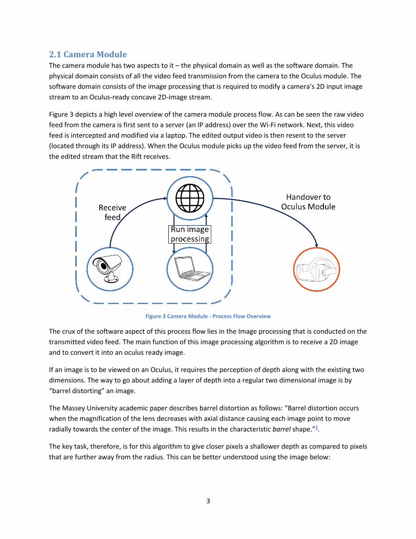
Figure 3 depicts a high level overview of the camera module process flow. As can be seen the raw video
feed from the camera is first sent to a server (an IP address) over the Wi-Fi network. Next, this video
feed is intercepted and modified via a laptop. The edited output video is then resent to the server
(located through its IP address). When the Oculus module picks up the video feed from the server, it is
the edited stream that the Rift receives.
Figure 3 Camera Module - Process Flow Overview
The crux of the software aspect of this process flow lies in the Image processing that is conducted on the
transmitted video feed. The main function of this image processing algorithm is to receive a 2D image
and to convert it into an oculus ready image.
If an image is to be viewed on an Oculus, it requires the perception of depth along with the existing two
dimensions. The way to go about adding a layer of depth into a regular two dimensional image is by
“barrel distorting” an image.
The Massey University academic paper describes barrel distortion as follows: “Barrel distortion occurs
when the magnification of the lens decreases with axial distance causing each image point to move
radially towards the center of the image. This results in the characteristic barrel shape.”1.
The key task, therefore, is for this algorithm to give closer pixels a shallower depth as compared to pixels
that are further away from the radius. This can be better understood using the image below:
4
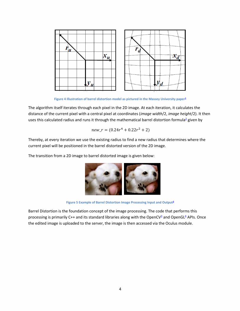
Figure 4 Illustration of barrel distortion model as pictured in the Massey University paper1
The algorithm itself iterates through each pixel in the 2D image. At each iteration, it calculates the
distance of the current pixel with a central pixel at coordinates (image width/2, image height/2). It then
uses this calculated radius and runs it through the mathematical barrel distortion formula2 given by
𝑛𝑒𝑤_𝑟 = (0.24𝑟4 + 0.22𝑟2 + 2)
Thereby, at every iteration we use the existing radius to find a new radius that determines where the
current pixel will be positioned in the barrel distorted version of the 2D image.
The transition from a 2D image to barrel distorted image is given below:
Figure 5 Example of Barrel Distortion Image Processing Input and Output2
Barrel Distortion is the foundation concept of the image processing. The code that performs this
processing is primarily C++ and its standard libraries along with the OpenCV3 and OpenGL4 APIs. Once
the edited image is uploaded to the server, the image is then accessed via the Oculus module.

5
2.2 Oculus Rift Unit The Oculus Unit5 is the main user-facing component of the project. This component had 2 major design
challenges – connection to the camera unit to get the video feed, and the connection to the swivel arm
unit to send the head motion coordinates.
The Oculus we used for our project is a DK1, which is the older model of the Oculus Rift. We used this
model mainly because of equipment issues. However, the entire project could very easily run on a DK2,
which is the latest version. There are two main sub-blocks – the Oculus Rift, and the SDK.
1. Oculus Rift
The Oculus Rift is what the user will actually wear in order to control the arm as well as view the
video feed. This consists of a 1080p display, the power supply, and the motion tracking sensors.
The display is where the video feed gets sent after processing though the SDK. The power supply
is used to power the device. The motion tracking sensors are a combination of an
accelerometer, a gyroscope, and a magnetometer. These combined track the user’s movements
while wearing the Oculus, and relay the information back to the SDK.
2. The SDK
The SDK is the backend of the Oculus Rift. The programs run on the SDK, which allow the Oculus
to show them on the display. The SDK has 3 tasks that keep running in a loop during the
program execution.
2.1 Receive video feed from remote server – The program first connects to the remote IP
address, and receives the video feed. Once it does this, it displays the stream of images on
the Oculus display on a separate thread. Is does this by converting the frames into OpenGL
texture data. Once that is done, the textures are mapped onto the Rift’s display.
2.2 Receive head motion data from Oculus sensors – The SDK has built in APIs that help retrieve
the head motion data from the Oculus. There are 6 values, the movement along x, y, and z,
axes (called Tx, Ty, and Tz) and the rotation around the 3 axes (called pitch, yaw, and roll).
We are only concerned with the Pitch, Yaw and Roll values, as our motors will mimic these
three movements only.
Figure 6: Pitch, Yaw, & Roll Illustration10
6
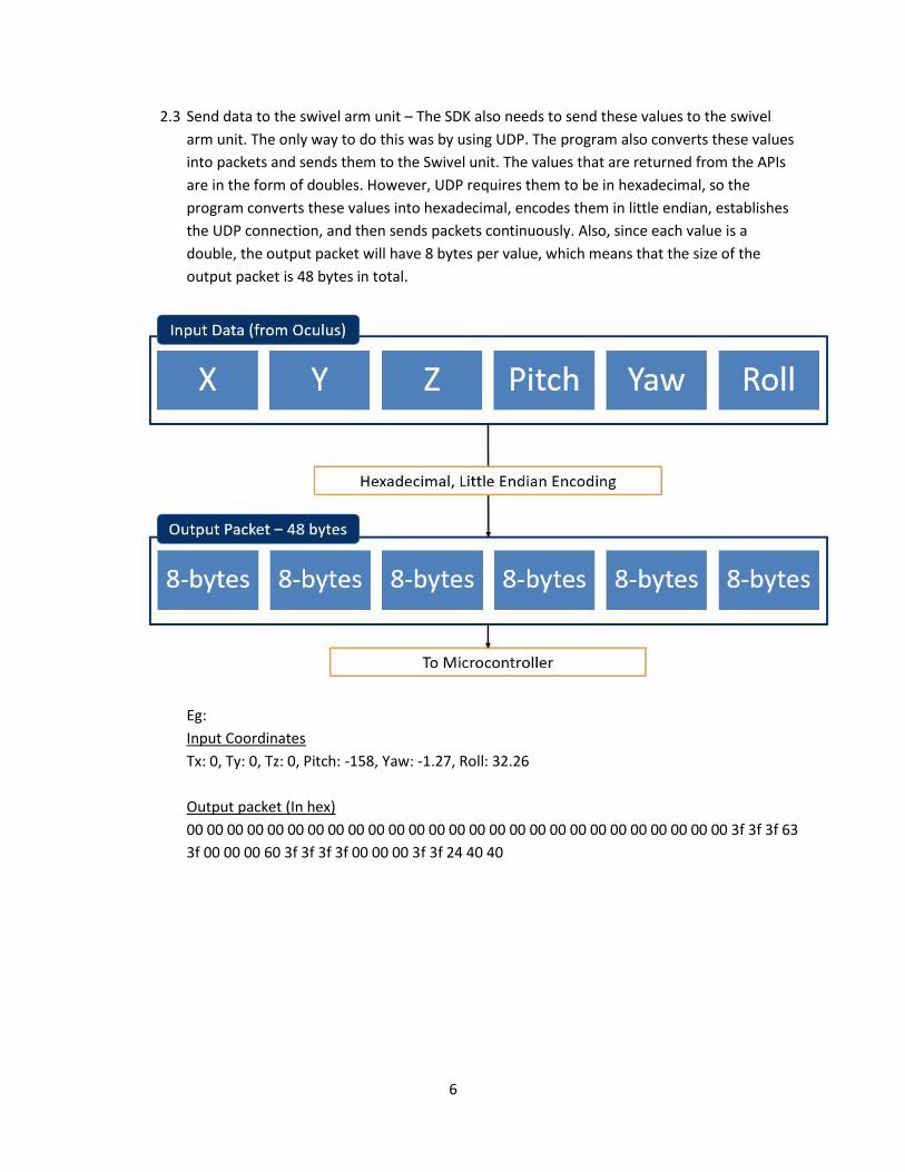
2.3 Send data to the swivel arm unit – The SDK also needs to send these values to the swivel
arm unit. The only way to do this was by using UDP. The program also converts these values
into packets and sends them to the Swivel unit. The values that are returned from the APIs
are in the form of doubles. However, UDP requires them to be in hexadecimal, so the
program converts these values into hexadecimal, encodes them in little endian, establishes
the UDP connection, and then sends packets continuously. Also, since each value is a
double, the output packet will have 8 bytes per value, which means that the size of the
output packet is 48 bytes in total.
Eg:
Input Coordinates
Tx: 0, Ty: 0, Tz: 0, Pitch: -158, Yaw: -1.27, Roll: 32.26
Output packet (In hex)
00 00 00 00 00 00 00 00 00 00 00 00 00 00 00 00 00 00 00 00 00 00 00 00 00 00 00 3f 3f 3f 63
3f 00 00 00 60 3f 3f 3f 3f 00 00 00 3f 3f 24 40 40

7
2.3 Swivel Arm Module The camera unit is physically attached to the camera, orienting it to point the camera in the same
direction the user wearing the oculus rift is looking. This is achieved via a Simulink model running on a
Raspberry Pi, controlling three powerful motors on the unit itself.
2.3.1 Motors
The motors were chosen based on their power and speed output, necessary to mimic human
movements accurately. We purchased Pololu 70:1 metal gearmotors with 64 CPR encoders attached to
the drive shafts6. This was the ideal balance between high torque to lift the camera and high velocity to
track the input signal quickly.
Required torque was calculated by estimating the moment of inertia about the axis of rotation for the
camera mount that has the highest moment of inertia for all possible orientations, as well through
repeated trials to estimate the acceleration of a human head while looking around. The moment of
inertia is given as
Using the formula for applied torque
𝜏 = 𝐼 ∗ 𝛼 (2)
Where α is estimate from the following data
𝐼𝑡𝑜𝑡 = 𝐼𝑟𝑜𝑑 + 𝐼𝑚𝑜𝑡𝑜𝑟 + 𝐼𝑐𝑎𝑚𝑒𝑟𝑎 = 0.01098 𝑘𝑔𝑚2 (1)
Head
orientation
Straight down
to straight up
Down, up, and
back down
Trial Time (s) Time(s)
1 0.46 0.99
2 0.51 0.95
3 0.59 1.02
4 0.47 1.09
5 0.44 1.00
6 0.45 1.03
7 0.51 1.14
8 0.49 0.98
Avg 0.49 1.03
(3)
8
From the data in table (4) we get an acceleration of approximately 50 rad/s. Plugging this back into
Equation (2) and compensating for the torque due to gravity, we get
𝜏 = 0.01098 ∗ 50.27 + 0.742 = 1.294 𝑁𝑚 (4)
2.3.2 Printed Circuit Board
The PCB (shown in Appendices B-1 and C) is where the Raspberry Pi is mounted, and well the buck
converter, logic level conversion array, and motor drivers. The buck converter takes 12 volts from the
battery and converts it down to 5 volts required by all of the other components on the board, as well as
the encoders on the motors. The logic level converters stand between the 3.3 volt logic of the Pi and the
5 volt logic of the motor drivers and encoders, protecting the GPIO pins on the PI from burning out. The
motor drivers regulate the current direction to the motors using H bridges.
Buck Converter
The buck converter (Appendix B-2) consists of a TI LMZ12008 Simple Switcher Power Module7, with the
various required peripheral components such as resistors and capacitors. This switching supply converts
the 12 volt input from the battery to a 5 volt supply line to power the raspberry pi, logic converters,
motor drivers, and motor encoders. It can source up to 8 amps of current, which is more than enough to
supply everything on the board. The efficiency of the converter is very high, and can reach as high as
92% with good circuit layout.
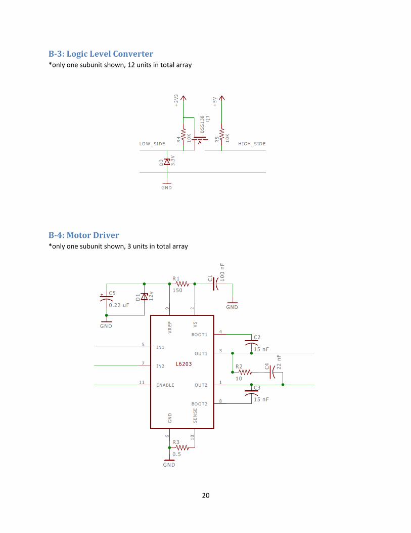
Logic Level Converters
The logic level converters (Appendix B-3) are in place because the Raspberry Pi operates on 3.3 volt logic
and has no built in protection circuitry between the GPIO pins and the processor, necessitating the
conversion from 5 volt logic to 3.3 volt logic. Each individual unit consists of a BSS138 NMOS transistor8,
two pull up resistors, and a 3.3 volt Zener diode as protection. Each unit is bi-directional, meaning that
either side can be pulled up to its logic high value, which will then pull the opposite side to its
corresponding logic supply level.
Motor Drivers
The main component in each of the motors drivers (Appendix B-4) is the L6203 DMOS Full Bridge
Driver9. This component was chosen primarily for its maximum current rating of 5 amps, which matches
that of the motors themselves. The L6203 utilizes H bridge drivers, allowing the motors to be driven in
either direction, a feature necessary for our applications.
2.3.3 Simulink Model
The Simulink model running on the Raspberry Pi is the real workhorse of the camera unit. It receives the
orientation coordinates of the Oculus Rift via UDP, and uses a PID loop to control the position of each of
the three motors corresponding to the yaw, pitch, and roll. The overall model can be seen in Appendix
D-1, which includes the UDP receive block, bus separator, PID loops, PWM generator block, and encoder
polling block.

9
The UDP receiver polls the buffer for packets of data every 0.1 seconds, offering a reasonably fast repost
to head movements without excessively bogging down the simulation time of the model. Since the
Oculus reports the X, Y, and Z position coordinates as well as the yaw, pitch, and roll, those portions are
separated out and sent to a terminator block. The yaw, pitch, and roll values are then fed into 3
separate PID loops that work to achieve zero difference between the current position, given by the
encoder reader block, and the desired position given by the input. The output of the PID loop is
multiplied by negative one by convention, since any deviation from the set point should be opposed
rather than amplified.
The PWM block, and its respective sub-blocks, as seen in Appendices D-2, D-3, and D-4, take the output
of the PID block and convert it to a PWM signal to be sent to the GPIO pin of the Raspberry Pi. Since
each motor driver has A and B input pins, each PID block corresponds to two GPIO pins. One pin is set
low, while the other is pulsed, depending on the sign of the signal going into the PWM block, which
determines the direction the motor is made to spin. Each sub-block also has an optional enable bit
accessible from within the model that allows the motors to be turned off while the model is running for
diagnostic purposes. The actual PWM signal is made using a triangle waveform generator - with a
frequency of 1 kHz – and a comparator.
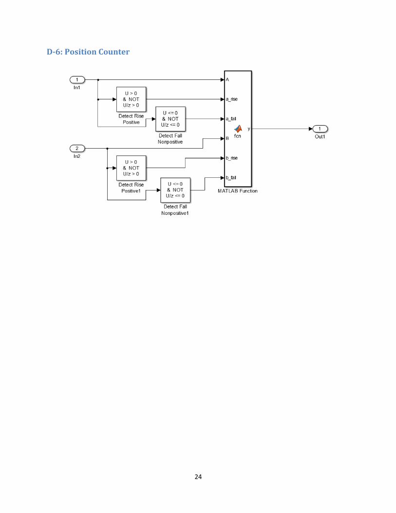
The encoder reader blocks (Appendices D-4 and D-5) read the input of the GPIO pins corresponding to
the encoder pins of the motors, and feed this into a sub-block that determines whether or not a change
of position has occurred and updates the position variable accordingly. Because the encoders have a
resolution of 64 counts per revolution of the motor, and the gear box has a reduction of 70:1, the drive
shaft has a resolution of 4,480 counts per revolution, which equates to approximately 12.5 counts per
degree of rotation. This number is used to convert the position of the motor from counts to degrees,
which is then fed out and into the PID loop.

10
3. Modular Design Changes As the project development progressed, our team had to make a significant number of calculated
changes to our original design in order to meet our functional requirements.
3.1 Changes in the Camera Module
Original Designs of the camera module consisted of two camera units along with a microcontroller on
which we intended to run our image manipulation program. However, over the course of the project,
we ended up using a single camera instead of two separate ones. We also scraped the idea of running
our processing on a microcontroller and decided to run it on a PC instead.
The reason we chose to work with a single camera was to avoid the added time lag that came with the
utilization of two cameras. Similarly, interfacing through a microcontroller was also proving to be a
relatively time consuming process. Instead we decided to run the program on the PC that we were
already using within the Oculus Module.
3.2 Changes in the Swivel Arm Module
Originally, the buck converter on the PCB used a LM2675 switching power supply, however it was
quickly discovered that this component was not capable of supplying the necessary current to the
various components on the board, so it was replaced with a more powerful component.

11
4. Design Verification This section details all the tests performed to ensure the functionality of all the components of the
system.
4.1 Camera Module Tests for the functionality of the camera module were all in place to measure one thing – the lag that
this module generates. The camera module tests were broken down into three levels.
The first level tested the time it took for the video feed to get from the camera to the server and then to
the computer. This test essentially measured the efficiency of sending and receiving video data packets
wirelessly over the network. The method of testing involved accessing the video feed on the server from
the laptop using VLC Media Player’s Network Stream options. Once the video was running on the media
player, we physically timed the lag using a stopwatch to measure the time between when an object was
placed in front of a camera and when that object actually appeared on the Media player video stream.
The second level tested the time it took for the video feed to get from the camera, to the computer and
then for the processed video feed to get back to the server. This test was designed to measure the
efficiency of the image processing program that runs locally on the laptop PC. The way we ran
verification for this test was the exact same as the verification for the test for the first level. What is
different here is that we subtracted the average time lag found here from the average time lag found in
the first test to determine the average run time of the image processing program.
Finally, we tested the time it took for the video feed to get from the camera all the way to the display of
the Oculus Rift. The method of testing involved physical time lag measurement using a stopwatch. Like
in the previous two tests, we measured the time it took between an object being placed in front of the
camera and the object appearing on the Oculus display.
All the tests indicated a success with the first level giving an average time lag of 1.15 seconds, the
second level returning an average lag of 0.03 seconds and the third level returning an average lag of 1.21
seconds.
4.2 Oculus Module The requirements for this unit were mostly concerned with latency and accuracy, as we wish to give the
user the least inconvenience when he is wearing the Oculus.
In order to ensure that we were getting accurate values, we had set up a requirement that the Oculus
rotation data vectors must be equal to the user movements with a tolerance of about 10 degrees. In
order to verify this, we set up a Simulink model that sent the values to the Raspberry Pi and recorded
the output from the Pi on a graph. From there, we compared the changes on the graph to the
coordinates that the SDK was receiving. We found that the values were exactly the same, so this
requirement was verified.
The next requirement we had was related to latency. Since there is already some latency between the
camera module and the Oculus, we wanted to keep the latency for the overall design as low as possible.

12
Our requirement was that the entire module should have a latency of less than 3 seconds. In order to
verify this requirement, we kept the same setup from the previous verification, where the Oculus was
sending coordinates to the Raspberry Pi and then displayed on the graph. Using an interactive graph on
MATLAB, we compared the timestamps of the coordinates received to the timestamps of the data on
the Oculus. We found that these timestamps differed by only 1.5 seconds. Since this was much less than
our original requirement, this was verified.
4.3 Swivel Arm Module Requirements for the swivel arm module focused entirely on establishing adequate control of the
motors and ensuring a fast and accurate response to changes in the orientation of the Oculus headset.
The first requirement states that the Raspberry Pi should be able to output PWM signals to the motors,
and read the encoder counts accurately. This was accomplished by making a simple Simulink module
with only a pulse generator connected to the GPIO_Write block in the model. Two GIPO_Read blocks
were connected to the corresponding pins for the encoders of the motors, and the signals were
displayed on a Scope in Simulink. When the system was powered on and the model run, the motors
began to turn and the Scope showed that the encoder ticks were registering on the Pi, proving that basic
input and output for the motors had been established.
The second requirement set a minimum torque for the motors, necessary to actuate the swivel arm
module itself with enough speed and power to mimic the user’s head movements. Our calculated
torque requirement was approximately 1.3 Nm, so we chose a requirement of 1.5 Nm to ensure more
than adequate power. This was tested by outputting a constant signal to the motor drivers to spin in one
direction, and the force of the motors was measured with a small scale. We were pleased to note that
the motors exceeded our requirement and could produce approximately 1.74 Nm of torque.
The final requirement was put in place to make sure that the user experienced as little disorientation as
possible wearing the Oculus. It states that the motors should not overshoot the desired set point by
more than 7% so that the view on the display of the Oculus does not appear to shake when it arrives at
the set point (the FOV of the camera is slightly wider than that of the Oculus, so any more than 7% will
exceed this tolerance which cannot be accounted for in the video feed). By plotting and analyzing the
system response to a step input, we found that the overshoot is approximately 5%, with a reasonable
settling time of around a tenth of a second.
4.4 Range of Unit The main focus of this product is to allow users a remote experience. This means that the unit must be
able to operate correctly at long distances. To test this we set up the Oculus and Swivel Arm Unit at
various distances from each other and tested the latency and responsiveness of the system. In each
iteration, control and feedback were maintained and the overall experience remained unchanged.

13
5. Costs
5.1 Parts
Part Value Digikey # Price Qua.
Capacitors 4.7 uF 493-10470-1-ND 0.24$ 1
10 nF 490-1312-1-ND 0.10$ 1
100 nF 490-1318-1-ND 0.10$ 1
47 uF P5539-ND 0.23$ 1
IC LMZ12008 LMZ12008TZ/NOPB-ND 13.74$ 1
14.41$
resistors 150 ohm 311-150GRCT-ND 0.10$ 1
10 ohm 311-10ERCT-ND 0.10$ 1
0.5 ohm 311-0.5LWCT-ND 0.47$ 1
capacitors .22 uF 493-1096-ND 0.23$ 1
100 nF 490-1318-1-ND 0.10$ 1
15 nF 490-1643-1-ND 0.34$ 2
22 nF 490-3884-1-ND 0.10$ 1
zener 12 v 568-6354-1-ND 0.20$ 1
IC L6203 497-1421-5-ND 9.07$ 1
11.05$
33.15$
resistors 10 kohm 311-10.0KCRCT-ND 0.10$ 2
IC BSS138 BSS138CT-ND 0.23$ 1
zener 3.3 v MMSZ4684-TPMSCT-ND 0.15$ 1
0.58$
6.96$
controllers Raspberry Pi 50.00$ 2
vision Oculus Rift 350.00$ 1
cameras GoPro Hero3+ Silver 300.00$ 1
motors 70:1 Metal Gearmotor 40.00$ 3
battery sealed lead-acid 20.00$ 1
charger UPG D1724 9.47$ 1
899.47$
Total cost of parts 953.99$
Motor Driver (x3)
Buck Converter (x1)
Logic Level Converter (x12)
Microcontrollers, etc…

14
5.2 Labor
5.3 Total Cost
Name Rate Time Cost (adjusted)
Siddharth Murali 100.00$ 200 50,000.00$
Aabhas Sharma 100.00$ 200 50,000.00$
Michael Congdon 100.00$ 200 50,000.00$
Total 150,000.00$
Section Total
Parts 953.99$
Labor 150,000.00$
Total 150,953.99$

15
6. Conclusion This project was a resounding success. We were able build and operate our virtual reality periscope and
use it to view a remote location, which was the key objective from the project’s inception.
6.1 Accomplishments Our device provides users with an in depth experience to remote locations, without ever having to step
foot in the environment itself. This can allow for remote exploration of hazardous environments, birds
eye views of various places from a UAV or airplane, and live viewing of events, all with the natural feel of
being able to look around rather than stare at a screen and move the camera using a joystick or other
input device.
6.2 Safety Considerations As is the case with all things involving the Oculus Rift, there are the dangers of epileptic seizures, and
disorientation or vertigo. The Oculus Rift is a 3D display headset that completely replaces the user’s
vision. If great care is not taken into ensuring that the motion of the video feed displayed on the screen
of the Oculus matches with the change in orientation of the user’s head, there is the potential for the
user to suffer undue stress as their brain tries to rectify this difference. At best this may cause them to
feel dizzy or experience slight vertigo, and at worst this can cause epileptic attacks that could be
dangerous to the user.
Other safety considerations arise due to the nature of the device. The power of the motors combined
with the size of the swivel arm unit mean that it can be somewhat dangerous to have your hand
anywhere near the unit while it is in operation. There is a pinching hazard as the arm reaches certain
limits of its range of motion, as well as the potential to be cut if the metal plate attached to the camera
is moving quickly. Also, the circuit itself can pose an (albeit small) electrical hazard. This module uses a
12 volt battery and includes a large number of components, so it is not a good idea to stick your hand
inside of the unit where the circuit is located.
6.3 Ethical Considerations We applied high safety standards to ensure that our product is easy to use. We have warnings that list
the potential consequences of using our product for too long, and safety methods to be followed to
ensure that the user has an enjoyable and safe experience with the product. We do not wish to cause
harm to any person or their property in any way. Our product is intended to broaden the scope of a
particular area and is not intended to harm anyone intentionally. Users will be notified of any and all
dangers associated with using the product.
6.4 Future work There are many things that we can do to improve the design of the project. The swivel arm module can
be redesigned and scaled down in size, allowing for better integration into various industries such as
medicine, surveillance, and advanced robotics. Additionally, the materials used in its construction could
be made water and pressure resistant, which would allow for underwater exploration. This could also
lead to applications in extraterrestrial exploration in hazardous environments.
16
References
1. Bailey, D.G. “Barrel Distortion Correction Algorithm.” Massey University, Web. (Link)
2. Barrel Distortion (Link)
3. OpenCV API (Link)
4. OpenGL API (Link)
5. Oculus Developer Guide (Link)
6. Pololu Gear Motors (Link)
7. LMZ 12008 Power Module (Link)
8. BSS138 NMOS Transistor (Link)
9. L6203 H Bridge Motor Driver (Link)
10. Oculus Coordinate Frame (Link)

17
Appendix A: Requirement and Verification Table Requirement Verification Verification
status
(Y or N)
1. The camera to PC image transition
latency must be within 1.2s ± 50ms
1. Connect the video feed over IP to the
VLC Media Player
2. Use a stopwatch to monitor object
appearance
Yes
2. The image processing algorithm must
return output within an additional 0.5s
Yes
3. Overall handover time from camera
module to Oculus module must be
within 1.3s
1. View final feed on Oculus SDK
2. Use a stopwatch to monitor object
appearance
Yes
4. The Oculus position data must
correspond 1:1 with User’s
movements with a tolerance of ~10
degrees
1. Compare SDK Pitch, Yaw and Roll
values with the received Matlab Pitch,
Yaw and Roll values
Yes
5. Achieve a maximum latency of 3s 1. When User movement degree and 3D
Vector degree are exactly equal,
timestamps should not differ by more
than 3s
Yes
6. Simulink can read encoder counts and
output PWM signals to control the
motors in the arm
1. Set up dummy models to read
encoder counts and output simple
PWM signals to motors
Yes
7. Motors are able to produce 1.5 Nm of
torque
1. With load attached, motors should be
able to actuate through all ranges of
motion
Yes
8. Motors should be able to actuate
camera unit with less than 7%
overshoot.
1. Use step input to simulate worst case
scenario
2. Measure encoder outputs and analyze
system response. Should not exceed
7% overshoot.
Yes

18
9. System works within a 5ft range of
wireless separation
1. Test with Oculus unit and Swivel-
Camera unit in the same room (~7ft)
Yes
10. System works within a 15ft range of
wireless separation
1. Test with Oculus unit and Swivel-
Camera unit in opposite ends of the
apartment room (~20ft)
Yes
11. System works within a 90ft range of
wireless separation
1. Test with Oculus unit and Swivel-
Camera unit on different levels within
the ECEB (~150ft)
Yes

19
Appendix B: Circuit Diagrams
B-1: Final PCB Schematic
B-2: Buck Converter
20
B-3: Logic Level Converter *only one subunit shown, 12 units in total array
B-4: Motor Driver *only one subunit shown, 3 units in total array

21
Appendix C: Final PCB Layout
Appendix D: Simulink Model
D-1: Overall Model

22
D-2: PWM_Output
D-3: PWM Direction Selector

23
D-4: PWM Signal Generator
D-5: Encoder Reader
24
D-6: Position Counter