project planning endownload.lenze.com/td/i55ae__inverter i550 cabinet 0.25... · 2020-02-19 ·...
TRANSCRIPT
Inverter i550 Cabinet 0.25 ... 132 kW
Project planning EN


ContentsAbout this document 9
Document description 9Further documents 9
Notations and conventions 10
Product information 11Product description 11Identification of the products 12Features 15The modular system 22
The concept 22Topologies / network 23Ways of commissioning 24
Functions 25Overview 25Motor control types 26
Features 26Motor setting range 26
Information on project planning 28Project planning process 28
Dimensioning 28Operation in motor and generator mode 31Overcurrent operation 32
Safety instructions 34Basic safety instructions 34Application as directed 35Handling 36Residual hazards 38
Control cabinet structure 40Arrangement of components 40Cables 41Earthing concept 41EMC-compliant installation 42
Information on mechanical installation 45Important notes 45Preparation 46
Contents
3
Information on electrical installation 47Important notes 47Preparation 49Connection according to UL 50Mains connection 53
1-phase mains connection 120 V 541-phase mains connection 230/240 V 553-phase mains connection 230/240 V 573-phase mains connection 230/240 V "Light Duty" 583-phase mains connection 400 V 593-phase mains connection 400 V "Light Duty" 593-phase mains connection 480 V 603-phase mains connection 480 V "Light Duty" 60
Motor connection 61Connection to the IT system 62Connection of motor temperature monitoring 64Brake resistor connection 65DC-bus connection 66Control connections 66Networks 67
CANopen 67EtherCAT 67EtherNet/IP 68Modbus RTU 68Modbus TCP 69POWERLINK 69PROFIBUS 70PROFINET 70IO-Link 71
Functional safety 72Important notes 73Basic Safety - STO 74
Connection diagram 75Terminal data 76
Contents
4
Technical data 77Standards and operating conditions 77
Conformities/approvals 77Protection of persons and device protection 77EMC data 77Motor connection 78Environmental conditions 78Electrical supply conditions 78Certification of the integrated safety 79
1-phase mains connection 120 V 80Rated data 81Fusing data 82Terminal data 82Brake resistors 82Mains chokes 82
1-phase mains connection 230/240 V 83Rated data 84Fusing data 88Terminal data 88Brake resistors 89Mains chokes 89RFI filters / Mains filters 90
3-phase mains connection 230/240 V 92Rated data 93Fusing data 95Terminal data 95Brake resistors 96Mains chokes 96
3-phase mains connection 230/240 V "Light Duty" 97Rated data 97Fusing data 99Terminal data 99Brake resistors 99Mains chokes 99
3-phase mains connection 400 V 100Rated data 100Fusing data 106Terminal data 107Brake resistors 108Mains chokes 109RFI filters / Mains filters 110Sine filter 112
Contents
5
3-phase mains connection 400 V "Light Duty" 113Rated data 113Fusing data 117Terminal data 118Brake resistors 119Mains chokes 120RFI filters / Mains filters 121Sine filter 122
3-phase mains connection 480 V 123Rated data 123Fusing data 129Terminal data 130Brake resistors 131Mains chokes 132RFI filters / Mains filters 133
3-phase mains connection 480 V "Light Duty" 136Rated data 136Fusing data 140Terminal data 141Brake resistors 142Mains chokes 143RFI filters / Mains filters 144
Dimensions 146
Contents
6
Product extensions 157Overview 157I/O extensions 158
Standard I/O 158Application I/O 159Data of control connections 160
Further control connections 163Relay output 163PTC input 163
Networks 164CANopen 164EtherCAT 166EtherNet/IP 167Modbus RTU 169Modbus TCP 171POWERLINK 173PROFIBUS 174PROFINET 175IO-Link 176
Functional safety 177General information and basics 177Safety sensors 178Safety functions 179
Safe Torque Off (STO) 180Acceptance 182Periodic inspections 182Technical data 183
Rated data 183
Accessories 184Overview 184Operation and diagnostics 185
Keypad 185External keypad 185USB module 186WLAN module 187Blanking cover 189Setpoint potentiometer 189
Memory modules 189Memory module copier 190Brake resistors 190Mains chokes 191RFI filters / Mains filters 192Sine filter 193Power supply units 193Brake switches 194Mounting 195
195197
Shield mounting kit Terminal strips DIN rail ...................... 198
Contents
7

Purchase order 199Notes on ordering 199Order code 200
Appendix 205Good to know 205
Approvals/directives 205Operating modes of the motor 206Motor control types 207Switching frequencies 209Enclosures 210
Glossary 210
Contents
8
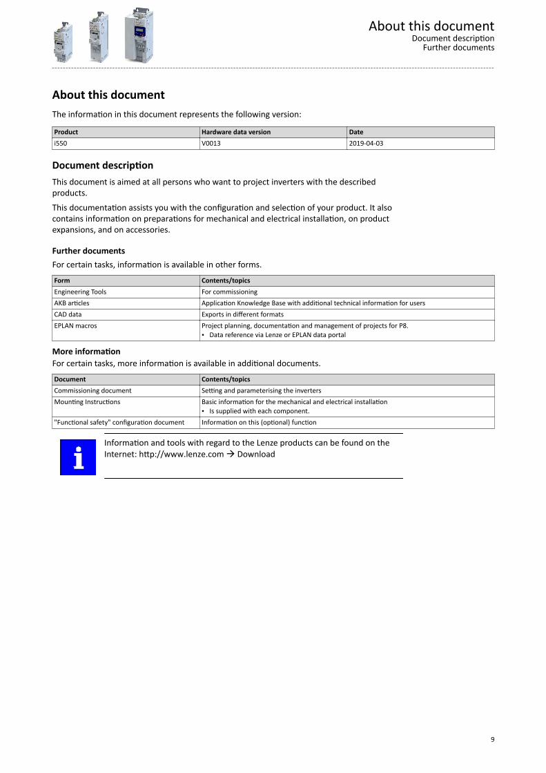
About this documentThe information in this document represents the following version:
Product Hardware data version Datei550 V0013 2019-04-03
Document descriptionThis document is aimed at all persons who want to project inverters with the describedproducts.This documentation assists you with the configuration and selection of your product. It alsocontains information on preparations for mechanical and electrical installation, on productexpansions, and on accessories.
Further documentsFor certain tasks, information is available in other forms.Form Contents/topicsEngineering Tools For commissioningAKB articles Application Knowledge Base with additional technical information for usersCAD data Exports in different formatsEPLAN macros Project planning, documentation and management of projects for P8.
• Data reference via Lenze or EPLAN data portal
More informationFor certain tasks, more information is available in additional documents.Document Contents/topicsCommissioning document Setting and parameterising the invertersMounting Instructions Basic information for the mechanical and electrical installation
• Is supplied with each component."Functional safety" configuration document Information on this (optional) function
Information and tools with regard to the Lenze products can be found on theInternet: http://www.lenze.com à Download
About this documentDocument description
Further documents
9
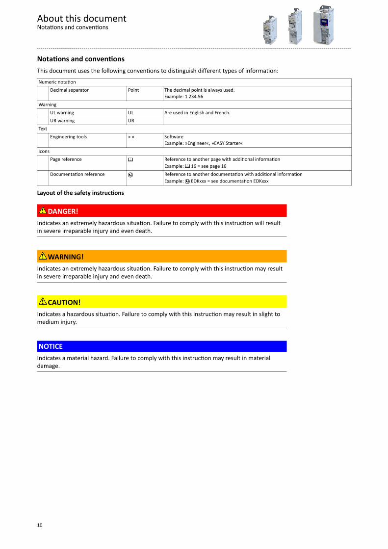
Notations and conventionsThis document uses the following conventions to distinguish different types of information:Numeric notation Decimal separator Point The decimal point is always used.
Example: 1 234.56Warning UL warning UL Are used in English and French. UR warning URText Engineering tools » « Software
Example: »Engineer«, »EASY Starter«Icons Page reference ¶ Reference to another page with additional information
Example: ¶ 16 = see page 16 Documentation reference , Reference to another documentation with additional information
Example: , EDKxxx = see documentation EDKxxx
Layout of the safety instructions
DANGER!Indicates an extremely hazardous situation. Failure to comply with this instruction will resultin severe irreparable injury and even death.
WARNING!Indicates an extremely hazardous situation. Failure to comply with this instruction may resultin severe irreparable injury and even death.
CAUTION!Indicates a hazardous situation. Failure to comply with this instruction may result in slight tomedium injury.
NOTICEIndicates a material hazard. Failure to comply with this instruction may result in materialdamage.
About this documentNotations and conventions
10
Product information
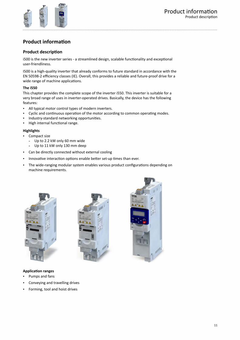
Product descriptioni500 is the new inverter series - a streamlined design, scalable functionality and exceptionaluser-friendliness.
I500 is a high-quality inverter that already conforms to future standard in accordance with theEN 50598-2 efficiency classes (IE). Overall, this provides a reliable and future-proof drive for awide range of machine applications.
The i550This chapter provides the complete scope of the inverter i550. This inverter is suitable for avery broad range of uses in inverter-operated drives. Basically, the device has the followingfeatures:• All typical motor control types of modern inverters.• Cyclic and continuous operation of the motor according to common operating modes.• Industry-standard networking opportunities.• High internal functional range.
Highlights• Compact size
- Up to 2.2 kW only 60 mm wide- Up to 11 kW only 130 mm deep
• Can be directly connected without external cooling• Innovative interaction options enable better set-up times than ever.• The wide-ranging modular system enables various product configurations depending on
machine requirements.
Application ranges• Pumps and fans• Conveying and travelling drives• Forming, tool and hoist drives
Product informationProduct description
11
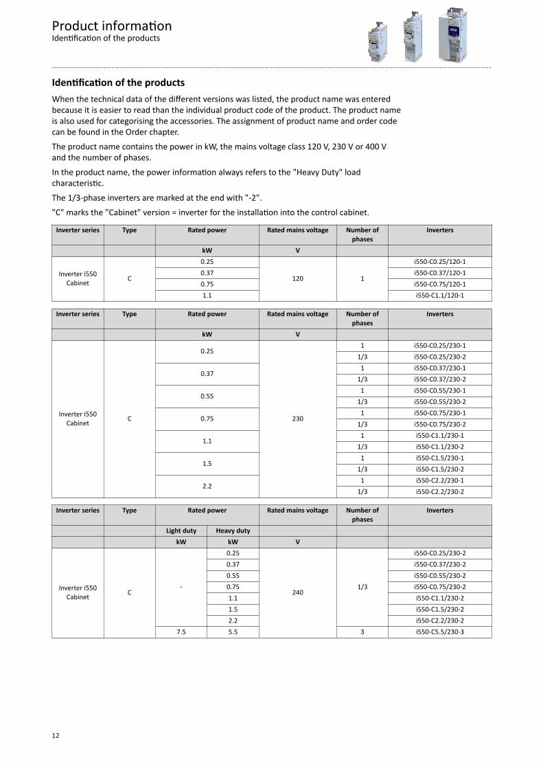
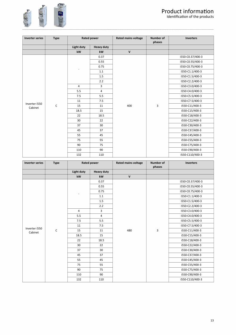
Identification of the productsWhen the technical data of the different versions was listed, the product name was enteredbecause it is easier to read than the individual product code of the product. The product nameis also used for categorising the accessories. The assignment of product name and order codecan be found in the Order chapter.The product name contains the power in kW, the mains voltage class 120 V, 230 V or 400 Vand the number of phases.In the product name, the power information always refers to the "Heavy Duty" loadcharacteristic.The 1/3-phase inverters are marked at the end with "-2"."C" marks the "Cabinet" version = inverter for the installation into the control cabinet.
Inverter series Type Rated power Rated mains voltage Number ofphases
Inverters
kW V
Inverter i550Cabinet C
0.25
120 1
i550-C0.25/120-10.37 i550-C0.37/120-10.75 i550-C0.75/120-11.1 i550-C1.1/120-1
Inverter series Type Rated power Rated mains voltage Number ofphases
Inverters
kW V
Inverter i550Cabinet C
0.25
230
1 i550-C0.25/230-11/3 i550-C0.25/230-2
0.371 i550-C0.37/230-1
1/3 i550-C0.37/230-2
0.551 i550-C0.55/230-1
1/3 i550-C0.55/230-2
0.751 i550-C0.75/230-1
1/3 i550-C0.75/230-2
1.11 i550-C1.1/230-1
1/3 i550-C1.1/230-2
1.51 i550-C1.5/230-1
1/3 i550-C1.5/230-2
2.21 i550-C2.2/230-1
1/3 i550-C2.2/230-2
Inverter series Type Rated power Rated mains voltage Number ofphases
Inverters
Light duty Heavy duty kW kW V
Inverter i550Cabinet C
-
0.25
2401/3
i550-C0.25/230-20.37 i550-C0.37/230-20.55 i550-C0.55/230-20.75 i550-C0.75/230-21.1 i550-C1.1/230-21.5 i550-C1.5/230-22.2 i550-C2.2/230-2
7.5 5.5 3 i550-C5.5/230-3
Product informationIdentification of the products
12
Inverter series Type Rated power Rated mains voltage Number ofphases
Inverters
Light duty Heavy duty kW kW V
Inverter i550Cabinet C
-
0.37
400 3
i550-C0.37/400-30.55 i550-C0.55/400-30.75 i550-C0.75/400-31.1 i550-C1.1/400-31.5 i550-C1.5/400-32.2 i550-C2.2/400-3
4 3 i550-C3.0/400-35.5 4 i550-C4.0/400-37.5 5.5 i550-C5.5/400-311 7.5 i550-C7.5/400-315 11 i550-C11/400-3
18.5 15 i550-C15/400-322 18.5 i550-C18/400-330 22 i550-C22/400-337 30 i550-C30/400-345 37 i550-C37/400-355 45 i550-C45/400-375 55 i550-C55/400-390 75 i550-C75/400-3
110 90 i550-C90/400-3132 110 i550-C110/400-3
Inverter series Type Rated power Rated mains voltage Number ofphases
Inverters
Light duty Heavy duty kW kW V
Inverter i550Cabinet C
-
0.37
480 3
i550-C0.37/400-30.55 i550-C0.55/400-30.75 i550-C0.75/400-31.1 i550-C1.1/400-31.5 i550-C1.5/400-32.2 i550-C2.2/400-3
4 3 i550-C3.0/400-35.5 4 i550-C4.0/400-37.5 5.5 i550-C5.5/400-311 7.5 i550-C7.5/400-315 11 i550-C11/400-3
18.5 15 i550-C15/400-322 18.5 i550-C18/400-330 22 i550-C22/400-337 30 i550-C30/400-345 37 i550-C37/400-355 45 i550-C45/400-375 55 i550-C55/400-390 75 i550-C75/400-3
110 90 i550-C90/400-3132 110 i550-C110/400-3
Product informationIdentification of the products
13
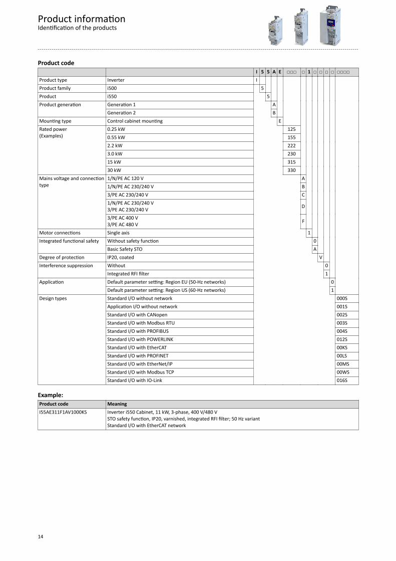
Product code I 5 5 A E 1 Product type Inverter I Product family i500 5 Product i550 5 Product generation Generation 1 A
Generation 2 B Mounting type Control cabinet mounting E Rated power(Examples)
0.25 kW 125 0.55 kW 155 2.2 kW 222 3.0 kW 230 15 kW 315 30 kW 330
Mains voltage and connectiontype
1/N/PE AC 120 V A 1/N/PE AC 230/240 V B 3/PE AC 230/240 V C 1/N/PE AC 230/240 V3/PE AC 230/240 V D
3/PE AC 400 V3/PE AC 480 V F
Motor connections Single axis 1 Integrated functional safety Without safety function 0
Basic Safety STO A Degree of protection IP20, coated V Interference suppression Without 0
Integrated RFI filter 1 Application Default parameter setting: Region EU (50-Hz networks) 0
Default parameter setting: Region US (60-Hz networks) 1 Design types Standard I/O without network 000S
Application I/O without network 001SStandard I/O with CANopen 002SStandard I/O with Modbus RTU 003SStandard I/O with PROFIBUS 004SStandard I/O with POWERLINK 012SStandard I/O with EtherCAT 00KSStandard I/O with PROFINET 00LSStandard I/O with EtherNet/IP 00MSStandard I/O with Modbus TCP 00WSStandard I/O with IO-Link 016S
Example:Product code MeaningI55AE311F1AV1000KS Inverter i550 Cabinet, 11 kW, 3-phase, 400 V/480 V
STO safety function, IP20, varnished, integrated RFI filter; 50 Hz variantStandard I/O with EtherCAT network
Product informationIdentification of the products
14
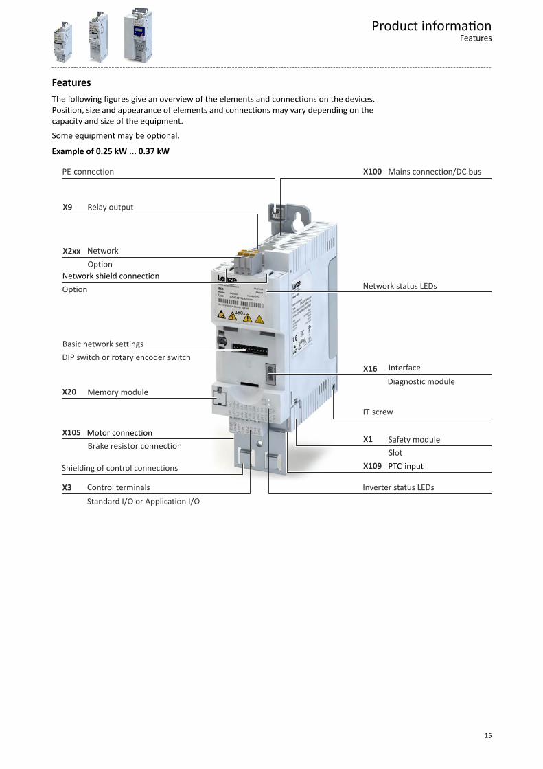
FeaturesThe following figures give an overview of the elements and connections on the devices.Position, size and appearance of elements and connections may vary depending on thecapacity and size of the equipment.Some equipment may be optional.
Example of 0.25 kW ... 0.37 kW
X9
X2xx
X20
X105
X3
X109
X1
X16
X100
Brake resistor connectionSlot
Diagnostic module
Standard I/O or Application I/O
PTC input
DIP switch or rotary encoder switch
Option
Option
Motor connection
Network status LEDsNetwork shield connection
Inverter status LEDs
Basic network settings
IT screw
Safety module
Shielding of control connections
Control terminals
Memory module
Interface
Network
Relay output
Mains connection/DC busPE connection
Product informationFeatures
15
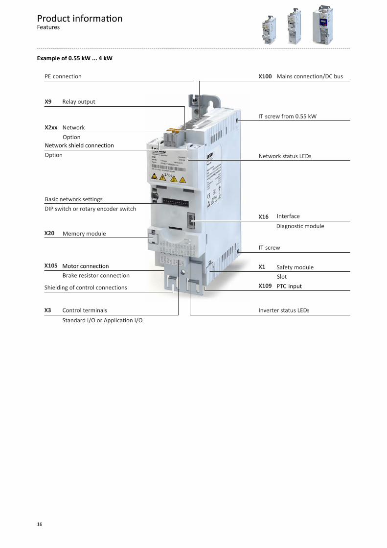
Example of 0.55 kW ... 4 kW
X9
X2xx
X20
X105
X3
X109
X1
X16
X100
Brake resistor connection Slot
Diagnostic module
Standard I/O or Application I/O
PTC input
DIP switch or rotary encoder switch
Option
Option
Motor connection
Network status LEDs
IT screw from 0.55 kW
Network shield connection
Inverter status LEDs
Basic network settings
IT screw
Safety module
Shielding of control connections
Control terminals
Memory module
Interface
Network
Relay output
Mains connection/DC busPE connection
Product informationFeatures
16
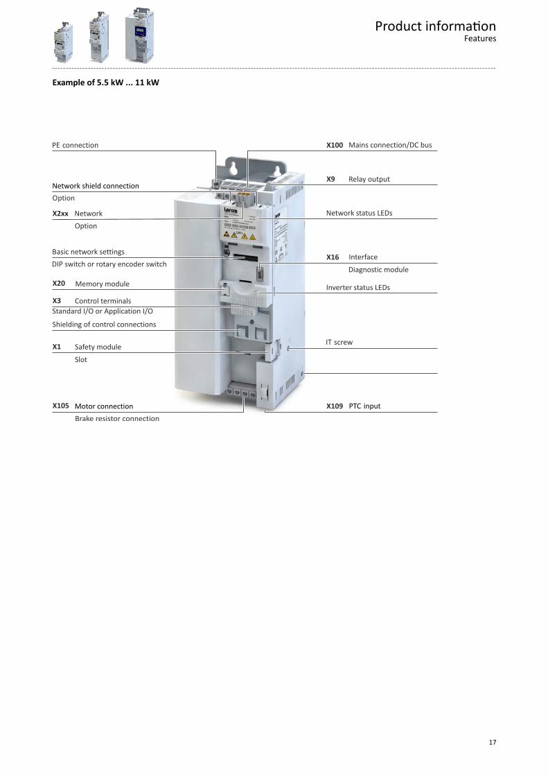
Example of 5.5 kW ... 11 kW
X9
X2xx
X20
X105
X3
X109
X1
X16
X100
Brake resistor connection
Slot
Diagnostic module
Standard I/O or Application I/O
PTC input
DIP switch or rotary encoder switch
Option
Option
Motor connection
Network status LEDs
Network shield connection
Inverter status LEDs
Basic network settings
IT screwSafety module
Shielding of control connections
Control terminals
Memory module
Interface
Network
Relay output
Mains connection/DC busPE connection
Product informationFeatures
17
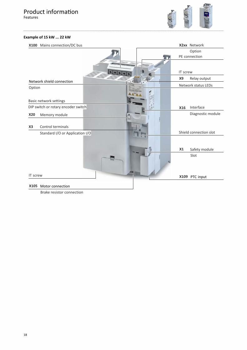
Example of 15 kW ... 22 kW
X9
X2xx
X20
X105
X3
X109
X1
X16
X100
Brake resistor connection
Slot
Diagnostic module
Standard I/O or Application I/O
PTC input
DIP switch or rotary encoder switch
Option
Motor connection
Network status LEDsNetwork shield connection
Basic network settings
IT screw
Safety module
Control terminals
Memory module
Interface
Network
Relay output
Mains connection/DC bus
PE connection
Shield connection slot
IT screw
Option
Product informationFeatures
18
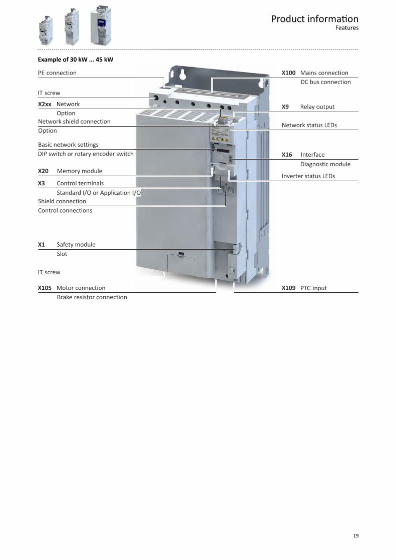
Example of 30 kW ... 45 kW
PE connection
Slot
Diagnostic module
Standard I/O or Application I/O
Control connections
PTC input
DIP switch or rotary encoder switch
Option
Option
Motor connection
Network status LEDs
IT screw
Network shield connection
Inverter status LEDs
Basic network settings
IT screw
Safety module
Shield connection
Control terminals
Memory module
Interface
Network Relay output
Mains connection
Brake resistor connection
X9
X100
X16
X109X105
X1
X3
X20
X2xx
DC bus connection
Product informationFeatures
19
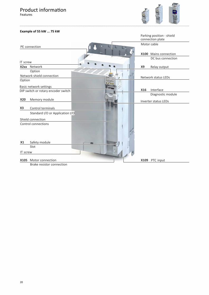
Example of 55 kW ... 75 kW
X20
X3
X1
X105
X2xx
X109
X16
X9
X100
Brake resistor connection
DC bus connection
Motor cable
SlotSafety module
Parking position - shieldconnection plate
PE connection
Diagnostic module
Standard I/O or Application I/O
Control connections
PTC input
DIP switch or rotary encoder switch
Option
Option
Motor connection
Network status LEDs
IT screw
Network shield connection
Inverter status LEDs
Basic network settings
IT screw
Shield connection
Control terminals
Memory module
Interface
Network Relay output
Mains connection
Product informationFeatures
20
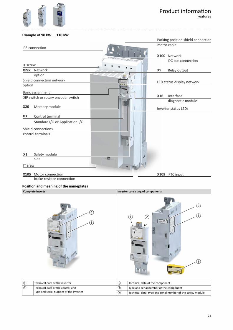
Example of 90 kW ... 110 kW
X20
X3
X1
X105
X2xx
X109
X16
X9
X100 Network
Relay outputNetwork
Interface
Memory module
Control terminal
Shield connections
IT srew
Basic assignment
Inverter status LEDs
Shield connection network
IT screw
LED status display network
Motor connection
option
option
DIP switch or rotary encoder switch
PTC input
control terminals
Standard I/O or Application I/O
diagnostic module
PE connection
Parking position shield connection
Safety moduleslot
motor cable
DC bus connection
brake resistor connection
Position and meaning of the nameplatesComplete inverter Inverter consisting of components
①
④①②
③
②
①
① Technical data of the inverter ① Technical data of the component④ Technical data of the control unit
Type and serial number of the inverter② Type and serial number of the component③ Technical data, type and serial number of the safety module
Product informationFeatures
21
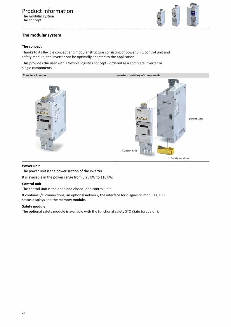
The modular system
The conceptThanks to its flexible concept and modular structure consisting of power unit, control unit andsafety module, the inverter can be optimally adapted to the application.This provides the user with a flexible logistics concept - ordered as a complete inverter orsingle components.
Complete inverter Inverter consisting of components
Control unit
Power unit
Safety module
Power unitThe power unit is the power section of the inverter.It is available in the power range from 0.25 kW to 110 kW.
Control unitThe control unit is the open and closed-loop control unit.It contains I/O connections, an optional network, the interface for diagnostic modules, LEDstatus displays and the memory module.
Safety moduleThe optional safety module is available with the functional safety STO (Safe torque off).
Product informationThe modular systemThe concept
22
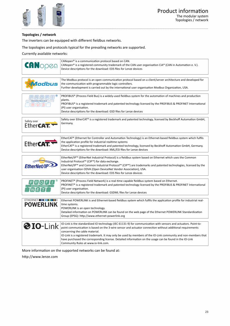
Topologies / networkThe inverters can be equipped with different fieldbus networks.
The topologies and protocols typical for the prevailing networks are supported.Currently available networks:
CANopen® is a communication protocol based on CAN.CANopen® is a registered community trademark of the CAN user organisation CiA® (CAN in Automation e. V.).Device descriptions for the download: EDS files for Lenze devices
The Modbus protocol is an open communication protocol based on a client/server architecture and developed forthe communication with programmable logic controllers.Further development is carried out by the international user organisation Modbus Organization, USA.
PROFIBUS® (Process Field Bus) is a widely-used fieldbus system for the automation of machines and productionplants.PROFIBUS® is a registered trademark and patented technology licensed by the PROFIBUS & PROFINET International(PI) user organisation.Device descriptions for the download: GSD files for Lenze devices
Safety over EtherCAT® is a registered trademark and patented technology, licensed by Beckhoff Automation GmbH,Germany.
EtherCAT® (Ethernet for Controller and Automation Technology) is an Ethernet-based fieldbus system which fulfilsthe application profile for industrial realtime systemsEtherCAT® is a registered trademark and patented technology, licensed by Beckhoff Automation GmbH, Germany.Device descriptions for the download: XML/ESI files for Lenze devices
EtherNet/IP™ (EtherNet Industrial Protocol) is a fieldbus system based on Ethernet which uses the CommonIndustrial Protocol™ (CIP™) for data exchange.EtherNet/IP™ and Common Industrial Protocol™ (CIP™) are trademarks and patented technologies, licensed by theuser organisation ODVA (Open DeviceNet Vendor Association), USA.Device descriptions for the download: EDS files for Lenze devices
PROFINET® (Process Field Network) is a real-time capable fieldbus system based on Ethernet.PROFINET® is a registered trademark and patented technology licensed by the PROFIBUS & PROFINET International(PI) user organisation.Device descriptions for the download: GSDML files for Lenze devices
Ethernet POWERLINK is and Ethernet-based fieldbus system which fulfils the application profile for industrial real-time systems.POWERLINK is an open technology.Detailed information on POWERLINK can be found on the web page of the Ethernet POWERLINK StandardizationGroup (EPSG): http://www.ethernet-powerlink.org
IO-Link is the standardized IO technology (IEC 61131-9) for communication with sensors and actuators. Point-to-point communication is based on the 3-wire sensor and actuator connection without additional requirementsconcerning the cable material.IO-Link is a registered trademark. It may only be used by members of the IO-Link community and non-members thathave purchased the corresponding license. Detailed information on the usage can be found in the IO-LinkCommunity Rules at www.io-link.com.
More information on the supported networks can be found at:http://www.lenze.com
Product informationThe modular system
Topologies / network
23
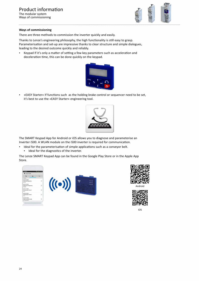
Ways of commissioningThere are three methods to commission the inverter quickly and easily.Thanks to Lenze’s engineering philosophy, the high functionality is still easy to grasp.Parameterisation and set-up are impressive thanks to clear structure and simple dialogues,leading to the desired outcome quickly and reliably.• Keypad If it’s only a matter of setting a few key parameters such as acceleration and
deceleration time, this can be done quickly on the keypad.
• »EASY Starter« If functions such as the holding brake control or sequencer need to be set,it’s best to use the »EASY Starter« engineering tool.
The SMART Keypad App for Android or iOS allows you to diagnose and parameterise anInverter i500. A WLAN module on the i500 inverter is required for communication.• Ideal for the parameterisation of simple applications such as a conveyor belt.
• Ideal for the diagnostics of the inverter.The Lenze SMART Keypad App can be found in the Google Play Store or in the Apple AppStore.
Android
iOS
Product informationThe modular systemWays of commissioning
24
Functions
OverviewWith regard to their functionality, the inverters i550 are adapted to extensive applications.This is also reflected in the overall scope of the products.
FunctionsMotor control Monitoring V/f characteristic control linear/square-law (VFC plus) Short circuit V/f characteristic control (VFC closed loop) Earth fault Energy saving function (VFC-Eco) Device overload (i*t) Sensorless vector control (SLVC) Motor overload (i²*t) Sensorless control for synchronous motors (SL-PSM)
(up to 22 kW, from 30 kW ... 75 kW: in preparation) Mains phase failure
Servo control for asynchronous motors (SC-ASM) Stall protectionMotor functions Motor current limit Flying restart circuit Maximum torque Slip compensation Ultimate motor current DC braking Motor speed Oscillation damping Load loss detection Skip frequencies Motor temperature Automatic identification of the motor data Diagnostics Braking energy management Error history buffer Holding brake control Logbook Voltage add – function LED status displays Rational Energy Ride Through (RERT) Keypad language selection German, English Speed feedback (HTL encoder) Network Brake resistor control (brake chopper integrated) CANopen Frequency setpoint Modbus RTU DC-bus connection (400V devices) Modbus TCPApplication functions PROFIBUS Process controller EtherCAT Access protection EtherNet/IP Process controller sleep mode and rinse function PROFINET Freely assignable favorite menu POWERLINK Parameter change-over IO-Link S-shaped ramps for smooth acceleration Safety functions Motor potentiometer STO (Safe Torque Off) Flexible I/O configuration Automatic restart OEM parameter set Complete control with 8-key keypad UPS operation Frequency output via digital output DO1 "Light Duty" load characteristic can be adjusted for selected inverters
Product informationFunctionsOverview
25
Motor control typesThe following table contains the possible control types with Lenze motors.Motors V/f characteristic control Sensorless vector control ASM servo control VFCplus SLVC SC ASMThree-phase AC motors MD
MF mH m500
Lenze synchronous servo motors are not suitable for the use with inverters, e. g. the MCS,MCM or m850 types.
Features
Motor setting range
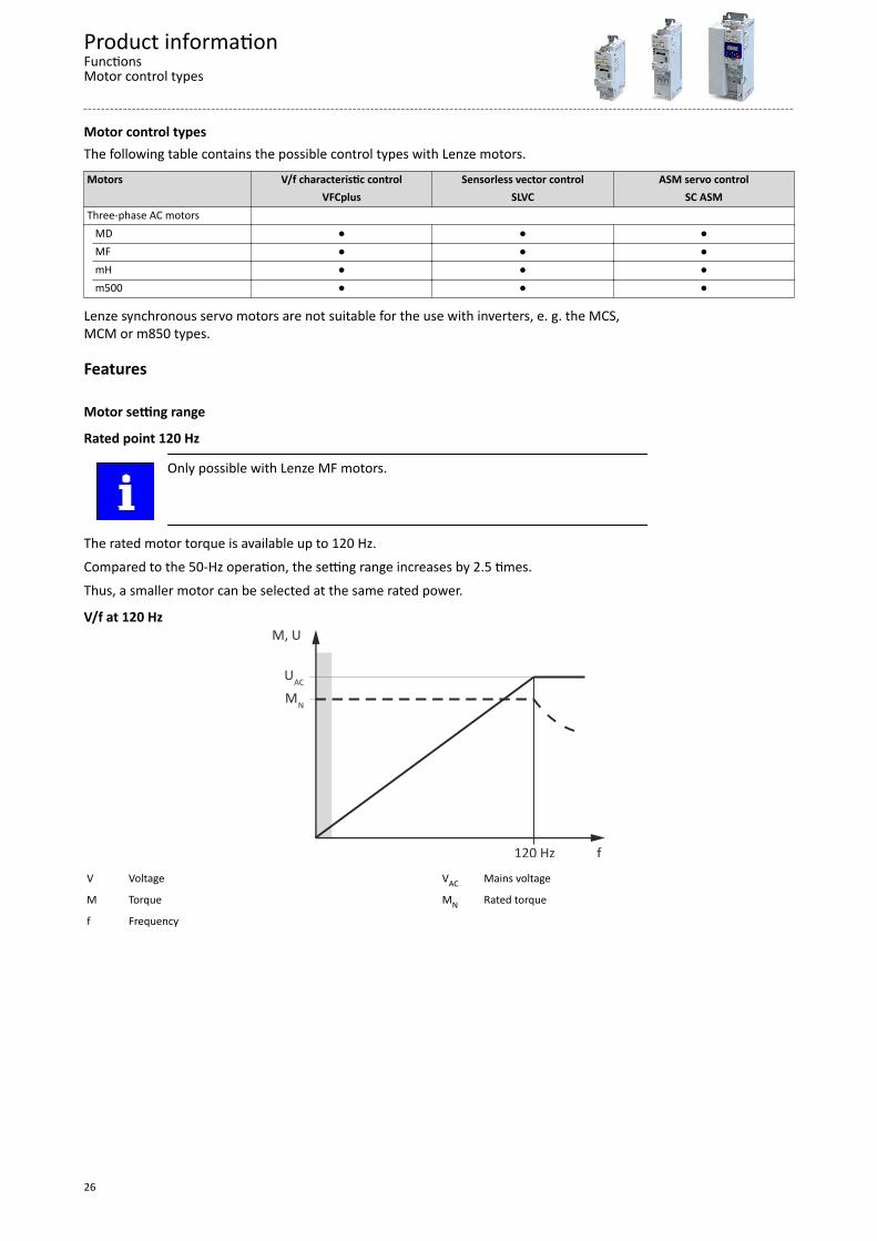
Rated point 120 Hz
Only possible with Lenze MF motors.
The rated motor torque is available up to 120 Hz.Compared to the 50-Hz operation, the setting range increases by 2.5 times.Thus, a smaller motor can be selected at the same rated power.
V/f at 120 Hz
120 Hz f
M, U
MN
UAC
V Voltage VAC Mains voltage
M Torque MN Rated torque
f Frequency
Product informationFunctionsMotor control types
26
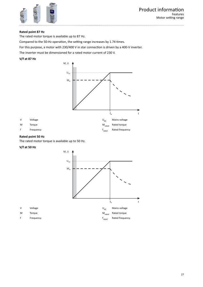
Rated point 87 HzThe rated motor torque is available up to 87 Hz.Compared to the 50-Hz operation, the setting range increases by 1.74 times.For this purpose, a motor with 230/400 V in star connection is driven by a 400-V inverter.The inverter must be dimensioned for a rated motor current of 230 V.
V/f at 87 Hz
f
M, U
MN
UAC
fN
V Voltage UAC Mains voltage
M Torque Mrated Rated torque
f Frequency frated Rated frequency
Rated point 50 HzThe rated motor torque is available up to 50 Hz.
V/f at 50 Hz
f
M, U
MN
UAC
fN
V Voltage UAC Mains voltage
M Torque Mrated Rated torque
f Frequency frated Rated frequency
Product informationFeatures
Motor setting range
27
Information on project planning
Project planning process
Dimensioning
3 methods for dimensioningFast: Selection of the inverter based on the motor data of a 4-pole asynchronous motor.
Detailed: In order to optimise the selection of the inverter and all drive components, it isworth to execute the detailed system dimensioning based on the physical requirements of theapplication. For this purpose, Lenze provides the «Drive Solution Designer» (DSD) designprogram.
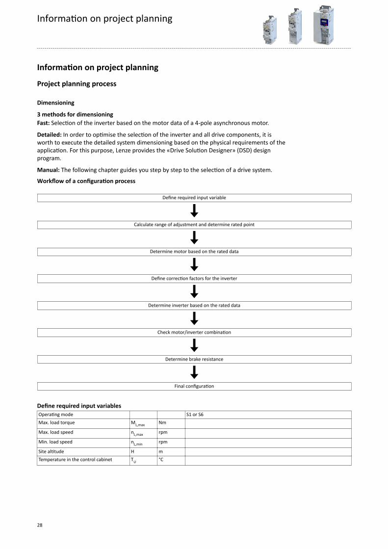
Manual: The following chapter guides you step by step to the selection of a drive system.
Workflow of a configuration process Define required input variable
Calculate range of adjustment and determine rated point
Determine motor based on the rated data
Define correction factors for the inverter
Determine inverter based on the rated data
Check motor/inverter combination
Determine brake resistance
Final configuration
Define required input variablesOperating mode S1 or S6Max. load torque ML,max Nm
Max. load speed nL,max rpm
Min. load speed nL,min rpm
Site altitude H m Temperature in the control cabinet TU °C
Information on project planning
28
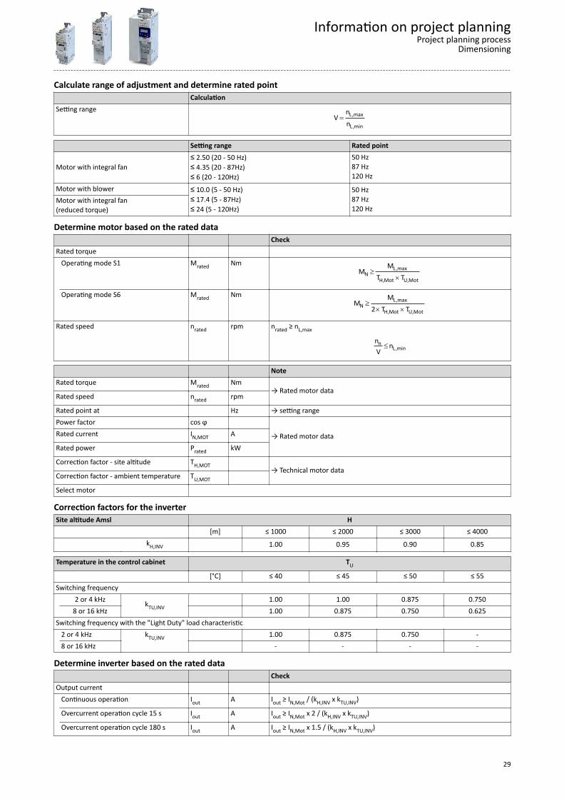
Calculate range of adjustment and determine rated point CalculationSetting range
= L,max
L,min
nV
n
Setting range Rated point
Motor with integral fan≤ 2.50 (20 - 50 Hz)≤ 4.35 (20 - 87Hz)≤ 6 (20 - 120Hz)
50 Hz87 Hz120 Hz
Motor with blower ≤ 10.0 (5 - 50 Hz)≤ 17.4 (5 - 87Hz)≤ 24 (5 - 120Hz)
50 Hz87 Hz120 Hz
Motor with integral fan(reduced torque)
Determine motor based on the rated data CheckRated torque Operating mode S1 Mrated Nm
³´
L,maxN
H,Mot U,Mot
MM
T T
Operating mode S6 Mrated Nm³
´ ´L,max
NH,Mot U,Mot
MM
2 T T
Rated speed nrated rpm nrated ≥ nL,max
£nL,min
n nV
NoteRated torque Mrated Nm
→ Rated motor dataRated speed nrated rpm
Rated point at Hz → setting rangePower factor cos ϕ
→ Rated motor dataRated current IN,MOT A
Rated power Prated kW
Correction factor - site altitude TH,MOT → Technical motor data
Correction factor - ambient temperature TU,MOT
Select motor
Correction factors for the inverterSite altitude Amsl H
[m] ≤ 1000 ≤ 2000 ≤ 3000 ≤ 4000
kH,INV 1.00 0.95 0.90 0.85
Temperature in the control cabinet TU
[°C] ≤ 40 ≤ 45 ≤ 50 ≤ 55Switching frequency 2 or 4 kHz kTU,INV
1.00 1.00 0.875 0.750 8 or 16 kHz 1.00 0.875 0.750 0.625Switching frequency with the "Light Duty" load characteristic 2 or 4 kHz kTU,INV 1.00 0.875 0.750 - 8 or 16 kHz - - - -
Determine inverter based on the rated data CheckOutput current Continuous operation Iout A Iout ≥ IN,Mot / (kH,INV x kTU,INV)
Overcurrent operation cycle 15 s Iout A Iout ≥ IN,Mot x 2 / (kH,INV x kTU,INV)
Overcurrent operation cycle 180 s Iout A Iout ≥ IN,Mot x 1.5 / (kH,INV x kTU,INV)
Information on project planningProject planning process
Dimensioning
29
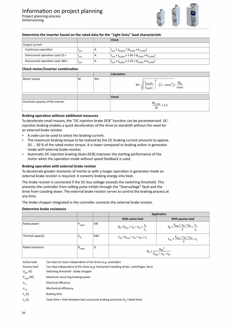
Determine the inverter based on the rated data for the "Light Duty" load characteristic CheckOutput current Continuous operation Iout A Iout ≥ IN,Mot / (kH,INV x kTU,INV)
Overcurrent operation cycle 15 s Iout A Iout ≥ IN,Mot x 1.65 / (kH,INV x kTU,INV)
Overcurrent operation cycle 180 s Iout A Iout ≥ IN,Mot x 1.25 / (kH,INV x kTU,INV)
Check motor/inverter combination CalculationMotor torque M Nm
( )æ ö= - - j ´ç ÷ç ÷ jè ø
2out,INV 2 N
N,MOT
l MM 1 cosI cos
CheckOverload capacity of the inverter
£L,maxM1.5
M
Braking operation without additional measuresTo decelerate small masses, the "DC injection brake DCB" function can be parameterised. DC-injection braking enables a quick deceleration of the drive to standstill without the need foran external brake resistor.• A code can be used to select the braking current.• The maximum braking torque to be realised by the DC braking current amounts to approx.
20 ... 30 % of the rated motor torque. It is lower compared to braking action in generatormode with external brake resistor.
• Automatic DC-injection braking (Auto-DCB) improves the starting performance of themotor when the operation mode without speed feedback is used.
Braking operation with external brake resistorTo decelerate greater moments of inertia or with a longer operation in generator mode anexternal brake resistor is required. It converts braking energy into heat.The brake resistor is connected if the DC-bus voltage exceeds the switching threshold. Thisprevents the controller from setting pulse inhibit through the "Overvoltage" fault and thedrive from coasting down. The external brake resistor serves to control the braking process atany time.The brake chopper integrated in the controller connects the external brake resistor.
Determine brake resistance Application With active load With passive loadRated power Prated kW
³ ´h ´h ´ 1N max e m
z
tP Pt
´h ´h³ ´max e m 1
Nz
P tP2 t
Thermal capacity Cth kWs ³ ´h ´h ´th max e m 1C P t ´h ´h³ ´max e m
th 1PC t
2
Rated resistance Rrated Ω³
´h ´h
2DC
Nmax e m
URP
Active load Can start to move independent of the drive (e.g. unwinder)Passive load Can stop independent of the drive (e.g. horizontal travelling drives, centrifuges, fans)UDC [V] Switching threshold - brake chopper
Pmax [W] Maximum occurring braking power
η e Electrical efficiency
η m Mechanical efficiency
t1 [s] Braking time
tz [s] Cycle time = time between two successive braking processes (t1+ dead time)
Information on project planningProject planning processDimensioning
30

Final configurationProduct extensions and accessories can be found here:• Product extensions ^ 157• Accessories ^ 184
Operation in motor and generator modeThe energy analysis differs between operation in motor mode and generator mode.
During operation in motor mode, the energy flows from the supplying mains via the inverterto the motor which converts electrical energy into mechanical energy (e. g. for lifting a load).
During operation in generator mode, the energy flows back from the motor to the inverter.The motor converts the mechanical energy into electrical energy - it acts as a generator (e. g.when lowering a load).The drive brakes the load in a controlled manner.The energy recovery causes a rise in the DC-bus voltage. If this voltage exceeds an upper limit,the output stage of the inverter will be blocked to prevent the device from being destroyed.The drive coasts until the DC-bus voltage reaches the permissible value range again.
In order that the excessive energy can be dissipated, a brake resistor or a regenerative moduleis required.
Information on project planningProject planning process
Operation in motor and generator mode
31
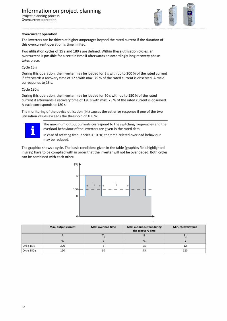
Overcurrent operationThe inverters can be driven at higher amperages beyond the rated current if the duration ofthis overcurrent operation is time limited.
Two utilisation cycles of 15 s and 180 s are defined. Within these utilisation cycles, anovercurrent is possible for a certain time if afterwards an accordingly long recovery phasetakes place.
Cycle 15 sDuring this operation, the inverter may be loaded for 3 s with up to 200 % of the rated currentif afterwards a recovery time of 12 s with max. 75 % of the rated current is observed. A cyclecorresponds to 15 s.
Cycle 180 sDuring this operation, the inverter may be loaded for 60 s with up to 150 % of the ratedcurrent if afterwards a recovery time of 120 s with max. 75 % of the rated current is observed.A cycle corresponds to 180 s.
The monitoring of the device utilisation (Ixt) causes the set error response if one of the twoutilisation values exceeds the threshold of 100 %.
The maximum output currents correspond to the switching frequencies and theoverload behaviour of the inverters are given in the rated data.In case of rotating frequencies < 10 Hz, the time-related overload behaviourmay be reduced.
The graphics shows a cycle. The basic conditions given in the table (graphics field highlightedin grey) have to be complied with in order that the inverter will not be overloaded. Both cyclescan be combined with each other.
t
I [%]
100
T1 T2
0
A
B
Max. output current Max. overload time Max. output current duringthe recovery time
Min. recovery time
A T1 B T2
% s % sCycle 15 s 200 3 75 12Cycle 180 s 150 60 75 120
Information on project planningProject planning processOvercurrent operation
32

Inverter load characteristicsThe inverter has two different load characteristics: "Light Duty" and "Heavy Duty". The "LightDuty" load characteristic allows for a higher output current with restrictions regardingoverload capacity, ambient temperature and switching frequency. This allows the motorrequired for the application to be driven by a less powerful inverter. Select the loadcharacteristic according to the application.
Heavy Duty compared to Light DutyThis table compares the two load characteristics: Heavy Duty Light dutyCharacteristics High dynamic requirements Low dynamic requirementsTypical applications Main tool drives, travelling drives, hoist drives,
winders, forming drives and conveyorsPumps, fans, general horizontal materials handlingtechnology and line drives
Overload capacity 3 s/200 %, 60 s/150 %See technical data
RestrictedSsee technical data
Devices with Light Duty load characteristic: See ^ 97, ^ 113, ^ 136
Comply with all data for this load characteristic and the corresponding mainsvoltage range. This comprises the information on the type of installation as wellas the required fuses, cable cross-sections, mains chokes and filters.
Information on project planningProject planning process
Overcurrent operation
33

Safety instructionsDisregarding the following basic safety measures and safety information may lead to severepersonal injury and damage to property!
Observe all specifications of the corresponding documentation supplied. This is theprecondition for safe and trouble-free operation and for obtaining the product featuresspecified.
Please observe the specific safety information in the other sections!
DANGER!Electrical voltagePossible consequences: Death or severe injuriesAny work on the inverter must only be carried out in the deenergised state. Inverter up to 45 kW: After switching off the mains voltage, wait for at least 3 min before
you start working. Inverter from 55 kW onwards: After switching off the mains voltage, wait for at least 10 min
before you start working.
Basic safety instructions
Personnel
The product must only be used by qualified personnel. IEC 60364 or CENELEC HD 384 definethe skills of these persons:• They are familiar with installing, mounting, commissioning, and operating the product.• They have the corresponding qualifications for their work.• They know and can apply all regulations for the prevention of accidents, directives, and
laws applicable at the place of use.
Process engineeringThe procedural notes and circuit details described are only proposals. It is up to the user tocheck whether they can be adapted to the particular applications. Lenze does not take anyresponsibility for the suitability of the procedures and circuit proposals described.
Information on project planningSafety instructionsBasic safety instructions
34

Application as directed• The product must only be operated under the operating conditions prescribed in this
documentation.• The product meets the protection requirements of 2014/35/EU: Low-Voltage Directive.• The product is not a machine in terms of 2006/42/EU: Machinery Directive.• Commissioning or starting the operation as directed of a machine with the product is not
permitted until it has been ensured that the machine meets the regulations of the EUDirective 2006/42/EU: Machinery Directive; observe EN 60204−1.
• Commissioning or starting operation as directed is only permissible if the EMC Directive2014/30/EU is complied with.
• The harmonised standard EN 61800−5−1 is applied.• The product is not a household appliance, but is only designed as a component for
commercial or professional use in terms of EN 61000−3−2.• The product can be used according to the technical data if drive systems have to comply
with categories according to EN 61800−3.In residential areas, the product may cause EMC interferences. The operator is responsiblefor taking interference suppression measures.
• The product must only be actuated with motors that are suitable for the operation withinverters.- Lenze L-force motors meet the requirements- Exception: m240 motors are designed for mains operation only.
Use of explosion-proof motorsExplosion-proof motors that are not designed for use with an inverter invalidate their approvalwhen used for variable speed applications. Due to the many areas of liability that may arisewhen handling these applications, the following declaration of principle applies:
The inverters from Lenze are sold without warranty of suitability for a particularpurpose or warranty of suitability for use in explosion-proof motors. Lenzeassumes no responsibility for any direct, incidental, or consequential damages,costs, or losses that may result from the use of AC inverters in theseapplications. The purchaser explicitly agrees to assume any risk of loss, cost ordamage that may result from such use.
The user is not allowed to change inverters that come with integrated safety technology.The safety module must not be removed. If the safety module is defective, the inverter has tobe replaced.
Information on project planningSafety instructions
Application as directed
35

Handling
Transport, storageObserve the notes regarding transport, storage and correct handling. Ensure proper handlingand avoid mechanical stress. Do not bend any components and do not change any insulationdistances during transport or handling. Do not touch any electronic components and contacts.Inverters contain electrostatically sensitive components which can easily be damaged byinappropriate handling. Do not damage or destroy any electrical components since therebyyour health could be endangered!
InstallationThe technical data and supply conditions can be obtained from the nameplate and thedocumentation. They must be strictly observed.The inverters have to be installed and cooled according to the regulations given in thecorresponding documentation Observe the climatic conditions according to the technicaldata. The ambient air must not exceed the degree of pollution 2 according to EN 61800−5−1.
Electrical connectionWhen working on live inverters, observe the applicable national regulations for the preventionof accidents.
The electrical installation must be carried out according to the appropriate regulations (e. g.cable cross-sections, fuses, PE connection). Additional information can be obtained from thedocumentation.
The documentation contains notes about installation according to EMC regulations (such asshielding, grounding, filters and cable routing). Also observe these notes for CE-markedinverters. The manufacturer of the system or machine is responsible for adherence to thelimits required in connection with EMC legislation. The inverters must be installed in housings(e g. control cabinets) to meet the limit values for radio interferences valid at the site ofinstallation. The housings have to enable an EMC-compliant installation. In particular observethat e. g. control cabinet doors preferably have a circumferential metallic connection to thehousing. Reduce openings or cutouts through the housing to a minimum.
Inverters may cause a DC current in the PE conductor. If a residual current device (RCD) is usedfor protection against direct or indirect contact for an inverter with three-phase supply, only aresidual current device (RCD) of type B is permissible on the supply side of the inverter. If theinverter has a single-phase supply, a residual current device (RCD) of type A is alsopermissible. Apart from using a residual current device (RCD), other protective measures canbe taken as well, e. g. electrical isolation by double or reinforced insulation or isolation fromthe supply system by means of a transformer.
OperationIf necessary, systems including inverters must be equipped with additional monitoring andprotection devices. Also comply with the safety regulations and provisions valid at theinstallation site.
After the inverter has been disconnected from the supply voltage, all live components andpower terminals must not be touched immediately because capacitors can still be charged.Please observe the corresponding stickers on the inverter.All protection covers and doors must be shut during operation.
You may adapt the inverters to your application by parameter setting within the limitsavailable. For this, observe the notes in the documentation.
Safety functionsCertain inverter versions support safety functions (e. g. ”safe torque off”, formerly ”safestandstill”) according to the requirements of the EC Machinery Directive 2006/42/EU. Thenotes on the integrated safety provided in this documentation must be observed.
Maintenance and servicingThe inverters do not require any maintenance if the prescribed operating conditions areobserved.
Information on project planningSafety instructionsHandling
36

DisposalIn accordance with the current provisions, Lenze products and accessories have to bedisposed of by means of professional recycling. Lenze products contain contain recyclable rawmaterial such as metal, plastics and electronic components.
Information on project planningSafety instructions
Handling
37

Residual hazardsEven if notes given are taken into consideration and protective measures are implemented,the occurrence of residual risks cannot be fully prevented.
The user must take the residual hazards mentioned into consideration in the risk assessmentfor his/her machine/system.If the above is disregarded, this can lead to severe injuries to persons and damage toproperty!
Protection of persons
Before working on the inverter, check if no voltage is applied to the power terminals.• Depending on the device, the power terminals X105 remain live for up to 3 ... 20 minutes.• The power terminals X100 and X105 remain live even when the motor is stopped.
Motor protection
With some settings of the inverter, the connected motor can be overheated.• E. g. by longer operation of self-ventilated motors at low speed.• E. g. by longer operation of the DC-injection brake.
Protection of the machine/system
Drives can reach dangerous overspeeds.• E. g. by setting high output frequencies in connection with motors and machines not
suitable for this purpose.• The inverters do not provide protection against such operating conditions. For this
purpose, use additional components.
Switch contactors in the motor cable only if the controller is inhibited.• Switching while the inverter is enabled is only permissible if no monitoring functions are
activated.
MotorIf there is a short circuit of two power transistors, a residual movement of up to 180°/numberof pole pairs can occur at the motor! (e. g. 4-pole motor: residual movement max. 180°/2 =90°).
Parameter set transfer
During the parameter set transfer, control terminals of the inverters can adopt undefinedstates.• Thus, the control terminal of the digital input signals have to be removed before the
transfer.• This ensures that the inverter is inhibited. The control terminals are in a defined state.
Degree of protection - protection of persons and device protection• Information applies to the mounted and ready-for-use state.• Information does not apply to the wire range of the terminals.
- Terminals that are not wired have low protection against physical contact.- Terminals for large cable cross-sections have lower classes of protection, e. g. from
15 kW IP10 only.
CommissioningIf you use the Application Loader as a download tool for safety-related parameter sets,validate the parameter sets after the download.
Device exchange without toolExchange a maximum of one safe device before recommissioning.
Exchange of devicesTest the compatibility of the devices before exchanging.
Information on project planningSafety instructionsResidual hazards
38

Risks when exchanging devices
WARNING!Incorrect handling of devices.Device damage.Check the compatibility of the devices before exchanging.Check the memory cards of the devices before exchanging.Set the safety address.Undertake a functional check after the exchange.
Information on project planningSafety instructions
Residual hazards
39
Control cabinet structure
Control cabinet requirements• Protection against electromagnetic interferences• Compliance with the ambient conditions of the installed components
Mounting plate requirements• The mounting plate must be electrically conductive.
- Use zinc-coated mounting plates or mounting plates made of V2A.- Varnished mounting plates are unsuitable, even if the varnish is removed from the
contact surfaces.• When using several mounting plates, make a conductive connection over a large surface
(e. g. using grounding strips).
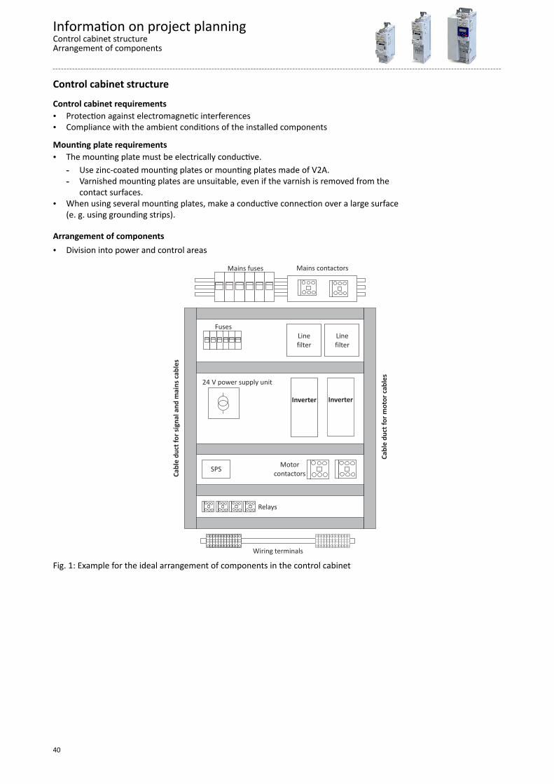
Arrangement of components• Division into power and control areas
Fig. 1: Example for the ideal arrangement of components in the control cabinet
Information on project planningControl cabinet structureArrangement of components
40

CablesRequirements• The cables used must correspond to the requirements at the location (e. g. EN 60204−1,
UL).• The cable cross-section must be dimensioned for the assigned fusing. Observe national
and regional regulations.• You must observe the regulations for minimum cross-sections of PE conductors. The cross-
section of the PE conductor must be at least as large as the cross-section of the powerconnections.
Installation inside the control cabinet• Always install cables close to the mounting plate (reference potential), as freely suspended
cables act like aerials.• Use separated cable channels for motor cables and control cables. Do not mix up different
cable types in one cable channel.• Lead the cables to the terminals in a straight line (avoid tangles of cables).• Minimise coupling capacities and coupling inductances by avoiding unnecessary cable
lengths and reserve loops.• Short-circuit unused cores to the reference potential.• Install the cables of a 24 V DC supply (positive and negative cable) close to each other or
twisted over the entire length to avoid loops.Installation outside the control cabinet• In the case of greater cable lengths, a greater cable distance between the cables is
required.• In the case of parallel routing (cable trays) of cables with different types of signals, the
degree of interference can be minimised by using a metallic cable separator or isolatedcable ducts.
Earthing concept• Set up the earthing system with a star topology.• Connect all components (inverters, filters, chokes) to a central earthing point (PE rail).• Comply with the corresponding minimum cross-sections of the cables.• When using several mounting plates, make a conductive connection over a large surface
(e. g. using grounding strips).
Information on project planningControl cabinet structure
Earthing concept
41
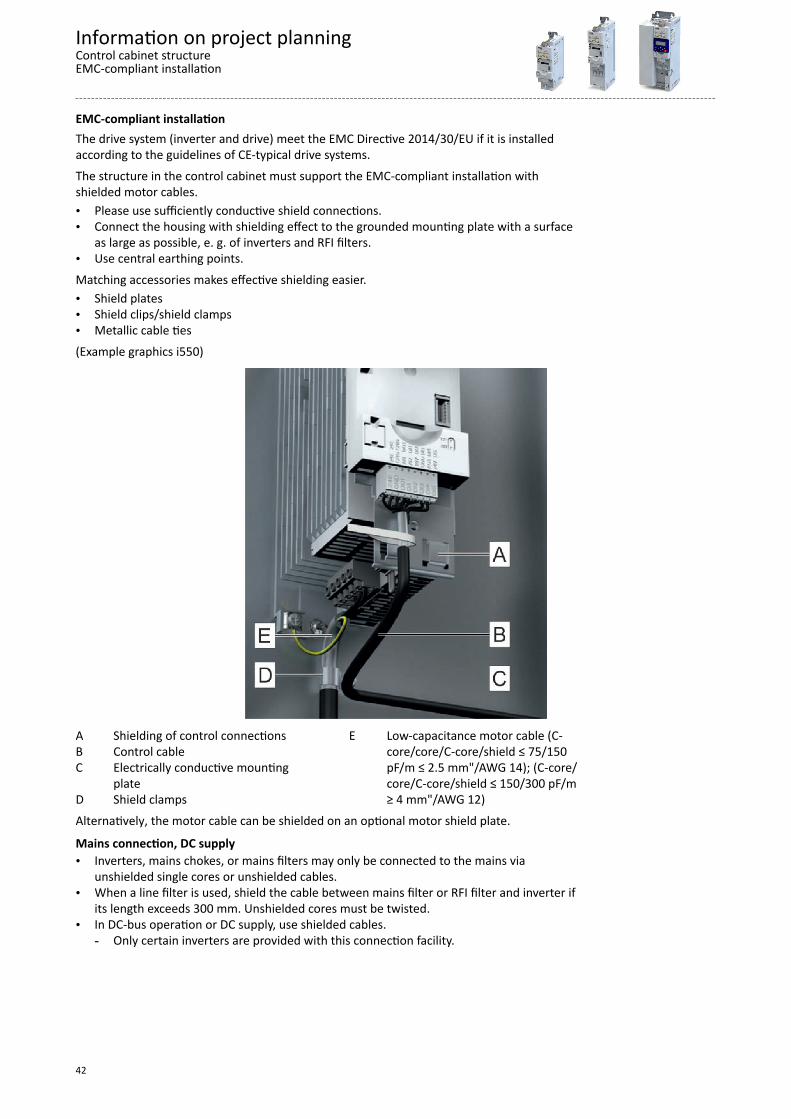
EMC-compliant installationThe drive system (inverter and drive) meet the EMC Directive 2014/30/EU if it is installedaccording to the guidelines of CE-typical drive systems.The structure in the control cabinet must support the EMC-compliant installation withshielded motor cables.• Please use sufficiently conductive shield connections.• Connect the housing with shielding effect to the grounded mounting plate with a surface
as large as possible, e. g. of inverters and RFI filters.• Use central earthing points.Matching accessories makes effective shielding easier.• Shield plates• Shield clips/shield clamps• Metallic cable ties(Example graphics i550)
A Shielding of control connectionsB Control cableC Electrically conductive mounting
plateD Shield clamps
E Low-capacitance motor cable (C-core/core/C-core/shield ≤ 75/150pF/m ≤ 2.5 mm"/AWG 14); (C-core/core/C-core/shield ≤ 150/300 pF/m≥ 4 mm"/AWG 12)
Alternatively, the motor cable can be shielded on an optional motor shield plate.
Mains connection, DC supply• Inverters, mains chokes, or mains filters may only be connected to the mains via
unshielded single cores or unshielded cables.• When a line filter is used, shield the cable between mains filter or RFI filter and inverter if
its length exceeds 300 mm. Unshielded cores must be twisted.• In DC-bus operation or DC supply, use shielded cables.
- Only certain inverters are provided with this connection facility.
Information on project planningControl cabinet structureEMC-compliant installation
42
Motor cable• Only use low-capacitance and shielded motor cables with braid made of tinned or nickel-
plated copper.- The overlap rate of the braid must be at least 70 % with an overlap angle of 90 °.- Shields made of steel braids are not suitable.
• Shield the cable for motor temperature monitoring (PTC or thermal contact) and install itseparately from the motor cable.- In Lenze system cables, the cable for brake control is integrated into the motor cable. If
this cable is not required for brake control, it can also be used to connect the motortemperature monitoring up to a length of 50 m.
- Only certain inverters are provided with this connection facility.• Connect the shield with a large surface and fix it with metal cable binders or conductive
clamp. The following is suitable for the connection of the shield:- The mounting plate- A central grounding rail- A shielding plate, if necessary, optional
• This is optimal:- The motor cable is separated from the mains cables and control cables.- The motor cable only crosses mains cables and control cables at right angles.- The motor cable is not interrupted.
• If the motor cable must be opened all the same (e. g. by chokes, contactors, or terminals):- The unshielded cable ends must not be longer than 100 mm (depending on the cable
cross-section).- Install chokes, contactors, terminals etc. spatially separated from other components
(with a minimum distance of 100 mm).- Install the shield of the motor cable directly before and behind the point of separation
to the mounting plate with a large surface.• Connect the shield with a large surface to PE in the terminal box of the motor at the motor
housing.- Metal EMC cable glands at the motor terminal box ensure a large surface connection of
the shield with the motor housing.
Control cables• Install the cables so that no induction-sensitive loops arise.• Distance of shield connections of control cables to shield connections of motor cables and
DC cables:- At least 50 mm
• Control cables for analog signals:- Must always be shielded- Connect the shield on one side of the inverter
• Control cables for digital signals:
Cable length< ca. 5 m ca. 5 m ... ca. 30 m > ca. 30 m
Type unshielded option unshielded twisted option always shieldedconnected on both sides
Network cables• Cables and wiring must comply with the specifications and requirements of the used
network.- Ensures the reliable operation of the network in typical systems.
Rated mains voltage DC voltage rangeV
400DC 450 V - 0 % ... 750 V + 0 %
480
Information on project planningControl cabinet structure
EMC-compliant installation
43
Detecting and eliminating EMC interferencesTrouble Cause RemedyInterferences of analog setpoints of your ownor other devices and measuring systems
Unshielded motor cable has been used Use shielded motor cableShield contact is not extensive enough Carry out optimal shielding as specifiedShield of the motor cable is interrupted, e. g. byterminal strips, switches etc.
• Separate components from other componentparts with a minimum distance of 100 mm
• Use motor chokes or motor filtersAdditional unshielded cables inside the motorcable have been installed, e. g. for motortemperature monitoring
Install and shield additional cables separately
Too long and unshielded cable ends of themotor cable
Shorten unshielded cable ends to maximally40 mm
Conducted interference level is exceeded on thesupply side
Terminal strips for the motor cable are directlylocated next to the mains terminals
Spatially separate the terminal strips for themotor cable from mains terminals and othercontrol terminals with a minimum distance of100 mm
Mounting plate varnished Optimise PE connection:• Remove varnish• Use zinc-coated mounting plate
HF short circuit Check cable routing
Information on project planningControl cabinet structureEMC-compliant installation
44

Information on mechanical installation
Important notes
After being mounted ,the safety module cannot be removed anymore!
Measures for cooling during operation• Ensure unimpeded ventilation of cooling air and outlet of exhaust air.• If the cooling air is polluted (fluff, (conductive) dust, soot, grease, aggressive gases), take
adequate countermeasures.• Install filters.• Arrange for regular cleaning of the filters.
• If required, implement a separate air guide.
Information on mechanical installationImportant notes
45

PreparationFurther data and information for mechanical mounting:4Control cabinet structure ^ 40
4Dimensions ^ 146
The scope of supply of the inverter comprises mounting instructions. Theydescribe technical data and information on mechanical and electricalinstallation.
Mounting position• Vertical alignment - all mains connections are at the top and the motor connections at the
bottom.
Free spaces• Maintain the specified free spaces above and below to the other installations.
Mechanical installation• The mounting location and material must ensure a durable mechanical connection.• Do not mount onto DIN rails!• In case of continuous vibrations or shocks use vibration dampers.
How to mount the inverters onto the mounting plate.Preconditions:• Mounting plate with conductive surfaceRequired:• Tool for drilling and thread cutting• Screwdriver• Screw and washer assemblies or hexagon socket screws with washers.1. Prepare mounting plate with corresponding threaded holes.2. Fit screws and washers (if applicable).3. Do not yet tighten the screws.4. Mount the inverter on the prepared mounting plate via keyhole suspension.5. Only tighten the screws hand-tight.6. Pre-assemble further units if necessary.7. Align the units with each other.8. Screw the units onto the mounting plate.The inverters are mounted on the mounting plate. You can begin with the wiring.
Screw and washer assemblies or hexagon socket screws with washers are recommended..M5 x ≥ 10 mm for devices up to and including 2.2 kWM5 x ≥ 12 mm for devices up to and including 11 kWM6 x ≥ 16 mm for devices up to and including 22 kWM8 x ≥ 16 mm for devices up to and including 110 kW
Information on mechanical installationPreparation
46

Information on electrical installation
Important notes
DANGER!Electrical voltagePossible consequences: Death or severe injuriesAny work on the inverter must only be carried out in the deenergised state. Inverter up to 45 kW: After switching off the mains voltage, wait for at least 3 min before
you start working. Inverter from 55 kW onwards: After switching off the mains voltage, wait for at least 10 min
before you start working.
DANGER!Dangerous electrical voltageThe leakage current against earth (PE) is > 3.5 mA AC or > 10 mA DC.Possible consequences: Death or severe injuries when touching the device in the event of anerror. Implement the measures requested in EN 61800−5−1 or EN 60204−1. Especially:Fixed installationThe PE connection must comply with the standards (PE conductor diameter ≥ 10 mm2 or
use a double PE conductor)
DANGER!Use of the inverter on a phase earthed mains with a rated mains voltage ≥ 400 VThe protection against accidental contact is not ensured without external measures. If protection against accidental contact according to EN 61800-5-1 is required for the control
terminals of the inverters and the connections of the plugged device modules, ...an additional basic insulation has to be provided. the components to be connected have to come with a second basic insulation.
NOTICENo protection against excessively high mains voltageThe mains input is not fused internally.Possible consequences: Destruction of the product in the event of excessively high mainsvoltage.Take note of the maximum permissible mains voltage.On the mains supply side, use fuses to adequately protect the product against mainsfluctuations and voltage peaks.
Information on electrical installation
47

NOTICEOvervoltage at devices with 230-V mains connectionAn impermissible overvoltage may occur if the central supply of the N conductor isinterrupted if the devices are connected to a TN three-phase system.Possible consequences: Destruction of the deviceProvide for the use of isolating transformers.
NOTICEThe product contains electrostatic sensitive devices.Possible consequences: Destruction of the deviceBefore working in the connection area, the personnel must be free of electrostatic charge.
NOTICEPluggable terminal strips or plug connectionsPlugging or removing the terminal strips or plug connections during operation may cause highvoltages and arcing.Possible consequences: Damage of the devicesSwitch off device.Only plug or remove the terminal strips or plug connections in deenergised status.
NOTICEUse of mains filters and RFI filters in IT systemsMains filters and RFI filters from Lenze contain components that are interconnected againstPE.Possible consequences: The filters may be destroyed when an earth fault occurs.Possible consequences: Monitoring of the IT system may be triggered.Do not use mains filters and RFI filters from Lenze in IT systems.Before using the inverter in the IT system, remove the IT screws.
NOTICEOvervoltage at componentsIn case of an earth fault in IT systems, intolerable overvoltages may occur in the plant.Possible consequences: Destruction of the device.Before using the inverter in the IT system, the contact screws must be removed.Positions and number of the contact screws depend on the device.
Ensure a trouble-free operation:Carry out the total wiring so that the separation of the separate potential areasis preserved.
When implementing machines and systems for the use in the UL/CSA scope, youhave to observe the relevant special notes.These notes are marked with "UL marking".
Information on electrical installationImportant notes
48

You have to install the devices into housings (e. g. control cabinets) to complywith valid regulations.Stickers with warning notes must be displayed prominently and close to thedevice.
PreparationFurther data and information for electrical installation:4EMC-compliant installation ^ 42
4Standards and operating conditions ^ 77
The scope of supply of the inverter comprises mounting instructions. Theydescribe technical data and information on mechanical and electricalinstallation.
Information on electrical installationPreparation
49

Connection according to UL
WARNING!UL markingSuitable for motor group installation or use on a circuit capable of delivering not more than
the rms symmetrical amperes (SCCR) of the drive at its rated voltage.Approved fusing is specified in SCCR tables below.Marquage ULConvient pour l'utilisation sur une installation avec un groupe de moteurs ou sur un circuit
capable de fournir au maximum une valeur de courant efficace symétrique en ampères à latension assignée de l'appareil.
Les dispositifs de protection adaptés sont spécifiés dans les SCCR tableaux suivants.
NOTICEUL markingThe opening of the Branch Circuit Protective Device may be an indication that a fault has
been interrupted. To reduce the risk of fire or electric shock, current-carring parts and othercomponents of the controller should beexamined and replaced if damaged. If burnout ofthe current element of an overload relay occurs, the complete overload relay must bereplaced.
Marquage ULLe déclenchement du dispositif de protection du circuit de dérivation peut être dû à une
coupure qui résulte d'un courant de défault. Pour limiter le risque d'incendie ou de chocélectrique, examiner les pièces porteuses de courant et les autres éléments du contrôleur etles remplacer s'ils sont endommagés. En cas de grillage de l'élément traversé par le courantdans un relais de surcharge, le relais tout entier doit être remplacé.
Information on electrical installationConnection according to UL
50

Branch Circuit Protection (BCP) with Short Circuit Current Ratings (SCCR) with Standard Fuses. (Tested perUL61800-5-1, reference UL file E132659)These devices are suitable for motor group installation when used with Standard Fuses. Forsingle motor installation, if the fuse value indicated is higher than 400% of the motor current(FLA), the fuse value has to be calculated. If the value of the fuse is below two standardratings, the nearest standard ratings less than the calculated value shall apply.
Inverter Standard Fuses (UL248)
Mains kW hp SCCR Max. ratedcurrent Class
120 V, 1-ph 0.25 0.33 5 kA 15 A CC120 V, 1-ph 0.37 0.50 5 kA 15 A CC120 V, 1-ph 0.75 1.00 5 kA 30 A CC, J, T120 V, 1-ph 1.10 1.50 5 kA 30 A CC, J, T230 V, 1-ph 0.25 0.33 65 kA 15 A CC230 V, 1-ph 0.37 0.50 65 kA 15 A CC230 V, 1-ph 0.55 0.75 65 kA 15 A CC230 V, 1-ph 0.75 1.00 65 kA 15 A CC230 V, 1-ph 1.10 1.50 65 kA 30 A CC, J, T230 V, 1-ph 1.50 2.00 65 kA 30 A CC, J, T230 V, 1-ph 2.20 3.00 65 kA 30 A CC, J, T
230 V, 1/3-ph 0.25 0.33 65 kA 15 A CC230 V, 1/3-ph 0.37 0.50 65 kA 15 A CC230 V, 1/3-ph 0.55 0.75 65 kA 15 A CC230 V, 1/3-ph 0.75 1.00 65 kA 15 A CC230 V, 1/3-ph 1.10 1.50 65 kA 30 A CC, J, T230 V, 1/3-ph 1.50 2.00 65 kA 30 A CC, J, T230 V, 1/3-ph 2.20 3.00 65 kA 30 A CC, J, T230 V, 3-ph 4.00 5.00 100 kA 40 A J, T230 V, 3-ph 5.50 7.50 100 kA 40 A J, T480 V, 3-ph 0.37 0.50 65 kA 15 A CC480 V, 3-ph 0.55 0.75 65 kA 15 A CC480 V, 3-ph 0.75 1.00 65 kA 15 A CC480 V, 3-ph 1.1 1.5 65 kA 15 A CC480 V, 3-ph 1.5 2.0 65 kA 15 A CC480 V, 3-ph 2.2 3.0 65 kA 15 A CC480 V, 3-ph 3.0 4.0 65 kA 25 A CC, J, T480 V, 3-ph 4.0 5.0 65 kA 25 A CC, J, T480 V, 3-ph 5.5 7.5 65 kA 25 A CC, J, T480 V, 3-ph 7.5 10.0 65 kA 40 A J, T480 V, 3-ph 11.0 15.0 65 kA 40 A J, T480 V, 3-ph 15.0 20.0 100 kA 70 A J, T480 V, 3-ph 18.5 25.0 100 kA 70 A J, T480 V, 3-ph 22 30 100 kA 70 A J, T
480 V, 3-ph * 30 40 22 kA 125 A J, T480 V, 3-ph * 37 50 22 kA 125 A J, T480 V, 3-ph * 45 60 22 kA 125 A J, T480 V, 3-ph * 55 75 22 kA 200 A J, T480 V, 3-ph * 75 100 22 kA 200 A J, T480 V, 3-ph * 90 125 22 kA 300 A J, T480 V, 3-ph * 110 150 22 kA 300 A J, T
* Mains choke required
Information on electrical installationConnection according to UL
51
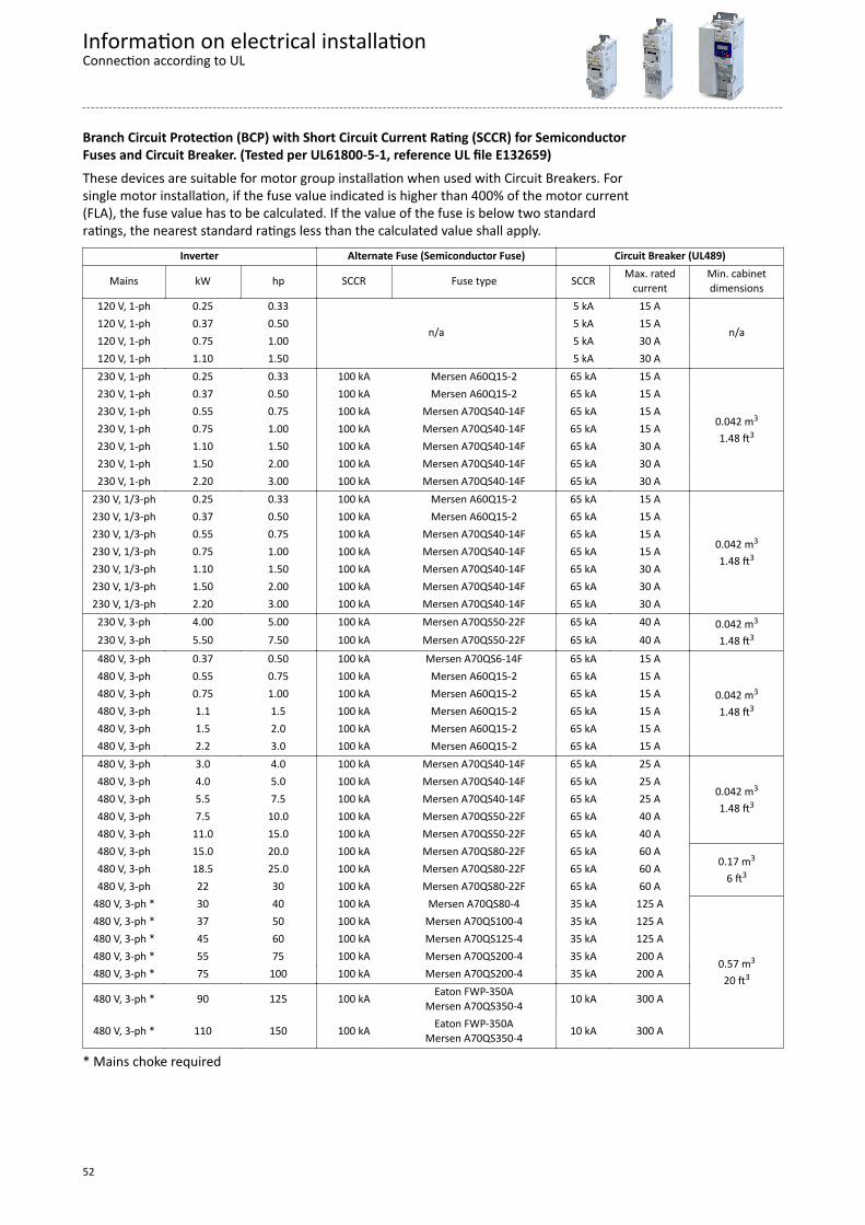
Branch Circuit Protection (BCP) with Short Circuit Current Rating (SCCR) for SemiconductorFuses and Circuit Breaker. (Tested per UL61800-5-1, reference UL file E132659)These devices are suitable for motor group installation when used with Circuit Breakers. Forsingle motor installation, if the fuse value indicated is higher than 400% of the motor current(FLA), the fuse value has to be calculated. If the value of the fuse is below two standardratings, the nearest standard ratings less than the calculated value shall apply.
Inverter Alternate Fuse (Semiconductor Fuse) Circuit Breaker (UL489)
Mains kW hp SCCR Fuse type SCCR Max. ratedcurrent
Min. cabinetdimensions
120 V, 1-ph 0.25 0.33
n/a
5 kA 15 A
n/a120 V, 1-ph 0.37 0.50 5 kA 15 A120 V, 1-ph 0.75 1.00 5 kA 30 A120 V, 1-ph 1.10 1.50 5 kA 30 A230 V, 1-ph 0.25 0.33 100 kA Mersen A60Q15-2 65 kA 15 A
0.042 m3
1.48 ft3
230 V, 1-ph 0.37 0.50 100 kA Mersen A60Q15-2 65 kA 15 A230 V, 1-ph 0.55 0.75 100 kA Mersen A70QS40-14F 65 kA 15 A230 V, 1-ph 0.75 1.00 100 kA Mersen A70QS40-14F 65 kA 15 A230 V, 1-ph 1.10 1.50 100 kA Mersen A70QS40-14F 65 kA 30 A230 V, 1-ph 1.50 2.00 100 kA Mersen A70QS40-14F 65 kA 30 A230 V, 1-ph 2.20 3.00 100 kA Mersen A70QS40-14F 65 kA 30 A
230 V, 1/3-ph 0.25 0.33 100 kA Mersen A60Q15-2 65 kA 15 A
0.042 m3
1.48 ft3
230 V, 1/3-ph 0.37 0.50 100 kA Mersen A60Q15-2 65 kA 15 A230 V, 1/3-ph 0.55 0.75 100 kA Mersen A70QS40-14F 65 kA 15 A230 V, 1/3-ph 0.75 1.00 100 kA Mersen A70QS40-14F 65 kA 15 A230 V, 1/3-ph 1.10 1.50 100 kA Mersen A70QS40-14F 65 kA 30 A230 V, 1/3-ph 1.50 2.00 100 kA Mersen A70QS40-14F 65 kA 30 A230 V, 1/3-ph 2.20 3.00 100 kA Mersen A70QS40-14F 65 kA 30 A230 V, 3-ph 4.00 5.00 100 kA Mersen A70QS50-22F 65 kA 40 A 0.042 m3
1.48 ft3230 V, 3-ph 5.50 7.50 100 kA Mersen A70QS50-22F 65 kA 40 A480 V, 3-ph 0.37 0.50 100 kA Mersen A70QS6-14F 65 kA 15 A
0.042 m3
1.48 ft3
480 V, 3-ph 0.55 0.75 100 kA Mersen A60Q15-2 65 kA 15 A480 V, 3-ph 0.75 1.00 100 kA Mersen A60Q15-2 65 kA 15 A480 V, 3-ph 1.1 1.5 100 kA Mersen A60Q15-2 65 kA 15 A480 V, 3-ph 1.5 2.0 100 kA Mersen A60Q15-2 65 kA 15 A480 V, 3-ph 2.2 3.0 100 kA Mersen A60Q15-2 65 kA 15 A480 V, 3-ph 3.0 4.0 100 kA Mersen A70QS40-14F 65 kA 25 A
0.042 m3
1.48 ft3
480 V, 3-ph 4.0 5.0 100 kA Mersen A70QS40-14F 65 kA 25 A480 V, 3-ph 5.5 7.5 100 kA Mersen A70QS40-14F 65 kA 25 A480 V, 3-ph 7.5 10.0 100 kA Mersen A70QS50-22F 65 kA 40 A480 V, 3-ph 11.0 15.0 100 kA Mersen A70QS50-22F 65 kA 40 A480 V, 3-ph 15.0 20.0 100 kA Mersen A70QS80-22F 65 kA 60 A
0.17 m3
6 ft3480 V, 3-ph 18.5 25.0 100 kA Mersen A70QS80-22F 65 kA 60 A480 V, 3-ph 22 30 100 kA Mersen A70QS80-22F 65 kA 60 A
480 V, 3-ph * 30 40 100 kA Mersen A70QS80-4 35 kA 125 A
0.57 m3
20 ft3
480 V, 3-ph * 37 50 100 kA Mersen A70QS100-4 35 kA 125 A480 V, 3-ph * 45 60 100 kA Mersen A70QS125-4 35 kA 125 A480 V, 3-ph * 55 75 100 kA Mersen A70QS200-4 35 kA 200 A480 V, 3-ph * 75 100 100 kA Mersen A70QS200-4 35 kA 200 A
480 V, 3-ph * 90 125 100 kA Eaton FWP-350AMersen A70QS350-4 10 kA 300 A
480 V, 3-ph * 110 150 100 kA Eaton FWP-350AMersen A70QS350-4 10 kA 300 A
* Mains choke required
Information on electrical installationConnection according to UL
52

Mains connectionThe following should be considered for the mains connection of inverters:Single inverters are either directly connected to the AC system or via upstream filters. RFIfilters are already integrated in many inverters. Depending on the requirements, mains chokesor mains filters can be used.Inverter groups are connected to the DC system with the DC bus. For this purpose, theinverters have to be provided with a connection for the DC link, e. g. terminals +UG/-UG.This enables the energy exchange in phases with operation in generator and motor mode ofseveral drives in the network.The DC system can be provided by power supply modules (AC/DC converters) or inverters witha power reserve.
The technical data informs about the possible applications in the given groups. In thedimensioning, data and further notes have to be observed.
Information on electrical installationMains connection
53
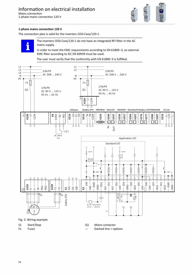
1-phase mains connection 120 VThe connection plan is valid for the inverters i550-Cxxx/120-1.
The inverters i550-Cxxx/120-1 do not have an integrated RFI filter in the ACmains supply.In order to meet the EMC requirements according to EN 61800−3, an externalEMC filter according to IEC EN 60939 must be used.The user must verify that the conformity with EN 61800−3 is fulfilled.
X28
7
X28
6
POWERLINK
X27
7
X27
6
Modbus TCP
X26
7
X26
6
EtherNet/IP
X25
7
X25
6
PROFINET
OUT
X24
7
IN X
246
EtherCAT
X22
6
PROFIBUSModbus RTU
TB
COM
TA
X21
6
CANopen
CL
CG
CH
X21
6
C/Q
L-
L+
X31
6
IO-Link
Safe
ty S
TO
X1
SIA
G
S S
IB
DC SELV PELV 24 V /(+19.2 … +28.8 V)
"
1k ..
. 10k
0 ...
10
V
S1
DI3 DI4
100 mA
4.4k
+24 V +10 V
4.4k
4.4k
4.4k
4.4k
10 m
A
Standard I/O
GND
DO1
DI1
DI2
DI3
DI4
DI5
24E
GND
AI1
AI2
10V
GND
AO1
24V
24E
X
3 24V
4.
4k D
I7
4.4k
AO2
DI1
D
O2
GND
G
ND
DI6
Application I/O
X10
5 U
V
W
R
b1
Rb2
+ X10
9 T
1 T
2
" "
M3~+
JJ
NC
NO
COM
X
9
AC 240 V3 A
F1
Q1
X10
0 L1
L2/N
1/ N/PE
90 V ... 132 VAC45 Hz ... 65 Hz
+
+
F1
Q1
X10
0 L1
L2/N
1/N/ PE 90 V ... 132 VAC
45 Hz ... 65 Hz
PEN
L2L1
2/N/ PE 208 V ... 240 VAC
PEN
L3L2L1
3/N/ PE 208 ... 240 VAC
Fig. 2: Wiring exampleS1 Start/StopFx Fuses
Q1 Mains contactor--- Dashed line = options
Information on electrical installationMains connection1-phase mains connection 120 V
54
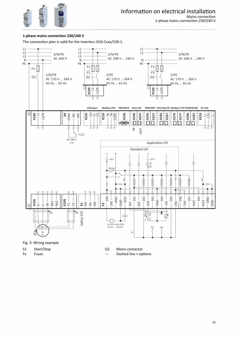
1-phase mains connection 230/240 VThe connection plan is valid for the inverters i550-Cxxx/230-1.
X28
7
X28
6
POWERLINK
X27
7
X27
6
Modbus TCP
X26
7
X26
6
EtherNet/IP
X25
7
X25
6
PROFINET
OUT
X24
7
IN X
246
EtherCAT
X22
6
PROFIBUSModbus RTU T
B C
OM
TA
X21
6CANopen
CL
CG
CH
X21
6
C/Q
L-
L+
X31
6
IO-Link
Safe
ty
ST
O X
1 S
IA
GS
SIB
DC SELV PELV 24 V /(+19.2 … +28.8 V)
"
1k ..
. 10k
0 ...
10
V
S1
DI3 DI4
100 mA
4.4k
+24 V +10 V
4.4k
4.4k
4.4k
4.4k
10 m
AStandard I/O
GND
DO1
DI1
DI2
DI3
DI4
DI5
24E
GND
AI1
AI2
10V
GND
AO
24V
24E
X
3 24V
4.
4k D
I7
4.4k
AO2
DI1
D
O2
GND
G
ND
DI6
Application I/O
X10
5 U
V
W
R
b1
Rb2
+ X10
9 T
1 T
2
" "
M3~+
JJ
NC
NO
COM
X
9
AC 240 V3 A
F1…F3Q1
X10
0 L1
L2/N
2/ PE 170 V ... 264 VAC
45 Hz ... 65 Hz+
2/ PE 170 V ... 264 VAC
45 Hz ... 65 Hz+
F1…F2Q1
X10
0 L1
L2/N
X10
0 L1
L2/N
F1
Q1
PEN
L2L1
2/N/ PE 208 V ... 240 VAC
PEN
L3L2L1
3/N/ PE 208 V ... 240 VAC
PEN
L3L2L1
+
1/N/PE 170 V ... 264 VAC
45 Hz ... 65 Hz
3/N/ PE 400 VAC
Fig. 3: Wiring exampleS1 Start/StopFx Fuses
Q1 Mains contactor--- Dashed line = options
Information on electrical installationMains connection
1-phase mains connection 230/240 V
55
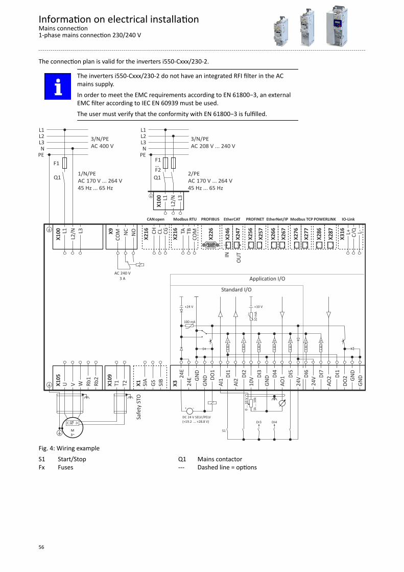
The connection plan is valid for the inverters i550-Cxxx/230-2.
The inverters i550-Cxxx/230-2 do not have an integrated RFI filter in the ACmains supply.In order to meet the EMC requirements according to EN 61800−3, an externalEMC filter according to IEC EN 60939 must be used.The user must verify that the conformity with EN 61800−3 is fulfilled.
X28
7
X28
6
POWERLINK
X27
7
X27
6
Modbus TCP
X26
7
X26
6
EtherNet/IP
X25
7
X25
6
PROFINET
OUT
X24
7
IN X
246
EtherCAT
X22
6 PROFIBUSModbus RTU
TB
COM
TA
X21
6
CANopen
CL
CG
CH
X21
6
C/Q
L-
L+
X31
6
IO-Link
Safe
ty
ST
O X
1 S
IA
GS
SIB
DC SELV PELV 24 V /(+19.2 … +28.8 V)
"
1k ..
. 10k
0 ...
10
V
S1
DI3 DI4
100 mA
4.4k
+24 V +10 V
4.4k
4.4k
4.4k
4.4k
10 m
A
Standard I/O
GND
DO1
DI1
DI2
DI3
DI4
DI5
24E
GND
AI1
AI2
10V
GND
AO1
24V
24E
X
3 24V
4.
4k D
I7
4.4k
AO2
DI1
D
O2
GND
G
ND
DI6
Application I/O
X10
5 U
V
W
R
b1
Rb2
+ X10
9 T
1 T
2
" "
M3~+
JJ
NC
NO
COM
X
9
AC 240 V3 A
2/ PE 170 V ... 264 VAC
45 Hz ... 65 Hz+
F1…F2Q1
X10
0 L1
L2/N
L3
X10
0 L1
L2/N
L3
F1
Q1
PEN
L3L2L1
+
1/N/PE 170 V ... 264 VAC
45 Hz ... 65 Hz
3/N/ PE 400 VAC
PEN
L3L2L1
3/N/ PE 208 V ... 240 VAC
Fig. 4: Wiring exampleS1 Start/StopFx Fuses
Q1 Mains contactor--- Dashed line = options
Information on electrical installationMains connection1-phase mains connection 230/240 V
56
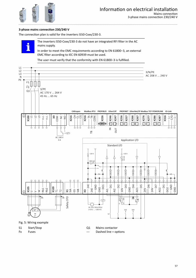
3-phase mains connection 230/240 VThe connection plan is valid for the inverters i550-Cxxx/230-3.
The inverters i550-Cxxx/230-3 do not have an integrated RFI filter in the ACmains supply.In order to meet the EMC requirements according to EN 61800−3, an externalEMC filter according to IEC EN 60939 must be used.The user must verify that the conformity with EN 61800−3 is fulfilled.
X28
7
X28
6
POWERLINK
X27
7
X27
6
Modbus TCP
X26
7
X26
6
EtherNet/IP
X25
7
X25
6
PROFINET
OUT
X24
7
IN X
246
EtherCAT
X22
6
PROFIBUSModbus RTU
TB
COM
TA
X21
6
CANopen
CL
CG
CH
X21
6
C/Q
L-
L+
X31
6
IO-Link
Safe
ty
ST
O X
1 S
IA
GS
SIB
DC SELV PELV 24 V /(+19.2 … +28.8 V)
"
1k ..
. 10k
0 ...
10
V
S1
DI3 DI4
100 mA
4.4k
+24 V +10 V
4.4k
4.4k
4.4k
4.4k
10 m
A
Standard I/O
GND
DO1
DI1
DI2
DI3
DI4
DI5
24E
GND
AI1
AI2
10V
GND
AO1
24V
24E
X
3 24V
4.
4k D
I7
4.4k
AO2
DI1
D
O2
GND
G
ND
DI6
Application I/O
X10
5 U
V
W
R
b1
Rb2
+ X10
9 T
1 T
2
" "
M3~+
JJ
NC
NO
COM
X
9
AC 240 V3 A
X10
0 L1
L2
L3
n.c
. n
.c.
F1…F3Q1
3/N/ PE 208 V ... 240 VAC
3/ PE 170 V ... 264 VAC
45 Hz ... 65 Hz
PEN
L3L2L1
+
TB
Fig. 5: Wiring exampleS1 Start/StopFx Fuses
Q1 Mains contactor--- Dashed line = options
Information on electrical installationMains connection
3-phase mains connection 230/240 V
57
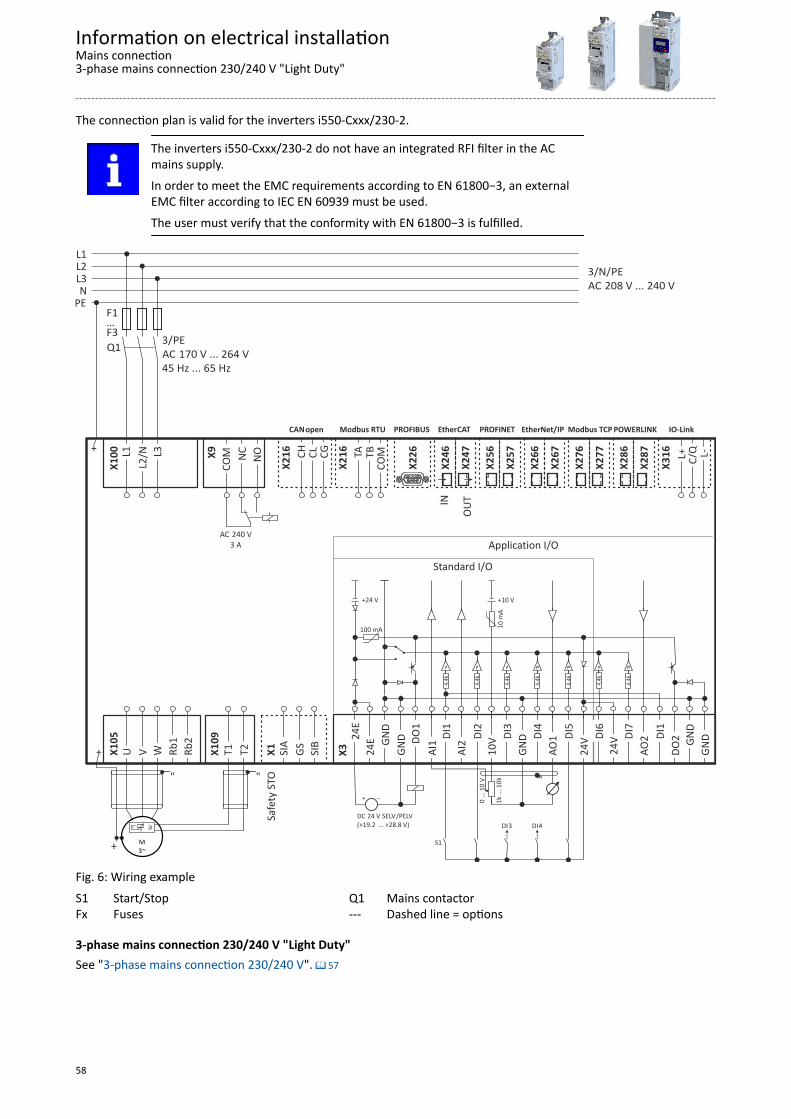
The connection plan is valid for the inverters i550-Cxxx/230-2.
The inverters i550-Cxxx/230-2 do not have an integrated RFI filter in the ACmains supply.In order to meet the EMC requirements according to EN 61800−3, an externalEMC filter according to IEC EN 60939 must be used.The user must verify that the conformity with EN 61800−3 is fulfilled.
X28
7
X28
6
POWERLINK
X27
7
X27
6
Modbus TCP
X26
7
X26
6
EtherNet/IP
X25
7
X25
6
PROFINET
OUT
X24
7
IN X
246
EtherCAT
X22
6 PROFIBUSModbus RTU
TB
COM
TA
X21
6
CANopen
CL
CG
CH
X21
6
C/Q
L-
L+
X31
6
IO-Link
Safe
ty
ST
O X
1 S
IA
GS
SIB
DC SELV PELV 24 V /(+19.2 … +28.8 V)
"
1k ..
. 10k
0 ...
10
V
S1
DI3 DI4
100 mA
4.4k
+24 V +10 V
4.4k
4.4k
4.4k
4.4k
10 m
A
Standard I/O
GND
DO1
DI1
DI2
DI3
DI4
DI5
24E
GND
AI1
AI2
10V
GND
AO1
24V
24E
X
3 24V
4.
4k D
I7
4.4k
AO2
DI1
D
O2
GND
G
ND
DI6
Application I/O
X10
5 U
V
W
R
b1
Rb2
+ X10
9 T
1 T
2
" "
M3~+
JJ
NC
NO
COM
X
9
AC 240 V3 A
X10
0 L1
L2/N
L3
F1…F3Q1
3/N/ PE 208 V ... 240 VAC
3/ PE 170 V ... 264 VAC
45 Hz ... 65 Hz
PEN
L3L2L1
+
Fig. 6: Wiring exampleS1 Start/StopFx Fuses
Q1 Mains contactor--- Dashed line = options
3-phase mains connection 230/240 V "Light Duty"See "3-phase mains connection 230/240 V". ^ 57
Information on electrical installationMains connection3-phase mains connection 230/240 V "Light Duty"
58
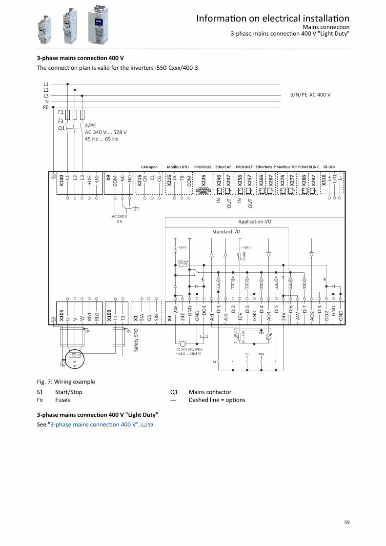
3-phase mains connection 400 VThe connection plan is valid for the inverters i550-Cxxx/400-3.
X28
7
X28
6
POWERLINK
X27
7
X27
6
Modbus TCP
X26
7
X26
6
EtherNet/IP
OUT
X25
7
IN X
256
PROFINET
OUT
X24
7
IN X
246
EtherCAT
X22
6
PROFIBUS
TB
COM
TA
X21
6 Modbus RTU
CL
CG
CH
X21
6
CANopen
C/Q
L-
L+
X31
6
IO-Link
Safe
ty
ST
O X
1
SI
A
GS
SI
B
DC SELV PELV 24 V /(+19.2 … +28.8 V)
"
1k ..
. 10k
0 ...
10
V
S1
DI3 DI4
100 mA
4.4k
+24 V +10 V
4.4k
4.4k
4.4k
4.4k
10 m
A
Standard I/O
GND
1
DO 1
DI 2
DI 3
DI 4
DI 5
DI
24E
GND
1
AI 2
AI 10V
GND
1
AO 24V
24E
X
3 24V
4.
4k
7 DI
4.4k
2
AO
1 DI
2
DO
GND
GND
6 DI
Application I/O
X10
5 U
V
W
R
b1
Rb2
+ X10
9 T
1 T
2
" "
M3~+
JJ
NC
NO
COM X9
AC 240 V3 A
X10
0 L1
L2
L3
+
UG -
UG
F1…F3Q1
3/N/ 400 VPE AC
3/ PE 340 V ... 528 VAC
45 Hz ... 65 Hz
PEN
L3L2L1
+
Fig. 7: Wiring exampleS1 Start/StopFx Fuses
Q1 Mains contactor--- Dashed line = options
3-phase mains connection 400 V "Light Duty"See "3-phase mains connection 400 V". ^ 59
Information on electrical installationMains connection
3-phase mains connection 400 V "Light Duty"
59
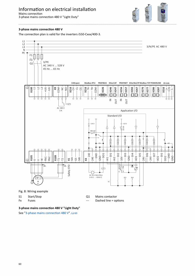
3-phase mains connection 480 VThe connection plan is valid for the inverters i550-Cxxx/400-3.
X28
7
X28
6
POWERLINK
X27
7
X27
6
Modbus TCP
X26
7
X26
6
EtherNet/IP
OUT
X25
7
IN X
256
PROFINET
OUT
X24
7
IN X
246
EtherCAT
X22
6
PROFIBUS
TB
COM
TA
X21
6 Modbus RTU
CL
CG
CH
X21
6
CANopen
C/Q
L-
L+
X31
6
IO-Link
NC
NO
COM X9
AC 240 V3 A
Safe
ty
ST
O X
1
SI
A
GS
SI
B
DC SELV PELV 24 V /(+19.2 … +28.8 V)
"
1k ..
. 10k
0 ...
10
V
S1
DI3 DI4
100 mA
4.4k
+24 V +10 V
4.4k
4.4k
4.4k
4.4k
10 m
A
Standard I/O
GND
1
DO 1
DI 2
DI 3
DI 4
DI 5
DI
24E
GND
1
AI 2
AI 10V
GND
1
AO 24V
24E
X
3 24V
4.
4k
7 DI
4.4k
2
AO
1 DI
2
DO
GND
GND
6 DI
Application I/O
X10
5 U
V
W
R
b1
Rb2
+ X10
9 T
1 T
2
" "
M3~+
JJ
X10
0 L1
L2
L3
+
UG -
UG
F1…F3Q1
3/N/ 480 VPE AC
3/ PE 340 V ... 528 VAC
45 Hz ... 65 Hz
PEN
L3L2L1
+
Fig. 8: Wiring exampleS1 Start/StopFx Fuses
Q1 Mains contactor--- Dashed line = options
3-phase mains connection 480 V "Light Duty"See "3-phase mains connection 480 V". ^ 60
Information on electrical installationMains connection3-phase mains connection 480 V "Light Duty"
60

Motor connectionSwitching in the motor cable
Switching on the motor side of the inverter is permissible:For safety shutdown (emergency stop).In case several motors are driven by one inverter (only in V/f operating mode).Please note the following:The switching elements on the motor side must be dimensioned for with themaximum occurring load.
Motor cable lengths• The rated data for the motor cable length must be observed.• Keep the motor cable as short as possible as this has a positive effect on the drive
behaviour and the EMC.• Several motors connected to an inverter form a group drive. In case of group drives, the
resulting motor cable length lres is relevant:
lres [m] = (l1 + l2 + l3 ... li) ∙ √i
lres Resulting length of the motor cables
l x Length of the single motor cable
i Number of the single motor cables
Information on electrical installationMotor connection
61
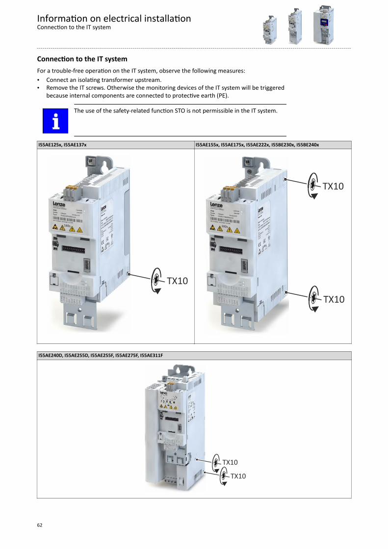
Connection to the IT systemFor a trouble-free operation on the IT system, observe the following measures:• Connect an isolating transformer upstream.• Remove the IT screws. Otherwise the monitoring devices of the IT system will be triggered
because internal components are connected to protective earth (PE).
The use of the safety-related function STO is not permissible in the IT system.
I55AE125x, I55AE137x I55AE155x, I55AE175x, I55AE222x, I55BE230x, I55BE240x
TX10
TX10
TX10
I55AE240D, I55AE255D, I55AE255F, I55AE275F, I55AE311F
TX10
TX10
Information on electrical installationConnection to the IT system
62
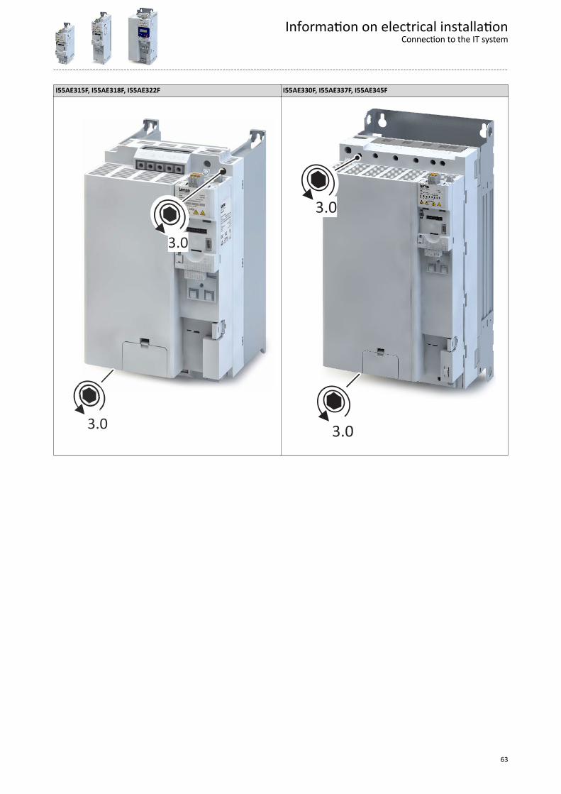
I55AE315F, I55AE318F, I55AE322F I55AE330F, I55AE337F, I55AE345F
3.0
3.0
3.0
3.0
Information on electrical installationConnection to the IT system
63
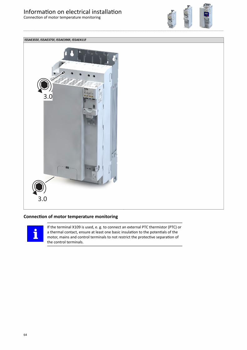
I55AE355F, I55AE375F, I55AE390F, I55AE411F
3.0
3.0
Connection of motor temperature monitoring
If the terminal X109 is used, e. g. to connect an external PTC thermistor (PTC) ora thermal contact, ensure at least one basic insulation to the potentials of themotor, mains and control terminals to not restrict the protective separation ofthe control terminals.
Information on electrical installationConnection of motor temperature monitoring
64
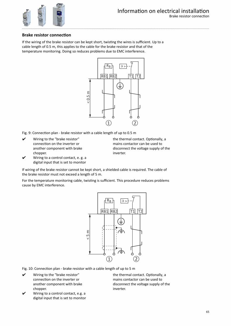
Brake resistor connectionIf the wiring of the brake resistor can be kept short, twisting the wires is sufficient. Up to acable length of 0.5 m, this applies to the cable for the brake resistor and that of thetemperature monitoring. Doing so reduces problems due to EMC interference.
RB
RB1 RB2
< 0.
5 m
T1 T2
+
① ②
Fig. 9: Connection plan - brake resistor with a cable length of up to 0.5 m Wiring to the "brake resistor"
connection on the inverter oranother component with brakechopper.
Wiring to a control contact, e. g. adigital input that is set to monitor
the thermal contact. Optionally, amains contactor can be used todisconnect the voltage supply of theinverter.
If wiring of the brake resistor cannot be kept short, a shielded cable is required. The cable ofthe brake resistor must not exceed a length of 5 m.For the temperature monitoring cable, twisting is sufficient. This procedure reduces problemscause by EMC interference.
RB
RB1 RB2
< 5
m
T1 T2
+"
"① ②
Fig. 10: Connection plan - brake resistor with a cable length of up to 5 m Wiring to the "brake resistor"
connection on the inverter oranother component with brakechopper.
Wiring to a control contact, e.g. adigital input that is set to monitor
the thermal contact. Optionally, amains contactor can be used todisconnect the voltage supply of theinverter.
Information on electrical installationBrake resistor connection
65
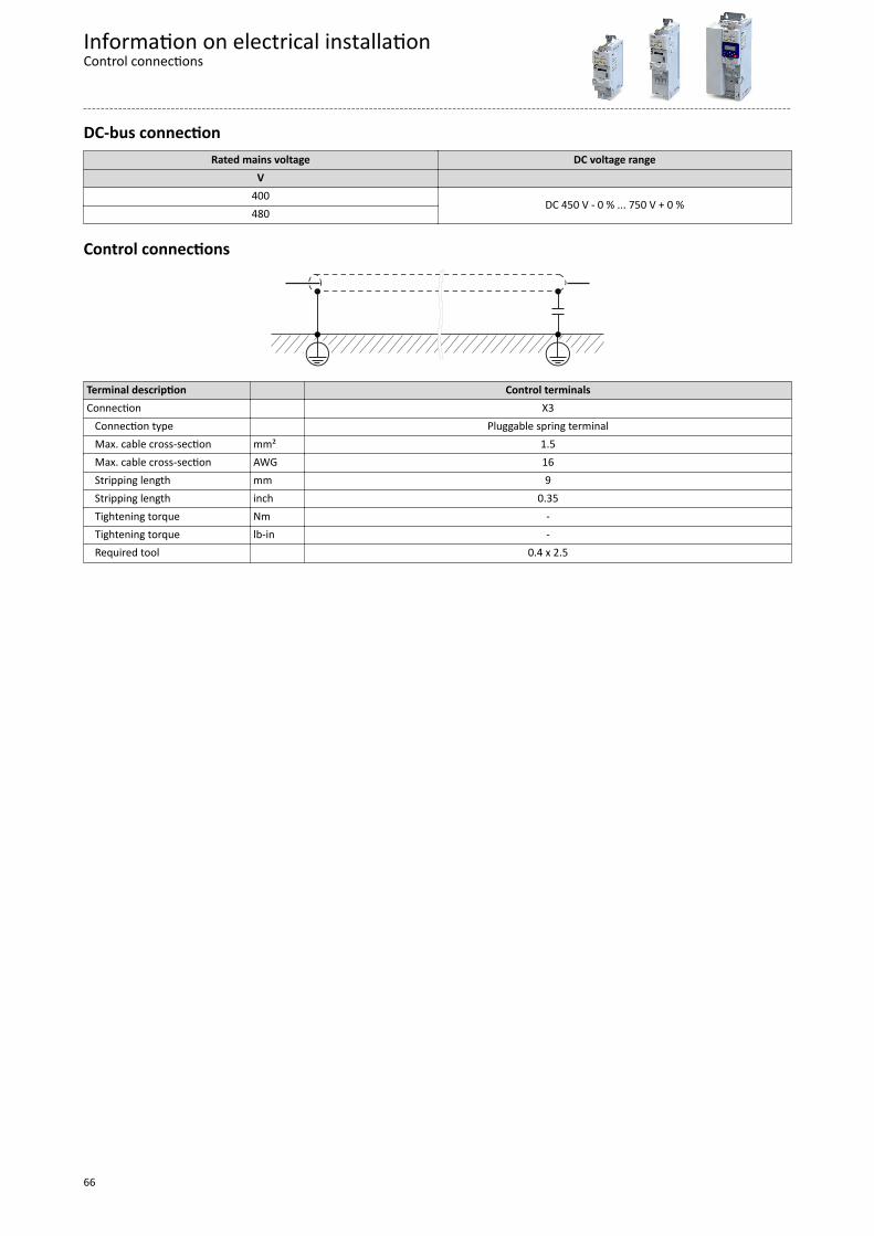
DC-bus connectionRated mains voltage DC voltage range
V 400
DC 450 V - 0 % ... 750 V + 0 %480
Control connections
Terminal description Control terminalsConnection X3 Connection type Pluggable spring terminal Max. cable cross-section mm² 1.5 Max. cable cross-section AWG 16 Stripping length mm 9 Stripping length inch 0.35 Tightening torque Nm - Tightening torque lb-in - Required tool 0.4 x 2.5
Information on electrical installationControl connections
66
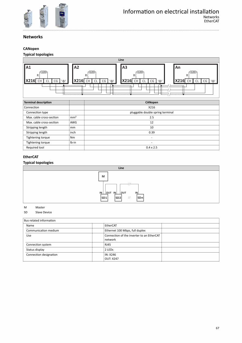
Networks
CANopenTypical topologies
Line
A1 A2 A3 An
X216 X216 X216 X216
120 120 120 120
CGCGCGCG CLCLCLCL CHCHCHCH
R R R R
Terminal description CANopenConnection X216 Connection type pluggable double spring terminal Max. cable cross-section mm² 2.5 Max. cable cross-section AWG 12 Stripping length mm 10 Stripping length inch 0.39 Tightening torque Nm - Tightening torque lb-in - Required tool 0.4 x 2.5
EtherCATTypical topologies
Line
IN OUT
M
R
SDnSD2SD1IN OUT IN
M Master SD Slave Device
Bus-related information
Name EtherCAT Communication medium Ethernet 100 Mbps, full duplex Use Connection of the inverter to an EtherCAT
network
Connection system RJ45 Status display 2 LEDs Connection designation IN: X246
OUT: X247
Information on electrical installationNetworksEtherCAT
67
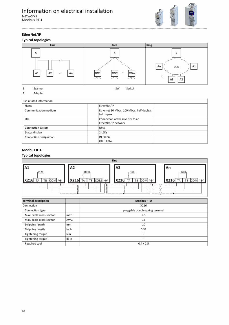
EtherNet/IPTypical topologies
Line Tree Ring
S
R
AnA2A1
S
SWnSW2SW1
S
An
A2
A1
A3
DLR
S Scanner SW SwitchA Adapter
Bus-related information
Name EtherNet/IP Communication medium Ethernet 10 Mbps, 100 Mbps, half duplex,
full duplex
Use Connection of the inverter to anEtherNet/IP network
Connection system RJ45 Status display 2 LEDs Connection designation IN: X266
OUT: X267
Modbus RTUTypical topologies
Line
A1 A2 A3 An
X216 X216 X216 X216
120 120 120 120
COM COM COM COMTB TB TB TBTA TA TA TA
Terminal description Modbus RTUConnection X216 Connection type pluggable double spring terminal Max. cable cross-section mm² 2.5 Max. cable cross-section AWG 12 Stripping length mm 10 Stripping length inch 0.39 Tightening torque Nm - Tightening torque lb-in - Required tool 0.4 x 2.5
Information on electrical installationNetworksModbus RTU
68
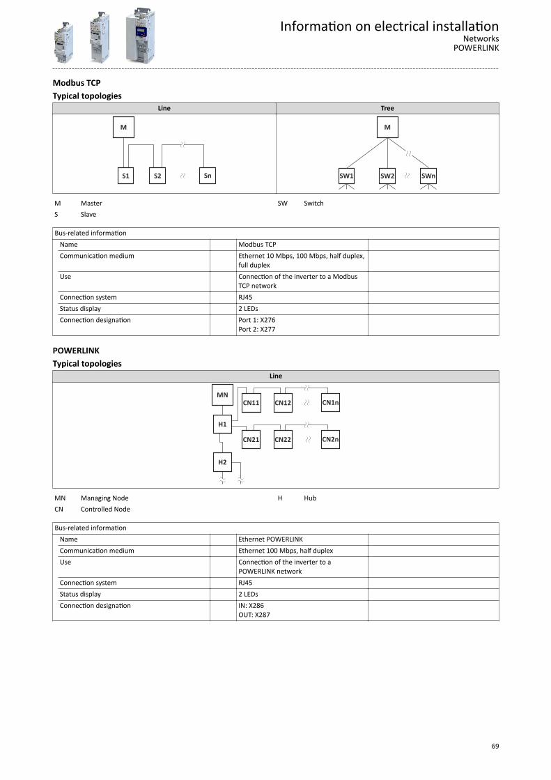
Modbus TCPTypical topologies
Line Tree
M
R
SnS2S1
M
SWnSW2SW1
M Master SW SwitchS Slave
Bus-related information
Name Modbus TCP Communication medium Ethernet 10 Mbps, 100 Mbps, half duplex,
full duplex
Use Connection of the inverter to a ModbusTCP network
Connection system RJ45 Status display 2 LEDs Connection designation Port 1: X276
Port 2: X277
POWERLINKTypical topologies
Line
CN2nCN22CN21
CN1nCN12CN11
H2
H1
MN
MN Managing Node H HubCN Controlled Node
Bus-related information
Name Ethernet POWERLINK Communication medium Ethernet 100 Mbps, half duplex Use Connection of the inverter to a
POWERLINK network
Connection system RJ45 Status display 2 LEDs Connection designation IN: X286
OUT: X287
Information on electrical installationNetworks
POWERLINK
69
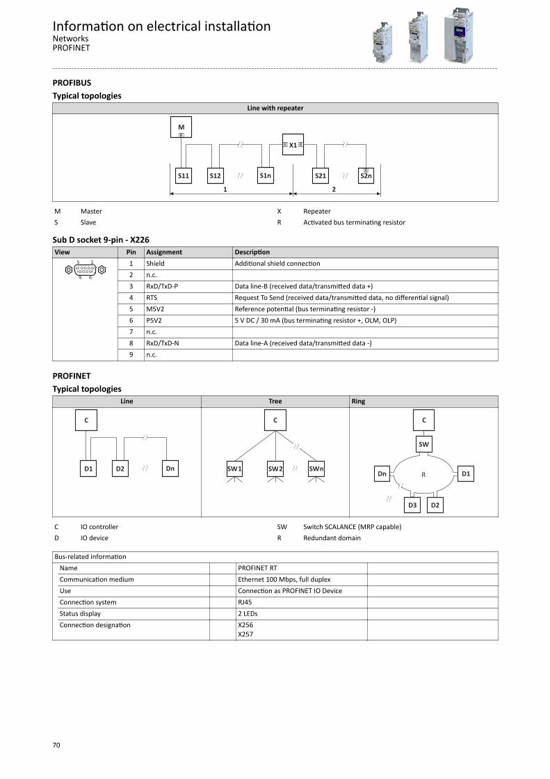
PROFIBUSTypical topologies
Line with repeater
M
R
1
S1nS12S11
2
X1
S21 S2n
R
R R
R
M Master X RepeaterS Slave R Activated bus terminating resistor
Sub D socket 9-pin - X226View Pin Assignment Description
1
6
5
9
5 1
9 6
1 Shield Additional shield connection2 n.c. 3 RxD/TxD-P Data line-B (received data/transmitted data +)4 RTS Request To Send (received data/transmitted data, no differential signal)5 M5V2 Reference potential (bus terminating resistor -)6 P5V2 5 V DC / 30 mA (bus terminating resistor +, OLM, OLP)7 n.c. 8 RxD/TxD-N Data line-A (received data/transmitted data -)9 n.c.
PROFINETTypical topologies
Line Tree Ring
C
R
DnD2D1
C
SWnSW2SW1
C
Dn
D2
D1
D3
R
SW
C IO controller SW Switch SCALANCE (MRP capable)D IO device R Redundant domain
Bus-related information
Name PROFINET RT Communication medium Ethernet 100 Mbps, full duplex Use Connection as PROFINET IO Device Connection system RJ45 Status display 2 LEDs Connection designation X256
X257
Information on electrical installationNetworksPROFINET
70
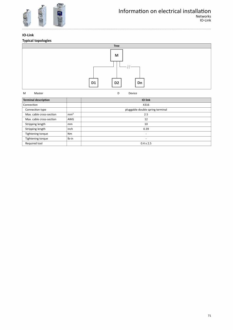
IO-LinkTypical topologies
Tree
M
DnD2D1
M Master D Device
Terminal description IO linkConnection X316 Connection type pluggable double spring terminal Max. cable cross-section mm² 2.5 Max. cable cross-section AWG 12 Stripping length mm 10 Stripping length inch 0.39 Tightening torque Nm - Tightening torque lb-in - Required tool 0.4 x 2.5
Information on electrical installationNetworks
IO-Link
71
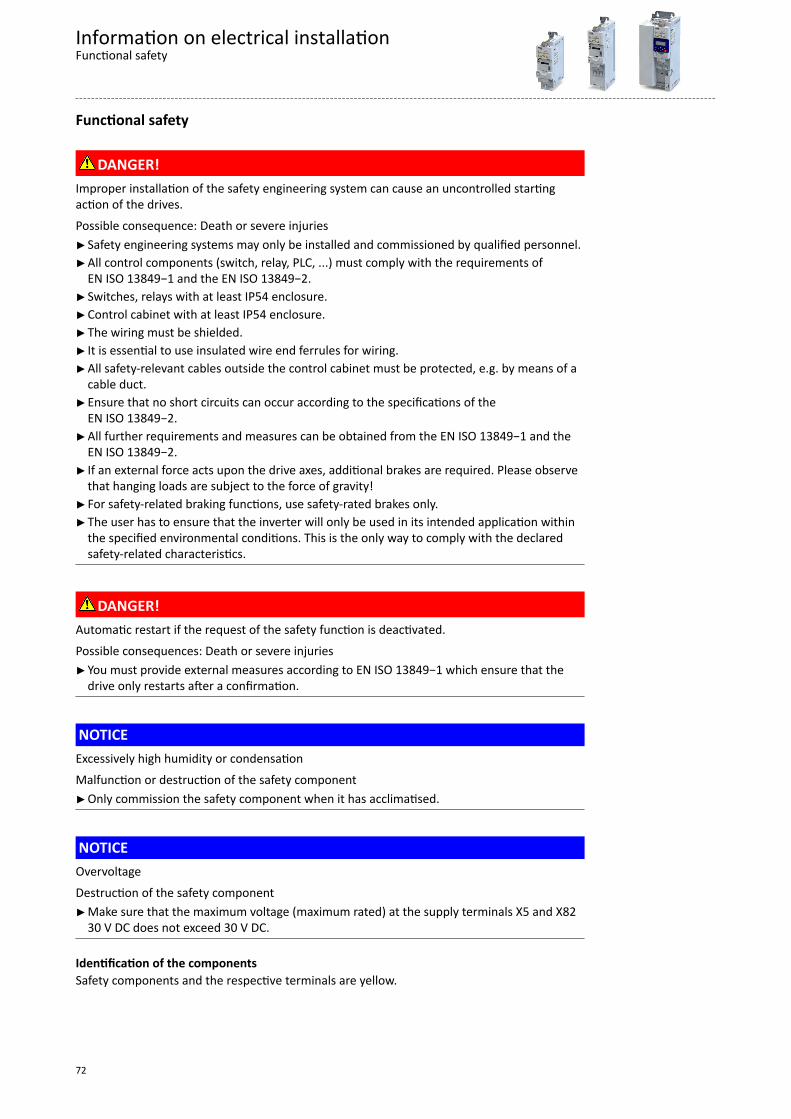
Functional safety
DANGER!Improper installation of the safety engineering system can cause an uncontrolled startingaction of the drives.Possible consequence: Death or severe injuriesSafety engineering systems may only be installed and commissioned by qualified personnel.All control components (switch, relay, PLC, ...) must comply with the requirements of
EN ISO 13849−1 and the EN ISO 13849−2.Switches, relays with at least IP54 enclosure.Control cabinet with at least IP54 enclosure.The wiring must be shielded. It is essential to use insulated wire end ferrules for wiring.All safety-relevant cables outside the control cabinet must be protected, e.g. by means of a
cable duct.Ensure that no short circuits can occur according to the specifications of the
EN ISO 13849−2.All further requirements and measures can be obtained from the EN ISO 13849−1 and the
EN ISO 13849−2. If an external force acts upon the drive axes, additional brakes are required. Please observe
that hanging loads are subject to the force of gravity!For safety-related braking functions, use safety-rated brakes only.The user has to ensure that the inverter will only be used in its intended application within
the specified environmental conditions. This is the only way to comply with the declaredsafety-related characteristics.
DANGER!Automatic restart if the request of the safety function is deactivated.Possible consequences: Death or severe injuriesYou must provide external measures according to EN ISO 13849−1 which ensure that the
drive only restarts after a confirmation.
NOTICEExcessively high humidity or condensationMalfunction or destruction of the safety componentOnly commission the safety component when it has acclimatised.
NOTICEOvervoltageDestruction of the safety componentMake sure that the maximum voltage (maximum rated) at the supply terminals X5 and X82
30 V DC does not exceed 30 V DC.
Identification of the componentsSafety components and the respective terminals are yellow.
Information on electrical installationFunctional safety
72

Important notes
StandardsSafety regulations are confirmed by laws and other governmental guidelines and measuresand the prevailing opinion among experts, e.g. by technical regulations.
The regulations and rules to be applied must be observed in accordance with the application.
Risk assessmentThis documentation can only accentuate the need for a risk assessment. The user of theintegrated safety system must read up on standards and the legal situation.
Before a machine can be put into circulation, the manufacturer of the machine has to conducta risk assessment according to the 2006/42/EU: Machinery Directive to determine the hazardsassociated with the use of the machine.
The Machinery Directive refers to three basic principles for the highest possible level of safety:• Hazard elimination / minimisation by the construction itself.• Taking the protective measures required against hazards that cannot be removed.• Existing residual hazards must be documented and the user must be informed of them.
Detailed information on the risk assessment is provided in the DIN EN ISO 12100:2013−08:Safety of machinery − general principles for design − risk assessment and risk reduction . Theresult of the risk assessment determines the category for safety-related control systemsaccording to EN ISO 13849−1. Safety-oriented parts of the machine control must be compliant.
Information on electrical installationFunctional safetyImportant notes
73

Basic Safety - STO
DANGER!With the "Safe torque off" (STO) function, no “emergency‑stop" can be executed according toEN 60204−1 without additional measures. There is no electrical isolation between the motorand inverter and no service switch or maintenance switch!Possible consequences: Death or severe injuries"Emergency stop" requires electrical isolation, e. g. via a central mains contactor.
Information on electrical installationFunctional safetyBasic Safety - STO
74
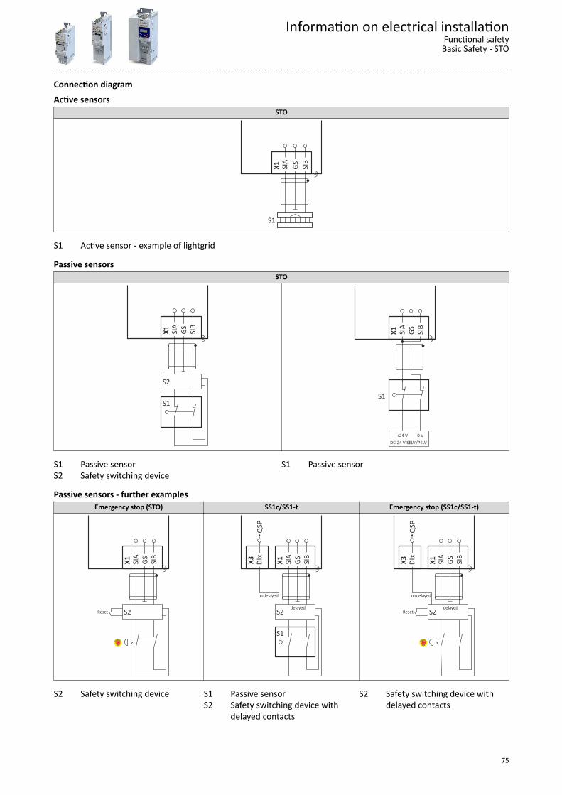
Connection diagramActive sensors
STO
X1
SIA
G
S S
IB
"
S1
S1 Active sensor - example of lightgrid
Passive sensorsSTO
X1
SIA
G
S S
IB
"
S2
S1 X
1 S
IA
GS
SIB
"
S1
DC 24 V SELV/PELV+24 V 0 V
S1 Passive sensorS2 Safety switching device
S1 Passive sensor
Passive sensors - further examplesEmergency stop (STO) SS1c/SS1-t Emergency stop (SS1c/SS1-t)
X1
SIA
G
S S
IB
"
S2 Reset
X1
SIA
G
S S
IB
"
S2
S1
X3
DIx
Q
SP
delayed
undelayed
X1
SIA
G
S S
IB
"
S2
X3
DIx
Q
SP
delayed
undelayed
Reset
S2 Safety switching device S1 Passive sensorS2 Safety switching device with
delayed contacts
S2 Safety switching device withdelayed contacts
Information on electrical installationFunctional safetyBasic Safety - STO
75
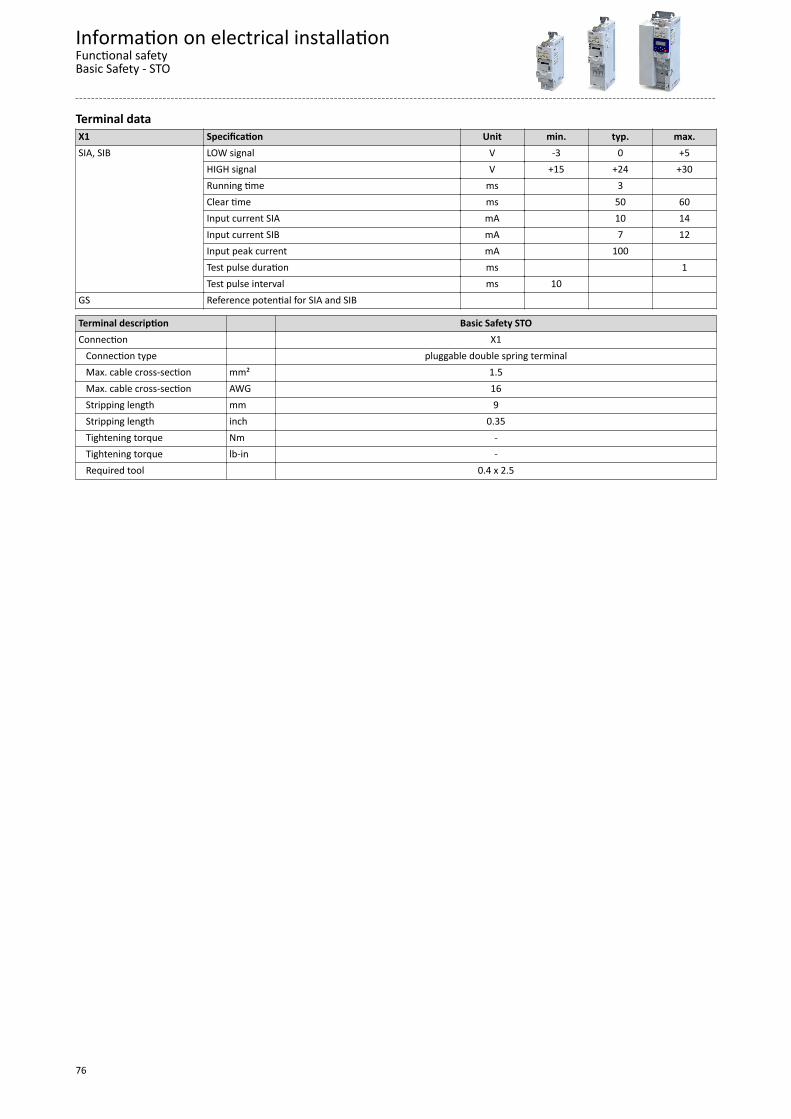
Terminal dataX1 Specification Unit min. typ. max.SIA, SIB LOW signal V -3 0 +5
HIGH signal V +15 +24 +30Running time ms 3 Clear time ms 50 60Input current SIA mA 10 14Input current SIB mA 7 12Input peak current mA 100 Test pulse duration ms 1Test pulse interval ms 10
GS Reference potential for SIA and SIB
Terminal description Basic Safety STOConnection X1 Connection type pluggable double spring terminal Max. cable cross-section mm² 1.5 Max. cable cross-section AWG 16 Stripping length mm 9 Stripping length inch 0.35 Tightening torque Nm - Tightening torque lb-in - Required tool 0.4 x 2.5
Information on electrical installationFunctional safetyBasic Safety - STO
76
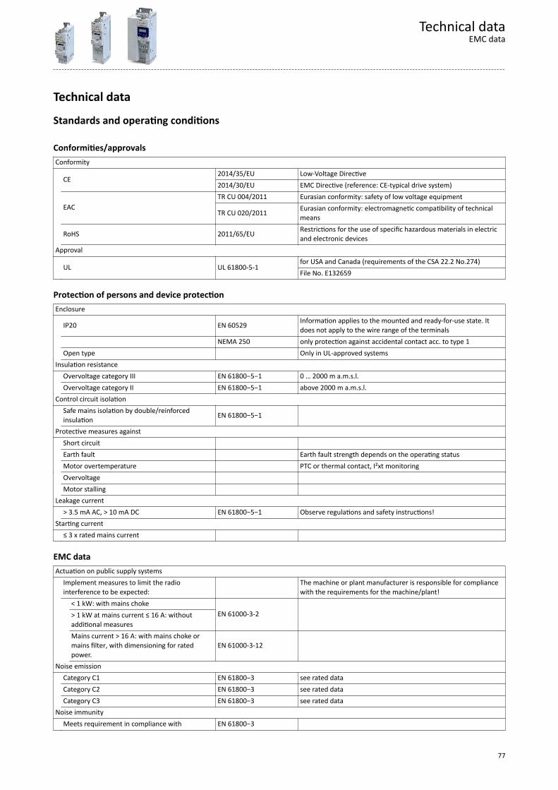
Technical data
Standards and operating conditions
Conformities/approvalsConformity
CE2014/35/EU Low-Voltage Directive2014/30/EU EMC Directive (reference: CE-typical drive system)
EACTR CU 004/2011 Eurasian conformity: safety of low voltage equipment
TR CU 020/2011 Eurasian conformity: electromagnetic compatibility of technicalmeans
RoHS 2011/65/EU Restrictions for the use of specific hazardous materials in electricand electronic devices
Approval
UL UL 61800-5-1for USA and Canada (requirements of the CSA 22.2 No.274)File No. E132659
Protection of persons and device protectionEnclosure
IP20 EN 60529 Information applies to the mounted and ready-for-use state. Itdoes not apply to the wire range of the terminals
NEMA 250 only protection against accidental contact acc. to type 1 Open type Only in UL-approved systemsInsulation resistance Overvoltage category III EN 61800−5−1 0 … 2000 m a.m.s.l. Overvoltage category II EN 61800−5−1 above 2000 m a.m.s.l.Control circuit isolation
Safe mains isolation by double/reinforcedinsulation EN 61800−5−1
Protective measures against Short circuit Earth fault Earth fault strength depends on the operating status Motor overtemperature PTC or thermal contact, I²xt monitoring Overvoltage Motor stalling Leakage current > 3.5 mA AC, > 10 mA DC EN 61800−5−1 Observe regulations and safety instructions!Starting current ≤ 3 x rated mains current
EMC dataActuation on public supply systems
Implement measures to limit the radiointerference to be expected: The machine or plant manufacturer is responsible for compliance
with the requirements for the machine/plant!
< 1 kW: with mains choke
EN 61000-3-2 > 1 kW at mains current ≤ 16 A: withoutadditional measures
Mains current > 16 A: with mains choke ormains filter, with dimensioning for ratedpower.
EN 61000-3-12
Noise emission Category C1 EN 61800−3 see rated data Category C2 EN 61800−3 see rated data Category C3 EN 61800−3 see rated dataNoise immunity Meets requirement in compliance with EN 61800−3
Technical dataEMC data
77
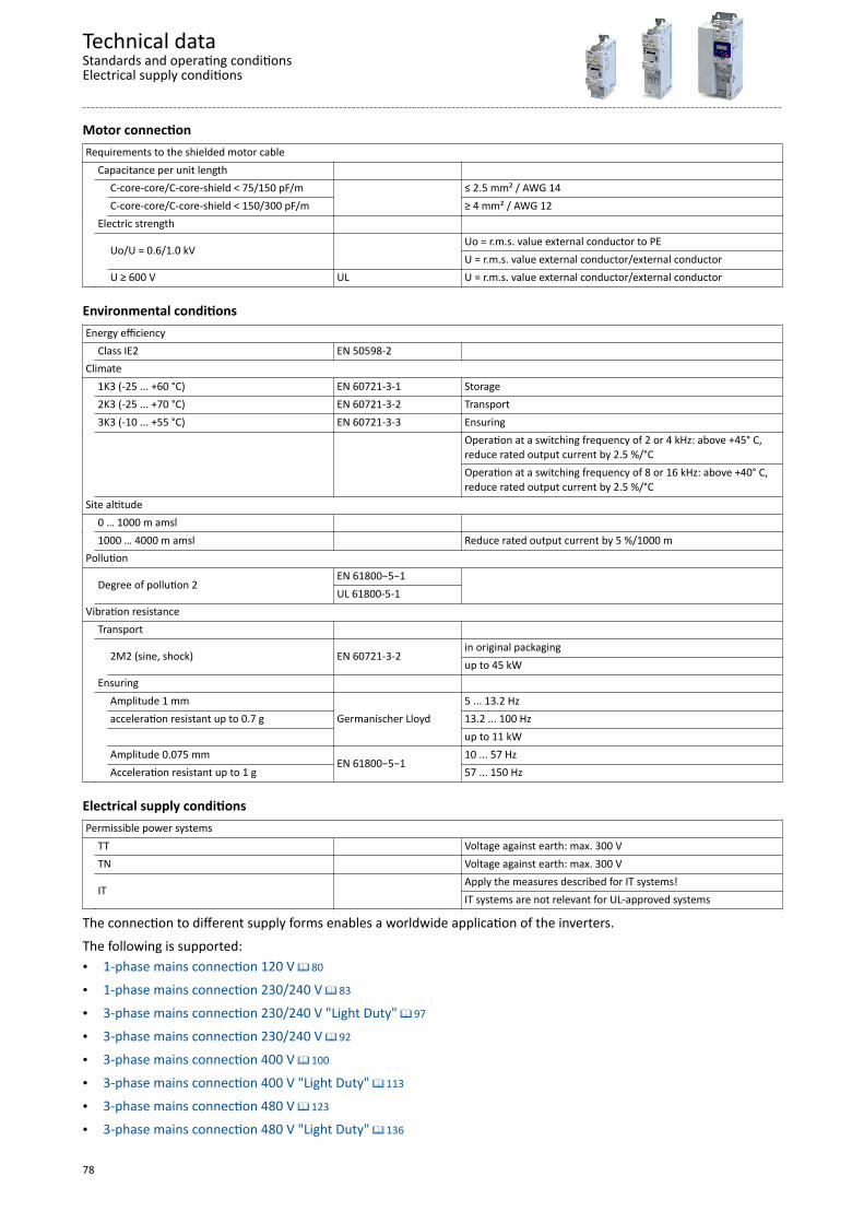
Motor connectionRequirements to the shielded motor cable Capacitance per unit length
C-core-core/C-core-shield < 75/150 pF/m
≤ 2.5 mm² / AWG 14
C-core-core/C-core-shield < 150/300 pF/m ≥ 4 mm² / AWG 12 Electric strength
Uo/U = 0.6/1.0 kV Uo = r.m.s. value external conductor to PEU = r.m.s. value external conductor/external conductor
U ≥ 600 V UL U = r.m.s. value external conductor/external conductor
Environmental conditionsEnergy efficiency Class IE2 EN 50598-2 Climate 1K3 (-25 ... +60 °C) EN 60721-3-1 Storage 2K3 (-25 ... +70 °C) EN 60721-3-2 Transport 3K3 (-10 ... +55 °C) EN 60721-3-3 Ensuring
Operation at a switching frequency of 2 or 4 kHz: above +45° C,reduce rated output current by 2.5 %/°COperation at a switching frequency of 8 or 16 kHz: above +40° C,reduce rated output current by 2.5 %/°C
Site altitude 0 … 1000 m amsl 1000 … 4000 m amsl Reduce rated output current by 5 %/1000 mPollution
Degree of pollution 2EN 61800−5−1
UL 61800-5-1
Vibration resistance Transport
2M2 (sine, shock) EN 60721-3-2in original packagingup to 45 kW
Ensuring
Amplitude 1 mm
Germanischer Lloyd5 ... 13.2 Hz
acceleration resistant up to 0.7 g 13.2 ... 100 Hz up to 11 kW
Amplitude 0.075 mm
EN 61800−5−110 ... 57 Hz
Acceleration resistant up to 1 g 57 ... 150 Hz
Electrical supply conditionsPermissible power systems TT Voltage against earth: max. 300 V TN Voltage against earth: max. 300 V
IT Apply the measures described for IT systems!IT systems are not relevant for UL-approved systems
The connection to different supply forms enables a worldwide application of the inverters.The following is supported:• 1-phase mains connection 120 V ^ 80
• 1-phase mains connection 230/240 V ^ 83
• 3-phase mains connection 230/240 V "Light Duty" ^ 97
• 3-phase mains connection 230/240 V ^ 92
• 3-phase mains connection 400 V ^ 100
• 3-phase mains connection 400 V "Light Duty" ^ 113
• 3-phase mains connection 480 V ^ 123
• 3-phase mains connection 480 V "Light Duty" ^ 136
Technical dataStandards and operating conditionsElectrical supply conditions
78

Certification of the integrated safety
The certification of the integrated safety is based on these test fundamentals:• EN ISO 13849−1: Safety of machinery − safety-related parts of control systems − Part 1• EN ISO 13849−2: Safety of machinery − safety-related parts of control systems − Part 2• EN 60204−1: Safety of machinery − electrical equipment of machines − Part 1• EN 61508, Part 1−7: Safety of machinery Functional safety of electrical/electronic/
programmable electronic safety-related systems• EN 61800−3: Electric variable-speed drives − Part 3: EMC requirements including specific
test procedures• EN 61800−5−1: Adjustable speed electrical power drive systems − Part 5−1: Safety
requirements − electrical, thermal and energy requirements• EN 61800−5−2: Adjustable speed electrical power drive systems − Part 5−2: Safety
requirements − functional safety• EN 62061: Safety of machinery − functional safety of safety-related electrical/electronic/
programmable electronic systems
Declarations of Conformity and certificates can be found on the internet athttp://www.Lenze.com
Technical dataStandards and operating conditionsCertification of the integrated safety
79

1-phase mains connection 120 V
EMC filters are not integrated in inverters for this mains connection.
Technical data1-phase mains connection 120 V
80
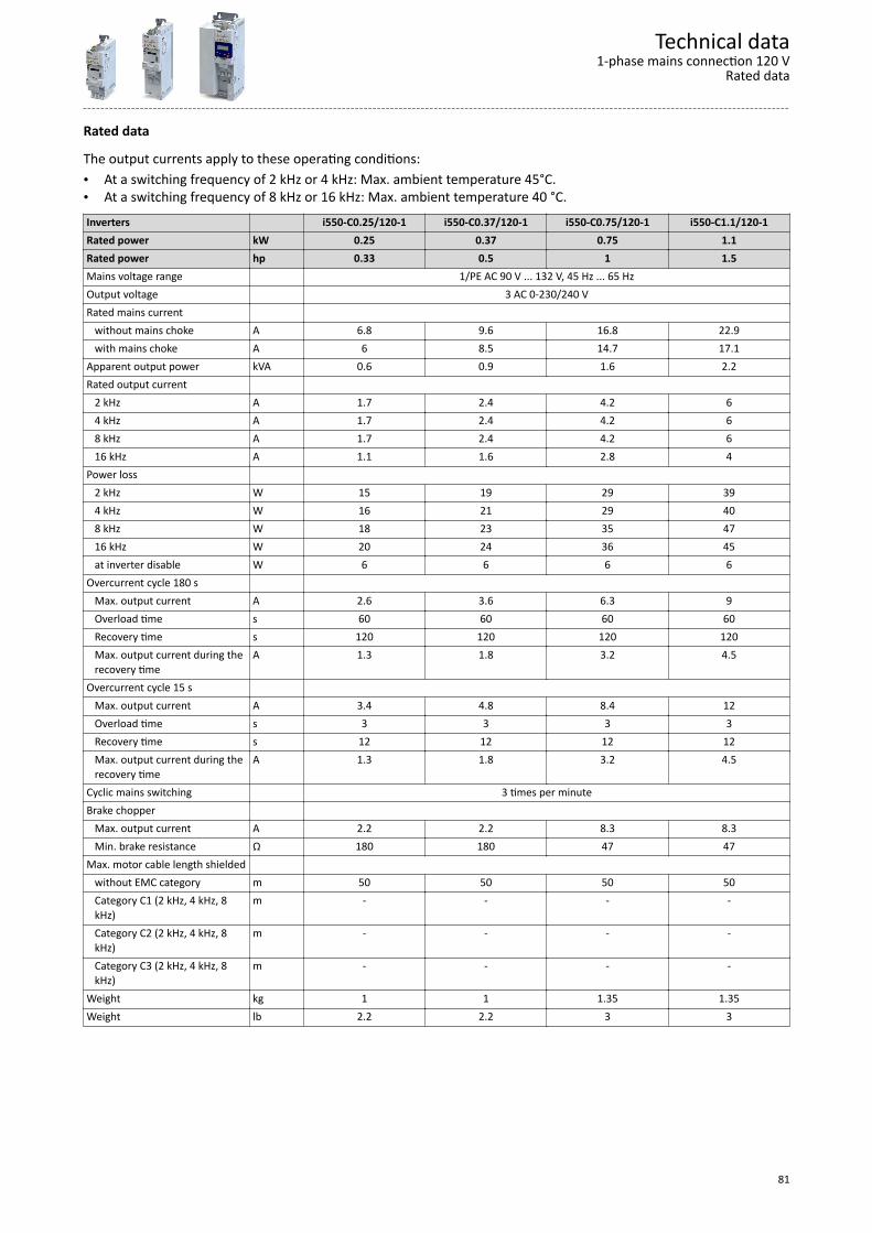
Rated data
The output currents apply to these operating conditions:• At a switching frequency of 2 kHz or 4 kHz: Max. ambient temperature 45°C.• At a switching frequency of 8 kHz or 16 kHz: Max. ambient temperature 40 °C.Inverters i550-C0.25/120-1 i550-C0.37/120-1 i550-C0.75/120-1 i550-C1.1/120-1Rated power kW 0.25 0.37 0.75 1.1Rated power hp 0.33 0.5 1 1.5Mains voltage range 1/PE AC 90 V ... 132 V, 45 Hz ... 65 HzOutput voltage 3 AC 0-230/240 VRated mains current without mains choke A 6.8 9.6 16.8 22.9 with mains choke A 6 8.5 14.7 17.1Apparent output power kVA 0.6 0.9 1.6 2.2Rated output current 2 kHz A 1.7 2.4 4.2 6 4 kHz A 1.7 2.4 4.2 6 8 kHz A 1.7 2.4 4.2 6 16 kHz A 1.1 1.6 2.8 4Power loss 2 kHz W 15 19 29 39 4 kHz W 16 21 29 40 8 kHz W 18 23 35 47 16 kHz W 20 24 36 45 at inverter disable W 6 6 6 6Overcurrent cycle 180 s Max. output current A 2.6 3.6 6.3 9 Overload time s 60 60 60 60 Recovery time s 120 120 120 120 Max. output current during the
recovery timeA 1.3 1.8 3.2 4.5
Overcurrent cycle 15 s Max. output current A 3.4 4.8 8.4 12 Overload time s 3 3 3 3 Recovery time s 12 12 12 12 Max. output current during the
recovery timeA 1.3 1.8 3.2 4.5
Cyclic mains switching 3 times per minuteBrake chopper Max. output current A 2.2 2.2 8.3 8.3 Min. brake resistance Ω 180 180 47 47Max. motor cable length shielded without EMC category m 50 50 50 50 Category C1 (2 kHz, 4 kHz, 8
kHz)m - - - -
Category C2 (2 kHz, 4 kHz, 8kHz)
m - - - -
Category C3 (2 kHz, 4 kHz, 8kHz)
m - - - -
Weight kg 1 1 1.35 1.35Weight lb 2.2 2.2 3 3
Technical data1-phase mains connection 120 V
Rated data
81
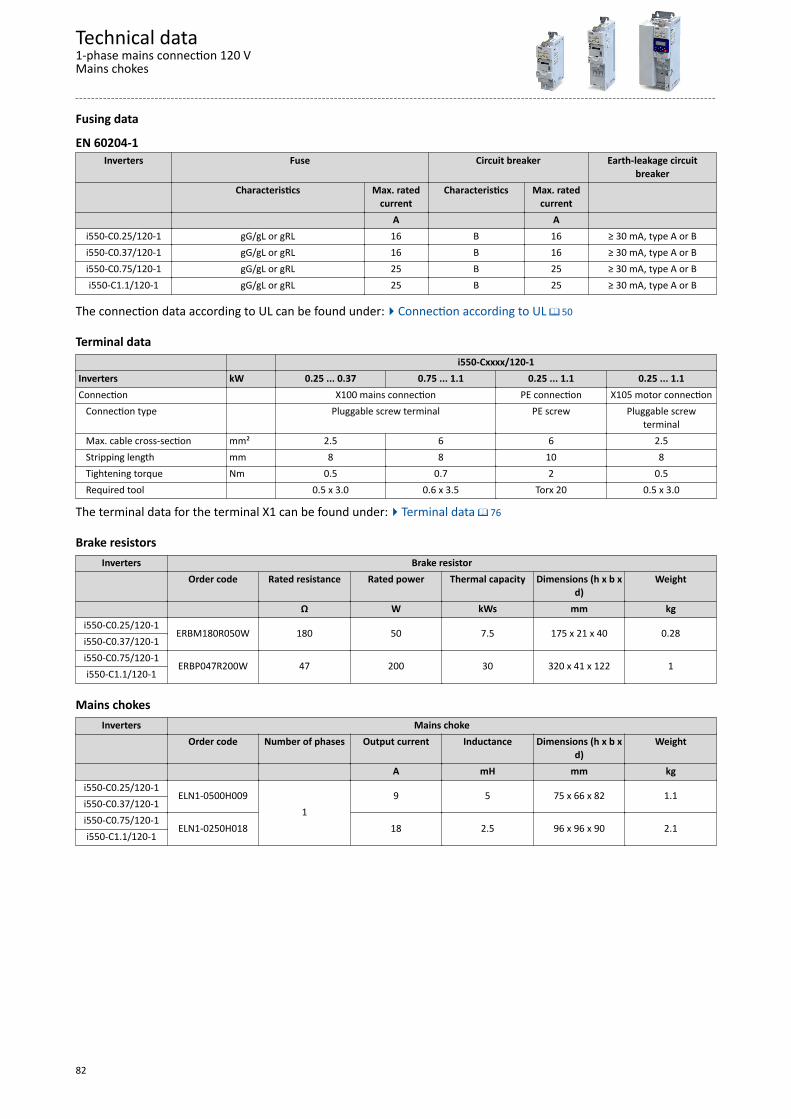
Fusing data
EN 60204-1Inverters Fuse Circuit breaker Earth-leakage circuit
breakerCharacteristics Max. rated
currentCharacteristics Max. rated
current A A
i550-C0.25/120-1 gG/gL or gRL 16 B 16 ≥ 30 mA, type A or Bi550-C0.37/120-1 gG/gL or gRL 16 B 16 ≥ 30 mA, type A or Bi550-C0.75/120-1 gG/gL or gRL 25 B 25 ≥ 30 mA, type A or Bi550-C1.1/120-1 gG/gL or gRL 25 B 25 ≥ 30 mA, type A or B
The connection data according to UL can be found under:4Connection according to UL ^ 50
Terminal data i550-Cxxxx/120-1Inverters kW 0.25 ... 0.37 0.75 ... 1.1 0.25 ... 1.1 0.25 ... 1.1Connection X100 mains connection PE connection X105 motor connection Connection type Pluggable screw terminal PE screw Pluggable screw
terminal Max. cable cross-section mm² 2.5 6 6 2.5 Stripping length mm 8 8 10 8 Tightening torque Nm 0.5 0.7 2 0.5 Required tool 0.5 x 3.0 0.6 x 3.5 Torx 20 0.5 x 3.0
The terminal data for the terminal X1 can be found under:4Terminal data ^ 76
Brake resistorsInverters Brake resistor
Order code Rated resistance Rated power Thermal capacity Dimensions (h x b xd)
Weight
Ω W kWs mm kgi550-C0.25/120-1
ERBM180R050W 180 50 7.5 175 x 21 x 40 0.28i550-C0.37/120-1i550-C0.75/120-1
ERBP047R200W 47 200 30 320 x 41 x 122 1i550-C1.1/120-1
Mains chokesInverters Mains choke
Order code Number of phases Output current Inductance Dimensions (h x b xd)
Weight
A mH mm kgi550-C0.25/120-1
ELN1-0500H0091
9 5 75 x 66 x 82 1.1i550-C0.37/120-1i550-C0.75/120-1
ELN1-0250H018 18 2.5 96 x 96 x 90 2.1i550-C1.1/120-1
Technical data1-phase mains connection 120 VMains chokes
82

1-phase mains connection 230/240 V
When selecting the inverters, please note: EMC filters are integrated in thei550-Cxxx/230-1 inverters. EMC filters are not integrated in the inverters i550-Cxxx/230-2.
Technical data1-phase mains connection 230/240 V
83
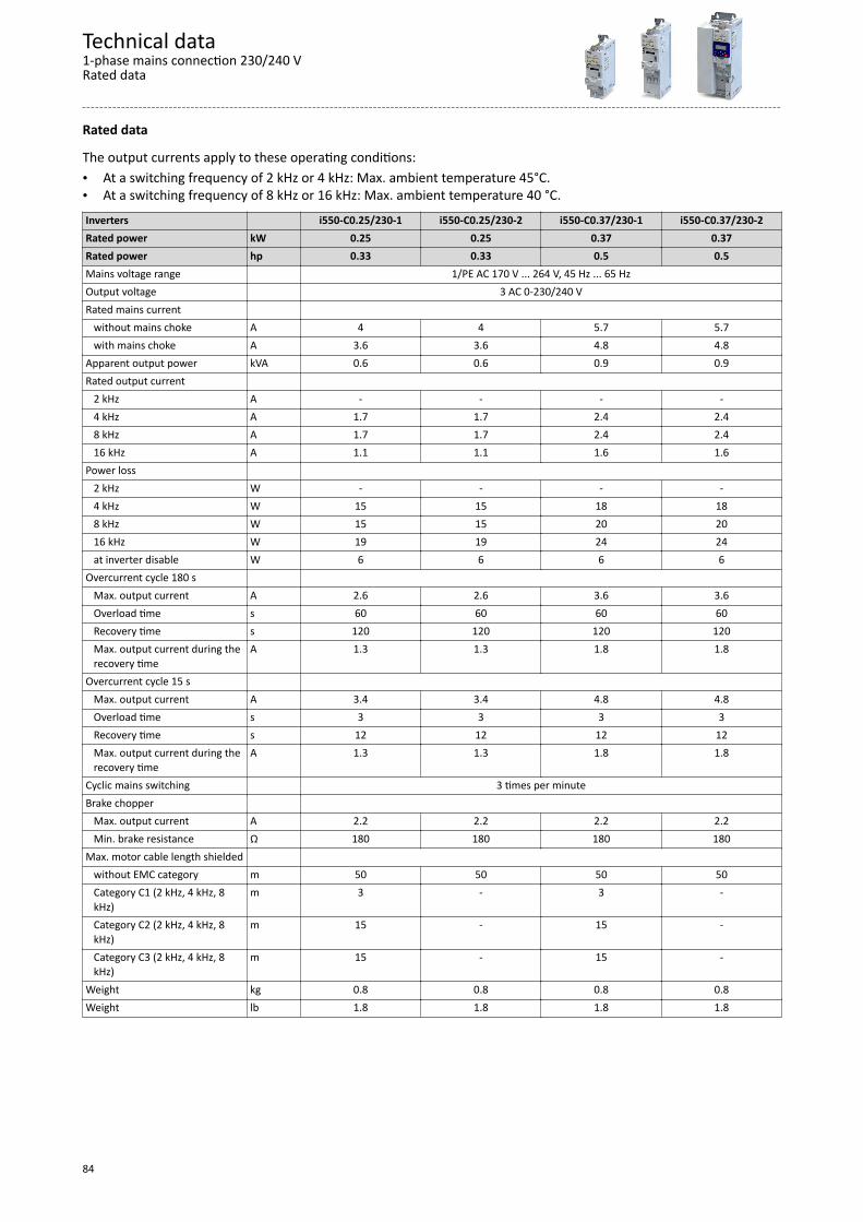
Rated data
The output currents apply to these operating conditions:• At a switching frequency of 2 kHz or 4 kHz: Max. ambient temperature 45°C.• At a switching frequency of 8 kHz or 16 kHz: Max. ambient temperature 40 °C.Inverters i550-C0.25/230-1 i550-C0.25/230-2 i550-C0.37/230-1 i550-C0.37/230-2Rated power kW 0.25 0.25 0.37 0.37Rated power hp 0.33 0.33 0.5 0.5Mains voltage range 1/PE AC 170 V ... 264 V, 45 Hz ... 65 HzOutput voltage 3 AC 0-230/240 VRated mains current without mains choke A 4 4 5.7 5.7 with mains choke A 3.6 3.6 4.8 4.8Apparent output power kVA 0.6 0.6 0.9 0.9Rated output current 2 kHz A - - - - 4 kHz A 1.7 1.7 2.4 2.4 8 kHz A 1.7 1.7 2.4 2.4 16 kHz A 1.1 1.1 1.6 1.6Power loss 2 kHz W - - - - 4 kHz W 15 15 18 18 8 kHz W 15 15 20 20 16 kHz W 19 19 24 24 at inverter disable W 6 6 6 6Overcurrent cycle 180 s Max. output current A 2.6 2.6 3.6 3.6 Overload time s 60 60 60 60 Recovery time s 120 120 120 120 Max. output current during the
recovery timeA 1.3 1.3 1.8 1.8
Overcurrent cycle 15 s Max. output current A 3.4 3.4 4.8 4.8 Overload time s 3 3 3 3 Recovery time s 12 12 12 12 Max. output current during the
recovery timeA 1.3 1.3 1.8 1.8
Cyclic mains switching 3 times per minuteBrake chopper Max. output current A 2.2 2.2 2.2 2.2 Min. brake resistance Ω 180 180 180 180Max. motor cable length shielded without EMC category m 50 50 50 50 Category C1 (2 kHz, 4 kHz, 8
kHz)m 3 - 3 -
Category C2 (2 kHz, 4 kHz, 8kHz)
m 15 - 15 -
Category C3 (2 kHz, 4 kHz, 8kHz)
m 15 - 15 -
Weight kg 0.8 0.8 0.8 0.8Weight lb 1.8 1.8 1.8 1.8
Technical data1-phase mains connection 230/240 VRated data
84

Inverters i550-C0.55/230-1 i550-C0.55/230-2 i550-C0.75/230-1 i550-C0.75/230-2Rated power kW 0.55 0.55 0.75 0.75Rated power hp 0.75 0.75 1 1Mains voltage range 1/PE AC 170 V ... 264 V, 45 Hz ... 65 HzOutput voltage 3 AC 0-230/240 VRated mains current without mains choke A 7.6 7.6 10 10 with mains choke A 7.1 7.1 8.8 8.8Apparent output power kVA 1.2 1.2 1.6 1.6Rated output current 2 kHz A 3.2 3.2 4.2 4.2 4 kHz A 3.2 3.2 4.2 4.2 8 kHz A 3.2 3.2 4.2 4.2 16 kHz A 2.1 2.1 2.8 2.8Power loss 2 kHz W 22 22 27 27 4 kHz W 23 23 29 29 8 kHz W 25 25 33 33 16 kHz W 30 30 38 38 at inverter disable W 6 6 6 6Overcurrent cycle 180 s Max. output current A 4.8 4.8 6.3 6.3 Overload time s 60 60 60 60 Recovery time s 120 120 120 120 Max. output current during the
recovery timeA 2.4 2.4 3.2 3.2
Overcurrent cycle 15 s Max. output current A 6.4 6.4 8.4 8.4 Overload time s 3 3 3 3 Recovery time s 12 12 12 12 Max. output current during the
recovery timeA 2.4 2.4 3.2 3.2
Cyclic mains switching 3 times per minuteBrake chopper Max. output current A 3.9 3.9 3.9 3.9 Min. brake resistance Ω 100 100 100 100Max. motor cable length shielded without EMC category m 50 50 50 50 Category C1 (2 kHz, 4 kHz, 8
kHz)m 3 - 3 -
Category C2 (2 kHz, 4 kHz, 8kHz)
m 20 - 20 -
Category C3 (2 kHz, 4 kHz, 8kHz)
m 50 - 50 -
Weight kg 1 1 1 1Weight lb 2.2 2.2 2.2 2.2
Technical data1-phase mains connection 230/240 V
Rated data
85
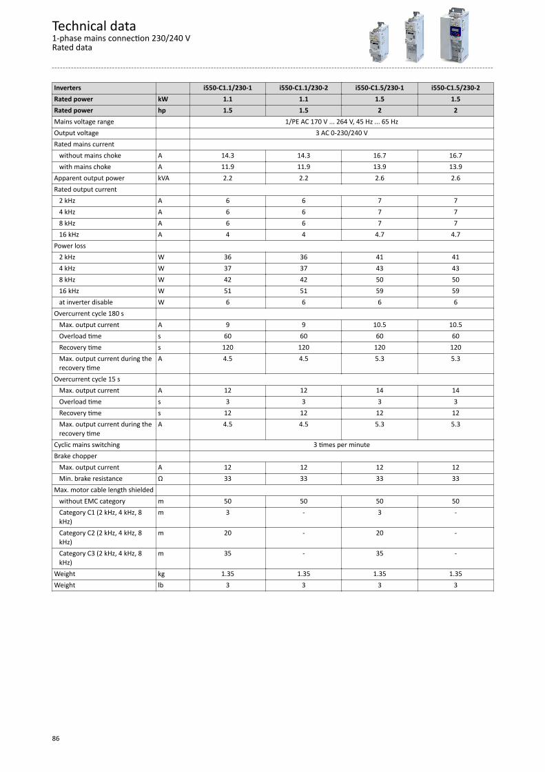
Inverters i550-C1.1/230-1 i550-C1.1/230-2 i550-C1.5/230-1 i550-C1.5/230-2Rated power kW 1.1 1.1 1.5 1.5Rated power hp 1.5 1.5 2 2Mains voltage range 1/PE AC 170 V ... 264 V, 45 Hz ... 65 HzOutput voltage 3 AC 0-230/240 VRated mains current without mains choke A 14.3 14.3 16.7 16.7 with mains choke A 11.9 11.9 13.9 13.9Apparent output power kVA 2.2 2.2 2.6 2.6Rated output current 2 kHz A 6 6 7 7 4 kHz A 6 6 7 7 8 kHz A 6 6 7 7 16 kHz A 4 4 4.7 4.7Power loss 2 kHz W 36 36 41 41 4 kHz W 37 37 43 43 8 kHz W 42 42 50 50 16 kHz W 51 51 59 59 at inverter disable W 6 6 6 6Overcurrent cycle 180 s Max. output current A 9 9 10.5 10.5 Overload time s 60 60 60 60 Recovery time s 120 120 120 120 Max. output current during the
recovery timeA 4.5 4.5 5.3 5.3
Overcurrent cycle 15 s Max. output current A 12 12 14 14 Overload time s 3 3 3 3 Recovery time s 12 12 12 12 Max. output current during the
recovery timeA 4.5 4.5 5.3 5.3
Cyclic mains switching 3 times per minuteBrake chopper Max. output current A 12 12 12 12 Min. brake resistance Ω 33 33 33 33Max. motor cable length shielded without EMC category m 50 50 50 50 Category C1 (2 kHz, 4 kHz, 8
kHz)m 3 - 3 -
Category C2 (2 kHz, 4 kHz, 8kHz)
m 20 - 20 -
Category C3 (2 kHz, 4 kHz, 8kHz)
m 35 - 35 -
Weight kg 1.35 1.35 1.35 1.35Weight lb 3 3 3 3
Technical data1-phase mains connection 230/240 VRated data
86
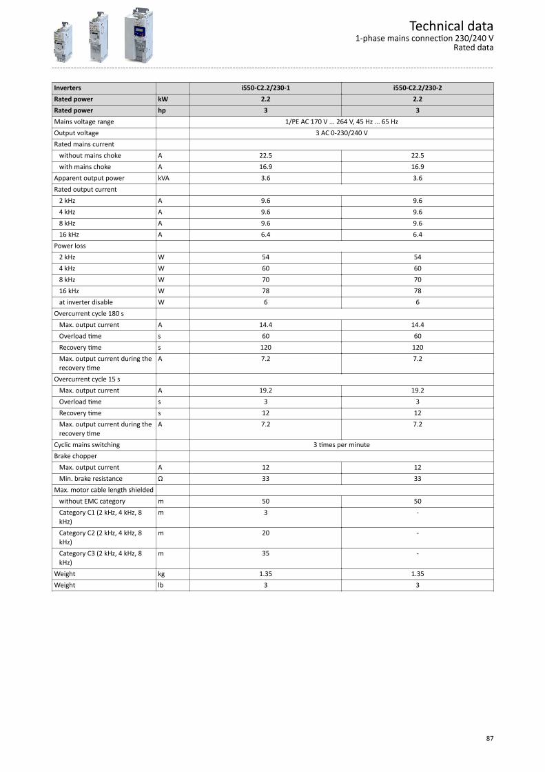
Inverters i550-C2.2/230-1 i550-C2.2/230-2Rated power kW 2.2 2.2Rated power hp 3 3Mains voltage range 1/PE AC 170 V ... 264 V, 45 Hz ... 65 HzOutput voltage 3 AC 0-230/240 VRated mains current without mains choke A 22.5 22.5 with mains choke A 16.9 16.9Apparent output power kVA 3.6 3.6Rated output current 2 kHz A 9.6 9.6 4 kHz A 9.6 9.6 8 kHz A 9.6 9.6 16 kHz A 6.4 6.4Power loss 2 kHz W 54 54 4 kHz W 60 60 8 kHz W 70 70 16 kHz W 78 78 at inverter disable W 6 6Overcurrent cycle 180 s Max. output current A 14.4 14.4 Overload time s 60 60 Recovery time s 120 120 Max. output current during the
recovery timeA 7.2 7.2
Overcurrent cycle 15 s Max. output current A 19.2 19.2 Overload time s 3 3 Recovery time s 12 12 Max. output current during the
recovery timeA 7.2 7.2
Cyclic mains switching 3 times per minuteBrake chopper Max. output current A 12 12 Min. brake resistance Ω 33 33Max. motor cable length shielded without EMC category m 50 50 Category C1 (2 kHz, 4 kHz, 8
kHz)m 3 -
Category C2 (2 kHz, 4 kHz, 8kHz)
m 20 -
Category C3 (2 kHz, 4 kHz, 8kHz)
m 35 -
Weight kg 1.35 1.35Weight lb 3 3
Technical data1-phase mains connection 230/240 V
Rated data
87
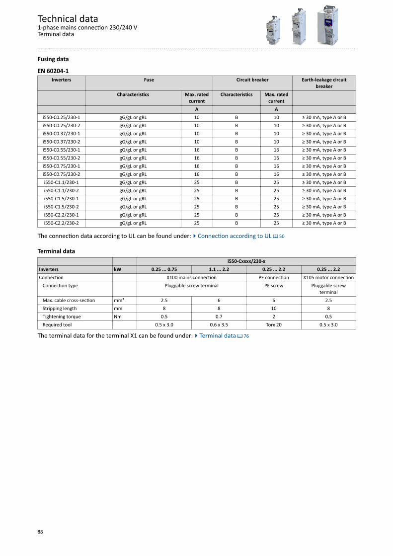
Fusing data
EN 60204-1Inverters Fuse Circuit breaker Earth-leakage circuit
breakerCharacteristics Max. rated
currentCharacteristics Max. rated
current A A
i550-C0.25/230-1 gG/gL or gRL 10 B 10 ≥ 30 mA, type A or Bi550-C0.25/230-2 gG/gL or gRL 10 B 10 ≥ 30 mA, type A or Bi550-C0.37/230-1 gG/gL or gRL 10 B 10 ≥ 30 mA, type A or Bi550-C0.37/230-2 gG/gL or gRL 10 B 10 ≥ 30 mA, type A or Bi550-C0.55/230-1 gG/gL or gRL 16 B 16 ≥ 30 mA, type A or Bi550-C0.55/230-2 gG/gL or gRL 16 B 16 ≥ 30 mA, type A or Bi550-C0.75/230-1 gG/gL or gRL 16 B 16 ≥ 30 mA, type A or Bi550-C0.75/230-2 gG/gL or gRL 16 B 16 ≥ 30 mA, type A or Bi550-C1.1/230-1 gG/gL or gRL 25 B 25 ≥ 30 mA, type A or Bi550-C1.1/230-2 gG/gL or gRL 25 B 25 ≥ 30 mA, type A or Bi550-C1.5/230-1 gG/gL or gRL 25 B 25 ≥ 30 mA, type A or Bi550-C1.5/230-2 gG/gL or gRL 25 B 25 ≥ 30 mA, type A or Bi550-C2.2/230-1 gG/gL or gRL 25 B 25 ≥ 30 mA, type A or Bi550-C2.2/230-2 gG/gL or gRL 25 B 25 ≥ 30 mA, type A or B
The connection data according to UL can be found under:4Connection according to UL ^ 50
Terminal data i550-Cxxxx/230-xInverters kW 0.25 ... 0.75 1.1 ... 2.2 0.25 ... 2.2 0.25 ... 2.2Connection X100 mains connection PE connection X105 motor connection Connection type Pluggable screw terminal PE screw Pluggable screw
terminal Max. cable cross-section mm² 2.5 6 6 2.5 Stripping length mm 8 8 10 8 Tightening torque Nm 0.5 0.7 2 0.5 Required tool 0.5 x 3.0 0.6 x 3.5 Torx 20 0.5 x 3.0
The terminal data for the terminal X1 can be found under:4Terminal data ^ 76
Technical data1-phase mains connection 230/240 VTerminal data
88
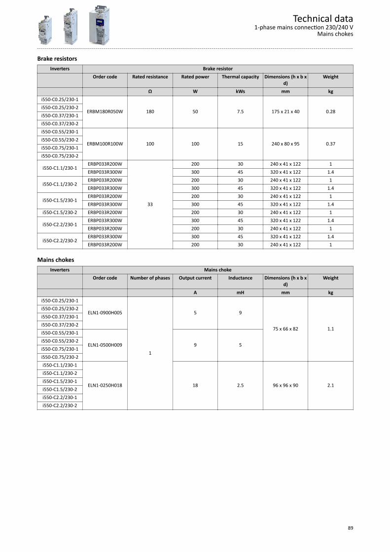
Brake resistorsInverters Brake resistor
Order code Rated resistance Rated power Thermal capacity Dimensions (h x b xd)
Weight
Ω W kWs mm kgi550-C0.25/230-1
ERBM180R050W 180 50 7.5 175 x 21 x 40 0.28i550-C0.25/230-2i550-C0.37/230-1i550-C0.37/230-2i550-C0.55/230-1
ERBM100R100W 100 100 15 240 x 80 x 95 0.37i550-C0.55/230-2i550-C0.75/230-1i550-C0.75/230-2
i550-C1.1/230-1ERBP033R200W
33
200 30 240 x 41 x 122 1ERBP033R300W 300 45 320 x 41 x 122 1.4
i550-C1.1/230-2ERBP033R200W 200 30 240 x 41 x 122 1ERBP033R300W 300 45 320 x 41 x 122 1.4
i550-C1.5/230-1ERBP033R200W 200 30 240 x 41 x 122 1ERBP033R300W 300 45 320 x 41 x 122 1.4
i550-C1.5/230-2 ERBP033R200W 200 30 240 x 41 x 122 1ERBP033R300W 300 45 320 x 41 x 122 1.4
i550-C2.2/230-1ERBP033R200W 200 30 240 x 41 x 122 1
i550-C2.2/230-2ERBP033R300W 300 45 320 x 41 x 122 1.4ERBP033R200W 200 30 240 x 41 x 122 1
Mains chokesInverters Mains choke
Order code Number of phases Output current Inductance Dimensions (h x b xd)
Weight
A mH mm kgi550-C0.25/230-1
ELN1-0900H005
1
5 9
75 x 66 x 82 1.1
i550-C0.25/230-2i550-C0.37/230-1i550-C0.37/230-2i550-C0.55/230-1
ELN1-0500H009 9 5i550-C0.55/230-2i550-C0.75/230-1i550-C0.75/230-2i550-C1.1/230-1
ELN1-0250H018 18 2.5 96 x 96 x 90 2.1
i550-C1.1/230-2i550-C1.5/230-1i550-C1.5/230-2i550-C2.2/230-1i550-C2.2/230-2
Technical data1-phase mains connection 230/240 V
Mains chokes
89
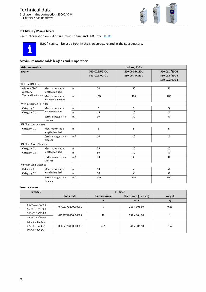
RFI filters / Mains filtersBasic information on RFI filters, mains filters and EMC: from ^ 192
EMC filters can be used both in the side structure and in the substructure.
Maximum motor cable lengths and FI operation
Mains connection 1-phase, 230 VInverter i550-C0.25/230-1 i550-C0.55/230-1 i550-C1.1/230-1 i550-C0.37/230-1 i550-C0.75/230-1 i550-C1.5/230-1 i550-C2.2/230-1Without RFI filter without EMC
categoryThermal limitation
Max. motor cablelength shielded
m 50 50 50
Max. motor cablelength unshielded
m 100 100 200
With integrated RFI filter Category C1 Max. motor cable
length shieldedm 3 3 3
Category C2 m 15 20 20 Earth-leakage circuit
breakermA 30 30 30
RFI filter Low Leakage Category C1 Max. motor cable
length shieldedm 5 5 5
Earth-leakage circuitbreaker
mA 10 10 10
RFI filter Short Distance Category C1 Max. motor cable
length shieldedm 25 25 25
Category C2 m 50 50 50 Earth-leakage circuit
breakermA 30 30 30
RFI filter Long Distance Category C1 Max. motor cable
length shieldedm 50 50 50
Category C2 m 50 50 50 Earth-leakage circuit
breakermA 300 300 300
Low LeakageInverters RFI filter
Order code Output current Dimensions (h x b x d) Weight A mm kg
i550-C0.25/230-1I0FAE137B100L0000S 6 226 x 60 x 50 0.85
i550-C0.37/230-1i550-C0.55/230-1
I0FAE175B100L0000S 10 276 x 60 x 50 1i550-C0.75/230-1i550-C1.1/230-1
I0FAE222B100L0000S 22.5 346 x 60 x 50 1.4i550-C1.5/230-1i550-C2.2/230-1
Technical data1-phase mains connection 230/240 VRFI filters / Mains filters
90
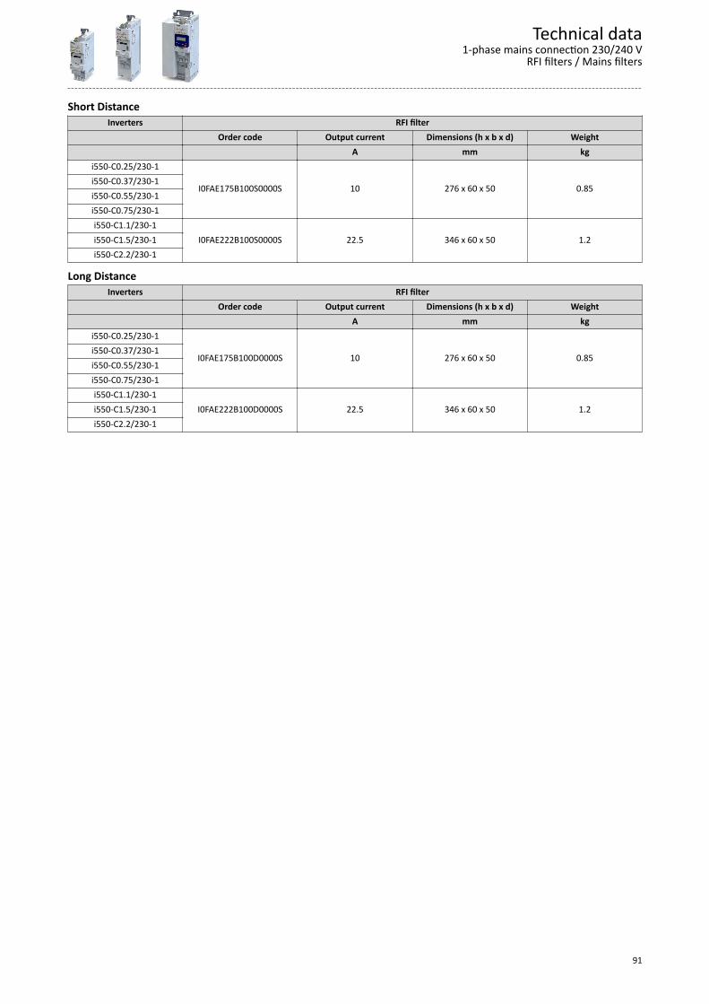
Short DistanceInverters RFI filter
Order code Output current Dimensions (h x b x d) Weight A mm kg
i550-C0.25/230-1
I0FAE175B100S0000S 10 276 x 60 x 50 0.85i550-C0.37/230-1i550-C0.55/230-1i550-C0.75/230-1i550-C1.1/230-1
I0FAE222B100S0000S 22.5 346 x 60 x 50 1.2i550-C1.5/230-1i550-C2.2/230-1
Long DistanceInverters RFI filter
Order code Output current Dimensions (h x b x d) Weight A mm kg
i550-C0.25/230-1
I0FAE175B100D0000S 10 276 x 60 x 50 0.85i550-C0.37/230-1i550-C0.55/230-1i550-C0.75/230-1i550-C1.1/230-1
I0FAE222B100D0000S 22.5 346 x 60 x 50 1.2i550-C1.5/230-1i550-C2.2/230-1
Technical data1-phase mains connection 230/240 V
RFI filters / Mains filters
91

3-phase mains connection 230/240 V
EMC filters are not integrated in inverters for this mains connection.
Technical data3-phase mains connection 230/240 V
92
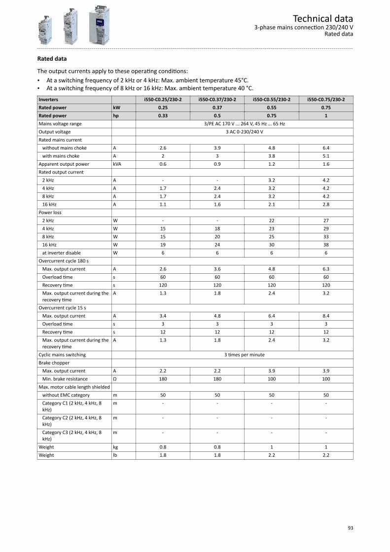
Rated data
The output currents apply to these operating conditions:• At a switching frequency of 2 kHz or 4 kHz: Max. ambient temperature 45°C.• At a switching frequency of 8 kHz or 16 kHz: Max. ambient temperature 40 °C.Inverters i550-C0.25/230-2 i550-C0.37/230-2 i550-C0.55/230-2 i550-C0.75/230-2Rated power kW 0.25 0.37 0.55 0.75Rated power hp 0.33 0.5 0.75 1Mains voltage range 3/PE AC 170 V ... 264 V, 45 Hz ... 65 HzOutput voltage 3 AC 0-230/240 VRated mains current without mains choke A 2.6 3.9 4.8 6.4 with mains choke A 2 3 3.8 5.1Apparent output power kVA 0.6 0.9 1.2 1.6Rated output current 2 kHz A - - 3.2 4.2 4 kHz A 1.7 2.4 3.2 4.2 8 kHz A 1.7 2.4 3.2 4.2 16 kHz A 1.1 1.6 2.1 2.8Power loss 2 kHz W - - 22 27 4 kHz W 15 18 23 29 8 kHz W 15 20 25 33 16 kHz W 19 24 30 38 at inverter disable W 6 6 6 6Overcurrent cycle 180 s Max. output current A 2.6 3.6 4.8 6.3 Overload time s 60 60 60 60 Recovery time s 120 120 120 120 Max. output current during the
recovery timeA 1.3 1.8 2.4 3.2
Overcurrent cycle 15 s Max. output current A 3.4 4.8 6.4 8.4 Overload time s 3 3 3 3 Recovery time s 12 12 12 12 Max. output current during the
recovery timeA 1.3 1.8 2.4 3.2
Cyclic mains switching 3 times per minuteBrake chopper Max. output current A 2.2 2.2 3.9 3.9 Min. brake resistance Ω 180 180 100 100Max. motor cable length shielded without EMC category m 50 50 50 50 Category C1 (2 kHz, 4 kHz, 8
kHz)m - - - -
Category C2 (2 kHz, 4 kHz, 8kHz)
m - - - -
Category C3 (2 kHz, 4 kHz, 8kHz)
m - - - -
Weight kg 0.8 0.8 1 1Weight lb 1.8 1.8 2.2 2.2
Technical data3-phase mains connection 230/240 V
Rated data
93

Inverters i550-C1.1/230-2 i550-C1.5/230-2 i550-C2.2/230-2 i550-C5.5/230-3Rated power kW 1.1 1.5 2.2 5.5Rated power hp 1.5 2 3 7.5Mains voltage range 3/PE AC 170 V ... 264 V, 45 Hz ... 65 HzOutput voltage 3 AC 0-230/240 VRated mains current without mains choke A 7.8 9.5 13.6 28.8 with mains choke A 5.6 6.8 9.8 21.9Apparent output power kVA 2.2 2.6 3.6 8.7Rated output current 2 kHz A 6 7 9.6 23 4 kHz A 6 7 9.6 23 8 kHz A 6 7 9.6 23 16 kHz A 4 4.7 6.4 15.3Power loss 2 kHz W 36 41 54 166 4 kHz W 37 43 60 175 8 kHz W 42 50 70 195 16 kHz W 51 59 78 159 at inverter disable W 6 6 6 6Overcurrent cycle 180 s Max. output current A 9 10.5 14.4 34.5 Overload time s 60 60 60 60 Recovery time s 120 120 120 120 Max. output current during the
recovery timeA 4.5 5.3 7.2 17.3
Overcurrent cycle 15 s Max. output current A 12 14 19.2 46 Overload time s 3 3 3 3 Recovery time s 12 12 12 12 Max. output current during the
recovery timeA 4.5 5.3 7.2 17.3
Cyclic mains switching 3 times per minuteBrake chopper Max. output current A 12 12 12 26 Min. brake resistance Ω 33 33 33 15Max. motor cable length shielded without EMC category m 50 50 50 50 Category C1 (2 kHz, 4 kHz, 8
kHz)m - - - -
Category C2 (2 kHz, 4 kHz, 8kHz)
m - - - -
Category C3 (2 kHz, 4 kHz, 8kHz)
m - - - -
Weight kg 1.35 1.35 1.35 2.1Weight lb 3 3 3 4.6
Technical data3-phase mains connection 230/240 VRated data
94
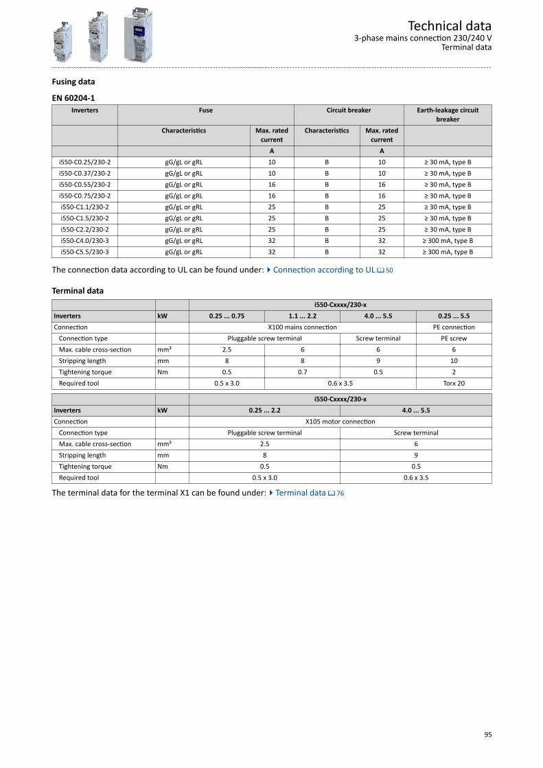
Fusing data
EN 60204-1Inverters Fuse Circuit breaker Earth-leakage circuit
breakerCharacteristics Max. rated
currentCharacteristics Max. rated
current A A
i550-C0.25/230-2 gG/gL or gRL 10 B 10 ≥ 30 mA, type Bi550-C0.37/230-2 gG/gL or gRL 10 B 10 ≥ 30 mA, type Bi550-C0.55/230-2 gG/gL or gRL 16 B 16 ≥ 30 mA, type Bi550-C0.75/230-2 gG/gL or gRL 16 B 16 ≥ 30 mA, type Bi550-C1.1/230-2 gG/gL or gRL 25 B 25 ≥ 30 mA, type Bi550-C1.5/230-2 gG/gL or gRL 25 B 25 ≥ 30 mA, type Bi550-C2.2/230-2 gG/gL or gRL 25 B 25 ≥ 30 mA, type Bi550-C4.0/230-3 gG/gL or gRL 32 B 32 ≥ 300 mA, type Bi550-C5.5/230-3 gG/gL or gRL 32 B 32 ≥ 300 mA, type B
The connection data according to UL can be found under:4Connection according to UL ^ 50
Terminal data i550-Cxxxx/230-xInverters kW 0.25 ... 0.75 1.1 ... 2.2 4.0 ... 5.5 0.25 ... 5.5Connection X100 mains connection PE connection Connection type Pluggable screw terminal Screw terminal PE screw Max. cable cross-section mm² 2.5 6 6 6 Stripping length mm 8 8 9 10 Tightening torque Nm 0.5 0.7 0.5 2 Required tool 0.5 x 3.0 0.6 x 3.5 Torx 20
i550-Cxxxx/230-xInverters kW 0.25 ... 2.2 4.0 ... 5.5Connection X105 motor connection Connection type Pluggable screw terminal Screw terminal Max. cable cross-section mm² 2.5 6 Stripping length mm 8 9 Tightening torque Nm 0.5 0.5 Required tool 0.5 x 3.0 0.6 x 3.5
The terminal data for the terminal X1 can be found under:4Terminal data ^ 76
Technical data3-phase mains connection 230/240 V
Terminal data
95
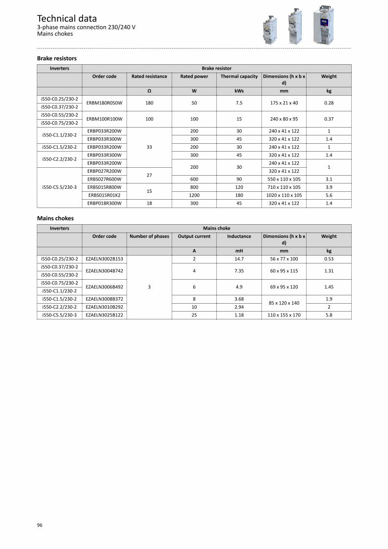
Brake resistorsInverters Brake resistor
Order code Rated resistance Rated power Thermal capacity Dimensions (h x b xd)
Weight
Ω W kWs mm kgi550-C0.25/230-2
ERBM180R050W 180 50 7.5 175 x 21 x 40 0.28i550-C0.37/230-2i550-C0.55/230-2
ERBM100R100W 100 100 15 240 x 80 x 95 0.37i550-C0.75/230-2
i550-C1.1/230-2ERBP033R200W
33
200 30 240 x 41 x 122 1ERBP033R300W 300 45 320 x 41 x 122 1.4
i550-C1.5/230-2 ERBP033R200W 200 30 240 x 41 x 122 1ERBP033R300W 300 45 320 x 41 x 122 1.4
i550-C2.2/230-2ERBP033R200W
200 30240 x 41 x 122
1
i550-C5.5/230-3
ERBP027R200W27
320 x 41 x 122ERBS027R600W 600 90 550 x 110 x 105 3.1ERBS015R800W
15800 120 710 x 110 x 105 3.9
ERBS015R01K2 1200 180 1020 x 110 x 105 5.6ERBP018R300W 18 300 45 320 x 41 x 122 1.4
Mains chokesInverters Mains choke
Order code Number of phases Output current Inductance Dimensions (h x b xd)
Weight
A mH mm kgi550-C0.25/230-2 EZAELN3002B153
3
2 14.7 56 x 77 x 100 0.53i550-C0.37/230-2
EZAELN3004B742 4 7.35 60 x 95 x 115 1.31i550-C0.55/230-2i550-C0.75/230-2
EZAELN3006B492 6 4.9 69 x 95 x 120 1.45i550-C1.1/230-2i550-C1.5/230-2 EZAELN3008B372 8 3.68
85 x 120 x 1401.9
i550-C2.2/230-2 EZAELN3010B292 10 2.94 2i550-C5.5/230-3 EZAELN3025B122 25 1.18 110 x 155 x 170 5.8
Technical data3-phase mains connection 230/240 VMains chokes
96

3-phase mains connection 230/240 V "Light Duty"
Rated data
EMC filters are not integrated in inverters for this mains connection.
Technical data3-phase mains connection 230/240 V "Light Duty"
Rated data
97
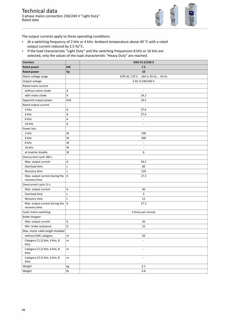
The output currents apply to these operating conditions:• At a switching frequency of 2 kHz or 4 kHz: Ambient temperature above 40 °C with a rated
output current reduced by 2.5 %/°C.• If the load characteristic "Light Duty" and the switching frequencies 8 kHz or 16 kHz are
selected, only the values of the load characteristic "Heavy Duty" are reached.Inverters i550-C5.5/230-3Rated power kW 7.5Rated power hp 10Mains voltage range 3/PE AC 170 V ... 264 V, 45 Hz ... 65 HzOutput voltage 3 AC 0-230/240 VRated mains current without mains choke A - with mains choke A 24.2Apparent output power kVA 10.5Rated output current 2 kHz A 27.6 4 kHz A 27.6 8 kHz A - 16 kHz A -Power loss 2 kHz W 190 4 kHz W 200 8 kHz W - 16 kHz W - at inverter disable W 6Overcurrent cycle 180 s Max. output current A 34.5 Overload time s 60 Recovery time s 120 Max. output current during the
recovery timeA 17.3
Overcurrent cycle 15 s Max. output current A 46 Overload time s 3 Recovery time s 12 Max. output current during the
recovery timeA 17.3
Cyclic mains switching 3 times per minuteBrake chopper Max. output current A 26 Min. brake resistance Ω 15Max. motor cable length shielded without EMC category m 50 Category C1 (2 kHz, 4 kHz, 8
kHz)m -
Category C2 (2 kHz, 4 kHz, 8kHz)
m -
Category C3 (2 kHz, 4 kHz, 8kHz)
m -
Weight kg 2.1Weight lb 4.6
Technical data3-phase mains connection 230/240 V "Light Duty"Rated data
98
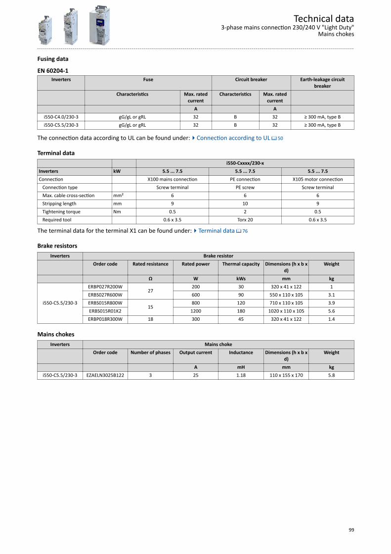
Fusing data
EN 60204-1Inverters Fuse Circuit breaker Earth-leakage circuit
breakerCharacteristics Max. rated
currentCharacteristics Max. rated
current A A
i550-C4.0/230-3 gG/gL or gRL 32 B 32 ≥ 300 mA, type Bi550-C5.5/230-3 gG/gL or gRL 32 B 32 ≥ 300 mA, type B
The connection data according to UL can be found under:4Connection according to UL ^ 50
Terminal data i550-Cxxxx/230-xInverters kW 5.5 ... 7.5 5.5 ... 7.5 5.5 ... 7.5Connection X100 mains connection PE connection X105 motor connection Connection type Screw terminal PE screw Screw terminal Max. cable cross-section mm² 6 6 6 Stripping length mm 9 10 9 Tightening torque Nm 0.5 2 0.5 Required tool 0.6 x 3.5 Torx 20 0.6 x 3.5
The terminal data for the terminal X1 can be found under:4Terminal data ^ 76
Brake resistorsInverters Brake resistor
Order code Rated resistance Rated power Thermal capacity Dimensions (h x b xd)
Weight
Ω W kWs mm kg
i550-C5.5/230-3
ERBP027R200W27
200 30 320 x 41 x 122 1ERBS027R600W 600 90 550 x 110 x 105 3.1ERBS015R800W
15800 120 710 x 110 x 105 3.9
ERBS015R01K2 1200 180 1020 x 110 x 105 5.6ERBP018R300W 18 300 45 320 x 41 x 122 1.4
Mains chokesInverters Mains choke
Order code Number of phases Output current Inductance Dimensions (h x b xd)
Weight
A mH mm kgi550-C5.5/230-3 EZAELN3025B122 3 25 1.18 110 x 155 x 170 5.8
Technical data3-phase mains connection 230/240 V "Light Duty"
Mains chokes
99
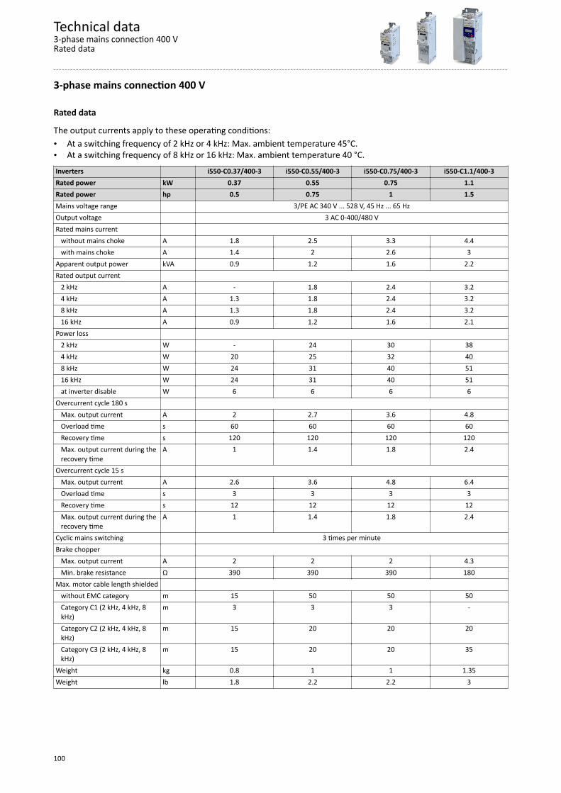
3-phase mains connection 400 V
Rated data
The output currents apply to these operating conditions:• At a switching frequency of 2 kHz or 4 kHz: Max. ambient temperature 45°C.• At a switching frequency of 8 kHz or 16 kHz: Max. ambient temperature 40 °C.Inverters i550-C0.37/400-3 i550-C0.55/400-3 i550-C0.75/400-3 i550-C1.1/400-3Rated power kW 0.37 0.55 0.75 1.1Rated power hp 0.5 0.75 1 1.5Mains voltage range 3/PE AC 340 V ... 528 V, 45 Hz ... 65 HzOutput voltage 3 AC 0-400/480 VRated mains current without mains choke A 1.8 2.5 3.3 4.4 with mains choke A 1.4 2 2.6 3Apparent output power kVA 0.9 1.2 1.6 2.2Rated output current 2 kHz A - 1.8 2.4 3.2 4 kHz A 1.3 1.8 2.4 3.2 8 kHz A 1.3 1.8 2.4 3.2 16 kHz A 0.9 1.2 1.6 2.1Power loss 2 kHz W - 24 30 38 4 kHz W 20 25 32 40 8 kHz W 24 31 40 51 16 kHz W 24 31 40 51 at inverter disable W 6 6 6 6Overcurrent cycle 180 s Max. output current A 2 2.7 3.6 4.8 Overload time s 60 60 60 60 Recovery time s 120 120 120 120 Max. output current during the
recovery timeA 1 1.4 1.8 2.4
Overcurrent cycle 15 s Max. output current A 2.6 3.6 4.8 6.4 Overload time s 3 3 3 3 Recovery time s 12 12 12 12 Max. output current during the
recovery timeA 1 1.4 1.8 2.4
Cyclic mains switching 3 times per minuteBrake chopper Max. output current A 2 2 2 4.3 Min. brake resistance Ω 390 390 390 180Max. motor cable length shielded without EMC category m 15 50 50 50 Category C1 (2 kHz, 4 kHz, 8
kHz)m 3 3 3 -
Category C2 (2 kHz, 4 kHz, 8kHz)
m 15 20 20 20
Category C3 (2 kHz, 4 kHz, 8kHz)
m 15 20 20 35
Weight kg 0.8 1 1 1.35Weight lb 1.8 2.2 2.2 3
Technical data3-phase mains connection 400 VRated data
100

Inverters i550-C1.5/400-3 i550-C2.2/400-3 i550-C3.0/400-3 i550-C4.0/400-3Rated power kW 1.5 2.2 3 4Rated power hp 2 3 4 5Mains voltage range 3/PE AC 340 V ... 528 V, 45 Hz ... 65 HzOutput voltage 3 AC 0-400/480 VRated mains current without mains choke A 5.4 7.8 9.6 12.5 with mains choke A 3.7 5.3 6.9 9Apparent output power kVA 2.6 3.8 4.9 6.4Rated output current 2 kHz A 3.9 5.6 7.3 9.5 4 kHz A 3.9 5.6 7.3 9.5 8 kHz A 3.9 5.6 7.3 9.5 16 kHz A 2.6 3.7 4.9 6.3Power loss 2 kHz W 45 62 79 102 4 kHz W 48 66 85 110 8 kHz W 61 85 110 140 16 kHz W 61 85 109 140 at inverter disable W 6 6 6 6Overcurrent cycle 180 s Max. output current A 5.9 8.4 11 14.3 Overload time s 60 60 60 60 Recovery time s 120 120 120 120 Max. output current during the
recovery timeA 2.9 4.2 5.5 7.1
Overcurrent cycle 15 s Max. output current A 7.8 11.2 14.6 19 Overload time s 3 3 3 3 Recovery time s 12 12 12 12 Max. output current during the
recovery timeA 2.9 4.2 5.5 7.1
Cyclic mains switching 3 times per minuteBrake chopper Max. output current A 4.3 4.3 9.5 16.6 Min. brake resistance Ω 180 150 82 47Max. motor cable length shielded without EMC category m 50 50 50 50 Category C1 (2 kHz, 4 kHz, 8
kHz)m - - - -
Category C2 (2 kHz, 4 kHz, 8kHz)
m 20 20 20 20
Category C3 (2 kHz, 4 kHz, 8kHz)
m 35 35 35 35
Weight kg 1.35 1.35 1.35 1.35Weight lb 3 3 3 3
Technical data3-phase mains connection 400 V
Rated data
101
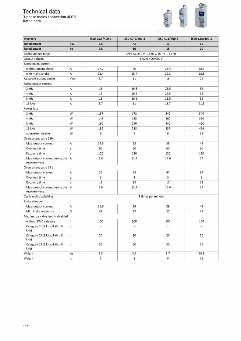
Inverters i550-C5.5/400-3 i550-C7.5/400-3 i550-C11/400-3 i550-C15/400-3Rated power kW 5.5 7.5 11 15Rated power hp 7.5 10 15 20Mains voltage range 3/PE AC 340 V ... 528 V, 45 Hz ... 65 HzOutput voltage 3 AC 0-400/480 VRated mains current without mains choke A 17.2 20 28.4 38.7 with mains choke A 12.4 15.7 22.3 28.8Apparent output power kVA 8.7 11 16 22Rated output current 2 kHz A 13 16.5 23.5 32 4 kHz A 13 16.5 23.5 32 8 kHz A 13 16.5 23.5 32 16 kHz A 8.7 11 15.7 21.3Power loss 2 kHz W 137 172 242 340 4 kHz W 145 185 260 360 8 kHz W 190 240 340 460 16 kHz W 189 238 337 469 at inverter disable W 6 6 6 18Overcurrent cycle 180 s Max. output current A 19.5 25 35 48 Overload time s 60 60 60 60 Recovery time s 120 120 120 120 Max. output current during the
recovery timeA 9.8 12.4 17.6 24
Overcurrent cycle 15 s Max. output current A 26 33 47 64 Overload time s 3 3 3 3 Recovery time s 12 12 12 12 Max. output current during the
recovery timeA 9.8 12.4 17.6 24
Cyclic mains switching 3 times per minuteBrake chopper Max. output current A 16.6 29 29 43 Min. brake resistance Ω 47 27 27 18Max. motor cable length shielded without EMC category m 100 100 100 100 Category C1 (2 kHz, 4 kHz, 8
kHz)m - - - -
Category C2 (2 kHz, 4 kHz, 8kHz)
m 20 20 20 20
Category C3 (2 kHz, 4 kHz, 8kHz)
m 35 50 50 35
Weight kg 2.3 3.7 3.7 10.3Weight lb 5 8 8 23
Technical data3-phase mains connection 400 VRated data
102

Inverters i550-C18/400-3 i550-C22/400-3 i550-C30/400-3 i550-C37/400-3Rated power kW 18.5 22 30 37Rated power hp 25 30 40 50Mains voltage range 3/PE AC 340 V ... 528 V, 45 Hz ... 65 HzOutput voltage 3 AC 0-400/480 VRated mains current without mains choke A 48.4 - - - with mains choke A 36 42 54.9 68Apparent output power kVA 27 32 41 51Rated output current 2 kHz A 40 47 61 76 4 kHz A 40 47 61 76 8 kHz A 40 47 61 76 16 kHz A 26.6 31.3 40.6 50.6Power loss 2 kHz W 420 491 639 790 4 kHz W 450 520 680 840 8 kHz W 570 670 880 1100 16 kHz W 581 680 884 1095 at inverter disable W 18 18 25 25Overcurrent cycle 180 s Max. output current A 60 71 92 114 Overload time s 60 60 60 60 Recovery time s 120 120 120 120 Max. output current during the
recovery timeA 30 35 46 57
Overcurrent cycle 15 s Max. output current A 80 94 122 152 Overload time s 3 3 3 3 Recovery time s 12 12 12 12 Max. output current during the
recovery timeA 30 35 46 57
Cyclic mains switching 3 times per minuteBrake chopper Max. output current A 52 52 98 98 Min. brake resistance Ω 15 15 7.5 7.5Max. motor cable length shielded without EMC category m 100 100 100 100 Category C1 (2 kHz, 4 kHz, 8
kHz)m - - - -
Category C2 (2 kHz, 4 kHz, 8kHz)
m 20 20 20 20
Category C3 (2 kHz, 4 kHz, 8kHz)
m 35 35 35 35
Weight kg 10.3 10.3 17.2 17.2Weight lb 23 23 38 38
Technical data3-phase mains connection 400 V
Rated data
103
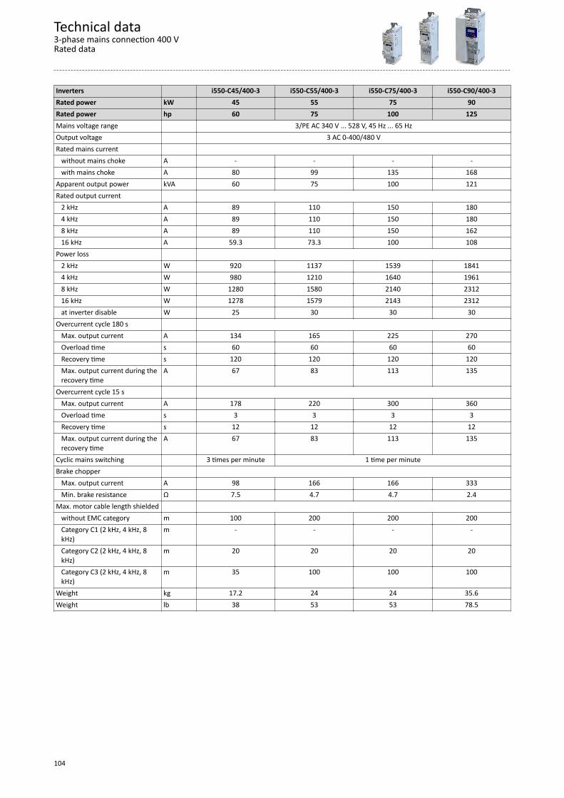
Inverters i550-C45/400-3 i550-C55/400-3 i550-C75/400-3 i550-C90/400-3Rated power kW 45 55 75 90Rated power hp 60 75 100 125Mains voltage range 3/PE AC 340 V ... 528 V, 45 Hz ... 65 HzOutput voltage 3 AC 0-400/480 VRated mains current without mains choke A - - - - with mains choke A 80 99 135 168Apparent output power kVA 60 75 100 121Rated output current 2 kHz A 89 110 150 180 4 kHz A 89 110 150 180 8 kHz A 89 110 150 162 16 kHz A 59.3 73.3 100 108Power loss 2 kHz W 920 1137 1539 1841 4 kHz W 980 1210 1640 1961 8 kHz W 1280 1580 2140 2312 16 kHz W 1278 1579 2143 2312 at inverter disable W 25 30 30 30Overcurrent cycle 180 s Max. output current A 134 165 225 270 Overload time s 60 60 60 60 Recovery time s 120 120 120 120 Max. output current during the
recovery timeA 67 83 113 135
Overcurrent cycle 15 s Max. output current A 178 220 300 360 Overload time s 3 3 3 3 Recovery time s 12 12 12 12 Max. output current during the
recovery timeA 67 83 113 135
Cyclic mains switching 3 times per minute 1 time per minuteBrake chopper Max. output current A 98 166 166 333 Min. brake resistance Ω 7.5 4.7 4.7 2.4Max. motor cable length shielded without EMC category m 100 200 200 200 Category C1 (2 kHz, 4 kHz, 8
kHz)m - - - -
Category C2 (2 kHz, 4 kHz, 8kHz)
m 20 20 20 20
Category C3 (2 kHz, 4 kHz, 8kHz)
m 35 100 100 100
Weight kg 17.2 24 24 35.6Weight lb 38 53 53 78.5
Technical data3-phase mains connection 400 VRated data
104

Inverters i550-C110/400-3Rated power kW 110Rated power hp 150Mains voltage range 3/PE AC 340 V ... 528 V, 45 Hz ... 65 HzOutput voltage 3 AC 0-400/480 VRated mains current without mains choke A - with mains choke A 198Apparent output power kVA 142Rated output current 2 kHz A 212 4 kHz A 212 8 kHz A 191 16 kHz A 127Power loss 2 kHz W 2163 4 kHz W 2305 8 kHz W 2717 16 kHz W 2717 at inverter disable W 30Overcurrent cycle 180 s Max. output current A 318 Overload time s 60 Recovery time s 120 Max. output current during the
recovery timeA 159
Overcurrent cycle 15 s Max. output current A 424 Overload time s 3 Recovery time s 12 Max. output current during the
recovery timeA 159
Cyclic mains switching 1 time per minuteBrake chopper Max. output current A 333 Min. brake resistance Ω 2.4Max. motor cable length shielded without EMC category m 200 Category C1 (2 kHz, 4 kHz, 8
kHz)m -
Category C2 (2 kHz, 4 kHz, 8kHz)
m 20
Category C3 (2 kHz, 4 kHz, 8kHz)
m 100
Weight kg 35.6Weight lb 78.5
Technical data3-phase mains connection 400 V
Rated data
105
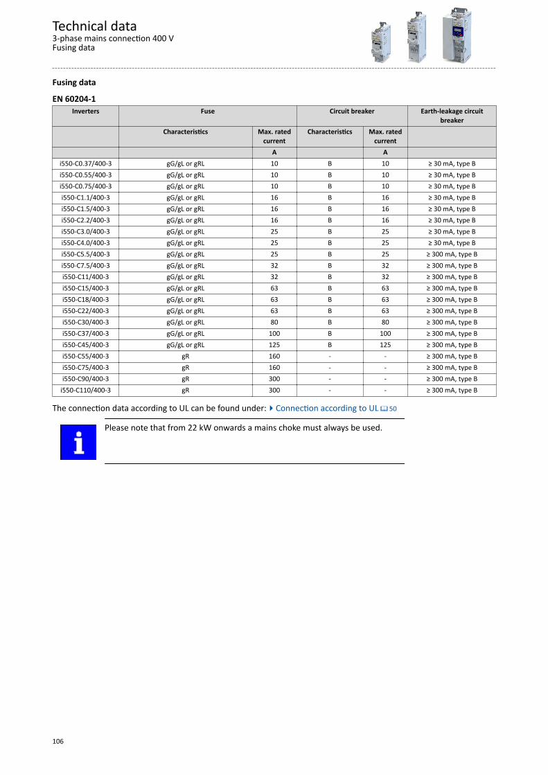
Fusing data
EN 60204-1Inverters Fuse Circuit breaker Earth-leakage circuit
breakerCharacteristics Max. rated
currentCharacteristics Max. rated
current A A
i550-C0.37/400-3 gG/gL or gRL 10 B 10 ≥ 30 mA, type Bi550-C0.55/400-3 gG/gL or gRL 10 B 10 ≥ 30 mA, type Bi550-C0.75/400-3 gG/gL or gRL 10 B 10 ≥ 30 mA, type Bi550-C1.1/400-3 gG/gL or gRL 16 B 16 ≥ 30 mA, type Bi550-C1.5/400-3 gG/gL or gRL 16 B 16 ≥ 30 mA, type Bi550-C2.2/400-3 gG/gL or gRL 16 B 16 ≥ 30 mA, type Bi550-C3.0/400-3 gG/gL or gRL 25 B 25 ≥ 30 mA, type Bi550-C4.0/400-3 gG/gL or gRL 25 B 25 ≥ 30 mA, type Bi550-C5.5/400-3 gG/gL or gRL 25 B 25 ≥ 300 mA, type Bi550-C7.5/400-3 gG/gL or gRL 32 B 32 ≥ 300 mA, type Bi550-C11/400-3 gG/gL or gRL 32 B 32 ≥ 300 mA, type Bi550-C15/400-3 gG/gL or gRL 63 B 63 ≥ 300 mA, type Bi550-C18/400-3 gG/gL or gRL 63 B 63 ≥ 300 mA, type Bi550-C22/400-3 gG/gL or gRL 63 B 63 ≥ 300 mA, type Bi550-C30/400-3 gG/gL or gRL 80 B 80 ≥ 300 mA, type Bi550-C37/400-3 gG/gL or gRL 100 B 100 ≥ 300 mA, type Bi550-C45/400-3 gG/gL or gRL 125 B 125 ≥ 300 mA, type Bi550-C55/400-3 gR 160 - - ≥ 300 mA, type Bi550-C75/400-3 gR 160 - - ≥ 300 mA, type Bi550-C90/400-3 gR 300 - - ≥ 300 mA, type B
i550-C110/400-3 gR 300 - - ≥ 300 mA, type B
The connection data according to UL can be found under:4Connection according to UL ^ 50
Please note that from 22 kW onwards a mains choke must always be used.
Technical data3-phase mains connection 400 VFusing data
106
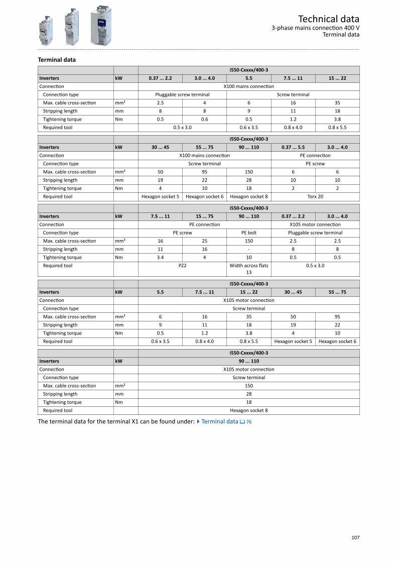
Terminal data i550-Cxxxx/400-3Inverters kW 0.37 ... 2.2 3.0 ... 4.0 5.5 7.5 ... 11 15 ... 22Connection X100 mains connection Connection type Pluggable screw terminal Screw terminal Max. cable cross-section mm² 2.5 4 6 16 35 Stripping length mm 8 8 9 11 18 Tightening torque Nm 0.5 0.6 0.5 1.2 3.8 Required tool 0.5 x 3.0 0.6 x 3.5 0.8 x 4.0 0.8 x 5.5
i550-Cxxxx/400-3Inverters kW 30 ... 45 55 ... 75 90 ... 110 0.37 ... 5.5 3.0 ... 4.0Connection X100 mains connection PE connection Connection type Screw terminal PE screw Max. cable cross-section mm² 50 95 150 6 6 Stripping length mm 19 22 28 10 10 Tightening torque Nm 4 10 18 2 2 Required tool Hexagon socket 5 Hexagon socket 6 Hexagon socket 8 Torx 20
i550-Cxxxx/400-3Inverters kW 7.5 ... 11 15 ... 75 90 ... 110 0.37 ... 2.2 3.0 ... 4.0Connection PE connection X105 motor connection Connection type PE screw PE bolt Pluggable screw terminal Max. cable cross-section mm² 16 25 150 2.5 2.5 Stripping length mm 11 16 - 8 8 Tightening torque Nm 3.4 4 10 0.5 0.5 Required tool PZ2 Width across flats
130.5 x 3.0
i550-Cxxxx/400-3Inverters kW 5.5 7.5 ... 11 15 ... 22 30 ... 45 55 ... 75Connection X105 motor connection Connection type Screw terminal Max. cable cross-section mm² 6 16 35 50 95 Stripping length mm 9 11 18 19 22 Tightening torque Nm 0.5 1.2 3.8 4 10 Required tool 0.6 x 3.5 0.8 x 4.0 0.8 x 5.5 Hexagon socket 5 Hexagon socket 6
i550-Cxxxx/400-3Inverters kW 90 ... 110Connection X105 motor connection Connection type Screw terminal Max. cable cross-section mm² 150 Stripping length mm 28 Tightening torque Nm 18 Required tool Hexagon socket 8
The terminal data for the terminal X1 can be found under:4Terminal data ^ 76
Technical data3-phase mains connection 400 V
Terminal data
107
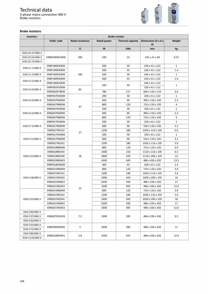
Brake resistorsInverters Brake resistor
Order code Rated resistance Rated power Thermal capacity Dimensions (h x b xd)
Weight
Ω W kWs mm kgi550-C0.37/400-3
ERBM390R100W 390 100 15 235 x 21 x 40 0.37i550-C0.55/400-3i550-C0.75/400-3
i550-C1.1/400-3ERBP180R200W
180
200 30 240 x 41 x 122 1ERBP180R300W 300 45 320 x 41 x 122 1.4
i550-C1.5/400-3 ERBP180R200W 200 30 240 x 41 x 122 1ERBP180R300W 300 45 320 x 41 x 122 1.4
i550-C2.2/400-3ERBP180R200W
200 30240 x 41 x 122
1i550-C3.0/400-3
ERBP082R200W82
320 x 41 x 122ERBS082R780W 780 117 666 x 124 x 122 3.6
i550-C4.0/400-3ERBP047R200W
47
200 30 320 x 41 x 122 1ERBS047R400W 400 60 400 x 110 x 105 2.3ERBS047R800W 800 120 710 x 110 x 105 4
i550-C5.5/400-3ERBP047R200W 200 30 320 x 41 x 122 1ERBS047R400W 400 60 400 x 110 x 105 2.3ERBS047R800W 800 120 710 x 110 x 105 4
i550-C7.5/400-3ERBP027R200W
27
200 30 320 x 41 x 122 1ERBS027R600W 600 90 550 x 110 x 105 3.1ERBS027R01K2 1200 180 1020 x 110 x 105 5.6
i550-C11/400-3ERBP027R200W 200 30 320 x 41 x 122 1ERBS027R600W 600 90 550 x 110 x 105 3.1ERBS027R01K2 1200 180 1020 x 110 x 105 5.6
i550-C15/400-3
ERBS018R800W
18
800 120 710 x 110 x 105 3.9ERBS018R01K4 1400 210 1110 x 110 x 105 6.2ERBS018R02K8 2800 420 1110 x 200 x 105 12ERBG018R04K3 4300 645 486 x 426 x 302 13.5ERBP018R300W 300 45 320 x 41 x 122 1.4
i550-C18/400-3
ERBS015R800W
15
800 120 710 x 110 x 105 3.9ERBS015R01K2 1200 180 1020 x 110 x 105 5.6ERBS015R02K4 2400 420 1020 x 200 x 105 10ERBG015R06K2 6200 930 486 x 526 x 302 17ERBG015R03K3 3300 495 486 x 326 x 302 12.6
i550-C22/400-3
ERBS015R800W 800 120 710 x 110 x 105 3.9ERBS015R01K2 1200 180 1020 x 110 x 105 5.6ERBS015R02K4 2400 420 1020 x 200 x 105 10ERBG015R06K2 6200 930 486 x 526 x 302 17ERBG015R03K3 3300 495 486 x 326 x 302 12.6
i550-C30/400-3ERBG075D01K9 7.5 1900 285 486 x 236 x 302 9.5i550-C37/400-3
i550-C45/400-3i550-C55/400-3
ERBG005R02K6 5 2600 390 486 x 326 x 302 11i550-C75/400-3i550-C90/400-3
ERBG028D04K1 2.8 4100 615 486 x 426 x 302 12.8i550-C110/400-3
Technical data3-phase mains connection 400 VBrake resistors
108
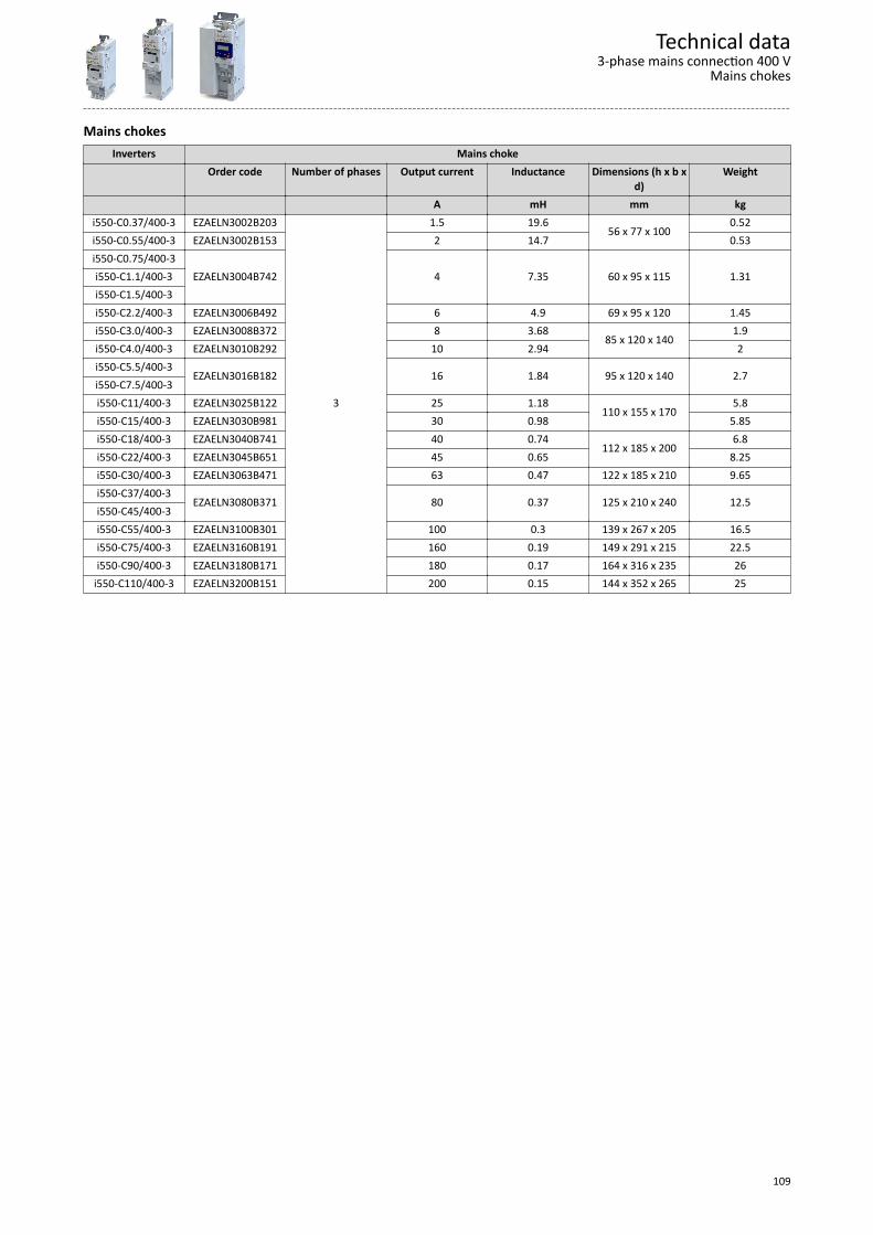
Mains chokesInverters Mains choke
Order code Number of phases Output current Inductance Dimensions (h x b xd)
Weight
A mH mm kgi550-C0.37/400-3 EZAELN3002B203
3
1.5 19.656 x 77 x 100
0.52i550-C0.55/400-3 EZAELN3002B153 2 14.7 0.53i550-C0.75/400-3
EZAELN3004B742 4 7.35 60 x 95 x 115 1.31i550-C1.1/400-3i550-C1.5/400-3i550-C2.2/400-3 EZAELN3006B492 6 4.9 69 x 95 x 120 1.45i550-C3.0/400-3 EZAELN3008B372 8 3.68
85 x 120 x 1401.9
i550-C4.0/400-3 EZAELN3010B292 10 2.94 2i550-C5.5/400-3
EZAELN3016B182 16 1.84 95 x 120 x 140 2.7i550-C7.5/400-3i550-C11/400-3 EZAELN3025B122 25 1.18
110 x 155 x 1705.8
i550-C15/400-3 EZAELN3030B981 30 0.98 5.85i550-C18/400-3 EZAELN3040B741 40 0.74
112 x 185 x 2006.8
i550-C22/400-3 EZAELN3045B651 45 0.65 8.25i550-C30/400-3 EZAELN3063B471 63 0.47 122 x 185 x 210 9.65i550-C37/400-3
EZAELN3080B371 80 0.37 125 x 210 x 240 12.5i550-C45/400-3i550-C55/400-3 EZAELN3100B301 100 0.3 139 x 267 x 205 16.5i550-C75/400-3 EZAELN3160B191 160 0.19 149 x 291 x 215 22.5i550-C90/400-3 EZAELN3180B171 180 0.17 164 x 316 x 235 26
i550-C110/400-3 EZAELN3200B151 200 0.15 144 x 352 x 265 25
Technical data3-phase mains connection 400 V
Mains chokes
109
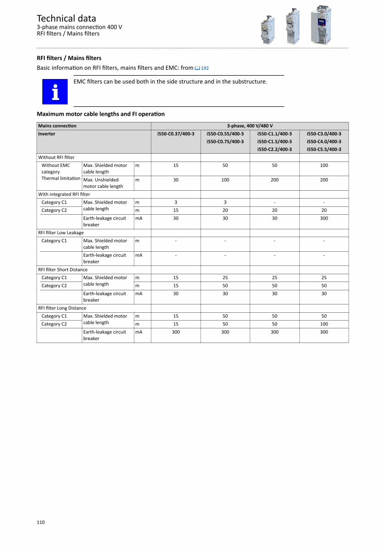
RFI filters / Mains filtersBasic information on RFI filters, mains filters and EMC: from ^ 192
EMC filters can be used both in the side structure and in the substructure.
Maximum motor cable lengths and FI operation
Mains connection 3-phase, 400 V/480 VInverter i550-C0.37/400-3 i550-C0.55/400-3 i550-C1.1/400-3 i550-C3.0/400-3 i550-C0.75/400-3 i550-C1.5/400-3 i550-C4.0/400-3 i550-C2.2/400-3 i550-C5.5/400-3Without RFI filter Without EMC
categoryThermal limitation
Max. Shielded motorcable length
m 15 50 50 100
Max. Unshieldedmotor cable length
m 30 100 200 200
With integrated RFI filter Category C1 Max. Shielded motor
cable lengthm 3 3 - -
Category C2 m 15 20 20 20 Earth-leakage circuit
breakermA 30 30 30 300
RFI filter Low Leakage Category C1 Max. Shielded motor
cable lengthm - - - -
Earth-leakage circuitbreaker
mA - - - -
RFI filter Short Distance Category C1 Max. Shielded motor
cable lengthm 15 25 25 25
Category C2 m 15 50 50 50 Earth-leakage circuit
breakermA 30 30 30 30
RFI filter Long Distance Category C1 Max. Shielded motor
cable lengthm 15 50 50 50
Category C2 m 15 50 50 100 Earth-leakage circuit
breakermA 300 300 300 300
Technical data3-phase mains connection 400 VRFI filters / Mains filters
110
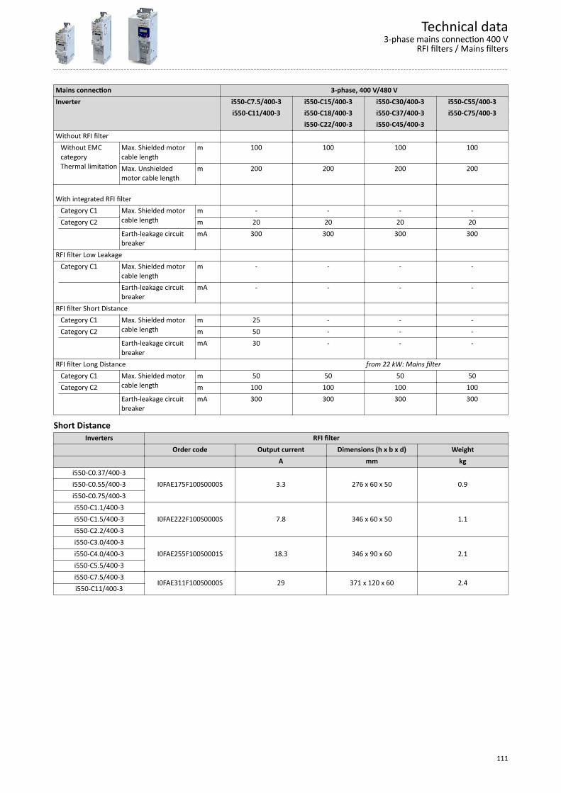
Mains connection 3-phase, 400 V/480 VInverter i550-C7.5/400-3 i550-C15/400-3 i550-C30/400-3 i550-C55/400-3 i550-C11/400-3 i550-C18/400-3 i550-C37/400-3 i550-C75/400-3 i550-C22/400-3 i550-C45/400-3 Without RFI filter Without EMC
categoryThermal limitation
Max. Shielded motorcable length
m 100 100 100 100
Max. Unshieldedmotor cable length
m 200 200 200 200
With integrated RFI filter
Category C1 Max. Shielded motorcable length
m - - - - Category C2 m 20 20 20 20 Earth-leakage circuit
breakermA 300 300 300 300
RFI filter Low Leakage Category C1 Max. Shielded motor
cable lengthm - - - -
Earth-leakage circuitbreaker
mA - - - -
RFI filter Short Distance Category C1 Max. Shielded motor
cable lengthm 25 - - -
Category C2 m 50 - - - Earth-leakage circuit
breakermA 30 - - -
RFI filter Long Distance from 22 kW: Mains filter Category C1 Max. Shielded motor
cable lengthm 50 50 50 50
Category C2 m 100 100 100 100 Earth-leakage circuit
breakermA 300 300 300 300
Short DistanceInverters RFI filter
Order code Output current Dimensions (h x b x d) Weight A mm kg
i550-C0.37/400-3I0FAE175F100S0000S 3.3 276 x 60 x 50 0.9i550-C0.55/400-3
i550-C0.75/400-3i550-C1.1/400-3
I0FAE222F100S0000S 7.8 346 x 60 x 50 1.1i550-C1.5/400-3i550-C2.2/400-3i550-C3.0/400-3
I0FAE255F100S0001S 18.3 346 x 90 x 60 2.1i550-C4.0/400-3i550-C5.5/400-3i550-C7.5/400-3
I0FAE311F100S0000S 29 371 x 120 x 60 2.4i550-C11/400-3
Technical data3-phase mains connection 400 V
RFI filters / Mains filters
111
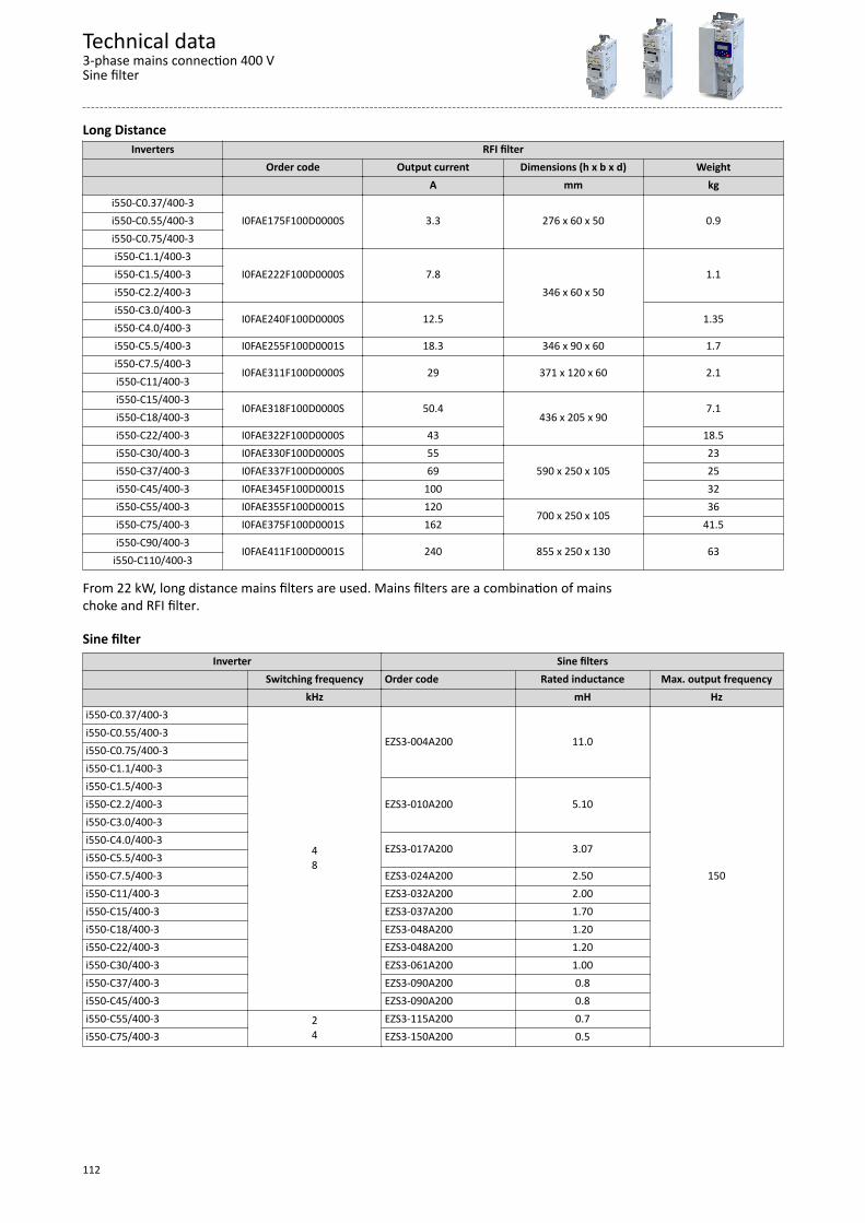
Long DistanceInverters RFI filter
Order code Output current Dimensions (h x b x d) Weight A mm kg
i550-C0.37/400-3I0FAE175F100D0000S 3.3 276 x 60 x 50 0.9i550-C0.55/400-3
i550-C0.75/400-3i550-C1.1/400-3
I0FAE222F100D0000S 7.8346 x 60 x 50
1.1i550-C1.5/400-3i550-C2.2/400-3i550-C3.0/400-3
I0FAE240F100D0000S 12.5 1.35i550-C4.0/400-3i550-C5.5/400-3 I0FAE255F100D0001S 18.3 346 x 90 x 60 1.7i550-C7.5/400-3
I0FAE311F100D0000S 29 371 x 120 x 60 2.1i550-C11/400-3i550-C15/400-3
I0FAE318F100D0000S 50.4436 x 205 x 90
7.1i550-C18/400-3i550-C22/400-3 I0FAE322F100D0000S 43 18.5i550-C30/400-3 I0FAE330F100D0000S 55
590 x 250 x 10523
i550-C37/400-3 I0FAE337F100D0000S 69 25i550-C45/400-3 I0FAE345F100D0001S 100 32i550-C55/400-3 I0FAE355F100D0001S 120
700 x 250 x 10536
i550-C75/400-3 I0FAE375F100D0001S 162 41.5i550-C90/400-3
I0FAE411F100D0001S 240 855 x 250 x 130 63i550-C110/400-3
From 22 kW, long distance mains filters are used. Mains filters are a combination of mainschoke and RFI filter.
Sine filterInverter Sine filters
Switching frequency Order code Rated inductance Max. output frequency kHz mH Hzi550-C0.37/400-3
48
EZS3-004A200 11.0
150
i550-C0.55/400-3i550-C0.75/400-3i550-C1.1/400-3i550-C1.5/400-3
EZS3-010A200 5.10i550-C2.2/400-3i550-C3.0/400-3i550-C4.0/400-3
EZS3-017A200 3.07i550-C5.5/400-3i550-C7.5/400-3 EZS3-024A200 2.50i550-C11/400-3 EZS3-032A200 2.00i550-C15/400-3 EZS3-037A200 1.70i550-C18/400-3 EZS3-048A200 1.20i550-C22/400-3 EZS3-048A200 1.20i550-C30/400-3 EZS3-061A200 1.00i550-C37/400-3 EZS3-090A200 0.8i550-C45/400-3 EZS3-090A200 0.8i550-C55/400-3 2
4EZS3-115A200 0.7
i550-C75/400-3 EZS3-150A200 0.5
Technical data3-phase mains connection 400 VSine filter
112
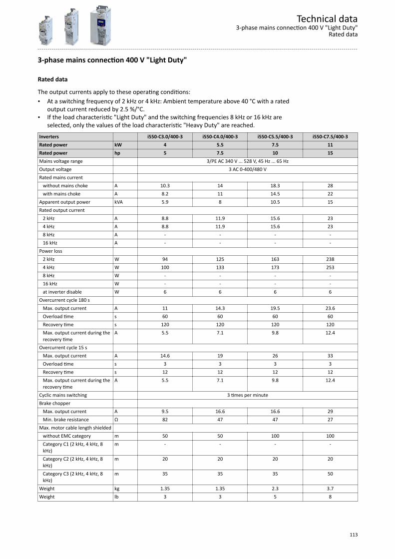
3-phase mains connection 400 V "Light Duty"
Rated data
The output currents apply to these operating conditions:• At a switching frequency of 2 kHz or 4 kHz: Ambient temperature above 40 °C with a rated
output current reduced by 2.5 %/°C.• If the load characteristic "Light Duty" and the switching frequencies 8 kHz or 16 kHz are
selected, only the values of the load characteristic "Heavy Duty" are reached.Inverters i550-C3.0/400-3 i550-C4.0/400-3 i550-C5.5/400-3 i550-C7.5/400-3Rated power kW 4 5.5 7.5 11Rated power hp 5 7.5 10 15Mains voltage range 3/PE AC 340 V ... 528 V, 45 Hz ... 65 HzOutput voltage 3 AC 0-400/480 VRated mains current without mains choke A 10.3 14 18.3 28 with mains choke A 8.2 11 14.5 22Apparent output power kVA 5.9 8 10.5 15Rated output current 2 kHz A 8.8 11.9 15.6 23 4 kHz A 8.8 11.9 15.6 23 8 kHz A - - - - 16 kHz A - - - -Power loss 2 kHz W 94 125 163 238 4 kHz W 100 133 173 253 8 kHz W - - - - 16 kHz W - - - - at inverter disable W 6 6 6 6Overcurrent cycle 180 s Max. output current A 11 14.3 19.5 23.6 Overload time s 60 60 60 60 Recovery time s 120 120 120 120 Max. output current during the
recovery timeA 5.5 7.1 9.8 12.4
Overcurrent cycle 15 s Max. output current A 14.6 19 26 33 Overload time s 3 3 3 3 Recovery time s 12 12 12 12 Max. output current during the
recovery timeA 5.5 7.1 9.8 12.4
Cyclic mains switching 3 times per minuteBrake chopper Max. output current A 9.5 16.6 16.6 29 Min. brake resistance Ω 82 47 47 27Max. motor cable length shielded without EMC category m 50 50 100 100 Category C1 (2 kHz, 4 kHz, 8
kHz)m - - - -
Category C2 (2 kHz, 4 kHz, 8kHz)
m 20 20 20 20
Category C3 (2 kHz, 4 kHz, 8kHz)
m 35 35 35 50
Weight kg 1.35 1.35 2.3 3.7Weight lb 3 3 5 8
Technical data3-phase mains connection 400 V "Light Duty"
Rated data
113

Inverters i550-C11/400-3 i550-C15/400-3 i550-C18/400-3 i550-C22/400-3Rated power kW 15 18.5 22 30Rated power hp 20 25 30 40Mains voltage range 3/PE AC 340 V ... 528 V, 45 Hz ... 65 HzOutput voltage 3 AC 0-400/480 VRated mains current without mains choke A - 48 - - with mains choke A 27.1 36 43 55Apparent output power kVA 19 26 32 38Rated output current 2 kHz A 28.2 38.4 48 56.4 4 kHz A 28.2 38.4 48 56.4 8 kHz A - - - - 16 kHz A - - - -Power loss 2 kHz W 290 404 501 585 4 kHz W 309 430 533 623 8 kHz W - - - - 16 kHz W - - - - at inverter disable W 6 18 18 18Overcurrent cycle 180 s Max. output current A 35 48 60 71 Overload time s 60 60 60 60 Recovery time s 120 120 120 120 Max. output current during the
recovery timeA 17.6 24 30 35
Overcurrent cycle 15 s Max. output current A 47 64 80 94 Overload time s 3 3 3 3 Recovery time s 12 12 12 12 Max. output current during the
recovery timeA 17.6 24 30 35
Cyclic mains switching 3 times per minuteBrake chopper Max. output current A 29 43 52 52 Min. brake resistance Ω 27 18 15 15Max. motor cable length shielded without EMC category m 100 100 100 100 Category C1 (2 kHz, 4 kHz, 8
kHz)m - - - -
Category C2 (2 kHz, 4 kHz, 8kHz)
m 20 20 20 20
Category C3 (2 kHz, 4 kHz, 8kHz)
m 50 35 35 35
Weight kg 3.7 10.3 10.3 10.3Weight lb 8 23 23 23
Technical data3-phase mains connection 400 V "Light Duty"Rated data
114

Inverters i550-C30/400-3 i550-C37/400-3 i550-C45/400-3 i550-C55/400-3Rated power kW 37 45 55 75Rated power hp 50 60 75 100Mains voltage range 3/PE AC 340 V ... 528 V, 45 Hz ... 65 HzOutput voltage 3 AC 0-400/480 VRated mains current without mains choke A - - - - with mains choke A 69 86 100 119Apparent output power kVA 49 61 72 89Rated output current 2 kHz A 73.2 91.2 107 132 4 kHz A 73.2 91.2 107 132 8 kHz A - - - - 16 kHz A - - - -Power loss 2 kHz W 761 942 1101 1358 4 kHz W 810 1004 1171 1446 8 kHz W - - - - 16 kHz W - - - - at inverter disable W 25 25 25 30Overcurrent cycle 180 s Max. output current A 92 114 134 165 Overload time s 60 60 60 60 Recovery time s 120 120 120 120 Max. output current during the
recovery timeA 46 57 67 83
Overcurrent cycle 15 s Max. output current A 122 152 178 220 Overload time s 3 3 3 3 Recovery time s 12 12 12 12 Max. output current during the
recovery timeA 46 57 67 83
Cyclic mains switching 3 times per minute 1 time per minuteBrake chopper Max. output current A 98 98 98 166 Min. brake resistance Ω 7.5 7.5 7.5 4.7Max. motor cable length shielded without EMC category m 100 100 100 200 Category C1 (2 kHz, 4 kHz, 8
kHz)m - - - -
Category C2 (2 kHz, 4 kHz, 8kHz)
m 20 20 20 20
Category C3 (2 kHz, 4 kHz, 8kHz)
m 35 35 35 100
Weight kg 17.2 17.2 17.2 24Weight lb 38 38 38 53
Technical data3-phase mains connection 400 V "Light Duty"
Rated data
115

Inverters i550-C75/400-3 i550-C90/400-3 i550-C110/400-3Rated power kW 90 110 132Rated power hp 125 150 175Mains voltage range 3/PE AC 340 V ... 528 V, 45 Hz ... 65 HzOutput voltage 3 AC 0-400/480 VRated mains current without mains choke A - - - with mains choke A 160 200 234Apparent output power kVA 121 145 171Rated output current 2 kHz A 180 216 254 4 kHz A 180 216 254 8 kHz A - - - 16 kHz A - - -Power loss 2 kHz W 1841 2203 2589 4 kHz W 1961 2348 2760 8 kHz W - - - 16 kHz W - - - at inverter disable W 30 30 30Overcurrent cycle 180 s Max. output current A 225 270 318 Overload time s 60 60 60 Recovery time s 120 120 120 Max. output current during the
recovery timeA 113 135 159
Overcurrent cycle 15 s Max. output current A 300 360 424 Overload time s 3 3 3 Recovery time s 12 12 12 Max. output current during the
recovery timeA 113 135 159
Cyclic mains switching 1 time per minuteBrake chopper Max. output current A 166 333 333 Min. brake resistance Ω 4.7 2.4 2.4Max. motor cable length shielded without EMC category m 200 200 200 Category C1 (2 kHz, 4 kHz, 8
kHz)m - - -
Category C2 (2 kHz, 4 kHz, 8kHz)
m 20 20 20
Category C3 (2 kHz, 4 kHz, 8kHz)
m 100 100 100
Weight kg 24 35.6 35.6Weight lb 53 78.5 78.5
Technical data3-phase mains connection 400 V "Light Duty"Rated data
116
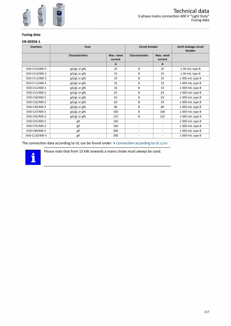
Fusing data
EN 60204-1Inverters Fuse Circuit breaker Earth-leakage circuit
breakerCharacteristics Max. rated
currentCharacteristics Max. rated
current A A
i550-C3.0/400-3 gG/gL or gRL 25 B 25 ≥ 30 mA, type Bi550-C4.0/400-3 gG/gL or gRL 25 B 25 ≥ 30 mA, type Bi550-C5.5/400-3 gG/gL or gRL 25 B 25 ≥ 300 mA, type Bi550-C7.5/400-3 gG/gL or gRL 32 B 32 ≥ 300 mA, type Bi550-C11/400-3 gG/gL or gRL 32 B 32 ≥ 300 mA, type Bi550-C15/400-3 gG/gL or gRL 63 B 63 ≥ 300 mA, type Bi550-C18/400-3 gG/gL or gRL 63 B 63 ≥ 300 mA, type Bi550-C22/400-3 gG/gL or gRL 63 B 63 ≥ 300 mA, type Bi550-C30/400-3 gG/gL or gRL 80 B 80 ≥ 300 mA, type Bi550-C37/400-3 gG/gL or gRL 100 B 100 ≥ 300 mA, type Bi550-C45/400-3 gG/gL or gRL 125 B 125 ≥ 300 mA, type Bi550-C55/400-3 gR 160 - - ≥ 300 mA, type Bi550-C75/400-3 gR 160 - - ≥ 300 mA, type Bi550-C90/400-3 gR 300 - - ≥ 300 mA, type B
i550-C110/400-3 gR 300 - - ≥ 300 mA, type B
The connection data according to UL can be found under:4Connection according to UL ^ 50
Please note that from 15 kW onwards a mains choke must always be used.
Technical data3-phase mains connection 400 V "Light Duty"
Fusing data
117
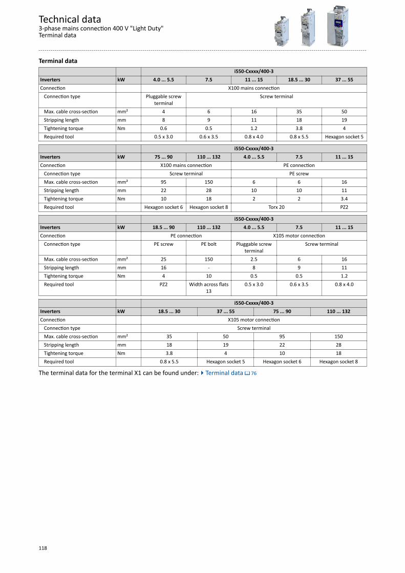
Terminal data i550-Cxxxx/400-3Inverters kW 4.0 ... 5.5 7.5 11 ... 15 18.5 ... 30 37 ... 55Connection X100 mains connection Connection type Pluggable screw
terminalScrew terminal
Max. cable cross-section mm² 4 6 16 35 50 Stripping length mm 8 9 11 18 19 Tightening torque Nm 0.6 0.5 1.2 3.8 4 Required tool 0.5 x 3.0 0.6 x 3.5 0.8 x 4.0 0.8 x 5.5 Hexagon socket 5
i550-Cxxxx/400-3Inverters kW 75 ... 90 110 ... 132 4.0 ... 5.5 7.5 11 ... 15Connection X100 mains connection PE connection Connection type Screw terminal PE screw Max. cable cross-section mm² 95 150 6 6 16 Stripping length mm 22 28 10 10 11 Tightening torque Nm 10 18 2 2 3.4 Required tool Hexagon socket 6 Hexagon socket 8 Torx 20 PZ2
i550-Cxxxx/400-3Inverters kW 18.5 ... 90 110 ... 132 4.0 ... 5.5 7.5 11 ... 15Connection PE connection X105 motor connection Connection type PE screw PE bolt Pluggable screw
terminalScrew terminal
Max. cable cross-section mm² 25 150 2.5 6 16 Stripping length mm 16 - 8 9 11 Tightening torque Nm 4 10 0.5 0.5 1.2 Required tool PZ2 Width across flats
130.5 x 3.0 0.6 x 3.5 0.8 x 4.0
i550-Cxxxx/400-3Inverters kW 18.5 ... 30 37 ... 55 75 ... 90 110 ... 132Connection X105 motor connection Connection type Screw terminal Max. cable cross-section mm² 35 50 95 150 Stripping length mm 18 19 22 28 Tightening torque Nm 3.8 4 10 18 Required tool 0.8 x 5.5 Hexagon socket 5 Hexagon socket 6 Hexagon socket 8
The terminal data for the terminal X1 can be found under:4Terminal data ^ 76
Technical data3-phase mains connection 400 V "Light Duty"Terminal data
118
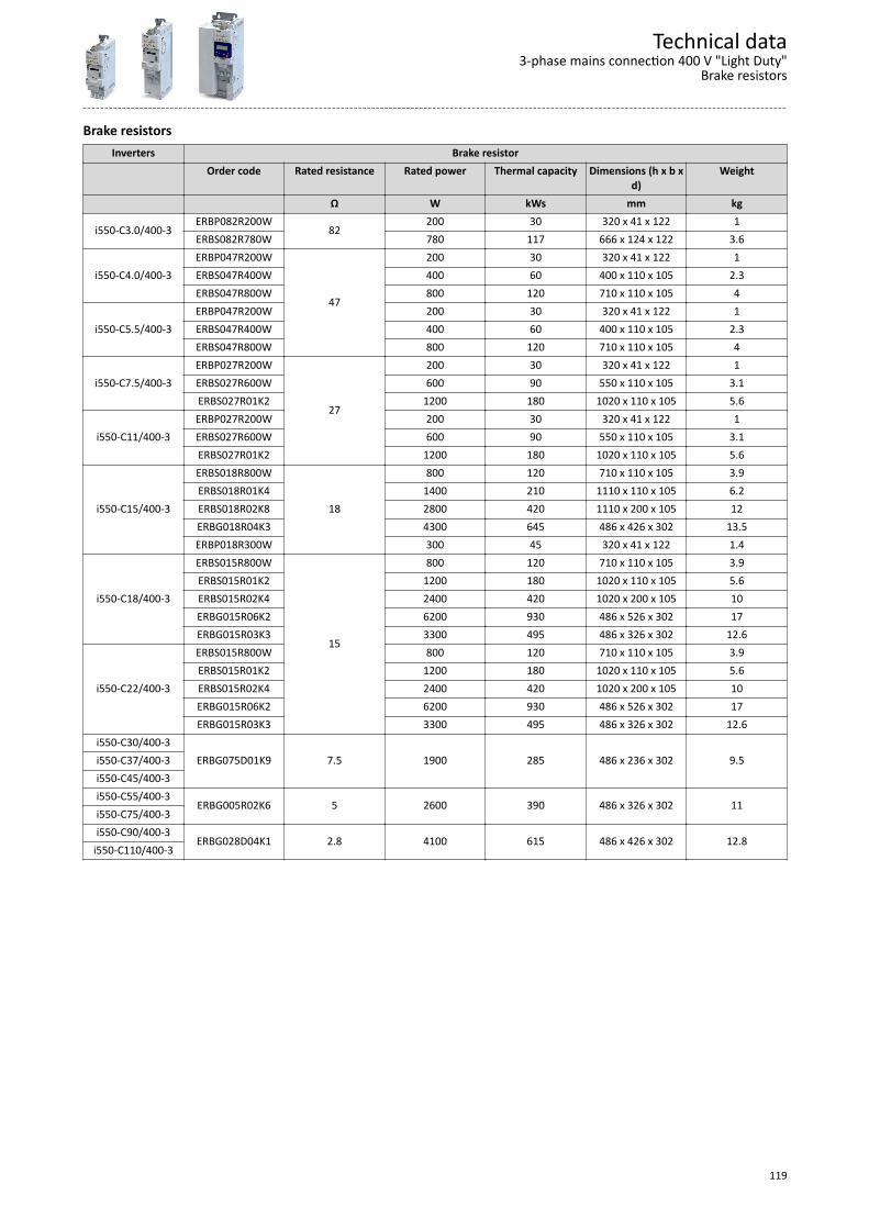
Brake resistorsInverters Brake resistor
Order code Rated resistance Rated power Thermal capacity Dimensions (h x b xd)
Weight
Ω W kWs mm kg
i550-C3.0/400-3ERBP082R200W
82200 30 320 x 41 x 122 1
ERBS082R780W 780 117 666 x 124 x 122 3.6
i550-C4.0/400-3ERBP047R200W
47
200 30 320 x 41 x 122 1ERBS047R400W 400 60 400 x 110 x 105 2.3ERBS047R800W 800 120 710 x 110 x 105 4
i550-C5.5/400-3ERBP047R200W 200 30 320 x 41 x 122 1ERBS047R400W 400 60 400 x 110 x 105 2.3ERBS047R800W 800 120 710 x 110 x 105 4
i550-C7.5/400-3ERBP027R200W
27
200 30 320 x 41 x 122 1ERBS027R600W 600 90 550 x 110 x 105 3.1ERBS027R01K2 1200 180 1020 x 110 x 105 5.6
i550-C11/400-3ERBP027R200W 200 30 320 x 41 x 122 1ERBS027R600W 600 90 550 x 110 x 105 3.1ERBS027R01K2 1200 180 1020 x 110 x 105 5.6
i550-C15/400-3
ERBS018R800W
18
800 120 710 x 110 x 105 3.9ERBS018R01K4 1400 210 1110 x 110 x 105 6.2ERBS018R02K8 2800 420 1110 x 200 x 105 12ERBG018R04K3 4300 645 486 x 426 x 302 13.5ERBP018R300W 300 45 320 x 41 x 122 1.4
i550-C18/400-3
ERBS015R800W
15
800 120 710 x 110 x 105 3.9ERBS015R01K2 1200 180 1020 x 110 x 105 5.6ERBS015R02K4 2400 420 1020 x 200 x 105 10ERBG015R06K2 6200 930 486 x 526 x 302 17ERBG015R03K3 3300 495 486 x 326 x 302 12.6
i550-C22/400-3
ERBS015R800W 800 120 710 x 110 x 105 3.9ERBS015R01K2 1200 180 1020 x 110 x 105 5.6ERBS015R02K4 2400 420 1020 x 200 x 105 10ERBG015R06K2 6200 930 486 x 526 x 302 17ERBG015R03K3 3300 495 486 x 326 x 302 12.6
i550-C30/400-3ERBG075D01K9 7.5 1900 285 486 x 236 x 302 9.5i550-C37/400-3
i550-C45/400-3i550-C55/400-3
ERBG005R02K6 5 2600 390 486 x 326 x 302 11i550-C75/400-3i550-C90/400-3
ERBG028D04K1 2.8 4100 615 486 x 426 x 302 12.8i550-C110/400-3
Technical data3-phase mains connection 400 V "Light Duty"
Brake resistors
119
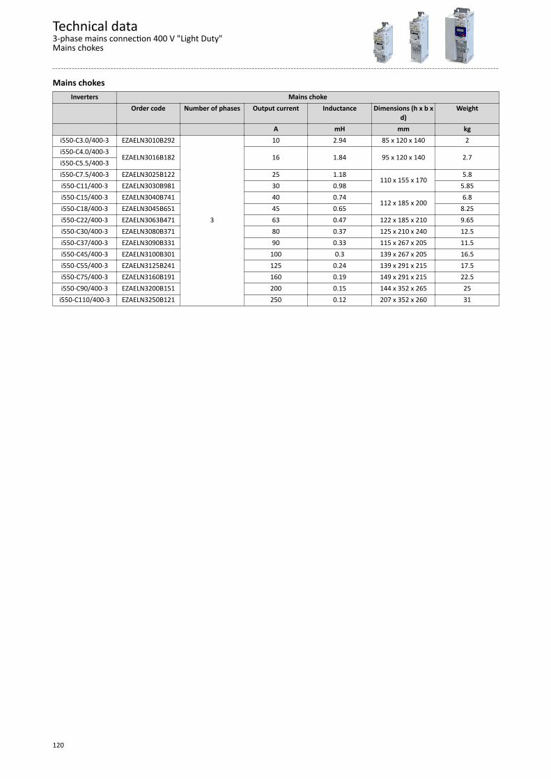
Mains chokesInverters Mains choke
Order code Number of phases Output current Inductance Dimensions (h x b xd)
Weight
A mH mm kgi550-C3.0/400-3 EZAELN3010B292
3
10 2.94 85 x 120 x 140 2i550-C4.0/400-3
EZAELN3016B182 16 1.84 95 x 120 x 140 2.7i550-C5.5/400-3i550-C7.5/400-3 EZAELN3025B122 25 1.18
110 x 155 x 1705.8
i550-C11/400-3 EZAELN3030B981 30 0.98 5.85i550-C15/400-3 EZAELN3040B741 40 0.74
112 x 185 x 2006.8
i550-C18/400-3 EZAELN3045B651 45 0.65 8.25i550-C22/400-3 EZAELN3063B471 63 0.47 122 x 185 x 210 9.65i550-C30/400-3 EZAELN3080B371 80 0.37 125 x 210 x 240 12.5i550-C37/400-3 EZAELN3090B331 90 0.33 115 x 267 x 205 11.5i550-C45/400-3 EZAELN3100B301 100 0.3 139 x 267 x 205 16.5i550-C55/400-3 EZAELN3125B241 125 0.24 139 x 291 x 215 17.5i550-C75/400-3 EZAELN3160B191 160 0.19 149 x 291 x 215 22.5i550-C90/400-3 EZAELN3200B151 200 0.15 144 x 352 x 265 25
i550-C110/400-3 EZAELN3250B121 250 0.12 207 x 352 x 260 31
Technical data3-phase mains connection 400 V "Light Duty"Mains chokes
120
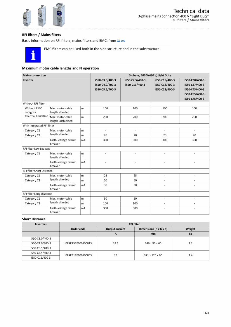
RFI filters / Mains filtersBasic information on RFI filters, mains filters and EMC: from ^ 192
EMC filters can be used both in the side structure and in the substructure.
Maximum motor cable lengths and FI operation
Mains connection 3-phase, 400 V/480 V, Light DutyInverter i550-C3.0/400-3 i550-C7.5/400-3 i550-C15/400-3 i550-C30/400-3 i550-C4.0/400-3 i550-C11/400-3 i550-C18/400-3 i550-C37/400-3 i550-C5.5/400-3 i550-C22/400-3 i550-C45/400-3 i550-C55/400-3 i550-C75/400-3Without RFI filter Without EMC
categoryThermal limitation
Max. motor cablelength shielded
m 100 100 100 100
Max. motor cablelength unshielded
m 200 200 200 200
With integrated RFI filter Category C1 Max. motor cable
length shieldedm - - - -
Category C2 m 20 20 20 20 Earth-leakage circuit
breakermA 300 300 300 300
RFI filter Low Leakage Category C1 Max. motor cable
length shieldedm - - - -
Earth-leakage circuitbreaker
mA - - - -
RFI filter Short Distance Category C1 Max. motor cable
length shieldedm 25 25 - -
Category C2 m 50 50 - - Earth-leakage circuit
breakermA 30 30 - -
RFI filter Long Distance Category C1 Max. motor cable
length shieldedm 50 50 - -
Category C2 m 100 100 - - Earth-leakage circuit
breakermA 300 300 - -
Short DistanceInverters RFI filter
Order code Output current Dimensions (h x b x d) Weight A mm kg
i550-C3.0/400-3I0FAE255F100S0001S 18.3 346 x 90 x 60 2.1i550-C4.0/400-3
i550-C5.5/400-3i550-C7.5/400-3
I0FAE311F100S0000S 29 371 x 120 x 60 2.4i550-C11/400-3
Technical data3-phase mains connection 400 V "Light Duty"
RFI filters / Mains filters
121
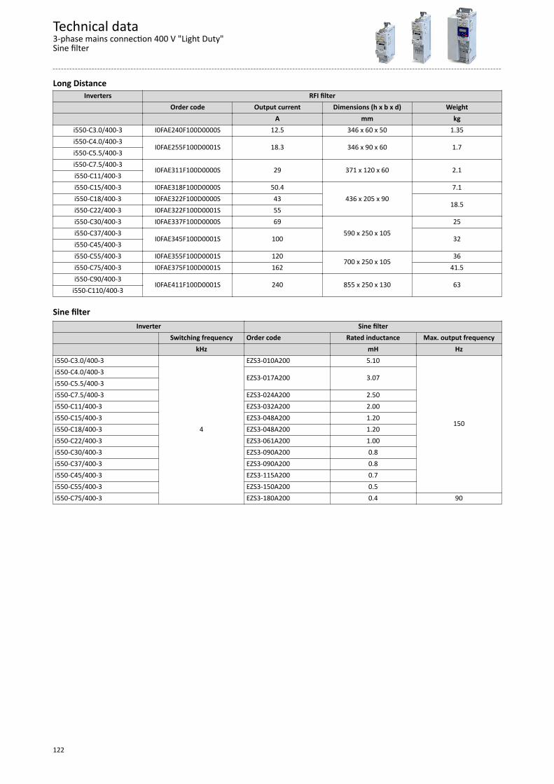
Long DistanceInverters RFI filter
Order code Output current Dimensions (h x b x d) Weight A mm kg
i550-C3.0/400-3 I0FAE240F100D0000S 12.5 346 x 60 x 50 1.35i550-C4.0/400-3
I0FAE255F100D0001S 18.3 346 x 90 x 60 1.7i550-C5.5/400-3i550-C7.5/400-3
I0FAE311F100D0000S 29 371 x 120 x 60 2.1i550-C11/400-3i550-C15/400-3 I0FAE318F100D0000S 50.4
436 x 205 x 907.1
i550-C18/400-3 I0FAE322F100D0000S 4318.5
i550-C22/400-3 I0FAE322F100D0001S 55i550-C30/400-3 I0FAE337F100D0000S 69
590 x 250 x 10525
i550-C37/400-3I0FAE345F100D0001S 100 32
i550-C45/400-3i550-C55/400-3 I0FAE355F100D0001S 120
700 x 250 x 10536
i550-C75/400-3 I0FAE375F100D0001S 162 41.5i550-C90/400-3
I0FAE411F100D0001S 240 855 x 250 x 130 63i550-C110/400-3
Sine filterInverter Sine filter
Switching frequency Order code Rated inductance Max. output frequency kHz mH Hzi550-C3.0/400-3
4
EZS3-010A200 5.10
150
i550-C4.0/400-3EZS3-017A200 3.07
i550-C5.5/400-3i550-C7.5/400-3 EZS3-024A200 2.50i550-C11/400-3 EZS3-032A200 2.00i550-C15/400-3 EZS3-048A200 1.20i550-C18/400-3 EZS3-048A200 1.20i550-C22/400-3 EZS3-061A200 1.00i550-C30/400-3 EZS3-090A200 0.8i550-C37/400-3 EZS3-090A200 0.8i550-C45/400-3 EZS3-115A200 0.7i550-C55/400-3 EZS3-150A200 0.5i550-C75/400-3 EZS3-180A200 0.4 90
Technical data3-phase mains connection 400 V "Light Duty"Sine filter
122
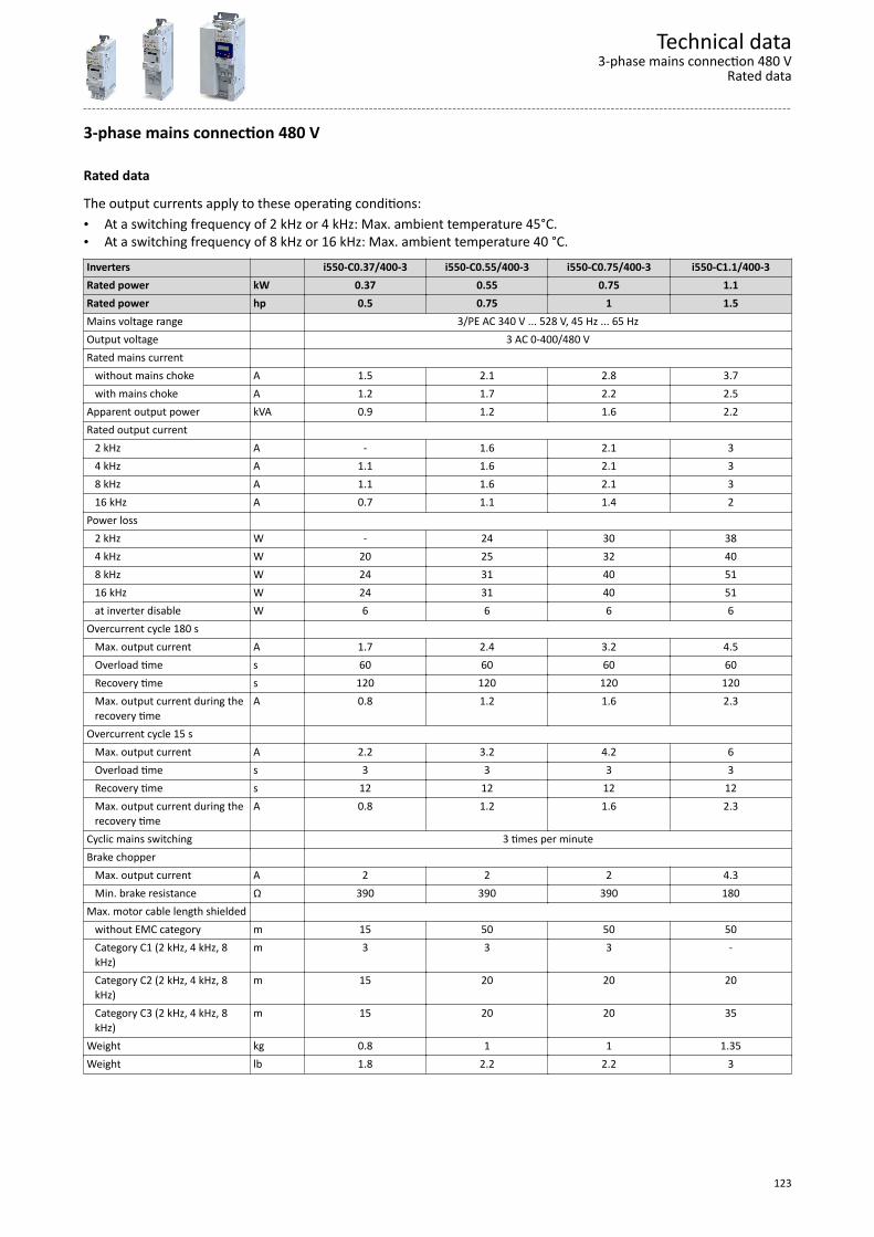
3-phase mains connection 480 V
Rated data
The output currents apply to these operating conditions:• At a switching frequency of 2 kHz or 4 kHz: Max. ambient temperature 45°C.• At a switching frequency of 8 kHz or 16 kHz: Max. ambient temperature 40 °C.Inverters i550-C0.37/400-3 i550-C0.55/400-3 i550-C0.75/400-3 i550-C1.1/400-3Rated power kW 0.37 0.55 0.75 1.1Rated power hp 0.5 0.75 1 1.5Mains voltage range 3/PE AC 340 V ... 528 V, 45 Hz ... 65 HzOutput voltage 3 AC 0-400/480 VRated mains current without mains choke A 1.5 2.1 2.8 3.7 with mains choke A 1.2 1.7 2.2 2.5Apparent output power kVA 0.9 1.2 1.6 2.2Rated output current 2 kHz A - 1.6 2.1 3 4 kHz A 1.1 1.6 2.1 3 8 kHz A 1.1 1.6 2.1 3 16 kHz A 0.7 1.1 1.4 2Power loss 2 kHz W - 24 30 38 4 kHz W 20 25 32 40 8 kHz W 24 31 40 51 16 kHz W 24 31 40 51 at inverter disable W 6 6 6 6Overcurrent cycle 180 s Max. output current A 1.7 2.4 3.2 4.5 Overload time s 60 60 60 60 Recovery time s 120 120 120 120 Max. output current during the
recovery timeA 0.8 1.2 1.6 2.3
Overcurrent cycle 15 s Max. output current A 2.2 3.2 4.2 6 Overload time s 3 3 3 3 Recovery time s 12 12 12 12 Max. output current during the
recovery timeA 0.8 1.2 1.6 2.3
Cyclic mains switching 3 times per minuteBrake chopper Max. output current A 2 2 2 4.3 Min. brake resistance Ω 390 390 390 180Max. motor cable length shielded without EMC category m 15 50 50 50 Category C1 (2 kHz, 4 kHz, 8
kHz)m 3 3 3 -
Category C2 (2 kHz, 4 kHz, 8kHz)
m 15 20 20 20
Category C3 (2 kHz, 4 kHz, 8kHz)
m 15 20 20 35
Weight kg 0.8 1 1 1.35Weight lb 1.8 2.2 2.2 3
Technical data3-phase mains connection 480 V
Rated data
123

Inverters i550-C1.5/400-3 i550-C2.2/400-3 i550-C3.0/400-3 i550-C4.0/400-3Rated power kW 1.5 2.2 3 4Rated power hp 2 3 4 5Mains voltage range 3/PE AC 340 V ... 528 V, 45 Hz ... 65 HzOutput voltage 3 AC 0-400/480 VRated mains current without mains choke A 4.5 6.5 8 10.5 with mains choke A 3.1 4.4 5.8 7.5Apparent output power kVA 2.6 3.8 4.9 6.4Rated output current 2 kHz A 3.5 4.8 6.3 8.2 4 kHz A 3.5 4.8 6.3 8.2 8 kHz A 3.5 4.8 6.3 8.2 16 kHz A 2.3 3.2 4.2 5.5Power loss 2 kHz W 45 62 79 102 4 kHz W 48 66 85 110 8 kHz W 61 85 110 140 16 kHz W 61 85 109 140 at inverter disable W 6 6 6 6Overcurrent cycle 180 s Max. output current A 5.3 7.2 9.5 12.3 Overload time s 60 60 60 60 Recovery time s 120 120 120 120 Max. output current during the
recovery timeA 2.6 3.6 4.7 6.2
Overcurrent cycle 15 s Max. output current A 7 9.6 12.6 16.4 Overload time s 3 3 3 3 Recovery time s 12 12 12 12 Max. output current during the
recovery timeA 2.6 3.6 4.7 6.2
Cyclic mains switching 3 times per minuteBrake chopper Max. output current A 4.3 4.3 9.5 16.6 Min. brake resistance Ω 180 150 82 47Max. motor cable length shielded without EMC category m 50 50 50 50 Category C1 (2 kHz, 4 kHz, 8
kHz)m - - - -
Category C2 (2 kHz, 4 kHz, 8kHz)
m 20 20 20 20
Category C3 (2 kHz, 4 kHz, 8kHz)
m 35 35 35 35
Weight kg 1.35 1.35 1.35 1.35Weight lb 3 3 3 3
Technical data3-phase mains connection 480 VRated data
124

Inverters i550-C5.5/400-3 i550-C7.5/400-3 i550-C11/400-3 i550-C15/400-3Rated power kW 5.5 7.5 11 15Rated power hp 7.5 10 15 20Mains voltage range 3/PE AC 340 V ... 528 V, 45 Hz ... 65 HzOutput voltage 3 AC 0-400/480 VRated mains current without mains choke A 14.3 16.6 23.7 32.3 with mains choke A 10.3 13.1 18.6 24Apparent output power kVA 8.7 11 16 22Rated output current 2 kHz A 11 14 21 27 4 kHz A 11 14 21 27 8 kHz A 11 14 21 27 16 kHz A 7.3 9.3 14 18Power loss 2 kHz W 137 172 242 340 4 kHz W 145 185 260 360 8 kHz W 190 240 340 460 16 kHz W 189 238 337 469 at inverter disable W 6 6 6 18Overcurrent cycle 180 s Max. output current A 16.5 21 31.5 40.5 Overload time s 60 60 60 60 Recovery time s 120 120 120 120 Max. output current during the
recovery timeA 8.3 10.5 15.8 20.3
Overcurrent cycle 15 s Max. output current A 22 28 42 54 Overload time s 3 3 3 3 Recovery time s 12 12 12 12 Max. output current during the
recovery timeA 8.3 10.5 15.8 20.3
Cyclic mains switching 3 times per minuteBrake chopper Max. output current A 16.6 29 29 43 Min. brake resistance Ω 47 27 27 18Max. motor cable length shielded without EMC category m 100 100 100 100 Category C1 (2 kHz, 4 kHz, 8
kHz)m - - - -
Category C2 (2 kHz, 4 kHz, 8kHz)
m 20 20 20 20
Category C3 (2 kHz, 4 kHz, 8kHz)
m 35 50 50 35
Weight kg 2.3 3.7 3.7 10.3Weight lb 5 8 8 23
Technical data3-phase mains connection 480 V
Rated data
125
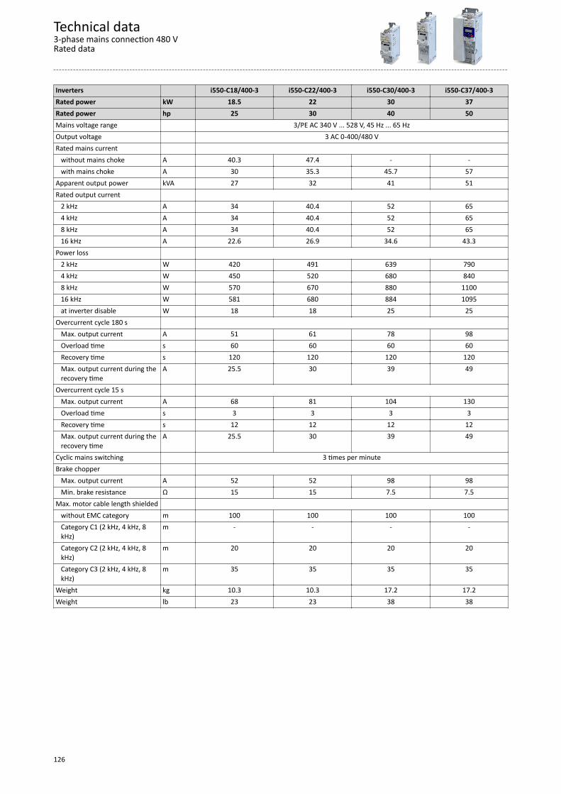
Inverters i550-C18/400-3 i550-C22/400-3 i550-C30/400-3 i550-C37/400-3Rated power kW 18.5 22 30 37Rated power hp 25 30 40 50Mains voltage range 3/PE AC 340 V ... 528 V, 45 Hz ... 65 HzOutput voltage 3 AC 0-400/480 VRated mains current without mains choke A 40.3 47.4 - - with mains choke A 30 35.3 45.7 57Apparent output power kVA 27 32 41 51Rated output current 2 kHz A 34 40.4 52 65 4 kHz A 34 40.4 52 65 8 kHz A 34 40.4 52 65 16 kHz A 22.6 26.9 34.6 43.3Power loss 2 kHz W 420 491 639 790 4 kHz W 450 520 680 840 8 kHz W 570 670 880 1100 16 kHz W 581 680 884 1095 at inverter disable W 18 18 25 25Overcurrent cycle 180 s Max. output current A 51 61 78 98 Overload time s 60 60 60 60 Recovery time s 120 120 120 120 Max. output current during the
recovery timeA 25.5 30 39 49
Overcurrent cycle 15 s Max. output current A 68 81 104 130 Overload time s 3 3 3 3 Recovery time s 12 12 12 12 Max. output current during the
recovery timeA 25.5 30 39 49
Cyclic mains switching 3 times per minuteBrake chopper Max. output current A 52 52 98 98 Min. brake resistance Ω 15 15 7.5 7.5Max. motor cable length shielded without EMC category m 100 100 100 100 Category C1 (2 kHz, 4 kHz, 8
kHz)m - - - -
Category C2 (2 kHz, 4 kHz, 8kHz)
m 20 20 20 20
Category C3 (2 kHz, 4 kHz, 8kHz)
m 35 35 35 35
Weight kg 10.3 10.3 17.2 17.2Weight lb 23 23 38 38
Technical data3-phase mains connection 480 VRated data
126

Inverters i550-C45/400-3 i550-C55/400-3 i550-C75/400-3 i550-C90/400-3Rated power kW 45 55 75 90Rated power hp 60 75 100 125Mains voltage range 3/PE AC 340 V ... 528 V, 45 Hz ... 65 HzOutput voltage 3 AC 0-400/480 VRated mains current without mains choke A - - - - with mains choke A 66.7 83 113 146Apparent output power kVA 60 75 100 121Rated output current 2 kHz A 77 96 124 156 4 kHz A 77 96 124 156 8 kHz A 77 96 124 140 16 kHz A 51.3 63.9 83.1 93.6Power loss 2 kHz W 920 1137 1539 1841 4 kHz W 980 1210 1640 1961 8 kHz W 1280 1580 2140 2312 16 kHz W 1278 1579 2143 2312 at inverter disable W 25 30 30 30Overcurrent cycle 180 s Max. output current A 116 144 186 234 Overload time s 60 60 60 60 Recovery time s 120 120 120 120 Max. output current during the
recovery timeA 58 72 93 117
Overcurrent cycle 15 s Max. output current A 154 192 248 312 Overload time s 3 3 3 3 Recovery time s 12 12 12 12 Max. output current during the
recovery timeA 58 72 93 117
Cyclic mains switching 3 times per minute 1 time per minuteBrake chopper Max. output current A 98 166 166 333 Min. brake resistance Ω 7.5 4.7 4.7 2.4Max. motor cable length shielded without EMC category m 100 200 200 200 Category C1 (2 kHz, 4 kHz, 8
kHz)m - - - -
Category C2 (2 kHz, 4 kHz, 8kHz)
m 20 20 20 20
Category C3 (2 kHz, 4 kHz, 8kHz)
m 35 100 100 100
Weight kg 17.2 24 24 35.6Weight lb 38 53 53 78.5
Technical data3-phase mains connection 480 V
Rated data
127

Inverters i550-C110/400-3Rated power kW 110Rated power hp 150Mains voltage range 3/PE AC 340 V ... 528 V, 45 Hz ... 65 HzOutput voltage 3 AC 0-400/480 VRated mains current without mains choke A - with mains choke A 168Apparent output power kVA 142Rated output current 2 kHz A 180 4 kHz A 180 8 kHz A 162 16 kHz A 108Power loss 2 kHz W 2163 4 kHz W 2305 8 kHz W 2717 16 kHz W 2717 at inverter disable W 30Overcurrent cycle 180 s Max. output current A 270 Overload time s 60 Recovery time s 120 Max. output current during the
recovery timeA 135
Overcurrent cycle 15 s Max. output current A 360 Overload time s 3 Recovery time s 12 Max. output current during the
recovery timeA 135
Cyclic mains switching 1 time per minuteBrake chopper Max. output current A 333 Min. brake resistance Ω 2.4Max. motor cable length shielded without EMC category m 200 Category C1 (2 kHz, 4 kHz, 8
kHz)m -
Category C2 (2 kHz, 4 kHz, 8kHz)
m 20
Category C3 (2 kHz, 4 kHz, 8kHz)
m 100
Weight kg 35.6Weight lb 78.5
Technical data3-phase mains connection 480 VRated data
128
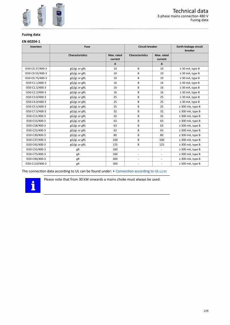
Fusing data
EN 60204-1Inverters Fuse Circuit breaker Earth-leakage circuit
breakerCharacteristics Max. rated
currentCharacteristics Max. rated
current A A
i550-C0.37/400-3 gG/gL or gRL 10 B 10 ≥ 30 mA, type Bi550-C0.55/400-3 gG/gL or gRL 10 B 10 ≥ 30 mA, type Bi550-C0.75/400-3 gG/gL or gRL 10 B 10 ≥ 30 mA, type Bi550-C1.1/400-3 gG/gL or gRL 16 B 16 ≥ 30 mA, type Bi550-C1.5/400-3 gG/gL or gRL 16 B 16 ≥ 30 mA, type Bi550-C2.2/400-3 gG/gL or gRL 16 B 16 ≥ 30 mA, type Bi550-C3.0/400-3 gG/gL or gRL 25 B 25 ≥ 30 mA, type Bi550-C4.0/400-3 gG/gL or gRL 25 B 25 ≥ 30 mA, type Bi550-C5.5/400-3 gG/gL or gRL 25 B 25 ≥ 300 mA, type Bi550-C7.5/400-3 gG/gL or gRL 32 B 32 ≥ 300 mA, type Bi550-C11/400-3 gG/gL or gRL 32 B 32 ≥ 300 mA, type Bi550-C15/400-3 gG/gL or gRL 63 B 63 ≥ 300 mA, type Bi550-C18/400-3 gG/gL or gRL 63 B 63 ≥ 300 mA, type Bi550-C22/400-3 gG/gL or gRL 63 B 63 ≥ 300 mA, type Bi550-C30/400-3 gG/gL or gRL 80 B 80 ≥ 300 mA, type Bi550-C37/400-3 gG/gL or gRL 100 B 100 ≥ 300 mA, type Bi550-C45/400-3 gG/gL or gRL 125 B 125 ≥ 300 mA, type Bi550-C55/400-3 gR 160 - - ≥ 300 mA, type Bi550-C75/400-3 gR 160 - - ≥ 300 mA, type Bi550-C90/400-3 gR 300 - - ≥ 300 mA, type B
i550-C110/400-3 gR 300 - - ≥ 300 mA, type B
The connection data according to UL can be found under:4Connection according to UL ^ 50
Please note that from 30 kW onwards a mains choke must always be used.
Technical data3-phase mains connection 480 V
Fusing data
129
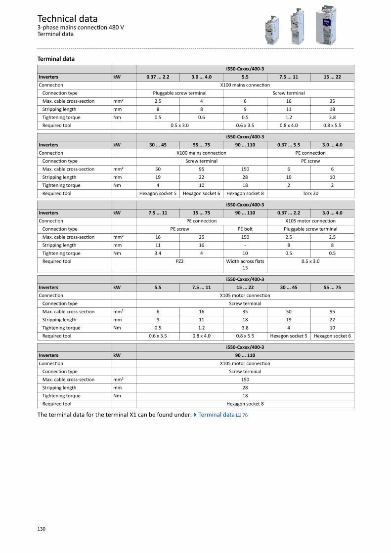
Terminal data i550-Cxxxx/400-3Inverters kW 0.37 ... 2.2 3.0 ... 4.0 5.5 7.5 ... 11 15 ... 22Connection X100 mains connection Connection type Pluggable screw terminal Screw terminal Max. cable cross-section mm² 2.5 4 6 16 35 Stripping length mm 8 8 9 11 18 Tightening torque Nm 0.5 0.6 0.5 1.2 3.8 Required tool 0.5 x 3.0 0.6 x 3.5 0.8 x 4.0 0.8 x 5.5
i550-Cxxxx/400-3Inverters kW 30 ... 45 55 ... 75 90 ... 110 0.37 ... 5.5 3.0 ... 4.0Connection X100 mains connection PE connection Connection type Screw terminal PE screw Max. cable cross-section mm² 50 95 150 6 6 Stripping length mm 19 22 28 10 10 Tightening torque Nm 4 10 18 2 2 Required tool Hexagon socket 5 Hexagon socket 6 Hexagon socket 8 Torx 20
i550-Cxxxx/400-3Inverters kW 7.5 ... 11 15 ... 75 90 ... 110 0.37 ... 2.2 3.0 ... 4.0Connection PE connection X105 motor connection Connection type PE screw PE bolt Pluggable screw terminal Max. cable cross-section mm² 16 25 150 2.5 2.5 Stripping length mm 11 16 - 8 8 Tightening torque Nm 3.4 4 10 0.5 0.5 Required tool PZ2 Width across flats
130.5 x 3.0
i550-Cxxxx/400-3Inverters kW 5.5 7.5 ... 11 15 ... 22 30 ... 45 55 ... 75Connection X105 motor connection Connection type Screw terminal Max. cable cross-section mm² 6 16 35 50 95 Stripping length mm 9 11 18 19 22 Tightening torque Nm 0.5 1.2 3.8 4 10 Required tool 0.6 x 3.5 0.8 x 4.0 0.8 x 5.5 Hexagon socket 5 Hexagon socket 6
i550-Cxxxx/400-3Inverters kW 90 ... 110Connection X105 motor connection Connection type Screw terminal Max. cable cross-section mm² 150 Stripping length mm 28 Tightening torque Nm 18 Required tool Hexagon socket 8
The terminal data for the terminal X1 can be found under:4Terminal data ^ 76
Technical data3-phase mains connection 480 VTerminal data
130
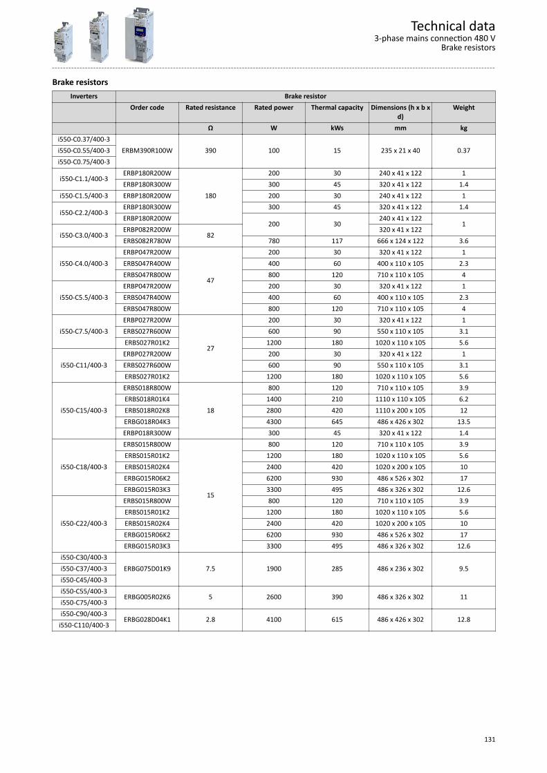
Brake resistorsInverters Brake resistor
Order code Rated resistance Rated power Thermal capacity Dimensions (h x b xd)
Weight
Ω W kWs mm kgi550-C0.37/400-3
ERBM390R100W 390 100 15 235 x 21 x 40 0.37i550-C0.55/400-3i550-C0.75/400-3
i550-C1.1/400-3ERBP180R200W
180
200 30 240 x 41 x 122 1ERBP180R300W 300 45 320 x 41 x 122 1.4
i550-C1.5/400-3 ERBP180R200W 200 30 240 x 41 x 122 1ERBP180R300W 300 45 320 x 41 x 122 1.4
i550-C2.2/400-3ERBP180R200W
200 30240 x 41 x 122
1i550-C3.0/400-3
ERBP082R200W82
320 x 41 x 122ERBS082R780W 780 117 666 x 124 x 122 3.6
i550-C4.0/400-3ERBP047R200W
47
200 30 320 x 41 x 122 1ERBS047R400W 400 60 400 x 110 x 105 2.3ERBS047R800W 800 120 710 x 110 x 105 4
i550-C5.5/400-3ERBP047R200W 200 30 320 x 41 x 122 1ERBS047R400W 400 60 400 x 110 x 105 2.3ERBS047R800W 800 120 710 x 110 x 105 4
i550-C7.5/400-3ERBP027R200W
27
200 30 320 x 41 x 122 1ERBS027R600W 600 90 550 x 110 x 105 3.1ERBS027R01K2 1200 180 1020 x 110 x 105 5.6
i550-C11/400-3ERBP027R200W 200 30 320 x 41 x 122 1ERBS027R600W 600 90 550 x 110 x 105 3.1ERBS027R01K2 1200 180 1020 x 110 x 105 5.6
i550-C15/400-3
ERBS018R800W
18
800 120 710 x 110 x 105 3.9ERBS018R01K4 1400 210 1110 x 110 x 105 6.2ERBS018R02K8 2800 420 1110 x 200 x 105 12ERBG018R04K3 4300 645 486 x 426 x 302 13.5ERBP018R300W 300 45 320 x 41 x 122 1.4
i550-C18/400-3
ERBS015R800W
15
800 120 710 x 110 x 105 3.9ERBS015R01K2 1200 180 1020 x 110 x 105 5.6ERBS015R02K4 2400 420 1020 x 200 x 105 10ERBG015R06K2 6200 930 486 x 526 x 302 17ERBG015R03K3 3300 495 486 x 326 x 302 12.6
i550-C22/400-3
ERBS015R800W 800 120 710 x 110 x 105 3.9ERBS015R01K2 1200 180 1020 x 110 x 105 5.6ERBS015R02K4 2400 420 1020 x 200 x 105 10ERBG015R06K2 6200 930 486 x 526 x 302 17ERBG015R03K3 3300 495 486 x 326 x 302 12.6
i550-C30/400-3ERBG075D01K9 7.5 1900 285 486 x 236 x 302 9.5i550-C37/400-3
i550-C45/400-3i550-C55/400-3
ERBG005R02K6 5 2600 390 486 x 326 x 302 11i550-C75/400-3i550-C90/400-3
ERBG028D04K1 2.8 4100 615 486 x 426 x 302 12.8i550-C110/400-3
Technical data3-phase mains connection 480 V
Brake resistors
131
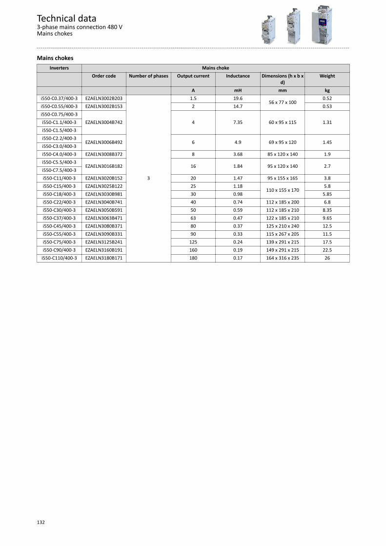
Mains chokesInverters Mains choke
Order code Number of phases Output current Inductance Dimensions (h x b xd)
Weight
A mH mm kgi550-C0.37/400-3 EZAELN3002B203
3
1.5 19.656 x 77 x 100
0.52i550-C0.55/400-3 EZAELN3002B153 2 14.7 0.53i550-C0.75/400-3
EZAELN3004B742 4 7.35 60 x 95 x 115 1.31i550-C1.1/400-3i550-C1.5/400-3i550-C2.2/400-3
EZAELN3006B492 6 4.9 69 x 95 x 120 1.45i550-C3.0/400-3i550-C4.0/400-3 EZAELN3008B372 8 3.68 85 x 120 x 140 1.9i550-C5.5/400-3
EZAELN3016B182 16 1.84 95 x 120 x 140 2.7i550-C7.5/400-3i550-C11/400-3 EZAELN3020B152 20 1.47 95 x 155 x 165 3.8i550-C15/400-3 EZAELN3025B122 25 1.18
110 x 155 x 1705.8
i550-C18/400-3 EZAELN3030B981 30 0.98 5.85i550-C22/400-3 EZAELN3040B741 40 0.74 112 x 185 x 200 6.8i550-C30/400-3 EZAELN3050B591 50 0.59 112 x 185 x 210 8.35i550-C37/400-3 EZAELN3063B471 63 0.47 122 x 185 x 210 9.65i550-C45/400-3 EZAELN3080B371 80 0.37 125 x 210 x 240 12.5i550-C55/400-3 EZAELN3090B331 90 0.33 115 x 267 x 205 11.5i550-C75/400-3 EZAELN3125B241 125 0.24 139 x 291 x 215 17.5i550-C90/400-3 EZAELN3160B191 160 0.19 149 x 291 x 215 22.5
i550-C110/400-3 EZAELN3180B171 180 0.17 164 x 316 x 235 26
Technical data3-phase mains connection 480 VMains chokes
132
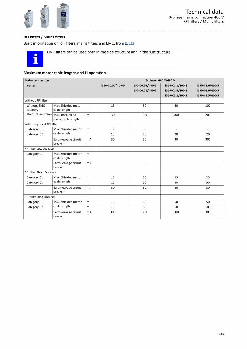
RFI filters / Mains filtersBasic information on RFI filters, mains filters and EMC: from ^ 192
EMC filters can be used both in the side structure and in the substructure.
Maximum motor cable lengths and FI operation
Mains connection 3-phase, 400 V/480 VInverter i550-C0.37/400-3 i550-C0.55/400-3 i550-C1.1/400-3 i550-C3.0/400-3 i550-C0.75/400-3 i550-C1.5/400-3 i550-C4.0/400-3 i550-C2.2/400-3 i550-C5.5/400-3Without RFI filter Without EMC
categoryThermal limitation
Max. Shielded motorcable length
m 15 50 50 100
Max. Unshieldedmotor cable length
m 30 100 200 200
With integrated RFI filter Category C1 Max. Shielded motor
cable lengthm 3 3 - -
Category C2 m 15 20 20 20 Earth-leakage circuit
breakermA 30 30 30 300
RFI filter Low Leakage Category C1 Max. Shielded motor
cable lengthm - - - -
Earth-leakage circuitbreaker
mA - - - -
RFI filter Short Distance Category C1 Max. Shielded motor
cable lengthm 15 25 25 25
Category C2 m 15 50 50 50 Earth-leakage circuit
breakermA 30 30 30 30
RFI filter Long Distance Category C1 Max. Shielded motor
cable lengthm 15 50 50 50
Category C2 m 15 50 50 100 Earth-leakage circuit
breakermA 300 300 300 300
Technical data3-phase mains connection 480 V
RFI filters / Mains filters
133
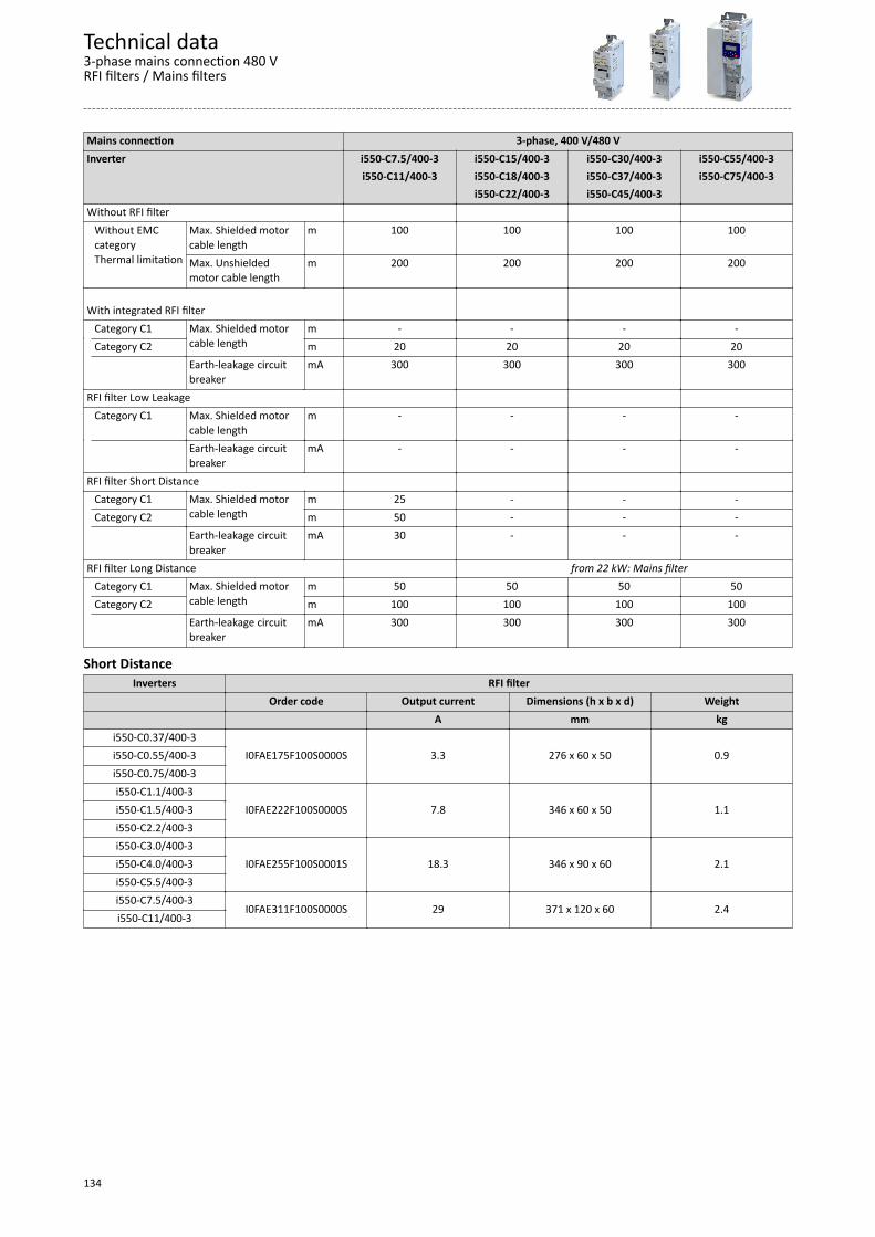
Mains connection 3-phase, 400 V/480 VInverter i550-C7.5/400-3 i550-C15/400-3 i550-C30/400-3 i550-C55/400-3 i550-C11/400-3 i550-C18/400-3 i550-C37/400-3 i550-C75/400-3 i550-C22/400-3 i550-C45/400-3 Without RFI filter Without EMC
categoryThermal limitation
Max. Shielded motorcable length
m 100 100 100 100
Max. Unshieldedmotor cable length
m 200 200 200 200
With integrated RFI filter
Category C1 Max. Shielded motorcable length
m - - - - Category C2 m 20 20 20 20 Earth-leakage circuit
breakermA 300 300 300 300
RFI filter Low Leakage Category C1 Max. Shielded motor
cable lengthm - - - -
Earth-leakage circuitbreaker
mA - - - -
RFI filter Short Distance Category C1 Max. Shielded motor
cable lengthm 25 - - -
Category C2 m 50 - - - Earth-leakage circuit
breakermA 30 - - -
RFI filter Long Distance from 22 kW: Mains filter Category C1 Max. Shielded motor
cable lengthm 50 50 50 50
Category C2 m 100 100 100 100 Earth-leakage circuit
breakermA 300 300 300 300
Short DistanceInverters RFI filter
Order code Output current Dimensions (h x b x d) Weight A mm kg
i550-C0.37/400-3I0FAE175F100S0000S 3.3 276 x 60 x 50 0.9i550-C0.55/400-3
i550-C0.75/400-3i550-C1.1/400-3
I0FAE222F100S0000S 7.8 346 x 60 x 50 1.1i550-C1.5/400-3i550-C2.2/400-3i550-C3.0/400-3
I0FAE255F100S0001S 18.3 346 x 90 x 60 2.1i550-C4.0/400-3i550-C5.5/400-3i550-C7.5/400-3
I0FAE311F100S0000S 29 371 x 120 x 60 2.4i550-C11/400-3
Technical data3-phase mains connection 480 VRFI filters / Mains filters
134
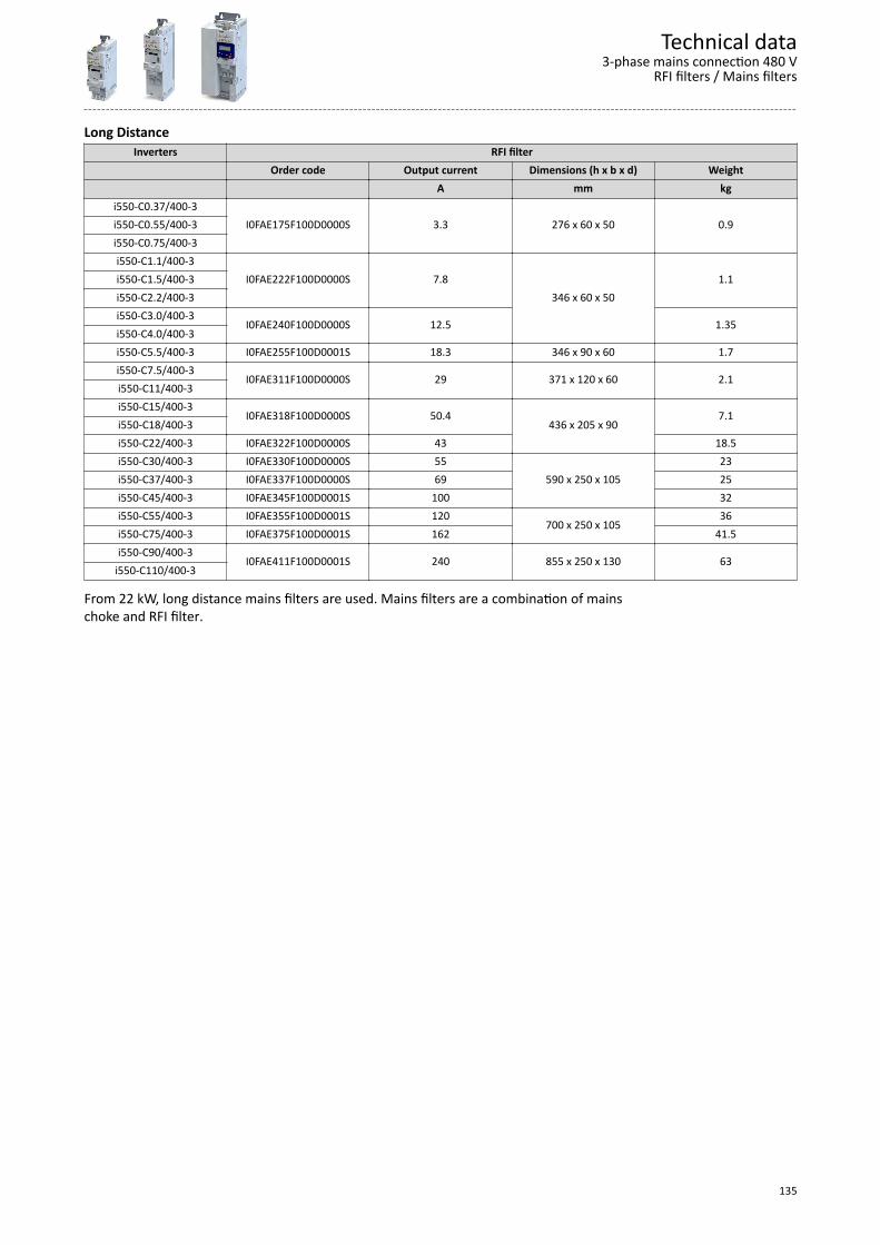
Long DistanceInverters RFI filter
Order code Output current Dimensions (h x b x d) Weight A mm kg
i550-C0.37/400-3I0FAE175F100D0000S 3.3 276 x 60 x 50 0.9i550-C0.55/400-3
i550-C0.75/400-3i550-C1.1/400-3
I0FAE222F100D0000S 7.8346 x 60 x 50
1.1i550-C1.5/400-3i550-C2.2/400-3i550-C3.0/400-3
I0FAE240F100D0000S 12.5 1.35i550-C4.0/400-3i550-C5.5/400-3 I0FAE255F100D0001S 18.3 346 x 90 x 60 1.7i550-C7.5/400-3
I0FAE311F100D0000S 29 371 x 120 x 60 2.1i550-C11/400-3i550-C15/400-3
I0FAE318F100D0000S 50.4436 x 205 x 90
7.1i550-C18/400-3i550-C22/400-3 I0FAE322F100D0000S 43 18.5i550-C30/400-3 I0FAE330F100D0000S 55
590 x 250 x 10523
i550-C37/400-3 I0FAE337F100D0000S 69 25i550-C45/400-3 I0FAE345F100D0001S 100 32i550-C55/400-3 I0FAE355F100D0001S 120
700 x 250 x 10536
i550-C75/400-3 I0FAE375F100D0001S 162 41.5i550-C90/400-3
I0FAE411F100D0001S 240 855 x 250 x 130 63i550-C110/400-3
From 22 kW, long distance mains filters are used. Mains filters are a combination of mainschoke and RFI filter.
Technical data3-phase mains connection 480 V
RFI filters / Mains filters
135
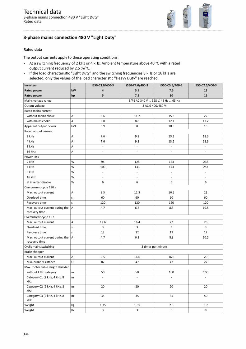
3-phase mains connection 480 V "Light Duty"
Rated data
The output currents apply to these operating conditions:• At a switching frequency of 2 kHz or 4 kHz: Ambient temperature above 40 °C with a rated
output current reduced by 2.5 %/°C.• If the load characteristic "Light Duty" and the switching frequencies 8 kHz or 16 kHz are
selected, only the values of the load characteristic "Heavy Duty" are reached.Inverters i550-C3.0/400-3 i550-C4.0/400-3 i550-C5.5/400-3 i550-C7.5/400-3Rated power kW 4 5.5 7.5 11Rated power hp 5 7.5 10 15Mains voltage range 3/PE AC 340 V ... 528 V, 45 Hz ... 65 HzOutput voltage 3 AC 0-400/480 VRated mains current without mains choke A 8.6 11.2 15.3 22 with mains choke A 6.8 8.8 12.1 17.2Apparent output power kVA 5.9 8 10.5 15Rated output current 2 kHz A 7.6 9.8 13.2 18.3 4 kHz A 7.6 9.8 13.2 18.3 8 kHz A - - - - 16 kHz A - - - -Power loss 2 kHz W 94 125 163 238 4 kHz W 100 133 173 253 8 kHz W - - - - 16 kHz W - - - - at inverter disable W 6 6 6 6Overcurrent cycle 180 s Max. output current A 9.5 12.3 16.5 21 Overload time s 60 60 60 60 Recovery time s 120 120 120 120 Max. output current during the
recovery timeA 4.7 6.2 8.3 10.5
Overcurrent cycle 15 s Max. output current A 12.6 16.4 22 28 Overload time s 3 3 3 3 Recovery time s 12 12 12 12 Max. output current during the
recovery timeA 4.7 6.2 8.3 10.5
Cyclic mains switching 3 times per minuteBrake chopper Max. output current A 9.5 16.6 16.6 29 Min. brake resistance Ω 82 47 47 27Max. motor cable length shielded without EMC category m 50 50 100 100 Category C1 (2 kHz, 4 kHz, 8
kHz)m - - - -
Category C2 (2 kHz, 4 kHz, 8kHz)
m 20 20 20 20
Category C3 (2 kHz, 4 kHz, 8kHz)
m 35 35 35 50
Weight kg 1.35 1.35 2.3 3.7Weight lb 3 3 5 8
Technical data3-phase mains connection 480 V "Light Duty"Rated data
136

Inverters i550-C11/400-3 i550-C15/400-3 i550-C18/400-3 i550-C22/400-3Rated power kW 15 18.5 22 30Rated power hp 20 25 30 40Mains voltage range 3/PE AC 340 V ... 528 V, 45 Hz ... 65 HzOutput voltage 3 AC 0-400/480 VRated mains current without mains choke A - 40 - - with mains choke A 22.6 30 38 46Apparent output power kVA 19 26 32 38Rated output current 2 kHz A 25.2 32.4 40.8 48.5 4 kHz A 25.2 32.4 40.8 48.5 8 kHz A - - - - 16 kHz A - - - -Power loss 2 kHz W 290 404 501 585 4 kHz W 309 430 533 623 8 kHz W - - - - 16 kHz W - - - - at inverter disable W 6 18 18 18Overcurrent cycle 180 s Max. output current A 31.5 40.5 51 61 Overload time s 60 60 60 60 Recovery time s 120 120 120 120 Max. output current during the
recovery timeA 15.8 20.3 25.5 30
Overcurrent cycle 15 s Max. output current A 42 54 68 81 Overload time s 3 3 3 3 Recovery time s 12 12 12 12 Max. output current during the
recovery timeA 15.8 20.3 25.5 30
Cyclic mains switching 3 times per minuteBrake chopper Max. output current A 29 43 52 52 Min. brake resistance Ω 27 18 15 15Max. motor cable length shielded without EMC category m 100 100 100 100 Category C1 (2 kHz, 4 kHz, 8
kHz)m - - - -
Category C2 (2 kHz, 4 kHz, 8kHz)
m 20 20 20 20
Category C3 (2 kHz, 4 kHz, 8kHz)
m 50 35 35 35
Weight kg 3.7 10.3 10.3 10.3Weight lb 8 23 23 23
Technical data3-phase mains connection 480 V "Light Duty"
Rated data
137
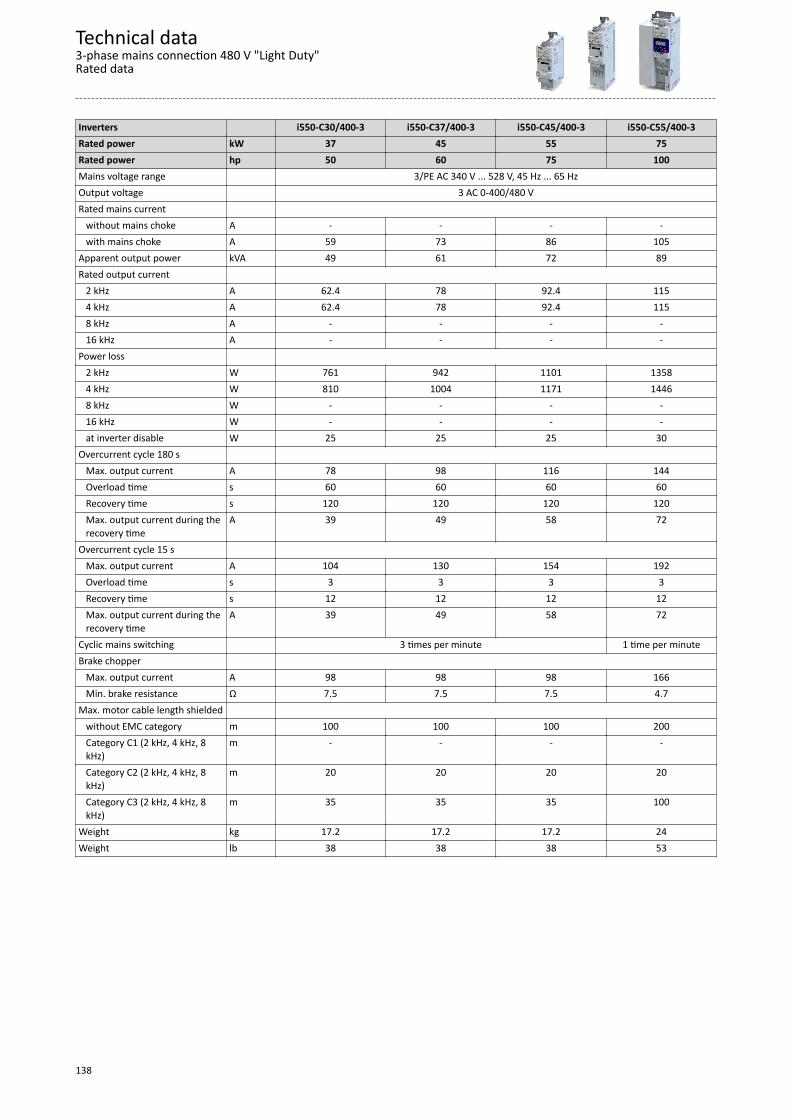
Inverters i550-C30/400-3 i550-C37/400-3 i550-C45/400-3 i550-C55/400-3Rated power kW 37 45 55 75Rated power hp 50 60 75 100Mains voltage range 3/PE AC 340 V ... 528 V, 45 Hz ... 65 HzOutput voltage 3 AC 0-400/480 VRated mains current without mains choke A - - - - with mains choke A 59 73 86 105Apparent output power kVA 49 61 72 89Rated output current 2 kHz A 62.4 78 92.4 115 4 kHz A 62.4 78 92.4 115 8 kHz A - - - - 16 kHz A - - - -Power loss 2 kHz W 761 942 1101 1358 4 kHz W 810 1004 1171 1446 8 kHz W - - - - 16 kHz W - - - - at inverter disable W 25 25 25 30Overcurrent cycle 180 s Max. output current A 78 98 116 144 Overload time s 60 60 60 60 Recovery time s 120 120 120 120 Max. output current during the
recovery timeA 39 49 58 72
Overcurrent cycle 15 s Max. output current A 104 130 154 192 Overload time s 3 3 3 3 Recovery time s 12 12 12 12 Max. output current during the
recovery timeA 39 49 58 72
Cyclic mains switching 3 times per minute 1 time per minuteBrake chopper Max. output current A 98 98 98 166 Min. brake resistance Ω 7.5 7.5 7.5 4.7Max. motor cable length shielded without EMC category m 100 100 100 200 Category C1 (2 kHz, 4 kHz, 8
kHz)m - - - -
Category C2 (2 kHz, 4 kHz, 8kHz)
m 20 20 20 20
Category C3 (2 kHz, 4 kHz, 8kHz)
m 35 35 35 100
Weight kg 17.2 17.2 17.2 24Weight lb 38 38 38 53
Technical data3-phase mains connection 480 V "Light Duty"Rated data
138
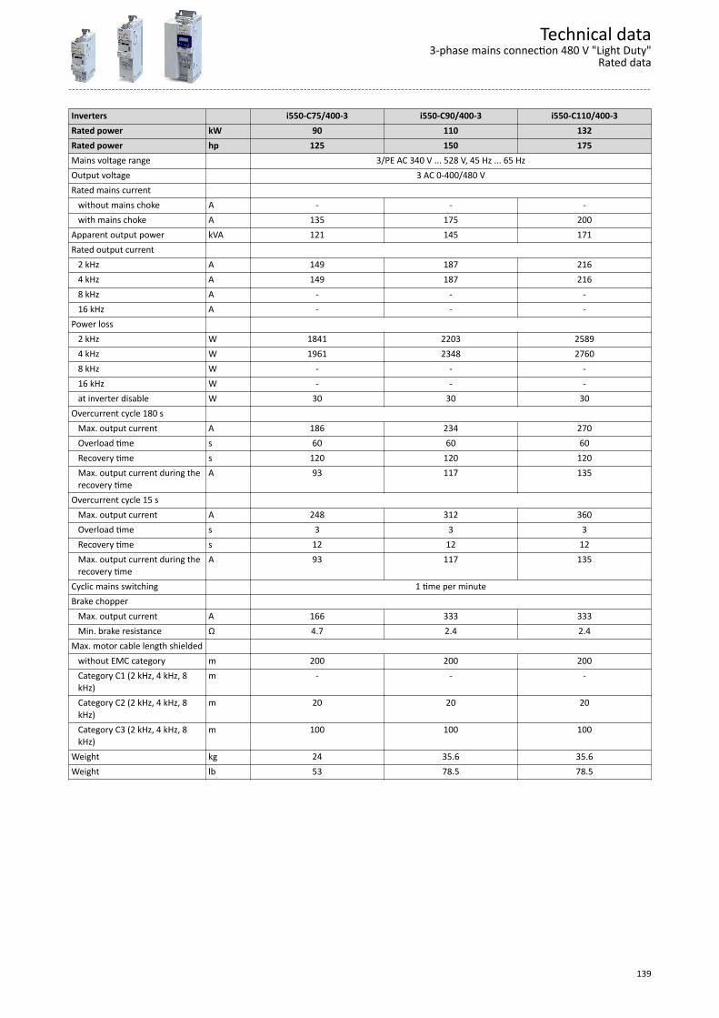
Inverters i550-C75/400-3 i550-C90/400-3 i550-C110/400-3Rated power kW 90 110 132Rated power hp 125 150 175Mains voltage range 3/PE AC 340 V ... 528 V, 45 Hz ... 65 HzOutput voltage 3 AC 0-400/480 VRated mains current without mains choke A - - - with mains choke A 135 175 200Apparent output power kVA 121 145 171Rated output current 2 kHz A 149 187 216 4 kHz A 149 187 216 8 kHz A - - - 16 kHz A - - -Power loss 2 kHz W 1841 2203 2589 4 kHz W 1961 2348 2760 8 kHz W - - - 16 kHz W - - - at inverter disable W 30 30 30Overcurrent cycle 180 s Max. output current A 186 234 270 Overload time s 60 60 60 Recovery time s 120 120 120 Max. output current during the
recovery timeA 93 117 135
Overcurrent cycle 15 s Max. output current A 248 312 360 Overload time s 3 3 3 Recovery time s 12 12 12 Max. output current during the
recovery timeA 93 117 135
Cyclic mains switching 1 time per minuteBrake chopper Max. output current A 166 333 333 Min. brake resistance Ω 4.7 2.4 2.4Max. motor cable length shielded without EMC category m 200 200 200 Category C1 (2 kHz, 4 kHz, 8
kHz)m - - -
Category C2 (2 kHz, 4 kHz, 8kHz)
m 20 20 20
Category C3 (2 kHz, 4 kHz, 8kHz)
m 100 100 100
Weight kg 24 35.6 35.6Weight lb 53 78.5 78.5
Technical data3-phase mains connection 480 V "Light Duty"
Rated data
139
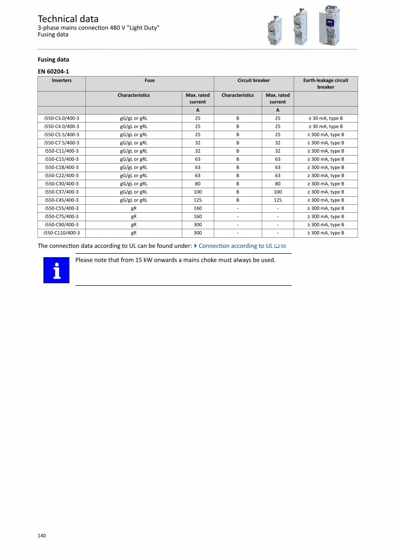
Fusing data
EN 60204-1Inverters Fuse Circuit breaker Earth-leakage circuit
breakerCharacteristics Max. rated
currentCharacteristics Max. rated
current A A
i550-C3.0/400-3 gG/gL or gRL 25 B 25 ≥ 30 mA, type Bi550-C4.0/400-3 gG/gL or gRL 25 B 25 ≥ 30 mA, type Bi550-C5.5/400-3 gG/gL or gRL 25 B 25 ≥ 300 mA, type Bi550-C7.5/400-3 gG/gL or gRL 32 B 32 ≥ 300 mA, type Bi550-C11/400-3 gG/gL or gRL 32 B 32 ≥ 300 mA, type Bi550-C15/400-3 gG/gL or gRL 63 B 63 ≥ 300 mA, type Bi550-C18/400-3 gG/gL or gRL 63 B 63 ≥ 300 mA, type Bi550-C22/400-3 gG/gL or gRL 63 B 63 ≥ 300 mA, type Bi550-C30/400-3 gG/gL or gRL 80 B 80 ≥ 300 mA, type Bi550-C37/400-3 gG/gL or gRL 100 B 100 ≥ 300 mA, type Bi550-C45/400-3 gG/gL or gRL 125 B 125 ≥ 300 mA, type Bi550-C55/400-3 gR 160 - - ≥ 300 mA, type Bi550-C75/400-3 gR 160 - - ≥ 300 mA, type Bi550-C90/400-3 gR 300 - - ≥ 300 mA, type B
i550-C110/400-3 gR 300 - - ≥ 300 mA, type B
The connection data according to UL can be found under:4Connection according to UL ^ 50
Please note that from 15 kW onwards a mains choke must always be used.
Technical data3-phase mains connection 480 V "Light Duty"Fusing data
140
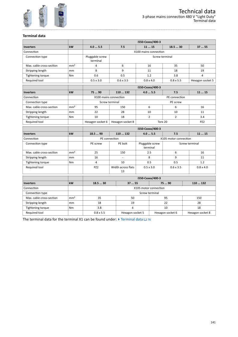
Terminal data i550-Cxxxx/400-3Inverters kW 4.0 ... 5.5 7.5 11 ... 15 18.5 ... 30 37 ... 55Connection X100 mains connection Connection type Pluggable screw
terminalScrew terminal
Max. cable cross-section mm² 4 6 16 35 50 Stripping length mm 8 9 11 18 19 Tightening torque Nm 0.6 0.5 1.2 3.8 4 Required tool 0.5 x 3.0 0.6 x 3.5 0.8 x 4.0 0.8 x 5.5 Hexagon socket 5
i550-Cxxxx/400-3Inverters kW 75 ... 90 110 ... 132 4.0 ... 5.5 7.5 11 ... 15Connection X100 mains connection PE connection Connection type Screw terminal PE screw Max. cable cross-section mm² 95 150 6 6 16 Stripping length mm 22 28 10 10 11 Tightening torque Nm 10 18 2 2 3.4 Required tool Hexagon socket 6 Hexagon socket 8 Torx 20 PZ2
i550-Cxxxx/400-3Inverters kW 18.5 ... 90 110 ... 132 4.0 ... 5.5 7.5 11 ... 15Connection PE connection X105 motor connection Connection type PE screw PE bolt Pluggable screw
terminalScrew terminal
Max. cable cross-section mm² 25 150 2.5 6 16 Stripping length mm 16 - 8 9 11 Tightening torque Nm 4 10 0.5 0.5 1.2 Required tool PZ2 Width across flats
130.5 x 3.0 0.6 x 3.5 0.8 x 4.0
i550-Cxxxx/400-3Inverters kW 18.5 ... 30 37 ... 55 75 ... 90 110 ... 132Connection X105 motor connection Connection type Screw terminal Max. cable cross-section mm² 35 50 95 150 Stripping length mm 18 19 22 28 Tightening torque Nm 3.8 4 10 18 Required tool 0.8 x 5.5 Hexagon socket 5 Hexagon socket 6 Hexagon socket 8
The terminal data for the terminal X1 can be found under:4Terminal data ^ 76
Technical data3-phase mains connection 480 V "Light Duty"
Terminal data
141
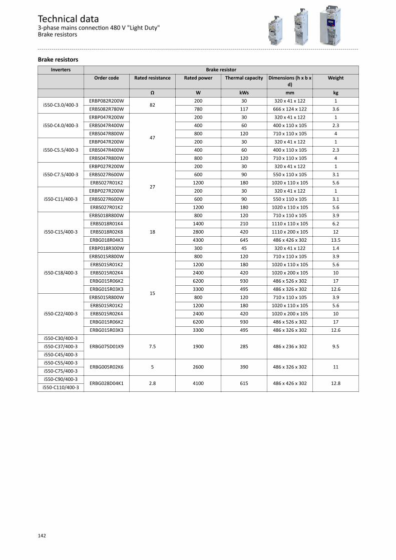
Brake resistorsInverters Brake resistor
Order code Rated resistance Rated power Thermal capacity Dimensions (h x b xd)
Weight
Ω W kWs mm kg
i550-C3.0/400-3ERBP082R200W
82200 30 320 x 41 x 122 1
ERBS082R780W 780 117 666 x 124 x 122 3.6
i550-C4.0/400-3ERBP047R200W
47
200 30 320 x 41 x 122 1ERBS047R400W 400 60 400 x 110 x 105 2.3ERBS047R800W 800 120 710 x 110 x 105 4
i550-C5.5/400-3ERBP047R200W 200 30 320 x 41 x 122 1ERBS047R400W 400 60 400 x 110 x 105 2.3ERBS047R800W 800 120 710 x 110 x 105 4
i550-C7.5/400-3ERBP027R200W
27
200 30 320 x 41 x 122 1ERBS027R600W 600 90 550 x 110 x 105 3.1ERBS027R01K2 1200 180 1020 x 110 x 105 5.6
i550-C11/400-3ERBP027R200W 200 30 320 x 41 x 122 1ERBS027R600W 600 90 550 x 110 x 105 3.1ERBS027R01K2 1200 180 1020 x 110 x 105 5.6
i550-C15/400-3
ERBS018R800W
18
800 120 710 x 110 x 105 3.9ERBS018R01K4 1400 210 1110 x 110 x 105 6.2ERBS018R02K8 2800 420 1110 x 200 x 105 12ERBG018R04K3 4300 645 486 x 426 x 302 13.5ERBP018R300W 300 45 320 x 41 x 122 1.4
i550-C18/400-3
ERBS015R800W
15
800 120 710 x 110 x 105 3.9ERBS015R01K2 1200 180 1020 x 110 x 105 5.6ERBS015R02K4 2400 420 1020 x 200 x 105 10ERBG015R06K2 6200 930 486 x 526 x 302 17ERBG015R03K3 3300 495 486 x 326 x 302 12.6
i550-C22/400-3
ERBS015R800W 800 120 710 x 110 x 105 3.9ERBS015R01K2 1200 180 1020 x 110 x 105 5.6ERBS015R02K4 2400 420 1020 x 200 x 105 10ERBG015R06K2 6200 930 486 x 526 x 302 17ERBG015R03K3 3300 495 486 x 326 x 302 12.6
i550-C30/400-3ERBG075D01K9 7.5 1900 285 486 x 236 x 302 9.5i550-C37/400-3
i550-C45/400-3i550-C55/400-3
ERBG005R02K6 5 2600 390 486 x 326 x 302 11i550-C75/400-3i550-C90/400-3
ERBG028D04K1 2.8 4100 615 486 x 426 x 302 12.8i550-C110/400-3
Technical data3-phase mains connection 480 V "Light Duty"Brake resistors
142
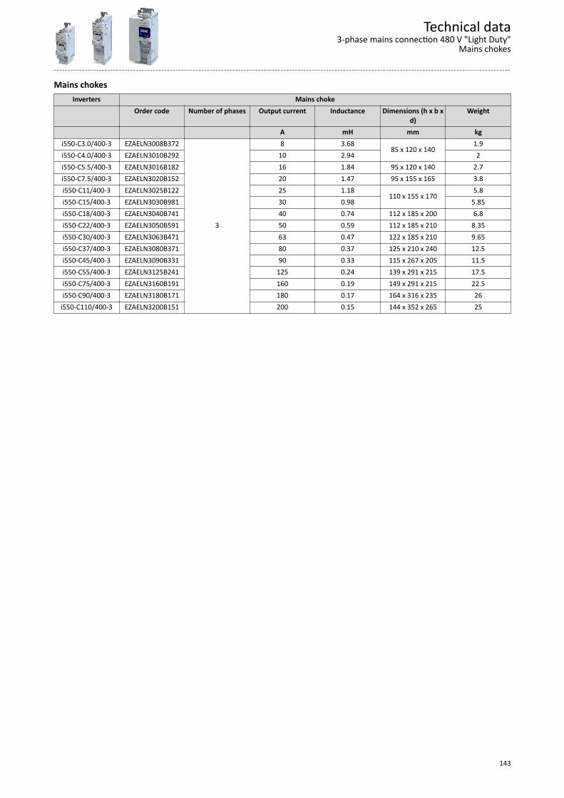
Mains chokesInverters Mains choke
Order code Number of phases Output current Inductance Dimensions (h x b xd)
Weight
A mH mm kgi550-C3.0/400-3 EZAELN3008B372
3
8 3.6885 x 120 x 140
1.9i550-C4.0/400-3 EZAELN3010B292 10 2.94 2i550-C5.5/400-3 EZAELN3016B182 16 1.84 95 x 120 x 140 2.7i550-C7.5/400-3 EZAELN3020B152 20 1.47 95 x 155 x 165 3.8i550-C11/400-3 EZAELN3025B122 25 1.18
110 x 155 x 1705.8
i550-C15/400-3 EZAELN3030B981 30 0.98 5.85i550-C18/400-3 EZAELN3040B741 40 0.74 112 x 185 x 200 6.8i550-C22/400-3 EZAELN3050B591 50 0.59 112 x 185 x 210 8.35i550-C30/400-3 EZAELN3063B471 63 0.47 122 x 185 x 210 9.65i550-C37/400-3 EZAELN3080B371 80 0.37 125 x 210 x 240 12.5i550-C45/400-3 EZAELN3090B331 90 0.33 115 x 267 x 205 11.5i550-C55/400-3 EZAELN3125B241 125 0.24 139 x 291 x 215 17.5i550-C75/400-3 EZAELN3160B191 160 0.19 149 x 291 x 215 22.5i550-C90/400-3 EZAELN3180B171 180 0.17 164 x 316 x 235 26
i550-C110/400-3 EZAELN3200B151 200 0.15 144 x 352 x 265 25
Technical data3-phase mains connection 480 V "Light Duty"
Mains chokes
143
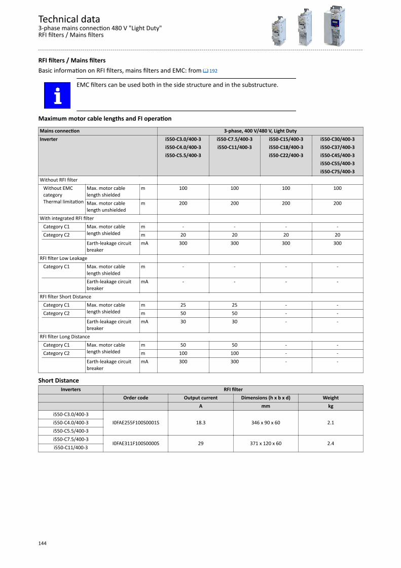
RFI filters / Mains filtersBasic information on RFI filters, mains filters and EMC: from ^ 192
EMC filters can be used both in the side structure and in the substructure.
Maximum motor cable lengths and FI operation
Mains connection 3-phase, 400 V/480 V, Light DutyInverter i550-C3.0/400-3 i550-C7.5/400-3 i550-C15/400-3 i550-C30/400-3 i550-C4.0/400-3 i550-C11/400-3 i550-C18/400-3 i550-C37/400-3 i550-C5.5/400-3 i550-C22/400-3 i550-C45/400-3 i550-C55/400-3 i550-C75/400-3Without RFI filter Without EMC
categoryThermal limitation
Max. motor cablelength shielded
m 100 100 100 100
Max. motor cablelength unshielded
m 200 200 200 200
With integrated RFI filter Category C1 Max. motor cable
length shieldedm - - - -
Category C2 m 20 20 20 20 Earth-leakage circuit
breakermA 300 300 300 300
RFI filter Low Leakage Category C1 Max. motor cable
length shieldedm - - - -
Earth-leakage circuitbreaker
mA - - - -
RFI filter Short Distance Category C1 Max. motor cable
length shieldedm 25 25 - -
Category C2 m 50 50 - - Earth-leakage circuit
breakermA 30 30 - -
RFI filter Long Distance Category C1 Max. motor cable
length shieldedm 50 50 - -
Category C2 m 100 100 - - Earth-leakage circuit
breakermA 300 300 - -
Short DistanceInverters RFI filter
Order code Output current Dimensions (h x b x d) Weight A mm kg
i550-C3.0/400-3I0FAE255F100S0001S 18.3 346 x 90 x 60 2.1i550-C4.0/400-3
i550-C5.5/400-3i550-C7.5/400-3
I0FAE311F100S0000S 29 371 x 120 x 60 2.4i550-C11/400-3
Technical data3-phase mains connection 480 V "Light Duty"RFI filters / Mains filters
144
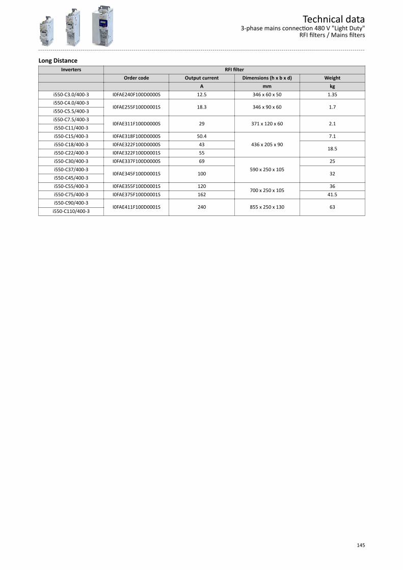
Long DistanceInverters RFI filter
Order code Output current Dimensions (h x b x d) Weight A mm kg
i550-C3.0/400-3 I0FAE240F100D0000S 12.5 346 x 60 x 50 1.35i550-C4.0/400-3
I0FAE255F100D0001S 18.3 346 x 90 x 60 1.7i550-C5.5/400-3i550-C7.5/400-3
I0FAE311F100D0000S 29 371 x 120 x 60 2.1i550-C11/400-3i550-C15/400-3 I0FAE318F100D0000S 50.4
436 x 205 x 907.1
i550-C18/400-3 I0FAE322F100D0000S 4318.5
i550-C22/400-3 I0FAE322F100D0001S 55i550-C30/400-3 I0FAE337F100D0000S 69
590 x 250 x 10525
i550-C37/400-3I0FAE345F100D0001S 100 32
i550-C45/400-3i550-C55/400-3 I0FAE355F100D0001S 120
700 x 250 x 10536
i550-C75/400-3 I0FAE375F100D0001S 162 41.5i550-C90/400-3
I0FAE411F100D0001S 240 855 x 250 x 130 63i550-C110/400-3
Technical data3-phase mains connection 480 V "Light Duty"
RFI filters / Mains filters
145
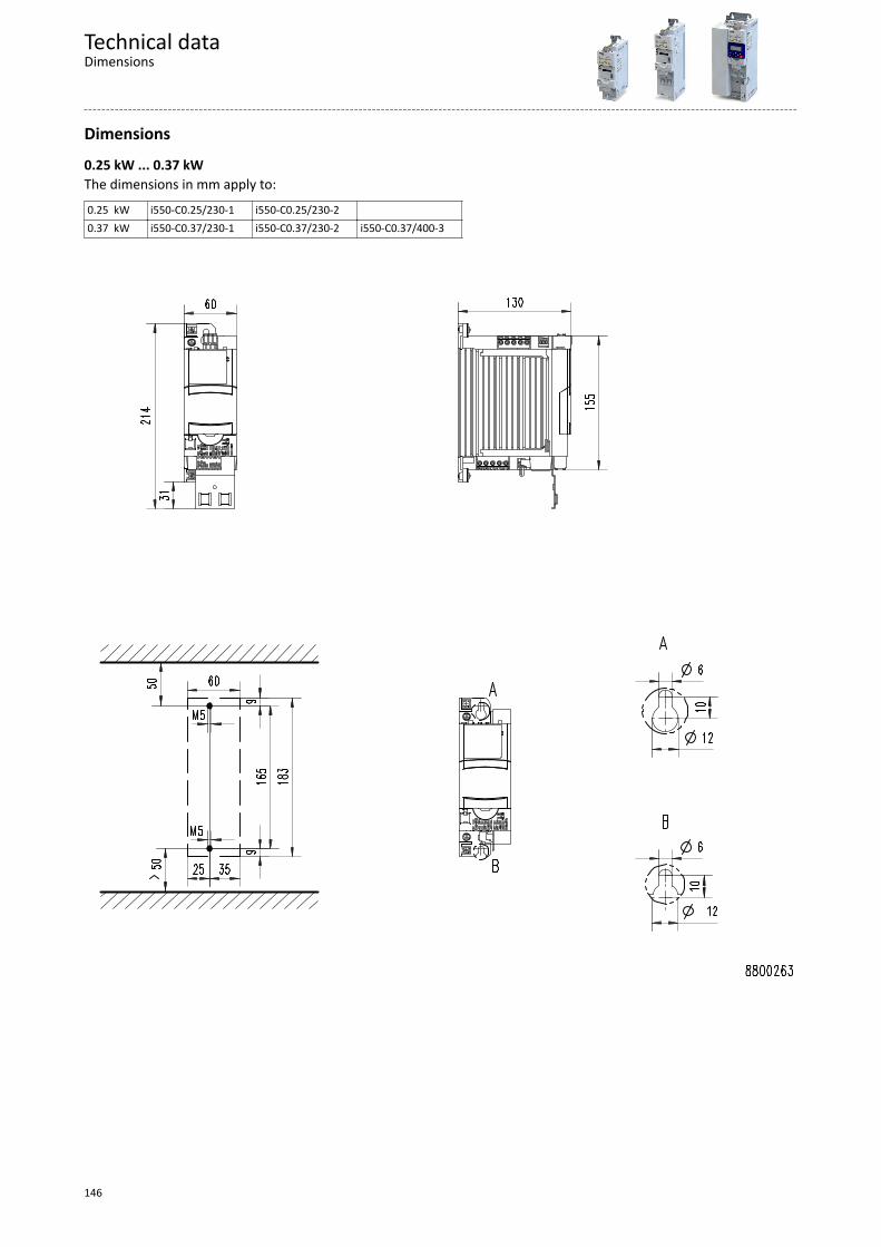
Dimensions
0.25 kW ... 0.37 kWThe dimensions in mm apply to:0.25 kW i550-C0.25/230-1 i550-C0.25/230-2 0.37 kW i550-C0.37/230-1 i550-C0.37/230-2 i550-C0.37/400-3
Technical dataDimensions
146
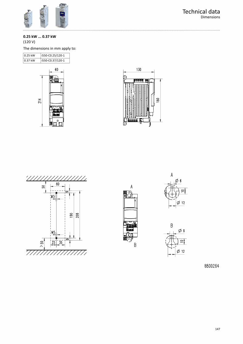
0.25 kW ... 0.37 kW(120 V)The dimensions in mm apply to:0.25 kW i550-C0.25/120-10.37 kW i550-C0.37/120-1
Technical dataDimensions
147
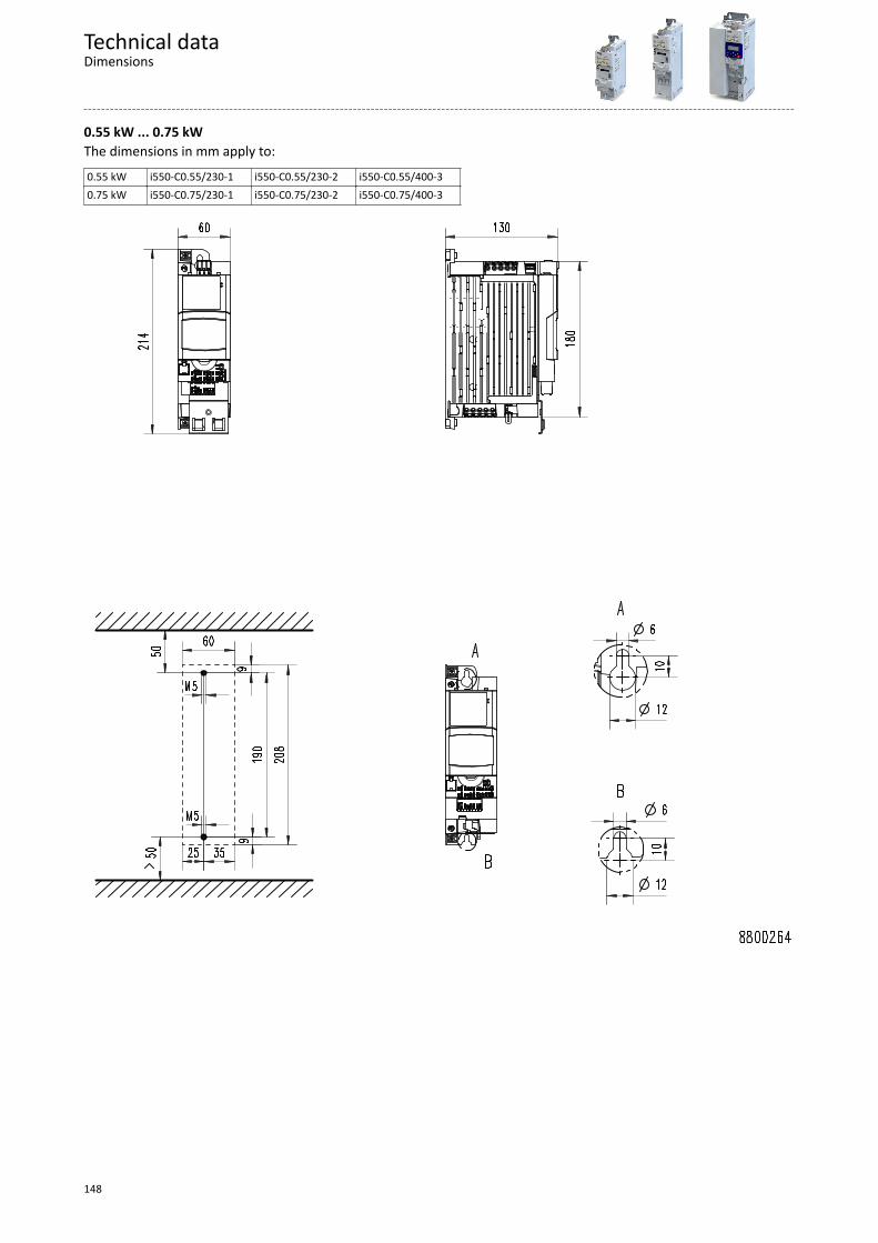
0.55 kW ... 0.75 kWThe dimensions in mm apply to:0.55 kW i550-C0.55/230-1 i550-C0.55/230-2 i550-C0.55/400-30.75 kW i550-C0.75/230-1 i550-C0.75/230-2 i550-C0.75/400-3
Technical dataDimensions
148

0.75 kW ... 1.1 kW(120 V)The dimensions in mm apply to:0.75 kW i550-C0.75/120-11.1 kW i550-C1.1/120-1
Technical dataDimensions
149
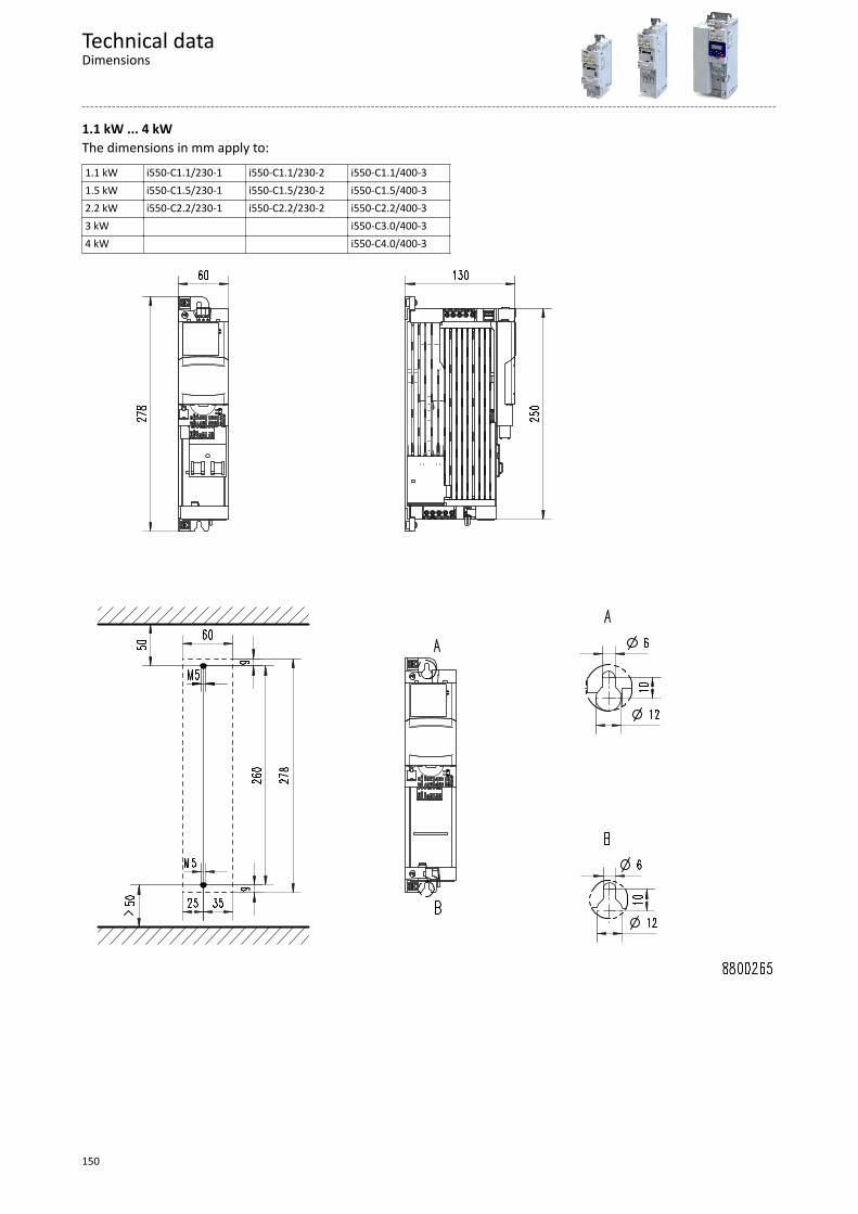
1.1 kW ... 4 kWThe dimensions in mm apply to:1.1 kW i550-C1.1/230-1 i550-C1.1/230-2 i550-C1.1/400-31.5 kW i550-C1.5/230-1 i550-C1.5/230-2 i550-C1.5/400-32.2 kW i550-C2.2/230-1 i550-C2.2/230-2 i550-C2.2/400-33 kW i550-C3.0/400-34 kW i550-C4.0/400-3
Technical dataDimensions
150
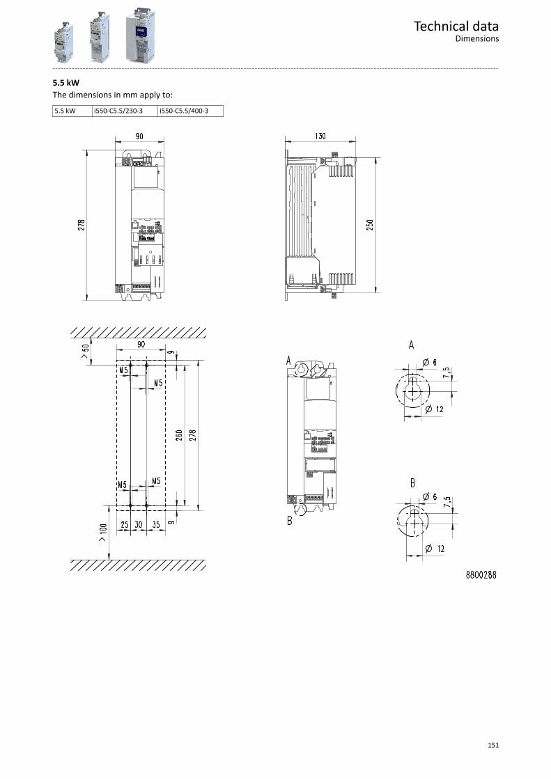
5.5 kWThe dimensions in mm apply to:5.5 kW i550-C5.5/230-3 i550-C5.5/400-3
Technical dataDimensions
151
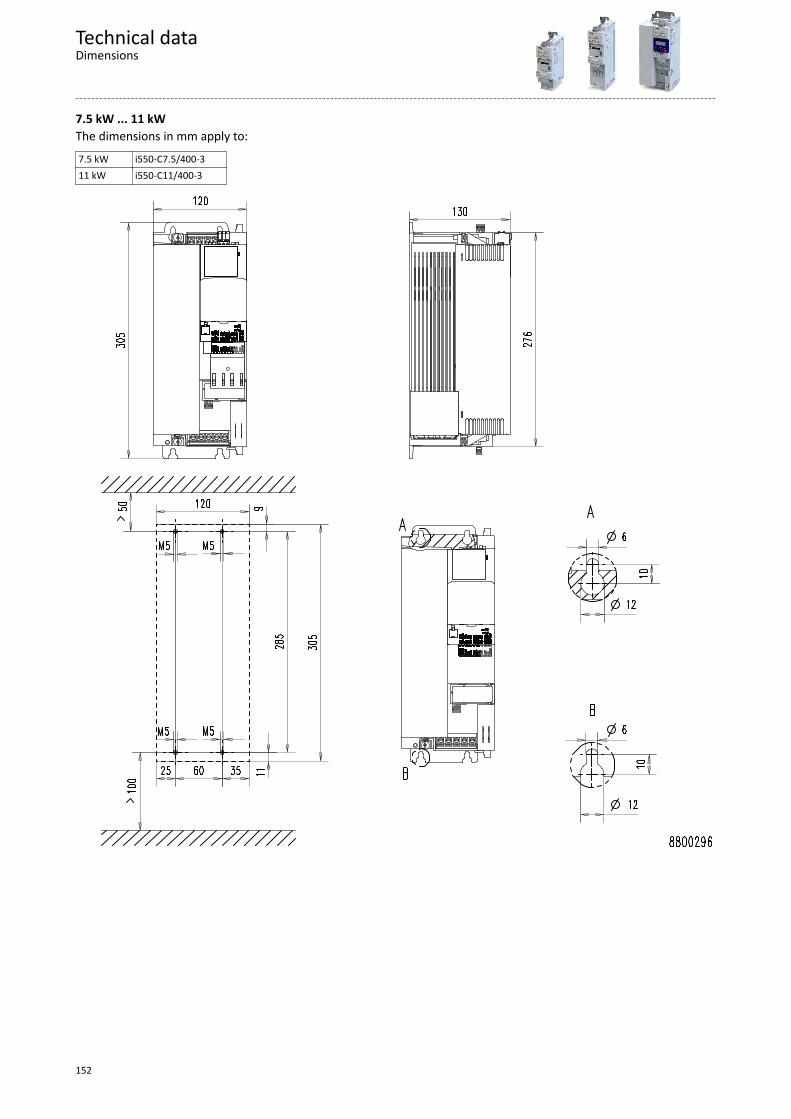
7.5 kW ... 11 kWThe dimensions in mm apply to:7.5 kW i550-C7.5/400-311 kW i550-C11/400-3
Technical dataDimensions
152
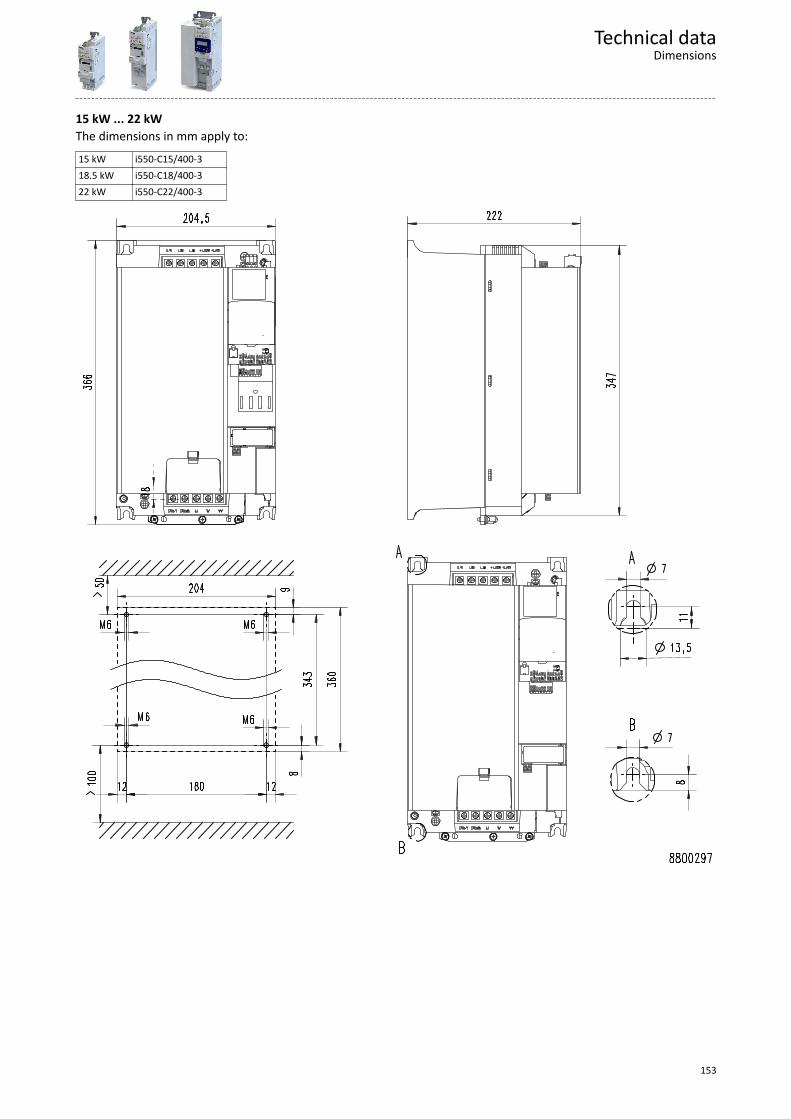
15 kW ... 22 kWThe dimensions in mm apply to:15 kW i550-C15/400-318.5 kW i550-C18/400-322 kW i550-C22/400-3
Technical dataDimensions
153
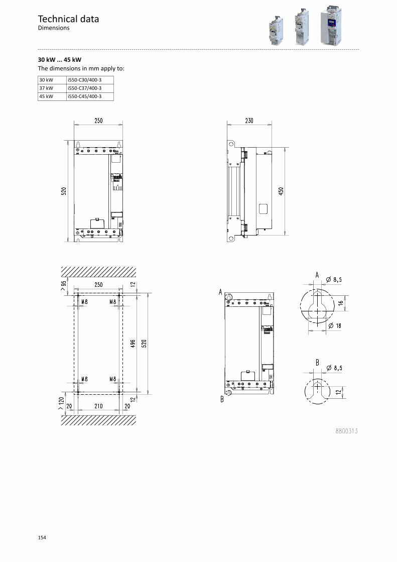
30 kW ... 45 kWThe dimensions in mm apply to:30 kW i550-C30/400-337 kW i550-C37/400-345 kW i550-C45/400-3
Technical dataDimensions
154
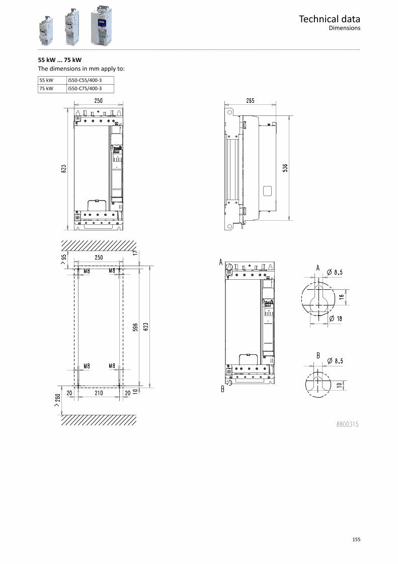
55 kW ... 75 kWThe dimensions in mm apply to:55 kW i550-C55/400-375 kW i550-C75/400-3
Technical dataDimensions
155
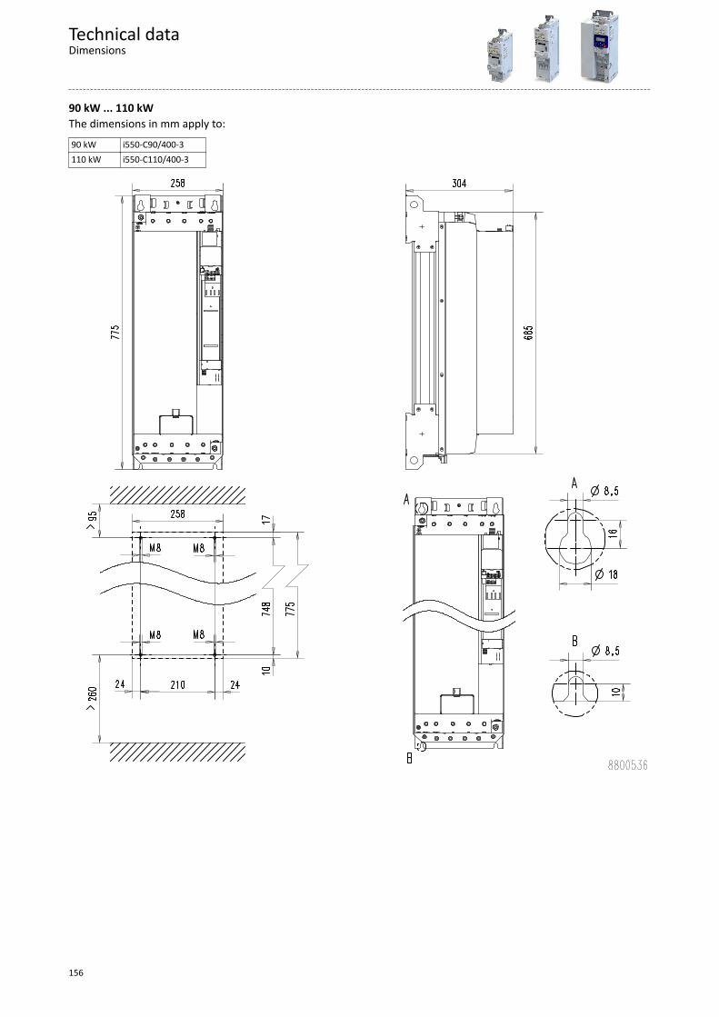
90 kW ... 110 kWThe dimensions in mm apply to:90 kW i550-C90/400-3110 kW i550-C110/400-3
Technical dataDimensions
156
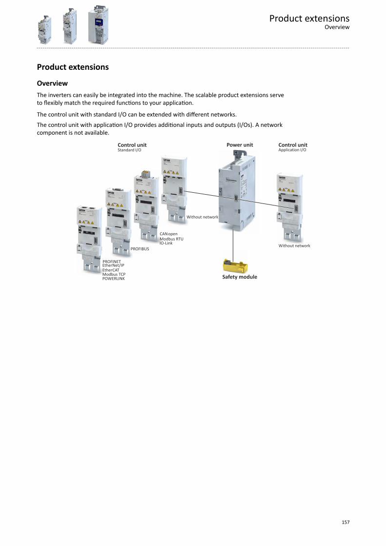
Product extensions
OverviewThe inverters can easily be integrated into the machine. The scalable product extensions serveto flexibly match the required functions to your application.
The control unit with standard I/O can be extended with different networks.The control unit with application I/O provides additional inputs and outputs (I/Os). A networkcomponent is not available.
PROFIBUS
Modbus RTUopenCAN
POWERLINKModbus TCPEtherCATEtherNet/IPPROFINET
IO-Link
Safety module
Control unitControl unit Power unitApplication I/OStandard I/O
Without network
Without network
Product extensionsOverview
157
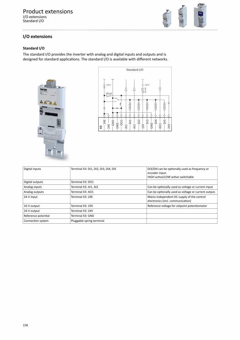
I/O extensions
Standard I/OThe standard I/O provides the inverter with analog and digital inputs and outputs and isdesigned for standard applications. The standard I/O is available with different networks.
100 mA
4.4k
+24 V +10 V
4.4k
4.4k
4.4k
4.4k
10 m
A
GND
1
DO 1
DI 2
DI 3
DI 4
DI 5
DI
24E
GND
1
AI 2
AI 10V
GND
1
AO 24V
24E
X
3
Standard-I/O
Digital inputs Terminal X3: DI1, DI2, DI3, DI4, DI5 DI3/DI4 can be optionally used as frequency orencoder input.HIGH active/LOW active switchable
Digital outputs Terminal X3: DO1 Analog inputs Terminal X3: AI1, AI2 Can be optionally used as voltage or current input.Analog outputs Terminal X3: AO1 Can be optionally used as voltage or current output.24-V input Terminal X3: 24E Mains-independent DC supply of the control
electronics (incl. communication)10-V output Terminal X3: 10V Reference voltage for setpoint potentiometer24-V output Terminal X3: 24V Reference potential Terminal X3: GND Connection system Pluggable spring terminal
Product extensionsI/O extensionsStandard I/O
158
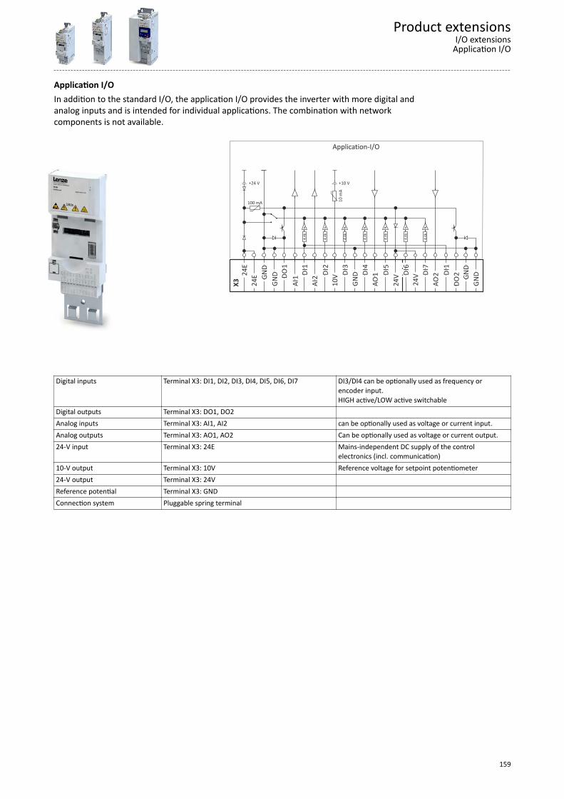
Application I/OIn addition to the standard I/O, the application I/O provides the inverter with more digital andanalog inputs and is intended for individual applications. The combination with networkcomponents is not available.
100 mA
4.4k
+24 V +10 V
4.4k
4.4k
4.4k
4.4k
10 m
A
GND
1
DO 1
DI 2
DI 3
DI 4
DI 5
DI
24E
GND
1
AI 2
AI 10V
GND
1
AO 24V
24E
X
3 24V
4.
4k
7 DI
4.4k
2
AO
1 DI
2
DO
GND
GND
6 DI
Application-I/O
Digital inputs Terminal X3: DI1, DI2, DI3, DI4, DI5, DI6, DI7 DI3/DI4 can be optionally used as frequency orencoder input.HIGH active/LOW active switchable
Digital outputs Terminal X3: DO1, DO2 Analog inputs Terminal X3: AI1, AI2 can be optionally used as voltage or current input.Analog outputs Terminal X3: AO1, AO2 Can be optionally used as voltage or current output.24-V input Terminal X3: 24E Mains-independent DC supply of the control
electronics (incl. communication)10-V output Terminal X3: 10V Reference voltage for setpoint potentiometer24-V output Terminal X3: 24V Reference potential Terminal X3: GND Connection system Pluggable spring terminal
Product extensionsI/O extensionsApplication I/O
159
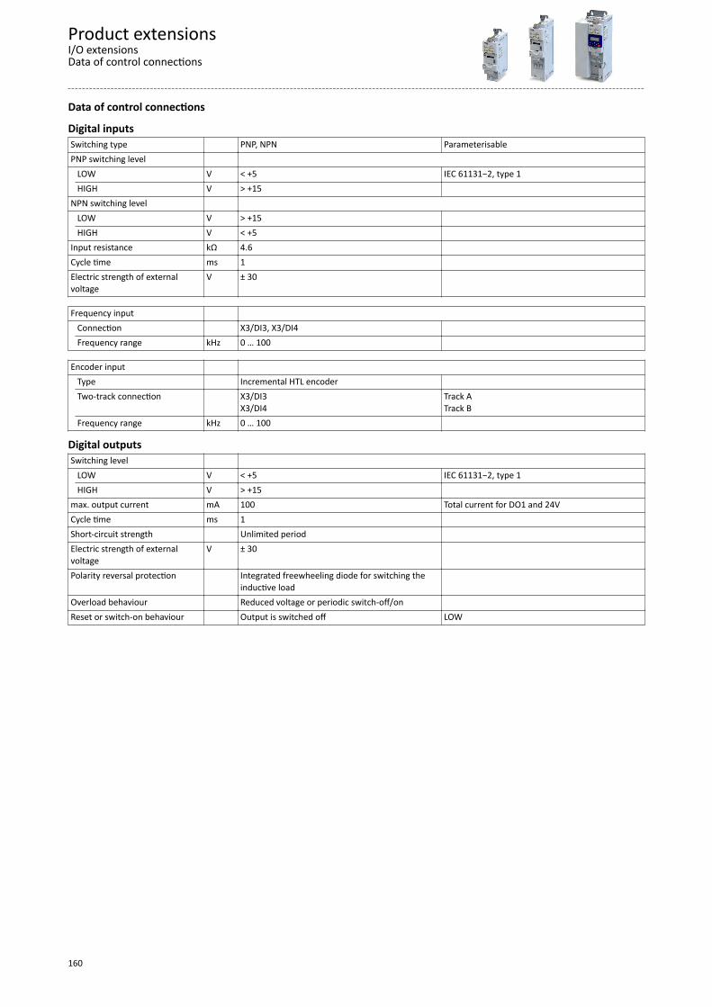
Data of control connections
Digital inputsSwitching type PNP, NPN ParameterisablePNP switching level LOW V < +5 IEC 61131−2, type 1
HIGH V > +15 NPN switching level LOW V > +15
HIGH V < +5 Input resistance kΩ 4.6 Cycle time ms 1 Electric strength of externalvoltage
V ± 30
Frequency input Connection X3/DI3, X3/DI4
Frequency range kHz 0 … 100
Encoder input Type Incremental HTL encoder
Two-track connection X3/DI3X3/DI4
Track ATrack B
Frequency range kHz 0 … 100
Digital outputsSwitching level LOW V < +5 IEC 61131−2, type 1
HIGH V > +15 max. output current mA 100 Total current for DO1 and 24VCycle time ms 1 Short-circuit strength Unlimited period Electric strength of externalvoltage
V ± 30
Polarity reversal protection Integrated freewheeling diode for switching theinductive load
Overload behaviour Reduced voltage or periodic switch-off/on Reset or switch-on behaviour Output is switched off LOW
Product extensionsI/O extensionsData of control connections
160
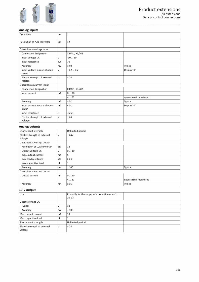
Analog inputsCycle time
ms 1
Resolution of A/D converter
Bit 12
Operation as voltage input Connection designation X3/AI1, X3/AI2
Input voltage DC V -10 … 10 Input resistance kΩ 70 Accuracy mV ± 50 TypicalInput voltage in case of opencircuit
V - 0.2 … 0.2 Display "0"
Electric strength of externalvoltage
V ± 24
Operation as current input Connection designation X3/AI1, X3/AI2
Input current mA 0 ... 20 4 … 20 open-circuit monitored
Accuracy mA ± 0.1 TypicalInput current in case of opencircuit
mA < 0.1 Display "0"
Input resistance Ω < 250 Electric strength of externalvoltage
V ± 24
Analog outputsShort-circuit strength Unlimited period Electric strength of externalvoltage
V + 24V
Operation as voltage output Resolution of D/A converter Bit 12
Output voltage DC V 0 ... 10 max. output current mA 5 min. load resistance kΩ ≥ 2.2 max. capacitive load µF 1 Accuracy mV ± 100 Typical
Operation as current output Output current mA 0 ... 20
4 … 20 open-circuit monitoredAccuracy mA ± 0.3 Typical
10-V outputUse Primarily for the supply of a potentiometer (1 ...
10 kΩ)
Output voltage DC Typical V 10
Accuracy mV ± 100 Max. output current mA 10 Max. capacitive load µF 1 Short-circuit strength Unlimited period Electric strength of externalvoltage
V + 24
Product extensionsI/O extensions
Data of control connections
161
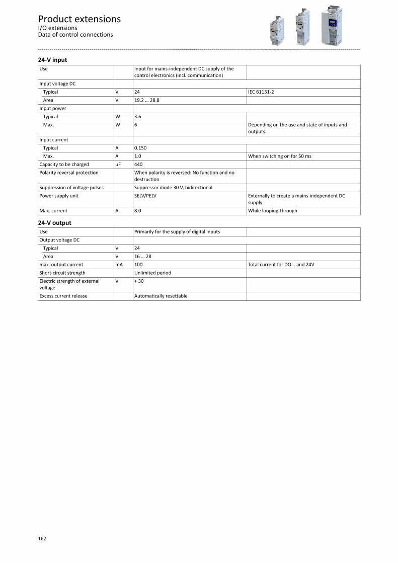
24-V inputUse Input for mains-independent DC supply of the
control electronics (incl. communication)
Input voltage DC Typical V 24 IEC 61131-2
Area V 19.2 … 28.8 Input power Typical W 3.6 Max. W 6 Depending on the use and state of inputs and
outputs.Input current Typical A 0.150
Max. A 1.0 When switching on for 50 msCapacity to be charged µF 440 Polarity reversal protection When polarity is reversed: No function and no
destruction
Suppression of voltage pulses Suppressor diode 30 V, bidirectional Power supply unit SELV/PELV Externally to create a mains-independent DC
supplyMax. current A 8.0 While looping-through
24-V outputUse Primarily for the supply of digital inputs Output voltage DC Typical V 24
Area V 16 … 28 max. output current mA 100 Total current for DO... and 24VShort-circuit strength Unlimited period Electric strength of externalvoltage
V + 30
Excess current release Automatically resettable
Product extensionsI/O extensionsData of control connections
162
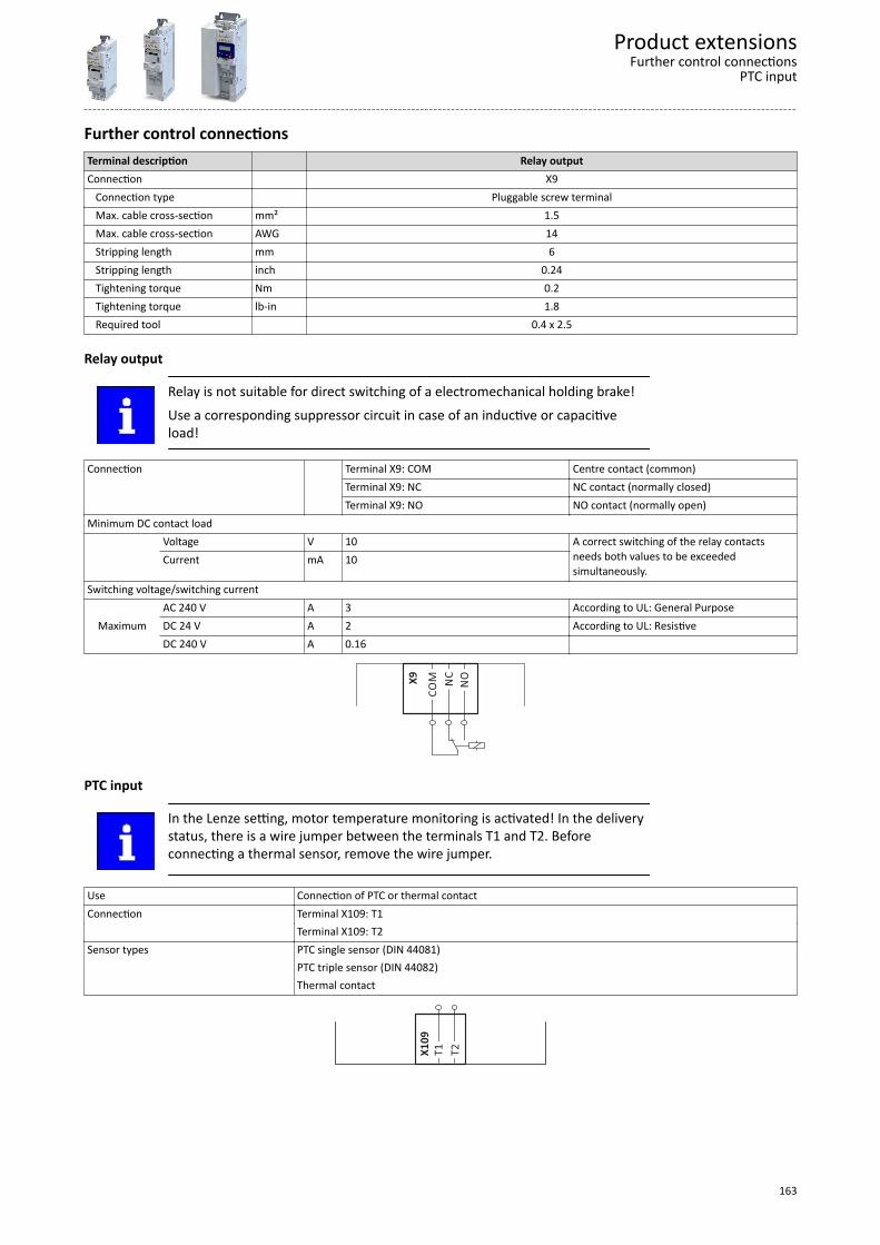
Further control connectionsTerminal description Relay outputConnection X9 Connection type Pluggable screw terminal Max. cable cross-section mm² 1.5 Max. cable cross-section AWG 14 Stripping length mm 6 Stripping length inch 0.24 Tightening torque Nm 0.2 Tightening torque lb-in 1.8 Required tool 0.4 x 2.5
Relay output
Relay is not suitable for direct switching of a electromechanical holding brake!Use a corresponding suppressor circuit in case of an inductive or capacitiveload!
Connection Terminal X9: COM Centre contact (common)Terminal X9: NC NC contact (normally closed)Terminal X9: NO NO contact (normally open)
Minimum DC contact load Voltage V 10 A correct switching of the relay contacts
needs both values to be exceededsimultaneously.
Current mA 10
Switching voltage/switching current
MaximumAC 240 V A 3 According to UL: General PurposeDC 24 V A 2 According to UL: ResistiveDC 240 V A 0.16
NC
NO
CO
MX9
PTC input
In the Lenze setting, motor temperature monitoring is activated! In the deliverystatus, there is a wire jumper between the terminals T1 and T2. Beforeconnecting a thermal sensor, remove the wire jumper.
Use Connection of PTC or thermal contactConnection Terminal X109: T1 Terminal X109: T2Sensor types PTC single sensor (DIN 44081) PTC triple sensor (DIN 44082) Thermal contact
X1
09
T1
T2
Product extensionsFurther control connections
PTC input
163
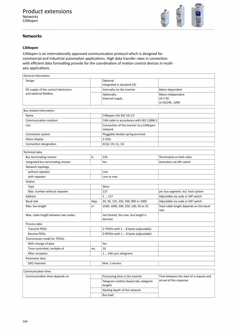
Networks
CANopenCANopen is an internationally approved communication protocol which is designed forcommercial and industrial automation applications. High data transfer rates in connectionwith efficient data formatting provide for the coordination of motion control devices in multi-axis applications.
General information Design Optional
Integrated in standard I/O
DC supply of the control electronicsand optional fieldbus
Internally via the inverter Mains-dependent Optionally:
External supplyMains-independent24 V DCat X3/24E...GND
Bus-related information
Name CANopen CiA 301 V4.2.0 Communication medium CAN cable in accordance with ISO 11898-2 Use Connection of the inverter to a CANopen
network
Connection system Pluggable double spring terminal Status display 2 LEDs Connection designation X216: CH, CL, CG
Technical data Bus terminating resistor Ω 120 Terminated on both sides
integrated bus terminating resistor Yes Activation via DIP switchNetwork topology without repeater Line
with repeater Line or tree Station Type Slave
Max. number without repeater 127 per bus segment, incl. host systemAddress 1 ... 127 Adjustable via code or DIP switchBaud rate kbps 20, 50, 125, 250, 500, 800 or 1000 Adjustable via code or DIP switchMax. bus length m 2500, 1000, 500, 250, 100, 50 or 25 Total cable length depends on the baud
rateMax. cable length between two nodes not limited, the max. bus length is
decisive
Process data Transmit PDOs 3 TPDOs with 1 … 8 bytes (adjustable)
Receive PDOs 3 RPDOs with 1 … 8 bytes (adjustable) Transmission mode for TPDOs With change of data Yes
Time-controlled, multiple of ms 10 After reception 1 … 240 sync telegrams
Parameter data SDO channels Max. 2 servers
Communication time Communication time depends on
Processing time in the inverter Time between the start of a request andarrival of the response
Telegram runtime (baud rate, telegramlength)
Nesting depth of the network Bus load
Product extensionsNetworksCANopen
164

Processing time of process data Update cycle ms 10 In the inverter
Processing time ms 0 ... 1Application task runtime of the technologyapplication used (tolerance)
ms 1 ... x
Other data Note There are no interdependencies between
parameter data and process data.
Product extensionsNetworksCANopen
165
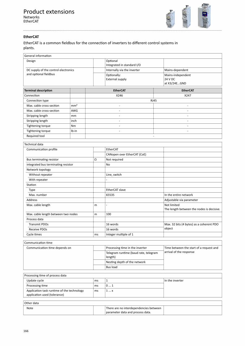
EtherCATEtherCAT is a common fieldbus for the connection of inverters to different control systems inplants.
General information Design Optional
Integrated in standard I/O
DC supply of the control electronicsand optional fieldbus
Internally via the inverter Mains-dependent Optionally:
External supplyMains-independent24 V DCat X3/24E...GND
Terminal description EtherCAT EtherCATConnection X246 X247 Connection type RJ45 Max. cable cross-section mm² - - Max. cable cross-section AWG - - Stripping length mm - - Stripping length inch - - Tightening torque Nm - - Tightening torque lb-in - - Required tool -
Technical data
Communication profile EtherCAT CANopen over EtherCAT (CoE)
Bus terminating resistor Ω Not required integrated bus terminating resistor No Network topology Without repeater Line, switch
With repeater - Station Type EtherCAT slave
Max. number 65535 In the entire networkAddress Adjustable via parameterMax. cable length m - Not limited
The length between the nodes is decisive.Max. cable length between two nodes m 100 Process data
Transmit PDOs 16 words Max. 32 bits (4 bytes) as a coherent PDOobjectReceive PDOs 16 words
Cycle times ms Integer multiple of 1
Communication time Communication time depends on
Processing time in the inverter Time between the start of a request andarrival of the response
Telegram runtime (baud rate, telegramlength)
Nesting depth of the network Bus load
Processing time of process data Update cycle ms 1 In the inverter
Processing time ms 0 ... 1Application task runtime of the technologyapplication used (tolerance)
ms 1 ... x
Other data Note There are no interdependencies between
parameter data and process data.
Product extensionsNetworksEtherCAT
166
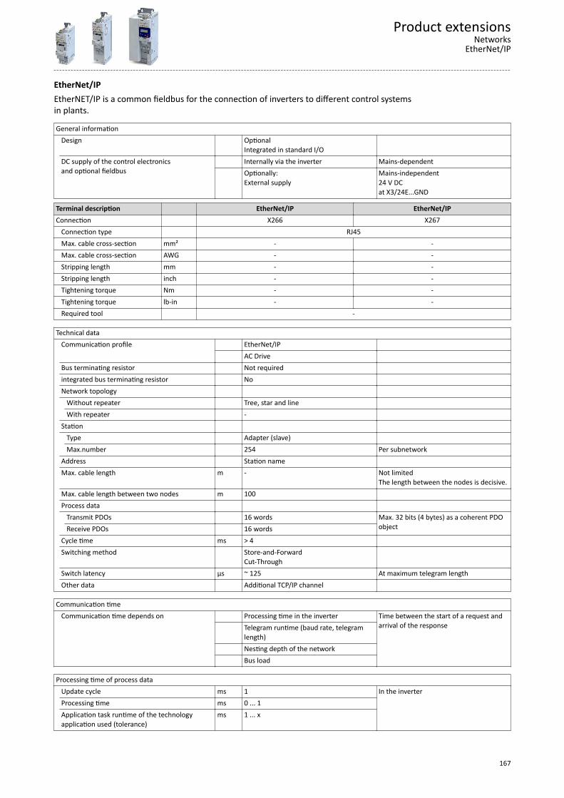
EtherNet/IPEtherNET/IP is a common fieldbus for the connection of inverters to different control systemsin plants.
General information Design Optional
Integrated in standard I/O
DC supply of the control electronicsand optional fieldbus
Internally via the inverter Mains-dependent Optionally:
External supplyMains-independent24 V DCat X3/24E...GND
Terminal description EtherNet/IP EtherNet/IPConnection X266 X267 Connection type RJ45 Max. cable cross-section mm² - - Max. cable cross-section AWG - - Stripping length mm - - Stripping length inch - - Tightening torque Nm - - Tightening torque lb-in - - Required tool -
Technical data
Communication profile EtherNet/IP AC Drive
Bus terminating resistor Not required integrated bus terminating resistor No Network topology Without repeater Tree, star and line
With repeater - Station Type Adapter (slave)
Max.number 254 Per subnetworkAddress Station name Max. cable length m - Not limited
The length between the nodes is decisive.Max. cable length between two nodes m 100 Process data
Transmit PDOs 16 words Max. 32 bits (4 bytes) as a coherent PDOobjectReceive PDOs 16 words
Cycle time ms > 4 Switching method Store-and-Forward
Cut-Through
Switch latency µs ~ 125 At maximum telegram lengthOther data Additional TCP/IP channel
Communication time Communication time depends on
Processing time in the inverter Time between the start of a request andarrival of the response
Telegram runtime (baud rate, telegramlength)
Nesting depth of the network Bus load
Processing time of process data Update cycle ms 1 In the inverter
Processing time ms 0 ... 1Application task runtime of the technologyapplication used (tolerance)
ms 1 ... x
Product extensionsNetworks
EtherNet/IP
167

Other data Note There are no interdependencies between
parameter data and process data.
Product extensionsNetworksEtherNet/IP
168
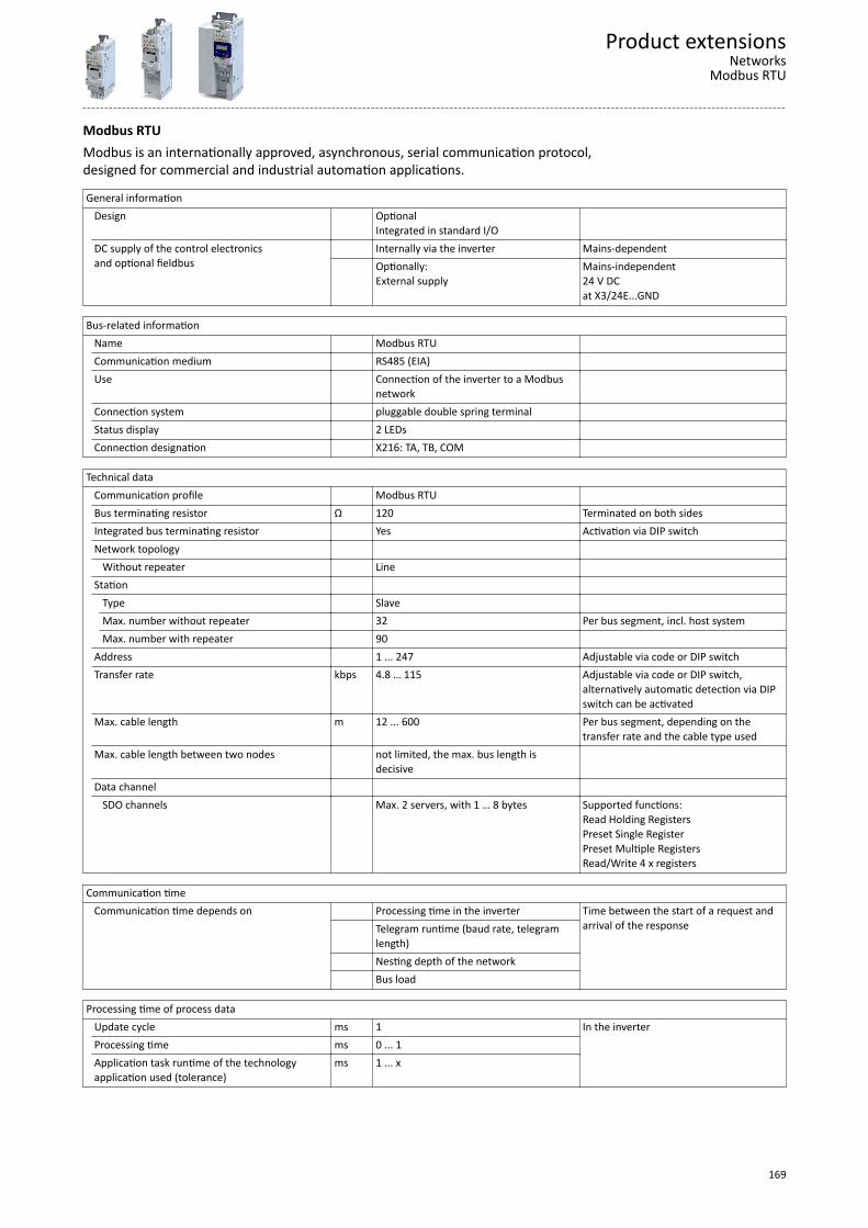
Modbus RTUModbus is an internationally approved, asynchronous, serial communication protocol,designed for commercial and industrial automation applications.
General information Design Optional
Integrated in standard I/O
DC supply of the control electronicsand optional fieldbus
Internally via the inverter Mains-dependent Optionally:
External supplyMains-independent24 V DCat X3/24E...GND
Bus-related information
Name Modbus RTU Communication medium RS485 (EIA) Use Connection of the inverter to a Modbus
network
Connection system pluggable double spring terminal Status display 2 LEDs Connection designation X216: TA, TB, COM
Technical data Communication profile Modbus RTU
Bus terminating resistor Ω 120 Terminated on both sidesIntegrated bus terminating resistor Yes Activation via DIP switchNetwork topology Without repeater Line Station Type Slave
Max. number without repeater 32 Per bus segment, incl. host systemMax. number with repeater 90
Address 1 ... 247 Adjustable via code or DIP switchTransfer rate kbps 4.8 … 115 Adjustable via code or DIP switch,
alternatively automatic detection via DIPswitch can be activated
Max. cable length m 12 ... 600 Per bus segment, depending on thetransfer rate and the cable type used
Max. cable length between two nodes not limited, the max. bus length isdecisive
Data channel SDO channels Max. 2 servers, with 1 … 8 bytes Supported functions:
Read Holding RegistersPreset Single RegisterPreset Multiple RegistersRead/Write 4 x registers
Communication time Communication time depends on
Processing time in the inverter Time between the start of a request andarrival of the response
Telegram runtime (baud rate, telegramlength)
Nesting depth of the network Bus load
Processing time of process data Update cycle ms 1 In the inverter
Processing time ms 0 ... 1Application task runtime of the technologyapplication used (tolerance)
ms 1 ... x
Product extensionsNetworks
Modbus RTU
169

Other data Note There are no interdependencies between
parameter data and process data.
Product extensionsNetworksModbus RTU
170
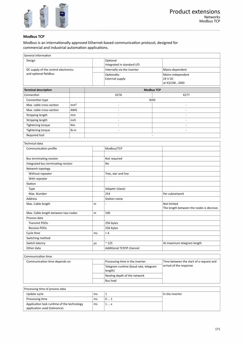
Modbus TCPModbus is an internationally approved Ethernet-based communication protocol, designed forcommercial and industrial automation applications.
General information Design Optional
Integrated in standard I/O
DC supply of the control electronicsand optional fieldbus
Internally via the inverter Mains-dependent Optionally:
External supplyMains-independent24 V DCat X3/24E...GND
Terminal description Modbus TCPConnection X276 X277 Connection type RJ45 Max. cable cross-section mm² - - Max. cable cross-section AWG - - Stripping length mm - - Stripping length inch - - Tightening torque Nm - - Tightening torque lb-in - - Required tool -
Technical data
Communication profile Modbus/TCP
Bus terminating resistor Not required integrated bus terminating resistor No Network topology Without repeater Tree, star and line
With repeater - Station Type Adapter (slave)
Max. Number 254 Per subnetworkAddress Station name Max. Cable length m - Not limited
The length between the nodes is decisive.Max. Cable length between two nodes m 100 Process data
Transmit PDOs 256 bytes Receive PDOs 256 bytes
Cycle time ms > 4 Switching method - Switch latency µs ~ 125 At maximum telegram lengthOther data Additional TCP/IP channel
Communication time Communication time depends on
Processing time in the inverter Time between the start of a request andarrival of the response
Telegram runtime (baud rate, telegramlength)
Nesting depth of the network Bus load
Processing time of process data Update cycle ms 1 In the inverter
Processing time ms 0 ... 1Application task runtime of the technologyapplication used (tolerance)
ms 1 ... x
Product extensionsNetworks
Modbus TCP
171

Other data Note There are no interdependencies between
parameter data and process data.
Product extensionsNetworksModbus TCP
172
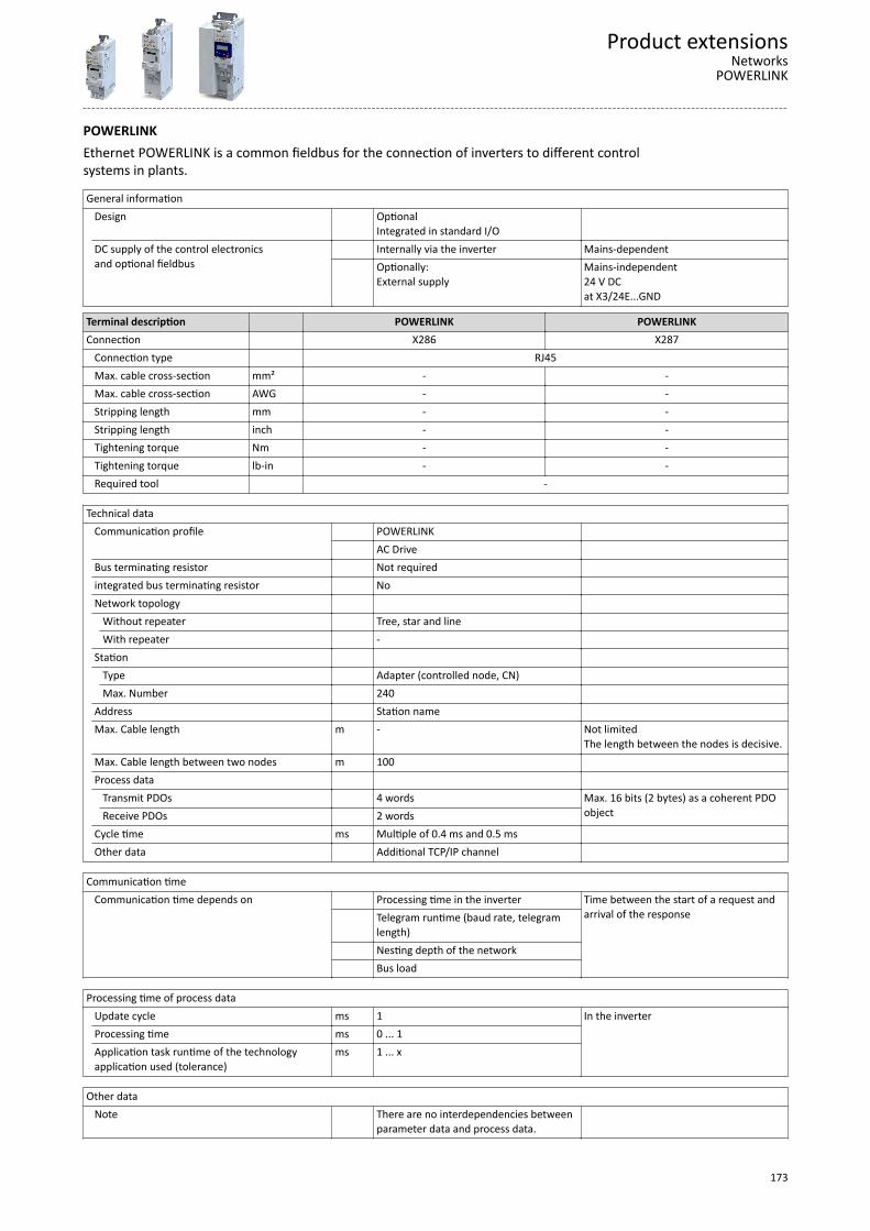
POWERLINKEthernet POWERLINK is a common fieldbus for the connection of inverters to different controlsystems in plants.
General information Design Optional
Integrated in standard I/O
DC supply of the control electronicsand optional fieldbus
Internally via the inverter Mains-dependent Optionally:
External supplyMains-independent24 V DCat X3/24E...GND
Terminal description POWERLINK POWERLINKConnection X286 X287 Connection type RJ45 Max. cable cross-section mm² - - Max. cable cross-section AWG - - Stripping length mm - - Stripping length inch - - Tightening torque Nm - - Tightening torque lb-in - - Required tool -
Technical data
Communication profile POWERLINK AC Drive
Bus terminating resistor Not required integrated bus terminating resistor No Network topology Without repeater Tree, star and line
With repeater - Station Type Adapter (controlled node, CN)
Max. Number 240 Address Station name Max. Cable length m - Not limited
The length between the nodes is decisive.Max. Cable length between two nodes m 100 Process data
Transmit PDOs 4 words Max. 16 bits (2 bytes) as a coherent PDOobjectReceive PDOs 2 words
Cycle time ms Multiple of 0.4 ms and 0.5 ms Other data Additional TCP/IP channel
Communication time Communication time depends on
Processing time in the inverter Time between the start of a request andarrival of the response
Telegram runtime (baud rate, telegramlength)
Nesting depth of the network Bus load
Processing time of process data Update cycle ms 1 In the inverter
Processing time ms 0 ... 1Application task runtime of the technologyapplication used (tolerance)
ms 1 ... x
Other data Note There are no interdependencies between
parameter data and process data.
Product extensionsNetworks
POWERLINK
173
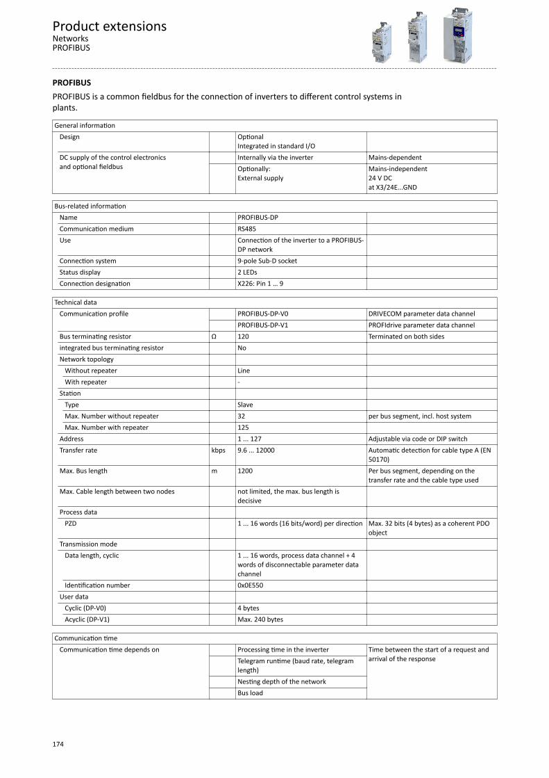
PROFIBUSPROFIBUS is a common fieldbus for the connection of inverters to different control systems inplants.
General information Design Optional
Integrated in standard I/O
DC supply of the control electronicsand optional fieldbus
Internally via the inverter Mains-dependent Optionally:
External supplyMains-independent24 V DCat X3/24E...GND
Bus-related information
Name PROFIBUS-DP Communication medium RS485 Use Connection of the inverter to a PROFIBUS-
DP network
Connection system 9-pole Sub-D socket Status display 2 LEDs Connection designation X226: Pin 1 … 9
Technical data Communication profile PROFIBUS-DP-V0 DRIVECOM parameter data channel
PROFIBUS-DP-V1 PROFIdrive parameter data channelBus terminating resistor Ω 120 Terminated on both sidesintegrated bus terminating resistor No Network topology Without repeater Line
With repeater - Station Type Slave
Max. Number without repeater 32 per bus segment, incl. host systemMax. Number with repeater 125
Address 1 ... 127 Adjustable via code or DIP switchTransfer rate kbps 9.6 ... 12000 Automatic detection for cable type A (EN
50170)Max. Bus length m 1200 Per bus segment, depending on the
transfer rate and the cable type usedMax. Cable length between two nodes not limited, the max. bus length is
decisive
Process data PZD 1 ... 16 words (16 bits/word) per direction Max. 32 bits (4 bytes) as a coherent PDO
objectTransmission mode Data length, cyclic 1 ... 16 words, process data channel + 4
words of disconnectable parameter datachannel
Identification number 0x0E550 User data Cyclic (DP-V0) 4 bytes
Acyclic (DP-V1) Max. 240 bytes
Communication time Communication time depends on
Processing time in the inverter Time between the start of a request andarrival of the response
Telegram runtime (baud rate, telegramlength)
Nesting depth of the network Bus load
Product extensionsNetworksPROFIBUS
174
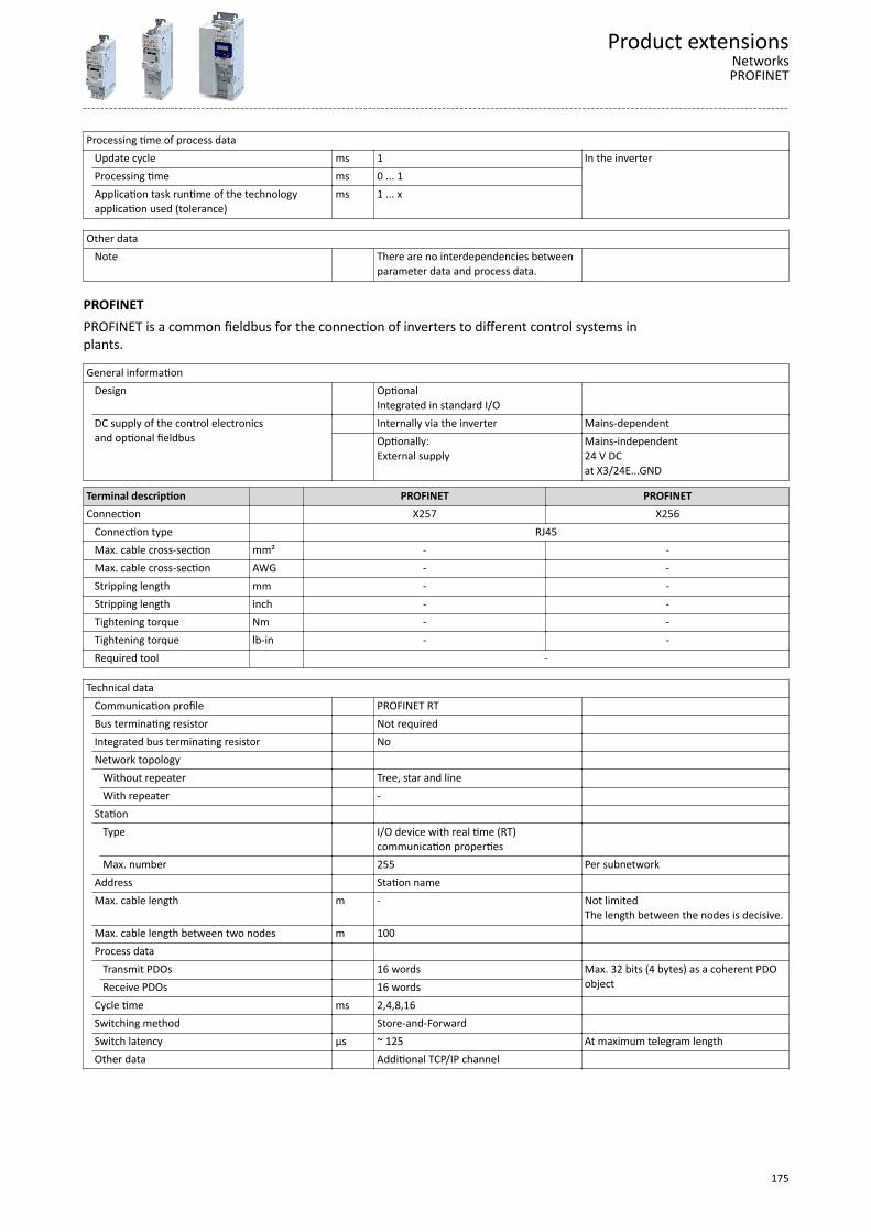
Processing time of process data Update cycle ms 1 In the inverter
Processing time ms 0 ... 1Application task runtime of the technologyapplication used (tolerance)
ms 1 ... x
Other data Note There are no interdependencies between
parameter data and process data.
PROFINETPROFINET is a common fieldbus for the connection of inverters to different control systems inplants.
General information Design Optional
Integrated in standard I/O
DC supply of the control electronicsand optional fieldbus
Internally via the inverter Mains-dependent Optionally:
External supplyMains-independent24 V DCat X3/24E...GND
Terminal description PROFINET PROFINETConnection X257 X256 Connection type RJ45 Max. cable cross-section mm² - - Max. cable cross-section AWG - - Stripping length mm - - Stripping length inch - - Tightening torque Nm - - Tightening torque lb-in - - Required tool -
Technical data
Communication profile PROFINET RT Bus terminating resistor Not required Integrated bus terminating resistor No Network topology Without repeater Tree, star and line
With repeater - Station Type I/O device with real time (RT)
communication properties
Max. number 255 Per subnetworkAddress Station name Max. cable length m - Not limited
The length between the nodes is decisive.Max. cable length between two nodes m 100 Process data
Transmit PDOs 16 words Max. 32 bits (4 bytes) as a coherent PDOobjectReceive PDOs 16 words
Cycle time ms 2,4,8,16 Switching method Store-and-Forward Switch latency µs ~ 125 At maximum telegram lengthOther data Additional TCP/IP channel
Product extensionsNetworksPROFINET
175
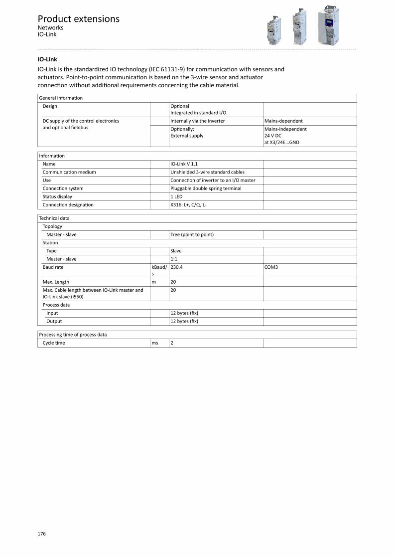
IO-LinkIO-Link is the standardized IO technology (IEC 61131-9) for communication with sensors andactuators. Point-to-point communication is based on the 3-wire sensor and actuatorconnection without additional requirements concerning the cable material.
General information Design Optional
Integrated in standard I/O
DC supply of the control electronicsand optional fieldbus
Internally via the inverter Mains-dependent Optionally:
External supplyMains-independent24 V DCat X3/24E...GND
Information
Name IO-Link V 1.1 Communication medium Unshielded 3-wire standard cables Use Connection of inverter to an I/O master Connection system Pluggable double spring terminal Status display 1 LED Connection designation X316: L+, C/Q, L-
Technical data Topology
Master - slave Tree (point to point) Station Type Slave
Master - slave 1:1 Baud rate kBaud/
s230.4 COM3
Max. Length m 20 Max. Cable length between IO-Link master andIO-Link slave (i550)
20
Process data Input 12 bytes (fix)
Output 12 bytes (fix)
Processing time of process data Cycle time ms 2
Product extensionsNetworksIO-Link
176

Functional safety
General information and basicsThe functional safety describes the necessary measures that need to be taken by means ofelectrical or electronic equipment to prevent or eliminate dangers due to malfunctions.
Protective devices prevent any human access to danger areas during normal operation.However, persons may have to be in the danger areas in certain operating modes. Themachine operator is protected by internal drive and control measures in these operatingmodes.
Integrated safetyThe integrated safety technology fulfils the control and drive conditions for implementing theprotective functions. The expenses for planning and installation decrease. Integrated safetyequipment increases machine functionality and availability. The integrated safety system canbe used for the protection of persons working on machines in accordance with the MachineryDirective.
The motion functions continue to be executed by the inverter. The integrated safety systemmonitors the safe compliance with the limit values and provides the safe inputs and outputs.If monitored limit values are exceeded, the integrated safety system in the inverter reacts withsafety functions according to EN 61800−5−2.
Identification of the componentsSafety components and the respective terminals are yellow.
Product extensionsFunctional safety
General information and basics
177

Safety sensorsThe components used must comply with the risk reduction required for the application.
Active sensorsActive sensors are units with 2-channel semiconductor outputs (OSSD outputs).
Test pulses for monitoring the outputs and lines are permissible.
P/M-switching sensors switch the positive and negative cable or the signal and ground cableof a sensor signal.
Please note the following:• The maximum permissible connection capacity of the outputs.• Active sensors are connected directly to the terminal strip, see section "Active sensor
connection".• Monitoring for short circuits must be carried out by the active sensor.
The outputs have to switch simultaneously (equivalently). Safety functions will be activated ifonly one channel is switched. Active triggering of only one channel points to faulty sensors orimpermissible wiring.
Examples of active sensors:• Lightgrid• Laser scanner• Control systems
Passive sensorsPassive sensors are 2-switching elements with contacts.
Please note the following:• The switches must be wired according to the closed-circuit principle.• Passive sensors are connected to the terminal strip via a safety switching device, see
section “Passive sensor connection”.• The connecting cables and the sensor function must be monitored by an external safety
component.
The contacts must switch simultaneously (equivalently). Safety functions will be activated ifonly one channel is switched. Switching of only one channel points to faulty sensors orimpermissible wiring.
Examples of passive sensors:• Door contact switch• Emergency stop control units
Product extensionsFunctional safetySafety sensors
178

Safety functions
Supported safety functions for "Basic Safety-STO"4Safe Torque Off (STO) ^ 180
Product extensionsFunctional safetySafety functions
179
Safe Torque Off (STO)The motor cannot generate torque and movements of the drive.
DANGER!With the "Safe torque off" (STO) function, no “emergency‑stop" can be executed according toEN 60204−1 without additional measures. There is no electrical isolation between the motorand inverter and no service switch or maintenance switch!Possible consequences: Death or severe injuries"Emergency stop" requires electrical isolation, e. g. via a central mains contactor.
DANGER!Automatic restart if the request of the safety function is deactivated.Possible consequences: Death or severe injuriesYou must provide external measures according to EN ISO 13849−1 which ensure that the
drive only restarts after a confirmation.
DANGER!The power supply is not safely disconnected.Death or serious injury due to electrical voltage.Turn off the power supply.
DetailsSafe disconnection of the drive1. A safety sensor requests the safety function.2. The pulse width modulation is safely switched off by the safety unit.The inverter switches to the STO active device status (0x6041, Bit15 = 0).The power drivers do not generate a rotating field anymore.The motor is safely switched to torqueless operation (STO).
The functional principle depicted applies to Basic Safety (STO) and ExtendedSafety. The terminals shown apply to Basic Safety.
Product extensionsFunctional safetySafety functions
180
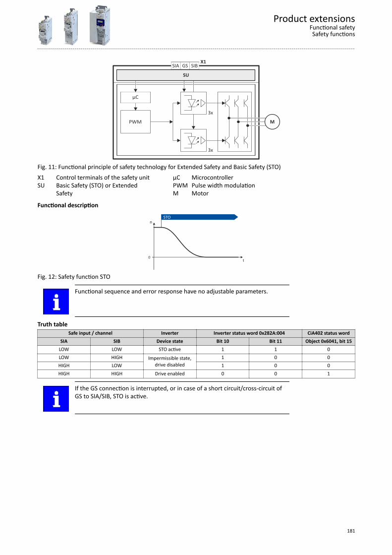
PWM
µC
3x
3x
X1
SU
M
SIA SIBGS
Fig. 11: Functional principle of safety technology for Extended Safety and Basic Safety (STO)X1 Control terminals of the safety unitSU Basic Safety (STO) or Extended
Safety
µC MicrocontrollerPWM Pulse width modulationM Motor
Functional description
n
t0
STO
Fig. 12: Safety function STO
Functional sequence and error response have no adjustable parameters.
Truth tableSafe input / channel Inverter Inverter status word 0x282A:004 CiA402 status word
SIA SIB Device state Bit 10 Bit 11 Object 0x6041, bit 15LOW LOW STO active 1 1 0LOW HIGH Impermissible state,
drive disabled1 0 0
HIGH LOW 1 0 0HIGH HIGH Drive enabled 0 0 1
If the GS connection is interrupted, or in case of a short circuit/cross-circuit ofGS to SIA/SIB, STO is active.
Product extensionsFunctional safetySafety functions
181

AcceptanceThe machine manufacturer must check and prove the operability of the safety functions used.• The machine manufacturer must authorise a person with expertise and knowledge of the
safety functions to carry out the test.• The test result of every safety function must be documented and signed by the inspector.
A complete test comprises the following:• Documenting the plant including the safety functions:
• Creating an overview screen of the plant.• Describing the plant.• Describing the safety equipment.• Documenting the safety functions used.• Checking the function of the safety functions used.
• Preparing the test report:• Documenting the functional test.• Checking the parameters.• Signing the test report.
• Preparing the appendix with test records:• Protocols for the plant• External recording
The tester must repeat the test after each change and record the results in thetest report.
Periodic inspectionsThe correct sequence of the safety−oriented functions must be checked in periodicinspections. The risk analysis or applicable regulations determine the time distances betweenthe tests.
The inspection interval should not exceed one year.
Product extensionsFunctional safetyPeriodic inspections
182
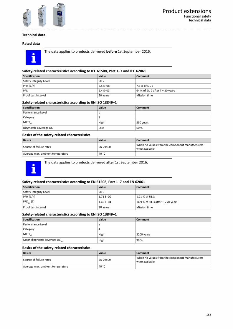
Technical data
Rated data
The data applies to products delivered before 1st September 2016.
Safety-related characteristics according to IEC 61508, Part 1−7 and IEC 62061Specification Value CommentSafety Integrity Level SIL 2 PFH [1/h] 7.5 E−08 7.5 % of SIL 2PFD 6.4 E−03 64 % of SIL 2 after T = 20 yearsProof test interval 20 years Mission time
Safety-related characteristics according to EN ISO 13849−1Specification Value CommentPerformance Level d Category 2 MTTFd High 530 years
Diagnostic coverage DC Low 60 %
Basics of the safety-related characteristicsBasics Value Comment
Source of failure rates SN 29500 When no values from the component manufacturerswere available.
Average max. ambient temperature 40 °C
The data applies to products delivered after 1st September 2016.
Safety-related characteristics according to EN 61508, Part 1−7 and EN 62061Specification Value CommentSafety Integrity Level SIL 3 PFH [1/h] 1.71 E−09 1.71 % of SIL 3PFDav (T) 1.49 E−04 14.9 % of SIL 3 after T = 20 years
Proof test interval 20 years Mission time
Safety-related characteristics according to EN ISO 13849−1Specification Value CommentPerformance Level e Category 4 MTTFd High 3200 years
Mean diagnostic coverage DCav High 99 %
Basics of the safety-related characteristicsBasics Value Comment
Source of failure rates SN 29500 When no values from the component manufacturerswere available.
Average max. ambient temperature 40 °C
Product extensionsFunctional safety
Technical data
183
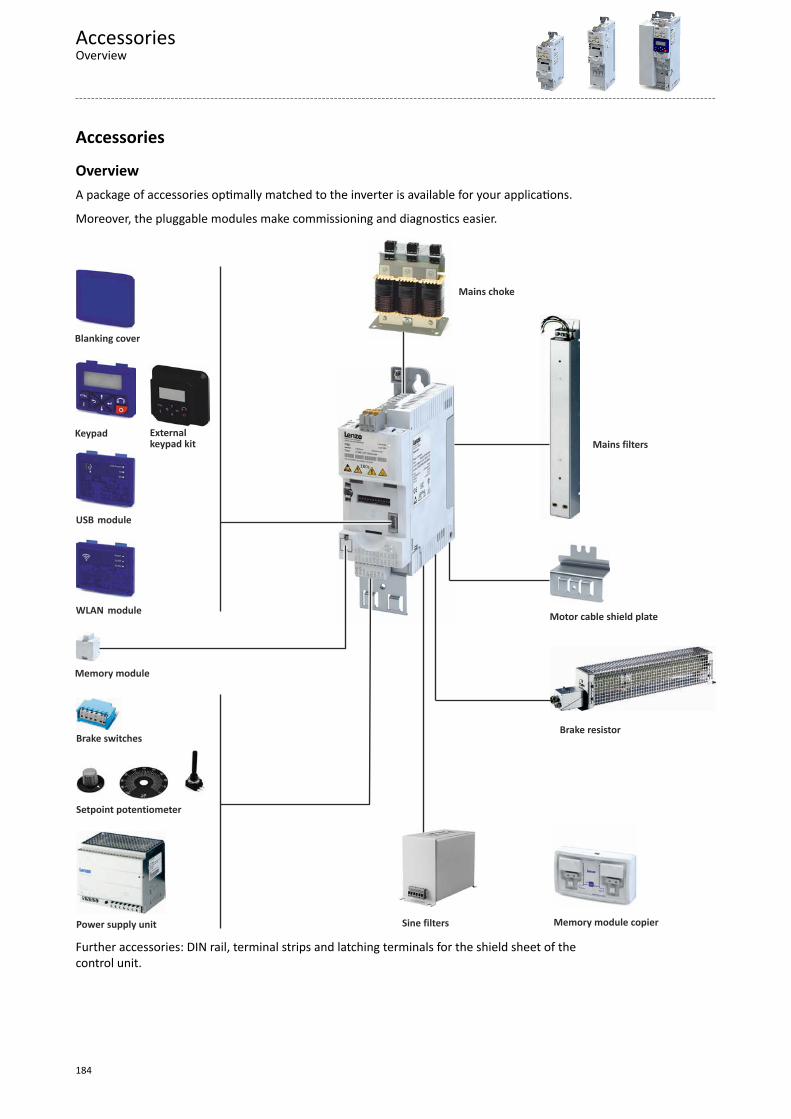
Accessories
OverviewA package of accessories optimally matched to the inverter is available for your applications.
Moreover, the pluggable modules make commissioning and diagnostics easier.
WLAN module
Blanking cover
USB module
Keypad
Brake switches
Power supply unit
Setpoint potentiometer
Sine filters Memory module copier
Brake resistor
Mains filtersExternalkeypad kit
Mains choke
Motor cable shield plate
Memory module
Further accessories: DIN rail, terminal strips and latching terminals for the shield sheet of thecontrol unit.
AccessoriesOverview
184
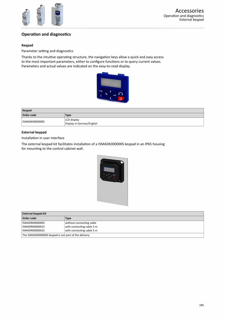
Operation and diagnostics
KeypadParameter setting and diagnosticsThanks to the intuitive operating structure, the navigation keys allow a quick and easy accessto the most important parameters, either to configure functions or to query current values.Parameters and actual values are indicated on the easy-to-read display.
KeypadOrder code Type
I5MADK0000000S LCD displayDisplay in German/English
External keypadInstallation in user interfaceThe external keypad kit facilitates installation of a I5MADK000000S keypad in an IP65 housingfor mounting to the control cabinet wall.
External keypad kitOrder code TypeI5MADR0000000SI5MADR0000001SI5MADR0000002S
without connecting cablewith connecting cable 3 mwith connecting cable 5 m
The I5MADK000000S keypad is not part of the delivery.
AccessoriesOperation and diagnostics
External keypad
185
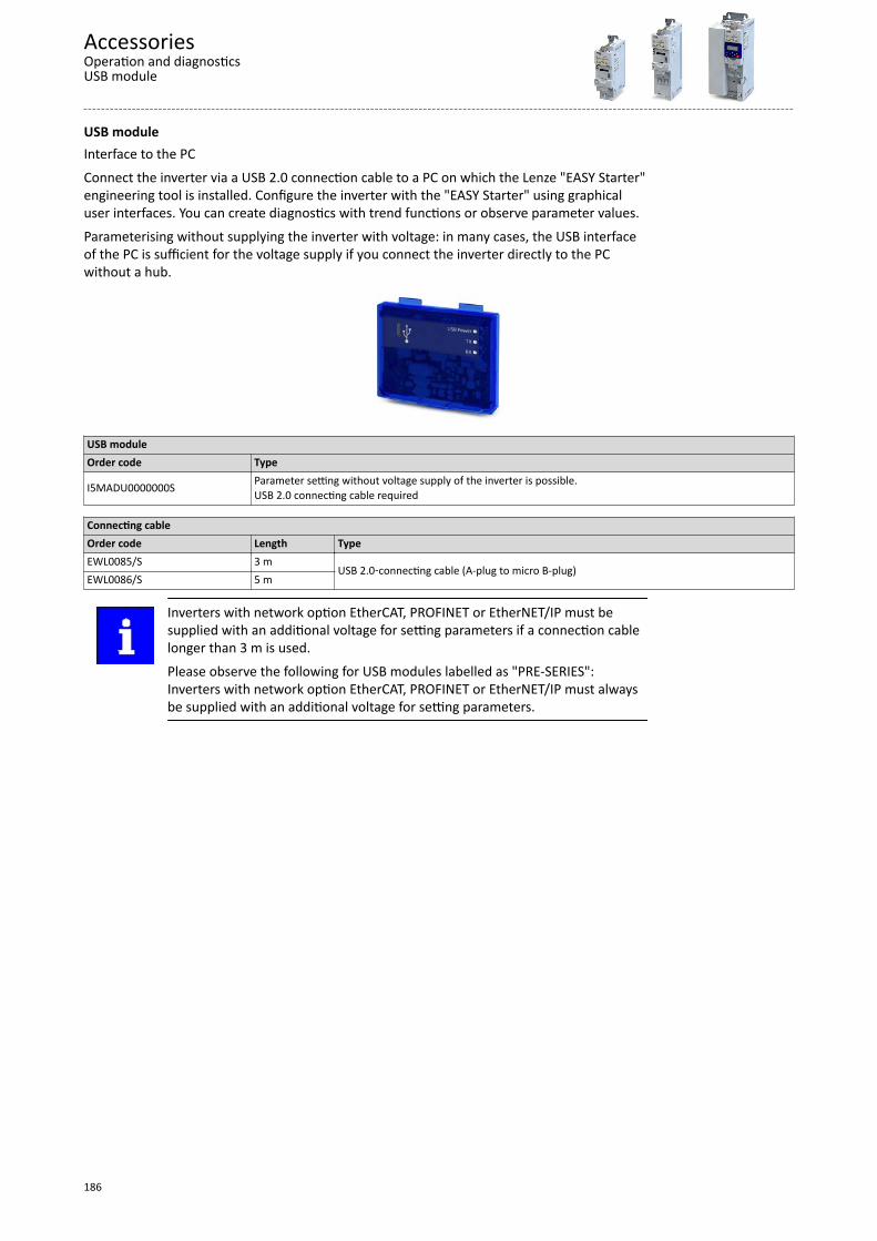
USB moduleInterface to the PCConnect the inverter via a USB 2.0 connection cable to a PC on which the Lenze "EASY Starter"engineering tool is installed. Configure the inverter with the "EASY Starter" using graphicaluser interfaces. You can create diagnostics with trend functions or observe parameter values.Parameterising without supplying the inverter with voltage: in many cases, the USB interfaceof the PC is sufficient for the voltage supply if you connect the inverter directly to the PCwithout a hub.
USB moduleOrder code Type
I5MADU0000000S Parameter setting without voltage supply of the inverter is possible.USB 2.0 connecting cable required
Connecting cableOrder code Length TypeEWL0085/S 3 m
USB 2.0‑connecting cable (A-plug to micro B-plug)EWL0086/S 5 m
Inverters with network option EtherCAT, PROFINET or EtherNET/IP must besupplied with an additional voltage for setting parameters if a connection cablelonger than 3 m is used.Please observe the following for USB modules labelled as "PRE-SERIES":Inverters with network option EtherCAT, PROFINET or EtherNET/IP must alwaysbe supplied with an additional voltage for setting parameters.
AccessoriesOperation and diagnosticsUSB module
186
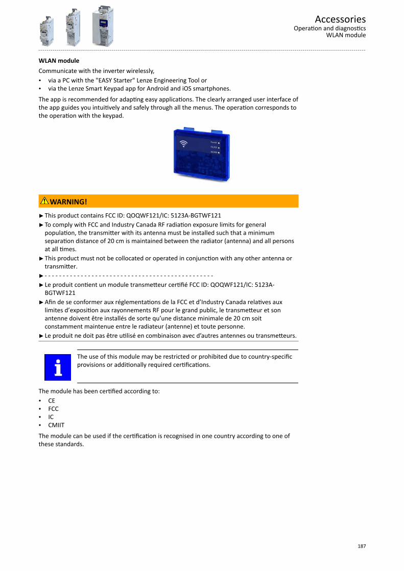
WLAN moduleCommunicate with the inverter wirelessly,• via a PC with the "EASY Starter" Lenze Engineering Tool or• via the Lenze Smart Keypad app for Android and iOS smartphones.The app is recommended for adapting easy applications. The clearly arranged user interface ofthe app guides you intuitively and safely through all the menus. The operation corresponds tothe operation with the keypad.
WARNING!This product contains FCC ID: QOQWF121/IC: 5123A-BGTWF121To comply with FCC and Industry Canada RF radiation exposure limits for generalpopulation, the transmitter with its antenna must be installed such that a minimumseparation distance of 20 cm is maintained between the radiator (antenna) and all personsat all times.
This product must not be collocated or operated in conjunction with any other antenna ortransmitter.
- - - - - - - - - - - - - - - - - - - - - - - - - - - - - - - - - - - - - - - - - - - - - - -Le produit contient un module transmetteur certifié FCC ID: QOQWF121/IC: 5123A-
BGTWF121Afin de se conformer aux réglementations de la FCC et d’Industry Canada relatives aux
limites d’exposition aux rayonnements RF pour le grand public, le transmetteur et sonantenne doivent être installés de sorte qu’une distance minimale de 20 cm soitconstamment maintenue entre le radiateur (antenne) et toute personne.
Le produit ne doit pas être utilisé en combinaison avec d’autres antennes ou transmetteurs.
The use of this module may be restricted or prohibited due to country-specificprovisions or additionally required certifications.
The module has been certified according to:• CE• FCC• IC• CMIITThe module can be used if the certification is recognised in one country according to one ofthese standards.
AccessoriesOperation and diagnostics
WLAN module
187
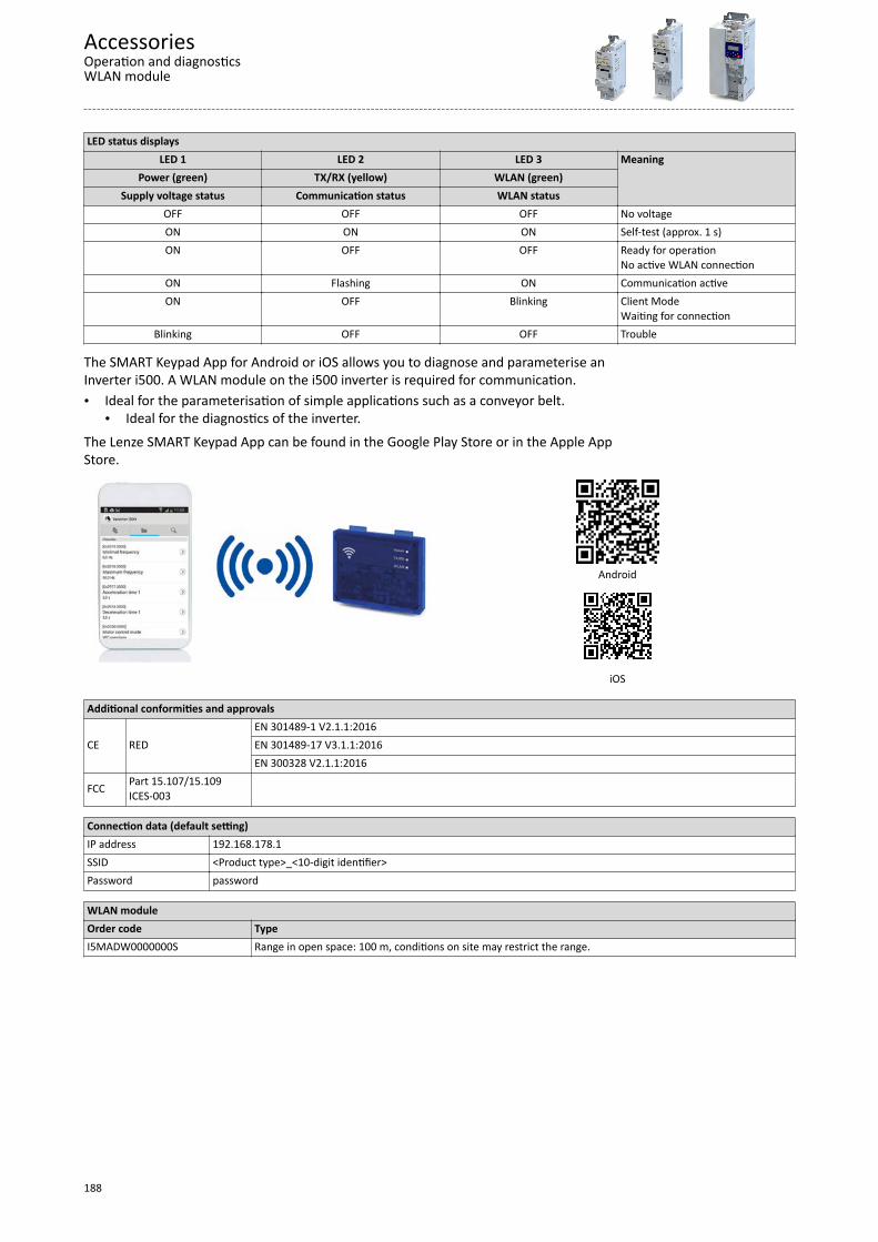
LED status displaysLED 1 LED 2 LED 3 Meaning
Power (green) TX/RX (yellow) WLAN (green)Supply voltage status Communication status WLAN status
OFF OFF OFF No voltageON ON ON Self-test (approx. 1 s)ON OFF OFF Ready for operation
No active WLAN connectionON Flashing ON Communication activeON OFF Blinking Client Mode
Waiting for connectionBlinking OFF OFF Trouble
The SMART Keypad App for Android or iOS allows you to diagnose and parameterise anInverter i500. A WLAN module on the i500 inverter is required for communication.• Ideal for the parameterisation of simple applications such as a conveyor belt.
• Ideal for the diagnostics of the inverter.The Lenze SMART Keypad App can be found in the Google Play Store or in the Apple AppStore.
Android
iOS
Additional conformities and approvals
CE REDEN 301489-1 V2.1.1:2016EN 301489-17 V3.1.1:2016EN 300328 V2.1.1:2016
FCC Part 15.107/15.109ICES-003
Connection data (default setting)IP address 192.168.178.1SSID <Product type>_<10-digit identifier>Password password
WLAN moduleOrder code TypeI5MADW0000000S Range in open space: 100 m, conditions on site may restrict the range.
AccessoriesOperation and diagnosticsWLAN module
188
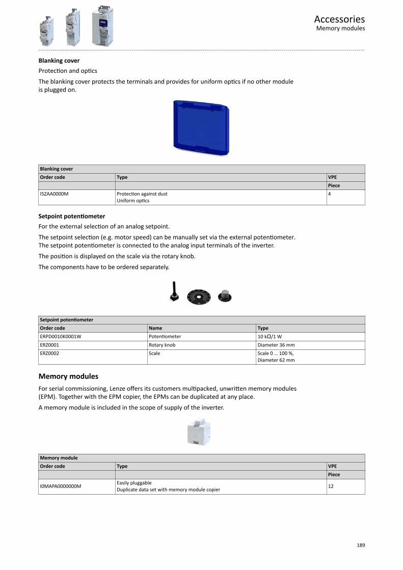
Blanking coverProtection and opticsThe blanking cover protects the terminals and provides for uniform optics if no other moduleis plugged on.
Blanking coverOrder code Type VPE PieceI5ZAA0000M Protection against dust
Uniform optics4
Setpoint potentiometerFor the external selection of an analog setpoint.The setpoint selection (e.g. motor speed) can be manually set via the external potentiometer.The setpoint potentiometer is connected to the analog input terminals of the inverter.The position is displayed on the scale via the rotary knob.The components have to be ordered separately.
Setpoint potentiometerOrder code Name TypeERPD0010K0001W Potentiometer 10 kΩ/1 WERZ0001 Rotary knob Diameter 36 mmERZ0002 Scale Scale 0 … 100 %,
Diameter 62 mm
Memory modulesFor serial commissioning, Lenze offers its customers multipacked, unwritten memory modules(EPM). Together with the EPM copier, the EPMs can be duplicated at any place.A memory module is included in the scope of supply of the inverter.
Memory moduleOrder code Type VPE Piece
I0MAPA0000000M Easily pluggableDuplicate data set with memory module copier 12
AccessoriesMemory modules
189
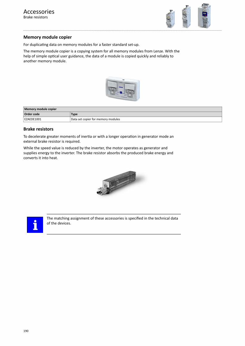
Memory module copierFor duplicating data on memory modules for a faster standard set-up.The memory module copier is a copying system for all memory modules from Lenze. With thehelp of simple optical user guidance, the data of a module is copied quickly and reliably toanother memory module.
Memory module copierOrder code TypeEZAEDE1001 Data set copier for memory modules
Brake resistorsTo decelerate greater moments of inertia or with a longer operation in generator mode anexternal brake resistor is required.While the speed value is reduced by the inverter, the motor operates as generator andsupplies energy to the inverter. The brake resistor absorbs the produced brake energy andconverts it into heat.
The matching assignment of these accessories is specified in the technical dataof the devices.
AccessoriesBrake resistors
190
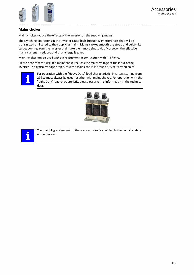
Mains chokesMains chokes reduce the effects of the inverter on the supplying mains.The switching operations in the inverter cause high-frequency interferences that will betransmitted unfiltered to the supplying mains. Mains chokes smooth the steep and pulse-likecurves coming from the Inverter and make them more sinusoidal. Moreover, the effectivemains current is reduced and thus energy is saved.Mains chokes can be used without restrictions in conjunction with RFI filters.Please note that the use of a mains choke reduces the mains voltage at the input of theinverter. The typical voltage drop across the mains choke is around 4 % at its rated point.
For operation with the "Heavy Duty" load characteristic, inverters starting from22 kW must always be used together with mains chokes. For operation with the"Light Duty" load characteristic, please observe the information in the technicaldata.
The matching assignment of these accessories is specified in the technical dataof the devices.
AccessoriesMains chokes
191
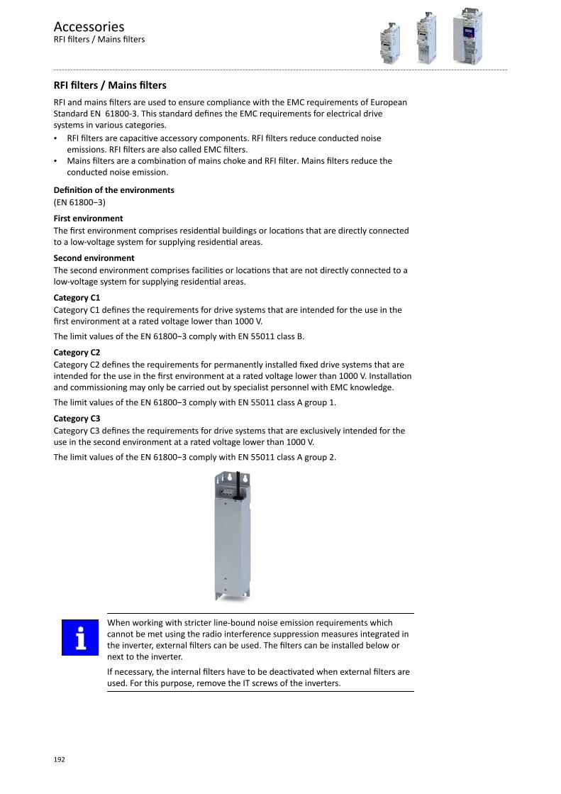
RFI filters / Mains filtersRFI and mains filters are used to ensure compliance with the EMC requirements of EuropeanStandard EN 61800-3. This standard defines the EMC requirements for electrical drivesystems in various categories.• RFI filters are capacitive accessory components. RFI filters reduce conducted noise
emissions. RFI filters are also called EMC filters.• Mains filters are a combination of mains choke and RFI filter. Mains filters reduce the
conducted noise emission.
Definition of the environments(EN 61800−3)
First environmentThe first environment comprises residential buildings or locations that are directly connectedto a low-voltage system for supplying residential areas.
Second environmentThe second environment comprises facilities or locations that are not directly connected to alow-voltage system for supplying residential areas.
Category C1Category C1 defines the requirements for drive systems that are intended for the use in thefirst environment at a rated voltage lower than 1000 V.The limit values of the EN 61800−3 comply with EN 55011 class B.
Category C2Category C2 defines the requirements for permanently installed fixed drive systems that areintended for the use in the first environment at a rated voltage lower than 1000 V. Installationand commissioning may only be carried out by specialist personnel with EMC knowledge.The limit values of the EN 61800−3 comply with EN 55011 class A group 1.
Category C3Category C3 defines the requirements for drive systems that are exclusively intended for theuse in the second environment at a rated voltage lower than 1000 V.The limit values of the EN 61800−3 comply with EN 55011 class A group 2.
When working with stricter line-bound noise emission requirements whichcannot be met using the radio interference suppression measures integrated inthe inverter, external filters can be used. The filters can be installed below ornext to the inverter.If necessary, the internal filters have to be deactivated when external filters areused. For this purpose, remove the IT screws of the inverters.
AccessoriesRFI filters / Mains filters
192
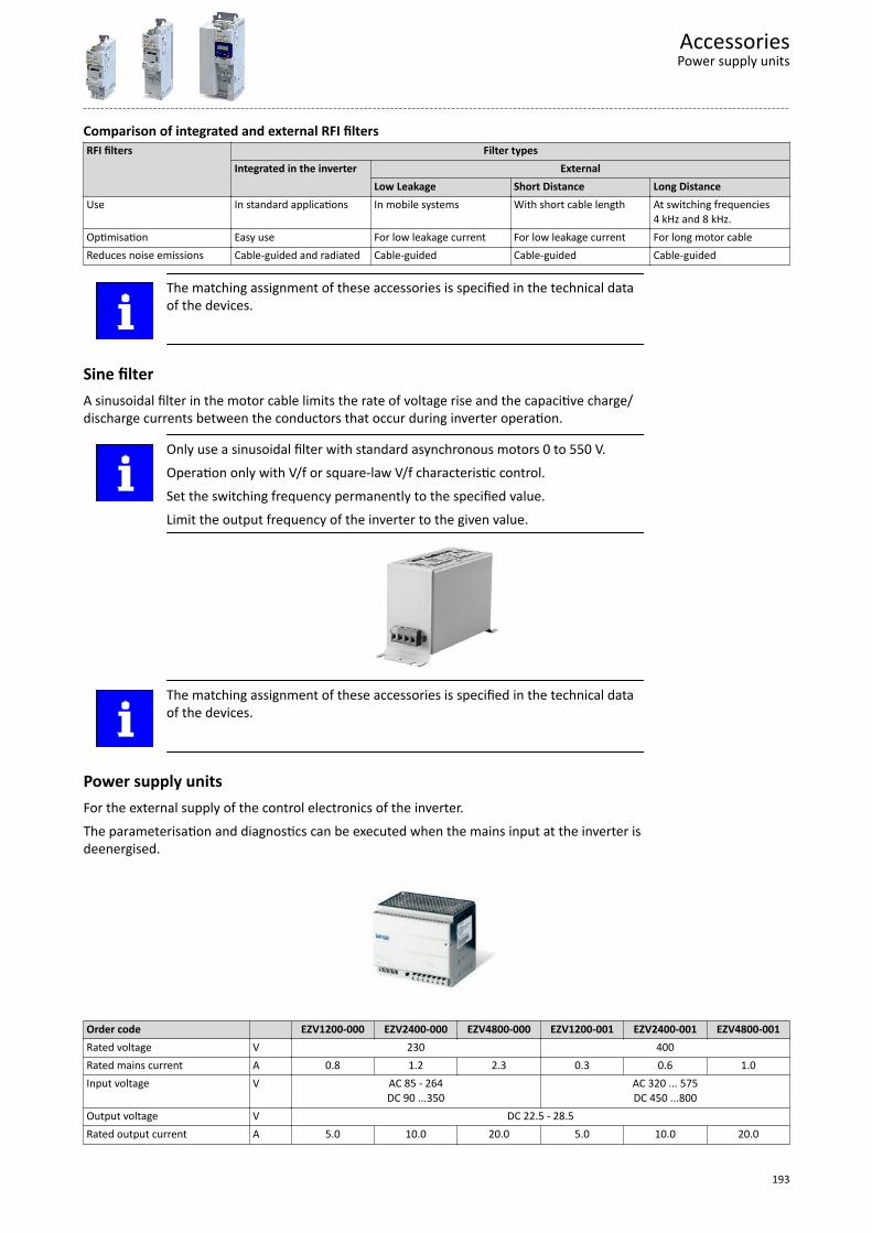
Comparison of integrated and external RFI filtersRFI filters Filter types
Integrated in the inverter ExternalLow Leakage Short Distance Long Distance
Use In standard applications In mobile systems With short cable length At switching frequencies4 kHz and 8 kHz.
Optimisation Easy use For low leakage current For low leakage current For long motor cableReduces noise emissions Cable-guided and radiated Cable-guided Cable-guided Cable-guided
The matching assignment of these accessories is specified in the technical dataof the devices.
Sine filterA sinusoidal filter in the motor cable limits the rate of voltage rise and the capacitive charge/discharge currents between the conductors that occur during inverter operation.
Only use a sinusoidal filter with standard asynchronous motors 0 to 550 V.Operation only with V/f or square-law V/f characteristic control.Set the switching frequency permanently to the specified value.Limit the output frequency of the inverter to the given value.
The matching assignment of these accessories is specified in the technical dataof the devices.
Power supply unitsFor the external supply of the control electronics of the inverter.The parameterisation and diagnostics can be executed when the mains input at the inverter isdeenergised.
Order code EZV1200-000 EZV2400-000 EZV4800-000 EZV1200-001 EZV2400-001 EZV4800-001Rated voltage V 230 400Rated mains current A 0.8 1.2 2.3 0.3 0.6 1.0Input voltage V AC 85 - 264
DC 90 ...350AC 320 ... 575DC 450 ...800
Output voltage V DC 22.5 - 28.5Rated output current A 5.0 10.0 20.0 5.0 10.0 20.0
AccessoriesPower supply units
193
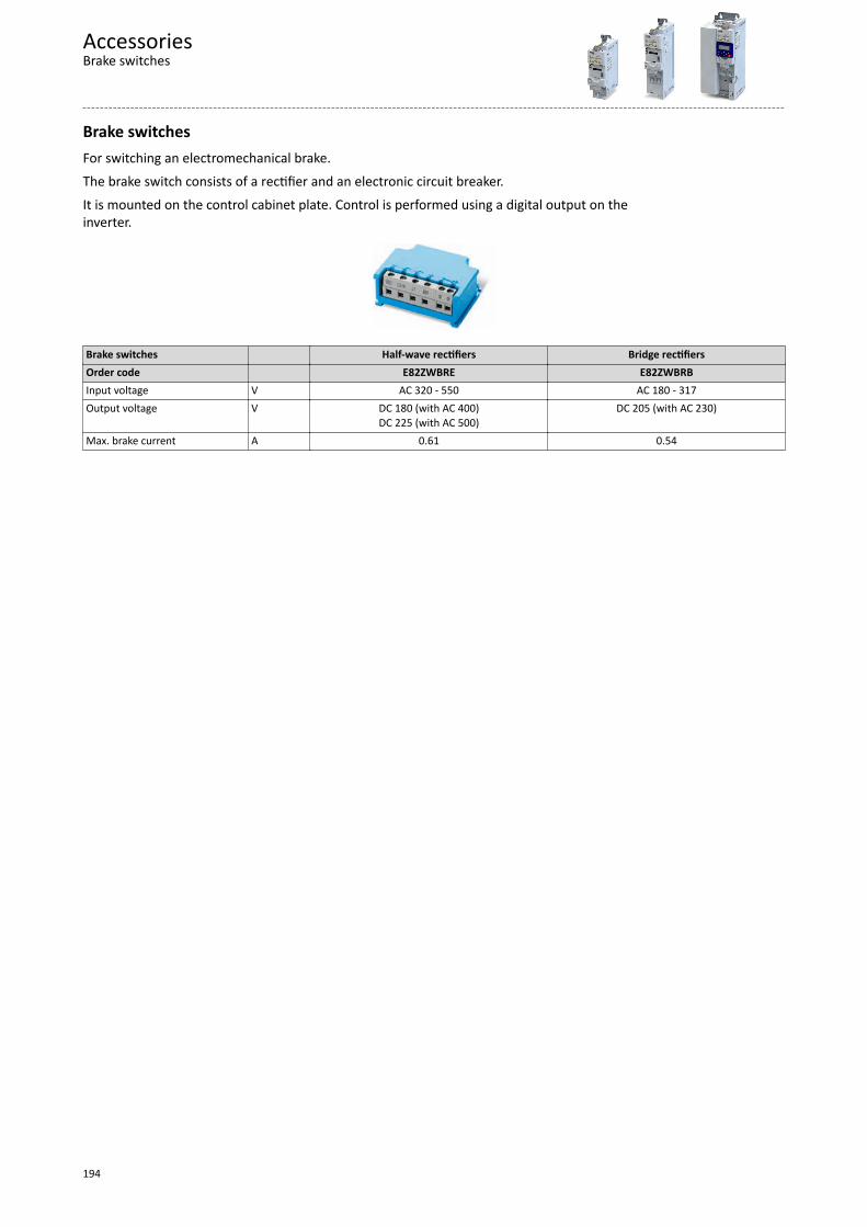
Brake switchesFor switching an electromechanical brake.The brake switch consists of a rectifier and an electronic circuit breaker.It is mounted on the control cabinet plate. Control is performed using a digital output on theinverter.
Brake switches Half-wave rectifiers Bridge rectifiersOrder code E82ZWBRE E82ZWBRBInput voltage V AC 320 - 550 AC 180 - 317Output voltage V DC 180 (with AC 400)
DC 225 (with AC 500)DC 205 (with AC 230)
Max. brake current A 0.61 0.54
AccessoriesBrake switches
194
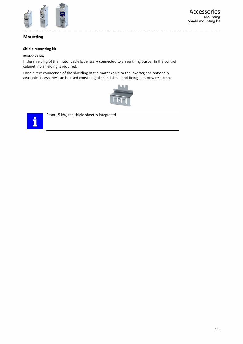
Mounting
Shield mounting kit
Motor cableIf the shielding of the motor cable is centrally connected to an earthing busbar in the controlcabinet, no shielding is required.For a direct connection of the shielding of the motor cable to the inverter, the optionallyavailable accessories can be used consisting of shield sheet and fixing clips or wire clamps.
From 15 kW, the shield sheet is integrated.
AccessoriesMounting
Shield mounting kit
195
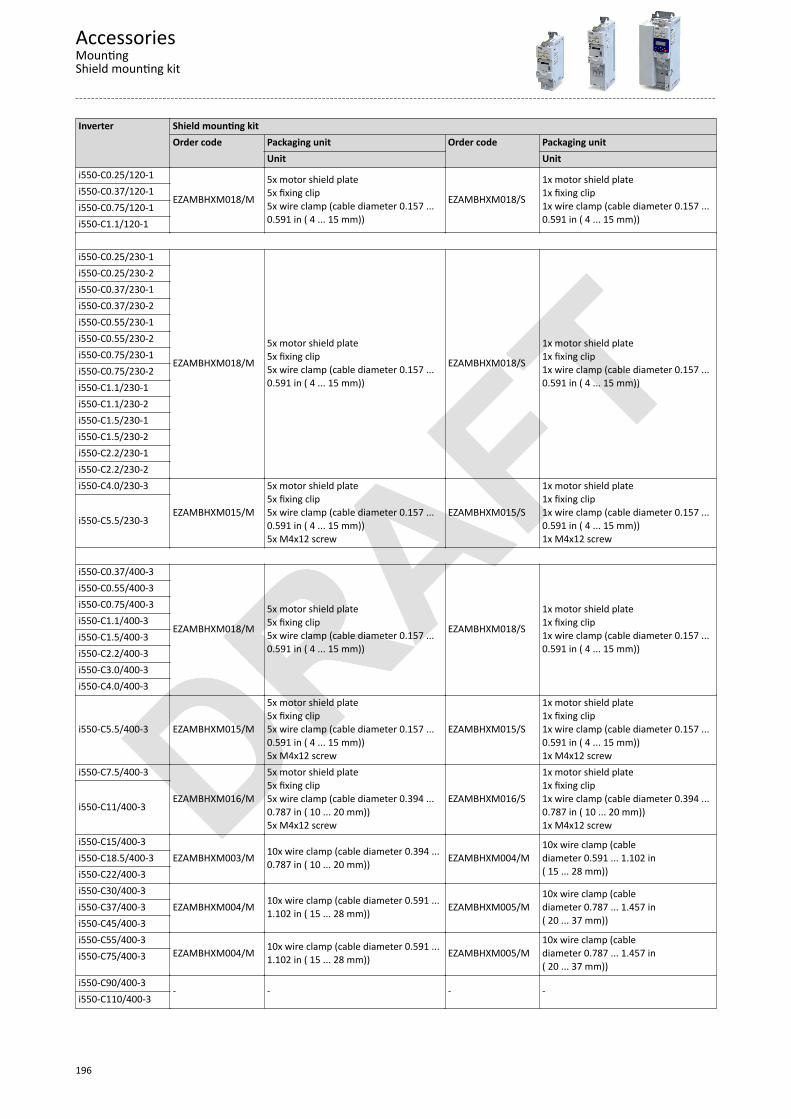
AccessoriesMountingShield mounting kit
196
Inverter Shield mounting kitOrder code Packaging unit Order code Packaging unit
Unit Uniti550-C0.25/120-1
EZAMBHXM018/M
5x motor shield plate5x fixing clip5x wire clamp (cable diameter 0.157 ...0.591 in ( 4 ... 15 mm))
EZAMBHXM018/S
1x motor shield plate1x fixing clip1x wire clamp (cable diameter 0.157 ...0.591 in ( 4 ... 15 mm))
i550-C0.37/120-1i550-C0.75/120-1i550-C1.1/120-1
i550-C0.25/230-1
EZAMBHXM018/M
5x motor shield plate5x fixing clip5x wire clamp (cable diameter 0.157 ...0.591 in ( 4 ... 15 mm))
EZAMBHXM018/S
1x motor shield plate1x fixing clip1x wire clamp (cable diameter 0.157 ...0.591 in ( 4 ... 15 mm))
i550-C0.25/230-2i550-C0.37/230-1i550-C0.37/230-2i550-C0.55/230-1i550-C0.55/230-2i550-C0.75/230-1i550-C0.75/230-2i550-C1.1/230-1i550-C1.1/230-2i550-C1.5/230-1i550-C1.5/230-2i550-C2.2/230-1i550-C2.2/230-2i550-C4.0/230-3
EZAMBHXM015/M
5x motor shield plate5x fixing clip5x wire clamp (cable diameter 0.157 ...0.591 in ( 4 ... 15 mm))5x M4x12 screw
EZAMBHXM015/S
1x motor shield plate1x fixing clip1x wire clamp (cable diameter 0.157 ...0.591 in ( 4 ... 15 mm))1x M4x12 screw
i550-C5.5/230-3
i550-C0.37/400-3
EZAMBHXM018/M
5x motor shield plate5x fixing clip5x wire clamp (cable diameter 0.157 ...0.591 in ( 4 ... 15 mm))
EZAMBHXM018/S
1x motor shield plate1x fixing clip1x wire clamp (cable diameter 0.157 ...0.591 in ( 4 ... 15 mm))
i550-C0.55/400-3i550-C0.75/400-3i550-C1.1/400-3i550-C1.5/400-3i550-C2.2/400-3i550-C3.0/400-3i550-C4.0/400-3
i550-C5.5/400-3 EZAMBHXM015/M
5x motor shield plate5x fixing clip5x wire clamp (cable diameter 0.157 ...0.591 in ( 4 ... 15 mm))5x M4x12 screw
EZAMBHXM015/S
1x motor shield plate1x fixing clip1x wire clamp (cable diameter 0.157 ...0.591 in ( 4 ... 15 mm))1x M4x12 screw
i550-C7.5/400-3
EZAMBHXM016/M
5x motor shield plate5x fixing clip5x wire clamp (cable diameter 0.394 ...0.787 in ( 10 ... 20 mm))5x M4x12 screw
EZAMBHXM016/S
1x motor shield plate1x fixing clip1x wire clamp (cable diameter 0.394 ...0.787 in ( 10 ... 20 mm))1x M4x12 screw
i550-C11/400-3
i550-C15/400-3EZAMBHXM003/M 10x wire clamp (cable diameter 0.394 ...
0.787 in ( 10 ... 20 mm)) EZAMBHXM004/M10x wire clamp (cablediameter 0.591 ... 1.102 in( 15 ... 28 mm))
i550-C18.5/400-3i550-C22/400-3i550-C30/400-3
EZAMBHXM004/M 10x wire clamp (cable diameter 0.591 ...1.102 in ( 15 ... 28 mm)) EZAMBHXM005/M
10x wire clamp (cablediameter 0.787 ... 1.457 in( 20 ... 37 mm))
i550-C37/400-3i550-C45/400-3i550-C55/400-3
EZAMBHXM004/M 10x wire clamp (cable diameter 0.591 ...1.102 in ( 15 ... 28 mm)) EZAMBHXM005/M
10x wire clamp (cablediameter 0.787 ... 1.457 in( 20 ... 37 mm))
i550-C75/400-3
i550-C90/400-3- - - -
i550-C110/400-3
Terminal stripsFor connecting the inverter, the connections are equipped with pluggable terminal strips.Pluggable terminal strips are available separately for service purposes or if cable harnessesneed to be physically separated.
Inverter Terminal stripsMains connection X100
Terminal stripsMotor connection X105
Order code VPE Order code VPEPiece Piece
i550-C0.25/230-1
EZAEVE032/M
10
EZAEVE039/M 5
i550-C0.37/230-1i550-C0.55/230-1i550-C0.75/230-1i550-C1.1/230-1
EZAEVE033/Mi550-C1.5/230-1i550-C2.2/230-1i550-C0.25/230-2
EZAEVE034/M
10
i550-C0.37/230-2i550-C0.55/230-2i550-C0.75/230-2i550-C1.1/230-2
EZAEVE035/Mi550-C1.5/230-2i550-C2.2/230-2i550-C0.37/400-3
EZAEVE037/M 5
i550-C0.55/400-3i550-C0.75/400-3i550-C1.1/400-3i550-C1.5/400-3i550-C2.2/400-3
Terminal strips Order code VPE Terminal strips Order code VPEPiece Piece
Safety (STO) X1 EZAEVE029/M 10 Standard I/O X3 EZAEVE040/M 5Relay X9 EZAEVE030/M 10 Application-I/O X3 EZAEVE041/M 5Motor PTC X109 EZAEVE031/M 10 CANopen / Modbus X216 EZAEVE042/M 10
AccessoriesMounting
Terminal strips
197
Shield mounting of the control cablesIn case of the control unit, the shield sheet for control cables is integrated.Usually, the shields can be fixed with standard plastic cable ties.Optionally, fixing clips are suitable for the shield connections of the control cables ofinverters 0.25 kW ... 0.75 kW.Shield mounting kitOrder code VPE
PieceEZAMBHXM007/M 20x fixing clip
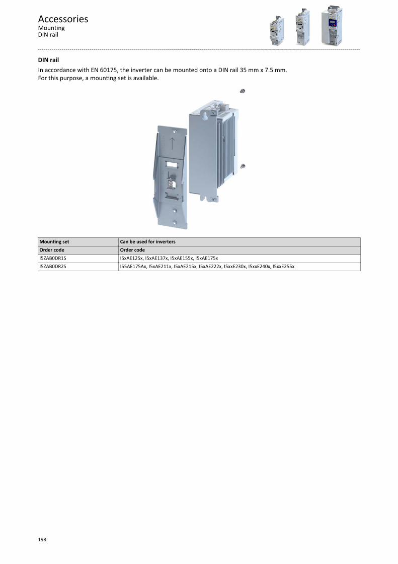
DIN railIn accordance with EN 60175, the inverter can be mounted onto a DIN rail 35 mm x 7.5 mm. For this purpose, a mounting set is available.
Mounting set Can be used for invertersOrder code Order codeI5ZAB0DR1S I5xAE125x, I5xAE137x, I5xAE155x, I5xAE175xI5ZAB0DR2S I55AE175Ax, I5xAE211x, I5xAE215x, I5xAE222x, I5xxE230x, I5xxE240x, I5xxE255x
AccessoriesMountingDIN rail
198
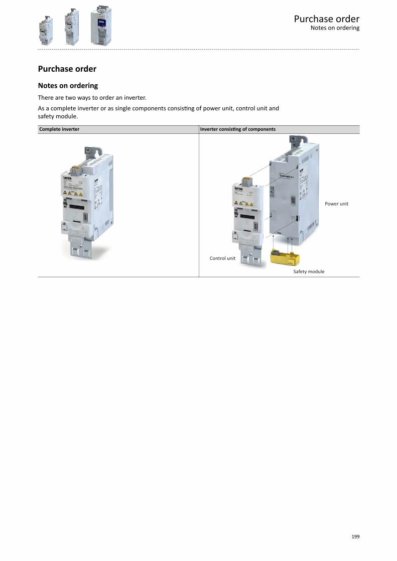
Purchase order
Notes on orderingThere are two ways to order an inverter.As a complete inverter or as single components consisting of power unit, control unit andsafety module.
Complete inverter Inverter consisting of components
Control unit
Power unit
Safety module
Purchase orderNotes on ordering
199
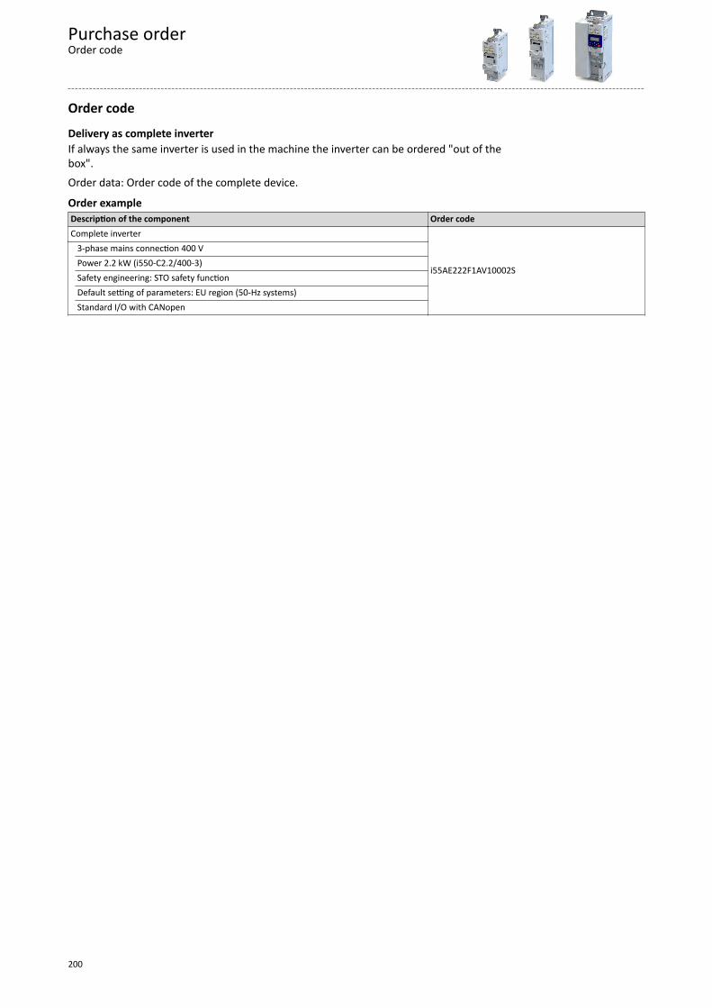
Order code
Delivery as complete inverterIf always the same inverter is used in the machine the inverter can be ordered "out of thebox".Order data: Order code of the complete device.
Order exampleDescription of the component Order codeComplete inverter
i55AE222F1AV10002S
3-phase mains connection 400 V Power 2.2 kW (i550-C2.2/400-3) Safety engineering: STO safety function Default setting of parameters: EU region (50-Hz systems) Standard I/O with CANopen
Purchase orderOrder code
200
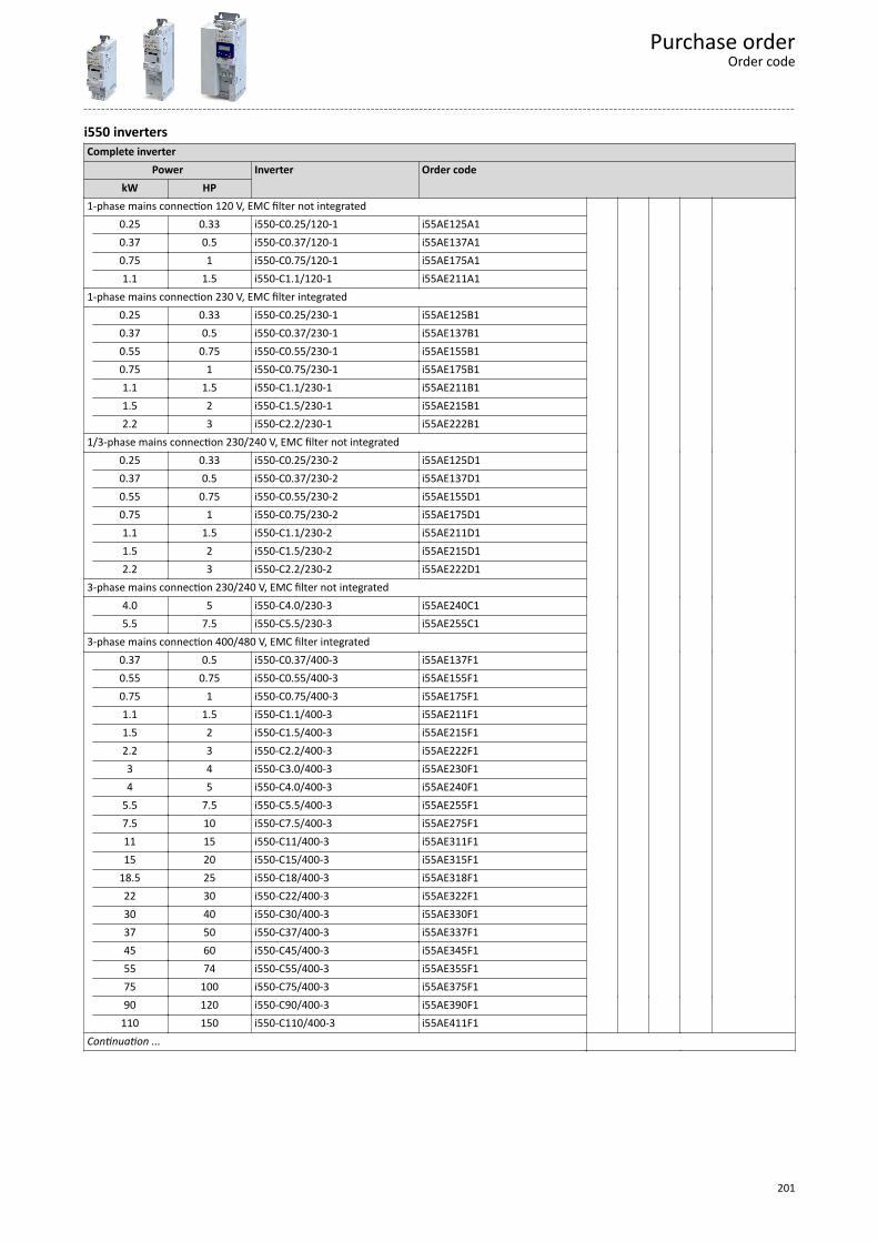
i550 invertersComplete inverter
Power Inverter Order code kW HP 1-phase mains connection 120 V, EMC filter not integrated 0.25 0.33 i550-C0.25/120-1 i55AE125A1
0.37 0.5 i550-C0.37/120-1 i55AE137A10.75 1 i550-C0.75/120-1 i55AE175A11.1 1.5 i550-C1.1/120-1 i55AE211A1
1-phase mains connection 230 V, EMC filter integrated 0.25 0.33 i550-C0.25/230-1 i55AE125B1
0.37 0.5 i550-C0.37/230-1 i55AE137B10.55 0.75 i550-C0.55/230-1 i55AE155B10.75 1 i550-C0.75/230-1 i55AE175B11.1 1.5 i550-C1.1/230-1 i55AE211B11.5 2 i550-C1.5/230-1 i55AE215B12.2 3 i550-C2.2/230-1 i55AE222B1
1/3-phase mains connection 230/240 V, EMC filter not integrated 0.25 0.33 i550-C0.25/230-2 i55AE125D1
0.37 0.5 i550-C0.37/230-2 i55AE137D10.55 0.75 i550-C0.55/230-2 i55AE155D10.75 1 i550-C0.75/230-2 i55AE175D11.1 1.5 i550-C1.1/230-2 i55AE211D11.5 2 i550-C1.5/230-2 i55AE215D12.2 3 i550-C2.2/230-2 i55AE222D1
3-phase mains connection 230/240 V, EMC filter not integrated 4.0 5 i550-C4.0/230-3 i55AE240C1 5.5 7.5 i550-C5.5/230-3 i55AE255C1 3-phase mains connection 400/480 V, EMC filter integrated
0.37 0.5 i550-C0.37/400-3 i55AE137F1 0.55 0.75 i550-C0.55/400-3 i55AE155F10.75 1 i550-C0.75/400-3 i55AE175F11.1 1.5 i550-C1.1/400-3 i55AE211F11.5 2 i550-C1.5/400-3 i55AE215F12.2 3 i550-C2.2/400-3 i55AE222F13 4 i550-C3.0/400-3 i55AE230F14 5 i550-C4.0/400-3 i55AE240F1
5.5 7.5 i550-C5.5/400-3 i55AE255F17.5 10 i550-C7.5/400-3 i55AE275F111 15 i550-C11/400-3 i55AE311F115 20 i550-C15/400-3 i55AE315F1
18.5 25 i550-C18/400-3 i55AE318F122 30 i550-C22/400-3 i55AE322F130 40 i550-C30/400-3 i55AE330F137 50 i550-C37/400-3 i55AE337F145 60 i550-C45/400-3 i55AE345F155 74 i550-C55/400-3 i55AE355F175 100 i550-C75/400-3 i55AE375F190 120 i550-C90/400-3 i55AE390F1
110 150 i550-C110/400-3 i55AE411F1
Continuation ...
Purchase orderOrder code
201
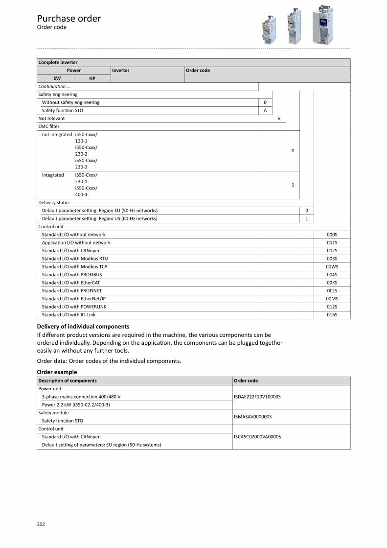
Complete inverterPower Inverter Order code
kW HP Continuation ... Safety engineering
V
Without safety engineering 0
Safety function STO A Not relevant EMC filter not integrated i550-Cxxx/
120-1i550-Cxxx/230-2i550-Cxxx/230-3
0
Integrated i550-Cxxx/230-1i550-Cxxx/400-3
1
Delivery status Default parameter setting: Region EU (50-Hz networks) 0
Default parameter setting: Region US (60-Hz networks) 1 Control unit Standard I/O without network 000SApplication I/O without network 001SStandard I/O with CANopen 002SStandard I/O with Modbus RTU 003SStandard I/O with Modbus TCP 00WSStandard I/O with PROFIBUS 004SStandard I/O with EtherCAT 00KSStandard I/O with PROFINET 00LSStandard I/O with EtherNet/IP 00MSStandard I/O with POWERLINK 012SStandard I/O with IO-Link 016S
Delivery of individual componentsIf different product versions are required in the machine, the various components can beordered individually. Depending on the application, the components can be plugged togethereasily an without any further tools.Order data: Order codes of the individual components.
Order exampleDescription of components Order codePower unit
I5DAE222F10V10000S 3-phase mains connection 400/480 V Power 2.2 kW (i550-C2.2/400-3)Safety module
I5MASAV000000S Safety function STOControl unit
I5CA5C02000VA0000S Standard I/O with CANopen Default setting of parameters: EU region (50-Hz systems)
Purchase orderOrder code
202
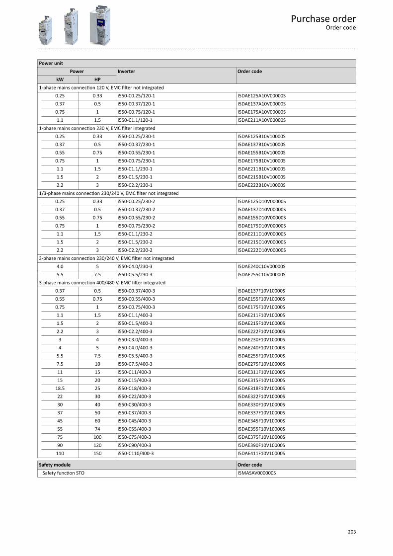
Power unitPower Inverter Order code
kW HP 1-phase mains connection 120 V, EMC filter not integrated 0.25 0.33 i550-C0.25/120-1 I5DAE125A10V00000S
0.37 0.5 i550-C0.37/120-1 I5DAE137A10V00000S0.75 1 i550-C0.75/120-1 I5DAE175A10V00000S1.1 1.5 i550-C1.1/120-1 I5DAE211A10V00000S
1-phase mains connection 230 V, EMC filter integrated 0.25 0.33 i550-C0.25/230-1 I5DAE125B10V10000S
0.37 0.5 i550-C0.37/230-1 I5DAE137B10V10000S0.55 0.75 i550-C0.55/230-1 I5DAE155B10V10000S0.75 1 i550-C0.75/230-1 I5DAE175B10V10000S1.1 1.5 i550-C1.1/230-1 I5DAE211B10V10000S1.5 2 i550-C1.5/230-1 I5DAE215B10V10000S2.2 3 i550-C2.2/230-1 I5DAE222B10V10000S
1/3-phase mains connection 230/240 V, EMC filter not integrated 0.25 0.33 i550-C0.25/230-2 I5DAE125D10V00000S
0.37 0.5 i550-C0.37/230-2 I5DAE137D10V00000S0.55 0.75 i550-C0.55/230-2 I5DAE155D10V00000S0.75 1 i550-C0.75/230-2 I5DAE175D10V00000S1.1 1.5 i550-C1.1/230-2 I5DAE211D10V00000S1.5 2 i550-C1.5/230-2 I5DAE215D10V00000S2.2 3 i550-C2.2/230-2 I5DAE222D10V00000S
3-phase mains connection 230/240 V, EMC filter not integrated 4.0 5 i550-C4.0/230-3 I5DAE240C10V00000S 5.5 7.5 i550-C5.5/230-3 I5DAE255C10V00000S3-phase mains connection 400/480 V, EMC filter integrated 0.37 0.5 i550-C0.37/400-3 I5DAE137F10V10000S
0.55 0.75 i550-C0.55/400-3 I5DAE155F10V10000S0.75 1 i550-C0.75/400-3 I5DAE175F10V10000S1.1 1.5 i550-C1.1/400-3 I5DAE211F10V10000S1.5 2 i550-C1.5/400-3 I5DAE215F10V10000S2.2 3 i550-C2.2/400-3 I5DAE222F10V10000S3 4 i550-C3.0/400-3 I5DAE230F10V10000S4 5 i550-C4.0/400-3 I5DAE240F10V10000S
5.5 7.5 i550-C5.5/400-3 I5DAE255F10V10000S7.5 10 i550-C7.5/400-3 I5DAE275F10V10000S11 15 i550-C11/400-3 I5DAE311F10V10000S15 20 i550-C15/400-3 I5DAE315F10V10000S
18.5 25 i550-C18/400-3 I5DAE318F10V10000S22 30 i550-C22/400-3 I5DAE322F10V10000S30 40 i550-C30/400-3 I5DAE330F10V10000S37 50 i550-C37/400-3 I5DAE337F10V10000S45 60 i550-C45/400-3 I5DAE345F10V10000S
55 74 i550-C55/400-3 I5DAE355F10V10000S75 100 i550-C75/400-3 I5DAE375F10V10000S90 120 i550-C90/400-3 I5DAE390F10V10000S
110 150 i550-C110/400-3 I5DAE411F10V10000S
Safety module Order code Safety function STO I5MASAV000000S
Purchase orderOrder code
203
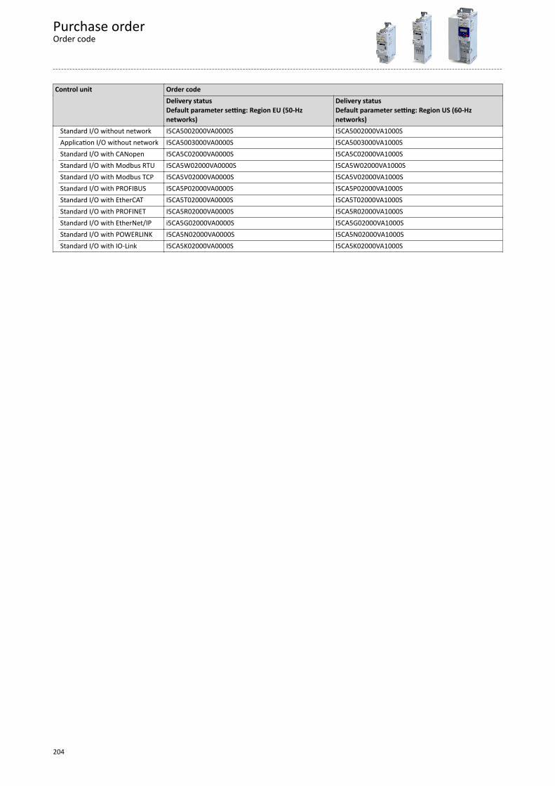
Control unit Order code Delivery status
Default parameter setting: Region EU (50-Hznetworks)
Delivery statusDefault parameter setting: Region US (60-Hznetworks)
Standard I/O without network I5CA5002000VA0000S I5CA5002000VA1000S Application I/O without network I5CA5003000VA0000S I5CA5003000VA1000S Standard I/O with CANopen I5CA5C02000VA0000S I5CA5C02000VA1000S Standard I/O with Modbus RTU I5CA5W02000VA0000S I5CA5W02000VA1000S Standard I/O with Modbus TCP I5CA5V02000VA0000S I5CA5V02000VA1000S Standard I/O with PROFIBUS I5CA5P02000VA0000S I5CA5P02000VA1000S Standard I/O with EtherCAT I5CA5T02000VA0000S I5CA5T02000VA1000S Standard I/O with PROFINET I5CA5R02000VA0000S I5CA5R02000VA1000S Standard I/O with EtherNet/IP i5CA5G02000VA0000S I5CA5G02000VA1000S Standard I/O with POWERLINK I5CA5N02000VA0000S I5CA5N02000VA1000S Standard I/O with IO-Link I5CA5K02000VA0000S I5CA5K02000VA1000S
Purchase orderOrder code
204
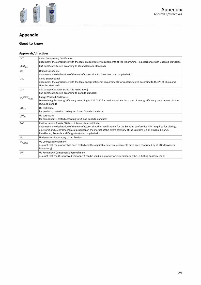
Appendix
Good to know
Approvals/directivesCCC China Compulsory Certification
documents the compliance with the legal product safety requirements of the PR of China - in accordance with Guobiao standards.
CCSAUS CSA certificate, tested according to US and Canada standards
UE Union Européennedocuments the declaration of the manufacturer that EU Directives are complied with.
CEL China Energy Labeldocuments the compliance with the legal energy efficiency requirements for motors, tested according to the PR of China andGuobiao standards
CSA CSA Group (Canadian Standards Association)CSA certificate, tested according to Canada standards
ULEnergyUS CA
Energy Verified CertificateDetermining the energy efficiency according to CSA C390 for products within the scope of energy efficiency requirements in theUSA and Canada
CULUS UL certificatefor products, tested according to US and Canada standards
CURUS UL certificatefor components, tested according to US and Canada standards
EAC Customs union Russia / Belarus / Kazakhstan certificatedocuments the declaration of the manufacturer that the specifications for the Eurasian conformity (EAC) required for placingelectronic and electromechanical products on the market of the entire territory of the Customs Union (Russia, Belarus,Kazakhstan, Armenia and Kyrgyzstan) are complied with.
UL Underwriters Laboratory Listed ProductULLISTED UL Listing approval mark
as proof that the product has been tested and the applicable safety requirements have been confirmed by UL (UnderwritersLaboratory).
UR UL Recognized Component approval markas proof that the UL approved component can be used in a product or system bearing the UL Listing approval mark.
AppendixApprovals/directives
205
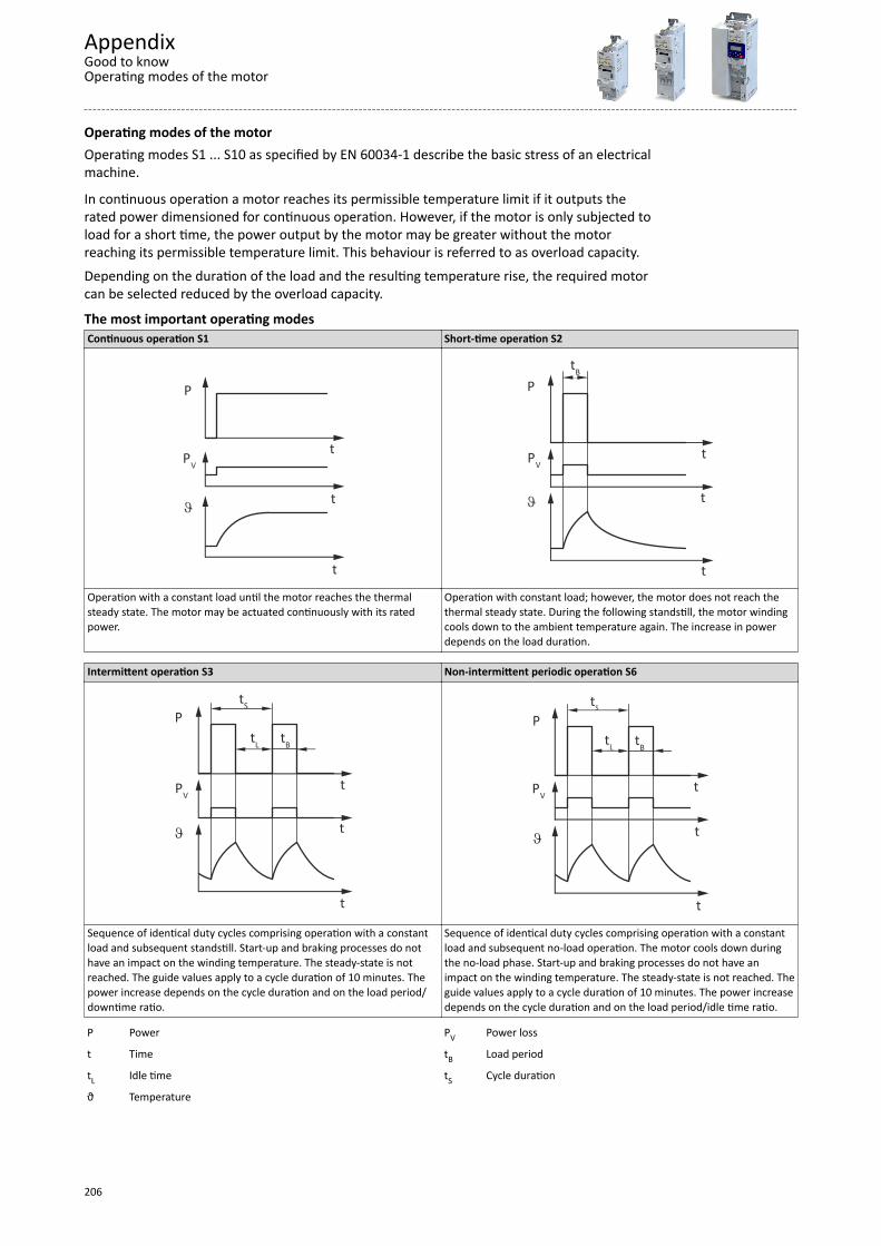
Operating modes of the motorOperating modes S1 ... S10 as specified by EN 60034-1 describe the basic stress of an electricalmachine.
In continuous operation a motor reaches its permissible temperature limit if it outputs therated power dimensioned for continuous operation. However, if the motor is only subjected toload for a short time, the power output by the motor may be greater without the motorreaching its permissible temperature limit. This behaviour is referred to as overload capacity.Depending on the duration of the load and the resulting temperature rise, the required motorcan be selected reduced by the overload capacity.
The most important operating modesContinuous operation S1 Short-time operation S2
P
PV
t
t
t
J
P
PVt
t
t
J
tB
Operation with a constant load until the motor reaches the thermalsteady state. The motor may be actuated continuously with its ratedpower.
Operation with constant load; however, the motor does not reach thethermal steady state. During the following standstill, the motor windingcools down to the ambient temperature again. The increase in powerdepends on the load duration.
Intermittent operation S3 Non-intermittent periodic operation S6
P
PVt
t
t
J
tS
tL tB
P
PVt
t
t
J
tS
tL tB
Sequence of identical duty cycles comprising operation with a constantload and subsequent standstill. Start-up and braking processes do nothave an impact on the winding temperature. The steady-state is notreached. The guide values apply to a cycle duration of 10 minutes. Thepower increase depends on the cycle duration and on the load period/downtime ratio.
Sequence of identical duty cycles comprising operation with a constantload and subsequent no-load operation. The motor cools down duringthe no-load phase. Start-up and braking processes do not have animpact on the winding temperature. The steady-state is not reached. Theguide values apply to a cycle duration of 10 minutes. The power increasedepends on the cycle duration and on the load period/idle time ratio.
P Power PV Power loss
t Time tB Load period
tL Idle time tS Cycle duration
ϑ Temperature
AppendixGood to knowOperating modes of the motor
206
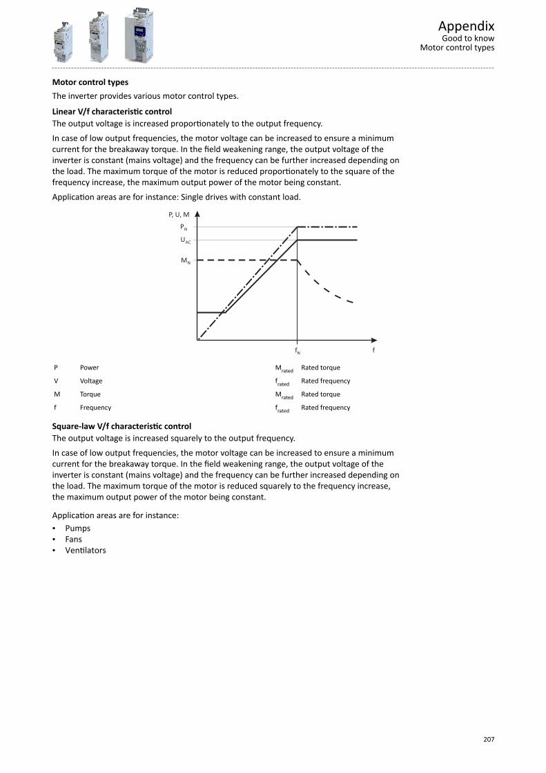
Motor control typesThe inverter provides various motor control types.
Linear V/f characteristic controlThe output voltage is increased proportionately to the output frequency.In case of low output frequencies, the motor voltage can be increased to ensure a minimumcurrent for the breakaway torque. In the field weakening range, the output voltage of theinverter is constant (mains voltage) and the frequency can be further increased depending onthe load. The maximum torque of the motor is reduced proportionately to the square of thefrequency increase, the maximum output power of the motor being constant.Application areas are for instance: Single drives with constant load.
fN f
P, U, M
MN
UAC
PN
P Power Mrated Rated torque
V Voltage frated Rated frequency
M Torque Mrated Rated torque
f Frequency frated Rated frequency
Square-law V/f characteristic controlThe output voltage is increased squarely to the output frequency.In case of low output frequencies, the motor voltage can be increased to ensure a minimumcurrent for the breakaway torque. In the field weakening range, the output voltage of theinverter is constant (mains voltage) and the frequency can be further increased depending onthe load. The maximum torque of the motor is reduced squarely to the frequency increase,the maximum output power of the motor being constant.
Application areas are for instance:• Pumps• Fans• Ventilators
AppendixGood to know
Motor control types
207
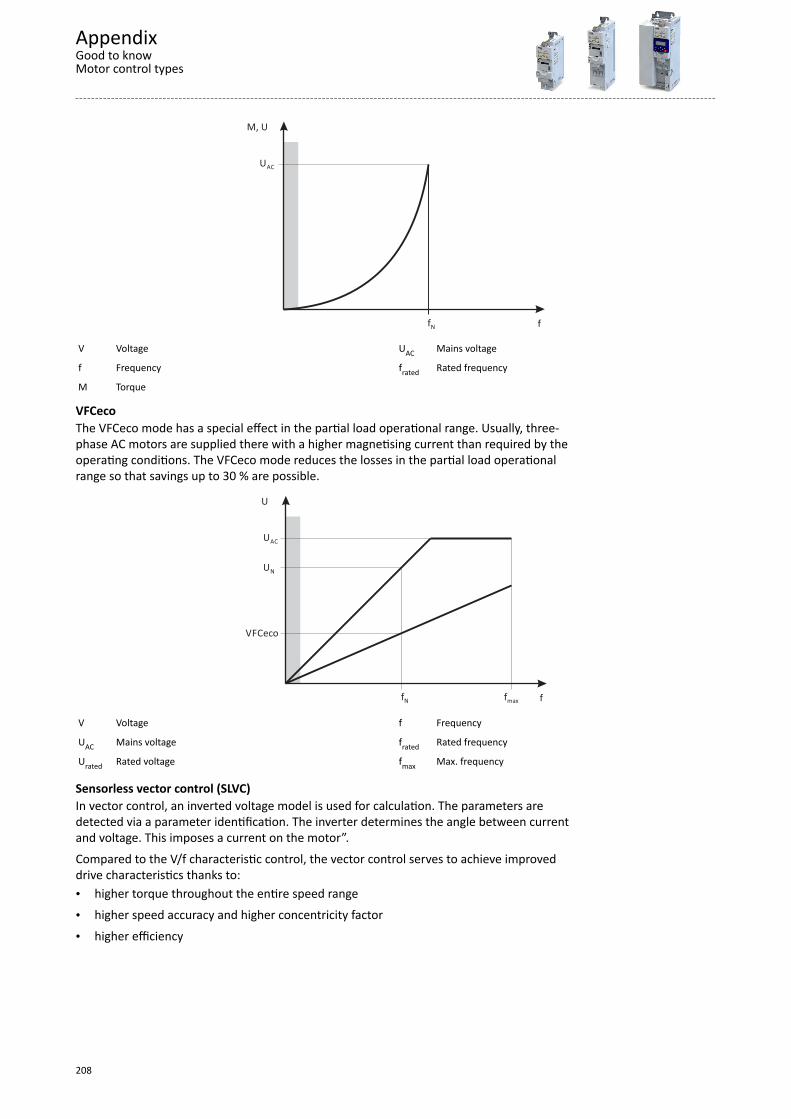
f
M, U
UAC
fN
V Voltage UAC Mains voltage
f Frequency frated Rated frequency
M Torque
VFCecoThe VFCeco mode has a special effect in the partial load operational range. Usually, three-phase AC motors are supplied there with a higher magnetising current than required by theoperating conditions. The VFCeco mode reduces the losses in the partial load operationalrange so that savings up to 30 % are possible.
f
U
UN
UAC
fN fmax
VFCeco
V Voltage f Frequency
UAC Mains voltage frated Rated frequency
Urated Rated voltage fmax Max. frequency
Sensorless vector control (SLVC)In vector control, an inverted voltage model is used for calculation. The parameters aredetected via a parameter identification. The inverter determines the angle between currentand voltage. This imposes a current on the motor”.Compared to the V/f characteristic control, the vector control serves to achieve improveddrive characteristics thanks to:• higher torque throughout the entire speed range• higher speed accuracy and higher concentricity factor• higher efficiency
AppendixGood to knowMotor control types
208
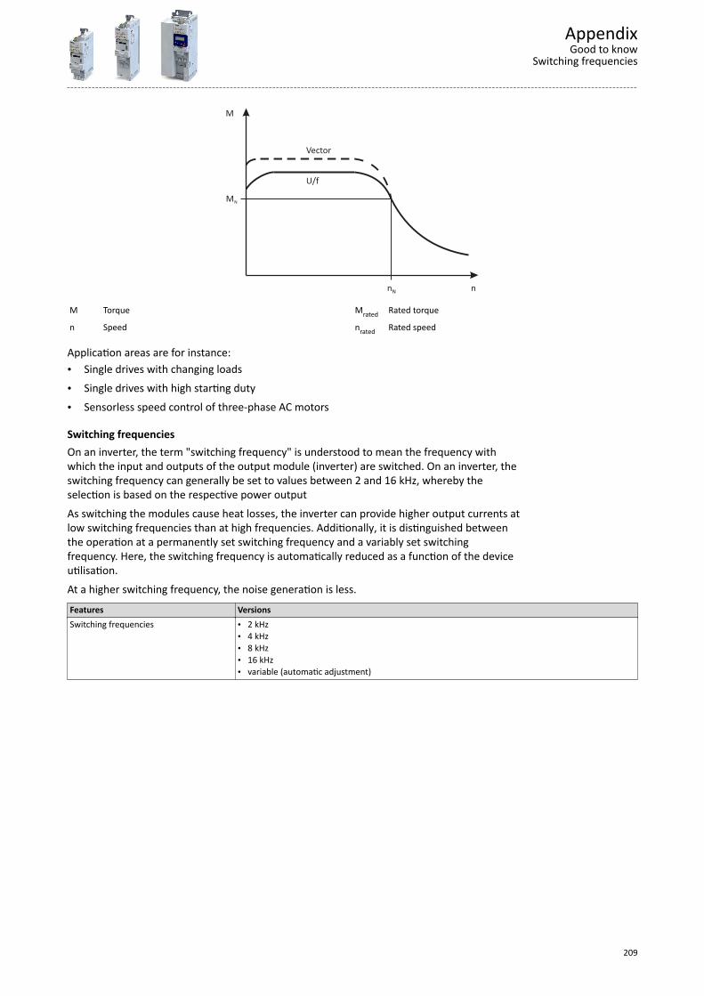
nN n
M
MN
U/f
Vector
M Torque Mrated Rated torque
n Speed nrated Rated speed
Application areas are for instance:• Single drives with changing loads• Single drives with high starting duty• Sensorless speed control of three-phase AC motors
Switching frequenciesOn an inverter, the term "switching frequency" is understood to mean the frequency withwhich the input and outputs of the output module (inverter) are switched. On an inverter, theswitching frequency can generally be set to values between 2 and 16 kHz, whereby theselection is based on the respective power outputAs switching the modules cause heat losses, the inverter can provide higher output currents atlow switching frequencies than at high frequencies. Additionally, it is distinguished betweenthe operation at a permanently set switching frequency and a variably set switchingfrequency. Here, the switching frequency is automatically reduced as a function of the deviceutilisation.At a higher switching frequency, the noise generation is less.Features VersionsSwitching frequencies • 2 kHz
• 4 kHz• 8 kHz• 16 kHz• variable (automatic adjustment)
AppendixGood to know
Switching frequencies
209
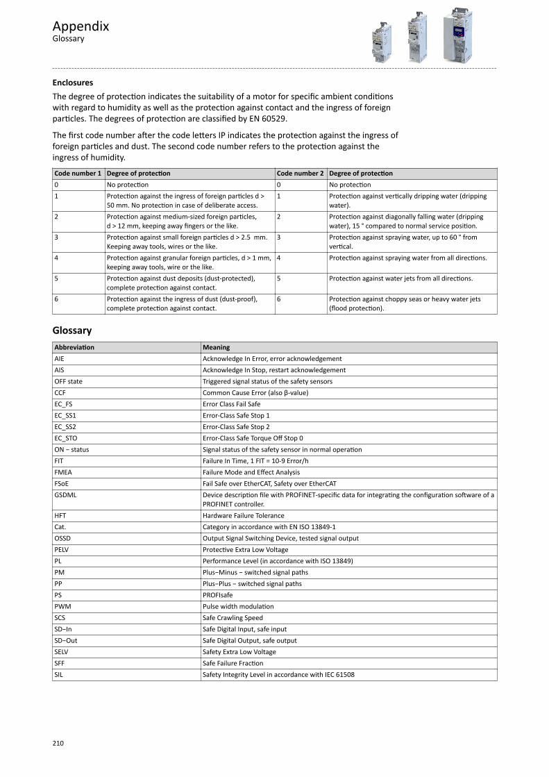
EnclosuresThe degree of protection indicates the suitability of a motor for specific ambient conditionswith regard to humidity as well as the protection against contact and the ingress of foreignparticles. The degrees of protection are classified by EN 60529.
The first code number after the code letters IP indicates the protection against the ingress offoreign particles and dust. The second code number refers to the protection against theingress of humidity.Code number 1 Degree of protection Code number 2 Degree of protection0 No protection 0 No protection1 Protection against the ingress of foreign particles d >
50 mm. No protection in case of deliberate access.1 Protection against vertically dripping water (dripping
water).2 Protection against medium-sized foreign particles,
d > 12 mm, keeping away fingers or the like.2 Protection against diagonally falling water (dripping
water), 15 ° compared to normal service position.3 Protection against small foreign particles d > 2.5 mm.
Keeping away tools, wires or the like.3 Protection against spraying water, up to 60 ° from
vertical.4 Protection against granular foreign particles, d > 1 mm,
keeping away tools, wire or the like.4 Protection against spraying water from all directions.
5 Protection against dust deposits (dust-protected),complete protection against contact.
5 Protection against water jets from all directions.
6 Protection against the ingress of dust (dust-proof),complete protection against contact.
6 Protection against choppy seas or heavy water jets(flood protection).
GlossaryAbbreviation MeaningAIE Acknowledge In Error, error acknowledgementAIS Acknowledge In Stop, restart acknowledgementOFF state Triggered signal status of the safety sensorsCCF Common Cause Error (also β-value)EC_FS Error Class Fail SafeEC_SS1 Error-Class Safe Stop 1EC_SS2 Error-Class Safe Stop 2EC_STO Error-Class Safe Torque Off Stop 0ON − status Signal status of the safety sensor in normal operationFIT Failure In Time, 1 FIT = 10-9 Error/hFMEA Failure Mode and Effect AnalysisFSoE Fail Safe over EtherCAT, Safety over EtherCATGSDML Device description file with PROFINET-specific data for integrating the configuration software of a
PROFINET controller.HFT Hardware Failure ToleranceCat. Category in accordance with EN ISO 13849-1OSSD Output Signal Switching Device, tested signal outputPELV Protective Extra Low VoltagePL Performance Level (in accordance with ISO 13849)PM Plus−Minus − switched signal pathsPP Plus−Plus − switched signal pathsPS PROFIsafePWM Pulse width modulationSCS Safe Crawling SpeedSD−In Safe Digital Input, safe inputSD−Out Safe Digital Output, safe outputSELV Safety Extra Low VoltageSFF Safe Failure FractionSIL Safety Integrity Level in accordance with IEC 61508
AppendixGlossary
210


Ö Lenze Drives GmbHPostfach 10 13 52, D-31763 HamelnBreslauer Straße 3, D-32699 ExtertalGermanyHR Lemgo B 6478
Ü +49 5154 82-0Ø +49 5154 82-2800Ù [email protected]Ú www.lenze.com
© 12/2019 | | 8.1