project report on - weeblynaresh1990.weebly.com/uploads/3/7/7/2/3772230/final_year_proj.pdf ·...
TRANSCRIPT
Manufacturing of
Project submitted in partial BACHELOR OF ENGINEERING
Prof. S.V. Ranade
(Internal Guide)
Department of Chemical Engineering
Mahatma Gandhi Mission’s College of Engineering
PROJECT REPORT ON
Manufacturing of Liquefied Petroleum Gas (LPG)
ubmitted in partial fulfilment of the requirement for the degree ofBACHELOR OF ENGINEERING (CHEMICAL)
University of Mumbai
By:
Rahul N Singh
Yatish Sharma
Under the Guidance of:
Mr. A.G. Dahake
(External Guide)
Department of Chemical Engineering
Mahatma Gandhi Mission’s College of Engineering & T echnology
Kamothe, Navi Mumbai
2010-2011
1
of the requirement for the degree of
Mr. A.G. Dahake
(External Guide)
echnology
MAHATMA GANDHI MISSION’SCOLLEGE OF ENGINEERING & TECHNOLOGY
(Affiliated to University of Mumbai)At NH-4 junction, Sion Panvel
This is to certify that
1. Rahul N. Singh 2. Yatish Sharma
have satisfactorily carried out their project work for B.E., semester VII on the pro“MANUFACTURING OF LIQUEFIED PETROLEUM GAS (LPG)
This is in partial fulfilment of the requirement towards the award of Bachelor’s degree in Chemical Engineering course.
Prof. S.V. Ranade Project Guide
Dr. C.K. Mistry H.O.D
MAHATMA GANDHI MISSION’S COLLEGE OF ENGINEERING & TECHNOLOGY
(Affiliated to University of Mumbai) 4 junction, Sion Panvel Expressway, Navi Mumbai-410209
CERTIFICATECERTIFICATECERTIFICATECERTIFICATE
have satisfactorily carried out their project work for B.E., semester VII on the pro“MANUFACTURING OF LIQUEFIED PETROLEUM GAS (LPG) ”.
of the requirement towards the award of Bachelor’s degree in
Examiner(s)
Principal
2
410209
have satisfactorily carried out their project work for B.E., semester VII on the project titled
of the requirement towards the award of Bachelor’s degree in
Examiner(s)
3
ACKNOWLEDGEMENT
Acknowledgement, not being just a formality, we express our sincere gratitude and thanks to
all those who are responsible for our project. Sincerely we express our gratitude to our guide
and well –wishers. Without them we would not have been able to move a single step ahead.
A special thank you to Mr. S.V.Ranade our technical guide for her constant support to our
project and our professors for believing in our ability to do what we aspire.
We are highly obliged to our Head of Department Mr. C.K.Mistri for his timely advice,
which has helped us in the progress of our project work.
Special thanks to Mr. A.G. Dahake (DGM-Production, ONGC Uran Plant) for allowing us to
develop our project with their organisation and guiding us in the right direction. Last but not
least, informal thanks to all our well wishers and friends who are directly or in directly
helping us on our project.
4
TABLE OF CONTENTS
1. INTRODUCTION............................................................................................................7
1.1 History…………………………………………................................................7
1.2 Physical And Chemical Properties……………................................................10
2. LITREATURE SURVEY…..............................................................................................12
2.1 LPG Subsides in India…..............................................................................................12
2.2 Indian LPG Scenario…................................................................................................17
2.3 Gap between Demand and Supply…...........................................................................18
2.4 Consumption Pattern…………………................................................................……19
3. MANUGACTURING PROCESSES…............................................................................20
3.1 Hydro cracking process for production of LPG and distillate hydrocarbon…..…20
3.2 Catalytic Reforming for production of LPG..................................................21
3.3 Recovery from Natural Gas........................................................................23
4. SELECTION OF MANUFACTURING PROCESS...............................................24
4.1 Recovery and Manufacture in the Refinery.................................................24
4.1.1 Re-Contacting-Compression…………………………................…….25
4.1.2 Refrigeration……………................................................………….26
4.1.3 Lean OIL Absorption…. ……………….........................................…31
4.1.4 Adsorption………………………..........................................………33
4.1.5 Purification…………………..................................................…….35
5. INTRODUCTION TO ONGC, URAN PLANT….................................................37
5.1 General…………………………..............................................................…37
5.2 Slug Catcher……………….......................................................…….….….38
5.3 Oil and Gas processing Facilities…………….….........................................39
5.4 Process Description of LPG Plant………………….....................................40
5.4.1 Feed Gas Supply/Pre-cooling………………………..........................42
5.4.2 Feed Gas Drying………………………...........................................43
5.4.3 Feed Gas Chill Down……………………….....................................43
5.4.4 LEF Column………………………................................................45
5
5.4.5 LPG Column…………………….......................................................46
5.4.6 Propane Column…………………………….....................................47
5.4.7 Refrigeration System…………………………................................48
6. THERMODYNAMIC PROPERTY……………………..........................................50
6.1 For Commercial Propane…………………...................................................51
6.2 For Commercial Butane……………………….............................................52
7. MATERIAL BALANCE…………………………………….....................................53
8. DESIGN……………………………………..............................................................57
8.1 Basis of Design……………………………...................................................57
8.2 Bubble point and Dew point calculation for LEF Column………………......57
8.2.1 Dew Point Determination……………………….............................57
8.2.2 Bubble Point Determination………………………….....................58
8.3 Bubble point and Dew point calculation for LPG Column………………......60
8.3.1 Dew Point Determination………………………..............................60
8.3.2 Bubble Point Determination………………………..........................60
8.4 Mechanical Design of LEF Column……………………………………………62
8.4.1 Thickness of Shell…………………………………………………….63
8.4.2 Selection of Head………………………………………………………63
8.4.3 Nozzle Thickness………………………………………………………64
9. SIMULATION OF LPG PLANT USING HYSYS 3.1…........................................65
10. COST ESTIMATION………………………………………....................................84
10.1 Factors affecting Investment and Production Costs……………………………84
10.1.1 Source of Equipment……………................................................84
10.1.2 Price Fluctuations…………….......................................................84
10.1.3 Company Policies………………..................................................84
10.1.4 Operating time and Cost of Equipment………………..................85
10.1.5 Government Policies………………………..................................84
10.2 Basis of Cost Estimation……………………………..................................86
10.3 Cost Summary (Plant & Machinery)…………………................................88
10.4 Project Cost……………………………………...........................................89
10.5 Operating Cost………………………………………...................................90
10.6 Revenue of Plant per day………………………………….............................91
11. PLANT LOCATION AND SITE SELECTION……………………………... .........92
11.1 Marketing Area………………...................................................................92
6
11.2 Raw Material……………………................................................................92
11.3 Transportation……………………………………........................................93
11.4 Availability of Labour……………….........................................................93
11.5 Utilities……………………........................................................................93
11.6 Effluent Disposal……………………….....................................................94
11.7 Local Community Consideration………………………..............................94
11.8 Land (Site Considering)……………………...............................................94
11.9 Climate…………………….......................................................................95
11.10 Political and Strategic Consideration…………………………....................95
12. LOCATION AND PLANT LAYOUT……………………………........... .................96
13. SAFETY AND HAZARDS FACTORS………………...........................................98
13.1 Introduction……………………….............................................................98
13.2 General Hazards in LPG recovery Plant…………………………..................98
13.3 Hazards of Petroleum Products…………………………..............................98
13.3.1 Classification of Hazardous Zone…………....................................98
13.4 Physiological Effects……………………....................................................99
13.5 Explosion Fire……………………………...................................................98
13.5.1 Explosive Limits of Hydrocarbon…………………….......................99
13.5.2 Sources of Heat and Open flames………………….......................100
13.5.3 Auto Ignition…………………....................................................100
13.5.4 Sparks……………………….........................................................100
13.5.5 Lightning…………………………................................................101
13.5.6 Static Electric Charge…………………….......................................101
ANNEXURES
Annexure I (List of Equipments)……………………........................................102
Annexure II (Equipment Layout)…………………………................................106
Annexure III (MSDS for LPG Plant).............................................................107
Annexure IV (PnID’s)………………………………….....................................117
BIBLIOGRAPHY………………………………………………….....................118
7
CHAPTER-1
INTRODUCTION
1.1 HISTORY
LPG was a late developer in the oil and gas business. The history of LPG can be traced back
to the beginning of the 20th Century. In the early production of gasoline, one problem faced
was that gasoline quickly evaporated when in storage. In 1911, an American chemist, Dr.
Walter Snelling, identified that the propane and butane within gasoline caused its
evaporation. He soon developed a practical method of removing these gases from the
gasoline.
The first commercial production of LPG had to wait until the 1920's, while the first regional
trade until the 1950's. The extensive use of LPG did not really develop until the 1940's
through the 1960's.
A large oil company introduced LPG to France in the mid 1930's. And a large gas company
built a bottling plant in Italy, near Venice, in 1938. But developments then were cut off by the
war.
By the early 1950's, companies were producing LPG cylinders for household use and these
were being marketed elsewhere under license.
Growth proceeded at the pace of refinery availabilities. These expanded, particularly in the
1960's, as new refineries were built and fuel oil displaced coal as the industrial fuel. Europe-
wide LPG sales increased from 300,000 tons in 1950, 3 million tons in 1960, and 11 million
tons in 1970.
Prior to the 1970's, LPG in international trade had been essentially a regional business, with
each region having its own pricing structure, shipping, and buyers and sellers. The first
regional trade, starting in the 1950's, had been from the US Gulf to South America.
The oil crisis of 1973 was a turning point. Many oil rich countries built liquids recovery
plants as they realised that the exports of LPG could generate a significant monetary return.
The expansion of Middle East LPG capacity which occurred over the 1975-1985 decade was
truly staggering - from a total of 6 million tons of installed capacity in 1975 to 17 million
tons by 1980 and 30 million tons by 1985. It was not only in the Middle East that LPG plants
8
were being built. Australia, Indonesia, Algeria, the North Sea, and Venezuela were also new
sources of supply. The 1980's in fact turned out to be a period of tremendous LPG exports
expansion worldwide. The LPG market became truly global at this time. Producers needed
buyers, whether they are in Asia, Europe, the United States, or South America. The new
export volumes had to find outlets somewhere.
Liquefied Petroleum Gas (LPG)
Liquefied Petroleum Gas (LPG), also known as propane, is a non-renewable gaseous fossil
fuel. LPG, a by-product of natural gas processing and oil refining, includes various mixtures
of hydrocarbons. The term liquefied petroleum gas (LPG) describes hydrocarbon mixtures in
which the main components are propane, butane, iso-butane, propene, and butenes
(butylenes). Most commonly this term is applied to mixtures of propane and butane. These
components and mixtures thereof are gaseous at normal temperature and pressure but can be
liquefied by cooling, compression, or a combination of both processes.
Commercial propane and, to a lesser extent, butane are the principal LPG products.
Commercial propane, however, is not a pure product but a mixture of LPG products, with the
primary component being propane (commercial LPG is generally more than 90 percent
propane). It may also contain up to 7 or 8 percent ethane, a neo-cryogenic hydrocarbon.
Liquefied petroleum gas is produced from two distinct sources. The first is by extraction
from crude oil and natural gas streams at or close to the point of production from the
reservoir and contains propane and butane. The quantities of LPG in the well stream fluid
vary greatly, depending on the nature of the reservoir. Production may be (1) of natural gas
from a gas reservoir, (2) of gas and light liquid hydrocarbons from a gas condensate reservoir
or (3) of crude oil and gas from a combined oil and gas field. The extent of recovery of LPG
and heavier hydrocarbons from gas depends on the composition of the gas produced and the
quality specifications of the gas to be transported to the consumer.
LPG is a low-carbon-emitting hydrocarbon fuel available in rural areas, emitting 81% of the
CO2 per kWh produced by oil, 70% of that of coal, and less than 50% of that emitted by coal-
generated electricity distributed via the grid. Being a mixture of propane and butane, LPG
emits less carbon per joule than butane but more carbon per joule than propane. As a low-
carbon, low-polluting fossil fuel, LPG is recognised by governments around the world for the
contribution it can make towards improved indoor and outdoor air quality and reduced
9
greenhouse gas emissions. LPG is widely available and can be used for hundreds of
commercial and domestic applications. LPG is also used alongside renewable technologies,
as well as with decentralized electricity generation to help reduce carbon emissions on a local
level
1.2 PHYSICAL AND CHEMICAL PROPERTIES
Physical Properties
10
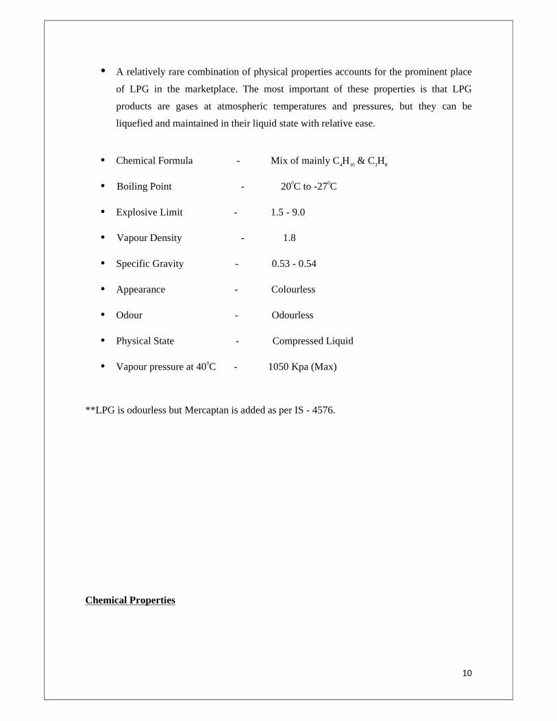
• A relatively rare combination of physical properties accounts for the prominent place
of LPG in the marketplace. The most important of these properties is that LPG
products are gases at atmospheric temperatures and pressures, but they can be
liquefied and maintained in their liquid state with relative ease.
• Chemical Formula - Mix of mainly C4H10 & C3H8
• Boiling Point - 200C to -270C
• Explosive Limit - 1.5 - 9.0
• Vapour Density - 1.8
• Specific Gravity - 0.53 - 0.54
• Appearance - Colourless
• Odour - Odourless
• Physical State - Compressed Liquid
• Vapour pressure at 400C - 1050 Kpa (Max)
**LPG is odourless but Mercaptan is added as per IS - 4576.
Chemical Properties
11
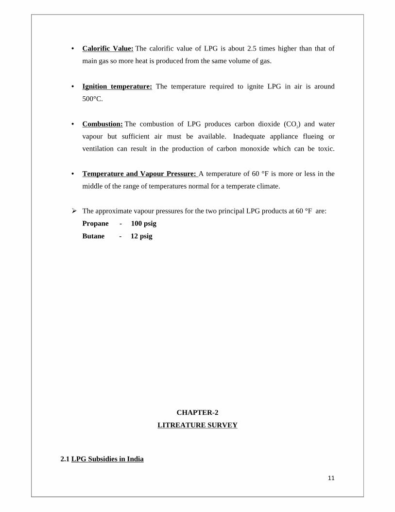
• Calorific Value: The calorific value of LPG is about 2.5 times higher than that of
main gas so more heat is produced from the same volume of gas.
• Ignition temperature: The temperature required to ignite LPG in air is around
500°C.
• Combustion: The combustion of LPG produces carbon dioxide (CO2) and water
vapour but sufficient air must be available. Inadequate appliance flueing or
ventilation can result in the production of carbon monoxide which can be toxic.
• Temperature and Vapour Pressure: A temperature of 60 °F is more or less in the
middle of the range of temperatures normal for a temperate climate.
� The approximate vapour pressures for the two principal LPG products at 60 °F are:
Propane - 100 psig
Butane - 12 psig
CHAPTER-2
LITREATURE SURVEY
2.1 LPG Subsidies in India
12
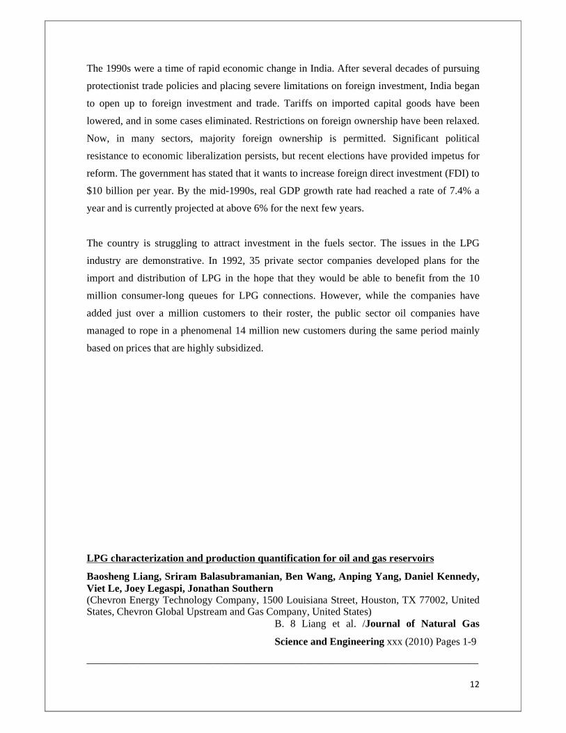
The 1990s were a time of rapid economic change in India. After several decades of pursuing
protectionist trade policies and placing severe limitations on foreign investment, India began
to open up to foreign investment and trade. Tariffs on imported capital goods have been
lowered, and in some cases eliminated. Restrictions on foreign ownership have been relaxed.
Now, in many sectors, majority foreign ownership is permitted. Significant political
resistance to economic liberalization persists, but recent elections have provided impetus for
reform. The government has stated that it wants to increase foreign direct investment (FDI) to
$10 billion per year. By the mid-1990s, real GDP growth rate had reached a rate of 7.4% a
year and is currently projected at above 6% for the next few years.
The country is struggling to attract investment in the fuels sector. The issues in the LPG
industry are demonstrative. In 1992, 35 private sector companies developed plans for the
import and distribution of LPG in the hope that they would be able to benefit from the 10
million consumer-long queues for LPG connections. However, while the companies have
added just over a million customers to their roster, the public sector oil companies have
managed to rope in a phenomenal 14 million new customers during the same period mainly
based on prices that are highly subsidized.
LPG characterization and production quantification for oil and gas reservoirs
Baosheng Liang, Sriram Balasubramanian, Ben Wang, Anping Yang, Daniel Kennedy, Viet Le, Joey Legaspi, Jonathan Southern (Chevron Energy Technology Company, 1500 Louisiana Street, Houston, TX 77002, United States, Chevron Global Upstream and Gas Company, United States)
B. 8 Liang et al. /Journal of Natural Gas
Science and Engineering xxx (2010) Pages 1-9
___________________________________________________________________________
13
Abstract
Liquefied petroleum gas (LPG) refers to the gas extracted and liquefied from the separator
gas in a processing plant and mainly consists of propane (C3) and butane (C4). Many offshore
projects have restrictions on flaring gases and special fiscal terms make extracted liquids
significantly more valuable than oil and condensate in some cases, which in turn impact the
economics of many projects.
This paper for the first time systematically investigates LPG characterization and production
quantification coupled together with reservoir simulation. Detailed calculations of LPG yields
from both gas cap and solution gas are given. LPG yield of fluid is a function of the initial
gas oil ratio (GOR), gas specific gravity, and separator condition: LPG yield, which is lower
in the gas cap, compared to the solution gas of the same reservoir, has a good correlation with
gas specific gravity and is impacted by separator conditions.
The concept of LPG-produced GOR correlation curve is introduced and applied together with
gas production rate to predict LPG production. Correlation curves depend on reservoir fluid
properties and development strategies. Generated from flashing the mixtures of different
proportions of oil and gas samples, LPG-produced GOR correlation curve has a good
agreement with the results from reservoir compositional simulation and can be coupled with
various forecasting tools in reservoir engineering.
Lean gas injection has an insignificant impact on LPG recovery but can substantially improve
the recovery of total liquid (oil and condensate). The paper also shows that lumping C3 and C4
as one pseudo component is suitable.
Modelling of thermal cracking of LPG: Application of artificial neural network in
prediction of the main product yields
R. Nabavi, A. Niaei, D. Salari, J. Towfighi
(Petroleum Research Laboratory, Department of Applied Chemistry, University of Tabriz,
Chemical Engineering Department, Tarbiat Modarres University.)
Journal of Analytical and Applied Pyrolysis (2007)
Pages 175–181
________________________________________________________________________
14
Abstract
A three layer perceptron neural network, with back propagation (BP) training algorithm, was
developed for modelling of thermal cracking of LPG. The optimum structure of neural
network was determined by a trial and error method and different structures were tried. The
model investigates the influence of the coil outlet temperature, steam ratio (H2O/LPG), total
mass feed rate and composition of feed such as C3H8, C2H6, iC4, and nC4 on the thermal
cracking product yields. Good agreement was found between model results and industrial
data. A comparison between the results of mathematical model and designed neural networks
was also conducted and ANOVA calculation was carried out. Performance of the neural
network model was better than mathematical model.
LPG: a secure, cleaner transport fuel??? A policy recommendation for Europe
Eric Johnson
(Atlantic Consulting, Obstgartenstrasse 14, Gattikon CH-9136, Switzerland)
Energy Policy 31 (2003)
Pages 1573–1577
___________________________________________________________________________
Abstract
LPG should play a greater role in road-transport-fuel policy in Western Europe, because-
(1) It is more secure than conventional and most alternative road-transport fuels;
15
(2) It is superior to most road-transport fuels with respect to public health and environmental
impact, and
(3) It is available commercially today, which most alternatives are not. Policy makers should
target a 2010 market share for LPG (known as Auto gas when used as an automotive fuel) at
3–5% of road-transport fuel, up from its current level of about 1%.
Numerical simulation and analysis on the deep drawing of LPG bottles
R. Padmanabhana, M.C. Oliveira, J.L. Alves, L.F. Menezes
(CEMUC, Department of Mechanical Engineering, University of Coimbra, Polo II, 3030 201
Coimbra, Portugal, Department of Mechanical Engineering, University of Minho, Campus de
Azure´m, 4800-058 Guimara˜ es, Portugal)
Journal of Materials processing technology 200 (2008)
Pages 416–423
___________________________________________________________________________
16
Abstract
Deep drawing is one of the most used sheet metal forming processes in the production of
automotive components, LPG bottles and household goods, among others. The formability of
a blank depends on the process parameters such as blank holder force, lubrication, punch and
die radii, die-punch clearance, in addition to material properties and thickness of the sheet
metal.
This paper presents a numerical study made on the deep drawing of LPG bottles. In
particular, the application of both variable blank holder forces and contact friction conditions
at specific location during deep drawing are considered. The numerical simulations were
carried out with DD3IMP FE code.
A variable blank holder force strategy was applied and the numerical results were compared
with results from other blank holder force schemes. It is evident that the proposed variable
blank holder force scheme reduces the blank thinning when compared to other schemes; the
friction coefficient also has a significant influence on the stress–strain distribution.
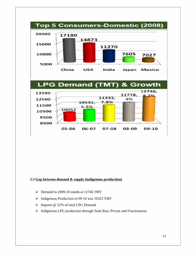
2.2 INDIAN LPG SCENARIO
� Fourth largest consumer of LPG in the world after USA, China & Japan
� Third largest consumer in domestic sector in the world after China & USA
� Major market of LPG is Domestic Sector
� Home Delivery of 3 Million LP Gas cylinders per day(i.e900 Million/ year)
� Steady Growth @ 8% p.a. in LPG Consumption in India
17
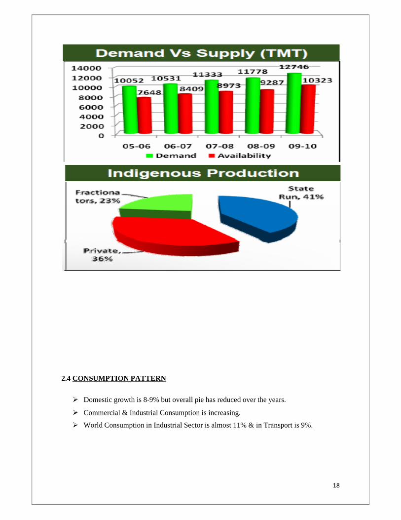
2.3 Gap between demand & supply (indigenous production)
� Demand in 2009‐10 stands at 12746 TMT
� Indigenous Production in 09‐10 was 10323 TMT
� Imports @ 22% of total LPG Demand
� Indigenous LPG production through State Run, Private and Fractionators
18
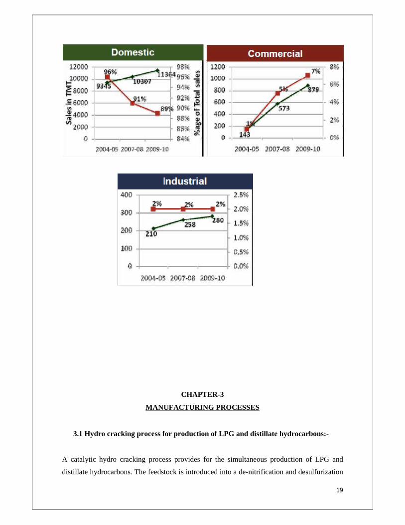
2.4 CONSUMPTION PATTERN
� Domestic growth is 8‐9% but overall pie has reduced over the years.
� Commercial & Industrial Consumption is increasing.
� World Consumption in Industrial Sector is almost 11% & in Transport is 9%.
19
CHAPTER-3
MANUFACTURING PROCESSES
3.1 Hydro cracking process for production of LPG and distillate hydrocarbons:-
A catalytic hydro cracking process provides for the simultaneous production of LPG and
distillate hydrocarbons. The feedstock is introduced into a de-nitrification and desulfurization
20
zone and then passed directly to a hot, high pressure stripper utilizing a hot, hydrogen-rich
stripping gas to produce a first liquid stream boiling in the range of the feedstock and a first
vapour stream comprising hydro carbonaceous compounds boiling at a temperature below the
boiling range of the feedstock. The first liquid stream is hydro cracked in a first hydro
cracking zone and then passed to the de-nitrification and desulfurization zone. At least a
portion of the first vapour stream is condensed to produce a second liquid stream comprising
hydro carbonaceous compounds boiling at a temperature below the boiling range of the
feedstock. At least a portion of the second liquid stream is hydro cracked in a second hydro
cracking zone containing a second hydro cracking catalyst to produce LPG boiling range
hydro carbonaceous compounds.
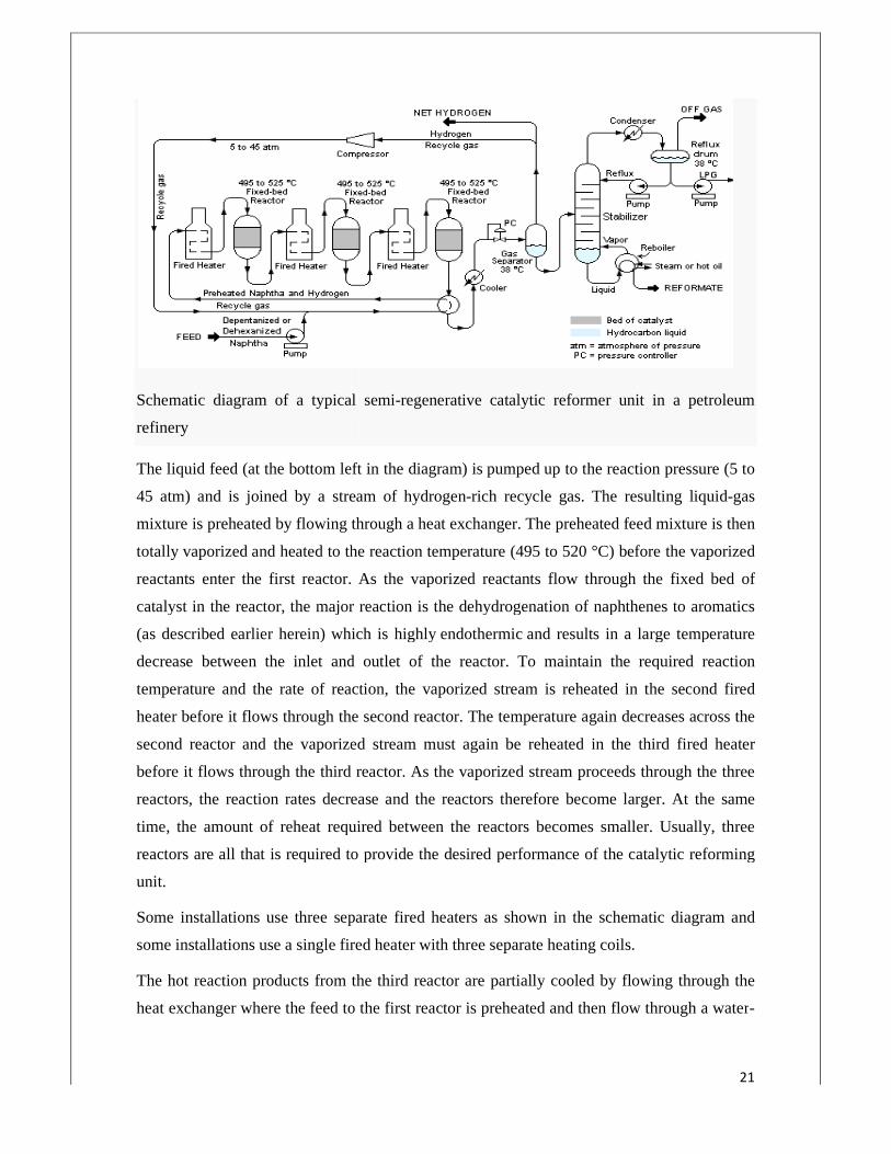
3.2 Catalytic Reforming for production of LPG:-
Schematic diagram of a typical semi
refinery
The liquid feed (at the bottom left in the diagram) is
45 atm) and is joined by a stream of hydrogen
mixture is preheated by flowing through a
totally vaporized and heated to the reaction tempe
reactants enter the first reactor. As the vaporized reactants flow through the fixed bed of
catalyst in the reactor, the major reaction is the dehydrogenation of naphthenes to aromatics
(as described earlier herein) which is highly
decrease between the inlet and outlet of the reactor. To maintain the required reaction
temperature and the rate of reaction, the vaporized stream is reheated in the second fired
heater before it flows through the second reactor. The temperature again decreases across the
second reactor and the vaporized stream must again be reheated in the third fired heater
before it flows through the third reactor. As the vaporized stream proceeds through
reactors, the reaction rates decrease and the reactors therefore become larger. At the same
time, the amount of reheat required between the reactors becomes smaller. Usually, three
reactors are all that is required to provide the desired perform
unit.
Some installations use three separate fired heaters as shown in the schematic diagram and
some installations use a single fired heater with three separate heating coils.
The hot reaction products from the third reactor
heat exchanger where the feed to the first reactor is preheated and then flow through a water
Schematic diagram of a typical semi-regenerative catalytic reformer unit in a petroleum
The liquid feed (at the bottom left in the diagram) is pumped up to the reaction pressure (5 to
45 atm) and is joined by a stream of hydrogen-rich recycle gas. The resulting liquid
mixture is preheated by flowing through a heat exchanger. The preheated feed mixture is then
and heated to the reaction temperature (495 to 520 °C) before the vaporized
reactants enter the first reactor. As the vaporized reactants flow through the fixed bed of
catalyst in the reactor, the major reaction is the dehydrogenation of naphthenes to aromatics
in) which is highly endothermic and results in a large temperature
decrease between the inlet and outlet of the reactor. To maintain the required reaction
temperature and the rate of reaction, the vaporized stream is reheated in the second fired
ore it flows through the second reactor. The temperature again decreases across the
second reactor and the vaporized stream must again be reheated in the third fired heater
before it flows through the third reactor. As the vaporized stream proceeds through
reactors, the reaction rates decrease and the reactors therefore become larger. At the same
time, the amount of reheat required between the reactors becomes smaller. Usually, three
reactors are all that is required to provide the desired performance of the catalytic reforming
Some installations use three separate fired heaters as shown in the schematic diagram and
some installations use a single fired heater with three separate heating coils.
The hot reaction products from the third reactor are partially cooled by flowing through the
heat exchanger where the feed to the first reactor is preheated and then flow through a water
21
regenerative catalytic reformer unit in a petroleum
reaction pressure (5 to
rich recycle gas. The resulting liquid-gas
. The preheated feed mixture is then
rature (495 to 520 °C) before the vaporized
reactants enter the first reactor. As the vaporized reactants flow through the fixed bed of
catalyst in the reactor, the major reaction is the dehydrogenation of naphthenes to aromatics
and results in a large temperature
decrease between the inlet and outlet of the reactor. To maintain the required reaction
temperature and the rate of reaction, the vaporized stream is reheated in the second fired
ore it flows through the second reactor. The temperature again decreases across the
second reactor and the vaporized stream must again be reheated in the third fired heater
before it flows through the third reactor. As the vaporized stream proceeds through the three
reactors, the reaction rates decrease and the reactors therefore become larger. At the same
time, the amount of reheat required between the reactors becomes smaller. Usually, three
ance of the catalytic reforming
Some installations use three separate fired heaters as shown in the schematic diagram and
are partially cooled by flowing through the
heat exchanger where the feed to the first reactor is preheated and then flow through a water-
22
cooled heat exchanger before flowing through the pressure controller (PC) into the gas
separator.
Most of the hydrogen-rich gas from the gas separator vessel returns to the suction of the
recycle hydrogen gas compressor and the net production of hydrogen-rich gas from the
reforming reactions is exported for use in the other refinery processes that consume hydrogen
(such as hydro desulfurization units and/or a hydrocracker unit).
The liquid from the gas separator vessel is routed into a fractionating column commonly
called a stabilizer. The overhead off gas product from the stabilizer contains the by-product
methane, ethane, propane and butane gases produced by the hydro cracking reactions as
explained in the above discussion of the reaction chemistry of a catalytic reformer, and it may
also contain some small amount of hydrogen. That off gas is routed to the refinery's central
gas processing plant for removal and recovery of propane and butane. The residual gas after
such processing becomes part of the refinery's fuel gas system.
The bottoms product from the stabilizer is the high-octane liquid reformate that will become a
component of the refinery's product gasoline.
3.3 Recovery from Natural Gas: -
23
Natural gas consists largely of methane and smaller quantities of ethane, propane, butanes,
and heavier hydrocarbons, together with varying amounts of water, carbon dioxide, nitrogen,
sulphur compounds, and other non hydrocarbons. Depending on the specifications of the gas
supplied to the consumer, a proportion of the ethane and heavier component content is
recovered in gas processing plants, which yield additional products such as ethane, LPG, and
higher boiling hydrocarbons (natural gasoline).
When no incentive to recover ethane exists, only the LPG and natural gasoline are recovered
from natural gas. Increasingly, however, ethane is considered a valuable product in the
petrochemical industry, and plants are designed to recover not only LPG but also ethane.
Potentially all of the ethane, LPG, and natural gasoline may be obtained as products from
natural gas; however, some ethane must normally remain in the gas to meet sales
specifications.
CHAPTER-4
SELECTION OF MANUFACTURING PROCESS
24
4.1 Recovery and Manufacture in the Refinery: -
After crude oil has been stabilized for transportation to the refinery, small but significant
amounts of LPG and lighter components (methane, ethane) remain in the oil. In the refinery,
crude oil is first separated into a number of fractions by distillation (fractionation). Gas,
which is the lightest fraction, is produced as the top product from the atmospheric
fractionation column; it consists of LPG, ethane, and methane. Other fractions that contain
the main refinery products are, in order of ascending atmospheric boiling points, naphtha,
kerosene, gas oil, and residue.
In practice, the yield of each fraction does not match market demand. Consequently, the less
valuable heavy fractions must be converted into lighter ones, and the lighter fractions must be
chemically modified to improve their properties.
Examples of these conversion processes are catalytic reforming, catalytic cracking, thermal
cracking, hydro cracking, and alkylation.
The products of thermal and catalytic cracking include LPG and lighter components (ethane,
ethylene, methane, hydrogen), both saturated and unsaturated. Conversely, during catalytic
reforming and hydro cracking, only saturated LPG and lighter components are formed.
Generally, the products of these conversion processes are separated in a fractionation column
to yield gas and the main products. Thus, gas streams consisting of LPG and lighter
components are produced from direct fractionation of crude oil and from fractionation of the
products of various refinery conversion processes.
These gas streams are used as fuel gas for refinery furnaces. However, LPG normally has a
significantly higher economic value than fuel gas, and recovery of LPG is economically
attractive. On the other hand, the most effective use of ethane in the refinery is as fuel gas
because normally no incentive exists to recover ethane. Depending on circumstances, various
techniques may be used for the recovery of LPG which can be applied in gas plants or
refineries.
These methods are:
� Re-Contacting –Compression,
� Refrigeration,
� Absorption,
25
� Adsorption, or
� Combination thereof.
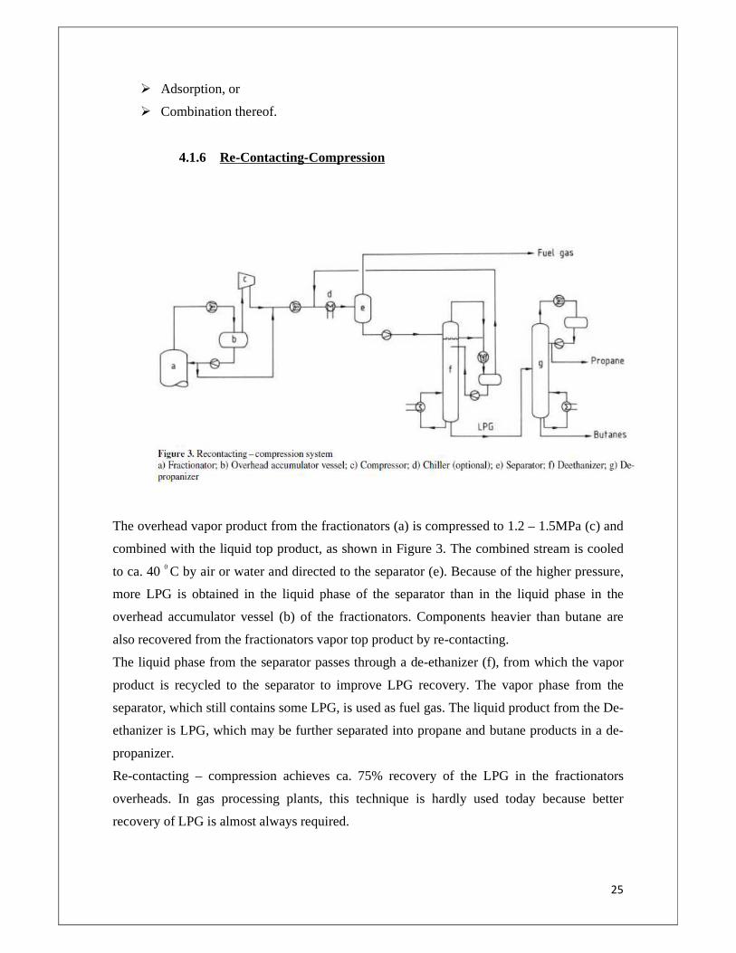
4.1.6 Re-Contacting-Compression
The overhead vapor product from the fractionators (a) is compressed to 1.2 – 1.5MPa (c) and
combined with the liquid top product, as shown in Figure 3. The combined stream is cooled
to ca. 40 0 C by air or water and directed to the separator (e). Because of the higher pressure,
more LPG is obtained in the liquid phase of the separator than in the liquid phase in the
overhead accumulator vessel (b) of the fractionators. Components heavier than butane are
also recovered from the fractionators vapor top product by re-contacting.
The liquid phase from the separator passes through a de-ethanizer (f), from which the vapor
product is recycled to the separator to improve LPG recovery. The vapor phase from the
separator, which still contains some LPG, is used as fuel gas. The liquid product from the De-
ethanizer is LPG, which may be further separated into propane and butane products in a de-
propanizer.
Re-contacting – compression achieves ca. 75% recovery of the LPG in the fractionators
overheads. In gas processing plants, this technique is hardly used today because better
recovery of LPG is almost always required.
26
4.1.7 Refrigeration
The recovery of LPGs from a gas stream can be accomplished by a variety of techniques. The
most common technique applied in new LPG recovery plants is to refrigerate the gas stream
to condense the LPG fraction. The recovered liquids are then fractionated to separate the LPG
components.
Some of the most commonly employed processes are summarized below.
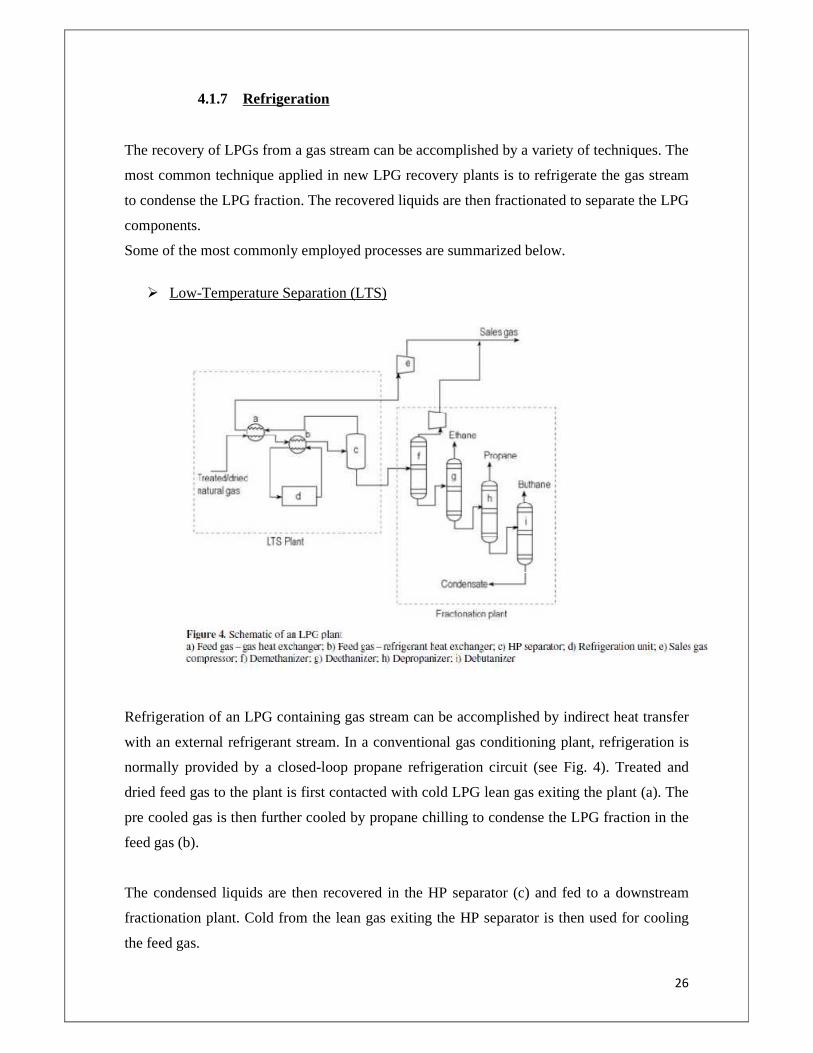
� Low-Temperature Separation (LTS)
Refrigeration of an LPG containing gas stream can be accomplished by indirect heat transfer
with an external refrigerant stream. In a conventional gas conditioning plant, refrigeration is
normally provided by a closed-loop propane refrigeration circuit (see Fig. 4). Treated and
dried feed gas to the plant is first contacted with cold LPG lean gas exiting the plant (a). The
pre cooled gas is then further cooled by propane chilling to condense the LPG fraction in the
feed gas (b).
The condensed liquids are then recovered in the HP separator (c) and fed to a downstream
fractionation plant. Cold from the lean gas exiting the HP separator is then used for cooling
the feed gas.
27
The liquids from the HP separator are fed to a conventional fractionation plant comprising a
de-methanizer, de-ethanizer, de-propanizer and debutanizer for separation of the LPG
components.
If no extra ethane outlets are available, then the de-methanizer and de-ethanizer column can
be combined to a single column. The chief advantages of this type of process are its
simplicity and low pressure drop.
Alternatively, chilling of the gas can be provided by a cascade refrigeration circuit. The
refrigerant in this case is either a propane – ethane, propane – ethylene, or a mixture of
propane – ethane – methane – nitrogen (commonly called mixture refrigerant). A cascade
ethane – propane circuit produces lower temperature than a single propane circuit.
Accordingly, the method selected depends on the ethane and LPG recoveries desired.
Recoveries of LPG >99 %, corresponding to ca. 85% ethane recovery, are achievable in
practice by using mechanical refrigeration.
Mechanical refrigeration is more usual in gas processing plants than in refineries because
higher LPG recovery is normally required in a gas processing plant to meet the hydrocarbon
dew point specification of the sales gas.
A cascade refrigeration plant is illustrated in Figure 4. Impurities such as water, carbon
dioxide, and sulfur compounds are removed from the inlet gas, whereupon it is chilled against
product gas and external refrigerant. Removal of water and carbon dioxide avoids possible
freezing problems in the cold sections of the process.
The liquid produced by chilling is fed to the de-methanizer, where methane and some ethane
are stripped. The vapor separated from separator (i) is used to chill the incoming feed before
being commingled with the overhead vapor from the de-methanizer. The liquid product from
the de-methanizer consists of ethane, LPG, and natural gasoline, from which LPG is
separated by fractionation. The vapor phase from the de-methanizer (mainly methane with
some ethane) is heated against the incoming feed before being compressed for sale.
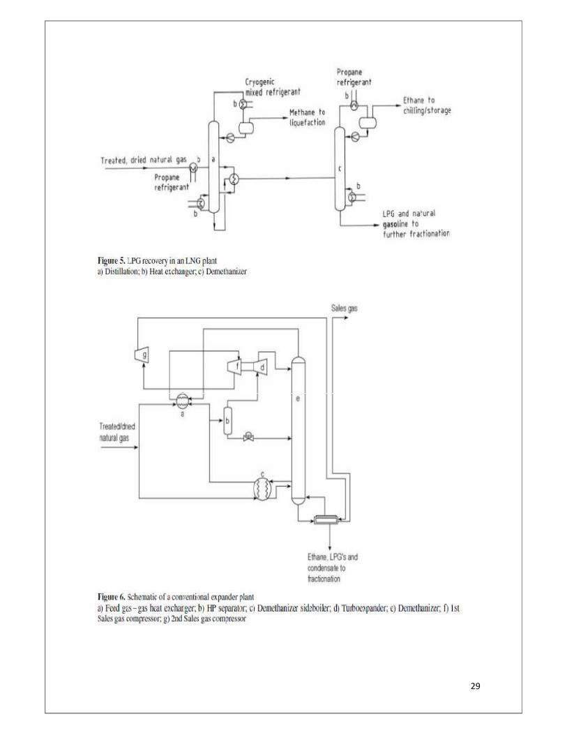
Liquid petroleum gas can also be recovered in a liquefied natural gas (LNG) plant, in which
natural gas is fully liquefied by mechanical refrigeration (see Fig. 5). Generally, the external
28
refrigerants employed are propane and a mixed refrigerant consisting of nitrogen – methane –
ethane and propane. In the liquefaction process the partially condensed natural gas stream is
passed to a distillation column (a) in which ethane, LPG, and the heavier natural gasoline are
separated from natural gas. The natural gas (predominantly methane) leaves the distillation
column overhead as a vapor product and is subsequently fully liquefied. The liquid phase
from the column bottom is routed to a series of fractionation columns for separation into
ethane, LPG (individually as propane and butane), and natural gasoline products. Some or all
of the ethane and propane products may be used as refrigerants for the LNG plant, with any
excess exported.
29
30
� Expander Plants
Expander plants generate refrigeration by expansion of the feed gas. By dropping the pressure
via a control valve or an expander a sufficiently low temperature can be generated to
condense the LPG fraction in the feed gas. The flow scheme for a conventional expander
plant is shown in Figure 6.
Treated and dried gas to the plant is first cooled via indirect heat exchange with the cold lean
gas exiting the plant (a). Any liquids formed during this first stage of cooling are then
recovered in the HP separator (b) and fed to the bottom section of the de-methanizer column
(e).
The overhead vapor from the HP separator is then expanded either via a rotating expander or
via a control valve (commonly called a Joule – Thomson valve, d). The cold gas/liquid from
the expansion is then fed to the top of the de-methanizer.
The de-methanizer strips the lighter components (methane, nitrogen) from the liquids. The
overhead vapor is subsequently fed to the feed gas – gas heat exchanger for recovery of cold
before being compressed for export as sales gas. Compression power is minimized by
coupling the first stage of the compression to the expander.
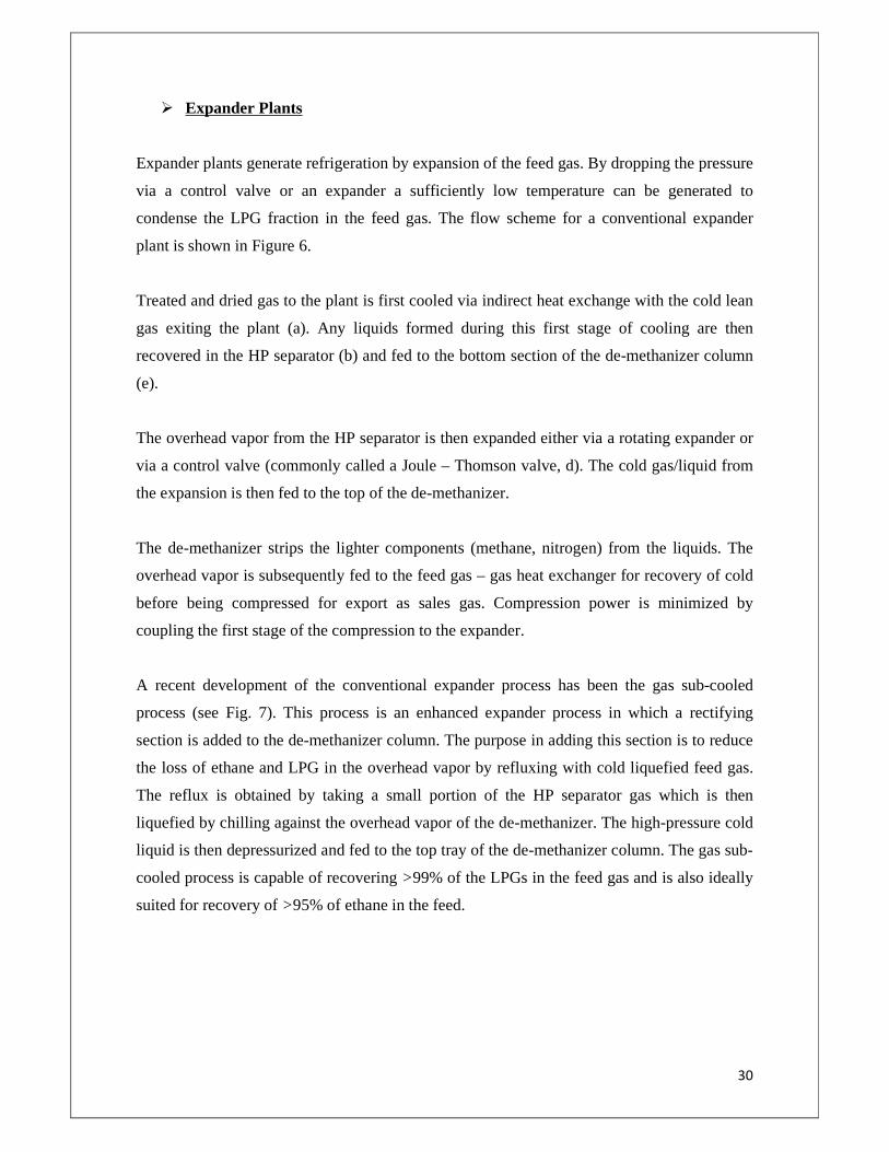
A recent development of the conventional expander process has been the gas sub-cooled
process (see Fig. 7). This process is an enhanced expander process in which a rectifying
section is added to the de-methanizer column. The purpose in adding this section is to reduce
the loss of ethane and LPG in the overhead vapor by refluxing with cold liquefied feed gas.
The reflux is obtained by taking a small portion of the HP separator gas which is then
liquefied by chilling against the overhead vapor of the de-methanizer. The high-pressure cold
liquid is then depressurized and fed to the top tray of the de-methanizer column. The gas sub-
cooled process is capable of recovering >99% of the LPGs in the feed gas and is also ideally
suited for recovery of >95% of ethane in the feed.
31
� Combined Processes When high recoveries of LPG and/or ethane are desired, it is possible to assist the
conventional expander process with external refrigeration.
External propane or cascade refrigeration is applied to cool the feed gas entering the HP
separator of the expander plant. The cold gas is then expanded and fed to a conventional de-
methanizer column.
With this type of process, more than 95% ethane recovery and essentially 100% recovery of
LPG can be achieved.
4.1.8 LEAN OIL ABSORPTION
The lean oil absorption process employs a hydrocarbon oil to recover light components from
either a natural gas or a refinery fuel gas stream.
The process is used in refineries worldwide, as well as in natural gas processing plants,
especially in the United States, where the vast majority of plants used the oil absorption
process until the first expander plant started up in 1963.
32
However, since 1963 expander plants have dominated natural gas processing.
Hydrocarbon oil may be bought in, or components of natural gasoline produced in the gas
processing plant may be used. In the refinery, an available fluid such as naphtha is often
employed.
Despite the different terminology, these streams from the natural gas processing plant and oil
refinery are very similar in terms of molecular mass. Typical absorption oils have a molecular
mass of 100 – 180.
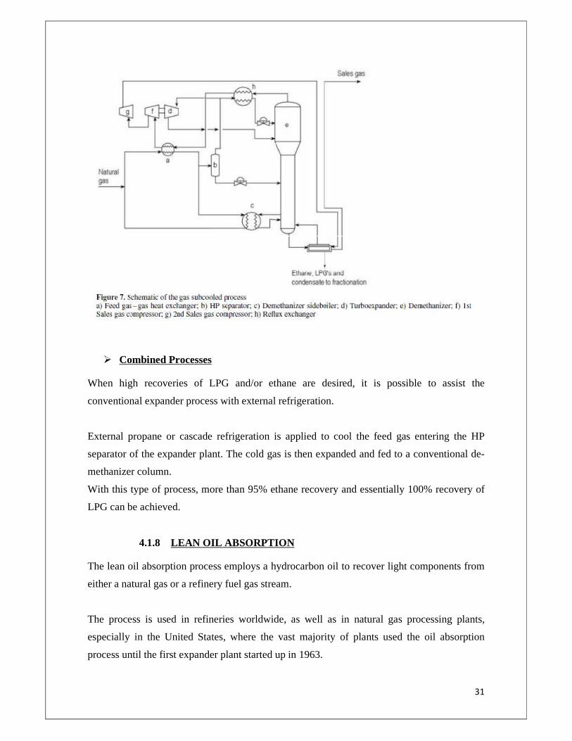
An example of refinery lean oil absorption scheme is shown in Figure 8. The fractionators
overhead vapour stream is compressed and combined with the liquid top product. The
combined stream is then de-ethanized, and the vapour top product of the de-ethanizer is
brought into contact counter currently with the absorption oil in the absorber column. The oil
absorbs propane and butane components from the gas, replacing them with fewer molecules
of the absorber oil.
The oil is taken from the main fractionation column (a), pre saturated with vapour from the
absorber column, chilled to 10 – 15 C, and fed to the absorber column as lean oil. Pre
saturation and chilling of the lean oil improve LPG recovery in the absorber. The remaining
vapour phase is directed to the fuel gas line. So-called rich oil from the bottom of the column,
which contains absorbed LPG, is recycled to the main fractionation column to complete the
33
oil circuit. There the LPG is stripped from the rich oil and passed overhead to the de-
ethanizer.
The liquid product from the de-ethanizer is routed to a fractionation column where the
propane and butanes are separated.
Typically, LPG recoveries of 85 – 90% are attainable.
The process applied in natural gas processing plants is, in principle, the same as that used in
the refinery, although LPG recoveries of around 98% are often needed to ensure that gas
supplied to the customer satisfies the hydrocarbon dew point specification. This high LPG
recovery is achieved by cooling the lean oil to −40 C, usually by propane refrigerant. So that
the absorber column can operate at this temperature, the natural gas feed must be dried to
avoid problems caused by freezing.
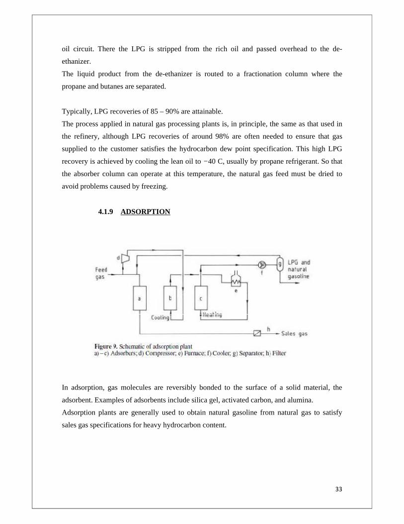
4.1.9 ADSORPTION
In adsorption, gas molecules are reversibly bonded to the surface of a solid material, the
adsorbent. Examples of adsorbents include silica gel, activated carbon, and alumina.
Adsorption plants are generally used to obtain natural gasoline from natural gas to satisfy
sales gas specifications for heavy hydrocarbon content.
34
The LPG recovery is significantly lower than that achieved by refrigeration or lean oil
absorption processes. A typical adsorption flow scheme is presented in Figure 9.
Three vessels are shown, each containing the solid adsorbent. The process is cyclical with, at
any one time, one vessel on adsorption, one on regeneration cooling, and one on regeneration
heating. The inlet gas passes through a bed (a) where heavy hydrocarbons are adsorbed. A
slipstream of the inlet gas is compressed and used to cool another bed (b), which has
previously been heated to remove adsorbed hydrocarbons.
Once this bed is cooled, it is placed on standby ready to be put into adsorption service. Gas
leaving this bed (b) is heated to ca. 300 •C in a furnace (e) and directed to another bed (c) to
remove adsorbed hydrocarbons. Heavy hydrocarbons present in the regeneration gas leaving
this bed (c) are recovered after cooling in a separator (g), from which the remaining gas is
returned upstream of the initial bed (a). Liquid removed from the regeneration gas, consisting
of natural gasoline and some LPG components may be processed further by fractionation to
yield separate LPG and natural gasoline products. Whichever method is used to obtain LPG
from natural gas or refinery fuel gas, LPG maybe produced as a mixed product or as separate
propane – propene, called C3 product, and butanes – butenes, called C4 product.
The relative quantities of saturated and unsaturated species depend on the types of processes
in the refinery that are responsible for LPG production.
Further fractionation is sometimes employed to recover iso-butane from the rest of the C4
product and propene from the C3 product. Isobutane is used in the refinery in the alkylation
process, in which it reacts catalytically with either propene or butene to produce high-octane
gasoline blend stocks.
Propene can also be a valuable chemical feedstock. Thus, depending on the configuration of
each refinery, the LPG pool may contain various blends of the saturated and unsaturated
components that comprise LPG.
4.1.10 PURIFICATION
35
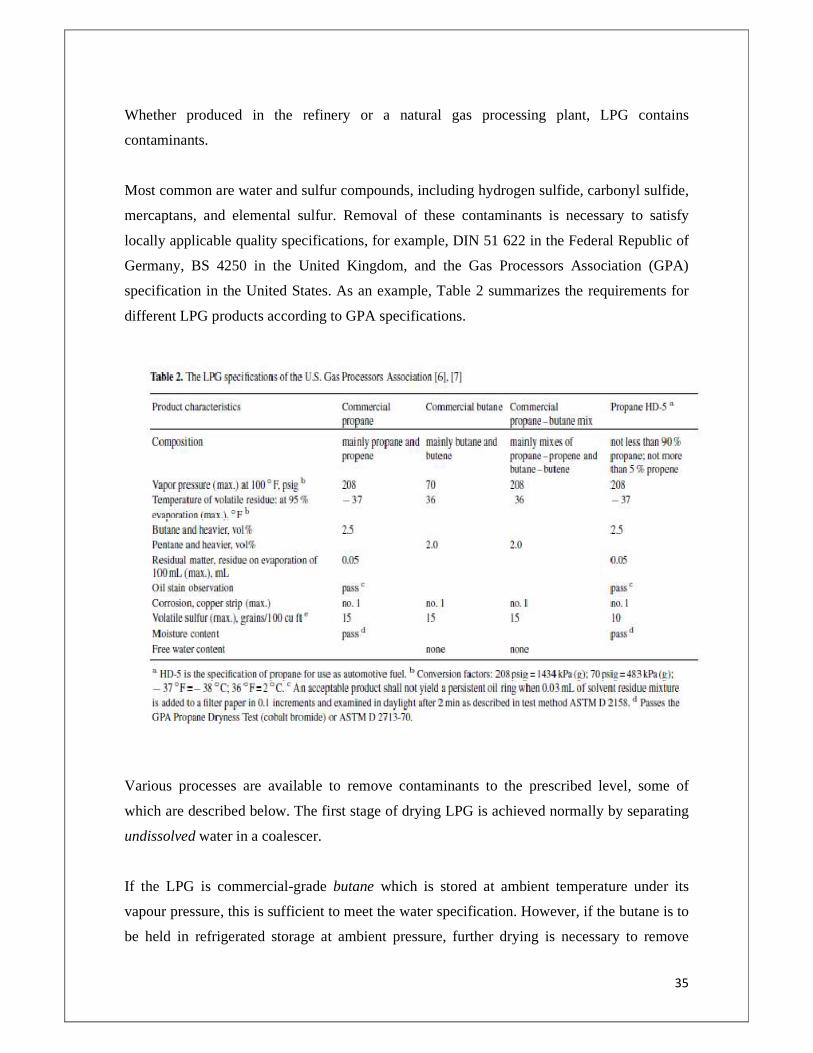
Whether produced in the refinery or a natural gas processing plant, LPG contains
contaminants.
Most common are water and sulfur compounds, including hydrogen sulfide, carbonyl sulfide,
mercaptans, and elemental sulfur. Removal of these contaminants is necessary to satisfy
locally applicable quality specifications, for example, DIN 51 622 in the Federal Republic of
Germany, BS 4250 in the United Kingdom, and the Gas Processors Association (GPA)
specification in the United States. As an example, Table 2 summarizes the requirements for
different LPG products according to GPA specifications.
Various processes are available to remove contaminants to the prescribed level, some of
which are described below. The first stage of drying LPG is achieved normally by separating
undissolved water in a coalescer.
If the LPG is commercial-grade butane which is stored at ambient temperature under its
vapour pressure, this is sufficient to meet the water specification. However, if the butane is to
be held in refrigerated storage at ambient pressure, further drying is necessary to remove
36
dissolved water. This must be performed before the butane is chilled, otherwise problems
caused by water freezing will ensue. Water levels in refrigerated LPG are typically less than
10 ppm (mol) to avoid freezing.
CHAPTER-5
37
INTRODUCTION TO ONGC, URAN PLANT
5.1 General
Crude oil and associated gas produced at Bombay High fields and satellite fields are
transported to URAN onshore facilities through sub-sea pipelines for further processing. Oil
& Gas is brought from Bombay High fields through 203 km long 30" dia. & 26" dia. trunk
lines respectively and from satellite fields through 81 km long 24" dia. & 26" dia. trunk lines
respectively.
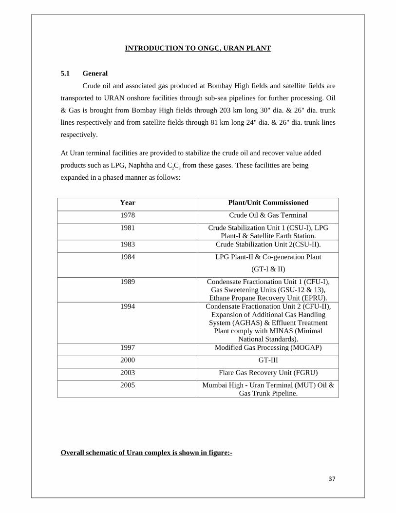
At Uran terminal facilities are provided to stabilize the crude oil and recover value added
products such as LPG, Naphtha and C2C3 from these gases. These facilities are being
expanded in a phased manner as follows:
Year Plant/Unit Commissioned
1978 Crude Oil & Gas Terminal
1981 Crude Stabilization Unit 1 (CSU-I), LPG Plant-I & Satellite Earth Station.
1983 Crude Stabilization Unit 2(CSU-II).
1984 LPG Plant-II & Co-generation Plant
(GT-I & II)
1989 Condensate Fractionation Unit 1 (CFU-I), Gas Sweetening Units (GSU-12 & 13), Ethane Propane Recovery Unit (EPRU).
1994 Condensate Fractionation Unit 2 (CFU-II), Expansion of Additional Gas Handling
System (AGHAS) & Effluent Treatment Plant comply with MINAS (Minimal
National Standards). 1997 Modified Gas Processing (MOGAP)
2000 GT-III
2003 Flare Gas Recovery Unit (FGRU)
2005 Mumbai High - Uran Terminal (MUT) Oil & Gas Trunk Pipeline.
Overall schematic of Uran complex is shown in figure:-
38
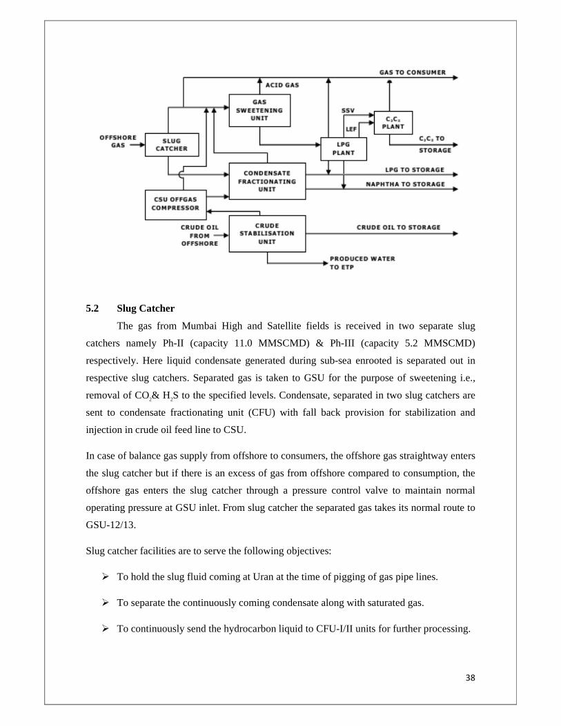
5.2 Slug Catcher
The gas from Mumbai High and Satellite fields is received in two separate slug
catchers namely Ph-II (capacity 11.0 MMSCMD) & Ph-III (capacity 5.2 MMSCMD)
respectively. Here liquid condensate generated during sub-sea enrooted is separated out in
respective slug catchers. Separated gas is taken to GSU for the purpose of sweetening i.e.,
removal of CO2& H 2S to the specified levels. Condensate, separated in two slug catchers are
sent to condensate fractionating unit (CFU) with fall back provision for stabilization and
injection in crude oil feed line to CSU.
In case of balance gas supply from offshore to consumers, the offshore gas straightway enters
the slug catcher but if there is an excess of gas from offshore compared to consumption, the
offshore gas enters the slug catcher through a pressure control valve to maintain normal
operating pressure at GSU inlet. From slug catcher the separated gas takes its normal route to
GSU-12/13.
Slug catcher facilities are to serve the following objectives:
� To hold the slug fluid coming at Uran at the time of pigging of gas pipe lines.
� To separate the continuously coming condensate along with saturated gas.
� To continuously send the hydrocarbon liquid to CFU-I/II units for further processing.
39
� To partially stabilize the liquid form PH-II liquid condensate and inject into crude
inlet to CSU in case of CFU-I/II plants are shut down.
� To supply gas (after condensate separation) to GSU-12, 13/ LPG-I, II plants.
5.3 Oil and Gas Processing Facilities
The crude oil received from offshore is stabilized in crude stabilization unit (CSU)
through three stage separation with a view to optimize the liquid recovery. The liberated gas
from CSU is compressed and mixed with offshore gas and fed to gas processing unit. The
stabilized oil is stored in floating roof tanks and as per demand of refineries is sent to
Trombay Terminal for onward transportation to refineries situated at Trombay and to various
coastal refineries through Jawahar Deep/JNPT tanker loading terminal.
Associated gas is received at slug catcher, where condensate formed during travel time gets
separated. Gas from slug catcher along with CSU off gas and Condensate Fractionating Unit
(CFU) off gas is routed to Gas Sweetening Unit (GSU) for removal of CO2 & H2S. The GSU
which consists of two trains viz. GSU-12 & GSU-13 with handling capacity of 5.75
MMSCMD each. The remaining gas is directly sent to consumers along with lean gas coming
from the processing plants. After removal of CO2 & H2S at GSU, treated gas is routed to LPG
recovery plant, which consists of two Units viz. LPG-I & LPG-II for extraction of LPG &
NGL/Naphtha. Remaining Second stage vapours (SSV) & Light End Fractionating column
(LEF) overhead vapour is taken to Ethane Propane Recovery Unit (EPRU) for recovery of
Ethane-Propane. The lean gas after recovery of Ethane-Propane is supplied to M/s. GAIL for
onward supply to various gas consumers like Usar LPG Plant, RCF, MSEB, MGL, TEC,
DFPCL etc. Ethane-Propane (liquefied) is sent to MGCC, Nagothane for using as feed stock
to Gas Cracker Unit. LPG & NGL/Naphtha are supplied to BPCL & HPCL refineries.
Naphtha is also supplied to various on land consumers or exported.
Condensate separated at slug catcher and at CSU off-gas compressors is sent to CFU plant for
removal of light end hydrocarbon gases along with CO2 and H2S. The treated sweet
condensate is sent to LPG column of CFU-II for recovery of LPG & NGL/Naphtha. The
treated condensate can also be routed to LPG plant for recovery of LPG & NGL/Naphtha.
5.4 Process Description of LPG Plant
40
Sweetened gas from GSU flows to knock out drum where any liquid present is
separated out, and then the gas is pre cooled to 250C. The pre cooled gas is sent to knockout
drum where liquefied hydrocarbon and water are separated out. The gas then flows to the
molecular sieve drier where the moisture is reduced to less than 5 ppm level. The dried gas is
cooled to -220C in the first stage chiller; condensed liquid is separated out in 1st stage
separator. Vapour is further cooled to -370C and condensed liquid again is separated out in
2nd stage separator. Remaining non-condensable gas (SSV) is sent to C2C3 plant. Cooling of
gas is achieved by exchanging heat against external refrigeration. External refrigeration is
supplied in three stages at -70C, -270C & -400C.
The SSV (second stage vapor) after separation of condensate are delivered as feed stock to
C2C3 recovery unit, alternatively the SSV can be delivered to consumer trunk line if C2C3 unit
is under shut down. The separated liquid from both the stages are combined and routed to
light ends fractionator (LEF) column. The light hydrocarbons (some propane and lighters) are
removed from the top of this column. These Light hydrocarbon gases from LEF top are sent
to C2C3 recovery plant alternatively these gases are compressed in residue gas compressor and
then delivered into consumer trunk-line if C2C3 plant is shut down.
Liquid from the bottom of light ends fractionator is routed to LPG recovery column.
Liquefied petroleum gas (LPG) is withdrawn from the column as overhead product and sent
to storage; Low Aromatic Naphtha (LAN) is withdrawn from the bottom and sent to storage
or to crude stabilizing unit in case of off-specification.
A propane column is provided in LPG-I to recover liquid propane from LPG stream. Propane
is used as refrigerant for LPG-I & II & C2C3 plant to maintain desired operating temperatures.
Propane column will be in service intermittently as per requirement to make up refrigerant
losses.
Plant capacity:
The capacity of each plant is:
41
Feed
Sweet gas : 5.65 MMSCMD
Product
LPG : 1, 58,500 MTPA
NAPTHA : 93,500 MTPA
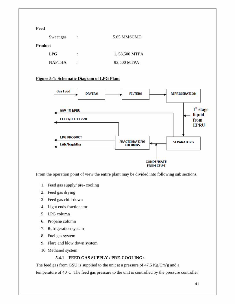
Figure 5-1: Schematic Diagram of LPG Plant
From the operation point of view the entire plant may be divided into following sub sections.
1. Feed gas supply/ pre- cooling
2. Feed gas drying
3. Feed gas chill-down
4. Light ends fractionator
5. LPG column
6. Propane column
7. Refrigeration system
8. Fuel gas system
9. Flare and blow down system
10. Methanol system
5.4.1 FEED GAS SUPPLY / PRE-COOLING:-
The feed gas from GSU is supplied to the unit at a pressure of 47.5 Kg/Cm2g and a
temperature of 40°C. The feed gas pressure to the unit is controlled by the pressure controller
42
PRC-101 which releases excess pressure to the consumer line bypassing the unit. PRC-101 is
a split range controller operating on control valves PV-101 A and PV-101 B. The two control
valves are provided to cover a wider range of gas bypassing and provide better control. In
normal case sweet gas is not bypassed through PV-101 A/B. The feed line is provided with a
high temperature alarm TAH 101, a high pressure alarm PAH 101, and a low pressure alarm
PAL 102. Feed flow to LPG unit is regulated by a flow controller FRC 101 and metered by
FQ 101.
Liquid if any, coming along with feed gases are separated in Feed Gas Inlet K.O. Drum
V-101; accumulated liquid is periodically routed to CSU by operating hand control valve
HIC-102. K.O. Drum (V-101) is a vertical drum of 3.0 meter OD and 5.2 meter height carbon
steel construction. The drum is fitted with a demister at the top to prevent entrainment. The
drum is provided with high and low level alarms LAH 101 and LAL 102. In case of a low
level in V-101, the shut down valve SDV-102 on the liquid line closes automatically on
actuation of LSL102; this prevents escape of gas to CSU. A safety valve is provided on V-
101 to protect it from over-pressure.
The gas is then pre-cooled to 25°C in two stages in exchangers E-121 and E-122. E-121is a
shell and tube exchanger with wet feed gas in tube side and plant outlet SSV in shell side
coming from E-118. Shell side of E-121 is provided with safety valve. Exchanger is provided
with bypass on both the sides which can be used in case of any flow restriction. The lean gas
leaving the exchanger is sent to EPRU header under pressure control by PRC-201 which
controls the plant back pressure by PV-201 and flare controller PIC-202 by operating 10-PV-
202.
After E-121 gas enters Feed Gas Cooler II E-122. This is a shell and tube heat exchanger with
feed gas on tube side and propane refrigerant on the shell side. Main purpose of this cooler is
to cool down the feed to 250 C before it enters the moisture separator. The outlet gas
temperature of E-122 is controlled by TIC-201 by regulating flow of refrigerant to the shell
side. The level controller on the shell side LlC-507 is linked with TIC-201. In normal
operating conditions propane flow is controlled as per the outlet temperature. In case of high
propane level accumulation on shell side; either due to less process load or any other reason,
LlC-507 overrides TIC-201. Hydrate formation is avoided by keeping a proper setting on
PIC-507 so that the corresponding boiling temperature is higher than gas hydrate forming
temperature.
43
The pre-cooled gas sent to moisture separator V-120 where liquefied hydrocarbons and water
are separated out and the liquid can be routed to CFU or to CSU.
5.4.2 FEED GAS DRYING:-
The pre-cooled gas is sent to molecular sieve dryers where the moisture is reduced to less
than 4 ppm level. There are 3 dryers out of which, two will be in line with parallel operations
and one will be under regeneration. Alternatively, two dryers can be operated in series also in
case the moisture content at downstream of dryer is high. D-101 A/B/C is vertical vessels of
3.0 meter OD and 9.8 meter height, carbon steel construction. The top and bottom layer are
ceramic support balls and in between 7.35 meter length is occupied by molecular sieve. The
charge for each drier is 36.5 Tons. At the outlet of drier a removable type bottom collector is
provided. Each drier bed is provided with a set of temperature indicators at the inlet and
outlet and safety valves to protect these from over pressure. The driers are also provided with
a differential pressure measurement in the field.
5.4.3 FEED GAS CHILL DOWN:-
The dried gas is cooled to -22°C in the 1st stage chiller and then further cooled to -37°C in
the 2nd stage chiller. This comprises a series of feed gas chillers E-101, E-102, E-103, E-104
and E-118 to cool the feed gas to -37°C and separators V-103 and V-104 to separate the
condensed hydrocarbons from the lean gas.
Feed gas chillers E-101, E-103 and E-118 are aluminium brazed plate fin exchanges housed
in one cold box. The housing of cold box is filled with insulation material ‘Pearlite’ and
sealed with inert gas supplied through a pressure regulating valve. Housing is provided with a
safety device protect it from over pressure.
Gas from filters X-101 A/B first passes through a feed gas chiller (E-101) where it is cooled
to –10.6°C, it then passes through propane chiller (E-102) and gets further cooled to – 22°C.
Methanol injection is provided at the inlet of E-101 for the purpose of de-hydrating/de-icing.
Propane refrigerant is supplied to E-102 under its level control LIC-504. Pressure in E-102
shell side is controlled by PRC-503 which determines the temperature of condensation in the
gas side.
The gas then flows to feed gas separator-I (V-103) to separate gas from condensed liquid. V-
103 is a vertical vessel of 3.0 meter O.D. and 5.6 meter height; carbon steel construction. The
44
vessel has a demister at the top. The separator is provided with a low and high level alarm
LAL 202 and LAH 201. V-103 operates as a pressure of 45.8 kg/cm2g. The liquid from
separator V-103 flows under its own pressure to Light Ends Fractionator (C-101); the flow is
regulated by flow controller FRC-202 which is reset by separator level controller LIC-201.
The gas from V-103 passes through another feed gas chiller E-103 cooling the gas to - 28°C
and then through propane chiller E-104 cooling the gas further to - 37°C
Methanol injection is provided at the vapour outlet line of separator V-103 for the purpose of
de-icing/de-hydrating. Propane refrigerant is supplied to the chiller E-104 under its level
control (LIC 506); pressure in the shell side of E-104 is controlled by PRC-504 which
determines temperature of condensation (TI-205) in process gas side. Pressure controller
PRC-504, in turn, acts upon the speed of propane compressor driver – a gas turbine – to
maintain the desired pressure in E-104 shell side.
The gas cooled in chiller E-104 then passes to separator II (V-104) where condensed liquid is
separated out. 1st stage liquid from V-1514 in EPRU is also pumped and sent to V-104 under
its flow control. V-104 is a vertical vessel 3.0 meter O.D. and 44 meter height. The vessel is
provided with high and low level alarms LAH-203 and LAL-204. V-104 operates under a
pressure of 44.8 Kg/Cm2g. The liquid from separator II (V-104) flows under its own pressure
to Light Ends Fractionator C-101 along with the liquid stream from V-103; the flow rate is
regulated by flow controller FRC-203 which is cascaded with level controller LIC-202 of V-
104.
Cold gas from the top of V-104, after exchanging heat with incoming gases in exchangers E-
101, E-103, E-118 and E-121 flows into lean gas header to EPRU. A back pressure controller
PRC-201 is provided in the lean gas header to maintain the desired operating pressure for
maximum recovery of LPG potential commensurate with unit through put; it also ensures that
unit operating pressure is unaffected by fluctuations at consumers end. A turbine meter FQ
201 is installed in the lean gas header to measure the gas flow from the unit to the lean gas
header. The pressure controller PIC-202 installed in the lean gas header releases excess
pressure into flare and thus takes care of abrupt stoppage of gas by any consumer. During
normal operation, there will be no release of gas to flare through PV-202.
5.4.4 LIGHT ENDS FRACTIONATOR (LEF Column):-
45
Separator liquid from V-103 and V-104 sent to LEF column at around 20°C to remove the
lighter fractions. The gas coming out from the top goes to LEF reflux drum V-105 through
LEF condenser E-105 where gas is cooled by external refrigeration. The liquid knocked out
in V-105 is pumped back to LEF column as reflux and the remaining gas called as LEF top is
sent to C2C3 after in heat from cold box. The bottom liquid goes to LPG Column. The LEF
column consists of 45 valve trays. The feed Tray of LEF column is 30th tray. If C2C3 plant is
under shutdown the LEF top gases can be sent to consumer line after compressing through
residue gas compressor K-102A/B. Also these gases can be used for regeneration of gas
dryers. The column has 45 nos. valve trays of single pass at the top section and double pass at
the bottom section; material of construction for the shell is carbon steel, tray deck material is
carbon steel while valves are stainless steel.
The column operates at a pressure of about 29.9 Kg/Cm2G and a temperature of 20°C (top).
Re-boiler E-106 is thermosyphon kettle type and heat is supplied by medium pressure steam
through flow controller FIC-302 cascaded with TRC-301 to maintain a constant temperature
at 43rd tray. The re-boiler is provided with a low and high level alarms LAL 304 and LAH
303. Steam condensate from re-boiler E-106 flows to condensate pot V-113 and from there
flows to condensate header under level control LIC 302 of V-113.
Column pressure is controlled by PRC-103 selector switch is provided to select the pressure
sensing point either at reflux drum vapour outlet (PT-301) or at the outlet of cold box E-101
(PT 103). Overhead vapours from light Ends Fractionator are partially condensed in
condenser E-105 and then flow to reflux drum V-105. The condensed liquid accumulated in
the reflux drum V-105 is totally refluxed. The reflux flow rate is regulated by flow controller
FRC-301
Reflux Drum is provided with a low and high level alarm LAL 302 and LAH 301. It has a
demister at the top.
Propane refrigerant is fed to E-105 under its level control LIC 502 and pressure in
E-105 shell side is controlled by PRC-502 to keep a constant temperature of condensation at
gas side. Methanol injection point is provided in vapour line to E-105 for de-icing. Light
Ends Fractionator bottom high pressure alarm PAH 301 closes steam to reboiler (FV-302).
Bottom product of the column C-101 flows from reboiler E-106 under flow control FRC 303
which is reset by reboiler level controller LIC 301. It flows to LPG column C-102 as feed
under pressure difference. The column C-101 is provided with a pressure drop indicator DPI
301.
46
5.4.5 LPG COLUMN:-
The bottom liquid of LEF column can enter either 9th or 12th or 15th trays of thetray being
selected based on the feed composition LPG column. The LPG column consists of 47 trays.
The top product of the column is propane and butane (called LPG, liquefied petroleum gas),
the bottom product is called as low aromatic naphtha called LAN. CFU I & II sweet
condensate can also be processed in LPG column C-102 (@ 20m3/hr. through 18-FIC-101.
C-102 has 47 Nos. valve type trays – all single pass. Material of construction for shell is
carbon steel; tray deck material is carbon steel while valves are stainless steel. C-102 operates
at a pressure of 10 Kg/Cm2g and a temperature of 60°C (top).
Reboiler E-108 is thermosyphon type and heat is supplied by medium pressure steam
regulated by flow controller FIC-404 which is reset by temperature controller TRC- 405. This
temperature controller measures the temperature on 31st tray. High pressure alarm PAH 401
cuts off steam flow to the reboiler through solenoid valve action. The column is provided
with a high and low level alarm LAH 405 and LAL 406. Steam condensate from reboiler
flows to condensate pot V-114 from where it flows to condensate header under its level
control (LIC 405).
Column pressure is maintained by split range pressure controller PRC 401. This controller
acts on the control valve PV 401A in hot vapour bypass line or on the control valve PV 401 B
in gas release line to flare. Hot vapour bypass line control valve PV 401 A varies the heat
transfer area in condenser E-107.
Overhead vapour condenses in condenser E-107 (circulating water as cooling medium) and
flows to LPG column Reflux Drum V-106. Initially the non condensable fuel gas will be
vented from E-107 shell side by opening bleeder valve releasing them to flare. Pump P-102
A/B draws condensed LPG from reflux drum and discharges partly as reflux to LPG column
under flow control FRC 401; the balance is routed to LPG storage under level control of
reflux drum LIC 402. Flow rate of LPG to storage is recorded on FR 407 and metered on FQ
407. The reflux drum has high and low level alarms LAH 401 and LAL 402.
Bottom product (low aromatic naphtha) flows out from the column bottom under level
control LIC 401 through cooler E-109 to go either to Naphtha storage via LV 401A or to
CSU (HP-separators) via LV 401B. The operation logic of both valves; at any point of time
47
either of the valve will remain open and other valve will remain close. The flow rate of LAN
is recorded by FR 408 and metered by FQ 408. Two turbine type flow meters are provided
for this – one operating and other stand by. The flow of LAN is cut off through solenoid
valve action by either a low temperature condition in re-boiler outlet vapour (TAL 402) or a
high temperature condition in run down line (TAH 401). LAL 406 of C-102 also activates
SOV which cuts off LAN to storage tank. Such condition may arise due to utilities failure in
re-boiler E-108 or cooler E-109. In case of necessity LAN can be diverted to CSU (HP-
separators) from control room using switch 10-SS-104.
5.4.6 PROPANE COLUMN:-
Propane is used as a refrigerant in the unit and is required as initial charge and subsequently
as make-up. Column C-103 recovers propane by distillation from LPG. This recovered
propane can be either directly routed to refrigeration system as make-up or diverted to storage
sphere for subsequent use. The feed flow to the column is regulated by flow controller FRC
403 in the unit. C-103 is a valve tray column having 35 trays – all single pass. Material of
construction for the shell is carbon steel, tray deck is carbon steel and valves are stainless
steel. C-103 operates at a pressure of 13.0 Kg/cm2g and top temperature of 40°C. The column
is provided with a low level alarm LAL 407. Re-boiler E-115 is thermosyphon type and heat
is supplied by medium pressure steam regulated by flow controller FIC-405 which is reset by
temperature controller TIC 402. This temperature controller measures the temperature on
33rd tray. Steam condensate from re-boiler flows to condensate pot V-116 from where it
flows to condensate header under its level control (LIC 406).
Column pressure is maintained by pressure controller PIC 402. This controller acts on the
control valve PV 402 in gas release line to either LP fuel gas system (presently kept blinded)
or to LP KOD V-205 of Off gas compressors. The same valve shall be used initially to vent
the non-condensable from the system. Overhead vapour condenses in condenser E-114
(circulating cooling water as cooling media) and flows to propane column Reflux Drum V-
107. Pump P-103 A/B draws suction from reflux drum and discharges as reflux to the column
under flow control FRC 402 which is reset by reflux drum level controller LIC-404. Reflux
drum is provided with a high and low level alarm LAH-404 and LAL-403. Product propane is
drawn as side cut from 5th tray and is pumped by P-105 A/B to either LPG storage sphere (in
case off-specification) or to propane storage sphere or directly to propane refrigeration
system. The flow in all cases is regulated by flow controller FIC 406. The flow rate of
48
propane is indicated on FIC 406 and metered by FQ 406. Two turbine type flow meters are
provided for this – one operating and the other stand by.
Column bottoms are drawn under its level control LIC 403 and are sent to LPG storage
sphere via cooler E-116.
5.4.7 REFRIGERATION SYSTEM:-
Propane refrigeration compressor supplied to LPG plant by M/s Eleara, Germany is a 4
stage centrifugal compressor having rotor of 6 impellers. It is designed to provide
refrigeration and for cooling process gas at 4 levels.
Propane refrigeration is used to chill the feed gas to the required temp levels. Three temp
levels i.e. -40oC, -27oC & -7oC are required by process. Besides this an economizer level
at 8oC is provided in order to reduce energy consumption of the system. Propane vapours
from all the stages are fed to the propane compressor which is a four stage centrifugal
machine. In LPG-I, it is driven by a gas turbine and in LPG-II by a constant speed electric
motor. The compressed gas is cooled to condense the propane which is then sent to an
accumulator.
In LPG-II, the propane liquid is sub-cooled utilized in one of the feed gas coolers for
cooling the feed gas to 25oC.
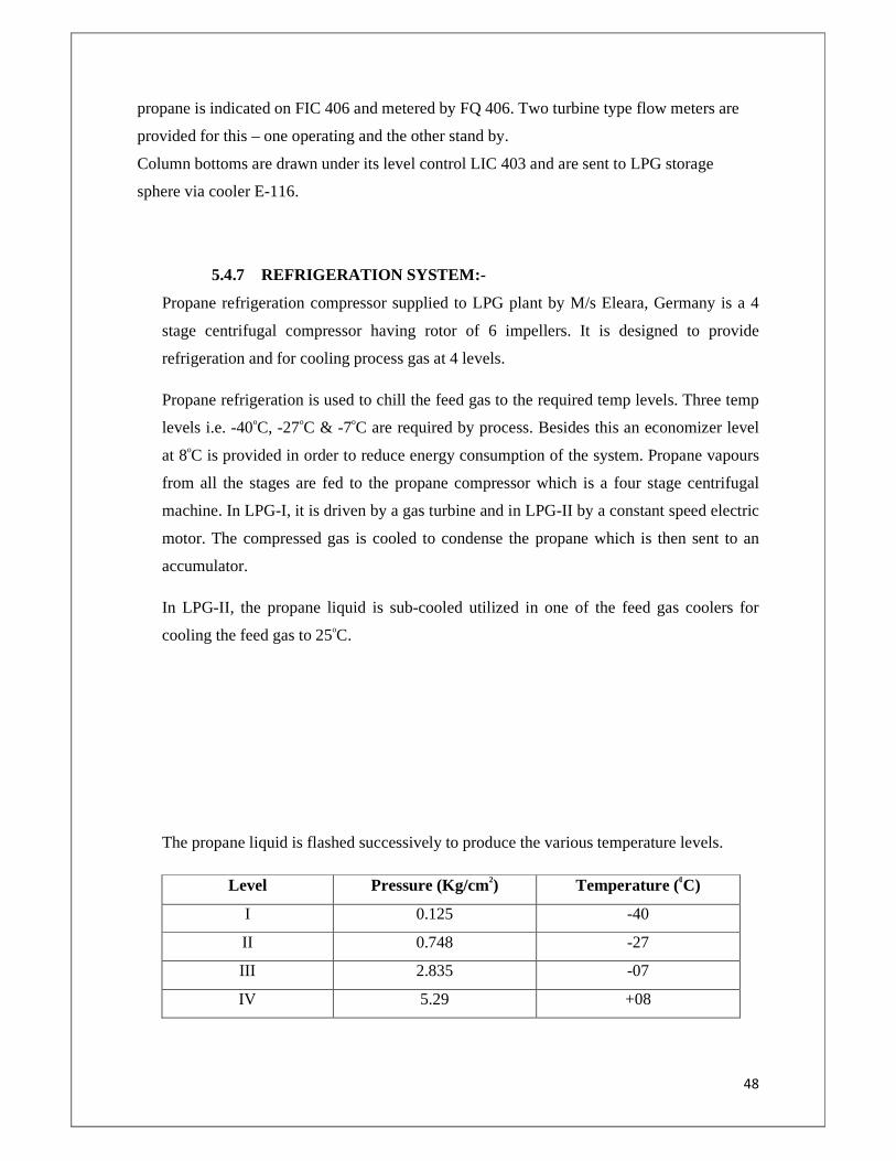
The propane liquid is flashed successively to produce the various temperature levels.
Level Pressure (Kg/cm2) Temperature (0C)
I 0.125 -40
II 0.748 -27
III 2.835 -07
IV 5.29 +08
49
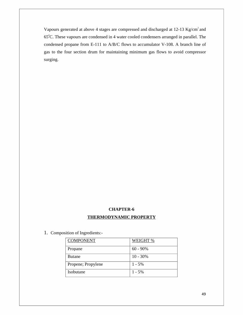
Vapours generated at above 4 stages are compressed and discharged at 12-13 Kg/cm2 and
650C. These vapours are condensed in 4 water cooled condensers arranged in parallel. The
condensed propane from E-111 to A/B/C flows to accumulator V-108. A branch line of
gas to the four section drum for maintaining minimum gas flows to avoid compressor
surging.
CHAPTER-6
THERMODYNAMIC PROPERTY
1. Composition of Ingredients:-
COMPONENT WEIGHT %
Propane 60 - 90%
Butane 10 - 30%
Propene; Propylene 1 - 5%
Isobutane 1 - 5%
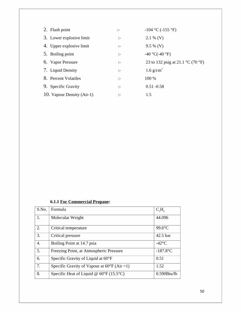
50
2. Flash point :- -104 °C (-155 °F)
3. Lower explosive limit :- 2.1 % (V)
4. Upper explosive limit :- 9.5 % (V)
5. Boiling point :- -40 °C(-40 °F)
6. Vapor Pressure :- 23 to 132 psig at 21.1 °C (70 °F)
7. Liquid Density :- 1.6 g/cm3
8. Percent Volatiles :- 100 %
9. Specific Gravity :- 0.51 -0.58
10. Vapour Density (Air-1) :- 1.5
6.1.1 For Commercial Propane:
S.No. Formula C3H8
1. Molecular Weight 44.096
2. Critical temperature 99.6°C
3. Critical pressure 42.5 bar
4. Boiling Point at 14.7 psia -42°C
5. Freezing Point, at Atmospheric Pressure -187.8°C
6. Specific Gravity of Liquid at 60°F 0.51
7. Specific Gravity of Vapour at 60°F (Air =1) 1.52
8. Specific Heat of Liquid @ 60°F (15.5°C) 0.590Btu/lb
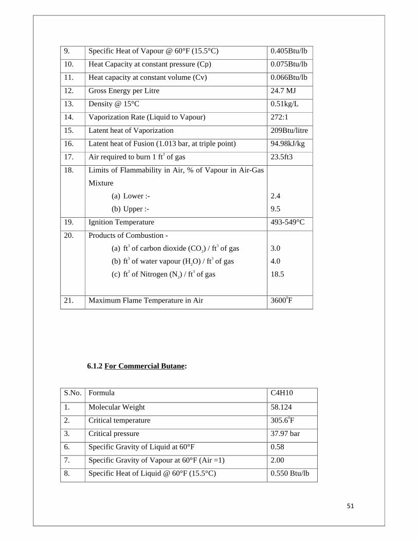
51
9. Specific Heat of Vapour @ 60°F (15.5°C) 0.405Btu/lb
10. Heat Capacity at constant pressure (Cp) 0.075Btu/lb
11. Heat capacity at constant volume (Cv) 0.066Btu/lb
12. Gross Energy per Litre 24.7 MJ
13. Density @ 15°C 0.51kg/L
14. Vaporization Rate (Liquid to Vapour) 272:1
15. Latent heat of Vaporization 209Btu/litre
16. Latent heat of Fusion (1.013 bar, at triple point) 94.98kJ/kg
17. Air required to burn 1 ft3 of gas 23.5ft3
18. Limits of Flammability in Air, % of Vapour in Air-Gas
Mixture
(a) Lower :-
(b) Upper :-
2.4
9.5
19. Ignition Temperature 493-549°C
20. Products of Combustion -
(a) ft3 of carbon dioxide (CO2) / ft3 of gas
(b) ft3 of water vapour (H2O) / ft3 of gas
(c) ft3 of Nitrogen (N2) / ft3 of gas
3.0
4.0
18.5
21. Maximum Flame Temperature in Air 36000F
6.1.2 For Commercial Butane:
S.No. Formula C4H10
1. Molecular Weight 58.124
2. Critical temperature 305.60F
3. Critical pressure 37.97 bar
6. Specific Gravity of Liquid at 60°F 0.58
7. Specific Gravity of Vapour at 60°F (Air =1) 2.00
8. Specific Heat of Liquid @ 60°F (15.5°C) 0.550 Btu/lb
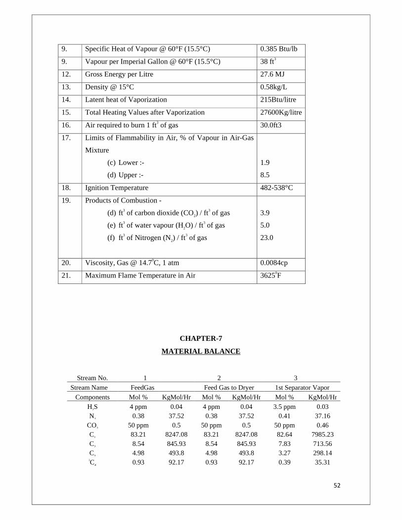
52
9. Specific Heat of Vapour @ 60°F (15.5°C) 0.385 Btu/lb
9. Vapour per Imperial Gallon @ 60°F (15.5°C) 38 ft3
12. Gross Energy per Litre 27.6 MJ
13. Density @ 15°C 0.58kg/L
14. Latent heat of Vaporization 215Btu/litre
15. Total Heating Values after Vaporization 27600Kg/litre
16. Air required to burn 1 ft3 of gas 30.0ft3
17. Limits of Flammability in Air, % of Vapour in Air-Gas
Mixture
(c) Lower :-
(d) Upper :-
1.9
8.5
18. Ignition Temperature 482-538°C
19. Products of Combustion -
(d) ft3 of carbon dioxide (CO2) / ft3 of gas
(e) ft3 of water vapour (H2O) / ft3 of gas
(f) ft3 of Nitrogen (N2) / ft3 of gas
3.9
5.0
23.0
20. Viscosity, Gas @ 14.70C, 1 atm 0.0084cp
21. Maximum Flame Temperature in Air 36250F
CHAPTER-7
MATERIAL BALANCE
Stream No. 1
2
3 Stream Name FeedGas
Feed Gas to Dryer 1st Separator Vapor
Components Mol % KgMol/Hr Mol % KgMol/Hr Mol % KgMol/Hr
H2S 4 ppm 0.04 4 ppm 0.04 3.5 ppm 0.03 N2 0.38 37.52 0.38 37.52 0.41 37.16
CO2 50 ppm 0.5 50 ppm 0.5 50 ppm 0.46 C1 83.21 8247.08 83.21 8247.08 82.64 7985.23 C2 8.54 845.93 8.54 845.93 7.83 713.56 C3 4.98 493.8 4.98 493.8 3.27 298.14 iC4 0.93 92.17 0.93 92.17 0.39 35.31
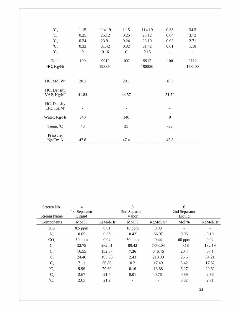
53
nC4 1.15 114.19 1.15 114.19 0.38 34.5 iC5 0.25 25.12 0.25 25.12 0.04 3.72 nC5 0.24 23.91 0.24 23.19 0.03 2.71 nC6 0.32 31.42 0.32 31.42 0.01 1.18 nC7 0 0.16 0 0.16 - -
Total 100 9912 100 9912 100 9112
HC, Kg/Hr 198850 198850 168400
HC, Mol Wt 20.1
20.1
18.5
HC, Density VAP, Kg/M3 41.84
44.57
51.72
HC, Density LIQ, Kg/M3 -
-
-
Water, Kg/Hr 340
140
0
Temp, 0C 40
25
-22
Pressure, Kg/Cm2A 47.8
47.4
45.8
Stream No. 4 5 6
Stream Name 1st Separator
Liquid 2nd Separator
Vapor 2nd Separator
Liquid
Components Mol % KgMol/Hr Mol % KgMol/Hr Mol % KgMol/Hr
H2S 8.5 ppm 0.01 10 ppm 0.03 - -
N2 0.05 0.36 0.42 36.97 0.06 0.19
CO2 50 ppm 0.04 50 ppm 0.44 60 ppm 0.02
C1 32.75 262.01 89.42 7853.04 40.18 132.19
C2 16.55 132.37 7.36 646.46 20.4 67.1
C3 24.46 195.66 2.43 213.93 25.6 84.21 iC4 7.11 56.86 0.2 17.49 5.42 17.82 nC4 9.96 79.69 0.16 13.88 6.27 20.62 iC5 2.67 21.4 0.01 0.76 0.89 2.96 nC5 2.65 21.2 - - 0.82 2.71
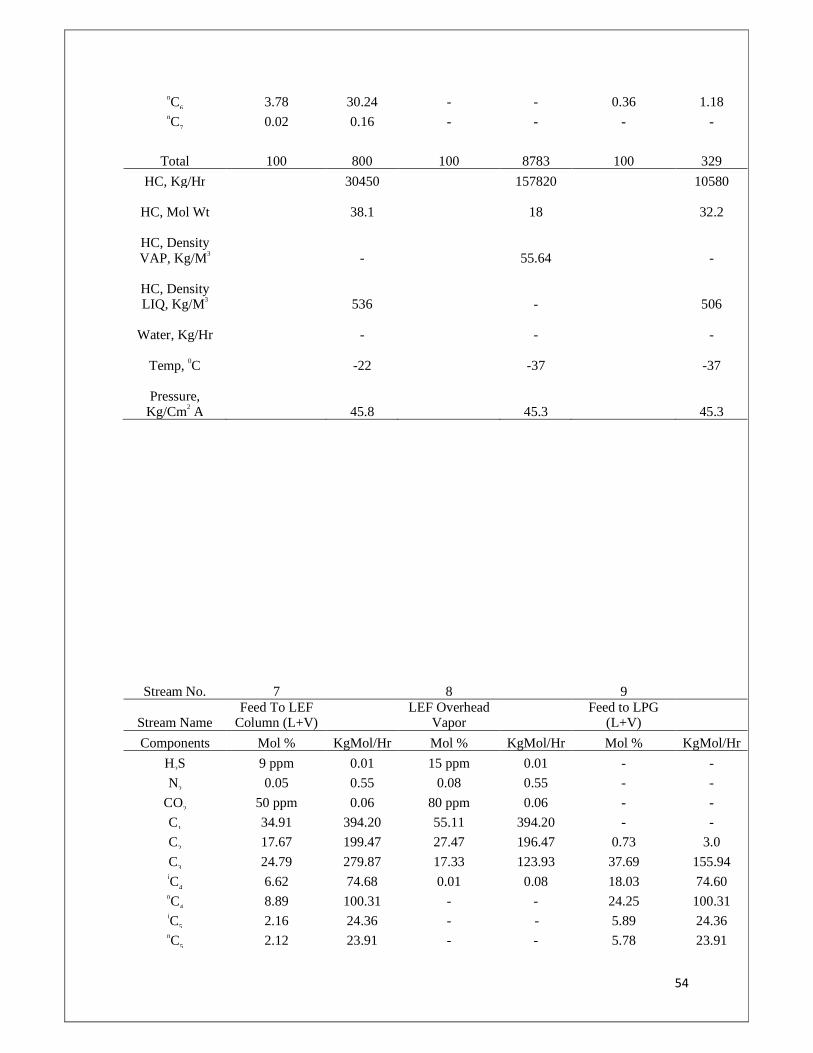
54
nC6 3.78 30.24 - - 0.36 1.18 nC7 0.02 0.16 - - - -
Total 100 800 100 8783 100 329
HC, Kg/Hr 30450 157820 10580
HC, Mol Wt
38.1
18
32.2
HC, Density VAP, Kg/M3
-
55.64
-
HC, Density LIQ, Kg/M3
536
-
506
Water, Kg/Hr
-
-
-
Temp, 0C
-22
-37
-37
Pressure, Kg/Cm2 A 45.8 45.3 45.3
Stream No. 7 8 9
Stream Name Feed To LEF
Column (L+V) LEF Overhead
Vapor Feed to LPG
(L+V)
Components Mol % KgMol/Hr Mol % KgMol/Hr Mol % KgMol/Hr
H2S 9 ppm 0.01 15 ppm 0.01 - -
N2 0.05 0.55 0.08 0.55 - -
CO2 50 ppm 0.06 80 ppm 0.06 - -
C1 34.91 394.20 55.11 394.20 - -
C2 17.67 199.47 27.47 196.47 0.73 3.0
C3 24.79 279.87 17.33 123.93 37.69 155.94 iC4 6.62 74.68 0.01 0.08 18.03 74.60 nC4 8.89 100.31 - - 24.25 100.31 iC5 2.16 24.36 - - 5.89 24.36 nC5 2.12 23.91 - - 5.78 23.91
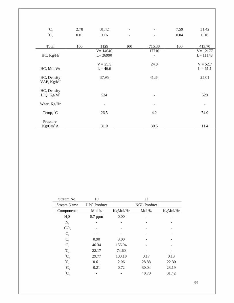
55
nC6 2.78 31.42 - - 7.59 31.42 nC7 0.01 0.16 - - 0.04 0.16
Total 100 1129 100 715.30 100 413.70
HC, Kg/Hr
V= 14040 L= 26990
17710 -
V= 12177 L= 11143
HC, Mol Wt
V = 25.5 L = 46.6
24.8 -
V = 52.7 L = 61.1
HC, Density VAP, Kg/M3
37.95
41.34
25.01
HC, Density LIQ, Kg/M3
524
-
528
Waer, Kg/Hr - - -
Temp, 0C
26.5
4.2
74.0
Pressure, Kg/Cm2 A 31.0 30.6 11.4
Stream No. 10 11
Stream Name LPG Product NGL Product
Components Mol % KgMol/Hr Mol % KgMol/Hr
H2S 0.7 ppm 0.00 - -
N2 - - - -
CO2 - - - -
C1 - - - -
C2 0.90 3.00 - -
C3 46.34 155.94 - - iC4 22.17 74.60 - - nC4 29.77 100.18 0.17 0.13 iC5 0.61 2.06 28.88 22.30 nC5 0.21 0.72 30.04 23.19 nC6 - - 40.70 31.42
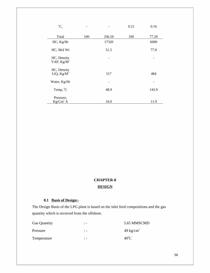
56
nC7 - - 0.21 0.16
Total 100 336.50 100 77.20
HC, Kg/Hr
17320
6000
HC, Mol Wt
51.5
77.8
HC, Density VAP, Kg/M3
-
-
HC, Density LIQ, Kg/M3
517
484
Water, Kg/Hr
-
-
Temp, 0C
48.9
143.9
Pressure, Kg/Cm2 A 16.0 11.9
CHAPTER-8
DESIGN
8.1 Basis of Design:-
The Design Basis of the LPG plant is based on the inlet feed compositions and the gas
quantity which is received from the offshore.
Gas Quantity : - 5.65 MMSCMD
Pressure : - 49 kg/cm2
Temperature : - 400C
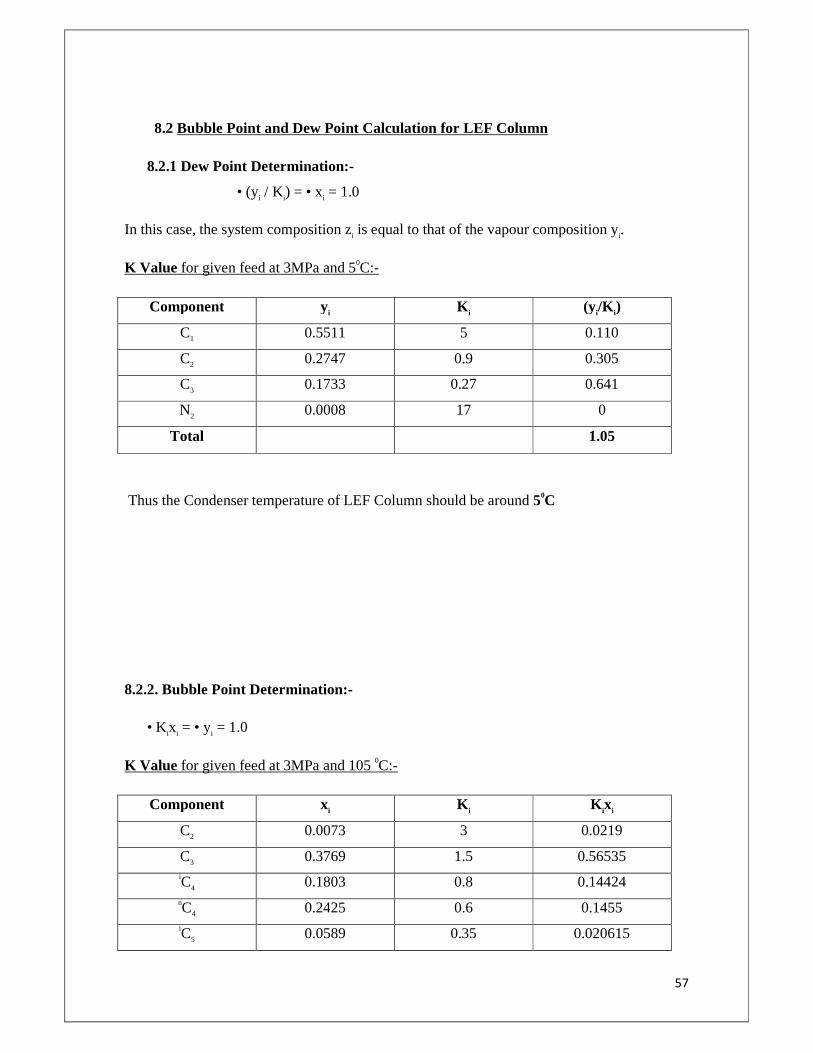
57
8.2 Bubble Point and Dew Point Calculation for LEF Column
8.2.1 Dew Point Determination:-
• (yi / Ki) = • xi = 1.0
In this case, the system composition zi is equal to that of the vapour composition yi.
K Value for given feed at 3MPa and 50C:-
Component yi K i (yi/K i)
C1 0.5511 5 0.110
C2 0.2747 0.9 0.305
C3 0.1733 0.27 0.641
N2 0.0008 17 0
Total 1.05
Thus the Condenser temperature of LEF Column should be around 50C
8.2.2. Bubble Point Determination:-
• Kixi = • yi = 1.0
K Value for given feed at 3MPa and 105 0C:-
Component xi K i K ixi
C2 0.0073 3 0.0219
C3 0.3769 1.5 0.56535 iC4 0.1803 0.8 0.14424 nC4 0.2425 0.6 0.1455 iC5 0.0589 0.35 0.020615
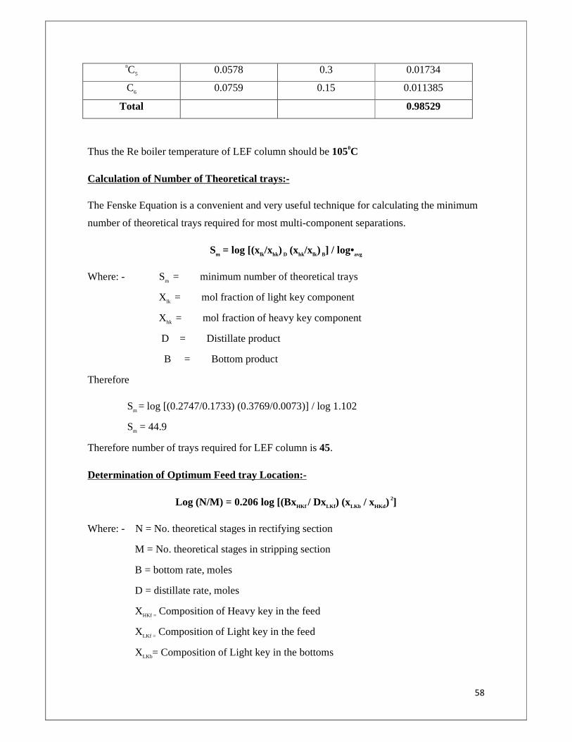
58
nC5 0.0578 0.3 0.01734
C6 0.0759 0.15 0.011385
Total 0.98529
Thus the Re boiler temperature of LEF column should be 1050C
Calculation of Number of Theoretical trays:-
The Fenske Equation is a convenient and very useful technique for calculating the minimum
number of theoretical trays required for most multi-component separations.
Sm = log [(xlk/xhk) D (xhk/xlk) B] / log•avg
Where: - Sm = minimum number of theoretical trays
Xlk = mol fraction of light key component
Xhk = mol fraction of heavy key component
D = Distillate product
B = Bottom product
Therefore
Sm = log [(0.2747/0.1733) (0.3769/0.0073)] / log 1.102
Sm = 44.9
Therefore number of trays required for LEF column is 45.
Determination of Optimum Feed tray Location:-
Log (N/M) = 0.206 log [(BxHKf / DxLKf ) (xLKb / xHKd ) 2]
Where: - N = No. theoretical stages in rectifying section
M = No. theoretical stages in stripping section
B = bottom rate, moles
D = distillate rate, moles
XHKf = Composition of Heavy key in the feed
XLKf = Composition of Light key in the feed
XLKb= Composition of Light key in the bottoms
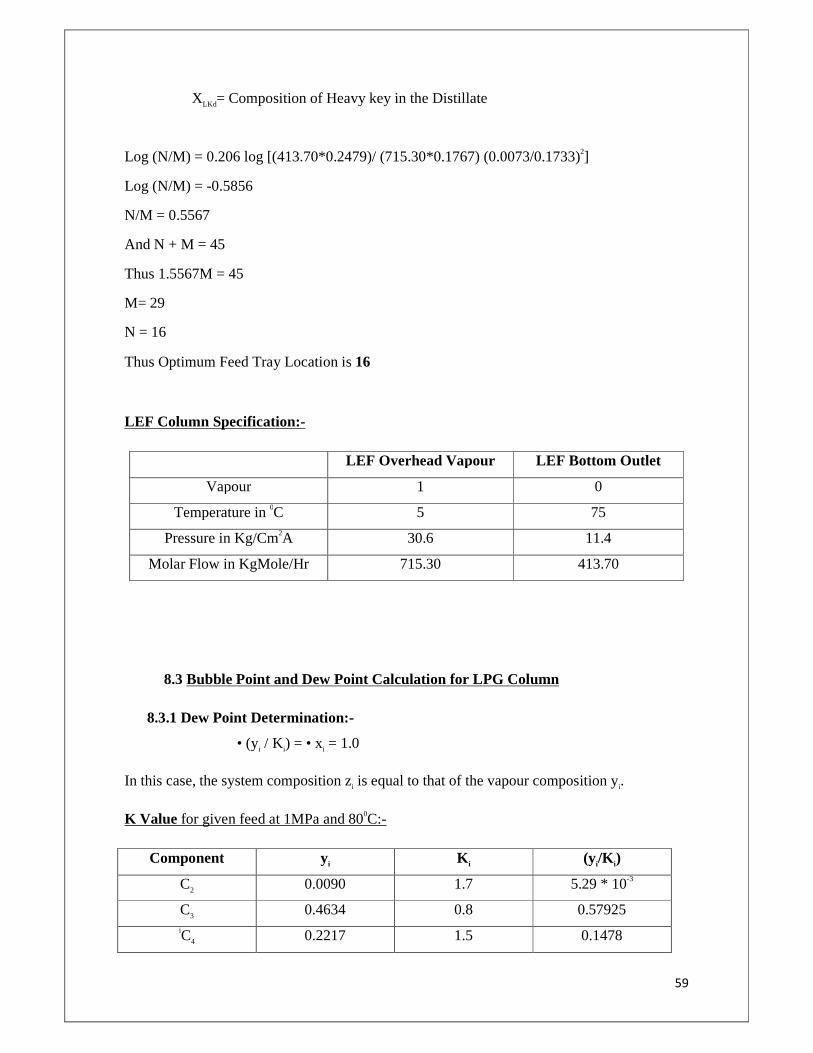
59
XLKd= Composition of Heavy key in the Distillate
Log (N/M) = 0.206 log [(413.70*0.2479)/ (715.30*0.1767) (0.0073/0.1733)2]
Log (N/M) = -0.5856
N/M = 0.5567
And N + M = 45
Thus 1.5567M = 45
M= 29
N = 16
Thus Optimum Feed Tray Location is 16
LEF Column Specification:-
LEF Overhead Vapour LEF Bottom Outlet
Vapour 1 0
Temperature in 0C 5 75
Pressure in Kg/Cm2A 30.6 11.4
Molar Flow in KgMole/Hr 715.30 413.70
8.3 Bubble Point and Dew Point Calculation for LPG Column
8.3.1 Dew Point Determination:-
• (yi / Ki) = • xi = 1.0
In this case, the system composition zi is equal to that of the vapour composition yi.
K Value for given feed at 1MPa and 800C:-
Component yi K i (yi/K i)
C2 0.0090 1.7 5.29 * 10-3
C3 0.4634 0.8 0.57925 iC4 0.2217 1.5 0.1478
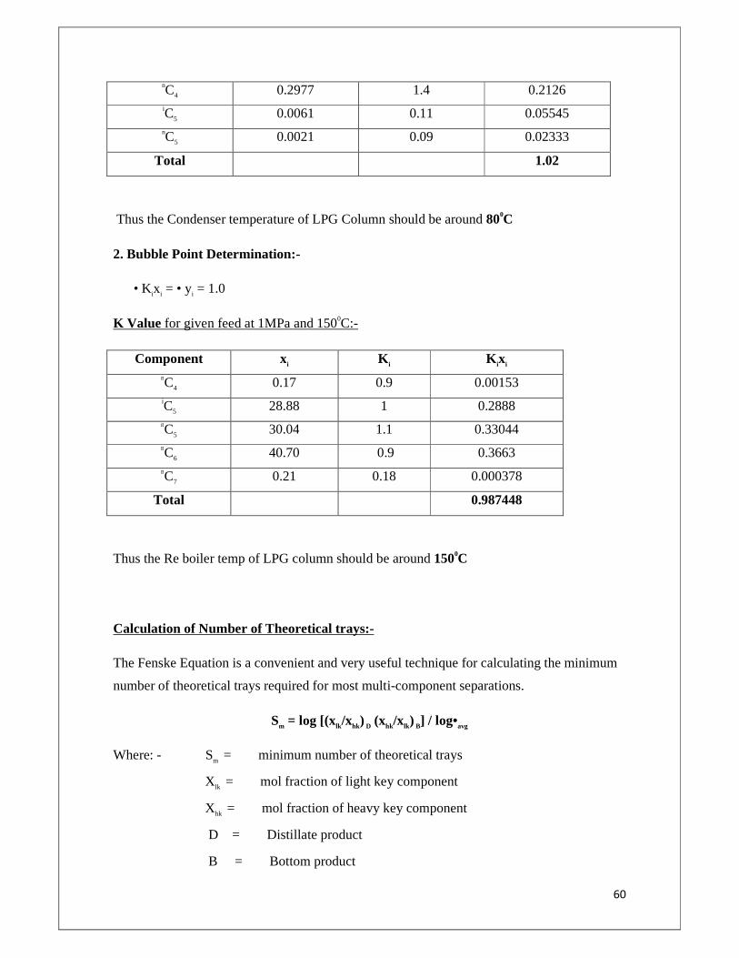
60
nC4 0.2977 1.4 0.2126 iC5 0.0061 0.11 0.05545 nC5 0.0021 0.09 0.02333
Total 1.02
Thus the Condenser temperature of LPG Column should be around 800C
2. Bubble Point Determination:-
• Kixi = • yi = 1.0
K Value for given feed at 1MPa and 1500C:-
Component xi K i
K ixi
nC4 0.17 0.9 0.00153 iC5 28.88 1 0.2888 nC5 30.04 1.1 0.33044 nC6 40.70 0.9 0.3663 nC7 0.21 0.18 0.000378
Total 0.987448
Thus the Re boiler temp of LPG column should be around 1500C
Calculation of Number of Theoretical trays:-
The Fenske Equation is a convenient and very useful technique for calculating the minimum
number of theoretical trays required for most multi-component separations.
Sm = log [(xlk/xhk) D (xhk/xlk) B] / log•avg
Where: - Sm = minimum number of theoretical trays
Xlk = mol fraction of light key component
Xhk = mol fraction of heavy key component
D = Distillate product
B = Bottom product
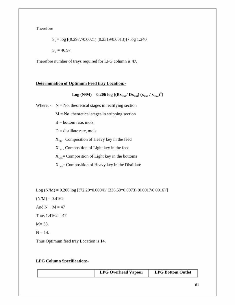
61
Therefore
Sm = log [(0.2977/0.0021) (0.2319/0.0013)] / log 1.240
Sm = 46.97
Therefore number of trays required for LPG column is 47.
Determination of Optimum Feed tray Location:-
Log (N/M) = 0.206 log [(BxHKf / DxLKf ) (xLKb / xHKd ) 2]
Where: - N = No. theoretical stages in rectifying section
M = No. theoretical stages in stripping section
B = bottom rate, mols
D = distillate rate, mols
XHKf = Composition of Heavy key in the feed
XLKf = Composition of Light key in the feed
XLKb= Composition of Light key in the bottoms
XLKd= Composition of Heavy key in the Distillate
Log (N/M) = 0.206 log [(72.20*0.0004)/ (336.50*0.0073) (0.0017/0.0016)2]
(N/M) = 0.4162
And N + M = 47
Thus 1.4162 = 47
M= 33.
N = 14.
Thus Optimum feed tray Location is 14.
LPG Column Specification:-
LPG Overhead Vapour LPG Bottom Outlet
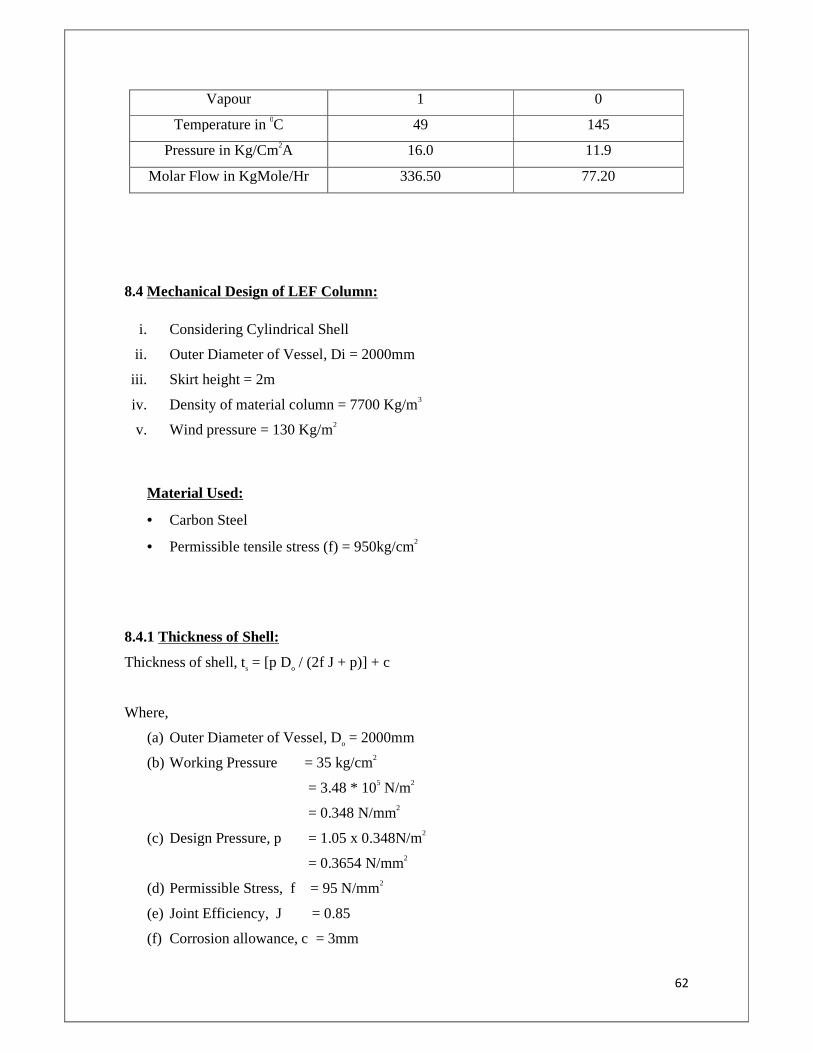
62
Vapour 1 0
Temperature in 0C 49 145
Pressure in Kg/Cm2A 16.0 11.9
Molar Flow in KgMole/Hr 336.50 77.20
8.4 Mechanical Design of LEF Column:
i. Considering Cylindrical Shell
ii. Outer Diameter of Vessel, Di = 2000mm
iii. Skirt height = 2m
iv. Density of material column = 7700 Kg/m3
v. Wind pressure = 130 Kg/m2
Material Used:
• Carbon Steel
• Permissible tensile stress (f) = 950kg/cm2
8.4.1 Thickness of Shell:
Thickness of shell, ts = [p Do / (2f J + p)] + c
Where,
(a) Outer Diameter of Vessel, Do = 2000mm
(b) Working Pressure = 35 kg/cm2
= 3.48 * 105 N/m2
= 0.348 N/mm2
(c) Design Pressure, p = 1.05 x 0.348N/m2
= 0.3654 N/mm2
(d) Permissible Stress, f = 95 N/mm2
(e) Joint Efficiency, J = 0.85
(f) Corrosion allowance, c = 3mm
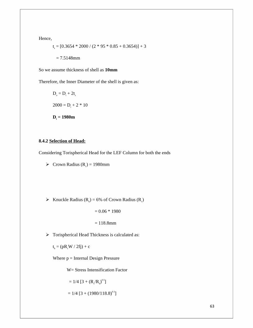
63
Hence,
ts = [0.3654 * 2000 / (2 * 95 * 0.85 + 0.3654)] + 3
= 7.5148mm
So we assume thickness of shell as 10mm
Therefore, the Inner Diameter of the shell is given as:
Do = Di + 2ts
2000 = Di + 2 * 10
Di = 1980m
8.4.2 Selection of Head:
Considering Torispherical Head for the LEF Column for both the ends
� Crown Radius (Rc) = 1980mm
� Knuckle Radius (Rk) = 6% of Crown Radius (Rc)
= 0.06 * 1980
= 118.8mm
� Torispherical Head Thickness is calculated as:
th = (pRcW / 2fj) + c
Where p = Internal Design Pressure
W= Stress Intensification Factor
= 1/4 [3 + (Rc/Rk)0.5]
= 1/4 [3 + (1980/118.8)0.5]
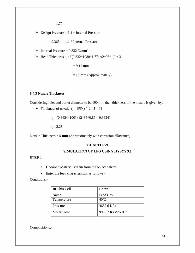
64
= 1.77
� Design Pressure = 1.1 * Internal Pressure
0.3654 = 1.1 * Internal Pressure
� Internal Pressure = 0.332 N/mm2
� Head Thickness th = [(0.332*1980*1.77) /(2*95*1)] + 3
= 9.12 mm
= 10 mm (Approximately)
8.4.3 Nozzle Thickness:
Considering inlet and outlet diameter to be 100mm, then thickness of the nozzle is given by,
� Thickness of nozzle, tn = (PDn) / [2 f J – P]
tn = (0.3654*100) / (2*95*0.85 – 0.3654)
tn= 2.26
Nozzle Thickness = 5 mm (Approximately with corrosion allowance).
CHAPTER-9
SIMULATION OF LPG USING HYSYS 3.1
STEP-1
• Choose a Material stream from the object palette
• Enter the feed characteristics as follows:-
Conditions:-
In This Cell Enter
Name Feed Gas Temperature 400C
Pressure 4687.6 KPa
Molar Flow 9930.7 KgMole/Hr
Compositions:-
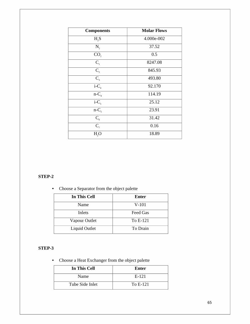
65
Components Molar Flows
H2S 4.000e-002
N2 37.52
CO2 0.5
C1 8247.08
C2 845.93
C3 493.80
i-C4 92.170
n-C4 114.19
i-C5 25.12
n-C5 23.91
C6 31.42
C7 0.16
H2O 18.89
STEP-2
• Choose a Separator from the object palette
In This Cell Enter
Name V-101
Inlets Feed Gas
Vapour Outlet To E-121
Liquid Outlet To Drain
STEP-3
• Choose a Heat Exchanger from the object palette
In This Cell Enter
Name E-121
Tube Side Inlet To E-121
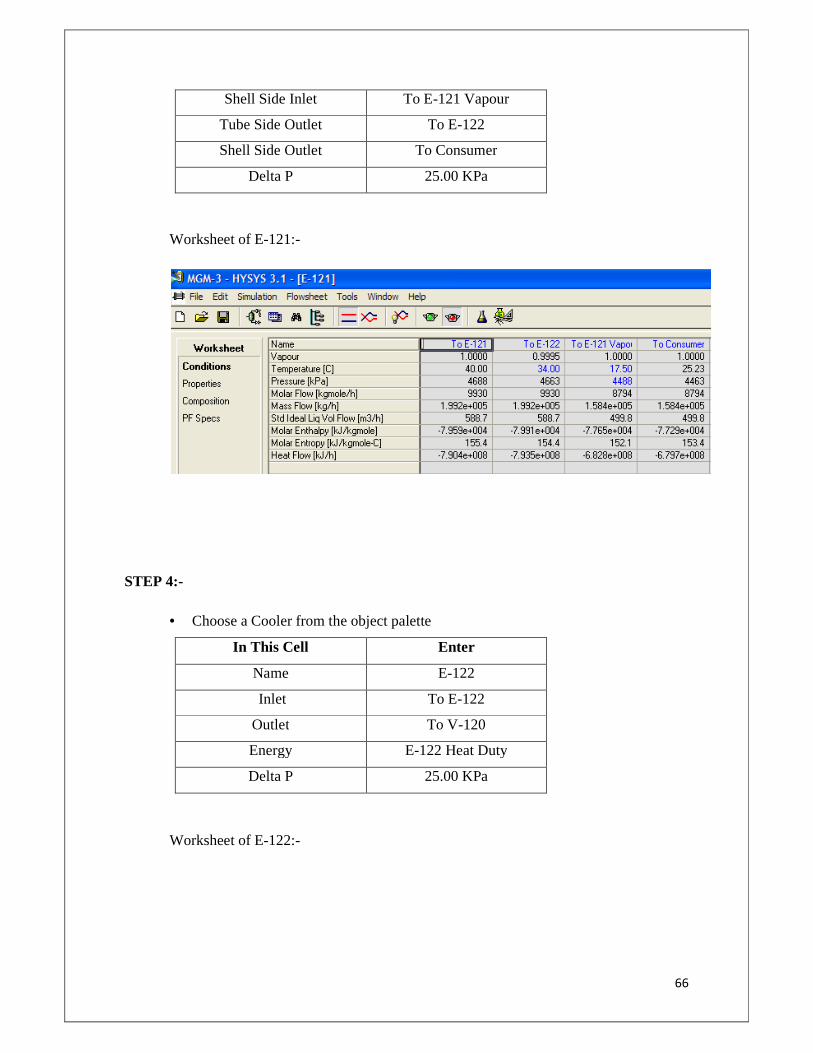
66
Shell Side Inlet To E-121 Vapour
Tube Side Outlet To E-122
Shell Side Outlet To Consumer
Delta P 25.00 KPa
Worksheet of E-121:-
STEP 4:-
• Choose a Cooler from the object palette
In This Cell Enter
Name E-122
Inlet To E-122
Outlet To V-120
Energy E-122 Heat Duty
Delta P 25.00 KPa
Worksheet of E-122:-
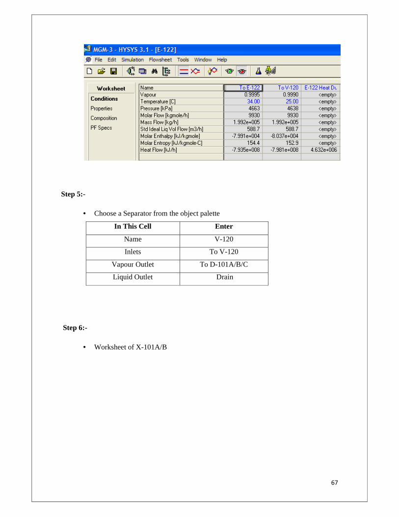
67
Step 5:-
• Choose a Separator from the object palette
In This Cell Enter
Name V-120
Inlets To V-120
Vapour Outlet To D-101A/B/C
Liquid Outlet Drain
Step 6:-
• Worksheet of X-101A/B
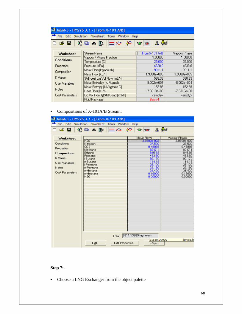
68
• Compositions of X-101A/B Stream:
Step 7:-
• Choose a LNG Exchanger from the object palette
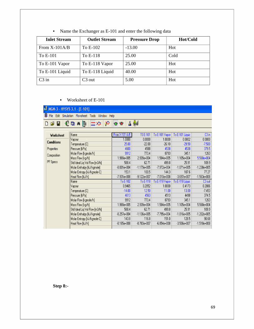
69
• Name the Exchanger as E-101 and enter the following data
Inlet Stream Outlet Stream Pressure Drop Hot/Cold
From X-101A/B To E-102 -13.00 Hot
To E-101 To E-118 25.00 Cold
To E-101 Vapor To E-118 Vapor 25.00 Hot
To E-101 Liquid To E-118 Liquid 40.00 Hot
C3 in C3 out 5.00 Hot
• Worksheet of E-101
Step 8:-
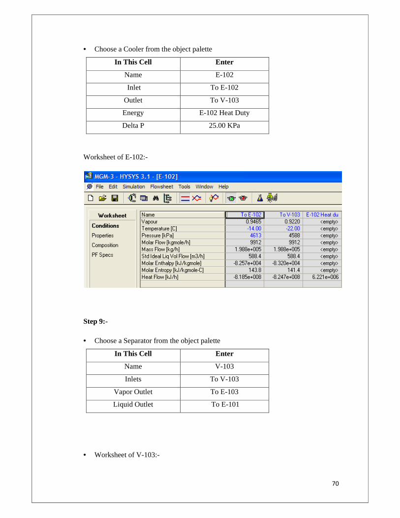
70
• Choose a Cooler from the object palette
In This Cell Enter
Name E-102
Inlet To E-102
Outlet To V-103
Energy E-102 Heat Duty
Delta P 25.00 KPa
Worksheet of E-102:-
Step 9:-
• Choose a Separator from the object palette
In This Cell Enter
Name V-103
Inlets To V-103
Vapor Outlet To E-103
Liquid Outlet To E-101
• Worksheet of V-103:-
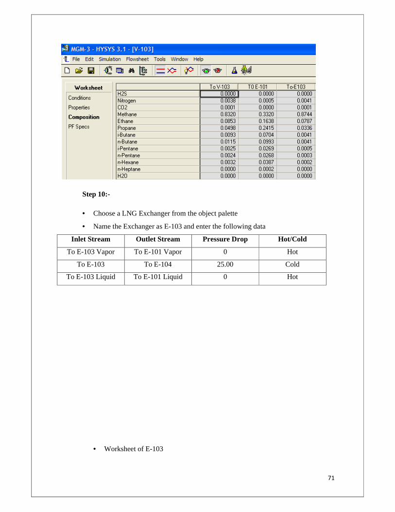
71
Step 10:-
• Choose a LNG Exchanger from the object palette
• Name the Exchanger as E-103 and enter the following data
Inlet Stream Outlet Stream Pressure Drop Hot/Cold
To E-103 Vapor To E-101 Vapor 0 Hot
To E-103 To E-104 25.00 Cold
To E-103 Liquid To E-101 Liquid 0 Hot
• Worksheet of E-103
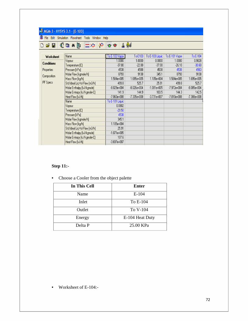
72
Step 11:-
• Choose a Cooler from the object palette
In This Cell Enter
Name E-104
Inlet To E-104
Outlet To V-104
Energy E-104 Heat Duty
Delta P 25.00 KPa
• Worksheet of E-104:-
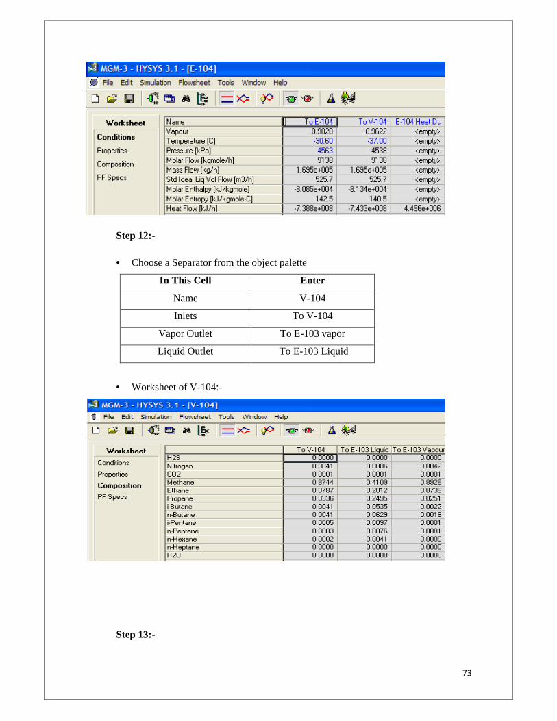
73
Step 12:-
• Choose a Separator from the object palette
In This Cell Enter
Name V-104
Inlets To V-104
Vapor Outlet To E-103 vapor
Liquid Outlet To E-103 Liquid
• Worksheet of V-104:-
Step 13:-
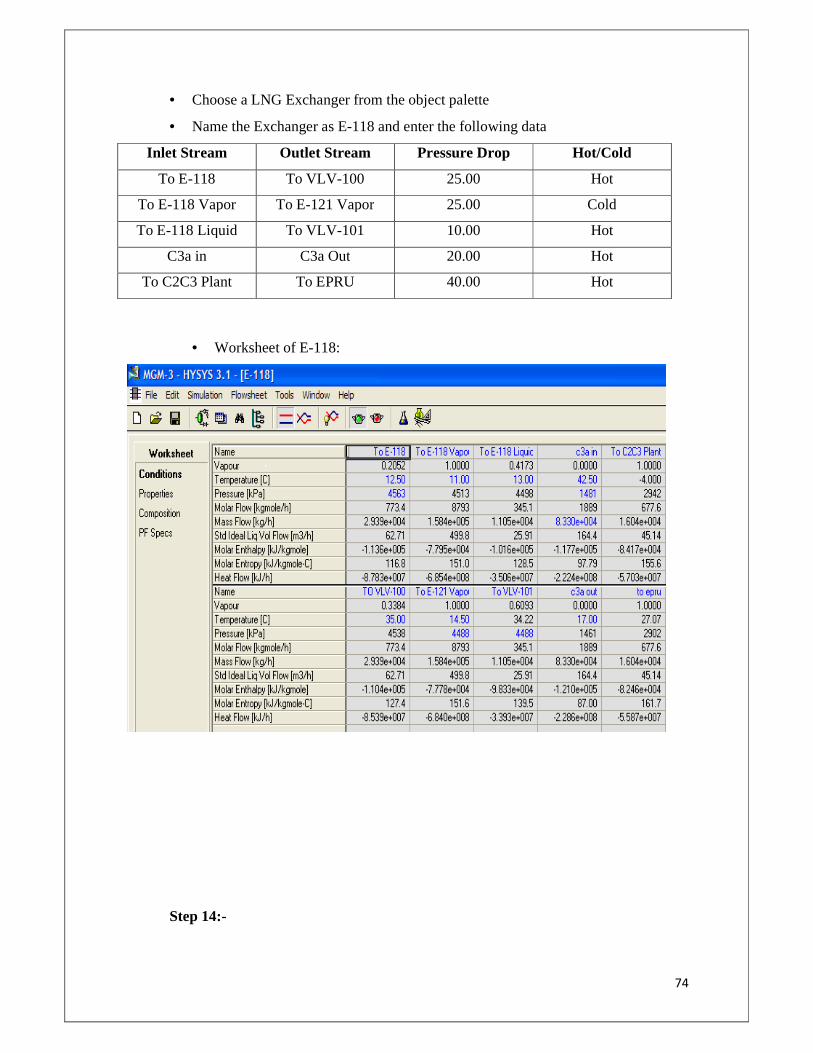
74
• Choose a LNG Exchanger from the object palette
• Name the Exchanger as E-118 and enter the following data
Inlet Stream Outlet Stream Pressure Drop Hot/Cold
To E-118 To VLV-100 25.00 Hot
To E-118 Vapor To E-121 Vapor 25.00 Cold
To E-118 Liquid To VLV-101 10.00 Hot
C3a in C3a Out 20.00 Hot
To C2C3 Plant To EPRU 40.00 Hot
• Worksheet of E-118:
Step 14:-
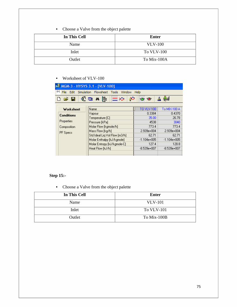
75
• Choose a Valve from the object palette
In This Cell Enter
Name VLV -100
Inlet To VLV-100
Outlet To Mix-100A
• Worksheet of VLV-100
Step 15:-
• Choose a Valve from the object palette
In This Cell Enter
Name VLV -101
Inlet To VLV-101
Outlet To Mix-100B
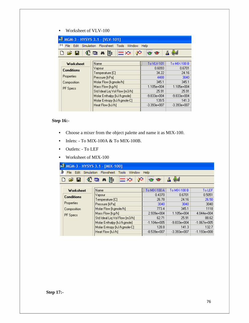
76
• Worksheet of VLV-100
Step 16:-
• Choose a mixer from the object palette and name it as MIX-100.
• Inlets: - To MIX-100A & To MIX-100B.
• Outlets: - To LEF
• Worksheet of MIX-100
Step 17:-
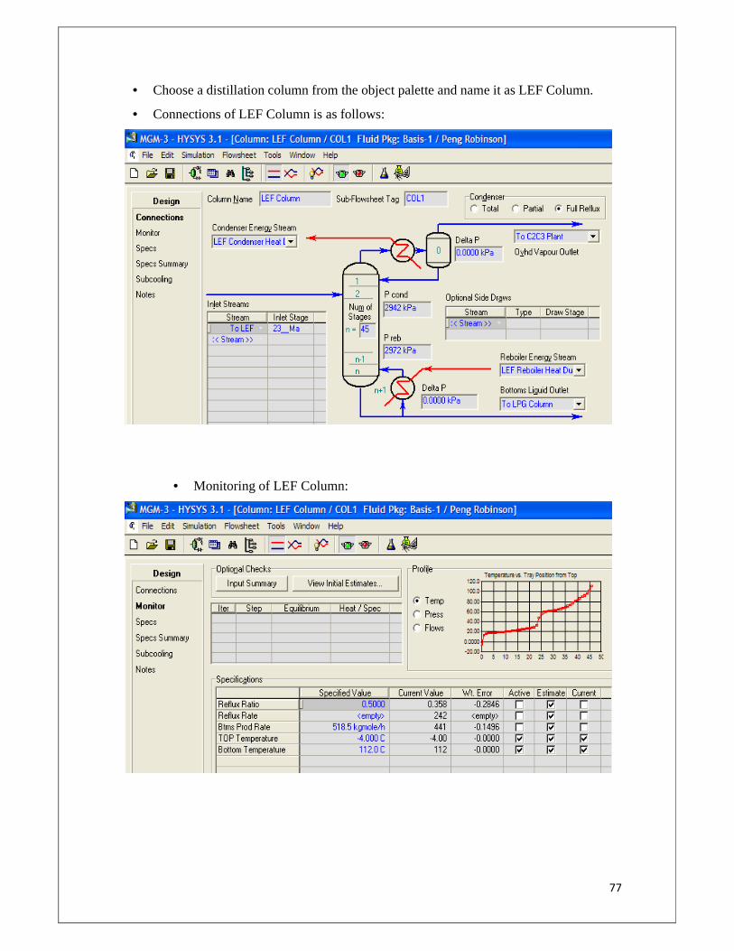
77
• Choose a distillation column from the object palette and name it as LEF Column.
• Connections of LEF Column is as follows:
• Monitoring of LEF Column:
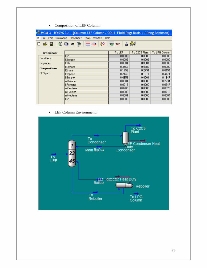
78
• Composition of LEF Column:
• LEF Column Environment:
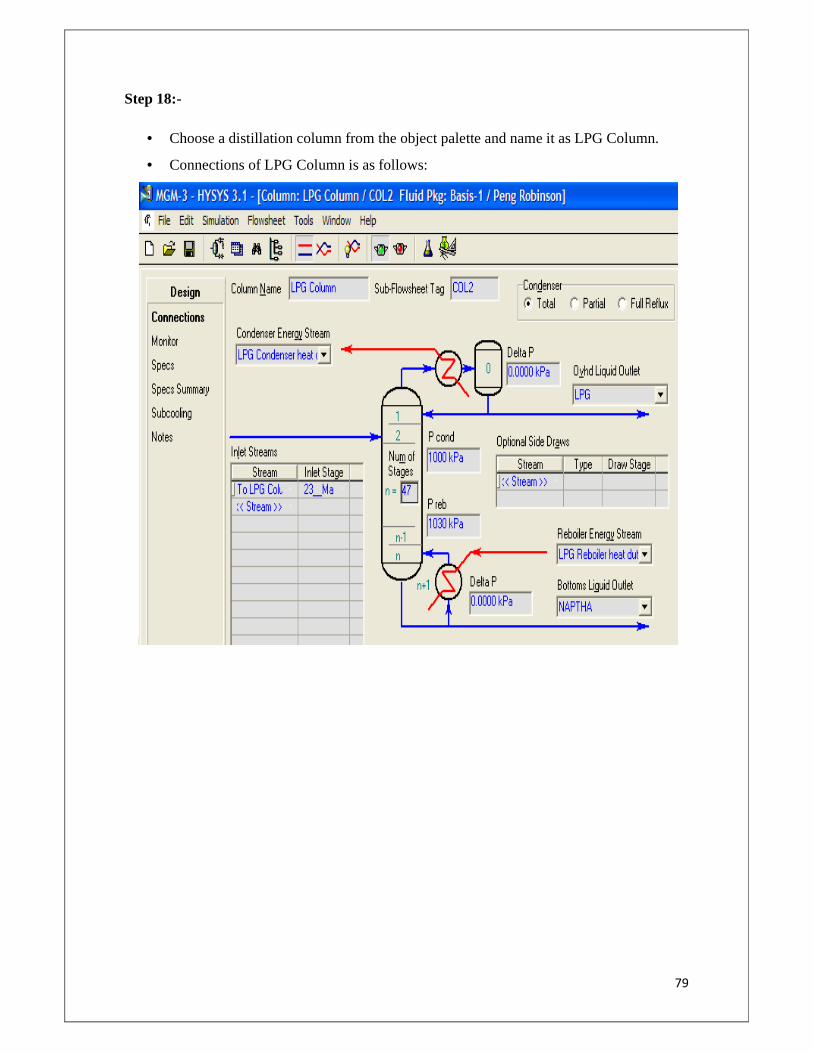
79
Step 18:-
• Choose a distillation column from the object palette and name it as LPG Column.
• Connections of LPG Column is as follows:
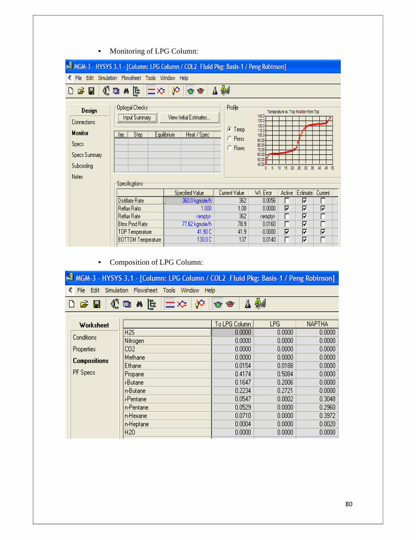
80
• Monitoring of LPG Column:
• Composition of LPG Column:
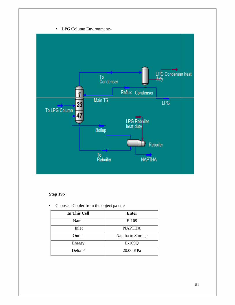
81
• LPG Column Environment:-
Step 19:-
• Choose a Cooler from the object palette
In This Cell Enter
Name E-109
Inlet NAPTHA
Outlet Naptha to Storage
Energy E-109Q
Delta P 20.00 KPa
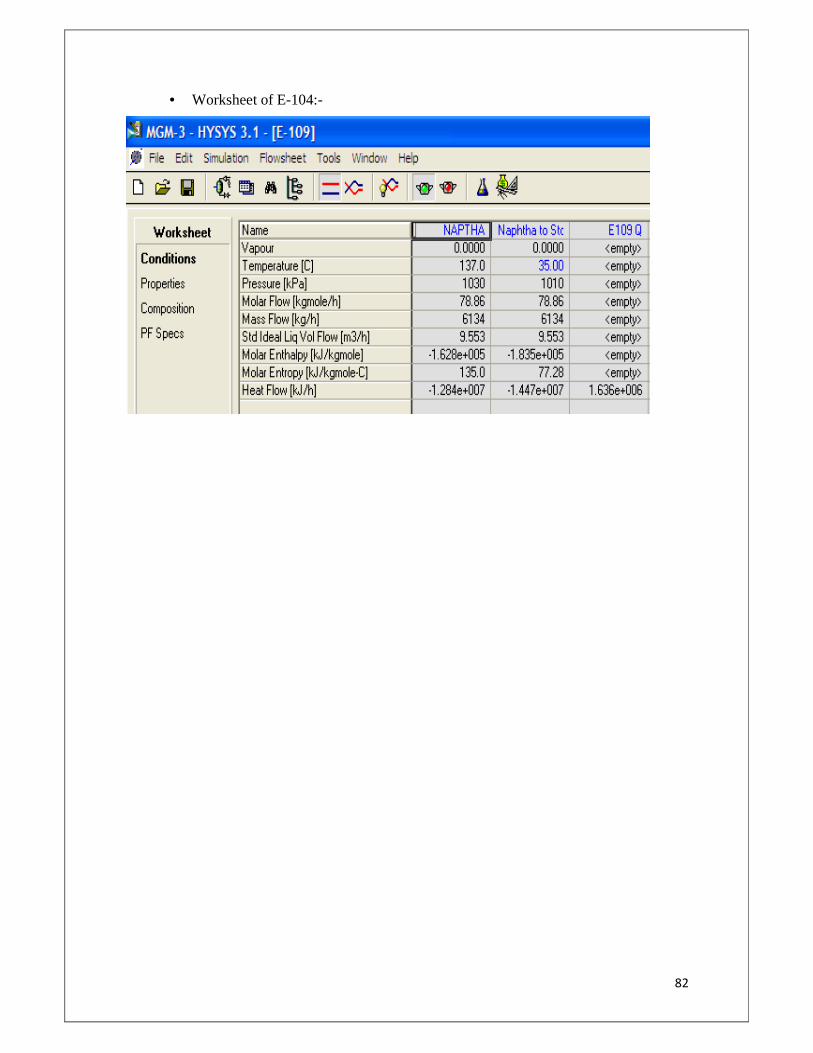
82
• Worksheet of E-104:-
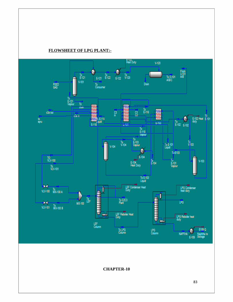
83
FLOWSHEET OF LPG PLANT:-
CHAPTER-10
84
COST ESTIMATION
The plant must not just produce the desired capacity and quality, but produce the product
under the conditions that will yield a profit. In general, the net profit equals the total income
minus all the expenses, so one must be aware of the various expenses that are incurred during
the construction period and also the day to day running expenses, such as those for raw
materials, labour and equipment. Besides direct expenses, many other indirect expenses are
incurred and those must be included if the complete analysis of the total cost is to be
obtained.
10.1 Factors affecting Investment and Production Costs:-
When cost estimation is done, this must be fairly accurate to provide reliable decisions. To
accomplish it, one must be aware of the factors that can affect the costs. These factors are
listed below:
10.1.1 Source of Equipment:
One of the major costs involved in the chemical industry is that of the equipment. In many
cases, standard types of tanks, reactors or other equipment is used and the substantial
reduction in cost can be made by employing idle equipment or by purchasing second hand
equipment. If new equipment is to be brought then several independent quotations should be
obtained from different manufacturers.
10.1.2 Price Fluctuations:
In modern economic society, prices may vary widely from one period to another and this
factor must be considered when the cost of an industrial process is determined.
10.1.3 Company Policies:
Policies of the company in concern have a direct effect on cost. This refers to policies such as
labour policies, safety regulations, overtime payment, etc. This policies may be differing
from company to company ad have a direct effect on cost.
10.1.4 Operating time and Cost of Equipment:
85
One of the factors that have an important effect on the cost is the fraction of total time
available time during which the process is in operation. When equipment stands idle for an
extended period of time, the labour costs are nil however costs such as those of maintenance,
production and depreciation continue even though the equipment is not in active use.
Operating time, rate of production and sales demand are closely inter-related. The
ideal plant must operate under a time schedule which gives the maximum production rate
while maintaining economic operating methods.
10.1.5 Government Policies:
The National and State Government have various rules and regulations, which have a direct
impact on the industrial costs. Some examples of these are imports and exports, tariff
regulations, Income Tax rules, and Environmental regulations.
10.2 BASIS OF COST ESTIMATION:-
86
The Plant cost has been worked out based on the broad equipment list developed for the
required facilities and in-house cost data from the recent experienced cost for similar
equipments.
10.2.1 Equipment: - Equipment cost is based on the broad equipment list and in house
cost data.
10.2.2 Bulk Materials (Piping, Electrical & Instrumentatio n): - A factored approach
has been adopted for estimating supply cost of bulk materials i.e. piping,
electrical, and instrumentation.
(a) Piping: 25% of the Equipment Costs.
(b) Electrical: 10% of the Equipment + Piping Costs.
(c) Instrumentation: 15% of the Equipment + Piping Costs.
10.2.3 Spares: - Cost of spares has been included on factor basis.
10.2.4 Erection Works: - Provision for Mechanical & piping, electrical &
instrumentation erection works is based on the factor of the respective supply cost.
(a) Mechanical: 13% of the Equipment + Piping Costs.
(b) Electrical: 20% of Electrical Bulk Material Cost.
(c) Instrumentation: 15% of Instrumentation Bulk Material Cost.
10.2.5 Civil & Structural Works: - Cost provision has been made for general Civil &
Structural works as a factor on the equipment Cost. It is taken as 15% of the
Equipment Cost.
10.2.6 Painting & Insulation: - Cost provision for Insulation, painting and fire proofing
is taken as a factor on the equipment and piping cost.
It is taken as 5% of the Equipment + Piping Cost.
87
10.2.7 Future Escalation: - Future Escalation for the execution period has been
considered in the cost estimation. It is taken as 5% of the total cost which includes
erection, bulk material, spares, erection, civil works, insulation & painting.
10.2.8 Indirect Costs & Statutory:- Following statutory taxes and duties have been
considered in the estimate:-
Custom Duty : 25.575%
Excise Duty : 14.42%
Service Tax : 12.36%
Sales Tax : 2.00%
Works Contract Tax : 6.06%
Following indirect Cost has been considered:-
Ocean freight : 6%
Port Handling and Transportation : 2%
Inland Freight : 3%
• Repair and Maintenance is taken as @1% of Plant & Machinery Costs.
• Insurance is taken as @1% of Capital Costs.
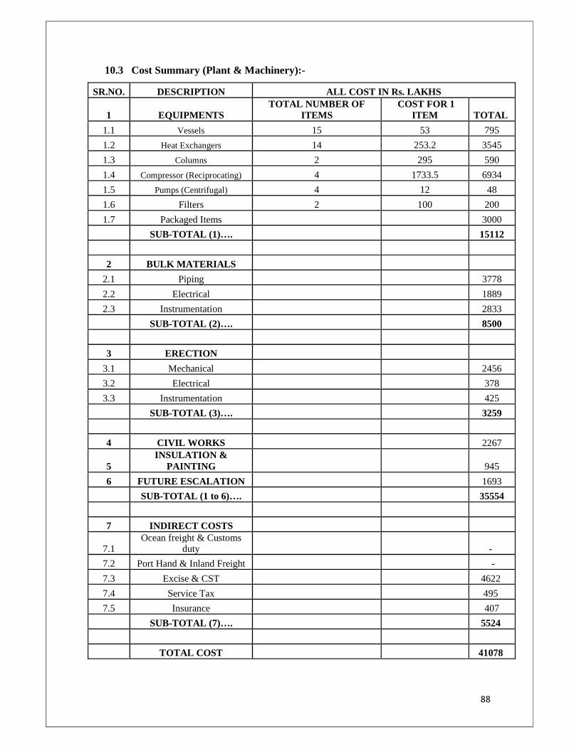
88
10.3 Cost Summary (Plant & Machinery):-
SR.NO. DESCRIPTION ALL COST IN Rs. LAKHS
1 EQUIPMENTS TOTAL NUMBER OF
ITEMS COST FOR 1
ITEM TOTAL
1.1 Vessels 15 53 795
1.2 Heat Exchangers 14 253.2 3545
1.3 Columns 2 295 590
1.4 Compressor (Reciprocating) 4 1733.5 6934
1.5 Pumps (Centrifugal) 4 12 48
1.6 Filters 2 100 200
1.7 Packaged Items 3000
SUB-TOTAL (1)…. 15112
2 BULK MATERIALS
2.1 Piping 3778
2.2 Electrical 1889
2.3 Instrumentation 2833
SUB-TOTAL (2)…. 8500
3 ERECTION
3.1 Mechanical 2456
3.2 Electrical 378
3.3 Instrumentation 425
SUB-TOTAL (3)…. 3259
4 CIVIL WORKS 2267
5 INSULATION &
PAINTING 945
6 FUTURE ESCALATION 1693
SUB-TOTAL (1 to 6)…. 35554
7 INDIRECT COSTS
7.1 Ocean freight & Customs
duty -
7.2 Port Hand & Inland Freight -
7.3 Excise & CST 4622
7.4 Service Tax 495
7.5 Insurance 407
SUB-TOTAL (7)…. 5524
TOTAL COST 41078
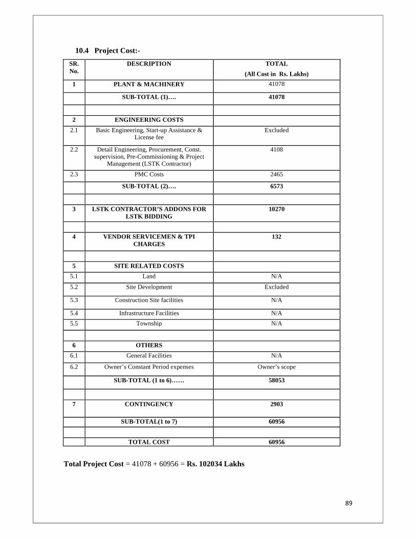
89
10.4 Project Cost:-
SR. No.
DESCRIPTION TOTAL
(All Cost in Rs. Lakhs)
1 PLANT & MACHINERY 41078
SUB-TOTAL (1)…. 41078
2 ENGINEERING COSTS
2.1 Basic Engineering, Start-up Assistance & License fee
Excluded
2.2 Detail Engineering, Procurement, Const. supervision, Pre-Commissioning & Project
Management (LSTK Contractor)
4108
2.3 PMC Costs 2465
SUB-TOTAL (2)…. 6573
3 LSTK CONTRACTOR’S ADDONS FOR LSTK BIDDING
10270
4 VENDOR SERVICEMEN & TPI CHARGES
132
5 SITE RELATED COSTS
5.1 Land N/A
5.2 Site Development Excluded
5.3 Construction Site facilities N/A
5.4 Infrastructure Facilities N/A
5.5 Township N/A
6 OTHERS
6.1 General Facilities N/A
6.2 Owner’s Constant Period expenses Owner’s scope
SUB-TOTAL (1 to 6)…… 58053
7 CONTINGENCY 2903
SUB-TOTAL(1 to 7) 60956
TOTAL COST 60956
Total Project Cost = 41078 + 60956 = Rs. 102034 Lakhs
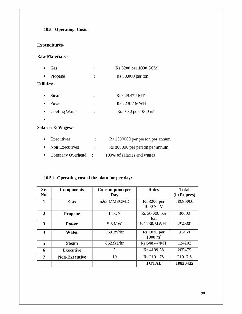
90
10.5 Operating Costs:-
Expenditures-
Raw Materials:-
• Gas : Rs 3200 per 1000 SCM
• Propane : Rs 30,000 per ton
Utilities:-
• Steam : Rs 648.47 / MT
• Power : Rs 2230 / MWH
• Cooling Water : Rs 1030 per 1000 m3
•
Salaries & Wages:-
• Executives : Rs 1500000 per person per annum
• Non Executives : Rs 800000 per person per annum
• Company Overhead : 100% of salaries and wages
10.5.1 Operating cost of the plant for per day:-
Sr. No.
Components Consumption per Day
Rates Total (in Rupees)
1 Gas 5.65 MMSCMD Rs 3200 per 1000 SCM
18080000
2 Propane 1 TON Rs 30,000 per ton
30000
3 Power 5.5 MW Rs 2230/MWH 294360
4 Water 3691m3/hr Rs 1030 per 1000 m3
91464
5 Steam 8623kg/hr Rs 648.47/MT 134202
6 Executive 5 Rs 4109.58 205479
7 Non-Executive 10 Rs 2191.78 21917.8
TOTAL 18830422
91
10.6 Revenue of the plant per day:-
Selling Price of various products is as follows:-
• LPG :- Rs 25000 per ton
• Naphtha :- Rs 20000 per ton
• Gas :- Rs 3200 per 1000 SCM
For LPG: - Total Production for 1 day = 18273 kg/hr
= 438552 kg/day
Therefore, Revenue from LPG per day = Rs 13156560
For Naphtha: - Total Production for 1 day = 6133.8 kg/hr
= 147211.2 kg/day
Therefore, Revenue from Naphtha per day = Rs 2944224
For Gas: - Total Production for 1 day = 8793.3 KgMole/Hr
= 4980525.12 SCMD
Therefore, Revenue from Gas per day = Rs 15937680
Thus, Total Revenue per day = Rs 32038464
INCOME = Rs 32038464 – Rs 18830422
= Rs 13208042
Now, Total Project cost is Rs 102034 lakhs
Therefore Payback Period = (102034 * 105) / 13208042 = 772.5 days
= 772.5 / 330 = 2.3 years
Thus the payback period of the LPG plant is 2.3 years. The above LPG plant is Economically Fisible with a payback period of 2.3 years
92
CHAPTER-11
PLANT LOCATION & SITE SELECTION
The location of the plant has a crucial effect on the profitability of a project and scope of
future expansion. Many factors must be considered while selecting a suitable site.
The principle factors to be considered are:
1. Location with respect to marketing area
2. Raw material supply
3. Transportation facility
4. Available labour
5. Availability of utilities: water, fuel, power
6. Availability of suitable land
7. Effluent disposal
8. Local community consideration
9. Climate
10. Political and strategic considerations
11.1 Marketing Area:
For materials that are produced in bulk quantities such as cement, fertilizers and
mineral acids, where cost of production per ton is relatively low and the cost of
transport is a significant factor of the sale price, the plant should be located close
to the primary market. This consideration will be less important for low volume
production, high priced products such as pharmaceuticals.
In case of LPG like cement, mineral acids and fertilizers, the transportation cost
of the product is an important fraction of the sale price. LPG bottling plant
should be located close to the LPG recovery plant so that the transportation cost
can be cut down.
11.2 Raw Material:
The availability and price of raw material will often determine the site location.
Plants producing bulk chemicals are best located close to the source of the major
raw materials.
93
In case of LPG, the basic raw material is the gas coming from the offshore. LPG
recovery plant should be located close to the seashore or oil wells where the gas
is obtained in large quantities and can be easily piped to the plant.
11.3 Transportation:
The transportation of raw materials and products to and from the plant will be an
overriding consideration in the site selection. If practicable, the site should be
selected close to at least two major forms of transport: road, rail, waterways or
seaport.
Road transportation is being increasingly used and is suitable for local
distribution from central ware house. Rail transport will be cheaper for long
distance transport of bulk chemical. Air transport is convenient and efficient for
the movement of personnel and essential equipment and supplies and proximity
of a site to a major airport should be considered.
In LPG bottling plant, the major transportation is of the finished product i.e. LPG
Cylinders. This is transported over land by trucks if the distance is short or by
railways for long distance.
11.4 Availability of Labour:
Labour will be needed for the construction of the plant and its operation. Skilled
construction workers will usually be bought in from outside the site area, but
there should be adequate pool of unskilled labour availability locally and the
labour suitable for training to operate plant. Skilled tradesman will be needed for
plant maintenance. Local trade union customs and restrictive practices will have
to be considered when assessing the availability and suitability of the local for
recruitment and training.
11.5 Utilities (Services):
Chemical processes invariably require a large amount of water for cooling and
general process use. Thus, the plant must be located near a source of water of
suitable quality. Process water may be drawn from a river, or from wells, or it
can be purchased from a local authority.
At some sites, the cooling water required for the process can be taken from a
river or lake or from the sea.
94
Electrical power will be needed at all sites. Electrochemical process that requires
large quantities of power for example aluminium smelters need to be located
close to a cheap source of power.
A competitively priced fuel must be available on site for steam and power
generation.
11.6 Effluent Disposal:
All industrial processes produce waste products, and full consideration must be
given to the difficulties and the cost of their disposal. The disposal of harmful
and toxic effluents will be covered by local regulations, and the appropriate
authorities must be consulted during the initial site survey to determine the
standards to be met.
In LPG Recovery plant, the effluent disposal is not a serious problem and there is
almost no effluents produced. The light fractions are flared out under the
allowable limits.
11.7 Local community considerations:
The proposed plant must fit in with and be acceptable to the local community.
Full consideration must be given to the safe location of the plant so that it does
not impose a significant additional risk to the community.
On a new site, the local community must be able to provide adequate facilities
for the plant personnel: schools, banks, housing, recreational and cultural
facilities.
11.8 Land (Site considering):
Sufficient land must be available for the proposed plant and for future
expansions. The land should ideally flat, well drained and have sufficient load
bearing characteristics. A full site evaluation should be made to determine the
need for pilling and other special foundations.
95
11.9 Climate:
Sufficient land must be available for the proposed plant and for future
expansions. The land should ideally be flat, well drained and have sufficient load
bearing characteristics. A full site evaluation should be made to determine the
need for pilling and other special foundations.
11.10 Political and Strategic considerations:-
Capital grants, Tax concession and other inducements are often given by the
governments to direct new investments to preferred locations such as areas of
high unemployment. The availability of such grants can be the overriding
considerations in the site selections.
96
CHAPTER-12
LOCATION & PLANT LAYOUT
The process units and ancillary buildings should be laid out to give the most economical flow
of material and personnel around the site. Hazardous processes must be located at a safe
distance from the other buildings. Consideration must be given for future expansion of the
site. The ancillary buildings and services required on a site in addition to the main processing
units will include:
1. Storage of Raw Materials & Products.
2. Storage
3. Laboratories
4. Fire station and other emergency services
5. Utilities: Steam Boilers, Compressed air, Power Generation, Refrigeration etc.
6. Effluent Disposal Plant
7. Offices for General Administration
8. Canteens and other amenity buildings
9. Parking Areas
When roughing out the preliminary site layout, the processes units will normally sited
first and arrange to give a smooth flow of material through the various processing
steps, from raw materials to final storage. Process units are spaced at least 30m apart,
greater spacing may be required for the hazardous processes.
The location of the principle ancillary building should then be decided. They should
be arranged so as to minimize the time spent by the personnel in travelling between
buildings. Administrative offices and laboratories, in which a relatively large number
of people might be working, should be located well away from potentially hazardous
processes. Control room should normally be located adjacent to the processing units
but for potentially hazardous processes, it may have to be sited at a safer distance.
Site of the main building will determine the layout of the plant roads, piping alleys
and drains. Access roads will be needed for each building for construction and for
operation and maintenance. Utility building should be sited to give the most
economical run off pipes to and from the process units.
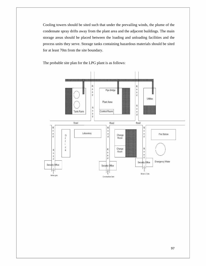
97
Cooling towers should be sited such that under the prevailing winds, the plume of the
condensate spray drifts away from the plant area and the adjacent buildings. The main
storage areas should be placed between the loading and unloading facilities and the
process units they serve. Storage tanks containing hazardous materials should be sited
for at least 70m from the site boundary.
The probable site plan for the LPG plant is as follows:
98
CHAPTER-13
SAFETY & HAZARDS FACTORS
13.1 Introduction
Safety of personnel and equipment is a very important consideration in the operation of the
unit. Though the design of the plant takes care of a number of emergency conditions and
makes the plant operationally safe, but proper operating procedures and use of safety
equipment are a must for the safe running of plant and a safe environment to work in. This
section contains some safety guidelines which should be strictly followed in the LPG
recovery plant. However these procedures should be updated from time to time in the light of
experience gained in operating the plant.
13.2 General Hazards in LPG Recovery Plant
It is essential to recognize the various possible hazards in the operation of the plant so that the
remedial measures can be planned. Following are some of the common safety hazards
encountered in the LPG recovery unit.
13.3 Hazards of petroleum products
All petroleum products give out vapors in amount depending upon the type of product. These
vapors, in a confined space, will tend to make the atmosphere leaner in oxygen content - thus
making it difficult to sustain normal breathing (asphyxiation).
The hydro carbon vapors also produce some adverse physiological effects. Fire and explosion
hazards are associated with these vapors under favorable conditions.
13.3.1 Classification of Hazardous Area
Hazardous Area: Hazardous area means an area where hazardous atmosphere exists or
likely to occur
Hazardous Atmosphere: Hazardous atmosphere means an atmosphere containing any
inflammable gas in a concentration capable of causing ignition.
Zone Zero: It means an area in which hazardous atmosphere is continuously present.
Zone -1: It means an area in which hazardous atmosphere is likely to occur under normal
operating conditions
Zone -2: It means an area in which hazardous atmosphere is likely to occur under abnormal
operating conditions
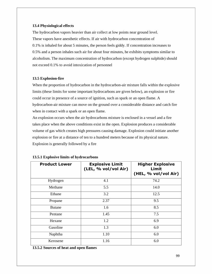
99
13.4 Physiological effects
The hydrocarbon vapors heavier than air collect at low points near ground level.
These vapors have anesthetic effects. If air with hydrocarbon concentration of
0.1% is inhaled for about 5 minutes, the person feels giddy. If concentration increases to
0.5% and a person inhales such air for about four minutes, he exhibits symptoms similar to
alcoholism. The maximum concentration of hydrocarbon (except hydrogen sulphide) should
not exceed 0.1% to avoid intoxication of personnel
13.5 Explosion-fire
When the proportion of hydrocarbon in the hydrocarbon-air mixture falls within the explosive
limits (these limits for some important hydrocarbons are given below), an explosion or fire
could occur in presence of a source of ignition, such as spark or an open flame. A
hydrocarbon-air mixture can move on the ground over a considerable distance and catch fire
when in contact with a spark or an open flame.
An explosion occurs when the air hydrocarbons mixture is enclosed in a vessel and a fire
takes place when the above conditions exist in the open. Explosion produces a considerable
volume of gas which creates high pressures causing damage. Explosion could initiate another
explosion or fire at a distance of ten to a hundred meters because of its physical nature.
Explosion is generally followed by a fire
13.5.1 Explosive limits of hydrocarbons
Product Lower
Explosive Limit (LEL, % vol/vol Air)
Higher Explosive Limit
(HEL, % vol/vol Air)
Hydrogen 4.1 74.2
Methane 5.5 14.0
Ethane 3.2 12.5
Propane 2.37 9.5
Butane 1.6 8.5
Pentane 1.45 7.5
Hexane 1.2 6.9
Gasoline 1.3 6.0
Naphtha 1.10 6.0
Kerosene 1.16 6.0
13.5.2 Sources of heat and open flames
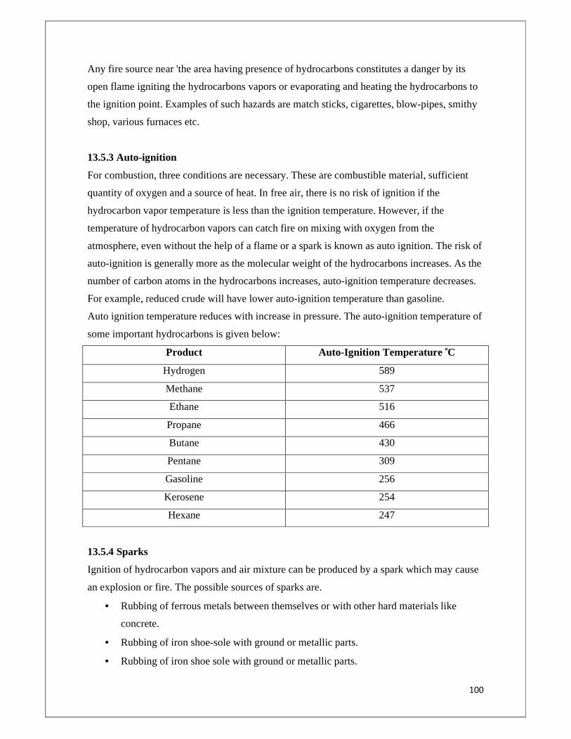
100
Any fire source near 'the area having presence of hydrocarbons constitutes a danger by its
open flame igniting the hydrocarbons vapors or evaporating and heating the hydrocarbons to
the ignition point. Examples of such hazards are match sticks, cigarettes, blow-pipes, smithy
shop, various furnaces etc.
13.5.3 Auto-ignition
For combustion, three conditions are necessary. These are combustible material, sufficient
quantity of oxygen and a source of heat. In free air, there is no risk of ignition if the
hydrocarbon vapor temperature is less than the ignition temperature. However, if the
temperature of hydrocarbon vapors can catch fire on mixing with oxygen from the
atmosphere, even without the help of a flame or a spark is known as auto ignition. The risk of
auto-ignition is generally more as the molecular weight of the hydrocarbons increases. As the
number of carbon atoms in the hydrocarbons increases, auto-ignition temperature decreases.
For example, reduced crude will have lower auto-ignition temperature than gasoline.
Auto ignition temperature reduces with increase in pressure. The auto-ignition temperature of
some important hydrocarbons is given below:
Product Auto-Ignition Temperature oC
Hydrogen 589
Methane 537
Ethane 516
Propane 466
Butane 430
Pentane 309
Gasoline 256
Kerosene 254
Hexane 247
13.5.4 Sparks
Ignition of hydrocarbon vapors and air mixture can be produced by a spark which may cause
an explosion or fire. The possible sources of sparks are.
• Rubbing of ferrous metals between themselves or with other hard materials like
concrete.
• Rubbing of iron shoe-sole with ground or metallic parts.
• Rubbing of iron shoe sole with ground or metallic parts.
101
• Falling of iron tools.
• Stroke of a steel hammer on a hard body like metal or concrete.
• Grinding by emery wheel.
• Sparks from loose electrical fittings.
• Hot job like gas cutting, grinding, welding, stress relieving etc.
13.5.5 Lightning
Lighting can fall on metallic objects such as chimneys, towers, tanks and tall buildings these
can damage the structures or lead to ignition of hydrocarbons-air mixtures, if present. The
vent/safety relief valve discharges at high points to the atmosphere are especially vulnerable
to lightning.
13.5.6 Static electric charges
Static electric charges can be produced by rubbing different bodies between themselves and
these can accumulate and produce sparks strong enough to initiate a fire or an explosion.
Such charges can be produced by rubbing of petroleum products on the internal surfaces of
pipes, tanks and various equipments. The handling of dry substances as coke, sulfur etc. in
metal chutes, bins or even through relatively dry air can also result in the generation of static
electricity.
Static charges can also be produced by other operations such as a driving belt, cleaning with
silk or nylon cloth and fine mesh screens and filters etc. A proper system of grounding is
essential for such operations.
Annexure-I
LISTS OF EQUIPMENTS
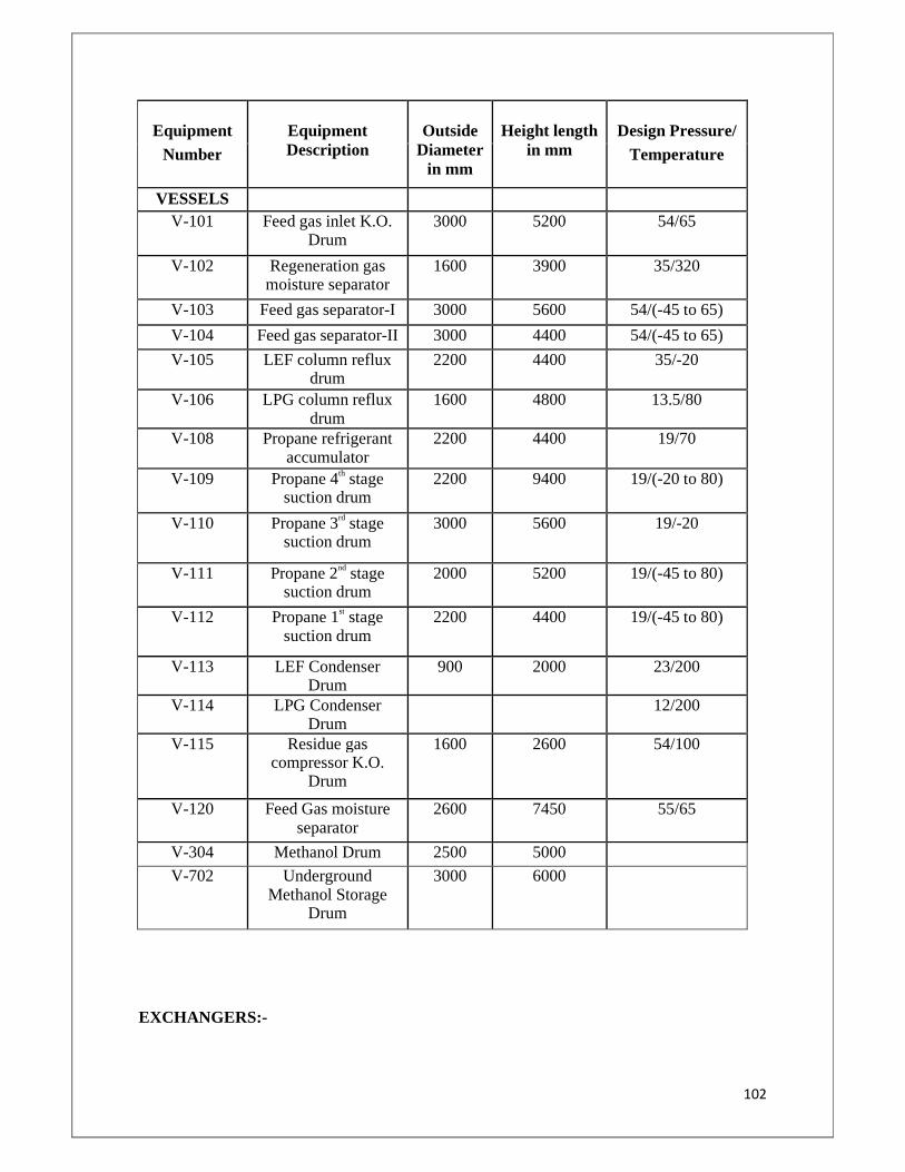
102
Equipment
Equipment Description
Outside
Diameter in mm
Height length
in mm
Design Pressure/
Number Temperature
VESSELS
V-101 Feed gas inlet K.O. Drum
3000 5200 54/65
V-102 Regeneration gas moisture separator
1600 3900 35/320
V-103 Feed gas separator-I 3000 5600 54/(-45 to 65)
V-104 Feed gas separator-II 3000 4400 54/(-45 to 65)
V-105 LEF column reflux drum
2200 4400 35/-20
V-106 LPG column reflux drum
1600 4800 13.5/80
V-108 Propane refrigerant accumulator
2200 4400 19/70
V-109 Propane 4th stage suction drum
2200 9400 19/(-20 to 80)
V-110 Propane 3rd stage suction drum
3000 5600 19/-20
V-111 Propane 2nd stage suction drum
2000 5200 19/(-45 to 80)
V-112 Propane 1st stage suction drum
2200 4400 19/(-45 to 80)
V-113 LEF Condenser Drum
900 2000 23/200
V-114 LPG Condenser Drum
12/200
V-115 Residue gas compressor K.O.
Drum
1600 2600 54/100
V-120 Feed Gas moisture separator
2600 7450 55/65
V-304 Methanol Drum 2500 5000 V-702 Underground
Methanol Storage Drum
3000 6000
EXCHANGERS:-
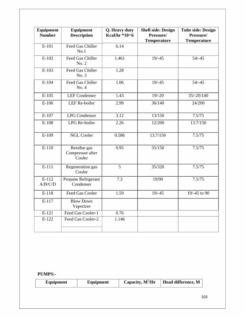
103
Equipment Number
Equipment Description
Q. Heavy duty Kcal/hr *10^6
Shell side: Design Pressure/
Temperature
Tube side: Design Pressure/
Temperature E-101 Feed Gas Chiller
No.1 6.14
E-102 Feed Gas Chiller No. 2
1.461 19/-45 54/-45
E-103 Feed Gas Chiller No. 3
1.28
E-104 Feed Gas Chiller No. 4
1.06 19/-45 54/-45
E-105 LEF Condenser 1.43 19/-20 35/-20/140
E-106 LEF Re-boiler 2.99 36/140 24/200
E-107 LPG Condenser 3.12 13/150 7.5/75
E-108 LPG Re-boiler 2.26 12/200 13.7/150
E-109 NGL Cooler 0.586 13.7/150 7.5/75
E-110 Residue gas Compressor after
Cooler
0.95 55/150 7.5/75
E-111 Regeneration gas Cooler
5 35/320 7.5/75
E-112 A/B/C/D
Propane Refrigerant Condenser
7.3 19/90 7.5/75
E-118 Feed Gas Cooler 1.59 19/-45 19/-45 to 90
E-117 Blow Down Vaporizer
E-121 Feed Gas Cooler-1 0.76 E-122 Feed Gas Cooler-2 1.146
PUMPS:-
Equipment Equipment Capacity, M 3/Hr Head difference, M
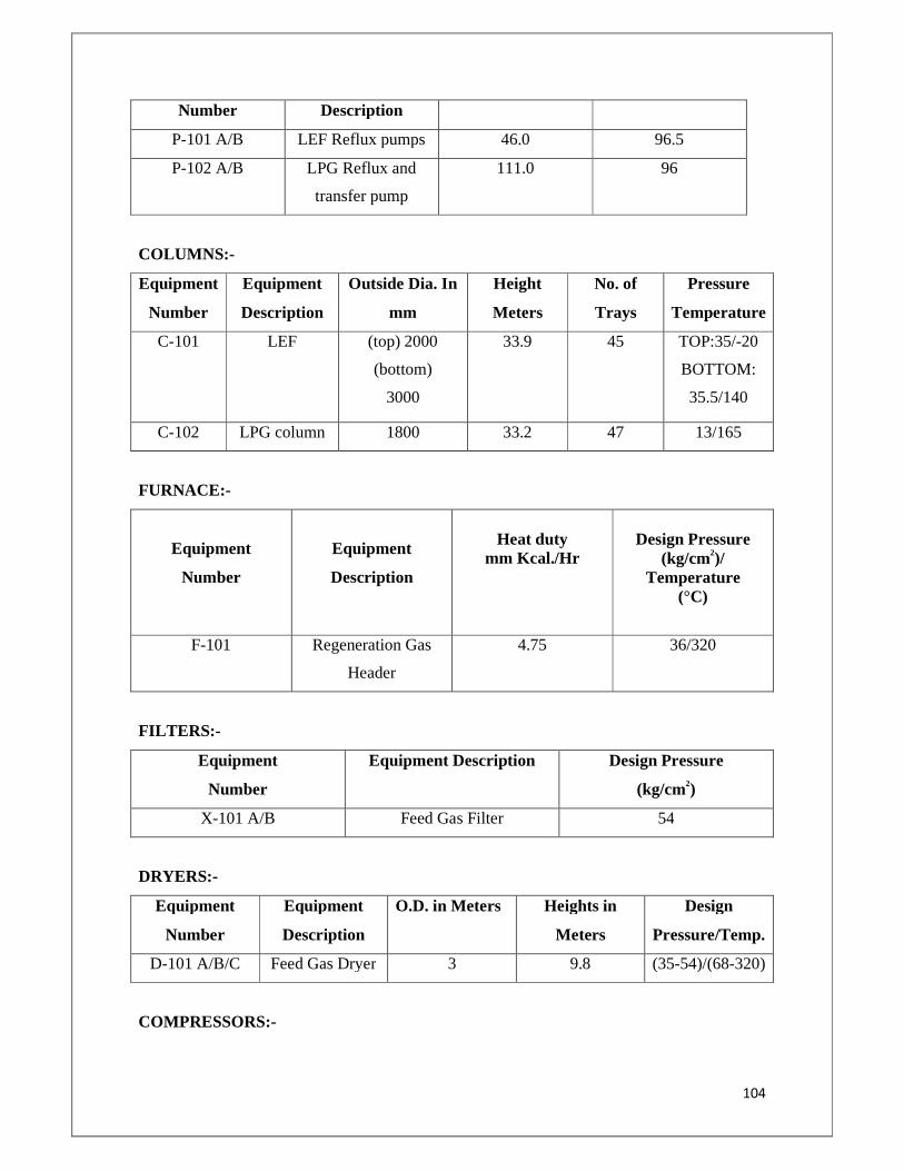
104
Number Description
P-101 A/B LEF Reflux pumps 46.0 96.5
P-102 A/B LPG Reflux and
transfer pump
111.0 96
COLUMNS:-
Equipment
Number
Equipment
Description
Outside Dia. In
mm
Height
Meters
No. of
Trays
Pressure
Temperature
C-101 LEF (top) 2000
(bottom)
3000
33.9 45 TOP:35/-20
BOTTOM:
35.5/140
C-102 LPG column 1800 33.2 47 13/165
FURNACE:-
Equipment
Number
Equipment
Description
Heat duty
mm Kcal./Hr
Design Pressure
(kg/cm2)/ Temperature
(°C)
F-101 Regeneration Gas
Header
4.75 36/320
FILTERS:-
Equipment
Number
Equipment Description Design Pressure
(kg/cm2)
X-101 A/B Feed Gas Filter 54
DRYERS:-
Equipment
Number
Equipment
Description
O.D. in Meters Heights in
Meters
Design
Pressure/Temp.
D-101 A/B/C Feed Gas Dryer 3 9.8 (35-54)/(68-320)
COMPRESSORS:-
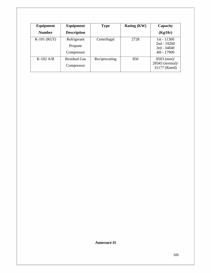
105
Equipment
Number
Equipment
Description
Type Rating (KW) Capacity
(Kg/Hr)
K-101 (RGT) Refrigerant
Propane
Compressor
Centrifugal 2728 1st - 11300 2nd - 19260 3rd - 34840 4th - 17900
K-102 A/B Residual Gas
Compressor
Reciprocating 850 8503 (min)/ 28343 (normal)/ 31177 (Rated)
Annexure-II
106
LPG PLANT EQUIPMENT LAYOUT
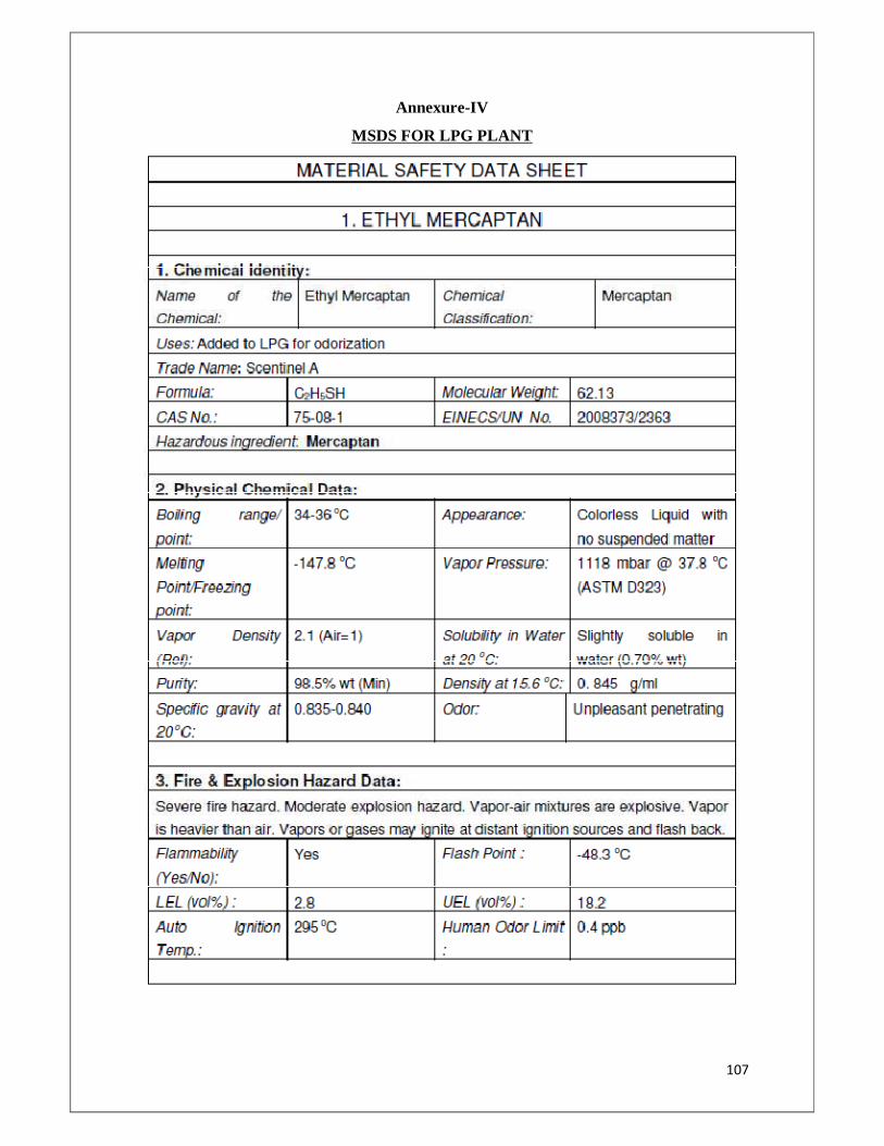
107
Annexure-IV
MSDS FOR LPG PLANT
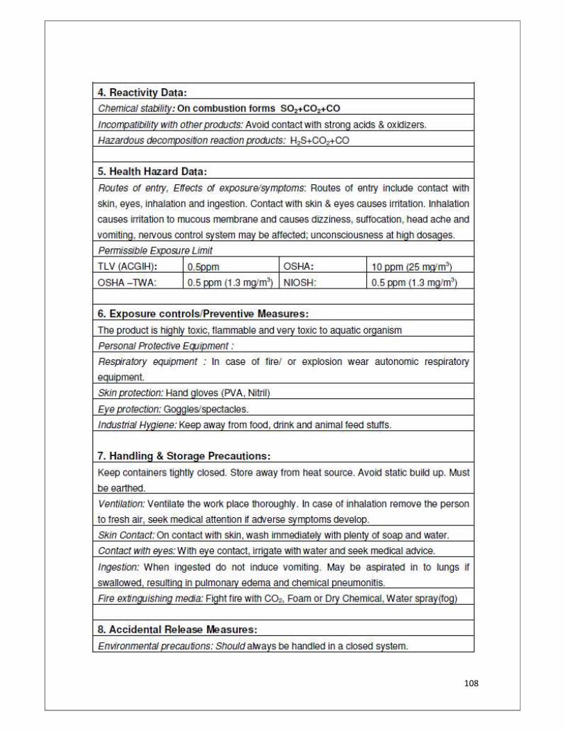
108
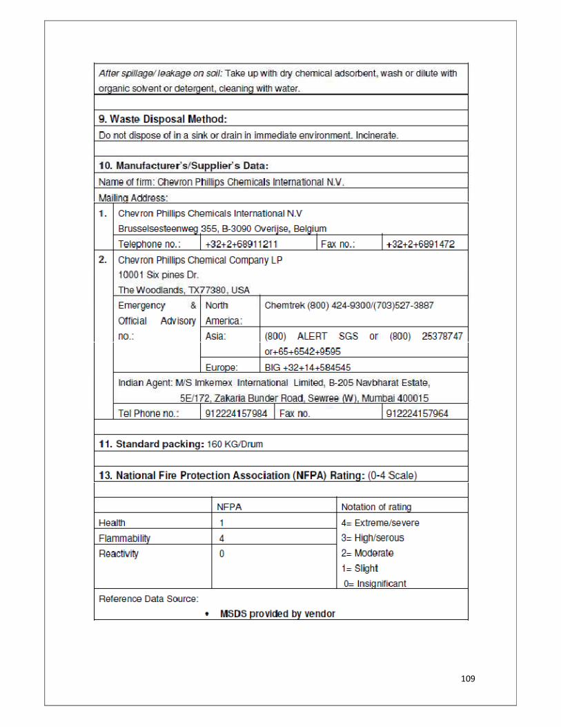
109
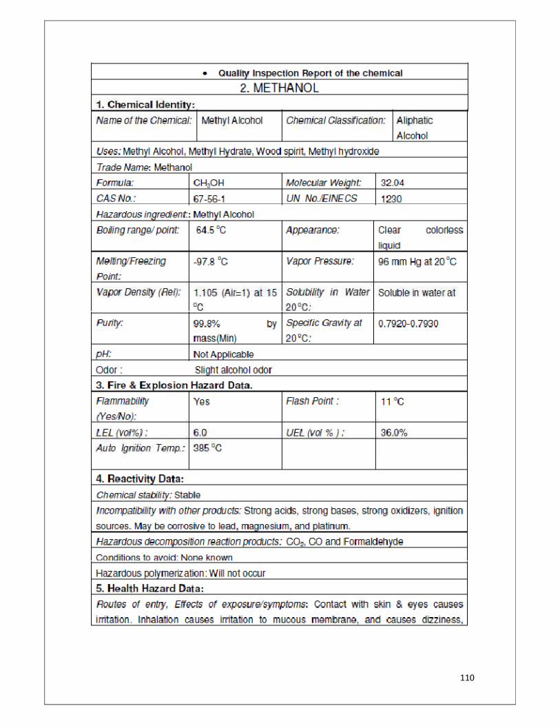
110
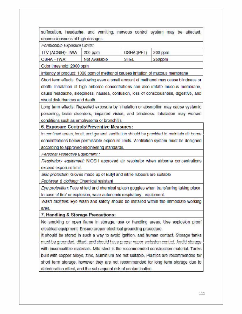
111
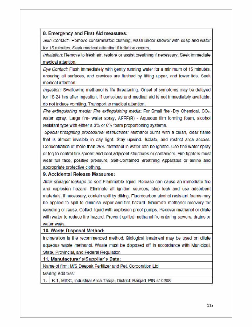
112
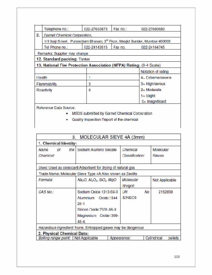
113
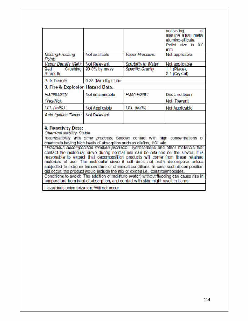
114
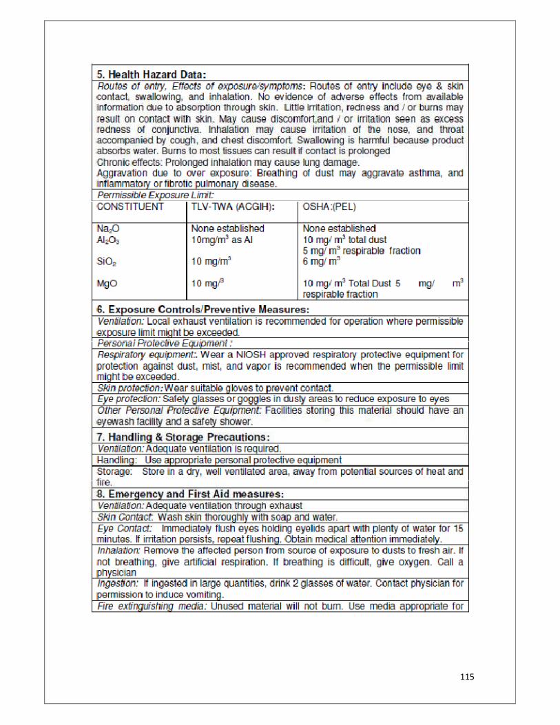
115

116

117
Annexure-IV
PnID’s
118
BIBLIOGRAPHY
1. EIA Country Analysis Brief, www.eia.doe.gov/emeu.cabs/india.html
2. Tata Energy and Resources Institute, www.teriin.org
3. Ministry of Petroleum and Natural Gas in India, petroleum.nic.in
4. Various Indian news publications.
5. ULLMAN’S Encyclopaedia of Industrial Chemistry.
6. Journal homepage: www.elsevier.com/locate/jngse
7. Journal of Natural Gas Science and Engineering xxx (2010),Pages 1-9
8. Journal of Analytical and Applied Pyrolysis (2007),Pages 175–181
9. Energy Policy 31 (2003),Pages 1573–1577
10. Journal of Materials processing technology 200 (2008),Pages 416–423
11. www.elsevier.com/locate/jaap
12. Journal homepage: www.elsevier.com/locate/jmatprotec
13. ONGC Manual
14. HYSYS tutorial
15. Gas condensing and processing unit, Vol–I and Vol-II by J.M. Campbell.
16. Heat Transfer by K.A. Gavahane
17. Petro-Chemicals by Dr. B.K. Bhaskararao
18. Process Equipment Design and Drawing by Kiran Hari Ghadyalji
19. Joshi’s Process Equipment Design