project team: project lead: jared mukina (electrical engineering) brian nguyen (computer...
TRANSCRIPT

Energy Production and Infrastructure Center
Photovoltaic Battery SystemProject Team:
Project Lead: Jared Mukina (Electrical Engineering)Brian Nguyen (Computer Engineering)Nou Lee (Computer Engineering)James Lee (Electrical Engineering Technology)Rona Vo (Electrical Engineering)Kurt Fischer (Electrical Engineering)

1. Problem Statement2. Load3. Design• Overall system block diagram• Detailed circuit schematics• Psuedocode
4. Design Requirements• Performance• Verifications
5. Feasibility• Manufacturability• With in budget/resources• Meets requirements/ safety
6. Risks• FMEA
Agenda
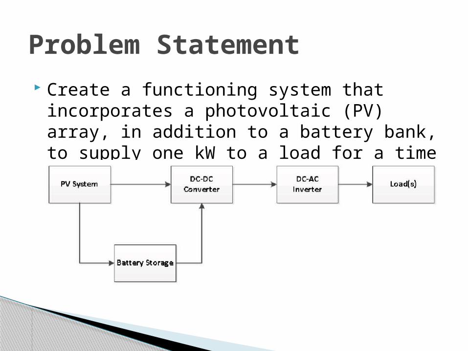
Create a functioning system that incorporates a photovoltaic (PV) array, in addition to a battery bank, to supply one kW to a load for a time period of 5 hours.
Problem Statement

EPIC cart battery charging station.
*NOTE: Load will dictate adjustments in the system design.
Load(s)

Location of Implementation
Epic charging dock is being under review of this location
Proposed Area for Shed
Proposed Area for Electric carts
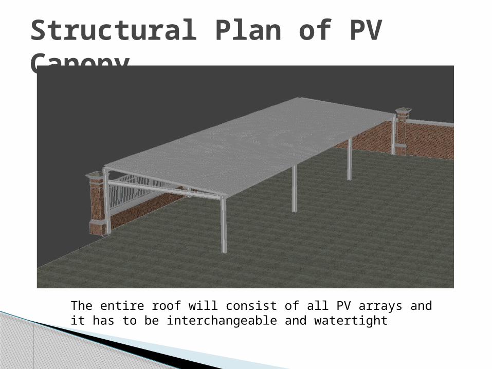
Structural Plan of PV Canopy
The entire roof will consist of all PV arrays and it has to be interchangeable and watertight

Structural Plan of PV Canopy
The entire roof will consist of all PV arrays and it has to be interchangeable and watertight
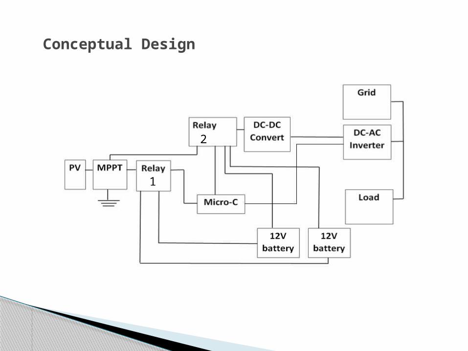
Conceptual Design
1
2
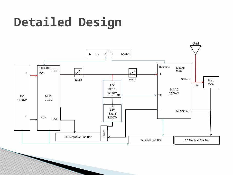
Detailed Design

Design Simulations
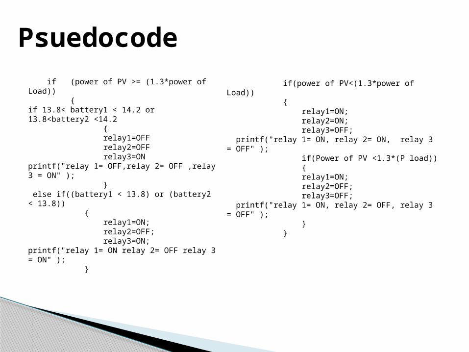
Psuedocode if (power of PV >= (1.3*power of Load)) {if 13.8< battery1 < 14.2 or 13.8<battery2 <14.2 { relay1=OFF relay2=OFF relay3=ONprintf("relay 1= OFF,relay 2= OFF ,relay 3 = ON" ); } else if((battery1 < 13.8) or (battery2 < 13.8)) { relay1=ON; relay2=OFF; relay3=ON;printf("relay 1= ON relay 2= OFF relay 3 = ON" ); }
if(power of PV<(1.3*power of Load)) { relay1=ON; relay2=ON; relay3=OFF; printf("relay 1= ON, relay 2= ON, relay 3 = OFF" ); if(Power of PV <1.3*(P load)) { relay1=ON; relay2=OFF; relay3=OFF; printf("relay 1= ON, relay 2= OFF, relay 3 = OFF" ); } }
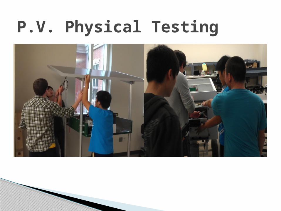
P.V. Physical Testing

The P.V. physical testing can not be completed properly until the P.V. system is set up outside for real time data testing.
P.V. Physical Testing Results

Battery Physical Testing

Battery Physical Testing
AfterBefore
Batteries are alive. Batteries need to be charged from PV
subsystem to charge quickly.
Battery Physical Testing Results

DC-AC Physical Testing

1KW average per hour for 5 hours. 2KW average peak for 1 hour. Max power point tracking to maintain
steady DC voltage. AC output must be 120 ± 5% volts at a
frequency of 60 ± 1% Hertz Protected device
◦ Relay◦ Breaker◦ Gauge sizing
Requirement/Specifications
By eliminating the DC-DC converter, microcontroller and the Relays, the cost of our product is cheaper by ~$1000.
Cheaper
Feasibility
Complexity of the design. Outback Power Systems Construction of housing.
Manufacturability

A budget of $2000 was provided.
Budget
Material Price
Circuit Breaker $100
Wires $100
Housing $750
Simulation Software $200
Total $1150

Provided Components
Quantity2118111
Total
1,626.00$ 155.00$
EPIC_PVBAT Devices and Components
7,742.19$
565.00$ 280.00$
1,250.00$
Price($)171.17$
1,563.85$
Leader LPS-151 DC Tracking Power Supply
Device/Component
Flexmax 80STP185-24Ad Photovoltaic Panel
Texktronix AFG310 Function GeneratorGW Instek GDS-2202A Digital Storage Oscilloscope
12 V Trojan SCS150 Deep Cycle BatteryOutback Power Systems GTFX 2524
High current. High voltage. Structural Integrity. Component overheating.
Safety

The system has grid tie capability. If the PV/battery sub system can not
produce the necessary power, power can be pulled in to system from the grid.
Failure Mode Effects Analysis (FMEA)

The final design should work as expected. All the criteria should be met. The load should consume enough energy. Excess energy will be delivered to the grid.
Conclusion

1. Farid Golnaraghi and Benjamin C. Kou. Wiley, 2010. Automatic Control Systems. 9th ed. Intext Citation: (Golnaraghi and Kou, 2010 p.g-p.g.)
2. 2012 IEEE Vehicle Power and Propulsion Conference, Oct. 9-12, 2012, Seoul, Korea Intext Citation: (2012 IEEE Oct. 9-12)
3. Prusty, K. B., Ali S. M., and Sahoo K. D. “Modeling And Control of Grid-Connected Hybrid Photovoltaic/Battery Distributed Generation System.” International Journal of Engineering Research & Technology (IJERT). URL: http://www.ijert.org/browse/november-2012-edition
4. “map_pv_national_hi-res_200.jpg.” www.nrel.gov. 2013. Accessed 9/8/13. http://www.nrel.gov/gis/images/map_pv_national_hi-res_200.jpg
5. “map_csp_national_hi-res.jpg.” www.nrel.gov. 2013. Accessed 9/8/13. http://www.nrel.gov/gis/images/map_csp_national_hi-res.jpg
6. “gem-e4-golf20-cart.jpg” gliccc.wordpress.com. 2011. Accessed 9/26/13. http://gliccc.files.wordpress.com/2011/05/gem-e4-golf20-cart.jpg
References

Questions?