project: the effects of damage and uncertainty on the ... effects of damage... · uncertainty on...
TRANSCRIPT
JAMS Meeting,
April 2011 1
Project:
The Effects of Damage and
Uncertainty on the Aeroelastic /
Aeroservoelastic Behavior and
Safety of Composite Aircraft
Presented by Eli Livne
Professor
Department of Aeronautics and Astronautics
University of Washington

JAMS Meeting,
April 2011 2
An Overview of the Project
covering
▪ Aeroelastic probabilistic reliability analysis of composite airframes
▪ Efficient aeroelastic simulation methods for composite airframes
undergoing large deformation and possible damage
▪ Wind tunnel tests of scaled aeroelastic models of nonlinear and
damaged composite airframes
3
Contributors
• Department of Aeronautics and Astronautics
• Dr. Eli Livne – PI, Professor
• Sang Wu – PhD student
• Department of Mechanical Engineering
• Francesca Paltera, PhD student
• Dr. Mark Tuttle, co-PI, professor and chairman
• Boeing Commercial, Seattle
• Dr. James Gordon, Associate Technical Fellow, Flutter Methods Development
• Dr. Kumar Bhatia, Senior Technical Fellow, Aeroelasticity and Multidisciplinary Optimization
• FAA Technical Monitor
• Lynn Pham, Advanced Materials & Structures, Aircraft and Airport Safety
• Curtis Davies, Program Manager of JAMS, FAA/Materials & Structures
• Other FAA Personnel Involved
• Dr. Larry Ilcewicz, Chief Scientific and Technical Advisor for Advanced Composite Materials
• Carl Niedermeyer, FAA Airframe and Cabin Safety Branch (previously, Boeing flutter manager for the 787 and 747-8 programs)

4
Motivation and Key Issues – a Review
• Variation (over time) of local structural characteristics might lead to a major impact on the global aeroservoelastic integrity of flight vehicles.
• Sources of uncertainty in composite structures: – Material property statistical spread
– Damage
– Delamination
– Joint/attachment changes
– Debonding
– Environmental effects, etc.
• Nonlinear structural behavior: – Delamination, changes in joints/attachments stiffness and damping, as well as
actuator nonlinearities may lead to nonlinear aeroelastic behavior such as Limit Cycle Oscillations (LCO) of control surfaces with stability, vibrations, and fatigue consequences.
• Nonlinear structural behavior:– Highly flexible, optimized composite structures (undamaged or damaged) may exhibit
geometrically nonlinear structural behavior, with aeroelastic consequences.
• Modification of control laws later in an airplane’s service can affect dynamic loads and fatigue life.

Effects of Uncertainty and Damage on Aeroelastic
Behavior and Safety
5

6
Objectives – a Review of the Multi-Year Program
• Develop computational tools (validated by experiments) for automatedlocal/global linear/nonlinear analysis of integrated structures/ aerodynamics / control systems subject to multiple local variations/ damage.
• Develop aeroservoelastic probabilistic / reliability analysis for composite actively-controlled aircraft.
• Link with design optimization tools to affect design and repair considerations.
• Develop a better understanding of effects of local structural and material variations in composites on overall Aeroservoelastic integrity.
• Establish a collaborative expertise base for future response to FAA, NTSB, and industry needs, R&D, training, and education.

7
Program Approach
• Efficient simulation (linear & nonlinear).
• Probabilistic reliability assessment.
• Aeroelastic tests of aeroelastically scaled models.

8
Life Cycle Probabilistic Structural /
Aeroelastic Modeling for Reliability
Evaluation of Damage Tolerant
Composite Structures
9
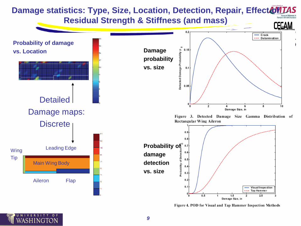
Damage statistics: Type, Size, Location, Detection, Repair, Effect of
Residual Strength & Stiffness (and mass)
Leading Edge
Main Wing Body
Wing
Tip
FlapAileron
Detailed
Damage maps:
Discrete
Damage
probability
vs. size
Probability of
damage
detection
vs. size
Probability of damage
vs. Location

10
Residual Flutter Speed over Service Life
In addition to residual strength, residual stiffness and residual
flutter speeds are tracked over time of service, and the
probability of flutter events due to uncertainty in flutter
characteristics AND operational speeds / dynamic pressures
is assessed.
-0.1
9.9
19.9
29.9
39.9
49.9
0 0.5 1Time
Da
ma
ge
Siz
e
DisbondHole
Flutter Speed
degradation due to
aging
0 . 5
0 . 7
0 . 9
1. 1
0 0 . 2 0 . 4 0 . 6 0 . 8 1
T ime
Res.F
lutt
er
Sp
eed
Disbond Hole
0
0.2
0.4
0.6
0.8
1
1.2
0 0.5 1
Res.F
lutt
er S
peed
Time
Combined Damage+Aging
DisbondHole
Damage
initiation
Damage
propagation
Damage
repair/
part
replacement

Virtual Testing
11

12
Automated System for Calculating Flutter Speeds of
Large Numbers of Airframe Structural Variations
For flutter –
NASTRAN only
May be used

13
An Example: Evaluation-Model of a Vertical Tail / Rudder System
Structure:
• Number of grid points =1268
• Number of CBAR elements = 309
• Number of CBUSH elements = 45
• Number of CONM2 elements = 28
• Number of CQUAD4 elements = 1409
• Number of CROD elements = 1056
• Number of CSHEAR elements = 91
• Number of CTRIA3 elements =187
• Number of RBE2 elements =16
• Number of RBE3 elements = 28
Unsteady Aerodynamics – Doublet Lattice
Caution: this case does not
represent any airplane in service.

14
Statistical Flutter Results for the Tail / Rudder System
No Damage
• Structural Variability (Construction. Assumptions are for illustration of the methodology)
• Flutter results
• Note: The flutter PDF is multi-modal. Some members of the fleet may have flutter due to
mechanisms different from those of others.
• The variance of VF is noticeably greater than variances for input parameters (in this case)
Property Panel-to-
panel
C.O.V.
Element-to-
element
C.O.V.
Radius of
Correlation, in
Thickness t 0.03 0.01 10
G11 0.05 0.02 100
G22 0.05 0.02 100
G12 0.05 0.02 100

15
Damaged Vertical Tail – Flutter Speed Statistics
( ) ( )
( ) ( )
;D DT T U T D
D DC C U C D
W W WW W
W W WW W
Residual stiffness (tension & compression) based upon a
rule-of-mixtures
for constant thickness panel
Locations of damaged elements havebeen chosen randomly for this study with
uniform distribution over the tail box skin area.

16
VATM – RELACS Studies for the Vertical Tail Example
• Statistical flutter results from the VATM simulations - now combined with flutter runs for
damaged structures using RELACS.
• Number of Design Cases = 1; Subsonic flight.
• Number of Damage Types = 2; Hole and Delamination.
• Number of Inspection Types =2; Visual and Instrumental.
• The CDF of maximum airspeed per life
• The probability of damage detection model
described previously by Styuart, Mor, Lin & Livne.
• Exceedance data of damage occurrence:
• Report DOT/FAA/AR-01/55, 2002
• recalculated for 60000 flight hours and torsion box skin.
Damage
exceedence
curve
Probability of
failure vs. design
safety margin
Note: results are case dependent. Results also depend strongly on damage scenarios and maintenance practices
17
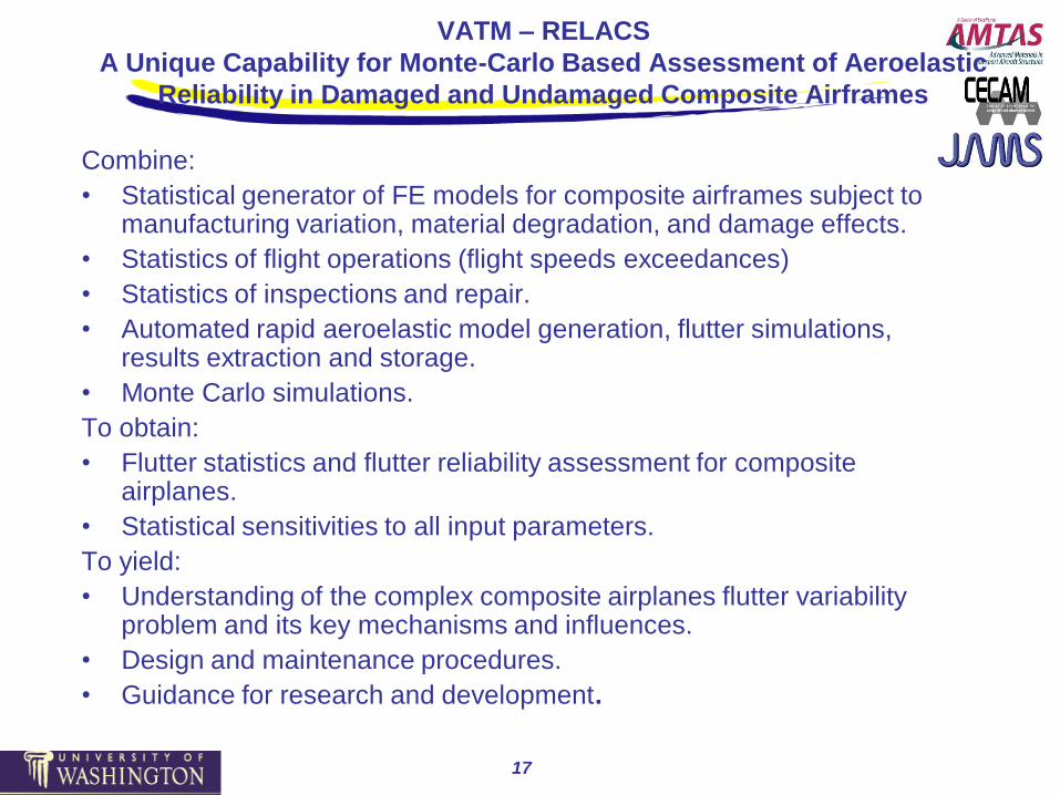
VATM – RELACS
A Unique Capability for Monte-Carlo Based Assessment of Aeroelastic
Reliability in Damaged and Undamaged Composite Airframes
Combine:
• Statistical generator of FE models for composite airframes subject to manufacturing variation, material degradation, and damage effects.
• Statistics of flight operations (flight speeds exceedances)
• Statistics of inspections and repair.
• Automated rapid aeroelastic model generation, flutter simulations, results extraction and storage.
• Monte Carlo simulations.
To obtain:
• Flutter statistics and flutter reliability assessment for composite airplanes.
• Statistical sensitivities to all input parameters.
To yield:
• Understanding of the complex composite airplanes flutter variability problem and its key mechanisms and influences.
• Design and maintenance procedures.
• Guidance for research and development.

JAMS Meeting,
April 2011
Dynamic Aeroelasticity of Structurally
Nonlinear Airplane Configurations Using
Linearized Unsteady Aerodynamic Models

Torq
ue
Flap Rotation
Localized “point” structural nonlinearities
Optimized
composite
airframes
Truss
Braced
Wings
Joined
Wings
“Distributed” geometric structural nonlinearities
Local and Global Nonlinear Structural Effects in
Composite Airframe Aeroelasticity
New
Configurations
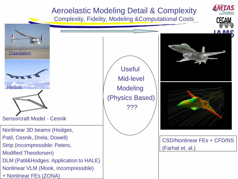
Aeroelastic Modeling Detail & ComplexityComplexity, Fidelity, Modeling &Computational Costs
Nonlinear 3D beams (Hodges,
Patil, Cesnik, Drela, Dowell)
Strip (incompressible: Peters,
Modified Theodorsen)
DLM (Patil&Hodges: Application to HALE)
Nonlinear VLM (Mook, incompressible)
+ Nonlinear FEs (ZONA)
Daedalus
Helios
Sensorcraft Model - Cesnik
CSD/Nonlinear FEs + CFD/NS
(Farhat et. al.)
Useful
Mid-level
Modeling
(Physics Based)
???
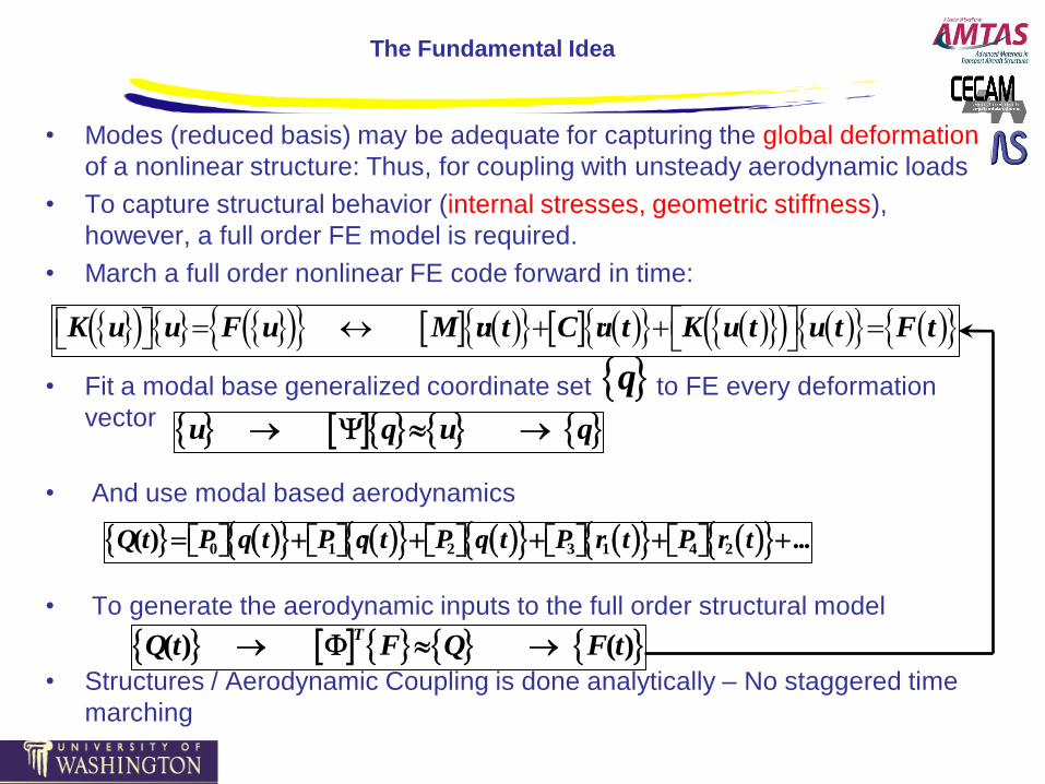
The Fundamental Idea
• Modes (reduced basis) may be adequate for capturing the global deformation
of a nonlinear structure: Thus, for coupling with unsteady aerodynamic loads
• To capture structural behavior (internal stresses, geometric stiffness),
however, a full order FE model is required.
• March a full order nonlinear FE code forward in time:
• Fit a modal base generalized coordinate set to FE every deformation
vector
• And use modal based aerodynamics
• To generate the aerodynamic inputs to the full order structural model
• Structures / Aerodynamic Coupling is done analytically – No staggered time
marching
q u q u q
K u u F u M u t C u t K u t u t F t
0 1 2 3 1 4 2( ) ...Q t P q t P q t P q t P r t P r t
( ) ( )T
Q t F Q F t

A Physics Based Nonlinear FE/Linear Aero Approach for Geometrically
Nonlinear Aeroelastic Time Domain Simulations
or full order
or full orderSee subsequent comments
on full-order linear aerodynamics
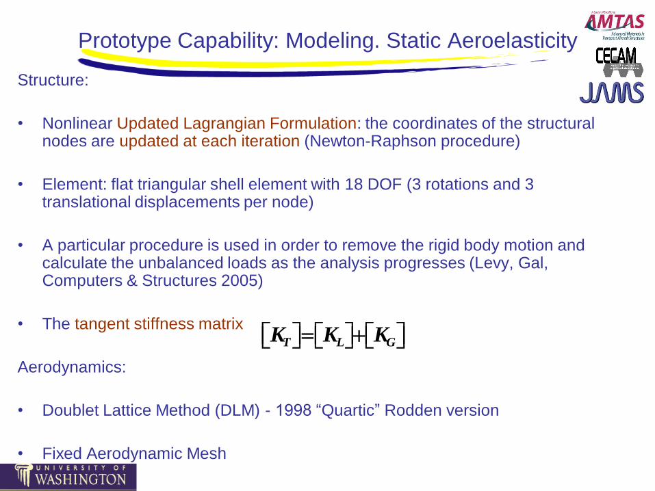
Prototype Capability: Modeling. Static Aeroelasticity
Structure:
• Nonlinear Updated Lagrangian Formulation: the coordinates of the structural nodes are updated at each iteration (Newton-Raphson procedure)
• Element: flat triangular shell element with 18 DOF (3 rotations and 3 translational displacements per node)
• A particular procedure is used in order to remove the rigid body motion and calculate the unbalanced loads as the analysis progresses (Levy, Gal, Computers & Structures 2005)
• The tangent stiffness matrix
Aerodynamics:
• Doublet Lattice Method (DLM) - 1998 “Quartic” Rodden version
• Fixed Aerodynamic Mesh
T L GK K K

Prototype Capability: Modeling. Static
Aeroelasticity. (Continued)
• Motion transformation from FE mesh to aerodynamic panel mesh: Infinite Plate Spline method
• Transformation of aero panel loads to the FE structural mesh: by finding the triangular element which contains the load and by using the area coordinates
• Aerodynamic linearity: all transformation matrices are assumed constant
• Aerodynamic forces change magnitude but not direction: small deformation where nonlinear effects are due to internal stresses in the structure, or large deformation where linear aerodynamic modeling is still adequate

Text Case: JW Results – Full Order Aerodynamics
Static aeroelastic solution:
incremental increase of airspeed
Dynamic aeroelastic solution:
Time marching

26
Conclusion
• A unique methodology was developed for the aeroelastic simulation of composite airframes subject to local and global geometric nonlinearity
• A set of coupled structure / aerodynamic aeroelastic equations are solved simultaneously (with no staggering), coupling detailed nonlinear FE models with linearized panel or linearized CFD aerodynamic models
• The methodology leads to high efficiency in problem formulation and solution, because currently used NASTRAN / Panel Aero models used in industry can be converted no nonlinear structural modeling and run with a change of a single input parameter.
• A prototype simulation code was created and tested successfully on one of the most demanding structurally-nonlinear aeroelastic problems: the Joined Wing problem.
The 2009 – 2011 Focus
Wind Tunnel Model Development for Aeroelastic
Tests of Wing / Control-Surface Systems with
Hinge Stiffness Loss and with a Velocity-
Squared Damper
27
28
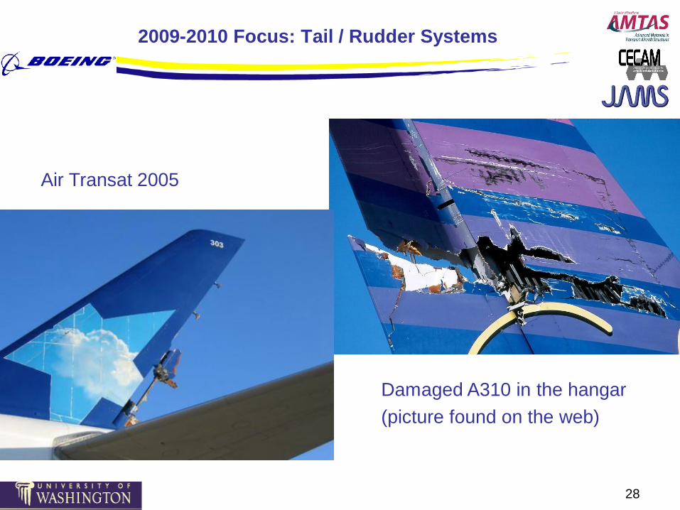
2009-2010 Focus: Tail / Rudder Systems
Air Transat 2005
Damaged A310 in the hangar
(picture found on the web)

29
Experiments and experimental capabilities development
Interests:
• Actuator / Actuator attachment hinge nonlinearities:
– Freeplay / bilinear stiffness (hardening nonlinearity)
– Buckling tendency (softening nonlinearity)
– Hinge failure (coupled rudder rotation / rudder bending instability)
– Actuator failure – nonlinear behavior with nonlinear hinge dampers
– Flutter / Limit Cycle Oscillations (LCO) of damaged rudders
• Use tests to validate and calibrate numerical models – a UW / Boeing / FAA
collaboration.
Important Notes:
• Rudder hinge stiffness nonlinearities and hinge failure can be caused by
actuator behavior or by failure of the composite structure locally and
globally.
• Wind tunnel model designs and tests will start with simulated hinge
nonlinearities using nonlinear springs and then proceed to composite rudder
structure with actual composite failure mechanisms.

University of Washington 30
Limit Cycle Oscillations and flutter due to control
surface hinge stiffness nonlinearity
To
rqu
e
Flap Rotation
Local degradation / damageBasic aeroelastic model
representation
Hinge stiffness
Hardening
softening

31
UW Flutter Test Wing / Control Surface Design
mounted vertically in the UW A&A 3 x 3 wind tunnel
U
Wing - wind tunnel
mount
Providing linear
Plunge
And torsional pitch
stiffnesses
Simulated actuator
/ damper
attachment
allowing for
different
nonlinearities
Aluminum wing
allowing for
variable inertia / cg
properties
Rudder –
composite
construction
allowing for
simulations of
hinge failure and
Rudder damage
Simulated actuator
allowing for
freeplay
nonlinearities

New Composite Rudder Designs
32

33
The tail / rudder model at the UW’s 3 x 3 wind tunnel
2009-2010

The Complexity of Nonlinear Aeroelastic Behavior with
Rudder Hinge Stiffness Free-Play
34
Predicted Limit Cycle Oscillation amplitudes of rudder
rotation at speeds below the flutter speed of the
no-freeplay system – The Duke University test case

Loss of Hinge Stiffness
• An important condition in the aeroelastic design and certification of lifting-
surface / control-surface systems is the case of loss of actuator stiffness,
with control surface rotation resisted only by a velocity-square damper.
• No experimental wind tunnel aeroelastic results are available for this case.
35

The Design of a Small Velocity Squared Damper
36
pL12vp
2pR12Vout
2ppRpL 12(Vout
2vp2)
Ap vp AorificeVoutVoutApAorifice
vp
1vp
Ftot FpressureFviscosityFinertial

The Design of a Small Velocity Squared Damper
37

38
Conclusion
• Major progress in the development of the UW’s aeroelastic wind
tunnel capabilities.
• Linear flutter as well as Limit Cycle Oscillations (LC) tested in the UW’s 3 x 3 wind tunnel and used to validate UW’s numerical modeling capabilities.
• A small velocity-squared damper was designed and built.
• Wind tunnel tests of tail / rudder systems with actuator failure and with nonlinear dampers – in development.
• Wind tunnel tests of representative tail / rudder systems with realistic rudder composite structures – in development.
• Results from this effort will provide valuable data for validation of simulation codes used by industry to certify composite airliners.

39
Future Directions
• Expand the probabilistic aeroelastic reliability methodology and associated capabilities to include dynamic loads due to gusts as well as uncertainty and damage in active flight control and load alleviation systems.
• Implement the new nonlinear aeroelastic simulation capability in commercial FE / aeroelastic packages, extend to include linearizedCFD aerodynamics, and improve the capability to capture both local and global failure.
• Complete aeroelastic wind tunnel tests of the tail / rudder system with nonlinear dampers; validate computer simulations and improve them.
• Proceed with simulation / testing work to the case of tail / rudder with failed rudder hinges and rudder structure loss of stiffness due to delamination.

40
Benefits to Aviation
Formulation of a comprehensive approach to the inclusion of aeroelastic failures in the reliability assessment of composite aircraft, and resulting benefits to both maintenance and design practices, covering:
– Different damage types in composite airframes and their statistics;
– Aeroelastic stability due to linear and nonlinear mechanisms;
– Aeroelastic response levels (vibration levels and fatigue due to gust response and response to other dynamic excitations);
– Theoretical, computational, and experimental work with aeroelasticsystems ranging from basic to complex full-size airplanes, to serve as benchmark for industry methods development and for understanding basic physics as well as design & maintenance tradeoffs.