projection projection - the transformation of points from a coordinate system in n dimensions to a...
TRANSCRIPT
Projection Projection - the transformation of
points from a coordinate system in n dimensions to a coordinate system in m dimensions where m<n.
We will be talking about projections from 3D to 2D, where the 3D space represents a world coordinate system and the 2D space is a window which is mapped to a screen viewport.
Specifying a Projection Two things must be specified
Projection plane and a center of projection. Projection plane
A 2D coordinate system onto which the 3D image is to be projected. We’ll call this the VRP for view reference plane.
Center of projection A point in space which serves as an end
point for projectors. We’ll refer to this point as the COP. It is also called a PRP for a projection reference point.
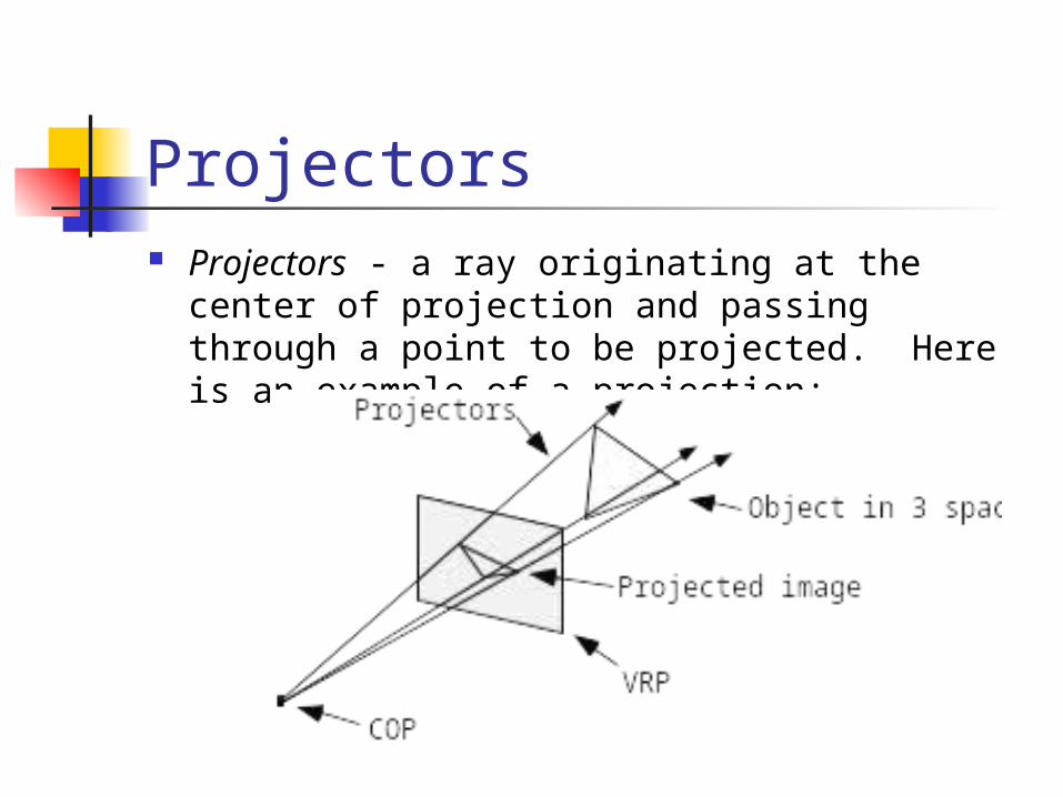
Projectors Projectors - a ray originating at the center of
projection and passing through a point to be projected. Here is an example of a projection:
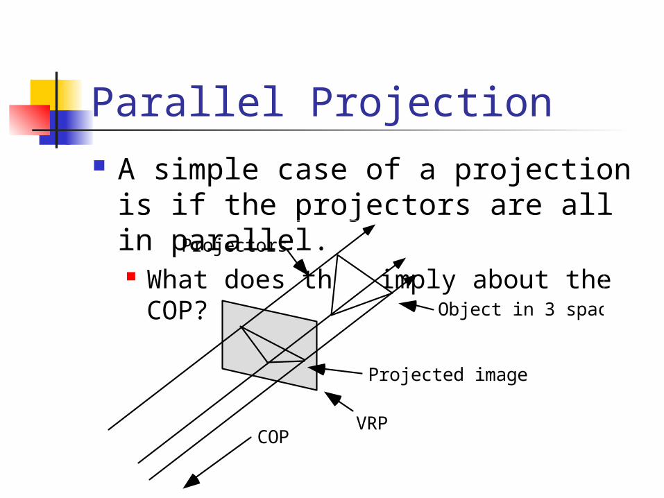
Parallel Projection A simple case of a projection is if
the projectors are all in parallel. What does this imply about the COP?
VRPCOP
Object in 3 space
Projectors
Projected image
Direction of Projection We can’t specify the COP for
parallel projection We’ll use Direction of Project (DOP)
instead

Some Trivia Planar geometric projection
A projection onto a planar surface (planar) using straight lines (geometric).
Foreshortening Varying lengths of lines due to angle
of presentation and/or distance from center of projection. Applies to both parallel and perspective projections.

Orthographic Projections Orthographic projection
parallel projection with the direction of projection and the projection plane normal parallel.
Elevation an orthographic projection in which the view
plane normal is parallel to an axis. The three elevations
front-elevation top-elevation (plan-elevation) side-elevation.
Axonometric orthographic projections Axonometric orthographic
projections Use projection planes which are not
normal to an axis. They show more than one face of an object at a time. They induce uniform foreshortening unrelated to depth.
AOP preserves parallelism of lines. It does not preserve angles.

Isometric projection Isometric projection
Axonometric orthographic projection where the projection plane normal (and the direction of projection) makes identical angles with each principle axis. How many of these are there?
x
y
z x
y
z
Da Cube

Oblique Projection Oblique projection
the projection plane normal and the direction of projection are at angles to each other.
VPN
DOP
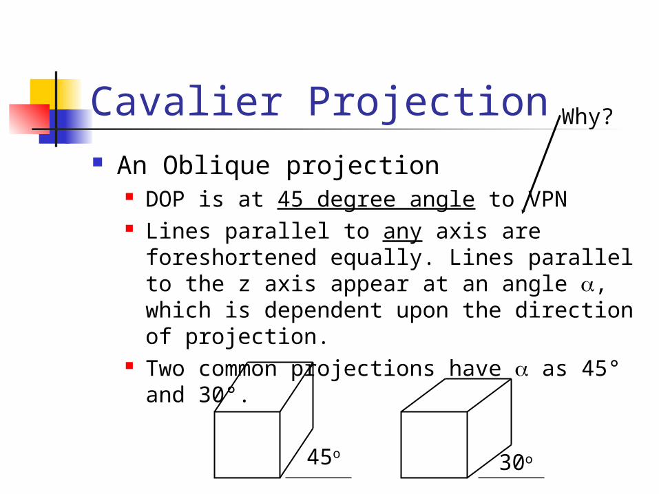
Cavalier Projection An Oblique projection
DOP is at 45 degree angle to VPN Lines parallel to any axis are foreshortened
equally. Lines parallel to the z axis appear at an angle , which is dependent upon the direction of projection.
Two common projections have as 45° and 30°.
45o 30o
Why?

Cavalier Projection Angles
VPN
DOP

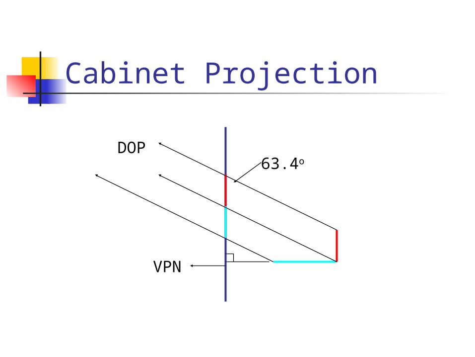
Cabinet projection Oblique projection
projection plane normal is at an arctan(2) = 63.4° degree angle to the projection plane. (typically projecting onto the x,y plane)
Lines parallel to the axis defining the projection plane are foreshortened equally. Lines parallel to the projection plane normal are halved!
Cabinet Projection
VPN
DOP63.4o

Parallel Projection
After transforming the object to the eye space, parallel projection is relative easy – we could just drop the Z
Xp = x
Yp = y Zp = -d
We actually want to keep Z – why?
x
y
z(x,y,z)
(Xp, Yp)
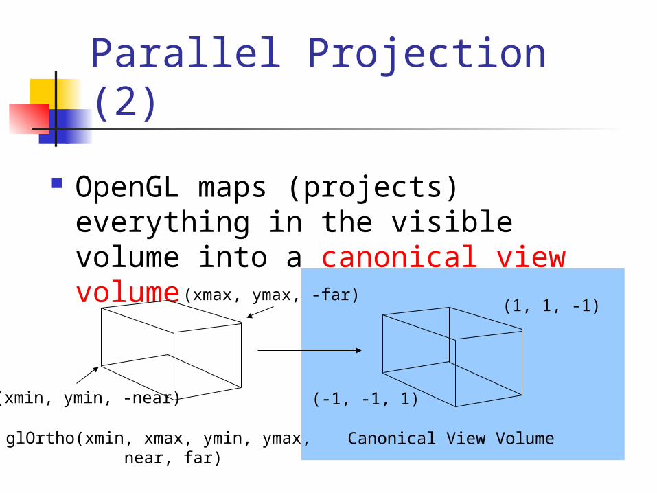
Parallel Projection (2)
OpenGL maps (projects) everything in the visible volume into a canonical view volume
(-1, -1, 1)
(1, 1, -1)
Canonical View VolumeglOrtho(xmin, xmax, ymin, ymax, near, far)
(xmin, ymin, -near)
(xmax, ymax, -far)

Parallel Projection (3)
Transformation sequence: 1. Translation (M1): (-near = zmax, -far = zmin)
-(xmax+xmin)/2, -(ymax+ymin)/2, -(zmax+zmin)/2
2. Scaling (M2): 2/(xmax-xmin), 2/(ymax-ymin), 2/(zmax-zmin)
2/(xmax-xmin) 0 0 - (xmax+xmin)/(xmax-xmin)M2 x M1 = 0 2/(ymax-ymin) 0 - (ymax+ymin)/(ymax-ymin) 0 0 2/(zmax-zmin) -(zmax+zmin)/(zmax-zmin) 0 0 0 1
Perspective Projection Perspective projections have
projectors at angles to each other radiating from a center of projection. Parallel lines not parallel to the
projection plane will not appear parallel in the projection.

Vanishing Points If not parallel?
If the lines are not parallel anymore, they must meet somewhere. In 3D space that point will be at infinity and is referred to as a vanishing point. There are an infinite number of vanishing points.
Axis vanishing points Lines parallel to one of the major axis come to
a vanishing point, these are called axis vanishing points. Only three axis vanishing points in 3D space.
y
x
z
z axis vanishing point

Center of Projection in OpenGL OpenGL always puts the center of
projection at 0,0,0 The projection plane is at z = -d This is sometimes called the “focal
length” or “f”
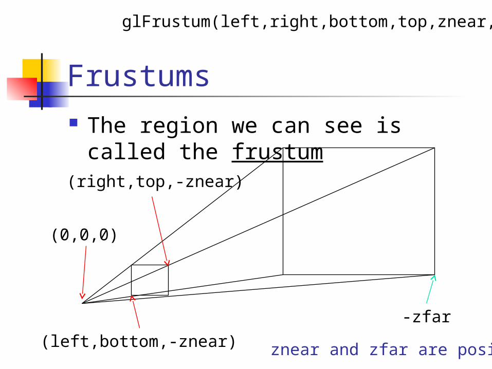
Frustums The region we can see is called the
frustum
-zfar
(left,bottom,-znear)
(right,top,-znear)
(0,0,0)
glFrustum(left,right,bottom,top,znear,zfar)
znear and zfar are positive

gluPerspective How do we get from:
gluPerspective(fovy, aspect, znear, zfar)
To glFrustum(left,right,bottom,top,znear,
zfar)
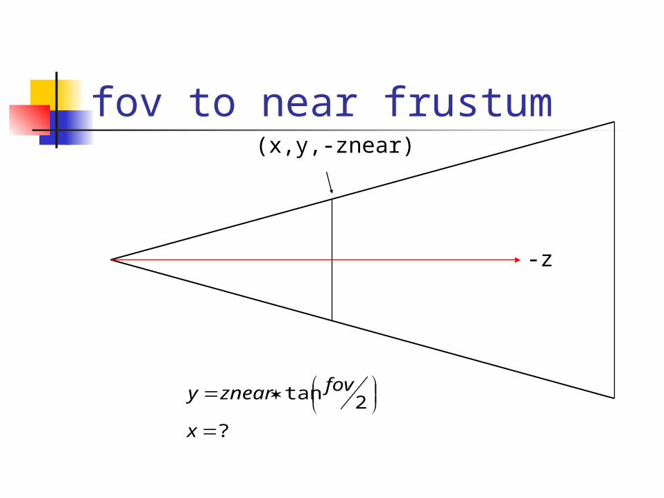
fov to near frustum
-z
(x,y,-znear)
?
2tan
x
fovzneary
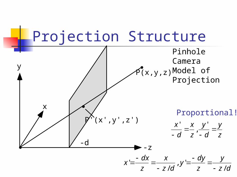
Projection Structure
-d
P(x,y,z)
P'(x',y',z')
-z
x
y
Proportional!
Pinhole Camera Model of Projection
z
y
d
y
z
x
d
x
'
,'
dz
y
z
dyy
dz
x
z
dxx
/',
/'

Matrix for Perspective Projection? We need division to do projection! But, matrix multiplication only does
multiplication and addition What about:
0/100
0100
0010
0001
d
M per
dz
z
y
x
z
y
x
d
PM per
/10/100
0100
0010
0001
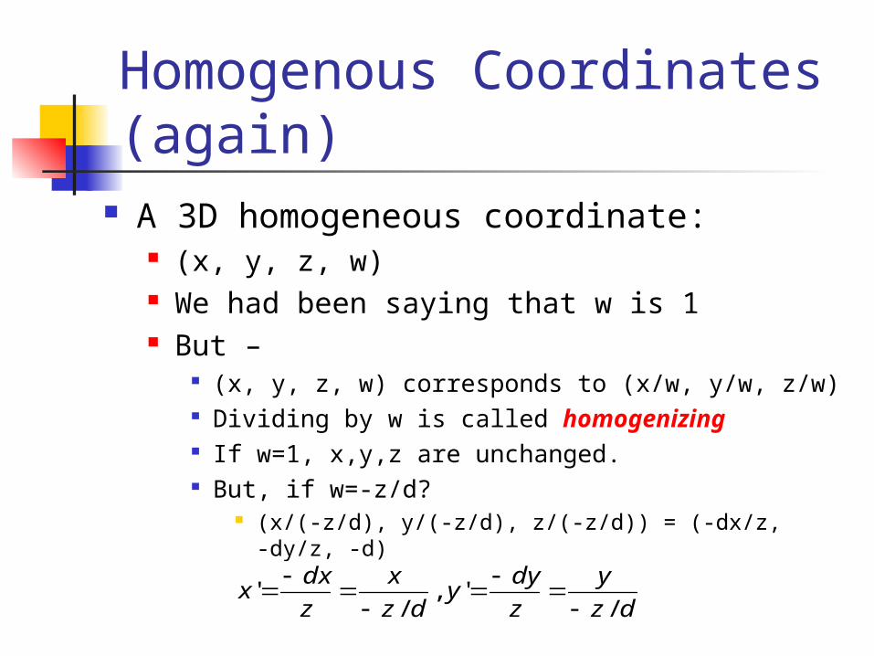
Homogenous Coordinates (again)
A 3D homogeneous coordinate: (x, y, z, w) We had been saying that w is 1 But –
(x, y, z, w) corresponds to (x/w, y/w, z/w) Dividing by w is called homogenizing If w=1, x,y,z are unchanged. But, if w=-z/d?
(x/(-z/d), y/(-z/d), z/(-z/d)) = (-dx/z, -dy/z, -d)
dz
y
z
dyy
dz
x
z
dxx
/',
/'

The Entire Viewing Process Rotate world so that the COP is at
0,0,0 and DOP is parallel to the Z axis
Apply perspective projection Homogenize Viewport transformation

Viewport Transformation(Window to Viewport) Window
Area of the projection plane Typically some normalized area with
0,0 in the center Viewport
Area of the computer display window Example:
(0, 0) to (640, 480)

Window to Viewport Example Assume Window (-1,-1) to (1,1)
OpenGL calls these normalized device coordinates
Viewport (0, 0) to (640, 480) OpenGL calls these window
coordinateslowerleftndw x
widthxx
2)1(
lowerleftndw yheight
yy
2)1(

Perspective Projection (6) Final Projection Matrix:
x’ 2N/(xmax-xmin) 0 (xmax+xmin)/(xmax-xmin) 0 x
y’ = 0 2N/(ymax-ymin) (ymax+ymin)/(ymax-ymin) 0 y
z’ 0 0 -(F + N)/(F-N) -2F*N/(F-N) z
w’ 0 0 -1 0 1
glFrustum(xmin, xmax, ymin, ymax, N, F) N = near plane, F = far plane

Within OpenGL glBegin(GL_POLYGON); glVertex3dv(a); glVertex3dv(b); glVertex3dv( c);glEnd();
ObjectCoordinates
Mod
elview
Matr
ix
Projec
tion
Matr
ix
Homog
enize
Wind
ow to
Viewpo
rt
Eye co
ordin
ates
Clip co
ordin
ates
Normali
zed d
evice
coor
dinate
s (2D
)
Viewpo
rt
coor
dinate
s