projection speaker pj-154bs - · pdf filecable gland. 3-3. connect the ... matching...
TRANSCRIPT

PROJECTION SPEAKER PJ-154BS
Thank you for purchasing TOA's Projection Speaker. Please carefully follow the instructions in this manual to ensure long, trouble-free use of your equipment.
Traceability Information for Europe (EMC directive 2004/108/EC)
Manufacturer:TOA Corporation7-2-1, Minatojima Nakamachi, Chuo-ku, Kobe, Hyogo, Japan
Authorized representative:TOA Electronics Europe GmbHSuederstrasse 282, 20537 Hamburg,Germany
INSTRUCTION MANUAL
1. SAFETY PRECAUTIONS ........................... 1
2. GENERAL DESCRIPTION
AND FEATURES ......................................... 2
3. IMPEDANCE CHANGE .............................. 2
4. INSTALLATION .......................................... 3
5. DIMENSIONAL DIAGRAM ......................... 4
6. WIRING DIAGRAM ..................................... 5
7. FREQUENCY RESPONSE (1 W, 4 m) ....... 5
8. SPECIFICATIONS ...................................... 5
TABLE OF CONTENTS
1. SAFETY PRECAUTIONS
• Before installation or use, be sure to carefully read all the instructions in this section for correct and safeoperation.
• Be sure to follow all the precautionary instructions in this section, which contain important warnings and/orcautions regarding safety.
• After reading, keep this manual handy for future reference.
When Installing the Unit
• Refer all installation work to the dealer from whomthe speaker was purchased. Installation workrequires extensive technical knowledge andexperience. The speaker may fall off if incorrectlyinstalled, resulting in possible personal injury.
• Install the speaker only in a location that canstructurally support the full weight of the unit andmounting bracket. Doing otherwise may result inthe speaker falling down and causing personalinjury and/or property damage.
• Since the unit is designed for in-door use, do not
install it outdoors. If installed outdoors, the aging ofparts causes the unit to fall off, resulting in personalinjury. Also, when it gets wet with rain, there is adanger of electric shock.
• Do not use other methods than specified to installthe speaker. Extreme force is applied to thespeaker and the speaker could fall off, possiblyresulting in personal injuries.
• Use screws that are appropriate for the ceiling's orwall's material and structure. Failure to do so maycause the speaker to fall, resulting in materialdamage and possible personal injury.
• Ensure that all screws are securely tightened. Ifthey are loose after installation, the speaker couldfall down, possibly resulting in personal injury.
• Do not mount the speaker in locations exposed toconstant vibration. The speaker or its mounts canbe damaged by excessive vibration, potentiallycausing the speaker to fall, which could result inpersonal injury.
Indicates a potentially hazardous situation which,if mishandled, could result in death or seriouspersonal injury.
WARNING
2
2. GENERAL DESCRIPTION AND FEATURES
The PJ-154BS is certified according to the European Standard EN 54-24: 2008, the International Standard7240-24: 2010 and compliant with the British Standard BS 5839-8: 2008 14.8.The PJ-154BS is a projection speaker designed for wall or ceiling installation. Considered in architectural design, it can blend in with lighting equipment.The supplied swivel bracket allows flexible speaker angle adjustment.The speaker is driven on high-impedance (100 V and 70 V) line, and its input power (impedance) can beeasily switched.
NoteNever dismantle the PJ-154BS in any way even for repainting reason. Since the PJ-154BS is certified in theform of complete assembly by the above-mentioned standards, it does not meet these standards ifdismantled.
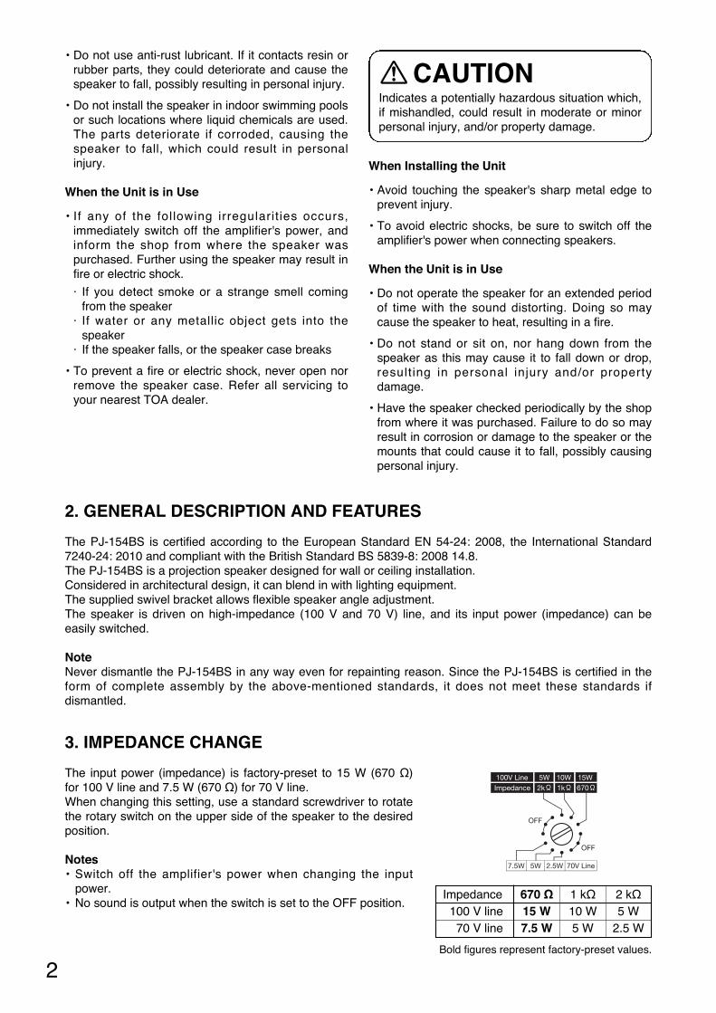
3. IMPEDANCE CHANGE
The input power (impedance) is factory-preset to 15 W (670 Ω)for 100 V line and 7.5 W (670 Ω) for 70 V line.When changing this setting, use a standard screwdriver to rotatethe rotary switch on the upper side of the speaker to the desiredposition.
Notes• Switch off the amplifier's power when changing the input
power.• No sound is output when the switch is set to the OFF position.
Indicates a potentially hazardous situation which,if mishandled, could result in moderate or minorpersonal injury, and/or property damage.
CAUTION• Do not use anti-rust lubricant. If it contacts resin or
rubber parts, they could deteriorate and cause thespeaker to fall, possibly resulting in personal injury.
• Do not install the speaker in indoor swimming poolsor such locations where liquid chemicals are used.The parts deteriorate if corroded, causing thespeaker to fall, which could result in personalinjury.
When the Unit is in Use
• If any of the following irregularit ies occurs,immediately switch off the amplifier's power, andinform the shop from where the speaker waspurchased. Further using the speaker may result infire or electric shock.
· If you detect smoke or a strange smell comingfrom the speaker
· If water or any metallic object gets into thespeaker
· If the speaker falls, or the speaker case breaks
• To prevent a fire or electric shock, never open norremove the speaker case. Refer all servicing toyour nearest TOA dealer.
When Installing the Unit
• Avoid touching the speaker's sharp metal edge toprevent injury.
• To avoid electric shocks, be sure to switch off theamplifier's power when connecting speakers.
When the Unit is in Use
• Do not operate the speaker for an extended periodof time with the sound distorting. Doing so maycause the speaker to heat, resulting in a fire.
• Do not stand or sit on, nor hang down from thespeaker as this may cause it to fall down or drop,result ing in personal injury and/or propertydamage.
• Have the speaker checked periodically by the shopfrom where it was purchased. Failure to do so mayresult in corrosion or damage to the speaker or themounts that could cause it to fall, possibly causingpersonal injury.
Impedance 670 Ω 1 kΩ 2 kΩ100 V line 15 W 10 W 5 W70 V line 7.5 W 5 W 2.5 W
Bold figures represent factory-preset values.

Ceiling
Swivel bracket
Speaker
Safety screw
Safety screw hole
Speaker bracket
Speaker fixing screw
Speaker cord
2-1, 2-3
2-3
2-2
Terminal box
Ceiling
Swivel bracket(accessory)
Safety screw
Tapping screw 4 x 16 (accessory)
NoteIf these screws are not appropriate for the ceiling material, separately prepare the proper screws.
NoteLoosen the safety screw until it's tip does not stick out from the bracket surface.If the screw tip sticks out, this obstructs the insertion of the speaker bracket in Step 2.
3
4. INSTALLATION
NoteBe sure to make speaker cable wiring via the supplied terminal box. (Refer to Step 3 on the next page.) The way of wiring without using the terminal box does not fulfill the standards requirements.
Step 1. Secure the swivel bracket to the ceiling or wall with 3 screws.
Loosen the safety screw (for fall prevention) as shown below.
Before installation
Step 2. Mount the speaker to the swivel bracket.Be sure to remove the Speaker Cord protectivesheet used for packing material.
2-1. Loosen the speaker fixing screws.NoteThese screws are pre-screwed into the bracket at the factory.Loosen them so that they can slip into the swivel bracket's screw slots.
2-2. Slip 2 speaker fixing screws into the swivel bracket's screw slots.
2-3. Tighten the speaker fixing screws and safety screw.NoteEnsure that the safety screw is fit into the given hole in the speaker bracket.
Before installation
Be sure to adjust the speaker angle within therange shown at right. Installing the speaker atan angle exceeding this range does not meetthe standards requirements.
Adjustable angle
(Horizontal)360º
70º
89º
20º
70º
Ceiling Wall

Terminal box3-2
Cable gland
To speaker
COM
HOT
COM
HOT
Terminal blocks
3-3[Cable end treatment]
55 mm (2.17")
8 mm(0.31")
3-1
From amplifier
Amplifier cable
Step 3. Connect the amplifier cable (cable from amplifier) to the terminal block in the terminal box. In advance of the cable connection, remove 2 screws fixing the terminal box’s cover plate to detach it.
3-1. Strip the amplifier cable jacket asshown at right.
3-2. Run the amplifier cable through thecable gland.
3-3. Connect the amplifier cable accordingto the polarity indication at the terminalblock.
3-4. Secure the terminal box to the ceilingor wall with screws using the 2mounting screw knockouts in theterminal box. Then, secure thedetached terminal box’s cover platewith screws.
NoteScrews for mounting the terminal boxto the ceiling or wall are not supplied.Use screws that are appropriate forthe ceiling's or wall's material andstructure.
Approx.625 (24.61)
51 (
2.01
)88
(3.
46)
88 (3.46)
ø186(ø7.32)
251
(9.8
8)
369
(14.
53)
ø72 (ø2.83)
333
(13.
11)
36(1
.42)
[Top]
[Front] [Side]
[Bottom]
30.5
(1.
2)
120º
ø60 (ø2.36) 3-ø6.5 (ø0.26)
5. DIMENSIONAL DIAGRAM
Unit: mm (in)
4
[When making a bridge connection]
Punch out the knockout in the terminal box,attach the cable gland (option) there, then makecable connections to the next speakers in thesame way as described in Steps 3-1 through 3-3.
Terminal box
Cover plate
Ceiling3-4
To the next speaker
Optional part

Rotary switch
2 kΩ
1 kΩ
670 Ω
8 Ω
0COM
COM
HOT
( )EARTH
Matching transformer
Networkcircuit
OFFOFF
OFF
(Factory-preset wiring)
Thermal fuse (84°C or 183.2°F)Terminal block
COM
HOT
( )EARTH
SP1
SP2
5020 100 50050 1 k 5 k
Frequency-SPL 10 k 20 k [Hz]
60
70
80
90[dB]
5
8. SPECIFICATIONS
Notes• The design and specifications are subject to change without notice for improvement. • The Specifications data was measured in an anechoic chamber, according to EN 54-24.• Reference axis: Axis is on the center of grille surface and perpendicular to the grille surface.• Reference plane: Plane is on the grille surface and perpendicular to the reference axis.• Horizontal plane: Plane is containing the reference axis and perpendicular to the reference plane.
* Suppliable cable gland's part code and name: 525-52-011-70 Cable gland AVC PGB13.5-12 (GRY)
6. WIRING DIAGRAM
7. FREQUENCY RESPONSE (1 W, 4 m)
EN 54-24: 2008110359-CPD-0106
0359
Standards Certified to the European Standard EN 54-24: 2008Loudspeaker for voice alarm systems for fire detection and fire alarm systemsCertification No. 0359-CPD-0106Certified to the International Standard ISO 7240-24: 2010Sound system loudspeakers for fire detection and fire alarm systemsIn Compliance with the British Standard BS5839-8: 2008 14.8
Environment Type Type A (Indoor applications)Rated Noise Power 15 W (100 V line), 7.5 W (70 V line)Rated Impedance 100 V line: 670 Ω (15 W), 1 kΩ (10 W), 2 kΩ (5 W)
70 V line: 670 Ω (7.5 W), 1 kΩ (5 W), 2 kΩ (2.5 W)Sensitivity 91 dB (1 W, 1 m at 500 Hz to 5 kHz pink noise)
87 dB (1 W, 1 m at 100 Hz to 10 kHz pink noise)75 dB (1 W, 4 m at 100 Hz to 10 kHz pink noise)
Max. SPL 99 dB (15 W, 1 m at 100 Hz to 10 kHz pink noise)87 dB (15 W, 4 m at 100 Hz to 10 kHz pink noise)
Frequency Response 70 Hz – 20 kHz Coverage Angle (–6 dB) Horizontal and Vertical: 360° (500 Hz), 170° (1 kHz), 90° (2 kHz), 70° (4 kHz)Speaker Component Low frequency: 12 cm (5") cone-type
High frequency: 2.5 cm (1") balanced dome tweeterOperating Temperature –10 ºC to +50 ºC (14 ºF to 122 ºF)Cable Gland Size: PG 13.5
One cable gland is factory-installed.For bridge connection, one cable gland can be added.*
Cable Connection Screw terminal (Steatite) x 2Applicable Cable Size Outer diameter: ø6.5 – ø12.5 mm
Conductor: Solid wire or 7-core wire0.8 – 7 mm2 (AWG 18 – 9) for solid wire,0.8 – 4 mm2 (AWG 18 – 11) for 7-core wire
Finish Enclosure: HIPS resin, off-white (RAL 9010 or equivalent color)Grille: Surface-treated steel plate net, off-white (RAL 9010 or equivalent color),
paint Dimensions ø186 x 251 (h) mm (ø7.32" x 9.88") (speaker only)Weight 2.1 kg (4.63 lb) (without swivel bracket)Accessories Swivel bracket ... 1, Tapping screw 4 x 16 ... 3


533-06-240-70
URL: http://www.toa.jp/