projekt katalog5 en 2017 - magnaplast.pl · table of contents introduction 4 inspection chamber,...
TRANSCRIPT

SEWAGE MANHOLES
CATALOGUE
SC


TABLE OF CONTENTS
Introduction 4
Inspection chamber, type 315 7
Inspection chamber, type 400 10
Inspection chamber, type 425 14
Assembly instruction 19
Catch basins 20
- Construction of a catch basin 20
- Installation of an in situ gasket 20
Backdrop chambers 21
Complete systems of sewage manholes 22
Table of contents
3TABLE OF CONTENTS

INTRODUCTIONInspection chambers are widely used in gravity sewerage systems, wellpoint systems and drainage systems. Inspection chambers allow cleaning and other works to be carried out on storm water drainage systems or sanitary sewage systems using suitable equipment, while catch basins fitted with a sump (blind or drainage) are used as chambers or tanks. They are easy to install and they supplement the external sewerage system.
A chamber comprises 3 basic elements:
- a chamber base (multi-inlet or straight-through),- rising pipe (smooth or corrugated, depending on the system),- cast iron telescope or concrete cone with concrete cover.
Magnaplast offers 3 types of inspection chamber: 315, 400, and 425.
Magnaplast chamber bases are made by injection moulding (PP), while rising pipes are made by extrusion moulding (PVC or PP). As the chamber bases are made of PP, they are exceptionally resistant to mechanical impact, even at low temperatures, which increases their usefulness significantly. Thanks to the internal smoothness of the chamber bases, the possibility of channel clogging has been eliminated.
Sewerage system inspection chambers made of plastic have many advantages, both in the economic and technical sense, taking into account environmental protection both in the area of sewerage exfiltration to the ground and underground water infiltration into the sewerage system.
The design of the Magnaplast chamber bases includes full compatibility with KG pipes, as well as the Magnacor system of corrugated pipes.
A rising pipe can be a smooth sewerage pipe, type 400, or corrugated pipe, type 315 or 425, depending on the type of chamber. They may be cut to the required size at the construction site with the use of a hand saw or a chainsaw.
Introduction
4 INTRODUCTION

Inspection chamber covers - area of application
Depending on the inspection chamber location, a suitable cover is selected according to the needs of the technical design. Magnaplast offers 3 classes of covers:
A – 1.5T - surfaces intended for pedestrian and cycle traffic only - group 1, B – 12.5T - low intensity vehicle traffic (pavements, squares, car parks) - group 2, D – 40T - high intensity vehicle traffic (roads, driveways) - group 3.
For green areas and places not exposed to loads, it is permissible to use a non-class cover, e.g. a PP cover.
Benefits:
- wide range,- quick and easy mounting of elements,- compatibility with other systems,- internal smoothness of walls to prevent the build up of deposits,- high resistance.
Introduction
Group 1 Group 2 Group 3 Group 2 Group 1
Group 1
footbridge
traffic roadSidewalk
5INTRODUCTION

Quality control
All Magnaplast products, including inspection chambers, undergo a strict quality inspection and must meet all the requirements of the relevant standards. The high quality of the products is additionally confirmed by the quality management system, implemented according to ISO 9001.
Standards and approvals
PN-EN 13598-2:2009Plastics piping systems for non-pressure underground drainage and sewerage. Unplasticized poly(vinyl chloride) (PVC-U), polypropylene (PP) and polyethylene (PE). Specifications for manholes and inspection chambers in traffic areas and deep underground installations
PN-EN 124:2000Gully tops and manhole tops for vehicular and pedestrian areas – Design requirements, type testing, marking, quality control.
PN-EN 681-1:2002/A3:2006Elastomeric seals - Materials requirements for pipe joint seals used in water and drainage applications - Part 1: Vulcanized rubber
Technical Approval ITB AT-15-8030/2009Inspection chambers without steps MAGNAPLAST made of elements of thermoplastic plastics, issued by Construction Technology Institute in Warsaw, Poland.
Technical Approval AT/2008-03-2345Inspection chambers Magnaplast made of polypropylene (PP), Unplasticized poly(vinyl chloride) (PVC-U) and polyethylene (PE) issued by Road and Bridge Research Institute in Warsaw, Poland
Technical Approval AT/07-2012-0250-00Inspection chambers without steps MAGNAPLAST made of elements of thermoplastic plastics, issued by Railway Institute in Warsaw, Poland
Introduction
6 INTRODUCTION

Chamber base type 315 3 inlets with seal
Chamber base straight with seal
type 315
DN [mm] DN1 [mm] H [mm] Hu [mm] L [mm] Product code
160 341 290 165 521 33116
200 341 336 200 513 33216
Magnaplast Inspection chamber, type 315
The Magnaplast type 315 inspection chamber consists of: - a chamber base with seal (base of the inspection chamber), with a specially profiled bottom and branches, if fitted. It can be connected to a rain water sewerage system or a sanitary sewerage system;- corrugated rising pipe (dia. 338 mm);- telescope (telescope pipe with cast iron cover);- seal for telescope.
The Magnaplast range includes:
7INSPECTION CHAMBER TYPE 315
DN [mm] DN1 [mm] H [mm] Hu [mm] L [mm] F [mm] Product code
160 341 310 185 521 650 33111
200 341 356 220 513 680 33211
Type 315

Corrugated rising pipe RCP 315
DN [mm] DN1 [mm] H [mm] Product code
300 338 1000 33011
300 338 2000 33021
300 338 3000 33031
300 338 6000 33061
PP cover A15 – 1.5T type 315 mounted directly on rising pipe RCP 315
Telescopic covertelescope pipe with cast iron cover
D [mm] DN1 [mm] DN2 [mm] H [mm] H1 [mm] Product code
A15 – 1.5T cover without ventilation 342 310 295 475 50 666450
B125 – 12.5T cover without ventilation 342 255 295 495 90 666400
D400 – 40T cover without ventilation 342 255 295 495 90 666420
B125 – 12.5T cover with ventilation 342 255 295 495 90 666410
D400 – 40T cover with ventilation 342 255 295 495 90 666430
DN1 [mm] DN2 [mm] H [mm] Product code
360 297 39 33400
8 INSPECTION CHAMBER TYPE 315
Type 315

Seal for telescope for rising corrugated pipe RCP 315
DN1 [mm] DN2 [mm] H [mm] Product code
292 342 26 661320
Concrete cone with cover type 315 and 400
DN1 [mm] DN2 [mm] DN3 [mm] H1 [mm] H2 [mm] Product code
410 700 640 110 70 34512
PP bottomfor corrugated rising pipe RCP 315
DN1 [mm] DN2 [mm] H [mm] Product code
331 297 58 30300
Concrete frame for cover
D1 [mm] D2 [mm] DN [mm] H [mm] Product code
440 350 330 100 34520
9INSPECTION CHAMBER TYPE 315
Type 315
Chamber base type 400 3 inlets with seal
Chamber base type 400 straightwith seal
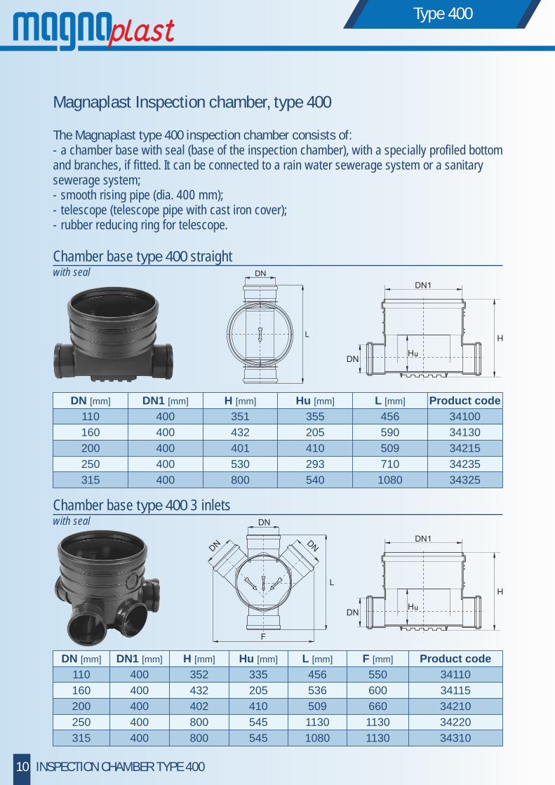
Magnaplast Inspection chamber, type 400
The Magnaplast type 400 inspection chamber consists of:- a chamber base with seal (base of the inspection chamber), with a specially profiled bottom and branches, if fitted. It can be connected to a rain water sewerage system or a sanitary sewerage system;- smooth rising pipe (dia. 400 mm);- telescope (telescope pipe with cast iron cover);- rubber reducing ring for telescope.
10 INSPECTION CHAMBER TYPE 400
Type 400
DN [mm] DN1 [mm] H [mm] Hu [mm] L [mm] Product code
110 400 351 355 456 34100
160 400 432 205 590 34130
200 400 401 410 509 34215
250 400 530 293 710 34235
315 400 800 540 1080 34325
DN [mm] DN1 [mm] H [mm] Hu [mm] L [mm] F [mm] Product code
110 400 352 335 456 550 34110
160 400 432 205 536 600 34115
200 400 402 410 509 660 34210
250 400 800 545 1130 1130 34220
315 400 800 545 1080 1130 34310

Chamber base type 400 right inlet
DN [mm] DN1 [mm] H [mm] Hu [mm] L [mm] F [mm] Product code
250 400 910 540 1130 860 34225
315 400 910 545 1080 880 34315
Chamber base type 400 left inlet
Smooth rising pipe RSP 400
DN [mm] H [mm] Product code
400 1000 34010
400 2000 34020
400 3000 34030
400 6000 34060
DN [mm] DN1 [mm] H [mm] Hu [mm] L [mm] F [mm] Product code
250 400 810 540 1130 860 34230
315 400 910 545 1080 880 34320
11INSPECTION CHAMBER TYPE 400
Type 400
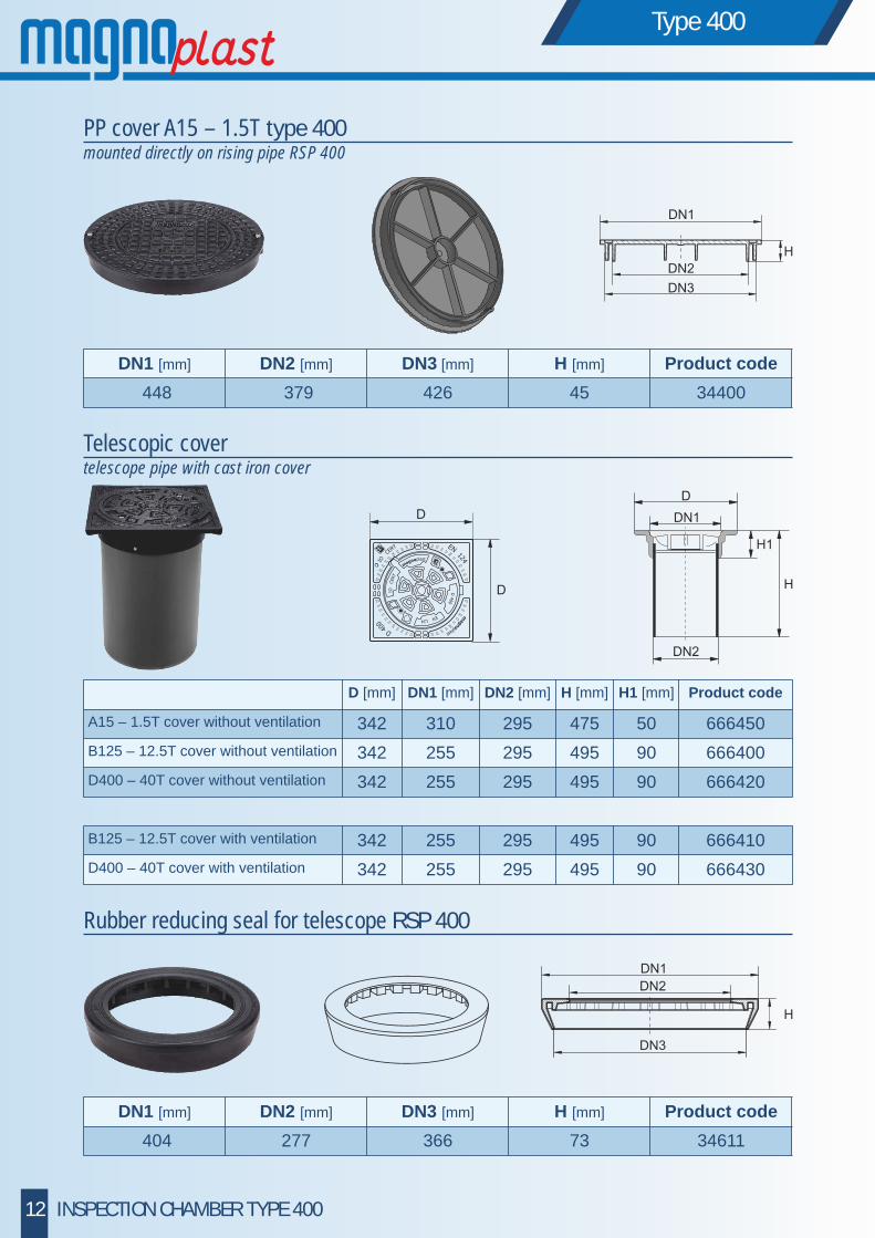
PP cover A15 – 1.5T type 400 mounted directly on rising pipe RSP 400
Rubber reducing seal for telescope RSP 400
DN1 [mm] DN2 [mm] DN3 [mm] H [mm] Product code
404 277 366 73 34611
DN1 [mm] DN2 [mm] DN3 [mm] H [mm] Product code
448 379 426 45 34400
Telescopic covertelescope pipe with cast iron cover
12 INSPECTION CHAMBER TYPE 400
Type 400
D [mm] DN1 [mm] DN2 [mm] H [mm] H1 [mm] Product code
A15 – 1.5T cover without ventilation 342 310 295 475 50 666450
B125 – 12.5T cover without ventilation 342 255 295 495 90 666400
D400 – 40T cover without ventilation 342 255 295 495 90 666420
B125 – 12.5T cover with ventilation 342 255 295 495 90 666410
D400 – 40T cover with ventilation 342 255 295 495 90 666430

Concrete cone with cover type 315 and 400
Concrete frame for cover
D1 [mm] D2 [mm] DN [mm] H [mm] Product code
440 350 330 100 34520
DN1 [mm] DN2 [mm] DN3 [mm] H1 [mm] H2 [mm] Product code
410 700 640 110 70 34512
13INSPECTION CHAMBER TYPE 400
Type 400

Chamber base type 425 3 inlets with seal
Chamber base type 425 straight with seal
Magnaplast Inspection chamber, type 425
The Magnaplast type 425 inspection chamber consists of:- a chamber base with seal (base of the inspection chamber), with a specially profiled bottom and branches, if fitted. It can be connected to a rain water sewerage system or a sanitary sewerage system;- corrugated rising pipe (dia. 451mm);- telescope (telescope pipe with cast iron cover);- rubber reducing seal / seal for telescope (depends on cover type)
14 INSPECTION CHAMBER TYPE 425
Type 425
DN [mm] DN1 [mm] H [mm] Hu [mm] L [mm] Product code
110 455 335 200 460 35100
160 455 441 210 590 35130
200 455 384 240 515 35215
250 455 780 515 1130 35235
315 455 780 520 1080 35325
DN [mm] DN1 [mm] H [mm] Hu [mm] L [mm] F [mm] Kod artykułu
110 455 334 200 460 550 35110
160 455 432 210 536 600 35115
200 455 384 240 515 620 35210
250 455 780 515 1130 1130 35220
315 455 780 520 1080 1130 35310

Corrugated rising pipe RCP 425
DN [mm] DN1 [mm] H [mm] Product code
400 451 2000 35020
400 451 3000 35030
400 451 6000 35060
PP cover A15 – 1.5T type 425 mounted directly on rising pipe RCP 425
DN1 [mm] DN2 [mm] H [mm] Product code
448 396 48 35400
Telescopic covertelescope pipe with cast iron cover
15INSPECTION CHAMBER TYPE 425
Type 425
D [mm] DN1 [mm] DN2 [mm] H [mm] H1 [mm] Product code
A15 – 1.5T cover without ventilation 342 310 295 475 50 666450
B125 – 12.5T cover without ventilation 342 255 295 495 90 666400
D400 – 40T cover without ventilation 342 255 295 495 90 666420
B125 – 12.5T cover with ventilation 342 255 295 495 90 666410
D400 – 40T cover with ventilation 342 255 295 495 90 666430
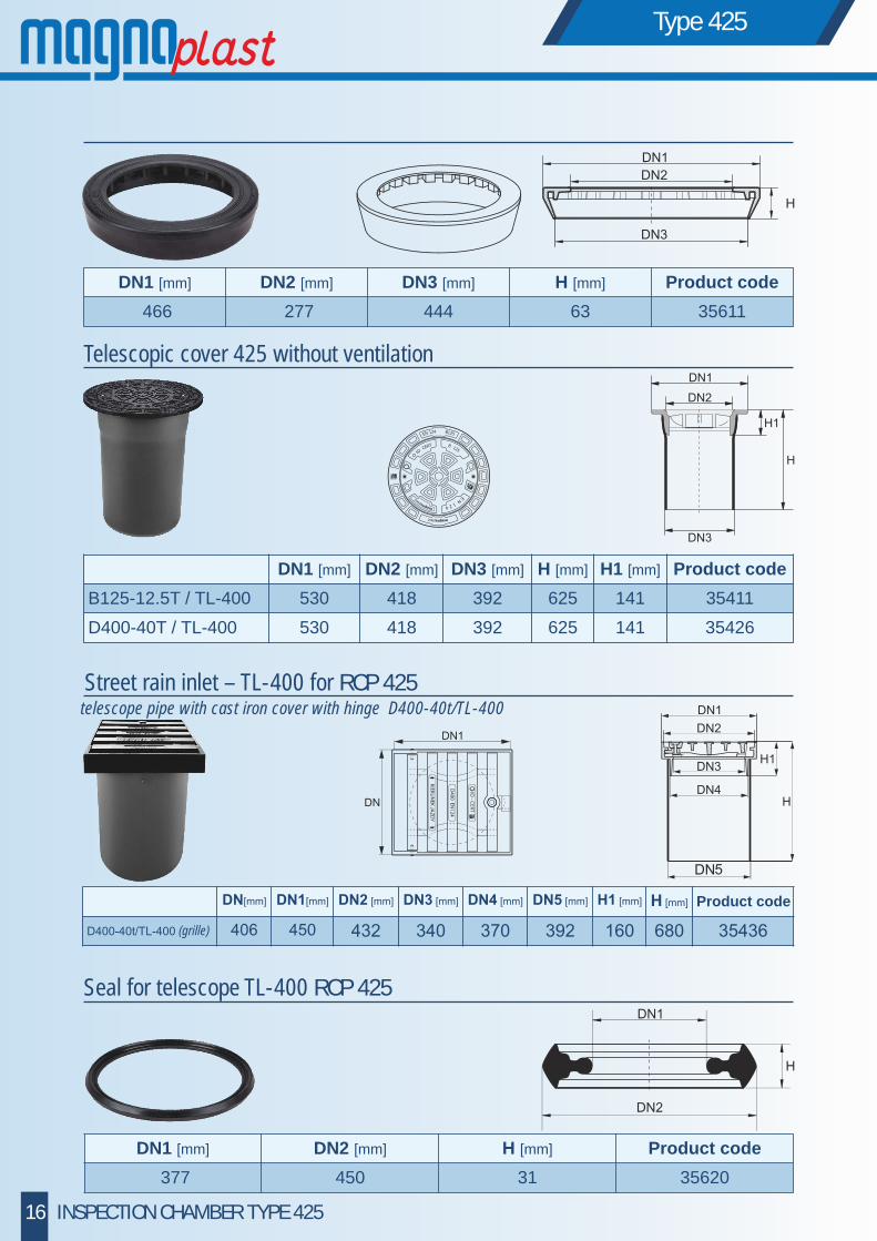
Seal for telescope TL-400 RCP 425
DN1 [mm] DN2 [mm] H [mm] Product code
377 450 31 35620
DN1 [mm] DN2 [mm] DN3 [mm] H [mm] Product code
466 277 444 63 35611
Street rain inlet – TL-400 for RCP 425
Telescopic cover 425 without ventilation
DN1 [mm] DN2 [mm] DN3 [mm] H [mm] H1 [mm] Product code
B125-12.5T / TL-400 530 418 392 625 141 35411
D400-40T / TL-400 530 418 392 625 141 35426
16 INSPECTION CHAMBER TYPE 425
Type 425
telescope pipe with cast iron cover with hinge D400-40t/TL-400
Product code
(grille)

PP bottomfor corrugated rising pipe RCP 425
DN1 [mm] DN2 [mm] H [mm] Product code
460 393 75 661600
Concrete frame for cover
D1 [mm] D2 [mm] DN [mm] H [mm] Product code
440 350 330 100 34520
Concrete cone with cover type 425
DN1 [mm] DN2 [mm] DN3 [mm] H1 [mm] H2 [mm] Product code
470 700 640 110 70 35512
17INSPECTION CHAMBER TYPE 425
Type 425
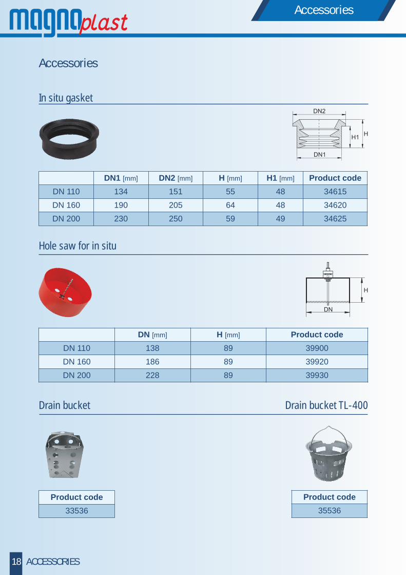
Accessories
In situ gasket
DN [mm] H [mm] Product code
DN 110 138 89 39900
DN 160 186 89 39920
DN 200 228 89 39930
DN1 [mm] DN2 [mm] H [mm] H1 [mm] Product code
DN 110 134 151 55 48 34615
DN 160 190 205 64 48 34620
DN 200 230 250 59 49 34625
Hole saw for in situ
Accessories
18 ACCESSORIES
Product code
33536
Product code
35536
Drain bucket Drain bucket TL-400

Assembly instruction
The inspection chambers should be mounted according to the technical design for the sewerage system, in a properly prepared and drained excavation.
1. Before mounting the inspection chamber, remove any large or sharp stones from the excavation and prepare a coarse-sand bed (min. 10 cm thick).
2. Place the chamber base on the excavation bottom (remember it should already be levelled with a bottom slope of 1.5%) and connect to the sewerage system pipes. To prevent movement of the chamber base, backfill the trench to 10 cm over the pipe level.
3. Cut the rising pipe to the required length (in the case of a corrugated pipe - the cut is made on the notch and seal is installed in the concave section after the first notch).
4. Remove any dirt from the chamber base. Smear the chamber base internals and the seal on the rising pipe with a lubricant, and then install it in the chamber base socket.
Having prepared the inspection chamber this way, backfill it with easily-compacted soil. Each layer of the backfill should not exceed 30 cm.
5. a) in the version with a corrugated rising pipe (type 315 or 425), install a seal inside the pipe, in its last concave section; then, install the telescopic cover;
b) in the version with a smooth rising pipe (type 400), install the cover. The rubber reducing seal is to be ordered separately.
An inspection chamber combined with the Magnacor corrugated pipe system.
Assembly instruction
19ASSEMBLY INSTRUCTION
1 2 3
4 5

CATCH BASINS
It is possible to construct a catch basin on the basis of a Magnaplast corrugated rising pipe. In this case, instead of a chamber base at the bottom, install an end plug and cover the rising pipe with a suitable top, following the mounting instructions (see section 5 page 19).In situ gaskets give the possibility of making an extra connection between the channel and the shaft. The drain line from the inspection chamber may be installed at any level by installing the in situ gasket.
Construction of a catch basin.
1a. PP cover1b. Telescopic cover 2. Rising pipe3. PP bottom4. In situ gasket
Installation of an in situ gasket
1. bore a hole at the required level and clean it of chips,
2. install the in situ gasket in the hole and apply the lubricant,
3. connect the sewerage system pipe.
Catch basins
20 CATCH BASINS
3
4
2
1b
1a
2
4
3
1 2 3
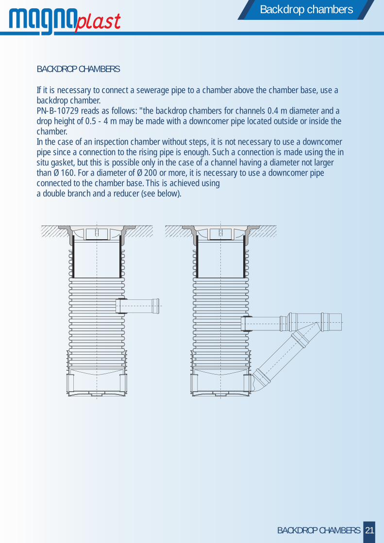
BACKDROP CHAMBERS
If it is necessary to connect a sewerage pipe to a chamber above the chamber base, use a backdrop chamber. PN-B-10729 reads as follows: "the backdrop chambers for channels 0.4 m diameter and a drop height of 0.5 - 4 m may be made with a downcomer pipe located outside or inside the chamber. In the case of an inspection chamber without steps, it is not necessary to use a downcomer pipe since a connection to the rising pipe is enough. Such a connection is made using the in situ gasket, but this is possible only in the case of a channel having a diameter not larger than Ø 160. For a diameter of Ø 200 or more, it is necessary to use a downcomer pipe connected to the chamber base. This is achieved using a double branch and a reducer (see below).
Backdrop chambers
21BACKDROP CHAMBERS

33536
Pipe diameter [mm]
Chamber type 315 Chamber type 400 Chamber type 425
straight 3 inlets straight 3 inlets connection on left
connection on right straight 3 inlets
110 - - 34100 34110 - - 35100 35110160 33116 33111 34130 34115 - - 35130 35115200 33216 33211 34215 34210 - - 35215 35210250 - - 34235 34220 34230 34225 35235 35220315 - - 34325 34310 34320 34315 35325 35310
prod
uct c
ode
TYPE 315 TYPE 400 TYPE 425
cover / bottomPP RCP 315
in situ gasket
Ø110 -Ø160 -Ø200 -
1m - 2m -3m -6m -
2m -3m -6m -
2m -3m -6m -
Ø110 - Ø160 -Ø200 -
in situ gasket
cover / bottomPP RCP 425
chamber - doublejunction
chamber - doublejunction
chamber - doublejunction
chamber - straight
riser PP
gasket
gasket
concrete framefor cover
cover withoutventilation
drain bucket drain bucket TL-400
cover - grill with ventilation cover TL - 400rain inlet
D400-40t (hinge) cover TL-400
cover PP
rubber reducing ring type 400
rubber reducing ring type 425
cover PP
concrete cone with cover
concretecone withcover
cover PP
riser PPriser PVC
chamber - straight chamber - straight
666450 - A15-1,5t- B125-12,5t- D400-40t
666410
3452035620
661320 34611
33400
34615 34615350203301133021
34020
3303134030
3306134060
34620 346203503034625 3462535060
34400 35400
34512
35512
35611
-B125-12,5t-D400-40t
35411 - B125-12,5t / TL-400
- D400-40t / TL-400
66643035426
666400666420
35536
35436
30300 661600
COMPLETE SYSTEMS OF SEWAGE MANHOLES SC


HTplus indoor sewage system
Ultra B low-noise indoor sewage system
Skolan- B thick-walled, low-noise sewage system
KG PVC outdoor sewerage system
PP outdoor sewerage system Magnacor
PP KG 2000 outdoor sewerage system
Sewerage chambers system
Polyethylene (PE) pressure pipes
Drainage (DR) systems
sieniawa żarska 69, 68-213 lipinki łużyckiePOLAND
tel.: +48 68 363 27 00fax: +48 68 363 27 72