prolight ps2p-tfpe-gp 0.2w power led version: 1 · pdf fileprolight ps2p-tfpe-gp 0.2w power...
TRANSCRIPT

We Provide the Light to the world
No. 89, Xiyuan Rd., Zhongli City, Taoyuan County 320,
Taiwan (R.O.C.)
Tel :+886-3-461-8618
Fax :+886-3-461-8677
www.prolightopto.com
ProLight PS2P-TFPE-GP0.2W Power LED Technical DatasheetVersion: 1.2
Features‧High Color rendering index ‧Good color uniformity‧Industry’s first lighting-class LED ‧Low Voltage DC operated‧Instant light (less than 100ns)‧No UV
Main Applications ‧The perfect light color for the Bakery counter‧T8/T5 tube‧LED bulb‧Indoor/Outdoor Commercial and
Residential Architectural
Introduction‧PS2P qualifies as the JEDEC Level 1 MSL sensitivity level and suitable forSMD process, Pb_free reflow soldering capability, and full compliance with EU Reduction of Hazardous Substances (RoHS) legislation.
2016/10DS-0078

We Provide the Light to the world
No. 89, Xiyuan Rd., Zhongli City, Taoyuan County 320,
Taiwan (R.O.C.)
Tel :+886-3-461-8618
Fax :+886-3-461-8677
www.prolightopto.com
Notes:
1. The cathode side of the device is denoted by the chamfer on the part body.
2. Drawing not to scale.
3. All dimensions are in millimeters.
4. Unless otherwise indicated, tolerances are ± 0.10mm.
5. Please do not solder the emitter by manual hand soldering, otherwise it will damage the emitter.
6. Please do not use a force of over 0.3kgf impact or pressure on the lens of the LED, otherwise
it will cause a catastrophic failure.
*The appearance and specifications of the product may be modified for improvement without notice.
2
Emitter Mechanical Dimensions

We Provide the Light to the world
No. 89, Xiyuan Rd., Zhongli City, Taoyuan County 320,
Taiwan (R.O.C.)
Tel :+886-3-461-8618
Fax :+886-3-461-8677
www.prolightopto.com
Radiation Color
Part Number Luminous Flux ΦV (lm) CRI
Pattern Emitter Minimum Typical Minimum
Lambertian Gold Plus PS2P-TFPE-GP 19.4 22 80
● ProLight maintains a tolerance of ± 7% on flux and power measurements.● ProLight maintains a tolerance of ± 2 on CRI measurements.● Please do not drive at rated current more than 1 second without proper heat sink.
Flux Characteristics at 60mA, TJ = 25°C
3
Optical Characteristics at 60mA, TJ = 25°C
Electrical Characteristics at 60mA, TJ = 25°C
ColorForward Voltage VF (V) Thermal Resistance
Min. Typ. Max. Junction to Slug (°C/ W)
Gold Plus 2.9 3.2 3.5 50
● ProLight maintains a tolerance of ± 0.1V for Voltage measurements.
Total
included Viewing
Angle Angle
RadiationColor
Color Temperature CCT (degrees) (degrees)
Pattern Min. Typ. Max. θ0.90V 2 θ1/2
Lambertian Gold Plus 2200 K - 2500 K 160 120
● ProLight maintains a tolerance of ± 5% for CCT measurements.
We Provide the Light to the world
No. 89, Xiyuan Rd., Zhongli City, Taoyuan County 320,
Taiwan (R.O.C.)
Tel :+886-3-461-8618
Fax :+886-3-461-8677
www.prolightopto.com
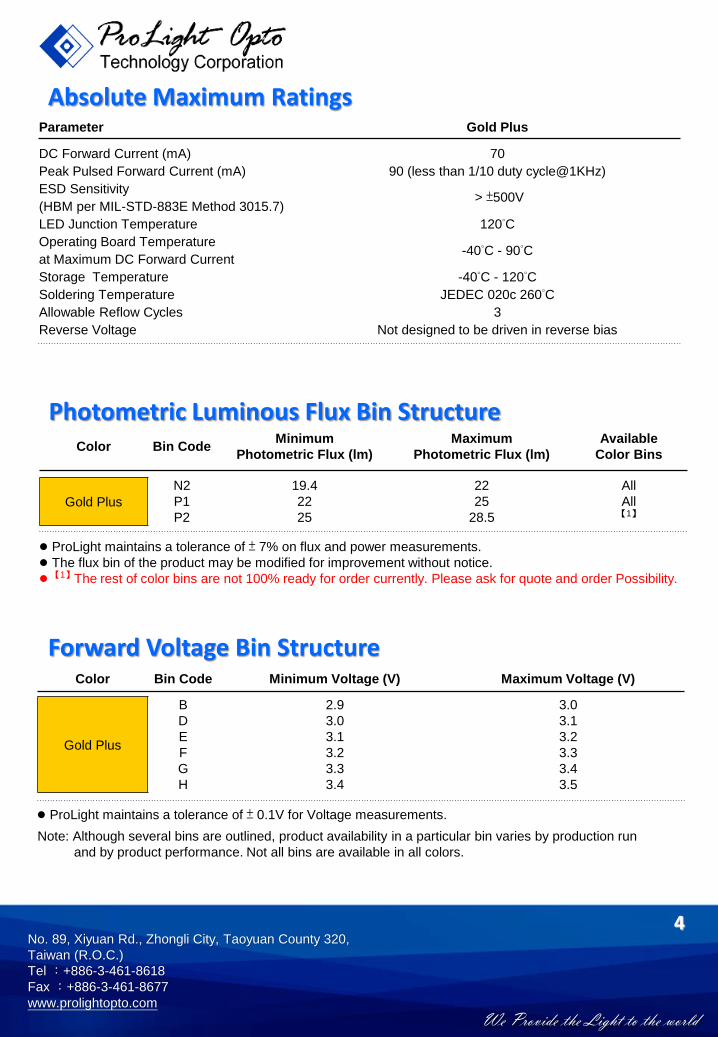
Absolute Maximum RatingsParameter Gold Plus
DC Forward Current (mA) 70
Peak Pulsed Forward Current (mA) 90 (less than 1/10 duty cycle@1KHz)
ESD Sensitivity> ±500V
(HBM per MIL-STD-883E Method 3015.7)
LED Junction Temperature 120°C
Operating Board Temperature-40°C - 90°C
at Maximum DC Forward Current
Storage Temperature -40°C - 120°C
Soldering Temperature JEDEC 020c 260°C
Allowable Reflow Cycles 3
Reverse Voltage Not designed to be driven in reverse bias
4
Photometric Luminous Flux Bin StructureColor Bin Code
Minimum Maximum Available
Photometric Flux (lm) Photometric Flux (lm) Color Bins
Gold Plus
N2 19.4 22 All
P1 22 25 All
P2 25 28.5 【1】
● ProLight maintains a tolerance of ± 7% on flux and power measurements.● The flux bin of the product may be modified for improvement without notice. ● 【1】The rest of color bins are not 100% ready for order currently. Please ask for quote and order Possibility.
Forward Voltage Bin Structure Color Bin Code Minimum Voltage (V) Maximum Voltage (V)
Gold Plus
B 2.9 3.0
D 3.0 3.1
E 3.1 3.2
F 3.2 3.3
G 3.3 3.4
H 3.4 3.5
● ProLight maintains a tolerance of ± 0.1V for Voltage measurements.
Note: Although several bins are outlined, product availability in a particular bin varies by production run
and by product performance. Not all bins are available in all colors.

We Provide the Light to the world
No. 89, Xiyuan Rd., Zhongli City, Taoyuan County 320,
Taiwan (R.O.C.)
Tel :+886-3-461-8618
Fax :+886-3-461-8677
www.prolightopto.com
y
x
Gold Plus
B2
B1 2200 K
B3B4
B0
2500 K
5
Color BinGold Plus Binning Structure Graphical Representation
Note:
1. ProLight SmartBin is working to make the color bin smarter, by selecting that intelligence is infused
into major B0 bin with minor B1-B4 bins and processes that make assembly easily

We Provide the Light to the world
No. 89, Xiyuan Rd., Zhongli City, Taoyuan County 320,
Taiwan (R.O.C.)
Tel :+886-3-461-8618
Fax :+886-3-461-8677
www.prolightopto.com
0
20
40
60
80
100
120
140
160
0 20 40 60 80 100 120
Rela
tive L
ight
Outp
ut
(%)
Junction Temperature, TJ (℃)
Gold Plus
0.0
0.2
0.4
0.6
0.8
1.0
350 400 450 500 550 600 650 700 750 800 850 900
Rela
tive S
pectr
al P
ow
er
Dis
trib
ution
Wavelength (nm)
Standard Eye Response Curve
Gold Plus
6
Color Spectrum, TJ = 25°C1. Gold Plus
Light Output CharacteristicsRelative Light Output vs. Junction Temperature at 60mA

We Provide the Light to the world
No. 89, Xiyuan Rd., Zhongli City, Taoyuan County 320,
Taiwan (R.O.C.)
Tel :+886-3-461-8618
Fax :+886-3-461-8677
www.prolightopto.com
Forward Current Characteristics, TJ = 25°C
0.0
0.2
0.4
0.6
0.8
1.0
1.2
0 10 20 30 40 50 60 70 80R
ela
tive L
um
inous F
lux
Forward Current (mA)
7
0
10
20
30
40
50
60
70
80
0 1 2 3 4 5
Avera
ge F
orw
ard
Curr
ent
(mA
)
Forward Voltage (V)
0
10
20
30
40
50
60
70
80
0 25 50 75 100 125 150
Forw
ard
Curr
ent
(mA
)
Ambient Temperature (℃)
RθJ-A = 150°C/W
RθJ-A = 125°C/W
RθJ-A = 75°C/W
RθJ-A = 100°C/W
Ambient Temperature vs. Maximum Forward Current1. Gold Plus (TJMAX = 120°C)

We Provide the Light to the world
No. 89, Xiyuan Rd., Zhongli City, Taoyuan County 320,
Taiwan (R.O.C.)
Tel :+886-3-461-8618
Fax :+886-3-461-8677
www.prolightopto.com
Typical Representative Spatial Radiation PatternLambertian Radiation Pattern
0
10
20
30
40
50
60
70
80
90
100
-100 -80 -60 -40 -20 0 20 40 60 80 100
Rela
tive I
nte
nsity
(%)
Angular Displacement (Degrees)
8

We Provide the Light to the world
No. 89, Xiyuan Rd., Zhongli City, Taoyuan County 320,
Taiwan (R.O.C.)
Tel :+886-3-461-8618
Fax :+886-3-461-8677
www.prolightopto.com
9
Soak Requirements
Level Floor Life Standard Accelerated Environment
Time Conditions Time (hours) Conditions Time (hours) Conditions
1 Unlimited≤30°C /
168 +5/-085°C /
NA NA85% RH 85% RH
● The standard soak time includes a default value of 24 hours for semiconductor manufature's
exposure time (MET) between bake and bag and includes the maximum time allowed out of
the bag at the distributor's facility.● Table below presents the moisture sensitivity level definitions per IPC/JEDEC's J-STD-020C.
Soak Requirements
Level Floor Life Standard Accelerated Environment
Time Conditions Time (hours) Conditions Time (hours) Conditions
1 Unlimited≤30°C /
168 +5/-085°C /
NA NA85% RH 85% RH
2 1 year≤30°C /
168 +5/-085°C /
NA NA60% RH 60% RH
2a 4 weeks≤30°C /
696 +5/-030°C /
120 +1/-060°C /
60% RH 60% RH 60% RH
3 168 hours≤30°C /
192 +5/-030°C /
40 +1/-060°C /
60% RH 60% RH 60% RH
4 72 hours≤30°C /
96 +2/-030°C /
20 +0.5/-060°C /
60% RH 60% RH 60% RH
5 48 hours≤30°C /
72 +2/-030°C /
15 +0.5/-060°C /
60% RH 60% RH 60% RH
5a 24 hours≤30°C /
48 +2/-030°C /
10 +0.5/-060°C /
60% RH 60% RH 60% RH
6Time on Label ≤30°C / Time on Label 30°C /
NA NA(TOL) 60% RH (TOL) 60% RH
Moisture Sensitivity Level - JEDEC Level 1

We Provide the Light to the world
No. 89, Xiyuan Rd., Zhongli City, Taoyuan County 320,
Taiwan (R.O.C.)
Tel :+886-3-461-8618
Fax :+886-3-461-8677
www.prolightopto.com
Stress Test Stress ConditionsStress
DurationFailure Criteria
Room Temperature25°C, IF = max DC (Note 1) 1000 hours Note 2
Operating Life (RTOL)
Wet High Temperature85°C/60%RH, IF = max DC (Note 1) 1000 hours Note 2
Operating Life (WHTOL)
Wet High Temperature85°C/85%RH, non-operating 1000 hours Note 2
Storage Life (WHTSL)
High Temperature110°C, non-operating 1000 hours Note 2
Storage Life (HTSL)
Low Temperature-40°C, non-operating 1000 hours Note 2
Storage Life (LTSL)
Non-operating -40°C to 120°C, 30 min. dwell,200 cycles Note 2
Temperature Cycle (TMCL) <5 min. transfer
Mechanical Shock1500 G, 0.5 msec. pulse,
Note 35 shocks each 6 axis
Natural Drop On concrete from 1.2 m, 3X Note 3
Variable Vibration 10-2000-10 Hz, log or linear sweep rate,Note 3
Frequency 20 G about 1 min., 1.5 mm, 3X/axis
Solder Heat Resistance260°C ± 5°C, 10 sec. Note 3
(SHR)
SolderabilitySteam age for 16 hrs., then solder dip Solder coverage
at 260°C for 5 sec. on lead
Notes:
1. Depending on the maximum derating curve.
2. Criteria for judging failure
Item Test ConditionCriteria for Judgement
Min. Max.
Forward Voltage (VF) IF = max DC -- Initial Level x 1.1
Luminous Flux or IF = max DC Initial Level x 0.7 --
Radiometric Power (ΦV)
Reverse Current (IR) VR = 5V -- 50 μA
* The test is performed after the LED is cooled down to the room temperature.
3. A failure is an LED that is open or shorted.
10
Qualification Reliability Testing
We Provide the Light to the world
No. 89, Xiyuan Rd., Zhongli City, Taoyuan County 320,
Taiwan (R.O.C.)
Tel :+886-3-461-8618
Fax :+886-3-461-8677
www.prolightopto.com
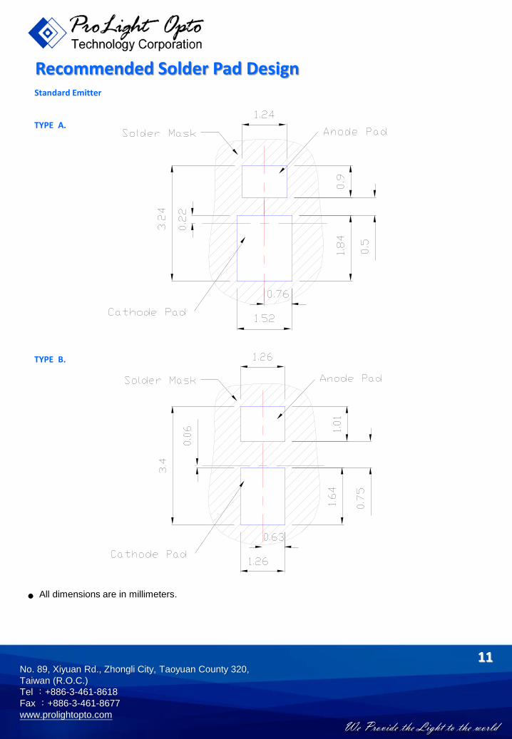
TYPE A.
11
Recommended Solder Pad DesignStandard Emitter
● All dimensions are in millimeters.
TYPE B.

We Provide the Light to the world
No. 89, Xiyuan Rd., Zhongli City, Taoyuan County 320,
Taiwan (R.O.C.)
Tel :+886-3-461-8618
Fax :+886-3-461-8677
www.prolightopto.com
12
Reflow Soldering ConditionProfile Feature Sn-Pb Eutectic Assembly Pb-Free Assembly
Average Ramp-Up Rate3°C / second max. 3°C / second max.
(TSmax to TP)Preheat– Temperature Min (TSmin) 100°C 150°C– Temperature Max (TSmax) 150°C 200°C– Time (tSmin to tSmax) 60-120 seconds 60-180 seconds
Time maintained above:– Temperature (TL) 183°C 217°C– Time (tL) 60-150 seconds 60-150 seconds
Peak/Classification Temperature (TP) 240°C 260°CTime Within 5°C of Actual Peak
10-30 seconds 20-40 secondsTemperature (tP)Ramp-Down Rate 6°C/second max. 6°C/second max.Time 25°C to Peak Temperature 6 minutes max. 8 minutes max.
● We recommend using the M705-S101-S4 solder paste from SMIC (Senju Metal Industry Co., Ltd.) for lead-free soldering.
● Do not use solder pastes with post reflow flux residue>47%. (58Bi-42Sn eutectic alloy, etc) This kindof solder pastes may cause a reliability problem to LED.
● All temperatures refer to topside of the package, measured on the package body surface.● Repairing should not be done after the LEDs have been soldered. When repairing is unavoidable, a
double-head soldering iron should be used. It should be confirmed beforehand whether thecharacteristics of the LEDs will or will not be damaged by repairing.
● Reflow soldering should not be done more than three times.● When soldering, do not put stress on the LEDs during heating.● After soldering, do not warp the circuit board.
t 25°C to Peak
tSPreheat
Time
Te
mp
era
ture
Critical Zone
TL to TPRamp-up
Ramp-down
TSmax
TSmin
tP
tL
TP
TL
25
IPC-020c

We Provide the Light to the world
No. 89, Xiyuan Rd., Zhongli City, Taoyuan County 320,
Taiwan (R.O.C.)
Tel :+886-3-461-8618
Fax :+886-3-461-8677
www.prolightopto.com
13
Emitter Reel Packaging
Notes:
1. Drawing not to scale.
2. All dimensions are in millimeters.
3. Unless otherwise indicated, tolerances are ± 0.10mm.
We Provide the Light to the world
No. 89, Xiyuan Rd., Zhongli City, Taoyuan County 320,
Taiwan (R.O.C.)
Tel :+886-3-461-8618
Fax :+886-3-461-8677
www.prolightopto.com
14
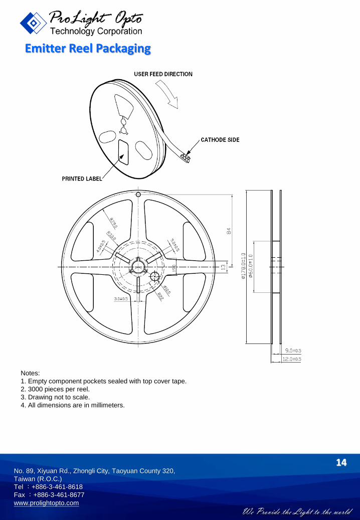
Emitter Reel Packaging
Notes:
1. Empty component pockets sealed with top cover tape.
2. 3000 pieces per reel.
3. Drawing not to scale.
4. All dimensions are in millimeters.
We Provide the Light to the world
No. 89, Xiyuan Rd., Zhongli City, Taoyuan County 320,
Taiwan (R.O.C.)
Tel :+886-3-461-8618
Fax :+886-3-461-8677
www.prolightopto.com
15
Precaution for Use● Storage
Please do not open the moisture barrier bag (MBB) more than one week. This may cause the
leads of LED discoloration. We recommend storing ProLight’s LEDs in a dry box after opening
the MBB. The recommended storage conditions are temperature 5 to 30°C and humidity less
than 40% RH. It is also recommended to return the LEDs to the MBB and to reseal the MBB.
● The slug is is not electrically neutral. Therefore, we recommend to isolate the heat sink.
● We recommend using the M705-S101-S4 solder paste from SMIC (Senju Metal Industry
Co., Ltd.) for lead-free soldering.
● Do not use solder pastes with post reflow flux residue>47%. (58Bi-42Sn eutectic alloy, etc) This
kind of solder pastes may cause a reliability problem to LED.
● Any mechanical force or any excess vibration shall not be accepted to apply during cooling
process to normal temperature after soldering.
● Please avoid rapid cooling after soldering.
● Components should not be mounted on warped direction of PCB.
● Repairing should not be done after the LEDs have been soldered. When repairing is unavoidable,
a heat plate should be used. It should be confirmed beforehand whether the characteristics of
the LEDs will or will not be damaged by repairing.
●This device should not be used in any type of fluid such as water, oil, organic solvent and etc.
When cleaning is required, isopropyl alcohol should be used.
●When the LEDs are illuminating, operating current should be decide after considering the
package maximum temperature.
● The appearance, specifications and flux bin of the product may be modified for improvement
without notice. Please refer to the below website for the latest datasheets.
http://www.prolightopto.com/
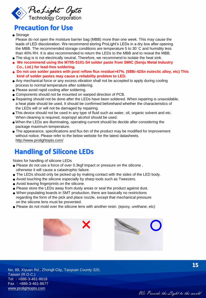
Handling of Silicone LEDsNotes for handling of silicone LEDs
● Please do not use a force of over 0.3kgf impact or pressure on the silicone ,
otherwise it will cause a catastrophic failure.
● The LEDs should only be picked up by making contact with the sides of the LED body.
● Avoid touching the silicone especially by sharp tools such as Tweezers.
● Avoid leaving fingerprints on the silicone.
● Please store the LEDs away from dusty areas or seal the product against dust.
● When populating boards in SMT production, there are basically no restrictions
regarding the form of the pick and place nozzle, except that mechanical pressure
on the silicone lens must be prevented.
● Please do not mold over the silicone lens with another resin. (epoxy, urethane, etc)