proline promag l 400 hart - endress+hauser
TRANSCRIPT

Products Solutions Services
Operating InstructionsProline Promag L 400HARTElectromagnetic flowmeter
BA01062D/06/EN/04.1571280366
Valid as of version01.00.zz (Device firmware)

Proline Promag L 400 HART
2 Endress+Hauser
• Make sure the document is stored in a safe place such that it is always available whenworking on or with the device.
• To avoid danger to individuals or the facility, read the "Basic safety instructions" sectioncarefully, as well as all other safety instructions in the document that are specific toworking procedures.
• The manufacturer reserves the right to modify technical data without prior notice. YourEndress+Hauser Sales Center will supply you with current information and updates tothese Instructions.
Proline Promag L 400 HART Table of contents
Endress+Hauser 3
Table of contents
1 Document information . . . . . . . . . . . . . . 61.1 Document function . . . . . . . . . . . . . . . . . . . . . 61.2 Symbols used . . . . . . . . . . . . . . . . . . . . . . . . . . 6
1.2.1 Safety symbols . . . . . . . . . . . . . . . . . . 61.2.2 Electrical symbols . . . . . . . . . . . . . . . . 61.2.3 Tool symbols . . . . . . . . . . . . . . . . . . . . 61.2.4 Symbols for certain types of
information . . . . . . . . . . . . . . . . . . . . 71.2.5 Symbols in graphics . . . . . . . . . . . . . . . 7
1.3 Documentation . . . . . . . . . . . . . . . . . . . . . . . . 71.3.1 Standard documentation . . . . . . . . . . . 81.3.2 Supplementary device-dependent
documentation . . . . . . . . . . . . . . . . . . 81.4 Registered trademarks . . . . . . . . . . . . . . . . . . . 8
2 Basic safety instructions . . . . . . . . . . . . 92.1 Requirements for the personnel . . . . . . . . . . . . 92.2 Designated use . . . . . . . . . . . . . . . . . . . . . . . . 92.3 Workplace safety . . . . . . . . . . . . . . . . . . . . . . 102.4 Operational safety . . . . . . . . . . . . . . . . . . . . . 102.5 Product safety . . . . . . . . . . . . . . . . . . . . . . . . 102.6 IT security . . . . . . . . . . . . . . . . . . . . . . . . . . . 11
3 Product description . . . . . . . . . . . . . . . . 123.1 Product design . . . . . . . . . . . . . . . . . . . . . . . . 12
4 Incoming acceptance and productidentification . . . . . . . . . . . . . . . . . . . . . 13
4.1 Incoming acceptance . . . . . . . . . . . . . . . . . . . 134.2 Product identification . . . . . . . . . . . . . . . . . . . 13
4.2.1 Transmitter nameplate . . . . . . . . . . . 144.2.2 Sensor nameplate . . . . . . . . . . . . . . . 154.2.3 Symbols on measuring device . . . . . . 16
5 Storage and transport . . . . . . . . . . . . . 175.1 Storage conditions . . . . . . . . . . . . . . . . . . . . . 175.2 Transporting the product . . . . . . . . . . . . . . . . 17
5.2.1 Measuring devices without liftinglugs . . . . . . . . . . . . . . . . . . . . . . . . . 17
5.2.2 Measuring devices with lifting lugs . . 185.2.3 Transporting with a fork lift . . . . . . . . 18
5.3 Packaging disposal . . . . . . . . . . . . . . . . . . . . . 18
6 Installation . . . . . . . . . . . . . . . . . . . . . . . 196.1 Installation conditions . . . . . . . . . . . . . . . . . . 19
6.1.1 Mounting position . . . . . . . . . . . . . . . 196.1.2 Requirements from environment and
process . . . . . . . . . . . . . . . . . . . . . . . 216.1.3 Special mounting instructions . . . . . . 22
6.2 Mounting the measuring device . . . . . . . . . . . 236.2.1 Required tools . . . . . . . . . . . . . . . . . . 23
6.2.2 Preparing the measuring device . . . . . 236.2.3 Mounting the sensor . . . . . . . . . . . . . 236.2.4 Mounting the transmitter of the
remote version . . . . . . . . . . . . . . . . . 276.2.5 Turning the transmitter housing . . . . 296.2.6 Turning the display module . . . . . . . . 31
6.3 Post-installation check . . . . . . . . . . . . . . . . . . 32
7 Electrical connection . . . . . . . . . . . . . . 337.1 Connection conditions . . . . . . . . . . . . . . . . . . 33
7.1.1 Required tools . . . . . . . . . . . . . . . . . . 337.1.2 Requirements for connecting cable . . . 337.1.3 Terminal assignment . . . . . . . . . . . . . 357.1.4 Shielding and grounding . . . . . . . . . . 367.1.5 Requirements for the supply unit . . . . 367.1.6 Preparing the measuring device . . . . . 367.1.7 Preparing the connecting cable for
the remote version . . . . . . . . . . . . . . 367.2 Connecting the measuring device . . . . . . . . . . 38
7.2.1 Connecting the remote version . . . . . 387.2.2 Connecting the transmitter . . . . . . . . 407.2.3 Ensuring potential equalization . . . . . 41
7.3 Special connection instructions . . . . . . . . . . . . 437.4 Ensuring the degree of protection . . . . . . . . . . 43
7.4.1 Degree of protection IP66/67, Type4X enclosure . . . . . . . . . . . . . . . . . . . 43
7.5 Post-connection check . . . . . . . . . . . . . . . . . . 43
8 Operation options . . . . . . . . . . . . . . . . . 448.1 Overview of operation options . . . . . . . . . . . . 448.2 Structure and function of the operating
menu . . . . . . . . . . . . . . . . . . . . . . . . . . . . . . 458.2.1 Structure of the operating menu . . . . 458.2.2 Operating philosophy . . . . . . . . . . . . 46
8.3 Access to the operating menu via the localdisplay . . . . . . . . . . . . . . . . . . . . . . . . . . . . . 478.3.1 Operational display . . . . . . . . . . . . . . 478.3.2 Navigation view . . . . . . . . . . . . . . . . 488.3.3 Editing view . . . . . . . . . . . . . . . . . . . 508.3.4 Operating elements . . . . . . . . . . . . . . 528.3.5 Opening the context menu . . . . . . . . . 528.3.6 Navigating and selecting from list . . . 548.3.7 Calling the parameter directly . . . . . . 548.3.8 Calling up help text . . . . . . . . . . . . . . 558.3.9 Changing the parameters . . . . . . . . . 568.3.10 User roles and related access
authorization . . . . . . . . . . . . . . . . . . 578.3.11 Disabling write protection via access
code . . . . . . . . . . . . . . . . . . . . . . . . . 578.3.12 Enabling and disabling the keypad
lock . . . . . . . . . . . . . . . . . . . . . . . . . 578.4 Access to the operating menu via the Web
browser . . . . . . . . . . . . . . . . . . . . . . . . . . . . . 588.4.1 Function range . . . . . . . . . . . . . . . . . 58

Table of contents Proline Promag L 400 HART
4 Endress+Hauser
8.4.2 Prerequisites . . . . . . . . . . . . . . . . . . . 588.4.3 Establishing a connection . . . . . . . . . 598.4.4 Logging on . . . . . . . . . . . . . . . . . . . . 608.4.5 User interface . . . . . . . . . . . . . . . . . . 608.4.6 Disabling the Web server . . . . . . . . . . 618.4.7 Logging out . . . . . . . . . . . . . . . . . . . . 62
8.5 Access to the operating menu via theoperating tool . . . . . . . . . . . . . . . . . . . . . . . . 628.5.1 Connecting the operating tool . . . . . . 628.5.2 Field Xpert SFX350, SFX370 . . . . . . . 638.5.3 FieldCare . . . . . . . . . . . . . . . . . . . . . 638.5.4 AMS Device Manager . . . . . . . . . . . . 648.5.5 SIMATIC PDM . . . . . . . . . . . . . . . . . . 658.5.6 Field Communicator 475 . . . . . . . . . . 65
9 System integration . . . . . . . . . . . . . . . . 669.1 Overview of device description files . . . . . . . . . 66
9.1.1 Current version data for the device . . . 669.1.2 Operating tools . . . . . . . . . . . . . . . . . 66
9.2 Measured variables via HART protocol . . . . . . 669.3 Other settings . . . . . . . . . . . . . . . . . . . . . . . . 67
9.3.1 Burst mode functionality inaccordance with HART 7Specification . . . . . . . . . . . . . . . . . . . 67
10 Commissioning . . . . . . . . . . . . . . . . . . . . 7010.1 Function check . . . . . . . . . . . . . . . . . . . . . . . 7010.2 Switching on the measuring device . . . . . . . . . 7010.3 Establishing a connection via FieldCare . . . . . . 7010.4 Setting the operating language . . . . . . . . . . . . 7010.5 Configuring the measuring device . . . . . . . . . . 71
10.5.1 Defining the tag name . . . . . . . . . . . . 7710.5.2 Configuring the status input . . . . . . . 7710.5.3 Configuring the current output . . . . . 7910.5.4 Configuring the pulse/frequency/
switch output . . . . . . . . . . . . . . . . . . 8010.5.5 Configuring the local display . . . . . . . 8710.5.6 Configuring the output
conditioning . . . . . . . . . . . . . . . . . . . 8910.5.7 Configuring the low flow cut off . . . . . 9110.5.8 Configuring empty pipe detection . . . 9310.5.9 Configuring the HART input . . . . . . . 94
10.6 Advanced settings . . . . . . . . . . . . . . . . . . . . . 9610.6.1 Setting the system units . . . . . . . . . . 9810.6.2 Carrying out a sensor adjustment . . . 10010.6.3 Configuring the totalizer . . . . . . . . . 10010.6.4 Carrying out additional display
configurations . . . . . . . . . . . . . . . . . 10110.6.5 Performing electrode cleaning . . . . . 10310.6.6 Administration configuration . . . . . 104
10.7 Configuration management . . . . . . . . . . . . . 10410.7.1 Function range of "Configuration
management" parameter . . . . . . . . . 10510.8 Simulation . . . . . . . . . . . . . . . . . . . . . . . . . . 10610.9 Protecting settings from unauthorized
access . . . . . . . . . . . . . . . . . . . . . . . . . . . . . 10810.9.1 Write protection via access code . . . 108
10.9.2 Write protection via write protectionswitch . . . . . . . . . . . . . . . . . . . . . . . 109
11 Operation . . . . . . . . . . . . . . . . . . . . . . . 11111.1 Reading the device locking status . . . . . . . . . 11111.2 Adjusting the operating language . . . . . . . . . 11111.3 Configuring the display . . . . . . . . . . . . . . . . 11111.4 Reading measured values . . . . . . . . . . . . . . . 111
11.4.1 Process variables . . . . . . . . . . . . . . . 11111.4.2 Totalizer . . . . . . . . . . . . . . . . . . . . . 11211.4.3 Input values . . . . . . . . . . . . . . . . . . 11211.4.4 Output values . . . . . . . . . . . . . . . . . 113
11.5 Adapting the measuring device to the processconditions . . . . . . . . . . . . . . . . . . . . . . . . . . 114
11.6 Performing a totalizer reset . . . . . . . . . . . . . 11411.7 Showing data logging . . . . . . . . . . . . . . . . . 115
12 Diagnostics and troubleshooting . . 11712.1 General troubleshooting . . . . . . . . . . . . . . . . 11712.2 Diagnostic information via light emitting
diodes . . . . . . . . . . . . . . . . . . . . . . . . . . . . . 11812.2.1 Transmitter . . . . . . . . . . . . . . . . . . . 118
12.3 Diagnostic information on local display . . . . . 12012.3.1 Diagnostic message . . . . . . . . . . . . . 12012.3.2 Calling up remedial measures . . . . . 122
12.4 Diagnostic information in the Web browser . 12312.4.1 Diagnostic options . . . . . . . . . . . . . . 12312.4.2 Calling up remedy information . . . . 123
12.5 Diagnostic information in FieldCare . . . . . . . 12412.5.1 Diagnostic options . . . . . . . . . . . . . . 12412.5.2 Calling up remedy information . . . . 125
12.6 Adapting the diagnostic information . . . . . . 12512.6.1 Adapting the diagnostic behavior . . . 12512.6.2 Adapting the status signal . . . . . . . . 125
12.7 Overview of diagnostic information . . . . . . . 12612.8 Pending diagnostic events . . . . . . . . . . . . . . 12912.9 Diagnostic list . . . . . . . . . . . . . . . . . . . . . . . 12912.10 Event logbook . . . . . . . . . . . . . . . . . . . . . . . 130
12.10.1 Event history . . . . . . . . . . . . . . . . . . 13012.10.2 Filtering the event logbook . . . . . . . 13112.10.3 Overview of information events . . . . 131
12.11 Resetting the measuring device . . . . . . . . . . 13212.11.1 Function scope of "Device reset"
parameter . . . . . . . . . . . . . . . . . . . . 13212.12 Device information . . . . . . . . . . . . . . . . . . . 13212.13 Firmware history . . . . . . . . . . . . . . . . . . . . . 135
13 Maintenance . . . . . . . . . . . . . . . . . . . . 13613.1 Maintenance tasks . . . . . . . . . . . . . . . . . . . . 136
13.1.1 Exterior cleaning . . . . . . . . . . . . . . . 13613.1.2 Interior cleaning . . . . . . . . . . . . . . . 13613.1.3 Replacing seals . . . . . . . . . . . . . . . . 136
13.2 Measuring and test equipment . . . . . . . . . . . 13613.3 Endress+Hauser services . . . . . . . . . . . . . . . 136
Proline Promag L 400 HART Table of contents
Endress+Hauser 5
14 Repair . . . . . . . . . . . . . . . . . . . . . . . . . . . 13714.1 General notes . . . . . . . . . . . . . . . . . . . . . . . 13714.2 Spare parts . . . . . . . . . . . . . . . . . . . . . . . . . 13714.3 Endress+Hauser services . . . . . . . . . . . . . . . 13714.4 Return . . . . . . . . . . . . . . . . . . . . . . . . . . . . . 13714.5 Disposal . . . . . . . . . . . . . . . . . . . . . . . . . . . 137
14.5.1 Removing the measuring device . . . . 13714.5.2 Disposing of the measuring device . . 138
15 Accessories . . . . . . . . . . . . . . . . . . . . . . 13915.1 Device-specific accessories . . . . . . . . . . . . . . 139
15.1.1 For the transmitter . . . . . . . . . . . . . 13915.1.2 For the sensor . . . . . . . . . . . . . . . . . 139
15.2 Communication-specific accessories . . . . . . . 13915.3 Service-specific accessories . . . . . . . . . . . . . . 14015.4 System components . . . . . . . . . . . . . . . . . . . 140
16 Technical data . . . . . . . . . . . . . . . . . . . 14116.1 Application . . . . . . . . . . . . . . . . . . . . . . . . . 14116.2 Function and system design . . . . . . . . . . . . . 14116.3 Input . . . . . . . . . . . . . . . . . . . . . . . . . . . . . . 14116.4 Output . . . . . . . . . . . . . . . . . . . . . . . . . . . . 14416.5 Power supply . . . . . . . . . . . . . . . . . . . . . . . . 14716.6 Performance characteristics . . . . . . . . . . . . . 14816.7 Installation . . . . . . . . . . . . . . . . . . . . . . . . . 14916.8 Environment . . . . . . . . . . . . . . . . . . . . . . . . 15016.9 Process . . . . . . . . . . . . . . . . . . . . . . . . . . . . 15116.10 Mechanical construction . . . . . . . . . . . . . . . 15216.11 Operability . . . . . . . . . . . . . . . . . . . . . . . . . 16416.12 Certificates and approvals . . . . . . . . . . . . . . 16616.13 Application packages . . . . . . . . . . . . . . . . . . 16716.14 Accessories . . . . . . . . . . . . . . . . . . . . . . . . . 16816.15 Documentation . . . . . . . . . . . . . . . . . . . . . . 168
17 Appendix . . . . . . . . . . . . . . . . . . . . . . . . 17017.1 Overview of the operating menu . . . . . . . . . . 170
17.1.1 "Operation" menu . . . . . . . . . . . . . . . 17017.1.2 "Setup" menu . . . . . . . . . . . . . . . . . . 17117.1.3 "Diagnostics" menu . . . . . . . . . . . . . . 17717.1.4 "Expert" menu . . . . . . . . . . . . . . . . . 181
Index . . . . . . . . . . . . . . . . . . . . . . . . . . . . . . . . . 199
Document information Proline Promag L 400 HART
6 Endress+Hauser
1 Document information
1.1 Document functionThese Operating Instructions contain all the information that is required in various phasesof the life cycle of the device: from product identification, incoming acceptance andstorage, to mounting, connection, operation and commissioning through totroubleshooting, maintenance and disposal.
1.2 Symbols used
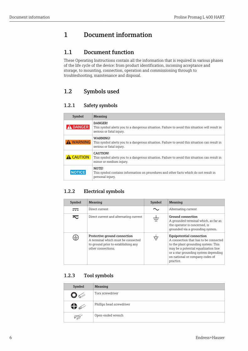
1.2.1 Safety symbols
Symbol Meaning
DANGER
DANGER!This symbol alerts you to a dangerous situation. Failure to avoid this situation will result inserious or fatal injury.
WARNING
WARNING!This symbol alerts you to a dangerous situation. Failure to avoid this situation can result inserious or fatal injury.
CAUTION
CAUTION!This symbol alerts you to a dangerous situation. Failure to avoid this situation can result inminor or medium injury.
NOTICE
NOTE!This symbol contains information on procedures and other facts which do not result inpersonal injury.
1.2.2 Electrical symbols
Symbol Meaning Symbol Meaning
Direct current Alternating current
Direct current and alternating current Ground connectionA grounded terminal which, as far asthe operator is concerned, isgrounded via a grounding system.
Protective ground connectionA terminal which must be connectedto ground prior to establishing anyother connections.
Equipotential connectionA connection that has to be connectedto the plant grounding system: Thismay be a potential equalization lineor a star grounding system dependingon national or company codes ofpractice.
1.2.3 Tool symbols
Symbol Meaning
Torx screwdriver
Phillips head screwdriver
Open-ended wrench
Proline Promag L 400 HART Document information
Endress+Hauser 7
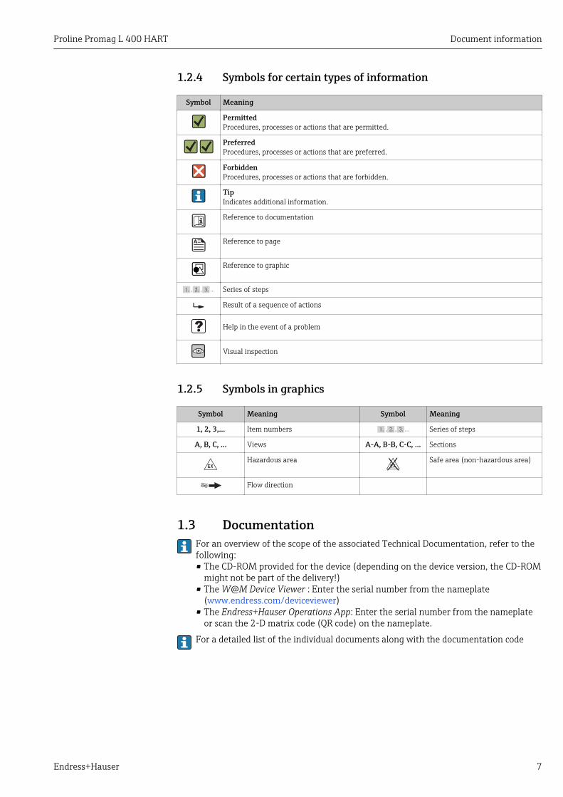
1.2.4 Symbols for certain types of information
Symbol Meaning
PermittedProcedures, processes or actions that are permitted.
PreferredProcedures, processes or actions that are preferred.
ForbiddenProcedures, processes or actions that are forbidden.
TipIndicates additional information.
Reference to documentation
Reference to page
Reference to graphic
, …, Series of steps
Result of a sequence of actions
Help in the event of a problem
Visual inspection
1.2.5 Symbols in graphics
Symbol Meaning Symbol Meaning
1, 2, 3,... Item numbers , …, Series of steps
A, B, C, ... Views A-A, B-B, C-C, ... Sections
-Hazardous area
.Safe area (non-hazardous area)
Flow direction
1.3 DocumentationFor an overview of the scope of the associated Technical Documentation, refer to thefollowing:• The CD-ROM provided for the device (depending on the device version, the CD-ROM
might not be part of the delivery!)• The W@M Device Viewer : Enter the serial number from the nameplate
(www.endress.com/deviceviewer)• The Endress+Hauser Operations App: Enter the serial number from the nameplate
or scan the 2-D matrix code (QR code) on the nameplate.
For a detailed list of the individual documents along with the documentation code

Document information Proline Promag L 400 HART
8 Endress+Hauser
1.3.1 Standard documentation
Document type Purpose and content of the document
Technical Information Planning aid for your deviceThe document contains all the technical data on the device and providesan overview of the accessories and other products that can be ordered forthe device.
Brief Operating Instructions Guide that takes you quickly to the 1st measured valueThe Brief Operating Instructions contain all the essential informationfrom incoming acceptance to initial commissioning.
1.3.2 Supplementary device-dependent documentationAdditional documents are supplied depending on the device version ordered: Alwayscomply strictly with the instructions in the supplementary documentation. Thesupplementary documentation is an integral part of the device documentation.
1.4 Registered trademarksHART®
Registered trademark of the HART Communication Foundation, Austin, USA
Microsoft®
Registered trademark of the Microsoft Corporation, Redmond, Washington, USA
Applicator®, FieldCare®, Field XpertTM, HistoROM®, Heartbeat TechnologyTM
Registered or registration-pending trademarks of the Endress+Hauser Group
Proline Promag L 400 HART Basic safety instructions
Endress+Hauser 9
2 Basic safety instructions
2.1 Requirements for the personnelThe personnel for installation, commissioning, diagnostics and maintenance must fulfillthe following requirements:‣ Trained, qualified specialists must have a relevant qualification for this specific function
and task‣ Are authorized by the plant owner/operator‣ Are familiar with federal/national regulations‣ Before beginning work, the specialist staff must have read and understood the
instructions in the Operating Instructions and supplementary documentation as well asin the certificates (depending on the application)
‣ Following instructions and basic conditions
The operating personnel must fulfill the following requirements:‣ Being instructed and authorized according to the requirements of the task by the
facility's owner-operator‣ Following the instructions in these Operating Instructions
2.2 Designated useApplication and mediaThe measuring device described in these Instructions is intended only for flowmeasurement of liquids with a minimum conductivity of 5 μS/cm.
Depending on the version ordered, the measuring device can also measure potentiallyexplosive, flammable, poisonous and oxidizing media.
Measuring devices for use in hazardous areas, in hygienic applications or in applicationswhere there is an increased risk due to process pressure, are labeled accordingly on thenameplate.
To ensure that the measuring device remains in proper condition for the operation time:‣ Only use the measuring device in full compliance with the data on the nameplate and
the general conditions listed in the Operating Instructions and supplementarydocumentation.
‣ Based on the nameplate, check whether the ordered device is permitted for theintended use in the hazardous area (e.g. explosion protection, pressure vessel safety).
‣ Use the measuring device only for media against which the process-wetted materialsare adequately resistant.
‣ If the measuring device is not operated at atmospheric temperature, compliance withthe relevant basic conditions specified in the associated device documentation isabsolutely essential: "Documentation" section → 7.
Incorrect useNon-designated use can compromise safety. The manufacturer is not liable for damagecaused by improper or non-designated use.
LWARNINGDanger of breakage of the sensor due to corrosive or abrasive fluids!‣ Verify the compatibility of the process fluid with the sensor material.‣ Ensure the resistance of all fluid-wetted materials in the process.‣ Observe the specified pressure and temperature range.
Verification for borderline cases:‣ For special fluids and fluids for cleaning, Endress+Hauser is glad to provide assistance
in verifying the corrosion resistance of fluid-wetted materials, but does not accept any
Basic safety instructions Proline Promag L 400 HART
10 Endress+Hauser
warranty or liability as minute changes in the temperature, concentration or level ofcontamination in the process can alter the corrosion resistance properties.
Residual risksThe external surface temperature of the housing can increase by max. 10 K due to thepower consumption of the electronic components. Hot process fluids passing through themeasuring device will further increase the surface temperature of the housing. The surfaceof the sensor, in particular, can reach temperatures which are close to the fluidtemperature.
Possible burn hazard due to fluid temperatures!‣ For elevated fluid temperature, ensure protection against contact to prevent burns.
2.3 Workplace safetyFor work on and with the device:‣ Wear the required personal protective equipment according to federal/national
regulations.
For welding work on the piping:‣ Do not ground the welding unit via the measuring device.
If working on and with the device with wet hands:‣ It is recommended to wear gloves on account of the higher risk of electric shock.
2.4 Operational safetyRisk of injury.‣ Operate the device in proper technical condition and fail-safe condition only.‣ The operator is responsible for interference-free operation of the device.
Conversions to the deviceUnauthorized modifications to the device are not permitted and can lead to unforeseeabledangers.‣ If, despite this, modifications are required, consult with Endress+Hauser.
RepairTo ensure continued operational safety and reliability,‣ Carry out repairs on the device only if they are expressly permitted.‣ Observe federal/national regulations pertaining to repair of an electrical device.‣ Use original spare parts and accessories from Endress+Hauser only.
Environmental requirementsIf a plastic transmitter housing is permanently exposed to certain steam and air mixtures,this can damage the housing.‣ If you are unsure, please contact your Endress+Hauser Sales Center for clarification.‣ If used in an approval-related area, observe the information on the nameplate.
2.5 Product safetyThis measuring device is designed in accordance with good engineering practice to meetstate-of-the-art safety requirements, has been tested, and left the factory in a condition inwhich it is safe to operate.
It meets general safety standards and legal requirements. It also complies with the ECdirectives listed in the device-specific EC Declaration of Conformity. Endress+Hauserconfirms this by affixing the CE mark to the device.

Proline Promag L 400 HART Basic safety instructions
Endress+Hauser 11
2.6 IT securityWe only provide a warranty if the device is installed and used as described in theOperating Instructions. The device is equipped with security mechanisms to protect itagainst any inadvertent changes to the device settings.
IT security measures in line with operators' security standards and designed to provideadditional protection for the device and device data transfer must be implemented by theoperators themselves.

Product description Proline Promag L 400 HART
12 Endress+Hauser
3 Product descriptionThe device consists of a transmitter and a sensor.
Two device versions are available:• Compact version - transmitter and sensor form a mechanical unit.• Remote version - transmitter and sensor are mounted in separate locations.
3.1 Product design
1
2
3
5
6
8
7
4
A0017218
1 Important components of the compact version
1 Display module2 Smart sensor electronics module3 HistoROM DAT (plug-in memory)4 Main electronics module5 Terminals (screw terminals, some available as plug-in terminals) or fieldbus connectors6 Transmitter housing, compact version7 Cable glands8 Sensor, compact version

Proline Promag L 400 HART Incoming acceptance and product identification
Endress+Hauser 13
4 Incoming acceptance and productidentification
4.1 Incoming acceptance
1+
2
1+
2
Are the order codes on thedelivery note (1) and theproduct sticker (2)identical?
Are the goods undamaged?
Do the nameplate datamatch the orderinginformation on the deliverynote?
Is the CD-ROM with theTechnical Documentation(depends on deviceversion) and documentspresent?
• If one of the conditions is not satisfied, contact your Endress+Hauser Sales Center.• Depending on the device version, the CD-ROM might not be part of the delivery!
The Technical Documentation is available via the Internet or via the Endress+HauserOperations App, see the "Product identification" section → 14.
4.2 Product identificationThe following options are available for identification of the measuring device:• Nameplate specifications• Order code with breakdown of the device features on the delivery note• Enter serial numbers from nameplates in W@M Device Viewer
(www.endress.com/deviceviewer): All information about the measuring device isdisplayed.
• Enter the serial number from the nameplates into the Endress+Hauser Operations Appor scan the 2-D matrix code (QR code) on the nameplate with the Endress+HauserOperations App: all the information for the measuring device is displayed.

Incoming acceptance and product identification Proline Promag L 400 HART
14 Endress+Hauser
For an overview of the scope of the associated Technical Documentation, refer to thefollowing:• The chapters "Additional standard documentation on the device" → 8 and
"Supplementary device-dependent documentation" → 8• The W@M Device Viewer: Enter the serial number from the nameplate
(www.endress.com/deviceviewer)• The Endress+Hauser Operations App: Enter the serial number from the nameplate or
scan the 2-D matrix code (QR code) on the nameplate.
4.2.1 Transmitter nameplate
Order code:
i
Ext. ord. cd.:
Ser. no.:
Patents i
Date:
12
3 4 5 6 7
8
9
10
111213
A0017346
2 Example of a transmitter nameplate
1 Manufacturing location2 Name of the transmitter3 Order code4 Serial number (Ser. no.)5 Extended order code (Ext. ord. cd.)6 Permitted ambient temperature (Ta)7 Firmware version (FW) and device revision (Dev.Rev.) from the factory8 Degree of protection9 Permitted temperature range for cable10 2-D matrix code11 Manufacturing date: year-month12 CE mark, C-Tick13 Electrical connection data, e.g. available inputs and outputs, supply voltage
Proline Promag L 400 HART Incoming acceptance and product identification
Endress+Hauser 15
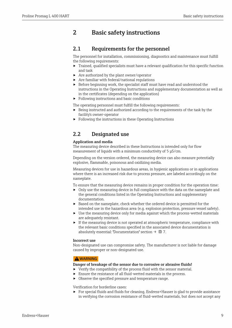
4.2.2 Sensor nameplate
i Patents i
Material:
Tm:
Ext. ord. cd.:
Order Code:
Ser.No.:
Date:
21
34
5
6 7
89
10
11
13 12
1415
A0017186
3 Example of sensor nameplate
1 Name of the sensor2 Manufacturing location3 Order code4 Serial number (ser. no.)5 Extended order code (ext. ord. cd.)6 Nominal diameter of sensor7 Test pressure of the sensor8 Fluid temperature range9 Material of lining and electrodes10 Degree of protection: e.g. IP, NEMA11 Permitted ambient temperature (Ta)12 2-D matrix code13 CE mark, C-Tick14 Flow direction15 Manufacturing date: year-month
Order codeThe measuring device is reordered using the order code.
Extended order code• The device type (product root) and basic specifications (mandatory features) are
always listed.• Of the optional specifications (optional features), only the safety and approval-
related specifications are listed (e.g. LA). If other optional specifications are alsoordered, these are indicated collectively using the # placeholder symbol (e.g. #LA#).
• If the ordered optional specifications do not include any safety and approval-relatedspecifications, they are indicated by the + placeholder symbol (e.g. XXXXXX-ABCDE+).

Incoming acceptance and product identification Proline Promag L 400 HART
16 Endress+Hauser
4.2.3 Symbols on measuring device
Symbol Meaning
WARNING!This symbol alerts you to a dangerous situation. Failure to avoid this situation can result in seriousor fatal injury.
Reference to documentationRefers to the corresponding device documentation.
Protective ground connectionA terminal which must be connected to ground prior to establishing any other connections.
Proline Promag L 400 HART Storage and transport
Endress+Hauser 17
5 Storage and transport
5.1 Storage conditionsObserve the following notes for storage:• Store in the original packaging to ensure protection from shock.• Do not remove protective covers or protective caps installed on process connections.
They prevent mechanical damage to the sealing surfaces and contamination in themeasuring tube.
• Protect from direct sunlight to avoid unacceptably high surface temperatures.• Select a storage location where moisture cannot collect in the measuring device as
fungus and bacteria infestation can damage the lining.• Store in a dry and dust-free place.• Do not store outdoors.• Storage temperature→ 150
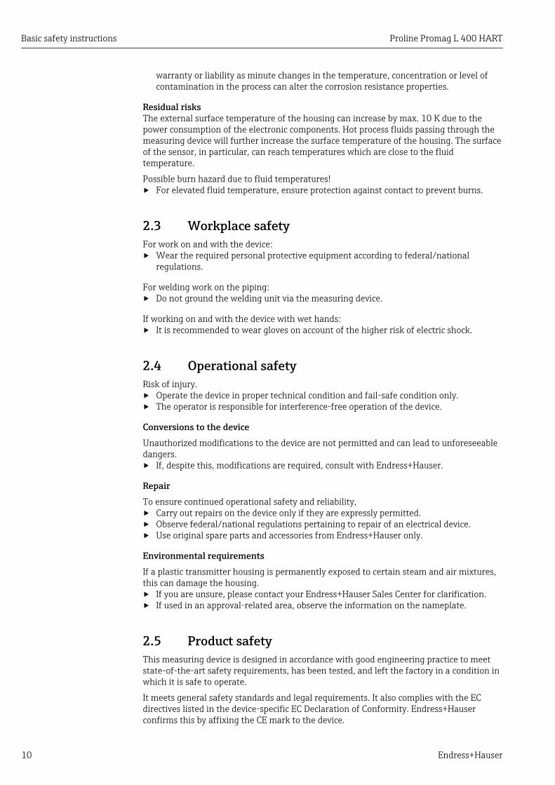
5.2 Transporting the productTransport the measuring device to the measuring point in the original packaging.
A0015604
Do not remove protective covers or caps installed on process connections. Theyprevent mechanical damage to the sealing surfaces and contamination in themeasuring tube.
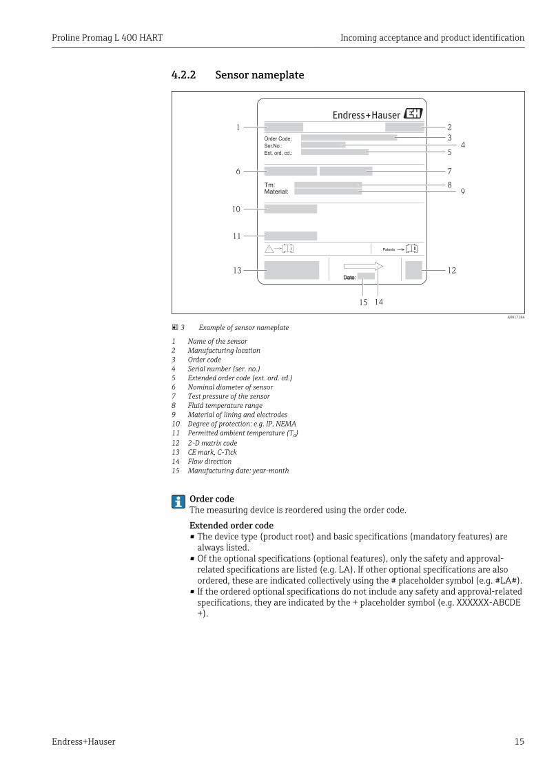
5.2.1 Measuring devices without lifting lugsLWARNING
Center of gravity of the measuring device is higher than the suspension points of thewebbing slings.Risk of injury if the measuring device slips.‣ Secure the measuring device against slipping or turning.‣ Observe the weight specified on the packaging (stick-on label).
A0015606

Storage and transport Proline Promag L 400 HART
18 Endress+Hauser
5.2.2 Measuring devices with lifting lugsLCAUTION
Special transportation instructions for devices with lifting lugs‣ Only use the lifting lugs fitted on the device or flanges to transport the device.‣ The device must always be secured at two lifting lugs at least.
5.2.3 Transporting with a fork liftIf transporting in wood crates, the floor structure enables the crates to be lifted lengthwiseor at both sides using a forklift.
LCAUTIONRisk of damaging the magnetic coil‣ If transporting by forklift, do not lift the sensor by the metal casing.‣ This would buckle the casing and damage the internal magnetic coils.
A0023726
5.3 Packaging disposalAll packaging materials are environmentally friendly and 100% recyclable:• Measuring device secondary packaging: polymer stretch film that conforms to EC
Directive 2002/95/EC (RoHS).• Packaging:
– Wood crate, treated in accordance with ISPM 15 standard, which is confirmed by theaffixed IPPC logo.or
– Carton in accordance with European Packaging Directive 94/62EC; recyclability isconfirmed by the affixed RESY symbol.
• Seaworthy packaging (optional): Wood crate, treated in accordance with ISPM 15standard, which is confirmed by the affixed IPPC logo.
• Carrying and mounting hardware:– Disposable plastic pallet– Plastic straps– Plastic adhesive strips
• Dunnage: Paper cushion

Proline Promag L 400 HART Installation
Endress+Hauser 19
6 Installation
6.1 Installation conditions
6.1.1 Mounting position
Mounting location
h A0023343
Preferably install the sensor in an ascending pipe, and ensure a sufficient distance to thenext pipe elbow: h ≥ 2 × DN
To prevent measuring errors arising from accumulation of gas bubbles in the measuringtube, avoid the following mounting locations in the pipe:• Highest point of a pipeline.• Directly upstream of a free pipe outlet in a down pipe.
Installation in down pipes
Install a siphon with a vent valve downstream of the sensor in down pipes whose length h≥ 5 m (16.4 ft). This precaution is to avoid low pressure and the consequent risk ofdamage to the measuring tube. This measure also prevents the system losing prime.
For information on the liner's resistance to partial vacuum
h
2
1
A0017064
4 Installation in a down pipe
1 Vent valve2 Pipe siphonh Length of down pipe
Installation in partially filled pipes
A partially filled pipe with a gradient necessitates a drain-type configuration.

Installation Proline Promag L 400 HART
20 Endress+Hauser
³5 ×
DN
³2 ×
DN
A0017063
OrientationThe direction of the arrow on the sensor nameplate helps you to install the sensoraccording to the flow direction (direction of medium flow through the piping).
An optimum orientation position helps avoid gas and air accumulations and deposits inthe measuring tube.
The measuring device also offers the empty pipe detection function to detect partially filledmeasuring pipes in the event of outgassing fluids or variable process pressures.
Vertical
A0015591
Optimum for self-emptying pipe systems and for use in conjunction with empty pipedetection.
Horizontal
1
2
3
2
A0016260
1 EPD electrode for empty pipe detection2 Measuring electrodes for signal detection3 Reference electrode for potential equalization
• The measuring electrode plane must be horizontal. This prevents brief insulation ofthe two measuring electrodes by entrained air bubbles.
• Empty pipe detection only works if the transmitter housing is pointing upwards asotherwise there is no guarantee that the empty pipe detection function will actuallyrespond to a partially filled or empty measuring tube.
Inlet and outlet runsIf possible, install the sensor upstream from fittings such as valves, T-pieces or elbows.
Observe the following inlet and outlet runs to comply with accuracy specifications:
Proline Promag L 400 HART Installation
Endress+Hauser 21
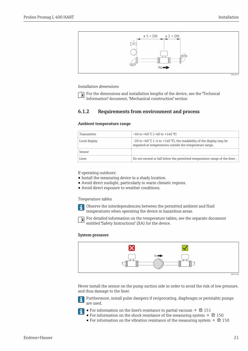
5 × DN≥ 2 × DN≥
A0016275
Installation dimensions
For the dimensions and installation lengths of the device, see the "TechnicalInformation" document, "Mechanical construction" section
6.1.2 Requirements from environment and process
Ambient temperature range
Transmitter –40 to +60 °C (–40 to +140 °F)
Local display –20 to +60 °C (–4 to +140 °F), the readability of the display may beimpaired at temperatures outside the temperature range.
Sensor
Liner Do not exceed or fall below the permitted temperature range of the liner .
If operating outdoors:• Install the measuring device in a shady location.• Avoid direct sunlight, particularly in warm climatic regions.• Avoid direct exposure to weather conditions.
Temperature tables
Observe the interdependencies between the permitted ambient and fluidtemperatures when operating the device in hazardous areas.
For detailed information on the temperature tables, see the separate documententitled "Safety Instructions" (XA) for the device.
System pressure
A0015594
Never install the sensor on the pump suction side in order to avoid the risk of low pressure,and thus damage to the liner.
Furthermore, install pulse dampers if reciprocating, diaphragm or peristaltic pumpsare used.
• For information on the liner's resistance to partial vacuum → 151• For information on the shock resistance of the measuring system → 150• For information on the vibration resistance of the measuring system → 150
Installation Proline Promag L 400 HART
22 Endress+Hauser
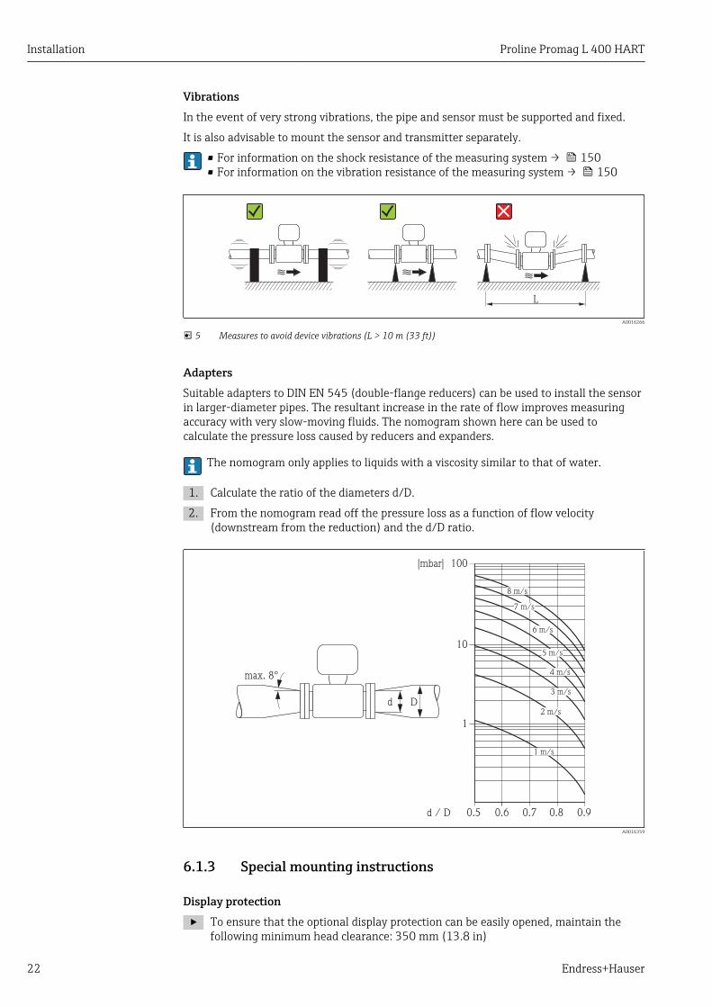
VibrationsIn the event of very strong vibrations, the pipe and sensor must be supported and fixed.
It is also advisable to mount the sensor and transmitter separately.
• For information on the shock resistance of the measuring system → 150• For information on the vibration resistance of the measuring system → 150
L
A0016266
5 Measures to avoid device vibrations (L > 10 m (33 ft))
AdaptersSuitable adapters to DIN EN 545 (double-flange reducers) can be used to install the sensorin larger-diameter pipes. The resultant increase in the rate of flow improves measuringaccuracy with very slow-moving fluids. The nomogram shown here can be used tocalculate the pressure loss caused by reducers and expanders.
The nomogram only applies to liquids with a viscosity similar to that of water.
1. Calculate the ratio of the diameters d/D.
2. From the nomogram read off the pressure loss as a function of flow velocity(downstream from the reduction) and the d/D ratio.
100
10
0.5d / D
[mbar]
0.6 0.7 0.8 0.9
1 m/s
2 m/s
3 m/s
4 m/s
5 m/s
6 m/s
7 m/s
8 m/s
1
Dd
max. 8°
A0016359
6.1.3 Special mounting instructions
Display protection
‣ To ensure that the optional display protection can be easily opened, maintain thefollowing minimum head clearance: 350 mm (13.8 in)
Proline Promag L 400 HART Installation
Endress+Hauser 23
6.2 Mounting the measuring device
6.2.1 Required tools
For transmitter• Torque wrench• For wall mounting:
Open-ended wrench for hexagonal screw max. M5• For pipe mounting:
– Open-ended wrench AF 8– Phillips head screwdriver PH 2
• For turning the transmitter housing (compact version):– Phillips head screwdriver PH 2– Torx screwdriver TX 20– Open-ended wrench AF 7
For sensorFor flanges and other process connections:• Screws, nuts, seals etc. are not included in the scope of supply and must be provided by
the customer.• Appropriate mounting tools
6.2.2 Preparing the measuring device1. Remove all remaining transport packaging.
2. Remove any protective covers or protective caps present from the sensor.
3. Remove stick-on label on the electronics compartment cover.
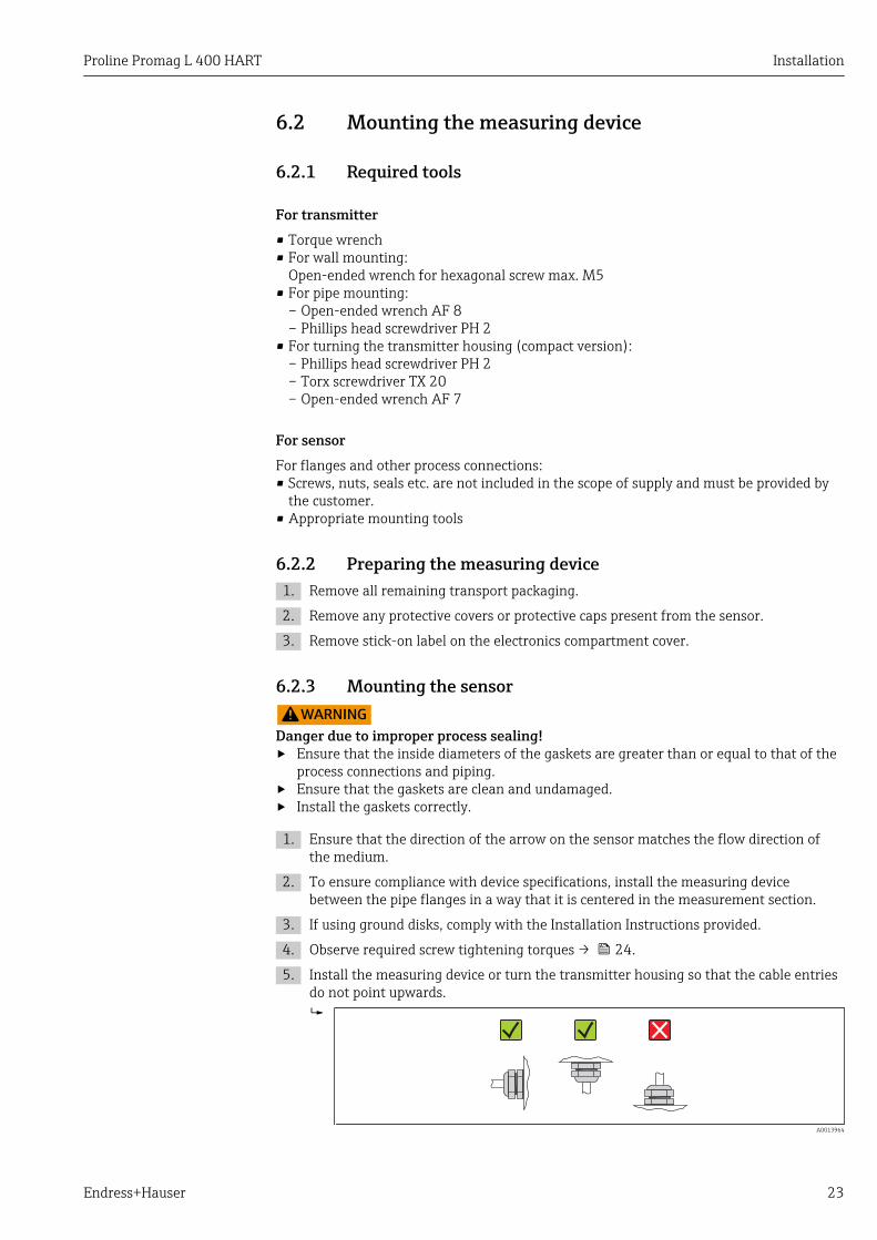
6.2.3 Mounting the sensorLWARNING
Danger due to improper process sealing!‣ Ensure that the inside diameters of the gaskets are greater than or equal to that of the
process connections and piping.‣ Ensure that the gaskets are clean and undamaged.‣ Install the gaskets correctly.
1. Ensure that the direction of the arrow on the sensor matches the flow direction ofthe medium.
2. To ensure compliance with device specifications, install the measuring devicebetween the pipe flanges in a way that it is centered in the measurement section.
3. If using ground disks, comply with the Installation Instructions provided.
4. Observe required screw tightening torques → 24.
5. Install the measuring device or turn the transmitter housing so that the cable entriesdo not point upwards.
A0013964

Installation Proline Promag L 400 HART
24 Endress+Hauser
Mounting the seals
LCAUTIONAn electrically conductive layer could form on the inside of the measuring tube!Risk of measuring signal short circuit.‣ Do not use electrically conductive sealing compounds such as graphite.
Comply with the following instructions when installing seals:• Make sure that the seals do not protrude into the piping cross-section.• For DIN flanges: only use seals according to DIN EN 1514-1.• For "hard rubber" lining: additional seals are always required.• For "polyurethane" lining: generally additional seals are not required.• For "PTFE" lining: generally additional seals are not required.
Mounting the ground cable/ground disksComply with the information on potential equalization and detailed mounting instructionsfor the use of ground cables/ground disks → 41.
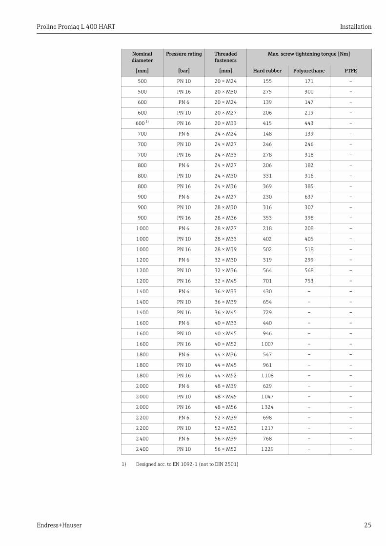
Screw tightening torquesPlease note the following:• The screw tightening torques listed below apply only to lubricated threads and to pipes
not subjected to tensile stress.• Tighten the screws uniformly and in diagonally opposite sequence.• Overtightening the screws will deform the sealing faces or damage the seals.
Screw tightening torques for EN 1092-1 (DIN 2501), PN 6/10/16
Nominaldiameter
Pressure rating Threadedfasteners
Max. screw tightening torque [Nm]
[mm] [bar] [mm] Hard rubber Polyurethane PTFE
25 PN 10/16 4 × M12 – 6 11
32 PN 10/16 4 × M16 – 16 27
40 PN 10/16 4 × M16 – 16 29
50 PN 10/16 4 × M16 – 15 40
65 1) PN 10/16 8 × M16 – 10 22
80 PN 10/16 8 × M16 – 15 30
100 PN 10/16 8 × M16 – 20 42
125 PN 10/16 8 × M16 – 30 55
150 PN 10/16 8 × M20 – 50 90
200 PN 16 12 × M20 – 65 87
250 PN 16 12 × M24 – 126 151
300 PN 16 12 × M24 – 139 177
350 PN 6 12 × M20 111 120 –
350 PN 10 16 × M20 112 118 –
350 PN 16 16 × M24 152 165 –
400 PN 6 16 × M20 90 98 –
400 PN 10 16 × M24 151 167 –
400 PN 16 16 × M27 193 215 –
450 PN 6 16 × M20 112 126 –
450 PN 10 20 × M24 153 133 –
500 PN 6 20 × M20 119 123 –
Proline Promag L 400 HART Installation
Endress+Hauser 25
Nominaldiameter
Pressure rating Threadedfasteners
Max. screw tightening torque [Nm]
[mm] [bar] [mm] Hard rubber Polyurethane PTFE
500 PN 10 20 × M24 155 171 –
500 PN 16 20 × M30 275 300 –
600 PN 6 20 × M24 139 147 –
600 PN 10 20 × M27 206 219 –
600 1) PN 16 20 × M33 415 443 –
700 PN 6 24 × M24 148 139 –
700 PN 10 24 × M27 246 246 –
700 PN 16 24 × M33 278 318 –
800 PN 6 24 × M27 206 182 –
800 PN 10 24 × M30 331 316 –
800 PN 16 24 × M36 369 385 –
900 PN 6 24 × M27 230 637 –
900 PN 10 28 × M30 316 307 –
900 PN 16 28 × M36 353 398 –
1 000 PN 6 28 × M27 218 208 –
1 000 PN 10 28 × M33 402 405 –
1 000 PN 16 28 × M39 502 518 –
1 200 PN 6 32 × M30 319 299 –
1 200 PN 10 32 × M36 564 568 –
1 200 PN 16 32 × M45 701 753 –
1 400 PN 6 36 × M33 430 – –
1 400 PN 10 36 × M39 654 – –
1 400 PN 16 36 × M45 729 – –
1 600 PN 6 40 × M33 440 – –
1 600 PN 10 40 × M45 946 – –
1 600 PN 16 40 × M52 1 007 – –
1 800 PN 6 44 × M36 547 – –
1 800 PN 10 44 × M45 961 – –
1 800 PN 16 44 × M52 1 108 – –
2 000 PN 6 48 × M39 629 – –
2 000 PN 10 48 × M45 1 047 – –
2 000 PN 16 48 × M56 1 324 – –
2 200 PN 6 52 × M39 698 – –
2 200 PN 10 52 × M52 1 217 – –
2 400 PN 6 56 × M39 768 – –
2 400 PN 10 56 × M52 1 229 – –
1) Designed acc. to EN 1092-1 (not to DIN 2501)
Installation Proline Promag L 400 HART
26 Endress+Hauser
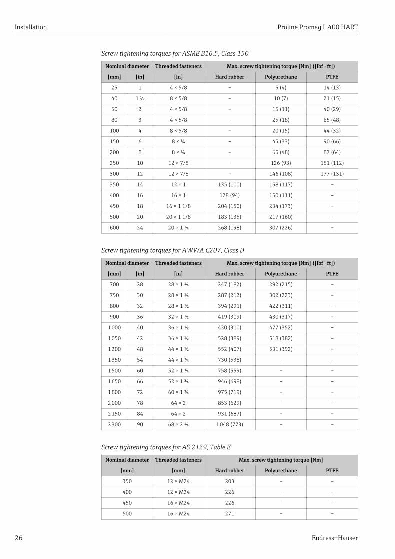
Screw tightening torques for ASME B16.5, Class 150
Nominal diameter Threaded fasteners Max. screw tightening torque [Nm] ([lbf · ft])
[mm] [in] [in] Hard rubber Polyurethane PTFE
25 1 4 × 5/8 – 5 (4) 14 (13)
40 1 ½ 8 × 5/8 – 10 (7) 21 (15)
50 2 4 × 5/8 – 15 (11) 40 (29)
80 3 4 × 5/8 – 25 (18) 65 (48)
100 4 8 × 5/8 – 20 (15) 44 (32)
150 6 8 × ¾ – 45 (33) 90 (66)
200 8 8 × ¾ – 65 (48) 87 (64)
250 10 12 × 7/8 – 126 (93) 151 (112)
300 12 12 × 7/8 – 146 (108) 177 (131)
350 14 12 × 1 135 (100) 158 (117) –
400 16 16 × 1 128 (94) 150 (111) –
450 18 16 × 1 1/8 204 (150) 234 (173) –
500 20 20 × 1 1/8 183 (135) 217 (160) –
600 24 20 × 1 ¼ 268 (198) 307 (226) –
Screw tightening torques for AWWA C207, Class D
Nominal diameter Threaded fasteners Max. screw tightening torque [Nm] ([lbf · ft])
[mm] [in] [in] Hard rubber Polyurethane PTFE
700 28 28 × 1 ¼ 247 (182) 292 (215) –
750 30 28 × 1 ¼ 287 (212) 302 (223) –
800 32 28 × 1 ½ 394 (291) 422 (311) –
900 36 32 × 1 ½ 419 (309) 430 (317) –
1 000 40 36 × 1 ½ 420 (310) 477 (352) –
1 050 42 36 × 1 ½ 528 (389) 518 (382) –
1 200 48 44 × 1 ½ 552 (407) 531 (392) –
1 350 54 44 × 1 ¾ 730 (538) – –
1 500 60 52 × 1 ¾ 758 (559) – –
1 650 66 52 × 1 ¾ 946 (698) – –
1 800 72 60 × 1 ¾ 975 (719) – –
2 000 78 64 × 2 853 (629) – –
2 150 84 64 × 2 931 (687) – –
2 300 90 68 × 2 ¼ 1 048 (773) – –
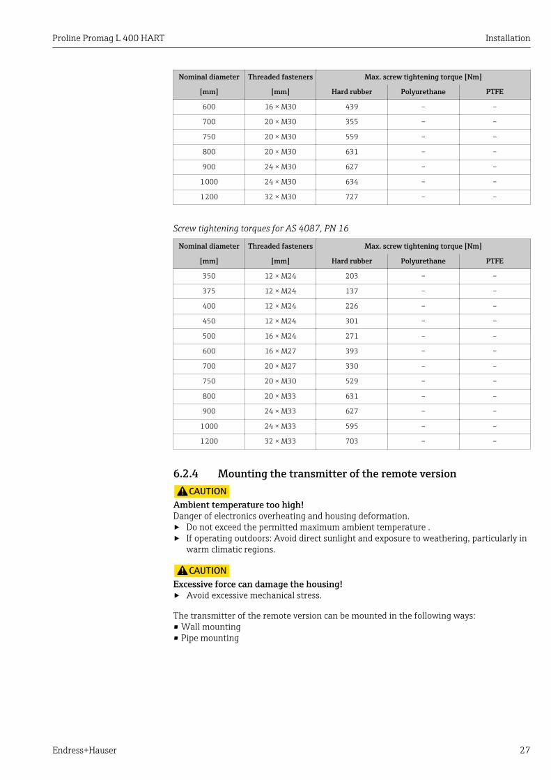
Screw tightening torques for AS 2129, Table E
Nominal diameter Threaded fasteners Max. screw tightening torque [Nm]
[mm] [mm] Hard rubber Polyurethane PTFE
350 12 × M24 203 – –
400 12 × M24 226 – –
450 16 × M24 226 – –
500 16 × M24 271 – –
Proline Promag L 400 HART Installation
Endress+Hauser 27
Nominal diameter Threaded fasteners Max. screw tightening torque [Nm]
[mm] [mm] Hard rubber Polyurethane PTFE
600 16 × M30 439 – –
700 20 × M30 355 – –
750 20 × M30 559 – –
800 20 × M30 631 – –
900 24 × M30 627 – –
1 000 24 × M30 634 – –
1 200 32 × M30 727 – –
Screw tightening torques for AS 4087, PN 16
Nominal diameter Threaded fasteners Max. screw tightening torque [Nm]
[mm] [mm] Hard rubber Polyurethane PTFE
350 12 × M24 203 – –
375 12 × M24 137 – –
400 12 × M24 226 – –
450 12 × M24 301 – –
500 16 × M24 271 – –
600 16 × M27 393 – –
700 20 × M27 330 – –
750 20 × M30 529 – –
800 20 × M33 631 – –
900 24 × M33 627 – –
1 000 24 × M33 595 – –
1 200 32 × M33 703 – –
6.2.4 Mounting the transmitter of the remote versionLCAUTION
Ambient temperature too high!Danger of electronics overheating and housing deformation.‣ Do not exceed the permitted maximum ambient temperature .‣ If operating outdoors: Avoid direct sunlight and exposure to weathering, particularly in
warm climatic regions.
LCAUTIONExcessive force can damage the housing!‣ Avoid excessive mechanical stress.
The transmitter of the remote version can be mounted in the following ways:• Wall mounting• Pipe mounting
Installation Proline Promag L 400 HART
28 Endress+Hauser
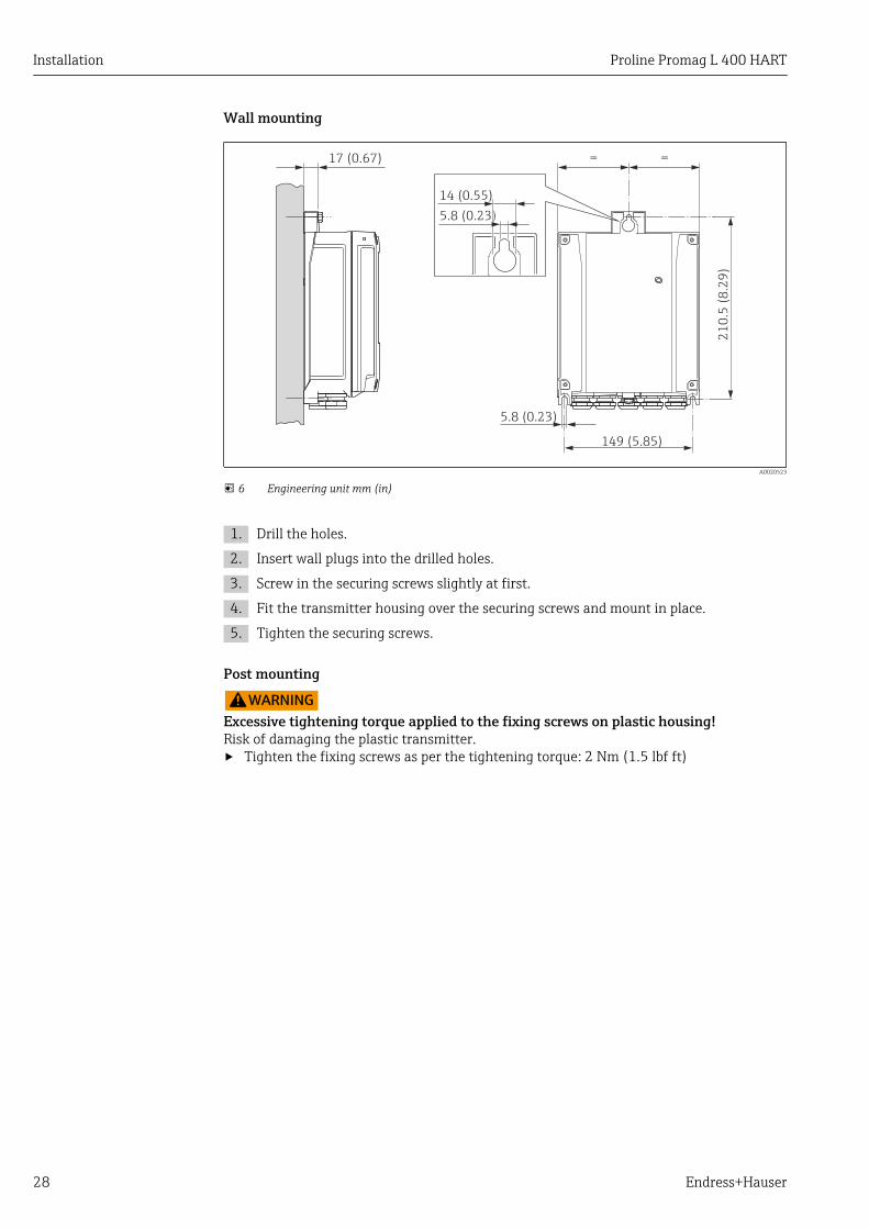
Wall mounting
149 (5.85)
21
0.5
(8
.29
)
=
5.8 (0.23)
17 (0.67) =
14 (0.55)
5.8 (0.23)
A0020523
6 Engineering unit mm (in)
1. Drill the holes.
2. Insert wall plugs into the drilled holes.
3. Screw in the securing screws slightly at first.
4. Fit the transmitter housing over the securing screws and mount in place.
5. Tighten the securing screws.
Post mounting
LWARNINGExcessive tightening torque applied to the fixing screws on plastic housing!Risk of damaging the plastic transmitter.‣ Tighten the fixing screws as per the tightening torque: 2 Nm (1.5 lbf ft)
Proline Promag L 400 HART Installation
Endress+Hauser 29
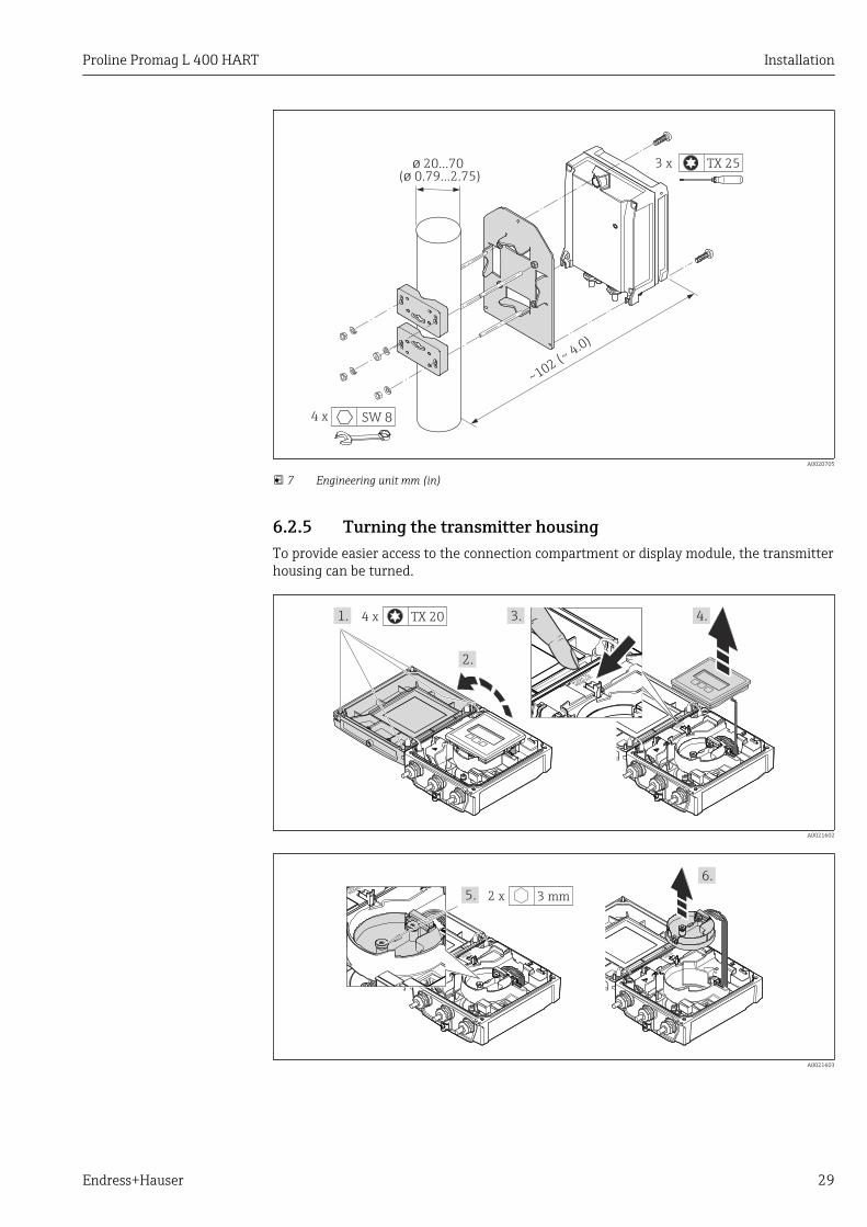
ø 20…70( 0.79…2.75)ø
~
~ 4.0)
102 (
4 x SW 8
3 x TX 25
A0020705
7 Engineering unit mm (in)
6.2.5 Turning the transmitter housingTo provide easier access to the connection compartment or display module, the transmitterhousing can be turned.
TX 204 x1.
2.
PUSHTO
REMO
VE
PUSHTO
REMO
VE
3. 4.
A0021602
PUSHTO
REMO
VE
3 mm2 x5.
6.
PUSHTO
REMO
VE
A0021603
Installation Proline Promag L 400 HART
30 Endress+Hauser
PUSHTO
REMO
VE
TX 204 x7.
PUSHTO
REMO
VE
8.
A0021604
10.
11.
9. 4 mm4 x
A0021605
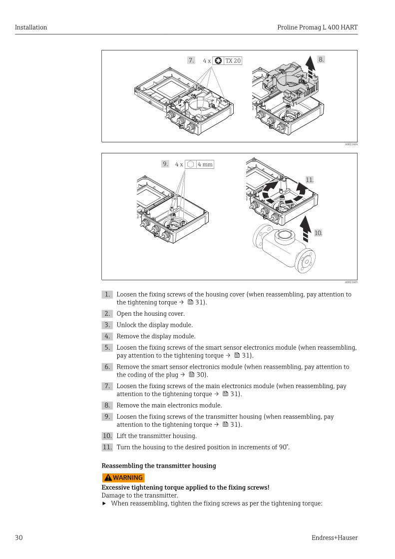
1. Loosen the fixing screws of the housing cover (when reassembling, pay attention tothe tightening torque → 31).
2. Open the housing cover.
3. Unlock the display module.
4. Remove the display module.
5. Loosen the fixing screws of the smart sensor electronics module (when reassembling,pay attention to the tightening torque → 31).
6. Remove the smart sensor electronics module (when reassembling, pay attention tothe coding of the plug → 30).
7. Loosen the fixing screws of the main electronics module (when reassembling, payattention to the tightening torque → 31).
8. Remove the main electronics module.
9. Loosen the fixing screws of the transmitter housing (when reassembling, payattention to the tightening torque → 31).
10. Lift the transmitter housing.
11. Turn the housing to the desired position in increments of 90°.
Reassembling the transmitter housing
LWARNINGExcessive tightening torque applied to the fixing screws!Damage to the transmitter.‣ When reassembling, tighten the fixing screws as per the tightening torque:

Proline Promag L 400 HART Installation
Endress+Hauser 31
Step Fixing screw Tightening torques for housing made of:
Aluminum Plastic
1 Housing cover 2.5 Nm (1.8 lbf ft) 1 Nm (0.7 lbf ft)
5 Smart sensor electronics module 0.6 Nm (0.4 lbf ft)
7 Main electronics module 1.5 Nm (1.1 lbf ft)
10 Transmitter housing 5.5 Nm (4.1 lbf ft)
NOTICEPlug of the smart sensor electronics module connected incorrectly!No measuring signal is output.‣ Plug in the plug of the smart sensor electronics module as per the coding.
PUSHTO
REMO
VE
A0021585
‣ Reverse the procedure to reassemble the measuring device.
6.2.6 Turning the display moduleThe display module can be turned to optimize display readability and operability.
TX 204 x1.
2.
PUSHTO
REMO
VE
PUSHTO
REMO
VE
3. 4.
A0021617
1. Loosen the fixing screws of the housing cover (when reassembling, pay attention tothe tightening torque → 32).
2. Open the housing cover.
3. Unlock the display module.
4. Pull out the display module and turn it to the desired position in increments of 90°.

Installation Proline Promag L 400 HART
32 Endress+Hauser
Reassembling the transmitter housing
LWARNINGExcessive tightening torque applied to the fixing screws!Damage to the transmitter.‣ When reassembling, tighten the fixing screws as per the tightening torque:
Step Fixing screw Tightening torque for housing made of:
Aluminum Plastic
1 Housing cover 2.5 Nm (1.8 lbf ft) 1 Nm (0.7 lbf ft)
‣ Reverse the procedure to reassemble the measuring device.
6.3 Post-installation check
Is the device undamaged (visual inspection)?
Does the measuring device conform to the measuring point specifications?
For example:• Process temperature• Process pressure (refer to the section on "Pressure-temperature ratings" in the "Technical
Information" document)• Ambient temperature• Measuring range
Has the correct orientation for the sensor been selected ?
• According to sensor type• According to medium temperature• According to medium properties (outgassing, with entrained solids)
Does the arrow on the sensor nameplate match the direction of flow of the fluid through thepiping ?
Are the measuring point identification and labeling correct (visual inspection)?
Is the device adequately protected from precipitation and direct sunlight?
Have the fixing screws been tightened with the correct tightening torque?

Proline Promag L 400 HART Electrical connection
Endress+Hauser 33
7 Electrical connectionThe measuring device does not have an internal circuit breaker. For this reason,assign the measuring device a switch or power-circuit breaker so that the powersupply line can be easily disconnected from the mains.
7.1 Connection conditions
7.1.1 Required tools• Torque wrench• For cable entries: Use corresponding tools• For housing cover: Torx screwdriver or flat-blade screwdriver• Wire stripper• When using stranded cables: crimping tool for ferrule
7.1.2 Requirements for connecting cableThe connecting cables provided by the customer must fulfill the following requirements.
Electrical safetyIn accordance with applicable federal/national regulations.
Permitted temperature range• –40 °C (–40 °F) to +80 °C (+176 °F)• Minimum requirement: cable temperature range ≥ ambient temperature +20 K
Power supply cableStandard installation cable is sufficient.
Signal cable
Current output
• For 0-20 mA and 4-20 mA: standard installation cable is sufficient.• For 4-20 mA HART: Shielded cable recommended. Observe grounding concept of the
plant.
Pulse/frequency/switch output
Standard installation cable is sufficient.
Status input
Standard installation cable is sufficient.
Connecting cable for remote version
Electrode cable
Standard cable 3 ×0.38 mm2 (20 AWG) with common, braided copper shield ( ~7 mm (0.28 in)and individual shielded cores
Cable for empty pipedetection (EPD)
4 ×0.38 mm2 (20 AWG) with common, braided copper shield ( ~7 mm (0.28 in)and individual shielded cores
Conductor resistance ≤50 Ω/km (0.015 Ω/ft)

Electrical connection Proline Promag L 400 HART
34 Endress+Hauser
Capacitance: core/shield ≤420 pF/m (128 pF/ft)
Operating temperature –20 to +80 °C (–68 to +176 °F)
Coil current cable
Standard cable 2 ×0.75 mm2 (18 AWG) with common, braided copper shield ( ~ 7 mm (0.28"))and individually shielded cores
Conductor resistance ≤37 Ω/km (0.011 Ω/ft)
Capacitance: core/core,shield grounded
≤120 pF/m (37 pF/ft)
Operating temperature –20 to +80 °C (–68 to +176 °F)
Test voltage for cableinsulation
≤ AC 1433 V r.m.s. 50/60 Hz or ≥ DC 2026 V
1
2
3
4
5
6
7
a b
A0003194
8 Cable cross-section
a Electrode cableb Coil current cable1 Core2 Core insulation3 Core shield4 Core jacket5 Core reinforcement6 Cable shield7 Outer jacket
Reinforced connecting cables
Reinforced connecting cables with an additional, reinforcing metal braid should be usedfor:• When laying the cable directly in the ground• Where there is a risk of damage from rodents
Operation in zones of severe electrical interference
The measuring system meets the general safety requirements → 167 and EMCspecifications → 151.
Grounding is by means of the ground terminal provided for the purpose inside theconnection housing. The stripped and twisted lengths of cable shield to the groundterminal must be as short as possible.
Cable diameter• Cable glands supplied:
– For standard cable: M20 × 1.5 with cable 6 to 12 mm (0.24 to 0.47 in)– For reinforced cable: M20 × 1.5 with cable 9.5 to 16 mm (0.37 to 0.63 in)
• (Plug-in) spring terminals for wire cross-sections 0.5 to 2.5 mm2 (20 to 14 AWG)

Proline Promag L 400 HART Electrical connection
Endress+Hauser 35
7.1.3 Terminal assignment
Transmitter
0-20 mA/4-20 mA HART connection version with additional outputs and inputs
The sensor can be ordered with terminals.
Connection methods availablePossible options for order code
"Electrical connection"Outputs Powersupply
Terminals Terminals • Option A: coupling M20x1• Option B: thread M20x1• Option C: thread G ½"• Option D: thread NPT ½"
26 27 24 25
23 20 2122
+ - + -
+ - + -
1 2
L+
/L
L-/N
1 2 3
A0020424
1 Supply voltage2 Output 1 (26/27) and output 2 (24/25)3 Output 3 (22/23) and input 1 (20/21)
Supply voltage
Order code for "Power supply" Terminal numbers
1 (L+/L) 2 (L-/N)
Option L(wide range power unit)
AC100 to 240 V
AC/DC24 V
Signal transmission 0-20 mA/4-20 mA HART with additional outputs and inputs
Order code for"Output" and
"Input"
Terminal numbers
Output 1 Output 2 Output 3 Input
26 (+) 27 (-) 24 (+) 25 (-) 22 (+) 23 (-) 20 (+) 21 (-)
Option H • 4-20 mA HART(active)
• 0-20 mA(active)
Pulse/frequencyoutput
(passive)
Switch output(passive)
-
Option I • 4-20 mA HART(active)
• 0-20 mA(active)
Pulse/frequency/switch output
(passive)
Pulse/frequency/switch output
(passive)
Status input
Electrical connection Proline Promag L 400 HART
36 Endress+Hauser
Remote version
E1
E2
GN
D E
S1
E1
E2
S2
GN
D
E S
5 7 4 37 42 41
6 5 7 8 4 37 36
n.c. n.c.
21
1
2
n.c.
42 41
A
B
A0020534
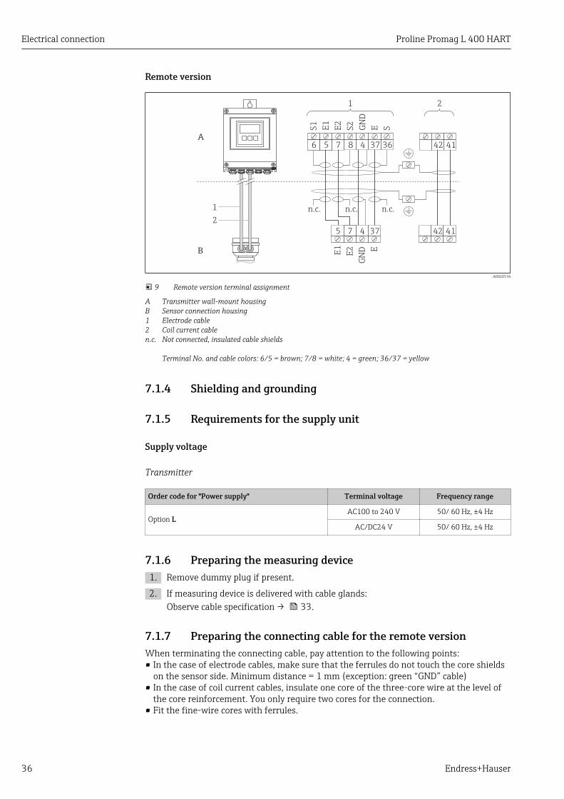
9 Remote version terminal assignment
A Transmitter wall-mount housingB Sensor connection housing1 Electrode cable2 Coil current cablen.c. Not connected, insulated cable shields
Terminal No. and cable colors: 6/5 = brown; 7/8 = white; 4 = green; 36/37 = yellow
7.1.4 Shielding and grounding
7.1.5 Requirements for the supply unit
Supply voltage
Transmitter
Order code for "Power supply" Terminal voltage Frequency range
Option LAC100 to 240 V 50/ 60 Hz, ±4 Hz
AC/DC24 V 50/ 60 Hz, ±4 Hz
7.1.6 Preparing the measuring device1. Remove dummy plug if present.
2. If measuring device is delivered with cable glands:Observe cable specification → 33.
7.1.7 Preparing the connecting cable for the remote versionWhen terminating the connecting cable, pay attention to the following points:• In the case of electrode cables, make sure that the ferrules do not touch the core shields
on the sensor side. Minimum distance = 1 mm (exception: green “GND” cable)• In the case of coil current cables, insulate one core of the three-core wire at the level of
the core reinforcement. You only require two cores for the connection.• Fit the fine-wire cores with ferrules.

Proline Promag L 400 HART Electrical connection
Endress+Hauser 37
Transmitter
Electrode cable Coil current cable
A
80 (3.15)
50 (1.97)17 (0.67)8 (0.31)
100 (3.94)*
BGND
1
21
21
2
2 A0021324
10 Engineering unit mm (in)
A
90 (3.54)*
70 (2.76)50 (1.97)
10 (0.39)8 (0.31)
B
1
A0021325
11 Engineering unit mm (in)
A = Termination of the cablesB = Termination of the fine-wire cores with ferrules1 = Red ferrules, 1.0 mm (0.04 in)2 = White ferrules, 0.5 mm (0.02 in)* = Stripping only for reinforced cables
Electrical connection Proline Promag L 400 HART
38 Endress+Hauser
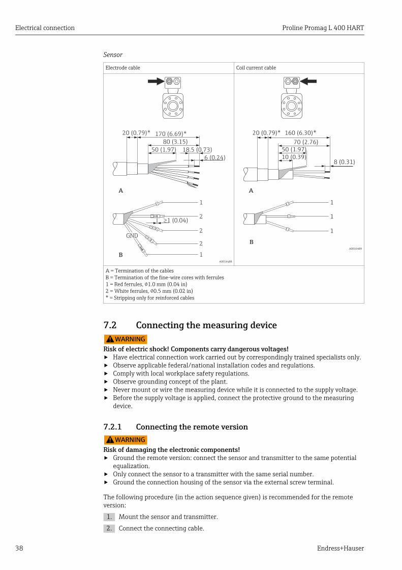
Sensor
Electrode cable Coil current cable
A
80 (3.15)
50 (1.97)
6 (0.24)
170 (6.69)*20 (0.79)*
18.5 (0.73)
B
GND
³1 (0.04)
1
2
2
2
1 A0016488
A
70 (2.76)
50 (1.97)
10 (0.39)8 (0.31)
160 (6.30)*20 (0.79)*
B
1
1
1
A0016489
A = Termination of the cablesB = Termination of the fine-wire cores with ferrules1 = Red ferrules, 1.0 mm (0.04 in)2 = White ferrules, 0.5 mm (0.02 in)* = Stripping only for reinforced cables
7.2 Connecting the measuring deviceLWARNING
Risk of electric shock! Components carry dangerous voltages!‣ Have electrical connection work carried out by correspondingly trained specialists only.‣ Observe applicable federal/national installation codes and regulations.‣ Comply with local workplace safety regulations.‣ Observe grounding concept of the plant.‣ Never mount or wire the measuring device while it is connected to the supply voltage.‣ Before the supply voltage is applied, connect the protective ground to the measuring
device.
7.2.1 Connecting the remote versionLWARNING
Risk of damaging the electronic components!‣ Ground the remote version: connect the sensor and transmitter to the same potential
equalization.‣ Only connect the sensor to a transmitter with the same serial number.‣ Ground the connection housing of the sensor via the external screw terminal.
The following procedure (in the action sequence given) is recommended for the remoteversion:
1. Mount the sensor and transmitter.
2. Connect the connecting cable.

Proline Promag L 400 HART Electrical connection
Endress+Hauser 39
3. Connect the transmitter.
1.
2.4.
3.
6 5 7 8 4 37 36 42 41
S1
E1
E2
S2
GN
D
E S
TX 204 x
A0017445
12 Transmitter: main electronics module with terminals
1. Loosen the 4 fixing screws on the housing cover.
2. Open the housing cover.
3. Push the cable through the cable entry . To ensure tight sealing, do not remove thesealing ring from the cable entry.
4. Strip the cable and cable ends. In the case of stranded cables, also fit ferrules→ 36.
5. Connect the cable in accordance with the terminal assignment → 36.
6. Firmly tighten the cable glands.
7. WARNING! Housing degree of protection may be voided due to insufficient sealing ofthe housing. Screw in the screw without using any lubricant.Reverse the removal procedure to reassemble the transmitter.
3.
57437
E1
E2
GN
D
E
42 41
A0021527
13 Sensor: connection module
1. Loosen the securing clamp of the housing cover.
2. Unscrew and lift off the housing cover.
3. Push the cable through the cable entry . To ensure tight sealing, do not remove thesealing ring from the cable entry.
4. Strip the cable and cable ends. In the case of stranded cables, also fit ferrules→ 36.
5. Connect the cable in accordance with the terminal assignment → 36.
6. Firmly tighten the cable glands.
Electrical connection Proline Promag L 400 HART
40 Endress+Hauser
7. WARNING! Housing degree of protection may be voided due to insufficient sealing ofthe housing. Screw in the screw without using any lubricant. The threads on thecover are coated with a dry lubricant.Reverse the procedure to reassemble the sensor.
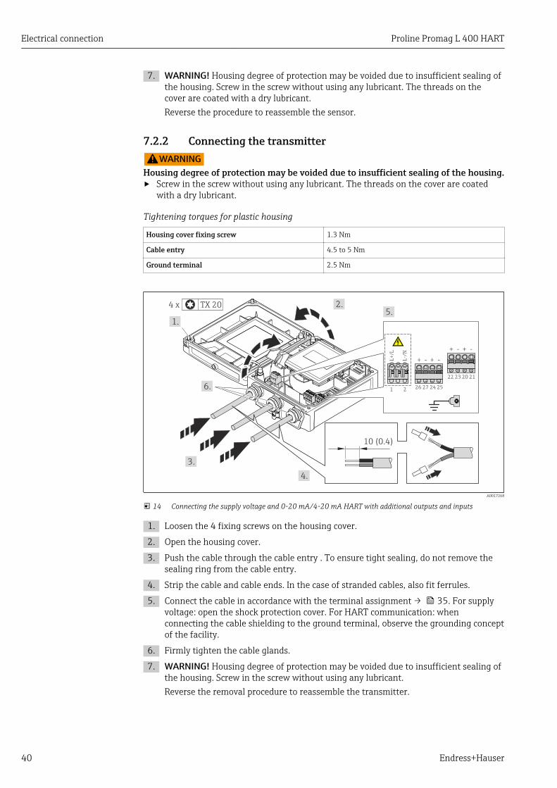
7.2.2 Connecting the transmitterLWARNING
Housing degree of protection may be voided due to insufficient sealing of the housing.‣ Screw in the screw without using any lubricant. The threads on the cover are coated
with a dry lubricant.
Tightening torques for plastic housing
Housing cover fixing screw 1.3 Nm
Cable entry 4.5 to 5 Nm
Ground terminal 2.5 Nm
TX 204 x
1.
2.
3.
26 27 24 25
23 20 2122
+ - + -
+ - + -
1 2L
+/L
L-/
N
6.
4.
5.
10 (0.4)
A0017268
14 Connecting the supply voltage and 0-20 mA/4-20 mA HART with additional outputs and inputs
1. Loosen the 4 fixing screws on the housing cover.
2. Open the housing cover.
3. Push the cable through the cable entry . To ensure tight sealing, do not remove thesealing ring from the cable entry.
4. Strip the cable and cable ends. In the case of stranded cables, also fit ferrules.
5. Connect the cable in accordance with the terminal assignment → 35. For supplyvoltage: open the shock protection cover. For HART communication: whenconnecting the cable shielding to the ground terminal, observe the grounding conceptof the facility.
6. Firmly tighten the cable glands.
7. WARNING! Housing degree of protection may be voided due to insufficient sealing ofthe housing. Screw in the screw without using any lubricant.Reverse the removal procedure to reassemble the transmitter.

Proline Promag L 400 HART Electrical connection
Endress+Hauser 41
7.2.3 Ensuring potential equalization
Requirements
LCAUTIONElectrode damage can result in the complete failure of the device!‣ Same electrical potential for the fluid and sensor‣ Remote version: same electrical potential for the sensor and transmitter‣ Company-internal grounding concepts‣ Pipe material and grounding
Connection examples for standard situations
Metal, grounded pipe
A0016315
15 Potential equalization via measuring tube
Connection example in special situations
Unlined and ungrounded metal pipe
This connection method also applies in situations where:• The customary potential equalization is not used• Equalizing currents are present
Ground cable Copper wire, at least6 mm2 (0.0093 in2)
DN 300≤ DN 350≥
A0016317
16 Potential equalization via ground terminal and pipe flanges
1. Connect both sensor flanges to the pipe flange via a ground cable and ground them.
2. If DN ≤ 300 (12"): Mount the ground cable directly on the conductive flange coatingof the sensor with the flange screws. If DN ≥ 350 (14"): Mount the ground cabledirectly on the metal transport bracket. Observe torques → 24.
3. Connect the connection housing of the transmitter or sensor to ground potential bymeans of the ground terminal provided for the purpose.
For remote device versions, the ground terminal in the example always refers to thesensor and not to the transmitter.
Electrical connection Proline Promag L 400 HART
42 Endress+Hauser
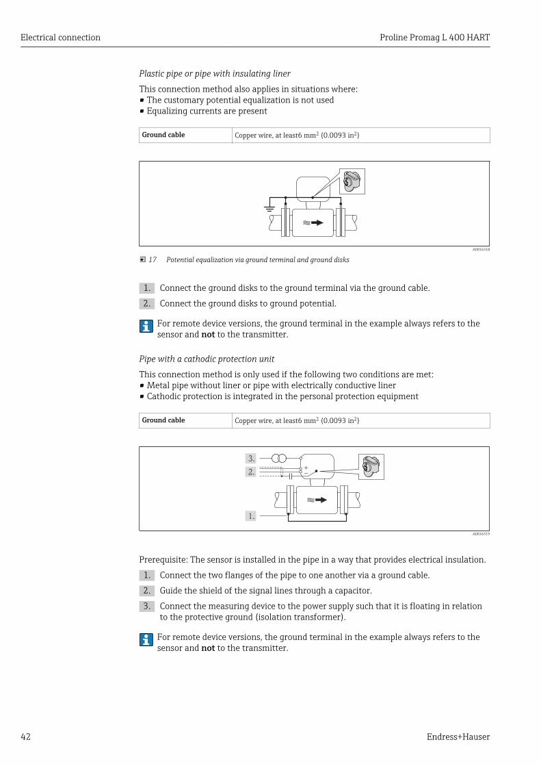
Plastic pipe or pipe with insulating liner
This connection method also applies in situations where:• The customary potential equalization is not used• Equalizing currents are present
Ground cable Copper wire, at least6 mm2 (0.0093 in2)
A0016318
17 Potential equalization via ground terminal and ground disks
1. Connect the ground disks to the ground terminal via the ground cable.
2. Connect the ground disks to ground potential.
For remote device versions, the ground terminal in the example always refers to thesensor and not to the transmitter.
Pipe with a cathodic protection unit
This connection method is only used if the following two conditions are met:• Metal pipe without liner or pipe with electrically conductive liner• Cathodic protection is integrated in the personal protection equipment
Ground cable Copper wire, at least6 mm2 (0.0093 in2)
+
–
A0016319
Prerequisite: The sensor is installed in the pipe in a way that provides electrical insulation.
1. Connect the two flanges of the pipe to one another via a ground cable.
2. Guide the shield of the signal lines through a capacitor.
3. Connect the measuring device to the power supply such that it is floating in relationto the protective ground (isolation transformer).
For remote device versions, the ground terminal in the example always refers to thesensor and not to the transmitter.

Proline Promag L 400 HART Electrical connection
Endress+Hauser 43
7.3 Special connection instructions
7.4 Ensuring the degree of protection
7.4.1 Degree of protection IP66/67, Type 4X enclosureThe measuring device fulfills all the requirements for the IP66/67 degree of protection,Type 4X enclosure.
To guarantee IP66/67 degree of protection, Type 4X enclosure, carry out the followingsteps after the electrical connection:
1. Check that the housing seals are clean and fitted correctly. Dry, clean or replace theseals if necessary.
2. Tighten all housing screws and screw covers.
3. Firmly tighten the cable glands.
4. To ensure that moisture does not enter the cable entry, route the cable so that itloops down before the cable entry ("water trap").
A0013960
5. Insert dummy plugs into unused cable entries.
7.5 Post-connection check
Are cables or the device undamaged (visual inspection)?
Do the cables comply with the requirements → 33?
Do the cables have adequate strain relief?
Are all the cable glands installed, firmly tightened and leak-tight? Cable run with "water trap"→ 43 ?
Only for remote version: is the sensor connected to the right transmitter?Check the serial number on the nameplate of the sensor and transmitter.
Does the supply voltage match the specifications on the transmitter nameplate ?
Is the terminal assignment correct ?
If supply voltage is present, do values appear on the display module?
Is the potential equalization established correctly → 41?
Are all housing covers installed and the screws tightened with the correct tightening torque?

Operation options Proline Promag L 400 HART
44 Endress+Hauser
8 Operation options
8.1 Overview of operation options
1 2 3 4 5
SC
A0015607
1 Local operation via display module2 Computer with Web browser (e.g. Internet Explorer) or with operating tool (e.g. FieldCare, AMS Device
Manager, SIMATIC PDM)3 Field Xpert SFX350 or SFX3704 Field Communicator 4755 Control system (e.g. PLC)

Proline Promag L 400 HART Operation options
Endress+Hauser 45
8.2 Structure and function of the operating menu
8.2.1 Structure of the operating menuFor an overview of the operating menu with menus and parameters → 170
!
Expert
System
Sensor
Communication
Application
Diagnostics
Access status display
Output
Operating menu for experts
Language
Operatation Language
Parameter 1
Setup
Submenu 1
Submenu n
Device tag
Advanced setup Enter access code
Parameter 1
Parameter n
Submenu 1
Submenu n
Diagnostics Parameter 1
Parameter n
Submenu 1
Submenu n
Operating menu for operators and maintenances
Parameter n
Op
era
tor
Ma
inte
na
nce
Ta
sk-o
rie
nte
dF
un
ctio
n-o
rie
nte
d
Ex
pe
rt
Wizard 1 / Parameter 1
Wizard n / Parameter n
Parameter n
Intput
A0018237-EN
18 Schematic structure of the operating menu
Operation options Proline Promag L 400 HART
46 Endress+Hauser
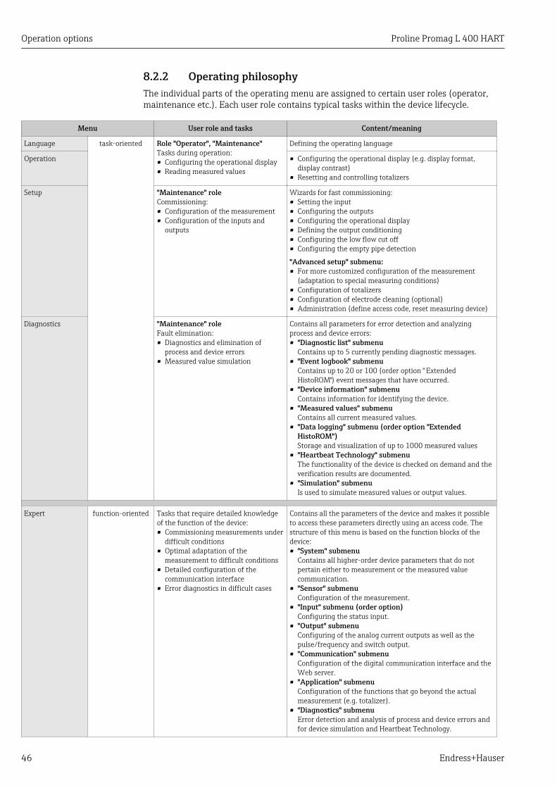
8.2.2 Operating philosophyThe individual parts of the operating menu are assigned to certain user roles (operator,maintenance etc.). Each user role contains typical tasks within the device lifecycle.
Menu User role and tasks Content/meaning
Language task-oriented Role "Operator", "Maintenance"Tasks during operation:• Configuring the operational display• Reading measured values
Defining the operating language
Operation • Configuring the operational display (e.g. display format,display contrast)
• Resetting and controlling totalizers
Setup "Maintenance" roleCommissioning:• Configuration of the measurement• Configuration of the inputs and
outputs
Wizards for fast commissioning:• Setting the input• Configuring the outputs• Configuring the operational display• Defining the output conditioning• Configuring the low flow cut off• Configuring the empty pipe detection
"Advanced setup" submenu:• For more customized configuration of the measurement
(adaptation to special measuring conditions)• Configuration of totalizers• Configuration of electrode cleaning (optional)• Administration (define access code, reset measuring device)
Diagnostics "Maintenance" roleFault elimination:• Diagnostics and elimination of
process and device errors• Measured value simulation
Contains all parameters for error detection and analyzingprocess and device errors:• "Diagnostic list" submenu
Contains up to 5 currently pending diagnostic messages.• "Event logbook" submenu
Contains up to 20 or 100 (order option " ExtendedHistoROM") event messages that have occurred.
• "Device information" submenuContains information for identifying the device.
• "Measured values" submenuContains all current measured values.
• "Data logging" submenu (order option "ExtendedHistoROM")Storage and visualization of up to 1000 measured values
• "Heartbeat Technology" submenuThe functionality of the device is checked on demand and theverification results are documented.
• "Simulation" submenuIs used to simulate measured values or output values.
Expert function-oriented Tasks that require detailed knowledgeof the function of the device:• Commissioning measurements under
difficult conditions• Optimal adaptation of the
measurement to difficult conditions• Detailed configuration of the
communication interface• Error diagnostics in difficult cases
Contains all the parameters of the device and makes it possibleto access these parameters directly using an access code. Thestructure of this menu is based on the function blocks of thedevice:• "System" submenu
Contains all higher-order device parameters that do notpertain either to measurement or the measured valuecommunication.
• "Sensor" submenuConfiguration of the measurement.
• "Input" submenu (order option)Configuring the status input.
• "Output" submenuConfiguring of the analog current outputs as well as thepulse/frequency and switch output.
• "Communication" submenuConfiguration of the digital communication interface and theWeb server.
• "Application" submenuConfiguration of the functions that go beyond the actualmeasurement (e.g. totalizer).
• "Diagnostics" submenuError detection and analysis of process and device errors andfor device simulation and Heartbeat Technology.

Proline Promag L 400 HART Operation options
Endress+Hauser 47
8.3 Access to the operating menu via the local display
8.3.1 Operational display
X X X X X X XX X
4
2
1
3
5
l/h
1120.50
F
A0016502
12345
Operational displayDevice tagStatus areaDisplay area for measured values (4-line)Operating elements → 52
Status areaThe following symbols appear in the status area of the operational display at the top right:• Status signals→ 120
– F: Failure– C: Function check– S: Out of specification– M: Maintenance required
• Diagnostic behavior→ 121– : Alarm– : Warning
• : Locking (the device is locked via the hardware )• : Communication (communication via remote operation is active)
Display areaIn the display area, each measured value is prefaced by certain symbol types for furtherdescription:
Measured variable Measurement channelnumber
Diagnostic behavior
↓ ↓ ↓
Example
Appears only if a diagnosticsevent is present for thismeasured variable.
Measured variables
Symbol Meaning
Volume flow
Conductivity
Operation options Proline Promag L 400 HART
48 Endress+Hauser
Mass flow
Totalizer
The measurement channel number indicates which of the three totalizers isdisplayed.
Output
The measurement channel number indicates which of the outputs is displayed.
Status input
Measurement channel numbers
Symbol Meaning
Measurement channel 1 to 4
The measurement channel number is displayed only if more than one channel is present for the same measuredvariable type (e.g. Totalizer 1 to 3).
Diagnostic behavior
The diagnostic behavior pertains to a diagnostic event that is relevant to the displayed measured variable.For information on the symbols → 121
The number and display format of the measured values can be configured via the"Format display" parameter→ 87. "Operation" menu → Display → Formatdisplay
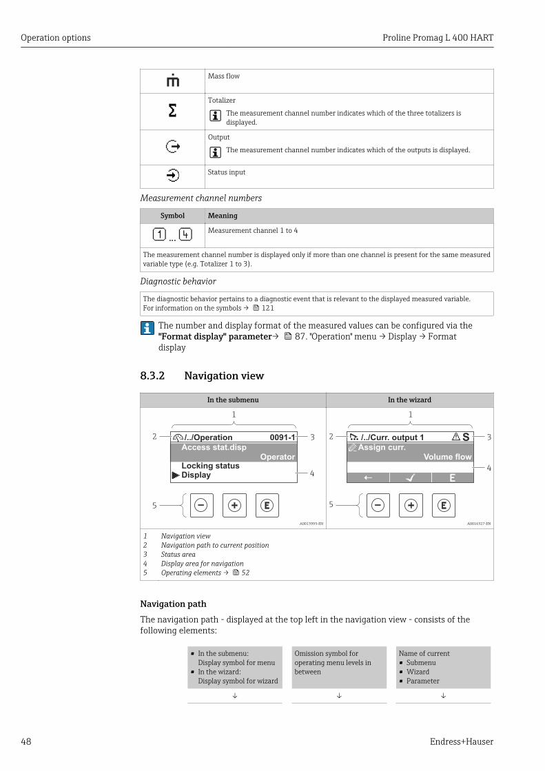
8.3.2 Navigation view
In the submenu In the wizard
4
2
1
3
5
/../Operation 0091-1
Access stat.dispOperator
Locking statusDisplay
A0013993-EN
S
4
2
1
5
3/../Curr. output 1
Assign curr.Volume flow
A0016327-EN
12345
Navigation viewNavigation path to current positionStatus areaDisplay area for navigationOperating elements → 52
Navigation pathThe navigation path - displayed at the top left in the navigation view - consists of thefollowing elements:
• In the submenu:Display symbol for menu
• In the wizard:Display symbol for wizard
Omission symbol foroperating menu levels inbetween
Name of current• Submenu• Wizard• Parameter
↓ ↓ ↓

Proline Promag L 400 HART Operation options
Endress+Hauser 49
Examples / ../ Display
/ ../ Display
For more information about the menu icons, refer to the "Display area" section→ 49
Status areaThe following appears in the status area of the navigation view in the top right corner:• Of the submenu
– The direct access code for the parameter you are navigating to (e.g. 0022-1)– If a diagnostic event is present, the diagnostic behavior and status signal
• In the wizardIf a diagnostic event is present, the diagnostic behavior and status signal
• For information on the diagnostic behavior and status signal → 120• For information on the function and entry of the direct access code → 54
Display area
Menus
Symbol Meaning
OperationAppears:• In the menu next to the "Operation" selection• At the left in the navigation path in the "Operation" menu
SetupAppears:• In the menu next to the "Setup" selection• At the left in the navigation path in the "Setup" menu
DiagnosticsAppears:• In the menu next to the "Diagnostics" selection• At the left in the navigation path in the "Diagnostics" menu
ExpertAppears:• In the menu next to the "Expert" selection• At the left in the navigation path in the "Expert" menu
Submenus, wizards, parameters
Symbol Meaning
Submenu
Wizard
Parameters within a wizard
No display symbol exists for parameters in submenus.

Operation options Proline Promag L 400 HART
50 Endress+Hauser
Locking
Symbol Meaning
Parameter lockedWhen displayed in front of a parameter name, indicates that the parameter is locked.• By a user-specific access code• By the hardware write protection switch
Wizard operation
Symbol Meaning
Switches to the previous parameter.
Confirms the parameter value and switches to the next parameter.
Opens the editing view of the parameter.
8.3.3 Editing view
Numeric editor Text editor
3
2
1
4
3 40 1 2
95 6 87
20
A0013941 A0013999
1234
Editing viewDisplay area of the entered valuesInput maskOperating elements → 52
Input maskThe following input symbols are available in the input mask of the numeric and text editor:
Numeric editor
Symbol Meaning
…0
9
Selection of numbers from 0 to 9.
.
Inserts decimal separator at the input position.
–
Inserts minus sign at the input position.
Confirms selection.
Moves the input position one position to the left.

Proline Promag L 400 HART Operation options
Endress+Hauser 51
Exits the input without applying the changes.
Clears all entered characters.
Text editor
Symbol Meaning
Aa1Toggle• Between upper-case and lower-case letters• For entering numbers• For entering special characters
XYZ
ABC_…
Selection of letters from A to Z.
xyz
abc _…
Selection of letters from a to z.
~&
"'^ _…
_
Selection of special characters.
Confirms selection.
Switches to the selection of the correction tools.
Exits the input without applying the changes.
Clears all entered characters.
Correction symbols under
Symbol Meaning
Clears all entered characters.
Moves the input position one position to the right.
Moves the input position one position to the left.
Deletes one character immediately to the left of the input position.

Operation options Proline Promag L 400 HART
52 Endress+Hauser
8.3.4 Operating elements
Key Meaning
Minus key
In a menu, submenuMoves the selection bar upwards in a choose list.
With a WizardConfirms the parameter value and goes to the previous parameter.
With a text and numeric editorIn the input mask, moves the selection bar to the left (backwards).
Plus key
In a menu, submenuMoves the selection bar downwards in a choose list.
With a WizardConfirms the parameter value and goes to the next parameter.
With a text and numeric editorMoves the selection bar to the right (forwards) in an input screen.
Enter key
For operational display• Pressing the key briefly opens the operating menu.• Pressing the key for 2 s opens the context menu.
In a menu, submenu• Pressing the key briefly:
– Opens the selected menu, submenu or parameter.– Starts the wizard.– If help text is open, closes the help text of the parameter.
• Pressing the key for 2 s for parameter:If present, opens the help text for the function of the parameter.
With a WizardOpens the editing view of the parameter.
With a text and numeric editor• Pressing the key briefly:
– Opens the selected group.– Carries out the selected action.
• Pressing the key for 2 s confirms the edited parameter value.
+
Escape key combination (press keys simultaneously)
In a menu, submenu• Pressing the key briefly:
– Exits the current menu level and takes you to the next higher level.– If help text is open, closes the help text of the parameter.
• Pressing the key for 2 s returns you to the operational display ("home position").
With a WizardExits the wizard and takes you to the next higher level.
With a text and numeric editorCloses the text or numeric editor without applying changes.
+Minus/Enter key combination (press the keys simultaneously)
Reduces the contrast (brighter setting).
+Plus/Enter key combination (press and hold down the keys simultaneously)
Increases the contrast (darker setting).
++
Minus/Plus/Enter key combination (press the keys simultaneously)
For operational displayEnables or disables the keypad lock (only SD02 display module).
8.3.5 Opening the context menuUsing the context menu, the user can call up the following menus quickly and directly fromthe operational display:
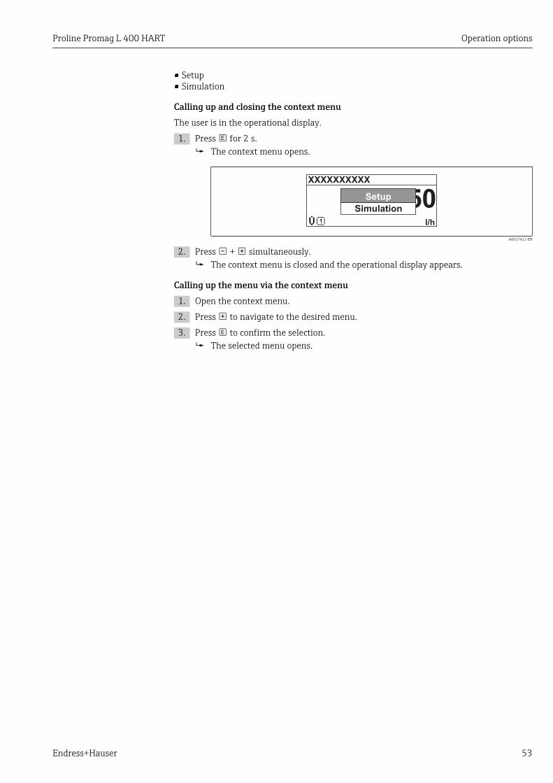
Proline Promag L 400 HART Operation options
Endress+Hauser 53
• Setup• Simulation
Calling up and closing the context menuThe user is in the operational display.
1. Press for 2 s. The context menu opens.
XXXXXXXXXX
l/h
20.50Setup
Simulation
A0017421-EN
2. Press + simultaneously. The context menu is closed and the operational display appears.
Calling up the menu via the context menu1. Open the context menu.
2. Press to navigate to the desired menu.
3. Press to confirm the selection. The selected menu opens.
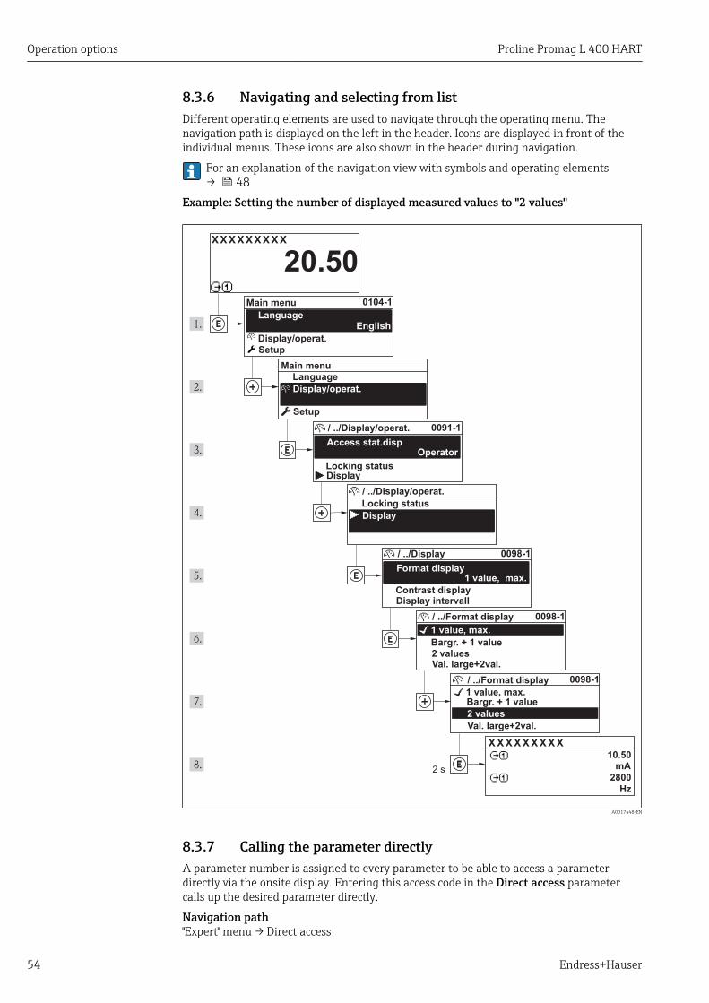
Operation options Proline Promag L 400 HART
54 Endress+Hauser
8.3.6 Navigating and selecting from listDifferent operating elements are used to navigate through the operating menu. Thenavigation path is displayed on the left in the header. Icons are displayed in front of theindividual menus. These icons are also shown in the header during navigation.
For an explanation of the navigation view with symbols and operating elements→ 48
Example: Setting the number of displayed measured values to "2 values"
X X X X X X XX X
20.500104-1
2 s
0091-1
0098-1
0098-1
0098-1
X X X X X X XX X10.50
2800
Hz
mA
Display/operat.
Display/operat.
Setup
Main menu
English
Main menu
Format display
/ ../Display
Contrast displayDisplay intervall
1 value, max.
Setup
Access stat.disp
/ ../Display/operat.
Display
Locking status
1 value, max.
/ ../Format display
2 valuesVal. large+2val.
Bargr. + 1 value
Locking status
/ ../Display/operat.
Display
1 value, max.
/ ../Format display
2 values
Val. large+2val.
Bargr. + 1 value
Operator
Language
Language
A0017448-EN
8.3.7 Calling the parameter directlyA parameter number is assigned to every parameter to be able to access a parameterdirectly via the onsite display. Entering this access code in the Direct access parametercalls up the desired parameter directly.
Navigation path"Expert" menu → Direct access

Proline Promag L 400 HART Operation options
Endress+Hauser 55
The direct access code consists of a 4-digit number and the channel number, whichidentifies the channel of a process variable: e.g. 0914-1. In the navigation view, thisappears on the right-hand side in the header of the selected parameter.
10914-2
A0017223
1 Direct access code
Note the following when entering the direct access code:• The leading zeros in the direct access code do not have to be entered.
Example: Input of "914" instead of "0914"• If no channel number is entered, channel 1 is jumped to automatically.
Example: Input of "0914" → Parameter Totalizer 1• If a different channel is jumped to: Enter the direct access code with the corresponding
channel number.Example: Input of "0914-2" → Parameter Totalizer 2
For the direct access codes of the individual parameters
8.3.8 Calling up help textFor some parameters, help texts exist, which the user can call up from the navigation view.These briefly describe the function of the parameter and thus support fast and reliablecommissioning.
Calling up and closing the help textThe user is in the navigation view and the selection bar is on a parameter.
1. Press for 2 s. The help text for the selected parameter opens.
Ent. access code
Enter access code to disable
write protec.
A0014002-EN
19 Example: Help text for parameter "Enter access code"
2. Press + simultaneously. The help text is closed.

Operation options Proline Promag L 400 HART
56 Endress+Hauser
8.3.9 Changing the parametersFor a description of the editing display - consisting of text editor and numeric editor -with symbols → 50, for a description of the operating elements → 52
Example: Changing the tag name in the "Tag description" parameter from 001-FT-101 to001-FT-102
3x
001-FT-101
DEFG HIJK
LMNO PQRS TUVW
XYZ Aa1@
ABC
001-FT-101
DEFG HIJK
LMNO PQRS TUVW
XYZ Aa1@
ABC
001-FT-101
DEFG HIJKABC
001-FT-10
DEFG HIJKABC
001-FT-10
DEFG HIJKABC
1x
001-FT-10
DEFG HIJK
LMNO PQRS TUVW
XYZ Aa1@
ABC
001-FT-10
DEFG HIJK
LMNO PQRS TUVW
XYZ Aa1@
ABC
001-FT-10
DEFG HIJKABC
A a 1 @
001-FT-10
DEFG HIJKABC
A a 1 @
001-FT-10
3456 789
= + - * / [ ] ( )
< > Aa1@
012
001-FT-10
3456 789012
0 1 2
001-FT-10
3456 789012
0 1 2
001-FT-102
3456 789012
0 1 2
001-FT-102
3456 789
= + - * / [ ] ( )
< > Aa1@
012
001-FT-102
3456 789012
0 1 2
001-FT-102
3456 789
= + - * / [ ] ( )
< > Aa1@
012
001-FT-102
3456 789012
0 1 2
001-FT-102
3456 789
= + - * / [ ] ( )
< > Aa1@
012
001-FT-102
1496-1
1x
2x
4x
2x
1x
001-FT-101
1496-1
Max.Tag description
Ent. access code
Def. access code
/../Advanced setup
Tag description
/../Advanced setup
Ent. access code
Def. access code
A0014020-EN
A message is displayed if the value entered is outside the permitted value range.
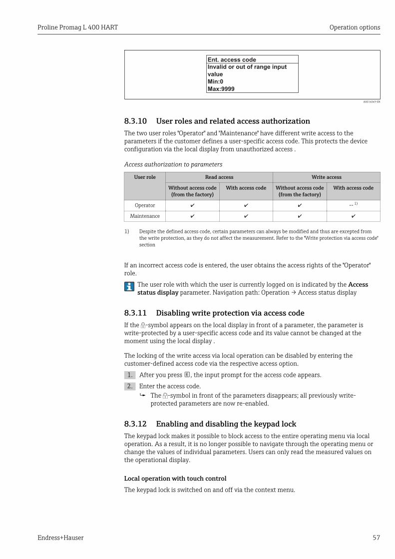
Proline Promag L 400 HART Operation options
Endress+Hauser 57
Ent. access code
Invalid or out of range input
value
Max:9999
Min:0
A0014049-EN
8.3.10 User roles and related access authorizationThe two user roles "Operator" and "Maintenance" have different write access to theparameters if the customer defines a user-specific access code. This protects the deviceconfiguration via the local display from unauthorized access .
Access authorization to parameters
User role Read access Write access
Without access code(from the factory)
With access code Without access code(from the factory)
With access code
Operator -- 1)
Maintenance
1) Despite the defined access code, certain parameters can always be modified and thus are excepted fromthe write protection, as they do not affect the measurement. Refer to the "Write protection via access code"section
If an incorrect access code is entered, the user obtains the access rights of the "Operator"role.
The user role with which the user is currently logged on is indicated by the Accessstatus display parameter. Navigation path: Operation → Access status display
8.3.11 Disabling write protection via access codeIf the -symbol appears on the local display in front of a parameter, the parameter iswrite-protected by a user-specific access code and its value cannot be changed at themoment using the local display .
The locking of the write access via local operation can be disabled by entering thecustomer-defined access code via the respective access option.
1. After you press , the input prompt for the access code appears.
2. Enter the access code. The -symbol in front of the parameters disappears; all previously write-
protected parameters are now re-enabled.
8.3.12 Enabling and disabling the keypad lockThe keypad lock makes it possible to block access to the entire operating menu via localoperation. As a result, it is no longer possible to navigate through the operating menu orchange the values of individual parameters. Users can only read the measured values onthe operational display.
Local operation with touch controlThe keypad lock is switched on and off via the context menu.
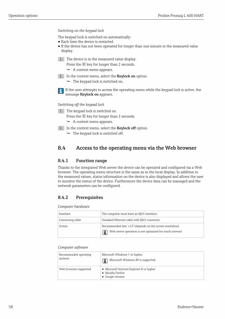
Operation options Proline Promag L 400 HART
58 Endress+Hauser
Switching on the keypad lock
The keypad lock is switched on automatically:• Each time the device is restarted.• If the device has not been operated for longer than one minute in the measured value
display.
1. The device is in the measured value display.Press the key for longer than 2 seconds. A context menu appears.
2. In the context menu, select the Keylock on option. The keypad lock is switched on.
If the user attempts to access the operating menu while the keypad lock is active, themessage Keylock on appears.
Switching off the keypad lock
1. The keypad lock is switched on.Press the key for longer than 2 seconds. A context menu appears.
2. In the context menu, select the Keylock off option. The keypad lock is switched off.
8.4 Access to the operating menu via the Web browser
8.4.1 Function rangeThanks to the integrated Web server the device can be operated and configured via a Webbrowser. The operating menu structure is the same as in the local display. In addition tothe measured values, status information on the device is also displayed and allows the userto monitor the status of the device. Furthermore the device data can be managed and thenetwork parameters can be configured.
8.4.2 Prerequisites
Computer hardware
Interface The computer must have an RJ45 interface.
Connecting cable Standard Ethernet cable with RJ45 connector.
Screen Recommended size: ≥12" (depends on the screen resolution)
Web server operation is not optimized for touch screens!
Computer software
Recommended operatingsystems
Microsoft Windows 7 or higher.
Microsoft Windows XP is supported.
Web browsers supported • Microsoft Internet Explorer 8 or higher• Mozilla Firefox• Google chrome

Proline Promag L 400 HART Operation options
Endress+Hauser 59
Computer settings
User rights User rights are required for TCP/IP and proxy server settings (for changes tothe IP address, subnet mask etc.).
Proxy server settings of theWeb browser
The Web browser setting Use proxy server for LAN must be disabled.
JavaScript JavaScript must be enabled.
If JavaScript cannot be enabled:enter http://192.168.1.212/basic.html in the address line of the Webbrowser. A fully functional but simplified version of the operating menustructure starts in the Web browser.
When installing a new firmware version: To enable correct data display,clear the temporary memory (cache) of the Web browser under Internetoptions.
Measuring device
Web server Web server must be enabled; factory setting: ON
For information on enabling the Web server → 61
8.4.3 Establishing a connection
Configuring the Internet protocol of the computer
IP address 192.168.1.XXX; for XXX all numerical values except: 0, 212 and 255 → e.g.192.168.1.213
Subnet mask 255.255.255.0
Default gateway 192.168.1.212 or leave cells empty
1. Switch on the measuring device and connect to the computer via the cable→ 63.
2. If a 2nd network card is not used: all the applications on the notebook should beclosed, or all the applications that require the Internet or network, such as e-mail,SAP applications, Internet or Windows Explorer, i.e. close all open Internet browsers.
3. Configure the properties of the Internet protocol (TCP/IP) as defined in the tableabove.
Starting the Web browser1. Start the Web browser on the computer.
2. Enter the IP address of the Web server in the address line of the Web browser:192.168.1.212
The login page appears.
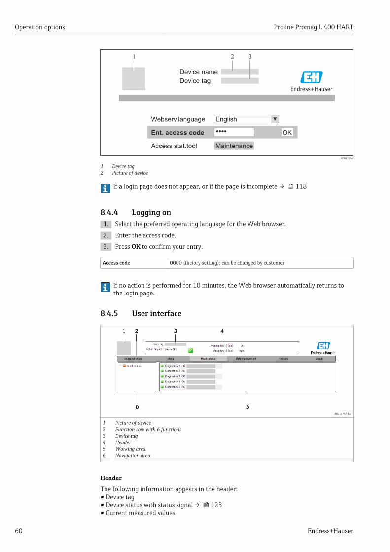
Operation options Proline Promag L 400 HART
60 Endress+Hauser
Device tag
Webserv.language English
Ent. access code
Access stat.tool Maintenance
21
OK
Device name
3
A0017362
1 Device tag2 Picture of device
If a login page does not appear, or if the page is incomplete → 118
8.4.4 Logging on1. Select the preferred operating language for the Web browser.
2. Enter the access code.
3. Press OK to confirm your entry.
Access code 0000 (factory setting); can be changed by customer
If no action is performed for 10 minutes, the Web browser automatically returns tothe login page.
8.4.5 User interface
2 4
6 5
1 32 4
6 5
1 32 4
6 5
1 32 4
6 5
1 32 4
6 5
1 3
A0017757-EN
123456
Picture of deviceFunction row with 6 functionsDevice tagHeaderWorking areaNavigation area
HeaderThe following information appears in the header:• Device tag• Device status with status signal → 123• Current measured values

Proline Promag L 400 HART Operation options
Endress+Hauser 61
Function row
Functions Meaning
Measured values The measured values of the device are displayed
Menu Access to the operating menu structure of the device, same as for the local display andoperating tool
Device status Displays the diagnostic messages currently pending, listed in order of priority
Data management
Data exchange between PC and measuring device:– Upload the configuration from the device (XML format, create configuration back-up)– Save the configuration to the device (XML format, restore configuration)– Export the event list (.csv file)– Export parameter settings (.csv file, create documentation of the measuring point
configuration)– Export the Heartbeat verification log (PDF file, only available with the "Heartbeat
Verification" application package)
Networkconfiguration
Configuration and checking of all the parameters required for establishing the connectionto the device:• Network settings (e.g. IP address, MAC address)• Device information (e.g. serial number, firmware version)
Logout End the operation and call up the login page
Navigation areaIf a function is selected in the function bar, the submenus of the function open in thenavigation area. The user can now navigate through the menu structure.
Working areaDepending on the selected function and the related submenus, various actions can beperformed in this area:• Configuring parameters• Reading measured values• Calling up help text• Starting an upload/download
8.4.6 Disabling the Web serverThe Web server for the measuring device can enabled and disabled as required via theWeb server functionality parameter.
Navigation"Expert" menu → Communication → Web server
Parameter overview with brief description
Parameter Description Selection Factory setting
Web server functionality Switch the Web server on and off. • Off• On
On
Enabling the Web serverIf the Web server is disabled it can only be re-enabled with the Web server functionalityparameter via the following operating options:• Via local display• Via "FieldCare" operating tool
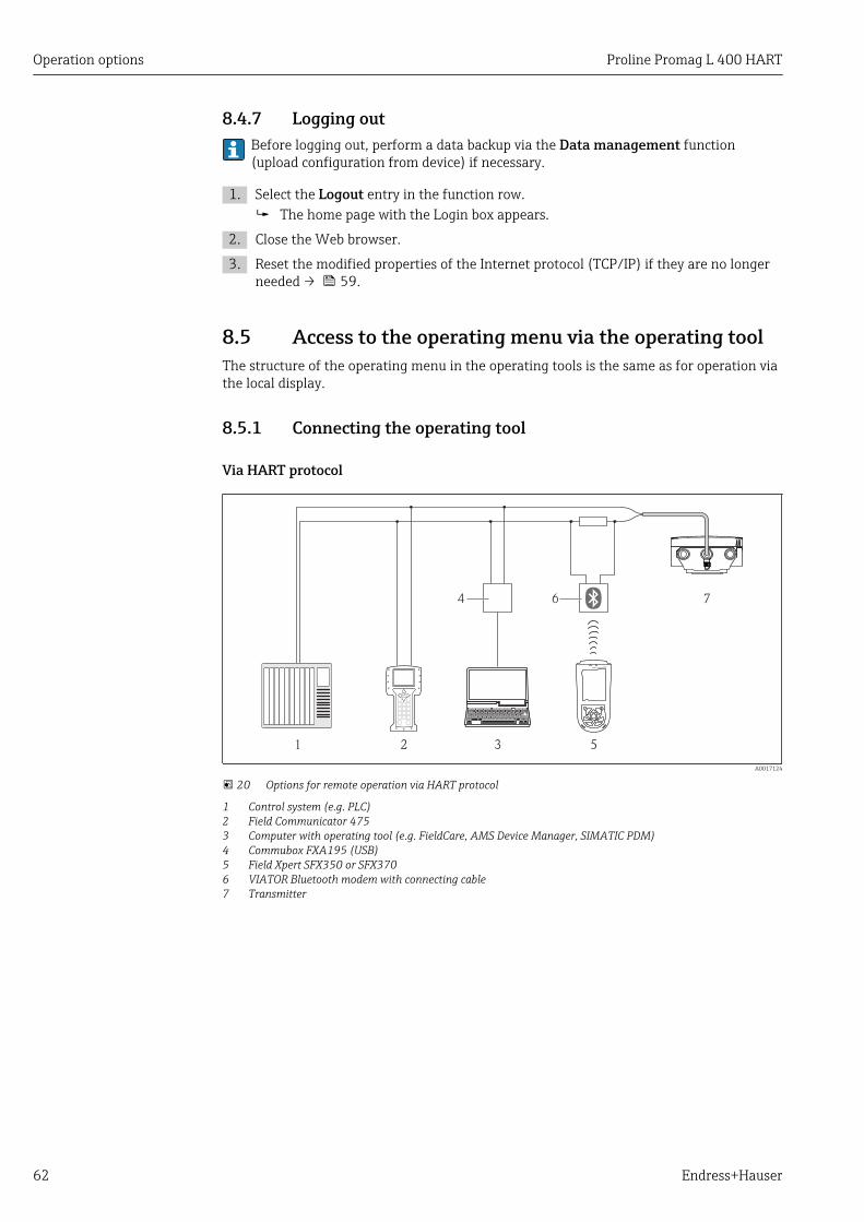
Operation options Proline Promag L 400 HART
62 Endress+Hauser
8.4.7 Logging outBefore logging out, perform a data backup via the Data management function(upload configuration from device) if necessary.
1. Select the Logout entry in the function row. The home page with the Login box appears.
2. Close the Web browser.
3. Reset the modified properties of the Internet protocol (TCP/IP) if they are no longerneeded → 59.
8.5 Access to the operating menu via the operating toolThe structure of the operating menu in the operating tools is the same as for operation viathe local display.
8.5.1 Connecting the operating tool
Via HART protocol
1 2 3 5
74 6
A0017124
20 Options for remote operation via HART protocol
1 Control system (e.g. PLC)2 Field Communicator 4753 Computer with operating tool (e.g. FieldCare, AMS Device Manager, SIMATIC PDM)4 Commubox FXA195 (USB)5 Field Xpert SFX350 or SFX3706 VIATOR Bluetooth modem with connecting cable7 Transmitter
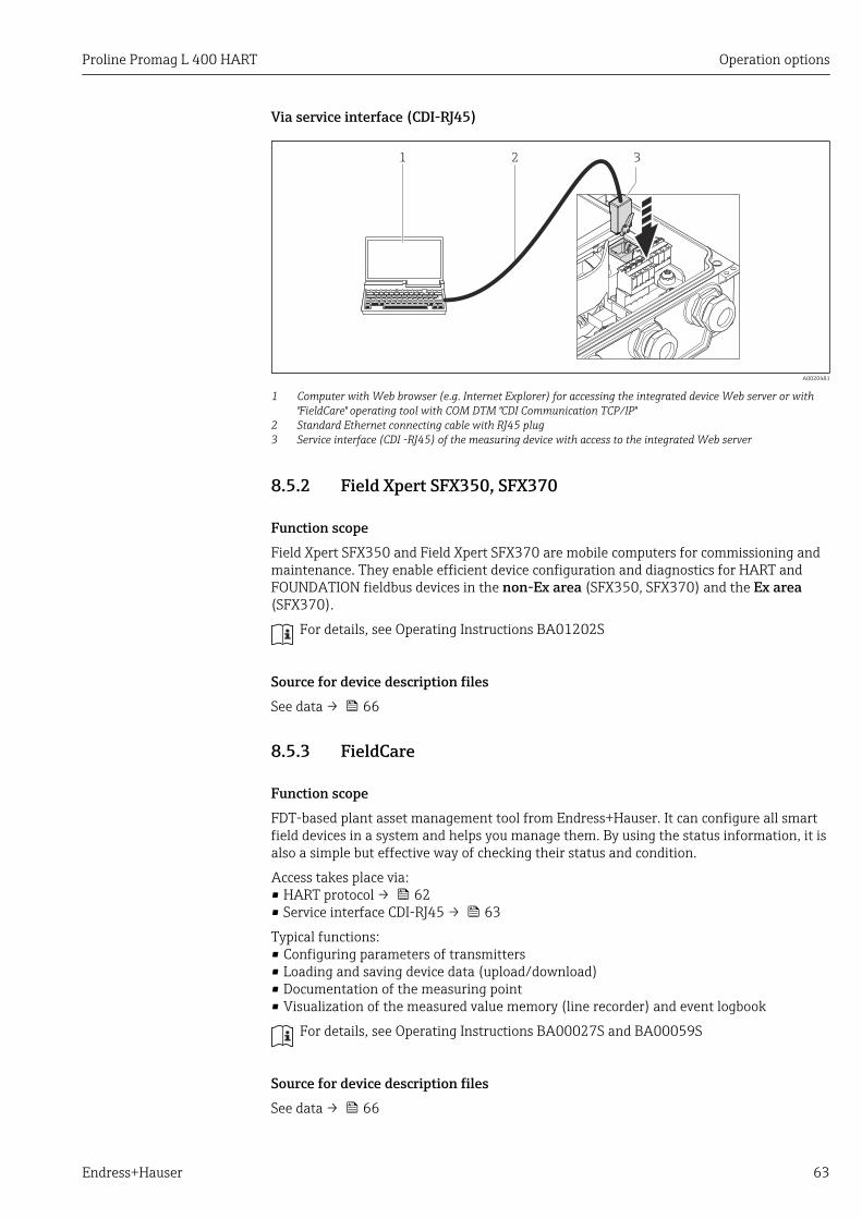
Proline Promag L 400 HART Operation options
Endress+Hauser 63
Via service interface (CDI-RJ45)
1 32
A0020481
1 Computer with Web browser (e.g. Internet Explorer) for accessing the integrated device Web server or with"FieldCare" operating tool with COM DTM "CDI Communication TCP/IP"
2 Standard Ethernet connecting cable with RJ45 plug3 Service interface (CDI -RJ45) of the measuring device with access to the integrated Web server
8.5.2 Field Xpert SFX350, SFX370
Function scopeField Xpert SFX350 and Field Xpert SFX370 are mobile computers for commissioning andmaintenance. They enable efficient device configuration and diagnostics for HART andFOUNDATION fieldbus devices in the non-Ex area (SFX350, SFX370) and the Ex area(SFX370).
For details, see Operating Instructions BA01202S
Source for device description filesSee data → 66
8.5.3 FieldCare
Function scopeFDT-based plant asset management tool from Endress+Hauser. It can configure all smartfield devices in a system and helps you manage them. By using the status information, it isalso a simple but effective way of checking their status and condition.
Access takes place via:• HART protocol → 62• Service interface CDI-RJ45 → 63
Typical functions:• Configuring parameters of transmitters• Loading and saving device data (upload/download)• Documentation of the measuring point• Visualization of the measured value memory (line recorder) and event logbook
For details, see Operating Instructions BA00027S and BA00059S
Source for device description filesSee data → 66
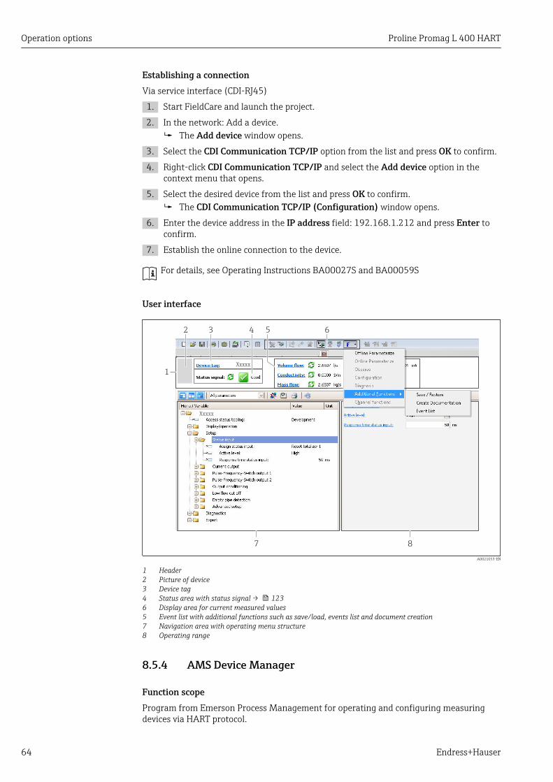
Operation options Proline Promag L 400 HART
64 Endress+Hauser
Establishing a connectionVia service interface (CDI-RJ45)
1. Start FieldCare and launch the project.
2. In the network: Add a device. The Add device window opens.
3. Select the CDI Communication TCP/IP option from the list and press OK to confirm.
4. Right-click CDI Communication TCP/IP and select the Add device option in thecontext menu that opens.
5. Select the desired device from the list and press OK to confirm. The CDI Communication TCP/IP (Configuration) window opens.
6. Enter the device address in the IP address field: 192.168.1.212 and press Enter toconfirm.
7. Establish the online connection to the device.
For details, see Operating Instructions BA00027S and BA00059S
User interface
1
3 4 5 6
7
2
8
Xxxxx
Xxxxx
A0021053-EN
1 Header2 Picture of device3 Device tag4 Status area with status signal → 1236 Display area for current measured values5 Event list with additional functions such as save/load, events list and document creation7 Navigation area with operating menu structure8 Operating range
8.5.4 AMS Device Manager
Function scopeProgram from Emerson Process Management for operating and configuring measuringdevices via HART protocol.
Proline Promag L 400 HART Operation options
Endress+Hauser 65
Source for device description filesSee data → 66
8.5.5 SIMATIC PDM
Function scopeSIMATIC PDM is a standardized, manufacturer-independent program from Siemens forthe operation, configuration, maintenance and diagnosis of intelligent field devices viaHART protocol.
Source for device description filesSee data → 66
8.5.6 Field Communicator 475
Function scopeIndustrial handheld terminal from Emerson Process Management for remoteconfiguration and measured value display via HART protocol.
Source for device description filesSee data → 66

System integration Proline Promag L 400 HART
66 Endress+Hauser
9 System integration
9.1 Overview of device description files
9.1.1 Current version data for the device
Firmware version 01.05.zz • On the title page of the Operating instructions• On transmitter nameplate → 13• Parameter firmware version
Diagnostics → Device info→ Firmware version
Release date of firmware version 05.2014 ---
Manufacturer ID 0x11 Manufacturer ID parameterDiagnostics → Device info→ Manufacturer ID
Device type ID 0x67 Device type parameterDiagnostics → Device info → Device type
HART protocol revision 7 ---
Device revision 6 • On transmitter nameplate → 13• Device revision parameter
Diagnostics → Device info → Device revision
9.1.2 Operating tools
Operating tool viaHART protocol
Sources for obtaining device descriptions
• Field Xpert SFX350• Field Xpert SFX370
Use update function of handheld terminal
FieldCare • www.endress.com → Download Area• CD–ROM (contact Endress+Hauser)• DVD (contact Endress+Hauser)
AMS Device Manager(Emerson Process Management)
www.endress.com → Download Area
SIMATIC PDM(Siemens)
www.endress.com → Download Area
Field Communicator 475(Emerson Process Management)
Use update function of handheld terminal
9.2 Measured variables via HART protocolThe following measured variables (HART device variables) are assigned to the dynamicvariables at the factory:
Dynamic variables Measured variables(HART device variables)
Primary dynamic variable (PV) Volume flow
Secondary dynamic variable (SV) Totalizer 1
Tertiary dynamic variable (TV) Totalizer 2
Quaternary dynamic variable (QV) Totalizer 3
The assignment of the measured variables to the dynamic variables can be modified andassigned as desired via local operation and the operating tool using the followingparameters:
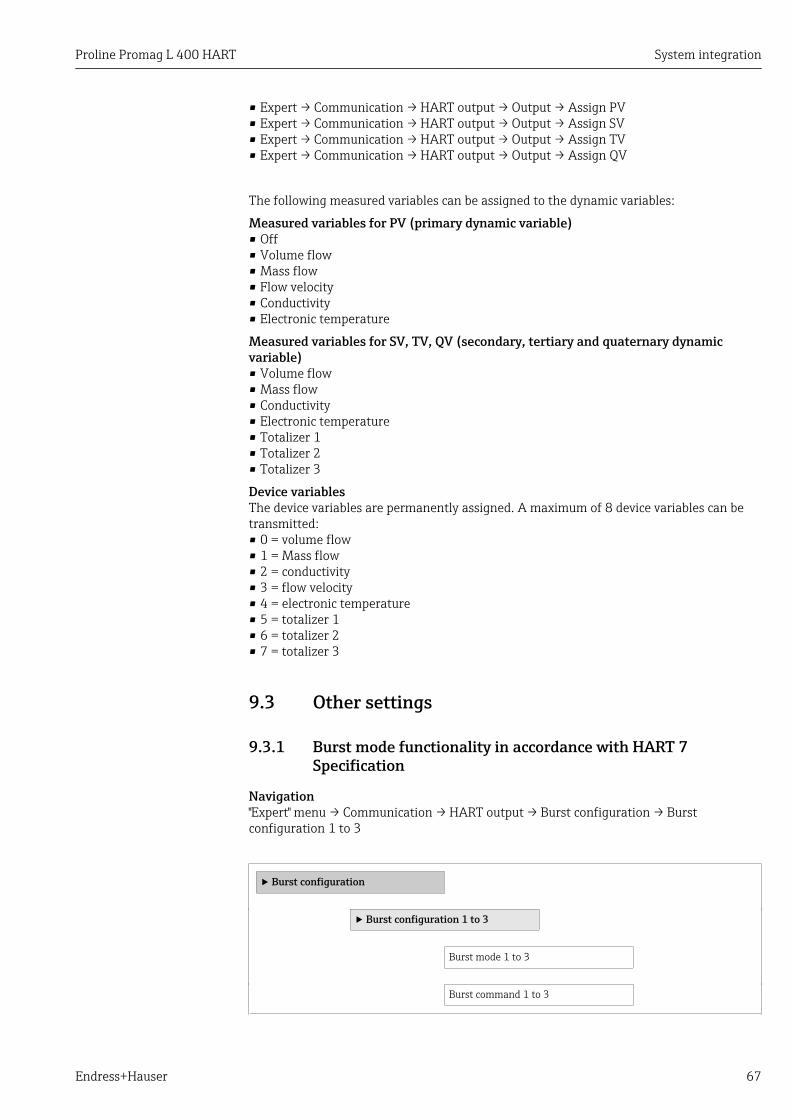
Proline Promag L 400 HART System integration
Endress+Hauser 67
• Expert → Communication → HART output → Output → Assign PV• Expert → Communication → HART output → Output → Assign SV• Expert → Communication → HART output → Output → Assign TV• Expert → Communication → HART output → Output → Assign QV
The following measured variables can be assigned to the dynamic variables:
Measured variables for PV (primary dynamic variable)• Off• Volume flow• Mass flow• Flow velocity• Conductivity• Electronic temperature
Measured variables for SV, TV, QV (secondary, tertiary and quaternary dynamicvariable)• Volume flow• Mass flow• Conductivity• Electronic temperature• Totalizer 1• Totalizer 2• Totalizer 3
Device variablesThe device variables are permanently assigned. A maximum of 8 device variables can betransmitted:• 0 = volume flow• 1 = Mass flow• 2 = conductivity• 3 = flow velocity• 4 = electronic temperature• 5 = totalizer 1• 6 = totalizer 2• 7 = totalizer 3
9.3 Other settings
9.3.1 Burst mode functionality in accordance with HART 7Specification
Navigation"Expert" menu → Communication → HART output → Burst configuration → Burstconfiguration 1 to 3
‣ Burst configuration
‣ Burst configuration 1 to 3
Burst mode 1 to 3
Burst command 1 to 3
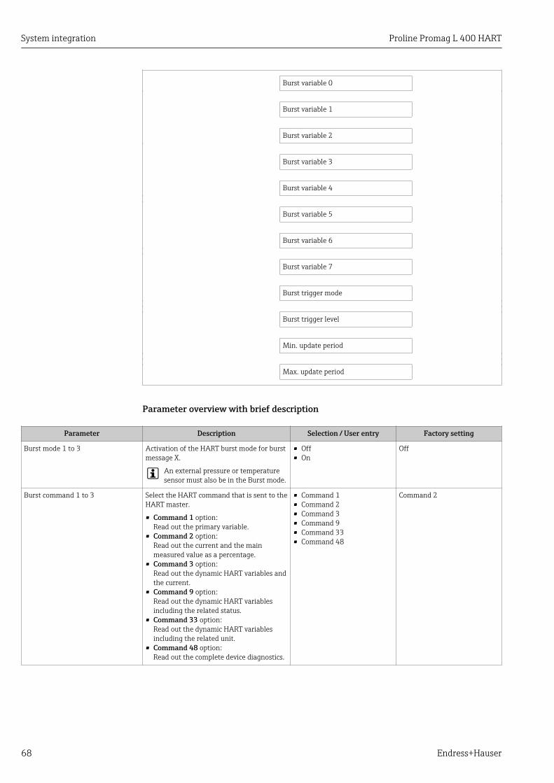
System integration Proline Promag L 400 HART
68 Endress+Hauser
Burst variable 0
Burst variable 1
Burst variable 2
Burst variable 3
Burst variable 4
Burst variable 5
Burst variable 6
Burst variable 7
Burst trigger mode
Burst trigger level
Min. update period
Max. update period
Parameter overview with brief description
Parameter Description Selection / User entry Factory setting
Burst mode 1 to 3 Activation of the HART burst mode for burstmessage X.
An external pressure or temperaturesensor must also be in the Burst mode.
• Off• On
Off
Burst command 1 to 3 Select the HART command that is sent to theHART master.
• Command 1 option:Read out the primary variable.
• Command 2 option:Read out the current and the mainmeasured value as a percentage.
• Command 3 option:Read out the dynamic HART variables andthe current.
• Command 9 option:Read out the dynamic HART variablesincluding the related status.
• Command 33 option:Read out the dynamic HART variablesincluding the related unit.
• Command 48 option:Read out the complete device diagnostics.
• Command 1• Command 2• Command 3• Command 9• Command 33• Command 48
Command 2

Proline Promag L 400 HART System integration
Endress+Hauser 69
Parameter Description Selection / User entry Factory setting
Burst variable 0 Assignment of the individual HARTvariables (PV, SV, TV, QV) and assignmentof the process variables available in thedevice to the HART command.
• Volume flow• Mass flow• Flow velocity• Conductivity• Electronic temperature• Totalizer 1• Totalizer 2• Totalizer 3• Density• Temperature• HART input• Percent Of Range• Measured current• Primary variable (PV)• Secondary variable (SV)• Tertiary variable (TV)• Quaternary variable (QV)• Not used
Volume flow
Burst variable 1 See burst variable 0. See burst variable 0. Not used
Burst variable 2 See burst variable 0. See burst variable 0. Not used
Burst variable 3 See burst variable 0. See burst variable 0. Not used
Burst variable 4 See burst variable 0. See burst variable 0. Not used
Burst variable 5 See burst variable 0. See burst variable 0. Not used
Burst variable 6 See burst variable 0. See burst variable 0. Not used
Burst variable 7 See burst variable 0. See burst variable 0. Not used
Burst trigger mode Use this function to select the event thattriggers burst message X.
• Continuous option:The message is triggered in a time-controlled manner, at least observing thetime interval defined in the Burst minperiod parameter.
• Window option:The message is triggered if the specifiedmeasured value has changed by the valuein the Burst trigger level parameter.
• Rising option:The message is triggered if the specifiedmeasured value exceeds the value in theBurst trigger level parameter.
• Falling option:The message is triggered if the specifiedmeasured value drops below the value inthe Burst trigger level parameter.
• On change option:The message is triggered if the measuredvalue changes.
• Continuous• Window• Rising• Falling• On change
Continuous
Burst trigger level For entering the burst trigger value.
Together with the option selected in theBurst trigger mode parameter the bursttrigger value determines the time of burstmessage X.
Positive floating-point number 2.0E-38
Min. update period Use this function to enter the minimum timespan between two burst commands of burstmessage X.
Positive integer 1 000 ms
Max. update period Use this function to enter the maximumtime span between two burst commands ofburst message X.
Positive integer 2 000 ms

Commissioning Proline Promag L 400 HART
70 Endress+Hauser
10 Commissioning
10.1 Function checkBefore commissioning the measuring device:
‣ Make sure that the post-installation and post-connection checks have beenperformed.
• "Post-installation check" checklist → 32• "Post-connection check" checklist → 43
10.2 Switching on the measuring device‣ After a successful function check, switch on the measuring device.
After a successful startup, the local display switches automatically from thestartup display to the operational display.
If nothing appears on the local display or a diagnostic message is displayed, refer tothe section on "Diagnostics and troubleshooting" → 117.
10.3 Establishing a connection via FieldCare• For FieldCare connection → 62• For establishing a connection via FieldCare → 64• For FieldCare user interface → 64
10.4 Setting the operating languageFactory setting: English or ordered local language
X X X X X X XX X
20.50
Operation
Setup
Main menu 0104-1
LanguageEnglish
Español
Français
Language
EnglishDeutsch
Ã
0104-1
Ã
Español
Français
Language
EnglishDeutsch
0104-1
Betrieb
Setup
Hauptmenü
SpracheDeutsch
0104-1
XXXX
A0013996
21 Taking the example of the local display

Proline Promag L 400 HART Commissioning
Endress+Hauser 71
10.5 Configuring the measuring deviceThe Setup menu with its guided wizards contains all the parameters needed for standardoperation.
Navigation to the Setup menu
X X X X X X XX X
20.500104-1
XXXXXXXXX
XXXXXXXXX
mA
Display/operat.
Setup
Diagnostic
Display/operat.
Setup
Main menu
English
Main menu
Status input
/ ../Setup
Language
A0017444-EN
22 Using the example of the local display
Navigation"Setup" menu
Setup
Device tag
‣ Status input
Assign status input
Active level
Response time status input
‣ Current output 1
Assign current output
Mass flow unit
Volume flow unit
Conductivity unit
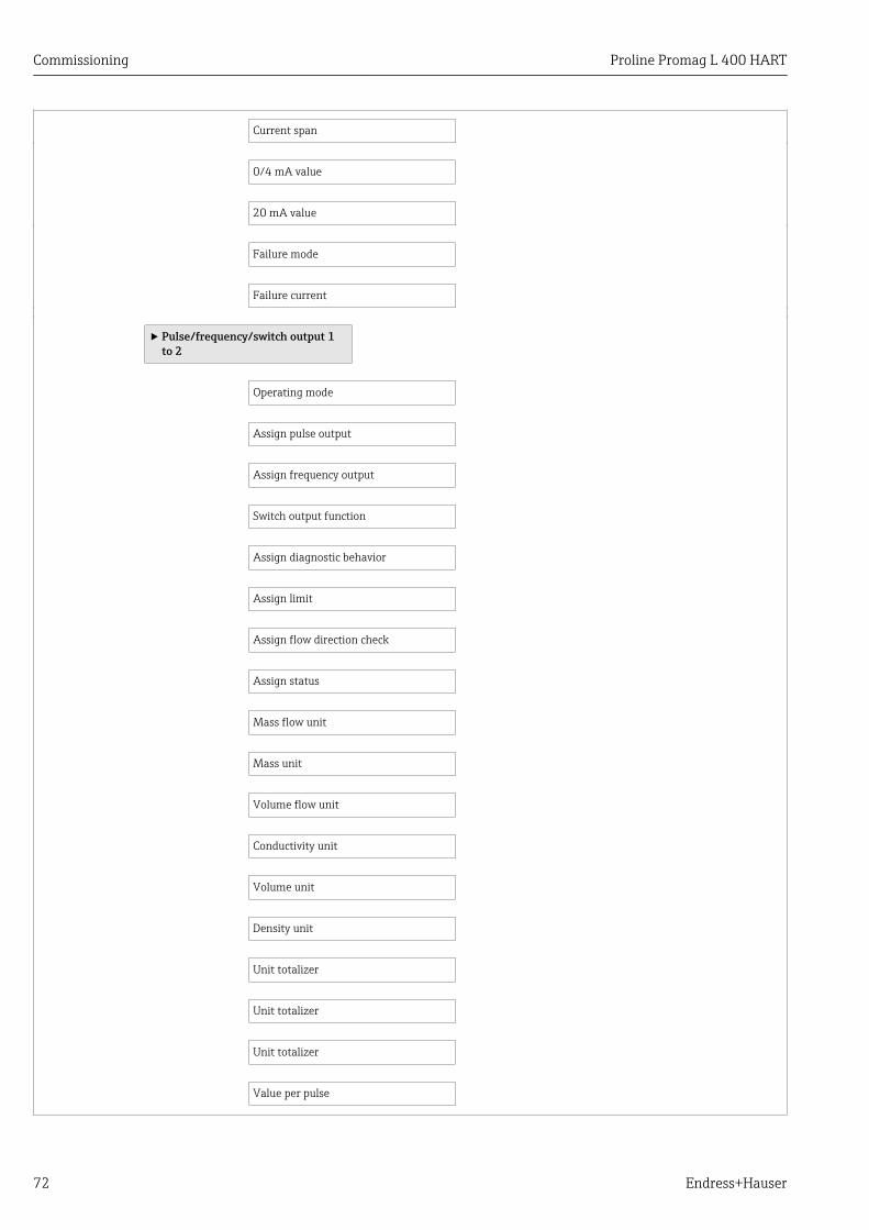
Commissioning Proline Promag L 400 HART
72 Endress+Hauser
Current span
0/4 mA value
20 mA value
Failure mode
Failure current
‣ Pulse/frequency/switch output 1to 2
Operating mode
Assign pulse output
Assign frequency output
Switch output function
Assign diagnostic behavior
Assign limit
Assign flow direction check
Assign status
Mass flow unit
Mass unit
Volume flow unit
Conductivity unit
Volume unit
Density unit
Unit totalizer
Unit totalizer
Unit totalizer
Value per pulse

Proline Promag L 400 HART Commissioning
Endress+Hauser 73
Pulse width
Failure mode
Minimum frequency value
Maximum frequency value
Measuring value at minimumfrequency
Measuring value at maximumfrequency
Failure mode
Failure frequency
Switch-on value
Switch-off value
Switch-on delay
Switch-off delay
Failure mode
Invert output signal
‣ Display
Format display
Value 1 display
0% bargraph value 1
100% bargraph value 1
Value 2 display
Value 3 display
0% bargraph value 3
100% bargraph value 3
Value 4 display
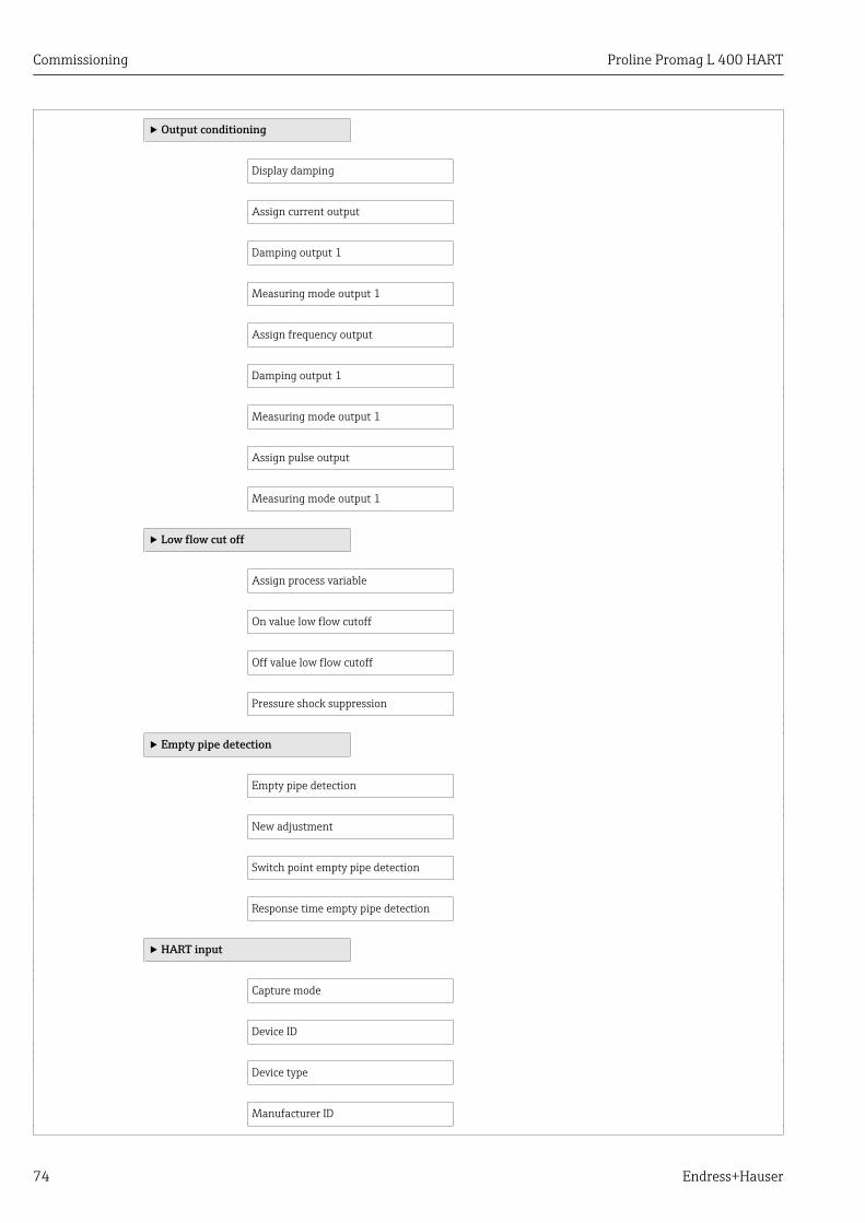
Commissioning Proline Promag L 400 HART
74 Endress+Hauser
‣ Output conditioning
Display damping
Assign current output
Damping output 1
Measuring mode output 1
Assign frequency output
Damping output 1
Measuring mode output 1
Assign pulse output
Measuring mode output 1
‣ Low flow cut off
Assign process variable
On value low flow cutoff
Off value low flow cutoff
Pressure shock suppression
‣ Empty pipe detection
Empty pipe detection
New adjustment
Switch point empty pipe detection
Response time empty pipe detection
‣ HART input
Capture mode
Device ID
Device type
Manufacturer ID

Proline Promag L 400 HART Commissioning
Endress+Hauser 75
Burst command
Slot number
Timeout
Failure mode
Failure value
‣ Advanced setup
Enter access code
‣ System units
Volume flow unit
Volume unit
Conductivity unit
Temperature unit
Mass flow unit
Mass unit
Density unit
‣ Sensor adjustment
Installation direction
‣ Totalizer 1 to 3
Assign process variable
Unit totalizer
Totalizer operation mode
Failure mode
‣ Display
Format display
Value 1 display

Commissioning Proline Promag L 400 HART
76 Endress+Hauser
0% bargraph value 1
100% bargraph value 1
Decimal places 1
Value 2 display
Decimal places 2
Value 3 display
0% bargraph value 3
100% bargraph value 3
Decimal places 3
Value 4 display
Decimal places 4
Display language
Display interval
Display damping
Header
Header text
Separator
Backlight
‣ Electrode cleaning circuit
Electrode cleaning circuit
ECC duration
ECC recovery time
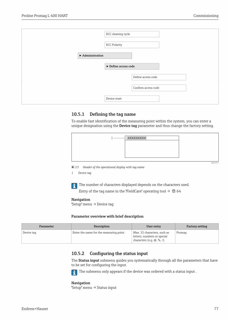
Proline Promag L 400 HART Commissioning
Endress+Hauser 77
ECC cleaning cycle
ECC Polarity
‣ Administration
‣ Define access code
Define access code
Confirm access code
Device reset
10.5.1 Defining the tag nameTo enable fast identification of the measuring point within the system, you can enter aunique designation using the Device tag parameter and thus change the factory setting.
1 XXXXXXXXX
A0013375
23 Header of the operational display with tag name
1 Device tag
The number of characters displayed depends on the characters used.
Entry of the tag name in the "FieldCare" operating tool → 64
Navigation"Setup" menu → Device tag
Parameter overview with brief description
Parameter Description User entry Factory setting
Device tag Enter the name for the measuring point. Max. 32 characters, such asletters, numbers or specialcharacters (e.g. @, %, /).
Promag
10.5.2 Configuring the status inputThe Status input submenu guides you systematically through all the parameters that haveto be set for configuring the input.
The submenu only appears if the device was ordered with a status input .
Navigation"Setup" menu → Status input

Commissioning Proline Promag L 400 HART
78 Endress+Hauser
Structure of the submenu
‣ Status input
Assign status input
Active level
Response time status input
Parameter overview with brief description
Parameter Description Selection / User entry Factory setting
Assign status input Select the function for the status input. • Off• Reset totalizer 1• Reset totalizer 2• Reset totalizer 3• Reset all totalizers• Flow override
Off
Active level Specify the input signal level at which theassigned function is triggered.
• High• Low
High
Response time status input Specify the minimum amount of time theinput signal level must be present before theselected function is triggered.
5 to 200 ms 50 ms
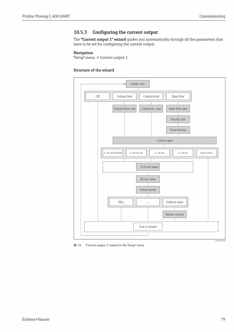
Proline Promag L 400 HART Commissioning
Endress+Hauser 79
10.5.3 Configuring the current outputThe "Current output 1" wizard guides you systematically through all the parameters thathave to be set for configuring the current output.
Navigation"Setup" menu → Current output 1
Structure of the wizard
Volume flow
Assign curr.
Mass flowConductivity
Volume flow unit
4...20 mA NAMUR 4...20 mA US 4...20 mA Fixed current
0/4 mA value
20 mA value
Failure mode
Defined valueMin. …
Failure current
End of wizard
Off
Mass flow unitConductiv. unit
Density unit
Fixed density
Current span
0...20 mA
A0017434-EN
24 "Current output 1" wizard in the "Setup" menu
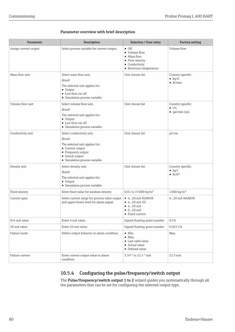
Commissioning Proline Promag L 400 HART
80 Endress+Hauser
Parameter overview with brief description
Parameter Description Selection / User entry Factory setting
Assign current output Select process variable for current output. • Off• Volume flow• Mass flow• Flow velocity• Conductivity• Electronic temperature
Volume flow
Mass flow unit Select mass flow unit.
Result
The selected unit applies for:• Output• Low flow cut off• Simulation process variable
Unit choose list Country-specific:• kg/h• lb/min
Volume flow unit Select volume flow unit.
Result
The selected unit applies for:• Output• Low flow cut off• Simulation process variable
Unit choose list Country-specific:• l/h• gal/min (us)
Conductivity unit Select conductivity unit.
Result
The selected unit applies for:• Current output• Frequency output• Switch output• Simulation process variable
Unit choose list µS/cm
Density unit Select density unit.
Result
The selected unit applies for:• Output• Simulation process variable
Unit choose list Country-specific:• kg/l• lb/ft³
Fixed density Enter fixed value for medium density. 0.01 to 15 000 kg/m³ 1 000 kg/m³
Current span Select current range for process value outputand upper/lower level for alarm signal.
• 4...20 mA NAMUR• 4...20 mA US• 4...20 mA• 0...20 mA• Fixed current
4...20 mA NAMUR
0/4 mA value Enter 4 mA value. Signed floating-point number 0 l/h
20 mA value Enter 20 mA value. Signed floating-point number 0.025 l/h
Failure mode Define output behavior in alarm condition. • Min.• Max.• Last valid value• Actual value• Defined value
Max.
Failure current Enter current output value in alarmcondition.
3.59-3 to 22.5-3 mA 22.5 mA
10.5.4 Configuring the pulse/frequency/switch outputThe Pulse/frequency/switch output 1 to 2 wizard guides you systematically through allthe parameters that can be set for configuring the selected output type.

Proline Promag L 400 HART Commissioning
Endress+Hauser 81
Configuring the pulse output
Navigation"Setup" menu → Pulse/frequency/switch output 1 to 2
Structure of the wizard for the pulse output
Failure mode
End of wizard
Invert outp.sig.
Operating mode
Pulse
Volume flow
Assign pulse
Mass flowOff
Mass unit
Density unit
Fixed density
Volume unit
Pulse width
Value per pulse
A0017435-EN
25 "Pulse/frequency/switch output 1 to 2" wizard in the "Setup" menu: "Operating mode" parameter"Pulse"option
Parameter overview with brief description
Parameter Description Selection / User entry Factory setting
Operating mode Define the output as a pulse, frequency orswitch output.
• Pulse• Frequency• Switch
Pulse
Assign pulse output Select process variable for pulse output. • Off• Volume flow• Mass flow
Off
Mass unit Select mass unit.
ResultThe selected unit is taken from: Mass flowunit parameter
Unit choose list Country-specific:• kg• lb

Commissioning Proline Promag L 400 HART
82 Endress+Hauser
Parameter Description Selection / User entry Factory setting
Volume unit Select volume unit.
ResultThe selected unit is taken from: Volumeflow unit parameter
Unit choose list Country-specific:• l• gal (us)
Density unit Select density unit.
Result
The selected unit applies for:• Output• Simulation process variable
Unit choose list Country-specific:• kg/l• lb/ft³
Fixed density Enter fixed value for medium density. 0.01 to 15 000 kg/m³ 1 000 kg/m³
Value per pulse Enter measured value at which a pulse isoutput.
Signed floating-point number 0
Pulse width Define time width of the output pulse. 0.05 to 2 000 ms 100 ms
Failure mode Define output behavior in alarm condition. • Actual value• No pulses
No pulses
Invert output signal Invert the output signal. • No• Yes
No
Configuring the frequency output
Navigation"Setup" menu → Pulse/frequency/switch output 1 to 2

Proline Promag L 400 HART Commissioning
Endress+Hauser 83
Structure of the wizard for the frequency output
Val. at min.freq
End of wizard
Invert outp.sig.
Operating mode
Frequency
Volume flow
Assign freq.
Mass flowOff
Mass unit
Density unit
Fixed density
Volume unit
Max. freq. value
Min. freq. value
Conductivity
Conductiv. unit
Val. at max.freq
Failure mode
Failure freq.
Defined valueActual value 0 Hz
A0017436-EN
26 "Pulse/frequency/switch output 1 to 2" wizard in the "Setup" menu"Operating mode" parameter"Frequency"option
Parameter overview with brief description
Parameter Description Selection / User entry Factory setting
Operating mode Define the output as a pulse, frequency orswitch output.
• Pulse• Frequency• Switch
Pulse
Assign frequency output Select process variable for frequency output. • Off• Volume flow• Mass flow• Flow velocity• Conductivity• Electronic temperature
Off

Commissioning Proline Promag L 400 HART
84 Endress+Hauser
Parameter Description Selection / User entry Factory setting
Mass flow unit Select mass flow unit.
Result
The selected unit applies for:• Output• Low flow cut off• Simulation process variable
Unit choose list Country-specific:• kg/h• lb/min
Volume flow unit Select volume flow unit.
Result
The selected unit applies for:• Output• Low flow cut off• Simulation process variable
Unit choose list Country-specific:• l/h• gal/min (us)
Conductivity unit Select conductivity unit.
Result
The selected unit applies for:• Current output• Frequency output• Switch output• Simulation process variable
Unit choose list µS/cm
Density unit Select density unit.
Result
The selected unit applies for:• Output• Simulation process variable
Unit choose list Country-specific:• kg/l• lb/ft³
Minimum frequency value Enter minimum frequency. 0.0 to 12 500.0 Hz 0.0 Hz
Maximum frequency value Enter maximum frequency. 0.0 to 12 500.0 Hz 12 500.0 Hz
Measuring value at minimumfrequency
Enter measured value for minmumfrequency.
Signed floating-point number 0
Measuring value at maximumfrequency
Enter measured value for maximumfrequency.
Signed floating-point number 0
Failure mode Define output behavior in alarm condition. • Actual value• Defined value• 0 Hz
0 Hz
Failure frequency Enter frequency output value in alarmcondition.
0.0 to 12 500.0 Hz 0.0 Hz
Invert output signal Invert the output signal. • No• Yes
No
Configuring the switch output
Navigation"Setup" menu → Pulse/frequency/switch output 1 to 2

Proline Promag L 400 HART Commissioning
Endress+Hauser 85
Structure of the wizard for the switch output
End of wizard
Operatingmode
Switch
Switchout funct
Diag.behavior
Off On
Assigndiag. beh
AlarmAlarm orwarning
Warning
Invert outp.sig.
A0017439-EN
27 "Pulse/frequency/switch output 1 to 2" wizard in the "Setup" menu: "Operating mode" parameter"Switch"option (part 1)

Commissioning Proline Promag L 400 HART
86 Endress+Hauser
LimitFl. direct.
checkStatus
Assignlimit
Assigndir.check
Assignstatus
End of wizard
Operatingmode
Switch
Switchout funct
Unit
Conduc-tivity
Totalizer1/2/3
Massflow
Volumeflow
Low flowcut off
Emptypipe det.
Massflow
Volumeflow
Switch-on value
Switch-offvalue
Switch-ondelay
Switch-offdelay
Failure mode
Invertoutp.sig.
Volumeflow unit
Massflow unit
Conductiv.unit
A0017440-EN
28 "Pulse/frequency/switch output 1 to 2" wizard in the "Setup" menu: "Operating mode" parameter"Switch"option (part 2)
Parameter overview with brief description
Parameter Description Selection / User entry Factory setting
Operating mode Define the output as a pulse, frequency orswitch output.
• Pulse• Frequency• Switch
Pulse
Switch output function Select function for switch output. • Off• On• Diagnostic behavior• Limit• Flow direction check• Status
Off
Assign diagnostic behavior Select diagnostic behavior for switch output. • Alarm• Alarm or warning• Warning
Alarm

Proline Promag L 400 HART Commissioning
Endress+Hauser 87
Parameter Description Selection / User entry Factory setting
Assign limit Select process variable for limit function. • Off• Volume flow• Mass flow• Flow velocity• Conductivity• Electronic temperature• Totalizer 1• Totalizer 2• Totalizer 3
Volume flow
Assign flow direction check Select process variable for flow directionmonitoring.
• Off• Volume flow• Mass flow
Volume flow
Assign status Select device status for switch output. • Empty pipe detection• Low flow cut off
Empty pipe detection
Mass flow unit Select mass flow unit.
Result
The selected unit applies for:• Output• Low flow cut off• Simulation process variable
Unit choose list Country-specific:• kg/h• lb/min
Volume flow unit Select volume flow unit.
Result
The selected unit applies for:• Output• Low flow cut off• Simulation process variable
Unit choose list Country-specific:• l/h• gal/min (us)
Conductivity unit Select conductivity unit.
Result
The selected unit applies for:• Current output• Frequency output• Switch output• Simulation process variable
Unit choose list µS/cm
Unit totalizer Select process variable totalizer unit. Unit choose list l
Switch-on value Enter measured value for the switch-onpoint.
Signed floating-point number 0 l/h
Switch-off value Enter measured value for the switch-offpoint.
Signed floating-point number 0 l/h
Switch-on delay Define delay for the switch-on of statusoutput.
0.0 to 100.0 s 0.0 s
Switch-off delay Define delay for the switch-off of statusoutput.
0.0 to 100.0 s 0.0 s
Failure mode Define output behavior in alarm condition. • Actual status• Open• Closed
Open
Invert output signal Invert the output signal. • No• Yes
No
10.5.5 Configuring the local displayThe Display wizard guides you systematically through all the parameters that canconfigured for configuring the local display.
Navigation"Setup" menu → Display

Commissioning Proline Promag L 400 HART
88 Endress+Hauser
Structure of the wizard
Format display
Value 1 display
0% bargraph
value 1
100% bargraph
value 1
Value 2 display
Value 3 display
0% bargraph
value 3
100% bargraph
value 3
Value 4 display
End of wizard
A0013797-EN
29 "Display" wizard in the "Setup" menu
Parameter overview with brief description
Parameter Prerequsite Description Selection / Userentry
Factory setting
Format display – Select how measured valuesare shown on the display.
• 1 value, max. size• 1 bargraph + 1
value• 2 values• 1 value large + 2
values• 4 values
1 value, max. size
Value 1 display – Select the measured value thatis shown on the local display.
• Volume flow• Mass flow• Conductivity• Temperature• Electronic
temperature• Totalizer 1• Totalizer 2• Totalizer 3• Current output 1
Volume flow

Proline Promag L 400 HART Commissioning
Endress+Hauser 89
Parameter Prerequsite Description Selection / Userentry
Factory setting
0% bargraph value 1 – Enter 0% value for bar graphdisplay.
Signed floating-pointnumber
0 l/h
100% bargraph value 1 – Enter 100% value for bargraph display.
Signed floating-pointnumber
0.025 l/h
Value 2 display – Select the measured value thatis shown on the local display.
Picklist (see 1stdisplay value)
None
Value 3 display – Select the measured value thatis shown on the local display.
Picklist (see 1stdisplay value)
None
0% bargraph value 3 An option was selected in theValue 3 display parameter.
Enter 0% value for bar graphdisplay.
Signed floating-pointnumber
0
100% bargraph value 3 An option was selected in theValue 3 display parameter.
Enter 100% value for bargraph display.
Signed floating-pointnumber
0
Value 4 display – Select the measured value thatis shown on the local display.
Picklist (see 1stdisplay value)
None
10.5.6 Configuring the output conditioning
Navigation"Setup" menu → Output conditioning
Navigation"Setup" menu → Output conditioning

Commissioning Proline Promag L 400 HART
90 Endress+Hauser
Structure of the "Output conditioning" wizard/"Output conditioning" submenu
Volume flow
Assign freq.
Mass flowOff Conductivity
Volume flow
Assign pulse
Mass flowOff
Volume flow
Assign curr.
Mass flowConductivityOff
Mode output 3
Reverse flow*Forward flow Forward/Reverse
End of wizard
Display damping
Damping out. 2
Damping out. 1
Mode output 2
Mode output 1
Rev. flow comp.
A0017459-EN
30 "Output conditioning" wizard in the "Setup" menu
Reverse flow* = option only for pulse and frequency output
Parameter overview with brief description
Parameter Description User entry / Selection Factory setting
Display damping Set display reaction time to fluctuations inthe measured value.
0.0 to 999.9 s 0.0 s
Assign current output Select process variable for current output. • Off• Volume flow• Mass flow• Flow velocity• Conductivity• Electronic temperature
Volume flow
Damping output 1 Set reaction time for output signal tofluctuations in the measured value.
0 to 999.9 s 1 s
Measuring mode output 1 Select measuring mode for output. • Forward flow• Forward/Reverse flow• Reverse flow compensation
Forward flow

Proline Promag L 400 HART Commissioning
Endress+Hauser 91
Parameter Description User entry / Selection Factory setting
Assign frequency output Select process variable for frequency output. • Off• Volume flow• Mass flow• Flow velocity• Conductivity• Electronic temperature
Off
Damping output 1 Set reaction time for output signal tofluctuations in the measured value.
0 to 999.9 s 1 s
Measuring mode output 1 Select measuring mode for output. • Forward flow• Forward/Reverse flow• Reverse flow• Reverse flow compensation
Forward flow
Assign pulse output Select process variable for pulse output. • Off• Volume flow• Mass flow
Off
Measuring mode output 1 Select measuring mode for output. • Forward flow• Forward/Reverse flow• Reverse flow• Reverse flow compensation
Forward flow
10.5.7 Configuring the low flow cut offThe Low flow cut off wizard guides you systematically through all the parameters thathave to be set for configuring the low flow cut off.
Navigation"Setup" menu → Low flow cut off
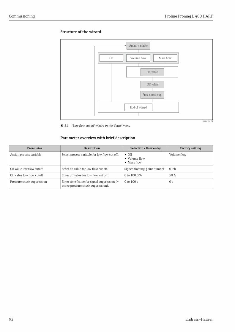
Commissioning Proline Promag L 400 HART
92 Endress+Hauser
Structure of the wizard
Volume flow
Assign variable
Off value
End of wizard
Off
On value
Mass flow
Pres. shock sup.
A0020524-EN
31 "Low flow cut off" wizard in the "Setup" menu
Parameter overview with brief description
Parameter Description Selection / User entry Factory setting
Assign process variable Select process variable for low flow cut off. • Off• Volume flow• Mass flow
Volume flow
On value low flow cutoff Enter on value for low flow cut off. Signed floating-point number 0 l/h
Off value low flow cutoff Enter off value for low flow cut off. 0 to 100.0 % 50 %
Pressure shock suppression Enter time frame for signal suppression (=active pressure shock suppression).
0 to 100 s 0 s

Proline Promag L 400 HART Commissioning
Endress+Hauser 93
10.5.8 Configuring empty pipe detectionThe Empty pipe detection wizard guides you systematically through all the parametersthat have to be set for configuring empty pipe detection.
Navigation"Setup" menu → Empty pipe detection
Structure of the wizard
Empty pipe det.
Response time
End of wizard
New adjustment
Cancel Empty pipe adj.
Progress
Full pipe adjust.
Ok Busy Not ok
On
Switch point EPD
Off
A0017210-EN
32 "Empty pipe detection" wizard in the "Setup" menu
Parameter overview with brief description
Parameter Description Selection / User interface / User entry
Factory setting
Empty pipe detection Switch empty pipe detection on and off. • Off• On
Off
New adjustment Select type of adjustment. • Cancel• Empty pipe adjust• Full pipe adjust
Cancel
Progress • Ok• Busy• Not ok
Switch point empty pipe detection Enter hysteresis in %, below this value themeasuring tube will detected as empty.
0 to 100 % 50 %
Response time empty pipe detection Enter the time before diagnostic messageS862 ''Pipe empty'' is displayed for emptypipe detection.
0 to 100 s 1 s

Commissioning Proline Promag L 400 HART
94 Endress+Hauser
10.5.9 Configuring the HART inputThe HART input submenu contains all the parameters that must be configured for theconfiguration of the HART input.
Navigation"Setup" menu → HART input
Failure mode
Fail safe value
Burst network
Capture mode
Off
Slot number
End of wizard
Assign ext. var.
Master network
Process pressure
Command 1 Command 3 Command 9 Command 33
Timeout
Manufacturer ID
Device ID
Burst command
Assign ext. var.
Process pressure
Device type
Burst command
A0016338-EN
33 "HART input" wizard in the "Setup" menu
Parameter overview with brief description
Parameter Description Selection / User entry Factory setting
Capture mode Select capture mode via burst or mastercommunication.
• Off• Burst network• Master network
Off
Device ID Enter device ID of external device. Positive integer 0
Device type Enter device type of external device. 0 to 255 0
Manufacturer ID Enter manufacture ID of external device. 0 to 255 0

Proline Promag L 400 HART Commissioning
Endress+Hauser 95
Parameter Description Selection / User entry Factory setting
Burst command Select command to read in external processvariable.
• Command 1• Command 3• Command 9• Command 33
Command 1
Slot number Define position of external process variablein burst command.
1 to 4 1
Timeout Enter deadline for process variable ofexternal device.
If the deadline is exceeded, diagnosticmessage F410 data transmission isoutput.
1 to 120 s 5 s
Failure mode Define behavior if external process variableis missed.
• Alarm• Last valid value• Defined value
Alarm
Failure value Enter value to be used by the device if inputvalue from external device is missing.
Signed floating-point number 0

Commissioning Proline Promag L 400 HART
96 Endress+Hauser
10.6 Advanced settingsThe Advanced setup submenu with its submenus contains parameters for specificsettings.
Navigation to the "Advanced setup" submenu
X X X X X X XX X
20.50
0104-1
0092-1
QQQQ
XXXXXXXXX
XXXXXXXXX
XXXXXXXXX
XXXXXXXXX
mA
Display/operat.
Setup
Diagnostic
Display/operat.
Setup
Main menu
English
Main menu
Status input
/ ../Setup
/ ../Setup
Advanced setup
Ent. access code
/ ../Advanced setup
Def. access code
Device tag
Language
A0017519-EN
34 Taking the example of the local display
Navigation"Setup" menu → Advanced setup
‣ Advanced setup
Enter access code
‣ System units
Volume flow unit
Volume unit
Conductivity unit
Temperature unit

Proline Promag L 400 HART Commissioning
Endress+Hauser 97
Mass flow unit
Mass unit
Density unit
‣ Sensor adjustment
Installation direction
‣ Totalizer 1 to 3
Assign process variable
Unit totalizer
Totalizer operation mode
Failure mode
‣ Display
Format display
Value 1 display
0% bargraph value 1
100% bargraph value 1
Decimal places 1
Value 2 display
Decimal places 2
Value 3 display
0% bargraph value 3
100% bargraph value 3
Decimal places 3
Value 4 display
Decimal places 4
Display language

Commissioning Proline Promag L 400 HART
98 Endress+Hauser
Display interval
Display damping
Header
Header text
Separator
Backlight
‣ Electrode cleaning circuit
Electrode cleaning circuit
ECC duration
ECC recovery time
ECC cleaning cycle
ECC Polarity
‣ Administration
‣ Define access code
Define access code
Confirm access code
Device reset
10.6.1 Setting the system unitsIn the System units submenu the units of all the measured values can be set.
Navigation"Setup" menu → Advanced setup → System units
‣ System units
Volume flow unit
Volume unit
Conductivity unit
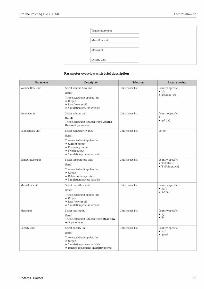
Proline Promag L 400 HART Commissioning
Endress+Hauser 99
Temperature unit
Mass flow unit
Mass unit
Density unit
Parameter overview with brief description
Parameter Description Selection Factory setting
Volume flow unit Select volume flow unit.
Result
The selected unit applies for:• Output• Low flow cut off• Simulation process variable
Unit choose list Country-specific:• l/h• gal/min (us)
Volume unit Select volume unit.
ResultThe selected unit is taken from: Volumeflow unit parameter
Unit choose list Country-specific:• l• gal (us)
Conductivity unit Select conductivity unit.
Result
The selected unit applies for:• Current output• Frequency output• Switch output• Simulation process variable
Unit choose list µS/cm
Temperature unit Select temperature unit.
Result
The selected unit applies for:• Output• Reference temperature• Simulation process variable
Unit choose list Country-specific:• °C (Celsius)• °F (Fahrenheit)
Mass flow unit Select mass flow unit.
Result
The selected unit applies for:• Output• Low flow cut off• Simulation process variable
Unit choose list Country-specific:• kg/h• lb/min
Mass unit Select mass unit.
ResultThe selected unit is taken from: Mass flowunit parameter
Unit choose list Country-specific:• kg• lb
Density unit Select density unit.
Result
The selected unit applies for:• Output• Simulation process variable• Density adjustment (in Expert menu)
Unit choose list Country-specific:• kg/l• lb/ft³

Commissioning Proline Promag L 400 HART
100 Endress+Hauser
10.6.2 Carrying out a sensor adjustmentThe Sensor adjustment submenu contains parameters that pertain to the functionality ofthe sensor.
Navigation"Setup" menu → Advanced setup → Sensor adjustment
‣ Sensor adjustment
Installation direction
Parameter overview with brief description
Parameter Description Selection Factory setting
Installation direction Set sign of flow direction to match thedirection of the arrow on the sensor.
• Flow in arrow direction• Flow against arrow direction
Flow in arrow direction
10.6.3 Configuring the totalizerIn the "Totalizer 1 to 3" submenu the individual totalizer can be configured.
Navigation"Setup" menu → Advanced setup → Totalizer 1 to 3
‣ Totalizer 1 to 3
Assign process variable
Unit totalizer
Totalizer operation mode
Failure mode
Parameter overview with brief description
Parameter Description Selection Factory setting
Assign process variable Select process variable for totalizer. • Off• Volume flow• Mass flow
Volume flow
Unit totalizer Select process variable totalizer unit. Unit choose list l
Totalizer operation mode Select totalizer calculation mode. • Net flow total• Forward flow total• Reverse flow total
Net flow total
Failure mode Define totalizer behavior in alarm condition. • Stop• Actual value• Last valid value
Stop

Proline Promag L 400 HART Commissioning
Endress+Hauser 101
10.6.4 Carrying out additional display configurationsIn the Display submenu you can set all the parameters associated with the configurationof the local display.
Navigation"Setup" menu → Advanced setup → Display
‣ Display
Format display
Value 1 display
0% bargraph value 1
100% bargraph value 1
Decimal places 1
Value 2 display
Decimal places 2
Value 3 display
0% bargraph value 3
100% bargraph value 3
Decimal places 3
Value 4 display
Decimal places 4
Display language
Display interval
Display damping
Header
Header text
Separator
Backlight

Commissioning Proline Promag L 400 HART
102 Endress+Hauser
Parameter overview with brief description
Parameter Prerequsite Description Selection / Userentry
Factory setting
Format display – Select how measured valuesare shown on the display.
• 1 value, max. size• 1 bargraph + 1
value• 2 values• 1 value large + 2
values• 4 values
1 value, max. size
Value 1 display – Select the measured value thatis shown on the local display.
• Volume flow• Mass flow• Conductivity• Temperature• Electronic
temperature• Totalizer 1• Totalizer 2• Totalizer 3• Current output 1
Volume flow
0% bargraph value 1 – Enter 0% value for bar graphdisplay.
Signed floating-pointnumber
0 l/h
100% bargraph value 1 – Enter 100% value for bargraph display.
Signed floating-pointnumber
0.025 l/h
Decimal places 1 – Select the number of decimalplaces for the display value.
• x• x.x• x.xx• x.xxx• x.xxxx
x.xx
Value 2 display – Select the measured value thatis shown on the local display.
Picklist (see 1stdisplay value)
None
Decimal places 2 – Select the number of decimalplaces for the display value.
• x• x.x• x.xx• x.xxx• x.xxxx
x.xx
Value 3 display – Select the measured value thatis shown on the local display.
Picklist (see 1stdisplay value)
None
0% bargraph value 3 An option was selected in theValue 3 display parameter.
Enter 0% value for bar graphdisplay.
Signed floating-pointnumber
0
100% bargraph value 3 An option was selected in theValue 3 display parameter.
Enter 100% value for bargraph display.
Signed floating-pointnumber
0
Decimal places 3 – Select the number of decimalplaces for the display value.
• x• x.x• x.xx• x.xxx• x.xxxx
x.xx
Value 4 display – Select the measured value thatis shown on the local display.
Picklist (see 1stdisplay value)
None
Decimal places 4 – Select the number of decimalplaces for the display value.
• x• x.x• x.xx• x.xxx• x.xxxx
x.xx
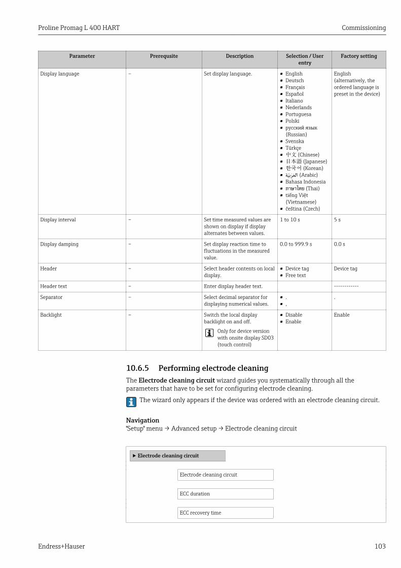
Proline Promag L 400 HART Commissioning
Endress+Hauser 103
Parameter Prerequsite Description Selection / Userentry
Factory setting
Display language – Set display language. • English• Deutsch• Français• Español• Italiano• Nederlands• Portuguesa• Polski• русский язык
(Russian)• Svenska• Türkçe• 中文 (Chinese)• 日本語 (Japanese)• 한국어 (Korean)• (Arabic) العربية• Bahasa Indonesia• ภาษาไทย (Thai)• tiếng Việt
(Vietnamese)• čeština (Czech)
English(alternatively, theordered language ispreset in the device)
Display interval – Set time measured values areshown on display if displayalternates between values.
1 to 10 s 5 s
Display damping – Set display reaction time tofluctuations in the measuredvalue.
0.0 to 999.9 s 0.0 s
Header – Select header contents on localdisplay.
• Device tag• Free text
Device tag
Header text – Enter display header text. ------------
Separator – Select decimal separator fordisplaying numerical values.
• .• ,
.
Backlight – Switch the local displaybacklight on and off.
Only for device versionwith onsite display SD03(touch control)
• Disable• Enable
Enable
10.6.5 Performing electrode cleaningThe Electrode cleaning circuit wizard guides you systematically through all theparameters that have to be set for configuring electrode cleaning.
The wizard only appears if the device was ordered with an electrode cleaning circuit.
Navigation"Setup" menu → Advanced setup → Electrode cleaning circuit
‣ Electrode cleaning circuit
Electrode cleaning circuit
ECC duration
ECC recovery time
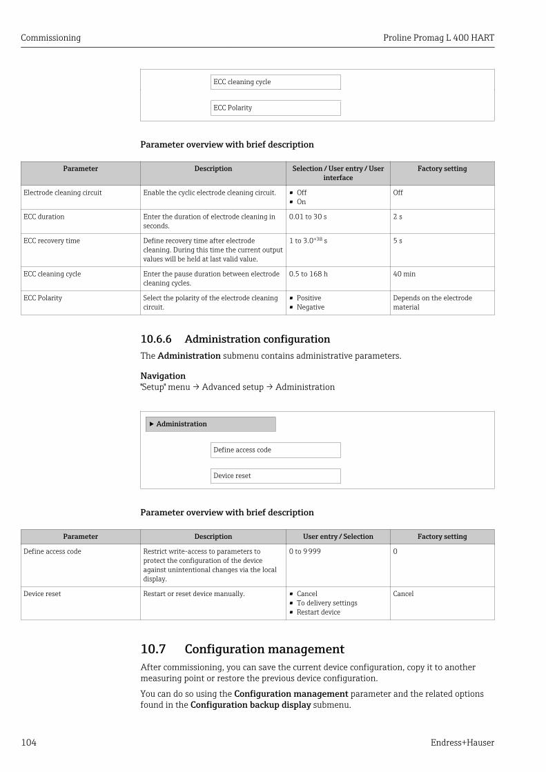
Commissioning Proline Promag L 400 HART
104 Endress+Hauser
ECC cleaning cycle
ECC Polarity
Parameter overview with brief description
Parameter Description Selection / User entry / Userinterface
Factory setting
Electrode cleaning circuit Enable the cyclic electrode cleaning circuit. • Off• On
Off
ECC duration Enter the duration of electrode cleaning inseconds.
0.01 to 30 s 2 s
ECC recovery time Define recovery time after electrodecleaning. During this time the current outputvalues will be held at last valid value.
1 to 3.0+38 s 5 s
ECC cleaning cycle Enter the pause duration between electrodecleaning cycles.
0.5 to 168 h 40 min
ECC Polarity Select the polarity of the electrode cleaningcircuit.
• Positive• Negative
Depends on the electrodematerial
10.6.6 Administration configurationThe Administration submenu contains administrative parameters.
Navigation"Setup" menu → Advanced setup → Administration
‣ Administration
Define access code
Device reset
Parameter overview with brief description
Parameter Description User entry / Selection Factory setting
Define access code Restrict write-access to parameters toprotect the configuration of the deviceagainst unintentional changes via the localdisplay.
0 to 9 999 0
Device reset Restart or reset device manually. • Cancel• To delivery settings• Restart device
Cancel
10.7 Configuration managementAfter commissioning, you can save the current device configuration, copy it to anothermeasuring point or restore the previous device configuration.
You can do so using the Configuration management parameter and the related optionsfound in the Configuration backup display submenu.

Proline Promag L 400 HART Commissioning
Endress+Hauser 105
Navigation"Setup" menu → Advanced setup → Configuration backup display
‣ Configuration backup display
Operating time
Last backup
Configuration management
Comparison result
Parameter overview with brief description
Parameter Prerequsite Description User interface / Selection
Factory setting
Operating time – Indicates how long the devicehas been in operation.
Days (d), hours (h),minutes (m), seconds(s)
–
Last backup – Indicates when the last databackup was saved to thedisplay module.
Days (d), hours (h),minutes (m), seconds(s)
–
Configuration management A local display is provided. Select action for managing thedevice data in the displaymodule.
• Cancel• Execute backup• Restore• Duplicate• Compare• Clear backup data
Cancel
Comparison result – Comparison between presentdevice data and displaybackup.
• Settings identical• Settings not
identical• No backup
available• Backup settings
corrupt• Check not done• Dataset
incompatible
Check not done
10.7.1 Function range of "Configuration management" parameter
Options Description
Execute backup The current device configuration is backed up from the integrated HistoROM to thedevice's display module. The backup copy includes the transmitter data of thedevice.
Restore The last backup copy of the device configuration is restored from the displaymodule to the device's integrated HistoROM. The backup copy includes thetransmitter data of the device.
Duplicate The transmitter configuration from another device is duplicated to the device usingthe display module.
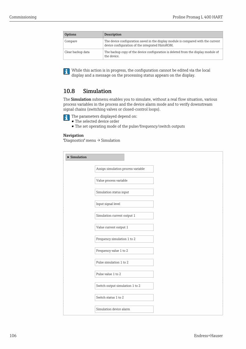
Commissioning Proline Promag L 400 HART
106 Endress+Hauser
Options Description
Compare The device configuration saved in the display module is compared with the currentdevice configuration of the integrated HistoROM.
Clear backup data The backup copy of the device configuration is deleted from the display module ofthe device.
While this action is in progress, the configuration cannot be edited via the localdisplay and a message on the processing status appears on the display.
10.8 SimulationThe Simulation submenu enables you to simulate, without a real flow situation, variousprocess variables in the process and the device alarm mode and to verify downstreamsignal chains (switching valves or closed-control loops).
The parameters displayed depend on:• The selected device order• The set operating mode of the pulse/frequency/switch outputs
Navigation"Diagnostics" menu → Simulation
‣ Simulation
Assign simulation process variable
Value process variable
Simulation status input
Input signal level
Simulation current output 1
Value current output 1
Frequency simulation 1 to 2
Frequency value 1 to 2
Pulse simulation 1 to 2
Pulse value 1 to 2
Switch output simulation 1 to 2
Switch status 1 to 2
Simulation device alarm
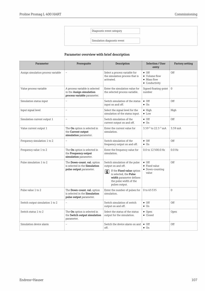
Proline Promag L 400 HART Commissioning
Endress+Hauser 107
Diagnostic event category
Simulation diagnostic event
Parameter overview with brief description
Parameter Prerequsite Description Selection / Userentry
Factory setting
Assign simulation process variable – Select a process variable forthe simulation process that isactivated.
• Off• Volume flow• Mass flow• Conductivity
Off
Value process variable A process variable is selectedin the Assign simulationprocess variable parameter.
Enter the simulation value forthe selected process variable.
Signed floating-pointnumber
0
Simulation status input – Switch simulation of the statusinput on and off.
• Off• On
Off
Input signal level – Select the signal level for thesimulation of the status input.
• High• Low
High
Simulation current output 1 – Switch simulation of thecurrent output on and off.
• Off• On
Off
Value current output 1 The On option is selected inthe Current outputsimulation parameter.
Enter the current value forsimulation.
3.59-3 to 22.5-3 mA 3.59 mA
Frequency simulation 1 to 2 – Switch simulation of thefrequency output on and off.
• Off• On
Off
Frequency value 1 to 2 The On option is selected inthe Frequency outputsimulation parameter.
Enter the frequency value forsimulation.
0.0 to 12 500.0 Hz 0.0 Hz
Pulse simulation 1 to 2 The Down-count. val. optionis selected in the Simulationpulse output parameter.
Switch simulation of the pulseoutput on and off.
If the Fixed value optionis selected, the Pulsewidth parameter definesthe pulse width of thepulses output.
• Off• Fixed value• Down-counting
value
Off
Pulse value 1 to 2 The Down-count. val. optionis selected in the Simulationpulse output parameter.
Enter the number of pulses forsimulation.
0 to 65 535 0
Switch output simulation 1 to 2 – Switch simulation of switchoutput on and off.
• Off• On
Off
Switch status 1 to 2 The On option is selected inthe Switch output simulationparameter.
Select the status of the statusoutput for the simulation.
• Open• Closed
Open
Simulation device alarm – Switch the device alarm on andoff.
• Off• On
Off

Commissioning Proline Promag L 400 HART
108 Endress+Hauser
Parameter Prerequsite Description Selection / Userentry
Factory setting
Diagnostic event category – Select the category of thediagnostic event.
• Sensor• Electronics• Configuration• Process
Process
Simulation diagnostic event – Switch simulation of thediagnostic event on and off.
For the simulation, you canchoose from the diagnosticevents of the category selectedin the Diagnostic eventcategory parameter.
• Off• Picklist
Diagnostic events(depends on theselected category)
Off
10.9 Protecting settings from unauthorized accessThe following options exist for protecting the configuration of the measuring device fromunintentional modification after commissioning:• Write protection via access code for the local display and Web browser• Write protection via write protection switch• Write protection via keypad lock → 57
10.9.1 Write protection via access codeThe effects of the customer-specific access code are as follows:• Via local operation, the parameters for the measuring device configuration are write-
protected and their values can no longer be changed.• Device access via the Web browser is protected, as are the parameters for the measuring
device configuration.
Navigation"Setup" menu → Advanced setup → Administration → Define access code
‣ Define access code
Define access code
Confirm access code
Defining the access code via local display1. Navigate to the Enter access code parameter.
2. Max. Define a max. 4-digit numeric code as an access code.
3. Enter the access code again to confirm the code. The -symbol appears in front of all write-protected parameters.
The device automatically locks the write-protected parameters again if a key is not pressedfor 10 minutes in the navigation and editing view. The device locks the write-protected

Proline Promag L 400 HART Commissioning
Endress+Hauser 109
parameters automatically after 60 s if the user skips back to the operational display modefrom the navigation and editing view.
• If write access is activated via access code, it can be also be deactivated only via theaccess code → 57.
• The user role with which the user is currently logged on via the local display→ 57 is indicated by the Access status display parameter. Navigation path:"Operation" menu → Access status display
Parameters which can always be modified via the local displayCertain parameters that do not affect the measurement are excepted from write protectionvia the local display. Despite the defined access code, these parameters can always bemodified even if the other parameters are locked.
Parameters for configuringthe local display
Parameters for configuringthe totalizer
↓ ↓
Language Format display Control Totalizer
Contrast display Preset value
Display interval Reset all totalizers
Defining the access code via the Web browser1. Navigate to the "Enter access code" parameter.
2. Max. Define a max. 4-digit numeric code as an access code.
3. Enter the access code again to confirm the code. The Web browser switches to the login page.
If no action is performed for 10 minutes, the Web browser automatically returns tothe login page.
The user role with which the user is currently logged on via the Web browser isindicated by the Access status tooling parameter.
Navigation path: "Operation" menu → Access status tooling
10.9.2 Write protection via write protection switchUnlike write protection via a user-specific access code, this allows write access to the entireoperating menu - other than the "Contrast display" parameter - to be locked.
The parameter values are now read only and cannot be edited any more (exception"Contrast display" parameter):• Via local display• Via service interface (CDI-RJ45)• Via HART protocol

Commissioning Proline Promag L 400 HART
110 Endress+Hauser
ON
+ - + -
+ - + -
OFF
A0017260
1. Loosen the 4 fixing screws on the housing cover and open the housing cover.
2. Setting the write protection switch (WP) on the main electronics module to the ONposition enables the hardware write protection. Setting the write protection switch(WP) on the main electronics module to the OFF position (factory setting) disablesthe hardware write protection. If hardware write protection is enabled, the Locking status parameter displays
the Hardware locked option. In addition, on the local display the -symbolappears in front of the parameters in the header of the operational display and inthe navigation view.
X X X X X X XX X
20.50XXXX
A0015870
If hardware write protection is disabled, no option is displayed in the Lockingstatus parameter. On the local display, the -symbol disappears from in front ofthe parameters in the header of the operational display and in the navigationview.
3. WARNING! Excessive tightening torque applied to the fixing screws! Risk ofdamaging the plastic transmitter. Tighten the fixing screws as per the tighteningtorque → 29.Reverse the removal procedure to reassemble the transmitter.

Proline Promag L 400 HART Operation
Endress+Hauser 111
11 Operation
11.1 Reading the device locking statusThe write protection types that are currently active can be determined using the Lockingstatus parameter.
Navigation"Operation" menu → Locking status
Function scope of "Locking status" parameter
Options Description
None The access status displayed in "Access status display" parameter applies → 57.Only appears on local display.
Hardware locked The DIP switch for hardware locking is activated on the main electronics module.This locks write access to the parameters .
Temporarily locked Write access to the parameters is temporarily lock due to device-internalprocessing (e.g. data upload/download, reset). Once the internal processing hasbeen completed, the parameters can be changed once again.
11.2 Adjusting the operating languageInformation → 70
For information on the operating languages supported by the measuring device→ 166
11.3 Configuring the display• Basic settings for local display → 87• Advanced settings for local display → 101
11.4 Reading measured valuesWith the Measured values submenu, it is possible to read all the measured values.
11.4.1 Process variablesThe Process variables submenu contains all the parameters needed to display the currentmeasured values for every process variable.
Navigation"Diagnostics" menu → Measured values → Process variables
‣ Process variables
Volume flow
Mass flow
Conductivity

Operation Proline Promag L 400 HART
112 Endress+Hauser
Parameter overview with brief description
Parameter Description User interface
Volume flow Displays the volume flow currently measured. Signed floating-point number
Mass flow Displays the mass flow currently calculated. Signed floating-point number
Conductivity Displays the corrected volume flow currently calculated. Signed floating-point number
11.4.2 TotalizerThe Totalizer submenu contains all the parameters needed to display the currentmeasured values for every totalizer.
Navigation"Diagnostics" menu → Measured values → Totalizer
‣ Totalizer
Totalizer value 1 to 3
Totalizer overflow 1 to 3
Parameter overview with brief description
Parameter Prerequsite Description User interface Factory setting
Totalizer value 1 to 3 In the Assign process variableparameter in the Totalizer 1to 3 submenu, one of thefollowing options is selected:• Volume flow• Mass flow
Displays the current totalizercounter value.
Signed floating-pointnumber
0 l
Totalizer overflow 1 to 3 In the Assign process variableparameter in the Totalizer 1to 3 submenu, one of thefollowing options is selected:• Volume flow• Mass flow
Displays the current totalizeroverflow.
Integer with sign 0
11.4.3 Input valuesThe Input values submenu guides you systematically to the individual input values.
The submenu only appears if the device was ordered with a status input → 35..
Navigation"Diagnostics" menu → Measured values → Input values
Structure of the submenu
‣ Input values
Value status input

Proline Promag L 400 HART Operation
Endress+Hauser 113
Parameter overview with brief description
Parameter Description User interface Factory setting
Value status input Displays the current input signal level. • High• Low
Low
11.4.4 Output valuesThe Output values submenu contains all the parameters needed to display the currentmeasured values for every output.
The parameters displayed depend on:• The selected device order• The set operating mode of the pulse/frequency/switch outputs
Navigation"Diagnostics" menu → Measured values → Output values
‣ Output values
Output current 1
Measured current 1
Pulse output 1
Output frequency 1
Switch status 1
Output frequency 2
Pulse output 2
Switch status 2
Parameter overview with brief description
Parameter Description User interface Factory setting
Output current 1 Displays the current value currentlycalculated for the current output.
3.59 to 22.5 mA 3.59 mA
Measured current 1 Displays the current value currentlymeasured for the current output.
0 to 30 mA 0 mA
Pulse output 1 Displays the value currently measured forthe pulse output.
Positive floating-point number 0 Hz
Output frequency 1 Displays the value currently measured forthe frequency output.
0.0 to 12 500.0 Hz 0.0 Hz
Switch status 1 Displays the current switch output status. • Open• Closed
Open
Output frequency 1 Displays the value currently measured forthe frequency output.
0.0 to 12 500.0 Hz 0.0 Hz

Operation Proline Promag L 400 HART
114 Endress+Hauser
Parameter Description User interface Factory setting
Pulse output 1 Displays the value currently measured forthe pulse output.
Positive floating-point number 0 Hz
Switch status 1 Displays the current switch output status. • Open• Closed
Open
11.5 Adapting the measuring device to the processconditions
The following are available for this purpose:• Basic settings using the Setup menu• Advanced settings using the Advanced setup submenu
11.6 Performing a totalizer resetIn the Operation submenu the totalizers are reset:• Control Totalizer• Reset all totalizers
Function scope of "Control Totalizer " parameter
Options Description
Totalize The totalizer is started.
Reset + hold The totaling process is stopped and the totalizer is reset to 0.
Preset + hold The totaling process is stopped and the totalizer is set to its defined start valuefrom the Preset value parameter.
Reset + totalize The totalizer is reset to 0 and the totaling process is restarted.
Preset + totalize The totalizer is set to the defined start value in Preset value parameterand thetotaling process is restarted.
Function scope of "Reset all totalizers" parameter
Options Description
Reset + totalize Resets all totalizers to 0 and restarts the totaling process. This deletes all the flowvalues previously totalized.
Navigation"Operation" menu → Operation
‣ Totalizer handling
Control Totalizer 1 to 3
Preset value 1 to 3
Reset all totalizers

Proline Promag L 400 HART Operation
Endress+Hauser 115
Parameter overview with brief description
Parameter Description Selection / User entry Factory setting
Control Totalizer 1 to 3 Control totalizer value. • Totalize• Reset + hold• Preset + hold• Reset + totalize• Preset + totalize
Totalize
Preset value 1 to 3 Specify start value for totalizer. Signed floating-point number 0 l
Reset all totalizers Reset all totalizers to 0 and start. • Cancel• Reset + totalize
Cancel
11.7 Showing data loggingIn the device, the extended function of the HistoROM must be enabled (order option) sothat the Data logging submenu appears. This contains all the parameters for themeasured value history.
The data logging history is also available via the FieldCare plant asset managementtool → 63.
Function scope• A total of 1000 measured values can be stored• 4 logging channels• Adjustable logging interval for data logging• Display of the measured value trend for each logging channel in the form of a chart
A0016222
35 Chart of a measured value trend
• x-axis: depending on the number of channels selected displays 250 to 1000 measuredvalues of a process variable.
• y-axis: displays the approximate measured value span and constantly adapts this to theongoing measurement.
If the length of the logging interval or the assignment of the process variables to thechannels is changed, the content of the data logging is deleted.
Navigation"Diagnostics" menu → Data logging
"Data logging" submenu
‣ Data logging
Assign channel 1
Assign channel 2
Assign channel 3

Operation Proline Promag L 400 HART
116 Endress+Hauser
Assign channel 4
Logging interval
Clear logging data
‣ Display channel 1
‣ Display channel 2
‣ Display channel 3
‣ Display channel 4
Parameter overview with brief description
Parameter Description Selection / User entry Factory setting
Assign channel 1 to 4 Assign process variable to logging channel. • Off• Volume flow• Mass flow• Flow velocity• Conductivity• Electronic temperature• Current output 1
Off
Logging interval Define the logging interval for data logging.This value defines the time interval betweenthe individual data points in the memory.
1.0 to 3 600.0 s 10.0 s
Clear logging data Clear the entire logging data. • Cancel• Clear data
Cancel

Proline Promag L 400 HART Diagnostics and troubleshooting
Endress+Hauser 117
12 Diagnostics and troubleshooting
12.1 General troubleshooting
For local display
Problem Possible causes Remedial action
Local display dark and no outputsignals
Supply voltage does not match thatspecified on the nameplate.
Apply the correct supply voltage .
Local display dark and no outputsignals
No contact between connectingcables and terminals.
Check the connection of the cablesand correct if necessary.
Local display dark and no outputsignals
Terminals are not plugged into themain electronics module correctly.
Check terminals.
Local display dark and no outputsignals
Main electronics module isdefective.
Order spare part → 137.
Local display dark and no outputsignals
The connector between the mainelectronics module and displaymodule is not plugged in correctly.
Check the connection and correct ifnecessary.
Local display dark and no outputsignals
The connecting cable is not pluggedin correctly.
1. Check the connection of theelectrode cable and correct ifnecessary.2. Check the connection of the coilcurrent cable and correct ifnecessary.
Local display is dark, but signaloutput is within the valid range
Display is set too bright or too dark. • Set the display brighter bysimultaneously pressing + .
• Set the display darker bysimultaneously pressing + .
Local display is dark, but signaloutput is within the valid range
Display module is defective. Order spare part → 137.
Backlighting of local display is red Diagnostic event with "Alarm"diagnostic behavior has occurred.
Take remedial measures → 126
Text on local display appears in aforeign language and cannot beunderstood.
Incorrect operating language isconfigured.
1. Press + for 2 s ("homeposition").2. Press .3. Set the desired language in theLanguage parameter.
Message on local display:"Communication Error""Check Electronics"
Communication between thedisplay module and the electronicsis interrupted.
• Check the cable and theconnector between the mainelectronics module and displaymodule.
• Order spare part → 137.
For output signals
Problem Possible causes Remedial action
Signal output outside the validrange
Main electronics module isdefective.
Order spare part → 137.
Device shows correct value on localdisplay, but signal output isincorrect, though in the valid range.
Configuration error Check and correct parameterconfiguration.
Device measures incorrectly. Configuration error or device isoperated outside the application.
1. Check and correct parameterconfiguration.2. Observe limit values specified inthe "Technical Data".
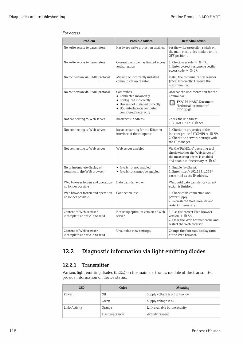
Diagnostics and troubleshooting Proline Promag L 400 HART
118 Endress+Hauser
For access
Problem Possible causes Remedial action
No write access to parameters Hardware write protection enabled Set the write protection switch onthe main electronics module to theOFF position .
No write access to parameters Current user role has limited accessauthorization
1. Check user role → 57.2. Enter correct customer-specificaccess code → 57.
No connection via HART protocol Missing or incorrectly installedcommunication resistor.
Install the communication resistor(250 Ω) correctly. Observe themaximum load .
No connection via HART protocol Commubox• Connected incorrectly• Configured incorrectly• Drivers not installed correctly• USB interface on computer
configured incorrectly
Observe the documentation for theCommubox.
FXA195 HART: Document"Technical Information"TI00404F
Not connecting to Web server Incorrect IP address Check the IP address:192.168.1.212 → 59
Not connecting to Web server Incorrect setting for the Ethernetinterface of the computer
1. Check the properties of theInternet protocol (TCP/IP) → 59.2. Check the network settings withthe IT manager.
Not connecting to Web server Web server disabled Via the "FieldCare" operating toolcheck whether the Web server ofthe measuring device is enabledand enable it if necessary → 61.
No or incomplete display ofcontents in the Web browser
• JavaScript not enabled• JavaScript cannot be enabled
1. Enable JavaScript.2. Enter http://192.168.1.212/basic.html as the IP address.
Web browser frozen and operationno longer possible
Data transfer active Wait until data transfer or currentaction is finished.
Web browser frozen and operationno longer possible
Connection lost 1. Check cable connection andpower supply.2. Refresh the Web browser andrestart if necessary.
Content of Web browserincomplete or difficult to read
Not using optimum version of Webserver.
1. Use the correct Web browserversion → 58.2. Clear the Web browser cache andrestart the Web browser.
Content of Web browserincomplete or difficult to read
Unsuitable view settings. Change the font size/display ratioof the Web browser.
12.2 Diagnostic information via light emitting diodes
12.2.1 TransmitterVarious light emitting diodes (LEDs) on the main electronics module of the transmitterprovide information on device status.
LED Color Meaning
Power Off Supply voltage is off or too low
Green Supply voltage is ok
Link/Activity Orange Link available but no activity
Flashing orange Activity present

Proline Promag L 400 HART Diagnostics and troubleshooting
Endress+Hauser 119
LED Color Meaning
Communication Flashing white HART communication is active.
Alarm Green Measuring device is ok
Flashing green Measuring device not configured
Off Firmware error
Red Main error
Flashing red Error
Flashing red/green Start measuring device

Diagnostics and troubleshooting Proline Promag L 400 HART
120 Endress+Hauser
12.3 Diagnostic information on local display
12.3.1 Diagnostic messageFaults detected by the self-monitoring system of the measuring device are displayed as adiagnostic message in alternation with the operational display.
Operational display in alarm condition Diagnostic message
1
4
3
X X X X X X XX X X X X X X X XX X
2
S S
XX
20.50
5
X i
S801
Menu
Supply voltage
A0013939-EN
12345
Status signalDiagnostic behaviorDiagnostic behavior with diagnostic codeShort textOperating elements
If two or more diagnostic events are pending simultaneously, only the message of thediagnostic event with the highest priority is shown.
Other diagnostic events that have occurred can be called up in the Diagnostics menu:• Via parameters → 129• Via submenus → 129
Status signalsThe status signals provide information on the state and reliability of the device bycategorizing the cause of the diagnostic information (diagnostic event).
The status signals are categorized according to VDI/VDE 2650 and NAMURRecommendation NE 107: F = Failure, C = Function Check, S = Out of Specification, M= Maintenance Required
Symbol Meaning
A0013956
FailureA device error has occurred. The measured value is no longer valid.
A0013959
Function checkThe device is in service mode (e.g. during a simulation).
A0013958
Out of specificationThe device is operated:• Outside its technical specification limits (e.g. outside the process temperature range)• Outside of the configuration carried out by the user (e.g. maximum flow in parameter
20 mA value)
A0013957
Maintenance requiredMaintenance is required. The measured value remains valid.

Proline Promag L 400 HART Diagnostics and troubleshooting
Endress+Hauser 121
Diagnostic behavior
Symbol Meaning
A0013961
Alarm• Measurement is interrupted.• Signal outputs and totalizers assume the defined alarm condition.• A diagnostic message is generated.• The background lighting changes to red.
A0013962
WarningMeasurement is resumed. The signal outputs and totalizers are not affected. A diagnosticmessage is generated.
Diagnostic informationThe fault can be identified using the diagnostic information. The short text helps you byproviding information about the fault. In addition, the corresponding symbol for thediagnostic behavior is displayed in front of the diagnostic information on the local display.
Diagnostic information
Diagnostic code
Diagnosticbehavior Status signal Diagnostic
number Short text
↓ ↓ ↓
Example A0013962 A0013958
441 Curr.output 1
NAMURNE 107
3-digit number
Operating elements
Key Meaning
A0013970
Plus key
In a menu, submenuOpens the message about the remedial measures.
A0013952
Enter key
In a menu, submenuOpens the operating menu.

Diagnostics and troubleshooting Proline Promag L 400 HART
122 Endress+Hauser
12.3.2 Calling up remedial measures
X X X X X X XX X X X X X X X XX XS S
XX
20.50X i
S801
Menu
S
(ID:203)
S801 0d00h02m25s
1
2
4
6
3
5
Increase supply voltage
S801 Supply voltage
Diagnostic list
Diagnostics 1
Diagnostics 2Diagnostics 3
Supply voltage
Supply voltage
A0013940-EN
36 Message for remedial measures
1 Diagnostic information2 Short text3 Service ID4 Diagnostic behavior with diagnostic code5 Operation time of occurrence6 Remedial measures
The user is in the diagnostic message.
1. Press ( symbol). The Diagnostic list submenu opens.
2. Select the desired diagnostic event with or and press . The message for the remedial measures for the selected diagnostic event opens.
3. Press + simultaneously. The message for the remedial measures closes.
The user is in the Diagnostics menu at an entry for a diagnostics event, e.g. in theDiagnostic list submenu or the Previous diagnostics parameter.
1. Press . The message for the remedial measures for the selected diagnostic event opens.
2. Press + simultaneously. The message for the remedial measures closes.

Proline Promag L 400 HART Diagnostics and troubleshooting
Endress+Hauser 123
12.4 Diagnostic information in the Web browser
12.4.1 Diagnostic optionsAny faults detected by the measuring device are displayed in the Web browser on thehome page once the user has logged on.
1
32 A0017759-EN
123
Status area with status signalDiagnostic information → 121Remedial measures with Service ID
Furthermore, diagnostic events that have occurred can be viewed in the Diagnosticsmenu:• Via parameters → 129• Via submenus → 129
Status signalsThe status signals provide information on the state and reliability of the device bycategorizing the cause of the diagnostic information (diagnostic event).
Symbol Meaning
A0017271
FailureA device error has occurred. The measured value is no longer valid.
A0017278
Function checkThe device is in service mode (e.g. during a simulation).
A0017277
Out of specificationThe device is operated:• Outside its technical specification limits (e.g. outside the process temperature range)• Outside of the configuration carried out by the user (e.g. maximum flow in parameter
20 mA value)
A0017276
Maintenance requiredMaintenance is required. The measured value is still valid.
The status signals are categorized in accordance with VDI/VDE 2650 and NAMURRecommendation NE 107.
12.4.2 Calling up remedy informationRemedy information is provided for every diagnostic event to ensure that problems can berectified quickly. These measures are displayed in red along with the diagnostic event andthe related diagnostic information.

Diagnostics and troubleshooting Proline Promag L 400 HART
124 Endress+Hauser
12.5 Diagnostic information in FieldCare
12.5.1 Diagnostic optionsAny faults detected by the measuring device are displayed on the home page of theoperating tool once the connection has been established.
Xxxxxx/…/…/
Xxxxxx
P
P
P
+
+
+
+Diagnostics 1:
Remedy information:
Failure (F)
Function check (C)
Out of spezification (S)
Maintenance required (M)
C485 Simulation measured vari...
Deactivate Simulation (Service...
Diagnostics 1: C485 Simu...
Remedy information: Deactivate...
Access status tooling: Mainenance
Operation
Setup
Diagnostics
Expert
Function check (C)Status signal:
Device tag:
Device name: Mass flow:
Volume flow:Xxxxxxx
12.34 kg/h
12.34 m /h³
Xxxxxxx
1
2
3
A0021799-EN
1 Status area with status signal → 1202 Diagnostic information → 1213 Remedial measures with Service ID
Furthermore, diagnostic events that have occurred can be viewed in the Diagnosticsmenu:• Via parameters → 129• Via submenu → 129
Diagnostic informationThe fault can be identified using the diagnostic information. The short text helps you byproviding information about the fault. In addition, the corresponding symbol for thediagnostic behavior is displayed in front of the diagnostic information on the local display.
Diagnostic information
Diagnostic code
Diagnosticbehavior Status signal Diagnostic
number Short text
↓ ↓ ↓
Example A0013962 A0013958
441 Curr.output 1
NAMURNE 107
3-digit number

Proline Promag L 400 HART Diagnostics and troubleshooting
Endress+Hauser 125
12.5.2 Calling up remedy informationRemedy information is provided for every diagnostic event to ensure that problems can berectified quickly:• On the home page
Remedy information is displayed in a separate field below the diagnostics information.• In the Diagnostics menu
Remedy information can be called up in the working area of the user interface.
The user is in the Diagnostics menu.
1. Call up the desired parameter.
2. On the right in the working area, mouse over the parameter. A tool tip with remedy information for the diagnostic event appears.
12.6 Adapting the diagnostic information
12.6.1 Adapting the diagnostic behaviorEach item of diagnostic information is assigned a specific diagnostic behavior at thefactory. The user can change this assignment for certain diagnostic information in theDiagnostic behavior submenu .
"Expert" menu → System → Diagnostic handling → Diagnostic behavior
A0014048-EN
37 Using the example of the local display
You can assign the following options to the diagnostic number as the diagnostic behavior:
Options Description
Alarm Measurement is interrupted. Signal outputs and totalizers assume the defined alarmcondition. A diagnostic message is generated.The background lighting changes to red.
Warning Measurement is resumed. The signal outputs and totalizers are not affected. Adiagnostics message is generated.
Logbook entry only The device continues to measure. The diagnostic message is entered in the Eventlogbook (events list) submenu only and is not displayed in alternation with the measuredvalue display.
Off The diagnostic event is ignored, and no diagnostic message is generated or entered.
12.6.2 Adapting the status signalEach item of diagnostic information is assigned a specific status signal at the factory. Theuser can change this assignment for certain diagnostic information in the Diagnosticevent category submenu .
"Expert" menu → Communication → Diagnostic event category
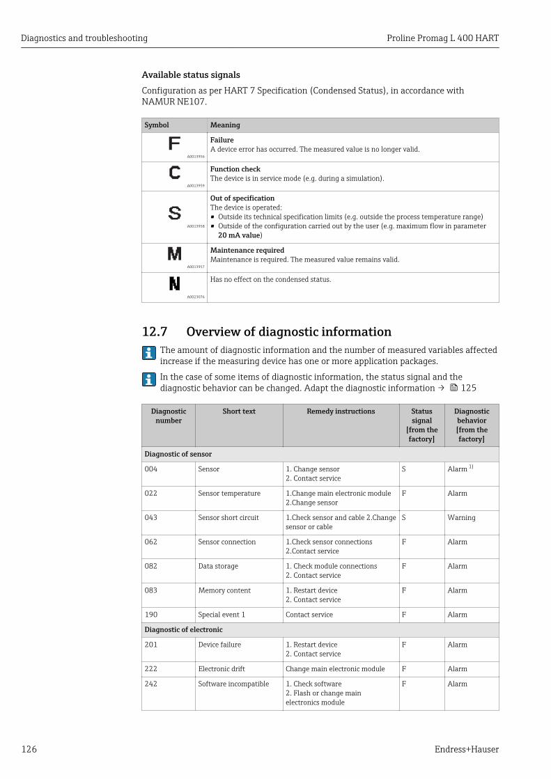
Diagnostics and troubleshooting Proline Promag L 400 HART
126 Endress+Hauser
Available status signalsConfiguration as per HART 7 Specification (Condensed Status), in accordance withNAMUR NE107.
Symbol Meaning
A0013956
FailureA device error has occurred. The measured value is no longer valid.
A0013959
Function checkThe device is in service mode (e.g. during a simulation).
A0013958
Out of specificationThe device is operated:• Outside its technical specification limits (e.g. outside the process temperature range)• Outside of the configuration carried out by the user (e.g. maximum flow in parameter
20 mA value)
A0013957
Maintenance requiredMaintenance is required. The measured value remains valid.
A0023076
Has no effect on the condensed status.
12.7 Overview of diagnostic information The amount of diagnostic information and the number of measured variables affectedincrease if the measuring device has one or more application packages.
In the case of some items of diagnostic information, the status signal and thediagnostic behavior can be changed. Adapt the diagnostic information → 125
Diagnosticnumber
Short text Remedy instructions Statussignal
[from thefactory]
Diagnosticbehavior[from thefactory]
Diagnostic of sensor
004 Sensor 1. Change sensor2. Contact service
S Alarm 1)
022 Sensor temperature 1.Change main electronic module2.Change sensor
F Alarm
043 Sensor short circuit 1.Check sensor and cable 2.Changesensor or cable
S Warning
062 Sensor connection 1.Check sensor connections2.Contact service
F Alarm
082 Data storage 1. Check module connections2. Contact service
F Alarm
083 Memory content 1. Restart device2. Contact service
F Alarm
190 Special event 1 Contact service F Alarm
Diagnostic of electronic
201 Device failure 1. Restart device2. Contact service
F Alarm
222 Electronic drift Change main electronic module F Alarm
242 Software incompatible 1. Check software2. Flash or change mainelectronics module
F Alarm
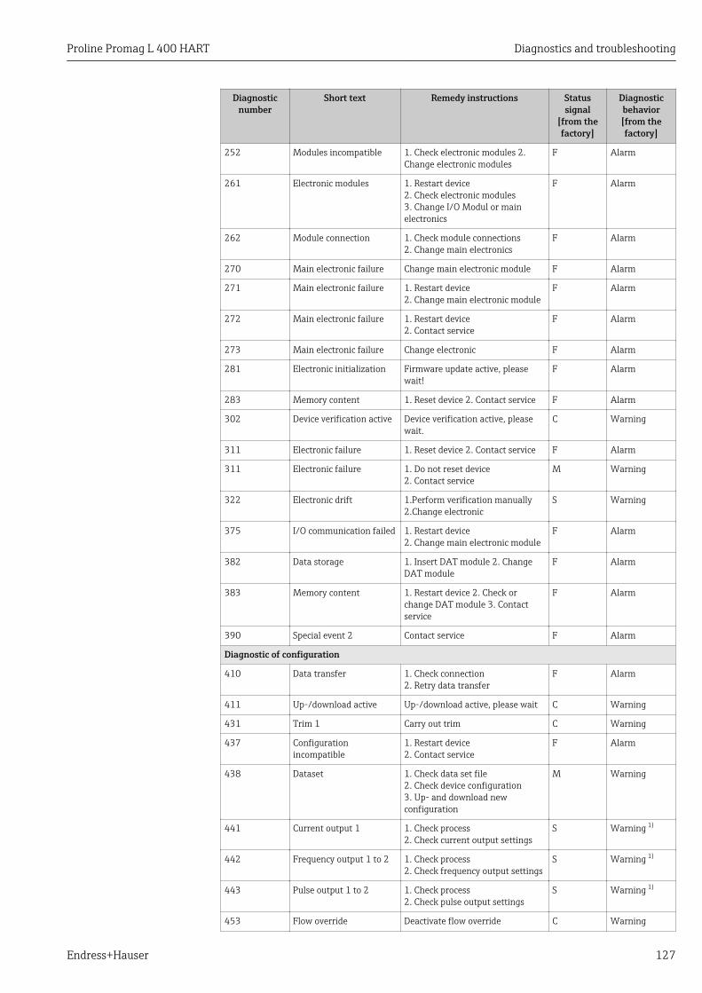
Proline Promag L 400 HART Diagnostics and troubleshooting
Endress+Hauser 127
Diagnosticnumber
Short text Remedy instructions Statussignal
[from thefactory]
Diagnosticbehavior[from thefactory]
252 Modules incompatible 1. Check electronic modules 2.Change electronic modules
F Alarm
261 Electronic modules 1. Restart device2. Check electronic modules3. Change I/O Modul or mainelectronics
F Alarm
262 Module connection 1. Check module connections2. Change main electronics
F Alarm
270 Main electronic failure Change main electronic module F Alarm
271 Main electronic failure 1. Restart device2. Change main electronic module
F Alarm
272 Main electronic failure 1. Restart device2. Contact service
F Alarm
273 Main electronic failure Change electronic F Alarm
281 Electronic initialization Firmware update active, pleasewait!
F Alarm
283 Memory content 1. Reset device 2. Contact service F Alarm
302 Device verification active Device verification active, pleasewait.
C Warning
311 Electronic failure 1. Reset device 2. Contact service F Alarm
311 Electronic failure 1. Do not reset device2. Contact service
M Warning
322 Electronic drift 1.Perform verification manually2.Change electronic
S Warning
375 I/O communication failed 1. Restart device2. Change main electronic module
F Alarm
382 Data storage 1. Insert DAT module 2. ChangeDAT module
F Alarm
383 Memory content 1. Restart device 2. Check orchange DAT module 3. Contactservice
F Alarm
390 Special event 2 Contact service F Alarm
Diagnostic of configuration
410 Data transfer 1. Check connection2. Retry data transfer
F Alarm
411 Up-/download active Up-/download active, please wait C Warning
431 Trim 1 Carry out trim C Warning
437 Configurationincompatible
1. Restart device2. Contact service
F Alarm
438 Dataset 1. Check data set file2. Check device configuration3. Up- and download newconfiguration
M Warning
441 Current output 1 1. Check process2. Check current output settings
S Warning 1)
442 Frequency output 1 to 2 1. Check process2. Check frequency output settings
S Warning 1)
443 Pulse output 1 to 2 1. Check process2. Check pulse output settings
S Warning 1)
453 Flow override Deactivate flow override C Warning
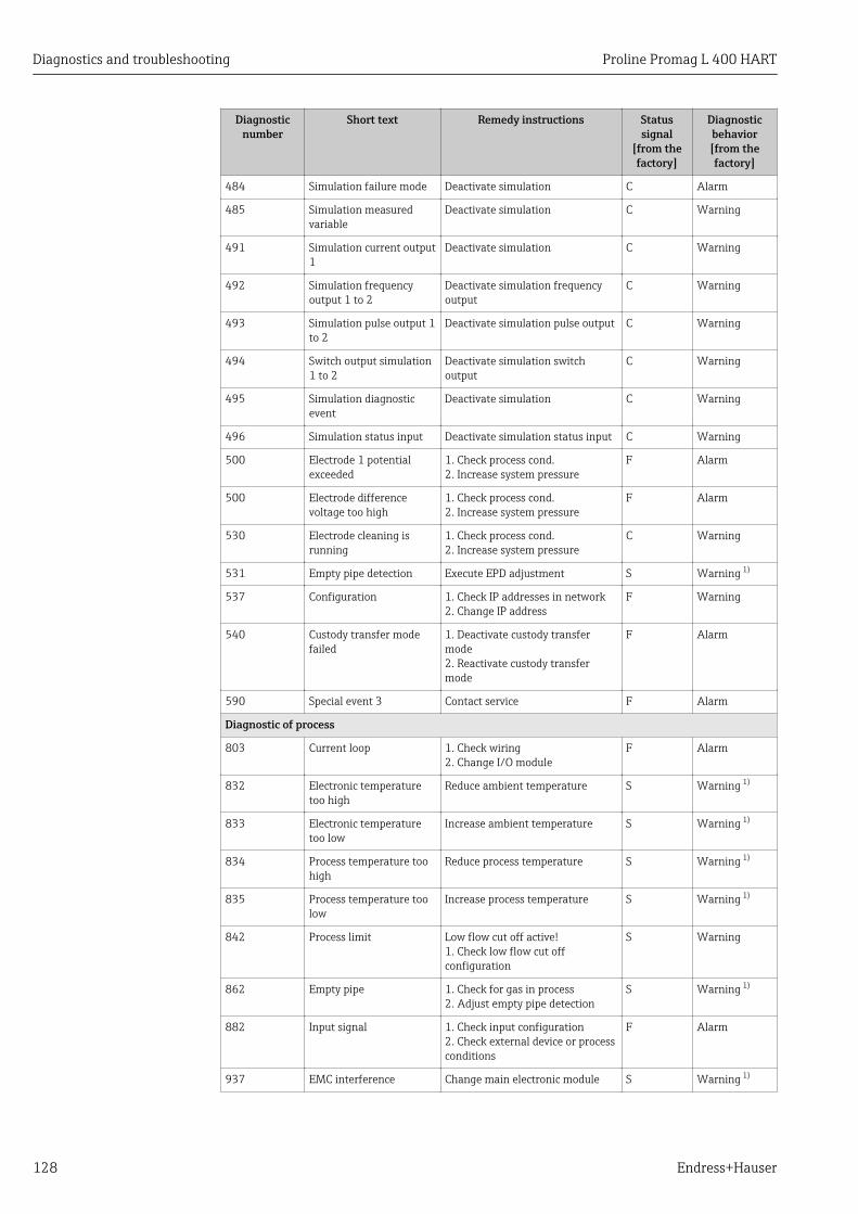
Diagnostics and troubleshooting Proline Promag L 400 HART
128 Endress+Hauser
Diagnosticnumber
Short text Remedy instructions Statussignal
[from thefactory]
Diagnosticbehavior[from thefactory]
484 Simulation failure mode Deactivate simulation C Alarm
485 Simulation measuredvariable
Deactivate simulation C Warning
491 Simulation current output1
Deactivate simulation C Warning
492 Simulation frequencyoutput 1 to 2
Deactivate simulation frequencyoutput
C Warning
493 Simulation pulse output 1to 2
Deactivate simulation pulse output C Warning
494 Switch output simulation1 to 2
Deactivate simulation switchoutput
C Warning
495 Simulation diagnosticevent
Deactivate simulation C Warning
496 Simulation status input Deactivate simulation status input C Warning
500 Electrode 1 potentialexceeded
1. Check process cond.2. Increase system pressure
F Alarm
500 Electrode differencevoltage too high
1. Check process cond.2. Increase system pressure
F Alarm
530 Electrode cleaning isrunning
1. Check process cond.2. Increase system pressure
C Warning
531 Empty pipe detection Execute EPD adjustment S Warning 1)
537 Configuration 1. Check IP addresses in network2. Change IP address
F Warning
540 Custody transfer modefailed
1. Deactivate custody transfermode2. Reactivate custody transfermode
F Alarm
590 Special event 3 Contact service F Alarm
Diagnostic of process
803 Current loop 1. Check wiring2. Change I/O module
F Alarm
832 Electronic temperaturetoo high
Reduce ambient temperature S Warning 1)
833 Electronic temperaturetoo low
Increase ambient temperature S Warning 1)
834 Process temperature toohigh
Reduce process temperature S Warning 1)
835 Process temperature toolow
Increase process temperature S Warning 1)
842 Process limit Low flow cut off active!1. Check low flow cut offconfiguration
S Warning
862 Empty pipe 1. Check for gas in process2. Adjust empty pipe detection
S Warning 1)
882 Input signal 1. Check input configuration2. Check external device or processconditions
F Alarm
937 EMC interference Change main electronic module S Warning 1)
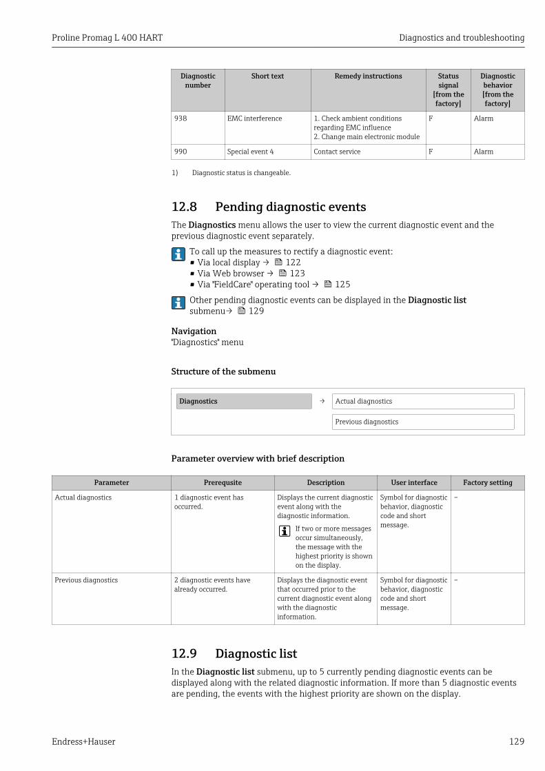
Proline Promag L 400 HART Diagnostics and troubleshooting
Endress+Hauser 129
Diagnosticnumber
Short text Remedy instructions Statussignal
[from thefactory]
Diagnosticbehavior[from thefactory]
938 EMC interference 1. Check ambient conditionsregarding EMC influence2. Change main electronic module
F Alarm
990 Special event 4 Contact service F Alarm
1) Diagnostic status is changeable.
12.8 Pending diagnostic eventsThe Diagnostics menu allows the user to view the current diagnostic event and theprevious diagnostic event separately.
To call up the measures to rectify a diagnostic event:• Via local display → 122• Via Web browser → 123• Via "FieldCare" operating tool → 125
Other pending diagnostic events can be displayed in the Diagnostic listsubmenu→ 129
Navigation"Diagnostics" menu
Structure of the submenu
Diagnostics → Actual diagnostics
Previous diagnostics
Parameter overview with brief description
Parameter Prerequsite Description User interface Factory setting
Actual diagnostics 1 diagnostic event hasoccurred.
Displays the current diagnosticevent along with thediagnostic information.
If two or more messagesoccur simultaneously,the message with thehighest priority is shownon the display.
Symbol for diagnosticbehavior, diagnosticcode and shortmessage.
–
Previous diagnostics 2 diagnostic events havealready occurred.
Displays the diagnostic eventthat occurred prior to thecurrent diagnostic event alongwith the diagnosticinformation.
Symbol for diagnosticbehavior, diagnosticcode and shortmessage.
–
12.9 Diagnostic listIn the Diagnostic list submenu, up to 5 currently pending diagnostic events can bedisplayed along with the related diagnostic information. If more than 5 diagnostic eventsare pending, the events with the highest priority are shown on the display.

Diagnostics and troubleshooting Proline Promag L 400 HART
130 Endress+Hauser
Navigation pathDiagnostics menu→Diagnostic list submenu
Diagnostics
/ ../Diagnose list
Diagnostics 3
Diagnostics 2
F273 Main electronic
A0014006-EN
38 Illustrated using the example of the local display
To call up the measures to rectify a diagnostic event:• Via local display → 122• Via Web browser → 123• Via "FieldCare" operating tool → 125
12.10 Event logbook
12.10.1 Event historyA chronological overview of the event messages that have occurred is provided in theEvents list submenu.
Navigation path"Diagnostics" menu → Event logbook → Events list
FI1091 Config. change
I1157 Mem.err. ev.list
F311 Electr. failure
/ ../Eventlist
0d01h19m10s
A0014008-EN
39 Illustrated using the example of the local display
A maximum of 20 event messages can be displayed in chronological order. If the advancedHistoROM function is enabled in the device (order option), up to 100 entries can bedisplayed.
The event history includes entries for:• Diagnostic events → 126• Information events → 131
In addition to the operation time of its occurrence, each event is also assigned a symbolthat indicates whether the event has occurred or is ended:• Diagnostic event
– : Event has occurred– : Event has ended
• Information event: Event has occurred
To call up the measures to rectify a diagnostic event:• Via local display → 122• Via Web browser → 123• Via "FieldCare" operating tool → 125
For filtering the displayed event messages → 131

Proline Promag L 400 HART Diagnostics and troubleshooting
Endress+Hauser 131
12.10.2 Filtering the event logbookUsing the Filter options parameter, you can define which category of event messages isdisplayed in the Events list submenu.
Navigation path"Diagnostics" menu → Event logbook → Filter options
Filter categories• All• Failure (F)• Function check (C)• Out of specification (S)• Maintenance required (M)• Information (I)
12.10.3 Overview of information eventsUnlike a diagnostic event, an information event is displayed in the event logbook only andnot in the diagnostic list.
Info number Info name
I1000 --------(Device ok)
I1089 Power on
I1090 Configuration reset
I1091 Configuration changed
I1092 Trend data deleted
I1110 Write protection switch changed
I1137 Electronic changed
I1151 History reset
I1155 Reset electronic temperature
I1156 Memory error trend
I1157 Memory error event list
I1184 Display connected
I1185 Display backup done
I1186 Restore via display done
I1187 Settings downloaded with display
I1188 Display data cleared
I1189 Backup compared
I1256 Display: access status changed
I1264 Safety sequence aborted
I1278 I/O module reset detected
I1335 Firmware changed
I1351 Empty pipe detection adjustment failure
I1353 Empty pipe detection adjustment ok
I1361 Wrong web server login
I1397 Fieldbus: access status changed
I1398 CDI: access status changed
I1444 Device verification passed
I1445 Device verification failed

Diagnostics and troubleshooting Proline Promag L 400 HART
132 Endress+Hauser
Info number Info name
I1457 Failed:Measured error verification
I1459 Failed: I/O module verification
I1461 Failed: Sensor verification
I1462 Failed:Sensor electronic module verific.
I1517 Custody transfer active
I1518 Custody transfe inactive
12.11 Resetting the measuring deviceUsing the Device reset parameter it is possible to reset the entire device configuration orsome of the configuration to a defined state.
Navigation"Setup" menu → Advanced setup → Administration → Device reset
‣ Administration
‣ Define access code
Define access code
Confirm access code
Device reset
Parameter overview with brief description
Parameter Description Selection Factory setting
Device reset Restart or reset device manually. • Cancel• To delivery settings• Restart device
Cancel
12.11.1 Function scope of "Device reset" parameter
Options Description
Cancel No action is executed and the user exits the parameter.
To delivery settings Every parameter for which a customer-specific default setting was ordered is resetto this customer-specific value. All other parameters are reset to the factorysetting.
Restart device The restart resets every parameter whose data are in the volatile memory (RAM)to the factory setting (e.g. measured value data). The device configuration remainsunchanged.
History reset Every parameter is reset to its factory setting.
12.12 Device informationThe Device information submenu contains all the parameters that display differentinformation for identifying the device.

Proline Promag L 400 HART Diagnostics and troubleshooting
Endress+Hauser 133
Navigation"Diagnostics" menu → Device information
‣ Device information
Device tag
Serial number
Firmware version
Device name
Order code
Extended order code 1
Extended order code 2
Extended order code 3
ENP version
Custody transfer counter
Timestamp last custody transfer
Device revision
Device ID
Device type
Manufacturer ID
IP address
Subnet mask
Default gateway
Parameter overview with brief description
Parameter Description User interface Factory setting
Device tag Enter the name for the measuring point. Max. 32 characters, such asletters, numbers or specialcharacters (e.g. @, %, /)
Promag 400
Serial number Displays the serial number of the measuringdevice.
Max. 11-digit character stringcomprising letters andnumbers.
79AFFF16000
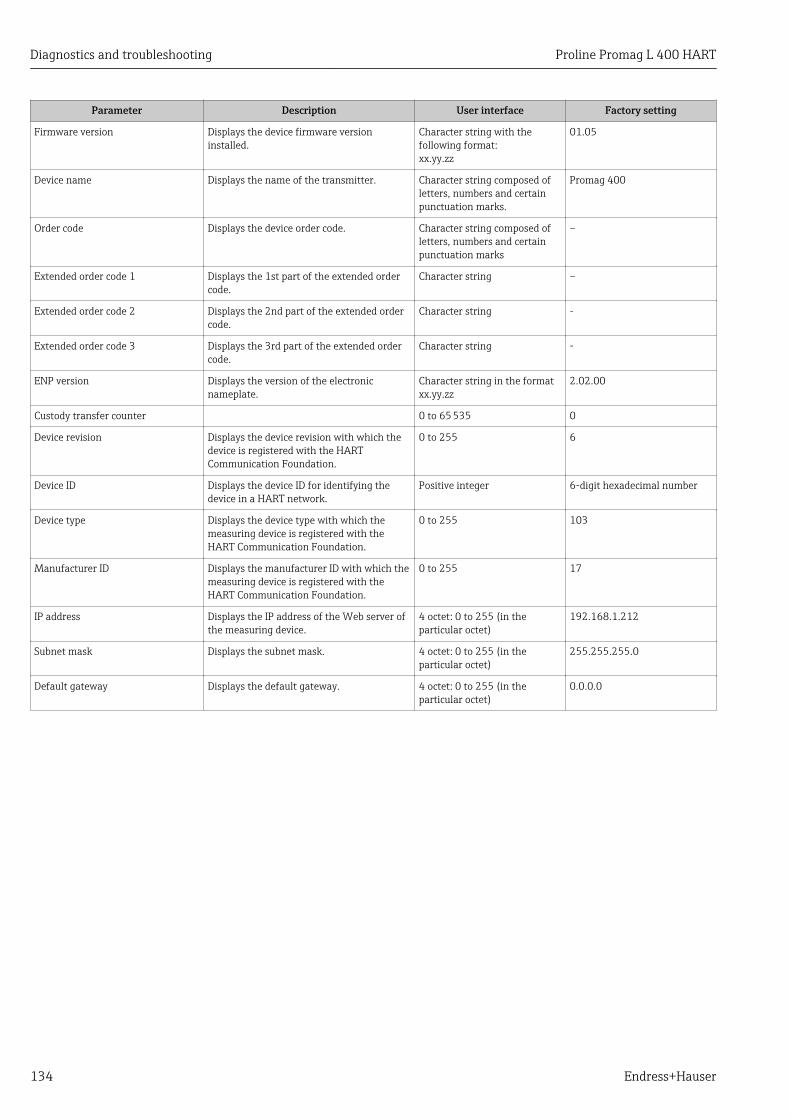
Diagnostics and troubleshooting Proline Promag L 400 HART
134 Endress+Hauser
Parameter Description User interface Factory setting
Firmware version Displays the device firmware versioninstalled.
Character string with thefollowing format:xx.yy.zz
01.05
Device name Displays the name of the transmitter. Character string composed ofletters, numbers and certainpunctuation marks.
Promag 400
Order code Displays the device order code. Character string composed ofletters, numbers and certainpunctuation marks
–
Extended order code 1 Displays the 1st part of the extended ordercode.
Character string –
Extended order code 2 Displays the 2nd part of the extended ordercode.
Character string -
Extended order code 3 Displays the 3rd part of the extended ordercode.
Character string -
ENP version Displays the version of the electronicnameplate.
Character string in the formatxx.yy.zz
2.02.00
Custody transfer counter 0 to 65 535 0
Device revision Displays the device revision with which thedevice is registered with the HARTCommunication Foundation.
0 to 255 6
Device ID Displays the device ID for identifying thedevice in a HART network.
Positive integer 6-digit hexadecimal number
Device type Displays the device type with which themeasuring device is registered with theHART Communication Foundation.
0 to 255 103
Manufacturer ID Displays the manufacturer ID with which themeasuring device is registered with theHART Communication Foundation.
0 to 255 17
IP address Displays the IP address of the Web server ofthe measuring device.
4 octet: 0 to 255 (in theparticular octet)
192.168.1.212
Subnet mask Displays the subnet mask. 4 octet: 0 to 255 (in theparticular octet)
255.255.255.0
Default gateway Displays the default gateway. 4 octet: 0 to 255 (in theparticular octet)
0.0.0.0
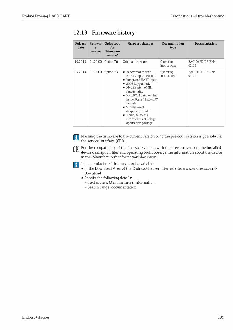
Proline Promag L 400 HART Diagnostics and troubleshooting
Endress+Hauser 135
12.13 Firmware history
Releasedate
Firmware
version
Order codefor
"Firmwareversion"
Firmware changes Documentationtype
Documentation
10.2013 01.04.00 Option 76 Original firmware OperatingInstructions
BA01062D/06/EN/02.13
05.2014 01.05.00 Option 73 • In accordance withHART 7 Specification
• Integrated HART input• SD03 keypad lock• Modification of SIL
functionality• HistoROM data logging
in FieldCare "HistoROM"module
• Simulation ofdiagnostic events
• Ability to accessHeartbeat Technologyapplication package
OperatingInstructions
BA01062D/06/EN/03.14
Flashing the firmware to the current version or to the previous version is possible viathe service interface (CDI) .
For the compatibility of the firmware version with the previous version, the installeddevice description files and operating tools, observe the information about the devicein the "Manufacturer's information" document.
The manufacturer's information is available:• In the Download Area of the Endress+Hauser Internet site: www.endress.com →
Download• Specify the following details:
– Text search: Manufacturer's information– Search range: documentation

Maintenance Proline Promag L 400 HART
136 Endress+Hauser
13 Maintenance
13.1 Maintenance tasksNo special maintenance work is required.
13.1.1 Exterior cleaningWhen cleaning the exterior of measuring devices, always use cleaning agents that do notattack the surface of the housing or the seals.
LWARNINGCleaning agents can damage the plastic transmitter housing!‣ Do not use high-pressure steam.‣ Only use the permitted cleaning agents specified.
Permitted cleaning agents for the plastic transmitter housing• Commercially available household cleaners• Methyl alcohol or isopropyl alcohol• Mild soap solutions
13.1.2 Interior cleaningNo interior cleaning is planned for the device.
13.1.3 Replacing sealsThe sensor's seals (particularly aseptic molded seals) must be replaced periodically.
The interval between changes depends on the frequency of the cleaning cycles, thecleaning temperature and the medium temperature.
Replacement seals (accessory) → 168
13.2 Measuring and test equipmentEndress+Hauser offers a wide variety of measuring and test equipment, such as W@M ordevice tests.
Your Endress+Hauser Sales Center can provide detailed information on the services.
For a list of some of the measuring and test equipment, refer to the "Accessories"chapter of the "Technical Information" document for the device.
13.3 Endress+Hauser servicesEndress+Hauser offers a wide variety of services for maintenance such as recalibration,maintenance service or device tests.
Your Endress+Hauser Sales Center can provide detailed information on the services.

Proline Promag L 400 HART Repair
Endress+Hauser 137
14 Repair
14.1 General notesRepair and conversion conceptThe Endress+Hauser repair and conversion concept provides for the following:• The measuring devices have a modular design.• Spare parts are grouped into logical kits with the associated Installation Instructions.• Repairs are carried out by Endress+Hauser Service or by correspondingly trained
customers.• Certified devices can be converted into other certified devices by Endress+Hauser Service
or at the factory only.
Notes for repair and conversionFor repair and modification of a measuring device, observe the following notes:• Use only original Endress+Hauser spare parts.• Carry out the repair according to the Installation Instructions.• Observe the applicable standards, federal/national regulations, Ex documentation (XA)
and certificates.• Document every repair and each conversion and enter them into the W@M life cycle
management database.
14.2 Spare partsW@M Device Viewer (www.endress.com/deviceviewer):All the spare parts for the measuring device, along with the order code, are listed here andcan be ordered. If available, users can also download the associated InstallationInstructions.
Measuring device serial number:• Is located on the nameplate of the device.• Can be read out via the Serial number parameter in the Device information
submenu → 132.
14.3 Endress+Hauser servicesContact your Endress+Hauser Sales Center for information on services and spareparts.
14.4 ReturnThe measuring device must be returned if it is need of repair or a factory calibration, or ifthe wrong measuring device has been delivered or ordered. Legal specifications requireEndress+Hauser, as an ISO-certified company, to follow certain procedures when handlingproducts that are in contact with the medium.
To ensure safe, swift and professional device returns, please refer to the procedure andconditions for returning devices provided on the Endress+Hauser website athttp://www.endress.com/support/return-material
14.5 Disposal
14.5.1 Removing the measuring device1. Switch off the device.

Repair Proline Promag L 400 HART
138 Endress+Hauser
2. WARNING! Danger to persons from process conditions. Beware of hazardous processconditions such as pressure in the measuring device, high temperatures or aggressivefluids.Carry out the mounting and connection steps from the chapters "Mounting themeasuring device" and "Connecting the measuring device" in the logically reversesequence. Observe the safety instructions.
14.5.2 Disposing of the measuring deviceLWARNING
Danger to personnel and environment from fluids that are hazardous to health.‣ Ensure that the measuring device and all cavities are free of fluid residues that are
hazardous to health or the environment, e.g. substances that have permeated intocrevices or diffused through plastic.
Observe the following notes during disposal:• Observe valid federal/national regulations.• Ensure proper separation and reuse of the device components.
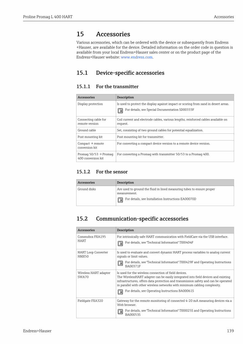
Proline Promag L 400 HART Accessories
Endress+Hauser 139
15 AccessoriesVarious accessories, which can be ordered with the device or subsequently from Endress+Hauser, are available for the device. Detailed information on the order code in question isavailable from your local Endress+Hauser sales center or on the product page of theEndress+Hauser website: www.endress.com.
15.1 Device-specific accessories
15.1.1 For the transmitter
Accessories Description
Display protection Is used to protect the display against impact or scoring from sand in desert areas.
For details, see Special Documentation SD00333F
Connecting cable forremote version
Coil current and electrode cables, various lengths, reinforced cables available onrequest.
Ground cable Set, consisting of two ground cables for potential equalization.
Post mounting kit Post mounting kit for transmitter.
Compact → remoteconversion kit
For converting a compact device version to a remote device version.
Promag 50/53 → Promag400 conversion kit
For converting a Promag with transmitter 50/53 to a Promag 400.
15.1.2 For the sensor
Accessories Description
Ground disks Are used to ground the fluid in lined measuring tubes to ensure propermeasurement.
For details, see Installation Instructions EA00070D
15.2 Communication-specific accessories
Accessories Description
Commubox FXA195HART
For intrinsically safe HART communication with FieldCare via the USB interface.
For details, see "Technical Information" TI00404F
HART Loop ConverterHMX50
Is used to evaluate and convert dynamic HART process variables to analog currentsignals or limit values.
For details, see "Technical Information" TI00429F and Operating InstructionsBA00371F
Wireless HART adapterSWA70
Is used for the wireless connection of field devices.The WirelessHART adapter can be easily integrated into field devices and existinginfrastructures, offers data protection and transmission safety and can be operatedin parallel with other wireless networks with minimum cabling complexity.
For details, see Operating Instructions BA00061S
Fieldgate FXA320 Gateway for the remote monitoring of connected 4-20 mA measuring devices via aWeb browser.
For details, see "Technical Information" TI00025S and Operating InstructionsBA00053S

Accessories Proline Promag L 400 HART
140 Endress+Hauser
Fieldgate FXA520 Gateway for the remote diagnostics and remote configuration of connected HARTmeasuring devices via a Web browser.
For details, see "Technical Information" TI00025S and Operating InstructionsBA00051S
Field Xpert SFX350 Field Xpert SFX350 is a mobile computer for commissioning and maintenance. Itenables efficient device configuration and diagnostics for HART and FOUNDATIONFieldbus devices in the non-Ex area.
For details, see Operating Instructions BA01202S
Field Xpert SFX370 Field Xpert SFX370 is a mobile computer for commissioning and maintenance. Itenables efficient device configuration and diagnostics for HART and FOUNDATIONFieldbus devices in the non-Ex area and the Ex area.
For details, see Operating Instructions BA01202S
15.3 Service-specific accessories
Accessories Description
Applicator Software for selecting and sizing Endress+Hauser measuring devices:• Calculation of all the necessary data for identifying the optimum flowmeter: e.g.
nominal diameter, pressure loss, accuracy or process connections.• Graphic illustration of the calculation results
Administration, documentation and access to all project-related data andparameters throughout the entire life cycle of a project.
Applicator is available:• Via the Internet: https://wapps.endress.com/applicator• On CD-ROM for local PC installation.
W@M Life cycle management for your plantW@M supports you with a wide range of software applications over the entireprocess: from planning and procurement, to the installation, commissioning andoperation of the measuring devices. All the relevant device information, such asthe device status, spare parts and device-specific documentation, is available forevery device over the entire life cycle.The application already contains the data of your Endress+Hauser device. Endress+Hauser also takes care of maintaining and updating the data records.
W@M is available:• Via the Internet: www.endress.com/lifecyclemanagement• On CD-ROM for local PC installation.
FieldCare FDT-based plant asset management tool from Endress+Hauser.It can configure all smart field units in your system and helps you manage them. Byusing the status information, it is also a simple but effective way of checking theirstatus and condition.
For details, see Operating Instructions BA00027S and BA00059S
15.4 System components
Accessories Description
Memograph M graphicdisplay recorder
The Memograph M graphic display recorder provides information on all relevantmeasured variables. Measured values are recorded correctly, limit values aremonitored and measuring points analyzed. The data are stored in the 256 MBinternal memory and also on a SD card or USB stick.
For details, see "Technical Information" TI00133R and Operating InstructionsBA00247R

Proline Promag L 400 HART Technical data
Endress+Hauser 141
16 Technical data
16.1 ApplicationThe measuring device described in these Instructions is intended only for flowmeasurement of liquids with a minimum conductivity of 5 μS/cm.
Depending on the version ordered, the measuring device can also measure potentiallyexplosive, flammable, poisonous and oxidizing media.
To ensure that the device remains in proper operating condition for its service life, use themeasuring device only for media against which the process-wetted materials areadequately resistant.
16.2 Function and system design
Measuring principle Electromagnetic flow measurement on the basis of Faraday's law of magnetic induction.
Measuring system The device consists of a transmitter and a sensor.
Two device versions are available:• Compact version - transmitter and sensor form a mechanical unit.• Remote version - transmitter and sensor are mounted in separate locations.
For information on the structure of the device
16.3 Input
Measured variable Direct measured variables• Volume flow (proportional to induced voltage)• Electrical conductivity
Calculated measured variablesMass flow
Measuring range Typically v = 0.01 to 10 m/s (0.03 to 33 ft/s) with the specified accuracy
Electrical conductivity: 5 to 10 000 µS/cm
Flow characteristic values in SI units
Nominaldiameter
Recommendedflow Factory settings
Min./max. full scale value(v ~ 0.3/10 m/s)
Full scale value currentoutput
(v ~ 2.5 m/s)
Pulse value(~ 2 pulse/s)
Low flow cut off(v ~ 0.04 m/s)
[mm] [in] [m3/h] [m3/h] [m3] [m3/h]
25 1 9 to 300 dm3/min 75 dm3/min 0.5 dm3 1 dm3/min
32 – 15 to 500 dm3/min 125 dm3/min 1.0 dm3 2 dm3/min
40 1 ½ 25 to 700 dm3/min 200 dm3/min 1.5 dm3 3 dm3/min
50 2 35 to 1 100 dm3/min 300 dm3/min 2.5 dm3 5 dm3/min
65 – 60 to 2 000 dm3/min 500 dm3/min 5 dm3 8 dm3/min

Technical data Proline Promag L 400 HART
142 Endress+Hauser
Nominaldiameter
Recommendedflow Factory settings
Min./max. full scale value(v ~ 0.3/10 m/s)
Full scale value currentoutput
(v ~ 2.5 m/s)
Pulse value(~ 2 pulse/s)
Low flow cut off(v ~ 0.04 m/s)
[mm] [in] [m3/h] [m3/h] [m3] [m3/h]
80 3 90 to 3 000 dm3/min 750 dm3/min 5 dm3 12 dm3/min
100 4 145 to 4 700 dm3/min 1 200 dm3/min 10 dm3 20 dm3/min
125 – 220 to 7 500 dm3/min 1 850 dm3/min 15 dm3 30 dm3/min
150 6 20 to 600 150 0.025 2.5
200 8 35 to 1 100 300 0.05 5
250 10 55 to 1 700 500 0.05 7.5
300 12 80 to 2 400 750 0.1 10
350 14 110 to 3 300 1 000 0.1 15
375 15 140 to 4 200 1 200 0.15 20
400 16 140 to 4 200 1 200 0.15 20
450 18 180 to 5 400 1 500 0.25 25
500 20 220 to 6 600 2 000 0.25 30
600 24 310 to 9 600 2 500 0.3 40
700 28 420 to 13 500 3 500 0.5 50
750 30 480 to 15 000 4 000 0.5 60
800 32 550 to 18 000 4 500 0.75 75
900 36 690 to 22 500 6 000 0.75 100
1 000 40 850 to 28 000 7 000 1 125
– 42 950 to 30 000 8 000 1 125
1 200 48 1 250 to 40 000 10 000 1.5 150
– 54 1 550 to 50 000 13 000 1.5 200
1 400 – 1 700 to 55 000 14 000 2 225
– 60 1 950 to 60 000 16 000 2 250
1 600 – 2 200 to 70 000 18 000 2.5 300
– 66 2 500 to 80 000 20 500 2.5 325
1 800 72 2 850 to 90 000 23 000 3 350
– 78 3 300 to 100 000 28 500 3.5 450
2 000 – 3 400 to 110 000 28 500 3.5 450
– 84 3 700 to 125 000 31 000 4.5 500
2 200 – 4 100 to 136 000 34 000 4.5 540
– 90 4 300 to 143 000 36 000 5 570
2 400 – 4 800 to 162 000 40 000 5.5 650
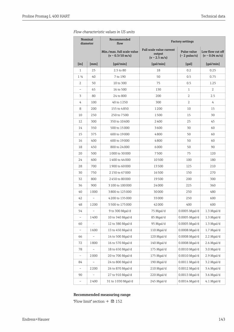
Proline Promag L 400 HART Technical data
Endress+Hauser 143
Flow characteristic values in US units
Nominaldiameter
Recommendedflow Factory settings
Min./max. full scale value(v ~ 0.3/10 m/s)
Full scale value currentoutput
(v ~ 2.5 m/s)
Pulse value(~ 2 pulse/s)
Low flow cut off(v ~ 0.04 m/s)
[in] [mm] [gal/min] [gal/min] [gal] [gal/min]
1 25 2.5 to 80 18 0.2 0.25
1 ½ 40 7 to 190 50 0.5 0.75
2 50 10 to 300 75 0.5 1.25
– 65 16 to 500 130 1 2
3 80 24 to 800 200 2 2.5
4 100 40 to 1 250 300 2 4
8 200 155 to 4 850 1 200 10 15
10 250 250 to 7 500 1 500 15 30
12 300 350 to 10 600 2 400 25 45
14 350 500 to 15 000 3 600 30 60
15 375 600 to 19 000 4 800 50 60
16 400 600 to 19 000 4 800 50 60
18 450 800 to 24 000 6 000 50 90
20 500 1 000 to 30 000 7 500 75 120
24 600 1 400 to 44 000 10 500 100 180
28 700 1 900 to 60 000 13 500 125 210
30 750 2 150 to 67 000 16 500 150 270
32 800 2 450 to 80 000 19 500 200 300
36 900 3 100 to 100 000 24 000 225 360
40 1 000 3 800 to 125 000 30 000 250 480
42 – 4 200 to 135 000 33 000 250 600
48 1 200 5 500 to 175 000 42 000 400 600
54 – 9 to 300 Mgal/d 75 Mgal/d 0.0005 Mgal/d 1.3 Mgal/d
– 1 400 10 to 340 Mgal/d 85 Mgal/d 0.0005 Mgal/d 1.3 Mgal/d
60 – 12 to 380 Mgal/d 95 Mgal/d 0.0005 Mgal/d 1.3 Mgal/d
– 1 600 13 to 450 Mgal/d 110 Mgal/d 0.0008 Mgal/d 1.7 Mgal/d
66 – 14 to 500 Mgal/d 120 Mgal/d 0.0008 Mgal/d 2.2 Mgal/d
72 1 800 16 to 570 Mgal/d 140 Mgal/d 0.0008 Mgal/d 2.6 Mgal/d
78 – 18 to 650 Mgal/d 175 Mgal/d 0.0010 Mgal/d 3.0 Mgal/d
– 2 000 20 to 700 Mgal/d 175 Mgal/d 0.0010 Mgal/d 2.9 Mgal/d
84 – 24 to 800 Mgal/d 190 Mgal/d 0.0011 Mgal/d 3.2 Mgal/d
– 2 200 26 to 870 Mgal/d 210 Mgal/d 0.0012 Mgal/d 3.4 Mgal/d
90 – 27 to 910 Mgal/d 220 Mgal/d 0.0013 Mgal/d 3.6 Mgal/d
– 2 400 31 to 1 030 Mgal/d 245 Mgal/d 0.0014 Mgal/d 4.1 Mgal/d
Recommended measuring range"Flow limit" section → 152
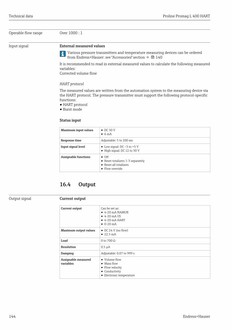
Technical data Proline Promag L 400 HART
144 Endress+Hauser
Operable flow range Over 1000 : 1
Input signal External measured valuesVarious pressure transmitters and temperature measuring devices can be orderedfrom Endress+Hauser: see "Accessories" section → 140
It is recommended to read in external measured values to calculate the following measuredvariables:Corrected volume flow
HART protocol
The measured values are written from the automation system to the measuring device viathe HART protocol. The pressure transmitter must support the following protocol-specificfunctions:• HART protocol• Burst mode
Status input
Maximum input values • DC 30 V• 6 mA
Response time Adjustable: 5 to 200 ms
Input signal level • Low signal: DC –3 to +5 V• High signal: DC 12 to 30 V
Assignable functions • Off• Reset totalizers 1-3 separately• Reset all totalizers• Flow override
16.4 Output
Output signal Current output
Current output Can be set as:• 4-20 mA NAMUR• 4-20 mA US• 4-20 mA HART• 0-20 mA
Maximum output values • DC 24 V (no flow)• 22.5 mA
Load 0 to 700 Ω
Resolution 0.5 µA
Damping Adjustable: 0.07 to 999 s
Assignable measuredvariables
• Volume flow• Mass flow• Flow velocity• Conductivity• Electronic temperature
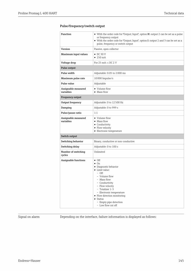
Proline Promag L 400 HART Technical data
Endress+Hauser 145
Pulse/frequency/switch output
Function • With the order code for "Output; Input", option H: output 2 can be set as a pulseor frequency output
• With the order code for "Output; Input", option I: output 2 and 3 can be set as apulse, frequency or switch output
Version Passive, open collector
Maximum input values • DC 30 V• 250 mA
Voltage drop For 25 mA: ≤ DC 2 V
Pulse output
Pulse width Adjustable: 0.05 to 2 000 ms
Maximum pulse rate 10 000 Impulse/s
Pulse value Adjustable
Assignable measuredvariables
• Volume flow• Mass flow
Frequency output
Output frequency Adjustable: 0 to 12 500 Hz
Damping Adjustable: 0 to 999 s
Pulse/pause ratio 1:1
Assignable measuredvariables
• Volume flow• Mass flow• Conductivity• Flow velocity• Electronic temperature
Switch output
Switching behavior Binary, conductive or non-conductive
Switching delay Adjustable: 0 to 100 s
Number of switchingcycles
Unlimited
Assignable functions • Off• On• Diagnostic behavior• Limit value:
– Off– Volume flow– Mass flow– Conductivity– Flow velocity– Totalizer 1-3– Electronic temperature
• Flow direction monitoring• Status
– Empty pipe detection– Low flow cut off
Signal on alarm Depending on the interface, failure information is displayed as follows:
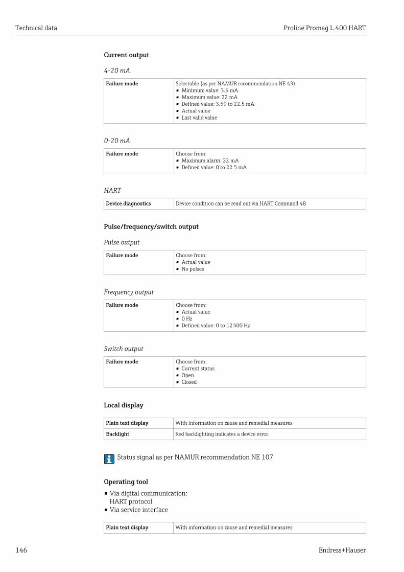
Technical data Proline Promag L 400 HART
146 Endress+Hauser
Current output
4-20 mA
Failure mode Selectable (as per NAMUR recommendation NE 43):• Minimum value: 3.6 mA• Maximum value: 22 mA• Defined value: 3.59 to 22.5 mA• Actual value• Last valid value
0-20 mA
Failure mode Choose from:• Maximum alarm: 22 mA• Defined value: 0 to 22.5 mA
HART
Device diagnostics Device condition can be read out via HART Command 48
Pulse/frequency/switch output
Pulse output
Failure mode Choose from:• Actual value• No pulses
Frequency output
Failure mode Choose from:• Actual value• 0 Hz• Defined value: 0 to 12 500 Hz
Switch output
Failure mode Choose from:• Current status• Open• Closed
Local display
Plain text display With information on cause and remedial measures
Backlight Red backlighting indicates a device error.
Status signal as per NAMUR recommendation NE 107
Operating tool• Via digital communication:
HART protocol• Via service interface
Plain text display With information on cause and remedial measures

Proline Promag L 400 HART Technical data
Endress+Hauser 147
Web browser
Plain text display With information on cause and remedial measures
Low flow cut off The switch points for low flow cut off are user-selectable.
Galvanic isolation The following connections are galvanically isolated from each other:• Inputs• Outputs• Power supply
Protocol-specific data HART• For information on the device description files → 66• For information on the dynamic variables and measured variables (HART device
variables) → 66
16.5 Power supply
Terminal assignment → 35
Supply voltage Transmitter
Order code for "Power supply" Terminal voltage Frequency range
Option LAC100 to 240 V 50/ 60 Hz, ±4 Hz
AC/DC24 V 50/ 60 Hz, ±4 Hz
Power consumption Order code for "Output" Maximum power consumption
Option H: 4-20mA HART, pulse/frequency/switchoutput, switch output 30 VA/8 W
Option I: 4-20mA HART, 2 x pulse/frequency/switchoutput, status input 30 VA/8 W
Current consumption Transmitter
Order code for "Power supply" MaximumCurrent consumption
Maximumswitch-on current
Option L: AC 100 to 240 V 145 mA 25 A (< 5 ms)
Option L: AC/DC 24 V 350 mA 27 A (< 5 ms)
Power supply failure • Totalizers stop at the last value measured.• Configuration is retained in the plug-in memory (HistoROM DAT).• Error messages (incl. total operated hours) are stored.
Electrical connection
Potential equalization → 41
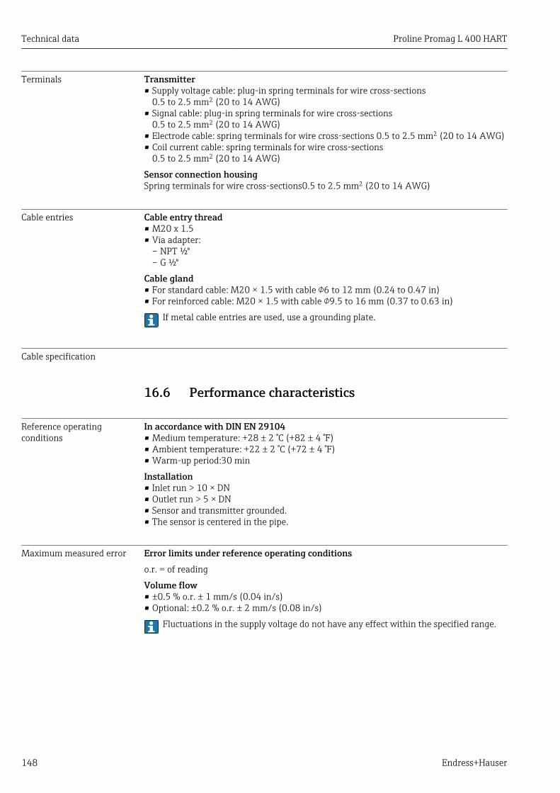
Technical data Proline Promag L 400 HART
148 Endress+Hauser
Terminals Transmitter• Supply voltage cable: plug-in spring terminals for wire cross-sections
0.5 to 2.5 mm2 (20 to 14 AWG)• Signal cable: plug-in spring terminals for wire cross-sections
0.5 to 2.5 mm2 (20 to 14 AWG)• Electrode cable: spring terminals for wire cross-sections 0.5 to 2.5 mm2 (20 to 14 AWG)• Coil current cable: spring terminals for wire cross-sections
0.5 to 2.5 mm2 (20 to 14 AWG)
Sensor connection housingSpring terminals for wire cross-sections0.5 to 2.5 mm2 (20 to 14 AWG)
Cable entries Cable entry thread• M20 x 1.5• Via adapter:
– NPT ½"– G ½"
Cable gland• For standard cable: M20 × 1.5 with cable 6 to 12 mm (0.24 to 0.47 in)• For reinforced cable: M20 × 1.5 with cable 9.5 to 16 mm (0.37 to 0.63 in)
If metal cable entries are used, use a grounding plate.
Cable specification
16.6 Performance characteristics
Reference operatingconditions
In accordance with DIN EN 29104• Medium temperature: +28 ± 2 °C (+82 ± 4 °F)• Ambient temperature: +22 ± 2 °C (+72 ± 4 °F)• Warm-up period:30 min
Installation• Inlet run > 10 × DN• Outlet run > 5 × DN• Sensor and transmitter grounded.• The sensor is centered in the pipe.
Maximum measured error Error limits under reference operating conditionso.r. = of reading
Volume flow• ±0.5 % o.r. ± 1 mm/s (0.04 in/s)• Optional: ±0.2 % o.r. ± 2 mm/s (0.08 in/s)
Fluctuations in the supply voltage do not have any effect within the specified range.

Proline Promag L 400 HART Technical data
Endress+Hauser 149
2.5
[%]
2.0
1.5
1.0
0.5
0
0.2 %
0.5 %
0 1 2 4 6 8 10 [m/s]
v
5 10 15 20 25 30 32 [ft/s]0
A0005531
40 Maximum measured error in % o.r.
Electrical conductivityMax. measured error not specified.
Accuracy of outputso.r. = of reading
The outputs have the following base accuracy specifications.
Current output
Accuracy Max. ±5 µA
Pulse/frequency output
Accuracy Max. ±50 ppm o.r. (across the complete ambient temperature range)
Repeatability o.r. = of reading
Volume flowmax. ±0.1 % o.r. ± 0.5 mm/s (0.02 in/s)
Electrical conductivityMax. ±5 % o.r.
Influence of ambienttemperature
o.r. = of reading
Current output
Temperature coefficient Max. ±0.005% o.r./°C
Pulse/frequency output
Temperature coefficient No additional effect. Included in accuracy.
16.7 Installation"Mounting requirements" → 19

Technical data Proline Promag L 400 HART
150 Endress+Hauser
16.8 Environment
Ambient temperaturerange
→ 21
Storage temperature The storage temperature corresponds to the operating temperature range of themeasuring transmitter and the appropriate measuring sensors.
• Protect the measuring device against direct sunlight during storage in order to avoidunacceptably high surface temperatures.
• Select a storage location where moisture cannot collect in the measuring device asfungus or bacteria infestation can damage the liner.
• If protection caps or protective covers are mounted these should never be removedbefore installing the measuring device.
Atmosphere If a plastic transmitter housing is permanently exposed to certain steam and air mixtures,this can damage the housing.
If you are unsure, please contact your Endress+Hauser Sales Center for clarification.
Degree of protection Transmitter• As standard: IP66/67, type 4X enclosure• When housing is open: IP20, type 1 enclosure
Sensor• As standard: IP66/67, type 4X enclosure• Optionally available for remote version:
IP68, type 6P enclosure (for DN ≤ 300 (12") only possible in conjunction with stainlesssteel flanges)Not suitable for use in corrosive atmospheres/liquids or in buried applications if specialprecautions are not taken.
Shock resistance Compact version6 ms 30 g, according to IEC 60068-2-27
Remote version• Transmitter: 6 ms 30 g, according to IEC 60068-2-27• Sensor: 6 ms 50 g, according to IEC 60068-2-27
Vibration resistance Compact version• Vibration sinusoidal, 1 g peak, according to IEC 60068-2-6• Vibration broad-band random, 1.54 g rms, according to IEC 60068-2-64
Remote version• Transmitter
– Vibration sinusoidal, 1 g peak, according to IEC 60068-2-6– Vibration broad-band random, 1.54 g rms, according to IEC 60068-2-64
• Sensor:– Vibration sinusoidal, 2 g peak, according to IEC 60068-2-6– Vibration broad-band random, 2.70 g rms, according to IEC 60068-2-64
Mechanical load • Protect the transmitter housing against mechanical effects, such as shock or impact; theuse of the remote version is sometimes preferable.
• Never use the transmitter housing as a ladder or climbing aid.

Proline Promag L 400 HART Technical data
Endress+Hauser 151
Electromagneticcompatibility (EMC)
• As per IEC/EN 61326 and NAMUR Recommendation 21 (NE 21)• Complies with emission limits for industry as per EN 55011 (Class A)
For details refer to the Declaration of Conformity.
16.9 Process
Medium temperature range • 0 to +80 °C (+32 to +176 °F) for hard rubber, DN 350 to 2400 (14 to 90")• –20 to +50 °C (–4 to +122 °F) for polyurethane, DN 25 to 1200 (1 to 48")• –20 to +90 °C (–4 to +194 °F) for PTFE, DN 25 to 300 (1 to 12")
Conductivity ≥ 5 μS/cm for liquids in general
Note that in the case of the remote version, the requisite minimum conductivity alsodepends on the cable length .
Pressure-temperatureratings
An overview of the pressure-temperature ratings for the process connections isprovided in the "Technical Information" document
Pressure tightness Liner: hard rubber, polyurethane
Nominal diameter Liner Limit values for absolute pressure in [mbar] ([psi]) for fluidtemperatures:
[mm] [in] +25 °C (+77 °F) +50 °C (+122 °F) +80 °C (+176 °F)
350…2400 14…90 Hard rubber 0 (0) 0 (0) 0 (0)
25…1200 1…48 Polyurethane 0 (0) 0 (0) –
Liner: PTFE
Nominal diameter Limit values for absolute pressure in [mbar] ([psi]) for fluid temperatures:
[mm] [in] +25 °C (+77 °F) +90 °C (+194 °F)
25 1 0 (0) 0 (0)
40 2 0 (0) 0 (0)
50 2 0 (0) 0 (0)
65 2 ½ 0 (0) 40 (0.58)
80 3 0 (0) 40 (0.58)
100 4 0 (0) 135 (2.0)
125 5 135 (2.0) 240 (3.5)
150 6 135 (2.0) 240 (3.5)
200 8 200 (2.9) 290 (4.2)
250 10 330 (4.8) 400 (5.8)
300 12 400 (5.8) 500 (7.3)
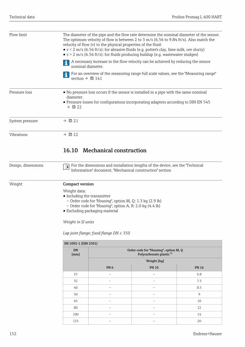
Technical data Proline Promag L 400 HART
152 Endress+Hauser
Flow limit The diameter of the pipe and the flow rate determine the nominal diameter of the sensor.The optimum velocity of flow is between 2 to 3 m/s (6.56 to 9.84 ft/s). Also match thevelocity of flow (v) to the physical properties of the fluid:• v < 2 m/s (6.56 ft/s): for abrasive fluids (e.g. potter's clay, lime milk, ore slurry)• v > 2 m/s (6.56 ft/s): for fluids producing buildup (e.g. wastewater sludges)
A necessary increase in the flow velocity can be achieved by reducing the sensornominal diameter.
For an overview of the measuring range full scale values, see the "Measuring range"section → 141
Pressure loss • No pressure loss occurs if the sensor is installed in a pipe with the same nominaldiameter.
• Pressure losses for configurations incorporating adapters according to DIN EN 545→ 22
System pressure → 21
Vibrations → 22
16.10 Mechanical construction
Design, dimensions For the dimensions and installation lengths of the device, see the "TechnicalInformation" document, "Mechanical construction" section
Weight Compact versionWeight data:• Including the transmitter
– Order code for "Housing", option M, Q: 1.3 kg (2.9 lb)– Order code for "Housing", option A, R: 2.0 kg (4.4 lb)
• Excluding packaging material
Weight in SI units
Lap joint flange; fixed flange DN ≥ 350
EN 1092-1 (DIN 2501)
DN[mm]
Order code for "Housing", option M, QPolycarbonate plastic 1)
Weight [kg]
PN 6 PN 10 PN 16
25 – – 6.8
32 – – 7.5
40 – – 8.5
50 – – 9
65 – – 10
80 – – 12
100 – – 14
125 – – 20

Proline Promag L 400 HART Technical data
Endress+Hauser 153
EN 1092-1 (DIN 2501)
DN[mm]
Order code for "Housing", option M, QPolycarbonate plastic 1)
Weight [kg]
PN 6 PN 10 PN 16
150 – – 24
200 – 43 44.4
250 – 63 70.2
300 – 68 85.3
350 77 88 103
400 89 104 121
450 99 112 138
500 114 132 178
600 155 162 223
700 190 240 287
800 240 315 349
900 308 393 440
1 000 359 468 562
1 200 529 717 839
1 400 784 1 114 1 200
1 600 1 058 1 624 1 840
1 800 1 484 2 107 2 353
2 000 1 877 2 630 2 925
2 200 2 512 3 422 –
2 400 2 996 4 094 –
1) Values for aluminum transmitter, AlSi10Mg, coated: + 0.7 kg
AS 2129, Table E
DN[mm]
Weight [kg]
Order code for "Housing", option M, QPolycarbonate plastic
Order code for "Housing", option A, RAluminum, AlSi10Mg, coated
350 99 99.7
400 120 120.7
450 143 143.7
500 182 182.7
600 260 260.7
700 346 346.7
750 433 433.7
800 493 493.7
900 690 690.7
1 000 761 761.7
1 200 1 237 1 237.7
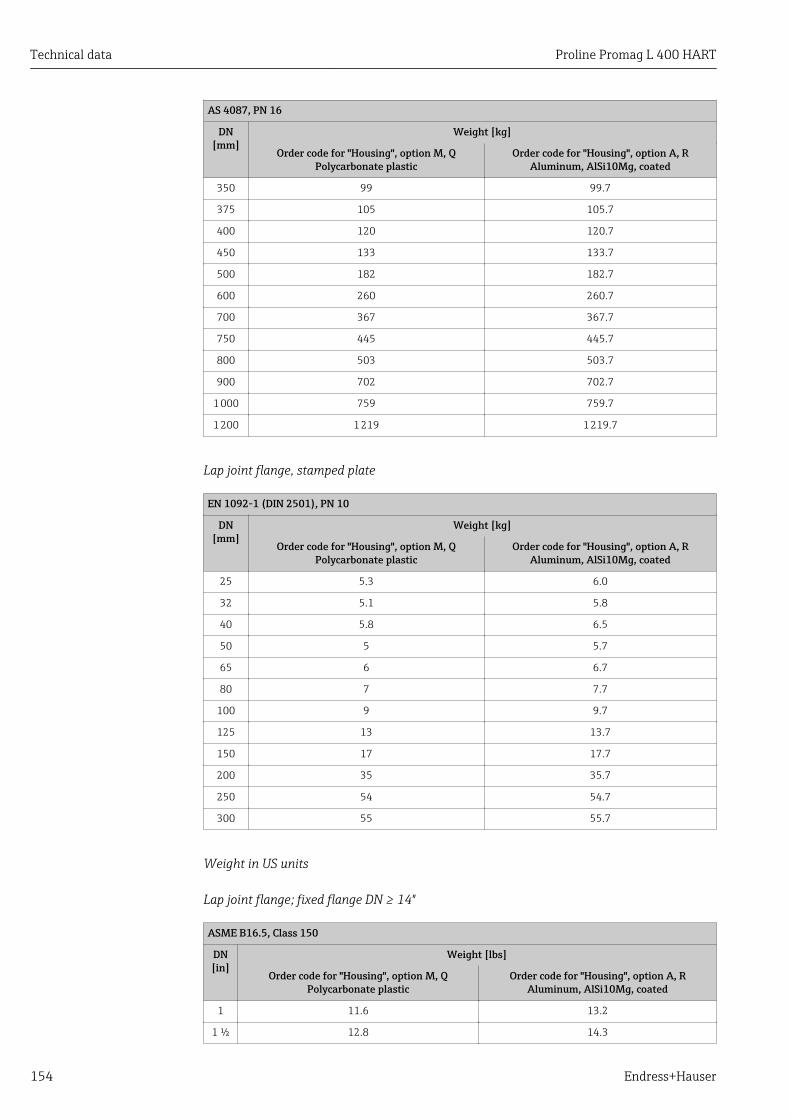
Technical data Proline Promag L 400 HART
154 Endress+Hauser
AS 4087, PN 16
DN[mm]
Weight [kg]
Order code for "Housing", option M, QPolycarbonate plastic
Order code for "Housing", option A, RAluminum, AlSi10Mg, coated
350 99 99.7
375 105 105.7
400 120 120.7
450 133 133.7
500 182 182.7
600 260 260.7
700 367 367.7
750 445 445.7
800 503 503.7
900 702 702.7
1 000 759 759.7
1 200 1 219 1 219.7
Lap joint flange, stamped plate
EN 1092-1 (DIN 2501), PN 10
DN[mm]
Weight [kg]
Order code for "Housing", option M, QPolycarbonate plastic
Order code for "Housing", option A, RAluminum, AlSi10Mg, coated
25 5.3 6.0
32 5.1 5.8
40 5.8 6.5
50 5 5.7
65 6 6.7
80 7 7.7
100 9 9.7
125 13 13.7
150 17 17.7
200 35 35.7
250 54 54.7
300 55 55.7
Weight in US units
Lap joint flange; fixed flange DN ≥ 14"
ASME B16.5, Class 150
DN[in]
Weight [lbs]
Order code for "Housing", option M, QPolycarbonate plastic
Order code for "Housing", option A, RAluminum, AlSi10Mg, coated
1 11.6 13.2
1 ½ 12.8 14.3

Proline Promag L 400 HART Technical data
Endress+Hauser 155
ASME B16.5, Class 150
DN[in]
Weight [lbs]
Order code for "Housing", option M, QPolycarbonate plastic
Order code for "Housing", option A, RAluminum, AlSi10Mg, coated
2 20 21.5
3 26 27.5
4 31 32.5
6 53 54.5
8 95 96.5
10 139 140.5
12 150 151.5
14 302 303.5
16 370 371.5
18 421 422.5
20 503 504.5
24 666 667.5
AWWA C207, Class D
DN[in]
Weight [lbs]
Order code for "Housing", option M, QPolycarbonate plastic
Order code for "Housing", option A, RAluminum, AlSi10Mg, coated
28 586 587.5
30 701 702.5
32 844 845.5
36 1 036 1 037.5
40 1 294 1 295.5
42 1 477 1 478.5
48 1 987 1 988.5
54 2 807 2 808.5
60 3 515 3 516.5
66 4 699 4 700.5
72 5 662 5 663.5
78 6 864 6 865.5
84 8 280 8 281.5
90 10 577 10 578.5
Transmitter remote version
Wall-mount housing
Depends on the material of the wall-mount housing:• Polycarbonate plastic: 1.3 kg (2.9 lb)• Aluminum, AlSi10Mg, coated: 2.0 kg (4.4 lb)

Technical data Proline Promag L 400 HART
156 Endress+Hauser
Sensor remote versionWeight data:• Including sensor connection housing• Excluding the connecting cable• Excluding packaging material
Weight in SI units
Lap joint flange; fixed flange DN ≥ 350
EN 1092-1 (DIN 2501)
DN[mm]
Weight [kg]
PN 6 PN 10 PN 16
25 – – 6.8
32 – – 7.5
40 – – 8.5
50 – – 6
65 – – 7
80 – – 9
100 – – 11
125 – – 16
150 – – 20
200 – 40 44.4
250 – 60 70.2
300 – 65 85.3
350 73 84 101
400 85 100 119
450 95 108 136
500 110 128 176
600 158 158 221
700 187 237 285
800 237 312 347
900 305 390 438
1 000 356 465 560
1 200 526 714 837
1 400 781 1 111 1 197
1 600 1 055 1 621 1 838
1 800 1 415 2 104 2 350
2 000 1 874 2 627 2 922
2 200 2 509 3 419 –
2 400 2 993 4 091 –
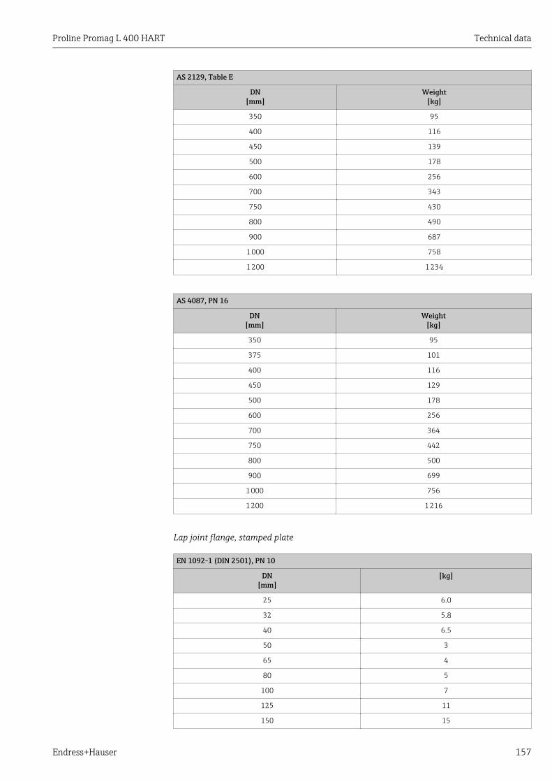
Proline Promag L 400 HART Technical data
Endress+Hauser 157
AS 2129, Table E
DN[mm]
Weight[kg]
350 95
400 116
450 139
500 178
600 256
700 343
750 430
800 490
900 687
1 000 758
1 200 1 234
AS 4087, PN 16
DN[mm]
Weight[kg]
350 95
375 101
400 116
450 129
500 178
600 256
700 364
750 442
800 500
900 699
1 000 756
1 200 1 216
Lap joint flange, stamped plate
EN 1092-1 (DIN 2501), PN 10
DN[mm]
[kg]
25 6.0
32 5.8
40 6.5
50 3
65 4
80 5
100 7
125 11
150 15

Technical data Proline Promag L 400 HART
158 Endress+Hauser
EN 1092-1 (DIN 2501), PN 10
DN[mm]
[kg]
200 33
250 52
300 53
Weight in US units
Lap joint flange; fixed flange DN ≥ 14"
ASME B16.5, Class 150
DN[in]
Weight[lbs]
1 13.2
1 ½ 14.3
2 13
3 20
4 24
6 44
8 88
10 132
12 143
14 293
15 –
16 361
18 412
20 494
24 657
AWWA C207, Class D
DN[in]
Weight[lbs]
28 580
30 695
32 838
36 1 030
40 1 288
42 1 471
48 1 980
54 2 800
60 3 508
66 4 692
72 5 656
78 6 858
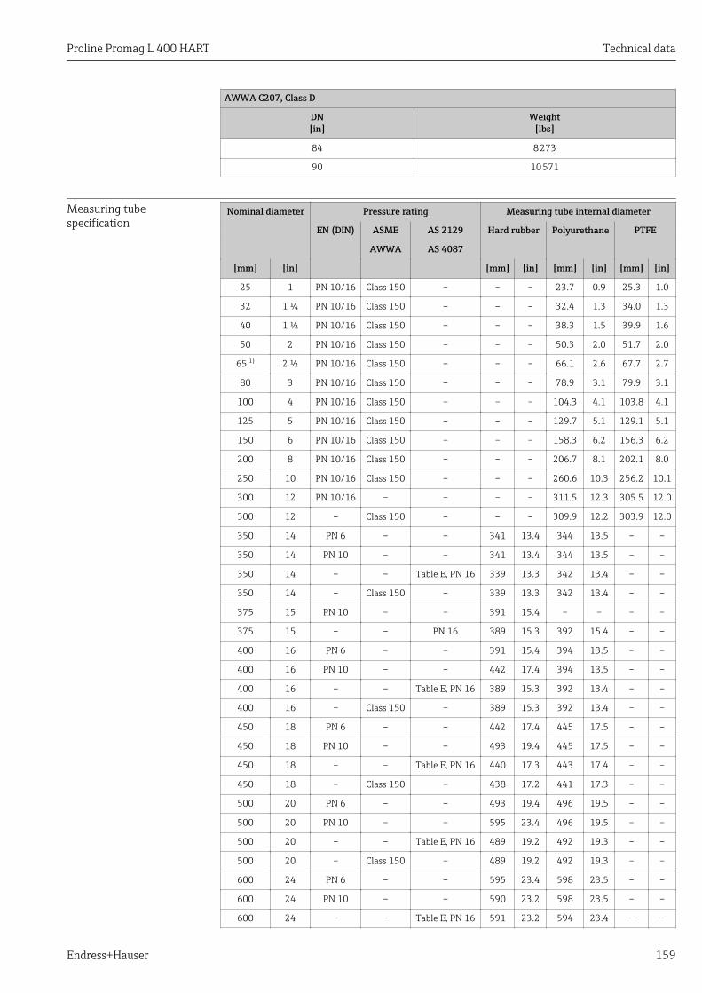
Proline Promag L 400 HART Technical data
Endress+Hauser 159
AWWA C207, Class D
DN[in]
Weight[lbs]
84 8 273
90 10 571
Measuring tubespecification
Nominal diameter Pressure rating Measuring tube internal diameter
EN (DIN) ASME AS 2129 Hard rubber Polyurethane PTFE
AWWA AS 4087
[mm] [in] [mm] [in] [mm] [in] [mm] [in]
25 1 PN 10/16 Class 150 – – – 23.7 0.9 25.3 1.0
32 1 ¼ PN 10/16 Class 150 – – – 32.4 1.3 34.0 1.3
40 1 ½ PN 10/16 Class 150 – – – 38.3 1.5 39.9 1.6
50 2 PN 10/16 Class 150 – – – 50.3 2.0 51.7 2.0
65 1) 2 ½ PN 10/16 Class 150 – – – 66.1 2.6 67.7 2.7
80 3 PN 10/16 Class 150 – – – 78.9 3.1 79.9 3.1
100 4 PN 10/16 Class 150 – – – 104.3 4.1 103.8 4.1
125 5 PN 10/16 Class 150 – – – 129.7 5.1 129.1 5.1
150 6 PN 10/16 Class 150 – – – 158.3 6.2 156.3 6.2
200 8 PN 10/16 Class 150 – – – 206.7 8.1 202.1 8.0
250 10 PN 10/16 Class 150 – – – 260.6 10.3 256.2 10.1
300 12 PN 10/16 – – – – 311.5 12.3 305.5 12.0
300 12 – Class 150 – – – 309.9 12.2 303.9 12.0
350 14 PN 6 – – 341 13.4 344 13.5 – –
350 14 PN 10 – – 341 13.4 344 13.5 – –
350 14 – – Table E, PN 16 339 13.3 342 13.4 – –
350 14 – Class 150 – 339 13.3 342 13.4 – –
375 15 PN 10 – – 391 15.4 – – – –
375 15 – – PN 16 389 15.3 392 15.4 – –
400 16 PN 6 – – 391 15.4 394 13.5 – –
400 16 PN 10 – – 442 17.4 394 13.5 – –
400 16 – – Table E, PN 16 389 15.3 392 13.4 – –
400 16 – Class 150 – 389 15.3 392 13.4 – –
450 18 PN 6 – – 442 17.4 445 17.5 – –
450 18 PN 10 – – 493 19.4 445 17.5 – –
450 18 – – Table E, PN 16 440 17.3 443 17.4 – –
450 18 – Class 150 – 438 17.2 441 17.3 – –
500 20 PN 6 – – 493 19.4 496 19.5 – –
500 20 PN 10 – – 595 23.4 496 19.5 – –
500 20 – – Table E, PN 16 489 19.2 492 19.3 – –
500 20 – Class 150 – 489 19.2 492 19.3 – –
600 24 PN 6 – – 595 23.4 598 23.5 – –
600 24 PN 10 – – 590 23.2 598 23.5 – –
600 24 – – Table E, PN 16 591 23.2 594 23.4 – –

Technical data Proline Promag L 400 HART
160 Endress+Hauser
Nominal diameter Pressure rating Measuring tube internal diameter
EN (DIN) ASME AS 2129 Hard rubber Polyurethane PTFE
AWWA AS 4087
[mm] [in] [mm] [in] [mm] [in] [mm] [in]
600 24 – Class 150 – 589 23.1 592 23.3 – –
700 28 PN 6 – – 696 27.4 699 27.5 – –
700 28 PN 10 – – 694 27.3 697 27.4 – –
700 28 – – Table E, PN 16 690 27.2 693 27.3 – –
700 28 – Class D – 694 27.3 697 27.4 – –
750 30 PN 6 – – – – 699 27.5 – –
750 30 PN 10 – – – – 697 27.4 – –
750 30 – – Table E, PN 16 741 29.2 744 29.3 – –
750 30 – Class D – 743 29.3 746 29.4 – –
800 32 PN 6 – – 798 31.4 801 31.5 – –
800 32 PN 10 – – 796 31.3 799 31.5 – –
800 32 – – Table E, PN 16 792 31.2 795 31.3 – –
800 32 – Class D – 794 31.3 797 31.4 – –
900 36 PN 6 – – 897 35.3 900 35.4 – –
900 36 PN 10 – – 895 35.2 898 35.4 – –
900 36 – – Table E, PN 16 889 35.0 892 35.1 – –
900 36 – Class D – 895 35.2 898 35.4 – –
1 000 40 PN 6 – – 999 39.3 1 002 39.4 – –
1 000 40 PN 10 – – 997 39.3 1 000 39.4 – –
1 000 40 – – Table E, PN 16 991 39.0 994 39.1 – –
1 000 40 – Class D – 995 39.1 998 39.3 – –
1 050 42 PN 6 – – – – – – – –
1 050 42 PN 10 – – – – – – – –
1 050 42 – – Table E, PN 16 – – – – – –
1 050 42 – Class D – 1 046 41.2 1 049 41.3 – –
1 200 48 PN 6 – – 1 203 47.4 1 206 47.5 – –
1 200 48 PN 10 – – 1 199 47.2 1 202 47.3 – –
1 200 48 – – Table E, PN 16 1 191 46.9 1 194 47.0 – –
1 200 48 – Class D – 1 195 47.0 1 198 47.2 – –
– 54 – Class D – 1 345 53.8 – – – –
1 400 – PN 6 – – 1 402 56.1 – – – –
1 400 – PN 10 – – 1 394 5 578 – – – –
– 60 – Class D – 1 498 59.9 – – – –
1 600 – PN 6 – – 1 600 64.0 – – – –
1 600 – PN 10 – – 1 590 63.6 – – – –
– 66 – Class D – 1 646 65.8 1 198 47.2 – –
1 800 72 PN 6 – – 1 800 72.0 1 206 47.5 – –
1 800 72 PN 10 – – 1 790 71.6 1 202 47.3 – –
1 800 72 – Class D – 1 790 71.6 1 198 47.2 – –
2 000 78 PN 6 – – 1 998 79.9 – – – –

Proline Promag L 400 HART Technical data
Endress+Hauser 161
Nominal diameter Pressure rating Measuring tube internal diameter
EN (DIN) ASME AS 2129 Hard rubber Polyurethane PTFE
AWWA AS 4087
[mm] [in] [mm] [in] [mm] [in] [mm] [in]
2 000 78 PN 10 – – 1 990 79.6 – – – –
2 000 78 – Class D – 1 986 79.4 – – – –
– 84 – Class D – 2 099 84.0 – – – –
2 200 – PN 6 – – 2 194 87.8 – – – –
2 200 – PN 10 – – 2 186 87.4 – – – –
– 90 – Class D – 2 246 89.8 – – – –
2 400 – PN 6 – – 2 394 95.8 – – – –
2 400 – PN 10 – – 2 386 95.4 – – – –
1) Designed acc. to EN 1092-1 (not to DIN 2501)
Materials Transmitter housing
Compact version, standard
• Order code for "Housing", option A "Compact, aluminum coated":Aluminum, AlSi10Mg, coated
• Order code for "Housing", option M: polycarbonate plastic• Window material:
– For order code for "Housing", option A: glass– For order code for "Housing", option M: plastic
Compact version, inclined
• Order code for "Housing", option R "Compact, aluminum coated":Aluminum, AlSi10Mg, coated
• Order code for "Housing", option Q: polycarbonate plastic• Window material:
– For order code for "Housing", option R: glass– For order code for "Housing", option Q: plastic
Remote version (wall-mount housing)
• Order code for "Housing", option P "Compact, aluminum coated":Aluminum, AlSi10Mg, coated
• Order code for "Housing", option N: polycarbonate plastic• Window material:
– For order code for "Housing", option P: glass– For order code for "Housing", option N: plastic
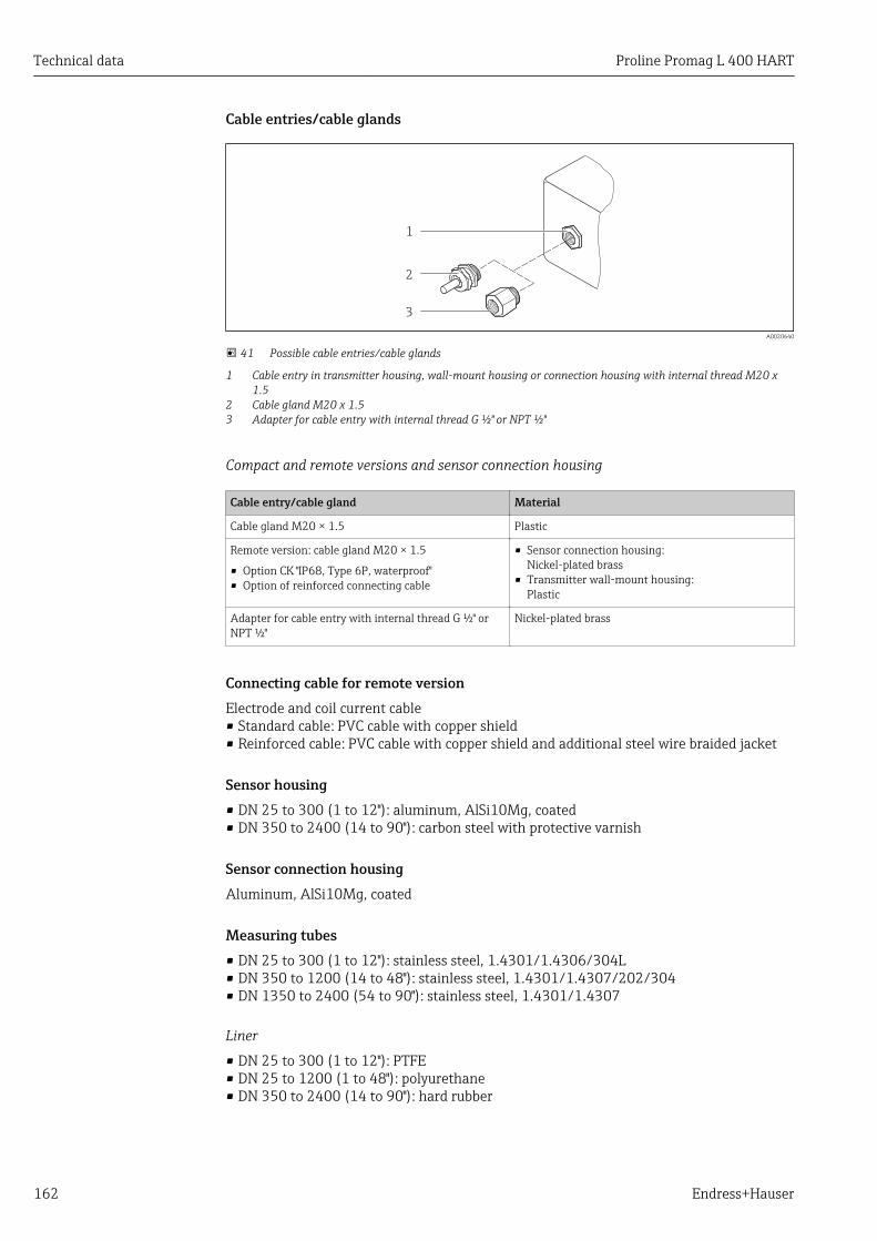
Technical data Proline Promag L 400 HART
162 Endress+Hauser
Cable entries/cable glands
1
2
3
A0020640
41 Possible cable entries/cable glands
1 Cable entry in transmitter housing, wall-mount housing or connection housing with internal thread M20 x1.5
2 Cable gland M20 x 1.53 Adapter for cable entry with internal thread G ½" or NPT ½"
Compact and remote versions and sensor connection housing
Cable entry/cable gland Material
Cable gland M20 × 1.5 Plastic
Remote version: cable gland M20 × 1.5
• Option CK "IP68, Type 6P, waterproof"• Option of reinforced connecting cable
• Sensor connection housing:Nickel-plated brass
• Transmitter wall-mount housing:Plastic
Adapter for cable entry with internal thread G ½" orNPT ½"
Nickel-plated brass
Connecting cable for remote versionElectrode and coil current cable• Standard cable: PVC cable with copper shield• Reinforced cable: PVC cable with copper shield and additional steel wire braided jacket
Sensor housing• DN 25 to 300 (1 to 12"): aluminum, AlSi10Mg, coated• DN 350 to 2400 (14 to 90"): carbon steel with protective varnish
Sensor connection housingAluminum, AlSi10Mg, coated
Measuring tubes• DN 25 to 300 (1 to 12"): stainless steel, 1.4301/1.4306/304L• DN 350 to 1200 (14 to 48"): stainless steel, 1.4301/1.4307/202/304• DN 1350 to 2400 (54 to 90"): stainless steel, 1.4301/1.4307
Liner
• DN 25 to 300 (1 to 12"): PTFE• DN 25 to 1200 (1 to 48"): polyurethane• DN 350 to 2400 (14 to 90"): hard rubber
Proline Promag L 400 HART Technical data
Endress+Hauser 163
Electrodes• Stainless steel, 1.4435 (316L)• Alloy C22, 2.4602 (UNS N06022)
Process connections
EN 1092-1 (DIN 2501)
DN 25 to 300:• Fixed flange
– Stainless steel, 1.4306/1.4404/1.4571/F316L– Carbon steel, A105/FE410WB/S235JRG2
• Lap joint flange, stamped plate– Stainless steel, 1.4301 similar to 304– Carbon steel, S235JRG2 similar to 1.0038 (S235JR+AR)
• DN 350 to 600:Carbon steel, A105/FE410WB/P250GH/S235JRG2/S235JR+N
• DN 700 to 1200:Carbon steel, A105/P250GH/S235JRG2/S235JR+N
• DN 1350 to 2400:Carbon steel, P250GH/S235JRG2/S235JR+N
ASME B16.5
DN 25 to 300 (1 to 12"):Fixed flange– Stainless steel, F316L similar to 1.4404– Carbon steel, A105 similar to 1.0432
DN 350 to 600 (14 to 24"):Carbon steel, A105/A515 Grade 70
AWWA C207
• DN 48":Carbon steel, A105/A181/FE410WB/P265GH/S275JR
• DN 54 to 90":Carbon steel, A105/A181/P265GH/S275JR
AS 2129
Carbon steel, A105/FE410WB/P235GH/P265GH/S235JRG2
AS 4087
Carbon steel, A105/P265GH/S275JRG2
SealsIn accordance with DIN EN 1514-1
Accessories
Display protection
Stainless steel, 1.4301 (304L)
Ground disks
• Stainless steel, 1.4435 (316L)• Alloy C22, 2.4602 (UNS N06022)

Technical data Proline Promag L 400 HART
164 Endress+Hauser
Fitted electrodes Measurement, reference and empty pipe detection electrodes available as standard with:• 1.4435 (316L)• Alloy C22, 2.4602 (UNS N06022)
Process connections • EN 1092-1 (DIN 2501)– DN ≤ 300: lap joint flange (PN 10/16), lap joint flange, stamped plate (PN 10) = form
A– DN ≥ 350: fixed flange (PN 6/10) = flat face
• ASME B16.5– DN ≤ 300 (12"): lap joint flange (Class 150)– DN ≥ 350 (14"): fixed flange (Class 150)
• AWWA C207DN 48 to 90": fixed flange (Class D)
• AS 2129DN 350 to 1200: fixed flange (Table E)
• AS 4087DN 350 to 1200: fixed flange (PN 16)
For information on the materials of the process connections → 163
Surface roughness Electrodes with 1.4435 (316L); Alloy C22, 2.4602 (UNS N06022):≤ 0.3 to 0.5 µm (11.8 to 19.7 µin)(All data relate to parts in contact with fluid)
16.11 Operability
Local operation Via display module
A0020538
Display elements• 4-line display• White background lighting; switches to red in event of device errors• Format for displaying measured variables and status variables can be individually
configured• Permitted ambient temperature for the display: –20 to +50 °C (–4 to +122 °F)
The readability of the display may be impaired at temperatures outside the temperaturerange.
Operating elementsExternal operation via touch control; 3 optical keys: , , E

Proline Promag L 400 HART Technical data
Endress+Hauser 165
Additional functionality• Data backup function
The device configuration can be saved in the display module.• Data comparison function
The device configuration saved in the display module can be compared to the currentdevice configuration.
• Data transfer functionThe transmitter configuration can be transmitted to another device using the displaymodule.
Remote operation Via HART protocolThis communication interface is available in device versions with a HART output.
1 2 3 5
74 6
A0017124
42 Options for remote operation via HART protocol
1 Control system (e.g. PLC)2 Field Communicator 4753 Computer with operating tool (e.g. FieldCare, AMS Device Manager, SIMATIC PDM)4 Commubox FXA195 (USB)5 Field Xpert SFX350 or SFX3706 VIATOR Bluetooth modem with connecting cable7 Transmitter
Service interface Via service interface (CDI-RJ45)

Technical data Proline Promag L 400 HART
166 Endress+Hauser
HART
1 32
A0020481
1 Computer with Web browser (e.g. Internet Explorer) for accessing the integrated device Web server or with"FieldCare" operating tool with COM DTM "CDI Communication TCP/IP"
2 Standard Ethernet connecting cable with RJ45 plug3 Service interface (CDI -RJ45) of the measuring device with access to the integrated Web server
Languages Can be operated in the following languages:• Via local display:
English, German, French, Spanish, Italian, Dutch, Portuguese, Polish, Russian, Turkish,Chinese, Japanese, Bahasa (Indonesian), Vietnamese, Czech
• Via "FieldCare" operating tool:English, German, French, Spanish, Italian, Chinese, Japanese
• Via Web browserEnglish, German, French, Spanish, Italian, Dutch, Portuguese, Polish, Russian, Turkish,Chinese, Japanese, Bahasa (Indonesian), Vietnamese, Czech
16.12 Certificates and approvals
CE mark The measuring system is in conformity with the statutory requirements of the applicableEC Directives. These are listed in the corresponding EC Declaration of Conformity alongwith the standards applied.
Endress+Hauser confirms successful testing of the device by affixing to it the CE mark.
C-Tick symbol The measuring system meets the EMC requirements of the "Australian Communicationsand Media Authority (ACMA)".
Ex approval The devices are certified for use in hazardous areas and the relevant safety instructions areprovided in the separate "Control Drawing" document. Reference is made to this documenton the nameplate.
Drinking water approval • ACS• KTW/W270• NSF 61• WRAS BS 6920
Proline Promag L 400 HART Technical data
Endress+Hauser 167
Other standards andguidelines
• EN 60529Degrees of protection provided by enclosures (IP code)
• EN 61010-1Safety requirements for electrical equipment for measurement, control and laboratoryuse
• IEC/EN 61326Emission in accordance with Class A requirements. Electromagnetic compatibility (EMCrequirements).
• ANSI/ISA-61010-1 (82.02.01): 2004Safety Requirements for Electrical Equipment for Measurement, Control and LaboratoryUse - Part 1 General Requirements
• CAN/CSA-C22.2 No. 61010-1-04Safety Requirements for Electrical Equipment for Measurement, Control and LaboratoryUse - Part 1 General Requirements
• NAMUR NE 21Electromagnetic compatibility (EMC) of industrial process and laboratory controlequipment
• NAMUR NE 32Data retention in the event of a power failure in field and control instruments withmicroprocessors
• NAMUR NE 43Standardization of the signal level for the breakdown information of digital transmitterswith analog output signal.
• NAMUR NE 53Software of field devices and signal-processing devices with digital electronics
• NAMUR NE 105Specifications for integrating fieldbus devices in engineering tools for field devices
• NAMUR NE 107Self-monitoring and diagnosis of field devices
• NAMUR NE 131Requirements for field devices for standard applications
16.13 Application packagesMany different application packages are available to enhance the functionality of thedevice. Such packages might be needed to address safety aspects or specific applicationrequirements.
The application packages can be ordered with the device or subsequently fromEndress+Hauser. Detailed information on the order code in question is available from yourlocal Endress+Hauser sales center or on the product page of the Endress+Hauser website:www.endress.com.
Cleaning Package Description
Electrode cleaning circuit(ECC)
The electrode cleaning circuit (ECC) function has been developed to have a solutionfor applications where magnetite (Fe3O4) deposits frequently occur (e.g. hotwater). Since magnetite is highly conductive this build up leads to measuring errorsand ultimately to the loss of signal. The application package is designed to AVOIDbuild up of highly conductive matter and thin layers (typical of magnetite).

Technical data Proline Promag L 400 HART
168 Endress+Hauser
Diagnostics functions Package Description
HistoROM extendedfunction
Comprises extended functions concerning the event log and the activation of themeasured value memory.
Event log:Memory volume is extended from 20 message entries (basic version) to up to 100entries.
Data logging (line recorder):• Memory capacity for up to 1000 measured values is activated.• 250 measured values can be output via each of the 4 memory channels. The
recording interval can be defined and configured by the user.• Data logging is visualized via the local display or FieldCare.
Heartbeat Technology Package Description
Heartbeat Verification+Monitoring
Heartbeat Monitoring:Continuously supplies monitoring data, which are characteristic of the measuringprinciple, for an external condition monitoring system. This makes it possible to:• Draw conclusions - using these data and other information - about the impact
the measuring application has on the measuring performance over time.• Schedule servicing in time.• Monitor the product quality, e.g. gas pockets.
Heartbeat Verification:Makes it possible to check the device functionality on demand when the device isinstalled, without having to interrupt the process.• Access via onsite operation or other operating interfaces, such as FieldCare for
instance.• End-to-end, traceable documentation of the verification results, including report.• Makes it possible to extend calibration intervals in accordance with operator's
risk assessment.
16.14 AccessoriesOverview of accessories available for order → 139
16.15 DocumentationFor an overview of the scope of the associated Technical Documentation, refer to thefollowing:• The CD-ROM provided for the device (depending on the device version, the CD-ROM
might not be part of the delivery!)• The W@M Device Viewer : Enter the serial number from the nameplate
(www.endress.com/deviceviewer)• The Endress+Hauser Operations App: Enter the serial number from the nameplate
or scan the 2-D matrix code (QR code) on the nameplate.
Standard documentation Brief Operating Instructions
Measuring device Documentation code
Promag L 400 KA01113D
Technical Information
Measuring device Documentation code
Promag L 400 TI01045D

Proline Promag L 400 HART Technical data
Endress+Hauser 169
Supplementary device-dependent documentation
Special documentation
Contents Documentation code
Heartbeat Technology SD01183D
Installation Instructions
Contents Documentation code
Installation Instructions for spare part sets Overview of accessories available for order → 139

Appendix Proline Promag L 400 HART
170 Endress+Hauser
17 Appendix
17.1 Overview of the operating menuThe following graphic provides an overview of the entire operating menu structure with itsmenus, submenus and parameters. The page reference indicates where a description of theparameter can be found in the manual.
Depending on the device version, not all submenus and parameters are available in everydevice. The selection can vary depending on the order code.
For the Order Code "Application Package", the associated parameters are described in theSpecial Documentation.
Display language → 103
Operation → 170
Setup → 171
Diagnostics → 177
Expert → 181
17.1.1 "Operation" menu
Navigation Operation
Operation → 111
Display language → 103
Web server language
Access status display
Access status tooling
Locking status
‣ Display → 87
Format display → 88
Contrast display

Proline Promag L 400 HART Appendix
Endress+Hauser 171
Backlight → 103
Display interval → 103
‣ Totalizer handling
Control Totalizer 1 to 3 → 115
Preset value 1 to 3 → 115
Reset all totalizers → 115
17.1.2 "Setup" menu
Navigation Setup
Setup → 71
Device tag → 77
‣ Status input → 77
Assign status input → 78
Active level → 78
Response time status input → 78
‣ Current output 1 → 79
Assign current output → 80
Mass flow unit → 80
Volume flow unit → 80
Conductivity unit → 80
Current span → 80
0/4 mA value → 80
20 mA value → 80
Failure mode → 80
Failure current → 80
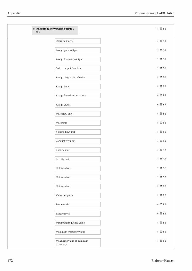
Appendix Proline Promag L 400 HART
172 Endress+Hauser
‣ Pulse/frequency/switch output 1to 2
→ 81
Operating mode → 81
Assign pulse output → 81
Assign frequency output → 83
Switch output function → 86
Assign diagnostic behavior → 86
Assign limit → 87
Assign flow direction check → 87
Assign status → 87
Mass flow unit → 84
Mass unit → 81
Volume flow unit → 84
Conductivity unit → 84
Volume unit → 82
Density unit → 82
Unit totalizer → 87
Unit totalizer → 87
Unit totalizer → 87
Value per pulse → 82
Pulse width → 82
Failure mode → 82
Minimum frequency value → 84
Maximum frequency value → 84
Measuring value at minimumfrequency
→ 84
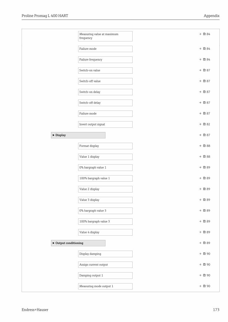
Proline Promag L 400 HART Appendix
Endress+Hauser 173
Measuring value at maximumfrequency
→ 84
Failure mode → 84
Failure frequency → 84
Switch-on value → 87
Switch-off value → 87
Switch-on delay → 87
Switch-off delay → 87
Failure mode → 87
Invert output signal → 82
‣ Display → 87
Format display → 88
Value 1 display → 88
0% bargraph value 1 → 89
100% bargraph value 1 → 89
Value 2 display → 89
Value 3 display → 89
0% bargraph value 3 → 89
100% bargraph value 3 → 89
Value 4 display → 89
‣ Output conditioning → 89
Display damping → 90
Assign current output → 90
Damping output 1 → 90
Measuring mode output 1 → 90
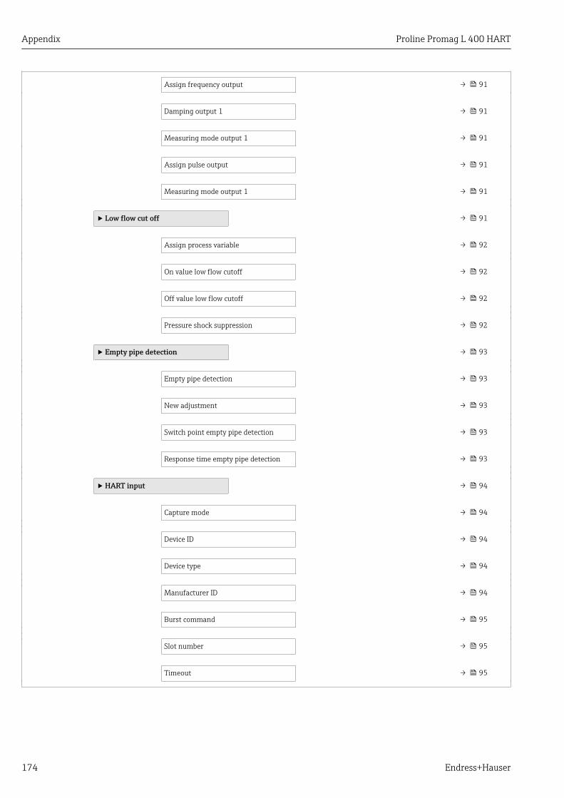
Appendix Proline Promag L 400 HART
174 Endress+Hauser
Assign frequency output → 91
Damping output 1 → 91
Measuring mode output 1 → 91
Assign pulse output → 91
Measuring mode output 1 → 91
‣ Low flow cut off → 91
Assign process variable → 92
On value low flow cutoff → 92
Off value low flow cutoff → 92
Pressure shock suppression → 92
‣ Empty pipe detection → 93
Empty pipe detection → 93
New adjustment → 93
Switch point empty pipe detection → 93
Response time empty pipe detection → 93
‣ HART input → 94
Capture mode → 94
Device ID → 94
Device type → 94
Manufacturer ID → 94
Burst command → 95
Slot number → 95
Timeout → 95
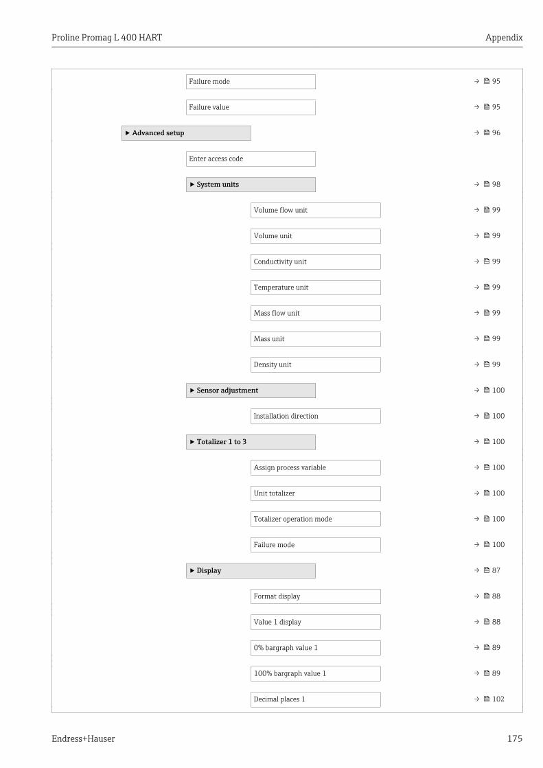
Proline Promag L 400 HART Appendix
Endress+Hauser 175
Failure mode → 95
Failure value → 95
‣ Advanced setup → 96
Enter access code
‣ System units → 98
Volume flow unit → 99
Volume unit → 99
Conductivity unit → 99
Temperature unit → 99
Mass flow unit → 99
Mass unit → 99
Density unit → 99
‣ Sensor adjustment → 100
Installation direction → 100
‣ Totalizer 1 to 3 → 100
Assign process variable → 100
Unit totalizer → 100
Totalizer operation mode → 100
Failure mode → 100
‣ Display → 87
Format display → 88
Value 1 display → 88
0% bargraph value 1 → 89
100% bargraph value 1 → 89
Decimal places 1 → 102

Appendix Proline Promag L 400 HART
176 Endress+Hauser
Value 2 display → 89
Decimal places 2 → 102
Value 3 display → 89
0% bargraph value 3 → 89
100% bargraph value 3 → 89
Decimal places 3 → 102
Value 4 display → 89
Decimal places 4 → 102
Display language → 103
Display interval → 103
Display damping → 103
Header → 103
Header text → 103
Separator → 103
Backlight → 103
‣ Electrode cleaning circuit → 103
Electrode cleaning circuit → 104
ECC duration → 104
ECC recovery time → 104

Proline Promag L 400 HART Appendix
Endress+Hauser 177
ECC cleaning cycle → 104
ECC Polarity → 104
‣ Administration → 104
‣ Define access code → 108
Define access code → 104
Confirm access code
Device reset → 104
17.1.3 "Diagnostics" menu
Navigation Diagnostics
Diagnostics → 129
Actual diagnostics → 129
Previous diagnostics → 129
Operating time from restart
Operating time → 105
‣ Diagnostic list
Diagnostics 1
Diagnostics 2
Diagnostics 3
Diagnostics 4
Diagnostics 5
‣ Event logbook
Filter options
‣ Event list

Appendix Proline Promag L 400 HART
178 Endress+Hauser
‣ Device information → 132
Device tag → 133
Serial number → 133
Firmware version → 134
Device name → 134
Order code → 134
Extended order code 1 → 134
Extended order code 2 → 134
Extended order code 3 → 134
ENP version → 134
Custody transfer counter → 134
Timestamp last custody transfer
Device revision → 134
Device ID → 134
Device type → 134
Manufacturer ID → 134
IP address → 134
Subnet mask → 134
Default gateway → 134
‣ Measured values
‣ Process variables → 111
Volume flow → 112
Mass flow → 112
Conductivity → 112
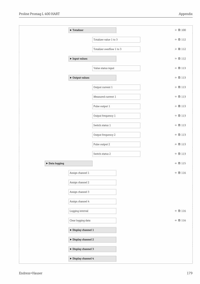
Proline Promag L 400 HART Appendix
Endress+Hauser 179
‣ Totalizer → 100
Totalizer value 1 to 3 → 112
Totalizer overflow 1 to 3 → 112
‣ Input values → 112
Value status input → 113
‣ Output values → 113
Output current 1 → 113
Measured current 1 → 113
Pulse output 1 → 113
Output frequency 1 → 113
Switch status 1 → 113
Output frequency 2 → 113
Pulse output 2 → 113
Switch status 2 → 113
‣ Data logging → 115
Assign channel 1 → 116
Assign channel 2
Assign channel 3
Assign channel 4
Logging interval → 116
Clear logging data → 116
‣ Display channel 1
‣ Display channel 2
‣ Display channel 3
‣ Display channel 4

Appendix Proline Promag L 400 HART
180 Endress+Hauser
‣ Heartbeat
‣ Performing verification
Year
Month
Day
Hour
AM/PM
Minute
Verification mode
External device information
External reference voltage 1
External reference voltage 2
Start verification
Progress
Measured values
Output values
Status
Overall result
‣ Verification results
Date/time
Verification ID
Operating time
Overall result
Sensor
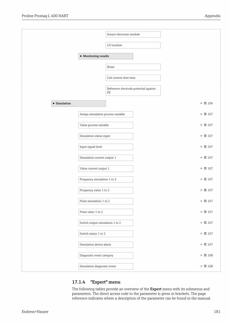
Proline Promag L 400 HART Appendix
Endress+Hauser 181
Sensor electronic module
I/O module
‣ Monitoring results
Noise
Coil current shot time
Reference electrode potential againstPE
‣ Simulation → 106
Assign simulation process variable → 107
Value process variable → 107
Simulation status input → 107
Input signal level → 107
Simulation current output 1 → 107
Value current output 1 → 107
Frequency simulation 1 to 2 → 107
Frequency value 1 to 2 → 107
Pulse simulation 1 to 2 → 107
Pulse value 1 to 2 → 107
Switch output simulation 1 to 2 → 107
Switch status 1 to 2 → 107
Simulation device alarm → 107
Diagnostic event category → 108
Simulation diagnostic event → 108
17.1.4 "Expert" menuThe following tables provide an overview of the Expert menu with its submenus andparameters. The direct access code to the parameter is given in brackets. The pagereference indicates where a description of the parameter can be found in the manual.

Appendix Proline Promag L 400 HART
182 Endress+Hauser
Navigation Expert
Expert
Direct access (0106)
Locking status (0004)
Access status display (0091)
Access status tooling (0005)
Enter access code (0003)
‣ System → 182
‣ Sensor → 184
‣ Input
‣ Output → 188
‣ Communication → 190
‣ Application → 193
‣ Diagnostics → 194
"System" submenu
Navigation Expert → System
‣ System
‣ Display → 87
Display language (0104) → 103
Format display (0098) → 88
Value 1 display (0107) → 88
0% bargraph value 1 (0123) → 89
100% bargraph value 1 (0125) → 89
Decimal places 1 (0095) → 102
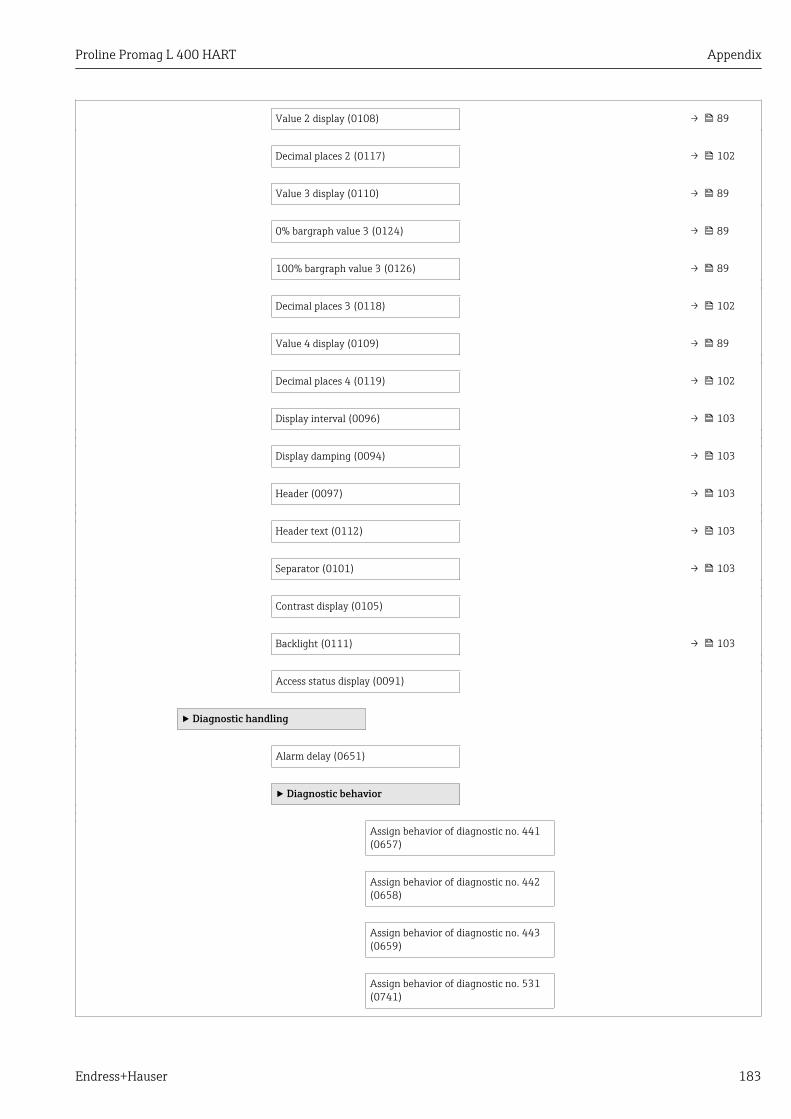
Proline Promag L 400 HART Appendix
Endress+Hauser 183
Value 2 display (0108) → 89
Decimal places 2 (0117) → 102
Value 3 display (0110) → 89
0% bargraph value 3 (0124) → 89
100% bargraph value 3 (0126) → 89
Decimal places 3 (0118) → 102
Value 4 display (0109) → 89
Decimal places 4 (0119) → 102
Display interval (0096) → 103
Display damping (0094) → 103
Header (0097) → 103
Header text (0112) → 103
Separator (0101) → 103
Contrast display (0105)
Backlight (0111) → 103
Access status display (0091)
‣ Diagnostic handling
Alarm delay (0651)
‣ Diagnostic behavior
Assign behavior of diagnostic no. 441(0657)
Assign behavior of diagnostic no. 442(0658)
Assign behavior of diagnostic no. 443(0659)
Assign behavior of diagnostic no. 531(0741)

Appendix Proline Promag L 400 HART
184 Endress+Hauser
Assign behavior of diagnostic no. 832(0681)
Assign behavior of diagnostic no. 833(0682)
Assign behavior of diagnostic no. 862(0745)
Assign behavior of diagnostic no. 937(0743)
Assign behavior of diagnostic no. 302(0739)
‣ Administration → 104
‣ Define access code → 108
Define access code → 104
Confirm access code
Device reset (0000) → 104
Activate SW option (0029)
Software option overview (0015)
"Sensor" submenu
Navigation Expert → Sensor
‣ Sensor
‣ Measured values
‣ Process variables → 111
Volume flow (1838) → 112
Mass flow (1847) → 112
Conductivity (1850) → 112
‣ Totalizer → 100
Totalizer value 1 to 3 (0911–1 to 3) → 112
Totalizer overflow 1 to 3 (0910–1 to 3) → 112

Proline Promag L 400 HART Appendix
Endress+Hauser 185
‣ Input values → 112
Value status input (1353) → 113
‣ Output values → 113
Output current 1 (0361–1) → 113
Measured current 1 (0366–1) → 113
Pulse output 1 (0456–1) → 113
Output frequency 1 (0471–1) → 113
Switch status 1 (0461–1) → 113
Output frequency 2 (0471–2) → 113
Pulse output 2 (0456–2) → 113
Switch status 2 (0461–2) → 113
‣ System units → 98
Volume flow unit (0553) → 99
Volume unit (0563) → 99
Conductivity unit (0582) → 99
Temperature unit (0557) → 99
Mass flow unit (0554) → 99
Mass unit (0574) → 99
Density unit (0555) → 99
Date/time format (2812)
‣ User-specific units
User volume text (0567)
User volume offset (0569)
User volume factor (0568)
User mass text (0560)

Appendix Proline Promag L 400 HART
186 Endress+Hauser
User mass offset (0562)
User mass factor (0561)
‣ Process parameters
Filter options (6710)
Flow damping (6661)
Flow override (1839)
Conductivity damping (1803)
Conductivity measurement (6514)
‣ Low flow cut off → 91
Assign process variable (1837) → 92
On value low flow cutoff (1805) → 92
Off value low flow cutoff (1804) → 92
Pressure shock suppression (1806) → 92
‣ Empty pipe detection → 93
Empty pipe detection (1860) → 93
Switch point empty pipe detection(6562)
→ 93
Response time empty pipe detection(1859)
→ 93
Empty pipe adjust value (6527)
Full pipe adjust value (6548)
Measured value EPD (6559)
‣ Empty pipe adjust
New adjustment (6560) → 93
‣ Electrode cleaning circuit → 103
Electrode cleaning circuit (6528) → 104

Proline Promag L 400 HART Appendix
Endress+Hauser 187
ECC duration (6555) → 104
ECC recovery time (6556) → 104
ECC cleaning cycle (6557) → 104
ECC Polarity (6631) → 104
‣ External compensation
External value (6707)
External density (6630)
Fixed density (6623)
‣ Sensor adjustment → 100
Installation direction (1809) → 100
Integration time (6533)
Measuring period (6536)
‣ Process variable adjustment
Volume flow offset (1831)
Volume flow factor (1832)
Mass flow offset (1841)
Mass flow factor (1846)
Conductivity offset (1848)
Conductivity factor (1849)
‣ Calibration
Nominal diameter (2807)
Calibration factor (6522)
Zero point (6546)
Conductivity calibration factor (6718)
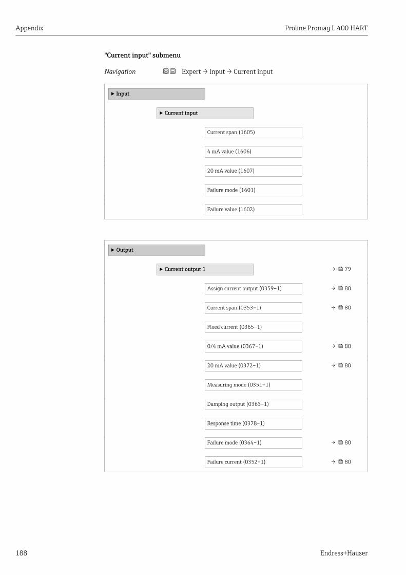
Appendix Proline Promag L 400 HART
188 Endress+Hauser
"Current input" submenu
Navigation Expert → Input → Current input
‣ Input
‣ Current input
Current span (1605)
4 mA value (1606)
20 mA value (1607)
Failure mode (1601)
Failure value (1602)
‣ Output
‣ Current output 1 → 79
Assign current output (0359–1) → 80
Current span (0353–1) → 80
Fixed current (0365–1)
0/4 mA value (0367–1) → 80
20 mA value (0372–1) → 80
Measuring mode (0351–1)
Damping output (0363–1)
Response time (0378–1)
Failure mode (0364–1) → 80
Failure current (0352–1) → 80

Proline Promag L 400 HART Appendix
Endress+Hauser 189
Output current 1 (0361–1) → 113
Measured current 1 (0366–1) → 113
‣ Pulse/frequency/switch output 1to 2
→ 81
Operating mode (0469–1 to 2) → 81
Assign pulse output (0460–1 to 2) → 81
Value per pulse (0455–1 to 2) → 82
Pulse width (0452–1 to 2) → 82
Measuring mode (0457–1 to 2)
Failure mode (0480–1 to 2) → 82
Pulse output 1 to 2 (0456–1 to 2) → 113
Assign frequency output (0478–1 to 2) → 83
Minimum frequency value(0453–1 to 2)
→ 84
Maximum frequency value(0454–1 to 2)
→ 84
Measuring value at minimumfrequency (0476–1 to 2)
→ 84
Measuring value at maximumfrequency (0475–1 to 2)
→ 84
Measuring mode (0479–1 to 2)
Damping output (0477–1 to 2)
Response time (0491–1 to 2)
Failure mode (0451–1 to 2) → 84
Failure frequency (0474–1 to 2) → 84
Output frequency 1 to 2 (0471–1 to 2) → 113
Switch output function (0481–1 to 2) → 86
Assign diagnostic behavior(0482–1 to 2)
→ 86
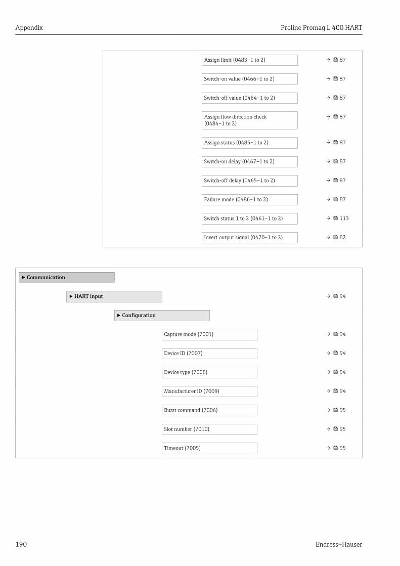
Appendix Proline Promag L 400 HART
190 Endress+Hauser
Assign limit (0483–1 to 2) → 87
Switch-on value (0466–1 to 2) → 87
Switch-off value (0464–1 to 2) → 87
Assign flow direction check(0484–1 to 2)
→ 87
Assign status (0485–1 to 2) → 87
Switch-on delay (0467–1 to 2) → 87
Switch-off delay (0465–1 to 2) → 87
Failure mode (0486–1 to 2) → 87
Switch status 1 to 2 (0461–1 to 2) → 113
Invert output signal (0470–1 to 2) → 82
‣ Communication
‣ HART input → 94
‣ Configuration
Capture mode (7001) → 94
Device ID (7007) → 94
Device type (7008) → 94
Manufacturer ID (7009) → 94
Burst command (7006) → 95
Slot number (7010) → 95
Timeout (7005) → 95
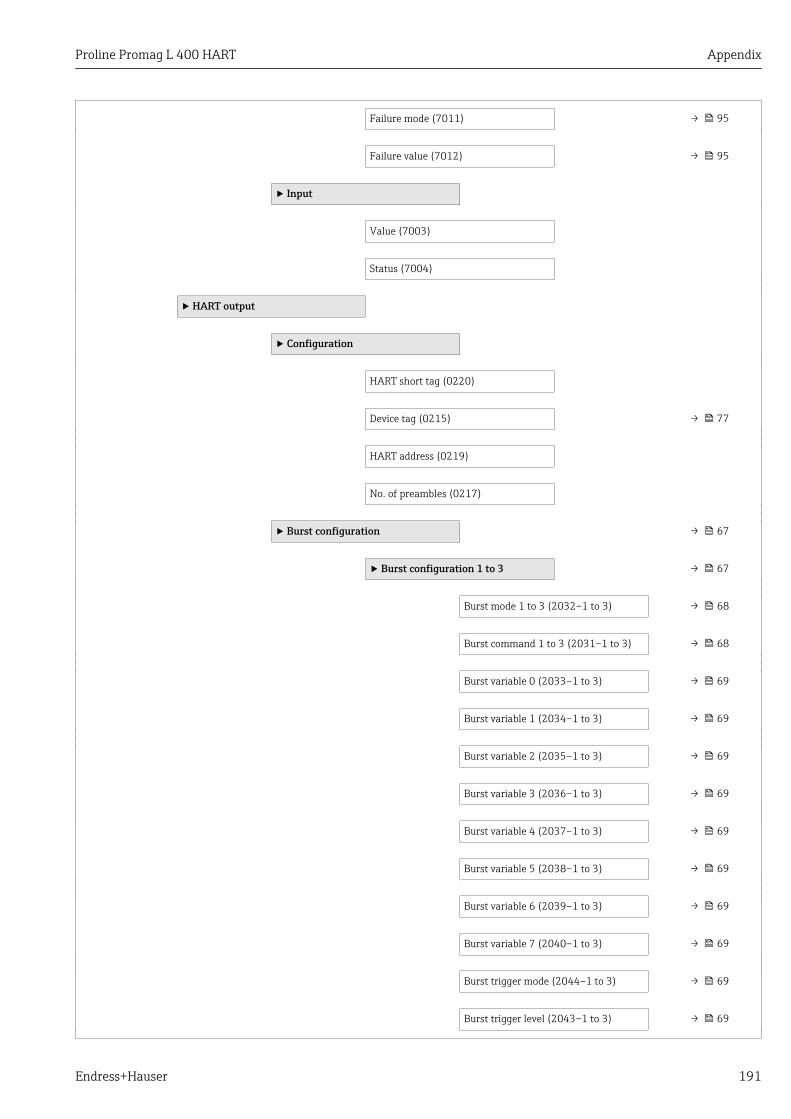
Proline Promag L 400 HART Appendix
Endress+Hauser 191
Failure mode (7011) → 95
Failure value (7012) → 95
‣ Input
Value (7003)
Status (7004)
‣ HART output
‣ Configuration
HART short tag (0220)
Device tag (0215) → 77
HART address (0219)
No. of preambles (0217)
‣ Burst configuration → 67
‣ Burst configuration 1 to 3 → 67
Burst mode 1 to 3 (2032–1 to 3) → 68
Burst command 1 to 3 (2031–1 to 3) → 68
Burst variable 0 (2033–1 to 3) → 69
Burst variable 1 (2034–1 to 3) → 69
Burst variable 2 (2035–1 to 3) → 69
Burst variable 3 (2036–1 to 3) → 69
Burst variable 4 (2037–1 to 3) → 69
Burst variable 5 (2038–1 to 3) → 69
Burst variable 6 (2039–1 to 3) → 69
Burst variable 7 (2040–1 to 3) → 69
Burst trigger mode (2044–1 to 3) → 69
Burst trigger level (2043–1 to 3) → 69

Appendix Proline Promag L 400 HART
192 Endress+Hauser
Min. update period (2042–1 to 3) → 69
Max. update period (2041–1 to 3) → 69
‣ Information
Device revision (0204) → 134
Device ID (0221) → 134
Device type (0209)
Manufacturer ID (0259)
HART revision (0205)
HART descriptor (0212)
HART message (0216)
Hardware revision (0206)
Software revision (0224)
HART date code (0202)
‣ Output → 188
Assign PV (0234)
Primary variable (PV) (0201)
Assign SV (0235)
Secondary variable (SV) (0226)
Assign TV (0236)
Tertiary variable (TV) (0228)
Assign QV (0237)
Quaternary variable (QV) (0203)
‣ Web server → 61
Web server language (7221)
MAC address (7214)

Proline Promag L 400 HART Appendix
Endress+Hauser 193
IP address (7209) → 134
Subnet mask (7211) → 134
Default gateway (7210) → 134
Web server functionality (7222) → 61
‣ Diagnostic configuration
Event category 004 (0238)
Event category 441 (0210)
Event category 442 (0230)
Event category 443 (0231)
Event category 531 (0262)
Event category 832 (0218)
Event category 833 (0225)
Event category 834 (0227)
Event category 835 (0229)
Event category 862 (0214)
Event category 937 (0260)
‣ Application
Reset all totalizers (2806) → 115
‣ Totalizer 1 to 3 → 100
Assign process variable (0914–1 to 3) → 100
Unit totalizer (0915–1 to 3) → 100
Totalizer operation mode(0908–1 to 3)
→ 100
Control Totalizer 1 to 3 (0912–1 to 3) → 115

Appendix Proline Promag L 400 HART
194 Endress+Hauser
Preset value 1 to 3 (0913–1 to 3) → 115
Failure mode (0901–1 to 3) → 100
‣ Diagnostics → 129
Actual diagnostics (0691) → 129
Previous diagnostics (0690) → 129
Operating time from restart (0653)
Operating time (0652) → 105
‣ Diagnostic list
Diagnostics 1 (0692)
Diagnostics 2 (0693)
Diagnostics 3 (0694)
Diagnostics 4 (0695)
Diagnostics 5 (0696)
‣ Event logbook
Filter options (0705)
‣ Event list
‣ Device information → 132
Device tag (0011) → 133
Serial number (0009) → 133
Firmware version (0010) → 134
Device name (0013) → 134
Order code (0008) → 134
Extended order code 1 (0023) → 134
Extended order code 2 (0021) → 134

Proline Promag L 400 HART Appendix
Endress+Hauser 195
Extended order code 3 (0022) → 134
Configuration counter (0233)
ENP version (0012) → 134
Custody transfer counter (14402) → 134
Timestamp last custody transfer(14403)
Counter custody transfer changes(14401)
IP address (7209) → 134
Subnet mask (7211) → 134
Default gateway (7210) → 134
‣ Data logging → 115
Assign channel 1 (0851) → 116
Assign channel 2 (0852)
Assign channel 3 (0853)
Assign channel 4 (0854)
Logging interval (0856) → 116
Clear logging data (0855) → 116
‣ Display channel 1
‣ Display channel 2
‣ Display channel 3
‣ Display channel 4

Appendix Proline Promag L 400 HART
196 Endress+Hauser
‣ Min/max values
Reset min/max values (6541)
‣ Main electronic temperature
Minimum value (6547)
Maximum value (6545)
‣ Heartbeat
‣ Heartbeat base settings
Plant operator (2754)
Location (2755)
‣ Performing verification
Year (2846)
Month (2845)
Day (2842)
Hour (2843)
AM/PM (2813)
Minute (2844)
Verification mode (12105)
External device information (12101)
External reference voltage 1 (12106)
External reference voltage 2 (12107)
Start verification (12127)
Progress (2808)
Measured values (12102)
Output values (12103)
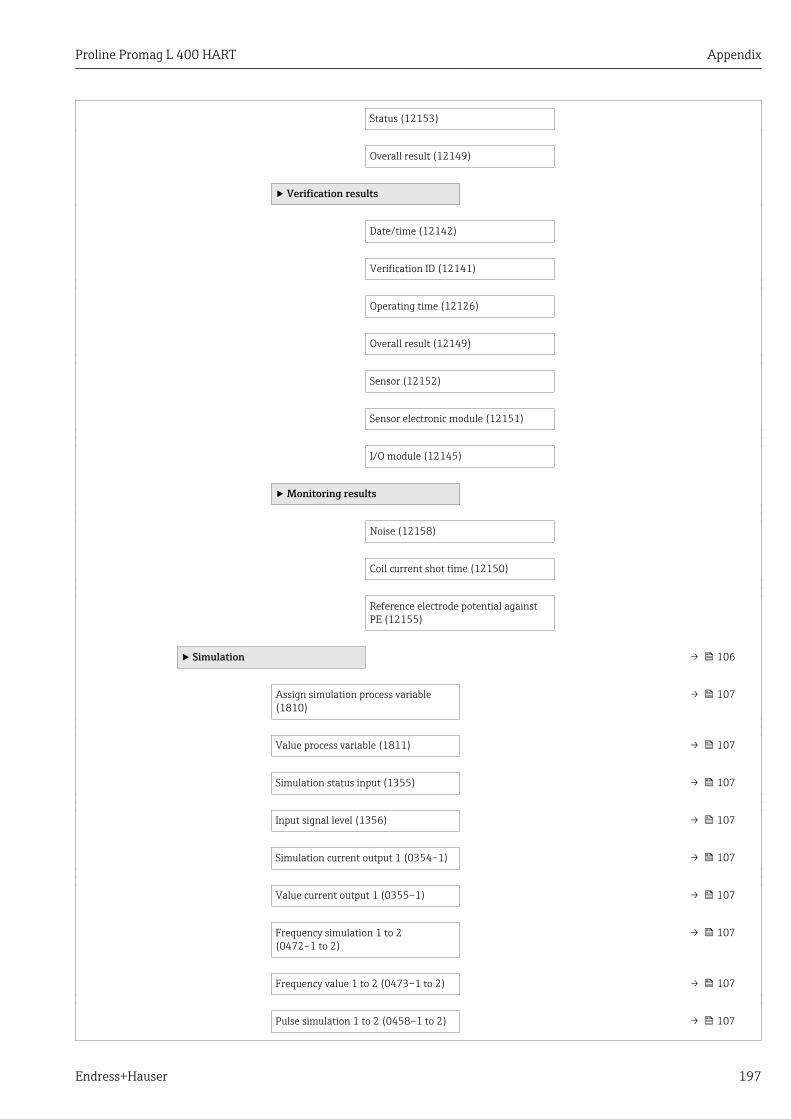
Proline Promag L 400 HART Appendix
Endress+Hauser 197
Status (12153)
Overall result (12149)
‣ Verification results
Date/time (12142)
Verification ID (12141)
Operating time (12126)
Overall result (12149)
Sensor (12152)
Sensor electronic module (12151)
I/O module (12145)
‣ Monitoring results
Noise (12158)
Coil current shot time (12150)
Reference electrode potential againstPE (12155)
‣ Simulation → 106
Assign simulation process variable(1810)
→ 107
Value process variable (1811) → 107
Simulation status input (1355) → 107
Input signal level (1356) → 107
Simulation current output 1 (0354–1) → 107
Value current output 1 (0355–1) → 107
Frequency simulation 1 to 2(0472–1 to 2)
→ 107
Frequency value 1 to 2 (0473–1 to 2) → 107
Pulse simulation 1 to 2 (0458–1 to 2) → 107

Appendix Proline Promag L 400 HART
198 Endress+Hauser
Pulse value 1 to 2 (0459–1 to 2) → 107
Switch output simulation 1 to 2(0462–1 to 2)
→ 107
Switch status 1 to 2 (0463–1 to 2) → 107
Simulation device alarm (0654) → 107
Diagnostic event category (0738) → 108
Simulation diagnostic event (0737) → 108

Proline Promag L 400 HART Index
Endress+Hauser 199
Index
AAccess authorization to parameters
Read access . . . . . . . . . . . . . . . . . . . . . . . . . . . . . 57Write access . . . . . . . . . . . . . . . . . . . . . . . . . . . . . 57
Access code . . . . . . . . . . . . . . . . . . . . . . . . . . . . . . . . 57Incorrect input . . . . . . . . . . . . . . . . . . . . . . . . . . . 57
Adapters . . . . . . . . . . . . . . . . . . . . . . . . . . . . . . . . . . 22Adapting the diagnostic behavior . . . . . . . . . . . . . . . 125Adapting the status signal . . . . . . . . . . . . . . . . . . . . 125Ambient temperature
Influence . . . . . . . . . . . . . . . . . . . . . . . . . . . . . . 149Ambient temperature range . . . . . . . . . . . . . . . . . . . 21AMS Device Manager . . . . . . . . . . . . . . . . . . . . . . . . 64
Function . . . . . . . . . . . . . . . . . . . . . . . . . . . . . . . 64Application . . . . . . . . . . . . . . . . . . . . . . . . . . . . . 9, 141Applicator . . . . . . . . . . . . . . . . . . . . . . . . . . . . . . . . 141Approvals . . . . . . . . . . . . . . . . . . . . . . . . . . . . . . . . 166
BBurst mode . . . . . . . . . . . . . . . . . . . . . . . . . . . . . . . . 67
CC-Tick symbol . . . . . . . . . . . . . . . . . . . . . . . . . . . . . 166Cable entries
Technical data . . . . . . . . . . . . . . . . . . . . . . . . . . 148Cable entry
Degree of protection . . . . . . . . . . . . . . . . . . . . . . . 43CE mark . . . . . . . . . . . . . . . . . . . . . . . . . . . . . . 10, 166Certificates . . . . . . . . . . . . . . . . . . . . . . . . . . . . . . . 166Checklist
Post-connection check . . . . . . . . . . . . . . . . . . . . . 43Post-installation check . . . . . . . . . . . . . . . . . . . . . 32
CleaningExterior cleaning . . . . . . . . . . . . . . . . . . . . . . . . 136Interior cleaning . . . . . . . . . . . . . . . . . . . . . . . . . 136
Commissioning . . . . . . . . . . . . . . . . . . . . . . . . . . . . . 70Advanced settings . . . . . . . . . . . . . . . . . . . . . . . . 96Configuring the measuring device . . . . . . . . . . . . . 71
Communication-specific data . . . . . . . . . . . . . . . . . . . 66Conductivity . . . . . . . . . . . . . . . . . . . . . . . . . . . . . . 151Connecting cable . . . . . . . . . . . . . . . . . . . . . . . . . . . . 33Connecting the measuring device . . . . . . . . . . . . . . . . 38Connection
see Electrical connectionConnection examples, potential equalization . . . . . . . 41Connection preparations . . . . . . . . . . . . . . . . . . . . . . 36Connection tools . . . . . . . . . . . . . . . . . . . . . . . . . . . . 33Context menu
Closing . . . . . . . . . . . . . . . . . . . . . . . . . . . . . . . . . 52Explanation . . . . . . . . . . . . . . . . . . . . . . . . . . . . . 52Opening . . . . . . . . . . . . . . . . . . . . . . . . . . . . . . . . 52
Current consumption . . . . . . . . . . . . . . . . . . . . . . . . 147Current input (Submenu) . . . . . . . . . . . . . . . . . . . . . 188
DDeclaration of Conformity . . . . . . . . . . . . . . . . . . . . . 10
Define access code . . . . . . . . . . . . . . . . . . . . . . 108, 109Degree of protection . . . . . . . . . . . . . . . . . . . . . 43, 150Design
Measuring device . . . . . . . . . . . . . . . . . . . . . . . . . 12Designated use . . . . . . . . . . . . . . . . . . . . . . . . . . . . . . 9Device components . . . . . . . . . . . . . . . . . . . . . . . . . . 12Device description files . . . . . . . . . . . . . . . . . . . . . . . 66Device documentation
Supplementary documentation . . . . . . . . . . . . . . . . 8Device locking, status . . . . . . . . . . . . . . . . . . . . . . . 111Device name
Sensor . . . . . . . . . . . . . . . . . . . . . . . . . . . . . . . . . 15Transmitter . . . . . . . . . . . . . . . . . . . . . . . . . . . . . 14
Device repair . . . . . . . . . . . . . . . . . . . . . . . . . . . . . . 137Device revision . . . . . . . . . . . . . . . . . . . . . . . . . . . . . 66Device type ID . . . . . . . . . . . . . . . . . . . . . . . . . . . . . . 66Diagnostic behavior
Explanation . . . . . . . . . . . . . . . . . . . . . . . . . . . . 121Symbols . . . . . . . . . . . . . . . . . . . . . . . . . . . . . . . 121
Diagnostic informationDesign, description . . . . . . . . . . . . . . . . . . . 121, 124FieldCare . . . . . . . . . . . . . . . . . . . . . . . . . . . . . . 124Light emitting diodes . . . . . . . . . . . . . . . . . . . . . 118Local display . . . . . . . . . . . . . . . . . . . . . . . . . . . 120Overview . . . . . . . . . . . . . . . . . . . . . . . . . . . . . . 126Remedial measures . . . . . . . . . . . . . . . . . . . . . . 126Web browser . . . . . . . . . . . . . . . . . . . . . . . . . . . 123
Diagnostic list . . . . . . . . . . . . . . . . . . . . . . . . . . . . . 129Diagnostic message . . . . . . . . . . . . . . . . . . . . . . . . . 120Diagnostics
Symbols . . . . . . . . . . . . . . . . . . . . . . . . . . . . . . . 120Diagnostics (Menu) . . . . . . . . . . . . . . . . . . . . . . . . . 177DIP switch
see Write protection switchDirect access . . . . . . . . . . . . . . . . . . . . . . . . . . . . . . . 54Direct access code . . . . . . . . . . . . . . . . . . . . . . . . . . . 49Disabling write protection . . . . . . . . . . . . . . . . . . . . 108Display
Current diagnostic event . . . . . . . . . . . . . . . . . . . 129Previous diagnostic event . . . . . . . . . . . . . . . . . . 129see Local display
Display areaFor operational display . . . . . . . . . . . . . . . . . . . . . 47In the navigation view . . . . . . . . . . . . . . . . . . . . . 49
Display valuesFor locking status . . . . . . . . . . . . . . . . . . . . . . . . 111
Disposal . . . . . . . . . . . . . . . . . . . . . . . . . . . . . . . . . 137Document
Function . . . . . . . . . . . . . . . . . . . . . . . . . . . . . . . . 6Symbols used . . . . . . . . . . . . . . . . . . . . . . . . . . . . . 6
Document function . . . . . . . . . . . . . . . . . . . . . . . . . . . 6Documentation . . . . . . . . . . . . . . . . . . . . . . . . . . . . 168Down pipe . . . . . . . . . . . . . . . . . . . . . . . . . . . . . . . . . 19Drinking water approval . . . . . . . . . . . . . . . . . . . . . 166

Index Proline Promag L 400 HART
200 Endress+Hauser
EECC . . . . . . . . . . . . . . . . . . . . . . . . . . . . . . . . . . . . . 103Electrical connection
Commubox FXA195 . . . . . . . . . . . . . . . . . . . . . . 62Commubox FXA195 (USB) . . . . . . . . . . . . . . . . . 165Degree of protection . . . . . . . . . . . . . . . . . . . . . . . 43Field Communicator . . . . . . . . . . . . . . . . . . . . . . 62Field Communicator 475 . . . . . . . . . . . . . . . . . . 165Field Xpert SFX350/SFX370 . . . . . . . . . . . . . . . . 165Handheld terminals . . . . . . . . . . . . . . . . . . . . . . . 62Measuring device . . . . . . . . . . . . . . . . . . . . . . . . . 33Operating tool (e.g. FieldCare, AMS DeviceManager, SIMATIC PDM) . . . . . . . . . . . . . . . . . . 165Operating tools . . . . . . . . . . . . . . . . . . . . . . . . . . 62
Via HART protocol . . . . . . . . . . . . . . . . . . 62, 165Via service interface (CDI-RJ45) . . . . . . . . 63, 165
VIATOR Bluetooth modem . . . . . . . . . . . . . . . . . 165Web server . . . . . . . . . . . . . . . . . . . . . . . . . . 63, 165
Electromagnetic compatibility . . . . . . . . . . . . . . . . . 151Enabling write protection . . . . . . . . . . . . . . . . . . . . 108Endress+Hauser services
Maintenance . . . . . . . . . . . . . . . . . . . . . . . . . . . 136Repair . . . . . . . . . . . . . . . . . . . . . . . . . . . . . . . . 137
EnvironmentAmbient temperature . . . . . . . . . . . . . . . . . . . . . . 21Mechanical load . . . . . . . . . . . . . . . . . . . . . . . . . 150Shock resistance . . . . . . . . . . . . . . . . . . . . . . . . . 150Storage temperature . . . . . . . . . . . . . . . . . . . . . . 150Vibration resistance . . . . . . . . . . . . . . . . . . . . . . 150
Error messagessee Diagnostic messages
Event history . . . . . . . . . . . . . . . . . . . . . . . . . . . . . . 130Events list . . . . . . . . . . . . . . . . . . . . . . . . . . . . . . . . 130Ex approval . . . . . . . . . . . . . . . . . . . . . . . . . . . . . . . 166Expert (Menu) . . . . . . . . . . . . . . . . . . . . . . . . . . . . 181Extended order code
Sensor . . . . . . . . . . . . . . . . . . . . . . . . . . . . . . . . . 15Transmitter . . . . . . . . . . . . . . . . . . . . . . . . . . . . . 14
Exterior cleaning . . . . . . . . . . . . . . . . . . . . . . . . . . . 136
FField Communicator
Function . . . . . . . . . . . . . . . . . . . . . . . . . . . . . . . 65Field Communicator 475 . . . . . . . . . . . . . . . . . . . . . . 65Field of application
Residual risks . . . . . . . . . . . . . . . . . . . . . . . . . . . . 10Field Xpert
Function . . . . . . . . . . . . . . . . . . . . . . . . . . . . . . . 63Field Xpert SFX350 . . . . . . . . . . . . . . . . . . . . . . . . . . 63FieldCare . . . . . . . . . . . . . . . . . . . . . . . . . . . . . . . . . 63
Device description file . . . . . . . . . . . . . . . . . . . . . . 66Establishing a connection . . . . . . . . . . . . . . . . . . . 64Function . . . . . . . . . . . . . . . . . . . . . . . . . . . . . . . 63User interface . . . . . . . . . . . . . . . . . . . . . . . . . . . 64
Filtering the event logbook . . . . . . . . . . . . . . . . . . . 131Firmware
Release date . . . . . . . . . . . . . . . . . . . . . . . . . . . . . 66Version . . . . . . . . . . . . . . . . . . . . . . . . . . . . . . . . 66
Firmware history . . . . . . . . . . . . . . . . . . . . . . . . . . . 135
Fitted electrodes . . . . . . . . . . . . . . . . . . . . . . . . . . . 164Flow direction . . . . . . . . . . . . . . . . . . . . . . . . . . . . . . 20Flow limit . . . . . . . . . . . . . . . . . . . . . . . . . . . . . . . . 152Function check . . . . . . . . . . . . . . . . . . . . . . . . . . . . . 70Function scope
AMS Device Manager . . . . . . . . . . . . . . . . . . . . . . 64Field Communicator . . . . . . . . . . . . . . . . . . . . . . 65Field Communicator 475 . . . . . . . . . . . . . . . . . . . 65Field Xpert . . . . . . . . . . . . . . . . . . . . . . . . . . . . . . 63SIMATIC PDM . . . . . . . . . . . . . . . . . . . . . . . . . . . 65
Functionssee Parameter
GGalvanic isolation . . . . . . . . . . . . . . . . . . . . . . . . . . 147
HHardware write protection . . . . . . . . . . . . . . . . . . . . 109HART input
Settings . . . . . . . . . . . . . . . . . . . . . . . . . . . . . . . . 94HART protocol
Device variables . . . . . . . . . . . . . . . . . . . . . . . . . . 66Measured variables . . . . . . . . . . . . . . . . . . . . . . . 66
Help textCalling up . . . . . . . . . . . . . . . . . . . . . . . . . . . . . . 55Close . . . . . . . . . . . . . . . . . . . . . . . . . . . . . . . . . . 55Explanation . . . . . . . . . . . . . . . . . . . . . . . . . . . . . 55
HistoROM . . . . . . . . . . . . . . . . . . . . . . . . . . . . . . . . 104
II/O electronics module . . . . . . . . . . . . . . . . . . . . . 12, 40Identifying the measuring device . . . . . . . . . . . . . . . . 13Incoming acceptance . . . . . . . . . . . . . . . . . . . . . . . . . 13Influence
Ambient temperature . . . . . . . . . . . . . . . . . . . . . 149Information on the document . . . . . . . . . . . . . . . . . . . 6Inlet runs . . . . . . . . . . . . . . . . . . . . . . . . . . . . . . . . . 20Input . . . . . . . . . . . . . . . . . . . . . . . . . . . . . . . . . . . 141Input mask . . . . . . . . . . . . . . . . . . . . . . . . . . . . . . . . 50Inspection
Installation . . . . . . . . . . . . . . . . . . . . . . . . . . . . . 32Received goods . . . . . . . . . . . . . . . . . . . . . . . . . . . 13
Inspection checkConnection . . . . . . . . . . . . . . . . . . . . . . . . . . . . . . 43
Installation . . . . . . . . . . . . . . . . . . . . . . . . . . . . . . . . 19Installation conditions
Adapters . . . . . . . . . . . . . . . . . . . . . . . . . . . . . . . 22Down pipe . . . . . . . . . . . . . . . . . . . . . . . . . . . . . . 19Inlet and outlet runs . . . . . . . . . . . . . . . . . . . . . . . 20Mounting location . . . . . . . . . . . . . . . . . . . . . . . . 19Orientation . . . . . . . . . . . . . . . . . . . . . . . . . . . . . 20Partially filled pipe . . . . . . . . . . . . . . . . . . . . . . . . 19System pressure . . . . . . . . . . . . . . . . . . . . . . . . . . 21Vibrations . . . . . . . . . . . . . . . . . . . . . . . . . . . . . . 22
Installation dimensions . . . . . . . . . . . . . . . . . . . . . . . 21Interior cleaning . . . . . . . . . . . . . . . . . . . . . . . . . . . 136
KKeypad lock
Disabling . . . . . . . . . . . . . . . . . . . . . . . . . . . . . . . 57
Proline Promag L 400 HART Index
Endress+Hauser 201
Enabling . . . . . . . . . . . . . . . . . . . . . . . . . . . . . . . 57
LLanguages, operation options . . . . . . . . . . . . . . . . . 166Line recorder . . . . . . . . . . . . . . . . . . . . . . . . . . . . . . 115Local display . . . . . . . . . . . . . . . . . . . . . . . . . . . . . . 164
Editing view . . . . . . . . . . . . . . . . . . . . . . . . . . . . . 50Navigation view . . . . . . . . . . . . . . . . . . . . . . . . . . 48see Diagnostic messagesee In alarm conditionsee Operational display
Low flow cut off . . . . . . . . . . . . . . . . . . . . . . . . . . . 147
MMain electronics module . . . . . . . . . . . . . . . . . . . . . . 12Maintenance tasks . . . . . . . . . . . . . . . . . . . . . . . . . 136
Replacing seals . . . . . . . . . . . . . . . . . . . . . . . . . . 136Managing the device configuration . . . . . . . . . . . . . 104Manufacturer ID . . . . . . . . . . . . . . . . . . . . . . . . . . . . 66Manufacturing date . . . . . . . . . . . . . . . . . . . . . . . 14, 15Materials . . . . . . . . . . . . . . . . . . . . . . . . . . . . . . . . 161Maximum measured error . . . . . . . . . . . . . . . . . . . . 148Measured variables
Calculated . . . . . . . . . . . . . . . . . . . . . . . . . . . . . 141Measured . . . . . . . . . . . . . . . . . . . . . . . . . . . . . . 141see Process variables
Measuring and test equipment . . . . . . . . . . . . . . . . 136Measuring device
Configuration . . . . . . . . . . . . . . . . . . . . . . . . . . . . 71Conversion . . . . . . . . . . . . . . . . . . . . . . . . . . . . . 137Design . . . . . . . . . . . . . . . . . . . . . . . . . . . . . . . . . 12Disposal . . . . . . . . . . . . . . . . . . . . . . . . . . . . . . . 138Integrating via HART protocol . . . . . . . . . . . . . . . . 66Mounting the sensor . . . . . . . . . . . . . . . . . . . . . . 23
Mounting the ground cable/ground disks . . . . . 24Mounting the seals . . . . . . . . . . . . . . . . . . . . . 24Screw tightening torques . . . . . . . . . . . . . . . . . 24
Preparing for electrical connection . . . . . . . . . . . . 36Preparing for mounting . . . . . . . . . . . . . . . . . . . . 23Removing . . . . . . . . . . . . . . . . . . . . . . . . . . . . . . 137Repair . . . . . . . . . . . . . . . . . . . . . . . . . . . . . . . . 137Switch-on . . . . . . . . . . . . . . . . . . . . . . . . . . . . . . 70
Measuring principle . . . . . . . . . . . . . . . . . . . . . . . . 141Measuring range . . . . . . . . . . . . . . . . . . . . . . . . . . . 141Measuring system . . . . . . . . . . . . . . . . . . . . . . . . . . 141Measuring tube specification . . . . . . . . . . . . . . . . . . 159Mechanical load . . . . . . . . . . . . . . . . . . . . . . . . . . . 150Media . . . . . . . . . . . . . . . . . . . . . . . . . . . . . . . . . . . . . 9Medium temperature range . . . . . . . . . . . . . . . . . . . 151Menu
Diagnostics . . . . . . . . . . . . . . . . . . . . . . . . 129, 177Expert . . . . . . . . . . . . . . . . . . . . . . . . . . . . . . . . 181Operation . . . . . . . . . . . . . . . . . . . . . . . . . . 111, 170Setup . . . . . . . . . . . . . . . . . . . . . . . . . . . 71, 77, 171
MenusFor measuring device configuration . . . . . . . . . . . . 71For specific settings . . . . . . . . . . . . . . . . . . . . . . . 96
Mounting dimensionssee Installation dimensions
Mounting location . . . . . . . . . . . . . . . . . . . . . . . . . . . 19Mounting preparations . . . . . . . . . . . . . . . . . . . . . . . 23Mounting requirements
Installation dimensions . . . . . . . . . . . . . . . . . . . . 21Mounting tools . . . . . . . . . . . . . . . . . . . . . . . . . . . . . 23
NNameplate
Sensor . . . . . . . . . . . . . . . . . . . . . . . . . . . . . . . . . 15Transmitter . . . . . . . . . . . . . . . . . . . . . . . . . . . . . 14
Navigation path (navigation view) . . . . . . . . . . . . . . . 48Navigation view
In the submenu . . . . . . . . . . . . . . . . . . . . . . . . . . 48In the wizard . . . . . . . . . . . . . . . . . . . . . . . . . . . . 48
Numeric editor . . . . . . . . . . . . . . . . . . . . . . . . . . . . . 50
OOperable flow range . . . . . . . . . . . . . . . . . . . . . . . . 144Operating elements . . . . . . . . . . . . . . . . . . . . . . 52, 121Operating keys
see Operating elementsOperating menu
Menus, submenus . . . . . . . . . . . . . . . . . . . . . . . . 45Overview of menus with parameters . . . . . . . . . . 170Structure . . . . . . . . . . . . . . . . . . . . . . . . . . . . . . . 45Submenus and user roles . . . . . . . . . . . . . . . . . . . 46
Operating philosophy . . . . . . . . . . . . . . . . . . . . . . . . 46Operation . . . . . . . . . . . . . . . . . . . . . . . . . . . . . . . . 111Operation (Menu) . . . . . . . . . . . . . . . . . . . . . . . . . . 170Operation options . . . . . . . . . . . . . . . . . . . . . . . . . . . 44Operational display . . . . . . . . . . . . . . . . . . . . . . . . . . 47Operational safety . . . . . . . . . . . . . . . . . . . . . . . . . . . 10Order code . . . . . . . . . . . . . . . . . . . . . . . . . . . . . 14, 15Orientation (vertical, horizontal) . . . . . . . . . . . . . . . . 20Outlet runs . . . . . . . . . . . . . . . . . . . . . . . . . . . . . . . . 20Output . . . . . . . . . . . . . . . . . . . . . . . . . . . . . . . . . . 144Output signal . . . . . . . . . . . . . . . . . . . . . . . . . . . . . 144Overview
Operating menu . . . . . . . . . . . . . . . . . . . . . . . . . 170
PPackaging disposal . . . . . . . . . . . . . . . . . . . . . . . . . . 18Parameter
Changing . . . . . . . . . . . . . . . . . . . . . . . . . . . . . . . 56Enter a value . . . . . . . . . . . . . . . . . . . . . . . . . . . . 56
Parameter settingsAdministration (Submenu) . . . . . . . . . . . . . 104, 132Burst configuration 1 to 3 (Submenu) . . . . . . . . . . 67Configuration backup display (Submenu) . . . . . . 104Current output 1 (Wizard) . . . . . . . . . . . . . . . . . . 79Data logging (Submenu) . . . . . . . . . . . . . . . . . . . 115Device information (Submenu) . . . . . . . . . . . . . . 132Diagnostics (Menu) . . . . . . . . . . . . . . . . . . . . . . 129Display (Submenu) . . . . . . . . . . . . . . . . . . . . . . . 101Display (Wizard) . . . . . . . . . . . . . . . . . . . . . . . . . 87Electrode cleaning circuit (Submenu) . . . . . . . . . 103Empty pipe detection (Wizard) . . . . . . . . . . . . . . . 93For the status input . . . . . . . . . . . . . . . . . . . . . . . 77HART input (Wizard) . . . . . . . . . . . . . . . . . . . . . . 94

Index Proline Promag L 400 HART
202 Endress+Hauser
Input values (Submenu) . . . . . . . . . . . . . . . . . . . 112Low flow cut off (Wizard) . . . . . . . . . . . . . . . . . . . 91Operation (Submenu) . . . . . . . . . . . . . . . . . . . . . 114Output conditioning (Submenu) . . . . . . . . . . . . . . 89Output conditioning (Wizard) . . . . . . . . . . . . . . . . 89Output values (Submenu) . . . . . . . . . . . . . . . . . . 113Process variables (Submenu) . . . . . . . . . . . . . . . . 111Pulse/frequency/switch output 1 to 2 (Wizard)81, 82, 84Sensor adjustment (Submenu) . . . . . . . . . . . . . . 100Setup (Menu) . . . . . . . . . . . . . . . . . . . . . . . . . . . . 77Simulation (Submenu) . . . . . . . . . . . . . . . . . . . . 106Status input (Submenu) . . . . . . . . . . . . . . . . . . . . 77System units (Submenu) . . . . . . . . . . . . . . . . . . . . 98Totalizer (Submenu) . . . . . . . . . . . . . . . . . . . . . . 112Totalizer 1 to 3 (Submenu) . . . . . . . . . . . . . . . . . 100Web server (Submenu) . . . . . . . . . . . . . . . . . . . . . 61
Partially filled pipe . . . . . . . . . . . . . . . . . . . . . . . . . . 19Performance characteristics . . . . . . . . . . . . . . . . . . . 148Post-connection check (checklist) . . . . . . . . . . . . . . . 43Post-installation check . . . . . . . . . . . . . . . . . . . . . . . 70Post-installation check (checklist) . . . . . . . . . . . . . . . 32Potential equalization . . . . . . . . . . . . . . . . . . . . . . . . 41Power consumption . . . . . . . . . . . . . . . . . . . . . . . . . 147Power supply failure . . . . . . . . . . . . . . . . . . . . . . . . 147Pressure loss . . . . . . . . . . . . . . . . . . . . . . . . . . . . . . 152Pressure tightness . . . . . . . . . . . . . . . . . . . . . . . . . . 151Pressure-temperature ratings . . . . . . . . . . . . . . . . . 151Process conditions
Conductivity . . . . . . . . . . . . . . . . . . . . . . . . . . . . 151Flow limit . . . . . . . . . . . . . . . . . . . . . . . . . . . . . 152Medium temperature . . . . . . . . . . . . . . . . . . . . . 151Pressure loss . . . . . . . . . . . . . . . . . . . . . . . . . . . 152Pressure tightness . . . . . . . . . . . . . . . . . . . . . . . 151
Process connections . . . . . . . . . . . . . . . . . . . . . . . . 164Product safety . . . . . . . . . . . . . . . . . . . . . . . . . . . . . . 10Protecting parameter settings . . . . . . . . . . . . . . . . . 108
RRead access . . . . . . . . . . . . . . . . . . . . . . . . . . . . . . . . 57Reading measured values . . . . . . . . . . . . . . . . . . . . 111Recalibration . . . . . . . . . . . . . . . . . . . . . . . . . . . . . . 136Reference operating conditions . . . . . . . . . . . . . . . . 148Registered trademarks . . . . . . . . . . . . . . . . . . . . . . . . . 8Remedial measures
Calling up . . . . . . . . . . . . . . . . . . . . . . . . . . . . . 122Closing . . . . . . . . . . . . . . . . . . . . . . . . . . . . . . . 122
Remote operation . . . . . . . . . . . . . . . . . . . . . . . . . . 165Remote version
Connecting the signal cables . . . . . . . . . . . . . . . . . 38Repair . . . . . . . . . . . . . . . . . . . . . . . . . . . . . . . . . . . 137
Notes . . . . . . . . . . . . . . . . . . . . . . . . . . . . . . . . . 137Repair of a device . . . . . . . . . . . . . . . . . . . . . . . . . . 137Repeatability . . . . . . . . . . . . . . . . . . . . . . . . . . . . . . 149Replacement
Device components . . . . . . . . . . . . . . . . . . . . . . . 137Replacing seals . . . . . . . . . . . . . . . . . . . . . . . . . . . . 136Requirements for personnel . . . . . . . . . . . . . . . . . . . . . 9Return . . . . . . . . . . . . . . . . . . . . . . . . . . . . . . . . . . 137
SSafety . . . . . . . . . . . . . . . . . . . . . . . . . . . . . . . . . . . . . 9Screw tightening torques . . . . . . . . . . . . . . . . . . . . . . 24Sensor
Mounting . . . . . . . . . . . . . . . . . . . . . . . . . . . . . . . 23Sensor (Submenu) . . . . . . . . . . . . . . . . . . . . . . . . . . 184Serial number . . . . . . . . . . . . . . . . . . . . . . . . . . . 14, 15Setting the operating language . . . . . . . . . . . . . . . . . 70Settings
Adapting the measuring device to the processconditions . . . . . . . . . . . . . . . . . . . . . . . . . . . . . 114Administration . . . . . . . . . . . . . . . . . . . . . . . . . . 104Advanced display configurations . . . . . . . . . . . . . 101Current output . . . . . . . . . . . . . . . . . . . . . . . . . . . 79Device reset . . . . . . . . . . . . . . . . . . . . . . . . . . . . 132Device tag . . . . . . . . . . . . . . . . . . . . . . . . . . . . . . 77Electrode cleaning circuit (ECC) . . . . . . . . . . . . . . 103Empty pipe detection (EPD) . . . . . . . . . . . . . . . . . 93HART input . . . . . . . . . . . . . . . . . . . . . . . . . . . . . 94Local display . . . . . . . . . . . . . . . . . . . . . . . . . . . . 87Low flow cut off . . . . . . . . . . . . . . . . . . . . . . . . . . 91Managing the device configuration . . . . . . . . . . . 104Operating language . . . . . . . . . . . . . . . . . . . . . . . 70Output conditioning . . . . . . . . . . . . . . . . . . . . . . . 89Pulse output . . . . . . . . . . . . . . . . . . . . . . . . . . . . . 81Pulse/frequency/switch output . . . . . . . . . . . . 80, 82Resetting the totalizer . . . . . . . . . . . . . . . . . . . . 114Sensor adjustment . . . . . . . . . . . . . . . . . . . . . . . 100Simulation . . . . . . . . . . . . . . . . . . . . . . . . . . . . . 106Status input . . . . . . . . . . . . . . . . . . . . . . . . . . . . . 77Switch output . . . . . . . . . . . . . . . . . . . . . . . . . . . . 84System units . . . . . . . . . . . . . . . . . . . . . . . . . . . . 98Totalizer . . . . . . . . . . . . . . . . . . . . . . . . . . . . . . 100Totalizer reset . . . . . . . . . . . . . . . . . . . . . . . . . . 114
Setup (Menu) . . . . . . . . . . . . . . . . . . . . . . . . . . . . . 171Shock resistance . . . . . . . . . . . . . . . . . . . . . . . . . . . 150Showing data logging . . . . . . . . . . . . . . . . . . . . . . . 115Signal on alarm . . . . . . . . . . . . . . . . . . . . . . . . . . . . 145SIMATIC PDM . . . . . . . . . . . . . . . . . . . . . . . . . . . . . . 65
Function . . . . . . . . . . . . . . . . . . . . . . . . . . . . . . . 65Software release . . . . . . . . . . . . . . . . . . . . . . . . . . . . 66Spare part . . . . . . . . . . . . . . . . . . . . . . . . . . . . . . . . 137Spare parts . . . . . . . . . . . . . . . . . . . . . . . . . . . . . . . 137Special connection instructions . . . . . . . . . . . . . . . . . 43Standards and guidelines . . . . . . . . . . . . . . . . . . . . . 167Status area
For operational display . . . . . . . . . . . . . . . . . . . . . 47In the navigation view . . . . . . . . . . . . . . . . . . . . . 49
Status signals . . . . . . . . . . . . . . . . . . . . . . . . . 120, 123Storage conditions . . . . . . . . . . . . . . . . . . . . . . . . . . . 17Storage temperature . . . . . . . . . . . . . . . . . . . . . . . . . 17Storage temperature range . . . . . . . . . . . . . . . . . . . 150Structure
Operating menu . . . . . . . . . . . . . . . . . . . . . . . . . . 45Submenu
Administration . . . . . . . . . . . . . . . . . . . . . . 104, 132Advanced setup . . . . . . . . . . . . . . . . . . . . . . . . . . 96Burst configuration 1 to 3 . . . . . . . . . . . . . . . . . . . 67Configuration backup display . . . . . . . . . . . . . . . 104

Proline Promag L 400 HART Index
Endress+Hauser 203
Current input . . . . . . . . . . . . . . . . . . . . . . . . . . . 188Data logging . . . . . . . . . . . . . . . . . . . . . . . . . . . 115Device information . . . . . . . . . . . . . . . . . . . . . . . 132Display . . . . . . . . . . . . . . . . . . . . . . . . . . . . . . . . 101Electrode cleaning circuit . . . . . . . . . . . . . . . . . . 103Events list . . . . . . . . . . . . . . . . . . . . . . . . . . . . . 130Input values . . . . . . . . . . . . . . . . . . . . . . . . . . . . 112Operation . . . . . . . . . . . . . . . . . . . . . . . . . . . . . 114Output conditioning . . . . . . . . . . . . . . . . . . . . . . . 89Output values . . . . . . . . . . . . . . . . . . . . . . . . . . . 113Overview . . . . . . . . . . . . . . . . . . . . . . . . . . . . . . . 46Process variables . . . . . . . . . . . . . . . . . . . . . . . . 111Sensor . . . . . . . . . . . . . . . . . . . . . . . . . . . . . . . . 184Sensor adjustment . . . . . . . . . . . . . . . . . . . . . . . 100Simulation . . . . . . . . . . . . . . . . . . . . . . . . . . . . . 106Status input . . . . . . . . . . . . . . . . . . . . . . . . . . . . . 77System . . . . . . . . . . . . . . . . . . . . . . . . . . . . . . . . 182System units . . . . . . . . . . . . . . . . . . . . . . . . . . . . 98Totalizer . . . . . . . . . . . . . . . . . . . . . . . . . . . . . . 112Totalizer 1 to 3 . . . . . . . . . . . . . . . . . . . . . . . . . . 100Web server . . . . . . . . . . . . . . . . . . . . . . . . . . . . . 61
Supply unitRequirements . . . . . . . . . . . . . . . . . . . . . . . . . . . . 36
Supply voltage . . . . . . . . . . . . . . . . . . . . . . . . . . 36, 147Surface roughness . . . . . . . . . . . . . . . . . . . . . . . . . . 164Symbols
For communication . . . . . . . . . . . . . . . . . . . . . . . 47For correction . . . . . . . . . . . . . . . . . . . . . . . . . . . . 50For diagnostic behavior . . . . . . . . . . . . . . . . . . . . 47For locking . . . . . . . . . . . . . . . . . . . . . . . . . . . . . . 47For measured variable . . . . . . . . . . . . . . . . . . . . . 47For measurement channel number . . . . . . . . . . . . 47For menus . . . . . . . . . . . . . . . . . . . . . . . . . . . . . . 49For parameters . . . . . . . . . . . . . . . . . . . . . . . . . . . 49For status signal . . . . . . . . . . . . . . . . . . . . . . . . . . 47For submenu . . . . . . . . . . . . . . . . . . . . . . . . . . . . 49For wizard . . . . . . . . . . . . . . . . . . . . . . . . . . . . . . 49In the status area of the local display . . . . . . . . . . . 47In the text and numeric editor . . . . . . . . . . . . . . . . 50
System (Submenu) . . . . . . . . . . . . . . . . . . . . . . . . . 182System design
Measuring system . . . . . . . . . . . . . . . . . . . . . . . 141see Measuring device design
System integration . . . . . . . . . . . . . . . . . . . . . . . . . . 66System pressure . . . . . . . . . . . . . . . . . . . . . . . . . . . . 21
TTechnical data, overview . . . . . . . . . . . . . . . . . . . . . 141Temperature range
Ambient temperature range for display . . . . . . . . 164Storage temperature . . . . . . . . . . . . . . . . . . . . . . . 17
Terminal assignment . . . . . . . . . . . . . . . . . . . 35, 38, 40Terminals . . . . . . . . . . . . . . . . . . . . . . . . . . . . . . . . 148Text editor . . . . . . . . . . . . . . . . . . . . . . . . . . . . . . . . 50Tool tip
see Help textTools
Electrical connection . . . . . . . . . . . . . . . . . . . . . . 33For mounting . . . . . . . . . . . . . . . . . . . . . . . . . . . . 23
Transport . . . . . . . . . . . . . . . . . . . . . . . . . . . . . . . 17Transmitter
Connecting the signal cables . . . . . . . . . . . . . . . . . 40Turning the display module . . . . . . . . . . . . . . . . . 31Turning the housing . . . . . . . . . . . . . . . . . . . . . . . 29
Transporting the measuring device . . . . . . . . . . . . . . 17Troubleshooting
General . . . . . . . . . . . . . . . . . . . . . . . . . . . . . . . 117Turning the display module . . . . . . . . . . . . . . . . . . . . 31Turning the electronics housing
see Turning the transmitter housingTurning the transmitter housing . . . . . . . . . . . . . . . . 29
UUse of the measuring device
Borderline cases . . . . . . . . . . . . . . . . . . . . . . . . . . . 9Incorrect use . . . . . . . . . . . . . . . . . . . . . . . . . . . . . 9see Designated use
User roles . . . . . . . . . . . . . . . . . . . . . . . . . . . . . . . . . 46
VVersion data for the device . . . . . . . . . . . . . . . . . . . . 66Vibration resistance . . . . . . . . . . . . . . . . . . . . . . . . 150Vibrations . . . . . . . . . . . . . . . . . . . . . . . . . . . . . . . . . 22
WW@M . . . . . . . . . . . . . . . . . . . . . . . . . . . . . . 136, 137W@M Device Viewer . . . . . . . . . . . . . . . . . . . . 13, 137Weight
Compact version . . . . . . . . . . . . . . . . . . . . . . . . . 152Sensor remote version . . . . . . . . . . . . . . . . . . . . 156Transport (notes) . . . . . . . . . . . . . . . . . . . . . . . . . 17
WizardCurrent output 1 . . . . . . . . . . . . . . . . . . . . . . . . . 79Define access code . . . . . . . . . . . . . . . . . . . . . . . 108Display . . . . . . . . . . . . . . . . . . . . . . . . . . . . . . . . . 87Empty pipe detection . . . . . . . . . . . . . . . . . . . . . . 93HART input . . . . . . . . . . . . . . . . . . . . . . . . . . . . . 94Low flow cut off . . . . . . . . . . . . . . . . . . . . . . . . . . 91Output conditioning . . . . . . . . . . . . . . . . . . . . . . . 89Pulse/frequency/switch output 1 to 2 . . . . 81, 82, 84
Workplace safety . . . . . . . . . . . . . . . . . . . . . . . . . . . 10Write access . . . . . . . . . . . . . . . . . . . . . . . . . . . . . . . 57Write protection
Via access code . . . . . . . . . . . . . . . . . . . . . . . . . . 108Via write protection switch . . . . . . . . . . . . . . . . . 109
Write protection switch . . . . . . . . . . . . . . . . . . . . . . 109

www.addresses.endress.com