promdry inline operating instructions...
TRANSCRIPT

Pleas
OperProMDry C
e completely
ProMi
ratingMinentChem
read through
be voided
nent Fluid Con
Instrut® Proical F
these operati
d due to dama
Ver
ntrols, Inc. (USA
uctionoMdryT
eed S
ng instruction
age caused by
r.09_21_2016
A), 136 Industr
ns TM Inlin
System
ns first! Do no
y operating er
ry Drive, Pittsbu
ne ms
ot discard! The
rrors!
urgh, PA 1527
e warranty ma
75
ay

2
Table of Contents
Contents
General Description (Figure 1) 3
System Components (Figure 2) 4
Layout Drawing (Figure 3) 5
Installation 6
Unpacking ................................................................................................................................ 6
Location .................................................................................................................................... 6
Electrical Connection .............................................................................................................. 6
Water Connection .................................................................................................................... 7
Discharge Connection ............................................................................................................ 7
Description of System Control 8
Volumetric Dry Feeder Calibration 11
Control Panel Layout 13
Commissioning/Start up 14
Setting of the Hopper level sensor 15 Operation 16
Maintenance 17
Volumetric Feeder ................................................................................................................. 17
Mixer Tank .............................................................................................................................. 17
Specifications 18
Dry Feeder Performance Curve 19
Spare Parts 21
Appendix 23
3
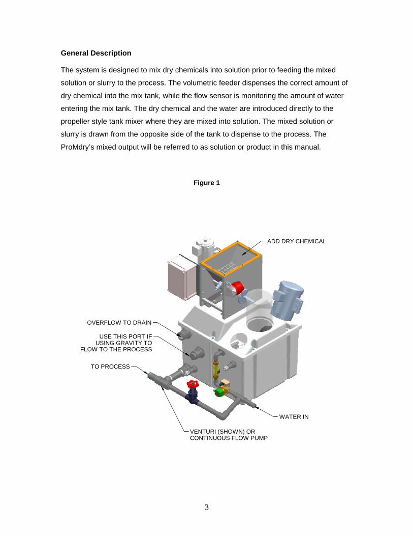
General Description
The system is designed to mix dry chemicals into solution prior to feeding the mixed
solution or slurry to the process. The volumetric feeder dispenses the correct amount of
dry chemical into the mix tank, while the flow sensor is monitoring the amount of water
entering the mix tank. The dry chemical and the water are introduced directly to the
propeller style tank mixer where they are mixed into solution. The mixed solution or
slurry is drawn from the opposite side of the tank to dispense to the process. The
ProMdry’s mixed output will be referred to as solution or product in this manual.
Figure 1
ADD DRY CHEMICAL
WATER IN
TO PROCESS
OVERFLOW TO DRAIN
USE THIS PORT IFUSING GRAVITY TO
FLOW TO THE PROCESS
VENTURI (SHOWN) ORCONTINUOUS FLOW PUMP
4
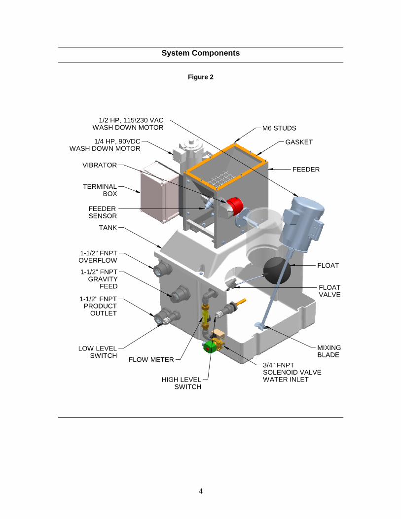
System Components
Figure 2
1/4 HP, 90VDCWASH DOWN MOTOR
GASKET
3/4" FNPTSOLENOID VALVEWATER INLET
1-1/2" FNPTPRODUCT
OUTLET
1-1/2" FNPTOVERFLOW
FLOW METER
MIXINGBLADE
VIBRATOR
LOW LEVELSWITCH
HIGH LEVELSWITCH
TERMINALBOX
1/2 HP, 115\230 VACWASH DOWN MOTOR
TANK
FLOAT
FEEDER
FLOATVALVE
FEEDERSENSOR
1-1/2" FNPTGRAVITY
FEED
M6 STUDS

5
Layout Drawing
Figure 3
Inline ProMdry Layout without Hopper
FRONT VIEW SIDE VIEW
PLAN VIEW
2.505.75
14.534.50
12.30
4.62
FEEDER MOUNTINGSTUD DIMENSIONS
25.00
39.25
4.72 4.72.39
.39
7.48
7.48
M6 STUDS8 PLACES TYP.
27.25
10.00
11.38
15.50

6
Installation
Unpacking
Inspect the packaging of your ProMdry for any damage in shipment, and report it to
the shipping company immediately, as shipping damage is not warranted by
ProMinent. Open the shipping container and inspect your ProMdry for damage
caused by rough handling, and report any damage immediately to the shipping
company.
Check your goods against the packing list and purchase order to be sure you have
received your entire order. If there is anything missing, contact your ProMinent
distributor.
Location
The ProMdry should be placed in a dry location that is protected from the elements
and is close to the pump to be used to feed the solution to the process. Be sure
there is ample space around the ProMdry for access to maintain and repair the unit
during its life.
Be sure there is ample access to load the dry chemical into the hopper, and there is
a drain nearby for routine maintenance and wash down of spilled chemical in the
area.
Electrical Installation
IMPORTANT Observe all local state and national electrical codes when installing your
ProMdry. The electrical installation of the system should only be performed by
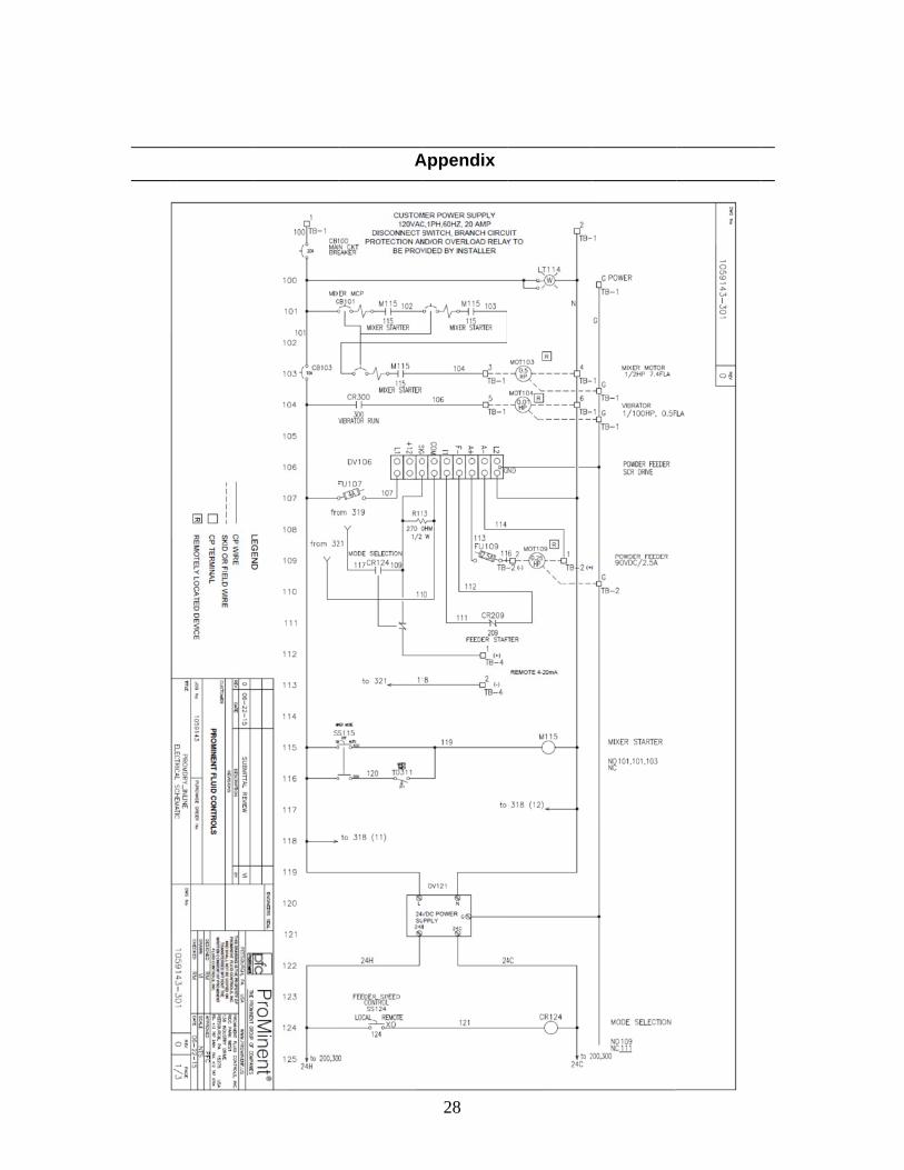
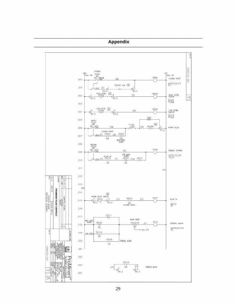
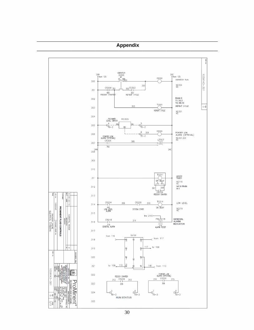
qualified electricians. The ProMdry is electrically connected according to the enclosed electrical diagram
(see Appendix for drawing). Make sure that the ProMdry is grounded per all
applicable electrical codes to prevent electrical shock. If electrical drawings were
provided with your ProMdry, they supersede the drawings in this manual.
7
Water Installation
Any suspended solids or particulates in supply water can clog or damage the
solenoid, fill valve or flow meter. Connect only clean incoming water supply to ¾”
FNPT solenoid water inlet connector (see Figure 2).
Installing a pressure regulator directly upstream of the inlet solenoid valve is
recommended to avoid over pressure problems or damage, and to produce a more
consistent solution mixture. Set pressure regulator between 30-60 psi
The clean water supply and piping should be selected so that the water pressures do
not fall below 30 psig, the operating pressure range is 30-80 psi.
Discharge Connection (Mixed Solution Outlet)
The 1 ½” FNPT “PRODUCT OUTLET” fitting should be connected to the inlet of the pump being used to feed the mixed solution to your process. (See Figure 2)
The unit comes with Drain assembly; see the appendix for different
recommended installation arrangements.

8
Description of System Control
Selector Switch Operation
SYSTEM Selector Switch
ON: The system will operate, if all other selector switches are in the AUTO mode. System will feed water, start the mixer and dry feeder whenever product usage is detected. REMOTE: The system will operate when a remote switch/contact is closed, if all other selector switches are in the AUTO mode. System will feed water, start the mixer and dry feeder whenever product usage is detected.
FEEDER SPEED CONTROL LOCAL: A local Digital potentiometer controls the speed of the dry chemical
feeder REMOTE: User provided 4-20mA signal to control the speed of the dry chemical
feeder WATER Selector Switch
ON: The water valve will open and fill the mixing tank, if the float is not at high level. This could be used during startup or troubleshooting for water valve check, pre-filling or flushing the chamber during routine maintenance.
CAUTION: In this mode the water valve is not interlocked with high level switch. Use caution to avoid overflowing.
AUTO: The water valve will open automatically when the System turns on. Water flow will be regulated by the float valve in the mixing tank.
FEEDER Selector Switch:
ON: The dry chemical feeder will start instantly; this mode will be used during startup/commissioning for dry feeder calibration.
CAUTION: Dry feeder won’t turn off in the ON mode! The user will need to select OFF or AUTO mode, to return to normal operation. AUTO: The dry chemical feeder will start automatically when the System turns on and will operate as long as the water flow switch detects flow.

9
MIXER Selector Switch
ON: The Mixer motor will start instantly. This could be used to manually mix the solution or verify the operation and direction of the mixer motor during startup.
CAUTION: Mixer won’t turn off in the ON mode! The user will need to select OFF or AUTO mode, to return to normal operation.
AUTO: The Mixer will start automatically when the system detects product use. It
will turn off after the product use stops, and the mixing timer times out.
VIBRATOR Selector Switch (optional)
ON: Vibrator will run instantly and it is used to keep the dry chemical, especially powders from sticking to the sides of the hopper. Do not operate vibrator for extended periods without the feeder operating. This will compact the material and increase the chance of material bridging.
CAUTION: Vibrator won’t turn off in ON mode! The user will need to select the OFF mode, or switch VIBRATOR to AUTO mode for normal operation.
AUTO: Vibrator is interlocked with feeder and a cycling timer will turn the vibrator ON and OFF based on programmed times.
HOPPER LOW Indicator (Optional) The ProMdry can be equipped with a proximity switch to activate an indicator light to alert for low chemical in hopper. Note: this is for information only, and will not affect the operation of the system.
ALARM
The unit will go into alarm if any of the following conditions exist:
- High solution tank level
- Low solution tank level (if the unit is in normal operation mode but detects
minimum water level in specified amount of time)
The alarm can be reset by pressing “ALARM RESET” push button to acknowledge
the alarm after the cause has been corrected.
MIXE
Time
moto
feede
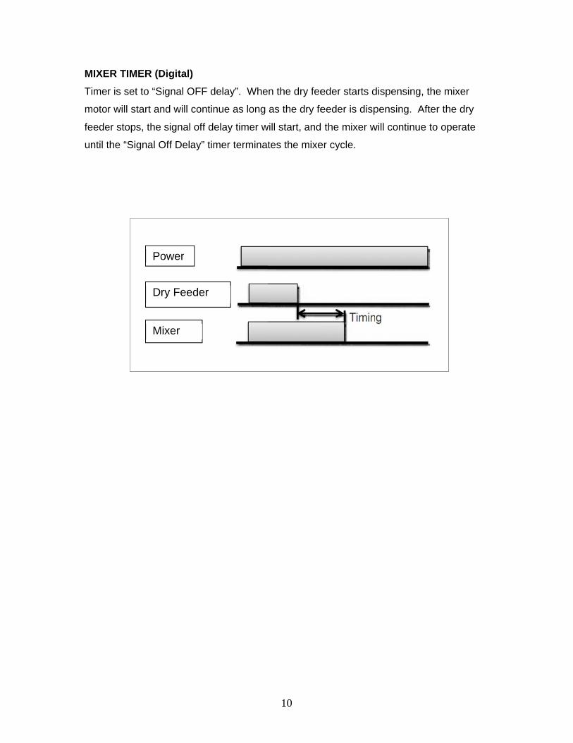
until t
ER TIMER (D
r is set to “S
r will start an
er stops, the
the “Signal O
Po
D
M
Digital)
Signal OFF d
nd will contin
signal off de
Off Delay” tim
ower
ry Feeder
Mixer
delay”. Whe
nue as long
elay timer w
mer terminat
10
n the dry fee
as the dry fe
will start, and
tes the mixe
eder starts d
eeder is disp
the mixer w
er cycle.
dispensing, t
pensing. Aft
will continue
the mixer
ter the dry
to operate
11
Volumetric Dry Feeder Calibration
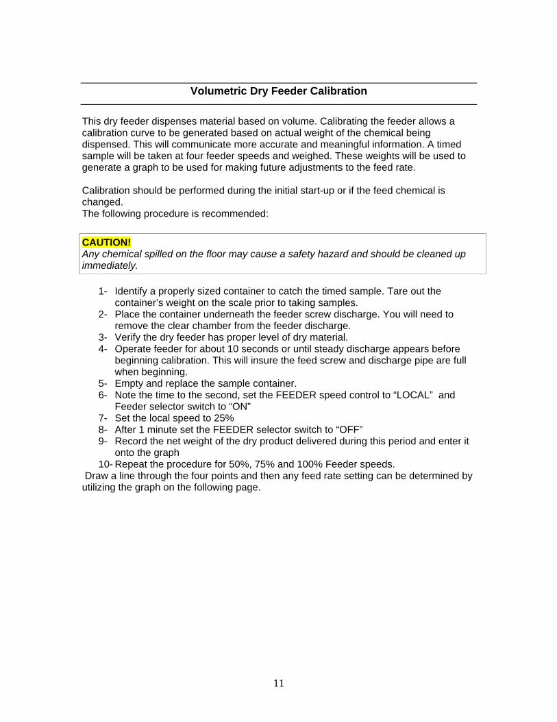
This dry feeder dispenses material based on volume. Calibrating the feeder allows a calibration curve to be generated based on actual weight of the chemical being dispensed. This will communicate more accurate and meaningful information. A timed sample will be taken at four feeder speeds and weighed. These weights will be used to generate a graph to be used for making future adjustments to the feed rate. Calibration should be performed during the initial start-up or if the feed chemical is changed. The following procedure is recommended:
CAUTION! Any chemical spilled on the floor may cause a safety hazard and should be cleaned up immediately.
1- Identify a properly sized container to catch the timed sample. Tare out the container’s weight on the scale prior to taking samples.
2- Place the container underneath the feeder screw discharge. You will need to remove the clear chamber from the feeder discharge.
3- Verify the dry feeder has proper level of dry material. 4- Operate feeder for about 10 seconds or until steady discharge appears before
beginning calibration. This will insure the feed screw and discharge pipe are full when beginning.
5- Empty and replace the sample container. 6- Note the time to the second, set the FEEDER speed control to “LOCAL” and
Feeder selector switch to “ON” 7- Set the local speed to 25% 8- After 1 minute set the FEEDER selector switch to “OFF” 9- Record the net weight of the dry product delivered during this period and enter it
onto the graph 10- Repeat the procedure for 50%, 75% and 100% Feeder speeds.
Draw a line through the four points and then any feed rate setting can be determined by utilizing the graph on the following page.

12
0
0.5
1
1.5
2
2.5
3
0 10 20 30 40 50 60 70 80 90 100

Contr
Pan
General
rols Label M
13
nel Layout
Controls La
Markings Ex
t
ayout
xpanded Vieew

The P
the p
contr
mech
as lon
dispe
flow g
valve
feede
resta
DNfe
E
E
T
C
P
E
C
O
E
P
fil
T
P
P
sw
P
S
ProMdry che
rocess. Wat
rolled via me
hanical float
ng as the wa
ense the pre
goes to zero
e will turn off
er and mixer
rt. If either lo
DANGER! RNever removeeder durin
Ensure syste
Ensure that c
Turn on main
Close and lat
Place all swit
Ensure there
Calibrate the
Open any ins
Ensure that th
Place the WA
ll.
The mechani
Place the WA
Place the FE
witches sho
Place FEEDE
Set the feede
Com
emical feed s
ter is control
echanical floa
valve will re
ater flow swi
set rate and
o (i.e. the pu
f the incomin
r will turn off
ow or high le
Risk of crusve the proteg operation
m has clean
correct powe
n breaker loc
tch the contr
ches in the O
is dry chem
dry feeder o
stalled servic
he water pre
ATER switch
cal float valv
ATER switch
EDER, MIXE
uld be in AU
ER SPEED t
er speed to t
mmissionin
system is de
led via solen
at valve. Wh
egulate the in
itch is detect
the mixer w
mp feeding f
ng water, the
. Once disch
evel switches
shing anythective safetyn of the sys
n inlet water
er is supplied
cated inside
rol cabinet d
OFF position
mical in the h
output (see a
ce valves in
essure is adj
h to the ON p
ve should tu
h to AUTO po
ER, and VIB
UTO position
to LOCAL (R
he desired r
14
ng/Start Up
esigned to fe
noid valve fo
hen the syste
ncoming wat
ting a minim
will mix it into
from the tan
e flow switch
harge flow is
s gets trippe
hing in the ay screen ortem.
and solution
d to the ProM
control pane
oor.
n.
opper
above proce
the water su
justed to 30-
position. Wa
rn off the wa
osition.
BRATOR sw
n.
REMOTE if y
rate.
p/Operation
eed mixed so
or on/off con
em is runnin
ter to match
mum flow, the
o solution for
nk turns off),
h will detect l
s re-establish
ed, the syste
area of the fr reach into
n discharge
Mdry (see el
el (see elect
edure)
upply line
-60 psi.
ater flow sho
ater at high l
itches to AU
you will utiliz
n
olution conti
ntrol and the
ng in AUTO,
the dischar
e dry feeder
r use. If the
the mechan
loss of flow,
hed, the sys
em will alarm
feed auger! the unprote
connected.
ectrical draw
trical drawing
uld start, allo
level.
UTO. All com
ze a 4-20mA
nuously to
flow rate is
the
ge rate, and
r will
discharge
nical float
and the
stem will
m.
! tected dry
wing).
g).
ow tank to
mponent
A signal)
d

P
T
B
e
A
st
A
O
O
su
c
Setti The rchem • Firs
cov • The
mo • Car
LED • Tur
off.
• Che
ope
The
be
and
Place the SY
The ProMdry
Begin solutio
tc.)
Allow system
teady state.
Adjust flow sw
Once flow is d
Observe the s
urface, the m
hemical into
ng of the op
response thrmicals being
st, fill the voluvered.
en, turn the aving the sen
refully turn thD turns off.
rn the adjust
eck the switc
eration after
e dry chemic
OFF with dr
d ON withou
STEM selec
is now read
n feed from
to operate u
witch on the
detected, the
system in op
mixing prope
o the solution
ptional Hop
reshold of thmixed.
umetric feed
adjusting scnsor toward y
he adjusting
ting screw to
ching functio
setting thes
cal sensor L
ry chemical i
t chemical.
ctor switch to
dy for service
the tank by
until mechan
flow meter t
e feeder and
peration. If th
eller can be a
n.
pper level se
he capacitive
der with dry c
rew of the leyou until the
screw to the
o the right by
on during
e limits.
ED must
n Hopper
15
o ON or REM
e.
turning on th
nical float va
to detect the
d mixer will o
he dry chem
adjusted upw
ensor
e level senso
chemical un
evel sensor te LED turns o
e left which w
y an addition
MOTE.
he delivery d
alve opens a
e steady stat
operate.
mical tends to
ward on the
or is adapted
til the level s
to the right, won.
will move the
nal 1 full turn
device (pum
and water flo
te flow rate.
o float on the
shaft to hel
d to the diffe
sensor is co
which will re
e sensor aw
n, the LED m
mp, eductor,
ow achieves
e water’s
p draw the
erent dry
mpletely
esult in
way until the
must still be
16
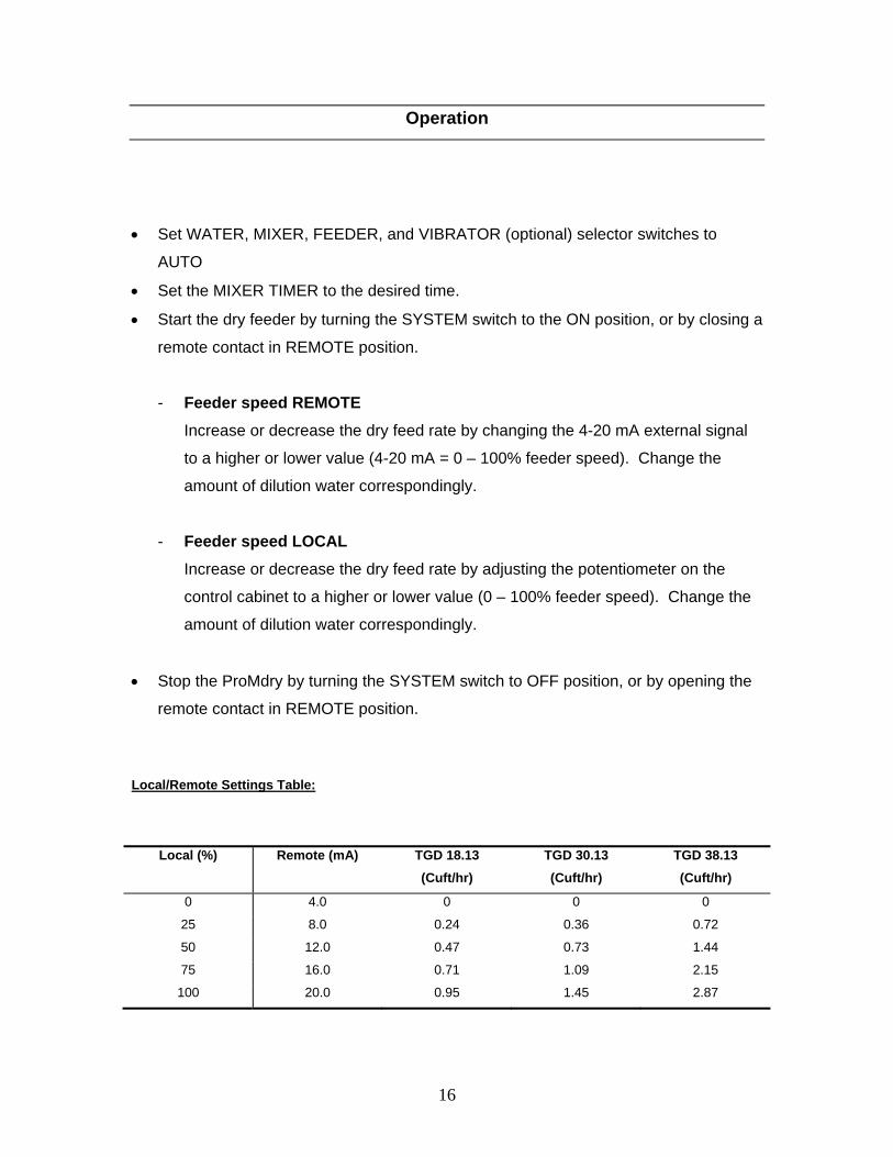
Operation
Set WATER, MIXER, FEEDER, and VIBRATOR (optional) selector switches to
AUTO
Set the MIXER TIMER to the desired time.
Start the dry feeder by turning the SYSTEM switch to the ON position, or by closing a
remote contact in REMOTE position.
- Feeder speed REMOTE
Increase or decrease the dry feed rate by changing the 4-20 mA external signal
to a higher or lower value (4-20 mA = 0 – 100% feeder speed). Change the
amount of dilution water correspondingly.
- Feeder speed LOCAL
Increase or decrease the dry feed rate by adjusting the potentiometer on the
control cabinet to a higher or lower value (0 – 100% feeder speed). Change the
amount of dilution water correspondingly.
Stop the ProMdry by turning the SYSTEM switch to OFF position, or by opening the
remote contact in REMOTE position.
Local/Remote Settings Table:
Local (%) Remote (mA) TGD 18.13
(Cuft/hr)
TGD 30.13
(Cuft/hr)
TGD 38.13
(Cuft/hr)
0 4.0 0 0 0
25 8.0 0.24 0.36 0.72
50 12.0 0.47 0.73 1.44
75 16.0 0.71 1.09 2.15
100 20.0 0.95 1.45 2.87
Dry F
DNfe
T
e
C
n
Clean
Us
DNsy
1. A
ca
2. T
d
3. If
c
W
Feeder
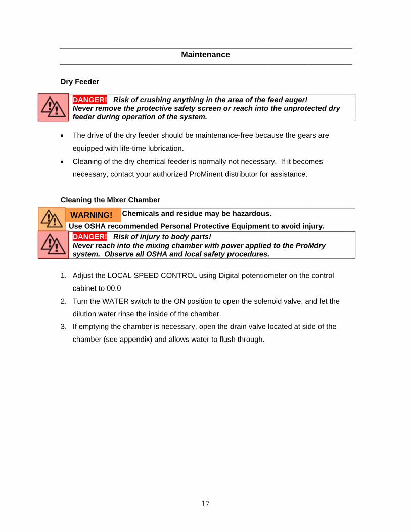
DANGER! RNever removeeder durin
The drive of t
quipped with
Cleaning of th
ecessary, co
ning the Mix
se OSHA rec
DANGER! RNever reach
ystem. Obs
Adjust the LO
abinet to 00
Turn the WAT
ilution water
f emptying th
hamber (see
WARNING!
Risk of crusve the proteg operation
the dry feede
h life-time lu
he dry chem
ontact your a
xer Chambe
Chemical
commende
Risk of injurinto the mi
serve all OS
OCAL SPEE
.0
TER switch t
r rinse the in
he chamber
e appendix)
Ma
shing anythective safetyn of the sys
er should be
brication.
mical feeder i
authorized P
er
ls and resid
d Personal
ry to body pixing chambSHA and loc
D CONTRO
to the ON po
nside of the c
is necessary
and allows w
17
intenance
hing in the ay screen ortem.
e maintenanc
s normally n
ProMinent di
due may be
Protective
parts! ber with pocal safety p
OL using Digi
osition to op
chamber.
y, open the d
water to flus
area of the fr reach into
ce-free beca
not necessar
stributor for
hazardous
Equipment
wer appliedprocedures.
ital potentiom
pen the solen
drain valve l
sh through.
feed auger! the unprote
ause the gea
ry. If it beco
assistance.
s.
t to avoid in
d to the Pro.
meter on the
noid valve, a
located at si
! tected dry
ars are
omes
njury.
oMdry
e control
and let the
de of the
Tech
Volu
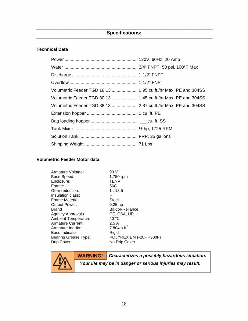
hnical Data
Power ....
Water .....
Discharge
Overflow
Volumetri
Volumetri
Volumetri
Extension
Bag loadi
Tank Mixe
Solution T
Shipping
metric Feed
Armature VBase SpeeEnclosure:Frame: Gear reducInsulation Frame MaOutput PowBrand Agency ApAmbient TArmature CArmature IBase IndicBearing GDrip Cover
...................
...................
e .................
...................
ic Feeder TG
ic Feeder TG
ic Feeder TG
n hopper .....
ng hopper ..
er ................
Tank ...........
Weight .......
der Motor d
Voltage: ed: :
ction: class: terial: wer:
pprovals emperature Current: Inertia: cator rease Type: r :
Your li
WARN
Spec
...................
...................
...................
...................
GD 18.13 ....
GD 30.13 ....
GD 38.13 ....
...................
...................
...................
...................
...................
ata
90 V 1,75 TEN 56C 1 : 1 F Stee 0.25 Bald CE, 40 ° 2.5 7.80 Rigi
POL No
Cha
ife may be i
ING!
18
cifications
.................. 1
.................. 3
.................. 1
.................. 1
.................. 0
.................. 1
.................. 2
.................. 1
..................
.................. ½
.................. F
.................. 7
V 50 rpm NV C 13.5
el 5 hp dor-Reliance CSA, UR °C A 04lb-ft2 id LYREX EM (-Drip Cover
aracterizes
in danger o
s:
120V, 60Hz
3/4” FNPT, 5
1-1/2” FNPT
1-1/2” FNPT
0.95 cu.ft./h
1.45 cu.ft./h
2.87 cu.ft./h
1 cu. ft. PE
___cu. ft. S
½ hp, 1725
FRP, 35 gal
71 Lbs
-20F +300F)
a possibly
or serious in
, 20 Amp
50 psi, 100°
T
T
r Max, PE a
r Max, PE a
r Max, PE a
SS
RPM
lons
hazardous
njuries may
F Max
nd 304SS
nd 304SS
nd 304SS
situation.
y result.
19
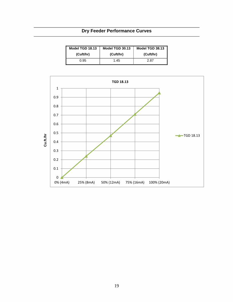
Dry Feeder Performance Curves
Model TGD 18.13
(Cuft/hr)
Model TGD 30.13
(Cuft/hr)
Model TGD 38.13
(Cuft/hr)
0.95 1.45 2.87
0
0.1
0.2
0.3
0.4
0.5
0.6
0.7
0.8
0.9
1
0% (4mA) 25% (8mA) 50% (12mA) 75% (16mA) 100% (20mA)
TGD 18.13
TGD 18.13
Cu
.ft.
/hr
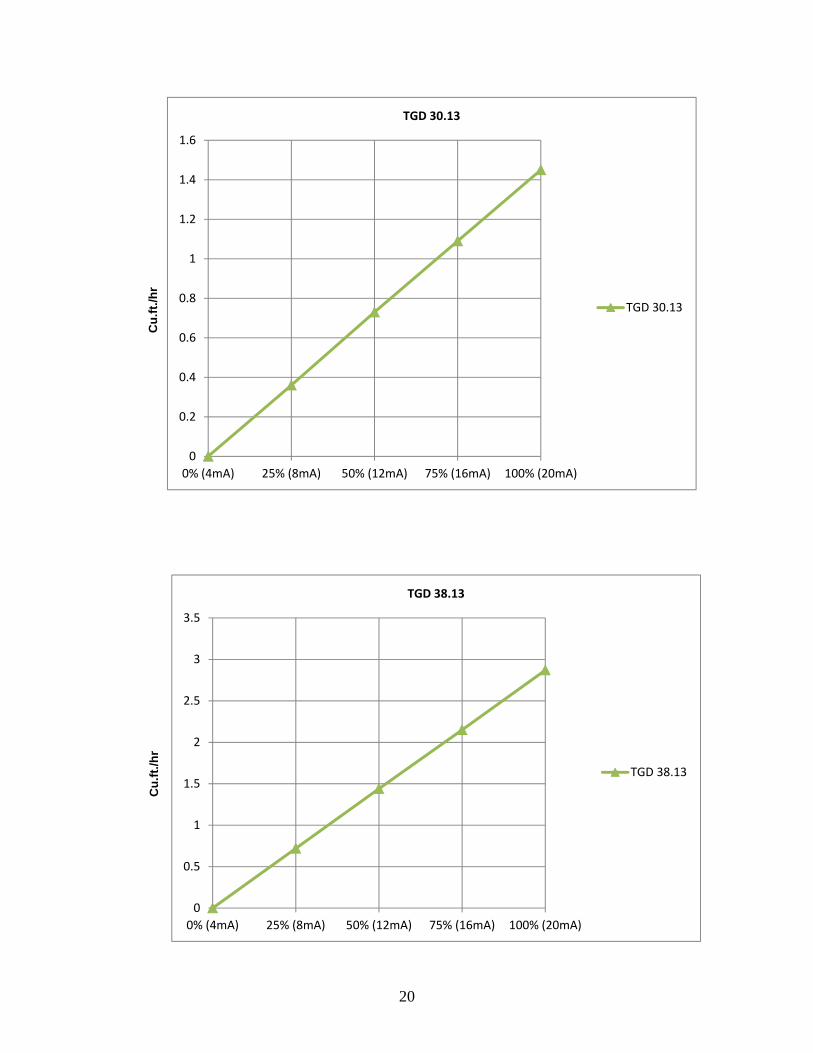
20
0
0.5
1
1.5
2
2.5
3
3.5
0% (4mA) 25% (8mA) 50% (12mA) 75% (16mA) 100% (20mA)
TGD 38.13
TGD 38.13
Cu
.ft.
/hr
0
0.2
0.4
0.6
0.8
1
1.2
1.4
1.6
0% (4mA) 25% (8mA) 50% (12mA) 75% (16mA) 100% (20mA)
TGD 30.13
TGD 30.13
Cu
.ft.
/hr
21
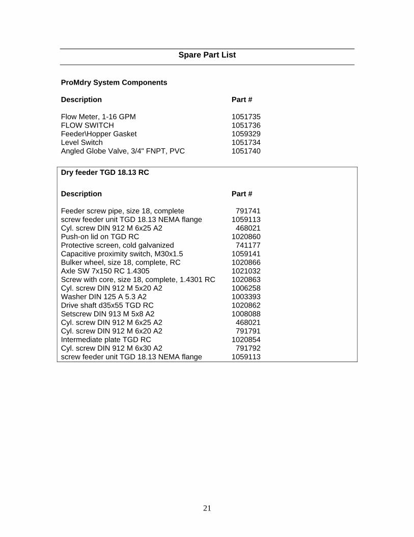
Spare Part List
ProMdry System Components Description Part # Flow Meter, 1-16 GPM 1051735 FLOW SWITCH 1051736 Feeder\Hopper Gasket 1059329 Level Switch 1051734 Angled Globe Valve, 3/4" FNPT, PVC 1051740
Dry feeder TGD 18.13 RC
Description Part # Feeder screw pipe, size 18, complete 791741 screw feeder unit TGD 18.13 NEMA flange 1059113
Cyl. screw DIN 912 M 6x25 A2 468021 Push-on lid on TGD RC 1020860 Protective screen, cold galvanized 741177 Capacitive proximity switch, M30x1.5 1059141 Bulker wheel, size 18, complete, RC 1020866 Axle SW 7x150 RC 1.4305 1021032 Screw with core, size 18, complete, 1.4301 RC 1020863 Cyl. screw DIN 912 M 5x20 A2 1006258 Washer DIN 125 A 5.3 A2 1003393 Drive shaft d35x55 TGD RC 1020862 Setscrew DIN 913 M 5x8 A2 1008088 Cyl. screw DIN 912 M 6x25 A2 468021 Cyl. screw DIN 912 M 6x20 A2 791791 Intermediate plate TGD RC 1020854 Cyl. screw DIN 912 M 6x30 A2 791792 screw feeder unit TGD 18.13 NEMA flange 1059113

22
Spare Parts List
Dry feeder TGD 30.13 RC Description Part # Feeder screw pipe, size 30, complete 791742 Cyl. screw DIN 912 M 6x25 A2 468021 Push-on lid on TGD RC 1020860 Protective screen, cold galvanized 741177 Capacitive proximity switch, M30x1.5 1059141 Bulker wheel, size 30, complete, RC 1021061 Axle SW 7x150 RC 1.4305 1021032 Screw with core, size 30, complete, 1.4301 RC 1021058 Cyl. screw DIN 912 M 5x20 A2 1006258 Washer DIN 125 A 5.3 A2 1003393 Drive shaft d35x55 TGD RC 1020862 Setscrew DIN 913 M 5x8 A2 1008088 Cyl. screw DIN 912 M 6x25 A2 468021 Cyl. screw DIN 912 M 6x20 A2 791791 Intermediate plate TGD RC 1020854 Cyl. screw DIN 912 M 6x30 A2 791792 screw feeder unit TGD 30.13 NEMA flange 1059114
Dry feeder TGD 38.13 RC Description Part # Feeder screw pipe, size 38, complete 791743 Cyl. screw DIN 912 M 6x25 A2 468021 Push-on lid on TGD RC 1020860 Protective screen, cold galvanized 741177 Capacitive proximity switch, M30x1.5 1059141 Bulker wheel, size 38, complete, RC 1021062 Axle SW 7x150 RC 1.4305 1021032 Screw with core, size 38, complete, 1.4301 RC 1021059 Cyl. screw DIN 912 M 5x20 A2 1006258 Washer DIN 125 A 5.3 A2 1003393 Drive shaft d35x55 TGD RC 1020862 Setscrew DIN 913 M 5x8 A2 1008088 Cyl. screw DIN 912 M 6x25 A2 468021 Cyl. screw DIN 912 M 6x20 A2 791791 Intermediate plate TGD RC 1020854 Cyl. screw DIN 912 M 6x30 A2 791792 screw feeder unit TGD 38.13 NEMA flange 1059115

23
Appendix
Inline ProMdry Layout with Polypropylene Hopper
FRONT VIEW SIDE VIEW
PLAN VIEW
2.505.75
14.534.50
25.00
50.19
27.25
10.00
11.38
15.50
ISOMETRIC VIEW

24
Appendix
Inline ProMdry Layout with Stainless Steel Hopper
FRONT VIEW SIDE VIEW
PLAN VIEW
2.505.75
14.534.50
25.00
48.31
27.25
10.00
11.38
15.50
ISOMETRIC VIEW

25
Appendix
20
250
40
30
170
150
90
100
110
120
180
60
50
80200
220
160
140
130
260
210
240
190
70
270
290
280
10
230

26
Appendix
INLINE PROMDRY SYSTEM
BILL OF MATERIAL
ITEM DESCRIPTION USA P\N
TGD 18.13RC FEEDER 1059113
10 TGD 30.13RC FEEDER 1059114
TGD 38.13RC FEEDER 1059115
20 MOTOR, 1/4 HP, TENV, 90 VDC, 56C 1059145
30 TANK, BOTTOM, PROMDRY 1051719
40 TANK, COVER, PROMDRY 1051718
50 CHAMBER, CLEAR, PROMDRY 1051728
60 COVER, CLEAR CHAMBER, PROMDRY 1051729
70 COVER, LID, PROMDRY 1051730
80 PLATE, MOTOR MOUNTING, 56C, PROMDRY 1058822
90 MOTOR, 1/2 HP, TEFC, 115\230 VAC, 1 PH 7747212
100 COUPLING, SHAFT 1051733
110 SHAFT, 5/8" OD, 18" LONG, 303 SS 1051732
120 BLADE, MIXING 1051731
130 SOLENOID VALVE, 3/4, FNPT, BRASS, NBR, 0‐150 PSIG 1051742
140 FLOW METER, 1‐16 GPM 1051735
*140 FLOW SWITCH 1051736
150 GASKET, FEEDER\HOPPER 1059329
160 LEVEL SWITCH 1051734
170 BRACKET, TERMINAL BOX MOUNTING 1058821
180 TERMINAL BOX 1059223
190 ANGLE, HOPPER MOUNTING 1051743
200 FITTING, BULKHEAD, 1‐1/2", FNPT X SKT, PVC, VITON, SCH 80 7745804
210 FITTING, BULKHEAD, 3/4", FNPT X FNPT, PVC, VITON, SCH 80 7745807
220 FITTING, BULKHEAD, LEVEL SWITCH, PVC, VITON, SCH 80 1060167
230 CORD GRIP 7735040
240 ELBOW‐90, 3/4", FT X FT, PVC, SCH 80 7741474
250 SENSOR, CAPACITIVE, FEEDER 1059141
260 VIBRATOR 1051720
270 ROD, FLOAT, 1/4" OD, 10" LONG, SS 1051739
280 FLOAT, 6" ROUND, PE 1051738
290 VALVE, FLOAT, 3/4" FNPT, PVC 1051737
*not shown in exploded view

27
Appendix
OPTION 1
OPTION 2
OPTION 3
Drain Plug Option 1
Drain Plug Option 2
Drain Plug Option 3
A
28
Appendix
A
29
Appendix
A
30
Appendix

A
31
Appendix

A
32
Appendix

A
33
Appendix

A
34
Appendix

A
35
Appendix
OpFoMo
Op The pManythreesmallthe sthe liqfunctswitc Modeused contrminim MouThe
peratior Plaodel:
erating
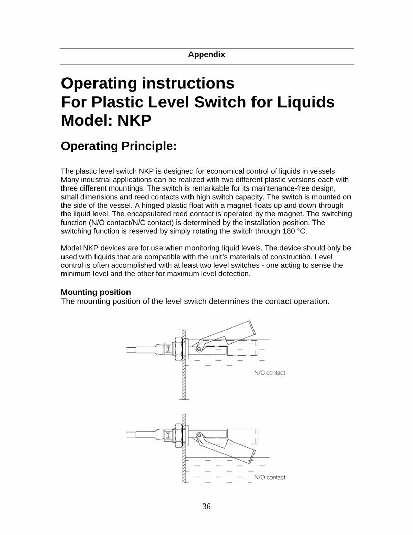
plastic level y industrial ae different mol dimensionside of the vequid level. Tion (N/O conhing function
el NKP devicwith liquids
rol is often acmum level an
nting posimounting p
ing instic LNKP
g Princi
switch NKP applications countings. Ths and reed cessel. A hingThe encapsuntact/N/C con is reserved
ces are for uthat are com
ccomplishednd the other
tion position of t
A
nstrucLevel
ple:
is designedcan be realiz
he switch is rcontacts withged plastic fllated reed c
ontact) is detd by simply
use when mompatible withd with at leasfor maximu
he level sw
36
Appendix
ctionsSwitc
for economzed with tworemarkable f
h high switchoat with a m
contact is optermined by rotating the
onitoring liquh the unit’s mst two level sm level dete
witch determ
s ch for
mical control o different plfor its mainte
h capacity. Tmagnet floats
erated by ththe installatswitch throu
uid levels. Thmaterials of switches - oection.
mines the co
r Liqu
of liquids in astic versionenance-free
The switch iss up and dowhe magnet. Tion position.
ugh 180 °C.
he device shconstructionne acting to
ontact oper
uids
vessels. ns each with
e design, s mounted onwn through The switchin. The
hould only ben. Level
sense the
ration.
h
n
g
e

A
37
Appendix

A
38
Appendix

A
39
Appendix
A
40
Appendix
A
41
Appendix

A
42
Appendix

43