promi-esd · enabling wireless serial communications promi-esd ... - when ttl level of micom is...
TRANSCRIPT

by Bluetooth
Enabling Wireless Serial Communications
Promi-ESDUser Manual Version 1.3 Q3 2005
Deutschland:Tel.: 0761 / 592100Fax: 0761 / 585228
Schweiz:Tel.: 061 / 27311-31Fax: 061 / 27311-39
Österreich:Tel.: 01 / 51474-415Fax: 01 / 51474-337
HANTZ + PARTNERThe Upgrade Company! www.hantz.com

Promi-ESD User Manual ver 1.3 www.PromiSerial.de www.PromiSerial.com
2
Revision History: User Manual of Promi-ESD™
Version Changed Contents Date
1.1 Draft version 02/01/2003
1.2 Modified Jig Board 09/04/2003
1.3 Changed Hardware information 07/26/2004

Promi-ESD User Manual ver 1.3 www.PromiSerial.de www.PromiSerial.com
3
Contents
1. Product Description ............................................5
1.1 About Promi-ESD™ .................................................................................................... 5
2. Technical Specifications......................................7
2.1 Pin Assignment.............................................................................................................. 7
2.2 Electrical Characteristics ............................................................................................... 9
2.3 Hardware Design......................................................................................................... 10
2.4 How to make a RS232 interfaced Jig Board ............................................................... 13
2.5 Power Consumption .................................................................................................... 14
2.6 Temperature ................................................................................................................ 14
2.7 Serial Interface ............................................................................................................ 15
2.8 Bluetooth Interface ...................................................................................................... 15
2.9 Maximum distance between Promi-ESD™s ............................................................... 16
3. Configuration ....................................................17
3.1 Using Promi-WIN™ ............................................................................................... 17
3.1.1 Making the first Promi-SDTM/Bluetooth connection 17
3.1.2 Setting Operating Mode for Automatic Connection 23
3.2. Using a Terminal Program.......................................................................................... 24
3.2.1 Connecting Promi-SD™ to host. 24
3.2.2 Making the first Promi-SD™/Bluetooth connection 25
3.2.3 Making Promi-SD™ do INQUIRY SCAN and PAGE SCAN 26
3.2.4 Releasing the existing Bluetooth connection 27
3.2.5 Automatic connection of two Promi-SD™ Units 28
3.2.6 AT command vs. Operational Status 29
4. Optional Antennas............................................31
5. For Multi-Serial Connections............................33
5.1 Promi-MSP™......................................................................................................... 33

Promi-ESD User Manual ver 1.3 www.PromiSerial.de www.PromiSerial.com
4
7. About this Manual.............................................36
Appendix A: AT command sets................................37

Promi-ESD User Manual ver 1.3 www.PromiSerial.de www.PromiSerial.com
5
1. Product Description
1.1 About Promi-ESD™
Promi-ESD™ is a board type of Promi-SD™, which can be embedded in your
applications such as mobile terminals or any kinds of machines for Wireless serial
communications of long range, easy-to-install, and low-cost. Provided is point-to-
point wireless connection without standard RS232 cables.
For point-to-multipoint connections, please refer to our Promi-MSP™, providing all
the features of RS485.
Model Name Part No. Spec.
Promi-ESD ESD00-10100 Class 1 / Output Power: 63mW (18dBm)
3~3.3V DC power supply
w/ An antenna on a cable
w/ Setup Software & manual on CD
Specification
Output Interface UART
Compliant Bluetooth Specification v1.1
Transmission Power Class 1(max 18dBm)
Receiving Signal Range -84 to -20dBm
Dimensions: 27 x 27 (mm)

Promi-ESD User Manual ver 1.3 www.PromiSerial.de www.PromiSerial.com
6
Promi-ESD™
Promi-ESD™ with a default external cable

Promi-ESD User Manual ver 1.3 www.PromiSerial.de www.PromiSerial.com
7
2. Technical Specifications
2.1 Pin Assignment
Physical Dimension
Promi-ESD User Manual ver 1.3 www.PromiSerial.de www.PromiSerial.com
8
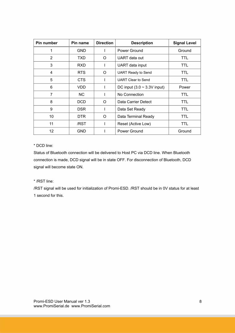
Pin number Pin name Direction Description Signal Level
1 GND I Power Ground Ground
2 TXD O UART data out TTL
3 RXD I UART data input TTL
4 RTS O UART Ready to Send TTL
5 CTS I UART Clear to Send TTL
6 VDD I DC input (3.0 ~ 3.3V input) Power
7 NC I No Connection TTL
8 DCD O Data Carrier Detect TTL
9 DSR I Data Set Ready TTL
10 DTR O Data Terminal Ready TTL
11 /RST I Reset (Active Low) TTL
12 GND I Power Ground Ground
* DCD line:
Status of Bluetooth connection will be delivered to Host PC via DCD line. When Bluetooth
connection is made, DCD signal will be in state OFF. For disconnection of Bluetooth, DCD
signal will become state ON.
* /RST line:
/RST signal will be used for initialization of Promi-ESD. /RST should be in 0V status for at least
1 second for this.

Promi-ESD User Manual ver 1.3 www.PromiSerial.de www.PromiSerial.com
9
2.2 Electrical Characteristics
Recommended Operating Conditions
Operating Condition ( Min Max
Operating Temperature Range -20°C 75°C
VDD 3.0V 3.6V
※ For safe operation, supply power of 3.3V.
Input/Output Terminal Characteristics
Digital Terminals Min Typ Max Unit
Input Voltage
VIL input logic level low (VDD=3.0V) -0.3 - 0.8 V
VIH input logic level high 0.7VDD - VDD+0.3 V
Output Voltage Input
VOL output logic level low, (lO = 4.0mA), - - 0.2 V
VOH output logic level high, (lO = -4.0mA), VDD-0.3 - - V

Promi-ESD User Manual ver 1.3 www.PromiSerial.de www.PromiSerial.com
10
2.3 Hardware Design
1) If you would like to supply 5~12V power to Promi-ESD, you need to regulate the power
to be 3.3V as in below. ( Min. 100mA regulator )
U?LM1117LD-3.3
3 2
4
1
Vin Vout1
Vout2GN
D
VDD
C?10uF
IN_POWER
C?10uF
Input to each signals when 5V power supplied.
R168K
ESD_RTS
MICOM_TXD
R4115K
ESD_DTR
MICOM_DTR
R6115K
ESD_RXD
R2115K
ESD_DCDMICOM_DCD
R368K
ESD_TXD
ESD_DSR
MICOM_DSR
MICOM_RXD
R568K
MICOM_RTS
MICOM_CTS
ESD_CTS

Promi-ESD User Manual ver 1.3 www.PromiSerial.de www.PromiSerial.com
11
2) For appropriate operation, please supply power of 3.3V to /RST line as well.
R6115K
MICOM_RST*
R568K
ESD_RST*
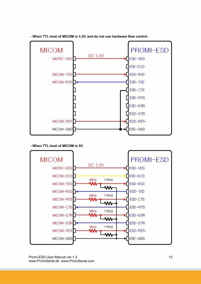
3) If you are not using Hardware flow control (handshaking), please bridge ESD_CTS
and ESD_GND to disable the function.
<Reference Guide>
- When TTL level of MICOM is 3.3V.
Promi-ESD User Manual ver 1.3 www.PromiSerial.de www.PromiSerial.com
12
- When TTL level of MICOM is 3.3V, and do not use hardware flow control.
- When TTL level of MICOM is 5V.
Promi-ESD™ User Manual ver 1.2 www.PromiSerial.de www.PromiSerial.com
13
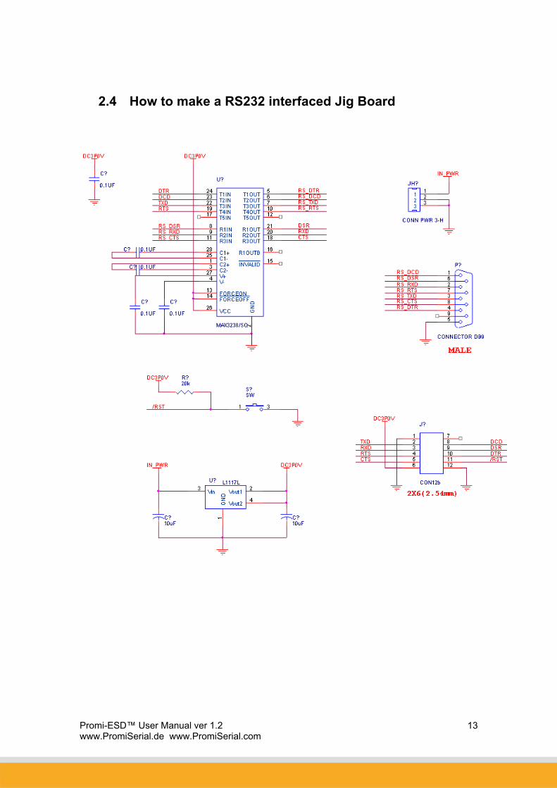
2.4 How to make a RS232 interfaced Jig Board

Promi-ESD™ User Manual ver 1.2 www.PromiSerial.de www.PromiSerial.com
14
2.5 Power Consumption
Condition Current Consumption
If NOT connected to Host 3 mA
If connected to Host 3 mA
For data communications with Host only 6 mA
During INQUIRY mode 72.4 mA
For Master connection 72.7 mA
During SCAN (page & inquiry) mode 21 mA
Park mode 6 mA
Non-Park mode 9 mA
Data Com. (9600bps) 26 mA
Data Com. (115000bps) 29 mA
* Low Power Mode
If you want to use low power mode to save power, use AT command “AT+BTLPM".
If you set "AT+BTLPM,1", low power mode will be functioned.
2.6 Temperature
Model No.: Promi-ESD
Recommended operating conditions: -20’C~75’C
Storage conditions: -40’C~85’C

Promi-ESD™ User Manual ver 1.2 www.PromiSerial.de www.PromiSerial.com
15
2.7 Serial Interface
Model No.: Promi-ESD
RS232, Female DSUB-9, 1200~230000 baud,
CTS/RTS flow control or no flow control
2.8 Bluetooth Interface
Bluetooth Specification V 1.1
Level 18 dBm
Range ~100m
Bluetooth protocols RFCOMM, L2CAP, SDP
Supported Profiles General Access Profile
Serial Port Profile
Promi-ESD™ User Manual ver 1.2 www.PromiSerial.de www.PromiSerial.com
16
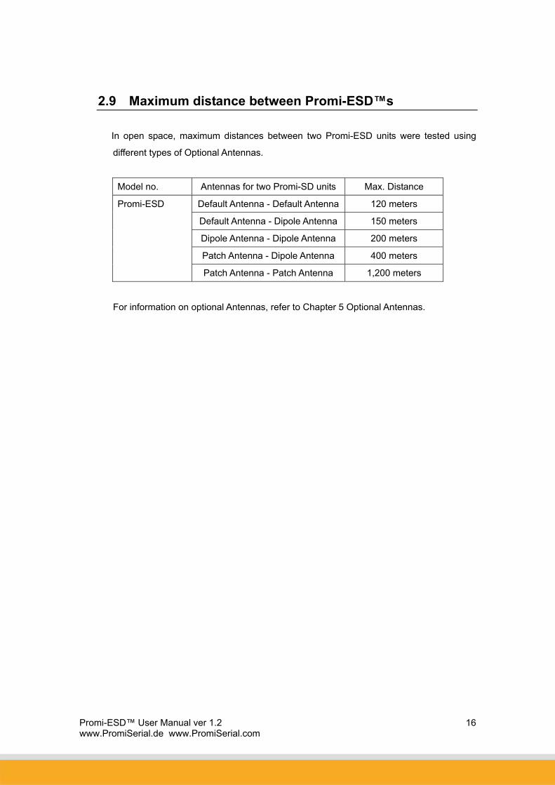
2.9 Maximum distance between Promi-ESD™s
In open space, maximum distances between two Promi-ESD units were tested using
different types of Optional Antennas.
Model no. Antennas for two Promi-SD units Max. Distance
Default Antenna - Default Antenna 120 meters
Default Antenna - Dipole Antenna 150 meters
Dipole Antenna - Dipole Antenna 200 meters
Patch Antenna - Dipole Antenna 400 meters
Promi-ESD
Patch Antenna - Patch Antenna 1,200 meters
For information on optional Antennas, refer to Chapter 5 Optional Antennas.

Promi-ESD™ User Manual ver 1.2 www.PromiSerial.de www.PromiSerial.com
17
3. Configuration
3.1 Using Promi-WIN™
To configure Promi-ESD, you need to prepare RS232 interfaced jig board.
1. Please connect Promi-ESD to RS232 interfaced jig board you prepared.
2. Connect the Jig board to your Host PC.
3. Supply power to the Jig board.
4. Start PromiWIN software on your Host PC and you may configure the Promi-ESD.
Configuration flow of Promi-ESD is same as the flow of Promi-SD.
Users may consider Promi-SD as Promi-ESD in the manual below.
3.1.1 Making the first Promi-SDTM/Bluetooth connection
To make Bluetooth wireless connections with SD, first connect the SD to a host
computer running PromiWINTM as instructed below. Then activate SD INQUIRY
SCAN and PAGE SCAN from PromiWINTM.
Let’s suppose there are 2 Promi-ESD™s, SD1 and SD2:
1. Connect the SD1 to a host serial port and turn on the SD.
2. Check the SD1 STATUS LED color. Amber indicates standard mode. Start the
PromiWINTM configuration program by clicking the program icon under
Start/Programs/PromiWINTM.
3. Please open PromiWIN PromWIN configuration menu to set up the
PromiWIN to be matched with Promi-ESD.

Promi-ESD™ User Manual ver 1.2 www.PromiSerial.de www.PromiSerial.com
18
Check COM port number of your PC where Promi-SD is plugged in.
Check BaudRate/Parity/StopBit. Users need to select the correct
configuration value of Promi-ESD to start.
Default Setting of Promi-ESD: 9600/NoParity/ One Stop bit. Users may NOT
change the configuration of Promi-ESD, the job should be done at
DeviceSetting menu
4. Select Promi-SD Start Configuration in the menu. Information will be
displayed as shown in Figure 1.

Promi-ESD™ User Manual ver 1.2 www.PromiSerial.de www.PromiSerial.com
19
Figure 1
Device Name: Shows default device name of Promi-SD. Ex) PSDv3a-120296
PSDv3a means the version of firmware of Promi-SD.
Users may change the Device name at Device Setting page.
Device Hardware Address: Default Bluetooth Device Address.
Current Mode: This show current operation MODE of Promi-SD.
Current Status: Status of Promi-SD operation: Standby / Pending/ Connect.
Security: This shows current Security setting values.
Uart Setting: Shows current setting of UART. If users want to change Baud
Rate/ StopBit/ Parity, please go to Device Setting page.
5. Click the ‘Device Setting’ icon in the list control box.
Figure 2.
Operation Mode:
Mode0: Default Mode to set up Bluetooth connection
Mode1: Mode1 & Mode 2 are for secure connection. Promi-SD that has
been set to Mode1 will try connection to the last connected
device only.
Mode2: Promi-SD that has been set to Mode2 will wait fro connection from

Promi-ESD™ User Manual ver 1.2 www.PromiSerial.de www.PromiSerial.com
20
the last connected device only.
Mode3: In Mode3, Promi-SD will be discoverable/connectable by any kind
of Bluetooth devices. If users want to make a connection between
Promi-SD and other Bluetooth CF cards or USB dongles, please
set Mode3. For more information, please refer to the Trouble
shooting guide of this manual.
*Promi-SDs which are paired using Mode1 & Mode2 will be
automatically connected, unless Mode setting is changed.
Uart: To change the Baud rate/Parity/StopBit, please use this Uart setting menu.
*NOTE: Please do not confuse with PromiWIN configuration menu.
PromiWIN configuration menu will only set the configuration of
PromiWIN. To Change the configuration of Promi-SD, users must
use this Uart setting menu in Red circle above.
Security Option: Users may set the security option. Authentication/ Encryption/
password.
Device Name: Users may change the device name to be more friendly.
Signal: If users want to remove the response signals from Promi-SD, such as
OK, CONNECT, DISCONNECT, ERROR on each events, users may
Promi-ESD™ User Manual ver 1.2 www.PromiSerial.de www.PromiSerial.com
21
turn off the signal here. This can be done by ATS10=n command.
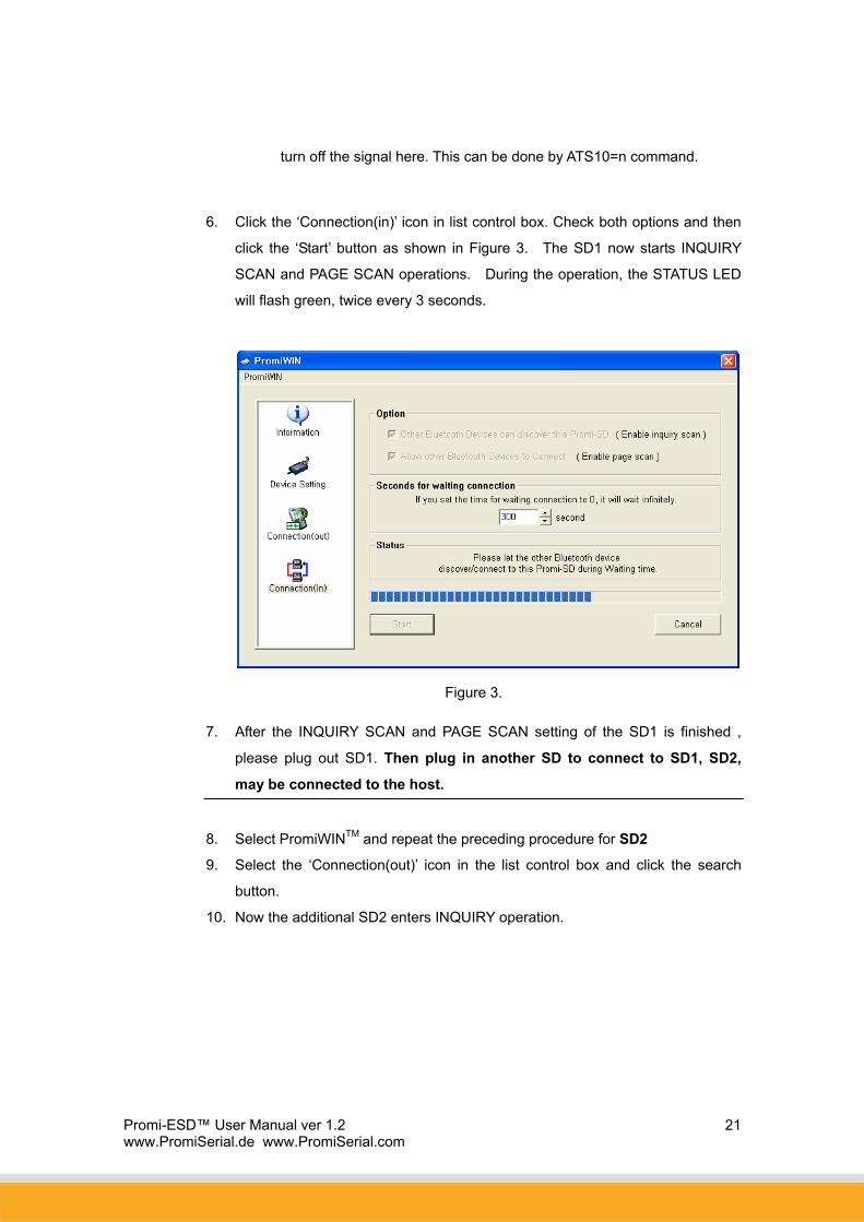
6. Click the ‘Connection(in)’ icon in list control box. Check both options and then
click the ‘Start’ button as shown in Figure 3. The SD1 now starts INQUIRY
SCAN and PAGE SCAN operations. During the operation, the STATUS LED
will flash green, twice every 3 seconds.
Figure 3.
7. After the INQUIRY SCAN and PAGE SCAN setting of the SD1 is finished ,
please plug out SD1. Then plug in another SD to connect to SD1, SD2,
may be connected to the host.
8. Select PromiWINTM and repeat the preceding procedure for SD2
9. Select the ‘Connection(out)’ icon in the list control box and click the search
button.
10. Now the additional SD2 enters INQUIRY operation.

Promi-ESD™ User Manual ver 1.2 www.PromiSerial.de www.PromiSerial.com
22
Figure 4.
11. From the ‘Search Result’ menu click the item with ‘Promi-SD1’ as its
DEVICE_NAME.
12. Once selected, its BD_ADDR will appear in the dialog box on the right side of
the ‘Connect to…’ button.
13. Click the ‘Connect to…’ button and the ‘Successful Connection’ Popup box will
appear as shown in Figure 5.
Figure 5.
14. To release the first Bluetooth wireless connection between the SD units click
the ‘Disconnect’ button.
15. For automatic connection setup, set SD1 as Mode 2 and SD2 as Mode 1.
To utilize the SD automatic connection feature, make a Bluetooth connection
between two SD units. Once connected, one SD stores the 48-bit BD_ADDR
of its counterpart.

Promi-ESD™ User Manual ver 1.2 www.PromiSerial.de www.PromiSerial.com
23
To expedite the 48-bit BD_ADDR input operation, SD is designed to store the
BD_ADDR of its latest counterpart.
3.1.2 Setting Operating Mode for Automatic Connection
New SD units are default set to ‘MODE 0’. For SD automatic connection
change the operating mode of an SD to MODE 1 and another to MODE 2.
The following simple steps describe the SD operating mode change
procedure.
1. After making a Bluetooth wireless connection between two SD units, set the
operating mode of one SD to MODE 1, as shown in Figure 6.
Figure 6.
2. Set the operating mode of another SD to MODE 2 as shown below.

Promi-ESD™ User Manual ver 1.2 www.PromiSerial.de www.PromiSerial.com
24
Figure 7.
3. Turn off both SD power supplies. From now, when both SD units are
powered up again, they will automatically connect.
3.2. Using a Terminal Program
Promi-SDTM units are easily controlled and configured via PromiWINTM . Likewise
functions are accomplished via any terminal program such as HyperTerminal. AT
command sets supported by Promi-SDTM add sophistication to Promi-SDTM control.
3.2.1 Connecting Promi-SD™ to host.
For SD use, follow the simple instructions below:
1. Connect an SD to a host serial port. Then, turn on the SD.
2. Check the STATUS LED color. Amber indicates standard mode.
3. Execute any terminal program and activate Local Echo.
4. Configure the host serial port to match the SD unit configuration. The SD
Promi-ESD™ User Manual ver 1.2 www.PromiSerial.de www.PromiSerial.com
25
default configuration is 9600 bps Baud, 8 Data bit, No Parity, 1 Stop bit and
H/W flow control.
5. Enter ‘AT’ command at the prompt. An SD ‘OK’ reply indicates proper
operation.
3.2.2 Making the first Promi-SD™/Bluetooth connection
As stated before, Bluetooth wireless connections can be made with any other
Bluetooth device supporting Bluetooth SPP (Serial Port Profile). For Bluetooth
wireless connections to an SD, first make another SD ‘Discoverable’ and
‘Connectable’. In this case, refer to section 3.3 before following the
instructions below.
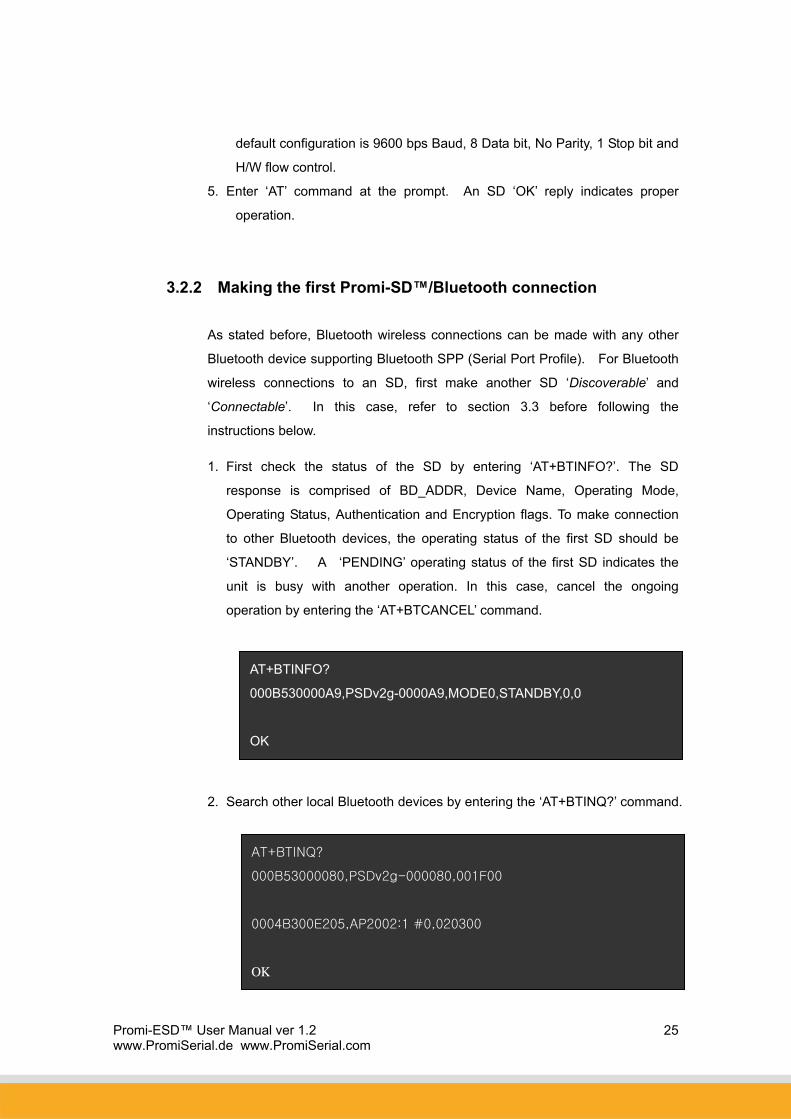
1. First check the status of the SD by entering ‘AT+BTINFO?’. The SD
response is comprised of BD_ADDR, Device Name, Operating Mode,
Operating Status, Authentication and Encryption flags. To make connection
to other Bluetooth devices, the operating status of the first SD should be
‘STANDBY’. A ‘PENDING’ operating status of the first SD indicates the
unit is busy with another operation. In this case, cancel the ongoing
operation by entering the ‘AT+BTCANCEL’ command.
2. Search other local Bluetooth devices by entering the ‘AT+BTINQ?’ command.
AT+BTINQ?
000B53000080,PSDv2g-000080,001F00
0004B300E205,AP2002:1 #0,020300
OK
AT+BTINFO?
000B530000A9,PSDv2g-0000A9,MODE0,STANDBY,0,0
OK

Promi-ESD™ User Manual ver 1.2 www.PromiSerial.de www.PromiSerial.com
26
3. Check the search list. Enter ‘ATD’ command in the BD_ADDR of any
Bluetooth device for connection. During the connection process, the
STATUS LED will flash green every second.
4. Connection is indicated by the SD returning a ‘CONNECT’ message and
displaying a green STATUS LED.
3.2.3 Making Promi-SD™ do INQUIRY SCAN and PAGE SCAN
Unlike many Bluetooth serial dongles, the SD has an internal, rechargeable
battery. As stated before, to maximize battery life, the SD INQUIRY SCAN and
PAGE SCAN is set to disabled in manufacture. Therefore, to make the SD
“Discoverable” (INQUIRY SCAN) and “Connectable” (PAGE SCAN), these
operations must be manually activated.
1. Check the SD status by entering a ‘AT+BTINFO?’ command.
2. Enter the ‘AT+BTSCAN’ command. The SD will start INQURY SCAN and
PAGE SCAN operation. During the process, the SD will flash twice every 3
seconds until it is connected to another Bluetooth device.
AT+BTINFO?
000B530000A9,PSDv2g-0000A9,MODE0,STANDBY,0,0
OK
ATD000B53000080
OK
CONNECT

Promi-ESD™ User Manual ver 1.2 www.PromiSerial.de www.PromiSerial.com
27
3. Try Bluetooth connection to the SD from the other Bluetooth device. Once
connected the first SD will return the ‘CONNECT’ message and the STATUS
LED will display a continuous green without flashing.
3.2.4 Releasing the existing Bluetooth connection
Once connected successfully, the SD becomes transparent to any serial
applications on hosts. Data may be transferred within the radio range of the
SD. According to SD terminology, this operating status is called ‘ONLINE
STATUS’. In ONLINE STATUS, all AT commands are treated as characters
and are ignored by the command interpreter of the SD. Therefore to escape
from ONLINE STATUS enter escape string ‘+++’.
1. Transition from ONLINE STATUS to STANDBY STATUS by entering ‘+++’
string to the SD. Check the current SD status by entering the
‘AT+BTINFO?’ command. The SD status should display CONNECT
STATUS.
AT+BTSCAN
OK
CONNECT
AT+BTSCAN
OK

Promi-ESD™ User Manual ver 1.2 www.PromiSerial.de www.PromiSerial.com
28
2. Release the current Bluetooth connection by entering ‘ATH’ command. Once
disconnected successfully, the SD returns the ‘DISCONNECT’ message.
3.2.5 Automatic connection of two Promi-SD™ Units
Two SD units connect automatically when powered up. For automatic SD
connection first make a Bluetooth connection between two SD units. Once
connected, the SD stores the 48-bit BD_ADDR of its counterpart. To expedite
48-bit BD_ADDR input operation, the SD is designed to store the BD_ADDR of
its latest counterpart.
1. Set one SD to do INQUIRY SCAN and PAGE SCAN operation as directed in
section 3.3.
2. Set the other SD to connect to the SD in the previous step.
3. Once connected successfully, both SD units store the BD_ADDR of their
counterpart in their internal Flash. When desired, release the connection as
ATH
OK
DISCONNECT
+++
OK
AT+BTINFO?
000B530000A9,PSDv2g-0000A9,MODE0,CONNECT,0,0
OK

Promi-ESD™ User Manual ver 1.2 www.PromiSerial.de www.PromiSerial.com
29
directed in section 3.4.
4. Set the operating mode of one SD to MODE 1 by entering an ‘AT+ BTMODE’
command as shown below.
5. Set the operating mode of the other SD to MODE 2 by entering an
‘AT+BTMODE’ command as show below.
6. Turn both SD units power off. The SD pair will connect automatically when
they are powered up again.
7. To release this paring, set them to MODE 0 by entering ‘AT+BTMODE, 0’. or
reset the units by pressing the RESET button.
3.2.6 AT command vs. Operational Status
The AT command sets listed above can be executed per Promi-SD™
operational status. The following table shows the operational status and
executable AT command sets.
AT Command Standby Pending Online
AT<cr> √ √
ATZ<cr> √ √
AT+BTMODE,0
OK
AT+BTCANCEL
OK
AT+BTMODE,2
OK
AT+BTMODE,1
OK

Promi-ESD™ User Manual ver 1.2 www.PromiSerial.de www.PromiSerial.com
30
AT+BTINQ?<cr> √1)
ATD112233445566<cr> √1)
ATD<cr> √1)
AT+BTSCAN,n<cr> √1)
AT+BTSCAN,112233445566<cr> √1)
AT+BTCANCEL<cr> √
+++ √
ATO<cr> √2)
ATH<cr> √2)
AT+BTAUTH,Auth,Encr<cr> √3)
AT+BTMODE,n<cr> √3) 4)
AT+BTNAME=”Name”<cr> √3)
AT+BTKEY=”nnnn”<cr> √3)
ATS10=0 or ATS10=1
AT+BTINFO?<cr> √ √
AT+UARTCONFIG,b,p,s<cr> √3) 4)
1) Effective when Promi-SD™ is not in connection with Bluetooth.
2) Effective when Promi-SD™ is in connection status with Bluetooth.
3) Recommend to be used when Promi-SD™ is not in connections status with
Bluetooth
4) To apply new values to Promi-SD™, software reset requires by ATZ
command or restart Promi-SD™.
*NOTE: Full AT commands set can be found in Appendix B.

Promi-ESD™ User Manual ver 1.2 www.PromiSerial.de www.PromiSerial.com
31
4. Optional Antennas
(1) Dipole Antenna
Part No.: PSD00-00050
20dBi
Connector: SMA
Size: 10cm
(2) Patch Antenna (w/ RF extension cable & wall-attachable nails)
Part No.: PSD00-00060
Including a 30cm RF extension cable
Longer RF extension cable
Part No.: PSD00-00061: 1m length
Part No.: PSD00-00063: 3m length
Part No.: PSD00-00061: 5m length
SMA connector
Promi-ESD™ User Manual ver 1.2 www.PromiSerial.de www.PromiSerial.com
32
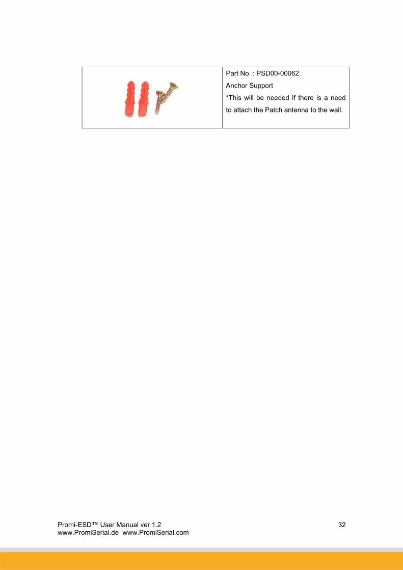
Part No. : PSD00-00062
Anchor Support
*This will be needed if there is a need
to attach the Patch antenna to the wall.
Promi-ESD™ User Manual ver 1.2 www.PromiSerial.de www.PromiSerial.com
33
5. For Multi-Serial Connections
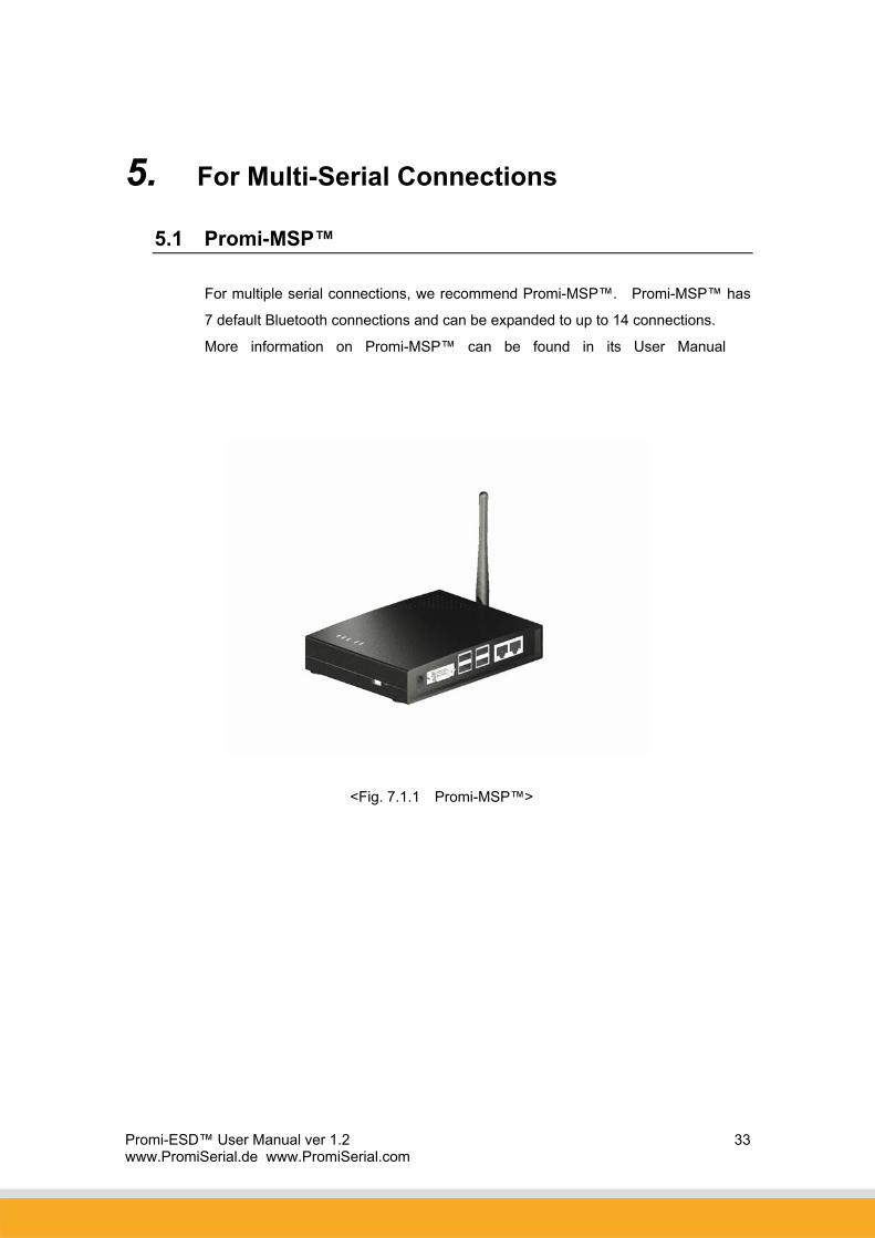
5.1 Promi-MSP™
For multiple serial connections, we recommend Promi-MSP™. Promi-MSP™ has
7 default Bluetooth connections and can be expanded to up to 14 connections.
More information on Promi-MSP™ can be found in its User Manual
<Fig. 7.1.1 Promi-MSP™>

Promi-ESD™ User Manual ver 1.2 www.PromiSerial.de www.PromiSerial.com
36
7. About this Manual
This manual is available in a printable PDF version on-line and on the CD enclosed in
the Promi-ESDTM product package.

Promi-ESD™ User Manual ver 1.2 www.PromiSerial.de www.PromiSerial.com
37
Appendix A: AT command sets
The following AT command sets are supported by PromiTM-SD. Here <cr> represents carriage
return of ASCII Code (0x0D) and <lf> represents line feed of ASCII Code (0x0A).
AT<cr>
Function : Check the presence of your SD.
Response : <cr><lf>OK<cr><lf> or
<cr><lf>ERROR<cr><lf>
Description : In standard mode, you can check whether your SD is connected to a host
correctly by using this AT command.
ATZ<cr>
Function : Do soft-reset
Response : <cr><lf>OK<cr><lf> or
<cr><lf>ERROR<cr><lf>
Description : You can do soft-reset by using this AT command. When your SD is already
connected to the other device, it disconnects the connected device. You can
halt the current ongoing operation by using this command.
AT&F<cr>
Function : Restore the default configuration of your SD.
Response : <cr><lf>OK<cr><lf> or
<cr><lf>ERROR<cr><lf>
Description : You can restore the default configuration of your SD by executing this AT
command.
AT+BTINQ?<cr>
Function : Search (INQUIRY) other Bluetooth devices nearby.
Response : <cr><lf>BD_ADDR, Device Name , Class of Device<cr><lf>
<cr><lf>BD_ADDR, Device Name , Class of Device<cr><lf>
…
<cr><lf>BD_ADDR, Device Name , Class of Device<cr><lf>
<cr><lf>OK<cr><lf>
Description : This command is used to inquiry other Bluetooth devices nearby. The
INQUIRY process is carried out during the predefined time duration (30
Promi-ESD™ User Manual ver 1.2 www.PromiSerial.de www.PromiSerial.com
38
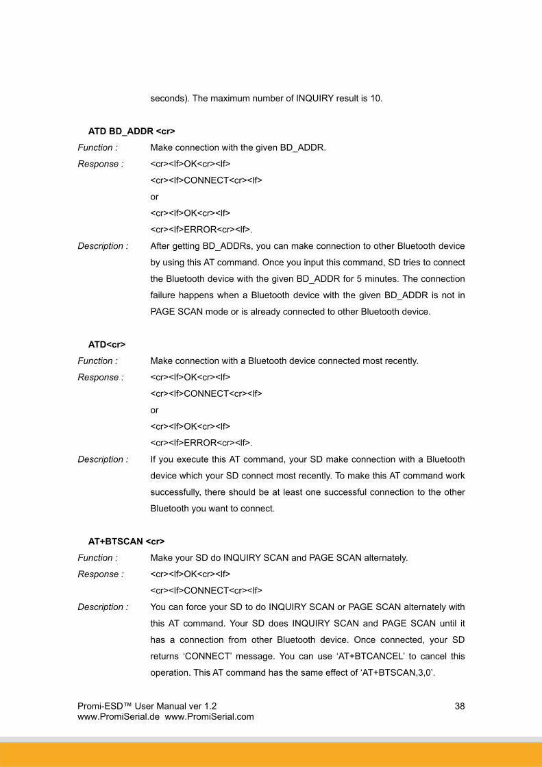
seconds). The maximum number of INQUIRY result is 10.
ATD BD_ADDR <cr>
Function : Make connection with the given BD_ADDR.
Response : <cr><lf>OK<cr><lf>
<cr><lf>CONNECT<cr><lf>
or
<cr><lf>OK<cr><lf>
<cr><lf>ERROR<cr><lf>.
Description : After getting BD_ADDRs, you can make connection to other Bluetooth device
by using this AT command. Once you input this command, SD tries to connect
the Bluetooth device with the given BD_ADDR for 5 minutes. The connection
failure happens when a Bluetooth device with the given BD_ADDR is not in
PAGE SCAN mode or is already connected to other Bluetooth device.
ATD<cr>
Function : Make connection with a Bluetooth device connected most recently.
Response : <cr><lf>OK<cr><lf>
<cr><lf>CONNECT<cr><lf>
or
<cr><lf>OK<cr><lf>
<cr><lf>ERROR<cr><lf>.
Description : If you execute this AT command, your SD make connection with a Bluetooth
device which your SD connect most recently. To make this AT command work
successfully, there should be at least one successful connection to the other
Bluetooth you want to connect.
AT+BTSCAN <cr>
Function : Make your SD do INQUIRY SCAN and PAGE SCAN alternately.
Response : <cr><lf>OK<cr><lf>
<cr><lf>CONNECT<cr><lf>
Description : You can force your SD to do INQUIRY SCAN or PAGE SCAN alternately with
this AT command. Your SD does INQUIRY SCAN and PAGE SCAN until it
has a connection from other Bluetooth device. Once connected, your SD
returns ‘CONNECT’ message. You can use ‘AT+BTCANCEL’ to cancel this
operation. This AT command has the same effect of ‘AT+BTSCAN,3,0’.
Promi-ESD™ User Manual ver 1.2 www.PromiSerial.de www.PromiSerial.com
39
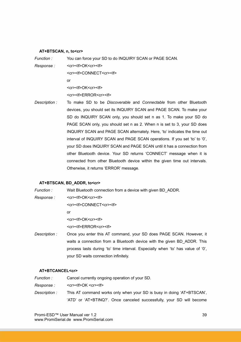
AT+BTSCAN, n, to<cr>
Function : You can force your SD to do INQUIRY SCAN or PAGE SCAN.
Response : <cr><lf>OK<cr><lf>
<cr><lf>CONNECT<cr><lf>
or
<cr><lf>OK<cr><lf>
<cr><lf>ERROR<cr><lf>
Description : To make SD to be Discoverable and Connectable from other Bluetooth
devices, you should set its INQUIRY SCAN and PAGE SCAN. To make your
SD do INQUIRY SCAN only, you should set n as 1. To make your SD do
PAGE SCAN only, you should set n as 2. When n is set to 3, your SD does
INQUIRY SCAN and PAGE SCAN alternately. Here, ‘to’ indicates the time out
interval of INQUIRY SCAN and PAGE SCAN operations. If you set ‘to’ to ‘0’,
your SD does INQUIRY SCAN and PAGE SCAN until it has a connection from
other Bluetooth device. Your SD returns ‘CONNECT’ message when it is
connected from other Bluetooth device within the given time out intervals.
Otherwise, it returns ‘ERROR’ message.
AT+BTSCAN, BD_ADDR, to<cr>
Function : Wait Bluetooth connection from a device with given BD_ADDR.
Response : <cr><lf>OK<cr><lf>
<cr><lf>CONNECT<cr><lf>
or
<cr><lf>OK<cr><lf>
<cr><lf>ERROR<cr><lf>
Description : Once you enter this AT command, your SD does PAGE SCAN. However, it
waits a connection from a Bluetooth device with the given BD_ADDR. This
process lasts during ‘to’ time interval. Especially when ‘to’ has value of ‘0’,
your SD waits connection infinitely.
AT+BTCANCEL<cr>
Function : Cancel currently ongoing operation of your SD.
Response : <cr><lf>OK <cr><lf>
Description : This AT command works only when your SD is busy in doing ‘AT+BTSCAN’,
‘ATD’ or ‘AT+BTINQ?’. Once canceled successfully, your SD will become

Promi-ESD™ User Manual ver 1.2 www.PromiSerial.de www.PromiSerial.com
40
STANBY STATUS’.
+++
Function : Make transition from ONLINE STATUS to STANDBY STATUS.
Response : <cr><lf>OK <cr><lf>.
Description : If you input ‘+++’ string to your SD in ONLINE STATUS, your SD goes into
STANBY STATUS. Once SD enters into STANDBY STATUS, you can use any
AT command sets supported by PromiTM-SD.
ATO<cr>
Function : Make transition from STANBY STATUS to ONLINE STATUS.
Response : None
Description : This AT command is the counter operation of ‘+++”. You can change the
operating status to ONLINE STATUS again by using this command. In
ONLINE STATUS, the data can be transferred between two hosts. The
existence of your SD becomes transparent to any host applications which use
serial ports.
ATH<cr>
Function : Release the current Bluetooth connection.
Response : <cr><lf>OK<cr><lf>
<cr><lf>DISCONNECT <cr><lf>.
Description : This AT command can be used for disconnecting the existing Bluetooth
connection.
AT+BTSEC, Authentication, Encryption <cr>
Function : Set Bluetooth authentication or encryption features selectively.
Response : <cr><lf>OK<cr><lf>.
Description : By using this AT command, you can set authentication or encryption feature of
your SD during Bluetooth connection process. Once you set authentication or
encryption features, your SD stores its status. To release authentication or
encryption features you set, you should use this AT commands or do soft-
reset. To enable authentication or encryption, set authentication or encryption
parameter as 1. Otherwise set either of them as 0.

Promi-ESD™ User Manual ver 1.2 www.PromiSerial.de www.PromiSerial.com
41
AT+BTLAST?<cr>
Function : Return BD_ADDR of the Bluetooth device to your host which your SD is
connected most recently.
Response : <cr><lf>BD_ADDR<cr><lf>
<cr><lf>OK< cr><lf>
Description : You can use this AT command if you need to refer the BD_ADDR of most
recently connected Bluetooth device.
AT+BTMODE, n<cr>
Function : Set the operating mode of your SD.
Response : <cr><lf>OK<cr><lf>
Description : Your SD has 4 different operating mode. According to the current operating
mode you set, your SD behavior differently.
n=0 : This means your SD is in MODE 0. MODE 0 is the default
configuration.
n=1 : In MODE 1, your SD will try to make connection to most recently
connected Bluetooth device.
n=2 : In MODE 2, your SD will wait connection from most recently
connected Bluetooth device.
n=3 : IN MODE 3, your SD does INQUIRY SCAN and PAGE SCAN
alternately.
AT+BTNAME=”FriendlyName”<cr>
Function : Assign user friendly device name to your SD.
Response : <cr><lf>OK<cr><lf>
Description : You can assign your SD user friendly name by using this AT command. With
the assigned name, you can distinguish your SD easily from other Bluetooth
devices. Up to 32 characters are permitted as user friendly name.
AT+BTKEY=”nnnn”<cr>
Function : Change the passkey.
Response : <cr><lf>OK<cr><lf>
Description : When the authentication is enabled in your SD, you should assign passkey.
Two Bluetooth devices which are to be connected should have the same
passkey. The default passkey of your SD is ‘1234’. You can assign maximum
16 alphanumeric characters as a passkey.

Promi-ESD™ User Manual ver 1.2 www.PromiSerial.de www.PromiSerial.com
42
AT+BTINFO?<cr>
Function : Return the internal status of your SD.
Response : <cr><lf>BD_ADDR,Name,Mode,Status,Auth,Encryp<cr><lf>
<cr><lf>OK<cr><lf>
Description : When you enter this AT commands at a host terminal, your SD returns its
device information and status to a host. It encompasses BD_ADDR, user
friendly name, operating mode, operating status and authentication/encryption
status. Especially when the operating status is PENDING, it means your SD is
busy in processing ‘AT+BTINQ?’, ‘ATD’ or ‘AT_BTSCAN’. When
Authentication or Encryption feature is activated, the corresponding
parameter has value of ‘1’.
AT+BTLPM,n<cr>
Function : Set Bluetooth Low power consumption mode.
Response : <cr><lf>OK<cr><lf>
Description : To minimize power consumption, your SD supports Bluetooth PARK mode.
When you set n as 1, your SD uses PARK mode. Using PARK mode might
cause extra data transmission delay in some cases.
AT+BTSD?<cr>
Function : Return the list of secured devices.
Response : <cr><lf>BD_ADDR<cr><lf>
<cr><lf>BD_ADDR<cr><lf>
…
<cr><lf>BD_ADDR<cr><lf>
<cr><lf>OK<cr><lf>
Description : Your SD can pair up to 5 Bluetooth devices. Upon receiving this AT command,
your SD returns all the BD_ADDRs of the previously paired Bluetooth devices.
AT+BTCSD<cr>
Function : Delete the info of all the paired devices stored in your SD.
Response : <cr><lf>OK<cr><lf>
Description : This AT command just deletes the info of paired devices stored on SD’s Flash
memory. To delete the same info resides on SD’s RAM, you have to do
software reset or hardware reset.

Promi-ESD™ User Manual ver 1.2 www.PromiSerial.de www.PromiSerial.com
43
AT+BTFP,n<cr>
Function : Force your SD to generate passkey automatically.
Response : <cr><lf>OK<cr><lf>
Description : Once paired, your SD uses the stored link key. By using this AT command,
you can make Bluetooth connection with a new link key. When n is set to 1,
your SD newly generates a link key during connection process.
AT+UARTCONFIG, baudrate, parity, stopbit<cr>
Function : Configure the serial port of your SD.
Response : <cr><lf>OK<cr><lf>
Description : By using this AT command, you can reconfigure the serial port of your SD.
You can set baudrate, parity, stopbit . To make this command result active,
you should do soft-reset or turn off/on your SD. The following values are
permitted for each parameter.
Baudrate = 9600, 19200, 38400, 57600 or 115200.
Parity = N (No parity), E (Even parity) or O (Odd parity).
Stopbit = 1 or 2.

Promi-ESD™ User Manual ver 1.2 www.PromiSerial.de www.PromiSerial.com
44
Full AT commands set
No. Command Response Comments
1) AT<cr> <cr><lf>OK<cr><lf>
2)
ATZ<cr> <cr><lf>OK<cr><lf> Drops all connections, disable Inquiry
and Page scans. Reset the bluetooth
module.
3) AT&F<cr> <cr><lf>OK<cr><lf> Reset to factory default state
4)
AT+BTINQ?<cr> <cr><lf>112233445
5,FriendlyName,Co
D<cr><lf>
<cr><lf>112233445
5,FriendlyName,Co
D<cr><lf>
<cr><lf>112233445
5,FriendlyName,Co
D<cr><lf>
<cr><lf>OK<cr><lf>
Inquiry nearby devices. The OK at
the end means end of inquiry.
5)
ATD112233445566<cr> <cr><lf>OK<cr><lf>
<cr><lf>CONNECT
<cr><lf> or
<cr><lf>ERROR<cr
><lf>
Connect to the specified device.
If you want to enable Authentication
and Encryption, just set variable as 1.
6)
ATD<cr> <cr><lf>OK<cr><lf>
<cr><lf>CONNECT
<cr><lf> or
<cr><lf>ERROR<cr
><lf>
Connect to the device that last
succefully connected.
7) AT+BTSCAN<cr> <cr><lf>OK<cr><lf> Enable inquiry and page scans with
timeout of infinity.
8)
AT+BTSCAN,n,to<cr> <cr><lf>OK<cr><lf> Enable inquiry or Page scans.
If n=1, disable page and enable
inquiry.
If n=2, enable page and disable
inquiry.
If n=3, enable both page and inquiry.
Promi-ESD™ User Manual ver 1.2 www.PromiSerial.de www.PromiSerial.com
45
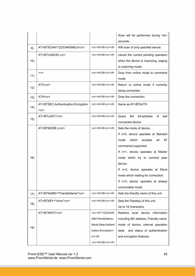
Scan will be performed during <to>
seconds.
9) AT+BTSCAN112233445566,to<cr> <cr><lf>OK<cr><lf> Will scan of only specifed device.
10)
AT+BTCANCEL<cr> <cr><lf>OK<cr><lf> cancel the current pending operation
when the device is inquirying, paging
or scanning mode.
11) +++ <cr><lf>OK<cr><lf> Drop from online mode to command
mode.
12) ATO<cr> <cr><lf>OK<cr><lf> Return to online mode if currently
being connected.
13) ATH<cr> <cr><lf>OK<cr><lf> Drop the connection.
14) AT+BTSEC,Authentication,Encryption
<cr>
<cr><lf>OK<cr><lf> Same as AT+BTAUTH
15) AT+BTLAST?<cr> <cr><lf>OK<cr><lf> Query the bd-address of last
connected device
16)
AT+BTMODE,n<cr> <cr><lf>OK<cr><lf> Sets the mode of device.
If n=0, device operates at Standart
mode which accepts all AT
commaned supported.
If n=1, device operates at Master
mode which try to connect peer
device.
If n=2, device operates at Slave
mode which waiting for connection.
If n=3, device operates at always
connectable mode.
17) AT+BTNAME="FriendlyName"<cr> <cr><lf>OK<cr><lf> Sets the friendly name of this unit.
18) AT+BTKEY="nnnn"<cr> <cr><lf>OK<cr><lf> Sets the Passkey of this unit.
Up to 16 characters.
19)
AT+BTINFO?<cr> <cr><lf>112233445
566,FriendlyName,
Mode,State,Authent
ication,Encryption<
cr><lf>
<cr><lf>OK<cr><lf>
Retrieve local device information
including BD address, Friendly name,
mode of device, internal operation
state and status of authentication
and encryption features.

Promi-ESD™ User Manual ver 1.2 www.PromiSerial.de www.PromiSerial.com
46
20)
AT+BTLPM,n<cr> <cr><lf>OK<cr><lf> Enable or disable the low power
mode of dongle.
n = 1 or 0
21)
AT&V<cr> <cr><lf>S0: m0;S1:
m1; … Sn:
mn<cr><lf>
<cr><lf>OK<cr><lf>
View all the values of internal S-
registers
22)
AT+BTSD?<cr> <cr><lf>bdaddr of
secured device
1<cr><lf>
<cr><lf>bdaddr of
secured device
1<cr><lf>
<cr><lf>OK<cr><lf>
Query the bd-addresses of secured
devices
23) AT+BTCSD<cr> <cr><lf>OK<cr><lf> Clear the list of secured devices
24) AT+BTFP,n<cr> <cr><lf>OK<cr><lf> Force paring when connecting as
master
25)
AT+UARTCONFIG,baudrate,parity,st
opbit<cr>
<cr><lf>OK<cr><lf> Sets the configuration of UART
interface. Possible values are;
baudrate
=1200,4800,9600,19200,38400,5760
0 or 115200.
parity = N(o parity), E(ven parity) or
O(dd parity).
stop = 1 or 2.
26)
AT+SETESC,nn<cr> <cr><lf>OK<cr><lf> Sets the escape sequence character.
‘nn’ should be ASCII code (Decimal),
and printable character. Default
escape charater is ‘+++’
27)
AT+PINQ?<cr> <cr><lf>OK<cr><lf> For Periodic Inquiry. Promi-SD will try
to inquire nearby Bluetooth devices
periodically and deliver the inquired
result to Host. To lease periodic
inquiry function, AT+BTCANCEL.

Promi-ESD™ User Manual ver 1.2 www.PromiSerial.de www.PromiSerial.com
47
28)
AT&V Shows S-register values
S-register command: If you change the values of S-register, please reboot Promi-SD.
ATSnn=mm<cr>: To change ATSnn register value
ATSnn?: To check current ATSnn register value.
29)
ATS3
Stream UART policy (Default 0)
If set as ‘0’, throughput is the priority, if set as ‘1’, Latency
is the priority.
30)
ATS4 Enable Remote name query (default 1)
Get BDaddress and device name during Inquiry.
If set as ‘0’, only get BD address. Inquiry time can be
faster.
31)
ATS10 Default 1
ATS10=1<cr> :
Enabling all of the response messages- OK, CONNECT,
DISCONNECT, and ERROR.
ATS10=0<cr> :
Disabling all of the response messages- OK, CONNECT,
DISCONNECT, and ERROR.
ATS10?<cr> : To see current status of ATS10
32)
ATS11 Enable Escape (default 1)
Escape sequence character enable change from on-line
mode to command mode. If set to ‘0’, transmission speed
can be improved.
33)
ATS12 Clear UART buffer at Disconnect. (default 0)
If set to ‘1’, when disconnected, data stored in Promi-SD
will be removed.
34)
ATS13 Enable DCD accept (default 0)
If set to ‘0’, Promi-SD will use CDC signal to let Host
know Bluetooth connection status.
If set to ‘1’, Promi-SD will send CDC signal to other paired
Bluetooth device.
Promi-ESD™ User Manual ver 1.2 www.PromiSerial.de www.PromiSerial.com
48
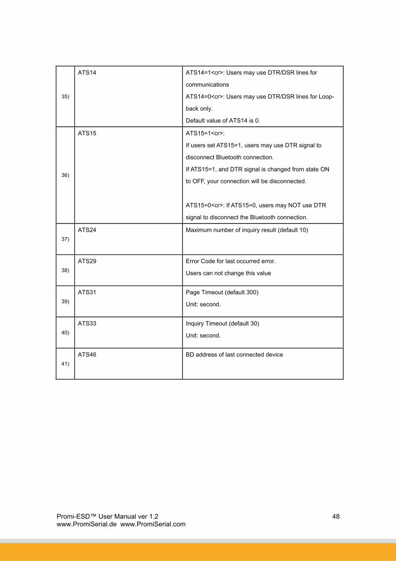
35)
ATS14 ATS14=1<cr>: Users may use DTR/DSR lines for
communications
ATS14=0<cr>: Users may use DTR/DSR lines for Loop-
back only.
Default value of ATS14 is 0.
36)
ATS15 ATS15=1<cr>:
If users set ATS15=1, users may use DTR signal to
disconnect Bluetooth connection.
If ATS15=1, and DTR signal is changed from state ON
to OFF, your connection will be disconnected.
ATS15=0<cr>: If ATS15=0, users may NOT use DTR
signal to disconnect the Bluetooth connection.
37)
ATS24 Maximum number of inquiry result (default 10)
38)
ATS29 Error Code for last occurred error.
Users can not change this value
39)
ATS31 Page Timeout (default 300)
Unit: second.
40)
ATS33 Inquiry Timeout (default 30)
Unit: second.
41)
ATS46 BD address of last connected device