promis-e® to autocad electrical® conversion … to autocad electrical conversion...autocad...
TRANSCRIPT
® to AutoCAD Electrical® Conversion Guide Copyright © 2008 Douglas R. McAlexander
All Rights Reserved
1
promis-e® to AutoCAD Electrical® Conversion Guide
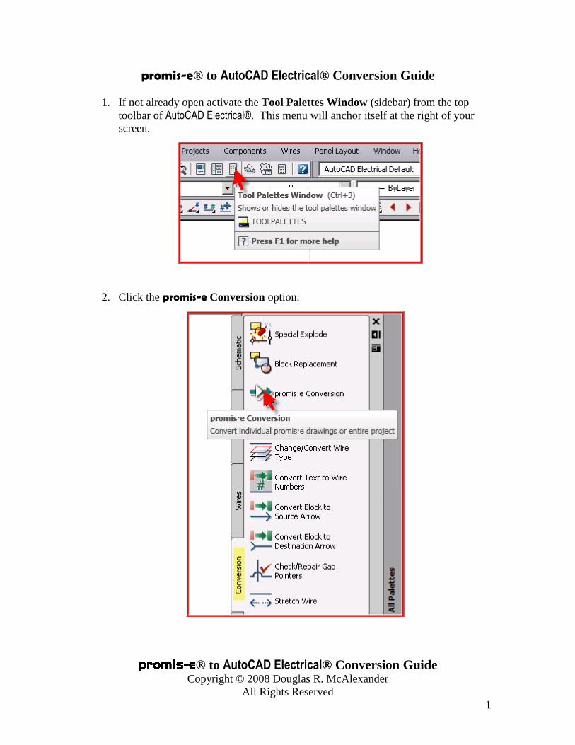
1. If not already open activate the Tool Palettes Window (sidebar) from the top
toolbar of AutoCAD Electrical®. This menu will anchor itself at the right of your
screen.
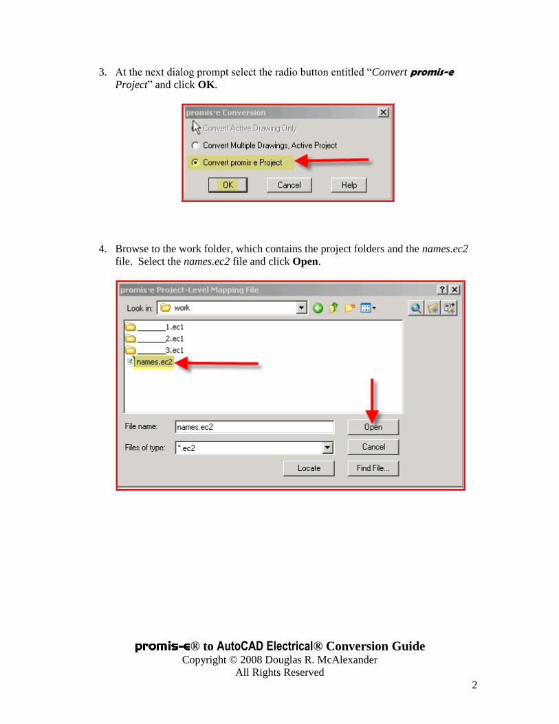
2. Click the promis-e Conversion option.
® to AutoCAD Electrical® Conversion Guide Copyright © 2008 Douglas R. McAlexander
All Rights Reserved
2
3. At the next dialog prompt select the radio button entitled “Convert promis-e
Project” and click OK.
4. Browse to the work folder, which contains the project folders and the names.ec2
file. Select the names.ec2 file and click Open.

® to AutoCAD Electrical® Conversion Guide Copyright © 2008 Douglas R. McAlexander
All Rights Reserved
3
5. Select the project name you wish to convert. Select at least one installation
from the Installation Codes window or click the Select all button to quickly select
all installation codes.
6. Click the Symbol Libraries button and browse to the AutoCAD Electrical® symbol
library that you prefer as a default. Hint: If you are converting a JIC or ladder-
style project select either JIC1(0.1 text height) or JIC125 (0.125 text height).

® to AutoCAD Electrical® Conversion Guide Copyright © 2008 Douglas R. McAlexander
All Rights Reserved
4
7. Click the Browse button and set the path to the AutoCAD Electrical® project
folder, which is usually named Proj. Hint: Do not create a new project folder.
The conversion utility will create this based upon the promis-e ® project name.
8. Click OK.

® to AutoCAD Electrical® Conversion Guide Copyright © 2008 Douglas R. McAlexander
All Rights Reserved
5
9. At the next dialog you can select specific drawings from within the promis-e
project that you wish to include in the conversion, or click Do All to quickly
select all drawings.

® to AutoCAD Electrical® Conversion Guide Copyright © 2008 Douglas R. McAlexander
All Rights Reserved
6
10. The selected drawings will move to the bottom window. Click OK.

® to AutoCAD Electrical® Conversion Guide Copyright © 2008 Douglas R. McAlexander
All Rights Reserved
7
11. The project/drawings are converted and the converted project becomes the
active project in the AutoCAD Electrical® Project Manager.
12. Double-click the converted promis-e project in the Project Manager to view the
list of converted drawings.

® to AutoCAD Electrical® Conversion Guide Copyright © 2008 Douglas R. McAlexander
All Rights Reserved
8
13. The conversion process doesn’t convert the drawing data but converts the
project data and copies the drawings from the promis-e folder path to the
AutoCAD Electrical® project path.
14. Double-click one of the converted drawings to open it into the viewer. Click
the AutoCAD Electrical® Edit Component command. You will receive a
prompt to insert the WD_M block; the required hidden block to enable AutoCAD Electrical® functionality. Click No/Cancel.
Step 15 will convert the individual drawings and add the WD_M block
automatically. The WD_M block is found in each symbol library folder of
AutoCAD Electrical®. This block stores the drawing properties for the AutoCAD Electrical® drawing environment. This would include such preferences as the
component tagging format, wire numbering format, PLC style, ladder styles and
sizes, etc. Once the drawings are converted the settings can be edited by right-
clicking on the project name in the
Project Manager and selecting
Properties. Make your selections
and click OK. Note: The project-
level properties do not automatically
apply to every drawing. The user
might opt to use different drawing
properties settings for certain
drawings in a project. After the
project level properties are selected,
select any combination of project
drawings or all project drawings
using the CTRL and SHIFT keys of
your keyboard. Right-click over any
highlighted drawing and select
Properties>Apply Project Defaults.
The WD_M block of all selected
drawings is updated.

® to AutoCAD Electrical® Conversion Guide Copyright © 2008 Douglas R. McAlexander
All Rights Reserved
9
15. It will be necessary to execute the promis-e conversion utility a second time in
order to convert the actual drawing data to AutoCAD Electrical® format. Return
to the Tool Pallettes menu and select promis-e Conversion once more.
16. Select to Convert Multiple Drawings, Active Project. Click OK.

® to AutoCAD Electrical® Conversion Guide Copyright © 2008 Douglas R. McAlexander
All Rights Reserved
10
17. At the next dialog click Do All.
18. Click OK.

® to AutoCAD Electrical® Conversion Guide Copyright © 2008 Douglas R. McAlexander
All Rights Reserved
11
Hint: AutoCAD Electrical® will add appropriate attributes and extended entity data
(xdata) as deemed necessary in order to make the promis-e symbols compatible with
AutoCAD Electrical’s editing functions. The command line will go active indicating the
conversion is underway. Once the command prompt returns the conversion process
will be complete.
19. Right-click over a component and you should now get the AutoCAD Electrical® context menu. Select Edit Component.

® to AutoCAD Electrical® Conversion Guide Copyright © 2008 Douglas R. McAlexander
All Rights Reserved
12
20. Notice that the MFG field is empty. This is due to the method that promis-e ®
uses to manage vendor information.
21. It will be necessary to enter the missing vendor name in all components. You
cannot click Lookup and assign the vendor from the AutoCAD Electrical® catalog
database because the symbol name of the promis-e ® symbol does not match
the table names in AutoCAD Electrical®.

® to AutoCAD Electrical® Conversion Guide Copyright © 2008 Douglas R. McAlexander
All Rights Reserved
13
22. Another approach to fill in the MFG data would be to use the AutoCAD Electrical® Export to Spreadsheet tool. Use the power of Excel ® to fill in the
MFG column. Save the spreadsheet file.
23. Use AutoCAD Electrical’s Update from Spreadsheet tool to update the project
and automatically fill in the missing MFG data.

® to AutoCAD Electrical® Conversion Guide Copyright © 2008 Douglas R. McAlexander
All Rights Reserved
14
24. The lines in the promis-e ® drawings that
represent wires are normally on a layer called
ECS_LVL_LINE or something similar. AutoCAD Electrical® allows users to assign each line entity
that represents a wire to a specific layer that
denotes the color, size, and type of wire. You can
add these wire types to the converted drawings by
clicking on Create/Edit Wire Type and adding the
wire types. You can even set the color so the wires
appear in their respective color. Once the wire
types are entered, click OK.
® to AutoCAD Electrical® Conversion Guide Copyright © 2008 Douglas R. McAlexander
All Rights Reserved
15
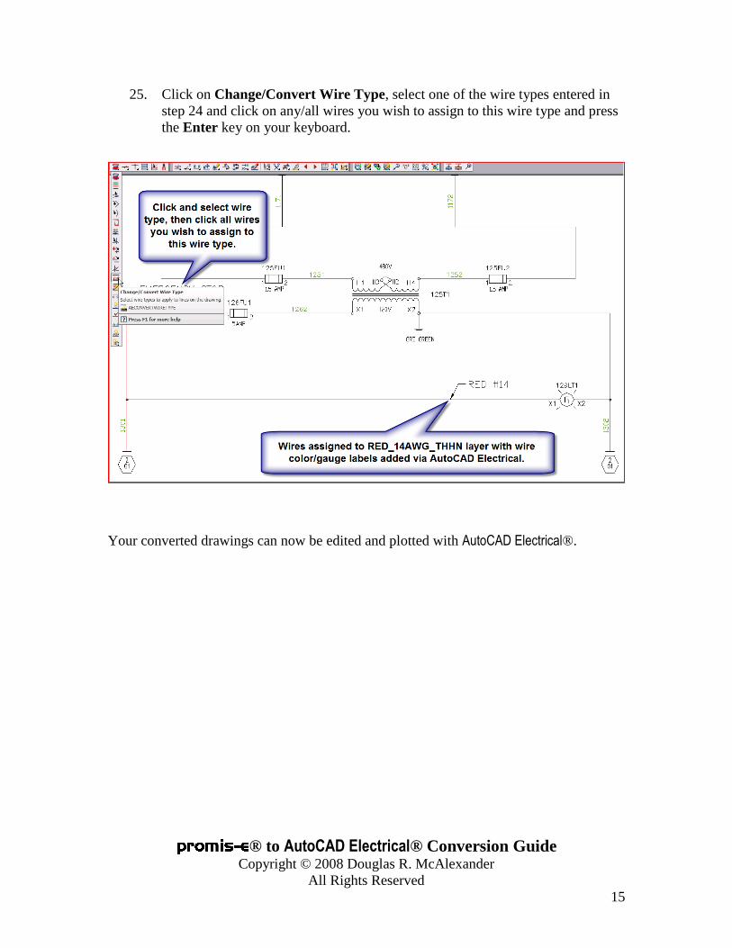
25. Click on Change/Convert Wire Type, select one of the wire types entered in
step 24 and click on any/all wires you wish to assign to this wire type and press
the Enter key on your keyboard.
Your converted drawings can now be edited and plotted with AutoCAD Electrical®.