promoting transnational investment: - unctc
TRANSCRIPT

Evolving Dependability
ANDY M. TYRRELL and ANDREW J. GREENSTED
The University of York, UK
Evolvable hardware offers much for the future of complex systems design. Evolutionary techniquesnot only have the potential for larger solution space coverage, but when implemented on hardware,also allow system designs to adapt to changes in the environment, including failures in systemcomponents. This article reviews a number of novel techniques, all based in the field of bio-inspiredsystems, that provide varying degrees of dependability over and above standard designs. In partic-ular, three different techniques are considered: using FPGAs and ideas from developmental biologyto create designs that possess emergent fault-tolerant properties, using FPGAs and continuous evo-lution to circumvent faults as and when they occur, and, finally, we consider a novel ASIC designedand built with bio-inspired systems in mind.
Categories and Subject Descriptors: B.8.1 [Performance and Reliability]: Reliability, Testingand Fault-Tolerance
General Terms: Algorithms, Reliability
Additional Key Words and Phrases: Evolutionary algorithms, fault tolerance, bio-inspired archi-tectures, RISA architecture
ACM Reference Format:Tyrrell, A. M. and Greensted, A. J. 2007. Evolving dependability. ACM J. Emerg. Technol. Comput.Syst. 3, 2, Article 7 (July 2007), 20 pages. DOI = 10.1145/1265949.1265953 http://doi.acm.org/10.1145/1265949.1265953
1. INTRODUCTION
With the increase in system complexity, performing complete fault coverage atthe testing phase of the design cycle is very difficult to achieve, if not impossible.In addition, environmental effects such as electromagnetic interference, misuseby users, and the natural ageing of components mean system faults are likelyto occur. These faults can cause errors which, if left untreated, could causesystem failure. The role of fault tolerance is to deal with the errors caused by
Parts of this work were funded by the EPSRC and the MOD.A shorter version of this article was presented at the Computing Frontiers Workshop in 2006.Authors’ address: Department of Electronics, University of York, Heslington, YO10 5DD, UK;email: {amt, ajg112}@ohm.york.ac.uk.Permission to make digital or hard copies of part or all of this work for personal or classroom use isgranted without fee provided that copies are not made or distributed for profit or direct commercialadvantage and that copies show this notice on the first page or initial screen of a display alongwith the full citation. Copyrights for components of this work owned by others than ACM must behonored. Abstracting with credit is permitted. To copy otherwise, to republish, to post on servers,to redistribute to lists, or to use any component of this work in other works requires prior specificpermission and/or a fee. Permissions may be requested from Publications Dept., ACM, Inc., 2 PennPlaza, Suite 701, New York, NY 10121-0701 USA, fax +1 (212) 869-0481, or [email protected]© 2007 ACM 1550-4832/2007/07-ART7 $5.00. DOI 10.1145/1265949.1265953 http://doi.acm.org/10.1145/1265949.1265953
ACM Journal on Emerging Technologies in Computing Systems, Vol. 3, No. 2, Article 7, Publication date: July 2007.

2 • A. M. Tyrrell and A. J. Greensted
faults in order to avoid failure. Fault tolerance along with fault detection andrecovery are techniques used in the design, implementation, and operation ofdependable computing systems [Lee and Anderson 1990].
Fault tolerance is increasingly a crucial part of system designs. Many systemshave part or all of their function classified as critical in one form or another.Since fully testing a system is generally unrealistic, critical functions must beprotected online. This is often achieved by using fault tolerance to cope witherrors produced during the operation of the system.
Traditionally, two approaches are taken, both requiring the replication ofthe system, or system subsections, to be protected. Simple static redundancy(such as N-version systems [Lee and Anderson 1990]) involves the concurrentoperation of redundant modules each contributing to a majority decision for afinal output. Alternatively, dynamic redundancy operates using a single mod-ule, and when a failure is detected or expected, one of the redundant modules isswitched into its place. However, these approaches are achieved at the expenseof increased equipment needs due to the required replication of hardware andincreased design time and costs. These redundancy schemes are termed spaceredundancy as the replicated sections are physically distributed over space.Another category, time redundancy, benefits from not requiring a replication ofhardware, instead the redundancy is distributed over time. The same operationis repeated, and an output achieved from a consensus of the individual runs.All these redundancy schemes apply equally to a hardware process, a softwareprocess, or a combination of both.
Providing continual fault-free operation in a system implies a continual map-ping of a logical system onto a nonfaulty physical system. When faults arise, amechanism must be provided for reconfiguring the physical system such thatthe logical system can still be represented by the remaining nonfaulty process-ing elements. Whether the physical platform is a distributed software processorsystem or consists purely of hard circuitry, for fault tolerance, redundancy inthe system’s basic processing elements is required. The reconfiguration mech-anisms that control utilization of these processing elements can be consideredto be based on one of two types of scheme: time-based redundancy reallocationor hardware-based redundancy reallocation.
Time-based use of redundancy involves distributing the function of faultyprocessing elements among neighboring resources. When reconfiguration oc-curs, processing elements dedicate some time to performing their own tasks andsome to performing the faulty neighbor’s functions, possibly resulting in somedegradation of the system’s performance. In addition, the system operationsthat are being performed must be sufficiently flexible to ensure their realloca-tion can be simply performed in real time. Reallocating processes in a hardwareredundancy scheme requires spare processing elements and interconnects inorder to replace those that become faulty. For this process, reconfiguration algo-rithms must optimize the use of spares. In the ideal case, a processing systemwith N spares is able to tolerate N faulty processing elements. However, inpractice, this goal is far from being achieved. Reconfiguration of the functionalsystem may not be possible due to limitations of the interconnection capabilitiesand available resources of each cell.
ACM Journal on Emerging Technologies in Computing Systems, Vol. 3, No. 2, Article 7, Publication date: July 2007.

Evolving Dependability • 3
The majority of hardware redundancy reconfiguration techniques rely oncomplex algorithms to reassign physical resources to the elements of the logi-cal array. In most cases, these algorithms are executed by a central controllerwhich also performs diagnostic functions and accomplishes the reconfigurationof the physical system. This approach has been demonstrated to be effective,but its centralized nature makes it prone to collapse if the control unit fails.These mechanisms also rely on the designer making a priori decisions on re-configuration strategies and data/code movement which are prone to error andmay in practice be less than ideal. Furthermore, the timing of signals involvedin the global control are often prohibitively long and are therefore unsuitablefor applying to the control of high-speed systems.
An alternative approach is to distribute the diagnosis and reconfigurationalgorithms among all the processing elements in the system. In this way, nocentral agent is necessary and, consequently, the reliability and time responseof the system should improve. However, this decentralised approach has tendedto increase the complexity of the reconfiguration algorithm and the amount ofcommunications within the network. In addition, considerable work is requiredin producing redundancy [Ortega et al. 2000].
Traditionally, fault tolerance has been added explicitly to system designsby including redundant hardware and/or software which take over when anerror has been detected. A novel alternative approach would be to design thesystem in such a way that the redundancy was incorporated implicitly into thehardware and/or software during the design phase. This should provide a moreholistic approach to the design process [Ortega et al. 2000; Hollingworth et al.2000; Canham and Tyrrell 2003; Tyrrell et al. 2001; Bradley and Tyrrell 2002].We already know that genetic algorithms and genetic programming can adaptand optimize the behavior and structure of solutions to perform a specific task[Fogel 2006], but the aim here is that they should learn to deal with faultswithin their operation space. This implicit redundancy would make the systemresponse invariant to the occurrence of faults [Thompson et al. 1999; Layzelland Thompson 2000].
This article illustrates a number of novel techniques, all based in the fieldof bio-inspired electronics, that provide varying degrees of dependability overand above standard designs. In particular, three different techniques are con-sidered: using FPGAs and ideas from developmental biology to create designsthat possess emergent fault-tolerant properties, using FPGAs and continuousevolution to circumvent faults as and when they occur, and, finally, we considera novel ASIC, designed and built with bio-inspired systems in mind, that showhow this too can cope with unexpected events during operation.
2. DEVELOPMENTAL TECHNIQUES
Multicellular organisms, the products of long-term biological evolution, demon-strate strong principles for the design of complex systems. Their nascent behav-iors, such as growth, cloning (self-replication) and healing (self-repair and faulttolerance), are attracting increasing interest from electronic engineers. All ofthese characteristics are encoded in the information stored in the genome ofthe fertilized cell (zygote).
ACM Journal on Emerging Technologies in Computing Systems, Vol. 3, No. 2, Article 7, Publication date: July 2007.

4 • A. M. Tyrrell and A. J. Greensted
Fig. 1. A cell pattern based on the French flag as originally used by Wolpert to describe cellulardevelopment.
The process of growth from a single zygote to a mature organism is calleddevelopment. Development is controlled by genes which determine the synthe-sis of proteins. The activity of genes sets up the complex interactions betweendifferent proteins, between proteins and genes within cells, and hence the in-teractions between cells. The development of an embryo is determined by theseinteractions [Wolpert 2002]. Figure 1 represents a cell pattern whose formationis controlled by the concentrations of a morphogen [Wolpert 2002]. Based on thelevel of morphogen in the cells, each cell develops into a specific type accordingto threshold values. These are extremely robust processes and can be subjectedto very high levels of failure and still manage to achieve the final goal. This worklooks at using development as a way of creating electronic systems based on acellular array, which we show have similar inherent robustness characteristics[Liu et al. 2005].
2.1 Cell Structure and Intercell Connections
One of the most fundamental features of development is the universal cell struc-ture; each of the cells in a multicellular organism contains the entire geneticmaterial, the genome. Similarly, in the proposed model, each cell is universaland able to perform any function required by the full organism. As shown inFigure 2, every cell only has direct access to the information of its four adja-cent cells; no direct long distance interaction between cells is permitted. Theinternal structure of a cell is shown in Figure 3. Each digital cell is composedof three main components: control unit (CU), execution unit (EU) and chemicaldiffusion module (CD).
The CU stores information about the cell, including the cell’s state (type) anda record of its local virtual chemical level. At every time-step of the model, anext states and chemical generator (NSCG), contained within the CU, deter-mines the cell’s next state and next chemical level according to its own and itsneighbors current state and chemical level. The operation of generating nextstate and chemical values is achieved using combinatorial circuits. As shownin Figure 2, these circuits make use of the connections to the cell’s 4 immediateneighbors.
The execution unit circuit provides the cell’s ability to perform the actualoperations of the target application. Using 3-bit-wide signals, data is input
ACM Journal on Emerging Technologies in Computing Systems, Vol. 3, No. 2, Article 7, Publication date: July 2007.

Evolving Dependability • 5
Fig. 2. Interconnection of cells.
Fig. 3. Digital cell structure.
to each EU from the immediate west and north neighbors and output to theeast and south, this configuration avoids the problem of combinatorial feedbackpaths being created. The state of the cell provides a further input to the EU. TheEU uses a 2-bit function selection signal to determine the state, or type, of thecell: 0 denotes a dead cell, other values encode a specific function. Dead cells arethose awaiting specialization; they perform no operation and simply propagatetheir north and west inputs unaltered to their south and east neighbors. Atpresent, only combinational applications are considered, hence the EU is alsoa combinational circuit.
The internal logical structures of the EU and the NSCG are generated byan evolutionary process, in this case a form of Cartesian genetic programming(CGP) [Miller and Thomson 2000]. The cell’s genotype encodes the logic struc-ture of the EU and NSCG.
2.2 Chemical Diffusion
The chemical diffusion module mimics aspects of the real environment in whichbiological organisms live. As the form of chemical diffusion used in this sys-tem would in nature occur within extra-cellular space, a strict biological modelwould not incorporate this process within the artificial cell. However, it is
ACM Journal on Emerging Technologies in Computing Systems, Vol. 3, No. 2, Article 7, Publication date: July 2007.

6 • A. M. Tyrrell and A. J. Greensted
more convenient to merge this process into the cell’s internal structure. Thechemical signal, encoded in 4 bits, enables the transfer of information betweencells. The process of chemical diffusion allows cells to send long-distance mes-sages. Furthermore, the chemical signal provides a means to transform a deadcell into an operational living cell. Previous experiments [Liu et al. 2005] sug-gest that chemicals are indispensable in order to achieve robust solutions;without chemicals; evolved individuals have poor stability and much lowerfitness.
The chemical diffusion rule employed in this work is similar to that used inMiller [2003] except in this model only 4 immediate neighbors are used. Therule is given in Equation (1). The chemical level at the next time-step at position(i, j) is calculated from the current chemical level at position (i, j), and those ofthe 4 immediate neighboring positions (k, l).
(Cij)t+1 = 12
(Cij)t + 18
∑
k,l∈N
(Ckl )t . (1)
The result is that each cell retains half of its previous chemical and dis-tributes the other half equally to its four adjacent cells and receives the diffusedchemical from them. Governed by this diffusion equation, it is the task of thechemical diffusion module to perform diffusion by updating a cell’s chemicallevel and propagating the new calculated value to the four adjacent cells.
2.3 Digital Organism Growth
Starting with an evolved genotype that specifies the cellular structure, a zygoteis placed at the center of the grid-based artificial environment. Initially, apartfrom the zygote cell, all other cells are dead (in state 0). The central positioningof the zygote speeds up the growth as it takes the least time for the digital
Algorithm 1. Organism Growth Algorithm
1: Initialise zygote and environment chemical.2: repeat3: Perform chemical diffusion.4: Simultaneously update the cells’ state.5: if no chemical exists at a position or the cell and
its four neighbours are dead then6: Cell’s genotype encoded program is not executed7: else8: Cell’s genotype encoded program is executed
generating the cell’s next chemical and state values.9: end if
10: if the next state generated is alive then11: Overwrite this position’s chemical with new chemical value.12: else13: Do not alter the chemical at this position.14: end if15: until the stopping criterion has been reached.
ACM Journal on Emerging Technologies in Computing Systems, Vol. 3, No. 2, Article 7, Publication date: July 2007.

Evolving Dependability • 7
Table I. Available Molecule Functions
Name Algebraic Expression Circuit
MUX1(A,B,C) AC + BC
MUX2(A,B,C) AC + BC
MUX3(A,B,C) AC + B C
MUX4(A,B,C) AC + B C
organism to cover the whole environment. The inputs to the cells located atthe border of the environment are fixed to 0. The cells in the model requirethe presence of chemicals to live, therefore, some initial chemicals must beinjected at the position of the zygote. Given a genotype, the growth procedureis described in Algorithm 1.
The model used in this article was inspired by software simulation of theFrench Flag problem [Wolpert 2002]. However, this experiment incorporates theEUs to enable a more practical application. The first such application, chosendue to its simplicity, was a 2-bit multiplier. The task was to evolve a cell circuitthat would grow to become a 3 × 3 cell organism implementing a 2-bit multiplier.The inputs to the multiplier were connected to the execution signals of cell(1, 1) and (2, 1), while the output execution signals of cell (2, 3) and (3, 3) drovethe output result.
2.4 Evolving Molecules
The molecule is the fundamental element of the cell’s evolved components. Eachevolvable subcircuit (the EU and NSCG) are composed of several molecules,each representing a different logic gate. The cell’s genotype encodes the choiceand connectivity of these molecules/gates forming a complete circuit.
The molecule used in this experiment is a 3-input universal logic module(ULM). The ULM is formed by a 2-1 multiplexer. This choice allows any 2-input logic function to be implemented. Higher order ULMs could have beenchosen, however, larger fan-in cells incur an increase in wiring density andcomplexity [Miller 2003].
The MUX circuit, described in Equation (2) when combined with negatedinput variables and constant input values, is able to realize all 2-input functions.However, the available molecule functions used in this experiment are limitedto the four shown in Table I.
f (A, B, C) = AC + BC. (2)
The available inputs to a molecule in the hardware implementation are con-strained. As a result, constant logic values are not available as molecule inputs.However, a constant value can be generated by an upstream MUX. MUX2 with
ACM Journal on Emerging Technologies in Computing Systems, Vol. 3, No. 2, Article 7, Publication date: July 2007.
8 • A. M. Tyrrell and A. J. Greensted
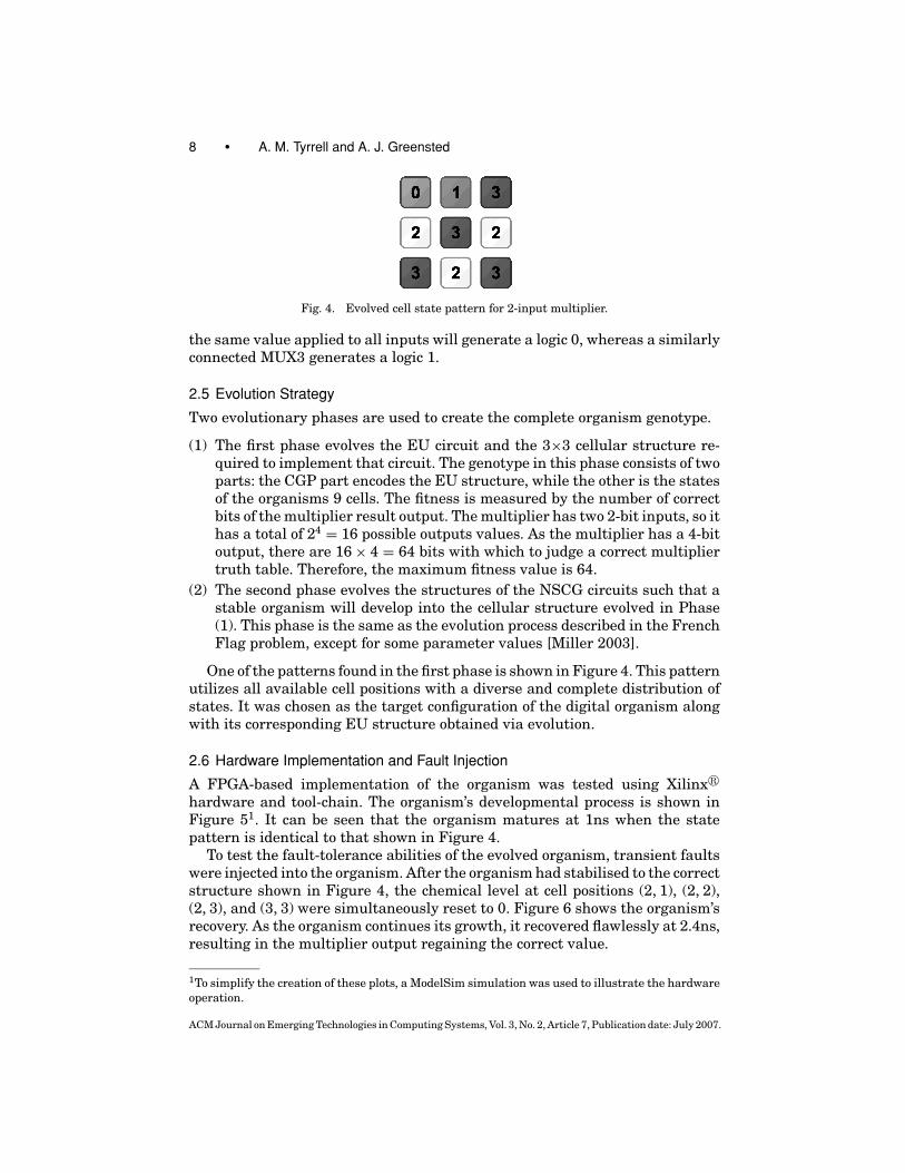
Fig. 4. Evolved cell state pattern for 2-input multiplier.
the same value applied to all inputs will generate a logic 0, whereas a similarlyconnected MUX3 generates a logic 1.
2.5 Evolution Strategy
Two evolutionary phases are used to create the complete organism genotype.
(1) The first phase evolves the EU circuit and the 3×3 cellular structure re-quired to implement that circuit. The genotype in this phase consists of twoparts: the CGP part encodes the EU structure, while the other is the statesof the organisms 9 cells. The fitness is measured by the number of correctbits of the multiplier result output. The multiplier has two 2-bit inputs, so ithas a total of 24 = 16 possible outputs values. As the multiplier has a 4-bitoutput, there are 16 × 4 = 64 bits with which to judge a correct multipliertruth table. Therefore, the maximum fitness value is 64.
(2) The second phase evolves the structures of the NSCG circuits such that astable organism will develop into the cellular structure evolved in Phase(1). This phase is the same as the evolution process described in the FrenchFlag problem, except for some parameter values [Miller 2003].
One of the patterns found in the first phase is shown in Figure 4. This patternutilizes all available cell positions with a diverse and complete distribution ofstates. It was chosen as the target configuration of the digital organism alongwith its corresponding EU structure obtained via evolution.
2.6 Hardware Implementation and Fault Injection
A FPGA-based implementation of the organism was tested using Xilinx�
hardware and tool-chain. The organism’s developmental process is shown inFigure 51. It can be seen that the organism matures at 1ns when the statepattern is identical to that shown in Figure 4.
To test the fault-tolerance abilities of the evolved organism, transient faultswere injected into the organism. After the organism had stabilised to the correctstructure shown in Figure 4, the chemical level at cell positions (2, 1), (2, 2),(2, 3), and (3, 3) were simultaneously reset to 0. Figure 6 shows the organism’srecovery. As the organism continues its growth, it recovered flawlessly at 2.4ns,resulting in the multiplier output regaining the correct value.
1To simplify the creation of these plots, a ModelSim simulation was used to illustrate the hardwareoperation.
ACM Journal on Emerging Technologies in Computing Systems, Vol. 3, No. 2, Article 7, Publication date: July 2007.

Evolving Dependability • 9
Fig. 5. Developmental growth procedure. Traces A and B show the multiplier inputs, Result showsthe output. The evolution of the cell state pattern can be seen in traces States (2:4). The patternfor a working multiplier is boxed and is also shown in Figure 4. The changing chemical levels arealso shown.
Fig. 6. Injection of the first set of faults (chemical disruption) and the recovery procedure.
Once the organism had again stabilized to the correct structure, the stateof the cells at positions (2, 1), (2, 3), and (3, 1) were simultaneously reset to 0(dead cell). Figure 7 shows the recovery process after this second set of transientfaults. The states of the 3 selected victim cells recover completely to the correctpattern at 4ns.
3. CONTINUOUS EVOLUTION
The majority of evolutionary algorithms stop when an acceptable solutionhas been found. However, in reality, evolution is a continuous process. Herewe show that by using this continuous evolutionary approach, it is possi-ble to produce systems that will continue to operate successfully even in thepresence of faults [Tyrrell et al. 2004]. This principle is demonstrated usinga simple robotic application, although the results should be generic to any
ACM Journal on Emerging Technologies in Computing Systems, Vol. 3, No. 2, Article 7, Publication date: July 2007.
10 • A. M. Tyrrell and A. J. Greensted
Fig. 7. Injection of the second set of faults (state disruption) and the recovery procedure.
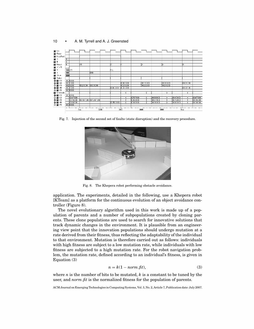
Fig. 8. The Khepera robot performing obstacle avoidance.
application. The experiments, detailed in the following, use a Khepera robot[KTeam] as a platform for the continuous evolution of an object avoidance con-troller (Figure 8).
The novel evolutionary algorithm used in this work is made up of a pop-ulation of parents and a number of subpopulations created by cloning par-ents. These clone populations are used to search for innovative solutions thattrack dynamic changes in the environment. It is plausible from an engineer-ing view point that the innovation populations should undergo mutation at arate derived from their fitness, thus reflecting the adaptability of the individualto that environment. Mutation is therefore carried out as follows: individualswith high fitness are subject to a low mutation rate, while individuals with lowfitness are subjected to a high mutation rate. For the robot navigation prob-lem, the mutation rate, defined according to an individual’s fitness, is given inEquation (3)
n = k(1 − norm fit), (3)
where n is the number of bits to be mutated, k is a constant to be tuned by theuser, and norm fit is the normalized fitness for the population of parents.
ACM Journal on Emerging Technologies in Computing Systems, Vol. 3, No. 2, Article 7, Publication date: July 2007.

Evolving Dependability • 11
Evolution starts with an initially randomized parent population P . This pop-ulation is cloned μ times, resulting in μ cloned populations, C, each the samesize as the original parent population. The cloned populations undergo muta-tion, resulting in μ mutated populations, C′. The mutated clone populationsand parent population are evaluated and then ordered in a single list accordingto fitness. The fittest individuals from the list are used to create the parent pop-ulation for the next generation, the remaining individuals are discarded. Theparent population, P , is not mutated in order to make sure that good parentindividuals are not lost by the mutation operation this way, a form of elitism isundertaken.
Choosing an appropriate fitness measure is an important part of designingan evolutionary algorithm. Special consideration must be taken for the robotcontroller fitness measure as individuals will encounter different aspects of adynamic environment. For our robot navigation problem, the controller’s fitnessis determined by simply measuring the time and distance the robot has runbefore hitting an obstacle; the more time elapsed without collision and thegreater the distance traveled, the higher the fitness value. This fitness measureis calculated as in Equation (4)
fitness = distance × time1000
. (4)
Distance is measured using wheel rotation counters built into the robot. Adistance of 1000 represents a movement of approximately 40mm. If the robotis turning, no adjustment to the distance value is made. To limit the time thateach controller is trialed, a maximum time limit of 140s is imposed. Individualsare killed when this limit is reached even if a collision has not occurred. Fur-thermore, if an individual is stuck in the same position without any distanceimprovement, it is killed. The fitness limit in the experiment is about 1400,which means the robot moved forward without any steering change. At thestart of evaluating a new individual, an escape time is provided to allow move-ment away from a potential dead zone where the last individual was killed.Clearly, since only one robot is used, only one individual is running at a time.
3.1 Experimental Results
For the following experiments, a parent population size of 16 was used; this wascloned three times (μ = 3) to result in a total population size of 64 (16+(3×16)).In order to compare the results, a baseline experiment was performed wherethe individuals of the cloned populations experience a constant mutation rate of8 bits per-bit string. Figure 9 shows the results for this experiment. All resultspresented are for the population of parents, and the fitness values are averagevalues of 10 runs.
The next experiment makes use of the mutation rate defined by Equation (3).It can be observed from the results in Figure 10, where k = 16, that the mu-tation operator is very important to evolve a controller for autonomous robotnavigation. It might be argued that it is quite difficult to obtain adaptive be-havior with a constant mutation rate.
ACM Journal on Emerging Technologies in Computing Systems, Vol. 3, No. 2, Article 7, Publication date: July 2007.

12 • A. M. Tyrrell and A. J. Greensted
Fig. 9. Behavior for the best and average fitness of the population of parents (P) when a constantmutation rate was applied to the individuals of the cloned populations (C).
Fig. 10. Behavior for the best and average fitness of the population of parents, P , when themutation rate for the individuals of the cloned populations (C) was calculated according to 16*(1-norm fit).
3.2 Fault Injection
The following results demonstrate the effects of applying faults to the robot’sproximity sensors. This can be considered equivalent to the dynamic natureof the environment affecting sensory data due to noise or sensor failure. Forthe following experiments, the maximum number of bits mutated in the clonedpopulations is set to k = 16. Faults were introduced by covering the robot’s prox-imity sensors used for navigation with paper masks. This results in the blockedsensor outputting a fixed reading. The results shown in Figure 11 illustratethe effect of the robot having a single failed sensor throughout the experiment.This shows that the algorithm is still able to evolve an effective controller witha reduced number of sensory inputs.
For the next experiments a fault was added at runtime. Once an acceptablecontroller had been evolved, a fault was applied to one of the robot’s proximitysensors. Figure 12 shows the result of applying a sensor fault at generation 50.This fault disrupted the whole population of controllers. It can be observed that
ACM Journal on Emerging Technologies in Computing Systems, Vol. 3, No. 2, Article 7, Publication date: July 2007.

Evolving Dependability • 13
Fig. 11. Behaviour for the best and average fitness of the population of parents, P , when a prox-imity sensor fault is applied before evolution starts.
Fig. 12. Behavior for the best and average fitness of the population of parents, P , when a proximitysensor fault is applied at generation 50.
both the average fitness and the fitness of the best individual dropped when thefault was applied. However, after around 10 generations, the fitness of the bestindividual climbs up and regains its original value. This result demonstratesthat while immediate failure is not prevented, when a fault occurs, the systemdoes quickly recover as fitness is regained.
4. DEDICATED HARDWARE
The previous two sections have discussed techniques for increasing dependabil-ity using evolutionary and developmental methods implemented on commercialFPGAs. In this final example, dependable architectures using hardware thathas been specifically designed to assist evolutionary methods will be considered.
The goal of the project was to design and build an ASIC with featuresamenable for bio-inspired work and, in particular, embryonics and dependablesystem design. The main novel features, setting the architecture and deviceapart from conventional programmable devices, are the following.
ACM Journal on Emerging Technologies in Computing Systems, Vol. 3, No. 2, Article 7, Publication date: July 2007.

14 • A. M. Tyrrell and A. J. Greensted
Fig. 13. The RISA architecture. A two-dimensional array of highly reconfigurable RISA cells.
—A distributed routing algorithm that performs automated creation of connec-tions between parts of the chip.
—The ability to perform intrinsic partial reconfiguration without disruptingcircuit operation.
—A random configuration-safe architecture such that random configurationbitstreams will not damage the chip.
—A microcontroller array with a dedicated microcontroller per-device cell.
The Reconfigurable Integrated System Array (RISA) [Greensted and Tyrrell2007] is a novel form of field programmable digital device. The architecture isformed by a two-dimensional array of RISA Cells, each containing a microcon-troller and a section of FPGA; this combination forms the Integrated Systemreferred to by the architecture name. An illustration of the RISA architectureis shown in Figure 13.
The RISA architecture is inspired by the structure of biological organisms.In particular, the microcontroller/FPGA combination used within each RISAcell reflects the structure and operation of real cells. As biological cells performsystem functions and control the embryonic development process, the electronicRISA cell must also contain this functionality. The RISA cell’s microcontrolleracts as the cell nucleus. It is able to control cell specialization using storedconfigurations, analogous to DNA, to implement different cell functions, de-pending on cell location. The FPGA fabric then provides the platform on whichsubsections of the system circuitry may be implemented. The mapping betweenbiological and electronic domains is illustrated in Figure 14.
Past embryonic architectures have been implemented on FPGAs [Ortegaet al. 2000]. However, despite their role as quick prototyping and testingplatforms, the inefficiency of implementing a reconfigurable platform withinanother means commercial FPGAs are not suitable for the RISA architecture.Therefore, an ASIC implementation of the RISA design has been fabricated.Two particular design features necessitating a custom ASIC are the mi-crocontroller array and an FPGA fabric that supports fine-grained partial
ACM Journal on Emerging Technologies in Computing Systems, Vol. 3, No. 2, Article 7, Publication date: July 2007.

Evolving Dependability • 15
Fig. 14. The biological to electronic mapping of the RISA architecture. The RISA cell must containsufficient functionality to perform the cell’s function and to drive differentiation.
reconfiguration. These two main aspects of the RISA design are detailed inSections 4.1 and 4.2, respectively.
4.1 SNAP Microcontroller
Each RISA cell microcontroller is responsible for the functional specializationof the cell. This involves determining the cell’s position within the system andconfiguring the cell’s FPGA fabric accordingly. Rather than using a hard-codedstate machine to control this process, a microcontroller core has been employedto provide the flexibility for investigating different differentiation methods. Fur-thermore, this approach allows other processor array-based applications to beimplemented on the RISA architecture.
A custom microcontroller core was developed for the RISA architecture. TheSimple Networked Application Processor (SNAP) is a 16-bit RISC core with anumber of peripheral modules providing extra functionality. The SNAP coreis illustrated in Figure 15. As already mentioned, the main role of the mi-crocontroller is to control the configuration of the cell’s FPGA fabric. In orderto simplify this task, the microcontroller contains dedicated configuration ac-cess ports (CAPs) to access the FPGA configuration chains. Furthermore, theSNAP instruction set has been specifically designed to include instructions thatsimplify the task of bitstream creation and manipulation. A set of peripheralmodules are available to the user via the core’s register file. Modules includea random number generator, general purpose counters, and a UART. To sim-plify the task of creating a SNAP network, each core includes four SNAPLinkmodules. These provide independent, full duplex, flow controlled connectivityto all four neighboring cells. Intermicrocontroller communication is as simpleas reading from and writing to the SNAPLink registers.
The SNAP microcontroller uses a von Neumann memory architecture. Thisapproach makes more efficient use of the core’s limited memory by avoidingwasted program memory space that could be used for data storage. To furtherreduce memory requirements, the SNAP design promotes compact assemblercode. This is achieved in two ways. First, all SNAP instructions can be madeconditional on the state of core status flags. This approach helps remove theneed for separate test instructions prior to a branch. Second, by accessing allperipheral modules through the register file, peripheral data may be directly
ACM Journal on Emerging Technologies in Computing Systems, Vol. 3, No. 2, Article 7, Publication date: July 2007.

16 • A. M. Tyrrell and A. J. Greensted
Fig. 15. The SNAP microcontroller, in summary, a 16-bit data width, 16-bit address space, 4-stagepipelined, RISC, von Neumann memory design. Peripheral modules, accessed via the register file,provide extra functionality.
written to or read from by all instructions, without having to also use memoryread and write instructions.
4.2 FPGA Fabric
The FPGA fabric used with the RISA architecture, like any commercial FPGA,should be sufficiently flexible to implement a multitude of different circuit de-signs. However, unlike standard FPGA devices, the RISA architecture uses aconsiderably more flexible configuration system. This satisfies the requirementof embryonic arrays for fine-grained partial reconfiguration, the ability to tar-get and reconfigure small areas of the FPGA fabric without having to take theremaining areas offline.
The RISA configuration scheme attempts to provide flexibility and simplicityto the designer. Reconfiguration takes place without affecting the current con-figuration. Furthermore, once the new configuration data is in place, it can bemade active, replacing the old configuration in a single clock cycle. FPGA logicconfiguration is separated from that of the routing, which makes reconfigura-tion faster if only the logic or routing needs altering. It is also possible, usingthe configuration circuitry, to read back a snapshot of FPGA register values.
An important design feature of the RISA FPGA architecture is the abilityto safely perform random configuration manipulation without risking devicedamage. It is the routing architecture that makes this possible. RISA routing ismultiplexer-based rather than bus-based. This approach removes the possibil-ity of bus contentions that may lead to device damage. Furthermore, the routingdesign removes the possibility of creating combinatorial feedback paths. Thisproperty makes the RISA architecture ideal for investigating evolvable hard-ware designs.
ACM Journal on Emerging Technologies in Computing Systems, Vol. 3, No. 2, Article 7, Publication date: July 2007.

Evolving Dependability • 17
Fig. 16. The FPGA fabric is formed by an array of clusters. Each cluster contains four functionunits that contain the configurable logic elements.
To achieve a random configuration-safe architecture, the FPGA fabric is or-ganized into four combinatorial directions. The main configurable element ofthe FPGA is the cluster. Each cluster contains four function units assigned toa different direction, north, east, south and west. Intercluster combinatorialconnections can only be made between function units of the same direction.In this way, it is not possible to form a combinatorial loop. Direction changesmust be made via a registered connection. The FPGA fabric is illustrated inFigure 16.
4.3 The RISA Chip
The RISA architecture has been fabricated using UMC’s 0.18μm 1P6M logicprocess. A cell-based approach was used as it provides a simple method for a firstASIC run [Smith 1997]. Due to the density limits this approach imposes, thefirst RISA chip only implements a single RISA Cell. The greater portion of thechip’s die area was used in implementing the FPGA, the density of which couldbe substantially improved by taking a full custom approach especially that ofthe FPGA routing circuitry. However, as the RISA architecture is array-based,it has been specifically designed to allow the abutment of separate devices tocreate larger arrays. This means that the current chip is still appropriate forforming a full RISA architecture with multiple RISA cells.
4.4 Specialization and Routing Algorithms
Traditional embryonics uses a simple Cartesian grid to determine cell locationand thus specialization [Jackson 2003; Mange et al. 2000]. However, as thisapproach requires the removal of a complete array row or column in order toreplace a faulty cell, repair is wasteful of resources. The approach taken inthis work uses a more efficient routing algorithm based on ideas from com-putational topology and geometry. The algorithm performs initial routing andsubsequent rerouting for fault recovery. The algorithm makes use of discreteMorse-Lyapunov functions to track the availability of chip resources, that is,the utilization of RISA cells. The algorithm operates on rooted binary treesbound within a finite region of a Euclidean plane. In a purely distributed
ACM Journal on Emerging Technologies in Computing Systems, Vol. 3, No. 2, Article 7, Publication date: July 2007.

18 • A. M. Tyrrell and A. J. Greensted
Fig. 17. The cell routing algorithm in operation. The images shows how a graph of connected cellsis relocated and rerouting after a cell failure has occurred. The blockage shows how the graph hasto be placed around dead cell locations.
fashion, the algorithm assigns weighting values to each node in the graph.These values represent the size of a particular node’s subtree. When reconfig-uration is required, the weightings are used by each graph node to determinea path for graph redirection. In this way, the algorithm provides the ability toperform complex deformation of the original circuit structure in a distributedmanner while maintaining the system’s functional integrity. Figure 17 showsan example of a graph that has rerouted after a node has been failed.
5. CONCLUSION
This article has described three different directions in evolvable hardware re-search; an evolved development circuit to drive the self-organization of a multi-cellular system, an algorithm for continuous evolution in order to achieve con-tinual adaptation to a changing environment, and a new hardware platformspecialized for investigating evolutionary processes.
The evolution of a developmental system has been described where a digitalsystem is grown via embryonic development of digital hardware cells. Mor-phogenic chemicals are used to mimic the pattern formation process of embry-onic growth. Artificial evolution was used to develop the internal circuitry of cellexecution units that provide cell function and next state and chemical genera-tors that drive the differentiation of the organism. Experimental results havedemonstrated that the developed system is able to tolerate transient faults inthe form of cell state and chemical-level disruptions. After the injection of thesefaults, the circuit is able to regrow back into a fully functional circuit.
The continual evolution research reflects that in nature the evolution of aspecies does not stop when strong individuals are bred, rather evolution con-tinues to allow subsequent generations to adapt to environmental changes.Experimental results using a Khepera robot have shown that a continual evo-lution algorithm is suitable for creating an autonomous navigation controllerfor collision avoidance even with the occurrence of sensor faults. The followingimportant features with regard to autonomy, adaptability, and robustness wereobserved.
ACM Journal on Emerging Technologies in Computing Systems, Vol. 3, No. 2, Article 7, Publication date: July 2007.

Evolving Dependability • 19
—By using a mutation rate defined according to the fitness of the individual,it is possible to obtain good adaptability in changing environments.
—A robust controller undergoing continual evolution can reevolve in order tocontinue operation in the presence of faults.
It was demonstrated that despite the introduction of permanent faults, theevolutionary process ensures the system recovers to full functionality. Such anability would be of great benefit to applications such as unmanned space andunderwater missions where the lack of an adaptation mechanism could lead tomission failure in the event of system faults.
Finally, a description of the RISA architecture, a new FPGA-like device de-signed specifically for use within the bio-inspired community, has been given.The device provides an advanced reconfigurable hardware platform suitablefor investigating embryonics. Furthermore, the ability to safely use randomconfiguration bitstreams and be able to target specific areas of the device’s re-configurable fabric makes the RISA chip far more suitable than commercialdevices for evolutionary hardware research.
A routing algorithm designed for use with the RISA architecture has been de-scribed. Compared to traditional embryonic architecture, this algorithm makesmore efficient use of system resources when reconfiguring a system to circum-vent faults.
ACKNOWLEDGMENTS
The authors would like to thank Julian Miller, Heng Liu, Natasha Dowdingand Renato Krohling for their help and advice.
REFERENCES
BRADLEY, D. AND TYRRELL, A. 2002. Immunotronics: Novel finite state machine architectures withbuilt in self test using self-nonself differentiation. IEEE Trans. Evolut. Computat. 6, 3, 227–238.
CANHAM, R. AND TYRRELL, A. 2003. An embryonic array with improved efficiency and faulttolerance. In 5th NASA Conference on Evolvable Hardware. IEEE Computer Society, 265–272.
FOGEL, D. 2006. Evolutionary Computation: Toward a New Philosophy of Machine Intelligence.Wiley-IEEE Press, Piscataway, NJ.
GREENSTED, A. AND TYRRELL, A. 2007. RISA: A hardware platform for evolutionary design. InProceedings of IEEE Workshop on Evolvable and Adaptive Hardware. IEEE Computer Society,1–7.
HOLLINGWORTH, G., SMITH, S., AND TYRRELL, A. 2000. Safe intrinsic evolution of virtex devices. InProceedings of the 2nd NASA/DoD Workshop on Evolvable Hardware, J. Lohn, A. Stoica, andD. Keymeulen, Eds. IEEE Computer Society, 195–202.
JACKSON, A. 2003. Asynchronous embryonics, self-timed biologically-inspired fault-tolerant com-puting arrays. Ph.D. thesis, The University of York.
KTEAM. Khepera Web site. http://www.k-team.com.LAYZELL, P. AND THOMPSON, A. 2000. Understanding inherent qualities of evolved circuits: Evolu-
tionary history as a predictor of fault tolerance. In Proceedings of the 3rd International Conferenceon Evolvable Systems (ICES’00). Lecture Notes in Computer Science, vol. 1801. Springer-Verlag,Berlin, Germany, 133–142.
LEE, P. AND ANDERSON, T. 1990. Fault Tolerance Principles and Practice 2nd ed. Springer-Verlag,Berlin, Germany.
ACM Journal on Emerging Technologies in Computing Systems, Vol. 3, No. 2, Article 7, Publication date: July 2007.

20 • A. M. Tyrrell and A. J. Greensted
LIU, H., MILLER, J., AND TYRRELL, A. 2005. Intrinsic evolvable hardware implementation of arobust biological development model for digital systems. In 6th NASA Conference on EvolvableHardware. IEEE Computer Society, 87–92.
MANGE, D., SIPPER, M., STAUFFER, A., AND TEMPESTI, G. 2000. Towards robust integrated circuits:The embryonics approach. Proceedings of the IEEE 88, 4 (April), 516–541.
MILLER, J. 2003. Evolving developmental programs for adaptation, morphogenesis, and self-repair. In 7th European Conference on Artificial Life. Lecture Notes on Artificial Life, vol. 2801.Springer-Verlag, Berlin, Germany, 56–265.
MILLER, J. AND THOMSON, P. 2000. Cartesian genetic programming. In Genetic Programming, Pro-ceedings of EuroGP’2000, R. Poli, W. Banzhaf, W. Langdon, J. Miller, P. Nordin, and T. Fogarty,Eds. Lecture Notes in Computer Science, vol. 1802. Springer-Verlag, Berlin, Germany, 121–132.
ORTEGA, C., MANGE, D., SMITH, S., AND TYRRELL, A. 2000. Embryonics: A bio-inspired cellular ar-chitecture with fault-tolerant properties. Genetic Program. Evolv. Machines 1, 3, 187–215.
SMITH, M. 1997. Application-Specific Integrated Circuits. Addison Wesley Professional Publish-ing, Boston, MA.
THOMPSON, A., LAYZELL, P., AND ZEBULUM, R. S. 1999. Explorations in design space: Unconventionalelectronics design through artificial evolution. IEEE Trans. Evolution. Computat. 3, 3, 167–196.
TYRRELL, A., HOLLINGWORTH, G., AND SMITH, S. 2001. Evolutionary strategies and intrinsic fault tol-erance. In Proceedings of the 3rd NASA/DoD Workshop on Evolvable Hardware. IEEE ComputerSociety, 98–106.
TYRRELL, A., KROHLING, R., AND ZHOU, Y. 2004. A new evolutionary algorithm for the promotion ofevolvable hardware. IEE Proceedings of Computers and Digital Techniques 151, 4 (July), 267–275.
WOLPERT, L. 2002. Principles of Development 2nd ed. Oxford University Press, Oxford, UK.
Received October 2006; revised January 2007; accepted February 2007 by Sally McKee
ACM Journal on Emerging Technologies in Computing Systems, Vol. 3, No. 2, Article 7, Publication date: July 2007.