proofreading - jeet park, seung-taek baek, yong-ho chung and gil-soo jang ... insulation level li si...
TRANSCRIPT

J Electr Eng Technol.2017; 12(?): 1921-718 http://doi.org/10.5370/JEET.2017.12.1.1921
1921Copyright ⓒ The Korean Institute of Electrical Engineers
This is an Open-Access article distributed under the terms of the Creative Commons Attribution Non-Commercial License (http://creativecommons.org/ licenses/by-nc/3.0/) which permits unrestricted non-commercial use, distribution, and reproduction in any medium, provided the original work is properly cited.
The Development of the±80kV 60MW HVDC System in Korea
Kyoung-Ho Park*, Seung-Taek Baek*, Yong-Ho Chung* and Gil-Soo Jang†
Abstract – HVDC transmission systems can be configured in many ways to take into account cost, flexibility and operational requirements. [1] For long-distance transmission, HVDC systems may be less expensive and suffer lower electrical losses. For underwater power cables, HVDC avoids the heavy currents required to charge and discharge the cable capacitance of each cycle. For shorter distances, the higher cost of DC conversion equipment compared to an AC system may still be warranted, due to other benefits of direct current links. HVDC allows power transmission between unsynchronized AC transmission systems. Since the power flow through an HVDC link can be controlled independently of the phase angle between the source and the load, it can stabilize a network against disturbances due to rapid changes in power. HVDC also allows the transfer of power between grid systems running at different frequencies, such as 50 Hz and 60 Hz. This improves the stability and economy of each grid, by allowing the exchange of power between incompatible networks. This paper proposed to establish Korean HVDC technology through a cooperative agreement between KEPCO and LSIS in 2010. During the first stage (2012), a design of the ±80kV 60MW HVDC bipole system was created by both KEPCO and LSIS. The HVDC system was constructed and an operation test was completed in December 2012. During the second stage, the pole#2 system was fully replaced with components that LSIS had recently developed. LSIS also successfully completed the operation test. (2014.3)
Keywords: Current Source Converter (CSC) HVDC, Jeju HVDC pilot project, HVDC converter transformer, HVDC thyrister valve, HVDC valve base electronics, HVDC valve cooling system, HVDC control and protection
1. Introduction As of 2012, due to more than 50 years of experience in
the operation of line-commutated CSC HVDC transmission, the transport of bulk power by direct current is commonly accepted to be a mature and well-understood technology such as the Wolgograd-Donbass interconnection or the SACOI link between the island of Sardinia, the island of Corsica, and the Italian mainland. [2] It presents HVDC system that converts AC to DC at one converter station, which is then transmitted to a second converter station, converted back to AC, and fed into another electrical network. LSIS successfully first produced the current source converter (CSC) HVDC project in Korea. Our project is based on the establishment of Korean HVDC technology by KEPCO and LSIS. During the first stage (2012), KEPCO and LSIS completed the design of the ±80kV 60MW HVDC bipole system. They also constructed the HVDC system and finished the operation test in December 2012. During the second stage, the pole#2 system was fully replaced with components that LSIS had developed. LSIS also successfully completed an operation test. (2014.3)
2. Basic Design for the Jeju HVDC Pilot Project The Jeju HVDC Pilot Project stations are typically a
CSC system that is composed of a thyrister valve, converter transformer, and control and protection. The HVDC Pilot’s power line connection diagram between stations is link with the Jeju Power System that it should consider the sub synchronous resonance (SSR) analysis since the SSR interaction impacts the turbine shaft oscillation that can damage the shaft of a generator. [3]
The multi-mass model is utilized to demonstrate the dynamic oscillation characteristic for a generator turbine. The SSR analysis is based on the difference between electrical torque and mechanical torque of generator with considering the dynamic characteristic. This difference can be a main factor of fatigue on turbine system. Therefore, the SSR stability is analyzed based on the convergence of the oscillation of this difference. The convergence is evaluated by prony analysis which provides the information on the damping ratio. The Eq. (1) explains the prony analysis. It contains the information on the magnitude, damping ratio, frequency, and phase angle of a waveform.
1
( ) cos(2 )i
Nt
i i ii
f t A e f tσ π φ=
= +∑ (1)
Fig. 1 shows the stable case of sub synchronous
† Corresponding Author: Dept. of Electrical and Electronic Engin-eering, Korea University, Korea. ([email protected])
* LSIS Co. Ltd. Korea. ({khparkc, stbaek, yhchung}@lsis.com) Received: October 2, 2015; Accepted: January 14, 2017
ISSN(Print) 1975-0102ISSN(Online) 2093-7423
Proofreading

The Development of the±80kV 60MW HVDC System in Korea
1922 │ J Electr Eng Technol.2017; 12(1): 1921-718
oscillation causing from a system disturbance. In the stable case, the waveform of the difference between electrical torque and mechanical torque of generator converges. Therefore, the prony analysis result of this case has no positive value on damping ratio.
Fig. 2 shows the HVDC systems in Jeju island. The HVDC #1, #2 which are commercial PJT was constructed by KEPCO. The ±80kV 60MW HVDC system design which is pilot PJT was done by LSIS.
The power flow is from Geumak C/S to Hallim C/S by HVDC. Also, the power flow of the reverse direction is acceptable. [Fig. 3] The system rating of DC voltage is ±80kV, and the DC rating is 60MW. [Table 1&2] The rectifier system is Geumak C/S. The inverter side is Hallim C/S.
The DC transmission line is 5.2km. The length of the cable is 500 meter and the overhead line is 4.8km. This DC line is located with the AC 154KV line at the same tower.
The upper side of the tower includes AC three phase lines. Lower sider is dc line. But there are no interference between ac and dc.
3. Main Components of the Jeju HVDC Pilot
Project The Jeju HVDC Pilot Project stations are typically
current source converter (CSC) systems, which are composed of a thyrister valve, converter transformer, smoothing reactor, AC filter, and control and protection. [Fig. 4] This chapter introduces the thyrister valve, converter transformer, valve base electronics (VBE), control and protection, valve cooling system composed of the ±80kV 60MW HVDC system.
3.1 HVDC thyrister valve
Thyrister is the most critical component in the valve.
Through the on/off operation of the thyrister valve, it can transform the AC to DC. Five or more thyrister levels in a valve section should be tested for adequate representation in case the valve section is composed of twelve or more levels in series. [4]
The used thyrister is electrical triggered thyrister (ETT) 6.5kV and 600A rating. Thyrister valves employ high power thyristers, together with associated gating, damping and grading circuits, arranged in 6 or 12 pulse converter groups. Fig. 5 is the structure of the thyrister valve. [5] The
Fig. 1. A stable case of the sub synchronous oscillation
Fig. 2. The Jeju HVDC pilot project location (Hallim C/S, Geumak C/S)
Fig. 3. The Jeju HVDC pilot project power transmission line
Table 1. The Jeju HVDC pilot project AC system specification AC system data Geumak Hallim
Nominal system voltage 154 kVrms 154 kVrms Nominal operating voltage 156 kVrms 156 kVrms
Minimum operating voltage, steady-state 139 kVrms 139 kVrms
Maximum operating voltage, steady-state 164 kVrms 164 kVrms
Maximum short circuit current, symmetrical 3 phase 1191.76 MVA 1166.47
MVA Minimum short circuit level (SCL) at AC contingency considered as the minimum AC System SCL
950.42 MVA 926.28 MVA
Rated frequency 60 Hz 60 Hz Frequency variation range 60±0.2 Hz 60±0.2 Hz
Table 2. The Jeju HVDC pilot project DC system
specification DC system data
Maximum (at 100% load) 60 MWDirect power - bipole Minimum (at 10% load) 6 MW
Measurement error ±0.6 % Nominal DC current (at 100% Load) 375 A Direct current Minimum DC current (at 10% Load) 0.375 A
Measurement error ±0.6 % Direct voltage Nominal (at 100% load) ±80 kV
Proofreading

Kyoung-Ho Park, Seung-Taek Baek, Yong-Ho Chung and Gil-Soo Jang
http://www.jeet.or.kr │ 1923
Table 3. The Jeju HVDC pilot project valve specification
Item Value Number of pulses 12
Converter bridge per pole 1 x 12 pulse Total number of levels per valve 20
Redundant levels per valve 1 Rated AC voltage 33.5 kVrms Rated DC voltage 80 kV No load voltage 91 kV
MCAV 52.77 kVpk Rated DC current 378 A
Continuous max current (1.05 p.u.) 396 A 2 hour overload current (1.13 p.u.) 426 A
10 seconds overload current (1.2 p.u.) 460 A Rectifier control angle at nominal 19.3° Inverter control angle at nominal 22°
Short circuit current 5.7 kApk SIPL 90.5 kVpk SIWL 104.13 kVpk LIPL 92.09 kVpk LIWL 112 kVpk
Fig. 4. Main components layout of the Jeju HVDC pilot
project
Fig. 5. The Jeju HVDC pilot project valve configuration
thyrister valve hall is contained in three quadri valves (valve×4). One of the three valves is replaced by LSIS’s valve. Table 3 shows specifications of the thrister valve designed by LSIS.
3.2 HVDC converter transformer
The HVDC converter transformer provides the
connections between the AC system and the valve. The role of the transformer is to provide stable voltage to the valve side, which is nearly independently of the AC side. [6] Therefore, the converter transformer is a very important component in the HVDC system. Fig. 6 is the structure of the HVDC converter transformer made by LSIS.
LSIS designed Table 4 which is the HVDC converter transformer specifications in the ±80kV 60MW HVDC system. [7]
3.3 The HVDC valve base electronics system
The valve base electronics (VBE) system is the electrical
optical firing interface between the control and protection (C&P) system and the valve gate units. In addition, the VBE provides valve monitoring and protection for each
Table 4. The Jeju HVDC pilot project converter trans-former specification
Item Specification Number of phases 3 Phases
Rated voltage 154/33.5 - 33.5 kV Rated frequency 60 Hz
Rated power 36/18 - 18 MVA Type of cooling ONAN/ONAF (56%/100%) Insulation level LI SI AC DC PR
- HV line terminal 650 - 275 - - - HV neutral 325 - 140 - - - LV I (Delta) 240 220 100 130 95 - LV II (Star) 145 135 55 70 45 Vector group YNy0d11
Top oil Average windingTemperature rise 50°C 55°C Total Shipment Weight 89,700 kg 47,400 kg
Application standards IEC 60076/61378
Fig. 6. The Jeju HVDC pilot project converter transformer
Proofreading
The Development of the±80kV 60MW HVDC System in Korea
1924 │ J Electr Eng Technol.2017; 12(1): 1921-718
thyrister valve. [Fig. 7] Table 5 is the VBE configuration made by LSIS.
Table 7. The Jeju HVDC pilot project control function
Control Function Detail Functions Power limits
Master power control Power/frequency control
Master Control/ AC Yard Control (4EA)
Reactive power control Blocking control
Pole power control Overload control
Current order coordinator Pole Control (5EA)
Current balancing Phase limit Oscillator
Ring counter Loop control
AC measurement Alpha balancing
Gamma balancing VDCL
Aux. loop control
Phase Control (10EA)
Tap changer control
Fig. 9. Structure of the Jeju HVDC pilot project redundancy
control and protection system
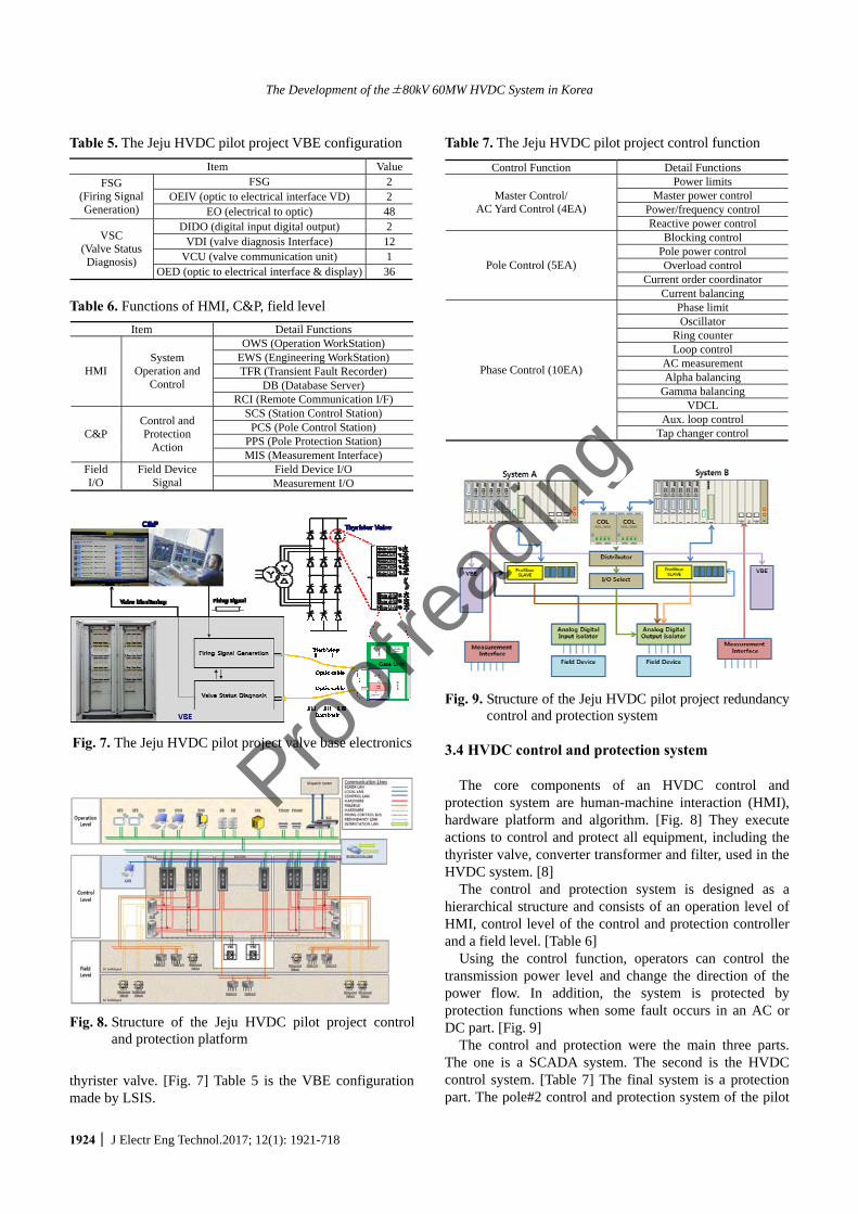
3.4 HVDC control and protection system The core components of an HVDC control and
protection system are human-machine interaction (HMI), hardware platform and algorithm. [Fig. 8] They execute actions to control and protect all equipment, including the thyrister valve, converter transformer and filter, used in the HVDC system. [8]
The control and protection system is designed as a hierarchical structure and consists of an operation level of HMI, control level of the control and protection controller and a field level. [Table 6]
Using the control function, operators can control the transmission power level and change the direction of the power flow. In addition, the system is protected by protection functions when some fault occurs in an AC or DC part. [Fig. 9]
The control and protection were the main three parts. The one is a SCADA system. The second is the HVDC control system. [Table 7] The final system is a protection part. The pole#2 control and protection system of the pilot
Table 5. The Jeju HVDC pilot project VBE configuration Item Value
FSG 2 OEIV (optic to electrical interface VD) 2
FSG (Firing Signal Generation) EO (electrical to optic) 48
DIDO (digital input digital output) 2 VDI (valve diagnosis Interface) 12
VCU (valve communication unit) 1
VSC (Valve Status Diagnosis)
OED (optic to electrical interface & display) 36
Table 6. Functions of HMI, C&P, field level Item Detail Functions
OWS (Operation WorkStation) EWS (Engineering WorkStation) TFR (Transient Fault Recorder)
DB (Database Server) HMI
System Operation and
Control RCI (Remote Communication I/F)
SCS (Station Control Station) PCS (Pole Control Station)
PPS (Pole Protection Station) C&P Control and Protection
Action MIS (Measurement Interface)
Field Device I/O Field I/O
Field Device Signal Measurement I/O
Fig. 7. The Jeju HVDC pilot project valve base electronics
Fig. 8. Structure of the Jeju HVDC pilot project control and protection platform
Proofreading
Kyoung-Ho Park, Seung-Taek Baek, Yong-Ho Chung and Gil-Soo Jang
http://www.jeet.or.kr │ 1925
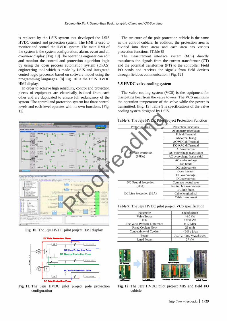
is replaced by the LSIS system that developed the LSIS HVDC control and protection system. The HMI is used to monitor and control the HVDC system. The main HMI of the system is the system configuration, alarm, event and all overview display. [Fig. 10] The operating engineer can edit and monitor the control and protection algorithm logic by using the open process automation system (OPAS) engineering tool which is made by LSIS and integrated control logic processor based on software model using the programming languages. [8] Fig. 10 is the LSIS HVDC HMI display.
In order to achieve high reliability, control and protection pieces of equipment are electrically isolated from each other and are duplicated to ensure full redundancy of the system. The control and protection system has three control levels and each level operates with its own functions. [Fig. 11]
The structure of the pole protection cubicle is the same as the control cubicle. In addition, the protection area is divided into three areas and each area has various protection functions. [Table 8]
The measurement interface system (MIS) directly transduces the signals from the current transformer (CT) and the potential transformer (PT) to the controller. Field I/O sends and receives the signals from field devices through fieldbus communication. [Fig. 12]
3.5 HVDC valve cooling system
The valve cooling system (VCS) is the equipment for
dissipating heat from the valve towers. The VCS maintains the operation temperature of the valve while the power is transmitted. [Fig. 13] Table 9 is specifications of the valve cooling system designed by LSIS.
Fig. 10. The Jeju HVDC pilot project HMI display
Fig. 11. The Jeju HVDC pilot project pole protection
configuration
Table 8. The Jeju HVDC Pilot Project Protection Function
Protection Area Protection Functions Asymmetry protection
Pole differential Abnormal firing
AC DC differential DC AC differential
AC overcurrent AC overvoltage (Line Side) AC overvoltage (valve side)
AC under voltage Tap limits
DC undercurrent Open line test
DC overvoltage
DC Pole Protection (14EA)
DC overcurrent Common neutral area DC Neutral Protection
(2EA) Neutral bus overvoltage DC line faults
Cable longitudinal DC Line Protection (3EA) Cable overcurrent
Table 9. The Jeju HVDC pilot project VCS specification
Parameter Specification Valve Tower 44.0 kW
Pole 132.0 kW The Valve Pressure Difference 0.12 MPa
Rated Coolant Flow 29 m3/h Conductivity of Coolant ≤0.5μS/cm
Power AC : 2×380 VAC±10% Rated Power 27 kW
Fig. 12. The Jeju HVDC pilot project MIS and field I/O cubicle
Proofreading

The Development of the±80kV 60MW HVDC System in Korea
1926 │ J Electr Eng Technol.2017; 12(1): 1921-718
Fig. 13. The Jeju HVDC pilot project VCS
Fig. 14. The Jeju HVDC pilot project reference made by
LSIS
Fig. 15. The Jeju HVDC pilot project test results of
monopole operation
4. The Jeju HVDC Pilot Project Operation On October 2013, the main components of the Jeju
HVDC Pilot Project pole#2 were replaced with LSIS products (C.TR, Valve, C&P). [Fig. 14]
LSIS’s current source converter HVDC system was first developed in Korea. [9]
In addition, LSIS successfully conducted and completed the operation test that involved a 30MW full load operation of pole#2. [Fig. 15]
Fig. 16 shows AC voltage, AC current, DC voltage, DC current about monopole test.
Fig. 16. The Jeju HVDC pilot project test waveform of
monopole operation
5. Conclusion This paper introduced the development of the ±80kV
60MW HVDC system on Jeju Island. The design of the Jeju HVDC pilot project made by LSIS took into account the diverse operating requirements of Korea.
For the future works, LSIS will offer advanced the current source converter (CSC) HVDC solutions and voltage source converter (VSC) HVDC solutions for the increasing demand for electric power in load centers, and a growing interest to use renewable energy resources usually generated far away from load centers calls for bulk power transmission. It is important to conduct other HVDC projects.
Acknowledgements This work was supported by LSIS.
References
[1] Arrillaga, Jos, High Voltage Direct Current Trans-mission, Second edition, Institution of Electrical Engineers, chapter. 4.1 ISBN 0 85296 941 4, 1998.
[2] Gianluigi Migliavacca, Advanced Technologies for Future Transmission Grids, Springer, pp 157, ISBN 978 1 4471 4548 6, 1998.
[3] KUNDUR P. Power System stability and control, McGraw-Hill, chapter.15, 1994.
[4] M. L. Woodhouse. J. P. Ballad. J. L. Haddock, B. A. Rowe, “The control and protection of thyristers in the English terminal Cross Channel valves particularly during forward recovery,” IEE Conference Publication 205, International Conference on Thyrister and Variable Static Equipment for AC and DC Trans-mission, December 1981.
[5] IEC 60700-1, Edition 1.2 “Thyristor valves for high voltage direct current (HVDC) power transmission Part 1: Electrical testing,” 2008-11.
[6] IEC 60076, Edition 2.1 “Power Transformers - Part
Proofreading

Kyoung-Ho Park, Seung-Taek Baek, Yong-Ho Chung and Gil-Soo Jang
http://www.jeet.or.kr │ 1927
1: General,” 2000-04 [7] IEC 61378-2, First Edition “Convertor Transformers
- Part 2: Transformers for HVDC applications,” 2001-02
[8] IEC 61131-3, Edition 3.0 “Programmable controllers - Part 3 : Programming languages,” 2013-02.
[9] M. Sampei, H. Magoroku, M. Hatano "Operating Experience of Hokkaido-Honshu High Voltage Direct Current Link,” IEEE Transactions on Power Delivery, Vol. 12, No. 3, July 1997.
Kyoung-Ho Park He received M.S degree in electrical engineering from Korea University, Seoul, Korea, in 2011. He is working for LSIS Co. Ltd. in Korea. Currently, he is the Senior Research Engineer of the HVDC D&B Unit of LSIS. His main research areas are power system analysis and system
verification connecting HVDC & FACTS.
Seung-Taek Baek He received the Ph.D. for Electrical Engineering from Myongji University, Korea in 2004. Since 2010, he is working for LSIS Co. Ltd, in Korea. Currently, he is the Principal Research Engineer of the HVDC D&B Unit of LSIS. His main research areas are static power con-
verter for renewable energy and HVDC System.
Yong-Ho Chung He received the Ph.D. for Electrical Engineering from the Korea Advanced Institute of Science and Technology (KAIST). Since 1985, he is working for LSIS Co. Ltd, in Korea. He is the Research Fellow of the HVDC D&B Unit of LSIS. His main research areas are static power
converters, UPS, Dynamic Voltage Restorer, Active Power Filter, photovoltaic inverter and HVDC system.
Gil-Soo Jang He received B.S. and M.S. degrees in electrical engineering from Korea University, Seoul, Korea, in 1991 and 1994, respectively, and the Ph.D. degree in electrical and com-puter engineering from Iowa State University, Ames, in 1997. He was a Visiting Scientist at Iowa State Uni-
versity from 1997 to 1998 and a Senior Researcher with the Korea Electric Power Research Institute, Daejeon, Korea, from 1998 to 2000. Currently, he is a Professor in the School of Electrical Engineering, Korea University. His research interests include power quality and power system control.
Proofreading